REPUBLIC OF KENYA COUNTY GOVERNMENT OF KWALE NATIONAL AGRICULTURAL AND RURAL INCLUSIVE GROWTH PROJECT TENDER No. 168345-WB REHABILITATION OF NYALANI IRRIGATION SCHEME BID DOCUMENT VOLUME 2 CONTENTS SECTION 1: GENERAL AND SPECIFIC SPECIFICATIONS SECTION 2: STANDARD REFERENCE NUMBERS Employer: Supervising Consultant: COUNTY PROJECT COORDINATOR, NARIGP - KWALE, P.O. BOX 4 CODE 80403, KWALE-KENYA ENG. STEVEN OJIAMBO (EBK E324) P.O. BOX 779 CITY SQUARE 00200 NAIROBI, KENYA E-mail: [email protected] Engineer: NATIONAL PROJECT COORDINATOR, NARIGP, P.O. BOX 30028-00100, NAIROBI - KENYA MARCH 2021

Welcome message from author
This document is posted to help you gain knowledge. Please leave a comment to let me know what you think about it! Share it to your friends and learn new things together.
Transcript

REPUBLIC OF KENYA COUNTY GOVERNMENT OF KWALE
NATIONAL AGRICULTURAL AND RURAL INCLUSIVE GROWTH PROJECT
TENDER No. 168345-WB
REHABILITATION OF NYALANI IRRIGATION SCHEME
BID DOCUMENT
VOLUME 2
CONTENTS SECTION 1: GENERAL AND SPECIFIC SPECIFICATIONS SECTION 2: STANDARD REFERENCE NUMBERS
Employer: Supervising Consultant:
COUNTY PROJECT COORDINATOR, NARIGP - KWALE, P.O. BOX 4 CODE 80403, KWALE-KENYA
ENG. STEVEN OJIAMBO (EBK E324) P.O. BOX 779 CITY SQUARE 00200 NAIROBI, KENYA E-mail: [email protected]
Engineer: NATIONAL PROJECT COORDINATOR, NARIGP, P.O. BOX 30028-00100, NAIROBI - KENYA
MARCH 2021
REHABILITATION OF NYALANI IRRIGATION SCHEME
TENDER No. 168345-WB
BID DOCUMENT
VOLUME 2
CONTENTS
• SECTION 1: GENERAL AND SPECIFIC SPECIFICATIONS
• SECTION 2: STANDARD REFERENCE NUMBERS
SECTION 1
GENERAL AND SPECIFIC SPECIFICATIONS
GENERAL AND SPECIFIC CONDITIONS
i
REHABILITATION OF NYALANI IRRIGATION SCHEME
TENDER No. 168345-WB
GENERAL AND SPECIFIC SPECIFICATIONS
TABLE OF CONTENTS 1. GENERAL .............................................................................................................................................................. 1-1
101. OFFICE FOR THE SENIOR RESIDENT ENGINEER ................................................................................. 1-1 101.(a) FURNITURE AND EQUIPMENT FOR THE SENIOR RESIDENT ENGINEER’S OFFICES ............. 1-3 101.(b) MAINTENANCE AND ATTENDANCE TO THE SENIOR RESIDENT ENGINEER’S OFFICES ....... 1-4 101.(c) SECRETARIES, OFFICE ASSISTANTS AND AutoCAD TECHNICIANS ............................................ 1-6 101.(d) PROJECT VEHICLES .......................................................................................................................... 1-6 101.(e) DRIVERS............................................................................................................................................... 1-6 101.(f) SURVEY EQUIPMENT ......................................................................................................................... 1-7 101.(g) ACCOMMODATION ............................................................................................................................ 1-8
102. OFFICE FOR CONTRACTOR ...................................................................................................................... 1-8 103. CLIMATE CONDITIONS ............................................................................................................................. 1-8 104. LEVEL DATUM ............................................................................................................................................ 1-8 105. SETTING OUT OF THE WORKS ................................................................................................................. 1-9 106. CONTROL OF TRAFFIC .............................................................................................................................. 1-9 107. TEMPORARY DIVERSION OF TRAFFIC .................................................................................................. 1-9 108. TEMPORARY TRAFFIC SIGNS ................................................................................................................ 1-10 109. PROTECTION OF WORKS ........................................................................................................................ 1-10 110. SURVEY BEACONS ................................................................................................................................... 1-10 111. DAMAGE TO LAND ................................................................................................................................... 1-10 112. RIVERS AND DRAINS ............................................................................................................................... 1-10 113. REINSTATEMENT OF ROADS AND FOOTWAYS FOR WATER MAINS AND SEWER CROSSINGS . 1-10 114. TEMPORARY WORKS .............................................................................................................................. 1-11 115. LIGHTING AND GUARDING OF OBSTRUCTIONS ............................................................................... 1-11 116. EXISTING SERVICES ................................................................................................................................ 1-12 117. CONNECTIONS TO EXISTING PIPES AND EQUIPMENT .................................................................... 1-12 118. PRIVATELY OWNED OR PUBLIC SERVICES ........................................................................................ 1-12 119. WATER SUPPLY ........................................................................................................................................ 1-12 120. ADDITIONAL LAND ................................................................................................................................. 1-13 121. USE OF HEAVY PLANT ............................................................................................................................ 1-13 122. PROVISION OF INSTRUMENTS AND LABOUR .................................................................................... 1-13 123. ACCESS TO SITES ..................................................................................................................................... 1-13 124. POLLUTION ................................................................................................................................................ 1-13 125. TREE PROTECTION .................................................................................................................................. 1-13 126. GEOLOGICAL DATA................................................................................................................................. 1-13 127. WATCHING, FENCING AND LIGHTING ................................................................................................ 1-14 128. TIPS .............................................................................................................................................................. 1-14 129. TROPICALISATION ................................................................................................................................... 1-14 130. MONTHLY SITE MEETINGS .................................................................................................................... 1-14 131. INSPECTION BY ENGINEER DURING DEFECTS LIABILITY PERIOD .............................................. 1-14 132. SUBMISSION OF SAMPLES ..................................................................................................................... 1-14 133. RESPONSIBILITY FOR ORDERING MATERIALS AND MANUFACTURED ARTICLES AND SAMPLES FOR TESTING ........................................................................................................................................ 1-15 134. TESTS OF MATERIALS AND MANUFACTURED ARTICLES BEFORE USE ...................................... 1-15 135. REJECTED MATERIALS ........................................................................................................................... 1-15 136. QUALITY OF MATERIALS AND WORKMANSHIP ............................................................................... 1-15 137. TEST RUNNING OF THE SCHEME .......................................................................................................... 1-15 138. EQUIPMENT FOR THE ENGINEER’S REPRESENTATIVE ................................................................... 1-16 139. OPERATION AND MAINTENANCE MANUAL ...................................................................................... 1-16
GENERAL AND SPECIFIC CONDITIONS
ii
140. CONSTRUCTION PROGRAMME ............................................................................................................. 1-16 141. CONTRACT DOCUMENTS ....................................................................................................................... 1-17 142. AS-BUILT AND RECORD DRAWINGS ................................................................................................... 1-18
2. CLEARING SITE .................................................................................................................................................. 2-1
201. CLEARING SITE ........................................................................................................................................... 2-1 202. VEGETATION ............................................................................................................................................... 2-1 203. BUSHES AND SMALL TREES .................................................................................................................... 2-1 204. HEDGES ........................................................................................................................................................ 2-1 205. FELLING TREES .......................................................................................................................................... 2-1 206. GRUBBING-UP ROOTS ............................................................................................................................... 2-2 207. WEED CONTROL ......................................................................................................................................... 2-2
3. EXCAVATION ...................................................................................................................................................... 3-1
301. DEFINITION AND CLASSIFICATION OF EXCAVATED MATERIALS ................................................. 3-1 302. STORAGE AND HANDLING OF EXPLOSIVES AND BLASTING .......................................................... 3-1 303. EXCAVATION FOR FILL ............................................................................................................................ 3-2 304. COMPACTION OF FILL ............................................................................................................................... 3-2 305. EMBANKMENTS OVER SEWERS ............................................................................................................. 3-3 306. STONE REVETMENTS (STONE PITCHING)............................................................................................. 3-3 307. TIPPED REFUSE ON SITE ........................................................................................................................... 3-3 308. REMOVAL OF INDUSTRIAL WASTE, ETC. ............................................................................................. 3-3 309. LAND SLIPS .................................................................................................................................................. 3-4 310. CLASSIFICATION OF MATERIAL FROM SLIPS ..................................................................................... 3-4 311. BORROW PITS.............................................................................................................................................. 3-4 312. STREAMS, WATERCOURSES AND DITCHES ......................................................................................... 3-4 313. FILLING OLD WATERCOURSES ............................................................................................................... 3-4 314. OPEN DITCHES ............................................................................................................................................ 3-4 315. CLEARING EXISTING DITCHES ............................................................................................................... 3-4 316. EXCAVATION FOR FOUNDATIONS BELOW OPEN WATER ............................................................... 3-4 317. TRENCHES OF GREATER WIDTH AND DEPTH THAN NECESSARY .................................................. 3-5 318. SUPPORTS FOR TRENCHES ...................................................................................................................... 3-5 319. PROVISION OF SPOIL HEAPS .................................................................................................................... 3-5 320. USE OF VIBRATORY COMPACTION PLANT .......................................................................................... 3-5 321. WATER IN EXCAVATIONS ........................................................................................................................ 3-5
4. CONCRETE ........................................................................................................................................................... 4-1
401. THE DESIGN OF CONCRETE MIXES ........................................................................................................ 4-1 402. MIXING CONCRETE ................................................................................................................................... 4-7 403. HAND-MIXED CONCRETE ........................................................................................................................ 4-8 404. TRANSPORT OF CONCRETE ..................................................................................................................... 4-9 405. PLACING OF CONCRETE ........................................................................................................................... 4-9 406. COMPACTION OF CONCRETE ................................................................................................................ 4-13 407. CURING OF CONCRETE ........................................................................................................................... 4-13 408. PROTECTION OF FRESH CONCRETE .................................................................................................... 4-15 409. CONCRETING IN HOT WEATHER .......................................................................................................... 4-15 410. FINISHES ON UNFORMED SURFACES .................................................................................................. 4-16 411. MORTAR ..................................................................................................................................................... 4-17 412. CONCRETE FOR SECONDARY PURPOSES ........................................................................................... 4-18 413. RECORDS OF CONCRETE PLACING ...................................................................................................... 4-18 414. CONSTRUCTION JOINTS ......................................................................................................................... 4-19 415. EXPANSION AND CONTRACTION JOINTS ........................................................................................... 4-20 416. WATERSTOPS ............................................................................................................................................ 4-20 417. GROUTING OF POCKETS AND HOLES AND UNDERPINNING OF BASEPLATES .......................... 4-21 418. REMEDIAL WORK TO DEFECTIVE SURFACES ................................................................................... 4-21 419. BENDING REINFORCEMENT .................................................................................................................. 4-22 420. FIXING REINFORCEMENT ...................................................................................................................... 4-22
5. FORMWORK ........................................................................................................................................................ 5-1 501. FORMWORK FOR CONCRETE .................................................................................................................. 5-1 502. CONSTRUCTION OF FORMWORK AND FALSEWORK ......................................................................... 5-1 503. PREPARATION OF FORMWORK............................................................................................................... 5-2
GENERAL AND SPECIFIC CONDITIONS
iii
504. REMOVAL OF FORMWORK ...................................................................................................................... 5-3 505. SURFACE FINISHES ON FORMED SURFACES ....................................................................................... 5-4 506. TOLERANCES .............................................................................................................................................. 5-5
6. MASONRY ............................................................................................................................................................. 6-1
601. GENERAL ..................................................................................................................................................... 6-1 602. WORKMANSHIP .......................................................................................................................................... 6-1 603. CAST STONEWORK .................................................................................................................................... 6-1
7. MATERIALS ......................................................................................................................................................... 7-1 701. GENERAL ..................................................................................................................................................... 7-1 702. GALVANISED PIPES AND SPECIALS ....................................................................................................... 7-2 703. DUCTILE IRON AND CAST IRON PIPES AND SPECIALS ...................................................................... 7-2 704. ASBESTOS CEMENT PIPES AND SPECIALS ........................................................................................... 7-3 705. STEEL PIPES AND SPECIALS .................................................................................................................... 7-3 706. UNPLASTICISED UPVC PIPES ................................................................................................................... 7-4 707. G.R.P. PIPES AND SPECIALS ...................................................................................................................... 7-5 708. GATE VALVES ............................................................................................................................................. 7-5 709. FIRE HYDRANTS ......................................................................................................................................... 7-5 710. AIR VALVES ................................................................................................................................................. 7-6 711. WATER METERS ......................................................................................................................................... 7-6 712. STOP VALVES .............................................................................................................................................. 7-7 713. CHECK VALVES (DIRECTIONAL VALVES) ........................................................................................... 7-7 714. PENSTOCKS ................................................................................................................................................. 7-7 715. FLANGED JOINTS ....................................................................................................................................... 7-8 716. FLEXIBLE JOINTS ....................................................................................................................................... 7-8 717. PRESSED STEEL TANKS AND TOWERS .................................................................................................. 7-8 718. PAINTS .......................................................................................................................................................... 7-9 719. MARKER AND INDICATOR POSTS .......................................................................................................... 7-9 720. POLYETHYLENE (PALOTHENE, PEH) PIPES .......................................................................................... 7-9 721. PRECAST CONCRETE UNITS .................................................................................................................. 7-10 722. FILTER MEDIA ........................................................................................................................................... 7-12 723. SUBMISSION OF SAMPLES ..................................................................................................................... 7-13 724. MATERIALS FOR CONCRETE ................................................................................................................. 7-13 725. BUILDING STONE ..................................................................................................................................... 7-20 726. STONE DUST .............................................................................................................................................. 7-20 727. MURRAM .................................................................................................................................................... 7-20 728. WATER FOR CEMENT TREATED MATERIALS .................................................................................... 7-20 729. CEMENT MORTAR .................................................................................................................................... 7-20 730. HYDRATED LIME ...................................................................................................................................... 7-21 731. CALCIUM CHLORIDE ............................................................................................................................... 7-21 732. LIME MORTAR .......................................................................................................................................... 7-21 733. CEMENT-LIME MORTAR ......................................................................................................................... 7-21 734. CEMENT GROUT ....................................................................................................................................... 7-21 735. CAST STONE .............................................................................................................................................. 7-21 736. REINFORCEMENT FOR CONCRETE ...................................................................................................... 7-21 737. STRUCTURAL STEEL FOR WELDED WORK ........................................................................................ 7-23 738. WATERPROOF UNDERLAY .................................................................................................................... 7-23 739. PREFORMED JOINT FILLER .................................................................................................................... 7-23 740. JOINT PRIMER ........................................................................................................................................... 7-23 741. JOINT SEALING COMPOUND .................................................................................................................. 7-23 742. CONCRETE PIPES AND SPECIALS ......................................................................................................... 7-24 743. CONCRETE POROUS PIPES ..................................................................................................................... 7-24 744. CONCRETE DRAIN INVERT BLOCKS .................................................................................................... 7-24 745. CONCRETE SLABS FOR OPEN DRAINS ................................................................................................. 7-24 746. AGRICULTURAL TILES AND PIPES ....................................................................................................... 7-24 747. MANHOLE COVERS AND FRAMES ........................................................................................................ 7-24 748. GULLY GRATINGS AND FRAMES .......................................................................................................... 7-24 749. PRECAST CONCRETE MANHOLES AND INSPECTION CHAMBERS ................................................ 7-25 750. PRECAST CONCRETE GULLIES ............................................................................................................. 7-25 751. MANHOLE STEP IRONS ........................................................................................................................... 7-25 752. TIMBER ....................................................................................................................................................... 7-25
GENERAL AND SPECIFIC CONDITIONS
iv
753. WATER BARS ............................................................................................................................................. 7-25 754. CONCRETE BLOCKS................................................................................................................................. 7-25
8. WORKMANSHIP .................................................................................................................................................. 8-1 801. HANDLING OF PIPES AND FITTINGS ...................................................................................................... 8-1 802. LOADING AND UNLOADING .................................................................................................................... 8-1 803. STORAGE ...................................................................................................................................................... 8-1 804. TRANSPORT ................................................................................................................................................. 8-1 805. EXAMINATION OF PIPES AND FITTINGS ............................................................................................... 8-1 806. INTERFERENCE WITH FENCES, DRAINS AND OTHER SERVICES .................................................... 8-1 807. METHOD OF EXCAVATION ...................................................................................................................... 8-1 808. MAIN LAYING ............................................................................................................................................. 8-3 809. BACKFILLING OF TRENCH ....................................................................................................................... 8-4 810. ANCHOR BLOCKS AND SUPPORTS ......................................................................................................... 8-4 811. CHAMBERS AND SURFACE BOXES ........................................................................................................ 8-5 812. TESTING ....................................................................................................................................................... 8-5 813. CLEANING AND STERILISING THE MAIN.............................................................................................. 8-6 814. CLEARANCE OF SITE ................................................................................................................................. 8-6 815. TESTING OF WATER RETAINING STRUCTURES .................................................................................. 8-6 816. STERILISATION OF WATER RETAINING STRUCTURES ..................................................................... 8-7
9. TESTING OF MATERIALS AND WORKMANSHIP ...................................................................................... 9-1 901. APPARATUS REQUIRED FOR TESTING ON SITE .................................................................................. 9-1 902. LOAD TESTING OF PIPES........................................................................................................................... 9-1
10. DRAINS, SEWERS AND MANHOLES ............................................................................................................ 10-1
1001. EXCAVATION FOR DRAINS, SEWERS AND MANHOLES .................................................................. 10-1 1002. SUPPORTS FOR PITS, TRENCHES AND OTHER EXCAVATIONS ...................................................... 10-1 1003. ROCK CUTTING IN TRENCHES FOR PIPES ........................................................................................... 10-1 1004. WATER IN TRENCHES FOR PIPELINES ................................................................................................. 10-2 1005. LAYING AND JOINTING RIGID JOINTED CONCRETE PIPES ............................................................. 10-2 1006. PIPES LAID WITH OPEN JOINTS ............................................................................................................. 10-3 1007. CAST IRON PIPES ...................................................................................................................................... 10-3 1008. DRAINS TO BE LEFT CLEAN ON COMPLETION .................................................................................. 10-3 1009. REFILLING TRENCHES ............................................................................................................................ 10-3 1010. CONNECTIONS OF EXISTING SEWERS AND DRAINS........................................................................ 10-3 1011. MANHOLES AND INSPECTION CHAMBERS ........................................................................................ 10-4 1012. PRECAST CONCRETE MANHOLES ........................................................................................................ 10-4 1013. GULLY CONNECTIONS ............................................................................................................................ 10-4 1014. SURFACE BOXES, COVERS ETC............................................................................................................. 10-4 1015. GULLIES ..................................................................................................................................................... 10-4 1016. COMPLETION OF DRAINAGE WORKS .................................................................................................. 10-5 1017. TEMPORARY STOPPERS ......................................................................................................................... 10-5 1018. PROVISION FOR FUTURE CONNECTION TO MANHOLES ................................................................ 10-5 1019. SURROUNDING OR HAUNCHING OF PIPES WITH CONCRETE ........................................................ 10-5 1020. INVERT BLOCK AND STONE-PITCHED DRAINS ................................................................................ 10-5 1021. TESTING OF JOINTED PIPES AND MANHOLES ................................................................................... 10-6 1022. PIPES WITH RUBBER RING JOINTS ....................................................................................................... 10-6 1023. LAYING, JOINTING AND BACKFILLING FOR FLEXIBLE JOINTED PIPES ...................................... 10-6
11. MISCELLANEOUS ............................................................................................................................................. 11-1
1101. GENERAL ................................................................................................................................................... 11-1 1102. BONDING TIES .......................................................................................................................................... 11-1 1103. PRECAST LINTELS .................................................................................................................................... 11-1 1104. BLOCKWORK ............................................................................................................................................ 11-1 1105. DAMP-PROOF COURSE (D.P.C.) .............................................................................................................. 11-2 1106. HARDWOOD .............................................................................................................................................. 11-2 1107. PLYWOOD .................................................................................................................................................. 11-2 1108. DOORS ........................................................................................................................................................ 11-2 1109. FRAMES AND LININGS ............................................................................................................................ 11-2 1110. ARCHITRAVES AND STOPS .................................................................................................................... 11-2 1111. IRONMONGERY ........................................................................................................................................ 11-2

GENERAL AND SPECIFIC CONDITIONS
v
1112. JOINERY ..................................................................................................................................................... 11-2 1113. FIXING JOINERY ....................................................................................................................................... 11-3 1114. FIXING IRONMONGERY .......................................................................................................................... 11-3 1115. BOLTS AND NUTS ..................................................................................................................................... 11-3 1116. STRUCTURAL STEELWORK ................................................................................................................... 11-3 1117. GALVANISED WORK ............................................................................................................................... 11-4 1118. ELECTRICAL INSTALLATION ................................................................................................................ 11-4 1119. WATER AUTHORITIES REGULATIONS ................................................................................................ 11-4 1120. RAINWATER INSTALLATIONS .............................................................................................................. 11-4 1121. TESTING PLUMBER’S WORK ................................................................................................................. 11-4 1122. SETTING OUT ............................................................................................................................................ 11-4 1123. COPPER TUBES AND FITTINGS .............................................................................................................. 11-5 1124. PLASTIC PIPES, FITTINGS AND ACCESSORIES ................................................................................... 11-5 1125. SLEEVES ..................................................................................................................................................... 11-5 1126. PIPEWORK GENERALLY ......................................................................................................................... 11-5 1127. BRASSWORK ............................................................................................................................................. 11-5 1128. CISTERNS ................................................................................................................................................... 11-5 1129. SANITARY FITTINGS ............................................................................................................................... 11-5 1130. GENERAL ................................................................................................................................................... 11-6 1131. METAL LATHING ...................................................................................................................................... 11-6 1132. CEMENT ...................................................................................................................................................... 11-6 1133. SANDS ......................................................................................................................................................... 11-6 1134. LIME PUTTY ............................................................................................................................................... 11-6 1135. PLASTICISERS ........................................................................................................................................... 11-6 1136. WATER PROOFERS ................................................................................................................................... 11-6 1137. ANGLE AND CASING BEADS AND RENDER STOPS ........................................................................... 11-6 1138. GLAZED CERAMIC WALL TILES ........................................................................................................... 11-7 1139. ADHESIVE .................................................................................................................................................. 11-7 1140. FIXING WALL TILES ................................................................................................................................. 11-7 1141. CERAMIC FLOOR TILES .......................................................................................................................... 11-7 1142. LAYING FLOOR TILES ............................................................................................................................. 11-7 1143. FIXING METAL LATHING ........................................................................................................................ 11-7 1144. FINISH ......................................................................................................................................................... 11-7 1145. INTERNAL RENDERING .......................................................................................................................... 11-7 1146. EXTERNAL RENDERING (TYROLEAN) ................................................................................................ 11-7 1147. EXPANSION JOINTS ................................................................................................................................. 11-8 1148. PREPARATION ........................................................................................................................................... 11-8 1149. PAINT AND PAINTING ............................................................................................................................. 11-8 1150. PREPARATION ........................................................................................................................................... 11-9 1151. PROTECTIVE DECORATIVE FINISH ...................................................................................................... 11-9 1152. RENDERED PANELS ................................................................................................................................. 11-9 1153. IRONMONGERY FURNITURE ................................................................................................................. 11-9 1154. PREPARATION OF ROAD FORMATION .............................................................................................. 11-10 1155. MURRAM SUB-BASE .............................................................................................................................. 11-10 1156. WATER-BOUND MACADAM BASE ..................................................................................................... 11-10 1157. ROLLED ASPHALT HOT PROCESS WEARING COURSE ................................................................... 11-11 1158. BITUMEN MACADAM WEARING COURSE ........................................................................................ 11-11 1159. COMPACTION AND SURFACE FINISH ................................................................................................ 11-11 1160. PREPARATION OF THE BASE FOR SURFACING OR SURFACE DRESSING .................................. 11-11 1161. PRIME COAT AND TACK COAT ............................................................................................................ 11-12 1162. ROLLING OF SURFACE MATERIALS .................................................................................................. 11-12 1163. TRAFFIC ON NEWLY CONSTRUCTED ROADS .................................................................................. 11-13 1164. LAYING KERBS, CHANNELS AND EDGING BLOCKS ...................................................................... 11-13 1165. CONCRETE BLOCK PAVINGS ............................................................................................................... 11-13 1166. LAYING OF BLOCKS .............................................................................................................................. 11-13 1167. LAYING COURSE .................................................................................................................................... 11-14 1168. CUTTING BLOCKS .................................................................................................................................. 11-14 1169. VIBRATION .............................................................................................................................................. 11-14 1170. PREPARATION OF FOOTPATH FORMATION ..................................................................................... 11-14 1171. PRECAST CONCRETE PAVING ............................................................................................................. 11-15 1172. CHASING .................................................................................................................................................. 11-15 1173. DAMP-PROOF COURSES (D.P.C.) .......................................................................................................... 11-15
GENERAL AND SPECIFIC CONDITIONS
vi
1174. BITUMINOUS FELT ROOFING .............................................................................................................. 11-15 1175. HACKING, ETC. ....................................................................................................................................... 11-15 1176. SURFACES ................................................................................................................................................ 11-15 1177. PRICES FOR PAVING .............................................................................................................................. 11-16 1178. POLISHED TERRAZZO ........................................................................................................................... 11-16 1179. ATTENDANCE UPON ENGINEER’S STAFF ......................................................................................... 11-16 1180. RADIO COMMUNICATION SYSTEM.................................................................................................... 11-16 1181. LABORATORY EQUIPMENT FOR ANALYSIS OF WATER ............................................................... 11-16 1182. TRAINING OF EMPLOYER’S PERSONNEL ......................................................................................... 11-18
12. ELECTRICAL INSTALLATION ...................................................................................................................... 12-1
1201. CONTRACTOR’S LICENCE ...................................................................................................................... 12-1 1202. REGULATIONS AND STANDARDS ........................................................................................................ 12-1 1203. EXTENT OF ELECTRICAL WORK WITHIN CONTRACT ..................................................................... 12-1 1204. MATERIALS ............................................................................................................................................... 12-2 1205. WORKMANSHIP ........................................................................................................................................ 12-3 1206. INSTRUCTIONS ON SITE .......................................................................................................................... 12-3 1207. WORKING DRAWINGS ............................................................................................................................. 12-3 1208. RECORD DRAWINGS ................................................................................................................................ 12-3 1209. TESTING ..................................................................................................................................................... 12-3 1210. M.V. SWITCHBOARD ................................................................................................................................ 12-4 1211. CONDUIT SYSTEM .................................................................................................................................... 12-4 1212. GENERAL WIRING .................................................................................................................................... 12-5 1213. LIGHTING SWITCHES .............................................................................................................................. 12-7 1214. SOCKETS AND SWITCH SOCKETS ........................................................................................................ 12-8 1215. FUSED CONNECTION UNIT .................................................................................................................... 12-8 1216. TELEPHONE OUTLETS ............................................................................................................................. 12-8 1217. TIME SWITCHES ........................................................................................................................................ 12-9 1218. M.C.B. DISTRIBUTION BOARDS AND CONSUMER UNITS ................................................................ 12-9 1219. WATER-TIGHT SWITCHES ...................................................................................................................... 12-9 1220. RADIO / T.V. AERIAL OUTLETS .............................................................................................................. 12-9 1221. BELL PUSHES ............................................................................................................................................ 12-9 1222. COOKER CONTROL UNIT ........................................................................................................................ 12-9 1223. WATER HEATER SWITCH & CONNECTION TO WATER HEATER ................................................... 12-9 1224. COMPLETION AND INSPECTION CERTIFICATES ............................................................................... 12-9 1225. SCOPE OF WORK ..................................................................................................................................... 12-10
13. PARTICULAR SPECIFICATION FOR ELECTRICAL WORKS ................................................................ 13-1
1301. EXTENT OF WORK .................................................................................................................................... 13-1 1302. INCOMING ELECTRICITY SUPPLIES ..................................................................................................... 13-1 1303. MEDIUM VOLTAGE SWITCHBOARD .................................................................................................... 13-1 1304. ELECTRICAL DISTRIBUTION SYSTEM ................................................................................................. 13-7 1305. ELECTRIC LIGHTING AND POWER INSTALLATION ......................................................................... 13-7 1306. LIGHTNING PROTECTION ..................................................................................................................... 13-11 1307. SECURITY LIGHTING INSTALLATION ............................................................................................... 13-12
14. MECHANICAL WORKS ................................................................................................................................... 14-1
1401. GENERAL ................................................................................................................................................... 14-1 1402. TRADE NAMES .......................................................................................................................................... 14-1 1403. SPARE PARTS ............................................................................................................................................ 14-1 1404. STORAGE OF MATERIALS ...................................................................................................................... 14-1 1405. TESTS ON MATERIALS / EQUIPMENT ................................................................................................... 14-2 1406. DRAWINGS................................................................................................................................................. 14-2 1407. DESCRIPTION OF SERVICES ................................................................................................................... 14-2 1408. MAINTENANCE ......................................................................................................................................... 14-3 1409. INITIAL DEFECTS LIABILITY PERIOD .................................................................................................. 14-3 1410. MAINTENANCE AND SERVICES AFTER COMPLETION OF INITIAL DEFECTS LIABILITY PERIOD 14-4 1411. MANUFACTURER’S MAINTENANCE MANUALS ............................................................................... 14-4 1412. PRESSURE GAUGES ................................................................................................................................. 14-4 1413. CHEMICAL DOSERS ................................................................................................................................. 14-4 1414. AGITATORS ............................................................................................................................................... 14-5

GENERAL AND SPECIFIC CONDITIONS
vii
GENERAL AND SPECIFIC CONDITIONS
1-1
1. GENERAL All materials, equipment and testing apparatus etc. to be furnished and Works to be executed by the Contractor in this Contract shall conform to the requirements of the latest Kenya Standards, International Standards Organization (ISO) Standards, DIN, British Standards or other approved applicable Standard in Kenya, unless otherwise specifically stated. Equipment to be purchased shall be from well recognized manufacturers whose products are standardized and controlled by any recognized Standards Organization. All dimensions and measurement units shall be in S.I. units. The Contractor may propose to the Engineer an alternative Standard other than specified, in which case he shall submit six (6) copies of the English translation of the proposed Standard and all other information for the materials, equipment and testing, together with written proof from a recognized Standards Organization that the proposed Standard is equivalent in all significant respects to the Standard specified. The equipment to be employed by the Contractor shall have sufficient performance capacity and durability as to secure the completion of the Works within the construction period stipulated under the Contract. All materials and equipment shall be subject to inspections or tests by the Engineer at any time and in any state of completion both off-site and on-site as he deems necessary. The Contractor shall furnish promptly, without additional charge, all facilities, labour and materials reasonably needed for performing such inspections and tests as may be required by the Engineer. The Contractor shall make diligent efforts to procure the specified materials, but when the materials specified are unavailable, for reasons beyond the control of the Contractor, substitutes may be used with prior written approval of the Engineer.
101. OFFICE FOR THE RESIDENT ENGINEER (NOT APPLICABLE) The Contractor shall construct and maintain a Site Offices for the Engineer's exclusive use, for the duration of the contract and the Defects Liability Period. These Offices will be handed over to NFCS at the end of the Defects Liability Period.] The New Offices shall be constructed within the initial 16 weeks. The Contractor shall however rent temporary Offices or construct pre-fab Offices at agreed locations so that the office accommodation is provided within 2 weeks of commencement of the works and shall be positioned at locations to be approved by the Engineer and acceptable to NFCS. The Offices shall be constructed to National Building By-laws for permanent buildings approved by the Engineer and shall be constructed of strong, durable and weatherproof materials with walls, ceilings and floors adequately insulated against heat and cold. The office shall have a floor area of 220 square metres. Should the need arise to increase or decrease the floor area of the Office, then a cost adjustment (upwards or downwards) will be made to compensate for the increase or decrease in size of the Office. This will be made under the appropriate item in the Bills of Quantities and shall be calculated on a pro-rata floor area basis.

GENERAL AND SPECIFIC CONDITIONS
1-2
The Office shall be provided with equipment and furniture detailed under the following Clauses. The Offices shall have burglar proofing to all windows and external doors. The Office shall be provided at all times with an adequate and safe electricity supply with lighting and a minimum of two 13 amp double-sockets in each room. The electrical cabling and switches will be installed using three compartment plastic / metal trunking. The Contractor shall provide generator backup ensuring a continuous supply of electricity. The generator shall be located away from the offices to avoid nuisance from noise and/or diesel fumes. The generator shall be sufficiently sized to allow simultaneous use of all appliances. The Senior Resident Engineer’s Office shall be separate from the Contractor’s Yard and shall be situated in a compound fenced with 1.5m high chain link fence on reinforced concrete posts complete with gate including padlock and chain. Hard-standing and access drives (not exceeding 20% of the area of the compound) shall be provided within the compound and constructed with graded gravel or other stable road making materials. The areas so provided shall be shaped to falls to provide adequate drainage and incidental kerbing and outfall drainage shall be provided where necessary, a lean-to corrugated iron shelter shall be provided as covered parking for at least three vehicles. The Office and parking areas which shall be maintained in a clean and accessible condition at all times. The Offices shall be provided with a water supply, and the kitchenette, the WC and wash-hand basin shall have a continuous supply of running water. Provision shall also be made by the Contractor for all necessary gas, electricity, kerosene, The Contractor shall be responsible for maintaining the Senior Resident Engineer's Site Offices throughout the contract period and Defects Liability Period. This shall include, but not be limited to:
i) Payment for all services including water, electricity, sewerage, Telephone and Internet;
ii) One dedicated office secretary, English speaking, able to use a computer, do filing, receive and make telephone calls, maintain delivery / receipt registers, organize meetings, maintain office supplies, etc. (Clause 906);
iii) One dedicated Office Assistant / cleaner / kitchen attendant (Clause 906); iv) Guarding of the premises; v) Maintaining insurance against theft of equipment and other materials from the
offices; vi) Provide box files, lever files, paper, toner cartridges, pens, CDs, and other office
consumables (Clause 903); vii) Service, maintain / repair office equipment and appliances; viii) Provide clean towels in washroom and kitchen, soaps and cleaning agents, and toilet
paper for the WC; ix) Refreshments

GENERAL AND SPECIFIC CONDITIONS
1-3
The Contractor shall arrange for the provision of telephones (and if necessary, extensions) with suitable privacy for conversation for the exclusive use of the Engineer’s Representative and his Staff by means of a separate connection to the Telephone Exchange. The Contractor shall include in the sum for provision of the Office Equipment and Furnishings and all charges for installation, maintenance and removal of the telephones. Provision shall also be made by the Contractor for all necessary gas, electricity, kerosene, water, light, attendance and stationery required in connection with execution of the Contract. The offices shall have telephone and 24-hour internet connections with hard wired networking between all workstations.
Security Guards shall be provided for day and night security at this Office. The Office, furniture and equipment shall be insured against fire, theft and natural calamity. The Contractor shall be responsible for maintaining the Resident Engineer's Site Offices throughout the contract period and Defects Liability Period.
101.(a) FURNITURE AND EQUIPMENT FOR THE RESIDENT ENGINEER’S OFFICES (NOT APPLICABLE)
The offices / kitchenette shall be suitably furnished with the following as minimum requirements (all shall revert to the Client at the end of Project):
Furniture Quantity
Writing Desk with 3 lockable drawers 4 Nr
Writing Desk without Locks 2 Nr
High Back Chairs with arm rests 5 Nr
Wooden Conference Table, 3.0m x 1.2m 1 Nr
Wooden Table, 2.4m x 1.2m 1 Nr
Office chairs without arm rests 12 Nr
Visitors Chairs without arm rests 5Nr
Plan Chest with 4 lockable drawers suitable for A1 size drawings 1 Nr
Drawing racks suitable for A1 drawings 1 Nr
Lockable Steel Cupboard (Size 1m x 1.8m x 0.5m deep) 1 Nr
Office paper punch 2 Nr
Pin board 2.4m x 1.2m 1 Nr
Whiteboard, 1.2m x 1.2m 1 Nr Office Tray (3 tier) 3 Nr
Office Stapling Machines 2 Nr
Heavy Duty Stapler 1 Nr
Steel File Cabinet with locks / 4 drawers (‘Mecol’ or equivalent approved) 1 Nr
‘Casio’ or similar small portable scientific electronic calculator 2 Nr
‘Casio’ or similar small portable electronic calculator 2 Nr
First Aid kit (for 10 persons) in Metal Box 2 Nr
GENERAL AND SPECIFIC CONDITIONS
1-4
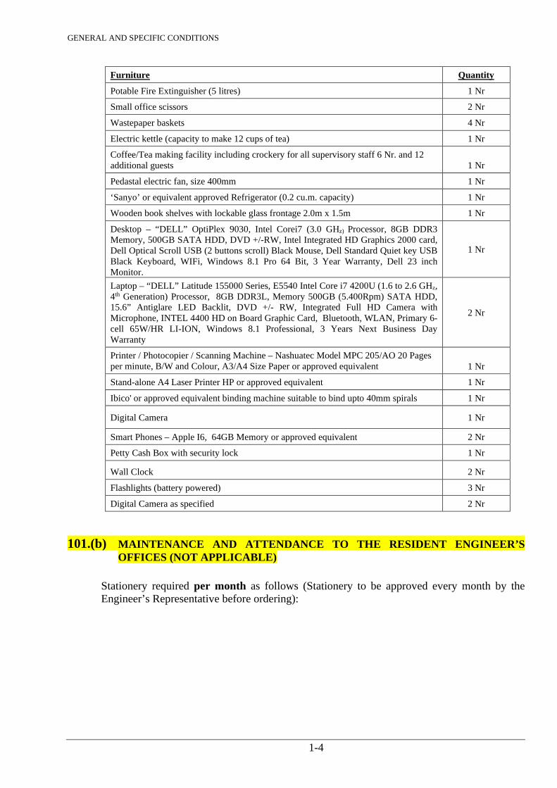
Furniture Quantity
Potable Fire Extinguisher (5 litres) 1 Nr
Small office scissors 2 Nr
Wastepaper baskets 4 Nr
Electric kettle (capacity to make 12 cups of tea) 1 Nr
Coffee/Tea making facility including crockery for all supervisory staff 6 Nr. and 12 additional guests 1 Nr
Pedastal electric fan, size 400mm 1 Nr
‘Sanyo’ or equivalent approved Refrigerator (0.2 cu.m. capacity) 1 Nr
Wooden book shelves with lockable glass frontage 2.0m x 1.5m 1 Nr
Desktop – “DELL” OptiPlex 9030, Intel Corei7 (3.0 GHz) Processor, 8GB DDR3 Memory, 500GB SATA HDD, DVD +/-RW, Intel Integrated HD Graphics 2000 card, Dell Optical Scroll USB (2 buttons scroll) Black Mouse, Dell Standard Quiet key USB Black Keyboard, WIFi, Windows 8.1 Pro 64 Bit, 3 Year Warranty, Dell 23 inch Monitor.
1 Nr
Laptop – “DELL” Latitude 155000 Series, E5540 Intel Core i7 4200U (1.6 to 2.6 GHz, 4th Generation) Processor, 8GB DDR3L, Memory 500GB (5.400Rpm) SATA HDD, 15.6” Antiglare LED Backlit, DVD +/- RW, Integrated Full HD Camera with Microphone, INTEL 4400 HD on Board Graphic Card, Bluetooth, WLAN, Primary 6-cell 65W/HR LI-ION, Windows 8.1 Professional, 3 Years Next Business Day Warranty
2 Nr
Printer / Photocopier / Scanning Machine – Nashuatec Model MPC 205/AO 20 Pages per minute, B/W and Colour, A3/A4 Size Paper or approved equivalent 1 Nr
Stand-alone A4 Laser Printer HP or approved equivalent 1 Nr
Ibico' or approved equivalent binding machine suitable to bind upto 40mm spirals 1 Nr
Digital Camera 1 Nr
Smart Phones – Apple I6, 64GB Memory or approved equivalent 2 Nr
Petty Cash Box with security lock 1 Nr
Wall Clock 2 Nr
Flashlights (battery powered) 3 Nr
Digital Camera as specified 2 Nr
101.(b) MAINTENANCE AND ATTENDANCE TO THE RESIDENT ENGINEER’S OFFICES (NOT APPLICABLE)
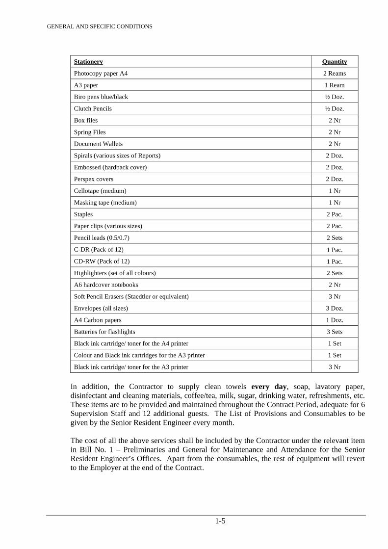
Stationery required per month as follows (Stationery to be approved every month by the Engineer’s Representative before ordering):
GENERAL AND SPECIFIC CONDITIONS
1-5
Stationery Quantity
Photocopy paper A4 2 Reams
A3 paper 1 Ream
Biro pens blue/black ½ Doz.
Clutch Pencils ½ Doz.
Box files 2 Nr
Spring Files 2 Nr
Document Wallets 2 Nr
Spirals (various sizes of Reports) 2 Doz.
Embossed (hardback cover) 2 Doz.
Perspex covers 2 Doz.
Cellotape (medium) 1 Nr
Masking tape (medium) 1 Nr
Staples 2 Pac.
Paper clips (various sizes) 2 Pac.
Pencil leads (0.5/0.7) 2 Sets
C-DR (Pack of 12) 1 Pac.
CD-RW (Pack of 12) 1 Pac.
Highlighters (set of all colours) 2 Sets
A6 hardcover notebooks 2 Nr
Soft Pencil Erasers (Staedtler or equivalent) 3 Nr
Envelopes (all sizes) 3 Doz.
A4 Carbon papers 1 Doz.
Batteries for flashlights 3 Sets
Black ink cartridge/ toner for the A4 printer 1 Set
Colour and Black ink cartridges for the A3 printer 1 Set
Black ink cartridge/ toner for the A3 printer 3 Nr
In addition, the Contractor to supply clean towels every day, soap, lavatory paper, disinfectant and cleaning materials, coffee/tea, milk, sugar, drinking water, refreshments, etc. These items are to be provided and maintained throughout the Contract Period, adequate for 6 Supervision Staff and 12 additional guests. The List of Provisions and Consumables to be given by the Senior Resident Engineer every month. The cost of all the above services shall be included by the Contractor under the relevant item in Bill No. 1 – Preliminaries and General for Maintenance and Attendance for the Senior Resident Engineer’s Offices. Apart from the consumables, the rest of equipment will revert to the Employer at the end of the Contract.
GENERAL AND SPECIFIC CONDITIONS
1-6
101.(c) AutoCAD TECHNICIAN(S) The Contractor shall provide: AutoCAD Technician with Civil Engineering Diploma from a recognized College and minimum 3 years’ experience in a Design Office exclusively for the Senior Resident Engineer’s Office.
101.(d) PROJECT VEHICLES (NOT APPLICABLE) The Contractor shall service and maintain the vehicles to be used for supervision of the Contract by the Senior Resident Engineer and his staff. The Contractor shall ensure that all vehicles are licensed, comprehensively insured at all times, serviced and maintained in good condition to the satisfaction of the Senior Resident Engineer or his authorized representative, so that the Senior Resident Engineer shall at all times have the vehicles available for use in good serviceable condition. In the event of the vehicles being unserviceable for whatsoever reason, the Contractor shall provide alternative vehicles at his own cost of the same model in compliance with the provisions of this clause. The cost for such replacement vehicle to be covered by his rates. Payments for maintenance shall include for provision of fuels, lubricants and tyres, all regular maintenance, minor and major repairs, including those occasioned by accidental damage from whatever cause arising, and everything else necessary to satisfy fully the requirements of this Clause. The makes, models and colours of the vehicles shall be approved by the Senior Resident Engineer prior to ordering. The Contractor shall, at completion bring the vehicle to the appropriate dealers for testing. The dealers shall recommend to the Engineer’s Authorized Representative what repairs in addition to the ordinary service are required to be carried out on the vehicle. The Contractor shall then ensure the necessary service/repairs are done. A certificate of road worthiness and satisfactory mechanical condition to be obtained from the Dealer. The following will be carried out:
• Inspection by the Government Inspection Unit, if applicable
• Inspection and Valuation by the Automobile Association (AA) of Kenya The Contractor shall hand over the respective Inspection / Valuation Reports to the Employer together with the vehicles. The costs for Inspection and Valuation Reports are deemed to be covered in the Contractor’s Rates. The vehicles will revert back to the Employer at the end of the Contract.
101.(e) DRIVERS (NOT APPLICABLE) The Contractor shall provide licensed drivers for the exclusive use of the Resident Engineer or his authorized representative. The drivers shall be available at all times during normal working hours and when specifically required by the Senior Resident Engineer or his authorized representative, outside these hours. The drivers shall have a minimum 10 years of clean driving record and a Certificate of Good Conduct from the Kenya Police. The drivers are to be employed and paid by the Contractor
GENERAL AND SPECIFIC CONDITIONS
1-7
(including all overtime, NSSF, NHIF, etc) but will report directly to the Senior Resident Engineer for day to day instructions. The Senior Resident Engineer will interview, test and approve the drivers prior to their deployment on the Works. Each driver shall be provided with uniform as follows, as a minimum, to be replenished/replaced as and when necessary as directed by the Senior Resident Engineer. The cost of uniform is deemed to be covered by the Contractor’s monthly rate for the drivers Item – of Bill No. 1- Preliminary and General.
• 2 Nr good quality Trousers - Navy Blue • 3 Nr Shirts - Sky Blue • 2 Nr woollen Sweaters - Navy Blue • 1 Nr pair Hard Toe Shoes - Black • 3 Nr Pairs of Socks - Black
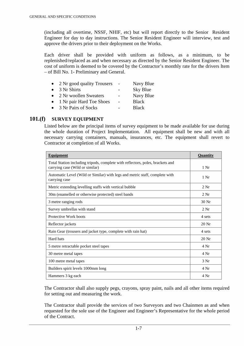
101.(f) SURVEY EQUIPMENT Listed below are the principal items of survey equipment to be made available for use during the whole duration of Project Implementation. All equipment shall be new and with all necessary carrying containers, manuals, insurances, etc. The equipment shall revert to Contractor at completion of all Works.
Equipment Quantity
Total Station including tripods, complete with reflectors, poles, brackets and carrying case (Wild or similar) 1 Nr
Automatic Level (Wild or Similar) with legs and metric staff, complete with carrying case 1 Nr
Metric extending levelling staffs with vertical bubble 2 Nr
30m (enamelled or otherwise protected) steel bands 2 Nr
3 metre ranging rods 30 Nr
Survey umbrellas with stand 2 Nr
Protective Work boots 4 sets
Reflector jackets 20 Nr
Rain Gear (trousers and jacket type, complete with rain hat) 4 sets
Hard hats 20 Nr
5 metre retractable pocket steel tapes 4 Nr
30 metre metal tapes 4 Nr
100 metre metal tapes 3 Nr
Builders spirit levels 1000mm long 4 Nr
Hammers 3 kg each 4 Nr
The Contractor shall also supply pegs, crayons, spray paint, nails and all other items required for setting out and measuring the work. The Contractor shall provide the services of two Surveyors and two Chainmen as and when requested for the sole use of the Engineer and Engineer’s Representative for the whole period of the Contract.

GENERAL AND SPECIFIC CONDITIONS
1-8
The cost for provision of the above for use of the Engineer’s Representative is deemed to be covered under relevant Items in Bill No 1 – Preliminary and General Maintain Survey/ Field Equipment The Contractor shall be responsible for maintaining the survey and field equipment throughout the Contract Period, including replacement of items damaged during the normal course of the Works. The Contractor shall provide all such labour and assistance as may be required by the Engineer for checking the Contractor's setting out and/or survey. The Contractor shall make available such labour, materials, equipment and consumables as the Engineer may require from time to time, for inspections and tests in connection with the Works.
101.(g) ACCOMMODATION (NOT APPLICABLE) The Contractor to make provision for accommodation for the Senior Resident Engineer (SRE). The furnished rented houses shall be to the approval of the Senior Resident Engineer and shall comply with all his requirements. All costs in connection with the rental of house, supply, consumption and maintenance of water supply, electrical power, house help, etc., shall be borne by the Contractor. Provisions of full time security guards shall be made for the houses for day and night security. The provision of this is made under the relevant item in Bill No. 1 – Preliminaries & General.
102. OFFICE FOR CONTRACTOR The Contractor shall have an Office on the Site’s to be approved by the Engineer and which shall be open and attended to at all hours during which work is in progress. Notwithstanding anything contained in Clause 6 (6.1) of the Conditions of Contract, any notice to be given to or served upon the Contractor shall be deemed and taken to be efficiently given or served by the delivery thereof at such office on the site.
103. CLIMATE CONDITIONS The Bidder is to verify on his/her own the prevailing climate conditions of the project location.
104. LEVEL DATUM Before the commencement of Constructional Work, the Contractor shall establish, in a position to the approval of the Engineer, a bench mark comprising of steel datum pegs which shall be securely concreted in. The level of these pegs shall be established and agreed with the Engineer and all levels used in the construction of the Works shall be referred to these established datum points. The correctness of this datum shall be checked at regular intervals during the construction period as agreed with the Engineer. Where possible construction drawings and all levels used for construction shall be referred to the national height datum as defined by the Survey of Kenya. The Contractor shall be responsible for obtaining the location and values of the permanent bench marks. In cases where such bench marks do not exist, the site datum shall be agreed with the Engineer.
GENERAL AND SPECIFIC CONDITIONS
1-9
105. SETTING OUT OF THE WORKS The Site Layout Drawings show indicative Site Layouts. Prior to commencing construction, the Engineer will agree with the Contractor the basic information supplementary to that shown on the Drawings such as the position of manholes, chambers, centre-lines and base-lines sufficient for the Contractor to locate the Works. The Contactor shall prepare detailed Setting Out Drawings and Data Sheets as necessary and submit them to the Engineer in triplicate for approval. Any modifications to the Setting Out Drawings or Data Sheets required by the Engineer shall be made by the Contractor and resubmitted for final approval. Should it be necessary during setting out or during construction for the approved setting out details to be amended, the Contractor shall amend the Drawings or Data Sheets or make new ones for approval as required by the Engineer. For water pipelines, sewers, etc. the Contractor shall in the presence of the Engineer set-out the pipeline alignments in accordance with the indicative alignments shown on the drawings taking into account physical features on the ground, any existing services, any requirements of relevant Authorities and any changes deemed necessary by the Engineer, confirming the locations of all valves, air valves, washouts, hydrants, bends, manholes, etc. The Contractor shall prepare and submit to the Engineer, at an approved scale, Plans of the Water / Sewerline Pipeline Routes and profiles of ground levels after any initial clearing of the wayleave or easement showing the proposed pipe invert levels and precise chainages for all valves, fittings, manholes, etc. for approval. Following approval the Contractor shall submit to the Engineer two copies of the agreed alignment and profiles. The Contractor shall also be required to carry out Site / Engineering Survey of demarcated land where permanent structures / appurtenances will be constructed as directed by the Engineer after initial clearance of sites. The Contractor shall prepare an updated layout plan with contours at 0.5m interval. The contours shall be generated from a 10x10m grid topo survey.
106. CONTROL OF TRAFFIC In the event of single way traffic becoming necessary on any particular section of the Works, or on the approaches to the Works, the Contractor shall, in maintaining through traffic routes, provide a width of at least 3 metres for single way traffic. He shall also provide approved electrically operated signals for traffic control on each of the affected sections and any additional traffic signs as may be directed in accordance with Clause 109. Signal lights are to be operated by competent operators provided by the Contractor, if and when required by the Engineer. Manually operated “Stop-Go” signs will only be permitted if approved by the Engineer, and shall be of the size, colour and type authorized. The Contractor shall be responsible for liaison with Police.
107. TEMPORARY DIVERSION OF TRAFFIC Temporary diversion ways, including those listed in any schedule to the Bill of Quantities shall be constructed whenever the site is intersected by existing public and private roads, footpaths, cycle tracks, farm accesses, temporary and accommodation roads. Any diversion way shall be of such a standard of construction that it is suitable in all respects for the class or classes of traffic requiring to use it. It shall be constructed in advance of the taking up of the existing way and regularly maintained for so long as required in a satisfactory condition all to the approval of the Engineer.
GENERAL AND SPECIFIC CONDITIONS
1-10
108. TEMPORARY TRAFFIC SIGNS The Contractor shall erect and maintain on the Works and at prescribed points on the approaches to the Works, all traffic signs necessary for the warning, direction and control of traffic and the size of all such signs and the lettering and wording thereon shall be reflectorised or adequately illuminated at night by approved means.
109. PROTECTION OF WORKS The Contractor shall carefully protect from injury by weather all work and materials which may be affected thereby.
110. SURVEY BEACONS During the progress of the Works, the Contractor shall not remove, damage, alter or destroy in any way whatsoever, any plot or survey beacons. He shall notify the Engineer of the need to interfere with any beacon. The Engineer shall authorize any removal and reinstatement that he considers necessary. Should any beacon be found to be above or below the level of the finished work, the Contractor shall immediately report the same to the Engineer. Should any beacon be damaged or destroyed, the Contractor shall forthwith report the damage to the Engineer and to the Director of Surveys and shall be held liable for the cost of reinstatement thereof.
111. DAMAGE TO LAND The Employer shall provide the Site upon which the Permanent Works are to be constructed. Where a drain or pipeline is to be within an existing road or track reserve or is otherwise located in land designated Public Domain, the Site width will be restricted to the limit of the public land. The existing boundary fences and walls shall not be disturbed without prior approval of the Engineer and, unless road diversions and closure notices are approved and posted, carriageways shall be left available for the safe passage of traffic. The Contractor shall not enter upon or occupy with men, tools, equipment or materials any land other than the site without the written consent of the owner of such land. On occupation of the Site or other land the Contractor shall provide such fencing, as required.
112. RIVERS AND DRAINS The Contractor shall at all times maintain the free flow of rivers and drains and prevent excavated material from the Works from being deposited in them.
113. REINSTATEMENT OF ROADS AND FOOTWAYS FOR WATER MAINS AND SEWER CROSSINGS Water Mains laid under roads shall be of ferrous material. Sewer Lines laid under roads shall be flexible jointed uPVC or concrete pipes The Contractor shall allow in his rates for liaison with the relevant Roads Authority and obtain a Road Opening Permit. Statutory fee for road crossings will be paid under relevant Item in the Bills of Quantity. The road crossings shall be constructed in the following specifications and any other requirement stipulated by the Road Authority:
GENERAL AND SPECIFIC CONDITIONS
1-11
Excavated width of the trench shall not be less than 1m to ensure compaction to required
standard Protective concrete raft slab shall be constructed for sewer pipes as per details given in
the drawings. Backfilling shall be carried out with suitable selected excavated material upto the top
300mm, in layer thickness not exceeding 150mm at optimum moisture content The top 300mm layer shall be backfilled in two layers of 150mm each comprising of well
graded stabilized gravel with 3% cement content at optimum moisture content Tarmac roads shall be reinstated to the original condition using approved asphalt from a
recommended supplier.
The Contractor shall be responsible for all liaison with the Police for traffic control during execution of the works.
114. TEMPORARY WORKS The Contractor shall provide, maintain and remove on completion of the Works all temporary Works including roadways, sleeper tracks and stagings etc., over roads, footpaths, suitable in every respect to carry all plant required for the work or for providing access or for any other purpose. Details of Temporary Works shall be submitted in advance to the Engineer for his approval and the approval shall not relieve the Contractor of complete responsibility for their safety and satisfactory operation.
115. LIGHTING AND GUARDING OF OBSTRUCTIONS The details of the method of signing and guarding an obstruction to traffic caused in the course of the execution of the Works shall be submitted to the Engineer for approval before that portion of the Works is commenced. No greater area of the road than the Engineer considers necessary shall be closed at any one time. Temporary traffic signs shall comply with Clause 109. Generally the following precautions will be required:- Signing An advance warning sign at least 1.22m x 0.92m in size and 70 metres in advance of the obstruction will be required, and where an appreciable change of direction is necessary at the obstruction, a sign (of the arrow or chevron type) at the obstruction itself. At particular danger points more comprehensive signing may be required. Guarding The obstruction shall be marked by posts carrying red flags or reflective red markers and by red lamps. The latter shall be spaced at 6 metres intervals in the direction of traffic flow and at 0.9 metres intervals across this direction. At least 3 lamps shall be placed across this direction of traffic flow. The flags and lamps on the traffic side of the obstruction shall be at least 5 metres from it.

GENERAL AND SPECIFIC CONDITIONS
1-12
Footpaths Where a footpath is affected by an obstruction in any way it shall be separated from both obstruction and traffic by effective banners and red lamps spaced at 0.9 metres intervals.
116. EXISTING SERVICES Before commencing Works which include excavation or ground levelling by manual or mechanical excavation the Contractor shall at his own expenses ascertain in writing from the Kenya Posts & Telecommunications Corporation, Kenya Power & Lighting Co. Ltd. and all other Public Bodies, Companies and persons who may be affected, the position and depth of their respective ducts, cables, mains, pipes, or other appurtenances. He shall thereupon search for and locate such services. The Contractor shall at his own expense arrange to have effectually propped, protected, underpinned, altered, diverted, restored and made as may be necessary, all water courses, pipes, cables or ducts, poles or wires or their appurtenances disturbed or damaged during the progress of the Works, or in consequence thereof. Except that such services as require to be removed or altered by virtue of the layout of the permanent work and not the manner in which the work is carried out, shall be so removed or altered at the direction and at the expense of the Employer. The Contractor shall be liable for the cost of repairs to any services damaged as a result of carrying out the Works and execution of these Works.
117. CONNECTIONS TO EXISTING PIPES AND EQUIPMENT The Contractor shall be responsible for joining up and making connections between water pipes, sewer pipes, etc. equipment installed by him and existing facilities. The Contractor shall submit to the Engineer a drawing showing the details of the connection, and shall state the date on which the particular connection is required, and the work shall not proceed until the Engineer’s approval has been given. The Contractor shall be responsible for ensuring the compatibility of new pipes with existing pipework, cables, tubing, equipment, etc.
118. PRIVATELY OWNED OR PUBLIC SERVICES If any privately owned or public services passing through the site will be affected by the Works, the Contractor shall provide at his own expense a satisfactory alternative service in full working order to the satisfaction of the owner of the services and the Engineer, before the cutting of the existing service. Any damage to private or public services shall be made good by the Contractor at his cost. In case the remedial work is not executed promptly by the Contractor, the Engineer may make alternative arrangements for the execution of the work and debit the costs to the Contractor.
119. WATER SUPPLY The Contractor shall provide for all purposes of the work, an adequate supply of water from a suitable source or sources approved by the Engineer. He must pay the water charges, if any, and make arrangements for supply, transport and distribution.
GENERAL AND SPECIFIC CONDITIONS
1-13
120. ADDITIONAL LAND The Contractor shall select and arrange at his own expenses for any temporary occupation of land outside the site which he requires for the efficient execution of the Works. The Contractor must comply fully with all By-laws and Regulations currently in force in the area.
121. USE OF HEAVY PLANT In the event of the Contractor desiring to use heavy machinery or plant, he shall first satisfy the Engineer that they will be of such size and used in such a manner as not to cause any disturbance or damage in particular to water, electricity, Post Office or other mains, cables and connections or to sewers, culverts etc. or interfere with the line or position of any overhead wires and cables of any sort, telegraph poles, power poles etc. The Contractor will be held liable for any such damage or disturbance and shall pay the full costs of any reinstatement, relaying, repairing or refixing as may be required, as agreed between the Engineer and the owner affected.
122. PROVISION OF INSTRUMENTS AND LABOUR The Contractor shall provide at his own expenses all instruments, materials, tools and other things which the Engineer considers necessary for his proper supervision of the Works and shall maintain the same in good order. He shall also provide materials, an experienced Surveyor and labour for attendance on the Engineer and his representatives in carrying out operations connected with the supervision of the Works. All charges arising out of such services shall be deemed to be included in his rates in the Bill of Quantities.
123. ACCESS TO SITES The Contractor shall construct and maintain all temporary accesses required for the execution of the Works. Access roads shall be constructed and maintained up to the Site Offices if required. The cost of all these Works shall be deemed to be covered by rates and prices quoted by the Contractor.
124. POLLUTION The Contractor shall ensure that during the course of his operations no pollution of the atmosphere, rivers, reservoir catchment areas or groundwater is allowed to take place.
125. TREE PROTECTION Trees within the permanent and temporary easement are the property of owners. Specific trees will be identified by the Engineer, prior to construction, and the Contractor shall neither remove nor cut their roots unless otherwise directed by the Engineer. If the roots of such trees appear within the trench areas, the Contractor shall handle the roots with maximum care so that no portion of the roots will be damaged. During the excavation of the trench, the exposed roots may be removed to a position that will not damage the roots and will not interfere with the pipelaying. During the construction, the roots shall be thoroughly protected by appropriate cover and wetted as directed. After the pipes are laid, the moved roots shall be placed back to the original locations and backfilled carefully by selected soft soil which can support vegetation.
126. GEOLOGICAL DATA Any geological data that is made available to the Contractor and is relevant to the Works, will be for his guidance only, and no guarantee is given that other ground conditions will not be encountered. No claims based on the geological data provided shall be entertained by the
GENERAL AND SPECIFIC CONDITIONS
1-14
Engineer. The Contractor shall be deemed to have made any additional investigations required before submission of his Bid.
127. WATCHING, FENCING AND LIGHTING The Contractor shall arrange to employ watchmen to guard the Works both during the day and night from the commencement of the Works until the substantial completion of the Works. Any excavation or other obstruction likely to cause injury or damage to any person or domestic animals must be fenced off as directed by the Engineer.
128. TIPS The Contractor shall be responsible for provision of all tips, at his own expense, for disposal of all spoil or other rubbish collected during the construction of the Works. Any surplus excavated material not required shall also be carted away to these tips. The site of the tips must be approved by the Engineer.
129. TROPICALISATION In choosing materials and their finishes, due regard shall be given to the tropical conditions of the site to which they will be subjected. The Contractor shall submit details of his practices which have proven satisfactory and which he recommends for application on the parts of the Works which may be affected by the tropical conditions.
130. MONTHLY SITE MEETINGS Throughout the project period, site meetings will be held at the Engineer’s Representative’s Office once every calendar month to discuss the progress of the work, schedule for the ensuing month, methods of construction, procurement, transportation, labours, etc. These meetings can be called at any other time intervals at the request of the Contractor or as directed by the Engineer.
131. INSPECTION BY ENGINEER DURING DEFECTS LIABILITY PERIOD The Engineer will give the Contractor due notice of his intention to carry out inspection during the Defects Liability Period and the Contractor shall upon receipt of such notice arrange for a responsible representative to be present at the times and dates named by the Engineer. This representative shall render all necessary assistance and take notice of all matters and things to which his attention is directed by the Engineer.
132. SUBMISSION OF SAMPLES Before incorporating in the finished work any materials or articles which he supplies under the terms of the Contract, the Contractor shall submit to the Engineer’s Representative for his approval a sample of each respective material or article, and such samples shall be delivered to and kept at his office for reference. All the respective kinds of materials and articles used in and upon the Works, shall be at least equal in quality to the approved samples. Each and every sample shall be a fair average of the bulk material or of the article which it represents. The Engineer’s Representative may decide the method by which each sample to be taken from the bulk material shall be obtained. Any costs related to adhere to above to be covered in Bidder’s Rates.
GENERAL AND SPECIFIC CONDITIONS
1-15
133. RESPONSIBILITY FOR ORDERING MATERIALS AND MANUFACTURED ARTICLES AND SAMPLES FOR TESTING The responsibility for so ordering and delivering materials and manufactured articles and samples that they may be tested sufficiently far in advance of the work as not to delay it, shall rest upon the Contractor, and he shall not be entitled to any time credit for delay occasioned by his neglect to order sufficiently well in advance or to effect payment of any costs he may incur as a result thereof. With regard to any item in the Bill of Quantities which is the subject of a P.C. Sum, the Contractor shall notify the Engineer of his requirements as early as possible leaving ample time for the Engineer to make any necessary arrangements so that no delay occurs in the progress of the work.
134. TESTS OF MATERIALS AND MANUFACTURED ARTICLES BEFORE USE Any or all of the materials and manufactured articles supplied by the Contractor for use on any of the Works throughout this Contract shall be subject in advance to tests as may be specified in the relevant Standard Specification as may from time to time be deemed necessary by the Engineer. Samples of all such materials and manufactured articles, together with all the necessary labour, materials, plant and apparatus for sampling and for carrying out of tests on the site on all such materials and manufactured articles shall be supplied by the Contractor at his own expenses. The cost of special tests ordered by the Engineer to be carried out by an independent person at a place other than the site or place of manufacture or fabrication shall be borne by the Contractor.
135. REJECTED MATERIALS Should any material or manufactured articles be brought on to the site of the Works which are in the judgement of the Engineer unsound or of inferior quality or in any way unsuited for the work in which it is proposed to employ them, such materials or manufactured articles shall not be used upon the Works but shall be branded if, in the opinion of the Engineer, this is necessary and shall forthwith be removed from the site of the Works, all at the Contractor’s expense and in each case as the Engineer shall direct.
136. QUALITY OF MATERIALS AND WORKMANSHIP The materials and workmanship shall be of the best of their respective kinds and shall be to the approval of the Engineer. In the reading of this Specification the words “to the approval of the Engineer” shall be deemed to be included in the description of all materials incorporated in the Works, whether manufactured or natural and in the description of all operations for the due execution of the Works.
137. TEST RUNNING OF THE SCHEME Upon substantial completion of the scheme and official inspection which agrees to this, the Contractor shall operate the entire scheme for the test period indicated in the Bill of Quantities. The Contractor shall supply all necessary personnel, electricity, fuels, oils and chemicals for the test running and together with the Engineer’s Representative shall compile a list of detailed operating instructions that shall be incorporated into the Operation and Maintenance Manual. The Contractor shall further bring to the attention of the Engineer’s Representative

GENERAL AND SPECIFIC CONDITIONS
1-16
and of the Employer’s operational staff any problem or defects he encounters during this period of test running so that solutions may be found and any necessary alterations made. The Contractor shall make provision for the on-site training of up to 3 of the Employer’s staff.
138. EQUIPMENT FOR THE ENGINEER’S REPRESENTATIVE The Contractor shall provide 2 Nr Digital Cameras, Sony or approved equivalent, suitable for Construction Sites with splash and shock proof casing for exclusive use of the Engineer’s Representative and his Staff for the purpose of taking record photographs of the progress of the Works. The Cameras should have picture capture resolution of 10 megapixels or more, both optical and digital zoom capabilities, storage capacity of 128 MB, downloading facility by means of USB port, neck strap and hard cover pouch. The Contractor shall further provide 1 Nr suitable photo printer with necessary photo paper and colour ink cartridges for prints production for Monthly, Quarterly Progress Reports as directed by the Engineer’s Representative. The cost for this service is deemed to be covered by the Contractor in his rates in the Bills of Quantities. The Contractor shall provide for the Engineer, his Representative and assistants any additional protective clothing and safety equipment necessary for the proper discharge of their duties on the Site. The Contractor shall provide any necessary protective clothing and safety equipment for the use of authorized visitors to the site including the Employer and his staff and representatives and those of any relevant Authority who have reason to visit the Site.
139. OPERATION AND MAINTENANCE MANUAL A draft Operation and Maintenance Manual will be compiled prior to Commencement of Construction of the Works. This Manual has to be revised and brought to a final draft state prior to the test running of the Scheme. The Contractor’s rates should include for provision in triplicate, and in English, details of all the different manufactured plant and components incorporated in the Works including but not limited to all pertinent Manufacturers’ Brochures, ‘As-Built’ Drawings prepared by the Contractor, Digital Progress Report Photographs, etc. Substantial completion of the Scheme will not be considered until such detailed information as is required in triplicate has been submitted by the Contractor to and accepted by the Engineer.
140. CONSTRUCTION PROGRAMME The Contractor shall submit to the Engineer for approval, a revision of the Construction Programme attached in four (4) copies and after approval to the Employer in two (2) copies in the following manner: (1) Within thirty (30) days after receiving the Letter of Acceptance, the Contractor shall
submit to the Engineer for approval, a detailed Programme based on the key date stated hereinafter or other dates which are given in the Letter of Acceptance in the form of a Critical Path Method (hereinafter referred to as CPM Network) showing the order of procedure in which he proposes to carry out the Works including design, manufacture, delivery to the site, transport, storage, survey, construction, commissioning and maintenance. This Programme shall indicate clearly all activities

GENERAL AND SPECIFIC CONDITIONS
1-17
and its duration along with the earliest and the latest event, times and the first and last dates of the submission of the Drawings and each date of shop inspection by the Engineer for the section or portion of the Works.
The Programme so prepared shall be rearranged in the form of a Time Bar-chart Schedule of which size shall be 841mm x 594mm (A-1 size). This Time Bar-chart Schedule shall be submitted to the Engineer together with the CPM Network.
(2) The CPM Network shall be in accordance with commonly accepted practices and shall show graphically the chain of activities / sub-activities and their sequential relationship with each other from the start of construction to the completion of the Contract. The Time Bar-chart Schedule shown in weeks shall list all main activities and its applicable sub-activities.
(3) In preparing the CPM Network and the Time Bar-chart Schedule the Contractor shall
make due allowances for possible delays. Under no circumstances shall the CPM Network or the Time Bar-chart Schedule show a completion in excess of the “Time for Completion” stated in the Form of Bid.
(4) The Programme once approved by the Engineer shall thereafter be referred to as the
Contractual Programme. The Engineer’s approval of such programme shall not relieve the Contractor of any of his duties or responsibilities under the Contract.
The Contractual Programme approved shall supersede all other Programmes and shall be deemed to be the Programme on which the Contractor has based his Contract Sum and in accordance with which he will undertake the execution of the Works. This Programme shall become part of the Contract. The Contractor shall ensure that all the Works especially Electrical and Mechanical Works which may be carried out by the Electrical/Mechanical Sub-Contractor, are well coordinated with the overall Works under the Contract for the efficient execution of the Works, and shall clearly indicate them on the construction Programme. The Contractor shall also describe the conditions of working shifts, if necessary, to execute the Works and whether work needs to be carried out at night and/or on Sundays and holidays. The Contractor should also indicate which particular Works are subject to these timings in his construction Programme. Whenever the Contractor proposes to change the Contractual Programme, approval of the revision shall be obtained in writing from the Engineer. If the Contractor has fallen behind the approved Contractual Programme or can foresee delay(s) therein, he shall, immediately after such default or event occurred or foreseen or at the request of the Engineer submit a revision of the Contractual Programme showing the reasons of such a delay and the proposed measures to recover such delay or to complete the Works on time, for the approval of the Engineer.
141. CONTRACT DOCUMENTS Without affecting the provisions in the Conditions of Contract, the Contractor shall print and submit at his own cost to the Employer at least ten (10) bound copies of the Contract
GENERAL AND SPECIFIC CONDITIONS
1-18
Documents except Volume III (Drawings) in the form and manner approved by the Employer. The Contractor’s rates are deemed to cover these costs.
142. AS-BUILT AND RECORD DRAWINGS The Contractor shall prepare, and keep up-to-date, a complete set of “as-built” records of the execution of the works, showing the exact “as-built” locations, sizes and details of the work as executed, with cross references to relevant specifications and data sheets. These records shall be kept on the Site and shall be used exclusively for the purposes of this specification. Two copies shall be submitted to the Engineers Representative prior to the commencement of the Tests on Completion of Works. In addition, the Contractor shall prepare and submit to the Engineer’s Representative “as-built-drawings” of the works, showing all works as executed. The drawings shall be prepared as the works proceed, and shall be submitted to the Engineers Representative for his inspection. The Contractor shall obtain the consent of the Engineers Representative as to their size, the referring system, and other pertinent details. Prior to the issue of any Taking-Over Certificate, the contractor shall submit to the Engineer’s Representative one full-size original copy, six printed copies of the relevant “as-built-drawings” and the corresponding computer files (AutoCAD, Excel, MS Word, etc.) on CD-ROM and any further Construction Documents specified in the Specifications. The works shall not be considered to be completed for the purposes of Taking-Over until such documents have been submitted to the Engineer’s Representative. The compliance of this Clause by the Contractor is deemed to be covered in his rates as quoted in the Bid.
GENERAL AND SPECIFIC CONDITIONS
2-1
2. CLEARING SITE
201. CLEARING SITE The Contractor shall demolish, break up and remove buildings, walls, gates, fences,
advertisements and other structures and obstructions, grub up and remove trees, hedges, bushes and shrubs and clear the site of the works at such time and to the extent required by the Engineer but not otherwise, subject to the provisions of Clause 27 of the Conditions of Contract: the materials so obtained shall so far as suitable be reserved and stacked for further use; all rubbish and materials for use shall be destroyed or removed from the site, as directed by the Engineer.
Where top soil has to be excavated this shall be removed and stacked on site. After
completion of construction, it shall be spread over the disturbed ground, any surplus being disposed of as directed by the Engineer.
Underground structures and chambers where required to be demolished, shall be demolished
to depths shown on drawings or as directed. They shall be properly cleaned out and backfilled and compacted with suitable material to the direction and approval of the Engineer.
202. VEGETATION No allowance will be made for the cutting and removal of crops, grass, weeds and similar
vegetation. The cost of all such work will be held to be included in the rates entered in the Bill of Quantities.
203. BUSHES AND SMALL TREES All bushes and small trees, the main stem of which is less than 500mm girth at 1 metre above
ground level shall be uprooted (unless otherwise directed by the Engineer) and burnt or otherwise disposed off as directed by the Engineer.
204. HEDGES Where directed by the Engineer, hedges shall be uprooted and disposed off by burning.
205. FELLING TREES Where shown on the drawings or directed by the Engineer, trees shall be uprooted or cut
down as near to ground level as is possible. The rates entered in the Bill of Quantities shall include for cutting down, removing branches and foliage, cutting useful timber into suitable lengths, loading, transporting not more than 1 km. and stacking or disposing off all as directed by the Engineer.
For the purpose of measurement trees cut down shall be classified according to their girth at 1
metre above ground level, the cost of grubbing up roots shall be deemed to be covered by the rate for felling trees.
GENERAL AND SPECIFIC CONDITIONS
2-2
206. GRUBBING-UP ROOTS Stumps and tree roots shall, unless otherwise directed, be grubbed up, blasted, burnt or
removed and disposed of in approved dumps to be provided by the Contractor. Where directed by the Engineer, the holes resulting from grubbing up shall be filled with approved materials, which shall be deposited and compacted in layers not exceeding 225mm loose depth, to the same dry density as that of the adjoining soil. For the purpose of measurement, tree roots shall be classified according to the mean diameter of the stump measured across the cut.
207. WEED CONTROL The Contractor shall take all necessary precautions against the growth on the site of weeds
and remove them as necessary throughout the period of works and maintenance. The finished base of all footways and elsewhere as directed shall be sprayed with an
approved persistent total herbicide at the rate recommended by the manufacturer. The application shall be by an even spray in a high volume of water at about 0.7 to 0.11 litres per square metre. After this application the footways shall receive at least two further waterings before the surface is sealed.
GENERAL AND SPECIFIC CONDITIONS
3-1
3. EXCAVATION
301. DEFINITION AND CLASSIFICATION OF EXCAVATED MATERIALS Excavation in the Bills of Quantities shall be classified in two categories:-
1) Common Excavation Any material which in the opinion of the Engineer can be excavated by use of pick
axes and hand levers shall be classified as common excavation. Water logged material shall be included in this class. Murram in any form shall be classified as common excavation.
2) Rock The decision of the Engineer in classifying rock shall be final and binding. Rock in the Bill of Quantities will be itemised in three classes:-
Class ‘A’
Soft rock of the type known locally as ‘tuff’ which in the opinion of the Engineer cannot be considered as hard rock but which considerably increases the amount of labour needed for its removal shall be known as Class ‘A’ rock.
Class ‘B’ Very weathered phonolite lava containing many fissures and faults shall be known as
hard rock. This type of rock contains stones and boulders of unweathered or incompletely formed blacktrap or lava. A boulder or outcrop of hard rock 1.5 cubic metres or less and grey or green building stone in a formation which is massive and geologically homogeneous, will be deemed to be Class ‘B’ rock.
Class ‘C’ Phonolite in a formation which is massive and geologically homogeneous shall be
known as Class ‘C’ rock.
302. STORAGE AND HANDLING OF EXPLOSIVES AND BLASTING The removal of hard materials by use of explosives will normally be permitted subject to
compliance by the Contractor in all respects with the Explosives Laws of Kenya. In the Bill of Quantities hard material is classified as rock where blasting will be permitted
subject to this clause.
GENERAL AND SPECIFIC CONDITIONS
3-2
The Contractor shall provide proper buildings or magazines in suitable positions for the storage of explosives in manner and quantities to be approved; he shall also be responsible for the prevention of any unauthorised issue or improper use of any explosives brought on the works and shall employ only licensed and responsible men to handle explosives for the purpose of the works.
The shots shall be properly loaded and tamped and where necessary, the Contractor shall use
heavy mesh blasting nets. Blasting shall be restricted to such periods and such parts of the works as the Engineer may prescribe. If, in the opinion of the Engineer, blasting would be dangerous to persons or property or to any finished work or is being carried out in a reckless manner, he may prohibit it, and order the rock to be excavated by other means and payment will be made at the rate for rock for excavation where blasting is permitted. The use of explosives by the Contractor in large blasts, as in seams, drifts, pits, or large holes, is prohibited unless authorized in writing by the Engineer. In the event of wasting of rock through any such blasting, the Contractor shall if required by the Engineer, furnish an equivalent amount of approved materials for fill, 1 cubic metre of rock in-situ being taken to equal 1.5 cubic metre of material in embankment.
303. EXCAVATION FOR FILL Where excavation reveals a combination of suitable and unsuitable materials, the Contractor
shall, wherever the Engineer considers it practicable, carry out the excavation in such a manner that the suitable materials are placed separately for use in the works without contamination by the unsuitable materials.
If any suitable material excavated from within the site is, with the agreement of the Engineer,
taken by the Contractor for his use, sufficient suitable filling material to occupy after specified compaction, a volume corresponding to that which the excavated material occupied, shall, unless otherwise directed by the Engineer be provided by the Contractor from his own sources.
No excavated material shall be dumped or run to spoil except on the direction or with the
permission of the Engineer who may require material which is unsuitable to be retained on site. Material used for haul roads shall not be re-used without the permission of the Engineer.
304. COMPACTION OF FILL All materials used in fill shall be compacted to specification by plant approved by the
Engineer for that purpose. Maximum compacted thickness of such layers shall not be more than 200mm.
Work on the compaction of plastic materials for fill shall proceed as soon as practicable after
excavation and shall be carried out only when the moisture content is not greater than 2 per cent above the plastic limit for that material. Where the moisture content of plastic material as excavated is higher than this value the material shall be run to spoil and an equal volume of material suitable for filling shall be replaced, unless the Contractor prefers, at his own expense, to wait until the material has dried sufficiently for acceptance again as suitable material.
GENERAL AND SPECIFIC CONDITIONS
3-3
Nevertheless, if with any material the Engineer doubts whether compaction will be obtained within the above moisture limits he may require compaction to proceed only when the limits of moisture content for the compaction of non-plastic materials are within the range of the optimum moisture content and 3 per cent below the optimum moisture content as determined by the laboratory compaction test method described in British Standard 1377: Methods of Test for Soil Classification and Compaction.
If any such non-plastic material on excavation is too wet for satisfactory compaction and the
Engineer orders the moisture content to be lowered or raised, such work shall be treated as included in the rates. All adjustments of moisture content shall be carried out in such a way that the specified moisture content remains uniform throughout compaction.
Work shall be continued until a state of compaction is reached throughout the fill, which shall
have relative compaction determined according to B.S. 1377 not less than 85% of maximum dry density at optimum moisture contents. For excavation under Roads, House Drives and Car Parks the backfilling shall be compacted in 150mm layer to 100% maximum dry density.
If with non-plastic materials the compacted material has become drier in the interval between
the completion of compaction and the measurement of the state of compaction, then the moisture content to be used for the calculation of the air content shall be the mean moisture content for the compaction of such materials as specified above.
305. EMBANKMENTS OVER SEWERS In carrying embankments over sewer pipes, care shall be taken by the Contractor to have the
embankments brought up equally on both sides and over the top of any such structures. Earth embankments shall be formed and compacted in layers of 200mm as the Engineer may direct. The filling immediately adjacent to structures shall be deposited and compacted in accordance with the drawings and approved by the Engineer. The cost of these works shall be included in the prices entered in the Bill of Quantities for the excavations from which embankments are formed.
306. STONE REVETMENTS (STONE PITCHING) Where shown on the drawings, the slopes of embankments, rivers, streams, watercourses and
other surfaces shall be protected against water or other action by hand-set stone facing set on end. The larger stones shall be roughly dressed on the bed and face, and roughly square to the full depth of the joints. No rounded boulder shall be used, or stones less than 225mm in depth of 0.05 cubic metre in volume. The stones shall be laid to break bond, and shall be well bedded on to a 75mm layer of gravel or fine rubble rammed to a uniform surface and the whole work finished to the satisfaction of the Engineer. Where required, a trench shall be excavated at the bottom of the slope to such a depth as will ensure a safe foundation for the revetment.
307. TIPPED REFUSE ON SITE Tipped refuse other than artificial deposits of industrial waste or shale found on the site shall
be removed and disposed off in a spoil heap to be provided by the Contractor.
308. REMOVAL OF INDUSTRIAL WASTE, ETC. Artificial deposits of industrial waste or shale found on the site shall be removed and
disposed off as directed by the Engineer. Should any particular deposits consist of or contain material which in the opinion of the Engineer is suitable for incorporation in fills, all such
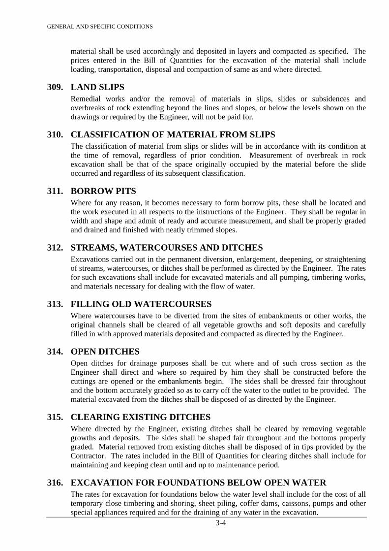
GENERAL AND SPECIFIC CONDITIONS
3-4
material shall be used accordingly and deposited in layers and compacted as specified. The prices entered in the Bill of Quantities for the excavation of the material shall include loading, transportation, disposal and compaction of same as and where directed.
309. LAND SLIPS Remedial works and/or the removal of materials in slips, slides or subsidences and
overbreaks of rock extending beyond the lines and slopes, or below the levels shown on the drawings or required by the Engineer, will not be paid for.
310. CLASSIFICATION OF MATERIAL FROM SLIPS The classification of material from slips or slides will be in accordance with its condition at
the time of removal, regardless of prior condition. Measurement of overbreak in rock excavation shall be that of the space originally occupied by the material before the slide occurred and regardless of its subsequent classification.
311. BORROW PITS Where for any reason, it becomes necessary to form borrow pits, these shall be located and
the work executed in all respects to the instructions of the Engineer. They shall be regular in width and shape and admit of ready and accurate measurement, and shall be properly graded and drained and finished with neatly trimmed slopes.
312. STREAMS, WATERCOURSES AND DITCHES Excavations carried out in the permanent diversion, enlargement, deepening, or straightening
of streams, watercourses, or ditches shall be performed as directed by the Engineer. The rates for such excavations shall include for excavated materials and all pumping, timbering works, and materials necessary for dealing with the flow of water.
313. FILLING OLD WATERCOURSES Where watercourses have to be diverted from the sites of embankments or other works, the
original channels shall be cleared of all vegetable growths and soft deposits and carefully filled in with approved materials deposited and compacted as directed by the Engineer.
314. OPEN DITCHES Open ditches for drainage purposes shall be cut where and of such cross section as the
Engineer shall direct and where so required by him they shall be constructed before the cuttings are opened or the embankments begin. The sides shall be dressed fair throughout and the bottom accurately graded so as to carry off the water to the outlet to be provided. The material excavated from the ditches shall be disposed of as directed by the Engineer.
315. CLEARING EXISTING DITCHES Where directed by the Engineer, existing ditches shall be cleared by removing vegetable
growths and deposits. The sides shall be shaped fair throughout and the bottoms properly graded. Material removed from existing ditches shall be disposed of in tips provided by the Contractor. The rates included in the Bill of Quantities for clearing ditches shall include for maintaining and keeping clean until and up to maintenance period.
316. EXCAVATION FOR FOUNDATIONS BELOW OPEN WATER The rates for excavation for foundations below the water level shall include for the cost of all
temporary close timbering and shoring, sheet piling, coffer dams, caissons, pumps and other special appliances required and for the draining of any water in the excavation.
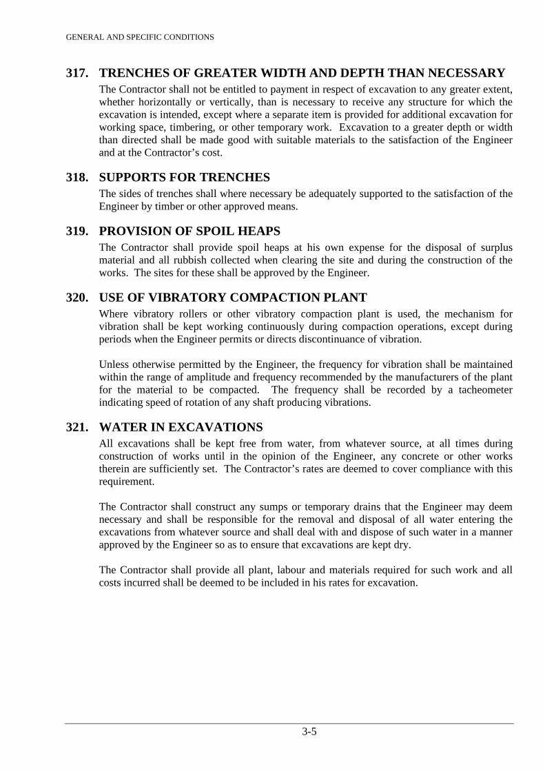
GENERAL AND SPECIFIC CONDITIONS
3-5
317. TRENCHES OF GREATER WIDTH AND DEPTH THAN NECESSARY The Contractor shall not be entitled to payment in respect of excavation to any greater extent,
whether horizontally or vertically, than is necessary to receive any structure for which the excavation is intended, except where a separate item is provided for additional excavation for working space, timbering, or other temporary work. Excavation to a greater depth or width than directed shall be made good with suitable materials to the satisfaction of the Engineer and at the Contractor’s cost.
318. SUPPORTS FOR TRENCHES The sides of trenches shall where necessary be adequately supported to the satisfaction of the
Engineer by timber or other approved means.
319. PROVISION OF SPOIL HEAPS The Contractor shall provide spoil heaps at his own expense for the disposal of surplus
material and all rubbish collected when clearing the site and during the construction of the works. The sites for these shall be approved by the Engineer.
320. USE OF VIBRATORY COMPACTION PLANT Where vibratory rollers or other vibratory compaction plant is used, the mechanism for
vibration shall be kept working continuously during compaction operations, except during periods when the Engineer permits or directs discontinuance of vibration.
Unless otherwise permitted by the Engineer, the frequency for vibration shall be maintained
within the range of amplitude and frequency recommended by the manufacturers of the plant for the material to be compacted. The frequency shall be recorded by a tacheometer indicating speed of rotation of any shaft producing vibrations.
321. WATER IN EXCAVATIONS All excavations shall be kept free from water, from whatever source, at all times during
construction of works until in the opinion of the Engineer, any concrete or other works therein are sufficiently set. The Contractor’s rates are deemed to cover compliance with this requirement.
The Contractor shall construct any sumps or temporary drains that the Engineer may deem
necessary and shall be responsible for the removal and disposal of all water entering the excavations from whatever source and shall deal with and dispose of such water in a manner approved by the Engineer so as to ensure that excavations are kept dry.
The Contractor shall provide all plant, labour and materials required for such work and all
costs incurred shall be deemed to be included in his rates for excavation.
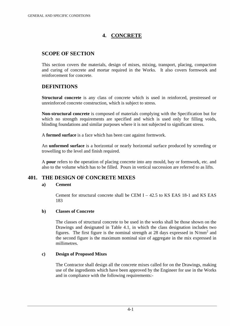
GENERAL AND SPECIFIC CONDITIONS
4-1
4. CONCRETE SCOPE OF SECTION This section covers the materials, design of mixes, mixing, transport, placing, compaction and curing of concrete and mortar required in the Works. It also covers formwork and reinforcement for concrete. DEFINITIONS Structural concrete is any class of concrete which is used in reinforced, prestressed or unreinforced concrete construction, which is subject to stress. Non-structural concrete is composed of materials complying with the Specification but for which no strength requirements are specified and which is used only for filling voids, blinding foundations and similar purposes where it is not subjected to significant stress. A formed surface is a face which has been cast against formwork. An unformed surface is a horizontal or nearly horizontal surface produced by screeding or trowelling to the level and finish required. A pour refers to the operation of placing concrete into any mould, bay or formwork, etc. and also to the volume which has to be filled. Pours in vertical succession are referred to as lifts.
401. THE DESIGN OF CONCRETE MIXES a) Cement
Cement for structural concrete shall be CEM I – 42.5 to KS EAS 18-1 and KS EAS 183
b) Classes of Concrete
The classes of structural concrete to be used in the works shall be those shown on the Drawings and designated in Table 4.1, in which the class designation includes two figures. The first figure is the nominal strength at 28 days expressed in N/mm2 and the second figure is the maximum nominal size of aggregate in the mix expressed in millimetres.
c) Design of Proposed Mixes
The Contractor shall design all the concrete mixes called for on the Drawings, making use of the ingredients which have been approved by the Engineer for use in the Works and in compliance with the following requirements:-
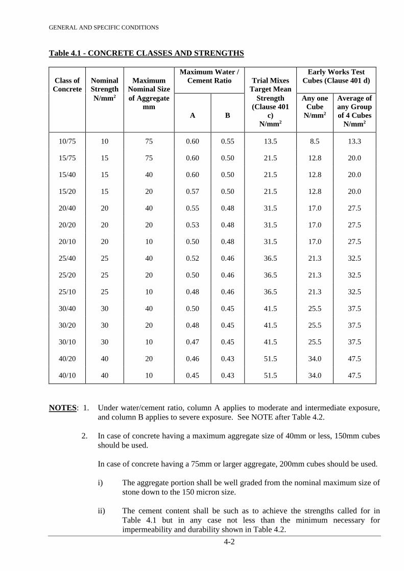
GENERAL AND SPECIFIC CONDITIONS
4-2
Table 4.1 - CONCRETE CLASSES AND STRENGTHS
Class of
Concrete
Nominal Strength
Maximum
Nominal Size
Maximum Water / Cement Ratio
Trial Mixes
Target Mean
Early Works Test Cubes (Clause 401 d)
N/mm2 of Aggregate mm
A
B
Strength (Clause 401
c) N/mm2
Any one Cube
N/mm2
Average of any Group of 4 Cubes
N/mm2
10/75 10 75 0.60 0.55 13.5 8.5 13.3
15/75 15 75 0.60 0.50 21.5 12.8 20.0
15/40 15 40 0.60 0.50 21.5 12.8 20.0
15/20 15 20 0.57 0.50 21.5 12.8 20.0
20/40 20 40 0.55 0.48 31.5 17.0 27.5
20/20 20 20 0.53 0.48 31.5 17.0 27.5
20/10 20 10 0.50 0.48 31.5 17.0 27.5
25/40 25 40 0.52 0.46 36.5 21.3 32.5
25/20 25 20 0.50 0.46 36.5 21.3 32.5
25/10 25 10 0.48 0.46 36.5 21.3 32.5
30/40 30 40 0.50 0.45 41.5 25.5 37.5
30/20 30 20 0.48 0.45 41.5 25.5 37.5
30/10 30 10 0.47 0.45 41.5 25.5 37.5
40/20 40 20 0.46 0.43 51.5 34.0 47.5
40/10 40 10 0.45 0.43 51.5 34.0 47.5
NOTES: 1. Under water/cement ratio, column A applies to moderate and intermediate exposure,
and column B applies to severe exposure. See NOTE after Table 4.2.
2. In case of concrete having a maximum aggregate size of 40mm or less, 150mm cubes should be used.
In case of concrete having a 75mm or larger aggregate, 200mm cubes should be used.
i) The aggregate portion shall be well graded from the nominal maximum size of
stone down to the 150 micron size. ii) The cement content shall be such as to achieve the strengths called for in
Table 4.1 but in any case not less than the minimum necessary for impermeability and durability shown in Table 4.2.
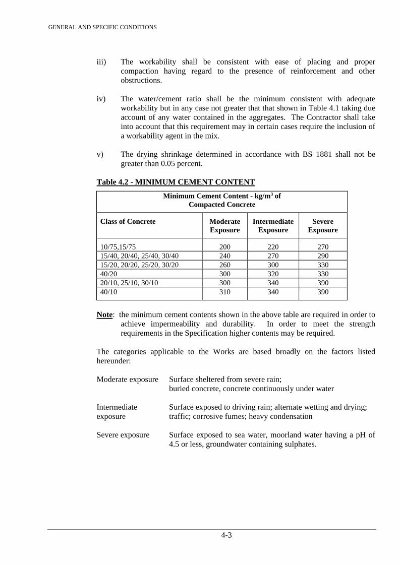
GENERAL AND SPECIFIC CONDITIONS
4-3
iii) The workability shall be consistent with ease of placing and proper
compaction having regard to the presence of reinforcement and other obstructions.
iv) The water/cement ratio shall be the minimum consistent with adequate
workability but in any case not greater that that shown in Table 4.1 taking due account of any water contained in the aggregates. The Contractor shall take into account that this requirement may in certain cases require the inclusion of a workability agent in the mix.
v) The drying shrinkage determined in accordance with BS 1881 shall not be
greater than 0.05 percent. Table 4.2 - MINIMUM CEMENT CONTENT
Minimum Cement Content - kg/m3 of Compacted Concrete
Class of Concrete Moderate Exposure
Intermediate Exposure
Severe Exposure
10/75,15/75 200 220 270 15/40, 20/40, 25/40, 30/40 240 270 290 15/20, 20/20, 25/20, 30/20 260 300 330 40/20 300 320 330 20/10, 25/10, 30/10 300 340 390 40/10 310 340 390
Note: the minimum cement contents shown in the above table are required in order to
achieve impermeability and durability. In order to meet the strength requirements in the Specification higher contents may be required.
The categories applicable to the Works are based broadly on the factors listed
hereunder: Moderate exposure Surface sheltered from severe rain;
buried concrete, concrete continuously under water Intermediate Surface exposed to driving rain; alternate wetting and drying;
exposure traffic; corrosive fumes; heavy condensation Severe exposure Surface exposed to sea water, moorland water having a pH of
4.5 or less, groundwater containing sulphates.
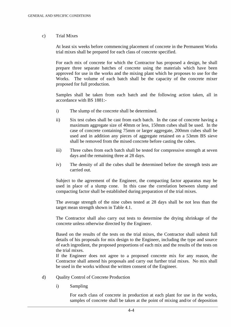
GENERAL AND SPECIFIC CONDITIONS
4-4
c) Trial Mixes
At least six weeks before commencing placement of concrete in the Permanent Works trial mixes shall be prepared for each class of concrete specified. For each mix of concrete for which the Contractor has proposed a design, he shall prepare three separate batches of concrete using the materials which have been approved for use in the works and the mixing plant which he proposes to use for the Works. The volume of each batch shall be the capacity of the concrete mixer proposed for full production. Samples shall be taken from each batch and the following action taken, all in accordance with BS 1881:- i) The slump of the concrete shall be determined. ii) Six test cubes shall be cast from each batch. In the case of concrete having a
maximum aggregate size of 40mm or less, 150mm cubes shall be used. In the case of concrete containing 75mm or larger aggregate, 200mm cubes shall be used and in addition any pieces of aggregate retained on a 53mm BS sieve shall be removed from the mixed concrete before casting the cubes.
iii) Three cubes from each batch shall be tested for compressive strength at seven
days and the remaining three at 28 days. iv) The density of all the cubes shall be determined before the strength tests are
carried out.
Subject to the agreement of the Engineer, the compacting factor apparatus may be used in place of a slump cone. In this case the correlation between slump and compacting factor shall be established during preparation of the trial mixes.
The average strength of the nine cubes tested at 28 days shall be not less than the
target mean strength shown in Table 4.1. The Contractor shall also carry out tests to determine the drying shrinkage of the
concrete unless otherwise directed by the Engineer. Based on the results of the tests on the trial mixes, the Contractor shall submit full
details of his proposals for mix design to the Engineer, including the type and source of each ingredient, the proposed proportions of each mix and the results of the tests on the trial mixes.
If the Engineer does not agree to a proposed concrete mix for any reason, the Contractor shall amend his proposals and carry out further trial mixes. No mix shall be used in the works without the written consent of the Engineer.
d) Quality Control of Concrete Production
i) Sampling For each class of concrete in production at each plant for use in the works,
samples of concrete shall be taken at the point of mixing and/or of deposition
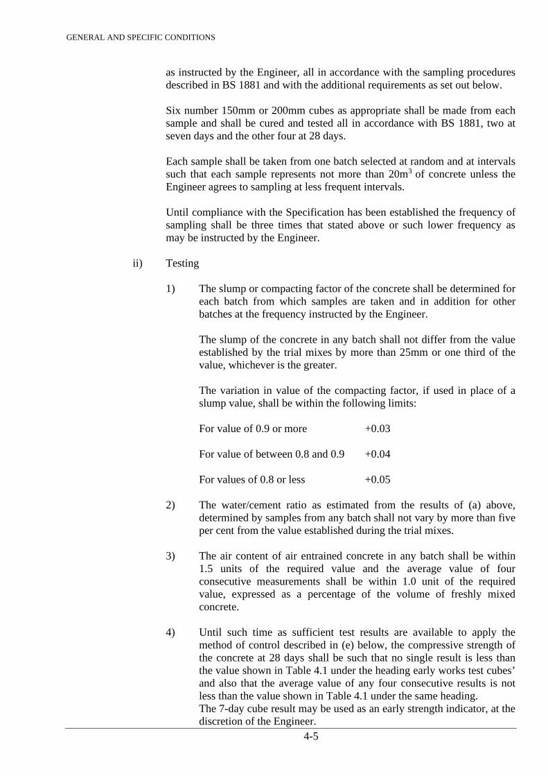
GENERAL AND SPECIFIC CONDITIONS
4-5
as instructed by the Engineer, all in accordance with the sampling procedures described in BS 1881 and with the additional requirements as set out below.
Six number 150mm or 200mm cubes as appropriate shall be made from each
sample and shall be cured and tested all in accordance with BS 1881, two at seven days and the other four at 28 days.
Each sample shall be taken from one batch selected at random and at intervals
such that each sample represents not more than 20m3 of concrete unless the Engineer agrees to sampling at less frequent intervals.
Until compliance with the Specification has been established the frequency of
sampling shall be three times that stated above or such lower frequency as may be instructed by the Engineer.
ii) Testing
1) The slump or compacting factor of the concrete shall be determined for each batch from which samples are taken and in addition for other batches at the frequency instructed by the Engineer.
The slump of the concrete in any batch shall not differ from the value
established by the trial mixes by more than 25mm or one third of the value, whichever is the greater.
The variation in value of the compacting factor, if used in place of a
slump value, shall be within the following limits: For value of 0.9 or more +0.03 For value of between 0.8 and 0.9 +0.04 For values of 0.8 or less +0.05
2) The water/cement ratio as estimated from the results of (a) above,
determined by samples from any batch shall not vary by more than five per cent from the value established during the trial mixes.
3) The air content of air entrained concrete in any batch shall be within
1.5 units of the required value and the average value of four consecutive measurements shall be within 1.0 unit of the required value, expressed as a percentage of the volume of freshly mixed concrete.
4) Until such time as sufficient test results are available to apply the
method of control described in (e) below, the compressive strength of the concrete at 28 days shall be such that no single result is less than the value shown in Table 4.1 under the heading early works test cubes’ and also that the average value of any four consecutive results is not less than the value shown in Table 4.1 under the same heading.
The 7-day cube result may be used as an early strength indicator, at the discretion of the Engineer.
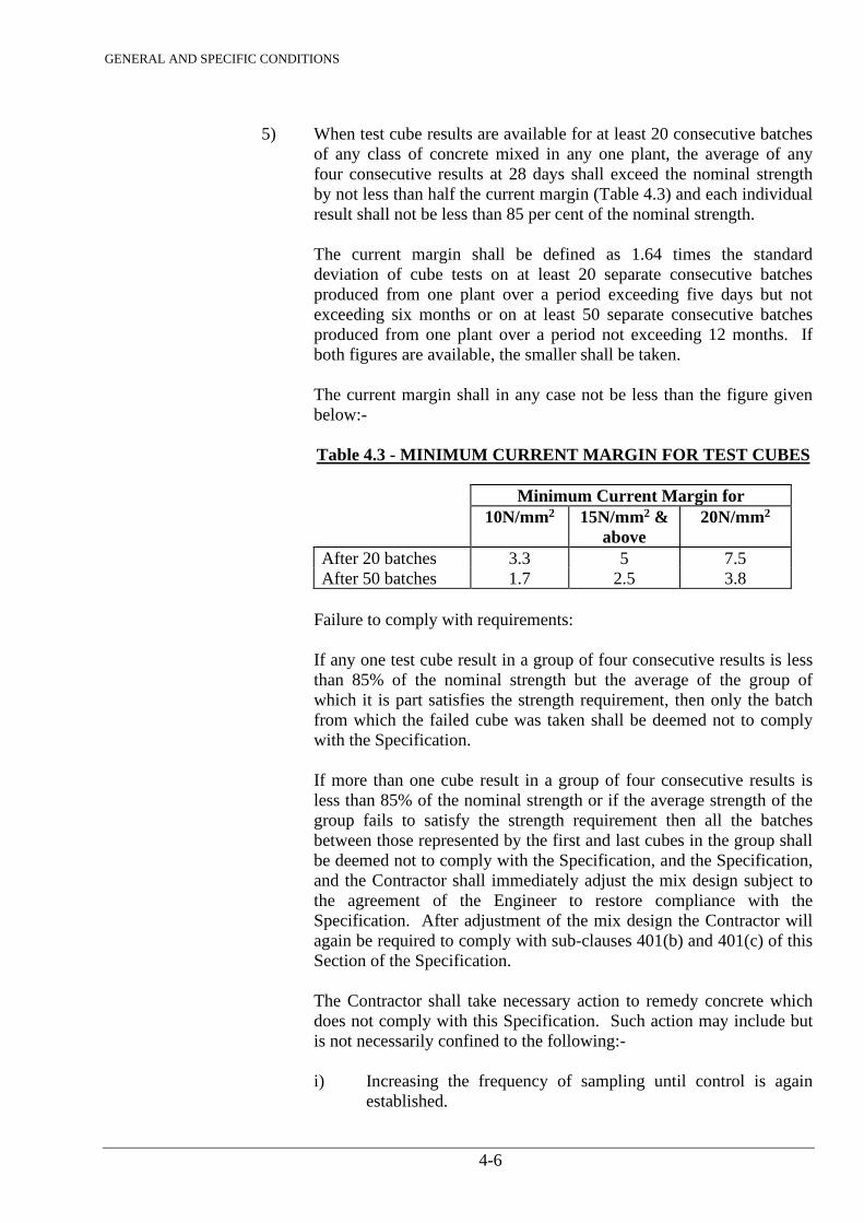
GENERAL AND SPECIFIC CONDITIONS
4-6
5) When test cube results are available for at least 20 consecutive batches
of any class of concrete mixed in any one plant, the average of any four consecutive results at 28 days shall exceed the nominal strength by not less than half the current margin (Table 4.3) and each individual result shall not be less than 85 per cent of the nominal strength.
The current margin shall be defined as 1.64 times the standard
deviation of cube tests on at least 20 separate consecutive batches produced from one plant over a period exceeding five days but not exceeding six months or on at least 50 separate consecutive batches produced from one plant over a period not exceeding 12 months. If both figures are available, the smaller shall be taken.
The current margin shall in any case not be less than the figure given
below:-
Table 4.3 - MINIMUM CURRENT MARGIN FOR TEST CUBES
Minimum Current Margin for 10N/mm2 15N/mm2 &
above 20N/mm2
After 20 batches 3.3 5 7.5 After 50 batches 1.7 2.5 3.8
Failure to comply with requirements: If any one test cube result in a group of four consecutive results is less
than 85% of the nominal strength but the average of the group of which it is part satisfies the strength requirement, then only the batch from which the failed cube was taken shall be deemed not to comply with the Specification.
If more than one cube result in a group of four consecutive results is less than 85% of the nominal strength or if the average strength of the group fails to satisfy the strength requirement then all the batches between those represented by the first and last cubes in the group shall be deemed not to comply with the Specification, and the Specification, and the Contractor shall immediately adjust the mix design subject to the agreement of the Engineer to restore compliance with the Specification. After adjustment of the mix design the Contractor will again be required to comply with sub-clauses 401(b) and 401(c) of this Section of the Specification. The Contractor shall take necessary action to remedy concrete which does not comply with this Specification. Such action may include but is not necessarily confined to the following:- i) Increasing the frequency of sampling until control is again
established.
GENERAL AND SPECIFIC CONDITIONS
4-7
ii) Cutting test cores from the concrete and testing in accordance with SRN 117.
iii) Carrying out strengthening or other remedial work to the
concrete where possible or appropriate. iv) Carrying out non-destructive testing such as load tests on
beams.
v) Removing the concrete.
402. MIXING CONCRETE Before any plant for batching, mixing, transporting, placing, compacting and finishing
concrete is ordered or delivered to site, the Contractor shall submit to the Engineer full details including drawings of all the plant which he proposes to use and the arrangements he proposes to make.
Concrete for the Works specifically for Treatment Works Units and Storage Reservoirs shall
be and mixed using an automatic batching plant in one or more central location. If the Contractor proposes to use ready mixed concrete he shall submit to the Engineer for his approval full details and test results of the concrete mixes. The Engineer may approve the use of ready mixed concrete provided that:
a) the proposed mixes, the material to be used and the method of storage and mixing
comply with the requirements of the Specification; and b) adequate control is exercised during mixing. Approval for the use of ready mixed concrete may be withdrawn if the Engineer is not satisfied with the control of the materials being used and control during mixing. The mixing of concrete shall be carried out at central plant located at a site remote from place of discharge of mixed concrete. The mixed concrete shall be transported from the central plant using transit lorry mixers and/or agitator trucks.
Batching and mixing plants shall be modern efficient equipment complying with the requirements of SRN 118 and capable of producing a uniform distribution of the ingredients throughout the mass. Truck mixes shall comply with the requirements of SRN 121 and shall only be used with the prior agreement of the Engineer. If the plant proposed by the Contractor does not fall within the scope of SRN 118, it shall have been tested in accordance with SRN 119 and shall have a mixing performance within the limits specified in SRN 118. All mixing operations shall be under the control of an experienced supervisor. The aggregate storage bins shall be provided with drainage facilities arranged so that drainage water is not discharged to the weigh hoppers. Each bin shall be drawn down at least once per week and any accumulations of mud or silt removed. Cement and aggregate shall be batched by weight. Water may be measured by weight or volume.
GENERAL AND SPECIFIC CONDITIONS
4-8
The weighing and water dispensing mechanisms shall be maintained in good order. Their accuracy shall be maintained within the tolerances described in SRN 118 and checked against accurate weighs and volumes when required by the Engineer. The weighs of cement and of each size of aggregate as indicated by the mechanisms employed shall be within a tolerance of plus or minus two percent of the respective weights per batch agreed by the Engineer. The Contractor shall provide standard test weights at least equivalent to the maximum working load used on the most heavily loaded scale and other auxiliary equipment required for checking the satisfactory operation of each scale or other measuring device. Tests shall be made by the Contractor at least once a week or at intervals to be determined by the Engineer and shall be carried out in his presence. For the purpose of carrying out these tests, there shall be easy access for personnel to the weigh hoppers. The Contractor shall furnish the Engineer with copies of the complete results of all check tests and shall make any adjustments, repairs or replacements necessary to ensure satisfactory performance. The nominal drum or pan capacity of the mixer shall not be exceeded. The turning speed and the mixing time shall be as recommended by the manufacturer, but in addition, when water is the last ingredient to be added, mixing shall continue for at least one minute after all the water has been added to the drum or pan. The blades of pan mixers shall be maintained within the tolerances specified by the manufacturer of the mixer and the blades shall be replaced when it is no longer possible to maintain the tolerances by adjustment. Mixers shall be fitted with an automatic recorder registering the number of batches discharged.
The water to be added to the mix shall be reduced by the amount of free water contained in the coarse and fine aggregates. This amount shall be determined by the Contractor by a method agreed by the Engineer immediately before mixing begins each day and thereafter at least once per hour during concreting and for each delivery of aggregates during concreting. When the correct quantity of water, determined as set out in the Specification, has been added to the mix, no further water shall be added, either during mixing or subsequently. After mixing for the required time, each batch shall be discharged completely from the mixer before any materials for the succeeding batch are introduced. Mixers which have been out of use for more than 30 minutes shall be thoroughly cleaned before any fresh concrete is mixed and thereafter the first batch of concrete through the mixers shall contain only half the normal quantity of coarse aggregate. This batch shall be mixed for one minute longer than the time applicable to a normal batch. Mixers shall be cleaned out before changing to another type of cement.
403. HAND-MIXED CONCRETE Concrete for structural purposes shall not be mixed by hand. Where non-structural concrete is required, hand mixing may be carried out subject to the agreement of the Engineer.
GENERAL AND SPECIFIC CONDITIONS
4-9
The mixing shall be done on a hard impermeable surface. The materials shall be turned over not less than three times dry, water shall then be sprayed on and the materials again turned over not less than three times in a wet condition and worked together until a mixture of uniform consistency is obtained. For hand mixed concrete the specified quantities of cement shall be increased by 10% and not more than 0.5 cubic metre shall be mixed at one time. During windy weather efficient precautions shall be taken to prevent cement from being blown away during the process of gauging and mixing.
404. TRANSPORT OF CONCRETE The concrete shall be discharged from the mixer and transported to the Works by means which shall prevent adulteration, segregation or loss of ingredients, and which shall ensure that the concrete is of the required workability at the point and time of placing. The loss of slump between discharge from the mixer and placing shall not exceed 25mm. The mixed concrete shall be transported using agitator trucks or transit truck mixers. The agitating speed of the drum shall be between 2 and 4 rpm. The interval between feeding of water into the mixer drum and final discharging of the concrete shall not exceed one hour. The time elapsed between mixing and placing a batch of concrete shall be as short as practicable and in any case not longer than will permit completion of placing and compaction before the onset of initial set. If the placing of any batch of concrete is delayed beyond this period, the concrete shall not be placed in the Works.
405. PLACING OF CONCRETE a) Consent for Placing
Concrete shall not be placed in any part of the Works until the Engineer’s consent has been given in writing, and the Contractor shall give the Engineer at least 1 full working day’s notice of his intention to place concrete. If concrete placing is not commenced within 24 hours of the Engineer’s consent the Contractor shall again request consent as specified above.
b) Preparation of Surface to Receive Concrete
Excavated surfaces on which concrete is to be deposited shall be prepared as set out in Section 3 of this Specification. Existing concrete surfaces shall be prepared as set out in Clause 414. Before deposition of further concrete they shall be clean, hard and sound and shall be wet but without any free-standing water. Any flow of water into an excavation shall be diverted through proper side drains to a sump, or be removed by other suitable methods which will prevent washing away the freshly deposited concrete or any of its constituents. Any underdrains constructed for this purpose shall be completely grouted up when they are no longer required by a method agreed by the Engineer. Unless otherwise instructed by the Engineer surfaces against which concrete is to be placed shall receive a prior coating of mortar mixed in the proportions similar to those
GENERAL AND SPECIFIC CONDITIONS
4-10
of the fines portion in the concrete to be placed. The mortar shall be kept ahead of the concrete. The mortar shall be well worked into all parts of the excavated surface and shall not be less than 5mm thick. If any fissures have been cleaned out as described in Section 3 of this Specification they shall be filled with mortar or with concrete as instructed by the Engineer. The amount of mortar placed at any one time shall be limited so that it does not dry out or set before being covered with concrete.
c) Chutes
In general, transportation of concrete by the use of chutes will not be permitted unless approved by the Engineer. The chute shall have a section with round corners and shall have a proper fixed slope so as to allow the concrete to flow satisfactorily and without segregation. The lower end of chute shall be provided with a drop chute not less than 0.6m in height to avoid segregation of falling concrete. The height of drop shall not exceed 1.5m. Chutes shall be protected from direct sunlight, wind and rain.
d) Concrete Pump or Placer
The type and capacity of pump shall be determined to meet the specified requirements, taking into account the placing speed, construction schedule, quality of concrete, location to which concrete is poured, etc. Diameter of the delivery pipes shall be not smaller than 3 times of the maximum size of aggregates to be used in the concrete. Delivery pipes shall be so installed as to permit easy removal. Before starting the pump or placer operation, about one cubic metre of mortar with the same proportion of water, admixture, cement and fine aggregate as designated for the regular concrete mix shall be passed through the pipe. The pipe shall be set as straight and horizontally as possible to prevent clogging of the concrete mix in the pipe. The supports of the pipe line shall be stiff enough to fix the pipes firmly without adverse effect on forms and reinforcing steel already set in position. Care shall be taken to prevent leakage of the concrete mix from the pipe line or any other part. Air boosters shall not be used except in conditions where the outlet of the pipe is completely embedded at least 2 metres in fresh concrete.
GENERAL AND SPECIFIC CONDITIONS
4-11
e) Placing Procedures
The concrete shall be deposited as nearly as possible in its final position. It shall be placed so as to avoid segregation of the concrete and displacement of the reinforcement, other embedded items, or formwork. It shall be brought up in layers approximately parallel to the construction joint planes and not exceeding 500mm in compacted thickness unless otherwise permitted or directed by the Engineer, but the layers shall not be thinner than four times the maximum nominal size of aggregate. Layers shall be placed so that they do not form feather edges nor shall they be placed on a previous layer which has taken its initial set. In order to comply with this requirement, a layer may be started before completion of the preceeding layer. All the concrete in a single bay or pour shall be placed in a continuous operation. It shall be carefully worked round all obstructions, irregularities in the foundations and the like so that all parts are completely full of compacted concrete with no segregation or honeycombing. It shall also be carefully worked round and between waterstops, reinforcement, embedded steelwork and similar items which protrude above the surface of the completed pour. All work shall be completed on each batch of concrete before its initial set commences and thereafter the concrete shall not be disturbed before it has set hard. No concrete that has partially hardened during transit shall be used in the Works and the transport of concrete from the mixer to the point of placing shall be such that this requirement can be complied with. Concrete shall not be placed during rain which is sufficiently heavy or prolonged as to wash mortar from coarse aggregate on the exposed faces of fresh concrete. Means shall be provided to remove any water accumulating on the surface of the placed concrete. Concrete shall not be deposited into such accumulation of water. In drying weather, covers shall be provided for all fresh concrete surfaces which are not being worked on. Water shall not be added to concrete for any reason. When concrete is discharged above its place of final deposition, segregation shall be prevented by the use of chutes, downpipes, trunking, baffles or other appropriate devices, as approved by the Engineer. Forms for walls, columns and other thin sections of significant height shall be provided with openings or other devices that will permit the concrete to be placed in a manner that will prevent segregation and accumulations of hardened concrete on the formwork or reinforcement above the level of the placed concrete. When it is necessary to place concrete under water the Contractor shall submit to the Engineer his proposals for the method and equipment to be employed. The concrete shall be deposited either by bottom-discharging watertight containers or through funnel-shaped tremies which are kept continuously full with concrete up to level above the water and which shall have the discharging bottom fitted with a trapdoor and immersed in the concrete in order to reduce to a minimum the contact of the concrete with the water. Special care shall be taken to avoid segregation.
GENERAL AND SPECIFIC CONDITIONS
4-12
If the level of concrete in a tremie pipe is allowed to fall to such an extent that water enters the pipe, the latter shall be removed from the pour and filled with concrete before being again lowered into the placing position. During and after concreting under water, pumping or dewatering in the immediate vicinity shall be suspended if there is any danger that such work will disturb the freshly placed concrete.
f) Interruptions to Placing
If concrete placing is interrupted for any reason and the duration of the interruption cannot be forecast or is likely to be prolonged, the Contractor shall immediately take the necessary action to form a construction joint so as to eliminate as far as possible feather edges and sloping top surfaces and shall thoroughly compact the concrete already placed in accordance with Clause 406. All work on the concrete shall be completed while it is still plastic and it shall not thereafter be disturbed until it is hard enough to resist damage. Plant and materials to comply with this requirement shall be readily available at all times during concrete placing. Before concreting is resumed after such an interruption the Contractor shall cut out and remove all damaged or uncompacted concrete, feather edges or any other undesirable features and shall leave a clean sound surface against which the fresh concrete may be placed. If it becomes possible to resume concrete placing without contravening the Specification and the Engineer consents to a resumption, the new concrete shall be thoroughly worked in and compacted against the existing concrete so as to eliminate any cold joints.
g) Dimensions of Pours
Unless otherwise agreed by the Engineer, pours shall not be more than two metres high and shall as far as possible have a uniform thickness over the plan area of the pour. Concrete shall be placed to the full planned height of all pours except in the circumstances described in sub-clause 405(d). The Contractor shall plan the dimensions and sequence of pours in such a way that cracking of the concrete does not take place due to thermal or shrinkage stresses.
h) Placing Sequence
The Contractor shall arrange that as far as possible the intervals between placing successive lifts of concrete in one section of the Works are of equal duration. This duration shall normally be not less than three or more than seven days under temperate weather conditions unless otherwise agreed by the Engineer. Where required by the Engineer to limit the opening of construction joints due to shrinkage, concrete shall not be placed against adjacent concrete which is less than 21 days old. When the drawings call for contraction gaps in concrete, these shall be of the widths and in the locations shown on the drawings and they shall not be filled until the full time interval shown on the drawings has elapsed.
GENERAL AND SPECIFIC CONDITIONS
4-13
406. COMPACTION OF CONCRETE The concrete shall be fully compacted throughout the full extent of the placed layer. It shall be thoroughly worked against the formwork and around any reinforcement and other embedded items, without displacing them. Particular care shall be taken at arises and other confined spaces. Successive layers of the same pour shall be thoroughly worked together. Concrete shall be compacted with the assistance of mechanical immersion vibrators, unless the Engineer agrees to another method. Immersion vibrators shall operate at a frequency of between 7,000 and 10,000 cycles per minute. The Contractor shall ensure that vibrators are operated at pressures and voltages not less than those recommended by the manufacturer in order that the compactive effort is not reduced. A sufficient number of vibrators shall be operated to enable the entire quantity of concrete being placed to be vibrated for the necessary period and, in addition, standby vibrators shall be available for instant use at each place where concrete is being placed. Where the concrete contains aggregate with a nominal size of 75mm or more, vibrators with a diameter of 100mm or more shall be used.
Vibration shall be continued at each point until the concrete ceases to contract, a thin layer of mortar has appeared on the surface and air bubbles have ceased to appear. Vibrators shall not be used to move concrete laterally and shall be withdrawn slowly to prevent the formation of voids. Vibration shall not be applied by way of reinforcement nor shall vibrators be allowed to touch reinforcement or other embedded items. The vibrators shall be inserted vertically into the concrete to penetrate the layer underneath at regular spacing. The spacing shall not exceed the distance from the vibrator over which vibration is visibly effective.
407. CURING OF CONCRETE a) General
Concrete shall be protected during the first stage of hardening from loss of moisture and from the development of temperature differentials within the concrete sufficient to cause cracking. The methods used for curing shall not cause damage of any kind to the concrete. Curing shall be continued for as long as may be necessary to achieve the above objectives but in any case for at least seven days or until the concrete is covered by later construction whichever is the shorter period. The above objectives are dealt with in sub-clause 407(b) and (c) but nothing shall prevent both objectives being achieved by a single method where circumstances permit. The curing process shall commence as soon as the concrete is hard enough to resist damage from the process, and in the case of large areas or continuous pours, shall commence on the completed section of the pour before the rest of the pour is finished.
GENERAL AND SPECIFIC CONDITIONS
4-14
Details of the Contractor’s proposals for curing concrete shall be submitted to the Engineer before the placing of concrete commences in the Works. Formed surfaces may be cured by retaining the formwork in place for the required curing period. If the use of the foregoing methods is inappropriate, surfaces which will not have further concrete bonded to them and which are not to receive an application of a finish may be cured by the application of a curing compound having an efficiency index of at least 90 percent. Curing compounds shall contain a fugitive dye to enable the extent of the spread to be seen easily. Curing compound is used on surfaces exposed to the atmosphere shall contain sufficient finely divided flake aluminium in suspension to produce a complete coverage of the surface with a metallic finish when applied at the rate recommended by the manufacturer. Curing compounds shall become stable and impervious to the evaporation of water from the concrete surface within 60 minutes of application. The material shall not react chemically with the concrete surfaces for at least the first four days of the curing period. If instructed by the Engineer, the Contractor shall, in addition to the curing provisions set out above provide a suitable form of shading to prevent the direct rays of the sun reaching the concrete surfaces for at least the first four days of the curing period.
b) Loss of Moisture
Exposed concrete surfaces shall be closely covered with impermeable sheeting, properly secured to prevent its removal by wind and the development of air spaces beneath it. Joints in the sheeting shall be lapped by at least 300mm. If for some reason it is not possible to use impermeable sheeting, the Contractor shall keep the exposed surfaces continuously wet by means of a water spray or by covering with a water absorbent material which is kept wet, unless this method conflicts with sub-clause 407(c). Water used for curing shall be of the same quality as that used for concrete mixing as stated in Clause 724 g).
GENERAL AND SPECIFIC CONDITIONS
4-15
c) Limitation of Temperature Differential
The Contractor shall limit the development of temperature differentials in concrete after placing by any means appropriate to the circumstances including the following: i) limiting concrete temperatures at placing as set out in sub-clause 409(b); ii) use of low heat cement, subject to the agreement of the Engineer; iii) insulation of exposed concrete surface by insulating blankets. Such blankets
shall have an insulation value at least equivalent to 50mm of dry mineral wool;
iv) leaving formwork in place during the curing period. Steel forms shall be
suitably insulated on the outside; v) preventing rapid dissipation of heat from surfaces by shielding from wind; vi) avoiding the use of water sprays when such use would cause rapid cooling of
the surface.
408. PROTECTION OF FRESH CONCRETE Freshly placed concrete shall be protected from rainfall and from water running over the surface until it is sufficiently hard to resist damage from these causes. No traffic shall be allowed on any concrete surface until such time as it is hard enough to resist damage by such traffic. Concrete placed in the Works shall not be subjected to any loading until it has attained at least its nominal strength as defined in Clause 401. If the Contractor desires to impose loads on newly-placed concrete, he shall make at least three test cubes and cure them in the same conditions as the concrete they represent. These cubes shall be tested singly at suitable intervals in order to estimate the time at which the nominal strength is reached.
409. CONCRETING IN HOT WEATHER a) General
The Contractor shall prevent damage to concrete arising from exposure to extreme temperatures, and shall maintain in good working order all plant and equipment required for this purpose. In the event that conditions become such that even with the use of the equipment the requirements cannot be met, concrete placing shall immediately cease until such time as the requirements can again be met.
GENERAL AND SPECIFIC CONDITIONS
4-16
b) Concrete Placing in Hot Weather
During hot weather the Contractor shall take all measures necessary to ensure that the temperature of concrete at the time of placing in the Works does not exceed 30 degrees centigrade and that the concrete does not loose any moisture during transporting and placing. Such measures may include but are not necessarily limited to the following:- i) Shielding aggregates from direct sunshine. ii) Use of a mist water spray on aggregates iii) Sun shields on mixing plants and transporting equipment. iv) Cooling the mixing water. If ice is used for this purpose it should preferably
be in flake form. Lump ice shall not be allowed to enter the tank supplying the mixer drum.
v) Covering skips closely with polythene sheet so that the latter is in contact with
the concrete. Areas in which concrete is to be placed shall be shielded from direct sunshine and rock or concrete surfaces shall be thoroughly wetted to reduce absorption of water from the concrete placed on or against them. After concrete in any part of an area has been placed, the selected curing process shall be commenced as soon as possible. If any interval occurs between completion of placing and start of curing, the concrete shall be closely covered during the interval with polythene sheet to prevent loss of moisture.
410. FINISHES ON UNFORMED SURFACES Horizontal or nearly horizontal surfaces which are not cast against formwork shall be finished to the class shown on the drawings and defined hereunder. UF 1 Finish All surfaces on which no higher class of finish is called for on the drawings or instructed by the Engineer shall be given a UF 1 finish. The concrete shall be levelled and screeded to produce a uniform plain or ridged surface, surplus concrete being struck off by a straight edge immediately after compaction. UF 2 Finish This is a floated finish for roof or floor slabs and other surfaces where a hard trowelled surface is not required.
GENERAL AND SPECIFIC CONDITIONS
4-17
The surface shall first be treated as a Class UF 1 finish and after the concrete has hardened sufficiently, it shall be floated by hand or machine sufficiently only to produce a uniform surface free from screed marks. UF 3 Finish This is a hard trowelled surface for use where weather resistance or appearance is important, or which is subject to high velocity water flow. The surface shall be floated as for a UF 2 finish but to the tolerance stated below. When the moisture film has disappeared and the concrete has hardened sufficiently to prevent laitance from being worked to the surface, it shall be steel trowelled under firm pressure to produce a dense, smooth uniform surface free from trowel marks.
Table 4.4 - SURFACE TOLERANCES
Class of Tolerance in mm. See notes Finish A B C UF 1 N/A 10 + 20 or - 10 UF 2 Nil 10 + 20 or - 10 UF 3 Nil 5 + 12.5 or -7.5
Notes: 1. Col. A is the maximum allowable value of any sudden change of level in the surface. 2. Col. B is the maximum allowable value of any gradual irregularity of the surface, as
indicated by the gap between the surface and a three metre long straight edge or correctly shaped template placed on the surface.
3. Col. C is the maximum allowable value of the difference in level or position between
a three metre long straight edge or correctly shaped template placed on the surface and the specified level or position of that surface.
Where dimensional tolerances are given on the drawings or in this Special Specification they shall take precedence over those given in Table 4.4.
411. MORTAR This clause covers mortar for use ahead of concrete placing, and other uses not covered elsewhere in the Specification. Mortar shall be composed of fine aggregate complying with Clause 724 c) and ordinary Portland cement complying with SRN 103. The mix proportions shall be as stated on the drawings or elsewhere in this Specification or if not stated shall be one part of cement to two parts of fine aggregate by weight. Small quantities of mortar may be hand mixed but for amounts over 0.5 cubic metre a mechanical mixer shall be used.
GENERAL AND SPECIFIC CONDITIONS
4-18
The water content of the mortar shall be as low as possible consistent with the use for which it is required but in any case the water/cement ratio shall not be more than 0.5. Mortar which is specified as ‘dry pack’ shall be mixed with sufficient water for the mix to become cohesive but not plastic when squeezed in the hand. Dry pack mortar shall be rammed into the cavity it is required to fill, using a hand rammer with sufficient force to ensure full compaction.
412. CONCRETE FOR SECONDARY PURPOSES a) Non-structural concrete (NS concrete) shall be used only for non-structural purposes
where shown on the drawings.
NS concrete shall be composed of ordinary Portland cement complying with SRN 103 and aggregates complying with SRN 108-111 including all-in aggregate within the grading limits of SRN 109 and SRN 111. The weight of cement mixed with 0.3 cubic metres of combined or all-in aggregate shall not be less than 50 kg. The mix shall be proportioned by weight or by volume. The maximum aggregate size shall be 40mm nominal. The concrete shall be mixed by machine or by hand to a uniform colour and consistency before placing. The quantity of water used shall not exceed that required to produce a concrete with sufficient workability to be placed and compacted where required. The concrete shall be compacted by hand or by mechanical vibration.
b) No Fines concrete (NF concrete) is intended for use where a porous concrete is required and shall only be used where shown on the drawings or instructed by the Engineer.
The mix shall consist of ordinary Portland cement complying with SRN 115. The aggregate size shall be 40mm to 10mm only. The weight of cement mixed with 0.3 cubic metre of aggregate shall not be less than 50 kg. The quantity of water shall not exceed that required to produce a smooth cement paste which will coat evenly the whole of the aggregate.
413. RECORDS OF CONCRETE PLACING Records, in a form agreed by the Engineer, shall be kept by the Contractor of the details of every pour of concrete placed in the Works. These records shall include class of concrete, location of pour, date of pour, ambient temperature and weather conditions during mixing and placing and concrete temperature at time of placing, moisture contents of aggregates, details of mixes, batch numbers, cement batch number, results of all tests undertaken, location of test cube sample points and details of any cores taken. The Contractor shall supply to the Engineer four copies of these records each week covering work carried out the preceeding week. In addition he shall supply to the Engineer monthly histograms of all 28 day cube strengths together with accumulative and monthly standard deviations and any other information which the Engineer may require concerning the concrete placed in the works.
GENERAL AND SPECIFIC CONDITIONS
4-19
414. CONSTRUCTION JOINTS Whenever concrete is to be bonded to other concrete which has hardened, the surface of contact between the sections shall be deemed a construction joint. Where construction joints are shown on the drawings, the Contractor shall form such joints in those positions. The location of joints which the Contractor requires to make for the purpose of construction shall be subject to the agreement of the Engineer. Construction joints shall be in vertical or horizontal planes except in sloping slabs where they shall be normal to the exposed surface or elsewhere where the drawings require a different arrangement. Construction joints shall be so arranged as to reduce to a minimum the effects of shrinkage in the concrete after placing, and shall be placed in the most advantageous positions with regard to stresses in the structures and the desirability of staggering joints. Feather edges of concrete at joint shall be avoided and any feather edges which may have formed where reinforcing bars project through a joint shall be cut back until sound concrete has been reached. The intersection of horizontal or near horizontal joints and exposed faces of concrete shall appear as straight lines produced by use of a guide strip fixed to the formwork at the top of the concrete lift, or by other means acceptable to the Engineer. Construction joints formed as free surfaces shall not exceed a slope of 20 per cent from the horizontal. The surface of the fresh concrete in horizontal or near horizontal joints shall be thoroughly cleaned and roughened by means of high pressure water and air jets when the concrete is hard enough to withstand the treatment without the leaching of cement. The surface of vertical or near vertical joints shall be similarly treated if circumstances permit the removal of formwork at a suitable time. Where concrete has become too hard for the above treatment to be successful, the surface whether formed or free is to be thoroughly scrabbled by mechanical means or wet sand blasted and then washed with clean water. The indentations produced by scrabbling shall be not less than 10mm deep and shall not extend closer than 40mm to a finished face. If instructed by the Engineer the surface of the concrete shall be thoroughly brushed with a thin layer of mortar composed of one part of cement to two parts of sand by weight and complying with Clause 411 all as set out in sub-clause 405(b) immediately prior to the deposition of fresh concrete. The mortar shall be kept just ahead of the fresh concrete being placed and the fresh layer of concrete shall be thoroughly and systematically vibrated to full depth to ensure complete bond with the adjacent layer. No mortar or concrete may be placed in position on or against a construction joint until the joint has been inspected and passed by the Engineer.
GENERAL AND SPECIFIC CONDITIONS
4-20
415. EXPANSION AND CONTRACTION JOINTS Expansion and contraction joints are discontinuities in concrete designed to allow thermal or other movements in the concrete. Expansion joints are formed with a gap between the concrete faces to permit subsequent expansion of the concrete. Contraction joints are formed to permit initial contraction of the concrete and may include provision for subsequent filling. Expansion and contraction joints shall be formed in the positions and in accordance with the details shown on the drawings or elsewhere in the Specifications.
416. WATERSTOPS All references to waterstops include grout stops. Waterstops shall be of the material and form shown on the drawings. No waterstop material shall be brought on the site until the Contractor has submitted full details of the materials he proposes to use, including samples, and these have been tested and approved by the Engineer. All samples shall be of adequate length for testing. Waterstops shall be made of materials which are resistant to chlorides, sulphates, or other deleterious substances which may be present in the environment of the Works. Rubber waterstops may be of natural rubber and shall have an elongation at breaking stress of at least 500 percent at 25 degrees centigrade and shall allow a joint movement of at least 50mm. Polyvinyl chloride (PVC) waterstops shall be extruded from an unfilled plasticised PVC polymer or copolymer which does not contain any reclaimed or scrap PVC. PVC waterstops shall have an elongation at breaking stress of at least 225 percent at 25 degrees centigrade and shall allow a joint movement of at least 10mm. Low modulus waterstops shall be of rubber or PVC as described above but shall have an elongation of at least 200 percent at 25 degrees centigrade under a tensile stress of 6 N/mm2 and shall allow a joint movement of at least 50mm. Waterstops shall be supplied in lengths as long as possible consistent with ease of handling and construction requirements. In rubber or plastic materials, joints other than butt joints shall be supplied ready made by the manufacturer. Butt joints shall be made on site in accordance with the manufacturer’s instructions and with equipment supplied for the purpose by the manufacturer. Waterstop material shall be stored carefully on site to avoid damage and contamination with oil, grease, or other pollutants. Rubber and plastic waterstops shall be stored in cool well ventilated places away from direct sunlight. Rubber and plastic waterstops which are embedded in one side of a joint more than one month before the scheduled date of placing concrete on the other side, shall be protected from the sun.
GENERAL AND SPECIFIC CONDITIONS
4-21
Waterstops shall be firmly fixed in the formwork so that they cannot be displaced during concrete placing and shall be completely free of all dirt, grease, oil, etc., before placing concrete. Where eyelets are provided these shall be fully wired to the reinforcement and be the only means whereby the waterstop is fixed. In no circumstances shall a waterstop be punctured with nails etc. as a means of fixing. Concrete shall be placed carefully round waterstops so as to avoid distortion or displacement and shall be fully compacted. Where waterstops lie in a horizontal or nearly horizontal plane the Contractor shall ensure that no voids are left on the underside of the waterstop. Formwork around waterstops shall be carefully removed to avoid damage. If waterstops suffer any damage which cannot be properly repaired in-situ the Engineer may require a section of concrete to be removed and the waterstop replaced.
417. GROUTING OF POCKETS AND HOLES AND UNDERPINNING OF BASEPLATES Pockets and holding-down bolt holes shall be thoroughly cleaned out using compressed air and water jet. Holes drilled by a diamond bit shall be roughened. The pockets and holes shall be filled with grout consisting of cement and clean fresh water mixed in proportion of two parts by weight of cement to one part by weight of water. The pouring of liquid grout shall cease as soon as each hole is filled and any excess grout on the surface of the concrete foundation shall be completely removed and the surface dried off before the next operation proceeds. The space between the top surface of foundation concrete and the underside of the baseplates shall be filled with a special mortar made up in the following proportions:-
• Portland Cement ......................... 50 kg. • Fine aggregate ........................... 50 kg. • An additive acceptable to the Engineer to counteract shrinkage in proportions
recommended by the manufacturer.
The special mortar shall be mixed with the lowest water-cement ratio which will result in a consistency of mix of sufficient workability to enable maximum compaction to be achieved. The special mortar shall then be well rammed in horizontally below the baseplate and from one edge only until it is extruded from the other three sides. The mortar which has extruded shall then be rammed back to ensure complete support without voids.
418. REMEDIAL WORK TO DEFECTIVE SURFACES If on stripping any formwork the concrete surface is found to be defective in any way, the Contractor shall make no attempt to remedy such defects prior to the Engineer’s inspection and the receipt of any instructions which the Engineer may give. Defective surfaces shall not be made good by plastering. Areas of honey combing (of a mild nature) which the Engineer agrees may be repaired shall be cut back to sound concrete or to 75mm whichever is the greater distance. In the case of reinforced concrete the area shall be cut back to at least 25mm clear distance behind the reinforcement or to 75mm, whichever is the greater distance. The cavity shall have sides at right angles to the face of the concrete. After cleaning out with water and compressed air, a
GENERAL AND SPECIFIC CONDITIONS
4-22
thin layer of cement grout shall be brushed on to the concrete surface in the cavity and it shall then be filled immediately with concrete of the same class as the main body but with aggregate larger than 20mm nominal size removed. A form shall be used against the cavity, provided with a lip to enable concrete to be placed. The form shall be filled to a point above the top edge of the cavity. After seven days the lip of concrete shall be broken off and the surface ground smooth. Surface irregularities which are outside the limits of tolerance set out in Clause 410 shall be ground down in the manner and to the extent instructed by the Engineer. Severe honeycombing and defects other than those mentioned above shall be dealt with as instructed by the Engineer.
419. BENDING REINFORCEMENT Unless otherwise shown on the drawings, bending and cutting shall comply with SRN 129. The Contractor shall satisfy himself as to the accuracy of any bar bending schedules supplied and shall be responsible for cutting, bending, and fixing the reinforcement in accordance with the drawings. Any discrepancies should be brought to the attention of the Engineer prior to ordering the reinforcement. Bars shall be bent cold by the application of slow steady pressure. At temperatures below 5 degrees centigrade the rate of bending shall be reduced if necessary to prevent fracture of the steel. After bending, bars shall be securely tied together in bundles or groups and legibly labelled as set out in SRN 129. Reinforcement shall be thoroughly cleaned and all dirt, scale, loose rust, oil and other contaminants removed before it is placed in the Works.
420. FIXING REINFORCEMENT Reinforcement shall be securely fixed in position within a dimensional tolerance of 20mm in any direction parallel to a concrete face and within a tolerance of 5mm at right angles to a face, provided that the cover is not thereby decreased below the minimum shown on the drawings, or if not shown shall be not less than 25mm or the diameter of the bar, whichever is the greater. Cover on distribution steel shall not be less than 15mm or the diameter of the bar whichever is the greater. Unless otherwise agreed by the Engineer, all intersecting bars shall either be tied together with 1.6mm diameter soft annealed iron wire and the ends of the wire turned into the body of the concrete, or shall be secured with a wire clip of a type agreed by the Engineer. Spacer blocks shall be used for ensuring that the correct cover is maintained on the reinforcement. Blocks shall be as small as practicable and of a shape agreed by the Engineer. They shall be made of mortar mixed in the proportions of one part of cement to two parts of sand. Wires cast into the block for tying in to the reinforcement shall be 1.6mm diameter soft annealed iron. Alternatively another type of spacer block may be used subject to the Engineer’s agreement.
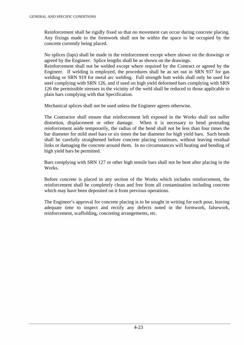
GENERAL AND SPECIFIC CONDITIONS
4-23
Reinforcement shall be rigidly fixed so that no movement can occur during concrete placing. Any fixings made to the formwork shall not be within the space to be occupied by the concrete currently being placed. No splices (laps) shall be made in the reinforcement except where shown on the drawings or agreed by the Engineer. Splice lengths shall be as shown on the drawings. Reinforcement shall not be welded except where required by the Contract or agreed by the Engineer. If welding is employed, the procedures shall be as set out in SRN 937 for gas welding or SRN 919 for metal arc welding. Full strength butt welds shall only be used for steel complying with SRN 126, and if used on high yield deformed bars complying with SRN 126 the permissible stresses in the vicinity of the weld shall be reduced to those applicable to plain bars complying with that Specification. Mechanical splices shall not be used unless the Engineer agrees otherwise.
The Contractor shall ensure that reinforcement left exposed in the Works shall not suffer distortion, displacement or other damage. When it is necessary to bend protruding reinforcement aside temporarily, the radius of the bend shall not be less than four times the bar diameter for mild steel bars or six times the bar diameter for high yield bars. Such bends shall be carefully straightened before concrete placing continues, without leaving residual links or damaging the concrete around them. In no circumstances will heating and bending of high yield bars be permitted. Bars complying with SRN 127 or other high tensile bars shall not be bent after placing in the Works. Before concrete is placed in any section of the Works which includes reinforcement, the reinforcement shall be completely clean and free from all contamination including concrete which may have been deposited on it from previous operations. The Engineer’s approval for concrete placing is to be sought in writing for each pour, leaving adequate time to inspect and rectify any defects noted in the formwork, falsework, reinforcement, scaffolding, concreting arrangements, etc.
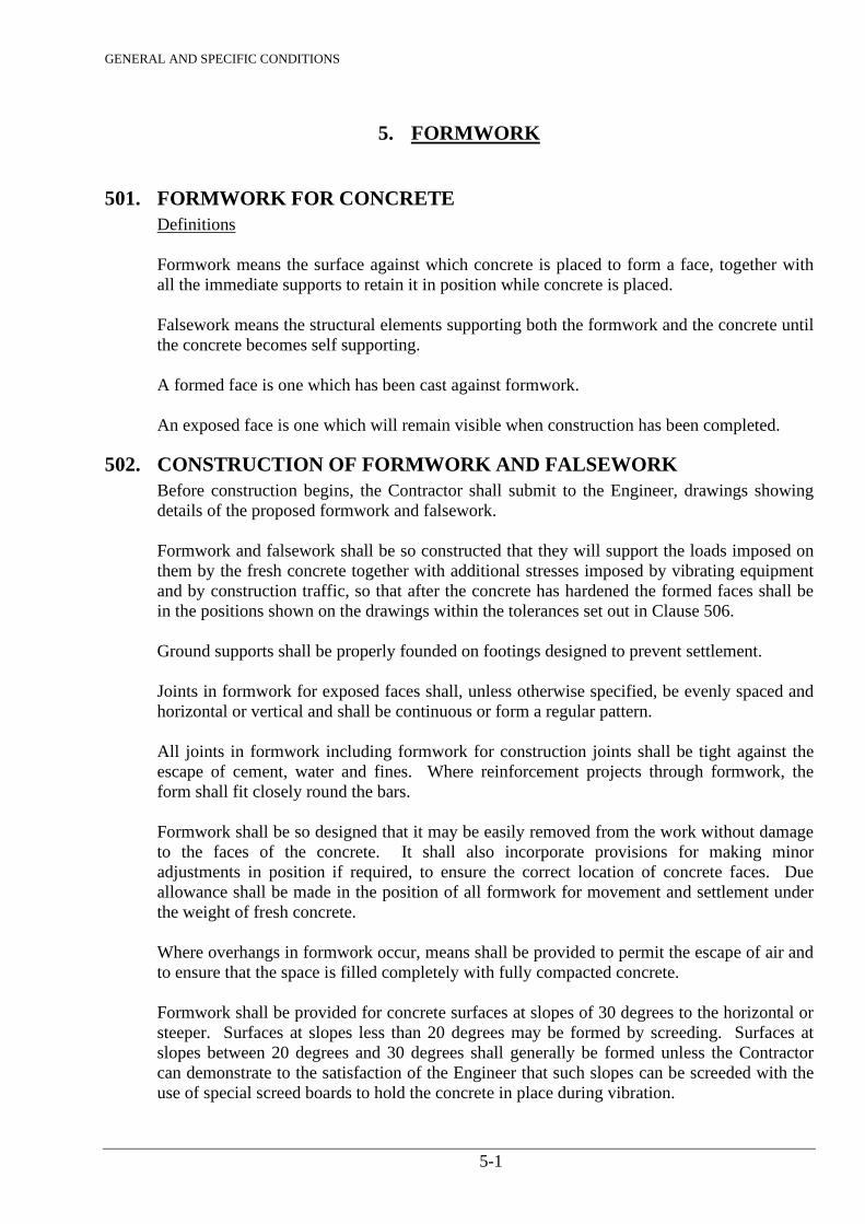
GENERAL AND SPECIFIC CONDITIONS
5-1
5. FORMWORK
501. FORMWORK FOR CONCRETE Definitions Formwork means the surface against which concrete is placed to form a face, together with
all the immediate supports to retain it in position while concrete is placed. Falsework means the structural elements supporting both the formwork and the concrete until
the concrete becomes self supporting. A formed face is one which has been cast against formwork. An exposed face is one which will remain visible when construction has been completed.
502. CONSTRUCTION OF FORMWORK AND FALSEWORK Before construction begins, the Contractor shall submit to the Engineer, drawings showing
details of the proposed formwork and falsework. Formwork and falsework shall be so constructed that they will support the loads imposed on
them by the fresh concrete together with additional stresses imposed by vibrating equipment and by construction traffic, so that after the concrete has hardened the formed faces shall be in the positions shown on the drawings within the tolerances set out in Clause 506.
Ground supports shall be properly founded on footings designed to prevent settlement. Joints in formwork for exposed faces shall, unless otherwise specified, be evenly spaced and horizontal or vertical and shall be continuous or form a regular pattern. All joints in formwork including formwork for construction joints shall be tight against the escape of cement, water and fines. Where reinforcement projects through formwork, the form shall fit closely round the bars. Formwork shall be so designed that it may be easily removed from the work without damage to the faces of the concrete. It shall also incorporate provisions for making minor adjustments in position if required, to ensure the correct location of concrete faces. Due allowance shall be made in the position of all formwork for movement and settlement under the weight of fresh concrete. Where overhangs in formwork occur, means shall be provided to permit the escape of air and to ensure that the space is filled completely with fully compacted concrete. Formwork shall be provided for concrete surfaces at slopes of 30 degrees to the horizontal or steeper. Surfaces at slopes less than 20 degrees may be formed by screeding. Surfaces at slopes between 20 degrees and 30 degrees shall generally be formed unless the Contractor can demonstrate to the satisfaction of the Engineer that such slopes can be screeded with the use of special screed boards to hold the concrete in place during vibration.
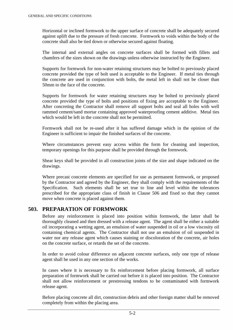
GENERAL AND SPECIFIC CONDITIONS
5-2
Horizontal or inclined formwork to the upper surface of concrete shall be adequately secured against uplift due to the pressure of fresh concrete. Formwork to voids within the body of the concrete shall also be tied down or otherwise secured against floating. The internal and external angles on concrete surfaces shall be formed with fillets and chamfers of the sizes shown on the drawings unless otherwise instructed by the Engineer. Supports for formwork for non-water retaining structures may be bolted to previously placed concrete provided the type of bolt used is acceptable to the Engineer. If metal ties through the concrete are used in conjunction with bolts, the metal left in shall not be closer than 50mm to the face of the concrete. Supports for formwork for water retaining structures may be bolted to previously placed concrete provided the type of bolts and positions of fixing are acceptable to the Engineer. After concreting the Contractor shall remove all support bolts and seal all holes with well rammed cement/sand mortar containing approved waterproofing cement additive. Metal ties which would be left in the concrete shall not be permitted. Formwork shall not be re-used after it has suffered damage which in the opinion of the Engineer is sufficient to impair the finished surfaces of the concrete. Where circumstances prevent easy access within the form for cleaning and inspection, temporary openings for this purpose shall be provided through the formwork. Shear keys shall be provided in all construction joints of the size and shape indicated on the drawings. Where precast concrete elements are specified for use as permanent formwork, or proposed by the Contractor and agreed by the Engineer, they shall comply with the requirements of the Specification. Such elements shall be set true to line and level within the tolerances prescribed for the appropriate class of finish in Clause 506 and fixed so that they cannot move when concrete is placed against them.
503. PREPARATION OF FORMWORK Before any reinforcement is placed into position within formwork, the latter shall be thoroughly cleaned and then dressed with a release agent. The agent shall be either a suitable oil incorporating a wetting agent, an emulsion of water suspended in oil or a low viscosity oil containing chemical agents. The Contractor shall not use an emulsion of oil suspended in water nor any release agent which causes staining or discoloration of the concrete, air holes on the concrete surface, or retards the set of the concrete. In order to avoid colour difference on adjacent concrete surfaces, only one type of release agent shall be used in any one section of the works. In cases where it is necessary to fix reinforcement before placing formwork, all surface preparation of formwork shall be carried out before it is placed into position. The Contractor shall not allow reinforcement or prestressing tendons to be contaminated with formwork release agent. Before placing concrete all dirt, construction debris and other foreign matter shall be removed completely from within the placing area.
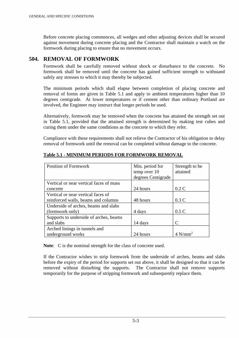
GENERAL AND SPECIFIC CONDITIONS
5-3
Before concrete placing commences, all wedges and other adjusting devices shall be secured against movement during concrete placing and the Contractor shall maintain a watch on the formwork during placing to ensure that no movement occurs.
504. REMOVAL OF FORMWORK Formwork shall be carefully removed without shock or disturbance to the concrete. No formwork shall be removed until the concrete has gained sufficient strength to withstand safely any stresses to which it may thereby be subjected. The minimum periods which shall elapse between completion of placing concrete and removal of forms are given in Table 5.1 and apply to ambient temperatures higher than 10 degrees centigrade. At lower temperatures or if cement other than ordinary Portland are involved, the Engineer may instruct that longer periods be used. Alternatively, formwork may be removed when the concrete has attained the strength set out in Table 5.1, provided that the attained strength is determined by making test cubes and curing them under the same conditions as the concrete to which they refer. Compliance with these requirements shall not relieve the Contractor of his obligation to delay removal of formwork until the removal can be completed without damage to the concrete. Table 5.1 - MINIMUM PERIODS FOR FORMWORK REMOVAL
Position of Formwork Min. period for
temp over 10 degrees Centigrade
Strength to be attained
Vertical or near vertical faces of mass concrete
24 hours
0.2 C
Vertical or near vertical faces of reinforced walls, beams and columns
48 hours
0.3 C
Underside of arches, beams and slabs (formwork only)
4 days
0.5 C
Supports to underside of arches, beams and slabs
14 days
C
Arched linings in tunnels and underground works
24 hours
4 N/mm2
Note: C is the nominal strength for the class of concrete used. If the Contractor wishes to strip formwork from the underside of arches, beams and slabs before the expiry of the period for supports set out above, it shall be designed so that it can be removed without disturbing the supports. The Contractor shall not remove supports temporarily for the purpose of stripping formwork and subsequently replace them.
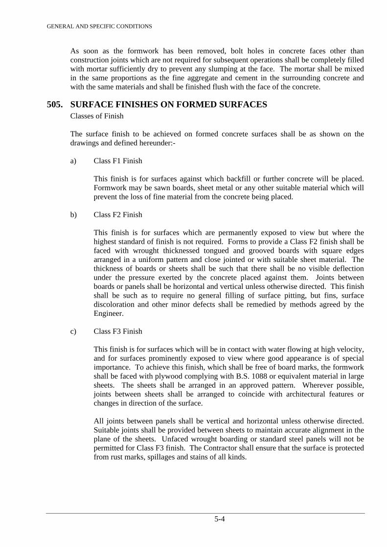
GENERAL AND SPECIFIC CONDITIONS
5-4
As soon as the formwork has been removed, bolt holes in concrete faces other than construction joints which are not required for subsequent operations shall be completely filled with mortar sufficiently dry to prevent any slumping at the face. The mortar shall be mixed in the same proportions as the fine aggregate and cement in the surrounding concrete and with the same materials and shall be finished flush with the face of the concrete.
505. SURFACE FINISHES ON FORMED SURFACES Classes of Finish The surface finish to be achieved on formed concrete surfaces shall be as shown on the drawings and defined hereunder:- a) Class F1 Finish
This finish is for surfaces against which backfill or further concrete will be placed. Formwork may be sawn boards, sheet metal or any other suitable material which will prevent the loss of fine material from the concrete being placed.
b) Class F2 Finish
This finish is for surfaces which are permanently exposed to view but where the highest standard of finish is not required. Forms to provide a Class F2 finish shall be faced with wrought thicknessed tongued and grooved boards with square edges arranged in a uniform pattern and close jointed or with suitable sheet material. The thickness of boards or sheets shall be such that there shall be no visible deflection under the pressure exerted by the concrete placed against them. Joints between boards or panels shall be horizontal and vertical unless otherwise directed. This finish shall be such as to require no general filling of surface pitting, but fins, surface discoloration and other minor defects shall be remedied by methods agreed by the Engineer.
c) Class F3 Finish
This finish is for surfaces which will be in contact with water flowing at high velocity, and for surfaces prominently exposed to view where good appearance is of special importance. To achieve this finish, which shall be free of board marks, the formwork shall be faced with plywood complying with B.S. 1088 or equivalent material in large sheets. The sheets shall be arranged in an approved pattern. Wherever possible, joints between sheets shall be arranged to coincide with architectural features or changes in direction of the surface. All joints between panels shall be vertical and horizontal unless otherwise directed. Suitable joints shall be provided between sheets to maintain accurate alignment in the plane of the sheets. Unfaced wrought boarding or standard steel panels will not be permitted for Class F3 finish. The Contractor shall ensure that the surface is protected from rust marks, spillages and stains of all kinds.
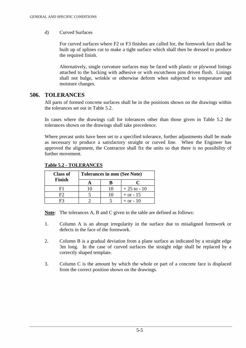
GENERAL AND SPECIFIC CONDITIONS
5-5
d) Curved Surfaces
For curved surfaces where F2 or F3 finishes are called for, the formwork face shall be built up of splines cut to make a tight surface which shall then be dressed to produce the required finish. Alternatively, single curvature surfaces may be faced with plastic or plywood linings attached to the backing with adhesive or with escutcheon pins driven flush. Linings shall not bulge, wrinkle or otherwise deform when subjected to temperature and moisture changes.
506. TOLERANCES All parts of formed concrete surfaces shall be in the positions shown on the drawings within the tolerances set out in Table 5.2. In cases where the drawings call for tolerances other than those given in Table 5.2 the tolerances shown on the drawings shall take precedence. Where precast units have been set to a specified tolerance, further adjustments shall be made as necessary to produce a satisfactory straight or curved line. When the Engineer has approved the alignment, the Contractor shall fix the units so that there is no possibility of further movement. Table 5.2 - TOLERANCES
Class of Finish
Tolerances in mm (See Note)
A B C F1 10 10 + 25 to - 10 F2 5 10 + or - 15 F3 2 5 + or - 10
Note: The tolerances A, B and C given in the table are defined as follows: 1. Column A is an abrupt irregularity in the surface due to misaligned formwork or
defects in the face of the formwork. 2. Column B is a gradual deviation from a plane surface as indicated by a straight edge
3m long. In the case of curved surfaces the straight edge shall be replaced by a correctly shaped template.
3. Column C is the amount by which the whole or part of a concrete face is displaced
from the correct position shown on the drawings.
GENERAL AND SPECIFIC CONDITIONS
6-1
6. MASONRY
601. GENERAL All masonry work shall be constructed from building stone as specified in Clause 725.
For culvert headwalls and other small works, the stone shall, unless otherwise specified, be rough dressed. For walls, facing and other exposed works the stone shall unless otherwise specified, be medium chisel-dressed.
602. WORKMANSHIP The Contractor shall provide and use proper setting out rods for all work. Stones shall be well soaked before use and the tops of walls shall be kept wet as the work
proceeds. The stones shall be properly bonded so that no vertical joint in a course is within 115mm of a joint in the previous course. Alternate courses of walling at angles and intersections shall be carried through the full thickness of the adjoining walls. All perpends, reveals and other angles of the walling shall be built strictly true and square.
The stones shall be bedded, jointed and pointed in mortar 1 to 3 in accordance with Clause
729 with beds and joints 9mm thick flushed up and grouted solid as the work proceeds. All masonry work shall be cured in accordance with the relevant requirements of Clause 407.
603. CAST STONEWORK Cast stone shall be as specified in Clause 735. Facing stones shall be brought up in courses
to a height not exceeding 1 metre at a time, the concrete backing being then brought up and well incorporated into and round the backs of the stones and the projecting metal ties to ensure a complete bond. The stones shall be bedded and jointed as shown on the drawings.
All materials, moulds, mixing, casting and surface treatment, setting, jointing and pointing,
and all centering, scaffolding and labour required to complete the cast stonework specified or as shown on the drawings, shall be included in the rates for such work.
GENERAL AND SPECIFIC CONDITIONS
7-1
7. MATERIALS
701. GENERAL The approval in writing or otherwise by the Engineer of any materials shall not in any way whatsoever relieve the Contractor from any liability or obligation under the Contract and no claim by the Contractor on account of the failure, insufficiency or unsuitability of any such materials will be entertained. a) All items shall be suitable for water works purposes and for use with cold water
installation and operation being in a tropical climate. b) All items hereinafter specified shall be to such other Standard or Specification which
in the opinion of the Engineer provides for a quality of material and workmanship not inferior to the Standard Reference Number (SRN) quoted. The Standard or Specification must be submitted to the Engineer for approval before commencement of work.
c) All ferrous pipes and fittings shall be coated with a protective paint suitable for use in
and transport through a tropical climate. d) The Contractor shall supply to the Employer a certificate stating that each item
supplied has been subjected to the tests hereinafter laid down and conforms in all respects to the said Specification.
e) The Contractor shall provide adequate protection to all piping, flanged items and
valves so as to guard effectively against damage in transit and storage and ingress of foreign matter inside the valves.
f) All pipework and fittings shall be subjected to a works hydrostatic test pressure which
shall be not less than twice the maximum operating pressure. g) The Contractor should exercise diligence to provide the best material. h) Where applicable the manufacturer’s Specification should accompany all offers. The
name of the manufacturer must in every case be stated. j) Where necessary the Contractor shall provide rubber gaskets to comply with SRN 208
and all other bolts, nuts, washers, etc. to undertake jointing at fittings etc. k) Any articles required under this Contract which are found to be faulty due to a crack,
flaw or any other reason or is not in accordance with the Specification stipulated will not be accepted nor will the Employer be liable for any charges in respect of such an article. Where any such rejected article can, in the opinion of the Engineer, be rendered usable, the Contractor may deal with it accordingly and include it in the Contract at a price to be mutually agreed. Straight pipes which have been cut will be accepted at the discretion of the Engineer, provided the length is not less than 4 metres or two thirds of the standard length whichever is the lesser and will be priced pro-rata.
GENERAL AND SPECIFIC CONDITIONS
7-2
l) Wherever possible, samples of pipes and fittings shall be submitted for approval of the Engineer prior to the Contractor obtaining the total requirements.
702. GALVANISED PIPES AND SPECIALS All piping shall conform to SRN 823 and SRN 903 for “Medium” Piping. The pipes shall be screwed and socketted, coupled or flanged. All specials shall be of such dimensions as will mate with the piping supplied. Screw down stopvalves shall conform to SRN 826. Barrel nipples shall conform to SRN 823 and all other specials shall conform to SRN 824. All pipes supplied shall be certified by the manufacturer to have been tested in accordance with the relevant Standard Specification.
703. DUCTILE IRON AND CAST IRON PIPES AND SPECIALS All cast iron piping and fittings shall conform to the requirements of SRN 200. Ductile iron pipes and fittings shall comply with SRN 202. Where required the pipes shall be protected as specified by the manufacturer of the pipes and shall be used as recommended by the manufacturer of the pipe. Where the requirements include for the supply of flexible couplings the Contractor shall submit for approval by the Engineer full details of the type of joint offered and a full description of the method of jointing prior to arranging for the delivery of goods on site. All flexible couplings shall be protected from corrosion by wrapping with Denso paste and tape or by some similar approved material. The quality of metal used for the manufacture of the pipes shall be of good quality grey cast iron and subject to the various quality control tests as specified in the relevant Standards. All piping and fittings shall be coated internally with cement mortar lining to SRN 211. Cement mortar lining shall not contain any constituents soluble in water nor any ingredient which could impart any taste or odour whatsoever to the water after sterilization and washing out of the mains. External protection to be as specified in SRN 258. The flanges of straight pipes shall be at right angles to axis of the pipe and the faces of the flanges shall be parallel and machine finished. The faces of the flanges of fittings shall be at right angles to the directional axis. The bolt holes shall be concentric with the bore and located symmetrically off the centre line. In flanged pipework the holes in one flange shall be located in line with those in the other. All flanges shall be drilled to SRN 207, unless otherwise detailed. The weights of the pipe and fittings shall comply with the Specification in the relevant Standard.
GENERAL AND SPECIFIC CONDITIONS
7-3
704. ASBESTOS CEMENT PIPES AND SPECIALS All piping and bends shall be plain ended suitable for use with flexible couplings and shall comply with the requirements of SRN 401. Fittings shall be of asbestos cement or cast iron complying with requirements of SRN 201, or mild steel complying with SRN 210. Where possible, fittings shall have plain ends of an external diameter equal to that of the asbestos cement pipes and shall be suitable for use with asbestos cement, cast iron or mild steel mechanical joints. Where compatible external diameters of fittings and pipes cannot be supplied, suitable stepped couplings of approved manufacturer shall be used. Flexible couplings shall be supplied complete with bolts, nuts, washers and joint rings as may be required. All metal parts of the joints shall be adequately protected with rust-proof paint. The couplings shall, if required by the Engineer, be protected from corrosion by wrapping with Denso paste and tape or by some similar approved material. The Contractor shall submit full details of the type of joint and a full description of the method of jointing. The lengths of piping supplied shall be in accordance with SRN 401. All pipes and bends supplied shall be certified by the manufacturer to have been tested in accordance with the relevant clauses of Standard Specification. Unless specified, the pipes, joints and bends shall be coated internally with cement mortar lining complying with SRN 212. This lining should not impart any taste or odour to the water. External protection for pipes, joints and bends to be as specified in SRN 212. Precautions shall be taken to avoid damage to the pipes and fittings during handling and storing and during laying, all to the satisfaction of the Engineer. Where ferrules are tapped into the piping, saddles should be used, otherwise service connections can be incorporated by use of suitable long collar joints.
705. STEEL PIPES AND SPECIALS All piping shall be plain ended unless otherwise specified and suitable for use with flexible mechanical couplings. The grade of steel used shall comply with the requirements of SRN 213. The pipes shall be welded or seamless and shall conform to SRN 210. All the pipes shall be internally protected with cement mortar lining in accordance with SRN 212. External protection to be as specified in SRN 241. All joints shall be of the flexible mechanical type and shall be supplied complete with all bolts, nuts, washers and joint rings as may be required. All metal parts of joints shall be adequately protected with rust-proof paint. The joints shall be protected from corrosion by wrapping with Denso paste and tape or by some similar approved material. All fittings and specials shall be of such dimensions as will mate up with the piping supplied.
GENERAL AND SPECIFIC CONDITIONS
7-4
Flanged adaptors shall be pieces suitable for connecting a flanged gate valve etc. to the type of piping supplied and shall be supplied complete with all bolts, nuts, washers and joint rings. The spigot ends of all Tees shall be suitable for connection to the pipework supplied using the aforementioned flexible mechanical joints. Branches shall be flanged with flanges drilled to NP 16 in accordance with SRN 207, unless otherwise detailed. All flanges on specials shall conform to NP 16 in accordance with SRN 207, unless otherwise detailed. All flanged joints shall be protected from corrosion by wrapping with Denso paste and tape or some similar approved material.
706. UNPLASTICISED uPVC PIPES Unplasticised PVC piping shall be in accordance with SRN 300. The maximum sustained working pressures to which the pipes and fittings will be subjected is based on water at a temperature of 20 degrees centigrade. The Contractor shall submit full details of the pipes he intends to supply. The pipes upto and including 40mm diameter can be of a solvent weld type. The pipe shall be supplied with interchangeable sockets preformed at the factory and of such internal diameter that it takes the plain end of the pipe with the same nominal diameter. The joint shall sustain the end thrust to which the pipe shall be subjected. The Contractor shall supply sufficient quantity of the cleaner and adhesive which shall be required to make the joints with the pipes. The pipes of 50mm diameter and over shall consist of a grooved socket at one end of the pipe. The socket shall be designed to give a clearance fit on the outside diameter of the parent pipe. The sealing medium which shall seat in the groove shall be a rubber ring. If the formation of the socket and groove results in the thinning of the original wall thickness of the pipe, it shall be compensated for by shrinking on to the outside of the socket area a reinforcing sleeve of the same material as the pipe. The socket and groove shall incorporate no sharp angles where the stress points are created. The joint shall take 10% deformation of the spigot at the point where it enters the socket without leakage from the pipe when subjected to the test pressure specified for the pipe. Thermal expansion of the pipe shall be accommodated in the joint. The joint shall be capable of linear deflection upto 3 degrees. The sealing ring shall be of first grade natural rubber and the physical properties of the mix shall meet the requirements of SRN 222. The Contractor shall supply sufficient quantity of any lubricant or other material which shall be needed to make the joint which shall be assembled by hand. The Contractor shall submit full details of the type of joint offered and a full description of the method of jointing.
GENERAL AND SPECIFIC CONDITIONS
7-5
The fittings shall have the same type of joint as for the pipes to be used. The Contractor shall submit full details of the materials dimensions and test pressures of the fittings offered. Precautions shall be taken to avoid damage to the pipes and fittings. In handling and storing the pipes and fittings, every care shall be taken to avoid distortion, flattening, scoring or other damage. The pipes and fittings shall not be allowed to drop or strike objects. Pipe lifting and lowering shall be carried out by approved equipment only. Special care shall be taken in transit, handling and storage to avoid any damage to the ends. Pipes and fittings shall be marked at not greater than one metre intervals showing their class and diameter.
707. G.R.P. PIPES AND SPECIALS Glass Reinforced Plasting piping shall be in accordance with SRN 317.
708. GATE VALVES Gate valves shall comply with the requirements of SRN 501. The gate valves shall be suitable for use in pipelines and for the operating pressure to a head of 160 metres of water (NP 16). The gate valves shall be double flanged. The dimensions and drilling of flanges shall be in accordance with SRN 207. Flanges shall be machined flat. Flanges shall be NP 16 complying with SRN 207. Spindles of the gate valves shall be provided with cast iron caps conforming to the requirements as specified under “Valve Caps” in SRN 501 or handwheels if so specified. The spindles of the gate valves shall be of the non-rising type and screwed so as to close the valves when rotated in a clockwise direction. The direction of closing shall be clearly cast on the valve cap or handwheel. The gate valves shall be subject to “Closed End Tests” in accordance with the procedure set out in SRN 501. The gate valves shall be suitable for opening and closing against an unbalanced head by manual operation.
709. FIRE HYDRANTS Fire hydrants shall be in accordance with SRN 509. They shall be for installation underground and shall be in accordance with SRN 509. The spindle shall be provided with a cast iron cap conforming to dimensions under “Spindle Cap” in SRN 501. The spindle of the fire hydrant shall be of the non-rising type and screwed so as to close the hydrant when rotated in a clockwise direction viewed from above. The direction of closing shall be clearly cast on the valve cap.
GENERAL AND SPECIFIC CONDITIONS
7-6
The flanged outlet of the outlet bend shall have a Bayonet Joint Outlet for a 63mm standpipe. The outlet of the hydrant shall be of the hooked type with hooks 112mm apart. The outlet shall have a gun metal standpipe seating and be covered by a loose cast iron cap which shall be attached to the hydrant by means of a chain. Both flanges shall be 63mm drilled to requirements of SRN 207. The outlet bends shall be subject to a hydrostatic test in accordance with procedure set out in SRN 509 and shall be water-tight against a test pressure of 1.85 Pa. head of water.
710. AIR VALVES The Contractor shall provide air valves to suit the site on which the main is located and the maximum water pressure specified. The body and cover of air valves shall comply with SRN 906 and SRN 916. The body, cover, splash cowl and joint support ring of the air valve shall be of mechanite cast iron with flanges drilled to SRN 207. The internal screwed isolating valve shall have the valve and seating of gun metal, operating screws of bronze, nuts of gun metal, and glands and cap of mechanite. The large orifice valve shall have a vulcanite covered ball closing on a moulded dexine seat ring. The bush may be in gun metal. The double orifice type of air valve shall comprise a small and large orifice unit with common connection to the main and screw down isolating valve to permit inspection of the valve. The spindle of the isolating valve shall be screwed so as to close the valve when rotated in a clockwise direction and be provided with a Spindle Cap to dimensions as specified in SRN 501. Design of the air valves shall be such that the balls do not blow shut under any working or test conditions when large volumes of air are being released.
711. WATER METERS All water meters upto 50mm size shall be of the rotary piston positive action type with all moving parts composed of non-corrosive material. 75mm diameter and over meters shall be of the inferential helix full flow type. The body of the 12mm to 25mm size of meter shall be of brass, the larger sizes in cast iron. The external surface of the brass bodies shall be coated with baked enamel and the cast iron bodies shall be painted to suit. The working chamber of the rotary type meter shall be made of bronze or similar non-corrosive material and the piston shall be in ebonite or similar material. The working parts of the Helix type meter shall facilitate removal for repair or replacement without removing the meter body from the pipeline. The working parts shall be inter-changeable and the working chamber so designed as to be full of water under all conditions of flow.
GENERAL AND SPECIFIC CONDITIONS
7-7
The dial of the meter shall be of the direct reading type registered in cubic metres with suitable lid locking device. The capacities of the piston type meter shall not be less than the following amounts per month:- 12mm meter 250 cubic metres 18mm meter 350 cubic metres 25mm meter 600 cubic metres 38mm meter 1100 cubic metres 50mm meter 1700 cubic metres The Helix type meter shall be capable of continuous working with a head loss not exceeding 300mm at the following rates of flow:- 75mm meter 22.5 cu.m./hr 100mm meter 45 cu.m./hr 150mm meter 90 cu.m./hr All meters shall be accurate to within + 2% over the range of the meter upwards from the minimum flows given for each size:- 12mm 23 litres/hour 18mm 28 litres/hour 25mm 32 litres/hour 38mm 110 litres/hour 50mm 190 litres/hour 75mm 2.5 cu.m./hr 100mm 2.8 cu.m./hr 150mm 4.5 cu.m./hr Meters above 150mm diameter should conform to manufacturer’s specifications approved by the Engineer. The 12mm and 18mm sizes shall be guaranteed to register commencing at 5 litres/hour. The meters shall be tested to a head of not less than 16 bar.
712. STOP VALVES All stop valves shall be in accordance with SRN 826. Samples of valves shall be submitted for test and approval to the Engineer.
713. CHECK VALVES (DIRECTIONAL VALVES) Check valves shall comply with the requirements of SRN 505 with cast iron body and cover, gun metal doors with bronze facing rings and flanged connections in accordance with SRN 207, NP 16.
714. PENSTOCKS Cast iron penstocks shall be all in accordance with SRN 906 and SRN 916. Seating faces shall be gun metal or bronze.
GENERAL AND SPECIFIC CONDITIONS
7-8
Spindles shall be threaded as necessary and non-rising unless otherwise specified. Spindles shall be of aluminium bronze, manganese bronze and extension spindles may be of mild steel. Handwheels shall be of cast iron and words “OPEN” and “SHUT” marked on upper side with appropriate direction arrows.
715. FLANGED JOINTS All flanges on fittings and pipework where flanged connections are required must comply with the requirements of SRN 207 and drilled to NP 16, unless otherwise specified. Inspection gaskets for flanged joints shall be rubber reinforced with cotton, 3mm thick and shall be in accordance with SRN 208. Bolts, washers and nuts for flanged joints shall be of mild steel complying with SRN 914.
716. FLEXIBLE JOINTS All flexible couplings (Viking Johnson or other approved type) shall be supplied complete with rubber gaskets, bolts, nuts and washers. All couplings shall be coated with red oxide primer and bituminous composition suitable for use with potable water.
717. PRESSED STEEL TANKS AND TOWERS The pressed steel tanks (or similar approved), towers and associated materials and fittings shall comply with SRN 909 and SRN 863. Detailed drawings of the steel tank should be submitted to the Engineer for approval prior to acceptance. The pressed steel tank to SRN 909 (B.S. 1564 Type A(2) or similar approved) shall be supplied complete with:- a) All stays, cleats, bolts, nuts, washers, jointing compound and associated materials and
fittings. b) Connections for inlet, outlet, washout and overflow. c) Galvanised access ladder 450mm wide. d) Steel roof cover to fit the tank complete with access manhole and mosquito-proof
cowl ventilators. e) Water level indicator. Jointing material to the tank to be a non-toxic plastic compound which does not impart taste, colour nor odour to the water. Connections to the tank shall be welded to the outside of the tank plate and drilled and tapped to suit flanges to SRN 207, NP 16 unless otherwise stated. The cover to the tank shall be of mild steel cambered for external use and adequately supported by rolled steel or pressed steel bearers or trusses. The tank tower shall be supplied complete with:-
GENERAL AND SPECIFIC CONDITIONS
7-9
a) Anchor bolts. b) Bolts, nuts, washers and associated materials and fittings. c) Access ladder 450mm wide extending from ground level to the top of the tank. Safety
rings shall be at 1.2m centres. The supports to the tank shall consist of steel joints designed to carry imposed load under each transverse joint and the two ends of the tank. The columns of the tank shall consist of rolled steel joist sections or similar. Four such columns shall be provided with adequate bracing. Internal surfaces of the tank shall be painted with approved non-toxic primer and non-toxic bituminous paint. External surfaces of the tank and tower shall be painted with approved primer and approved bituminous aluminium paint.
718. PAINTS All priming, undercoating and finishing paints shall be in accordance with SRN 877 or SRN 878 as appropriate. The painting of all building works shall comprise a special paint recommended for external work while all other paints, plastic emulsion coating etc. are to be of an approved manufacturer. All paints, distempers etc. shall be delivered on site intact in the original drums or tins, and shall be mixed and applied in accordance with the manufacturer’s printed directions. The only addition which will be allowed to be made will be liquid thinners, driers etc. supplied by the makers for the purpose. All surfaces must be thoroughly cleaned down prior to painting and decorating work and no external painting shall be carried out in rainy weather. All paint must be thoroughly well worked on and excess of paint in any coat must be avoided. All colours will be selected by the Engineer from the standard range of colours.
719. MARKER AND INDICATOR POSTS Marker posts shall be erected at changes in direction of water mains as directed by the Engineer. Indicator posts shall be erected at valves and other fittings as directed. Marker and indicator posts shall be embedded in concrete as shown on drawings and shall be vibrated precast reinforced concrete as per dimensions shown on drawings. They should be painted in colours as indicated on the drawings.
720. POLYETHYLENE (PALOTHENE, PEH) PIPES Polyethylene High Density pipes shall comply with SRN 307 for testing, storage, handling, laying and backfilling. Contractor shall conform to requirement indicated for PVC pipes. Joints shall be required to sustain test pressures similar to which the pipe shall be subjected. Contractor shall comply with all instructions issued by the manufacturers and shall submit full details of the type, class, dimensions and test pressures of the brass fittings to the Engineer for approval.
GENERAL AND SPECIFIC CONDITIONS
7-10
721. PRECAST CONCRETE UNITS Precast concrete covers to be precast units for use in the works, whether instructed under the Contract or proposed by the Contractor. a) Formwork for Precast Units Moulds shall be so constructed that they do not suffer distortion or dimensional
changes during use and are tight against loss of cement grout or fines from the concrete.
Moulds shall be set up on firm foundations so that no settlement occurs under the
weight of the fresh concrete. Moulds shall be constructed so that units may be removed from them without
sustaining any damage. Release agents used for demoulding shall not stain the concrete or affect its properties
in any way. b) Reinforcement for Precast Units Reinforcement in precast units shall comply with the requirement of Clauses 736 and
419-420. When preformed cages are used the cages shall be made up on jigs to ensure dimensional accuracy and shall be carefully supported within the could in such a way that they cannot move when concrete is placed. Reinforcement complying with SRN 126 may be tack welded where bars cross to provide rigidity in the cage but reinforcement complying with SRN 127 shall not be welded.
Cover to main reinforcement shall be as shown on the drawings, or if not shown shall
be not less than 25mm or the diameter of the bar, whichever is the greater. Cover on distribution steel shall not be less than 15mm or the diameter of the bar whichever is the greater.
Bars shall be spaced so that the minimum clear distance between them is the
maximum nominal aggregate size plus five millimetres but in any case not less than the diameter of the bars.
Bars may be placed in pairs provided that there are no laps in the paired lengths. c) Casting of Units Concrete for precast units shall comply with Clauses 724 and 401-410 using the class
of concrete specified on the drawings. If lightweight aggregates are specified, they shall comply with SRN 147. The area in which units are cast shall be adequately protected from the weather so that
the process is not affected by rain, sun or drying winds. d) Curing Precast Units
GENERAL AND SPECIFIC CONDITIONS
7-11
Requirements for curing shall be generally as set out in Clause 407. The Contractor shall ensure that units do not suffer any loss of moisture or sudden
changes of temperature for at least four days after casting. If a water spray is used for curing, the water shall be at a temperature within 5 degrees centigrade of the temperature of the unit being cured.
If Contractor proposes curing at elevated temperatures, the method shall be subject to
the agreement of the Engineer and shall include means whereby units are heated and subsequently cooled evenly without sudden changes of temperature.
e) Dimensional Tolerances of Precast Units Units shall be accurately formed to the dimensions shown on the drawings unless
closer tolerances are called for by the Engineer. f) Surface Finish of Precast Units The formed faces of precast units shall be finished to Class F3 as set out in Clause
505c) unless another class of finish is specified on the drawings. Free faces shall be finished to Class UF2 unless another class of finish is specified on
the drawings. In cases where a special finish is required a trial panel shall be constructed by the
Contractor which after approval by the Engineer shall be kept available for inspection at the place of casting and production units shall thereafter match the approved pattern.
Those parts of the unit which are to be joined to other units or to in-situ concrete shall
be brushed with a stiff brush before the concrete has fully hardened. Alternatively, if the concrete has been allowed to harden, the surfaces shall be roughened by sand blasting or by the use of a needle gun.
g) Handling and Storage of Precast Units Precast units shall be handled in a manner which will not cause damage of any kind
and shall be stored on a hard impermeable base. Prestressed units and large precast normally reinforced units shall be handled and
stored so that no stresses shall be induced in excess of those which they will incur in their final positions in the Works unless they have been designed to resist such stresses.
Units shall be provided with adequate lifting holes or loops, placed in the locations
shown on the drawings or agreed by the Engineer and they shall be lifted only by such holes or loops. Where it is not possible to provide holes or loops, suitable sling positions shall be indicated in paint on the units.
GENERAL AND SPECIFIC CONDITIONS
7-12
Units shall be marked indelibly with the reference number and date of casting and shall be stacked on suitable packers which will not damage the concrete or stain the surfaces. Not more than two packers shall be placed under each unit and these shall be located either at the positions of the permanent support points or in positions such that the induced stresses in the unit will be a minimum.
h) Testing Precast Units Precast units shall be capable of safely sustaining the loads which they have been
designed to carry. The Contractor shall subject units selected by the Engineer to load tests simulating the working conditions. Details of such tests shall be agreed between the Engineer and the Contractor.
In the case of units subject to bending loads the test piece shall be supported at full
span and a loading equivalent to 1.25 times the sum of the live and dead loads which were assumed in the design shall be maintained for one hour without the appearance of any signs of distress. The recovery one hour after the removal of load shall be not less than 75 per cent of the full load deflection.
If the unit fails to meet the above requirements, further tests shall be carried out on
two more units. If either of these fail the whole batch of units will be rejected. If the Engineer so requires, a test to destruction shall also be carried out which on
units subject to bending shall be as follows:- The units shall be supported at full span and a load applied in increments instructed
by the Engineer up to 95 per cent of the designed ultimate load. This load shall be held for 15 minutes without failure of the unit. The deflection at the end of this period shall be not more than 1/40th of the span. The load shall then be further increased until failure occurs.
If the unit fails to sustain the required load for the prescribed period or if the
deflection exceeds the specified amount, the Engineer may order two further tests, and if either of these fail, the batch of units which they represent may be rejected.
722. FILTER MEDIA The grading of filter media shall be in accordance to the table of gradings shown on drawings. Filter media must be free from fines which would clog the air spaces, and free from dirt, silt and all foreign matter. The media shall be delivered in clean vehicles and if stored it shall be placed on a clean and firm surface and if it is liable to be contaminated, protected with sheets. Different sizes of media shall be kept strictly separate. The uniformity coefficient as indicated in the drawings should be adhered to and Contractor to submit samples and carry out sieve analysis, organic content, friability tests, etc. to the satisfaction of the Engineer. These tests are to be carried out before the media is placed in filters. All costs arising to be borne by the Contractor.
GENERAL AND SPECIFIC CONDITIONS
7-13
723. SUBMISSION OF SAMPLES As soon as possible after the contract has been awarded, the Contractor shall submit to the Engineer a list of the suppliers from whom he proposes to purchase the materials necessary for the execution of the Works. Each supplier must be willing to admit the Engineer or his representatives, to his premises during ordinary working hours for the purpose of obtaining samples of the materials in question. Alternatively, if desired by the Engineer, the Contractor shall deliver the samples of the materials to the Engineer’s office without charge. The information regarding the names of the suppliers may be submitted at different times, as may be convenient, but no source of supply shall be changed without the Engineer’s prior approval once a supplier, source or material has been approved. Samples of materials approved will be retained at the Engineer’s office until the completion of the contract. Samples may be tested to destruction. All materials delivered to site must be at least equal in all respects to approved samples, otherwise they shall be rejected. No special payment will be made for compliance with clauses specifying tests etc. to ensure quality control etc. unless specifically itemised in Bills of Quantities.
724. MATERIALS FOR CONCRETE a) General
The Contractor shall submit to the Engineer full details of all materials which he proposes to use for making concrete. No concrete shall be placed in the Works until the Engineer has approved the materials of which it is composed. Approved materials shall not thereafter be altered or substituted by other materials without the consent of the Engineer.
b) Cement Cement shall comply with the following Kenya Standards:-
• SRN 103 for Ordinary Portland cement.
• SRN 103 for Rapid Hardening Portland cement plus all special conditions to its use stipulated by the manufacturer.
• SRN 104 for Sulphate Resisting or High Alumina cement. Cement shall be free flowing and free of lumps. It shall be supplied in the manufacturer’s sealed unbroken bags or in bulk. Bagged cement shall be transported in vehicles with effective means of ensuring that it is protected from the weather. Bulk cement shall be transported in vehicles or in containers specially built and equipped for the purpose. Cement in bags shall be stored in a suitable weatherproof structure of which the interior shall be dry and well ventilated at all times. The floor shall be raised above
GENERAL AND SPECIFIC CONDITIONS
7-14
the surrounding ground level and shall be so constructed that no moisture rises through it. Each delivery of cement in bags shall be stacked together in one place. The bags shall be closely stacked so as to reduce air circulation but shall not be stacked against an outside wall. If pallets are used, they shall be constructed so that bags are not damaged during handling and stacking. No stack of cement bags shall exceed 3 metres in height. Different types of cement in bags shall be clearly distinguished by visible markings and shall be stored in separate stacks. Cement from broken bags shall not be used in the Works. Cement in bags shall be used in the order in which it is delivered. Bulk cement shall be stored in weatherproof silos which shall bear a clear indication of the type of cement contained in them. Different types of cement shall not be mixed in the same silo. The Contractor shall provide sufficient storage capacity on site to ensure that his anticipated programme or work is not interrupted due to lack of cement. Cement which has become hardened or lumpy or fails to comply with the Specification in any way shall be removed from the site. All cement for any one structure shall be from the same source. All cement used in the Works shall be tested by the manufacturer or the Contractor in a laboratory acceptable to the Engineer. The tests to be performed shall be those set out in SRN 103 and the Contractor shall supply two copies of each certificate to the Engineer. Each set of tests carried out by the manufacturer or Contractor shall relate to not more than one day’s output of each cement plant, and shall be made on samples taken from cement which is subsequently delivered to the site. Alternatively, subject to the agreement of the Engineer, the frequency of testing shall be one set of tests for every 200 tones of cement delivered to site from each cement plant. Cement which is stored on site for longer than one month shall be re-tested in the laboratory of the Materials Branch of the Ministry of Transport & Communications or at the Kenya Bureau of Standards or at any other approved laboratory at the rate of one set of tests as shown in SRN 103 for every 200 tonnes, and at monthly intervals thereafter. Cement which does not comply with the Specification shall not be used in the Works and it shall be disposed off by the Contractor. The Contractor shall keep full records of all data relevant to the manufacture, delivery, testing and use of all cement used in the Works and shall provide the Engineer with two copies thereof.
c) Fine Aggregate
GENERAL AND SPECIFIC CONDITIONS
7-15
Fine aggregate shall be clean, hard and durable and shall be natural sand, crushed gravel sand or crushed rock sand complying with SRN 108. All the material shall pass through a 5mm standard sieve and the grading shall be in accordance with Zones 1, 2 or 3 of SRN 109. In order to achieve an acceptable grading, it may be necessary to blend materials from more than one source. Fine aggregate for mortar only shall comply with SRN 135. The fine aggregate shall not contain iron pyrites or iron oxides. It shall not contain mica, shale, coal or other laminar, soft or porous materials or organic matter unless the Contractor can show by comparative tests, on finished concrete as set out in SRN 117, that the presence of such materials does not adversely affect the properties of the concrete. Other properties shall be as set out below: Content passing a 75 micron standard sieve shall not exceed 3 per cent for natural or crushed gravel sand or 15 per cent for crushed rock sand. Chlorides soluble in a 10 per cent solution by weight of nitric acid shall not exceed 0.05 per cent by weight expressed as chloride ion when tested as set out in SRN 107, subject also to the further restriction given in the note on total chloride content in sub-clause 724 (d). Sulphates soluble in a 10 per cent solution by weight of hydrochloric acid shall not exceed 0.4 per cent by weight expressed as SO3, when tested as set out in SRN 601, subject also to the further restriction given in the note on total sulphate content in sub-clause 724 (d). Soundness: After five cycles of the test in AASHO T104 or an approved equivalent, the aggregate shall not show a weight loss of more than 10 per cent. Organic impurities: If the test for presence of organic impurities in aggregates described below shows that more than a trace of organic impurities is present, the fine aggregate shall not be used in the Works unless the Contractor can show by tests on finished concrete as set out in SRN 117 that the presence of organic impurities does not adversely affect the properties of the concrete. Test for presence of organic impurities in aggregates: This test is designed to indicate the presence of organic impurities in aggregates used for making concrete. A 350 cc graduated bottle shall be filled to the 120 cc mark with a sample of the aggregate to be tested and a 3% solution of sodium hydroxide in water added until the volume of aggregate and liquid after shaking gives a total volume of 200 cc. The bottle shall be stoppered, shaken thoroughly and allowed to stand for 24 hours. If, after 24 hours, the colour of the solution is not darker than a pale brown, the aggregate under test may be deemed satisfactory.
d) Coarse Aggregate
GENERAL AND SPECIFIC CONDITIONS
7-16
Coarse aggregate shall be clean, hard and durable crushed rock, crushed gravel or natural gravel complying with the requirements of SRN 110. The material shall not contain any iron pyrites, iron oxides, flaky or laminated material, hollow shells, coal or other soft or porous material, or organic matter unless the Contractor can show by comparative tests on finished concrete as set out in SRN 117 that the presence of such materials does not adversely affect the properties of the concrete. The pieces shall be angular, rounded or irregular as defined in SRN 107. Coarse aggregate shall be supplied in the nominal sizes called for in the Contract and shall be graded in accordance with SRN 111 for each nominal size. Other properties shall be as set out below:- The proportion of clay, silt and other impurities passing a 75 micron standard sieve shall not be more than one per cent by weight. The content of hollow and flat shells shall be such as will not adversely affect the concrete quality when tested as set out in SRN 117. The total content of aggregate shall not be more than the following: • 40mm nominal size and above 2% of dry weight • 20mm nominal size 5% of dry weight • 10mm nominal size 15% of dry weight Chlorides soluble in a 10 per cent solution by weight of nitric acid shall not exceed 0.03 per cent by weight, expressed as chloride ion when tested as set out in SRN 107 but subject also to the further restriction under the note on total chloride content hereunder. Sulphates soluble in a 10 per cent solution by weight of hydrochloric acid shall not exceed 0.4 per cent by weight expressed as SO3 when tested as set out in SRN 601 subject also to the further restriction given in the note on total sulphate content hereunder. Soundness: After 5 cycles of the test in AASHO T104, the aggregate shall not show a weight loss of more than 12 per cent. When tested in accordance with test C289 of the American Society for Testing of Materials, the aggregate shall be non-reactive. Flakiness Index when tested in accordance with SRN 113 shall be as set out hereunder: • For 40mm stone and above, not more than 40 • For 20mm stone and below, not more than 35 If the Flakiness Index of the coarse aggregate varies by more than five units from the average value of the aggregate used in the approved trial mix, then a new set of trial mixes shall be carried out if the workability of the mixes has been adversely affected by such variation. Impact value: Not more than 45 per cent when tested in accordance with SRN 107.
GENERAL AND SPECIFIC CONDITIONS
7-17
Ten per cent fines value: Not less than 50kN when tested in accordance with SRN 107. Shrinkage: When mixed with other ingredients in the approved proportions for concrete and tested as set out in SRN 117, the shrinkage factor shall not exceed 0.05 per cent. Organic impurities: If the test for presence of organic impurities in aggregates shows that more than a trace of organic impurities is present, the aggregate shall not be used in the Works unless the Contractor can show by tests on finished concrete as set out in SRN 117 that the presence of organic impurities does not adversely affect the properties of the concrete. Water absorption: The aggregate shall not have a water absorption of more than 2.5 per cent when tested as set out in SRN 112. Aggregate Crushing Value (ACV): Not more than 35 per cent. Los Angeles Abrasion (LAA): Not more than 50 per cent. Note: Total chloride and sulphate content:- The total chloride content, expressed as chloride ion, arising from all ingredients in a mix including cement, water and admixtures shall not exceed the following limits, expressed as a percentage of the weight of cement in the mix:- For prestressed concrete, steam cured concrete or concrete containing sulphate resisting or super sulphated cement: 0.05 per cent. For any other reinforced concrete: 0.3 per cent in 95 per cent of all test results provided no result is more than 0.5 per cent. The total sulphate content expressed as SO3 of all the ingredients in a mix including cement, water and admixtures shall not exceed 0.4 per cent by weight of the aggregate or 4.0 per cent of the weight of cement in the mix, whichever is the lesser.
e) Testing Aggregates i) Acceptance Testing
The Contractor shall deliver to the Engineer samples containing not less than 50 kg of any aggregate which he proposes to use in the Works and shall supply such further samples as the Engineer may require. Each sample shall be clearly labelled to show its origin and shall be accompanied by all the information called for in SRN 107.
Tests to determine compliance of the aggregates with the requirements of sub-
clause 724(c) and (d) shall be carried out by the Contractor in a laboratory acceptable to the Engineer. If the tested materials fail to comply with the Specification, further tests shall be made in the presence of the Contractor and the Engineer and acceptance of the material shall be based on such tests.
GENERAL AND SPECIFIC CONDITIONS
7-18
A material shall be accepted if not less than three consecutive sets of test results show compliance with the Specification.
ii) Compliance Testing
The Contractor shall carry out routine testing of aggregates for compliance with the Specification during the period that concrete is being produced for the Works. The tests set out below shall be performed on aggregates from each separate source on the basis of one set of tests for each day on which aggregates are delivered to site provided that no set of tests shall represent more than 250 tonnes of fine aggregate nor more than 500 tonnes of coarse aggregate, and provided also that the aggregates are of uniform quality. If the aggregate from any source is variable, the frequency of testing shall be increased as instructed by the Engineer.
• Grading SRN 107 • Silt and clay contents SRN 107 • Moisture content SRN 107 • Check on organic impurities
In addition to the above routine tests, the Contractor shall carry out the
following tests at the frequencies stated:
Moisture content: As frequently as may be required in order to control the water content of the concrete as required by the Specification.
Chloride content: As frequently as may be required to ensure that the
proportion of chlorides in the aggregates does not exceed the limit stated in the Specification.
The Contractor shall take account of the fact that when the chloride content is variable
it may be necessary to test every load in order to prevent excessive amounts of chloride contaminating the concrete. For this purpose the Contractor shall use the rapid field test (the Quantab test). In the event of disagreement regarding the results of the field test, the chloride content of the aggregate shall be determined in the laboratory as described in SRN 107 (the Volhard test).
f) Delivery and Storage of Aggregates Aggregates shall be delivered to site in clean and suitable vehicles. Different types or
sizes of aggregate shall not be delivered in one vehicle. Each type or size of aggregate shall be stored in a separate bin or compartment having
a base such that contamination of the aggregate is prevented. Dividing walls between bins shall be substantial and continuous so that no mixing of types or sizes occurs.
The storage of aggregates shall be arranged so that as far as possible rapid drying out
in hot weather is prevented in order to avoid sudden fluctuations in water content. Storage of fine aggregates shall be arranged so that they can drain sufficiently before use in order to prevent fluctuations in water content of the concrete.
GENERAL AND SPECIFIC CONDITIONS
7-19
g) Water for Concrete and Mortar Sea water or brackish water containing more than 1,000 ppm chloride ion or 2,000
ppm sulphate ion shall not be used for mixing or curing concrete. Water shall be clean and free from harmful matter and shall comply with the
requirements of SRN 114. The Contractor shall carry out tests in accordance with SRN 114 to establish
compliance with the Specification. h) Admixtures i) General
The use of the admixtures in concrete may be required under the Contract to promote special properties in the finished concrete or may be proposed by the Contractor to assist him to comply with the Specification.
In all cases the Contractor shall submit to the Engineer full details of the
admixture he proposes to use and the manner in which he proposes to add it to the mix. The information provided shall include but not be limited to:-
a) The typical dosage, the method of dosing and the detrimental effects of
an excess or deficiency in the dosage. b) The chemical names of the main active ingredients in the admixture. c) Whether or not the admixture contains chlorides, and if so the chloride
ion content expressed as a percentage by weight of admixture. d) Whether the admixture leads to the entrainment of air when used at the
manufacturer’s recommended dosage, and if so, the extent to which it does so.
e) Details of previous uses of the admixture in Kenya.
The chloride ion content of any admixture shall not exceed 2 per cent by weight of the admixture nor 0.03 per cent by weight of the cement in the mix.
Admixtures shall not be mixed together without the consent of the Engineer. Calcium chloride or admixtures containing calcium chloride shall not be used
in prestressed concrete. ii) Workability Agents Workability agents shall comply with SRN 149 and shall not have any adverse
effect on the properties of the concrete.
GENERAL AND SPECIFIC CONDITIONS
7-20
725. BUILDING STONE All building stone shall be capable of withstanding when wet a crushing stress of 3.5
N/sq.mm. The source of stone shall be approved by the Engineer and stone supplied therefrom shall be free from magadi, overburden, mudstone, cracks, sandholes, veins, laminations or other imperfections.
The stone shall be chisel dressed into true rectangular blocks, with each surface even and at
right angles to all adjoining surfaces, to the size specified. For exposed stonework the maximum permissible variation of any of the specified dimensions shall be 6mm provided that cut stone, supplied as ‘rock face’ stone may be hammer dressed on one face only, or on one face and one end, if in other respects it conforms with this specification. Stones shorter than 375mm will not be accepted.
Unless the Engineer allows otherwise the Contractor shall at his own expense provide and
dress four 100mm cubes of stone for testing. The stone shall be sound when tested in accordance with SRN 870 except that:-
i) The treatment shall be repeated for 10 cycles only; and ii) The second criterion of failure shall be amended to allow for a loss of weight of not
more than 20% of its original weight.
726. STONE DUST Stone dust for blinding shall be blacktrap screened to the following grading:- Passing 10mm sieve 100% Passing No. 4 sieve 85% - 100% Passing No. 100 sieve 5% - 25%
727. MURRAM Murram shall be from an approved source quarried so as to exclude vegetable matter, loam,
top soil or clay. The California Bearing Ratio of the murram, as determined for a sample compacted to maximum density (as defined under SRN 601) and allowed to soak in water for four days, shall not be less than 30%. This C.B.R. is a guide to quality only and the compaction in the work will be judged by density.
728. WATER FOR CEMENT TREATED MATERIALS If water for the works is not available from the Employer’s supply the Engineer’s approval
must be obtained regarding the source of supply and manner of its use. Water to be used with cement or lime shall be free from salt, oil, alkali, organic matter, and other deleterious substances. If the water is required to be tested, this shall be done in accordance with SRN 114: Tests for Water for Making Concrete, all to the cost of the Contractor.
729. CEMENT MORTAR Cement mortar shall consist of proportions by volume as specified of Portland Cement and
natural sand or crushed natural stone or a combination of both as specified in SRN 135 and SRN 136 : Building Sands from Natural Sources. The constituent materials shall be accurately gauged and mixed in an approved manner.
GENERAL AND SPECIFIC CONDITIONS
7-21
Cement mortar shall be made in small quantities only as and when required, and any mortar
which has begun to set or which has been mixed for a period of more than one hour shall be rejected.
730. HYDRATED LIME Hydrated lime shall comply with SRN 801: Building Limes, and shall be of the semi-hydrated type.
731. CALCIUM CHLORIDE Calcium chloride shall be of good industrial grade, and shall be obtained from an approved source.
732. LIME MORTAR Lime mortar shall consist of proportions by volume as specified of hydrated lime and naturals
and/or crushed natural stone or a combination of both as specified for cement mortar in Clause 729. The constituent materials shall be accurately gauged and mixed in an approved manner.
733. CEMENT-LIME MORTAR Cement-lime mortar shall consist of Portland Cement, hydrated lime and natural sand or
crushed natural stone or a combination of both, as specified for cement mortar in Clause 729. The constituent materials shall be accurately gauged and mixed by volume in an approved manner in the proportions specified.
Cement-lime mortar shall be made only in small quantities as and when required. Any
mortar which has begun to set or which has been mixed for a period of more than two hours shall be rejected.
734. CEMENT GROUT Cement grout shall consist of Portland Cement and water mixed in the proportion of one part
by volume of cement and one and a half parts by volume of water. The grout shall be used within one hour of mixing.
735. CAST STONE Cast stone shall be manufactured by an approved manufacturer to the shapes and dimensions
shown on the drawings, and shall conform to the requirements of SRN 871: Cast Stone. It shall have a dense and even surface of the texture and colour detailed on the drawings or required by the Engineer. Where indicated exposed faces of the stone shall be formed of a specially graded mix. Metal bond ties of approved manufacture shall be cast in with the stone as shown on the drawings. Samples of the completed stone shall be submitted for the Engineer’s prior approval.
All stones shall be protected from damage during transport and erection by means of cement
slurry coatings or by other approved methods.
736. REINFORCEMENT FOR CONCRETE Reinforcement which shall comply with the following Standards, covers plain and deformed bar reinforcement and steel fabric to be cast into concrete in any part of the Works but does not include prestressing tendons or any other embedded steel.
GENERAL AND SPECIFIC CONDITIONS
7-22
• SRN 126 for hot rolled plain bar and high yield deformed bar • SRN 127 for cold worked steel bar • SRN 128 for steel mesh fabric All reinforcement shall be from an approved manufacturer and, if required by the Engineer, the Contractor shall submit a test certificate from the manufacturer. All reinforcement for use in the Works shall be tested for compliance with the appropriate British Standard in a laboratory acceptable to the Engineer and two copies of each test certificate shall be supplied to the Engineer. The frequency of testing shall be as set out in the relevant Standard. In addition to the testing requirements described above, the Contractor shall carry out additional tests as instructed by the Engineer. Any reinforcement which does not comply with the Specification shall be removed from site. All reinforcement shall be delivered to site either in straight lengths or cut and bent. No reinforcement shall be accepted in long lengths which have been transported bent over double. Any reinforcement which is likely to remain in storage for a long period shall be protected from the weather so as to avoid corrosion and pitting. All reinforcement which has become corroded or pitted to an extent which, in the opinion of the Engineer, will affect its properties shall either be removed from site or may be tested for compliance with the appropriate Standard at the Contractor’s expense. Dowel Bars Dowel bars and tie bars shall consist of mild steel, or deformed bars of high yield steel all complying with SRN 126 and they shall be free from oil, paint other than bond-breaking compound, dirt, loose rust and scale. Dowel bars and tie bars shall be of sizes as shown on the drawings and directed by the Engineer, and shall be straight, free from burred edges, or other irregularities and shall have their sliding ends sawn or, if approved, sheared. Bond breaking compound for dowel bars shall consist of 66 per cent of 200 pen bitumen blended hot with 14 per cent light creosote oil and, when cold, brought to the consistency of paint by the addition of 20 per cent solvent naphtha or other approved compound meeting the following requirements. i) It shall not retard or in any other way affect the setting of concrete. ii) The average bond stress on bars coated with the compound with half their length cast
into concrete specimens and subject to pull out tests at 7 days shall not exceed 0.14 newtons per square millimetre and the total movement of the dowel bar relative to the concrete shall not be less than 0.25 millimetres at that stress. The concrete specimens shall be 150 millimetres by 150 millimetres in section and 0.45 metre long and made with the same mix proportions as used in the Works.
GENERAL AND SPECIFIC CONDITIONS
7-23
737. STRUCTURAL STEEL FOR WELDED WORK Structural steel for riveted and welded work shall comply with the requirements of SRN 125:
Structural Steel, SRN 126 : The Use of Structural Steel in Building and for Welded Work, SRN 125 : High Yield Stress and High Tensile Structural Steel, High Tensile (Fusion Welding Quality) Structural Steel for Bridges, etc. and General Building Construction.
738. WATERPROOF UNDERLAY Waterproof underlay shall consist of either waterproof paper complying with SRN 856:
Waterproof Building Paper, containing approved fibrous reinforcement, or 500 gauge polythene sheeting as stated in the Bill of Quantities.
739. PREFORMED JOINT FILLER Preformed joint filler shall be of the thickness shown on the drawings or as stated in the Bill
of Quantities. The material comprising joint filler shall be as stated on the drawings or approved by the
Engineer.
740. JOINT PRIMER Joint priming compound shall be entirely in accordance with the manufacturer’s
recommendations for the joint sealant to be used.
741. JOINT SEALING COMPOUND Poured joint sealing material shall consist of an approved rubber-bitumen compound,
complying with the requirements of SRN 879, or a two component, cold applied compound complying with SRN 879 as stated in the Bill of Quantities. Test Certificates, prepared by an approved testing laboratory, shall be supplied by the Contractor to show that the material does in fact comply in respect of cone penetration, flow and bond with the under-mentioned requirements:
Test Cone Penetration 0.15 kg. for 5 secs. at 25o centigrade using standard grease cone
Hot-poured Materials Penetration not to exceed 9mm
Cold-poured Materials Penetration to be not less than 5mm not more than 27.5mm
Flow On a plane inclined at 75o to the horizontal, 5 hours at 60o centigrade
Flow not to exceed 5mm
Flow not to exceed 20mm
Bond 25mm wide joint extended 12mm at rate of 4mm per hour at 18o centigrade. No more than one specimen in three to develop a crack separation or other opening
Five cycles of extension and recompression
Three cycles of extension and recompression
GENERAL AND SPECIFIC CONDITIONS
7-24
more than 4mm deep Approved hot-poured materials shall also comply with a requirement whereby when heated
for a period of 6 hours at a temperature of 80 degrees centigrade above recommended pouring temperature or 30 degrees centigrade below the safe heating temperature whichever is the greater shall still comply with the flow requirements of this clause.
In addition to materials complying with SRN 879, the Engineer may approve the use of
alternative materials provided that they meet the requirements of this clause relating to cold-poured joint sealing compounds.
742. CONCRETE PIPES AND SPECIALS Concrete pipes and specials shall comply with the requirements of SRN 840. They shall
carry the relevant Standards Institution registration certification trade mark, or test certificates shall be furnished by the manufacturers.
743. CONCRETE POROUS PIPES Concrete porous pipes shall comply with the requirements of SRN 410: Concrete Porous
Pipes for Under-drainage.
744. CONCRETE DRAIN INVERT BLOCKS Precast concrete invert blocks shall be manufactured to the detail drawings supplied from concrete Class 20/10 as specified in Table 4.2 using maximum 12mm size aggregates. If required, cube test certificates shall be supplied by the manufacturer.
745. CONCRETE SLABS FOR OPEN DRAINS Precast concrete slabs for lining open drains shall be manufactured to the detail drawings supplied from concrete Class 20/10 as specified in Table 4.2 using maximum 12mm size aggregates. If required, cube test certificates shall be supplied by the manufacturer.
746. AGRICULTURAL TILES AND PIPES Agricultural tiles and pipes shall be best well-burnt earthenware, true and circular in bore and with an external flat bottom and plain ends suitable for laying with open or butt joints.
747. MANHOLE COVERS AND FRAMES Manhole covers and frames shall be basically in accordance with the requirements of SRN 846 : Cast Manhole Covers, Road Gully Gratings and Frames for Drainage Purposes except that the manhole covers shall be constructed of mild steel, concrete filled, in accordance with the standard detail drawings. Foul water sewer manholes shall have triangular Grade “A” heavy duty covers and frames. Circular manhole covers and frames shall be used on surface water sewer manholes.
748. GULLY GRATINGS AND FRAMES Gully gratings and frames shall be basically in accordance with the requirements of SRN 846, nominal size 500mm x 350mm except that the gully gratings shall be constructed of mild steel concrete filled in accordance with the standard detail drawings.
GENERAL AND SPECIFIC CONDITIONS
7-25
Where indicated as being kerb inlet type, the gullies shall conform to the shape and dimensions given on the detail drawings supplied, but in respect of materials and workmanship conform to SRN 846.
749. PRECAST CONCRETE MANHOLES AND INSPECTION CHAMBERS Precast concrete manholes and inspection chambers shall comply with the requirements of SRN 854: Concrete Cylindrical Pipes and Fittings including Manholes, Inspection Chambers and Street Gullies, and they shall carry the relevant Standard Institution registered certification trade mark, or test certificates shall be furnished by the manufacturer.
750. PRECAST CONCRETE GULLIES Precast concrete gullies shall be unreinforced and shall comply with the requirements of SRN 854: Concrete Cylindrical Pipes and Fittings including Manholes, Inspection Chambers and Street Gullies.
751. MANHOLE STEP IRONS Step irons of general purpose type shall comply in all respects with SRN 845: Malleable Step Irons.
752. TIMBER Timber shall be sound, well seasoned and entirely free from worm, beetle, warps, shakes, splits, and all forms of rot and deadwood. Where required, all timber shall be treated with creosote, as specified in SRN 872: Coal Tar Creosote for the Preservation of Timber or an alternative approved timber preservative.
753. WATER BARS Water bars shall be “Dumbell” type and be of natural or synthetic rubber or extruded PVC. They shall be flexible, tough, elastic and durable and of dimensions detailed. They should be unaffected on contact with dilute acids or alkalis. Joints and junctions shall, when possible, be prefabricated by the manufacturer, but if made at site the manufacturer’s instructions including recommended adhesives shall be followed and used. Samples shall be submitted for approval of the Engineer before use of any material.
754. CONCRETE BLOCKS Solid and hollow concrete blocks for walling shall comply with SRN 904 in every respect. All solid and hollow concrete blocks used in the walling must be capable of withstanding a crushing pressure of not less than 0.35 kg per square millimetre after 28 days. The blocks shall be cast in Metric sizes.
GENERAL AND SPECIFIC CONDITIONS
8-1
8. WORKMANSHIP
801. HANDLING OF PIPES AND FITTINGS The Contractor shall exercise care in the handling of all pipes, specials, valves etc., to
prevent damage to the structure surfaces and to the ends of the pipes.
802. LOADING AND UNLOADING Normally loading and unloading of small diameter pipes and fittings can be undertaken by
hand; where mechanical means are used care should be exercised to ensure that the handling methods do not damage the pipes and fittings.
803. STORAGE The Contractor shall comply with the manufacturer’s specification regarding the storage of
pipes, fittings and valves. Where storage dumps are to be provided along the route of the pipeline, these will be subject to the Engineer’s approval. The cost of so providing shall be borne by the Contractor and deemed to be covered by his rates in the Bill of Quantities.
804. TRANSPORT The Contractor shall provide such transport arrangements as will effectively cater for the
lengths of pipes provided and the material of the piping. Adequate support shall be provided so as to ensure that the piping and fittings are not subject to excessive movement.
805. EXAMINATION OF PIPES AND FITTINGS The Contractor shall examine all pipes, valves, fittings and other materials to ascertain that
they are in perfectly sound condition before commencing to lay the pipes, valves etc.
806. INTERFERENCE WITH FENCES, DRAINS AND OTHER SERVICES The Contractor shall ensure the proper reinstatement of fences, drains, telephone lines,
KP&L cables etc. where affected by his work. All services shall be adequately protected and propped to the satisfaction of the Engineer. The Contractor shall be liable for any damage caused to the services due to his failure to provide adequate protection.
807. METHOD OF EXCAVATION The Contractor is deemed to have covered in his excavation rates all the work that is
necessary in order to comply with the provisions of the Specifications in general and this Clause in particular.
a) The Contractor shall excavate the pipe trenches in the line and to the depths
indicated on drawings or as indicated by the Engineer. Except where otherwise indicated on the drawings or directed by the Engineer, it is intended that the trench shall be excavated to such a depth as will allow of a minimum cover of 600mm over the top of the barrel of the pipe when laid. All trenches shall be excavated in open cuttings and for trenching to uPVC piping, shall not be opened too far in advance of pipe laying.
b) For the purpose of measurement, the width of trench shall be taken as the
nominated width for the particular size of sewer, irrespective of the width of trench the Contractor may choose to excavate.
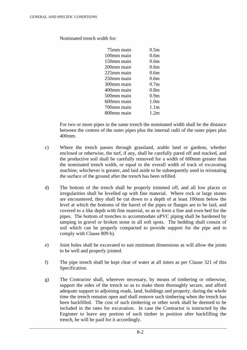
GENERAL AND SPECIFIC CONDITIONS
8-2
Nominated trench width for: 75mm main 0.5m 100mm main 0.6m 150mm main 0.6m 200mm main 0.6m 225mm main 0.6m 250mm main 0.6m 300mm main 0.7m 400mm main 0.8m 500mm main 0.9m 600mm main 1.0m 700mm main 1.1m 800mm main 1.2m For two or more pipes in the same trench the nominated width shall be the distance
between the centres of the outer pipes plus the internal radii of the outer pipes plus 400mm.
c) Where the trench passes through grassland, arable land or gardens, whether
enclosed or otherwise, the turf, if any, shall be carefully pared off and stacked, and the productive soil shall be carefully removed for a width of 600mm greater than the nominated trench width, or equal to the overall width of track of excavating machine, whichever is greater, and laid aside to be subsequently used in reinstating the surface of the ground after the trench has been refilled.
d) The bottom of the trench shall be properly trimmed off, and all low places or
irregularities shall be levelled up with fine material. Where rock or large stones are encountered, they shall be cut down to a depth of at least 100mm below the level at which the bottoms of the barrel of the pipes or flanges are to be laid, and covered to a like depth with fine material, so as to form a fine and even bed for the pipes. The bottom of trenches to accommodate uPVC piping shall be hardened by tamping in gravel or broken stone in all soft spots. The bedding shall consist of soil which can be properly compacted to provide support for the pipe and to comply with Clause 809 b).
e) Joint holes shall be excavated to suit minimum dimensions as will allow the joints
to be well and properly jointed. f) The pipe trench shall be kept clear of water at all times as per Clause 321 of this
Specification. g) The Contractor shall, wherever necessary, by means of timbering or otherwise,
support the sides of the trench so as to make them thoroughly secure, and afford adequate support to adjoining roads, land, buildings and property, during the whole time the trench remains open and shall remove such timbering when the trench has been backfilled. The cost of such timbering or other work shall be deemed to be included in the rates for excavation. In case the Contractor is instructed by the Engineer to leave any portion of such timber in position after backfilling the trench, he will be paid for it accordingly.
GENERAL AND SPECIFIC CONDITIONS
8-3
h) The clear width inside the timbering shall be at least 150mm in excess of the external diameter of the pipe being laid, in order to allow it to be freely lowered into position, in the trench without damage to the external protection.
i) Should the excavation be taken out to a greater depth than is specified the bottom
shall be made good to the correct level with Class 15/20 concrete or other material approved by the Engineer. No payment shall be made for any over excavation carried out by the Contractor nor for the cost of filling up to required levels.
j) If a mechanical excavator is used by the Contractor, he shall indemnify the
Employer against all claims for damage which in the opinion of the Engineer, may be caused by the use of this plant.
k) The Contractor shall fix Sight Rails for use with boning rods at intervals of not
more than 30 metres and temporary Bench Marks related to the Survey of Kenya Datum shall be provided at such intervals as directed by the Engineer.
808. MAIN LAYING a) Mains shall be laid in straight lines and/or smooth curves as indicated on the
drawings. The vertical profile of the pipe shall be to even gradients. Any pipes not so laid shall be removed if so directed by the Engineer, and re-laid in proper manner at the Contractor’s expense.
In laying the pipes and specials care shall be taken not to damage the protective
linings and the pipes shall be handled with tackle if so directed by the Engineer. The pipes and specials shall be checked for flaws before they are lowered into the
trench. After the pipes or specials have been checked they shall be cleaned and set to proper gradient and line so that there is a continuous rise from each washout to air valve.
When laying uPVC pipes, final connection at any fixed joints shall be deferred
until the majority of the pipeline has been covered with backfill. b) Large diameter curves to mains shall wherever possible be formed by allowing for
deflection at flexible joints, not exceeding 3 degrees, or as specified by the manufacturers.
c) In jointing of the pipes and specials the Contractor shall comply with the standards
adopted for the various types of joints as specified. d) In laying pipes and specials with flanged joints, flanges shall be brought together
and bolted with the faces absolutely parallel. A rubber jointing gasket ring 3mm thick shall be used in each flange joint and one washer with and not provided for each bolt.
The bolts shall be tightened up gradually and equally in the customary manner in order to distribute the stress evenly over the flange. If it is found necessary to deviate slightly from the normal run of the flanged piping, the deflection shall be obtained by means of a bevelled gun metal ring washer between the flanges.
GENERAL AND SPECIFIC CONDITIONS
8-4
e) The Contractor shall fix the gate valves, air valves and washout pipes all in accordance with the drawings.
f) The Contractor shall, subject to approval of the Engineer, cut pipes to such lengths
as directed. Pipes should be cut off clean and square with the axis. Cuts should be made with an approved cutting device dependant on the type of pipe specified. Ends of pipes should be tapered by means approved by the Engineer if mechanical joints are to be used.
g) Equipment for tapping off the mains under pressure may be employed in the
making of service or branch connections. The Contractor is required to choose a suitable method for fixing of the ferrule to the type of pipe specified, to the Engineer’s approval.
809. BACKFILLING OF TRENCH a) When a section of the main has been jointed, the ends shall be temporarily closed
with caps, plugs or flanges to prevent ingress of foreign matter into the pipe to the satisfaction of the Engineer. The trench shall be properly backfilled and rammed for its whole length so that the soil cover to the main shall not be less than 600mm except at joint holes which shall be kept clear of all backfilling, if necessary, by the use of timbering, so that each joint is left fully exposed for the Engineer’s inspection. Special care shall be exercised when using surround to A.C. and uPVC pipes which shall be free from any stones and well compacted in layers to not less than 100mm above the crown of the pipe.
b) The Contractor’s attention is drawn to the special requirements for bedding and
sidefill to uPVC pipes. Clay should not be used. Soils which are of a granular nature and provide adequate support after compaction shall be used. If unavailable from excavated material the Contractor should provide suitable material for which an item in the Bill has been included.
With flexible pipes it is important that the sidefill should be firmly compacted
between the pipe and the soil sides of the trench. The bedding material shall be placed in 75mm layers up to the crown of the pipe with adequate compaction and then to a minimum height of 100mm or two thirds of the pipe diameter. The progress of filling and tamping should proceed equally on either side of the pipe so as to maintain an equal pressure on both sides.
c) Where a main is laid across a road or is in such a position as to interfere seriously
with the normal use of the road, the Contractor may, with the consent of the Engineer and at his own risk, fill such holes as may be necessary. Due consideration is to be given to compaction of section of the trench across the road to prevent undue settlement. In the event of damage at this section the Contractor is required to re-excavate and repair the pipeline all at his own expense.
810. ANCHOR BLOCKS AND SUPPORTS Concrete Class 15/20 shall be placed in anchor blocks at all changes of direction of the pipeline exceeding 6 degrees and wherever else required to withstand thrust resulting from internal water pressure e.g. at blank ends. Concrete in plinths shall be placed where specified.
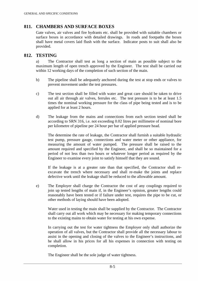
GENERAL AND SPECIFIC CONDITIONS
8-5
811. CHAMBERS AND SURFACE BOXES Gate valves, air valves and fire hydrants etc. shall be provided with suitable chambers or surface boxes in accordance with detailed drawings. In roads and footpaths the boxes shall have metal covers laid flush with the surface. Indicator posts to suit shall also be provided.
812. TESTING a) The Contractor shall test as long a section of main as possible subject to the maximum length of open trench approved by the Engineer. The test shall be carried out within 12 working days of the completion of such section of the main. b) The pipeline shall be adequately anchored during the test at stop ends or valves to
prevent movement under the test pressures. c) The test section shall be filled with water and great care should be taken to drive
out all air through air valves, ferrules etc. The test pressure is to be at least 1.5 times the nominal working pressure for the class of pipe being tested and is to be applied for at least 2 hours.
d) The leakage from the mains and connections from each section tested shall be
according to SRN 316, i.e. not exceeding 0.02 litres per millimetre of nominal bore per kilometre of pipeline per 24 hour per bar of applied pressure head.
The determine the rate of leakage, the Contractor shall furnish a suitable hydraulic
test pump, pressure gauge, connections and water meter or other appliance, for measuring the amount of water pumped. The pressure shall be raised to the amount required and specified by the Engineer, and shall be so maintained for a period of not less than two hours or whatever longer period as required by the Engineer to examine every joint to satisfy himself that they are sound.
If the leakage is at a greater rate than that specified, the Contractor shall re-
excavate the trench where necessary and shall re-make the joints and replace defective work until the leakage shall be reduced to the allowable amount.
e) The Employer shall charge the Contractor the cost of any couplings required to
join up tested lengths of main if, in the Engineer’s opinion, greater lengths could reasonably have been tested or if failure under test, requires the pipe to be cut, or other methods of laying should have been adopted.
Water used in testing the main shall be supplied by the Contractor. The Contractor
shall carry out all work which may be necessary for making temporary connections to the existing mains to obtain water for testing at his own expense.
In carrying out the test for water tightness the Employer only shall authorize the
operation of all valves, but the Contractor shall provide all the necessary labour to assist in the opening and closing of the valves to the Engineer’s instructions, and he shall allow in his prices for all his expenses in connection with testing on completion.
The Engineer shall be the sole judge of water tightness.
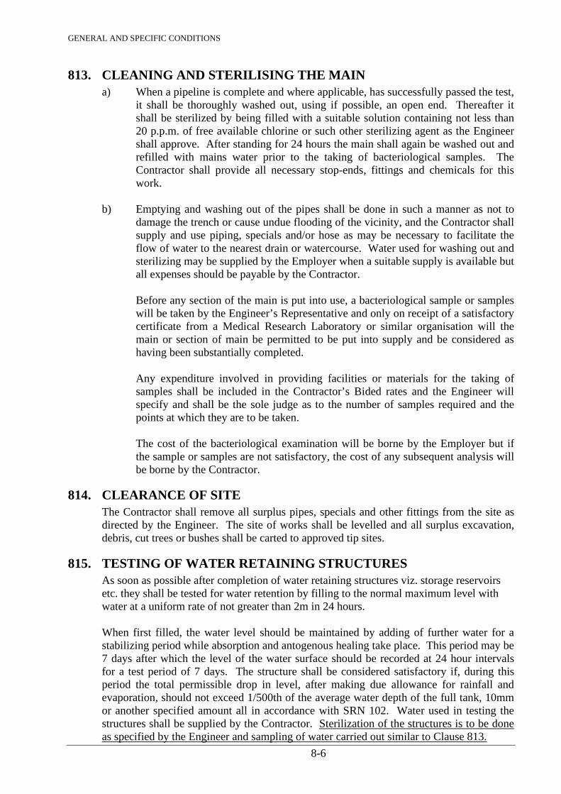
GENERAL AND SPECIFIC CONDITIONS
8-6
813. CLEANING AND STERILISING THE MAIN a) When a pipeline is complete and where applicable, has successfully passed the test,
it shall be thoroughly washed out, using if possible, an open end. Thereafter it shall be sterilized by being filled with a suitable solution containing not less than 20 p.p.m. of free available chlorine or such other sterilizing agent as the Engineer shall approve. After standing for 24 hours the main shall again be washed out and refilled with mains water prior to the taking of bacteriological samples. The Contractor shall provide all necessary stop-ends, fittings and chemicals for this work.
b) Emptying and washing out of the pipes shall be done in such a manner as not to
damage the trench or cause undue flooding of the vicinity, and the Contractor shall supply and use piping, specials and/or hose as may be necessary to facilitate the flow of water to the nearest drain or watercourse. Water used for washing out and sterilizing may be supplied by the Employer when a suitable supply is available but all expenses should be payable by the Contractor.
Before any section of the main is put into use, a bacteriological sample or samples
will be taken by the Engineer’s Representative and only on receipt of a satisfactory certificate from a Medical Research Laboratory or similar organisation will the main or section of main be permitted to be put into supply and be considered as having been substantially completed.
Any expenditure involved in providing facilities or materials for the taking of
samples shall be included in the Contractor’s Bided rates and the Engineer will specify and shall be the sole judge as to the number of samples required and the points at which they are to be taken.
The cost of the bacteriological examination will be borne by the Employer but if
the sample or samples are not satisfactory, the cost of any subsequent analysis will be borne by the Contractor.
814. CLEARANCE OF SITE The Contractor shall remove all surplus pipes, specials and other fittings from the site as directed by the Engineer. The site of works shall be levelled and all surplus excavation, debris, cut trees or bushes shall be carted to approved tip sites.
815. TESTING OF WATER RETAINING STRUCTURES As soon as possible after completion of water retaining structures viz. storage reservoirs etc. they shall be tested for water retention by filling to the normal maximum level with water at a uniform rate of not greater than 2m in 24 hours. When first filled, the water level should be maintained by adding of further water for a stabilizing period while absorption and antogenous healing take place. This period may be 7 days after which the level of the water surface should be recorded at 24 hour intervals for a test period of 7 days. The structure shall be considered satisfactory if, during this period the total permissible drop in level, after making due allowance for rainfall and evaporation, should not exceed 1/500th of the average water depth of the full tank, 10mm or another specified amount all in accordance with SRN 102. Water used in testing the structures shall be supplied by the Contractor. Sterilization of the structures is to be done as specified by the Engineer and sampling of water carried out similar to Clause 813.
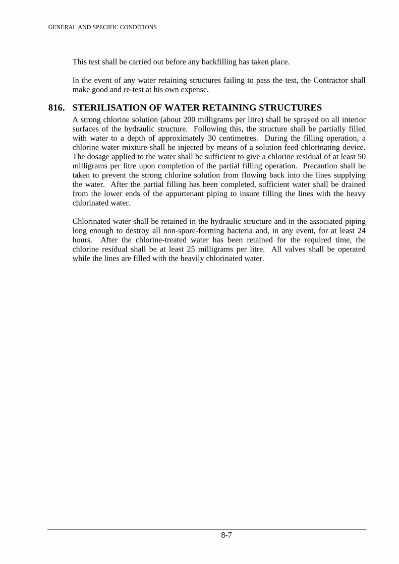
GENERAL AND SPECIFIC CONDITIONS
8-7
This test shall be carried out before any backfilling has taken place. In the event of any water retaining structures failing to pass the test, the Contractor shall make good and re-test at his own expense.
816. STERILISATION OF WATER RETAINING STRUCTURES A strong chlorine solution (about 200 milligrams per litre) shall be sprayed on all interior surfaces of the hydraulic structure. Following this, the structure shall be partially filled with water to a depth of approximately 30 centimetres. During the filling operation, a chlorine water mixture shall be injected by means of a solution feed chlorinating device. The dosage applied to the water shall be sufficient to give a chlorine residual of at least 50 milligrams per litre upon completion of the partial filling operation. Precaution shall be taken to prevent the strong chlorine solution from flowing back into the lines supplying the water. After the partial filling has been completed, sufficient water shall be drained from the lower ends of the appurtenant piping to insure filling the lines with the heavy chlorinated water. Chlorinated water shall be retained in the hydraulic structure and in the associated piping long enough to destroy all non-spore-forming bacteria and, in any event, for at least 24 hours. After the chlorine-treated water has been retained for the required time, the chlorine residual shall be at least 25 milligrams per litre. All valves shall be operated while the lines are filled with the heavily chlorinated water.
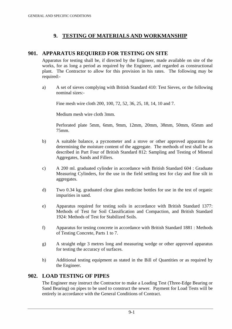
GENERAL AND SPECIFIC CONDITIONS
9-1
9. TESTING OF MATERIALS AND WORKMANSHIP
901. APPARATUS REQUIRED FOR TESTING ON SITE Apparatus for testing shall be, if directed by the Engineer, made available on site of the
works, for as long a period as required by the Engineer, and regarded as constructional plant. The Contractor to allow for this provision in his rates. The following may be required:-
a) A set of sieves complying with British Standard 410: Test Sieves, or the following
nominal sizes:- Fine mesh wire cloth 200, 100, 72, 52, 36, 25, 18, 14, 10 and 7. Medium mesh wire cloth 3mm. Perforated plate 5mm, 6mm, 9mm, 12mm, 20mm, 38mm, 50mm, 65mm and
75mm. b) A suitable balance, a pycnometer and a stove or other approved apparatus for
determining the moisture content of the aggregate. The methods of test shall be as described in Part Four of British Standard 812: Sampling and Testing of Mineral Aggregates, Sands and Fillers.
c) A 200 ml. graduated cylinder in accordance with British Standard 604 : Graduate
Measuring Cylinders, for the use in the field settling test for clay and fine silt in aggregates.
d) Two 0.34 kg. graduated clear glass medicine bottles for use in the test of organic
impurities in sand. e) Apparatus required for testing soils in accordance with British Standard 1377:
Methods of Test for Soil Classification and Compaction, and British Standard 1924: Methods of Test for Stabilized Soils.
f) Apparatus for testing concrete in accordance with British Standard 1881 : Methods
of Testing Concrete, Parts 1 to 7. g) A straight edge 3 metres long and measuring wedge or other approved apparatus
for testing the accuracy of surfaces. h) Additional testing equipment as stated in the Bill of Quantities or as required by
the Engineer.
902. LOAD TESTING OF PIPES The Engineer may instruct the Contractor to make a Loading Test (Three-Edge Bearing or
Sand Bearing) on pipes to be used to construct the sewer. Payment for Load Tests will be entirely in accordance with the General Conditions of Contract.
GENERAL AND SPECIFIC CONDITIONS
10-1
10. DRAINS, SEWERS AND MANHOLES
1001. EXCAVATION FOR DRAINS, SEWERS AND MANHOLES The ground shall be excavated to the lines and depths shown on the drawings or to such
other lines and depths as the Engineer may direct. Excavations taken out to a greater depth than is necessary shall be filled to the required level with approved material as specified for the pipe bed at the Contractor’s own cost. Trenches shall be of sufficient width to enable the pipes to be properly laid and jointed. In case of pipes of greater diameter than 300mm, the width of trench shall be external diameter of pipe, plus 400mm. When any excavation has been taken out and trimmed to the levels and dimensions shown on the drawings or as directed by the Engineer, the Engineer shall be informed accordingly so that he may inspect the completed trench and no excavation shall be filled in or covered with concrete until it has been so inspected and the Contractor has been authorized to proceed with the work. All surplus materials from such excavations not required for refilling shall be carted away to tips, or otherwise disposed of, as directed. All excavations shall be kept dry, and all bailing and pumping, timbering, shoring and supporting of sides that may be required, and any refilling, ramming and disposal of surplus materials necessary in carrying out the excavations and backfilling of trenches shall be taken to provide a solid and even bed for barrels of the pipes and, where a concrete bed is not specified, the floor of the trench shall be properly shaped to receive the sockets and the backfill must be thoroughly rammed along the sides of the pipe.
The rate of excavation in the Bill of Quantities shall include for keeping trenches dry and
for all bailing, pumping, timbering, shoring and supporting of sides that may be required.
1002. SUPPORTS FOR PITS, TRENCHES AND OTHER EXCAVATIONS The sides of pits, trenches and other excavations shall, where necessary, be adequately
supported to the satisfaction of the Engineer, and all such excavations shall be of sizes sufficient to enable the pipes and bedding to be laid accurately, and proper refilling and compacting to be carried out.
The Contractor shall take all precautions necessary for the safety of adjoining structures
and building by shoring, opening in short lengths or otherwise, during the time the trenches are open.
1003. ROCK CUTTING IN TRENCHES FOR PIPES Where solid rock is met within trenches, it shall be cut out to a depth of 100mm below the
intended level of the bottom of the pipes, and replaced with 100mm of approved material as specified. In measuring such rock excavation the Contractor will be allowed a width of 400mm more than the external diameter of the pipes to a level of 100mm below the bottom of the pipes. The price inserted in the Bill of Quantities shall be held to cover all expenses in connection with excavating the rock, backfilling after laying of pipes and disposing of surplus material as directed by the Engineer.
GENERAL AND SPECIFIC CONDITIONS
10-2
1004. WATER IN TRENCHES FOR PIPELINES Trenches shall be kept free from water at all times during construction of works until, in
the opinion of the Engineer, any concrete or other works therein are sufficiently set, and the Contractor shall construct any sumps or temporary drains that the Engineer may deem necessary.
The Contractor shall be responsible for the removal and disposal of all water entering the
excavations from whatever source and shall deal with and dispose of such water in a manner approved by the Engineer so as to ensure that excavations are kept dry while ensuring that the disposal of this water does not cause a nuisance to adjacent plot holders or works.
The Contractor shall provide all plant, labour and materials required for such work and all
costs incurred shall be deemed to be included in his rates for excavation.
1005. LAYING AND JOINTING RIGID JOINTED CONCRETE PIPES Concrete pipes as specified in Clause 742, shall be laid true to line and level, each pipe
being separately boned between sight rails. For spigot and socket joints, the spigot of each pipe shall be placed home in the socket of
the one previously laid, and the pipe then adjusted and fixed in its correct position with the spigot of the pipe accurately centred in the socket. A ring of tarred rope yarn shall next be inserted in the socket of each pipe previously laid and driven home with a wooden caulking tool and wooden mallet, such yarn when in position shall be 25mm in depth. The socket shall then be completely filled with cement mortar 1 to 2 as specified in Clause 707 and a fillet of the same worked all round the side. The fillet shall be levelled off and extend for a length of not less than 50mm from the face of the socket.
For ‘Ogee’ jointed pipes, the joints shall be thoroughly cleaned before laying, and cement
mortar, as specified in Clause 707 shall be applied evenly to the ends for jointing so as to completely fill the joint. The pipes shall then be neatly pointed with a band of cement mortar approximately 125mm wide and 20mm thick. The inside of each joint shall also be pointed up as the work proceeds.
Special care shall be taken to see that any excess of cement mortar etc. is neatly cleaned
off while each joint is being made and any earth, cement or other material cleaned out of the pipes by drawing a tight-fitting wad through them as the work proceeds, or by other approved means. A properly fitting plug shall be well secured at the end of the last laid pipe and shall be removed only when pipe laying is proceeding. The trenches, pipes and joint holes shall be kept free from water until the joints are thoroughly set.
Where shown on the drawings or directed by the Engineer, concrete pipes shall be bedded
and haunched or surrounded with concrete as specified in Clause 1019. The price inserted in the Bill of Quantities shall include for providing, laying and jointing
of pipes.
GENERAL AND SPECIFIC CONDITIONS
10-3
1006. PIPES LAID WITH OPEN JOINTS O.G. porous concrete pipes as specified in Clause 742 shall be laid unjointed with a space
of 12mm between the spigot and the inner end of the socket. All pipes shall be packed and surrounded as directed by the Engineer with approved
broken stone, sand or gravel aggregate, to the gradings as shown on the drawings or stated in the Bill of Quantities. The prices inserted in the Bill of Quantities shall include the trench excavation, providing and laying pipes, supplying and placing graded packing material, refilling trench and disposing of surplus all as specified.
1007. CAST IRON PIPES Cast iron pipes and special castings, shall be as specified in Clause 703 and shall be
supplied, laid and jointed with lead wool properly caulked to form perfectly uniform and watertight joints, and when laid and jointed they shall be true to line and level.
Where cast iron pipe drains are laid on unstable ground or ground which is likely to settle
appreciably over a period of years they shall be pointed by means of an approved self adjusting or screwed gland joint as directed by the Engineer.
1008. DRAINS TO BE LEFT CLEAN ON COMPLETION On completion, all drains, manholes, etc. shall be flushed from end to end with water from
an approved source and left clean and free from obstructions.
1009. REFILLING TRENCHES Trenches shall be refilled with suitable excavated material of 100mm surround but not
before the work has been measured and approved by the Engineer. For pipes which are not surrounded with concrete, the first layer of filling material shall be free from stones and shall not be thrown directly on to the pipes, but shall be placed and packed with care all round them. All filling shall be deposited and compacted in layers, not exceeding 225mm loose depth, to a dry density not less than that of the adjoining soil. The last 450mm of filling must be returned in the order in which it has been removed. Timber and framing shall be withdrawn ahead of the layer to be compacted, care being taken to keep the sides of the trenches solid and to fill all the spaces left by the withdrawn timber.
1010. CONNECTIONS OF EXISTING SEWERS AND DRAINS Where shown on the drawings, existing sewers and drains shall be properly extended,
connected and jointed to new sewers, culverts, drains or channels. All such connections shall be made during the construction of the main sewer, drain or other work and a record of their positions kept for future use or reference. Where pipe connections are made to a sewer, stone pitched or lined channel, the pipes shall be well and tightly built into the concrete, or masonry work and be so placed as to discharge in the direction of the main sewer, drain or channel and with the end of the pipe carefully cut to the necessary angle. Where the connections are between pipe sewers or drains, special connecting pipes as shown on the drawings shall be supplied and be truly laid and properly jointed.
GENERAL AND SPECIFIC CONDITIONS
10-4
1011. MANHOLES AND INSPECTION CHAMBERS Manholes and inspection chambers shall be constructed in accordance with the drawings
and in the position shown on the drawings or directed by the Engineer. Foundation slabs shall consist of concrete of the appropriate classes as specified on drawings. The side walls shall consist of similar concrete or building stone as specified in Clause 703 in accordance with the drawings.
The side walls shall be fair faced or rendered internally as specified on drawings. They
shall be brought up vertically to receive a precast slab formed of concrete of the appropriate classes specified and reinforced all as shown on the drawings. Cast iron manhole covers and frames as specified in Clause 747 shall be provided and frames shall be bedded in cement mortar 1 to 3 and so set that the tops of the covers shall be flush at all points with surrounding surface of the footway, verge or carriageway, as the case may be. Any slight adjustment of the slab level which may be necessary to accomplish this shall be effected by topping the side walls with concrete integral with the slab.
If required, half channel pipes, bends and junctions as specified in Clause 749 and Clause
742 shall be laid and bedded in cement mortar 1 to 3 to the required lines and levels, and both sides of the channel pipes shall be benched up with concrete of the appropriate class and finished smooth to the slopes and levels as shown on the drawings or directed by the Engineer. The ends of all pipes shall be neatly built in and finished flush with cement mortar 1 to 3. Where the depth of the invert exceeds 1 metre below the finished surface of the carriageway or the adjacent ground, iron steps as specified in Clause 751 shall be built in with alternate steps in line vertically and with such additional hand irons as the Engineer may direct.
All manholes when completed shall be watertight and to the satisfaction of the Engineer.
The prices inserted in the Bill of Quantities shall include for excavation, provision of all materials, construction, refilling and disposal of surplus.
1012. PRECAST CONCRETE MANHOLES Precast concrete manholes as specified in Clause 749 shall be supplied and laid generally
in accordance with Clause 1011 and the drawings.
1013. GULLY CONNECTIONS Connections from gullies to sewers and surface water drains or ditches shall consist of
concrete pipes and fittings as specified in Clause 750 jointed with cement mortar 1 to 3 as specified in Clause 729. All pipes, bends and junctions shall be laid to the lines and levels shown on the drawings or as directed by the Engineer.
1014. SURFACE BOXES, COVERS ETC. Surface boxes, manholes and other covers lying within the site of the works, shall be
raised, lowered, altered or removed as directed by the Engineer.
1015. GULLIES Gullies complete with gratings and with rodding eyes where necessary all as specified in
Clause 750 shall be supplied and laid in accordance with the drawings. Where directed by the Engineer, precast concrete gullies shall be laid on and surrounded with 100mm of concrete of the appropriate grade specified in Table 4.2. The concrete surround is to be brought up to the underside of the frame or flush with the top surface as the case may be.
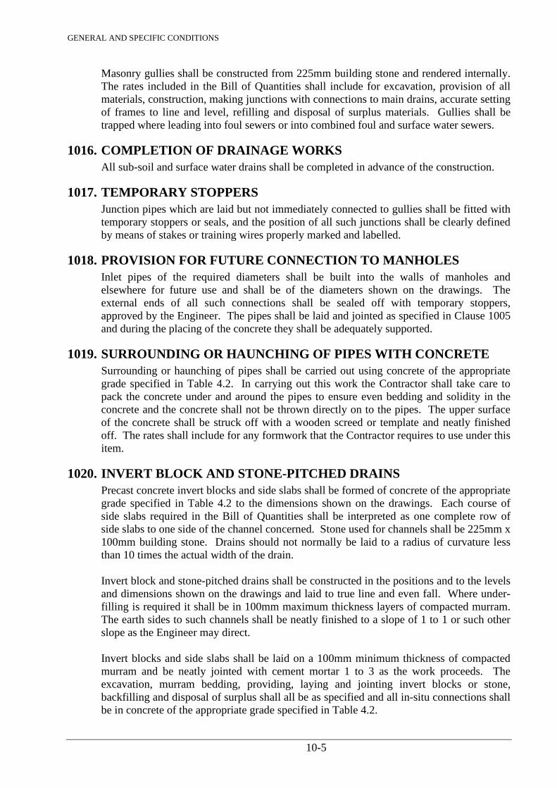
GENERAL AND SPECIFIC CONDITIONS
10-5
Masonry gullies shall be constructed from 225mm building stone and rendered internally. The rates included in the Bill of Quantities shall include for excavation, provision of all materials, construction, making junctions with connections to main drains, accurate setting of frames to line and level, refilling and disposal of surplus materials. Gullies shall be trapped where leading into foul sewers or into combined foul and surface water sewers.
1016. COMPLETION OF DRAINAGE WORKS All sub-soil and surface water drains shall be completed in advance of the construction.
1017. TEMPORARY STOPPERS Junction pipes which are laid but not immediately connected to gullies shall be fitted with
temporary stoppers or seals, and the position of all such junctions shall be clearly defined by means of stakes or training wires properly marked and labelled.
1018. PROVISION FOR FUTURE CONNECTION TO MANHOLES Inlet pipes of the required diameters shall be built into the walls of manholes and
elsewhere for future use and shall be of the diameters shown on the drawings. The external ends of all such connections shall be sealed off with temporary stoppers, approved by the Engineer. The pipes shall be laid and jointed as specified in Clause 1005 and during the placing of the concrete they shall be adequately supported.
1019. SURROUNDING OR HAUNCHING OF PIPES WITH CONCRETE Surrounding or haunching of pipes shall be carried out using concrete of the appropriate
grade specified in Table 4.2. In carrying out this work the Contractor shall take care to pack the concrete under and around the pipes to ensure even bedding and solidity in the concrete and the concrete shall not be thrown directly on to the pipes. The upper surface of the concrete shall be struck off with a wooden screed or template and neatly finished off. The rates shall include for any formwork that the Contractor requires to use under this item.
1020. INVERT BLOCK AND STONE-PITCHED DRAINS Precast concrete invert blocks and side slabs shall be formed of concrete of the appropriate
grade specified in Table 4.2 to the dimensions shown on the drawings. Each course of side slabs required in the Bill of Quantities shall be interpreted as one complete row of side slabs to one side of the channel concerned. Stone used for channels shall be 225mm x 100mm building stone. Drains should not normally be laid to a radius of curvature less than 10 times the actual width of the drain.
Invert block and stone-pitched drains shall be constructed in the positions and to the levels
and dimensions shown on the drawings and laid to true line and even fall. Where under-filling is required it shall be in 100mm maximum thickness layers of compacted murram. The earth sides to such channels shall be neatly finished to a slope of 1 to 1 or such other slope as the Engineer may direct.
Invert blocks and side slabs shall be laid on a 100mm minimum thickness of compacted
murram and be neatly jointed with cement mortar 1 to 3 as the work proceeds. The excavation, murram bedding, providing, laying and jointing invert blocks or stone, backfilling and disposal of surplus shall all be as specified and all in-situ connections shall be in concrete of the appropriate grade specified in Table 4.2.
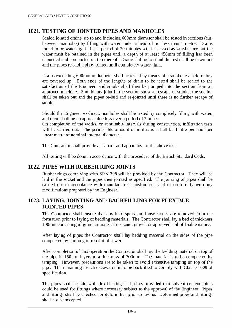
GENERAL AND SPECIFIC CONDITIONS
10-6
1021. TESTING OF JOINTED PIPES AND MANHOLES Sealed jointed drains, up to and including 600mm diameter shall be tested in sections (e.g.
between manholes) by filling with water under a head of not less than 1 metre. Drains found to be water-tight after a period of 30 minutes will be passed as satisfactory but the water must be retained in the pipes until a depth of at least 450mm of filling has been deposited and compacted on top thereof. Drains failing to stand the test shall be taken out and the pipes re-laid and re-jointed until completely water-tight.
Drains exceeding 600mm in diameter shall be tested by means of a smoke test before they
are covered up. Both ends of the lengths of drain to be tested shall be sealed to the satisfaction of the Engineer, and smoke shall then be pumped into the section from an approved machine. Should any joint in the section show an escape of smoke, the section shall be taken out and the pipes re-laid and re-jointed until there is no further escape of smoke.
Should the Engineer so direct, manholes shall be tested by completely filling with water,
and there shall be no appreciable loss over a period of 2 hours. On completion of the works, or at suitable intervals during construction, infiltration tests
will be carried out. The permissible amount of infiltration shall be 1 litre per hour per linear metre of nominal internal diameter.
The Contractor shall provide all labour and apparatus for the above tests. All testing will be done in accordance with the procedure of the British Standard Code.
1022. PIPES WITH RUBBER RING JOINTS Rubber rings complying with SRN 308 will be provided by the Contractor. They will be
laid in the socket and the pipes then jointed as specified. The jointing of pipes shall be carried out in accordance with manufacturer’s instructions and in conformity with any modifications proposed by the Engineer.
1023. LAYING, JOINTING AND BACKFILLING FOR FLEXIBLE JOINTED PIPES
The Contractor shall ensure that any hard spots and loose stones are removed from the formation prior to laying of bedding materials. The Contractor shall lay a bed of thickness 100mm consisting of granular material i.e. sand, gravel, or approved soil of friable nature.
After laying of pipes the Contractor shall lay bedding material on the sides of the pipe
compacted by tamping into soffit of sewer. After completion of this operation the Contractor shall lay the bedding material on top of
the pipe in 150mm layers to a thickness of 300mm. The material is to be compacted by tamping. However, precautions are to be taken to avoid excessive tamping on top of the pipe. The remaining trench excavation is to be backfilled to comply with Clause 1009 of specification.
The pipes shall be laid with flexible ring seal joints provided that solvent cement joints
could be used for fittings where necessary subject to the approval of the Engineer. Pipes and fittings shall be checked for deformities prior to laying. Deformed pipes and fittings shall not be accepted.
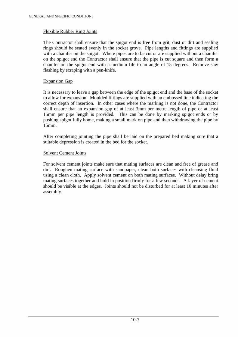
GENERAL AND SPECIFIC CONDITIONS
10-7
Flexible Rubber Ring Joints The Contractor shall ensure that the spigot end is free from grit, dust or dirt and sealing
rings should be seated evenly in the socket grove. Pipe lengths and fittings are supplied with a chamfer on the spigot. Where pipes are to be cut or are supplied without a chamfer on the spigot end the Contractor shall ensure that the pipe is cut square and then form a chamfer on the spigot end with a medium file to an angle of 15 degrees. Remove saw flashing by scraping with a pen-knife.
Expansion Gap It is necessary to leave a gap between the edge of the spigot end and the base of the socket
to allow for expansion. Moulded fittings are supplied with an embossed line indicating the correct depth of insertion. In other cases where the marking is not done, the Contractor shall ensure that an expansion gap of at least 3mm per metre length of pipe or at least 15mm per pipe length is provided. This can be done by marking spigot ends or by pushing spigot fully home, making a small mark on pipe and then withdrawing the pipe by 15mm.
After completing jointing the pipe shall be laid on the prepared bed making sure that a
suitable depression is created in the bed for the socket. Solvent Cement Joints For solvent cement joints make sure that mating surfaces are clean and free of grease and
dirt. Roughen mating surface with sandpaper, clean both surfaces with cleansing fluid using a clean cloth. Apply solvent cement on both mating surfaces. Without delay bring mating surfaces together and hold in position firmly for a few seconds. A layer of cement should be visible at the edges. Joints should not be disturbed for at least 10 minutes after assembly.
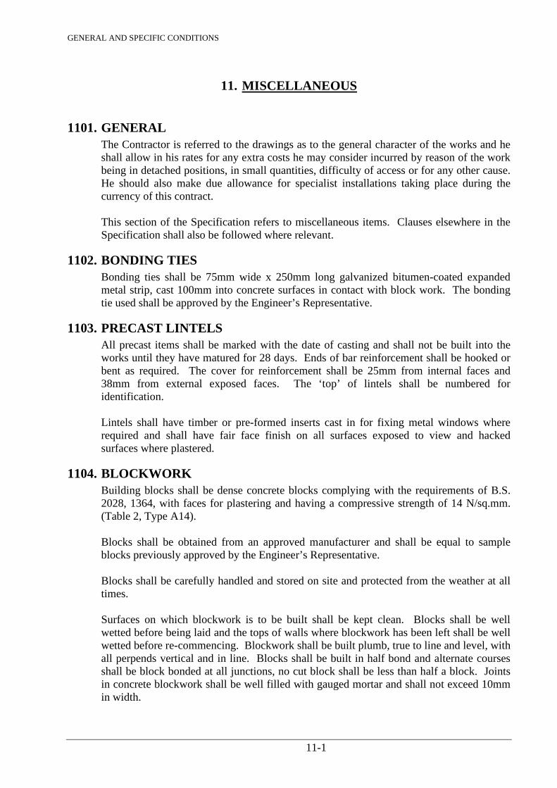
GENERAL AND SPECIFIC CONDITIONS
11-1
11. MISCELLANEOUS
1101. GENERAL The Contractor is referred to the drawings as to the general character of the works and he
shall allow in his rates for any extra costs he may consider incurred by reason of the work being in detached positions, in small quantities, difficulty of access or for any other cause. He should also make due allowance for specialist installations taking place during the currency of this contract.
This section of the Specification refers to miscellaneous items. Clauses elsewhere in the
Specification shall also be followed where relevant.
1102. BONDING TIES Bonding ties shall be 75mm wide x 250mm long galvanized bitumen-coated expanded
metal strip, cast 100mm into concrete surfaces in contact with block work. The bonding tie used shall be approved by the Engineer’s Representative.
1103. PRECAST LINTELS All precast items shall be marked with the date of casting and shall not be built into the
works until they have matured for 28 days. Ends of bar reinforcement shall be hooked or bent as required. The cover for reinforcement shall be 25mm from internal faces and 38mm from external exposed faces. The ‘top’ of lintels shall be numbered for identification.
Lintels shall have timber or pre-formed inserts cast in for fixing metal windows where
required and shall have fair face finish on all surfaces exposed to view and hacked surfaces where plastered.
1104. BLOCKWORK Building blocks shall be dense concrete blocks complying with the requirements of B.S.
2028, 1364, with faces for plastering and having a compressive strength of 14 N/sq.mm. (Table 2, Type A14).
Blocks shall be obtained from an approved manufacturer and shall be equal to sample
blocks previously approved by the Engineer’s Representative. Blocks shall be carefully handled and stored on site and protected from the weather at all
times. Surfaces on which blockwork is to be built shall be kept clean. Blocks shall be well
wetted before being laid and the tops of walls where blockwork has been left shall be well wetted before re-commencing. Blockwork shall be built plumb, true to line and level, with all perpends vertical and in line. Blocks shall be built in half bond and alternate courses shall be block bonded at all junctions, no cut block shall be less than half a block. Joints in concrete blockwork shall be well filled with gauged mortar and shall not exceed 10mm in width.
GENERAL AND SPECIFIC CONDITIONS
11-2
1105. DAMP-PROOF COURSE (D.P.C.) Hessian based metal cored bitumen for damp-proof courses shall be lead cored, complying
with B.S. 743 paragraph 4, type D, weighing not less than 4.4 kg. per square metre. Damp-proof course shall be bedded horizontally in mortar as for blockwork with 115mm laps in length and full laps at angles.
1106. HARDWOOD Hardwood for joinery shall be sound, well conditioned and seasoned Mvuli complying
with the requirements of B.S. 1186 Part 1, Class 1. A sample of each representative section for use in the work shall be previously submitted by the Contractor for approval by the Engineer’s Representative. Moisture content shall be 12% (+ or - 2%).
1107. PLYWOOD Plywood generally shall comply with B.S. 1455. That from sources not included in B.S.
1455 shall be of corresponding grades of veneers and types of bonding. Plywood for flush doors shall be Grade I Mvuli veneered.
1108. DOORS Internal doors shall be hardwood framed solid cored flush doors constructed in accordance
with B.S. 459 Part 3, faced both sides with 3mm thick Mvuli veneered plywood and lipped all round with matching hardwood lipping. Moisture content at delivery shall be 12% (+ or - 2%).
1109. FRAMES AND LININGS Door frames and linings shall be Class 1 Mvuli mortice and tenon jointed at angles. Sub-
frames for internal doors shall be Class 1 Mvuli tongued at angles.
1110. ARCHITRAVES AND STOPS Architraves and stops shall be Class 1 Mvuli matching to the frames and linings.
1111. IRONMONGERY All ironmongery shall be obtained from a source approved by the Engineer’s
Representative. Samples shall be submitted before ordering and the articles ordered shall match up with the approved samples. Screws of a like metal shall be used for all fittings.
1112. JOINERY All exposed joiner’s work shall have wrought faces. The prices of all joiner’s work shall
include for slightly rounded arises. Where the term ‘framing’ or ‘framed’ is made use of, it shall be understood to mean all
halvings, dovetails, tenons and hardwood pins and the best known means of putting the work together.
All framed work shall be put together loosely and stacked under cover where a free current
of air can circulate and is not to be wedged and glued until it is required for fixing. All joinery, when brought on the works, shall be stacked under cover.
GENERAL AND SPECIFIC CONDITIONS
11-3
The Engineer or his representative, shall have full right of access to the joinery works and power to condemn any work not approved and any approval expressed or implied is not to relieve the Contractor from his responsibility and liability to make good any shrinkage or other defects that may appear after the work is fixed.
All joinery to be painted shall be knotted and primed. The Contractor shall provide all materials, labour, framing, fixing, etc., nails, screws and
everything necessary for the proper execution and completion of the work.
1113. FIXING JOINERY Doors shall be hung on one or one and a half pairs of butt hinges to give a maximum even
tolerance of 2mm all round. Sub-frames shall be fixed to blockwork with three fixing clamps per side and one dowel
let 50mm into the floor and 50mm into the foot of each leg. Linings shall be fixed after completion of other finishings by means of screwing and pellating to sub-frames with matching hardwood pellates. Architraves and stops shall be pinned on, heads punched and filled with tinted filler.
1114. FIXING IRONMONGERY The rates for supplying and fixing ironmongery shall include for all sinking, cutting,
boring, mortising etc., making good, replacing damaged screws, oiling, adjusting and leaving in good working order and for mastering all keys.
1115. BOLTS AND NUTS Bolts and nuts shall comply with the relevant requirements of the British Standards as set
out below:- Black Hexagon Bolts, Screws and Nuts B.S. 4190, Grade 4.6 Metal Washers for General Purpose B.S. 4320 Black Cup and Countersunk Head Bolts and Screws, with Nuts B.S. 4993 The items shall preferably have coarse metric threads but items with B.S.W. threads may
be used. Bolt lengths shall be sufficient to ensure that nuts are full threaded when tightened in their final position.
1116. STRUCTURAL STEELWORK The whole of the structural steelwork and testing shall comply with the relevant clauses of
B.S. 449. The Contractor shall include for the preparation of all shop details from the drawings supplied by the Engineer. All such details shall be approved in writing by the Engineer before the work is put in hand. Every drawing shall show the number and sizes of all rivets and bolts, complete details of welds, type of electrodes, welding procedure, whether the welds are to be made in the shop or elsewhere and any other relevant information. The Contractor shall be responsible for the accuracy of his shop details and for shop fittings and site connections.
The Contractor shall take the dimensions from the structure and he shall verify all dimensions given on the drawings before the work is put in hand.

GENERAL AND SPECIFIC CONDITIONS
11-4
Any damage to materials on the site due to inadequate precautions being taken during the
erection of the steelwork shall be made good to the satisfaction of the Engineer’s Representative at the Contractor’s expense.
The fabrication and erection of the steelwork shall be carried out in accordance with Part 5
of B.S. 449.
1117. GALVANISED WORK Iron and steel, where galvanized, shall comply with B.S. 729, entirely coated with zinc
after fabrication by complete immersion in a zinc bath in one operation and all excess carefully removed. The finished surface shall be clean and uniform.
1118. ELECTRICAL INSTALLATION The electrical installations will be carried out by Licensed Electrician and complying with
the following:-
a) Regulations for Electrical Equipment of Buildings issued by the Institution of Electrical Engineers.
b) Electric Power Act. c) The K.P.&L. Co.’s Bye-Laws. d) Relevant current British Standards and Codes of Practice. e) All the relevant clauses in this Specification, particularly the clauses in Sections 13
and 14. PLUMBING INSTALLATION
1119. WATER AUTHORITIES REGULATIONS The internal plumbing work shall be carried out to the satisfaction of and in accordance
with the regulations of the local Water Authority.
1120. RAINWATER INSTALLATIONS Rainwater installation shall be in grey PVC pipework with ‘O’ ring joints.
1121. TESTING PLUMBER’S WORK The plumbing work and sanitary fittings shall be tested at such times as the Engineer’s
Representative shall direct and to his entire satisfaction. Gutters and rainwater pipes shall be tested with water to satisfy the Engineer’s Representative that gutters are to correct falls, pipes are unobstructed and joints are sound.
1122. SETTING OUT The positions of all pipe runs, including joints and connections, shall be agreed with the
Engineer’s Representative before work is commenced.
GENERAL AND SPECIFIC CONDITIONS
11-5
1123. COPPER TUBES AND FITTINGS Light gauge copper tubes shall comply with B.S. 2871 Part 1, Table X. Fittings: Fittings and couplings for jointing pipes shall comply with B.S. 864, Part 2 for
capillary and compression type A fittings. Fixing: Tubes shall be fixed clear of walls or soffits with two piece copper spacing clips
complying with B.S. 1494 Table 8d, but in metric sizes to suit tubes spaced at not more than 1.2m horizontally and 1.5m vertically for 15mm diameter pipes 2.0m horizontally and 2.5m vertically for 22mm and 28mm diameter pipes.
1124. PLASTIC PIPES, FITTINGS AND ACCESSORIES uPVC soil and ventilating pipes and fittings shall comply with B.S. 4514. Waste pipes
and fittings shall be modified unplasticised polyvinyl chloride (MuPVC). Waste traps shall comply with B.S. 3943. Balloon gratings shall be plastic coated steel wire.
1125. SLEEVES Where sleeves are required for pipes passing through concrete or blockwork they shall be
of galvanized steel heavy gauge tube of sufficient diameter to give a space of 3mm all round the pipe.
1126. PIPEWORK GENERALLY Pipes shall be in the maximum lengths possible to avoid unnecessary jointing and fixed to
sufficient falls to prevent air locks and to enable the system to be drained down.
1127. BRASSWORK Ball Valves: Piston type ball valves shall comply with B.S. 1212, Part 1 for high or low
pressure as described. Floats to break feed cisterns shall be copper type complying with B.S. 1968, Class C.
Bib-taps shall comply with B.S. 1010 and shall be of brass with fixed jumpers, chromium
plated and colour coded for hot and cold. Pillar valves shall comply with B.S. 1010 and shall be of brass with fixed jumpers,
chromium plated and colour coded for hot and cold. Stop valves shall comply with B.S. 1010 and shall be of brass with crutch handles.
1128. CISTERNS Storage cisterns and break feed cisterns shall be galvanized steel cisterns complying with
B.S. 417, Grade A.
1129. SANITARY FITTINGS Sanitary fittings shall be manufactured from glazed vitreous china complying with the
requirements of B.S. 3402. They shall be supplied by an approved firm and shall pass the requirements of the local Water Authority.
PLASTERWORK AND OTHER FLOOR, WALL AND CEILING
GENERAL AND SPECIFIC CONDITIONS
11-6
FINISHINGS
1130. GENERAL All branded materials shall be delivered in the manufacturer’s packages bearing the
manufacturer’s name and the name of the material concerned. Cement, lime, plaster etc., shall be stored separately off the ground in dry conditions. All surfaces shall be properly prepared for plastering, rendering and screeding and brushed or cleaned free from dust and all traces of efflorescence and contamination removed. Concrete surfaces shall be thoroughly cleaned free from all traces of mould oil or other formwork coatings and hacked to provide a key.
Surface to receive plastering, rendering, screeding etc. shall be wetted sufficiently in
advance to ensure the correct conditions for adhesion. Undercoats shall be thoroughly scratched to allow for keying and allowed to dry sufficiently before application of further coats. Dubbing out shall be in the same mix as the subsequent coat and shall not exceed 20mm in thickness in one application.
1131. METAL LATHING Metal lathing shall be light galvanized expanded metal weighing not less than 1.2 kg. per
square metre and complying in all other respects with B.S. 1369.
1132. CEMENT Cement shall be Ordinary Portland Cement and shall comply with KS 02-21. White and
coloured cements shall comply with KS 02-21 and shall be obtained from an approved manufacturer.
1133. SANDS Sand for cement and lime shall comply with B.S. 1199, Table 1 for undercoats and Table 2
for finishing coats. Sand for floor screeds shall comply with B.S. 1199, Table 1.
1134. LIME PUTTY Lime putty shall be prepared from hydrated lime complying with B.S. 890, Table 2.
Hydrated lime shall be added to water, stirred to a creamy consistency and left to mature for at least sixteen hours before use. Alternatively, ready slaked lime may be obtained from an approved manufacturer. The lime putty shall be protected from drying out.
1135. PLASTICISERS Plasticisers shall be of the resin type and shall be used only with the approval of the
Engineer’s Representative in accordance with the manufacturer’s instructions.
1136. WATER PROOFERS Water proofers shall be approved integral water proofers and shall be used in accordance
with the manufacturer’s instructions.
1137. ANGLE AND CASING BEADS AND RENDER STOPS Galvanised steel angle and casing beads and render stops shall be as manufactured by
“Expamet” or other equal and approved.
GENERAL AND SPECIFIC CONDITIONS
11-7
TILE WORK
1138. GLAZED CERAMIC WALL TILES Glazed and eggshell ceramic wall tiles shall comply with B.S. 1218 and shall be of the
colours described. Samples of tiles shall be submitted to the Engineer’s Representative for approval.
1139. ADHESIVE Adhesive for fixing wall tiles shall be approved adhesive.
1140. FIXING WALL TILES Tiles shall be wiped clean and fixed dry with the approved adhesive all in accordance with
manufacturer’s recommendations with straight joints 1.6mm wide, pointed in white cement.
1141. CERAMIC FLOOR TILES Ceramic floor tiles shall be fully vitrified clay tiles complying with B.S. 1286 and having a
water absorption not exceeding 0.3%.
1142. LAYING FLOOR TILES For laying of floor tiles the surface of the compacted bedding shall be spread with a 3mm
thick cement and sand (1:1) slurry. Floor tiles shall be wiped clean and laid dry, in a square pattern with 3mm wide joints and tapped into the grout. Pointing shall be in an approved proprietory tile grout, tinted to match floor tiles.
1143. FIXING METAL LATHING At junctions of blockwork and concrete where rendering continues over both surfaces a
100mm wide strip of expanded metal lath shall be fixed, centred on the joint.
1144. FINISH Cement-lime-sand undercoats shall be allowed to dry out thoroughly before a further coat
is applied and scratched to provide an adequate key for the next coat. The finishing coat shall be finished with a steel float. A neat cut shall be made with the edge of the trowel through all coats of the wall plaster at junctions with concrete columns and soffits.
1145. INTERNAL RENDERING The internal rendering on concrete block panels shall be two coat work, total 20mm
finished thickness. The undercoat to be 1:1:5 cement, lime putty, sand by volume, 9mm to 12mm thick and scratched for key. The finishing coat to be 1:1:6 cement, lime putty, sand by volume, 6mm to 9mm thick, trowelled smooth. At junctions of panels to concrete columns and beam soffit, finish the rendering with a clean trowel cutting through both coats of rendering.
1146. EXTERNAL RENDERING (TYROLEAN) The external rendering on concrete blockwork and outer face of in-situ concrete frame
shall be two coat work, total 15mm finished thickness. Clean and prepare block and concrete surfaces, shot pin metal lath strip 100mm wide at concrete/blockwork junctions and apply undercoat 10mm finished thickness of 1:1:6 cement, lime putty, sand by
GENERAL AND SPECIFIC CONDITIONS
11-8
volume, floated smooth. The finishing coat shall be approximately 6mm thick off white Culamix Tyrolean open honeycombed texture machine applied to the required thickness by skilled operatives strictly in accordance with the manufacturer’s recommendations, manufactured and supplied by Blue Circle Industries Ltd., agents in Kenya, Kencem, P.O. Box 14267, Nairobi, Kenya or other approved alternative. The undercoat surface shall be sound and clean and free from any loose material. All window and door frames shall be protected by suitable masking.
1147. EXPANSION JOINTS Expansion joints in clay ceramic tile flooring shall be 6mm wide x 50mm deep, unless
otherwise described, formed with 6mm wide x 38mm deep butyl rubber or other equal and approved compressible strip pointed with 6mm wide x 12mm deep polysulphide compound to match colour of tiling. All surfaces of concrete or screed in contact with the butyl rubber shall be primed.
Expansion joints shall be formed at perimeters and at not less than 4.5 metre centres both
ways in the tiled areas.
1148. PREPARATION Concrete floors to receive screeds shall be raked where necessary to remove concrete,
plaster or mortar droppings and well brushed to remove all loose particles and dirt. Concrete floors shall be well wetted before the screeds are laid.
PAINTING AND DECORATING
1149. PAINT AND PAINTING All paint, including primers, undercoats and finishings, polish, emulsion etc., to be used shall be obtained ready for use from the manufacturer approved by the Engineer. The Contractor shall order direct from the manufacturer and only fresh paint will be allowed to be used. All paints shall be of the qualities, i.e. exterior, interior etc., types and colours scheduled. All coats of paint system shall be obtained from the same manufacturer, shall be ordered for use together and as far as practicable, shall be ordered on one order in sufficient quantity for the whole of the work, particularly in the case of the finishing colour. Where more than one of the three systems (gloss, semi-gloss or flat) is in use, these paints shall be used in strict accordance with their accompanying printed instructions.
The Contractor shall use only paints delivered to the site in original sealed containers, not exceeding five litre capacity, stamped and bearing the manufacturer’s name of mark, the specification number, method of application (e.g. brushing) colour, quantity, batch number and date of manufacture, and expiry. Contractor’s stocks shall not be accepted unless expressly approved by the Engineer’s Representative. The paint, which will be subject to sampling and testing, shall be used exactly as received, after adequate stirring, without the addition of thinners, driers, or adulterating materials of any kind.
GENERAL AND SPECIFIC CONDITIONS
11-9
All tints and shades (including colours of undercoats) shall be selected and approved by the Engineer’s Representative and the Contractor shall allow in his prices for executing the painting work in colour schemes, to be prepared from a wide range of colours. All paints described as oil paint shall be alkyd paint. No painting on exterior work shall be carried out in wet weather or upon surfaces which are not thoroughly dry. Painting shall not proceed in dusty conditions. Each coat of paint shall be thoroughly dry and shall be rubbed down with glass paper before a subsequent coat is applied. Adequate care must be taken to protect surfaces of paintwork, still wet. Lead based priming paints for steelwork shall conform to B.S. 2521 and 2523.
1150. PREPARATION Copper pipes shall be washed with soap and water, roughened with abrasive paper and
washed with white spirit. Metalwork - remove all scale from unprimed iron and steelwork, degrease using
proprietary solution compatible with paint finish, remove all dirt and rust by brushing with a steel wire brush. Clean all steel delivered primed, of dirt and dust and touch up any damage to primed surfaces in transit or erection.
Hardwood - rub down and brush off all dirt and dust, stop any holes or other imperfections with stopping tinted to match pigment finish.
1151. PROTECTIVE DECORATIVE FINISH The protective decorative finish on hardwood joinery shall be PX65 (Pinotex) and Holdex
as manufactured and supplied by Sadolins Paints (E.A.), or other equal and approved finish.
External frames and doors shall be treated with two coats PX65 (Pinotex) Pigmented
before fixing and one coat PX65 (Pinotex) Top Coat after fixing. Internal frames and doors shall be treated with two coats PX65 (Pinotex) Pigmented
before fixing and one coat after fixing and finished with two coats of Holdex, Silk Matt Interior Lacquer.
Application shall be strictly in accordance with the manufacturer’s recommendations. Not more than three months should separate the initial (before fixing) and final (after
fixing) coats.
1152. RENDERED PANELS The internal rendered blockwork panels shall be painted with two coats Sandtex Matt
resin- based surface coating or other equal and approved coating. Rendered wall surface shall be cleaned down and Sandtex coats laid on by brush or roller
in accordance with the manufacturer’s recommendations. Spraying wall surfaces will not be allowed.
1153. IRONMONGERY FURNITURE The rates for painting shall include for taking down and refixing ironmongery furniture,
kicking plates etc., as necessary.
GENERAL AND SPECIFIC CONDITIONS
11-10
ROADS AND FOOTPATHS
1154. PREPARATION OF ROAD FORMATION After excavation or filling has been completed the road formation shall be shaped to the
required contour and compacted with an 8 - 10 tonne roller. If any soft places develop in the formation during compaction they shall be excavated to
such depths as the Engineer may direct, refilled with hardcore or other approved granular material, levelled and re-compacted before the sub-base is laid.
1155. MURRAM SUB-BASE The murram sub-base will be constructed only in poor soil conditions where directed by
the Engineer. The murram shall be from an approved source quarried so as to exclude vegetable matter, loam, topsoil or clay. The California Bearing Ratio (C.B.R.) of the murram, as determined for a sample compacted to maximum density as defined under B.S. 1377 and allowed to soak in water for four days, shall not be less than 30. This C.B.R. is a guide to quality only and the compaction in the work will be judged by density.
The murram sub-base shall be of the thickness as shown on drawings or stated in the Bill
of Quantities. The sub-base shall be evenly spread and compacted using an 8-10 tonne roller for road
construction and a 2-4 tonne roller for footpath construction. The Contractor will be required to maintain the selected material at its optimum moisture content to achieve maximum compaction. The roads and footpaths shall be finished to the grades and levels shown on the drawings.
1156. WATER-BOUND MACADAM BASE The base shall consist of crushed building stone mechanically laid in one or more separate
layers, so as to give a total compacted thickness as shown on the drawings, or stated in the Bill of Quantities. The first layer shall be placed to produce a thickness of 75mm to 150mm after compaction as specified. Where a greater thickness than 150mm of base is specified the material shall be laid in separate layers each not less than 75mm or more than 150mm in thickness after compaction.
The stone shall have the following gradings:- B.S. Sieve Size % by Weight Passing 5 in. (125mm) ring 100 3 in. (75mm) 25 - 80 1.5 in. (38mm) 0 - 20 3/4 in. (20mm) 0 - 5 Alternatively, a stone base may be placed by hand. In this case the first stones in each
layer, which shall be of a cubical nature, shall be placed to the approximate height of the layer. When an area has been covered in this way a second placing of stones of smaller size shall be positioned by eye in the spaces between these first placed, and wedged home by hammering. A third placing of stones shall follow the second and so on until in the opinion of the Engineer the voids are sufficiently filled to permit compaction.
GENERAL AND SPECIFIC CONDITIONS
11-11
Thorough watering shall be carried out at all stages of compaction. Initial compaction shall be with a light roller. The surface shall then be blinded with quarry dust so as to fill the interstices completely and again rolled, this time using a heavy roller. The base shall then be well watered and brushed and permitted to dry. Further rolling with a heavy roller, blinding with quarry dust, watering and brushing shall be carried on until the whole presents a homogeneous surface and no movement is visible under the action of the heavy roller. On completion of the base, and before any surfacing is laid, the finishing surface shall be maintained free from potholes, ruts and undulations, irregularities, depressions, loose material or other defects, and shall remain true to cross-section, line and level.
1157. ROLLED ASPHALT HOT PROCESS WEARING COURSE Rolled asphalt wearing course shall be made and laid in accordance with British Standard
594 : Rolled Asphalt (Hot Process) and the thickness after compaction shall be as shown on the drawings or stated in the Bill of Quantities. Except where impracticable, the rolled asphalt shall be laid using an approved paver.
Where a base course has been used as part of the surfacing, the wearing course shall be
laid thereon as soon as practicable, care being taken that the latter is thoroughly clean. In any case the wearing course should be laid within 3 days of the laying of the base course, unless the Engineer allows otherwise, and no construction or other traffic shall be allowed on the base course.
1158. BITUMEN MACADAM WEARING COURSE Bitumen macadam wearing course shall be made and laid in accordance with British
Standard 1621 : Bitumen Macadam with Crushed Rock or Slag Aggregate, using the appropriate Table and Section(s) thereof, other than those for Dense Bitumen Macadam, and nominal size of aggregate all as shown on the drawings or stated in the Bill of Quantities. Except where impracticable the bitumen macadam shall be laid using an approved paver. The maximum mixing temperature for straight run bitumen of penetration 85-100 is 155 degrees centigrade. For other penetration bitumens the mixing temperature shall be as determined by the Engineer.
1159. COMPACTION AND SURFACE FINISH As soon as rolling can be effected without causing undue displacement of the material, and
while the material is above the minimum temperature stated in Table 6.3, it shall be uniformly compacted by an 8-10 tonne roller having a width of roll not less than 18 inches.
1160. PREPARATION OF THE BASE FOR SURFACING OR SURFACE DRESSING
Before any binder or coating material is applied to a base the latter shall have been freed from all extraneous material by brushing with mechanical sweepers or stiff brooms.
Macadam or murram bases shall normally receive a priming coat in accordance with the
following clause. Concrete, bitumen bound or rolled asphalt bases shall normally receive a tack coat in
accordance with the following clause.
GENERAL AND SPECIFIC CONDITIONS
11-12
1161. PRIME COAT AND TACK COAT When a base is to be sealed before surfacing by means of a prime coat, the surface shall
first be prepared in accordance with the preceding clause. Unless otherwise stated in the Bill of Quantities or ordered by the Engineer, the prime coat
material shall be bitumen grade M.C.O. at a rate of application of 1.2-1.5 lit./sq.m. It shall be applied with a mechanical bitumen distributor complying with the requirements of British Standard 1707: Binder Distributors for Road Surface Dressing.
The prime coat shall be cured for 48 hours. This period may be relaxed at the discretion of
the Engineer who shall be informed and shall give his consent before any surfacing works are commenced.
The Contractor shall not permit traffic to run on a prime coat. Where this is unavoidable
the Engineer shall order an application of medium sand at a rate of 6 kg./sq.m. which item shall be measured and paid for separately.
Where adhesion on an existing surface is to be improved before surfacing by means of a
tack coat, the surface shall first be prepared in accordance with the preceding clause. Unless otherwise stated in the Bill of Quantities or ordered by the Engineer, the tack coat
material shall be approved bitumen emulsion in accordance with British Standard 434: Bitumen Road Emulsion containing not less than 55% of bitumen. It shall be mechanically applied at a rate of 0.38 - 0.43 lit./sq.m.
The tack coat shall be allowed to cure to a tacky condition and the Engineer’s consent
obtained before any surfacing works are commenced. Any ponding which has occurred must be brushed out to bring the coverage within the limits specified.
The Contractor shall not permit traffic under any circumstances to run on a tack coat.
1162. ROLLING OF SURFACE MATERIALS The type and weight of roller to be employed on each course of surfacing shall be
approved before hand by the Engineer. Notwithstanding this, the Engineer may call for a certified weighbridge ticket in respect of any roller at any time.
Roller wheels shall always be clean and even. An adequate water tank shall be provided
together with a fully operating roller sprinkler system. The roller shall be operated by a person fully trained and experienced in rolling technique.
Rolling shall be generally carried out in a longitudinal direction, working from the edge of
the carriageway to the crown or, in the case of a super elevated carriageway, from the low to the high side. The second pass should be precisely on the path of the first, before the roller shifts transversely. Heavy drive wheels should approach the freshly laid material. Reversing should be carried out slowly and smoothly and the reversing points staggered across the carriageway to avoid any wave effect. Rolling should be continued until all rollmarks are eliminated and there is no perceptible movement under the roller wheels.
Idle standing on freshly laid material is not permitted.
GENERAL AND SPECIFIC CONDITIONS
11-13
If the total surfacing to be compacted exceeds 3,300 sq.m. per day, the Contractor shall provide a second roller.
In confined areas where normal rolling is not possible, mechanical tamping will be
permitted. The tampers must be employed systematically to give a smooth “as-rolled” finish.
No traffic will be permitted on a surfacing course until it has been compacted and in the
opinion of the Engineer has acquired a sufficient set.
1163. TRAFFIC ON NEWLY CONSTRUCTED ROADS The Contractor will not be permitted to use a new carriageway at any stage of construction
without the written permission of the Engineer’s Representative. Notwithstanding any conditions which the Engineer’s Representative may stipulate at the
time of giving his permission, the Contractor will be solely responsible for maintaining the new carriageway, keeping the surface clean and for making good at his own expense any damage or wear so caused.
1164. LAYING KERBS, CHANNELS AND EDGING BLOCKS Kerbs, channels and edging blocks shall be bedded true to line and level in cement mortar
on a concrete foundation Grade 15. They shall be haunched with concrete Grade 15. The foundation and haunch shall be laid before the approved sub-base is laid to the dimensions shown on the drawings.
1165. CONCRETE BLOCK PAVINGS The precast concrete blocks have to be manufactured to the following requirements:-
i) Depth of block to be 60mm and 80mm. ii) The concrete used shall have a maximum aggregate size of 20mm, high
workability, and shall be designed to have a 20 day characteristic cube strength of 45 N/sq.mm.
iii) To ensure that the surface does not polish but retains a micro texture to give good
low speed skidding resistance, sands containing more than 25% acid soluble material must not be used.
iv) To ensure interlock between blocks, they must be manufactured to accurate
dimensions, which allows them to be laid with only small spaces between the joints. When laid, the spaces between blocks should not exceed 2 to 3mm.
1166. LAYING OF BLOCKS The blocks should be laid in such a way so as to develop interlock. The surface course comprises closely fitting paving blocks, the spaces between them being filled with dust and sand particles.
The finished surface level shall be within 5mm of the design level. The maximum
deformation within the completed surface measured by a 3m straight edge placed parallel to the centre line of the road in parts of the carriageway where vertical curves necessitate a greater deviation.
GENERAL AND SPECIFIC CONDITIONS
11-14
The level of any two adjacent blocks should not deviate by more than 2mm.
1167. LAYING COURSE The laying course shall consist of 40mm sand as specified containing not more than 3% of silt and clay by weight, and, with no more than 10% retained on a 5mm sieve. It is spread to give a thickness when compacted of 40mm. The profile of the uncompacted sand should be similar to that of the final surface. The required thickness of uncompacted sand forming the laying course will depend upon its moisture content grading, and degree of pre-compaction. The laying course sand needs to be spread to a greater depth than the target compacted depth of 40mm. The amount of surcharge will be of the order of 10 to 15mm but the exact value is best determined by trial. To avoid any need to adjust the surcharge during construction, it is helpful to keep the sand grading and moisture content sensibly constant.
Once spread the sand should be screed smooth to level. For roads less than 4.5m wide, the
kerbs may be used as screeding guides, but on wide pavements, it is necessary to set temporary screed rails for striking off the laying course. During spreading and screeding, operatives must not stand in the sand, otherwise uneven pre-compaction will occur causing irregularities in the final road surface. To minimise the risk of disturbance, it is advisable to avoid screeding sand long distances in front of the block laying face.
1168. CUTTING BLOCKS Awkward shapes at edges or obstructions, like gulleys manholes are filled by cutting
blocks with a block splitter or by using a bolster chisel and hammer.
1169. VIBRATION When the laying of concrete blocks has been completed, then blocks should be vibrated
with a plate vibrator. The vibrator should have a centrifugal force of 0.35 to 0.50 sq.m. A frequency of 75 to 100 Hz is recommended.
The required number of passes of the plate depends upon a variety of factors and is best
determined by site trial. It should be sufficient to provide an even riding surface and prevent vehicles from causing further compaction. Normally two or three passes will suffice. Vibration should not be carried out within about 1m of unrestricted blocks; on the other hand, as little surface course as possible should be left unvibrated overnight.
Finally, sand should be brushed over the surface and two or three further passes of the
vibrator made, to complete interlock and fill the joints. As soon as vibration has been completed, the road can be used.
1170. PREPARATION OF FOOTPATH FORMATION After the excavation of filling has been completed as specified the footpath formation shall
be regulated to an even and uniform surface, and compacted with a roller weighing not less than 2.5 tonnes.
If any soft places develop in the formation during compaction they shall be excavated and
backfilled with approved granular material, levelled and re-compacted.
GENERAL AND SPECIFIC CONDITIONS
11-15
1171. PRECAST CONCRETE PAVING Precast concrete paving slabs shall be to B.S. 368: 1971 and shall be laid with 1:3 lime
mortar using five pats not less than 150mm diameter for each slab. They shall be laid at a level not exceeding 4mm above the top of the kerb or concrete edging. The joints shall be thoroughly cleaned out and grouted with cement mortar well brushed in and flushed off. No cracked or broken slabs shall be used.
1172. CHASING Chasing in load-bearing walling for pipes, etc., is to be kept to a minimum size of cut and
the positions and runs of chases are to be approved by the Engineer before any cutting is commenced.
1173. DAMP-PROOF COURSES (D.P.C.) Damp-proof courses shall be 1000 gauge polythene free from tears and holes and be laid
with 150mm minimum laps on and including a levelling screed of cement mortar.
1174. BITUMINOUS FELT ROOFING Bituminous felt roofing shall be carried out complete by an approved Specialist Sub-
Contractor. Felt roofing shall be executed in accordance with British Standard Code of Practice C.P.
114/101 and strictly in accordance with the manufacturer’s instructions, laps shall be 100mm minimum and falls 100mm minimum in 3 metres for flat roofs, and the minimum specification shall be as follows (Felt to B.S. 747):-
a) One layer of asphalt saturated felt (weighing 6.8 kg. per 10 square metres) laid
loose to screed or random and lap nailed to the boarding. b) One layer of asphalt saturated felt but weighing 9 kg. per 10 square metres and
bedded to underlayer with hot bituminous compound. c) One layer of white mineral surfaced roofing felt (weighing not less than 23 kg. per
10 square metres) bedded to underlayer with hot bituminous compound.
1175. HACKING, ETC. The prices for all pavings and plastering, etc., shall include for hacking concrete surfaces
and for raking out joints of walls 12mm deep and for cross scoring undercoats to form a proper key.
Plastering on walls generally shall be taken to include flush faces of lintels, beams, etc., in
the walls.
1176. SURFACES All surfaces to be paved or plastered must be brushed clean and well wetted before each
coat is applied. All cement pavings and plaster shall be kept continually damp in the interval between application of coats and for seven days after the application of the final coat.

GENERAL AND SPECIFIC CONDITIONS
11-16
1177. PRICES FOR PAVING Prices for paving are to include for adequate covering and protection during the progress
of the Works to ensure that the floors are handed over in perfect condition on completion.
1178. POLISHED TERRAZZO Polished terrazzo shall be laid by an approved Sub-Contractor and shall consist of a screed
or backing coat and a finishing coat of “Snowcrete” and marble chippings (1:2) mixed with “Cemantone No. 1” colouring compound in accordance with the manufacturer’s instructions in the proportions of 10 lbs. compound to 100 lbs. cement. Overall thicknesses are to be as specified.
The finishing coat shall be a minimum of 12mm thick for pavings trowelled to a smooth
and even finish and well rubbed and polished with carborundum.
1179. ATTENDANCE UPON ENGINEER’S STAFF The Contractor is to provide the necessary support staff, as and when requested by the
Engineer, to assist in some of the duties on site. These staff may include but not be limited to chainmen and other short term staff required for quality control monitoring. An allowance for these is made in the Bill of Quantities.
1180. RADIO COMMUNICATION SYSTEM The existing Communication System to be checked and rectified where necessary to make it efficient.
1181. LABORATORY EQUIPMENT FOR ANALYSIS OF WATER The laboratory is to be equipped with the following equipment and apparatus described in Table below.
Water Quality Testing Equipment and Apparatus
Item No.
Description Model No. Specification Unit Qty
I Water Quality Testing Equipment
1 Water Sampling Bottle Hyroht Type 1000 ml Lot 1 2 pH Meter Sension 1
Portable pH Meter
From 2 to 19.9(pH), 10 to 110(Temp)
Lot 1
3 Turbidity Meter 2100AN 0 to 10,000 NTU Lot 1 4 Residual Chlorine Meter Pocket
Colorimeter 0 to 5mg/l (free) and 0 to 2mg/l (Total)
Lot 1
5 Jar Tester MLS-6 200 rpm Lot 1
II Water Quality Testing Apparatus 1 Beaker 1000 ml hard glass Nos 6 2 Beaker 500 ml hard glass Nos 6 3 Beaker 500 ml Nos 4 4 Graduated Glass
Measuring Cylinder
25 – 250 ml
Nos
25
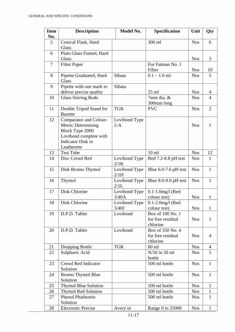
GENERAL AND SPECIFIC CONDITIONS
11-17
Item No.
Description Model No. Specification Unit Qty
5 Conical Flask, Hard Glass
300 ml Nos 6
6 Plain Glass Funnel, Hard Glass
Nos
3
7 Filter Paper For Fatman No. 1 Filter
Nos
10
8 Pipette Graduated, Hard Glass
Sibata 0.1 – 1.0 ml Nos 5
9 Pipette with one mark to deliver precise quality
Sibata 25 ml
Nos
4
10 Glass Stirring Rods 7mm dia. & 300mm long
Nos 4
11 Double Tripod Stand for Burette
TGK PVC Nos 2
12 Comparator and Colour-Metric Determining Block Type 2000 Lovibond complete with Indicator Disk in Leatherette
Lovibond Type 2-A
Nos
1
13 Test Tube 10 ml Nos 12 14 Disc Cresol Red Lovibond Type
2/1K Red 7.2-8.8 pH test Nos 1
15 Disk Bromo Thymol Lovibond Type 2/1H
Blue 6.0-7.6 pH test Nos 1
16 Thymol Lovibond Type 2/1L
Blue 8.0-9.0 pH test Nos 1
17 Disk Chlorine Lovibond Type 3/40A
0.1-1.0mg/l (Red colour test)
Nos
1
18 Disk Chlorine Lovibond Type 3/40J
0.1-2.0mg/l (Red colour test)
Nos
1
19 D.P.D. Tablet Lovibond Box of 100 No. 1 for free residual chlorine
Nos
1
20 D.P.D. Tablet Lovibond Box of 350 No. 4 for free residual chlorine
Nos
4
21 Dropping Bottle TGK 60 ml Nos 4 22 Sulphuric Acid N/50 in 50 ml
bottle Nos 5
23 Cresol Red Indicator Solution
500 ml bottle Nos 1
24 Bromo Thymol Blue Solution
500 ml bottle Nos 1
25 Thymol Blue Solution 500 ml bottle Nos 1 26 Thymol Red Solution 500 ml bottle Nos 1 27 Phenol Phatherein
Solution 500 ml bottle Nos 1
28 Electronic Precise Avery or Range 0 to 25009 Nos 1

GENERAL AND SPECIFIC CONDITIONS
11-18
Item No.
Description Model No. Specification Unit Qty
Analytical weighing balance
Approved Equipment
in milligram divisions
29 Turbidity Rod Nos 1 30 Wet Bulb Thermometers Nos 1 31 Dry Bulb Thermometer Nos 1
1182. TRAINING OF EMPLOYER’S PERSONNEL On commissioning of all the Works, the Contractor will be responsible for the operation and maintenance of the Works for 4 weeks, during which period training of WWSC Staff will be done.
During the above training period, the Contractor will deploy specialised persons capable
of giving theoretical and practical training to the WWSC’s Staff in the following fields: • operation and maintenance • treatment process and laboratory tests • mechanical / electrical units
After the training period, the Plant Manager(s) or other Designated Staff by WWSC will take over the operation of the Works. In the Bid, the Contractor shall outline his proposal for training. An item for such training is allowed for in the Bills of Quantities. Prior to Commissioning of the Works, a detailed training programme shall be submitted to the Engineer for approval. The training shall be divided into four different levels: 1. Training of Management Staff and Department Heads: Theoretical and Practical Seminar(s) 2. Training of Skilled Personnel: Short theoretical introduction and practical seminar(s)
The laboratory personnel shall be trained in analysing various parameters and handling of laboratory equipment. Include for training of Plant Operators especially in operation and maintenance of electro/mechanical equipment
3. Training of Unskilled Personnel:
Familiarisation with various appurtenances of the Works and daily and routine works associated with maintenance works
4. General Operation and Maintenance of all the Works i.e. daily, weekly, monthly
and yearly procedures to be followed, recording of observations, and reporting action plan for any remedial works, etc.

GENERAL AND SPECIFIC CONDITIONS
12-1
12. ELECTRICAL INSTALLATION
1201. CONTRACTOR’S LICENCE The complete electrical installation shall be carried out by a Registered Electrical Contractor with the valid Class ‘A’ Electrician’s License issued by the Ministry of Energy & Regional Development of the Republic of Kenya.
1202. REGULATIONS AND STANDARDS The complete electrical installation shall be carried out as per the Specifications and complying with the following documents: - a) Regulations for the Electrical Equipment of Buildings (14th Edition) issued by the
Institution of Electrical Engineers of Great Britain. b) Electric Power Act and the Rules made thereunder.
c) The Kenya Power & Lighting Co. Ltd.’s Bye-Laws.
d) Relevant current British, Deutsche Industries Norm (DIN), International Standards
Organisation and Kenya Standard Specifications and Codes of Practice.
e) Government Electrical Specification GES 1 and 2, which can be seen at the office of Chief Electrical Engineer of Ministry of Public Works.
Regulations of 14th Edition of I.E.E. Regulations are in force at present in Kenya and are to be observed in conjunction with other related local Bye-Laws and Acts.
1203. EXTENT OF ELECTRICAL WORK WITHIN CONTRACT The electrical works in the proposed development are required to be complete in all respects as specified herein and shall include all items of equipment, materials, accessories, switchgear, lighting fittings, cables, labour, etc., necessary whether such items are specifically referred in the Contract or not. The Contractor shall be deemed to have included in his Bid, price for all items necessary such that the installations are complete in all respects and left in a satisfactory working order. The Contractor will be responsible for liaison with the Kenya Power & Lighting Company Limited and the Kenya Posts & Telecommunications Corporation to suit the incoming power and telephone requirements. The Contractor shall include for all Civil Works, Structures, Foundations, Builder’s Works and associated requirements for the mounting, housing and support of all items of plant and equipment supplied and installed under this Contract. The concrete foundation will be to approved manufacturer’s details and instructions. All work and materials are to be of the best quality approved by the Engineer and strictly in accordance with the Specification.
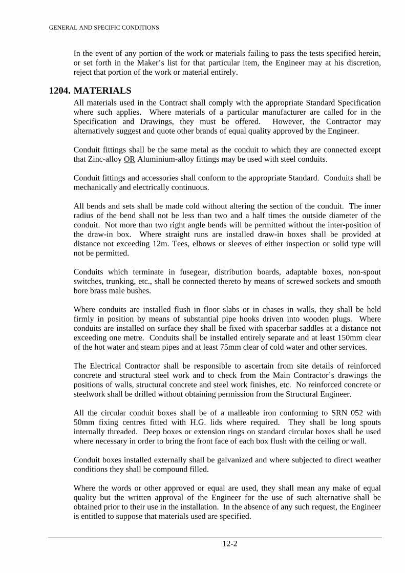
GENERAL AND SPECIFIC CONDITIONS
12-2
In the event of any portion of the work or materials failing to pass the tests specified herein, or set forth in the Maker’s list for that particular item, the Engineer may at his discretion, reject that portion of the work or material entirely.
1204. MATERIALS All materials used in the Contract shall comply with the appropriate Standard Specification where such applies. Where materials of a particular manufacturer are called for in the Specification and Drawings, they must be offered. However, the Contractor may alternatively suggest and quote other brands of equal quality approved by the Engineer. Conduit fittings shall be the same metal as the conduit to which they are connected except that Zinc-alloy OR Aluminium-alloy fittings may be used with steel conduits. Conduit fittings and accessories shall conform to the appropriate Standard. Conduits shall be mechanically and electrically continuous. All bends and sets shall be made cold without altering the section of the conduit. The inner radius of the bend shall not be less than two and a half times the outside diameter of the conduit. Not more than two right angle bends will be permitted without the inter-position of the draw-in box. Where straight runs are installed draw-in boxes shall be provided at distance not exceeding 12m. Tees, elbows or sleeves of either inspection or solid type will not be permitted. Conduits which terminate in fusegear, distribution boards, adaptable boxes, non-spout switches, trunking, etc., shall be connected thereto by means of screwed sockets and smooth bore brass male bushes. Where conduits are installed flush in floor slabs or in chases in walls, they shall be held firmly in position by means of substantial pipe hooks driven into wooden plugs. Where conduits are installed on surface they shall be fixed with spacerbar saddles at a distance not exceeding one metre. Conduits shall be installed entirely separate and at least 150mm clear of the hot water and steam pipes and at least 75mm clear of cold water and other services. The Electrical Contractor shall be responsible to ascertain from site details of reinforced concrete and structural steel work and to check from the Main Contractor’s drawings the positions of walls, structural concrete and steel work finishes, etc. No reinforced concrete or steelwork shall be drilled without obtaining permission from the Structural Engineer. All the circular conduit boxes shall be of a malleable iron conforming to SRN 052 with 50mm fixing centres fitted with H.G. lids where required. They shall be long spouts internally threaded. Deep boxes or extension rings on standard circular boxes shall be used where necessary in order to bring the front face of each box flush with the ceiling or wall. Conduit boxes installed externally shall be galvanized and where subjected to direct weather conditions they shall be compound filled.
Where the words or other approved or equal are used, they shall mean any make of equal quality but the written approval of the Engineer for the use of such alternative shall be obtained prior to their use in the installation. In the absence of any such request, the Engineer is entitled to suppose that materials used are specified.
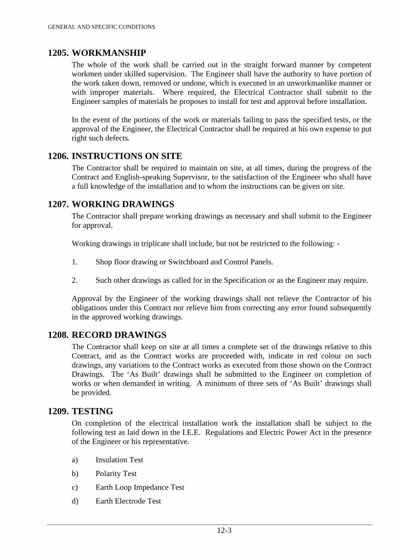
GENERAL AND SPECIFIC CONDITIONS
12-3
1205. WORKMANSHIP The whole of the work shall be carried out in the straight forward manner by competent workmen under skilled supervision. The Engineer shall have the authority to have portion of the work taken down, removed or undone, which is executed in an unworkmanlike manner or with improper materials. Where required, the Electrical Contractor shall submit to the Engineer samples of materials he proposes to install for test and approval before installation. In the event of the portions of the work or materials failing to pass the specified tests, or the approval of the Engineer, the Electrical Contractor shall be required at his own expense to put right such defects.
1206. INSTRUCTIONS ON SITE The Contractor shall be required to maintain on site, at all times, during the progress of the Contract and English-speaking Supervisor, to the satisfaction of the Engineer who shall have a full knowledge of the installation and to whom the instructions can be given on site.
1207. WORKING DRAWINGS The Contractor shall prepare working drawings as necessary and shall submit to the Engineer for approval. Working drawings in triplicate shall include, but not be restricted to the following: - 1. Shop floor drawing or Switchboard and Control Panels.
2. Such other drawings as called for in the Specification or as the Engineer may require.
Approval by the Engineer of the working drawings shall not relieve the Contractor of his obligations under this Contract nor relieve him from correcting any error found subsequently in the approved working drawings.
1208. RECORD DRAWINGS The Contractor shall keep on site at all times a complete set of the drawings relative to this Contract, and as the Contract works are proceeded with, indicate in red colour on such drawings, any variations to the Contract works as executed from those shown on the Contract Drawings. The ‘As Built’ drawings shall be submitted to the Engineer on completion of works or when demanded in writing. A minimum of three sets of ‘As Built’ drawings shall be provided.
1209. TESTING On completion of the electrical installation work the installation shall be subject to the following test as laid down in the I.E.E. Regulations and Electric Power Act in the presence of the Engineer or his representative. a) Insulation Test
b) Polarity Test
c) Earth Loop Impedance Test
d) Earth Electrode Test
GENERAL AND SPECIFIC CONDITIONS
12-4
Any other test which may be required by the Engineer. The results of all the tests shall be recorded on a Test Certificate to be signed by the Contractor and submitted to the Client for record. The original of the Test Certificate shall be submitted to the Kenya Power & Lighting Co. Ltd. together with a Completion Certificate. The Contract works shall not be considered complete until all testing has been completed to the satisfaction of the Engineer and the Record Drawings have been approved as installed and all specified spares have been provided.
1210. M.V. SWITCHBOARD This shall be self supporting, floor mounted, totally enclosed, dust-proof, air-insulated cubicle type switchboard complying with SRN 027 designed for use of 415/440 volts, 3 phase, 50 cycles, 4-wire A.C. System and having a short circuit rating of 31 MVA at low power factor. The switchboard shall be fully front access or near access as instructed by the Engineer. The switchboard shall be completely wired internally using manufacturer’s links for connections between busbar and switch fuses. The switchboard shall be complete with labels and ready for installation. The fuse switch shall be with H.R.C. fuses with fully interlocked front door and conforming to SRN 007 on moulded case circuit breakers conforming to SRN 040. The busbars shall be of high conductivity copper and shall be manufactured and tested in accordance with SRN 053. They shall be mounted fully enclosed within the main enclosure of the switchboard in separate chamber in accordance with SRN 027. The busbars shall be fully separated from the incoming and outgoing cable areas. Except for instrument, potential or current connections, which shall be clamped in position and of minimum length, no circuit wiring shall be within the busbar chamber. Such wiring shall be protected with fuses where necessary as called for by the Engineer. Interconnections between busbars and switchgear shall be of minimum length, properly insulated and rigidly supported. All contact areas of the busbar and the connections fastened to the busbars shall be heavily plated. Joints and connections shall be rigidly made with clamps, bolts and nuts with spring washers.
1211. CONDUIT SYSTEM a) Metallic Conduits and Accessories
Metallic conduits shall be of heavy gauge solid drawn or welded steel to SRN 052. No conduit shall be less than 20mm diameter. Conduits installed within the buildings shall be black enamel finish. Where installed externally or on surface in basement areas, conduits shall be galvanized.
GENERAL AND SPECIFIC CONDITIONS
12-5
b) Non-Metallic Conduits and Accessories
These shall be rigid PVC super high impact heavy gauge Class ‘A’ conduit to SRN 054. No conduit shall be smaller than 20mm diameter. Joints shall be made by using an approved cement. Tube and fittings shall be perfectly clean and free from greases. The cement shall be applied to both surfaces and the tube shall be rotated within the accessory to ensure complete coverage. In cases of screwed joints, tubes shall be screwed with standard stocks and dies and shall be used with threaded accessories. PVC conduits shall be used only in situation where ambient temperature is between 70 degrees centigrade (153 degrees Fahrenheit) - 60 degrees centigrade (140 degrees Fahrenheit). Expansion couplers shall be used in straight runs exceeding 6 metre with flexible type joint. These couplers shall be extended in length, the one end of which shall be bored standard depth and the other end shall be provided with a sliding entrance over a longer distance allowing the tube to slide up and down as it expands or contracts. For a watertight joint, adhesive shall be used for the sliding end. All PVC conduit boxes shall be circular pattern of Rigid PVC with push fit or screwed spout conformed to SRN 054, and circular looping boxes to SRN 054.
1212. GENERAL WIRING The wiring throughout shall be in looping cables from point to point and no tee or other joints shall be permitted. Conductors of the same circuit shall be contained in the same conduit of trunking. At distribution boards, the neutral conductors shall be connected to the neutral bar in the same sequence as the line conductors connected to fuses or circuit breakers so that they can be readily identified. a) PVC Cables in Conduits
PVC cables in conduits unless otherwise specified shall conform to SRN 055, 600/1000 volts grade, single core PVC insulated. No cable smaller than 1.5mm2 shall be used in the installation.
b) Flexible Cords
Flexible cords shall be of 300 volts grade, V.R.I. OR PVC insulated conforming to SRN 056. No flexible cord shall be smaller than 0.72mm2 (24/0.20mm).
c) PVC These cables shall be 600/1000 volt grade, conforming to SRN 024 having standard copper conductors with PVC insulation, cores laid up circular, PVC sheath beading, single wire armour and PVC sheath. The cables shall be terminated on distribution boards, switchboards, trunking or adaptable box with compression type brass gland with locknuts and shroud. d) PVC Armoured Cables (with Aluminium Conductors)
GENERAL AND SPECIFIC CONDITIONS
12-6
These cables shall be 600/1000 volt grade, conforming to SRN 063 having cores of solid Aluminium conductors, insulated with PVC, armoured with aluminium strip or steel wire with PVC sheath overall.
e) M.I.C.C. Cables
These cables shall be 440 or 660 volt grade consisting of high conductivity copper conductors embedded in pure and dense, magnesium oxide insulation, contained in a robust yet ductile, seamless, solid drawn copper sheath conforming to SRN 057. Where installed in corrosive situations, they shall be sheathed with PVC sleeving. Terminations of cables shall be provided with sleeves having a temperature rating similar to that of the seals. Terminations shall be made by means of cold screw on pot type seals and in conjunction with ring type universal glands. The greatest care shall be exercised at all times when terminating M.I.C.C. cables and insulation after. All cables shall give infinity test when tested on 1000 volt megger.
Where single core M.I.C.C. cables are used, all necessary precautions shall be taken to prevent Hysteresis. Ferrous plates or structure through which the cables pass shall be slotted and brass glands and sockets shall be used.
f) Wiring System
System A - Cables enclosed in concealed steel screwed conduit or trunking The wiring shall be carried out in PVC insulated cables installed in steel screwed conduit or trunking concealed in floor slabs, walls of buildings, installed in roof space or concealed in structural beams and columns. System B - Cables enclosed in steel screwed conduits or trunking fixed to the surface of walls and ceiling The wiring shall be carried out in PVC insulated cables installed in steel screwed conduit or trunking installed on the surface of the walls and ceiling or in false ceiling spaces. Conduits shall be screwed in position by means of space bar saddles using brass round head screws fixed with rawlplags. Where two or more conduits are installed in parallel, multiple saddles which are screwed between each way shall be used. Conduits shall be installed horizontally on the walls and vertically to switches or outlets. System C - Cables enclosed in concealed non-metallic conduits The wiring shall be carried out in PVC insulated cables installed in rigid, PVC super high impact heavy gauge conduit concealed in floor slabs, walls of buildings in ceiling space or concealed in structural beams and columns. Each continuity conductor shall be installed throughout the length of the conduit. System D - Cables enclosed in non-metallic conduits fixed to the surface of walls and ceilings
GENERAL AND SPECIFIC CONDITIONS
12-7
The wiring shall be carried out in PVC insulated cables installed in rigid PVC super high impact heavy gauge conduit installed on surface of the walls and ceiling or in false ceiling spaces. Where straight run of conduit in excess of 6m are installed on the surface and approved expansion coupling must be installed at every 6m distance. Switch boxes and lighting point boxes shall be fitted with purpose made earthing connectors. Lighting point outlet boxes shall be fitted with steel insert clips to prevent distortion under load. System E - M.I.C.C. cables installed on surface of the walls and ceilings in the roof space or concealed in walls and floors M.I.C.C. cables shall be secured with copper saddles fixed at 375mm centres on vertical runs and 525mm centres on horizontal runs. Termination shall be made by means of cold screw on pot type seals and conjunctions with ring type universal glands. Insulation test shall be taken as described in Clause 1209 above. System F - cables clipped to the roof members and run in steel conduit or rigid PVC conduit drops concealed in walls The wiring shall be in PVC insulated and sheathed cables securely fixed to the roof member by means of buckle clips and then to switches and outlets through conduit drop (steel conduit or rigid conduit). Earth continuity conductor shall be run throughout, if PVC single insulated and sheathed cables are used or PVC twin with earth shall be used. System G - PVC insulated and sheathed cables clipped to the surface of the wall and roof members or to the ceiling The wiring shall be in PVC insulated and sheathed cables fixed to the roof member, surface of the walls and ceiling only when there is no reasonable access from above. They shall be fixed by means of buckle clips. Where cables pass through holes they shall be bushed. System H - PVC insulated single wire armoured, PVC sheathed cables laid in ducts or saddled to walls All the PVC insulated single wire armoured PVC cables laid direct in the ground shall be laid at minimum depth of 600mm, on 75mm bed of sand. Cables shall be suspended on purpose made frames and hangers, drawn through ducts or laid in trenches. Cables suspended on multiple hangers shall be so arranged that one can be removed without disturbing the other. Frames and hangers shall be galvanized or of non-ferrous material and shall not be fixed in contact with which they are liable to set up electrolytic action. All spacing of cable hangers and supports shall not exceed those laid down for the relevant size and type of cables in the I.E.E. regulations. PVC SWA cables laid direct in ground shall be provided with concrete cable tiles marked “Danger”, “Hatari”, throughout. Cables shall be terminated using brass compression glands and cable lugs of appropriate size.
1213. LIGHTING SWITCHES Flush Switches
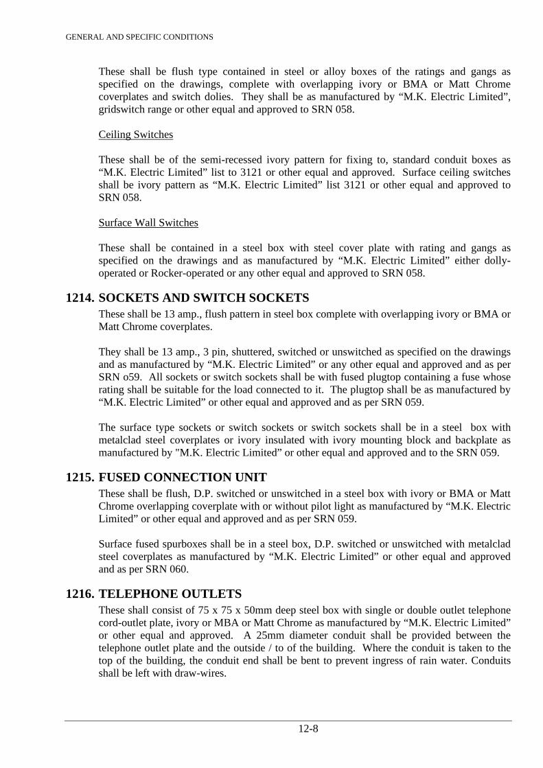
GENERAL AND SPECIFIC CONDITIONS
12-8
These shall be flush type contained in steel or alloy boxes of the ratings and gangs as specified on the drawings, complete with overlapping ivory or BMA or Matt Chrome coverplates and switch dolies. They shall be as manufactured by “M.K. Electric Limited”, gridswitch range or other equal and approved to SRN 058. Ceiling Switches These shall be of the semi-recessed ivory pattern for fixing to, standard conduit boxes as “M.K. Electric Limited” list to 3121 or other equal and approved. Surface ceiling switches shall be ivory pattern as “M.K. Electric Limited” list 3121 or other equal and approved to SRN 058. Surface Wall Switches These shall be contained in a steel box with steel cover plate with rating and gangs as specified on the drawings and as manufactured by “M.K. Electric Limited” either dolly-operated or Rocker-operated or any other equal and approved to SRN 058.
1214. SOCKETS AND SWITCH SOCKETS These shall be 13 amp., flush pattern in steel box complete with overlapping ivory or BMA or Matt Chrome coverplates. They shall be 13 amp., 3 pin, shuttered, switched or unswitched as specified on the drawings and as manufactured by “M.K. Electric Limited” or any other equal and approved and as per SRN o59. All sockets or switch sockets shall be with fused plugtop containing a fuse whose rating shall be suitable for the load connected to it. The plugtop shall be as manufactured by “M.K. Electric Limited” or other equal and approved and as per SRN 059. The surface type sockets or switch sockets or switch sockets shall be in a steel box with metalclad steel coverplates or ivory insulated with ivory mounting block and backplate as manufactured by "M.K. Electric Limited” or other equal and approved and to the SRN 059.
1215. FUSED CONNECTION UNIT These shall be flush, D.P. switched or unswitched in a steel box with ivory or BMA or Matt Chrome overlapping coverplate with or without pilot light as manufactured by “M.K. Electric Limited” or other equal and approved and as per SRN 059. Surface fused spurboxes shall be in a steel box, D.P. switched or unswitched with metalclad steel coverplates as manufactured by “M.K. Electric Limited” or other equal and approved and as per SRN 060.
1216. TELEPHONE OUTLETS These shall consist of 75 x 75 x 50mm deep steel box with single or double outlet telephone cord-outlet plate, ivory or MBA or Matt Chrome as manufactured by “M.K. Electric Limited” or other equal and approved. A 25mm diameter conduit shall be provided between the telephone outlet plate and the outside / to of the building. Where the conduit is taken to the top of the building, the conduit end shall be bent to prevent ingress of rain water. Conduits shall be left with draw-wires.
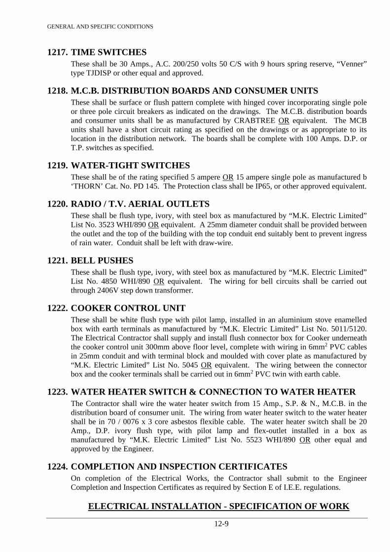
GENERAL AND SPECIFIC CONDITIONS
12-9
1217. TIME SWITCHES These shall be 30 Amps., A.C. 200/250 volts 50 C/S with 9 hours spring reserve, “Venner” type TJDISP or other equal and approved.
1218. M.C.B. DISTRIBUTION BOARDS AND CONSUMER UNITS These shall be surface or flush pattern complete with hinged cover incorporating single pole or three pole circuit breakers as indicated on the drawings. The M.C.B. distribution boards and consumer units shall be as manufactured by CRABTREE OR equivalent. The MCB units shall have a short circuit rating as specified on the drawings or as appropriate to its location in the distribution network. The boards shall be complete with 100 Amps. D.P. or T.P. switches as specified.
1219. WATER-TIGHT SWITCHES These shall be of the rating specified 5 ampere OR 15 ampere single pole as manufactured b ‘THORN’ Cat. No. PD 145. The Protection class shall be IP65, or other approved equivalent.
1220. RADIO / T.V. AERIAL OUTLETS These shall be flush type, ivory, with steel box as manufactured by “M.K. Electric Limited” List No. 3523 WHI/890 OR equivalent. A 25mm diameter conduit shall be provided between the outlet and the top of the building with the top conduit end suitably bent to prevent ingress of rain water. Conduit shall be left with draw-wire.
1221. BELL PUSHES These shall be flush type, ivory, with steel box as manufactured by “M.K. Electric Limited” List No. 4850 WHI/890 OR equivalent. The wiring for bell circuits shall be carried out through 2406V step down transformer.
1222. COOKER CONTROL UNIT These shall be white flush type with pilot lamp, installed in an aluminium stove enamelled box with earth terminals as manufactured by “M.K. Electric Limited” List No. 5011/5120. The Electrical Contractor shall supply and install flush connector box for Cooker underneath the cooker control unit 300mm above floor level, complete with wiring in 6mm2 PVC cables in 25mm conduit and with terminal block and moulded with cover plate as manufactured by “M.K. Electric Limited” List No. 5045 OR equivalent. The wiring between the connector box and the cooker terminals shall be carried out in 6mm2 PVC twin with earth cable.
1223. WATER HEATER SWITCH & CONNECTION TO WATER HEATER The Contractor shall wire the water heater switch from 15 Amp., S.P. & N., M.C.B. in the distribution board of consumer unit. The wiring from water heater switch to the water heater shall be in 70 / 0076 x 3 core asbestos flexible cable. The water heater switch shall be 20 Amp., D.P. ivory flush type, with pilot lamp and flex-outlet installed in a box as manufactured by “M.K. Electric Limited” List No. 5523 WHI/890 OR other equal and approved by the Engineer.
1224. COMPLETION AND INSPECTION CERTIFICATES On completion of the Electrical Works, the Contractor shall submit to the Engineer Completion and Inspection Certificates as required by Section E of I.E.E. regulations.
ELECTRICAL INSTALLATION - SPECIFICATION OF WORK
GENERAL AND SPECIFIC CONDITIONS
12-10
1225. SCOPE OF WORK Scope of work shall include the following: - a) Various Buildings
Complete installation of lighting, power, telephone points, lighting fittings, distribution board, meter board, etc. in all buildings at the Water Treatment Works.
b) Security Lighting
Complete installation of security lighting with columns, cables, lanterns, distribution board, etc.
c) Supply and Installation of generator in the generator / switchroom.

GENERAL AND SPECIFIC CONDITIONS
13-1
13. PARTICULAR SPECIFICATION FOR ELECTRICAL WORKS
1301. EXTENT OF WORK The work includes the supply of all labour, material, equipment, plant and components necessary for the complete installation and setting to work of the entire electrical services for the following system as shown on the drawings. a) Income electricity supplies b) Solar PV system and associated works b) Medium voltage switchboard c) Electrical distribution system d) Electric lighting and power installation e) Security lighting installation f) Telephone system g) Rehabilitation Works
The site of work is as follows: -
1302. INCOMING ELECTRICITY SUPPLIES a) Water Treatment Works The incoming electricity supplies to the Main M.V. Switchboards are located within the switchrooms.
The incoming service cable shall be four cores and the size and type of cable shall be decided by the Kenya Power & Lighting Company Limited due to increased loads and it will be laid and jointed to the cut-outs in the M.V. Switchboard by the supply authority. The M.V. Switchboards for the Water Treatment Works shall be supplied and installed under this Contract.
1303. MEDIUM VOLTAGE SWITCHBOARD a) Medium Voltage Switchboards at the Water Treatment Works
The construction of the M.V. Switchboard shall be self-supporting, floor mounted, totally enclosed, dust-proof, cubicle type switchboard as described in Clause No. 1210. General layout of the switchboards shall be submitted to the Engineer for approval before commencing to manufacture.
b) General The general arrangement of incoming and outgoing circuits shall be as shown on Site Plans for each Town.
c) Labels
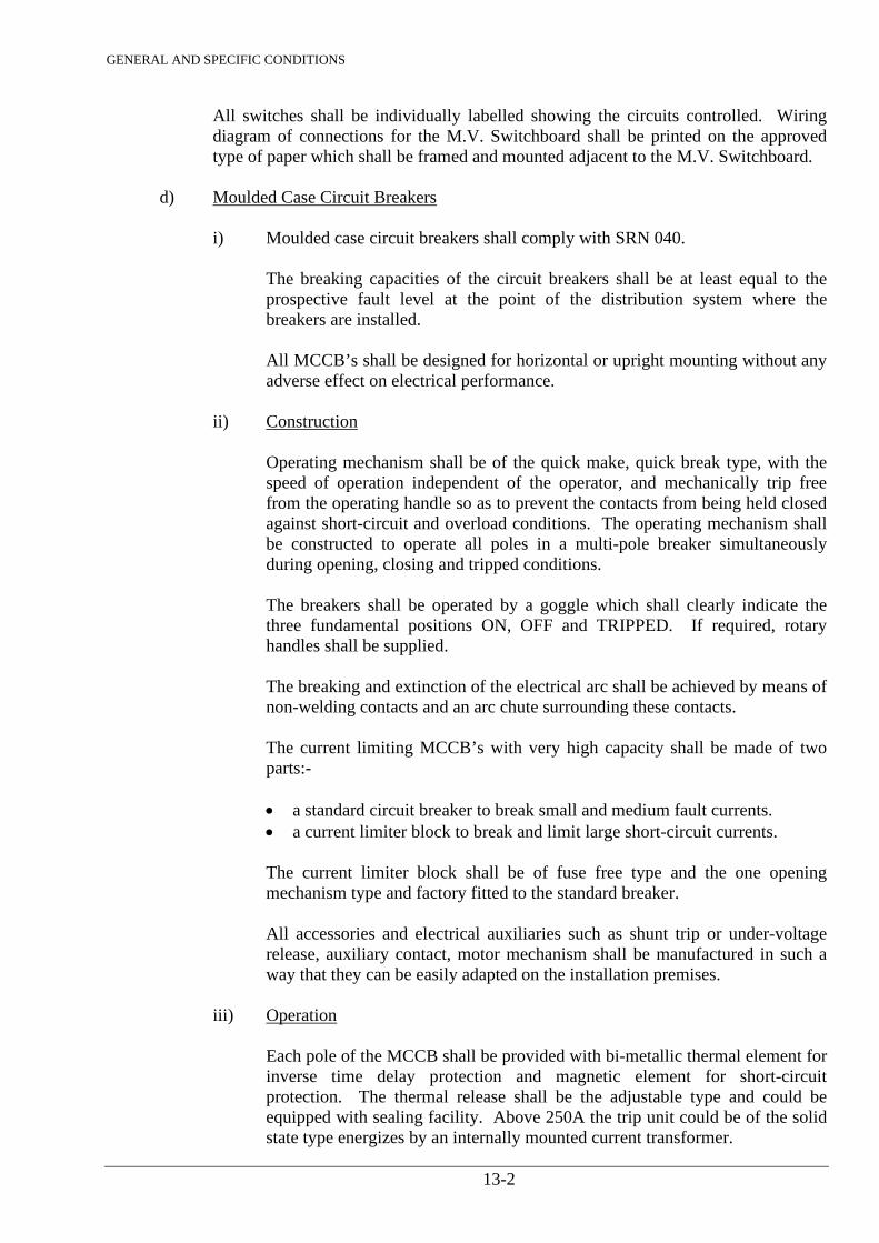
GENERAL AND SPECIFIC CONDITIONS
13-2
All switches shall be individually labelled showing the circuits controlled. Wiring diagram of connections for the M.V. Switchboard shall be printed on the approved type of paper which shall be framed and mounted adjacent to the M.V. Switchboard.
d) Moulded Case Circuit Breakers
i) Moulded case circuit breakers shall comply with SRN 040. The breaking capacities of the circuit breakers shall be at least equal to the
prospective fault level at the point of the distribution system where the breakers are installed.
All MCCB’s shall be designed for horizontal or upright mounting without any
adverse effect on electrical performance. ii) Construction Operating mechanism shall be of the quick make, quick break type, with the
speed of operation independent of the operator, and mechanically trip free from the operating handle so as to prevent the contacts from being held closed against short-circuit and overload conditions. The operating mechanism shall be constructed to operate all poles in a multi-pole breaker simultaneously during opening, closing and tripped conditions.
The breakers shall be operated by a goggle which shall clearly indicate the
three fundamental positions ON, OFF and TRIPPED. If required, rotary handles shall be supplied.
The breaking and extinction of the electrical arc shall be achieved by means of
non-welding contacts and an arc chute surrounding these contacts. The current limiting MCCB’s with very high capacity shall be made of two
parts:-
• a standard circuit breaker to break small and medium fault currents. • a current limiter block to break and limit large short-circuit currents.
The current limiter block shall be of fuse free type and the one opening mechanism type and factory fitted to the standard breaker. All accessories and electrical auxiliaries such as shunt trip or under-voltage release, auxiliary contact, motor mechanism shall be manufactured in such a way that they can be easily adapted on the installation premises.
iii) Operation Each pole of the MCCB shall be provided with bi-metallic thermal element for
inverse time delay protection and magnetic element for short-circuit protection. The thermal release shall be the adjustable type and could be equipped with sealing facility. Above 250A the trip unit could be of the solid state type energizes by an internally mounted current transformer.
GENERAL AND SPECIFIC CONDITIONS
13-3
It shall not require any external power supply to operate the tripping
mechanism. All MCCB’s shall be provided with interchargeable trip unit. Current discrimination tables showing overload and short-circuit
discrimination shall be provided for each rating of breaker.
e) Starters
The starters and controllers shall comply in all respects to SRN 008 and shall form complete units within the switchboard.
The control and protection arrangements shall be suitable for the type, size, voltage
and duty capability of the relevant motor. The Contractor shall submit in details of the control and protection equipment which he proposes to use for each type and size of motor.
f) Starting of Three-Phase Motors The Contractor shall liaise fully with the Kenya Power & Lighting Company Limited
to determine and agree the method of starting for the pumping plant and associated motors. The Contractor shall provide pumping plant/motor plant and associated starting equipment such that they fully meet the requirements of the Kenya Power & Lighting Company Limited. This may necessitate the use of slip ring motors and associated starters for the large pumping sets. It shall be deemed that the prices entered by the Contractor include for all motors/starters to meet the specification and the Kenya Power & Lighting Company’s requirements.
Supply and installation of pumping plants/motors are covered under another section
of the specification/ g) Equipment for Starters of Motors The starters shall be of a current limiting type suitable for remote, automatic and local
manual operation and equipment as follows:
1) Contactor shall be of the air break type fitted with arch chutes, magnetic blow outs and heavy hard drawn copper main contacts.
2) Timing relay, where required, shall be electro-magnetic operated controlling
timing of contactor sequence; a fully adjustable eddy current retarding mechanism shall be provided where necessary to suit the nature and conditions of the motor.
3) Continuously rated operated coil (240 volts). 4) Auxiliary contacts for remote automatic control. 5) Adjustable over-voltage and under-voltage relay units complete with timer to
allow for voltage dip associated with the Kenya Power & Lighting Company’s supply and motor starting. Voltage setting to be agreed.
GENERAL AND SPECIFIC CONDITIONS
13-4
6) Overload relays of the adjustable type. 7) Relay unit to prevent single phasing. 8) Three ammeters; each in each phase with two times overload scale. 9) Indicator lamps – “Motor Running – Green Indicator”, “Motor Trip – Amber”. 10) Rotary switch for HAND/OFF/AUTO operation. 11) Removable neutral link of copper. 12) Motor winding over-temperature release. 13) Duty selection switches. 14) Manual stop-start button units to operate with Rotary switch (10) above. 15) Earth leakage protection relay unit. 16) Relay unit to prevent phase reversal. 17) Relay unit to prevent sudden overload or jamming etc. 18) Hours run meter. 19) Power factor meter.
h) Connections to Electric Motors Where the Contractor is required to connect to electric motors all reasonable
precautions shall be taken to ensure that the connections are unaffected by vibration. Conduits used for motor circuits shall terminate at a suitable junction box mounted
adjacent to the motor and a flexible conduit used between the junction box and the terminal box. Approved adaptors shall be used at each end of the flexible conduit. The insulated stranded tinned copper bonding earth conductor of the circuit, generally of the same size as the phase wire but in no case less than 2.5mm2, shall be connected to the earth terminal of the motor starter and run inside the flexible conduit and/or conduit system to earth terminal of the motor terminal block.
PVC sheathed and steel wire armoured cables shall be terminated with appropriate
glands of the type as previously specified, in the terminal box of the motor. i) Power Factor Correction Power factor correction capacitors have been indicated on the drawing. The
Contractor shall liaise with the Kenya Power & Lighting Company Limited and include correction as required. The connection being carried out at each motor starter
GENERAL AND SPECIFIC CONDITIONS
13-5
rather than a bulk connection on each switchboard as indicated on the drawings. It is the responsibility of the Contractor to include in his prices for this requirement as no claims will be entertained at a later date should it be found that the power factor is not to the requirement of the supply authority.
j) Contactors Contactors where required shall be suitable for continuous heavy duty and normally
fitted with 240 volt coils. They shall be of robust construction to SRN 061 where applicable and rated at not less than the current carrying capacity of the outgoing circuit or as indicated on the drawings.
k) Electric Photocell Electric Photocell for the automatic control of the external lighting including
contactors shall be fitted in the M.V. Switchboard as indicated on the drawings. l) Cables to Pump Sets The cables shall be generally PVCSWAPVC. The cables from the M.V. Switchboard
to the motor terminals shall run on cable trays. The Contractor shall ensure that the final connections to all motors are suitably flexible.
m) Automatic Change-Over Contactor Unit
i) General The Contractor shall supply and install complete and automatic change-over contactor to operate in conjunction with the KPLC supply and the Standby Diesel Generating Plant. The automatic change-over contactors shall be housed within the cubicle type L.V. Switchboard as shown on the drawing.
ii) Contactor Unit
The automatic change-over contactor unit shall consist of contactors feeding a common busbar system to which the load shall be directly connected. One contactor shall control the normal mains supply and the other shall control the standby diesel generating plant supply. Substantial mechanical and electrical interlocks shall be provided so that both supplies cannot be closed at the same time. The change-over contactor unit shall be suitable for continuous rating and shall be of robust construction.
iii) Manual Change-Over Switches Manual change-over switches shall be provided so that the supply can be maintained from source, normal or standby in the event of a contactor failure. These shall be suitable for continuous rating and robust construction. They shall be installed in a separate compartment in the main L.V. Switchboard.

GENERAL AND SPECIFIC CONDITIONS
13-6
iv) Operation
In the event of a KPLC power supply failure, the automatic change-over contactor shall be designed to break the connections of the normal incoming mains supply and make the connections to the standby diesel generator set. When the normal supply is restored the reverse action shall take place. The standby generator shall also operate if there is loss of one or more phases on the incoming KPLC supply cable. The automatic change-over unit shall come into operation in the event of one or more of the following occurring: - • Loss of KPLC supply; • Loss of one or more phases; • Under-voltage, within prescribed limits; • Over-voltage, within prescribed limits; • Any other feature offered by the specialist manufacturers.
With the restoration of the KPLC supply to the normal voltage, frequency and regulation, the automatic change-over unit shall again, automatically connect the buildings back onto the mains, this taking place after a prescribed time to prevent the continual starting/stopping of the Diesel Generating Plant in the event of there being intermittent KPLC interruptions. Suitable timers shall be provided so that the change-back period can be adjusted and agreed with the Client. The protection relays and monitoring device shall be suitably mounted and located on the incoming supply with signal cables extended to the Diesel Generator Control Panel. The Diesel Generator shall continue to run for a pre-determined period after the restoration of the mains supply before finally shutting down and reverting, automatically, to a standby power unit ready to start-up in the event of loss of KPLC supply. Full details shall be agreed with the Engineer.
n) Under Voltage and Over Voltage Protection
To safeguard against voltage spikes suitable under-voltage and over-voltage protection relays shall be supplied and installed under this Contract. The relay units shall be of adjustable type and shall be suitable for operation under all voltage conditions anticipated. The unit shall be housed in the main L.V. switchboard. The Contractor shall include for one under-voltage protection relay unit of -15% and over-voltage protection relay unit +15%. Details shall be submitted with the Bid and shall be fully discussed and agreed by all parties prior to placing the order.
o) Phase Failure Relays
An alarm system, to indicate when there has been a loss of one or more phases on the incoming supply and the automatic tripping of the main circuit breaker, under these fault conditions shall be supplied and installed under this Contract.
p) Earthing
GENERAL AND SPECIFIC CONDITIONS
13-7
Earthing system shall be provided for the switchboard. Details of earthing shall be
agreed with the Kenya Power & Lighting Company Limited.
1304. ELECTRICAL DISTRIBUTION SYSTEM a) Scope of the Work The Contractor shall supply, deliver, install, test and commission all sub-main cables,
consumer units, etc., to complete the electrical distribution system as shown on the drawings.
b) Sub-Main Cables All sub-main cables shall be PVC insulated with stranded copper conductors and shall
be 600 volts grade. The underground cables (PVCSWAPVC) shall be terminated in brass compression
type cable gland of the correct size which shall secure the cable inner sheath and ensure effective electrical continuity between the cable armouring wires and the metal enclosure on which the cable is terminated. A copper earth link shall be taken from the cable termination point to an associated consumer unit.
c) Wiring System PVCSWAPVC cable from the M.V. Switchboard located within the generator/switch
room at the Water Treatment Works to the various buildings shall be laid in ground as shown on the drawings.
All the other sub-main cables to the consumer units shall be drawn in conduit
concealed in walls, floors and ceiling slabs of the buildings. d) Consumer Units Consumer units, as manufactured by Crabtree, shall be of the flush type complete
with all MCBs and not less than 100 Amp. isolating switches. Details shall be submitted for approval.
e) Contactors Contactors where required shall be suitable for continuous heavy duty and normally
fitted with 240 volt coils. This shall be of robust construction to SRN 061 where applicable and rated at not less than the current carrying capacity of the outgoing circuits.
1305. ELECTRIC LIGHTING AND POWER INSTALLATION a) Scope of the Work The Contractor shall supply, deliver, install, connect, test and commission the electric
lighting and power installation as shown on the drawings. b) Conduit Installation
GENERAL AND SPECIFIC CONDITIONS
13-8
The installation shall be carried out in black rigid super high impact heavy gauge class
‘A’ PVC in accordance with Clause 1211(b). The conduit installation, in general shall be concealed throughout.
The method of installing PVC conduits and fittings shall conform strictly to the
manufacturer’s recommendations. c) Wiring System All cables drawn into conduit shall be PVC insulated 600/1000 volts grade with
copper conductors. Generally conductors shall be stranded and none smaller than 1.5mm2 will be permitted. The circuit wiring shall be continuous throughout on a loop-in-loop-out system and there shall be no joints other than at the conduit boxes. The final connections to the lighting fittings shall be from a conduit box, complete with cord grip. The circuit wiring terminating within the box at a suitably rated terminate block and wiring (via the cord grip) or the fitting carried out in heat resisting 3 core PVC/PVC cable.
A separate insulated earth conductor, coloured green, shall be run in PVC conduits
and earth facilities shall be provided at all terminate points including all lighting points.
The number of cables in any conduit shall not exceed those stated in the Local of
International Regulations. All cables shall be colour coded in accordance with Local Regulations.
d) Flexible Cords Flexible cords shall be PVC insulated and PVC sheathed 300/500 volts. The colour
of PVC sheathing shall be generally white. No flexible conductor smaller than 0.75mm2 shall be used. Core identification shall be phase/brown; neutral/blue and earth/green-yellow.
e) Lighting Switches Lighting switches shall be rated 10 Amp. of the rocker type complete with white
moulded logic range plates all as manufactured by Crabtree, or approved equivalent. All switches shall be flush mounted.
f) Water Heater Switches Water heater switches shall be with neon indicator fitted with 20 Amp. double pole
switch manufactured by Crabtree for flush mounting, or approved equivalent. A flush connector unit shall be fitted where indicated on the drawing. This shall be
manufactured by Crabtree and it shall be connected to the water heater switch with a 20mm diameter conduit.
GENERAL AND SPECIFIC CONDITIONS
13-9
The Contractor shall provide wiring to this unit from the water heater element. The cables shall be of approved flexible heat resistant type.
g) Lighting Fittings The Contractor shall supply, deliver, install, connect, test and commission all the
lighting fittings as specified. These shall be suitable for 240 volts, 50 cycles, A.C. supply. Lighting fittings shall be earthed if required and fluorescent fittings shall be fitted with radio interference suppression capacitors with power factor improvement capacitors. All lighting fittings shall be supplied with lamps. All locally manufactured lighting fittings shall be approved by the Engineer.
h) Telephone Installation The Contractor shall construct the inspection chambers and lay 50 mm diameter PVC
heavy duty conduit as shown on the Site Plan drawing for incoming telephone service cable of Telkom Kenya Limited.
Flush telephone outlets shall be provided where shown on the drawings and it shall be
complete with white finish plate with PVC sleeve cord with internal diameter of 5mm complete with steel clamp to retain sleeve cord on underside. The manufacturer shall be Crabtree, or approved equivalent. The minimum conduit between telephones shall not be less than 25 mm diameter conduit.
j) Switched Socket Outlets These shall be 13 Amp. flush pattern, complete with overlapping white coverplates as
manufactured by Crabtree, or approved equivalent. Unless otherwise stated, 13 Amp. switched socket outlets shall be wired to ring
circuits. The socket outlet plates shall match those of the lighting switch plates. The circuit wiring shall be rated/sized to IEE Regulations and shall not be less than
2.5mm2 PVC. k) Plugs Each socket outlet shall be provided with a 13 Amp. 3 pin plug, fused at 13 Amp. l) Fused connection units shall be switched or unswitched manufactured by Crabtree or
approved equivalent and shall be installed in position as indicated on the drawings. m) Ceiling Roses Ceiling roses shall be of the 3 plate pattern and fitted to all pendants. They shall be
white manufactured by Volex or approved equivalent. n) Cooker Control Units
GENERAL AND SPECIFIC CONDITIONS
13-10
Cooker control units shall be metalclad with neon indicator fitted with 45 Amp. double pole switch, and 13 Amp. switched socket outlet. These shall be manufactured by Crabtree, or approved equivalent.
A flush connector unit shall be fitted where indicated on the drawing. This shall be
manufactured by Crabtree, or approved equivalent and it shall be connected to the cooker control unit with a 25mm diameter conduit.
p) Water Heater Supply and installation of water heaters are covered under another section of the
specification, but the Contractor shall include in his prices for water heater switches, wiring, connections and testing.
q) Remote Indicator Panel (Mimic)
In order to supervise the operation of the pumps and the water levels in clear water tank and elevated backwash tank, the Contractor shall supply, install, test and commission the remote indicator panel. It shall operate from 24 volts D.C. supply. Location: Operator's Room in the Administration Building The remote indicator panel shall be surface type, wall mounting or self-standing floor mounting. It shall comprise a sheet steel, cubicle type, dust proof with front access. The remote indicator panel shall be rigidly constructed with an angle iron or heavy gauge folded steel framework panelled in zinconneal or galvanized sheet of not less than 1.5 mm gauge. Doors shall be of similar rigid construction free from twists and warps. Piano hinges, locks and latches shall be brass and attached with brass screws. Locks shall be spring type, provided with 3 keys. Internal colour shall be white and external colour shall be grey or as approved by the Engineer.
The remote control panel shall be fully equipped with the following items and others: (a) 24 DC volts indicating lamps (22 mm diameter type LED lamps) + alarm (b) 250 VA DC rectifier (c) Push button to test all lamps at a time (d) Wiring, fuses, etc.
Indication on the panel shall be as follows: (a) Pumps - ON - OFF - Trip (b) Indication details are shown on Drawings and shall be submitted to the Engineer
for approval before commencing the manufacture of the Remote Indicator Panel.
r) Marshalling Boxes The marshalling box shall be surface type, wall mounting or suitable for mounting in
the main switchboard panel and control panels for the pumps as required. The marshalling boxes shall comprise a sheet steel, cubicle type with front access. Cubicle type marshalling boxes shall be rigidly constructed with an angle iron and
GENERAL AND SPECIFIC CONDITIONS
13-11
heavy gauge folded steel framework, panelled in zinconneal or galvanized of not less than 1.5 mm gauge.
Doors shall be of similar rigid construction free from twists and warps. Piano hinges and locks or latches shall be brass and fixed with brass screws. Locks shall be spring type, provided with 3 keys. Internal colour shall be white and external colour shall be grey unless otherwise specified or approved by the Engineer. Marshalling boxes shall be equipped with terminal blocks for incoming and outgoing control cables and the terminal blocks shall be numbered.
s) Electrodes Electrodes in the tanks shall be stainless steel of 6 mm diameter and shall be
suspended from top using special electrode holders. Provide electrode separator at every one metre for long electrodes in the water tanks.
1306. LIGHTNING PROTECTION a) Scope of Work
The Contractor shall include for supply, installation and testing of lightning protection. All lightning prevention system shall be in accordance with British Standard C.P. 326 1965 / MOW Technical Instruction No. 58.
b) Lightning Conductor
This shall consist of 25 mm x 3 mm copper tape exposed, between the roof structure and the test clamp. The connections to the earth copper rod from the test clamp shall be made with copper tape of size 25 mm x 3 mm and the protection pipe shall not be less than 38 mm diameter fixed on the walls.
c) Air Terminals
These shall be provided as required on the shape of the buildings of suitable configuration to ensure complete protection.
d) Test Clamps
These shall be provided for each down conductor where indicated on the Drawing and shall be fixed at 1800 mm (6' 0") from finish ground level. No connection should be made to earth tape below the test clamps, except the earth rod.
e) Earth Rods
These shall consist of 16 mm diameter hard drawn copper rods. Approximately 1.5 m long and shall be drawn in the position indicated on the Drawings. There shall not be less than 3 metres from the column / wall of the building. The head of the earth rods shall be located in a concrete inspection pit with cover.
GENERAL AND SPECIFIC CONDITIONS
13-12
f) Connections
Connections between the various members of the termination network and to the down conductors either be riveted or soldered, welded or made with mechanical clamps specifically designed for the purpose. Clamped joints shall be first cleaned, then inhibited from oxidation with a suitable non-corrosive compound.
The resistance of the earth system shall comply with the Regulation i.e. 10.0 ohms maximum. If the earth resistance with one earth rod is not satisfactory, then additional earth rod or an earth mat shall be provided as directed by the Engineer.
1307. SECURITY LIGHTING INSTALLATION a) General Security lighting shall be installed at the Treatment Works and shall be installed
generally as defined in SRN 062. The installation shall include security lighting columns, lanterns, trenching, tiling and backfilling, laying of duct across the roads etc., to complete, test and commission the security lighting installation to the satisfaction of the Engineer.
b) Supply Cables The supply cables to originate at the switchboard and run underground to the security
lighting columns, terminating at the base of each column in a suitably rated fused cut-out. The cable routes are shown on the drawing.
c) Control of Security Lighting The lanterns shall be controlled by means of electric photocell installed on the
generator / switch room building and the Contractor shall provide a by-pass switch “ON-OFF” push button on the front panel of the M.V. switchboard for local isolation in case electric photocell fails to operate.
d) Lighting Columns The columns for the post of lanterns shall be 5.0 metres above the ground level. The
columns shall be installed at a minimum depth of 750mm in the ground on a 75mm thick concrete foundation and the columns shall be surrounded with concrete upto 230mm in height. All columns shall be completed with fused cut-outs having 5 Amp. H.R.C. fuses.
e) Lanterns Post top lantern's bowl shall be injection moulded vandal-resistant, polycarbonate,
opal reeded. They shall be capable of accommodating one single 100 watt HPS-T lamp, lamp holder connected with heat resisting cables. The post top lanterns shall incorporate integral control gear, lamp and reflector. The post top lanterns shall be as Thorn Cat. No. QG6NB1100.4 with large black canopy as Thorn Cat. No. QG6W or Approved Equivalent.
f) Earthing
GENERAL AND SPECIFIC CONDITIONS
13-13
All poles, lanterns and other metal parts shall be adequately earthed and bonded.
Electrical and mechanical continuity shall be preserved throughout the whole system of wiring. The E.E.C. resistance must not exceed 0.5 ohms. Every 4th pole must be efficiently earthed through an earth electrode using substantial copper clamps screwed by non-rusting bolts.
The earthing lead between the pole and the earth electrode shall not be less than 4
sq.mm in size.
GENERAL AND SPECIFIC CONDITIONS
14-1
14. MECHANICAL WORKS
1401. GENERAL The workmanship and materials covered by this section shall include for the supply, installation and commissioning of all mechanical equipment like pumps, compressors, agitators, chemical solution feeders and ancillary equipment required at Treatment Works. It shall also include submission of shop and working drawings, testing and test connections, and operation manuals as specified. All materials and equipment shall be obtained from reputable manufacturers, who have well established agent(s) in Kenya. The local agent(s) shall be able to provide an efficient service for the equipment and shall have ample stocks of all expendable items such as packings, impellers, fuses, etc. The Engineer reserves the right to reject manufacturer(s) or agent(s) not fulfilling the above requirements. It is the responsibility of the Contractor to provide evidence that the equipment is in compliance with the Bills of Quantities, Specifications herein, and as shown on the drawings, and that the equipment will operate satisfactorily under the conditions under which it is installed. The work shall comprise complete installation such as anchor bolts, base plates, gaskets, painting, etc., all to the satisfaction of the Engineer.
1402. TRADE NAMES Where trade names or manufacturers’ catalogue numbers are mentioned in the Specification herein or shown on the drawings, the references are intended as a guide to the type of equipment or quality of materials required. The Contractor may propose any equipment or materials in type or quality to those described herein or shown on the drawings subject to prior approval of the Engineer and at his absolute discretion. The Contractor shall guarantee that the quality of the equipment he proposes are equal to or higher than that indicated herein or as shown on the drawings.
1403. SPARE PARTS The Contractor shall supply sufficient amount of spare parts to properly operate and maintain all the equipment furnished and installed under this Contract for over three (3) years period. The Contractor shall, as recommended by the manufacturer supply the quantities of such spare parts, the list of which must be submitted with the Bid, and costs thereof shall be covered by the Contractor’s rates.
1404. STORAGE OF MATERIALS The Contractor shall provide weather-proof lock-up sheds for safe storage and custody of materials for the works. The sheds shall be removed upon completion of the works, and the site shall be restored to the original conditions to the satisfaction of the Engineer.

GENERAL AND SPECIFIC CONDITIONS
14-2
1405. TESTS ON MATERIALS / EQUIPMENT The Engineer reserves the right to inspect, examine and test materials and workmanship, from time to time during the period of manufacturing, all equipment to be supplied under the Contract at manufacturer’s factories. Such inspections and testing, however, will not in any way relieve the Contractor from any obligation under the Contract. The Contractor shall carry out any tests on the quality of materials and workmanship of equipment as directed by the Engineer. Performance tests shall be carried out by the Contractor for all mechanical equipment to ensure that the equipment complies with the requirements of the Specification. All tests shall be carried out in the presence of the Engineer or such personnel as appointed by the Engineer for this purpose. The Contractor shall provide all necessary labour and instruments for carrying out these tests, and he shall be responsible for the use and discharge of any water and chemicals during these tests. The Contractor shall give to the Engineer, a written notice of the date after which he will be ready to conduct the tests as required in the Contract. Unless otherwise agreed, the test shall take place within 14 days after the said date on such day or days as the Engineer shall notify the Contractor. If the Engineer fails to appoint a time after having been asked to do so, or does not attend at the time and place appointed, the Contractor shall be entitled to proceed with the tests in his absence. The tests shall then be deemed to have been made in the presence of the Engineer and the results of the tests shall be accepted as accurate. The Engineer shall give the Contractor 7 days notice in writing of his intention to attend the tests.
1406. DRAWINGS The works as shown on the drawings are prepared for Biding purposes only, and it is the Contractor’s responsibility to provide promptly, detailed shop drawings of the equipment he proposes to use. It is also the Contractor’s responsibility to see that all openings, recesses, channels, conduits, etc., in structures are so located and installed as to fit and function properly with mechanical and electrical works. The Contractor shall prepare all necessary detailed or workshop drawings required for manufacturing and erecting the equipment. Such drawings shall be submitted to the Engineer for approval prior to the commencement of manufacture and installation of the equipment. Upon completion of the works, the Contractor shall prepare and submit information on as-built drawings to the Engineer for his retention. The Contractor shall be responsible for any discrepancies, errors, or omissions in the Contractor’s drawings unless they are due to incorrect drawings or other written information supplied by the Employer or the Engineer. Approval by the Engineer of the Contractor’s drawings shall not relieve the Contractor from any responsibility under this section.
1407. DESCRIPTION OF SERVICES The Contractor shall supply, transport, deliver, install, connect, commission and hand over all equipment and materials specified in the Specifications, Drawings, Bills of Quantities, in a
GENERAL AND SPECIFIC CONDITIONS
14-3
clean complete and in every detail working condition. He shall carry out all tests specified herein to Kenyan or other International Standards together with any tests which might be requested by the Engineer with respect to the use of these materials or equipment. All costs accruing due to preparation of the above drawings, manuals, tests and other obligations including all necessary labour, overheads and profits, duties, sales taxes, etc., shall be deemed to be included in the Contract Price.
1408. MAINTENANCE The Contractor shall be liable for all defects and shall maintain all Mechanical and Electrical Equipment for a period of twelve (12) calendar months from the date the works are taken over by the Employer. All such expendable items necessary for the maintenance of the works as gaskets, filters, fuses, indicator lamps, relays, coils, switches, oils, etc., are to be supplied by the Contractor. In case permanent power supply is not made available in time for testing equipment, the Contractor, if he intends to clear out of the site, shall make his own arrangement for testing equipment and again return to the site for final testing when permanent power supply is made available. No extra payment will be made for such arrangement. The Contractor shall be responsible for making good any defect in or damage to any part of the works which may appear or occur during the Defects Liability Period. The Defects Liability Period for the works shall not end until all defects which occurred or appeared during the period have been satisfactorily rectified. The Defects Liability Period for the works shall be extended by a period equal to the period during which the works cannot be used by reason of a defect or damage of equipment. If only part of the works is affected the Defects Liability Period shall be extended only for that part.
1409. INITIAL DEFECTS LIABILITY PERIOD During the twelve months Defects Liability Period, the Contractor shall carry out all necessary adjustments and repairs, cleaning and lubricating, etc., required for maintaining the equipment in good working condition. A report of any work executed with respect to such maintenance shall be submitted to the Engineer and incorporated in Maintenance Records. The Contractor shall inform the Employer his schedule of any routine maintenance inspection work before the work commences. Any items of materials found to be defective shall be replaced by the Contractor within seven (7) days after the receipt of such notice by the Employer or his representative. If the defect or damage is such that repairs cannot be expeditiously carried out on the site, the Contractor may with the consent of the Engineer remove from the site for the purposes of repair any part of the works which is defective or damaged. The Contractor shall bear all the costs required for maintenance and inspection services of the equipment and provide for all labour, tools, instruments and plant, and the transportation thereof, as required for the satisfactory execution of these obligations and for the provision, use and installation of all materials such as fuses, expendable items, oils, greases, etc., and
GENERAL AND SPECIFIC CONDITIONS
14-4
such parts which are periodically renewed as relay contacts or parts which are faulty for any reason.
1410. MAINTENANCE AND SERVICES AFTER COMPLETION OF INITIAL DEFECTS LIABILITY PERIOD The Contractor shall, if required by the Employer, enter into a Maintenance and Service Agreement with the Employer for a period of up to five (5) years from the last day of the Initial Defects Liability Period. Such an Agreement shall offer the same services as specified under “Initial Defects Liability Period”. The Contractor shall be entitled to be paid the cost for such additional maintenance and services which will be determined by negotiation between the Employer and the Contractor.
1411. MANUFACTURER’S MAINTENANCE MANUALS Upon completion of the works, the Contractor shall furnish to the Engineer six (6) copies of Manufacturer’s Maintenance Manuals for the equipment installed in A-4 size loose leaf type binding containing information on the following items: a) Description of Equipment b) Full Operation and Maintenance Instructions c) Valve Operations d) Fault-finding Charts e) Emergency Procedures f) Maintenance and Service Periods g) Lubricating Instructions h) Colour Code Legend i) Spares List j) Record Drawings in size A-4 / A-3 k) Any other relevant information. The Manual shall be specifically written for this Contract and not be the manufacturer’s standard manual unless otherwise approved by the Engineer. All instructions in the Manual shall be written with reference to the drawings. All valves, terminals and controls in the plant and other sites be labeled to correspond with the Operation and Maintenance Manual. The Works will not be considered completed for the purpose of taking over until such Manual containing instructions and the drawings have been supplied to the Employer.
1412. PRESSURE GAUGES Pressure gauges shall be wall mounted, in metric units complete with connection to delivery side of pumps, and copper pipe from pipe to gauge supplied with isolating cock. If proposed and instructed, the gauges can be directly mounted on the delivery pipework.
1413. CHEMICAL DOSERS Dosers shall be of gravity solution feeder type and shall consist of constant level tank with level regulator, inlet valve with hose connection, outlet regulator unit, funnel with outlet hose connector and pipes, as shown on the drawings. Constant level tanks shall be of hard chemical resistant rubber lined aluminium or steel tank, and be sufficiently large to contain an expanded PVC float of ample area.
GENERAL AND SPECIFIC CONDITIONS
14-5
Float shall be connected to a valve consisting of a PVC body with soft rubber or PVC seat which gives sensitive and accurate control of the liquid level in the tank. Outlet regulator unit shall be of a needle valve type and fixed to the constant level tank. Flow shall be controlled easily by adjusting a knob rotation. Type of discharge orifice in the outlet regulator unit shall be such that it can always be drained so as to avoid crystallisation of chemicals. Regulator shall be so fixed as to discharge the contents into a plastic funnel from which it is led to reinforced flexible chemical resistant pipe or reinforced polythylene tube to a point of application. All valves shall be made of materials that resist chemical attack of any sort.
1414. AGITATORS Agitator, to be used for mixing, shall be of vertical shaft, paddle or impeller type. The assembly shall be of such construction that it can be operated both manually and electric motor. It shall consist of an impeller mounted on a vertical shaft, a speed reducing device, a clutch selector for selection of manual or electric operation, bearings, couplings, motor and base frame. Length and diameter of shaft and impeller shall be for proper mixing of chemicals without causing vibration, and spilling. Anti-friction type thrust and guide bearings shall be located above liquid level for supporting and guiding shaft and impeller and to resist all hydraulic loading on the shaft. Drive assembly shall include a vertically mounted motor, clutch selector and speed reducer to provide the speed necessary. Speed reducers shall be of vertical type, adequate capacity for transmitting the required power and torque output. Reducer shall be equipped with a cast iron or steel construction pedestal. Shaft and impeller shall be made of chlorinated rubber or neoprene lined steel or other materials accepted by the Engineer. All materials used must be resistant to chemical reaction of any kind and approval of the Engineer is a must before fabrication or ordering of the Agitators. Agitators shall be provided with a removable handle for manual operation.
STANDARDS REFERENCE
SECTION 2
STANDARD REFERENCE NUMBERS
STANDARDS REFERENCE
- 1 -
1. Introduction
The Engineer has agreed to use a method of modifying the text of Engineering specifications by referring to a Standard Specification Reference Number (SRN) instead of a National Standard and then providing a tabulated comparison between British and German Standards, cross-referenced further where appropriate to an International Standard (ISO), an International Electro-technical Standard (IEC), to an American Waterworks Standard (AWWA) or other appropriate National Standards.
2. General Clause on Standard Specification
A general introductory clause to be inserted into general specification documents has been prepared. It is quoted below to assist in the preparation of Future Specification Volumes. Standards The Contractor shall observe these Specifications and shall carry out all work in a skilled and workmanlike manner in keeping with modern methods of mechanical and construction Engineering. In addition, the Contractor shall conform with all conditions currently in force with regard to the execution of construction work and shall follow all instructions issued by the competent Authorities, the Employer and the Engineer. Where Standard Specifications are referred to in the Text of the Specifications this is done by reference to a Standard Specification Reference Number (SRN). A table of comparison is annexed to this Specification where the SRN is cross-referenced to Standard Specifications issued by the International Standards Organization (ISO) and to National Standard Specification that will be accepted in their English version by the Engineer as providing for the quality of workmanship etc. required. The Bidder shall at his discretion base his Bid on one or other of the National Standard Specifications indicated in that table save that where a relevant Standard Specification issued by the ISO exists at the date of Bid, such an International Standard should as a minimum be compiled with. As the National Standards referred to in the table of comparison may expand on or strengthen further the requirements of ISO, Bidders choosing not to comply with one of the National Standards indicated may either indicate an alternative National Standard with which they shall comply or provide with their Bid a full and detailed description of the Standards they propose to attain. Where a Bidder offers a particular item to a National Standard not specified in the table of comparison he shall comply with the requirements of the Instructions to Bidders in this respect and shall enclose a copy in English of the alternative National Standard offered with his Bid. Alternative National Standards or Bidder’s own detailed description of the Standards they propose shall be subject to the approval of the Engineer.
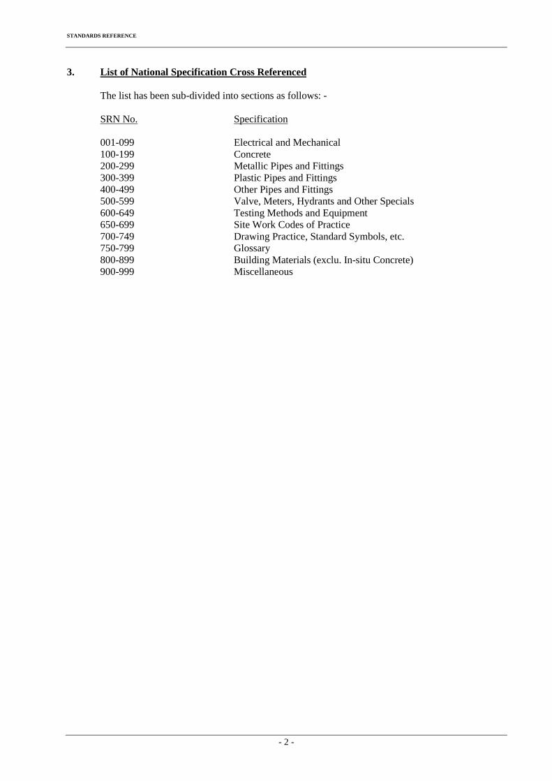
STANDARDS REFERENCE
- 2 -
3. List of National Specification Cross Referenced
The list has been sub-divided into sections as follows: - SRN No. Specification 001-099 Electrical and Mechanical 100-199 Concrete 200-299 Metallic Pipes and Fittings 300-399 Plastic Pipes and Fittings 400-499 Other Pipes and Fittings 500-599 Valve, Meters, Hydrants and Other Specials 600-649 Testing Methods and Equipment 650-699 Site Work Codes of Practice 700-749 Drawing Practice, Standard Symbols, etc. 750-799 Glossary 800-899 Building Materials (exclu. In-situ Concrete) 900-999 Miscellaneous
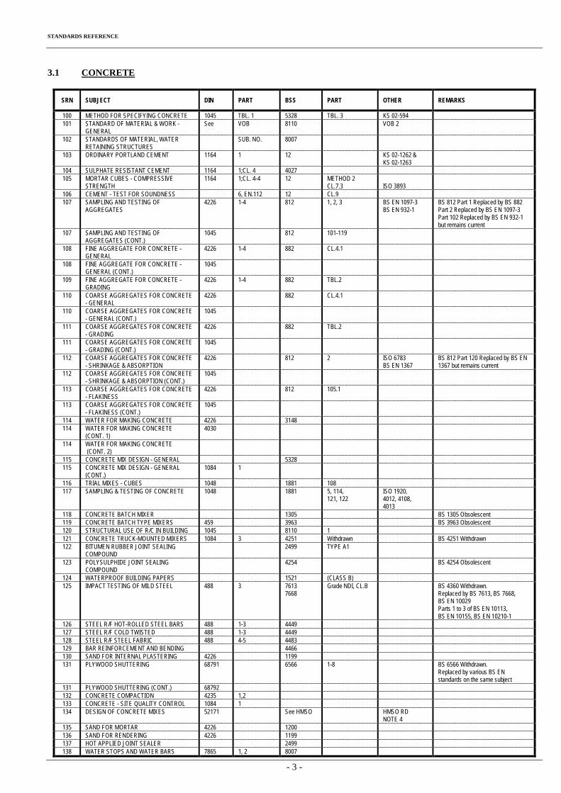
STANDARDS REFERENCE
- 3 -
3.1 CONCRETE
SRN SUBJECT DIN PART BSS PART OTHER REMARKS
100 METHOD FOR SPECIFYING CONCRETE 1045 TBL. 1 5328 TBL. 3 KS 02-594 101 STANDARD OF MATERIAL & WORK -
GENERAL See VOB 8110 VOB 2
102 STANDARDS OF MATERIAL, WATER RETAINING STRUCTURES
SUB. NO. 8007
103 ORDINARY PORTLAND CEMENT 1164 1 12 KS 02-1262 & KS 02-1263
104 SULPHATE RESISTANT CEMENT 1164 1;CL. 4 4027 105 MORTAR CUBES - COMPRESSIVE
STRENGTH 1164 1;CL. 4-4 12 METHOD 2
CL.7.3 ISO 3893
106 CEMENT - TEST FOR SOUNDNESS 6, EN.112 12 CL.9 107 SAMPLING AND TESTING OF
AGGREGATES 4226 1-4 812 1, 2, 3 BS EN 1097-3
BS EN 932-1 BS 812 Part 1 Replaced by BS 882 Part 2 Replaced by BS EN 1097-3 Part 102 Replaced by BS EN 932-1 but remains current
107 SAMPLING AND TESTING OF AGGREGATES (CONT.)
1045 812 101-119
108 FINE AGGREGATE FOR CONCRETE - GENERAL
4226 1-4 882 CL.4.1
108 FINE AGGREGATE FOR CONCRETE - GENERAL (CONT.)
1045
109 FINE AGGREGATE FOR CONCRETE - GRADING
4226 1-4 882 TBL.2
110 COARSE AGGREGATES FOR CONCRETE - GENERAL
4226 882 CL.4.1
110 COARSE AGGREGATES FOR CONCRETE - GENERAL (CONT.)
1045
111 COARSE AGGREGATES FOR CONCRETE - GRADING
4226 882 TBL.2
111 COARSE AGGREGATES FOR CONCRETE - GRADING (CONT.)
1045
112 COARSE AGGREGATES FOR CONCRETE - SHRINKAGE & ABSORPTION
4226 812 2 ISO 6783 BS EN 1367
BS 812 Part 120 Replaced by BS EN 1367 but remains current
112 COARSE AGGREGATES FOR CONCRETE - SHRINKAGE & ABSORPTION (CONT.)
1045
113 COARSE AGGREGATES FOR CONCRETE - FLAKINESS
4226 812 105.1
113 COARSE AGGREGATES FOR CONCRETE - FLAKINESS (CONT.)
1045
114 WATER FOR MAKING CONCRETE 4226 3148 114 WATER FOR MAKING CONCRETE
(CONT. 1) 4030
114 WATER FOR MAKING CONCRETE (CONT. 2)
115 CONCRETE MIX DESIGN - GENERAL 5328 115 CONCRETE MIX DESIGN - GENERAL
(CONT.) 1084 1
116 TRIAL MIXES - CUBES 1048 1881 108 117 SAMPLING & TESTING OF CONCRETE 1048 1881 5, 114,
121, 122 ISO 1920, 4012, 4108, 4013
118 CONCRETE BATCH MIXER 1305 BS 1305 Obsolescent 119 CONCRETE BATCH TYPE MIXERS 459 3963 BS 3963 Obsolescent 120 STRUCTURAL USE OF R/C IN BUILDING 1045 8110 1 121 CONCRETE TRUCK-MOUNTED MIXERS 1084 3 4251 Withdrawn BS 4251 Withdrawn 122 BITUMEN RUBBER JOINT SEALING
COMPOUND 2499 TYPE A1
123 POLYSULPHIDE JOINT SEALING COMPOUND
4254 BS 4254 Obsolescent
124 WATERPROOF BUILDING PAPERS 1521 (CLASS B) 125 IMPACT TESTING OF MILD STEEL 488 3 7613
7668 Grade NDI, CL.B BS 4360 Withdrawn.
Replaced by BS 7613, BS 7668, BS EN 10029 Parts 1 to 3 of BS EN 10113, BS EN 10155, BS EN 10210-1
126 STEEL R/F HOT-ROLLED STEEL BARS 488 1-3 4449 127 STEEL R/F COLD TWISTED 488 1-3 4449 128 STEEL R/F STEEL FABRIC 488 4-5 4483 129 BAR REINFORCEMENT AND BENDING 4466 130 SAND FOR INTERNAL PLASTERING 4226 1199 131 PLYWOOD SHUTTERING 68791 6566 1-8 BS 6566 Withdrawn.
Replaced by various BS EN standards on the same subject
131 PLYWOOD SHUTTERING (CONT.) 68792 132 CONCRETE COMPACTION 4235 1,2 133 CONCRETE - SITE QUALITY CONTROL 1084 1 134 DESIGN OF CONCRETE MIXES 52171 See HMSO HMSO RD
NOTE 4
135 SAND FOR MORTAR 4226 1200 136 SAND FOR RENDERING 4226 1199 137 HOT APPLIED JOINT SEALER 2499 138 WATER STOPS AND WATER BARS 7865 1, 2 8007
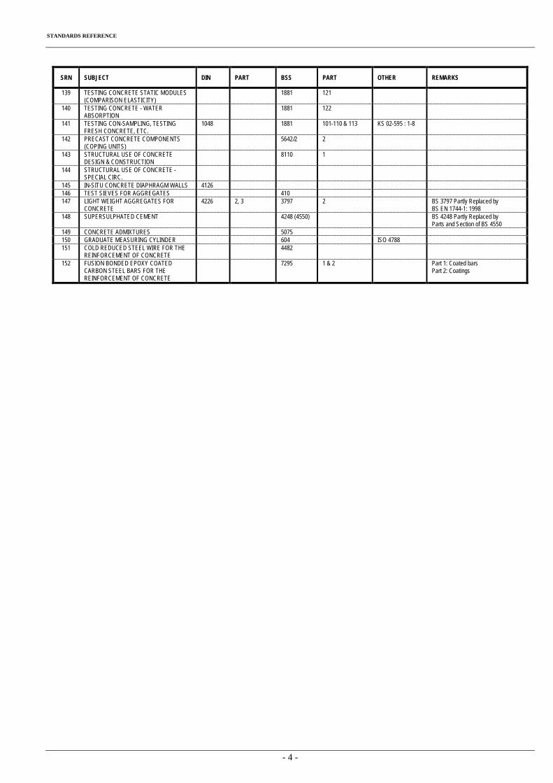
STANDARDS REFERENCE
- 4 -
SRN SUBJECT DIN PART BSS PART OTHER REMARKS
139 TESTING CONCRETE STATIC MODULES (COMPARISON ELASTICITY)
1881 121
140 TESTING CONCRETE - WATER ABSORPTION
1881 122
141 TESTING CON-SAMPLING, TESTING FRESH CONCRETE, ETC.
1048 1881 101-110 & 113 KS 02-595 : 1-8
142 PRECAST CONCRETE COMPONENTS (COPING UNITS)
5642/2 2
143 STRUCTURAL USE OF CONCRETE DESIGN & CONSTRUCTION
8110 1
144 STRUCTURAL USE OF CONCRETE - SPECIAL CIRC.
145 IN-SITU CONCRETE DIAPHRAGM WALLS 4126 146 TEST SIEVES FOR AGGREGATES 410 147 LIGHT WEIGHT AGGREGATES FOR
CONCRETE 4226 2, 3 3797 2 BS 3797 Partly Replaced by
BS EN 1744-1: 1998 148 SUPERSULPHATED CEMENT 4248 (4550) BS 4248 Partly Replaced by
Parts and Section of BS 4550 149 CONCRETE ADMIXTURES 5075 150 GRADUATE MEASURING CYLINDER 604 ISO 4788 151 COLD REDUCED STEEL WIRE FOR THE
REINFORCEMENT OF CONCRETE 4482
152 FUSION BONDED EPOXY COATED CARBON STEEL BARS FOR THE REINFORCEMENT OF CONCRETE
7295 1 & 2 Part 1: Coated bars Part 2: Coatings
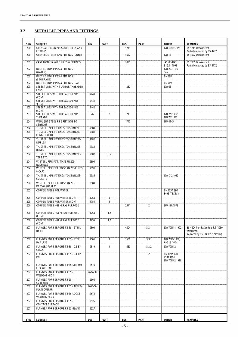
STANDARDS REFERENCE
- 5 -
3.2 METALLIC PIPES AND FITTINGS
SRN SUBJECT DIN PART BSS PART OTHER REMARKS 200 GREYCAST IRON PRESSURE PIPES AND
FITTINGS 1211 ISO 13; ISO 49 BS 1211 Obsolescent
Partially replaced by BS 4772 200 GREY IRON PIPES AND FITTINGS (CONT) 4622 ISO 13 BS 4622 Obsolescent
201 CAST IRON FLANGED PIPES & FITTINGS 2035 ASME/ANSI B16.1 - 1998
BS 2035 Obsolescent Partially replaced by BS 4772
202 DUCTILE IRON PIPES & FITTINGS (WATER)
ISO 2531, EN 545
202 DUCTILE IRON PIPES & FITTINGS (SEWERAGE)
EN 598
202 DUCTILE IRON PIPES & FITTINGS (GAS) EN 969 203 STEEL TUBES WITH PLAIN OR THREADED
ENDS 1387 ISO 65
203 STEEL TUBES WITH THREADED ENDS
(CONT) 2440
203 STEEL TUBES WITH THREADED ENDS
)CONT) 2441
203 STEEL TUBES WITH THREADED ENDS
(CONT) 2442
203 STEEL TUBES WITH THREADED ENDS-
THREADS 76 2 21 ISO 7/1:1982;
ISO 7/2:1982 204 WROUGHT STEEL PIPE FITTINGS TO
SSRN 203 1740 1 ISO 4145
204 TH. STEEL PIPE FITTINGS TO SSRN 203 2980 204 TH. STEEL PIPE FITTINGS TO SSRN 203-
LONG THREAD 2981
204 TH. STEEL PIPE FITTINGS TO SSRN 203-
NIPPLES 2982
204 TH. STEEL PIPE FITTINGS TO SSRN 203-
BENDS 2983
204 TH. STEEL PIPE FITTINGS TO SSRN 203-
TEES ETC. 2987 1, 2
204 W. STEEL PIPE FITT. TO SSRN 203-
BUSHINGS 2990
204 W. STEEL PIPE FITT. TO SSRN 203-PLUGS
& CAPS 2991
204 TH. STEEL PIPE FITTINGS TO SSRN 203-
SOCKETS 2986 ISO 7-2:1982
204 W. STEEL PIPE FITT. TO SSRN 203-
RED'NG SOCKETS 2988
205 COPPER TUBES FOR WATER EN 1057, ISO
8493 (TESTS) 205 COPPER TUBES FOR WATER (CONT) 1754 3 205 COPPER TUBES FOR WATER (CONT) 1755 3 206 COPPER TUBES - GENERAL PURPOSE 2871 2 ISO 196:1978
206 COPPER TUBES - GENERAL PURPOSE
(CONT) 1754 1,2
206 COPPER TUBES - GENERAL PURPOSE
(CONT) 1755 1,2
207 FLANGES FOR FERROUS PIPES - STEEL
BY PN 2500 4504 3-3.1 ISO 7005-1:1992 BS 4504 Part 3: Sections 3.2 (1989)
Withdrawn. Replaced by BS EN 1092-2 (1997)
207 FLANGES FOR FERROUS PIPES - STEEL BY CLASS
2501 1 1560 3-3.1 ISO 7005:1988; ANSI B 16.5
207 FLANGES FOR FERROUS PIPES - C.I. BY CLASS
2519 1 1560 3-3.2 ISO 7005-2
207 FLANGES FOR FERROUS PIPES - C.I. BY PN
2 EN 1092, ISO 2531:1991; ISO 7005-2:1988
207 FLANGES FOR FERROUS PIPES-SLIP ON FOR WELDING
2576
207 FLANGES FOR FERROUS PIPES-WELDING NECK
2627-38
207 FLANGES FOR FERROUS PIPES-SCREWED
2566
207 FLANGES FOR FERROUS PIPES-LAPPED-PLAIN COLLAR
2655-56
207 FLANGES FOR FERROUS PIPES-LOOSE-WELDING NECK
2673
207 FLANGES FOR FERROUS PIPES-CONTACT SURFACE
2526
207
FLANGES FOR FERROUS PIPES-BLANK 2527
SRN SUBJECT DIN PART BSS PART OTHER REMARKS
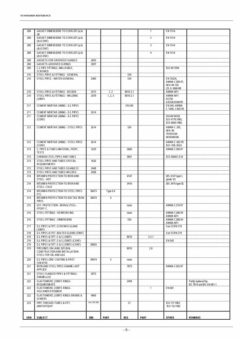
STANDARDS REFERENCE
- 6 -
208 GASKET DIMENSIONS TO SSRN 207 (a) & (d)
1 EN 1514
208 GASKET DIMENSIONS TO SSRN 207 (a) & (d) (CONT)
2 EN 1514
208 GASKET DIMENSIONS TO SSRN 207 (a) & (d) (CONT)
3 EN 1514
208 GASKET DIMENSIONS TO SSRN 207 (a) & (d) (CONT)
4 EN 1514
208 GASKETS-FOR GROOVED FLANGES 2693 208 GASKETS-GROOVED O-RINGS 2697 209 C.I. PIPE FITTINGS, MALLEABLE,
SCREWED ISO 49:1994
210 STEEL PIPES & FITTINGS - GENERAL 534 210 STEEL PIPES - WATER-GENERAL 2460 534 EN 10224,
AWWA C200-97, NFA 49-150 JIS G 3460-88
210 STEEL PIPES & FITTINGS - DESIGN 2413 1, 2 8010 2.1 AWWA M11 210 STEEL PIPES & FITTINGS - WELDING
JOINTS 2559 1, 2, 3 8010 2.1 AWWA M11
ASTM A333/A333M-99
211 CEMENT MORTAR LINING - D.I. PIPES EN 545 EN 545, AWWA C.104A, C602-95
211 CEMENT MORTAR LINING - D.I. PIPES 2614 211 CEMENT MORTAR LINING - D.I. PIPES
(CONT) DVGW W343
ISO 4179:1985, ISO 6600:1980,
212 CEMENT MORTAR LINING - STEEL PIPES 2614 534 AWWA C 205, NFA 49-701DVGW-W343/W346
212 CEMENT MORTAR LINING - STEEL PIPES (CONT)
2614 AWWA C 602-95 ISO / DIS 8324
213 S. PIPES & TUBES-MATERIAL, PROP., TESTS
1629 3600 AWWA C200-97
213 CARBON STEEL PIPES AND TUBES 3601 ISO 2604/2 /3 /6 213 STEEL PIPES AND TUBES-SPECIAL
REQUIREMENTS 1626
213 STEEL PIPES AND TUBES-SEAMLESS 2448 213 STEEL PIPES AND TUBES-WELDED 2458 214 BITUMEN PROTECTION TO IRON AND
STEEL - HOT 4147 (BS 4147 type I,
grade 'd') 214 BITUMEN PROTECTION TO IRON AND
STEEL- COLD 3416 (BS 3416 type II)
214 BITUMEN PROTECTION TO STEEL PIPES
ETC. 30673 Type E4
214 BITUMEN PROTECTION TO DUCTILE IRON
PIPES 30674 4
215 EXT. PROTECTION - IRON & STEEL-
EPOXY C. none AWWA C210-97
216 STEEL FITTINGS - REINFORCING none AWWA C208-59
AWWA M11 216 STEEL FITTINGS - DIMENSIONS 534 AWWA C208-59
AWWA M11 217 D.I. PIPES & FITT.-SCREWED GLAND
JOINTS See SSRN 219
218 D.I. PIPES & FITT.-BOLTED GLAND JOINTS See SSRN 219 219 D.I. PIPES & FITT.-S & S JOINTS 8010 2-2.1 219 D.I. PIPES & FITT.-S & S JOINTS (CONT) EN 545 219 D.I. PIPES & FITT.-S & S JOINTS (CONT) 28603 219 PIPELINES ON LAND; DESIGN,
CONSTRUCTION AND INSTALLATION: STEEL FOR OIL AND GAS
8010 2.8
220 D.I. PIPES-ZINC COATING & PROT.
SHEATHS 30674 3 none
221 IRON AND STEEL PIPES-ENAMEL-HOT
APPLIED 7873 AWWA C203-97
221 STEEL FLANGED PIPES & FITTINGS-
ENAMELLED 2873
222 ELASTOMERIC JOINTS RINGS-
REQUIREMENTS 2494 Partly replaced by
BS 7874 and BS EN 681-1 222 ELASTOMERIC JOINTS RINGS-
VULCANISED RUBBER 1 EN 681
222 ELASTOMERIC JOINTS RINGS-DRAINS &
SEWERS 4060
223 PIPE THREADS-TUBES & FITT.
(WATERTIGHT
See ISO DIN 21 ISO 7/1:1982; ISO 7/2:1982
SRN SUBJECT DIN PART BSS PART OTHER REMARKS
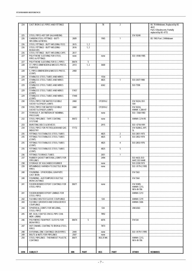
STANDARDS REFERENCE
- 7 -
224 CAST IRON S & S PIPES AND FITTINGS 78 2 BS 78 Withdrawn, Replaced by BS 4622 Part 2 Obsolescent, Partially replaced by BS 4772
225 STEEL PIPES-HOT DIP GALVANISING EN 10240 226 CARBON STEEL FITTINGS - BUTT-
WELDING-GENERAL 2609 1965 1 BS 1965 Part 2 Withdrawn
226 STEEL FITTINGS - BUTT-WELDING-TEES 2615 1, 2 226 STEEL FITTINGS - BUTT-WELDING-
REDUCERS 2616 1, 2
226 STEEL FITTINGS - BUTT-WELDING-CAPS 2617 227 POLYTHENE SLEEVING FOR STEEL
PIPES & FITTINGS none none ISO 8180:1985
227 POLYTHENE SLEEVING FOR D. I. PIPES 30674 5 228 ST. PIPES-DIMENSION & MASSES-PRESS.
PURPOSE 2413 1, 2 3600
228 S. PIPES-DIMENSION & MASSES-PRESS.
(CONT) 2460
229 STAINLESS STEEL TUBES AND WIRES 1554 229 STAINLESS STEEL TUBES AND WIRES
(CONT) 4825 1 ISO 2037:1980
229 STAINLESS STEEL TUBES AND WIRES
(CONT) 6362 ISO 7598
229 STAINLESS STEEL TUBES AND WIRES
(CONT) 17457
229 STAINLESS STEEL TUBES AND WIRES
(CONT) 17440
230 STEEL PIPES FOR WATER FLEXIBLE
SOCKET & SPIGOT JOINTS 2460 CP2010-2 EN 10224, ISO
559 230 STEEL PIPES FOR WATER FLEXIBLE
SOCKET & SPIGOT JOINTS 2460 CP2010-2 EN 10224,
AWWA C200-97 231 FERROUS P. DEFINITION OF NOMINAL
PRESSURE none ISO 7268:1983
232 STEEL PIPELINES - TAPE COATING
SYSTEMS 30672 1 none AWWA C214-95
233 BURSTING DISCS & DEVICES 2915 ISO 6718:1991 234 STEEL PIPES FOR PETROLUEM AND GAS
INDUSTRY 17172 EN 10208-2, API
5L 235 FITTINGS TO STAINLESS STEEL TUBES 4825 2 ISO 2851:1973 235 FITTINGS TO STAINLESS STEEL TUBES
(CONT) 4825 3 ISO 2852:1974
235 FITTINGS TO STAINLESS STEEL TUBES
(CONT) 4825 4 ISO 2853:1976
235 FITTINGS TO STAINLESS STEEL TUBES
(CONT) 4825 5
236 FITTINGS TO BRASS TUBES 2051 1 237 RUBBER GASKET MATERIAL JOINTS FOR
PIPELINES 2494 ISO 4633; ISO
6447; ISO 6448
238 STORAGE OF VULCANISED RUBBER none ISO 2230:1973 239 BITUMINOUS VARNISH TO DUCTILE IRON
PIPES none ISO 8179-2:1995
240 FOUNDING - SPHEROIDAL GRAPHITE
CAST IRON EN 1563
240 FOUNDING - AUSTEMPERED DUCTILE
IRON CASTINGS EN 1564
241 FUSION BONDED EPOXY COATINGS FOR
STEEL PIPES 30671 none EN 10309,
AWWA C213, NFA 49-706
241 FUSION BONDED EPOXY LININGS FOR STEEL PIPES
AWWA C213
242 FLEXIBLE BOLTED SLEEVE COUPLINGS 534 AWWA C219 243 FLEXIBLE GROOVED AND SHOULDERED
COUPLINGS AWWA C606
244 SPHERICAL JOINTS FOR WELDING,
STEEL PIPES 534 UNI 6363
245 BIT. SEAL COAT'GS ON D.I. PIPE CEM.
MOR. LINING 7892
246 POLYMERIC FILM PROT. SLEEV'G FOR
IRON PIPES 30674 5 6076 EN 534
247 HOT ENAMEL COATING TO IRON & STEEL
PIPES 7873
248 EXTERNAL ZINC COATINGS ON DI PIPES 2444 none ISO 8179-1:1995 249 BOLTS & NUTS FOR PIPELINES 2507 none 250 STEEL PIPELINES - THERMOSET PLASTIC
COATINGS
30671 BGC/CW6 AWWA C213, NFA 49-706
SRN SUBJECT DIN PART BSS PART OTHER REMARKS
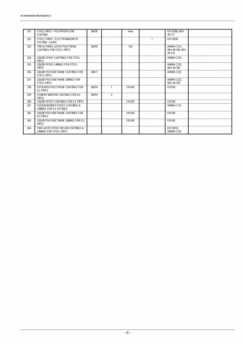
STANDARDS REFERENCE
- 8 -
251 STEEL PIPES - POLYPROPYLENE COATING
30678 none EN 10286, NFA 49-711
252 STEEL TUBES - ELECTROMAGNETIC TESTING - LEAKS
1 EN 10246
253 TWO & THREE LAYER POLYTHENE COATINGS FOR STEEL PIPES
30670 534 AWWA C215, NFA 49-704, NFA 49-710
254 LIQUID EPOXY COATINGS FOR STEEL PIPES
AWWA C210
255 LIQUID EPOXY LININGS FOR STEEL PIPES
AWWA C210, NFA 49-709
256 LIQUID POLYURETHANE COATINGS FOR STEEL PIPES
30671 AWWA C222
257 LIQUID POLYURETHANE LININGS FOR STEEL PIPES
AWWA C222, NFA 49-709
258 EXTRUDED POLYTHENE COATINGS FOR D.I. PIPES
30674 1 EN 545 EN 545
259 CEMENT MORTAR COATINGS FOR D.I. PIPES
30674 2
260 LIQUID EPOXY COATINGS FOR D.I. PIPES EN 545 EN 545 261 FUSION BONDED EPOXY COATINGS &
LININGS FOR D.I. FITTINGS AWWA C116
262 LIQUID POLYURETHANE COATINGS FOR
D.I. PIPES EN 545 EN 545
263 LIQUID POLYURETHANE LININGS FOR D.I.
PIPES EN 545 EN 545
264 TWO LAYER EPOXY-NYLON COATINGS &
LININGS FOR STEEL PIPES EN 10310,
AWWA C224
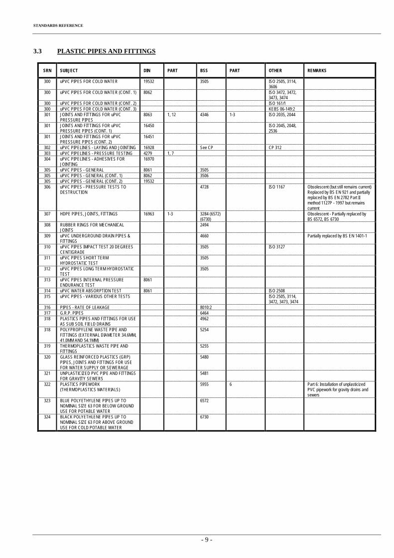
STANDARDS REFERENCE
- 9 -
3.3 PLASTIC PIPES AND FITTINGS
SRN SUBJECT DIN PART BSS PART OTHER REMARKS
300 uPVC PIPES FOR COLD WATER 19532 3505 ISO 2505, 3114, 3606
300 uPVC PIPES FOR COLD WATER (CONT. 1) 8062 ISO 3472, 3472, 3473, 3474
300 uPVC PIPES FOR COLD WATER (CONT. 2) ISO 161/1 300 uPVC PIPES FOR COLD WATER (CONT. 3) KEBS 06-149:2 301 JOINTS AND FITTINGS FOR uPVC
PRESSURE PIPES 8063 1, 12 4346 1-3 ISO 2035, 2044
301 JOINTS AND FITTINGS FOR uPVC PRESSURE PIPES (CONT. 1)
16450 ISO 2045, 2048, 2536
301 JOINTS AND FITTINGS FOR uPVC PRESSURE PIPES (CONT. 2)
16451
302 uPVC PIPELINES - LAYING AND JOINTING 16928 See CP CP 312 303 uPVC PIPELINES - PRESSURE TESTING 4279 1, 7 304 uPVC PIPELINES - ADHESIVES FOR
JOINTING 16970
305 uPVC PIPES - GENERAL 8061 3505 305 uPVC PIPES - GENERAL (CONT. 1) 8062 3506 305 uPVC PIPES - GENERAL (CONT. 2) 19532 306 uPVC PIPES - PRESSURE TESTS TO
DESTRUCTION 4728 ISO 1167 Obsolescent (but still remains current)
Replaced by BS EN 921 and partially replaced by BS EN 2782 Part II method 1127P - 1997 but remains current
307 HDPE PIPES, JOINTS, FITTINGS 16963 1-3 3284 (6572) (6730)
Obsolescent - Partially replaced by BS 6572, BS 6730
308 RUBBER RINGS FOR MECHANICAL JOINTS
2494
309 uPVC UNDERGROUND DRAIN PIPES & FITTINGS
4660 Partially replaced by BS EN 1401-1
310 uPVC PIPES IMPACT TEST 20 DEGREES CENTIGRADE
3505 ISO 3127
311 uPVC PIPES SHORT TERM HYDROSTATIC TEST
3505
312 uPVC PIPES LONG TERM HYDROSTATIC TEST
3505
313 uPVC PIPES INTERNAL PRESSURE ENDURANCE TEST
8061
314 uPVC WATER ABSORPTION TEST 8061 ISO 2508 315 uPVC PIPES - VARIOUS OTHER TESTS ISO 2505, 3114,
3472, 3473, 3474
316 PIPES - RATE OF LEAKAGE 8010:2 317 G.R.P. PIPES 6464 318 PLASTICS PIPES AND FITTINGS FOR USE
AS SUB SOIL FIELD DRAINS 4962
318 POLYPROPYLENE WASTE PIPE AND FITTINGS (EXTERNAL DIAMETER 34.6MM, 41.0MM AND 54.1MM)
5254
319 THERMOPLASTICS WASTE PIPE AND FITTINGS
5255
320 GLASS REINFORCED PLASTICS (GRP) PIPES, JOINTS AND FITTINGS FOR USE FOR WATER SUPPLY OR SEWERAGE
5480
321 UNPLASTICIZED PVC PIPE AND FITTINGS FOR GRAVITY SEWERS
5481
322 PLASTICS PIPEWORK (THERMOPLASTICS MATERIALS)
5955 6 Part 6: Installation of unplasticized PVC pipework for gravity drains and sewers
323 BLUE POLYETHYLENE PIPES UP TO NOMINAL SIZE 63 FOR BELOW GROUND USE FOR POTABLE WATER
6572
324 BLACK POLYETHLENE PIPES UP TO NOMINAL SIZE 63 FOR ABOVE GROUND USE FOR COLD POTABLE WATER
6730
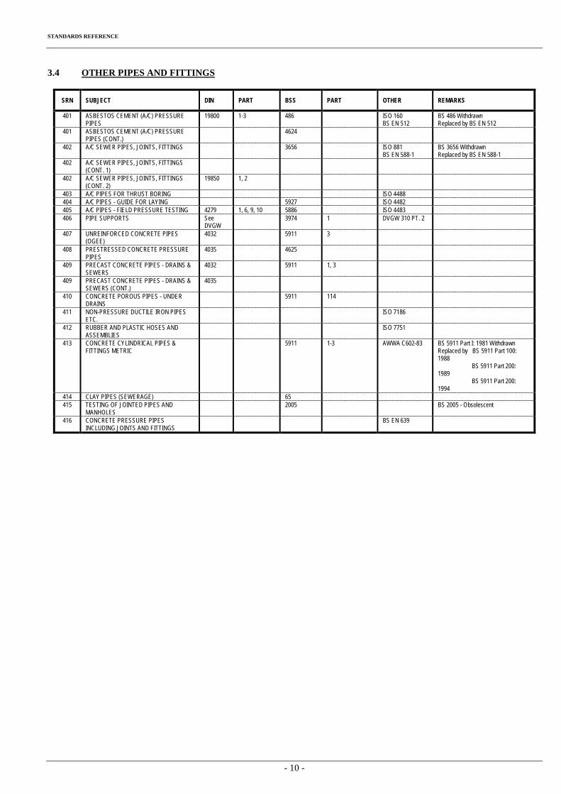
STANDARDS REFERENCE
- 10 -
3.4 OTHER PIPES AND FITTINGS
SRN SUBJECT DIN PART BSS PART OTHER REMARKS
401 ASBESTOS CEMENT (A/C) PRESSURE PIPES
19800 1-3 486 ISO 160 BS EN 512
BS 486 Withdrawn Replaced by BS EN 512
401 ASBESTOS CEMENT (A/C) PRESSURE PIPES (CONT.)
4624
402 A/C SEWER PIPES, JOINTS, FITTINGS 3656 ISO 881 BS EN 588-1
BS 3656 Withdrawn Replaced by BS EN 588-1
402 A/C SEWER PIPES, JOINTS, FITTINGS (CONT. 1)
402 A/C SEWER PIPES, JOINTS, FITTINGS (CONT. 2)
19850 1, 2
403 A/C PIPES FOR THRUST BORING ISO 4488 404 A/C PIPES - GUIDE FOR LAYING 5927 ISO 4482 405 A/C PIPES - FIELD PRESSURE TESTING 4279 1, 6, 9, 10 5886 ISO 4483 406 PIPE SUPPORTS See
DVGW 3974 1 DVGW 310 PT. 2
407 UNREINFORCED CONCRETE PIPES (OGEE)
4032 5911 3
408 PRESTRESSED CONCRETE PRESSURE PIPES
4035 4625
409 PRECAST CONCRETE PIPES - DRAINS & SEWERS
4032 5911 1, 3
409 PRECAST CONCRETE PIPES - DRAINS & SEWERS (CONT.)
4035
410 CONCRETE POROUS PIPES - UNDER DRAINS
5911 114
411 NON-PRESSURE DUCTILE IRON PIPES ETC.
ISO 7186
412 RUBBER AND PLASTIC HOSES AND ASSEMBLIES
ISO 7751
413 CONCRETE CYLINDRICAL PIPES & FITTINGS METRIC
5911 1-3 AWWA C602-83 BS 5911 Part I: 1981 Withdrawn Replaced by BS 5911 Part 100: 1988 BS 5911 Part 200: 1989 BS 5911 Part 200: 1994
414 CLAY PIPES (SEWERAGE) 65 415 TESTING OF JOINTED PIPES AND
MANHOLES 2005 BS 2005 - Obsolescent
416 CONCRETE PRESSURE PIPES INCLUDING JOINTS AND FITTINGS
BS EN 639
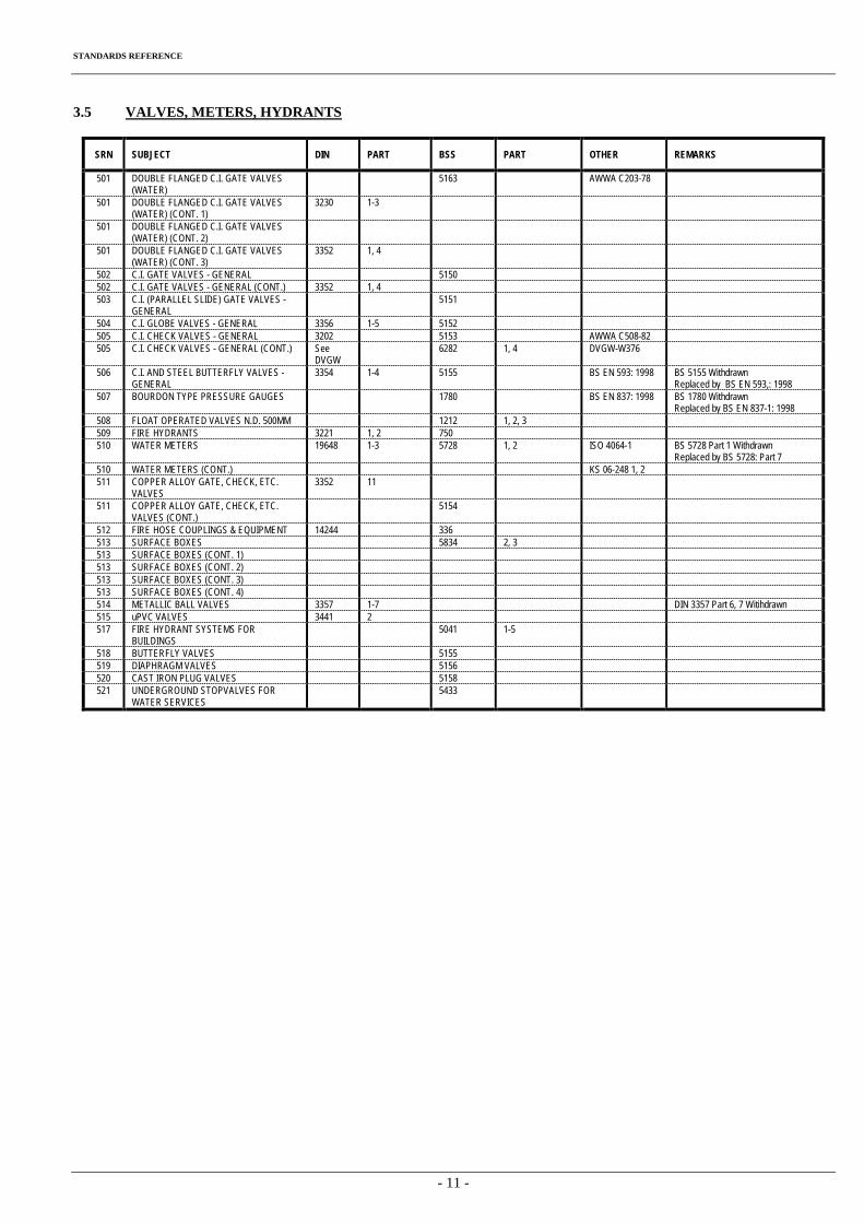
STANDARDS REFERENCE
- 11 -
3.5 VALVES, METERS, HYDRANTS
SRN SUBJECT DIN PART BSS PART OTHER REMARKS
501 DOUBLE FLANGED C.I. GATE VALVES (WATER)
5163 AWWA C203-78
501 DOUBLE FLANGED C.I. GATE VALVES (WATER) (CONT. 1)
3230 1-3
501 DOUBLE FLANGED C.I. GATE VALVES (WATER) (CONT. 2)
501 DOUBLE FLANGED C.I. GATE VALVES (WATER) (CONT. 3)
3352 1, 4
502 C.I. GATE VALVES - GENERAL 5150 502 C.I. GATE VALVES - GENERAL (CONT.) 3352 1, 4 503 C.I. (PARALLEL SLIDE) GATE VALVES -
GENERAL 5151
504 C.I. GLOBE VALVES - GENERAL 3356 1-5 5152 505 C.I. CHECK VALVES - GENERAL 3202 5153 AWWA C508-82 505 C.I. CHECK VALVES - GENERAL (CONT.) See
DVGW 6282 1, 4 DVGW-W376
506 C.I. AND STEEL BUTTERFLY VALVES - GENERAL
3354 1-4 5155 BS EN 593: 1998 BS 5155 Withdrawn Replaced by BS EN 593,: 1998
507 BOURDON TYPE PRESSURE GAUGES 1780 BS EN 837: 1998 BS 1780 Withdrawn Replaced by BS EN 837-1: 1998
508 FLOAT OPERATED VALVES N.D. 500MM 1212 1, 2, 3 509 FIRE HYDRANTS 3221 1, 2 750 510 WATER METERS 19648 1-3 5728 1, 2 ISO 4064-1 BS 5728 Part 1 Withdrawn
Replaced by BS 5728: Part 7 510 WATER METERS (CONT.) KS 06-248 1, 2 511 COPPER ALLOY GATE, CHECK, ETC.
VALVES 3352 11
511 COPPER ALLOY GATE, CHECK, ETC. VALVES (CONT.)
5154
512 FIRE HOSE COUPLINGS & EQUIPMENT 14244 336 513 SURFACE BOXES 5834 2, 3 513 SURFACE BOXES (CONT. 1) 513 SURFACE BOXES (CONT. 2) 513 SURFACE BOXES (CONT. 3) 513 SURFACE BOXES (CONT. 4) 514 METALLIC BALL VALVES 3357 1-7 DIN 3357 Part 6, 7 Witihdrawn 515 uPVC VALVES 3441 2 517 FIRE HYDRANT SYSTEMS FOR
BUILDINGS 5041 1-5
518 BUTTERFLY VALVES 5155 519 DIAPHRAGM VALVES 5156 520 CAST IRON PLUG VALVES 5158 521 UNDERGROUND STOPVALVES FOR
WATER SERVICES 5433
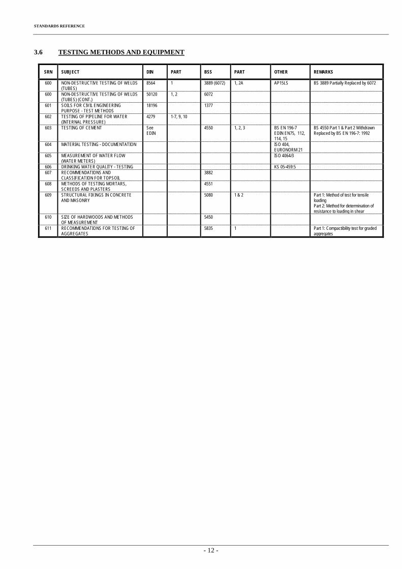
STANDARDS REFERENCE
- 12 -
3.6 TESTING METHODS AND EQUIPMENT
SRN SUBJECT DIN PART BSS PART OTHER REMARKS
600 NON-DESTRUCTIVE TESTING OF WELDS (TUBES)
8564 1 3889 (6072) 1, 2A AP15LS BS 3889 Partially Replaced by 6072
600 NON-DESTRUCTIVE TESTING OF WELDS (TUBES) (CONT.)
50120 1, 2 6072
601 SOILS FOR CIVIL ENGINEERING PURPOSE - TEST METHODS
18196 1377
602 TESTING OF PIPELINE FOR WATER (INTERNAL PRESSURE)
4279 1-7, 9, 10
603 TESTING OF CEMENT See EDIN
4550 1, 2, 3 BS EN 196-7 EDIN EN75, 112, 114, 15
BS 4550 Part 1 & Part 2 Withdrawn Replaced by BS EN 196-7: 1992
604 MATERIAL TESTING - DOCUMENTATION ISO 404, EURONORM 21
605 MEASUREMENT OF WATER FLOW (WATER METERS)
ISO 4064/3
606 DRINKING WATER QUALITY - TESTING KS 05-459:5 607 RECOMMENDATIONS AND
CLASSIFICATION FOR TOPSOIL 3882
608 METHODS OF TESTING MORTARS, SCREEDS AND PLASTERS
4551
609 STRUCTURAL FIXINGS IN CONCRETE AND MASONRY
5080 1 & 2 Part 1: Method of test for tensile loading Part 2: Method for determination of resistance to loading in shear
610 SIZE OF HARDWOODS AND METHODS OF MEASUREMENT
5450
611 RECOMMENDATIONS FOR TESTING OF AGGREGATES
5835 1 Part 1: Compactibility test for graded aggregates
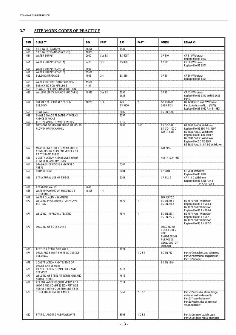
STANDARDS REFERENCE
- 13 -
3.7 SITE WORK CODES OF PRACTICE
SRN SUBJECT DIN PART BSS PART OTHER REMARKS
650 SITE INVESTIGATIONS 18196 5930 650 SITE INVESTIGATIONS (CONT.) 18307 651 WATER SUPPLY 2000 See BS BS 6007 CP 310 CP 310 Withdrawn
Replaced by BS 6007 651 WATER SUPPLY (CONT. 1) 2425 3, 5 BS 8301 CP 301 CP 301 Withdrawn
Replaced by BS 8301 651 WATER SUPPLY (CONT. 2) 4046 651 WATER SUPPLY (CONT. 3) 19630 652 BUILDING DRAINAGE 1986 2-4 BS 8301 CP 301 CP 301 Withdrawn
Replaced by BS 8301 653 WATER PIPELINE CONSTRUCTION 19630 654 TRENCHING FOR PIPELINES 4124 655 SEWAGE PIPELINE CONSTRUCTION 656 WALLING (BRICK & BLOCK MASONRY) 18330 See BS 5390
5628 CP 121 CP 121 Withdrawn
Replaced by BS 5390 and BS 5628 Part 3
657 USE OF STRUCTURAL STEEL IN BUILDING
18203 1, 2 449 BS 5950
2 GB 7101-91 SABS 1431
BS 449 Parts 1 and 2 Withdrawn Part 2: Addendum No. 1 (1975) Replaced by BS 5950 Part 5 (1987)
658 SEWERAGE 8005 BS EN 1610 659 SMALL SEWAGE TREATMENT WORKS
AND CESSPOOLS 6297
660 TEST PUMPING OF WATER WELLS 6316 661 METHODS OF MEASUREMENT OF LIQUID
FLOW IN OPEN CHANNEL 3680 1-10 BS ISO 748
BS ISO 1100-2 ISO TR 8363
BS 3680 Part 3A Withdrawn Replaced by BS ISO 748: 1997 BS 3680 Part 3C Withdrawn Replaced by BS ISO 1100-2 BS 3680 Part 3G Withdrawn Replaced by ISO TR 8363 BS 3680 Parts 3J, 8F, 8G Withdrawn
662 MEASUREMENT OF FLOW IN CLOSED CONDUITS (BY CURRENT METERS OR PITOT STATIC TUBES)
ISO 7194
663 CONSTRUCTION AND DEMOLITION OF CONCRETE AND MASONRY
ANSI A10, 9-1983
664 DRAINAGE OF ROOFS AND PAVED AREAS
6367
665 FOUNDATIONS 8004 CP 2004 CP 2004 Withdrawn Replaced by BS 8004
666 STRUCTURAL USE OF TIMBER 5268 CP 112, 2 CP 112, 2 Withdrawn Replaced by BS 5268 Part 2 BS 5268 Part 3
667 RETAINING WALLS 4085 668 WATERPROOFING OF BUILDINGS &
STRUCTURES 18195 1-4
669 WATER QUALITY - SAMPLING ISO 5667/2/3 670 WELDING PROCEDURES - APPROVAL
TESTING 4870 1 BS EN 288-3
BS EN 288-4 BS 4870 Part 1 Withdrawn Replaced by BS EN 288-3 BS 4870 Part 2 Withdrawn Replaced by BS EN 288-4
671 WELDING - APPROVAL TESTING 4871 1 BS EN 287-1 BS EN 287-2
BS 4871 Part 1 Withdrawn Replaced by BS EN 287-1 BS 4871 Part 2 Withdrawn Replaced by BS EN 287-2
672 LOGGING OF ROCK CORES LOGGING OF ROCK CORES FOR ENGINEERING PURPOSES, GEOL. SOC. OF LONDON
673 TEST FOR STABILISED SOILS 1924 674 DRAIN AND SEWER SYSTEMS OUTSIDE
BUILDINGS 1, 2 & 3 BS EN 752 Part 1: Generalities and definitions
Part 2: Performance requirements Part 3: Planning
675 CONSTRUCTION AND TESTING OF DRAINS AND SEWERS
BS EN 1610
676 IDENTIFICATION OF PIPELINES AND SERVICES
1710
677 WELDING OF STEEL PIPELINES ON LAND AND OFFSHORE
4515
678 PERFORMANCE REQUIREMENTS FOR JOINTS AND COMPRESSION FITTINGS FOR USE WITH POLYETHYLENE PIPES
5114
679 STRUCTURAL USE OF TIMBER 5268 2, 3 & 5 Part 2: Permissible stress design, materials and workmanship Part 3: Trussed rafter roof Part 5: Preservative treatment of structural timber
680 STAIRS, LADDERS AND WALKWAYS 5395 1, 2 & 3 Part 1: Design of straight stairs Part 2: Design of helical and spiral
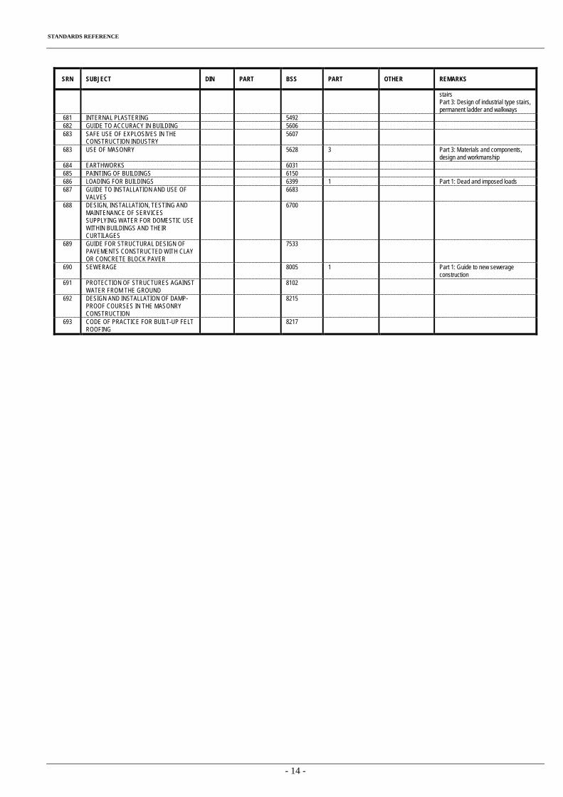
STANDARDS REFERENCE
- 14 -
SRN SUBJECT DIN PART BSS PART OTHER REMARKS
stairs Part 3: Design of industrial type stairs, permanent ladder and walkways
681 INTERNAL PLASTERING 5492 682 GUIDE TO ACCURACY IN BUILDING 5606 683 SAFE USE OF EXPLOSIVES IN THE
CONSTRUCTION INDUSTRY 5607
683 USE OF MASONRY 5628 3 Part 3: Materials and components, design and workmanship
684 EARTHWORKS 6031 685 PAINTING OF BUILDINGS 6150 686 LOADING FOR BUILDINGS 6399 1 Part 1: Dead and imposed loads 687 GUIDE TO INSTALLATION AND USE OF
VALVES 6683
688 DESIGN, INSTALLATION, TESTING AND MAINTENANCE OF SERVICES SUPPLYING WATER FOR DOMESTIC USE WITHIN BUILDINGS AND THEIR CURTILAGES
6700
689 GUIDE FOR STRUCTURAL DESIGN OF PAVEMENTS CONSTRUCTED WITH CLAY OR CONCRETE BLOCK PAVER
7533
690 SEWERAGE 8005 1 Part 1: Guide to new sewerage construction
691 PROTECTION OF STRUCTURES AGAINST WATER FROM THE GROUND
8102
692 DESIGN AND INSTALLATION OF DAMP-PROOF COURSES IN THE MASONRY CONSTRUCTION
8215
693 CODE OF PRACTICE FOR BUILT-UP FELT ROOFING
8217
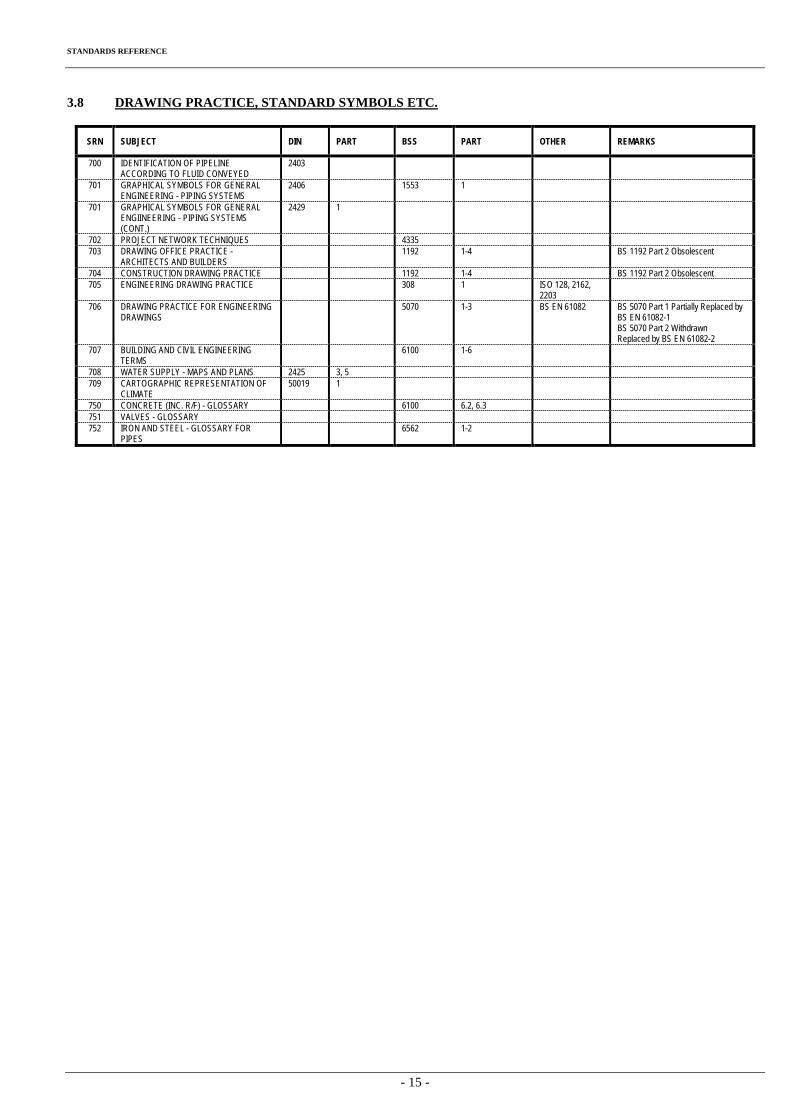
STANDARDS REFERENCE
- 15 -
3.8 DRAWING PRACTICE, STANDARD SYMBOLS ETC.
SRN SUBJECT DIN PART BSS PART OTHER REMARKS
700 IDENTIFICATION OF PIPELINE ACCORDING TO FLUID CONVEYED
2403
701 GRAPHICAL SYMBOLS FOR GENERAL ENGINEERING - PIPING SYSTEMS
2406 1553 1
701 GRAPHICAL SYMBOLS FOR GENERAL ENGIINEERING - PIPING SYSTEMS (CONT.)
2429 1
702 PROJECT NETWORK TECHNIQUES 4335 703 DRAWING OFFICE PRACTICE -
ARCHITECTS AND BUILDERS 1192 1-4 BS 1192 Part 2 Obsolescent
704 CONSTRUCTION DRAWING PRACTICE 1192 1-4 BS 1192 Part 2 Obsolescent 705 ENGINEERING DRAWING PRACTICE 308 1 ISO 128, 2162,
2203
706 DRAWING PRACTICE FOR ENGINEERING DRAWINGS
5070 1-3 BS EN 61082 BS 5070 Part 1 Partially Replaced by BS EN 61082-1 BS 5070 Part 2 Withdrawn Replaced by BS EN 61082-2
707 BUILDING AND CIVIL ENGINEERING TERMS
6100 1-6
708 WATER SUPPLY - MAPS AND PLANS 2425 3, 5 709 CARTOGRAPHIC REPRESENTATION OF
CLIMATE 50019 1
750 CONCRETE (INC. R/F) - GLOSSARY 6100 6.2, 6.3 751 VALVES - GLOSSARY 752 IRON AND STEEL - GLOSSARY FOR
PIPES 6562 1-2
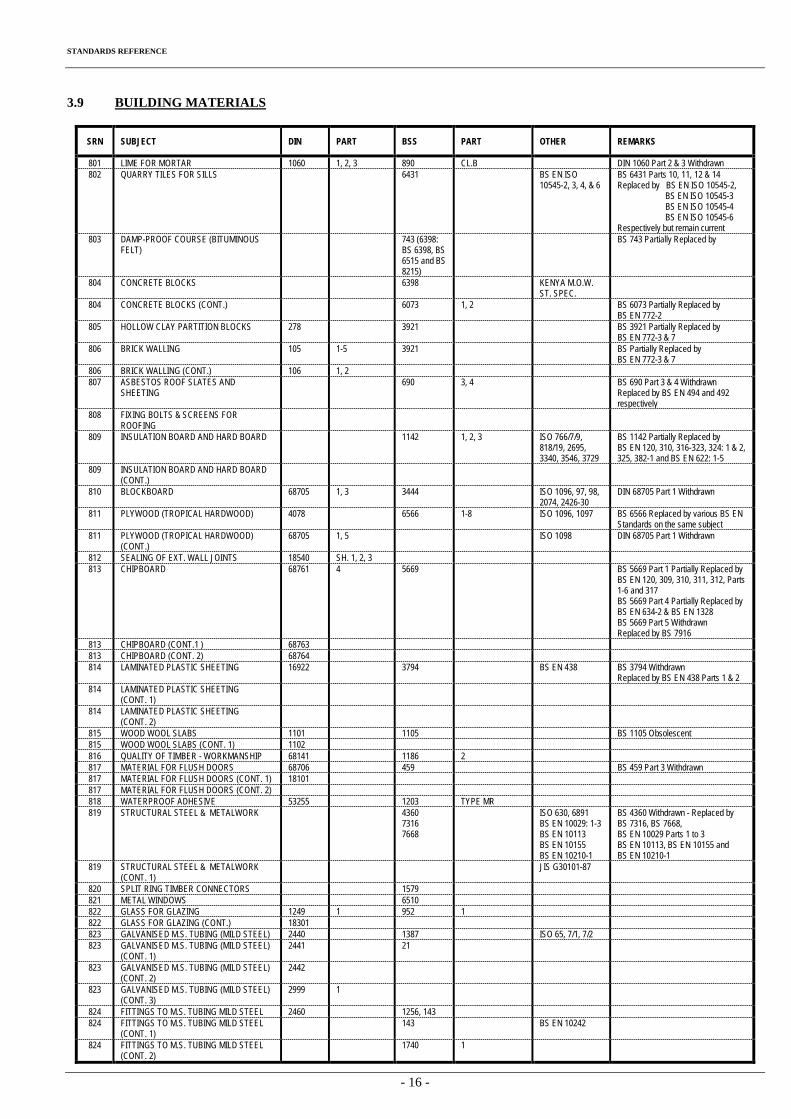
STANDARDS REFERENCE
- 16 -
3.9 BUILDING MATERIALS
SRN SUBJECT DIN PART BSS PART OTHER REMARKS
801 LIME FOR MORTAR 1060 1, 2, 3 890 CL.B DIN 1060 Part 2 & 3 Withdrawn 802 QUARRY TILES FOR SILLS 6431 BS EN ISO
10545-2, 3, 4, & 6 BS 6431 Parts 10, 11, 12 & 14 Replaced by BS EN ISO 10545-2, BS EN ISO 10545-3 BS EN ISO 10545-4 BS EN ISO 10545-6 Respectively but remain current
803 DAMP-PROOF COURSE (BITUMINOUS FELT)
743 (6398: BS 6398, BS 6515 and BS 8215)
BS 743 Partially Replaced by
804 CONCRETE BLOCKS 6398 KENYA M.O.W. ST. SPEC.
804 CONCRETE BLOCKS (CONT.) 6073 1, 2 BS 6073 Partially Replaced by BS EN 772-2
805 HOLLOW CLAY PARTITION BLOCKS 278 3921 BS 3921 Partially Replaced by BS EN 772-3 & 7
806 BRICK WALLING 105 1-5 3921 BS Partially Replaced by BS EN 772-3 & 7
806 BRICK WALLING (CONT.) 106 1, 2 807 ASBESTOS ROOF SLATES AND
SHEETING 690 3, 4 BS 690 Part 3 & 4 Withdrawn
Replaced by BS EN 494 and 492 respectively
808 FIXING BOLTS & SCREENS FOR ROOFING
809 INSULATION BOARD AND HARD BOARD 1142 1, 2, 3 ISO 766/7/9, 818/19, 2695, 3340, 3546, 3729
BS 1142 Partially Replaced by BS EN 120, 310, 316-323, 324: 1 & 2, 325, 382-1 and BS EN 622: 1-5
809 INSULATION BOARD AND HARD BOARD (CONT.)
810 BLOCKBOARD 68705 1, 3 3444 ISO 1096, 97, 98, 2074, 2426-30
DIN 68705 Part 1 Withdrawn
811 PLYWOOD (TROPICAL HARDWOOD) 4078 6566 1-8 ISO 1096, 1097 BS 6566 Replaced by various BS EN Standards on the same subject
811 PLYWOOD (TROPICAL HARDWOOD) (CONT.)
68705 1, 5 ISO 1098 DIN 68705 Part 1 Withdrawn
812 SEALING OF EXT. WALL JOINTS 18540 SH. 1, 2, 3 813 CHIPBOARD 68761 4 5669 BS 5669 Part 1 Partially Replaced by
BS EN 120, 309, 310, 311, 312, Parts 1-6 and 317 BS 5669 Part 4 Partially Replaced by BS EN 634-2 & BS EN 1328 BS 5669 Part 5 Withdrawn Replaced by BS 7916
813 CHIPBOARD (CONT.1 ) 68763 813 CHIPBOARD (CONT. 2) 68764 814 LAMINATED PLASTIC SHEETING 16922 3794 BS EN 438 BS 3794 Withdrawn
Replaced by BS EN 438 Parts 1 & 2 814 LAMINATED PLASTIC SHEETING
(CONT. 1)
814 LAMINATED PLASTIC SHEETING (CONT. 2)
815 WOOD WOOL SLABS 1101 1105 BS 1105 Obsolescent 815 WOOD WOOL SLABS (CONT. 1) 1102 816 QUALITY OF TIMBER - WORKMANSHIP 68141 1186 2 817 MATERIAL FOR FLUSH DOORS 68706 459 BS 459 Part 3 Withdrawn 817 MATERIAL FOR FLUSH DOORS (CONT. 1) 18101 817 MATERIAL FOR FLUSH DOORS (CONT. 2) 818 WATERPROOF ADHESIVE 53255 1203 TYPE MR 819 STRUCTURAL STEEL & METALWORK 4360
7316 7668
ISO 630, 6891 BS EN 10029: 1-3 BS EN 10113 BS EN 10155 BS EN 10210-1
BS 4360 Withdrawn - Replaced by BS 7316, BS 7668, BS EN 10029 Parts 1 to 3 BS EN 10113, BS EN 10155 and BS EN 10210-1
819 STRUCTURAL STEEL & METALWORK (CONT. 1)
JIS G30101-87
820 SPLIT RING TIMBER CONNECTORS 1579 821 METAL WINDOWS 6510 822 GLASS FOR GLAZING 1249 1 952 1 822 GLASS FOR GLAZING (CONT.) 18301 823 GALVANISED M.S. TUBING (MILD STEEL) 2440 1387 ISO 65, 7/1, 7/2 823 GALVANISED M.S. TUBING (MILD STEEL)
(CONT. 1) 2441 21
823 GALVANISED M.S. TUBING (MILD STEEL) (CONT. 2)
2442
823 GALVANISED M.S. TUBING (MILD STEEL) (CONT. 3)
2999 1
824 FITTINGS TO M.S. TUBING MILD STEEL 2460 1256, 143 824 FITTINGS TO M.S. TUBING MILD STEEL
(CONT. 1) 143 BS EN 10242
824 FITTINGS TO M.S. TUBING MILD STEEL (CONT. 2)
1740 1
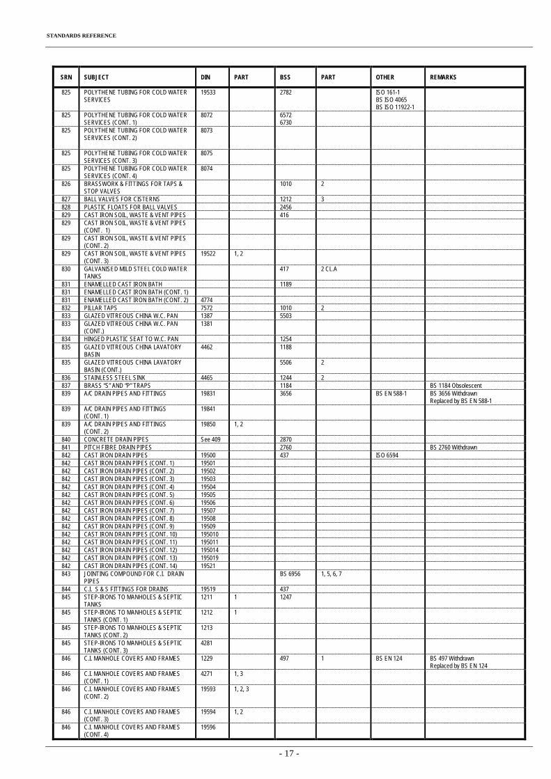
STANDARDS REFERENCE
- 17 -
SRN SUBJECT DIN PART BSS PART OTHER REMARKS
825 POLYTHENE TUBING FOR COLD WATER SERVICES
19533 2782 ISO 161-1 BS ISO 4065 BS ISO 11922-1
825 POLYTHENE TUBING FOR COLD WATER SERVICES (CONT. 1)
8072 6572 6730
825 POLYTHENE TUBING FOR COLD WATER SERVICES (CONT. 2)
8073
825 POLYTHENE TUBING FOR COLD WATER SERVICES (CONT. 3)
8075
825 POLYTHENE TUBING FOR COLD WATER SERVICES (CONT. 4)
8074
826 BRASSWORK & FITTINGS FOR TAPS & STOP VALVES
1010 2
827 BALL VALVES FOR CISTERNS 1212 3 828 PLASTIC FLOATS FOR BALL VALVES 2456 829 CAST IRON SOIL, WASTE & VENT PIPES 416 829 CAST IRON SOIL, WASTE & VENT PIPES
(CONT. 1)
829 CAST IRON SOIL, WASTE & VENT PIPES (CONT. 2)
829 CAST IRON SOIL, WASTE & VENT PIPES (CONT. 3)
19522 1, 2
830 GALVANISED MILD STEEL COLD WATER TANKS
417 2 CL.A
831 ENAMELLED CAST IRON BATH 1189 831 ENAMELLED CAST IRON BATH (CONT. 1) 831 ENAMELLED CAST IRON BATH (CONT. 2) 4774 832 PILLAR TAPS 7572 1010 2 833 GLAZED VITREOUS CHINA W.C. PAN 1387 5503 833 GLAZED VITREOUS CHINA W.C. PAN
(CONT.) 1381
834 HINGED PLASTIC SEAT TO W.C. PAN 1254 835 GLAZED VITREOUS CHINA LAVATORY
BASIN 4462 1188
835 GLAZED VITREOUS CHINA LAVATORY BASIN (CONT.)
5506 2
836 STAINLESS STEEL SINK 4465 1244 2 837 BRASS “S” AND “P” TRAPS 1184 BS 1184 Obsolescent 839 A/C DRAIN PIPES AND FITTINGS 19831 3656 BS EN 588-1 BS 3656 Withdrawn
Replaced by BS EN 588-1 839 A/C DRAIN PIPES AND FITTINGS
(CONT. 1) 19841
839 A/C DRAIN PIPES AND FITTINGS (CONT. 2)
19850 1, 2
840 CONCRETE DRAIN PIPES See 409 2870 841 PITCH FIBRE DRAIN PIPES 2760 BS 2760 Withdrawn 842 CAST IRON DRAIN PIPES 19500 437 ISO 6594 842 CAST IRON DRAIN PIPES (CONT. 1) 19501 842 CAST IRON DRAIN PIPES (CONT. 2) 19502 842 CAST IRON DRAIN PIPES (CONT. 3) 19503 842 CAST IRON DRAIN PIPES (CONT. 4) 19504 842 CAST IRON DRAIN PIPES (CONT. 5) 19505 842 CAST IRON DRAIN PIPES (CONT. 6) 19506 842 CAST IRON DRAIN PIPES (CONT. 7) 19507 842 CAST IRON DRAIN PIPES (CONT. 8) 19508 842 CAST IRON DRAIN PIPES (CONT. 9) 19509 842 CAST IRON DRAIN PIPES (CONT. 10) 195010 842 CAST IRON DRAIN PIPES (CONT. 11) 195011 842 CAST IRON DRAIN PIPES (CONT. 12) 195014 842 CAST IRON DRAIN PIPES (CONT. 13) 195019 842 CAST IRON DRAIN PIPES (CONT. 14) 19521 843 JOINTING COMPOUND FOR C.I. DRAIN
PIPES BS 6956 1, 5, 6, 7
844 C.I. S & S FITTINGS FOR DRAINS 19519 437 845 STEP-IRONS TO MANHOLES & SEPTIC
TANKS 1211 1 1247
845 STEP-IRONS TO MANHOLES & SEPTIC TANKS (CONT. 1)
1212 1
845 STEP-IRONS TO MANHOLES & SEPTIC TANKS (CONT. 2)
1213
845 STEP-IRONS TO MANHOLES & SEPTIC TANKS (CONT. 3)
4281
846 C.I. MANHOLE COVERS AND FRAMES 1229 497 1 BS EN 124 BS 497 Withdrawn Replaced by BS EN 124
846 C.I. MANHOLE COVERS AND FRAMES (CONT. 1)
4271 1, 3
846 C.I. MANHOLE COVERS AND FRAMES (CONT. 2)
19593 1, 2, 3
846 C.I. MANHOLE COVERS AND FRAMES (CONT. 3)
19594 1, 2
846 C.I. MANHOLE COVERS AND FRAMES (CONT. 4)
19596
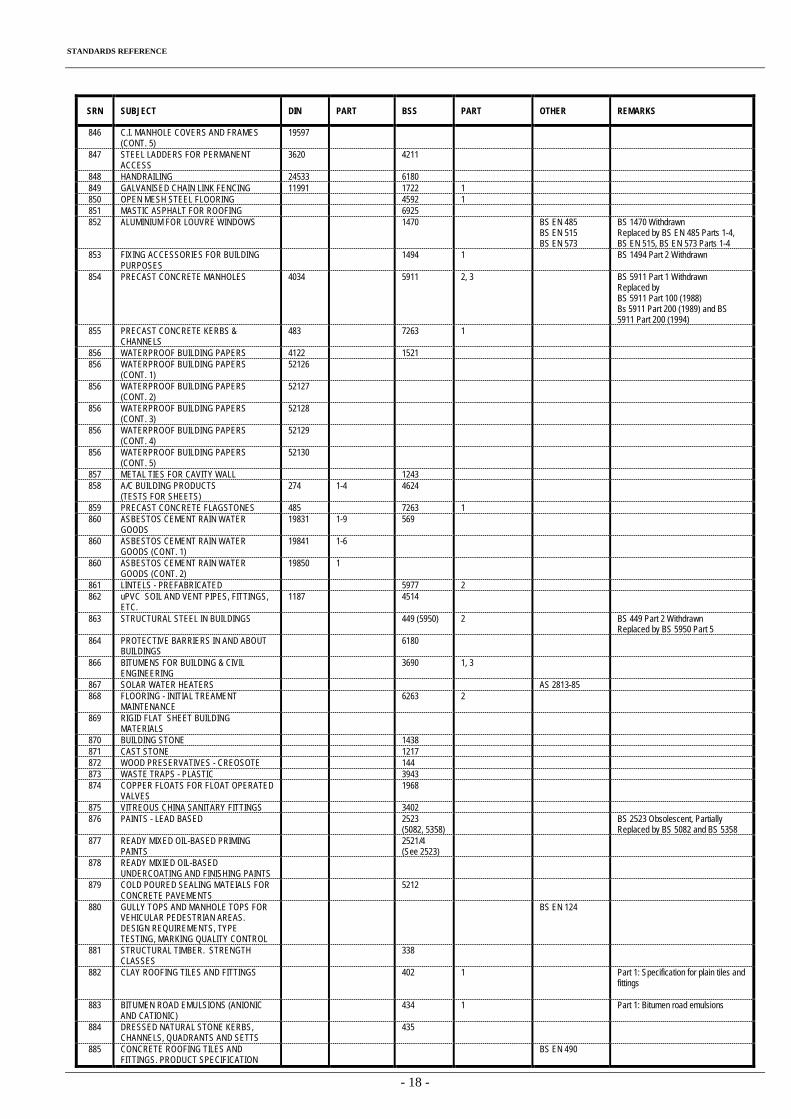
STANDARDS REFERENCE
- 18 -
SRN SUBJECT DIN PART BSS PART OTHER REMARKS
846 C.I. MANHOLE COVERS AND FRAMES (CONT. 5)
19597
847 STEEL LADDERS FOR PERMANENT ACCESS
3620 4211
848 HANDRAILING 24533 6180 849 GALVANISED CHAIN LINK FENCING 11991 1722 1 850 OPEN MESH STEEL FLOORING 4592 1 851 MASTIC ASPHALT FOR ROOFING 6925 852 ALUMINIUM FOR LOUVRE WINDOWS 1470 BS EN 485
BS EN 515 BS EN 573
BS 1470 Withdrawn Replaced by BS EN 485 Parts 1-4, BS EN 515, BS EN 573 Parts 1-4
853 FIXING ACCESSORIES FOR BUILDING PURPOSES
1494 1 BS 1494 Part 2 Withdrawn
854 PRECAST CONCRETE MANHOLES 4034 5911 2, 3 BS 5911 Part 1 Withdrawn Replaced by BS 5911 Part 100 (1988) Bs 5911 Part 200 (1989) and BS 5911 Part 200 (1994)
855 PRECAST CONCRETE KERBS & CHANNELS
483 7263 1
856 WATERPROOF BUILDING PAPERS 4122 1521 856 WATERPROOF BUILDING PAPERS
(CONT. 1) 52126
856 WATERPROOF BUILDING PAPERS (CONT. 2)
52127
856 WATERPROOF BUILDING PAPERS (CONT. 3)
52128
856 WATERPROOF BUILDING PAPERS (CONT. 4)
52129
856 WATERPROOF BUILDING PAPERS (CONT. 5)
52130
857 METAL TIES FOR CAVITY WALL 1243 858 A/C BUILDING PRODUCTS
(TESTS FOR SHEETS) 274 1-4 4624
859 PRECAST CONCRETE FLAGSTONES 485 7263 1 860 ASBESTOS CEMENT RAIN WATER
GOODS 19831 1-9 569
860 ASBESTOS CEMENT RAIN WATER GOODS (CONT. 1)
19841 1-6
860 ASBESTOS CEMENT RAIN WATER GOODS (CONT. 2)
19850 1
861 LINTELS - PREFABRICATED 5977 2 862 uPVC SOIL AND VENT PIPES, FITTINGS,
ETC. 1187 4514
863 STRUCTURAL STEEL IN BUILDINGS 449 (5950) 2 BS 449 Part 2 Withdrawn Replaced by BS 5950 Part 5
864 PROTECTIVE BARRIERS IN AND ABOUT BUILDINGS
6180
866 BITUMENS FOR BUILDING & CIVIL ENGINEERING
3690 1, 3
867 SOLAR WATER HEATERS AS 2813-85 868 FLOORING - INITIAL TREAMENT
MAINTENANCE 6263 2
869 RIGID FLAT SHEET BUILDING MATERIALS
870 BUILDING STONE 1438 871 CAST STONE 1217 872 WOOD PRESERVATIVES - CREOSOTE 144 873 WASTE TRAPS - PLASTIC 3943 874 COPPER FLOATS FOR FLOAT OPERATED
VALVES 1968
875 VITREOUS CHINA SANITARY FITTINGS 3402 876 PAINTS - LEAD BASED 2523
(5082, 5358) BS 2523 Obsolescent, Partially
Replaced by BS 5082 and BS 5358 877 READY MIXED OIL-BASED PRIMING
PAINTS 2521/4
(See 2523)
878 READY MIXIED OIL-BASED UNDERCOATING AND FINISHING PAINTS
879 COLD POURED SEALING MATEIALS FOR CONCRETE PAVEMENTS
5212
880 GULLY TOPS AND MANHOLE TOPS FOR VEHICULAR PEDESTRIAN AREAS. DESIGN REQUIREMENTS, TYPE TESTING, MARKING QUALITY CONTROL
BS EN 124
881 STRUCTURAL TIMBER. STRENGTH CLASSES
338
882 CLAY ROOFING TILES AND FITTINGS 402 1 Part 1: Specification for plain tiles and fittings
883 BITUMEN ROAD EMULSIONS (ANIONIC AND CATIONIC)
434 1 Part 1: Bitumen road emulsions
884 DRESSED NATURAL STONE KERBS, CHANNELS, QUADRANTS AND SETTS
435
885 CONCRETE ROOFING TILES AND FITTINGS. PRODUCT SPECIFICATION
BS EN 490
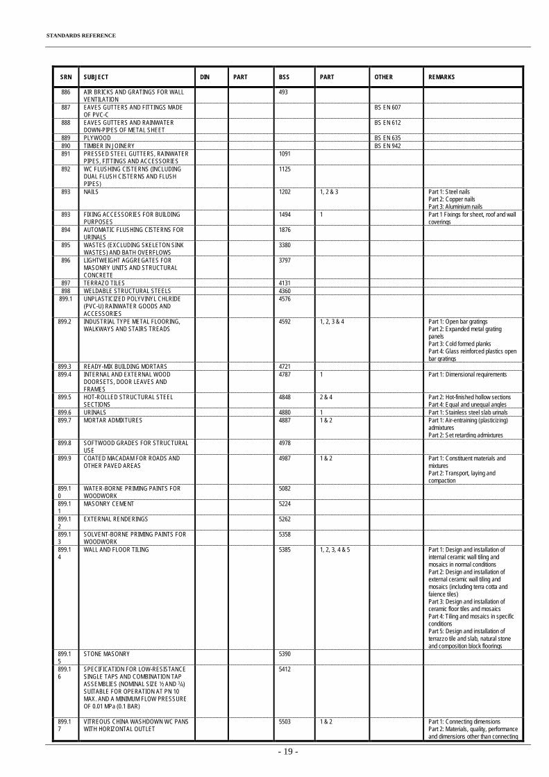
STANDARDS REFERENCE
- 19 -
SRN SUBJECT DIN PART BSS PART OTHER REMARKS
886 AIR BRICKS AND GRATINGS FOR WALL VENTILATION
493
887 EAVES GUTTERS AND FITTINGS MADE OF PVC-C
BS EN 607
888 EAVES GUTTERS AND RAINWATER DOWN-PIPES OF METAL SHEET
BS EN 612
889 PLYWOOD BS EN 635 890 TIMBER IN JOINERY BS EN 942 891 PRESSED STEEL GUTTERS, RAINWATER
PIPES, FITTINGS AND ACCESSORIES 1091
892 WC FLUSHING CISTERNS (INCLUDING DUAL FLUSH CISTERNS AND FLUSH PIPES)
1125
893 NAILS 1202 1, 2 & 3 Part 1: Steel nails Part 2: Copper nails Part 3: Aluminium nails
893 FIXING ACCESSORIES FOR BUILDING PURPOSES
1494 1 Part 1 Fixings for sheet, roof and wall coverings
894 AUTOMATIC FLUSHING CISTERNS FOR URINALS
1876
895 WASTES (EXCLUDING SKELETON SINK WASTES) AND BATH OVERFLOWS
3380
896 LIGHTWEIGHT AGGREGATES FOR MASONRY UNITS AND STRUCTURAL CONCRETE
3797
897 TERRAZO TILES 4131 898 WELDABLE STRUCTURAL STEELS 4360
899.1 UNPLASTICIZED POLYVINYL CHLRIDE (PVC-U) RAINWATER GOODS AND ACCESSORIES
4576
899.2 INDUSTRIAL TYPE METAL FLOORING, WALKWAYS AND STAIRS TREADS
4592 1, 2, 3 & 4 Part 1: Open bar gratings Part 2: Expanded metal grating panels Part 3: Cold formed planks Part 4: Glass reinforced plastics open bar gratings
899.3 READY-MIX BUILDING MORTARS 4721 899.4 INTERNAL AND EXTERNAL WOOD
DOORSETS, DOOR LEAVES AND FRAMES
4787 1 Part 1: Dimensional requirements
899.5 HOT-ROLLED STRUCTURAL STEEL SECTIONS
4848 2 & 4 Part 2: Hot-finished hollow sections Part 4: Equal and unequal angles
899.6 URINALS 4880 1 Part 1: Stainless steel slab urinals 899.7 MORTAR ADMIXTURES 4887 1 & 2 Part 1: Air-entraining (plasticizing)
admixtures Part 2: Set retarding admixtures
899.8 SOFTWOOD GRADES FOR STRUCTURAL USE
4978
899.9 COATED MACADAM FOR ROADS AND OTHER PAVED AREAS
4987 1 & 2 Part 1: Constituent materials and mixtures Part 2: Transport, laying and compaction
899.10
WATER-BORNE PRIMING PAINTS FOR WOODWORK
5082
899.11
MASONRY CEMENT 5224
899.12
EXTERNAL RENDERINGS 5262
899.13
SOLVENT-BORNE PRIMING PAINTS FOR WOODWORK
5358
899.14
WALL AND FLOOR TILING 5385 1, 2, 3, 4 & 5 Part 1: Design and installation of internal ceramic wall tiling and mosaics in normal conditions Part 2: Design and installation of external ceramic wall tiling and mosaics (including terra cotta and faience tiles) Part 3: Design and installation of ceramic floor tiles and mosaics Part 4: Tiling and mosaics in specific conditions Part 5: Design and installation of terrazzo tile and slab, natural stone and composition block floorings
899.15
STONE MASONRY 5390
899.16
SPECIFICATION FOR LOW-RESISTANCE SINGLE TAPS AND COMBINATION TAP ASSEMBLIES (NOMINAL SIZE ½ AND 3/4) SUITABLE FOR OPERATION AT PN 10 MAX. AND A MINIMUM FLOW PRESSURE OF 0.01 MPa (0.1 BAR)
5412
899.17
VITREOUS CHINA WASHDOWN WC PANS WITH HORIZONTAL OUTLET
5503 1 & 2 Part 1: Connecting dimensions Part 2: Materials, quality, performance and dimensions other than connecting
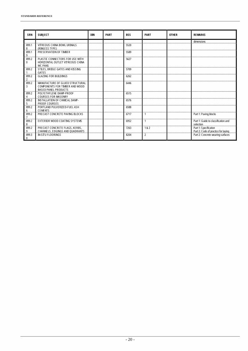
STANDARDS REFERENCE
- 20 -
SRN SUBJECT DIN PART BSS PART OTHER REMARKS
dimensions 899.18
VITREOUS CHINA BOWL URINALS (RIMLESS TYPE)
5520
899.19
PRESERVATION OF TIMBER 5589
899.20
PLASTIC CONNECTORS FOR USE WITH HORIZONTAL OUTLET VITREOUS CHINA WC PANS
5627
899.21
STILES, BRIDLE GATES AND KISSING GATES
5709
899.22
GLAZING FOR BUILDINGS 6262
899.23
MANUFACTURE OF GLUED STRUCTURAL COMPONENTS FOR TIMBER AND WOOD BASED PANEL PRODUCTS
6446
899.24
POLYETHYLENE DAMP-PROOF COURSES FOR MASONRY
6515
899.25
INSTALLATION OF CHMICAL DAMP-PROOF COURSES
6576
899.26
PORTLAND PULVERIZED-FUEL ASH CEMENTS
6588
899.27
PRECAST CONCRETE PAVING BLOCKS 6717 1 Part 1: Paving blocks
899.28
EXTERIOR WOOD COATING SYSTEMS 6952 1 Part 1: Guide to classification and selection
899.29
PRECAST CONCRETE FLAGS, KERBS, CHANNELS, EDGINGS AND QUADRANTS
7263 1 & 2 Part 1: Specification Part 2: Code of practice for laying
899.30
IN-SITU FLOORINGS 8204 2 Part 2: Concrete wearing surfaces
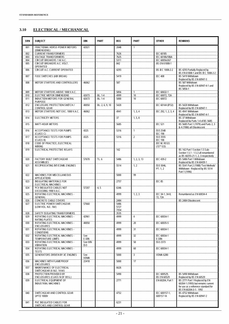
STANDARDS REFERENCE
- 21 -
3.10 ELECTRICAL / MECHANICAL
SRN SUBJECT DIN PART BSS PART OTHER REMARKS
001 FRACTIONAL HORSE-POWER MOTORS (DIMENSIONS)
42021 2048 1
002 CURRENT FRANSFORMERS 7626 IEC 60185 003 VOLTAGE TRANSFORMERS 7625 IEC 60186/186A 004 CIRCUIT BREAKERS 1 kV A.C. 5311 IEC 60056/267 005 CIRCUIT BREAKERS A.C. VOLT.
OPERATED 842 BS EN 61008-1
006 CIRCUIT A.C. CURRENT OPERATED 4293 BS IEC 1008-2-2 BS 4293 Partially Replaced by BS EN 61008-1 and BS IEC 1008-2-2
007 FUSE SWITCHES (AIR BREAK) 5419 IEC 408 BS 5419 Withdrawn Replaced by BS EN 60947-3
008 MOTOR STARTERS AND CONTROLLERS 46062 587 BS 587 Withdrawn Replaced by BS EN 60947-4-1 and BS 5856-1
009 MOTOR STARTERS ABOVE 1000 V.A.C. 5856 1 IEC 60632-1 010 ELECTRIC MOTOR DIMENSIONS 42673 BL. 1-4 4999 10 IEC 60072, 72A 011 INDUCTION MOTORS FOR GENERAL
PURPOSE 42673 BL. 1-4 5000 10 IEC 60072
012 ENCLOSURE PROTECTION SWITCH / CONTROL GEAR
40050 BL. 2, 6, 9, 10 5420 IEC 60144 (IP32) BS 5420 Withdrawn Replaced by BS EN 60947-1
013 MOTOR STARTERS NOT EXC. 1000 V.A.C. 46062 4941 1, 3, 4 IEC 292, 1, 2, 3, 4 BS 4941 Withdrawn Replaced by BS EN 60947-4-1
014 ELECTRICITY METERS 37 1, 5, 8 BS 37 Withdrawn Replaced by Parts 1-4 of BS 5685
015 WATT-HOUR METERS 5685 IEC 521 BS 5685 Part 1 (1979) and Parts 2, 3 & 4 (1986) all Obsolescent
016 ACCEPTANCE TESTS FOR PUMPS (CLASS C)
4325 5316 1 ISO 2548 IEC 198
017 ACCEPTANCE TESTS FOR PUMPS (CLASS B)
4325 5316 2 ISO 3555 IEC 198
018 CODE OF PRACTICE, ELECTRICAL WIRING
IEE W. REGS (15TH ED)
019 ELECTRICAL PROTECTIVE RELAYS 142 BS 142 Part 1 Section 1.5 Sub-Section 1.5.1 - 1.5.3 all renumbered as BS 60255-21-1, 2, 3 respectively
020 FACTORY BUILT SWITCHGEAR ASSEMBLIES
57670 TL. 6 5486 1, 2, 3, 13 IEC 439-2 BS 5486 Part 1 Withdrawn Replaced by BS EN 60439-1
021 RECIPROCATING INT/COMB. ENGINES 5514 1, 2 ISO 3046, PT. 1, 2
BS 5541 Part 2 (1988) 'Test Methods' Withdrawn - Replaced by BS 5514 Part 1 (1996)
022 MACHINES FOR MISCELLANEOUS APPLICATIONS
5000 99
023 INSULATING MATERIALS FOR ELECTRICAL MACHINES
2757 IEC 85
024 PCV INSULATED CABLES NOT EXCEEDING 1900 V.A.C.
57207 4, 5 6346
025 ROTATING ELECTRICAL MACHINES - GENERAL
4999 1, 2, 3 IEC 34-1, 34-8, 72, 72A
Renumbered as EN 60034-4
026 CONCRETE CABLE COVERS 2484 BS 2484 Obsolescent 027 ELECTRIC POWER SWITCHGEAR
(LOW VOL. N.E. 1kV) 57660 5486
5727 7354
028 SAFETY ISOLATING TRANSFORMERS 3535 029 ROTATING ELECTRICAL MACHINES -
RATING PLATES 42961 4999 4 IEC 60034-1
030 ROTATING ELECTRICAL MACHINES - ENCLOSURES
40050 4999 20 IEC 60035-5
031 ROTATING ELECTRICAL MACHINES - CONDITIONS
4999 31 IEC 60034-1
032 ROTATING ELECTRICAL MACHINES - TEMPERATURE LIMITS
See E DIN
4999 32 IEC 60034-1 E DIN
033 ROTATING ELECTRICAL MACHINES - VIBRATION
See DIN ISO
4999 50 ISO 2373
034 ROTATING ELECTRICAL MACHINES - TESTS
4999 60 IEC 60034-1
035 GENERATORS DRIVEN BY I/C ENGINES See VDMA
5000 3 VDMA 6280
036 MACHINES WITH FLAMEPROOF ENCLOSURES
22418 5000 17
037 MAINTENANCE OF ELECTRICAL SWITCHGEAR (V.N.E. 14 kV)
6626
038 PROTECTION PROVIDED BY ENCLOSURES (CLASS N OF DEG.)
5490 IEC 600529, BS EN 60529
BS 5490 Withdrawn Replaced by BS EN 60529
039 ELECTRICAL EQUIPMENT OF INDUSTRIAL MACHINES
2771 EN 60204, Part 1 BS 2771 Part 1 Replaced by EN 60204-1 (1993) but remains current for use as a reference standard for BS EN 60204-3-1: 1992
040 SWITCHGEAR AND CONTROL GEAR UPTO 1000V
4752 IEC 600157-1, 600157-1A
BS 4752 Withdrawn Replaced by BS EN 60947-2
041 PVC INSULATED CABLES FOR SWITCHES AND CONTROL GEAR
6231
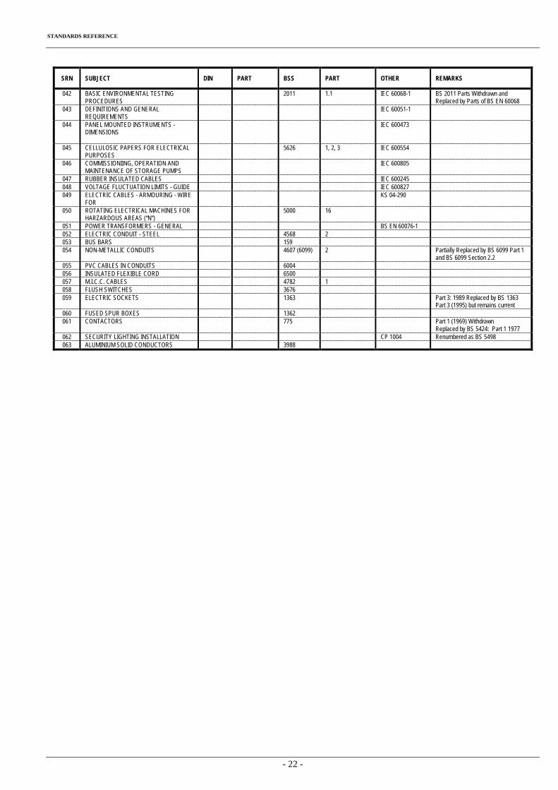
STANDARDS REFERENCE
- 22 -
SRN SUBJECT DIN PART BSS PART OTHER REMARKS
042 BASIC ENVIRONMENTAL TESTING PROCEDURES
2011 1.1 IEC 60068-1 BS 2011 Parts Withdrawn and Replaced by Parts of BS EN 60068
043 DEFINITIONS AND GENERAL REQUIREMENTS
IEC 60051-1
044 PANEL MOUNTED INSTRUMENTS - DIMENSIONS
IEC 600473
045 CELLULOSIC PAPERS FOR ELECTRICAL PURPOSES
5626 1, 2, 3 IEC 600554
046 COMMISSIONIING, OPERATION AND MAINTENANCE OF STORAGE PUMPS
IEC 600805
047 RUBBER INSULATED CABLES IEC 600245 048 VOLTAGE FLUCTUATION LIMITS - GUIDE IEC 600827 049 ELECTRIC CABLES - ARMOURING - WIRE
FOR KS 04-290
050 ROTATING ELECTRICAL MACHINES FOR HARZARDOUS AREAS (“N”)
5000 16
051 POWER TRANSFORMERS - GENERAL BS EN 60076-1 052 ELECTRIC CONDUIT - STEEL 4568 2 053 BUS BARS 159 054 NON-METALLIC CONDUITS 4607 (6099) 2 Partially Replaced by BS 6099 Part 1
and BS 6099 Section 2.2 055 PVC CABLES IN CONDUITS 6004 056 INSULATED FLEXIBLE CORD 6500 057 M.I.C.C. CABLES 4782 1 058 FLUSH SWITCHES 3676 059 ELECTRIC SOCKETS 1363 Part 3: 1989 Replaced by BS 1363
Part 3 (1995) but remains current 060 FUSED SPUR BOXES 1362 061 CONTACTORS 775 Part 1 (1969) Withdrawn
Replaced by BS 5424: Part 1 1977 062 SECURITY LIGHTING INSTALLATION CP 1004 Renumbered as BS 5498 063 ALUMINIUM SOLID CONDUCTORS 3988
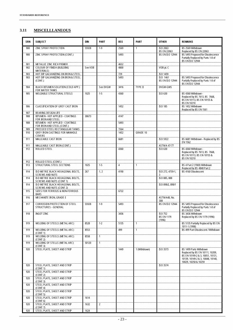
STANDARDS REFERENCE
- 23 -
3.11 MISCELLLANEOUS
SRN SUBJECT DIN PART BSS PART OTHER REMARKS
900 ZINC SPRAY PROTECTION 55928 1-9 2569 1 ISO 2063 BS EN 22063
BS 2569 Withdrawn Replaced by BS EN 22063
900 ZINC SPRAY PROTECTION (CONT.) 5493 BS EN ISO 12944 BS 5493 Proposed for Obsolescence Partially Replaced by Parts 1-8 of BS EN ISO 12944
901 METALLIC ZINC RICH PRIMER 4652 902 COLOUR OF FINISH (BUILDING
MATERIALS) See VOB 4800 VOB pt. C
903 HOT DIP GALVANIZING ON IRON & STEEL 729 ISO 1459 903 HOT DIP GALVANIZING ON IRON & STEEL
(CONT.) 5493 ISO 1461
BS EN ISO 12944 BS 5493 Proposed for Obsolescence Partially Replaced by Parts 1-8 of BS EN ISO 12944
904 BLACK BITUMEN SOLUTION (COLD APP.) FOR WATER TANKS
See DVGW 3416 TYPE II DVGW-GWS
905 WELDABLE STRUCTURAL STEELS 1025 1-5 4360 ISO 630 BS 4360 Withdrawn - Replaced by BS 7613, BS 7668, BS EN 10113, BS EN 10155 & BS EN 10210
906 CLASSIFICATION OF GREY CAST IRON 1452 ISO 185 BS 1452 Withdrawn Replaced by BS EN 1561
907 BEARING DESIGN LIFE 908 BITUMEN - HOT APPLIED - COATINGS
FOR IRON AND STEEL 30673 4147
908 BITUMEN - HOT APPLIED - COATINGS FOR IRON AND STEEL (CONT.)
5493
909 PRESSED STEEL RECTANGULAR TANKS 1564 910 GREY IRON CASTINGS FOR MANHOLE
COVERS 1452 GRADE 10
911 MALLEABLE CAST IRON 6681 ISO 5922 BS 6681 Withdrawn - Replaced by BS EN 1562
911 MALLEABLE CAST IRON (CONT.) ASTM A 47-77 912 ROLLED STEEL 4360 ISO 630 BS 4360 Withdrawn -
Replaced by BS 7613, BS 7668, BS EN 10113, BS EN 10155 & BS EN 10210
912 ROLLED STEEL (CONT.) 913 STRUCTURAL STEEL SECTIONS 1025 1-5 4 1 BS 4 Part 2 (1969) Withdrawn
Replaced by BS 4848 Part 2 914 ISO METRIC BLACK HEXAGONAL BOLTS,
SCREWS AND NUTS 267 1, 2 4190 ISO 272, 4759-1,
3 BS 4160 Obsolescent
914 ISO METRIC BLACK HEXAGONAL BOLTS, SCREWS AND NUTS (CONT 1)
ISO 885, 888
914 ISO METRIC BLACK HEXAGONAL BOLTS, SCREWS AND NUTS (CONT 2)
ISO 898/2, 898/1
915 SIZES FOR FERROUS & NON-FERROUS BARS
6722
916 MECHANITE IRON, GRADE E ASTM A48, No. 308
917 CORROSION PROTECTION OF STEEL STRUCTURES - GENERAL
55928 1-9 5493 BS EN ISO 12944 BS 5493 Proposed for Obsolescence Partially Replaced by Parts 1-8 of BS EN ISO 12944
918 INGOT ZINC 3436 ISO 752 BS EN 1179 (1996)
BS 3436 Withdrawn Replaced by BS EN 1179 (1996)
919 WELDING OF STEELS (METAL ARC) 8528 1-2 5135 1 BS 5135 Partially Replaced by BS EN 1011-1 (1998)
919 WELDING OF STEELS (METAL ARC) (CONT 1)
8553 499 1 BS 499 Part Obsolescent / Withdrawn
919 WELDING OF STEELS (METAL ARC) (CONT 2)
8558 1
919 WELDING OF STELLS (METAL ARC) (CONT 3)
50120 1
920 STEEL PLATE, SHEET AND STRIP 1449 1 (Withdrawn) ISO 3573 BS 1499 Parts Withdrawn Replaced by BS EN 10111, 10209, BS EN 10149-2 & 3, 10051, 10131, 10139, 10149-2 & 3, 10048, 10140, 10029, 10258 & 10259
920 STEEL PLATE, SHEET AND STRIP (CONT 1)
ISO 3574
920 STEEL PLATE, SHEET AND STRIP (CONT 2)
920 STEEL PLATE, SHEET AND STRIP (CONT 3)
920 STEEL PLATE, SHEET AND STRIP (CONT 4)
920 STEEL PLATE, SHEET AND STRIP (CONT 5)
920 STEEL PLATE, SHEET AND STRIP (CONT 6)
1614
920 STEEL PLATE, SHEET AND STRIP (CONT 7)
1632 2
920 STEEL PLATE, SHEET AND STRIP 1624
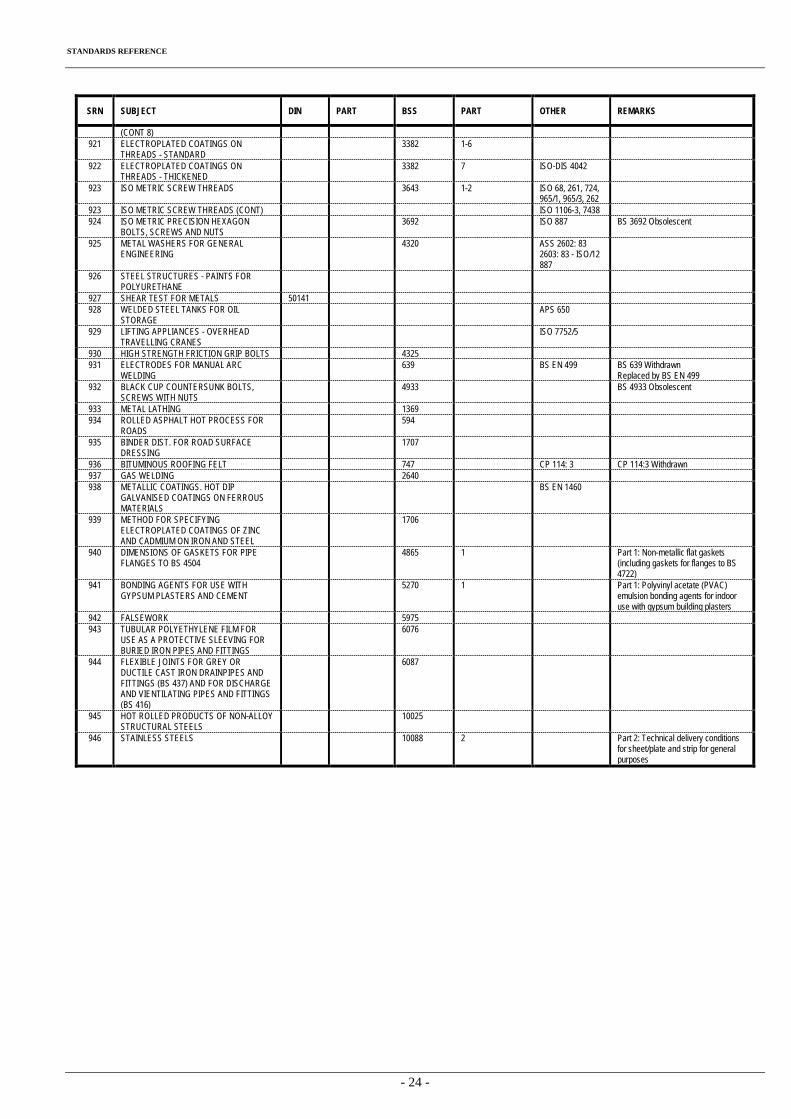
STANDARDS REFERENCE
- 24 -
SRN SUBJECT DIN PART BSS PART OTHER REMARKS
(CONT 8) 921 ELECTROPLATED COATINGS ON
THREADS - STANDARD 3382 1-6
922 ELECTROPLATED COATINGS ON THREADS - THICKENED
3382 7 ISO-DIS 4042
923 ISO METRIC SCREW THREADS 3643 1-2 ISO 68, 261, 724, 965/1, 965/3, 262
923 ISO METRIC SCREW THREADS (CONT) ISO 1106-3, 7438 924 ISO METRIC PRECISION HEXAGON
BOLTS, SCREWS AND NUTS 3692 ISO 887 BS 3692 Obsolescent
925 METAL WASHERS FOR GENERAL ENGINEERING
4320 ASS 2602: 83 2603: 83 - ISO/12 887
926 STEEL STRUCTURES - PAINTS FOR POLYURETHANE
927 SHEAR TEST FOR METALS 50141 928 WELDED STEEL TANKS FOR OIL
STORAGE APS 650
929 LIFTING APPLIANCES - OVERHEAD TRAVELLING CRANES
ISO 7752/5
930 HIGH STRENGTH FRICTION GRIP BOLTS 4325 931 ELECTRODES FOR MANUAL ARC
WELDING 639 BS EN 499 BS 639 Withdrawn
Replaced by BS EN 499 932 BLACK CUP COUNTERSUNK BOLTS,
SCREWS WITH NUTS 4933 BS 4933 Obsolescent
933 METAL LATHING 1369 934 ROLLED ASPHALT HOT PROCESS FOR
ROADS 594
935 BINDER DIST. FOR ROAD SURFACE DRESSING
1707
936 BITUMINOUS ROOFING FELT 747 CP 114: 3 CP 114:3 Withdrawn 937 GAS WELDING 2640 938 METALLIC COATINGS. HOT DIP
GALVANISED COATINGS ON FERROUS MATERIALS
BS EN 1460
939 METHOD FOR SPECIFYING ELECTROPLATED COATINGS OF ZINC AND CADMIUM ON IRON AND STEEL
1706
940 DIMENSIONS OF GASKETS FOR PIPE FLANGES TO BS 4504
4865 1 Part 1: Non-metallic flat gaskets (including gaskets for flanges to BS 4722)
941 BONDING AGENTS FOR USE WITH GYPSUM PLASTERS AND CEMENT
5270 1 Part 1: Polyvinyl acetate (PVAC) emulsion bonding agents for indoor use with gypsum building plasters
942 FALSEWORK 5975 943 TUBULAR POLYETHYLENE FILM FOR
USE AS A PROTECTIVE SLEEVING FOR BURIED IRON PIPES AND FITTINGS
6076
944 FLEXIBLE JOINTS FOR GREY OR DUCTILE CAST IRON DRAINPIPES AND FITTINGS (BS 437) AND FOR DISCHARGE AND VIENTILATING PIPES AND FITTINGS (BS 416)
6087
945 HOT ROLLED PRODUCTS OF NON-ALLOY STRUCTURAL STEELS
10025
946 STAINLESS STEELS 10088 2 Part 2: Technical delivery conditions for sheet/plate and strip for general purposes
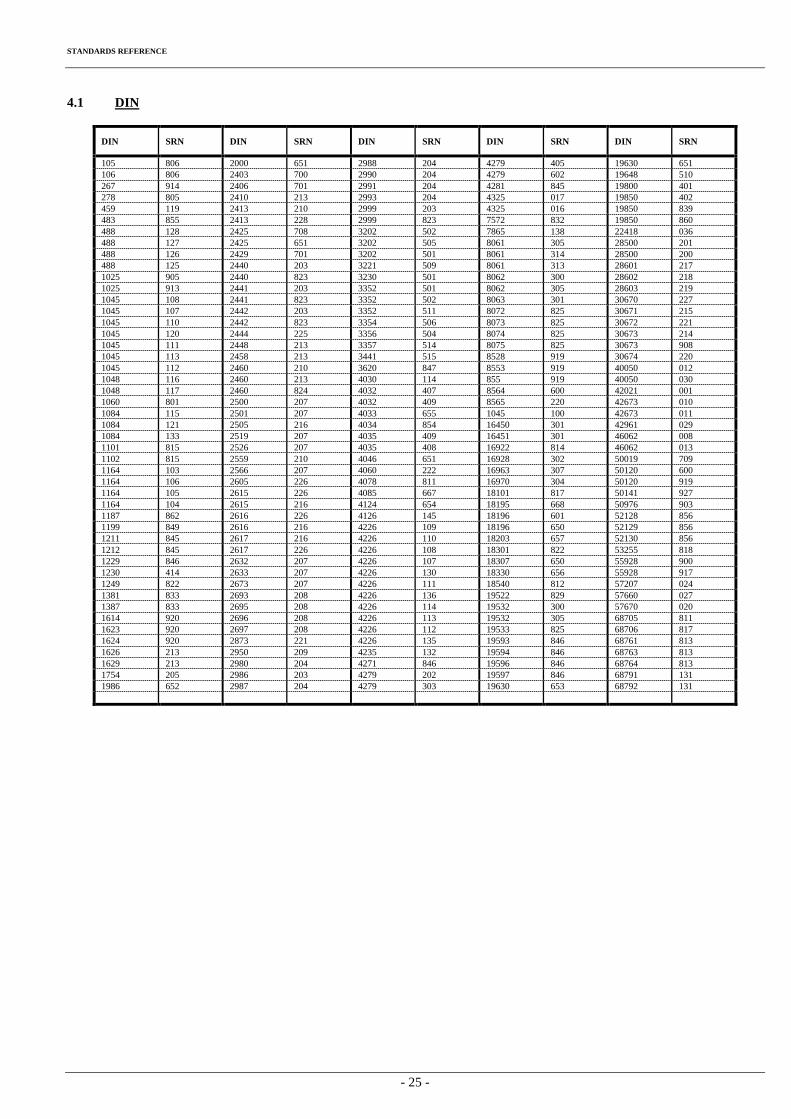
STANDARDS REFERENCE
- 25 -
4.1 DIN
DIN SRN DIN SRN DIN SRN DIN SRN DIN SRN
105 806 2000 651 2988 204 4279 405 19630 651 106 806 2403 700 2990 204 4279 602 19648 510 267 914 2406 701 2991 204 4281 845 19800 401 278 805 2410 213 2993 204 4325 017 19850 402 459 119 2413 210 2999 203 4325 016 19850 839 483 855 2413 228 2999 823 7572 832 19850 860 488 128 2425 708 3202 502 7865 138 22418 036 488 127 2425 651 3202 505 8061 305 28500 201 488 126 2429 701 3202 501 8061 314 28500 200 488 125 2440 203 3221 509 8061 313 28601 217 1025 905 2440 823 3230 501 8062 300 28602 218 1025 913 2441 203 3352 501 8062 305 28603 219 1045 108 2441 823 3352 502 8063 301 30670 227 1045 107 2442 203 3352 511 8072 825 30671 215 1045 110 2442 823 3354 506 8073 825 30672 221 1045 120 2444 225 3356 504 8074 825 30673 214 1045 111 2448 213 3357 514 8075 825 30673 908 1045 113 2458 213 3441 515 8528 919 30674 220 1045 112 2460 210 3620 847 8553 919 40050 012 1048 116 2460 213 4030 114 855 919 40050 030 1048 117 2460 824 4032 407 8564 600 42021 001 1060 801 2500 207 4032 409 8565 220 42673 010 1084 115 2501 207 4033 655 1045 100 42673 011 1084 121 2505 216 4034 854 16450 301 42961 029 1084 133 2519 207 4035 409 16451 301 46062 008 1101 815 2526 207 4035 408 16922 814 46062 013 1102 815 2559 210 4046 651 16928 302 50019 709 1164 103 2566 207 4060 222 16963 307 50120 600 1164 106 2605 226 4078 811 16970 304 50120 919 1164 105 2615 226 4085 667 18101 817 50141 927 1164 104 2615 216 4124 654 18195 668 50976 903 1187 862 2616 226 4126 145 18196 601 52128 856 1199 849 2616 216 4226 109 18196 650 52129 856 1211 845 2617 216 4226 110 18203 657 52130 856 1212 845 2617 226 4226 108 18301 822 53255 818 1229 846 2632 207 4226 107 18307 650 55928 900 1230 414 2633 207 4226 130 18330 656 55928 917 1249 822 2673 207 4226 111 18540 812 57207 024 1381 833 2693 208 4226 136 19522 829 57660 027 1387 833 2695 208 4226 114 19532 300 57670 020 1614 920 2696 208 4226 113 19532 305 68705 811 1623 920 2697 208 4226 112 19533 825 68706 817 1624 920 2873 221 4226 135 19593 846 68761 813 1626 213 2950 209 4235 132 19594 846 68763 813 1629 213 2980 204 4271 846 19596 846 68764 813 1754 205 2986 203 4279 202 19597 846 68791 131 1986 652 2987 204 4279 303 19630 653 68792 131
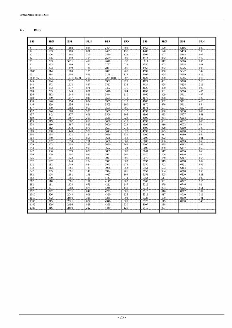
STANDARDS REFERENCE
- 26 -
4.2 BSS
BSS SRN BSS SRN BSS SRN BSS SRN BSS SRN
4 913 1188 835 2494 308 4466 129 5486 020 12 103 1189 831 2499 137 4483 128 5493 900 12 106 1192 703 2439 122 4504 207 5493 908 12 105 1192 704 2569 900 4514 862 5493 917 21 203 5911 410 2640 937 6811 012 5506 835 21 223 1199 130 2757 023 4550 603 5514 021 21 823 1199 136 2871 206 4568 052 5626 045 5685 014 1200 135 2871 205 4592 850 5642 142 65 414 1203 818 3148 114 4607 054 5669 813 78 (4772) 224 1211 (4772) 200 3284 (6811) 307 4622 200 5685 015 143 824 1212 508 3382 921 4624 401 5728 510 144 872 1212 827 3382 922 4624 858 5834 513 159 053 1217 871 3402 875 4625 408 5856 009 308 705 1243 857 3416 904 4652 901 5886 405 336 512 1244 836 3444 810 4660 309 5911 407 368 859 1247 845 3505 311 4670 938 5911 409 410 146 1254 834 3505 310 4800 902 5911 413 416 829 1256 824 3505 300 4870 670 5911 854 417 830 1363 059 3505 305 4871 671 5927 404 437 844 1369 933 3505 312 4999 030 5930 650 437 842 1377 601 3506 305 4999 033 5977 861 459 817 1387 203 3535 028 4999 034 6004 055 499 919 1362 060 3600 213 4999 031 6072 600 534 210 1387 823 3600 228 4999 010 6073 804 534 212 1438 870 3601 213 4999 029 6100 707 569 860 1449 920 3643 923 4999 025 6100 750 594 934 1521 124 3656 839 5000 011 6180 864 604 150 1521 856 3676 058 5000 022 6231 041 690 807 1553 701 3680 661 5000 036 6263 868 729 903 1554 229 3690 866 5000 035 6282 505 743 803 1564 909 3692 924 5000 050 6297 659 747 936 1579 820 3889 600 5041 517 6316 660 750 509 1707 935 3921 805 5070 706 6346 024 775 061 1722 849 3921 806 5075 149 6367 664 812 107 1740 204 3941 003 5135 919 6398 804 812 112 1740 824 3943 873 5150 502 6431 802 812 113 1881 139 3988 063 5151 503 6464 317 842 005 1881 140 3974 406 5152 504 6500 056 882 108 1881 141 4027 104 5153 505 6510 821 882 109 1881 116 4147 214 5154 511 6626 037 882 110 1881 117 4147 908 5163 501 6722 915 882 111 1924 673 4211 847 5212 879 6746 024 890 801 1968 874 4248 148 5311 004 6925 851 952 822 2011 042 4293 006 5316 016 8007 102 1010 826 2048 001 4320 925 5316 017 8010 316 1010 832 2494 318 4335 702 5328 100 8110 101 1105 815 2521 877 4346 301 5328 115 8110 143 1142 809 2456 828 4395 930 8007 138 1186 816 2494 222 4449 126 5419 007
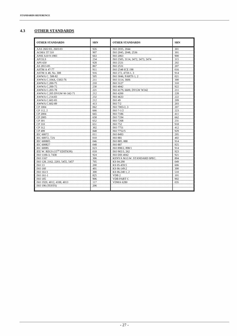
STANDARDS REFERENCE
- 27 -
4.3 OTHER STANDARDS
OTHER STANDARDS SRN OTHER STANDARDS SRN
AAS 2602:83, 2603:03 926 ISO 2035, 2044 301 AGMA 5T 510 907 ISO 2045, 2048, 2536 301 ANSI A10 9-1983 663 ISO 2063 900 AP15LS 234 ISO 2505, 3114, 3472, 3473, 3474 315 APS 650 928 ISO 2531 202 AS 2813-85 867 ISO 2531 207 ASTM A 47-77 911 ISO 2548 ICE 198 016 ASTM A 48, No. 308 916 ISO 272, 4759-1, 3 914 AWWA C. 508-82 505 ISO 3046, PARTS 1, 2 021 AWWA C.104A, C602-76 211 ISO 3114, 3606 300 AWWA C.200-75 210 ISO 3127 310 AWWA C.200-75 230 ISO 4042 922 AWWA C.203-78 221 ISO 4179, 6600, DVGW W342 211 AWWA C.205 DVGW-W-342-71 212 ISO 4200 228 AWWA C.214-83 232 ISO 4633 222 AWWA C.602-83 212 ISO 49 209 AWWA C.602-89 413 ISO 7/2 203 CP 1004 062 ISO 7005/2, 3 207 CP 112, 2 666 ISO 7-1/2 223 CP 2004 665 ISO 7186 411 CP 2005 658 ISO 7194 662 CP 301 652 ISO 7268 231 CP 310 651 ISO 752 918 CP 312 302 ISO 7751 412 CP 499 848 ISO 7752/5 929 IEC 60072 011 ISO 8493 205 IEC 60072, 72A 010 ISO 881 402 IEC 600805 046 ISO 885, 888 914 IEC 600827 048 ISO 887 925 IEC 60085 023 ISO 898/2, 898/1 914 IEE W. REGS (15TH EDITION) 018 ISO 965/3, 262 923 ISO 1106-3, 7438 924 ISO DIS 4042 921 ISO 1167 306 KENYA M.O.W. STANDARD SPEC. 804 ISO 128, 2162, 2203, 5455, 5457 705 KS 04-290 049 ISO 13 200 KS 05-459:5 606 ISO 160 401 KS 06-149:2 300 ISO 161/1 300 KS 06-248 1, 2 510 ISO 161-1 825 VDB 2 101 ISO 185 906 VDB PART C 902 ISO 1920, 4012, 4108, 4013 117 VDMA 6280 035 ISO 196 (TESTS) 206
Related Documents