1 Face Alignment in Full Pose Range: A 3D Total Solution Xiangyu Zhu, Xiaoming Liu, Member, IEEE, Zhen Lei, Senior Member, IEEE, and Stan Z. Li, Fellow, IEEE Abstract— Face alignment, which fits a face model to an image and extracts the semantic meanings of facial pixels, has been an important topic in the computer vision community. However, most algorithms are designed for faces in small to medium poses (yaw angle is smaller than 45 ◦ ), which lack the ability to align faces in large poses up to 90 ◦ . The challenges are three-fold. Firstly, the commonly used landmark face model assumes that all the landmarks are visible and is therefore not suitable for large poses. Secondly, the face appearance varies more drastically across large poses, from the frontal view to the profile view. Thirdly, labelling landmarks in large poses is extremely challenging since the invisible landmarks have to be guessed. In this paper, we propose to tackle these three challenges in an new alignment framework termed 3D Dense Face Alignment (3DDFA), in which a dense 3D Morphable Model (3DMM) is fitted to the image via Cascaded Convolutional Neural Networks. We also utilize 3D information to synthesize face images in profile views to provide abundant samples for training. Experiments on the challenging AFLW database show that the proposed approach achieves significant improvements over the state-of-the-art methods. Index Terms—Face Alignment, 3D Morphable Model, Convolutional Neural Network, Cascaded Regression ✦ 1 I NTRODUCTION Face alignment is the process of moving and deforming a face model to an image, so as to extract the semantic meanings of facial pixels. It is an essential preprocessing step for many face analysis tasks, e.g. recognition [1], animation [2], tracking [3], attributes classification [4] and image restoration [5]. Traditionally, face alignment is approached as a landmark detection problem that aims to locate a sparse set of facial fiducial points, some of which include “eye corner”, “nose tip” and “chin center”. In the past two decades, a number of effective frameworks have been proposed such as ASM [6], AAM [7] and CLM [8]. Recently, with the introduction of Cascaded Regression [9], [10], [11] and Convolutional Neural Networks [12], [13], face alignment has observed significant improvements in accuracy. However, most of the existing methods are designed for medium poses, under the assumptions that the yaw angle is smaller than 45 ◦ and all the landmarks are visible. When the range of yaw angle is extended up to 90 ◦ , significant challenges emerge. These challenges can be differentiated in three main ways: Modelling: Landmark shape model [6] implicitly assumes that each landmark can be robustly detected by its distinctive visual patterns. However, when faces deviate from the frontal view, some landmarks become invisible due to self-occlusion [14]. In medium poses, this problem can be addressed by changing the semantic positions of face contour landmarks to the silhouette, which is termed landmark marching [15]. However, in large poses where half of face is occluded, some landmarks are inevitably invisible • X. Zhu, Z. Lei and S. Li are with Center for Biometrics and Security Research & National Laboratory of Pattern Recognition, Institute of Automation, Chinese Academy of Sciences, 95 Zhongguancun Donglu, Beijing 100190, China. Email: {xiangyu.zhu,zlei,szli}@nlpr.ia.ac.cn. • X. Liu is with the Department of Computer Science and Engineering, Michigan State University, East Lansing, MI 48824, USA. Email: li- [email protected]. Fig. 1. Fitting results of 3DDFA (the blue/red points indicate visi- ble/invisible landmarks). For each pair of the four results, on the left is the rendering of the fitted 3D face with the mean texture, which is made transparent to demonstrate the fitting accuracy. On the right is the landmarks overlayed on the fitted 3D face model. and show no detectable appearance. In turn, landmarks can lose their semantic meanings, which may cause the shape model to fail. Fitting: Another challenge in full-pose face alignment is derived from the dramatic appearance variations from front to profile. Cascaded Linear Regression [11] and traditional nonlinear models [16], [10] are not flexible enough to cover these complex variations in a unified way. Another framework demonstrates more flexibility by adopting different landmark and fitting models for differing view categories [14], [17], [18]. Unfortunately, since the nature of this framework must test every view, computational cost is likely to significantly increase. More recently, Convolutional Neural Network (CNN) based methods have demonstrated im- proved performance over traditional methods in many applica- tions. For effective large-pose face alignment, CNN should be combined with the Cascaded Regression framework. However, most existing methods adopt a single network to complete fitting [13], which limits its performance. Training Data: Labelled data is the basis for any supervised learning based algorithms. However, manual labelling of land- arXiv:1804.01005v1 [cs.CV] 2 Apr 2018

Welcome message from author
This document is posted to help you gain knowledge. Please leave a comment to let me know what you think about it! Share it to your friends and learn new things together.
Transcript
1
Face Alignment in Full Pose Range:A 3D Total Solution
Xiangyu Zhu, Xiaoming Liu, Member, IEEE, Zhen Lei, Senior Member, IEEE, and Stan Z. Li, Fellow, IEEE
Abstract— Face alignment, which fits a face model to an image and extracts the semantic meanings of facial pixels, has been animportant topic in the computer vision community. However, most algorithms are designed for faces in small to medium poses (yawangle is smaller than 45◦), which lack the ability to align faces in large poses up to 90◦. The challenges are three-fold. Firstly, thecommonly used landmark face model assumes that all the landmarks are visible and is therefore not suitable for large poses. Secondly,the face appearance varies more drastically across large poses, from the frontal view to the profile view. Thirdly, labelling landmarks inlarge poses is extremely challenging since the invisible landmarks have to be guessed. In this paper, we propose to tackle these threechallenges in an new alignment framework termed 3D Dense Face Alignment (3DDFA), in which a dense 3D Morphable Model (3DMM)is fitted to the image via Cascaded Convolutional Neural Networks. We also utilize 3D information to synthesize face images in profileviews to provide abundant samples for training. Experiments on the challenging AFLW database show that the proposed approachachieves significant improvements over the state-of-the-art methods.
Index Terms—Face Alignment, 3D Morphable Model, Convolutional Neural Network, Cascaded Regression
F
1 INTRODUCTION
Face alignment is the process of moving and deforming a facemodel to an image, so as to extract the semantic meanings offacial pixels. It is an essential preprocessing step for many faceanalysis tasks, e.g. recognition [1], animation [2], tracking [3],attributes classification [4] and image restoration [5]. Traditionally,face alignment is approached as a landmark detection problemthat aims to locate a sparse set of facial fiducial points, some ofwhich include “eye corner”, “nose tip” and “chin center”. In thepast two decades, a number of effective frameworks have beenproposed such as ASM [6], AAM [7] and CLM [8]. Recently,with the introduction of Cascaded Regression [9], [10], [11] andConvolutional Neural Networks [12], [13], face alignment hasobserved significant improvements in accuracy. However, most ofthe existing methods are designed for medium poses, under theassumptions that the yaw angle is smaller than 45◦ and all thelandmarks are visible. When the range of yaw angle is extendedup to 90◦, significant challenges emerge. These challenges can bedifferentiated in three main ways:
Modelling: Landmark shape model [6] implicitly assumes thateach landmark can be robustly detected by its distinctive visualpatterns. However, when faces deviate from the frontal view, somelandmarks become invisible due to self-occlusion [14]. In mediumposes, this problem can be addressed by changing the semanticpositions of face contour landmarks to the silhouette, which istermed landmark marching [15]. However, in large poses wherehalf of face is occluded, some landmarks are inevitably invisible
• X. Zhu, Z. Lei and S. Li are with Center for Biometrics and SecurityResearch & National Laboratory of Pattern Recognition, Institute ofAutomation, Chinese Academy of Sciences, 95 Zhongguancun Donglu,Beijing 100190, China. Email: {xiangyu.zhu,zlei,szli}@nlpr.ia.ac.cn.
• X. Liu is with the Department of Computer Science and Engineering,Michigan State University, East Lansing, MI 48824, USA. Email: [email protected].
Fig. 1. Fitting results of 3DDFA (the blue/red points indicate visi-ble/invisible landmarks). For each pair of the four results, on the leftis the rendering of the fitted 3D face with the mean texture, which ismade transparent to demonstrate the fitting accuracy. On the right is thelandmarks overlayed on the fitted 3D face model.
and show no detectable appearance. In turn, landmarks can losetheir semantic meanings, which may cause the shape model to fail.
Fitting: Another challenge in full-pose face alignment isderived from the dramatic appearance variations from front toprofile. Cascaded Linear Regression [11] and traditional nonlinearmodels [16], [10] are not flexible enough to cover these complexvariations in a unified way. Another framework demonstrates moreflexibility by adopting different landmark and fitting models fordiffering view categories [14], [17], [18]. Unfortunately, since thenature of this framework must test every view, computational costis likely to significantly increase. More recently, ConvolutionalNeural Network (CNN) based methods have demonstrated im-proved performance over traditional methods in many applica-tions. For effective large-pose face alignment, CNN should becombined with the Cascaded Regression framework. However,most existing methods adopt a single network to completefitting [13], which limits its performance.
Training Data: Labelled data is the basis for any supervisedlearning based algorithms. However, manual labelling of land-
arX
iv:1
804.
0100
5v1
[cs
.CV
] 2
Apr
201
8

2
marks on large-pose faces is very tedious since the occludedlandmarks have to be “guessed” which is impossible for most ofpeople. As a result, almost all the public face alignment databasessuch as AFW [18], LFPW [19], HELEN [20] and IBUG [21]are collected in medium poses. Few large-pose databases suchas AFLW [22] only contain visible landmarks, which could beambiguous in invisible landmarks, makes it hard to train a unifiedface alignment model.
In this paper, we aim to solve the problem of face alignment infull pose range, where the yaw angle is allowed to vary between±90◦. We believe that face alignment is not barely a 2D problemsince self-occlusion and large appearance variations are causedby the face rotation in the 3D space, which can be convenientlyaddressed by incorporating 3D information. More specifically, weimprove the face model from 2D sparse landmarks to a dense 3DMorphable Model (3DMM) [23] and consider face alignment as a3DMM fitting task. The optimization concept therein will changeaccordingly from landmark positions to pose (scale, rotation andtranslation) and morphing (shape and expression) parameters.We call this novel face alignment framework 3D Dense FaceAlignment (3DDFA). To realize 3DDFA, we propose to combinetwo achievements in recent years, namely, Cascaded Regressionand the Convolutional Neural Network (CNN). This combinationrequires the introduction of a new input feature which fulfills the“cascade manner” and “convolution manner” simultaneously (seeSec. 3.2) and a new cost function which can model the priority of3DMM parameters (see Sec. 3.4). Besides to provide enough datafor training, we find that given a face image and its corresponding3D model, it is possible to rotate the image out of plane with highfidelity. This rotation enables the synthesis of a large number oftraining samples in large poses.
In general, we propose a novel face alignment framework toaddress the three challenges of modelling, fitting and trainingdata in large poses. The main contributions of the paper aresummarized as follows:
1) To address the self-occlusion challenge, we assert that inlarge poses, fitting a 3DMM is more suitable than detecting2D landmarks. The visibility estimated from 3DMM enablesus to only fit the vertices with detected image patterns. Thelandmarks, if needed, can be sampled from the fitted 3D faceafterwards. See the samples in Fig. 1.
2) To handle appearance variations across large poses, wepropose a novel Cascaded Convolutional Neural Network asthe regressor, in which two specially designed input featurescalled Projected Normalized Coordinate Code (PNCC) andPose Adaptive Feature (PAF) are introduced to connect CNNsin a cascade manner. Besides, a novel cost function namedOptimized Weighted Parameter Distance Cost (OWPDC) isproposed to formulate the priority of 3DMM parametersduring training.
3) To enable the training of the 3DDFA, we construct a facedatabase consisting of pairs of 2D face images and 3D facemodels. We further elucidate a face profiling method tosynthesize 60k+ training samples across large poses. Thesynthesized samples well simulate the face appearances inlarge poses and boost the performance of both previous andthe proposed face alignment approaches.
This paper is an extension of our previous work [24] thefollowing four aspects: 1) Traditional 3DMM uses Euler anglesto represent the 3D rotation, which shows ambiguity when the
yaw angle reaches 90◦. In this paper, quaternions are used insteadas the rotation formulation to eliminate the ambiguity. 2) A newinput feature called Pose Adaptive Feature (PAF) is utilized toremedy the drawbacks of PNCC to further boost the performance.3) We improve the cost function in [24] through the OWPDCwhich not only formulates the importance but also the priority of3DMM parameters during training. 4) Additional experiments areconducted to better analyze the motivation behind the design ofthe input features and the cost function.
2 RELATED WORKS
Face alignment can be summarized as fitting a face model toan image. As such, there are two basic problems involved withthis task: how to model the face shape and how to estimate themodel parameters. In this section, we motivate our approach bydiscussing related works with respect to these two problems.
2.1 Face ModelTraditionally, face shape is represented by a sparse set of 2Dfacial fiducial points. Cootes et al. [6], [7] show that shapevariations can be modeled with subspace analysis such as PrincipalComponents Analysis (PCA). Although, this 2D-subspace modelcan only cope with shape variations from a narrow range offace poses, since the non-linear out-of-plane rotation cannot bewell represented with the linear subspace. To deal with the posevariations, some modifications like Kernel PCA [25] and BayesianMixture Model [14] are proposed to introduce non-linearityinto the subspace models. Recently, Cao et al. [10] propose toabandon any explicit shape constraints and directly use landmarkcoordinates as the shape model, which called 2D Non-ParametricModel (2D-NPM). 2D-NPM considerably improves the flexibilityof the shape model at the cost of losing any shape priors andincreasing the difficulty of model fitting. Besides 2D shape model,Blanz et al. [26], [23] propose the 3D Morphable Model (3DMM)which applies PCA on a set of 3D face scans. By incorporating3D information, 3DMM disentangles the non-linear out-of-planetransformation from the PCA subspace. The remaining shapeand expression variations have shown high linearity [23], [2],which can be well modeled with PCA. Compared with 2Dmodels, 3DMM separates rigid (pose) and non-rigid (shape andexpression) transformations, enabling it to cover diverse shapevariations and keep shape prior at the same time. Additionally,points visibility can be easily estimated by 3DMM [24], whichcan provide important clues to handle self-occlusion in profileviews.
2.2 Model FittingMost fitting methods can be divided into two categories: thetemplate fitting based [7], [27] and regression based [28], [9],[11], [29]. The template fitting methods always maintain a faceappearance model to fit images. For example, Active AppearanceModel (AAM) [7] and Analysis-by-Synthesis 3DMM Fitting [23]simulate the process of face image generation and achievealignment by minimizing the difference between the modelappearance and the input image. Active Shape Model (ASM) [6]and Constrained Local Model (CLM) [8], [30] build a templatemodel for each landmark and use a PCA shape model to constrainthe fitting results. TSPM [18] and CDM [17] employ part basedmodel and DPM-like [31] method to align faces. Generally, the
3
performance of template fitting methods depends on whetherthe image patterns reside within the variations described by theface appearance model. Therefore, it shows limited robustness inunconstrained environment where appearance variations are toowide and complicated.
Regression based methods estimate model parameters byregressing image features. For example, Hou et al. [32] andSaragih et al. [33] perform regression between texture residualsand parameter updates to fit AAM. Valstar et al. [34] locatelandmark positions by mapping the landmark related local patcheswith support vector regression. Recently, Cascaded Regression [9]has been proposed and becomes most popular in face alignmentcommunity [10], [11], [35], [36], which can be summarized inEqn. 1:
pk+1 = pk + Regk(Fea(I,pk)). (1)
where the shape parameter pk at the kth iteration is updated byconducting regression Regk on the shape indexed feature Fea,which should depend on both the image I and the current pa-rameter pk. The regression Regk shows an important “feedback”property that its input feature Fea(I,p) can be updated by itsoutput since after each iteration p is updated. With this property anarray of weak regressors can be cascaded to reduce the alignmenterror progressively.
Besides Cascaded Regression, another breakthrough is theintroduction of Convolutional Neural Network (CNN), whichformulates face alignment as a regression from raw pixels tolandmarks positions. For example, Sun et al. [12] propose touse the CNN to locate landmarks in two stages, first the fullset of landmarks are located with a global CNN and then eachlandmark is refined with a sub-network on its local patch. Withone CNN for each landmark, the complexity of the method highlydepends on the number of landmarks. Zhang et al. [13] combineface alignment with attribute analysis through multi-task CNNto boost the performance of both tasks. Wu et al. [37] clusterface appearances with mid-level CNN features and deal with eachcluster with an independent regressor. Jourabloo et al. [38] arrangethe local landmark patches into a large 2D map as the CNN inputto regress model parameters. Trigeorgis et al. [29] convolve thelandmark local patch as the shape index feature and conduct linearregression to locate landmarks.
2.3 Large Pose Face Alignment
Despite the great achievements in face alignment, most of thestate-of-the-art methods lack the flexibility in large-pose scenarios,since they need to build the challenging relationship betweenthe landmark displacement and landmark related image features,where the latter may be self-occluded. In 2D methods, a com-mon solution is the multi-view framework which uses differentlandmark configurations for different views. It has been appliedin AAM [39], DAM [40] and DPM [18], [17] to align faceswith different shape models, among which the one having thehighest possibility is chosen as the final result. However, sinceevery view has to be tested, the computational cost is always high.Another method is explicitly estimating the visibility of landmarksand shrink the contribution of occluded features [14], [41], [42].Nevertheless, occlusion estimation is itself a challenging task andhandling varying dimensional feature is still an ill-posed problem.
Different from 2D methods, 3D face alignment [43] aims to fita 3DMM [23] to a 2D image. By incorporating 3D information,
3DMM can inherently provide the visibility of each model pointwithout any additional estimation, making it possible to deal withthe self-occluded points. The original 3DMM fitting method [23]fits the 3D model by minimizing the pixel-wise difference betweenimage and rendered face model. Since only the visible model ver-tices are fitted, it is the first method to cover arbitrary poses [23],[44], but it suffers from the one-minute-per-image computationalcost. Recently, regression based 3DMM fitting, which estimatesthe model parameters by regressing the features at projected 3Dlandmarks [17], [45], [46], [47], [38], [48], [49], has looked toimprove the efficiency. Although these methods face two majorchallenges. First the projected 3D landmarks may be self-occludedand lose their image patterns, making the features no longer poseinvariant. Second, parameters of 3DMM have different prioritiesduring fitting, despite that existing regression based methods treatthem equally [10]. As a result, directly minimizing the parametererror may be sub-optimal, because smaller parameter errors are notnecessarily equivalent to smaller alignment errors. This problemwill be further discussed in Sec. 3.4. A relevant but distinct taskis 3D face reconstruction [50], [15], [51], [52], which recoversa 3D face from given 2D landmarks. Interestingly, 2D/3D facealignment results can be mutually transformed, where 3D to 2D ismade by sampling landmark vertices and 2D to 3D is made by 3Dface reconstruction.
In this work, we propose a framework to combine three majorachievements—3DMM, Cascaded Regression and CNN—to solvethe large-pose face alignment problem.
3 3D DENSE FACE ALIGNMENT (3DDFA)In this section, we introduce how to combine Cascaded Regressionand CNNs to realize 3DDFA. By applying a CNN as the regressorin Eqn. 1, Cascaded CNN can be formulated as:
pk+1 = pk + Netk(Fea(I,pk)). (2)
There are four components in this framework: the regressionobjective p (Sec. 3.1), the image features Fea (Sec. 3.2), theCNN structure Net (Sec. 3.3) and the cost function to train theframework (Sec. 3.4).
3.1 3D Morphable ModelBlanz et al. [23] propose the 3D Morphable Model (3DMM) todescribe the 3D face space with PCA:
S = S + Aidαid + Aexpαexp, (3)
where S is a 3D face, S is the mean shape, Aid is the principleaxes trained on the 3D face scans with neutral expression and αid
is the shape parameter, Aexp is the principle axes trained on theoffsets between expression scans and neutral scans and αexp isthe expression parameter. In this work, the Aid and Aexp comefrom BFM [53] and FaceWarehouse [54] respectively. After the3D face is constructed, it can be projected onto the image planewith scale orthographic projection:
V (p) = f ∗Pr ∗R ∗ (S + Aidαid + Aexpαexp) + t2d, (4)
where V (p) is the model construction and projection function,leading to the 2D positions of model vertices, f is the scale factor,
Pr is the orthographic projection matrix(
1 0 00 1 0
), R is
the rotation matrix and t2d is the translation vector. The collectionof all the model parameters is p = [f,R, t2d,αid,αexp]T.
4
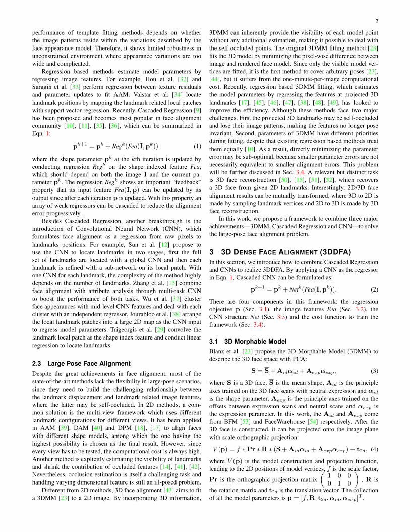
Fig. 2. An overview of the two-stream network in 3DDFA. With an intermediate parameter pk, in the first stream we construct a novel ProjectedNormalized Coordinate Code (PNCC), which is stacked with the input image and sent to the CNN. In the second stream, we get some featureanchors with consistent semantics and conduct Pose Adaptive Convolution (PAC) on them. The outputs of the two streams are merged with anadditional fully connected layer to predict the parameter update ∆pk.
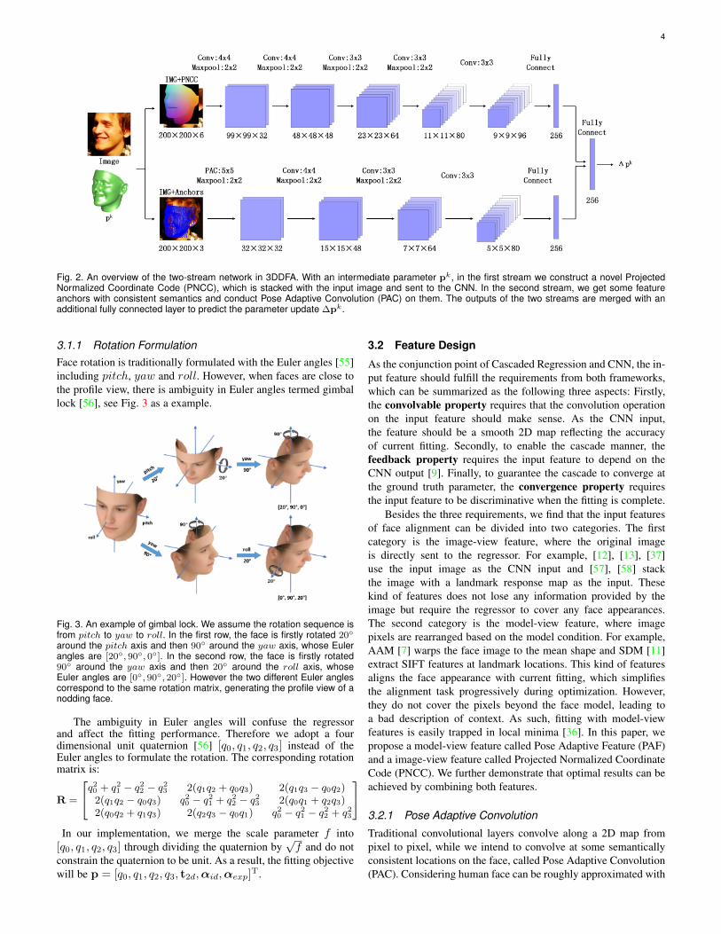
3.1.1 Rotation FormulationFace rotation is traditionally formulated with the Euler angles [55]including pitch, yaw and roll. However, when faces are close tothe profile view, there is ambiguity in Euler angles termed gimballock [56], see Fig. 3 as a example.
Fig. 3. An example of gimbal lock. We assume the rotation sequence isfrom pitch to yaw to roll. In the first row, the face is firstly rotated 20◦
around the pitch axis and then 90◦ around the yaw axis, whose Eulerangles are [20◦, 90◦, 0◦]. In the second row, the face is firstly rotated90◦ around the yaw axis and then 20◦ around the roll axis, whoseEuler angles are [0◦, 90◦, 20◦]. However the two different Euler anglescorrespond to the same rotation matrix, generating the profile view of anodding face.
The ambiguity in Euler angles will confuse the regressorand affect the fitting performance. Therefore we adopt a fourdimensional unit quaternion [56] [q0, q1, q2, q3] instead of theEuler angles to formulate the rotation. The corresponding rotationmatrix is:
R =
q20 + q21 − q22 − q23 2(q1q2 + q0q3) 2(q1q3 − q0q2)2(q1q2 − q0q3) q20 − q21 + q22 − q23 2(q0q1 + q2q3)2(q0q2 + q1q3) 2(q2q3 − q0q1) q20 − q21 − q22 + q23
In our implementation, we merge the scale parameter f into
[q0, q1, q2, q3] through dividing the quaternion by√f and do not
constrain the quaternion to be unit. As a result, the fitting objectivewill be p = [q0, q1, q2, q3, t2d,αid,αexp]T.
3.2 Feature Design
As the conjunction point of Cascaded Regression and CNN, the in-put feature should fulfill the requirements from both frameworks,which can be summarized as the following three aspects: Firstly,the convolvable property requires that the convolution operationon the input feature should make sense. As the CNN input,the feature should be a smooth 2D map reflecting the accuracyof current fitting. Secondly, to enable the cascade manner, thefeedback property requires the input feature to depend on theCNN output [9]. Finally, to guarantee the cascade to converge atthe ground truth parameter, the convergence property requiresthe input feature to be discriminative when the fitting is complete.
Besides the three requirements, we find that the input featuresof face alignment can be divided into two categories. The firstcategory is the image-view feature, where the original imageis directly sent to the regressor. For example, [12], [13], [37]use the input image as the CNN input and [57], [58] stackthe image with a landmark response map as the input. Thesekind of features does not lose any information provided by theimage but require the regressor to cover any face appearances.The second category is the model-view feature, where imagepixels are rearranged based on the model condition. For example,AAM [7] warps the face image to the mean shape and SDM [11]extract SIFT features at landmark locations. This kind of featuresaligns the face appearance with current fitting, which simplifiesthe alignment task progressively during optimization. However,they do not cover the pixels beyond the face model, leading toa bad description of context. As such, fitting with model-viewfeatures is easily trapped in local minima [36]. In this paper, wepropose a model-view feature called Pose Adaptive Feature (PAF)and a image-view feature called Projected Normalized CoordinateCode (PNCC). We further demonstrate that optimal results can beachieved by combining both features.
3.2.1 Pose Adaptive Convolution
Traditional convolutional layers convolve along a 2D map frompixel to pixel, while we intend to convolve at some semanticallyconsistent locations on the face, called Pose Adaptive Convolution(PAC). Considering human face can be roughly approximated with
5
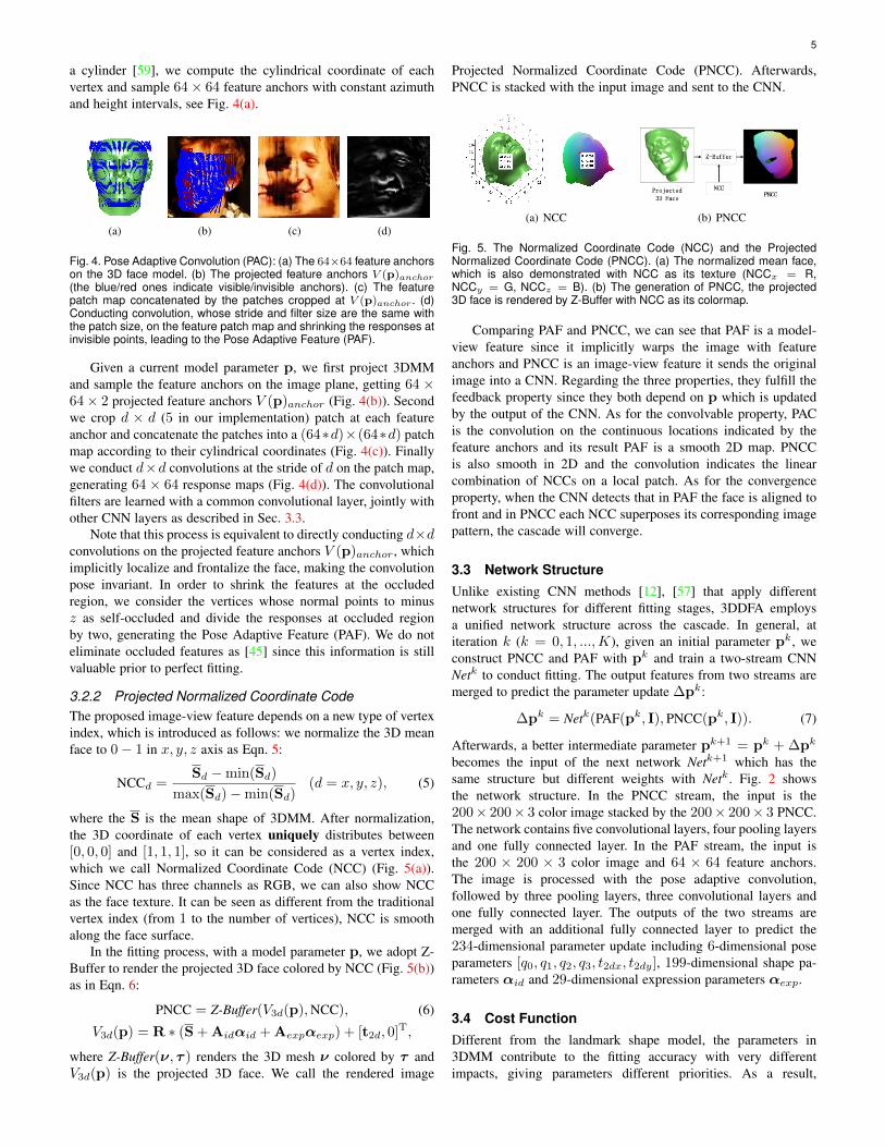
a cylinder [59], we compute the cylindrical coordinate of eachvertex and sample 64× 64 feature anchors with constant azimuthand height intervals, see Fig. 4(a).
(a) (b) (c) (d)
Fig. 4. Pose Adaptive Convolution (PAC): (a) The 64×64 feature anchorson the 3D face model. (b) The projected feature anchors V (p)anchor
(the blue/red ones indicate visible/invisible anchors). (c) The featurepatch map concatenated by the patches cropped at V (p)anchor . (d)Conducting convolution, whose stride and filter size are the same withthe patch size, on the feature patch map and shrinking the responses atinvisible points, leading to the Pose Adaptive Feature (PAF).
Given a current model parameter p, we first project 3DMMand sample the feature anchors on the image plane, getting 64 ×64× 2 projected feature anchors V (p)anchor (Fig. 4(b)). Secondwe crop d × d (5 in our implementation) patch at each featureanchor and concatenate the patches into a (64∗d)×(64∗d) patchmap according to their cylindrical coordinates (Fig. 4(c)). Finallywe conduct d×d convolutions at the stride of d on the patch map,generating 64 × 64 response maps (Fig. 4(d)). The convolutionalfilters are learned with a common convolutional layer, jointly withother CNN layers as described in Sec. 3.3.
Note that this process is equivalent to directly conducting d×dconvolutions on the projected feature anchors V (p)anchor , whichimplicitly localize and frontalize the face, making the convolutionpose invariant. In order to shrink the features at the occludedregion, we consider the vertices whose normal points to minusz as self-occluded and divide the responses at occluded regionby two, generating the Pose Adaptive Feature (PAF). We do noteliminate occluded features as [45] since this information is stillvaluable prior to perfect fitting.
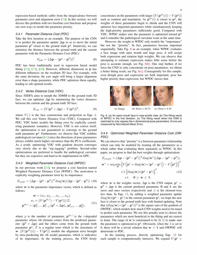
3.2.2 Projected Normalized Coordinate CodeThe proposed image-view feature depends on a new type of vertexindex, which is introduced as follows: we normalize the 3D meanface to 0− 1 in x, y, z axis as Eqn. 5:
NCCd =Sd −min(Sd)
max(Sd)−min(Sd)(d = x, y, z), (5)
where the S is the mean shape of 3DMM. After normalization,the 3D coordinate of each vertex uniquely distributes between[0, 0, 0] and [1, 1, 1], so it can be considered as a vertex index,which we call Normalized Coordinate Code (NCC) (Fig. 5(a)).Since NCC has three channels as RGB, we can also show NCCas the face texture. It can be seen as different from the traditionalvertex index (from 1 to the number of vertices), NCC is smoothalong the face surface.
In the fitting process, with a model parameter p, we adopt Z-Buffer to render the projected 3D face colored by NCC (Fig. 5(b))as in Eqn. 6:
PNCC = Z-Buffer(V3d(p),NCC), (6)
V3d(p) = R ∗ (S + Aidαid + Aexpαexp) + [t2d, 0]T,
where Z-Buffer(ν, τ ) renders the 3D mesh ν colored by τ andV3d(p) is the projected 3D face. We call the rendered image
Projected Normalized Coordinate Code (PNCC). Afterwards,PNCC is stacked with the input image and sent to the CNN.
(a) NCC (b) PNCC
Fig. 5. The Normalized Coordinate Code (NCC) and the ProjectedNormalized Coordinate Code (PNCC). (a) The normalized mean face,which is also demonstrated with NCC as its texture (NCCx = R,NCCy = G, NCCz = B). (b) The generation of PNCC, the projected3D face is rendered by Z-Buffer with NCC as its colormap.
Comparing PAF and PNCC, we can see that PAF is a model-view feature since it implicitly warps the image with featureanchors and PNCC is an image-view feature it sends the originalimage into a CNN. Regarding the three properties, they fulfill thefeedback property since they both depend on p which is updatedby the output of the CNN. As for the convolvable property, PACis the convolution on the continuous locations indicated by thefeature anchors and its result PAF is a smooth 2D map. PNCCis also smooth in 2D and the convolution indicates the linearcombination of NCCs on a local patch. As for the convergenceproperty, when the CNN detects that in PAF the face is aligned tofront and in PNCC each NCC superposes its corresponding imagepattern, the cascade will converge.
3.3 Network StructureUnlike existing CNN methods [12], [57] that apply differentnetwork structures for different fitting stages, 3DDFA employsa unified network structure across the cascade. In general, atiteration k (k = 0, 1, ...,K), given an initial parameter pk, weconstruct PNCC and PAF with pk and train a two-stream CNNNetk to conduct fitting. The output features from two streams aremerged to predict the parameter update ∆pk:
∆pk = Netk(PAF(pk, I), PNCC(pk, I)). (7)
Afterwards, a better intermediate parameter pk+1 = pk + ∆pk
becomes the input of the next network Netk+1 which has thesame structure but different weights with Netk. Fig. 2 showsthe network structure. In the PNCC stream, the input is the200× 200× 3 color image stacked by the 200× 200× 3 PNCC.The network contains five convolutional layers, four pooling layersand one fully connected layer. In the PAF stream, the input isthe 200 × 200 × 3 color image and 64 × 64 feature anchors.The image is processed with the pose adaptive convolution,followed by three pooling layers, three convolutional layers andone fully connected layer. The outputs of the two streams aremerged with an additional fully connected layer to predict the234-dimensional parameter update including 6-dimensional poseparameters [q0, q1, q2, q3, t2dx, t2dy], 199-dimensional shape pa-rameters αid and 29-dimensional expression parameters αexp.
3.4 Cost FunctionDifferent from the landmark shape model, the parameters in3DMM contribute to the fitting accuracy with very differentimpacts, giving parameters different priorities. As a result,
6
regression-based methods suffer from the inequivalence betweenparameter error and alignment error [10]. In this section, we willdiscuss this problem with two baseline cost functions and proposeour own ways to model the parameter priority.
3.4.1 Parameter Distance Cost (PDC)Take the first iteration as an example. The purpose of the CNNis to predict the parameter update ∆p so as to move the initialparameter p0 closer to the ground truth pg . Intuitively, we canminimize the distance between the ground truth and the currentparameter with the Parameter Distance Cost (PDC):
Epdc = ‖∆p− (pg − p0)‖2. (8)
PDC has been traditionally used in regression based modelfitting [32], [33], [60]. However, different dimension in p hasdifferent influences on the resultant 3D face. For example, withthe same deviation, the yaw angle will bring a larger alignmenterror than a shape parameter, while PDC optimizes them equally,leading to sub-optimal results.
3.4.2 Vertex Distance Cost (VDC)Since 3DDFA aims to morph the 3DMM to the ground truth 3Dface, we can optimize ∆p by minimizing the vertex distancesbetween the current and the ground truth 3D face:
Evdc = ‖V (p0 + ∆p)− V (pg)‖2, (9)
where V (·) is the face construction and projection as Eqn. 4.We call this cost Vertex Distance Cost (VDC). Compared withPDC, VDC better models the fitting error by explicitly consid-ering parameter semantics. However, VDC is not convex itself,the optimization is not guaranteed to converge to the groundtruth parameter pg . Furthermore, we observe that VDC exhibitspathological curvature [61] since the directions of pose parametersalways exhibit much higher curvatures than the PCA coefficients.As a result, optimizing VDC with gradient descent convergesvery slowly due to the “zig-zagging” problem. Second-orderoptimizations are preferred to handle the pathological curvaturebut they are expensive and hard to be implemented on GPU.
3.4.3 Weighted Parameter Distance Cost (WPDC)In our previous work [24], we propose a cost function namedWeighted Parameter Distance Cost (WPDC). The motivation isexplicitly weighting parameter error by its importance:
Ewpdc = (∆p− (pg−p0))Tdiag(w)(∆p− (pg−p0)) (10)
where w is the parameter importance vector, which is defined asfollows:
w = (w1, w2, ..., wi, ..., wp),
wi = ‖V (pde,i)− V (pg)‖/Z,pde,i = (pg
1, ...,pgi−1,(p
0 + ∆p)i,pgi+1, ...,p
gp),
(11)
where p is the number of parameter, pde,i is the i-degradedparameter whose ith element comes from the predicted param-eter (p0 + ∆p) and the others come from the ground truthparameter pg , Z is a regular term which is the maximum ofw. ‖V (pde(i)) − V (pg)‖ models the alignment error broughtby miss-predicting the ith model parameter, which is indicativeof its importance. In the training process, the CNN firstly
concentrates on the parameters with larger ‖V (pde(i))−V (pg)‖such as rotation and translation. As pde(i) is closer to pg , theweights of these parameters begin to shrink and the CNN willoptimize less important parameters while simultaneously keepingthe high-priority parameters sufficiently good. Compared withVDC, WPDC makes sure the parameter is optimized toward pg
and it remedies the pathological curvature issue at the same time.However, the weight in WPDC only models the “importance”
but not the “priority”. In fact, parameters become importantsequentially. Take Fig. 6 as an example, when WPDC evaluatesa face image with open mouth and large pose, it will assignboth expression and rotation high weights. We can observe thatattempting to estimate expression makes little sense before thepose is accurate enough, see Fig. 6(b). One step further, if weforce the CNN to only concentrate on pose parameters, we obtaina better fitting result, see Fig. 6(c). Consequently for this sample,even though pose and expression are both important, pose hashigher priority than expression, but WPDC misses that.
(a) Image (b) Error = 10.72 (c) Error = 4.39
Fig. 6. (a) An open-mouth face in near-profile view. (b) The fitting resultof WPDC in the first iteration. (c) The fitting result when the CNN isrestricted to only regress the 6-dimensional pose parameters. Errors aremeasured by Normalized Mean Error.
3.4.4 Optimized Weighted Parameter Distance Cost (OW-PDC)We can observe that “priority” is a between-parameter relationshipwhich can only be modeled by treating all the parameters as awhole rather than evaluating them separately as WPDC. In thispaper, we propose to find the best weights through optimization:
Eowpdc = (∆p− (pg − p0))Tdiag(w∗)(∆p− (pg − p0)),
w∗ = arg minw
∥∥∥V (pc + diag(w) ∗ (pg − pc)
)− V
(pg
)∥∥∥2+λ
∥∥∥diag(w)∗(pg − pc)∥∥∥2, (12)
s.t. 0 � w � 1,
where w is the weights vector, ∆p is the CNN output, pc =p0 + ∆p is the current predicted parameter, 0 and 1 are thezeros and ones vectors respectively and � is the element-wiseless than. In Eqn. 12, by adding a weighted parameter updatediag(w)(pg − pc) to the current parameter pc, we hope the newface is closer to the ground truth face with limited updating. Notethat ‖diag(w) ∗ (pg −pc)‖2 is the square sum of the gradient ofOWPDC, which models how much CNN weights need to be tunedto predict each parameter. We use this penalty term to choose theparameters which are most beneficial to the fitting and are easiestto learn. The range of w is constrained to be [0, 1] to make surethe parameter is optimized to pg . Obviously, when the λ is set to0, there will be a trivial solution that w = 1 and OWPDC willdeteriorate to PDC.
In the training process, directly optimizing Eqn. 12 foreach sample is computationally intensive. We expand V (pc +

7
diag(w)(pg − pc)) at pg with the Taylor formula and let∆pc = pg − pc, Eqn. 12 will be:∥∥∥V ′(pg)∗diag(w−1)∗∆pc
∥∥∥2 +λ∥∥∥diag(w)∗∆pc
∥∥∥2, (13)
where V ′(pg) is the Jacobian. Expanding Eqn. 13 and removingthe constant terms, we get:
wT(
diag(∆pc)V ′(pg)TV ′(pg)diag(∆pc))w
−2 ∗ 1T(
diag(∆pc)V ′(pg)TV ′(pg)diag(∆pc))w
+λ ∗wTdiag(∆pc. ∗∆pc)w, (14)
where .∗ is the element-wise multiplication. Let H =V ′(pg)diag(∆pc) which is a 2n × p matrix where n is thenumber of vertices and p is the number of parameters, theoptimization will be:
arg minw
wT ∗ (HT ∗H + λ∗diag(∆pc. ∗∆pc)) ∗w
+2 ∗ 1T ∗HT ∗H ∗w,s.t. 0 � w � 1, (15)
which is a standard quadratic programming problem with theunique solution. The most consuming component in Eqn. 15 isthe computation of V ′(pg). Fortunately, pg is constant duringtraining and V ′(pg) can be pre-computed offline. As a result, thecomputation of w∗ can be reduced to a p-dimensional quadraticprogramming which can be efficiently solved. The only parameterin OWPDC is the λ. It directly determines which parameter isvalid during training. We set λ = 0.17 ∗ ‖V (pc) − V (pg)‖2 inour implementation.
4 FACE PROFILING
All the regression based methods rely on training data, espe-cially for CNNs which have thousands of parameters to learn.Therefore, massive labelled faces in large poses are crucial for3DDFA. However, few of the released face alignment databasescontain large-pose samples [18], [19], [20], [21] since labellingstandardized landmarks on them is very challenging. In this work,we demonstrate that profile faces can be well synthesized fromexisting training samples with the help of 3D information. Inspiredby the recent achievements in face frontalization [15], [62] whichgenerates the frontal view of faces, we propose to invert thisprocess to synthesize the profile view of faces from medium-posesamples, which is called face profiling. Different from the facesynthesizing in recognition [63], face profiling is not required tokeep the identity information but to make the synthesizing resultsrealistic. However, current synthesizing methods do not keep theexternal face region [64], [63], which contains important contextinformation for face alignment. In this section, we elucidate anovel face synthesizing method to generate the profile views offace image with out-of-plane rotation, providing abundant realistictraining samples for 3DDFA.
4.1 3D Image MeshingThe depth estimation of a face image can be conducted on theface region and the external region respectively, with differentrequirements of accuracy. On the face region, we fit a 3DMMthrough the Multi-Features Framework (MFF) [44] (see Fig. 7(b)).With the ground truth landmarks as a solid constraint throughout
the fitting process, MFF can always get accurate results. Fewdifficult samples can be easily adjusted manually. On the externalregion, we follow the 3D meshing method proposed by Zhu etal. [15] to mark some anchors beyond the face region and simulatetheir depth, see Fig. 7(c). Afterwards the whole image can be tunedinto a 3D object through triangulation (see Fig. 7(c)7(d)).
(a) (b) (c) (d)
Fig. 7. 3D Image Meshing. (a) The input image. (b) The fitted 3D facethrough MFF. (c) The depth image from 3D meshing. (d) A different viewof the depth image.
4.2 3D Image Rotation
The simulated depth information enables the 2D image to rotateout of plane to generate the appearances in larger poses. However,as shown in Fig. 8(b), the 3D rotation squeezes the external faceregion and loses the background. As a result, we need to furtheradjust the anchors to keep the background relatively unchangedand preserve the smoothness simultaneously. Inspired by ourprevious work [15], we propose to adjust background anchors bysolving an equation list about their relative positions.
Fig. 8. The face profiling and anchor adjustment process. (a) The sourceimage. (b) The profiled face with out of plane rotation. It can be seen thatthe face locates on the hollow since the background is squeezed. (c) Thesynthesized image after anchor adjustment.
In the source image as shown in Fig. 8(a), the triangulatedanchors build up a graph where the anchors are the vertices andthe mesh lines are the edges. In the graph, each edge represents ananchor-to-anchor relationship:
xa src − xb src = ∆xsrc, ya src − yb src = ∆ysrc, (16)
where (xa src, ya src) and (xb src, yb src) are two connectinganchors, ∆xsrc and ∆ysrc are the spatial offsets in x, y axes,which should be preserved in synthesizing. After profiling, wekeep the face contour anchors (the magenta points in Fig. 8(b))consistent and predicting other anchors with the unchanged anchoroffsets:
xa adj − xb adj = ∆xsrc, ya adj − yb adj = ∆ysrc, (17)
8
Specifically, if a is a face contour anchor, we set (xa adj , ya adj)to the positions after profiling (xa pro, ya pro), otherwise(xa adj , ya adj) are two unknowns need to be solved. By collect-ing Eqn. 17 for each graph edge, we form an equation list whoseleast square solution is the adjusted anchors (as seen in Fig. 8(c)).
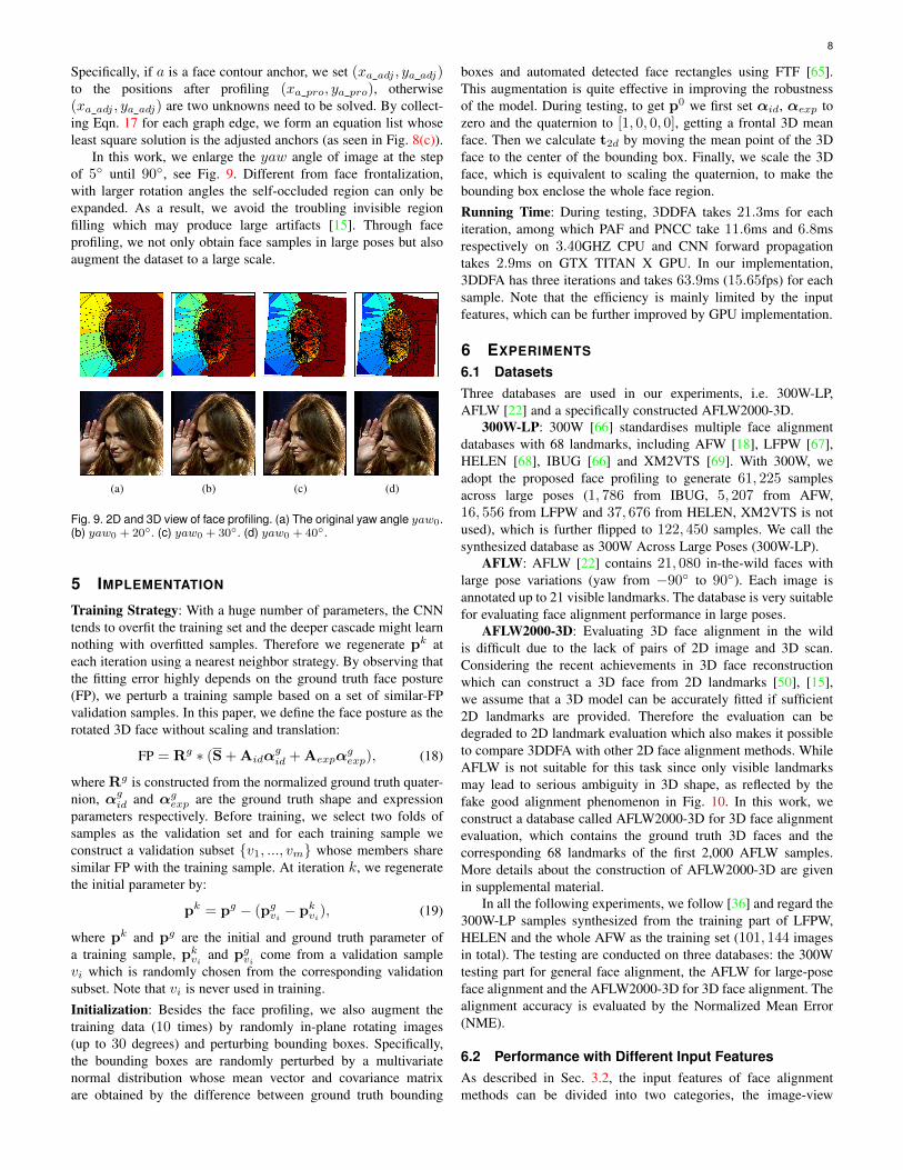
In this work, we enlarge the yaw angle of image at the stepof 5◦ until 90◦, see Fig. 9. Different from face frontalization,with larger rotation angles the self-occluded region can only beexpanded. As a result, we avoid the troubling invisible regionfilling which may produce large artifacts [15]. Through faceprofiling, we not only obtain face samples in large poses but alsoaugment the dataset to a large scale.
(a) (b) (c) (d)
Fig. 9. 2D and 3D view of face profiling. (a) The original yaw angle yaw0.(b) yaw0 + 20◦. (c) yaw0 + 30◦. (d) yaw0 + 40◦.
5 IMPLEMENTATION
Training Strategy: With a huge number of parameters, the CNNtends to overfit the training set and the deeper cascade might learnnothing with overfitted samples. Therefore we regenerate pk ateach iteration using a nearest neighbor strategy. By observing thatthe fitting error highly depends on the ground truth face posture(FP), we perturb a training sample based on a set of similar-FPvalidation samples. In this paper, we define the face posture as therotated 3D face without scaling and translation:
FP = Rg ∗ (S + Aidαgid + Aexpα
gexp), (18)
where Rg is constructed from the normalized ground truth quater-nion, αg
id and αgexp are the ground truth shape and expression
parameters respectively. Before training, we select two folds ofsamples as the validation set and for each training sample weconstruct a validation subset {v1, ..., vm} whose members sharesimilar FP with the training sample. At iteration k, we regeneratethe initial parameter by:
pk = pg − (pgvi − pk
vi), (19)
where pk and pg are the initial and ground truth parameter ofa training sample, pk
vi and pgvi come from a validation sample
vi which is randomly chosen from the corresponding validationsubset. Note that vi is never used in training.Initialization: Besides the face profiling, we also augment thetraining data (10 times) by randomly in-plane rotating images(up to 30 degrees) and perturbing bounding boxes. Specifically,the bounding boxes are randomly perturbed by a multivariatenormal distribution whose mean vector and covariance matrixare obtained by the difference between ground truth bounding
boxes and automated detected face rectangles using FTF [65].This augmentation is quite effective in improving the robustnessof the model. During testing, to get p0 we first set αid, αexp tozero and the quaternion to [1, 0, 0, 0], getting a frontal 3D meanface. Then we calculate t2d by moving the mean point of the 3Dface to the center of the bounding box. Finally, we scale the 3Dface, which is equivalent to scaling the quaternion, to make thebounding box enclose the whole face region.Running Time: During testing, 3DDFA takes 21.3ms for eachiteration, among which PAF and PNCC take 11.6ms and 6.8msrespectively on 3.40GHZ CPU and CNN forward propagationtakes 2.9ms on GTX TITAN X GPU. In our implementation,3DDFA has three iterations and takes 63.9ms (15.65fps) for eachsample. Note that the efficiency is mainly limited by the inputfeatures, which can be further improved by GPU implementation.
6 EXPERIMENTS
6.1 DatasetsThree databases are used in our experiments, i.e. 300W-LP,AFLW [22] and a specifically constructed AFLW2000-3D.
300W-LP: 300W [66] standardises multiple face alignmentdatabases with 68 landmarks, including AFW [18], LFPW [67],HELEN [68], IBUG [66] and XM2VTS [69]. With 300W, weadopt the proposed face profiling to generate 61, 225 samplesacross large poses (1, 786 from IBUG, 5, 207 from AFW,16, 556 from LFPW and 37, 676 from HELEN, XM2VTS is notused), which is further flipped to 122, 450 samples. We call thesynthesized database as 300W Across Large Poses (300W-LP).
AFLW: AFLW [22] contains 21, 080 in-the-wild faces withlarge pose variations (yaw from −90◦ to 90◦). Each image isannotated up to 21 visible landmarks. The database is very suitablefor evaluating face alignment performance in large poses.
AFLW2000-3D: Evaluating 3D face alignment in the wildis difficult due to the lack of pairs of 2D image and 3D scan.Considering the recent achievements in 3D face reconstructionwhich can construct a 3D face from 2D landmarks [50], [15],we assume that a 3D model can be accurately fitted if sufficient2D landmarks are provided. Therefore the evaluation can bedegraded to 2D landmark evaluation which also makes it possibleto compare 3DDFA with other 2D face alignment methods. WhileAFLW is not suitable for this task since only visible landmarksmay lead to serious ambiguity in 3D shape, as reflected by thefake good alignment phenomenon in Fig. 10. In this work, weconstruct a database called AFLW2000-3D for 3D face alignmentevaluation, which contains the ground truth 3D faces and thecorresponding 68 landmarks of the first 2,000 AFLW samples.More details about the construction of AFLW2000-3D are givenin supplemental material.
In all the following experiments, we follow [36] and regard the300W-LP samples synthesized from the training part of LFPW,HELEN and the whole AFW as the training set (101, 144 imagesin total). The testing are conducted on three databases: the 300Wtesting part for general face alignment, the AFLW for large-poseface alignment and the AFLW2000-3D for 3D face alignment. Thealignment accuracy is evaluated by the Normalized Mean Error(NME).
6.2 Performance with Different Input FeaturesAs described in Sec. 3.2, the input features of face alignmentmethods can be divided into two categories, the image-view
9
Fig. 10. Fake good alignment in AFLW. For each sample, the first showsthe visible 21 landmarks and the second shows all the 68 landmarks.The Normalized Mean Error (NME) reflects their accuracy. It can beseen that only evaluating visible landmarks cannot well reflect theaccuracy of 3D fitting.
feature and the model-view feature, which correspond to PNCCand PAF in this paper. To test their effectiveness respectively andevaluate their complementarity, we divide the network in Fig. 2into PNCC stream and PAF stream by removing the last fullyconnected layer and regress the 256-dimensional output of eachstream to the parameter update respectively. The combined two-stream network is also reported to demonstrate the improvements.As shown in Fig. 11, PNCC performs better than PAF when used
Fig. 11. The Normalized Mean Error (%) with different input features,evaluated on AFLW2000-3D with different yaw intervals.
individually and the improvement is enlarged as the pose becomeslarger. Besides, PNCC and PAF achieve better performance whencombined, which may infer a complementary relationship. Thiscomplementary relationship might be because PNCC covers thewhole image and contains rich context information, enabling itto fit large scale facial components like the face contour. WhilePAF is more adept at fitting facial features due to the implicitfrontalizion, which can well assist PNCC.
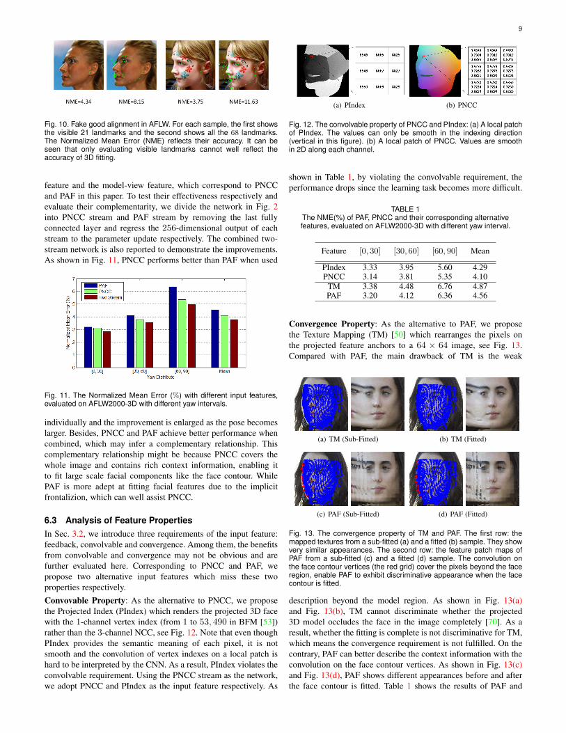
6.3 Analysis of Feature PropertiesIn Sec. 3.2, we introduce three requirements of the input feature:feedback, convolvable and convergence. Among them, the benefitsfrom convolvable and convergence may not be obvious and arefurther evaluated here. Corresponding to PNCC and PAF, wepropose two alternative input features which miss these twoproperties respectively.Convovable Property: As the alternative to PNCC, we proposethe Projected Index (PIndex) which renders the projected 3D facewith the 1-channel vertex index (from 1 to 53, 490 in BFM [53])rather than the 3-channel NCC, see Fig. 12. Note that even thoughPIndex provides the semantic meaning of each pixel, it is notsmooth and the convolution of vertex indexes on a local patch ishard to be interpreted by the CNN. As a result, PIndex violates theconvolvable requirement. Using the PNCC stream as the network,we adopt PNCC and PIndex as the input feature respectively. As
(a) PIndex (b) PNCC
Fig. 12. The convolvable property of PNCC and PIndex: (a) A local patchof PIndex. The values can only be smooth in the indexing direction(vertical in this figure). (b) A local patch of PNCC. Values are smoothin 2D along each channel.
shown in Table 1, by violating the convolvable requirement, theperformance drops since the learning task becomes more difficult.
TABLE 1The NME(%) of PAF, PNCC and their corresponding alternativefeatures, evaluated on AFLW2000-3D with different yaw interval.
Feature [0, 30] [30, 60] [60, 90] Mean
PIndex 3.33 3.95 5.60 4.29PNCC 3.14 3.81 5.35 4.10
TM 3.38 4.48 6.76 4.87PAF 3.20 4.12 6.36 4.56
Convergence Property: As the alternative to PAF, we proposethe Texture Mapping (TM) [50] which rearranges the pixels onthe projected feature anchors to a 64 × 64 image, see Fig. 13.Compared with PAF, the main drawback of TM is the weak
(a) TM (Sub-Fitted) (b) TM (Fitted)
(c) PAF (Sub-Fitted) (d) PAF (Fitted)
Fig. 13. The convergence property of TM and PAF. The first row: themapped textures from a sub-fitted (a) and a fitted (b) sample. They showvery similar appearances. The second row: the feature patch maps ofPAF from a sub-fitted (c) and a fitted (d) sample. The convolution onthe face contour vertices (the red grid) cover the pixels beyond the faceregion, enable PAF to exhibit discriminative appearance when the facecontour is fitted.
description beyond the model region. As shown in Fig. 13(a)and Fig. 13(b), TM cannot discriminate whether the projected3D model occludes the face in the image completely [70]. As aresult, whether the fitting is complete is not discriminative for TM,which means the convergence requirement is not fulfilled. On thecontrary, PAF can better describe the context information with theconvolution on the face contour vertices. As shown in Fig. 13(c)and Fig. 13(d), PAF shows different appearances before and afterthe face contour is fitted. Table 1 shows the results of PAF and
10
TM which use the PAF stream as the network. We can see thatPAF outperforms TM by over 6% which verifies the effectivenessof the convergence property.
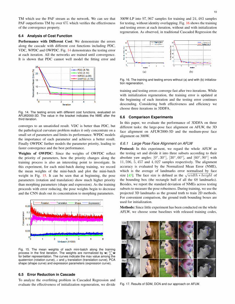
6.4 Analysis of Cost FunctionPerformance with Different Cost: We demonstrate the errorsalong the cascade with different cost functions including PDC,VDC, WPDC and OWPDC. Fig. 14 demonstrates the testing errorat each iteration. All the networks are trained until convergence.It is shown that PDC cannot well model the fitting error and
Fig. 14. The testing errors with different cost functions, evaluated onAFLW2000-3D. The value in the bracket indicates the NME after thethird iteration.
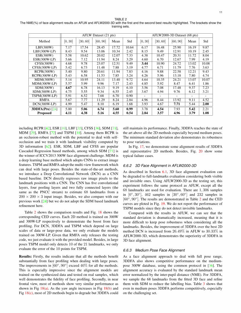
converges to an unsatisfied result. VDC is better than PDC, butthe pathological curvature problem makes it only concentrate on asmall set of parameters and limits its performance. WPDC modelsthe importance of each parameter and achieves a better result.Finally OWPDC further models the parameter priority, leading tofaster convergence and the best performance.Weights of OWPDC: Since the weights of OWPDC reflectthe priority of parameters, how the priority changes along thetraining process is also an interesting point to investigate. Inthis experiment, for each mini-batch during training, we recordthe mean weights of the mini-batch and plot the mini-batchweight in Fig. 15. It can be seen that at beginning, the poseparameters (rotation and translation) show much higher prioritythan morphing parameters (shape and expression). As the trainingproceeds with error reducing, the pose weights begin to decreaseand the CNN deals out its concentration to morphing parameters.
Fig. 15. The mean weights of each mini-batch along the trainingprocess in the first iteration. The weights are normalized by w/
∑w
for better representation. The curves indicate the max value among thequaternion (rotation curve), x and y translation (translation curve), PCAshape (shape curve) and expression parameters (expression curve).
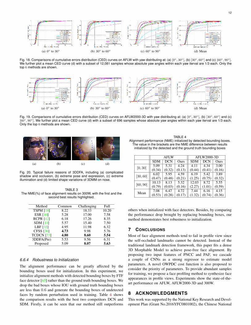
6.5 Error Reduction in CascadeTo analyze the overfitting problem in Cascaded Regression andevaluate the effectiveness of initialization regeneration, we divide
300W-LP into 97, 967 samples for training and 24, 483 samplesfor testing, without identity overlapping. Fig. 16 shows the trainingand testing errors at each iteration, without and with initializationregeneration. As observed, in traditional Cascaded Regression the
(a) (b)
Fig. 16. The training and testing errors without (a) and with (b) initializa-tion regeneration.
training and testing errors converge fast after two iterations. Whilewith initialization regeneration, the training error is updated atthe beginning of each iteration and the testing error continuesdescending. Considering both effectiveness and efficiency wechoose three iterations in 3DDFA.
6.6 Comparison ExperimentsIn this paper, we evaluate the performance of 3DDFA on threedifferent tasks: the large-pose face alignment on AFLW, the 3Dface alignment on AFLW2000-3D and the medium-pose facealignment on 300W.
6.6.1 Large Pose Face Alignment on AFLWProtocol: In this experiment, we regard the whole AFLW asthe testing set and divide it into three subsets according to theirabsolute yaw angles: [0◦, 30◦], [30◦, 60◦], and [60◦, 90◦] with11, 596, 5, 457 and 4, 027 samples respectively. The alignmentaccuracy is evaluated by the Normalized Mean Error (NME),which is the average of landmarks error normalised by facesize [45]. The face size is defined as the
√width ∗ height of
the bounding box (the rectangle hull of all the 68 landmarks).Besides, we report the standard deviation of NMEs across testingsubsets to measure the pose robustness. During training, we use theprojected 3D landmarks as the ground truth to train 2D methods.For convenient comparison, the ground truth bounding boxes areused for initialization.Methods: Since little experiment has been conducted on the wholeAFLW, we choose some baselines with released training codes,
Fig. 17. Results of SDM, DCN and our approach on AFLW.
11
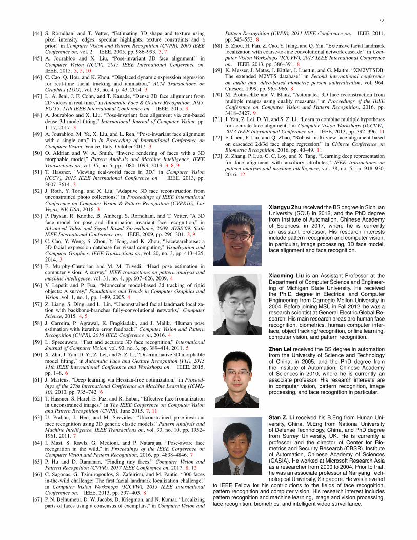
TABLE 2The NME(%) of face alignment results on AFLW and AFLW2000-3D with the first and the second best results highlighted. The brackets show the
training sets.
AFLW Dataset (21 pts) AFLW2000-3D Dataset (68 pts)
Method [0, 30] [30, 60] [60, 90] Mean Std [0, 30] [30, 60] [60, 90] Mean Std
LBF(300W) 7.17 17.54 28.45 17.72 10.64 6.17 16.48 25.90 16.19 9.87LBF(300W-LP) 8.43 9.54 13.06 10.34 2.42 8.15 9.49 12.91 10.19 2.45
ESR(300W) 5.58 10.62 20.02 12.07 7.33 4.38 10.47 20.31 11.72 8.04ESR(300W-LP) 5.66 7.12 11.94 8.24 3.29 4.60 6.70 12.67 7.99 4.19CFSS(300W) 4.68 9.78 23.07 12.51 9.49 3.44 10.90 24.72 13.02 10.08
CFSS(300W-LP) 5.42 6.73 11.48 7.88 3.19 4.77 6.71 11.79 7.76 3.63RCPR(300W) 5.40 9.80 20.61 11.94 7.83 4.16 9.88 22.58 12.21 9.43
RCPR(300W-LP) 5.43 6.58 11.53 7.85 3.24 4.26 5.96 13.18 7.80 4.74MDM(300W) 5.14 10.95 24.11 13.40 9.72 4.64 10.35 24.21 13.07 10.07
MDM(300W-LP) 5.57 5.99 9.96 7.17 2.43 4.85 5.92 8.47 6.41 1.86SDM(300W) 4.67 6.78 16.13 9.19 6.10 3.56 7.08 17.48 9.37 7.23
SDM(300W-LP) 4.75 5.55 9.34 6.55 2.45 3.67 4.94 9.76 6.12 3.21TSPM(300W-LP) 5.91 6.52 7.68 6.70 0.90 - - - - -
RMFA 5.67 7.77 11.29 8.24 2.84 4.96 8.44 13.92 9.11 4.52DCN(300W-LP) 4.99 5.47 8.10 6.19 1.68 3.93 4.67 7.71 5.44 2.00
3DDFA(Pre) [24] 5.00 5.06 6.74 5.60 0.99 3.78 4.54 7.93 5.42 2.21Proposed 4.11 4.38 5.16 4.55 0.54 2.84 3.57 4.96 3.79 1.08
including RCPR [42], ESR [10], LBF [35], CFSS [36], SDM [71],MDM [29], RMFA [72] and TSPM [18]. Among them RCPR isan occlusion-robust method with the potential to deal with self-occlusion and we train it with landmark visibility computed by3D information [62]. ESR, SDM, LBF and CFSS are popularCascaded Regression based methods, among which SDM [71] isthe winner of ICCV2013 300W face alignment challenge. MDM isa deep learning base method which adopts CNNs to extract imagefeatures. TSPM and RMFA adopt the multi-view framework whichcan deal with large poses. Besides the state-of-the-art methods,we introduce a Deep Convolutional Network (DCN) as a CNNbased baseline. DCN directly regresses raw image pixels to thelandmark positions with a CNN. The CNN has five convolutionallayers, four pooling layers and two fully connected layers (thesame as the PNCC stream) to estimate 68 landmarks from a200 × 200 × 3 input image. Besides, we also compare with ourprevious work [24] but we do not adopt the SDM based landmarkrefinement here.
Table 2 shows the comparison results and Fig. 18 shows thecorresponding CED curves. Each 2D method is trained on 300Wand 300W-LP respectively to demonstrate the boost from faceprofiling. For DCN, 3DDFA and TSPM which depend on largescales of data or large-pose data, we only evaluate the modelstrained on 300W-LP. Given that RMFA only releases the testingcode, we just evaluate it with the provided model. Besides, in largeposes TSPM model only detects 10 of the 21 landmarks, we onlyevaluate the error of the 10 points for TSPM.
Results: Firstly, the results indicate that all the methods benefitsubstantially from face profiling when dealing with large poses.The improvements in [60◦, 90◦] exceed 40% for all the methods.This is especially impressive since the alignment models aretrained on the synthesized data and tested on real samples, whichwell demonstrates the fidelity of face profiling. Secondly, in nearfrontal view, most of methods show very similar performance asshown in Fig 18(a). As the yaw angle increases in Fig 18(b) andFig 18(c), most of 2D methods begin to degrade but 3DDFA could
still maintain its performance. Finally, 3DDFA reaches the state ofthe art above all the 2D methods especially beyond medium poses.The minimum standard deviation also demonstrates its robustnessto pose variations.
In Fig. 17, we demonstrate some alignment results of 3DDFAand representative 2D methods. Besides, Fig. 20 show sometypical failure cases.
6.6.2 3D Face Alignment in AFLW2000-3D
As described in Section 6.1, 3D face alignment evaluation canbe degraded to full-landmarks evaluation considering both visibleand invisible ones. Using AFLW2000-3D as the testing set, thisexperiment follows the same protocol as AFLW, except all the68 landmarks are used for evaluation. There are 1, 306 samplesin [0◦, 30◦], 462 samples in [30◦, 60◦] and 232 samples in[60◦, 90◦]. The results are demonstrated in Table 2 and the CEDcurves are ploted in Fig. 19. We do not report the performance ofTSPM models since they do not detect invisible landmarks.
Compared with the results in AFLW, we can see that thestandard deviation is dramatically increased, meaning that it ismore difficult to keep pose robustness when considering all thelandmarks. Besides, the improvement of 3DDFA over the best 2Dmethod DCN is increased from 26.49% in AFLW to 30.33% inAFLW2000-3D, which demonstrates the superiority of 3DDFA in3D face alignment.
6.6.3 Medium Pose Face Alignment
As a face alignment approach to deal with full pose range,3DDFA also shows competitive performance on the medium-pose 300W database, using the common protocol in [36]. Thealignment accuracy is evaluated by the standard landmark meanerror normalized by the inter-pupil distance (NME). For 3DDFA,we sample the 68 landmarks from the fitted 3D face and refinethem with SDM to reduce the labelling bias. Table 3 shows thateven in medium poses 3DDFA performs competitively, especiallyon the challenging set.
12
(a) 0◦ to 30◦ (b) 30◦ to 60◦ (c) 60◦ to 90◦ (d) Mean
Fig. 18. Comparisons of cumulative errors distribution (CED) curves on AFLW with yaw distributing at: (a) [0◦, 30◦], (b) [30◦, 60◦] and (c) [60◦, 90◦].We further plot a mean CED curve (d) with a subset of 12,081 samples whose absolute yaw angles within each yaw iterval are 1/3 each. Only thetop 6 methods are shown.
(a) 0◦ to 30◦ (b) 30◦ to 60◦ (c) 60◦ to 90◦ (d) Mean
Fig. 19. Comparisons of cumulative errors distribution (CED) curves on AFLW2000-3D with yaw distributing at: (a) [0◦, 30◦], (b) [30◦, 60◦] and (c)[60◦, 90◦]. We further plot a mean CED curve (d) with a subset of 696 samples whose absolute yaw angles within each yaw iterval are 1/3 each.Only the top 6 methods are shown.
(a) (b) (c) (d)
Fig. 20. Typical failure reasons of 3DDFA, including (a) complicatedshadow and occlusion, (b) extreme pose and expression, (c) extremeillumination and (d) limited shape variations of 3DMM on nose.
TABLE 3The NME(%) of face alignment results on 300W, with the first and the
second best results highlighted.
Method Common Challenging FullTSPM [18] 8.22 18.33 10.20ESR [10] 5.28 17.00 7.58
RCPR [42] 6.18 17.26 8.35SDM [11] 5.57 15.40 7.50LBF [35] 4.95 11.98 6.32
CFSS [36] 4.73 9.98 5.76TCDCN [73] 4.80 8.60 5.543DDFA(Pre) 5.53 9.56 6.31
Proposed 5.09 8.07 5.63
6.6.4 Robustness to Initialization
The alignment performance can be greatly affected by thebounding boxes used for initialization. In this experiment, weinitialize alignment methods with detected bounding boxes by FTFface detector [65] rather than the ground truth bounding boxes. Wedrop the bad boxes whose IOU with ground truth bounding boxesare less than 0.6 and generate the bounding boxes of undetectedfaces by random perturbation used in training. Table 4 showsthe comparison results with the best two competitors DCN andSDM. Firstly, it can be seen that our method still outperforms
TABLE 4Alignment performance (NME) initialized by detected bounding boxes.
The value in the brackets are the NME difference between resultsinitialized by the detected and the ground truth bounding boxes
AFLW AFLW2000-3DSDM DCN Ours SDM DCN Ours
[0, 30]5.09
(0.34)5.31
(0.32)4.24
(0.13)4.11
(0.44)4.34
(0.41)3.00
(0.16)
[30, 60]6.02
(0.47)5.95
(0.48)4.59
(0.21)6.19
(1.25)5.42
(0.75)3.89
(0.32)
[60, 90]10.13(0.79)
8.13(0.03)
5.32(0.16)
12.03(2.27)
8.72(1.01)
5.55(0.59)
Mean 7.08(0.53)
6.47(0.28)
4.72(0.17)
7.44(1.32)
6.16(0.74)
4.15(0.36)
others when initialized with face detectors. Besides, by comparingthe performance drop brought by replacing bounding boxes, ourmethod demonstrates best robustness to initialization.
7 CONCLUSIONS
Most of face alignment methods tend to fail in profile view sincethe self-occluded landmarks cannot be detected. Instead of thetraditional landmark detection framework, this paper fits a dense3D Morphable Model to achieve pose-free face alignment. Byproposing two input features of PNCC and PAF, we cascadea couple of CNNs as a strong regressor to estimate modelparameters. A novel OWPDC cost function is also proposed toconsider the priority of parameters. To provide abundant samplesfor training, we propose a face profiling method to synthesize faceappearances in profile views. Experiments show the state-of-the-art performance on AFLW, AFLW2000-3D and 300W.
8 ACKNOWLEDGMENTSThis work was supported by the National Key Research and Devel-opment Plan (Grant No.2016YFC0801002), the Chinese National

13
Natural Science Foundation Projects #61473291, #61572501,#61502491, #61572536 and AuthenMetric R&D Funds. Zhen Leiis the corresponding author.
REFERENCES
[1] Y. Taigman, M. Yang, M. Ranzato, and L. Wolf, “Deepface: Closing thegap to human-level performance in face verification,” in Proceedings ofthe IEEE Conference on Computer Vision and Pattern Recognition, 2013,pp. 1701–1708. 1
[2] C. Cao, Y. Weng, S. Lin, and K. Zhou, “3D shape regression for real-timefacial animation.” ACM Trans. Graph., vol. 32, no. 4, p. 41, 2013. 1, 2
[3] X. Xiong and F. De la Torre, “Global supervised descent method,” inProceedings of the IEEE Conference on Computer Vision and PatternRecognition, 2015, pp. 2664–2673. 1
[4] V. Bettadapura, “Face expression recognition and analysis: The state ofthe art,” Computer Science, 2012. 1
[5] C.-Y. Yang, S. Liu, and M.-H. Yang, “Structured face hallucination,” inProceedings of the IEEE Conference on Computer Vision and PatternRecognition, 2013, pp. 1099–1106. 1
[6] T. F. Cootes, C. J. Taylor, D. H. Cooper, and J. Graham, “Activeshape models-their training and application,” Computer vision and imageunderstanding, vol. 61, no. 1, pp. 38–59, 1995. 1, 2
[7] T. F. Cootes, G. J. Edwards, and C. J. Taylor, “Active appearancemodels,” Pattern Analysis and Machine Intelligence, IEEE Transactionson, vol. 23, no. 6, pp. 681–685, 2001. 1, 2, 4
[8] D. Cristinacce and T. F. Cootes, “Feature detection and tracking withconstrained local models.” in BMVC, vol. 17, 2006, pp. 929–938. 1, 2
[9] P. Dollar, P. Welinder, and P. Perona, “Cascaded pose regression,”in Computer Vision and Pattern Recognition (CVPR), 2010 IEEEConference on. IEEE, 2010, pp. 1078–1085. 1, 2, 3, 4
[10] X. Cao, Y. Wei, F. Wen, and J. Sun, “Face alignment by explicit shaperegression,” in Computer Vision and Pattern Recognition (CVPR), 2012IEEE Conference on. IEEE, 2012, pp. 2887–2894. 1, 2, 3, 6, 11, 12
[11] X. Xiong and F. De la Torre, “Supervised descent method and its appli-cations to face alignment,” in Computer Vision and Pattern Recognition(CVPR), 2013 IEEE Conference on. IEEE, 2013, pp. 532–539. 1, 2, 3,4, 12
[12] Y. Sun, X. Wang, and X. Tang, “Deep convolutional network cascadefor facial point detection,” in Computer Vision and Pattern Recognition(CVPR), 2013 IEEE Conference on. IEEE, 2013, pp. 3476–3483. 1, 3,4, 5
[13] Z. Zhang, P. Luo, C. C. Loy, and X. Tang, “Facial landmark detection bydeep multi-task learning,” in Computer Vision–ECCV 2014. Springer,2014, pp. 94–108. 1, 3, 4
[14] Y. Zhou, W. Zhang, X. Tang, and H. Shum, “A Bayesian mixturemodel for multi-view face alignment,” in Computer Vision and PatternRecognition, 2005. CVPR 2005. IEEE Computer Society Conference on,vol. 2. IEEE, 2005, pp. 741–746. 1, 2, 3
[15] X. Zhu, Z. Lei, J. Yan, D. Yi, and S. Z. Li, “High-fidelity pose andexpression normalization for face recognition in the wild,” in Proceedingsof the IEEE Conference on Computer Vision and Pattern Recognition,2015, pp. 787–796. 1, 3, 7, 8
[16] J. Zhang, S. Shan, M. Kan, and X. Chen, “Coarse-to-fine auto-encodernetworks (CFAN) for real-time face alignment,” in Computer Vision–ECCV 2014. Springer, 2014, pp. 1–16. 1
[17] X. Yu, J. Huang, S. Zhang, W. Yan, and D. N. Metaxas, “Pose-free faciallandmark fitting via optimized part mixtures and cascaded deformableshape model,” in Computer Vision (ICCV), 2013 IEEE InternationalConference on. IEEE, 2013, pp. 1944–1951. 1, 2, 3
[18] X. Zhu and D. Ramanan, “Face detection, pose estimation, and landmarklocalization in the wild,” in Computer Vision and Pattern Recognition(CVPR), 2012 IEEE Conference on. IEEE, 2012, pp. 2879–2886. 1, 2,3, 7, 8, 11, 12
[19] S. Jaiswal, T. R. Almaev, and M. F. Valstar, “Guided unsupervisedlearning of mode specific models for facial point detection in thewild,” in Computer Vision Workshops (ICCVW), 2013 IEEE InternationalConference on. IEEE, 2013, pp. 370–377. 2, 7
[20] V. Le, J. Brandt, Z. Lin, L. Bourdev, and T. S. Huang, “Interactive facialfeature localization,” in Computer Vision–ECCV 2012. Springer, 2012,pp. 679–692. 2, 7
[21] C. Sagonas, G. Tzimiropoulos, S. Zafeiriou, and M. Pantic, “A semi-automatic methodology for facial landmark annotation,” in ComputerVision and Pattern Recognition Workshops (CVPRW), 2013 IEEEConference on. IEEE, 2013, pp. 896–903. 2, 7
[22] M. Kostinger, P. Wohlhart, P. M. Roth, and H. Bischof, “Annotatedfacial landmarks in the wild: A large-scale, real-world database forfacial landmark localization,” in Computer Vision Workshops (ICCVWorkshops), 2011 IEEE International Conference on. IEEE, 2011, pp.2144–2151. 2, 8
[23] V. Blanz and T. Vetter, “Face recognition based on fitting a 3D morphablemodel,” Pattern Analysis and Machine Intelligence, IEEE Transactionson, vol. 25, no. 9, pp. 1063–1074, 2003. 2, 3
[24] X. Zhu, Z. Lei, X. Liu, H. Shi, and S. Z. Li, “Face alignment acrosslarge poses: A 3D solution,” in Computer Vision and Pattern Recognition(CVPR), 2016 IEEE Conference on, 2016. 2, 6, 11
[25] S. Romdhani, S. Gong, A. Psarrou et al., “A multi-view nonlinear activeshape model using kernel pca,” in BMVC, vol. 10, 1999, pp. 483–492. 2
[26] V. Blanz and T. Vetter, “A morphable model for the synthesis of 3Dfaces,” in Proceedings of the 26th annual conference on Computergraphics and interactive techniques. ACM Press/Addison-WesleyPublishing Co., 1999, pp. 187–194. 2
[27] D. Cristinacce and T. Cootes, “Automatic feature localisation withconstrained local models,” Pattern Recognition, vol. 41, no. 10, pp. 3054–3067, 2008. 2
[28] T. F. Cootes, G. J. Edwards, and C. J. Taylor, “A comparative evaluationof active appearance model algorithms.” in BMVC, vol. 98, 1998, pp.680–689. 2
[29] G. Trigeorgis, P. Snape, M. A. Nicolaou, E. Antonakos, and S. Zafeiriou,“Mnemonic descent method: A recurrent process applied for end-to-endface alignment,” in Proceedings of IEEE International Conference onComputer Vision & Pattern Recognition (CVPR16), Las Vegas, NV, USA,2016. 2, 3, 11
[30] J. M. Saragih, S. Lucey, and J. F. Cohn, “Deformable model fittingby regularized landmark mean-shift,” International Journal of ComputerVision, vol. 91, no. 2, pp. 200–215, 2011. 2
[31] P. F. Felzenszwalb, R. B. Girshick, D. McAllester, and D. Ramanan,“Object detection with discriminatively trained part-based models,”Pattern Analysis and Machine Intelligence, IEEE Transactions on,vol. 32, no. 9, pp. 1627–1645, 2010. 2
[32] X. Hou, S. Z. Li, H. Zhang, and Q. Cheng, “Direct appearancemodels,” in Computer Vision and Pattern Recognition, 2001. CVPR 2001.Proceedings of the 2001 IEEE Computer Society Conference on, vol. 1.IEEE, 2001, pp. I–828. 3, 6
[33] J. Saragih and R. Goecke, “A nonlinear discriminative approach to aamfitting,” in 2007 IEEE 11th International Conference on Computer Vision.IEEE, 2007, pp. 1–8. 3, 6
[34] M. Valstar, B. Martinez, X. Binefa, and M. Pantic, “Facial point detectionusing boosted regression and graph models,” in Computer Vision andPattern Recognition (CVPR), 2010 IEEE Conference on. IEEE, 2010,pp. 2729–2736. 3
[35] S. Ren, X. Cao, Y. Wei, and J. Sun, “Face alignment at 3000 FPSvia regressing local binary features,” in Computer Vision and PatternRecognition (CVPR), 2014 IEEE Conference on. IEEE, 2014, pp. 1685–1692. 3, 11, 12
[36] S. Zhu, C. Li, C. C. Loy, and X. Tang, “Face alignment by coarse-to-fineshape searching,” in Proceedings of the IEEE Conference on ComputerVision and Pattern Recognition, 2015, pp. 4998–5006. 3, 4, 8, 11, 12
[37] Y. Wu, T. Hassner, K. G. Kim, G. Medioni, and P. Natarajan, “Faciallandmark detection with tweaked convolutional neural networks,” Com-puter Science, 2015. 3, 4
[38] A. Jourabloo and X. Liu, “Large-pose face alignment via CNN-based dense 3D model fitting,” in Proceedings of IEEE InternationalConference on Computer Vision & Pattern Recognition (CVPR16), LasVegas, NV, USA, 2016. 3
[39] T. F. Cootes, G. V. Wheeler, K. N. Walker, and C. J. Taylor, “View-basedactive appearance models,” Image and vision computing, vol. 20, no. 9,pp. 657–664, 2002. 3
[40] S. Z. Li, H. Zhang, Q. Cheng et al., “Multi-view face alignment usingdirect appearance models,” in Automatic Face and Gesture Recognition,2002. Proceedings. Fifth IEEE International Conference on. IEEE,2002, pp. 324–329. 3
[41] R. Gross, I. Matthews, and S. Baker, “Active appearance models withocclusion,” Image and Vision Computing, vol. 24, no. 6, pp. 593–604,2006. 3
[42] X. P. Burgos-Artizzu, P. Perona, and P. Dollar, “Robust face landmarkestimation under occlusion,” in Computer Vision (ICCV), 2013 IEEEInternational Conference on. IEEE, 2013, pp. 1513–1520. 3, 11, 12
[43] L. Gu and T. Kanade, “3D alignment of face in a single image,” inComputer Vision and Pattern Recognition, 2006 IEEE Computer SocietyConference on, vol. 1. IEEE, 2006, pp. 1305–1312. 3
14
[44] S. Romdhani and T. Vetter, “Estimating 3D shape and texture usingpixel intensity, edges, specular highlights, texture constraints and aprior,” in Computer Vision and Pattern Recognition (CVPR), 2005 IEEEConference on, vol. 2. IEEE, 2005, pp. 986–993. 3, 7
[45] A. Jourabloo and X. Liu, “Pose-invariant 3D face alignment,” inComputer Vision (ICCV), 2015 IEEE International Conference on.IEEE, 2015. 3, 5, 10
[46] C. Cao, Q. Hou, and K. Zhou, “Displaced dynamic expression regressionfor real-time facial tracking and animation,” ACM Transactions onGraphics (TOG), vol. 33, no. 4, p. 43, 2014. 3
[47] L. A. Jeni, J. F. Cohn, and T. Kanade, “Dense 3D face alignment from2D videos in real-time,” in Automatic Face & Gesture Recognition, 2015.FG’15. 11th IEEE International Conference on. IEEE, 2015. 3
[48] A. Jourabloo and X. Liu, “Pose-invariant face alignment via cnn-baseddense 3d model fitting,” International Journal of Computer Vision, pp.1–17, 2017. 3
[49] A. Jourabloo, M. Ye, X. Liu, and L. Ren, “Pose-invariant face alignmentwith a single cnn,” in In Proceeding of International Conference onComputer Vision, Venice, Italy, October 2017. 3
[50] O. Aldrian and W. A. Smith, “Inverse rendering of faces with a 3Dmorphable model,” Pattern Analysis and Machine Intelligence, IEEETransactions on, vol. 35, no. 5, pp. 1080–1093, 2013. 3, 8, 9
[51] T. Hassner, “Viewing real-world faces in 3D,” in Computer Vision(ICCV), 2013 IEEE International Conference on. IEEE, 2013, pp.3607–3614. 3
[52] J. Roth, Y. Tong, and X. Liu, “Adaptive 3D face reconstruction fromunconstrained photo collections,” in Proceedings of IEEE InternationalConference on Computer Vision & Pattern Recognition (CVPR16), LasVegas, NV, USA, 2016. 3
[53] P. Paysan, R. Knothe, B. Amberg, S. Romdhani, and T. Vetter, “A 3Dface model for pose and illumination invariant face recognition,” inAdvanced Video and Signal Based Surveillance, 2009. AVSS’09. SixthIEEE International Conference on. IEEE, 2009, pp. 296–301. 3, 9
[54] C. Cao, Y. Weng, S. Zhou, Y. Tong, and K. Zhou, “Facewarehouse: a3D facial expression database for visual computing,” Visualization andComputer Graphics, IEEE Transactions on, vol. 20, no. 3, pp. 413–425,2014. 3
[55] E. Murphy-Chutorian and M. M. Trivedi, “Head pose estimation incomputer vision: A survey,” IEEE transactions on pattern analysis andmachine intelligence, vol. 31, no. 4, pp. 607–626, 2009. 4
[56] V. Lepetit and P. Fua, “Monocular model-based 3d tracking of rigidobjects: A survey,” Foundations and Trends in Computer Graphics andVision, vol. 1, no. 1, pp. 1–89, 2005. 4
[57] Z. Liang, S. Ding, and L. Lin, “Unconstrained facial landmark localiza-tion with backbone-branches fully-convolutional networks,” ComputerScience, 2015. 4, 5
[58] J. Carreira, P. Agrawal, K. Fragkiadaki, and J. Malik, “Human poseestimation with iterative error feedback,” Computer Vision and PatternRecognition (CVPR), 2016 IEEE Conference on, 2016. 4
[59] L. Spreeuwers, “Fast and accurate 3D face recognition,” InternationalJournal of Computer Vision, vol. 93, no. 3, pp. 389–414, 2011. 5
[60] X. Zhu, J. Yan, D. Yi, Z. Lei, and S. Z. Li, “Discriminative 3D morphablemodel fitting,” in Automatic Face and Gesture Recognition (FG), 201511th IEEE International Conference and Workshops on. IEEE, 2015,pp. 1–8. 6
[61] J. Martens, “Deep learning via Hessian-free optimization,” in Proceed-ings of the 27th International Conference on Machine Learning (ICML-10), 2010, pp. 735–742. 6
[62] T. Hassner, S. Harel, E. Paz, and R. Enbar, “Effective face frontalizationin unconstrained images,” in The IEEE Conference on Computer Visionand Pattern Recognition (CVPR), June 2015. 7, 11
[63] U. Prabhu, J. Heo, and M. Savvides, “Unconstrained pose-invariantface recognition using 3D generic elastic models,” Pattern Analysis andMachine Intelligence, IEEE Transactions on, vol. 33, no. 10, pp. 1952–1961, 2011. 7
[64] I. Masi, S. Rawls, G. Medioni, and P. Natarajan, “Pose-aware facerecognition in the wild,” in Proceedings of the IEEE Conference onComputer Vision and Pattern Recognition, 2016, pp. 4838–4846. 7
[65] P. Hu and D. Ramanan, “Finding tiny faces,” Computer Vision andPattern Recognition (CVPR), 2017 IEEE Conference on, 2017. 8, 12
[66] C. Sagonas, G. Tzimiropoulos, S. Zafeiriou, and M. Pantic, “300 facesin-the-wild challenge: The first facial landmark localization challenge,”in Computer Vision Workshops (ICCVW), 2013 IEEE InternationalConference on. IEEE, 2013, pp. 397–403. 8
[67] P. N. Belhumeur, D. W. Jacobs, D. Kriegman, and N. Kumar, “Localizingparts of faces using a consensus of exemplars,” in Computer Vision and
Pattern Recognition (CVPR), 2011 IEEE Conference on. IEEE, 2011,pp. 545–552. 8
[68] E. Zhou, H. Fan, Z. Cao, Y. Jiang, and Q. Yin, “Extensive facial landmarklocalization with coarse-to-fine convolutional network cascade,” in Com-puter Vision Workshops (ICCVW), 2013 IEEE International Conferenceon. IEEE, 2013, pp. 386–391. 8
[69] K. Messer, J. Matas, J. Kittler, J. Luettin, and G. Maitre, “XM2VTSDB:The extended M2VTS database,” in Second international conferenceon audio and video-based biometric person authentication, vol. 964.Citeseer, 1999, pp. 965–966. 8
[70] M. Piotraschke and V. Blanz, “Automated 3D face reconstruction frommultiple images using quality measures,” in Proceedings of the IEEEConference on Computer Vision and Pattern Recognition, 2016, pp.3418–3427. 9
[71] J. Yan, Z. Lei, D. Yi, and S. Z. Li, “Learn to combine multiple hypothesesfor accurate face alignment,” in Computer Vision Workshops (ICCVW),2013 IEEE International Conference on. IEEE, 2013, pp. 392–396. 11
[72] F. Chen, F. Liu, and Q. Zhao, “Robust multi-view face alignment basedon cascaded 2d/3d face shape regression,” in Chinese Conference onBiometric Recognition, 2016, pp. 40–49. 11
[73] Z. Zhang, P. Luo, C. C. Loy, and X. Tang, “Learning deep representationfor face alignment with auxiliary attributes,” IEEE transactions onpattern analysis and machine intelligence, vol. 38, no. 5, pp. 918–930,2016. 12
Xiangyu Zhu received the BS degree in SichuanUniversity (SCU) in 2012, and the PhD degreefrom Institute of Automation, Chinese Academyof Sciences, in 2017, where he is currentlyan assistant professor. His research interestsinclude pattern recognition and computer vision,in particular, image processing, 3D face model,face alignment and face recognition.
Xiaoming Liu is an Assistant Professor at theDepartment of Computer Science and Engineer-ing of Michigan State University. He receivedthe Ph.D. degree in Electrical and ComputerEngineering from Carnegie Mellon University in2004. Before joining MSU in Fall 2012, he was aresearch scientist at General Electric Global Re-search. His main research areas are human facerecognition, biometrics, human computer inter-face, object tracking/recognition, online learning,computer vision, and pattern recognition.
Zhen Lei received the BS degree in automationfrom the University of Science and Technologyof China, in 2005, and the PhD degree fromthe Institute of Automation, Chinese Academyof Sciences,in 2010, where he is currently anassociate professor. His research interests arein computer vision, pattern recognition, imageprocessing, and face recognition in particular.
Stan Z. Li received his B.Eng from Hunan Uni-versity, China, M.Eng from National Universityof Defense Technology, China, and PhD degreefrom Surrey University, UK. He is currently aprofessor and the director of Center for Bio-metrics and Security Research (CBSR), Instituteof Automation, Chinese Academy of Sciences(CASIA). He worked at Microsoft Research Asiaas a researcher from 2000 to 2004. Prior to that,he was an associate professor at Nanyang Tech-nological University, Singapore. He was elevated
to IEEE Fellow for his contributions to the fields of face recognition,pattern recognition and computer vision. His research interest includespattern recognition and machine learning, image and vision processing,face recognition, biometrics, and intelligent video surveillance.
Related Documents