1 Electronics & Signals Honolulu Community College Cisco Academy Training Center Semester 1 Version 2.1.1

1 Electronics & Signals Honolulu Community College Cisco Academy Training Center Semester 1 Version 2.1.1.
Dec 27, 2015
Welcome message from author
This document is posted to help you gain knowledge. Please leave a comment to let me know what you think about it! Share it to your friends and learn new things together.
Transcript

1
Electronics & Signals
Honolulu Community College
Cisco Academy Training Center
Semester 1
Version 2.1.1
2
Overview Focus is basic theory of electricity. Provides foundation for understanding the
physical layer of the OSI model. How data is transmitted through physical media,
such as cables and connectors. Different factors that affect data transmission
such as AC power line noise.

3
Static Electricity Charges can be separated by friction, e.g. by
shuffling you feet across a carpet. Very high voltages (thousands of volts) can be
generated , referred to as static electricity. When you reach for a metal object, a spark
occurs - this is current flow, as the high voltage pushes the free electrons to the metal object.
This is ESD or electro-static discharge. can randomly damage computer chips and/or
data.
4

5
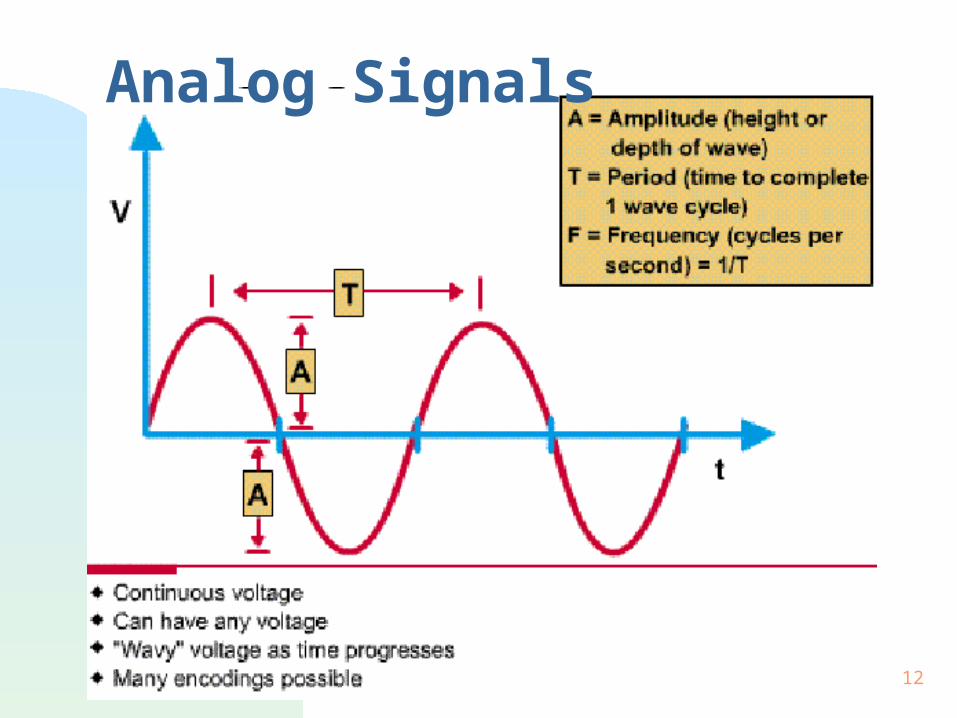
Electrical Terms (1) Voltage: electrical force, or pressure on charges.
Represented by the letter "V” or "E”. unit of voltage is volt (v).
Current: flow of charges (free electrons). Represented by the letter "I". unit of current is ampere (amp).
Resistance: opposition to the movement of electrons. Represented by the letter "R". unit of resistance is the ohm, .
6
Electrical Terms (2) Alternating Current (AC) or AC voltage.
varies with time, periodically changes direction or polarity.
Direct Current (DC) or DC voltage always flow in the same direction; or always has
the same polarity. Impedance
total opposition to current flow (for AC and DC). represented by the letter "Z". unit of impedance is the ohm ( ).

7
Electrical Terms (3) Voltage, Current, Resistance Relationship
Currents flow in closed loops called circuits. Voltage causes current flow. Resistance and impedance oppose current flow.
Ground Earth potential at your location. Zero reference level.
8
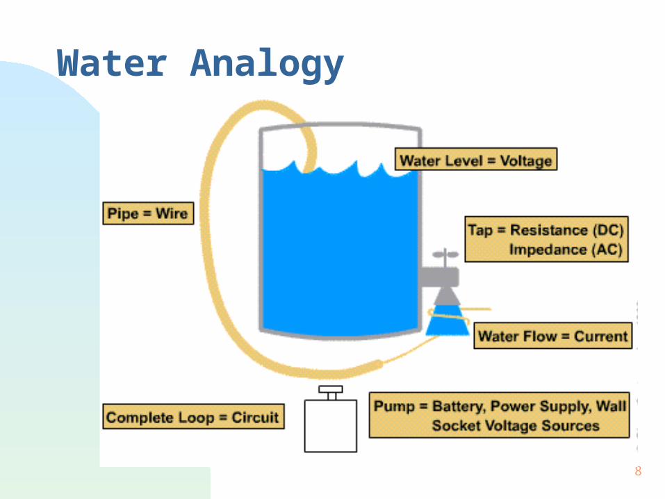
Water Analogy

9
Grounding Network Equipment AC power is supplied in homes, schools, etc
through a 3 prong plug. Top 2 connectors are
the power. Other connector is safety
ground (earth ground). Any exposed metal is
connected to safety ground. Computer motherboard’s ground plane is
connected to the chassis and safety ground. Ground helps dissipate static electricity.

10
Safety Ground Purpose - to prevent exposed metal parts
from becoming energized should a wiring fault occur in device.
In this case, current will flow through the ground connection, and activate protective devices such as circuit breakers to disconnect the power.

11
12
Analog Signals

13
Digital Signals
14
15
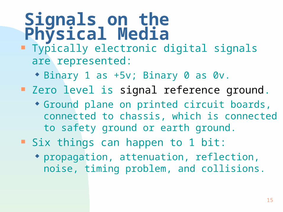
Signals on the Physical Media Typically electronic digital signals are represented:
Binary 1 as +5v; Binary 0 as 0v. Zero level is signal reference ground.
Ground plane on printed circuit boards, connected to chassis, which is connected to safety ground or earth ground.
Six things can happen to 1 bit: propagation, attenuation, reflection, noise, timing
problem, and collisions.

16
Network Signal Propagation Propagation means travel. It takes some time for a signal to travel through
the network, from source to destination. Propagation delay.
17
Network Attenuation Attenuation is the loss of signal strength. Can resolve problem of attenuation:
by choice of networking media. Using structures with low amounts of attenuation.
use of repeaters (There are repeaters for electrical, optical, and wireless bits).
18
Network Reflection Reflection occurs when voltage pulses, or bits, hit
a discontinuity and some energy is ‘reflected’. Reflection can cause interference with later bits. For optimal network performance, it is important
that the impedance of the network media matches the NICs.

19
Impedance Matching For optimal signal transfer (max power transfer),
we need matched impedance. Cables have a characteristic impedance:
UTP - 100 ohms. STP - 100 ohms / 150 ohms. Coax - 50 ohms / 75 ohms.
Need to match impedances of the cables to minimize signal loss.
20
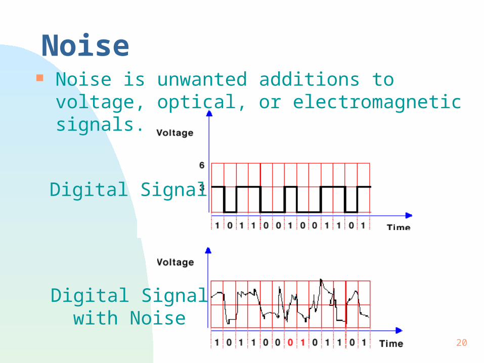
Noise Noise is unwanted additions to voltage, optical, or
electromagnetic signals.
Digital Signal
Digital Signal with Noise

21
Sources of Noise NEXT - near end crosstalk.
from signals on other wires in the cable. Usually due to untwisting at ends of cable.
Thermal Noise due to the random motion of electrons, usually
relatively small compared to our signals. AC Power and reference ground noises. EMI / RFI
caused by lighting, electrical motors, and radio systems.

22
AC Power Line Noise Electricity supplied by the power company is
AC voltage. AC voltage creates noise, due to a changing
magnetic field around the power lines. AC noise, a form of EMI, can produce errors in
your data.
23
Avoiding Problem of Electrical Noise Single power transformer for your LAN.
Short neutral and ground lines. Restrict noise creating devices like motors,
heater, etc. Use separate power panels for each work
area. Minimizes neutral and ground leads (connected
together at power panel).
24
Interference EMI - electromagnetic interference, from
magnetic fields from motors, heavy equipment. RFI - radio frequency interference, from
transmitting equipment. Two techniques in dealing with EMI and RFI
are shielding and cancellation. shielding (a barrier to any interfering signals)
increases size of the conductors and its costs. cancellation is the preferred technique to deal
with undesirable interference.

25
Cancellation Currents in circuit
creates magnetic fields. Fields cancel if currents
are in opposite directions.
Cancellation is enhanced by twisting.
This process is also referred to as “self-shielding”.
26
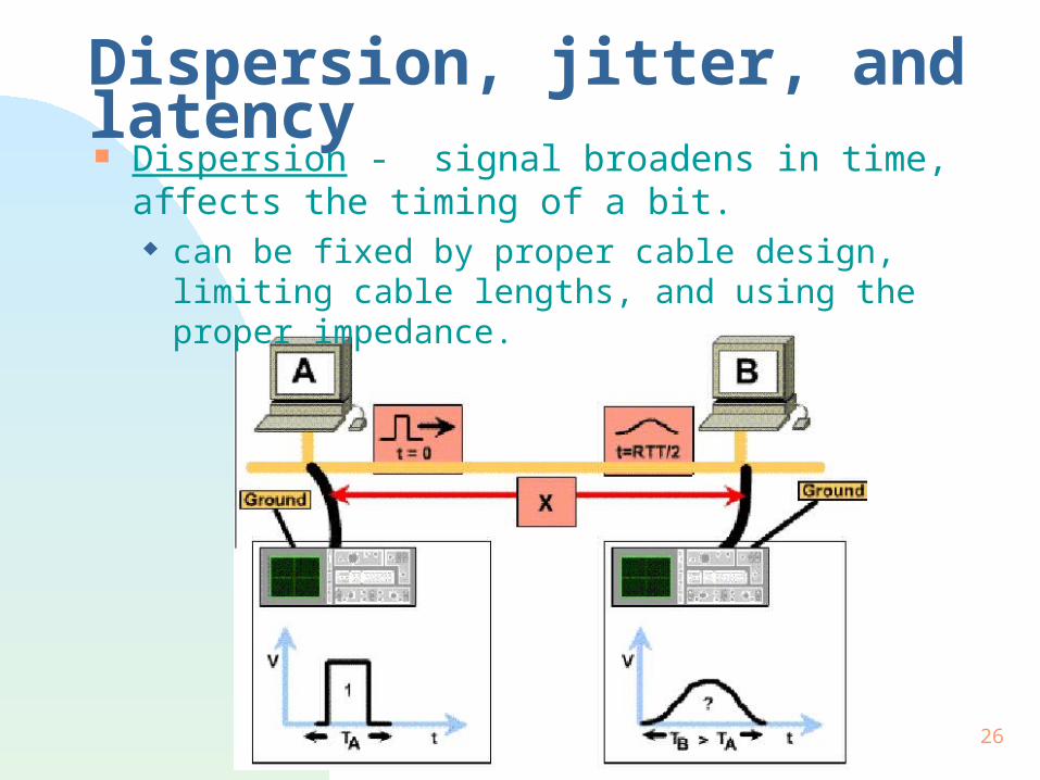
Dispersion, jitter, and latency Dispersion - signal broadens in time, affects the
timing of a bit. can be fixed by proper cable design, limiting cable
lengths, and using the proper impedance.

27
Jitter If the clock on source host is not synchronized
with the destination, you get timing jitter. bits will arrive a little earlier and later than expected.
Jitter can be fixed by a series of complicated clock synchronization, including hardware and software, or protocol synchronization.
Jitter can cause errors as the receiving computer tries to reassemble packets into a message
28
Latency Latency is delay.
Signals take some time to travel thru the network, giving propagation delay.
Devices have latency, time it takes to process the signal.
It takes time to transmit a signal, giving transmission delay.
Problem of latency is solved by careful use of internetworking devices, different encoding strategies, and various layer protocols.
29
Collisions Collision occurs when two bits from two different
communicating computers are on a shared-medium at the same time. The bits are corrupted, "destroyed".
Excessive collisions can slow the network down or bring it to a halt.
One way is to deal with collisions is to have rules, such as backoff in Ethernet.
Another way is to try to prevent collisions, as with tokens in token-ring and FDDI.
30
Encoding Network Signals To send a message over a long distance, need to
address two problems: how to express the message (encoding or
modulation);. Encoding means converting binary data into a form
that can be sent on a physical communications link. Modulation means using the binary data to
manipulate a wave. how to transport the message (carrier).

31
Encoding Network Signals(2)
Computers use three technologies, encoding messages as: voltages on copper media. pulses of guided light on optical fibers. modulated, radiated electromagnetic waves.

32
Modulation and Encoding Encoding means converting 1s and 0s into a form
for transmission: an electrical pulse on a wire, a light pulse on an
optical fiber, or a pulse of electromagnetic waves. Two methods of enncoding are:
NRZ encoding - non-return to zero - based on the signal level.
Manchester encoding - based on the transitions..

33
Encoding Schemes

34
Modulation Taking a wave and changing, or modulating it so
that it carries information.

35
Summary Basic electricity - voltage, current, resistance,
and impedance. AC and DC. Electrical grounds provide a reference from which
to measure voltage. They also provide a safety mechanism to prevent hazardous shocks.
Signals in a network: propagation, attenuation, reflection, Noise,
Dispersion, jitter, and latency, Collision. Encoding and Modulation.
36
The End
Related Documents


![[PPT]ALOHA FROM HAWAIIekladata.com/T87xXLe0Y72JoKgvTgg575PI2tM/Hawaiil.pps · Web view* HONOLULU - HARBOUR HONOLULU - AIRPORT HONOLULU IOLANI PALACE - HONOLULU ROYAL GUARD KAMEHAMEHA](https://static.cupdf.com/doc/110x72/5af655b67f8b9a5b1e8effcd/pptaloha-from-view-honolulu-harbour-honolulu-airport-honolulu-iolani-palace.jpg)


