1 Dust Explosion Propagation in Small Diameter Pipes Jérôme Taveau a,b , Saul Lemkowitz c , Simone Hochgreb d , Dirk Roekaerts b,e a Fike Corporation, Blue Springs, MO, USA b Section Fluid Mechanics, Department of Process and Energy, Delft University of Technology, Delft, The Netherlands c Department of Chemical Engineering, Delft University of Technology, Delft, The Netherlands d Department of Engineering, University of Cambridge, England, United Kingdom e Section Multiphase & Reactive Flows, Department of Mechanical Engineering, Eindhoven University of Technology, Eindhoven, The Netherlands Abstract In facilities handling combustible dusts, the isolation of propagating deflagrations requires great attention due to the potential catastrophic consequences of secondary dust explosions. While the ability of dust explosions to propagate is widely recognized, some misconceptions still exist. One of the common myths is that a dust explosion cannot propagate through small diameter pipes and that explosion isolation may not be required in that case. This paper first presents a simplified theory of flame propagation in pipes. Dust explosion experiments performed in industrial-scale pipes smaller or equal to 4 inches (or 100 mm) in diameter are then reviewed. The findings of the experiments are interpreted in the light of the simplified theory. Our study reveals that dust explosion propagation has been consistently observed in pipes with a diameter as small as one inch. While the likelihood of flame propagation seems to decrease with pipe diameter and other “chemical” and “engineering” factors, it remains a realistic scenario and therefore should be addressed in the design and operation of powder handling systems. Keywords: dust; deflagration; explosion propagation; small pipes; explosion isolation Email: [email protected] Accepted for publication, Process Safety Progress, 7 December 2018

Welcome message from author
This document is posted to help you gain knowledge. Please leave a comment to let me know what you think about it! Share it to your friends and learn new things together.
Transcript
1
Dust Explosion Propagation in Small Diameter Pipes
Jérôme Taveau a,b, Saul Lemkowitz c, Simone Hochgreb d, Dirk Roekaerts b,e
a Fike Corporation, Blue Springs, MO, USA b Section Fluid Mechanics, Department of Process and Energy, Delft University of
Technology, Delft, The Netherlands
c Department of Chemical Engineering, Delft University of Technology, Delft, The Netherlands
d Department of Engineering, University of Cambridge, England, United Kingdom e Section Multiphase & Reactive Flows, Department of Mechanical Engineering,
Eindhoven University of Technology, Eindhoven, The Netherlands
Abstract
In facilities handling combustible dusts, the isolation of propagating deflagrations requires great attention due to the potential catastrophic consequences of secondary dust explosions. While the ability of dust explosions to propagate is widely recognized, some misconceptions still exist. One of the common myths is that a dust explosion cannot propagate through small diameter pipes and that explosion isolation may not be required in that case. This paper first presents a simplified theory of flame propagation in pipes. Dust explosion experiments performed in industrial-scale pipes smaller or equal to 4 inches (or 100 mm) in diameter are then reviewed. The findings of the experiments are interpreted in the light of the simplified theory. Our study reveals that dust explosion propagation has been consistently observed in pipes with a diameter as small as one inch. While the likelihood of flame propagation seems to decrease with pipe diameter and other “chemical” and “engineering” factors, it remains a realistic scenario and therefore should be addressed in the design and operation of powder handling systems. Keywords: dust; deflagration; explosion propagation; small pipes; explosion isolation Email: [email protected] Accepted for publication, Process Safety Progress, 7 December 2018
2
Nomenclature: AV: vent area (m2) D: pipe diameter (m) DDT: deflagration to detonation transition KSt: deflagration index for dusts (bar.m/s) MAIT: minimum auto ignition temperature (K) MEC: minimum explosible concentration (g/m3) MESG: maximum experimental safe gap (mm) MIE: minimum ignition energy (mJ) Pmax: maximum pressure of an unvented deflagration initially at atmospheric
pressure (barg) Pred: reduced pressure after deflagration venting (barg) Pstat: static burst pressure of the vent (barg) Sf: flame velocity or speed (m/s)
3
1.Introduction When a combustible dust cloud is ignited within a process vessel, large amounts of heat and high pressures are generated in milliseconds. The resulting dust deflagration may compromise the vessel’s structural integrity, unless it is adequately protected. Nevertheless, the explosion pressure will push the fireball through any existing openings, including process interconnections. The flame front will stretch and speed up due to increased turbulence, increasing the severity of the initial event. Ultimately, a more violent secondary deflagration can take place when the flame reaches the next process vessel, such that existing protection measures may well fail under these aggravated conditions. Many accidents involving secondary explosions [1] and flame propagation [2, 3] have been reported in the literature, and numerous researchers have carried out laboratory experiments to better understand flame propagation features. However, flame propagation in industrial-scale piping is still misunderstood, leading to some common myths in the industry [4]. This paper focuses on one of the most tenacious myths, namely that propagation of dust explosions in small diameter pipes is not possible. This myth has some important practical consequences, since the previous edition of NFPA 654 standard [5] allowed the absence of explosion isolation for pipes with a diameter below 4 inches (see Appendix). After a short insight on flame propagation mechanisms, a review of dust explosion propagation experiments in pipes smaller or equal to 4 inches (or 100 mm) in diameter is presented by increasing order of complexity: first we examine flame propagation following ignition of a dust cloud in a pipe, then in a vessel connected to an open pipe, and finally in a vented vessel connected to an open pipe. Our study shows that explosion propagation is possible in industrial-scale pipes with a diameter as small as one inch [6].
4
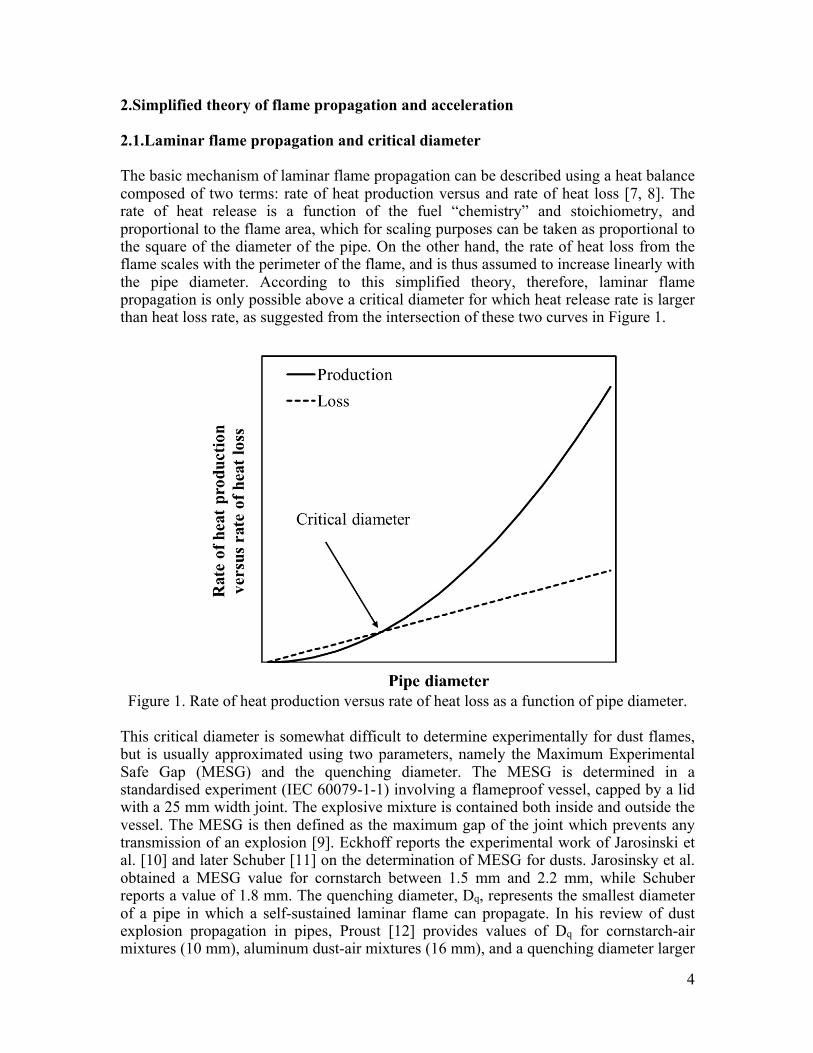
2.Simplified theory of flame propagation and acceleration 2.1.Laminar flame propagation and critical diameter The basic mechanism of laminar flame propagation can be described using a heat balance composed of two terms: rate of heat production versus and rate of heat loss [7, 8]. The rate of heat release is a function of the fuel “chemistry” and stoichiometry, and proportional to the flame area, which for scaling purposes can be taken as proportional to the square of the diameter of the pipe. On the other hand, the rate of heat loss from the flame scales with the perimeter of the flame, and is thus assumed to increase linearly with the pipe diameter. According to this simplified theory, therefore, laminar flame propagation is only possible above a critical diameter for which heat release rate is larger than heat loss rate, as suggested from the intersection of these two curves in Figure 1.
Figure 1. Rate of heat production versus rate of heat loss as a function of pipe diameter.
This critical diameter is somewhat difficult to determine experimentally for dust flames, but is usually approximated using two parameters, namely the Maximum Experimental Safe Gap (MESG) and the quenching diameter. The MESG is determined in a standardised experiment (IEC 60079-1-1) involving a flameproof vessel, capped by a lid with a 25 mm width joint. The explosive mixture is contained both inside and outside the vessel. The MESG is then defined as the maximum gap of the joint which prevents any transmission of an explosion [9]. Eckhoff reports the experimental work of Jarosinski et al. [10] and later Schuber [11] on the determination of MESG for dusts. Jarosinsky et al. obtained a MESG value for cornstarch between 1.5 mm and 2.2 mm, while Schuber reports a value of 1.8 mm. The quenching diameter, Dq, represents the smallest diameter of a pipe in which a self-sustained laminar flame can propagate. In his review of dust explosion propagation in pipes, Proust [12] provides values of Dq for cornstarch-air mixtures (10 mm), aluminum dust-air mixtures (16 mm), and a quenching diameter larger
5
than 100 mm for coal dust-air mixtures. Jarosinski et al. [13] report values of 5.5 mm for cornstarch, 10.4 mm for aluminum, 25 mm for fine particles of coal and 190 mm for coarse particles of coal. These two parameters (MESG and quenching diameter) are closely related, since they involve the same phenomena described above, i.e. a competition between heat release and heat loss. Eckhoff [14] suggested the rule of thumb: Dq = 2 x MESG. Regardless of the particular mixture, it is clear that both parameters fall in a range significantly smaller than the dimensions of most pipes in industrial processes. 2.2.Turbulent flame propagation and optimum diameter MESG and quenching diameters represent the situation of a laminar propagating flame, which is a rather ideal case that can only stand in the early phases of combustion. In reality, a flame will transit to a turbulent regime due to factors such as flame instabilities, turbulence generated by pipe roughness or obstacles, and pressure wave/flame interactions. This takes place, for example, when a mixture is ignited at a pipe closed end (as further illustrated in paragraph 3.1): under these conditions, the expanding gases accelerate the flame front, generate additional turbulence, which increases flame area, leading to an increasingly hazardous situation associated with the greater heat release. The process of turbulence generation and flame acceleration is limited by the competing roles of pipe flow resistance and heat loss. An “optimum” diameter exists for which there is a maximum acceleration, which is typically several orders of magnitude larger than the original MESG or quenching values. Experiments by Pineau & Ronchail [15], and later by Srinath et al. [16] provide clear evidence of the three propagation regimes described above:
1. No flame propagation for diameters below a critical value, depending on the fuel reactivity;
2. A steady (or laminar) flame propagation without flame acceleration for pipes larger than the critical diameter;
3. An accelerated (or turbulent) flame propagation, possibly leading to a deflagration to detonation transition (DDT), for an “optimum” diameter and sufficiently long pipes.
2.3.Volumetric explosion and its influence on flame propagation in pipes The first two sections considered the case of the ignition of a dust-air mixture in a pipe. However, in a real industrial explosion, ignition would most likely take place in a vented vessel of considerable volume, rather than in a pipe, as pipes often operate with a dust concentration below the minimum explosible concentration (MEC). The addition of this primary volume provides an additional driving force for the propagation of the explosion: the expanding gases generated by the combustion of the dust-air mixture in this large volume (compared to the pipe volume) acts as a piston, pushing and accelerating the flame front down the pipe, generating additional turbulence and increasing flame area. This phenomenon is further illustrated by experiments reviewed in sections 3.2 and 3.3 involving initiating vessels connected to pipes. This piston action is more pronounced for higher overpressures and longer duration explosions (i.e. greater impulse); this means ultimately that the design (i.e. explosion
6
pressure resistance) and the method of protection of the process vessel will largely impact the propagation likelihood and distance within a given pipe. For a closed vessel, all the expanding gases are redirected to the pipes, thus fully promoting flame propagation; in the case of a vented vessel, on the other hand, part of the expanding gases are discharged through the relief area and only the remainder participates in flame propagation. The duration and severity of the explosion in the vented enclosure depends both on the static burst pressure of the vent panel (controlling how early the discharge will occur) and its area (controlling how much gases will be discharged). These engineering factors play an important role in flame propagation through pipes. Based on the simplified theory established above, the flame velocity can be described as the combined effects of the expansion velocity of the burnt gases driven by the primary explosion, and the turbulent flame velocity. The latter depends not only on the overall equivalence ratio, temperature and pressure, but also on particle concentration, size distribution and spatial homogeneity in the mixture. 2.4.Interlinked explosions in vessel-pipe arrangements Of course, an explosion in a vessel-pipe system involves more complex phenomena than what is presented in this simplified theory. Research on the explosion pressure relief through short pipes (namely vent ducts) has led to the current understanding that two interlinked explosions actually occur: a primary explosion in the vessel and a secondary explosion at the interconnection with the vent duct, partly overlapping in time and interacting with each other. Numerous researchers [17-24] have shown that the presence of a duct downstream of the venting device increases the reduced explosion pressure in a vented vessel. This was first attributed to the flow resistance induced by the duct itself (i.e. pressure losses). However, a more in-depth analysis revealed that this pressure enhancement must be attributed to the occurrence of a secondary explosion in the duct. Ferrara et al. [24] clearly explain the mutual interaction between internal (in the vessel) and external (in the duct) explosions:
• In the initial phase of the explosion and after the vent bursts, unburnt dust and air is pushed out of the vessel into the vent duct;
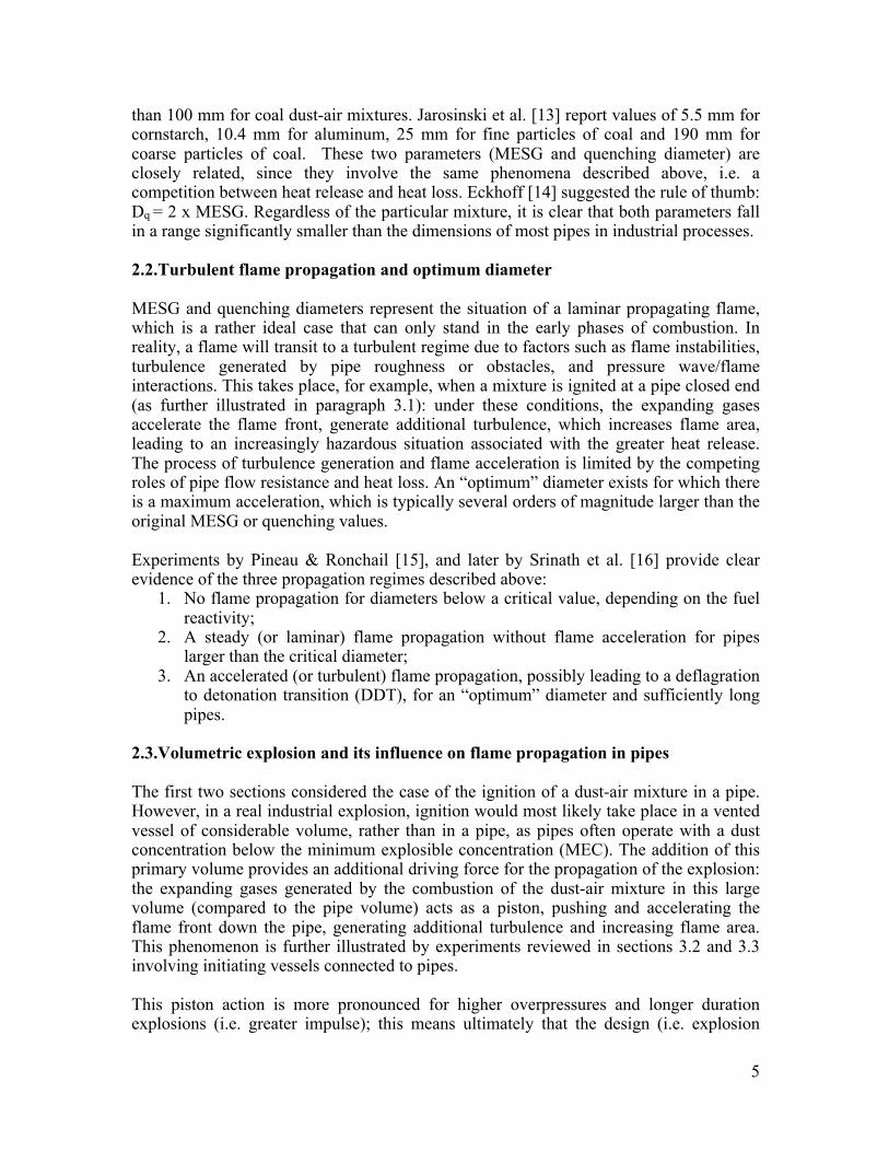
• When the explosion pressure rises and the flow velocity through the vent duct increases, the flow restriction at the vessel-pipe interconnection generates a highly turbulent fluid area with intense mixing of dust and air (Figure 2). When the flame enters the vent duct, an intense and violent secondary explosion occurs, associated with very high rates of pressure rise (in some cases, this intense mixing can also result in flame quenching [23]);
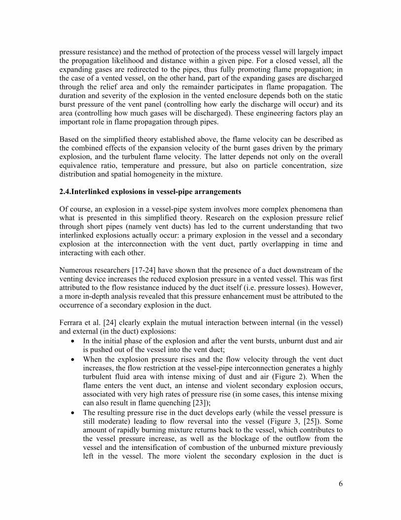
• The resulting pressure rise in the duct develops early (while the vessel pressure is still moderate) leading to flow reversal into the vessel (Figure 3, [25]). Some amount of rapidly burning mixture returns back to the vessel, which contributes to the vessel pressure increase, as well as the blockage of the outflow from the vessel and the intensification of combustion of the unburned mixture previously left in the vessel. The more violent the secondary explosion in the duct is
7
(depending on the turbulence intensity, the reactivity of the fuel, etc.), the higher the second peak pressure in the vessel.
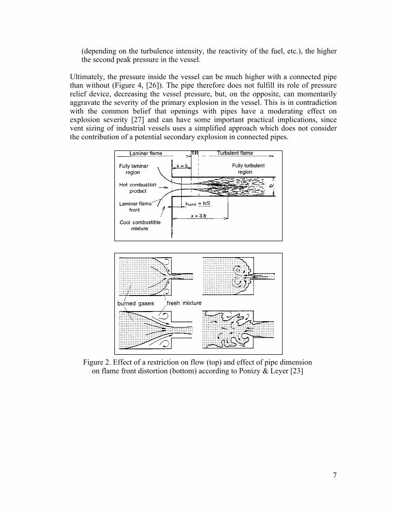
Ultimately, the pressure inside the vessel can be much higher with a connected pipe than without (Figure 4, [26]). The pipe therefore does not fulfill its role of pressure relief device, decreasing the vessel pressure, but, on the opposite, can momentarily aggravate the severity of the primary explosion in the vessel. This is in contradiction with the common belief that openings with pipes have a moderating effect on explosion severity [27] and can have some important practical implications, since vent sizing of industrial vessels uses a simplified approach which does not consider the contribution of a potential secondary explosion in connected pipes.
Figure 2. Effect of a restriction on flow (top) and effect of pipe dimension
on flame front distortion (bottom) according to Ponizy & Leyer [23]
8
Figure 3. Flame transmission from the test chamber to the tube (left) and flow reversal in
3 steps [25]
Figure 4. Pressure variation in the test chamber - Curve a: vessel alone - Curve b: vessel
+ duct [26]
The next section discusses dust explosion propagation experiments performed in industrial-scale, small diameter pipes that illustrate the different explosion regimes described above. They are presented in increasing order of complexity and according to the simplified and qualitative theory presented above:
1. Ignition of a dust cloud in a pipe; 2. Ignition of a dust cloud in a closed vessel connected to an open pipe; 3. Ignition of a dust cloud in a vented vessel connected to an open pipe.
9
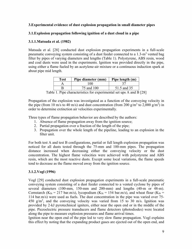
3.Experimental evidence of dust explosion propagation in small diameter pipes 3.1.Explosion propagation following ignition of a dust cloud in a pipe 3.1.1.Matsuda et al. (1982) Matsuda et al. [28] conducted dust explosion propagation experiments in a full-scale pneumatic conveying system consisting of a dust feeder connected to a 1.3-m3 vented bag filter by pipes of varying diameters and lengths (Table 1). Polystyrene, ABS resin, wood and coal dusts were used in the experiments. Ignition was provided directly in the pipe, using either a flame fueled by an acetylene-air mixture or a continuous induction spark at about pipe mid length.
Test Pipe diameter (mm) Pipe length (m) A 100 37 B 75 and 100 51.5 and 35
Table 1. Pipe characteristics for experimental set ups A and B [28] Propagation of the explosion was investigated as a function of the conveying velocity in the pipe (from 10 m/s to 40 m/s) and dust concentration (from 200 g/m3 to 2,000 g/m3) in order to determine extinction air velocities experimentally. Three types of flame propagation behavior are described by the authors:
1. Absence of flame propagation away from the ignition source; 2. Partial propagation over a fraction of the length of the pipe; 3. Propagation over the whole length of the pipeline, leading to an explosion in the
filter unit.
For both test A and test B configurations, partial or full length explosion propagation was noticed for all dusts tested through the 75-mm and 100-mm pipes. The propagation distance increased when decreasing either the conveying velocity or the dust concentration. The highest flame velocities were achieved with polystyrene and ABS resin, which are the most reactive dusts. Except some local variations, the flame speeds tend to decrease as the flame moved away from the ignition source.
3.1.2.Vogl (1996) Vogl [29] conducted dust explosion propagation experiments in a full-scale pneumatic conveying system consisting of a dust feeder connected to a vented cyclone by pipes of several diameters (100-mm, 150-mm and 200-mm) and lengths (40-m or 48-m). Cornstarch (KSt = 217 bar.m/s), lycopodium (KSt = 154 bar.m/s), and wheat flour (KSt = 114 bar.m/s) were used as fuels. The dust concentration in the pipe was varied over 75-450 g/m3, and the conveying velocity was varied from 15 to 30 m/s. Ignition was provided by 2-kJ pyrotechnical igniters, either near the open end or in the middle of the pipe. Piezoelectric pressure transducers and flame detectors (photodiodes) were located along the pipe to measure explosion pressures and flame arrival times. Ignition near the open end of the pipe led to very slow flame propagation. Vogl explains this effect by noting that the expanding product gases are ejected out of the open end, and
10
thus are not accelerated towards the fresh mixture. In contrast, ignition at the middle of the pipe led to flame acceleration, resulting in apparent deflagration-to-detonation transition (DDT) and over-driven detonations in some cases. The most extreme effects occurred with the most reactive dust (cornstarch: highest KSt-value), for the largest pipe diameter (200 mm) and the longest pipe (48 m). Maximum flame velocities of over 1,000 m/s and explosion pressures of above 20-40 bar were observed. In these cases, the conveying velocity was not important, as the maximum flame velocities were often over 10 times larger than the maximum flow velocities (15 to 30 m/s). Both flame velocity and explosion pressure were reduced with decreasing pipe diameter. Vogl explains that a reason for this effect may be an increasing heat loss due to increasing surface/volume ratio as well as an increasing pipe resistance against the expansion flow. Interestingly, no flame propagation against the conveying flow could be observed under the following conditions:
• Wheat flour (KSt = 114 bar.m/s) and pipe diameter D < 150 mm; • Lycopodium (KSt = 154 bar.m/s) and pipe diameter D < 100 mm.
An empirical equation was developed for the estimation of a boundary condition with which flame propagation against the conveying direction could not be obtained.
11
3.2.Explosion propagation following ignition of a dust cloud in a closed vessel The experiments discussed in this paragraph differ from those presented above in the following key aspect: the initial explosion takes place in a small closed volume. The confinement leads to pressure rise providing an additional driving force for dust explosion propagation. 3.2.1.Pineau & Ronchail (1982) Pineau & Ronchail [30] report dust explosion propagation tests in two types of experimental apparatuses and geometries:
• Case 1 involved the explosion of wheat flour in straight pipes of varying diameters: 250, 400, and 700 mm;
• Case 2 involved the explosion of wheat flower and wood flour (more reactive) using an initiating vessel of 0.1-m3 or 1-m3 volume and connected to pipes of 25, 50, and 100 mm.
Pipes of length 10, 25, and 40 m, were used in both cases 1 and 2. In Case 1, four types of boundary conditions were studied, (i) ignition at a closed end of the pipe, with one open end, (ii) same as (i), but partially closed at open end, (iii) both ends closed, and (iv) same as (ii), but with ignition midway in the pipe:
• As expected from the previous discussion, the maximum flame acceleration occurred for condition (i), for ignition at the closed of the pipe. The highest acceleration took place with the smallest diameter of 250 mm. This is explained by the fact that the pipe diameter is larger than the quenching or critical diameter, but sufficiently small to generate large flame acceleration by virtue of the expansion of the burned gases;
• Condition (ii) with the partial closing of the end of the pipe led to increased pressures. All results showed flame acceleration, except in the smallest diameter pipe, where flame deceleration occurred;
• For condition (iii), pipes were completely closed off, forming a constant volume elongated cylinder, and thereby, in comparison with the other, eventually impeding the acceleration of the expanding flame;
• The final case for condition (iv) with ignition at the center generated two flames propagating towards opposite ends. The limited length for acceleration means that the speed was lower than the ignition at the closed end.
In Case 2, experiments using wheat flour and wood flour were carried out in a setup comprising an initiating vessel connected to a pipe of much smaller diameter than in Case 1:
• Flame propagation over the entire pipe length (or “full” propagation) occurred more frequently with wood flour than with wheat flour due to its higher reactivity. In addition, significant flame acceleration, including numerous cases of transition from deflagration to detonation (DDT), occurred with wood flour but never with wheat flour under identical conditions: in the 100-mm pipe, pronounced flame acceleration occurred, with a high probability of a DDT (75 to 100%), and values of maximum pressures (> 16 bar, up to 32 bar) characteristic of over-driven detonations;
12
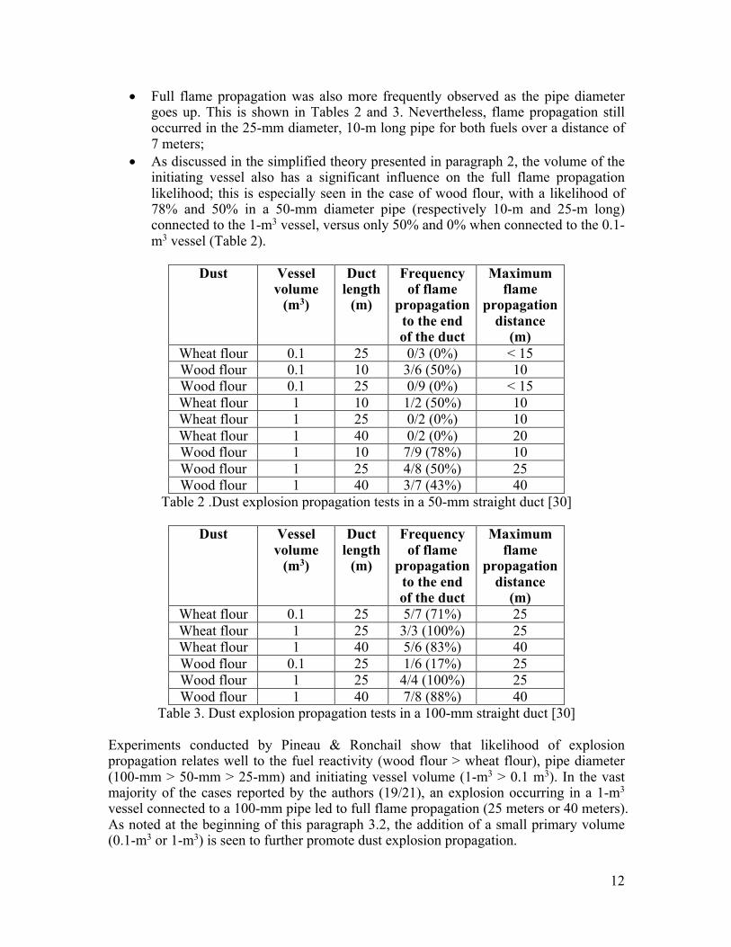
• Full flame propagation was also more frequently observed as the pipe diameter goes up. This is shown in Tables 2 and 3. Nevertheless, flame propagation still occurred in the 25-mm diameter, 10-m long pipe for both fuels over a distance of 7 meters;
• As discussed in the simplified theory presented in paragraph 2, the volume of the initiating vessel also has a significant influence on the full flame propagation likelihood; this is especially seen in the case of wood flour, with a likelihood of 78% and 50% in a 50-mm diameter pipe (respectively 10-m and 25-m long) connected to the 1-m3 vessel, versus only 50% and 0% when connected to the 0.1-m3 vessel (Table 2).
Dust Vessel
volume (m3)
Duct length
(m)
Frequency of flame
propagation to the end of the duct
Maximum flame
propagation distance
(m) Wheat flour 0.1 25 0/3 (0%) < 15 Wood flour 0.1 10 3/6 (50%) 10 Wood flour 0.1 25 0/9 (0%) < 15 Wheat flour 1 10 1/2 (50%) 10 Wheat flour 1 25 0/2 (0%) 10 Wheat flour 1 40 0/2 (0%) 20 Wood flour 1 10 7/9 (78%) 10 Wood flour 1 25 4/8 (50%) 25 Wood flour 1 40 3/7 (43%) 40
Table 2 .Dust explosion propagation tests in a 50-mm straight duct [30]
Dust Vessel volume
(m3)
Duct length
(m)
Frequency of flame
propagation to the end of the duct
Maximum flame
propagation distance
(m) Wheat flour 0.1 25 5/7 (71%) 25 Wheat flour 1 25 3/3 (100%) 25 Wheat flour 1 40 5/6 (83%) 40 Wood flour 0.1 25 1/6 (17%) 25 Wood flour 1 25 4/4 (100%) 25 Wood flour 1 40 7/8 (88%) 40
Table 3. Dust explosion propagation tests in a 100-mm straight duct [30] Experiments conducted by Pineau & Ronchail show that likelihood of explosion propagation relates well to the fuel reactivity (wood flour > wheat flour), pipe diameter (100-mm > 50-mm > 25-mm) and initiating vessel volume (1-m3 > 0.1 m3). In the vast majority of the cases reported by the authors (19/21), an explosion occurring in a 1-m3 vessel connected to a 100-mm pipe led to full flame propagation (25 meters or 40 meters). As noted at the beginning of this paragraph 3.2, the addition of a small primary volume (0.1-m3 or 1-m3) is seen to further promote dust explosion propagation.
13
3.2.2.Roser (1998) Roser [31] carried out dust explosion propagation tests in a 1-m3 vessel connected to a 9.22-m long, 100-mm diameter open ended straight pipe. Explosions were initiated in the 1-m3 vessel and propagated through the straight pipe, which was empty (i.e. contained no dust) before each experiment. The vent area was changed between 0 m2 (closed vessel) and 0.031 m2. Cornstarch (KSt = 190 bar.m/s) and wheat flour (KSt = 80 bar.m/s) were used as fuels. Full flame propagation was obtained under these conditions and a maximum flame speed Vmax ~ 416 m/s was obtained with cornstarch.
14
3.3.Explosion propagation following ignition of a dust cloud in a vented vessel
Experiments reviewed in the present section include pipes connected to full-scale vented vessels of several cubic meters of volume, and therefore offer a realistic representation of industrial systems and explosion scenarios.
3.3.1.Vogl (1996)
Following the first successful series of experiments described in paragraph 3.1.2, Vogl [32] added a 9.4-m3 vented initiating vessel between a hopper and a vented cyclone, and connected them with two lengths of piping of constant diameter (100 mm or 200 mm) and lengths of 18.55 m. A similar cornstarch (KSt = 200 bar m/s) and a significantly less reactive wheat flour (KSt = 80 bar m/s) were used as fuels. Dust clouds were ignited by two 5-kJ pyrotechnical igniters located at the center of the vessel, thus flame propagation could occur in two opposing directions: in the same direction as the dust-air flow (top pipe) and in the direction opposite to (and thus against) the dust-air flow (bottom pipe). Vogl obtained more consistent flame propagation than in the previous experiments, independently of the type of fuel, pipe diameter, direction of flame propagation (i.e. flame front propagating with or against the dust-air flow), or conveying velocity, for a reduced explosion pressure as low as 0.14 bar. In addition to consistent flame propagation, flame acceleration, leading to high flame speeds (e.g. up to 600 m/s), were also observed. Vogl found clear chemical effects: the more reactive cornstarch exhibited greater flame acceleration and thus higher flame speeds than the less reactive dust, wheat flour. He also extensively discusses engineering effects, such as the expansion flow coming from the 9.4-m3 explosion vessel, as a dominant driving force for the dust explosion propagation occurring in the pipes of his experimental setup (the expansion flow (m/s) in the 100 mm piping being a factor of 4 greater than the expansion flow in the 200 mm piping). This ultimately explains the absence of flame propagation in some cases (wheat flour with 100-mm and 150-mm diameter pipes and lycopodium with a 100-mm pipe) using the previous experimental set up, where there was no initiating vessel. Another engineering factor mentioned relates to the importance of the heat balance illustrated in Figure 1, in relation to expansion flow. Vogl notes that lower relative heat losses are expected for the larger pipe diameters (i.e. 200 mm), yet these can be offset by the higher expansion flow rates associated with the pipes with smaller diameters (100 mm). 3.3.2.Vogl & Radandt (2001) Five years later, Vogl & Radandt [33] reported a comprehensive study of dust explosion propagation in small diameter pipes. These experiments are particularly relevant in the context of the paragraph 7.6.1.2 of the 2013 edition of NFPA 654, since they fulfill all five listed conditions (see also appendix of the present paper):
1. Cornstarch (KSt = 200 bar.m/s) and wheat flour (KSt = 120 bar.m/s) were used as fuels (Table 4),
2. Experiments involved 27-mm, 42-mm and 82-mm diameter pipes (Figure 5), 3. Conveying velocity was varied from 0 to 30 m/s,
15
4. No dust was injected into the process pipes, 5. Interconnected 1-m3 vessels were both vented.
Dust Particle
size (μm)
MEC (g/m3)
Pmax (barg)
KSt (bar.m/s)
MIE (mJ)
MAIT (°C)
Cornstarch 13 60 9 200 5 400 Wheat flour 38 60 8.5 120 20 390
Table 4. Ignitability and explosibility characteristics of cornstarch and wheat flour [33]
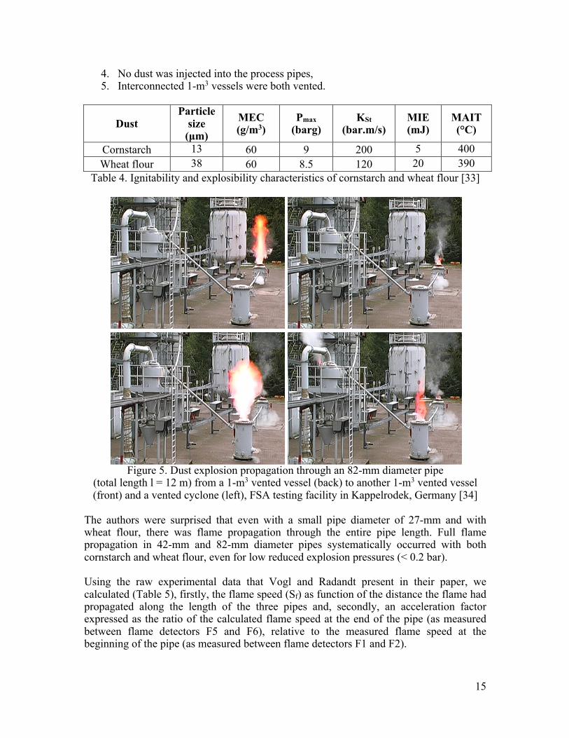
Figure 5. Dust explosion propagation through an 82-mm diameter pipe
(total length l = 12 m) from a 1-m3 vented vessel (back) to another 1-m3 vented vessel (front) and a vented cyclone (left), FSA testing facility in Kappelrodek, Germany [34]
The authors were surprised that even with a small pipe diameter of 27-mm and with wheat flour, there was flame propagation through the entire pipe length. Full flame propagation in 42-mm and 82-mm diameter pipes systematically occurred with both cornstarch and wheat flour, even for low reduced explosion pressures (< 0.2 bar). Using the raw experimental data that Vogl and Radandt present in their paper, we calculated (Table 5), firstly, the flame speed (Sf) as function of the distance the flame had propagated along the length of the three pipes and, secondly, an acceleration factor expressed as the ratio of the calculated flame speed at the end of the pipe (as measured between flame detectors F5 and F6), relative to the measured flame speed at the beginning of the pipe (as measured between flame detectors F1 and F2).
16
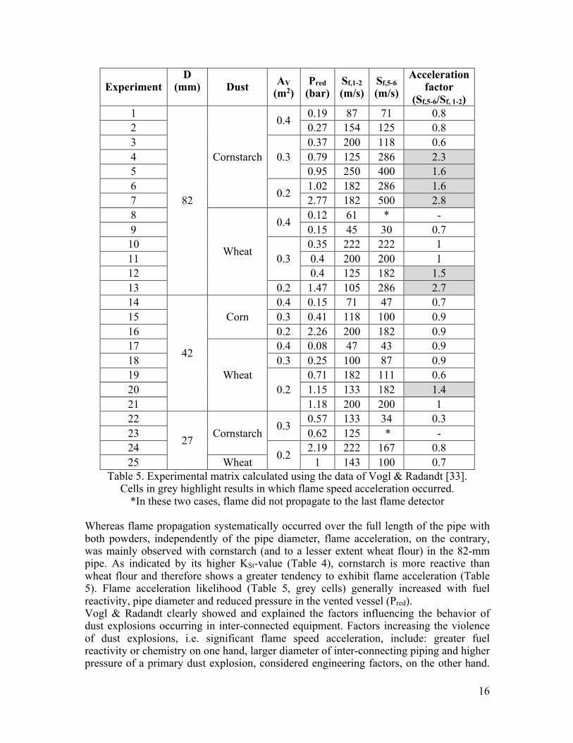
Experiment D
(mm) Dust AV (m2)
Pred (bar)
Sf,1-2 (m/s)
Sf,5-6 (m/s)
Acceleration factor
(Sf,5-6/Sf, 1-2) 1
82
Cornstarch
0.4 0.19 87 71 0.8 2 0.27 154 125 0.8 3
0.3 0.37 200 118 0.6
4 0.79 125 286 2.3 5 0.95 250 400 1.6 6 0.2 1.02 182 286 1.6 7 2.77 182 500 2.8 8
Wheat
0.4 0.12 61 * - 9 0.15 45 30 0.7 10
0.3 0.35 222 222 1
11 0.4 200 200 1 12 0.4 125 182 1.5 13 0.2 1.47 105 286 2.7 14
42
Corn 0.4 0.15 71 47 0.7
15 0.3 0.41 118 100 0.9 16 0.2 2.26 200 182 0.9 17
Wheat
0.4 0.08 47 43 0.9 18 0.3 0.25 100 87 0.9 19
0.2 0.71 182 111 0.6
20 1.15 133 182 1.4 21 1.18 200 200 1 22
27 Cornstarch 0.3 0.57 133 34 0.3 23 0.62 125 * - 24 0.2 2.19 222 167 0.8 25 Wheat 1 143 100 0.7
Table 5. Experimental matrix calculated using the data of Vogl & Radandt [33]. Cells in grey highlight results in which flame speed acceleration occurred.
*In these two cases, flame did not propagate to the last flame detector Whereas flame propagation systematically occurred over the full length of the pipe with both powders, independently of the pipe diameter, flame acceleration, on the contrary, was mainly observed with cornstarch (and to a lesser extent wheat flour) in the 82-mm pipe. As indicated by its higher KSt-value (Table 4), cornstarch is more reactive than wheat flour and therefore shows a greater tendency to exhibit flame acceleration (Table 5). Flame acceleration likelihood (Table 5, grey cells) generally increased with fuel reactivity, pipe diameter and reduced pressure in the vented vessel (Pred). Vogl & Radandt clearly showed and explained the factors influencing the behavior of dust explosions occurring in inter-connected equipment. Factors increasing the violence of dust explosions, i.e. significant flame speed acceleration, include: greater fuel reactivity or chemistry on one hand, larger diameter of inter-connecting piping and higher pressure of a primary dust explosion, considered engineering factors, on the other hand.
17
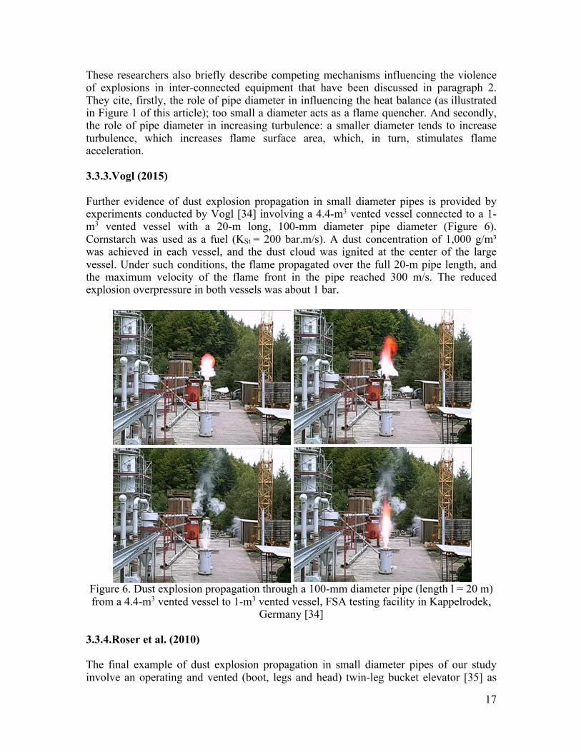
These researchers also briefly describe competing mechanisms influencing the violence of explosions in inter-connected equipment that have been discussed in paragraph 2. They cite, firstly, the role of pipe diameter in influencing the heat balance (as illustrated in Figure 1 of this article); too small a diameter acts as a flame quencher. And secondly, the role of pipe diameter in increasing turbulence: a smaller diameter tends to increase turbulence, which increases flame surface area, which, in turn, stimulates flame acceleration. 3.3.3.Vogl (2015) Further evidence of dust explosion propagation in small diameter pipes is provided by experiments conducted by Vogl [34] involving a 4.4-m3 vented vessel connected to a 1-m3 vented vessel with a 20-m long, 100-mm diameter pipe diameter (Figure 6). Cornstarch was used as a fuel (KSt = 200 bar.m/s). A dust concentration of 1,000 g/m³ was achieved in each vessel, and the dust cloud was ignited at the center of the large vessel. Under such conditions, the flame propagated over the full 20-m pipe length, and the maximum velocity of the flame front in the pipe reached 300 m/s. The reduced explosion overpressure in both vessels was about 1 bar.
Figure 6. Dust explosion propagation through a 100-mm diameter pipe (length l = 20 m) from a 4.4-m3 vented vessel to 1-m3 vented vessel, FSA testing facility in Kappelrodek,
Germany [34]
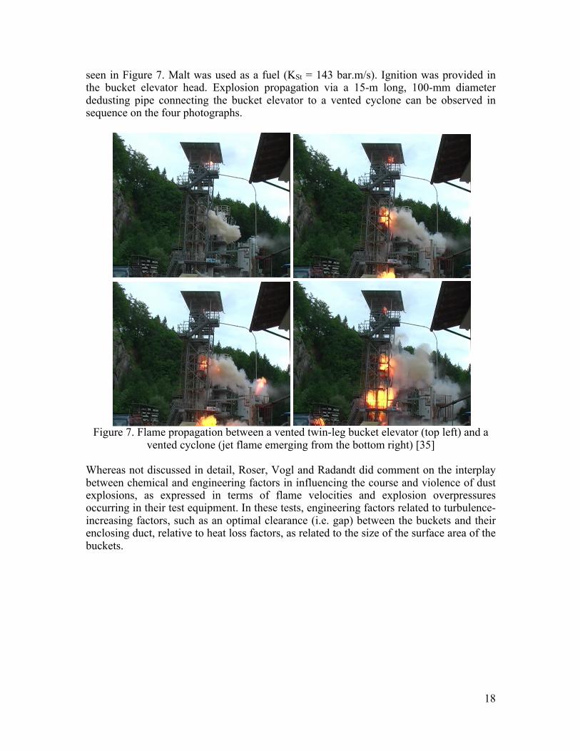
3.3.4.Roser et al. (2010) The final example of dust explosion propagation in small diameter pipes of our study involve an operating and vented (boot, legs and head) twin-leg bucket elevator [35] as
18
seen in Figure 7. Malt was used as a fuel (KSt = 143 bar.m/s). Ignition was provided in the bucket elevator head. Explosion propagation via a 15-m long, 100-mm diameter dedusting pipe connecting the bucket elevator to a vented cyclone can be observed in sequence on the four photographs.
Figure 7. Flame propagation between a vented twin-leg bucket elevator (top left) and a
vented cyclone (jet flame emerging from the bottom right) [35]
Whereas not discussed in detail, Roser, Vogl and Radandt did comment on the interplay between chemical and engineering factors in influencing the course and violence of dust explosions, as expressed in terms of flame velocities and explosion overpressures occurring in their test equipment. In these tests, engineering factors related to turbulence-increasing factors, such as an optimal clearance (i.e. gap) between the buckets and their enclosing duct, relative to heat loss factors, as related to the size of the surface area of the buckets.
19
4.Conclusions Dust explosion propagation in small pipes has always been a controversial topic. The previous edition of NFPA 654 standard allowed the absence of explosion isolation as long as several requirements were met, the main condition being that the diameter of the system’s piping must be less than 4 inches. Our detailed review of dust explosion in small diameter pipes reveals that propagation has been consistently observed by different researchers and for various configurations in pipe diameters down to one-inch only. The experimental work done by Vogl, and then Vogl & Radandt, can be considered the most comprehensive study illustrating dust explosion propagation in small diameter pipes. The researchers show that, even though the likelihood of flame propagation seems to decrease with pipe diameter, propagation remains a realistic scenario even for low reduced explosion pressure in the initiating vessel (< 0.2 bar). The data also shows that both chemical and physical mechanisms determine the onset and intensity of explosion propagation in small diameter pipes:
• Increasing chemical and thermodynamic reactivity of the powders concerned tends to facilitate propagation in smaller diameter pipes. In general, chemical reactivity increases with smaller and drier particles. It is also to be expected that reactivity is highest for particles with high volumetric heats of combustion (J/m3) and high adiabatic flame temperatures, such as metal powders;
• Engineering factors, including inter-connectedness of piping with vessels, length and diameter of piping, vessel volume, vessel protection, as well as flow rate and flow direction, which relate to physical transport phenomena associated with heat losses and development of turbulence, also influence the course of dust explosions. On one hand, reducing pipe diameter tends to hamper flame propagation owing to higher surface to volume ratio. On the other hand, smaller diameters lead to higher flow rates once a given pressure starts to develop, which enhances turbulence levels and the rate of heat release. Thus, for a given set of chemical parameters, and given engineering factors associated with the geometric setup, there may be a worst-case, optimum diameter corresponding to the maximum flame acceleration over a given length of piping, which can potentially lead to a deflagration-to-detonation transition (DDT). The addition of a volume provides an additional driving force for the propagation of the explosion: the expanding gases generated by the combustion of the dust-air mixture in a large volume (compared to the pipe volume) can act as a piston, which can propel the flame front down the pipe, generating further turbulence and increasing flame area. The action of this piston is more pronounced for higher overpressures and longer duration explosions (i.e. greater impulse); this means ultimately that the design (i.e. explosion pressure resistance) and the method of protection of the process vessel can significantly impact the propagation likelihood and distance within a given pipe.
Vogl and Radandt recommend, and our analysis of a larger set of experiments supports this recommendation, not ruling out the possibility of dust explosion propagation in small

20
diameter pipes but, on the contrary, to consider it carefully for the design and operation of powder handling systems.
21
References [1] J. Taveau, Secondary Dust Explosions: How to Prevent them or Mitigate their Effects?, Process Safety Progress 31 (2012), pp. 36-50. [2] J. Taveau, Dust explosion propagation and isolation, Journal of Loss Prevention in the Process Industries 48 (2017), pp. 320-330. [3] J. Taveau, S. Hochgreb, S. Lemkowitz, D. Roekaerts, Explosion hazards of aluminum finishing operations, Journal of Loss Prevention in the Process Industries 51 (2018), pp. 84-93. [4] J. Taveau, Demystify dust explosion propagation, Chemical Processing Magazine, December 2013, pp. 8-14. [5] NFPA 654, Standard for the Prevention of Fire and Dust Explosions from the Manufacturing, Processing, and Handling of Combustible Particulate Solids, National Fire Protection Association, Quincy, MA, 2013. [6] J. Taveau, Dust explosion propagation through small diameter pipes: a review, NFPA 654 committee meeting, Salt Lake City, UT, 2015. [7] S.M. Lemkowitz, R.M. Schotte, Explosion Theory for Dummies: Using Simple Theory to Predict How Process Changes Affect Gas Explosion Risk, NPT Procestechnologie 2 (1999), pp. 19-24. [8] S.M. Lemkowitz, A. Pekalski, H.J. Pasman, J.F. Zevenbergen, How the combination of “chemistry” and “engineering” determine dust and gas explosion behaviour: Educating science and engineering students and training industrial professionals in practical gas and dust explosion theory, In: Fourth International Symposium on Hazards, Prevention, and Mitigation of Industrial Explosions, Bourges, France, pp. 197-198. [9] R.K. Eckhoff, Dust explosions in the process industries, 3rd edition, Elsevier Science, Burlington, MA, 2003. [10] J. Jarosinski, J.H. Lee, R. Knystautas, J.D. Crowley, Quenching distance of self-propagating dust-air flames, Archivum Combustionis 7 (1987), pp. 267-278. [11] G. Schuber, Ignition breakthrough behaviour of dust/air and hybrid mixtures through narrow gaps, In: Proceedings of the Sixth International Symposium on Loss Prevention Safety Promotion in the Process Industries, Oslo, Norway, 1989. [12] C. Proust, Dust explosions in pipes: A review, Journal of Loss Prevention in the Process Industries 9 (1996), pp. 267-277. [13] J. Jarosinski, J.H. Lee, R. Knystautas, J.D. Crowley, Quenching of dust-air flames, Twenty-first Symposium (International) on Combustion/The Combustion Institute, pp. 1917-1924, 1986. [14] R.K. Eckhoff, Explosion hazards in the process industries, 4th edition, Gulf Professional Publishing, Amsterdam, 2016. [15] J.-P. Pineau, G. Ronchail, Propagation of dust explosions in ducts, In: The Control and Prevention of Dust Explosions, Basel, Switzerland,16-17 November 1982. [16] S.R. Srinath, C.W. Kauffman, J.A. Nicholls, M. Sichel, Secondary dust explosions, In: Industrial Dust Explosions, ASTM STP 958, Kenneth L. Cashdollar and Martin Hertzberg, Eds., American Society for Testing and Materials, Philadelphia, pp. 90-106, 1987.
22
[17] B.J. Wiekema, H. Pasman, T.M. Groothuizen, The effect of tubes connected with pressure relief vents, In: Proceedings of the Second International Symposium on Loss Prevention and Safety Promotion in the Process Industries, Heidelberg, Federal Republic of Germany, 1977. [18] W. Kordylewski, J. Wach, Influence of ducting on explosion pressure, Combustion and Flame 66 (1986), pp. 77-79. [19] W. Kordylewski, J. Wach, Influence of ducting on explosion pressure: small scale experiments, Combustion and Flame 71 (1988), pp. 51-61. [20] G. Lunn, D. Crowhurst, M. Hey, The effect of vent ducts on the reduced explosion pressures of vented dust explosions, Journal of Loss Prevention in the Process Industries 1 (1988), pp. 182-196. [21] E.A. Ural, A simplified method for predicting the effect of ducts connected to explosion vents, Journal of Loss Prevention in the Process Industries 6 (1993), pp. 3-10. [22] F. Tamanini, An improved correlation of experimental data on the effects of ducts in vented dust explosions, In: Proceedings of the Eighth International Symposium on Loss Prevention and Safety Promotion in the Process Industries, Antwerp, Belgium, 1995. [23] B. Ponizy, J.C. Leyer, Flame dynamics in a vented vessel connected to a duct. I. Mechanism of vessel-duct interaction, Combustion and Flame 116 (1999), pp. 259-271. [24] G. Ferrara, S.K. Willacy, H.N. Phylaktou, G.E. Andrews, A. Di Benedetto, E. Salzano, G. Russo, Venting of gas explosion through relief ducts: interaction between internal and external explosions, Journal of Hazardous Materials 155 (2008), pp. 358-368. [25] N. Henneton, Propagation d’une flamme de prémélange gazeux d’une enceinte vers un tube: étude des mécanismes de transport et de coincement au changement de section, Thèse de Doctorat, École Nationale Supérieure de Mécanique et d’Aérotechnique, Poitiers, France, 2007. [26] B. Ponizy, B.Veyssière, Mitigation of Explosions in a Vented Vessel Connected to a Duct, Combustion Science and Technology 158 (2000), pp. 167-182. [27] J. Bucher, A. Ibarreta, K. Marr, T. Myers, Testing of marginally explosible dusts: Evaluation of overdriving and realistic ignition sources in process facilities, In: Proceedings of the 15th Mary Kay O’Connor Process Safety Center International Symposium, pp. 688-697, 2012. [28] T. Matsuda, K. Toyonaga, Y. Nozima, M. Kobayashi, T. Shimizu, Some observations on dust explosibility in a pneumatic transport system, Journal of Powder & Solids Technology 6 (1982), pp. 22-28 [29] A. Vogl, Flame propagation in pipes of pneumatic conveying systems and exhaust equipment, Process Safety Progress 15 (1996), pp. 219-226. [30] J.-P. Pineau, G. Ronchail, Propagation of coal dust explosions in pipes, In: Industrial Dust Explosions, ASTM STP 958, Kenneth L. Cashdollar and Martin Hertzberg, Eds., American Society for Testing and Materials, Philadelphia, pp. 74-89, 1987. [31] M. Roser, Investigation of dust explosion phenomena in interconnected process vessels, PhD thesis, Loughborough University, UK, 1998. [32] A. Vogl, Explosionsübertragung aus Behältern in Rohrhleitungen pneumatischer Anlagen, VDI Berichte 1272, pp. 215-236, 1996. [33] A. Vogl, S. Radandt, Explosionsübertragung durch dünne Rohrleitungen, FSA Report F-05-9903, VDI-Berichte 1601, pp. 575-594, 2001.

23
[34] A. Vogl, Private communication, 2015. [35] M. Roser, A. Vogl, S. Radandt, Constructional explosion protection for elevators, FSA Research Report F-05-0701, 2010.
24
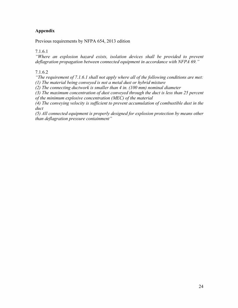
Appendix Previous requirements by NFPA 654, 2013 edition 7.1.6.1 “Where an explosion hazard exists, isolation devices shall be provided to prevent deflagration propagation between connected equipment in accordance with NFPA 69.” 7.1.6.2 “The requirement of 7.1.6.1 shall not apply where all of the following conditions are met: (1) The material being conveyed is not a metal dust or hybrid mixture (2) The connecting ductwork is smaller than 4 in. (100 mm) nominal diameter (3) The maximum concentration of dust conveyed through the duct is less than 25 percent of the minimum explosive concentration (MEC) of the material (4) The conveying velocity is sufficient to prevent accumulation of combustible dust in the duct (5) All connected equipment is properly designed for explosion protection by means other than deflagration pressure containment”
Related Documents


![DUST EXPLOSION PROPAGATION: MYTHS AND REALITIES · White Paper 3 Van Wingerden et al. [8] carried out a series of tests with maize starch, peat and wheat dusts to study explosion](https://static.cupdf.com/doc/110x72/5e785ccca773ff41aa45bfae/dust-explosion-propagation-myths-and-realities-white-paper-3-van-wingerden-et-al.jpg)