1 DLD Lecture 15 Magnitude Comparators and Multiplexers

Welcome message from author
This document is posted to help you gain knowledge. Please leave a comment to let me know what you think about it! Share it to your friends and learn new things together.
Transcript

1
DLD
Lecture 15Magnitude Comparators and Multiplexers

2
Overview
° Discussion of two digital building blocks
° Magnitude comparators• Compare two multi-bit binary numbers
• Create a single bit comparator
• Use repetitive pattern
° Multiplexers• Select one out of several bits
• Some inputs used for selection
• Also can be used to implement logic

3
Comparators° Comparing two binary words is a common operation in
computers.
° A circuit that compares 2 binary words and indicates whether they are equal is a comparator.
° Some comparators interpret their input as signed or unsigned numbers and also indicate an arithmetic relationship (greater or less than) between the words.
° These circuits are often called magnitude comparators.
° XOR and XNOR gates can be viewed as 1-bit comparators.
° Comparator is a combinational logic circuit that compares the magnitudes of two binary quantities to determine which one has the greater magnitude.
° In other word, a comparator determines the relationship of two binary quantities.

4
Designing Comparators Functionally

5
Designing Comparators Functionally
Add an enable line
A=B
A
B
A>B
Enable

6
Build a four-bit Comparator (from four one-bit ones)
7
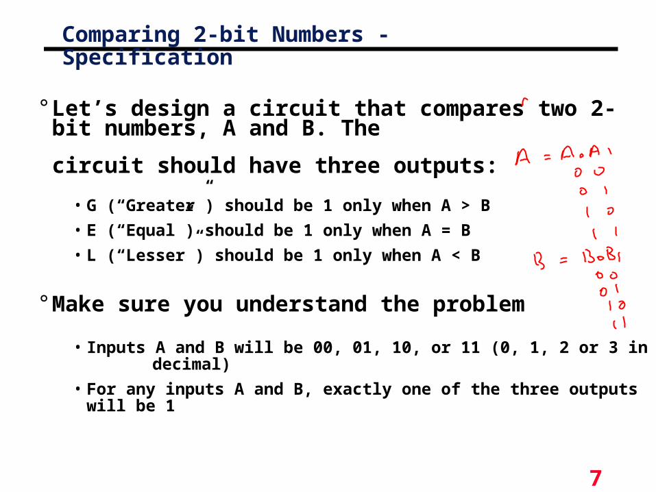
Comparing 2-bit Numbers - Specification
° Let’s design a circuit that compares two 2-bit numbers, A and B. The
circuit should have three outputs:
• G (“Greater”) should be 1 only when A > B
• E (“Equal”) should be 1 only when A = B
• L (“Lesser”) should be 1 only when A < B
° Make sure you understand the problem
• Inputs A and B will be 00, 01, 10, or 11 (0, 1, 2 or 3 in decimal)
• For any inputs A and B, exactly one of the three outputs will be 1

8
° Two 2-bit numbers means a total of four inputs
• We should name each of them
• Let’s say the first number consists of digits A1 and A0 from left to
right, and the second number is B1 and B0
° The problem specifies three outputs: G, E and L
Comparing 2-bit Numbers - Specification

9
Comparing 2-bit Numbers - Formulation° For this problem, it’s probably
easiest to start with a truth table. This way, we can explicitly show the relationship (>, =, <) between inputs
° A four-input function has a sixteen-row truth table
° It’s usually clearest to put the truth table rows in binary numeric order; in this case, from 0000 to 1111 for A1, A0, B1 and B0
° Example: 01 < 10, so the sixth row of the truth table (corresponding to inputs A=01 and B=10) shows that output L=1, while G and E are both 0.
A1 A0 B1 B0 G E L
0 0 0 0 0 0 0 1 0 0 1 0 0 0 1 1
0 1 0 0 0 1 0 1 0 1 1 0 0 0 1 0 1 1 1
1 0 0 0 1 0 0 1 1 0 1 0 1 0 1 1
1 1 0 0 1 1 0 1 1 1 1 0 1 1 1 1

10
A1 A0 B1 B0 G E L
0 0 0 0 0 1 00 0 0 1 0 0 10 0 1 0 0 0 10 0 1 1 0 0 1
0 1 0 0 1 0 00 1 0 1 0 1 00 1 1 0 0 0 10 1 1 1 0 0 1
1 0 0 0 1 0 01 0 0 1 1 0 01 0 1 0 0 1 01 0 1 1 0 0 1
1 1 0 0 1 0 01 1 0 1 1 0 01 1 1 0 1 0 01 1 1 1 0 1 0
Comparing 2-bit Numbers - Formulation
11
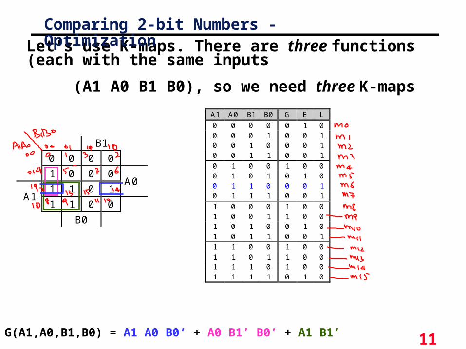
Let’s use K-maps. There are three functions (each with the same inputs
(A1 A0 B1 B0), so we need three K-maps
G(A1,A0,B1,B0) = A1 A0 B0’ + A0 B1’ B0’ + A1 B1’
B1
0 0 0 0
1 0 0 0
1 1 0 1A0
A11 1 0 0
B0
Comparing 2-bit Numbers - Optimization
A1 A0 B1 B0 G E L
0 0 0 0 0 1 00 0 0 1 0 0 10 0 1 0 0 0 10 0 1 1 0 0 1
0 1 0 0 1 0 00 1 0 1 0 1 00 1 1 0 0 0 10 1 1 1 0 0 1
1 0 0 0 1 0 01 0 0 1 1 0 01 0 1 0 0 1 01 0 1 1 0 0 1
1 1 0 0 1 0 01 1 0 1 1 0 01 1 1 0 1 0 01 1 1 1 0 1 0

12
Comparing 2-bit Numbers - Optimization
E(A1,A0,B1,B0) = A1’ A0’ B1’ B0’ + A1’ A0 B1’ B0 + A1 A0 B1 B0 + A1 A0’ B1 B0’
B1
1 0 0 0
0 1 0 0
0 0 1 0A0
A10 0 0 1
B0
A1 A0 B1 B0 G E L
0 0 0 0 0 1 00 0 0 1 0 0 10 0 1 0 0 0 10 0 1 1 0 0 1
0 1 0 0 1 0 00 1 0 1 0 1 00 1 1 0 0 0 10 1 1 1 0 0 1
1 0 0 0 1 0 01 0 0 1 1 0 01 0 1 0 0 1 01 0 1 1 0 0 1
1 1 0 0 1 0 01 1 0 1 1 0 01 1 1 0 1 0 01 1 1 1 0 1 0

13
Comparing 2-bit Numbers - Optimization
L(A1,A0,B1,B0) = A1’ A0’ B0 + A0’ B1 B0 + A1’ B1
B1
0 1 1 1
0 0 1 1
0 0 0 0A0
A10 0 1 0
B0
A1 A0 B1 B0 G E L
0 0 0 0 0 1 00 0 0 1 0 0 10 0 1 0 0 0 10 0 1 1 0 0 1
0 1 0 0 1 0 00 1 0 1 0 1 00 1 1 0 0 0 10 1 1 1 0 0 1
1 0 0 0 1 0 01 0 0 1 1 0 01 0 1 0 0 1 01 0 1 1 0 0 1
1 1 0 0 1 0 01 1 0 1 1 0 01 1 1 0 1 0 01 1 1 1 0 1 0

14
Comparing 2-bit Numbers - Optimization
G = A1 A0 B0’ + A0 B1’ B0’ + A1 B1‘
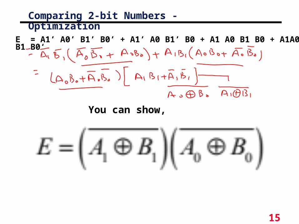
E = A1’ A0’ B1’ B0’ + A1’ A0 B1’ B0 + A1 A0 B1 B0 + A1A0’ B1 B0‘
L = A1’ A0’ B0 + A0’ B1 B0 + A1’ B1
15
Comparing 2-bit Numbers - Optimization
You can show,
E = A1’ A0’ B1’ B0’ + A1’ A0 B1’ B0 + A1 A0 B1 B0 + A1A0’ B1 B0‘
16
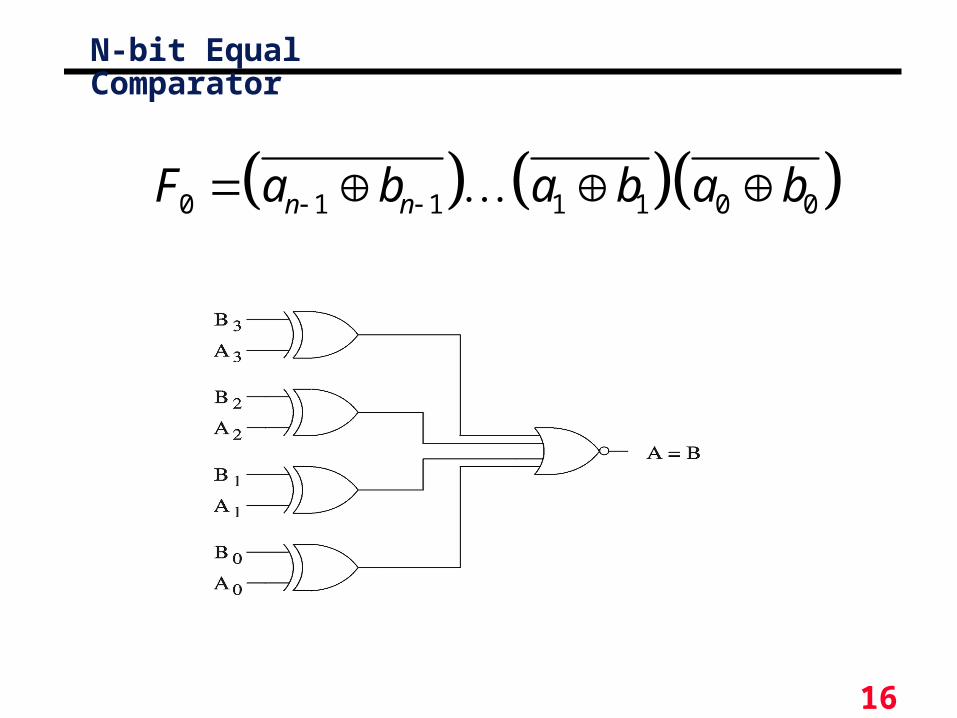
N-bit Equal Comparator
0 1 1 1 1 0 0n nF a b a b a b

17
1-bit comparator
° If two input bits are not equal, its output is a 1. But if two input bits are equal, its output is a 0.
° So exclusiveOR gate can be used as a 2bit Comparator.
18
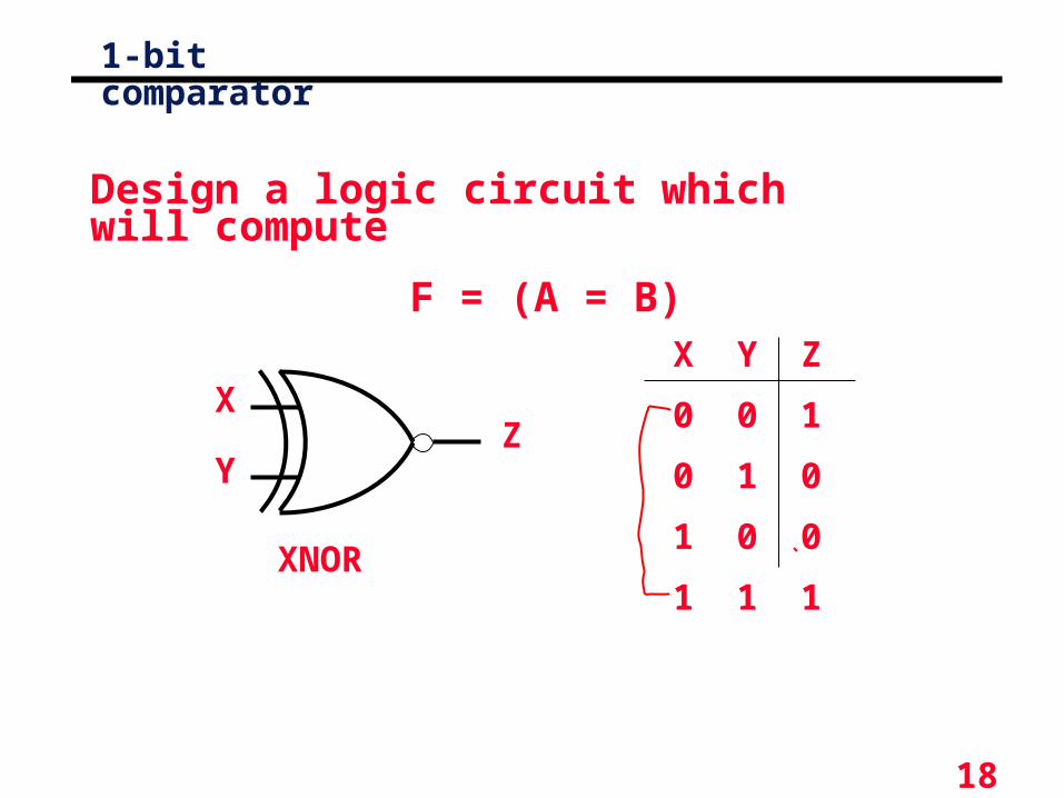
1-bit comparator
XNOR
X
YZ
X Y Z
0 0 1
0 1 0
1 0 0
1 1 1
Design a logic circuit which will compute
F = (A = B)

19
Magnitude Comparator
° The comparison of two numbers• outputs: A>B, A=B, A<B
° Design Approaches• the truth table
- 22n
entries - too cumbersome for large n
• use inherent regularity of the problem
- reduce design efforts
- reduce human errors
MagnitudeCompare
A[3..0]
B[3..0]A = B
A < B
A > B
20
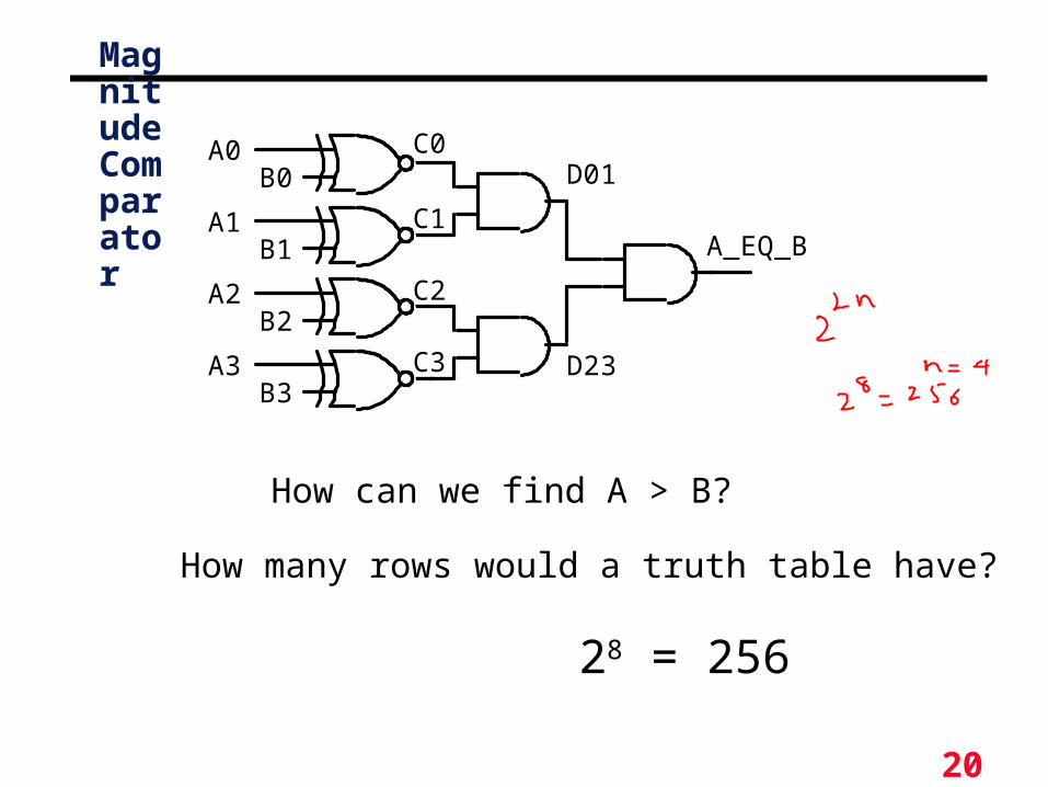
Magnitude Comparator
A0
A1
A2
A3
B0
B1
B2
B3
A_EQ_B
C0
C1
C3
C2
D01
D23
How can we find A > B?
How many rows would a truth table have?
28 = 256
21
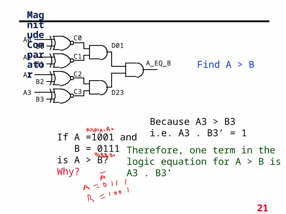
Magnitude Comparator
A0
A1
A2
A3
B0
B1
B2
B3
A_EQ_B
C0
C1
C3
C2
D01
D23
If A =1001 and B = 0111is A > B?Why?
Because A3 > B3i.e. A3 . B3’ = 1
Therefore, one term in thelogic equation for A > B isA3 . B3’
Find A > B
22
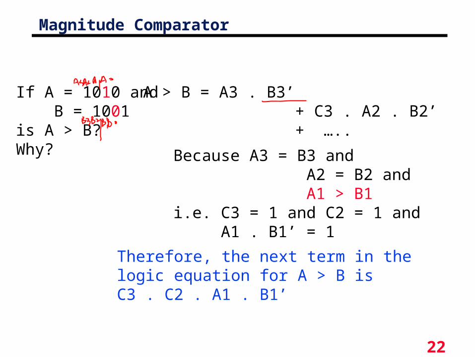
Magnitude Comparator
If A = 1010 and B = 1001is A > B?Why? Because A3 = B3 and
A2 = B2 and A1 > B1i.e. C3 = 1 and C2 = 1 and A1 . B1’ = 1
Therefore, the next term in thelogic equation for A > B isC3 . C2 . A1 . B1’
A > B = A3 . B3’ + C3 . A2 . B2’ + …..

23
Magnitude Comparison
° Algorithm -> logic• A = A3A2A1A0 ; B = B3B2B1B0
• A=B if A3=B3, A2=B2, A1=B1and A1=B1
° Test each bit:- equality: xi= AiBi+Ai'Bi'
- (A=B) = x3x2x1x0
° More difficult to test less than/greater than• (A>B) = A3B3'+x3A2B2'+x3x2A1B1'+x3x2x1 A0B0'
• (A<B) = A3'B3+x3A2'B2+x3x2A1'B1+x3x2x1 A0'B0
• Start comparisons from high-order bits
° Implementation• xi = (AiBi'+Ai'Bi)’
24
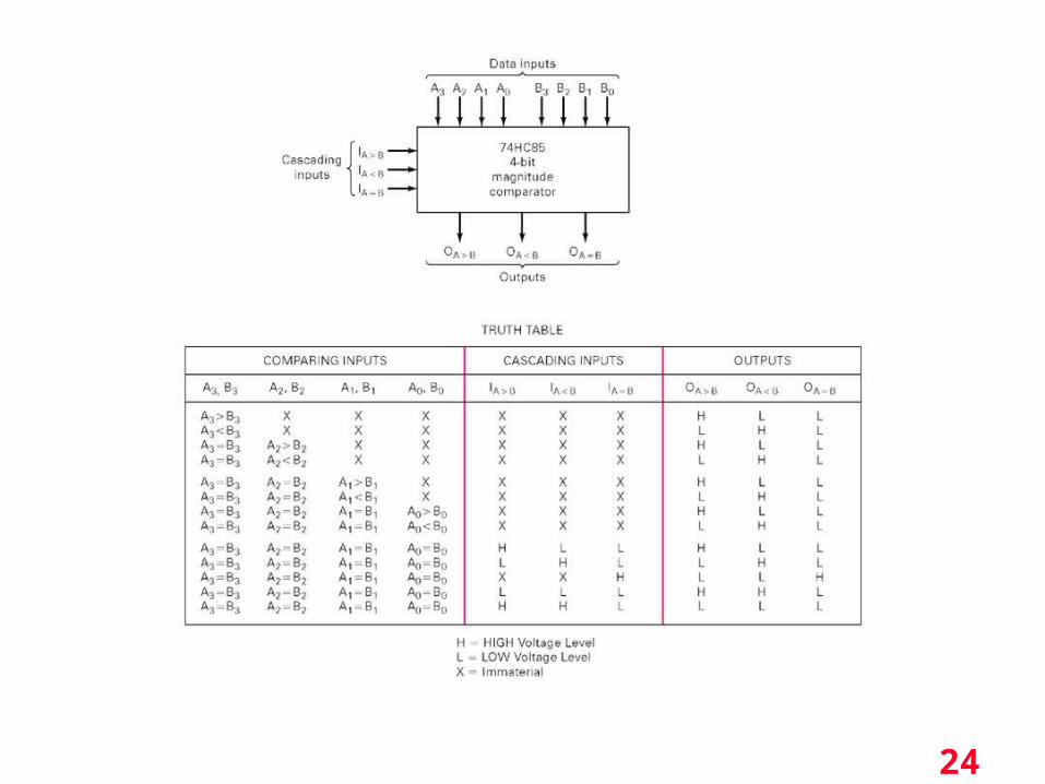
Magnitude Comparison
° Hardware chips
25
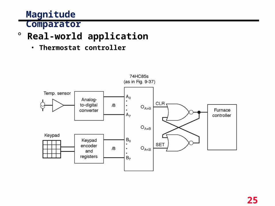
Magnitude Comparator
° Real-world application• Thermostat controller

26
Multiplexers (Data Selectors)
• A multiplexer (MUX) is a device that allows several low-speed signals to be sent over one high-speed output line.
• “Select lines” are used to specify which input signal is sent to the output.
• A demultiplexer (DEMUX) performs the opposite task as the multiplexer: it divides one high-speed input signal into several low-speed components.
• Multiplexers and demultiplexers must be synchronized so that the proper signals are selected.
• This type of multiplexing is referred to as time-division multiplexing (TDM). Another type of multiplexing is frequency-division multiplexing (FDM)
• Multiplexed signals are typically transmitted in precisely organized manners according to a set of rules for transmission called a protocol.

27
Multiplexers
o A multiplexer haso N control inputso 2N data inputso 1 output
o A multiplexer routes (or connects) the selected data input to the output.
o The value of the control inputs determines the data input that is selected.

28
Multiplexers
Z = A′.I0 + A.I1
Data
inputsControl
input
29
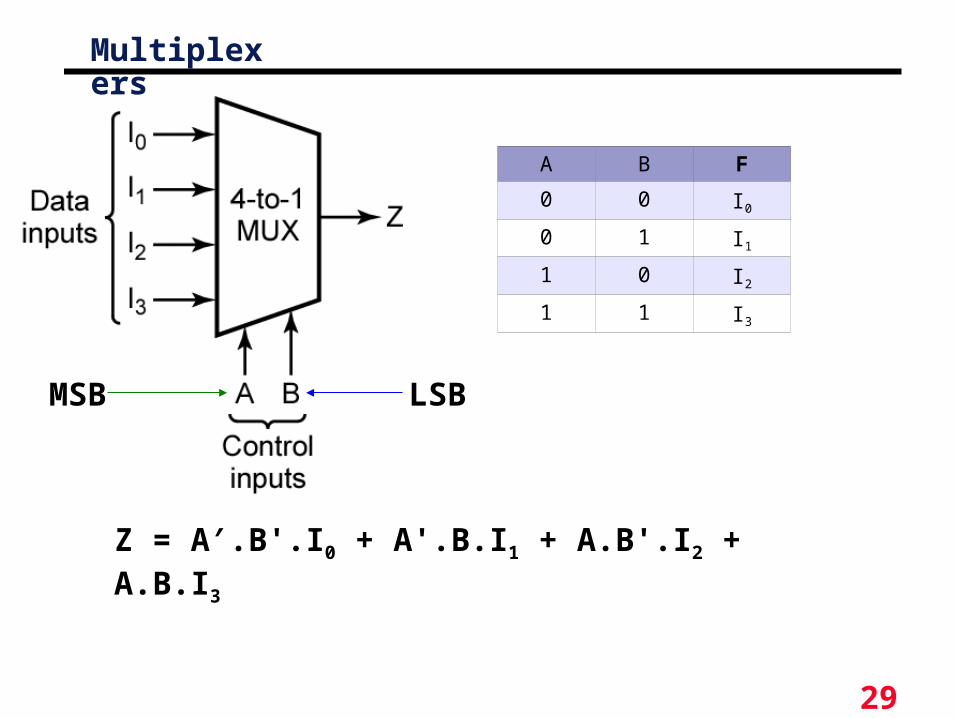
Multiplexers
Z = A′.B'.I0 + A'.B.I1 + A.B'.I2 + A.B.I3
A B F
0 0 I0
0 1 I1
1 0 I2
1 1 I3
MSB LSB

30
Multiplexers
Z = A′.B'.C'.I0 + A'.B'.C.I1 + A'.B.C'.I2 + A'.B.C.I3 +
A.B'.C'.I0 + A.B'.C.I1 + A'.B.C'.I2 + A.B.C.I3
MSB LSB
A B C F
0 0 0 I0
0 0 1 I1
0 1 0 I2
0 1 1 I3
1 0 0 I4
1 0 1 I5
1 1 0 I6
1 1 1 I7
31
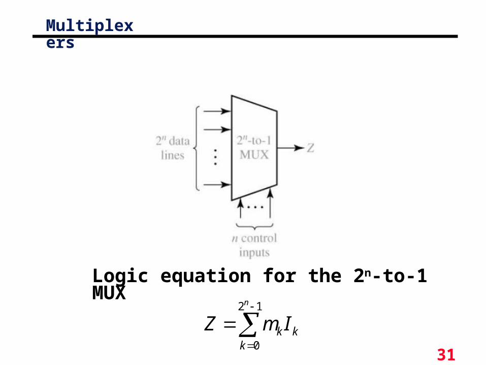
Multiplexers
12
0
n
kkk ImZ
Logic equation for the 2n-to-1 MUX

32
MultiplexersA multiplexer (MUX) selects one data line from two or more
input lines and routes data from the selected line to the output. The particular data line that is selected is determined by the select inputs.
°Select an input value with one or more select bits
°Use for transmitting data
°Allows for conditional transfer of data
°Sometimes called a mux

33
4– to– 1- Line Multiplexer

34
Quadruple 2–to–1-Line Multiplexer
° Notice enable bit
° Notice select bit
° 4 bit inputs

35
Multiplexer as combinational modules° Connect input variables to select inputs of
multiplexer (n-1 for n variables)
° Set data inputs to multiplexer equal to values of function for corresponding assignment of select variables
° Using a variable at data inputs reduces size of the multiplexer
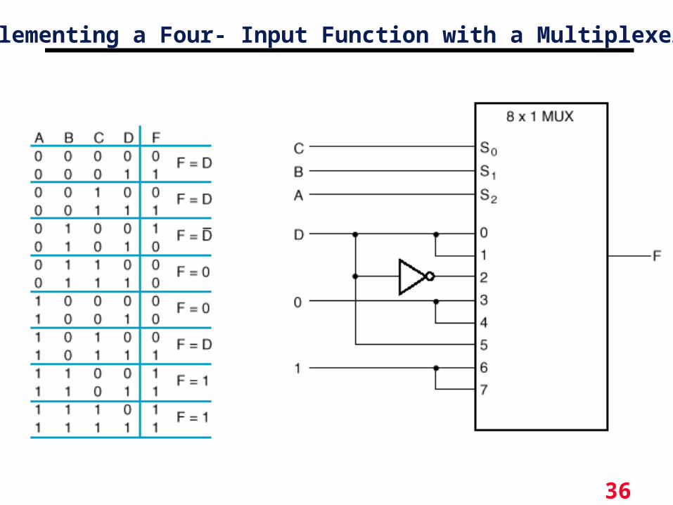
36
Implementing a Four- Input Function with a Multiplexer

37
Typical multiplexer uses

38
Three-state gates
• A multiplexer can be constructed with three-state gates
• Output state: 0, 1, and high-impedance (open ckts)
• If the select input (E) is 0, the three-state gate has no output
Opposite true here,
No output if E is 1
39
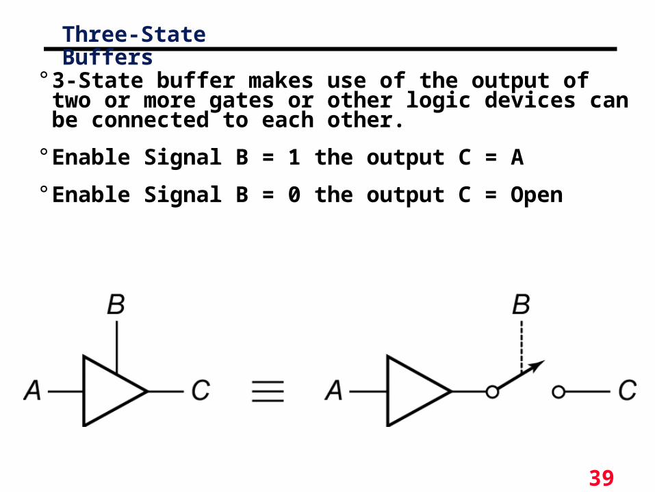
Three-State Buffers
° 3-State buffer makes use of the output of two or more gates or other logic devices can be connected to each other.
° Enable Signal B = 1 the output C = A
° Enable Signal B = 0 the output C = Open
40
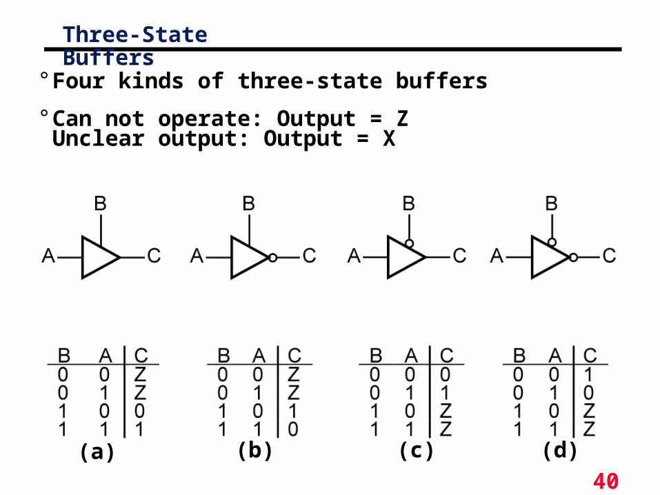
Three-State Buffers
° Four kinds of three-state buffers
° Can not operate: Output = ZUnclear output: Output = X
(a) (b) (c) (d)

41
Three-state gates
• A multiplexer can be constructed with three-state gates
• Output state: 0, 1, and high-impedance (open ckts)
• If the select input is low, the three-state gate has no output

42
Summary
° Magnitude comparators allow for data comparison• Can be built using and-or gates
° Greater/less than requires more hardware than equality
° Multiplexers are fundamental digital components• Can be used for logic
• Useful for datapaths
• Scalable
° Tristate buffers have three types of outputs• 0, 1, high-impedence (Z)
• Useful for datapaths
Related Documents