1_ DIRECTORATE GENERAL INTERNATIONAL COOPERATION MINISTRY OF FOREIGN AFFAIRS KINGDOM OF THE NETHERLANDS GUIDE FOR USERS OF TRAINING MATERIALS REFERENCE CEN-l-~ FOR COMMUNIflFWA SUPPLY AND SANITATION (IRcJ 8 1 DIRECTORATE OF WATER SUPPLY I DIRECTORATE GENERAL CIPTA KARYA MINISTRY OF PUBLIC WORKS 0 4.1 I REPUBLIC OF INDONESIA 5 TR MDP PRODUCTION TEAM I TRAINING MATERIALS FOR WATER ENTERPRISES VOLUME 6B E~I TRAINING MODULES GENERAL OR GA N ISA TIO NAL BasIc knowledge / skills Processes/procedures Equipment/materIals • TECHNICAL Basic knowledge/skills Processes/procedures • withdrawal • treatment distrIbutIon consumption EquIpment/materIals LI TAPE / SLIDE PROGRAMMES MDP PRODUCTION TEAM L DHV - IWACO - -~ -- ~

Welcome message from author
This document is posted to help you gain knowledge. Please leave a comment to let me know what you think about it! Share it to your friends and learn new things together.
Transcript

1_
DIRECTORATE GENERALINTERNATIONAL COOPERATIONMINISTRY OF FOREIGN AFFAIRSKINGDOM OF THE NETHERLANDS
GUIDE FOR USERS OF TRAINING MATERIALS
REFERENCECEN-l-~FOR COMMUNIflFWA SUPPLY ANDSANITATION (IRcJ
8
1 DIRECTORATE OF WATER SUPPLYI DIRECTORATE GENERAL CIPTA KARYA
MINISTRY OF PUBLIC WORKS0 4.1 I REPUBLIC OF INDONESIA
5 TR
MDP PRODUCTION TEAM
I TRAINING MATERIALS FOR WATER ENTERPRISES
VOLUME 6B
E~ITRAINING MODULES
GENERAL
OR GA N ISA TIO NAL
BasIc knowledge / skills
Processes/procedures
Equipment/materIals
• TECHNICAL
Basic knowledge/skills
Processes/procedures
• withdrawal
• treatment
distrIbutIon
consumption
EquIpment/materIals
LI TAPE / SLIDE PROGRAMMES
MDP PRODUCTION TEAM
L DHV - IWACO -
-~
- - ~


DIRECTORATE OF WATER SUPPLYDIRECTORATE GENERAL CIPTA KARYADEPARTh~ENTOF PUBLIC WORKSGOVERNMENT OF INDONESIA
MDP PRODUCTION TEAM
TRAIN ING MATER IALS
DIRECTORATE GENERALFOR INTERNATIONAL COOPERATIONMINISTRY OF FOREIGN AFFAIRSGOVERNMENT OF THE NETHERLANDS
FOR WATER EN TE RFPI I SE S
LIBc~i~yINTERNATICN/\L R~FE7E\4CECENTRE FOR COMMUI\j ~E~UPPLYAND SAN1rAT~O~(C~Zc}P.O. ~ 931gb 2Log AD Ihe Hag
Tel. (070) 814911 ext 141/142
VOLUME 613TRAINING MODULES -±- ~TECHNI
DHV CONSULTING ENGINEERSIWACO B.V.T.G. INTERNATIONAL
JAKARTAAPRIL 1985

PREFACE
This volume is part of the Final Report of the MDP Production Team whichproduced Training Materials for Water Enterprises as part of a projectunder the bilateral cooperation programme between the Government of theRepublic of Indonesia and the Government of the Kingdom of the Nether-lands.
following volumes:
training materials
GENERAL + ORGANIZATIONAL(basic knowledge/skills)
GENERAL+ ORGANIZATIONAL(basic knowledge/skills)
ORGANIZATIONAL (processes/procedures;equipment/materials)
TECHNICAL (basic knowledge/skills)
TECHNICAL (processes/procedures)
TECHNICAL (processes/procedures)
TECHNICAL (Withdrawal + Treatment)
TECHNICAL (Withdrawal + Treatment)
TECHNICAL (Distribution + Consumption)
TECHNICAL (equipment/materials)
This Final Report contains the
Volume 1 Guide for users of
Volume 2A
Volume 2B
Volume 3
Volume 4
Volume 5A
Volume 5B
Volume 6A
Volume 6B
Volume 7
Volume 8
Training Modules,
Training Modules,
Training Modules,
Training Modules,
Training Modules,
Training Modules,
Training Modules,
Training Modules,
Training Modules,
Training Modules,
Volume 9 Tape/slide programmes

4.
TABLE OF CONTENTS
TRAINING MODULES
CODE TITLE
TTG 311 Rapid gravity sand filtration
TTG 400 Neutralization
TTG 500 Chemicals handling, mixing and dosing
TTO 051 Operation of water treatment facilities — surface water
TTO 205 Jar test
TTh1 050 Maintenance of water treatment facilities

S
-‘4
cc

DEPARTMENT OF PUBLIC WORKS
DIRECTORATE GENERAL CIPTA KARVA
______ DIRECTORATE OF WATER SUPPLY
Special features
Keywords Filter medium/filter run period/head ioss/filtered water quality/filtret ion efficiency/constant rate filtration/declining rate filtra-tion/break—through.
Module : RAPID GRAVITY SAND FILTRATION Code : TTG 311
Edition : 18—03—1985
MDPPDHVTG I
IWACO
Section 1 : I N F 0 R M A T I 0 N S H E E T Page : 01 of 01/19
Duration 45 minutes.
Training objectives : After this session the trainees will be able to:-. explain the principles and characteristics of
rapid gravity sand filtration;— recite the procedures for operatioii of rapid
travity sand filters:— recite the coniinon faults in the operation of
rapid gravity sand filters and list thecorresponding remedies.
Trainee selection : — Head of Technical Department;— Head of Section Production;— Head of Sub—section Water Treatment;— Water Treatment Plant Operator.
Training aids — Viewfoils : TTG 311/V 1—8;— Handout : TTG 311/H 1.


Module : RAPID GRAVITY SAND FILTRATION Code : TTG 311
Edition : 18—03—1985
Section2: SESSION NOTES Page : OlofOS
1. Principles
Introduction
— Rapid sand filtration is a purificationprocess, suitable for the the removal of:
suspended solids;colloidal matter;bacteria.
— Sand is a suitable filter medium becauseof:
deep penetrationof filtered wateravailability;low cost;satisfactory experience.
— The filtering process leads to:removal of impurities;reduction of pore space;increase of resistance against flow;drop in efficiency;nessecity of cleaning.
— Cleaning is accomplishedinvolving:
reversed high—rate flow;bed expansion;scouring;removal of impuritieswater
Mechanisms of filtration
— Removal of impurities during thetion is accomplished by
straining;• sedimentation;
adsorption;chemical reaction;biological activity.
without deteriorationquality;
Use whiteboard
Use whiteboard
Use whiteboard
Use whiteboard
Show V 1
by backwashing,
with backwash
filtra—

4

Module : RAPID GRAVITY SAND FILTRATION Code : TTG 311
Edition : 18—03—1985
Section2: SESSION NOTES Page : O2ofOS
— Filter configuration consists of:box (concrete, steel, etc.); Show V 2filter bed (sand);filter bottom (porous);
• inlet;• outlet;• wash water provisions;
overflow gutter;drain.
2. Characteristics of rapid sand filtration
mt~.run period
— Filter run period dependson: Show V 3head loss;filtered water quality.
4— Termination of the filter run because of
head loss is influenced by:clogging of the pores;increase of head loss;rise of water level;maximum allowable water level.
— Termination of the filter run because offiltered water quality is influenced by:• standards : turbidity < 1 FTU;
initially slow increase;suddenly steep increase : “break-through”.
— Normally the filter run as based on headloss is shorter than the filter run asbased on turbidity of filtered water.
— At end of the filter run the filter isbackwashed.
Ui~r~tion efficiency
— Filtration efficiency dependson: Use whiteboardraw water quality;filtration rate;filter medium.

a
I
I
Module : RAPID GRAVITY SAND FILTRATION Code : TTG 311
Edition : 18—03—1985
Section2: SESSION NOTES Page : 03of05
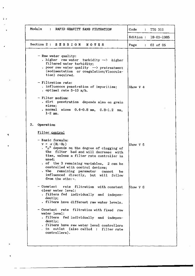
— Raw water quality:higher raw water turbidity ——> higherfiltered water turbidity;poor raw water quality ——> pretreatment(sedimentation or coagulation/floccula-tion) required.
— Filtration rate:influences penetration of impurities; Show V 4optimal rate 5-10 m/h.
— Filter medium:dirt penetration depends also on grainsizes;normal sizes 0.4—0.8 mm, 0.8—1.2 mm,1—2 mm.
3. Operation
Filter control
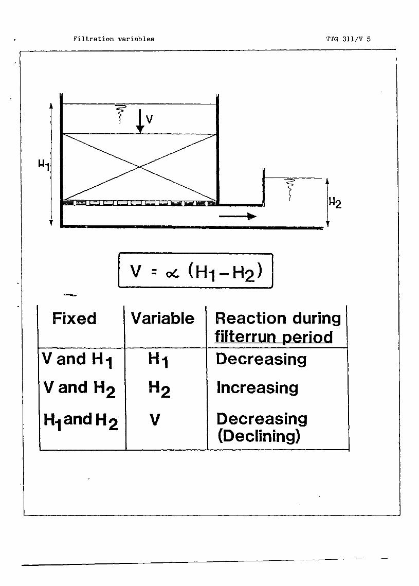
— Basic formula:v a (Hi—Ha) Show V 5
“a” depends on the degree of clogging ofthe filter bed and will decrease withtime, unless a filter rate controller isused;of the 3 remaining variables, 2 can becontrolled with control devices;the remaining parameter cannot beinfluenced directly, but will followfrom the otherc.
— Constant rate filtration with constant ;how V 6clear water level:
filters fed individually and indepen-dent ly;filters have different raw water levels.
— Constant rate filtration with fixed rawwater level:
filters fed individually and indepen-dently;filters have raw water level controllers
• in outlet (also called : filter ratecontrollers).

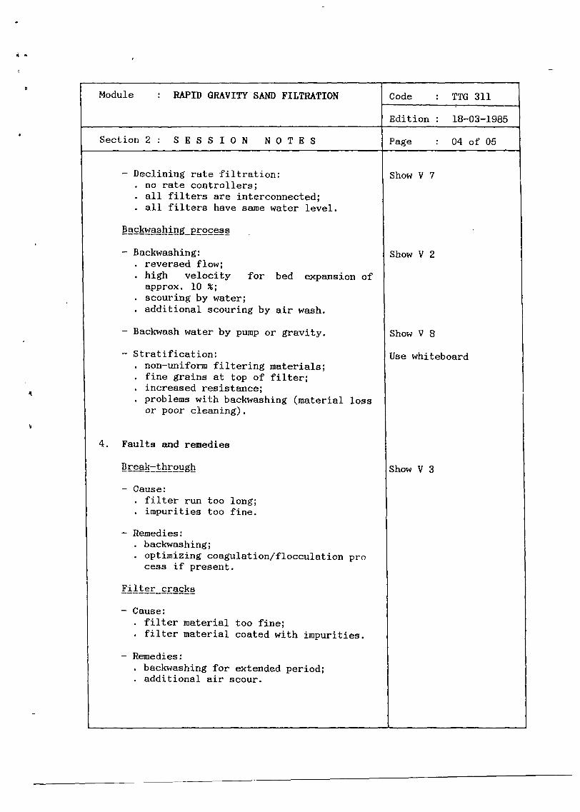
— Declining rate filtration:no rate controllers;all filters are interconnected;all filters have samewater level.
— Backwashing:reversed flow;high velocity forapprox. 10 ~scouring by water;additional scouring by
— Backwashwater by pump or gravity.
— Stratification:non—uniform filtering materials;fine grains at top of filter;increased resistance;problems with backwashing (material lossor poor cleaning).
— Cause:filter run too long;impurities too fine.
— Remedies:backwashing;optimizing coagulation/flocculation process if present.
Filter cracks
— Cause:filter material too fine;filter material coated with impurities.
— Remedies:backwashing for extended period;additional air scour.
Module : RAPID GRAVITY SAND FILTRATION
~
Code : TTG 311
Edition: 18—03—1985
Section2: SESSION NOTES Page : 04of05
bed expansion of
air wash.
4
Show V 7
Show V 2
Show V 8
Use whiteboard
Show V 3
4. Faults and remedies


Module : RAPID GRAVITY SAND FILTRATION Code : TTG 311
Edition : 18—03—1985
Section 2 : S E S S I 0 N N 0 T E S
—
Page : 05 of 05
Gas bubbles in filter bed
— Cause:water pressure smaller thansure, due to head loss.
— Remedies:increase supernatant water levelpressure);remove part of filterbed.
Loss of_filter ma~ hing
— Cause:backwash rate too high;non—uniform filter material.
— Remedies:adjust backwash rate;replace filter material by uniform mate-rial.
gas pres—
(water
6. Summary Give H 1


Module : RAPID GRAVITY SAND FILTRATION Code : TTG 311
Edition : 18—03—1985
Section3: TRAINING AIDS Page : OlofO2
Filtration mechanisms TTG 311/V 1
STRAINING
•SEDIMENTATION
ADSORPTION
CHEMICAL REACTION
.BIOLOGICAL ACTIVITY
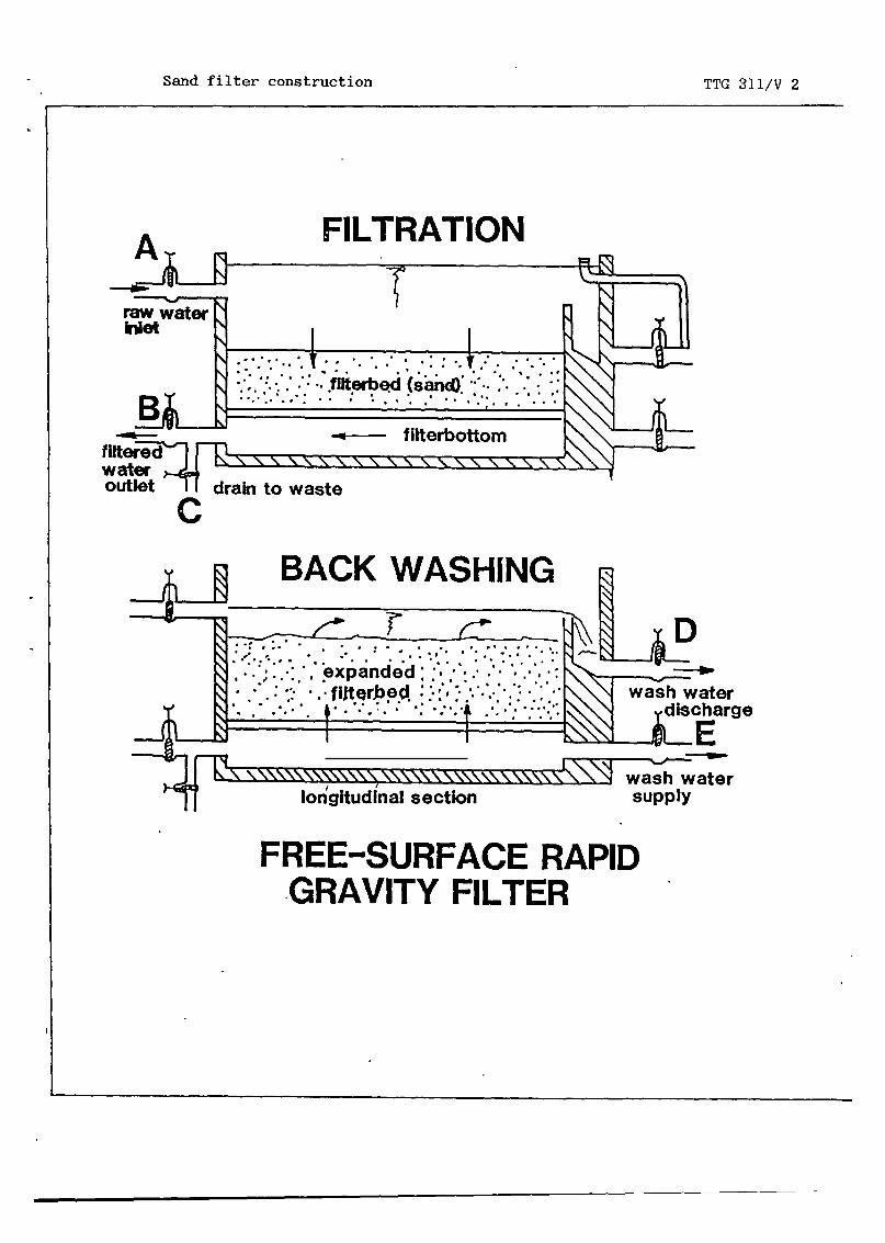
Sand filter TTG 311/V 2construction
A FiLTRATION,
~ -
B
C
~D
FREE-SURFAc~ERAPOGRAVifY ALTER
Filter run period TTG 311/V 3•
b~kw~nhIn9
H.md lou
~
L~~H1~
bCkwflNng
1FTU~:L~.:~/
• Iflte run pfFo4 T1m.
Penetration of TTG 311/V 4impurities
LOW CAPACITY mAD OYALIYY
\I/ I~
/1\ I /4\IHO,11 TILTED DUD DAD OUAUTT
~
/4\ 4 /i~\Filtration variables TTG 311/V 5
~r~J~T
~ (Hi_H~)J
Fixed Variable ReacUon duringflltern.s, period
Vend H1 H1 DecreasIng
V and H2 112 Increaalng
H1andH2 V Decreasing(Declining)
Constant rate TTG 3fl/V 6filtration
CONSTANT RAW WATER LEVEL


DY ODAYITY
Module : RAPID GRAVITY SAND FILTRATION Code : TTG 311
Edition : 18—03—1985
Section3 : TRAINING AIDS Page : 02of02
Declining rate TTG 311/V 7filtration
Backwashing TTG 311/V 8
ST PUMP
Rapid gravity sand TTG 311/H 1filtration

TA
-V
as
DEPARTMENT OF PUBLIC WORKS MDPP
,4.~DIRECTORATE GENERAL CIPTA KARYAI DIRECTORATE OF WATER SUPPLY WACO
Module : RAPID GRAVITY SAND FILTRATION Code : TTG 311
Edition : 18—03—1985
Section4 : HANDOUT Page : 01 of 11
1. PRINCIPLES
Introduction
Rapid filtration is a purification process, whereby the water to betreated is passed through a porous medium at relatively high veloci-ties. During the passage the water quality improves by partial re—moval of suspended and colloidal matter, by reduction of the numberof bacteria and other organisms, and by changes in its chemical cons-tituents. In the practice of water purification, the porous medium inprinciple may be any stable material.In the field of public and larger private water supplies, however,granular beds of sand are used almost exclusively. Such beds allowfor the penetration and accumulation of impurities from the raw waterinto the filter medium up to a certain period, before deteriorationof filtered water quality will occur.Sand as filtering material further has the advantages of availabili-ty, relatively low cost and the satisfactory experience gained withit over a long period of time.
During the process of filtration the impurities are removed from thewater, and accumulated on the grains and in the pores between thegrains of the filter bed. As a result, the effective pore space willbe reduced and the resistance against the flow of water increased.The filtration efficiency will gradually become lower. After sometime the resistance (head loss) becomes so high, or the quality ofthe filtered water so poor, that cleaning of the filter becomesnecessary
Cleaning of rapid filters is accomplished by backwashing. Backwashingis performed by directing water at a high flow rate back through thefilter bed, wheieby the bed expands and is scoured. The backwashwater carries the accumulated dirt out of the filter. The cleaning ofa rapid filter can be carried out quickly; it normally takes not morethan about half an hour.It should be done as frequently as required in order to maintainfavourable process conditions; normally once per 24—48 hours ofoperation.
Mechanisms of filtration
The removal of impurities during the filtration is brought about by:
— ~Particles larger than the openings between the grains of the fil-tering medium are retained.


Module : RAPID GRAVITY SAND FILTRATION Code : TTG 311
Edition : 18—03—1985
Section4 : HANDOUT Page : O2of 11
a
— Sedimentation:Particles smaller than the openings between the grains but stilllarge enough to settle will reach the surface of a grain sooner orlater and are thus removed by sedimentation.
~2E2t]aflLColloidal particles which cannot be removed by sedimentation may beadsorbed to the grains due to electrostatical forces.
— Chemical reaction:Dissolved impurities may be converted into insoluble compoundswhich are removed by straining, sedimentation or adsorption.
—Bacteria living on and in the filterbed, adsorbed to the filtergrains, use inorganic and organic impurities as nutrients, in thisway removing material by converting it into cell material.
Configuration of a rapid gravity sand filter
A rapid gravity sand filter consists of:
— A box (usually concrete) containing the filter bed and the waterbeing treated.
— A filter bed consisting of the filtering material (sand of uniformsize).
— A filter bottom supporting the filter bed and provided with smallopenings for the even discharge of filtered water and even distri-bution of wash water.
— Raw water inlet and filtered water outlet, providedfloat control devices.
— Wash water supply and wash water discharge (gutter)valves or float control devices.
— Drain for draining the filter bed when it has to beoperation.
with valves or
provided with
taken out of

r

Module : RAPID GRAVITY SAND FILTRATION Code : TTG 311
Edition : 18—03—1985
Section 4 : H A N D 0 U T Page : 03 of 11
FILTRATION
Fig. 1. Rapid sand filter construction.
2. CHARACTERISTICS OF RAPID GRAVITY SAND FILTRATION
Filter run period
The time between two successive cleanings of a filter bed is calledthe filter run period or length of filter run. The filter run perioddependson twoparameters: head loss and filtered water quality.
— Head loss
Head loss is a value for the resistance of the filter bed againstwater movement. During the filtration process the head loss (re-sistance) increases, caused by clogging of the pores between thegrains. An increase of head loss will make the water level on topof the filter rise, so the maximum head loss which can be accepted
A


Module : RAPID GRAVITY SAND FILTRATION Code : TTG 311
Edition : 31—12—1984
Section4 : HANDOUT Page : O4ofll
is limited by the maximum allowable water level (the overflow levelof the filter bed). When this level is reached, backwashingmustbe carried out to restore the original head loss and lower the rat-water level.The filter run period is thus ended when the maximum designed headloss is reached (e.g. when the level of the water on the filterwill reach its maximum allowable value).
-
The filtered water quality can be measured as turbidity and itsvalue must be lower than 1 FTIJ according to drinking water stan-dards. When the filter run period is proceeding, the turbidity ofthe filtered water will only slightly increase with time. At acertain moment however, a steep increase in turbidity may occurrather suddenly. This is called the “break—through” of the filter.The impurities cannot be retained adequately anymore by the filterbed so backwashing must be performed. The filter run period isthus ended by a deteriorating filtered water quality.
In normal water treatment practice the filter run period is deter-mined by the maximum allowable head loss, which should be reachedbefore the filter bed water quality deteriorates by a “break-throught’ of the filter bed. The turbidity of the filtered water,should be measured regularly for control however, so in case“break—through” would happen before the maximum allowable head lossis reached, backwashing can be executed and the water quality isguaranteed.
Filtration efficiency
Filtration efficiency or the way in which the impurities are retaineddepends on three parameters: (i) raw water quality, (ii) filtrationrate and (iii) filter medium.
-
The turbidity of the filtered water depends directly on that of theraw water. In other words, the lower the turbidity of the rawwater, the lower the turbidity of the filtered water.When the turbidity of the filtered water does not satisfy drinkingwater standards, due to high turbidity of the raw water, a pre-treatment will be necessary.This pretreatment can be:Sedimentation: when the impurities are large enough to settle bygravity.

Module : RAPID GRAVITY SAND FILTRATION Code : TTG 311
Edition : 18—03—1985
Section4 : HANDOUT Page : OSof 11
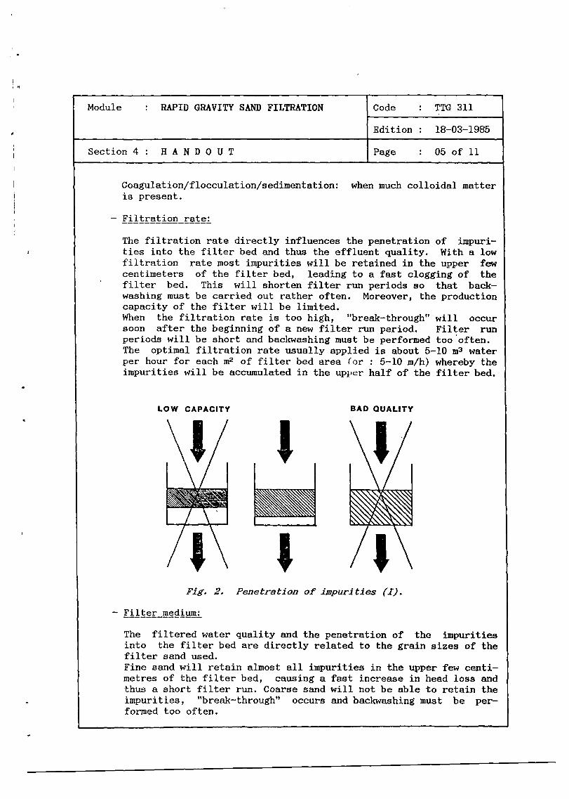
Coagulation/flocculation/sedimentation: when much colloidal matteris present.
— Filtration rate:
The filtration rate directly influences the penetration of impuri-ties into the filter bed and thus the effluent quality. With a lowfiltration rate most impurities will be retained in the upper fewcentimeters of the filter bed, leading to a fast clogging of thefilter bed. This will shorten filter run periods so that back—washing must be carried out rather often. Moreover, the productioncapacity of the filter will be limited.When the filtration rate is too high, “break—through” will occursoon after the beginning of a new filter run period. Filter runperiods will be short and backwashing must be performed too often.The optimal filtration rate usually applied is about 5—10 & waterper hour for each in
2 of filter bed area (or : 5—10 m/h) whereby theimpurities will be accumulated in the upper half of the filter bed.
LOW CAPACITY BAD QUALITY
— Filter medium:
The filtered water quality and the penetration of the impuritiesinto the filter bed are directly related to the grain sizes of thefilter sand used.Fine sand will retain almost all impurities in the upper few centi-metres of the filter bed, causing a fast increase in head loss andthus a short filter run. Coarse sand will not be able to retain theimpurities, “break—through” occurs and backwashing must be per-formed too often.
Fig. 2. Penetration of impurities (I).


Module : RAPID GRAVITY SAND FILTRATION Code : TTG 311
Edition : 18—03—1985
Section 4 : H A N D 0 U T Page : 06 of 11
Grain sizes of the sand layer should therefore be chosen carefully,and be as uniform as possible. Normally sizes used are 0.4—0.8 mm,0.8—1.2 mm or 1—2 nun, depending on the raw water quality. Thethickness of the filter bed should be 0.6—2 m. The filter bed issupported by an under drainage system or several gravel layers,graded in size between 2 imn and 60 mm and provided with a drainsystem.
3. OPERATION
RUN
Filter control
The most important relationship for understanding filter control isthe proportionality between the head loss over a filter bed (H1—H2)and the filtration rate (v) at any moment.
SHORT
1~Fig. 3. Penetration of impurities (II).
In formula: = a (Hi—Re)


Module : RAPID GRAVITY SAND FILTRATION Code TTG 311
Edition 18—03—1985
Section4 HANDOUT Page : 07 of 11
where v = filtration rate;a = proportionality constant; decreasing during the filter
run period because of clogging of the pores;Hi = water level on filter, above datum line;112 = filtered water level above datum line.
By using filter control devices such as float—controlled valves andoverflow weirs it is possible to choose two of the three variables v,Hi~ 112 at will. The remaining variable will then automatically bedetermined, as follows from the formula. This will lead to thefollowing alternatives in filter control:
Fixed Variable Change of variable parameterduring filter run
1. v and Hi Decreasing2. v and 112 Hi Increasing3. Hi and 112 v Decreasing (Declining)
A fourth possibility is to use a so—called filter rate controller inthe filtered water pipeline. This is essentially a valve that isalmost closed when the filter is clean, and automatically compensatesfor a growing resistance of the filter bed itself by adjusting itsdegree of opening. In this case all 3 values (v, Hi,H2) can remainfixed.
Two of these alternatives will be discussed here because their usehas found a wide application.
a. Constant_fil r wi n ng raw water level
The method of constant filtration rate is used when a set offilters are fed individually and independently of each other.When the head loss increases, the water level on the filterrises, up to a maximum level (overflow level), to maintain theconstant flow rate in the filter bed. In such cases all theJ.LlLers will have different water levels.


Module RAPID GRAVITY SAND FILTRATION Code : TTG 311
Edition : 18—03—1985
Section4 : HANDOUT Page : O8of 11
b. Declining rate filtration
When no filter rate controllers are used, filtration will tak&place at a declining rate. Declining—rate filters are lessexpensive than constant rate filters, as the constant water levelon the filters allows the filter boxes to be lower.All filters are in open connection with the raw water conduit,and discharging over weirs that have the same level for all.Consequently, all have the same raw water level and filteredwater level so that all filters will operate under the same head.The filtration rate for the various filter units, however, willbe different: highest in the filter just cleaned by backwashingand lowest for the one longest underway in its current filterrun. For all filters jointly, the production will be determinedby the supply of raw water which should be high enough to meetthe demand for filtered water. During filtration the filter bedsare gradually clogged and the raw water level in all filters willrise due to the increased resistance against water flow in thefilter beds. The filter unit that has been in operation for thelongest period of time will normally have the lowest output (asseen at the filtered water wei~r) and needs cleaning by backwash—ing first. After its cleaning this filter will have the lowestresistance against flow so that a considerable portion of the rawwater supplied will pass this filter. The load on the otherfilters is temporarily reduced. These units will show a fall infiltered water production but later the further clogging of thecleanest filter bed will cause the distribution of water over the
Fig. 4. Constant clear water level.


Module RAPID GRAVITY SAND FILTRATION Code : TTG 311
Edition : 18—03--1985
Section 4 : H A N D 0 U T Page : 09 of 11
filters to become more even. When in a second filter the outputhas reached its minimum allowable value this one will be back—washed, and so forth.
The high output of newly backwashed filters often results in apoorer quality of the water produced by that filter, which lowersthe over—all filtered water quality temporarily. This is the maindraw—back of declining rate filtration.
Backwa8hing process
4J~
A rapid filter is cleaned by backwashing. Backwashing is accomplishedby directing a flow of clean water at a specific flow rate upwardthrough the filter bed for a period of several minutes. Filtered~‘ater froi~i any storage reservoir or a special wash water reservoircan be used (by gravity or pumping), or the effluent from the other(operating) filter units of the filtration plant (‘self—wash arrange-ments’). The velocity of the upward water flow should be high enoughto produce an expansion of the filter bed so that the accumulateddirt can be carried away with the washwater after being loosened bythe water scour. The expansion should be about 5—l5~ of the normalfilter bed height.
Fig. 5. Declining rate filtration.

Module : RAPID GRAVITY SAND FILTRATION Code : TTG 311
Edition : 18—03—1985
Section 4 : H A N D 0 U T Page : 10 of 11
Particularly when fine sand is used, the scouring force of the risingwash water may be inadequate to keep the filter grains clean in thelong run. After some time they could become covered with a stickylayer of organic matter. This may cause problems such as mud ballsand filter cracks.
This can be prevented by applying an addiLional scour through airwash. Filter cleaning now starts by backwashing with air, usuallyfollowed by a combined air and water backwashing and completed withwater backwashing. This should remove the coatings from the filtergrains and the loosened material is carried away by the followingwater wash. For backwashing with air a separate pipe system is used.
Backwashing is usually performed as follows:a. with compressed air 5—10 minutes at v(air) = 50 rn/h;b. with air and water 5—10 minutes at v(air) = 50 rn/h,
v(water) = 25 rn/h;c. with water 5—10 minutes at v(water) 25 rn/h.
With non—uniform filter materials, backwashing will result in astratification, with the fine grains in the upper and the coarsegrains in the lower part of the filter bed. Backwashing such beds atlow rates will only expand the upper part, while in the lower partthe grains remain stationary, thus hampering the removal of impuri-ties accumulated here during the previous filter run. When for thisreason the backwash rate is increased to provide an adequate ex-pansion of the lower part of the bed, the expansion of the upper partmay be so high that a serious loss of filter material could occur.These problems will be avoided by using a uniform filter materialwith upper and lower grain sizes not more than a factor 2 apart.
4. FAULTS AND REMEDIES
Break—through
When the filter reaches a certain degree of clogging, the turbidityof the filtered water might suddenly increase very steeply. Thissudden increase of turbidity is called “break—through” and it iscaused by dirt particles that are no longer adequately retained.Usually this “break—through” will occur near the end of the filterrun so a backwash cycle will restore filtrate quality.In case coagulation/flocculation and sedimentation are preliminarysteps in water treatment, break—through might occur in an early stageof the filter run, due to an improper functioning of the coagulation!flocculat ion process.Filtrate quality must then be restored by optimizing the coagulatiori/flocculation process before backwashing.


Module RAPID GRAVITY SAND FILTRATION Code : TTG 311
Edition : 18—03—1985
Section 4: HANDOUT Page : llof 11
Filter cracks
Filter cracks may develop when finely grained filter material isused. The fine grains may become coated with soft and compressible,often organic, material retained from the passing water. The dirtcan be removed by backwashing for extended periods or with an airscour before a water scour is applied. If the problems cannot besolved by this method the fine grains must be replaced by coarsergrains, which means that the filter has to be taken out of operationtemporarily.
Gas bubbles in filter bed
Gases dissolved in the water will come out of solution when thewater pressure is lower than the gas pressure. Gases may be releasedinside the filter bed when the water pressure in the filter bed isdecreasing during the filter run due to an increasing loss of headwhile the gas pressure stays constant. The released gas bubbleswill accumulate in the pores between the sand grains, hamperingdownward water movement, increasing filter resistance and prematurilyending filter runs. When this problem is of a more or less permanentnature the only remedy is to increase the filter water level and/orto remove part of the filter bed, resulting in a smaller bed height,combined with a thicker layer of water on top of the filter.
Loss of filter material during backwashing
When filter material is lost during backwashing, too high a backwashrate is applied. This results in a bed expansion that will reach thebackwash overflow gutter so the material is carried away with thebackwash water in the gutter. The backwash rate should now beadjusted to a proper level by partly closing the backwash water valveuntil a proper bed expansion is obtained.
5. SIM4ARY
Rapid filtration is a purification process whereby the water to betreated is filtered through a filter bed containing sand. Due to theretaining of impurities the filter bed has to be cleaned regularly bybackwashing. The period between two successive backwashings is calledthe filter run and depends on the head loss over the filter bed andthe turbidity of the filtered water.Two systems of rapid filtration are widely used : rapid! filtration ata constant rate and at a declining rate. Rapid filtration is a re—liable treatment process, that is easy to operate.


Module : RAPID GRAVITY SAND FILTRATION Code TTG 311
Edition : 18—03—1985
Annex : VIEWFOILS Page : 01 of 09
TITLE : CODE
1. Filtration mechanisms TTG 311/V 1
2. Sand filter construction TTG 311/V 2
3. Filter run period TTG 311/V 3
4. Penetration of impurities TTG 311/V 4
5. Filtration variab]es TTG 311/V 5
6. Constant rate filtration TTG 311/V 6
7. Declining rate filtration TTG 311/V 7
8. Back washing TTG 311/V 8


Filtration mechanisms TTG 311/V 1
z
I-C/)
z0
I-zwawCl).
>-
>1
p0
-J
0
0-J0
z0p0w-j
0
wI0I
z0p
0Cl)

Sand filter construction TTG 311/V 2
\NN wash waterdischarge
::L~ I I __~ I:ss~sS~ s~ wash water
longitudinal section supply
FREE-SURFACE RAPIDGRAVITY FILTER
A FILTRATION
C
4) BACK WASHING
-w —


Filter run period TTG 311/V 3
Head Loss
backwashlng
— -I----~--—--
filter run period Time
Turbiditybackwashing
1
Break through
Time


Penetration of impurities TTG 311/V 4
LOW CAPACITY
I
BAD QUALITY
•0 •~ft~..•...‘ ft• k •u .,D •ø
/,\
RUN
Jr
SHORT
/BAD QUALITY
I//Jr

Filtration variables TTG 311/V 5
I V (H1- H2)1
Fixed
and
and
V H1
V H2
H1 and H2
Variable
H1
H2
V
Reaction duringfilterrun periodDecreasing
Increasing
Decreasing(Declining)
I-li
V
I-~


Constant rate filtration TTG 311/V 6
CONSTANT CLEAR WATER LEVEL
CONSTANT RAW WATER LEVEL


Declining rate filtration TTG 311/V 7


Back washing TTG 311/V 8
BY PUMP
BY GRAVITY


~LDEPARTMENT OF PUBLIC WORKS
I DIRECTORATE GENERAL CIPTA KARYAL DIRECTORATE OF WATER SUPPLY
Module NEUTRALIZATION Code : TTG 400
Edition : 18—03—1985
Sectionl: INFORMATION SHEEP Page OlofOl/lO
— Head of Technical Department;— Head of Section Production;— Head of Sub—section Water Treatment;— Water Treatment Plant Operator;— Head of Sub Section Laboratory.
Special features
Keywords Neutralization/corrosiveness/scale forming/ag—gressive C02/saturation index/aeration/limestonefiltration /liine saturator! alkaline solutions.
MD P PDHVTGI
IWACO
90 minutes.
After the session the trainees will be able to:— recite the principles of neutralization or p11
correction;— indicate neutralization.
Duration
Training objectives
Trainee selection
Training aids — Bottle of— Viewfoils—Handout
Sprite;TTG 400/V 1—4;TTG 400/H 1.


Module : NEUTRALIZATION Code : TTG 400
Edition : 18—03--1985
Section2: SESSION NOTES Page : OlofO2
1. Introduction
— Neutralization is the reduction of exces-sive carbon dioxide concentration in orderto eliminate corrosiveness.
— Reduction of CO2 content is done by:aeration;Limestone filtration;dosing of alkaline solutions.
2. Theory
— CO2 can be found:a. in air;b. in breath;c. in Sprite (bubbles);d. ix~ groundwater at high concentrations;e. in surface water at normal concentra—
— CO2 is not dangerous for health.
— If concentration of CO2 in water is higherthan 20 ppm, then:• it reacts with CaCOs in:
— cement;— asbestos cement;— concrete;as CaCOa dissolves, cement products willbecome porous, causing leakage and
• deterioration of water quality.
— In ground water the OOz contentvery high C> 100 ppm), giving aneutralization is necessary.
— In surface water the C02 concentration isnormally very low because of the frequentand intensive contact of water with air.
— The corrosiveness of the water ispressed as the saturation index, SI.SI = p11 — pH~ wherein:pH = the actual pH of the water,pH~ = the pH of the water when it
saturated with CaCO3.
Use whiteboard
Use whiteboard
Demonstrate and drinkSpriteUse whiteboard
tions.
can below pH:
ex—
is

— Deten~irtationof SI can be done by:• water examination in a well organised
laboratory;- practical test by adding 1 gram of CaCO3
to 1 litre of water and measuring thepH~ after 24 hours of contact time.
can be:less than —0.3 : the water isand neutralization is neces—
the water is scale forming orprecipitate on pipe walls and
3. Neutralization syst~ns
— Aggressive CO2 can be removedby:aeration;
- limestone filtration;- dosing of alkaline solutions:
a. lime saturator (Ca(OH)z);b. pump dosing systems (NaOH or Na2CO3).
Show V 1—4
Module : NEUTRALIZATION Code : TTG 400
Edition : 18—03—1985
Section2: SESSION NOTES Page : 02of02
Use whiteboard
— Values of SI• negative,
corrosivesary;possitive,CaCOa willvalves.
4. Summary Give H 1


Module : NEUTRALIZATION Code : TTG 400
Edition : 18—03—1985
Section3: TRAINING AIDS Page : OlofOl
Aeration TTG 400/V 1
~
•flnyQuflp44~~~~
flAt TRATI
0
.~MULTII TRAY URATOA
Limestone filtration TTG 400/V 2
M~~T
Lime saturator TTG 400/V 3~
I•_
~:
Dosing system for TTG 400/V 4soda ash
~
Neutralization TTG 400/H 1
- WATRA&VCT~
SATURATOR


DEPARTMENT OF PUBLIC WORKS MDPP
DIRECTORATEGENERAL CIPTA KARYA
______ DIRECTORATE OF WATER SUPPLY IWACO
Module : NEUTRALIZATION Code : TTG 400
Edition : 18—03—1985
Section4 : HANDOUT Page : Olof 06
1. INTRODUCTION
Neutralization, or pH correction, is the reduction of excessivecarbon dioxyde, dissolved in water, to a concentration that is notcorrosive to construction materials as used in water supply systems.Aggressive CO2 can be removed by aeration or chemically bound bylimestone filtration or by the addition of alkaline solutions.
2. THEORY
Carbon dioxyde (CO2) is a very common gas. It can be found in theair (2%), in respired breath and in soft drinks (Sprite) at veryhigh concentrations. It is also found in groundwater, usually inhigh. concentrations and in surface water at normal concentrations.
Considering humah health, carbon dioxyde is not dangerous, even athigh concentrations. Water containing high concentrations of carbondioxyde (CO2), however, will corrode and dissolve respectively metal-lic and concrete parts of the system, causing leakage, damage topumps and a deterioration of water quality.
In general, the content of corrosive carbon dioxyde is considered toohigh when there is more than 20 ppm of free carbon dioxyde in thewater. Treatment is necessary for neutralization:a. to avoid chemical reactions such as dissolution of calcium car-
bonate from the concrete and asbestos cement products, andb. to avoid corrosion of the metal parts.
CO2 present in water lowers the PH at increasing contents.Concentrations in groundwater can be as high as 100 mg/l COz,resulting in a low pH of the water. In surface water the COz contentis normally low, due to the intimate contact with the air, giving anormal pH value (approx. 7) to the water.
The corrosiveness of water can be expressed by the saturation index;if thiS value is negative, the water is said to be corrosive, if thevalue is positive, the water is scale—forming. Scale forming is thedeposition of insoluble CaCOa on pipe walls and valves.
The saturation index can be calculated with the following formula:
Saturation index = pH — pHa ; wherein
pH the actual pH of the water;the theoretical pH when the water is saturated with respect toCaCO3.


Module : NEUTRALIZATION Code : TTG 400
Edition : 18—03—1985
Section 4 : H A N D 0 U T Page : 02 of 06
The pHa can be calculated as follows:
= 9.3 — A value + B value — C value — D value
The A, B, C and D values are listed in the table below.In this way, however, the index can only be determined by a wellequipped water laboratory.Without a laboratory, satisfactory results1 gram of pure CaCOa to 1 litre of water.time the water is saturated with respect tomeasured with a pH meter.
When the saturation index has shown to be less than —0.3, it isnecessary to raise the pH of the water by neutralization in order tosuppress corrosiveness The water will not be corrosive when the pHvalue is in the range of 7.5 to 8.0.
Water BTemperature Value
(°C)
can be obtained by addingAfter 24 hours contact
CaCO3, so the pH3 can be
TotalResidue
(ppm)50 — 300
400 — 1000
AValue
0.10.2
CalciumHardness
(ppm)
CValue
TotalAlkalinity Valu
10 —
12 —
14 —
18 —
23 —
28 —
35 —
44 —
56 —
70 —
88 —
111 —
139 —
175 —
230 —
280 —
350 —
440 —
560 —
700 —
800 —
0— 12— 66— 9
10 — 1314 — 1718 — 2122 — 2728 — 3132 — 3738 — 4344 — 5051 — 5657 — 6364 — 7172 — 81
11131722273443556987
110138174220270340430550690870
1000
0.60.70.80.91.01.11.21.31.41.51.61.71.81.92.02.12.22.32.42.52.6
2.62.52.42.32.22.12.01.91.81.71.61.51.41.31.2
10 —
12 —
14 —
18 —
23 —
28 —
36 —
45 —
56 —
70 —
89 —
111 —
140 —
177 —
230 —
280 —
360 —
450 —
560 -
700 —
• 890 —
11131722273544556988
110139176220270350440550690880
1000
0.11.11.21.31.41.51.61.71.81.92.02.12.22.32.42.52.62.72.82.93.0


~odu1e : NEUTRALIZATION Code : TTG 400
Edition : 18—03—1985
Section 4 : H A N D 0 U T Page : 03 of 06
3. NEUTRALIZATION SYSTEMS
Aggressive C02 can be removed bysystems:— aeration;— limestone filtration;— dosing of alkaline solutions.
Aeration
Aeration is a process whereby the water is broughtcontact with air, thus reducing the excessive C02intimate contact is obtained by creating an artificialas the multiple tray aerator or the cascade aerator.of CO2 by waterfall aerators can be considerable butdent ~hén treating very corrosive water. In thatneutralization is required.
FLAT TRAYS
RESERVOI~~~~7
~MULTIPLE TRAY AERATOR
the following neutralization
into intimatecontent. Thewaterfall such
The reductionis not suff i—
case chemical
AERATEDWATER
CASCADE AERATOR
Fig. 1. Multiple tray arid cascadeaerators.


Module : NEUTRALIZATION Code : TTG 400
Edition : 18—03—1985
Section4: HANDOUT Page 04of06
Limestone filtration
The aggressive CO2 is chemically bound to limestone during its pass-age of a filter bed containing limestone grains (marble filter).
RAWWATERIN LET
~tJTh H. • :~~ ::~~‘:~ :‘.~: ;:~ ~ ~
.°~ FILtER MEDIUM (LIMESTONç)••a •_~..• •••et II. •••~• • •q, S • I • ~ .
I • •~ • • •• • • I SI • • • • • S • •~
~\\\~~\ \\\\\ \\\_\__\~IVALVE k—. ‘FILTER BOTTOM
FILTERED WATEROUTLET
Fig. 2. Marble filter.
Dosing of alkaline solutions
a. Lime saturator
The lime saturator consists of a tank wherein the water to betreated passes a fluidized bed of lime (Ca(OH)2) particles. Theaggressive C02 is now chemically converted into bicarbonates,saturating the water.


Module NEUTRALIZATION Code : TTG 400
Edition 18—03—1985
Section 4 : H A N 0 0 U T Page : 05 of 06
LIME SOLUTION
DOSING
VALVE A
CLEAN WATER
WATER METER
SATURATED WATEROVERFLOW
-~
IDIZED BED OF LIME
WATERINJECTION
SATURATORFig. 3. Lime saturator.


Module : NEUTRALIZATION Code : TTG 400
Edition 18—03—1985
Section4: HANDOUT Page : 06of06
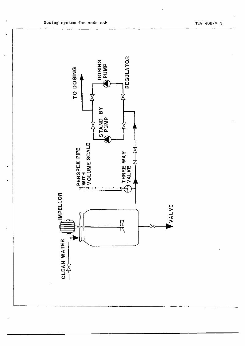
b. p_pg_~j~~~
For pH correction an alkaline solution of soda ash or causticsoda can be added with the aid of a dosing pump. For a propercorrection the rate of dosing flow must be calculated andadjusted correctly.
CLEAN WATER
4. StM4ARY
Neutralization is protecting construction materials of the watersupply system against corrosion by adjusting the pH of the water to anormal level (7.5 to 8.0) with the aid of’ neutralization systems.
PERSPEX PIPEWITH
TO DOSING
THREE WAYVALVE
VALVE
Fig. 4. Pump dosing systems.


Module NEUTRALIZATION Code : TTG 400
Edition : 18—03—1985
Annex VIEWFOILS Page : OlofO5
TITLE CODE
1. Aeration
2. Lime stone filtration
3. Lime saLurator
4. Dosing system for soda ash
TTG 400/V 1
TTG 400/V 2
TTG 400/V 3
TTG 400/V 4


Aeration TTG 400/V 1
AERATEDWATER
CASCADEAERATOR
RESERVOl
FLAT TRAYS
MULTIPLE TRAY AERATOR


Lime stone filtration TTG 400/V 2
RAW WATERINLET
FILTERED WATEROUTLET
FILTER BOTTOM


Lime saturator TTG 400/V 3
LIME SOLUTION
— ~ DOSING
VALVE A
CLEAN WATER
WATERMETER
SATURATEDWATER
OVERFLOW
LUIDIZED BED OF LIME
WATERINJECT ION
SATURATOR

Dosing system for soda ash TTG 400/V 4
0~z(I,0O0I.-
0I-cC-J
LU
LULU~- cC— C.)
C,)>< LU
r~i-LU—Q_ >
>-
wwLi>
IcCF->
0-J-JLU0~
LU>-JcC>
LUF-cC
zcCLU-I0

- Head of Technical Department;— Head of Section Production;- Head of Sub--section Water Treatment;— Water Treatment Plant Operator;— Head of Sub—section Laboratory.
Handling/dosing/mixing/commercial strength/solu-tion strength/dosing tank/mixing tank/gravity/feed dosing systems/hydraulic mixers/mechanicalmixers.
~.iiI~ DEPARTMENT
DIRECTORATE
_______ DIRECTORATE
OF PUBLIC WORKS
GENERAL CIPTA KARYA
OF WATER SUPPLY
MDPPDHVTGI
IWACO
Module : CH~4ICALSHANDLING, DOSINGAND MIXING
Code : TTG 500-
Edition : 18—03—1985
Sectioni: INFORMATION SHEET Page : OlofOl/21
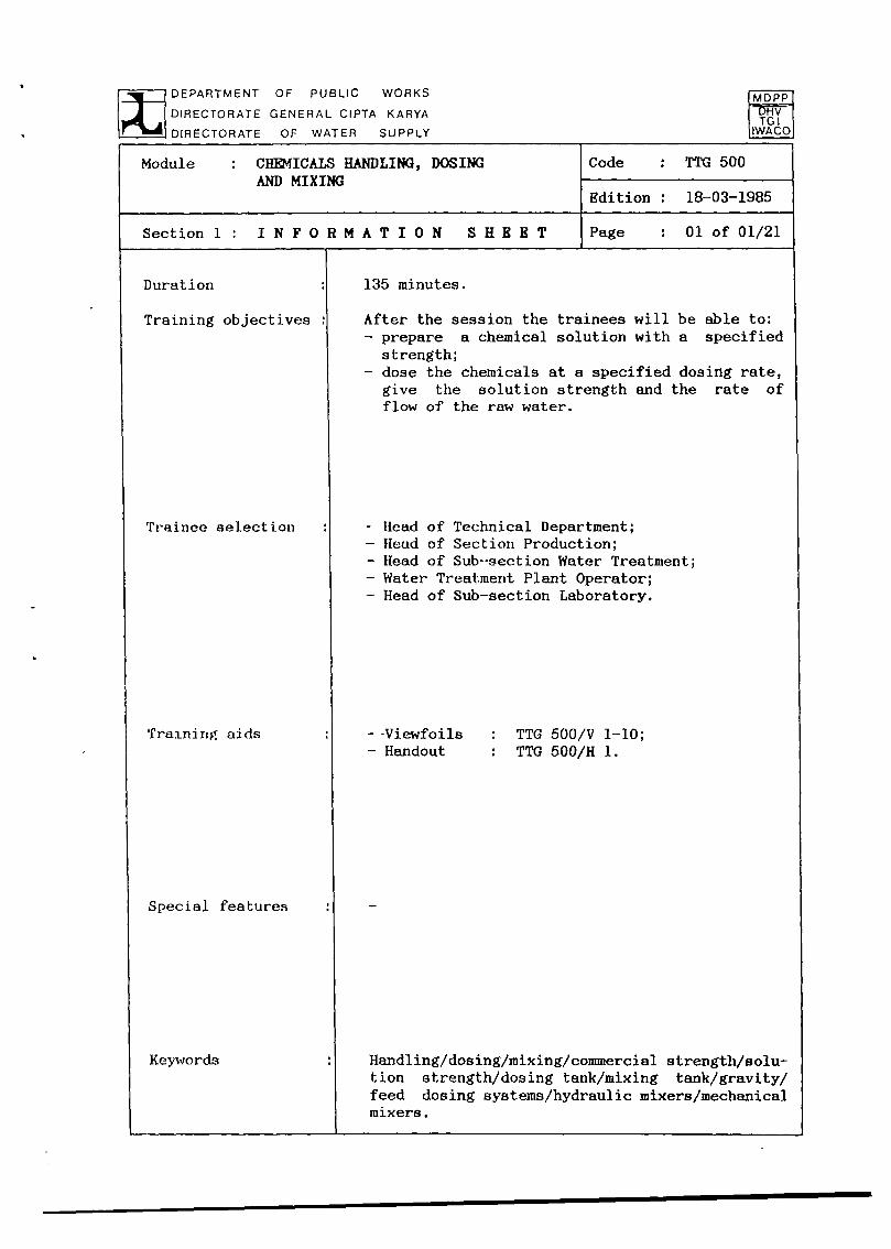
135 minutes.
After the session the trainees will be able to:— prepare a chemical solution with a specified
strength;— dose the chemicals at a specified dosing rate,
give the solution strength and the rate offlow of the raw water.
Duration
Training objectives
Trainoc selection
Training aids
Special features
Keywords
- -Viewfoils— Handout
TTG 500/V 1—10;TTG 500/H 1.

Module : CU~iICALS HANDLING, DOSINGAND MIXING
Code : TTG 500
Edition : 18—03—1985
Section 2 S E S S I 0 N - NO T E S Page : 01 of 04
1. Introduction
— The chemicals used most often in watertreatment are:
alum for the coagulation/flocculationprocess;soda ash or lime for neutralization and/or pH correction;kaporit for disinfection.
— Chemicals are available in powder form,packed in bags or barrels.
— Chemicals have to be stored:to ensure continuity of the process.
— The places where chemicals are dosed nor-mally are:
alum and soda ash or lime at the coagu—’Lation/flocculatjon basin;soda ash or lime at the neutralizationat the end of the treatment process;
- kaporit for disinfection just beforeclear water storage and distribution.
2. Properties -Chemicals have quite differentances.
- Available forms are:blocks;powder; -
crystals;liquid.
- The commercial strength indicates theamount of usable compound in the bulk ofchemical (chemical in commercial form willnever be pure but contain some foreigncompounds).
— Chemicals can be:corrosive;explosive;poisonous.
Use whiteboard
Show V 1
Show V 2appear—

— The solution strength is the strength ofthe dosed solution.
4. Operation
— Operation activities can be divided into:preparing a solution;dosing the solution;mixing of the solution with water.
— Solution strength.a L0~ solution means 10 kg of chemi-cal + 90 kg of water;a 1% solution means 1 kg of chemical +
99 kg of water;1 kg of water equals 1 liter;
. commercial strength of the chemicalshas to be taken in account.
— Chemicals are prepared in a mixing tank.
— Preparation of a chemical solution isdone by:
• filling a tank with a known amount ofwater;calculating the amoumt of chemicalwhich must be added for obtaining thedesired solution strength;
• weighing out the desired amount ofchemical;mixing the chemical with the water.
Module : CH~4ICALSHANDLING, DOSINGAND MIXING
Code : TTG 500
Edition : 18—03—1985
Section2 : SESSION NOTES Page : 02of04
3. Storage and handling
— Chemicals have to be imported.
— Handling and storage of chemicals asks formechanical equipment;storage building with a large capacity.
Use whiteboard
Use whiteboard
Show V 3
Show V 4Use whiteboard


— Chemicals can be added to the water:• as a powder or slurry;
as a solution (the most common way).
— Solution feeders consist of:• a dosing tank;
• a dosing rate of flow controller.
— There are two kinds of dosers:• gravity feed;• displacement pumps or tippers.
— Basically there are two groups of mixers:• hydraulic mixers;• mechanical mixers.
— Hydraulic mixers are:• baffled channels;
• overflow weirs;• hydraulic jumps.
— Mechanical mixers need power for theagitation of the water by propellors orturbines.
Note: - - - -
ALWAYS TAKE CARE WHEN HANDLING CHEMICALS.USE PLASTIC OR RUBBER HANDGLOVES. WEARPROTECTIVE CLOTHES AND COVER NOSE ANDMOUTH.
— The following problems may occur when Use whiteboardhandling chemicals:
- . the prepared solution doesn’t have thecorrect strength; -the dosing rate is not correct;
• not all the necessary chemicals are
Module : CB~4ICALSHANDLING, DOSING
AND MIXINGCode : TTG 500
Edition : 18—03—1985
Section 2 : S B S S I 0 N N 0 T B S Page : 03 of 04
Show V 3
Show V 5
Show V 6—7
Show V 8
5. Proble.s
storein

V

— The following measures have to be taken inorder to avoid the above mentioned pro—b lems
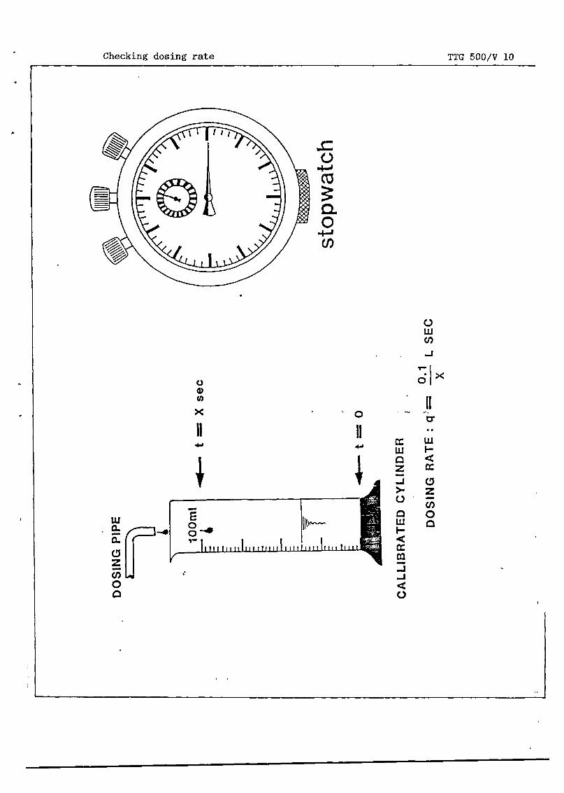
checking of the solution strength byusing a Baumè meter;checking the dosing rate with a cali-brated cylinder and a stopwatch;record keeping of the chemical use andthe chemicals still in store and order-ing new chemicals when the time thequantity still in store will last, isonly slightly more than the time neededfor delivery.
Module : CHEMICALS HANDLING, DOSINGAND MIXING
Code : TTG 500
Edition : 18—03—1985
Section2: SESSION NOTES Page : 04o104
Show V 9
Show V 10
6. Summary Give H 1


Module : CH~4ICALSHANDLING, DOSINGAND MIXING
Code : TTG 500
Edition : 18—03—1985
Section3: TRAINING AIDS Page : OlofO2
Chemical dosing TTG 500/V 1points
UMS 0*ALUM SODA ASU
.*DlsI.TA,IOS .L~I:~~
~ L
\tI•‘~V.AVa- I
VA.A0 WATOMSIDTSAAJ*A:.o: ITOSA~
Properties of chemicals TTG 500/V 2
~. nvsaasa o..aa PTWS S~S~
eLba. WI 1CT1
Atsa ~S .. ,, . ~ ~—
~ ~: :....~~
EAAOI ~ SD. IS a, ~
Mixing tank TTG 500/V 3
~ ALbMIOAOIW
PVC Pfl- •.~
OOS5TUM~ --
~0
Preparation of TTG 500/V 4solution
0. DALb~ATI
~V • I. ~J, .
~‘
~ *50W ?W SI SI
Gravity feed doser TTG 500/V 5
~~,‘-_
- SIOULATISS TUM1AT~CSSIS(S
.
Hydraulic mixing TTG 500/V 6~*5~__
SO~tiSSODS
~ aSS SW SD COASALSOT,_ S_A,,,_*p aunt
~ Poy Is co~ouo.,
~_
Fm POt SD COaalaAMT
~
~
S. Wyman
—WATER TISXT
JOIST
0 WATtS TANS


VO_,
1W
TO PtOba.ATOS
MEcRAJ1.DcAL RAPID MXW’~G
Module : CH~4ICALSHANDLING, DOSINGAND MIXING
Code : TTG 500
Edition : 18—03—1985
Section3: TRAINING AIDS Page : 02of02
Hydraulic mixing - TTG 500/V 7(lime saturator)
— S_s
.4. s.ST,cS flit.
Mechanical rapid TTG 500/V 8mixing
Baumé meter TTG 500/V 9
M-PSI. 5500 SIneS
Checking dosing TTG 500/VlOrate
CMLIS*ATIS Cfl*SS
SODaS RATS II — 1_! t uc
Chemicals handling, TTG 500/H 1dosing end mixing
— , — 5 S..

DEPARTMENT OF PUBLIC WORKS IMOPP
rk4DIRECTORATE GENERAL CIPTA KARYA [9~y
______ DIRECTORATE OF WATER SUPPLY IIWACO
Module CHJ*!ICALS HANDLING, DOSINGAND MIXING
Code : TTG 500.
Edition : 18—03—1985
Section4 : HANDOUT Page : 01 of 14
1. INTRODUCTION
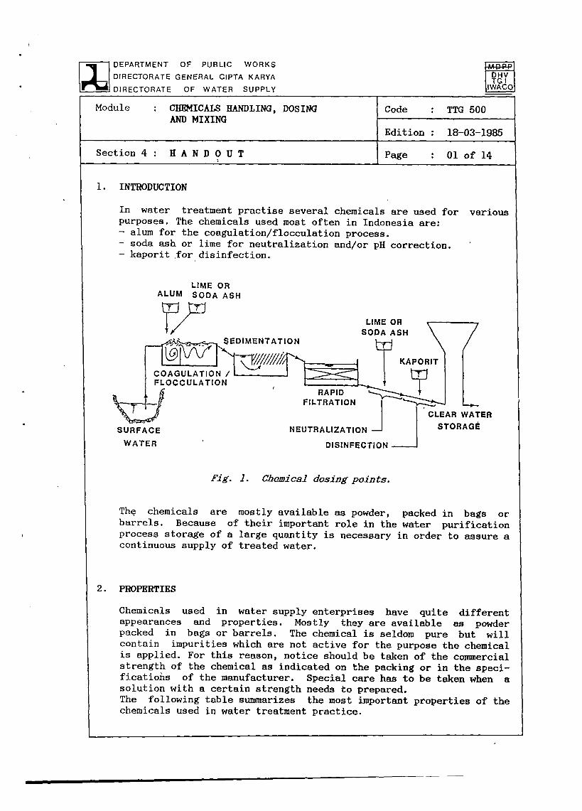
In water treatment practise several chemicals are used for variouspurposes. The chemicals used most often in Indonesia are:— alum for the coagulation/flocculation process.— soda ash or lime for neutralization and/or pH correction.— kaporit for disinfection.
LIME ORALUM SODA ASH
DISINFECTION
Fig. 1. Chewiccl dosingpoints.
The chemicals are mostly available as powder, packed in bags orbarrels. Because of their important role in the water purificationprocess storage of a large quantity is necessary in order to assure acontinuous supply of treated water.
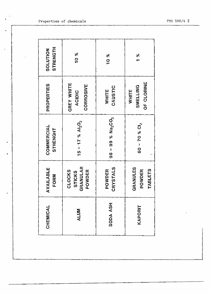
2. PROPERTIES
Chemicals used in water supply enterprises have quite differentappearances and properties. Mostly they are available as powderpacked in bags or barrels. The chemical is seldom pure but willcontain impurities which are not active for the purpose the chemicalis applied. For this reason, notice should be taken of the coimnercialstrength of the chemical as indicated on the packing or in the speci—ficatiohs of the manufacturer. Special care has to be taken when asolution with a certain strength needs to prepared.The following table summarizes the most important properties of thechemicals used in water treatment practice.
SEDIMENTATION
LIME ORSODA ASH
ULATION
SURFACE
WATER
RAPIDFILTRATION
NEUTRALIZATION
CLEAR WATERSTORAGE


Module : CHEMICALS HANDLING, DOSINGAND MIXING
Code : TTG 500.
Edition : 18—03—1985
Section 4 : H A N D 0 U T Page : 02 of 14
COMMON CHEMICALS USED IN WATERTREAThIENT
Chemical Conunon Use Avail— Connner— Appear. Usualname and name able cial and solutionformula forms strength propert. strength
Alum
Sodaash
Burntlime,chemicallime,unslakedlime
Hydratedlime,slakedlime
Kaporit
Alumo iumsulphateA12 (SO4)3
Sodiumcarbo-nateNa2 COn
CaO
Calciumhydro-xideCa(OH)2
Calciumhypocblo—riteCa( OC1)2
Coagu-lant
pHadjust-ment,neutra-lization
pHadjust-ment andneut ra—lization
pHadjust-ment andneutra—lizat ion
Dis in-fection
Blocks,sticks,lumps,granu—lespowder
Powderorcrys-tals
Lumps,pebblesgran-ules,powder
Powder
Granu-les,powder,tab lets
15—17%Al2 O~
98—99%Naa COn
75—99%
80—95%Ca(OH)2
60—70%CaO
60—70%avail-ablechlo-rineCl2
Grey—white tolightbrown,crys-tallineacidic,corro—aiveslightlyhygro—scopic
Whitepowder,caus-tic
Whitetolightgrey,caus-tic
Whitepowder,caus-tic
Whitegran-ules,smellingof chlo-rine,explo-sive
8—10%
1—10%solu—t ion
1—5%so lu—t ion
Satu-ratedor1—5%suspen—Sion
1-3%avail-ablechlori-ne so—lution

Module : CHEMICALSHANDLING, DOSINGAND MIXING
Code : TTG 500.
Edition : 18—03—1985
Section 4: HANDOUT Page : O3of 14
3. STORAGEAND HANDLING OF CHEMICALS
In many Asian countries chemicals have to be imported and arrive atthe works in bags or drums. In larger cities it is increasinglylikely that delivery will be made by bulk carriers designed to trans-port powders that may be unloaded pneumatically, or liquids which canbe pumped.
On small—to—medium works in developing countries,nally large consignments of bags or drums carryingto be handled and stored. At typical dosagesized works of, say, 25.000 nP/day output,of chemicals daily. Thought should thereforeloading, storage and daily transportationparticularly when these are at high level.works in countries where labour is cheap andmechanic~1 equipn~ent is necessary. In itsmerely. comprise hand trolleys and a hoist,
rates, even a moderatelywould use over one tonnebe given to initial off—to the solution tanks,At all but the smallestplentiful, some sort ofsimplest form this maybut in bigger installa-
tions highly sophisticated bulk handling machinery can be justified.Such machinery is rarely designed only for waterworks but is similarto that used in installations handling sugar, flour, lime or similarsubstances. The equipment is normally bought as a package either fromwaterworks plant manufacturers or from the makers of the individualitems.
4. OPERATION
Operation activities can be subdivided into:— preparing a solution of the chemical to be applied;— dosing of the solution to the water to be treated;— mixing the chemical solution with the water to be treated.
Preparing a solution
In preparing solutions of any chemical it should be noted that a 5%solution means that 5 parts of the chemical should be added to 95parts of water (by weight) to get 100 parts of solution, and so on.An 8% solution would contain 8 kg of chemical to 92 kg of water. (1kg water equals 1 liter).Percentages normally relate to the actual substance (e.g. alum, lime)being handled and not to any of the basic elements (e.g. calcium,aluminium) therein included.
however, occasio—the chemicals have


I.
Module : CHEMICALS HANDLING, DOSINGAND MIXING
Code : TTG 500.
Edition : 18—03--1985
Section 4 : H A N D 0 U T Page : 04 of 14
A - CALCULATEV In liters
x x ~H ~ V ItSri
- 1. ALUM, SODA ASH (10%)— V x 100
V x 100 g/z ~ooo k~
B - 2. KAPORIT (1%)V x 10
V x 10 g/e— kg1000
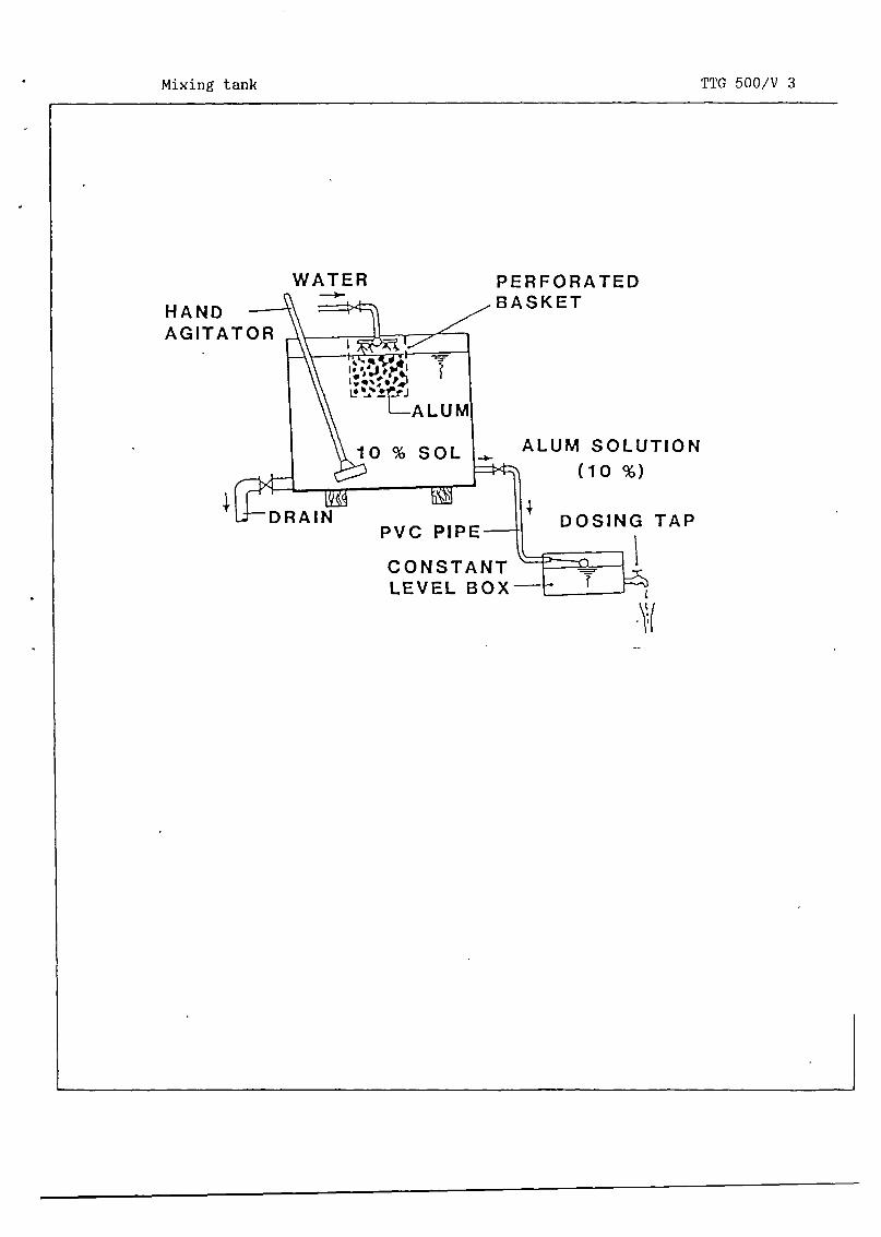
MIXING TIME 20 - 30 MIN
Fig. 2. Preparation of solution.
Chemicals are prepared in a special mixing tank which 18 suited tohold the chemical to be prepared.
The preparation of a solution can be done as follows:
— Fill the mixing tank with a certain amount of water.
— Calculate the amount of water by measuring the volume of wateradded to the tank. This volume is called V liters : 1 liter waterequals 1 kg in weight.
clear water
©


Module : CHEMICALS HANDLING, DOSINGAND MIXING
Code : TTG 500.
Edition : 18—03—1985
Section 4 : H A N D 0 U T Page : 05 of 14
— Calculate the amount of chemical required to obtainsolution strength (see table in par. 2). -
For instance : for a 10% solution (alum or soda ash)we have to add 0.1 * V kg of pure chemical.We have to take the commercial strength (s%) in account,to add : (100/a) * 0.1 * V (kg) of the available powder.
the correct
so we have
— Enter the amount of weighed chemical.(Note : Some chemicals are toxic, explosive (kaporit) or
violent reactions when added to the water (unslakedso care must be taken).
— Mix during 20—30 mm.
— Stop mixing and let solids settle. Normally the settled solidsconsist of impurities or CaCO3, formed by the addition of thechemical. These do not influence the strength of the solution.
— Check the strength of the solution by using a Baumé meter.
Chemical dosing -
Chemicals can be added to the water either as a solution, which isthe most usual way, or in powder or slurry form. As treatment is acontinuous process, dosing must also proceed in a continuous andcontrolled fashion.
Solution feed -
The two essential parts of a solution feed system comprise a tank inwhich a solution of the correct strength may be stored, and a dosingrate—of—flow controller. The tank should hold 24 h supply and beduplicated so that one tank may be in service while the other isbeing replenished. There should be some sort of continuous stirringmechanism to obviate the risk of settlement after initial prepara-tion. Many chemicals (particularly alum and kaporit) are corrosiveand the tanks should be lined with acid—resisting material, commonlyrubber, glass or special cement.
causelime)


Module CHEMICALS HANDLING, DOSINGAND MIXING
Code : TTG 500
Edition : 18—03—1985
Section 4: HANDOUT Page : 06o1 14
DISCHARGE OVER INLETOF WATER TANK
Fig. 3. Cravity feed doser.
The dosing mechanism should be capable of being controlled manually.There are two kinds of dosers : gravity—feed, and displacement pumpsor tippers. The rate of flow can be altered in the former by adjust-ing the outlet valve in a constant—head tank, in the latter by alter-ing the length of piston stroke of the specially made plunger pumps.The speed at which tippers operate can also be regulated. In bigworks of sophisticated design, dosing can be controlled automatical—
ly. -
A dry feeder incorporates a hopper which contains the powder andfeeds a measuring device. This often takes the form of a revolvingtable from which a scraper of adjustable length deflects a greater orlesser amount of powder into the raw water. If the powder is not verysoluble it may be mixed with water and fed as a slurry, like in thelime saturator that is used to neutralize the water by saturationwhen it passes a lime suspension. In humid, tropical conditions,trouble by ‘caking’ is sometimes experienced on dry feeders and forthis reason solution feeders are preferred.
FLOATINGBOWL
REGULATING TIJ~EPLASTIC, RUBBEROR GLASS
JOINT


Module CHEMICALS HANDLING, DOSINGAND MIXING
Code : TTG 500
Edition : 18—03—1985
Section 4 H A N D 0 U T Page : 07 of 14
LIME MILKSERVICE WATER
4
Fig. 4. Hydraulic mixing in lime saturator.


Module : CHEMICALS HANDLING, DOSINGAND MIXING
Code : TTG 500
Edition 18—03—1985
Section 4 : H A N D 0 U T Page 08 of 14
Most feeders lend themselves to automation, with the rate of flow ofchemical dependent on the rate of flow of water through the works. Ona small (or unsophisticated) works, where the rate of flow tends tobe constant, the simplicity of manual regulation is much to be pre-ferred.
Dosing appliances are mostly of proprietary make and they vary widelyin detail, their mode of operation being described in the variousmakers’ literature.
Mixing
Many devices are used to provide mixing for the dispersal of chemi-cals in water. Basically, there are two groups:— hydraulic mixing;— mechanical mixing.

Module : CHEMICALS HANDLING, DOSINGAND MIXING
Code : TTG 500~
Edition 18—03—1985
Section 4 : H A N D 0 U T Page : 09 of 14
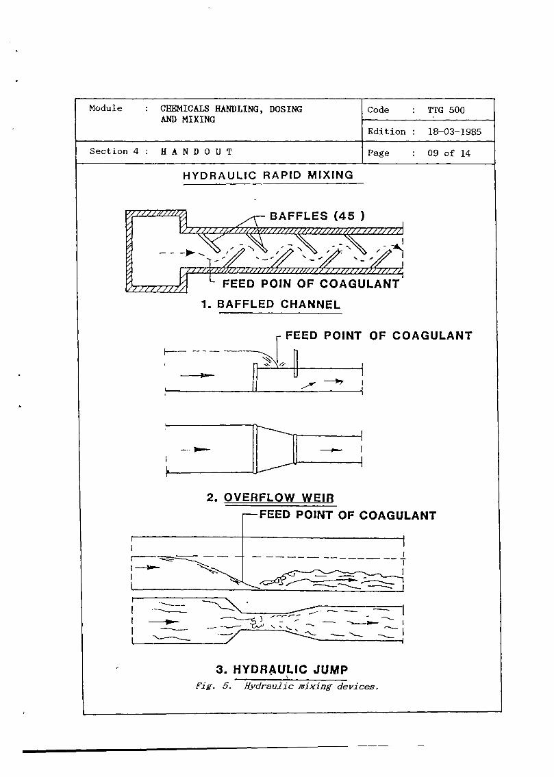
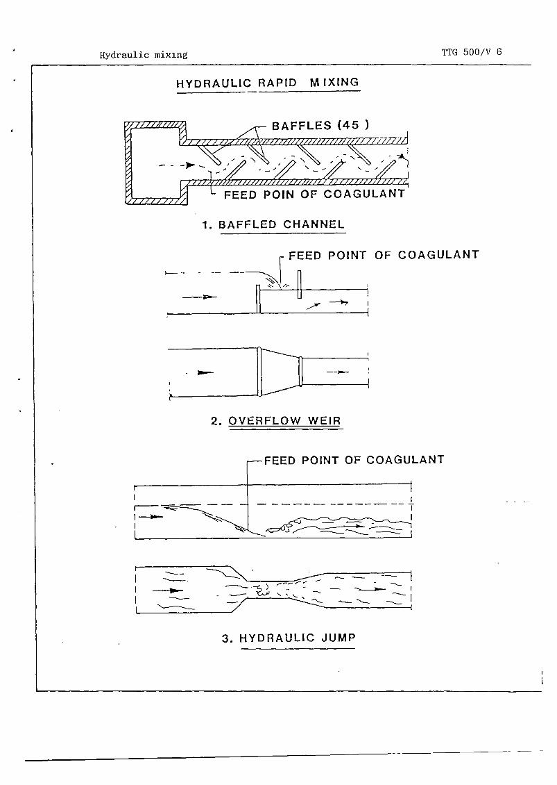
HYDRAULIC RAPID MIXING
1. BAFFLED CHANNEL
FEED POINT OF COAGULANT
-1
2. OVERFLOW WEIR—FEED POINT OF COAGULANT
r
-
~
-----------------4
III
•~-:::~:::~
—~ - -— --S--—--- - ~ S
~
—.
~
—-
p.—
~
II
~
3. HYDRAULIC JUMP
FEED POIN OF COAGULANT
I-—
Fig. 5. Hydraulic mixing devices.


Module : CHEMICALS HANDLING, DOSINGAND MIXING
Code : TTG 500
Edition : 18—03—1985
Sect ion 4 : H A N D 0 U T Page : 10 of 14
~~kc ~
For hydraulic mixing, arrangements are used such as : channels orchambers with baffles producing turbulent flow conditions, overflowweirs and hydraulic Jumps. Mixing may also be achieved by feeding thechemicals at the suction side of pumps. With a good design, a hydrau—lic mixer can be as effective as a mechanical mixing device.
~
With mechanical mixing the power required for agitation of the wateris delivered by impellers, propellors or turbines.
CHEMICAL FEED
.~Yjg. C. Nechanical mixing device.
ELECTRIC MOTOR
TO FLOCCULATOR


Module : CHEMICALS HANDLING, DOSINGAND MIXING
Code : TTG 500
Edition : 18—03—1985
Section4 : HANDOUT Page 11 of 14
Generally, mechanical rapid mixers are less suitable for small treat-ment plants than hydraulic ones since they require a reliable andcontinuous supply of power.
Note:
ALWAYS TAKE CARE WHENHANDLING CHEMICALS. USE PLASTIC ORHANDGLOVES, WEARPROTECTIVE CLOTHES AND COVER NOSE AND MOUTH.
5. PROBLEMS
The next problems can be experienced when handling chemicals:
Prepared solution doesn’t have the correct strength.
RUBBER
When preparing a solution with a required strength, a certain amountof chemical must be added to a certain amount of water. The chemicalmust be obtained from a bulk source with a certain commercialstrength which has to be taken in account. Improper calculation caneasily lead to an incorrect strength of the solution prepared. Toavoid mistakes, the strength of the solution can be checked by usinga Baumé meter.
CHECKING THE SOLUTION STRENGTHWITH A BAIJME METER:
— Fill a 500 ml calibrated cylinder with the prepared solution.
— Enter the Baumé meter. The meter will float more of less accordingto the density of the solution.
— Read the figure indicated on the meter at the liquid levelaccurately. The result is in Baumé degrees (see table).
— Convert the value into the density using the table.
— Convert the density into the solution strength using the table.


Module : CHEMICALS HANDLING, DOSINGAND MIXING
Code : TTG 500
Edition : l8—03--l985
Section 4 : H A N D 0 U T Page : 12 of’ 14
wF-.w
w
0F-I—0
0crLL.
LULU
LU
z-J>-
C-)
LUF-
-J
C-)
E00It)
C,,E0a,
I 1
Fig. 7. Use of Rauw~meter


Module : CHEMICALS HANDLING, DOSINGAND MIXING
Code : TTG 500.
Edition : 18—03—1985
Section 4 : H A N D 0 U T Page : 13 of 14
Relation between the density and the concentration of solution ofalum, soda ash, kaporit (grams of pure product per litre of solutionat 15 CC)
BaumeDegrees
Densitykg/ltr.
AluminiumsulphateA12(S04)318 H20
Soda ashNa2CO3
CalciumhypochloriteCa(OC1)2
°Be kg/liter c (g/1) c (g/l) c (g/1)
123456789
10ii121314151617181920
1.0071.0141.0211.0281.0361.0441.0511.0591.0671.0751.0831.0911.0991.1081.1161.1251.1341.1431.1521.161
142842577389
103119135152168184200218235255274293312332
6.313.119.52935.441.150.858.867.976.185.093.5
101.2110.6122131141.5150.5162.5
—
2.85.58
10.5131618.521232527.5303234363840
—
—
—
The dosing rate is not correct
One should check the dosing rate regularly and adjust if necessary.The dosing rate should be in accordance with the dose required, whichis:
— for alum: —- - -
the optimal dose as determined by the jar test.Normally this dose will vary between 5 and 15 mg/i alum.


Module : CHEMICALS HANDLING, DOSINGAND MIXING
Code : TTG 500
Edition : l8—03--1985
Section 4 : H A N D 0 U T Page : 14 of 14
—
a dose which will lead to a residual chlorine content in the dis-tribution system of 0.2 — 0.5 ppm.
— for alkaline solutions:a dose which will lead to the pH value desired (as determined bythe jar test).
For instance : a calibrated cylinder of 100 ml is filled in 20seconds (use stopwatch) by the discharge of the dosingpipe).
The dosing rate : 100 ml 5 mi/sec 18 1/hour20 sec
No chemicals in store
As treatment is a continuous process, dosing must also proceed in acontinuous fashion, requiring an appropriate storage of a largequantity of chemicals. To avoid any problems of this type a properrecord must be kept of the chemical use and the chemicals still instore. One should order new chemicals when the time for use of thequantity still in store equals the time which is needed for delivery.
Chemicals used mostkaporit and lime orcarefully since mostconsists of preparingsolution with the water.
often in water treatment practise are alum,soda ash. Handling of chemicals must be donechemicals have dangerous properties. Handlinga solution, dosing the solution and mixing the
The dosing rate can always be checked manually bybrated cylinder with the discharge of the preparedpipe, and measuring the time that elapses for a 100
filling a cali—solution dosing
ml discharge.
6. SUt44ARY


Module : CHEMICALS HANDLING, DOSINGAND MIXING
Code : TTG 500
Edition : 18—03—1985
Annex : VIEWFOILS Page : Olofll
TITLE CODE
1. TTG 500/V 1
2. TTG 500/V 2
3. TTG 500/V 3
4. TTG 500/V 4
5. TTG 500/V 5
6. TTG 500/V 6
7. TTG 500/V 7
8. TTG 500/V 8
9. TTG 500/v 9
10. TTG 500/V 10
Chemical dosing points
Properties of chemicals
Mixing tank
Preparation of solution
Gravity feeding doser
Hydraulic mixing
Lime saturator
Mechanical rapid mixing
Baume meter
Checking dosing rate


Chemical dosing points
I
LUF-
TTG 500/V 1
LUF-
LU-J0
LUa
0I—C’)
03-
0<
C,,
z0F-0LULi-zci)a
a0~
z0z —o
—
I— N-J
I—
LUzz0
F-
I-.zLU
aLUC/) -.5-
z0I—
-J
0U—
-J
00
LU0
IL.
U)

Properties of chemicals TTG 500/V ~
z~2c.~F-Z~W
OF-0(1)
0‘-
0‘-
1~
~,,LU~~LU3-0~~
LU w~XO~~ao>-0—~
LU<~a 0
oW~
~C”I~~
LUaz
WZ~~J0~~
C’)~
J
~F-~I~aW~~
~F—0U)0
0<
~
N-‘-
I
Lt)~-.
C,,00
c’1c~z~C)C)I
coC)
r..~
C-)~0F’-
‘0
-~
LU
r~,~~
~LL
<
ECU)U)<~~c~-lW0C)~00
QU)~.
C’)~W~aF-~U)0>~3-~
~jWF-~aw~<0<~3-F-
-J
<2~LUI0
J
<
IU)<<
a0~
03-<~

Mixing tank TTG 500/V 3
HANDAGITATOR
(10 %)
DOSING TAP
WATER PERFORATEDBASKET
ALUM SOLUTION
PVC PIPE
CONSTANTLEVEL BOX


Preparation of solution TTG 500/V 4
a)
C)ol010 0I—5
~ >(l’-’II- 100> )<Io~ ‘— I
II >1; i IIII COI< ~
L.. ~ __LU ~ _ 0
0 • _x z
~ > >0C,,
0 I
I 0C.’l
LU
az>(
1~
a,CD
I-.
CDa,C)
8


Gravity feeding doser TTG 500/V 5
CONTAINER
FLOATINGBOWL
REGULATING TUBPLASTiC, RUBBEF
OR GLASS
WATER TIGH1
JOINT
DISCHARGE OVER INLET
OF WATER TANK

Hydraulic mixing
HYDRAULIC RAPID MIXING
TTG 500/V 6
1. BAFFLED CHANNEL
FEED POINT
U
OF COAGULANT
2. OVERFLOW WEIR
—FEED POINT OF COAGULANT
r- I
I
[--------------------+
~
3. HYDRAULIC JUMP
BAFFLES (45 )
FEED POIN OF COAGULANT
-


Lime saturator TTG 500/V 7
LIME MILKSERVICE WATER


Mechanical rapid mixing TTG 500/V 8
CHEMICAL FEED
MECHANICAL RAPID MIXING
ELECTRIC MOTOR
TO FLOCCULATOR


Bauine meter TTG 500/V 9
0I—I—0
0
U-LULUU-
LUaz-J>-.
0aLUI-
-J
0
E00Lt)
C,,E0
a,
ccLUI-LU
LU

Checking dosing rate TTG 500/V 10
C-).4~JCo
0(I)
0LUC,)-J
‘—I
0a)
Cl) •II>< a.
U.’LU I—a <z ~
aI>- z10.~
a 0U.’ U.’3- F- a
c~az —
-J5. -J
0a C.)
ii* *


~L
DEPARTMENT OF PUBLIC WORKS
DIRECTORATE GENERAL CIPTA KARYA
______ DIRECTORATE OF WATER SUPPLY
Module : OPERATIONOF WATERTREAThENTFACILITIES — SURFACEWATER
Code : TTO 051
Edition 18—03—1985
Section 1: INFORMATION SHEET Page : OlofOl/15
— Head of Sub Section Water Treatment;— Water Treatment Plant Operator;— Plant attendant;— Intake attendant.
- Viewfoils : TTO 051/V 1—7;— Handout : TTO 051/11 1.
Package plants/standard treatment plants/startprocedure/water intake/chemical dosing/sludgewithdrawl/backwashing/water treatment plant con-trol/shut down procedure.
MDPPDHVTGI
IWACO
90 minutes.
After the session the trainees will be able to:— construct a typical surface water treatment
scheme;— recite the steps to be taken at the start and
the shut down procedure;— mention four important operation procedures;— recite the observations to be made continuous-
ly by the operator.
Duration
Training objectives
Trainee selection
Training aids
Special features
Keywords

A

Module : OPERATION OF WATERTREANENTFACILITIES — SURFACEWATER
Code : TTO 051
Edition : 18—03—1985
Section2 : SESSION NOTES Page : OlofO4
1. Introduction
— In Indonesia there are two main typessurface water treatment plants.
package plants as built by:Sumber Tjipta Djaja (STD),Boma Stork (BS),Wijaya Kusuma (WK);standard treatment plants asDirektorat Air Bersih (DAB).
— All plants follow a typicalscheme comprising- surface water intake;
coagulation/flocculation;sedimentation;rapid filtration;neutralization;disinfection.
— The main differences between packageplants anc~1standard treatment plants are:- the water intake is operated automa-
tically or manually;• the chemical dosing is operated automa—
• tically or manually.
— The start—up procedure comprises:preparation of chemical solutions;performance of the jar test;calculation of chemical dosing and flowcapacities;start the intake pumps;adjustment of raw water flow;start chemical dosing;checking and, if necessary, adjustmentof chemical flows.
Use whiteboard
of
built by:
purification
Use whiteboard
Show V 1
Show V 2
2. Main Characteristics
3. Starting Procedure


Module : OPERATION OF WATERTREAThENTFACILITIES — SURFACEWATER
Code : TTO 051
Edition : 18—03—1985
Section2: SESSION NOTES Page : 02of04
4. Operation Procedures
— Package plant STD: Show V 3alum is added for coagulation, in theinlet pipe;soda ash is added for pH correction;
• mechanical flocculators are used;• sedimentation takes place in a tray
settler unit;• the backwash water of the filter takes
the impurities at the filter and traysettler to the sludge outlet;surface washing can be applied to loosenthe impurities at the top of the filter—bed;kaporit is added to the clear water fordisinfection.
— Package plant BS: Show V 4alum is dosed for coagulation, in theinlet pipe;
• flocculation is favoured by corrugatedplates;
• sedimentation takes place in tubesettlers;rapid filtration is at a constant rate;backwashing is performed by an addition-al air scour;
• soda ash is dosed for neutralization;kaporit is dosed for disinfection.
— Package plant WK: Show V 5alum is dosed for coagulation, in theinlet pipe;flocculation and sedimentation arecombined in a sludge blanket unit;
• rapid filtration takes place at a con-stant rate;backwashing is performed by an additi-onal air scour;
• soda ash is dosed for neutralization;kaporit is dosed for disinfection.


takes place at tilted
5. Water Treathent Plant Control
Show V 6
Show V 7
During operation:
— The following observations have to be madecontinuously by the operator:- raw water is flowing to the intake;- raw water is flowing into the plant;
• chemical solutions are dosed;- flocs occur in the flocculator;- sediment is accumulating in the settler;- sludge withdrawal occurs properly;- water level in the filters is rising
slowly.
Use whiteboard
Show V 1Point at the placesthat require observa—t ion
Module : OPERATION OF WATERTREANENTFACILITIES - SURFACEWATER
Code : TTO 051
Edition : 18—03—1985
Section2 : SESSION NOTES Page : 03of04
— Concrete water treatment plant DAB:- alum is dosed for coagulation, at an
overflow weir;- flocculation is obtained by hydraulic
chambers;- sedimentation
plates;- rapid filtration takes place at a
declining rate;filters are backwashed one by one withthe product water of the other filters;lime is dosed for neutralization;
- kaporit is dosed for disinfection.
— Steel water treatment plant DAB:- alum is dosed for coagulation, at an
overflow weir;- flocculation is obtained by hydraulic
chambers;- sedimentation takes place at tilted
plates;rapid filtration takes place at a decli-ning rate;filters are backwashedone by one withthe product water of the other filters;lime is dosed for neutralization;kaporit is dosed for disinfection.


— The following figures must be obtainedseveral times per day by the operator:- raw water flow Q;
• alum dosing flow ql;• alkaline dosing flow q2;- kaporit dosing flow q3;- water level in clear water reservoir;- pH and turbidity of raw water, settled
water, filtered water and clear water;- free and total chlorine in distributed
water;- amounts of chemicals used;- amounts of chemicals in stock.
— The following daily activities are re-quired for proper operation- execute the jar test and adjust the
coagulant dose if necessary;- prepare chemical solutions;- execute sludge withdrawal if not done
automatically;- execute backwashing if not done automa-
tically;- remove sediments from the dosing tanks
and flocculators;- write any action in the logbook.
6. •Shut D~n Procedure
— The shut down procedure comprises the fol-lowing steps:• stop the intake pumps;- stop the dosing of chemicals if not done
automatically.
— Shut Down Procedure is required when:- the clear water reservoir is filled;- new chemical solutions have to be pre-
pared;- the intake pumps are not able to ab-
stract water;- repair of one treatment unit is necessa-
ry;cleaning of the plant is necessary.
Module : OPERATIONOF WATERTREATMENTFACILITIES — SURFACE WATER
Code : TTO 051
Edition : 18—03—1985
Section2: SESSION NOTES Page : 04of04
Use whiteboard
Show V 1Point at the placeswhere figures must beobtained
Use whiteboard
Use whiteboard
7. Give H 1


Module : OPERATIONOF WATERTREATMENTFACILITIES — SURFACEWATER
Code : TTO 051
Edition : 18—03—1985
Section3 : TRAINING AIDS Page : OlofO2
Surface water TTO 051/V 1treatment
L14110~LIUW lOSS SINcD,j2~
, ? :~::~:•~~
Sonnet NIUTOALIZA DOS
Watip 01511C7W0 -
Operation of water TTO 051/V 2treatment plant
Package plant “STD” TTO 051/V 3
Se~N IAPW
,LncAaAT~s TAflOS PtflATI
— COMCTIOS 1M0t
~Ijb~JJ~
Package plant “BS” TTO 051/V 4
II? ~TW1aSK~AflOS
I
Package plant “WK” TTO 051/V 5
.LOCaP.ATTOWSISIINTAflO. ~APS PtTtAY.O4
Concrete water treat— TTO 051/V 6ment plant (DAB)
I_sn.ocaano. SLSUTATIOM fl3SaflOS
5.L$ ~i
~


Module : OPERATION OF WATER TREATMENTFACILITIES — SURFACEWATER
Code : TTO 051
Edition : 18—03—1985
Section3: TRAINING AIDS Page : 02of02
Steel water treatment TTO 051/V 7plant (DAB)
I_sIt•C~S.nnO_ N0D5?ATTO ,W.TWAflO
L.a 5.4 ~ L4 ~4
S
Operation of surfacewater treatment plants
TTO 051/H 1

S
1. INT1~DUCTION
MDPPOHTG
IWACO
This module deals with the main characteristics of 2 types of surfacewater treatment plants namely:
— Package plants as built by contractors like:Sumber Tjipta DjaJa (STD plant);Boma Stork (BS plant);
- Wijaya Kusuma (WK plant).
— Standard treatment plants in concrete or steel as builtDirektorat Air Bersih (DAB plants).
by the
For all plantssurface waterSedimentation
- processes.
the purification process follows a typical scheme fortreatment containing Coagulation — Flocculation —
— Rapid Filtration — Neutralization and Disinfection
2. MAIN CHARACTERISTICS
The next table summarizes the main characteristics of the variousplants.
;L1 DEPARTMENT OF PUBLIC WORKS
DIRECTORATEGENERAL CIPTA KARYA
U DIRECTORATE OF WATER SUPPLY
Module : OPERATIONOF WATERTREATMENTFACILITIES — SURFACE WATER
Code : TTO 051
Edition 18—03—1985
Section 4: HANDOUT Page : OlofO8


Module : OPERATION OF WATERTREAThENTFACILITIES — SURFACE WATER
Code TTO 051~
Edition : 17—04—1985
Section 4 : H A N D 0 U T Page : 02 of 08
Table
Plant STD BS WK DAB
Coagulant Alum Alum Alum Alum
Rapid mixing Pipeinjection
Pipeinjection
Pipeinjecton
Overflowweir
p11 correction Soda ash — — —
Flocculator Mechanicalrakes
Corru--gatedplates
Sludgeblanketunit
Hydraulicchambers
Settler Trays Tiltedplates
Sludgeblanketunit
Tiltedplates
Rapid filtration Constantrate
Constantrate
Constantrate
De—diningrate
Neutr. agent — Soda ash Soda ash Lime
Disinfectant Kaporit Kaporit Kaporit Kaporit
3. STARTING PROCEDURE
For any surface water treatment plant thethe following steps:
start procedure comprises
— Preparation of chemical solutions.— Performance of the jar test iii order to determine the optimal dose
of coagulant and optimal pH for flocculation.— Calculation of chemical dosing and flow capacity.— Start of the intake pumps.— ttdjustmiiut of raw water flow.
Start ~-‘f r~hemicn1 dosing : coagulation, neutralization, disinfec-tion.Checking and if necessary adjustment of the chemical flows.


Module OPERATIONOF WATERTREAThIENT Code : TTO 051FACILITIES — SURFACEWATER -
Edition : 18—03—1985
Section4 : HANDOUT Page : 03of08
4. OPERATIONPROCEDURES
Water Intake
The water intake pumps which transport the water from the surfacewater intake to the plant are automatically controlled at the packageplants STD, BS and WK. At the DAB standard treatment plants theintake pumps have to be started manually.
Chemical Dosing
At the package plants the chemical dosing is started automaticallywhen the intake pumps start working i.e. when water is flowingthrough the plant. At the standard treatment plant the chemicaldosing ihust be started manually after starting the intake pumps.
Sludge Withdrawal
At all types of plants mentioned, certain amounts of sludge accumu-lating in the settler unit, have to be removed regularly. The with-drawal is quite different for the various plants and will be dis-cussed separately
STD : Backwash water from the filters is flowing with high veloci-ties in reversed direction through the settling compartment,taking the settled sludge from the trays to the drain outlet.In this way, filtered impurities and settled sludge areremoved at the same time during backwashing (See Fig. 1)
BS Sludge settled on the tilted plates will move by gravity intothe sludge cone. Hydraulically operating valves perform theregular sludge withdrawal from the cone (See Fig. 2).
WK : Sludge will be retained in a sludge blanket near the top ofthe clarifier. From this blanket a continuous flow of wateris taking the retained flocs to the drain. This flow amountsto approximately 2.5% of the incoming main flow (See Fig. 3).
DAB Sludge settled on the tilted plates will move by gravity tothe bottom of the settler unit. Sludge withdrawal is per—formed from here by manual operation of the drain valves (SeeFig. 4 and 5).


Module : OPERATIONOF WATERTREATMENT Code : TTO 051FACILITIES — SURFACE WATER -
Edition : 18—03—1985
Section4 : HANDOUT Page : 04of08
Backwashing
Due to an increasing resistance against water moving through thefilterbed during the filter run period, the filters have to be back—washed. Backwashing procedures are quite different for the variousplants and will be discussed seperately:
STD : In addition to backwashing, surface washing is performed.Both procedures are controlled automatically.The surface washing is performed in order to loosen impuri-ties that stick to the relatively fine sand grains in the topof the filter bed.
BS/WK : Backwashing is performed with an additional air scour, bymanual operating pump and blower. The backwash procedure must
-- be started when the maximum water level in the filters isreached.
Note:During backwashing of the package plants, the water intake andchemical dosing is automatically out of operation.
DAB : Backwashing of the filters is performed one by one by closingthe inlet valve and opening the drain valve of the filter Ube backwashed. In this situation, the filtered water from theremaining filters is flowing through the filter that isbackwashed.Contrary to the package plants the water intake is continued,in order to provide a sufficient amount of backwash water.
5. WATERTREATMENTPLANT CONTROL
During operation:
— The following observations have to be made by the operator conti-nuous ly:
raw water is flowing to the intake;raw water is flowing into the plant;chemical solutions are dosed;flocs are formed in the flocculator;sediment is accumulating in the settler;sludge withdrawal occurs properly;water level in the filters is rising slowly.


Module : OPERATION OF WATER TREATMENT Code : TTO 051FACILITIES — SURFACEWATER -
Edition : 18—03—1985
Section 4 : H A N D 0 U T Page : 05 of 08
— The following figures must regularly be obtained by the operator(many times per day):
raw water flow Q;alum dosing flow ql;alkaline dosing flow q2;kaporit dosing flow q3;water level in clear water reservoir;pH and turbidity of raw water, settled water, filtered water andclear water;free and total chlorine in distributed water;amounts of chemicals used;amounts of chemicals present.
— The following daily activities are required for proper operation:execute the jar test and adjust the alum dose if necessary;prepare chemical solutions;execute sludge withdrawal if not done automatically;execute backwashing if not done automatically;remove sediments from the dosing tanks and flocculators;write any action in the log book.
6. SHUT DOWN PROCEDURE
The shut down procedure comprises the following steps:— Stop the intake pumps;— Stop the dosing of chemicals if not done automatically.
The shut down procedure is required when:— The clear water reservoir is filled;— New chemical solutions have to be prepared;— The intake pumps’are not able to abstract water;— Repair of one unit is necessary;— Cleaning of the plant is necessary.
7. SU~41ARY
The operation of surface water treatment plants is discussed forpackage plants and standard treatment plants. All plants requirecertain start—up and shut—down procedures and main operation pro-cedures like water intake, chemical dosing, sludge withdrawal andbackwashing. Water treatment control must be carried out to controlthe purification process.

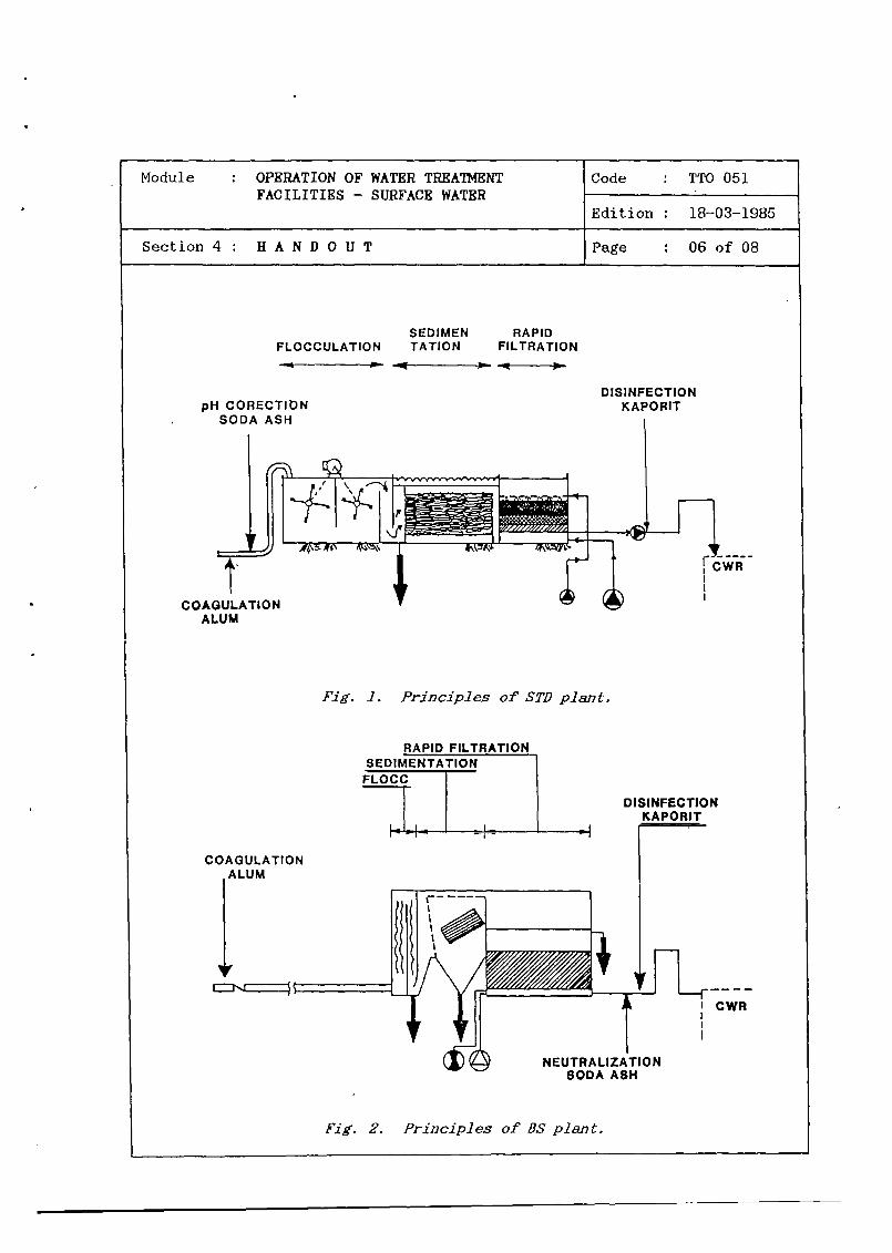
Module : OPERATIONOF WATERTREAThIENTFACILITIES — SURFACEWATER
Code : TTO 051.
Edition 18—03—1985
Section4: HANDOUT Page 06of08
SEDIMEN RAPIDFLOCCULATION TATION FILTRATION
~- -~----—-----~- ~- ~-
pH CORECTIONSODA ASH
COAGULATIONALUM
Fig. 1. Principles of STD plant.
DISINFECTIONKAPORIT
CWR
RAPID FILTRATIONSEDIMENTATION
FLOCC
Iii
DISINFECTIONKAPORIT
I CWR
COAGULATIONLU M
-~
NEUTRALIZATIONSODA ASH
Pig. 2. Principles of BS plant.


Module OPERATION OF WATER TREAThENTFACILITIES — SURFACEWATER
Code : TTO 051.
Edition : 18—03—1985
Section 4 : H A N D 0 U T Page 07 of 08
FLOCCULATION/8EDIMENTATION RAPID FILTRATIOPL—
Fig. 3. Principles of WK plant.
FLOCCULATIONSEDIMENTATION
RAPIDI FILTRATION
NEWRALIZATIONSODA ASH
C.,
DISINFECTIONKAPORIT
COAGULATIONALUM NEUTRALZATION
LIME
WR
Pig. 4. Principles of DAB plant (concrete).


Module OPERATIONOF WATERTREAThIENTFACILITIES — SURFACE WATER
Code : TTO 051~
Edition 18—03—1985
Section 4 : H A N D 0 U T Page : 08 of 08
FLOCCULATION
COAGULATIONALUM
~•~4~SEDIMENTATI0NRAPID
FILTRATION
DISINFECTIONKAPORIT
Fig. 5. Principles of DAB plant (steel).


Module : OPERATIONOF WATERTREATMENTFACILITIES — SURFACEWATER
Code : TTO 051
Edition : 17—04—1985
Annex : VIEWFOILS Page : OlofO8
TITLE : CODE
1. Surface water treatment TTO 051/V 1
2. Operation of water treatment plants TTO 051/V 2
3. Package plant “STD” TTO 051/V 3
4. Package plant “BS” TTO 051/V 4
5. Package plant “WK” TTO 051/V 5
6. Concrete water treatment plant (DAB) TTO 051/V 6
7. Steel treatment plant (DAB) TTO 051/V 7


Surface water treatment
IC,)
rc<0
TTO 051/V 1
ccLuI—
cc
Lu-jC-)
LuC!,
cc0I—0,
00~
=ccci)0<
(I,
z0
0LuU-z(I)
z0
<cccc1~.
-iU-
z0
I—
N
cc
F—
Luz0I-
I-zLu
LuC,)
z0I—
-J
z0F-
-J
000-J
Ui
0
U-cc
0,
ccLuI-

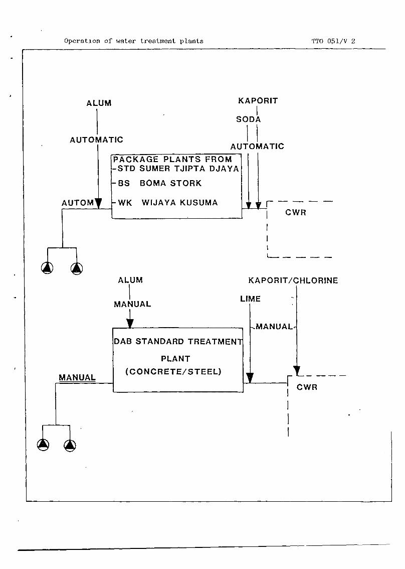
Operation of water treatment plants TTO 0~l/V 2
MANUAL
CWR
~MANUAL
CWR
ALUM
AUTOMATIC
KAPORIT
SODA
HAUTOMATIC
rAUTOM’
PACKAGE PLANTS FROM-STD SUMER TJIPTA DJAYA
-BS BOMA STORK
-WK WIJAYA KUSUMA
ALUM
MANUAL
KAPORIT/CHLORINE
LIME
DAB STANDARD TREATMEN1
PLANT
(CONCRETE/STEEL)


Package plant “ STD VI TTO 051/V 3
z
wz
Cl,’—
z0I-
~~1
000-jU..
z211.-C,)0<wcc<
I
z2~-.Lu
U-a-
C,)
z0
—<
<F-
U-
z0I-
00

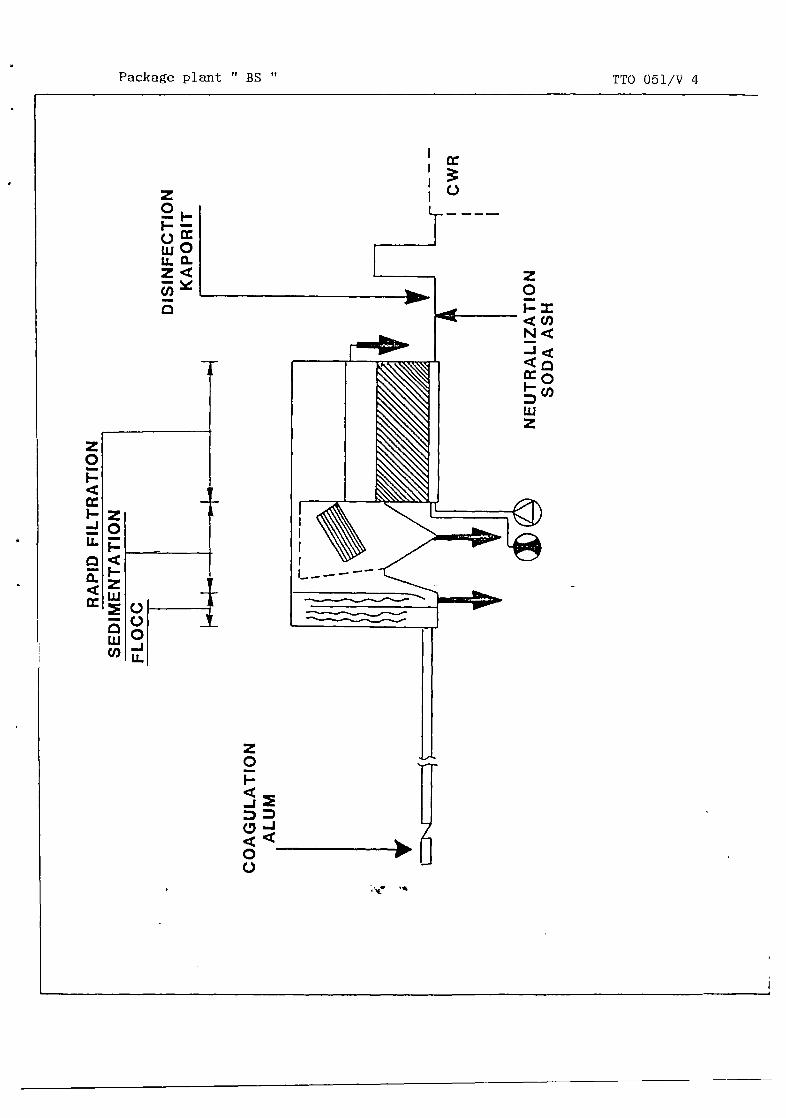
Package plant “ BS
z
I--.
Lu0
TTO 051/V 4
cc
0
z0F-I<Cl)
~.1<
cc0
I-
Luz
z0F-
0~0


Package plant “ WK TTO 051/V 5
0I-
ccF--j
U-
a-
cc
z01-
F-zLU
Lu
U)
z0I-
C-)00-JU-
z0I-I<U)N<
~C/,Luz
z0F-
U-cczo
r
z0I-
-j


Concrete water treatment plant (DAB)
z0
—<
I-
U-
z0I-
-J
000-jU-
z0F-—
Lu0U-a-
I~0
z0I-
F-zLu
LUU)
z0I-
0C-)
L~__~


Steel water treatment plant (DAB) TTO 051/V 7
z0F-
F-zLU
LuU)
z0I-
-J
C-)00-JU-
z0
WOU-a.
1
1!
z0I-
00


-- Head of Technical Department;— Head of Section Production;— Head of Sub—section Water Treatment;— Operalor;— Head of Sub--section Laboratory;— Laboratory Assistant.
— Jar test equipment;-- Turbidity meter;• pH—meter;
Laboratory glassware;- Audiovisual on Jar tester and Jar test experi-
ments;-- Viewfoils : TTO 205/V 1—9;- Handout : TTO 205/H 1.
This module shull preferably be used togetherwith tue Module “coagulation/flocculation” andthc Audiovisual “Jar tester and Jar test experi—men
[~ DEPARTMENTDIRECTORATE______ DIRECTORATE
OF PUBLIC WORKS
GENERAL CIPTA KARYAOF WATER SUPPLY
MDPP
T~WA 0
Module JAR TEST Code : TTO 205
Edition : 18—03—1985
Section 1 1 N F 0 R M A T I 0 N S H E B T Page : 01 of 01/20
45 minutes.
After the session the trainees will be able to:recite the purpose, application and function-ing of jar test equipment;recite the procedures for jar test experi--ments:perform jar tests and evaluate jar test re-sults.
Duration
Training objectives
Trainee selection
Training aids
Special features
Keywords Jar test/jar tester.


1. Introduction
— Purpose of jar test:• evaluation of coagulation/flocculation
processes.
— Application of jar tests:- optimization of coagulation/flocculation
processes in existing treatment pldnts;- design of new treatment plants;- upgrading/revision of existing plants.
jar tests:dosing procedures;doses of chemicals;
duration and intensity of mix—
duration of clarification.
2. Description of jar test equipment
— Essential parts:- adjustable motor;- stirring rods with impellors (rotors);- jars.
— Optional parts:stators;
- dosing of funnels for chemicals;siphons for sample withdrawal;
- bar with test—tubes.
— Suitable jar test equipment for small tomedium sized treatment works:- Phipps and Bird, type 7790—200;- HACH, Type 15.057—02.
— Additional laboratory equipment:Turbidity meter;
- pH meter;Thermometer;
- Balance;Laboratory glassware;Miscellaneous laboratory equipment.
Module : JAR TEST Code : TTO 205
Edition : 18—03—1985
Section2 : SESSION NOTES Page : OlofO3
— Output ofoptimum
- optimumoptimuming;optimum
Show V 1
Show V 2
Show V 3
Show V 4

Module : JAR TEST Code : TTO 205
Edition : 18—03—1985
Section2: SESSION NOTES Page : 02of03
3. Jar test procedures
1. Limitations:— presented jar test procedures are
applicable for:determination of optimum alum dose;determination of optimum p11—range;
— presented jar test procedures arebased on jar’ tester with 4 jars.~
2. General preparations: Show V 5— preparation of 1% alum solution;— preparation of 0.36~ caustic soda
solution;— collection of raw water sample.
3. Determination of optimum alum dose: Show V 6— preparation of alum and caustic soda
doses to jars;— filling of jars with raw water samplb;— rapid mixing and dosing of chemicals;— slow mixing (flocculation);— clarification;— withdrawal of samples;— determination of turbidity, p11, tem-
perature;— graphical interpretation of results. Show V 7
4. Determination of optimum p11:— preparation of alum and caustic soda
doses;— filling of jars with raw water;— rapid mixing and dosing of chemicals;— slow mixing;— clarification;— withdrawal of samples;— determination of turbidity, p11, tem-
perature;— graphical interpretation of results. Show V 8
4. Evaluation
— Improved jar test results will be obtained Show V 9by subsequent series of tests using re-sults of previous tests (iterative pro-cess).

— Final pH adjustment may be requiredorder to remove aggressivity causedalum dosing. -
5. Frequency of jar test
— Before start—up of treatment plant.— For properly functioning treatment ~lants
once per day.— If treatment plant does not function pro-
perly several times per day.
Module : JAR TEST Code : TTO 205
Edition : 18—03—1985
Section2: SESSION NOTES Page : 03of03
inby
6. Summary Distribute H 1


Module : JAR TEST Code : TTO 205
Edition : 18—03—1985
Section3: TRAINING AIDS Page : OlofO2
Purpose and applica— TTO 205/V 1tion of jar—test
— PURPOSEOFJARTEST:
Coagulation/flocculationprocesses evaluation
~- APPUCATIONSOFJARTEST:
1. OptimizIng coagulation/fiocculationprocesses In existing treatment plants
2. Design of new treatment plants
3. Upgrading of existing treatment plants
Possible results of TTO 205/V 2jar—test
POSSIBLE RESULTSOF JAR TEST:
1. OPTIMAL DOSESOF CHEMICALS— alum do8e— pH range (Soda—ash or caustic soda dose)
2. OPTIMAL CHEMICAL DOSINGPROCEDURES
~ or subsec~ientdosing of varIou~chemicals on or beneath water e~rface
— Dosing location in relation to mixing device— Soiutlon strength of chemical solutions
3. OPTIMAL INTENSITY AND DURATION OF MIXING
4. OPTIMAL SEDiMENTATION PERIOD
Main parts of jar— TTO 205/V 3tester
MOTOR WITHSPEED •DJUITER_~m m
ITIRRIOG RODU WflHIIIflLLEDI
~
MAIN PARTS OF THEJAR TESTER
Optional jar—tester TTO 205/V 4equipment
HOEING U~EL SIPHON ~OSWATER SAMPUNG
ETAToRl~~1 ~fl.I• CC’ OD•
I WITH III? TLIEIP0110011MG C CHIC LI
OPTIONALJAR TEST EQUIPMENT
Preparation of TTO 205/V 5standard chemicalsolution
A SCACTIONI OP ALUM All CAUSTIC SODA IN WATCH
£1~S0~~• 519T — HAN0Mj~ - 3S0~ - 50’
- — •‘. • ~‘s~• ~ ~ • ~,. -
I MOLE Of ALUM C~ S 1101.11 OP CAUSTIC ~o. II ~ 4~!U oHSS 5.00
I. ALUM U0I.UTIO AUM CAUSTIC 000* IOI.UTIOI
ALUM SOLUTION ~ ~ ~ Of ~ ~ ~OIl
s.o.s 0.05 SOLUT~OM ~ •~~ e1’ ~0s “.UTIC Of WATER
c PROUAASOII — — —
I 01*1.011 IOLUTIOII II SI 1.fl I 011.011 SOLUTIOS 11.015)
Jar test — aluri dosis TTO 205/V 6
DETERMINING OPTIMAL ALUM DOSING:
1. prepare chemIcal solutions2. pour raw water Into Jars3. rapid mixing of chemicals4. slow mixing5. sedimentation8. remove samples7. d6tCflflI110 turbidity, pH, temperature8. graphical presentation of results


(NYU)
Module - : JAR TEST Code : TTO 205
Edition : 18—03—1985
Section3: TRAINING AIDS Page 02of02
Turbidity and alum TTO 205/V 7dose
A,B,C,D : 1 lItre samplesall samples : pH 6.9
IN! Sal 51,1 5I0 CAUSTIC ROSA DOlt 102551
Relation turbidity TTO 205/V 8and pH
TUPIPIOITV IIITIC
A.B,C,D: 1 litre samplesall samples: alum dosis~3Omg
SO
00
10
to -~SO 52 UI US AU TO............. ps
Iterative process TTO 205/V 9
TEST SEQUENCE FORDETERMININGCHEMICAL DOSE
EstImate Test serIes Results ClassIfIcatIon
Ls~iumdose L~÷JI~..,1Alum dose IpHpH Good
I
~h~ose Better
~I~•~u~6o1 Bestloptlmal
Jar test - TTO 205/H 1


DEPARTMENT OF PUBLIC WORKS MDPP
rk4 DIRECTORATE GENERAL CIPTA KARYA 9~yDIRECTORATE OF WATER SUPPLY IWACO
Module : JAil TEST
~
Code : TTO 205
Edition : 18—03—1985
Section 4 : H A N D 0 U T Page : 01 of 14
1. INTRODUCTION
The jar test is a method to evaluate coagulation/flocculation pro-cesses. When the test is carefully performed, useful information canbe derived to aid the plant operator in optimizing the coagulation,flocculation and clarification processes, and the engineer in design-ing a new water treatment plant or revising an existing one. The jartest may provide data on the optimum conditions for process para-meters such as:- dosage of coagulant and coagulant aid(s);- pH;- method of dosing of chemicals (on or beneath water surface, simul-
taneous or subsequent dosing of several chemicals, dosing locationin relation to mixing device, etc.);
- solution strength of chemical solutions;— duration and intensity of rapid mixing and slow mixing (floccula-
tion)duration of clarification.
For Jar tests the establishment of standardized, fixed procedures isa prerequisite in order to obtain reproducible, meaningful results.
Apart from the the abovementioned process parameters the followingvariables shall also be carefully monitored and controlled:— temperature of water in jars;— turbidity, color and alkalinity of raw and treated water;- method of sample withdrawal;- laboratory test equipment and laboratory analysis procedures.
2. APPARATUS
Jar test equipment of various designs is nowadays commercially avail-able. Specific designs allow for accurate monitoring and controllingof various process variables. All jar testers contain the followingparts (see also Figure 1):(i) an adjustable motor which actuates;(ii) stirring rods with impellors, or rotors; the rotational speed
of the rotors is adjustable;(iii) a beaker glass or jar under each of the rotors.
In addition, the jar tester may contain the following equipmentparts:— stators in each of the jars;— dosing funnels for chemicals, one for each jar;— siphons for sample withdrawal, one for each jar;— a bar with test—tubes for dosing of chemicals to the jars.

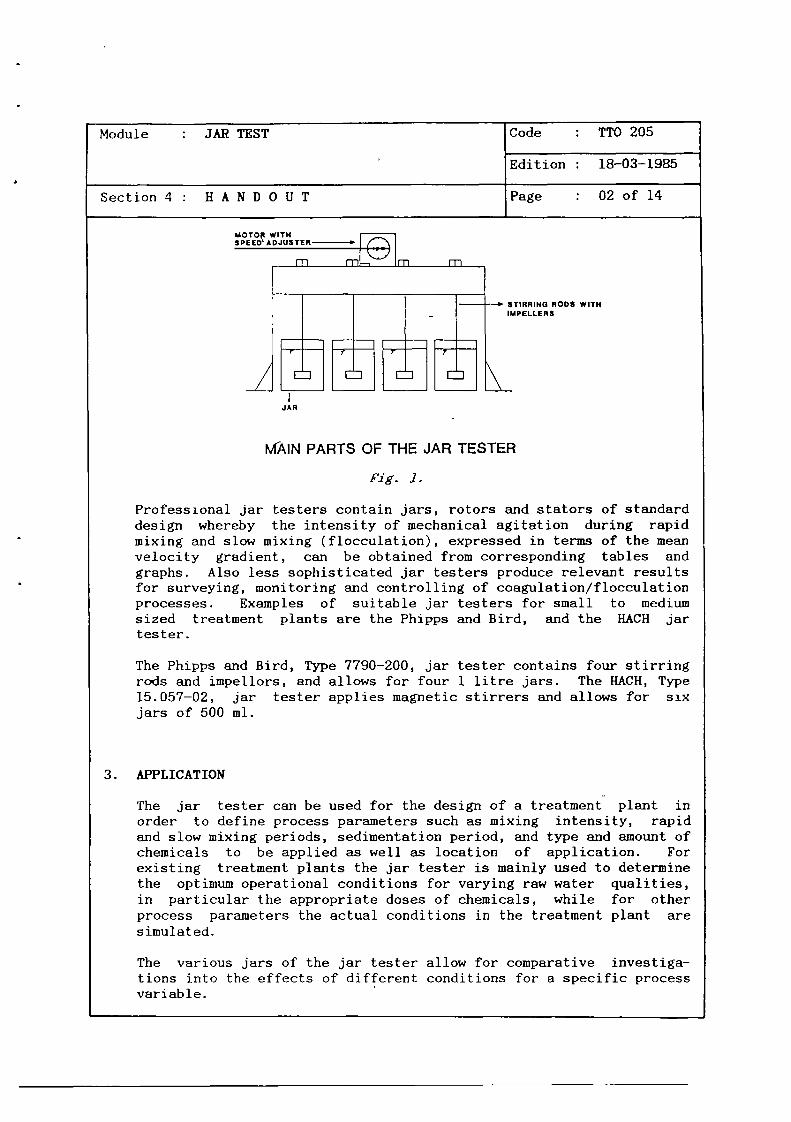
Module : JAR TEST
~
Code : TTO 205
Edition : 18—03—1985
Section 4 : H A N D 0 U T Page : 02 of 14
SPEJADJUSTER D Qm1- m
I I I— —~ STIRRING RODS WITHI — IMPELLERS
~_HP___JAR
MAIN PARTS OF THE JAR TESTER
Fig. J.
Professional jar testers contain jars, rotors and stators of standarddesign whereby the intensity of mechanical agitation during rapidmixing and slow mixing (flocculation), expressed in terms of the meanvelocity gradient, can be obtained from corresponding tables andgraphs. Also less sophisticated jar testers produce relevant resultsfor surveying, monitoring and controlling of coagulation/flocculationprocesses. Examples of suitable jar testers for small to mediumsized treatment plants are the Phipps and Bird, and the HACH jartester.
The Phipps and Bird, Type 7790—200, jar tester contains four stirringrods and impellors, and allows for four 1 litre jars- The HACH, Type15.057—02, jar tester applies magnetic stirrers and allows for sixjars of 500 ml.
3. APPLICATION
The jar tester can be used for the design of a treatment plant inorder to define process parameters such as mixing intensity, rapidand slow mixing periods, sedimentation period, and type and amount ofchemicals to be applied as well as location of application. Forexisting treatment plants the jar tester is mainly used to determinethe optimum operational conditions for varying raw water qualities,in particular the appropriate doses of chemicals, while for otherprocess parameters the actual conditions in the treatment plant aresimulated.
The various jars of the jar tester allow for comparative investiga-tions into the effects of different conditions for a specific processvariable.

4-

Module : JAR TEST Code : TTO 205
Edition : 18—03—1985
Section 4 : H A N D 0 U T Page : 03 of 14
In order to monitor the effects of varying of a particular processparameter on the coagulation/flocculation/clarification process, theother process parameters should be kept at the same value for alljars taking part in the comparative study.For example if a jar test is undertaken to determine the optimumdosage of the coagulant alum for a particular raw water, the follow—ins process conditions should be kept identical in all jars:— the raw water samples;— the temperature;- the pH;— the configuration of the rotors (and stators);— the configuration of the Jars;— the mixing intensities;— the mixing periods;— the sedimentation period.
If the purpose of the jar test is to determine the optimum mixingintensities, different rotors and stators will be applied in thedifferent jars so as to create different mixing intensities. Allother process parameters, including the alum dose, then must have thesame values in all jars.
For existing treatment plants jar tests are mostly ~,ised to determineoptimum doses of chemicals for coagulation/flocculation, in particu-lar the optimum dose of the coagulant and conditioning chemicals forp11 correction, for different raw water qualities. All other processvariables are normally kept at their fixed value. The procedures forthe execution of the jar test under such conditions are brieflydescribed in paragraph 4, Procedures5 It is thereby assumed thatalum is used as coagulant, and caustic soda as conditioning chemicalfor p11—correction.
4. PROCEDURES
Coagulation and flocculation are the result of the addition of alumto raw water under subsequent rapid and slow mixing conditions. Alumhas acidic properties. By adding this chemical to raw water the pHof the raw water will be reduced.The magnitude of the pH reduction depends on the raw water composi-tion, in particular on its buffering capacity. The pH can have astrong influence on the coagulation/flocculation and the subsequentsedimentation process. The pH can be adjusted by adding a certainamount of the base, such as caustic soda.


Module : JAR TEST Code : TTO 205
Edition : 18—03—1985
Sect ion 4 : H A N D 0 U T Page : 04 of 14
In order to investigate the particular influence of both alum and pHon the coagulation/flocculation process by means of the jar testeronly one variable at the time should be changed: either the alumconcentration or the pH. Therefore actually two comparative investi—gations have to be executed: one in which the dose of alum to thevarious jars is varied while the pH is kept constant, and one inwhich the pH in each of the jars is varied while dosing the sameamount of alum.
The test procedures for the determination of the optimum dose ofalum, and the optimum value of the pH for coagulation/flocculation ofa particular raw water are given below. It is assumed that use ismade of a jar tester with four jars labelled A, B, C and D respec-tively.
I. General preparations
1. Preparation of alum solution and caustic soda solution:— preparation of a 1~ (by weight) alum solution by dissolving 10
graxmnes of alum (A12(S04)3.18H20) in 1 litre of distilledwater;
— preparation of a 0.36~ (by weight) caustic soda solution bydissolving 3.6 grammes of caustic soda (NaOH) in 1 litredistilled water.
2. Collection of raw water sample:- with a bucket take 10 litres of raw water from the river when
the plant is not running, or from the inlet to the treatmentplant when the plant has been running for several hours;
— measure and record the pH of the raw water. It is good prac—tice also to determine the EC, alkalinity, calcium content,turbidity and temperature of the raw water. Record the appro—priate data on the jar test form. See Figure 2.
II. Determination of optimum alum dose
I. Prepare dosage of 10, 20, 30 and 40 ing of alum to 1 litre of rawwater in the jars A, B, C and D by bringing 1, 2, 3 and 4 ml ofalum solution in the test—tubes A, B, C and D respectively (usea pipet of 10 ml). Record the appropriate data on the jar testform.
Note 1: The said quantities of the alum solution are applicablefor raw water turbidities up to 500 NTU. For higherturbidities apply double quantities.


Module : JAR TEST Code : TTO 205
Edition : 18—03—1985
Section 4 : H A N D 0 U T Page : 05 of 14
a,0a4aaj 0
a, I,
g ~I- ~a,
~_5 ~-.. .(
4_. Q.~. ‘U
!~~:~a, 0 i—a.~ a,~ 0~wI- Ui-I-
00C
@3
3.0CC
I U
U
I. ~
a, I.
a
+
•0 —o -@~obC_C
I-• ~
+C
+ CU
.c_ —ao abC I..
a~. .0U> 5—
+a
+ 3-30
+ C‘-3
C Ii-U
a43 43
•1 —
0~0~
L — U U13~~4Z ULaW EU
‘U.3a
a,
0
w
a,
z
0xc
413a,,-
a. a.00
4!!0 i-I-
a,
0‘UI-a,UI-
Fig. 2.


Module : JAR TEST Code : TTO 205
Edition : 18—03—1985
Section 4 : H A N D 0 U T Page : 06 of 14
2. In order to compensate for pH reduction of raw water after dosingof alum, prepare dosage of 3.6 mg, 7.2 mg, 10.8 mug and 14.4 mg ofcaustic soda to 1 litre of raw water in the jars A, B, C, and D,by bringing 1, 2, 3, and 4 ml of caustic soda solution in thetest—tubes AX, B*, C~, and DX, respectively (use a pipet of10 ml).
Note 2: See Note 1, if alum doses are doubled also caustic sodadoses are doubled.
Note 3: For raw waters with pH values above 7 a complete neutra-lization of the acid produced by alum is not recommend-able since practical experience has shown that for alumthe coagulation/flocculation process performs best inthe pH—range 6—7. At raw water pH—values above 7 thecaustic soda dose can be reduced by 50~ (or 0.5 mlcaustic soda solution for each ml of alum solution).
3. Mix the raw water sample thoroughly and fill each of the jars A,B, C, and D with exactly 1 litre of raw water.
4. Place the jars under the corresponding rotors, insert the rotorsin the jars, and start and adjust motor to 100 r.p.m.
5. Add simultaneously the contentsof the test—tubes (A+A*, B+B*,C+C*, D.1~D*) to the corresponding jars; simultaneously start astopwatch and continue the rapid mixing for 30 seconds. Makesure that the test tubes are completely emptied, or rinse withdistilled water and add to corresponding jars within the 30seconds of rapid mixing period.
Note 4: In order to simulate actual process conditions in atreatment plant a different period of rapid mixiiig maybe applied.
6. After 30 seconds of rapid mixing, reduce mixing intensity to 40r.p.m. for flocculation. Keep this mixing intensity for 20minutes. Observe the appearance of floes and classify the floesin each jar by using the Floe Size Chart (see Figure 3). Recordthe data on the jar test form.
Note 5: In order to simulate process conditions in a treatmentplant different procedures for slow mixing may be ap-plied, e.g. 3 intervals of 6 minutes each with sub-sequent mixing intensities of 60, 40, and 20 r.p.m.

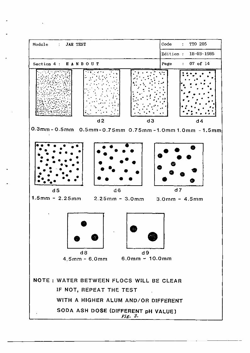
••. . , S
~ S 5,
a . •• •
S. S•Il • •V • • • ~
S
S • • •
. p
S
• . a• ~ •
S• •. S
• • • •p a
d4
O.3mm - 0.5mm 0.5mm-O.7Smn, 0.75mm-1.Omml.Omm -1.5mm
d5
1.5mm - 2.25mm
d6
2.25mm - 3.0mm
d7
3.0mm - 4.5mm
d84.5mm - 6.0mm
d96.0mm - 10.0mm
NOTE : WATER BETWEEN FLOCS WILL BE CLEAR
IF NOT, REPEAT THE TEST
WITH A HIGHER ALUM AND/OR DIFFERENT
SODA ASH DOSE (DIFFERENT pH VALUE)fig. 3.
Module : JAR TEST Code : TTO 205
Edition : 18—03—1985
Section 4 : H A N 13 0 U T Page 07 of 14
.1..~
—. .. I. — ..
‘.~ ~‘ ~ ~:~:~~ ~
•I.. . .
— I.
p
I
.~ ~ ~
~ :~•..~
• a • • .
I • I
a• .. . . .
I
d2 d3
S. S • .SS. •• •• S• • S• S •S .• .
• •.•• ~ .
S ~ S•• . .. .
..
S• • ••S. •
•. ••
•• •0
0
... ..


Module : JAR TEST Code : TTO 205
Edition : 18—03—1985
Section 4 : H A N D 0 U T Page : 08 of 14
7. After(i)(ii)(iii)
20 minutes of slow mixing (flocculation):stop the mixers;remove them from the jars, andallow the formed flocs to settle in the jarsminutes.
during 20
Note 6: In order to simulate actual process conditions in atreatment plant a different period of clarification canbe applied.
8. After 20 minutes of clarification carefully transfer a 200 mlsample of each jar into a clean beaker glass of 250 ml by siphon-ing (with inlet of siphon approx. 2 cm below water surface) andcarry out the following laboratory measurements for each of thefour samples:— turbidity;— pH;— temperature.Record aLl data on the jar test form.
9. Prepare a graph of turbidity versus alum dose, i.e.turbidities of the clarified water from the jars A, B,against the alum doses for these jars. See Figure 4.
30
20
I0
plot theC and D
(NTU)
A,B,C,D : 1 litre samplesall samples : pH 6.9
40
0
Imi 2m1 3m1 4..l—.- CAUSTIC SODA DOSS (036%)
Fig. 4. Graph of clarified water turbidities versus alum doses.


Module : JAR TEST Code : TTO 205
Edition : 18—03—1985
Section 4 : H A N D 0 U T Page : 09 of 14
10. Determine the optimum alum dose as follows:
(i) draw the tangent line to the graph, that has an inclinationwith a tangent value of 1;
(ii) from the graph read which alum dose corresponds with theintersection of graph and tangent line. This alum dose isconsidered the optimum alum dose resulting from the firstjar test.
Note 7: - For the selected alum dose an increase of the dose by 1mg/l will exactly result in an increase of turbidityremoval by 1 NTU. For higher alum doses the effect onturbidity removal is gradually decreasing. It is ob—vious that the procedure mentioned under Ci) and (ii)for determining the optimum alum dose is partly based onan economic criterion, and needs to be checked furtheron its technical applicability in subsequent tests.
Note If no tangent line as specified above can be drawn tothe graph the coagulation/flocculation of the raw wateris incomplete and a new test will have to be carried outwith higher alum doses and/or lower pH—values.
III. Determination of optimum pH
All parts of the jar tester shall be cleaned thoroughly before thetest for the determination of the optimum pH is undertaken.
1. Prepare dosage of optimum alum dose (see II; optimum alum dose isx mg per litre raw water) to each of the jars by bringing x ml ofalum solution in each of the test—tubes A, B, C, and D.
2. In order to create different pH values in each of the jars,prepare dosage of caustic soda doses that will neutralize 0~,20~, 50~ and l00~of the acid production of the alum dose, bybringing 0 ml, 0.2x ml, 0.5x ml and x ml of caustic soda solutionin the test tubes A”, B”, Cx, and D”, respectively.
3. See 11.3.
4. See 11.4.
5. See 11.5.
6. See 11.6.
7. See 11.7.


Module : JAR TEST Code : TTO 205
Edition : 18—03—1985
Section 4 : H A N 13 0 U T Page : 10 of 14
8. See 11.8.
9. Prepare a graph of turbidity versus pH, i.e. plot the turbiditiesof the clarified water from the jars A, B, C, and D against thepH values of the clarified water in these jars. See Figure 5.
TURBIDITY (NYU)
10
50
40
30
20
10
A,B,C,D: 1 litre samplesall samples: alum dosis=30 mg
060 62 64 6~ 6.8 70 _______
Fig. 5. Graph of turbidi ties of clan lied water versus pH values.
10. Determine the optimum pH value as follows:
(i) Draw horizontal lines on the graph for Turbidity = 5 NThand Turbidity = 2 NTU, and read the pH values at the inter-sections of these lines with the graph.
(ii) The pH—range for which the turbidity is between 2—5 NTU isconsidered the optimum pH—range for coagulation/floccu-lation. Normally this pH range will amount to approx. 0.3pH units.


Module : JAIl TEST Code : TTO 205
Edition : 18—03—1985
Section 4 : H A N D 0 U T Page : 11 of 14
5. EVALUATION
1. Optimum chemical dosages
The tests described under II and III normally produce satisfacto-ry results for a first estimate of the optimum coagulant dose andoptimum pH—range for coagulation/flocculation. Jar test experi-ments have, however, an iterative character. Often more seriesof tests are required. By repeating the tests with doses slight-ly higher and lower than the “optimum’1 doses found during thefirst series of tests more accurate data on the optimum chemicaldoses and optimum pH—range may be found. See also Figure 6.
For example, if the test for the determination of the optimumalum dose (see II) would now be repeated while applying theoptimum pH values (see III), it may be found that the optimumalum dose is 0.8x rug alum per litre of raw water. This wouldresult in 20~savings in alum consumption.
For subsequent test to determine the optimum alum dose whileobserving the optimum pH—range (as found in III) normally thefollowing dosages are applied (assuming an optimum dose of x nig
alum per litre of raw water found in II, series 1):— series 2 : x—30~, x—20~, x—l0~, and x rug alum in jars A, B, C
and 13, respectively;output : new optimum dose of y rug alum;
— series 3 : y—l0~, y—5~, y, and y+5X rug alum in jars A, B, Cand D respectively;
output : new optimum dose of z mg/i.
2. pH adjustment
The jar tests may indicate that for coagulation/flocculation/se-dimentation no or only partial pH adjustment is desirable inconjunction with the alum addition, in order to obtain a goodpurification of the water. By adding the alum the acidity of thewater has, however, been increased and it may now have obtainedan aggressive character towards materials applied in the treat-ment works, transmission system and distribution system.
This in turn will cause operation and maintenance problems, aswell as costs for repairs and replacements. The seãondary ef-fects of possible corrosion in the system on the water qualityshould also be taken into account. Therefore a further pH ad-justment shall be carried out after the sedimentation. This canbe~done before or after the final filtration process, dependingon possible additional treatment.

x

Module : JAR TEST Code TTO 205
Edition : 18—03—1985
Section 4 : H A N D 0 U T Page : 12 of 14
TEST SEQUENCE FORDETERMINING CHEMICAL DOSE
Estimate Test series Results Classification
Good
Better
Best/optimal
HLIIF-÷Alum dose
pH
Fig. 6.


Module : JAR TEST Code TTO 205
Edition : 18—03—1985
Section 4 : H A N D 0 U T Page : 13 of 14
3. Floc formation
Both during and after the jar testing a number of observationsare made in order to assess the efficiency of the treatmentprocess. Already at an early stage of the flocculation, commonlysome 1 minute after the chemical injection, first floc growth canbe distinguished. As the test continues, these very fine Ilocsgradually increase in size while the water between the flocbecomes clear.
In a properly executed test the clear water becomes evident aftersome 3.5 to 5 minutes; its absence is a definite indi-cation thatthe chemical dosing or the pH was incorrect. The growing flocscan be light and fluffy or well compacted. The light and fluffyflocs tend to have poor settling characteristics and are deemedundesirable because of their fragility. Even a minor disturbancewill disrupt this type of floc.
Generally the fluffy type of flocs is observed in combinationwith pin point flocs left in the water after the majority of theflocs have settled. Pin point flocs are undersized flocs, of adiameter normally below 0.5 mm, which have not been recombinedinto larger compounds. Unfavourable mixing conditions duringflocculation may be the cause of these flocs. More likely,however, it is an incorrect alum ~dosing or pH of the sample.
6. FREQUENCYOF JAR TESTING
The frequency of the execution of jar tests strongly depends on thevariations and fluctuations in the raw water quality (turbidity, typeof suspended and colloidal matter). Usually, directly before orimmediately after the start—up of the coagulation/flocculation plant,a jar test with a representative raw water sample has to be performedin order to establish the optimum doses of applied chemicals.
During normal and satisfactory operation of the coagulation/floccula-tion plant the jar test should be performed at least once a day. Ifpurification results are not satisfactory, the frequency of jartesting has to be increased in order to define the right conditionsfor production of water with an acceptable quality.

Module : JAR TEST Code : TTO 205
Edition : 18—03—1985
Section 4 H A N D 0 U T Page : 14 of 14
7. SI144ARY
The jar tester appears to be an excellent piece of laboratoriumequipment for the determination of optimum process conditions forcoagulation, flocculation and sedimentation of various raw waterqualities.
It is used in survey and design stages for new treatment plants, aswell as during the operation of existing treatment plants in order todetermine optimum doses of chemicals for fluctuating raw water quali-ties.


Module : JAR TEST Code : TTO 205
Edition : 18—03—1985
Annex V I H W F 0 I L S Page : 01 of 10
TITLE CODE
1. Purpose and application of jar test TTO 205/V 1
2. Possible results of jar test TTO 205/V 2
3. Main parts of the jar tester TTO 205/V 3
4. Optional jar tester equipment TTO 205/V 4
5. Preparation of standard chemical TTO 205/V 5solutions
6. Jar test alum dose TTO 205/V 6
7. Turbidity and alum dose TTO 205/V 7
8. Relation turbidity and pH TTO 205/V 8
9. Iterative process TTO 205/V 9


Purpose and application of jar test TTO 205/V 1
cr5
cr5>C’,
C,,U. (,)
C)
LL~ ccio~0
C,)
ft% -i—I
~
J ~‘%I. 4~I
o ~0—C,)
.— C/)N C,,
.— ci~•—
o~U
C,’
cci
Eccia)4-’
.~
4-’Cl)
.~a)‘4-
0c,)
U-a
cci
ci
ct~
U-0C,)z0p0
a-a-
CO4-’cr5
4-’
ii)E4-’ccia)4-’
a)‘4-
0U
a)
c~i

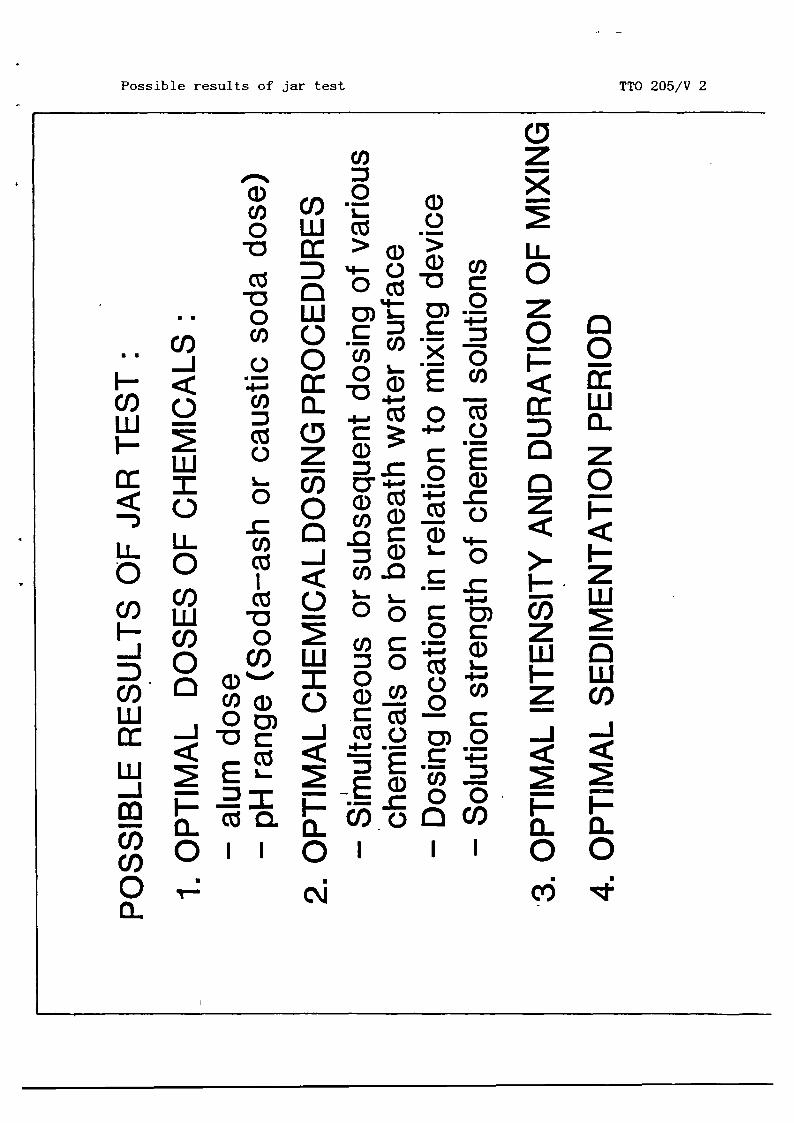
Possible results of jar test TTO 205/V 2
z
LL0z0
cc0
0z>-
cr~zw
-J
0~0
0Ew0~z0
F-zw
wCo-J
0~0
ci)
wo Wai 0-o cc >~5
c~,-o ~ O~~j0 ~0 W
0)’t ~Cl) C/)
0 Q(1) X~5.I-J
OZg~c~Cl) ~ a)
LL IL Cl)o 0 .j a)~-~< co_~~
oCOW~~2
~ 0 ~ I
cc jg0)~ U —
-J —=
m F--~1 ~1D ~
0Cl)oOC1)1101 II
o c%4J


Main parts of the jar tester
II—
(I)
0cc
TTO 205/V 3
ccwC~)wF-cc
wIF-
U-0C/)F-cca-z
C/)
cciii
C,)—

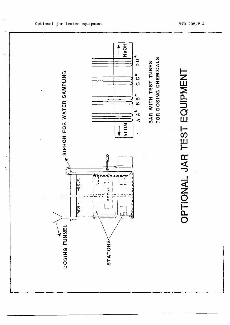
* U)
c~
*0 Ui,.~ I-I•~ C/)Q
Ui
-0
-~ <0~
TTO 205/V 4Optional jar tester equipment
z-jC-
U)ccwI.-
cc0U-
z0I0~C/)
F-zwa-5awF-C,)wF-cc
-J
z0pa-0
-JUizz
cc
0z F-—
C/) F-0 Cl,


Preparation of standard chemical solutions TTO 205/V 5
A. REACTIONS OF ALUM AND CAUSTIC SODA IN WATER
AI2(S04)3 + 6H20 >. 2AI(OH)3 + 3SO~ + 6H~
6NaOH + 6H4 >~ 6Na~ + 6H~O
A12(S04)3 + 6NaOH— > 2A1(OH)3 + 6Na~ + 3SO~
OR: 1 MOLE OF ALUM CYD 6 MOLES OF CAUSTIC SODA6 x 40
OR :lg Al (S04)~18H2O~ 666 = 0.36 g NaOH
B. ALUM SOLUTION AND CAUSTIC SODA SOLUTION
1 % ALUM SOLUTION CVD 10 GRAMMES OF ALUM PER LITRI
OF WATER
0.36 % NaOH SOLUTION ~ 3.6 GRAMMES OF NaOH PER
C. FROMAANDB:
LITRE OF WATER
1 ml ALUM SOLUTION (1 %) c~’~D1 ml NaOH SOLUTION (0.36

4

Jar test alum dose TTO 205/V 6
U.
0Z a)C/) CO0o
a)CO~CO
CO E~OCO-~ a)0
U
4-’~cr50— . . . — ..L~ 0E
— — 0 .—
I— o~a- U a)~4- ~ COa)(I~ cr5 ~ E L.cci 0.
~‘ CO —Z• — U —
Z ~Cr5EEØa)f-0U—
_ E 0.cc a)a~~DE4-acr5w ~-0cr52a)a)a)L~I— CO CO~D 0)

4

Turbidity and alum dose TTO 205/V 7
I—z
>-
F-
cc
I-
C/)
c~(OCl)
4-a•—
I
C.
oco
Coce).0
UiC/)0
4
0U)
0I-
U)4C)
E
C,
-j
4
t
EC.,
0 Ec.,1
0CO
0Lt)
0-~ 0C.)
0csJ
0 0

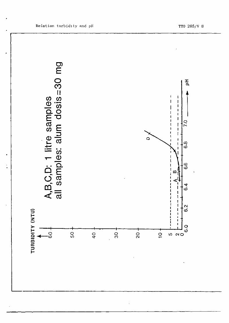
0)E0C!,II
COCO
0.0
cr5CO
=a)—I-
4-’
..0~
~5cci
C<cci
Relation turbidity and p11 TTO 205/V 8
=a.
ICD
I-z
~41
I I
>.
0 0 C 0 0 0 LO~1Q_-‘4 CC) It) C’J
cc
I-
0C

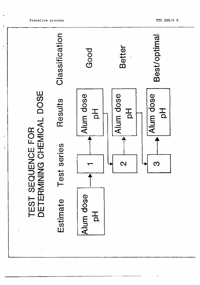
Iterative process TTO 205/V 9
000
a)4-’
Ia)CO0
=
cci0
‘4-
COCl)cci
Cl)4-’
=Cl)a)cc
COa)a)Cl)
4-’COa)F-
a)4-’cci
0.
a)CO0-DE=
wC/)00-J
0
wI0a.z
ccwF-w0
cc0U-w0zwawci)F-C/)UJF—


Special features
Keywords Watermaintenance.
treatment/maintenance/treatment plant
DEPARTMENT
DIRECTORATE
______ DIRECTORATE
OF PUBLIC WORKS
GENERAL CIPTA KARYA
OF WATER SUPPLY
MDPPDHVTGI
IWACO
Module : MAINTENANCE ACTIVITIESFOR WATKRTREANENTPLANTS
Code : TTh 050
Edition : 17—04—1985
Section 1: INFORMATION SHEET Page : Olof0l/18
Duration
Training objectives
Trainee selection
Training aids
45 minutes.
After this session the trainees will be able to:— recognize the various maintenance activities;— supervise the various maintenance activities.
— Head of Technical Department;— Supervisor of Production Section;— Supervisor of Workshop.
— Handout : Tfl4 050/H 1—2.


Module : MAINTENANCEACTIVITIESFOR WATER TREANENTPLANTS
Code : TN 050
Edition : 17—04—1985
Section2: SESSION NOTES Page : OlofO5
1. Maintenance activities
— Routine “Preventive” actions:daily and weekly;inspection, lubrication and tests;during production while operation conti-nues.
— Periodic “preventive” actions:monthly, 1/2 year, year, 2 years;inspections (use detailed checklists);
• lubrications;• tests;
• cleanings;overhauls;repainting.
— Immediate repair/replacement ofparts and/or failures.
2. Inspection (checks)
— Daily: observation.
— Weekly: recording/reporting.
— Use checklists for periodical inspection.
— Pay attention to:leakages;functioning;obstructions;moveable parts/items;rotating parts/items;deviations from standards;lubrication needs.
— Unusual phenomena have to beimmediately.
reported
Explain using white—board
Write on whiteboard
Explain usingwhiteboard
broken

‘4

3. Lubrications
— Drain/refill of oil bathes:water pumps;
• air blowers;• compressors;
gensets;• gearboxes.
— Grease weekly:• shafts (mixers a.o.);• valve actuators;• air blowers;• compressors.
— Follow the instruction manuals.
only recommended types of oil
NOTE 2:Too much grease catches dust(abrasion); too little grease:parts may be blocked and damaged.
NOTE 3:Too much oil will damage packings inmachine and oil will leak; too littlewill block rotating parts.
NOTE 4:Unusual oil consumption should beimmediately to the supervisor.
NOTE 5:No grease or oil may reach the water (to be)treated.
4. Tests
— Test have to be done periodically.— Dosing systems to be tested daily.— Standards of conditions as specified in
manuals like for max. flows, r.p.m., etc.— For more complex equipment: use specific
checklists (e.g. genset).— Electrical equipment to be tested by the
electrical engineer.
Explain and write onwhiteboard
Explain using
whiteboard
Write keywords
Module : MAINTENANCEACTIVITIESFOR WATERTREATMENTPLANTS
Code : TN 050
Edition : 17—04—1985
Section2: SESSION NOTES Page : 02of05
NOTE 1:Usegrease
andRead full NOTES 1—4
and sandrotating
theoil
reported


— Faults to be corrected as soon as possi—b le.
— Unusual phenomenato be reported immèdia—tely.
— Special test of filter bed composition tobe done by expert sanitary engineer/trouble shooter.
5. Cleaning
— Plant and plant site and buildingsbe kept clean.
- Spoiled chemicals and solutionsrinsed with plenty of water.
— Inside walls of plant and clear waterreservoir: use brush and plenty of water.
— Spoiled, wasted oil and fuel should becollected with cloth and dumped into spe—cia1 containers.
NOTE:Never forget that the plant is producingwater that will be used for consumption.Therefore, keep the plant clean.
6. Overhauls Explain usingwhiteboard
— Simple equipment (valves, etc.) to beoverhauled at plant site.
— Pumps and their motors in workshop.
— Dosing systems with pumps at the plantsite by expert/trouble shooter.
— Gensets at plant site by expert/troubleshooter/mechanical engineer.
— Control panels and electrical wiring byelectrical engineer.
— Frequency of overhauls depends on totalnumber of operation hours; to be re-gistered for each item.
Module : MAINTENANCE ACTIVITIESFOR WATER TREATMENTPLANTS
Code : TN 050
Edition : 17—04—1985
Section2 : SESSION NOTES Page : 03of05
should
to be
Use whiteboard
Read full NOTE


Explain usingwhiteboard
Explain usingwhi teboardWrite keywords:
REPAINTINGsteel parts/surfacesother surfaces:wood, concrete, etc.instructions ofsupplier
ExplainWrite keywords:
REPAIRfaultsproduction continues
Module : MAINTENANCEACTIVITIESFOR WATER TREAThIENT PLANTS
Code : TN 050
Edition : 17—04—1985
Section2 : SESSION NOTES Page : 04of05
7. Replacement
— To be replaced as soon as possible:broken fuses, lamp; switches and meters;
• faulty items found during inspectionsand tests.
8. Repainting
— Steel surfaces:• free from dirt and rusty loose particles
with steel brush;use paint equal to original type (seemanual)
— Other surfaces:free from dirt and loose particles;repair first if damaged;
• use proper paint.
— Frequency as indicated on “Maintenanceservices chart”.
Repairs
- Faults are to be repaired immediately.
— Let operations be taken over by stand—byequipment when possible.
— Use spare parts to ensure that productioncan be continued.
— Repair remainder of damaged parts.
9. Summary
— Maintenance activities for water treatmentplants consist of:
routine maintenance;periodical preventive maintenance.


— General instructionsInspections.Lubrication.Tests.Cleanings.
• Overhauls.Replacements.
• Repainting.Rèpáirs.
Module : MAINTENANCEACTIVITIESFOR WATER TREATMENTPLANTS
Code : TN 050
Edition : 17—04—1985
Section2: SESSION NOTES Page : 05of05
apply for:
Distribute H 1 and H 2


Module : MAINTENANCE ACTIVITIESFOR WATERTREATMENTPLANTS
Code : TN 050
Edition : 17—04—1985
Section3 : TRAINING AIDS Page : OlofOl
Maintenance activities TN 050/H 1for water treatment plants
Maintenance activities TN 050/H 2for water treatment plants


DEPARTMENT OF PUBLIC WORKS MDPP
rk4 DIRECTORATEGENERAL CIPTA KARYA
______ DIRECTORATE OF WATER SUPPLY IWACO
Module : MAINTENANCEACTIVITIESFOIl WATERTREATMENTPLANTS
Code : TN 050
Edition : 17—04—1985
Section4: HANDOUT 1 Page : Olofil
1. MAINTENANCEACTIVITIES
Maintenance activities must be executed at regular time intervals.Those executed once a week or more often are normally classified asroutine maintenance.The activities mainly comprise: regular checks, tests and lubrica—Lions. While these activites are carried out, production can becontinued or at least partly.
Periodic preventive maintenance activities have longer time inter-vals, for instance once a month, twice or once a year, or evenlonger.rI~hese maintenance activities comprise inspections, test, overhauls,etc.
For more complex equipment like gensets, air blowers etc., a speciallist with frequencies of maintenance activities has to be prepared.
General instructions for these kinds of maintenanceactivities are:
Inspection/checks
— daily observations: faults have to be reported immediately to theopreators and to the supervisor;
— weekly: the results of the checks carried out during the previousweek should be reported (journal);
- for periodic inspections see the check lists in H2 of this module;— pay attention to leakages (water, oil), proper functioning of
machines, obstructions to mobility of movable and rotating parts,levels of water and oil, position of pressure meters, ampere meters.
Lubrication
The need for lubrication of the moving and rotating parts or itemsshould be observed permanently and the operator should pay attentionto possible sudden changes in the need for lubrication.Weekly levels of oil baths must be checked and compared with predes—cribed levels. Replenish if at any time the oillevel is belowstandard.Normally the frequency to drain/refill oil baths dependson the typeof machine and the number of running hours, as specified in theirrespective manuals.

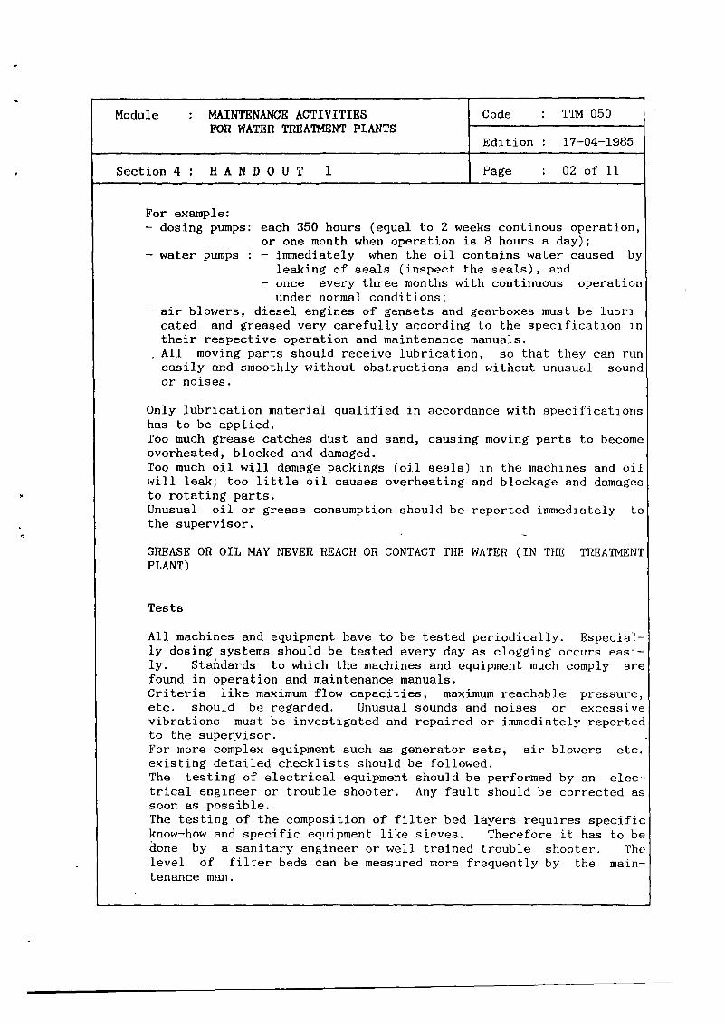
Module : MAINTENANCE ACTIVITIESFOR WATER TREAThENT PLANTS
Code : TN 050
Edition : 17—04—1985
Section 4 : H A N D 0 U T 1 Page : 02 of 11
For example:— dosing pumps:
— water pumps
Only lubrication material qualified in accordance with specificationshas to be applied.Too much grease catches dust and sand, causing moving parts to becomeoverheated, blocked and damaged.Too much oil will damage packings (oil seals) in the machines and oilwill leak; too little oil causes overheating and blockage and damagesto rotating parts.Unusual oil or grease consumption should be reported immediotely tothe supervisor.
GREASE OR OIL MAY NEVER REACH OR CONTACT THE WATER (IN THE TREATMENTPLANT)
Tests
All machines and equipment have to be tested periodically. Especial-ly dosing systems should be tested every day as clogging occurs easi-ly. Standards to which the machines and equipment much comply arefound in operation and maintenance manuals.Criteria like maximum flow capacities, maximum reachable pressure,etc. should be regarded. Unusual sounds and noises or excessivevibrations must be investigated and repaired or immediately reportedto the supervisor.For more complex equipment such as generator sets, air blowers etc.existing detailed checklists should be followed.The testing of electrical equipment should be performed by an elec-trical engineer or trouble shooter. Any fault should be corrected assoon as possible.The testing of the composition of filter bed layers requires specificknow—how and specific equipment like sieves. Therefore it has to beaone by a sanitary engineer or well trained trouble shooter. Thelevel of filter beds can be measured more frequently by the main-tenance man.
each 350 hours (equal to 2 weeks continous operation,or one month when operation is 8 hours a day);— immediately when the oil contains water caused by
leaking of seals (inspect the seals), and— once every three months with continuous operation
under normal conditions;— air blowers, diesel engines of gensets and gearboxes must be lubri-
cated and greased very carefully according to the specification intheir respective operation and maintenance manuals.All moving parts should receive lubrication, so that they can runeasily and smoothly without obstructions and without unusuEd soundor noises.


Module : MAINTENANCEACTIVITIESFOR WATER TREATMENT PLANTS
Code : TN 050
Edition : 17—04—1985
Section 4 : H A N D 0 U T 1 Page : 03 of 11
Cleaning
The plant, the building inside and outside and the site of the plantshould always look like they are just cleaned.
The inside walls of the plant should be cleaned once a month withwater and brush.Once a year the clear water reservoirs’ floor and walls (inside)should be brushed with lots of water. Afterwards they should bedig infeeted.Manholes in the reservoir must be clean and free.
Solid waste and waste oil must be carefully collected an properlydisposed of.Never drain fuel and oil to water carrying bodies such as rivers,water sources, canals, etc. or directly upon or into the ground.
Ground mixed with oil or fuel should be collected and properly dis-posed of.Waste chemicals and chemical solutions should be rinsed away ~withplenty of water.Substantial amounts of kaporit should never be dumped into a river orcanal; they will unnecessarily kill biological life.
ALWAYS REMEMBFH THAT THE TREAThIENT PLANT AND ITS RESERVOIRS CONTAINWATER THAT WILL BE USED FOR HUMAN CONSUMPTION.
Overhauls
Periodic overhauls will extend the lifetime of the machines due tothe exchange of vital parts of them.Overhauls have to be done regularly, depending on the number ofoperating hours of the equipment.Overhaul, for simple equipment such as gate valves, etc. can be doneat the plant site.For overhauls of pumps and electricmotors (smaller size) the equip-ment can be sent to an adequate workshop. Overhauls of big pumps, -
motors, air blowers, compressor and generator sets should he done onsite, by a special maintenance team and using the proper tools andinstruction sheets.Once every two years the control panels and the electrical systemmust receive a full check—up and vital items must be repaired orreplaced.

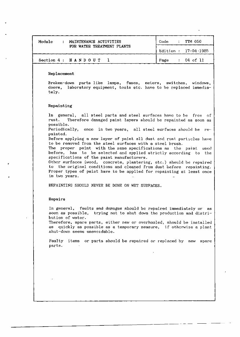
Module : MAINTENANCEACTIVITIESFOR WATERTREA~NENTPLANTS
Code : TTh 050
Edition 17—04—1985
Section 4 : H A N D 0 U T 1 Page : 04 of 11
Replacement
Broken—down parts like lamps, fuses, inel.ers, switches, windows,doors, laboratory equipment, tools etc. have to be replaced iinmedia—tely.
Repainting
In general, all steel parts and steel surfaces have to be free ofrust. Therefore damagedpaint layers should be repainted as soon aspossible.Periodically, once in two years, all steel surfaces should be re—painted.Before applying a new layer of paint all dust and rust particles haveto be removed from the steel surfaces with a steel brush.The proper paint with the same specifications as the paint usedbefore, has to be selected and applied strictly according to thespecifications of the paint manufacturers.Other surfaces (-wood, concrete, plastering, etc.) should be repairedto the original conditions and cleaned from dust before repainting.Proper types of paint have to be applied for repainting at least oncein two years. —REPAINTING SHOULD NEVER BE DONE ON WET SURFACES.
Repairs
In general, faults and damages should be repaired immediately or assoon as possible, trying not to shut down the production and distri—bution of water.Therefore, spare parts, either new or overhauled, should be installedas quickly as possible as a temporary measure, if otherwise a plantshut—down seems unavoidable.
Faulty items or parts should be repaired or rep]aced by new~ spareparts. -


Module MAINTENANCEACTIVITIESFOR WATER TREATMENTPLANTS
Code : TTh1 050
Edition : 17—04—1985
Section 4 : H A N D 0 U T 1 Page : 05 of 11
3. SIMIARY
— Routine maintenance.— Periodic preventive maintenance.— Repair/replacement of failures.— General instructions for:
inspection;lubrications;tests;cleanings;overhauls;repainting;repair/replacement.


Module : MAINTENANCE ACTIVITIESFOR WATERTREATMENT PLANTS
Code : TN 050
Edition : 17—04—1985
Section 4 H A N D 0 U T 2 Page : 06 of 11
EXAMPLE
NAME: LOCATION WEEK NO: *)
ITEM CHECK LUBR. TEST CLEAN OVER—HAUL
REMARKS
INTAKE SCREEN 0INTAKE PUMPS 0FLOW METER 0 0PLANT BASINS 0PADDLES (FLOCC.) oPLATES (SETTLER) 0FILTER BEDFILTER BACKWASH 0FILTER SURFACEWASH 0 .VALVESVALVES OPERATORS 0 0PRESSUREMETERS 0DOSING SYSTEMS 0 0 0BACKWASHPUMPSSURFACE WASH PUMPSEFFLUENT PUMPSAIR BLOWER(S) 0AIR COMPRESSOR 0 0DISTRIBUTION PUMPSHYDROPHORE 0GENSETS 0 0ELECTRICAL SYSTEMSLEVEL SWITCH INDIC. 0FLOW SWITCH INDIC. 0DRAINAGE SYSTEM 0BUILDINGS 0 0CONCRETE STRUCTURES 0SITE 0 0
WEEKLY INSTRUCTIONS CHECK/LUBR./TEST/CLEAN/OVERHAUL
Every week except Week 5, 25 and 51


Module : MAINTENANCEACTIVITIESFOR WATER TREAThiENT PLANTS
Code : TTh1 050
Edition : 17—04—1985
Section 4 : H A N D 0 U T 2 Page : 07 of 11
EXAMPLE
NAME: LOCATION WEEKNO: 5
ITEM CHECK LUBR. TEST CLEAN OVER— REMARKSHAUL
INTAKE SCREEN 0INTAKE PUMPS 0 0FLOWMETER 0PLANT BASINS 0PADDLES (FLOCC.) 0PLATES (SETTLER) 0FILTER BED 0FILTER BACKWASH 0FILTER SURFACEWASH 0VALVESVALVES OPERATORS 0 0PRESSUREMETERSDOSING SYSTEMS 0 0BACKWASHPUMPS 0 0SURFACEWASHPUMPS 0 0EFFLUENT PUMPS 0 -- 0 -
AIR BLOWER(S) 0AIR COMPRESSOR 0DISTRIBUTION PUMPS 0 0HYDROPHORE 0GENSETS 0ELECTRICAL SYSTEMSLEVEL SWITCH INDIC. 0FLOW SWITCH INDIC. 0DRAINAGE SYSTEM 0BUILDINGS 0CONCRETE’ STRUCTURESSITE 0
WEEKLY INSTRUCTIONS CHECK/LUER./TEST/CLEAN/OVERHAUL

p.

Module : MAINTENANCE ACTIVITIESFOR WATERTREATMENTPLANTS
Code : TN 050
Edition : 17—04—1985
Section 4 : H A N D 0 U T 2 Page : 08 of 11
EXAMPLE
NAME: LOCATION WEEK NO: 25
ITEM CHECK LUBR. TEST CLEAN OVER—HAUL
REMARKS
INTAKE SCREENINTAKE PUMPSFLOWMETERPLANT BASINSPADDLES (FLOCC.)PLATES (SETTLER)FILTER BEDFILTER BACKWASHFILTER SURFACEWASHVALVESVALVES OPERATORSPRESSUREMETERSDOSING SYSTEMSBACKWASHPUMPSSURFACEWASHPUMPSEFFLUENT PUMPSAIR BLOWER(S)AIR COMPRESSORDISTRIBUTION PUMPSHYDROPHOREGENSETSELECTRICAL SYSTEMSLEVEL SWITCH INDIC.FLOWSWITCH INDIC.DRAINAGE SYSTEMBUILDINGSCONCRETESTRUCTURESSITE
0
000
0
0
0
000o00
0
0
00000
0000000
0
00
00o000
00
00
00000
0
00
0
REPAINT
WEEKLY INSTRUCTIONS CHECK/LUBR./TEST/CLEAN/OVERHAUL

4.
4

Module : MAINTENANCEACTIVITIESFOR WATERTREAThIENT PLANTS
Code : TTh 050
Edition : 17—04—1985
Section 4 : H A N D 0 U T 2 Page :. 09 of 11
EXAMPLE
NAME: LOCATION WEEK NO: 51
ITEM CHECK LUSH. TEST CLEAN OVER—HAUL
REMARKS
INTAKE SCREEN 0INTAKE PUMPS 0 0 0 0FLOW METER 0PLANT BASINS 0 REPAINTPADDLES (FLOCC.) 0 0PLATES (SETTLER) 0FILTER BED 0FILTER BACKWASH 0FILTER SURFACEWASH 0VALVES 0VALVES OPERATORS 0 0PRESSUREMETERS 0DOSING SYSTEMS 0 0 0 0BACKWASH PUMPS 0 0SURFACEWASHPUMPS 0 0EFFLUENT PUMPS 0 0AIR BLOWER(S) 0 0 0AIR COMPRESSOR 0 0 0DISTRIBUTION PUMPS 0 0HYDROPHORE 0 0 0G~NSETS 0 0 0 0 0ELECTRICAL SYSTEMS 0LEVEL SWITCH INDIC. 0 0FLOW SWITCH INDIC. 0 0DRAINAGE SYSTEM 0BUILDINGS 0CONCRETESTRUCTURES 0 REPAINTSITE 0
WEEKLY INSTRUCTIONS CFIECK/LUBR. /TEST/CLEAN/OVERHAUL


Module : MAINTENANCEACTIVITIESFOR WATERTREAIMENT PLANTS
Code : TTh 050
Edition : 17—04—1985
Section4 : HANDOUT 2 Page : lOof 11
Lubri—cant
Suction valveDischargevalveInterior faceof cylinderWater jacket
Piston ring
Drain tank
Level gaugeof lubricantLubricanttank forcrank case
Gland packing
Wiper ring
SuctionstrainerPilot valve
V—belt
ReceiverAfter coolerSafety valve
Each bearing& other wholebody
Dismantle & cleanDismantle & clean
Overhaul abrasiveconditionRemove iricrusta—t ionOverhaul whetheror not somethingabnormalDrain discharge
Examine lubricantquantityExchange lubri-cant
Overhaul defect,abrasion, etc.Overhaul, defect,abrasion, etc.Clean: 1st layer
2nd layerDismantle, clean,confirm thefunctioningAdjust thetensionDischarge drainDischarge drainConfirm thefunctioningOverhaul
a = 8 hours;c = 250 hours;e = 2000 hours;g = 4000 hours.
b = 60 hours;d 1000 hours;f = 3000 hours;
EXAMPLE
Cylin-der
part Contents of worksOverhaul time
— — — — —a b c d e f g
0
0
0
0
0
0
Others 0
0
0
0
0
0 0
0
0
0
0


Module : MAINTENANCEACTIVITIESFOR WATER TREANENT PLANTS
Code : TN 050
Edition : 17—04—1985
Section 4 : H A N D 0 U T 2 Page : 11 of 11
EXAMPLE
Partto beinspected
PoiDtsof inspection
and adJustaents
To b. carri.d out:
Daily 50 hr. 100 hr. 200 hr. 800 hr.
Fuel valve Inspection of Jet pressureand_auto.izing_condition
o
Functioning exasination of~et valve
duringthe ope.
AdJustaent of Jet voluse o
Fuel pusp Cleaning of filter .esh offuel puap
o
Test of discharge valve andoil_density_of_plunger
Working exeination of fuelpuap
duringthe ope—ration
to bere—placed
Fuelfilter
Exasination, cleaning andreplaceaent of filter
afterthe ope—rat ion
o
Lubricant Exa..ination and supply oflubricant and dirt,replaceisent of lubricant
afterthe ope-ration
o
Supply of each part o
Lubricantfilter
Cleaning & rcplaceaent offilter and its segh
a to bere-placed
Suction &exhaustvalves
AdJust.ant & inspection ofgap between the valves
~ •
o
Cylinder Exa.inetion of co~presslveforce of each cylinder
o
Piston andbearing
Exasipation of abrasion anddasage after diasantling
0
> 2.000
Loosenessof boltssnd nuts
Exasination of each pert afterthe ope—ration
o
Aircleaner
Cleaning of the inside andoil change
o
Coolingwater
Supply, replace.entand flushing
beforethe ope-ration
o
Engine Ad)ustaent of idling oFlushing o
Gauge duringthe ope—ration
Electricsystea
Tension oOil supply of startIng
sotoro
Exasination of starting.otor generator & regulator
o
Oil supply to generator o
Otherparts
Exasination of startingi,otor pinion, flywheelring_gear
o
Ther.o~tat a

I
r1


Related Documents