1 ELECTRICAL AND ELECTRONICS FUNDAMENTALS ELEC 1003

Welcome message from author
This document is posted to help you gain knowledge. Please leave a comment to let me know what you think about it! Share it to your friends and learn new things together.
Transcript
1
ELECTRICAL AND ELECTRONICS FUNDAMENTALS
ELEC 1003
2
Concepts of Electricity
•All matter (solids, liquids or gases) contain two basic particles of electric charge…..the electron and proton
•An electron is negatively charged, while a proton is positively charged.
•All materials contain equal quantities of electrons and protons making the material electrically neutral.
•By applying some force (friction, heat, voltage, light, radiation, etc.) the material’s electrical balance can be changed thereby generating electricity.
3
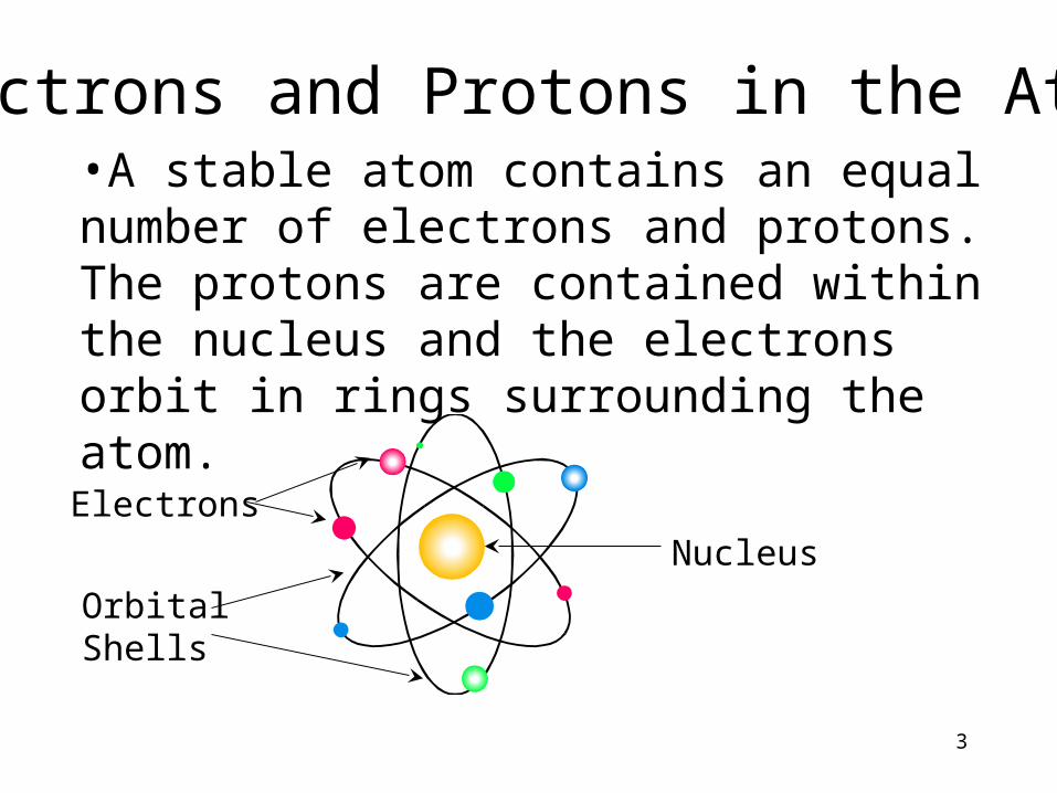
Electrons and Protons in the Atom•A stable atom contains an equal number of electrons and protons. The protons are contained within the nucleus and the electrons orbit in rings surrounding the atom.
NucleusElectrons
OrbitalShells
4
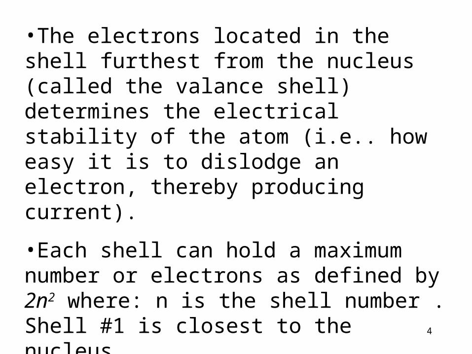
•The electrons located in the shell furthest from the nucleus (called the valance shell) determines the electrical stability of the atom (i.e.. how easy it is to dislodge an electron, thereby producing current).•Each shell can hold a maximum number or electrons as defined by 2n2 where: n is the shell number . Shell #1 is closest to the nucleus. •The fewer the number of electrons in the valance shell the less stable is the atom.
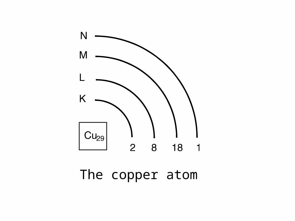
The copper atom
6
•When some external force causes a valence electron to leave its shell, a hole is left and the atom becomes a positive ion. If an electron moves into an atom where the valance shell is incomplete (where a hole exists) the atom becomes a negative ion.•This movement of electrons from atom to atom due to an external force such as heat is random and produces no net movement of electrons in any particular direction .
•If an external force such as an electromotive force(EMF) is applied between two points of a conductor then the net flow of electrons is in a particular direction .
•The rate of flow of these electrons is called current
•Electron Current flow is the movement of electrons within the conductor.
•Conventional Current flow is the movement of holes within the conductor.
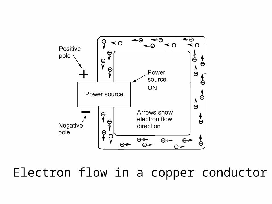
Electron flow in a copper conductor
9
•A conductor (copper, silver, aluminium) is any material which has very few electrons in the valence shell of the atom and will provide current flow easily.•An insulator (rubber, glass, plastic) is any material in which the valence shell is completely full with electrons. Electrons are tightly bound and current flow is strongly resisted.•A semiconductor (silicon, germanium) is any material in which the valance shell is only half full with electrons.
10
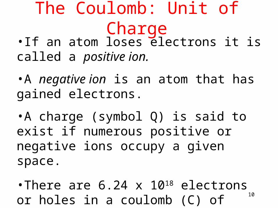
The Coulomb: Unit of Charge
•If an atom loses electrons it is called a positive ion. •A negative ion is an atom that has gained electrons.•A charge (symbol Q) is said to exist if numerous positive or negative ions occupy a given space.•There are 6.24 x 10¹⁸ electrons or holes in a coulomb (C) of charge. Each electron or hole has a charge of: 1C 6.24 x 1018 = 1.6 x 10 -19 C
Calculate the charge of:
a. 4.5x10²⁰ electrons
b. 2.75x10²² protons
Exercise
12
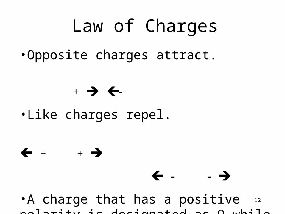
Law of Charges•Opposite charges attract. + •Like charges repel. + +
•A charge that has a positive polarity is designated as Q while a negative charge is shown a -Q.
13
The Volt: Unit of Potential Difference
•An electrostatic field exists around each charge.•When two unlike charges exist in the same vicinity an attractive electrostatic field results.•When like charges exist in the same vicinity a repulsive electrostatic field results.•Potential refers to the possibility of doing work by a charge placed in this resulting field.
14
•Potential difference between two points in the field is the work needed to move a unit charge between both points.•V = W/Q•The unit of PD is the volt (symbol V or E) and is the unit of work needed to move a unit charge between the two points.
15
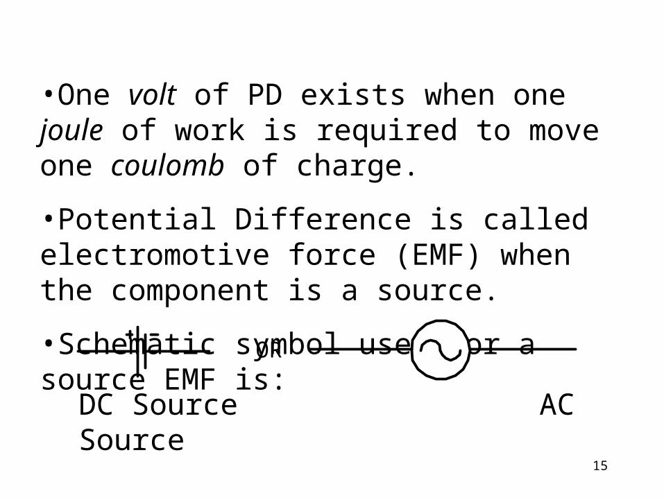
•One volt of PD exists when one joule of work is required to move one coulomb of charge.•Potential Difference is called electromotive force (EMF) when the component is a source.•Schematic symbol used for a source EMF is:
OR
DC Source AC Source
72 J of energy is expended to add 50x1018 electrons to an uncharged body.
a. What charge is transferred?
b. What is the potential of the body?
Exercise
17
Charge in Motion (Current)•When the PD between two charges
forces a third charge (electrons or holes) to move through a conductor, the charge in motion is an electric current. •Current (I) is defined as the rate of flow of charge. When one coulomb of charge passes a given point in one second, one ampere (A) of current exists. where: I is current in Amps, Q is charge in Coulombs and t = time is seconds.
tQI
18
•When 5 C of charge moves past a given point in 100 seconds, determine the current. I = Q / t = (5 x 10⁻⁶) (100 x 10-6 ) = 50 mA•The amount of current flowing depends on the PD and the resistance (R) of the conductor. As PD, I . And as R, I.•Current can be defined in terms of electron current flow or in terms of conventional current (hole) flow. With electron flow the electrons are said to move from the - + of the source of PD. With conventional flow the holes move from the + - of the source of PD.
1. Find the current in a conductor through which 1.25x10²⁰ electrons pass in 5 seconds.2. How many electrons pass a given point in 2.2 milliseconds in a conductor carrying 0.96 nA?
Exercise
20
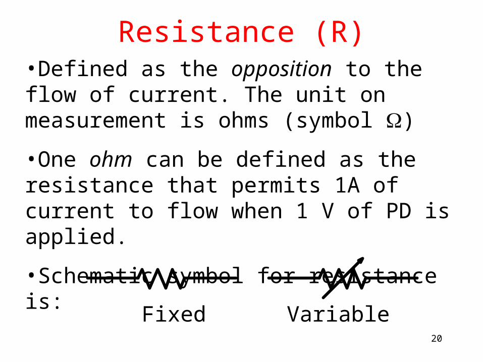
Resistance (R)•Defined as the opposition to the flow of current. The unit on measurement is ohms (symbol )•One ohm can be defined as the resistance that permits 1A of current to flow when 1 V of PD is applied.•Schematic symbol for resistance is: Fixed Variable
21
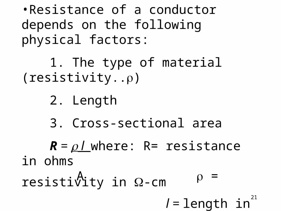
•Resistance of a conductor depends on the following physical factors:
1. The type of material (resistivity..)
2. Length3. Cross-sectional areaR = l where: R= resistance
in ohms A = resistivity in -cm
l = length in cm
A = area in square cm
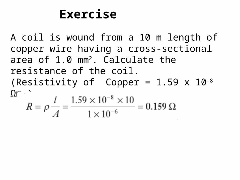
A coil is wound from a 10 m length of copper wire having a cross-sectional area of 1.0 mm2. Calculate the resistance of the coil.(Resistivity of Copper = 1.59 x 10⁻⁸
Ωm )
Exercise
23
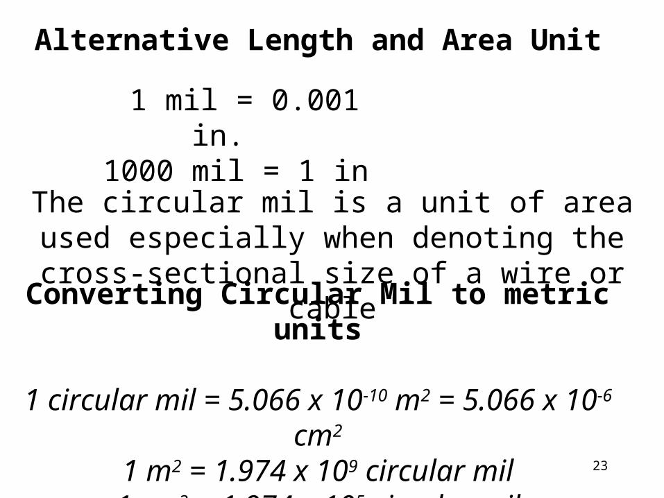
1 mil = 0.001 in.
1000 mil = 1 in
Alternative Length and Area Unit
The circular mil is a unit of area used especially when denoting the cross-sectional size of a wire or
cableConverting Circular Mil to metric units
1 circular mil = 5.066 x 10⁻¹⁰ m2 = 5.066 x 10⁻⁶ cm2
1 m2 = 1.974 x 10⁹ circular mil1 cm2 = 1.974 x 10⁵ circular mil
24
Standard Wire Sizes are in American Wire Gauge (AWG) tables. The smaller the AWG number the larger the conductor size
American Wire Gauge
The AWG standard includes copper, aluminum and other wire materials.
Typical household copper wiring is AWG number 12 or 14.
Telephone wire is usually 22, 24, or 26.
The higher the gauge number, the smaller the diameter and the thinner the wire.
25
Resistance Variation with Temperature. •Some materials (i.e. copper, aluminum, gold and silver) exhibit an increase in resistance as the temperature increases. This is called a material with a positive temperature coefficient (PTC). •Any material (i.e. silicon, germanium) whose resistance decreases with an increase in temperature has a negative temperature coefficient (NTC)..
26
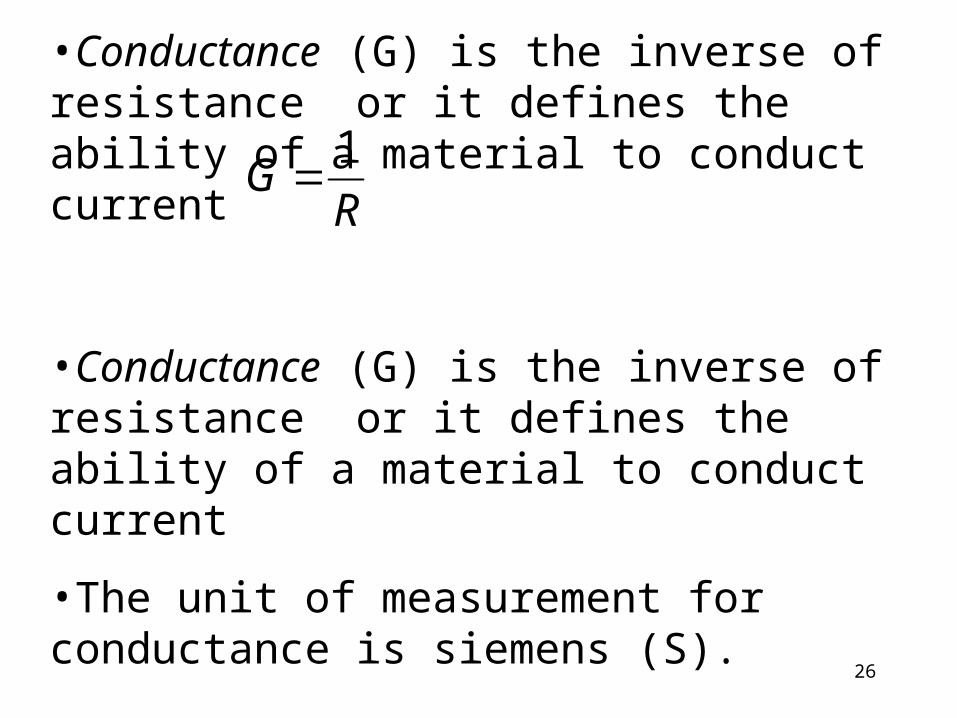
•Conductance (G) is the inverse of resistance or it defines the ability of a material to conduct current
•Conductance (G) is the inverse of resistance or it defines the ability of a material to conduct current•The unit of measurement for conductance is siemens (S).
RG 1
27
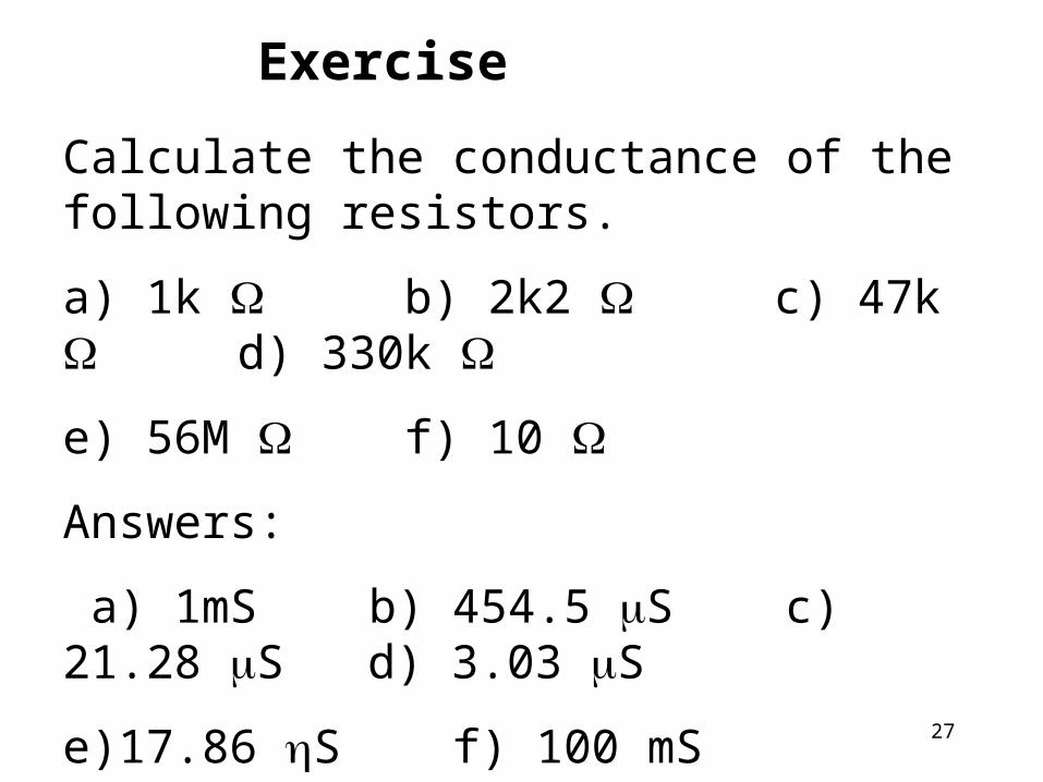
Calculate the conductance of the following resistors. a) 1k b) 2k2 c) 47k d) 330k e) 56M f) 10 Answers: a) 1mS b) 454.5 S c) 21.28 S d) 3.03 S e)17.86 S f) 100 mS
Exercise
RESISTORA device or component whose main property is to resist or reduce a current in a circuit is called a resistor.
A resistor also dissipates energy in the form of heat. This energy is lost and can never be returned to the source.
29
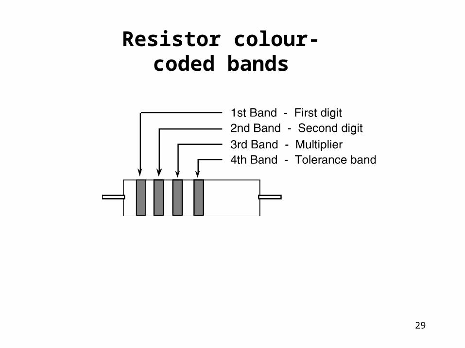
Resistor colour-coded bands
30
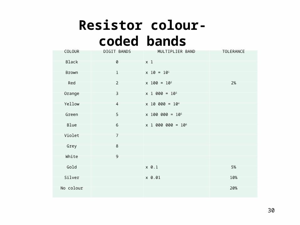
Resistor colour-coded bands
COLOUR DIGIT BANDS MULTIPLIER BAND TOLERANCE
Black 0 x 1
Brown 1 x 10 = 101
Red 2 x 100 = 102 2%
Orange 3 x 1 000 = 103
Yellow 4 x 10 000 = 104
Green 5 x 100 000 = 105
Blue 6 x 1 000 000 = 106
Violet 7
Grey 8
White 9
Gold x 0.1 5%
Silver x 0.01 10%
No colour 20%
31
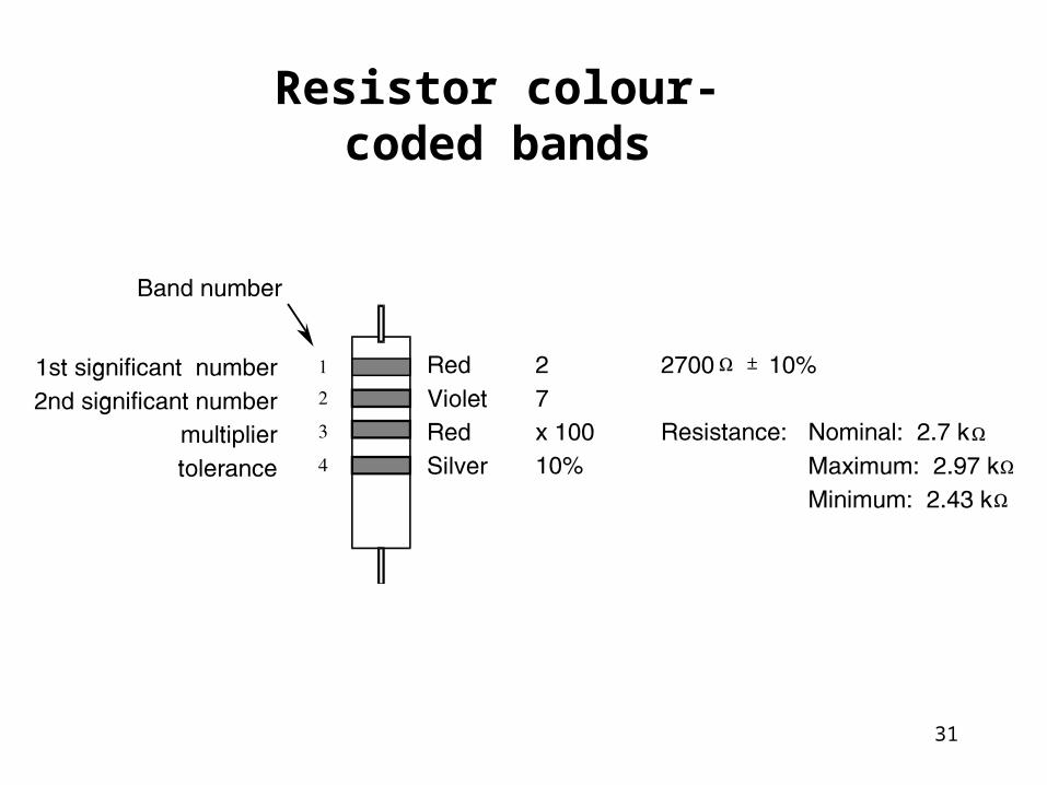
Resistor colour-coded bands
32
Types of Resistors1. Fixed•Most commonly used resistors are made from molded carbon composition.•Other types of fixed resistors include the wire wound, the metal film, ceramic, and surface mount.•Power rating of resistors refers to the ability of the resistor to dissipate power in the form of heat.
33
•Power or wattage rating of resistors is determined by the physical size of the resistor. •Choose resistors for your circuit that will dissipate less than the power rating of the resistor.2. Variable Resistors •are resistors in which the resistance value can be adjustable. • can be either 2 or 3 terminal devices.
34
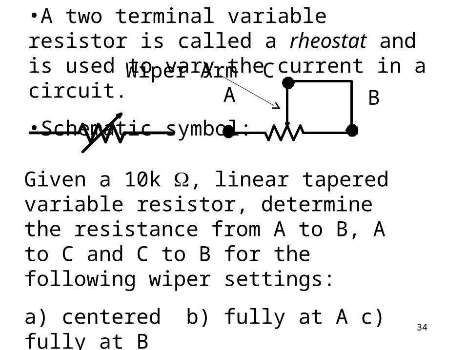
•A two terminal variable resistor is called a rheostat and is used to vary the current in a circuit.•Schematic symbol:
Given a 10k , linear tapered variable resistor, determine the resistance from A to B, A to C and C to B for the following wiper settings:a) centered b) fully at A c) fully at B
AC
BWiper Arm
35
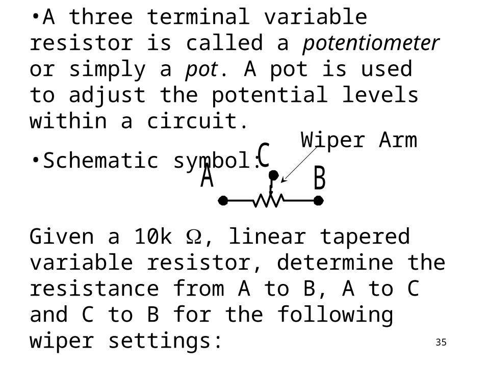
•A three terminal variable resistor is called a potentiometer or simply a pot. A pot is used to adjust the potential levels within a circuit.•Schematic symbol:A BC
Given a 10k , linear tapered variable resistor, determine the resistance from A to B, A to C and C to B for the following wiper settings:a) centered b) fully at A c) fully at B
Wiper Arm
36
37
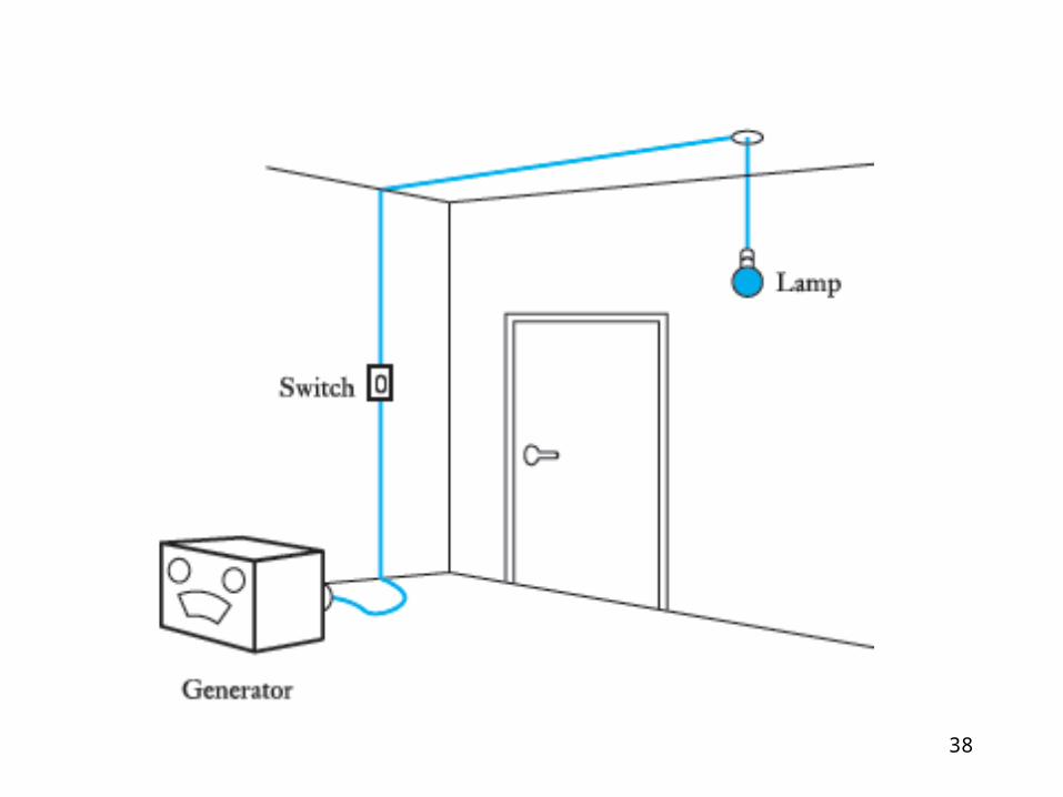
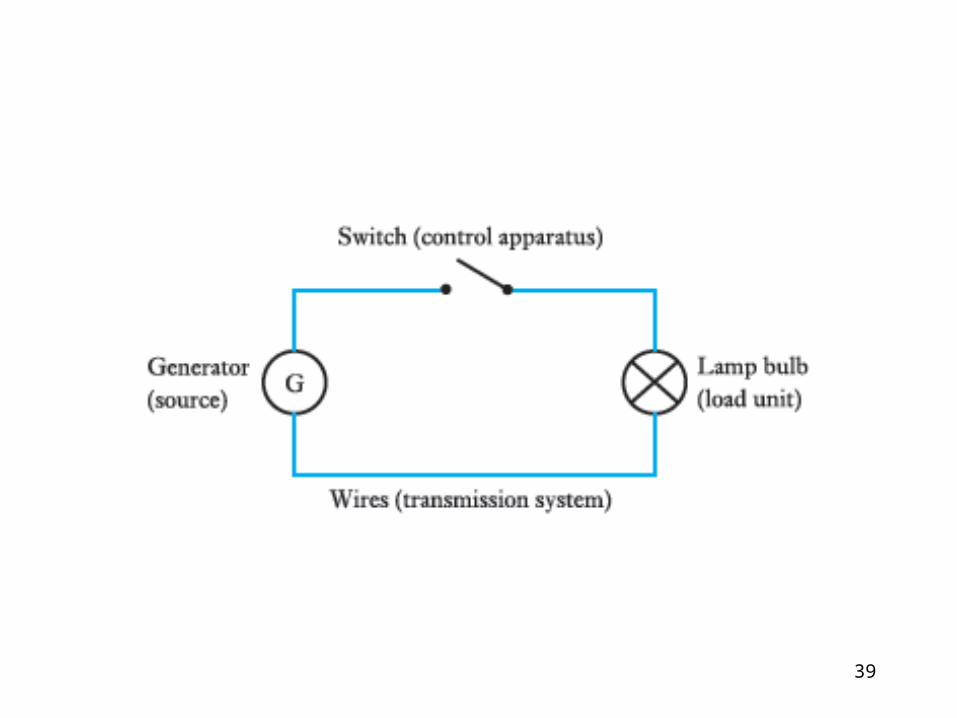
The Electric Circuit•Is a schematic diagram using component symbols.•Consists of the following characteristics:
1. Must have some source of PD. (E)
2. Must have some resistance (load). (R)
3. Must have a connecting path for the flow of current. 4. Must have a control switch
38
39
Other Parts•A protective element is also found in most circuits
•This can be a fuse or circuit breaker
41
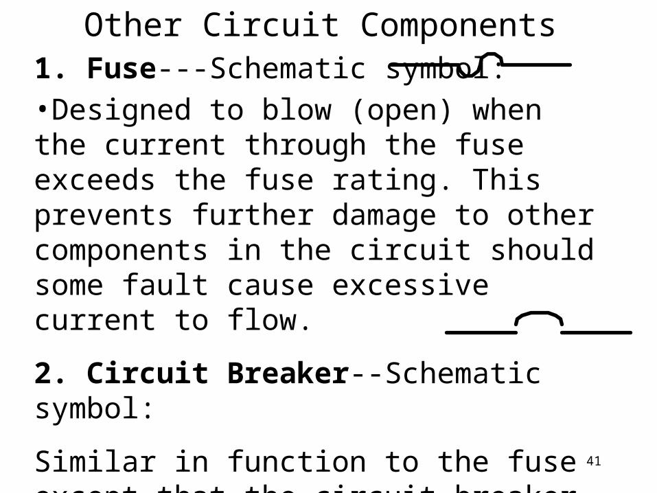
Other Circuit Components1. Fuse---Schematic symbol:•Designed to blow (open) when the current through the fuse exceeds the fuse rating. This prevents further damage to other components in the circuit should some fault cause excessive current to flow.2. Circuit Breaker--Schematic symbol:Similar in function to the fuse except that the circuit breaker can be reset when the cause for the excessive circuit current is repaired.
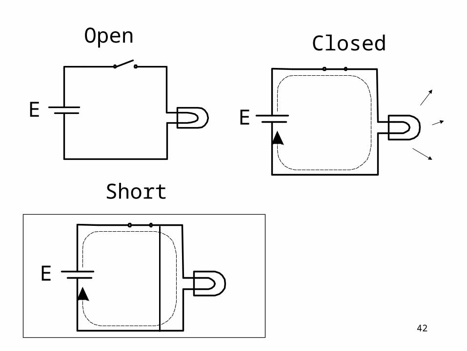
42
Open Closed
EE
E
Short

43
Types of Switches1. Single Pole Single Throw (SPST)
44
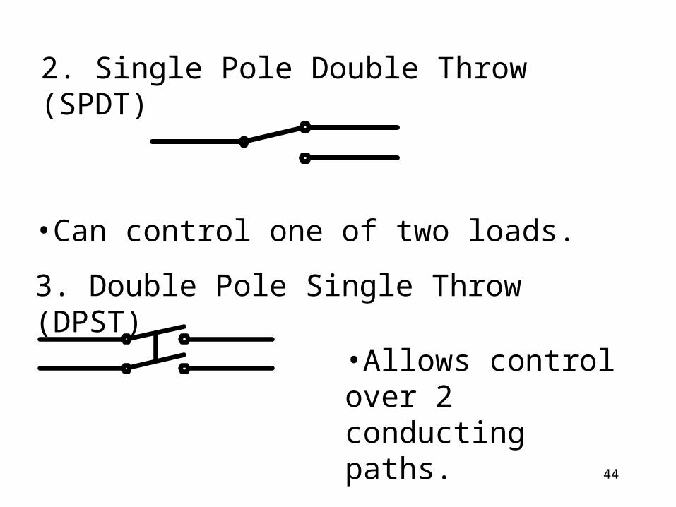
2. Single Pole Double Throw (SPDT)
•Can control one of two loads.3. Double Pole Single Throw (DPST)
•Allows control over 2 conducting paths.
45
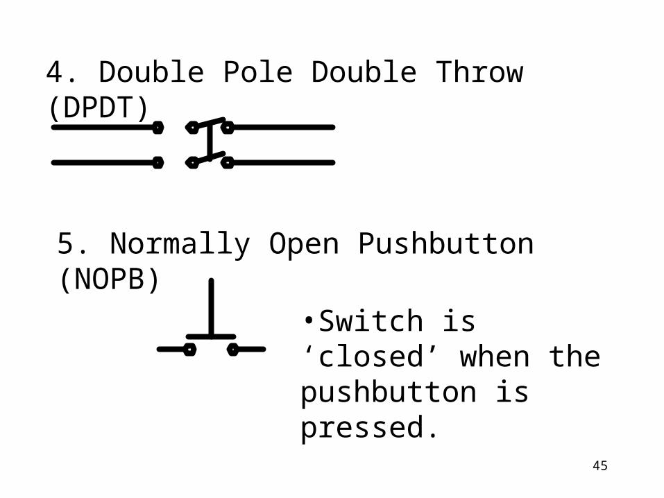
4. Double Pole Double Throw (DPDT)
5. Normally Open Pushbutton (NOPB)
•Switch is ‘closed’ when the pushbutton is pressed.
46
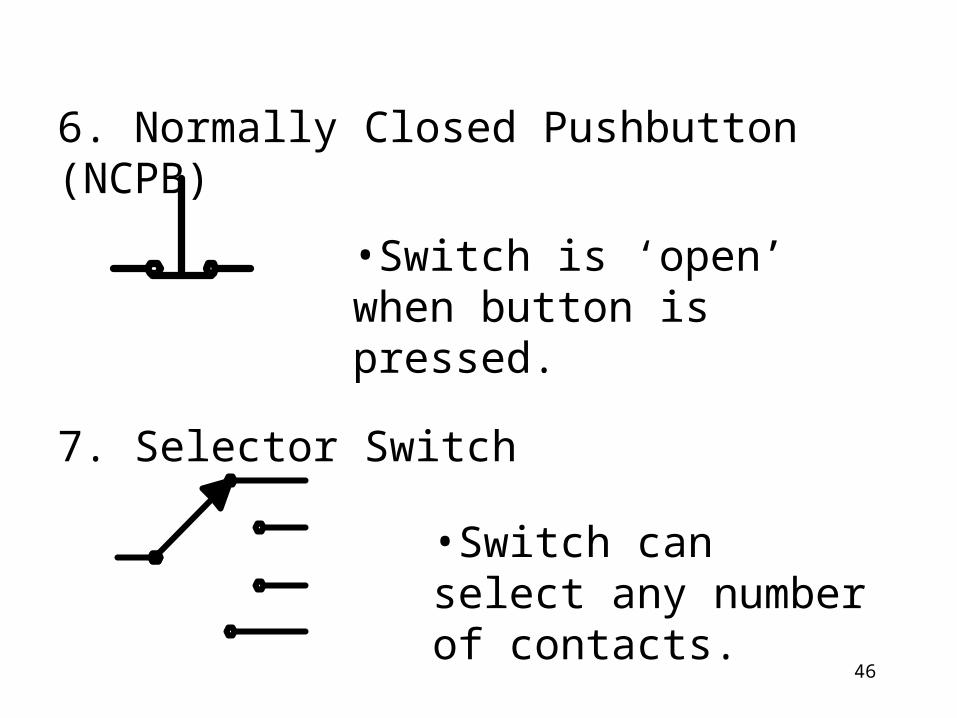
6. Normally Closed Pushbutton (NCPB)
•Switch is ‘open’ when button is pressed.
7. Selector Switch
•Switch can select any number of contacts.
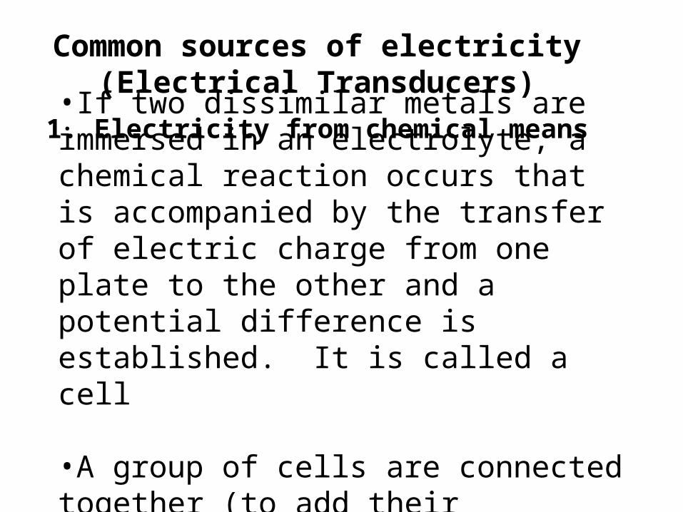
Common sources of electricity(Electrical Transducers)
1. Electricity from chemical means•If two dissimilar metals are immersed in an electrolyte, a chemical reaction occurs that is accompanied by the transfer of electric charge from one plate to the other and a potential difference is established. It is called a cell
•A group of cells are connected together (to add their voltages) to make a battery.
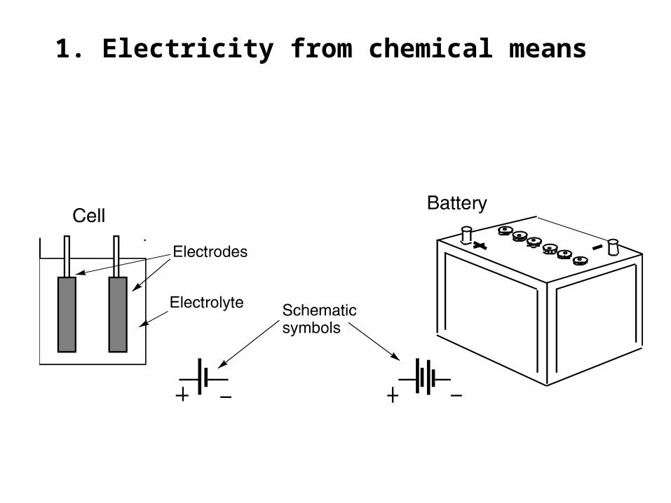
1. Electricity from chemical means
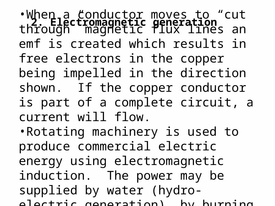
2. Electromagnetic generation•When a conductor moves to “cut through” magnetic flux lines an emf is created which results in free electrons in the copper being impelled in the direction shown. If the copper conductor is part of a complete circuit, a current will flow.•Rotating machinery is used to produce commercial electric energy using electromagnetic induction. The power may be supplied by water (hydro-electric generation), by burning fuel or by wind
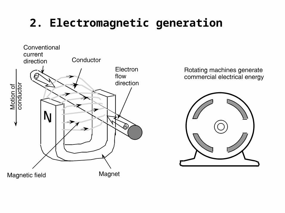
2. Electromagnetic generation
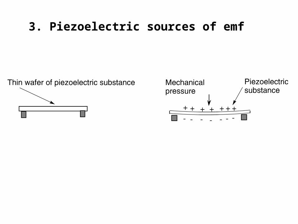
3. Piezoelectric sources of emf
Small emfs can be produced by applying mechanical pressure to some crystalline substances such as Rochelle salt (sodium potassium tartrate), quartz (silicon dioxide) and ceramic materials (lead zirconate tartrate).
3. Piezoelectric sources of emf
•The voltage produced is a signal. Although small, it can readily be amplified by electronic circuitry.
•Some examples of applications are:
microphonesmedical applications (e.g.,
stethoscopes)frequency control
applicationspick-up cartridges
3. Piezoelectric sources of emf
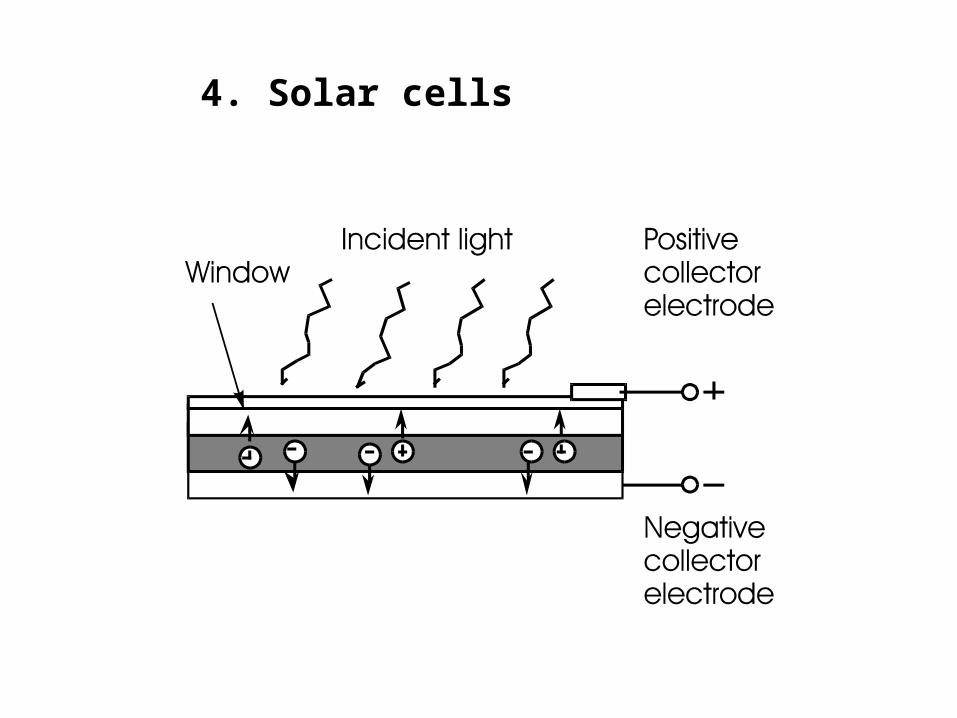
4. Solar cellsLight is another form of energy that can be converted directly to electrical energy by means of solar cells and photocells. They are referred to as photovoltaic devices
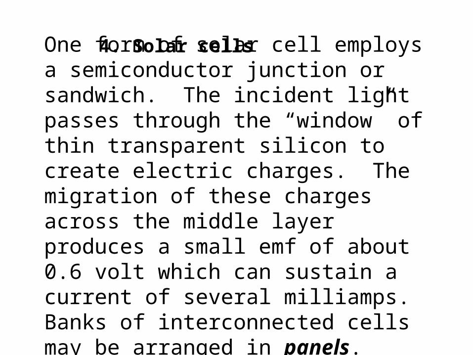
One form of solar cell employs a semiconductor junction or sandwich. The incident light passes through the “window” of thin transparent silicon to create electric charges. The migration of these charges across the middle layer produces a small emf of about 0.6 volt which can sustain a current of several milliamps. Banks of interconnected cells may be arranged in panels.
4. Solar cells
4. Solar cells
5. Thermoelectric voltage production
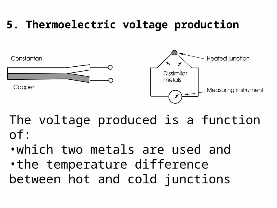
Heat energy can be transformed directly into electrical energy by a device called a thermocouple. Two dissimilar metals form a junction that, when heated, produces an emf between this heated junction and the cold ends of the metals.
5. Thermoelectric voltage production
The voltage produced is a function of:•which two metals are used and•the temperature difference between hot and cold junctions
5. Thermoelectric voltage productionOne of the applications of thermocouples is in the field of temperature measurement. They are especially suited to measuring temperatures beyond the range of liquid-in-glass types of thermometer. These instruments are called pyrometers and can be used for temperatures in excess of 1,500C. To provide higher and more useful voltages, thermocouples can be connected together into a thermopile

60
THE END
Related Documents