1 Concept of Routing in Network Layer

1 Concept of Routing in Network Layer. 2 Network Layer II (routing) Routing Styles: Static vs. Dynamic Routing Routing Protocols/Algorithms Routing.
Dec 25, 2015
Welcome message from author
This document is posted to help you gain knowledge. Please leave a comment to let me know what you think about it! Share it to your friends and learn new things together.
Transcript
1
Concept of Routing in Network Layer
2
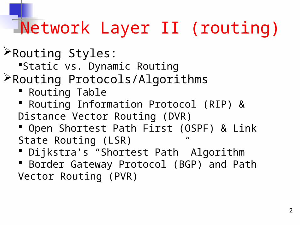
Network Layer II (routing)Routing Styles:
Static vs. Dynamic RoutingRouting Protocols/Algorithms
Routing Table Routing Information Protocol (RIP) & Distance Vector Routing (DVR) Open Shortest Path First (OSPF) & Link State Routing (LSR) Dijkstra’s “Shortest Path” Algorithm Border Gateway Protocol (BGP) and Path Vector Routing (PVR)
Routing Protocol & Routing Algorithm
3
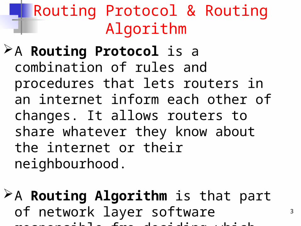
A Routing Protocol is a combination of rules and procedures that lets routers in an internet inform each other of changes. It allows routers to share whatever they know about the internet or their neighbourhood.
A Routing Algorithm is that part of network layer software responsible fro deciding which output line and incoming packet should be transmitted on.
4
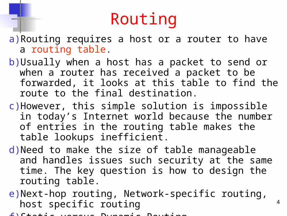
Routinga) Routing requires a host or a router to have a routing table.b) Usually when a host has a packet to send or when a router has
received a packet to be forwarded, it looks at this table to find the route to the final destination.
c) However, this simple solution is impossible in today’s Internet world because the number of entries in the routing table makes the table lookups inefficient.
d) Need to make the size of table manageable and handles issues such security at the same time. The key question is how to design the routing table.
e) Next-hop routing, Network-specific routing, host specific routingf) Static versus Dynamic Routingg) Routing Protocols: RIP, OSPF, BGPh) Routing Algorithms: DVR, LSR, PVR
5
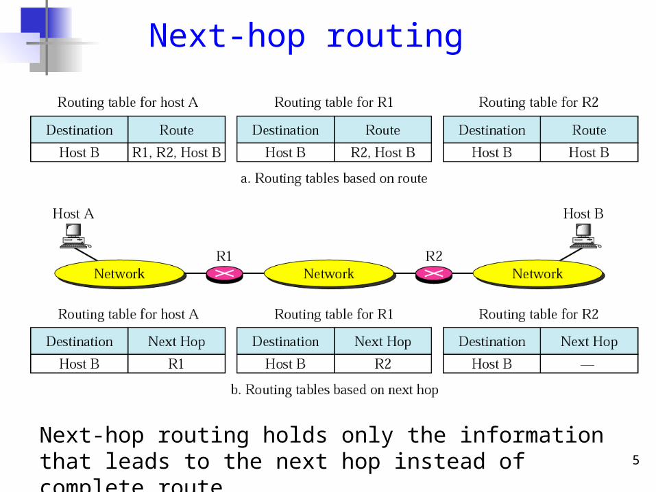
Next-hop routing
Next-hop routing holds only the information that leads to the next hop instead of complete route.
6
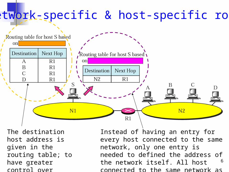
Network-specific & host-specific routing
Instead of having an entry for every host connected to the same network, only one entry is needed to defined the address of the network itself. All host connected to the same network as one single entity.
The destination host address is given in the routing table; to have greater control over routing.
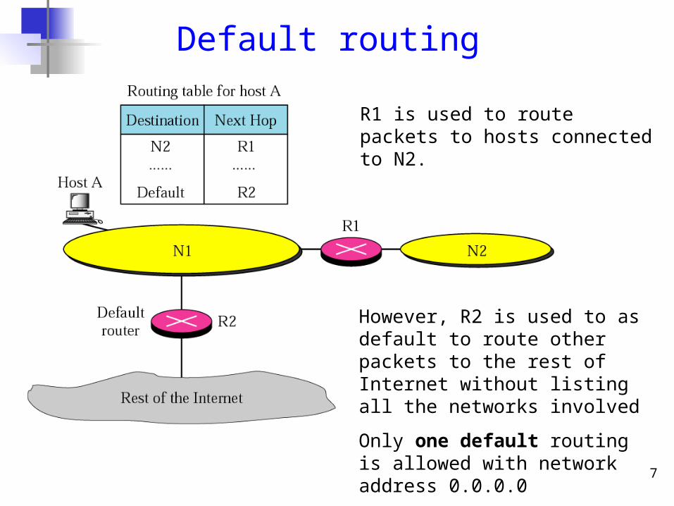
7
Default routing
R1 is used to route packets to hosts connected to N2.
However, R2 is used to as default to route other packets to the rest of Internet without listing all the networks involved
Only one default routing is allowed with network address 0.0.0.0
8
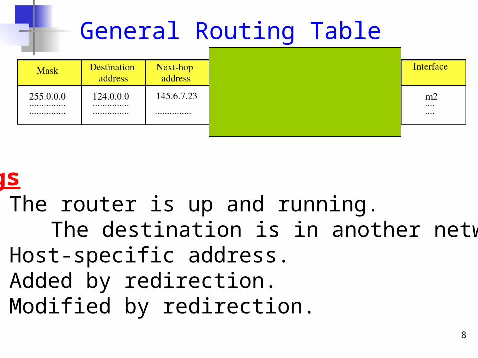
General Routing Table
FlagsU The router is up and running. G The destination is in another network.H Host-specific address. D Added by redirection.M Modified by redirection.
9
Routing tablea) Generally, a routing table needs a minimum of 4
columns: mask, destination network address, next hop address and interface.
b) When a packet arrives, the router applies the mask to the destination address it receives (one-by-one until a match is found) in order to find the corresponding destination network address.
c) So, the mask serves as essential tool to match destination address in routing table and the address it receives.
d) If found, the packet is sent out from the corresponding interface in the table. If not found, the packet is delivered to the default interface which carries the packet to default router.
10
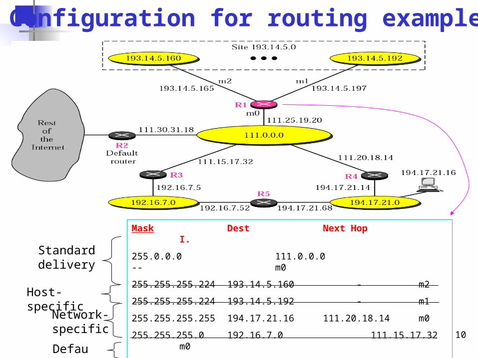
Configuration for routing example
Mask Dest. Next Hop I.
255.0.0.0 111.0.0.0 -- m0
255.255.255.224 193.14.5.160 - m2
255.255.255.224 193.14.5.192 - m1
255.255.255.255 194.17.21.16 111.20.18.14 m0
255.255.255.0 192.16.7.0 111.15.17.32 m0
255.255.255.0 194.17.21.0 111.20.18.14 m0
0.0.0.0 0.0.0.0 111.30.31.18 m0
Standard delivery
Host-specific
Network-specific
Default
11
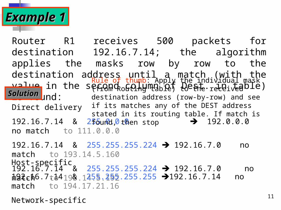
Example 1Example 1
Router R1 receives 500 packets for destination 192.16.7.14; the algorithm applies the masks row by row to the destination address until a match (with the value in the second column of Dest. in table) is found:
SolutionSolution
Direct delivery
192.16.7.14 & 255.0.0.0 192.0.0.0 no match to 111.0.0.0
192.16.7.14 & 255.255.255.224 192.16.7.0 no match to 193.14.5.160
192.16.7.14 & 255.255.255.224 192.16.7.0 no match to 193.14.5.192
Host-specific
192.16.7.14 & 255.255.255.255 192.16.7.14 no match to 194.17.21.16
Network-specific
192.16.7.14 & 255.255.255.0 192.16.7.0 match to 192.16.7.0
Rule of thumb: Apply the individual mask (from Routing table) to the received destination address (row-by-row) and see if its matches any of the DEST address stated in its routing table. If match is found, then stop
12
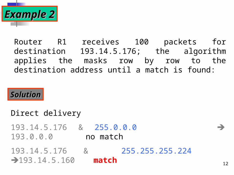
Example 2Example 2
Router R1 receives 100 packets for destination 193.14.5.176; the algorithm applies the masks row by row to the destination address until a match is found:
SolutionSolution
Direct delivery
193.14.5.176 & 255.0.0.0 193.0.0.0 no match
193.14.5.176 & 255.255.255.224 193.14.5.160 match
13
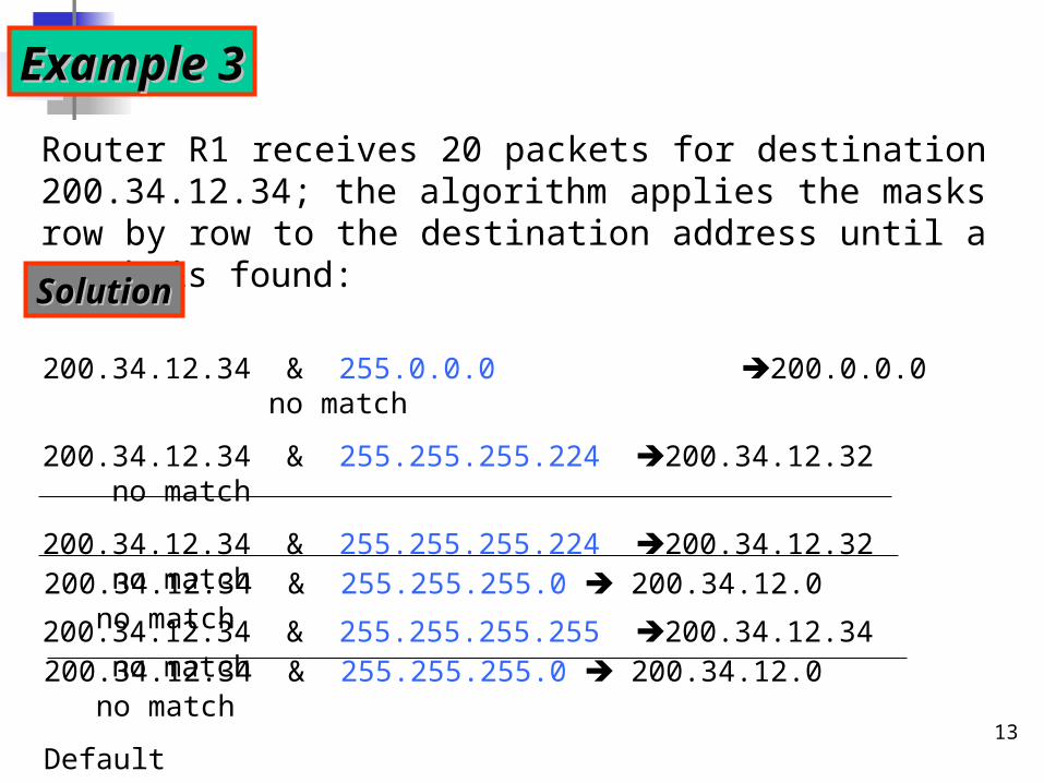
Example 3Example 3
Router R1 receives 20 packets for destination 200.34.12.34; the algorithm applies the masks row by row to the destination address until a match is found:
SolutionSolution
200.34.12.34 & 255.0.0.0 200.0.0.0 no match
200.34.12.34 & 255.255.255.224 200.34.12.32 no match
200.34.12.34 & 255.255.255.224 200.34.12.32 no match
200.34.12.34 & 255.255.255.255 200.34.12.34 no match
200.34.12.34 & 255.255.255.0 200.34.12.0 no match
200.34.12.34 & 255.255.255.0 200.34.12.0 no match
Default
200.34.12.34 & 0.0.0.0 0.0.0.0. match
14
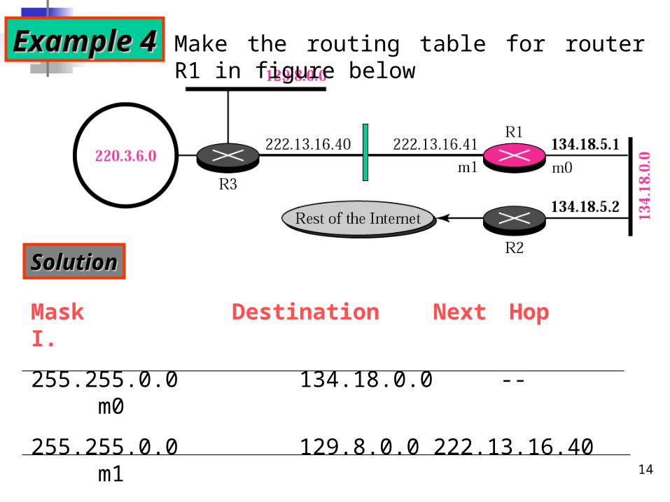
Example 4Example 4 Make the routing table for router R1 in figure below
SolutionSolution
Mask Destination Next Hop I.
255.255.0.0 134.18.0.0 -- m0
255.255.0.0 129.8.0.0 222.13.16.40 m1
255.255.255.0 220.3.6.0 222.13.16.40 m1
0.0.0.0 0.0.0.0 134.18.5.2 m0
15
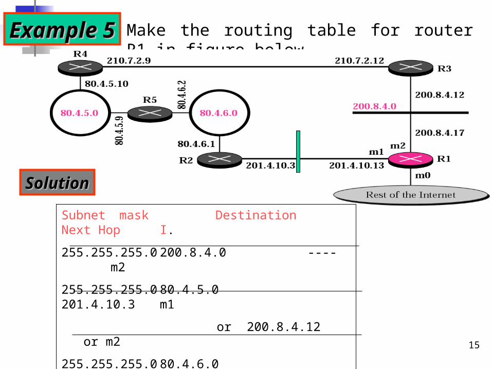
Example 5Example 5 Make the routing table for router R1 in figure below
Subnet mask Destination Next HopI.
255.255.255.0 200.8.4.0 ---- m2
255.255.255.0 80.4.5.0 201.4.10.3 m1
or 200.8.4.12 or m2
255.255.255.0 80.4.6.0 201.4.10.3 m1
or 200.4.8.12 or m2
0.0.0.0 0.0.0.0 m0
SolutionSolution
16
In classless addressing, we need at least four columns in a routing table.
Note
17
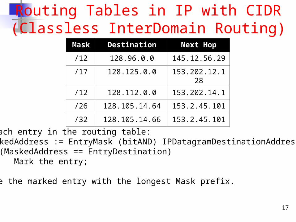
Routing Tables in IP with CIDR(Classless InterDomain Routing)
Mask Destination Next Hop
/12 128.96.0.0 145.12.56.29
/17 128.125.0.0 153.202.12.128
/12 128.112.0.0 153.202.14.1
/26 128.105.14.64 153.2.45.101
/32 128.105.14.66 153.2.45.101
For each entry in the routing table:MaskedAddress := EntryMask (bitAND) IPDatagramDestinationAddress;if (MaskedAddress == EntryDestination)
Mark the entry;
Choose the marked entry with the longest Mask prefix.
18
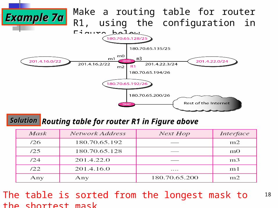
Make a routing table for router R1, using the configuration in Figure belowExample 7aExample 7a
Routing table for router R1 in Figure aboveSolutionSolution
m3
The table is sorted from the longest mask to the shortest mask.
19
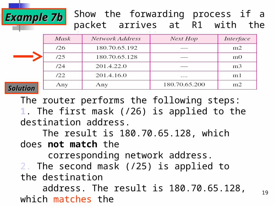
Show the forwarding process if a packet arrives at R1 with the destination address 180.70.65.140.
The router performs the following steps:1. The first mask (/26) is applied to the destination address. The result is 180.70.65.128, which does not match the corresponding network address.2. The second mask (/25) is applied to the destination address. The result is 180.70.65.128, which matches the corresponding network address. The next-hop address and the interface number m0 are passed on for further processing.
Example 7bExample 7b
SolutionSolution
20
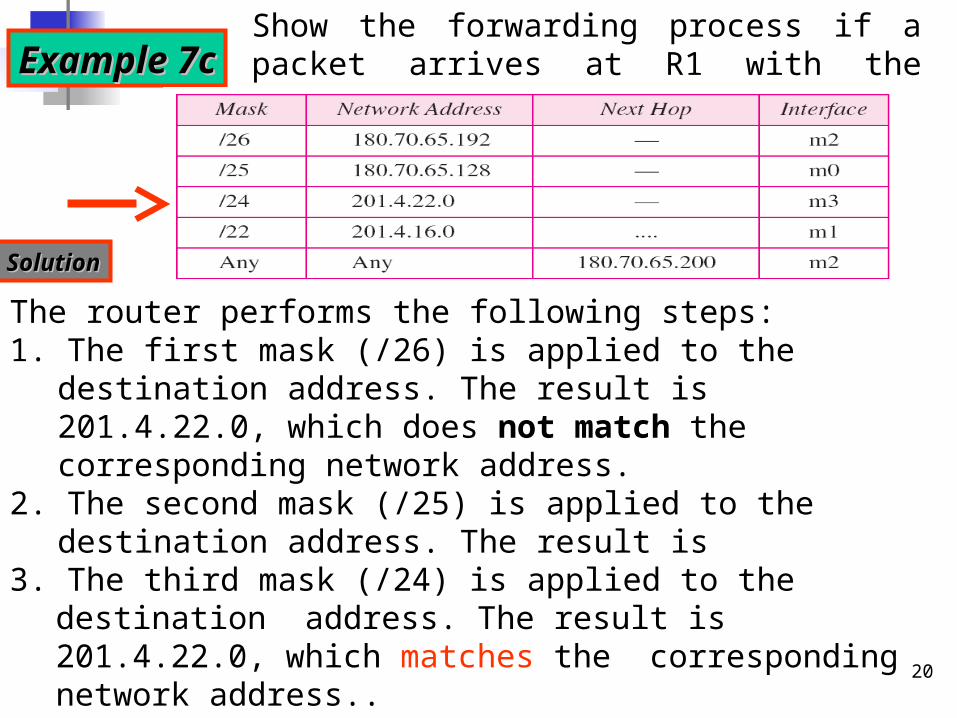
Show the forwarding process if a packet arrives at R1 with the destination address 201.4.22.35.
The router performs the following steps:1. The first mask (/26) is applied to the destination address. The
result is 201.4.22.0, which does not match the corresponding network address.
2. The second mask (/25) is applied to the destination address. The result is 201.4.22.0, which does not match the corresponding network address (row 2).
Example 7cExample 7c
SolutionSolution
3. The third mask (/24) is applied to the destination address. The result is 201.4.22.0, which matches the corresponding network address..
21
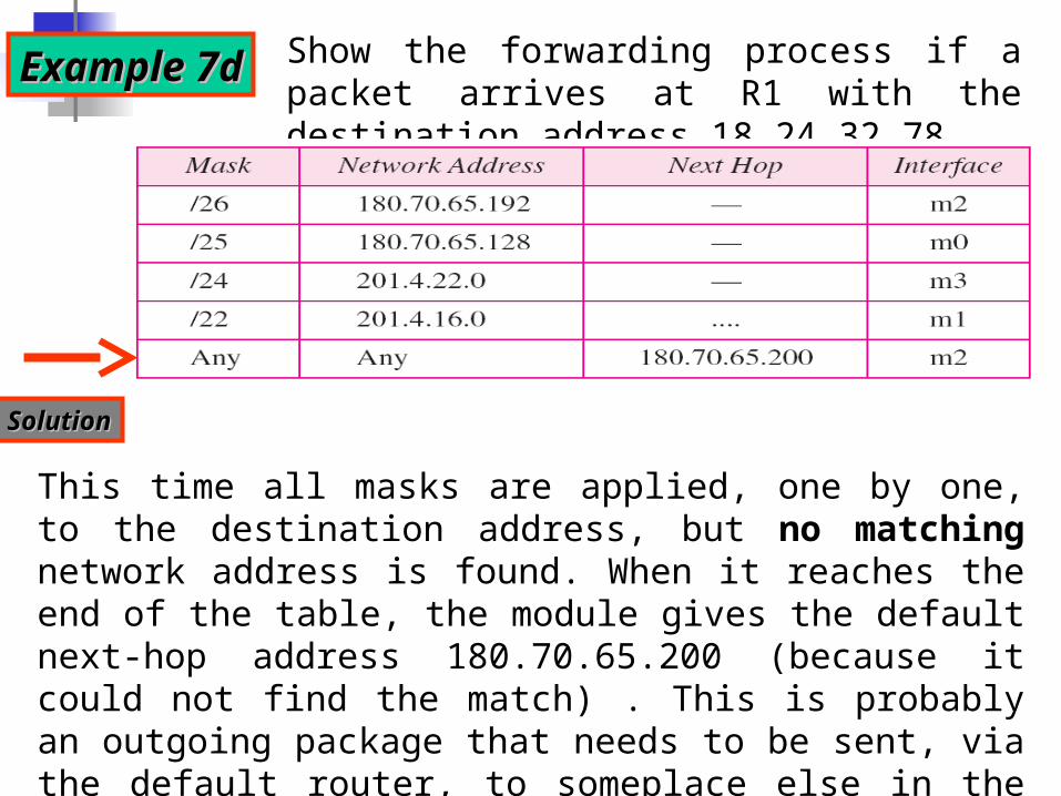
Show the forwarding process if a packet arrives at R1 with the destination address 18.24.32.78.
This time all masks are applied, one by one, to the destination address, but no matching network address is found. When it reaches the end of the table, the module gives the default next-hop address 180.70.65.200 (because it could not find the match) . This is probably an outgoing package that needs to be sent, via the default router, to someplace else in the Internet.
Example 7dExample 7d
SolutionSolution
22
Routing/routersa) An internet is a combination of networks connected by routers.b) When a packet goes from a source to a destination, it will pass
through many routers until it reaches the router attached to destination network.
c) A router consults a routing table when a packet is ready to be forwarded. The routing table specifies the optimum path for the packet and can be either static of dynamic. Dynamic routing is more popular.
d) Static table does not change frequently. Dynamic table is updated automatically when there is a change somewhere in the network; i.e when a route is down or a better route has been created.
e) Routing protocols is a combination of rules/procedures that lets routers in the internet inform one another when changes occur; mostly based on sharing/combining information between routers at different networks.
23
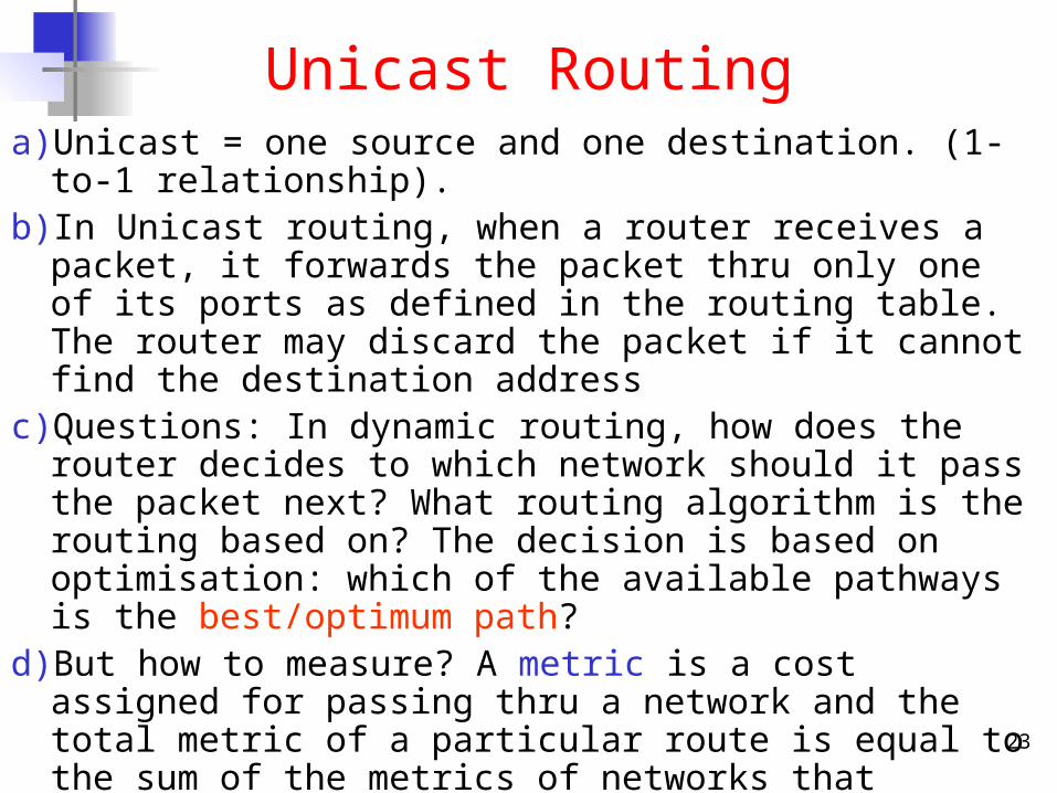
Unicast Routinga) Unicast = one source and one destination. (1-to-1 relationship).b) In Unicast routing, when a router receives a packet, it forwards the
packet thru only one of its ports as defined in the routing table. The router may discard the packet if it cannot find the destination address
c) Questions: In dynamic routing, how does the router decides to which network should it pass the packet next? What routing algorithm is the routing based on? The decision is based on optimisation: which of the available pathways is the best/optimum path?
d) But how to measure? A metric is a cost assigned for passing thru a network and the total metric of a particular route is equal to the sum of the metrics of networks that comprise the route.
e) Simple protocols such as Routing Information Protocol (RIP), treat all network equally; cost of passing each network is the same as one hop count per network.
f) Other sophisticated protocols e.g. OSPF, based on services required and using different metrics: max throughput, minimum delay.
24
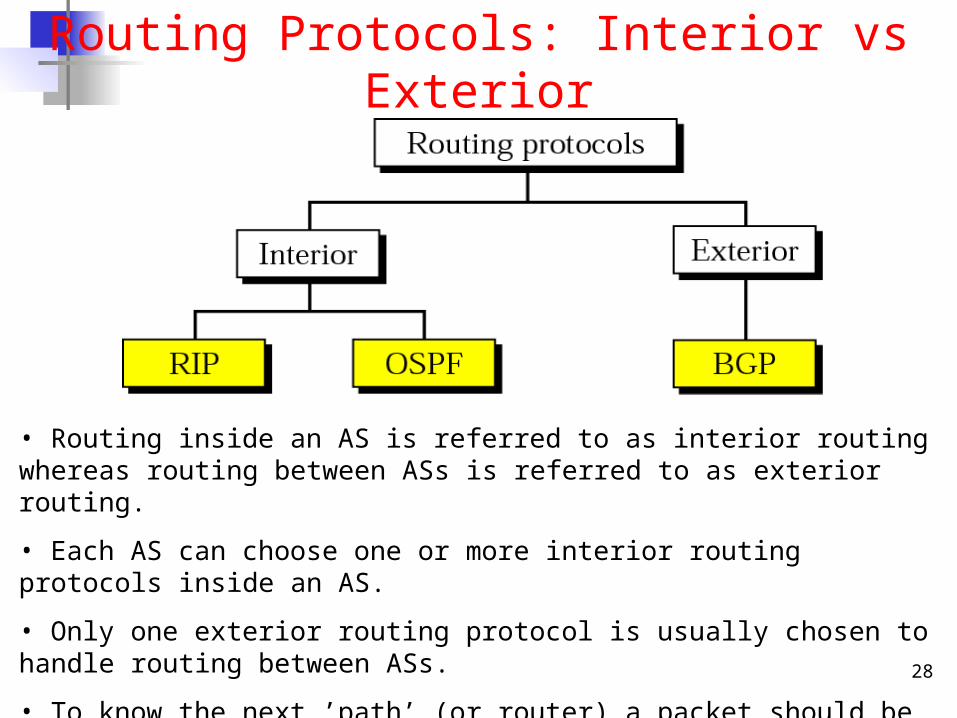
Routing Protocol:Interior Vs Exterior
25
Routing Architecture in the Internet
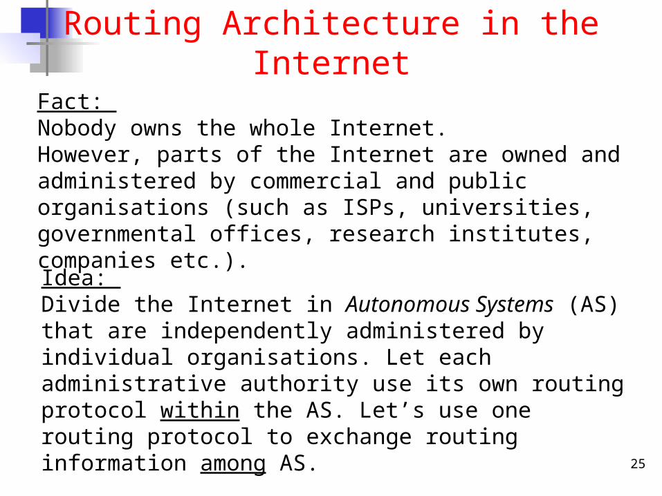
Fact: Nobody owns the whole Internet. However, parts of the Internet are owned and administered by commercial and public organisations (such as ISPs, universities, governmental offices, research institutes, companies etc.).
Idea: Divide the Internet in Autonomous Systems (AS) that are independently administered by individual organisations. Let each administrative authority use its own routing protocol within the AS. Let’s use one routing protocol to exchange routing information among AS.
26
Routing Architecture in the Internet
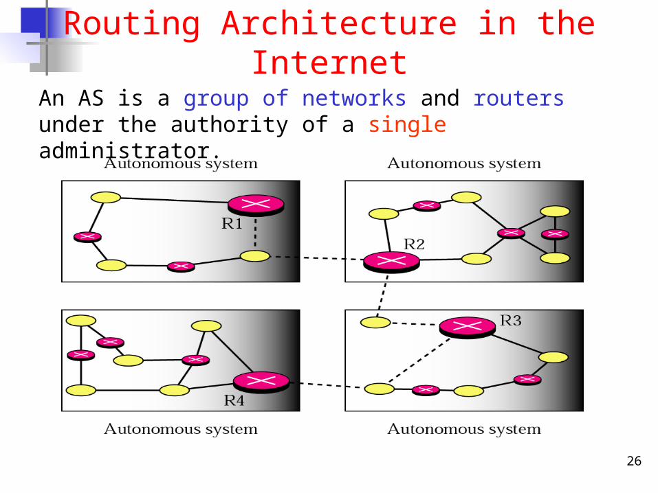
An AS is a group of networks and routers under the authority of a single administrator.
27
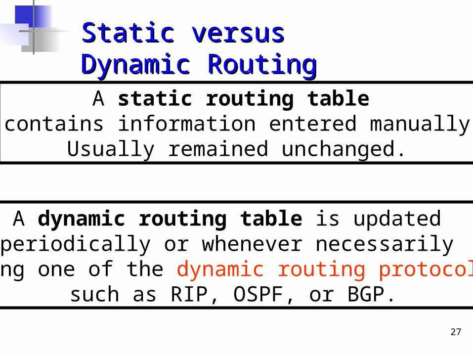
A static routing table contains information entered manually
Usually remained unchanged.
A dynamic routing table is updated periodically or whenever necessarily
using one of the dynamic routing protocols such as RIP, OSPF, or BGP.
Static versus Dynamic RoutingStatic versus Dynamic Routing
28
Routing Protocols: Interior vs Exterior
• Routing inside an AS is referred to as interior routing whereas routing between ASs is referred to as exterior routing.
• Each AS can choose one or more interior routing protocols inside an AS.
• Only one exterior routing protocol is usually chosen to handle routing between ASs.
• To know the next ’path’ (or router) a packet should be pass-on, the decision is based on some optimisation rule/protocol, e.g. using different assignment of the cost (metric) for each passing through a network for different routing Protocol above.
29
Interior Routing Protocol 1:Routing Information Protocol
(RIP)
30
Distance Vector Routing (DVR)
a) 3 keys to understand how this algorithm works:• Sharing knowledge about the entire AS. Each router
shares its knowledge about the entire AS with neighbours. It sends whatever it has.
• Sharing only with immediate neighbours. Each router sends whatever knowledge it has thru all its interface.
• Sharing at regular intervals. sends at fixed intervals, e.g. every 30 sec.
b) Problems: Tedious comparing/updating process, slow response to infinite loop problem, huge list to be maintained!!
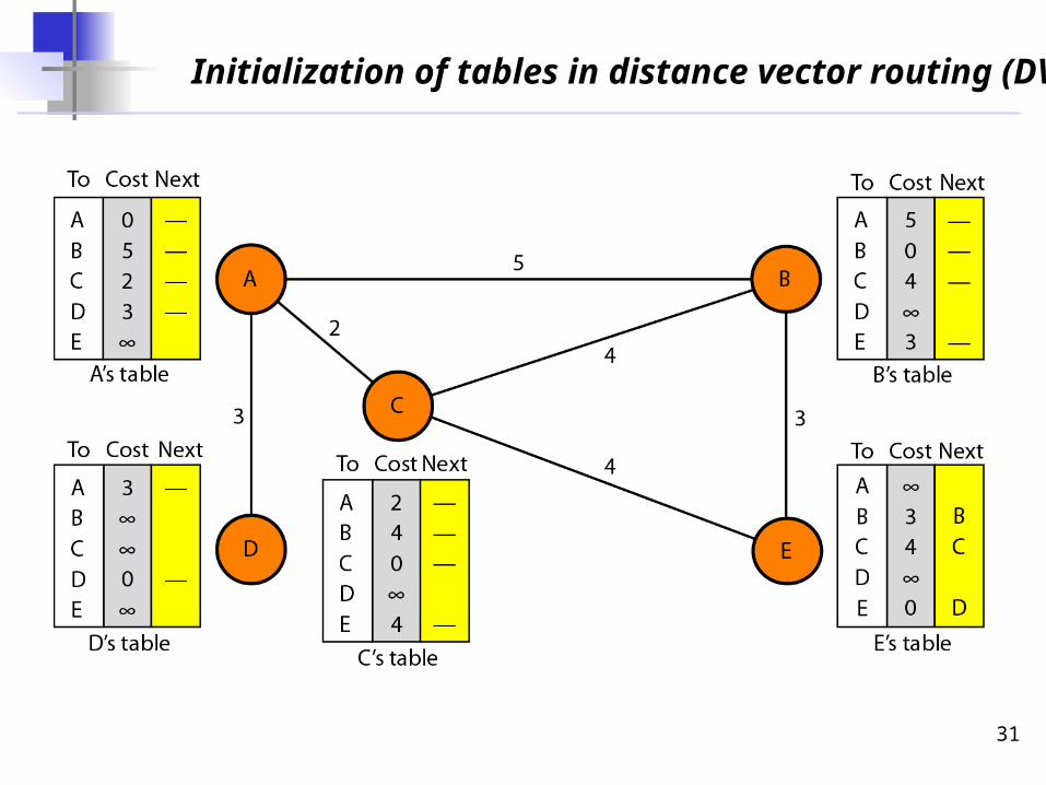
31
Initialization of tables in distance vector routing (DVR)
32
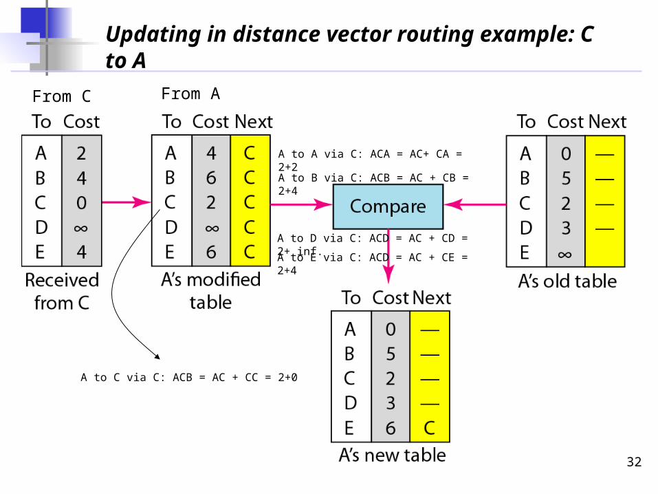
Updating in distance vector routing example: C to A
A to A via C: ACA = AC+ CA = 2+2
A to B via C: ACB = AC + CB = 2+4
From C From A
A to D via C: ACD = AC + CD = 2+ inf.
A to C via C: ACB = AC + CC = 2+0
A to E via C: ACD = AC + CE = 2+4
33
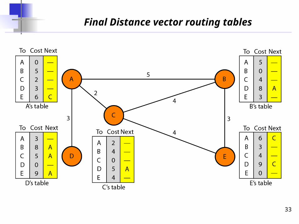
Final Distance vector routing tables
34
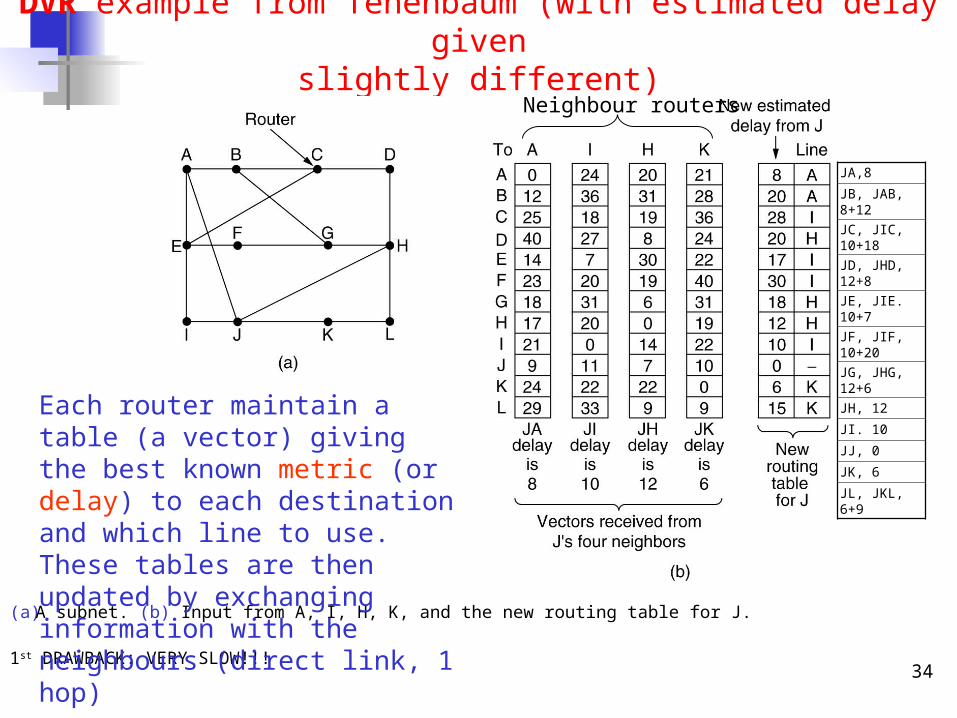
DVR example from Tenenbaum (with estimated delay givenslightly different)
(a) A subnet. (b) Input from A, I, H, K, and the new routing table for J.
1st DRAWBACK: VERY SLOW!!!
Each router maintain a table (a vector) giving the best known metric (or delay) to each destination and which line to use. These tables are then updated by exchanging information with the neighbours (direct link, 1 hop)
JA,8
JB, JAB, 8+12
JC, JIC, 10+18
JD, JHD, 12+8
JE, JIE. 10+7
JF, JIF, 10+20
JG, JHG, 12+6
JH, 12
JI. 10
JJ, 0
JK, 6
JL, JKL, 6+9
Neighbour routers
35
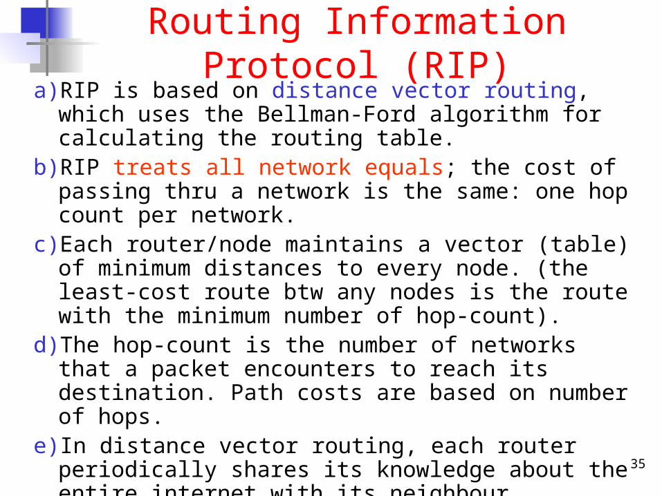
Routing Information Protocol (RIP)a) RIP is based on distance vector routing, which uses the Bellman-
Ford algorithm for calculating the routing table.b) RIP treats all network equals; the cost of passing thru a network
is the same: one hop count per network.c) Each router/node maintains a vector (table) of minimum
distances to every node. (the least-cost route btw any nodes is the route with the minimum number of hop-count).
d) The hop-count is the number of networks that a packet encounters to reach its destination. Path costs are based on number of hops.
e) In distance vector routing, each router periodically shares its knowledge about the entire internet with its neighbour.
f) Each router keeps a routing table that has one entry for each destination network of which the router is aware.
g) The entry consists of Destination Network Address/id, Hop-Count and Next-Router.
36
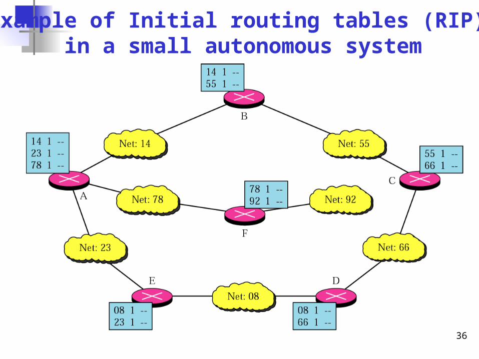
Example of Initial routing tables (RIP) in a small autonomous system
37
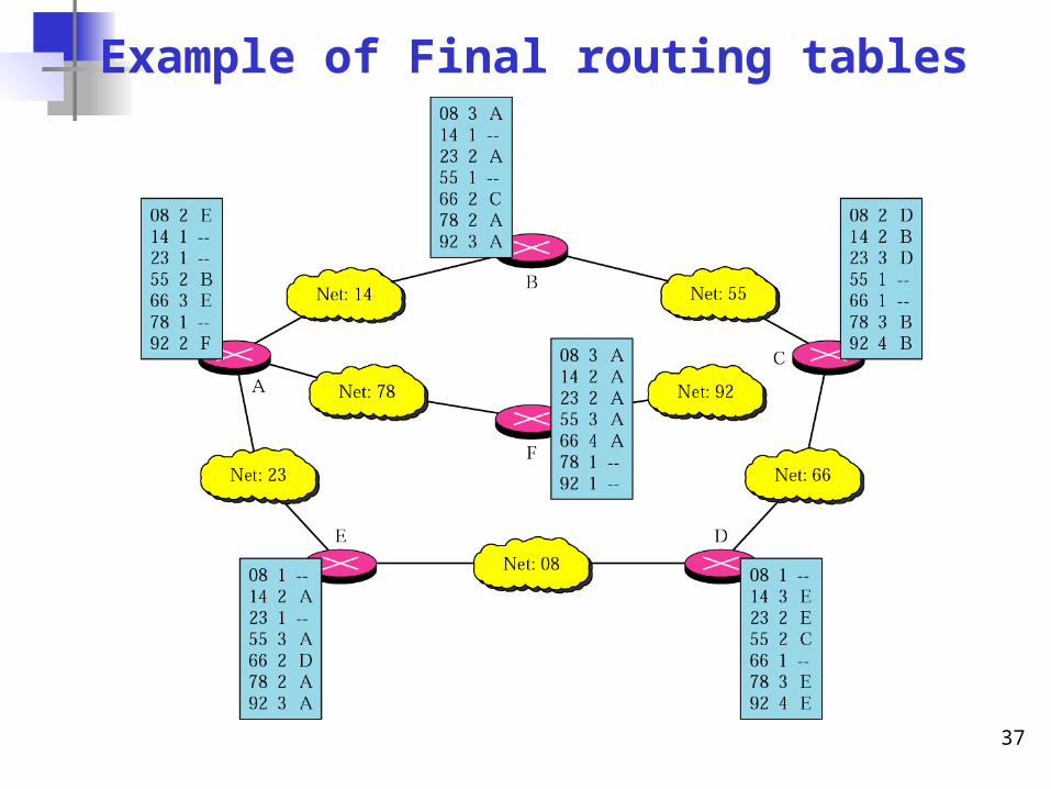
Example of Final routing tables
38
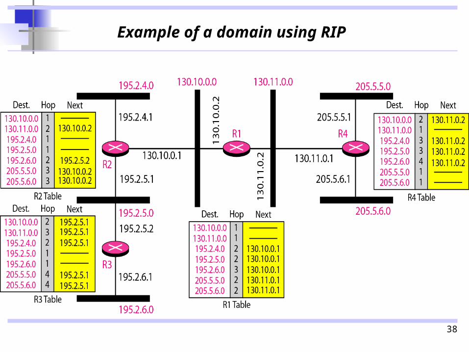
Example of a domain using RIP
39
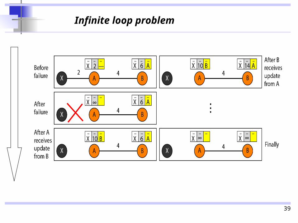
Infinite loop problem
40
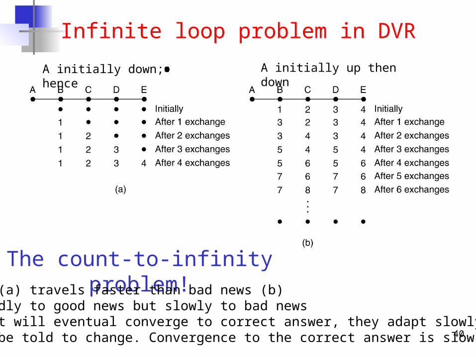
Infinite loop problem in DVR
The count-to-infinity problem!Good news (a) travels faster than bad news (b)React rapidly to good news but slowly to bad news Although it will eventual converge to correct answer, they adapt slowly,they must be told to change. Convergence to the correct answer is slow.
A initially down; hence A initially up then down
41
Interior Routing Protocol 2:Open Shortest Path First
Protocol (OSPF)
42
Open Shortest Path First (OSPF)
a) OSPF uses link state routing to update the routing table in an area; OSPF divides an AS into different areas (depending on their type).
b) Unlike RIP, OSPF treats the entire network within differently with different philosophy; depending on the types, cost (metric) and condition of each link: to define the ‘state’ of a link.
c) OSPF allows the administrator to (only) assign a cost for passing through a network based on the type of service required. e.g. minimum delay, maximum throughput. (but not stating exact path)
d) Each router should have the exact topology of the AS network(a picture of entire AS network) at every moment. The topology is a graph consisting of nodes and edges.
e) Each router needs to advertise to the neighbourhood of every other routers involved in an Area. (flood)
43
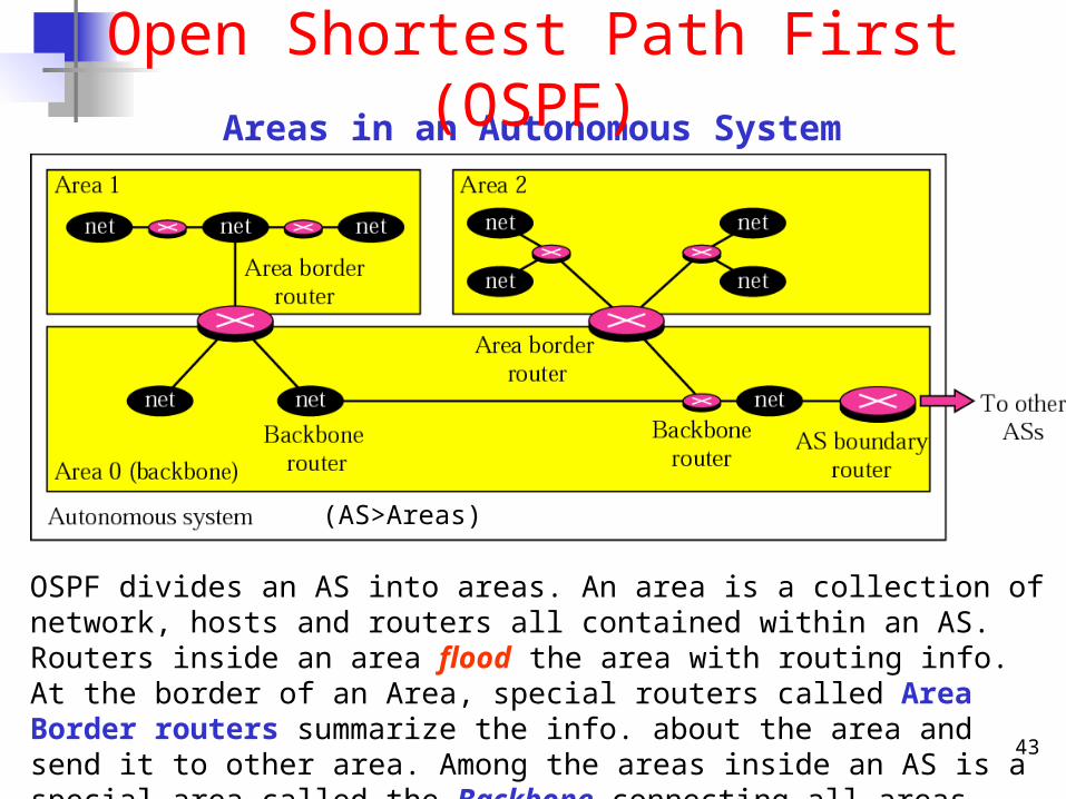
Areas in an Autonomous System
Open Shortest Path First (OSPF)
OSPF divides an AS into areas. An area is a collection of network, hosts and routers all contained within an AS. Routers inside an area flood the area with routing info. At the border of an Area, special routers called Area Border routers summarize the info. about the area and send it to other area. Among the areas inside an AS is a special area called the Backbone connecting all areas through Backbone routers and serves as a primary area to the outside (other ASs) via the AS Boundary router.
(AS>Areas)
44
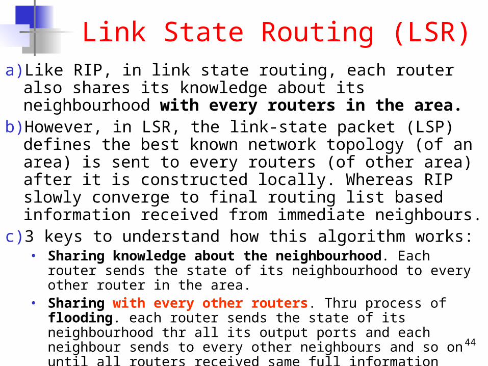
Link State Routing (LSR)a) Like RIP, in link state routing, each router also shares its knowledge
about its neighbourhood with every routers in the area. b) However, in LSR, the link-state packet (LSP) defines the best known
network topology (of an area) is sent to every routers (of other area) after it is constructed locally. Whereas RIP slowly converge to final routing list based information received from immediate neighbours.
c) 3 keys to understand how this algorithm works:• Sharing knowledge about the neighbourhood. Each router sends the state of
its neighbourhood to every other router in the area.• Sharing with every other routers. Thru process of flooding. each router sends
the state of its neighbourhood thr all its output ports and each neighbour sends to every other neighbours and so on until all routers received same full information eventually.
• Sharing when there is a change. Each router share its state of its neighbour only when there is a change; contrasting DVR results in lower traffic.
d) From the received LSPs and knowledge of entire topology, a router can then calculate the shortest path between itself and each network.
45
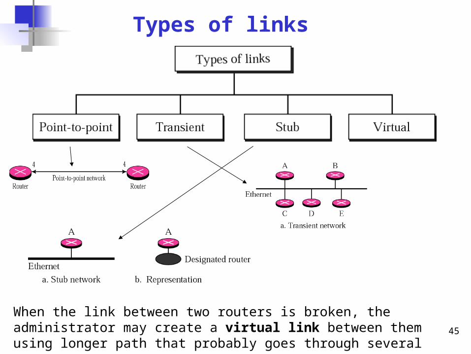
Types of links
When the link between two routers is broken, the administrator may create a virtual link between them using longer path that probably goes through several routers
46
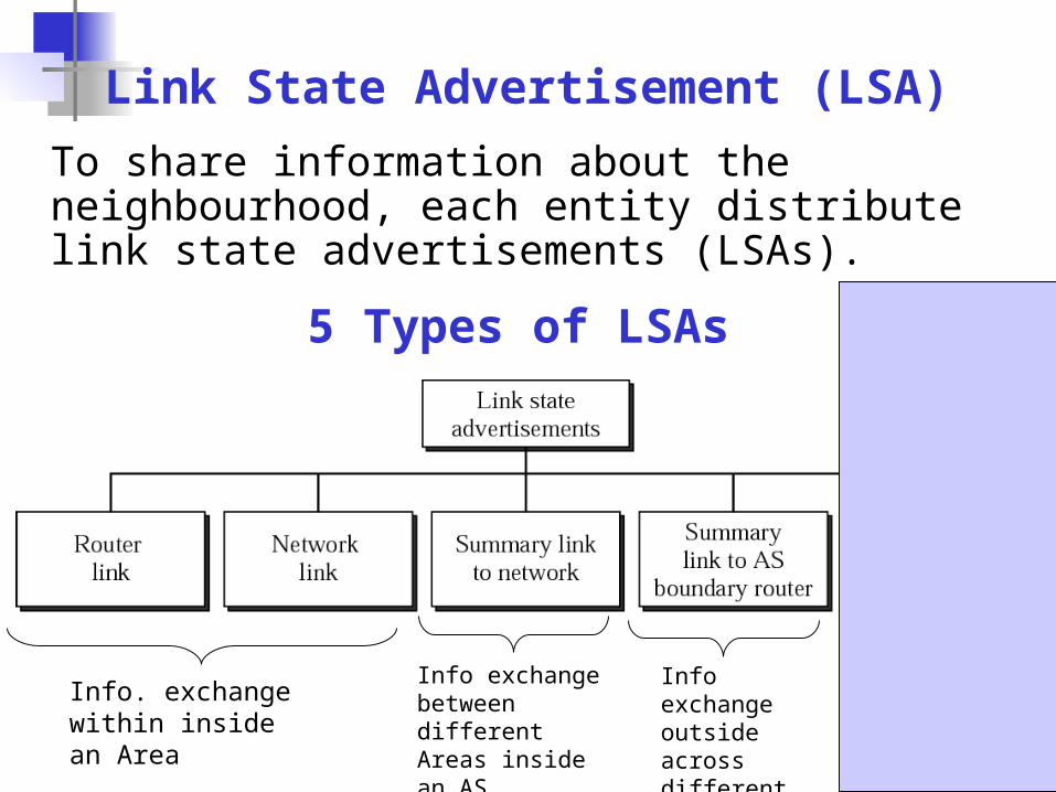
Link State Advertisement (LSA)
5 Types of LSAs
To share information about the neighbourhood, each entity distribute link state advertisements (LSAs).
Info. exchange within inside an Area
Info exchange between different Areas inside an AS
Info exchange outside across different AS
Info exchange to external internet
47
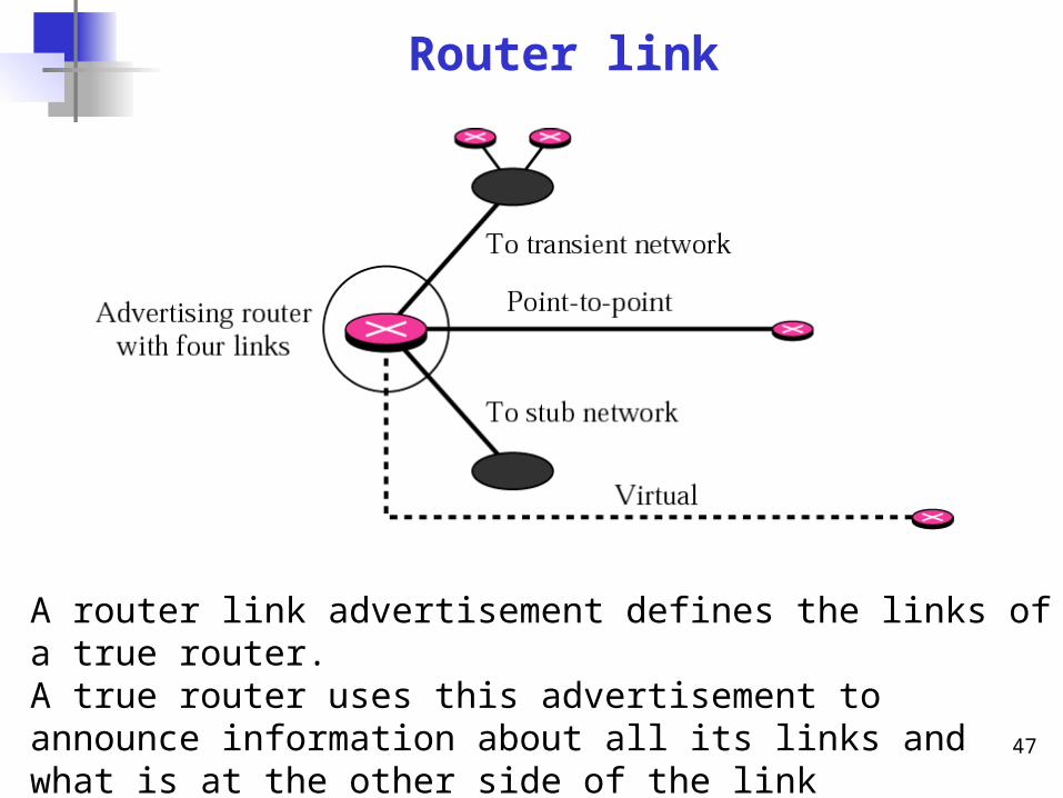
Router link
A router link advertisement defines the links of a true router. A true router uses this advertisement to announce information about all its links and what is at the other side of the link (neighbour).
48
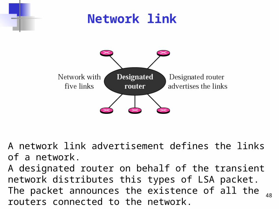
Network link
A network link advertisement defines the links of a network. A designated router on behalf of the transient network distributes this types of LSA packet. The packet announces the existence of all the routers connected to the network.
49
Summary link to network
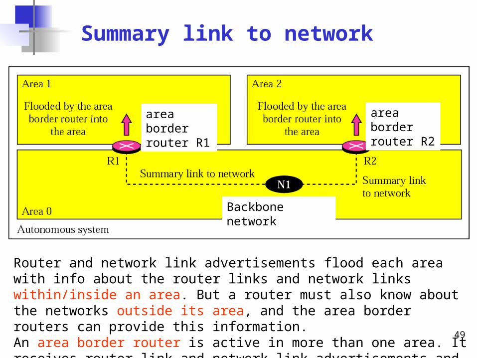
Router and network link advertisements flood each area with info about the router links and network links within/inside an area. But a router must also know about the networks outside its area, and the area border routers can provide this information. An area border router is active in more than one area. It receives router link and network link advertisements and creates a routing table for each area.
area border router R1
area border router R2
Backbone network
50
Summary link to AS boundary router
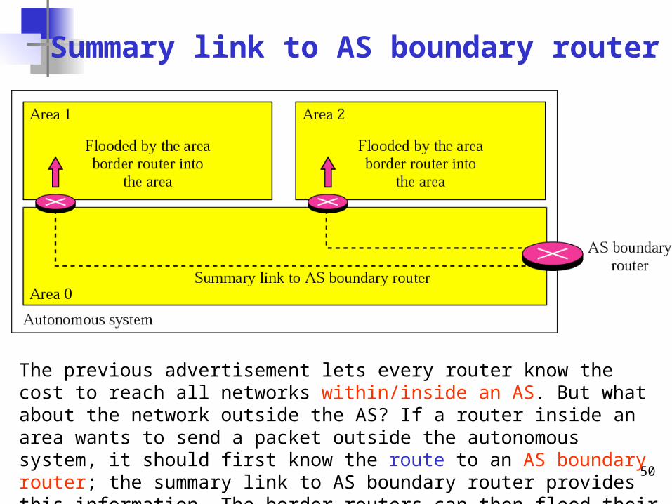
The previous advertisement lets every router know the cost to reach all networks within/inside an AS. But what about the network outside the AS? If a router inside an area wants to send a packet outside the autonomous system, it should first know the route to an AS boundary router; the summary link to AS boundary router provides this information. The border routers can then flood their areas with this information.
51
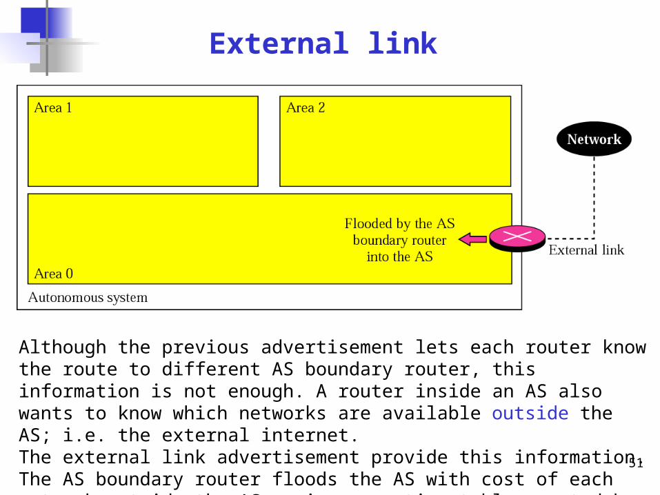
External link
Although the previous advertisement lets each router know the route to different AS boundary router, this information is not enough. A router inside an AS also wants to know which networks are available outside the AS; i.e. the external internet. The external link advertisement provide this information. The AS boundary router floods the AS with cost of each network outside the AS, using a routing table created by an exterior routing table protocol. Each advertisement announces one single network. If there is more than one network. Separate announcements are made.
52
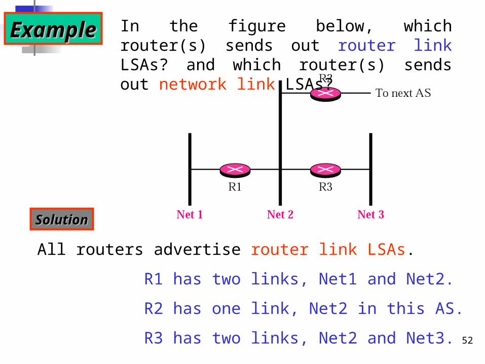
ExampleExample In the figure below, which router(s) sends out router link LSAs? and which router(s) sends out network link LSAs?
SolutionSolution
All routers advertise router link LSAs.
R1 has two links, Net1 and Net2.
R2 has one link, Net2 in this AS.
R3 has two links, Net2 and Net3.
53
Solution ContinueSolution Continue
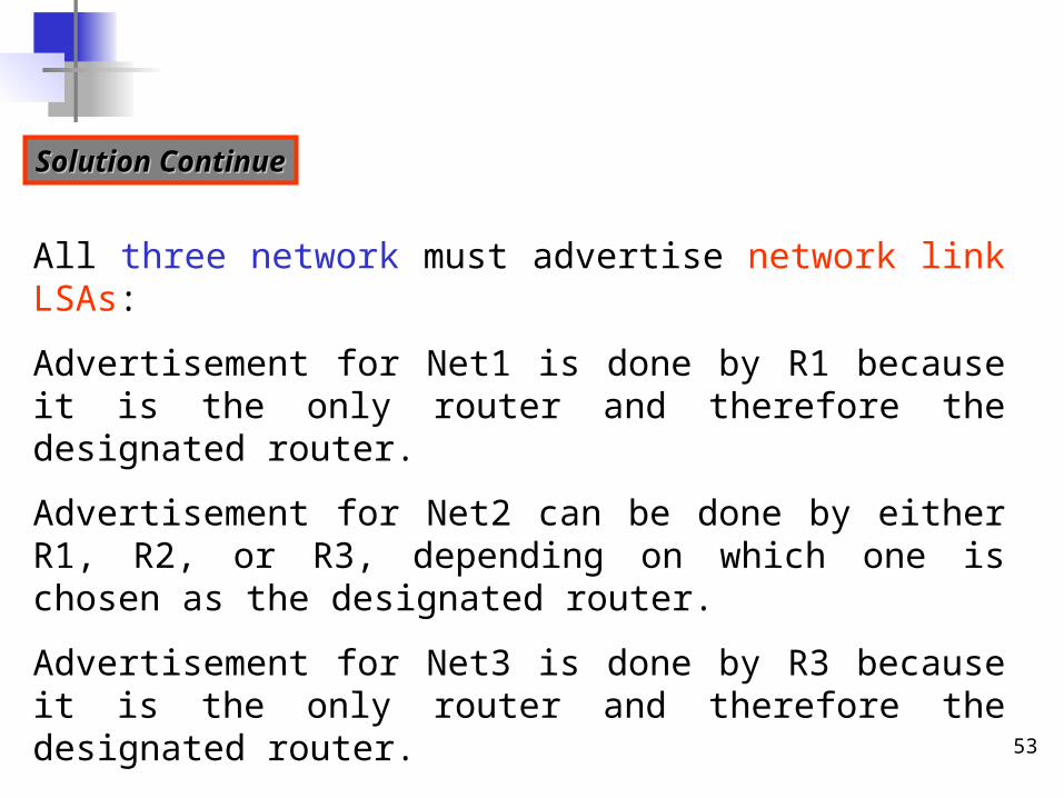
All three network must advertise network link LSAs:
Advertisement for Net1 is done by R1 because it is the only router and therefore the designated router.
Advertisement for Net2 can be done by either R1, R2, or R3, depending on which one is chosen as the designated router.
Advertisement for Net3 is done by R3 because it is the only router and therefore the designated router.
54
In OSPF, all routers have In OSPF, all routers have the same the same Link State databaseLink State database..
• Every router in an area receives the router link and network link LSAs and form a link state database.
• Every router in the same area has the same link state database.
• A link state database is a tabular representation of the topology of the internet inside an area. It shows the relationship between each router and its neighbors including the metrics used.
• To calculate its next-route in the routing table, each router applies the Dijkstra algorithm to its state database, to find the shortest path between 2 points on a network, using a graph (nodes and edges).
• The algorithm divides the nodes into two sets: tentative and permanent. It chooses nodes, makes them tentative, examines them, and if they pass the criteria, makes permanent.
55
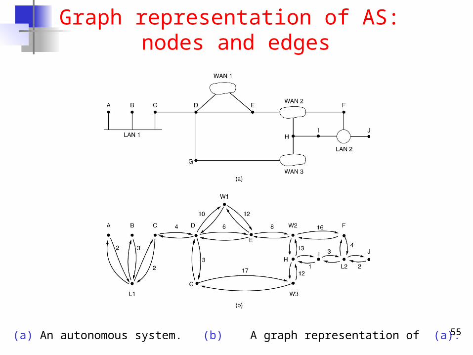
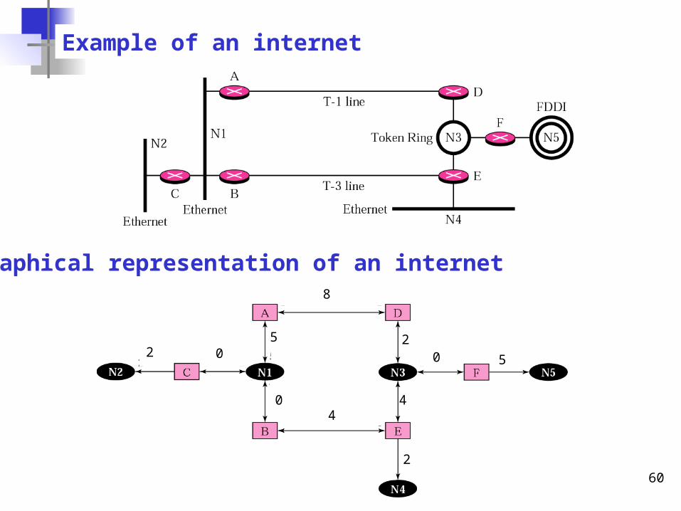
Graph representation of AS: nodes and edges
(a) An autonomous system. (b) A graph representation of (a).
56
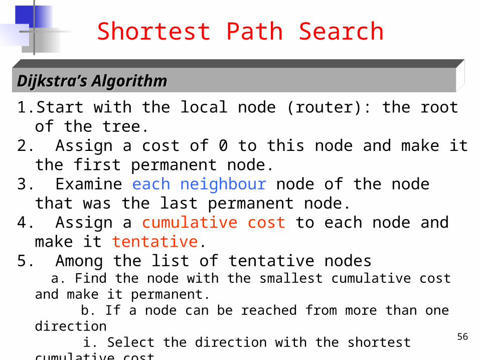
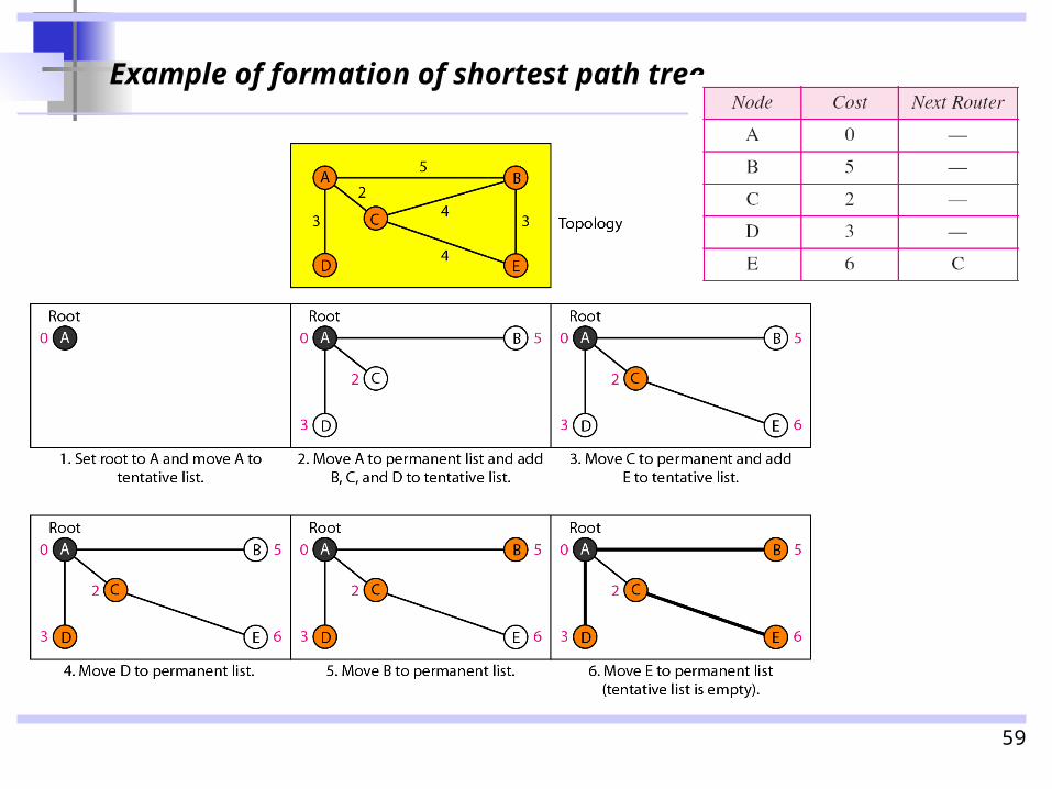
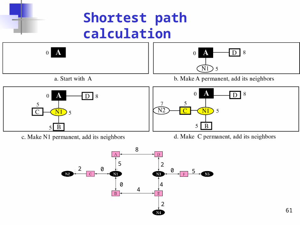
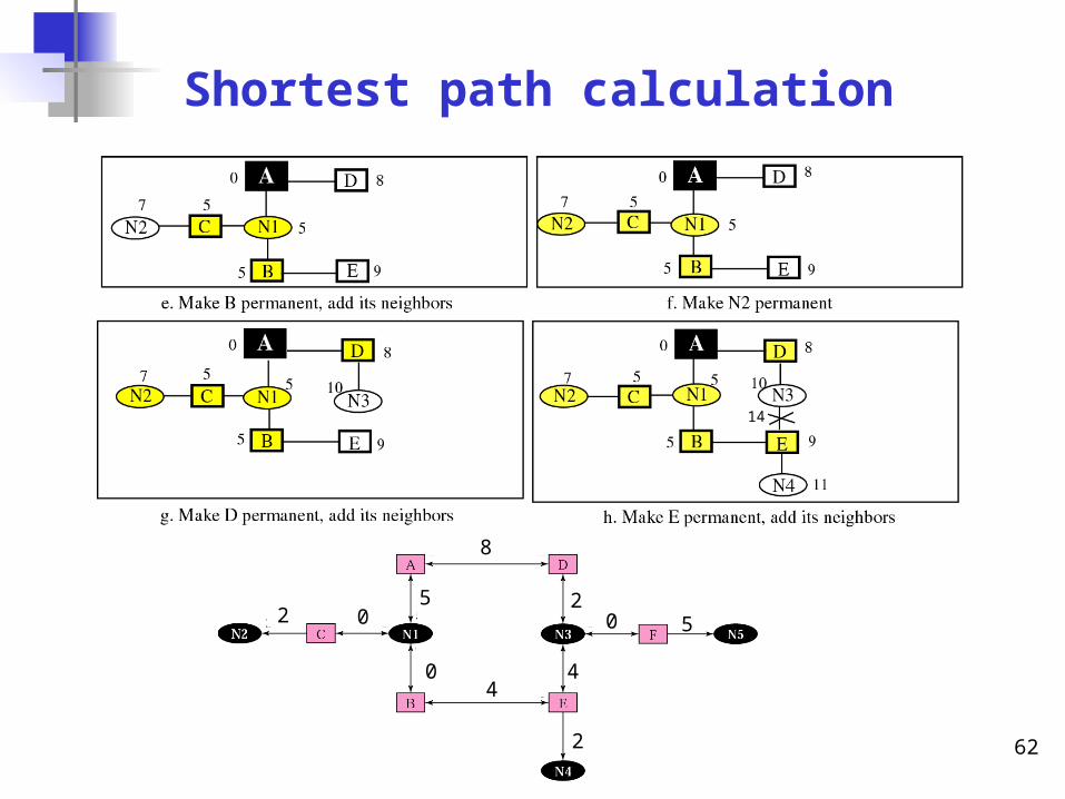
1. Start with the local node (router): the root of the tree. 2. Assign a cost of 0 to this node and make it the first permanent node.3. Examine each neighbour node of the node that was the last
permanent node. 4. Assign a cumulative cost to each node and make it tentative.5. Among the list of tentative nodes
a. Find the node with the smallest cumulative cost and make it permanent. b. If a node can be reached from more than one direction i. Select the direction with the shortest cumulative cost.
6. Repeat steps 3 to 5 until every node becomes permanent.
Dijkstra’s AlgorithmDijkstra’s Algorithm
Shortest Path Search
57
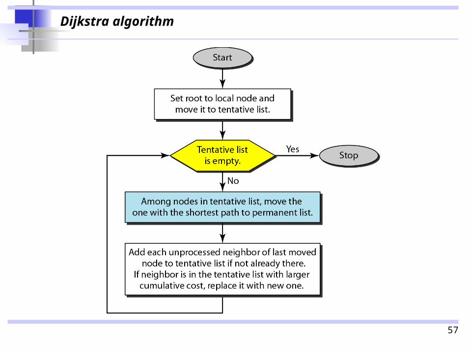
Dijkstra algorithm
58
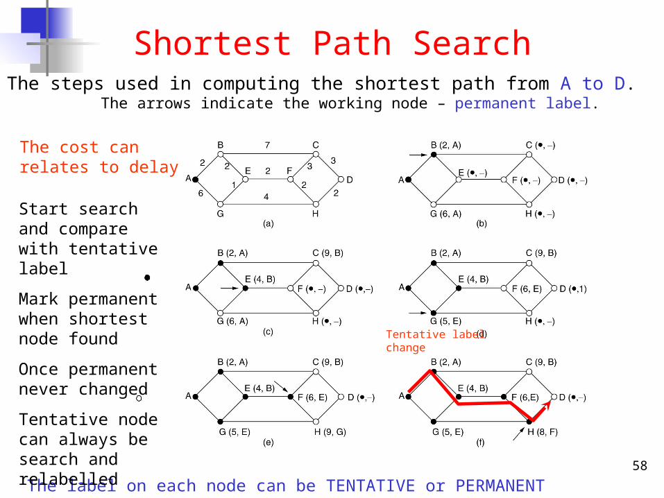
Shortest Path SearchThe steps used in computing the shortest path from A to D.
The arrows indicate the working node – permanent label.
The cost can relates to delay
The label on each node can be TENTATIVE or PERMANENT
Start search and compare with tentative label
Mark permanent when shortest node found
Once permanent never changed
Tentative node can always be search and relabelled
Tentative label change
59
Example of formation of shortest path tree
60
Example of an internet
Graphical representation of an internet8
5
0
02
4
2
4
2
0 5
61
Shortest path calculation
8
5
0
02
4
2
4
2
0 5
62
Shortest path calculation
8
5
0
02
4
2
4
2
0 5
14
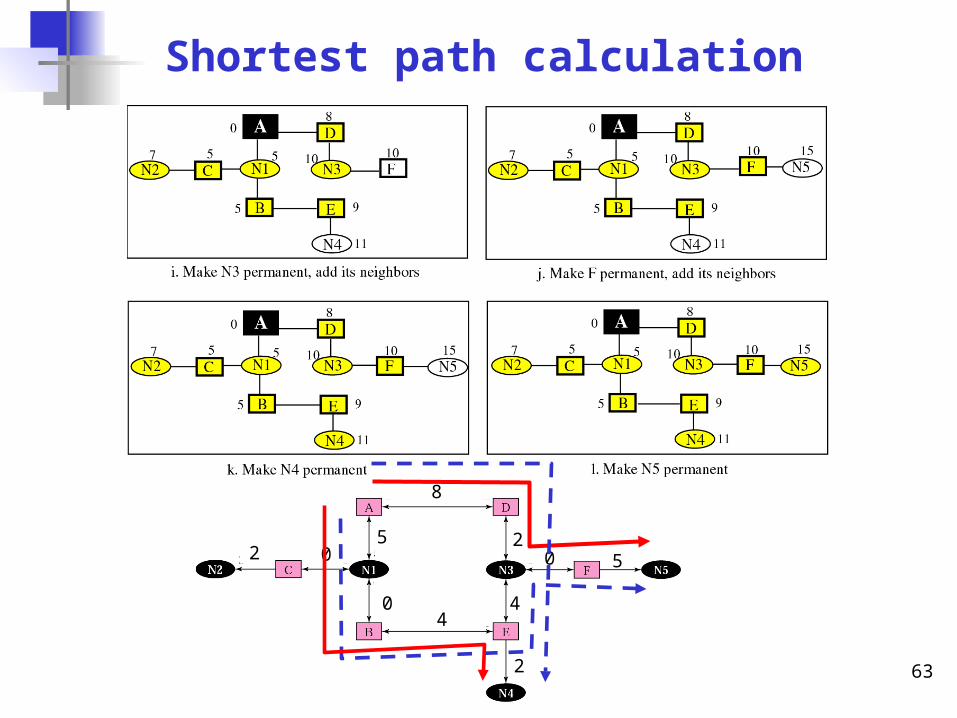
63
Shortest path calculation
8
5
0
02
4
2
4
2
0 5
64
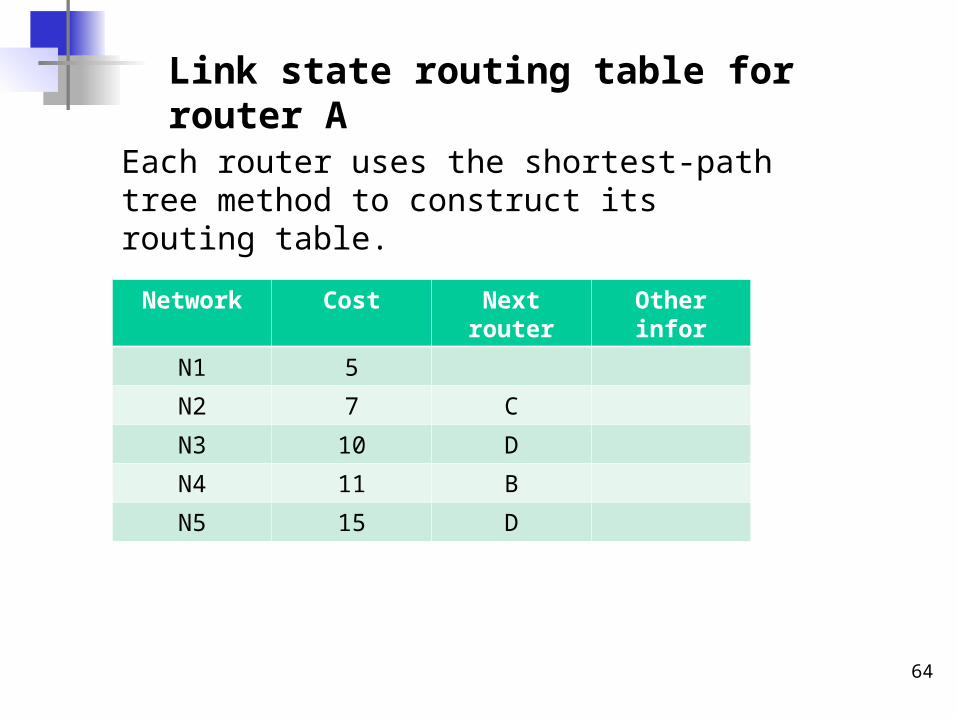
Link state routing table for router A
Each router uses the shortest-path tree method to construct its routing table.
Network Cost Next router Other infor
N1 5
N2 7 C
N3 10 D
N4 11 B
N5 15 D
65
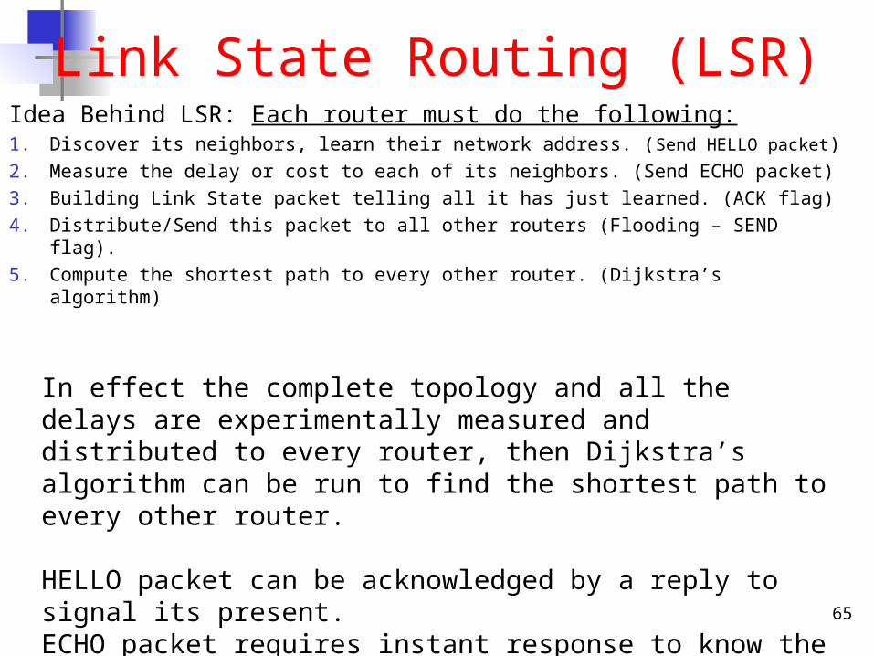
Link State Routing (LSR)Idea Behind LSR: Each router must do the following:1. Discover its neighbors, learn their network address. (Send HELLO
packet)
2. Measure the delay or cost to each of its neighbors. (Send ECHO packet)
3. Building Link State packet telling all it has just learned. (ACK flag)
4. Distribute/Send this packet to all other routers (Flooding – SEND flag).
5. Compute the shortest path to every other router. (Dijkstra’s algorithm)
In effect the complete topology and all the delays are experimentally measured and distributed to every router, then Dijkstra’s algorithm can be run to find the shortest path to every other router.
HELLO packet can be acknowledged by a reply to signal its present.ECHO packet requires instant response to know the round-trip-time.
66
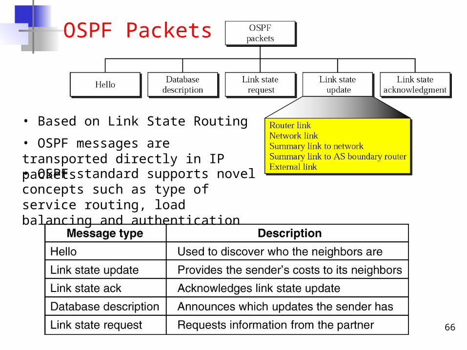
OSPF Packets
• Based on Link State Routing
• OSPF messages are transported directly in IP packets• OSPF standard supports novel concepts such as type of service routing, load balancing and authentication
67
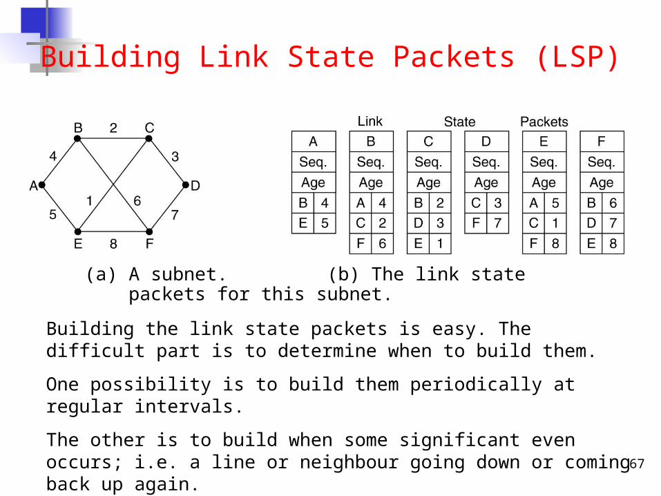
Building Link State Packets (LSP)
(a) A subnet. (b) The link state packets for this subnet.
Building the link state packets is easy. The difficult part is to determine when to build them.
One possibility is to build them periodically at regular intervals.
The other is to build when some significant even occurs; i.e. a line or neighbour going down or coming back up again.
68
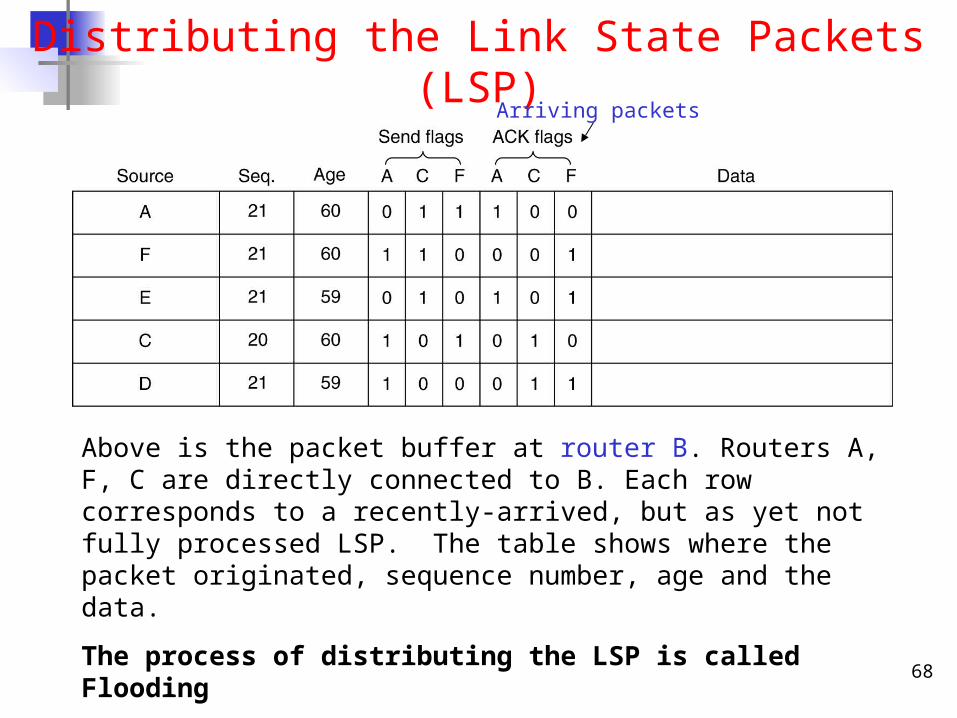
Distributing the Link State Packets (LSP)
Above is the packet buffer at router B. Routers A, F, C are directly connected to B. Each row corresponds to a recently-arrived, but as yet not fully processed LSP. The table shows where the packet originated, sequence number, age and the data.
The process of distributing the LSP is called Flooding
Arriving packets
69
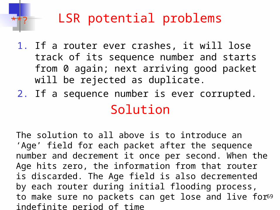
LSR potential problems
1. If a router ever crashes, it will lose track of its sequence number and starts from 0 again; next arriving good packet will be rejected as duplicate.
2. If a sequence number is ever corrupted.
**?
The solution to all above is to introduce an ‘Age’ field for each packet after the sequence number and decrement it once per second. When the Age hits zero, the information from that router is discarded. The Age field is also decremented by each router during initial flooding process, to make sure no packets can get lose and live for indefinite period of time
Solution
70
Compute the shortest path
• When a router has accumulate a full set of link state packets, it can build the entire subnet graph because every link is represented.
• Every link is in fact, represented twice, once for each direction. E.g AB – 4, BA – 4.
• The two values can be averaged or used separately• Next, Dijkstra’s algorithm can be run locally to find the
shortest path to all possible destinations. The results can be installed in the routing tables and normal operation resumed.
• For a subnet with n routers, each of which has k neighbours, therefore memory required to store the input data is proportional to k*n.
71
Exterior Routing Protocol:Border Gateway Protocol
(BGP)
72
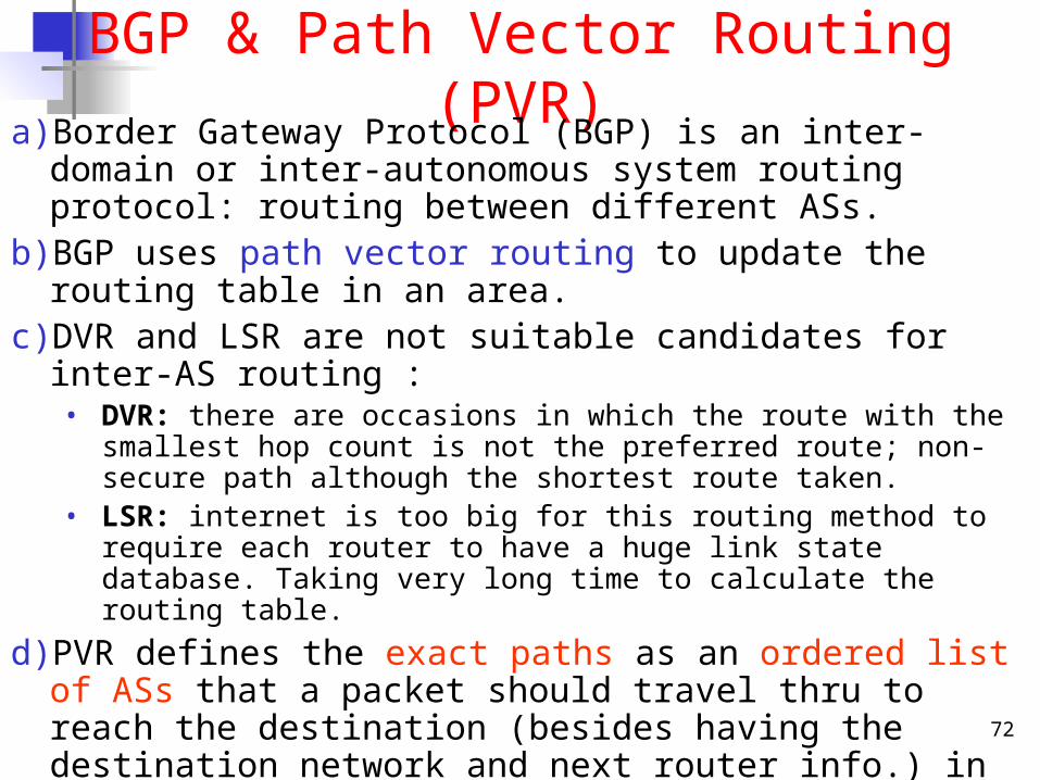
BGP & Path Vector Routing (PVR)a) Border Gateway Protocol (BGP) is an inter-domain or inter-
autonomous system routing protocol: routing between different ASs.b) BGP uses path vector routing to update the routing table in an area.c) DVR and LSR are not suitable candidates for inter-AS routing :
• DVR: there are occasions in which the route with the smallest hop count is not the preferred route; non-secure path although the shortest route taken.
• LSR: internet is too big for this routing method to require each router to have a huge link state database. Taking very long time to calculate the routing table.
d) PVR defines the exact paths as an ordered list of ASs that a packet should travel thru to reach the destination (besides having the destination network and next router info.) in its routing table.
e) Security and Political issues involved: more desired to avoid ‘unsaved’ paths/routes/ASs than to take a shorter route.
f) The AS boundary router that participate in PVR advertise the routes of the networks in their own AS to neighbour AS boundary routers.
g) Solve the count-to-infinity problem
73
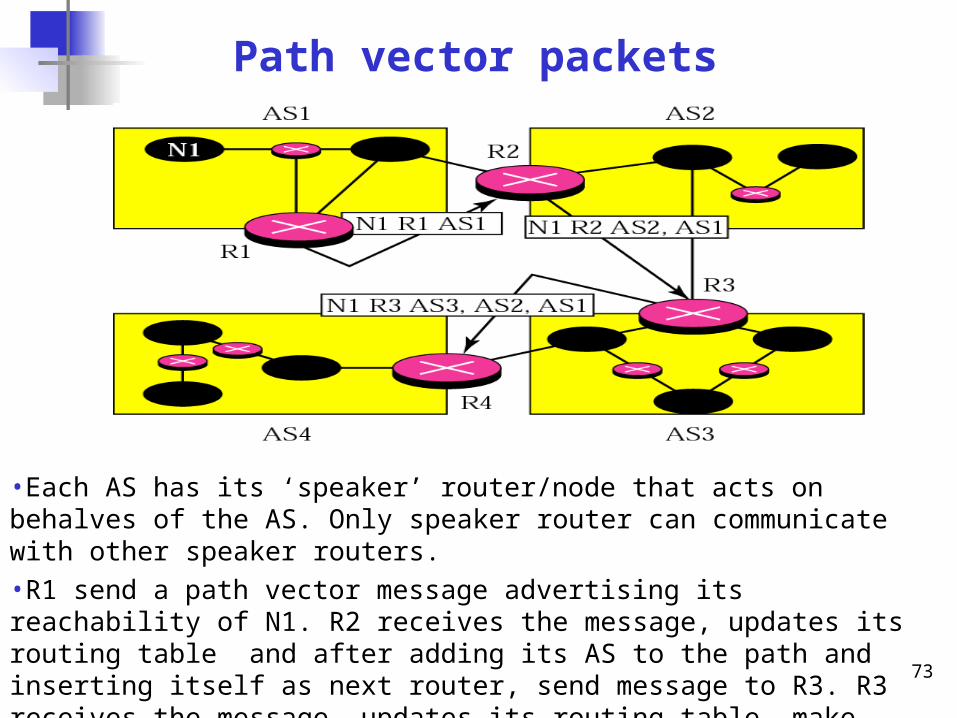
Path vector packets
•Each AS has its ‘speaker’ router/node that acts on behalves of the AS. Only speaker router can communicate with other speaker routers.•R1 send a path vector message advertising its reachability of N1. R2 receives the message, updates its routing table and after adding its AS to the path and inserting itself as next router, send message to R3. R3 receives the message, updates its routing table, make changes and sends the message to R4.
74
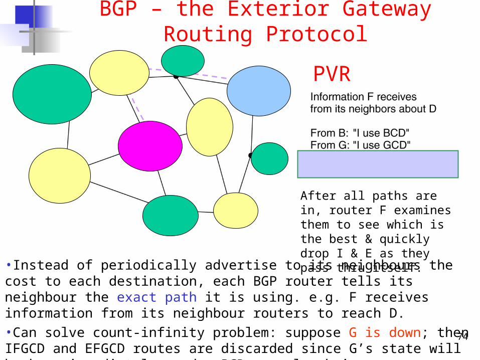
BGP – the Exterior Gateway Routing Protocol
•Instead of periodically advertise to its neighbours the cost to each destination, each BGP router tells its neighbour the exact path it is using. e.g. F receives information from its neighbour routers to reach D. •Can solve count-infinity problem: suppose G is down; then IFGCD and EFGCD routes are discarded since G’s state will be know immediately render BCD as only choice.
After all paths are in, router F examines them to see which is the best & quickly drop I & E as they pass thru itself.
PVR
75
Path Vector Routing Policya) Policy routing can be easily implemented through path vector routing. b) When a router receives a message from its neighbour, the speaker
node or AS boundary router can check the path with its approved list of ASs.
c) If one of the ASs listed in the path is against its policy, the router can ignore that path entirely and that destination.
d) For any unapproved paths, the router does not update its routing table with this path, and it does not send the PV message to its neighbours.
e) This means that the routing table in path vector routing are not based on the smallest hop count (as in distance vector routing) or the minimum delay metric (as in open shortest path first routing); they are based on the policy imposed on the router by the administrator.
f) The path was presented as a list of ASs, but is in fact, a list of attributes. Each attributes gives some information about the path. The list of attributes helps the receiving router make a better decision when applying its policy. (Well-known & Optional)
76
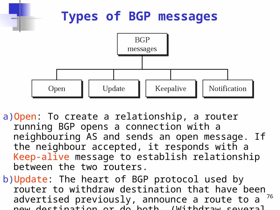
Types of BGP messages
a) Open: To create a relationship, a router running BGP opens a connection with a neighbouring AS and sends an open message. If the neighbour accepted, it responds with a Keep-alive message to establish relationship between the two routers.
b) Update: The heart of BGP protocol used by router to withdraw destination that have been advertised previously, announce a route to a new destination or do both. (Withdraw several but advertise only one).
c) Notification: sent by a router whenever an error condition is detected or router wants to close the connection (down).
77
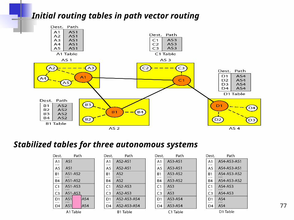
Initial routing tables in path vector routing
Stabilized tables for three autonomous systems
78
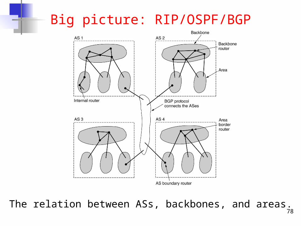
Big picture: RIP/OSPF/BGP
The relation between ASs, backbones, and areas.
79
Due to time limitation and the vast-scope of the network layer, we will NOT go into any more detail about Multicast.Interested students can find more detail in “Internetworking with TCP/IP vol.1” by Douglas Comer, Section-10.22 and Forouzan’s Chapter-21.
Too much to take in!!! - Brain Freeze?
80
Further Reading
1- “Computer Networks”, Andrew Tanenbaum, 4th Ed. to learn more about the generic network layer.
2- “Internetworking with TCP/IP vol.1”, Douglas Comer, 4th Ed., provides a detailed and comprehensive presentation of TCP/IP.
3- “Data Communications and Networking”, Behrouz Forouzan, 4th Ed., when you get confused and wonder if there’s a simpler explanation of all these issues.
Copyright Information : Some figures used in this presentation have been either directly copied or adapted from several books.
Related Documents