1 Chapter 10 Advanced Programming, PLC Interfacing, and Troubleshooting

Welcome message from author
This document is posted to help you gain knowledge. Please leave a comment to let me know what you think about it! Share it to your friends and learn new things together.
Transcript

1
Chapter 10Advanced Programming,
PLC Interfacing, and Troubleshooting

2
Jump Commands
• PLCs have instructions that allow the normal sequential execution of the program to be altered if certain conditions exist
• Output instructions that perform this function are known as override commands
• An example of an override command would be the jump instruction

3
Implementing Jump Instructions• The jump instruction allows the
program to skip certain parts of a program, effectively allowing several programs
• A set of rung conditions precede the jump instruction. When rung conditions are true, the jump will take place
• The jump will be always be associated with a label, which defines the jump to location
• Several jump instructions can use the same label as the jump location

4
Jump to Subroutine• Another jump operation is
the subroutine operation (JSR)
• A JSR label tells the program where to jump to
• A return (RET) instruction is used at the end of the subroutine to tell the program to continue executing where it left off

5
Data Manipulation• Data manipulation instructions
allow data to be manipulated by shifting bits left or right in a register permitting more efficient programming of the PLC
• Shift registers are used for most data manipulation instructions
• An example of forward shift registers in an application is demonstrated on the right

6
Programming Implementation of Shift
Register Example

7
Shift Register Operations• Bit Shift Left (BSL) will
shift data left within a register for each false-true rung transition
• Bit Shift Right (BSR) will shift data right within a register for each false-true rung transition

8
Sequencers• Before PLCs, the control
of an automatic machine was often performed by a drum sequencer
• As the drum rotated, pegs and cams determined what outputs and the dwell of the outputs during a cycle

9
PLC Sequencers• PLCs can perform sequencer
functions on entire words within the PLC
• The words are transferred from memory to output modules in consecutive order
• Parameters necessary for sequencer operations include:
– File - designated memory location that forms the 16-bit pattern of the outputs during the sequence
– Mask - some bits in a word need not be controlled during a sequence. These bits are masked out
– Dest - the output destination to
which the data in the sequencer is to be transferred to
– Control - this parameter indicates the address of where the control bits of the instruction are located
– Length - number of steps of the sequencer file starting at position 1
– Position - this parameter shows the actual step in the sequence that’s being performed

10
Architecture of Sequencer Output Instructions

11
Discrete Input/Output Modules• Discreet I/O modules contain the necessary
connections and interfacing between field devices and the internal process unit
• Many types of I/O modules are available to accommodate different requirements for power, interfacing, and logic

12
Types of Field Devices Connected to I/O Modules

13
Discrete Input Modules• There are two types of field devices that
operate in on/off modes:– Relay contacts– Solid-state relays
• PLC produce several types of discrete input modules for connection to field devices
• Specifications for input modules should take into consideration the following requirements:
– Type of current (AC or DC)– Voltage level– Number of inputs– Active-high or Active-low inputs

14
Relay Contact Input Modules

15
Discrete Output Modules• Several types of discrete output modules are
available to handle a variety of applications• Requirements for output modules should take into
consideration:– AC or DC current– Voltage level– Active-high or Active-low outputs– Relay or Solid-state relay switching– Load capability

16
Types of DC Output Modules
Relay output Solid-state active-high Sinking active-low
17
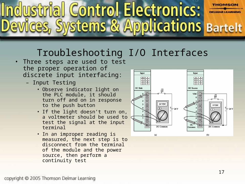
Troubleshooting I/O Interfaces• Three steps are used to test the proper
operation of discrete input interfacing:– Input Testing
• Observe indicator light on the PLC module, it should turn off and on in response to the push button
• If the light doesn’t turn on, a voltmeter should be used to test the signal at the input terminal
• In an improper reading is measured, the next step is to disconnect from the terminal of the module and the power source, then perform a continuity test

18
Troubleshooting Discrete Output Modules• The following steps
should be used to troubleshoot output modules:– Activate the output terminal
of the module– An indicator lamp
connected should energize– If the lamp fails to light and
the field device fails to energize, the problem may lie within the program

19
Analog Input and Output Modules• These modules are fed analog signals and then convert
them into equivalent digital signals for the PLC to work with.
• Analog input modules are sometimes used with sensors and transducers to perform process control functions such as PID control
• The most common analog signal used is the 4-20 mA level associated with process control, however other ranges are available or selectable

20
Special Purpose Modules• Several types of special purpose modules are
available for a variety of applications, including:– Bar Code modules– Radio Frequency (RF) modules– Vision System modules– PID Control modules– Fuzzy Logic modules– Stepper Motor modules– Thermocouple modules

21
Troubleshooting Programmable Controllers• The most effective approach to troubleshooting PLC faults
is to use a logical procedure• Typically, six areas of a PLC are likely to be the source of
faults:– I/O field wiring– Incorrect wiring of the field devices– Input module– CPU or power supply– Programming error– Output module
Related Documents