1 “CFD Analysis of Inlet and Outlet Regions of Coolant Channels in an Advanced Hydrocarbon Engine Nozzle” Dr. Kevin R. Anderson Associate Professor California State Polytechnic University at Pomona Department of Mechanical Engineering Thermal/Fluids Engineer, Swales Aerospace Faculty Part Time T&FSE, NASA-JPL TFAWS 2004 Thermal & Fluids Analysis Workshop Aerothermal / CFD Paper 109-A0019 JPL Pasadena, CA August 30 – September 3, 2004 Pasadena Center, Pasadena, CA

1 “CFD Analysis of Inlet and Outlet Regions of Coolant Channels in an Advanced Hydrocarbon Engine Nozzle” Dr. Kevin R. Anderson Associate Professor California.
Dec 16, 2015
Welcome message from author
This document is posted to help you gain knowledge. Please leave a comment to let me know what you think about it! Share it to your friends and learn new things together.
Transcript
1
“CFD Analysis of Inlet and Outlet Regions of Coolant Channels in an Advanced
Hydrocarbon Engine Nozzle”
Dr. Kevin R. AndersonAssociate Professor
California State Polytechnic University at PomonaDepartment of Mechanical Engineering
Thermal/Fluids Engineer, Swales AerospaceFaculty Part Time T&FSE, NASA-JPL
TFAWS 2004Thermal & Fluids Analysis Workshop Aerothermal / CFD Paper 109-A0019
JPL Pasadena, CA August 30 – September 3, 2004Pasadena Center, Pasadena, CA

2
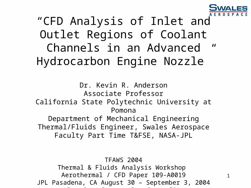
CFD Analysis Required to Model Channel Outlet Regions
Background:
AHEP – Advanced Hydrocarbon Engine Program
Air Force sponsored research contracted Swales Aerospace to perform CFD analysis
3
CFD Analysis Required to Model Channel Outlet Regions
Goal: Estimate Convective Heat Transfer Coefficient On Hot Gas Wall At Inlet And Outlet
Region Of Rectangular Channel
A
A
Coolant Inlet
Section A-A
Coolant Outlet
Combustion Chamber Geometry

4
Injector MountingFlange Stresses
Copper Combustor LinerStresses
Electroformed NickelStructural Closeout Stresses
Copper/EF NickelBond Joint Stresses
Inje
cto
r E
xit
Pla
ne
Combustion ChamberCross-Section
Combustor Geometry

5
Combustor Liner Dimensions
Vacuum Plasma Sprayed GRCop-84 Combustor Liner
CoolantChannel
ElectroformedNickel Structural Closeout
300 R
Throat Cross-section
All Dimensions are in Inches
1210 R
270 R
0.140
0.30
0.0350.050

6
Bounding Calculations• Based upon inlet flow rates and LN2 properties
– Reynolds Number
2300~3 ,4
,4
transhh
Rew
h
P
AD
D
mRe
Flow Rate (lb/s) Re inlet ×105 Re outlet ×105
0.7 0.815 38.6
1.0 1.165 55.1
1.2 1.398 66.1
• Thus, flow is modeled as Turbulent
7
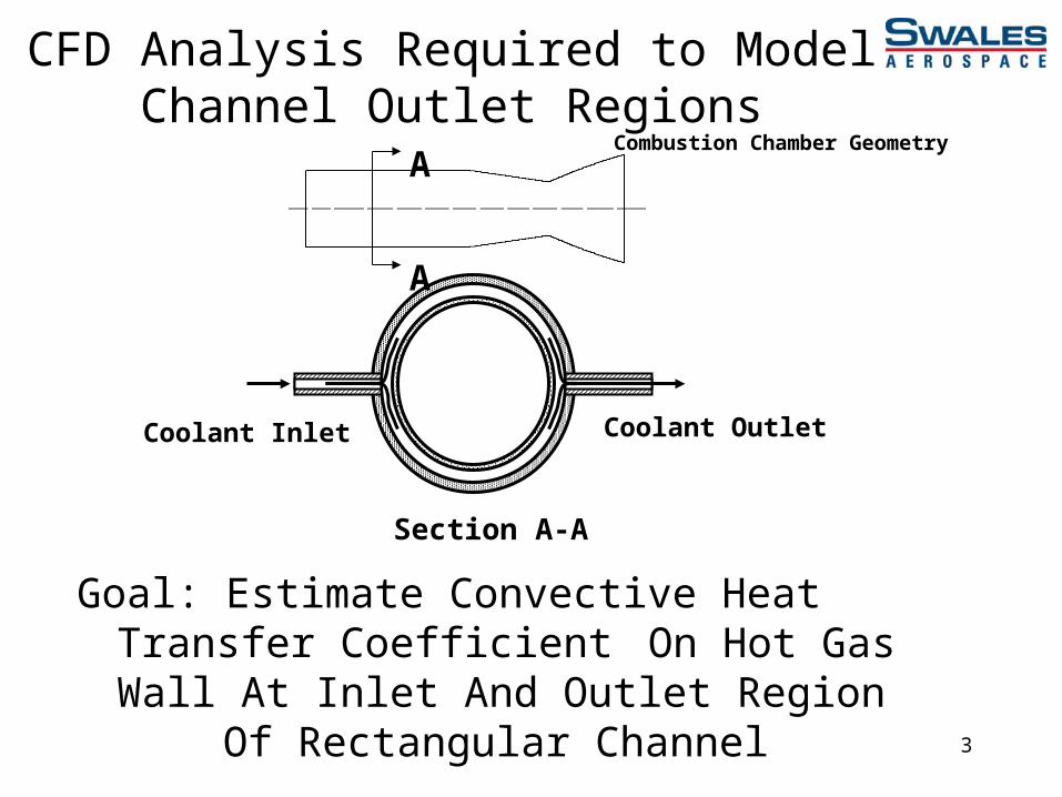
Bounding Calculations• Based upon inlet and outlet speed of sound in LN2
– Mach Number
Flow Subsonic 1 , , MaA
mu
c
uMa
Flow Rate (lb/s) Ma inlet Ma outlet
0.7 0.073 0.171
1.0 0.105 0.244
1.2 0.126 0.293
• Thus, flow is modeled as Incompressible

8
CFD Modeling Methodology• GAMBIT© 2.0 Used to Build Computational Grid
• FLUENT© 6.0 3-D Finite Volume
• Incompressible, Viscous Internal flow
• Standard k- Turbulence Model
• Internal Flow Convective Heat Transfer
• FLUENT User Defined Fluid Option for LN2
• NIST 12 Database Used to Obtain LN2 Properties:ckccsh p ,,,,,,,

9
CFD Modeling MethodologyLN2 DENSITY NIST 12 DATA CURVE FITS
T;p=6000 psia) = 9E-05T2 - 0.1429T + 73.415(T;p=5000 psia) = 0.0001T2 - 0.1594T + 75.011(T;p=4000 psia) = 0.0001T2 - 0.1844T + 77.658
0
10
20
30
40
50
60
0 100 200 300 400 500 600
TEMPERATURE (R)
DE
NS
ITY
(L
BM
/FT
3 )

10
Governing Equations• Conservation of Mass
• Conservation of Momentum
0)(
t
I
pt
T ~
3
2)(~
~)()(

11
Governing Equations• Conservation of Energy
K 15.298
flows ibleincompressfor
2
~)()(
,
2
ref
T
T
jpj
jj
j
effeff
TdTch
phYh
phE
TkpEt
E
ref

12
Governing Equations• Conservation of Energy
- Segregated solver does not include Pressure Work or Kinetic Energy terms, which are negligible for incompressible flows
- Viscous Dissipation terms which describe the thermal energy created by the viscous shear in the flow must be included since Brinkman number:
- Br ~ 1.14, 2.3, 3.4, Viscous Heating present
1 2
Tk
uBr stream

13
Governing Equations• Standard k- Turbulence Model
)()(
)()(
2
21 kC
x
uuu
kC
xxx
u
t
x
uuu
x
k
xx
ku
t
k
i
jji
j
t
ji
i
i
jji
jk
t
ji
i

14
Governing Equations• Turbulent Eddy Viscosity
• Model Constants
2
kCt
31 ,0.1
09.0 ,92.1 ,44.1 21
.σσ
CCC
εk
15
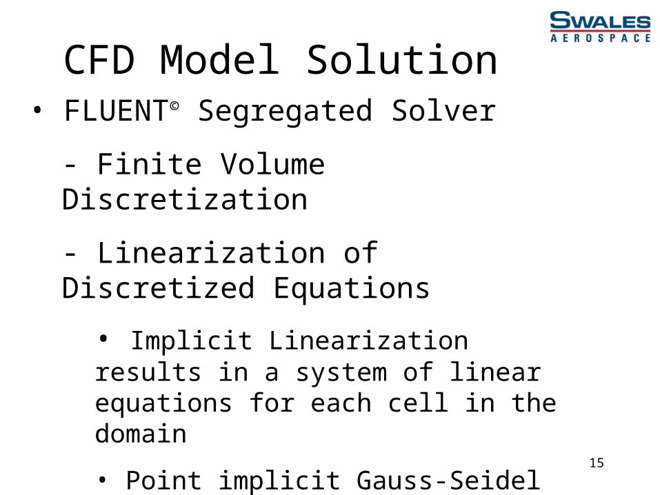
CFD Model Solution• FLUENT© Segregated Solver
- Finite Volume Discretization
- Linearization of Discretized Equations
• Implicit Linearization results in a system of linear equations for each cell in the domain
• Point implicit Gauss-Seidel linear equation solver used in conjunction with an Algebraic Multigrid Method (AMG) to solve the resultant scalar system

16
CFD Model Solution• Overview of the Segregated Solution Method
• Mesh independence study showed approx. 70,000 Finite Volumes required for grid independent converged results
UPDATE PROPERTIES
SOLVE MOMENTUM EQUATIONS
SOLVE PRESSURE-CORRECTION (CONTINUITY) EQUATION
UPDATE PRESSURE,
FACE MASS FLOW RATE
SOLVE ENERGY, TURBULENCE AND OTHER SCALAR
EQUATIONS
CONVERGED ?STOP

17
Boundary ConditionsA
A
Coolant Inlet
Section A-A
Coolant Outlet
Mass Flow Rate Inlet BC
Supply LN2:
140 R
6000 psia
Pressure Outlet BC
Exit LN2:
285 R
4870 psia
Heat Flux BC
97 BTU/in2-s
(50.3×10⁶ BTU/hr-ft2)
k- log-law of the wall
wall functions
18
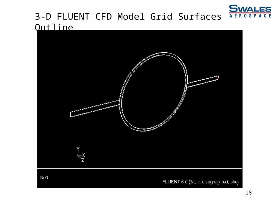
3-D FLUENT CFD Model Grid Surfaces Outline
19
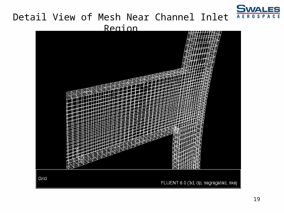
Detail View of Mesh Near Channel Inlet Region

20
Detail View of Mesh Near Channel Outlet Region
21
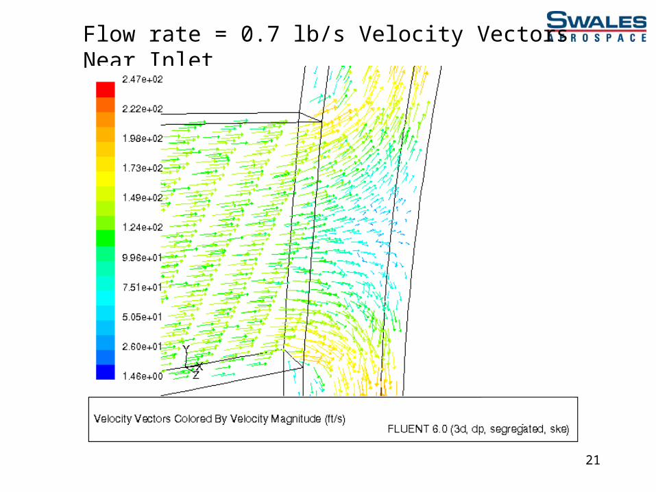
Flow rate = 0.7 lb/s Velocity Vectors Near Inlet

22
Flow rate = 0.7 lb/s Velocity Vectors Near Outlet

23
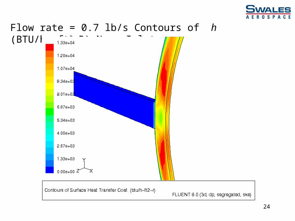
Flow rate = 0.7 lb/s Contours of h (BTU/hr-ft2-R)
24
Flow rate = 0.7 lb/s Contours of h (BTU/hr-ft2-R) Near Inlet

25
Flow rate = 0.7 lb/s Contours of h (BTU/hr-ft2-R) Near Outlet
26
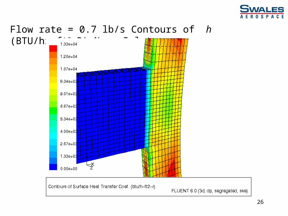
Flow rate = 0.7 lb/s Contours of h (BTU/hr-ft2-R) Near Inlet
27
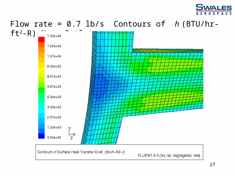
Flow rate = 0.7 lb/s Contours of h (BTU/hr-ft2-R) Near Outlet
28
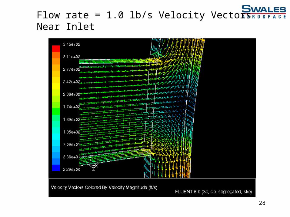
Flow rate = 1.0 lb/s Velocity Vectors Near Inlet
29
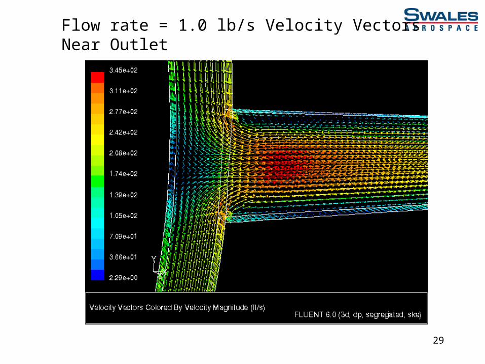
Flow rate = 1.0 lb/s Velocity Vectors Near Outlet

30
Flow rate = 1.0 lb/s Contours of h (BTU/hr-ft2-R)
31
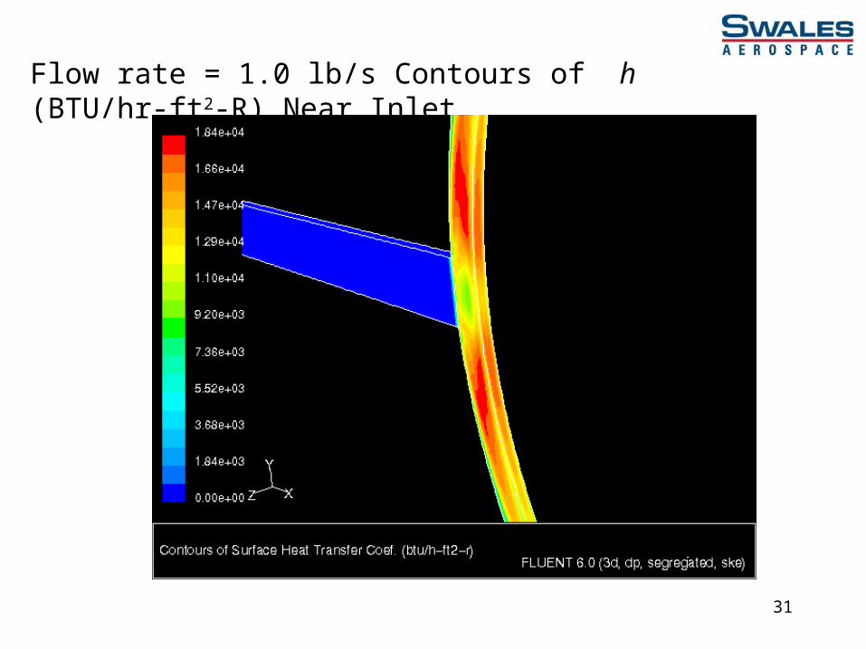
Flow rate = 1.0 lb/s Contours of h (BTU/hr-ft2-R) Near Inlet

32
Flow rate = 1.0 lb/s Contours of h (BTU/hr-ft2-R) Near Outlet

33
Flow rate = 1.0 lb/s Contours of h (BTU/hr-ft2-R) Near Inlet
34
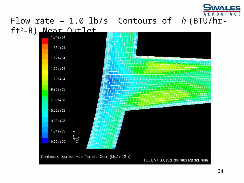
Flow rate = 1.0 lb/s Contours of h (BTU/hr-ft2-R) Near Outlet

35
Flow rate = 1.2 lb/s Velocity Vectors Near Inlet
36
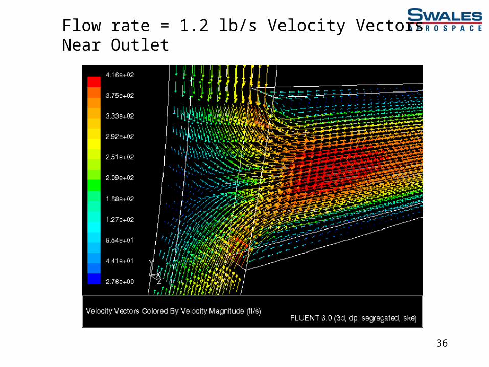
Flow rate = 1.2 lb/s Velocity Vectors Near Outlet

37
Flow rate = 1.2 lb/s Contours of h (BTU/hr-ft2-R)

38
Flow rate = 1.2 lb/s Contours of h (BTU/hr-ft2-R) Near Inlet
39
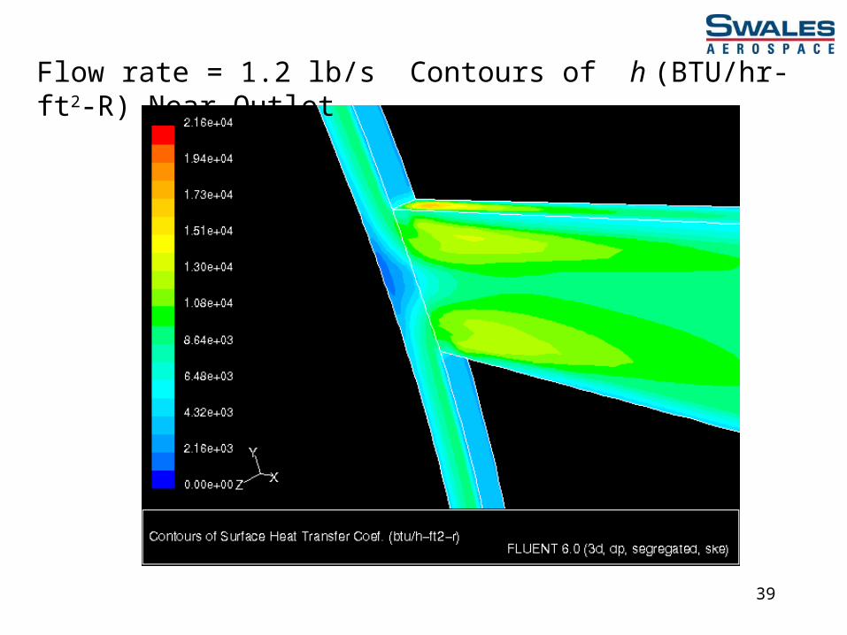
Flow rate = 1.2 lb/s Contours of h (BTU/hr-ft2-R) Near Outlet

40
Flow rate = 1.2 lb/s Contours of h (BTU/hr-ft2-R) Near Inlet
41
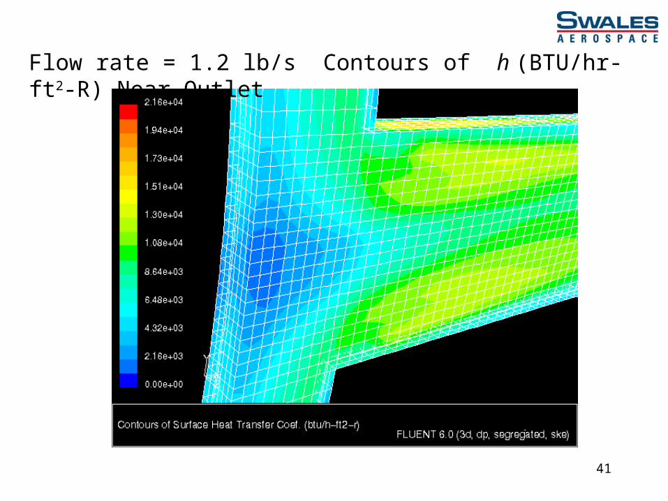
Flow rate = 1.2 lb/s Contours of h (BTU/hr-ft2-R) Near Outlet

42
LOCAL HEAT TRANSFER COEFFICIENT h(x) VS. DISTANCE ALONG CHANNEL(CURVE SHOWN FOR UPPER HALF OF COMBUSTOR WALL)
3000
5000
7000
9000
11000
13000
15000
17000
19000
21000
-1 -0.8 -0.6 -0.4 -0.2 0 0.2 0.4 0.6 0.8 1
DISTANCE ALONG CHANNEL
h(x)
(B
TU
/hr-
ft2 -R
)
Flow Rate = 0.7 lb/s
Flow Rate = 1.0 lb/s
Flow Rate = 1.2 lb/s
1 2
1
2
2
43
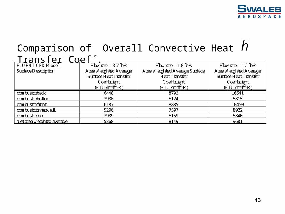
Comparison of Overall Convective Heat Transfer Coeff. hFLUENT CFD Model Surface Description
Flowrate = 0.7 lb/s Area Weighted Average Surface Heat Transfer
Coefficient (BTU/hr-ft2-R)
Flowrate = 1.0 lb/s Area Weighted Average Surface
Heat Transfer Coefficient
(BTU/hr-ft2-R)
Flowrate = 1.2 lb/s Area Weighted Average Surface Heat Transfer
Coefficient (BTU/hr-ft2-R)
combustorback 6448 8702 10541 combustorbottom 3986 5124 5815 combustorfront 6187 8885 10450 combustorinnerwall 5206 7507 8922 combustortop 3989 5159 5840 Net area weighted average 5868 8149 9681
Related Documents