Breakdown Mechanism of Gaseous, Liquid and Solid Materials 1 1 1.0 INTRODUCTION With ever increasing demand of electrical energy, the power system is growing both in size and com- plexities. The generating capacities of power plants and transmission voltage are on the increase be- cause of their inherent advantages. If the transmission voltage is doubled, the power transfer capability of the system becomes four times and the line losses are also relatively reduced. As a result, it becomes a stronger and economical system. In India, we already have 400 kV lines in operation and 800 kV lines are being planned. In big cities, the conventional transmission voltages (110 kV–220 kV etc.) are being used as distribution voltages because of increased demand. A system (transmission, switchgear, etc.) designed for 400 kV and above using conventional insulating materials is both bulky and expensive and, therefore, newer and newer insulating materials are being investigated to bring down both the cost and space requirements. The electrically live conductors are supported on insulating materials and sufficient air clearances are provided to avoid flashover or short circuits between the live parts of the system and the grounded structures. Sometimes, a live conductor is to be immersed in an insulating liquid to bring down the size of the container and at the same time provide sufficient insulation between the live conductor and the grounded container. In electrical engineering all the three media, viz. the gas, the liquid and the solid are being used and, therefore, we study here the mechanism of breakdown of these media. 1.1 MECHANISM OF BREAKDOWN OF GASES At normal temperature and pressure, the gases are excellent insulators. The current conduction is of the order of 10 –10 A/cm 2 . This current conduction results from the ionisation of air by the cosmic radiation and the radioactive substances present in the atmosphere and the earth. At higher fields, charged parti- cles may gain sufficient energy between collision to cause ionisation on impact with neutral molecules. It is known that during an elastic collision, an electron loses little energy and rapidly builds up its kinetic energy which is supplied by an external electric field. On the other hand, during elastic colli- sion, a large part of the kinetic energy is transformed into potential energy by ionising the molecule struck by the electron. Ionisation by electron impact under strong electric field is the most important process leading to breakdown of gases. This ionisation by radiation or photons involves the interaction of radiation with matter. Photoionisation occurs when the amount of radiation energy absorbed by an atom or molecule exceeds its ionisation energy and is represented as A + hν → A + + e where A represents a neutral atom or

Welcome message from author
This document is posted to help you gain knowledge. Please leave a comment to let me know what you think about it! Share it to your friends and learn new things together.
Transcript
Breakdown Mechanism of Gaseous,Liquid and Solid Materials
1
1
1.0 INTRODUCTION
With ever increasing demand of electrical energy, the power system is growing both in size and com-plexities. The generating capacities of power plants and transmission voltage are on the increase be-cause of their inherent advantages. If the transmission voltage is doubled, the power transfer capabilityof the system becomes four times and the line losses are also relatively reduced. As a result, it becomesa stronger and economical system. In India, we already have 400 kV lines in operation and 800 kV linesare being planned. In big cities, the conventional transmission voltages (110 kV–220 kV etc.) are beingused as distribution voltages because of increased demand. A system (transmission, switchgear, etc.)designed for 400 kV and above using conventional insulating materials is both bulky and expensiveand, therefore, newer and newer insulating materials are being investigated to bring down both the costand space requirements. The electrically live conductors are supported on insulating materials andsufficient air clearances are provided to avoid flashover or short circuits between the live parts of thesystem and the grounded structures. Sometimes, a live conductor is to be immersed in an insulatingliquid to bring down the size of the container and at the same time provide sufficient insulation betweenthe live conductor and the grounded container. In electrical engineering all the three media, viz. the gas,the liquid and the solid are being used and, therefore, we study here the mechanism of breakdown ofthese media.
1.1 MECHANISM OF BREAKDOWN OF GASES
At normal temperature and pressure, the gases are excellent insulators. The current conduction is of theorder of 10–10 A/cm2. This current conduction results from the ionisation of air by the cosmic radiationand the radioactive substances present in the atmosphere and the earth. At higher fields, charged parti-cles may gain sufficient energy between collision to cause ionisation on impact with neutral molecules.It is known that during an elastic collision, an electron loses little energy and rapidly builds up itskinetic energy which is supplied by an external electric field. On the other hand, during elastic colli-sion, a large part of the kinetic energy is transformed into potential energy by ionising the moleculestruck by the electron. Ionisation by electron impact under strong electric field is the most importantprocess leading to breakdown of gases.
This ionisation by radiation or photons involves the interaction of radiation with matter.Photoionisation occurs when the amount of radiation energy absorbed by an atom or molecule exceedsits ionisation energy and is represented as A + hν → A+ + e where A represents a neutral atom or
DharmN-HIGH\HG1-1.PM5 2
2 HIGH VOLTAGE ENGINEERING
molecule in the gas and hν the photon energy. Photoionization is a secondary ionization process and isessential in the streamer breakdown mechanism and in some corona discharges. If the photon energy isless than the ionization energy, it may still be absorbed thus raising the atom to a higher energy level.This is known as photoexcitation.
The life time of certain elements in some of the excited electronic states extends to seconds.These are known as metastable states and these atoms are known as metastables. Metastables have arelatively high potential energy and are, therefore, able to ionize neutral particles. Let A be the atom tobe ionized and Bm the metastable, when Bm collides with A, ionization may take place according to thereaction.
A + Bm → A+ + B + e
Ionization by metastable interactions comes into operation long after excitation and it has beenshown that these reactions are responsible for long-time lags observed in some gases.
Thermal Ionisation: The term thermal ionisation in general applies to the ionizing actions ofmolecular collisions, radiation and electron collisions occurring in gases at high temperatures. When agas is heated to high temperature, some of the gas molecules acquire high kinetic energy and theseparticles after collision with neutral particles ionize them and release electrons. These electrons andother high-velocity molecules in turn collide with other particles and release more electrons. Thus, thegas gets ionized. In this process, some of the electrons may recombine with positive ions resulting intoneutral molecule. Therefore, a situation is reached when under thermodynamic equilibrium conditionthe rate of new ion formation must be equal to the rate of recombination. Using this assumption, Sahaderived an expression for the degree of ionization β in terms of the gas pressure and absolute tempera-ture as follows:
ββ
π2
2
3 25 2
1
1 2
−= −
p
m
hKT ee W KT( )
( )/
/ /
orβ
β
2
2
45 2
1
2 4 10
−= × −
−. / /
pT e W KTi
where p is the pressure in Torr, Wi the ionization energy of the gas, K the Boltzmann’s constant, β theratio ni/n and ni the number of ionized particles of total n particles. Since β depends upon the tempera-ture it is clear that the degree of ionization is negligible at room temperature. Also, if we substitute thevalues of p, Wi, K and T, it can be shown that thermal ionization of gas becomes significant only iftemperature exceeds 1000° K.
1.2 TOWNSEND’S FIRST IONIZATION COEFFICIENT
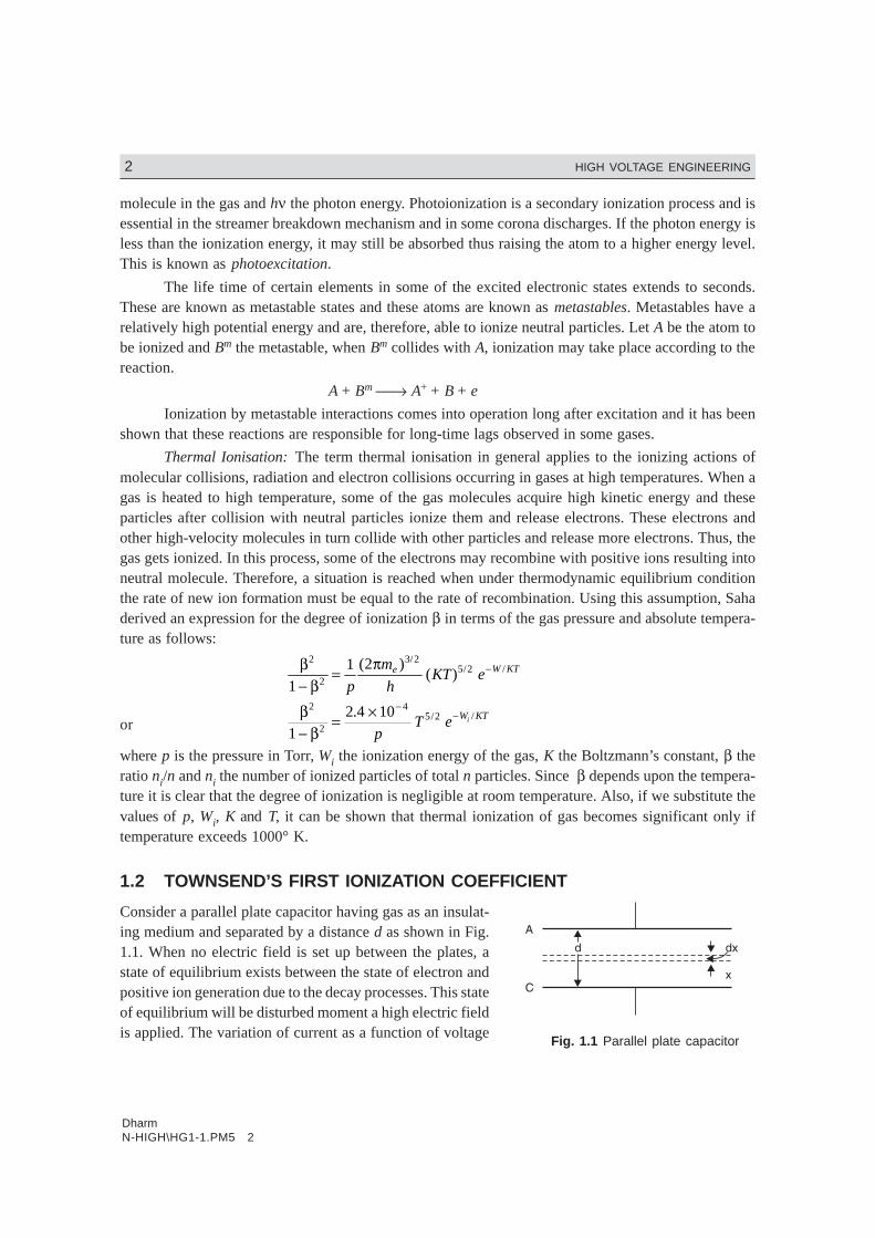
Consider a parallel plate capacitor having gas as an insulat-ing medium and separated by a distance d as shown in Fig.1.1. When no electric field is set up between the plates, astate of equilibrium exists between the state of electron andpositive ion generation due to the decay processes. This stateof equilibrium will be disturbed moment a high electric fieldis applied. The variation of current as a function of voltage
Fig. 1.1 Parallel plate capacitor

DharmN-HIGH\HG1-1.PM5 3
BREAKDOWN MECHANISM OF GASEOUS, LIQUID AND SOLID MATERIALS 3
was studied by Townsend. He found that the current atfirst increased proportionally as the voltage is increasedand then remains constant, at I0 which corresponds to thesaturation current. At still higher voltages, the current in-creases exponentially. The variation of current asa function of voltage is shown in Fig. 1.2. The exponen-tial increase in current is due to ionization of gas by elec-tron collision. As the voltage increases V/d increases andhence the electrons are accelerated more and more andbetween collisions these acquire higher kinetic energy and,therefore, knock out more and more electrons.
To explain the exponential rise in current, Townsend introduced a coefficient α known asTownsend’s first ionization coefficient and is defined as the number of electrons produced by an elec-tron per unit length of path in the direction of field. Let n0 be the number of electons leaving thecathode and when these have moved through a distance x from the cathode, these become n. Now whenthese n electrons move through a distance dx produce additional dn electrons due to collision. There-fore,
dn = α n dx
ordn
ndx= α
or ln n = αx + A
Now at x = 0, n = n0. Therefore,
ln n0 = A
or ln n = αx + ln n0
or ln n
nx
0
= α
At x = d, n = n0 eαd. Therefore, in terms of current
I = I0 eαd
The term eαd is called the electron avalanche and it represents the number of electrons producedby one electron in travelling from cathode to anode.
1.3 CATHODE PROCESSES—SECONDARY EFFECTS
Cathode plays an important role in gas discharges by supplying electrons for the initiation, sustainanceand completion of a discharge. In a metal, under normal condition, electrons are not allowed to leavethe surface as they are tied together due to the electrostatic force between the electrons and the ions inthe lattice. The energy required to knock out an electron from a Fermi level is konwn as the workfunction and is a characteristic of a given material. There are various ways in which this energy can besupplied to release the electron.
Fig. 1.2 Variation of current as afunction of voltage
DharmN-HIGH\HG1-1.PM5 4
4 HIGH VOLTAGE ENGINEERING
Thermionic Emission: At room temperature, the conduction electrons of the metal do not have suffi-cient thermal energy to leave the surface. However, if the metals are heated to temperature 1500°K andabove, the electrons will receive energy from the violent thermal lattice in vibration sufficient to crossthe surface barrier and leave the metal. After extensive investigation of electron emission from metalsat high temperature, Richardson developed an expression for the saturation current density Js as
Js = 4 2
32π αm K
hT ee W KT− / A/m2
where the various terms have their usual significance.
Let A = 4 2
3
πm K
he
the above expression becomes
Js = AT2e–W/KT
which shows that the saturation current density increases with decrease in work function and increasein temperature. Substituting the values of me, K and h, A is found to be 120 × 104 A/m2 K2. However, theexperimentally obtained value of A is lower than what is predicted by the equation above. The discrep-ancy is due to the surface imperfections and surface impurities of the metal. The gas present betweenthe electrode affects the thermionic emission as the gas may be absorbed by the metal and can alsodamage the electrode surface due to continuous impinging of ions. Also, the work function is observedto be lowered due to thermal expansion of crystal structure. Normally metals with low work functionare used as cathode for thermionic emission.
Field Emission: If a strong electric field is applied between the electrodes, the effective work functionof the cathode decreases and is given by
W′ = W – ε3/2 E1/2
and the saturation current density is then given by
Js = AT2 e–W′/KT
This is known as Schottky effect and holds good over a wide range of temperature and electricfields. Calculations have shown that at room temperature the total emission is still low even when fieldsof the order of 105 V/cm are applied. However, if the field is of the order of 107 V/cm, the emissioncurrent has been observed to be much larger than the calculated thermionic value. This can be ex-plained only through quantum mechanics at these high surface gradients, the cathode surface barrierbecomes very thin and quantum tunnelling of electrons occurs which leads to field emission even atroom temperature.
Electron Emission by Positive Ion and Excited Atom BombardmentElectrons may be emitted by the bombardment of positive ion on the cathode surface. This is known assecondary emission. In order to effect secondary emission, the positive ion must have energy more thantwice the work function of the metal since one electron will neutralize the bombarding positive ion andthe other electron will be released. If Wk and Wp are the kinetic and potential energies, respectively ofthe positive ion then for secondary emission to take place Wk + Wp ≥ 2W. The electron emission bypositive ion is the principal secondary process in the Townsend spark discharge mechanism. Neutral
DharmN-HIGH\HG1-1.PM5 5
BREAKDOWN MECHANISM OF GASEOUS, LIQUID AND SOLID MATERIALS 5
excited atoms or molecules (metastables) incident upon the cathode surface are also capable of releas-ing electron from the surface.
1.4 TOWNSEND SECOND IONISATION COEFFICIENT
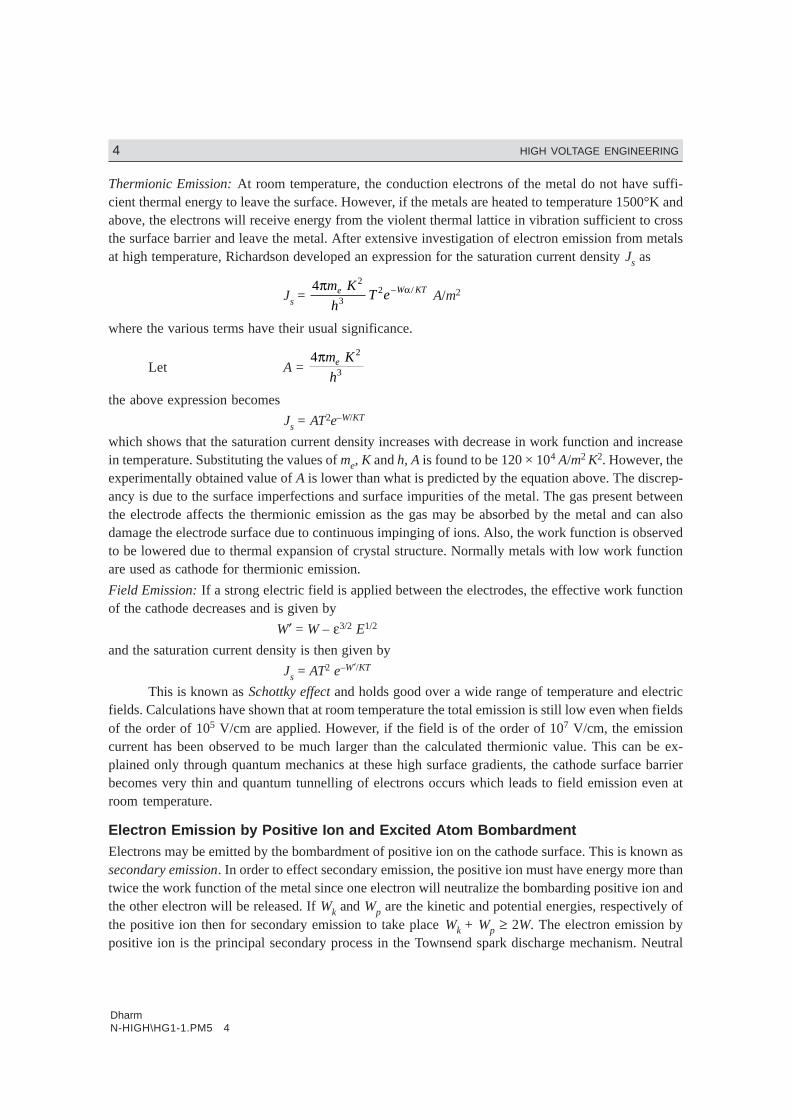
From the equation
I = I0 eαx
We have, taking log on both the sides.
Fig. 1.3 Variation of gap current with electrode spacing in uniform E
ln I = ln I0 + αx
This is a straight line equation with slope α and intercept ln I0 as shown in Fig. 1.3 if for a givenpressure p, E is kept constant.
Townsend in his earlier investigations had observed that the current in parallel plate gap in-creased more rapidly with increase in voltage as compared to the one given by the above equation. Toexplain this departure from linearity, Townsend suggested that a second mechanism must be affectingthe current. He postulated that the additional current must be due to the presence of positive ions andthe photons. The positive ions will liberate electrons by collision with gas molecules and by bombard-ment against the cathode. Similarly, the photons will also release electrons after collision with gasmolecules and from the cathode after photon impact.
Let us consider the phenomenon of self-sustained discharge where the electrons are releasedfrom the cathode by positive ion bombardment.
Let n0 be the number of electrons released from the cathode by ultraviolet radiation, n+ thenumber of electrons released from the cathode due to positive ion bombardment and n the number ofelectrons reaching the anode. Let ν, known as Townsend second ionization co-efficient be defined asthe number of electrons released from cathode per incident positive ion, Then
n = (n0 + n+)eαd
Now total number of electrons released from the cathode is (n0 + n+) and those reaching theanode are n, therefore, the number of electrons released from the gas = n – (n0 + n+), and correspondingto each electron released from the gas there will be one positive ion and assuming each positive ionreleases ν effective electrons from the cathode then

DharmN-HIGH\HG1-1.PM5 6
6 HIGH VOLTAGE ENGINEERING
n+ = ν [n – (n0 + n+)]
or n+ = νn – νn0 – νn+
or (1 + ν) n+ = ν(n – n0)
or n+ = ν
ν( )n n−
+0
1
Substituting n+ in the previous expression for n, we have
n = nn n
ve d
00
1+ −
+LNM
OQP
ν α( ) =
( )1
10 0+ + −
+ν ν ν
ναn n n
e d
= n n
e d0
1
++
νν
α
or (n + νn) = n0 eαd + νneαd
or n + νn – νneαd = n0eαd
or n[1+ ν – νeαd] = n0eαd
or n = n e
n e
d
d0
1 1
α
αν+ −( ) =
n e
e
d
d0
1 1
α
αν− −( )
In terms of current
I = I e
e
d
d0
1 1
α
αν− −( )
Earlier Townsend derived an expression for current as
I = Ie
e
d
d0( ) ( )
( )
α βα β
α β
α β−−
−
−
where β represents the number of ion pairs produced by positive ion travelling 1 cm path in the direc-tion of field. Townsend’s original suggestion that the positive ion after collision with gas moleculereleases electron does not hold good as ions rapidly lose energy in elastic collision and ordinarily areunable to gain sufficient energy from the electric field to cause ionization on collision with gas moleculesor atoms.
In practice positive ions, photons and metastable, all the three may participate in the process ofionization. It depends upon the experimental conditions. There may be more than one mechanismproducing secondary ionization in the discharge gap and, therefore, it is customary to express the netsecondary ionization effect by a single coefficient v and represent the current by the above equationkeeping in mind that ν may represent one or more of the several possible mechanism.
ν = ν1 + ν2 + ν3 + .....
It is to be noted that the value of ν depends upon the work function of the material. If the workfunction of the cathode surface is low, under the same experimental conditions will produce moreemission. Also, the value of ν is relatively small at low value of E/p and will increase with increase inE/p. This is because at higher values of E/p, there will be more number of positive ions and photons ofsufficiently large energy to cause ionization upon impact on the cathode surface. It is to be noted thatthe influence of ν on breakdown mechanism is restricted to Townsend breakdown mechanism i.e., tolow-pressure breakdown only.
DharmN-HIGH\HG1-1.PM5 7
BREAKDOWN MECHANISM OF GASEOUS, LIQUID AND SOLID MATERIALS 7
1.5 TOWNSEND BREAKDOWN MECHANISM
When voltage between the anode and cathode is increased, the current at the anode is given by
I = I e
e
d
d0
1 1
α
αν− −( )
The current becomes infinite if
1 – ν(eαd –1) = 0
or ν(eα d – 1) = 1
or νeα d ≈ 1
Since normally eα d >> 1
the current in the anode equals the current in the external cirrcuit. Theoretically the current becomesinfinitely large under the above mentioned condition but practically it is limited by the resistance of theexternal circuit and partially by the voltage drop in the arc. The condition νeαd = 1 defines the conditionfor beginning of spark and is known as the Townsend criterion for spark formation or Townsend break-down criterion. Using the above equations, the following three conditions are possible.
(1) νeαd =1
The number of ion pairs produced in the gap by the passage of arc electron avalanche is suffi-ciently large and the resulting positive ions on bombarding the cathode are able to relase onesecondary electron and so cause a repetition of the avalanche process. The discharge is then saidto be self-sustained as the discharge will sustain itself even if the source producing I0 is removed.
Therefore, the condition νeαd = 1 defines the threshold sparking condition.
(2) νeαd > 1
Here ionization produced by successive avalanche is cumulative. The spark discharge growsmore rapidly the more νeαd exceeds unity.
(3) νeαd < 1
Here the current I is not self-sustained i.e., on removal of the source the current I0 ceases to flow.
1.6 STREAMER OR KANAL MECHANISM OF SPARK
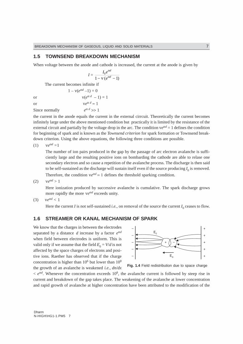
We know that the charges in between the electrodesseparated by a distance d increase by a factor eαd
when field between electrodes is uniform. This isvalid only if we assume that the field E0 = V/d is notaffected by the space charges of electrons and posi-tive ions. Raether has observed that if the chargeconcentration is higher than 106 but lower than 108
the growth of an avalanche is weakened i.e., dn/dx< eαd. Whenever the concentration exceeds 108, the avalanche current is followed by steep rise incurrent and breakdown of the gap takes place. The weakening of the avalanche at lower concentrationand rapid growth of avalanche at higher concentration have been attributed to the modification of the
Fig. 1.4 Field redistribution due to space charge
DharmN-HIGH\HG1-1.PM5 8
8 HIGH VOLTAGE ENGINEERING
electric field E0 due to the space charge field. Fig. 1.4 shows the electric field around an avalanche as itprogresses along the gap and the resultant field i.e., the superposition of the space charge field and theoriginal field E0. Since the electrons have higher mobility, the space charge at the head of the avalancheis considered to be negative and is assumed to be concentrated within a spherical volume. It can be seenfrom Fig. 1.4 that the filed at the head of the avalanche is strengthened. The field between the twoassumed charge centres i.e., the electrons and positive ions is decreased as the field due to the chargecentres opposes the main field E0 and again the field between the positive space charge centre and thecathode is strengthened as the space charge field aids the main field E0 in this region. It has beenobserved that if the charge carrier number exceeds 106, the field distortion becomes noticeable. If thedistortion of field is of 1%, it would lead to a doubling of the avalanche but as the field distortion isonly near the head of the avalanche, it does not have a significance on the discharge phenomenon.However, if the charge carrier exceeds 108, the space charge field becomes almost of the same magni-tude as the main field E0 and hence it may lead to initiation of a streamer. The space charge field,therefore, plays a very important role in the mechanism of electric discharge in a non-uniform gap.
Townsend suggested that the electric spark discharge is due to the ionization of gas molecule bythe electron impact and release of electrons from cathode due to positive ion bombardment at thecathode. According to this theory, the formative time lag of the spark should be at best equal to theelectron transit time tr. At pressures around atmospheric and above p.d. > 103 Torr-cm, the experimen-tally determined time lags have been found to be much shorter than tr. Study of the photographs of theavalanche development has also shown that under certain conditions, the space charge developed in anavalanche is capable of transforming the avalanche into channels of ionization known as streamers thatlead to rapid development of breakdown. It has also been observed through measurement that thetransformation from avalanche to streamer generally takes place when the charge within the avalanchehead reaches a critical value of
n0eαx ≈ 108 or αxc ≈ 18 to 20
where Xc is the length of the avalanche parth in field direction when it reaches the critical size. If thegap length d < Xc, the initiation of streamer is unlikely.
The short-time lags associated with the discharge development led Raether and independentlyMeek and Meek and Loeb to the advancement of the theory of streamer of Kanal mechanism for sparkformation, in which the secondary mechanism results from photoionization of gas molecules and isindependent of the electrodes.
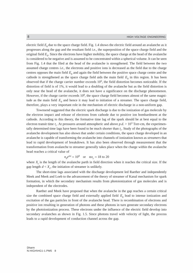
Raether and Meek have proposed that when the avalanche in the gap reaches a certain criticalsize the combined space charge field and externally applied field E0 lead to intense ionization andexcitation of the gas particles in front of the avalanche head. There is recombination of electrons andpositive ion resulting in generation of photons and these photons in turn generate secondary electronsby the photoionization process. These electrons under the influence of the electric field develop intosecondary avalanches as shown in Fig. 1.5. Since photons travel with velocity of light, the processleads to a rapid development of conduction channel across the gap.
DharmN-HIGH\HG1-1.PM5 9
BREAKDOWN MECHANISM OF GASEOUS, LIQUID AND SOLID MATERIALS 9
Fig. 1.5 Secondary avalanche formation by photoelectrons
Raether after thorough experimental investigation developed an empirical relation for the streamerspark criterion of the form
αxc = 17.7 + ln xc + ln E
Er
0
where Er is the radial field due to space charge and E0 is the externally applied field.
Now for transformation of avalanche into a streamer Er ≈ E
Therefore, αxc = 17.7 + ln xc
For a uniform field gap, breakdown voltage through streamer mechanism is obtained on theassumption that the transition from avalanche to streamer occurs when the avalanche has just crossedthe gap. The equation above, therefore, becomes
αd = 17.7 + ln d
When the critical length xc ≥ d minimum breakdown by streamer mechanism is brought about.The condition Xc = d gives the smallest value of α to produce streamer breakdown.
Meek suggested that the transition from avalanche to streamer takes place when the radial fieldabout the positive space charge in an electron avalanche attains a value of the order of the externallyapplied field. He showed that the value of the radial field can be otained by using the expression.
Er = 5.3 × 10⁻⁷ α αe
x P
x
( / ) /1 2 volts/cm.
where x is the distance in cm which the avalanche has progressed, p the gas pressure in Torr and α theTownsend coefficient of ionization by electrons corresponding to the applied field E. The minimumbreakdown voltage is assumed to correspond to the condition when the avalanche has crossed the gapof length d and the space charge field Er approaches the externally applied field i.e., at x = d, Er = E.Substituting these values in the above equation, we have
E = 5.3 × 10⁻⁷ α αe
d p
d
( / ) /1 2
Taking ln on both the sides, we have
ln E = – 14.5 + ln α – 1
2ln
d
p + αd
ln E – ln p = – 14.5 + ln α – ln p – 1
21n
d
p + αd

DharmN-HIGH\HG1-1.PM5 10
10 HIGH VOLTAGE ENGINEERING
1n E
p p
d
pd= − + − +14 5
1
2. lnln
α α
The experimentally determined values of α/p and the corresponding E/p are used to solve theabove equation using trial and error method. Values of α/p corresponding to E/p at a given pressure arechosen until the equation is satisfied.
1.7. THE SPARKING POTENTIAL—PASCHEN’S LAW
The Townsend’s Criterion
ν(eαd – 1) = 1
enables the evaluation of breakdown voltage of the gap by the use of appropriate values of α/p and νcorresponding to the values E/p when the current is too low to damage the cathode and also the spacecharge distortions are minimum. A close agreement between the calculated and experimentally deter-mined values is obtained when the gaps are short or long and the pressure is relatively low.
An expression for the breakdown voltage for uniform field gaps as a function of gap length andgas pressure can be derived from the threshold equation by expressing the ionization coefficient α/p asa function of field strength E and gas pressure p i.e.,
αp
fE
p=
FHG
IKJ
Substituting this, we have
ef(E/p) pd = 1
1ν
+
Taking ln both the sides, we have
fE
ppd K
FHG
IKJ = +L
NMOQP =ln say
11
ν
For uniform field E = V
db
.
Therefore, fV
pdpd KbF
HGIKJ =.
or fV
pd
K
pdbF
HGIKJ =
or Vb = F (p.d)This shows that the breakdown voltage of a uniform field gap is a unique function of the product
of gas pressure and the gap length for a particular gas and electrode material. This relation is known asPaschen’s law. This relation does not mean that the breakdown voltage is directly proportional toproduct pd even though it is found that for some region of the product pd the relation is linear i.e., thebreakdown voltage varies linearly with the product pd. The variation over a large range is shown inFig. 1.6.

DharmN-HIGH\HG1-1.PM5 11
BREAKDOWN MECHANISM OF GASEOUS, LIQUID AND SOLID MATERIALS 11
Fig. 1.6 Paschen’s law curve
Let us now compare Paschen’s law and the Townsend’s criterion for spark potential. We drawthe experimentally obtained relation between the ionization coefficient α/p and the field strength f(E/p)
for a given gas. Fig. 1.7. Here point E
pb
c
FHG
IKJ represents the onset of ionization.
Fig. 1.7 The relation between Townsend’s criterion for spark = k and Paschen’s criterion
Now the Townsend’s criterion αd = K can be re-written as
α αp
V
E
K
p p
K
V
E
P. .= =or
This is equation to a straight line with slope equal to K/V depending upon the value of K. Thehigher the voltage the smaller the slope and therefore, this line will intersect the ionization curve at twopoints e.g., A and B in Fig. 1.7. Therefore, there must exist two breakdown voltages at a constantpressure (p = constant), one corresponding to the small value of gap length i.e., higher E (E = V/d) i.e.,point B and the other to the longer gap length i.e., smaller E or smaller E/p i.e., the point A. At lowvalues of voltage V the slope of the straight line is large and, therefore, there is no intersection betweenthe line and the curve 1. This means no breakdown occurs with small voltages below Paschen’s mini-mum irrespective of the value of pd. The point C on the curve indicates the lowest breakdown voltageor the minimum sparking potential. The spark over voltages corresponding to points A, B, C are shownin the Paschen’s curve in Fig. 1.6.

DharmN-HIGH\HG1-1.PM5 12
12 HIGH VOLTAGE ENGINEERING
The fact that there exists a minimum sparking potential in the relation between the sparkingpotential and the gap length assuming p to be constant can be explained quantitatively by consideringthe efficiency of ionization of electrons traversing the gap with different electron energies. Assumingthat the Townsend’s second ionization coefficient ν is small for values pd > (pd)min., electrons cross-ing the gap make more frequent collision with the gas molecules than at (pd)min. but the energy gainedbetween the successive collision is smaller than at (pd). Hence, the probability of ionization is lowerunless the voltage is increased. In case of (pd) < (pd) min., the electrons cross the gap without makingany collision and thus the sparking potential is higher. The point (pd)min., therefore, corresponds to thehighest ionization efficiency and hence minimum sparking potential.
An analytical expression for the minimum sparking potential can be obtained using the generalexpression for α/p.
αp
AeBp E= /or α = −pAe Bpd Vb/
or e Bpd Vb− / = pA
αor 1
α= e
pA
Bpd Vb/
or d . 1
αd
e
pA
B Vpd
=/ b
We know that αd = 1n 11+F
HIKν
Therefore, de
pA
Bpd Vb
= +FH
IK
/
1 11
nν
Assuming ν to be constant, let 1 11
n +FH
IK =
νk
Then de
pAK
Bpd Vb
=/
In order to obtain minimum sparking potential, we rearrange the above expression as
Vb = f(pd)
Taking 1n on both sides, we haveBpd
V
Apd
Kb
= ln
or Vb = Bpd
Apd kln /Differentiating Vb w.r. to pd and equating the derivative to zero
dV
d pd
Apd
KB Bpd
K
Apd
A
K
Apd
K
b
( )
. . .=
−
FH
IK
ln
n12 =
BApdK
Apd
K
B
Apd
K
ln
1n nFH
IK
−FH
IK
=2 2
1
0
or1 1
2ln ln
Apd
KApd
K
=FH
IK
DharmN-HIGH\HG1-1.PM5 13
BREAKDOWN MECHANISM OF GASEOUS, LIQUID AND SOLID MATERIALS 13
or 1nApd
K = 1
or 1nApd
K = e
or (pd)min = e
AK
or Vb min = B e B
AeK
K A/
.1
=
Vbmin = 2.718 B
A1 1
1n +FH
IKν
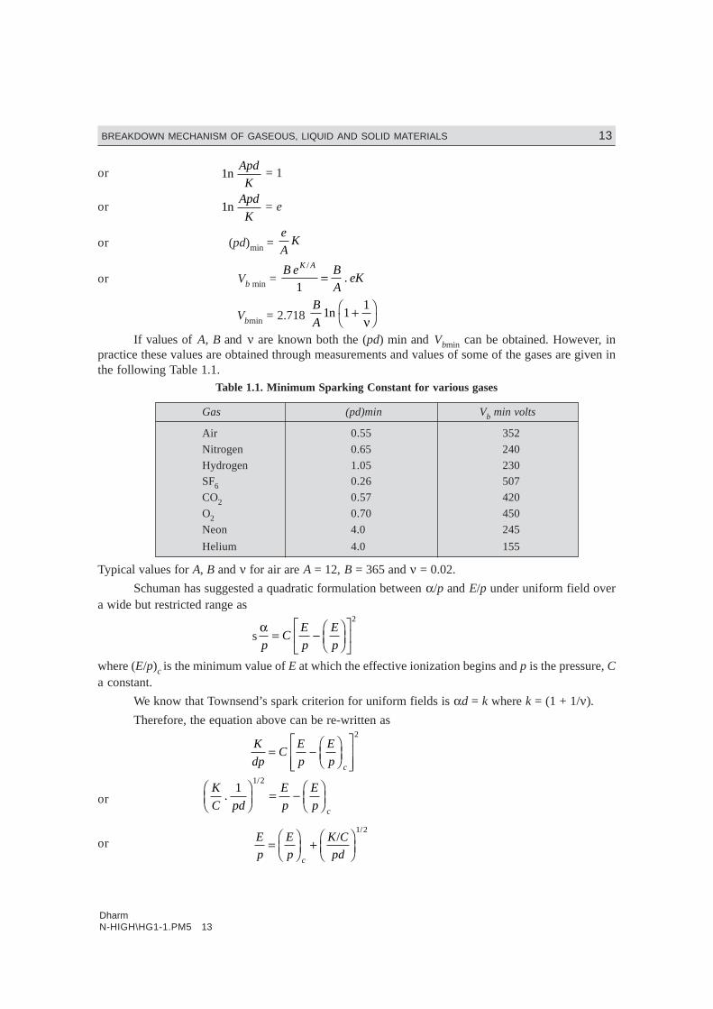
If values of A, B and ν are known both the (pd) min and Vbmin can be obtained. However, inpractice these values are obtained through measurements and values of some of the gases are given inthe following Table 1.1.
Table 1.1. Minimum Sparking Constant for various gases
Gas (pd)min Vb min volts
Air 0.55 352
Nitrogen 0.65 240
Hydrogen 1.05 230SF6 0.26 507
CO2 0.57 420
O2 0.70 450
Neon 4.0 245
Helium 4.0 155
Typical values for A, B and ν for air are A = 12, B = 365 and ν = 0.02.
Schuman has suggested a quadratic formulation between α/p and E/p under uniform field overa wide but restricted range as
sαp
CE
p
E
p= −
FHG
IKJ
LNM
OQP
2
where (E/p)c is the minimum value of E at which the effective ionization begins and p is the pressure, Ca constant.
We know that Townsend’s spark criterion for uniform fields is αd = k where k = (1 + 1/ν).
Therefore, the equation above can be re-written as
K
dpC
E
p
E
p c
= −FHG
IKJ
LNMM
OQPP
2
or K
C pd
E
p
E
p c
./
11 2F
HGIKJ = −
FHG
IKJ
or E
p
E
p
K C
pdc
=FHG
IKJ +
FHG
IKJ
//1 2
DharmN-HIGH\HG1-1.PM5 14
14 HIGH VOLTAGE ENGINEERING
V
dp
E
p
K C
pdc
=FHG
IKJ +
FHG
IKJ
//1 2
or VE
ppd
K
cpdb
c
=FHG
IKJ + F
HIK
1 2/
.
Sohst and Schröder have suggested values for Ec = 24.36 kV/cm K/C = 45.16 (kV)2 /cm for airat p = 1 bar and temperature 20°C.
Substituting these values in the above equation, we have
Vb = 6.72 pd + 24.36 (pd) kV
The breakdown voltages suggested in tables or obtained through the use of empirical relationnormally correspond to ambient temperature and pressure conditions, whereas the atmospheric airprovides basic insulation between various electrical equipments. Since the atmospheric conditions (Tem-perature, pressure) vary widely from time to time and from location to location, to obtain the actualbreakdown voltage, the voltage obtained from the STP condition should be multiplied by the air den-sity correction factor. The air density correction factor is given as
δ = 3 92
273
. b
t+where b is the atmospheric pressure in cm of Hg and t the temperature in °C.
1.8 PENNING EFFECT
Paschen’s law does not hold good for many gaseous mixtures. A typical example is that of mixture ofArgon in Neon. A small percentage of Argon in Neon reduces substantially the dielectric strength ofpure Neon. In fact, the dielectric strength is smaller than the dielectric strengths of either pure Neon orArgon. The lowering of dielectric strength is due to the fact that the lowest excited stage of neon ismetastable and its excitation potential (16 ev) is about 0.9 ev greater than the ionization potential ofArgon. The metastable atoms have a long life in neon gas, and on hitting Argon atoms there is a veryhigh probability of ionizing them. This phenomenon is known as Penning Effect.
1.9 CORONA DISCHARGES
If the electric field is uniform and if the field is increased gradually, just when measurable ionizationbegins, the ionization leads to complete breakdown of the gap. However, in non-uniform fields, beforethe spark or breakdown of the medium takes place, there are many manifestations in the form of visualand audible discharges. These discharges are known as Corona discharges. In fact Corona is defined asa self-sustained electric discharge in which the field intensified ionization is localised only over aportion of the distance (non-uniform fields) between the electrodes. The phenomenon is of particularimportance in high voltage engineering where most of the fields encountered are non-uniform fieldsunless of course some design features are involved to make the filed almost uniform. Corona is respon-sible for power loss and interference of power lines with the communication lines as corona frequencylies between 20 Hz and 20 kHz. This also leads to deterioration of insulation by the combined action ofthe discharge ion bombarding the surface and the action of chemical compounds that are formed by thecorona discharge.
DharmN-HIGH\HG1-1.PM5 15
BREAKDOWN MECHANISM OF GASEOUS, LIQUID AND SOLID MATERIALS 15
When a voltage higher than the critical voltage is applied between two parallel polished wires,the glow is quite even. After operation for a short time, reddish beads or tufts form along the wire,while around the surface of the wire there is a bluish white glow. If the conductors are examinedthrough a stroboscope, so that one wire is always seen when at a given half of the wave, it is noticedthat the reddish tufts or beads are formed when the conductor is negative and a smoother bluish whiteglow when the conductor is positive. The a.c. corona viewed through a stroboscope has the sameapperance as direct current corona. As corona phenomenon is initiated a hissing noise is heard andozone gas is formed which can be detected by its chracteristic colour.
When the voltage applied corresponds to the critical disruptive voltage, corona phenomenonstarts but it is not visible because the charged ions in the air must receive some finite energy to causefurther ionization by collisions. For a radial field, it must reach a gradient (visual corona gradient) gu atthe surface of the conductor to cause a gradient g0, finite distance away from the surface of the conduc-tor. The distance between g0 and gv is called the energy distance. According to Peek, this distance is
equal to (r + 0.301 r ) for two parallel conductors and (r + 0.308 r ) for coaxial conductors. Fromthis it is clear that gv is not constant as g0 is, and is a function of the size of the conductor. The electricfield intensity for two parallel wires is given as
E = 30 10 301
+FHG
IKJ
./
r δδ kV cm
and for a coaxial wire E = 30 10 308+F
HGIKJ
.
rδδ
Investigation with point-plane gaps in air have shown that when point is positive, the coronacurrent increases steadily with voltage. At sufficiently high voltage, current amplification increasesrapidly with voltage upto a current of about 10–7 A, after which the current becomes pulsed with repeti-tion frequency of about 1 kHz composed of small bursts. This form of corona is known as burst corona.The average current then increases steadily with applied voltage, leading to breakdown.
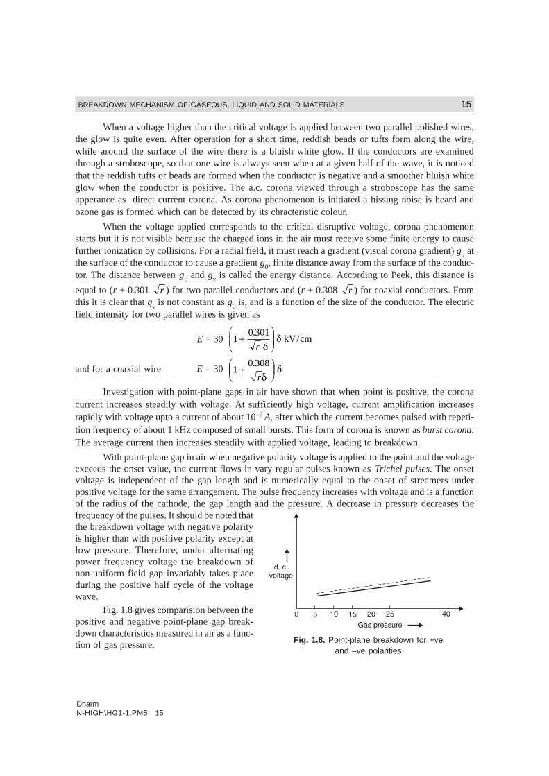
With point-plane gap in air when negative polarity voltage is applied to the point and the voltageexceeds the onset value, the current flows in vary regular pulses known as Trichel pulses. The onsetvoltage is independent of the gap length and is numerically equal to the onset of streamers underpositive voltage for the same arrangement. The pulse frequency increases with voltage and is a functionof the radius of the cathode, the gap length and the pressure. A decrease in pressure decreases thefrequency of the pulses. It should be noted thatthe breakdown voltage with negative polarityis higher than with positive polarity except atlow pressure. Therefore, under alternatingpower frequency voltage the breakdown ofnon-uniform field gap invariably takes placeduring the positive half cycle of the voltagewave.
Fig. 1.8 gives comparision between thepositive and negative point-plane gap break-down characteristics measured in air as a func-tion of gas pressure. Fig. 1.8. Point-plane breakdown for +ve
and –ve polarities

DharmN-HIGH\HG1-1.PM5 16
16 HIGH VOLTAGE ENGINEERING
When the spacing is small the breakdown characteristics for the two polarities nearly coincideand no corona stabilised region is observed. As the spacing is increased, the positive characteristicsdisplay the distinct high corona beakdown upto a pressure of about 7 bars, followed by a sudden dropin breakdown strengths. Under the negative polarity, the corona stabilised region extends to muchhigher pressures.
Fig. 1.9 shows the corona inception and breakdown voltages of the sphere-plane arrangement.From the figure, it is clear that—
(i) For small spacings (Zone–I), the field is uniform and the breakdown voltage depends mainlyon the gap spacing.
(ii) In zone–II, where the spacing is relatively larger, the electric field is non-uniform and thebreakdown voltage depends on both the sphere diameter and the spacing.
(iii) For still larger spacings (Zone-III) the field is non-uniform and the breakdown is precededby corona and is controlled only by the spacing. The corona inception voltage mainly de-pends on the sphere diameter.
Fig. 1.9 Breakdown and corona inception characteristics for spheres of differentdiameters in sphere-plane gap geometry
1.10 TIME-LAG
In order to breakdown a gap, certain amount of energy is required. Also it depends upon the availabilityof an electron between the gap for initiation of the avalanche. Normally the peak value of a.c. and d.c.are smaller as compared to impulse wave as the duration of the former are pretty large as compared tothe letter and the energy content is large. Also withd.c. and a.c. as the duration is large there are usuallysufficient initiatory electrons created by cosmic rayand naturally occuring radioactive sources.
Suppose Vd is the maximum value of d.c. volt-age applied for a long time to cause breakdown of agiven gap. Fig. 1.10.
Let the same gap be subjected to a step volt-age of peak value Vd1 > Vd and of a duration suchthat the gap breaks down in time t. If the breakdown
Fig. 1.10 Time lag components under astep voltage
DharmN-HIGH\HG1-1.PM5 17
BREAKDOWN MECHANISM OF GASEOUS, LIQUID AND SOLID MATERIALS 17
were purely a function of voltage magnitude, the breakdown should have taken place the moment thestep voltage had just crossed the voltage Vd.
The time that elapses between the application of the voltage to a gap sufficient to cause break-down, and the breakdown, is called the time lag. In the given case shown in Fig. 1.10, t is the time lag.It consists of two components. One is the that elapses during the voltage applications until a primaryelectron appears to initiate the discharge and is known as the statistical time lag ts and the other is thetime required for the breakdown to develop once initiated and is known as the formative time lag tf.
The statistical time lag depends upon (i) The amount of pre-ionization present in between thegap (ii) Size of the gap (iii) The amount of over voltage (Vd1 – Vd) applied to the gap. The larger the gapthe higher is going to be the statistical time lag. Similarly, a smaller over voltage results in higherstatistical time lag. However, the formative time lag depends mainly on the mechanism of breakdown.In cases when the secondary electrons arise entirely from electron emission at the cathode by positiveions, the transit time from anode to cathode will be the dominant factor determining the formative time.The formative time lag increases with increase in gap length and field non-uniformity, decreases withincrease in over voltage applied.
1.10.1 Breakdown in Electronegative GasesSF6, has excellent insulating strength because of its affinity for electrons (electronegativity) i.e., when-ever a free electron collides with the neutral gas molecule to form negative ion, the electron is absorbedby the neutral gas molecule. The attachment of the electron with the neutral gas molecule may occur intwo ways:
SF6 + e → SF6–
SF6 + e → SF5– + F
The negative ions formed are relatively heavier as compared to free electrons and, therefore,under a given electric field the ions do not attain sufficient energy to lead cumulative ionization in thegas. Thus, these processes represent an effective way of removing electrons from the space whichotherwise would have contributed to form electron avalanche. This property, therefore, gives rise tovery high dielectric strength for SF6. The gas not only possesses a good dielectric strength but it has theunique property of fast recombination after the source energizing the spark is removed.
The dielectric strength of SF6 at normal pressure and temperature is 2–3 times that of air and at2 atm its strength is comparable with the transformer oil. Although SF6 is a vapour, it can be liquifiedat moderate pressure and stored in steel cylinders. Even though SF6 has better insulating and arc-quencling properties than air at an equal pressure, it has the important disadvantage that it can not beused much above 14 kg/cm2 unless the gas is heated to avoid liquifaction.
1.10.2 Application of Gases in Power SystemThe gases find wide application in power system to provide insulation to various equipments andsubstations. The gases are also used in circuit breakers for arc interruption besides providing insulationbetween breaker contacts and from contact to the enclosure used for contacts. The various gases usedare (i) air (ii) oxygen (iii) hydrogen (iv) nitrogen (v) CO2 and (vi) electronegative gases like sulphurhexafluoride, arcton etc.
The various properties required for providing insulation and arc interruption are:
(i) High dielectric strength.
(ii) Thermal and chemical stability.
DharmN-HIGH\HG1-1.PM5 18
18 HIGH VOLTAGE ENGINEERING
(iii) Non-inflammability.
(iv) High thermal conductivity. This assists cooling of current carrying conductors immersed inthe gas and also assists the arc-extinction process.
(v) Arc extinguishing ability. It should have a low dissociation temperature, a short thermaltime constant (ratio of energy contained in an arc column at any instant to the rate of energy dissipationat the same instant) and should not produce conducting products such as carbon during arcing.
(vi) Commercial availability at moderate cost. Of the simple gases air is the cheapest and mostwidely used for circuit breaking. Hydrogen has better arc extinguishing property but it has lower di-electric strength as compared with air. Also if hydrogen is contaminated with air, it forms an explosivemixture. Nitrogen has similar properties as air, CO2 has almost the same dielectric strength as air but isa better arc extinguishing medium at moderate currents. Oxygen is a good extinguishing medium but ischemically active. SF6 has outstanding arc-quenching properties and good dielectric strength. Of allthese gases, SF6 and air are used in commercial gas blast circuit breakers.
Air at atmospheric pressure is ‘free’ but dry air costs a lot when stored at say 75 atmosphere.The compressed air supply system is a vital part of an air blast C.B. Moisture from the air is removed byrefrigeration, by drying agents or by storing at several times the working pressure and then expandingit to the working pressure for use in the C.B. The relative cost of storing the air reduces with increase inpressure. If the air to be used by the breaker is at 35 kg/cm2 it is common to store it at 210 kg/cm2.
Air has an advantage over the electronegative gases in that air can be compressed to extremelyhigh pressures at room temperature and then its dielectric strength even exceeds that of these gases.
The SF6 gas is toxic and its release in the form of leakage causes environmental problems.Therefore, the electrical industry has been looking for an alternative gas or a mixture of SF6 with someother gas as an insulating and arc interrupting medium. It has been observed that a suitable mixture ofSF6 with N2 is a good replacement for SF6. This mixture is not only finding acceptability for providinginsulation e.g., gas insulated substation and other equipments, it is able to quench high current magni-tude arcs. The mixture is not only cost effective, it is less sensitive to find non-uniformities presentwithin the equipment. Electric power industry is trying to find optimum SF6 to N2 mixture ratio forvarious components of the system viz., GIS, C.B., capacitors, CT, PT and cables. A ratio 70% of SF6and 30% of N2 is found to be optimum for circuit breaking. With this ratio, the C.B. has higher recoveryrate than pure SF6 at the same partial pressure. The future of using SF6 with N2 or He for providinginsulation and arc interruption is quite bright.
1.11 BREAKDOWN IN LIQUID DIELECTRICS
Liquid dielectrics are used for filling transformers, circuit breakers and as impregnants in high voltagecables and capacitors. For transformer, the liquid dielectric is used both for providing insulation betweenthe live parts of the transformer and the grounded parts besides carrying out the heat from the transformerto the atmosphere thus providing cooling effect. For circuit breaker, again besides providing insulationbetween the live parts and the grounded parts, the liquid dielectric is used to quench the arc developedbetween the breaker contacts. The liquid dielectrics mostly used are petroleum oils. Other oils used aresynthetic hydrocarbons and halogenated hydrocarbons and for very high temperature applicationssillicone oils and fluorinated hyrocarbons are also used.
The three most important properties of liquid dielectric are (i) The dielectric strength (ii) Thedielectric constant and (iii) The electrical conductivity. Other important properties are viscosity, ther-mal stability, specific gravity, flash point etc. The most important factors which affect the dielectric
DharmN-HIGH\HG1-1.PM5 19
BREAKDOWN MECHANISM OF GASEOUS, LIQUID AND SOLID MATERIALS 19
strength of oil are the, presence of fine water droplets and the fibrous impurities. The presence of even0.01% water in oil brings down the dielectric strength to 20% of the dry oil value and the presence offibrous impurities brings down the dielectric strength much sharply. Therefore, whenever these oils areused for providing electrical insulation, these should be free from moisture, products of oxidation andother contaminants.
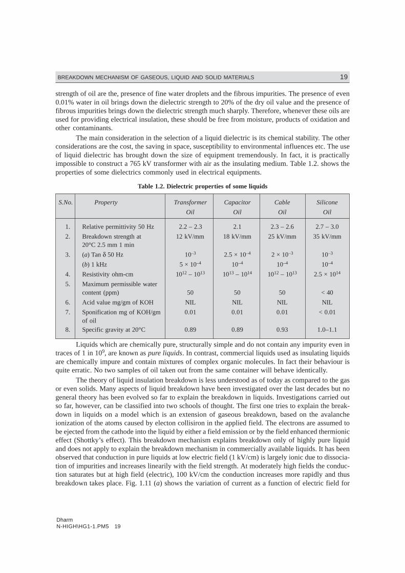
The main consideration in the selection of a liquid dielectric is its chemical stability. The otherconsiderations are the cost, the saving in space, susceptibility to environmental influences etc. The useof liquid dielectric has brought down the size of equipment tremendously. In fact, it is practicallyimpossible to construct a 765 kV transformer with air as the insulating medium. Table 1.2. shows theproperties of some dielectrics commonly used in electrical equipments.
Table 1.2. Dielectric properties of some liquids
S.No. Property Transformer Capacitor Cable Silicone
Oil Oil Oil Oil
1. Relative permittivity 50 Hz 2.2 – 2.3 2.1 2.3 – 2.6 2.7 – 3.0
2. Breakdown strength at 12 kV/mm 18 kV/mm 25 kV/mm 35 kV/mm20°C 2.5 mm 1 min
3. (a) Tan δ 50 Hz 10–3 2.5 × 10⁻⁴ 2 × 10⁻³ 10–3
(b) 1 kHz 5 × 10⁻⁴ 10–4 10–4 10–4
4. Resistivity ohm-cm 1012 – 1013 1013 – 1014 1012 – 1013 2.5 × 10¹⁴
5. Maximum permissible watercontent (ppm) 50 50 50 < 40
6. Acid value mg/gm of KOH NIL NIL NIL NIL
7. Sponification mg of KOH/gm 0.01 0.01 0.01 < 0.01of oil
8. Specific gravity at 20°C 0.89 0.89 0.93 1.0–1.1
Liquids which are chemically pure, structurally simple and do not contain any impurity even intraces of 1 in 109, are known as pure liquids. In contrast, commercial liquids used as insulating liquidsare chemically impure and contain mixtures of complex organic molecules. In fact their behaviour isquite erratic. No two samples of oil taken out from the same container will behave identically.
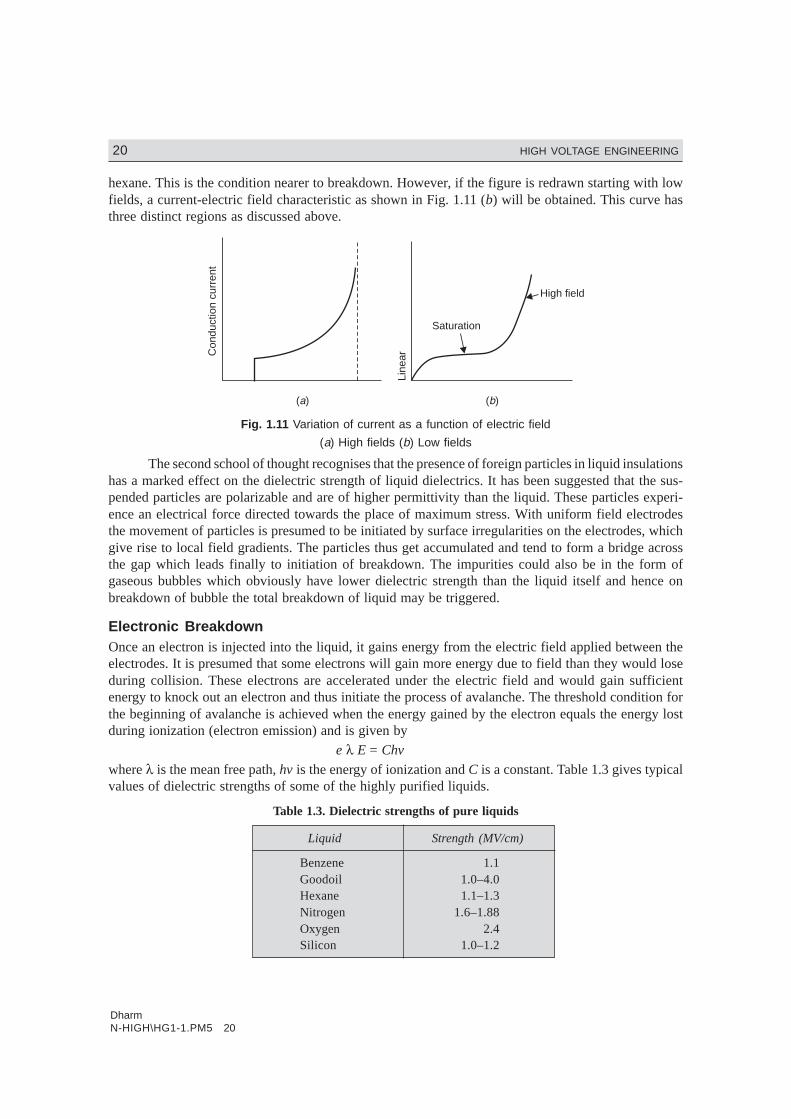
The theory of liquid insulation breakdown is less understood as of today as compared to the gasor even solids. Many aspects of liquid breakdown have been investigated over the last decades but nogeneral theory has been evolved so far to explain the breakdown in liquids. Investigations carried outso far, however, can be classified into two schools of thought. The first one tries to explain the break-down in liquids on a model which is an extension of gaseous breakdown, based on the avalancheionization of the atoms caused by electon collisiron in the applied field. The electrons are assumed tobe ejected from the cathode into the liquid by either a field emission or by the field enhanced thermioniceffect (Shottky’s effect). This breakdown mechanism explains breakdown only of highly pure liquidand does not apply to explain the breakdown mechanism in commercially available liquids. It has beenobserved that conduction in pure liquids at low electric field (1 kV/cm) is largely ionic due to dissocia-tion of impurities and increases linearily with the field strength. At moderately high fields the conduc-tion saturates but at high field (electric), 100 kV/cm the conduction increases more rapidly and thusbreakdown takes place. Fig. 1.11 (a) shows the variation of current as a function of electric field for
DharmN-HIGH\HG1-1.PM5 20
20 HIGH VOLTAGE ENGINEERING
hexane. This is the condition nearer to breakdown. However, if the figure is redrawn starting with lowfields, a current-electric field characteristic as shown in Fig. 1.11 (b) will be obtained. This curve hasthree distinct regions as discussed above.
Line
ar
Saturation
High field
( )a ( )b
Con
duct
ion
curr
ent
Fig. 1.11 Variation of current as a function of electric field
(a) High fields (b) Low fields
The second school of thought recognises that the presence of foreign particles in liquid insulationshas a marked effect on the dielectric strength of liquid dielectrics. It has been suggested that the sus-pended particles are polarizable and are of higher permittivity than the liquid. These particles experi-ence an electrical force directed towards the place of maximum stress. With uniform field electrodesthe movement of particles is presumed to be initiated by surface irregularities on the electrodes, whichgive rise to local field gradients. The particles thus get accumulated and tend to form a bridge acrossthe gap which leads finally to initiation of breakdown. The impurities could also be in the form ofgaseous bubbles which obviously have lower dielectric strength than the liquid itself and hence onbreakdown of bubble the total breakdown of liquid may be triggered.
Electronic BreakdownOnce an electron is injected into the liquid, it gains energy from the electric field applied between theelectrodes. It is presumed that some electrons will gain more energy due to field than they would loseduring collision. These electrons are accelerated under the electric field and would gain sufficientenergy to knock out an electron and thus initiate the process of avalanche. The threshold condition forthe beginning of avalanche is achieved when the energy gained by the electron equals the energy lostduring ionization (electron emission) and is given by
e λ E = Chv
where λ is the mean free path, hv is the energy of ionization and C is a constant. Table 1.3 gives typicalvalues of dielectric strengths of some of the highly purified liquids.
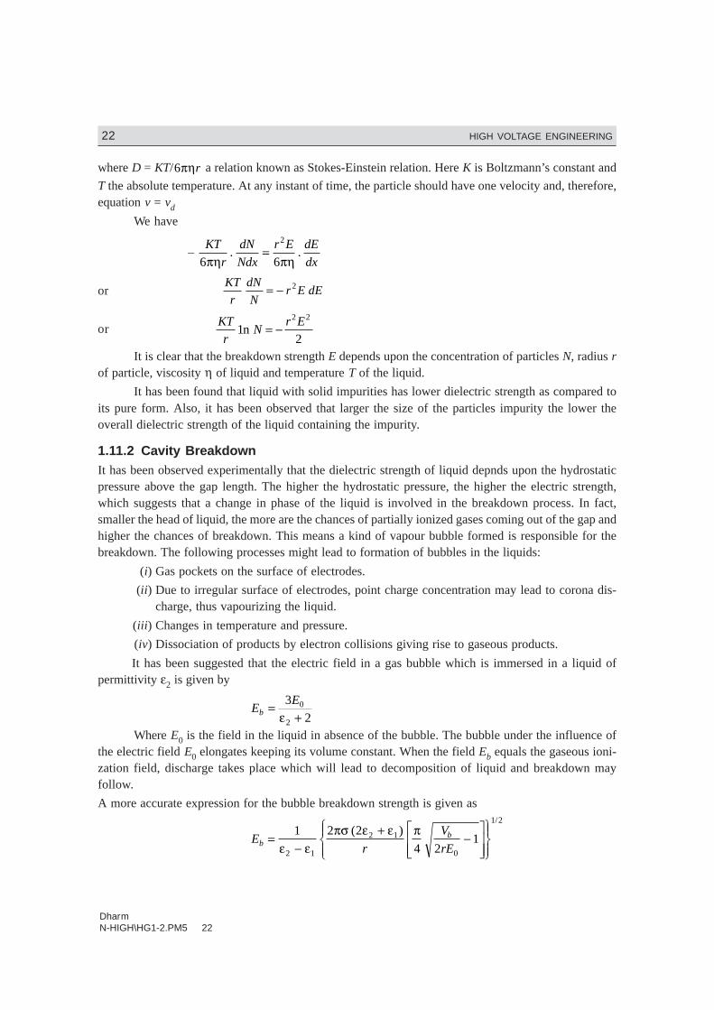
Table 1.3. Dielectric strengths of pure liquids
Liquid Strength (MV/cm)
Benzene 1.1Goodoil 1.0–4.0Hexane 1.1–1.3Nitrogen 1.6–1.88Oxygen 2.4Silicon 1.0–1.2

DharmN-HIGH\HG1-2.PM5 21
BREAKDOWN MECHANISM OF GASEOUS, LIQUID AND SOLID MATERIALS 21
The electronic theory whereas predicts the relative values of dielectric strength satisfactorily,the formative time lags observed are much longer as compared to the ones predicted by the electronictheory.
1.11.1 Suspended Solid Particle MechanismCommercial liquids will always contain solid impurities either as fibers or as dispersed solid particles.The permittivity of these solids (E1) will always be different from that of the liquid (E2). Let us assumethese particles to be sphere of radisus r. These particles get polarized in an electric field E and experi-ence a force which is given as
F = r3 ε εε ε
1 2
1 22
–.
+E
dE
dx
and this force is directed towards a place of higher stress if ε1 > ε2 and towards a place of lower stressif ε1 < ε2 when ε1 is the permittivity of gas bubbles. The force given above increases as the permittivityof the suspended particles (ε1) increases. If ε1 → ∞
F = r3 1
1 22 1
2 1
−+
ε εε ε
/
/E
dE
dx
Let ε1 → ∞
F = r3E . dE
dxThus, the force will tend the particle to move towards the strongest region of the field. In a
uniform electric field which usually can be developed by a small sphere gap, the field is the strongest inthe uniform field region. Here dE/dx → 0 so that the force on the particle is zero and the particleremains in equilibrium. Therefore, the particles will be dragged into the uniform field region. Since thepermittivity of the particles is higher than that of the liquid, the presence of particle in the uniform fieldregion will cause flux concentration at its surface. Other particles if present will be attracted towardsthe higher flux concentration. If the particles present are large, they become aligned due to these forcesand form a bridge across the gap. The field in the liquid between the gap will increase and if it reachescritical value, brakdown will take place. If the number of particles is not sufficient to bridge the gap, theparticles will give rise to local field enhancement and if the field exceeds the dielectric strength ofliquid, local breakdown will occur near the particles and thus will result in the formation of gas bubbleswhich have much less dielectric strength and hence finally lead to the breakdown of the liquid.
The movement of the particle under the influence of electric field is oposed by the viscous forceposed by the liquid and since the particles are moving into the region of high stress, diffusion must alsobe taken into account. We know that the viscous force is given by (Stoke’s relation) FV = 6πnrν whereη is the viscosity of liquid, r the raidus of the particle and v the velocity of the particle.
Equating the electrical force with the viscous force we have
6πηrν = r3 E dE
dxor ν =
r E dE
dx
2
6πη
However, if the diffusion process is included, the drift velocity due to diffusion will be given by
νd = – D
N
dN
dx
KT
r
dN
Ndx= −
6πη
DharmN-HIGH\HG1-2.PM5 22
22 HIGH VOLTAGE ENGINEERING
where D = KT/6πηr a relation known as Stokes-Einstein relation. Here K is Boltzmann’s constant and
T the absolute temperature. At any instant of time, the particle should have one velocity and, therefore,equation v = vd
We have
– KT
r
dN
Ndx
r E dE
dx6 6
2
πη πη. .=
or KT
r
dN
Nr E dE= − 2
orKT
rN
r E1
2
2 2
n = −
It is clear that the breakdown strength E depends upon the concentration of particles N, radius rof particle, viscosity η of liquid and temperature T of the liquid.
It has been found that liquid with solid impurities has lower dielectric strength as compared toits pure form. Also, it has been observed that larger the size of the particles impurity the lower theoverall dielectric strength of the liquid containing the impurity.
1.11.2 Cavity BreakdownIt has been observed experimentally that the dielectric strength of liquid depnds upon the hydrostaticpressure above the gap length. The higher the hydrostatic pressure, the higher the electric strength,which suggests that a change in phase of the liquid is involved in the breakdown process. In fact,smaller the head of liquid, the more are the chances of partially ionized gases coming out of the gap andhigher the chances of breakdown. This means a kind of vapour bubble formed is responsible for thebreakdown. The following processes might lead to formation of bubbles in the liquids:
(i) Gas pockets on the surface of electrodes.
(ii) Due to irregular surface of electrodes, point charge concentration may lead to corona dis-charge, thus vapourizing the liquid.
(iii) Changes in temperature and pressure.
(iv) Dissociation of products by electron collisions giving rise to gaseous products.
It has been suggested that the electric field in a gas bubble which is immersed in a liquid ofpermittivity ε2 is given by
EE
b =+
3
20
2εWhere E0 is the field in the liquid in absence of the bubble. The bubble under the influence of
the electric field E0 elongates keeping its volume constant. When the field Eb equals the gaseous ioni-zation field, discharge takes place which will lead to decomposition of liquid and breakdown mayfollow.
A more accurate expression for the bubble breakdown strength is given as
Er
V
rEbb=
−+
−LNMM
OQPP
RS|T|
UV|W|
1 2 2
4 21
2 1
2 1
0
1 2
ε επσ ε ε π( )
/
DharmN-HIGH\HG1-2.PM5 23
BREAKDOWN MECHANISM OF GASEOUS, LIQUID AND SOLID MATERIALS 23
where σ is the surface tension of the liquid, ε2 and ε1 are the permittivities of the liquid and bubble,respectively, r the initial radius of the bubble and Vb the voltage drop in the bubble. From the expres-sion it can be seen that the breakdown strength depends on the initial size of the bubble which of coursedepends upon the hydrostatic pressure above the bubble and temperature of the liquid. Since the aboveformation does not take into account the production of the initial bubble, the experimental values ofbreakdown were found to be much less than the calculated values. Later on it was suggested that onlyincompressible bubbles like water bubbles can elongate at constant volume according to the simple gaslaw pV = RT. Such a bubble under the influence of electric field changes its shape to that of a prolatespheroid and reaches a condition of instability when β, the ratio of the longer to the shorter diameter ofthe spheroid is about 1.85 and the critical field producing the instability will be given by
Ec = 6002
2
2 1
π σε
εε εr
G H−
−LNM
OQP
where G = 1
1 112
1
2 1 2ββ ββ− −
−LNM
OQP
−cosh
( ) /
and H2 = 2β1/3 2 112β
β− −
FHG
IKJ
For transformer oil ε2 = 2.0 and water globule with r = 1 µm, σ = 43 dynes/cm, the aboveequation gives Ec = 226 KV/cm.
Electroconvection BreakdownIt has been recognized that the electroconvection plays an important role in breakdown of insulatingfluids subjected to high voltages. When a highly pure insulating liquid is subjected to high voltage,electrical conduction results from charge carriers injected into the liquid from the electrode surface.The resulting space charge gives rise to coulombic forces which under certain conditions causes hydro-dynamic instability, yielding convecting current. It has been shown that the onset of instability is asso-ciated with a critical voltage. As the applied voltage approaches the critical voltage, the motion at firstexhibits a structure of hexagonal cells and as the voltage is increased further the motion becomesturbulent. Thus, interaction between the space charge and the electric field gives rise to forces creatingan eddy motion of liquid. It has been shown that when the voltage applied is near to breakdown value,
the speed of the eddy motion is given by νe = ε ρ2 / where ρ is the density of liquid. In liquids, the
ionic drift velocity is given by
νd = KE
where K is the mobility of ions.
Let M KEe
d
νν
ερ
= 2 /
The ratio M is usually greater than unity and sometimes much greater than unity (Table 1.4).

DharmN-HIGH\HG1-2.PM5 24
24 HIGH VOLTAGE ENGINEERING
Table 1.4
Medium Ion ε M
Air NTP O–2 1.0 2.3 × 10⁻²
Ethanol Cl– 2.5 26.5
Methanol H+ 33.5 4.1
Nitrobenzene Cl– 35.5 22
Propylene Carbonate Cl– 69 51
Transformer Oil H+ 2.3 200
Thus, in the theory of electroconvection, M plays a dominant role. The charge transport will belargely by liquid motion rather than by ionic drift. The criterion for instability is that the local flowvelocity should be greater than drift velocity.
1.12 TREATMENT OF TRANSFORMER OIL
Even though new synthetic materials with better mechanical and thermal properties are being developed,the use of oil/paper complex for high voltages is still finding applications. Oil, besides being a goodinsulating medium, it allows better dispersion of heat. It allows transfer and absorption of water, air andresidues created by the ageing of the solid insulation. In order to achieve operational requirements, itmust be treated to attain high degree of purity.
Whatever be the nature of impurities whether solid, liquid or gaseous, these bring down thedielectric strength of oil materially. Oil at 20°C with water contents of 44 ppm will have 25% of itsnormal dielectric strength. The presence of water in paper not only increases the loss angle tan δ, itaccelerates the process of ageing. Similarly, air dissolved in oil produces a risk of forming bubble andreduces the dielectric strength of oil.
Air Absorption: The process of air absorption can be compared to a diffusing phenomenon inwhich a gaseous substance in this case air is in contact with liquid (oil here).
If the viscosity of the liquid is low, the convection movements bring about a continuous inter-mixing whereby a uniform concentration is achieved. This phenomenon can, for example, be checkedin a tank where the air content or the water content measured both at the top and the bottom areapproximately equal.
Let G(t) = Air content of the oil after time t
Gm = Air content under saturation condition
p = Probability of absorption per unit time
S = Surface of oil
V = Volume of oil
The absorption of air by oil can be given by the equation
dG
dtp
S
VG G tm= −. [ ( )]
with boundary condition at t = 0 G = G0
DharmN-HIGH\HG1-2.PM5 25
BREAKDOWN MECHANISM OF GASEOUS, LIQUID AND SOLID MATERIALS 25
Solving the above equation
dG
G G tp
S
Vdt
m −=
( )
or 1n {Gm – G (t)} = – p S
Vt A+
At t = 0 G = G0. Therefore, A = + 1n ← {Gm – G0}
or 10
nG G t
G Gp
S
Vtm
m
−−
= −( )
or Gm – G (t) = (Gm – G0) e -pSt/V
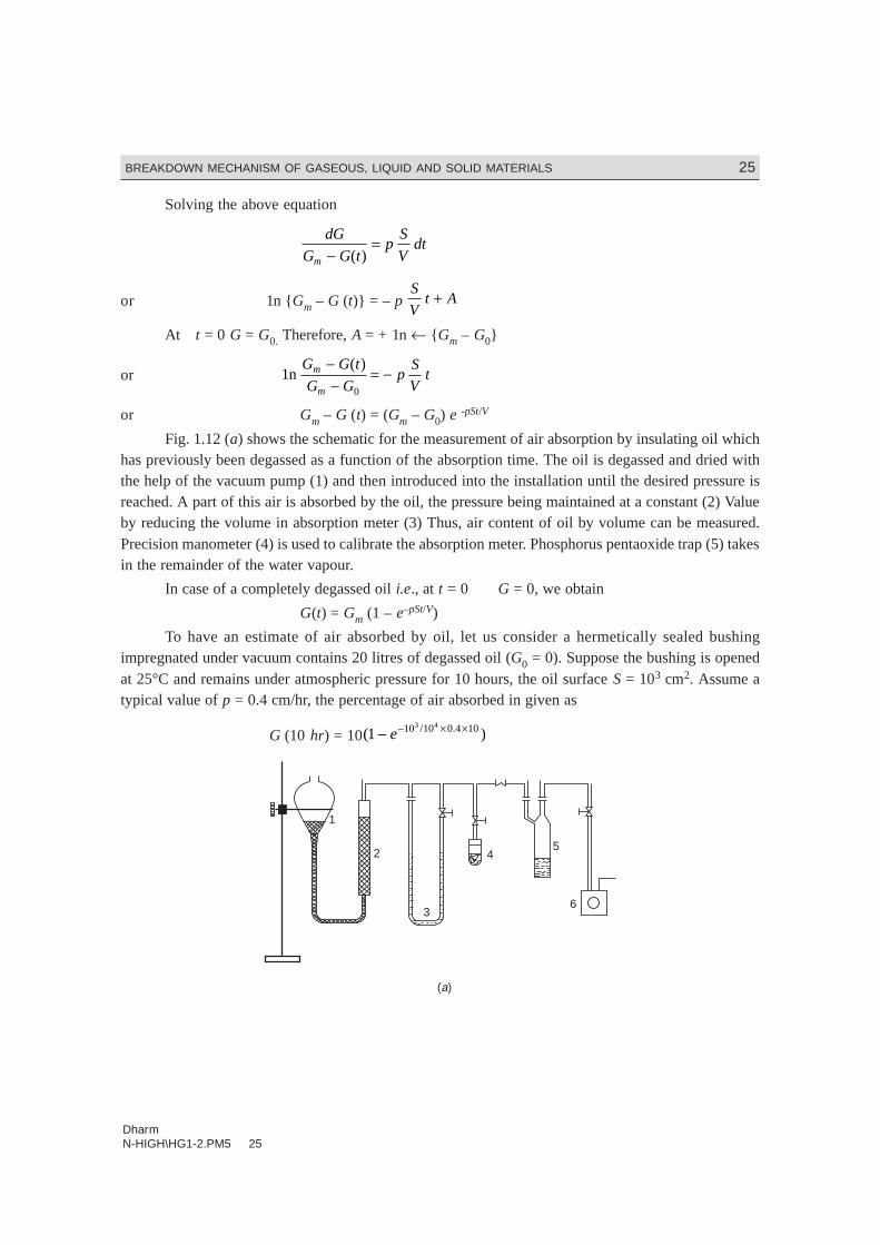
Fig. 1.12 (a) shows the schematic for the measurement of air absorption by insulating oil whichhas previously been degassed as a function of the absorption time. The oil is degassed and dried withthe help of the vacuum pump (1) and then introduced into the installation until the desired pressure isreached. A part of this air is absorbed by the oil, the pressure being maintained at a constant (2) Valueby reducing the volume in absorption meter (3) Thus, air content of oil by volume can be measured.Precision manometer (4) is used to calibrate the absorption meter. Phosphorus pentaoxide trap (5) takesin the remainder of the water vapour.
In case of a completely degassed oil i.e., at t = 0 G = 0, we obtain
G(t) = Gm (1 – e–pSt/V)
To have an estimate of air absorbed by oil, let us consider a hermetically sealed bushingimpregnated under vacuum contains 20 litres of degassed oil (G0 = 0). Suppose the bushing is openedat 25°C and remains under atmospheric pressure for 10 hours, the oil surface S = 103 cm2. Assume atypical value of p = 0.4 cm/hr, the percentage of air absorbed in given as
G (10 hr) = 10( )/ .1 10 10 0 4 103 4
− − × ×e
1
2
3
45
6
( )a
DharmN-HIGH\HG1-2.PM5 26
26 HIGH VOLTAGE ENGINEERING
2
1
78 9 10
5 6
3
4
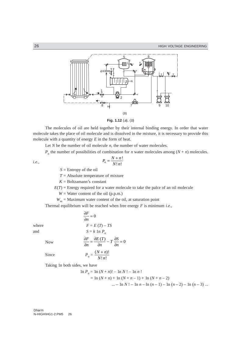
( )b
Fig. 1.12 (a), (b)
The molecules of oil are held together by their internal binding energy. In order that watermolecule takes the place of oil molecule and is dissolved in the mixture, it is necessary to provide thismolecule with a quantity of energy E in the form of heat.
Let N be the number of oil molecule n, the number of water molecules.
Pn the number of possibilities of combination for n water molecules among (N + n) molecules.
i.e., PN n
N nn = + !
! !S = Entropy of the oilT = Absolute temperature of mixtureK = Boltzamann’s constant
E(T) = Energy required for a water molecule to take the palce of an oil moleculeW = Water content of the oil (p.p.m.)
Wm = Maximum water content of the oil, at saturation point
Thermal equilibrium will be reached when free energy F is minimum i.e.,
∂∂
=F
n0
where F = E (T) – TS
and S = k 1n Pn
Now ∂∂
= ∂∂
− ∂∂
=F
n
E T
nT
S
n
( )0
Since Pn = ( )!
! !
N n
N n
+
Taking 1n both sides, we have
1n Pn = 1n (N + n)! – 1n N ! – 1n n !
= 1n (N + n) + 1n (N + n – 1) + 1n (N + n – 2)
... – 1n N ! – 1n n – ln (n – 1) – 1n (n – 2) – 1n (n – 3) ...
DharmN-HIGH\HG1-2.PM5 27
BREAKDOWN MECHANISM OF GASEOUS, LIQUID AND SOLID MATERIALS 27
Differentiating both sides,
1 1 1
1
1 1
1
∂∂
=+
++ −
+ − −−
P
P n N n N n n nn
n
... ...
≈ 1 1
N n n+− = –
N
n N n( )+
Since ∂∂
= ∂∂
S
n
K
P
P
nn
n ≈ – KN
n N n( )+Substituting for ∂S/∂n in the equation
We have, ∂∂
− ∂∂
=E T
nT
S
n
( )0
∂∂
++
=E T
nT
TKN
n N n
( )
( )0
or∂∂
= −+
E
n
TKN
n N n( )
∂E = – TK N dn
n N n( )+Since N >> N + n ≈ N
Therefore, ∂E = – TK dn
nor E = – TK ln n + A
when E = 0, n = N. Therefore, 0 = – TK ln N + A or A = TK ln N
or E = TK ln N
n
or ln n
N
E
TK= − or n
Ne E TK≈ − /
or n = N e–E/TK ≈ Wm
Following impurities should be considered for purification of oil (i) solid impurities (ii) free anddissolved water particles (iii) dissolved air. Some of the methods used to remove these impurities havebeen described below.
Filtration and Treatment Under Vacuum: Different types of filters have been used. Filter press withsoft and hard filter papers is found to be more suitable for insulating oil. Due to hygroscopic propertiesof the paper, oil is predried before filtering. Therefore, this oil can not be used for high voltage insulation.The subsequent process of drying is carried out in a specially, designed tank under vacuum. The oil isdistributed over a large surface by a so-called ‘‘Rasching-ring’’ degassing column. Through this process,both the complete drying and degassing are achieved simultaneously. By suitable selection of the variouscomponents of the plant e.g., rate of flow of oil, degassing surface, vacuum pump etc., a desired degreeof purity can be obtained.
Fig. 1.12 (b) shows a typical plant for oil treatment. The oil from a transformer or a storage tankis prefiltered (1) so as to protect the feeder pump (2). In (3), the oil is heated up and is allowed to flow

DharmN-HIGH\HG1-2.PM5 28
28 HIGH VOLTAGE ENGINEERING
through filter press (4) into degassing tank (5). The degassing tank is evacuated by means of vacuumpump (6) whereas the second vacuum pump (7) is either connected with the degassing tank in parallelwith pump (6) or can be used for evacuating the transformer tank which is to be treated.
The operating temperature depends upon the quality and the vapour pressure of oil. In order toprevent an excessive evaporation of the aromatics, the pressure should be greater than 0.1 Torr. Thefilteration should be carried out at a suitable temperature as a higher temperature will cause certainproducts of the ageing process to be dissolved again in the oil.Centrifugal Method: This method is helpful in partially extracting solid impurities and free water. It istotally ineffective as far as removal of water and dissolved gases is concerned and oil treated in thismanner is even over-saturated with air as air, is thoroughly mixed into it during the process. However,if the centrifugal device is kept in a tank kept under vacuum, partial improvement can be obtained. Butthe slight increase in efficiency of oil achieved is out of proportion to the additional costs involved.Adsorption Columns: Here the oil is made to flow through one or several columns filled with an adsorbingagent either in the form of grains or powder. Following adsorbing agents have been used:
(i) Fuller earth(ii) Silica gel
(iii) Molecular sievesActivated Fuller earths absorb carbonyl and hydroxyl groups which from the principal ageing
products of oil and small amount of humidity. Best results of oil treatment are obtained by a combina-tion of Fuller earth and subsequent drying under vacuum.
Silica gel and in particular molecular sieves whose pore diameter measures 4 Å show a strongaffinity for water. Molecular sieves are capable of adsorbing water 20% of its original weight at 25°Cand water vapour pressure of 1 Torr whereas sillica gel and Fuller earth take up 6 and 4 per centrespectively.
Molecular sieves are synthetically produced Zeolites which are activated by removal of thecrystallisation water. Their adsorption capacity remains constant upto saturation point. The constructionof an oil drying plant using molecular sieves is, therefore, simple. The plant consists of an adsorptioncolumn containing the sieves and of an oil circulating pump.
The adsorption cycle is followed by a desorption cycle once the water content of the sieves hasexceeded 20 per cent. It has been found that the two processes adsorption and desorption are readilyreversible. In order to attain disorption of the sieves, it is sufficient to dry them in air stream of 200°C.
Electrostatic Filters: The oil to be treated is passed between the two electrodes placed in a container.The electrostatic field charges the impurities and traces of water which are then attracted and retainedby the foam coated electrodes. This method of drying oil is found to be economical if the water contentof the oil is less than 2 ppm. It is, therefore, essential that the oil is dried before hand if the water contentis large. Also, it is desirable that the oil flow should be slow if efficient filtering is required. Therefore,for industrial application where large quantity of oil is to be filtered, large number of filters will have tobe connected in parallel which may prove uneconomical.
1.13 TESTING OF TRANSFORMER OIL
The oil is poured in a container known as test-cell which has internal dimensions of 55 mm × 90 mm× 100 mm high. The electrodes are polished spheres of 12.7 to 13 mm diameter, preferably of brass,arranged horizontally with their axis not less than 40 mm above the bottom of the cell. For the test, the
DharmN-HIGH\HG1-2.PM5 29
BREAKDOWN MECHANISM OF GASEOUS, LIQUID AND SOLID MATERIALS 29
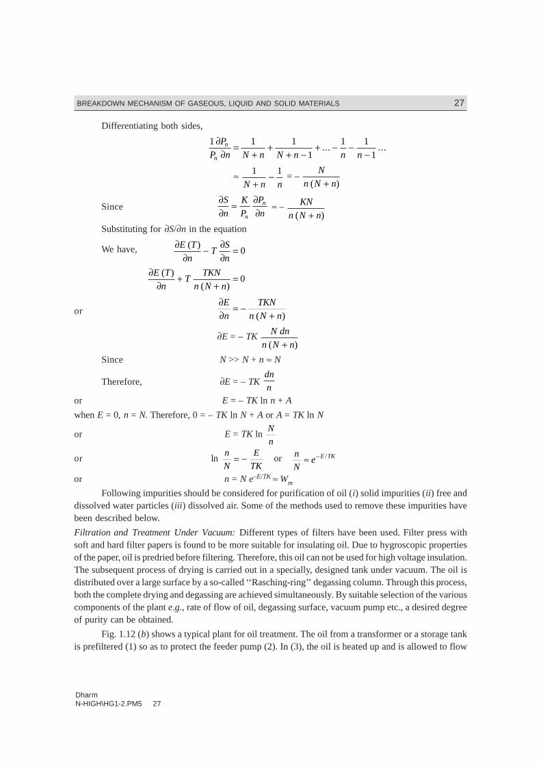
distance between the spheres shall be 4 + 0.02 mm. A suitable gauge is used to adjust the gap. Whilepreparing the oil sample, the test-cell should be thoroughly cleaned and the moisture and suspendedparticles should be avoided. Fig. 1.13 shows an experimental set-up for finding out the dielectric strengthof the given sample of oil. The voltmeter is connected on to the primary side of the high voltagetransformer but calibrated on the high voltage side.
Fig. 1.13
The gap between the spheres is adjusted to 4 mm with the help of a gauge and the spheres areimmersed in oil to a depth as mentioned earlier. The voltage is increased gradually and continuously tilla flash over of the gap is seen or the MCB operates. Note down this voltage. This voltage is known asrapidly-applied voltage. The breakdown of the gap has taken place mainly due to field effect. Thethermal effect is minimal as the time of application is short.
Next bring the voltage back to zero and start with 40% of the rapidly applied voltage and waitfor one minute. See if the gap has broken. If not, increase the voltage everytime by 2.1/2% of therapidly applied voltage and wait for one minute till the flash over is seen or the MCB trips. Note downthis voltage.
Start again with zero voltage and increase the voltage to a value just obtained in the previousstep and wait for a minute. It is expected that the breakdown will take place. A few trials around thispoint will give us the breakdown value of the dielectric strength. The acceptable value is 30 kV for 4mm applied for one minute. In fact these days transformer oils with 65 kV for 4 mm 1 minute value areavailable. If it is less than 30 kV, the oil should be sent for reconditioning. It is to be noted that if theelectrodes are immersed vertically in the oil, the dielectric strength measured may turn out to be lowerthan what we obtained by placing the electrodes in horizontal position which is the normal configura-tion. It is due to the fact that when oil decomposes carbon particles being lighter rise up and if theelectrodes are in vertical configuration, these will bridge the gap and the breakdown will take place ata relatively lower value.
1.13.1 Application of Oil in Power ApparatusOil is normally used for providing insulation between the live parts of different phases and betweenphases and the grounded enclosure containing the oil and the main parts of the apparatus. Also itprovides cooling effect to the apparatus placed within the enclosure. Besides providing insulation, theoil helps the C.B. to quench the arc produced between the breaker contacts when they begin to separateto eliminate the faulted section from the healthy section of the system.
DharmN-HIGH\HG1-2.PM5 30
30 HIGH VOLTAGE ENGINEERING
In an oil circuit breaker, the heat of the oil decomposes the oil which boils at 658 K. The gasesliberated are approx. (i) Hydrogen, 70%, (ii) Acetylene, 20%, (iii) Methane, 5% and (iv) Ethane, 5%.(the abbreviation for these gases could be used as HAME).
The temperature about the arc is too high for the three last-named gases to exist and the arc itselfruns into a mixture of hydrogen, carbon and copper vapour at temperature above 6000 K. The hydrogenbeing a diatomic gas gets dissociated into the atomic state which changes the characteristics of the arcon account of its associated change in its thermal conductivity. The outcome of this is that the dischargesuddenly contracts and acquires an appreciably higher core temperature. In certain cases, the thermalionization may be so great that the discharge runs with a lower voltage which may stop the ionizationdue to the electric field strength. The transition from the field ionization to thermal ionization is mostmarked in hydrogen and, therefore, in oil circuit breakers.
The separation of the C.B. contacts which are carrying current gives rise to an arc withoutchanging much the current wave form. Initially when the contacts just begin to separate the magnitudeof current is very large but the contact resistance being very small, a small voltage appears across them.But the distance of separation being very very small, a large voltage gradient is set up which is goodenough to cause ionization of the particles between the contacts. Also it is known that with the coppercontacts which are generally used for the circuit breakers very little thermal ionization can occur attemperature below the melting point. For effective field emission, the voltage gradient required is 106
V/cm. From this it is clear that the arc is initiated by the field emission rather than the thermal ioniza-tion. This high voltage gradient exists only for a fraction of a micro-second. But in this short period, alarge number of electrons would have been liberated from the cathode and these electrons while reach-ing anode, on their way would have collided with the atoms and molecules of the gases. Thus, eachemitted electron tends to create others and these in turn derive energy from the field and multiply. Inshort, the work done by the initially-emitted electrons enables the discharge to be maintained. Finally,if the current is high, the discharge attains the form of an arc having a temperature high enough forthermal ionization, which results in lower voltage gradient. Thus, an arc is initiated due to field effectand then maintained due to thermal ionization.
1.14 BREAKDOWN IN SOLID DIELECTRICS
Solid insulating materials are used almost in all electrical equipments, be it an electric heater or a 500MW generator or a circuit breaker, solid insulation forms an integral part of all electrical equipmentsespecially when the operating voltages are high. The solid insulation not only provides insulation to thelive parts of the equipment from the grounded structures, it sometimes provides mechanical support tothe equipment. In general, of course, a suitable combination of solid, liquid and gaseous insulations areused.
The processes responsible for the breakdown of gaseous dielectrics are governed by the rapidgrowth of current due to emission of electrons from the cathode, ionization of the gas particles and fastdevelopment of avalanche process. When breakdown occurs the gases regain their dielectric strengthvery fast, the liquids regain partially and solid dielectrics lose their strength completely.
The breakdown of solid dielectrics not only depends upon the magnitude of voltage applied butalso it is a function of time for which the voltage is applied. Roughly speaking, the product of thebreakdown voltage and the log of the time required for breakdown is almost a constant i.e.,
Vb = 1n tb = constant
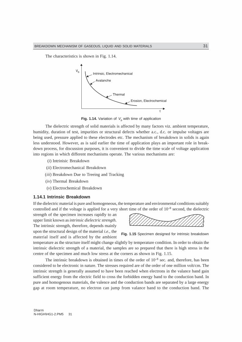
DharmN-HIGH\HG1-2.PM5 31
BREAKDOWN MECHANISM OF GASEOUS, LIQUID AND SOLID MATERIALS 31
The characteristics is shown in Fig. 1.14.
Fig. 1.14. Variation of Vb with time of application
The dielectric strength of solid materials is affected by many factors viz. ambient temperature,humidity, duration of test, impurities or structural defects whether a.c., d.c. or impulse voltages arebeing used, pressure applied to these electrodes etc. The mechanism of breakdown in solids is againless understood. However, as is said earlier the time of application plays an important role in break-down process, for discussion purposes, it is convenient to divide the time scale of voltage applicationinto regions in which different mechanisms operate. The various mechanisms are:
(i) Intrinisic Breakdown
(ii) Electromechanical Breakdown
(iii) Breakdown Due to Treeing and Tracking
(iv) Thermal Breakdown
(v) Electrochemical Breakdown
1.14.1 Intrinsic BreakdownIf the dielectric material is pure and homogeneous, the temperature and environmental conditions suitablycontrolled and if the voltage is applied for a very short time of the order of 10–8 second, the dielectricstrength of the specimen increases rapidly to anupper limit known as intrinsic dielectric strength.The intrinsic strength, therefore, depends mainlyupon the structural design of the material i.e., thematerial itself and is affected by the ambienttemperature as the structure itself might change slightly by temperature condition. In order to obtain theintrinsic dielectric strength of a material, the samples are so prepared that there is high stress in thecentre of the specimen and much low stress at the corners as shown in Fig. 1.15.
The intrinsic breakdown is obtained in times of the order of 10–8 sec. and, therefore, has beenconsidered to be electronic in nature. The stresses required are of the order of one million volt/cm. Theintrinsic strength is generally assumed to have been reached when electrons in the valance band gainsufficient energy from the electric field to cross the forbidden energy band to the conduction band. Inpure and homogenous materials, the valence and the conduction bands are separated by a large energygap at room temperature, no electron can jump from valance band to the conduction band. The
Fig. 1.15 Specimen designed for intrinsic breakdown

DharmN-HIGH\HG1-2.PM5 32
32 HIGH VOLTAGE ENGINEERING
conductivity of pure dielectrics at room temperature is, therfore, zero. However, in practice, no insulatingmaterial is pure and, therefore, has some impurities and/or imperfections in their structural designs.The impurity atoms may act as traps for free electrons in energy levels that lie just below the conductionband is small. An amorphous crystal will, therefore, always have some free electrons in the conductionband. At room temperature some of the trapped electrons will be excited thermally into the conductionband as the energy gap between the trapping band and the conduction band is small. An amorphouscrystal will, therefore, always have some free electrons in the conduction band. As an electric field isapplied, the electrons gain energy and due to collisions between them the energy is shared by all electrons.In an amorphous dielectric the energy gained by electrons from the electric field is much more thanthey can transfer it to the lattice. Therefore, the temperature of electrons will exceed the lattice temperatureand this will result into increase in the number of trapped electrons reaching the conduction band andfinally leading to complete breakdown.
When an electrode embeded in a solid specimen is subjected to a uniform electric field, breakdownmay occur. An electron entering the conduction band of the dielectric at the cathode will move towardsthe anode under the effect of the electric field. During its movement, it gains energy and on collision itloses a part of the energy. If the mean free path is long, the energy gained due to motion is more thanlost during collision. The process continues and finally may lead to formation of an electron avalanchesimilar to gases and will lead finally to breakdown if the avalanche exceeds a certain critical size.
1.14.2 Electromechanical BreakdownWhen a dielectric material is subjected to an electric field, charges of opposite nature are induced onthe two opposite surfaces of the material and hence a force of attraction is developed and the specimentis subjected to electrostatic compressive forces and when these forces exceed the mechanical withstandstrength of the material, the material collapses. If the initial thickness of the material is d0 and iscompressed to a thickness d under the applied voltage V then the compressive stress developed due toelectric field is
F = 12
ε ε0
2
2rV
dwhere εr is the relative permittivity of the specimen. If γ is the Young’s modulus, the mechanicalcompressive strength is
γ 1n d
d0
Equating the two under equilibrium condition, we have
12
10
2
20ε ε γr
V
d
d
d= n
or V2 = d2 . 2
10
0γε ε r
d
dn = Kd2 1n
d
d0
Differentiating with respect to d, we have
2V dV
ddK d
d
dd
d
d
d
d= −
LNM
OQP
2 1 0 2
0
02n . . = 0
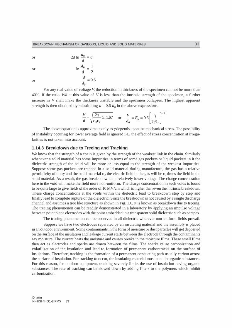
DharmN-HIGH\HG1-2.PM5 33
BREAKDOWN MECHANISM OF GASEOUS, LIQUID AND SOLID MATERIALS 33
or 2d ln d
d0 = d
or ln d
d0 =
1
2
or d
d0
0 6= .
For any real value of voltage V, the reduction in thickness of the specimen can not be more than40%. If the ratio V/d at this value of V is less than the intrinsic strength of the specimen, a furtherincrease in V shall make the thickness unstable and the specimen collapses. The highest apparentstrength is then obtained by substituting d = 0.6 d0 in the above expressions.
V
d r
= 21 1 67
0
γε ε
n . orV
dEa
r0 0
1 2
0 6= =LNM
OQP
./
γε ε
The above equation is approximate only as γ depends upon the mechanical stress. The possibilityof instability occuring for lower average field is ignored i.e., the effect of stress concentration at irregu-larities is not taken into account.
1.14.3 Breakdown due to Treeing and TrackingWe know that the strength of a chain is given by the strength of the weakest link in the chain. Similarlywhenever a solid material has some impurities in terms of some gas pockets or liquid pockets in it thedielectric strength of the solid will be more or less equal to the strength of the weakest impurities.Suppose some gas pockets are trapped in a solid material during manufacture, the gas has a relativepermittivity of unity and the solid material εr, the electric field in the gas will be εr times the field in thesolid material. As a result, the gas breaks down at a relatively lower voltage. The charge concentrationhere in the void will make the field more non-uniform. The charge concentration in such voids is foundto be quite large to give fields of the order of 10 MV/cm which is higher than even the intrinsic breakdown.These charge concentrations at the voids within the dielectric lead to breakdown step by step andfinally lead to complete rupture of the dielectric. Since the breakdown is not caused by a single dischargechannel and assumes a tree like structure as shown in Fig. 1.6, it is known as breakdown due to treeing.The treeing phenomenon can be readily demonstrated in a laboratory by applying an impulse voltagebetween point plane electrodes with the point embedded in a transparent solid dielectric such as perspex.
The treeing phenomenon can be observed in all dielectric wherever non-uniform fields prevail.Suppose we have two electrodes separated by an insulating material and the assembly is placed
in an outdoor environment. Some contaminants in the form of moisture or dust particles will get depositedon the surface of the insulation and leakage current starts between the electrode through the contaminantssay moisture. The current heats the moisture and causes breaks in the moisture films. These small filmsthen act as electrodes and sparks are drawn between the films. The sparks cause carbonization andvolatilization of the insulation and lead to formation of permanent carbontracks on the surface ofinsulations. Therefore, tracking is the formation of a permanent conducting path usually carbon acrossthe surface of insulation. For tracking to occur, the insulating material must contain organic substances.For this reason, for outdoor equipment, tracking severely limits the use of insulation having organicsubstances. The rate of tracking can be slowed down by adding filters to the polymers which inhibitcarbonization.

DharmN-HIGH\HG1-2.PM5 34
34 HIGH VOLTAGE ENGINEERING
Fig. 1.16
1.14.4 Thermal BreakdownWhen an insulating material is subjected to an electric field, the material gets heated up due to conduc-tion current and dielectric losses due to polarization. The conductivity of the material increases withincrease in termperature and a condition of instability is reached when the heat generated exceeds theheat dissipated by the material and the material breaks down. Fig. 1.17 shows various heating curvescorresponding to different electric stresses as a function of specimen temperature. Assuming that thetemperature difference between the ambient and the specimen temperature is small, Newton’s law ofcooling is represented by a straight line.
Fig. 1.17 Thermal stability or instability of different fields

DharmN-HIGH\HG1-3.PM5 35
BREAKDOWN MECHANISM OF GASEOUS, LIQUID AND SOLID MATERIALS 35
The test specimen is at thermal equilibrium corresponding to field E1 at temperature T1 as be-yond that heat generated is less than heat lost. Unstable equilibrium exists for field E2 at T2,
and forfield E3 the state of equilibrium is never reached and hence the specimen breaks down thermally.
Fig. 1.18. Cubical speciman—Heat flow
In order to obtain basic equation for studying thermal breakdown, let us consider a small cube(Fig. 1.18) within the dielectric specimen with side ∆x and temperature difference across its faces in thedirection of heat flow (assume here flow is along x-direction) is ∆T. Therefore, the temperature gradient is
∆∆
T
x
dT
dx≈
Let ∆x2 = A. The heat flow across face 1
KA dT
dxJoules
Heat flow across face 2
KA dT
dx – KA
d
dx
dT
dxxF
HIK ∆
Here the second term indicates the heat input to the differential specimen. Therefore, the heatabsorbed by the differential cube volume
=
FH
IK
= FH
IK
KAd
dx
dT
dxx
VK
d
dx
dT
dx
∆
∆The heat input to the block will be partly dissipated into the surrounding and partly it will raise
the temperature of the block. Let CV be the thermal capacity of the dielectric, σ the electrical conductivity,E the electric field intensity. The heat generated by the electric field = σE2 watts, and suppose the risein temperature of the block is ∆T, in time dt, the power required to raise the temperature of the block by∆T is
CV dT
dt watts
Therefore, CV dT
dtK
d
dx
dT
dxE+ F
HIK = σ 2
The solution of the above equation will give us the time required to reach the critical temperatureTc for which thermal instability will reach and the dielectric will lose its insulating properties. However,unfortunately the equation can be solved in its present from CV, K and σ are all functions of temperatureand in fact σ may also depend on the intensity of electrical field.
Therefore, to obtain solution of the equation, we make certain practical assumptions and weconsider two extreme situations for its solution.
DharmN-HIGH\HG1-3.PM5 36
36 HIGH VOLTAGE ENGINEERING
Case I: Assume that the heat absorbed by the block is very fast and heat generated due to the electricfield is utilized in raising the temperature of the block and no heat is dissipated into the surroundings.We obtain, therefore, an expression for what is known as impulse thermal breakdown. The main equa-tion reduces to
CV dT
dt = σE2
The objective now is to obtain critical field strength Ec which will generate sufficient heat veryfast so that above requirement is met. Let
E = E
ttc
c
FHG
IKJ
i.e., the field is a ramp function
σE2 = CV dT
dt = CV
dT
dE
dE
dt.
and Let σ = σ0 e–u/KT
where K is Boltzamann’s constant and σ0 is the conductivity at ambinent temperature T0.Substituting these values in the simplified equation, we have
σ02e E C
dE
dt
dT
dEu KT
V− =/ .
NowdE
dt
E
tc
c
=
Therefore, σ0e–u/KT E2 = CV
E
t
dT
dEc
c
or σ0 E2
t
EdEc
c = CV e
u/KTdT
or σ0
0
2
0C
t
EE dE e dT
V
c
c
Eu
KT
T
Tc cz z=
The integral on the left hand side
σ σ0 2 0 3
0
1
3C
t
EE dE
C
t
EE
V
c
c V
c
cc
Ec
=z . = 1
30 2t
CEc
Vc
σ
The integral on the right hand side
e dt TK
ue
u
KT u KT
T
Tc
→z 02 0
0
/
when Tc >> T0
Therefore, Ec = 3
0
02
0C
t
KT
ueV
c
u KT
σ. /
From the above expression, it is clear that the critical condition requires a combination of criti-cal time and critical field. However, the critical field is independent of the critical temperature due tothe fast rise in temperature.
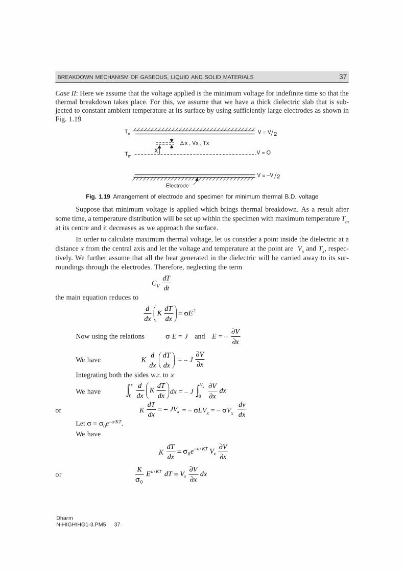
DharmN-HIGH\HG1-3.PM5 37
BREAKDOWN MECHANISM OF GASEOUS, LIQUID AND SOLID MATERIALS 37
Case II: Here we assume that the voltage applied is the minimum voltage for indefinite time so that thethermal breakdown takes place. For this, we assume that we have a thick dielectric slab that is sub-jected to constant ambient temperature at its surface by using sufficiently large electrodes as shown inFig. 1.19
Fig. 1.19 Arrangement of electrode and specimen for minimum thermal B.D. voltage
Suppose that minimum voltage is applied which brings thermal breakdown. As a result aftersome time, a temperature distribution will be set up within the specimen with maximum temperature Tmat its centre and it decreases as we approach the surface.
In order to calculate maximum thermal voltage, let us consider a point inside the dielectric at adistance x from the central axis and let the voltage and temperature at the point are Vx and Tx, respec-tively. We further assume that all the heat generated in the dielectric will be carried away to its sur-roundings through the electrodes. Therefore, neglecting the term
CV dT
dtthe main equation reduces to
d
dxK
dT
dxEF
HIK = σ 2
Now using the relations σ E = J and E = – ∂∂V
x
We have K d
dx
dT
dxFH
IK = – J
∂∂V
x
Integrating both the sides w.r. to x
We have d
dxK
dT
dx
x FH
IKz0 dx = – J
∂∂z V
xdx
Vx
0
or K dT
dxJVx= − = – σEVx = – σVx
dv
dxLet σ = σ0e
–u/KT.
We have
K dT
dxe V
V
xu KT
x= ∂∂
−σ0/
or K
E dT VV
xdxu KT
xσ0
/ = ∂∂

DharmN-HIGH\HG1-3.PM5 38
38 HIGH VOLTAGE ENGINEERING
or K
e dT V dVu KTx
V
T
T mc
σ0 0
2
0
/ /
= zzThis shows that the maximum thermal voltage depends upon the critical temperature Tc at the
centre of dielectric at which the specimen loses is insulating properties. However, Vm is independent ofthe thickness of the insulating material but for thin specimens the thermal breakdown becomes touch-ing asymptotically to a constant value for thick specimen. Under alternating currents the total heatgenerated will be
σE2 + V2 ωc tan δand, therefore, this being higher than what we have in d.c. circuits, the maximum thermal breakdownvoltage will be lower in a.c. supplies. In fact, higher the frequency the lower the thermal breakdownvoltage.
Table 1.5 gives for thick specimen, thermal breakdown values for some dielectric under a.c. andd.c. voltages at 20°C.
Table 1.5. Thermal breakdown voltage
Material Maximum thermal voltage in
MV/cm
d.c. a.c.
Ceramics HV Steatite — 9.8
LF Steatite — 1.5
High grade porcelain 2.8Organic materials Ebonite — 1.45–2.75
Polythene 3.5
Polystyrene 5.0
Polystyrene at 1 MHz 0.05
Acrylic resins 0.3–1.0Crystals Mica muscovite 24 7–18
Rock salt 38 1.4
Quartz Perpendiculars to axis 12000 —
Paralle to axis 66 —
Impure — 2.2
1.14.5 Electrochemical Breakdown
Whenever cavities are formed in solid dielectrics, the dielectric strength in these solid specimen de-creases. When the gas in the cavity breaks down, the surfaces of the specimen provide instantaneous
anode and cathode. Some of the electrons dashing against the anode with sufficient energy shall breakthe chemical bonds of the insulation surface. Similarly, positive ions bombarding against the cathodemay increase the surface temperature and produce local thermal instability. Similarly, chemical degra-dation may also occur from the active discharge products e.g., O3, NO2 etc. formed in air. The net effect
of all these processes is a slow erosion of the material and a consequent reduction in the thickness ofthe specimen. Normally, it is desired that with ageing, the dielectric strength of the specimen should notdecrease. However, because of defects in manufacturing processes and/or design, the dielectric strength

DharmN-HIGH\HG1-3.PM5 39
BREAKDOWN MECHANISM OF GASEOUS, LIQUID AND SOLID MATERIALS 39
decreases with time of voltage application or even without voltage application and in many cases; thedecrease in dielectric strength (Eb) with time follows the following empirical relation.
t Ebn = constant
where the exponent n depends upon the dielectric material, the ambient temperature humidity and thequality of manufacture. This is the main reason why high a.c. voltage testing is not recommended. Infact, these days very low frequency testing is being suggested (0.1 HZ) which simulates the effects of
both a.c. 50 HZ and d.c. voltages and yet the dielectric strength of the specimen is not affected muchwith VLF voltage application.
The breakdown of solid dielectric due to internal discharges or partial discharges has beenelaborately explained in section 6.9 of the book.
1.14.6 Solid Dielectrics Used in Power ApparatusThe main requirements of the insulating materials used for power apparatus are:
1. High insulation resistance
2. High dielectric strength
3. Good mechanical properties i.e., tenacity and elasticity
4. It should not be affected by chemicals around it
5. It should be non-hygroscopic because the dielectric strength of any material goes very muchdown with moisture content
Vulcanized rubber : Rubber in its natural form is highly insulating but it absorbs moisture readily andgets oxidized into a resinous material; thereby it loses insulating properties. When it is mixed withsulphur alongwith other carefully chosen ingredients and is subjected to a particular temperature itchanges into vulcanized rubber which does not absorb moisture and has better insulating propertiesthan even the pure rubber. It is elastic and resilient.
The electrical properties expected of rubber insulation are high breakdown strength and highinsulation resistance. In fact the insulation strength of the vulcanized rubber is so good that for lowervoltages the radial thickness is limited due to mechanical consideration.
The physical properties expected of rubber insulation are that the cable should withstand nor-mal hazards of installation and it should give trouble-free service.
Vulcanized rubber insulated cables are used for wiring of houses, buildings and factories forlow-power work.
There are two main groups of synthetic rubber material : (i) general purpose synthetics whichhave rubber-like properties and (ii) special purpose synthetics which have better properties than therubber e.g., fire resisting and oil resisting properties. The four main types are: (i) butyl rubber, (ii)silicon rubber, (iii) neoprene, and (iv) styrene rubber.
Butyl rubber: The processing of butyl rubber is similar to that of natural rubber but it is moredifficult and its properties are comparable to those of natural rubber. The continuous temperature towhich butyl rubber can be subjected is 85°C whereas for natural rubber it is 60°C. The current rating of
DharmN-HIGH\HG1-3.PM5 40
40 HIGH VOLTAGE ENGINEERING
butyl insulated cables is approximately same as those of paper or PVC insulated cables. Butyl rubbercompound can be so manufactured that it has low water absorption and offers interesting possibilitiesfor a non-metallic sheathed cable suitable for direct burial in the ground.
Silicone rubber: It is a mechanically weak material and needs external protection but it has highheat resistant properties. It can be operated at temperatures of the order of 150°C. The raw materialsused for the silicon rubber are sand, marsh gas, salt, coke and magnesium.
Neoprene: Neoprene is a polymerized chlorobutadiene. Chlorobutadiene is a colourless liquidwhich is polymerized into a solid varying from a pale yellow to a darkish brown colour. Neoprene doesnot have good insulating properties and is used upto 660 V a.c. but it has very good fire resistingproperties and therefore it is more useful as a sheathing material.
Styrene rubber: Styrene is used both for insulating and sheathing of cables. It has propertiesalmost equal to the natural rubber.
Polyvinyl Chloride (PVC)
It is a polymer derived generally from acetylene and it can be produced in different gradesdepending upon the polymerization process. For use in cable industry the polymer must be compoundedwith a plasticizer which makes it plastic over a wide range of temperature. The grade of PVC dependsupon the plasticizer. PVC is inferior to vulcanized in respect of elasticity and insulation resistance.PVC material has many grades.
General purpose type: It is used both for sheathing and as an insulating material. In this com-pound monomeric plasticizers are used. It is to be noted that a V.R. insulated PVC sheathed cable is notgood for use.
Hard grade PVC: These are manufactured with less amount of plasticizer as compared withgeneral purpose type. Hard grade PVC are used for higher temperatures for short duration of time likein soldering and are better than the general purpose type. Hard grade can not be used for low continu-ous temperatures.
Heat resisting PVC: Because of the use of monomeric plasticizer which volatilizes at tempera-ture 80°C–100°C, general purpose type compounds become stiff. By using polymeric plasticizers it ispossible to operate the material continuously around 100°C.
PVC compounds are normally costlier than the rubber compounds and the polymeric plasticizedcompounds are more expensive than the monomeric plasticized ones. PVC is inert to oxygen, oils,alkalis and acids and, therefore, if the environmental conditions are such that these things are present inthe atmosphere, PVC is more useful than rubber.
Polythene
This material can be used for high frequency cables. This has been used to a limited extent forpower cables also. The thermal dissipation properties are better than those of impregnated paper andthe impulse strength compares favourably with an impregnated paper-insulated device. The maximumoperating temperature of this material under short circuits is 100°C.
Cross-linked polythene: The use of polythene for cables has been limited by its low meltingpoint. By cross-linking the molecules, in roughly the same way as vulcanising rubber, a new material isproduced which does not melt but carbonizes at 250 to 300°C. By using chemical process it has been
DharmN-HIGH\HG1-3.PM5 41
BREAKDOWN MECHANISM OF GASEOUS, LIQUID AND SOLID MATERIALS 41
made technically possible to cross-link polythene in conventional equipment for the manufacture ofrubber. This is why the product is said to be “vulcanised” or “cross-linked” polythene.
The polythene is inert to chemical reactions as it does not have double bonds and polar groups.Therefore, it was thought that polythene could be cross-linked only through special condition, e.g., byirradiating polythene with electrons, thereby it could be given properties of cross-linking such as changeof tensile strength and better temperature stability. Many irradiation processes have been developed inthe cable making industry even though large amounts of high energy radiations are required and theprocedure is expensive.
Polythene can also be irradiated with ultraviolet light, after adding to it a smal quantity of ultra-violet sensitive material such as benzophenone. Under the influence of ultraviolet light on benzophenone,a radical is formed of the same type as in the decomposition of peroxide by the radical mechanism.Organic peroxides have also been used successfully to crosslink the polythene.
Impregnated paper
A suitable layer of the paper is lapped on the conductor depending upon the operating voltage.It is then dried by the combined application of heat and vacuum. This is carried out in a hermeticallysealed steam heated chamber. The temperature is 120°–130°C before vacuum is created. After thedevice is dried, an insulating compound having the same temperature as that of the chamber is forcedinto the chamber. All the pores of the paper are completely filled with this compound. After impregna-tion the device is allowed to cool under the compound so that the void formation due to compoundshrinkage is minimized.
In case of pre-impregnated type the papers are dried and impregnated before they are applied onthe conductor.
The compound used in case of impregnated paper is a semifluid and when the cables are laid ongradients the fluid tends to move from higher to lower gradient. This reduces the compound content athigher gradients and may result in void formation at higher gradients. This is very serious for cablesoperating at voltages higher than 3.3 kV. In many cases, the failures of the cables have been due to thevoid formation at the higher levels or due to the bursting of the sheath at the lower levels because of theexcessive internal pressure of the head of compound.
Insulating press boards. If the thickness of paper is 0.8 mm or more, it is called paper board.When many layers of paper are laminated with an adhesive to get desired thickness, these are known aspress boards and are used in bushings, transformers as insulating barriers or supporting materials. Theelectrical properties of press boards varies depending upon the resin content. The application of thesepress boards depends upon the thickness and density of paper used. For high frequency capacitors andcables usually low density paper (0.8 gm/cm3) is used where medium density paper is used for powercapacitors and high density papers are used in d.c. machines and energy storage capacitors. The electricstrength of press board is higher than that of resins or porcelain. However, it is adversely affected bytemperature above 20°C. The loss angle tan δ also decreases with increase in temperature. The mainadvantage of this material is that it provides good mechanical support even at higher temperatures upto120°C.
Mica. Mica consists of crystalline mineral silicates of alumina and potash. It has high dielectricstrength, low dielectric losses and good mechanical strength. All these properties make it useful for

DharmN-HIGH\HG1-3.PM5 42
42 HIGH VOLTAGE ENGINEERING
many electrical devices e.g., commutator segment separator, aremature windings, electrical heatingand cooling equipments and switchgear. Thin layers of mica are laminated with a suitable resin orvarnish to make thick sheets of mica. Mica can be mixed with the required type of resin to obtain itsapplication at different operating temperatures. Mica is used as a filler in insulating materials to im-prove their dielectric strength, reduce dielectric loss and improve heat resistance property.
Ceramics. Ceramics materials are produced from clay containing aluminium oxide and otherinorganic materials. The thick parts of these substances is given the desired shape and form at roomtemperature and then baked at high temperature about (1450°C) to provide a solid inelastic final struc-ture. Ceramics also known as porcelain in one of its forms have high mechanical strength and lowpermittivity (εr < 12) are widely used for insulators and bushings. These have 40% to 50% of clay, 30-20% of aluminium oxide and 30% of fieldspar. The ceramics with higher permittivity (εr > 12) are usedin capacitors and transducers.
The specific insulation resistance of ceramics is comparatively low. The tan δ of these materialsis high and increases with increase in temperature resulting in higher dielectric loss. The breakdownstrength of porecelain compared to other insulating material is low but it remains unaffected over awide range of temperature variation. Porcelain is chemically insert to alkalies and acids and, therefore,corrosion resistant and does not get contaminated. Alumina (Al2O3) has replaced quartz because of itsbetter thermal conductivity, insulating property and mechanical strength. It is used for the fabricationof high current vacuum circuit breakers.
Glass. Glass is a thermoplastic inorganic material consisting of silicondioxide (SiO2), which isavailable in nature in the form of quartz. Different types of metal oxides could be used for producingdifferent types of glasses but for use in electrical engineering only non-alkaline glasses are suitablehaving alkaline content less than 0.8%.
The dielectric constant of glass varies between 3.6 and 10.0 and the density varies between 2000kg/m3 and 6000 kg/m3. The loss angle tan δ is less than 10–3 and losses are higher for lower frequen-cies. Its dielectric strength varies between 300 and 500 kV/mm and it decreases with increase in tem-perature. Glass is used for X-ray equipments, electronic valves, electric bulbs etc.
Epoxy Resins. Epoxy resins are low molecular but soluble thermosetting plastics which exhibitsufficient hardening quality in their molecules. The chemical cross-linking of epoxy resins is normallycarried out at room temperatures either by a catalytic mechanism or by bridging across epoxy moleculethrough the epoxy or hydroxyl group.
Epoxy resins have high dielectric and mechanical strength. They can be cast into desired shapeseven at room temperature. They are highly elastic and it is found that when it is subjected to a pressureof 175000 psi, it returned to its original shape after the load is removed. The dielectric constant variesbetween 2.5 and 4.0. Epoxy resins basically being non-polar substances have high dc specific insula-tion resistance and low loss tan δ compared to polar materials like PVC. However, when the tempera-ture exceeds 100°C the specific insulation resistance begins to decrease considerably and tan δ in-creases. Compared to porcelain the breakdown strength of epoxy resin is almost double at temperaturesupto 100°C but decreases rapidly at higher temperatures.
As filler materials, the inorganic substances like quartz powder (SiO2) are used for castingapplications. In SF6 gas insulated systems having epoxy resin spacers, aluminium oxide and also dolo-

DharmN-HIGH\HG1-3.PM5 43
BREAKDOWN MECHANISM OF GASEOUS, LIQUID AND SOLID MATERIALS 43
mite are used as filler materials. These are found to be more compatible to the decomposed products ofSF6 by partial discharge and arcing discharges.
It is to be noted that the cast or encapsulation should not contain voids or humidity especially inhigh voltage applications and the material is desired to be homogeneous. It is, therefore, desirable todry and degas the individual components of the mixture and casting is preferably carried out in vacuum.
The epoxy resins casts are inert to ether, alcohol and benzol. However, most of them are solublein mineral oils at about 70°C. It is for this reason that they are not found suitable for applications infilled transformers.
There are certain application which require insulating materials to operate between a high rangeof temperature e.g., –270°C to 400°C. Some of the applications are space shuttle solar arrays, capaci-tors, transformers high speed locomotive, microprocessor chip carriers, cryogenic cables and otherapplications at cryogenic temperatures. For this some thermoplastic polymer films are used which haveunique combination of electrical, mechanical and physical quantities and these materials are able toretain these properties over a wide range of temperatures where other insulating materials may fail.Perfluoro carbon films have high dielectric strength very low dielectric constant of 2 and low dielectricloss of 2 × 10⁻⁴ at 100 Hz and 7.5 × 10⁻⁴ at 100 MHz. These films are used under extreme conditions oftemperature and environment. These films are used for insulation on high temperature wires, cables,motor coils phase and ground insulation and for capacitors. This is also used as a substrate for flexibleprinted circuits and flexible cables.
Another insulating film in which has the best thermal properties in this category of insulatingmaterials is polyimide film under the trade name of Kapton manufactured by DuPont of America.These films can be used between a very wide range of temperature variation varying between –270°Cand 350°C. Its continuous temperature rating is 240°C. It has high dielectric and tensile strength. Thedisadvantages of the film are
(i) high moisture absorption rate and (ii) it is affected by alkalies and strong inorganic acids.
Kepton films can be used capacitors, transformers formed coil insulation, motor state insulationand flexible printed circuits. The film is selectively costlier and is mainly used where its unique charac-teristics makes it the only suitable insulation. The use of this insulation for motors reduces the overalldimensions of the motors for the same ratings. It is, therefore, used in almost all situations whose spaceis a serious problem and the other nature insulation result in bigger dimension.
Another recently developed resins is poly carbonate (PC) which is good heat resistant; it isflexible and has good dielectric characteristic. It is not affected by oils, fats and dilute acids but isadversely affected by alkalies, esters and aromatic hydrocarbons. The film being cost effective and fastresistant, it is used for coil insulation, slot insulation for motors and for capacitor insulation. This isknown as the lexon polymer.
General Electric Co. of USA has developed a film under the trade name Ultem which is a polyetherimine (PEI) film which has dielectric strength comparable to that of polyimide film and has higherthermal conductivity and lower moisture absorption and is relatively less costlier. It is used as insula-tion for transformers and motors.

DharmN-HIGH\HG1-3.PM5 44
44 HIGH VOLTAGE ENGINEERING
1.14.7 Application of Insulating MaterialsInsulating fluids (gases and liquids) provide insulation between phases and between phase and groundedparts of electrical equipments. These also carry out heat from the windings of the electrical equipments.However, solid insulating materials are used only to provide insulation only.
International Electrotechincal Commission has categories various insulating materials depend-ing upon the temperature of operations of the equipments under the following categories.
Class Y 90°C Natural rubber, PVC, paper cotton, silk without impregnation.Class A 105°C Same as class Y but impregnatedClass E 120°C Polyethylene, terephthalate, cellulose tricetrate, polyvinyl acetate enamelClass B 130°C Bakelite, bituminised asbestos, fibre glass, mica, polyester enamelClass F 155°C As class B but with epoxy based resinClass H 180°C As class B with silicon resin binder silicone rubber, aromatic polyamide
(nomex paper and fibre), polyimide film (enamel, varnish and film) and estermideenamel
Class C Above 180°C, as class B but with suitable non-organic binders, teflon and otherhigh temperature polymers.
While describing the dielectric and other properties of various insulating materials, their appli-cation for various electrical apparatus has also been mentioned in the previous paragraphs. However, areverse process i.e., what insulating materials are used for a particular apparatus depending upon itsratings and environmental condition where the apparatus is required to operate, is also desirable and abrief review is given here.
Power Transformers. For small rating, the coils are made of super-enamelled copper wire. Forlayer to layer, coil to coil and coil to ground (iron core) craft paper is used.
However, for large size transformers paper or glass tape is rapped on the rectangular conductorswhereas for coil to coil or coil to ground, insulation is provided using thick radial spacers made of pressboard or glas fibre.
In oil-filled transformers, the transformer oil is the main insulation. However between variouslayers of low voltage and high voltage winding oil-impregnated press boards are placed.
SF6 gas insulated power transformers make use of sheet aluminium conductors for windingsand turn to turn insulation is provided by a polymer film. The transformer has annular cooling ductsthrough which SF6 gas circulates for cooling the winding. SF6 gas provides insulations to all majorgaps in the transformer. This transformer is used where oil filled transform is not suitable e.g., incinema halls, high rise buildings and some especial circumstances: The end turns of a large powertransformer are provided with extra insulation to avoid damage to coil when lighting or switchingsurges of high frequency are incident on the transformer winding.
The terminal bushings of large size power transformer are made of condenser type bushing. Theterminal itself consists of a brass rod or tube which is wound with alternate layers of treated paper andtin foil, so proportioned, as to length, that the series of condensers formed by the tin foil cylinders andthe intervening insulation have equal capacitances, thereby the dielectric stress is distributed uniformly.
Circuit Breakers. The basic construction of any circuit breaker requires the separation of con-tacts in an insulating fluid which serves two functions here:
(i) It extinguishes the arc drawn between the contacts when the CB, opens.(ii) It provides adequate insulation between the contacts and from each contact to earth.
DharmN-HIGH\HG1-3.PM5 45
BREAKDOWN MECHANISM OF GASEOUS, LIQUID AND SOLID MATERIALS 45
Many insulating fluids are used for arc extinction and the fluid chosen depends upon the ratingand type of C.B. The insulating fluids commonly used for circuit breakers are
(i) Air at atmospheric pressure: Air break circuit breaker upto 11 kV.(ii) Compressed air (Air blast circuit breaker between 220 kV and 400 kV)
(iii) Mineral oil which produces hydrogen for arc extrictrion (transformer oil)(a) Plain break oil, C.B. 11 kV–66 kV(b) Controlled break oil C.B. or bulk oil C.B. between 66 kV–220 kV(c) Minimum oil C.B. between 66 kV and 132 kV.
(iv) Ultra high vacuum C.B. upto 33 kV.(v) SF6 circuit breakers above 220 kV.
The controlled break and minimum oil circuit breakers enclose the breaker contacts in an arcingchamber made of insulating materials such as glassfibre reinforced synthetic resins etc.
Rotating Machines. For low voltage a.c. and d.c. machines, the winding wire are super enamelledwire and the other insulation used are vulcanised rubber and varnished cambric and paper. For highvoltage and large power capacity machines, the space limitations demand the use of insulating materialshaving substantially greater dielectric strength. Mica is considered to be a good choice not only due tospace requirements but because of its ability to withstand higher temperatures. However, the brittlenessof mica makes it necessary to build up the required thickness by using thin flakes cemented together byvarnish or bakelite generally with a backing of thin paper or cloth and then baking it under pressure.Epoxy resin bounded mica paper is widely used for both low and high voltage machines. Multilayerslot insulation is made of press board and polyester film. However, for machines with high operatingtemperatures kapton polymide is used for slot insulation. Mica has always been used for stator insulations.In addition to mica, conducting non-woven polyesters are used for corona protection both inside and atthe edges of the slots. Glass fibre reinforced epoxy wedge profiles are used to provide support betweenthe winding bars, slots and the core laminations.
Power Cables. The various insulating materials used are vulcanised rubber, PVC, Polyethyleneand impregnated papers.
Vulcanised rubber, insulated cables are used for wiring of houses, buildings and factories forlow power work.
PVC is inert to oxygen, oils, alkalies and acids and therefore, if the environmental conditionsare such that these things are present in the atmosphere, PVC is more useful than rubber.
Polyethylene is used for high frequency cables. This has been used to a limited extent for powercables also. The thermal dissipation properties are better than those of impregnated poper. The maxi-mum oprating temperature of this cable under short circuits is 100°C.
In case of impregnated paper, a suitable layer of the paper is lapped on the conductor dependingupon the operating voltage. It is then dried by the combined application of heat and vacuum. Thecompound used in case of impregnated paper is semifluid and when the cables are laid on gradients thefluid tends to move from higher to lower gradients which reduces the compound content at highergradients and may result in void formation at higher gradients. For this reason, impregnated papercables are used upto 3.3 kV.
Following methods are used for elimination of void formation in the cables:(i) The use of low viscosity mineral oil for the impregnation of the dielectric and the inclusion
of oil channels so that any tendency of void formation (due to cyclic heating and cooling ofimpregnate) is eliminated.
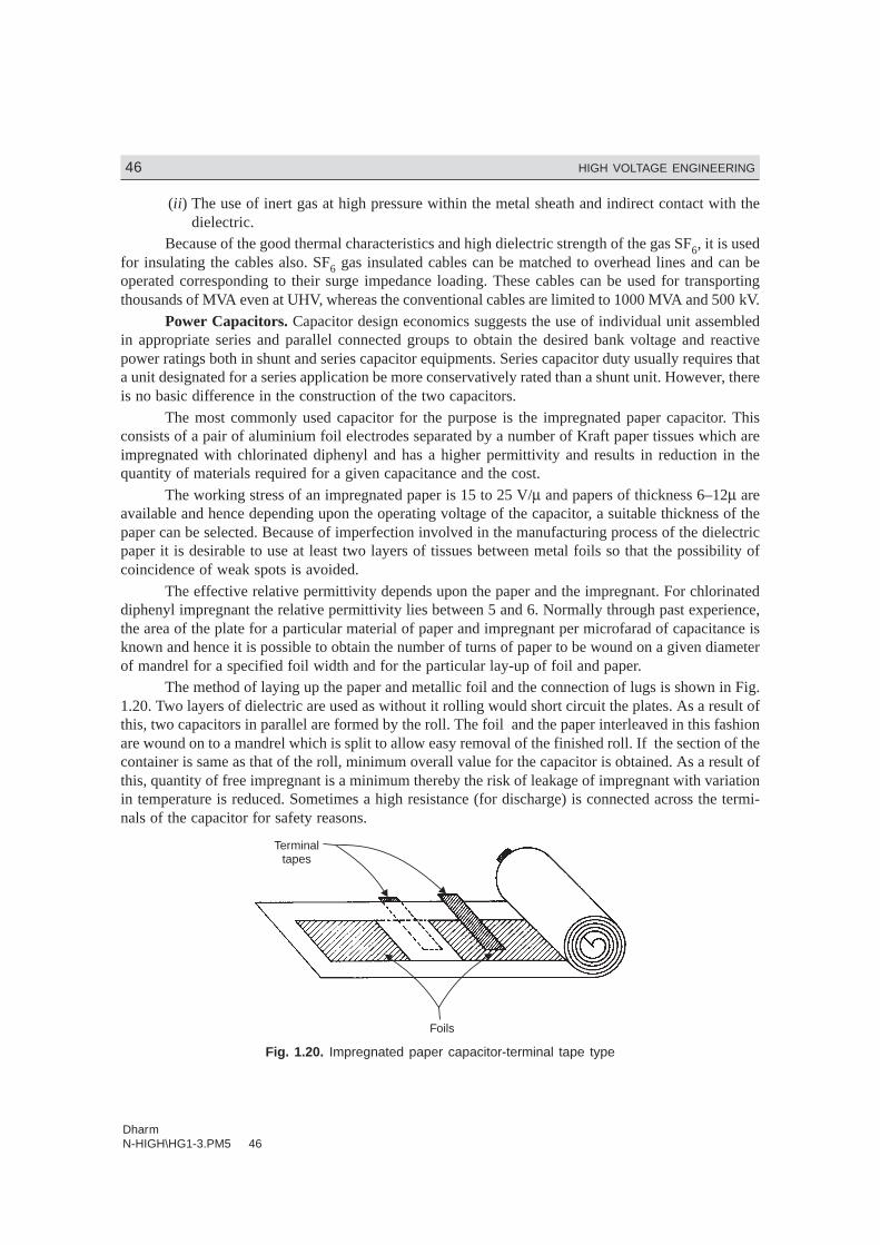
DharmN-HIGH\HG1-3.PM5 46
46 HIGH VOLTAGE ENGINEERING
(ii) The use of inert gas at high pressure within the metal sheath and indirect contact with thedielectric.
Because of the good thermal characteristics and high dielectric strength of the gas SF6, it is usedfor insulating the cables also. SF6 gas insulated cables can be matched to overhead lines and can beoperated corresponding to their surge impedance loading. These cables can be used for transportingthousands of MVA even at UHV, whereas the conventional cables are limited to 1000 MVA and 500 kV.
Power Capacitors. Capacitor design economics suggests the use of individual unit assembledin appropriate series and parallel connected groups to obtain the desired bank voltage and reactivepower ratings both in shunt and series capacitor equipments. Series capacitor duty usually requires thata unit designated for a series application be more conservatively rated than a shunt unit. However, thereis no basic difference in the construction of the two capacitors.
The most commonly used capacitor for the purpose is the impregnated paper capacitor. Thisconsists of a pair of aluminium foil electrodes separated by a number of Kraft paper tissues which areimpregnated with chlorinated diphenyl and has a higher permittivity and results in reduction in thequantity of materials required for a given capacitance and the cost.
The working stress of an impregnated paper is 15 to 25 V/µ and papers of thickness 6–12µ areavailable and hence depending upon the operating voltage of the capacitor, a suitable thickness of thepaper can be selected. Because of imperfection involved in the manufacturing process of the dielectricpaper it is desirable to use at least two layers of tissues between metal foils so that the possibility ofcoincidence of weak spots is avoided.
The effective relative permittivity depends upon the paper and the impregnant. For chlorinateddiphenyl impregnant the relative permittivity lies between 5 and 6. Normally through past experience,the area of the plate for a particular material of paper and impregnant per microfarad of capacitance isknown and hence it is possible to obtain the number of turns of paper to be wound on a given diameterof mandrel for a specified foil width and for the particular lay-up of foil and paper.
The method of laying up the paper and metallic foil and the connection of lugs is shown in Fig.1.20. Two layers of dielectric are used as without it rolling would short circuit the plates. As a result ofthis, two capacitors in parallel are formed by the roll. The foil and the paper interleaved in this fashionare wound on to a mandrel which is split to allow easy removal of the finished roll. If the section of thecontainer is same as that of the roll, minimum overall value for the capacitor is obtained. As a result ofthis, quantity of free impregnant is a minimum thereby the risk of leakage of impregnant with variationin temperature is reduced. Sometimes a high resistance (for discharge) is connected across the termi-nals of the capacitor for safety reasons.
Terminaltapes
Foils
Fig. 1.20. Impregnated paper capacitor-terminal tape type
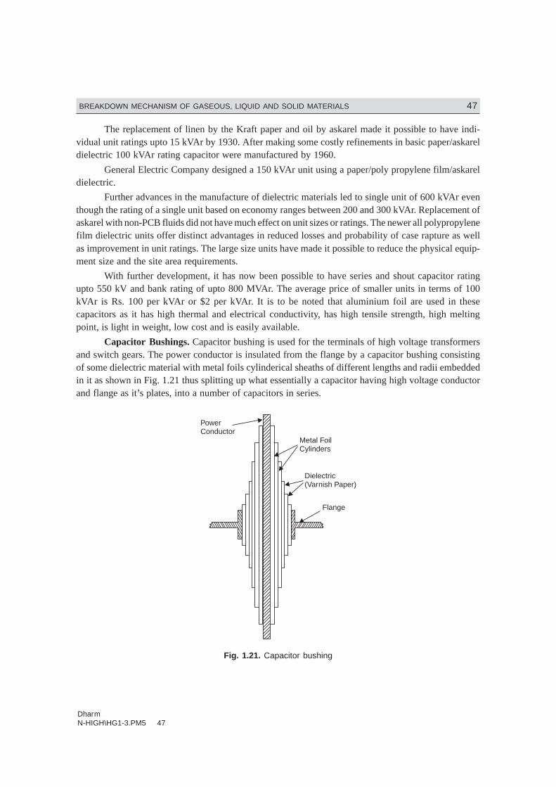
DharmN-HIGH\HG1-3.PM5 47
BREAKDOWN MECHANISM OF GASEOUS, LIQUID AND SOLID MATERIALS 47
The replacement of linen by the Kraft paper and oil by askarel made it possible to have indi-vidual unit ratings upto 15 kVAr by 1930. After making some costly refinements in basic paper/askareldielectric 100 kVAr rating capacitor were manufactured by 1960.
General Electric Company designed a 150 kVAr unit using a paper/poly propylene film/askareldielectric.
Further advances in the manufacture of dielectric materials led to single unit of 600 kVAr eventhough the rating of a single unit based on economy ranges between 200 and 300 kVAr. Replacement ofaskarel with non-PCB fluids did not have much effect on unit sizes or ratings. The newer all polypropylenefilm dielectric units offer distinct advantages in reduced losses and probability of case rapture as wellas improvement in unit ratings. The large size units have made it possible to reduce the physical equip-ment size and the site area requirements.
With further development, it has now been possible to have series and shout capacitor ratingupto 550 kV and bank rating of upto 800 MVAr. The average price of smaller units in terms of 100kVAr is Rs. 100 per kVAr or $2 per kVAr. It is to be noted that aluminium foil are used in thesecapacitors as it has high thermal and electrical conductivity, has high tensile strength, high meltingpoint, is light in weight, low cost and is easily available.
Capacitor Bushings. Capacitor bushing is used for the terminals of high voltage transformersand switch gears. The power conductor is insulated from the flange by a capacitor bushing consistingof some dielectric material with metal foils cylinderical sheaths of different lengths and radii embeddedin it as shown in Fig. 1.21 thus splitting up what essentially a capacitor having high voltage conductorand flange as it’s plates, into a number of capacitors in series.
Flange
Dielectric(Varnish Paper)
Metal FoilCylinders
PowerConductor
Fig. 1.21. Capacitor bushing
DharmN-HIGH\HG1-3.PM5 48
48 HIGH VOLTAGE ENGINEERING
The capacitance of the capacitors formed by the metal foil cylinders is given by
C = εl
R
R2 2
1
ln
where l is the axial length of the capacitor R1 and R2 are the radii of its cylinderical plates. If thesecapacitor have the same capacitance, the potential difference between their plates will be equal. Theequal capacitance between different layers is made possible by choosing suitable axial length together
with ratio R
R2
1
. With this strategy the potential gradient in the dielectric is uniform but the edges of the
foil sheets lie on a curve, thus giving unequal surfaces of dielectric between the edges of successivesheets. This is undesirable as this would result into flashovers by “Creeping” along the surface. How-ever, if the differences between the lengths of successive sheets are made equal, the radial stress is notuniform and hence a compromise between the two conditions is usually adopted.
There are three types of papers used as insulating materials for capacitor bushings; oil impreg-nated paper, resin bonded paper and resin impregnated paper. The oil impregnated paper bushing ismade by wrapping untreated paper after inserting foil sheets at the appropriate position and then im-pregnating with transformer oil after vacuum drying. Before impregnation, it is ensured that moistureand air voids are avoided. This bushing can work at a radial stress of 40 kV/cm.
In case of resin impregnated bushing creped paper tape is wrapped round the conductor andthen dried in an autoclave under controlled heat and vacuum. Epoxyresin is then sprayed to fill thewinding. The permissible radial stress in this case is 30 kV/cm.
In case of resin bonded paper bushing, the paper is first coated with epoxyresin and wrappedround a cylinderical form under heat and pressure after inserting foil sheets at appropriate position. Thepermissible radial stress in this case in 20 kV/cm.
1.15 BREAKDOWN IN VACUUM
A vacuum system is one in which the pressure maintained is at a value below the atmospheric pressureand is measured in terms of mm of mercury. One standard atmospheric pressure at 0°C is equal to 760mm of mercury. One mm of Hg pressure is also known as one torr after the name of Torricelli who wasthe first to obtain pressures below atmosphere, with the help of mercury barometer. Sometimes 10–3
torr is known as one micron. It is now possible to obtain pressures as low as 10–8 torr.
In a Townsend type of discharge, in a gas, the mean free path of the particles is small andelectrons get multiplied due to various ionization processes and an electron avalanche is formed. In avacuum of the order of 10–5 torr, the mean free path is of the order of few metres and thus when theelectrodes are separated by a few mm an electron crosses the gap without any collision. Therefore, in avacuum, the current growth prior to breakdown can not take place due to formation of electron ava-lanches. However, if it could be possible to liberate gas in the vacuum by some means, the dischargecould take place according to Townsend process. Thus, a vacuum arc is different from the general classof low and high pressure arcs. In the vacuum arc, the neutral atoms, ions and electrons do not comefrom the medium in which the arc is drawn but they are obtained from the electrodes themselves by
DharmN-HIGH\HG1-3.PM5 49
BREAKDOWN MECHANISM OF GASEOUS, LIQUID AND SOLID MATERIALS 49
evaporating its surface material. Because of the large mean free path for the electrons, the dielectricstrength of the vacuum is a thousand times more than when the gas is used as the interrupting medium.In this range of vacuum, the breakdown strength is independent of the gas density and depends only onthe gap length and upon the condition of electrode surface. Highly polished and thoroughly degassedelectrodes show higher breakdown strength. Electrodes get roughened after use and thus the dielectricstrength or breakdown strength decreases which can be improved by applying successive high voltageimpulses which of course does not change the roughened surface but removes the loosely adheringmetal particles from the electrodes which were deposited during arcing. It has been observed that for avacuum of 10–6 torr, some of the metals like silver, bismuth-copper etc. attain their maximum break-down strength when the gap is slightly less than 3 mm. This property of vacuum switches permits theuse of short gaps for fast operation.
Electric Discharge in VacuumThe electric discharge in vacuum results from the neutral atoms, ions and electrons emitted from
the electrodes themselves. Cathode spots are formed depending upon the current flowing. For lowcurrents a highly mobile cathode spot is formed and for large currents a multiple number of cathodespots are formed. These spots constitute the main source of vapour in the arc. The processes involvedin drawing the discharge will be due to high electric field between the contacts or resistive heatingproduced at the point of operation or a combination of the two. The cathode surfaces, normally, are notperfectly smooth but have many micro projections. Due to their small area of cross-section, the projec-tions will suffer explosive evaporation by resistive heating and supply sufficient quantity of vapour forthe arc formation. Since in case of vacuum, the emission occurs only at the cathode spots and not fromthe entire surface of the cathode, the vacuum discharge is also known as cold cathode discharge. Incold cathode the emission of electrons could be due to any of the combinations of the following mecha-nisms: (i) Field emission; (ii) Thermionic emission; (iii) Field and Thermionic emission; (iv) Second-ary emission by positive ion bombardment; (v) Secondary emission by photons; and (vi) Pinch effect.
The stability of discharge in vacuum depends upon: (i) the contact material and its vapour pres-sure, and (ii) circuit parameters such as voltage, current, inductance and capacitance. It has been ob-served that higher the vapour pressure at low temperature the better is the stability of the discharge.There are certain metals like Zn, Bi which show these characteristics and are better electrode materialsfor vacuum breakers. Besides the vapour pressure, the thermal conductivity of the metal also affects thecurrent chopping level. A good heat conducting metal will cool its surface faster and hence its elec-trode surface temperature will fall which will result into reduction in evaporation rate and arc will bechopped because of insufficient vapour. On the other hand, a bad heat conductor will maintain itstemperature and vaporization for a longer time and the arc will be more stable.
The process of multiplication of charged particles by the process of collision is very small in thespace between the electrode in vacuum, electron avalanche is not possible. If somehow a gas cloudcould be formed in vacuum, the usual kind of breakdown process can take place. This is the line ofaction adopted by the researchers to study mechanism of breakdown in vacuum. By finding the way,gas cloud could be created in a vacuum.
1.15.1 Non-metallic Electron Emission MechanismThe pre-breakdown conduction current in vacuum normally originates from a nonmetallic electrodesurface. These are present in the form of insulating/semiconducting oxide layer on the surfaces or asimpurities in the electrode material. These microinclusions present in the electrode surface can producestrong electron emission and significantly reduce the break down strength of the gap.
DharmN-HIGH\HG1-3.PM5 50
50 HIGH VOLTAGE ENGINEERING
Even when a vacuum system is completely sealed off, the electrode surfaces may still get con-taminated. It has been observed that when glass is heated to ‘its’ working temperature for sealing theelectrodes into a closed container, fluxes are vaporised from the glass which get deposited in the coolinner surfaces in the form of spherical particles upto a µm diameter . Therefore, the surface of a sealedelectrode may have on its surface contaminates e.g., sodium, potassium, boron aluminium and silicon.When an electric field is applied across such electrodes the oxides adsorbates and dust particles, thenundergo chemical changes e.g., oxides and adsorbates undergo chemical reactions which are initiatedby photons, electrons and ions and thus these contaminants limit the maximum field intensity for thefollowing reasons:
(i) The adsorbates and dust enhance the field emission of electrons.
(ii) The oxides adsorbates and dust particles enhance the secondary electron emission.
(iii) The oxides adsorbates and dust particles exhibit stimulated desorption of molecules andions under the impact of electrons, protons or ions.
Due to these mechanism, there is increase in electron emission process and therefore, moreelectric field energy is converted into kinetic energy of electron and ions which leads to an increase insurface energy of the metal. Thus, the electric strength of the gap may reduce to a level as low as 10 kV/cm as compared to 104 kV/cm which is required for the field emission process.
1.15.2 Clump MechanismThe vacuum breakdown mechanism based on this theory makes following assumption:
(i) A loosely bound particle known as clump exists on one of the electrode surfaces.
(ii) When a high voltage is applied between the two electrodes, this clump gets charged andsubsequently gets detached from the mother electrode and is attracted by the other electrode.
(iii) The breakdown occurs due to a discharge in the vapour or gas released by the impact to theparticle at the opposite electrode.
It has been observed that for a certain vacuum gap if frequent recurrent electric breakdowns arecarried out, the withstand voltage of the gap increases and after certain number of breakdown, it reachesan optimum maximum value. This is known as conditioning of electrodes and is of paramount importancefrom practical reasons. In this electrode conditioning, the microemission sites are supposed to havebeen destroyed.
Various methods for conditioning the electrodes have been suggested. Some of these are
(i) To treat the electrodes by means of hydrogen glow discharge. This method gives moreconsistent results.
(ii) Allowing the pre-breakdown currents in the gap to flow for some time or to heat the elec-trodes in vacuum to high temperature.
(iii) Treating the electrodes with repeated spark breakdown. This method is however quite timeconsuming.
The area of electrodes for breakdown of gases, liquids, solids or vacuum plays an importantrole. It has been observed that if the area of electrodes is increased for the same gap distance in uniformfield, the breakdown voltages are reduced.
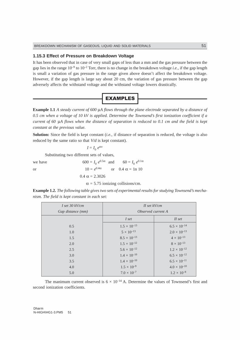
DharmN-HIGH\HG1-3.PM5 51
BREAKDOWN MECHANISM OF GASEOUS, LIQUID AND SOLID MATERIALS 51
1.15.3 Effect of Pressure on Breakdown VoltageIt has been observed that in case of very small gaps of less than a mm and the gas pressure between thegap lies in the range 10–9 to 10–2 Torr, there is no change in the breakdown voltage i.e., if the gap lengthis small a variation of gas pressure in the range given above doesn’t affect the breakdown voltage.However, if the gap length is large say about 20 cm, the variation of gas pressure between the gapadversely affects the withstand voltage and the withstand voltage lowers drastically.
��������
Example 1.1 A steady current of 600 µA flows through the plane electrode separated by a distance of
0.5 cm when a voltage of 10 kV is applied. Determine the Townsend’s first ionization coefficient if a
current of 60 µA flows when the distance of separation is reduced to 0.1 cm and the field is kept
constant at the previous value.
Solution: Since the field is kept constant (i.e., if distance of separation is reduced, the voltage is alsoreduced by the same ratio so that V/d is kept constant).
I = I0 eαx
Substituting two different sets of values,
we have 600 = I0 e0.5α and 60 = I0 e0.1α
or 10 = e0.4α or 0.4 α = 1n 10
0.4 α = 2.3026
α = 5.75 ionizing collisions/cm.
Example 1.2. The following table gives two sets of experimental results for studying Townsend’s mecha-
nism. The field is kept constant in each set:
I set 30 kV/cm II set kV/cm
Gap distance (mm) Observed current A
I set II set
0.5 1.5 × 10⁻¹³ 6.5 × 10⁻¹⁴
1.0 5 × 10–13 2.0 × 10⁻¹³
1.5 8.5 × 10⁻¹³ 4 × 10–13
2.0 1.5 × 10⁻¹² 8 × 10–13
2.5 5.6 × 10⁻¹² 1.2 × 10⁻¹²
3.0 1.4 × 10⁻¹⁰ 6.5 × 10⁻¹²
3.5 1.4 × 10⁻¹⁰ 6.5 × 10⁻¹¹
4.0 1.5 × 10⁻⁹ 4.0 × 10⁻¹⁰
5.0 7.0 × 10⁻⁷ 1.2 × 10⁻⁸
The manimum current observed is 6 × 10–14 A. Determine the values of Townsend’s first andsecond ionization coefficients.
DharmN-HIGH\HG1-3.PM5 52
52 HIGH VOLTAGE ENGINEERING
Solution: 1st Set. Since there is gradual increase in current upto gap distance of 3 mm, slope betweenany two points
1 0n I I
x
/FH
IK
will give us the value of α.
Let us take gap distances of 2 and 2.5 mm.
The respective 1n I/I0 are
1n 1 5 10
6 10
12
14
. ××
FHG
IKJ
−
− = 3.2188
and 1n 1 5 10
6 10
12
14
. ××
FHG
IKJ
−
− = 4.5362
∴ The slope = 4 5362 3 2188
0 0526 34
. .
..
− =
Since there is sudden rise in current at the last observation, this is used to evaluate γ .
We know that
or I = I e
e
x
x0
1 1
α
αγ− −( )
or I
I
e
e0
726 34 0 5
13 17
7
610
1 1= × =
− −
×. .
.( )γ
= 5 24 10
1 5 24 10
5
5
.
.
×− × γ
or7
610
1
5 24 10
1
1 5 24 107
5 5××
=− ×. . γ
or 0.0449 = 1 – 5.24 × 10⁵ γor 0.9551 = 5.24 × 10⁵ γor γ = 0.182 × 10⁻⁵ /cm.
Set-II. For the same gap distance the slope will be α = 1n (12/8)/0.05 = 8.1 collisions/cm andtherefore
I
I
e
e0
58 1 0 5
4 052 101 1
= × =− −
×. .
.( )γ
2 × 105 = 57 39
1 56 39
.
( . )− γ
or200 10
57 393 4849 10
1
1 56 39
33× = × =
−..
. γ
2.87 × 10–4 = 1 – 56.39 γ
DharmN-HIGH\HG1-3.PM5 53
BREAKDOWN MECHANISM OF GASEOUS, LIQUID AND SOLID MATERIALS 53
56.39γ = 1.0
or γ = 1.7 × 10⁻² collisions/cm
Example 1.3. The following observations were made in an experiment for determination of dielectricstrength of transformer oil. Determine the power law equation.
Gap spacing 4 6 8 10
Breakdown 88 135 165 212Voltage (kV)
Solution: Let us assume that the relation between gap spacing and breakdown voltage be given as
Vb = Kdn
Our objective is to find out values of K and n. Substituting values of two observations , we have
88 = K.4n
165 = K.8n
∴165
88
8
42= =
n
nn
1.875 = 2n
0.6286 = n × 0.693
or n = 0.9068
and K = 88
425 030 9068. .=
Similarly taking 2nd and 4th observation, we have
135 = K6n
212 = K10n
or212
1351 67= . n
1.57 = 1.67n
Taking 1n on both sides
0.4513 = 0.5128 nor n = 0.88
and K = 135
627 90 88. .=
Therefore, average value of n ≈ 0.89 and that of K ≈ 26.46 Ans.
Example 1.4. State and explain Paschen’s law. Derive expression for (pd)min and Vbmin. AssumeA = 12, B = 365 and γ = 0.02 for air. Determine (pd)min and Vbmin.
Solution: We know that
(pd)min = ek
Awhere K = ln (1 + 1/γ)
DharmN-HIGH\HG1-3.PM5 54
54 HIGH VOLTAGE ENGINEERING
Therefore, (pd)min = e
A ln (1 + 1/γ)
Substituting the values, we have
(pd)min = 2 718
121 1 1 0 02
.( / . )n + = 0.89 Ans.
Now Vbmin = B
Ae K =
365
122 718 1 51× . n = 325 Volts Ans.
������
1.1. Discuss various factors which affect breakdown of gases.
1.2. Define Townsend’s first and second ionisation coefficients. Explain the Townsends criterion for a spark.
1.3. State and explain Paschen’s law. How do you account for the minimum voltage for breakdown under agiven pd condition?
1.4. Explain the mechanism of development of anode and cathode streamers and explain how these lead tobreakdown.
1.5. What is time-lag? Discuss its components and the factors which affect these components.
1.6. Explain briefly various theories of breakdown in liquid dielectrics.
1.7. Explain clearly suspended particle mechanism of liquid breakdown.
1.8. State various process which lead to formation of bubbles in liquid dielectrics and explain clearly cavitybreakdown mechanism in liquid dielectrics.
1.9. What is electroconvection? Explain liquid breakdown based on electroconvection.
1.10. Discuss various criteria suggested by researchers for transition from avalanche to streamer.
1.11. Explain Penning Effect when referred to gaseous discharges.
1.12. What is corona discharge? Explain clearly Anode and Cathode coronas.
1.13. Describe briefly various mechanism of breakdown in solids.
1.14. What are ‘Treeing’ and ‘Tracking’? Explain clearly the two processes in solid dielectrics.
1.15. Derive an expression for maximum thermal voltage and show that the voltage is independent of thicknessof specimen. State clearly the assumptions made.
1.16. Derive an expression for critical electric field and show that the field is independent of the critical tem-perature of the dielectric. State the assumptions made.
1.17. What do you mean by ‘Intrinsic strength’ of a solid dielectric? Explain electric breakdown of soliddielectrics.
1.18. Explain Thermal breakdown in solid dielectrics. How this mechanism is more significant than the othermechanisms?
1.19. Explain the process of breakdown in electronegative gases.
1.20. Explain the application of oil in power apparatus and discuss clearly its function with reference to acircuit breaker.
1.21. Describe the main requirements of solid insulating materials used for power apparatus and describe thedielectric characteristics of the following material:
(i) vulcanized rubber (ii) PVC (iii) cross-link polyethylene (iv) insulating press board (v) mica (vi) ceram-ics (vii) glass (viii) epoxy resins.

DharmN-HIGH\HG1-3.PM5 55
BREAKDOWN MECHANISM OF GASEOUS, LIQUID AND SOLID MATERIALS 55
1.22. Describe the application of various insulating materials used in the following power apparatus:
(i) Power transformers (ii) Circuit breakers
(iii) Rotating machines (iv) Power cables
(v) Power capacitors (vi) Capacitor bushings
1.23. Explain clearly various processes which explain electric breakdown in vacuum.
1.24. What is ‘‘conditioning of elecrodes’’? How does it affect breakdown in vacuum?
1.25. Discuss the effect of ‘‘Area of electrode’’ and ‘‘Effect of pressure’’ on the breakdown of vacuum.
1.26. Discuss the application of gases in electric power apparatus.
������� ��
Alston, High Voltage Technology, Oxford University Press, 1968.
E.W. Mc Daniel, Collision Phenomenon in Ionised Gases, John Wiley, New York, 1964.
L.D. Loeb, The kinetic Theory of Gases, Johm Wiley, New York, 1963.
E. Kuffel and W.S. Zaengl, High Voltage Engineering-Fundamentals, Pergamon Press, 1984.
M.S. Naidu and V. Kamaraju, High Voltage Engineering, Tata McGraw-Hill 1982.
Ravindra Arora & W. Mosch, High Voltage Insulation Engineering, New Age International, 2005.
Related Documents


