www.grid4eu.eu 3 #1 Autonomous Switching System in the Demo1 Type of solution Equipment / Hardware / Firmware Manufacturer(s) implied (for equipment or hardware) ABB Workstream considered • DER integration • MV Innovation Location / Topology (with regards to distribution grid) • HV/MV Substation • MV/LV SS Thematic(s) • Grid Monitoring / state estimation • DER Integration / increased grid capacity • Automatic Failure Detection • Remote Grid Operations • Automatic Failure Management / Grid recovery • Automatic Grid topology reconfiguration Use Case(s) • Failure Management in MV networks • Decentralized grid operation in MV Networks Key figures MV grid with: • ~100 secondary substations • 7 switching modules • 11 measurement modules Table- 1 – Technical table of the Autonomous Switching System in the Demo1 Objective and technical requirements Context & Objective The high share and still massively increasing amount of distributed generation, predominantly wind and photovoltaic, set new challenges to the DSOs in Germany. In order to provide hosting capacity to integrate these resources huge investments in grid infrastructure are required. Moreover, grid operation and grid observation become more complex since power flows become less predictable. At present in Germany there are hardly any surveillance facilities or grid automation in place in medium voltage networks. Demo1 addressed these challenges with the demonstrator built up in the area of “Reken”, located in North Rhine-Westphalia. The considered grid was well selected since it showed already at the beginning of the project a balance between installed generation power and maximum demand. Further increase in renewables to be connected was forecasted. The grid focused on consists of around 100 secondary substations. The following objectives are targeted: • Integrating an increasing number of decentralized energy resources (DER) in the medium-voltage (MV) network and underlying low-voltage (LV) networks • Achieving higher reliability, shorter recovery times after grid failures • Avoiding unknown overloads and voltage violations • Fulfilling the needs of surveillance and remote-control in MV- networks • Reducing network losses The principle idea is to implement an autonomous switching system that is based on an autonomous interaction between these modules and a lean control centre in the primary substation. The modules are divided into two groups: Switching Modules and Measuring Modules. Switching Modules can execute the switchgear of their secondary substation whereas Measuring Modules provide measured values. The possibility of autonomous switching provides dynamic topology reconfiguration which is a new concept of operation. Requirements Technical standards & guidelines One essential technical requirement for the simulations of the grid calculations with the software tool NEPLAN is handled in the DIN EN 50160. The DIN EN 50160 defines the maximum level of the voltage restrictions in MV and LV networks. Table 1 shows the valid values for both voltage levels. Character Medium voltage Low voltage Slow voltage variation 95 % of the 10-min- average values: ±10 % supply voltage 95 % of the 10-min- average values: ±10 % supply voltage Table 1 - DIN EN 50160 For safety reasons the modules have to be equipped with a service- modus (deactivation of autonomous switching and remote-control) for work on the grid, e.g. maintenance. If service or maintenance works are in progress, earthed parts of the grid have to stay earthed. The modules are not allowed to switch in this case. Technical upgrade of secondary substations The secondary substations were enhanced in two ways: they were equipped with devices for remote-control and surveillance to connect them to the SCADA-system to enable the control engineers to survey and execute the switching facilities in the MV grid. Therefore new circuit breakers and communication modules were installed. Additionally, the primary substation and secondary substations were equipped with RTUs to add the “intelligence” to the local grid. This enables the autonomous switching system to survey and control the local part of the MV grid on its own. Development and implementation Architecture and technical characteristics The basic idea of the autonomous switching system is depicted in Figure 1.

Welcome message from author
This document is posted to help you gain knowledge. Please leave a comment to let me know what you think about it! Share it to your friends and learn new things together.
Transcript
www.grid
4eu.eu
32
#1 Autonomous Switching System in the Demo1
Type of solutionEquipment / Hardware / Firmware
Manufacturer(s) implied (for equipment or hardware)ABB
Workstream considered• DER integration• MV Innovation
Location / Topology (with regards to distribution grid)• HV/MV Substation• MV/LV SS
Thematic(s)
• Grid Monitoring / state estimation• DER Integration / increased grid capacity• Automatic Failure Detection• Remote Grid Operations• Automatic Failure Management / Grid recovery• Automatic Grid topology reconfiguration
Use Case(s)
• Failure Management in MV networks• Decentralized grid operation in MV Networks
Key figures
MV grid with:• ~100 secondary substations• 7 switching modules• 11 measurement modules
Table- 1 – Technical table of the AutonomousSwitching System in the Demo1
Objective and technical requirements
Context & ObjectiveThe high share and still massively increasing amount of distributed generation, predominantly wind and photovoltaic, set new challenges to the DSOs in Germany. In order to provide hosting capacity to integrate these resources huge investments in grid infrastructure are required. Moreover, grid operation and grid observation become more complex since power flows become less predictable. At present in Germany there are hardly any surveillance facilities or grid automation in place in medium voltage networks.
Demo1 addressed these challenges with the demonstrator built up in the area of “Reken”, located in North Rhine-Westphalia. The considered grid was well selected since it showed already at the beginning of the project a balance between installed generation power and maximum demand. Further increase in renewables to be connected was forecasted. The grid focused on consists of around 100 secondary substations.
The following objectives are targeted:
• Integrating an increasing number of decentralized energy resources (DER) in the medium-voltage (MV) network and underlying low-voltage (LV) networks
• Achieving higher reliability, shorter recovery times after grid failures
• Avoiding unknown overloads and voltage violations
• Fulfilling the needs of surveillance and remote-control in MV-networks
• Reducing network losses
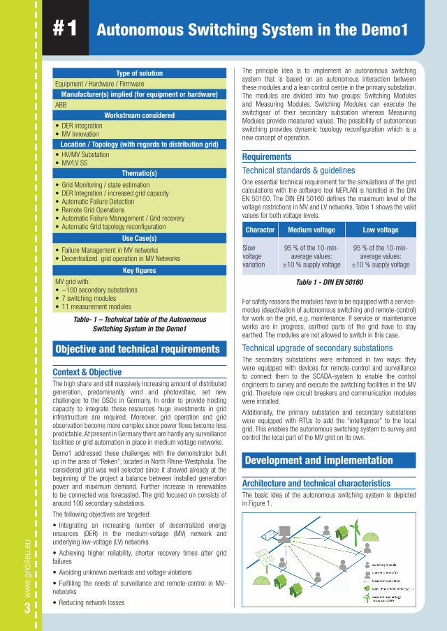
The principle idea is to implement an autonomous switching system that is based on an autonomous interaction between these modules and a lean control centre in the primary substation. The modules are divided into two groups: Switching Modules and Measuring Modules. Switching Modules can execute the switchgear of their secondary substation whereas Measuring Modules provide measured values. The possibility of autonomous switching provides dynamic topology reconfiguration which is a new concept of operation.
RequirementsTechnical standards & guidelinesOne essential technical requirement for the simulations of the grid calculations with the software tool NEPLAN is handled in the DIN EN 50160. The DIN EN 50160 defines the maximum level of the voltage restrictions in MV and LV networks. Table 1 shows the valid values for both voltage levels.
Character Medium voltage Low voltage
Slow voltage variation
95 % of the 10-min-average values:
±10 % supply voltage
95 % of the 10-min-average values:
±10 % supply voltage
Table 1 - DIN EN 50160
For safety reasons the modules have to be equipped with a service-modus (deactivation of autonomous switching and remote-control) for work on the grid, e.g. maintenance. If service or maintenance works are in progress, earthed parts of the grid have to stay earthed. The modules are not allowed to switch in this case.
Technical upgrade of secondary substationsThe secondary substations were enhanced in two ways: they were equipped with devices for remote-control and surveillance to connect them to the SCADA-system to enable the control engineers to survey and execute the switching facilities in the MV grid. Therefore new circuit breakers and communication modules were installed.
Additionally, the primary substation and secondary substations were equipped with RTUs to add the “intelligence” to the local grid. This enables the autonomous switching system to survey and control the local part of the MV grid on its own.
Development and implementation
Architecture and technical characteristicsThe basic idea of the autonomous switching system is depicted in Figure 1.
www.grid
4eu.eu
54
The measuring and switching modules observe the local grid and estimate its current state. If the load flow calculation results in one or more off-limit-conditions the module system analyses the topology and finds a switching state in which no boundary condition is violated. Following, the autonomous switching system develops a suitable switching program for the change of topology and the switching modules execute the switching actions accordingly. With this dynamic and autonomous way of changing the topology according to the current load and generation situation in the local grid it is possible to increase the hosting capacity for distributed energy resources (DER).
In case of an outage the autonomous switching system is able to detect and isolate the faulty part of the grid and to restore the faultless parts. Thus, the outage time for the customers in the faultless parts is decreased significantly. Moreover, the time that is needed by the operation teams for localising and fixing the grid failure declines.
Another feature of the autonomous switching system is the possibility to operate the MV grid in a loss-optimised way. The central RTU in the primary substation performs the state estimation for the surveyed part of the MV grid and forecasts the load flow situation for the next 24 hours. With this information it is possible to develop a loss optimised topology for every load and generation situation within the scope of the forecast. Following this analysis the autonomous switching system sets up a switching protocol to change the grid topology according to the forecasted states. This task is performed regularly and the switching protocols are updated likewise.
Decentralised grid operation in MV NetworksThe autonomous switching system is connected to the SCADA-system of the DSO and sends all important information to the control centre. The SCADA-engineers can control and execute the switching modules.
However, the important and innovative part of the system is that the local MV grid can survey, control and operate itself within fixed boundary conditions. In this case, the intelligence moved away from the control centre into the decentral parts of the distribution system.
Technical resultsAs a first step, the software of the autonomous switching system was tested in different simulations according to the main objectives. The delivered results of the simulation show the high potential for decentralised grid operation.
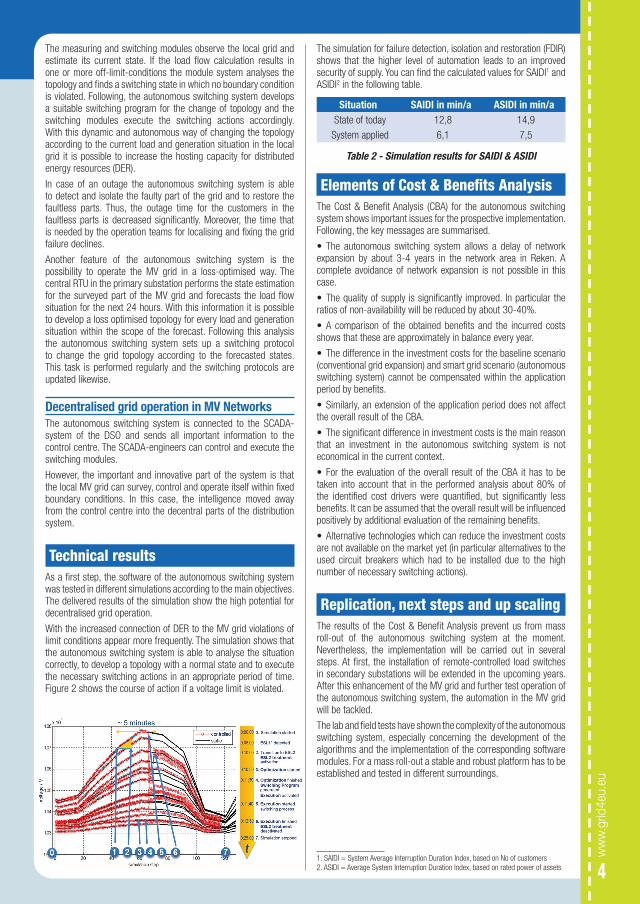
With the increased connection of DER to the MV grid violations of limit conditions appear more frequently. The simulation shows that the autonomous switching system is able to analyse the situation correctly, to develop a topology with a normal state and to execute the necessary switching actions in an appropriate period of time. Figure 2 shows the course of action if a voltage limit is violated.
The simulation for failure detection, isolation and restoration (FDIR) shows that the higher level of automation leads to an improved security of supply. You can find the calculated values for SAIDI1 and ASIDI2 in the following table.
Situation SAIDI in min/a ASIDI in min/aState of today 12,8 14,9
System applied 6,1 7,5
Table 2 - Simulation results for SAIDI & ASIDI
Elements of Cost & Benefits AnalysisThe Cost & Benefit Analysis (CBA) for the autonomous switching system shows important issues for the prospective implementation. Following, the key messages are summarised.
• The autonomous switching system allows a delay of network expansion by about 3-4 years in the network area in Reken. A complete avoidance of network expansion is not possible in this case.
• The quality of supply is significantly improved. In particular the ratios of non-availability will be reduced by about 30-40%.
• A comparison of the obtained benefits and the incurred costs shows that these are approximately in balance every year.
• The difference in the investment costs for the baseline scenario (conventional grid expansion) and smart grid scenario (autonomous switching system) cannot be compensated within the application period by benefits.
• Similarly, an extension of the application period does not affect the overall result of the CBA.
• The significant difference in investment costs is the main reason that an investment in the autonomous switching system is not economical in the current context.
• For the evaluation of the overall result of the CBA it has to be taken into account that in the performed analysis about 80% of the identified cost drivers were quantified, but significantly less benefits. It can be assumed that the overall result will be influenced positively by additional evaluation of the remaining benefits.
• Alternative technologies which can reduce the investment costs are not available on the market yet (in particular alternatives to the used circuit breakers which had to be installed due to the high number of necessary switching actions).
Replication, next steps and up scaling The results of the Cost & Benefit Analysis prevent us from mass roll-out of the autonomous switching system at the moment. Nevertheless, the implementation will be carried out in several steps. At first, the installation of remote-controlled load switches in secondary substations will be extended in the upcoming years. After this enhancement of the MV grid and further test operation of the autonomous switching system, the automation in the MV grid will be tackled.
The lab and field tests have shown the complexity of the autonomous switching system, especially concerning the development of the algorithms and the implementation of the corresponding software modules. For a mass roll-out a stable and robust platform has to be established and tested in different surroundings.
1. SAIDI = System Average Interruption Duration Index, based on No of customers2. ASIDI = Average System Interruption Duration Index, based on rated power of assets
Related Documents