1 Arrester Arrester Application Application bringing it all bringing it all together together ! ! Selection (see EM Selection (see EM Section 14 SI 1.00 Section 14 SI 1.00 and and IEEE C62.11-1999 IEEE C62.11-1999 1. 1. Overvoltage Overvoltage 2. 2. Energy Energy 3. 3. Margins Margins 4. 4. Coordinating across Coordinating across the transformer the transformer

1 Arrester Application bringing it all together! Selection (see EM Selection (see EM Section 14 SI 1.00 and Section 14 SI 1.00 and IEEE C62.11-1999 IEEE.
Dec 15, 2015
Welcome message from author
This document is posted to help you gain knowledge. Please leave a comment to let me know what you think about it! Share it to your friends and learn new things together.
Transcript

1
Arrester Application Arrester Application bringing it all togetherbringing it all together!!
Selection (see EM Selection (see EM
Section 14 SI 1.00 andSection 14 SI 1.00 and
IEEE C62.11-1999IEEE C62.11-1999
1.1. OvervoltageOvervoltage
2.2. EnergyEnergy
3.3. MarginsMargins4.4. Coordinating across the Coordinating across the
transformertransformer

2
Arrester Selection – Step 1Arrester Selection – Step 1
a.a. Select an MCOV rating that is just greater than Select an MCOV rating that is just greater than the maximum continuous operating voltage of the maximum continuous operating voltage of the systemthe system
b.b. Check the system maximum temporary 60hz Check the system maximum temporary 60hz over-voltage (magnitude and duration) with the over-voltage (magnitude and duration) with the arrester temporary over-voltage capability from arrester temporary over-voltage capability from the manufacturer’s curvethe manufacturer’s curve
c.c. Choose the higher rating from a or b aboveChoose the higher rating from a or b above
3
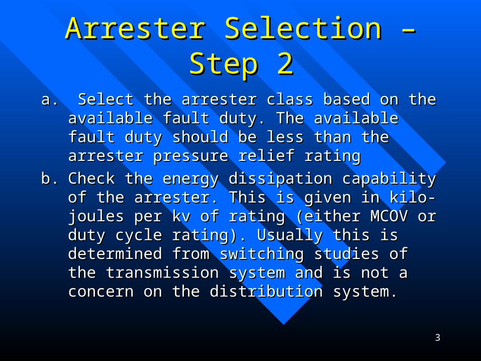
Arrester Selection – Step 2Arrester Selection – Step 2
a.a. Select the arrester class based on the available Select the arrester class based on the available fault duty. The available fault duty should be fault duty. The available fault duty should be less than the arrester pressure relief ratingless than the arrester pressure relief rating
b.b. Check the energy dissipation capability of the Check the energy dissipation capability of the arrester. This is given in kilo-joules per kv of arrester. This is given in kilo-joules per kv of rating (either MCOV or duty cycle rating). rating (either MCOV or duty cycle rating). Usually this is determined from switching Usually this is determined from switching studies of the transmission system and is not a studies of the transmission system and is not a concern on the distribution system.concern on the distribution system.

4
Arrester Selection – Step 3Arrester Selection – Step 3
a.a. Calculate the protective margins and Calculate the protective margins and check they are adequate:check they are adequate:
a.a. PMPM11> > 20% 20% Front-of-WaveFront-of-Wave
b.b. PMPM22> 15> 15%% Lightning Lightning
c.c. PMPM33> 15> 15%% SwitchingSwitching
5
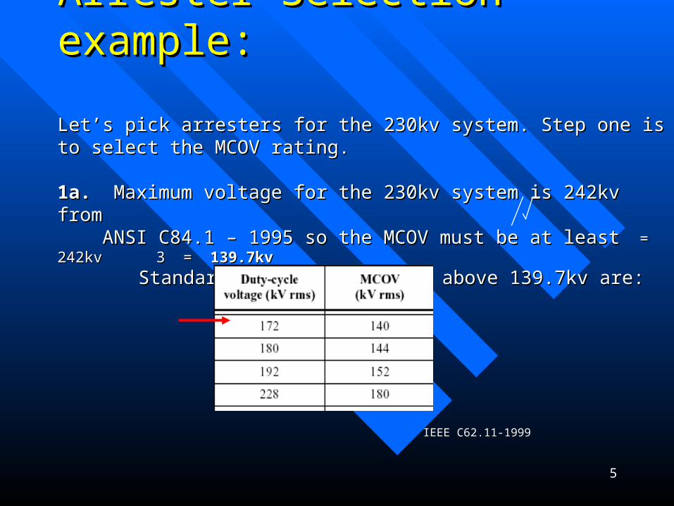
Arrester Selection – example:Arrester Selection – example:
Let’s pick arresters for the 230kv system. Step one is to select the MCOV rating.Let’s pick arresters for the 230kv system. Step one is to select the MCOV rating.
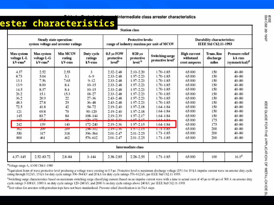
1a.1a. Maximum voltage for the 230kv system is 242kv from Maximum voltage for the 230kv system is 242kv from ANSI ANSI C84.1 – 1995 so the MCOV must be at least C84.1 – 1995 so the MCOV must be at least = 242kv 3 = = 242kv 3 = 139.7kv139.7kv
Standard ratings available above 139.7kv are:Standard ratings available above 139.7kv are:
IEEE C62.11-1999

6
Arrester Selection – example cont:Arrester Selection – example cont:
1b. 1b. The next step is to check the maximum possible system 60hz over-voltage The next step is to check the maximum possible system 60hz over-voltage
– First let’s check First let’s check the maximum voltage rise on the un-faulted phase for the maximum voltage rise on the un-faulted phase for
a phase to ground fault. System analysis shows a worst case maximum a phase to ground fault. System analysis shows a worst case maximum voltage rise of voltage rise of 197kv197kv for a phase to ground fault on the system for a phase to ground fault on the system (COG of (COG of 81.4%). Assume a clearing time of 5 cycles.81.4%). Assume a clearing time of 5 cycles.– Next check for the possibility of back-feed during clearing of a 230kv fault.Next check for the possibility of back-feed during clearing of a 230kv fault.
Consider a 230-34.5kv delta-wye transformer. A high side fault is also back-fedConsider a 230-34.5kv delta-wye transformer. A high side fault is also back-fed
from the 34.5kv system: from the 34.5kv system:

7
Neutral shift And Back-feed:
Phase to ground fault
230-34.5kv
Neutral shifts duringclearing of a phase to
ground fault
The 230kv line fault is back-fed from the 34.5kvsystem until the reversepower relaying clears (up to 1 sec).
The 230kv breakers clearin 3-5 cycles
The xfmr high side arresters must withstand the increasedphase to ground voltage on the unfaulted phases until thefault clears
Arrester voltage
140kv
197kv
242k
v
8
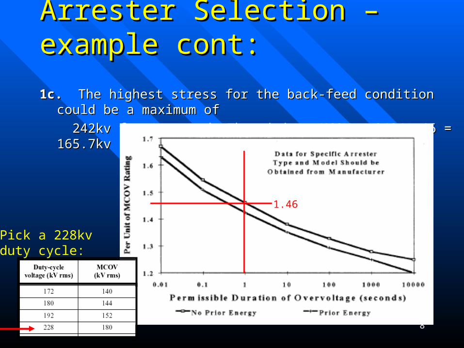
Arrester Selection – example cont:Arrester Selection – example cont:
1c. 1c. The highest stress for the back-feed condition could be a maximum of The highest stress for the back-feed condition could be a maximum of
242kv for 1 second. The minimum MCOV = 242/1.46 = 165.7kv 242kv for 1 second. The minimum MCOV = 242/1.46 = 165.7kv
1.46
Pick a 228kvduty cycle:

9
Arrester Selection – example cont:Arrester Selection – example cont:
2a. 2a. Next select the arrester class: Next select the arrester class:
The worst case phase to ground fault duty on the 230kv system is at The worst case phase to ground fault duty on the 230kv system is at
Doubs and is around 50ka. Doubs and is around 50ka.
Need to select a station class arrester since the fault duty is > 16ka.Need to select a station class arrester since the fault duty is > 16ka.
2b. Check transmission line discharge duty. Transmission studies show the 2b. Check transmission line discharge duty. Transmission studies show the maximum switching duty on the 230kv system is within the 7KJ/kv rating for maximum switching duty on the 230kv system is within the 7KJ/kv rating for standard station class metal oxide arresters.standard station class metal oxide arresters.

10
Arrester Selection – example Arrester Selection – example cont: cont:
3a.3a. Calculate the protective margins and check they are adequate:Calculate the protective margins and check they are adequate:
a.a. PMPM11> > 20% 20% Front-of-WaveFront-of-Wave
b.b. PMPM22> 20> 20%% Lightning Lightning
c.c. PMPM33> 15> 15%% SwitchingSwitching
Normally margins are calculated for the transformers since theyNormally margins are calculated for the transformers since they
usually have reduced insulation (less than full BIL)usually have reduced insulation (less than full BIL)
11
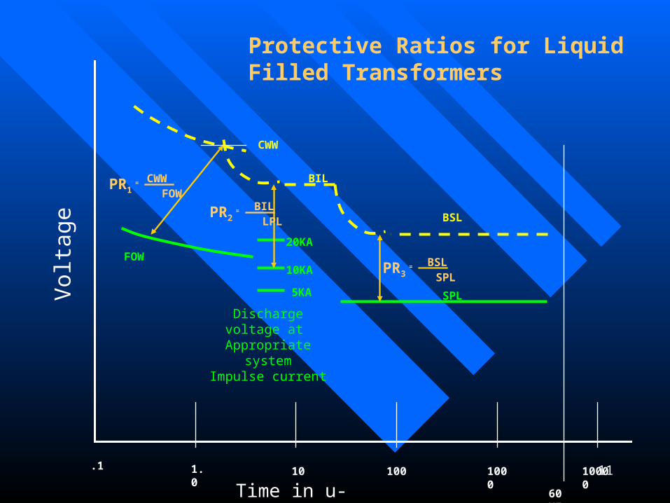
Protective Ratios for LiquidFilled Transformers
Time in u-seconds
BSL
100001000101.0.1
60 HZ
100
BIL
CWW
SPL
FOW
5KA
20KA
10KA
Vol
tage
Discharge voltage at Appropriate system
Impulse current
= CWW FOW
PR1
= BIL LPL
PR2
= BSL SPL
PR3
12
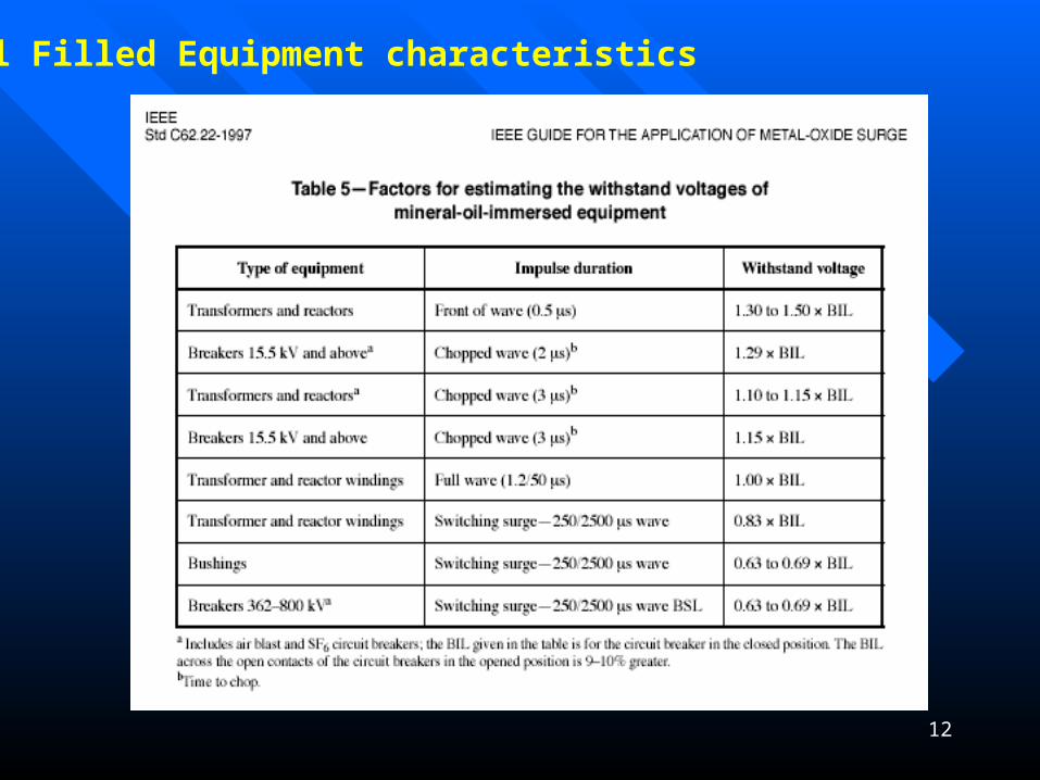
Oil Filled Equipment characteristics
13
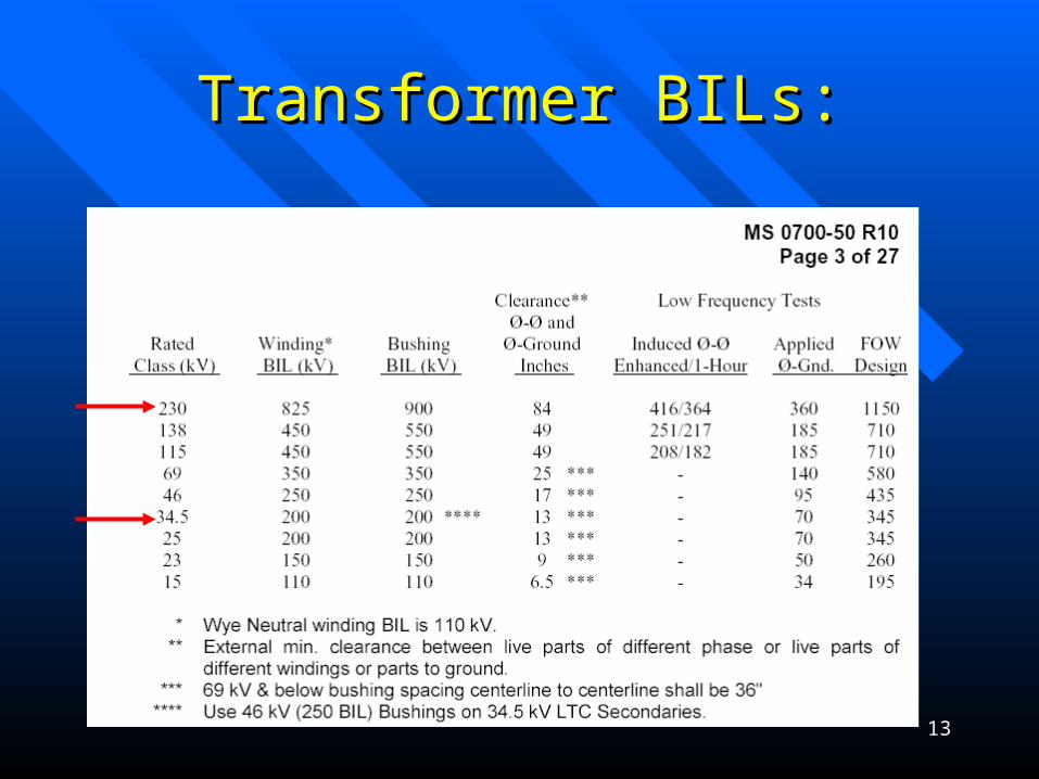
Transformer BILs:Transformer BILs:
14
Arrester characteristics
15
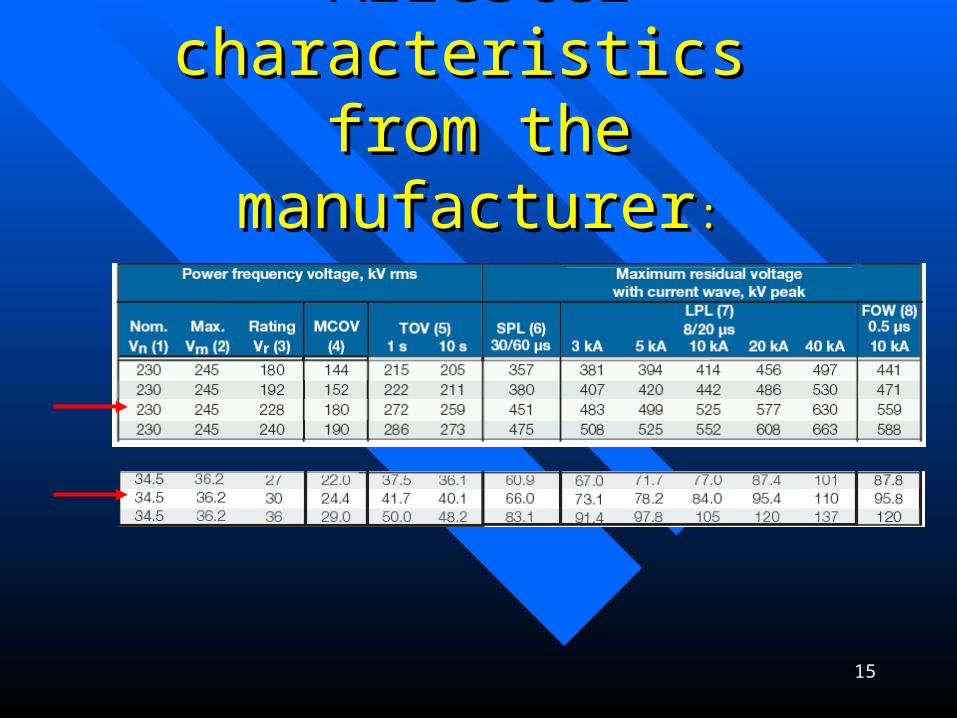
Arrester characteristics Arrester characteristics from the manufacturerfrom the manufacturer::

16
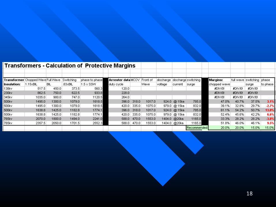
Protective MarginsProtective Margins
Example: 230-34.5kv transformer high side:
PRPR11 = CWW/FOW=(825x1.1)/(559) = 1.62 = CWW/FOW=(825x1.1)/(559) = 1.62
PMPM11= (PR= (PR11-1) x 100%=(1.62-1)x100%= -1) x 100%=(1.62-1)x100%= 62%62%
PRPR22= BIL/LPL= 825/(525) =1.57= BIL/LPL= 825/(525) =1.57
PMPM22= (PR= (PR22-1) x 100% =(1.57-1)x100%= -1) x 100% =(1.57-1)x100%=
57%57%
PRPR33 = BSL/SPL=(825x.83)/(451)= 1.52 = BSL/SPL=(825x.83)/(451)= 1.52
PMPM33= (PR= (PR33-1) x 100%=(1.52-1)= -1) x 100%=(1.52-1)= 52%52%
PRPR11 = CWW/FOW = CWW/FOW
PRPR22 = BIL/LPL = BIL/LPL
PRPR33 = BSL/SPL = BSL/SPL
PMPM11= (PR= (PR11-1) x 100% > -1) x 100% > 20%20%
PMPM22= (PR= (PR22-1) x 100% > -1) x 100% > 20%20%
PMPM33= (PR= (PR33-1) x 100% > -1) x 100% > 15%15%

17
Protective MarginsProtective Margins
Example: 230-34.5kv transformer low side:
PRPR11 = CWW/FOW=(200x1.1)/(95.8) = 2.30 = CWW/FOW=(200x1.1)/(95.8) = 2.30
PMPM11= (PR= (PR11-1) x 100%=(2.30-1)x100%= -1) x 100%=(2.30-1)x100%= 130%130%
PRPR22= BIL/LPL= 200/(84) =2.38= BIL/LPL= 200/(84) =2.38
PMPM22= (PR= (PR22-1) x 100% =(2.38-1)x100%= -1) x 100% =(2.38-1)x100%= 238%238%
PRPR33 = BSL/SPL=(200x.83)/(66)= 2.52 = BSL/SPL=(200x.83)/(66)= 2.52
PMPM33= (PR= (PR33-1) x 100%=(2.52-1)= -1) x 100%=(2.52-1)= 252%252%
Why are the low side margins so high?
18
19
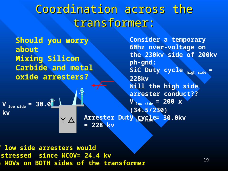
Coordination across the transformer:Coordination across the transformer:
Should you worry about Mixing Silicon Carbide and metal oxide arresters?
Arrester Duty cycle = 228 kv
MOV low side arresters would be stressed since MCOV= 24.4 kvUse MOVs on BOTH sides of the transformer
V low side = 30.0 kv
Consider a temporary 60hz over-voltage on the 230kv side of 200kv ph-gnd:SiC Duty cycle high side = 228kvWill the high side arrester conduct??V low side = 200 x (34.5/230)V low side = 30.0kv

20
21
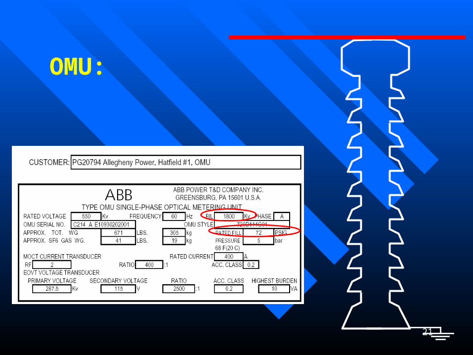
OMU:

22

23
The OMUThe OMU(optical metering unit)(optical metering unit)
What is the BIL? BSL? 60 hertz withstand?What is the BIL? BSL? 60 hertz withstand? How do you know? What impulse testing has been done? How do you know? What impulse testing has been done?
Is there a design test report?Is there a design test report? Should it be protected by an arrester? Is the insulation self-Should it be protected by an arrester? Is the insulation self-
restoring? Will it flashover on the outside or the inside? restoring? Will it flashover on the outside or the inside? What happens when it loses SF6? What is the withstand at What happens when it loses SF6? What is the withstand at
reduced gas pressure? Can we add gas if its energized?reduced gas pressure? Can we add gas if its energized? Should we trip it for low gas? What is the minimum Should we trip it for low gas? What is the minimum
pressure that is acceptable?pressure that is acceptable? When its switched out could the switching surge cause a When its switched out could the switching surge cause a
flashover? (could the porcelain explode?)flashover? (could the porcelain explode?)
24
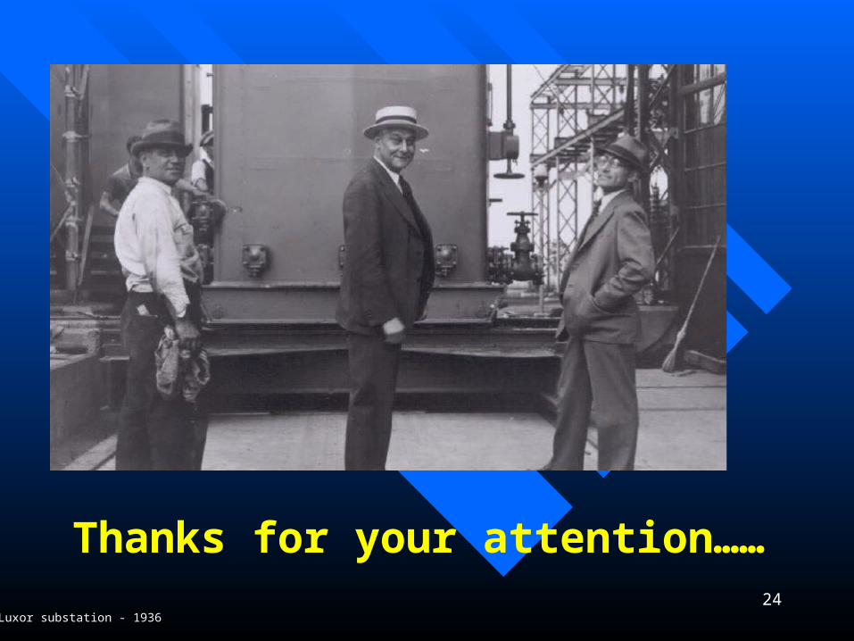
Thanks for your attention…… Your substation support staff!Luxor substation - 1936
Related Documents


