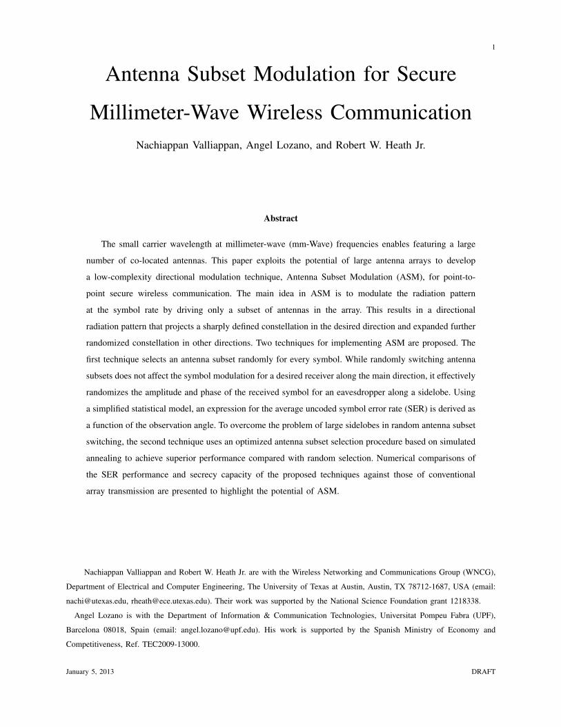
1 Antenna Subset Modulation for Secure Millimeter-Wave Wireless Communication Nachiappan Valliappan, Angel Lozano, and Robert W. Heath Jr. Abstract The small carrier wavelength at millimeter-wave (mm-Wave) frequencies enables featuring a large number of co-located antennas. This paper exploits the potential of large antenna arrays to develop a low-complexity directional modulation technique, Antenna Subset Modulation (ASM), for point-to- point secure wireless communication. The main idea in ASM is to modulate the radiation pattern at the symbol rate by driving only a subset of antennas in the array. This results in a directional radiation pattern that projects a sharply defined constellation in the desired direction and expanded further randomized constellation in other directions. Two techniques for implementing ASM are proposed. The first technique selects an antenna subset randomly for every symbol. While randomly switching antenna subsets does not affect the symbol modulation for a desired receiver along the main direction, it effectively randomizes the amplitude and phase of the received symbol for an eavesdropper along a sidelobe. Using a simplified statistical model, an expression for the average uncoded symbol error rate (SER) is derived as a function of the observation angle. To overcome the problem of large sidelobes in random antenna subset switching, the second technique uses an optimized antenna subset selection procedure based on simulated annealing to achieve superior performance compared with random selection. Numerical comparisons of the SER performance and secrecy capacity of the proposed techniques against those of conventional array transmission are presented to highlight the potential of ASM. Nachiappan Valliappan and Robert W. Heath Jr. are with the Wireless Networking and Communications Group (WNCG), Department of Electrical and Computer Engineering, The University of Texas at Austin, Austin, TX 78712-1687, USA (email: [email protected], [email protected]). Their work was supported by the National Science Foundation grant 1218338. Angel Lozano is with the Department of Information & Communication Technologies, Universitat Pompeu Fabra (UPF), Barcelona 08018, Spain (email: [email protected]). His work is supported by the Spanish Ministry of Economy and Competitiveness, Ref. TEC2009-13000. January 5, 2013 DRAFT

Welcome message from author
This document is posted to help you gain knowledge. Please leave a comment to let me know what you think about it! Share it to your friends and learn new things together.
Transcript
1
Antenna Subset Modulation for Secure
Millimeter-Wave Wireless CommunicationNachiappan Valliappan, Angel Lozano, and Robert W. Heath Jr.
Abstract
The small carrier wavelength at millimeter-wave (mm-Wave) frequencies enables featuring a large
number of co-located antennas. This paper exploits the potential of large antenna arrays to develop
a low-complexity directional modulation technique, Antenna Subset Modulation (ASM), for point-to-
point secure wireless communication. The main idea in ASM is to modulate the radiation pattern
at the symbol rate by driving only a subset of antennas in the array. This results in a directional
radiation pattern that projects a sharply defined constellation in the desired direction and expanded further
randomized constellation in other directions. Two techniques for implementing ASM are proposed. The
first technique selects an antenna subset randomly for every symbol. While randomly switching antenna
subsets does not affect the symbol modulation for a desired receiver along the main direction, it effectively
randomizes the amplitude and phase of the received symbol for an eavesdropper along a sidelobe. Using
a simplified statistical model, an expression for the average uncoded symbol error rate (SER) is derived as
a function of the observation angle. To overcome the problem of large sidelobes in random antenna subset
switching, the second technique uses an optimized antenna subset selection procedure based on simulated
annealing to achieve superior performance compared with random selection. Numerical comparisons of
the SER performance and secrecy capacity of the proposed techniques against those of conventional
array transmission are presented to highlight the potential of ASM.
Nachiappan Valliappan and Robert W. Heath Jr. are with the Wireless Networking and Communications Group (WNCG),
Department of Electrical and Computer Engineering, The University of Texas at Austin, Austin, TX 78712-1687, USA (email:
[email protected], [email protected]). Their work was supported by the National Science Foundation grant 1218338.
Angel Lozano is with the Department of Information & Communication Technologies, Universitat Pompeu Fabra (UPF),
Barcelona 08018, Spain (email: [email protected]). His work is supported by the Spanish Ministry of Economy and
Competitiveness, Ref. TEC2009-13000.
January 5, 2013 DRAFT
2
I. INTRODUCTION
Large-dimensional antenna arrays can play an important role in millimeter-wave (mm-Wave) communi-
cation. The mm-Wave band between 30 and 300 GHz offers an abundance of bandwidth for applications
such as wireless backhaul, personal area networking, local area networking, and mm-Wave cellular
communication [1]–[6]. Because of the large bandwidth and ensuing high noise levels, most mm-Wave
systems use directional transmission in order to provide array gain to enhance the signal-to-noise ratio
(SNR). The protocols of [1]–[5] are designed entirely around the support of directional transmission and
reception including features such as directional device discovery, hierarchical beam selection, and beam
tracking. Adaptive arrays are a flexible approach to implement directional transmission. At mm-Wave
frequencies, these arrays can contain in excess of 64 antennas and may be co-located with active
circuit components on a single silicon die [7], [8] due to the small wavelengths. The implementation of
beamforming in mm-Wave systems is different than in microwave systems because it is mostly analog
in nature so as to reduce the power consumption of the baseband circuitry [9], [10].
Security is an important requirement for commercial wireless systems, and mm-Wave communication
is no exception. While 60-GHz links experience high atmospheric absorption [11], other mm-Wave bands
may be more vulnerable to interception. It may be possible, for a sufficiently sensitive eavesdropper, to
recover information from the signal power that escapes through sidelobes. Consequently, it is of interest
to develop beamforming techniques that provide an extra layer of security by exploiting flexibility at the
physical (PHY) layer.
Directional modulation (DM) is one approach for achieving enhanced security. Several related ap-
proaches have been proposed that leverage multiple transmit antennas including near-field antenna-level
modulation, switched antenna phased array transmitters and spatial keying (SK) transmission techniques
such as spatial modulation (SM) and space shift keying (SSK). Previous work in [12], [13] introduced an
analog transmit architecture for synthesizing directional information based on near-field direct antenna
modulation. In this approach, there is no digital baseband and data modulation takes place at the antenna
level. Specifically, an unmodulated carrier drives a single antenna (or a phased array) with multiple
reflectors and switches. By varying the antenna near-field electromagnetic boundary conditions using
switches, the phase and amplitude of the far-field antenna pattern is modulated. While carefully chosen
switching configurations produce the desired modulation symbols along an intended direction, the nature
of the resulting antenna pattern causes the constellation to appear scrambled in undesired directions.
Other prior work on DM techniques [14]–[22] has primarily dealt with sub-GHz communication via small
January 5, 2013 DRAFT

3
antenna arrays. Recent work in [14]–[16] demonstrates a DM technique for phased-array transmitters. By
modifying the weights at each antenna, a symbol with desired phase and amplitude can be created along
a particular direction while purposely distorting the constellation in other directions. A closely related
DM technique using pattern-reconfigurable antennas is presented in [17]. In [18], hopping among the
antennas in an array is shown to produce a directional frequency/phase modulated signal. DM for spread
spectrum communication is introduced in [19] and [20], where the DM signal is modulated at both the
baseband and the antenna levels. While [19] proposes a dual-beam technique to create a modulated signal
using two different radiation patterns, [20] relies on switching antennas based on a chipping sequence.
Apart from DM techniques designed to achieve communication secrecy, there have also been studies on
the effect of multiple antennas and fading on the secrecy capacity. In [21], [22], the secrecy capacity of
a SM technique, where one of several transmit antennas is active per channel use to convey information,
is analyzed. By exploiting the randomness in space, due to antenna location, and the randomness of the
wireless channel, due to fading, SK-based transmission techniques are seen to offer improved outage
secrecy capacity.
In this paper, we propose a low-complexity DM technique called Antenna Subset Modulation (ASM).
We introduce ASM as an antenna-level modulation technique that eliminates conventional baseband
circuitry and takes advantage of the full antenna array with a limited number of radio frequency (RF)
chains. By providing a simple inter-antenna phase shift and driving a different subset of antennas at
each symbol interval, we show that it is possible to create a direction-dependent modulated signal. This
allows the transmitter to introduce additional randomness in the constellations viewed at angles other
than the target direction. It is worth noting that the proposed ASM technique is motivated by the large
number of antennas available in mm-Wave communication and the requirements for lower complexity
mixed-signal hardware, but the theory and methods hold for in general for large antenna arrays and thus
are conceptually applicable to any frequency band.
We propose two antenna subset selection techniques to implement ASM in uniform linear arrays. In
the first technique, the antenna subsets used for transmission are selected at random from the set of all
subsets with same number of active antennas. We capture this subset selection procedure using a simplified
statistical model and show that the received symbol distribution in undesired directions can be closely
approximated by a Gaussian distribution. Equipped with the statistics of the received symbol distribution,
we then proceed to evaluate the average uncoded symbol error rate (SER) achieved by ASM with K-ary
PSK modulation. In the second technique, we propose an optimized antenna subset selection procedure
based on simulated annealing to overcome the large sidelobe levels that may result from random antenna
January 5, 2013 DRAFT
4
selection. In this improved technique, antenna subsets are selected from a carefully constructed codebook
exhibiting satisfactory sidelobe properties. Random subset selection has the advantages of being easier
to analyze and implement, while the optimized subset selection offers better performance but requires
either on-line optimization or off-line computation and storage of optimum antenna subsets.
Compared to DM techniques [12]–[15], [17], [19] that scramble the constellation in undesired trans-
mission directions, ASM artificially introduces randomness in the received constellation through antenna
subset selection to combine the benefits of security and directional transmission. One benefit of ASM is
that it allows for a large number of antennas to be co-located, despite the increase in the design space.
Exploring such larger design space to find the parameters (switch combinations in [12], [13], phase
shifts in [14] or antenna weights in [15]) that produce a desired constellation along an intended direction
while still enforcing a high error rate in other directions can be unwieldy. For instance, the number of
switch configurations to be explored for producing a desired symbol along a particular direction increases
exponentially with the array size in [12]. Another benefit of ASM is that it enables the transmitter to steer
the main beam towards a desired direction while still offering DM. Prior work in [14], [15], [18], [20]
does not account for beam-steering since these references consider communication at lower frequencies
where spatial diversity from widely spaced antennas is more important than array gain. The DM technique
in [12] can steer the beam to an arbitrary direction in a phased-array configuration, but the constellation
synthesis involves searching a very large design space. In turn, [17] features only restricted beam-steering
capabilities and requires a separate design procedure for every possible orientation.
Relative to SK-based transmission techniques such as SM and SSK, ASM is designed to facilitate
directional transmission using compact arrays. First, in SK-based transmission techniques, a block of bits
is mapped to spatial positions of the transmit antennas in the array [23]–[28]. Information is encoded in
the choice of transmit antennas in SM and SSK, whereas symbol modulation takes place at the phase
shifters in ASM and the particular choice of antennas does not convey information. Second, in SK, the
wireless channel acts as a modulation unit and hence rich-scattering environment may be needed to create
distinct (albeit random) spatial signatures for the different transmit antennas; the receiver then detects
the set of active transmit antennas from the modulated signal to decode the transmitted information
symbol. In ASM, however, the digital modulation symbols received in the desired direction are not
randomized. Moreover, the receiver performs conventional digital demodulation and is unaware of the
transmit antenna subset used for the symbol transmission. Finally, unlike SM technique where multiple
transmit antennas are used to provide multiplexing gain at low system complexity, ASM uses multiple
antennas for directional beamforming—most necessary at mm-Wave frequencies to overcome the huge
January 5, 2013 DRAFT
5
path loss, the atmospheric absorption, and the high noise levels. Essentially, SK techniques and ASM
techniques are designed under different channel and array assumptions and each has its application in its
preferred operating regime.
Organization: The remainder of this paper is organized as follows. In Section II, we introduce the
channel model and explain the concept of ASM. Subsequently, in Section III, we discuss the constellation
synthesis procedure for ASM. In Sections IV and V, we propose the two antenna subset selection
techniques for implementing ASM. In Section VI, we provide simulation results comparing the security
and array performance of ASM against conventional transmission. Finally in Section VII, we draw some
conclusions and point to topics of future work.
Notation: ai is the ith entry of the vector a, [A]i,j is the entry of the matrix A in the ith row and
jth column, a b indicates Hadamard (entrywise) product of two vectors a and b, N (µ,P) denotes a
real Gaussian random vector with mean µ and covariance P, CN (µ,P) denotes a complex Gaussian
distribution with mean µ and covariance P, Bern(p) denotes a Bernoulli random variable with parameter
p, and U(.) denotes a discrete uniform distribution. We use P[·] to denote probability, E[·] to denote
expectation, var[·] to denote variance, ⊥⊥ to denote statistical independence between random variables,
<[·] and =[·] to denote real and imaginary parts, and(NM
)to denote the binomial coefficient.
II. PRINCIPLES OF ANTENNA SUBSET MODULATION
A. Channel Model
Consider a multiple-input single-output (MISO) communication system with N transmit and a single
receive antenna; although the ideas developed in this paper can be extended to multiple receive antennas,
we consider a single receive antenna for the sake of the exposition. The transmitter is equipped with
M ≤ N RF chains. We consider uniform linear arrays with isotropic antennas; the same approach can be
applied to multidimensional periodic arrays, i.e., 2D/3D arrays on regular grids. We posit an N -element
linear array with antennas uniformly spaced by d along the x-axis and with the array centered at the origin.
Since the linear array positioned on the x-y plane cannot resolve elevation (φ), the receiver’s angular
location is solely specified by the azimuth angle θ. The transmitter knows the angular location of the target
receiver, but not of the eavesdroppers. Assuming a narrowband channel with perfect synchronization and
symbol-rate sampling, the received signal along any direction θ at discrete-time k can be written as
y(k, θ) = h∗(θ)x(k) + v(k) (1)
January 5, 2013 DRAFT
6
where h is the N × 1 channel vector, x is the transmit signal vector and v ∼ CN (0, N0/2). Invoking a
narrowband channel model is justified at mm-Wave because the line-of-sight (LoS) component usually
dominates over the multipath due to relatively high reflection and scattering losses from indoor building
materials [29]; incorporating a more complex channel model is a topic of future work. The channel vector
(and, hence, the received symbol) is a function of the receiver’s angular location.
We specify d ≤ λ/2, where λ is the wavelength, to avoid creating grating lobes. The channel for a
receiver located along the θ direction can then be written as [30]
h(θ) =[e−j(
N−1
2 ) 2πd
λcos θ, e−j(
N−1
2−1) 2πd
λcos θ, . . . , ej(
N−1
2 ) 2πd
λcos θ]∗
(2)
where the phase-shifts introduced by path-length differences are referred to the center of the array.
We consider the use of directional beamforming to provide array gain. There is no attempt to place
nulls in the locations of potential eavesdroppers because their positions are unknown. With beamforming,
the transmitted vector symbol at time k is x(k) = w(k)x(k) where w is the beamforming vector and x
is a scalar transmit symbol. For the LoS channel considered, the beamforming solution that maximizes
the received SNR is the spatial matched filter. Under our LoS and uniform linear array assumptions, the
channel coefficients have equal magnitude and consequently only co-phasing is required. Such uniform
amplitudes maximize the directivity of the array among all amplitude excitation patterns [30] and enable
a simple feed network.
B. Conventional Array Transmission
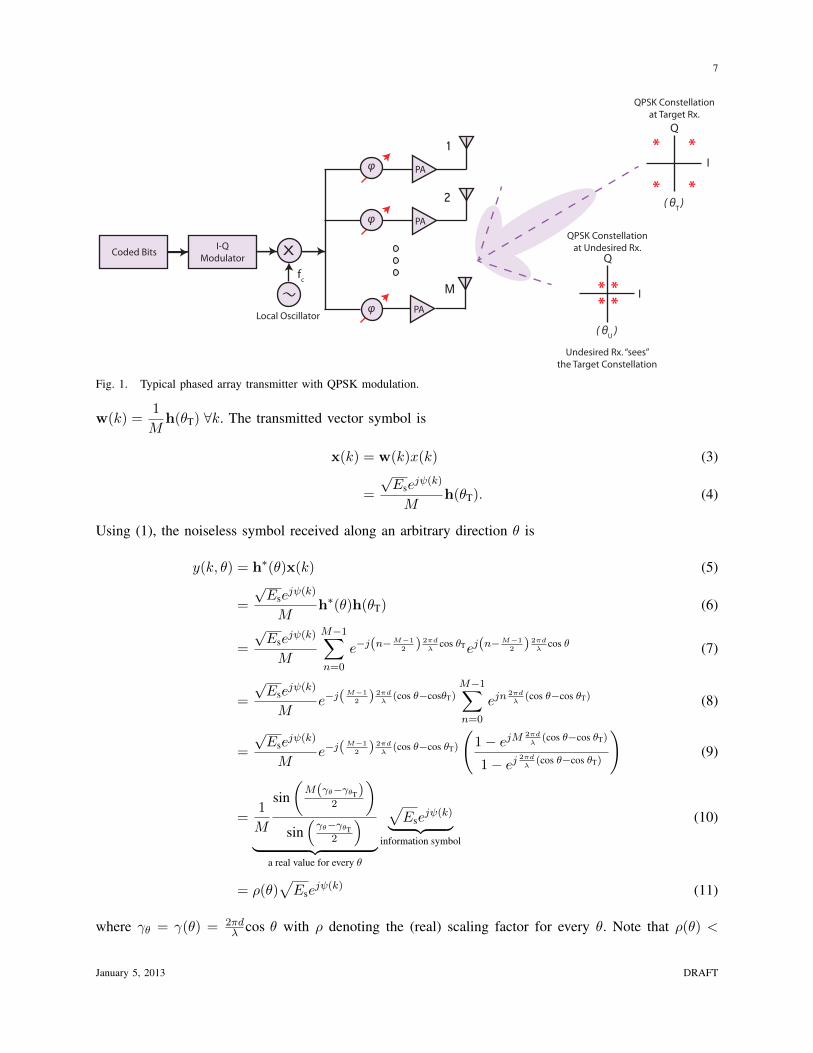
Fig. 1 shows the block diagram of a typical phased array transmitter where the number transmit
antennas equals the number of RF chains, i.e., N = M . The in-phase (I) and quadrature (Q) components
of the signal are modulated at baseband followed by RF up-conversion and beamforming in the RF
domain. Finally, the phase shifted signal at each branch is amplified by a power amplifier (PA) before
coupling onto the antenna.
Consider the situation in Fig. 1, where the array is transmitting a complex phase-modulated symbol,
x(k) =√Ese
jψ(k), to a target receiver using conventional baseband modulation. The target receiver
is along the θT radial while another receiver located along the θU direction is eavesdropping. Recall
that the transmitter knows θT but not θU. The transmitter can orient its main beam along θT by setting
January 5, 2013 DRAFT
7
PA
PA
PA
Coded Bits
Local Oscillator
* *
* *
I
Q
I
Q
QPSK Constellationat Target Rx.
I-Q Modulator
X
* ** *
1
2
Mfc
QPSK Constellationat Undesired Rx.
( θT )
( θU )
Undesired Rx. “sees” the Target Constellation
φ
φ
φ
Fig. 1. Typical phased array transmitter with QPSK modulation.
w(k) =1
Mh(θT) ∀k. The transmitted vector symbol is
x(k) = w(k)x(k) (3)
=
√Ese
jψ(k)
Mh(θT). (4)
Using (1), the noiseless symbol received along an arbitrary direction θ is
y(k, θ) = h∗(θ)x(k) (5)
=
√Ese
jψ(k)
Mh∗(θ)h(θT) (6)
=
√Ese
jψ(k)
M
M−1∑n=0
e−j(n−M−1
2 ) 2πd
λcos θTej(n−
M−1
2 ) 2πd
λcos θ (7)
=
√Ese
jψ(k)
Me−j(
M−1
2 ) 2πd
λ(cos θ−cosθT)
M−1∑n=0
ejn2πd
λ(cos θ−cos θT) (8)
=
√Ese
jψ(k)
Me−j(
M−1
2 ) 2πd
λ(cos θ−cos θT)
(1− ejM
2πd
λ(cos θ−cos θT)
1− ej2πd
λ(cos θ−cos θT)
)(9)
=1
M
sin(M(γθ−γθT)
2
)sin(γθ−γθT
2
)︸ ︷︷ ︸
a real value for every θ
√Ese
jψ(k)︸ ︷︷ ︸information symbol
(10)
= ρ(θ)√Ese
jψ(k) (11)
where γθ = γ(θ) = 2πdλ cos θ with ρ denoting the (real) scaling factor for every θ. Note that ρ(θ) <
January 5, 2013 DRAFT
8
ρ(θT) = 1 ∀ θ 6= θT.
Both the target and the undesired receiver observe effectively the same information. The constellation
received in undesired transmit directions differs only in terms of power. Therefore, an eavesdropper with
a sufficiently sensitive receiver can recover information from the received signal if it has enough gain to
overcome the loss embodied ρ(θ).
C. Antenna Subset Modulation
Next, we explain the principles of ASM and provide some intuition about the security aspect of this
transmission technique.
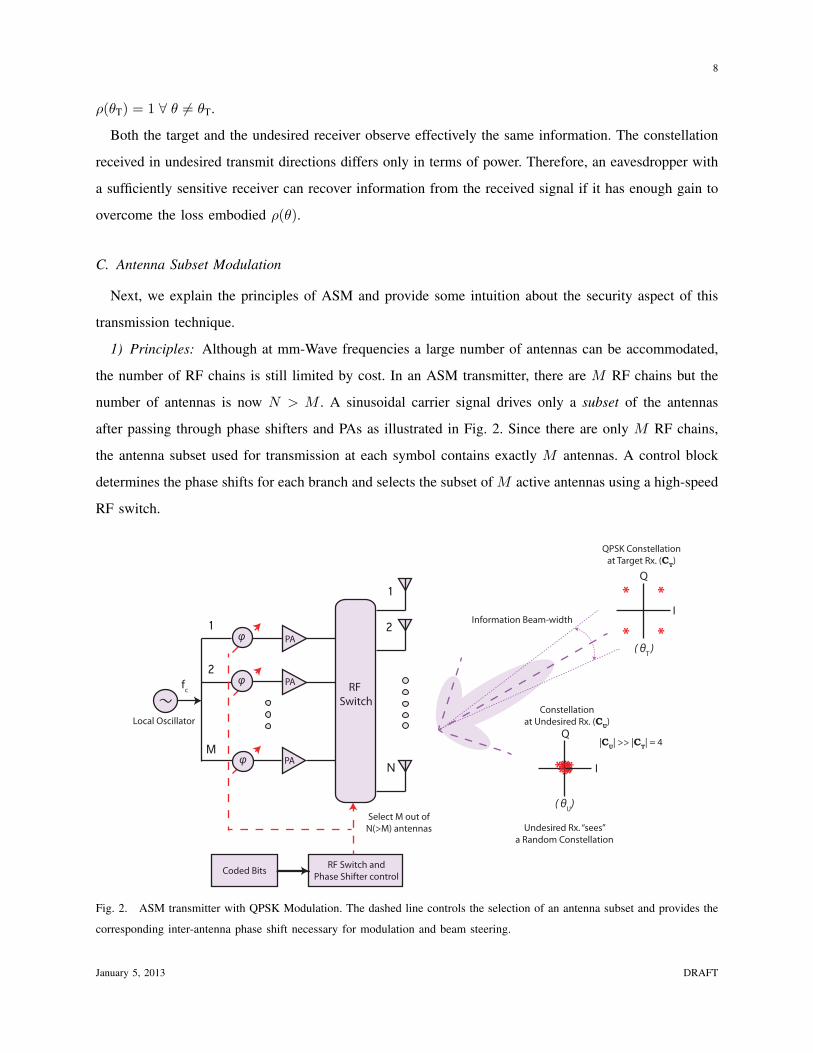
1) Principles: Although at mm-Wave frequencies a large number of antennas can be accommodated,
the number of RF chains is still limited by cost. In an ASM transmitter, there are M RF chains but the
number of antennas is now N > M . A sinusoidal carrier signal drives only a subset of the antennas
after passing through phase shifters and PAs as illustrated in Fig. 2. Since there are only M RF chains,
the antenna subset used for transmission at each symbol contains exactly M antennas. A control block
determines the phase shifts for each branch and selects the subset of M active antennas using a high-speed
RF switch.
φ PA
PA
PA
RF Switch and Phase Shifter controlCoded Bits
Local Oscillator
* *
* *I
Q
********** I
Q
**
QPSK Constellationat Target Rx. (CT)
Information Beam-width
fc
Constellationat Undesired Rx. (CU)
1
2
N
Undesired Rx. “sees” a Random Constellation
( θT )
( θU)
RF Switch
Select M out of N(>M) antennas
1
2
M |CU| >> |CT| = 4
φ
φ
Fig. 2. ASM transmitter with QPSK Modulation. The dashed line controls the selection of an antenna subset and provides the
corresponding inter-antenna phase shift necessary for modulation and beam steering.
January 5, 2013 DRAFT
9
A fundamental difference between ASM and conventional array transmission is that, in ASM, modu-
lation occurs in the RF domain. At each symbol, the control block synthesizes an array by selecting a
subset of M antennas. The chosen subset defines the array geometry and an associated far-field radiation
pattern. Since the set of antennas used for transmission is changed from one symbol to the next, this
pattern appears to be modulated at the symbol rate. This changing radiation pattern enhances the security
of ASM. In the absence of any multipath, the pattern (along a particular radial) defines a complex symbol
on the I-Q plane.
Modulation of information bits to symbols with simultaneous beam-steering is achieved by phase
shifting the active antennas in the synthesized array. By providing a phase offset besides the progressive
inter-antenna phase shift (for beam-steering), ASM can produce the desired phase of each symbol along
the target radial.
Since there is no complex baseband modulation involved, x(k) =√Es ∀k representing the constant
amplitude (unmodulated) carrier. The effects of data modulation, beam-steering and antenna subset
selection at symbol k are succinctly represented by the beamforming vector
w(k) =1
M[b(k) h(θT)] ejψ(k) (12)
where ψ is a constant data-dependent phase offset introduced in addition to the progressive inter-antenna
phase shifts, b is an N × 1 vector with bi = 0, 1 and∑N
i=0 bi = M enforcing the constraint on the
total number of active antennas. The binary vector b(k) thus encodes the M -antenna subset selected for
transmitting the kth symbol. The positions with ones indicate active antennas while zeros indicate unused
antennas. The ASM transmit signal is expressed as
x(k) = w(k)x(k) (13)
=
√Ese
jψ(k)
M[b(k) h(θT)]. (14)
If B denotes the set of all such binary vectors b, the noiseless received symbol can be expressed from
(1) as
y(k, θ) = h∗(θ)x(k) (15)
=
√Ese
jψ(k)
Mh∗(θ)[b(k) h(θT)] (16)
=1
Mh∗(θ)[b(k) h(θT)]︸ ︷︷ ︸
complex scalardependant on θ and b(k)
√Ese
jψ(k)︸ ︷︷ ︸information symbol
(17)
January 5, 2013 DRAFT
10
= ρ(θ,b(k))√Ese
jψ(k) (18)
for some b(k) ∈ B. The scaling factor ρ in (18) is in general complex for every θ 6= θT and changes
with the symbol index k.
Since the ASM technique relies on switching antennas at the symbol rate, high-speed RF switches are a
critical part of the transmitter design. To achieve fast antenna switching in ASM, a series of high-frequency
single-pole multi-throw (SPMT) switches capable of switching at nanosecond or sub-nanosecond speeds
with low insertion loss and good isolation properties is needed. Several solid-state switch implementations
such as PIN diodes, metal semiconductor field effect transistors (MESFETs) and hot electron mobility
transistors (HEMTs) have been reported previously [31]–[37] for mm-Wave transceiver applications and
are applicable to the ASM transmitter array design.
2) Secure Data Transmission: In addition to providing directional information to the target receiver,
ASM conveys misinformation in undesired directions. This makes it more difficult for an eavesdropper
to decode useful information.
Let the active antenna subset, b, be chosen at random from the set B for each symbol. Because of
beamforming along the target direction, the various (phase shifted) signal replicas add coherently along
the mainlobe direction, i.e., y(k, θT) =√Ese
jψ(k) since ρ(θT,b(k)) = 1 ∀ b(k) ∈ B. But, outside of a
narrow solid cone centered on the target radial, the signals add up misaligned in phase. Depending on
the antenna subset chosen, the desired modulation symbol appears scaled and rotated to an undesired
receiver. This creates a distorted constellation CU that is very different from the target constellation CT as
shown in Fig. 2. The constellation in unintended directions appears randomized because of the random
choice of an antenna subset for each symbol. Rather than scrambling the desired constellation in unwanted
directions [12], [14], [19], ASM synthesizes a multi-point constellation to confuse undesired receivers.
The additional constellation points introduced can equivalently be thought off as being generated by the
changing far-field pattern along the sidelobes as a result of the randomized antenna selection procedure.
Thus, while switching the active antenna subset does not alter the constellation along the mainlobe, the
symbols are distorted in both phase and amplitude for undesired receivers on the sidelobes.
III. ASM CONSTELLATION SYNTHESIS
ASM can be produce the desired phase of each symbol for any constant-envelope modulation scheme.
The use of constant envelope signals in ASM minimizes the linearity requirement on the PAs, enabling
high power efficiency by operating near the saturation region.
January 5, 2013 DRAFT
11
Suppose that the symbol to be synthesized at time k has magnitude and phase given by√Es and ψ(k),
respectively. Equivalently, we require the far-field radiation pattern, denoted henceforth by F (θ), to equal√Ese
jψ(k) along θT. Note that the dependence of the far-field pattern on symbol index k is implicit.
As remarked earlier, only a subset of M(< N) antennas is selected for use during each symbol in
ASM. The process of selectively turning off certain antennas in an array is called array thinning and the
array thus synthesized is referred to as a thinned array. Let I(k) denote the set of M antennas used for
transmitting the kth symbol, i.e.,
I(k) = n ∈ 0, 1, . . . , N − 1 : bn+1(k) = 1, |I(k)| = M ∀k. (19)
The set I(k) encodes the location of the active antennas for time index k. Thus, for a given antenna
spacing d, I(k) completely characterizes the resulting spatially nonuniform array.
In ASM, we perform the modulation and beam-steering operations jointly. The inter-antenna phase
shift applied to each branch to steer the mainlobe towards θT can be obtained using (2), (12) and (19) as
wn+1(k) =
1
Mej(ψ(k)−(n−N−1
2 ) 2πd
λcos θT) n ∈ I(k)
0 n /∈ I(k)(20)
Thus the composite inter-antenna phase shift, denoted by ϕn, needed to produce the desired complex
symbol along θT is
ϕn(k) = ψ(k)︸︷︷︸modulationcomponent
−(n− N − 1
2
)2πd
λcos θT︸ ︷︷ ︸
beam-steeringcomponent
, n ∈ I(k). (21)
Using (20) as beam-steering vector, the far-field radiation pattern (in the absence of mutual coupling)
of the synthesized linear array along an arbitrary direction θ is
F (θ) = h∗(θ)x(k) (22)
=√Esh
∗(θ)w(k) (23)
=√Es
∑n ∈ I(k)
1
Mej(ψ(k)−(n−N−1
2 ) 2πd
λcos θT)ej(n−
N−1
2 ) 2πd
λcos θ (24)
=
√Ese
jψ(k)
M
∑n ∈ I(k)
ej(n−N−1
2 ) 2πd
λ(cos θ−cos θT) (25)
and the pattern of the array along the desired orientation θT is
F (θT) =√Ese
jψ(k). (26)
January 5, 2013 DRAFT
12
It is critical to recognize that the signals from each antenna add up with perfect alignment along the
mainlobe direction to produce the desired symbol irrespective of the antenna subset picked, i.e., any
randomness in the choice of the antenna subset I(k) disappears along θ = θT. Thus, by appropriately
varying the inter-antenna phase shifts, ASM can produce every symbol in any constant-envelope modu-
lation scheme.
Notice that only the inter-antenna phase shift needs to be changed to transmit along an arbitrary
direction. This makes the constellation design procedure in ASM much simpler than other DM techniques
such as [12], [14], [38], where one must typically run an optimization algorithm to identify the correct
set of weights, phase shifts or switching combinations required to produce a desired modulation symbol
for each target direction. Moreover, these DM methods may suffer from symbol approximation errors
with respect to a true constellation point whereas the symbols synthesized by ASM are exact along any
target radial.
IV. ASM FOR SECURE COMMUNICATION
A. Random Antenna Subset Selection
Random Antenna Subset Selection (RASS) is a simple antenna subset selection technique for ASM.
In RASS, the antenna subset chosen for a particular symbol is equally likely to be any of the subsets
containing M active antennas. While the signals from each antenna add coherently along the mainlobe
irrespective of the selected antenna subset (cf. (26)), they add up misaligned in phase causing signal
defocusing along any sidelobe direction. An example illustrating the randomization of a transmit symbol
in an undesired direction is shown in Fig. 3. Since the antenna subsets used for transmission are picked
at random, the arrays synthesized have large sidelobes on average. Nevertheless, the RASS technique
yields itself to a simplified statistical analysis and provides the basic intuition behind secure transmission
using ASM. In Section V we propose an optimized antenna subset selection technique that offers reduced
sidelobe levels.
B. Statistical Model and Analysis
The modulation symbols are represented by
s` =√Es e
j`2π/K , ` = 0, 1, . . . ,K − 1. (27)
Let θT and Ω denote, respectively, the target radial and the angular region outside of a solid cone centered
on that target radial, i.e., Ω , (θ, φ) : θ /∈ (θT − ζ, θT + ζ) for some small value ζ > 0 (usually ζ ≈
January 5, 2013 DRAFT

13
−0.4 −0.2 0 0.2 0.4 0.6 0.8 1 1.2
−0.5
−0.4
−0.3
−0.2
−0.1
0
0.1
0.2
0.3
0.4
0.5
In−phase component (I)
Qua
drat
ure
com
pone
nt (
Q) Symbol produced at the
target rx. along θT=45°: 1+j0
Constellation as it appears toan undesired rx. along θ
U=90°
Fig. 3. Received constellation as it appears to undesired and desired receivers when using RASS to transmit the symbol 1+ j0
repeatedly. The parameters are N = 20, M = 12 and θT = 45.
distance to the first null). Since the antennas are chosen independently at random for every symbol,
we can model each antenna as an independent Bernoulli random variable with parameter p denoting
the probability of antenna selection. Choosing p = M/N , the thinning ratio, ensures that the arrays
synthesized have M active antennas asymptotically. The pattern F (θ) is then modeled as a sum of N
independent complex random variables (for each k) whose first- and second-order statistics can be derived
analytically. We will then use these statistics to approximate the uncoded SER (hereafter referred to as
simply SER) produced by RASS. Note that, while the proposed statistical model closely approximates
the pattern of the actual array synthesized by RASS for θ ∈ Ω, the approximation may not be accurate
outside of Ω. This is because, inside the cone, the signals from different antennas add constructively; the
randomness introduced by RASS disappears and the constellation produced approaches CT.
Let Xn(k) be a complex random variable denoting the weighting coefficient at the nth antenna when
transmitting the kth symbol. We can express Xn(k) as
Xn(k) = Yn(k)Zn (28)
where Yn(k) models randomness in transmit symbol selection whereas Zn models randomness in antenna
subset selection. According to the proposed statistical model,
Yn(k) =
√Es
Mejψ(k)e−j(n−
N−1
2 ) 2πd
λcos θT , n = 0, 1, . . . , N − 1, (29)
January 5, 2013 DRAFT

14
ψ(k) ∼ U(
1
K
)∀k i.e., P
(ψ(k) = `
2π
K
)=
1
K` = 0, 1, . . . ,K − 1, (30)
Zn ∼ Bern
(M
N
)=
1 w.p. MN
0 w.p. 1− MN
n = 0, 1, . . . , N − 1. (31)
By construction, Yn(i) ⊥⊥ Yn(j) if i 6= j, Zi ⊥⊥ Zj if i 6= j, and Yi ⊥⊥ Zj ∀i, j ∈ 0, 1, . . . , N − 1.
Rewriting Xn(k) in terms of Yn(k) using (28) and (31),
Xn(k) =
Yn(k) w.p. MN
0 w.p. 1− MN
(32)
Analogous to (24), an approximate stochastic model for the pattern of a thinned array synthesized
using RASS is
F (θ) =
N−1∑n=0
Xn(k)ej(n−N−1
2 ) 2πd
λcos θ (33)
where ∼ differentiates the stochastic model from the true pattern F (θ). For any given k, (33) is a
weighted sum of N independent and identically distributed (i.i.d.) complex random variables and it is
thereby closely approximated by a complex Gaussian distribution for large enough N , i.e., F (θ) ∼
CN (µ(θ), P (θ)). The I and Q parts of F (θ) can be stacked to form a two-dimensional real Gaussian
vector
f(θ) =
<[F (θ)]
=[F (θ)]
∼ N (µ(θ), P(θ)) (34)
where µ(θ) ∈ R2×1 and P(θ) ∈ R2×2 denote the mean and covariance of the two-dimensional real
Gaussian distribution. Note that the parameters of the distribution depend on the observation angle θ and
implicitly on the actual transmit symbol. The Gaussian approximation improves with N and is better
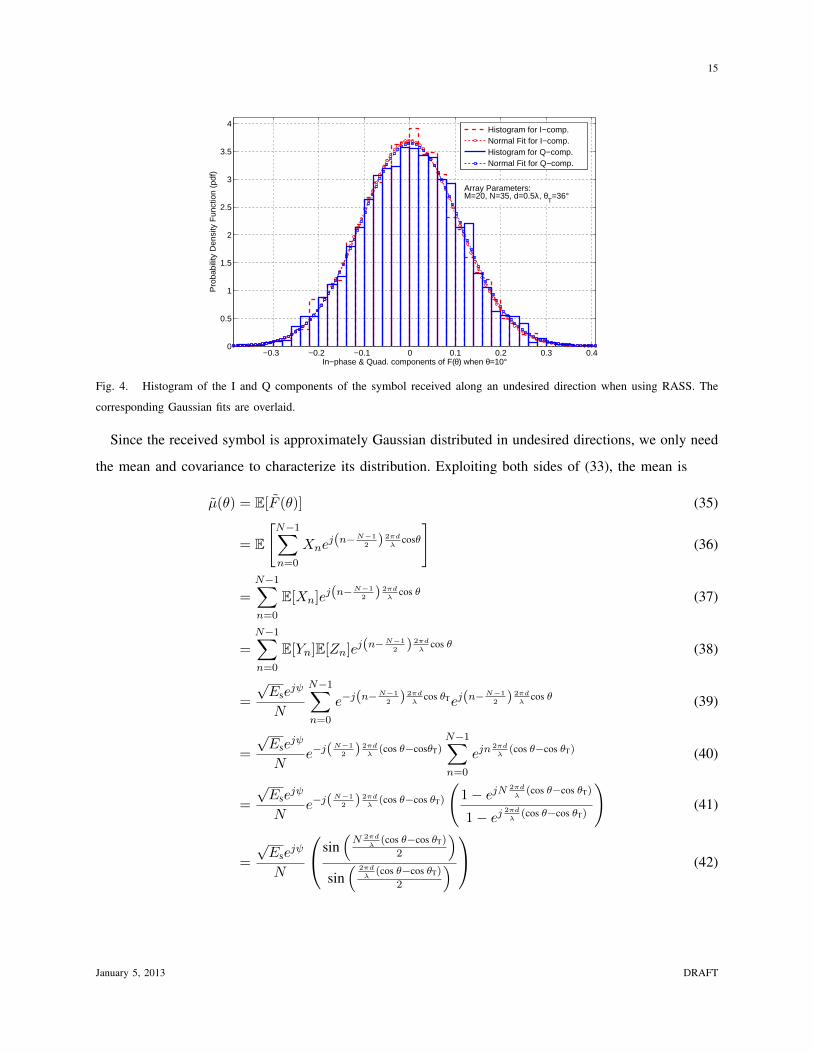
when the thinning ratio M/N is not too close to 0 or 1. Fig. 4 depicts the goodness of a Gaussian fit to
the empirical distribution of the I and Q components produced by RASS along an undesired direction. In
this example, a 35-antenna array was steered towards θT = 36. A histogram of the I and Q components
of the received symbol along θ = 10 is also shown.
To analyze the average SER under RASS, we only need a statistical description of the received symbol
cluster (as a function of direction) when transmitting an arbitrary symbol. To simplify the notation, we
drop the dependence of Xn, Yn and ψ on the symbol index k.
January 5, 2013 DRAFT
15
−0.3 −0.2 −0.1 0 0.1 0.2 0.3 0.40
0.5
1
1.5
2
2.5
3
3.5
4
Pro
babi
lity
Den
sity
Fun
ctio
n (p
df)
In−phase & Quad. components of F(θ) when θ=10°
Histogram for I−comp.Normal Fit for I−comp.Histogram for Q−comp.Normal Fit for Q−comp.
Array Parameters: M=20, N=35, d=0.5λ, θ
T=36°
Fig. 4. Histogram of the I and Q components of the symbol received along an undesired direction when using RASS. The
corresponding Gaussian fits are overlaid.
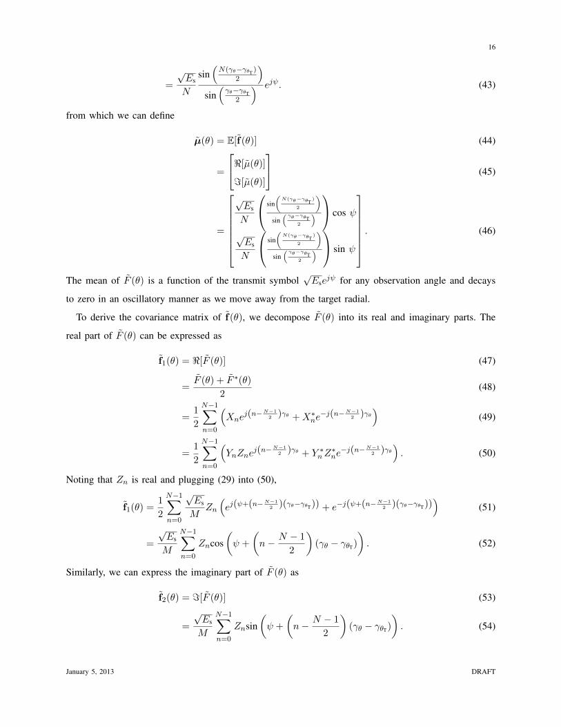
Since the received symbol is approximately Gaussian distributed in undesired directions, we only need
the mean and covariance to characterize its distribution. Exploiting both sides of (33), the mean is
µ(θ) = E[F (θ)] (35)
= E
[N−1∑n=0
Xnej(n−N−1
2 ) 2πd
λcosθ
](36)
=
N−1∑n=0
E[Xn]ej(n−N−1
2 ) 2πd
λcos θ (37)
=
N−1∑n=0
E[Yn]E[Zn]ej(n−N−1
2 ) 2πd
λcos θ (38)
=
√Ese
jψ
N
N−1∑n=0
e−j(n−N−1
2 ) 2πd
λcos θTej(n−
N−1
2 ) 2πd
λcos θ (39)
=
√Ese
jψ
Ne−j(
N−1
2 ) 2πd
λ(cos θ−cosθT)
N−1∑n=0
ejn2πd
λ(cos θ−cos θT) (40)
=
√Ese
jψ
Ne−j(
N−1
2 ) 2πd
λ(cos θ−cos θT)
(1− ejN
2πd
λ(cos θ−cos θT)
1− ej2πd
λ(cos θ−cos θT)
)(41)
=
√Ese
jψ
N
sin(N 2πd
λ(cos θ−cos θT)
2
)sin( 2πd
λ(cos θ−cos θT)
2
) (42)
January 5, 2013 DRAFT
16
=
√Es
N
sin(N(γθ−γθT )
2
)sin(γθ−γθT
2
) ejψ. (43)
from which we can define
µ(θ) = E[f(θ)] (44)
=
<[µ(θ)]
=[µ(θ)]
(45)
=
√Es
N
sin(N(γθ−γθT
)
2
)sin
( γθ−γθT2
) cos ψ
√Es
N
sin(N(γθ−γθT
)
2
)sin
( γθ−γθT2
) sin ψ
. (46)
The mean of F (θ) is a function of the transmit symbol√Ese
jψ for any observation angle and decays
to zero in an oscillatory manner as we move away from the target radial.
To derive the covariance matrix of f(θ), we decompose F (θ) into its real and imaginary parts. The
real part of F (θ) can be expressed as
f1(θ) = <[F (θ)] (47)
=F (θ) + F ∗(θ)
2(48)
=1
2
N−1∑n=0
(Xne
j(n−N−1
2 )γθ +X∗ne−j(n−N−1
2 )γθ)
(49)
=1
2
N−1∑n=0
(YnZne
j(n−N−1
2 )γθ + Y ∗nZ∗ne−j(n−N−1
2 )γθ). (50)
Noting that Zn is real and plugging (29) into (50),
f1(θ) =1
2
N−1∑n=0
√Es
MZn
(ej(ψ+(n−N−1
2 )(γθ−γθT)) + e−j(ψ+(n−N−1
2 )(γθ−γθT)))
(51)
=
√Es
M
N−1∑n=0
Zncos(ψ +
(n− N − 1
2
)(γθ − γθT)
). (52)
Similarly, we can express the imaginary part of F (θ) as
f2(θ) = =[F (θ)] (53)
=
√Es
M
N−1∑n=0
Znsin(ψ +
(n− N − 1
2
)(γθ − γθT)
). (54)
January 5, 2013 DRAFT

17
We first find [P(θ)]1,1, the variance of the real component of the received symbol under our stochastic
model. From (52), we see that the variance of <[F (θ)] is
[P(θ)]1,1 = var[f1(θ)] (55)
= var
[N−1∑n=0
√Es
MZncos
(ψ +
(n− N − 1
2
)(γθ − γθT)
)](56)
=Es
M2
N−1∑n=0
var [Zn] cos2
(ψ +
(n− N − 1
2
)(γθ − γθT)
)(57)
=Es
NM
(1− M
N
)N−1∑n=0
cos2
(ψ +
(n− N − 1
2
)(γθ − γθT)
)(58)
where we have used Zn ∼ Bern(MN
). Using trigonometric identities we can simplify (58) as
[P(θ)]1,1 =Es
2NM
(1− M
N
)(N + cos (2ψ)
sin (N (γθ − γθT))
sin (γθ − γθT)
). (59)
A similar analysis on the imaginary component of the received symbol (54) yields
[P(θ)]2,2 =Es
2NM
(1− M
N
)(N − cos (2ψ)
sin (N (γθ − γθT))
sin (γθ − γθT)
). (60)
It is important to note that, like the mean, the variances of the real and imaginary components of F (θ)
oscillate and depend on the transmitted symbol. However, the total variance P (θ) is constant (in terms
of the observation angle θ) for a given array configuration. Indeed, using (59) and (60),
P (θ) = var[F (θ)] (61)
= [P(θ)]1,1 + [P(θ)]2,2 (62)
=Es
M
(1− M
N
). (63)
Several observations can be made from (59), (60), and (63). First, when M = N the thinned array
degenerates to a uniform array and there is no randomness in the received symbol in any direction. This
is confirmed by the individual variances of the I and Q components going to zero irrespective of θ.
Second, for a fixed M , adding more antennas to the array (thereby reducing the thinning ratio M/N )
increases the total variance. An increase in the variance of the received symbol in undesired directions
is helpful because it provides more security. Also, increasing the total number of antennas in the array
increases the effective aperture size thereby enabling the randomly synthesized thinned array to have a
reduced mainlobe width compared to a uniform array with M antennas. This leads to a narrow beamwidth
towards the target receiver, which is desirable.
January 5, 2013 DRAFT

18
Next, we compute the covariance between the real and imaginary components of the received symbol
as a function of angle using our statistical model. The covariance between f1(θ) and f2(θ) is
[P(θ)]1,2 = [P(θ)]2,1 = E[f1(θ)f2(θ)]− µ1(θ)µ2(θ). (64)
Using (52) and (54), we can express the first term in (64) as
E[f1(θ)f2(θ)] = E
[N−1∑m,n=0
Es
M2ZmZncos
(ψ +
(m− N − 1
2
)(γθ − γθT)
)sin(ψ +
(n− N − 1
2
)(γθ − γθT)
)](65)
=Es
M2
N−1∑n=0
E[Z2n]cos
(ψ +
(n− N − 1
2
)(γθ − γθT)
)sin(ψ +
(n− N − 1
2
)(γθ − γθT)
)
+
N−1∑m,n=0m6=n
E[ZmZn]cos(ψ +
(m− N − 1
2
)(γθ − γθT)
)sin(ψ +
(n− N − 1
2
)(γθ − γθT)
) . (66)
Since Zm ⊥⊥ Zn, ∀m 6= n, E[ZmZn] = E[Zm]E[Zn] = (M/N)2 and (66) becomes
E[f1(θ)f2(θ)] =Es
MN
N−1∑n=0
cos(ψ +
(n− N − 1
2
)(γθ − γθT)
)sin(ψ +
(n− N − 1
2
)(γθ − γθT)
)
+Es
N2
N−1∑m,n=0m6=n
cos(ψ +
(m− N − 1
2
)(γθ − γθT)
)sin(ψ +
(n− N − 1
2
)(γθ − γθT)
) .
(67)
Again, using trigonometric identities we can simplify the two parenthetical expressions in (67) as follows:N−1∑n=0
cos(ψ +
(n− N − 1
2
)(γθ − γθT)
)sin(ψ +
(n− N − 1
2
)(γθ − γθT)
)=
1
2
sin (N(γθ − γθT))
sin (γθ − γθT)sin (2ψ) , (68)
N−1∑m,n=0m6=n
cos(ψ +
(m− N − 1
2
)(γθ − γθT)
)sin(ψ +
(n− N − 1
2
)(γθ − γθT)
)
=sin(N(γθ−γθT )
2
)sin(γθ−γθT
2
) sin(
(N−1)(γθ−γθT)2
)sin (γθ − γθT)
sin (2ψ) . (69)
Substituting (68) and (69) into (67),
E[f1(θ)f2(θ)] =Es
2MN
sin (N(γθ − γθT))
sin (γθ − γθT)sin (2ψ)
+Es
N2
sin(N(γθ−γθT )
2
)sin(γθ−γθT
2
) sin(
(N−1)(γθ−γθT )
2
)sin (γθ − γθT)
sin (2ψ) . (70)
January 5, 2013 DRAFT
19
Using (46), the product of the means is
µ1(θ)µ2(θ) =Es
2N2
sin(N(γθ−γθT )
2
)sin
(γθ−γθT
2
)2
sin (2ψ) . (71)
Finally, substituting (70) and (71) into (64), we obtain the covariance between the real and imaginary
parts as
[P(θ)]1,2 = [P(θ)]2,1 (72)
=Es
2MN
(1− M
N
)sin (N(γθ − γθT))
sin (γθ − γθT)sin (2ψ) (73)
which evidences that the artificial randomness introduced in the I and Q components of the received
symbol along undesired transmit directions may be correlated depending on the transmit symbol and
observation angle. However, the magnitude of the correlation is small (< 0.1) for most angles.
Eqs. (46), (59), (60), and (73) are the parameters of the Gaussian approximation to the noiseless
received symbol distribution in undesired directions. Additive White Gaussian Noise (AWGN) is easily
incorporated by modifying the covariance P(θ): if N0 denotes the total noise variance, the mean and
covariance of the received symbol in undesired directions becomes
µN(θ) = µ(θ), (74)
PN(θ) = P(θ) +N0
2I2. (75)
It is worth restating that the Gaussian approximation to the received symbol distribution is accurate as
long as the eavesdropper is in the angular region outside the target cone.
C. Secure Communication Link
Equipped with the statistics of the Gaussian approximation to the received symbol, we now analyze the
corresponding SER. We first consider the case when there is no AWGN and assume optimal maximum-
likelihood (ML) detection by the eavesdropper. Analyzing the average SER in a noiseless setting is
important because it helps quantify the level of security inherent to RASS. Note that conventional array
transmission cannot guarantee any security in the absence of noise.
The computation of the average SER with RASS parallels the one used for deriving the error rates
for conventional digital modulation [39], only with the AWGN replaced by the statistical model for the
randomness introduced by antenna subset selection (discussed in the previous subsection). For K-ary PSK,
the modulation symbols are represented by s` for ` = 0, 1, . . . ,K−1 as in (27). As discussed previously,
January 5, 2013 DRAFT
20
the received symbol in undesired transmit directions can be regarded as approximately Gaussian. From
(46), (59), (60), and (73), we see that, unlike in AWGN, the parameters of the received distribution
depend on the transmit symbol s`. To make this dependence explicit, we denote the mean and covariance
of the received symbol by µ(`, θ) and P(`, θ), respectively.
Under ML detection, a received symbol is in error if it falls outside the Voronoi region of the actual
symbol transmitted along θT. The average SER according to our statistical model for the received symbol
distribution can be expressed as
Ps(θ) = 1− 1
K
K−1∑`=0
∫Λ`
1
2π|P(`, θ)|1
2
exp−1
2(z− µ(`, θ))T P(`, θ)−1 (z− µ(`, θ))
dz (76)
where Λ` is the Voronoi region associated with s` and P(`, θ) > 0. When K = 4, i.e., with QPSK, (76)
can be simplified by virtue of the symmetry and the diagonal form of P(`, θ) as
Ps(θ) = 1− 1
2π√
[P(0, θ)]1,1[P(0, θ)]2,2
∫Λ0
exp
−1
2
((z1 − µ1(0, θ))2
[P(0, θ)]1,1+
(z2 − µ2(0, θ))2
[P(0, θ)]2,2
)dz1dz2
(77)
where
µ(0, θ) =
√Es
N
sin(N(γθ−γθT
)
2
)sin
( γθ−γθT2
)
0
(78)
P(0, θ) =
Es
2MN
(1− M
N
)(N +
sin(N(γθ−γθT ))sin(γθ−γθT)
)0
0Es
2MN
(1− M
N
)(N − sin(N(γθ−γθT ))
sin(γθ−γθT)
) (79)
Λ0 = (z1, z2) ∈ R : z1 + z2 ≥ 0, z1 − z2 ≥ 0 (80)
and the 2-D integral in (77) can be evaluated using the cumulative distribution function of the bivariate
normal distribution. For K > 4, however, no closed forms exist for (76) and numerical integration is
required. Note that (76) represents the irreducible SER with RASS, which can only increase with AWGN.
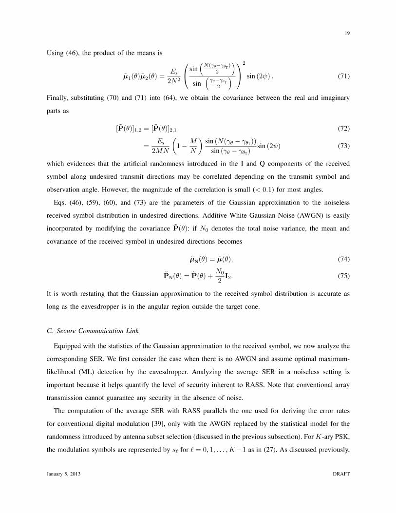
Fig. 5 shows the SER achieved by RASS with QPSK. We observe that the statistical error rate
expression derived from (76) closely approximates the simulated error rate even for a moderate value of
N = 28. From Fig. 5, it is evident that the theoretical average SER approaches zero as θ approaches θT
since it is the error rate in the absence of any additive noise. From analysis and simulations, the limit
point in θ where the average error rate plummets to zero is approximately given by the location of the
January 5, 2013 DRAFT
21
first null from θT i.e., θ ≈ cos−1(λNd ± cos(θT)
)for an N -element linear array. Thus, for a given d
λ and
θT, a larger aperture size (N ) leads to a narrower cone where the error rate approaches zero.
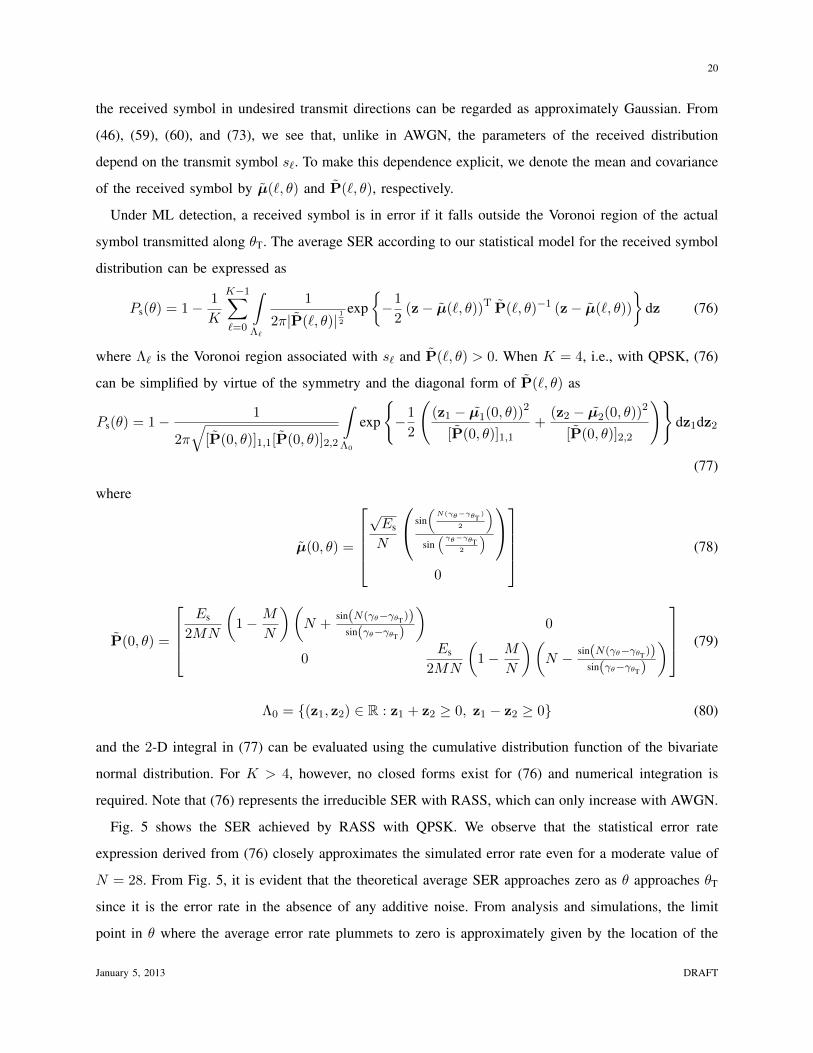
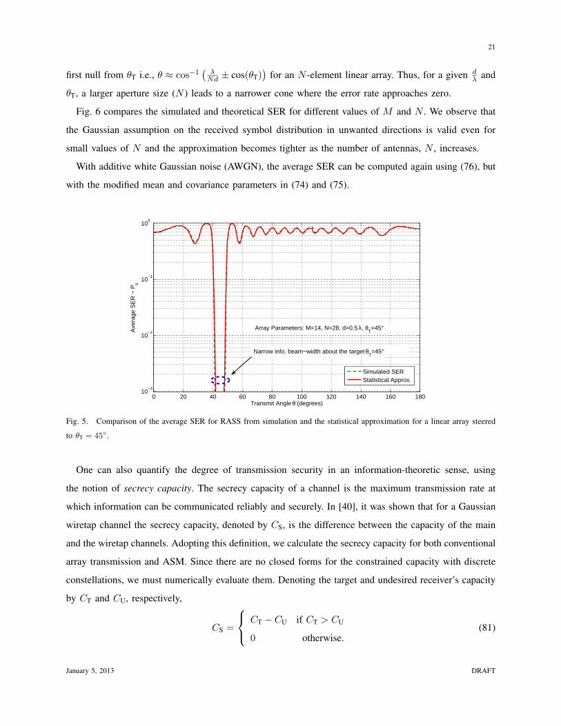
Fig. 6 compares the simulated and theoretical SER for different values of M and N . We observe that
the Gaussian assumption on the received symbol distribution in unwanted directions is valid even for
small values of N and the approximation becomes tighter as the number of antennas, N , increases.
With additive white Gaussian noise (AWGN), the average SER can be computed again using (76), but
with the modified mean and covariance parameters in (74) and (75).
0 20 40 60 80 100 120 140 160 18010
−3
10−2
10−1
100
Transmit Angle θ (degrees)
Ave
rage
SE
R −
Ps
Simulated SERStatistical Approx.
Narrow info. beam−width about the target θT=45°
Array Parameters: M=14, N=28, d=0.5 λ, θT=45°
Fig. 5. Comparison of the average SER for RASS from simulation and the statistical approximation for a linear array steered
to θT = 45.
One can also quantify the degree of transmission security in an information-theoretic sense, using
the notion of secrecy capacity. The secrecy capacity of a channel is the maximum transmission rate at
which information can be communicated reliably and securely. In [40], it was shown that for a Gaussian
wiretap channel the secrecy capacity, denoted by CS, is the difference between the capacity of the main
and the wiretap channels. Adopting this definition, we calculate the secrecy capacity for both conventional
array transmission and ASM. Since there are no closed forms for the constrained capacity with discrete
constellations, we must numerically evaluate them. Denoting the target and undesired receiver’s capacity
by CT and CU, respectively,
CS =
CT − CU if CT > CU
0 otherwise.(81)
January 5, 2013 DRAFT
22
0 20 40 60 80 100 120 140 160 18010
−2
10−1
100
0 20 40 60 80 100 120 140 160 18010
−2
10−1
100
0 20 40 60 80 100 120 140 160 180
10−1
100
Simulated SERStatistical Approx.
Simulated SERStatistical Approx.
Simulated SERStatistical Approx.
Array Parameters: M=9, N=12, d=0.5 λ, θT=36°
Array Parameters: M=20, N=35, d=0.5 λ, θT=36°
Array Parameters: M=18, N=30, d=0.5 λ, θT=36°
Fig. 6. Comparison between the statistical approximation of the average SER and simulated error rates for linear arrays with
different length when steered towards θT = 36.
For QPSK symbol transmission,
CS(θ) = CQPSK(SNR(θT))− CQPSK(SNR(θ)) (82)
where CQPSK(·) denotes the AWGN constrained capacity with QPSK.
We need to find the average SNR for the two transmission schemes to calculate their secrecy capacities.
For conventional array transmission, invoking (5), the SNR assuming rectangular pulse-shaping is
SNR(θ) =Es
2N0
1
M
sin(M(γθ−γθT)
2
)sin(γθ−γθT
2
)
2
. (83)
Note that SNR(θT) = Es2N0
, as expected.
For ASM, the SNR at the target receiver’s location equals that of conventional array transmission
since the constellation is undistorted in this direction. To calculate the SNR along undesired directions,
we invoke the Gaussian approximation to the received symbol distribution. Specifically, the square of
µN(θ) in (74) for every angle is a measure of the average symbol energy in that direction. The noise
variance (in undesired directions) consists of AWGN plus the artificial noise introduced by RASS. Since
such artificial noise is uncorrelated with the AWGN, the effective noise covariance is the sum of individual
covariances PN(θ) from (75).
With QPSK, the noise introduced by ASM has zero-mean and uncorrelated I and Q components, i.e.,
January 5, 2013 DRAFT
23
[P]1,2 = [P]2,1 = 0. Therefore, the aggregate noise can be modeled as AWGN with the modified variance
PN = 2N0 +Es
M
(1− M
N
). (84)
The average SNR for ASM is thus
SNR(θ) =|µN|2
2N0 + EsM
(1− M
N
) (85)
=Es
2N0 + EsM
(1− M
N
) 1
N
sin(N(γθ−γθT)
2
)sin(γθ−γθT
2
)
2
∀ θ ∈ Ω. (86)
A numerical example comparing secrecy capacity of ASM and conventional array transmission is pre-
sented in Section VI.
Thus, we see that the use of RASS in ASM synthesizes a constellation that is a function of direction.
While the constellation for the intended receiver is not affected by the random choice of antenna subset, the
undesired receiver sees an effectively random constellation. In the next section, we propose an optimized
antenna subset selection technique that offers even better security and array performance.
V. OPTIMIZED ANTENNA SUBSET SELECTION
Every antenna subset having a fixed number of active antennas is equally probable in RASS. Though
the spatially nonuniform arrays these subsets correspond to have a similar mainlobe, the sidelobes can
be rather different. Therefore, we next seek to create a smaller codebook of antenna subsets that possess
low sidelobes so as to select antenna subsets at random only from this collection. Note that, since all
antenna subsets are equivalent along the mainlobe, restricting the set of possibilities does not affect our
ability to communicate with the target receiver.
A. Thinned Array Pattern Synthesis
The problem of synthesizing thinned arrays with desirable characteristics is a combinatorial optimiza-
tion problem that has been studied extensively in the past [41]–[49]. The effect of thinning on the array
gain and mainlobe width is predictable. Harder to characterize is the effect of thinning on the sidelobe
levels because that depends on both the location and the number of active antennas. Unfortunately, there
are no analytical techniques to synthesize a thinned array with certain sidelobe behavior. For an N -
antenna array, the number of subsets with exactly M(< N) active antennas is(NM
)= N !
(N−M)!M ! . Even
for moderate values of N and M , this number can be enormous; for N = 64 and M = 32, for instance,
January 5, 2013 DRAFT

24
(NM
)∼ 1018. Given the impracticality of an exhaustive search, heuristic optimization techniques based on
simulated annealing, genetic algorithms and its variants have been proposed to find near-optimal solutions
[41]–[49]. We henceforth focus on simulated annealing.
B. Optimized Antenna Subset Selection Based on Simulated Annealing
Simulated annealing [50], [51] is a probabilistic iterative algorithm for finding approximate solutions
to the global optimum of a function in a large search space. It emulates the physical process of annealing,
whereby heating and controlled cooling of a substance results in a molecular configuration with lower
internal energy compared to the initial state.
For optimized antenna subset selection, we seek to build a codebook B consisting of antenna subsets
that correspond to nonuniform arrays with low sidelobe levels, with the constraint that the number of
active antennas in the thinned array, M , be fixed. The simulated annealing algorithm as applied to antenna
subset selection is illustrated below using pseudo code.
The simulated annealing algorithm retains only one array solution (and an associated temperature) at
each instant. The algorithm is initialized with a random array configuration containing M active antennas.
Then, at every iteration, the solution is perturbed. By allowing perturbations that only swap the location
of an “on” antenna for an “off” antenna we ensure that the number of active antennas is always M . If
the perturbed solution results in lowering the cost function E we accept it and move to the next iteration.
Otherwise, we probabilistically accept the perturbed solution and this acceptance probability decreases
as the temperature diminishes. The replacement of better solutions by worse ones at higher temperatures
ensures that the algorithm does not gets stuck in a local optimum. After a sufficient number of iterations,
the algorithm converges to a near-optimal solution that has a lower cost.
January 5, 2013 DRAFT
25
Algorithm Simulated Annealing1: procedure ANTENNA SUBSET SELECTION (M,N )
2: Initialize(b0, T0, iter count) . bi is the thinning pattern rep. as a binary vector
3: for i = 1 to iter count do
4: Ti = βTi−1 ensure β < 1 . Exponential cooling schedule
5: b∗ = swap(bi−1) . Perturb bi−1 by swapping the loc. of a 0 and 1 at random
6: ∆E = E(b∗)− E(bi−1) . Compute the change in cost ∆E
7: if ∆E < 0 or exp[−∆E
Ti
]> rand[0, 1]2 then
8: bi = b∗ . Probabilistically accept the new solution if ∆E ≥ 0
9: else
10: bi = bi−1 . Try another perturbation
11: end if
12: end for
13: end procedure
The performance of any simulated annealing algorithm depends heavily on the choice of the cost
function and cooling schedule. For this work, an exponential cooling schedule produced the best results.
The algorithm seeks to minimize the cost function
E = max |SLL|2dB (87)
= maxθ∈Ω
20 log10 |F (θ)| (88)
where SLL stands for the sidelobe level. As long as the number of possible subsets is large, we can get
a sufficient collection of array configurations with similar sidelobe properties after multiple runs of the
algorithm. The random initialization and the probabilistic nature of the algorithm ensures that we do not
converge to the same local optimum after each run. The arrays thus synthesized are stacked to form the
codebook B from which the transmitter draws antenna subsets for each symbol.
Reducing the sidelobe levels has benefits in terms of security. While the magnitude of the received
symbols in undesired directions is now lower, the randomization in phase caused by antenna subset
selection is preserved by the use of a large enough codebook. Therefore, the resulting symbol distribution
in undesired directions has a mean closer to zero and is hence more susceptible to errors.
2rand[0,1] generates a number uniformly distributed on the interval[0,1].
January 5, 2013 DRAFT

26
We hasten to emphasize that, for a given array configuration, the codebook is constructed only once
and is independent of the target direction. This keeps the antenna subset selection procedure simple.
VI. SIMULATION RESULTS
In this section, we present numerical examples illustrating constellation synthesis, array performance
and transmission security of ASM. Linear arrays with isotropic antennas are considered. The parameters
for each simulation are overlaid on the corresponding plots. In some of the results that follow, the
performance of ASM is compared against a conventional array with array size equal to the number of
active elements in the ASM array.
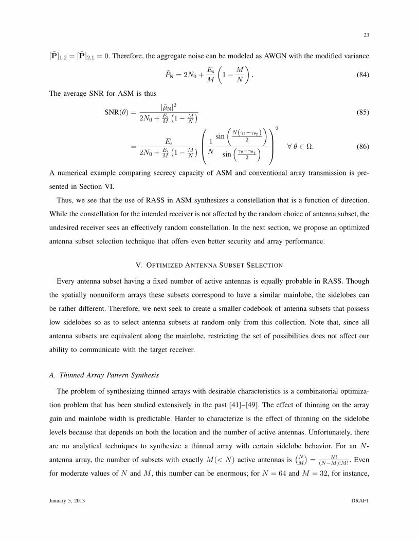
A. Constellation Synthesis Results
First, we show the constellation synthesized by ASM when using the proposed antenna subset selection
techniques (cf. Sections IV and V) to transmit a QPSK signal. As is evident in Fig. 7, the constellation
produced by ASM along the target direction is undistorted while, along an undesired transmit direction, the
received symbols appear randomized. Notice how the received symbol cluster has a lower magnitude when
using optimized antenna subset selection compared to RASS. Also shown in Fig. 7 is the constellation
produced by conventional array transmission in these directions, which is still crisp enough for a sensitive
eavesdropper to demodulate.
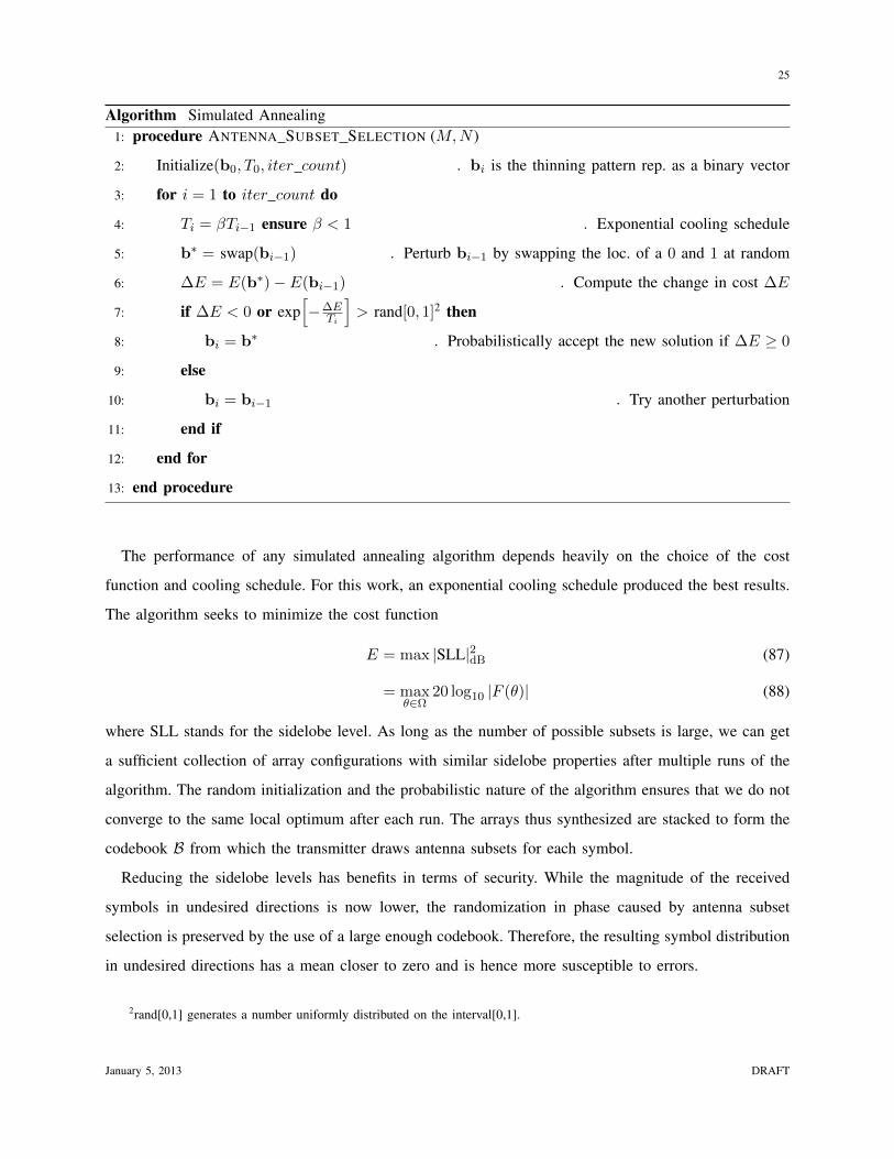
B. Array Performance Results
Fig. 8 depicts the radiation patterns of a randomly thinned array and of an array synthesized using
simulated annealing. The optimized array exhibits a lower sidelobe level, as expected, at the expense of a
small increase in the mainlobe width. However, both arrays feature a narrower mainlobe width compared
to a conventional array (with the same number of active antennas).
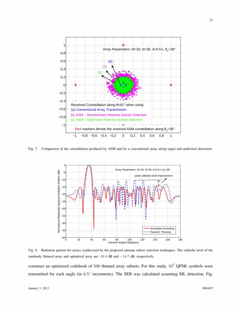
Histograms of the resulting sidelobe levels are shown in Fig. 9. The sidelobe behavior of the optimized
array is superior to that of a conventional array, which has a sidelobe level of −13.5 dB when steered
to broadside [30].
C. Transmission Security Results
In this section, we demonstrate that ASM can achieve a low SER around the target angle while
enforcing a high SER in undesired directions. The setup consists of N = 35 antennas of which only
M = 20 are active at a given time. The array beamforms along θT = 36. Simulated annealing is used to
January 5, 2013 DRAFT
27
−1 −0.8 −0.6 −0.4 −0.2 0 0.2 0.4 0.6 0.8 1
−1
−0.8
−0.6
−0.4
−0.2
0
0.2
0.4
0.6
0.8
1
Received Constellation along θ=41° when using:
(a)
(b)
(c)
(b) ASM − Randomized Antenna Subset Selection
(a) Conventional Array Transmission
markers denote the received ASM constellation along θT=36°
(c) ASM − Optimized Antenna Subset Selection
Array Parameters: M=20, N=35, d=0.5 λ, θT=36°
Red
Fig. 7. Comparison of the constellation produced by ASM and by a conventional array along target and undesired directions.
0 20 40 60 80 100 120 140 160 180−50
−45
−40
−35
−30
−25
−20
−15
−10
−5
0
Nor
mal
ized
Mag
nitu
de S
quar
ed R
adia
tion
Pat
tern
(dB
)
Transmit Angle θ (degrees)
Simulated AnnealingRandom Thinning
Array Parameters: M=20, N=35, d=0.5 λ, θT=36°
peak sidelobe level improvement
Fig. 8. Radiation pattern for arrays synthesized by the proposed antenna subset selection techniques. The sidelobe level of the
randomly thinned array and optimized array are -10.4 dB and −14.7 dB, respectively.
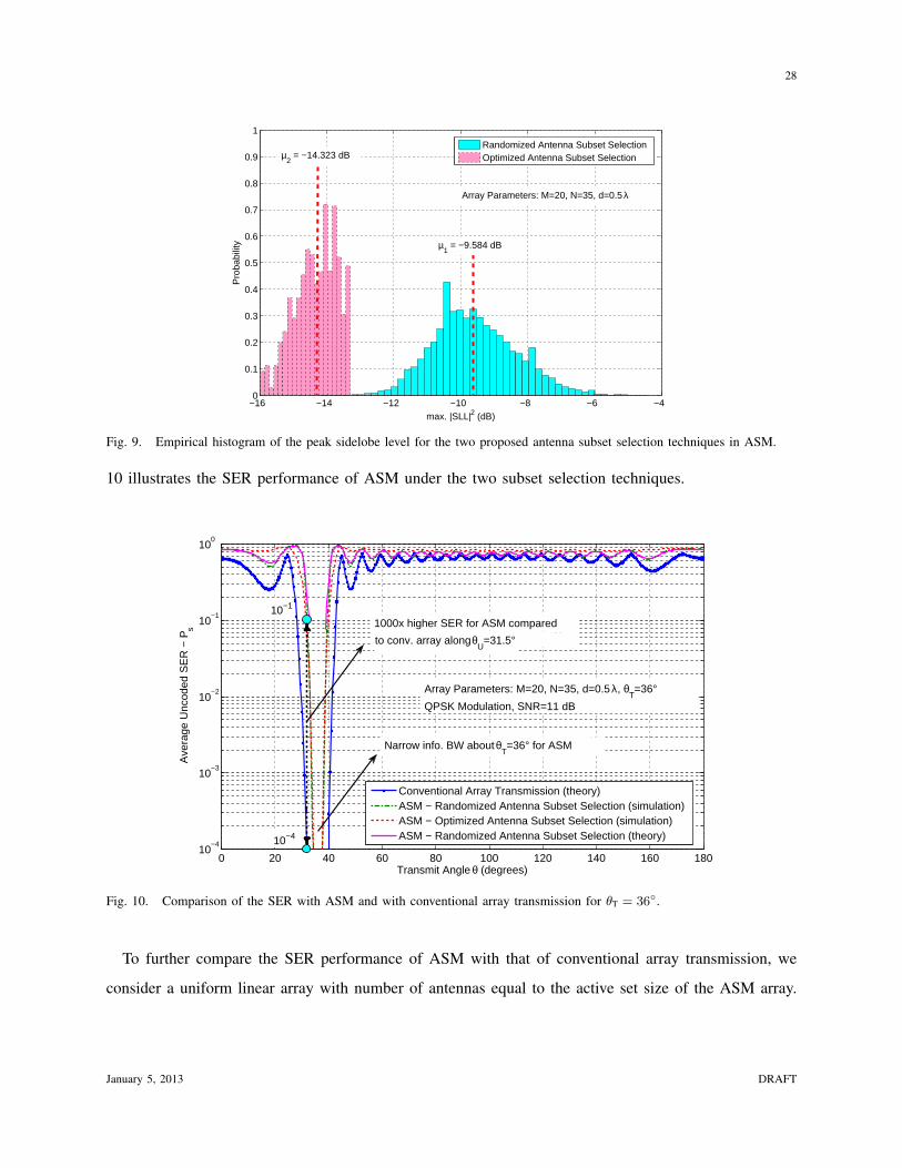
construct an optimized codebook of 500 thinned array subsets. For this study, 107 QPSK symbols were
transmitted for each angle (in 0.5 increments). The SER was calculated assuming ML detection. Fig.
January 5, 2013 DRAFT
28
−16 −14 −12 −10 −8 −6 −40
0.1
0.2
0.3
0.4
0.5
0.6
0.7
0.8
0.9
1
max. |SLL|2 (dB)
Pro
babi
lity
Randomized Antenna Subset SelectionOptimized Antenna Subset Selection
µ1 = −9.584 dB
µ2 = −14.323 dB
Array Parameters: M=20, N=35, d=0.5 λ
Fig. 9. Empirical histogram of the peak sidelobe level for the two proposed antenna subset selection techniques in ASM.
10 illustrates the SER performance of ASM under the two subset selection techniques.
0 20 40 60 80 100 120 140 160 18010
−4
10−3
10−2
10−1
100
Transmit Angle θ (degrees)
Ave
rage
Unc
oded
SE
R −
Ps
Conventional Array Transmission (theory)ASM − Randomized Antenna Subset Selection (simulation)ASM − Optimized Antenna Subset Selection (simulation)ASM − Randomized Antenna Subset Selection (theory)
10−1
Narrow info. BW about θT=36° for ASM
10−4
Array Parameters: M=20, N=35, d=0.5 λ, θT=36°
QPSK Modulation, SNR=11 dB
to conv. array along θU=31.5°
1000x higher SER for ASM compared
Fig. 10. Comparison of the SER with ASM and with conventional array transmission for θT = 36.
To further compare the SER performance of ASM with that of conventional array transmission, we
consider a uniform linear array with number of antennas equal to the active set size of the ASM array.
January 5, 2013 DRAFT
29
The exact SER for K-ary PSK then equals [52]
Ps(θ) = F
(1,
√2Es
N0, cot
π
K
)(89)
where F is the cumulative distribution function of the noncentral t-distribution. The SER for conventional
array transmission is thus computed and also shown in Fig. 10. ASM under both antenna subset selection
techniques achieves a higher SER compared to conventional array transmission in unwanted directions.
Moreover, ASM produces a narrow information beamwidth around the target angle. Also, optimized
antenna subset selection is shown to exhibit better transmission security compared to RASS. Along with
the average SER curves from simulation, the theoretical SER for RASS is plotted in Fig. 10 using (77).
The theoretical SER based on the proposed statistical model closely matches the simulation for angles
θ ∈ Ω. It is important to note that ASM provides these security benefits without additional transmit
power, unlike other DM techniques [14], [15] that trade-off security for some increase in transmission
power.
Next, in Fig 11, we present results on the SER of ASM for an eavesdropper and compare it against
conventional array transmission. A 12-antenna array with 9 active antennas is considered and RASS is
employed in ASM. With the target receiver located along θT = 45, two angular locations are considered
for the eavesdropper: scenario (a) θa = θT +10 = 55, and scenario (b) θb = θT +122 = 167. Scenario
(a) illustrates a situation where the eavesdropper is angularly close to the target while, in scenario (b) the
eavesdropper is far from the target angle. In both situations, ASM under RASS outperforms conventional
array transmission. Even as the SNR increases, ASM maintains a high SER while, for a conventional
array, the SER falls off rapidly with SNR.
Finally, Fig. 12 shows the improved secrecy capacity of ASM. Eqs. (82), (83) and (86) were applied
with QPSK. ASM achieves better secrecy capacity compared to conventional array transmission, where
in multiple transmit angles the secrecy capacity is rather low. Another desirable characteristic of ASM,
which is evident in the figure, is its ability to create a link with secrecy capacity close to the actual
capacity without eavesdropping (in this case, 2 bits/s/Hz) over a wide range of angles. Moreover, the
secrecy capacity of ASM is nonzero even as SNR → ∞ because of its inherent irreducible artificial
noise.
VII. CONCLUSION
In this paper, Antenna Subset Modulation (ASM) was proposed to take advantage of massive antenna
arrays at mm-Wave frequencies. In ASM, the radiation pattern of the array is modulated at the symbol
January 5, 2013 DRAFT

30
7 9 11 13 15 17 19 21 2310
−3
10−2
10−1
100
SNR (dB)
Ave
rage
Unc
oded
SE
R −
Ps
Scenario (a) − Conv. ArrayScenario (a) − ASMScenario (b) − Conv. ArrayScenario (b) − ASM
High SER (indep. of SNR)
Exponential fall off with SNR
16−PSK, θT=45°, θ
a=167°, θ
b=55°
Array Parameters: M=9, N=12, d=0.5 λ,
Fig. 11. Average SER versus SNR for an eavesdropper when using ASM and conventional array transmission for two scenarios
with θT = 45. Scenario (a) eavesdropper is close to the target angle, along θa = 55. Scenario (b) eavesdropper is far off the
target angle, along θb = 167.
0 20 40 60 80 100 120 140 160 1800
0.2
0.4
0.6
0.8
1
1.2
1.4
1.6
1.8
2
Transmit angle θ (degrees)
Sec
recy
Cap
acity
Cs (
bits
/s/H
z)
Conv. ArrayASM
Array Parameters: M=10, N=30, θT=36°
QPSK Modulation, SNR=15 dB
high secrecy capacityin undesired dirns. for ASM
zero secrecy capacityregion near target angle
low secrecy capacityfor a conv. array
Fig. 12. Secrecy capacity for different eavesdropper angles when using ASM and conventional array transmission. The crosses
are the interpolated values of the secrecy capacity of ASM for θ near the target angle θT.
rate to achieve direction-dependent data transmission. Unlike other directional modulation techniques,
which scramble the desired constellation in unwanted directions, ASM provides security by introducing
additional points in the constellation that appear effectively random to an undesired receiver. A simple
January 5, 2013 DRAFT

31
constellation design procedure involving the calculation of progressive inter-antenna phase shifts was
described. Two different antenna subset selection techniques were proposed for implementing ASM:
(i) random antenna subset selection, and (ii) optimized antenna subset selection based on simulated
annealing. Simulation examples were used to validate the security benefits of ASM against conventional
array transmission. It was concluded that ASM achieves a narrow beamwidth in the desired direction
and a high SER in undesired directions under both subset selection techniques. The optimized antenna
subset selection was found to provide higher security benefits.
Future work will involve an extension of the analysis to multidimensional periodic arrays. Incorporating
multidirectional transmission capabilities to ASM using array partitioning techniques is also an interesting
research problem that merits further study.
January 5, 2013 DRAFT
32
REFERENCES
[1] “IEEE standard for information technology - Telecommunications and information exchange between systems - Local and
metropolitan area networks - Specific requirements. Part 15.3: Wireless Medium Access Control (MAC) and Physical Layer
(PHY) Specifications for High Rate Wireless Personal Area Networks (WPANs) Amendment 2: Millimeter-wave-based
Alternative Physical Layer Extension,” IEEE Std 802.15.3c-2009 (Amendment to IEEE Std 802.15.3-2003), pp. c1–187,
Dec. 2009.
[2] ECMA International, “High rate 60 GHz PHY, MAC and HDMI PAL,” ECMA-387, Dec. 2008. [Online]. Available:
http://www.ecma-international.org/publications/files/ECMA-ST/ECMA-387.pdf
[3] “WirelessHD Specification Overview,” WirelessHD Std. Overview, Aug. 2009. [Online]. Available: http://www.wirelesshd.
org/wp-content/uploads/2009/12/WirelessHDSpecification-Overview-v1-0-4-Aug09.pdf
[4] E. Perahia, C. Cordeiro, M. Park, and L. Yang, “IEEE 802.11ad: Defining the Next Generation Multi-Gbps Wi-Fi,” in
Proc., IEEE Consum. Commun. Netw. Conf. (CCNC), Jan. 2010, pp. 1–5.
[5] “WiGig White Paper: Defining the Future of Multi-Gigabit Wireless Communications,” July 2010. [Online]. Available:
http://wirelessgigabitalliance.org/specifications/
[6] Z. Pi and F. Khan, “An introduction to millimeter-wave mobile broadband systems,” IEEE Commun. Mag., vol. 49, no. 6,
pp. 101–107, June 2011.
[7] X. Guan, H. Hashemi, and A. Hajimiri, “A fully integrated 24-GHz eight-element phased-array receiver in silicon,” IEEE
J. Solid-State Circuits, vol. 39, no. 12, pp. 2311–2320, Dec. 2004.
[8] A. Babakhani, X. Guan, A. Komijani, A. Natarajan, and A. Hajimiri, “A 77-GHz phased-array transceiver with on-chip
antennas in silicon: Receiver and antennas,” IEEE J. Solid-State Circuits, vol. 41, no. 12, pp. 2795–2806, Dec. 2006.
[9] C. Doan, S. Emami, D. Sobel, A. Niknejad, and R. Brodersen, “Design considerations for 60 GHz CMOS radios,” IEEE
Commun. Mag., vol. 42, no. 12, pp. 132–140, Dec. 2004.
[10] D. Cabric, M. S. W. Chen, D. A. Sobel, S. Wang, J. Yang, and R. W. Brodersen, “Novel radio architectures for UWB,
60 GHz, and cognitive wireless systems,” EURASIP J. Wireless Commun. Netw., vol. 2006, no. 17957, pp. 1–18, Jan.
2006. [Online]. Available: http:///php/pubs/pubs.php/203.html
[11] J. Wells, “Faster than fiber: The future of multi-G/s wireless,” IEEE Microw. Mag., vol. 10, no. 3, pp. 104–112, May 2009.
[12] A. Babakhani, D. Rutledge, and A. Hajimiri, “Transmitter architectures based on near-field direct antenna modulation,”
IEEE J. Solid-State Circuits, vol. 43, no. 12, pp. 2674–2692, Dec. 2008.
[13] A. Babakhani, D. Rutledge, and A. Hajimiri, “A near-field modulation technique using antenna reflector switching,” in
Proc., IEEE Intl. Solid-State Circuits Conf. (ISSCC), Feb. 2008, pp. 188–605.
[14] M. Daly and J. Bernhard, “Directional modulation technique for phased arrays,” IEEE Trans. Antennas Propag., vol. 57,
no. 9, pp. 2633–2640, Sept. 2009.
[15] M. Daly and J. Bernhard, “Directional modulation and coding in arrays,” in Proc., IEEE Intl. Symposium on Antennas and
Propag. (APSURSI), July 2011, pp. 1984–1987.
[16] M. Daly, E. Daly, and J. Bernhard, “Demonstration of directional modulation using a phased array,” IEEE Trans. Antennas
Propag., vol. 58, no. 5, pp. 1545–1550, May 2010.
[17] M. Daly and J. Bernhard, “Beamsteering in pattern reconfigurable arrays using directional modulation,” IEEE Trans.
Antennas Propag., vol. 58, no. 7, pp. 2259–2265, July 2010.
[18] E. Baghdady, “Directional signal modulation by means of switched spaced antennas,” IEEE Trans. Commun., vol. 38,
no. 4, pp. 399–403, Apr. 1990.
January 5, 2013 DRAFT

33
[19] T. Hong, M.-Z. Song, and Y. Liu, “Dual-beam directional modulation technique for physical-layer secure communication,”
IEEE Antennas Wireless Propag. Lett., vol. 10, pp. 1417–1420, 2011.
[20] T. Hong, M.-Z. Song, and Y. Liu, “RF directional modulation technique using a switched antenna array for physical
layer secure communication applications,” Progress In Electromagnetics Research (PIER), vol. 116, pp. 363–379, 2011.
[Online]. Available: http://www.jpier.org/pier/pier.php?paper=11031605
[21] S. Sinanovic, M. Di Renzo, and H. Haas, “Secrecy rate of time switched transmit diversity system,” in Proc., IEEE Veh.
Technol. Conf. (VTC), May 2011, pp. 1–5.
[22] M. Di Renzo, H. Haas, N. Serafimovski, and S. Sinanovic, “Secrecy capacity of space keying with two
antennas,” in Proc., IEEE Veh. Technol. Conf. (VTC), Quebec, Canada, Sept. 2012, pp. 1–5. [Online]. Available:
http://hal-supelec.archives-ouvertes.fr/hal-00732647
[23] M. Renzo, H. Haas, and P. Grant, “Spatial modulation for multiple-antenna wireless systems: a survey,” IEEE Commun.
Mag., vol. 49, no. 12, pp. 182–191, Dec. 2011.
[24] Y. Chau and S.-H. Yu, “Space modulation on wireless fading channels,” in Proc., IEEE Veh. Technol. Conf. (VTC), vol. 3,
2001, pp. 1668–1671.
[25] R. Mesleh, H. Haas, S. Sinanovic, C. W. Ahn, and S. Yun, “Spatial modulation,” IEEE Trans. Veh. Technol., vol. 57, no. 4,
pp. 2228–2241, July 2008.
[26] A. Younis, N. Serafimovski, R. Mesleh, and H. Haas, “Generalised spatial modulation,” in Proc., ASILOMAR Conf. Signals,
Systems and Computers, Nov. 2010, pp. 1498–1502.
[27] J. Jeganathan, A. Ghrayeb, L. Szczecinski, and A. Ceron, “Space shift keying modulation for MIMO channels,” IEEE
Trans. Wireless Commun, vol. 8, no. 7, pp. 3692–3703, July 2009.
[28] J. Jeganathan, A. Ghrayeb, and L. Szczecinski, “Generalized space shift keying modulation for MIMO channels,” in Proc.,
IEEE Intl. Symposium on Pers., Indoor and Mobile Radio Commun. (PIMRC), Sept. 2008, pp. 1–5.
[29] P. F. M. Smulders, “Deterministic modelling of indoor radio propagation at 40-60 GHz,” Wireless Personal Communications,
vol. 1, pp. 127–135, 1994, 10.1007/BF01098690. [Online]. Available: http://dx.doi.org/10.1007/BF01098690
[30] H. L. Van Trees, Optimum Array Processing (Detection, Estimation, and Modulation Theory, Part IV), 1st ed. Wiley-
Interscience, Mar. 2002.
[31] D. Liu, U. Pfeiffer, J. Grzyb, and B. Gaucher, Advanced Millimeter-wave Technologies: Antennas, Packaging and Circuits.
Wiley, 2009. [Online]. Available: http://books.google.com/books?id=iVtrwmDCn7oC
[32] R. B. Lai, S. F. Chao, Z. M. Tsai, J. Lee, and H. Wang, “Topology analysis and design of passive HEMT millimeter-wave
multiple-port switches,” IEEE Trans. Microw. Theory and Techniques, vol. 56, no. 7, pp. 1545–1554, July 2008.
[33] J. H. Lee, S. Hong, W. K. Kim, J. W. An, and M. Y. Park, “A switched array antenna module for millimeter-wave wireless
communications,” in Proc., Global Symp. on Millimeter Waves, Apr. 2008, pp. 161–163.
[34] M. Madihian, L. Desclos, K. Maruhashi, K. Onda, and M. Kuzuhara, “A high-speed resonance-type FET transceiver switch
for millimeter-wave band wireless network,” in Proc., Microw. Conf., vol. 2, Sept. 1996, pp. 941–944.
[35] Y. Tanaka, H. Uda, H. Hayashi, H. Ueda, and M. Usui, “A 76-77 GHz high isolation GaAs PIN-diode switch MMIC,”
R&D Review of Toyota CRDL, vol. 37, no. 2, p. 19, 2002.
[36] “18-40 GHz GaAs MMIC high isolation SPST reflective PIN switch,” Data sheet of AP640R1-00 in Alpha, Industry
Catalog.
[37] “GaAs beamlead PIN diode,” Data sheet of MA4GP905 in M/A-COM Technology Solutions.
January 5, 2013 DRAFT
34
[38] J. Lavaei, A. Babakhani, A. Hajimiri, and J. Doyle, “A study of near-field direct antenna modulation systems using convex
optimization,” in Proc., American Control Conf. (ACC), July 2010, pp. 1065–1072.
[39] A. Goldsmith, Wireless Communications. New York, NY, USA: Cambridge University Press, 2005.
[40] S. Leung-Yan-Cheong and M. Hellman, “The Gaussian wire-tap channel,” IEEE Trans. Info. Theory, vol. 24, no. 4, pp.
451–456, July 1978.
[41] R. Haupt, “Thinned arrays using genetic algorithms,” IEEE Trans. Antennas Propag., vol. 42, no. 7, pp. 993–999, July
1994.
[42] M. T. Ali, R. Abdolee, and T. A. Rahman, “Decimal genetics algorithms for null steering and sidelobe cancellation in
switch beam smart antenna system.” Intl. J. of Comput. Sci. and Security, vol. 1, no. 3, pp. 19–26, Oct. 2007.
[43] M. Skolnik, G. Nemhauser, and I. Sherman, J., “Dynamic programming applied to unequally spaced arrays,” IEEE Trans.
Antennas Propag., vol. 12, no. 1, pp. 35–43, Jan. 1964.
[44] R. Arora and N. Krisnamacharyulu, “Synthesis of unequally spaced arrays using dynamic programming,” IEEE Trans.
Antennas Propag., vol. 16, no. 5, pp. 593–595, Sept. 1968.
[45] V. Murino, A. Trucco, and C. Regazzoni, “Synthesis of unequally spaced arrays by simulated annealing,” IEEE Trans.
Signal Process., vol. 44, no. 1, pp. 119–122, Jan. 1996.
[46] C. Meijer, “Simulated annealing in the design of thinned arrays having low sidelobe levels,” in Proc., South African
Symposium on Commun. Signal Process. (COMSIG), Sept. 1998, pp. 361–366.
[47] J.-F. Hopperstad, “Optimization of thinned arrays,” Master’s thesis, Department of Informatics, University of Oslo, May
1998.
[48] J.-F. Hopperstad and S. Holm, “Optimization of sparse arrays by an improved simulated annealing algorithm,” Proc., Intl.
Workshop on Sampling Theory and Appl., pp. 91–95, Aug. 1999.
[49] L. Zhang, Y.-C. Jiao, Z.-B. Weng, and F.-S. Zhang, “Design of planar thinned arrays using a Boolean differential evolution
algorithm,” IET Microw., Antennas Propag., vol. 4, no. 12, pp. 2172–2178, Dec. 2010.
[50] S. Kirkpatrick, C. D. Gelatt, and M. P. Vecchi, “Optimization by simulated annealing,” Science, vol. 220, no. 4598, pp.
671–680, 1983. [Online]. Available: http://www.sciencemag.org/content/220/4598/671.abstract
[51] D. Bertsimas and J. Tsitsiklis, “Simulated annealing,” Statistical Science, vol. 8, no. 1, pp. 10–15, 1993.
[52] J. Lassing, E. Strom, T. Ottosson, and E. Agrell, “The exact symbol and bit error probabilities of coherent M-ary PSK,”
in Proc., IEEE Intl. Symposium Info. Theory (ISIT), June 2003, p. 11.
January 5, 2013 DRAFT
Related Documents