1 minar

1 5 th Integrated Seminar 18.5.2005. 2 FACTORS AFFECTING ON COOLING TOWER PERFORMANCE AND INTRODUCTION TO OUTLINES OF THESIS.
Dec 28, 2015
Welcome message from author
This document is posted to help you gain knowledge. Please leave a comment to let me know what you think about it! Share it to your friends and learn new things together.
Transcript

1 5th Integrated Seminar 18.5.2005

2
FACTORS AFFECTING ON
COOLING TOWER PERFORMANCE
AND
INTRODUCTION TO OUTLINES OF THESIS
3
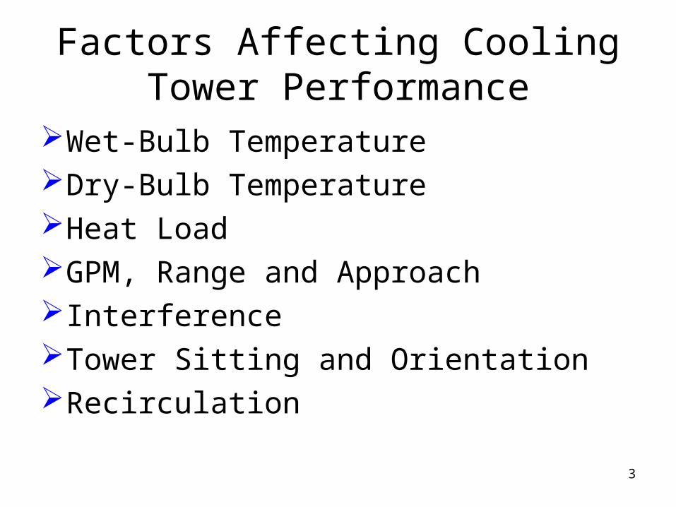
Factors Affecting Cooling Tower Performance
Wet-Bulb TemperatureDry-Bulb TemperatureHeat LoadGPM, Range and ApproachInterferenceTower Sitting and OrientationRecirculation

4
Cooling Tower Performance Curve
Fig 1 – A Sample of Typical Performance Curve

5
Wet-Bulb Temperature
• The temperature (WB) of the entering or ambient air adjacent to the cooling tower.
Fig 2 – Sling Psychrometer Fig 3 – Daily Variation of WB Temperature

6
Fig 4 – Annual Variation of WB Temperature
Fig 5 – Typical WB Temperature Duration Curve
7
Dry-Bulb and/or Relative Humidity
• The temperature (DB) of the entering or ambient air adjacent to the cooling tower.
• The ratio of the mole fraction of water vapor present in the air to the mole fraction of water vapor present in saturated air at the same temperature and barometric pressure.
8
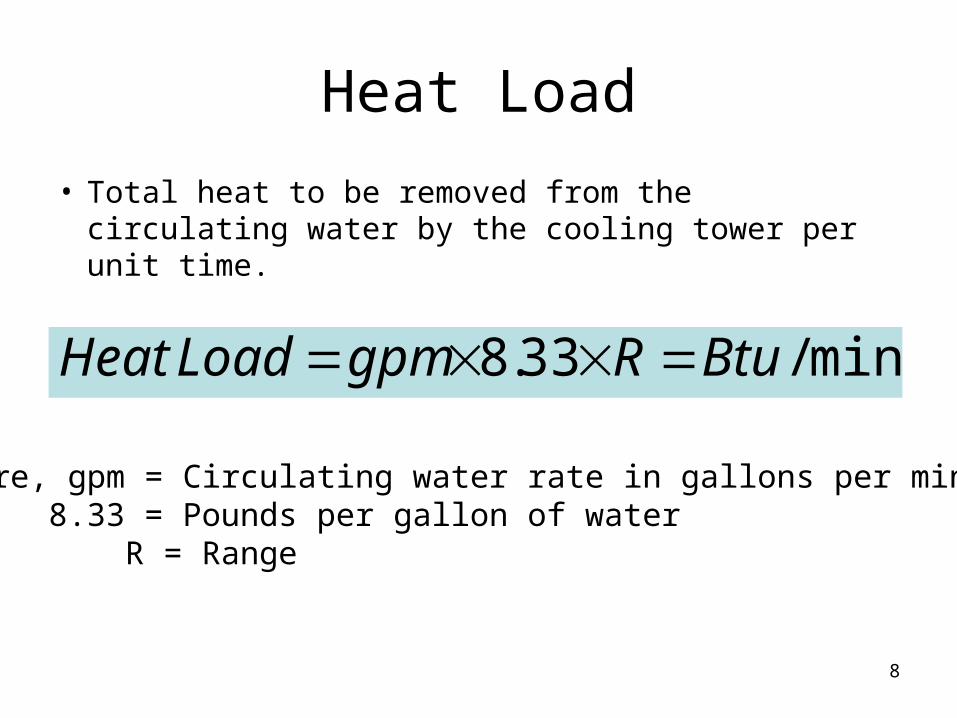
Heat Load
• Total heat to be removed from the circulating water by the cooling tower per unit time.
min/33.8 BtuRgpmLoadHeat
where, gpm = Circulating water rate in gallons per minute 8.33 = Pounds per gallon of water R = Range

9
GPM, Range and Approach
Fig 6 – Diagram showing of Cooling Range and Approach
Fig 7 – Effect of chosen Approach on Tower Size at fixed Heat Load, GPM, and WB Temperature
10
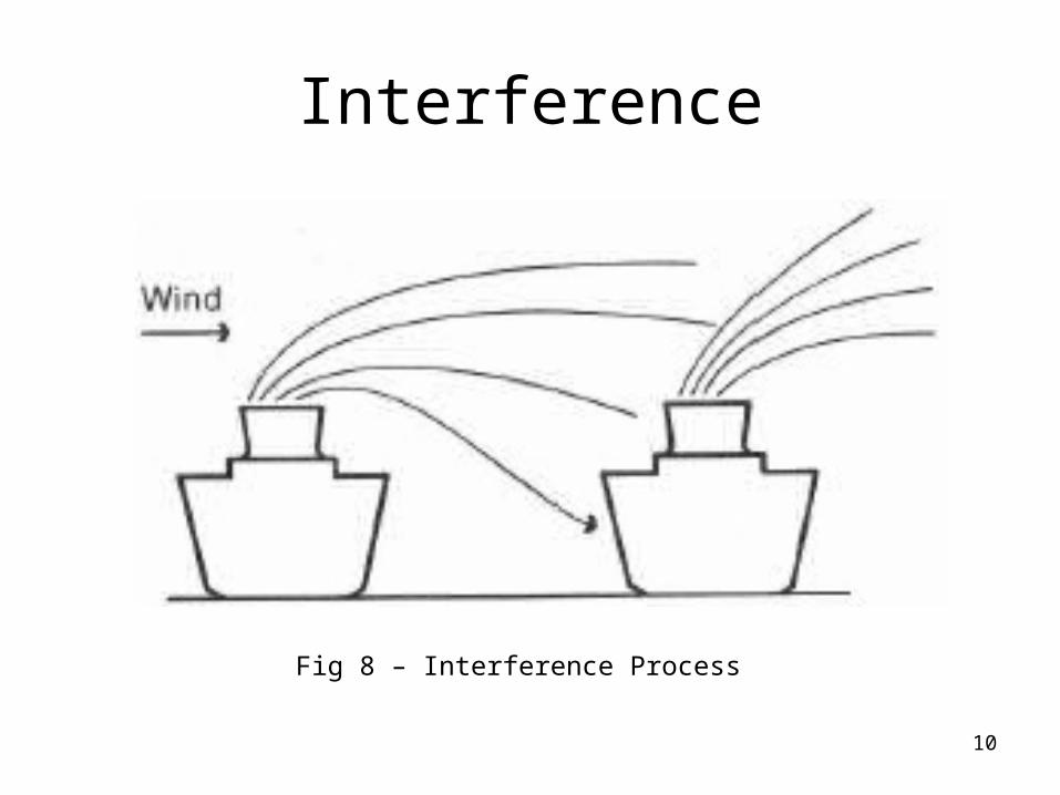
Interference
Fig 8 – Interference Process

11
Tower Sitting and Orientation
It is the responsibility of the owner/ specifier.
• Air Restrictions
• Recirculation
• Interference
• Effect on Site Piping

12
Recirculation
• Undesirable Situation• Control
– Tower Shape
– Orientation with Prevailing Wind
– Air Discharge Velocity– Fan Cylinder Height
and Spacing
Fig 9 – Recirculation Process

13
Fig 10 – Longitudinal Wind Direction concentrates Separate Stack Plumes into one of High Buoyancy
Fig 11 – Effect of Wind Velocity Potential of Round and Rectangular Tower

14
Fig 12 – Comparative Recirculation Potential of Round and Rectangular Tower
Fig 13 – Recirculation Potential in a Forced-draft Cooling Tower
15
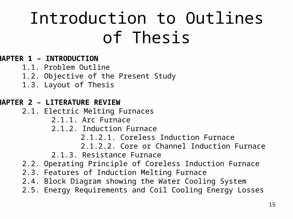
Introduction to Outlines of Thesis
CHAPTER 1 – INTRODUCTION1.1. Problem Outline1.2. Objective of the Present Study1.3. Layout of Thesis
CHAPTER 2 – LITERATURE REVIEW2.1. Electric Melting Furnaces
2.1.1. Arc Furnace2.1.2. Induction Furnace
2.1.2.1. Coreless Induction Furnace2.1.2.2. Core or Channel Induction Furnace
2.1.3. Resistance Furnace2.2. Operating Principle of Coreless Induction Furnace2.3. Features of Induction Melting Furnace2.4. Block Diagram showing the Water Cooling System2.5. Energy Requirements and Coil Cooling Energy Losses

16
2.6. Water Cooling System – Important Role in Coreless Induction Furnace2.6.1. Water Requirements2.6.2. Effects of Water Quality2.6.3. Water Purification/ Maintenance2.6.4. Filtration2.6.5. Effects of Impurities2.6.6. Emergency Water Supply and Cooling System
2.7. Cooling Pond System2.8. Spray Pond System2.9. Evaporative Cooling Tower-open Circuit System2.10. Fan-radiator Closed-circuit System2.11. Water/water Heat-Exchanger Dual System2.12. Dual System with Closed-circuit Cooling Tower2.13. Selection of Cooling System
CHAPTER 3 – COOLING POND – CURRENT STATUS OF RESEARCH AND PROJECT
CHAPTER 4 – DESIGN AND CALCULATION OF COOLING POND SYSTEMCHAPTER 5 – CLOSED RECIRCULATING SYSTEM WITH COOLING TOWERCHAPTER 6 – RESULT, DISCUSSION, AND CONCLUSION

17
Related Documents