1 4-Integrating Peripherals in Embedded Systems

1 4-Integrating Peripherals in Embedded Systems. 2 Introduction Single-purpose processors Performs specific computation task Custom single-purpose.
Dec 28, 2015
Welcome message from author
This document is posted to help you gain knowledge. Please leave a comment to let me know what you think about it! Share it to your friends and learn new things together.
Transcript

1
4-Integrating Peripherals in Embedded Systems

2
Introduction
Single-purpose processors Performs specific computation task Custom single-purpose processors
Designed by us for a unique task Standard single-purpose processors
“Off-the-shelf” -- pre-designed for a common taska.k.a., peripheralsserial transmissionanalog/digital conversions

3
Timers, counters, watchdog timers
Timer: measures time intervals To generate timed output events
e.g., hold traffic light green for 10 s To measure input events
e.g., measure a car’s speed
Based on counting clock pulsesE.g., let Clk period be 10 ns And we count 20,000 Clk pulsesThen 200 microseconds have passed16-bit counter would count up to 65,535*10 ns =
655.35 microsec., resolution = 10 nsTop: indicates top count reached, wrap-around
16-bit up counter
Clk Cnt
Basic timer
Top
Reset
16

4
Counters
Counter: like a timer, but counts pulses on a general input signal rather than clock e.g., count cars passing over a sensor Can often configure device as either a
timer or counter
16-bit up counter
Clk16
Cnt_in
2x1 mux
Mode
Timer/counter
Top
Reset
Cnt

5
Timer Design
Custom-FSM based (review)Standard-(Off the shelf), with component
configuration.

6
Custom Timer Design (review) Five basic step controller design process

7
Laser Timer Example Step 1: Capture the FSM
Already done Step 2: Create architecture
2-bit state register (for 4 states)
Input b, output xNext state signals n1,
n0 Step 3: Encode the states
Any encoding will work
x=1 x=1 x=1
x=0
b
b’
01
00
10 11On2On1
Off
On3
Inputs: b; Outputs: x
Combinationallogic
State register
s1 s0
n1
n0
xb
clk
FSM
inputs
FSM
outp
uts
8
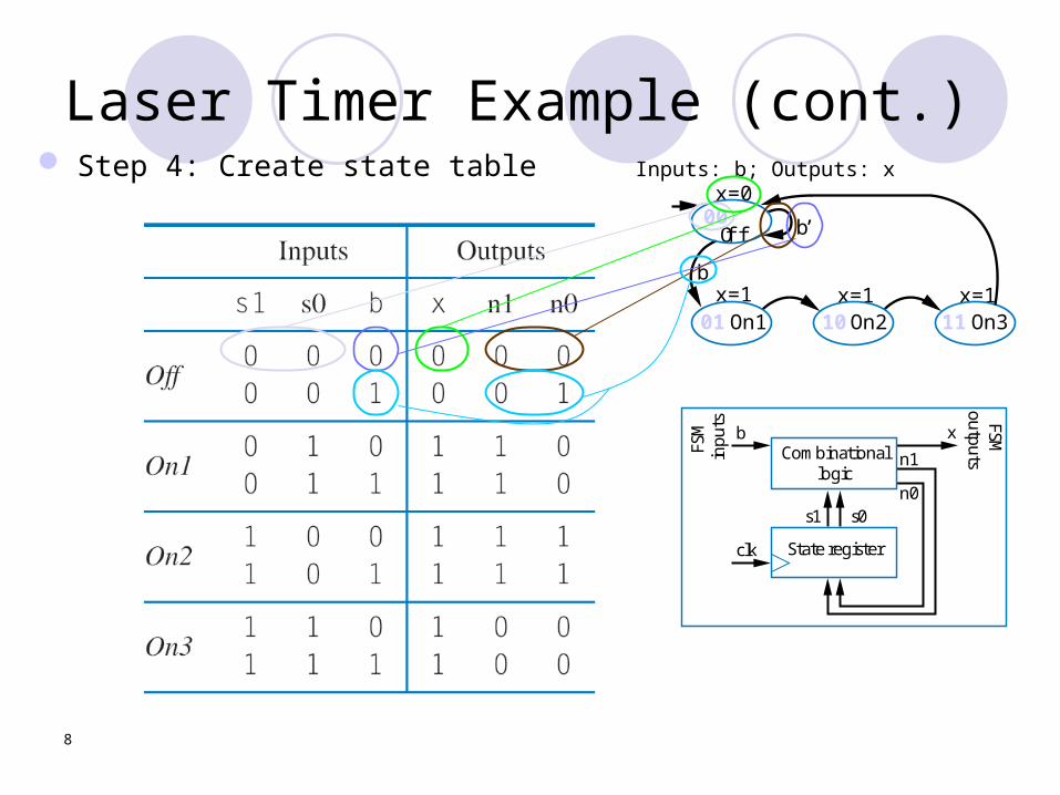
Laser Timer Example (cont.) Step 4: Create state table
x=1 x=1 x=1
x=0
b
b’
01
00
10 11On2On1
Off
On3
Inputs: b; Outputs: x
Combinationallogic
Stateregister
s1 s0
n1
n0
xb
clk
FSM
inpu
ts FSMoutputs

9
Laser Timer Example (cont.) Step 5: Implement combinational
logic Combinationallogic
Stateregister
s1 s0
n1
n0
xb
clk
FSM
inpu
ts FSMoutputs
x = s1 + s0 (note from the table that x=1 if s1 = 1 or s0 = 1)
n1 = s1’s0b’ + s1’s0b + s1s0’b’ + s1s0’bn1 = s1’s0 + s1s0’
n0 = s1’s0’b + s1s0’b’ + s1s0’bn0 = s1’s0’b + s1s0’
10
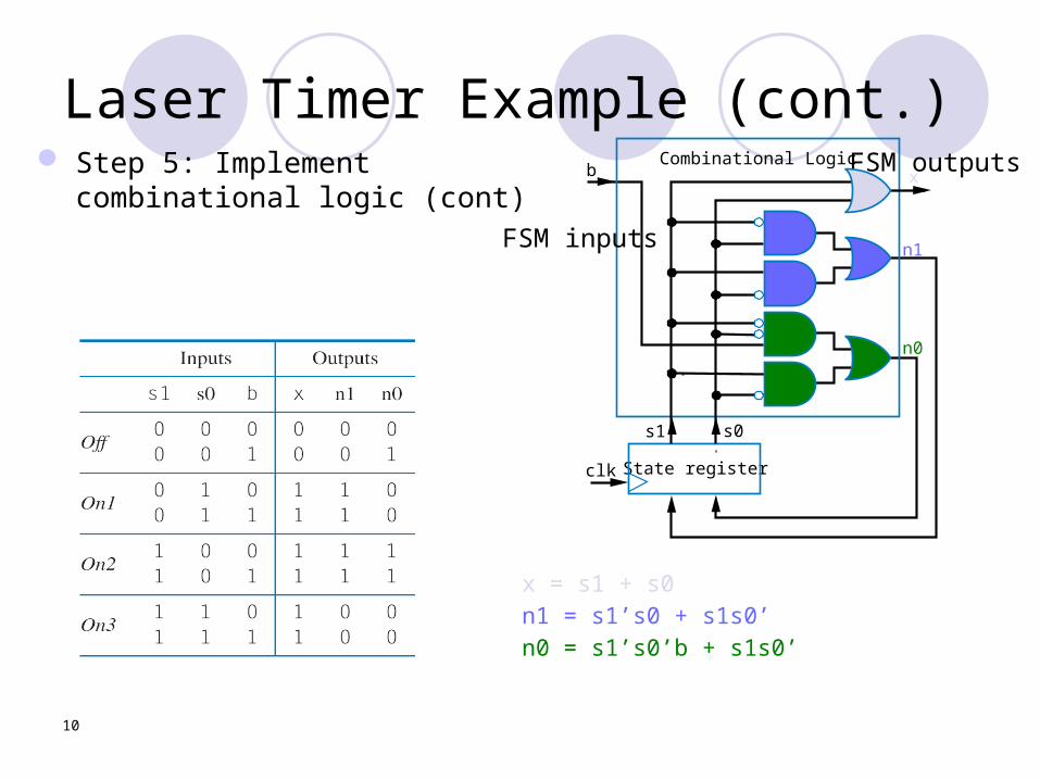
Laser Timer Example (cont.) Step 5: Implement combinational
logic (cont)
x = s1 + s0n1 = s1’s0 + s1s0’n0 = s1’s0’b + s1s0’
Combinationallogic
Stateregister
s1 s0
n1
n0
xb
clk
FSM
inpu
ts FSMoutputs
n1
n0
s0s1
clk
Combinational Logic
State register
b FSM outputs
FSM inputs
x

11
Understanding the Controller’s Behavior
s0s1
b x
n1
n0
x=1 x=1 x=1b
01 10 11On2On1
Off
On3
00
0 0
0
00
0
b’
0
0
0
00
x=0
000
clk
clk
Inputs:
Outputs:
1
0
10
b
1
0
10
0
s0s1
b x
n1
n0
x=1 x=1 x=1
b’
01 10 11On2On1
Off
On3
clk
b
x
00
0 0
x=0
000
state=00 state=00
s0s1
b x
n1
n0
x=1 x=1 x=1
x=0
b
b’
01
00
10 11On2On1
Off
On3
1
0
1
1
0
00
110
clk0 1
01
state=01

12
Standard timers: timer configurations
Top2
Time with prescaler
16-bit up counter
Clk Prescaler
Mode
Interval timer Indicates when desired time
interval has passed We set terminal count to desired
intervalNumber of clock cycles
= Desired time interval / Clock period
Cascaded counters Prescaler
Divides clock Increases range, decreases
resolution
16-bit up counter
Clk16
Terminal count
=Top
Reset
Timer with a terminal count
Cnt
16-bit up counter
Clk
16-bit up counter
16
Cnt2
Top1
16/32-bit timer
Cnt1
16

13
Example: Reaction Timer
indicator light
reaction button
time: 100 msLCD
/* main.c */
#define MS_INIT 63535 void main(void){ int count_milliseconds = 0; configure timer mode set Cnt to MS_INIT
wait a random amount of time turn on indicator light start timer
while (user has not pushed reaction button){ if(Top) { stop timer set Cnt to MS_INIT start timer reset Top count_milliseconds++; } } turn light off printf(“time: %i ms“, count_milliseconds);}
Measure time between turning light on and user pushing button 16-bit timer, clk period is 83.33 ns, counter
increments every 6 cycles Resolution = 6*83.33=0.5 microsec. Range = 65535*0.5 microseconds = 32.77
milliseconds Want a program to count increments of 1 millisec.
So, we initialize an up counter to 65535 – 1000/0.5 = 63535:
MaxCount - Time needed/ resolution=initial count

14
Watchdog timer
scalereg
checkreg
timereg to system resetor
interrupt
osc clkprescaler
Top overflow
12 MHz
1MHz X11 bit Up counter
16 bit Up counter
0 disable 1 enable
/* main.c */
main(){ wait until card inserted call watchdog_reset_routine while(transaction in progress){ if(button pressed){ perform corresponding action call watchdog_reset_routine }
/* if watchdog_reset_routine not called every < 2 minutes, interrupt_service_routine is called */}
watchdog_reset_routine(){/* checkreg is set so we can load value into timereg. Zero is loaded into scalereg and 11070 is loaded into timereg */
checkreg = 1 scalereg = 0 timereg = 5535}
void interrupt_service_routine(){ eject card reset screen}
Must reset timer every X time unit, else timer generates a signal
Common use: detect failure, self-reset
Another use: timeouts e.g., ATM machine Scalereg: 11-bit timer,
1μsec resolution. Scalereg Top signal
toggles every 211*1μsec= 2.048 msec
Hence, Timereg: 16-bit timer, 2 msec. resolution
timereg value = maxCnt-time needed/resoloution
X = 65535-2min/2msec X=65535-2*60/0.002
X=5535

Software based timers // Example 2a: Binary count on LEDs #include <hidef.h> /* common defines and macros */ #include <mc9s12dg256.h> /* derivative information */ #pragma LINK_INFO DERIVATIVE "mc9s12dg256b"
#include "main_asm.h" /* interface to the assembly module */
void delay(void);
void main(void) { int i; PLL_init(); // set system clock frequency to 24 MHz led_enable(); // enable LEDs seg7_disable(); // diable 7-segment displays while(1){ for (i=0;i<256;i++) { leds_on(i); // display i as binary on LEDs delay(); } } } void delay() { int i,j; for(i=0;i<500;i++) { for (j=0;j<6248;j++){ //do nothing..just spend time } } }
500x6248=3,124,000 times. Bus frequency 24MHz, assume the no-op inner loop takes 4 clock cycles:
4*3,124,000/24,000,000=0.52 seconds
15
16
Serial Transmission Using UARTs
embedded device1 0
0 11 0 1
1
Sending UART
1 0 0 1 1 0 1 1
Receiving UART
1 0 0 1 1 0 1 1
start bitdata
end bit
1 0 0 1 1 0 1 1
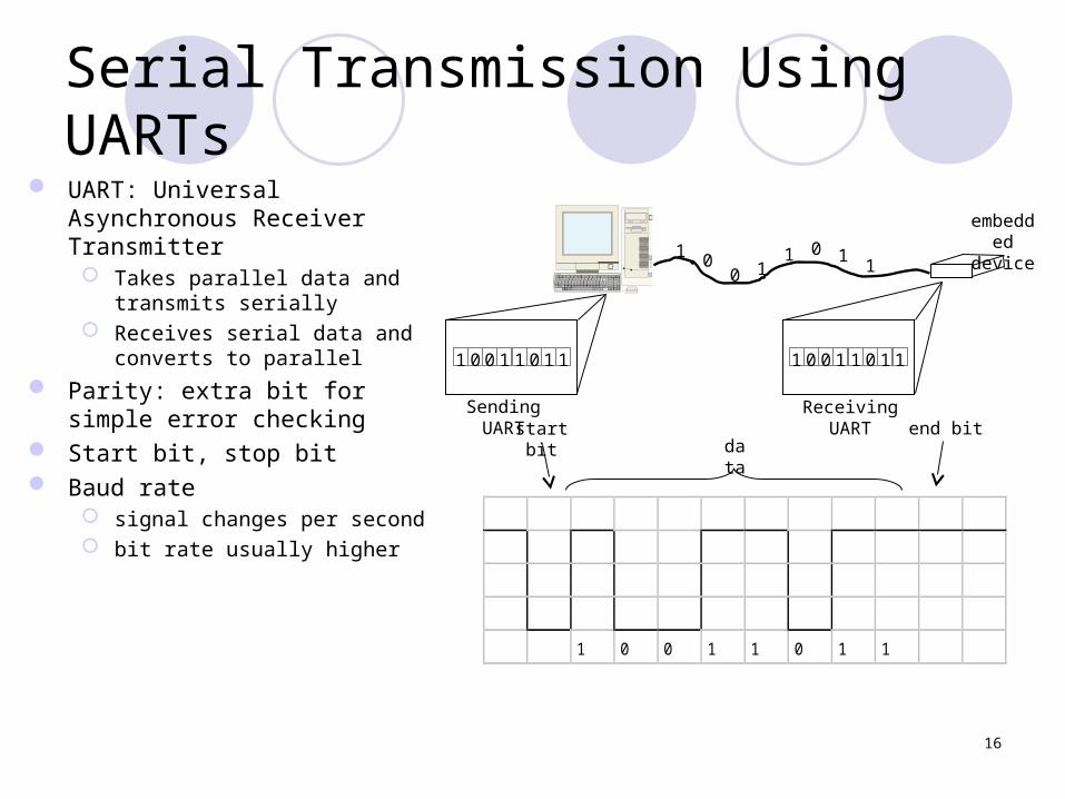
UART: Universal Asynchronous Receiver Transmitter Takes parallel data and transmits
serially Receives serial data and converts
to parallel
Parity: extra bit for simple error checking
Start bit, stop bit Baud rate
signal changes per second bit rate usually higher

17
Serial Transmission Using UARTs Clocks on sender and receiver are
never exactly in sync Requires synchronization of
receiver High-low transition signals frame
boundary
18
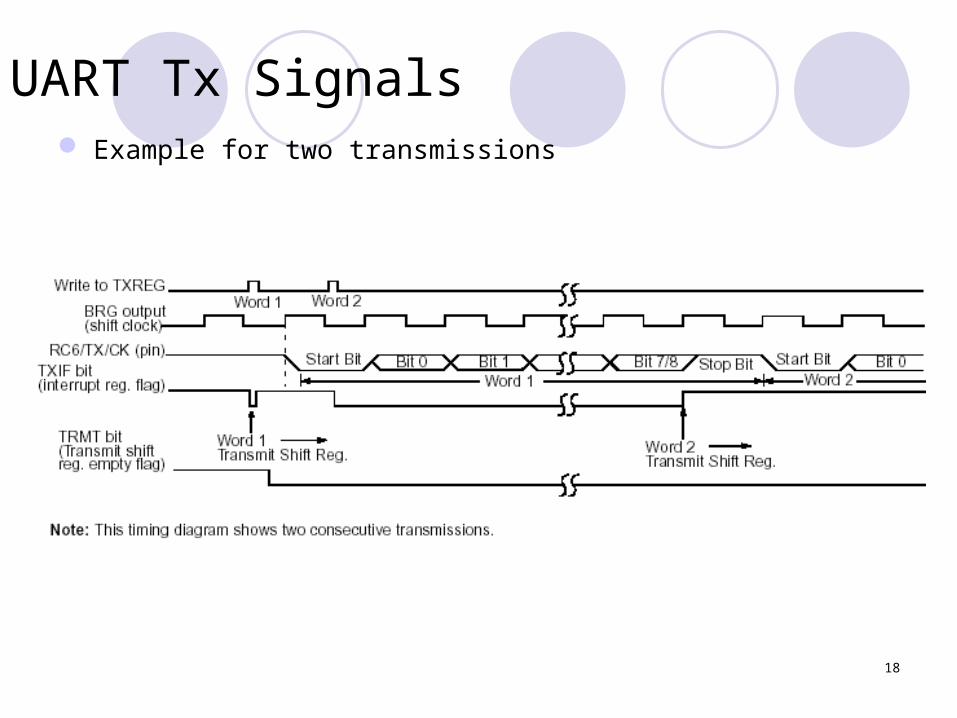
UART Tx Signals Example for two transmissions

19
UART Receiving example 2-byte FIFO

20
Example UART /MAX 232 interface

21
MAX232 The MAX232 is a dual driver/receiver that
includes a capacitive voltage generator to supply standard voltage levels for TIA/EIA-232-F interface.
Uses a single 5-V supply. Each receiver converts TIA/EIA-232-F
inputs to 5-V TTL/CMOS levels. These receivers have a typical threshold
of 1.3 V, a typical hysteresis of 0.5 V, and can accept ±30-V inputs.
Each driver converts TTL/CMOS input levels into TIA/EIA-232-F levels.

22
MAX232

23
MAX232: Receiver
24
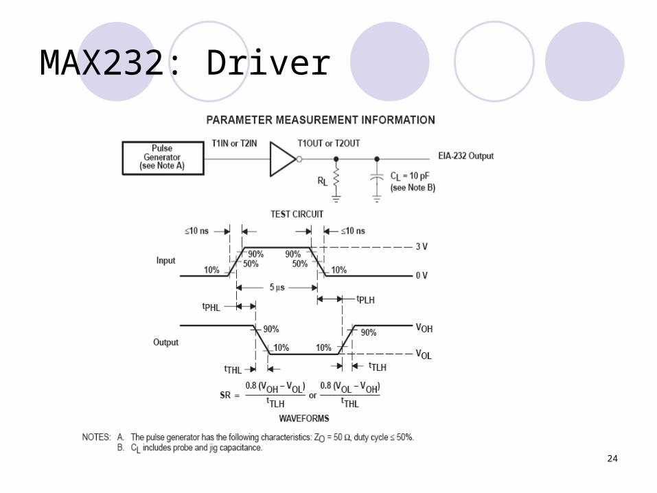
MAX232: Driver
Related Documents