SITOP power supply SITOP expansion modules Manual SITOP RED1200 redundancy module 6EP4346-7RB00-0AX0 SITOP RED1200 redundancy module 6EP4347-7RB00-0AX0 SITOP PSE202U redundancy module 6EP1961-3BA21 SITOP PSE202U redundancy module 6EP1962-2BA00 SITOP PSE202U redundancy module 6EP1964-2BA00 SITOP PSE201U buffer module 6EP1961-3BA01 Inrush current limiter Logo! ICL230 6EP4683-6LB00-0AY0 SITOP inrush current limiter 6EP1967-2AA00 06.2019 A5E36605235-1-76 Overview Safety instructions 1 Description, device design, dimension drawing 2 Mounting/removal 3 Mounting position, mounting clearances 4 Installation 5 Technical data 6 Safety, approvals, EMC 7 Ambient conditions 8 Applications 9 Environment 10 Service & Support 11

Welcome message from author
This document is posted to help you gain knowledge. Please leave a comment to let me know what you think about it! Share it to your friends and learn new things together.
Transcript

SITOP power supply
SITOP expansion modules
Manual
SITOP RED1200 redundancy module 6EP4346-7RB00-0AX0 SITOP RED1200 redundancy module 6EP4347-7RB00-0AX0 SITOP PSE202U redundancy module 6EP1961-3BA21 SITOP PSE202U redundancy module 6EP1962-2BA00 SITOP PSE202U redundancy module 6EP1964-2BA00 SITOP PSE201U buffer module 6EP1961-3BA01 Inrush current limiter Logo! ICL230 6EP4683-6LB00-0AY0 SITOP inrush current limiter 6EP1967-2AA00 06.2019 A5E36605235-1-76
Overview
Safety instructions 1
Description, device design, dimension drawing
2
Mounting/removal 3
Mounting position, mounting clearances
4
Installation 5
Technical data 6
Safety, approvals, EMC 7
Ambient conditions 8
Applications 9
Environment 10
Service & Support 11

Siemens AG Digital Industries Postfach 48 48 90026 NÜRNBERG GERMANY
A5E36605235-1-76 Ⓟ 06/2019 Subject to change
Copyright © Siemens AG 2019. All rights reserved
Legal information Warning notice system
This manual contains notices you have to observe in order to ensure your personal safety, as well as to prevent damage to property. The notices referring to your personal safety are highlighted in the manual by a safety alert symbol, notices referring only to property damage have no safety alert symbol. These notices shown below are graded according to the degree of danger.
DANGER indicates that death or severe personal injury will result if proper precautions are not taken.
WARNING indicates that death or severe personal injury may result if proper precautions are not taken.
CAUTION indicates that minor personal injury can result if proper precautions are not taken.
NOTICE indicates that property damage can result if proper precautions are not taken.
If more than one degree of danger is present, the warning notice representing the highest degree of danger will be used. A notice warning of injury to persons with a safety alert symbol may also include a warning relating to property damage.
Qualified Personnel The product/system described in this documentation may be operated only by personnel qualified for the specific task in accordance with the relevant documentation, in particular its warning notices and safety instructions. Qualified personnel are those who, based on their training and experience, are capable of identifying risks and avoiding potential hazards when working with these products/systems.
Proper use of Siemens products Note the following:
WARNING Siemens products may only be used for the applications described in the catalog and in the relevant technical documentation. If products and components from other manufacturers are used, these must be recommended or approved by Siemens. Proper transport, storage, installation, assembly, commissioning, operation and maintenance are required to ensure that the products operate safely and without any problems. The permissible ambient conditions must be complied with. The information in the relevant documentation must be observed.
Trademarks All names identified by ® are registered trademarks of Siemens AG. The remaining trademarks in this publication may be trademarks whose use by third parties for their own purposes could violate the rights of the owner.
Disclaimer of Liability We have reviewed the contents of this publication to ensure consistency with the hardware and software described. Since variance cannot be precluded entirely, we cannot guarantee full consistency. However, the information in this publication is reviewed regularly and any necessary corrections are included in subsequent editions.
SITOP expansion modules Manual, 06.2019, A5E36605235-1-76 3
Overview
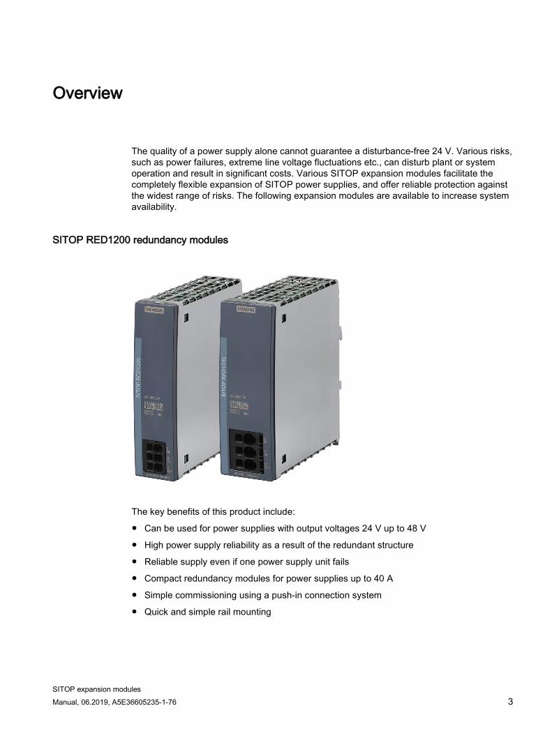
The quality of a power supply alone cannot guarantee a disturbance-free 24 V. Various risks, such as power failures, extreme line voltage fluctuations etc., can disturb plant or system operation and result in significant costs. Various SITOP expansion modules facilitate the completely flexible expansion of SITOP power supplies, and offer reliable protection against the widest range of risks. The following expansion modules are available to increase system availability.
SITOP RED1200 redundancy modules
The key benefits of this product include:
● Can be used for power supplies with output voltages 24 V up to 48 V
● High power supply reliability as a result of the redundant structure
● Reliable supply even if one power supply unit fails
● Compact redundancy modules for power supplies up to 40 A
● Simple commissioning using a push-in connection system
● Quick and simple rail mounting

Overview
SITOP expansion modules 4 Manual, 06.2019, A5E36605235-1-76
SITOP PSE202U redundancy modules
The key benefits of this product include:
● High 24 V supply reliability as a result of the redundant structure
● Reliable supply even if one power supply unit fails
● Compact redundancy modules for power supplies up to 40 A
● 24 V/NEC Class 2 redundancy module with 100 VA limit
● Diagnostics signal using LED and signaling contacts
● Adjustable activation threshold for LED and signaling contacts
● Quick and simple rail mounting

Overview
SITOP expansion modules Manual, 06.2019, A5E36605235-1-76 5
SITOP PSE201U buffer module
The key benefits of this product include:
● Only 2 cables are required to connect to the basic module
● Protection against brief power failures
● 100 ms up to max. 10 s buffer time depending on the load current
● The buffer time can be extended many times by connecting units in parallel
● Electrolytic capacitors are used for maintenance-free operation
● Quick and simple rail mounting

Overview
SITOP expansion modules 6 Manual, 06.2019, A5E36605235-1-76
Inrush current limiter Logo! ICL230
The key benefits of this product include:
● Inrush currents are reliably reduced
● Can be used on 1-phase AC line supplies with rated voltages of 100 V, 120 V or 230 V
● Can be used on 2-phase AC line supplies with a rated voltage of 208 V
● Minimized power loss by bypassing the limiting resistor in operation
● Quick and simple rail mounting

Overview
SITOP expansion modules Manual, 06.2019, A5E36605235-1-76 7
SITOP inrush current limiter
The key benefits of this product include:
● Inrush currents are reliably reduced
● Can be used on 1-phase AC line supplies with rated voltages of 100 V, 120 V or 230 V
● Can be used on 2 and 3-phase AC line supplies with rated voltages of 208 V to 480 V
● Minimized power loss by bypassing the limiting resistor in operation
● Quick and simple rail mounting

Overview
SITOP expansion modules 8 Manual, 06.2019, A5E36605235-1-76
Ordering data The following device versions are available: Expansion modules Type Order number SITOP RED1200 redundancy module 24 V DC/20 A input/output
6EP4346-7RB00-0AX0
SITOP RED1200 redundancy module 24 V DC/40 A input/output
6EP4347-7RB00-0AX0
SITOP PSE202U redundancy module 24 V DC/40 A input/output
6EP1961-3BA21
SITOP PSE202U redundancy module NEC CLASS 2 input/output 24 V DC/4 A
6EP1962-2BA00
SITOP PSE202U redundancy module Input/output 24 V DC/10 A
6EP1964-2BA00
SITOP PSE201U buffer module 6EP1961-3BA01 Inrush current limiter Logo! ICL230 6EP4683-6LB00-0AY0 SITOP inrush current limiter 6EP1967-2AA00
Accessory for SITOP RED1200 Type Order number Reference labeling plate (160 plates) 6ES7193-6LF30-0AW0

SITOP expansion modules Manual, 06.2019, A5E36605235-1-76 9
Table of contents
Overview................................................................................................................................................. 3
1 Safety instructions ................................................................................................................................. 13
1.1 General safety instructions ..................................................................................................... 13
1.2 Safety instructions for hazardous zones ................................................................................. 14 1.2.1 6EP1961-3BA21 redundancy module .................................................................................... 14 1.2.2 6EP1961-3BA01 buffer module .............................................................................................. 14
2 Description, device design, dimension drawing...................................................................................... 15
2.1 Device description ................................................................................................................... 15 2.1.1 Redundancy modules ............................................................................................................. 15 2.1.1.1 SITOP RED1200 ..................................................................................................................... 15 2.1.1.2 SITOP PSE202U .................................................................................................................... 16 2.1.2 Buffer module .......................................................................................................................... 19 2.1.3 Inrush current limiter ............................................................................................................... 20 2.1.3.1 Logo! ICL230 .......................................................................................................................... 20 2.1.3.2 SITOP inrush current limiter ................................................................................................... 21
2.2 Connections and terminal designation.................................................................................... 22 2.2.1 Redundancy modules ............................................................................................................. 22 2.2.1.1 SITOP RED1200 ..................................................................................................................... 22 2.2.1.2 SITOP PSE202U .................................................................................................................... 24 2.2.2 Buffer module .......................................................................................................................... 26 2.2.3 Inrush current limiter ............................................................................................................... 27 2.2.3.1 Logo! ICL230 .......................................................................................................................... 27 2.2.3.2 SITOP inrush current limiter ................................................................................................... 28
2.3 Potentiometer .......................................................................................................................... 29 2.3.1 SITOP PSE202U redundancy modules .................................................................................. 29
2.4 Status displays and signaling ................................................................................................. 30 2.4.1 SITOP PSE202U redundancy modules .................................................................................. 30 2.4.2 Buffer module .......................................................................................................................... 31 2.4.3 Inrush current limiter ............................................................................................................... 32 2.4.3.1 Logo! ICL230 .......................................................................................................................... 32 2.4.3.2 SITOP inrush current limiter ................................................................................................... 33
2.5 Dimensions and weight ........................................................................................................... 34 2.5.1 Redundancy modules ............................................................................................................. 34 2.5.1.1 SITOP RED1200 ..................................................................................................................... 34 2.5.1.2 SITOP PSE202U .................................................................................................................... 36 2.5.2 Buffer module .......................................................................................................................... 38 2.5.3 Inrush current limiter ............................................................................................................... 39 2.5.3.1 Logo! ICL230 .......................................................................................................................... 39 2.5.3.2 SITOP inrush current limiter ................................................................................................... 40

Table of contents
SITOP expansion modules 10 Manual, 06.2019, A5E36605235-1-76
3 Mounting/removal ................................................................................................................................. 41
3.1 Redundancy modules ............................................................................................................ 41 3.1.1 SITOP RED1200 .................................................................................................................... 41 3.1.2 6EP1961-3BA21 .................................................................................................................... 43 3.1.3 6EP1962-2BA00 and 6EP1964-2BA00 ................................................................................. 44
3.2 Buffer module ......................................................................................................................... 45
3.3 Inrush current limiter .............................................................................................................. 46 3.3.1 Logo! ICL230 .......................................................................................................................... 46 3.3.2 SITOP inrush current limiter ................................................................................................... 48
4 Mounting position, mounting clearances ................................................................................................ 49
4.1 Standard mounting position ................................................................................................... 49
4.2 Other mounting positions ....................................................................................................... 52 4.2.1 Other mounting positions ....................................................................................................... 52 4.2.2 SITOP RED1200 .................................................................................................................... 52 4.2.2.1 6EP4346-7RB00-0AX0 .......................................................................................................... 52 4.2.2.2 6EP4347-7RB00-0AX0 .......................................................................................................... 55 4.2.3 SITOP PSE202U.................................................................................................................... 57 4.2.3.1 6EP1961-3BA21 .................................................................................................................... 57 4.2.3.2 6EP1962-2BA00 .................................................................................................................... 59 4.2.3.3 6EP1964-2BA00 .................................................................................................................... 61 4.2.4 Buffer module ......................................................................................................................... 62 4.2.5 Inrush current limiter .............................................................................................................. 62
5 Installation ............................................................................................................................................ 63
5.1 Input connections ................................................................................................................... 63 5.1.1 Redundancy modules ............................................................................................................ 63 5.1.1.1 SITOP RED1200 .................................................................................................................... 63 5.1.1.2 SITOP PSE202U.................................................................................................................... 64 5.1.2 Buffer module ......................................................................................................................... 65 5.1.3 Inrush current limiter .............................................................................................................. 66 5.1.3.1 Logo! ICL230 .......................................................................................................................... 66 5.1.3.2 SITOP inrush current limiter ................................................................................................... 66
5.2 Output connections ................................................................................................................ 68 5.2.1 Redundancy modules ............................................................................................................ 68 5.2.1.1 SITOP RED1200 .................................................................................................................... 68 5.2.1.2 SITOP PSE202U.................................................................................................................... 71 5.2.2 Buffer module ......................................................................................................................... 72 5.2.3 Inrush current limiter .............................................................................................................. 73 5.2.3.1 Logo! ICL230 .......................................................................................................................... 73 5.2.3.2 SITOP inrush current limiter ................................................................................................... 73
6 Technical data ...................................................................................................................................... 75
6.1 Input ....................................................................................................................................... 75 6.1.1 Redundancy modules ............................................................................................................ 75 6.1.2 Buffer module ......................................................................................................................... 75 6.1.3 Inrush current limiter .............................................................................................................. 76

Table of contents
SITOP expansion modules Manual, 06.2019, A5E36605235-1-76 11
6.2 Output ..................................................................................................................................... 77 6.2.1 Redundancy modules ............................................................................................................. 77 6.2.2 Buffer module .......................................................................................................................... 78 6.2.3 Inrush current limiter ............................................................................................................... 79
6.3 Protection and monitoring ....................................................................................................... 80 6.3.1 Redundancy modules ............................................................................................................. 80 6.3.2 Buffer module .......................................................................................................................... 80 6.3.3 Inrush current limiter ............................................................................................................... 80
6.4 Mechanical system ................................................................................................................. 81 6.4.1 Redundancy modules ............................................................................................................. 81 6.4.2 Buffer module .......................................................................................................................... 82 6.4.3 Inrush current limiter ............................................................................................................... 83
6.5 Accessories ............................................................................................................................. 84 6.5.1 Redundancy modules ............................................................................................................. 84
6.6 Dimension drawing ................................................................................................................. 85 6.6.1 Redundancy modules ............................................................................................................. 85 6.6.2 Buffer module .......................................................................................................................... 85 6.6.3 Inrush current limiter ............................................................................................................... 85
7 Safety, approvals, EMC......................................................................................................................... 87
7.1 Safety ...................................................................................................................................... 87
7.2 Approvals ................................................................................................................................ 88 7.2.1 SITOP RED1200 ..................................................................................................................... 88 7.2.2 SITOP PSE202U .................................................................................................................... 88 7.2.3 Buffer module .......................................................................................................................... 89 7.2.4 Inrush current limiter ............................................................................................................... 89
7.3 EMC ........................................................................................................................................ 90 7.3.1 SITOP RED1200 ..................................................................................................................... 90 7.3.2 PSE202U ................................................................................................................................ 90 7.3.3 Buffer module .......................................................................................................................... 91 7.3.4 Inrush current limiter ............................................................................................................... 91
8 Ambient conditions ................................................................................................................................ 93
9 Applications .......................................................................................................................................... 95
9.1 Redundancy circuit for increased system availability ............................................................. 95
9.2 Design of 24 V load feeders with power limiting according to NEC class2 ............................ 98
9.3 Protection against short-time voltage dips .............................................................................. 99
10 Environment........................................................................................................................................ 101
11 Service & Support ............................................................................................................................... 103

Table of contents
SITOP expansion modules 12 Manual, 06.2019, A5E36605235-1-76

SITOP expansion modules Manual, 06.2019, A5E36605235-1-76 13
Safety instructions 1 1.1 General safety instructions
WARNING
Correct handling of the devices
When operating electrical devices, it is inevitable that certain components will carry dangerous voltages.
Therefore, failure to handle the units properly can result in death or serious physical injury as well as extensive property damage.
Only appropriately qualified personnel may work on or in the vicinity of this equipment.
Perfect, safe, and reliable operation of this equipment is dependent on proper transportation, storage, installation and mounting.
Before installation or maintenance work can begin, the system's main switch must be switched off and measures taken to prevent it being switched on again.
If this instruction is not observed, touching live parts can result in death or serious injury.

Safety instructions 1.2 Safety instructions for hazardous zones
SITOP expansion modules 14 Manual, 06.2019, A5E36605235-1-76
1.2 Safety instructions for hazardous zones It is only permissible that the devices listed below are used in hazardous zones.
1.2.1 6EP1961-3BA21 redundancy module The device complies with the ATEX directive 2014/34/EU; EN 60079-0; EN 60079-15.
WARNING
ONLY ADJUST VOLTAGES IN NON-HAZARDOUS AREAS!
1.2.2 6EP1961-3BA01 buffer module The device complies with the ATEX directive 2014/34/EU; EN 60079-0; EN 60079-15.

SITOP expansion modules Manual, 06.2019, A5E36605235-1-76 15
Description, device design, dimension drawing 2 2.1 Device description
2.1.1 Redundancy modules
2.1.1.1 SITOP RED1200 SITOP RED1200 redundancy modules are the optimal addition to all 24 - 48 V power supplies to provide additional protection against failure of the 24 - 48 V supply. The redundancy module continuously monitors the feeding power supplies, and when one device fails, the other one automatically takes over the complete 24 - 48 V supply.
① 24 - 48 V input – supply voltage from power supplies 1 and 2 ② 24 - 48 V output – supply voltage to the load and 0 V connection to the internal supply ③ Mounting rail slider ④ Natural convection ⑤ Clearance above/below
Figure 2-1 Design

Description, device design, dimension drawing 2.1 Device description
SITOP expansion modules 16 Manual, 06.2019, A5E36605235-1-76
2.1.1.2 SITOP PSE202U SITOP PSE202U redundancy modules are the optimum addition to all 24 V power supplies to provide additional protection against failure of the 24 V supply. The redundancy module continuously monitors the feeding power supplies, and when one device fails, the other one automatically takes over the complete 24 V supply.
The failure of a 24 V power supply is signaled using an LED and a relay contact. The response threshold for this signal can be set between 20 V and 25 V using a potentiometer on the redundancy module. (when delivered, 20 V)
With redundancy module NEC class2, a redundant 24 V power supply can be implemented, where the output power is limited to 100 VA.
① 24 V input – supply voltage from power supplies 1 and 2 ② 24 V output – supply voltage to the load and 0 V connection to the internal supply ③ Floating relay contact (changeover contact) ④ 20 - 25 V potentiometer ⑤ Indicator light ⑥ Mounting rail slider ⑦ Natural convection ⑧ Clearance above/below
Figure 2-2 Design of the 6EP1961-3BA21

Description, device design, dimension drawing 2.1 Device description
SITOP expansion modules Manual, 06.2019, A5E36605235-1-76 17
① 24 V input – supply voltage from power supplies 1 and 2 as well as 0 V connection to the
internal supply ② 24 V output – supply voltage to the load and floating relay contact ③ Indicator light (LED) ④ Potentiometer for setting the signal threshold ⑤ Latch for manual unlocking ⑥ Lug for unlocking using a screwdriver ⑦ RST button to switch on again ⑧ Natural convection ⑨ Clearance above/below
Figure 2-3 Design of the 6EP1962-2BA00

Description, device design, dimension drawing 2.1 Device description
SITOP expansion modules 18 Manual, 06.2019, A5E36605235-1-76
① 24 V input – supply voltage from power supplies 1 and 2 as well as 0 V connection to the
internal supply ② 24 V output – supply voltage to the load and floating relay contact ③ Indicator light (LED) ④ Potentiometer for setting the signal threshold ⑤ Latch for manual unlocking ⑥ Lug for unlocking using a screwdriver ⑦ Natural convection ⑧ Clearance above/below
Figure 2-4 Design of the 6EP1964-2BA00

Description, device design, dimension drawing 2.1 Device description
SITOP expansion modules Manual, 06.2019, A5E36605235-1-76 19
2.1.2 Buffer module The SITOP PSE201U buffer module buffers brief power failures in the seconds range and can be used with all SITOP smart and SITOP modular 24 V power supplies. The buffer module uses maintenance-free capacitors as energy storage devices and automatically supplies 24 V in the event that the power supply voltage fails.
The buffer module is simply connected in parallel to the power supply output.
To increase the buffer time (max. 10 s), several buffer modules can be connected in parallel.
① 24 V DC supply voltage ② Indicator light (24 V OK) ③ Mounting rail slider ④ Natural convection ⑤ Clearance above/below
Figure 2-5 Design

Description, device design, dimension drawing 2.1 Device description
SITOP expansion modules 20 Manual, 06.2019, A5E36605235-1-76
2.1.3 Inrush current limiter
2.1.3.1 Logo! ICL230 The Logo! ICL230 inrush current limiter is used to reliably reduce inrush currents, e.g. caused by LEDs, transformers or switched-mode power supplies as a result of the rectifier circuit at the input with capacitor charging.
It is used for 1-phase AC line supplies with 100 V, 120 V or 230 V or for 2-phase line supplies with 208 V rated voltage on the line side, upstream of transformers, power supplies or LEDs. Using the integrated fixed resistor, it limits the inrush current to approx. 10 A at 230 V. In steady-state operation, the limiting resistor is bypassed after approx. 60 ms, therefore minimizing the associated power loss.
① AC input ② AC output ③ Indicator light ④ Mounting rail slider ⑤ Mounting lug to remove ⑥ Convection ⑦ Clearance above/below
Figure 2-6 Design

Description, device design, dimension drawing 2.1 Device description
SITOP expansion modules Manual, 06.2019, A5E36605235-1-76 21
2.1.3.2 SITOP inrush current limiter The SITOP inrush current limiter is used to reliably reduce inrush currents, e.g. caused by transformers or switched-mode power supplies as a result of the rectifier circuit at the input with capacitor charging.
It is used for 1-phase AC line supplies with 100 V, 120 V or 230 V or for 2 and 3- phase line supplies with 208 V to 480 V line voltage on the line side, upstream of transformers or power supplies. Using the integrated fixed resistor, it limits the inrush current to e.g. < 10 A at 230 V. In steady-state operation, the limiting resistor is bypassed after approx. 120 ms, therefore minimizing the associated power loss.
① Input ② Output ③ Indicator light
Figure 2-7 Design

Description, device design, dimension drawing 2.2 Connections and terminal designation
SITOP expansion modules 22 Manual, 06.2019, A5E36605235-1-76
2.2 Connections and terminal designation
2.2.1 Redundancy modules
2.2.1.1 SITOP RED1200
Note
UL requirement: Use suitable copper cables that are designed for operating temperatures of at least 90 °C (only for UL508).
Connections and terminal designations of the 6EP4346-7RB00-0AX0 redundancy module
① 24 - 48 V input – supply voltage from power supplies 1 and 2 "DC IN1", "DC IN2"
one spring-loaded terminal each
② 24 - 48 V output - supply voltage to the load /"DC OUT1"
one spring-loaded terminal each
Figure 2-8 6EP4346-7RB00-0AX0 terminal data

Description, device design, dimension drawing 2.2 Connections and terminal designation
SITOP expansion modules Manual, 06.2019, A5E36605235-1-76 23
Connections and terminal designations of the 6EP4347-7RB00-0AX0 redundancy module
① 24 - 48 V input – supply voltage from power supplies 1 and 2 "DC IN1", "DC IN2"
one spring-loaded terminal each
② 24 - 48 V output - supply voltage to the load /"DC OUT1"
one spring-loaded terminal each
Figure 2-9 6EP4347-7RB00-0AX0 terminal data

Description, device design, dimension drawing 2.2 Connections and terminal designation
SITOP expansion modules 24 Manual, 06.2019, A5E36605235-1-76
2.2.1.2 SITOP PSE202U
Note
UL requirement: Use suitable copper cables that are designed for operating temperatures of at least 65/75 °C.
Connections and terminal designations of the 6EP1961-3BA21 redundancy module
① 24 V input – supply voltage from power supplies 1 and 2 "IN 24 V-1", "IN 24 V-2"
One screw terminal each
② 24 V output - supply voltage to the load /"OUT 24 V" 0 V connection to the internal supply "GND"
One screw terminal each
③ Floating relay contact (changeover contact) "OK"
Plug-in terminal 3 screw terminals
*1) Do not subject the end stop to higher loads *2) 16 mm2 for square crimping, otherwise 10 mm2
Figure 2-10 6EP1961-3BA21 terminal data

Description, device design, dimension drawing 2.2 Connections and terminal designation
SITOP expansion modules Manual, 06.2019, A5E36605235-1-76 25
Connections and terminal designations of the 6EP1962-2BA00 and 6EP1964-2BA00 redundancy modules
① 24 V input – supply voltage from power sup-plies 1 and 2 "IN 24V-1", "IN 24V-2" 0 V connection to the internal supply "GND"
Plug-in terminal each with a screw terminal
② 24 V output - supply voltage to the load "OUT 24 V" Floating relay contact "O.K."
Plug-in terminal with one screw terminal (output) and two screw terminals (relay contact)
*1) Do not subject the end stop to higher loads
Figure 2-11 6EP1962-2BA00 / 6EP1964-2BA00 terminal data

Description, device design, dimension drawing 2.2 Connections and terminal designation
SITOP expansion modules 26 Manual, 06.2019, A5E36605235-1-76
2.2.2 Buffer module Connections and terminal designations
① 24 V DC supply voltage "+", "-" 1 screw terminal each
*1) 16 mm2 for square crimping, otherwise 10 mm2
Figure 2-12 Terminal data

Description, device design, dimension drawing 2.2 Connections and terminal designation
SITOP expansion modules Manual, 06.2019, A5E36605235-1-76 27
2.2.3 Inrush current limiter
2.2.3.1 Logo! ICL230
Note
Use copper wire certified for 90 °C (only for UL508).
Connections and terminal designations
① Input "L1", "N" One screw terminal each
② Output "L1", "N" One screw terminal each
Figure 2-13 Terminal data

Description, device design, dimension drawing 2.2 Connections and terminal designation
SITOP expansion modules 28 Manual, 06.2019, A5E36605235-1-76
2.2.3.2 SITOP inrush current limiter
Note
Use suitable copper cables that are designed for operating temperatures of at least 65/75 °C.
Connections and terminal designations
① Input "L1", "N" One screw terminal each
② Output "L1", "N" One screw terminal each
Figure 2-14 Terminal data

Description, device design, dimension drawing 2.3 Potentiometer
SITOP expansion modules Manual, 06.2019, A5E36605235-1-76 29
2.3 Potentiometer
2.3.1 SITOP PSE202U redundancy modules The potentiometer ④ at the front of the device is used to set the response threshold of the LED signal and the signaling contact; it can be set in the range from 20 V up to 25 V. (when delivered, 20 V)
Figure 2-15 6EP1961-3BA21 potentiometer
Figure 2-16 6EP196x-2BA00 potentiometer (example, 6EP1962-2BA00)
Note
It is only permissible to use an insulated screwdriver when actuating the potentiometer.
For notes on actuating the potentiometer (screwdriver, torque), see Figure 2-10 6EP1961-3BA21 terminal data (Page 24) and Figure 2-11 6EP1962-2BA00 / 6EP1964-2BA00 terminal data (Page 25)

Description, device design, dimension drawing 2.4 Status displays and signaling
SITOP expansion modules 30 Manual, 06.2019, A5E36605235-1-76
2.4 Status displays and signaling
2.4.1 SITOP PSE202U redundancy modules
Figure 2-17 Operating display and signaling
Operating display and signaling 6EP1961-3BA21
LED ⑤ lights up green both input voltages > switching threshold
LED ⑤ lights up red at least one input voltage < switching threshold
O.K. (floating relay contact) O.K. if both input voltages are > switching threshold (contact rating, 8 A/AC 240 V, 24 V DC)
Operating display and signaling 6EP1962-2BA00 6EP1964-2BA00
LED ③ lights up green both input voltages > switching threshold both input voltages > switching threshold
LED ③ lights up red at least one input voltage < switching threshold or the output is switched off
at least one input voltage < switching threshold
O.K. (floating relay contact) Contact is closed if one or both input voltages is/are < the switching threshold, or if the output is switched off. (contact rating 6 A/AC 42 V, 30 V DC; however, 100 VA max.)
Contact is open if one or both input voltages is/are < the switching threshold. (contact rating 6 A/AC 42 V, 30 V DC)

Description, device design, dimension drawing 2.4 Status displays and signaling
SITOP expansion modules Manual, 06.2019, A5E36605235-1-76 31
2.4.2 Buffer module
Figure 2-18 Status indicator
Status indicator 6EP1961-3BA01
LED ② lights up green Supply voltage > 20.5 V
LED ② off Supply voltage < 20.5 V

Description, device design, dimension drawing 2.4 Status displays and signaling
SITOP expansion modules 32 Manual, 06.2019, A5E36605235-1-76
2.4.3 Inrush current limiter
2.4.3.1 Logo! ICL230
Figure 2-19 Status indicator
Status indicator 6EP4683-6LB00-0AY0
LED ③ lights up green Normal operation
LED ③ off Supply voltage missing

Description, device design, dimension drawing 2.4 Status displays and signaling
SITOP expansion modules Manual, 06.2019, A5E36605235-1-76 33
2.4.3.2 SITOP inrush current limiter
Figure 2-20 Status indicator
Status indicator 6EP1967-2AA00
LED ③ lights up green Normal operation
LED ③ off Supply voltage missing

Description, device design, dimension drawing 2.5 Dimensions and weight
SITOP expansion modules 34 Manual, 06.2019, A5E36605235-1-76
2.5 Dimensions and weight
2.5.1 Redundancy modules
2.5.1.1 SITOP RED1200
Figure 2-21 Dimension drawing 6EP4346-7RB00-0AX0

Description, device design, dimension drawing 2.5 Dimensions and weight
SITOP expansion modules Manual, 06.2019, A5E36605235-1-76 35
Figure 2-22 Dimension drawing 6EP4347-7RB00-0AX0
6EP4346-7RB00-0AX0 6EP4347-7RB00-0AX0 Dimensions (W × H × D) in mm 35 × 135 × 125 45 × 135 × 125 Weight 0.47 kg 0.50 kg

Description, device design, dimension drawing 2.5 Dimensions and weight
SITOP expansion modules 36 Manual, 06.2019, A5E36605235-1-76
2.5.1.2 SITOP PSE202U
Figure 2-23 Dimension drawing 6EP1961-3BA21
Figure 2-24 Dimension drawing 6EP1962-2BA00

Description, device design, dimension drawing 2.5 Dimensions and weight
SITOP expansion modules Manual, 06.2019, A5E36605235-1-76 37
Figure 2-25 Dimension drawing 6EP1964-2BA00
6EP1961-3BA21 6EP1962-2BA00 6EP1964-2BA00 Dimensions (W × H × D) in mm 70 × 125 × 120.1 30 × 80 × 100 30 × 80 × 100 Weight 0.5 kg 0.125 kg 0.125 kg

Description, device design, dimension drawing 2.5 Dimensions and weight
SITOP expansion modules 38 Manual, 06.2019, A5E36605235-1-76
2.5.2 Buffer module
Figure 2-26 Dimension drawing
6EP1961-3BA01 Dimensions (W × H × D) in mm 70 × 125 × 120.9 Weight approx. 1.2 kg

Description, device design, dimension drawing 2.5 Dimensions and weight
SITOP expansion modules Manual, 06.2019, A5E36605235-1-76 39
2.5.3 Inrush current limiter
2.5.3.1 Logo! ICL230
Figure 2-27 Dimension drawing
6EP4683-6LB00-0AY0 Dimensions (W × H × D) in mm 18 × 90 × 53 Weight 0.14 kg

Description, device design, dimension drawing 2.5 Dimensions and weight
SITOP expansion modules 40 Manual, 06.2019, A5E36605235-1-76
2.5.3.2 SITOP inrush current limiter
Figure 2-28 Dimension drawing
6EP1967-2AA00 Dimensions (W × H × D) in mm 22.5 × 80 × 86.6 Weight 0.12 kg

SITOP expansion modules Manual, 06.2019, A5E36605235-1-76 41
Mounting/removal 3
WARNING
Installing the device in a housing or a control cabinet
SITOP expansion modules are chassis devices. They must be installed in a housing or control cabinet where only qualified personnel have access.
3.1 Redundancy modules
3.1.1 SITOP RED1200 The device can be mounted in a control cabinet on standard mounting rails (see Chapter Mechanical system (Page 81))
Mounting
To mount the device, position it with the mounting rail guide at the upper edge of the standard mounting rail and press down to lock it into place. If this is too difficult, press the slider ③ at the same time, as described under "Removal".
Removing
To remove, pull up the slider ③ using a screwdriver (see Figure 3-1 Mounting/removal (Page 42)) and disengage the device at the bottom edge of the standard mounting rail. Then you can remove the device from the upper edge of the standard mounting rail.

Mounting/removal 3.1 Redundancy modules
SITOP expansion modules 42 Manual, 06.2019, A5E36605235-1-76
Figure 3-1 Mounting/removal

Mounting/removal 3.1 Redundancy modules
SITOP expansion modules Manual, 06.2019, A5E36605235-1-76 43
3.1.2 6EP1961-3BA21 The device can be mounted in a control cabinet on standard mounting rails (see Chapter Mechanical system (Page 81))
Mounting
To mount the device, position it with the mounting rail guide at the upper edge of the standard mounting rail and press down to lock it into place. If this is too difficult, press slider ⑥ at the same time, as described under "Removal".
Removing
To remove, pull up the slider ⑥ using a screwdriver (see Figure 3-2 Mounting/removal (Page 43)) and disengage the device at the bottom edge of the standard mounting rail. Then you can remove the device from the upper edge of the standard mounting rail.
Figure 3-2 Mounting/removal
WARNING
Use in hazardous zones
If the devices are to be used in hazardous zones (II 3G Ex nA nC IIC T4 Gc) they must be installed in a distribution box with degree of protection IP54 or higher.

Mounting/removal 3.1 Redundancy modules
SITOP expansion modules 44 Manual, 06.2019, A5E36605235-1-76
3.1.3 6EP1962-2BA00 and 6EP1964-2BA00 The device can be mounted in a control cabinet on standard mounting rails (see Chapter Mechanical system (Page 81))
Mounting
To mount the device, position it with the mounting rail guide at the upper edge of the standard mounting rail and press down to lock it into place. If this is too difficult, press slider ⑥ at the same time, as described under "Removal".
Removing
To remove, pull up the slider ⑥ using a screwdriver (see Figure 3-3 Mounting/removal (Page 44)) and disengage the device at the bottom edge of the standard mounting rail. Then you can remove the device from the upper edge of the standard mounting rail.
Note
As an alternative to using a screwdriver, the mounting rail interlocking can be manually actuated from the top using the latch ⑤, and therefore no tools are required when mounting and removing.
Figure 3-3 Mounting/removal

Mounting/removal 3.2 Buffer module
SITOP expansion modules Manual, 06.2019, A5E36605235-1-76 45
3.2 Buffer module The device can be mounted in a control cabinet on standard mounting rails (see Chapter Mechanical system (Page 81))
Mounting
To mount the device, position it with the mounting rail guide at the upper edge of the standard mounting rail and press down to lock it into place. If this is too difficult, press the slider ③ at the same time, as described under "Removal".
Removing
To remove, pull up the slider ③ using a screwdriver (see Figure 3-4 Mounting/removal (Page 45)) and disengage the device at the bottom edge of the standard mounting rail. Then you can remove the device from the upper edge of the standard mounting rail.
Figure 3-4 Mounting/removal

Mounting/removal 3.3 Inrush current limiter
SITOP expansion modules 46 Manual, 06.2019, A5E36605235-1-76
3.3 Inrush current limiter
3.3.1 Logo! ICL230 The device can be mounted in a control cabinet and snapped onto standard mounting rails (see Chapter Mechanical system (Page 81)), or can be mounted on walls and panels using the withdrawable mounting lug (see Figure 3-6 Wall/panel mounting (Page 47)).
Mounting
To mount the device, position it with the mounting rail guide at the upper edge of the standard mounting rail and press down to lock it into place. If this is too difficult, press the slider ④ at the same time, as described under "Removal".
Removing
To remove, pull up the slider ④ using a screwdriver (see Figure 3-5 Mounting/removal (Page 46)) and disengage the device at the bottom edge of the standard mounting rail. Then you can remove the device from the upper edge of the standard mounting rail.
To remove the device, press it downwards and release it from the mounting rail.
Figure 3-5 Mounting/removal

Mounting/removal 3.3 Inrush current limiter
SITOP expansion modules Manual, 06.2019, A5E36605235-1-76 47
Figure 3-6 Wall/panel mounting

Mounting/removal 3.3 Inrush current limiter
SITOP expansion modules 48 Manual, 06.2019, A5E36605235-1-76
3.3.2 SITOP inrush current limiter The device can be mounted in a control cabinet on standard mounting rails (see Chapter Mechanical system (Page 81))
Mounting
To snap on, attach the device to the top of the mounting rail (I), press down gently (II), press-in the lower side (III) and snap it into place (IV).
Removing
To remove the device, press it downwards and release it from the mounting rail.
Figure 3-7 Mounting/removal

SITOP expansion modules Manual, 06.2019, A5E36605235-1-76 49
Mounting position, mounting clearances 4 4.1 Standard mounting position
Expansion modules must be mounted vertically in such a way that
- 6EP1961-3BA21 terminals are at the bottom
- 6EP1962-2BA00 terminals "OK" and "OUT 24V" are at the bottom
- 6EP1964-2BA00 terminals "OK" and "OUT 24V" are at the bottom
- 6EP1961-3BA01 terminals are at the bottom
- 6EP1967-2AA00 input terminals are at the top and the output terminals at the bottom.
A clearance of at least 50 mm should be maintained above and below the device; no clearance is required at the sides
The SITOP RED1200 redundancy modules must be mounted vertically to ensure correct cooling so that
- 6EP4346-7RB00-0AX0 terminals are at the bottom
- 6EP4347-7RB00-0AX0 terminals are at the bottom
A clearance of at least 45 mm should be maintained above and below the device; no clearance is required at the sides.
The LOGO! ICL230 inrush limiter must be mounted vertically to ensure correct cooling so that
- 6EP4683-6LB00-0AY0 output terminals are at the top and the input terminals at the bottom.
A clearance of at least 20 mm should be maintained above and below the device; no clearance is required at the sides.

Mounting position, mounting clearances 4.1 Standard mounting position
SITOP expansion modules 50 Manual, 06.2019, A5E36605235-1-76
Output current as a function of the ambient temperature and mounting height 6EP1961-3BA01 buffer module: -25 ... 70°C without derating 6EP1967-2AA00 inrush limiter: -25 ... 60°C without derating 6EP4683-6LB00-0AY0 inrush limiter: -40 ... 70°C without derating
Figure 4-1 6EP4346-7RB00-0AX0: Output current in the standard mounting position
Figure 4-2 6EP4347-7RB00-0AX0: Output current in the standard mounting position
Figure 4-3 6EP1961-3BA21: Output current in the standard mounting position

Mounting position, mounting clearances 4.1 Standard mounting position
SITOP expansion modules Manual, 06.2019, A5E36605235-1-76 51
Figure 4-4 6EP1962-2BA00: Output current in the standard mounting position
Figure 4-5 6EP1964-2BA00: Output current in the standard mounting position
Figure 4-6 Altitude derating

Mounting position, mounting clearances 4.2 Other mounting positions
SITOP expansion modules 52 Manual, 06.2019, A5E36605235-1-76
4.2 Other mounting positions
4.2.1 Other mounting positions For mounting positions that deviate from the standard mounting position, derating factors (reduction of the output power or the permissible ambient temperature) must be observed in accordance with the following diagrams.
Note
In the case of mounting positions that deviate from the standard mounting position, reduced mechanical resistance of the devices against vibration and shock must be expected.
Especially when installing on a vertically fastened standard mounting rail, additional measures may be required, e.g. to prevent the device from slipping on the standard mounting rail.
4.2.2 SITOP RED1200
4.2.2.1 6EP4346-7RB00-0AX0
Figure 4-7 Mounting position 1
Mounting position, mounting clearances 4.2 Other mounting positions
SITOP expansion modules Manual, 06.2019, A5E36605235-1-76 53
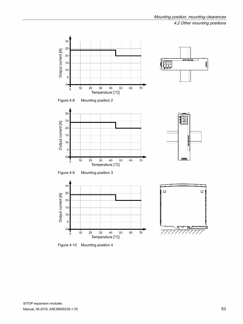
Figure 4-8 Mounting position 2
Figure 4-9 Mounting position 3
Figure 4-10 Mounting position 4

Mounting position, mounting clearances 4.2 Other mounting positions
SITOP expansion modules 54 Manual, 06.2019, A5E36605235-1-76
Figure 4-11 Mounting position 5

Mounting position, mounting clearances 4.2 Other mounting positions
SITOP expansion modules Manual, 06.2019, A5E36605235-1-76 55
4.2.2.2 6EP4347-7RB00-0AX0
Figure 4-12 Mounting position 1
Figure 4-13 Mounting position 2
Figure 4-14 Mounting position 3

Mounting position, mounting clearances 4.2 Other mounting positions
SITOP expansion modules 56 Manual, 06.2019, A5E36605235-1-76
Figure 4-15 Mounting position 4
Figure 4-16 Mounting position 5

Mounting position, mounting clearances 4.2 Other mounting positions
SITOP expansion modules Manual, 06.2019, A5E36605235-1-76 57
4.2.3 SITOP PSE202U
4.2.3.1 6EP1961-3BA21
Figure 4-17 Mounting position 1
Figure 4-18 Mounting position 2
Mounting position, mounting clearances 4.2 Other mounting positions
SITOP expansion modules 58 Manual, 06.2019, A5E36605235-1-76
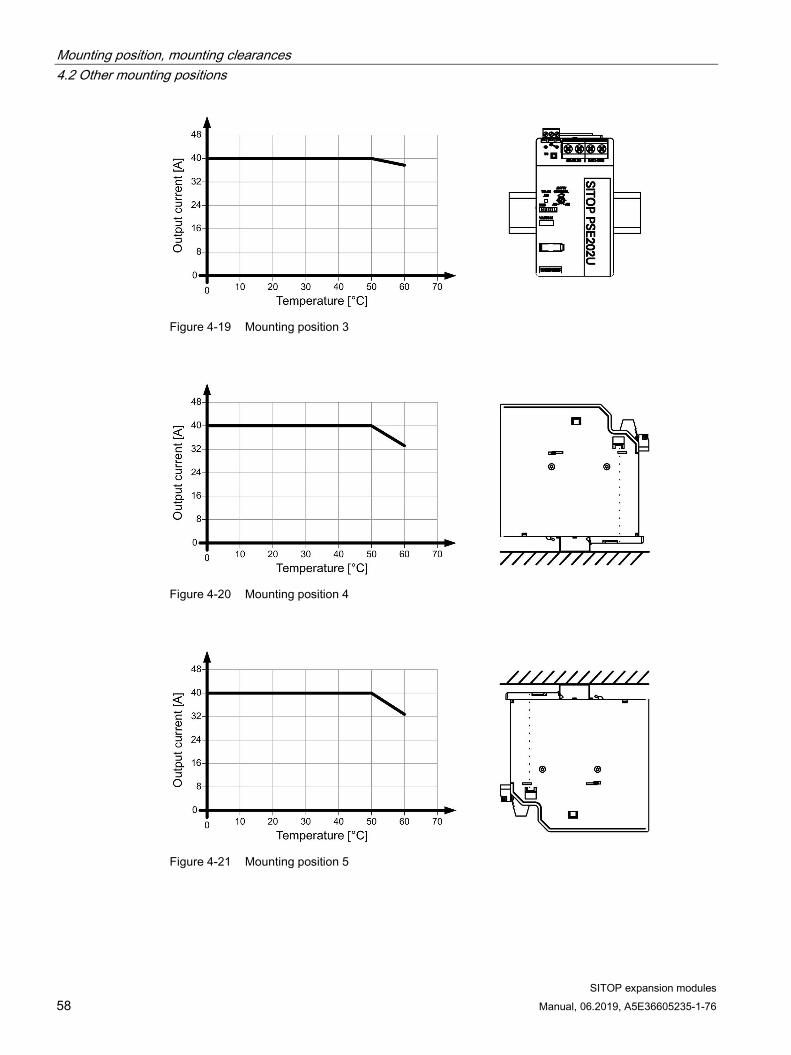
Figure 4-19 Mounting position 3
Figure 4-20 Mounting position 4
Figure 4-21 Mounting position 5

Mounting position, mounting clearances 4.2 Other mounting positions
SITOP expansion modules Manual, 06.2019, A5E36605235-1-76 59
4.2.3.2 6EP1962-2BA00
Figure 4-22 Mounting position 1
Figure 4-23 Mounting position 2
Figure 4-24 Mounting position 3

Mounting position, mounting clearances 4.2 Other mounting positions
SITOP expansion modules 60 Manual, 06.2019, A5E36605235-1-76
Figure 4-25 Mounting position 4
Figure 4-26 Mounting position 5

Mounting position, mounting clearances 4.2 Other mounting positions
SITOP expansion modules Manual, 06.2019, A5E36605235-1-76 61
4.2.3.3 6EP1964-2BA00
Figure 4-27 Mounting position 1
Figure 4-28 Mounting position 2
Figure 4-29 Mounting position 3

Mounting position, mounting clearances 4.2 Other mounting positions
SITOP expansion modules 62 Manual, 06.2019, A5E36605235-1-76
Figure 4-30 Mounting position 4
Figure 4-31 Mounting position 5
4.2.4 Buffer module The following applies for the 6EP1961-3BA01 buffer module: 0 ... 60 °C without derating in all mounting positions
4.2.5 Inrush current limiter The following applies for the 6EP1967-2AA00 and 6EP4683-6LB00-0AY0 inrush limiters: Mounting position rotated through 180° without derating, for all other mounting positions, maximum switch-on frequency once every 15 min.

SITOP expansion modules Manual, 06.2019, A5E36605235-1-76 63
Installation 5
WARNING
Hazard due to electric shock
Before installation or maintenance work can begin, the system's main switch must be switched off and measures taken to prevent it being switched on again. If this instruction is not observed, touching live parts can result in death or serious injury.
5.1 Input connections
NOTICE
Country-specific regulations must be observed when installing.
5.1.1 Redundancy modules
5.1.1.1 SITOP RED1200 Inputs "DC IN1" and "DC IN2" of the redundancy module must be connected with outputs "+" of the supplying power supplies.
Figure 5-1 Input/output

Installation 5.1 Input connections
SITOP expansion modules 64 Manual, 06.2019, A5E36605235-1-76
5.1.1.2 SITOP PSE202U Inputs "IN 24 V-1" and "IN 24 V-2" of the redundancy module must be connected with the "+" outputs of the supplying power supplies, and input "GND" of the redundancy module with the "-" outputs of the supplying power supplies.
NOTICE
It is not permissible to operate the device without the GND cable/conductor being connected. It is not permissible that cable IN 24V-1 or IN 24V-2 and the GND cable/conductor are interchanged.
Figure 5-2 Input 6EP1961-3BA21
Figure 5-3 Inputs 6EP1962-2BA00 in 6EP1964-2BA00

Installation 5.1 Input connections
SITOP expansion modules Manual, 06.2019, A5E36605235-1-76 65
5.1.2 Buffer module The buffer module is connected in parallel with the SITOP power supply. To do this, input/output "+" of the buffer module must be connected with output "+" of the supplying power supply and input/output "-" of the buffer module, with output "-" of the supplying power supply. The buffer module must be wired with the same cable/conductor cross-section as the output cable/conductor of the power supply.
Figure 5-4 Input/output
Installation 5.1 Input connections
SITOP expansion modules 66 Manual, 06.2019, A5E36605235-1-76
5.1.3 Inrush current limiter
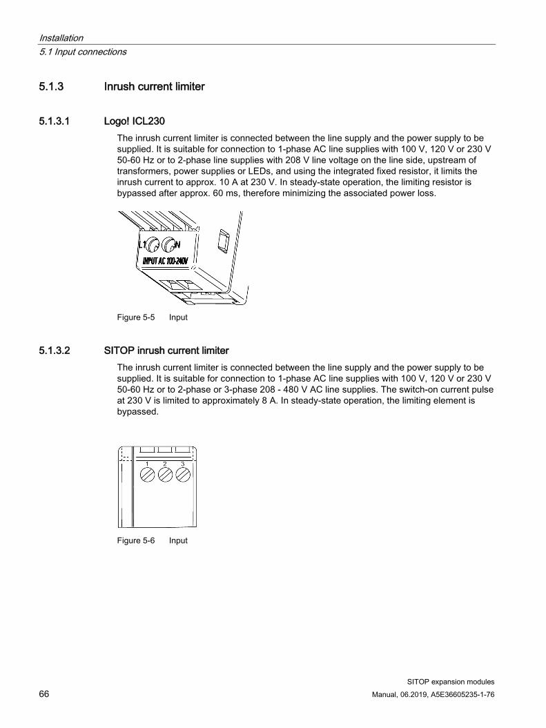
5.1.3.1 Logo! ICL230 The inrush current limiter is connected between the line supply and the power supply to be supplied. It is suitable for connection to 1-phase AC line supplies with 100 V, 120 V or 230 V 50-60 Hz or to 2-phase line supplies with 208 V line voltage on the line side, upstream of transformers, power supplies or LEDs, and using the integrated fixed resistor, it limits the inrush current to approx. 10 A at 230 V. In steady-state operation, the limiting resistor is bypassed after approx. 60 ms, therefore minimizing the associated power loss.
Figure 5-5 Input
5.1.3.2 SITOP inrush current limiter The inrush current limiter is connected between the line supply and the power supply to be supplied. It is suitable for connection to 1-phase AC line supplies with 100 V, 120 V or 230 V 50-60 Hz or to 2-phase or 3-phase 208 - 480 V AC line supplies. The switch-on current pulse at 230 V is limited to approximately 8 A. In steady-state operation, the limiting element is bypassed.
Figure 5-6 Input

Installation 5.1 Input connections
SITOP expansion modules Manual, 06.2019, A5E36605235-1-76 67
Depending on the particular application, the input terminals should be connected as shown in the following wiring diagram:
Figure 5-7 Wiring diagram

Installation 5.2 Output connections
SITOP expansion modules 68 Manual, 06.2019, A5E36605235-1-76
5.2 Output connections
5.2.1 Redundancy modules
5.2.1.1 SITOP RED1200 Output "DC OUT1" of the redundancy module must be connected to the load. See Figure 5-1 Input/output (Page 63).
The subsequent wiring is recommended to guarantee safe and reliable operation of the power supplies in all operating states:
Figure 5-8 Wiring, 1 module

Installation 5.2 Output connections
SITOP expansion modules Manual, 06.2019, A5E36605235-1-76 69
Figure 5-9 Wiring, 2 modules
To achieve an output voltage of 48 V DC, two 24 V SITOP power supplies of the same type can be connected in series. Depending on the grounding point of the secondary output voltage, voltages of +48 V, ±24 V or -48 V can be realized. To guarantee safe and reliable operation of the power supplies in all operating states, for the series circuit, the subsequent wiring when using two redundancy modules RED1200 (6EP4346-7RB00-0AX0 or 6EP4347-7RB00-0AX0) is recommended.

Installation 5.2 Output connections
SITOP expansion modules 70 Manual, 06.2019, A5E36605235-1-76
Figure 5-10 Series connection to increase the voltage
WARNING
SELV is not guaranteed in the case of a fault
When two power supplies are connected in series, it is not possible to ensure the continuously permissible SELV voltage of maximum of 60 V DC acc. to EN 60950-1 in the event of a fault.

Installation 5.2 Output connections
SITOP expansion modules Manual, 06.2019, A5E36605235-1-76 71
5.2.1.2 SITOP PSE202U Output "Out 24 V" of the redundancy module must be connected to the load.
Note
The output cable of the redundancy module must have a cable cross-section that can conduct the maximum total current of both supplying power supplies.
Figure 5-11 Output 6EP1961-3BA21
Figure 5-12 Outputs 6EP1962-2BA00 and 6EP1964-2BA00

Installation 5.2 Output connections
SITOP expansion modules 72 Manual, 06.2019, A5E36605235-1-76
The subsequent wiring is recommended for the 6EP1961-3BA21 to guarantee safe and reliable operation of the power supplies in all operating states:
Figure 5-13 Wiring note
5.2.2 Buffer module See Buffer module (Page 65)

Installation 5.2 Output connections
SITOP expansion modules Manual, 06.2019, A5E36605235-1-76 73
5.2.3 Inrush current limiter
5.2.3.1 Logo! ICL230 The power supply to be supplied is connected at the output terminals of the inrush current limiter.
Figure 5-14 Output
5.2.3.2 SITOP inrush current limiter The power supply to be supplied is connected at the output terminals of the inrush current limiter.
Figure 5-15 Output
Depending on the particular application, the output terminals should be connected as shown in the wiring diagram (see Figure 5-7 Wiring diagram (Page 67))
Note
For 3-phase applications, the N conductor is only connected on the input side to supply the the inrush current limiter itself. It is not permissible that N is connected on the output side.

Installation 5.2 Output connections
SITOP expansion modules 74 Manual, 06.2019, A5E36605235-1-76

SITOP expansion modules Manual, 06.2019, A5E36605235-1-76 75
Technical data 6
Note
Technical data apply for a rated input voltage, rated load and 25 °C ambient temperature if nothing else is specified.
6.1 Input
6.1.1 Redundancy modules
6EP4346-7RB00-0AX0 6EP4347-7RB00-0AX0
6EP1961-3BA21 6EP1962-2BA00 6EP1964-2BA00
Input DC voltage DC voltage DC voltage Rated input voltage Uin rated: 24 - 48 V 24 V 24 V Voltage range 24 - 56 V 24 - 28.8 V 19 - 29 V
6.1.2 Buffer module
6EP1961-3BA01 Input DC voltage Rated input voltage Uin rated: 24 V Voltage range 24 - 28.8 V Charging time Approx. 60 s

Technical data 6.1 Input
SITOP expansion modules 76 Manual, 06.2019, A5E36605235-1-76
6.1.3 Inrush current limiter
6EP4683-6LB00-0AY0 6EP1967-2AA00 Input 1 and 2-phase AC 1, 2 and 3-phase AC Rated input voltage Uin rated: 100 - 240 V 100 - 480 V Voltage range 85 - 264 V 85 - 575 V Line frequency range 47 - 63 Hz 47 - 63 Hz Maximum input current Iin 5 A 10 A Own consumption 1.5 W/16 mArms at 230 V 1.5 W/16 mArms at 230 V Recommended protection/fusing in the line feeder cable (IEC 898)
Generally, the protective element to be connected upstream can be dimensioned independent of the tripping characteristics, just above the sum of the rated currents of the connected loads. It is not permissible that the rated current of the upstream protective element exceeds 10 A! Please also refer to the operating instructions for the connected device!
For rated input voltages of 120 V and 230 V, generally the miniature circuit breaker can now be dimensioned independent of the tripping characteristics, just above the sum of the rated currents of the connected loads. For rated input voltages of 400 V or 480 V, for characteris-tic B, the miniature circuit breaker should be dimensioned as a minimum with 5 A and for characteristic C, with 3 A. The rated current of the miniature circuit breaker should not exceed 10 A. Please also refer to the oper-ating instructions for the connected device!

Technical data 6.2 Output
SITOP expansion modules Manual, 06.2019, A5E36605235-1-76 77
6.2 Output
6.2.1 Redundancy modules
6EP4346-7RB00-0AX0 6EP4347-7RB00-0AX0 Output DC voltage Rated output voltage Uout rated: 24 - 48 V 24 - 48 V Output voltage Uin - approx. 0.6 V Uin - approx. 0.6 V Output current Iout • Remark
0 - 20 A 120 % Iout rated in the range -25 ... 45 °C
0 - 40 A 120 % Iout rated in the range - 25 ... 45 °C
6EP1961-3BA21 6EP1962-2BA00 6EP1964-2BA00 Output DC voltage Rated output voltage Uout rated: 24 V 24 V 24 V Output voltage Uin - approx. 0.5 V Uin - approx. 0.5 V Uin - approx. 0.5 V Output current Iout
• Remark
0 - 40 A 0 - 4.3 A (at 19 V Uout) 0 - 3.5 A (at 24 V Uout) 0 - 2.8 A (at 28.5 V Uout) Max. output power (NEC Class2): 100 VA
0 - 10 A

Technical data 6.2 Output
SITOP expansion modules 78 Manual, 06.2019, A5E36605235-1-76
6.2.2 Buffer module
6EP1961-3BA01 Output DC voltage Output voltage Uin - approx. 1 V Output current (rated value) 40 A
Buffer time:
for 40 A load current: 200 ms for 20 A load current: 400 ms for 10 A load current: 800 ms for 5 A load current: 1.6 s
When using the 6EP1437-3BA10, the buffer time is reduced by 100 ms.
A longer buffer time is achieved for lower load currents. The maximum possible buffer time is 10 seconds.
Figure 6-1 Buffer capacity

Technical data 6.2 Output
SITOP expansion modules Manual, 06.2019, A5E36605235-1-76 79
6.2.3 Inrush current limiter
6EP4683-6LB00-0AY0 6EP1967-2AA00 Output corresponding to the supply voltage Rated output voltage Uout rated corresponding to the supply voltage Can be connected in parallel to increase the power rating
No
Maximum operating current: 5 A 10 A Limiting value starting current Approx. 10 A at 230 V AC Approx. 8 A at 230 V AC Recommended device combinations
All SITOP power supplies
Several power supplies con-nected in parallel at an inrush current limiter, 1/2 phase line supply (100 - 230 V AC)
A parallel connection is permissible. It is not permissible that the sum of the maximum operating currents of all of the connected loads exceeds 5 A. The permitted switching frequency is limited to 2 events per minute; whereby, once per hour for the duration of one minute an increased switching frequen-cy is permissible (typically, 30 events per minute). The internal temperature protection may respond if this is not complied with.
A parallel connection is permissible. It is not permissible that the sum of the maximum operating currents of the power supplies exceed 10 A.
2/3 phase line supply (400 - 480 V AC) (3 ph: observe the wiring notes)
- A parallel connection is permissible. It is not permissible that the sum of the maximum operating currents of the power supplies exceed 10 A. The permitted switching frequency is limited to 1 event per minute. (The internal temperature protection may respond if this is not complied with)

Technical data 6.3 Protection and monitoring
SITOP expansion modules 80 Manual, 06.2019, A5E36605235-1-76
6.3 Protection and monitoring
6.3.1 Redundancy modules
6EP1962-2BA00 Current limiting The output switches off for an overload condition. Can be switched on again using the
RST button, or by switching both power supplies off and on again.
6.3.2 Buffer module
6EP1961-3BA01 Static current limiting, typ. 40 A Reverse polarity protection Yes
6.3.3 Inrush current limiter
6EP4683-6LB00-0AY0 Short-circuit protection Ensure by using an upstream protective element Type of response threshold value setting
Permitted switching frequency is limited to 2 events per minute. Increased switching frequency limited from a time perspective to once per hour for one minute (typ. 30 events per minute).
Characteristic of the electronic overload shutdown
Non-reversible thermal protection
6EP1967-2AA00 Short-circuit protection Ensure by using an upstream protective element

Technical data 6.4 Mechanical system
SITOP expansion modules Manual, 06.2019, A5E36605235-1-76 81
6.4 Mechanical system
6.4.1 Redundancy modules
6EP4346-7RB00-0AX0 6EP4347-7RB00-0AX0 6EP1961-3BA21 6EP1962-2BA00 6EP1964-2BA00
Connection system Spring-loaded terminal Spring-loaded terminal Screw connection Screw connection Connections Input, output:
1 spring-loaded terminal each for 0.2 - 10 mm² solid/finely stranded
Input, output: 1 spring-loaded terminal each for 0.75 - 16 mm² solid and 0.75 - 25 mm2 finely stranded
Input, output and ground: 1 screw terminal each for 0.5 - 16 mm² solid/finely stranded
Input, output and ground: removable screw terminal, 1 screw terminal each for 0.5 - 2.5 mm² solid/finely stranded
Connections: Auxiliary contacts
- - Relay contact: 1 screw terminal each for 0.2 - 2.5 mm² solid/finely stranded
Relay contact: 1 screw terminal each (removable) for 0.5 to 2.5 mm² solid/finely stranded
Width of the housing 35 mm 45 mm 70 mm 30 mm Height of the housing
135 mm 135 mm 125 mm 80 mm
Depth of the housing 125 mm 125 mm 120.1 mm 100 mm Mounting width 35 mm 45 mm 70 mm 30 mm Mounting height 225 mm 225 mm 225 mm 180 mm Weight, approx. 0.47 kg 0.50 kg 0.5 kg 0.125 kg Product feature of the housing: hous-ings can be lined up next to one another
Yes Yes Yes Yes
Mounting type: Wall/panel mounting
No No No No
Mounting type: Rail mounting
Yes Yes Yes Yes
Mounting type: S7-300 rail mounting
No No No No
Mounting Can be snapped onto a standard mounting rail TH35-15/7.5 (EN 60715)
Can be snapped onto a standard mounting rail TH35-15/7.5 (EN 60715)
Can be snapped onto a standard mounting rail TH35-15/7.5 (EN 60715)
Can be snapped onto a standard mounting rail TH35-15/7.5 (EN 60715)

Technical data 6.4 Mechanical system
SITOP expansion modules 82 Manual, 06.2019, A5E36605235-1-76
6.4.2 Buffer module
6EP1961-3BA01 Connection system Screw connection Connections: Input +: 1 screw terminal for 0.5 - 16 mm² solid/finely stranded Connections: Output -: 1 screw terminal for 0.5 - 16 mm² solid/finely stranded Width of the housing 70 mm Height of the housing 125 mm Depth of the housing 120.9 mm Mounting width 70 mm Mounting height 225 mm Weight, approx. 1.2 kg Product feature of the housing: housings can be lined up next to one another
Yes
Mounting type: Wall/panel mounting No Mounting type: Rail mounting Yes Mounting type: S7-300 rail mounting No Mounting Can be snapped onto a standard mounting rail TH35-15/7.5 (EN 60715).

Technical data 6.4 Mechanical system
SITOP expansion modules Manual, 06.2019, A5E36605235-1-76 83
6.4.3 Inrush current limiter
6EP4683-6LB00-0AY0 6EP1967-2AA00 Connection system Screw connection Screw connection Connections: Line input L, N 1 screw terminal each for
0.5 - 2.5 mm² solid/finely stranded L, N 1 screw terminal each for 0.5 - 2.5 mm² solid/finely stranded
Connections: Output +, - N 1 screw terminal each for 0.5 - 2.5 mm² solid/finely stranded
L, N 1 screw terminal each for 0.5 - 2.5 mm² solid/finely stranded
Width of the housing 18 mm 22.5 mm Height of the housing 90 mm 80 mm Depth of the housing 53 mm 86.6 mm Mounting width 18 mm 22.5 mm Mounting height 130 mm 180 mm Weight, approx. 0.14 kg 0.12 kg Product feature of the housing: housings can be lined up next to one another
Yes Yes
Mounting type: Wall/panel mounting
Yes No
Mounting type: Rail mounting Yes Yes Mounting type: S7-300 rail mounting
No No
Mounting Can be snapped onto a standard mounting rail TH35-15/7,5 (EN 60715) or for wall/panel mounting with withdrawable mounting lugs
Can be snapped onto standard TH35-15/7,5 mounting rails (EN 60715)

Technical data 6.5 Accessories
SITOP expansion modules 84 Manual, 06.2019, A5E36605235-1-76
6.5 Accessories
6.5.1 Redundancy modules
6EP1962-2BA00 6EP1964-2BA00
Electrical accessories Removable 6EP1971-5BA00 spring-loaded terminal

Technical data 6.6 Dimension drawing
SITOP expansion modules Manual, 06.2019, A5E36605235-1-76 85
6.6 Dimension drawing
6.6.1 Redundancy modules See chapter Dimensions and weight (Page 34)
CAD data that can be downloaded from the Internet:
6EP4346-7RB00-0AX0 (http://www.automation.siemens.com/bilddb/index.aspx?objKey=G_KT01_XX_01519)
6EP4347-7RB00-0AX0 (http://www.automation.siemens.com/bilddb/index.aspx?objKey=G_KT01_XX_01522)
6EP1961-3BA21 (http://www.automation.siemens.com/bilddb/index.aspx?objKey=G_KT01_XX_00529)
6EP1962-2BA00 (http://www.automation.siemens.com/bilddb/index.aspx?objKey=G_KT01_XX_00710)
6EP1964-2BA00 (http://www.automation.siemens.com/bilddb/index.aspx?objKey=G_KT01_XX_00713)
6.6.2 Buffer module See chapter Buffer module (Page 38)
CAD data that can be downloaded from the Internet:
6EP1961-3BA01 (http://www.automation.siemens.com/bilddb/index.aspx?objKey=G_KT01_XX_00532)
6.6.3 Inrush current limiter See chapter Inrush current limiter (Page 39)
CAD data that can be downloaded from the Internet:
6EP4683-6LB00-0AY0 (http://www.automation.siemens.com/bilddb/index.aspx?objKey=G_KT01_XX_01483)
6EP1967-2AA00 (http://www.automation.siemens.com/bilddb/index.aspx?objKey=G_KT01_XX_00349)

Technical data 6.6 Dimension drawing
SITOP expansion modules 86 Manual, 06.2019, A5E36605235-1-76

SITOP expansion modules Manual, 06.2019, A5E36605235-1-76 87
Safety, approvals, EMC 7 7.1 Safety
6EP4346-7RB00-0AX0 6EP4347-7RB00-0AX0
6EP1961-3BA21 6EP1962-2BA00 6EP1964-2BA00
Electrical isolation - Yes, SELV acc. to EN 60950-1 (relay contact) Protection class Class III Class III Degree of protection (EN 60529)
IP 20 IP 20
6EP1961-3BA01 6EP4683-6LB00-0AY0 6EP1967-2AA00
Electrical isolation - - Protection class Class III Class II Degree of protection (EN 60529)
IP 20 IP 20

Safety, approvals, EMC 7.2 Approvals
SITOP expansion modules 88 Manual, 06.2019, A5E36605235-1-76
7.2 Approvals
7.2.1 SITOP RED1200
6EP4346-7RB00-0AX0 6EP4347-7RB00-0AX0
CE marking Yes, (2014/35/EU, 2014/30/EU, 2011/65/EU, being prepared: 2014/34/EU) CB approval Yes UL/cUL (CSA) approval cULus (UL 508, CSA C22.2 No. 107.1) File E197259 cCSAus approval cCSAus (CSA C22.2 No. 60950-1, UL 60950-1) Explosion protection Available soon ATEX approval Available soon IECEx approval Available soon cULus HazLoc Available soon Marine approvals Available soon RCM Yes EAC Yes
7.2.2 SITOP PSE202U
6EP1961-3BA21 6EP1962-2BA00 6EP1964-2BA00 CE marking Yes, (2014/35/EU,
2014/30/EU, 2011/65/EU and 2014/34/EU)
Yes, (2014/35/EU, 2014/30/EU and 2011/65/EU)
Yes, (2014/35/EU, 2014/30/EU and 2011/65/EU)
UL/cUL (CSA) approval cULus (UL 508, CSA C22.2 No. 107.1) File E197259
cULus (UL 508, CSA C22.2 No. 107.1) File E197259 UL-R/C (UL 60950-1, NEC class 2), File E151273
cULus (UL 508, CSA C22.2 No. 107.1) File E197259
Explosion protection Yes - - ATEX approval II 3G Ex nA nC IIC T4 Gc - - cUSAus HazLoc Class I, Div. 2,
Group ABCD, T4 - -
Marine approvals DNV GL, ABS - -
Safety, approvals, EMC 7.2 Approvals
SITOP expansion modules Manual, 06.2019, A5E36605235-1-76 89
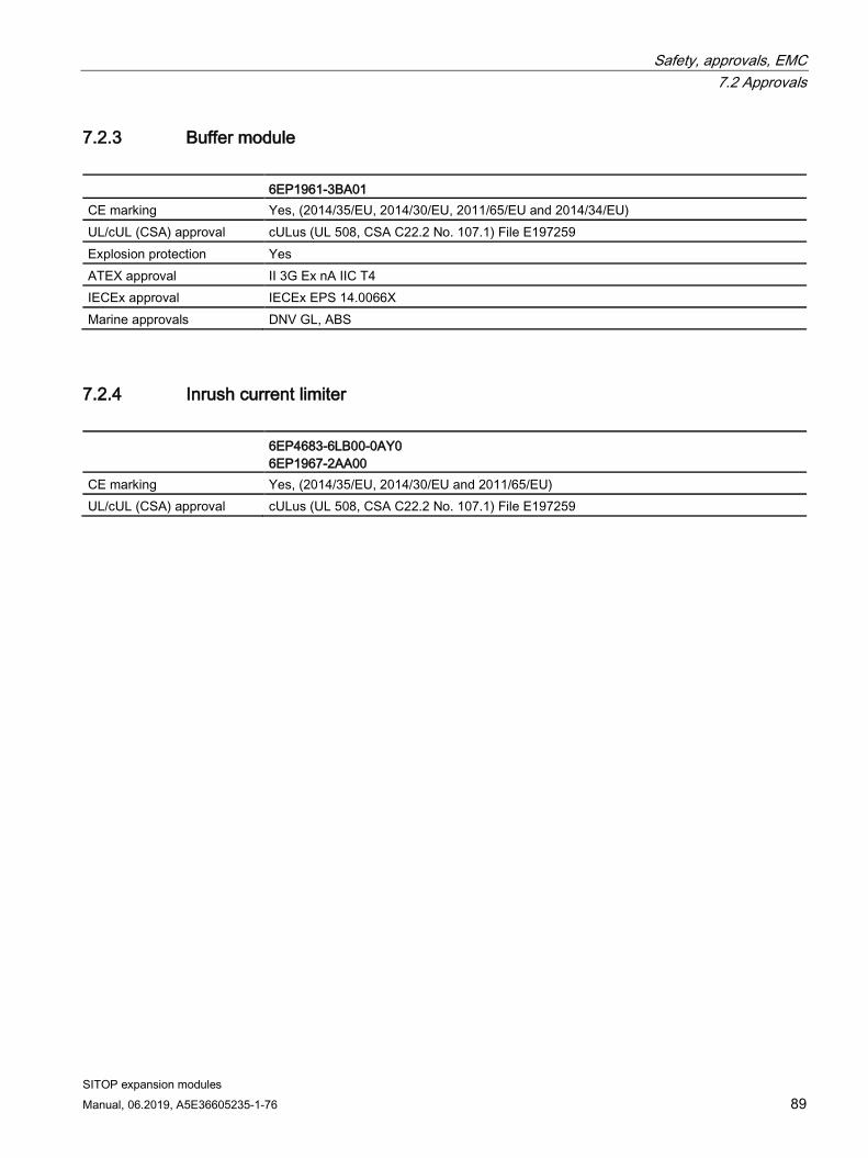
7.2.3 Buffer module
6EP1961-3BA01 CE marking Yes, (2014/35/EU, 2014/30/EU, 2011/65/EU and 2014/34/EU) UL/cUL (CSA) approval cULus (UL 508, CSA C22.2 No. 107.1) File E197259 Explosion protection Yes ATEX approval II 3G Ex nA IIC T4 IECEx approval IECEx EPS 14.0066X Marine approvals DNV GL, ABS
7.2.4 Inrush current limiter
6EP4683-6LB00-0AY0 6EP1967-2AA00
CE marking Yes, (2014/35/EU, 2014/30/EU and 2011/65/EU) UL/cUL (CSA) approval cULus (UL 508, CSA C22.2 No. 107.1) File E197259

Safety, approvals, EMC 7.3 EMC
SITOP expansion modules 90 Manual, 06.2019, A5E36605235-1-76
7.3 EMC
7.3.1 SITOP RED1200
6EP4346-7RB00-0AX0 6EP4347-7RB00-0AX0
Electrostatic discharge EN 61000-4-2 8 kV contact, 8 kV air Fast transient disturbance variables (burst)
EN 61000-4-4 2 kV at DC input 2 kV at DC output
Surge voltages EN 61000-4-5 0.5 V asymmetrical on DC output cables Generic standards EN 61000-6-2 Interference immunity for industrial environments
(only for tests applicable for the device)
7.3.2 PSE202U
6EP1961-3BA21
6EP1962-2BA00 6EP1964-2BA00
Electrostatic discharge EN 61000-4-2 4 kV contact 6 kV contact, 8 kV air Electromagnetic fields EN 61000-4-3 30 - 2000 MHz 3 V/m 80 - 6000 MHz 10 V/m,
1000 - 2700 MHz 10 V/m Fast transient disturbance variables (burst)
EN 61000-4-4 1 kV at DC output 1 kV on signal line
2 kV at DC input 2 kV at DC output 2 kV on signal line
Surge voltages EN 61000-4-5 1 kV at DC output 1 kV on signal line
High-frequency fields EN 61000-4-6 3 V; 0.15 - 80 MHz 10 V; 0.15 - 80 MHz Magnetic fields EN 61000-4-8 30 A/m; 50 Hz 30 A/m; 50 Hz Emitted interference EN 55022
(corresponds to EN 55032)
Class B -
Generic standards EN 61000-6-2 - Noise immunity for industrial environments
EN 61000-6-3 - Interference emission for residential areas

Safety, approvals, EMC 7.3 EMC
SITOP expansion modules Manual, 06.2019, A5E36605235-1-76 91
7.3.3 Buffer module
6EP1961-3BA01 Electrostatic discharge EN 61000-4-2 8 kV contact, 8 kV air Electromagnetic fields EN 61000-4-3 80 - 1000 MHz 50 V/m, 900 MHz ±5 MHz 10 V/m Fast transient disturbance variables (burst)
EN 61000-4-4 Tested with 6EP1436-3BA00 power supply: 4 kV at upstream power supply 2 kV at DC output
Surge voltages EN 61000-4-5 Tested with 6EP1436-3BA00 power supply: 3 kV symmetrical at the power supply input 3 kV asymmetrical at the power supply input 0.5 kV symmetrical/asymmetrical on DC output cables/conductors
High-frequency fields EN 61000-4-6 10 V; 0.15 - 80 MHz Generic standards EN 61000-6-2 Noise immunity for industrial environments
7.3.4 Inrush current limiter
6EP1967-2AA00 6EP4683-6LB00-0AY0 Electrostatic discharge EN 61000-4-2 8 kV contact, 8 kV air Electromagnetic fields EN 61000-4-3 80 - 1000 MHz 20 V/m,
1400 - 2000 MHz 3 V/m, 2000 - 2700 MHz 1 V/m, 900 MHz ±5 MHz 10 V/m
80 - 1000 MHz 10 V/m, 1400 - 2000 MHz 3 V/m, 2000 - 2700 MHz 1 V/m, 900 MHz ±5 MHz and 1.89 GHz 10 V/m
Fast transient disturbance variables (burst)
EN 61000-4-4 4 kV at input/output 2 kV at input/output
Surge voltages EN 61000-4-5 3 kV symmetrical at input/output 1 kV symmetrical at input/output High-frequency fields EN 61000-4-6 10 V; 0.15 - 80 MHz Magnetic fields EN 61000-4-8 30 A/m; 50 Hz - Line harmonics limit EN 61000-3-2 Class A Generic standards EN 61000-6-2 Noise immunity for industrial environments
EN 61000-6-3 Interference emission for residential areas

Safety, approvals, EMC 7.3 EMC
SITOP expansion modules 92 Manual, 06.2019, A5E36605235-1-76

SITOP expansion modules Manual, 06.2019, A5E36605235-1-76 93
Ambient conditions 8
6EP4346-7RB00-0AX0 6EP4347-7RB00-0AX0 6EP1961-3BA01
6EP1961-3BA21 6EP1967-2AA00
6EP4683-6LB00-0AY0 6EP1962-2BA00 6EP1964-2BA00
Ambient temperature -25 ... 70 °C for natural convection (self convection)
-25 ... 60 °C for natural convection (self convection)
-40 ... 70 °C for natural convection (self convection)
-20 ... 70 °C for natural convection (self convection)
Tested according to: • EN 60068-2-1 Cold • EN 60068-2-2 Dry heat • EN 60068-2-78 Humid heat, constant • EN 60068-2-14 Temperature change
Transport and storage temperature
-40 ... 85 °C Tests (packed for shipping) according to: • EN 60068-2-1 Cold • EN 60068-2-2 Dry heat • EN 60068-2-30 Humid heat, cyclic
Humidity class Climatic class 3K3 according to EN 60721, 5 - 95 % no condensation Degree of pollution 2 Mechanical stressing in operation
• Tested according to EN 60068-2-6 vibration, test Fc:
3.5 mm deflection in the range 5 - 8.4 Hz 2 g acceleration in the range 8.4 - 150 Hz
3.5 mm deflection in the range 5 - 8.4 Hz 1.3 g acceleration in the range 8.4 – 50 Hz
• Tested according to EN 60068-2-27 shock, test Ea: acceleration 150 m/s2, test duration 11 ms

Ambient conditions
SITOP expansion modules 94 Manual, 06.2019, A5E36605235-1-76
6EP4346-7RB00-0AX0 6EP4347-7RB00-0AX0 6EP1961-3BA01
6EP1961-3BA21 6EP1967-2AA00
6EP4683-6LB00-0AY0 6EP1962-2BA00 6EP1964-2BA00
Damaging gases Tested according to: • EN 60068-2-42 sulfur dioxide • EN 60068-2-43 hydrogen sulfide
Atmospheric pressure Operation: • 1080 - 795 hPa (-1000 - 2000 m) • For operation at altitudes of 2000 m up to 6000 m above sea level:
output must be derated by -7.5% / 1000 m or the ambient temperature must be reduced by 5 K / 1000 m see Figure 4-6 Altitude derating (Page 51)
• Overvoltage category: III to 2000 m (EN 50178) II from 2000 m to 6000 m (EN 50178) II to 2000 m (EN 60950-1) I from 2000 m to 6000 m (EN 60950-1)
Storage: • 1080 - 660 hPa (-1000 - 3500 m)

SITOP expansion modules Manual, 06.2019, A5E36605235-1-76 95
Applications 9 9.1 Redundancy circuit for increased system availability
SITOP PSE202U redundancy modules provide additional protection against the failure of 24 V supplies. By decoupling two power supplies through a redundancy module, a power supply that fails does not influence the 24 V supply. The redundancy module continuously monitors the feeding power supplies, and when one device fails, the other one automatically takes over the complete load circuit supply. In addition, a signal contact sends a signal, which can be evaluated by a controller, a PC or a control system.
Note
To implement 100% redundancy, the supply via the primary side of the power supply must also be redundantly implemented; this means that each power supply must be separately protected using a fuse or a miniature circuit breaker.
When using 1-phase power supplies, the supply should be implemented using different phases, e.g. if a three-phase line supply is available.
Redundancy of two power supplies with maximum rated output currents of 5 A
Two power supplies with maximum rated output currents of 5 A can be decoupled through a SITOP PSE202U 10 A redundancy module (6EP1964-2BA00). To do this, outputs "+" of the power supplies are connected to inputs "IN 24 V-1" and "IN 24 V-2 of the redundancy module, output "OUT 24 V" of the redundancy module is connected to the load circuit.
Figure 9-1 Redundancy of two power supplies with maximum rated output currents of 5 A
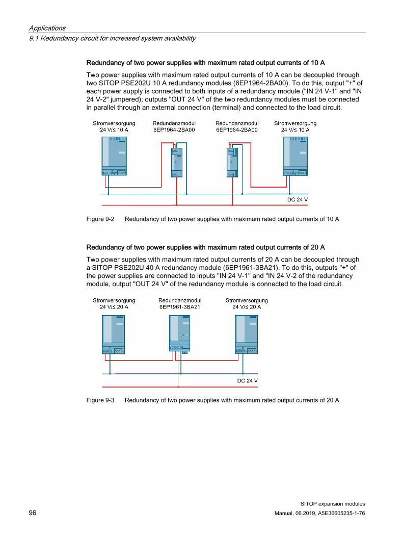
Applications 9.1 Redundancy circuit for increased system availability
SITOP expansion modules 96 Manual, 06.2019, A5E36605235-1-76
Redundancy of two power supplies with maximum rated output currents of 10 A
Two power supplies with maximum rated output currents of 10 A can be decoupled through two SITOP PSE202U 10 A redundancy modules (6EP1964-2BA00). To do this, output "+" of each power supply is connected to both inputs of a redundancy module ("IN 24 V-1" and "IN 24 V-2" jumpered); outputs "OUT 24 V" of the two redundancy modules must be connected in parallel through an external connection (terminal) and connected to the load circuit.
Figure 9-2 Redundancy of two power supplies with maximum rated output currents of 10 A
Redundancy of two power supplies with maximum rated output currents of 20 A
Two power supplies with maximum rated output currents of 20 A can be decoupled through a SITOP PSE202U 40 A redundancy module (6EP1961-3BA21). To do this, outputs "+" of the power supplies are connected to inputs "IN 24 V-1" and "IN 24 V-2 of the redundancy module, output "OUT 24 V" of the redundancy module is connected to the load circuit.
Figure 9-3 Redundancy of two power supplies with maximum rated output currents of 20 A

Applications 9.1 Redundancy circuit for increased system availability
SITOP expansion modules Manual, 06.2019, A5E36605235-1-76 97
Redundancy of two power supplies with maximum rated output currents of 40 A
Two power supplies with maximum rated output currents of 40 A can be decoupled through two SITOP PSE202U 40 A redundancy modules (6EP1961-3BA21). To do this, output "+" of each power supply is connected to both inputs of a redundancy module ("IN 24 V-1" and "IN 24 V-2" jumpered); outputs "OUT 24 V" of the two redundancy modules must be connected in parallel through an external connection (terminal) and connected to the load circuit.
Figure 9-4 Redundancy of two power supplies with maximum rated output currents of 40 A

Applications 9.2 Design of 24 V load feeders with power limiting according to NEC class2
SITOP expansion modules 98 Manual, 06.2019, A5E36605235-1-76
9.2 Design of 24 V load feeders with power limiting according to NEC class2
A 24 V power supply with power limiting according to NEC class2 can be implemented using a SITOP PSE202U Class2 redundancy module (6EP1962-2BA00). To implement this, output "+" of the power supply is connected to both inputs of a redundancy module ("IN 24 V-1" and "IN 24 V-2" jumpered); the output power of the load circuit at output "OUT 24 V" of the redundancy module is limited to 100 VA. Several load circuits connected in parallel, whose output power is limited, can be implemented with several redundancy modules.
Figure 9-5 Design of 24 V load feeders with power limiting according to NEC class2
Note
The feeding SITOP power supply must be certified according to UL60950-1.

Applications 9.3 Protection against short-time voltage dips
SITOP expansion modules Manual, 06.2019, A5E36605235-1-76 99
9.3 Protection against short-time voltage dips For a drop in the line-side supply voltage, the 24 V power supply still maintains the output voltage for a short time in the millisecond range (see Chapter Technical data (Page 75)).
For line supplies that manifest frequent brief voltage dips, in order to increase the power supply reliability, it may make sense to increase the line buffering time in the device using an additional SITOP PSE201U buffer module.
The SITOP PSE201U buffer module, based on electrolytic capacitors, is connected in parallel to the power supply output (Figure 9-6 Buffering brief power failures using the SITOP PSE201U buffer module (Page 99)). The buffer time is 200 ms at 40 A up to 1.6 s for a load current of 5 A. This time can be increased a multiple number of times by connecting buffer modules in parallel; the maximum buffer time is 10 s.
You can find additional information at:
SITOP PSE201U manual (https://support.industry.siemens.com/cs/ww/en/view/41129219)
Figure 9-6 Buffering brief power failures using the SITOP PSE201U buffer module

Applications 9.3 Protection against short-time voltage dips
SITOP expansion modules 100 Manual, 06.2019, A5E36605235-1-76

SITOP expansion modules Manual, 06.2019, A5E36605235-1-76 101
Environment 10
The devices are in conformance with RoHS.
As a rule, only non-silicon precipitating materials are used.
Disposal guidelines Packaging and packaging aids can and should always be recycled. The product itself may not be disposed of as domestic refuse.

Environment
SITOP expansion modules 102 Manual, 06.2019, A5E36605235-1-76

SITOP expansion modules Manual, 06.2019, A5E36605235-1-76 103
Service & Support 11
Technical support
Technical support for all IA/DT products can be accessed through the following communication channels:
● Telephone: + 49 (0) 911 895 7222
● Internet: Web form for support request (http://www.siemens.de/automation/support-request)
Technical documentation on the Internet
Operating instructions and manuals for SITOP are available in the Internet: Operating instructions/manuals (http://www.siemens.de/sitop/manuals)
SITOP power supply homepage
General news about our power supplies is available in the Internet at the SITOP home page: SITOP (http://www.siemens.de/sitop)
Information material
SITOP information can be downloaded from the Internet: Information and download center (http://www.siemens.de/sitop-infomaterial)
CAx data
2D/3D data and circuit diagram macros can be downloaded from the Internet: Siemens image database (http://www.siemens.de/sitop-cax)
Request all CAx data via the CAx download manager: CAx shopping cart (http://www.siemens.de/cax)
SITOP Selection Tool
Simply and quickly select the optimum the power supply or DC-UPS: SITOP Selection Tool (http://www.siemens.de/sitop-selection-tool)
Online catalog and ordering system
The online catalog and the online ordering system are available through the Industry Mall homepage: Industry Mall (http://www.siemens.com/industrymall/de)

Service & Support
SITOP expansion modules 104 Manual, 06.2019, A5E36605235-1-76
Contact persons
If you have any questions regarding the use of our products, then contact the Siemens contact person in your regional Siemens sales office.
You can find these addresses as follows:
● On the Internet (http://www.siemens.de/automation/partner)
● Industry Mall (http://www.siemens.com/industrymall/de)
Related Documents