Fluid Dynamics FLUID DYNAMICS - JENNA EMMANOUILIDES Fluid Dynamics n. (used with a sing. verb) The branch of applied science that is concerned with the movement of gases and liquids.

09.06.03 presentation
Mar 24, 2016
presentation
Welcome message from author
This document is posted to help you gain knowledge. Please leave a comment to let me know what you think about it! Share it to your friends and learn new things together.
Transcript
Fluid Dynamics
FLUID DYNAMICS - JENNA EMMANOUILIDES
Fluid Dynamics n. (used with a sing. verb)The branch of applied science that is concerned with the movement of gases and liquids.

FLUID DYNAMICS - DEFINITION
Laminar flow –noun Hydraulics, Mechanics.the flow of a viscous fluid in which particles of the fluid move in parallel layers, each of which has a constant velocity but is in motion relative to its neighboring layers.
Turbulent flow –noun Hydraulics.the flow of a fluid past an object such that the velocity at any fixed point in the fluid varies ir-regularly.
Cavitationn.
1. The sudden formation and collapse of low-pressure bubbles in liquids by means of me-chanical forces, such as those resulting from rotation of a marine propeller. 2. The pitting of a solid surface. 3. Medicine. The formation of cavities in a body tissue or an organ, especially those formed in the lung as a result of tuberculosis.
Vortex:
A vortex (pl. vortices) is a spinning, often turbulent, flow of fluid. Any spiral motion with closed streamlines is vortex flow. The motion of the fluid swirling rapidly around a center is called a vortex. The speed and rate of rotation of the fluid are greatest at the center, and decrease progressively with distance from the center.
Definitions
Hummingbird
a)
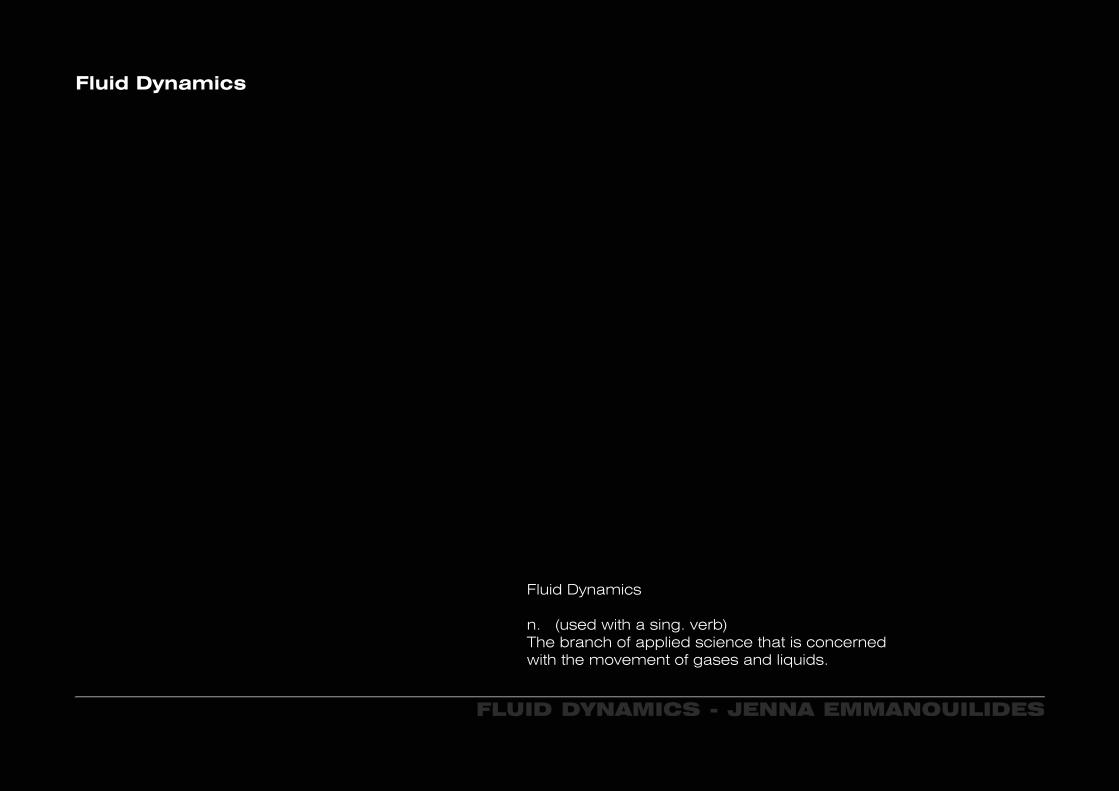
Hovering Motion (Rear View) Hovering Motion (Top View)
b) c)
a) Forwardb) Hoveringc) Backward
FLUID DYNAMICS - HUMMINGBIRD
A hummingbird can fly forwards, backwards, up, down, sideways or hover in space. For a humming bird to hover, their wings move forward and backwards in a repetitive figure eight.Hummingbirds produce 75% of their weight support during the down stroke and 25% during the upstroke. Some of this asymmetry could be due to inversion of their cambered wings during upstroke. What makes a humming bird aerodynamic are the vortices produced by the motion of its wings.
FLUID DYNAMICS - HUMMINGBIRD
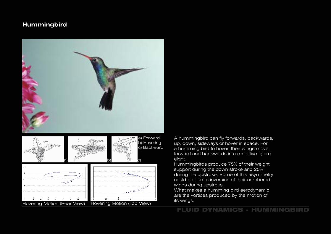
Hummingbird - DeHavilland DH 53 Hummingbird
The wake of the hummingbirds wings demonstrates that small vortices are created during the hummingbirds down stroke, indicating that the ratio of internal forces is extremely low, allowing an upwards stroke to follow, thus operating at Reynolds number sufficiently low enough to exploit a key mechanism, typical to that of an insect hovering. Therefore it may be possible that the hummingbird is exploiting a key mechanism typical to that of an insect hovering.
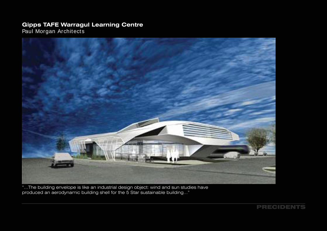
Gipps TAFE Warragul Learning CentrePaul Morgan Architects
“...The building envelope is like an industrial design object: wind and sun studies have produced an aerodynamic building shell for the 5 Star sustainable building...”
PRECIDENTS

PRECIDENTS
Gipps TAFE Warragul Learning CentrePaul Morgan Architects
PRECIDENTS
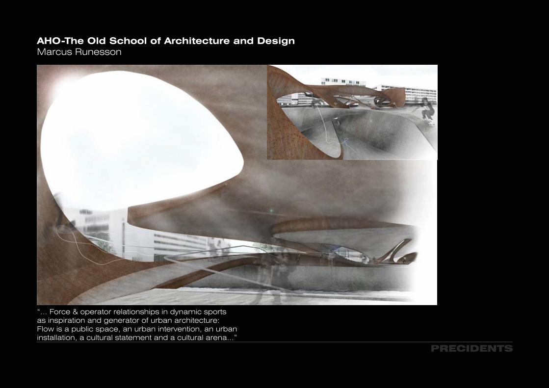
AHO-The Old School of Architecture and DesignMarcus Runesson
“... Force & operator relationships in dynamic sports as inspiration and generator of urban architecture: Flow is a public space, an urban intervention, an urban installation, a cultural statement and a cultural arena...”

AHO-The Old School of Architecture and DesignMarcus Runesson
PRECIDENTS
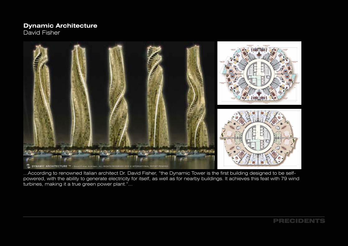
Dynamic ArchitectureDavid Fisher
...According to renowned Italian architect Dr. David Fisher, “the Dynamic Tower is the first building designed to be self-powered, with the ability to generate electricity for itself, as well as for nearby buildings. It achieves this feat with 79 wind turbines, making it a true green power plant.”...
PRECIDENTS
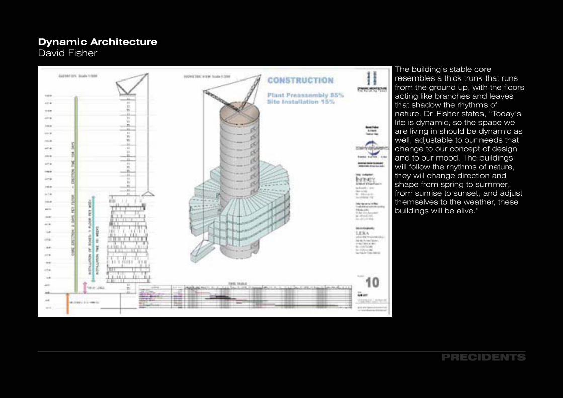
The building’s stable core resembles a thick trunk that runs from the ground up, with the floors acting like branches and leaves that shadow the rhythms of nature. Dr. Fisher states, “Today’s life is dynamic, so the space we are living in should be dynamic as well, adjustable to our needs that change to our concept of design and to our mood. The buildings will follow the rhythms of nature, they will change direction and shape from spring to summer, from sunrise to sunset, and adjust themselves to the weather, these buildings will be alive.”
Dynamic ArchitectureDavid Fisher
PRECIDENTS
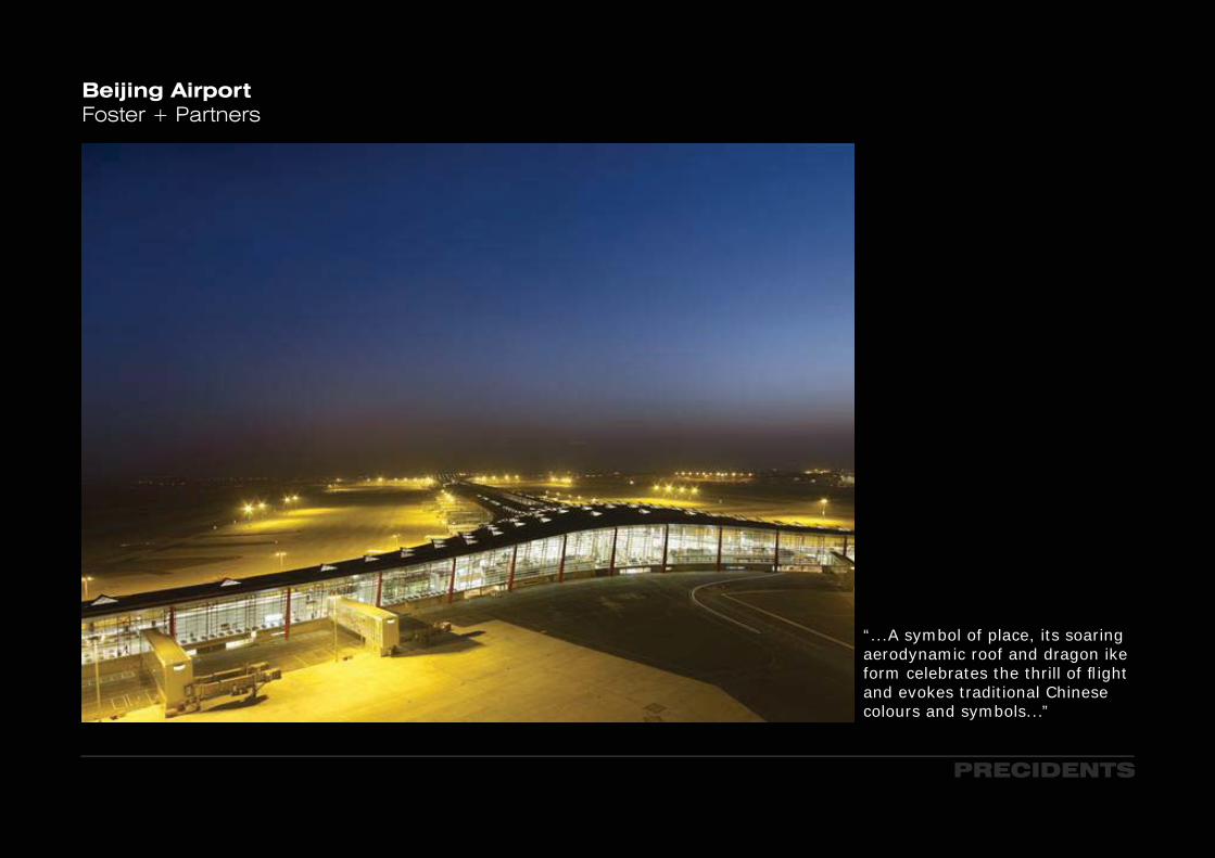
Beijing AirportFoster + Partners
PRECIDENTS
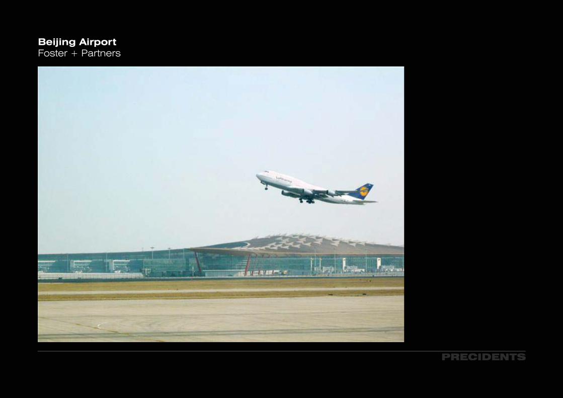
“...A symbol of place, its soaring aerodynamic roof and dragon ike form celebrates the thrill of fl ight and evokes traditional Chinese colours and symbols...”
PRECIDENTS
Beijing AirportFoster + Partners
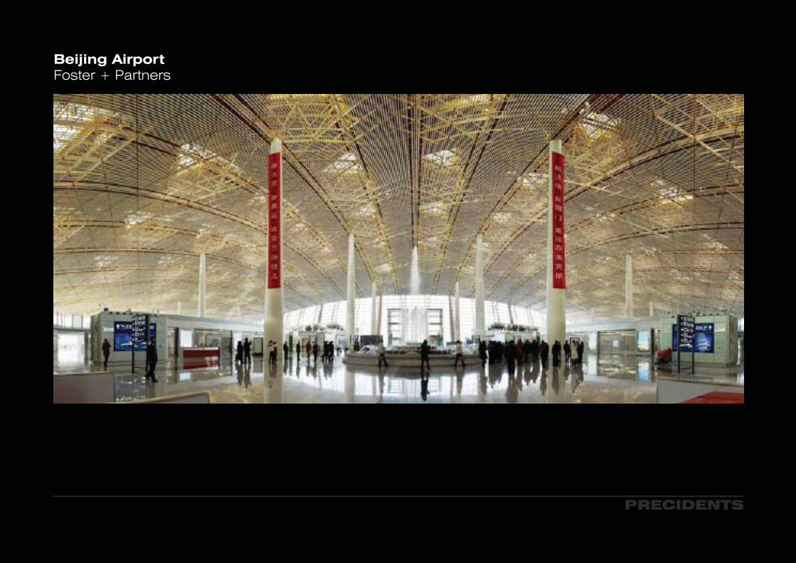
Beijing AirportFoster + Partners
PRECIDENTS
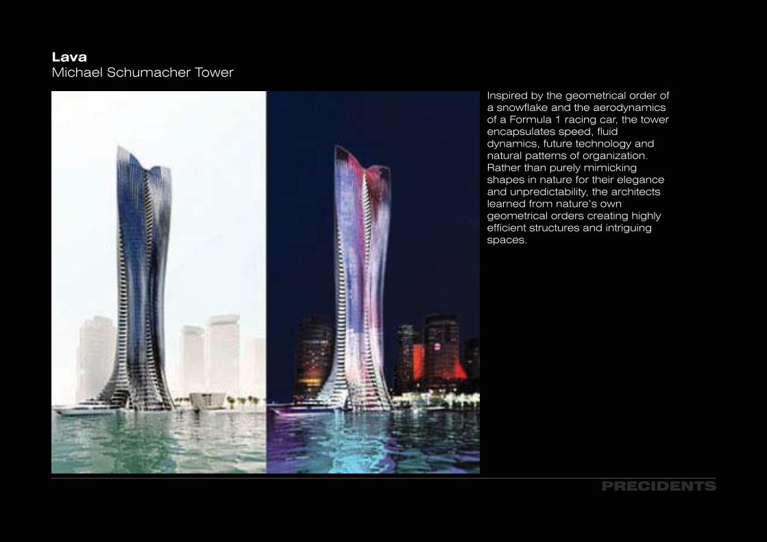
LavaMichael Schumacher Tower
Inspired by the geometrical order of a snowflake and the aerodynamics of a Formula 1 racing car, the tower encapsulates speed, fluid dynamics, future technology and natural patterns of organization. Rather than purely mimicking shapes in nature for their elegance and unpredictability, the architects learned from nature’s own geometrical orders creating highly efficient structures and intriguing spaces.
PRECIDENTS

LavaMichael Schumacher Tower
PRECIDENTS
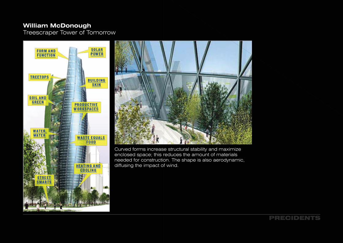
William McDonoughTreescraper Tower of Tomorrow
Curved forms increase structural stability and maximize enclosed space; this reduces the amount of materials needed for construction. The shape is also aerodynamic, diffusing the impact of wind.
PRECIDENTS

Richard RogersMillennium Dome, Greenwich
The cables carry both wind uplift and downloads in the same way, resulting in a very efficient structure. This inherent efficiency,combined with the aerodynamic shape of the envelope, means that loads should be small enough to be carried on conventional pad foundations. Differential settlement of the masts then will be catered for by jacking up the base connections as necessary.
PRECIDENTS
Wind effects are often the driving factor in the design of large roof structures. In particular, turbulent wind flows have the potential to exert significant loading on large lightweight roof structures including augmentations due to dynamic effects.
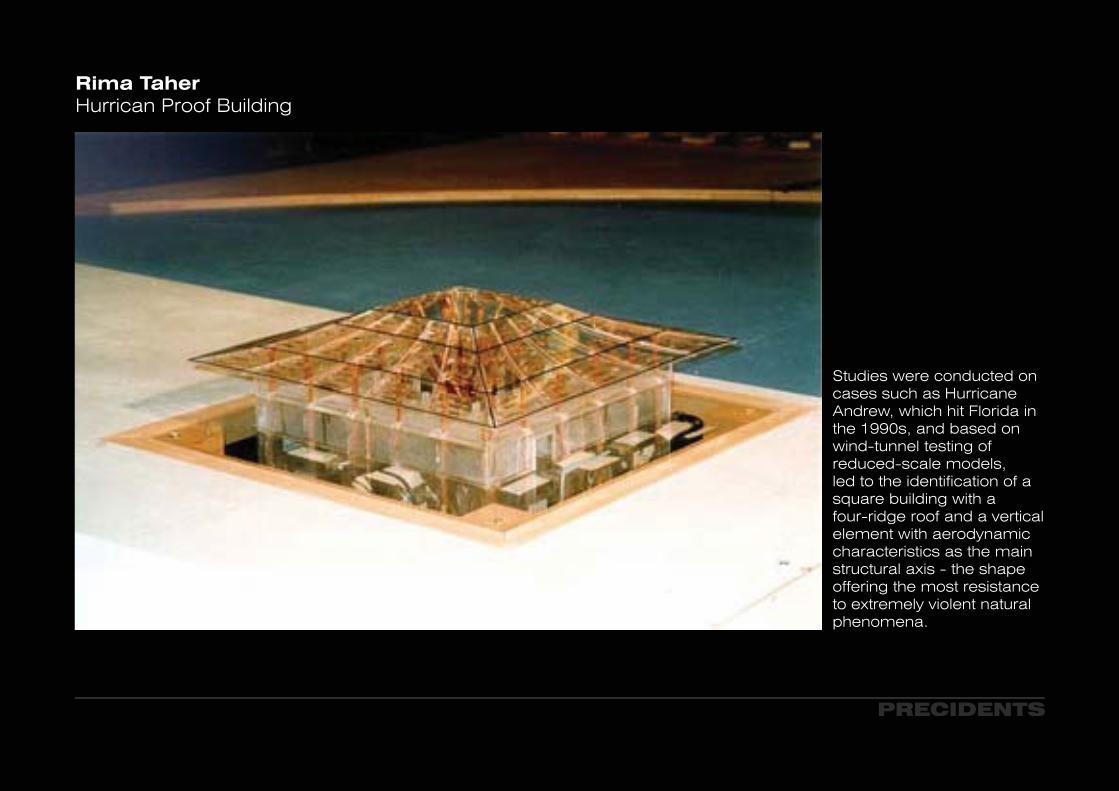
Rima TaherHurrican Proof Building
Studies were conducted on cases such as Hurricane Andrew, which hit Florida in the 1990s, and based on wind-tunnel testing of reduced-scale models, led to the identification of a square building with a four-ridge roof and a vertical element with aerodynamic characteristics as the main structural axis - the shape offering the most resistance to extremely violent natural phenomena.
PRECIDENTS
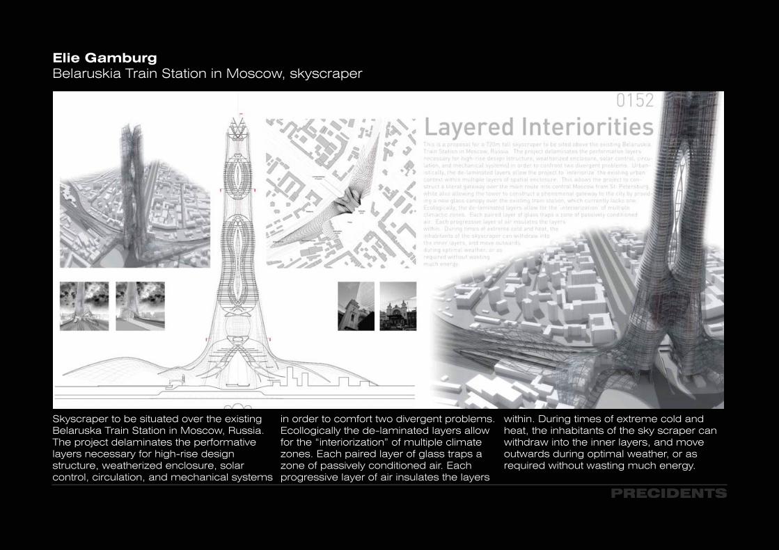
Elie GamburgBelaruskia Train Station in Moscow, skyscraper
Skyscraper to be situated over the existing Belaruska Train Station in Moscow, Russia.The project delaminates the performative layers necessary for high-rise design structure, weatherized enclosure, solar control, circulation, and mechanical systems
in order to comfort two divergent problems. Ecollogically the de-laminated layers allow for the “interiorization” of multiple climate zones. Each paired layer of glass traps a zone of passively conditioned air. Each progressive layer of air insulates the layers
within. During times of extreme cold and heat, the inhabitants of the sky scraper canwithdraw into the inner layers, and move outwards during optimal weather, or as required without wasting much energy.
PRECIDENTS
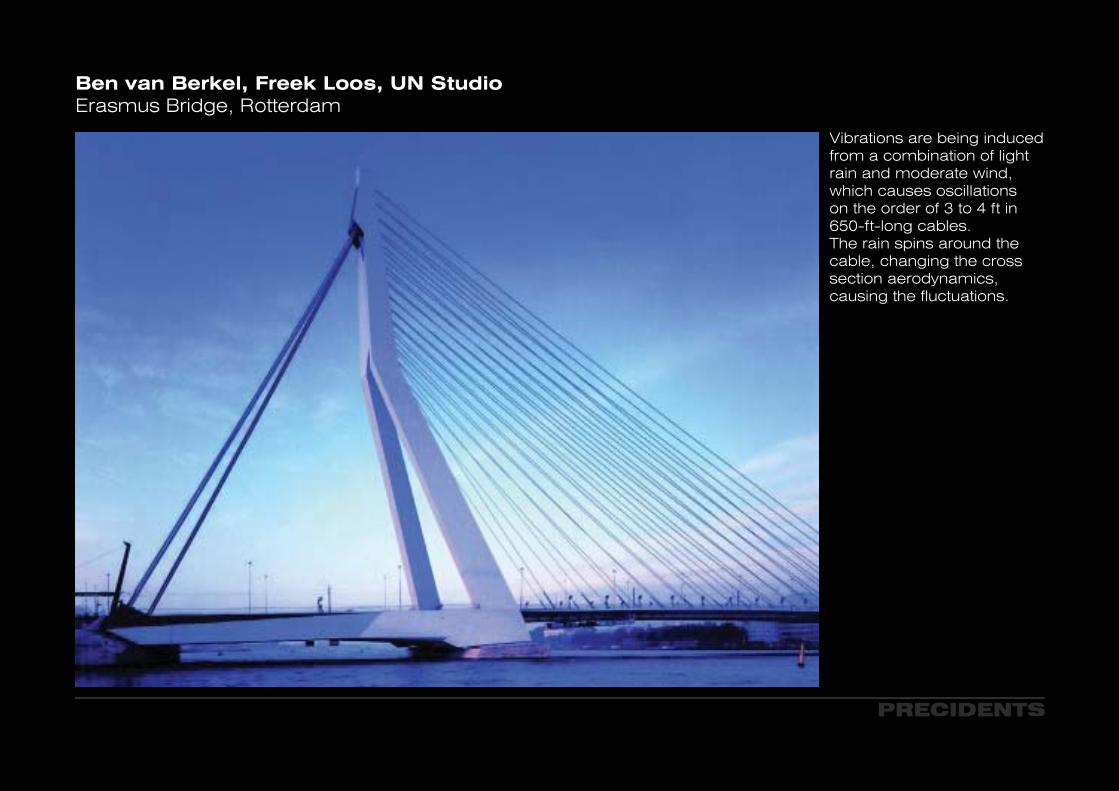
Ben van Berkel, Freek Loos, UN StudioErasmus Bridge, Rotterdam
Vibrations are being induced from a combination of light rain and moderate wind, which causes oscillations on the order of 3 to 4 ft in 650-ft-long cables.The rain spins around the cable, changing the cross section aerodynamics, causing the fluctuations.
PRECIDENTS
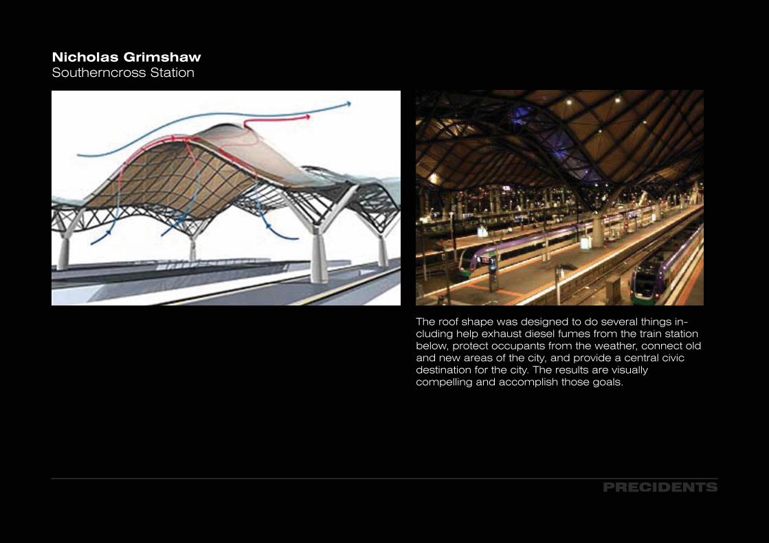
Nicholas GrimshawSoutherncross Station
The roof shape was designed to do several things in-cluding help exhaust diesel fumes from the train station below, protect occupants from the weather, connect old and new areas of the city, and provide a central civic destination for the city. The results are visually compelling and accomplish those goals.
PRECIDENTS
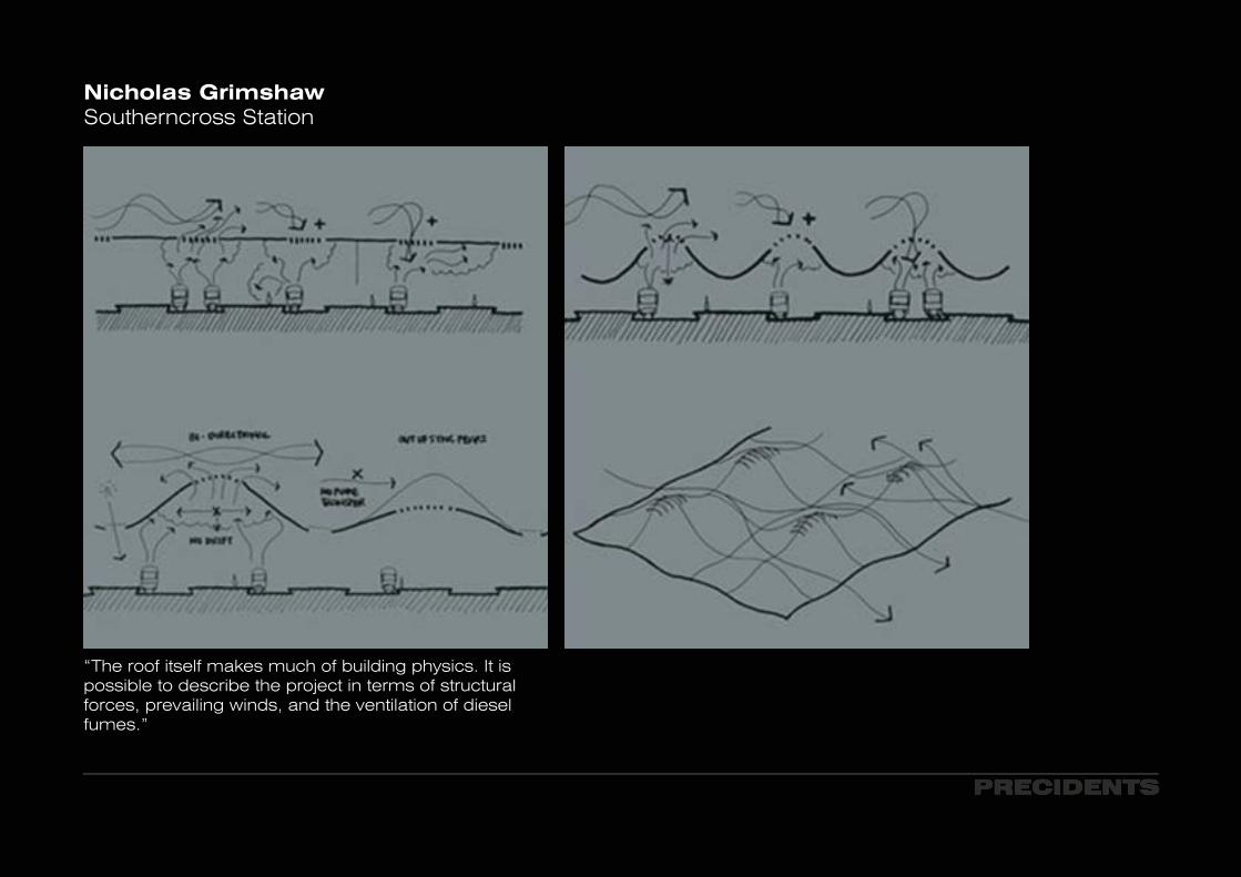
“The roof itself makes much of building physics. It is possible to describe the project in terms of structural forces, prevailing winds, and the ventilation of diesel fumes.”
Nicholas GrimshawSoutherncross Station
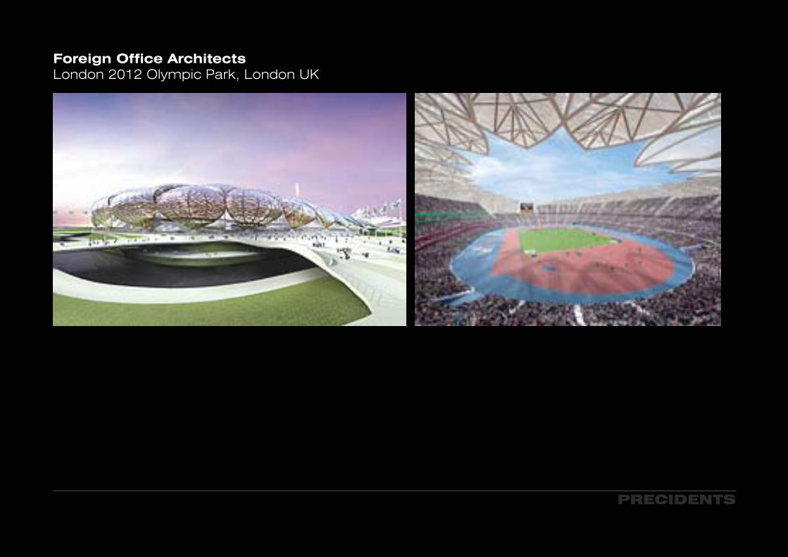
Foreign Office ArchitectsLondon 2012 Olympic Park, London UK
PRECIDENTS
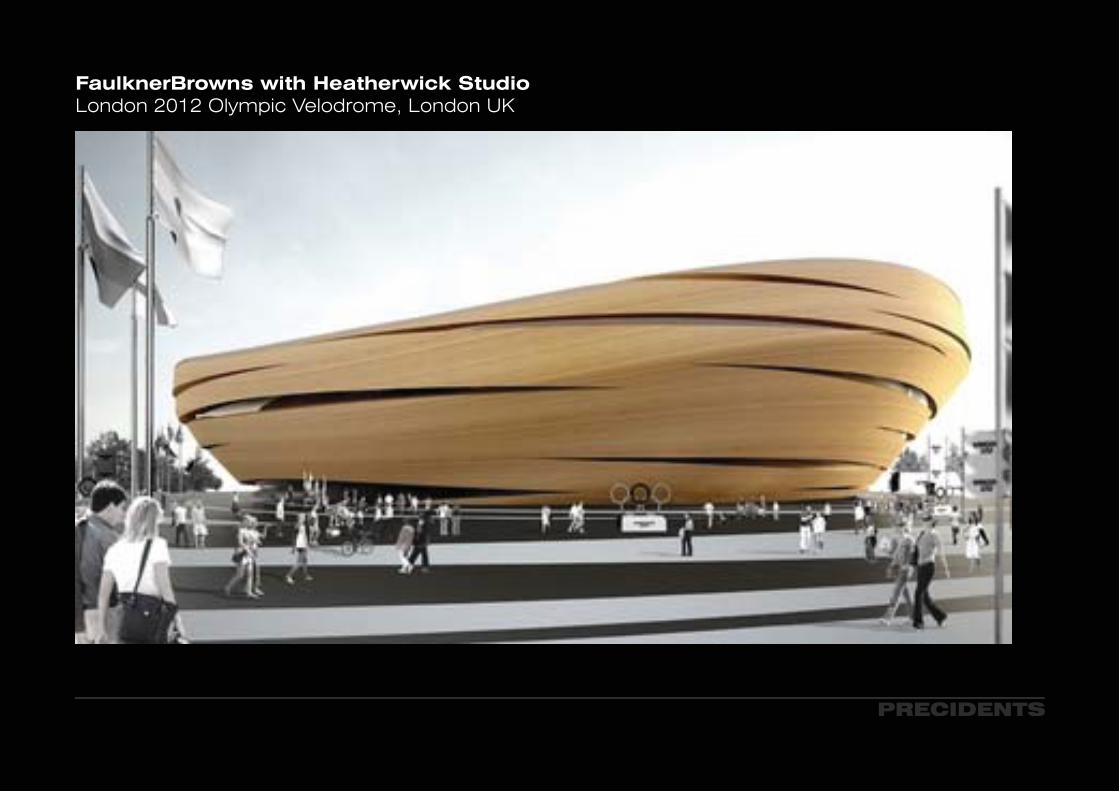
FaulknerBrowns with Heatherwick StudioLondon 2012 Olympic Velodrome, London UK
PRECIDENTS
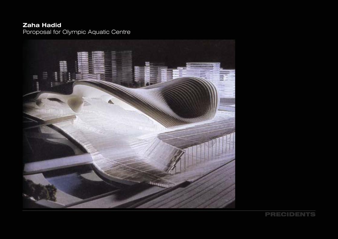
Zaha HadidPoroposal for Olympic Aquatic Centre
PRECIDENTS
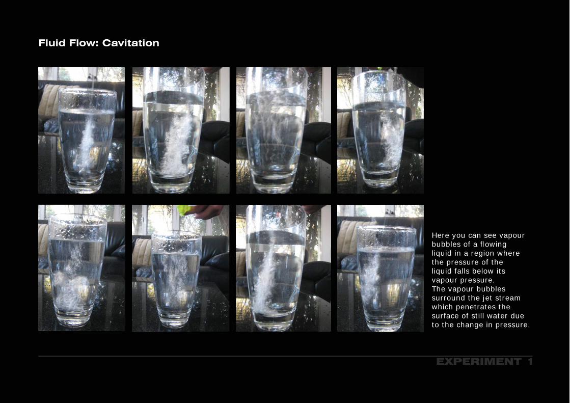
Fluid Flow: Cavitation
Here you can see vapour bubbles of a fl owing liquid in a region where the pressure of the liquid falls below its vapour pressure.The vapour bubbles surround the jet stream which penetrates the surface of still water due to the change in pressure.
EXPERIMENT 1

Turbulence and Vortices
Turbulence from the hairdryer is holding up the christmas decoration. As the airflows you get tur-bulence above here, and the turbulence creates a lower pressure. Therefore, the vortices which are the turbulence, are keeping the christmas decoration up.The reason why it is so stable is because the velocity at the ball is the highest as it is diverging the air as it is comming out.
When the ball is pushed to the side it has a lower stabilty to one side and is pushed back into the centre.The stronger the airflow the further the ball sits and the more angulated the air can be directed.
3500 Twin Turbo Hairdryer
2500 Twin Turbo Hairdryer
EXPERIMENT 2
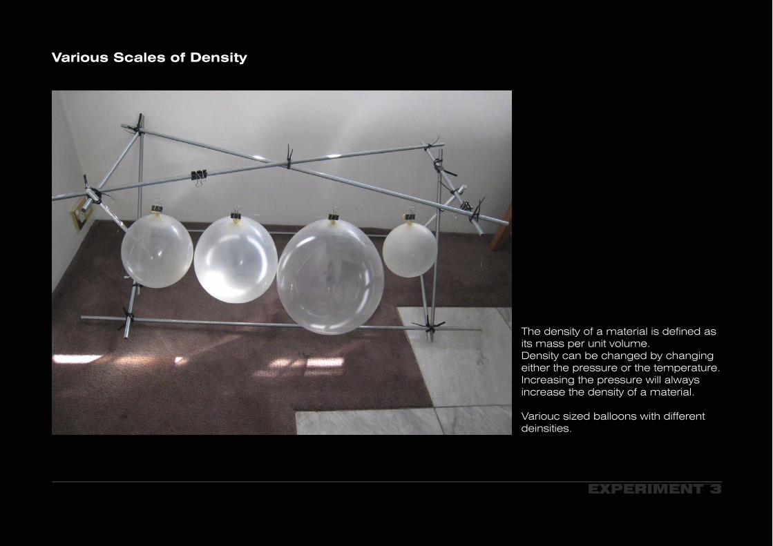
The density of a material is defined as its mass per unit volume.Density can be changed by changing either the pressure or the temperature. Increasing the pressure will always increase the density of a material.
Variouc sized balloons with different deinsities.
Various Scales of Density
EXPERIMENT 3

Above you can see that the pressure applied to the balloons is minimal. Allowing them to maintain to a certain extent their original form.
Bellow the pressure upon the balloons has increased, therefore, the density of the balloons has increased.
Various Scales of Density
EXPERIMENT 3.2

EXPERIMENT 4
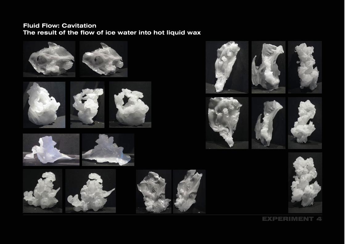
Fluid Flow: Cavitation The result of the flow of ice water into hot liquid wax
EXPERIMENT 4
Fluid Flow: Cavitation The result of the flow of ice water into hot liquid wax
INTERESTS IN FLUID DYNAMICS
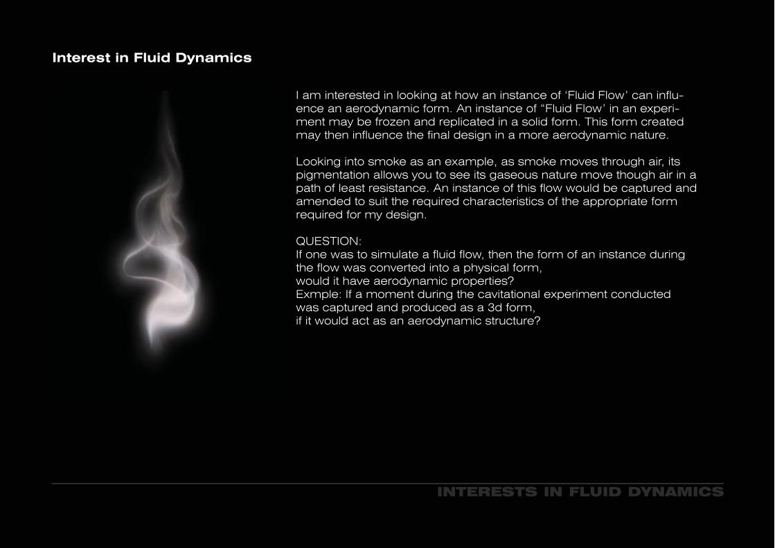
I am interested in looking at how an instance of ‘Fluid Flow’ can influ-ence an aerodynamic form. An instance of “Fluid Flow’ in an experi-ment may be frozen and replicated in a solid form. This form created may then influence the final design in a more aerodynamic nature.
Looking into smoke as an example, as smoke moves through air, its pigmentation allows you to see its gaseous nature move though air in a path of least resistance. An instance of this flow would be captured and amended to suit the required characteristics of the appropriate form required for my design.
QUESTION:If one was to simulate a fluid flow, then the form of an instance during the flow was converted into a physical form, would it have aerodynamic properties?Exmple: If a moment during the cavitational experiment conducted was captured and produced as a 3d form, if it would act as an aerodynamic structure?
Interest in Fluid Dynamics

Taking the Cavitation experiment from above, i have considered using ‘bubbles’ which are produced during the experiment to influence the facade. The proposal is to have ‘bubbles’ on areas of the facade which would internally need ventilation, allowing the facade to have 2 states: an open one; allowing for natural ventilation, as well as a closed state; for the more extreme conditions. The appatures of the ‘bubbles’ would be dependant on the weaher conditions.
Fluid Flow Facade: Bubbles formed during Cavitation experiments
FACADE IDEAS
The ‘bubbles’ may also have a variety of functions, such as; allowing natural daylight into the building and possibly assist in power generation.
FACADE IDEAS
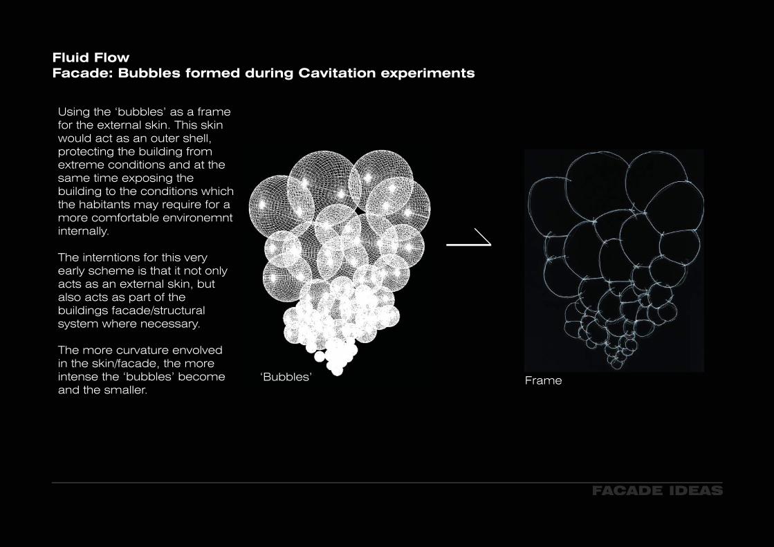
FrameFrame
Using the ‘bubbles’ as a frame for the external skin. This skin would act as an outer shell, protecting the building from extreme conditions and at the same time exposing the building to the conditions which the habitants may require for a more comfortable environemnt internally.
The interntions for this very early scheme is that it not only acts as an external skin, but also acts as part of the buildings facade/structural system where necessary.
The more curvature envolved in the skin/facade, the more intense the ‘bubbles’ become and the smaller.
Fluid Flow Facade: Bubbles formed during Cavitation experiments
‘Bubbles’

FACADE IDEAS
Examples of Nature: Hyacinth Flower
Open
Closed
When looking into natural movement in nature, I chose to look at the Hyacinth flower and Pine cone and how they respond naturally to the elements which surround them. Their movements respond to the elements to better protect themselves.
Hyacinth Flower: During the dark and the cold, the Hyacinth flower will close. However, during the sunlight it will open.
FACADE IDEAS
Examples of Nature: Pine Cone
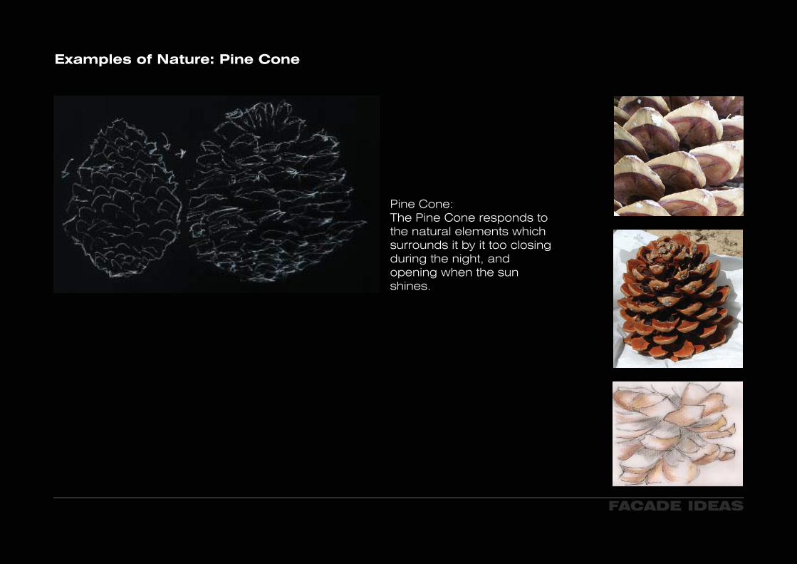
Pine Cone: The Pine Cone responds to the natural elements which surrounds it by it too closing during the night, and opening when the sun shines.
TRADITIONAL ISLAMIC ARCHITECTURE
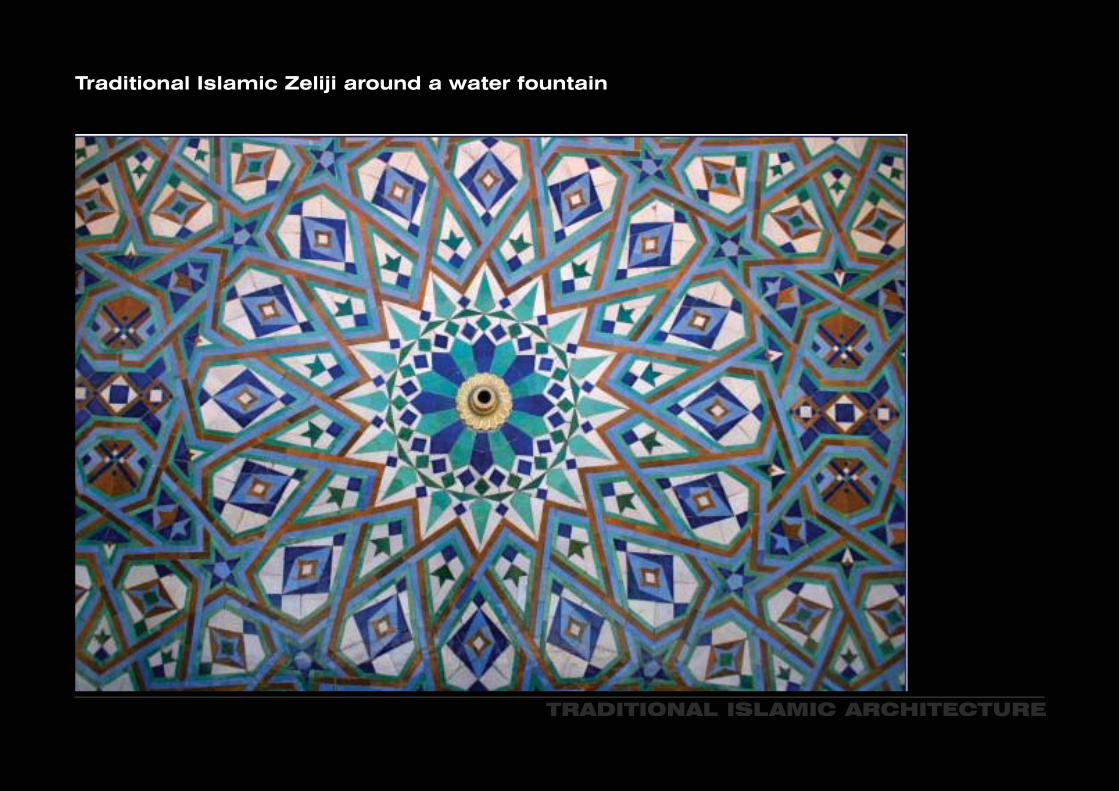
Traditional Islamic Zeliji around a water fountain
TRADITIONAL ISLAMIC ARCHITECTURE
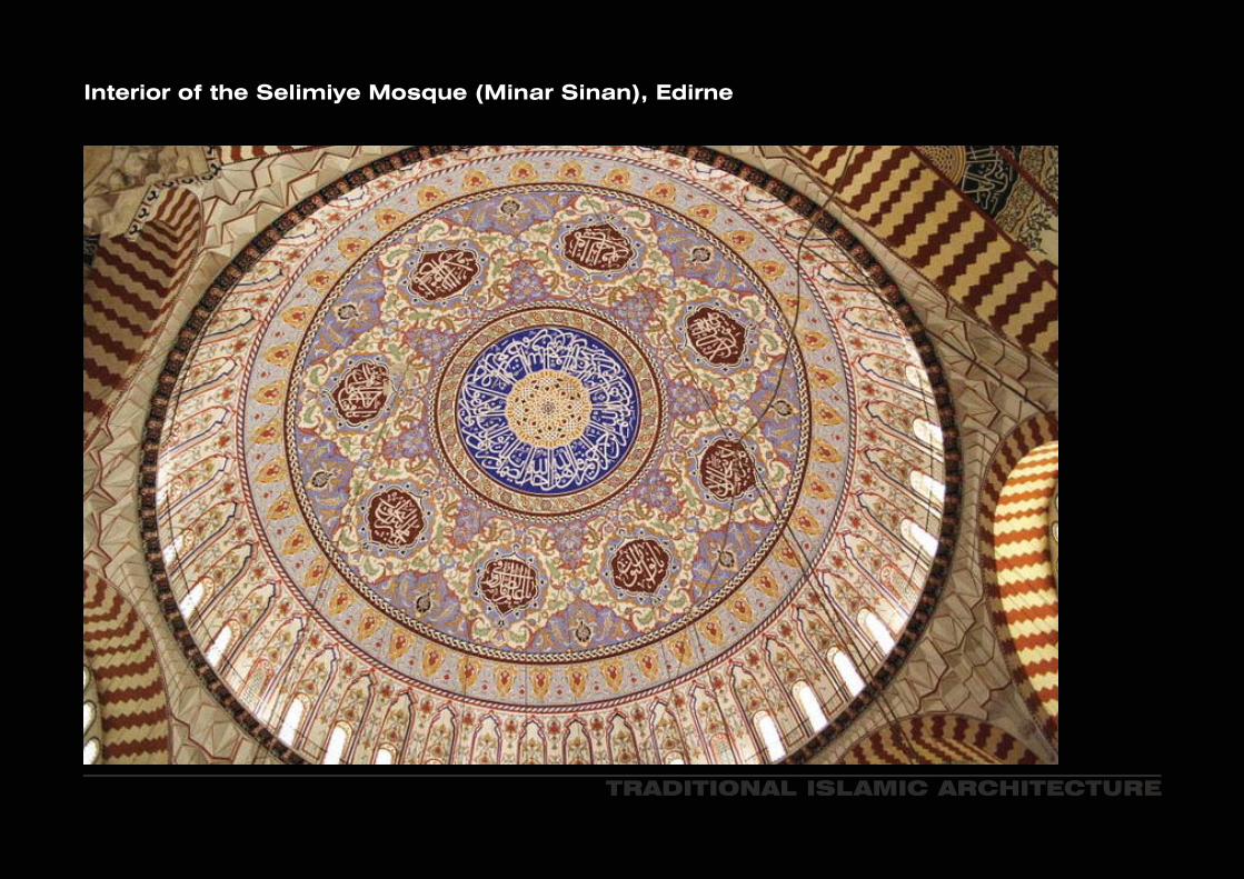
Interior of the Selimiye Mosque (Minar Sinan), Edirne

TRADITIONAL ISLAMIC ARCHITECTURE
Jean NouvelOffice Tower, Doha, Qatar
The exterior of the tower is made from glass covered in a metal skin that is designed, based on a traditional islamic pattern.
TRADITIONAL ISLAMIC ARCHITECTURE
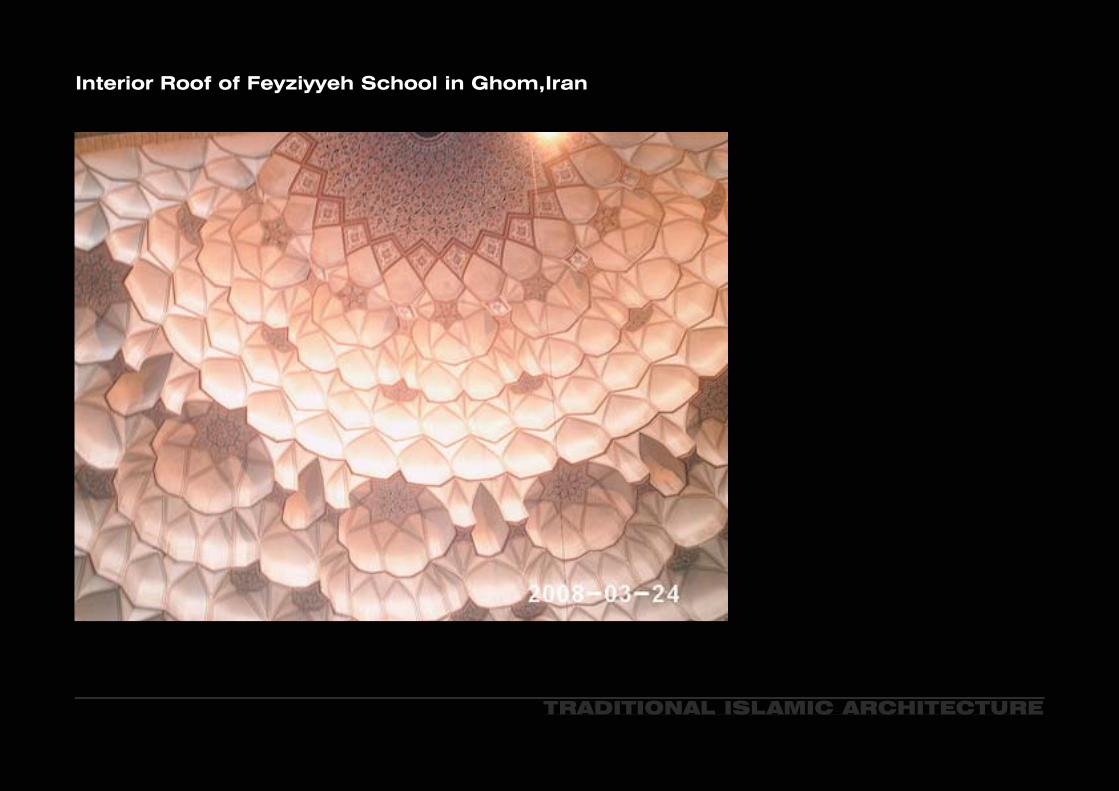
Interior Roof of Feyziyyeh School in Ghom,Iran

TRADITIONAL ISLAMIC ARCHITECTURE
Dome of the Mausoleum of Sultan Qaytbay, Cairo

Jean NouvelInstitut du Monde Arabe, Paris
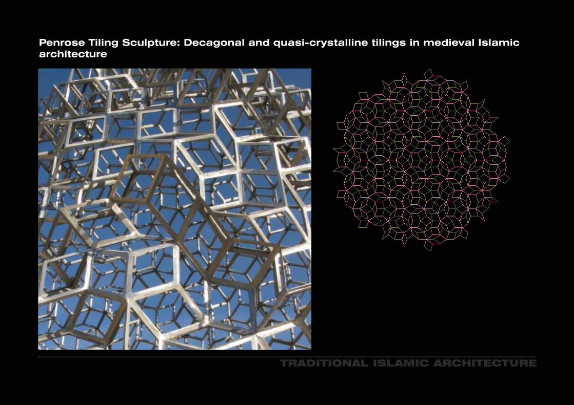
Penrose Tiling Sculpture: Decagonal and quasi-crystalline tilings in medieval Islamic architecture
TRADITIONAL ISLAMIC ARCHITECTURE
TRADITIONAL ISLAMIC PERIODIC TILING
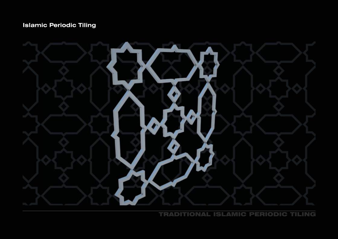
Islamic Periodic Tiling

TRADITIONAL ISLAMIC PERIODIC TILING
Islamic Periodic Tiling

TRADITIONAL ISLAMIC PERIODIC TILING
Islamic Periodic Tiling

TRADITIONAL ISLAMIC PERIODIC TILING
Islamic Periodic Tiling

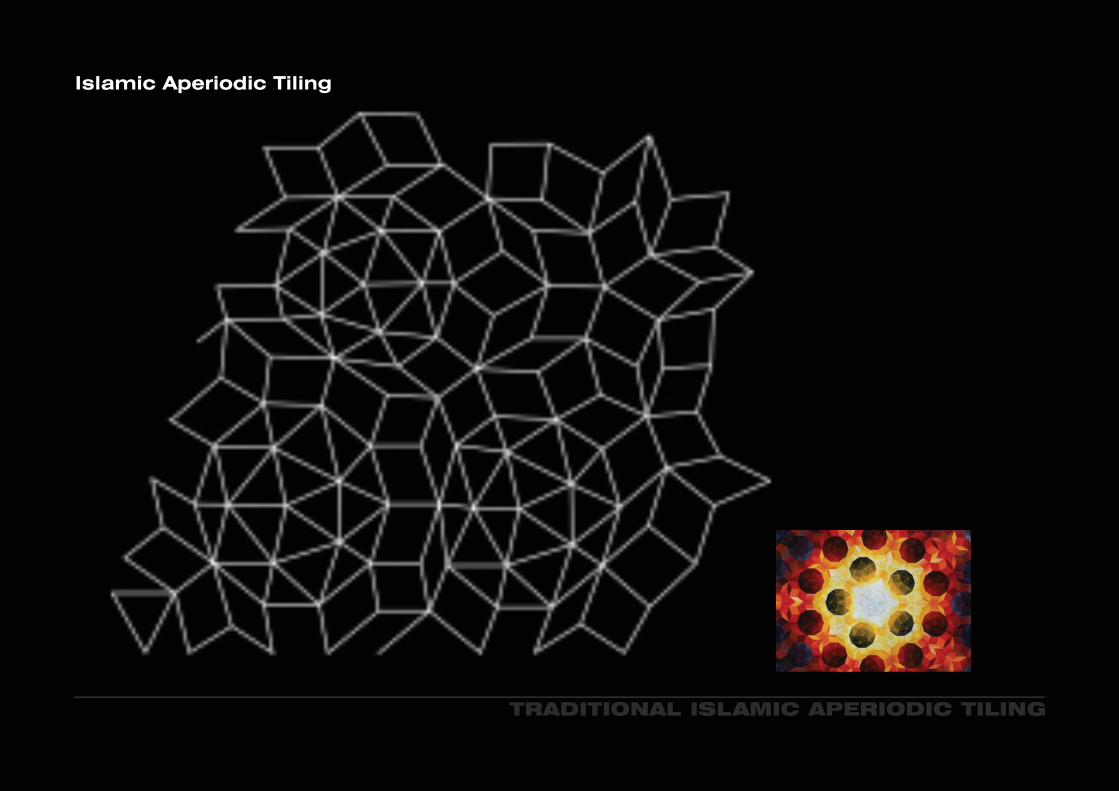
TRADITIONAL ISLAMIC APERIODIC TILING
Islamic Aperiodic Tiling
TRADITIONAL ISLAMIC APERIODIC TILING
Islamic Aperiodic Tiling

TRADITIONAL ISLAMIC APERIODIC TILING
Islamic Aperiodic Tiling
C SRIODIC TILINGRIODIC TILING

Solar SkinStudio Formwork
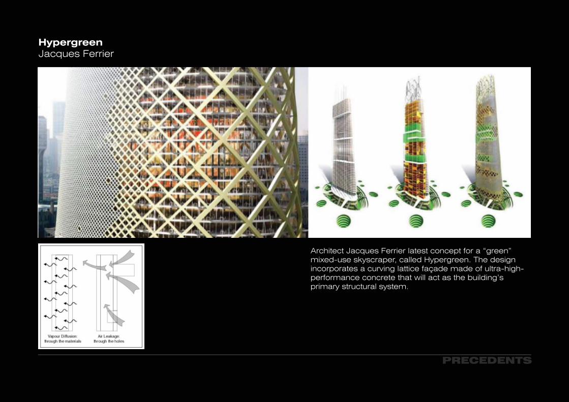
Architect Jacques Ferrier latest concept for a “green” mixed-use skyscraper, called Hypergreen. The design incorporates a curving lattice façade made of ultra-high-performance concrete that will act as the building’s primary structural system.
HypergreenJacques Ferrier
PRECEDENTS

Tornado Tower, QatarvzSIAT Architects

PRECEDENTS
Mexico’s Bicentenary TowersGregorio Vasquez and Manuel Wedeles

Mexico’s Bicentenary TowersGregorio Vasquez and Manuel Wedeles

Rak Convention and Ehibition Centre, UAERas Al Khaimah
PRECEDENTS
PRECEDENTS
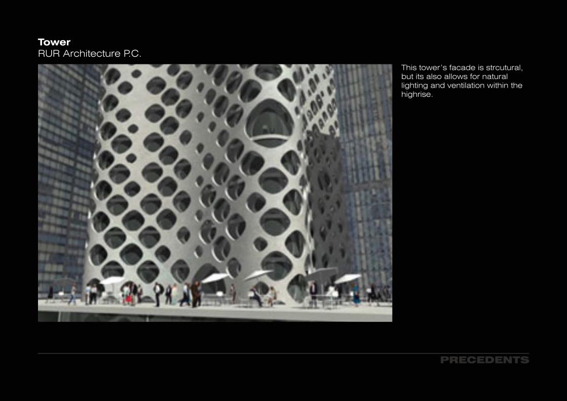
TowerRUR Architecture P.C.
This tower’s facade is strcutural, but its also allows for natural lighting and ventilation within the highrise.

Unknown

Studio Anticipation
PRECEDENTS PRECEDENTSPRECEDENTSPRECEDENTS
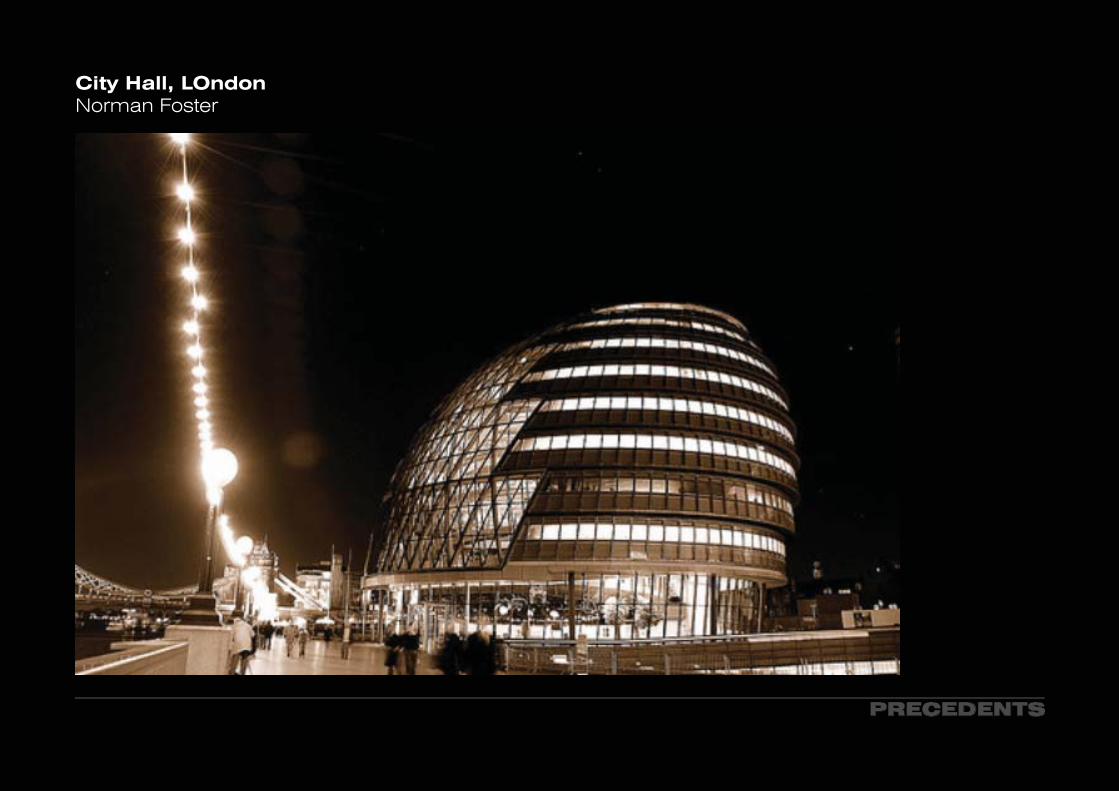
City Hall, LOndonNorman Foster
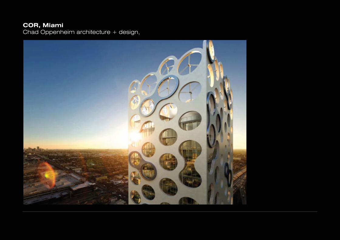
COR, MiamiChad Oppenheim architecture + design,
PRECEDENTS
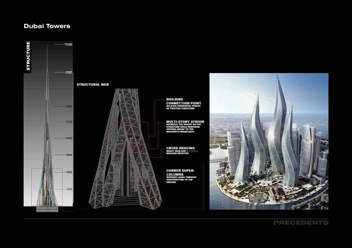
Dubai Towers
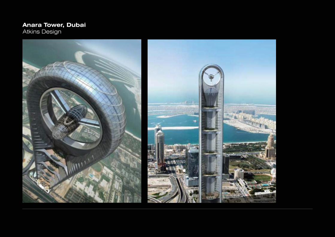
Anara Tower, DubaiAtkins Design

PRECEDENTS
ADNEC: Abu Dhabi National Exhibition CenterRMJM Architects

Cybertecture Egg for IndiaJames Law

PRECEDENTS
ALDAR Headquarters, Abu DhabiArchitects MZ & Partners

SIMPLIFICATION OF PERIODIC PATTERN
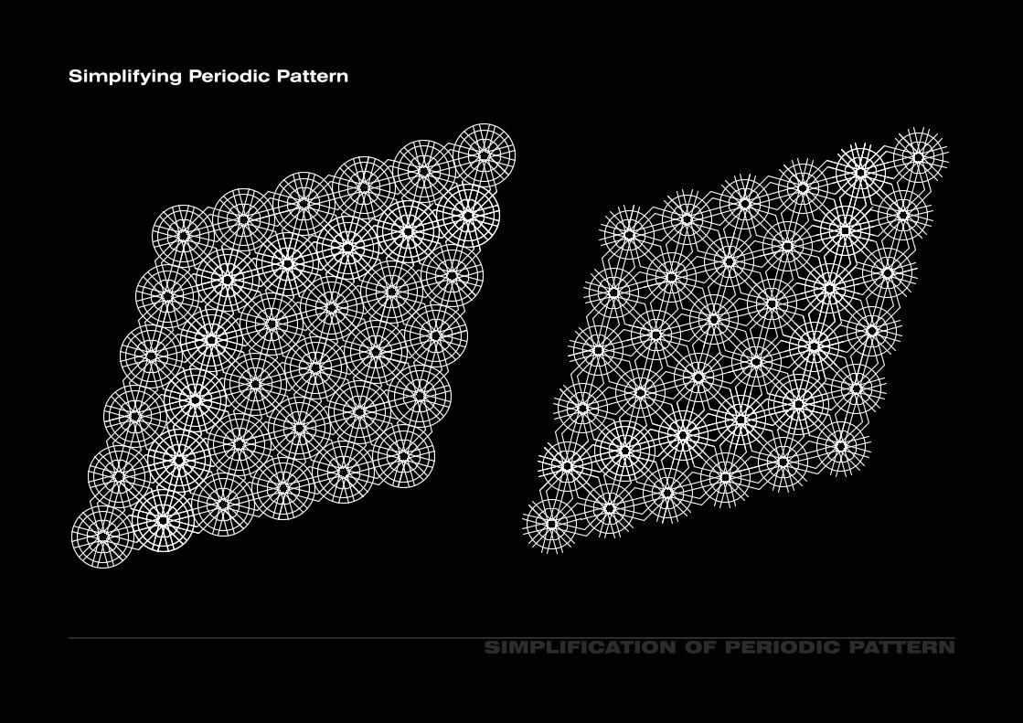
Simplifying Periodic Pattern
SIMPLIFICATION OF PERIODIC PATTERN
Simplifying Periodic Pattern

SIMPLIFICATION OF PERIODIC PATTERN
Simplifying Periodic Pattern

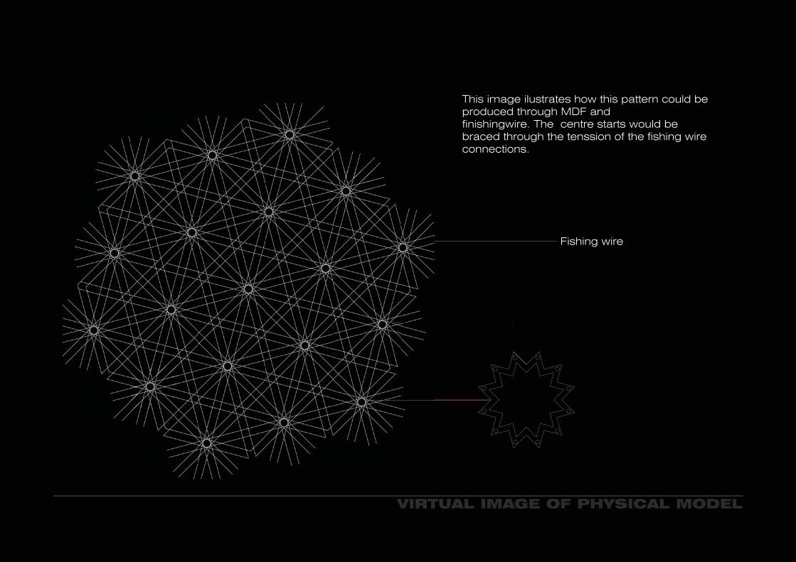
VIRTUAL IMAGE OF PHYSICAL MODEL
This image ilustrates how this pattern could be produced through MDF and finishingwire. The centre starts would be braced through the tenssion of the fishing wire connections.
Fishing wire
STRUCTURAL ELEMENTS
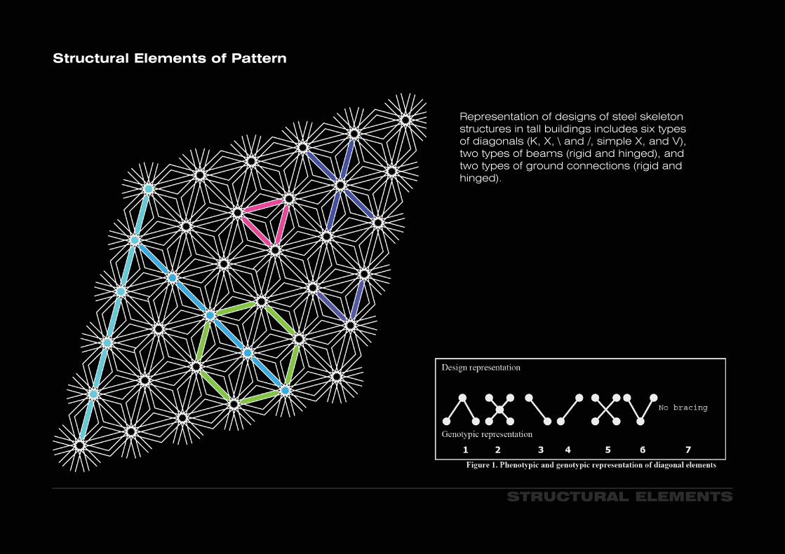
Representation of designs of steel skeleton structures in tall buildings includes six types of diagonals (K, X, \ and /, simple X, and V), two types of beams (rigid and hinged), and two types of ground connections (rigid and hinged).
Structural Elements of Pattern
FACADE: PATTERN
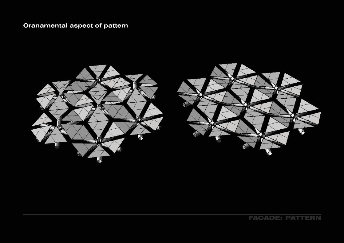
Oranamental aspect of pattern
FACADE: PATTERN
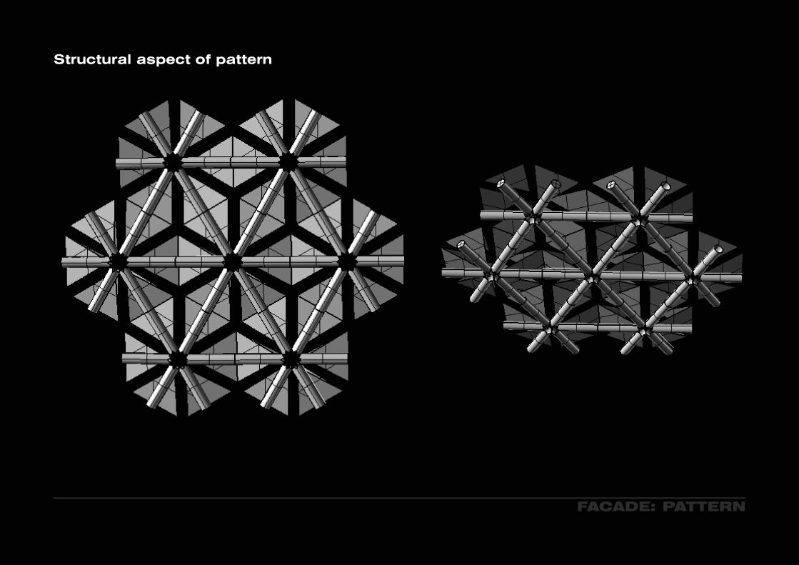
Structural aspect of pattern
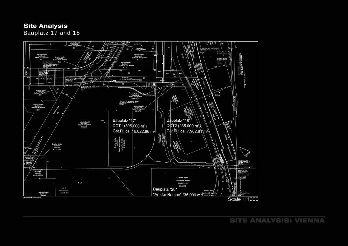
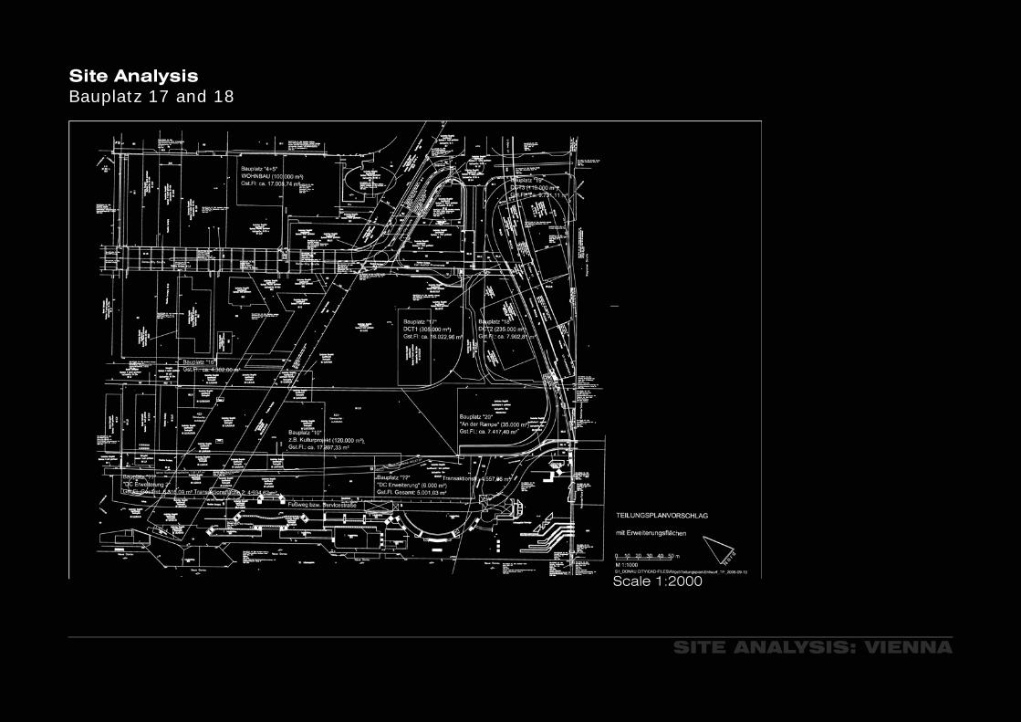
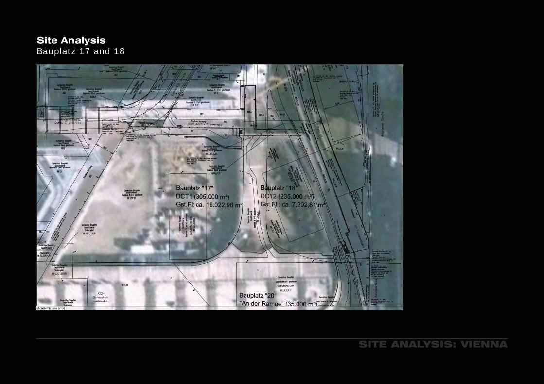
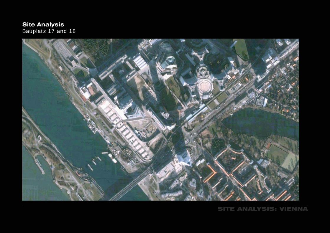
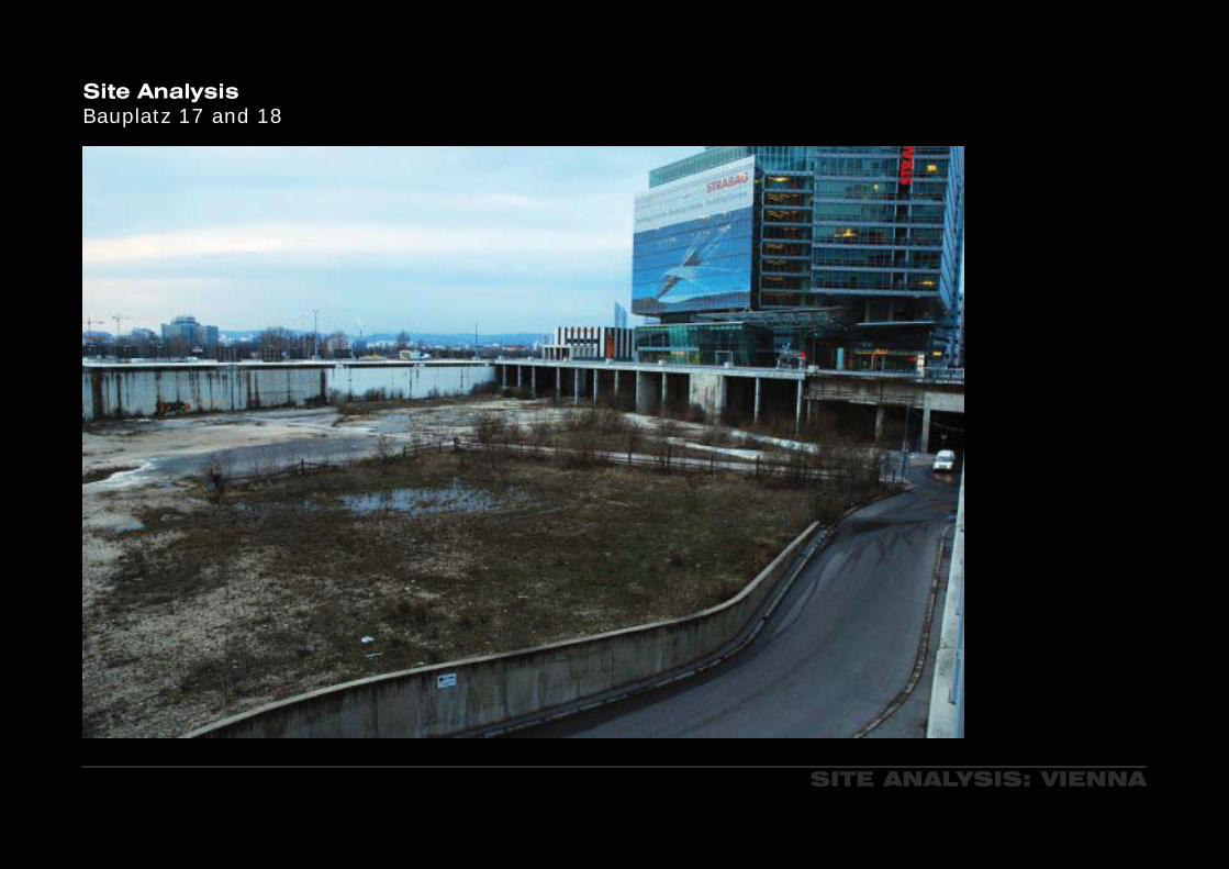
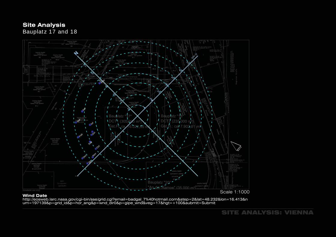
Site AnalysisBauplatz 17 and 18
SITE ANALYSIS: VIENNA
Scale 1:1000
SITE ANALYSIS: VIENNA
Scale 1:2000
Site AnalysisBauplatz 17 and 18

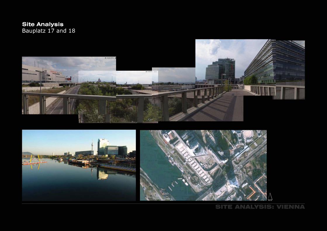
Site AnalysisBauplatz 17 and 18
SITE ANALYSIS: VIENNA
Scale 1:1000
N
Jul
Aug
Sep
Oct
Nov
Dec
Feb
Mar
Jan
Apr
Jun
May4
22
1 1
3
6
4
5
5
7
6
7(m
s-1)
3
Wind Datehttp://eosweb.larc.nasa.gov/cgi-bin/sse/grid.cgi?email=badgal_7%40hotmail.com&step=2&lat=48.232&lon=16.413&num=197139&p=grid_id&p=hor_ang&p=wnd_dir0&p=gipe_wnd&veg=17&hgt=+100&submit=Submit
SITE ANALYSIS: VIENNA
Site AnalysisBauplatz 17 and 18
SITE ANALYSIS: VIENNA
Site AnalysisBauplatz 17 and 18
SITE ANALYSIS: VIENNA
Site AnalysisBauplatz 17 and 18

SITE ANALYSIS: VIENNA
Site AnalysisBauplatz 17 and 18

SITE ANALYSIS: VIENNA
Site AnalysisBauplatz 17 and 18
SITE ANALYSIS: VIENNA
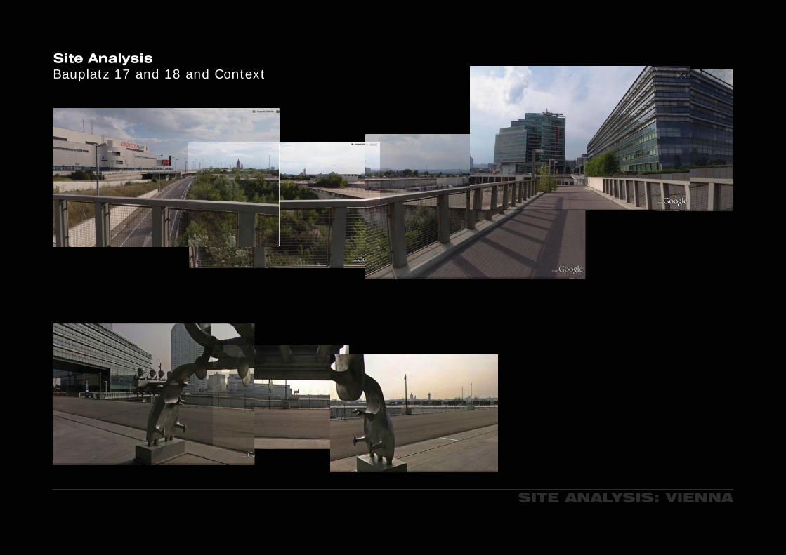
Site AnalysisBauplatz 17 and 18 and Context
SITE ANALYSIS: VIENNA
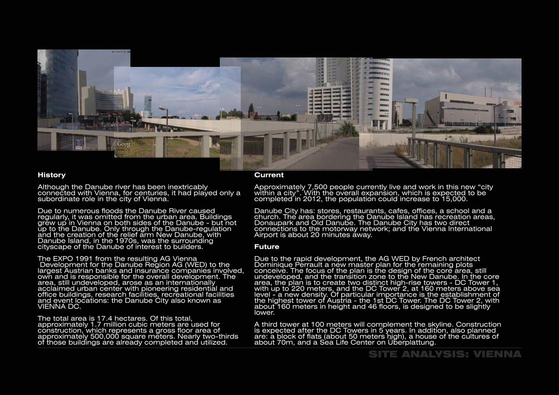
History
Although the Danube river has been inextricably connected with Vienna, for centuries, it had played only a subordinate role in the city of Vienna.
Due to numerous floods the Danube River caused regularly, it was omitted from the urban area. Buildings grew up in Vienna on both sides of the Danube - but not up to the Danube. Only through the Danube-regulation and the creation of the relief arm New Danube, with Danube Island, in the 1970s, was the surrounding cityscape of the Danube of interest to builders.
The EXPO 1991 from the resulting AG Vienna Development for the Danube Region AG (WED) to the largest Austrian banks and insurance companies involved, own and is responsible for the overall development. The area, still undeveloped, arose as an internationally acclaimed urban center with pioneering residential and office buildings, research facilities, recreational facilities and event locations: the Danube City also known as VIENNA DC.
The total area is 17.4 hectares. Of this total, approximately 1.7 million cubic meters are used for construction, which represents a gross floor area of approximately 500,000 square meters. Nearly two-thirds of those buildings are already completed and utilized.
Current
Approximately 7,500 people currently live and work in this new “city within a city”. With the overall expansion, which is expected to be completed in 2012, the population could increase to 15,000.
Danube City has: stores, restaurants, cafes, offices, a school and a church. The area bordering the Danube Island has recreation areas, Donaupark and Old Danube. The Danube City has two direct connections to the motorway network; and the Vienna International Airport is about 20 minutes away.
Future
Due to the rapid development, the AG WED by French architect Dominique Perrault a new master plan for the remaining plots conceive. The focus of the plan is the design of the core area, still undeveloped, and the transition zone to the New Danube. In the core area, the plan is to create two distinct high-rise towers - DC Tower 1, with up to 220 meters, and the DC Tower 2, at 160 meters above sea level - a new density. Of particular importance is the establishment of the highest tower of Austria - the 1st DC Tower. The DC Tower 2, with about 160 meters in height and 46 floors, is designed to be slightly lower.
A third tower at 100 meters will complement the skyline. Construction is expected after the DC Towers in 5 years. In addition, also planned are: a block of flats (about 50 meters high), a house of the cultures of about 70m, and a Sea Life Center on Überplattung.

SITE ANALYSIS: VIENNA
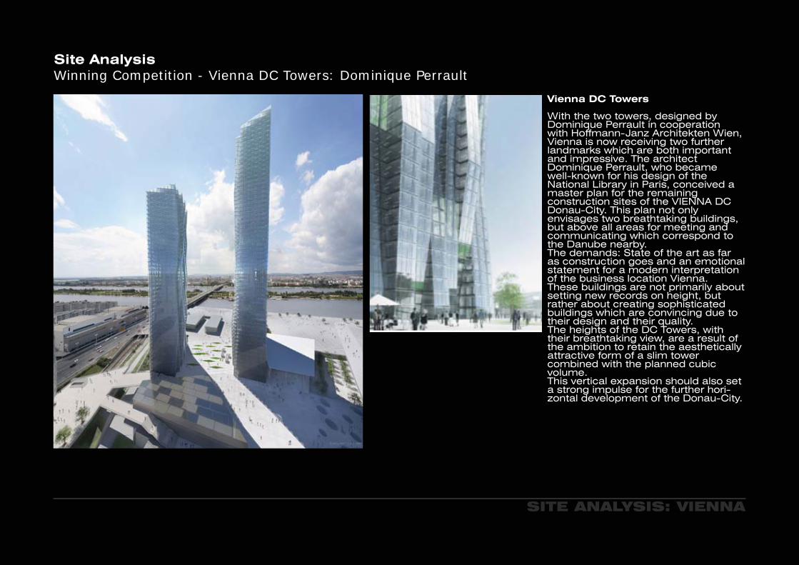
Site AnalysisWinning Comitition - Vienna DC Towers: Dominique Perrault
Vienna DC Towers
With the two towers, designed by Dominique Perrault in cooperation with Hoffmann-Janz Architekten Wien, Vienna is now receiving two further landmarks which are both important and impressive. The architect Dominique Perrault, who became well-known for his design of the National Library in Paris, conceived a master plan for the remaining construction sites of the VIENNA DC Donau-City. This plan not only envisages two breathtaking buildings, but above all areas for meeting and communicating which correspond to the Danube nearby. The demands: State of the art as far as construction goes and an emotional statement for a modern interpretation of the business location Vienna. These buildings are not primarily about setting new records on height, but rather about creating sophisticated buildings which are convincing due to their design and their quality. The heights of the DC Towers, with their breathtaking view, are a result of the ambition to retain the aesthetically attractive form of a slim tower combined with the planned cubic volume. This vertical expansion should also set a strong impulse for the further hori-zontal development of the Donau-City.
PHYSICAL MODEL
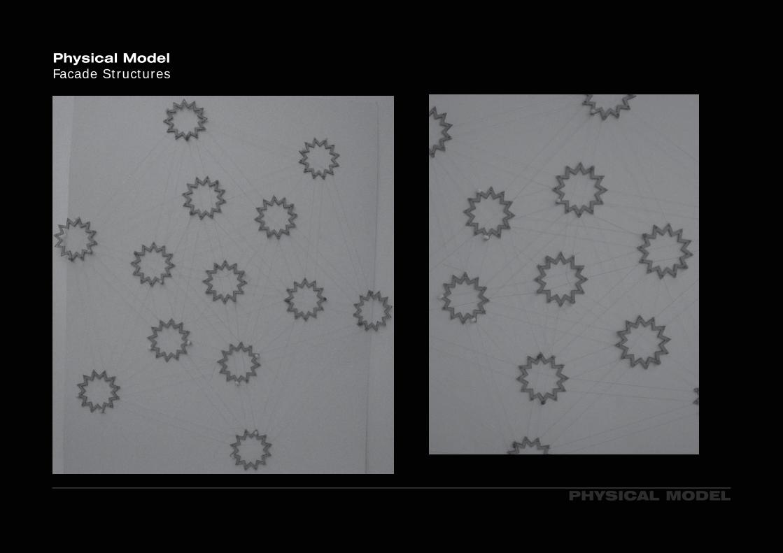
Physical Model Facade Structures

PHYSICAL MODEL
Physical Model Facade Structures

DEVELOPEMENT OF FACADE
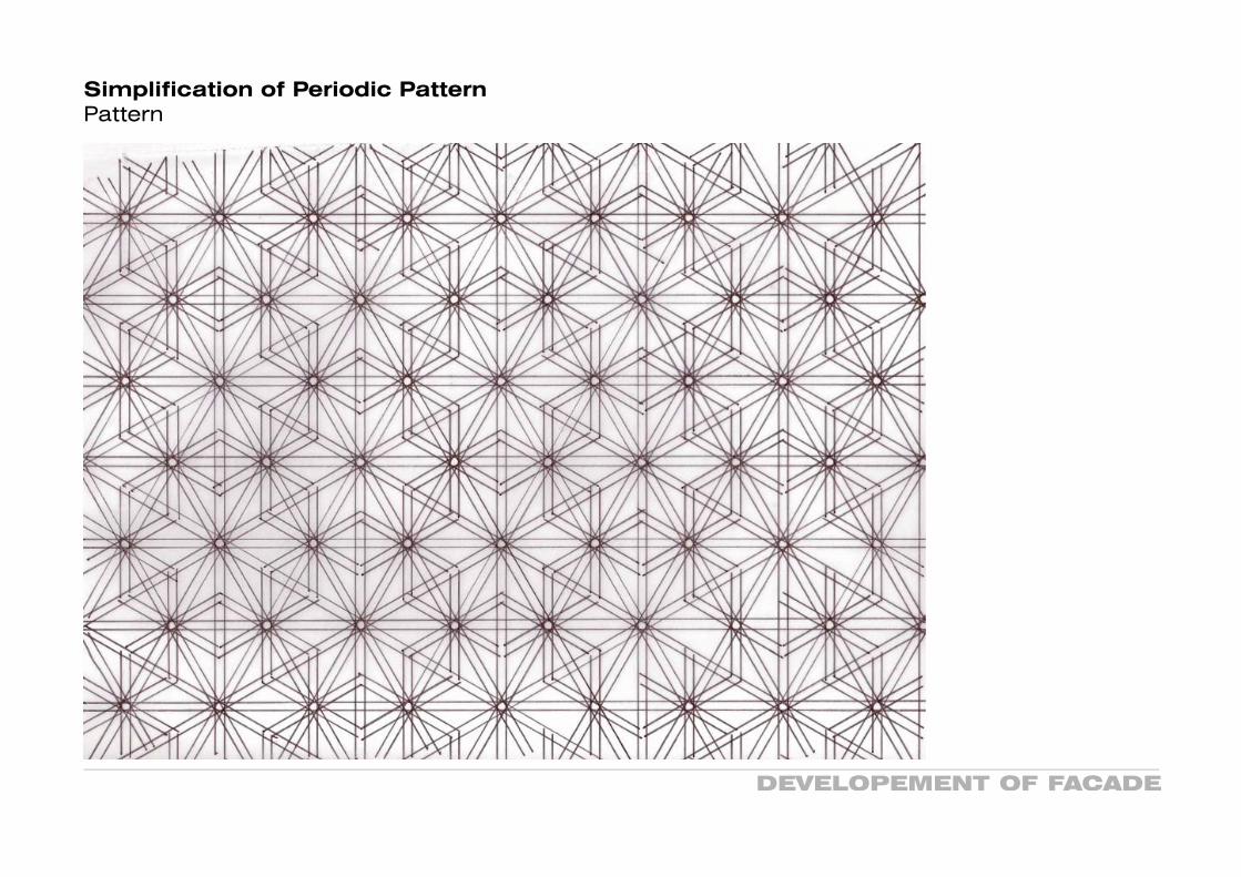
Simplification of Periodic PatternPattern
I
~
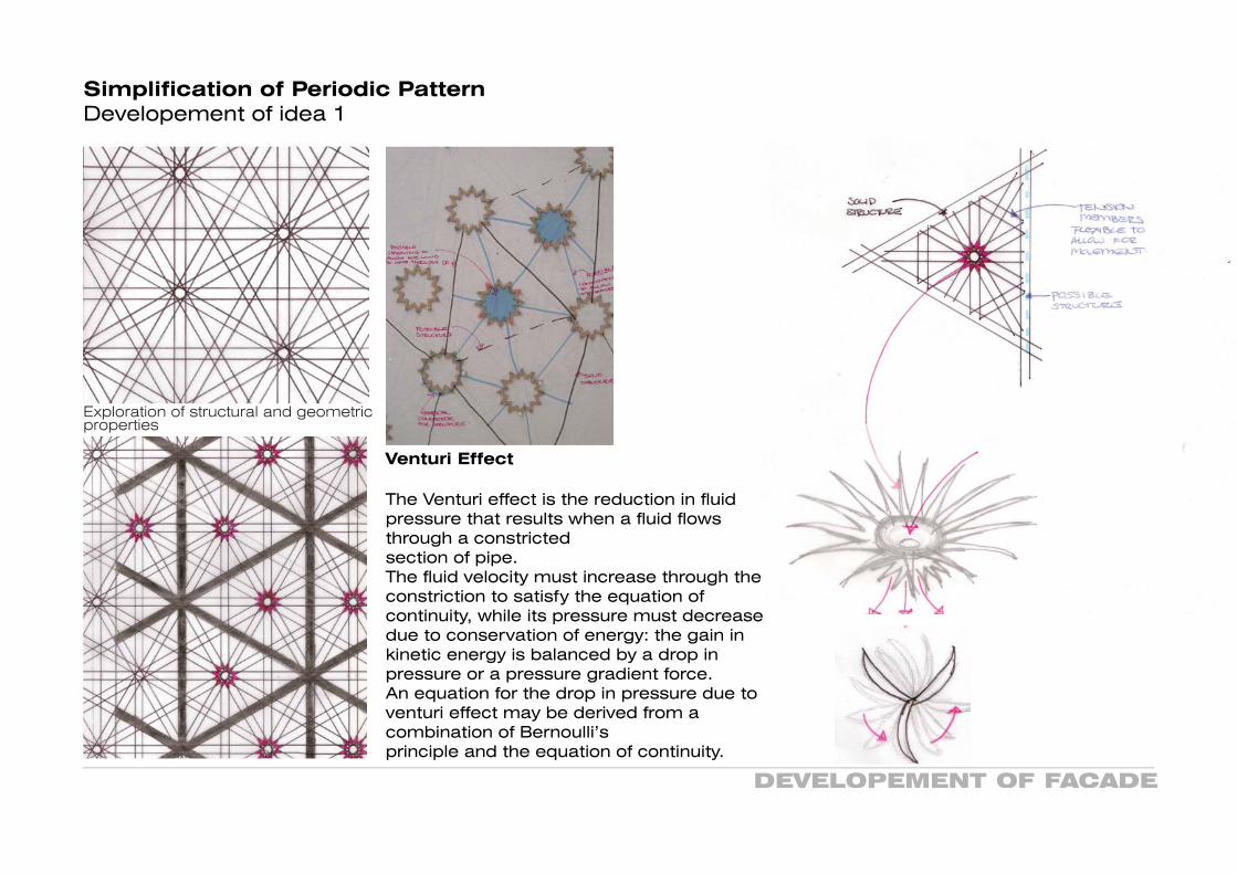
Exploration of structural and geometric properties

DEVELOPEMENT OF FACADE
Simplification of Periodic PatternDevelopement of idea 1
.'TE S~fYleVY\'e:>S~
.~&:-E "toPru-Ov.:, F-~
1Y1CVGYY>~U1'
pass l Ec..e::.. _S""T\Zvcrc..>lZ.L:'::-
S1'e:e.P ~....:s~t> '-Oc.VG:~ "'tr\ ~ t--li1\AT e~ r-n~ Q...
'foss\~(...,G~e;t>..> (~~ "t"O
Au.,a....::> 'Fe<.. c...,:) ,~ Q
\0 COVlG -t1-\ t:£X)c..\.\
DEVELOPEMENT OF FACADE
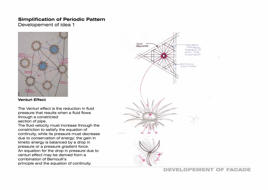
Simplification of Periodic PatternDevelopement of idea 1
Venturi Effect
The Venturi effect is the reduction in fluid pressure that results when a fluid flows through a constricted section of pipe. The fluid velocity must increase through the constriction to satisfy the equation of continuity, while its pressure must decrease due to conservation of energy: the gain in kinetic energy is balanced by a drop in pressure or a pressure gradient force. An equation for the drop in pressure due to venturi effect may be derived from a combination of Bernoulli’s principle and the equation of continuity.
DEVELOPEMENT OF FACADE
Simplification of Periodic PatternPattern

DEVELOPEMENT OF FACADE
Simplification of Periodic PatternStructural Quality
nn~~Ci.~~cl]l3~~~~q.)(
OMACCTV Builindg, Beijing

·r-t~ll'~~w.:;;@(3,...,0"5~
L<\N'~J~~81"h-'D~~~~6~~~
~~("('H~·.~3VN'''"''>-'9C''lIr\S@(<ie..,1CV').~~~\"
~~~~~~aL~CD S'3l~'QJ~-:J.\tr')'.~\~C'I';Z....L-.1
DEVELOPEMENT OF FACADE
Simplification of Periodic PatternFacade Exploration and Power Generation
Dynamic Aeroelasticity studies the interactions among aero-dynamic, elastic, and inertial forces. Examples of dynamic aeroelastic phenomena are:
Flutter
Flutter is a self-feeding and potentially destructive vibration where aerodynamic forces on an object couple with a structure’s natural mode of vibration to produce rapid periodic motion. Flutter can occur in any object within a strong fluid flow, under the conditions that a positive feedback occurs between the structure’s natural vibration and the aerodynamic forces. That is, that the vibrational movement of the object increases an aerodynamic load which in turn drives the object to move further. If the energy during the period of aerodynamic excitation is larger than the natural damping of the system, the level of vibration will increase. The vibration levels can thus build up and are only limited when the aerodynamic or mechanical damping of the object match the energy input, this often results in large amplitudes and can lead to rapid failure. It is however not always a destructive force; recent progress has been made in wind generators, for the third world designed specifically to take advantage of this effect. A type of wind generator using this effect is known as the Windbelt.
DEVELOPEMENT OF FACADE
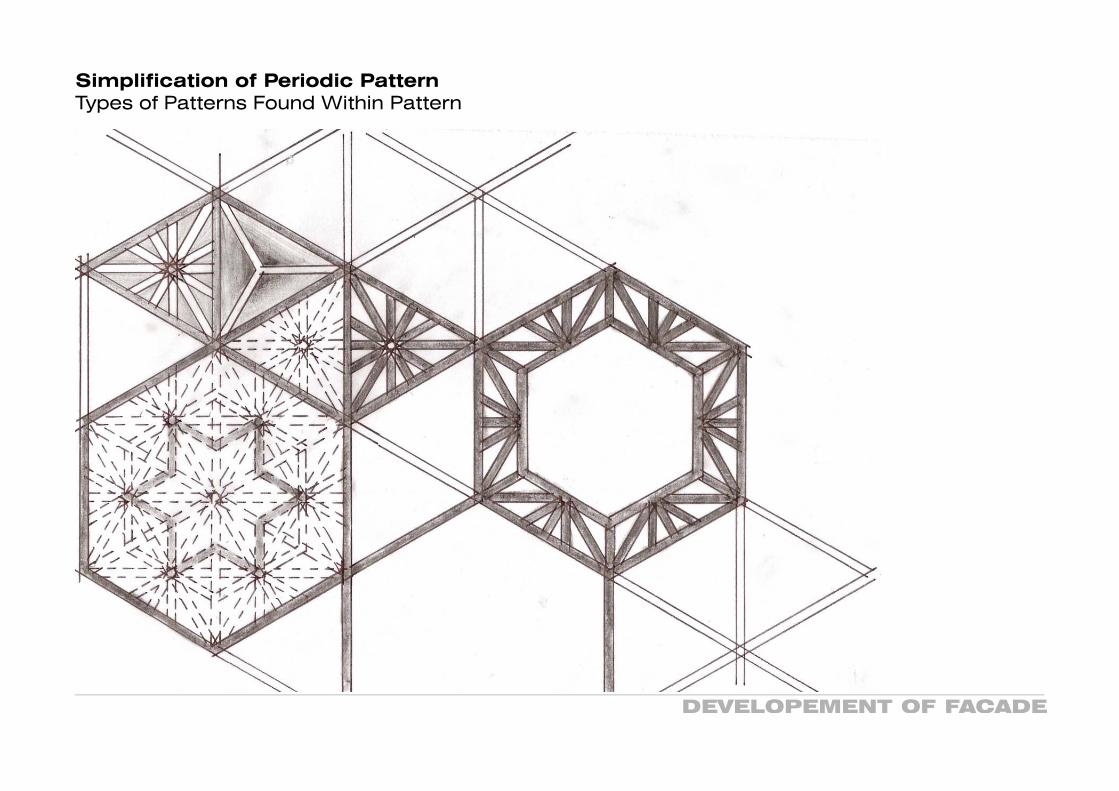
Simplification of Periodic PatternTypes of Patterns Found Within Pattern

DEVELOPEMENT OF FACADE
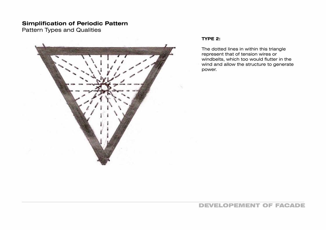
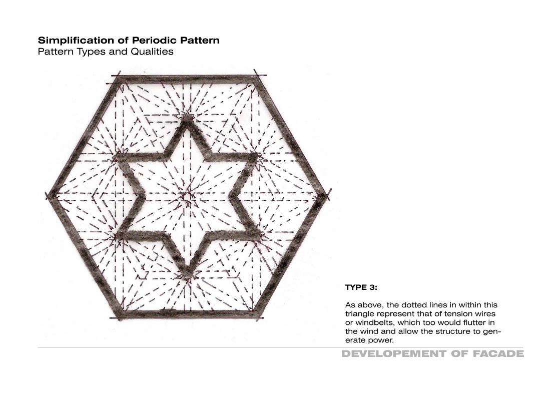
Simplification of Periodic PatternPattern Types and Qualities
TYPE 1: Types 1 through to 3, generate power through vibrations caused by the wind.
The shadded area of this pattern (excluding the structual triangle) are intended to flutter in the wind (shingles), mimmicing that of wind charms. The shingles would be hinged to the outer triangle.
DEVELOPEMENT OF FACADE
Simplification of Periodic PatternPattern Types and Qualities
TYPE 2:
The dotted lines in within this triangle represent that of tension wires or windbelts, which too would flutter in the wind and allow the structure to generate power.
DEVELOPEMENT OF FACADE
Simplification of Periodic PatternPattern Types and Qualities
TYPE 3:
As above, the dotted lines in within this triangle represent that of tension wires or windbelts, which too would flutter in the wind and allow the structure to gen-erate power.
DEVELOPEMENT OF FACADE
Simplification of Periodic PatternPattern Types and Qualities
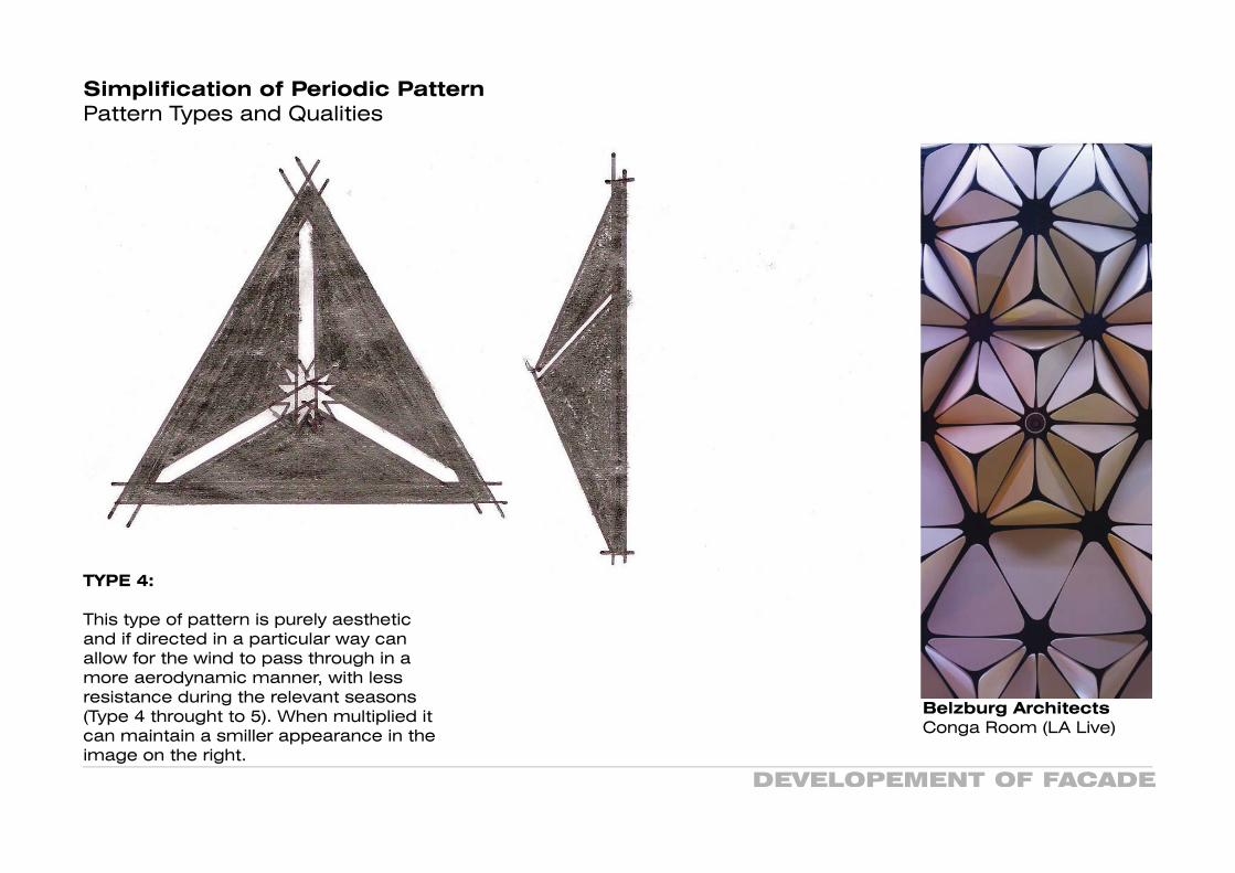
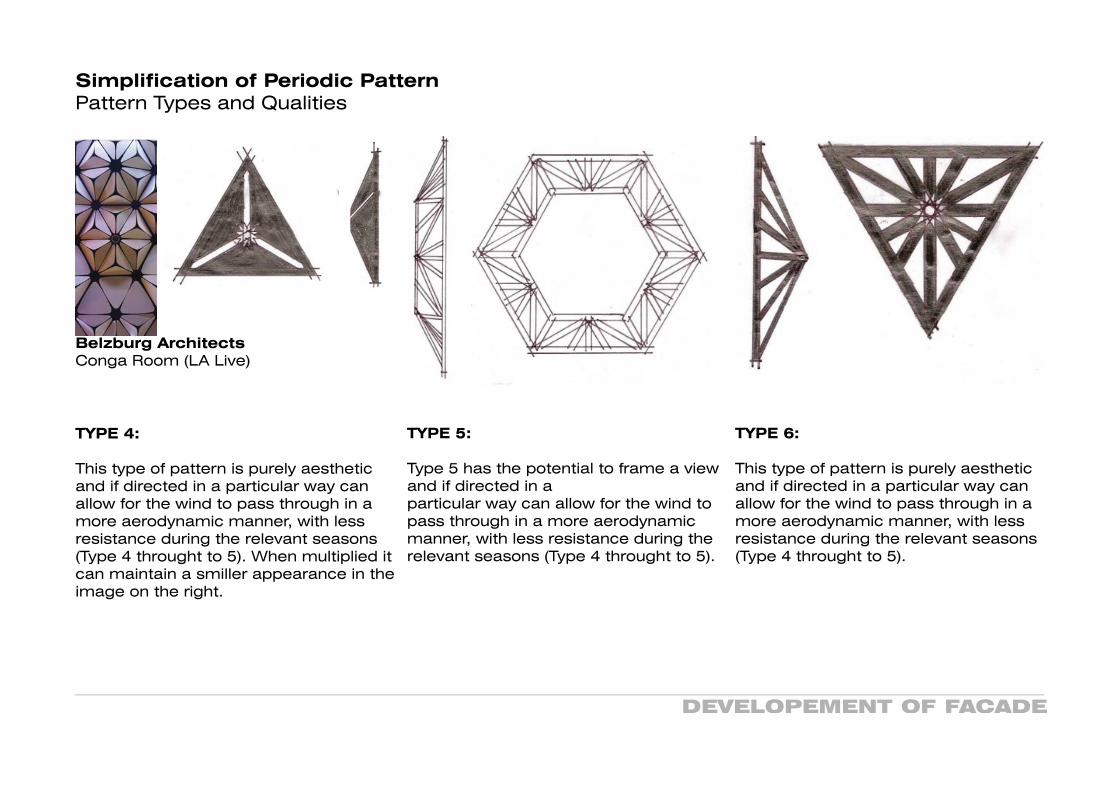
TYPE 4:
This type of pattern is purely aesthetic and if directed in a particular way can allow for the wind to pass through in a more aerodynamic manner, with less resistance during the relevant seasons (Type 4 throught to 5). When multiplied it can maintain a smiller appearance in the image on the right.
Belzburg ArchitectsConga Room (LA Live)

DEVELOPEMENT OF FACADE
Simplification of Periodic PatternPattern Types and Qualities
TYPE 5:
Type 5 has the potential to frame a view and if directed in a particular way can allow for the wind to pass through in a more aerodynamic manner, with less resistance during the relevant seasons (Type 4 throught to 5).

DEVELOPEMENT OF FACADE
Simplification of Periodic PatternPattern Types and Qualities
TYPE 6:
This type of pattern is purely aesthetic and if directed in a particular way can allow for the wind to pass through in a more aerodynamic manner, with less resistance during the relevant seasons (Type 4 throught to 5).
PROGRAMMING
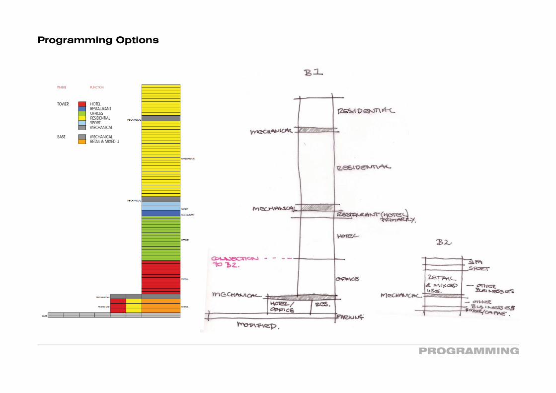
Programming Options
eNT\~
~e
~
\"
~(~~~~\P'1 ':]I.
II'\E:O!"'"
•III Oe..\.
~~\L4 IY\ ('l'- C2.'PU~.
-..•..
model studies, both tral Vienna that is able to
energy concept and on ng is a classic (big) inner
nd a hotel with amenities the tower. Underground
eds to be provided.
elopment - you may in mind that the infor-
o useable area cannot D site plan. The building op a landscaping strategy
pare a rough functional ound relationships in alter-ass models.
00.aken down projects.
WHERE FUNCTION F
TOWER HOTELRESTAURANTOFFICESRESIDENTIALSPORTMECHANICAL
BASE MECHANICALRETAIL & MIXED U

SITE ANALYSIS: VIENNA
Site AnalysisSite Oportunities
-.J.f~£...
It~ctZ
~~_
A~A
(.~~-ptFF
Ef..,)"\fl-Y
A'-l~~.

Site AnalysisSun Shadow Summer 12pm
SITE ANALYSIS: VIENNA
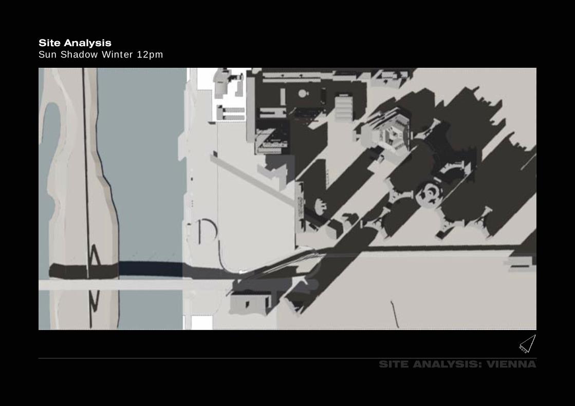
Site AnalysisSun Shadow Winter 12pm
SITE ANALYSIS: VIENNA

PROGRAM
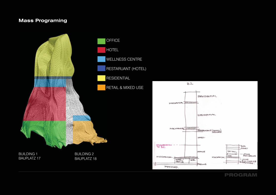
Mass Programing
OFFICE
HOTEL
WELNESS CENTRE
RESTARUANT (HOTEL)
RESIDENTIAL
RETAIL & MIXED USE
BUILDING 1BAUPLATZ 17
BUILDING 1BAUPLATZ 17
BUILDING 2BAUPLATZ 18
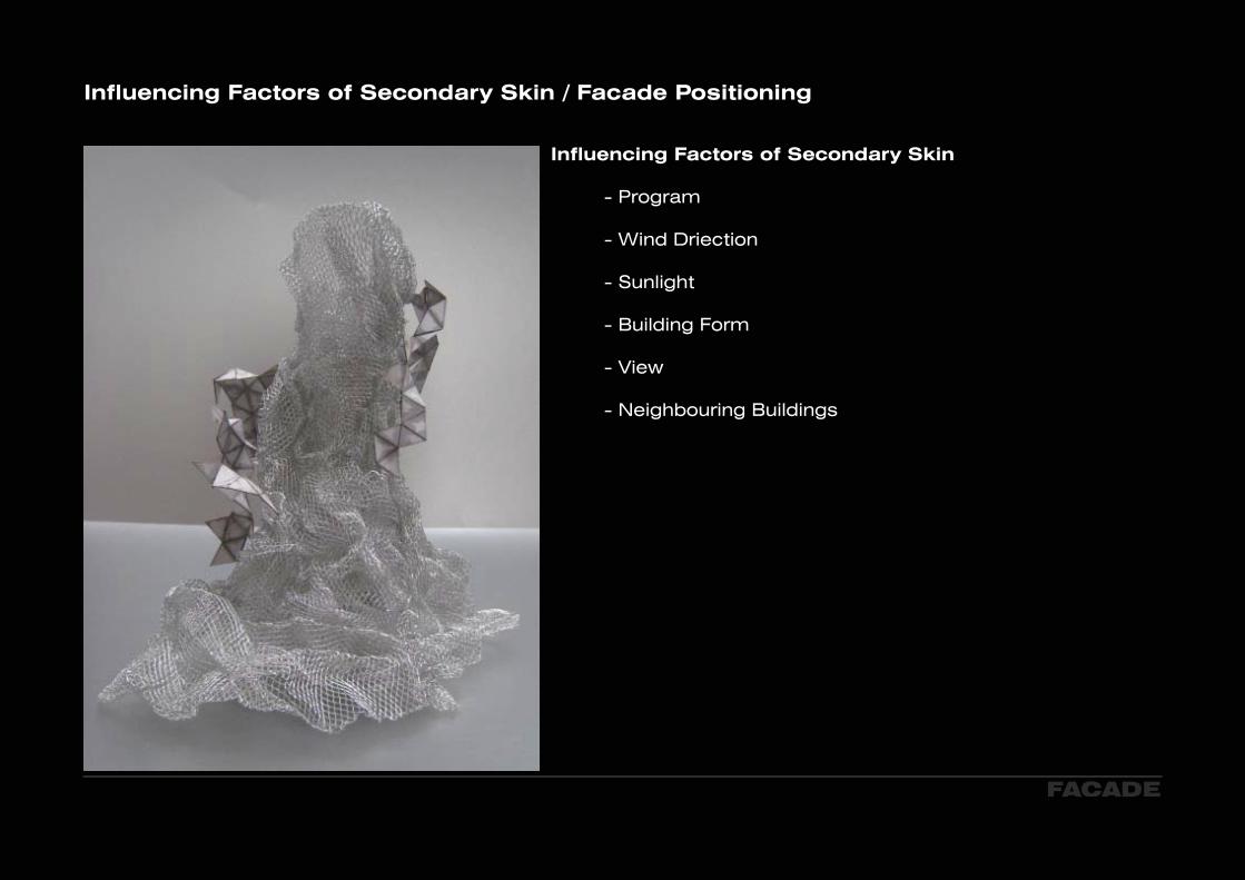
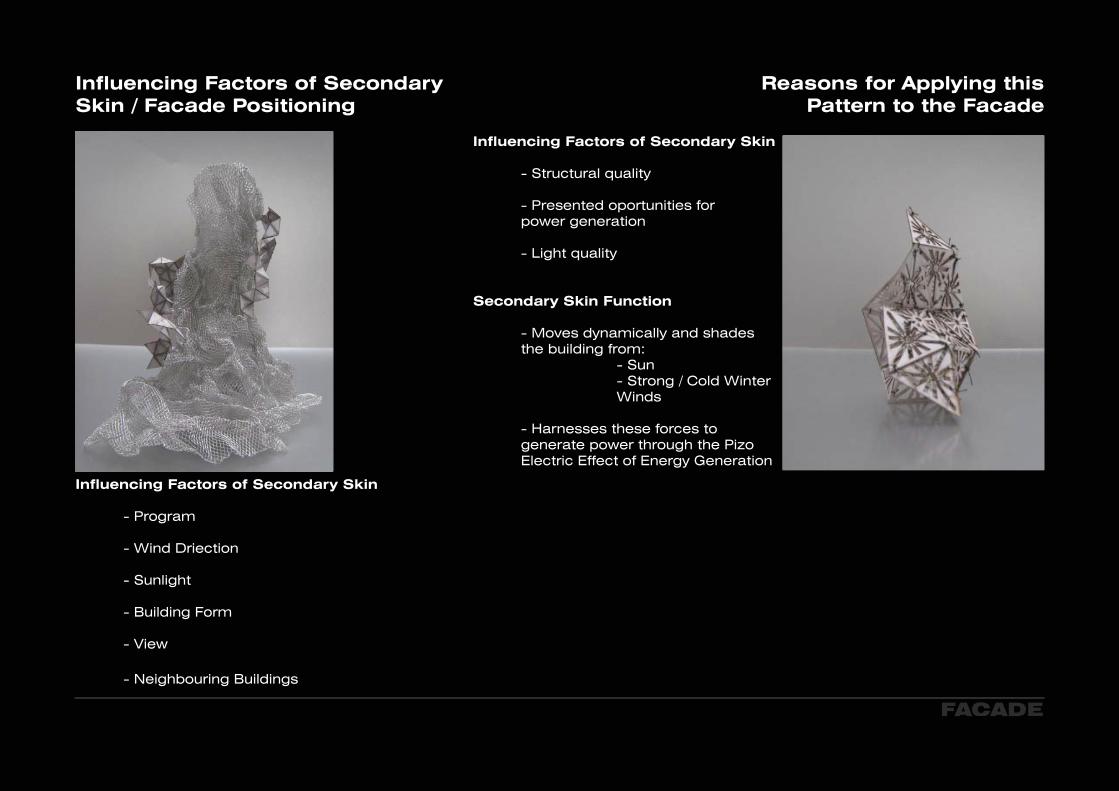
Influencing Factors of Secondary Skin / Facade Positioning
Influencing Factors of Secondary Skin
- Program
- Wind Driection
- Sunlight
- Building Form - View
- Neighbouring Buildings
FACADE
FACADE
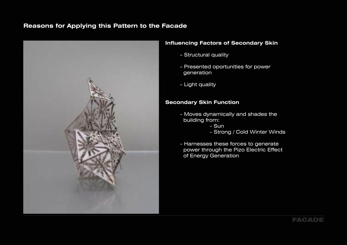
Reasons for Applying this Pattern to the Facade
Influencing Factors of Secondary Skin
- Structural quality
- Presented oportunities for power generation
- Light quality
Secondary Skin Function
- Moves dynamically and shades the building from: - Sun - Strong / Cold Winter Winds
- Harnesses these forces to generate power through the Pizo Electric Effect of Energy Generation

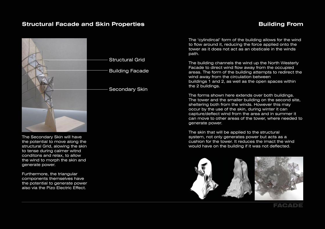
Structural Facade and Skin Properties
FACADE
Structural Grid
Building Facade
Secondary Skin
The Secondary Skin will have the potential to move along the structural Grid, alowing the skin to tense during calmer witnd conditons and relax, to allow the wind to morph the skin and generate power.
Furthermore, the triangular components themselves have the potential to generate power also via the Pizo Electric Effect.

Building From
FORM
The ‘cylindircal’ form of the building allows for the wind to flow around it, reducing the force applied onto the tower as it does not act as an obsticale in the winds path.
The building channels the wind up the North Westerly Facade to direct wind flow away from the occupied areas. The form of the building attempts to redirect the wind away from the circulation between buildings 1 and 2, as well as the open spaces within the 2 buildings.
The forms shown here extends over both buildings. The tower and the smaller building on the second site, sheltering both from the winds. However this may occur by the use of the skin, during winter it can capture/deflect wind from the area and in summer it can move to other areas of the tower, where needed to generate power.
The skin that will be applied to the structural system, not only generates power but acts as a cushion for the tower. It reduces the imact the wind would have on the building if it was not deflected.

DONAUCITY TOWER
Donaucity TowerBrief
Based on the research of dynamic forces and the subsequent model studies, both virtual and physical you are asked to design a highrise in central Vienna that is able to generate energy through both geometry and envelope.
The focus is placed on the overall geometry according to the energy concept and on the development of the building skin. The function of the building is a classic (big) inner city program of retail in the base of the tower, office spaces and a hotel with amenities located centrally and residential areas in the upper section of the tower. Underground car parking for 1.000 cars with access to the public streets needs to be provided.
Site AnalysisBauplatz 17 and 18
SITE ANALYSIS: VIENNA
Scale 1:1000
N
Jul
Aug
Sep
Oct
Nov
Dec
Feb
Mar
Jan
Apr
Jun
May4
22
1 1
3
6
4
5
5
7
6
7(m
s-1)
3
Wind Datehttp://eosweb.larc.nasa.gov/cgi-bin/sse/grid.cgi?email=badgal_7%40hotmail.com&step=2&lat=48.232&lon=16.413&num=197139&p=grid_id&p=hor_ang&p=wnd_dir0&p=gipe_wnd&veg=17&hgt=+100&submit=Submit
SITE ANALYSIS: VIENNA
Site AnalysisWinning Competition - Vienna DC Towers: Dominique Perrault
Vienna DC Towers
With the two towers, designed by Dominique Perrault in cooperation with Hoffmann-Janz Architekten Wien, Vienna is now receiving two further landmarks which are both important and impressive. The architect Dominique Perrault, who became well-known for his design of the National Library in Paris, conceived a master plan for the remaining construction sites of the VIENNA DC Donau-City. This plan not only envisages two breathtaking buildings, but above all areas for meeting and communicating which correspond to the Danube nearby. The demands: State of the art as far as construction goes and an emotional statement for a modern interpretation of the business location Vienna. These buildings are not primarily about setting new records on height, but rather about creating sophisticated buildings which are convincing due to their design and their quality. The heights of the DC Towers, with their breathtaking view, are a result of the ambition to retain the aesthetically attractive form of a slim tower combined with the planned cubic volume. This vertical expansion should also set a strong impulse for the further hori-zontal development of the Donau-City.

SIMPLIFICATION OF PERIODIC PATTERN
Simplifying Periodic Pattern
The simplification of the patterns allow primary shapes to become evident and present themselves in a clear manner. This allows you to distinguish a relationship with particular qualities within the pattern. i.e the function a specific shape can take and its qualities (i.e structural resemblance).

STRUCTURAL ELEMENTS
Representation of designs of steel skeleton structures in tall buildings includes six types of diagonals (K, X, \ and /, simple X, and V), two types of beams (rigid and hinged), and two types of ground connections (rigid and hinged).
Structural Elements of Pattern
VIRTUAL IMAGE OF PHYSICAL MODEL
This image ilustrates how this pattern could be produced through MDF and finishingwire. The centre starts would be braced through the tenssion of the fishing wire connections.
Fishing wire
.'TE S~fYleVY\'e:>S~
.~&:-E "toPru-Ov.:, F-~
1Y1CVGYY>~U1'
pass l Ec..e::.. _S""T\Zvcrc..>lZ.L:'::-
S1'e:e.P ~....:s~t> '-Oc.VG:~ "'tr\ ~ t--li1\AT e~ r-n~ Q...
'foss\~(...,G~e;t>..> (~~ "t"O
Au.,a....::> 'Fe<.. c...,:) ,~ Q
\0 COVlG -t1-\ t:£X)c..\.\
DEVELOPEMENT OF FACADE
Simplification of Periodic PatternDevelopement of idea 1
Venturi Effect
The Venturi effect is the reduction in fluid pressure that results when a fluid flows through a constricted section of pipe. The fluid velocity must increase through the constriction to satisfy the equation of continuity, while its pressure must decrease due to conservation of energy: the gain in kinetic energy is balanced by a drop in pressure or a pressure gradient force. An equation for the drop in pressure due to venturi effect may be derived from a combination of Bernoulli’s principle and the equation of continuity.
Exploration of structural and geometric properties

DEVELOPEMENT OF FACADE
Simplification of Periodic PatternStructural Quality
nn~~Ci.~~cl]l3~~~~q.)(
OMACCTV Builindg, Beijing

·r-t~ll'~~w.:;;@(3,...,0"5~
L<\N'~J~~81"h-'D~~~~6~~~
~~("('H~·.~3VN'''"''>-'9C''lIr\S@(<ie..,1CV').~~~\"
~~~~~~aL~CD S'3l~'QJ~-:J.\tr')'.~\~C'I';Z....L-.1
DEVELOPEMENT OF FACADE
Simplification of Periodic PatternFacade Exploration and Power Generation
Dynamic Aeroelasticity studies the interactions among aerodynamic, elastic, and inertial forces. Examples of dynamic aeroelastic phenomena are:
Flutter
Flutter is a self-feeding and potentially destructive vibration where aerodynamic forces on an object couple with a structure’s natural mode of vibration to produce rapid periodic motion. Flutter can occur in any object within a strong fluid flow, under the conditions that a positive feedback occurs between the structure’s natural vibration and the aerodynamic forces. That is, that the vibrational movement of the object increases an aerodynamic load which in turn drives the object to move further. If the energy during the period of aerodynamic excitation is larger than the natural damping of the system, the level of vibration will increase. The vibration levels can thus build up and are only limited when the aerodynamic or mechanical damping of the object match the energy input, this often results in large amplitudes and can lead to rapid failure. It is however not always a destructive force; recent progress has been made in wind generators, for the third world designed specifically to take advantage of this effect. A type of wind generator using this effect is known as the Windbelt.

DEVELOPEMENT OF FACADE
Simplification of Periodic PatternPattern Types and Qualities
TYPE 1: Types 1 through to 3, generate power through vibrations caused by the wind.
The shadded area of this pattern (excluding the structual triangle) are intended to flutter in the wind (shingles), mimmicing that of wind charms. The shingles would be hinged to the outer triangle.
TYPE 2:
The dotted lines in within this triangle represent that of tension wires or windbelts, which too would flutter in the wind and allow the structure to generate power.
TYPE 3:
As above, the dotted lines in within this triangle represent that of tension wires or windbelts, which too would flutter in the wind and allow the structure to gen-erate power.
DEVELOPEMENT OF FACADE
Simplification of Periodic PatternPattern Types and Qualities
TYPE 4:
This type of pattern is purely aesthetic and if directed in a particular way can allow for the wind to pass through in a more aerodynamic manner, with less resistance during the relevant seasons (Type 4 throught to 5). When multiplied it can maintain a smiller appearance in the image on the right.
Belzburg ArchitectsConga Room (LA Live)
TYPE 5:
Type 5 has the potential to frame a view and if directed in a particular way can allow for the wind to pass through in a more aerodynamic manner, with less resistance during the relevant seasons (Type 4 throught to 5).
TYPE 6:
This type of pattern is purely aesthetic and if directed in a particular way can allow for the wind to pass through in a more aerodynamic manner, with less resistance during the relevant seasons (Type 4 throught to 5).
Influencing Factors of Secondary Skin / Facade Positioning
Influencing Factors of Secondary Skin
- Program
- Wind Driection
- Sunlight
- Building Form - View
- Neighbouring Buildings
FACADE
Reasons for Applying this Pattern to the Facade
Influencing Factors of Secondary Skin
- Structural quality
- Presented oportunities for power generation
- Light quality
Secondary Skin Function
- Moves dynamically and shades the building from: - Sun - Strong / Cold Winter Winds
- Harnesses these forces to generate power through the Pizo Electric Effect of Energy Generation
Structural Facade and Skin Properties Building From
FACADE
Structural Grid
Building Facade
Secondary Skin
The Secondary Skin will have the potential to move along the structural Grid, alowing the skin to tense during calmer witnd conditons and relax, to allow the wind to morph the skin and generate power.
Furthermore, the triangular components themselves have the potential to generate power also via the Pizo Electric Effect.
The ‘cylindircal’ form of the building allows for the wind to flow around it, reducing the force applied onto the tower as it does not act as an obsticale in the winds path.
The building channels the wind up the North Westerly Facade to direct wind flow away from the occupied areas. The form of the building attempts to redirect the wind away from the circulation between buildings 1 and 2, as well as the open spaces within the 2 buildings.
The forms shown here extends over both buildings. The tower and the smaller building on the second site, sheltering both from the winds. However this may occur by the use of the skin, during winter it cancapture/deflect wind from the area and in summer it can move to other areas of the tower, where needed to generate power.
The skin that will be applied to the structural system, not only generates power but acts as a cushion for the tower. It reduces the imact the wind would have on the building if it was not deflected.
PROGRAM
Mass Programing
OFFICE
HOTEL
WELLNESS CENTRE
RESTARUANT (HOTEL)
RESIDENTIAL
RETAIL & MIXED USE
BUILDING 1BAUPLATZ 17
BUILDING 2BAUPLATZ 18
eNT\~
~e
~
\"
~(~~~~\P'1 ':]I.
II'\E:O!"'"
•III Oe..\.
~~\L4 IY\ ('l'- C2.'PU~.
-..•..

Generation of Power via Venturi Effect
POWER GENERATION
The fixed section acts as in inlet, where the external skin acts as an inward part of a sail, compressed by the wind force to decrease the size of the appature, i.e the space between the external skin and the building itself, in order to create a high speed tunnel, driving the horizontal wind turbines thus generating substantial power via the Venturi effect.
Deformation of external skin due to wind forces (Left side of form)
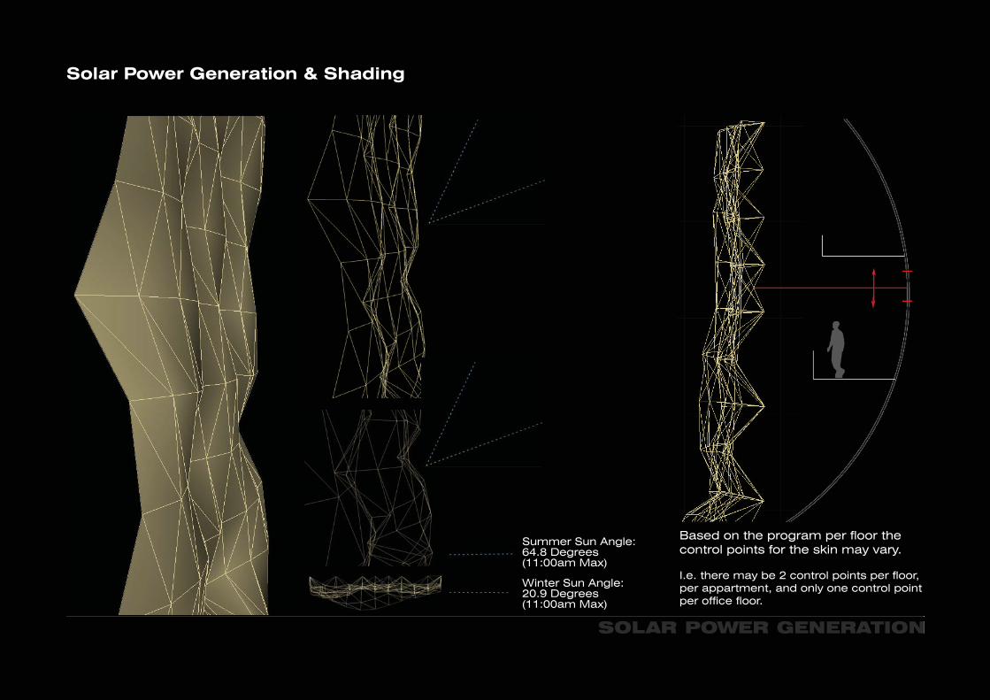
Solar Power Generation & Shading
SOLAR POWER GENERATION
Summer Sun Angle: 64.8 Degrees (11:00am Max)
Winter Sun Angle: 20.9 Degrees (11:00am Max)
Based on the program per floor the control points for the skin may vary.
I.e. there may be 2 control points per floor, per appartment, and only one control point per office floor.
CONNECTIONS - SUNLIGHT STUDY
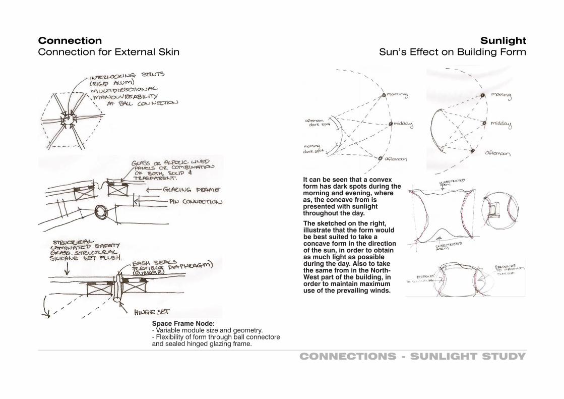
Connection Connection for External Skin
Space Frame Node: - Variable module size and geometry.- Flexibility of form through ball connectore and sealed hinged glazing frame.
It can be seen that a convex form has dark spots during the morning and evening, where as, the concave from is presented with sunlight throughout the day.
SunlightSun’s Effect on Building Form
The sketched on the right, illustrate that the form would be best suited to take a concave form in the direction of the sun, in order to obtain as much light as possible during the day. Also to take the same from in the North-West part of the building, in order to maintain maximum use of the prevailing winds.

DONAUCITY TOWER
Donaucity TowerBrief
Based on the research of dynamic forces and the subsequent model studies, both virtual and physical you are asked to design a highrise in central Vienna that is able to generate energy through both geometry and envelope.
The focus is placed on the overall geometry according to the energy concept and on the development of the building skin. The function of the building is a classic (big) inner city program of retail in the base of the tower, office spaces and a hotel with amenities located centrally and residential areas in the upper section of the tower. Underground car parking for 1.000 cars with access to the public streets needs to be provided.
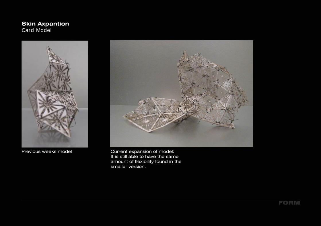
Skin AxpantionCard Model
FORM
Previous weeks model Current expansion of model:It is still able to have the same amount of flexibility found in the smaller version.

Form ExplorarionClay Model
FORM
Clay form, exploring the form the building could take with regards to site influences, i.e sun and wind.
The form does not seem suitable, difficult to position a central core and appears to have very little volume to occupy.
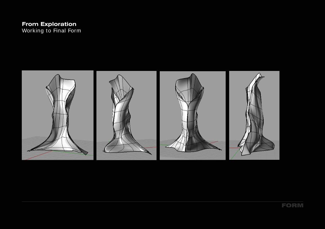
From ExplorationWorking to Final Form
FORM
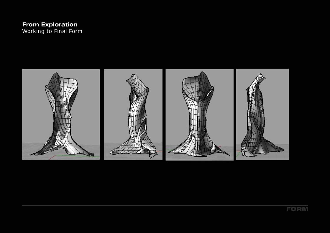
From ExplorationWorking to Final Form
FORM
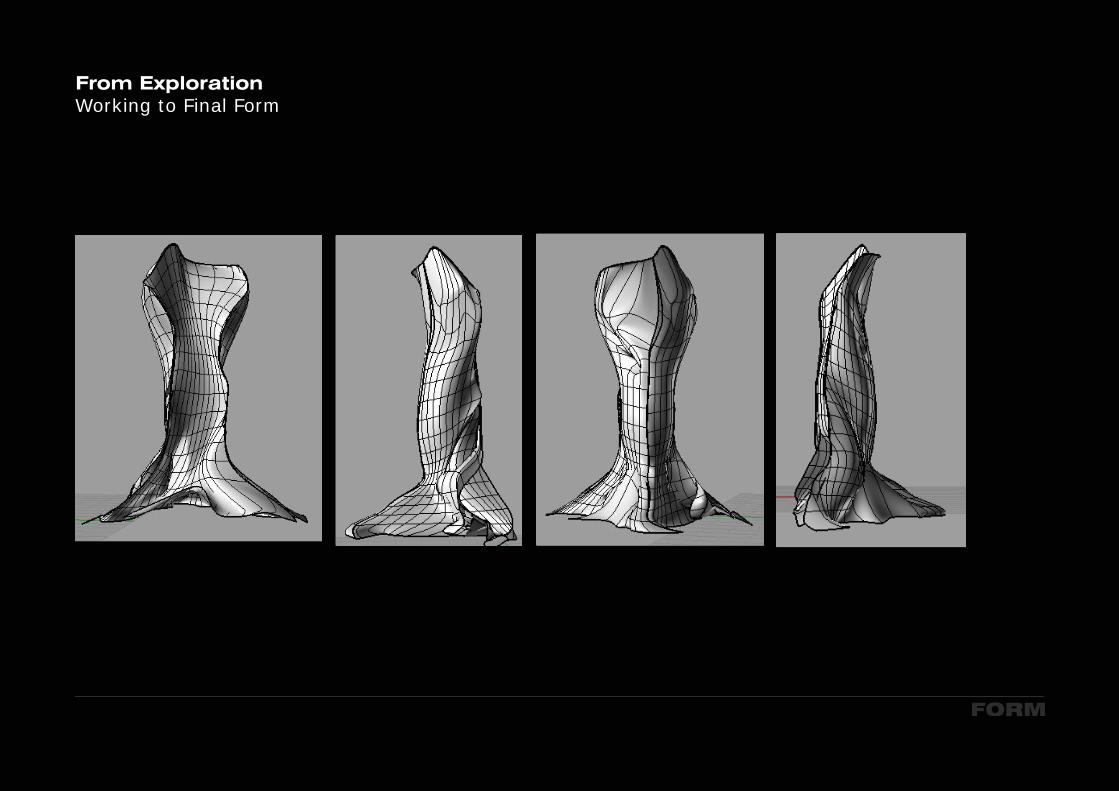
From ExplorationWorking to Final Form
FORM

FORM
From ExplorationWorking to Final Form
The concave from on the southern facade, has been developed to maxi-mise the use of the sun.
The curved back of the building allows the Venturi Effect to be incorportated on that facade, the most windiest. The form also allows for the wind to flow around the curved surface taking the path of least resistance.
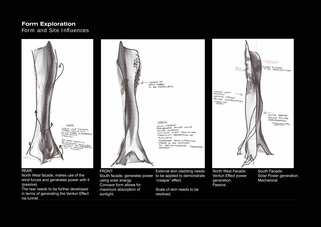
Form ExplorationForm and Site Infl uences
~~'U:.~lf'\~~~~,~ ~~fl<k:JS~~I
~l-\.l.C\n-;iOJ..S~"Id;e;a~
.C~I'IS<;;:'\;rd)..u~C"">~d
s.~~:'9~0""10'7~"'::-l-\:.L~o3~(J~B"'"3Q~~.d-~"'tL~
:-a~
d--~~~N \oJE3)S
-+0 BE" \<:C~\:>.
..£'@\.$~
~~~~~~r.s ~~ ~1....:Q-
&::lL.A-<2-- taJ~CON~~ ~ Au.a...,)~ ~~lr'Y\~~ ~~~ ~
"t:oN <....l C:&' '\."~f'\'1.- "C!.\Gl~ Ct..~t>1 ~G-J.J~ TO ~~ ~?UE:D1l::> D~"&~ '"e:::t""'Fecr. QU5' ~~'
J.\c,o\~l4-:::Qw:
~~\"T:>d~.~~S);>
REAR: North West facade, makes use of the wind forces and generates power with it (passive).The rear needs to be further developed in terms of generating the Venturi Effect via tunnel.
FRONT: South facade, generates power using solar energy. Concave form allows for maximum absorption of sunlight.
North West Facade:Venturi Effect power generation.Passive.
South Facade:Solar Power generation.Mechanical
External skin cladding needs to be applied to demonstrate ‘creaper’ effect.
Scale of skin needs to be resolved.
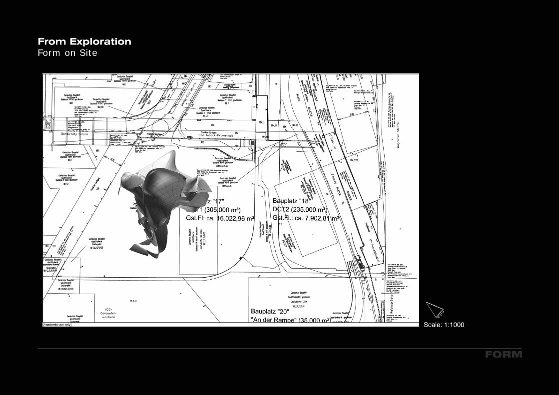
Scale: 1:1000
From ExplorationForm on Site
FORM
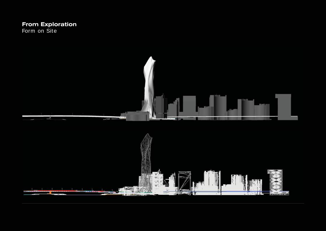
From ExplorationForm on Site

From ExplorationForm on Site
FORM
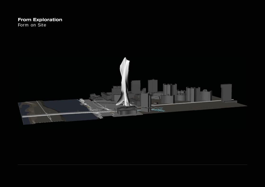
From ExplorationForm on Site
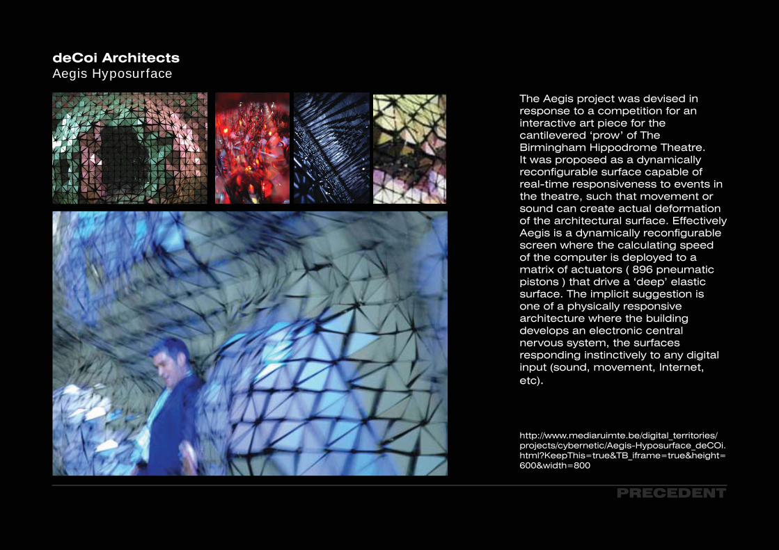
deCoi ArchitectsAegis Hyposurface
PRECEDENT
The Aegis project was devised in response to a competition for an interactive art piece for the cantilevered ‘prow’ of The Birmingham Hippodrome Theatre. It was proposed as a dynamically reconfigurable surface capable of real-time responsiveness to events in the theatre, such that movement or sound can create actual deformation of the architectural surface. Effectively Aegis is a dynamically reconfigurable screen where the calculating speed of the computer is deployed to a matrix of actuators ( 896 pneumatic pistons ) that drive a ‘deep’ elastic surface. The implicit suggestion is one of a physically responsive architecture where the building develops an electronic central nervous system, the surfaces responding instinctively to any digital input (sound, movement, Internet, etc).
http://www.mediaruimte.be/digital_territories/projects/cybernetic/Aegis-Hyposurface_deCOi.html?KeepThis=true&TB_iframe=true&height=600&width=800
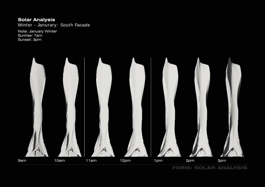
Solar AnalysisWinter - Janurary: South Facade
FORM: SOLAR ANALYSIS
9am 10am 11am 12pm 1pm 2pm 3pm
Note: January WinterSunrise: 7amSunset: 3pm
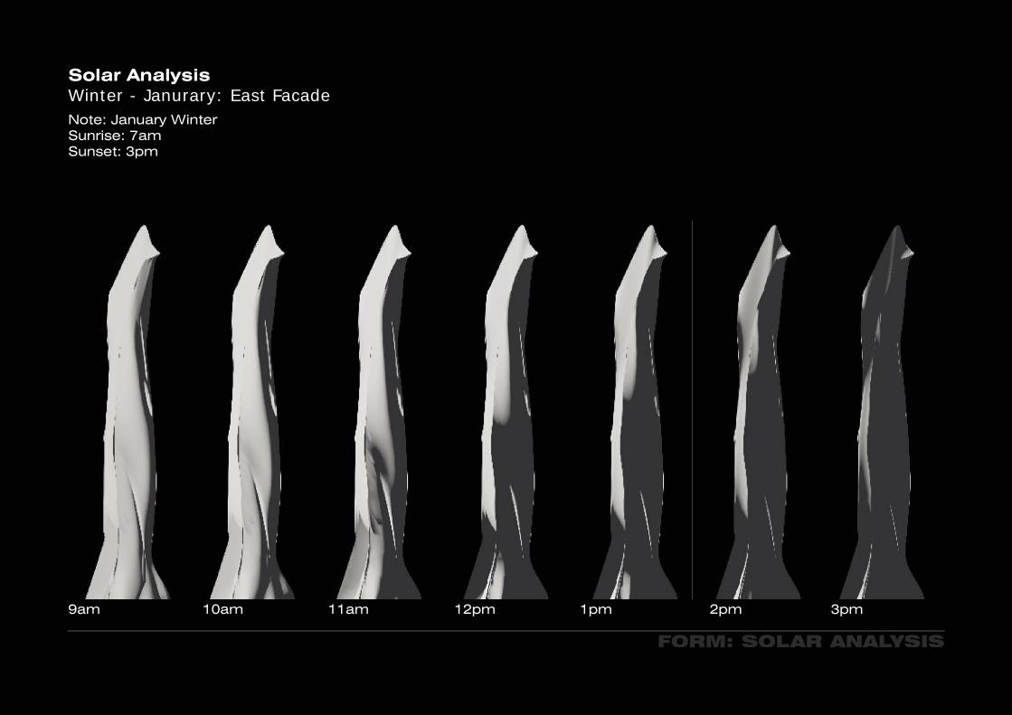
Solar AnalysisWinter - Janurary: East Facade
FORM: SOLAR ANALYSIS
9am 10am 11am 12pm 1pm 2pm 3pm
Note: January WinterSunrise: 7amSunset: 3pm
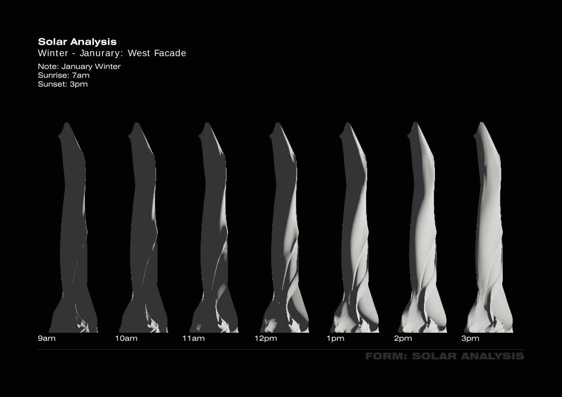
FORM: SOLAR ANALYSIS
Solar AnalysisWinter - Janurary: West Facade
9am 10am 11am 12pm 1pm 2pm 3pm
Note: January WinterSunrise: 7amSunset: 3pm
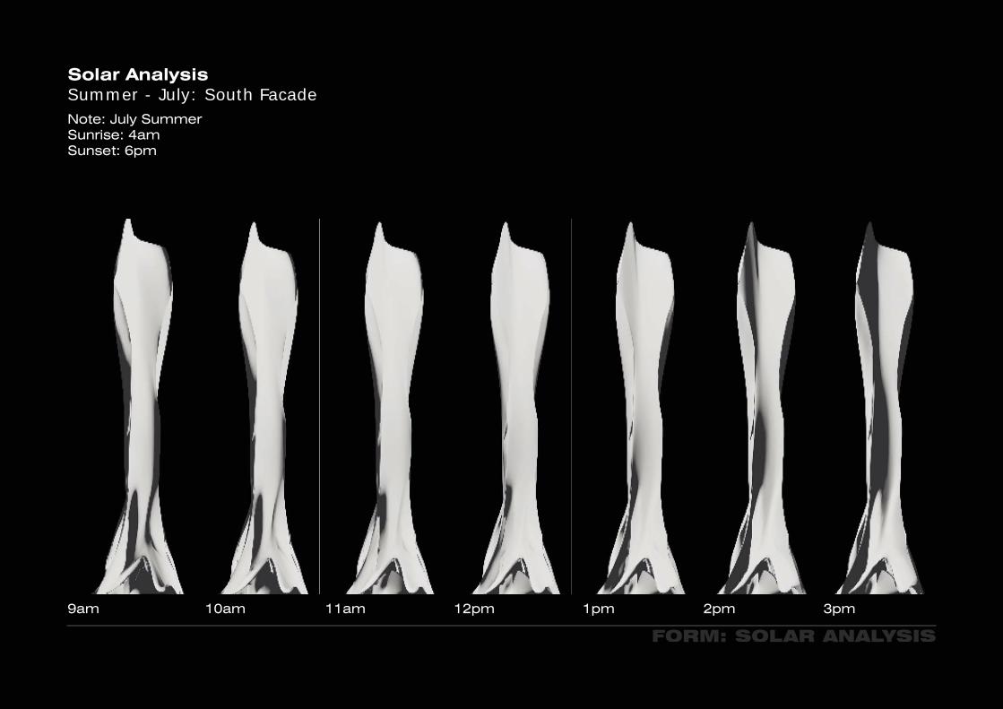
Solar AnalysisSummer - July: South Facade
FORM: SOLAR ANALYSIS
9am 10am 11am 12pm 1pm 2pm 3pm
Note: July Summer Sunrise: 4am Sunset: 6pm
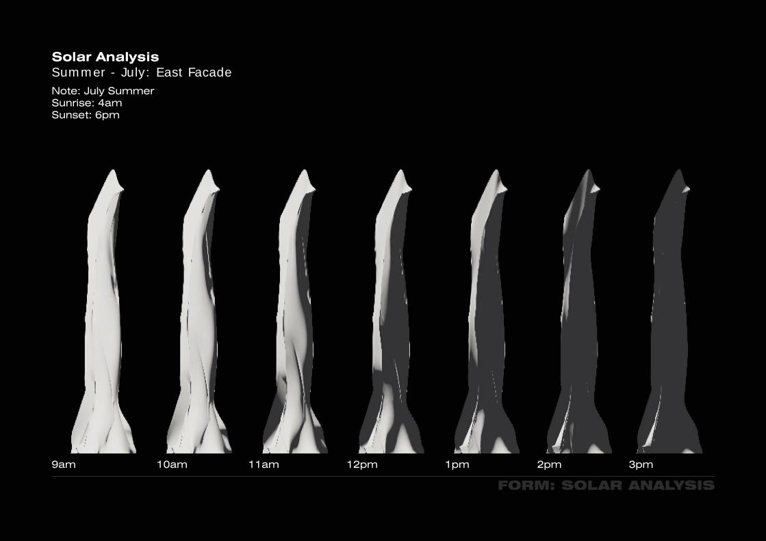
Solar AnalysisSummer - July: East Facade
FORM: SOLAR ANALYSIS
9am 10am 11am 12pm 1pm 2pm 3pm
Note: July Summer Sunrise: 4am Sunset: 6pm

Solar AnalysisSummer - July: West Facade
FORM: SOLAR ANALYSIS
9am 10am 11am 12pm 1pm 2pm 3pm
Note: July Summer Sunrise: 4am Sunset: 6pm

Solar AnalysisEctotect: December - Feb 8am-3pm
FORM: SOLAR ANALYSIS
Still rendering....

Solar AnalyisisSoth Facade
FORM
Comparison of South Facade and Cylindrical form, showing the intensity of sun hours through the Winter period.

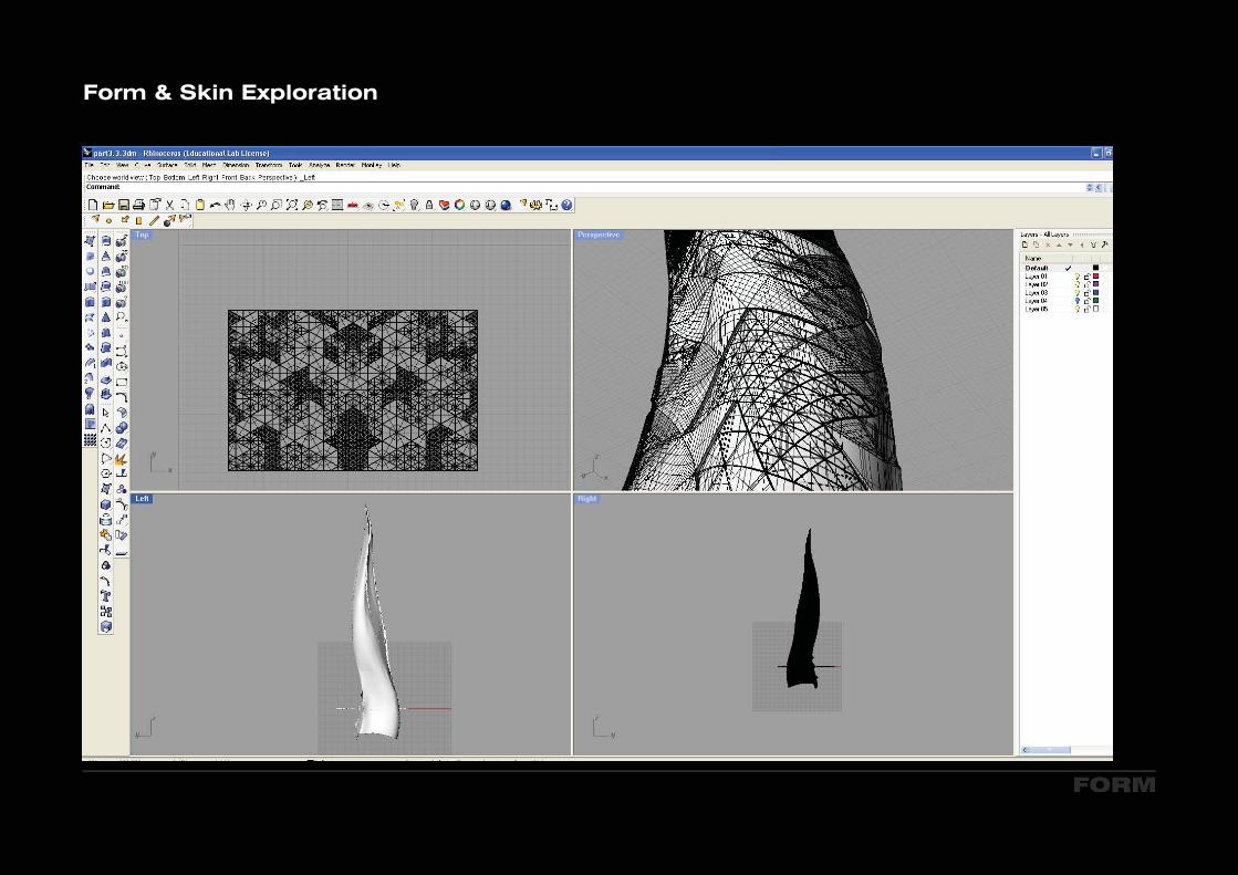
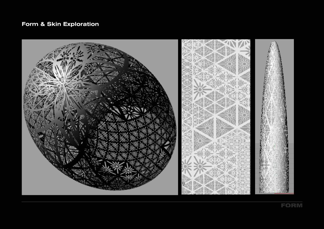
Form & Skin Exploration
FORM
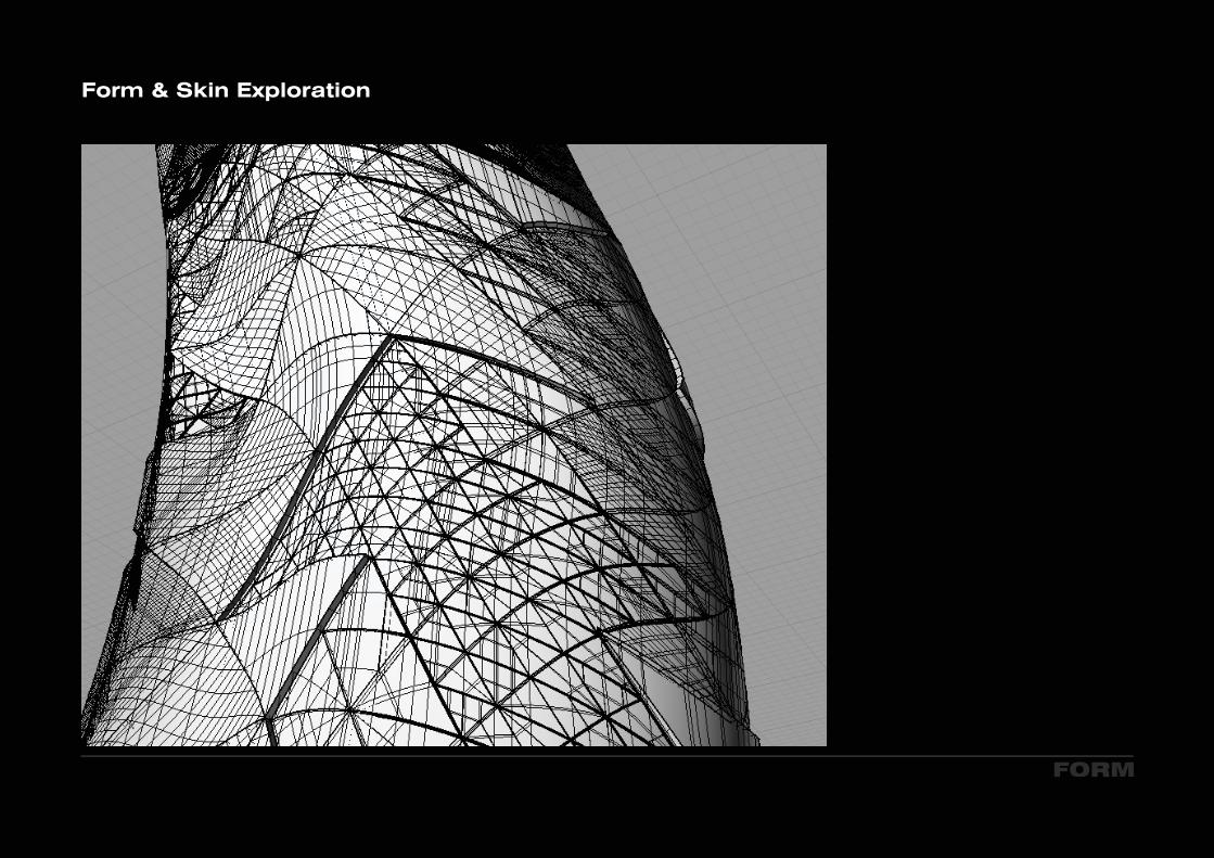
Form & Skin Exploration
FORM

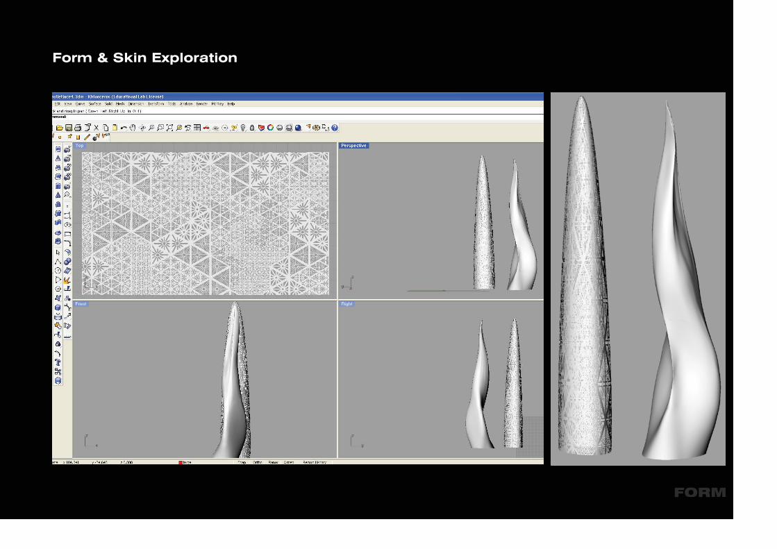
FORM
Form & Skin Exploration
FORM
Form & Skin Exploration

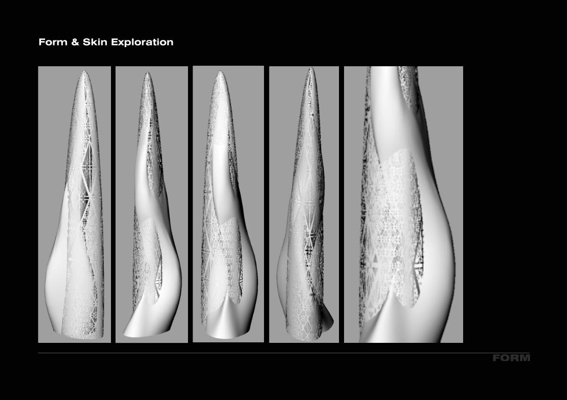
FORM
Form & Skin Exploration
FORM
Form & Skin Exploration

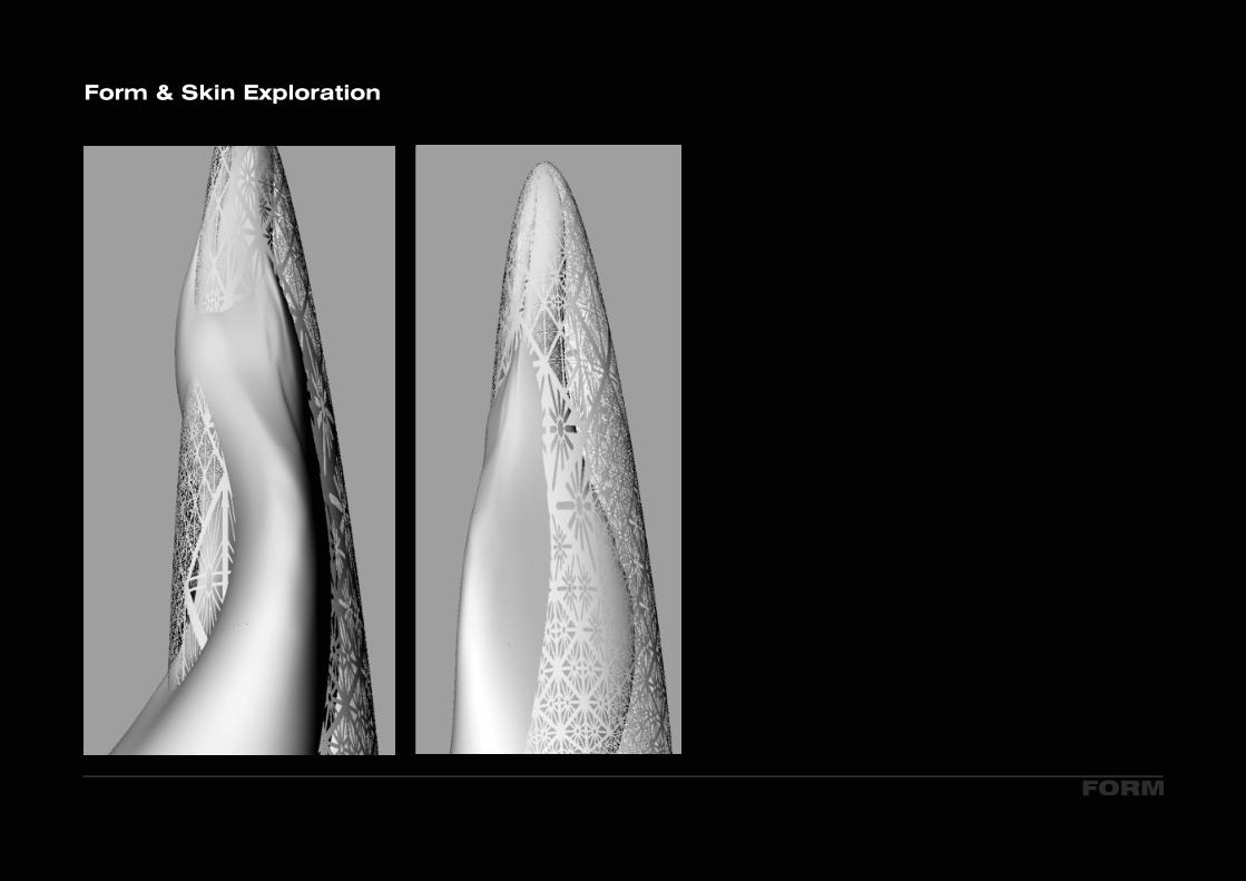
FORM
Form & Skin Exploration
FORM
Form & Skin Exploration

FORM
Form & Skin Exploration

FORM
Form & Skin Exploration
FORM
Form & Skin Exploration
FORM
Form & Skin Exploration
Related Documents