9/0 9 Busbar systems

09 Busbar Holder Web 1
Oct 30, 2015
busbar
Welcome message from author
This document is posted to help you gain knowledge. Please leave a comment to let me know what you think about it! Share it to your friends and learn new things together.
Transcript
9/0
9
Busbar systems

9/1
9
Busbar systemsContents
Page
Busbars for low-voltage switchgear and controlgear assemblies
General information 9/2
Busbar connections
General information 9/4
Busbar systems and accessories 9/6
Installation position busbar systems 9/20
Technical specifications busbar holder 9/24
Dynamic short-circuit withstand strength according to DIN EN 60439-1 (VDE 0660-500)
Rating for Continuous current for copper busbars according to DIN 43671.
Busbar drillings, screw fittings and busbars with square cross-section according to
DIN 43673 part 1.
9
9/2
Busbars for low-voltage switchgear and controlgear assemblies
General informationProfile selection and configuration for alternating current
The profile form for busbars has a considerable influence not only on the mechanical bending strength, but also on the electrical rating. With direct current there is no skin effect. For this reason, the profile form is important only in regard to the surface emitting heat.
Whereas with alternating current, resistance increases due to the skin effect and other effects; resistance can be minimized by select-ing a favourable profile form. If the current strength permits it, one or two flat busbars can be mounted for each phase/N conductor in simple mounting. Two busbars are more favourable in terms of smaller losses and are, therefore, recommended.
For larger current strengths (> 2,500 A), four flat busbars are a favourable and economical solution. This makes the eddy current smaller and the inductive voltage drop lower.
The geometric configuration of the busbars in the assembly can be analysed and rated in regard to the following:
■ Greater personal safety
■ Greater system safety
■ Higher level of availability
■ Greater electrical arc safety
■ Higher dynamic resistance
■ Rated currents
■ Radiation of heat/influence of heat
■ Number of main busbar systems
■ Double-sided operation
■ Cable entry
■ Couplings
■ Mounting
■ Maintenance
■ Economy
Busbars for low-voltage switchgear and controlgear assemblies
General informationBusbar systems in low-voltage switchgear and controlgear assem-blies must be dimensioned and designed for safe and effective current distribution.
In practice, the need for correct dimensioning, the required rated values and proper mounting is often underestimated and, therefore, not adequately met.
To plan and implement busbars according to need and function, various DIN standards and VDE regulations must be applied, e.g., dimensioning the busbar system according to DIN 43771 depending on:
■ Busbar cross section
■ Number of busbars
■ Rated current
■ Untreated/coated
■ Ambient temperature inside the enclosure
■ Max. busbar temperature
In addition, there are other factors that need to be taken into account to attempt to present practical states in theory.
Physical conditions that occur with modern switchgear controlgear assemblies can be covered only partially or not at all by this method.
Realistic values can be determined only through type tests, e.g. according to DIN EN 60439-1 (currently valid until 2014-11) or the following DIN EN 61439-1/-2, and, in this way, they ensure the required safety.
The type-tested results can be used, to a limited extent, for deriva-tion. Generally, the method of derivation must be documented for the required verification.
Such as: DIN VDE 0660 Part 507 Method for determining heat rise in partially type-tested assemblies (PTTA) through extrapolation
VDE 0660 Part 509 Method for determining short-circuit withstand strength of partially type-tested assemblies (PTTA)
Busbar systems
9
9/3
The following standards should be taken into account.
DIN 43671: Copper busbars Ratings for continuous current
DIN 43673 part 1: Busbars drilling and screw fitting Busbars with square cross section
Design of busbar connections:
In general a torque wrench must be used on rust-resistant screws.
In addition, spring elements that are designed to maintain the required contact pressure should be used. The strain washers sustain the tensional force within a certain range and can therefore also be recommended for screw locking.
Adequate tensional force prevents the screws from loosening on their own. This principle allows the realization of maintenance free busbar connections.
For vibrations and the like, microencapsulated screws should be used as well.
For direct and alternating currents up to 6300 A, connecting material (screws, washers) of torsional strength 8.8 or higher (DIN 267 part 3) can be used for indoor applications. Above 6300 A, connection material with a torsional strength of A2-70 or A4-70 (DIN ISO 3506) is recommended.
Treatment of contact surfaces:
The surfaces should be smooth, but not polished. The contact resistance is actually smaller when the contact surfaces have average roughness (RA 1.6-3.2) since the oxides are overcome more easily. The contact surfaces should, however, be free of oxides and grease. If this is not the case, the contact surfaces must be cleaned.
Busbar systems
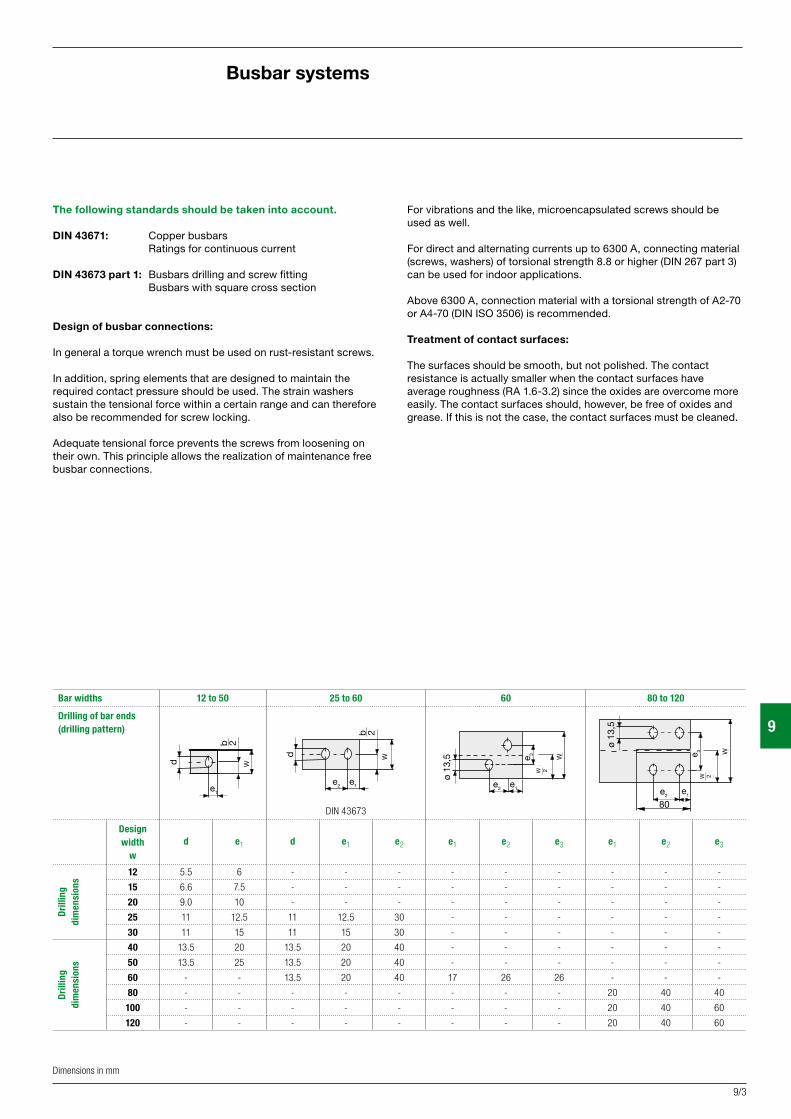
Bar widths 12 to 50 25 to 60 60 80 to 120
Drilling of bar ends(drilling pattern)
DIN 43673
Design width
wd e1 d e1 e2 e1 e2 e3 e1 e2 e3
Drill
ing
dim
ensi
ons
12 5.5 6 - - - - - - - - -
15 6.6 7.5 - - - - - - - - -
20 9.0 10 - - - - - - - - -
25 11 12.5 11 12.5 30 - - - - - -
30 11 15 11 15 30 - - - - - -
Drill
ing
di
men
sion
s
40 13.5 20 13.5 20 40 - - - - - -
50 13.5 25 13.5 20 40 - - - - - -
60 - - 13.5 20 40 17 26 26 - - -
80 - - - - - - - - 20 40 40
100 - - - - - - - - 20 40 60
120 - - - - - - - - 20 40 60
b 2
d
e1
b d
e2e1
b
b 2
e2e1
ø 13
,5 e 3 b
b 2
ø 13
,5
e 3 b
b 2
e1e2
80
b 2
d
e1
b d
e2e1
b
b 2
e2e1
ø 13
,5 e 3 b
b 2
ø 13
,5
e 3 b
b 2
e1e2
80
b 2
d
e1
b d
e2e1
b
b 2
e2e1
ø 13
,5 e 3 b
b 2
ø 13
,5
e 3 b
b 2
e1e2
80
b 2
d
e1
b d
e2e1
b
b 2
e2e1
ø 13
,5 e 3 b
b 2
ø 13
,5
e 3 b
b 2
e1e2
80
Dimensions in mm
W
W
W
W
W 2
W 2
9
9/4
Busbar outgoing feeder
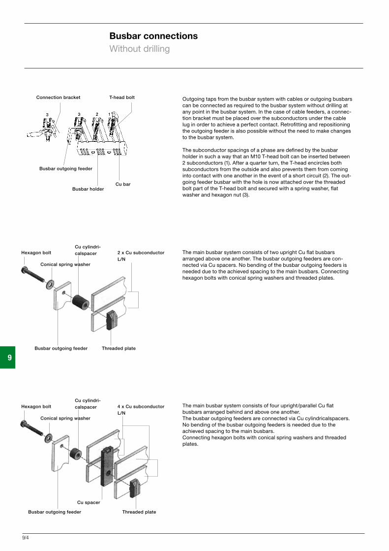
T-head bolt Connection bracket
Cu barBusbar holder
Outgoing taps from the busbar system with cables or outgoing busbars can be connected as required to the busbar system without drilling at any point in the busbar system. In the case of cable feeders, a connec-tion bracket must be placed over the subconductors under the cable lug in order to achieve a perfect contact. Retrofitting and repositioning the outgoing feeder is also possible without the need to make changes to the busbar system.
The subconductor spacings of a phase are defined by the busbar holder in such a way that an M10 T-head bolt can be inserted between 2 subconductors (1). After a quarter turn, the T-head encircles both subconductors from the outside and also prevents them from coming into contact with one another in the event of a short circuit (2). The out-going feeder busbar with the hole is now attached over the threaded bolt part of the T-head bolt and secured with a spring washer, flat washer and hexagon nut (3).
The main busbar system consists of two upright Cu flat busbars arranged above one another. The busbar outgoing feeders are con-nected via Cu spacers. No bending of the busbar outgoing feeders is needed due to the achieved spacing to the main busbars. Connecting hexagon bolts with conical spring washers and threaded plates.
The main busbar system consists of four upright/parallel Cu flat busbars arranged behind and above one another. The busbar outgoing feeders are connected via Cu cylindricalspacers. No bending of the busbar outgoing feeders is needed due to the achieved spacing to the main busbars. Connecting hexagon bolts with conical spring washers and threaded plates.
Busbar connectionsWithout drilling
Hexagon boltCu cylindri-calspacer 4 x Cu subconductor
L/NConical spring washer
Busbar outgoing feeder Threaded plate
Cu spacer
Hexagon boltCu cylindri-calspacer 2 x Cu subconductor
L/NConical spring washer
Busbar outgoing feeder Threaded plate

9
9/5
Two subconductors per phase
Busbar outgoing feeders with Cu spacerNot necessary to bend the busbar outgoing feeders
Connection with Cu busbar connection plates
Connection without Cu connection plates, with an offset in the main busbar system
Main busbar systems/main busbar system connections
Busbar outgoing tap
Busbar connectionsDrilled
CU bars
CU bar
CU bar
CU bar CU busbar connection plates
CU bar
CU spacer
CU spacer
Subconductor

9
9/6
Busbar systemsBusbar holder type ZX2/ZB5/ZX95
Busbar holder type ZX2Busbar spacing 40 mmContinuous current 250-355 A
Suitable for E-Cu busbars,untreated and bright
Busbar Continuous current in A Cross section Weight dimensions (mm) 1 bar 2 bars 3 bars (mm2) (kg/m)
12 x 5 250 59.5 0.53212 x 10 355 119.0 1.064
For technical specifications, see page 9/24
Busbar holder type ZX95Busbar spacing 40 mmContinuous current 250-355 A
Suitable for E-Cu busbars,untreated and bright
Busbar Continuous current in A Cross section Weight dimensions (mm) 1 bar 2 bars 3 bars (mm2) (kg/m)
12 x 5 250 59.5 0.53212 x 10 355 119.0 1.064
Busbar holder type ZB5Busbar spacing 40 mmContinuous current 250-355 A
Suitable for E-Cu busbars,untreated and bright
Busbars Continuous current in A Cross section Weight dimensions (mm) 1 bar 2 bars 3 bars (mm2) (kg/m)
12 x 5 250 59.5 0.53212 x 10 355 119.0 1.06420 x 5 320 99.1 0.882
(Dimensions in mm)
Busbar holder type ZX387Busbar spacing 40 mmContinuous current 250-355 A
Suitable for E-Cu busbars,untreated and bright
Busbar Continuous current in A Cross section Weight dimensions (mm) 1 bar 2 bars 3 bars (mm2) (kg/m)
12 x 5 250 59,5 0,53212 x 10 355 119,0 1,064

Article Type Ord.no.F Article Type Ord.no.F
9
9/7
Busbar systemsBusbar holder type ZX2/ZB5/ZX95 and accessories
Busbar holdersInstallation in distribution board panels for copper bars12 x 5 mm = 250 A and12 x 10 mm = 355 A(12 x 10 by knocking out)(2 pcs.) ZX2P2 62489
Busbar holdersFor copper bars12 x 5 mm = 250 A and12 x 10 mm = 355 A(12 x 10 by knocking out)(2 pcs.) ZX95P2 62638
End cover ED111 39321To snap on
BusbarsFor panel width 250, Cu 12 x 5 mm ZX101 39101For panel width 500, Cu 12 x 5 mm ZX102 39102For panel width 750, Cu 12 x 5 mm ZX103 39103For panel width 1000, Cu 12 x 5 mm ZX104 39104
Cu bar 250 A12 x 5 mm Length 1 m ZX400 61400 Length 2 m ZX401 61401 Length 3 m ZX402 61402 Length 4 m ZX350 61350
Cu bar 360 A12 x 10 mm Length 1 m ZX403 61403 Length 2 m ZX404 61404 Length 3 m ZX405 61405 Length 4 m ZX354 61354
Cu bar 320 A20 x 5 mm Length 1 m ZX406 61406 Length 2 m ZX407 61407 Length 3 m ZX408 61408 Length 4 m ZX351 61351
Cover profile ZB19 38187For snapping onto busbars12 x 5 and 12 x 10 mm, by the metre
Device carrier ZB1 39121For snapping onto the busbar system, width 53 mmFor Cu 12 x 5 mm
Device carrier ZX100 39100For snapping onto the busbar system, width 86 mmFor Cu 12 x 5 mmFor Cu 12 x 10 mm
Busbar connectorPanel-panel (with cover strip)1 set 4-pole, 250 A ZX90 390901 set 5-pole, 250 A ZX91 39091
1 set 5-pole, 355 A ZX106 39106
Busbar holderFor copper bars12 x 5 mm = 250 A12 x 10 mm = 355 A20 x 5 mm = 320 A1 pc. ZB5 3845910 pcs. ZB5P10 62556
End cover ZX172 7.00To snap on
Busbar holder, 3 pole ZX387 68092Busbar centre spacing 40 mm For switch disconnector modules
Connection terminals
1.5-16 mm2 for Cu 5 mm1 pc. ZK79 6487950 pcs. ZK79P50 62429
1.5-35 mm2 for Cu 5 mm1 pc. ZK81 6488150 pcs. ZK81P50 62431
1.5-50 mm2 for Cu 5 mm1 pc. ZK150 6486050 pcs. ZK150P50 62432
16-95 mm2 for Cu 12 x 5 mm16-70 mm2 for Cu 12 x 10 mm1 pc. ZK83 648835 pcs. ZK83P5 6265550 pcs. ZK83P50 62433
16-150 mm2 for Cu 12 x 5 mm4 pcs. ZK891P4 62626
35-150 mm2 for Cu 12 x 5 mm35-150 mm2 for Cu 12 x 5 mm35-150 mm2 for Cu 25 x 5 mm1 pc. ZK86 6488620 pcs. ZK86P20 62434
1.5-16 mm2 for Cu 10 mm1 pc. ZK87 6488750 pcs. ZK87P50 62430
16-120 mm2 for Cu 10 mm1 pc. ZK154 6486450 pcs. ZK154P50 62435
16-70 mm2 for Cu 5 mm1 pc. ZK178 6497850 pcs. ZK178P50 62622
16-120 mm2 for Cu 5 mm1 pc. ZK157 6486750 pcs. ZK157P50 62437
For technical specifications, see page 9/24
(Dimensions in mm)
9
9/8
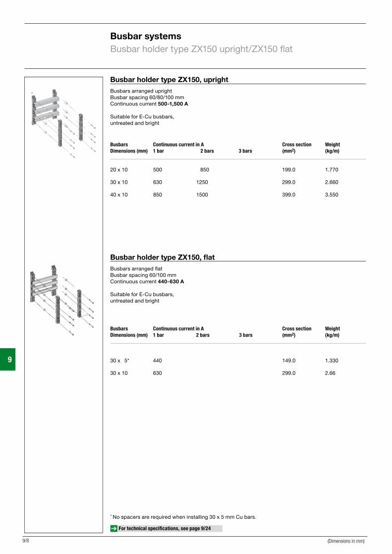
Busbar holder type ZX150, uprightBusbars arranged uprightBusbar spacing 60/80/100 mmContinuous current 500-1,500 A
Suitable for E-Cu busbars,untreated and bright
Busbars Continuous current in A Cross section Weight Dimensions (mm) 1 bar 2 bars 3 bars (mm2) (kg/m)
20 x 10 500 850 199.0 1.770 30 x 10 630 1250 299.0 2.660 40 x 10 850 1500 399.0 3.550
Busbars Continuous current in A Cross section Weight Dimensions (mm) 1 bar 2 bars 3 bars (mm2) (kg/m)
30 x 5* 440 149.0 1.330 30 x 10 630 299.0 2.66
Busbar holder type ZX150, flatBusbars arranged flatBusbar spacing 60/100 mmContinuous current 440-630 A
Suitable for E-Cu busbars,untreated and bright
* No spacers are required when installing 30 x 5 mm Cu bars.
Busbar systemsBusbar holder type ZX150 upright/ZX150 flat
For technical specifications, see page 9/24
(Dimensions in mm)

Article Type Ord.no.F Article Type Ord.no.F
9
9/9
Accessories
Busbar holder ZX150 44016With phase spacing of 80/100 mm
Deep-mounting bracket for WR frameFor stepless depth adjustment of busbar holders Incl. fastening material 2 pcs. ZW142P2 6246340 pcs. ZW142P40 62477
Deep-mounting bracket for WR frameFor depth adjustment of busbar holders in steps of 15 mm Incl. fastening material2 pcs. ZW60P2 62454 100 pcs. ZW60P100 62476
Copper bars
Cu bar 440 A30 x 5 mm Length 1 m ZX409 61409 Length 2 m ZX410 61410 Length 3 m ZX411 61411 Length 4 m ZX353 61353Cu bar 500 A20 x 10 mm Length 1 m ZX362 61362 Length 2 m ZX363 61363 Length 3 m ZX364 61364 Length 4 m ZX355 61355Cu bar 630 A30 x 10 mm Length 1 m ZX412 61412 Length 2 m ZX413 61413 Length 3 m ZX414 61414 Length 4 m ZX356 61356Cu bar 850 A40 x 10 mm Length 1 m ZX415 61415 Length 2 m ZX416 61416 Length 3 m ZX417 61417 Length 4 m ZX357 61357
T-head boltFor 2 x 10 mm Cu bars, parallel
M 10 x 50 mm for Cu 30 mm ZX197 60242M 10 x 60 mm for Cu 40 mm ZX198 60243
Connecting bracket for cable lugs XAB10 44229For 2 x 10 mm Cu bars, parallel
Accessories for ZX150, upright
Spacer for busbar holder(Four spacers are required for each busbar holder)
Cu bar D x d x H (mm) 20 x 10 mm 17 x 7 x 4 mm ZX192 44028 30 x 10 mm 17 x 7 x 14 mm ZX193 4402940 x 10 mm 17 x 7 x 24 mm ZX194 44030
Accessories for ZX150, flat
Spacer for busbar holders (Four spacers are requiredfor each busbar holder.) No spacers are required when installing 30 x 5 mm Cu bars.
Cu bar D x d x H (mm) 30 x 10 mm 17 x 7 x 4 ZX192 44028
Cu spacer
D x d x s Cross section
30 x 10.5 x 11 620 mm2 ZX39 6021330 x 10.5 x 22 620 mm2 ZX40 6021430 x 10.5 x 33 620 mm2 ZX41 60215
Connection terminalsOn bar terminals
50-120 mm2 for Cu 30 x 5 mm 50-120 mm2 for Cu 30 x 10 mm1 pc. ZK152 64862 20 pcs. ZK152P20 62444
16-120 mm2 for Cu 10 mm1 pc. ZK154 64864 50 pcs. ZK154P50 62435
35-70 mm2 for Cu 10 mm 1 pc. ZK156 6486650 pcs. ZK156P50 62438
16-70 mm2 for Cu 5 mm1 pc. ZK178 64978 50 pcs. ZK178P50 62622
25-70 mm2 for Cu 30 x 5 mm25-70 mm2 for Cu 30 x 10 mm1 pc. ZK161 6487120 pcs. ZK161P20 62441
35-120 mm2 for Cu 30 x 5 mm35-120 mm2 for Cu 30 x 10 mm 1 pc. ZK162 6487220 pcs. ZK162P20 62442
95-185 mm2 for Cu 30 x 5 mm95-185 mm2 for Cu 30 x 10 mm 1 pc. ZK163 6487320 pcs. ZK163P20 62443
10-95 mm2
1 pc. ZK302 62645 20 pcs. ZK302P20 62648
16-150 mm2 1 pc. ZK303 62646 20 pcs. ZK303P20 62649
Busbar systemsBusbar holder type ZX150 and accessories
(Dimensions in mm)
For technical specifications, see page 9/24 For technical specifications, see as of page 10/16

9
9/10
N/PE busbar holder type ZX149Fastening hole spacing 75 mmCu 12 x 5 to 30 x 10 mmSuitable for E-Cu busbars
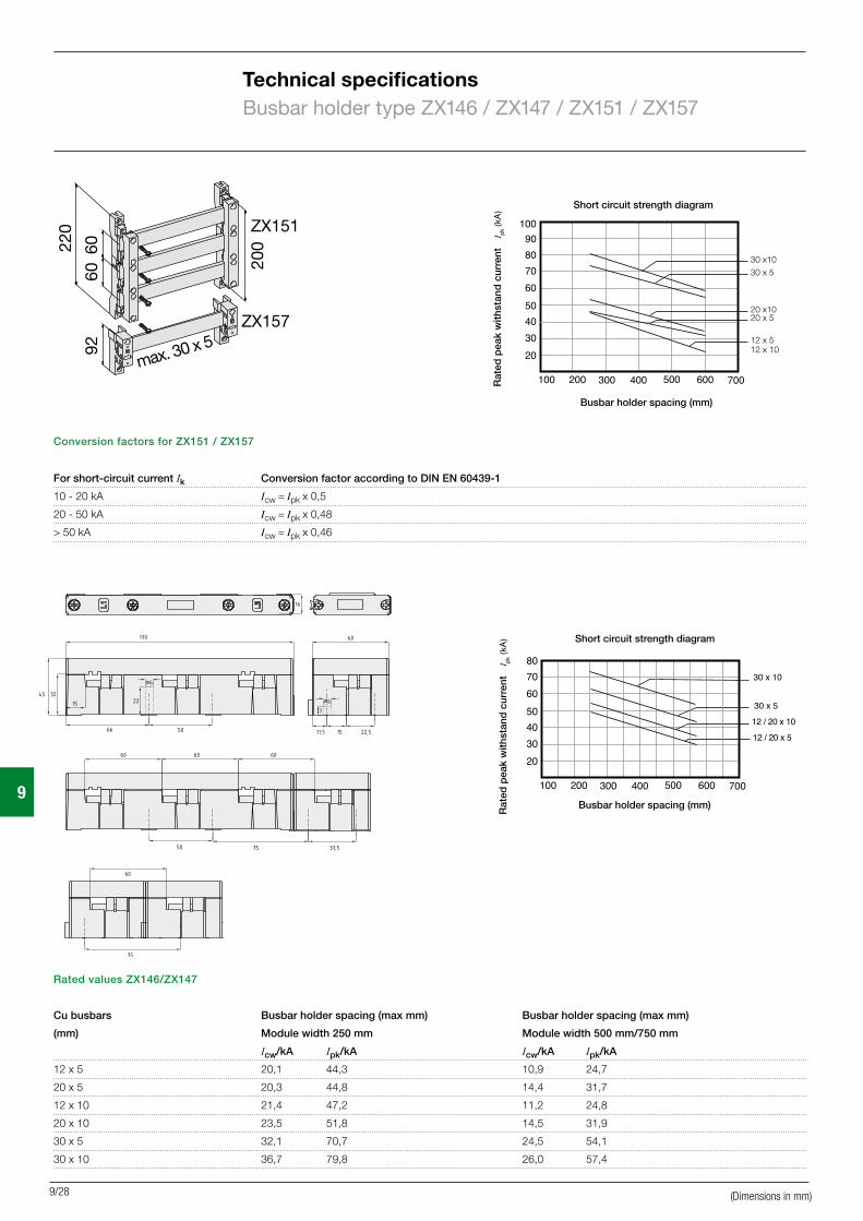
Busbar holder type ZX151/ZX157Fastening hole spacing 200 mmBusbar spacing 60 mmContinuous current 250-630 ACu 12 x 5 to 30 x 10 mmSuitable for E-Cu busbars
N/PE busbar holder type ZX518Fastening directly on the carrier profileCu 12 x 5 mm can be used twiceCu 20 x 5 mm or 30 x 5 mm can be used onceSuitable for E-Cu busbars
Busbar holder type ZX146/ZX147 and accessories
Busbar holder 1-pole ZX147 44011 For series connection to ZX146 For Cu 12 x 5, 12 x 10, 20 x 5, 20 x 10, 30 x 5 and 30 x 10 mm
Busbar holder 3-pole ZX146 44010 Busbar spacing 60 mmFor Cu 12 x 5, 12 x 10, 20 x 5, 20 x 10, 30 x 5 and 30 x 10 mm
End cover ZX172 60232For busbar holder type ZX146
Mounting cross member ZW399 62972For busbar holder type ZX146 (3-pole)For horizontal installation
Mounting cross member ZW403LR 62974For busbar holder ZX146 (3-pole) For vertical installation on WR profile
Article Type Ord.no.F
Busbar systemsBusbar holder type ZX151/ZX157/ZX149/ZX518 Busbar holder type ZX146/ZX147 and accessories
For technical specifications, see page 9/24
(Dimensions in mm)

Article Type Ord.no.F Article Type Ord.no.F
9
9/11
Busbar holderBusbar spacing 60 mm ZX151 44006
End coverFor busbar holder type ZX151 ZX158 60208
N and PE busbar holder ZX157 44009
N and PE busbar holderMax. 30 x 10 mm Cu ZX149 44019
N and PE busbar holderFor copper bars12 x 5 mm, 20 x 5 mm, 30 x 5 mm1 pc. ZX518 6780510 pcs. ZX518P10 62551
Deep-mounting bracket for WR frameFor stepless depth adjustment of busbar holders Incl. fastening material2 pcs. ZW142P2 6246340 pcs. ZW142P40 62477
Deep-mounting bracket for WR frameFor depth adjustment of busbar holders in steps of 15 mm Incl. fastening material2 pcs. ZW60P2 62454100 pcs. ZW60P100 62476
Copper bars Cu bar 250 A12 x 5 mm Length 1 m ZX400 61400 Length 2 m ZX401 61401 Length 3 m ZX402 61402 Length 4 m ZX350 61350Cu bar 360 A12 x 10 mm Length 1 m ZX403 61403 Length 2 m ZX404 61404 Length 3 m ZX405 61405 Length 4 m ZX354 61354Cu bar 320 A20 x 5 mm Length 1 m ZX406 61406 Length 2 m ZX407 61407 Length 3 m ZX408 61408 Length 4 m ZX351 61351Cu bar 500 A20 x 10 mm Length 1 m ZX362 61362 Length 2 m ZX363 61363 Length 3 m ZX364 61364 Length 4 m ZX355 61355Cu bar 390 A25 x 5 mm Length 1 m ZX365 61365 Length 2 m ZX366 61366 Length 3 m ZX367 61367 Length 4 m ZX352 61352Cu bar 440 A30 x 5 mm Length 1 m ZX409 61409 Length 2 m ZX410 61410 Length 3 m ZX411 61411 Length 4 m ZX353 61353Cu bar 630 A30 x 10 mm Length 1 m ZX412 61412 Length 2 m ZX413 61413 Length 3 m ZX414 61414 Length 4 m ZX356 61356
Connection terminals
1.5-16 mm2 for Cu 5 mm1 pc. ZK79 6487950 pcs. ZK79P50 62429
1.5-35 mm2 for Cu 5 mm1 pc. ZK81 6488150 pcs. ZK81P50 62431
1.5-50 mm2 for Cu 5 mm1 pc. ZK150 6486050 pcs. ZK150P50 62432
16-95 mm2 for Cu 12 x 5 mm4 pcs. ZK891P4 62626
16-95 mm2 for Cu 12 x 5 mm16-70 mm2 for Cu 12 x 10 mm1 pc. ZK83 64883 5 pcs. ZK83P5 6265550 pcs. ZK83P50 62433
50-120 mm2 for Cu 30 x 5 mm50-120 mm2 for Cu 30 x 10 mm1 pc. ZK152 6486220 pcs. ZK152P20 62444 35-150 mm2 for Cu 12 x 5 mm35-150 mm2 for Cu 20 x 5 mm35-150 mm2 for Cu 25 x 5 mm1 pc. ZK86 6488620 pcs. ZK86P20 62434
1.5-16 mm2 for Cu 10 mm1 pc. ZK87 6488750 pcs. ZK87P50 62430
16-120 mm2 for Cu 10 mm1 pc. ZK154 64864 50 pcs. ZK154P50 62435
16-70 mm2 for Cu 5 mm1 pc. ZK178 6497850 pcs. ZK178P50 62622
35-70 mm2 for Cu 10 mm1 pc. ZK156 64866 50 pcs. ZK156P50 62438
16-120 mm2 for Cu 5 mm1 pc. ZK157 64867 50 pcs. ZK157P50 62437
On bar terminals
35-120 mm2 For Cu 30 x 5 mm up to Cu 100 x 10 mm1 pc. ZK162 6487220 pcs. ZK162P20 62442
95-185 mm2 For Cu 30 x 5 mm up to Cu 100 x 10 mm1 pc. ZK163 6487320 pcs. ZK163P20 62443
Busbar systemsBusbar holder type ZX151/ZX157/ZX149/ZX518 and accessories
(Dimensions in mm)
For technical specifications, see page 9/24

9
9/12
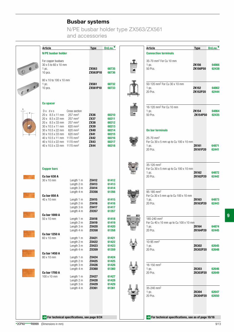
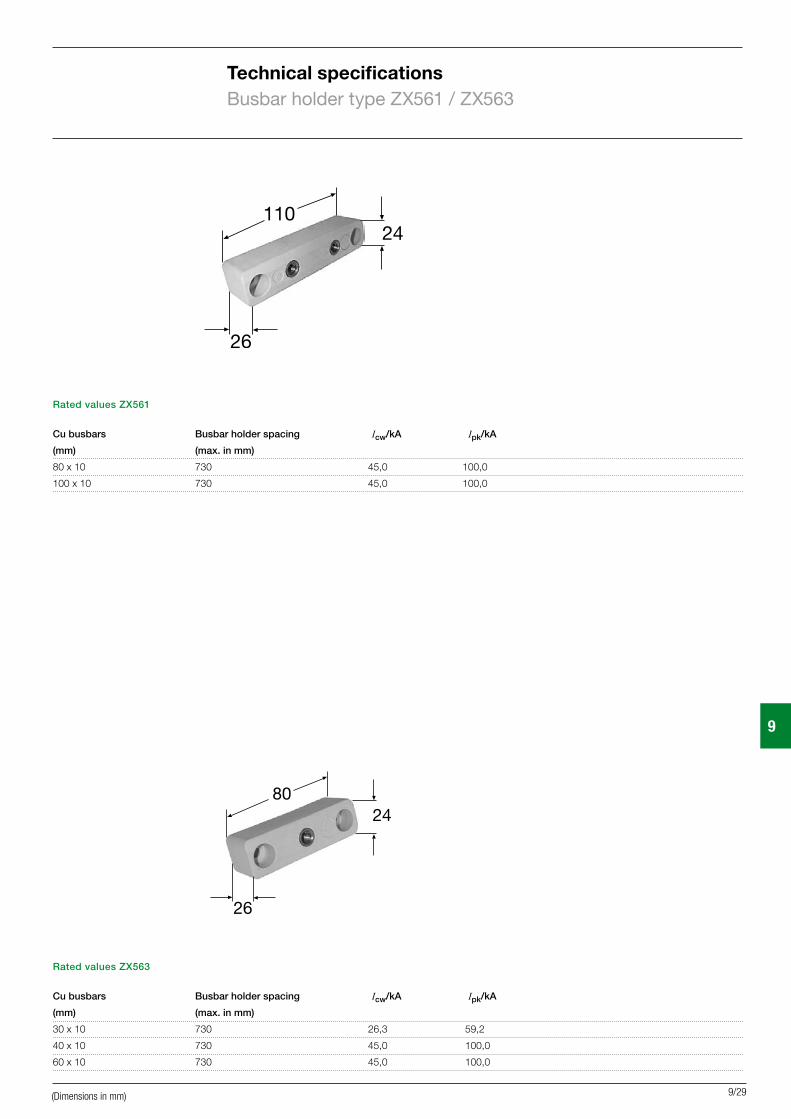
N/PE busbar holder type ZX563Fastening hole spacing 60 mmCu 30 x 10 to 60 x 10 mmSuitable for E-Cu busbars
N/PE busbar holder type ZX561Fastening hole spacing 90 mmCu 80 x 10 to 100 x 10 mmSuitable for E-Cu busbars
Busbar systemsN/PE busbar holder type ZX563/ZX561
For technical specifications, see page 9/24
(Dimensions in mm)
Article Type Ord.no.F Article Type Ord.no.F
9
9/13
Connection terminals
35-70 mm2 For Cu 10 mm1 pc. ZK156 64866 50 Pcs. ZK156P50 62438
50-120 mm2 For Cu 30 x 10 mm1 pc. ZK152 6486220 Pcs. ZK152P20 62444
16-120 mm2 For Cu 10 mm1 pc. ZK154 6486450 Pcs. ZK154P50 62435
On bar terminals
25-70 mm2 For Cu 30 x 5 mm up to Cu 100 x 10 mm1 pc. ZK161 6487120 Pcs. ZK161P20 62441
35-120 mm2 For Cu 30 x 5 mm up to Cu 100 x 10 mm1 pc. ZK162 6487220 Pcs. ZK162P20 62442
95-185 mm2 For Cu 30 x 5 mm up to Cu 100 x 10 mm1 pc. ZK163 6487320 Pcs. ZK163P20 62443
185-240 mm2 For Cu 40 x 10 mm up to Cu 100 x 10 mm1 pc. ZK164 6487420 Pcs. ZK164P20 62445
10-95 mm2
1 pc. ZK302 62645 20 Pcs. ZK302P20 62648
16-150 mm2 1 pc. ZK303 62646 20 Pcs. ZK303P20 62649
35-240 mm2 1 pc. ZK304 62647 20 Pcs. ZK304P20 62650
N/PE busbar holder
For copper busbars30 x 5 to 60 x 10 mm1 pc. ZX563 6873510 pcs. ZX563P10 68736
80 x 10 to 100 x 10 mm1 pc. ZX561 6873210 pcs. ZX561P10 68733
Cu spacer
D x d x s Cross section20 x 8.5 x 11 mm 257 mm2 ZX36 6021020 x 8.5 x 22 mm 257 mm2 ZX37 6021120 x 8.5 x 33 mm 257 mm2 ZX38 6021230 x 10.5 x 11 mm 620 mm2 ZX39 6021330 x 10.5 x 22 mm 620 mm2 ZX40 6021430 x 10.5 x 33 mm 620 mm2 ZX41 6021540 x 10.5 x 11 mm 1170 mm2 ZX42 6021640 x 10.5 x 22 mm 1170 mm2 ZX43 6021740 x 10.5 x 33 mm 1170 mm2 ZX44 60218
Copper bars
Cu bar 630 A 30 x 10 mm Length 1 m ZX412 61412 Length 2 m ZX413 61413 Length 3 m ZX414 61414 Length 4 m ZX356 61356Cu bar 850 A40 x 10 mm Length 1 m ZX415 61415 Length 2 m ZX416 61416 Length 3 m ZX417 61417 Length 4 m ZX357 61357Cu bar 1000 A50 x 10 mm Length 1 m ZX418 61418 Length 2 m ZX419 61419 Length 3 m ZX420 61420 Length 4 m ZX358 61358Cu bar 1250 A60 x 10 mm Length 1 m ZX421 61421 Length 2 m ZX422 61422 Length 3 m ZX423 61423 Length 4 m ZX359 61359Cu bar 1450 A80 x 10 mm Length 1 m ZX424 61424 Length 2 m ZX425 61425 Length 3 m ZX426 61426 Length 4 m ZX360 61360Cu bar 1700 A100 x 10 mm Length 1 m ZX427 61427 Length 2 m ZX428 61428 Length 3 m ZX429 61429 Length 4 m ZX361 61361
Busbar systemsN/PE busbar holder type ZX563/ZX561 and accessories
(Dimensions in mm)
For technical specifications, see page 9/24 For technical specifications, see as of page 10/16

9
9/14
Busbar spacing 100 mmContinuous current 630-1,250 AFastening hole spacing 275 mmCu 30 x 10 to 60 x 10 mmSuitable for E-Cu busbars
Busbar holder type ZX152
(Dimensions in mm)
Busbar holder type ZX153Busbar spacing 100 mm 185 mmContinuous current 630-1,450 A 630-1,700 ACu 30 x 10 to 100 x 10 mmSuitable for E-Cu busbars
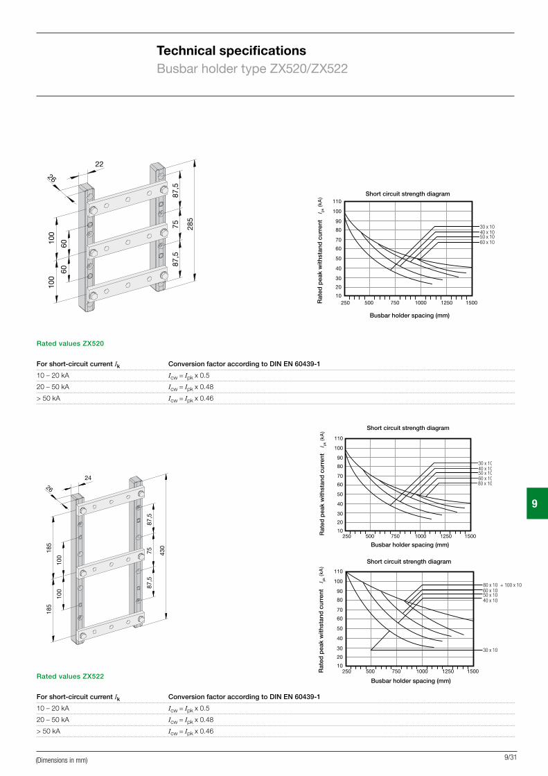
Busbar holder type ZX522Busbar spacing 100 mm 185 mmContinuous current 630-1,450 A 630-1,700 ACu 30 x 10 to 100 x 10 mmSuitable for E-Cu busbars
Busbar holder type ZX520Busbar spacing 60 mm 100 mmContinuous current 630 A 1,250 A Cu 30 x 10 to 60 x 10 mmSuitable for E-Cu busbars
Busbar systemsBusbar holder type ZX152/ZX520/ZX153/ZX522
For technical specifications, see page 9/24

Article Type Ord.no.F Article Type Ord.no.F
9
9/15
Busbar holder ZX152 44007 Busbar centre spacing 100 mm
End cover ZX159 60209For busbar holder type ZX152
Deep-mounting bracket for WR frame For stepless depth adjustment of busbar holders ZX152 2 pcs. ZW143P2 62464Incl. fastening material
Busbar holderBusbar centre spacing 60/100 mm1 pc. ZX520 6786110 pcs. ZX520P10 62552
Busbar holder ZX153 44008Busbar centre spacing 100-185 mm
Deep-mounting bracket for WR frame ZW144LR 62465For stepless depth adjustment of busbar holders ZX1532 pcs.Incl. fastening material
Busbar holderBusbar centre spacing 100-185 mm1 pc. ZX522 6790910 pcs. ZX522P10 62553
Deep-mounting bracket for WR frameFor stepless depth adjustment of busbar holders ZX522 and ZX520 Incl. fastening material2 pcs. ZW142P2 62463 40 pcs. ZW142P40 62477
Cu spacer
D x d x s Cross section20 x 8.5 x 11 mm 257 mm2 ZX36 6021020 x 8.5 x 22 mm 257 mm2 ZX37 6021120 x 8.5 x 33 mm 257 mm2 ZX38 6021230 x 10.5 x 11 mm 620 mm2 ZX39 6021330 x 10.5 x 22 mm 620 mm2 ZX40 6021430 x 10.5 x 33 mm 620 mm2 ZX41 6021540 x 10.5 x 11 mm 1170 mm2 ZX42 6021640 x 10.5 x 22 mm 1170 mm2 ZX43 6021740 x 10.5 x 33 mm 1170 mm2 ZX44 60218
Connection terminals
35-70 mm2 for Cu 10 mm1 pc. ZK156 64866 50 pcs. ZK156P50 62438
50-120 mm2 for Cu 30 x 10 mm1 pc. ZK152 6486220 pcs. ZK152P20 62444
16-120 mm2 for Cu 10 mm1 pc. ZK154 6486450 pcs. ZK154P50 62435
On bar terminals
25-70 mm2 For Cu 30 x 5 mm up to Cu 100 x 10 mm1 pc. ZK161 6487120 Pcs. ZK161P20 62441
35-120 mm2 For Cu 30 x 5 mm up to Cu 100 x 10 mm1 pc. ZK162 6487220 Pcs. ZK162P20 62442
95-185 mm2 For Cu 30 x 5 mm up to Cu 100 x 10 mm1 pc. ZK163 6487320 Pcs. ZK163P20 62443
185-240 mm2 For Cu 40 x 10 mm up to Cu 100 x 10 mm1 pc. ZK164 6487420 Pcs. ZK164P20 62445
10-95 mm2
1 pc. ZK302 62645 20 Pcs. ZK302P20 62648
16-150 mm2 1 pc. ZK303 62646 20 Pcs. ZK303P20 62649
35-240 mm2 1 pc. ZK304 62647 20 Pcs. ZK304P20 62650
Copper bars
Cu bar 630 A30 x 10 mm Length 1 m ZX412 61412 Length 2 m ZX413 61413 Length 3 m ZX414 61414 Length 4 m ZX356 61356Cu bar 850 A40 x 10 mm Length 1 m ZX415 61415 Length 2 m ZX416 61416 Length 3 m ZX417 61417 Length 4 m ZX357 61357Cu bar 1000 A50 x 10 mm Length 1 m ZX418 61418 Length 2 m ZX419 61419 Length 3 m ZX420 61420 Length 4 m ZX358 61358Cu bar 1250 A60 x 10 mm Length 1 m ZX421 61421 Length 2 m ZX422 61422 Length 3 m ZX423 61423 Length 4 m ZX359 61359Cu bar 1450 A80 x 10 mm Length 1 m ZX424 61424 Length 2 m ZX425 61425 Length 3 m ZX426 61426 Length 4 m ZX360 61360Cu bar 1700 A100 x 10 mm Length 1 m ZX427 61427 Length 2 m ZX428 61428 Length 3 m ZX429 61429 Length 4 m ZX361 61361
(Dimensions in mm)
Busbar systemsBusbar holder type ZX152/ZX520/ZX153/ZX522 and accessories
For technical specifications, see page 9/24
9
9/16
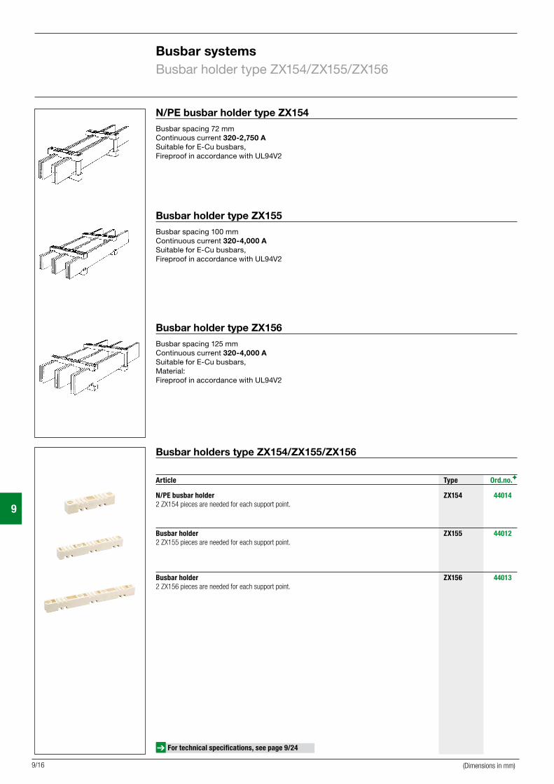
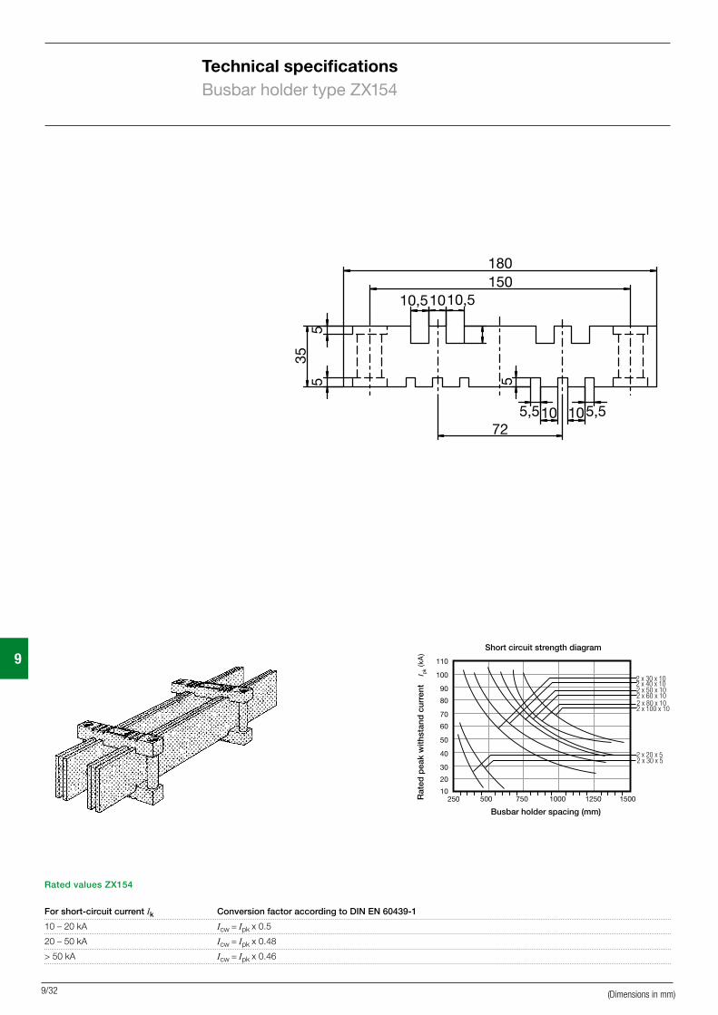
N/PE busbar holder type ZX154Busbar spacing 72 mmContinuous current 320-2,750 ASuitable for E-Cu busbars,Fireproof in accordance with UL94V2
Busbar holder type ZX156Busbar spacing 125 mmContinuous current 320-4,000 A Suitable for E-Cu busbars, Material:Fireproof in accordance with UL94V2
Busbar holder type ZX155Busbar spacing 100 mmContinuous current 320-4,000 ASuitable for E-Cu busbars, Fireproof in accordance with UL94V2
Busbar systemsBusbar holder type ZX154/ZX155/ZX156
> For technical specifications, see page 10/24 ff
Busbar holders type ZX154/ZX155/ZX156
N/PE busbar holder ZX154 440142 ZX154 pieces are needed for each support point.
Busbar holder ZX155 44012 2 ZX155 pieces are needed for each support point.
Busbar holder ZX156 440132 ZX156 pieces are needed for each support point.
Article Type Ord.no.F
For technical specifications, see page 9/24
(Dimensions in mm)
Article Type Ord.no.F Article Type Ord.no.F
9
9/17
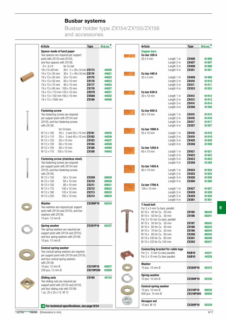
Spacer made of hard paper Two spacers are required per support point with ZX154 and ZX155, and four spacers with ZX156. D x d x H for Cu bar 19 x 13 x 20 mm 20 x 5 + 30 x 10 mm ZX173 44020 19 x 13 x 30 mm 30 x 5 + 40 x 10 mm ZX174 4402119 x 13 x 40 mm 50 x 10 mm ZX175 4402219 x 13 x 50 mm 60 x 10 mm ZX176 4402319 x 13 x 70 mm 80 x 10 mm ZX177 4402519 x 13 x 90 mm 100 x 10 mm ZX178 4402719 x 13 x 110 mm 120 x 10 mm ZX579 4403119 x 13 x 150 mm 160 x 10 mm ZX580 4403219 x 13 x 1000 mm ZX180 44026
Fastening screwTwo fastening screws are required per support point with ZX154 and ZX155, and four fastening screws with ZX156. for CU barsM 12 x 100 20 x 5 and 30 x 10 mm ZX181 44035M 12 x 110 30 x 5 and 40 x 10 mm ZX182 44036M 12 x 120 50 x 10 mm ZX183 44037M 12 x 130 60 x 10 mm ZX184 44038M 12 x 150 80 x 10 mm ZX186 44040M 12 x 170 100 x 10 mm ZX188 44042
Fastening screw (stainless steel)Two fastening screws are required per support point with ZX154 and ZX155, and four fastening screws with ZX156.M 12 x 120 50 x 10 mm ZX209 60629M 12 x 130 60 x 10 mm ZX210 60630M 12 x 150 80 x 10 mm ZX211 60631M 12 x 170 100 x 10 mm ZX212 60632M 12 x 190 120 x 10 mm ZX213 60633 M 12 x 230 160 x 10 mm ZX214 60634
Washer ZX286P10 62534Two washers are required per support point with ZX154 and ZX155, and four washers with ZX156. 10 pcs. 12 mm Ø
Spring washer ZX291P10 62537Two spring washers are required per support point with ZX154 and ZX155, and four spring washers with ZX156.10 pcs. 12 mm Ø
Conical spring washer Two conical spring washers are required per support point with ZX154 and ZX155, and four conical spring washers with ZX156. 10 pcs. 12 mm Ø ZX219P10 60637 250 pcs. 12 mm Ø ZX219P250 62659
Sliding nuts ZX190 44153Two sliding nuts are required per support point with ZX154 and ZX155, and four sliding nuts with ZX156.1 pc. 25 x 25 x 10 M 12
Copper barsCu bar 320 A20 x 5 mm Length 1 m ZX406 61406 Length 2 m ZX407 61407 Length 3 m ZX408 61408 Length 4 m ZX351 61351Cu bar 440 A30 x 5 mm Length 1 m ZX409 61409 Length 2 m ZX410 61410 Length 3 m ZX411 61411 Length 4 m ZX353 61353Cu bar 630 A30 x 10 mm Length 1 m ZX412 61412 Length 2 m ZX413 61413 Length 3 m ZX414 61414 Length 4 m ZX356 61356Cu bar 850 A40 x 10 mm Length 1 m ZX415 61415 Length 2 m ZX416 61416 Length 3 m ZX417 61417 Length 4 m ZX357 61357Cu bar 1000 A50 x 10 mm Length 1 m ZX418 61418 Length 2 m ZX419 61419 Length 3 m ZX420 61420 Length 4 m ZX358 61358Cu bar 1250 A60 x 10 mm Length 1 m ZX421 61421 Length 2 m ZX422 61422 Length 3 m ZX423 61423 Length 4 m ZX359 61359Cu bar 1450 A80 x 10 mm Length 1 m ZX424 61424 Length 2 m ZX425 61425 Length 3 m ZX426 61426 Length 4 m ZX360 61360Cu bar 1700 A100 x 10 mm Length 1 m ZX427 61427 Length 2 m ZX428 61428 Length 3 m ZX429 61429 Length 4 m ZX361 61361
T-head boltFor 2 x 5 mm Cu bars, parallelM 10 x 40 for Cu 20 mm ZX195 60240M 10 x 50 for Cu 30 mm ZX196 60241For 2 x 10 mm Cu bars, parallelM 10 x 50 for Cu 30 mm ZX197 60242M 10 x 60 for Cu 40 mm ZX198 60243M 10 x 70 for Cu 50 mm ZX199 60244M 10 x 80 for Cu 60 mm ZX200 60245M 10 x 100 for Cu 80 mm ZX201 60246M 10 x 120 for Cu 100 mm ZX202 60247
Connecting bracket for cable lugsFor 2 x 5 mm Cu bars parallel RAB10 44231For 2 x 10 mm Cu bars parallel XAB10 44229
Washer10 pcs. 10 mm Ø ZX285P10 62533
Spring washer10 pcs. 10 mm Ø ZX290P10 62536
Conical spring washer10 pcs. 10 mm Ø ZX218P10 60636500 pcs. 10 mm Ø ZX218P500 62658
Hexagon nut10 pcs. M 10 ZX295P10 62539
Busbar systemsBusbar holder type ZX154/ZX155/ZX156 and accessories
(Dimensions in mm)
For technical specifications, see page 9/24

9
9/18
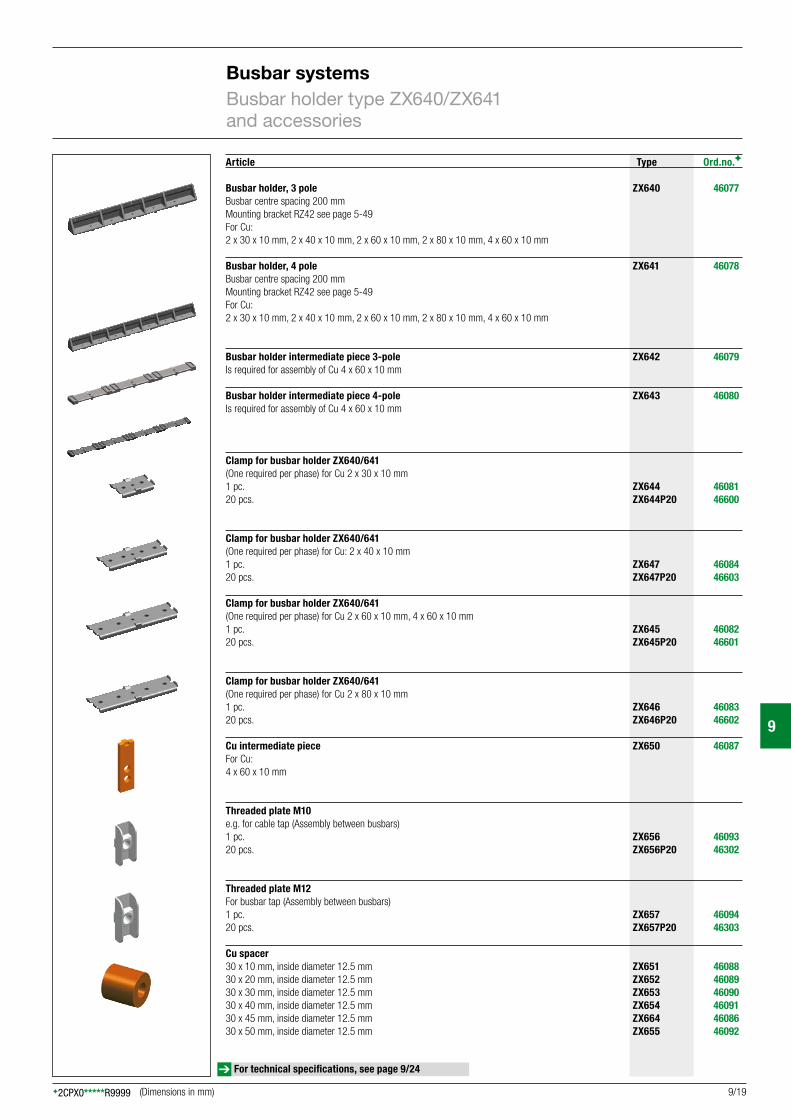
Busbar holder type ZX640Busbar spacing 200 mmContinuous current 1250 A – 3150 ASuitable for E-Cu busbars
Busbar holder type ZX641Busbar spacing 200 mmContinuous current 1250 A – 3150 ASuitable for E-Cu busbars
Busbar systemsBusbar holder type ZX640/ZX641
For technical specifications, see page 9/24
(Dimensions in mm)
9
9/19
Article Type Ord.no.F
Busbar holder, 3 pole ZX640 46077 Busbar centre spacing 200 mmMounting bracket RZ42 see page 5-49 For Cu: 2 x 30 x 10 mm, 2 x 40 x 10 mm, 2 x 60 x 10 mm, 2 x 80 x 10 mm, 4 x 60 x 10 mm Busbar holder, 4 pole ZX641 46078 Busbar centre spacing 200 mmMounting bracket RZ42 see page 5-49 For Cu: 2 x 30 x 10 mm, 2 x 40 x 10 mm, 2 x 60 x 10 mm, 2 x 80 x 10 mm, 4 x 60 x 10 mm
Busbar holder intermediate piece 3-pole ZX642 46079 Is required for assembly of Cu 4 x 60 x 10 mm
Busbar holder intermediate piece 4-pole ZX643 46080 Is required for assembly of Cu 4 x 60 x 10 mm
Clamp for busbar holder ZX640/641 (One required per phase) for Cu 2 x 30 x 10 mm 1 pc. ZX644 46081 20 pcs. ZX644P20 46600
Clamp for busbar holder ZX640/641 (One required per phase) for Cu: 2 x 40 x 10 mm 1 pc. ZX647 46084 20 pcs. ZX647P20 46603 Clamp for busbar holder ZX640/641 (One required per phase) for Cu 2 x 60 x 10 mm, 4 x 60 x 10 mm1 pc. ZX645 46082 20 pcs. ZX645P20 46601
Clamp for busbar holder ZX640/641 (One required per phase) for Cu 2 x 80 x 10 mm 1 pc. ZX646 4608320 pcs. ZX646P20 46602
Cu intermediate piece ZX650 46087 For Cu: 4 x 60 x 10 mm
Threaded plate M10 e.g. for cable tap (Assembly between busbars)1 pc. ZX656 4609320 pcs. ZX656P20 46302
Threaded plate M12 For busbar tap (Assembly between busbars)1 pc. ZX657 4609420 pcs. ZX657P20 46303
Cu spacer 30 x 10 mm, inside diameter 12.5 mm ZX651 4608830 x 20 mm, inside diameter 12.5 mm ZX652 4608930 x 30 mm, inside diameter 12.5 mm ZX653 4609030 x 40 mm, inside diameter 12.5 mm ZX654 46091 30 x 45 mm, inside diameter 12.5 mm ZX664 4608630 x 50 mm, inside diameter 12.5 mm ZX655 46092
Busbar systemsBusbar holder type ZX640/ZX641 and accessories
For technical specifications, see page 9/24
(Dimensions in mm)

9
9/20
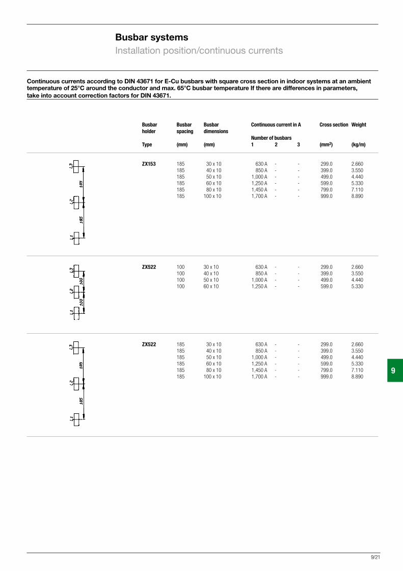
Continuous currents according to DIN 43671 for E-Cu busbars with square cross section in indoor systems at an ambient temperature of 25°C around the conductor and max. 65°C busbar temperature If there are differences in parameters, take into account correction factors for DIN 43671.
Busbar Busbar Busbar Continuous current in A Cross section Weight holder spacing dimensions Number of busbars Type (mm) (mm) 1 2 3 (mm2) (kg/m)
ZB5 40 12 x 5 250 A - - 59.5 0.532 40 12 x 10 360 A - - 119.0 1.064 40 20 x 5 320 A - - 99.1 0.882
ZX2 40 12 x 5 250 A - - 59.5 0.532 ZX95 40 12 x 10 360 A - - 119.0 1.064
ZX150 60 30 x 5 440 A - - 149.0 1.33 100 30 x 10 630 A - - 299.0 2.66
ZX150 60 20 x 10 500 A 850 A - 199.0 1.77 80 30 x 10 630 A 1,250 A - 299.0 2.66 100 40 x 10 850 A 1,500 A - 399.0 3.55
ZX151 60 12 x 5 250 A - - 59.5 0.532 60 20 x 5 320 A - - 99.1 0.882 60 25 x 5 390 A - - 124.0 1.110 60 30 x 5 440 A - - 149.0 1.330 60 12 x 10 360 A - - 119.0 1.064 60 20 x 10 500 A - - 199.0 1.770 60 30 x 10 630 A - - 299.0 2.660
ZX149 95 12 x 5 250 A - - 59.5 0.532 95 12 x 10 360 A - - 119.0 1.064 95 20 x 5 320 A - - 99.1 0.882 95 20 x 10 500 A - - 199.0 1.770 95 30 x 5 440 A - - 149.0 1.330 95 30 x 10 630 A - - 299.0 2.660
ZX518 40 12 x 5 250 A - - 59.5 0.532 40 20 x 5 320 A - - 99.1 0.882 40 30 x 5 440 A - - 149.0 1.330
ZX152 100 30 x 10 630 A - - 299.0 2.660 100 40 x 10 850 A - - 399.0 3.550 100 50 x 10 1,000 A - - 499.0 4.440 100 60 x 10 1,250 A - - 599.0 5.330
ZX520 60 30 x 10 630 A - - 299.0 2.660
ZX520 100 30 x 10 630 A - - 299.0 2.660 100 40 x 10 850 A - - 399.0 3.550 100 50 x 10 1,000 A - - 499.0 4.440 100 60 x 10 1,250 A - - 599.0 5.330
Busbar systemsInstallation position/continuous currents
9
9/21
Busbar Busbar Busbar Continuous current in A Cross section Weight holder spacing dimensions Number of busbars Type (mm) (mm) 1 2 3 (mm2) (kg/m)
ZX153 185 30 x 10 630 A - - 299.0 2.660 185 40 x 10 850 A - - 399.0 3.550 185 50 x 10 1,000 A - - 499.0 4.440 185 60 x 10 1,250 A - - 599.0 5.330 185 80 x 10 1,450 A - - 799.0 7.110 185 100 x 10 1,700 A - - 999.0 8.890
ZX522 100 30 x 10 630 A - - 299.0 2.660 100 40 x 10 850 A - - 399.0 3.550 100 50 x 10 1,000 A - - 499.0 4.440 100 60 x 10 1,250 A - - 599.0 5.330
ZX522 185 30 x 10 630 A - - 299.0 2.660 185 40 x 10 850 A - - 399.0 3.550 185 50 x 10 1,000 A - - 499.0 4.440 185 60 x 10 1,250 A - - 599.0 5.330 185 80 x 10 1,450 A - - 799.0 7.110 185 100 x 10 1,700 A - - 999.0 8.890
Continuous currents according to DIN 43671 for E-Cu busbars with square cross section in indoor systems at an ambient temperature of 25°C around the conductor and max. 65°C busbar temperature If there are differences in parameters, take into account correction factors for DIN 43671.
Busbar systemsInstallation position/continuous currents

9
9/22
Busbar systemsInstallation position/continuous currents
Busbar Busbar Busbar Continuous current in A Cross section Weight holder spacing dimensions Number of busbars Type (mm) (mm) 1 2 3 (mm2) (kg/m)
ZX154 72 20 x 5 320 A 500 A 690 A 99.1 0.882 72 30 x 5 440 A 672 A 896 A 149.0 1.330
ZX154 72 30 x 10 630 A 1,250 A - 299.0 2.660 72 40 x 10 850 A 1,500 A - 399.0 3.550 72 50 x 10 1,000 A 1,700 A - 499.0 4.440 72 60 x 10 1,250 A 2,000 A - 599.0 5.330 72 80 x 10 1,450 A 2,400 A - 799.0 7.110 72 100 x 10 1,700 A 2,750 A - 999.0 8.890
ZX155 100 20 x 5 320 A 500 A 690 A 99.1 0.882 100 30 x 5 440 A 672 A 896 A 149.0 1.330
ZX155 100 30 x 10 630 A 1,250 A - 299.0 2.660 100 40 x 10 850 A 1,500 A - 399.0 3.550 100 50 x 10 1,000 A 1,700 A - 499.0 4.440 100 60 x 10 1,250 A 2,000 A - 599.0 5.330 100 80 x 10 1,450 A 2,400 A - 799.0 7.110 100 100 x 10 1,700 A 2,750 A - 999.0 8.890 100 120 x 10 2,000 A 3,500 A - 1199.0 10.660 100 160 x 10 2,500 A 4,000 A - 1599.0 14.220
ZX156 125 20 x 5 320 A 500 A 690 A 99.1 0.882 125 30 x 5 440 A 672 A 896 A 149.0 1.330
ZX156 125 30 x 10 630 A 1,250 A - 299.0 2.660 125 40 x 10 850 A 1,500 A - 399.0 3.550 125 50 x 10 1,000 A 1,700 A - 499.0 4.440 125 60 x 10 1,250 A 2,000 A - 599.0 5.330 125 80 x 10 1,450 A 2,400 A - 799.0 7.110 125 100 x 10 1,700 A 2,750 A - 999.0 8.890 125 120 x 10 2,000 A 3,500 A - 1199.0 10.660 125 160 x 10 2,500 A 4,000 A - 1599.0 14.220
Continuous currents according to DIN 43671 for E-Cu busbars with square cross section in indoor systems at an ambient temperature of 25° C around the conductor and max. 65° C busbar temperature If there are differences in parameters, take into account correction factors for DIN DIN 43671.

9
9/23
Busbar systemsInstallation position/continuous currents
Busbar Busbar Busbar Continuous current in A Cross section Weight holder spacing dimensions Number of busbars Type (mm) (mm) 1 2 4 (mm2) (kg/m)
ZX561 - 80 x 10 1,450 A - - 799.0 7.110 - 100 x 10 1,700 A - - 999.0 8.890
ZX563 - 30 x 10 630 A - - 299.0 2.660 - 40 x 10 850 A - - 399.0 3.550 - 50 x 10 1,000 A - - 499.0 4.440 - 60 x 10 1,250 A - - 599.0 5.330
ZX640 200 30 x 10 - 1,250 A - 299.0 2.660 200 40 x 10 - 1,600 A - 399.0 3.550 200 60 x 10 - 2,000 A - 599.0 5.330 200 80 x 10 - 2,500 A - 799.0 7.110
200 60 x 10 - - 3,150 A 599.0 5.330
ZX641 200 30 x 10 - 1,250 A - 299.0 2.660 200 40 x 10 - 1,600 A - 399.0 3.550 200 60 x 10 - 2,000 A - 599.0 5.330 200 80 x 10 - 2,500 A - 799.0 7.110
Type-tested according to DIN EN 60439-1
9
9/24
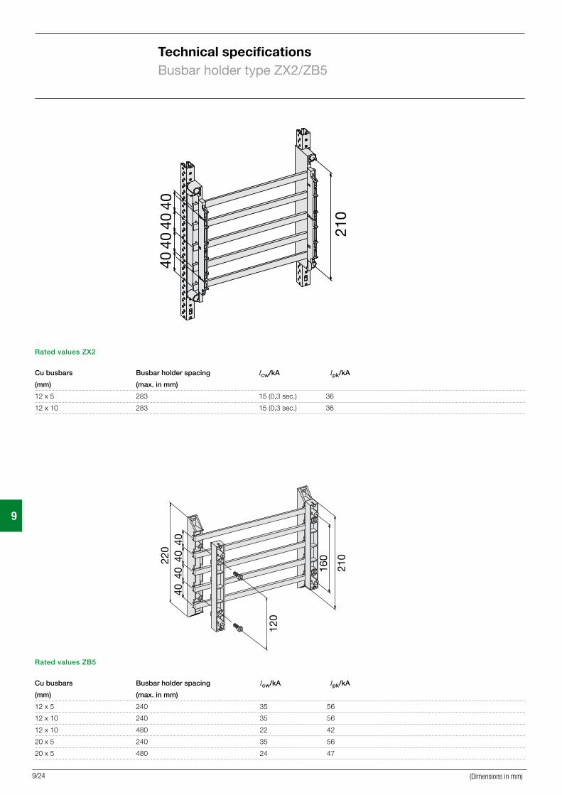
Technical specificationsBusbar holder type ZX2/ZB5
Rated values ZX2
Cu busbars Busbar holder spacing Icw/kA Ipk/kA
(mm) (max. in mm)
12 x 5 283 15 (0,3 sec.) 36
12 x 10 283 15 (0,3 sec.) 36
Rated values ZB5
Cu busbars Busbar holder spacing Icw/kA Ipk/kA
(mm) (max. in mm)
12 x 5 240 35 56
12 x 10 240 35 56
12 x 10 480 22 42
20 x 5 240 35 56
20 x 5 480 24 47
210
4040
4040
160
120
220
210
4040
4040
(Dimensions in mm)
9
9/25
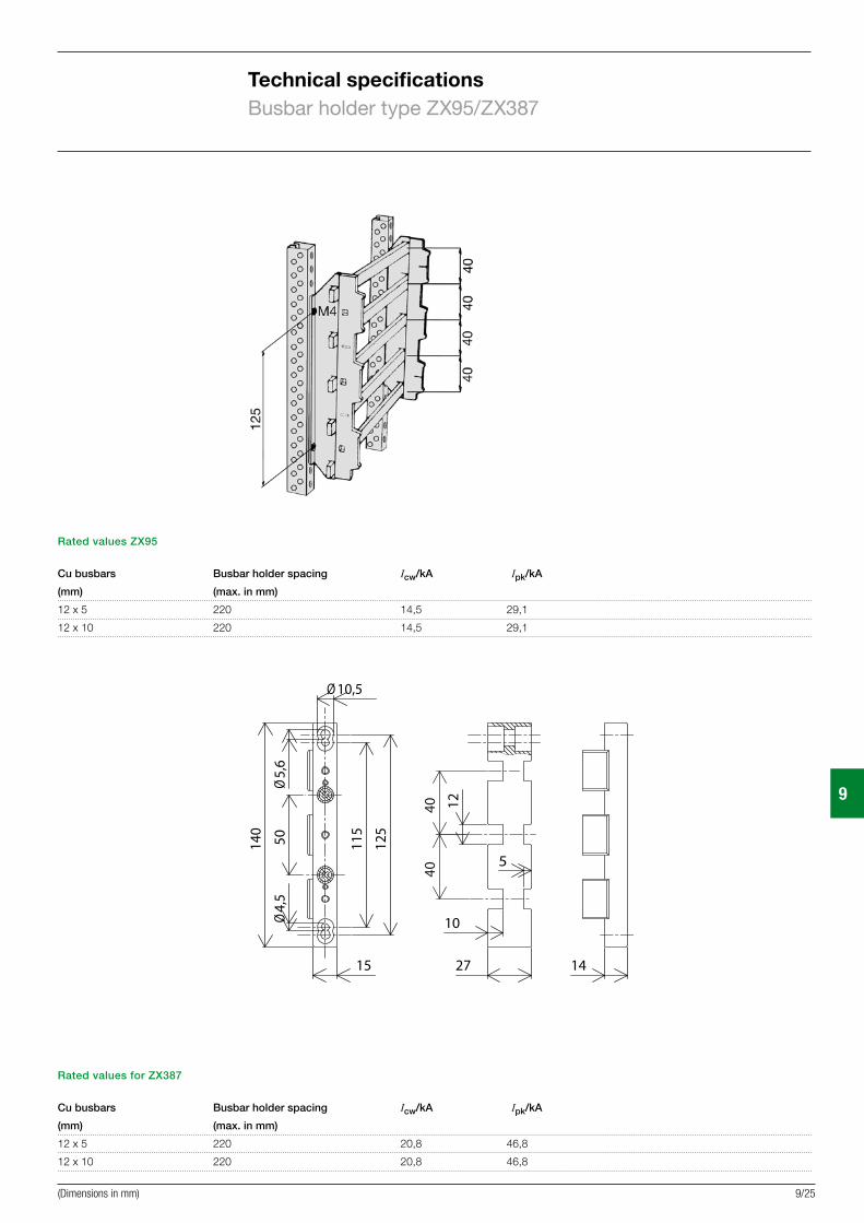
Technical specificationsBusbar holder type ZX95/ZX387
Rated values ZX95
Cu busbars Busbar holder spacing Icw/kA Ipk/kA
(mm) (max. in mm)
12 x 5 220 14,5 29,1
12 x 10 220 14,5 29,1
Rated values for ZX387
Cu busbars Busbar holder spacing Icw/kA Ipk/kA
(mm) (max. in mm)
12 x 5 220 20,8 46,8
12 x 10 220 20,8 46,8
(Dimensions in mm)
4,5
Ø5,
6Ø
10,5Ø
115
50
15
125
140
12
5
10
4040
27 14
9
9/26
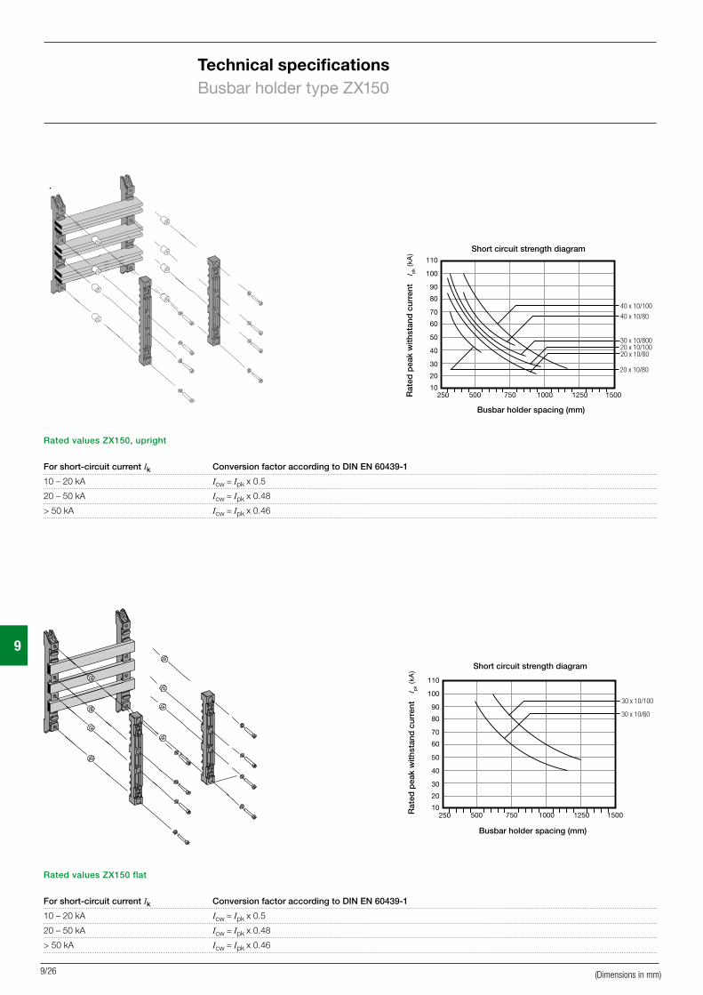
Technical specificationsBusbar holder type ZX150
Rated values ZX150, upright
For short-circuit current Ik Conversion factor according to DIN EN 60439-1
10 – 20 kA Icw = Ipk x 0.5
20 – 50 kA Icw = Ipk x 0.48
> 50 kA Icw = Ipk x 0.46
Rated values ZX150 flat
For short-circuit current Ik Conversion factor according to DIN EN 60439-1
10 – 20 kA Icw = Ipk x 0.5
20 – 50 kA Icw = Ipk x 0.48
> 50 kA Icw = Ipk x 0.46
(Dimensions in mm)
Short circuit strength diagram
Busbar holder spacing (mm)
Rat
ed p
eak
with
stan
d c
urre
nt
Short circuit strength diagram
Busbar holder spacing (mm)R
ated
pea
k w
ithst
and
cur
rent

9
9/27
Technical specificationsBusbar holder type ZX149/ZX518
Rated values ZX149
Cu busbars Busbar holder spacing Icw/kA Ipk/kA
(mm) (max. in mm)
30 x 10 240 15 33,4
30 x 10 480 15 33,4
Rated values ZX518
Cu busbars Busbar holder spacing Icw/kA Ipk/kA
(mm) (max. in mm)
12 x 5 240 12,5 27,9
12 x 5 480 12,5 27,9
20 x 5 240 12,5 27,9
20 x 5 480 12,5 27,9
30 x 5 240 12,5 27,9
30 x 5 480 12,5 27,9
(Dimensions in mm)
7515
592
16
40
58
34
9
9/28
Rated values ZX146/ZX147
Cu busbars Busbar holder spacing (max mm) Busbar holder spacing (max mm)
(mm) Module width 250 mm Module width 500 mm/750 mm
Icw/kA Ipk/kA Icw/kA Ipk/kA
12 x 5 20,1 44,3 10,9 24,7
20 x 5 20,3 44,8 14,4 31,7
12 x 10 21,4 47,2 11,2 24,8
20 x 10 23,5 51,8 14,5 31,9
30 x 5 32,1 70,7 24,5 54,1
30 x 10 36,7 79,8 26,0 57,4
Technical specificationsBusbar holder type ZX146 / ZX147 / ZX151 / ZX157
(Dimensions in mm)
Short circuit strength diagram
Busbar holder spacing (mm)
Rat
ed p
eak
with
stan
d c
urre
nt
ZX151
20060
ZX157
220
6092
max. 30 x 5
Conversion factors for ZX151 / ZX157
For short-circuit current Ik Conversion factor according to DIN EN 60439-1
10 - 20 kA Icw = Ipk x 0,5
20 - 50 kA Icw = Ipk x 0,48
> 50 kA Icw = Ipk x 0,46
Short circuit strength diagram
Short circuit strength diagram
Busbar holder spacing (mm)
Busbar holder spacing (mm)
Rat
ed p
eak
with
stan
d c
urre
nt
Rat
ed p
eak
with
stan
d c
urre
nt
9
9/29
Technical specificationsBusbar holder type ZX561 / ZX563
Rated values ZX563
Cu busbars Busbar holder spacing Icw/kA Ipk/kA
(mm) (max. in mm)
30 x 10 730 26,3 59,2
40 x 10 730 45,0 100,0
60 x 10 730 45,0 100,0
Rated values ZX561
Cu busbars Busbar holder spacing Icw/kA Ipk/kA
(mm) (max. in mm)
80 x 10 730 45,0 100,0
100 x 10 730 45,0 100,0
(Dimensions in mm)

9
9/30
Technical specificationsBusbar holder type ZX152/ZX153
Rated values ZX152
For short-circuit current Ik Conversion factor according to DIN EN 60439-1
10 – 20 kA Icw = Ipk x 0.5
20 – 50 kA Icw = Ipk x 0.48
> 50 kA Icw = Ipk x 0.46
Rated values ZX153
For short-circuit current Ik Conversion factor according to DIN EN 60439-1
10 – 20 kA Icw = Ipk x 0.5
20 – 50 kA Icw = Ipk x 0.48
> 50 kA Icw = Ipk x 0.46
62
320
275
100
100
70
100
100
100
8518
5 185
185 43
2
38
Short circuit strength diagram
Busbar holder spacing (mm)
Rat
ed p
eak
with
stan
d c
urre
nt
Short circuit strength diagram
Busbar holder spacing (mm)
Rat
ed p
eak
with
stan
d c
urre
nt
Short circuit strength diagram
Short circuit strength diagram
Busbar holder spacing (mm)
Busbar holder spacing (mm)R
ated
pea
k w
ithst
and
cur
rent
R
ated
pea
k w
ithst
and
cur
rent
(Dimensions in mm)
9
9/31
Technical specificationsBusbar holder type ZX520/ZX522
Rated values ZX520
For short-circuit current Ik Conversion factor according to DIN EN 60439-1
10 – 20 kA Icw = Ipk x 0.5
20 – 50 kA Icw = Ipk x 0.48
> 50 kA Icw = Ipk x 0.46
Rated values ZX522
For short-circuit current Ik Conversion factor according to DIN EN 60439-1
10 – 20 kA Icw = Ipk x 0.5
20 – 50 kA Icw = Ipk x 0.48
> 50 kA Icw = Ipk x 0.46
22
100
26
100
6060
7587
,587
,5
285
22
100
26
100
6060
7587
,587
,5
285
22
100
26
185
185
100
24
100
26
185
185
100
87,5
430
7587
,5
87,5
430
7587
,5
Short circuit strength diagram
Busbar holder spacing (mm)R
ated
pea
k w
ithst
and
cur
rent
Short circuit strength diagram
Busbar holder spacing (mm)
Rat
ed p
eak
with
stan
d c
urre
nt
Short circuit strength diagram
Busbar holder spacing (mm)
Rat
ed p
eak
with
stan
d c
urre
nt
(Dimensions in mm)
9
9/32
Technical specificationsBusbar holder type ZX154
Rated values ZX154
For short-circuit current Ik Conversion factor according to DIN EN 60439-1
10 – 20 kA Icw = Ipk x 0.5
20 – 50 kA Icw = Ipk x 0.48
> 50 kA Icw = Ipk x 0.46
Short circuit strength diagram
Busbar holder spacing (mm)
Rat
ed p
eak
with
stan
d c
urre
nt
180150
355
510,5 10,510
72
5
5,510 105,5
(Dimensions in mm)
9
9/33
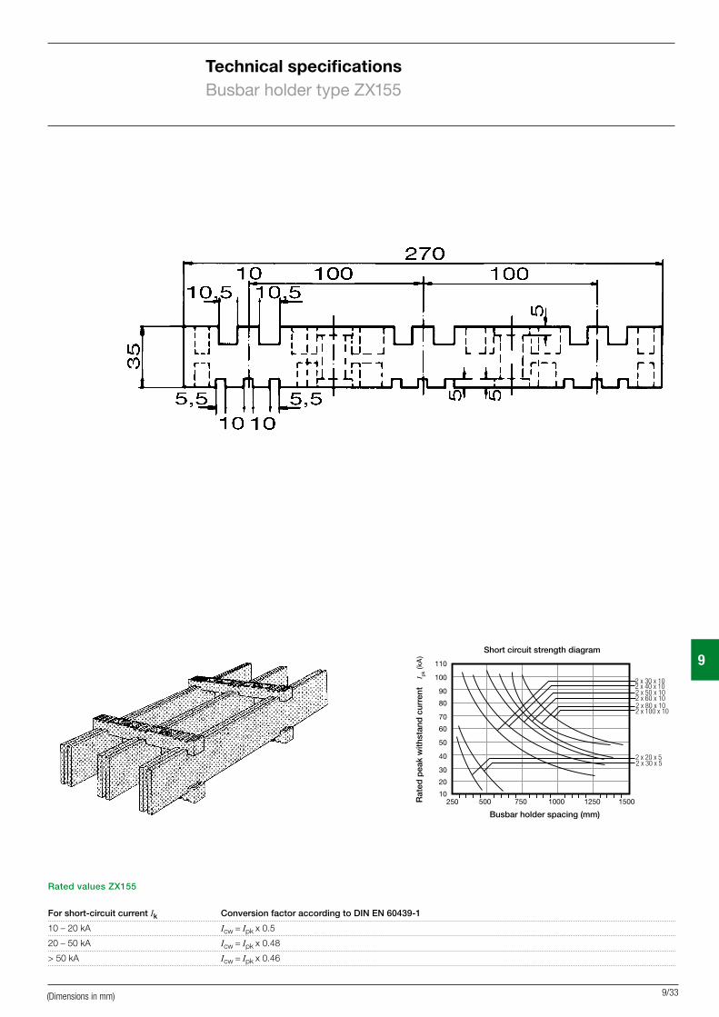
Technical specificationsBusbar holder type ZX155
Rated values ZX155
For short-circuit current Ik Conversion factor according to DIN EN 60439-1
10 – 20 kA Icw = Ipk x 0.5
20 – 50 kA Icw = Ipk x 0.48
> 50 kA Icw = Ipk x 0.46
Short circuit strength diagram
Busbar holder spacing (mm)
Rat
ed p
eak
with
stan
d c
urre
nt
(Dimensions in mm)
9
9/34
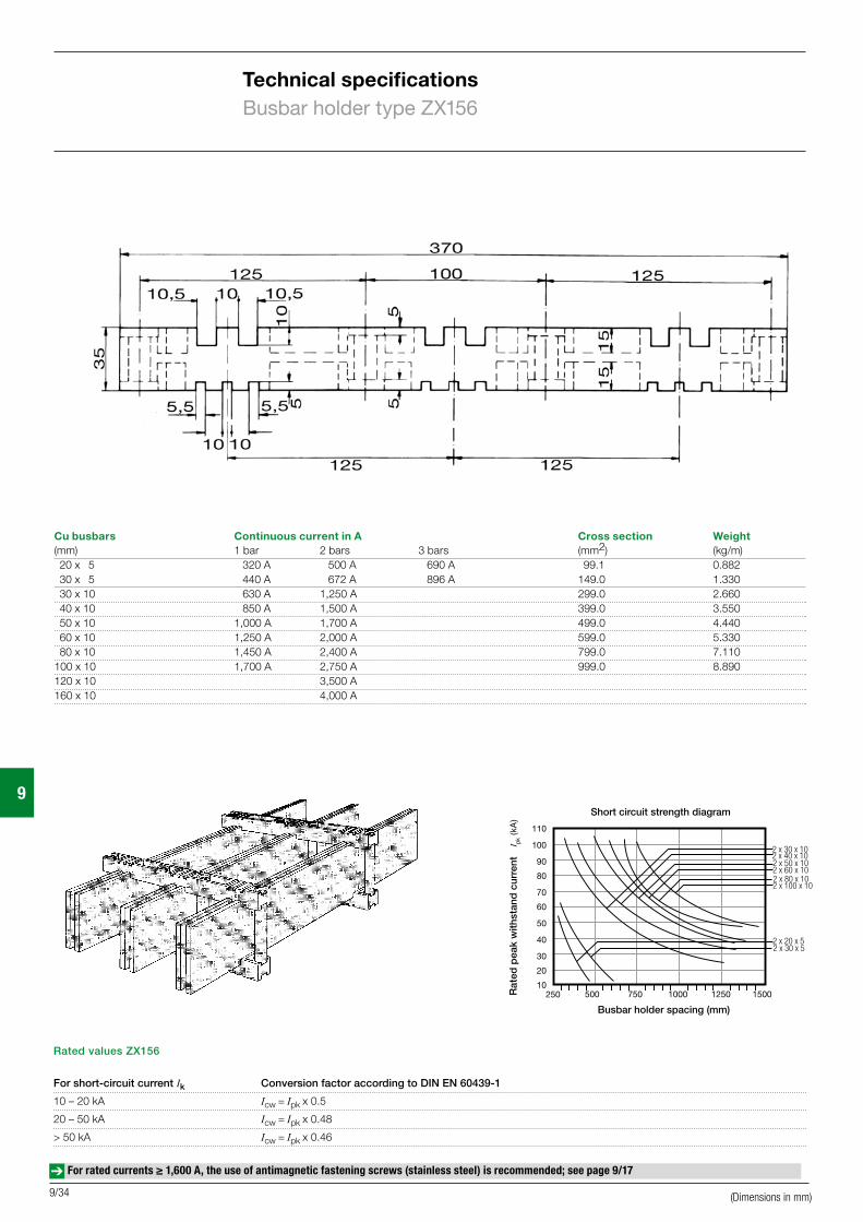
Technical specificationsBusbar holder type ZX156
Rated values ZX156
For short-circuit current Ik Conversion factor according to DIN EN 60439-1
10 – 20 kA Icw = Ipk x 0.5
20 – 50 kA Icw = Ipk x 0.48
> 50 kA Icw = Ipk x 0.46
Short circuit strength diagram
Busbar holder spacing (mm)
Rat
ed p
eak
with
stan
d c
urre
nt
Cu busbars Continuous current in A Cross section Weight(mm) 1 bar 2 bars 3 bars (mm2) (kg/m) 20 x 5 320 A 500 A 690 A 99.1 0.882 30 x 5 440 A 672 A 896 A 149.0 1.330 30 x 10 630 A 1,250 A 299.0 2.660 40 x 10 850 A 1,500 A 399.0 3.550 50 x 10 1,000 A 1,700 A 499.0 4.440 60 x 10 1,250 A 2,000 A 599.0 5.330 80 x 10 1,450 A 2,400 A 799.0 7.110100 x 10 1,700 A 2,750 A 999.0 8.890120 x 10 3,500 A160 x 10 4,000 A
For rated currents ≥ 1,600 A, the use of antimagnetic fastening screws (stainless steel) is recommended; see page 9/17
(Dimensions in mm)
9
9/35
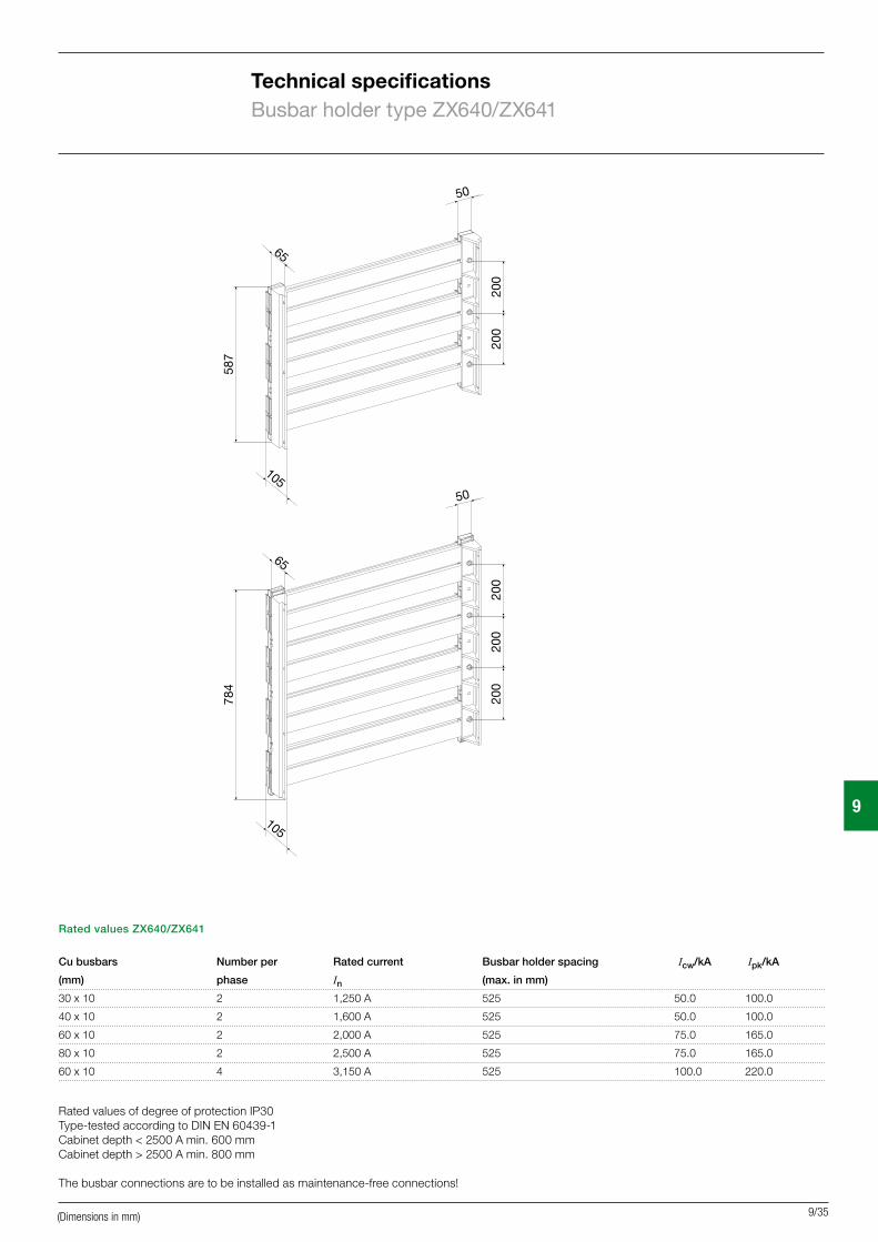
Technical specificationsBusbar holder type ZX640/ZX641
Rated values ZX640/ZX641
Cu busbars Number per Rated current Busbar holder spacing Icw/kA Ipk/kA
(mm) phase In (max. in mm)
30 x 10 2 1,250 A 525 50.0 100.0
40 x 10 2 1,600 A 525 50.0 100.0
60 x 10 2 2,000 A 525 75.0 165.0
80 x 10 2 2,500 A 525 75.0 165.0
60 x 10 4 3,150 A 525 100.0 220.0
200
200
587
65
50
105
105
784
200
200
200
50
65
Rated values of degree of protection IP30Type-tested according to DIN EN 60439-1Cabinet depth < 2500 A min. 600 mmCabinet depth > 2500 A min. 800 mm
The busbar connections are to be installed as maintenance-free connections!
(Dimensions in mm)
Related Documents