POWER WINDOW SYSTEMS CONTENTS page page GENERAL INFORMATION INTRODUCTI ON . . . . . . . . . . . . . . . . . . . . . . . . 1 POWER WINDOW SYSTEM . . . . . . . . . . . . . . . . 1 DESCRIPTION AND OPERATION BODY CONTROL MODULE . . . . . . . . . . . . . . . . 2 CIRCUIT BREAKER . . . . . . . . . . . . . . . . . . . . . . 3 DOOR MODULE . . . . . . . . . . . . . . . . . . . . . . . . 2 POWER WI NDOW MOT OR . . . . . . . . . . . . . . . . 2 POWER WINDOW SWI TCH . . . . . . . . . . . . . . . . 1 DIAGNOSIS AND TESTING CIRCUIT BREAKER . . . . . . . . . . . . . . . . . . . . . . 3 DOOR MODU LE . . . . . . . . . . . . . . . . . . . . . . . . 3 POWER WINDOW MOT OR . . . . . . . . . . . . . . . . 5 POWER WI NDOW SWI TCH . . . . . . . . . . . . . . . . 4 POWER WINDOW SYSTEM . . . . . . . . . . . . . . . . 3 REMOVAL AND INSTALLATION DOOR MODU LE . . . . . . . . . . . . . . . . . . . . . . . . 5 POWER WI NDOW MOT OR . . . . . . . . . . . . . . . . 6 POWER WI NDOW SWI TCH . . . . . . . . . . . . . . . . 6 GENERAL INFORMATION INTRODUCTION Pow er windows are standard factory-installed equipment on this model. This group covers diagnosis and service of only th e electrical components in the power window system. For servic e of mechanical components, such as the regulator, lift plate, window tracks, or glass refer to Group 23 - Body. Fol lowing are general descript i on s of the majo r components in the power window system. Refer to 8W-60 - P ower Windows in Group 8W - Wiring Dia- grams for complete circuit descriptions and diagrams. Refer t o the owner’ s manua l for more informa tion on the features and use of this system. NOTE: This group covers both Left -Hand Drive (LHD) and Right-Hand Drive (RHD) versions of this model. Whenever req uir ed and feasible, the RHD versions of affected vehicle components have been construct ed as mir ror -image of the LHD ver sions. While mos t of the illustrations used in thi s gro up represent only the LHD version, the diagnostic and service pr ocedures outlined can generall y be appl ied to ei ther version . Except ions to this rule have been cle ar ly identi fi ed as LHD or RHD, if a special illustration or procedure is required. POWER W INDOW SYSTE M The power window system allo ws all of the door windows to be opened or closed by operating a switch on the trim panel for that door. The master switches on the driver side front door trim panel can be oper- ated to open or clo se any of th e door windows. In additio n, a lockout swi tch on the driver side front door trim panel a l lows t he driver to disable all of the passenger door window switches. The power window system includes th e door mod- ules mounted in each front door, the switches mounted on the rear doors, an d the power window motors mounted to the window regulator in eac h door. In addition, several features and functio ns of the power window system a re made possible bec ause of the communication of the door modules on the Chrysler Collision Detection (CCD) data bus network. The power window system operates with battery power supplied through a circuit breaker in the junc- tion block, only when the ignition switch is in the On position. However, a feature of this system will allow the windows to be operated for up to thirty seconds after the ignition switch is turned to the Off position, or until a front door is opened, whichever occurs first. An auto-down feature allo ws the driver side front door window to be lowered all the way , even if the window switch is released. The driver side front door window switch must be depressed in the down direc- tion to a second detent to begin an auto-down event. Depressing the swi tch again in any direction will stop the window movement and cancel the auto-down event. DESCRIPTION AND OPERATION POWER WINDOW SWITCH The power windows are controll ed by a two-way momentary switch mounted on t he t rim pa nel of each passenger door, and four two-w ay momentary switches on the driver side front door trim panel. The driver side front door trim panel also has a two-posi- tion power window lockout switch. Z G POWER WINDOW SYSTEMS 8S - 1

Welcome message from author
This document is posted to help you gain knowledge. Please leave a comment to let me know what you think about it! Share it to your friends and learn new things together.
Transcript

7/31/2019 08S Power Window Systems
http://slidepdf.com/reader/full/08s-power-window-systems 1/8
POWER WINDOW SYSTEMS
CONTENTS
page page
GENERAL INFORMATIONINTRODUCTION . . . . . . . . . . . . . . . . . . . . . . . . 1
POWER WINDOW SYSTEM . . . . . . . . . . . . . . . . 1DESCRIPTION AND OPERATION
BODY CONTROL MODULE . . . . . . . . . . . . . . . . 2CIRCUIT BREAKER . . . . . . . . . . . . . . . . . . . . . . 3DOOR MODULE . . . . . . . . . . . . . . . . . . . . . . . . 2
POWER WINDOW MOTOR . . . . . . . . . . . . . . . . 2POWER WINDOW SWITCH . . . . . . . . . . . . . . . . 1
DIAGNOSIS AND TESTINGCIRCUIT BREAKER . . . . . . . . . . . . . . . . . . . . . . 3
DOOR MODULE . . . . . . . . . . . . . . . . . . . . . . . . 3POWER WINDOW MOTOR . . . . . . . . . . . . . . . . 5
POWER WINDOW SWITCH . . . . . . . . . . . . . . . . 4POWER WINDOW SYSTEM . . . . . . . . . . . . . . . . 3
REMOVAL AND INSTALLATIONDOOR MODULE . . . . . . . . . . . . . . . . . . . . . . . . 5POWER WINDOW MOTOR . . . . . . . . . . . . . . . . 6
POWER WINDOW SWITCH . . . . . . . . . . . . . . . . 6
GENERAL INFORMATION
INTRODUCTION
P ow er w in d ow s a r e s t a n da r d fa ct or y-in s t a ll ed
equipment on this model. This group covers diagnosis
and service of only th e electrical components in the
p ower win d ow s ys t e m . F or s e r vi ce of m e ch a n i ca l
components, such as the regulator, lift plate, window
tracks, or glass refer to Group 23 - Body.
F ol lowin g a r e g en e r a l d e scr i pt i on s of t h e m a j or
com p on e n t s i n t h e p ower win d ow s ys t e m . R efe r t o
8W-60 - P ower Windows in Group 8W - Wiring Dia-
grams for complete circuit descriptions and diagrams.Refer t o the owner’s m an ua l for more informa tion on
t h e f e a t u r e s a n d u s e o f t h i s s y s t e m .
NOTE: This group covers both Left-Hand Drive
(LHD) and Right-Hand Drive (RHD) versions of thismodel. Whenever required and feasible, the RHDversions of affected vehicle components have beenconstructed as mirror-image of the LHD versions.
While most of the illustrations used in this grouprepresent only the LHD version, the diagnostic andservice procedures outlined can generally beapplied to either version. Exceptions to this rule
have been clearly identified as LHD or RHD, if aspecial illustration or procedure is required.
POWER W INDOW SYSTEM
The power window system allows all of the door
windows to be opened or closed by operating a switch
on the trim panel for that door. The master switches
on the driver side front door trim panel can be oper-
a t e d t o o p en or cl os e a n y of t h e d oor win d ows . I n
a d d it i on , a l ock ou t s wit ch on t h e d r iv er s id e fr on t
door trim panel a llows t he driver to disable a ll of the
passenger door window switches.
The power window system includes th e door mod-
u les m ou n t ed in ea ch fr on t d oor, t h e s wit ch es
m ou n t e d on t h e r e a r d oor s , a n d t h e p ower win d ow
m ot or s m ou n t e d t o t h e w in d ow r e gu la t or in e a ch
door. In addition, several features and functions of
the power window system a re made possible because
of t h e com m u n i ca t i on of t h e d oor m od u le s on t h e
Chrysler Collision Detection (CCD) data bus network.
T h e p ower win d ow s ys t e m op e r a t es wit h b a t t e r y
power supplied through a circuit breaker in the junc-
tion block, only when the ignition switch is in the Onposition. However, a feature of this system will allow
the windows to be operated for up to thirty seconds
after the ignition switch is turned to the Off position,
or u n t i l a fr on t d oor i s op e n ed , wh ich e ve r occu r s
first.
An auto-down feature allows the driver side front
door window to be lowered all t he way, even if the
window switch is released. The driver side front door
window switch must be depressed in the down direc-
tion to a second detent to begin an auto-down event.
Dep r e ss in g t h e s wit ch a g a in i n a n y d ir e ct i on wil l
stop the window movement and cancel the auto-down
event.
DESCRIPTION AND OPERATION
POWER WINDOW SWITCH
The power windows are controlled by a two-way
momentary switch mounted on t he t rim pa nel of each
p a ss en ge r d oor, a n d fou r t wo-w ay m om en t a r y
switches on the driver side front door trim panel. The
driver side front door trim panel also has a two-posi-
tion power window lockout switch.
Z G POW ER W I ND OW SYSTEM S 8 S - 1

7/31/2019 08S Power Window Systems
http://slidepdf.com/reader/full/08s-power-window-systems 2/8
E a ch p ower win d ow s wit ch , e xce p t t h e l ock ou t
s wit ch , i s i ll u m in a t e d b y a L ig h t -E m i t t in g Diod e
( L E D) wh e n t h e i g n i t i o n s wi t c h i s t u r n e d t o t h e On
position. However, when the lockout switch is placed
in the Lock position, the LED for the locked-out front
a n d r e a r p a s s en g er d oor p ower win d ow s wit ch e s i s
turned off.T h e fr on t d oor p ower win d ow s wit ch e s a n d t h e
p ow er w in d ow lock ou t s wit ch a r e in t e gr a l t o t h e
Driver Door Module (DDM) or Pa ssenger Door Mod-
u le (P D M), r e sp ect ive ly. T h es e p ow er w in d ow
switches provide an up or down (or lock and unlock
signal in the case of the lockout switch) to the door
module circuitry.
T he D DM cir cu it r y con t r ols t h e ou t pu t t o t h e
driver side front and rear door power window motors,
and supplies electrical current as required for opera-
t ion of t h e d r ive r s id e r e a r d oor p ow er w in d ow
switch. The PDM circuitry controls the output to the
p a s s en g er s id e fr on t a n d r e a r d oor p ower win d owm ot or s , a n d s u p p li es e le ct r i ca l cu r r e n t a s r e qu i r ed
for operation of th e passenger side rear door power
window switch. When a DDM-integrated power win-
dow switch for a passenger side window is actuated,
t h e DDM c i r c u i t r y s e n d s a m e s s a g e t o t h e P DM o n
the Chrysler Collision Detection (CCD) dat a bus to
activate the output to that power window motor(s).
The front door power window switches an d their
l a m p s c a n n ot b e r e p a ir e d s o, i f fa u l t y o r d a m a g ed ,
t h e e n t ir e d oor m od u l e m u s t b e r e p l a ce d . T h e r e a r
door power window switches and their lamps cannot
b e r ep a ir ed b ut , if fa u lt y or d a ma ge d, on ly t h e
affected switch unit must be replaced.
DOOR MODULE
A Dr i ve r Door M od u le (DDM ) a n d a P a s s e n ge r
Door Module (PDM) are used on this model to control
a n d i nt e gr a t e m a n y of t h e e le ct r on ic fe a t u r es a n d
functions on the vehicle. The DDM and PDM commu-
nicate with each other, and with other vehicle mod-
ules on th e Ch rysler Collision Detection (CCD) data
bus network.
T h e C C D d a t a b u s n e t wo r k a l l o ws t h e s h a r i n g o f
s e n sor i n for m a t i on . T h is h e lp s t o r e d u ce wir e h a r -
ness complexity, internal controller har dware, and
com p on e n t s e n sor cu r r e n t l oa d s . At t h e s a m e t i m e,
this system provides increased reliabili ty, enhan ced
diagnostics, and allows the addition of many new fea-
ture capabilities.
T he D DM cir cu it r y con t r ols t h e ou t pu t t o t h e
driver side front and rear door power windows. The
P DM ci r cu i t r y c on t r o ls t h e ou t p u t t o t h e p a s s en g er
side front a nd rear door power windows. The DDM
can control the PDM output by sending control mes-
s a g e s t o t h e P DM o v e r t h e C C D d a t a b u s .
S om e of t h e fe a t u r e s a n d fu n c t ion s of t h e p ower
window system made possible because of the commu-
n i ca t i on of t h e d oor m od u le s on t h e C CD d a t a b u s
network include:
• Power window operation after ignition off fea-
t u r e .
•
Power window lockout fun ction.• Power window switch LED illumination control
function.
For diagnosis of the DDM, PDM, or the CCD data
b u s n e t wor k , r e fe r t o t h e p r op e r B od y Dia g n os t ic
Procedures manual.
BODY CONTROL MODULE
A B od y C on t r ol M od u le (B CM ) is u s ed on t h is
model t o control an d integrat e many of the electronic
functions and features included on the vehicle. The
B C M c on t a i n s a ce n t r a l p r oce ss in g u n i t a n d i n t er -
fa ces w it h ot h er m od u le s in t h e ve hicle on t h e
Chrysler Collision Detection (CCD) data bus network.T h e C C D d a t a b u s n e t wo r k a l l o ws t h e s h a r i n g o f
s e n sor i n for m a t i on . T h is h e lp s t o r e d u ce wir e h a r -
ness complexity, reduce internal controller hardware,
a n d r e d u ce com p on e n t s e n sor cu r r e n t l oa d s . At t h e
same time, this system provides increased reliability,
e n h a n ce d d ia g n os t ics , a n d a l lows t h e a d d it i on of
many new feature capabili t ies.
O n e o f t h e fu n ct ion s a n d fe a t u r es t h a t t h e B CM
supports and controls, is the power window system.
T h e B C M r e ce iv es i n pu t s fr om t h e i gn i t ion s wit ch
and the door ajar switches. The programming in the
BCM allows i t to process the information from these
inputs and send ignition switch and door ajar statusm e ss a ge s t o t h e D DM a n d P D M on t h e C CD d a t a
bus. The DDM and PDM use this information to con-
trol the l ighting of the power window switch lamps,
a n d t o con t r o l t h e op e r a t ion of t h e p ower win d ow
after ignition off feature.
T h e B C M i s m ou n t e d u n d er t h e d r iv er s id e ou t -
board end of the instrument panel, behind the instru-
m en t pa nel su ppor t a rm at ur e a nd below t he
outboard switch pod. Refer to Group 8E - Instrum ent
Panel Systems for the removal and installation pro-
cedures. For diagnosis of the BCM or the CCD data
bus, refer to t he proper Body Diagnostic P rocedures
manual. The BCM can only be serviced by an autho-
r i ze d e le ct r on i c r e p a i r s t a t i on . R efe r t o t h e l a t es t
Warranty Policies and Procedures manual for a cur-
rent l isting of a uthorized electronic repair stations.
POWER WINDOW MOTOR
A p e r m a n e n t m a g n et r e ve r s ib le m ot or m ov es t h e
window regulator through an integral gearbox mech-
anism. A positive and negative battery connection to
t h e t w o m ot or t e r mi n al s w ill ca u s e t h e m ot or t o
r ot a t e in on e d ir ect ion . R eve rs in g t h e cu r r en t
8 S - 2 POW ER W I ND OW SYSTEM S Z G
DESCRIPTION AND OPERATION (Continued)
7/31/2019 08S Power Window Systems
http://slidepdf.com/reader/full/08s-power-window-systems 3/8
t h r o u gh t h e s e s a m e t wo c on n e ct i on s wil l c a u s e t h e
motor to r otate in the opposite direction.
In addition, each power window motor is equipped
with an integral self-resetting circuit breaker to pro-
t e ct t h e m ot or fr om ov er l oa d s . T h e p ower win d ow
motor and gearbox assembly cannot be repaired and,
if faulty or damaged, the entire motor assembly mu stbe replaced.
CIRCUIT BREAKER
An automatic resetting circuit breaker in the junc-
tion block is u sed t o protect the power window sys-
t e m ci rcu it . T h e cir cu it b r ea k er ca n p r ot e ct t h e
system from a short circuit, or from an overload con-
dition caused by an obstructed or stuck window glass
or regulator.
T h e cir cu i t b r ea k e r ca n n ot b e r e pa ir e d a n d , if
faulty, it must be replaced.
DIAGNOSIS AND TESTING
POWER W INDOW SYSTEM
NOTE: The following tests may not prove conclu-sive in the diagnosis of this component. The most
reliable, efficient, and accurate means to diagnosethis system involves the use of a DRB scan tooland the proper Body Diagnostic Procedures man-ual.
Remember, the DDM circuitry controls the output
t o t h e d r iver s id e fr on t a n d r ea r p ow er w in d ow
motors. The PDM circuitry controls the output to the
passenger side front and rear power window motors.
For circuit descriptions and diagrams, refer to 8W-60
- Power Windows in Group 8W - Wiring Diagrams.
ALL WINDOWS INOPERATIVE
(1) Test the circuit breaker in the junction block,
as described in this group. If OK, go to Step 2. If not
OK, replace the faulty circuit breaker.
(2 ) Dis con n e ct a n d i sol a t e t h e b a t t e r y n e ga t i ve
cable. Remove the left and right front door trim pan-
els. Check the 12-way door module wire harness con-
n e c t o r s t o s e e t h a t t h e y a r e f u l l y s e a t e d i n t h e d o o r
module receptacles. If OK, go to St ep 3. If n ot OK,
install the wire harness connectors properly.
(3 ) Un p l u g t h e 1 2-wa y d oor m od u l e wi r e h a r n e s s
connectors. Check for continuity between the ground
circuit cavity of each door module wire h arn ess con-
nector and a good ground. If OK, go to Step 4. If not
OK, repair the open circuit as required.
(4) Connect the battery negative cable. Check for
b a t t e r y v ol t a ge a t t h e fu s e d B (+ ) c ir cu i t ca v it y of
each 12-way door module wire h arness connector. If
OK, use a DRB scan tool and the proper Body Diag-
nostic Procedures manual to diagnose the door mod-
u le s a n d t h e C C D d a t a b u s. I f n o t O K , r e pa i r t h e
open circuit to the junction block as required.
ONE WINDOW INOPERATIVE
T h e w i n dow g la s s m u s t b e f r ee t o s l id e u p a n d
down for the power window motor to function prop-
erly. If the glass is not free to move up and down, th e
m ot or w ill ov er loa d a n d t r ip t h e i nt e gr a l cir cu it
breaker. To determine if the glass is free, disconnect
t h e r e gu l a t or p la t e fr om t h e g la s s . T h e n s li de t h e
wi n d o w u p a n d d o wn b y h a n d .
T h e r e i s a n a l t er n a t e m e t h od t o c h eck i f t h e g l a s s
is free. Position the glass between the up and down
stops. Then, shake the glass in the door. Check that
t h e g la s s ca n b e m ov ed s li gh t l y f r om s id e t o s id e ,
f r o n t t o r e a r , a n d u p a n d d o wn . T h e n c h e c k t h a t t h e
glass is not bound tight in the tracks. If the glass is
free, proceed to the Door Module diagnosis in this
g r ou p . I f t h e g la s s i s n o t fr e e , r e fe r t o Gr ou p 2 3 -Body for the door window glass and hardware service
and adjustment procedures.
CIRCUIT BREAKER
F or cir cu it d es cr ip t ion s a n d d ia g ra m s , r e fe r t o
8W-60 - Power Windows in Group 8W - Wiring Dia-
grams.
(1) Locate the correct circuit breaker in the junc-
tion block. Pull out the circuit breaker slightly, but
be sure that the terminals sti l l contact the terminals
in the junction block cavities.
(2) Connect th e n egative lead of a 12-volt DC volt-
meter to a good ground.(3) With the voltmeter positive lead, check both
terminals of the circuit breaker for battery voltage.
If only one term inal h as battery voltage, t he circuit
breaker is faulty and must be replaced. If neither ter-
m i n a l h a s b a t t e r y v ol t a ge , r e p a i r t h e op en ci r cu i t
fr om t h e P ow er D is t rib ut ion C en t er (P DC ) a s
r e q u ir e d . I f t h e ci r cu i t b r ea k e r ch e ck s OK, b u t n o
power windows operate, see t he diagnosis for Power
Window System.
DOOR MODULE
NOTE: The following tests may not prove conclu-sive in the diagnosis of this component. The mostreliable, efficient, and accurate means to diagnosethis system involves the use of a DRB scan tool
and the proper Body Diagnostic Procedures man-ual.
If the problem being diagnosed is a rear door win-
dow that does not operate from the rear door switch,
bu t d oes op er a t e fr om t h e m a st er s wit ch on t h e
driver side front door, go to th e diagnosis for Power
Window Switch in this group. If the problem is a pas-
Z G POW ER W I ND OW SYSTEM S 8 S - 3
DESCRIPTION AND OPERATION (Continued)
7/31/2019 08S Power Window Systems
http://slidepdf.com/reader/full/08s-power-window-systems 4/8
senger side front or rear window that operates from
t h e s wit ch on t h a t d oor , b u t d oe s n ot op e r a t e f r om
the master switch on the driver side front door, use a
DRB scan tool and the proper Body Diagnostic Pro-
cedures manual to diagnose the circuitry of the door
modules and the CCD data bus. For circuit descrip-
tions and diagrams, refer to 8W-60 - Power Windowsin Group 8W - Wiring Diagrams.
(1 ) Dis con n e ct a n d i sol a t e t h e b a t t e r y n e ga t i ve
cable. Remove the front door trim panel as described
i n t h i s g r ou p . Go t o S t e p 2 .
(2 ) C h e ck t h e 1 2-wa y d oor m od u le wir e h a r n e s s
con n e ct or t o s e e t h a t i t i s f u ll y s e a t e d i n t h e d oor
m od u l e r e ce p t a cl e. I f OK, g o t o S t e p 3 . I f n ot OK,
install the wire harness connector properly.
(3 ) Un p l u g t h e 1 2-wa y d oor m od u l e wi r e h a r n e s s
connector from the door module. Check for continuity
between the ground circuit cavity of the door module
wir e h a r n e s s con n e ct or a n d a g ood g r ou n d . T h e r e
should be continuity. If OK, go to Step 4. If not OK,repair the open circuit as required.
(4) Connect the battery negative cable. Check for
battery voltage at the fused B(+) circuit cavity of the
12-way door module wire har ness connector. If OK,
g o t o S t e p 5 . I f n ot OK, r e p a ir t h e op e n ci r cu i t a s
required.
(5) If the inoperative window is on a front door, go
to Step 6. If the inoperative window is on a rear door
g o t o S t e p 9 .
(6 ) Dis con n e ct a n d i sol a t e t h e b a t t e r y n e ga t i ve
cable. Unplug the inoperative power window m otor
wire harness connector. Check for continuity between
t h e fr on t w in d ow d r iv er u p cir cu it ca vit y of t h e1 2-wa y d oor m od u le wir e h a r n e s s con n e ct or a n d a
good ground. Repeat the check for the front window
driver down circuit cavity of the door module wire
h a r n e s s con n e ct or . I n e a ch ca s e t h e r e s h ou l d b e n o
continuity. If OK, go to Step 7. If not OK, repair the
short circuit as required.
(7) Check for continuity between the front window
driver u p circuit cavities of th e 12-way door module
wire ha rness connector and the power window motor
wir e h a r n e s s con n e ct or . R e p ea t t h e ch e ck for t h e
front window driver down circuit cavities. In each
case there should be continuity. If OK, go to Step 8.
If not OK, repair the open circuit as required.
(8) Plug the 12-way door module wire harness con-
n e ct or b a ck i n t o t h e d oor m od u l e. C on n e ct t h e b a t -
t er y n ega t ive ca ble. Con n ect t h e p robes of a
reversible DC digital voltmeter to t he door module
side of the power window motor wire harness connec-
tor. Observe the voltmeter while actuating the switch
in the up and down directions. There should be bat-
tery voltage for as long as the switch is held in both
t h e u p a n d d ow n p os it ion s , a n d n o v ol ta g e i n t h e
neutra l position. If OK, see the diagnosis for Power
Window Motors. If not OK, replace the faulty door
module.
(9 ) Dis con n e ct a n d i sol a t e t h e b a t t e r y n e ga t i ve
cable. Remove the rear door power window switch as
described in t his group. Check the rear door power
window switch continuity as described in this group.
I f OK, g o t o S t e p 1 0 . I f n o t OK, r e p l a c e t h e f a u l t yswitch.
(10) Plug the rear door power window switch into
the wire har ness connector. Unplug t he inoperative
power window motor connector. Check for continuity
between the rear window driver up circuit cavity of
the 12-way door module wire harness connector and
a good ground. Repeat the check for the rear window
driver down circuit cavity. In each case there should
b e n o c on t i n u it y. I f OK, g o t o S t e p 11 . I f n ot OK,
repair the short circuit as required.
(11) Check for cont inuity between t he r ear window
driver u p circuit cavities of the 12-way d oor m odule
wire harness connector and the power window motorwire harness connector. Repeat the check for the rear
win d ow d r iv er d own ci r cu i t ca v it i es . I n e a ch ca s e
t h e r e s h o u l d b e c o n t i n u i t y . I f OK, g o t o S t e p 1 2 . I f
not OK, repair the open circuit as required.
NOTE: The door module feeds battery voltage toboth terminals of the rear door power windowmotors when the power window lockout switch is inthe Unlock position, until the master window switch
on the driver side front door is actuated. The doormodule feeds ground to both terminals of the reardoor power window motor when the power window
lockout switch is in the Lock position, until themaster window switch on the driver side front dooris actuated.
(1 2) P l u g t h e 1 2-wa y d oor m od u le wir e h a r n e s s
con n e ct or b a ck i n t o t h e d oor m od u le . C on n e ct t h e
battery negative cable. Check for battery voltage at
each cavity of th e switch side of th e power window
m ot or wir e h a r n e s s con n e ct or . E a c h ca v it y s h ou l d
h a v e b a t t e r y v ol t a ge i n t h e n e u t r a l p os it i on . E a c h
cavity should also have battery voltage in one other
s wit ch p os it i on , e it h e r u p or d own , a n d z er o v ol t s
with the switch in the opposite position. If OK, go to
the Power Window Motor diagnosis in this group. If not OK, replace the faulty door module.
POWER WINDOW SWITCH
This diagnosis is for the rear door power window
switches. The front door power window switches are
i n t eg r a l t o t h e d oor m od u le s . F o r d ia g n os is of t h e
front door power window switches, see Door Module
in this group. For circuit descriptions and diagrams,
refer to 8W-60 - Power Windows in Group 8W - Wir-
ing Diagrams.
8 S - 4 POW ER W I ND OW SYSTEM S Z G
DIAGNOSIS AND T ESTING (Continued)
7/31/2019 08S Power Window Systems
http://slidepdf.com/reader/full/08s-power-window-systems 5/8
(1 ) Dis con n e ct a n d i sol a t e t h e b a t t e r y n e ga t i ve
cable.
(2 ) R em ov e t h e p ower win d ow s wit ch fr om t h e
rear door trim panel as described in this group.
(3 ) C a r e fu l ly u n p l u g t h e p ower win d ow s wit ch
from the wire harness connector.
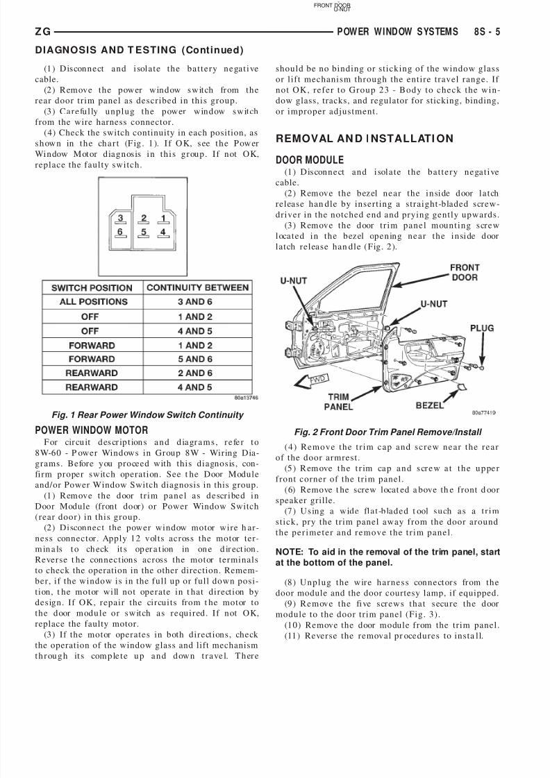
(4) Check the switch continuity in each position, ass h ow n in t h e ch a r t (F ig . 1 ). I f O K, s ee t h e P ow er
Wi n dow M ot or d ia g n os is i n t h i s g r ou p . I f n ot OK,
replace the faulty switch.
POWER WINDOW MOTOR
F or cir cu it d es cr ip t ion s a n d d ia gr a m s , r e fe r t o
8W-60 - P ower Windows in Group 8W - Wiring Dia-
grams. Before you proceed with this diagnosis, con-
firm proper switch operation. See t he Door Module
and/or Power Window Switch diagnosis in this group.
(1 ) R em ov e t h e d oor t r i m p a n e l a s d e scr i be d i n
Door Module (front door) or Power Window Switch
(rear door) in this group.
(2) Disconnect the power window motor wire h ar-
ness connector. Apply 12 volts across the motor ter-
m in a ls t o ch eck it s op er a t ion in on e d ir ect ion .
Reverse t he connections across the motor terminals
to check the operation in the other direction. Remem-
ber, if the window is in the full up or full down posi-
tion, t he motor will not operate in t hat direction by
design. If OK, repair the circuits from t he motor to
t h e d oor m od u l e o r s wit ch a s r e qu i r ed . I f n ot OK,
replace the faulty motor.
(3) If the motor operates in both directions, check
the operation of the window glass and lift mechanism
t h r ou g h it s com p le t e u p a n d d ow n t r a ve l. T h er e
should be no binding or sticking of the window glass
or l ift mechanism through the entire travel range. If
n o t OK, r e f e r t o Gr o u p 2 3 - B o d y t o c h e c k t h e wi n -
dow glass, tracks, and regulator for sticking, binding,
or improper adjustment.
REMOVAL AN D I NSTALLATI ON
DOOR MODULE
(1 ) Dis con n e ct a n d i sol a t e t h e b a t t e r y n e ga t i ve
cable.
(2 ) R em ov e t h e b ez el n e a r t h e i n si de d oor l a t ch
release han dle by inserting a straight-bladed screw-
driver in the notched end and prying gently upwards.
(3 ) R em ov e t h e d oor t r i m p a n e l m ou n t i n g s cr e w
l oca t e d i n t h e b ez el op e n in g n e a r t h e i n si de d oor
latch release han dle (Fig. 2).
( 4 ) R e m o v e t h e t r i m c a p a n d s c r e w n e a r t h e r e a r
of the door armrest.
(5 ) R em ove t h e t r im ca p a n d s cr e w a t t h e u p pe r
front corner of the trim panel.
(6) Remove t he screw locat ed a bove th e front d oor
speaker grille.
(7 ) Us in g a wid e fl a t -b la d e d t ool s u ch a s a t r i m
stick, pry the trim panel away from the door around
t h e p e r i m e t e r a n d r e m o v e t h e t r i m p a n e l .
NOTE: To aid in the removal of the trim panel, startat the bottom of the panel.
(8 ) Un p l u g t h e wir e h a r n e s s con n e ct or s fr om t h e
door module and the door courtesy lamp, if equipped.
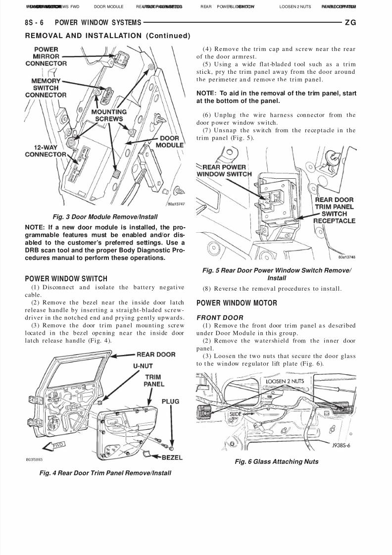
(9 ) R e m ov e t h e fi ve s cr e ws t h a t s ecu r e t h e d oor
module to the door trim panel (Fig. 3).
(10) Remove the door module from the trim panel.
(11) Reverse the removal pr ocedures to insta ll.
Fig. 1 Rear Power Window Switch Continuity
Fig. 2 Front Door Trim Panel Remove/Install
U-NUTFRONT DOOR
-
Z G POW ER W I ND OW SYSTEM S 8 S - 5
DIAGNOSIS AND T ESTING (Continued)
7/31/2019 08S Power Window Systems
http://slidepdf.com/reader/full/08s-power-window-systems 6/8
NOTE: If a new door module is installed, the pro-grammable features must be enabled and/or dis-
abled to the customer’s preferred settings. Use aDRB scan tool and the proper Body Diagnostic Pro-cedures manual to perform these operations.
POWER WINDOW SWITCH
(1 ) Dis con n e ct a n d i sol a t e t h e b a t t e r y n e ga t i ve
cable.
(2 ) R em ov e t h e b ez el n e a r t h e i n s id e d oor l a t ch
release handle by inserting a straight-bladed screw-
driver in the notched end and prying gently upwards.
(3 ) R em ov e t h e d oor t r i m p a n e l m ou n t i n g s cr e w
l oca t e d i n t h e b ez el op e n in g n e a r t h e i n si de d oor
latch release handle (Fig. 4).
( 4 ) R e m o v e t h e t r i m c a p a n d s c r e w n e a r t h e r e a r
of the door armrest.
(5 ) Us in g a wid e fl a t -b la d e d t ool s u ch a s a t r i m
stick, pry the trim panel away from the door around
t h e p e r im e t e r a n d r e m ov e t h e t r i m p a n e l .
NOTE: To aid in the removal of the trim panel, startat the bottom of the panel.
(6 ) Un p lu g t h e wir e h a r n e s s con n e ct or fr om t h e
door p ower window switch.
(7 ) Un s n a p t h e s wit ch fr om t h e r e ce p t a cl e i n t h e
trim panel (Fig. 5).
(8) Reverse t he removal procedures to install .
POWER WINDOW MOTOR
FRONT DOOR
(1) Remove the front door trim panel a s described
under Door Module in this group.
(2 ) R em ov e t h e wa t e r sh i el d fr om t h e i n n er d oor
panel.
(3) Loosen the two nuts that secure the door glass
to t he window regulator l ift plate (Fig. 6).
Fig. 3 Door Module Remove/Install
POWER MIRRORCONNECTOR DOOR MODULE 12–WAYCON-NECTORMOUNTING SCREWSMEMORY SWITCHCONNECTOR
Fig. 4 Rear Door Trim Panel Remove/Install
REARDOORU-NUTTRIM PANEL PLUGBEZELFWD
Fig. 5 Rear Door Power Window Switch Remove/ Install
REAR POWER WINDOWSWITCH REAR DOOR TRIMPANEL SWITCHRECEPTACLE
Fig. 6 Glass Attaching Nuts
LOOSEN 2 NUTSSLIDE
8 S - 6 POW ER W I ND OW SYSTEM S Z G
REMOVAL AND INSTALLATION (Continued)
7/31/2019 08S Power Window Systems
http://slidepdf.com/reader/full/08s-power-window-systems 7/8
(4) Slide the door glass rearward to remove it from
t h e n u t s .
( 5 ) P u l l t h e d o o r g l a s s t o t h e f u l l u p p o s i t i o n a n d
tape the glass to the upper door window frame.
(6 ) Un p lu g t h e wir e h a r n e s s con n e ct or fr om t h e
power window motor.
(7) Remove the four screws that secure the windowregulator to the inner door panel (Fig. 7).
(8) Loosen the last two screws that secure the reg-
ulator to the inner door panel.
(9 ) R em ove t h e w in d ow r egu la t or a n d m ot or
assembly from inside the door.
(10) To install, place the window r egulator inside
the door and slide the two loose screws into the slot-
ted holes in the door inner panel.(11 ) I n st a ll t h e r e m a in in g r e gu la t or m ou n t in g
screws and t ighten to 12 N·m (105 in. lbs.) .
( 1 2 ) R e m o v e t h e t a p e u s e d t o s e c u r e t h e g l a s s t o
t h e u p p er d oor win d ow fr a m e a n d l ower t h e g la s s .
M o v e t h e g l a s s a s f a r r e a r wa r d i n t o t h e c h a n n e l a s
possible and push down. Tighten the two loose win-
dow regulator screws to 12 N·m (105 in. lbs.).
(13) Attach the door glass by sliding the two nuts
in t o t h e s lot t e d h ole s on t h e r e gu la t or li ft p la t e .
Tighten the nuts to 12 N·m (105 in. lbs.) .
(1 4) P lu g in t h e w ir e h a r n e ss con n e ct or t o t h e
power window motor.
(15) Use an adhesive/sealant to install the plastic
watershield to the door inner panel.
(16) Reverse the remaining removal procedures to
complete the installation.
REAR DOOR
(1) Remove t he rear door trim panel a s described
under Power Window Switch in this group.
(2 ) R em ov e t h e wa t e r sh i el d fr om t h e i n n er d oor
panel.
(3) Loosen the two nuts that secure the door glass
to t he window regulator l ift plate (Fig. 8).
(4) Slide the door glass forward to r emove it from
t h e n u t s .
(5) Pull the door glass to the full up position and
tape the glass to the upper door window frame.
(6 ) Un p lu g t h e wir e h a r n e s s con n e ct or fr om t h e
power wind ow motor.
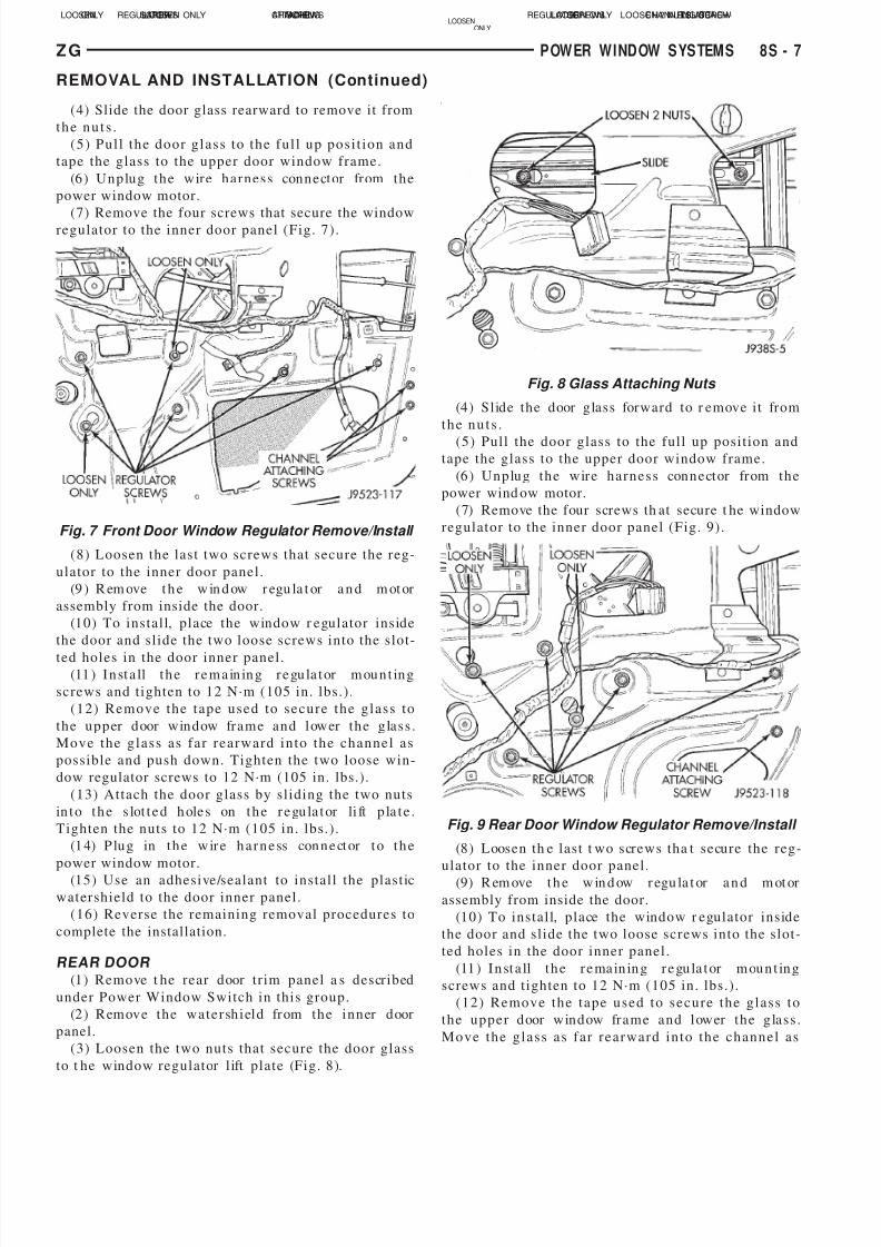
(7) Remove the four screws th at secure t he window
regulator to the inner door panel (Fig. 9).
(8) Loosen th e last t wo screws tha t secure the reg-
ulator to the inner door panel.
(9) R em ove t h e w in d ow r egu la t or a n d m ot or
assembly from inside the door.
(10) To install, place the window r egulator inside
the door and slide the two loose screws into the slot-
ted holes in the door inner panel.
(11 ) I n st a ll t h e r e ma in in g r e gu la t or m ou n t in g
screws and t ighten to 12 N·m (105 in. lbs.) .
( 1 2 ) R e m o v e t h e t a p e u s e d t o s e c u r e t h e g l a s s t o
t h e u p p e r d oor win d ow fr a m e a n d l ower t h e g la s s .
M o v e t h e g l a s s a s f a r r e a r wa r d i n t o t h e c h a n n e l a s
Fig. 7 Front Door Window Regulator Remove/Install
LOOSEN ONLY CHANNELATTACHINGSCREWSREGULATORSCREWSLOOSENONLY
Fig. 8 Glass Attaching Nuts
LOOSEN 2 NUTSSLIDE
Fig. 9 Rear Door Window Regulator Remove/Install
LOOSENONLY
LOOSEN ONLY CHANNEL ATTACH-ING SCREWREGULATORSCREWS
Z G POW ER W I ND OW SYSTEM S 8 S - 7
REMOVAL AND INSTALLATION (Continued)

7/31/2019 08S Power Window Systems
http://slidepdf.com/reader/full/08s-power-window-systems 8/8
Related Documents