IGNITION SYSTEM CONTENTS page page GENERAL INFORMATION INTRODUCTION ........................ 1 DESCRIPTION AND OPERATION AUTOMATIC SHUTDOWN (ASD) RELAY ...... 3 CAMSHAFT POSITION SENSOR ............ 3 CRANKSHAFT POSITION SENSOR—4.0L ENGINE ............................. 3 CRANKSHAFT POSITION SENSOR—5.2L/5.9L V-8 ENGINES ......................... 3 DISTRIBUTOR .......................... 2 ENGINE COOLANT TEMPERATURE SENSOR . . 4 IGNITION COIL ......................... 3 IGNITION SWITCH AND KEY LOCK CYLINDER . 4 IGNITION SYSTEM ...................... 1 INTAKE MANIFOLD AIR TEMPERATURE SENSOR ............................. 4 MANIFOLD ABSOLUTE PRESSURE (MAP) SENSOR ............................. 4 POWERTRAIN CONTROL MODULE (PCM) .... 2 SPARK PLUG CABLES ................... 3 SPARK PLUGS ......................... 2 THROTTLE POSITION SENSOR ............ 4 DIAGNOSIS AND TESTING AUTOMATIC SHUTDOWN (ASD) RELAY TEST . 4 CAMSHAFT POSITION SENSOR ............ 7 CRANKSHAFT POSITION SENSOR .......... 7 DISTRIBUTOR CAP ...................... 6 DISTRIBUTOR ROTOR ................... 6 ENGINE COOLANT TEMPERATURE SENSOR . . 8 FAILURE TO START TEST ................. 5 IGNITION COIL TEST ..................... 5 IGNITION TIMING ....................... 7 INTAKE MANIFOLD AIR TEMPERATURE SENSOR ............................. 8 MAP SENSOR .......................... 7 SPARK PLUG CABLES ................... 8 SPARK PLUG CONDITIONS ............... 9 TESTING FOR SPARK AT COIL ............. 4 REMOVAL AND INSTALLATION AUTOMATIC SHUTDOWN (ASD) RELAY ..... 14 CAMSHAFT POSITION SENSOR ........... 15 CRANKSHAFT POSITION SENSOR—4.0L ENGINE ............................ 14 CRANKSHAFT POSITION SENSOR—5.2L/5.9L ENGINES ........................... 14 DISTRIBUTOR—4.0L ENGINE ............. 17 DISTRIBUTOR—5.2L/5.9L ENGINES ........ 16 ENGINE COOLANT TEMPERATURE SENSOR . 15 IGNITION COIL—4.0L ENGINE ............. 13 IGNITION COIL—5.2L/5.9L ENGINES ........ 13 IGNITION SWITCH AND KEY CYLINDER ..... 20 INTAKE MANIFOLD AIR TEMPERATURE SENSOR ............................ 15 MANIFOLD ABSOLUTE PRESSURE (MAP) SENSOR ............................ 15 POWERTRAIN CONTROL MODULE (PCM) ... 20 SHIFTER/IGNITION INTERLOCK ........... 23 SPARK PLUG CABLES ................... 11 SPARK PLUGS ........................ 12 THROTTLE POSITION SENSOR ........... 15 SPECIFICATIONS ENGINE FIRING ORDER—4.0L 6-CYLINDER ENGINE ............................ 23 ENGINE FIRING ORDER—5.2L/5.9L V-8 ENGINES ........................... 23 IGNITION COIL RESISTANCE ............. 24 IGNITION TIMING ...................... 23 SPARK PLUG CABLE RESISTANCE ........ 24 SPARK PLUGS ........................ 24 TORQUE CHART ....................... 23 VECI LABEL ........................... 23 GENERAL INFORMATION INTRODUCTION This group describes the ignition systems for 5.2L/ 5.9L V–8 and 4.0L 6–cylinder engines. On Board Diagnostics is described in Group 25, Emission Control Systems. Group 0, Lubrication and Maintenance, contains general maintenance information (in time or mileage intervals) for ignition related items. The Owner’s Manual also contains maintenance information. DESCRIPTION AND OPERATION IGNITION SYSTEM The ignition systems used on 5.2L/5.9L V–8 and 4.0L 6–cylinder engines are basically identical. Simi- larities and differences between the systems will be discussed. The ignition system is controlled by the powertrain control module (PCM) on all engines. The ignition system consists of: • Spark Plugs ZG IGNITION SYSTEM 8D - 1

Welcome message from author
This document is posted to help you gain knowledge. Please leave a comment to let me know what you think about it! Share it to your friends and learn new things together.
Transcript
ZG IGNITION SYSTEM 8D - 1
IGNITION SYSTEM
CONTENTS
page
GENERAL INFORMATIONINTRODUCTION . . . . . . . . . . . . . . . . . . . . . . . . 1
DESCRIPTION AND OPERATIONAUTOMATIC SHUTDOWN (ASD) RELAY . . . . . . 3CAMSHAFT POSITION SENSOR . . . . . . . . . . . . 3CRANKSHAFT POSITION SENSOR—4.0L
ENGINE . . . . . . . . . . . . . . . . . . . . . . . . . . . . . 3CRANKSHAFT POSITION SENSOR—5.2L/5.9L
V-8 ENGINES . . . . . . . . . . . . . . . . . . . . . . . . . 3DISTRIBUTOR . . . . . . . . . . . . . . . . . . . . . . . . . . 2ENGINE COOLANT TEMPERATURE SENSOR . . 4IGNITION COIL . . . . . . . . . . . . . . . . . . . . . . . . . 3IGNITION SWITCH AND KEY LOCK CYLINDER . 4IGNITION SYSTEM . . . . . . . . . . . . . . . . . . . . . . 1INTAKE MANIFOLD AIR TEMPERATURE
SENSOR . . . . . . . . . . . . . . . . . . . . . . . . . . . . . 4MANIFOLD ABSOLUTE PRESSURE (MAP)
SENSOR . . . . . . . . . . . . . . . . . . . . . . . . . . . . . 4POWERTRAIN CONTROL MODULE (PCM) . . . . 2SPARK PLUG CABLES . . . . . . . . . . . . . . . . . . . 3SPARK PLUGS . . . . . . . . . . . . . . . . . . . . . . . . . 2THROTTLE POSITION SENSOR . . . . . . . . . . . . 4
DIAGNOSIS AND TESTINGAUTOMATIC SHUTDOWN (ASD) RELAY TEST . 4CAMSHAFT POSITION SENSOR . . . . . . . . . . . . 7CRANKSHAFT POSITION SENSOR . . . . . . . . . . 7DISTRIBUTOR CAP . . . . . . . . . . . . . . . . . . . . . . 6DISTRIBUTOR ROTOR . . . . . . . . . . . . . . . . . . . 6ENGINE COOLANT TEMPERATURE SENSOR . . 8FAILURE TO START TEST . . . . . . . . . . . . . . . . . 5IGNITION COIL TEST . . . . . . . . . . . . . . . . . . . . . 5IGNITION TIMING . . . . . . . . . . . . . . . . . . . . . . . 7INTAKE MANIFOLD AIR TEMPERATURE
SENSOR . . . . . . . . . . . . . . . . . . . . . . . . . . . . . 8MAP SENSOR . . . . . . . . . . . . . . . . . . . . . . . . . . 7SPARK PLUG CABLES . . . . . . . . . . . . . . . . . . . 8
page
SPARK PLUG CONDITIONS . . . . . . . . . . . . . . . 9TESTING FOR SPARK AT COIL . . . . . . . . . . . . . 4
REMOVAL AND INSTALLATIONAUTOMATIC SHUTDOWN (ASD) RELAY . . . . . 14CAMSHAFT POSITION SENSOR . . . . . . . . . . . 15CRANKSHAFT POSITION SENSOR—4.0L
ENGINE . . . . . . . . . . . . . . . . . . . . . . . . . . . . 14CRANKSHAFT POSITION SENSOR—5.2L/5.9L
ENGINES . . . . . . . . . . . . . . . . . . . . . . . . . . . 14DISTRIBUTOR—4.0L ENGINE . . . . . . . . . . . . . 17DISTRIBUTOR—5.2L/5.9L ENGINES . . . . . . . . 16ENGINE COOLANT TEMPERATURE SENSOR . 15IGNITION COIL—4.0L ENGINE . . . . . . . . . . . . . 13IGNITION COIL—5.2L/5.9L ENGINES . . . . . . . . 13IGNITION SWITCH AND KEY CYLINDER . . . . . 20INTAKE MANIFOLD AIR TEMPERATURE
SENSOR . . . . . . . . . . . . . . . . . . . . . . . . . . . . 15MANIFOLD ABSOLUTE PRESSURE (MAP)
SENSOR . . . . . . . . . . . . . . . . . . . . . . . . . . . . 15POWERTRAIN CONTROL MODULE (PCM) . . . 20SHIFTER/IGNITION INTERLOCK . . . . . . . . . . . 23SPARK PLUG CABLES . . . . . . . . . . . . . . . . . . . 11SPARK PLUGS . . . . . . . . . . . . . . . . . . . . . . . . 12THROTTLE POSITION SENSOR . . . . . . . . . . . 15
SPECIFICATIONSENGINE FIRING ORDER—4.0L 6-CYLINDER
ENGINE . . . . . . . . . . . . . . . . . . . . . . . . . . . . 23ENGINE FIRING ORDER—5.2L/5.9L V-8
ENGINES . . . . . . . . . . . . . . . . . . . . . . . . . . . 23IGNITION COIL RESISTANCE . . . . . . . . . . . . . 24IGNITION TIMING . . . . . . . . . . . . . . . . . . . . . . 23SPARK PLUG CABLE RESISTANCE . . . . . . . . 24SPARK PLUGS . . . . . . . . . . . . . . . . . . . . . . . . 24TORQUE CHART . . . . . . . . . . . . . . . . . . . . . . . 23VECI LABEL . . . . . . . . . . . . . . . . . . . . . . . . . . . 23
GENERAL INFORMATION
INTRODUCTIONThis group describes the ignition systems for 5.2L/
5.9L V–8 and 4.0L 6–cylinder engines.On Board Diagnostics is described in Group 25,
Emission Control Systems.Group 0, Lubrication and Maintenance, contains
general maintenance information (in time or mileageintervals) for ignition related items. The Owner’sManual also contains maintenance information.
DESCRIPTION AND OPERATION
IGNITION SYSTEMThe ignition systems used on 5.2L/5.9L V–8 and
4.0L 6–cylinder engines are basically identical. Simi-larities and differences between the systems will bediscussed.
The ignition system is controlled by the powertraincontrol module (PCM) on all engines.
The ignition system consists of:• Spark Plugs
PCM(3) 32-WAY CONNECTORS SYNC SIGNALGENERATOR CAMSHAFTPOSITION SEN-SORPULSE RINGDISTRIBUTORASSEMBLY
8D - 2 IGNITION SYSTEM ZG
)
• Ignition Coil• Secondary Ignition Cables• Distributor (contains rotor and camshaft position
sensor)• Powertrain Control Module (PCM)• Crankshaft Position, Camshaft Position, Throt-
tle Position and MAP Sensors
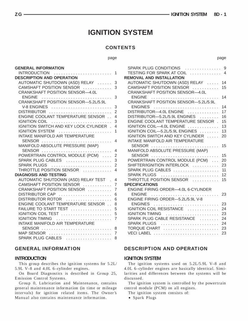
POWERTRAIN CONTROL MODULE (PCM)The Powertrain Control Module (PCM) is located
in the engine compartment (Fig. 1).
The ignition system is controlled by the PCM.
NOTE: Base ignition timing by rotation of distribu-tor is not adjustable.
The PCM opens and closes the ignition coil groundcircuit to operate the ignition coil. This is done toadjust ignition timing, both initial (base) andadvance, and for changing engine operating condi-tions.
The amount of electronic spark advance providedby the PCM is determined by five input factors:engine coolant temperature, engine rpm, intake man-ifold temperature, manifold absolute pressure andthrottle position.
DISTRIBUTORAll 4.0L/5.2L/5.9L engines are equipped with a
camshaft driven mechanical distributor containing ashaft driven distributor rotor. All distributors areequipped with an internal camshaft position (fuel
Fig. 1 Powertrain Control Module (PCM) Location
DESCRIPTION AND OPERATION (Continued
sync) sensor (Fig. 2). This sensor provides fuel injec-tion synchronization and cylinder identification.
The distributor does not have built in centrifugalor vacuum assisted advance. Base ignition timingand all timing advance is controlled by the power-train control module (PCM). Because ignition timingis controlled by the PCM, base ignition timing isnot adjustable on any of these engines.
On the 4.0L 6–cylinder engine, the distributor islocked in place by a fork with a slot located on thedistributor housing base. The distributor holddownclamp bolt passes through this slot when installed.Because the distributor position is locked wheninstalled, its rotational position can not be changed.Do not attempt to modify the distributor hous-ing to get distributor rotation. Distributor posi-tion will have no effect on ignition timing. Theposition of the distributor will determine fuelsynchronization only.
All 4.0L/5.2L/5.9L distributors contain an internaloil seal that prevents oil from entering the distribu-tor housing. The seal is not serviceable.
SPARK PLUGSAll engines use resistor type spark plugs. Remove
the spark plugs and examine them for burned elec-trodes and fouled, cracked or broken porcelain insu-lators. Keep plugs arranged in the order in whichthey were removed from the engine. A single plugdisplaying an abnormal condition indicates that aproblem exists in the corresponding cylinder. Replacespark plugs at the intervals recommended in GroupO, Lubrication and Maintenance
Spark plugs that have low milage may be cleanedand reused if not otherwise defective, carbon or oilfouled. Refer to the Spark Plug Condition section ofthis group.
Fig. 2 Distributor and CamshaftPosition Sensor-Typical (5.2L/5.9L Shown)
CRANKSHAFT POSITIONSENSORNOTCHES FLYWHEEL
ZG IGNITION SYSTEM 8D - 3
SPARK PLUG CABLESSpark plug cables are sometimes referred to as sec-
ondary ignition wires. These cables transfer electricalcurrent from the ignition coil(s) and/or distributor, toindividual spark plugs at each cylinder. The resistivespark plug cables are of nonmetallic construction.The cables provide suppression of radio frequencyemissions from the ignition system.
IGNITION COILBattery voltage is supplied to the ignition coil pos-
itive terminal from the ASD relay.The Powertrain Control Module (PCM) opens and
closes the ignition coil ground circuit for ignition coiloperation.
Base ignition timing is not adjustable on anyengine. By controlling the coil ground circuit, thePCM is able to set the base timing and adjust theignition timing advance. This is done to meet chang-ing engine operating conditions.
The ignition coil is not oil filled. The windings areembedded in an epoxy compound. This provides heatand vibration resistance that allows the ignition coilto be mounted on the engine.
AUTOMATIC SHUTDOWN (ASD) RELAYAs one of its functions, the ASD relay will supply
battery voltage to the ignition coil. The ground cir-cuit for the ASD relay is controlled by the PowertrainControl Module (PCM). The PCM regulates ASDrelay operation by switching the ground circuiton-and-off.
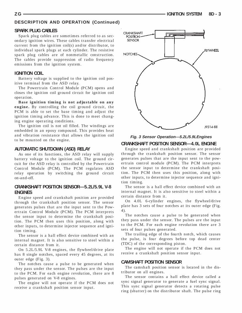
CRANKSHAFT POSITION SENSOR—5.2L/5.9L V-8ENGINES
Engine speed and crankshaft position are providedthrough the crankshaft position sensor. The sensorgenerates pulses that are the input sent to the Pow-ertrain Control Module (PCM). The PCM interpretsthe sensor input to determine the crankshaft posi-tion. The PCM then uses this position, along withother inputs, to determine injector sequence and igni-tion timing.
The sensor is a hall effect device combined with aninternal magnet. It is also sensitive to steel within acertain distance from it.
On 5.2L/5.9L V-8 engines, the flywheel/drive platehas 8 single notches, spaced every 45 degrees, at itsouter edge (Fig. 3).
The notches cause a pulse to be generated whenthey pass under the sensor. The pulses are the inputto the PCM. For each engine revolution, there are 8pulses generated on V-8 engines.
The engine will not operate if the PCM does notreceive a crankshaft position sensor input.
DESCRIPTION AND OPERATION (Continued
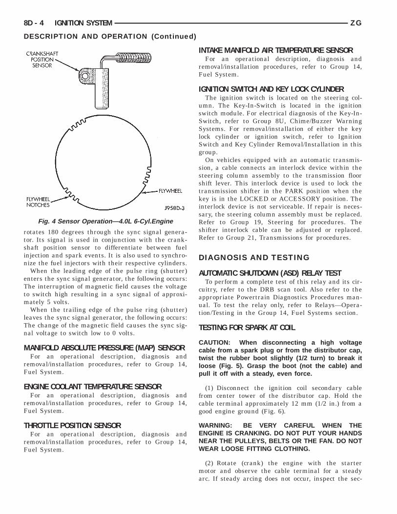
CRANKSHAFT POSITION SENSOR—4.0L ENGINEEngine speed and crankshaft position are provided
through the crankshaft position sensor. The sensorgenerates pulses that are the input sent to the pow-ertrain control module (PCM). The PCM interpretsthe sensor input to determine the crankshaft posi-tion. The PCM then uses this position, along withother inputs, to determine injector sequence and igni-tion timing.
The sensor is a hall effect device combined with aninternal magnet. It is also sensitive to steel within acertain distance from it.
On 4.0L 6-cylinder engines, the flywheel/driveplate has 3 sets of four notches at its outer edge (Fig.4).
The notches cause a pulse to be generated whenthey pass under the sensor. The pulses are the inputto the PCM. For each engine revolution there are 3sets of four pulses generated.
The trailing edge of the fourth notch, which causesthe pulse, is four degrees before top dead center(TDC) of the corresponding piston.
The engine will not operate if the PCM does notreceive a crankshaft position sensor input.
CAMSHAFT POSITION SENSORThe camshaft position sensor is located in the dis-
tributor on all engines.The sensor contains a hall effect device called a
sync signal generator to generate a fuel sync signal.This sync signal generator detects a rotating pulsering (shutter) on the distributor shaft. The pulse ring
Fig. 3 Sensor Operation—5.2L/5.9LEngines
)
CRANKSHAFT POSITIONSENSOR FLYWHEELFLYWHEEL NOTCHES
8D - 4 IGNITION SYSTEM ZG
)
rotates 180 degrees through the sync signal genera-tor. Its signal is used in conjunction with the crank-shaft position sensor to differentiate between fuelinjection and spark events. It is also used to synchro-nize the fuel injectors with their respective cylinders.
When the leading edge of the pulse ring (shutter)enters the sync signal generator, the following occurs:The interruption of magnetic field causes the voltageto switch high resulting in a sync signal of approxi-mately 5 volts.
When the trailing edge of the pulse ring (shutter)leaves the sync signal generator, the following occurs:The change of the magnetic field causes the sync sig-nal voltage to switch low to 0 volts.
MANIFOLD ABSOLUTE PRESSURE (MAP) SENSORFor an operational description, diagnosis and
removal/installation procedures, refer to Group 14,Fuel System.
ENGINE COOLANT TEMPERATURE SENSORFor an operational description, diagnosis and
removal/installation procedures, refer to Group 14,Fuel System.
THROTTLE POSITION SENSORFor an operational description, diagnosis and
removal/installation procedures, refer to Group 14,Fuel System.
Fig. 4 Sensor Operation—4.0L 6-Cyl.Engine
DESCRIPTION AND OPERATION (Continued
INTAKE MANIFOLD AIR TEMPERATURE SENSORFor an operational description, diagnosis and
removal/installation procedures, refer to Group 14,Fuel System.
IGNITION SWITCH AND KEY LOCK CYLINDERThe ignition switch is located on the steering col-
umn. The Key-In-Switch is located in the ignitionswitch module. For electrical diagnosis of the Key-In-Switch, refer to Group 8U, Chime/Buzzer WarningSystems. For removal/installation of either the keylock cylinder or ignition switch, refer to IgnitionSwitch and Key Cylinder Removal/Installation in thisgroup.
On vehicles equipped with an automatic transmis-sion, a cable connects an interlock device within thesteering column assembly to the transmission floorshift lever. This interlock device is used to lock thetransmission shifter in the PARK position when thekey is in the LOCKED or ACCESSORY position. Theinterlock device is not serviceable. If repair is neces-sary, the steering column assembly must be replaced.Refer to Group 19, Steering for procedures. Theshifter interlock cable can be adjusted or replaced.Refer to Group 21, Transmissions for procedures.
DIAGNOSIS AND TESTING
AUTOMATIC SHUTDOWN (ASD) RELAY TESTTo perform a complete test of this relay and its cir-
cuitry, refer to the DRB scan tool. Also refer to theappropriate Powertrain Diagnostics Procedures man-ual. To test the relay only, refer to Relays—Opera-tion/Testing in the Group 14, Fuel Systems section.
TESTING FOR SPARK AT COIL
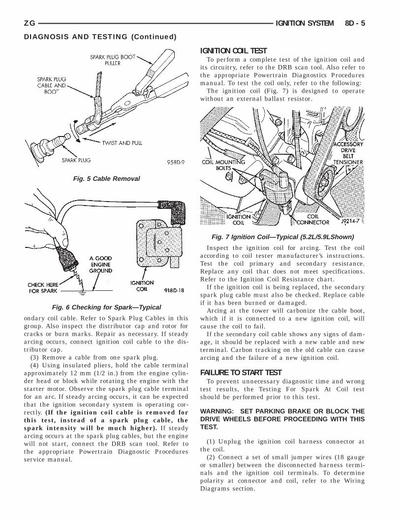
CAUTION: When disconnecting a high voltagecable from a spark plug or from the distributor cap,twist the rubber boot slightly (1/2 turn) to break itloose (Fig. 5). Grasp the boot (not the cable) andpull it off with a steady, even force.
(1) Disconnect the ignition coil secondary cablefrom center tower of the distributor cap. Hold thecable terminal approximately 12 mm (1/2 in.) from agood engine ground (Fig. 6).
WARNING: BE VERY CAREFUL WHEN THEENGINE IS CRANKING. DO NOT PUT YOUR HANDSNEAR THE PULLEYS, BELTS OR THE FAN. DO NOTWEAR LOOSE FITTING CLOTHING.
(2) Rotate (crank) the engine with the startermotor and observe the cable terminal for a steadyarc. If steady arcing does not occur, inspect the sec-
SPARK PLUGCABLE ANDBOOT SPARK PLUG BOOTPULLERTWIST AND PULLSPARK PLUGA GOODENGINEGROUNDCHECK HEREFOR SPARK IGNITION COIL COIL MOUNT-ING BOLTS ACCESSORYDRIVE BELTTENSIONERCOIL CONNEC-TORIGNITION COIL
ZG IGNITION SYSTEM 8D - 5
ondary coil cable. Refer to Spark Plug Cables in thisgroup. Also inspect the distributor cap and rotor forcracks or burn marks. Repair as necessary. If steadyarcing occurs, connect ignition coil cable to the dis-tributor cap.
(3) Remove a cable from one spark plug.(4) Using insulated pliers, hold the cable terminal
approximately 12 mm (1/2 in.) from the engine cylin-der head or block while rotating the engine with thestarter motor. Observe the spark plug cable terminalfor an arc. If steady arcing occurs, it can be expectedthat the ignition secondary system is operating cor-rectly. (If the ignition coil cable is removed forthis test, instead of a spark plug cable, thespark intensity will be much higher). If steadyarcing occurs at the spark plug cables, but the enginewill not start, connect the DRB scan tool. Refer tothe appropriate Powertrain Diagnostic Proceduresservice manual.
Fig. 5 Cable Removal
Fig. 6 Checking for Spark—Typical
DIAGNOSIS AND TESTING (Continued)
IGNITION COIL TESTTo perform a complete test of the ignition coil and
its circuitry, refer to the DRB scan tool. Also refer tothe appropriate Powertrain Diagnostics Proceduresmanual. To test the coil only, refer to the following:
The ignition coil (Fig. 7) is designed to operatewithout an external ballast resistor.
Inspect the ignition coil for arcing. Test the coilaccording to coil tester manufacturer’s instructions.Test the coil primary and secondary resistance.Replace any coil that does not meet specifications.Refer to the Ignition Coil Resistance chart.
If the ignition coil is being replaced, the secondaryspark plug cable must also be checked. Replace cableif it has been burned or damaged.
Arcing at the tower will carbonize the cable boot,which if it is connected to a new ignition coil, willcause the coil to fail.
If the secondary coil cable shows any signs of dam-age, it should be replaced with a new cable and newterminal. Carbon tracking on the old cable can causearcing and the failure of a new ignition coil.
FAILURE TO START TESTTo prevent unnecessary diagnostic time and wrong
test results, the Testing For Spark At Coil testshould be performed prior to this test.
WARNING: SET PARKING BRAKE OR BLOCK THEDRIVE WHEELS BEFORE PROCEEDING WITH THISTEST.
(1) Unplug the ignition coil harness connector atthe coil.
(2) Connect a set of small jumper wires (18 gaugeor smaller) between the disconnected harness termi-nals and the ignition coil terminals. To determinepolarity at connector and coil, refer to the WiringDiagrams section.
Fig. 7 Ignition Coil—Typical (5.2L/5.9LShown)
PCM(3) 32–WAY CONNECTORS CAPACITOR CONNECT THISCLIP TO COIL NEG-ATIVE ALLIGATORCLIPMOMENTARILYGROUND THISCLIP TO COILNEGATIVE.33 MFALLIGATOR CLIPGROUND THISCLIP
COIL (MANUFACTURER)PRIMARY RESISTANCE
21-27°C (70-80°F)SECONDARY RESISTANCE
21-27°C (70-80°F)
Diamond 0.97 - 1.18 Ohms 11,300 - 15,300 Ohms
Toyodenso 0.95 - 1.20 Ohms 11,300 - 13,300 Ohms
IGNITION COIL RESISTANCE
8D - 6 IGNITION SYSTEM ZG
DIAGNOSIS AND TESTING (Continued)
(3) Attach one lead of a voltmeter to the positive(12 volt) jumper wire. Attach the negative side ofvoltmeter to a good ground. Determine that sufficientbattery voltage (12.4 volts) is present for the startingand ignition systems.
(4) Determine that sufficient battery voltage (12.4volts) is present for the starting and ignition sys-tems.
(5) Crank the engine for 5 seconds while monitor-ing the voltage at the coil positive terminal:
• If the voltage remains near zero during theentire period of cranking, refer to On-Board Diagnos-tics in Group 14, Fuel Systems. Check the Power-train Control Module (PCM) and auto shutdownrelay.
• If voltage is at or near battery voltage and dropsto zero after 1-2 seconds of cranking, check the pow-ertrain control module circuit. Refer to On-BoardDiagnostics in Group 14, Fuel Systems.
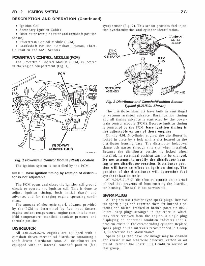
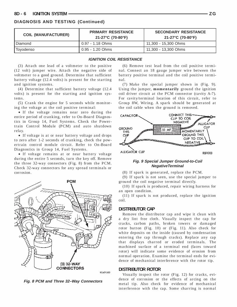
• If voltage remains at or near battery voltageduring the entire 5 seconds, turn the key off. Removethe three 32-way connectors (Fig. 8) from the PCM.Check 32-way connectors for any spread terminals orcorrosion.
Fig. 8 PCM and Three 32–Way Connectors
(6) Remove test lead from the coil positive termi-nal. Connect an 18 gauge jumper wire between thebattery positive terminal and the coil positive termi-nal.
(7) Make the special jumper shown in (Fig. 9).Using the jumper, momentarily ground the ignitioncoil driver circuit at the PCM connector (cavity A-7).For cavity/terminal location of this circuit, refer toGroup 8W, Wiring. A spark should be generated atthe coil cable when the ground is removed.
(8) If spark is generated, replace the PCM.(9) If spark is not seen, use the special jumper to
ground the coil negative terminal directly.(10) If spark is produced, repair wiring harness for
an open condition.(11) If spark is not produced, replace the ignition
coil.
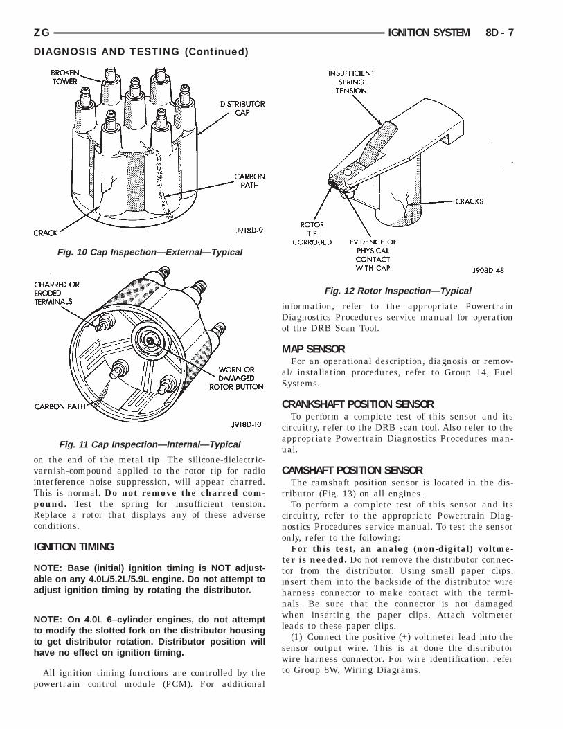
DISTRIBUTOR CAPRemove the distributor cap and wipe it clean with
a dry lint free cloth. Visually inspect the cap forcracks, carbon paths, broken towers or damagedrotor button (Fig. 10) or (Fig. 11). Also check forwhite deposits on the inside (caused by condensationentering the cap through cracks). Replace any capthat displays charred or eroded terminals. Themachined surface of a terminal end (faces towardrotor) will indicate some evidence of erosion fromnormal operation. Examine the terminal ends for evi-dence of mechanical interference with the rotor tip.
DISTRIBUTOR ROTORVisually inspect the rotor (Fig. 12) for cracks, evi-
dence of corrosion or the effects of arcing on themetal tip. Also check for evidence of mechanicalinterference with the cap. Some charring is normal
Fig. 9 Special Jumper Ground-to-CoilNegativeTerminal
BROKENTOWER DISTRIBUTORCAPCARBONPATHCRACKCHARRED ORERODED TER-MINALS WORN OR DAM-AGED ROTOR BUT-TONCARBON PATH INSUFFICIENTSPRING TEN-SION CRACKSEVIDENCE OFPHYSICAL CONTACTWITH CAPROTOR TIPCORRODED
ZG IGNITION SYSTEM 8D - 7
on the end of the metal tip. The silicone-dielectric-varnish-compound applied to the rotor tip for radiointerference noise suppression, will appear charred.This is normal. Do not remove the charred com-pound. Test the spring for insufficient tension.Replace a rotor that displays any of these adverseconditions.
IGNITION TIMING
NOTE: Base (initial) ignition timing is NOT adjust-able on any 4.0L/5.2L/5.9L engine. Do not attempt toadjust ignition timing by rotating the distributor.
NOTE: On 4.0L 6–cylinder engines, do not attemptto modify the slotted fork on the distributor housingto get distributor rotation. Distributor position willhave no effect on ignition timing.
All ignition timing functions are controlled by thepowertrain control module (PCM). For additional
Fig. 10 Cap Inspection—External—Typical
Fig. 11 Cap Inspection—Internal—Typical
DIAGNOSIS AND TESTING (Continued)
information, refer to the appropriate PowertrainDiagnostics Procedures service manual for operationof the DRB Scan Tool.
MAP SENSORFor an operational description, diagnosis or remov-
al/ installation procedures, refer to Group 14, FuelSystems.
CRANKSHAFT POSITION SENSORTo perform a complete test of this sensor and its
circuitry, refer to the DRB scan tool. Also refer to theappropriate Powertrain Diagnostics Procedures man-ual.
CAMSHAFT POSITION SENSORThe camshaft position sensor is located in the dis-
tributor (Fig. 13) on all engines.To perform a complete test of this sensor and its
circuitry, refer to the appropriate Powertrain Diag-nostics Procedures service manual. To test the sensoronly, refer to the following:
For this test, an analog (non-digital) voltme-ter is needed. Do not remove the distributor connec-tor from the distributor. Using small paper clips,insert them into the backside of the distributor wireharness connector to make contact with the termi-nals. Be sure that the connector is not damagedwhen inserting the paper clips. Attach voltmeterleads to these paper clips.
(1) Connect the positive (+) voltmeter lead into thesensor output wire. This is at done the distributorwire harness connector. For wire identification, referto Group 8W, Wiring Diagrams.
Fig. 12 Rotor Inspection—Typical
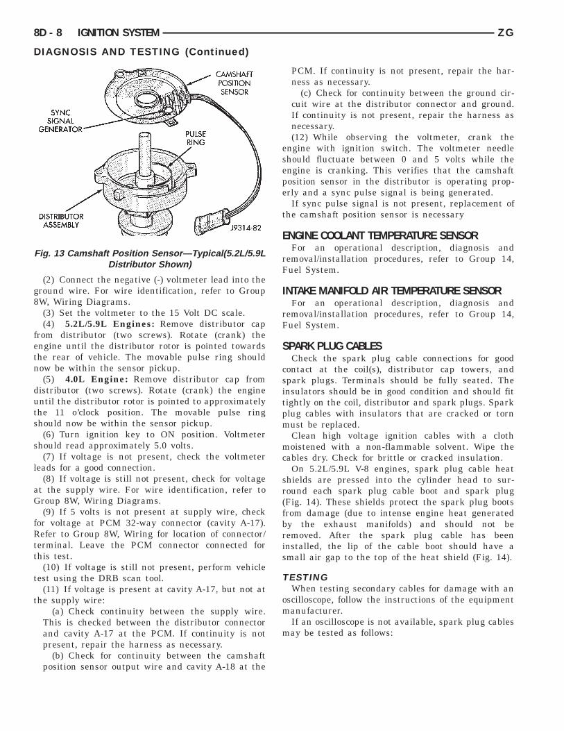
SYNC SIGNALGENERATOR CAMSHAFTPOSITION SEN-SORPULSE RINGDISTRIBUTORASSEMBLY
8D - 8 IGNITION SYSTEM ZG
(2) Connect the negative (-) voltmeter lead into theground wire. For wire identification, refer to Group8W, Wiring Diagrams.
(3) Set the voltmeter to the 15 Volt DC scale.(4) 5.2L/5.9L Engines: Remove distributor cap
from distributor (two screws). Rotate (crank) theengine until the distributor rotor is pointed towardsthe rear of vehicle. The movable pulse ring shouldnow be within the sensor pickup.
(5) 4.0L Engine: Remove distributor cap fromdistributor (two screws). Rotate (crank) the engineuntil the distributor rotor is pointed to approximatelythe 11 o’clock position. The movable pulse ringshould now be within the sensor pickup.
(6) Turn ignition key to ON position. Voltmetershould read approximately 5.0 volts.
(7) If voltage is not present, check the voltmeterleads for a good connection.
(8) If voltage is still not present, check for voltageat the supply wire. For wire identification, refer toGroup 8W, Wiring Diagrams.
(9) If 5 volts is not present at supply wire, checkfor voltage at PCM 32-way connector (cavity A-17).Refer to Group 8W, Wiring for location of connector/terminal. Leave the PCM connector connected forthis test.
(10) If voltage is still not present, perform vehicletest using the DRB scan tool.
(11) If voltage is present at cavity A-17, but not atthe supply wire:
(a) Check continuity between the supply wire.This is checked between the distributor connectorand cavity A-17 at the PCM. If continuity is notpresent, repair the harness as necessary.
(b) Check for continuity between the camshaftposition sensor output wire and cavity A-18 at the
Fig. 13 Camshaft Position Sensor—Typical(5.2L/5.9LDistributor Shown)
DIAGNOSIS AND TESTING (Continued)
PCM. If continuity is not present, repair the har-ness as necessary.
(c) Check for continuity between the ground cir-cuit wire at the distributor connector and ground.If continuity is not present, repair the harness asnecessary.(12) While observing the voltmeter, crank the
engine with ignition switch. The voltmeter needleshould fluctuate between 0 and 5 volts while theengine is cranking. This verifies that the camshaftposition sensor in the distributor is operating prop-erly and a sync pulse signal is being generated.
If sync pulse signal is not present, replacement ofthe camshaft position sensor is necessary
ENGINE COOLANT TEMPERATURE SENSORFor an operational description, diagnosis and
removal/installation procedures, refer to Group 14,Fuel System.
INTAKE MANIFOLD AIR TEMPERATURE SENSORFor an operational description, diagnosis and
removal/installation procedures, refer to Group 14,Fuel System.
SPARK PLUG CABLESCheck the spark plug cable connections for good
contact at the coil(s), distributor cap towers, andspark plugs. Terminals should be fully seated. Theinsulators should be in good condition and should fittightly on the coil, distributor and spark plugs. Sparkplug cables with insulators that are cracked or tornmust be replaced.
Clean high voltage ignition cables with a clothmoistened with a non-flammable solvent. Wipe thecables dry. Check for brittle or cracked insulation.
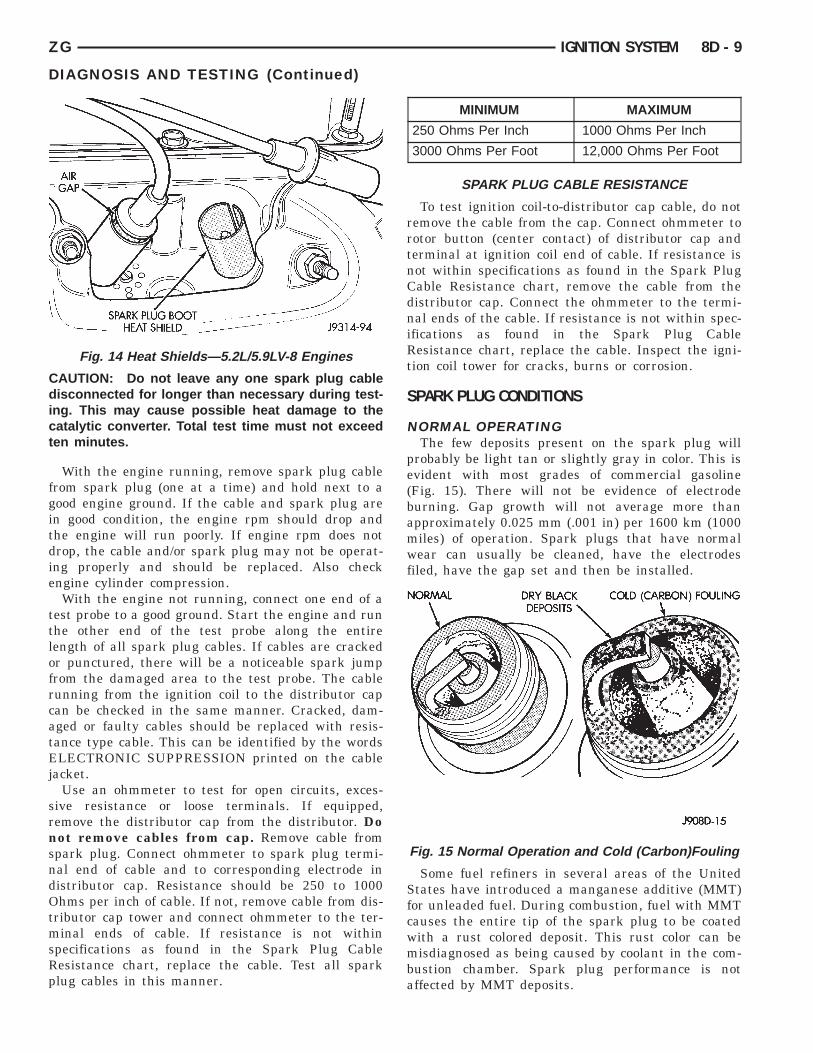
On 5.2L/5.9L V-8 engines, spark plug cable heatshields are pressed into the cylinder head to sur-round each spark plug cable boot and spark plug(Fig. 14). These shields protect the spark plug bootsfrom damage (due to intense engine heat generatedby the exhaust manifolds) and should not beremoved. After the spark plug cable has beeninstalled, the lip of the cable boot should have asmall air gap to the top of the heat shield (Fig. 14).
TESTINGWhen testing secondary cables for damage with an
oscilloscope, follow the instructions of the equipmentmanufacturer.
If an oscilloscope is not available, spark plug cablesmay be tested as follows:
AIR GAP SPARK PLUG BOOTHEAT SHIELD NORMAL DRY BLACKDEPOSITS COLD (CARBON) FOULING
ZG IGNITION SYSTEM 8D - 9
CAUTION: Do not leave any one spark plug cabledisconnected for longer than necessary during test-ing. This may cause possible heat damage to thecatalytic converter. Total test time must not exceedten minutes.
With the engine running, remove spark plug cablefrom spark plug (one at a time) and hold next to agood engine ground. If the cable and spark plug arein good condition, the engine rpm should drop andthe engine will run poorly. If engine rpm does notdrop, the cable and/or spark plug may not be operat-ing properly and should be replaced. Also checkengine cylinder compression.
With the engine not running, connect one end of atest probe to a good ground. Start the engine and runthe other end of the test probe along the entirelength of all spark plug cables. If cables are crackedor punctured, there will be a noticeable spark jumpfrom the damaged area to the test probe. The cablerunning from the ignition coil to the distributor capcan be checked in the same manner. Cracked, dam-aged or faulty cables should be replaced with resis-tance type cable. This can be identified by the wordsELECTRONIC SUPPRESSION printed on the cablejacket.
Use an ohmmeter to test for open circuits, exces-sive resistance or loose terminals. If equipped,remove the distributor cap from the distributor. Donot remove cables from cap. Remove cable fromspark plug. Connect ohmmeter to spark plug termi-nal end of cable and to corresponding electrode indistributor cap. Resistance should be 250 to 1000Ohms per inch of cable. If not, remove cable from dis-tributor cap tower and connect ohmmeter to the ter-minal ends of cable. If resistance is not withinspecifications as found in the Spark Plug CableResistance chart, replace the cable. Test all sparkplug cables in this manner.
Fig. 14 Heat Shields—5.2L/5.9LV-8 Engines
DIAGNOSIS AND TESTING (Continued)
To test ignition coil-to-distributor cap cable, do notremove the cable from the cap. Connect ohmmeter torotor button (center contact) of distributor cap andterminal at ignition coil end of cable. If resistance isnot within specifications as found in the Spark PlugCable Resistance chart, remove the cable from thedistributor cap. Connect the ohmmeter to the termi-nal ends of the cable. If resistance is not within spec-ifications as found in the Spark Plug CableResistance chart, replace the cable. Inspect the igni-tion coil tower for cracks, burns or corrosion.
SPARK PLUG CONDITIONS
NORMAL OPERATINGThe few deposits present on the spark plug will
probably be light tan or slightly gray in color. This isevident with most grades of commercial gasoline(Fig. 15). There will not be evidence of electrodeburning. Gap growth will not average more thanapproximately 0.025 mm (.001 in) per 1600 km (1000miles) of operation. Spark plugs that have normalwear can usually be cleaned, have the electrodesfiled, have the gap set and then be installed.
Some fuel refiners in several areas of the UnitedStates have introduced a manganese additive (MMT)for unleaded fuel. During combustion, fuel with MMTcauses the entire tip of the spark plug to be coatedwith a rust colored deposit. This rust color can bemisdiagnosed as being caused by coolant in the com-bustion chamber. Spark plug performance is notaffected by MMT deposits.
MINIMUM MAXIMUM
250 Ohms Per Inch 1000 Ohms Per Inch
3000 Ohms Per Foot 12,000 Ohms Per Foot
SPARK PLUG CABLE RESISTANCE
Fig. 15 Normal Operation and Cold (Carbon)Fouling
GROUNDELECTRODE DEPOSITSCENTERELECTRODEGROUND ELECTRODE COV-ERED WITH WHITE OR YEL-LOW DEPOSITSCENTERELEC-TRODE
8D - 10 IGNITION SYSTEM ZG
COLD FOULING/CARBON FOULINGCold fouling is sometimes referred to as carbon
fouling. The deposits that cause cold fouling are basi-cally carbon (Fig. 15). A dry, black deposit on one ortwo plugs in a set may be caused by sticking valvesor defective spark plug cables. Cold (carbon) foulingof the entire set of spark plugs may be caused by aclogged air cleaner element or repeated short operat-ing times (short trips).
WET FOULING OR GAS FOULINGA spark plug coated with excessive wet fuel or oil
is wet fouled. In older engines, worn piston rings,leaking valve guide seals or excessive cylinder wearcan cause wet fouling. In new or recently overhauledengines, wet fouling may occur before break-in (nor-mal oil control) is achieved. This condition can usu-ally be resolved by cleaning and reinstalling thefouled plugs.
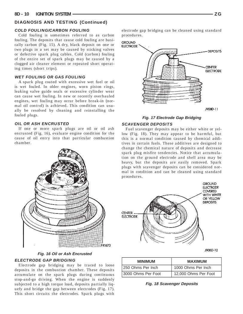
OIL OR ASH ENCRUSTEDIf one or more spark plugs are oil or oil ash
encrusted (Fig. 16), evaluate engine condition for thecause of oil entry into that particular combustionchamber.
ELECTRODE GAP BRIDGINGElectrode gap bridging may be traced to loose
deposits in the combustion chamber. These depositsaccumulate on the spark plugs during continuousstop-and-go driving. When the engine is suddenlysubjected to a high torque load, deposits partially liq-uefy and bridge the gap between electrodes (Fig. 17).This short circuits the electrodes. Spark plugs with
Fig. 16 Oil or Ash Encrusted
DIAGNOSIS AND TESTING (Continued)
electrode gap bridging can be cleaned using standardprocedures.
SCAVENGER DEPOSITSFuel scavenger deposits may be either white or yel-
low (Fig. 18). They may appear to be harmful, butthis is a normal condition caused by chemical addi-tives in certain fuels. These additives are designed tochange the chemical nature of deposits and decreasespark plug misfire tendencies. Notice that accumula-tion on the ground electrode and shell area may beheavy, but the deposits are easily removed. Sparkplugs with scavenger deposits can be considered nor-mal in condition and can be cleaned using standardprocedures.
Fig. 17 Electrode Gap Bridging
MINIMUM MAXIMUM
250 Ohms Per Inch 1000 Ohms Per Inch
3000 Ohms Per Foot 12,000 Ohms Per Foot
Fig. 18 Scavenger Deposits
GROUNDELECTRODE CENTERELECTRODECHIPPEDINSULATOR GROUNDELECTRODESTARTING TODISSOLVE CENTERELECTRODEDISSOLVEDBLISTERED WHITE ORGRAY COLORED INSULATOR
ZG IGNITION SYSTEM 8D - 11
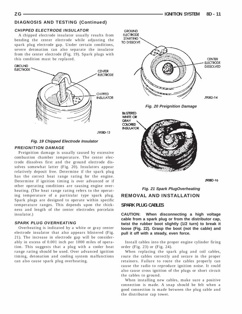
CHIPPED ELECTRODE INSULATORA chipped electrode insulator usually results from
bending the center electrode while adjusting thespark plug electrode gap. Under certain conditions,severe detonation can also separate the insulatorfrom the center electrode (Fig. 19). Spark plugs withthis condition must be replaced.
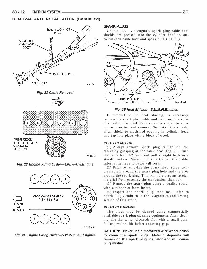
PREIGNITION DAMAGEPreignition damage is usually caused by excessive
combustion chamber temperature. The center elec-trode dissolves first and the ground electrode dis-solves somewhat latter (Fig. 20). Insulators appearrelatively deposit free. Determine if the spark plughas the correct heat range rating for the engine.Determine if ignition timing is over advanced or ifother operating conditions are causing engine over-heating. (The heat range rating refers to the operat-ing temperature of a particular type spark plug.Spark plugs are designed to operate within specifictemperature ranges. This depends upon the thick-ness and length of the center electrodes porcelaininsulator.)
SPARK PLUG OVERHEATINGOverheating is indicated by a white or gray center
electrode insulator that also appears blistered (Fig.21). The increase in electrode gap will be consider-ably in excess of 0.001 inch per 1000 miles of opera-tion. This suggests that a plug with a cooler heatrange rating should be used. Over advanced ignitiontiming, detonation and cooling system malfunctionscan also cause spark plug overheating.
Fig. 19 Chipped Electrode Insulator
DIAGNOSIS AND TESTING (Continued)
REMOVAL AND INSTALLATION
SPARK PLUG CABLES
CAUTION: When disconnecting a high voltagecable from a spark plug or from the distributor cap,twist the rubber boot slightly (1/2 turn) to break itloose (Fig. 22). Grasp the boot (not the cable) andpull it off with a steady, even force.
Install cables into the proper engine cylinder firingorder (Fig. 23) or (Fig. 24).
When replacing the spark plug and coil cables,route the cables correctly and secure in the properretainers. Failure to route the cables properly cancause the radio to reproduce ignition noise. It couldalso cause cross ignition of the plugs or short circuitthe cables to ground.
When installing new cables, make sure a positiveconnection is made. A snap should be felt when agood connection is made between the plug cable andthe distributor cap tower.
Fig. 20 Preignition Damage
Fig. 21 Spark PlugOverheating
SPARK PLUGCABLE ANDBOOT SPARK PLUG BOOTPULLERTWIST AND PULLSPARK PLUGFIRING ORDER:1 5 3 6 2 4CLOCKWISE ROTATION FRONTFRONTOFENGINE CLOCKWISE ROTATION1-8-4-3-6-5-7-2 AIR GAP SPARK PLUG BOOTHEAT SHIELD
8D - 12 IGNITION SYSTEM ZG
Fig. 22 Cable Removal
Fig. 23 Engine Firing Order—4.0L 6–Cyl.Engine
Fig. 24 Engine Firing Order—5.2L/5.9LV-8 Engines
REMOVAL AND INSTALLATION (Continued)
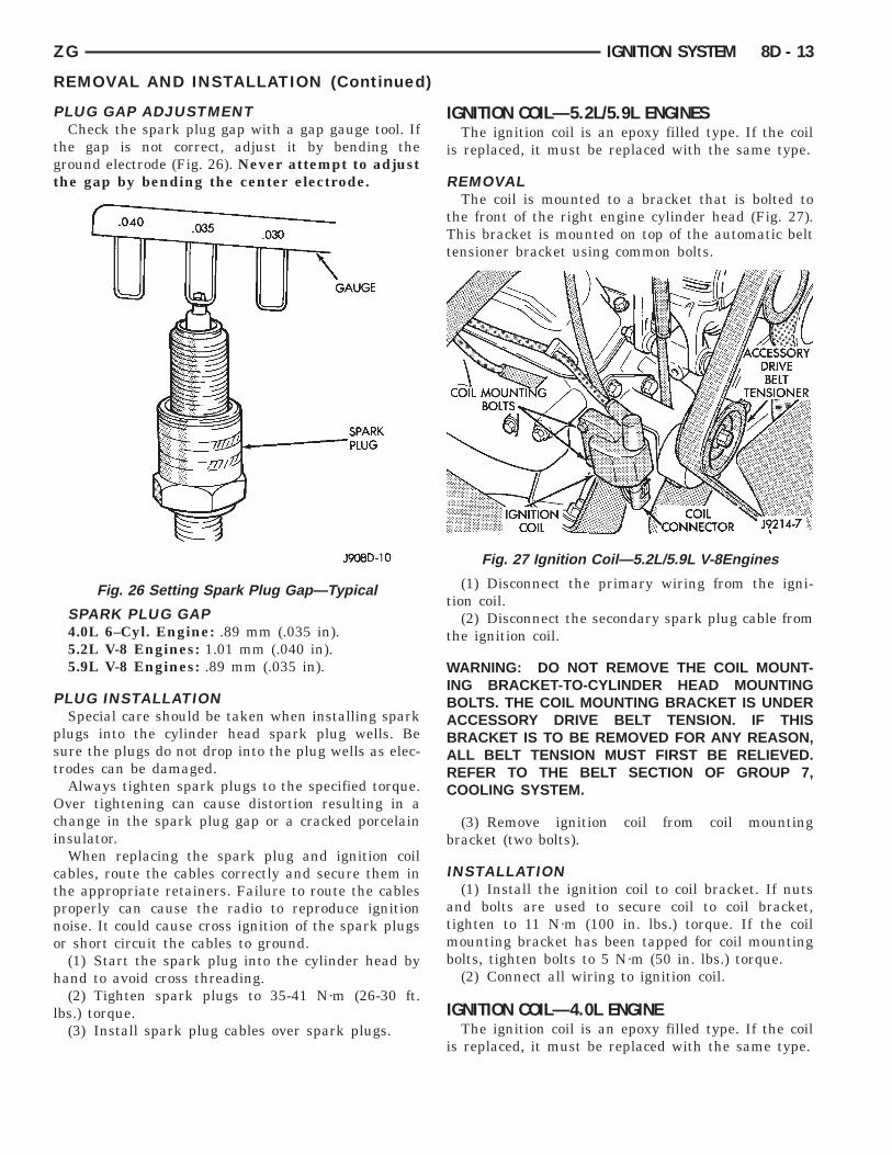
SPARK PLUGSOn 5.2L/5.9L V-8 engines, spark plug cable heat
shields are pressed into the cylinder head to sur-round each cable boot and spark plug (Fig. 25).
If removal of the heat shield(s) is necessary,remove the spark plug cable and compress the sidesof shield for removal. Each shield is slotted to allowfor compression and removal. To install the shields,align shield to machined opening in cylinder headand tap into place with a block of wood.
PLUG REMOVAL(1) Always remove spark plug or ignition coil
cables by grasping at the cable boot (Fig. 22). Turnthe cable boot 1/2 turn and pull straight back in asteady motion. Never pull directly on the cable.Internal damage to cable will result.
(2) Prior to removing the spark plug, spray com-pressed air around the spark plug hole and the areaaround the spark plug. This will help prevent foreignmaterial from entering the combustion chamber.
(3) Remove the spark plug using a quality socketwith a rubber or foam insert.
(4) Inspect the spark plug condition. Refer toSpark Plug Condition in the Diagnostics and Testingsection of this group.
PLUG CLEANINGThe plugs may be cleaned using commercially
available spark plug cleaning equipment. After clean-ing, file the center electrode flat with a small pointfile or jewelers file before adjusting gap.
CAUTION: Never use a motorized wire wheel brushto clean the spark plugs. Metallic deposits willremain on the spark plug insulator and will causeplug misfire.
Fig. 25 Heat Shields—5.2L/5.9LEngines
GAUGESPARKPLUG COIL MOUNT-ING BOLTS ACCESSORYDRIVE BELTTENSIONERCOIL CONNEC-TORIGNITION COIL
ZG IGNITION SYSTEM 8D - 13
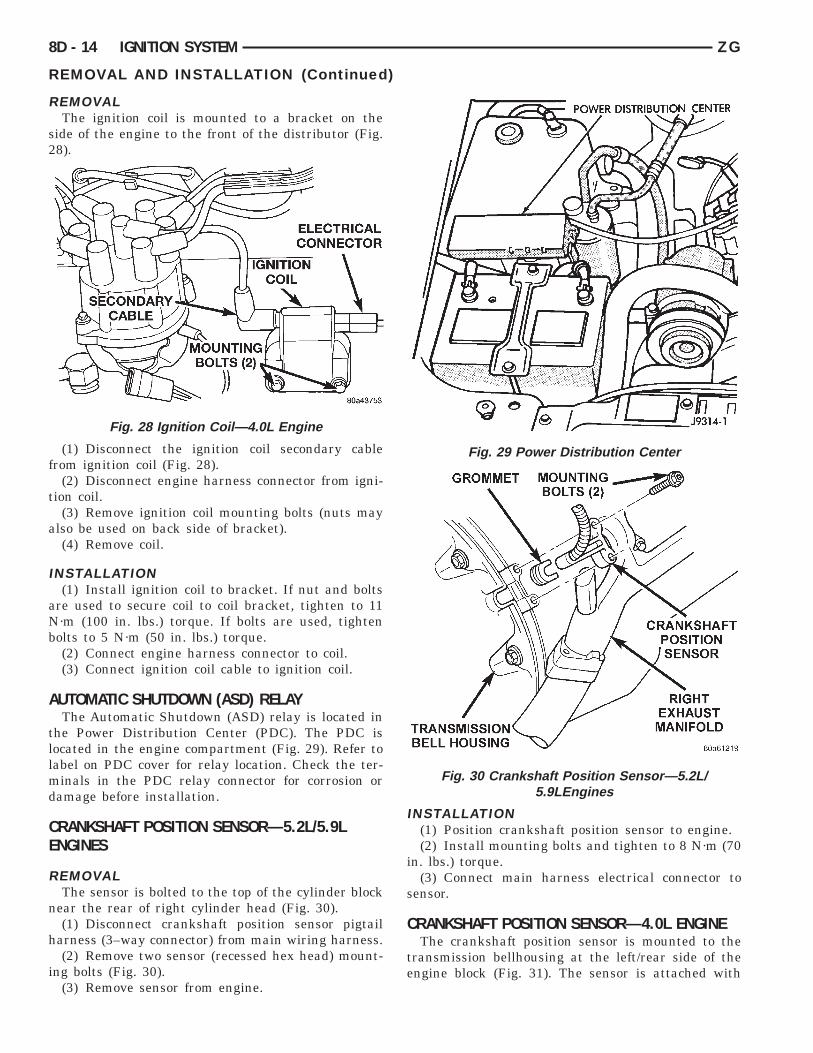
PLUG GAP ADJUSTMENTCheck the spark plug gap with a gap gauge tool. If
the gap is not correct, adjust it by bending theground electrode (Fig. 26). Never attempt to adjustthe gap by bending the center electrode.
SPARK PLUG GAP4.0L 6–Cyl. Engine: .89 mm (.035 in).5.2L V-8 Engines: 1.01 mm (.040 in).5.9L V-8 Engines: .89 mm (.035 in).
PLUG INSTALLATIONSpecial care should be taken when installing spark
plugs into the cylinder head spark plug wells. Besure the plugs do not drop into the plug wells as elec-trodes can be damaged.
Always tighten spark plugs to the specified torque.Over tightening can cause distortion resulting in achange in the spark plug gap or a cracked porcelaininsulator.
When replacing the spark plug and ignition coilcables, route the cables correctly and secure them inthe appropriate retainers. Failure to route the cablesproperly can cause the radio to reproduce ignitionnoise. It could cause cross ignition of the spark plugsor short circuit the cables to ground.
(1) Start the spark plug into the cylinder head byhand to avoid cross threading.
(2) Tighten spark plugs to 35-41 N·m (26-30 ft.lbs.) torque.
(3) Install spark plug cables over spark plugs.
Fig. 26 Setting Spark Plug Gap—Typical
REMOVAL AND INSTALLATION (Continued)
IGNITION COIL—5.2L/5.9L ENGINESThe ignition coil is an epoxy filled type. If the coil
is replaced, it must be replaced with the same type.
REMOVALThe coil is mounted to a bracket that is bolted to
the front of the right engine cylinder head (Fig. 27).This bracket is mounted on top of the automatic belttensioner bracket using common bolts.
(1) Disconnect the primary wiring from the igni-tion coil.
(2) Disconnect the secondary spark plug cable fromthe ignition coil.
WARNING: DO NOT REMOVE THE COIL MOUNT-ING BRACKET-TO-CYLINDER HEAD MOUNTINGBOLTS. THE COIL MOUNTING BRACKET IS UNDERACCESSORY DRIVE BELT TENSION. IF THISBRACKET IS TO BE REMOVED FOR ANY REASON,ALL BELT TENSION MUST FIRST BE RELIEVED.REFER TO THE BELT SECTION OF GROUP 7,COOLING SYSTEM.
(3) Remove ignition coil from coil mountingbracket (two bolts).
INSTALLATION(1) Install the ignition coil to coil bracket. If nuts
and bolts are used to secure coil to coil bracket,tighten to 11 N·m (100 in. lbs.) torque. If the coilmounting bracket has been tapped for coil mountingbolts, tighten bolts to 5 N·m (50 in. lbs.) torque.
(2) Connect all wiring to ignition coil.
IGNITION COIL—4.0L ENGINEThe ignition coil is an epoxy filled type. If the coil
is replaced, it must be replaced with the same type.
Fig. 27 Ignition Coil—5.2L/5.9L V-8Engines
ELECTRICAL CONNECTORIGNITION COIL
MOUNTING BOLTS (2)
POWER DISTRIBUTION CEN-TERGROMMETMOUNTING BOLTS (2)
CRANKSHAFT POSITIONSENSOR
8D - 14 IGNITION SYSTEM ZG
REMOVALThe ignition coil is mounted to a bracket on the
side of the engine to the front of the distributor (Fig.28).
(1) Disconnect the ignition coil secondary cablefrom ignition coil (Fig. 28).
(2) Disconnect engine harness connector from igni-tion coil.
(3) Remove ignition coil mounting bolts (nuts mayalso be used on back side of bracket).
(4) Remove coil.
INSTALLATION(1) Install ignition coil to bracket. If nut and bolts
are used to secure coil to coil bracket, tighten to 11N·m (100 in. lbs.) torque. If bolts are used, tightenbolts to 5 N·m (50 in. lbs.) torque.
(2) Connect engine harness connector to coil.(3) Connect ignition coil cable to ignition coil.
AUTOMATIC SHUTDOWN (ASD) RELAYThe Automatic Shutdown (ASD) relay is located in
the Power Distribution Center (PDC). The PDC islocated in the engine compartment (Fig. 29). Refer tolabel on PDC cover for relay location. Check the ter-minals in the PDC relay connector for corrosion ordamage before installation.
CRANKSHAFT POSITION SENSOR—5.2L/5.9LENGINES
REMOVALThe sensor is bolted to the top of the cylinder block
near the rear of right cylinder head (Fig. 30).(1) Disconnect crankshaft position sensor pigtail
harness (3–way connector) from main wiring harness.(2) Remove two sensor (recessed hex head) mount-
ing bolts (Fig. 30).(3) Remove sensor from engine.
Fig. 28 Ignition Coil—4.0L Engine
REMOVAL AND INSTALLATION (Continued)
INSTALLATION(1) Position crankshaft position sensor to engine.(2) Install mounting bolts and tighten to 8 N·m (70
in. lbs.) torque.(3) Connect main harness electrical connector to
sensor.
CRANKSHAFT POSITION SENSOR—4.0L ENGINEThe crankshaft position sensor is mounted to the
transmission bellhousing at the left/rear side of theengine block (Fig. 31). The sensor is attached with
Fig. 29 Power Distribution Center
Fig. 30 Crankshaft Position Sensor—5.2L/5.9LEngines
PIGTAIL HARNESS TO DIS-TRIBUTOR SIDE OF ENGINE
CRANKSHAFT POSITIONSENSOR
SYNC SIGNALGENERATOR CAMSHAFTPOSITION SEN-SORPULSE RINGDISTRIBUTORASSEMBLY
ZG IGNITION SYSTEM 8D - 15
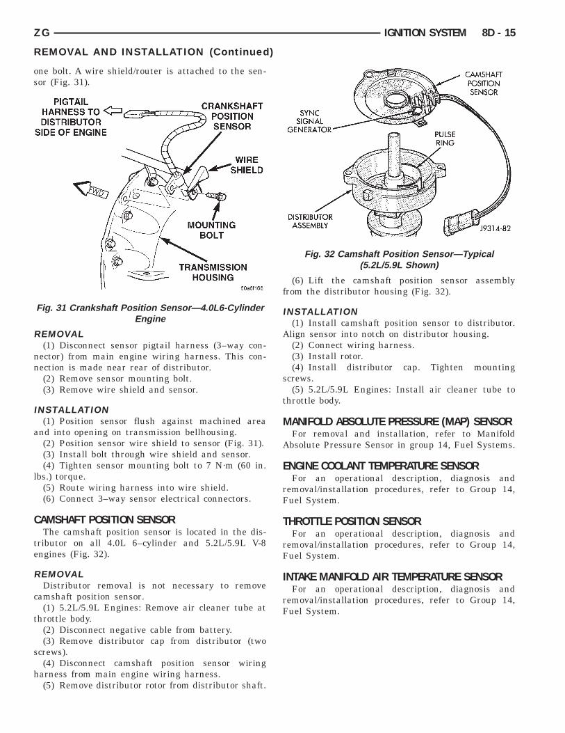
one bolt. A wire shield/router is attached to the sen-sor (Fig. 31).
REMOVAL(1) Disconnect sensor pigtail harness (3–way con-
nector) from main engine wiring harness. This con-nection is made near rear of distributor.
(2) Remove sensor mounting bolt.(3) Remove wire shield and sensor.
INSTALLATION(1) Position sensor flush against machined area
and into opening on transmission bellhousing.(2) Position sensor wire shield to sensor (Fig. 31).(3) Install bolt through wire shield and sensor.(4) Tighten sensor mounting bolt to 7 N·m (60 in.
lbs.) torque.(5) Route wiring harness into wire shield.(6) Connect 3–way sensor electrical connectors.
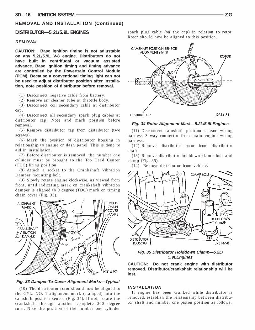
CAMSHAFT POSITION SENSORThe camshaft position sensor is located in the dis-
tributor on all 4.0L 6–cylinder and 5.2L/5.9L V-8engines (Fig. 32).
REMOVALDistributor removal is not necessary to remove
camshaft position sensor.(1) 5.2L/5.9L Engines: Remove air cleaner tube at
throttle body.(2) Disconnect negative cable from battery.(3) Remove distributor cap from distributor (two
screws).(4) Disconnect camshaft position sensor wiring
harness from main engine wiring harness.(5) Remove distributor rotor from distributor shaft.
Fig. 31 Crankshaft Position Sensor—4.0L6-CylinderEngine
REMOVAL AND INSTALLATION (Continued)
(6) Lift the camshaft position sensor assemblyfrom the distributor housing (Fig. 32).
INSTALLATION(1) Install camshaft position sensor to distributor.
Align sensor into notch on distributor housing.(2) Connect wiring harness.(3) Install rotor.(4) Install distributor cap. Tighten mounting
screws.(5) 5.2L/5.9L Engines: Install air cleaner tube to
throttle body.
MANIFOLD ABSOLUTE PRESSURE (MAP) SENSORFor removal and installation, refer to Manifold
Absolute Pressure Sensor in group 14, Fuel Systems.
ENGINE COOLANT TEMPERATURE SENSORFor an operational description, diagnosis and
removal/installation procedures, refer to Group 14,Fuel System.
THROTTLE POSITION SENSORFor an operational description, diagnosis and
removal/installation procedures, refer to Group 14,Fuel System.
INTAKE MANIFOLD AIR TEMPERATURE SENSORFor an operational description, diagnosis and
removal/installation procedures, refer to Group 14,Fuel System.
Fig. 32 Camshaft Position Sensor—Typical(5.2L/5.9L Shown)
ALIGNMENT MARK TIMINGCHAINCOVERMARKSCRANKSHAFTVIBRATIONDAMPER CAMSHAFT POSITION SENSORALIGNMENT MARK ROTORDISTRIBUTOR CLAMP BOLTHOLDDOWNCLAMPDISTRIBUTORHOUSING
8D - 16 IGNITION SYSTEM ZG
DISTRIBUTOR—5.2L/5.9L ENGINES
REMOVAL
CAUTION: Base ignition timing is not adjustableon any 5.2L/5.9L V-8 engine. Distributors do nothave built in centrifugal or vacuum assistedadvance. Base ignition timing and timing advanceare controlled by the Powertrain Control Module(PCM). Because a conventional timing light can notbe used to adjust distributor position after installa-tion, note position of distributor before removal.
(1) Disconnect negative cable from battery.(2) Remove air cleaner tube at throttle body.(3) Disconnect coil secondary cable at distributor
cap.(4) Disconnect all secondary spark plug cables at
distributor cap. Note and mark position beforeremoval.
(5) Remove distributor cap from distributor (twoscrews).
(6) Mark the position of distributor housing inrelationship to engine or dash panel. This is done toaid in installation.
(7) Before distributor is removed, the number onecylinder must be brought to the Top Dead Center(TDC) firing position.
(8) Attach a socket to the Crankshaft VibrationDamper mounting bolt.
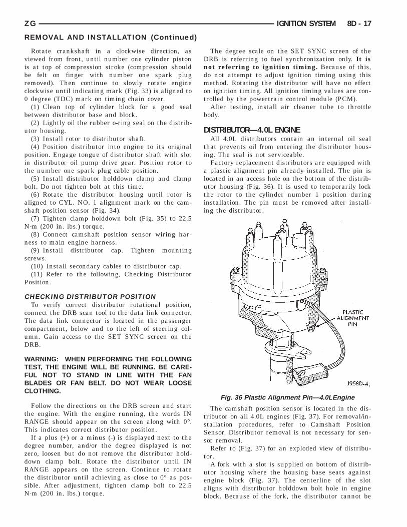
(9) Slowly rotate engine clockwise, as viewed fromfront, until indicating mark on crankshaft vibrationdamper is aligned to 0 degree (TDC) mark on timingchain cover (Fig. 33).
(10) The distributor rotor should now be aligned tothe CYL. NO. 1 alignment mark (stamped) into thecamshaft position sensor (Fig. 34). If not, rotate thecrankshaft through another complete 360 degreeturn. Note the position of the number one cylinder
Fig. 33 Damper-To-Cover Alignment Marks—Typical
REMOVAL AND INSTALLATION (Continued)
spark plug cable (on the cap) in relation to rotor.Rotor should now be aligned to this position.
(11) Disconnect camshaft position sensor wiringharness 3–way connector from main engine wiringharness.
(12) Remove distributor rotor from distributorshaft.
(13) Remove distributor holddown clamp bolt andclamp (Fig. 35).
(14) Remove distributor from vehicle.
CAUTION: Do not crank engine with distributorremoved. Distributor/crankshaft relationship will belost.
INSTALLATIONIf engine has been cranked while distributor is
removed, establish the relationship between distribu-tor shaft and number one piston position as follows:
Fig. 34 Rotor Alignment Mark—5.2L/5.9LEngines
Fig. 35 Distributor Holddown Clamp—5.2L/5.9LEngines
PLASTIC ALIGN-MENT PIN
ZG IGNITION SYSTEM 8D - 17
Rotate crankshaft in a clockwise direction, asviewed from front, until number one cylinder pistonis at top of compression stroke (compression shouldbe felt on finger with number one spark plugremoved). Then continue to slowly rotate engineclockwise until indicating mark (Fig. 33) is aligned to0 degree (TDC) mark on timing chain cover.
(1) Clean top of cylinder block for a good sealbetween distributor base and block.
(2) Lightly oil the rubber o-ring seal on the distrib-utor housing.
(3) Install rotor to distributor shaft.(4) Position distributor into engine to its original
position. Engage tongue of distributor shaft with slotin distributor oil pump drive gear. Position rotor tothe number one spark plug cable position.
(5) Install distributor holddown clamp and clampbolt. Do not tighten bolt at this time.
(6) Rotate the distributor housing until rotor isaligned to CYL. NO. 1 alignment mark on the cam-shaft position sensor (Fig. 34).
(7) Tighten clamp holddown bolt (Fig. 35) to 22.5N·m (200 in. lbs.) torque.
(8) Connect camshaft position sensor wiring har-ness to main engine harness.
(9) Install distributor cap. Tighten mountingscrews.
(10) Install secondary cables to distributor cap.(11) Refer to the following, Checking Distributor
Position.
CHECKING DISTRIBUTOR POSITIONTo verify correct distributor rotational position,
connect the DRB scan tool to the data link connector.The data link connector is located in the passengercompartment, below and to the left of steering col-umn. Gain access to the SET SYNC screen on theDRB.
WARNING: WHEN PERFORMING THE FOLLOWINGTEST, THE ENGINE WILL BE RUNNING. BE CARE-FUL NOT TO STAND IN LINE WITH THE FANBLADES OR FAN BELT. DO NOT WEAR LOOSECLOTHING.
Follow the directions on the DRB screen and startthe engine. With the engine running, the words INRANGE should appear on the screen along with 0°.This indicates correct distributor position.
If a plus (+) or a minus (-) is displayed next to thedegree number, and/or the degree displayed is notzero, loosen but do not remove the distributor hold-down clamp bolt. Rotate the distributor until INRANGE appears on the screen. Continue to rotatethe distributor until achieving as close to 0° as pos-sible. After adjustment, tighten clamp bolt to 22.5N·m (200 in. lbs.) torque.
REMOVAL AND INSTALLATION (Continued)
The degree scale on the SET SYNC screen of theDRB is referring to fuel synchronization only. It isnot referring to ignition timing. Because of this,do not attempt to adjust ignition timing using thismethod. Rotating the distributor will have no effecton ignition timing. All ignition timing values are con-trolled by the powertrain control module (PCM).
After testing, install air cleaner tube to throttlebody.
DISTRIBUTOR—4.0L ENGINEAll 4.0L distributors contain an internal oil seal
that prevents oil from entering the distributor hous-ing. The seal is not serviceable.
Factory replacement distributors are equipped witha plastic alignment pin already installed. The pin islocated in an access hole on the bottom of the distrib-utor housing (Fig. 36). It is used to temporarily lockthe rotor to the cylinder number 1 position duringinstallation. The pin must be removed after install-ing the distributor.
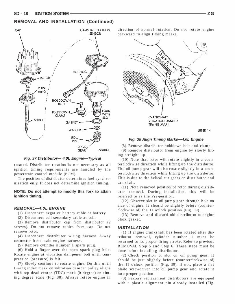
The camshaft position sensor is located in the dis-tributor on all 4.0L engines (Fig. 37). For removal/in-stallation procedures, refer to Camshaft PositionSensor. Distributor removal is not necessary for sen-sor removal.
Refer to (Fig. 37) for an exploded view of distribu-tor.
A fork with a slot is supplied on bottom of distrib-utor housing where the housing base seats againstengine block (Fig. 37). The centerline of the slotaligns with distributor holddown bolt hole in engineblock. Because of the fork, the distributor cannot be
Fig. 36 Plastic Alignment Pin—4.0LEngine
CAMSHAFT POSITION SEN-SORHOUSING FORKWITHSLOTDRIVE GEARROLL PINWASHERGASKETHOLDDOWNCLAMPHOLDDOWNBOLT
SHAFT
CRANKSHAFT VIBRATIONDAMPER TIMING MARK
8D - 18 IGNITION SYSTEM ZG
rotated. Distributor rotation is not necessary as allignition timing requirements are handled by thepowertrain control module (PCM).
The position of distributor determines fuel synchro-nization only. It does not determine ignition timing.
NOTE: Do not attempt to modify this fork to attainignition timing.
REMOVAL—4.0L ENGINE(1) Disconnect negative battery cable at battery.(2) Disconnect coil secondary cable at coil.(3) Remove distributor cap from distributor (2
screws). Do not remove cables from cap. Do notremove rotor.
(4) Disconnect distributor wiring harness 3–wayconnector from main engine harness.
(5) Remove cylinder number 1 spark plug.(6) Hold a finger over the open spark plug hole.
Rotate engine at vibration dampener bolt until com-pression (pressure) is felt.
(7) Slowly continue to rotate engine. Do this untiltiming index mark on vibration damper pulley alignswith top dead center (TDC) mark (0 degree) on tim-ing degree scale (Fig. 38). Always rotate engine in
Fig. 37 Distributor— 4.0L Engine—Typical
REMOVAL AND INSTALLATION (Continued)
direction of normal rotation. Do not rotate enginebackward to align timing marks.
(8) Remove distributor holddown bolt and clamp.(9) Remove distributor from engine by slowly lift-
ing straight up.(10) Note that rotor will rotate slightly in a coun-
terclockwise direction while lifting up the distributor.The oil pump gear will also rotate slightly in a coun-terclockwise direction while lifting up the distributor.This is due to the helical cut gears on distributor andcamshaft.
(11) Note removed position of rotor during distrib-utor removal. During installation, this will bereferred to as the Pre-position.
(12) Observe slot in oil pump gear through hole onside of engine. It should be slightly before (counter-clockwise of) the 11 o’clock position (Fig. 39).
(13) Remove and discard old distributor-to-engineblock gasket.
INSTALLATION(1) If engine crankshaft has been rotated after dis-
tributor removal, cylinder number 1 must bereturned to its proper firing stroke. Refer to previousREMOVAL Step 5 and Step 6. These steps must bedone before installing distributor.
(2) Check position of slot on oil pump gear. Itshould be just slightly before (counterclockwise of)the 11 o’clock position (Fig. 39). If not, place a flatblade screwdriver into oil pump gear and rotate itinto proper position.
(3) Factory replacement distributors are equippedwith a plastic alignment pin already installed (Fig.
Fig. 38 Align Timing Marks—4.0L Engine
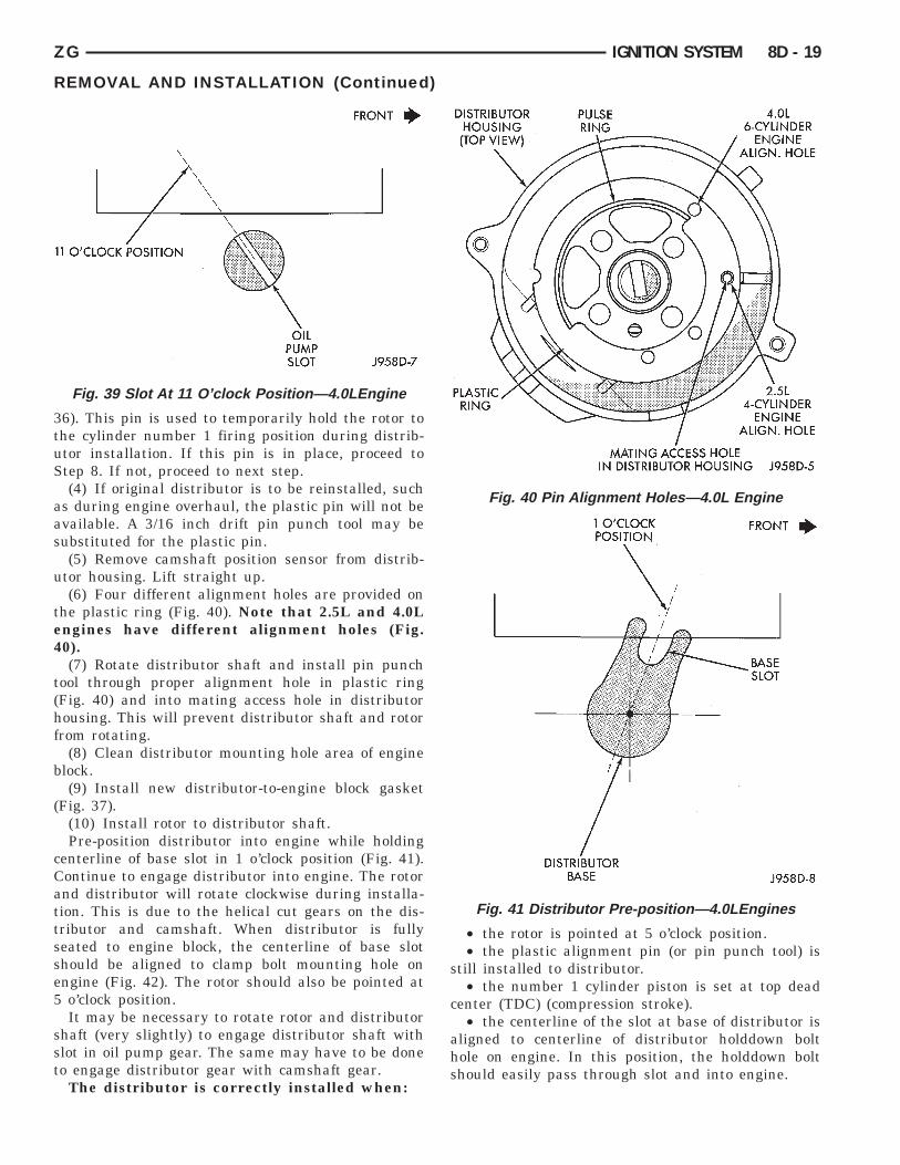
FRONT11 O’CLOCK POSITIONOIL PUMP SLOT DISTRIBUTORHOUSING (TOPVIEW) PULSE RING 4.0L 6–CYLIN-DER ENGINEALIGN. HOLE2.5L 4–CYLIN-DER ENGINEALIGN. HOLEMATING ACCESS HOLE INDISTRIBUTOR HOUSINGPLASTIC RING 1 O’CLOCKPOSITION FRONTBASE SLOTDISTRIBUTOR BASE
ZG
36). This pin is used to temporarily hold the rotor tothe cylinder number 1 firing position during distrib-utor installation. If this pin is in place, proceed toStep 8. If not, proceed to next step.
(4) If original distributor is to be reinstalled, suchas during engine overhaul, the plastic pin will not beavailable. A 3/16 inch drift pin punch tool may besubstituted for the plastic pin.
(5) Remove camshaft position sensor from distrib-utor housing. Lift straight up.
(6) Four different alignment holes are provided onthe plastic ring (Fig. 40). Note that 2.5L and 4.0Lengines have different alignment holes (Fig.40).
(7) Rotate distributor shaft and install pin punchtool through proper alignment hole in plastic ring(Fig. 40) and into mating access hole in distributorhousing. This will prevent distributor shaft and rotorfrom rotating.
(8) Clean distributor mounting hole area of engineblock.
(9) Install new distributor-to-engine block gasket(Fig. 37).
(10) Install rotor to distributor shaft.Pre-position distributor into engine while holding
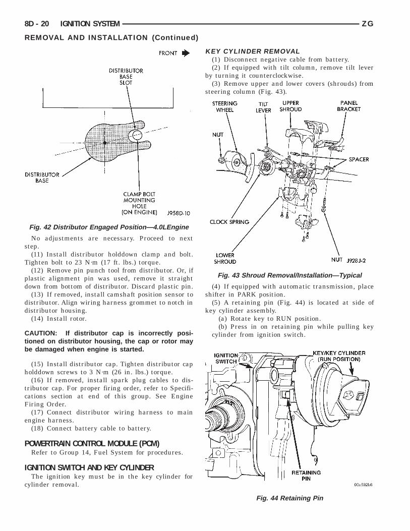
centerline of base slot in 1 o’clock position (Fig. 41).Continue to engage distributor into engine. The rotorand distributor will rotate clockwise during installa-tion. This is due to the helical cut gears on the dis-tributor and camshaft. When distributor is fullyseated to engine block, the centerline of base slotshould be aligned to clamp bolt mounting hole onengine (Fig. 42). The rotor should also be pointed at5 o’clock position.
It may be necessary to rotate rotor and distributorshaft (very slightly) to engage distributor shaft withslot in oil pump gear. The same may have to be doneto engage distributor gear with camshaft gear.
The distributor is correctly installed when:
Fig. 39 Slot At 11 O’clock Position—4.0LEngine
REMOVAL AND INSTALLATION (Continued)
• the rotor is pointed at 5 o’clock position.• the plastic alignment pin (or pin punch tool) is
still installed to distributor.• the number 1 cylinder piston is set at top dead
center (TDC) (compression stroke).• the centerline of the slot at base of distributor is
aligned to centerline of distributor holddown bolthole on engine. In this position, the holddown boltshould easily pass through slot and into engine.
Fig. 40 Pin Alignment Holes—4.0L Engine
Fig. 41 Distributor Pre-position—4.0LEngines
IGNITION SYSTEM 8D - 19
DISTRIBUTORBASE SLOTCLAMP BOLT MOUNTINGHOLE (ON ENGINE)DISTRIBUTORBASE FRONT NUT STEERINGWHEEL TILT LEVER UPPERSHROUDPANELBRACKET SPACERNUTLOWERSHROUD CLOCK SPRINGIGNITION SWITCHKEY/KEY CYLINDER (RUNPOSITION)
8D - 20 IGNITION SYSTEM ZG
No adjustments are necessary. Proceed to nextstep.
(11) Install distributor holddown clamp and bolt.Tighten bolt to 23 N·m (17 ft. lbs.) torque.
(12) Remove pin punch tool from distributor. Or, ifplastic alignment pin was used, remove it straightdown from bottom of distributor. Discard plastic pin.
(13) If removed, install camshaft position sensor todistributor. Align wiring harness grommet to notch indistributor housing.
(14) Install rotor.
CAUTION: If distributor cap is incorrectly posi-tioned on distributor housing, the cap or rotor maybe damaged when engine is started.
(15) Install distributor cap. Tighten distributor capholddown screws to 3 N·m (26 in. lbs.) torque.
(16) If removed, install spark plug cables to dis-tributor cap. For proper firing order, refer to Specifi-cations section at end of this group. See EngineFiring Order.
(17) Connect distributor wiring harness to mainengine harness.
(18) Connect battery cable to battery.
POWERTRAIN CONTROL MODULE (PCM)Refer to Group 14, Fuel System for procedures.
IGNITION SWITCH AND KEY CYLINDERThe ignition key must be in the key cylinder for
cylinder removal.
Fig. 42 Distributor Engaged Position—4.0LEngine
REMOVAL AND INSTALLATION (Continued
KEY CYLINDER REMOVAL(1) Disconnect negative cable from battery.(2) If equipped with tilt column, remove tilt lever
by turning it counterclockwise.(3) Remove upper and lower covers (shrouds) from
steering column (Fig. 43).
(4) If equipped with automatic transmission, placeshifter in PARK position.
(5) A retaining pin (Fig. 44) is located at side ofkey cylinder assembly.
(a) Rotate key to RUN position.(b) Press in on retaining pin while pulling key
cylinder from ignition switch.
Fig. 43 Shroud Removal/Installation—Typical
Fig. 44 Retaining Pin
)
IGNITION SWITCHSLOTS NOT ALIGNED
SLOTS ALIGNED( )
KEY-IN SWITCH & HALOLIGHT MULTI-FUNCTIONSWITCHTURN SIGNALSWITCH & LEVERIGNITION SWITCH SPEED CONTROL REAR OF IGNITION SWITCHPARK LOCK DOWEL PIN(RUN POSITION)IGNITION KEY LOCK CYLIN-DER
PUSH PIN
ZG IGNITION SYSTEM 8D - 21
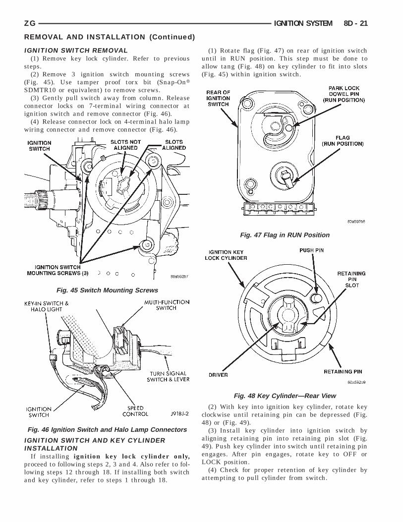
IGNITION SWITCH REMOVAL(1) Remove key lock cylinder. Refer to previous
steps.(2) Remove 3 ignition switch mounting screws
(Fig. 45). Use tamper proof torx bit (Snap-OntSDMTR10 or equivalent) to remove screws.
(3) Gently pull switch away from column. Releaseconnector locks on 7-terminal wiring connector atignition switch and remove connector (Fig. 46).
(4) Release connector lock on 4-terminal halo lampwiring connector and remove connector (Fig. 46).
IGNITION SWITCH AND KEY CYLINDERINSTALLATION
If installing ignition key lock cylinder only,proceed to following steps 2, 3 and 4. Also refer to fol-lowing steps 12 through 18. If installing both switchand key cylinder, refer to steps 1 through 18.
Fig. 45 Switch Mounting Screws
Fig. 46 Ignition Switch and Halo Lamp Connectors
REMOVAL AND INSTALLATION (Continued)
(1) Rotate flag (Fig. 47) on rear of ignition switchuntil in RUN position. This step must be done toallow tang (Fig. 48) on key cylinder to fit into slots(Fig. 45) within ignition switch.
(2) With key into ignition key cylinder, rotate keyclockwise until retaining pin can be depressed (Fig.48) or (Fig. 49).
(3) Install key cylinder into ignition switch byaligning retaining pin into retaining pin slot (Fig.49). Push key cylinder into switch until retaining pinengages. After pin engages, rotate key to OFF orLOCK position.
(4) Check for proper retention of key cylinder byattempting to pull cylinder from switch.
Fig. 47 Flag in RUN Position
Fig. 48 Key Cylinder—Rear View
IGNITION SWITCHDRIVER
IGNITION KEY LOCK CYLIN-DER
REAR OF IGNITION SWITCHPARK LOCK DOWEL PIN(LOCK POSITION)
DOWEL LOCATING HOLES(2)
PARK LOCK SLIDER LINK-AGE
STEERING COLUMNSTEERING WHEEL LOCKLEVER
8D - 22 IGNITION SYSTEM ZG
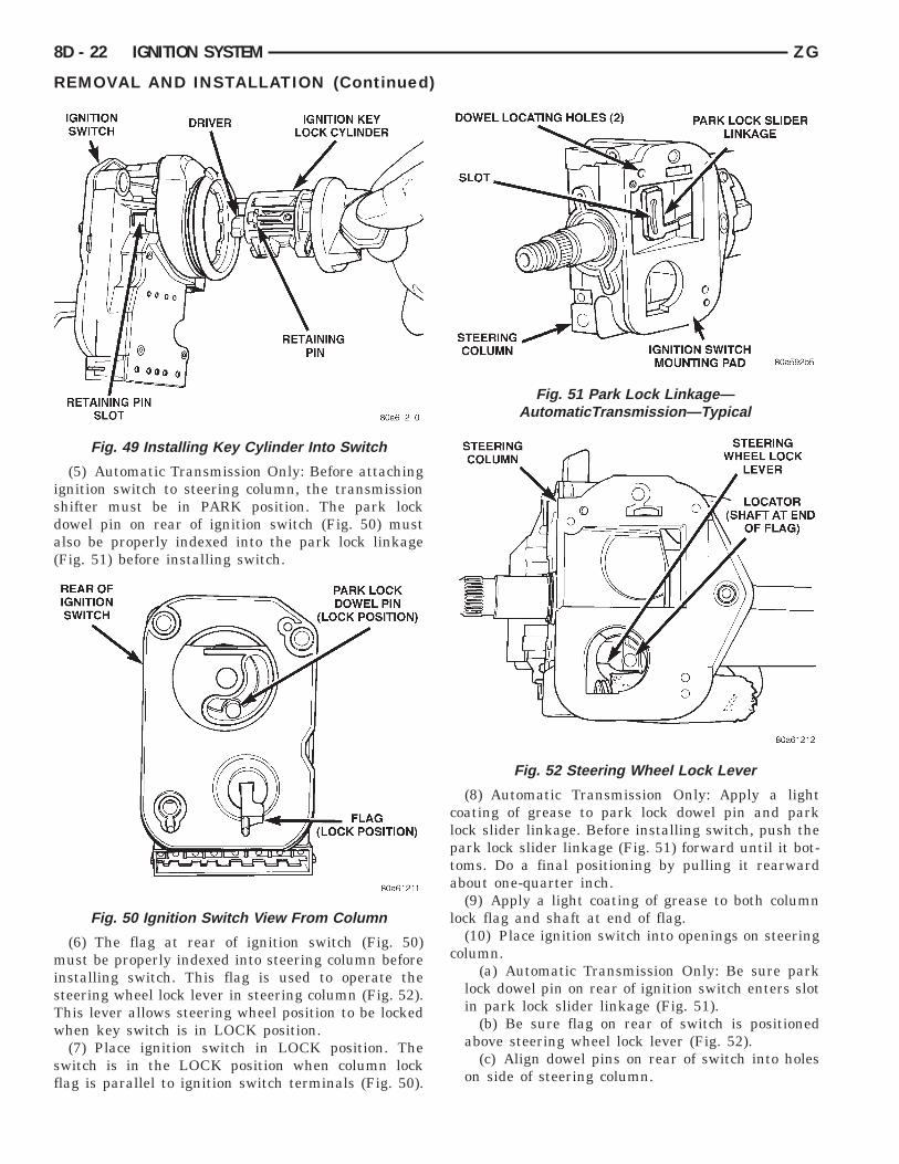
(5) Automatic Transmission Only: Before attachingignition switch to steering column, the transmissionshifter must be in PARK position. The park lockdowel pin on rear of ignition switch (Fig. 50) mustalso be properly indexed into the park lock linkage(Fig. 51) before installing switch.
(6) The flag at rear of ignition switch (Fig. 50)must be properly indexed into steering column beforeinstalling switch. This flag is used to operate thesteering wheel lock lever in steering column (Fig. 52).This lever allows steering wheel position to be lockedwhen key switch is in LOCK position.
(7) Place ignition switch in LOCK position. Theswitch is in the LOCK position when column lockflag is parallel to ignition switch terminals (Fig. 50).
Fig. 49 Installing Key Cylinder Into Switch
Fig. 50 Ignition Switch View From Column
REMOVAL AND INSTALLATION (Continued)
(8) Automatic Transmission Only: Apply a lightcoating of grease to park lock dowel pin and parklock slider linkage. Before installing switch, push thepark lock slider linkage (Fig. 51) forward until it bot-toms. Do a final positioning by pulling it rearwardabout one-quarter inch.
(9) Apply a light coating of grease to both columnlock flag and shaft at end of flag.
(10) Place ignition switch into openings on steeringcolumn.
(a) Automatic Transmission Only: Be sure parklock dowel pin on rear of ignition switch enters slotin park lock slider linkage (Fig. 51).
(b) Be sure flag on rear of switch is positionedabove steering wheel lock lever (Fig. 52).
(c) Align dowel pins on rear of switch into holeson side of steering column.
Fig. 51 Park Lock Linkage—AutomaticTransmission—Typical
Fig. 52 Steering Wheel Lock Lever
FRONT FIRINGORDER:1 5 3 62 4CLOCK-WISEROTA-TIONFRONTOFENGINE CLOCKWISE ROTATION1-8-4-3-6-5-7-2
ZG
(d) Install 3 ignition switch mounting screws.Tighten screws to 3 N·m 6 .5 N·m (26 in. lbs. 6 4in. lbs.) torque.(11) Connect electrical connectors to ignition
switch and halo lamp. Make sure that switch lockingtabs are fully seated in wiring connectors.
(12) Install steering column covers (shrouds).Tighten screws to 2 N·m (17 in. lbs.) torque.
(13) Install tilt column lever (if equipped).(14) Connect negative cable to battery.(15) Check for proper operation of halo light.(16) Automatic Transmission Only: Shifter should
lock in PARK position when key is in LOCK position(if equipped with shift lock device). Shifter shouldunlock when key rotated to ON position.
(17) Check for proper operation of ignition switchin ACCESSORY, LOCK, OFF, ON, RUN, and STARTpositions.
(18) Steering wheel should lock when key is inLOCK position. Rotate steering wheel to verify.Steering wheel should unlock when key is rotated toON position.
SHIFTER/IGNITION INTERLOCKOn models equipped with an automatic transmis-
sion, a cable connects the ignition switch with thefloor shift lever. The shifter will be locked in thePARK position when the ignition key is in the LOCKor ACCESSORY positions. The cable can be adjustedor replaced. Refer to Group 21, Transmissions forprocedures. The ignition interlock device within thesteering column is not serviceable. If service is nec-essary, the steering column must be replaced. Referto Group 19, Steering for procedures.
SPECIFICATIONS
VECI LABELIf anything differs between the specifications found
on the Vehicle Emission Control Information (VECI)label and the following specifications, use specifica-tions on VECI label. The VECI label is located in theengine compartment.
IGNITION TIMINGIgnition timing is not adjustable on any engine.
Refer to Ignition Timing in the Diagnostics/ServiceProcedures section of this group for more informa-tion.
REMOVAL AND INSTALLATION (Continued)
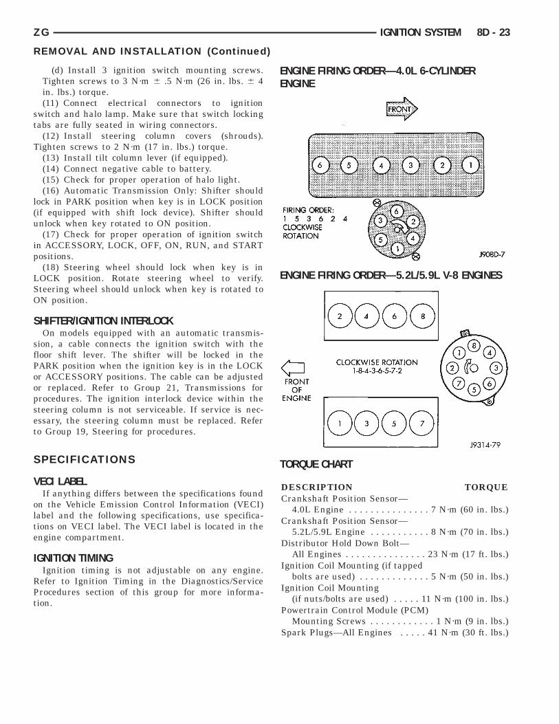
ENGINE FIRING ORDER—4.0L 6-CYLINDERENGINE
ENGINE FIRING ORDER—5.2L/5.9L V-8 ENGINES
TORQUE CHART
DESCRIPTION TORQUECrankshaft Position Sensor—
4.0L Engine . . . . . . . . . . . . . . . 7 N·m (60 in. lbs.)Crankshaft Position Sensor—
5.2L/5.9L Engine . . . . . . . . . . . 8 N·m (70 in. lbs.)Distributor Hold Down Bolt—
All Engines . . . . . . . . . . . . . . . 23 N·m (17 ft. lbs.)Ignition Coil Mounting (if tapped
bolts are used) . . . . . . . . . . . . . 5 N·m (50 in. lbs.)Ignition Coil Mounting
(if nuts/bolts are used) . . . . . 11 N·m (100 in. lbs.)Powertrain Control Module (PCM)
Mounting Screws . . . . . . . . . . . . 1 N·m (9 in. lbs.)Spark Plugs—All Engines . . . . . 41 N·m (30 ft. lbs.)
IGNITION SYSTEM 8D - 23
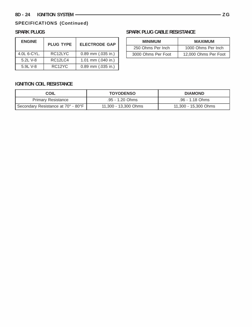
SPARK PLUGS SPARK PLUG CABLE RESISTANCE
IGNITION COIL RESISTANCE
ENGINEPLUG TYPE ELECTRODE GAP
4.0L 6-CYL. RC12LYC 0.89 mm (.035 in.)
5.2L V-8 RC12LC4 1.01 mm (.040 in.)
5.9L V-8 RC12YC 0.89 mm (.035 in.)
MINIMUM MAXIMUM
250 Ohms Per Inch 1000 Ohms Per Inch
3000 Ohms Per Foot 12,000 Ohms Per Foot
COIL TOYODENSO DIAMOND
Primary Resistance .95 - 1.20 Ohms .96 - 1.18 Ohms
Secondary Resistance at 70° - 80°F 11,300 - 13,300 Ohms 11,300 - 15,300 Ohms
8D - 24 IGNITION SYSTEM ZG
SPECIFICATIONS (Continued)
Related Documents