Report No. 086111R-RFUSP08V01 Page: 1 of 38 Version:1.0 Test Report Product Name : 2G Wireless NPort Model No : NPort W2150 Plus, NPort W2250 Plus,NPort W2150 Plus-T, NPort W2250 Plus-T FCC ID : SLEW2250Plus Applicant : Moxa Inc. Address : Fl.4, No. 135, Lane 235, Pao-Chiao Rd., Shing Tien City, Taipei, Taiwan, R.O.C. Date of Receipt : June. 02, 2008 Issued Date : June. 19, 2008 Report No. : 086111R-RFUSP08V01 Version : V1.0 The test results relate only to the samples tested. The test report shall not be reproduced except in full without the written approval of QuieTek Corporation. This report must not be used to claim product endorsement by NVLAP any agency of the U.S. Government

Welcome message from author
This document is posted to help you gain knowledge. Please leave a comment to let me know what you think about it! Share it to your friends and learn new things together.
Transcript

Report No. 086111R-RFUSP08V01
Page: 1 of 38 Version:1.0
Test Report
Product Name : 2G Wireless NPort
Model No : NPort W2150 Plus, NPort W2250 Plus,NPort W2150 Plus-T, NPort W2250 Plus-T
FCC ID : SLEW2250Plus
Applicant : Moxa Inc.
Address : Fl.4, No. 135, Lane 235, Pao-Chiao Rd., Shing Tien City,
Taipei, Taiwan, R.O.C.
Date of Receipt : June. 02, 2008
Issued Date : June. 19, 2008
Report No. : 086111R-RFUSP08V01
Version : V1.0
The test results relate only to the samples tested. The test report shall not be reproduced except in full without the written approval of QuieTek Corporation.This report must not be used to claim product endorsement by NVLAP any agency of the U.S. Government

Report No. 086111R-RFUSP08V01
Page: 2 of 38 Version:1.0
Test Report Cert i f icat ion Issued Date: June. 19, 2008 Rport No.: 086111R-RFUSP08V01
The Test Results relate only to the samples tested. The test report shall not be reproduced except in full without the written approval of QuieTek Corporation. This report must not be used to claim product endorsement by NVLAP any agency of the U.S. Government
Product Name : 2G Wireless NPort
Applicant : Moxa Inc.
Address : Fl.4, No. 135, Lane 235, Pao-Chiao Rd., Shing Tien City, Taipei, Taiwan, R.O.C.
Manufacturer : Moxa Inc.
Model No. : NPort W2150 Plus, NPort W2250 Plus,NPort W2150 Plus-T, NPort W2250 Plus-T
FCC ID. : SLEW2250Plus
Rated Voltage : AC 120V/60Hz
Working Voltage : DC 12V
Trade Name : Moxa
Applicable Standard : FCC CFR Title 47 Part 15 Subpart E: 2007
ANSI C63.4: 2003
Test Result : Complied
Documented By :
( Adm. Specialist /Leven Huang )
Tested By :
( Senior Engineer /Tim Sung )
Approved By :
( Deputy Manager /Vincent Lin )
Report No. 086111R-RFUSP08V01
Page: 3 of 38 Version:1.0
TABLE OF CONTENTS
Description Page
1. GENERAL INFORMATION ................................................................................................ 4
1.1. EUT Description....................................................................................................................... 4 1.2. Operational Description ........................................................................................................... 5 1.3. Tested System Datails............................................................................................................... 6 1.4. Configuration of tested System ................................................................................................ 6 1.5. EUT Exercise Software ............................................................................................................ 6 1.6. Test Facility .............................................................................................................................. 7
2. Undesirable Emission............................................................................................................. 8
2.1. Test Equipment......................................................................................................................... 8 2.2. Test Setup ................................................................................................................................. 8 2.3. Limits ....................................................................................................................................... 8 2.4. Test Procedure .......................................................................................................................... 9 2.5. Uncertainty ............................................................................................................................... 9 2.6. Test Result of Undesirable Emission...................................................................................... 10
3. Radiated Emission................................................................................................................ 18
3.1. Test Equipment....................................................................................................................... 18 3.2. Test Setup ............................................................................................................................... 19 3.3. Limits ..................................................................................................................................... 20 3.4. Test Procedure ........................................................................................................................ 20 3.5. Uncertainty ............................................................................................................................. 21 3.6. Test Result of Radiated Emission........................................................................................... 22
4. Band Edge ............................................................................................................................. 30
4.1. Test Equipment....................................................................................................................... 30 4.2. Test Setup ............................................................................................................................... 30 4.3. Limits ..................................................................................................................................... 31 4.4. Test Procedure ........................................................................................................................ 31 4.5. Uncertainty ............................................................................................................................. 31 4.6. Test Result of Band Edge .......................................................................................................32
5. EMI Reduction Method During Compliance Testing ....................................................... 36
Attachment 1: EUT Test Photographs Attachment 2: EUT Detailed Photographs

Report No. 086111R-RFUSP08V01
Page: 4 of 38 Version:1.0
1. GENERAL INFORMATION
1.1. EUT Description
Product Name : 2G Wireless NPort Trade Name : Moxa FCC ID. : SLEW2250Plus Model No. : NPort W2150 Plus, NPort W2250 Plus,NPort W2150 Plus-T, NPort W2250 Plus-T
Frequency Range : 2412 – 2462MHz for 802.11 b/g 5180 – 5240MHz, 5745 – 5805MHz for 802.11a
Number of Channels : 11 in 2.4GHz band, 8 in 5GHz band Channel Separation : 5MHz in 2.4GHz band, 20MHz in 5GHz band Channel Control : Auto Data Rate : 802.11b – 1, 2, 5.5, 11Mbps 802.11a/g – 6, 9, 12, 18, 24, 36, 48, 54Mbps
Type of Modulation :
802.11b:DSSS DBPSK, DQPSK, CCK 802.11 a/g: OFDM BPSK, QPSK, 16QAM, 64QAM
Antenna type : Connector (Reverse SMA) Antenna Gain : Refer to the table “Antenna List” Power Adapter : MFR: BLANCE, M/N: GPSA-1200120
Input: AC 100-240V, 50-60Hz, 0.5A Output: DC 12V-1.2A Cable out: Non-Shielded, 1.9m with one ferrite core bonded.
Antenna List
No. Manufacturer Part No. Peak Gain 1 WANSHIH WNW1730A1 1.76 dBi for 2.4 GHz
1.47 dBi for 5.0 GHz 2 KINSUN 6602D03081 1.21 dBi for 2.4 GHz
1.73 dBi for 5.0 GHz Note:
1. Due to Ant 1 and Ant 2 are the same type antennas. Only the 5GHz band higher gain antenna “Ant 2”was tested and recorded in this report.

Report No. 086111R-RFUSP08V01
Page: 5 of 38 Version:1.0
Frequency of Each Channel:
Channel Frequency Channel Frequency Channel Frequency Channel Frequency
Channel 1 5180 MHz Channel 2 5200 MHz Channel 3 5220 MHz Channel 4 5240 MHz
Channel 5 5745 MHz Channel 6 5765 MHz Channel 7 5785 MHz Channel 8 5805 MHz Note: 1. This device is a 2G Wireless NPort with a built-in 2.4GHz and 5GHz transceiver. 2. Regarding to the operation frequency, the lowest, middle and highest frequency are selected to
perform the test. Lowest and highest data rates are tested in each mode. Only worst case is shown in the report. (802.11b is 1Mbps and 802.11a/g is 6Mbps)
3. These tests were conducted on a sample of the equipment for the purpose of demonstrating compliance with Part 15 Subpart E for Unlicensed National Information Infrastructure devices.
4. The EUT is including four models for different marketing requirement.
1.2. Operational Description
The EUT is an 2G Wireless NPort with 11 channels. for 802.11b/g and 9 channels for 802.11a.This device provides four kinds of transmitting speed 1, 2, 5.5 and 11Mbps. The modulation of device is BPSK, QPSK and CCK (IEEE 802.11b) and eight kinds of transmitting speed 6, 9, 12, 18, 24, 36, 48 and 54Mbps are provided. The technology of this device used is OFDM (IEEE 802.11 a/g).
The device adapts direct sequence spread spectrum modulation. The antenna provides diversity function to improve the receiving function.
This 2G Wireless NPort, compliant with IEEE 802.11b and IEEE 802.11 a/g, is a high-efficiency Wireless LAN adapter. It allows your computer to connect to a wireless network and to share resources, such as files or printers without being bound to the network wires. Operation in 2.4GHz Direst Sequence Spread Spectrum (DSSS) radio transmission, the 2G Wireless NPort Wired Equivalent Protection (WEP) algorithm is used. In addition, its standard compliance ensures that it can communicate with any IEEE 802.11b and IEEE 802.11 a/g network.
Test Mode Mode 1: Transmitter 802.11a

Report No. 086111R-RFUSP08V01
Page: 6 of 38 Version:1.0
1.3. Tested System Datails
The types for all equipment, plus descriptions of all cables used in the tested system (including inserted cards) are:
Product Manufacturer Model No. Serial No. Power Cord
1 Notebook PC DELL PP18L 42649348672 Non-Shielded, 0.8m
Signal Cable Type Signal cable Description
A LAN Cable Shielded, 1.5m
1.4. Configuration of tested System
1.5. EUT Exercise Software
(1) Setup the EUT as shown in Section 1.4 (2) Execute Telnet IP on the notebook. (3) Configure the test mode, the test channel, and the data rate. (4) Press “OK” to start the continuous transmission. (5) Verify that the EUT works properly.
Report No. 086111R-RFUSP08V01
Page: 7 of 38 Version:1.0
1.6. Test Facility
Ambient conditions in the laboratory:
Items Required (IEC 68-1) Actual
Temperature (°C) 15-35 20-35
Humidity (%RH) 25-75 50-65
Barometric pressure (mbar) 860-1060 950-1000
Site Description: File on Federal Communications Commission FCC Engineering Laboratory 7435 Oakland Mills Road Columbia, MD 21046 Registration Number: 92195 Accreditation on NVLAP NVLAP Lab Code: 200533-0 Site Name: Quietek Corporation Site Address: No. 5-22, Ruei-Shu Valley, Ruei-Ping Tsuen, Lin-Kou Shiang, Taipei, Taiwan, R.O.C. TEL: 886-2-8601-3788 / FAX : 886-2-8601-3789 E-Mail : [email protected] FCC Accreditation Number: TW1014
Report No. 086111R-RFUSP08V01
Page: 8 of 38 Version:1.0
2. Undesirable Emission
2.1. Test Equipment
The following test equipment are used during the radiated emission test:
Test Site Equipment Manufacturer Model No./Serial No. Last Cal.
X Test Receiver R & S ESI 26 / 838786 / 004 May, 2008X Spectrum Analyzer Agilent E4407B / US39440758 May, 2008X Pre-Amplifier QTK QTK-AMP-03 / 0003 May, 2008X Bilog Antenna SCHAFFNER CBL6112B / 2697 May, 2008X Horn Antenna ETS 3115 / 0005-6160 July, 2007
Site # 3
X Pre-Amplifier QTK QTK-AMP-01 / 0001 July, 2007Note: 1. All equipments are calibrated every one year. 2. The test instruments marked by “X” are used to measure the final test results.
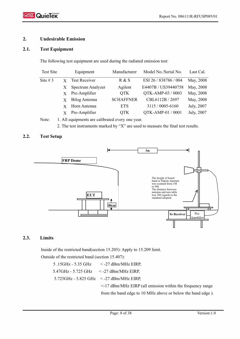
2.2. Test Setup
2.3. Limits
Inside of the restricted band(section 15.205): Apply to 15.209 limit. Outside of the restricted band (section 15.407):
5 .15GHz - 5.35 GHz < -27 dBm/MHz EIRP, 5.47GHz - 5.725 GHz < -27 dBm/MHz EIRP, 5.725GHz - 5.825 GHz < -27 dBm/MHz EIRP,
<-17 dBm/MHz EIRP (all emission within the frequency range from the band edge to 10 MHz above or below the band edge ).
EUT
FRP Dome
The height of board band or Dipole Antenna was scanned from 1M to 4M. The distance between antenna and turn table was 3M regards to the standard adopted.
3m
80cm
To Receiver Pre- Amplifier

Report No. 086111R-RFUSP08V01
Page: 9 of 38 Version:1.0
2.4. Test Procedure
The EUT was setup according to ANSI C63.4, 2003 and tested according to FCC Public Notice DA 02-2138 test procedure for compliance to FCC 47CFR 15. 407 requirements. The EUT is placed on a turn table which is 0.8 meter above ground. The turn table is rotated 360 degrees to determine the position of the maximum emission level. The EUT was positioned such that the distance from antenna to the EUT was 3 meters. The antenna is scanned from 1 meter to 4 meters to find out the maximum emission level. This is repeated for both horizontal and vertical polarization of the antenna. In order to find the maximum emission, all of the interface cables were manipulated according to ANSI C63.4:2003 on radiated measurement.
2.5. Uncertainty
± 3.8 dB below 1GHz ± 3.9 dB above 1GHz

Report No. 086111R-RFUSP08V01
Page: 10 of 38 Version:1.0
2.6. Test Result of Undesirable Emission
Product : 2G Wireless NPort Test Item : Undesirable Emission Test Site : No.3 OATS Test Mode : Mode 1: Transmitter 802.11a (5180MHz)
RF Radiated Measurement (Horizontal):
Channel No. Frequency
(MHz) Correct Factor
(dB) Reading Level
(dBm) Measure Level
(dBm/m) Margin
(dB) Limit
(dBm/m) Result
1 (Peak) 5147.200 14.275 -58.703 -44.428 -17.428 -27.000 Pass
Figure Channel 1: Horizontal (Peak)
Note: Spectrum setting: Detector=Peak detector and maximum hold, RBW= 1MHz, VBW=3 MHz.

Report No. 086111R-RFUSP08V01
Page: 11 of 38 Version:1.0
Product : 2G Wireless NPort Test Item : Undesirable Emission Test Site : No.3 OATS Test Mode : Mode 1: Transmitter 802.11a (5180MHz)
RF Radiated Measurement (VERTICAL):
Channel No. Frequency
(MHz) Correct Factor
(dB) Reading Level
(dBm) Measure Level
(dBm/m) Margin
(dB) Limit
(dBm/m) Result
1 (Peak) 5150.000 14.631 -49.909 -35.278 -8.278 -27.000 Pass
Figure Channel 1: Vertical (Peak)
Note: Spectrum setting: Detector=Peak detector and maximum hold, RBW= 1MHz, VBW=3 MHz.

Report No. 086111R-RFUSP08V01
Page: 12 of 38 Version:1.0
Product : 2G Wireless NPort Test Item : Undesirable Emission Test Site : No.3 OATS Test Mode : Mode 1: Transmitter 802.11a (5240MHz)
RF Radiated Measurement (Horizontal):
Channel No. Frequency
(MHz) Correct Factor
(dB) Reading Level
(dBm) Measure Level
(dBm/m) Margin
(dB) Limit
(dBm/m) Result
4 (Peak) 5350.000 14.464 -57.250 -42.786 -15.786 -27.000 Pass
Figure Channel 4: Horizontal (Peak)
Note: Spectrum setting: Detector=Peak detector and maximum hold, RBW= 1MHz, VBW=3 MHz.

Report No. 086111R-RFUSP08V01
Page: 13 of 38 Version:1.0
Product : 2G Wireless NPort Test Item : Undesirable Emission Test Site : No.3 OATS Test Mode : Mode 1: Transmitter 802.11a (5240MHz)
RF Radiated Measurement (VERTICAL):
Channel No. Frequency
(MHz) Correct Factor
(dB) Reading Level
(dBm) Measure Level
(dBm/m) Margin
(dB) Limit
(dBm/m) Result
4 (Peak) 5350.000 14.773 -58.216 -43.443 -16.443 -27.000 Pass
Figure Channel 4: Vertical (Peak)
Note: Spectrum setting: Detector=Peak detector and maximum hold, RBW= 1MHz, VBW=3 MHz.

Report No. 086111R-RFUSP08V01
Page: 14 of 38 Version:1.0
Product : 2G Wireless NPort Test Item : Undesirable Emission Test Site : No.3 OATS Test Mode : Mode 1: Transmitter 802.11a (5745MHz)
RF Radiated Measurement (Horizontal):
Channel No. Frequency
(MHz) Correct Factor
(dB) Reading Level
(dBm) Measure Level
(dBm/m) Margin
(dB) Limit
(dBm/m) Result
5 (Peak) 5715.000 4.791 -59.498 -54.707 -27.707 -27.000 Pass 5 (Peak) 5725.000 4.802 -48.874 -44.072 -27.072 -17.000 Pass
Figure Channel 5: Horizontal (Peak)
Note: Spectrum setting: Detector=Peak detector and maximum hold, RBW= 1MHz, VBW=3 MHz.

Report No. 086111R-RFUSP08V01
Page: 15 of 38 Version:1.0
Product : 2G Wireless NPort Test Item : Undesirable Emission Test Site : No.3 OATS Test Mode : Mode 1: Transmitter 802.11a (5745MHz)
RF Radiated Measurement (VERTICAL):
Channel No. Frequency
(MHz) Correct Factor
(dB) Reading Level
(dBm) Measure Level
(dBm/m) Margin
(dB) Limit
(dBm/m) Result
5 (Peak) 5711.600 4.788 -58.100 -53.313 -26.313 -27.000 Pass 5 (Peak) 5725.000 4.802 -44.101 -39.299 -22.299 -17.000 Pass
Figure Channel 5: Vertical (Peak)
Note: Spectrum setting: Detector=Peak detector and maximum hold, RBW= 1MHz, VBW=3 MHz.

Report No. 086111R-RFUSP08V01
Page: 16 of 38 Version:1.0
Product : 2G Wireless NPort Test Item : Undesirable Emission Test Site : No.3 OATS Test Mode : Mode 1: Transmitter 802.11a (5805MHz)
RF Radiated Measurement (Horizontal):
Channel No. Frequency
(MHz) Correct Factor
(dB) Reading Level
(dBm) Measure Level
(dBm/m) Margin
(dB) Limit
(dBm/m) Result
8 (Peak) 5825.000 4.946 -50.602 -45.656 -28.656 -17.000 Pass 8 (Peak) 5835.000 4.958 -62.894 -57.936 -30.936 -27.000 Pass
Figure Channel 8: Horizontal (Peak)
Note: Spectrum setting: Detector=Peak detector and maximum hold, RBW= 1MHz, VBW=3 MHz.
Report No. 086111R-RFUSP08V01
Page: 17 of 38 Version:1.0
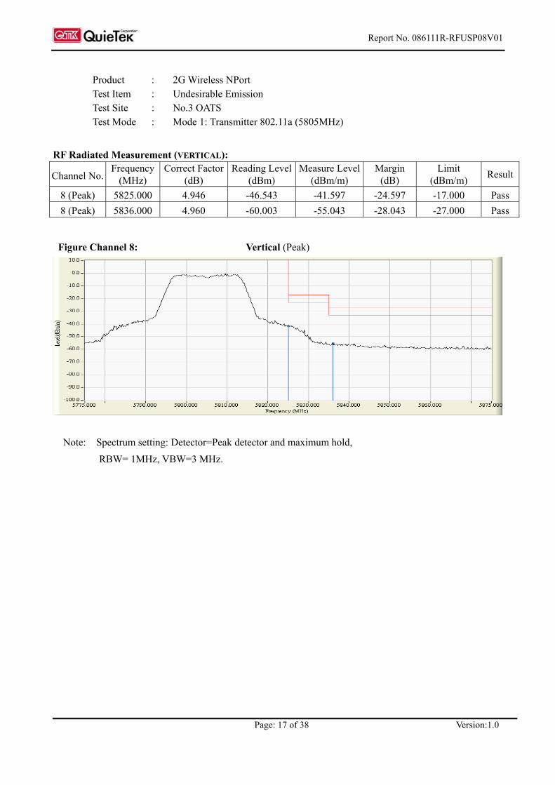
Product : 2G Wireless NPort Test Item : Undesirable Emission Test Site : No.3 OATS Test Mode : Mode 1: Transmitter 802.11a (5805MHz)
RF Radiated Measurement (VERTICAL):
Channel No. Frequency
(MHz) Correct Factor
(dB) Reading Level
(dBm) Measure Level
(dBm/m) Margin
(dB) Limit
(dBm/m) Result
8 (Peak) 5825.000 4.946 -46.543 -41.597 -24.597 -17.000 Pass 8 (Peak) 5836.000 4.960 -60.003 -55.043 -28.043 -27.000 Pass
Figure Channel 8: Vertical (Peak)
Note: Spectrum setting: Detector=Peak detector and maximum hold, RBW= 1MHz, VBW=3 MHz.
Report No. 086111R-RFUSP08V01
Page: 18 of 38 Version:1.0
3. Radiated Emission
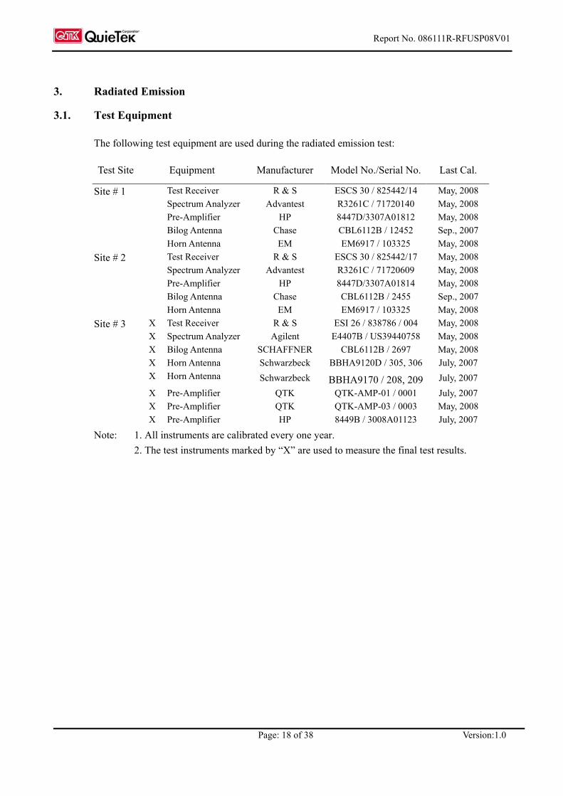
3.1. Test Equipment
The following test equipment are used during the radiated emission test:
Test Site Equipment Manufacturer Model No./Serial No. Last Cal.
Test Receiver R & S ESCS 30 / 825442/14 May, 2008 Spectrum Analyzer Advantest R3261C / 71720140 May, 2008 Pre-Amplifier HP 8447D/3307A01812 May, 2008 Bilog Antenna Chase CBL6112B / 12452 Sep., 2007
Site # 1
Horn Antenna EM EM6917 / 103325 May, 2008 Test Receiver R & S ESCS 30 / 825442/17 May, 2008 Spectrum Analyzer Advantest R3261C / 71720609 May, 2008 Pre-Amplifier HP 8447D/3307A01814 May, 2008 Bilog Antenna Chase CBL6112B / 2455 Sep., 2007
Site # 2
Horn Antenna EM EM6917 / 103325 May, 2008 X Test Receiver R & S ESI 26 / 838786 / 004 May, 2008 X Spectrum Analyzer Agilent E4407B / US39440758 May, 2008 X Bilog Antenna SCHAFFNER CBL6112B / 2697 May, 2008 X Horn Antenna Schwarzbeck BBHA9120D / 305, 306 July, 2007 X Horn Antenna Schwarzbeck BBHA9170 / 208, 209 July, 2007 X Pre-Amplifier QTK QTK-AMP-01 / 0001 July, 2007 X Pre-Amplifier QTK QTK-AMP-03 / 0003 May, 2008
Site # 3
X Pre-Amplifier HP 8449B / 3008A01123 July, 2007
Note: 1. All instruments are calibrated every one year. 2. The test instruments marked by “X” are used to measure the final test results.

Report No. 086111R-RFUSP08V01
Page: 19 of 38 Version:1.0
3.2. Test Setup
Radiated Emission Below 1GHz
Radiated Emission Above 1GHz
EUT
FRP Dome
The height of Horn Antenna was scanned from 1m to 4m. The distance between antenna and turn table was 3m.
3m
80cm
To Receiver Pre- Amplifier
EUT
FRP Dome
Test Receiver
The height of board band Antenna was scanned from 1m to 4m. The distance between antenna and turn table was 3m.
To ControllerTo Receiver
Fully soldered Metal Ground
Non-Conducted Table
3m
1m to 4m
80cm
Report No. 086111R-RFUSP08V01
Page: 20 of 38 Version:1.0
3.3. Limits
Emissions radiated outside of the specified frequency bands, except for harmonics, shall be attenuated by at least 20dB below the level of the fundamental or to the general radiated emission limits in paragraph 15.209, whichever is the lesser attenuation.
FCC Part 15 Subpart C Paragraph 15.209(a) Limits Frequency
MHz uV/m @3m dBuV/m@3m
30-88 100 40
88-216 150 43.5
216-960 200 46
Above 960 500 54
Remarks : 1. RF Voltage (dBuV) = 20 log RF Voltage (uV) 2. In the Above Table, the tighter limit applies at the band edges. 3. Distance refers to the distance in meters between the measuring instrument antenna and the closed point of any part of the device or system.
3.4. Test Procedure
The EUT was setup according to ANSI C63.4, 2003 and tested according to DTS test procedure of Oct 2002 KDB558074 for compliance to FCC 47CFR 15.247 requirements. The EUT is placed on a turn table which is 0.8 meter above ground. The turn table is rotated 360 degrees to determine the position of the maximum emission level. The EUT was positioned such that the distance from antenna to the EUT was 3 meters. The resolution bandwidth below 1GHz setting on the field strength meter is 120 kHz and above 1GHz is 1MHz. Radiated emission measurements below 1GHz are made using broadband Bilog antenna and above 1GHz are made using Horn Antennas. The measurement is divided into the Preliminary Measurement and the Final Measurement. The suspected frequencies are searched for in Preliminary Measurement with the measurement antenna kept pointed at the source of the emission both in azimuth and elevation, with the polarization of the antenna oriented for maximum response. The antenna is pointed at an angle towards the source of the emission, and the EUT is rotated in both height and polarization to maximize the measured emission. The emission is kept within the illumination area of the 3 dB beam width of the antenna. The worst radiated emission is measured on the Final Measurement. The frequency range from 30MHz to 10th harminics is checked.
Report No. 086111R-RFUSP08V01
Page: 21 of 38 Version:1.0
3.5. Uncertainty
± 3.9 dB above 1GHz ± 3.8 dB below 1GHz

Report No. 086111R-RFUSP08V01
Page: 22 of 38 Version:1.0
3.6. Test Result of Radiated Emission
Product : 2G Wireless NPort Test Item : Undesirable Emission Test Site : No.3 OATS Test Mode : Mode 1: Transmitter 802.11a (5180MHz)
Frequency Correct Reading Measurement Margin Limit
Factor Level Level MHz dB dBuV dBuV/m dB dBuV/m
Horizontal Peak Detector
10360.000 13.175 35.140 48.315 -25.685 74.000
Average Detector --
Vertical Peak Detector
10360.000 13.175 37.111 50.286 -23.714 74.000
Average Detector --
Note:
1. All Readings below 1GHz are Quasi-Peak, above are average value. 2. Receiver setting (Peak Detector) : RBW:1MHz; VBW:1MHz; Span:100MHz. 3. Receiver setting (AVG Detector) : RBW:1MHz; VBW:30Hz; Span:20MHz. 4. Measurement Level = Reading Level + Correct Factor. 5. The average measurement was not performed when the peak measured data under the limit of
average detection. If the readings given are average, peak measurement should also be supplied.

Report No. 086111R-RFUSP08V01
Page: 23 of 38 Version:1.0
Product : 2G Wireless NPort Test Item : Undesirable Emission Test Site : No.3 OATS Test Mode : Mode 1: Transmitter 802.11a (5220MHz)
Frequency Correct Reading Measurement Margin Limit
Factor Level Level MHz dB dBuV dBuV/m dB dBuV/m
Horizontal Peak Detector
10440.000 13.599 35.780 49.379 -24.621 74.000
Average Detector --
Vertical Peak Detector
10440.000 13.599 36.140 49.739 -24.261 74.000
Average Detector --
Note:
1. All Readings below 1GHz are Quasi-Peak, above are average value. 2. Receiver setting (Peak Detector) : RBW:1MHz; VBW:1MHz; Span:100MHz. 3. Receiver setting (AVG Detector) : RBW:1MHz; VBW:30Hz; Span:20MHz. 4. Measurement Level = Reading Level + Correct Factor.. 5. The average measurement was not performed when the peak measured data under the limit of
average detection. If the readings given are average, peak measurement should also be supplied.

Report No. 086111R-RFUSP08V01
Page: 24 of 38 Version:1.0
Product : 2G Wireless NPort Test Item : Undesirable Emission Test Site : No.3 OATS Test Mode : Mode 1: Transmitter 802.11a (5240MHz)
Frequency Correct Reading Measurement Margin Limit
Factor Level Level MHz dB dBuV dBuV/m dB dBuV/m
Horizontal Peak Detector
10480.000 13.934 35.780 49.714 -24.286 74.000
Average Detector --
Vertical Peak Detector
10480.000 13.934 35.890 49.824 -24.176 74.000
Average Detector --
Note:
1. All Readings below 1GHz are Quasi-Peak, above are average value. 2. Receiver setting (Peak Detector) : RBW:1MHz; VBW:1MHz; Span:100MHz。 3. Receiver setting (AVG Detector) : RBW:1MHz; VBW:30Hz; Span:20MHz。 4. Measurement Level = Reading Level + Correct Factor. 5. The average measurement was not performed when the peak measured data under the limit of
average detection. If the readings given are average, peak measurement should also be supplied.
Report No. 086111R-RFUSP08V01
Page: 25 of 38 Version:1.0
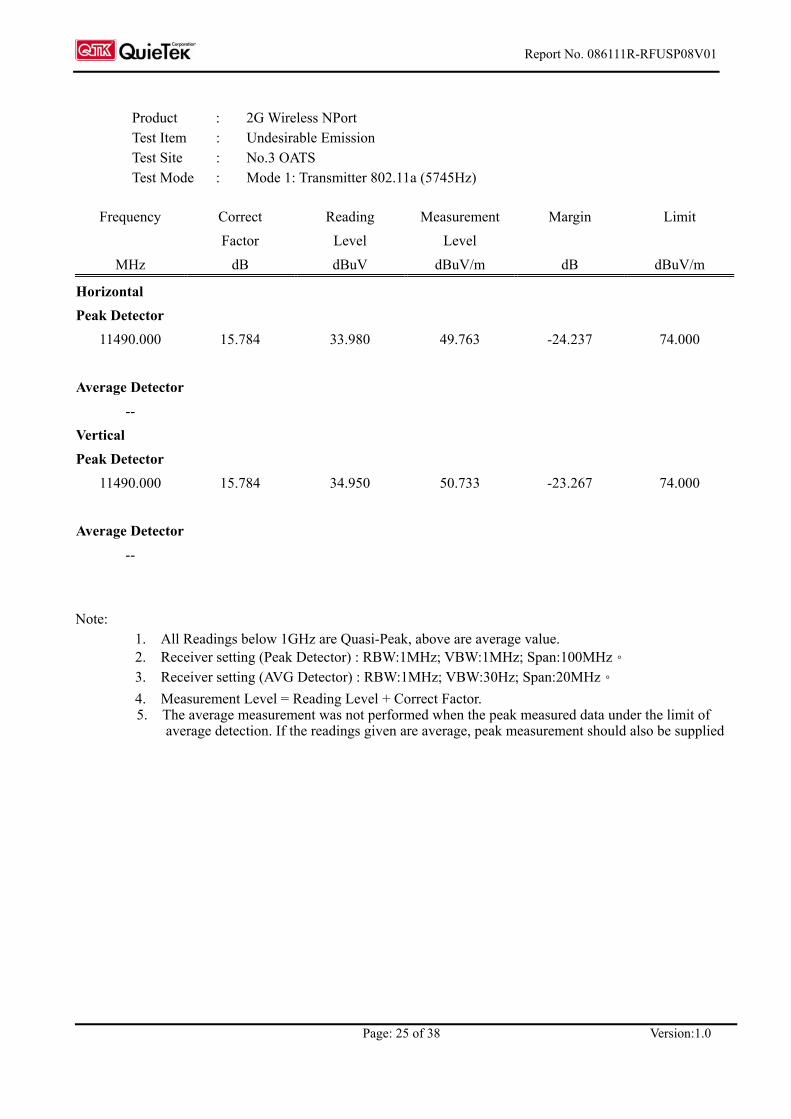
Product : 2G Wireless NPort Test Item : Undesirable Emission Test Site : No.3 OATS Test Mode : Mode 1: Transmitter 802.11a (5745Hz)
Frequency Correct Reading Measurement Margin Limit
Factor Level Level MHz dB dBuV dBuV/m dB dBuV/m
Horizontal Peak Detector
11490.000 15.784 33.980 49.763 -24.237 74.000
Average Detector --
Vertical Peak Detector
11490.000 15.784 34.950 50.733 -23.267 74.000
Average Detector --
Note:
1. All Readings below 1GHz are Quasi-Peak, above are average value. 2. Receiver setting (Peak Detector) : RBW:1MHz; VBW:1MHz; Span:100MHz。 3. Receiver setting (AVG Detector) : RBW:1MHz; VBW:30Hz; Span:20MHz。 4. Measurement Level = Reading Level + Correct Factor. 5. The average measurement was not performed when the peak measured data under the limit of
average detection. If the readings given are average, peak measurement should also be supplied

Report No. 086111R-RFUSP08V01
Page: 26 of 38 Version:1.0
Product : 2G Wireless NPort Test Item : Undesirable Emission Test Site : No.3 OATS Test Mode : Mode 1: Transmitter 802.11a (5785MHz)
Frequency Correct Reading Measurement Margin Limit
Factor Level Level MHz dB dBuV dBuV/m dB dBuV/m
Horizontal Peak Detector
11570.000 15.226 33.740 48.965 -25.035 74.000
Average Detector --
Vertical Peak Detector
11570.000 15.226 35.840 51.065 -22.935 74.000
Average Detector --
Note:
1. All Readings below 1GHz are Quasi-Peak, above are average value. 2. Receiver setting (Peak Detector) : RBW:1MHz; VBW:1MHz; Span:100MHz。 3. Receiver setting (AVG Detector) : RBW:1MHz; VBW:30Hz; Span:20MHz。 4. Measurement Level = Reading Level + Correct Factor. 5. The average measurement was not performed when the peak measured data under the limit of
average detection. If the readings given are average, peak measurement should also be supplied
Report No. 086111R-RFUSP08V01
Page: 27 of 38 Version:1.0
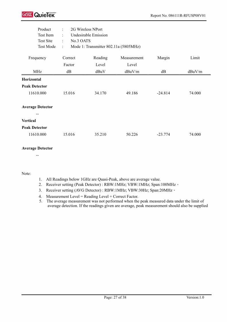
Product : 2G Wireless NPort Test Item : Undesirable Emission Test Site : No.3 OATS Test Mode : Mode 1: Transmitter 802.11a (5805MHz)
Frequency Correct Reading Measurement Margin Limit
Factor Level Level MHz dB dBuV dBuV/m dB dBuV/m
Horizontal Peak Detector
11610.000 15.016 34.170 49.186 -24.814 74.000
Average Detector --
Vertical Peak Detector
11610.000 15.016 35.210 50.226 -23.774 74.000
Average Detector --
Note:
1. All Readings below 1GHz are Quasi-Peak, above are average value. 2. Receiver setting (Peak Detector) : RBW:1MHz; VBW:1MHz; Span:100MHz。 3. Receiver setting (AVG Detector) : RBW:1MHz; VBW:30Hz; Span:20MHz。 4. Measurement Level = Reading Level + Correct Factor. 5. The average measurement was not performed when the peak measured data under the limit of
average detection. If the readings given are average, peak measurement should also be supplied

Report No. 086111R-RFUSP08V01
Page: 28 of 38 Version:1.0
Product : 2G Wireless NPort Test Item : Undesirable Emission Test Site : No.3 OATS Test Mode : Mode 1: Transmitter 802.11a (5220MHz)
Frequency Correct Reading Measurement Margin Limit
Factor Level Level MHz dB dBuV dBuV/m dB dBuV/m
Horizontal Peak Detector
336.580 14.434 13.156 27.590 -18.410 46.000 431.580 17.742 13.908 31.650 -14.350 46.000 465.980 18.699 5.881 24.580 -21.420 46.000 625.480 20.832 6.019 26.850 -19.150 46.000 724.580 21.155 8.425 29.580 -16.420 46.000 864.250 22.207 9.373 31.580 -14.420 46.000 Vertical
Peak Detector 288.250 13.845 20.405 34.250 -11.750 46.000 342.590 14.611 11.969 26.580 -19.420 46.000 465.850 18.455 8.395 26.850 -19.150 46.000 625.360 21.144 3.707 24.850 -21.150 46.000 735.590 23.173 6.408 29.580 -16.420 46.000 811.260 21.703 5.947 27.650 -18.350 46.000
Note:
1. All Readings below 1GHz are Quasi-Peak, above are average value. 2. “ ” means the worst emission level. 3. Measurement Level = Reading Level + Correct Factor 4. The radiated emissions below 1GHz of the lowest, middle, highest frequency are pretested. Only
the worst case is shown on the report.

Report No. 086111R-RFUSP08V01
Page: 29 of 38 Version:1.0
Product : 2G Wireless NPort Test Item : Undesirable Emission Test Site : No.3 OATS Test Mode : Mode 1: Transmitter 802.11a (5785MHz)
Frequency Correct Reading Measurement Margin Limit
Factor Level Level MHz dB dBuV dBuV/m dB dBuV/m
Horizontal Peak Detector
288.250 13.483 13.097 26.580 -19.420 46.000 383.450 15.804 13.146 28.950 -17.050 46.000 512.480 19.077 9.373 28.450 -17.550 46.000 625.400 20.839 6.011 26.850 -19.150 46.000 833.200 21.825 2.674 24.500 -21.500 46.000 931.400 22.910 5.449 28.360 -17.640 46.000 Vertical
Peak Detector 265.850 14.363 17.488 31.850 -14.150 46.000 336.520 14.364 12.486 26.850 -19.150 46.000 431.590 19.266 12.424 31.690 -14.310 46.000 523.400 18.824 7.476 26.300 -19.700 46.000 605.400 21.817 5.783 27.600 -18.400 46.000 733.480 23.135 4.455 27.590 -18.410 46.000
Note:
1. All Readings below 1GHz are Quasi-Peak, above are average value. 2. “ ” means the worst emission level. 3. Measurement Level = Reading Level + Correct Factor 4. The radiated emissions below 1GHz of the lowest, middle, highest frequency are pretested. Only
the worst case is shown on the report.

Report No. 086111R-RFUSP08V01
Page: 30 of 38 Version:1.0
4. Band Edge
4.1. Test Equipment
The following test equipments are used during the band edge tests:
Test Site Equipment Manufacturer Model No./Serial No. Last Cal.
X Test Receiver R & S ESI 26 / 838786 / 004 May, 2008X Spectrum Analyzer Agilent E4407B / US39440758 May, 2008X Pre-Amplifier QTK QTK-AMP-03 / 0003 May, 2008X Bilog Antenna SCHAFFNER CBL6112B / 2697 May, 2008X Horn Antenna ETS 3115 / 0005-6160 July, 2007
Site # 3
X Pre-Amplifier QTK QTK-AMP-01 / 0001 July, 2007
4.2. Test Setup
RF Radiated Measurement:
EUT
FRP Dome
Test Receiver
The height of board band or Dipole Antenna was scanned from 1M to 4M. The distance between antenna and turn table was 3M regards to the standard adopted.
To ControllerTo Receiver
Fully soldered Metal Ground
Non-Conducted Table
3m
1m to 4m
80cm

Report No. 086111R-RFUSP08V01
Page: 31 of 38 Version:1.0
4.3. Limits
The provisions of Section 15.205 of this part apply to intentional radiators operating under this section. Radiated emissions which fall in the restricted bands, as defined in Section 15.205, must also comply with the radiated emission limits specified in Section 15.209:
FCC Part 15 Subpart C Paragraph 15.209 Limits Frequency
MHz uV/m @3m dBuV/m@3m
30-88 100 40
88-216 150 43.5
216-960 200 46
Above 960 500 54
Remarks : 1. RF Voltage (dBuV) = 20 log RF Voltage (uV) 2. In the Above Table, the tighter limit applies at the band edges.
3. Distance refers to the distance in meters between the measuring instrument antenna and the closed point of any part of the device or system.
4.4. Test Procedure
The EUT and its simulators are placed on a turn table which is 0.8 meter above ground. The turn table can rotate 360 degrees to determine the position of the maximum emission level. The EUT was positioned such that the distance from antenna to the EUT was 3 meters. The antenna can move up and down between 1 meter and 4 meters to find out the maximum emission level. Both horizontal and vertical polarization of the antenna are set on measurement. In order to find the maximum emission, all of the interface cables must be manipulated according to ANSI C63.4:1992 on radiated measurement. The bandwidth below 1GHz setting on the field strength meter is 120 kHz, above 1GHz are 1 MHz.
4.5. Uncertainty
± 3.8 dB below 1GHz ± 3.9 dB above 1GHz
Report No. 086111R-RFUSP08V01
Page: 32 of 38 Version:1.0
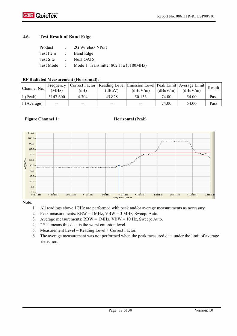
4.6. Test Result of Band Edge
Product : 2G Wireless NPort Test Item : Band Edge Test Site : No.3 OATS Test Mode : Mode 1: Transmitter 802.11a (5180MHz)
RF Radiated Measurement (Horizontal):
Channel No. Frequency
(MHz) Correct Factor
(dB) Reading Level
(dBuV) Emission Level
(dBuV/m) Peak Limit (dBuV/m)
Average Limit(dBuV/m) Result
1 (Peak) 5147.600 4.304 45.828 50.133 74.00 54.00 Pass 1 (Average) -- -- -- -- 74.00 54.00 Pass
Figure Channel 1: Horizontal (Peak)
Note:
1. All readings above 1GHz are performed with peak and/or average measurements as necessary. 2. Peak measurements: RBW = 1MHz, VBW = 3 MHz, Sweep: Auto. 3. Average measurements: RBW = 1MHz, VBW = 10 Hz, Sweep: Auto. 4. “ * ”, means this data is the worst emission level. 5. Measurement Level = Reading Level + Correct Factor. 6. The average measurement was not performed when the peak measured data under the limit of average
detection.

Report No. 086111R-RFUSP08V01
Page: 33 of 38 Version:1.0
Product : 2G Wireless NPort Test Item : Band Edge Test Site : No.3 OATS Test Mode : Mode 1: Transmitter 802.11a (5180MHz)
RF Radiated Measurement (Vertical):
Channel No. Frequency
(MHz) Correct Factor
(dB) Reading Level
(dBuV) Emission Level
(dBuV/m) Peak Limit (dBuV/m)
Average Limit(dBuV/m) Result
1 (Peak) 5147.000 4.305 53.564 57.868 74.00 54.00 Pass 1 (Average) 5150.000 4.305 36.020 40.325 74.00 54.00 Pass
Figure Channel 1: Vertical (Peak)
Figure Channel 1: Vertical (Average)
Note:
1. All readings above 1GHz are performed with peak and/or average measurements as necessary. 2. Peak measurements: RBW = 1MHz, VBW = 3 MHz, Sweep: Auto. 3. Average measurements: RBW = 1MHz, VBW = 10 Hz, Sweep: Auto. 4. “ * ”, means this data is the worst emission level. 5. Measurement Level = Reading Level + Correct Factor. 6. The average measurement was not performed when the peak measured data under the limit of average
detection.

Report No. 086111R-RFUSP08V01
Page: 34 of 38 Version:1.0
Product : 2G Wireless NPort Test Item : Band Edge Test Site : No.3 OATS Test Mode : Mode 1: Transmitter 802.11a (5240MHz)
RF Radiated Measurement (Horizontal):
Channel No. Frequency
(MHz) Correct Factor
(dB) Reading Level
(dBuV) Emission Level
(dBuV/m) Peak Limit (dBuV/m)
Average Limit(dBuV/m) Result
4 (Peak) 5350.000 4.446 41.500 45.946 74.00 54.00 Pass 4 (Average) -- -- -- -- 74.00 54.00 Pass
Figure Channel 4: Horizonal (Peak)
Note:
1. All readings above 1GHz are performed with peak and/or average measurements as necessary. 2. Peak measurements: RBW = 1MHz, VBW = 3 MHz, Sweep: Auto. 3. Average measurements: RBW = 1MHz, VBW = 10 Hz, Sweep: Auto. 4. “ * ”, means this data is the worst emission level. 5. Measurement Level = Reading Level + Correct Factor. 6. The average measurement was not performed when the peak measured data under the limit of average
detection.
Report No. 086111R-RFUSP08V01
Page: 35 of 38 Version:1.0
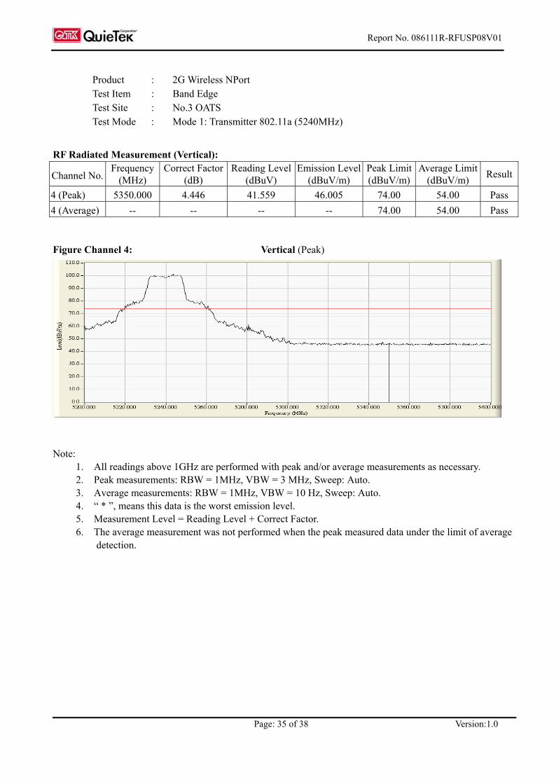
Product : 2G Wireless NPort Test Item : Band Edge Test Site : No.3 OATS Test Mode : Mode 1: Transmitter 802.11a (5240MHz)
RF Radiated Measurement (Vertical):
Channel No. Frequency
(MHz) Correct Factor
(dB) Reading Level
(dBuV) Emission Level
(dBuV/m) Peak Limit (dBuV/m)
Average Limit(dBuV/m) Result
4 (Peak) 5350.000 4.446 41.559 46.005 74.00 54.00 Pass 4 (Average) -- -- -- -- 74.00 54.00 Pass
Figure Channel 4: Vertical (Peak)
Note:
1. All readings above 1GHz are performed with peak and/or average measurements as necessary. 2. Peak measurements: RBW = 1MHz, VBW = 3 MHz, Sweep: Auto. 3. Average measurements: RBW = 1MHz, VBW = 10 Hz, Sweep: Auto. 4. “ * ”, means this data is the worst emission level. 5. Measurement Level = Reading Level + Correct Factor. 6. The average measurement was not performed when the peak measured data under the limit of average
detection.

Report No. 086111R-RFUSP08V01
Page: 36 of 38 Version:1.0
5. EMI Reduction Method During Compliance Testing
No modification was made during testing.
Report No. 086111R-RFUSP08V01
Page: 37 of 38 Version:1.0
Attachment 1: EUT Test Photographs

Report No.: 086111R-RFUSP08V01
Page : 1 of 3 Version:1.0
Attachment 1: EUT Test Setup Photographs
Front View of Radiated Test
Back View of Radiated Test

Report No.: 086111R-RFUSP08V01
Page : 2 of 3 Version:1.0
Front View of Radiated Test (Horn)
Back View of Radiated Test (Horn)

Report No.: 086111R-RFUSP08V01
Page : 3 of 3 Version:1.0
Front View of Radiated Test (Horn)
Back View of Radiated Test (Horn)

Report No. 086111R-RFUSP08V01
Page: 38 of 38 Version:1.0
Attachment 2: EUT Detailed Photographs

Report No.: 086111R-RFUSP08V01
Page : 1 of 16 Version:1.0
Attachment 2 : EUT Detailed Photographs (1) EUT Photo
(2) EUT Photo
Report No.: 086111R-RFUSP08V01
Page : 2 of 16 Version:1.0
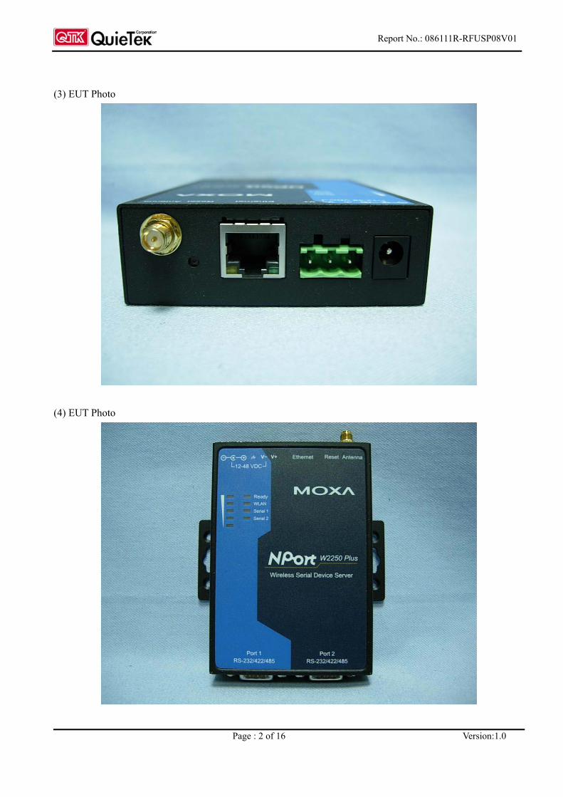
(3) EUT Photo
(4) EUT Photo
Report No.: 086111R-RFUSP08V01
Page : 3 of 16 Version:1.0
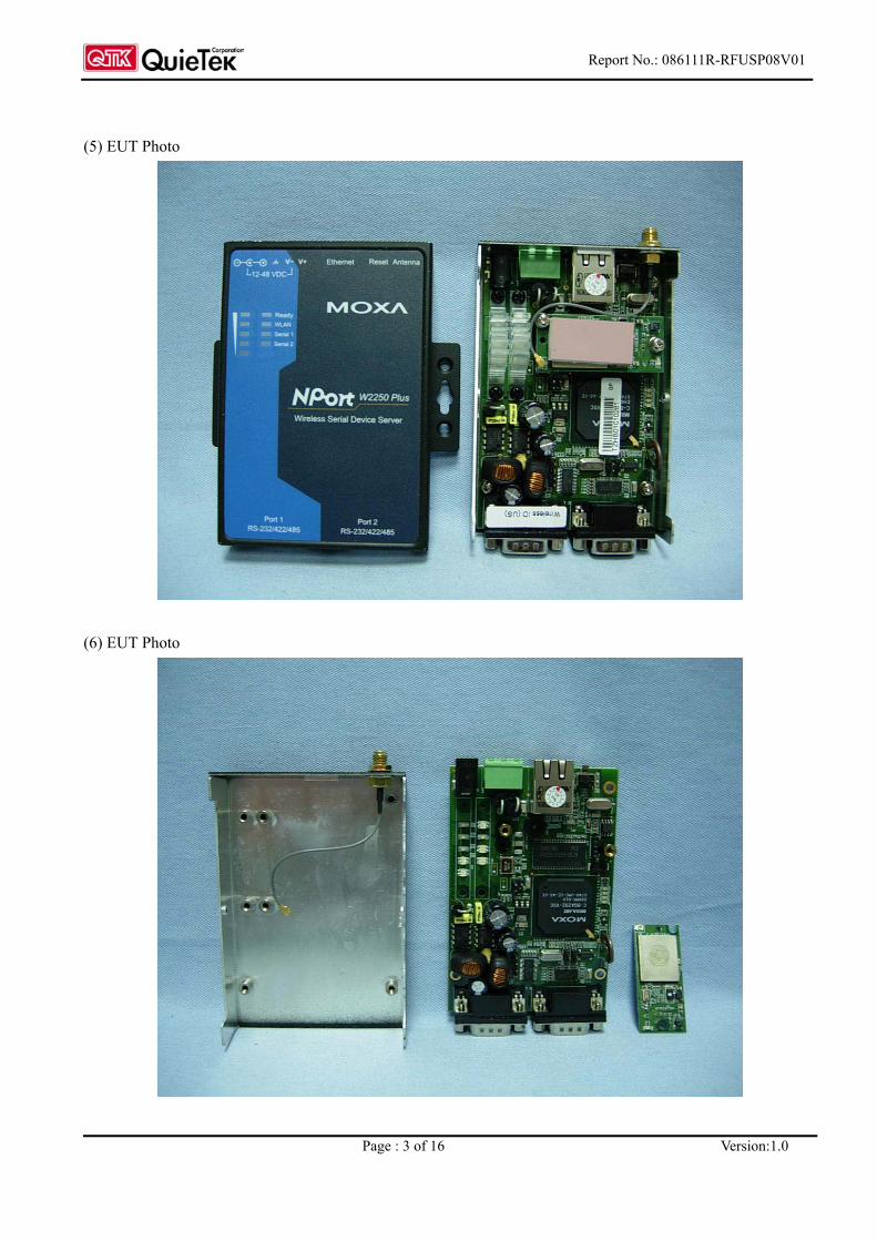
(5) EUT Photo
(6) EUT Photo

Report No.: 086111R-RFUSP08V01
Page : 4 of 16 Version:1.0
(7) EUT Photo
(8) EUT Photo
Report No.: 086111R-RFUSP08V01
Page : 5 of 16 Version:1.0
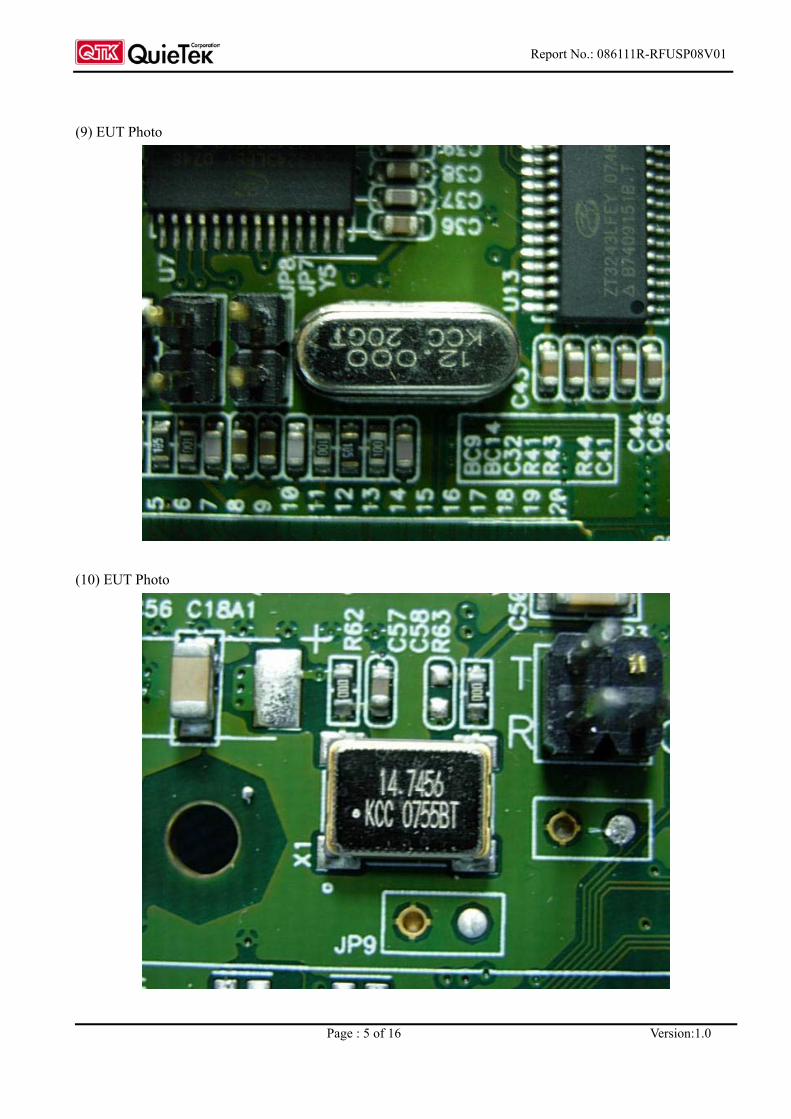
(9) EUT Photo
(10) EUT Photo

Report No.: 086111R-RFUSP08V01
Page : 6 of 16 Version:1.0
(11) EUT Photo
(12) EUT Photo

Report No.: 086111R-RFUSP08V01
Page : 7 of 16 Version:1.0
(13) EUT Photo
(14) EUT Photo

Report No.: 086111R-RFUSP08V01
Page : 8 of 16 Version:1.0
(15) EUT Photo
(16) EUT Photo
Report No.: 086111R-RFUSP08V01
Page : 9 of 16 Version:1.0
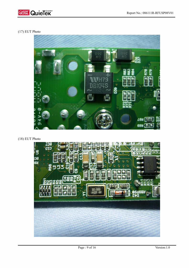
(17) EUT Photo
(18) EUT Photo

Report No.: 086111R-RFUSP08V01
Page : 10 of 16 Version:1.0
(19) EUT Photo
(20) EUT Photo

Report No.: 086111R-RFUSP08V01
Page : 11 of 16 Version:1.0
(21) EUT Photo
(22) EUT Photo

Report No.: 086111R-RFUSP08V01
Page : 12 of 16 Version:1.0
(23) EUT Photo
(24) EUT Photo
Report No.: 086111R-RFUSP08V01
Page : 13 of 16 Version:1.0
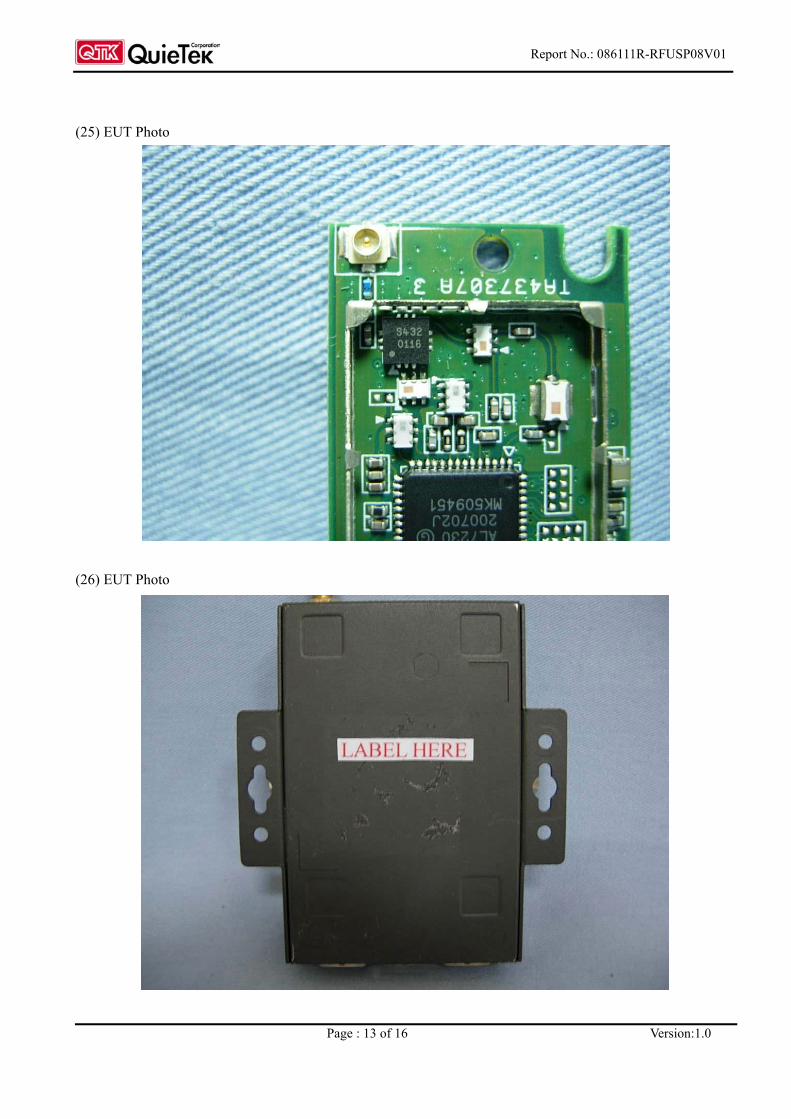
(25) EUT Photo
(26) EUT Photo

Report No.: 086111R-RFUSP08V01
Page : 14 of 16 Version:1.0
(27) EUT Photo
(28) EUT Photo
Trade Name: WANSHIH Model No.: WNW1730A1
Trade Name: WANSHIH Model No.: WNW1730A1

Report No.: 086111R-RFUSP08V01
Page : 15 of 16 Version:1.0
(29) EUT Photo
(30) EUT Photo
Trade Name: WANSHIH Model No.: WNW1730A1
Trade Name: KINSUN Model No.: 6602D03081

Report No.: 086111R-RFUSP08V01
Page : 16 of 16 Version:1.0
(31) EUT Photo
(32) EUT Photo
Trade Name: KINSUN Model No.: 6602D03081
Trade Name: KINSUN Model No.: 6602D03081

Report No. 073L065-RFUSP08V01
Page: 1 of 61 Version:1.0
Test Report
Product Name : 2G Wireless NPort
Model No : NPort W2150 Plus, NPort W2250 Plus
FCC ID : SLEW2250Plus
Applicant : Moxa Technologies Co., Ltd
Address : Fl.4, No. 135, Lane 235, Pao-Chiao Rd., Shing Tien City,
Taipei, Taiwan, R.O.C.
Date of Receipt : March 13, 2007
Issued Date : April 07, 2007
Report No. : 073L065-RFUSP08V01
The test results relate only to the samples tested. The test report shall not be reproduced except in full without the written approval of QuieTek Corporation.This report must not be used to claim product endorsement by NVLAP any agency of the U.S. Government

Report No. 073L065-RFUSP08V01
Page: 2 of 61 Version:1.0
Test Report Cert i f icat ion Issued Date: April 07, 2007 Rport No.: 073L065-RFUSP08V01
The Test Results relate only to the samples tested. The test report shall not be reproduced except in full without the written approval of QuieTek Corporation. This report must not be used to claim product endorsement by NVLAP any agency of the U.S. Government
Product Name : 2G Wireless NPort
Applicant : Moxa Technologies Co., Ltd
Address : Fl.4, No. 135, Lane 235, Pao-Chiao Rd., Shing Tien City, Taipei, Taiwan, R.O.C.
Manufacturer : Moxa Technologies Co., Ltd
Model No. : NPort W2150 Plus, NPort W2250 Plus
FCC ID. : SLEW2250Plus
Rated Voltage : AC 120V/60Hz
Working Voltage : DC 12V
Trade Name : Moxa
Applicable Standard : FCC CFR Title 47 Part 15 Subpart E: 2005
ANSI C63.4: 2003
Test Result : Complied
Documented By :
( Engineering Adm. Specialist /
Genie Chang )
Tested By :
( Senior Engineer /Tim Sung )
Approved By :
( President /Gene Chang ) 0914

Report No. 073L065-RFUSP08V01
Page: 3 of 61 Version:1.0
TABLE OF CONTENTS
Description Page
1. GENERAL INFORMATION .....................................................................................................5
1.1. EUT Description............................................................................................................................5 1.2. Operational Description ................................................................................................................6 1.3. Tested System Datails....................................................................................................................7 1.4. Configuration of tested System .....................................................................................................7 1.5. EUT Exercise Software .................................................................................................................7 1.6. Test Facility ...................................................................................................................................8
2. Conducted Emission....................................................................................................................9
2.1. Test Equipment..............................................................................................................................9 2.2. Test Setup ......................................................................................................................................9 2.3. Limits ............................................................................................................................................9 2.4. Test Procedure .............................................................................................................................10 2.5. Uncertainty ..................................................................................................................................10 2.6. Test Result of Conducted Emission.............................................................................................11
3. Peak Transmit Power ................................................................................................................15
3.1. Test Equipment............................................................................................................................15 3.2. Test Setup ....................................................................................................................................15 3.3. Limits ..........................................................................................................................................15 3.4. Uncertainty ..................................................................................................................................15 3.5. Test Result of Peak Transmit Power............................................................................................16
4. Peak Power Spectral Density....................................................................................................28
4.1. Test Equipment............................................................................................................................28 4.2. Test Setup ....................................................................................................................................28 4.3. Limits ..........................................................................................................................................28 4.4. Uncertainty ..................................................................................................................................28 4.5. Test Result of Peak Power Spectral Density ...............................................................................29
5. Peak Excursion ..........................................................................................................................33
5.1. Test Equipment............................................................................................................................33 5.2. Test Setup ....................................................................................................................................33 5.3. Limits ..........................................................................................................................................33 5.4. Uncertainty ..................................................................................................................................33 5.5. Test Result of Peak Excursion.....................................................................................................34
6. Undesirable Emission................................................................................................................38
6.1. Test Equipment............................................................................................................................38 6.2. Test Setup ....................................................................................................................................38 6.3. Limits ..........................................................................................................................................39 6.4. Test Procedure .............................................................................................................................40 6.5. Uncertainty ..................................................................................................................................40 6.6. Test Result of Undesirable Emission...........................................................................................41
7. Band Edge ..................................................................................................................................49
7.1. Test Equipment............................................................................................................................49 7.2. Test Setup ....................................................................................................................................49 7.3. Limits ..........................................................................................................................................50

Report No. 073L065-RFUSP08V01
Page: 4 of 61 Version:1.0
7.4. Test Procedure .............................................................................................................................50 7.5. Uncertainty ..................................................................................................................................50 7.6. Test Result of Band Edge ............................................................................................................51
8. Frequency Stability....................................................................................................................57
8.1. Test Equipment............................................................................................................................57 8.2. Test Setup ....................................................................................................................................57 8.3. Limits ..........................................................................................................................................57 8.4. Uncertainty ..................................................................................................................................57 8.5. Test Result of Frequency Stability...............................................................................................58
9. EMI Reduction Method During Compliance Testing ............................................................59
Attachment 1: EUT Test Photographs Attachment 2: EUT Detailed Photographs

Report No. 073L065-RFUSP08V01
Page: 5 of 61 Version:1.0
1. GENERAL INFORMATION
1.1. EUT Description
Product Name : 2G Wireless NPort Trade Name : Moxa FCC ID. : SLEW2250Plus Model No. : NPort W2150 Plus, NPort W2250 Plus Frequency Range : 2412MHz - 2462MHz, 5150-5250MHz, 5725-5825MHz Number of Channels : 11 in 2.4GHz band, 8 in 5GHz band Channel Separation : 5MHz in 2.4GHz band, 20MHz in 5GHz band Channel Control : Auto Data Rate : 802.11b – 1, 2, 5.5, 11Mbps 802.11a/g – 6, 9, 12, 18, 24, 36, 48, 54Mbps Type of Modulation : DSSS/ OFDM Antenna type : Connector (Reverse SMA) Antenna Gain : Refer to the table “Antenna List” Power Adapter : MFR: BLANCE, M/N: GPSA-1200120
Input: AC 100-240V, 50-60Hz, 0.5A Output: DC 12V-1.2A Cable out: Non-Shielded, 1.9m with one ferrite core bonded.
Antenna List
No. Manufacturer Part No. Peak Gain 1 SmartAnt SAA05-220420 2.0 dBi for 2.4 GHz
2.0 dBi for 5.0 GHz
Frequency of Each Channel:
Channel Frequency Channel Frequency Channel Frequency Channel Frequency
Channel 1 5180 MHz Channel 2 5200 MHz Channel 3 5220 MHz Channel 4 5240 MHz
Channel 5 5745 MHz Channel 6 5765 MHz Channel 7 5785 MHz Channel 8 5805 MHz Note: 1. This device is a 2G Wireless NPort with a built-in 2.4GHz and 5GHz transceiver. 2. Regarding to the operation frequency, the lowest, middle and highest frequency are selected to
perform the test. Lowest and highest data rates are tested in each mode. Only worst case is shown in the report. (802.11b is 1Mbps and 802.11a/g is 6Mbps)
3. These tests were conducted on a sample of the equipment for the purpose of demonstrating compliance with Part 15 Subpart E for Unlicensed National Information Infrastructure devices.

Report No. 073L065-RFUSP08V01
Page: 6 of 61 Version:1.0
1.2. Operational Description
EUT is a 2G Wireless NPort with a built-in 2.4GHz and 5GHz transceiver. The channels are separated by 20MHz of 802.11a and 5MHz of 802.11b/g. This device supports the data rates of 1, 2, 5.5, 11Mbps in 802.11b mode and 6, 9, 12, 18, 24, 36, 48, 54Mbps in 802.11a/g mode. The signals are modulated by DSSS in 802.11b mode and OFDM in 802.11a/g mode. The antennas are Connector and use diversity to improve the receiving sensitivity.
This 2G Wireless NPort, complied with IEEE 802.11b, IEEE 802.11g, and IEEE 802.11a, is a high-efficiency Wireless LAN adapter. It allows your computer to connect to a wireless network and to share resources, such as files or printers without network wires. Wired Equivalent Protection (WEP) algorithm is used. In addition, its standard compliance ensures that it can communicate with any IEEE 802.11b, IEEE 802.11g, and IEEE 802.11a network.
Test Mode Mode 1: Transmitter 802.11a

Report No. 073L065-RFUSP08V01
Page: 7 of 61 Version:1.0
1.3. Tested System Datails
The types for all equipment, plus descriptions of all cables used in the tested system (including inserted cards) are:
Product Manufacturer Model No. Serial No. Power Cord
1 Notebook PC DELL PP04X C8YYM1S Non-Shielded, 0.8m
Signal Cable Type Signal cable Description
A LAN Cable Non-Shielded, 7.0m
1.4. Configuration of tested System
1.5. EUT Exercise Software
(1) Setup the EUT as shown in Section 1.4 (2) Execute Telnet IP on the notebook. (3) Configure the test mode, the test channel, and the data rate. (4) Press “OK” to start the continuous transmission. (5) Verify that the EUT works properly.

Report No. 073L065-RFUSP08V01
Page: 8 of 61 Version:1.0
1.6. Test Facility
Ambient conditions in the laboratory:
Items Required (IEC 68-1) Actual
Temperature (°C) 15-35 20-35
Humidity (%RH) 25-75 50-65
Barometric pressure (mbar) 860-1060 950-1000
Site Description: File on Federal Communications Commission FCC Engineering Laboratory 7435 Oakland Mills Road Columbia, MD 21046 Reference 31040/SIT1300F2 Accreditation on NVLAP NVLAP Lab Code: 200533-0 Site Name: Quietek Corporation Site Address: No. 5-22, Ruei-Shu Valley, Ruei-Ping Tsuen, Lin-Kou Shiang, Taipei, Taiwan, R.O.C. TEL: 886-2-8601-3788 / FAX : 886-2-8601-3789 E-Mail : [email protected] 0914

Report No. 073L065-RFUSP08V01
Page: 9 of 61 Version:1.0
2. Conducted Emission
2.1. Test Equipment
The following test equipment are used during the conducted emission test:
Item Instrument Manufacturer Type No./Serial No Last Cal. Remark
1 Test Receiver R & S ESCS 30/825442/17 May, 2007
2 L.I.S.N. R & S ESH3-Z5/825016/6 May, 2007 EUT
3 L.I.S.N. Kyoritsu KNW-407/8-1420-3 May, 2007 Peripherals
4 Pulse Limiter R & S ESH3-Z2 May, 2007
5 No.1 Shielded Room N/A
Note: All equipments are calibrated every one year.
2.2. Test Setup
2.3. Limits
FCC Part 15 Subpart C Paragraph 15.207 (dBuV) Limit
Limits Frequency
MHz QP AV
0.15 - 0.50 66-56 56-46
0.50-5.0 56 46
5.0 - 30 60 50
Remarks : In the above table, the tighter limit applies at the band edges.
40cm Test Receiver
EUT
LISN
LISN
12dBuV
Ground Plane
Reference Plane
LISN
Load
Report No. 073L065-RFUSP08V01
Page: 10 of 61 Version:1.0
2.4. Test Procedure
The EUT and simulators are connected to the main power through a line impedance stabilization network (L.I.S.N.). This provides a 50 ohm /50uH coupling impedance for the measuring equipment. The peripheral devices are also connected to the main power through a LISN that provides a 50ohm /50uH coupling impedance with 50ohm termination. (Please refers to the block diagram of the test setup and photographs.) Both sides of A.C. line are checked for maximum conducted interference. In order to find the maximum emission, the relative positions of equipment and all of the interface cables must be changed according to ANSI C63.4: 2003 on conducted measurement. Conducted emissions were invested over the frequency range from 0.15MHz to 30MHz using a receiver bandwidth of 9kHz.
2.5. Uncertainty
± 2.26 dB
Report No. 073L065-RFUSP08V01
Page: 11 of 61 Version:1.0
2.6. Test Result of Conducted Emission
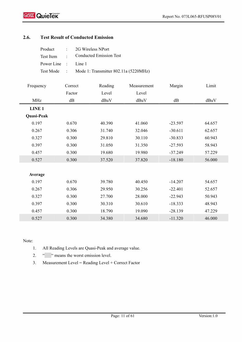
Product : 2G Wireless NPort Test Item : Conducted Emission Test
Power Line : Line 1 Test Mode : Mode 1: Transmitter 802.11a (5220MHz)
Frequency Correct Reading Measurement Margin Limit
Factor Level Level MHz dB dBuV dBuV dB dBuV
LINE 1 Quasi-Peak
0.197 0.670 40.390 41.060 -23.597 64.657 0.267 0.306 31.740 32.046 -30.611 62.657 0.327 0.300 29.810 30.110 -30.833 60.943 0.397 0.300 31.050 31.350 -27.593 58.943 0.457 0.300 19.680 19.980 -37.249 57.229 0.527 0.300 37.520 37.820 -18.180 56.000
Average
0.197 0.670 39.780 40.450 -14.207 54.657 0.267 0.306 29.950 30.256 -22.401 52.657 0.327 0.300 27.700 28.000 -22.943 50.943 0.397 0.300 30.310 30.610 -18.333 48.943 0.457 0.300 18.790 19.090 -28.139 47.229 0.527 0.300 34.380 34.680 -11.320 46.000
Note: 1. All Reading Levels are Quasi-Peak and average value. 2. “ “ means the worst emission level. 3. Measurement Level = Reading Level + Correct Factor

Report No. 073L065-RFUSP08V01
Page: 12 of 61 Version:1.0
Product : 2G Wireless NPort Test Item : Conducted Emission Test Power Line : Line 2 Test Mode : Mode 1: Transmitter 802.11a (5220MHz)
Frequency Correct Reading Measurement Margin Limit Factor Level Level
MHz dB dBuV dBuV dB dBuV
LINE 2 Quasi-Peak
0.201 0.300 38.580 38.880 -25.663 64.543 0.261 0.300 30.680 30.980 -31.849 62.829 0.331 0.301 32.490 32.791 -28.038 60.829 0.391 0.310 23.710 24.020 -35.094 59.114 0.461 0.310 27.430 27.740 -29.374 57.114 0.531 0.310 35.680 35.990 -20.010 56.000
Average
0.201 0.300 37.850 38.150 -16.393 54.543 0.261 0.300 28.850 29.150 -23.679 52.829 0.331 0.301 30.450 30.751 -20.078 50.829 0.391 0.310 22.970 23.280 -25.834 49.114 0.461 0.310 26.630 26.940 -20.174 47.114 0.531 0.310 32.480 32.790 -13.210 46.000
Note: 1. All Reading Levels are Quasi-Peak and average value. 2. “ “ means the worst emission level. 3. Measurement Level = Reading Level + Correct Factor
Report No. 073L065-RFUSP08V01
Page: 13 of 61 Version:1.0
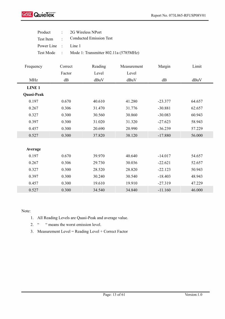
Product : 2G Wireless NPort Test Item : Conducted Emission Test
Power Line : Line 1 Test Mode : Mode 1: Transmitter 802.11a (5785MHz)
Frequency Correct Reading Measurement Margin Limit
Factor Level Level MHz dB dBuV dBuV dB dBuV
LINE 1 Quasi-Peak
0.197 0.670 40.610 41.280 -23.377 64.657 0.267 0.306 31.470 31.776 -30.881 62.657 0.327 0.300 30.560 30.860 -30.083 60.943 0.397 0.300 31.020 31.320 -27.623 58.943 0.457 0.300 20.690 20.990 -36.239 57.229 0.527 0.300 37.820 38.120 -17.880 56.000
Average
0.197 0.670 39.970 40.640 -14.017 54.657 0.267 0.306 29.730 30.036 -22.621 52.657 0.327 0.300 28.520 28.820 -22.123 50.943 0.397 0.300 30.240 30.540 -18.403 48.943 0.457 0.300 19.610 19.910 -27.319 47.229 0.527 0.300 34.540 34.840 -11.160 46.000
Note: 1. All Reading Levels are Quasi-Peak and average value. 2. “ “ means the worst emission level. 3. Measurement Level = Reading Level + Correct Factor

Report No. 073L065-RFUSP08V01
Page: 14 of 61 Version:1.0
Product : 2G Wireless NPort Test Item : Conducted Emission Test Power Line : Line 2 Test Mode : Mode 1: Transmitter 802.11a (5785MHz)
Frequency Correct Reading Measurement Margin Limit Factor Level Level
MHz dB dBuV dBuV dB dBuV
LINE 2 Quasi-Peak
0.197 0.300 40.630 40.930 -23.727 64.657 0.267 0.300 31.490 31.790 -30.867 62.657 0.327 0.300 30.820 31.120 -29.823 60.943 0.397 0.310 30.960 31.270 -27.673 58.943 0.457 0.310 21.400 21.710 -35.519 57.229 0.527 0.310 37.820 38.130 -17.870 56.000
Average
0.197 0.300 40.010 40.310 -14.347 54.657 0.267 0.300 29.800 30.100 -22.557 52.657 0.327 0.300 28.850 29.150 -21.793 50.943 0.397 0.310 30.240 30.550 -18.393 48.943 0.457 0.310 20.370 20.680 -26.549 47.229 0.527 0.310 34.790 35.100 -10.900 46.000
Note: 1. All Reading Levels are Quasi-Peak and average value. 2. “ “ means the worst emission level. 3. Measurement Level = Reading Level + Correct Factor

Report No. 073L065-RFUSP08V01
Page: 15 of 61 Version:1.0
3. Peak Transmit Power
3.1. Test Equipment
The following test equipments are used during the radiated emission tests:
Equipment Manufacturer Model No./Serial No. Last Cal.
X Spectrum Analyzer Agilent E4407B / US39440758 May, 2007
Note: 1. All equipments are calibrated every one year. 2. The test instruments marked by “X” are used to measure the final test results.
3.2. Test Setup
Conduction Power Measurement
3.3. Limits
(1) For the band 5.15-5.25 GHz, the peak transmit power over the frequency band of operation shall not exceed the lesser of 50 mW or 4 dBm + 10log B, where B is the 26-dB emission bandwidth in MHz. If transmitting antenna of directional gain greater than 6 dBi are used, the peak transmit power shall be reduced by the amount in dB that directional gain of the antenna exceeds 6 dBi.
(2) For the band 5.25-5.35 GHz, the peak transmit power over the frequency band of operation shall not exceed the lesser of 250 mW or 11 dBm + 10log B, where B is the 26-dB emission bandwidth in MHz. If transmitting antenna of directional gain greater than 6 dBi are used, the peak transmit power shall be reduced by the amount in dB that directional gain of the antenna exceeds 6 dBi.
(3) For the band 5.725-5.825 GHz, the peak transmit power over the frequency band of operation shall not exceed the lesser of 1W or 17 dBm + 10log B, where B is the 26-dB emission bandwidth in MHz. If transmitting antenna of directional gain greater than 6 dBi are used, the peak transmit power shall be reduced by the amount in dB that directional gain of the antenna exceeds 6 dBi.
3.4. Uncertainty
± 1.27 dB
SMA Connecter
EUT Spectrum Analyzer
RF Cable
Report No. 073L065-RFUSP08V01
Page: 16 of 61 Version:1.0
3.5. Test Result of Peak Transmit Power
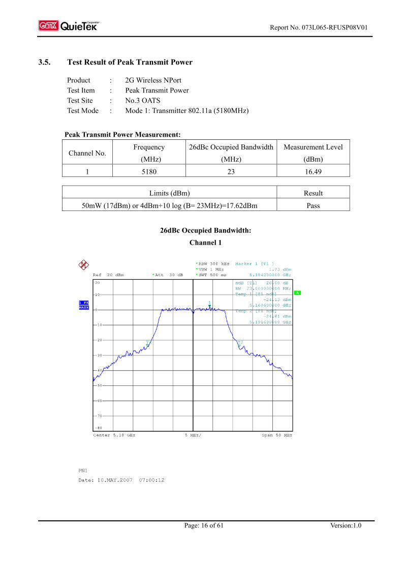
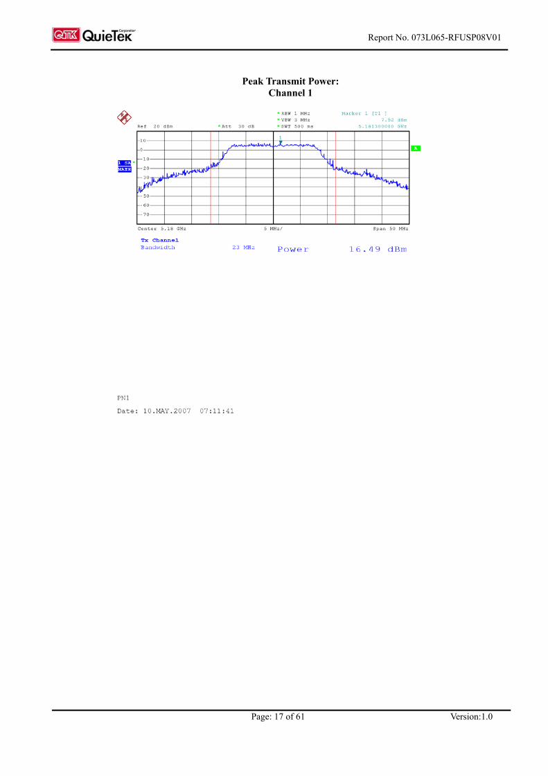
Product : 2G Wireless NPort Test Item : Peak Transmit Power Test Site : No.3 OATS Test Mode : Mode 1: Transmitter 802.11a (5180MHz)
Peak Transmit Power Measurement:
Channel No. Frequency
(MHz) 26dBc Occupied Bandwidth
(MHz) Measurement Level
(dBm)
1 5180 23 16.49
Limits (dBm) Result
50mW (17dBm) or 4dBm+10 log (B= 23MHz)=17.62dBm Pass
26dBc Occupied Bandwidth:
Channel 1
Report No. 073L065-RFUSP08V01
Page: 17 of 61 Version:1.0
Peak Transmit Power: Channel 1

Report No. 073L065-RFUSP08V01
Page: 18 of 61 Version:1.0
Product : 2G Wireless NPort Test Item : Peak Transmit Power Test Site : No.3 OATS Test Mode : Mode 1: Transmitter 802.11a (5220MHz)
Peak Transmit Power Measurement:
Channel No. Frequency
(MHz) 26dBc Occupied Bandwidth
(MHz) Measurement Level
(dBm)
3 5220 22.7 16.45
Limits (dBm) Result
50mW (17dBm) or 4dBm+10 log (B= 22.7MHz)=17.56dBm Pass
26dBc Occupied Bandwidth:
Channel 3

Report No. 073L065-RFUSP08V01
Page: 19 of 61 Version:1.0
Peak Transmit Power:
Channel 3

Report No. 073L065-RFUSP08V01
Page: 20 of 61 Version:1.0
Product : 2G Wireless NPort Test Item : Peak Transmit Power Test Site : No.3 OATS Test Mode : Mode 1: Transmitter 802.11a (5240MHz)
Peak Transmit Power Measurement:
Channel No. Frequency
(MHz) 26dBc Occupied Bandwidth
(MHz) Measurement Level
(dBm)
4 5240 22.7 16.44
Limits (dBm) Result
50mW (17dBm) or 4dBm+10 log (B=22.7MHz)=17.56dBm Pass
26dBc Occupied Bandwidth:
Channel 4

Report No. 073L065-RFUSP08V01
Page: 21 of 61 Version:1.0
Peak Transmit Power: Channel 4
Report No. 073L065-RFUSP08V01
Page: 22 of 61 Version:1.0
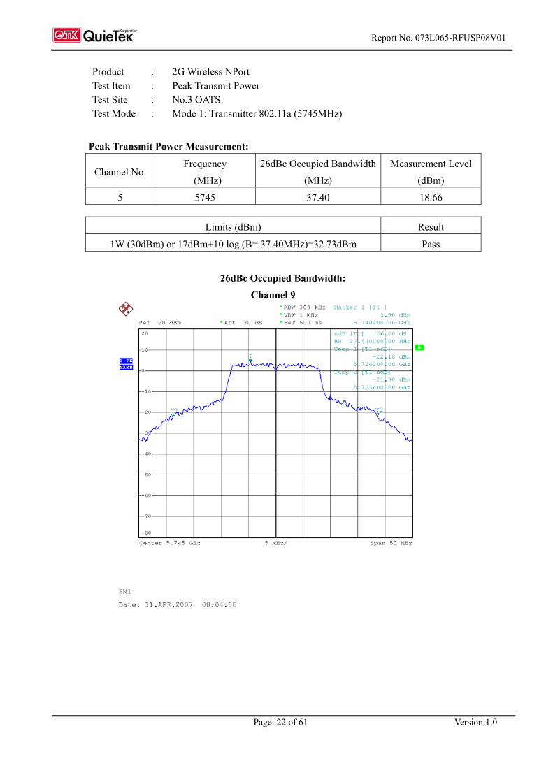
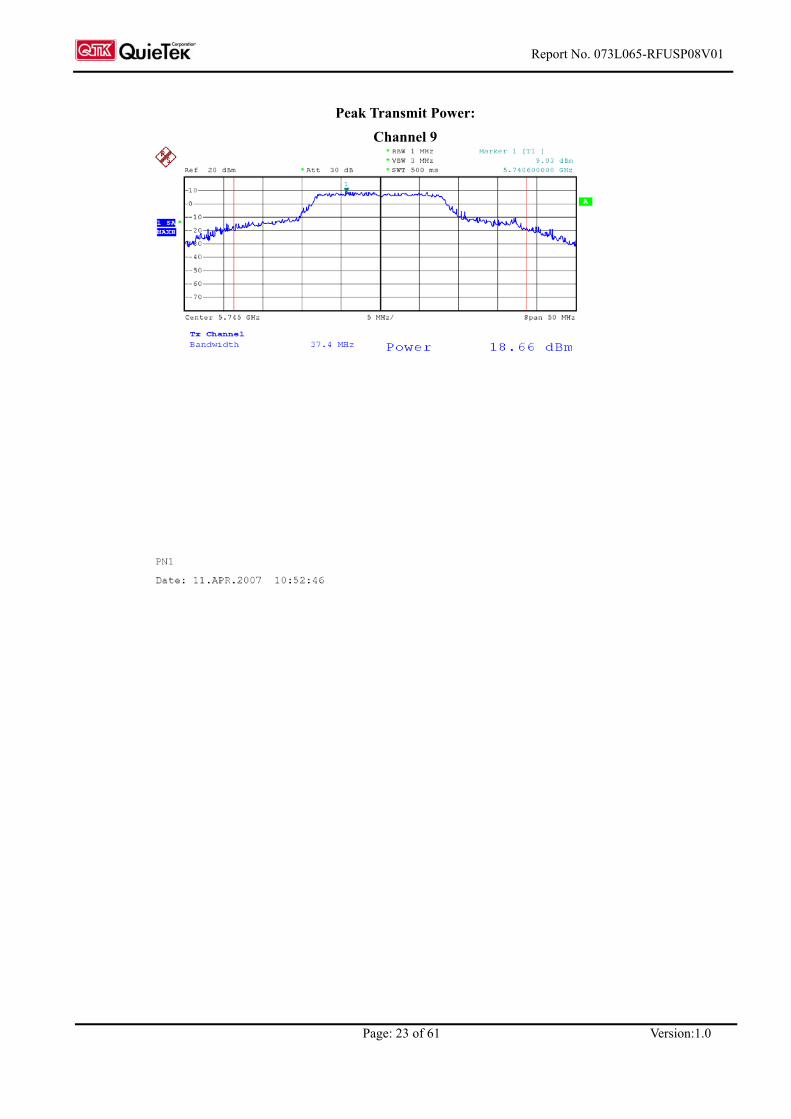
Product : 2G Wireless NPort Test Item : Peak Transmit Power Test Site : No.3 OATS Test Mode : Mode 1: Transmitter 802.11a (5745MHz)
Peak Transmit Power Measurement:
Channel No. Frequency
(MHz) 26dBc Occupied Bandwidth
(MHz) Measurement Level
(dBm)
5 5745 37.40 18.66
Limits (dBm) Result
1W (30dBm) or 17dBm+10 log (B= 37.40MHz)=32.73dBm Pass
26dBc Occupied Bandwidth:
Channel 9
Report No. 073L065-RFUSP08V01
Page: 23 of 61 Version:1.0
Peak Transmit Power:
Channel 9
Report No. 073L065-RFUSP08V01
Page: 24 of 61 Version:1.0
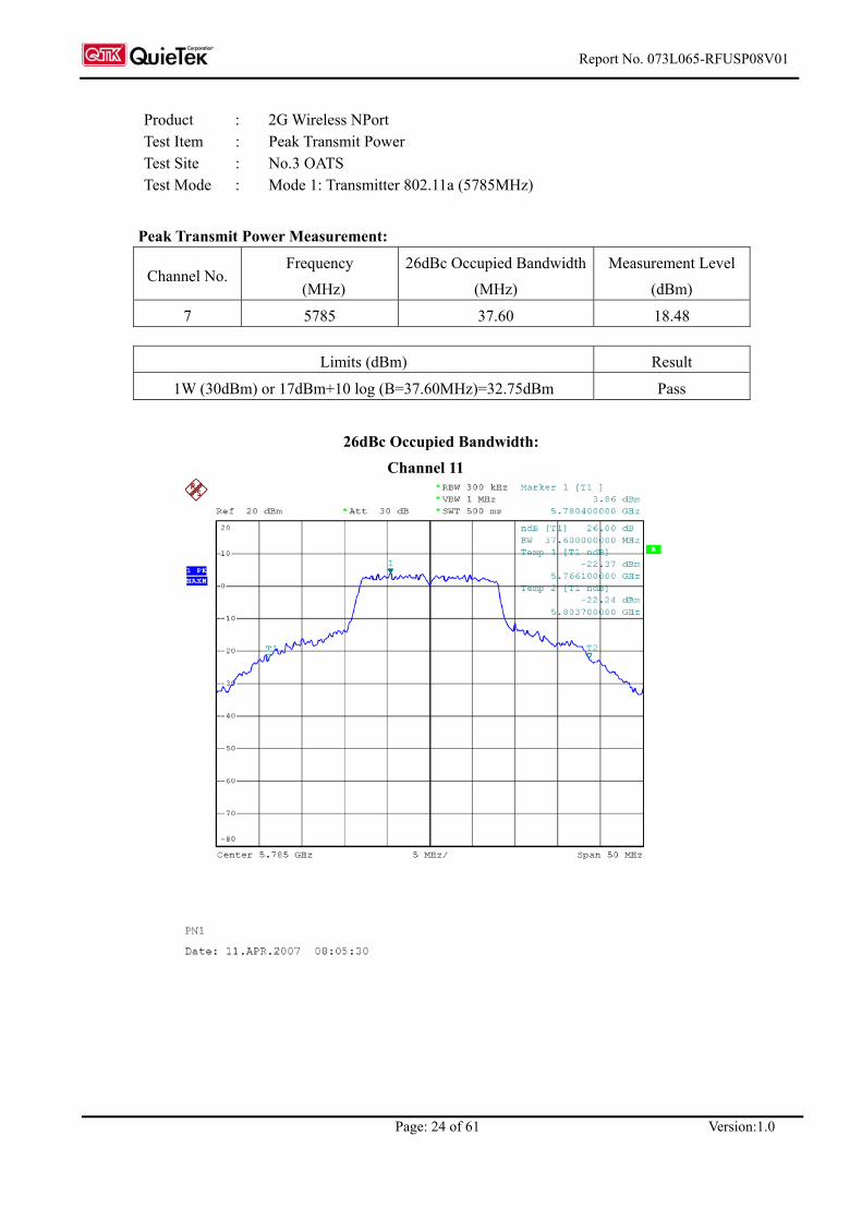
Product : 2G Wireless NPort Test Item : Peak Transmit Power Test Site : No.3 OATS Test Mode : Mode 1: Transmitter 802.11a (5785MHz)
Peak Transmit Power Measurement:
Channel No. Frequency
(MHz) 26dBc Occupied Bandwidth
(MHz) Measurement Level
(dBm)
7 5785 37.60 18.48
Limits (dBm) Result
1W (30dBm) or 17dBm+10 log (B=37.60MHz)=32.75dBm Pass
26dBc Occupied Bandwidth:
Channel 11

Report No. 073L065-RFUSP08V01
Page: 25 of 61 Version:1.0
Peak Transmit Power: Channel 11
Report No. 073L065-RFUSP08V01
Page: 26 of 61 Version:1.0
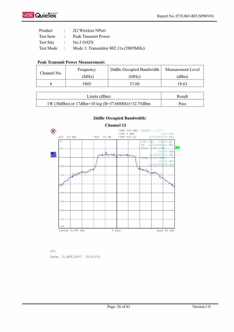
Product : 2G Wireless NPort Test Item : Peak Transmit Power Test Site : No.3 OATS Test Mode : Mode 1: Transmitter 802.11a (5805MHz)
Peak Transmit Power Measurement:
Channel No. Frequency
(MHz) 26dBc Occupied Bandwidth
(MHz) Measurement Level
(dBm)
8 5805 37.60 18.63
Limits (dBm) Result
1W (30dBm) or 17dBm+10 log (B=37.60MHz)=32.75dBm Pass
26dBc Occupied Bandwidth:
Channel 12

Report No. 073L065-RFUSP08V01
Page: 27 of 61 Version:1.0
Peak Transmit Power: Channel 12

Report No. 073L065-RFUSP08V01
Page: 28 of 61 Version:1.0
4. Peak Power Spectral Density
4.1. Test Equipment
The following test equipments are used during the radiated emission tests:
Equipment Manufacturer Model No./Serial No. Last Cal.
X Spectrum Analyzer Agilent E4407B / US39440758 May, 2007
Note: 1. All equipments are calibrated every one year. 2. The test instruments marked by “X” are used to measure the final test results.
4.2. Test Setup
4.3. Limits
(4) For the band 5.15-5.25 GHz, the peak power spectral density shall not exceed 4 dBm in any 1-MHz band. If transmitting antenna of directional gain greater than 6 dBi are used, the peak power spectral density shall be reduced by the amount in dB that directional gain of the antenna exceeds 6 dBi.
(5) For the band 5.25-5.35 GHz, the peak power spectral density shall not exceed 11 dBm in any 1-MHz band. If transmitting antenna of directional gain greater than 6 dBi are used, the peak power spectral density shall be reduced by the amount in dB that directional gain of the antenna exceeds 6 dBi.
(6) For the band 5.725-5.825 GHz, the peak power spectral density shall not exceed 17 dBm in any 1-MHz band. If transmitting antenna of directional gain greater than 6 dBi are used, the peak power spectral density shall be reduced by the amount in dB that directional gain of the antenna exceeds 6 dBi.
4.4. Uncertainty
± 1.27 dB
SMA Connecter
EUT Spectrum Analyzer
RF Cable

Report No. 073L065-RFUSP08V01
Page: 29 of 61 Version:1.0
4.5. Test Result of Peak Power Spectral Density
Product : 2G Wireless NPort Test Item : Peak Power Spectral Density Test Site : No.3 OATS Test Mode : Mode 1: Transmitter 802.11a
Channel No. Frequency
(MHz) Measurement Level
(dBm) Required Limit
(dBm) Result
1 5180.00 -1.28 < 4 Pass
3 5220.00 -1.45 < 4 Pass
4 5240.00 -1.47 < 4 Pass
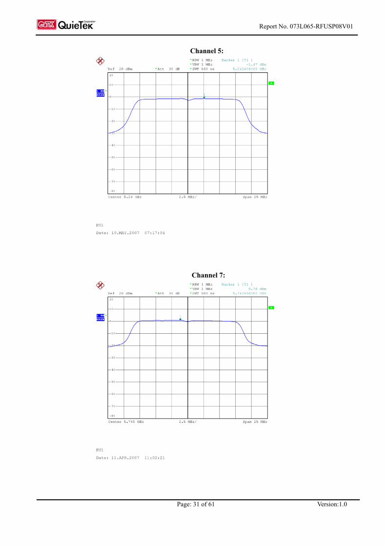
5 5745.00 0.76 < 17 Pass
7 5785.00 0.72 < 17 Pass
8 5805.00 0.80 < 17 Pass

Report No. 073L065-RFUSP08V01
Page: 30 of 61 Version:1.0
Channel 1:
Channel 3:
Report No. 073L065-RFUSP08V01
Page: 31 of 61 Version:1.0
Channel 5:
Channel 7:

Report No. 073L065-RFUSP08V01
Page: 32 of 61 Version:1.0
Channel 8:

Report No. 073L065-RFUSP08V01
Page: 33 of 61 Version:1.0
5. Peak Excursion
5.1. Test Equipment
The following test equipments are used during the radiated emission tests:
Equipment Manufacturer Model No./Serial No. Last Cal.
X Spectrum Analyzer Agilent E4407B / US39440758 May, 2007
Note: 1. All equipments are calibrated every one year. 2. The test instruments marked by “X” are used to measure the final test results.
5.2. Test Setup
Conduction Power Measurement
5.3. Limits
The ratio of the peak excursion of the modulation envelope (measured suing a peak hold function) to the peak transmit power (measured as specified above) shall not exceed 13 dB across any 1 MHz bandwidth or the emission bandwidth whichever is less.
5.4. Uncertainty
± 1.27 dB
SMA Connecter
EUT Spectrum Analyzer
RF Cable

Report No. 073L065-RFUSP08V01
Page: 34 of 61 Version:1.0
5.5. Test Result of Peak Excursion
Product : 2G Wireless NPort Test Item : Peak Excursion Test Site : No.3 OATS Test Mode : Mode 1: Transmitter 802.11a
Channel 1:
Channel No. Frequency
(MHz) Measurement Level
(dB) Required Limit
(dB) Result
1 5180.00 0.93 ≦ 13 Pass
3 5220.00 0.84 ≦ 13 Pass
4 5240.00 0.73 ≦ 13 Pass
5 5745.00 0.33 ≦ 13 Pass
7 5785.00 0.79 ≦ 13 Pass
8 5805.00 0.63 ≦ 13 Pass

Report No. 073L065-RFUSP08V01
Page: 35 of 61 Version:1.0
Channel 3:
Channel 4:

Report No. 073L065-RFUSP08V01
Page: 36 of 61 Version:1.0
Channel 5:
Channel 7:

Report No. 073L065-RFUSP08V01
Page: 37 of 61 Version:1.0
Channel 8:
Report No. 073L065-RFUSP08V01
Page: 38 of 61 Version:1.0
6. Undesirable Emission
6.1. Test Equipment
The following test equipment are used during the radiated emission test:
Test Site Equipment Manufacturer Model No./Serial No. Last Cal.
X Test Receiver R & S ESI 26 / 838786 / 004 May, 2007X Spectrum Analyzer Agilent E4407B / US39440758 May, 2007X Pre-Amplifier QTK QTK-AMP-03 / 0003 May, 2007X Bilog Antenna SCHAFFNER CBL6112B / 2697 May, 2007X Horn Antenna ETS 3115 / 0005-6160 July, 2006
Site # 3
X Pre-Amplifier QTK QTK-AMP-01 / 0001 July, 2006Note: 1. All equipments are calibrated every one year. 2. The test instruments marked by “X” are used to measure the final test results.
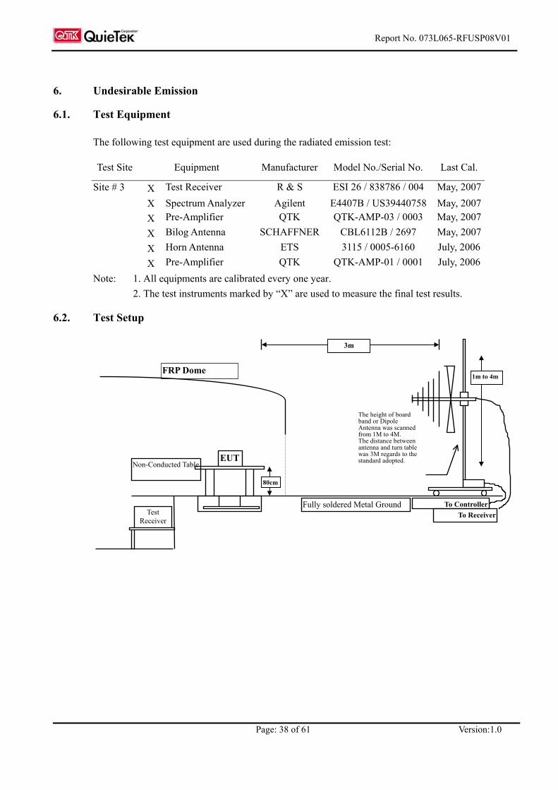
6.2. Test Setup
EUT
FRP Dome
Test Receiver
The height of board band or Dipole Antenna was scanned from 1M to 4M. The distance between antenna and turn table was 3M regards to the standard adopted.
To ControllerTo Receiver
Fully soldered Metal Ground
Non-Conducted Table
3m
1m to 4m
80cm

Report No. 073L065-RFUSP08V01
Page: 39 of 61 Version:1.0
6.3. Limits
(1) For transmitters operating in the 5.15-5.25 GHz band: all emissions outside of the 5.15-5.35 GHz band shall not exceed an EIRP of –27 dBm/MHz.
(2) For transmitters operating in the 5.25-5.35 GHz band: all emissions outside of the 5.15-5.35 GHz band shall not exceed an EIRP of –27 dBm/MHz. Devices operating in the 5.25-5.35 GHz band that generate emissions in the 5.15-5.25 GHz band must meet all applicable technical requirements for operation in the 5.15-5.25 GHz band (including indoor use) or alternatively meet an out-of-band emission EIRP limit of –27 dBm/MHz in the 5.15-5.25 GHz band.
(3) For transmitters operating in the 5.725-5.825 GHz band: all emissions within the frequency range from the band edge to 10 MHz above or below the band edge shall not exceed an EIRP of –17 dBm/MHz; for frequencies 10 MHz or greater above or below the band edge, emissions shall not exceed an EIRP of –27 dBm/MHz.
(4) The field strength of emissions appearing within restricted bands of operation shall not exceed the limits in the Section 15.209.
(5) Unwanted emissions below 1 GHz must comply with the general field strength limits set forth in Section 15.209:
FCC Part 15 Subpart C Paragraph 15.209 Limits Frequency
MHz uV/m @3m dBuV/m@3m
30-88 100 40
88-216 150 43.5
216-960 200 46
Above 960 500 54
Remarks : 1. RF Voltage (dBuV) = 20 log RF Voltage (uV) 2. In the Above Table, the tighter limit applies at the band edges. 3. Distance refers to the distance in meters between the measuring instrument antenna and the closed point of any part of the device or system.

Report No. 073L065-RFUSP08V01
Page: 40 of 61 Version:1.0
6.4. Test Procedure
The EUT and its simulators are placed on a turn table which is 0.8 meter above ground. The turn table can rotate 360 degrees to determine the position of the maximum emission level. The EUT was positioned such that the distance from antenna to the EUT was 3 meters. The antenna can move up and down between 1 meter and 4 meters to find out the maximum emission level. Both horizontal and vertical polarization of the antenna are set on measurement. In order to find the maximum emission, all of the interface cables must be manipulated according to ANSI C63.4:2003 on radiated measurement. The additional latch filter below 1GHz was used to measure the level of harmonics radiated emission during field dtrength of harmonics measurement. The bandwidth below 1GHz setting on the field strength meter is 120 kHz, above 1GHz are 1 MHz. The frequency range from 30MHz to 10th harminics is checked.
6.5. Uncertainty
± 3.8 dB below 1GHz ± 3.9 dB above 1GHz

Report No. 073L065-RFUSP08V01
Page: 41 of 61 Version:1.0
6.6. Test Result of Undesirable Emission
Product : 2G Wireless NPort Test Item : Undesirable Emission Test Site : No.3 OATS Test Mode : Mode 1: Transmitter 802.11a (5180MHz)
Frequency Correct Reading Measurement Margin Limit
Factor Level Level MHz dB dBuV dBuV/m dB dBuV/m
Horizontal Peak Detector
10360.000 10.363 42.728 53.091 -20.909 74.000 15540.000 16.803 34.667 51.469 -22.531 74.000
Average Detector
-- Vertical Peak Detector
10360.000 10.363 43.084 53.447 -20.553 74.000 15540.000 16.803 34.434 51.236 -22.764 74.000
Average Detector
-- Note:
1. All Readings below 1GHz are Quasi-Peak, above are average value. 2. Receiver setting (Peak Detector) : RBW:1MHz; VBW:1MHz; Span:100MHz. 3. Receiver setting (AVG Detector) : RBW:1MHz; VBW:30Hz; Span:20MHz. 4. Measurement Level = Reading Level + Correct Factor. 5. The average measurement was not performed when the peak measured data under the limit of
average detection. If the readings given are average, peak measurement should also be supplied.

Report No. 073L065-RFUSP08V01
Page: 42 of 61 Version:1.0
Product : 2G Wireless NPort Test Item : Undesirable Emission Test Site : No.3 OATS Test Mode : Mode 1: Transmitter 802.11a (5220MHz)
Frequency Correct Reading Measurement Margin Limit
Factor Level Level MHz dB dBuV dBuV/m dB dBuV/m
Horizontal Peak Detector
10440.000 10.388 42.502 52.890 -21.110 74.000 15660.000 10.804 40.466 51.270 -22.730 74.000
Average Detector --
Vertical Peak Detector
10440.000 41.293 43.377 53.765 -20.235 74.000 15660.000 40.036 40.479 51.283 -22.717 74.000
Average Detector --
Note:
1. All Readings below 1GHz are Quasi-Peak, above are average value. 2. Receiver setting (Peak Detector) : RBW:1MHz; VBW:1MHz; Span:100MHz. 3. Receiver setting (AVG Detector) : RBW:1MHz; VBW:30Hz; Span:20MHz. 4. Measurement Level = Reading Level + Correct Factor.. 5. The average measurement was not performed when the peak measured data under the limit of
average detection. If the readings given are average, peak measurement should also be supplied.

Report No. 073L065-RFUSP08V01
Page: 43 of 61 Version:1.0
Product : 2G Wireless NPort Test Item : Undesirable Emission Test Site : No.3 OATS Test Mode : Mode 1: Transmitter 802.11a (5240MHz)
Frequency Correct Reading Measurement Margin Limit
Factor Level Level MHz dB dBuV dBuV/m dB dBuV/m
Horizontal Peak Detector
10480.000 10.503 42.238 52.741 -21.259 74.000 15720.000 10.636 40.598 51.233 -22.767 74.000
Average Detector
-- Vertical Peak Detector
10480.000 10.503 43.448 53.951 -20.049 74.000 15720.000 10.636 40.221 50.856 -23.144 74.000
Average Detector --
Note:
1. All Readings below 1GHz are Quasi-Peak, above are average value. 2. Receiver setting (Peak Detector) : RBW:1MHz; VBW:1MHz; Span:100MHz。 3. Receiver setting (AVG Detector) : RBW:1MHz; VBW:30Hz; Span:20MHz。 4. Measurement Level = Reading Level + Correct Factor. 5. The average measurement was not performed when the peak measured data under the limit of
average detection. If the readings given are average, peak measurement should also be supplied.

Report No. 073L065-RFUSP08V01
Page: 44 of 61 Version:1.0
Product : 2G Wireless NPort Test Item : Undesirable Emission Test Site : No.3 OATS Test Mode : Mode 1: Transmitter 802.11a (5745Hz)
Frequency Correct Reading Measurement Margin Limit
Factor Level Level MHz dB dBuV dBuV/m dB dBuV/m
Horizontal Peak Detector
11490.000 11.785 41.153 52.938 -21.062 74.000 17235.000 9.933 41.514 51.447 -22.553 74.000
Average Detector
-- Vertical Peak Detector
11490.000 11.785 41.969 53.754 -20.246 74.000 17235.000 9.933 41.919 51.852 -22.148 74.000
Average Detector --
Note:
1. All Readings below 1GHz are Quasi-Peak, above are average value. 2. Receiver setting (Peak Detector) : RBW:1MHz; VBW:1MHz; Span:100MHz。 3. Receiver setting (AVG Detector) : RBW:1MHz; VBW:30Hz; Span:20MHz。 4. Measurement Level = Reading Level + Correct Factor. 5. The average measurement was not performed when the peak measured data under the limit of
average detection. If the readings given are average, peak measurement should also be supplied

Report No. 073L065-RFUSP08V01
Page: 45 of 61 Version:1.0
Product : 2G Wireless NPort Test Item : Undesirable Emission Test Site : No.3 OATS Test Mode : Mode 1: Transmitter 802.11a (5785MHz)
Frequency Correct Reading Measurement Margin Limit
Factor Level Level MHz dB dBuV dBuV/m dB dBuV/m
Horizontal Peak Detector
11570.000 11.751 41.395 53.146 -20.854 74.000 17355.000 9.662 42.034 51.697 -22.303 74.000
Average Detector
-- Vertical Peak Detector
11570.000 11.751 41.902 53.653 -20.347 74.000 17355.000 9.662 41.564 51.227 -22.773 74.000
Average Detector
-- Note:
1. All Readings below 1GHz are Quasi-Peak, above are average value. 2. Receiver setting (Peak Detector) : RBW:1MHz; VBW:1MHz; Span:100MHz。 3. Receiver setting (AVG Detector) : RBW:1MHz; VBW:30Hz; Span:20MHz。 4. Measurement Level = Reading Level + Correct Factor. 5. The average measurement was not performed when the peak measured data under the limit of
average detection. If the readings given are average, peak measurement should also be supplied

Report No. 073L065-RFUSP08V01
Page: 46 of 61 Version:1.0
Product : 2G Wireless NPort Test Item : Undesirable Emission Test Site : No.3 OATS Test Mode : Mode 1: Transmitter 802.11a (5805MHz)
Frequency Correct Reading Measurement Margin Limit
Factor Level Level MHz dB dBuV dBuV/m dB dBuV/m
Horizontal Peak Detector
11610.000 11.730 41.015 52.745 -21.255 74.000 17415.000 9.527 41.706 51.233 -22.767 74.000
Average Detector
-- Vertical Peak Detector
11610.000 11.730 41.554 53.284 -20.716 74.000 17415.000 9.527 40.758 50.285 -23.715 74.000
Average Detector --
Note:
1. All Readings below 1GHz are Quasi-Peak, above are average value. 2. Receiver setting (Peak Detector) : RBW:1MHz; VBW:1MHz; Span:100MHz。 3. Receiver setting (AVG Detector) : RBW:1MHz; VBW:30Hz; Span:20MHz。 4. Measurement Level = Reading Level + Correct Factor. 5. The average measurement was not performed when the peak measured data under the limit of
average detection. If the readings given are average, peak measurement should also be supplied

Report No. 073L065-RFUSP08V01
Page: 47 of 61 Version:1.0
Product : 2G Wireless NPort Test Item : Undesirable Emission Test Site : No.3 OATS Test Mode : Mode 1: Transmitter 802.11a (5220MHz)
Frequency Correct Reading Measurement Margin Limit
Factor Level Level MHz dB dBuV dBuV/m dB dBuV/m
Horizontal Peak Detector
287.050 13.473 29.222 42.695 -3.305 46.000 384.050 15.761 25.570 41.331 -4.669 46.000 481.050 18.786 17.055 35.841 -10.159 46.000 672.625 20.659 21.683 42.342 -3.658 46.000 767.200 22.117 15.366 37.483 -8.517 46.000 864.200 22.212 19.448 41.660 -4.340 46.000 Vertical
Peak Detector 107.600 11.442 19.359 30.801 -12.699 43.500 287.050 13.637 27.624 41.261 -4.739 46.000 384.050 16.822 15.753 32.575 -13.425 46.000 599.875 21.898 7.984 29.882 -16.118 46.000 672.625 19.955 22.496 42.451 -3.549 46.000 864.200 21.968 8.134 30.102 -15.898 46.000
Note:
1. All Readings below 1GHz are Quasi-Peak, above are average value. 2. “ ” means the worst emission level. 3. Measurement Level = Reading Level + Correct Factor 4. The radiated emissions below 1GHz of the lowest, middle, highest frequency are pretested. Only
the worst case is shown on the report.

Report No. 073L065-RFUSP08V01
Page: 48 of 61 Version:1.0
Product : 2G Wireless NPort Test Item : Undesirable Emission Test Site : No.3 OATS Test Mode : Mode 1: Transmitter 802.11a (5785MHz)
Frequency Correct Reading Measurement Margin Limit
Factor Level Level MHz dB dBuV dBuV/m dB dBuV/m
Horizontal Peak Detector
287.050 13.473 29.065 42.538 -3.462 46.000 384.050 15.761 25.668 41.429 -4.571 46.000 481.050 18.786 16.593 35.379 -10.621 46.000 672.625 20.659 22.339 42.998 -3.002 46.000 767.200 22.117 15.699 37.816 -8.184 46.000 864.200 22.212 19.556 41.768 -4.232 46.000 Vertical
Peak Detector 107.600 11.442 18.586 30.028 -13.472 43.500 287.050 13.637 27.529 41.166 -4.834 46.000 384.050 16.822 15.542 32.364 -13.636 46.000 612.000 21.748 8.761 30.509 -15.491 46.000 672.625 19.955 22.346 42.301 -3.699 46.000 864.200 21.968 8.337 30.305 -15.695 46.000
Note:
1. All Readings below 1GHz are Quasi-Peak, above are average value. 2. “ ” means the worst emission level. 3. Measurement Level = Reading Level + Correct Factor 4. The radiated emissions below 1GHz of the lowest, middle, highest frequency are pretested. Only
the worst case is shown on the report.
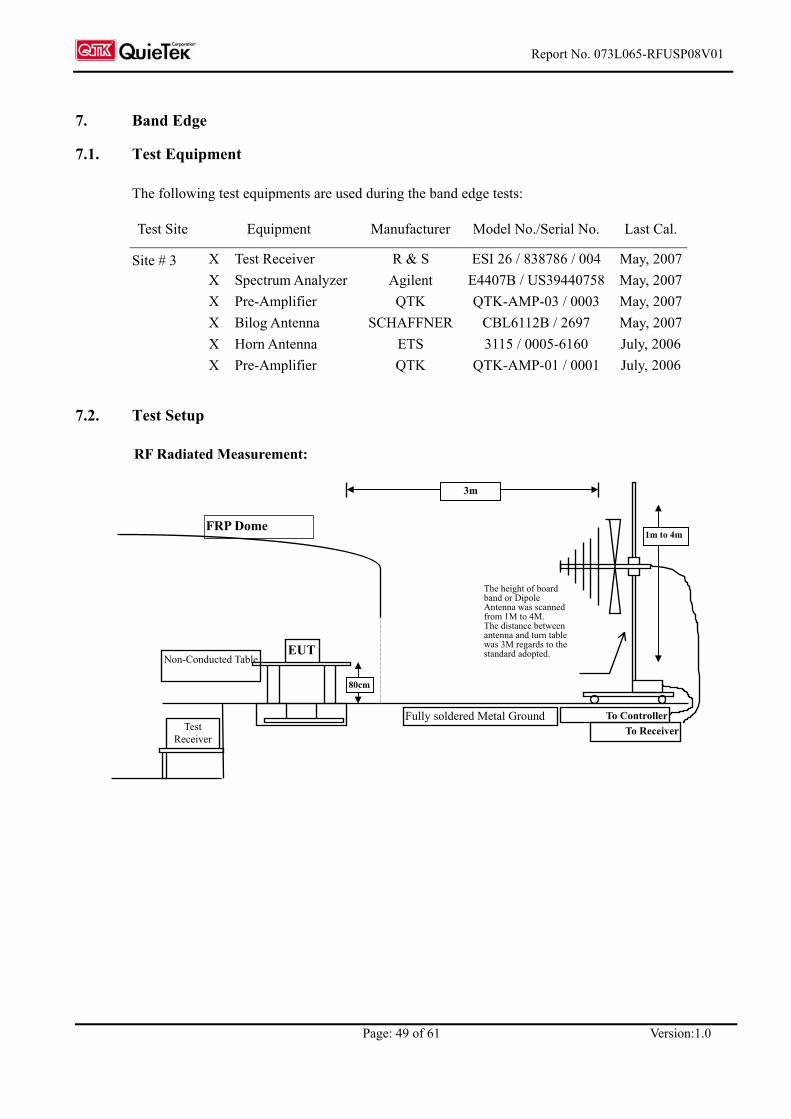
Report No. 073L065-RFUSP08V01
Page: 49 of 61 Version:1.0
7. Band Edge
7.1. Test Equipment
The following test equipments are used during the band edge tests:
Test Site Equipment Manufacturer Model No./Serial No. Last Cal.
X Test Receiver R & S ESI 26 / 838786 / 004 May, 2007X Spectrum Analyzer Agilent E4407B / US39440758 May, 2007X Pre-Amplifier QTK QTK-AMP-03 / 0003 May, 2007X Bilog Antenna SCHAFFNER CBL6112B / 2697 May, 2007X Horn Antenna ETS 3115 / 0005-6160 July, 2006
Site # 3
X Pre-Amplifier QTK QTK-AMP-01 / 0001 July, 2006
7.2. Test Setup
RF Radiated Measurement:
EUT
FRP Dome
Test Receiver
The height of board band or Dipole Antenna was scanned from 1M to 4M. The distance between antenna and turn table was 3M regards to the standard adopted.
To ControllerTo Receiver
Fully soldered Metal Ground
Non-Conducted Table
3m
1m to 4m
80cm

Report No. 073L065-RFUSP08V01
Page: 50 of 61 Version:1.0
7.3. Limits
The provisions of Section 15.205 of this part apply to intentional radiators operating under this section. Radiated emissions which fall in the restricted bands, as defined in Section 15.205, must also comply with the radiated emission limits specified in Section 15.209:
FCC Part 15 Subpart C Paragraph 15.209 Limits Frequency
MHz uV/m @3m dBuV/m@3m
30-88 100 40
88-216 150 43.5
216-960 200 46
Above 960 500 54
Remarks : 1. RF Voltage (dBuV) = 20 log RF Voltage (uV) 2. In the Above Table, the tighter limit applies at the band edges.
3. Distance refers to the distance in meters between the measuring instrument antenna and the closed point of any part of the device or system.
7.4. Test Procedure
The EUT and its simulators are placed on a turn table which is 0.8 meter above ground. The turn table can rotate 360 degrees to determine the position of the maximum emission level. The EUT was positioned such that the distance from antenna to the EUT was 3 meters. The antenna can move up and down between 1 meter and 4 meters to find out the maximum emission level. Both horizontal and vertical polarization of the antenna are set on measurement. In order to find the maximum emission, all of the interface cables must be manipulated according to ANSI C63.4:1992 on radiated measurement. The bandwidth below 1GHz setting on the field strength meter is 120 kHz, above 1GHz are 1 MHz.
7.5. Uncertainty
± 3.8 dB below 1GHz ± 3.9 dB above 1GHz
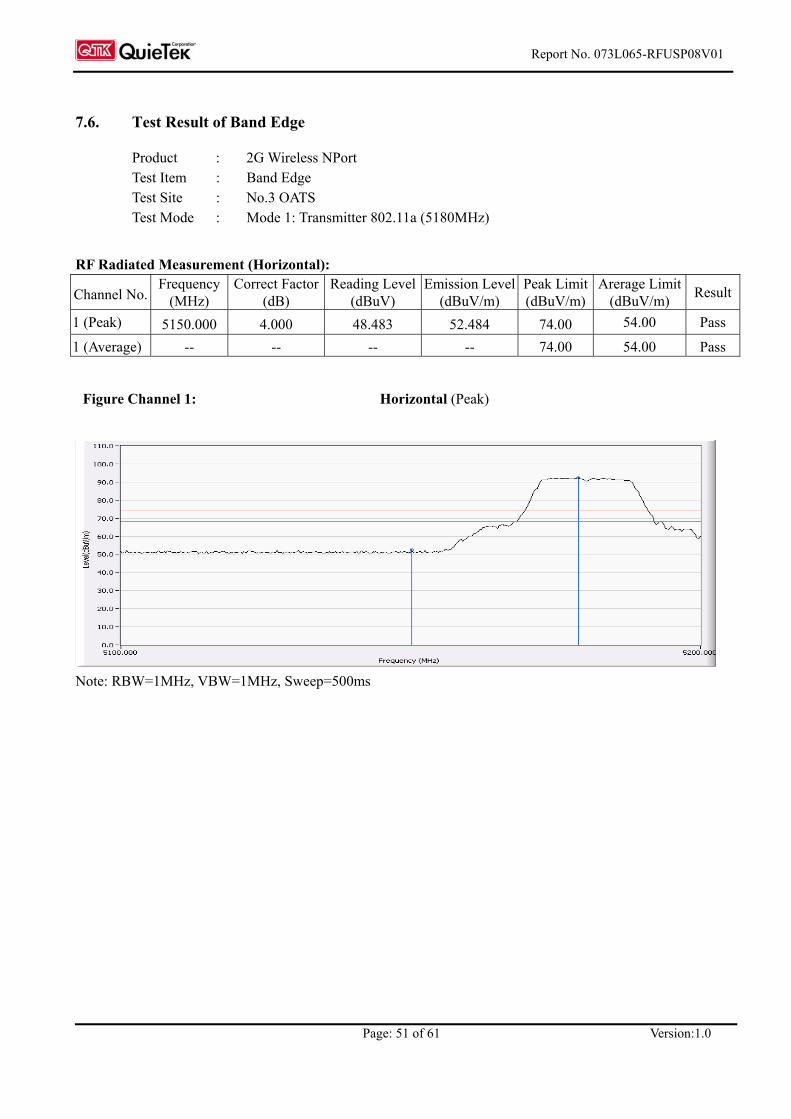
Report No. 073L065-RFUSP08V01
Page: 51 of 61 Version:1.0
7.6. Test Result of Band Edge
Product : 2G Wireless NPort Test Item : Band Edge Test Site : No.3 OATS Test Mode : Mode 1: Transmitter 802.11a (5180MHz)
RF Radiated Measurement (Horizontal):
Channel No. Frequency
(MHz) Correct Factor
(dB) Reading Level
(dBuV) Emission Level
(dBuV/m) Peak Limit (dBuV/m)
Arerage Limit(dBuV/m) Result
1 (Peak) 5150.000 4.000 48.483 52.484 74.00 54.00 Pass
1 (Average) -- -- -- -- 74.00 54.00 Pass
Figure Channel 1: Horizontal (Peak)
Note: RBW=1MHz, VBW=1MHz, Sweep=500ms

Report No. 073L065-RFUSP08V01
Page: 52 of 61 Version:1.0
Product : 2G Wireless NPort Test Item : Band Edge Test Site : No.3 OATS Test Mode : Mode 1: Transmitter 802.11a (5180MHz)
RF Radiated Measurement (Vertical):
Channel No. Frequency
(MHz) Correct Factor
(dB) Reading Level
(dBuV) Emission Level
(dBuV/m) Peak Limit (dBuV/m)
Arerage Limit(dBuV/m) Result
1 (Peak) 5150.000 4.000 47.269 51.270 74.00 54.00 Pass
1 (Average) -- -- -- -- 74.00 54.00 Pass
Figure Channel 1: Vertical (Peak)
Note: RBW=1MHz, VBW=1MHz, Sweep=500ms

Report No. 073L065-RFUSP08V01
Page: 53 of 61 Version:1.0
Product : 2G Wireless NPort Test Item : Band Edge Test Site : No.3 OATS Test Mode : Mode 1: Transmitter 802.11a (5240MHz)
RF Radiated Measurement (Horizontal):
Channel No. Frequency
(MHz) Correct Factor
(dB) Reading Level
(dBuV) Emission Level
(dBuV/m) Peak Limit (dBuV/m)
Arerage Limit(dBuV/m) Result
4 (Peak) 5350.000 3.242 47.309 50.551 74.00 54.00 Pass
4 (Average) 5350.000 -- -- -- 74.00 54.00 Pass
Figure Channel 8: Horizonal (Peak)
Note: RBW=1MHz, VBW=1MHz, Sweep=500ms

Report No. 073L065-RFUSP08V01
Page: 54 of 61 Version:1.0
Product : 2G Wireless NPort Test Item : Band Edge Test Site : No.3 OATS Test Mode : Mode 1: Transmitter 802.11a (5240MHz)
RF Radiated Measurement (Vertical):
Channel No. Frequency
(MHz) Correct Factor
(dB) Reading Level
(dBuV) Emission Level
(dBuV/m) Peak Limit (dBuV/m)
Arerage Limit(dBuV/m) Result
4 (Peak) 5350.000 3.242 47.818 51.060 74.00 54.00 Pass
4 (Average) 5350.000 -- -- -- 74.00 54.00 Pass
Figure Channel 8: Vertical (Peak)
Note: RBW=1MHz, VBW=1MHz, Sweep=500ms
Note: The average measurement was not performed when the peak measured data under the limit of average detection. If the readings given are average, peak measurement should also be supplied.

Report No. 073L065-RFUSP08V01
Page: 55 of 61 Version:1.0
Product : 2G Wireless NPort Test Item : Band Edge Test Site : No.3 OATS Test Mode : Mode 1: Transmitter 802.11a (5745MHz)
RF Radiated Measurement:
Channel No. Frequency (MHz)
Required Limit (dBc) Result
5 <5725 >20 Pass
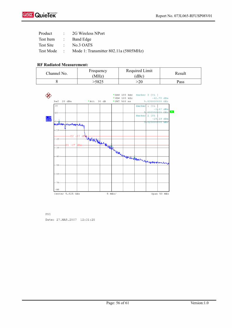
Report No. 073L065-RFUSP08V01
Page: 56 of 61 Version:1.0
Product : 2G Wireless NPort Test Item : Band Edge Test Site : No.3 OATS Test Mode : Mode 1: Transmitter 802.11a (5805MHz)
RF Radiated Measurement:
Channel No. Frequency (MHz)
Required Limit (dBc) Result
8 >5825 >20 Pass
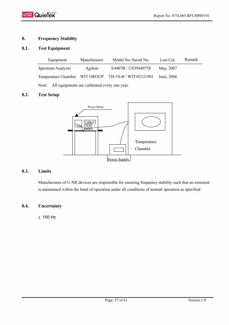
Report No. 073L065-RFUSP08V01
Page: 57 of 61 Version:1.0
8. Frequency Stability
8.1. Test Equipment
Equipment Manufacturer Model No./Serial No. Last Cal. Remark
Spectrum Analyzer Agilent E4407B / US39440758 May, 2007
Temperature Chamber WIT GROUP TH-1S-B / WIT-02121901 June, 2006
Note: All equipments are calibrated every one year.
8.2. Test Setup
8.3. Limits
Manufactures of U-NII devices are responsible for ensuring frequency stability such that an emission is maintained within the band of operation under all conditions of normal operation as specified
8.4. Uncertainty
± 150 Hz
Power Meter
12dBuV
Temperature Chamber
Power Supply

Report No. 073L065-RFUSP08V01
Page: 58 of 61 Version:1.0
8.5. Test Result of Frequency Stability
Product : 2G Wireless NPort Test Item : Frequency Stability Test Site : Temperature Chamber Test Mode : Mode 1: Transmitter 802.11a
1 5180.00 5180.00 0.00 3 5220.00 5220.00 0.00 4 5240.00 5240.00 0.00 5 5745.00 5745.00 0.00 7 5785.00 5785.00 0.00
Tnim (0) oC Vmax (126.5)V
8 5805.00 5805.00 0.00 1 5180.00 5180.00 0.00 3 5220.00 5220.00 0.00 4 5240.00 5240.00 0.00 5 5745.00 5745.00 0.00 7 5785.00 5785.00 0.00
Tnim (0) oC Vnim (93.5)V
8 5805.00 5805.00 0.00
Test Conditions Channel Frequency (MHz) Frequency (MHz) △F (MHz)
1 5180.00 5180.00 0.00 3 5220.00 5220.00 0.00 4 5240.00 5240.00 0.00 5 5745.00 5745.00 0.00 7 5785.00 5785.00 0.00
Tnom (20) oC Vnom (110)V
8 5805.00 5805.00 0.00 1 5180.00 5180.00 0.00 3 5220.00 5220.00 0.00 4 5240.00 5240.00 0.00 5 5745.00 5745.00 0.00 7 5785.00 5785.00 0.00
Tmax (50) oC Vmax (126.5)V
8 5805.00 5805.00 0.00 1 5180.00 5180.00 0.00 3 5220.00 5220.00 0.00 4 5240.00 5240.00 0.00 5 5745.00 5745.00 0.00 7 5785.00 5785.00 0.00
Tmax (50) oC Vnim (93.5)V
8 5805.00 5805.00 0.00

Report No. 073L065-RFUSP08V01
Page: 59 of 61 Version:1.0
9. EMI Reduction Method During Compliance Testing
No modification was made during testing.
Report No. 073L065-RFUSP08V01
Page: 60 of 61 Version:1.0
Attachment 1: EUT Test Photographs
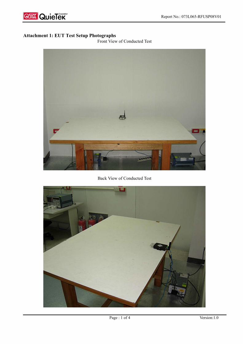
Report No.: 073L065-RFUSP08V01
Page : 1 of 4 Version:1.0
Attachment 1: EUT Test Setup Photographs Front View of Conducted Test
Back View of Conducted Test
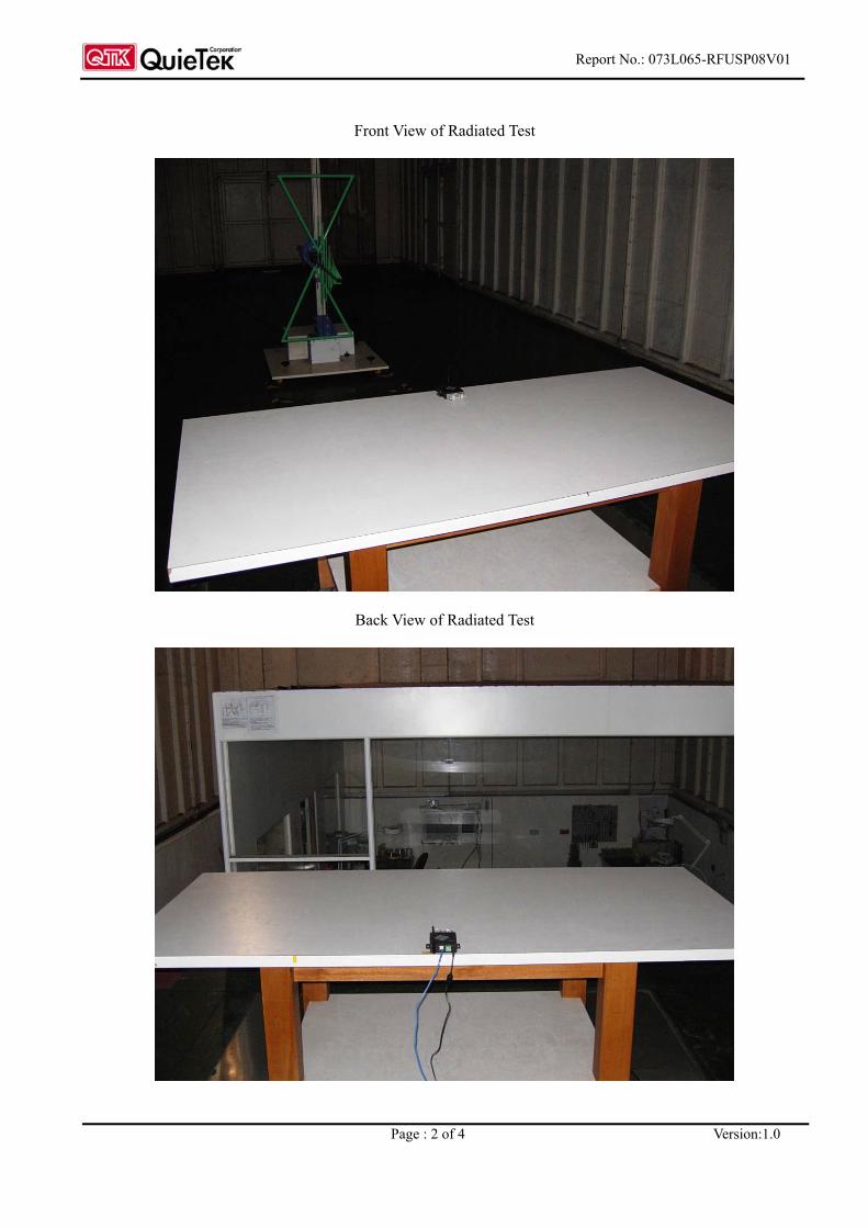
Report No.: 073L065-RFUSP08V01
Page : 2 of 4 Version:1.0
Front View of Radiated Test
Back View of Radiated Test

Report No.: 073L065-RFUSP08V01
Page : 3 of 4 Version:1.0
Front View of Radiated Test (Horn)
Back View of Radiated Test (Horn)

Report No.: 073L065-RFUSP08V01
Page : 4 of 4 Version:1.0
Front View of Radiated Test (Horn)
Back View of Radiated Test (Horn)
Report No. 073L065-RFUSP08V01
Page: 61 of 61 Version:1.0
Attachment 2: EUT Detailed Photographs

Report No.: 073L065-RFUSP08V01
Page : 1 of 9 Version:1.0
Attachment 2 : EUT Detailed Photographs (1) EUT Photo
(2) EUT Photo

Report No.: 073L065-RFUSP08V01
Page : 2 of 9 Version:1.0
(3) EUT Photo
(4) EUT Photo

Report No.: 073L065-RFUSP08V01
Page : 3 of 9 Version:1.0
(5) EUT Photo
(6) EUT Photo

Report No.: 073L065-RFUSP08V01
Page : 4 of 9 Version:1.0
(7) EUT Photo
(8) EUT Photo

Report No.: 073L065-RFUSP08V01
Page : 5 of 9 Version:1.0
(9) EUT Photo
(10) EUT Photo

Report No.: 073L065-RFUSP08V01
Page : 6 of 9 Version:1.0
(11) EUT Photo
(12) EUT Photo

Report No.: 073L065-RFUSP08V01
Page : 7 of 9 Version:1.0
(13) EUT Photo
(14) EUT Photo

Report No.: 073L065-RFUSP08V01
Page : 8 of 9 Version:1.0
(15) EUT Photo
(16) EUT Photo

Report No.: 073L065-RFUSP08V01
Page : 9 of 9 Version:1.0
(17) EUT Photo
(18) EUT Photo
Related Documents