SISTEMI EMBEDDED Building a Nios II Computer from scratch Federico Baronti Last version: 20180326 1

Welcome message from author
This document is posted to help you gain knowledge. Please leave a comment to let me know what you think about it! Share it to your friends and learn new things together.
Transcript

SISTEMI EMBEDDED
Building a Nios II Computerfrom scratch
Federico Baronti Last version: 201803261
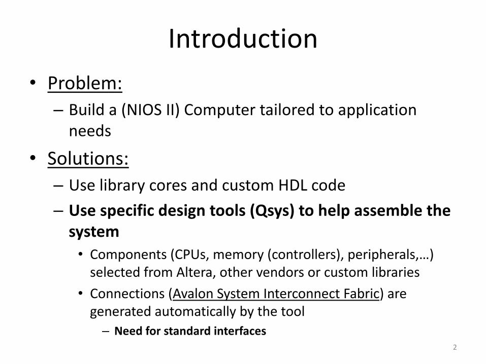
Introduction• Problem:– Build a (NIOS II) Computer tailored to application
needs
• Solutions:– Use library cores and custom HDL code– Use specific design tools (Qsys) to help assemble the
system• Components (CPUs, memory (controllers), peripherals,…)
selected from Altera, other vendors or custom libraries• Connections (Avalon System Interconnect Fabric) are
generated automatically by the tool– Need for standard interfaces
2

Avalon System Interconect Fabric
• Overview of Avalon standard interfaces:– Clock– Reset– Interrupt– Memory-Mapped (master and slave)– Streaming (source and sink)– Conduit
3

Example: First Nios System
• Handles slider switches and LEDs through PIO peripherals
Avalon System Fabric
Nios II
Core/eJTAG Debug
Module
KEY0
JTAG Controller
Max 10: 10M50DAF484C7G
On-chip
mem
PIO(10-
bit in)
SW9 ... SW0
PIO (10-
bit out)
LEDR9...LEDR0
JTAG HUB
USB-
BlasterHOST-PC
System
ID
MAX10_CLOCK1_50
Clock
source
reset_n clk
4

First Nios Computer components
• CPU (simplest, i.e., economy version) with JTAG Debug Module
• On-chip memory for program and data (64 KB)• 2 PIOs– Input for reading slider switches (10 bit)– Output for driving red LEDs (10 bit)
• System ID Peripheral for computer identification
5

Nios II Hardware Flow
<proc_design_unit>.v<proc_design_unit>.v
Qsys<nios_system>.qsys
Quartus II
<nios_system>.sopcinfo
Nios II SBTEclipse
<nios_system>.v
<top_level_name>.v
<project_name>.sof
<proc_design_unit>.v
<custom_design_unit>.v<custom_design_unit>.v<custom_design_unit>.v
<project_name>.qpf
<top_level_name >.sdc
<onchip_mem>.hex
6

Qsys Flow
<proc_design_unit>.v<proc_design_unit>.v
Create/OpenNios II system
<nios_system>.qsys
<nios_system>.v <proc_design_unit>.v
Insert componentfrom library
Configure component HW parameters
Configure Base addresses and IRQ
End?
Generate Nios system
<nios_system>.qsys
Library
<nios_system>.sopcinfo
NoYes
ConfigureConnections
7

Guided example (1)
• Open the template Quartus project: DE10_Lite_First_Computer• Launch Qsys tool• Define the Nios_system components
– Clock source: clk (it is added automatically)– Nios II Proc.: nios2_proc
• Choose the economy version of the NiosII proc. (NiosII/e) and the Level 1 for the JTAG Debug Module
– On-chip Memory: onchip_memory (dual-port configuration, single clock)
– PIO: leds• Output for driving LEDS
– PIO: sliders• Input for reading slider switches status
– System ID Peripheral: sysid (ID = 1!)
8

Other components
Qsys main window
Conf
igur
e in
tern
al co
nnec
tions
Decid
e sig
nals
to b
e ro
uted
(e
xpor
ted)
to th
eQs
yssy
stem
bou
ndar
y
Component instance name Base address
9

CPU choice
• Choose the most suited processor core
• 3 variants:– Economy– Standard– Fast
• Different features– Trade-off
performance-cost
At least one memory must be present in the Qsys system in order to configure the Reset and Exception addresses
10

Additional peripherals
11
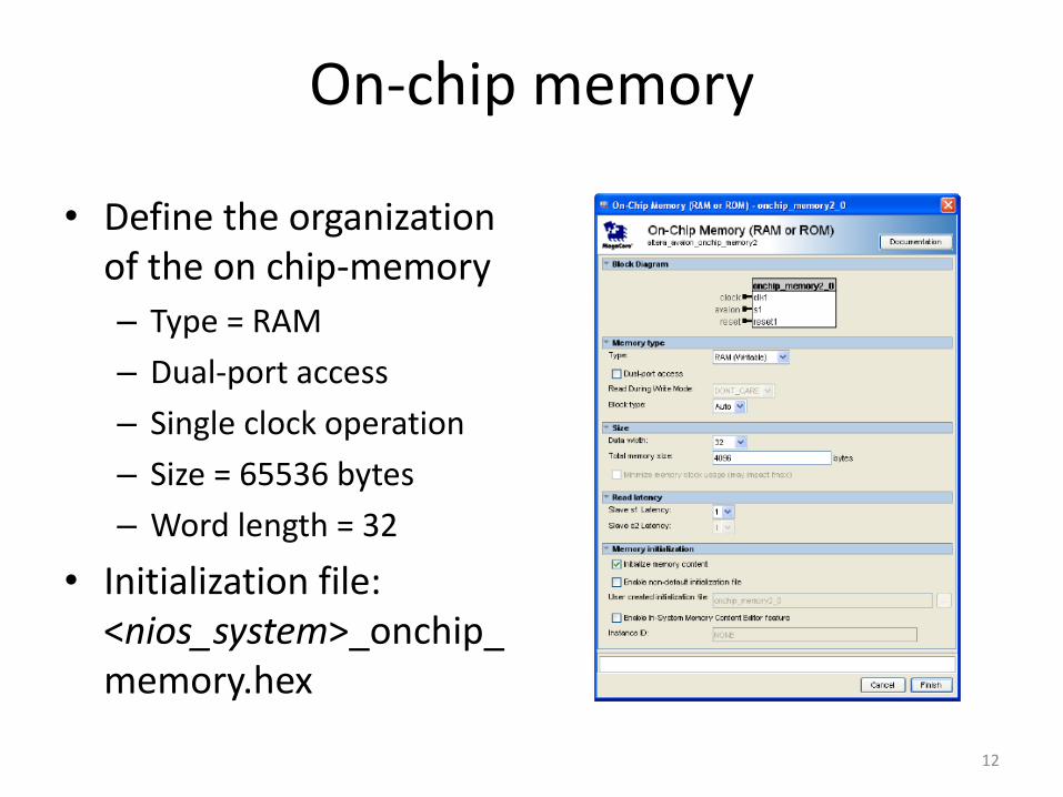
On-chip memory
• Define the organizationof the on chip-memory– Type = RAM
– Dual-port access
– Single clock operation
– Size = 65536 bytes
– Word length = 32
• Initialization file:<nios_system>_onchip_memory.hex
12

Guided example (2)• Configure internal connections– Route clk from Clock Source component to the other
components
– Create reset network• “Route” reset signals from Clock Source and JTAG Debug Module (within
the Nios II proc.) components to the other components
• Can be done automatically using Create Global Reset Network command(System menu)
– Link the Avalon Memory-Mapped Interfaces:• data_master (Nios II proc.), jtag_debug_module (Nios II proc.), s1
(onchip_memory), s1 (PIO: sliders, leds), control_slave (sysid)
• instruction_master (Nios II proc.), jtag_debug_module (Nios II proc.), s2 (onchip_memory)
13

Guided example (3)• Export external connections– Sliders and leds PIOs have conduit interfaces, the related
signals (external_connection) must be routed to the Qsyssystem boundary
• Assign base addresses– Manually to each component with slave Memory-
Mapped Interfaces (pay attention to avoid overlaps!)
– Assign Base Addresses (from the System menu)
14

Guided example (4)We are now ready to generate the Qsys system
and go back to Quartus II
15

Guided example (6)
• Back to Quartus II– Import Qsys system into Quartus project. Do one
of the followings:• Method I: Add the .qip file stored in nios_system>/synthesisto the project• Method II: Add the .qsys file to the project
– Create/Edit the root module of the project– Include the Nios_system module as hierarchical
block (Verilog)– Compile the project to make the hardware ready
16

Guided example (7)
• Integrating Qsys system into Quartus II project– Method I: Add the (Quartus II file) .qip file stored
in <nios_system>/synthesis to the project
• .qip file is created when generating the Qsys system
together with the .sopcinfo and the HDL files
• It lists all the files necessary for compilation in Quartus
II, including the references to the HDL files generated
by Qsys
17

Guided example (8)
• Integrating Qsys system into Quartus II project– Method II: Add the .qsys file to project
• The Qsys system is now (re)generated by Quartus II at each compilation
• The generated HDL files are stored at a different path than those generated directly by Qsys
– db/ip/<nios_system>
• Note that the sysid timestamp changes at each compilation in Quartus II
• The BSP must be regenerated using the new sopcinfo file after each compilation, even if we have not made any change to the Qsys system!
18

Guided example (7a)• Project root module
19
nios_system.v
clk
DE10_Lite_First_Computer.v(top module)
A8 LEDR[0]
LEDR```
LEDR[9]B11
C11 SW[0]```
SW[9]F15
``
``` leds
SW sliders
8
8
MAX10_CLOCK1_50
P11MAX10_CLOCK1_50
OSC
50
MHz
KEY[0] B8KEY[0]reset_n``
Max 10: 10M50DAF484C7G
VccVcc
```

Guided example (7b)• Project root module
// DE10_Lite_First_Computer.v
module DE10_Lite_first_computer(//inputMAX10_CLOCK1_50,KEY,SW,//outputLEDR
);input MAX10_CLOCK1_50;input [1:0] KEY;input [9:0] SW;
output [9:0] LEDR;
// Add the nios_system instance// The instance template can be copied from Qsys HDL example tab
endmodule 20

Guided example (7c)• Project root module
(using Verilog-2001 C-style port declaration)
// DE10_Lite_First_Computer.v
module DE10_Lite_first_computer(input MAX10_CLOCK1_50,input [1:0] KEY,input [9:0] SW,
output [9:0] LEDR);
// Add the nios_system instance// The instance template can be copied from Qsys HDL example tab
endmodule
21

Testing First Nios System (1)
• Write a program that makes the RED LEDS to be controlled by the SLIDERS SWITCHES
• If successful, generate the hex file to initialize the on-chip memory. Recompile the Quartus project and reprogramthe FPGA. Your program should run automatically!
• To generate the hex file from elf. Open the Nios 2 Command Shell and navigate to the Eclipse project folder. Customize the following command:
elf2hex --record=4 --width=32 --base=<onchip_memory base address>--end=<onchip_memory end address> --input=<eclipse_project_name.elf>
--output=../../Hardware/onchip_mem.hex
22

Testing First Nios System (1a)
• Enrich the First Nios System w/ 2 additional
PIOs properly configured to control the push buttons (w/ edge capture capability) and the
HEX3-HEX0 7-seg displays available on the
DE10-Lite board.
– Make the ID of this new computer equal to 2
– Test the computer running the LED rotation, the
Fast Click and the Week day programs
– Recall that the push button signal is low when the
switch is pressed and that a led of the 7-seg
display is ON when driven low
23

Testing First Nios System (2)
• Go back to Qsys, add the JTAG-UART peripheral (Library/Interface Protocols/Serial), regenerate the Nios system and compile the design again (top level entry does not need to be changed)
• Write a program that say Hello to the hosttogether w/ the system ID and timestamp
24
Related Documents