1 1 Introduction to Programming Embedded Systems Sebastian Fischmeister [email protected] Department of Computer and Information Science University of Pennsylvania CSE480/CIS700 S. Fischmeister 2 Goals Rough understanding of the underlying hardware. Understand how to develop software for the lab platform.

07 Introduction to Programming Embedded Systems...1 1 Introduction to Programming Embedded Systems Sebastian Fischmeister [email protected] Department of Computer and Information
May 17, 2020
Welcome message from author
This document is posted to help you gain knowledge. Please leave a comment to let me know what you think about it! Share it to your friends and learn new things together.
Transcript
1
1
Introduction to ProgrammingEmbedded Systems
Sebastian [email protected]
Department of Computer and Information ScienceUniversity of Pennsylvania
CSE480/CIS700 S. Fischmeister 2
Goals
Rough understanding of the underlying hardware.
Understand how to develop software for the lab platform.
2
CSE480/CIS700 S. Fischmeister 3
What is An Embedded System?
A general-purpose definition of embedded systems is that they aredevices used to control, monitor or assist the operation ofequipment, machinery or plant. “Embedded” reflects the fact thatthey are an integral part of the system. In many cases, their“embeddedness” may be such that their presence is far fromobvious to the casual observer.
Institute of Electrical Engineers (IEE)
CSE480/CIS700 S. Fischmeister 4
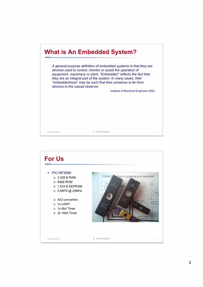
For Us
PIC18F2680o 3,328 B RAMo 64kB ROMo 1.024 B EEPROMo 5 MIPS @ 20MHz
o A/D converterso 1x UARTo 1x 8bit Timero 3x 16bit Timer
3
CSE480/CIS700 S. Fischmeister 5
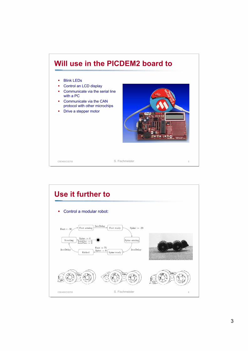
Will use in the PICDEM2 board to
Blink LEDs Control an LCD display Communicate via the serial line
with a PC Communicate via the CAN
protocol with other microchips Drive a stepper motor
CSE480/CIS700 S. Fischmeister 6
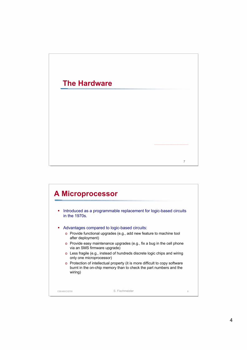
Use it further to
Control a modular robot:
4
7
The Hardware
CSE480/CIS700 S. Fischmeister 8
A Microprocessor
Introduced as a programmable replacement for logic-based circuitsin the 1970s.
Advantages compared to logic-based circuits:o Provide functional upgrades (e.g., add new feature to machine tool
after deployment)o Provide easy maintenance upgrades (e.g., fix a bug in the cell phone
via an SMS firmware upgrade)o Less fragile (e.g., instead of hundreds discrete logic chips and wiring
only one microprocessor)o Protection of intellectual property (it is more difficult to copy software
burnt in the on-chip memory than to check the part numbers and thewiring)
5
CSE480/CIS700 S. Fischmeister 9
What makes a Microprocessor?
Processoro An arithmetic logic unit (ALU) for processing.
Memoryo Permanent memory for keeping the program (= ROM)o Volatile memory for computation (= RAM)o Rewritable permanent memory for logging, tuning, storing intermediate
data (= EEPROM)
Connectivity to peripheralso Binary outputs via single chip pinso Integrated asynchronous and synchronous serial interfaces such as
UART, I2C, RS232, CAN
CSE480/CIS700 S. Fischmeister 10
What makes a Microprocessor?
Timerso Event counting, input capture, real-time interrupt, watchdog timero Pulse-width modulation (PWM)
Support for the analogue worldo Analog-to-digital converter (ADC)o Digital-to-analog converter (DAC)
Software debug support hardwareo JTAG
6
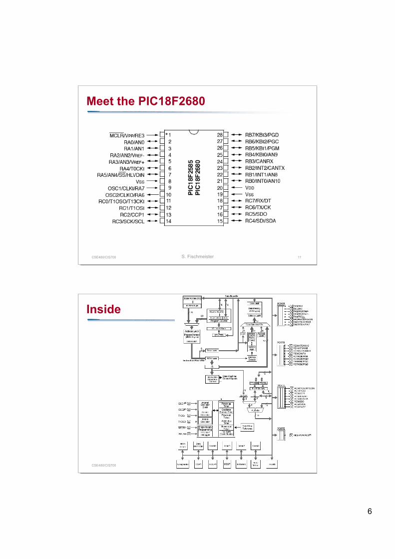
CSE480/CIS700 S. Fischmeister 11
Meet the PIC18F2680
CSE480/CIS700 S. Fischmeister 12
Inside
7
CSE480/CIS700 S. Fischmeister 13
Harvard Architecture
Assign data and program instructions to different memory spaces. Each memory space has a separate bus.
This allows:o Different timing, size, and structure for program instructions and data.o Concurrent access to data and instructions.o Clear partitioning of data and instructions (=> security)
This makes it harder to program, because static data can be in theprogram space or in the data space.
If the program space and the data space are incompatible, copyingdata is no longer a (<start>,len) dump.
CSE480/CIS700 S. Fischmeister 14
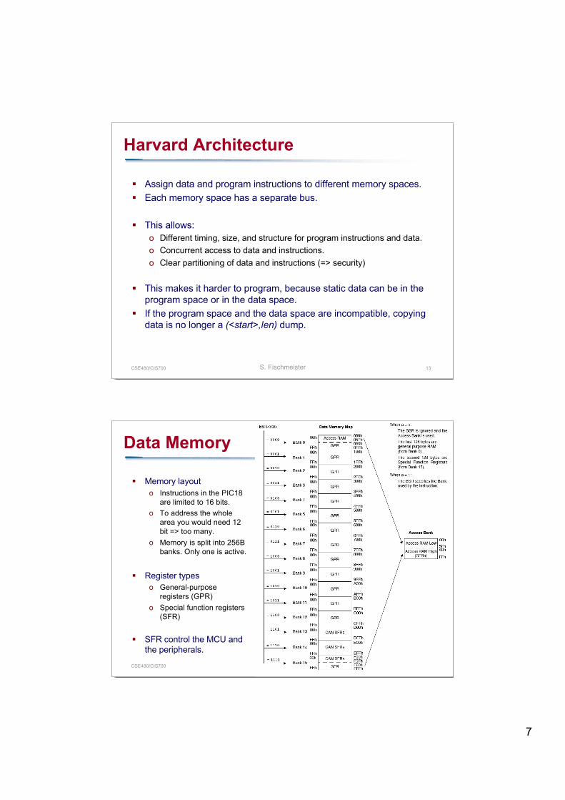
Data Memory
Memory layouto Instructions in the PIC18
are limited to 16 bits.o To address the whole
area you would need 12bit => too many.
o Memory is split into 256Bbanks. Only one is active.
Register typeso General-purpose
registers (GPR)o Special function registers
(SFR)
SFR control the MCU andthe peripherals.
8
CSE480/CIS700 S. Fischmeister 15
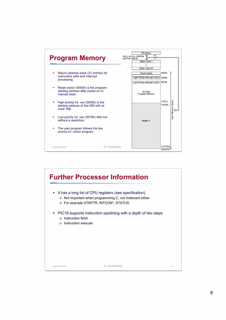
Program Memory
Return address stack (31-entries) forsubroutine calls and interruptprocessing.
Reset vector (0000h) is the program-starting address after power-on ormanual reset.
High priority int. vec (0008h) is thestarting address of this ISR with atmost 16B.
Low priority int. vec (0018h) ditto butwithout a restriction.
The user program follows the lowpriority int. vector program.
CSE480/CIS700 S. Fischmeister 16
Further Processor Information
It has a long list of CPU registers (see specification).o Not important when programming C, not irrelevant either.o For example STKPTR, INTCON*, STATUS
PIC18 supports instruction pipelining with a depth of two stepso Instruction fetcho Instruction execute
9
17
The Programming Process
CSE480/CIS700 S. Fischmeister 18
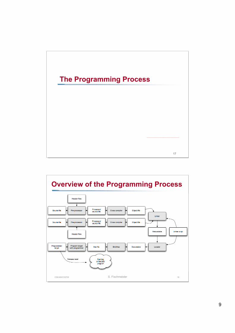
Overview of the Programming Process
10
CSE480/CIS700 S. Fischmeister 19
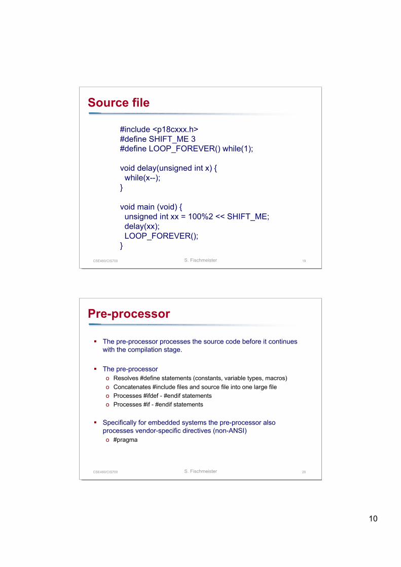
Source file
#include <p18cxxx.h>#define SHIFT_ME 3#define LOOP_FOREVER() while(1);
void delay(unsigned int x) { while(x--);}
void main (void) { unsigned int xx = 100%2 << SHIFT_ME; delay(xx); LOOP_FOREVER();}
CSE480/CIS700 S. Fischmeister 20
Pre-processor
The pre-processor processes the source code before it continueswith the compilation stage.
The pre-processoro Resolves #define statements (constants, variable types, macros)o Concatenates #include files and source file into one large fileo Processes #ifdef - #endif statementso Processes #if - #endif statements
Specifically for embedded systems the pre-processor alsoprocesses vendor-specific directives (non-ANSI)o #pragma
11
CSE480/CIS700 S. Fischmeister 21
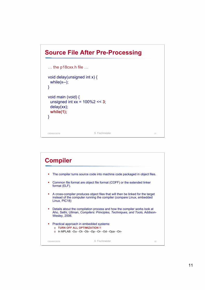
Source File After Pre-Processing
… the p18cxx.h file …
void delay(unsigned int x) { while(x--);}
void main (void) { unsigned int xx = 100%2 << 3; delay(xx); while(1);}
CSE480/CIS700 S. Fischmeister 22
Compiler
The compiler turns source code into machine code packaged in object files.
Common file format are object file format (COFF) or the extended linkerformat (ELF).
A cross-compiler produces object files that will then be linked for the targetinstead of the computer running the compiler (compare Linux, embeddedLinux, PIC18)
Details about the compilation process and how the compiler works look atAho, Sethi, Ullman, Compilers: Principles, Techniques, and Tools, Addison-Wesley, 2006.
Practical approach in embedded systems:o TURN OFF ALL OPTIMIZATION !!o In MPLAB: -Ou- -Ot- -Ob- -Op- -Or- -Od- -Opa- -On-
12
CSE480/CIS700 S. Fischmeister 23
Linker
The linker performs the followingo It combines object files by merging object file sections.
.text section for code .data section for initialized global variables .bss section for uninitialized global variables
o It resolves all unresolved symbols. External variables Function calls
o Reports errors about unresolved symbols.o Appends the start-up code (see next slide)o Provide symbolic debug information
The linker produces a relocatable file. For standard operatingsystems with a dynamic loader, the processes is now finished - notso for embedded systems which need absolutely located binaries.
CSE480/CIS700 S. Fischmeister 24
Startup Code
Startup is a small fragment of assembly code that prepares themachine for executing a program written in a high-level language.o For C in Unix it is called crt1.o or crt0.S (assembly)o For PIC it is typically also an object file specified in the linker script.
Tasks of the startup codeo Disable all interruptso Initialize stack pointers for software stacko Initialize idata sectionso Zero all uninitialized data areas in data memory (ANSI standard)o Call loop: main(); goto loop;
13
CSE480/CIS700 S. Fischmeister 25
Relocator
The relocator converts a relocatable binary into an absolutelylocated binary.
The relocator is guided by a linker script that specifies:o Program and data memory for the target parto Stack size and locationo Logical sections used in the source code to place code and ata
The relocator then produces an ‘executable’, that is ready fordeployment on the target or for the simulator.
CSE480/CIS700 S. Fischmeister 26
Linker File for MPLINK
The linker directives fall into four basic categories. Since MPLINKcombines the linker and relocator in one, there is no cleanseparation.
Command line directiveso LIBPATH: Search path for library and object files.o LKRPATH: Search path for linker command files.o FILES: Additional files to be linked.o INCLUDE: Additional linker command files to be included.
Stack definition directive.o STACK SIZE=allocSize [RAM=memName]
Specifies the size and location of the software stack.
14
CSE480/CIS700 S. Fischmeister 27
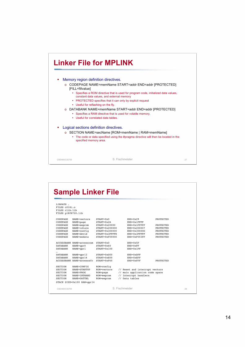
Linker File for MPLINK
Memory region definition directives.o CODEPAGE NAME=memName START=addr END=addr [PROTECTED]
[FILL=fillvalue] Specifies a ROM directive that is used for program code, initialized data values,
constant data values, and external memory PROTECTED specifies that it can only by explicit request Useful for reflashing on the fly.
o DATABANK NAME=memName START=addr END=addr [PROTECTED] Specifies a RAM directive that is used for volatile memory. Useful for correlated data tables.
Logical sections definition directives.o SECTION NAME=secName [ROM=memName | RAM=memName]
The code or data specified using the #pragma directive will then be located in thespecified memory area.
CSE480/CIS700 S. Fischmeister 28
Sample Linker FileLIBPATH . FILES c018i.o FILES clib.lib FILES p18f8720.lib
CODEPAGE NAME=vectors START=0x0 END=0x29 PROTECTED CODEPAGE NAME=page START=0x2A END=0x1FFFF CODEPAGE NAME=eeprom START=0x20000 END=0x1FFFFF PROTECTED CODEPAGE NAME=idlocs START=0x200000 END=0x200007 PROTECTED CODEPAGE NAME=config START=0x300000 END=0x30000D PROTECTED CODEPAGE NAME=devid START=0x3FFFFE END=0x3FFFFF PROTECTED CODEPAGE NAME=eedata START=0xF00000 END=0xF003FF PROTECTED
ACCESSBANK NAME=accessram START=0x0 END=0x5F DATABANK NAME=gpr0 START=0x60 END=0xFF DATABANK NAME=gpr1 START=0x100 END=0x1FF …DATABANK NAME=gpr13 START=0xD00 END=0xDFF DATABANK NAME=gpr14 START=0xE00 END=0xEFF ACCESSBANK NAME=accesssfr START=0xF60 END=0xFFF PROTECTED
SECTION NAME=CONFIG ROM=config SECTION NAME=STARTUP ROM=vectors // Reset and interrupt vectors SECTION NAME=PROG ROM=page // main application code space SECTION NAME=INTHAND ROM=eeprom // Interrupt handlers SECTION NAME=DATTBL ROM=eeprom // Data tables
STACK SIZE=0x100 RAM=gpr14
15
CSE480/CIS700 S. Fischmeister 29
Map File after Linking and Relocating
Open external file…
CSE480/CIS700 S. Fischmeister 30
Bin2Hex
The executable still has to be transferred to the target via a serialline (or even Ethernet with applicable boot loaders).
For standard compliance, the binary is converted into an ASCIIrepresentation useful to PROM programmers and emulators.
A number of standards exists, Intel HEX is widespread.o Each line in an Intel HEX file contains one HEX record.
16
CSE480/CIS700 S. Fischmeister 31
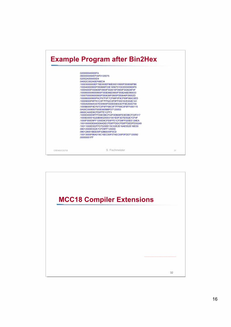
Example Program after Bin2Hex
:020000040000FA:0600000094EF00F0120075:02002A000000D4:04002C002A0EF66E34:10003000000EF76E000EF86E00010900F550656FB6:100040000900F550666F03E1656701D03DD00900F6:10005000F550606F0900F550616F0900F550626F4F:1000600009000900F550E96E0900F550EA6E090033:1000700009000900F550636F0900F550646F09002D:100080000900F6CF67F0F7CF68F0F8CF69F060C0ED:10009000F6FF61C0F7FF62C0F8FF0001635302E1A1:1000A000645307E00900F550EE6E6307F8E2640759:1000B000F9D767C0F6FF68C0F7FF69C0F8FF000115:0A00C0006507000E665BBFD7120053:0600CA00D9CFE6FFE1CFF3:1000D000D9FFFD0EDBCF02F0DB06FE0EDBCF03F017:1000E00001E2DB060250031001E0F3D7E552E7CF4F:1000F000D9FF1200D9CFE6FFE1CFD9FF020EE126EA:10010000DE6ADD6ADECFE6FFDDCFE6FFDEDFE55249:10011000E552FFD7020EE15C02E2E16AE552E16ED0:08012000E552E7CFD9FF120000:080128001BEE00F02BEE00F0CD:10013000F86A019C16EC00F07AEC00F0FDD7120092:00000001FF
32
MCC18 Compiler Extensions
17
CSE480/CIS700 S. Fischmeister 33
Embedded Systems C Compilers
Embedded systems developers need more control over thegenerated file than traditional C developers.o Access to assembly instructions for high-performance functionso Specify memory area for code and datao Extra functionality for saving memoryo Define ISRso Define chip configuration
Every compiler provides different extensions. GCC is available for a small set of targets, but not for too many.
CSE480/CIS700 S. Fischmeister 34
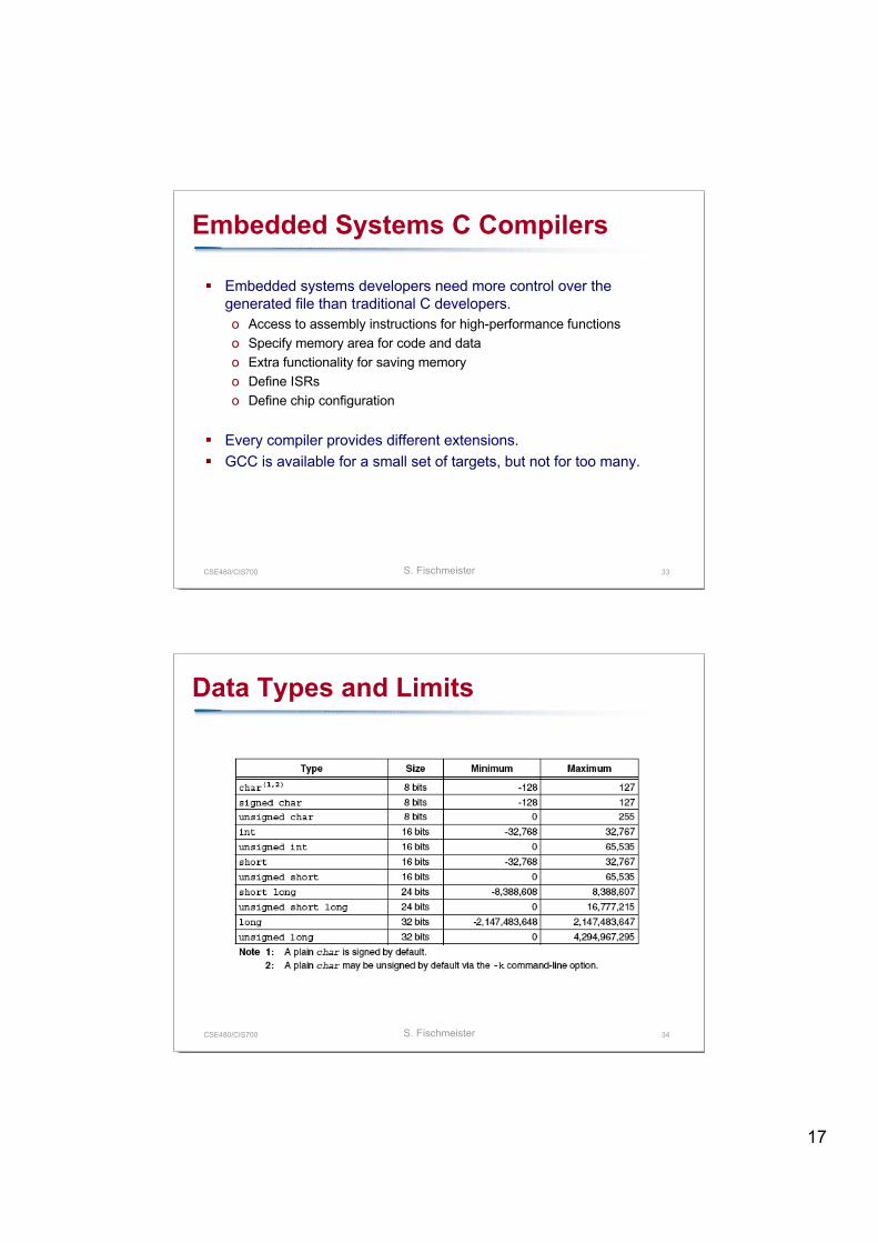
Data Types and Limits
18
CSE480/CIS700 S. Fischmeister 35
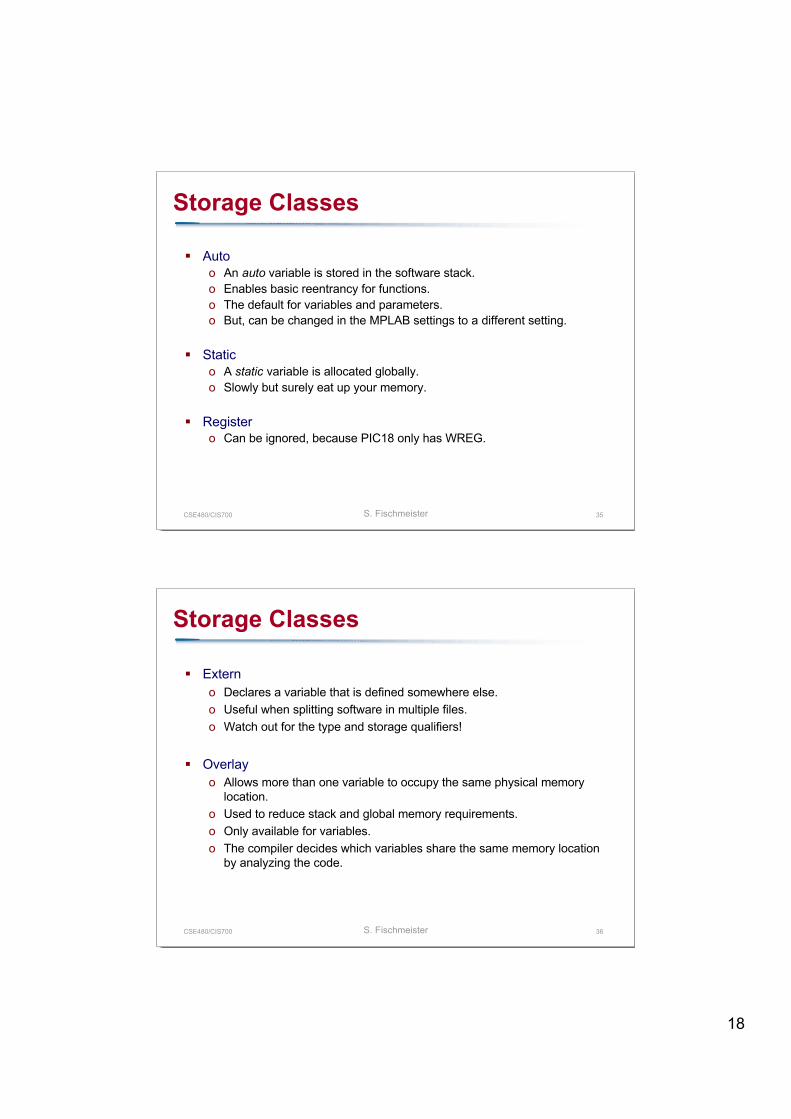
Storage Classes
Autoo An auto variable is stored in the software stack.o Enables basic reentrancy for functions.o The default for variables and parameters.o But, can be changed in the MPLAB settings to a different setting.
Statico A static variable is allocated globally.o Slowly but surely eat up your memory.
Registero Can be ignored, because PIC18 only has WREG.
CSE480/CIS700 S. Fischmeister 36
Storage Classes
Externo Declares a variable that is defined somewhere else.o Useful when splitting software in multiple files.o Watch out for the type and storage qualifiers!
Overlayo Allows more than one variable to occupy the same physical memory
location.o Used to reduce stack and global memory requirements.o Only available for variables.o The compiler decides which variables share the same memory location
by analyzing the code.
19
CSE480/CIS700 S. Fischmeister 37
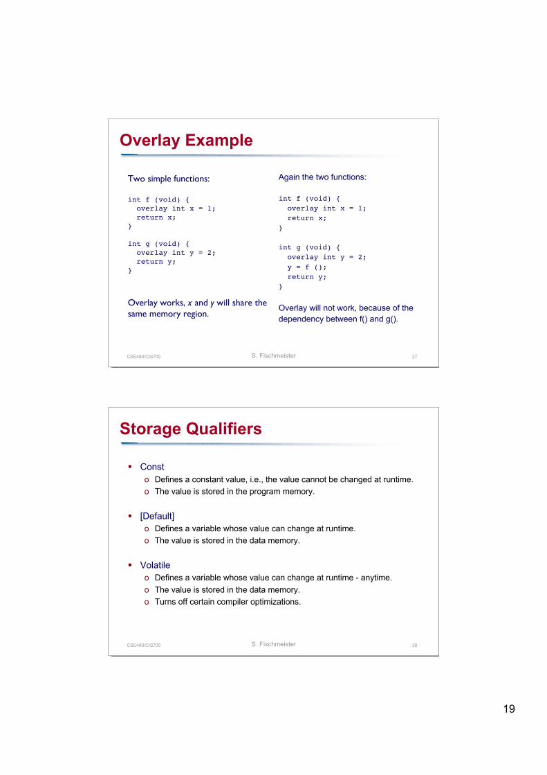
Overlay Example
Two simple functions:
int f (void) { overlay int x = 1; return x;}
int g (void) { overlay int y = 2; return y;}
Overlay works, x and y will share thesame memory region.
Again the two functions:
int f (void) { overlay int x = 1; return x;}
int g (void) { overlay int y = 2; y = f (); return y;}
Overlay will not work, because of thedependency between f() and g().
CSE480/CIS700 S. Fischmeister 38
Storage Qualifiers
Consto Defines a constant value, i.e., the value cannot be changed at runtime.o The value is stored in the program memory.
[Default]o Defines a variable whose value can change at runtime.o The value is stored in the data memory.
Volatileo Defines a variable whose value can change at runtime - anytime.o The value is stored in the data memory.o Turns off certain compiler optimizations.
20
CSE480/CIS700 S. Fischmeister 39
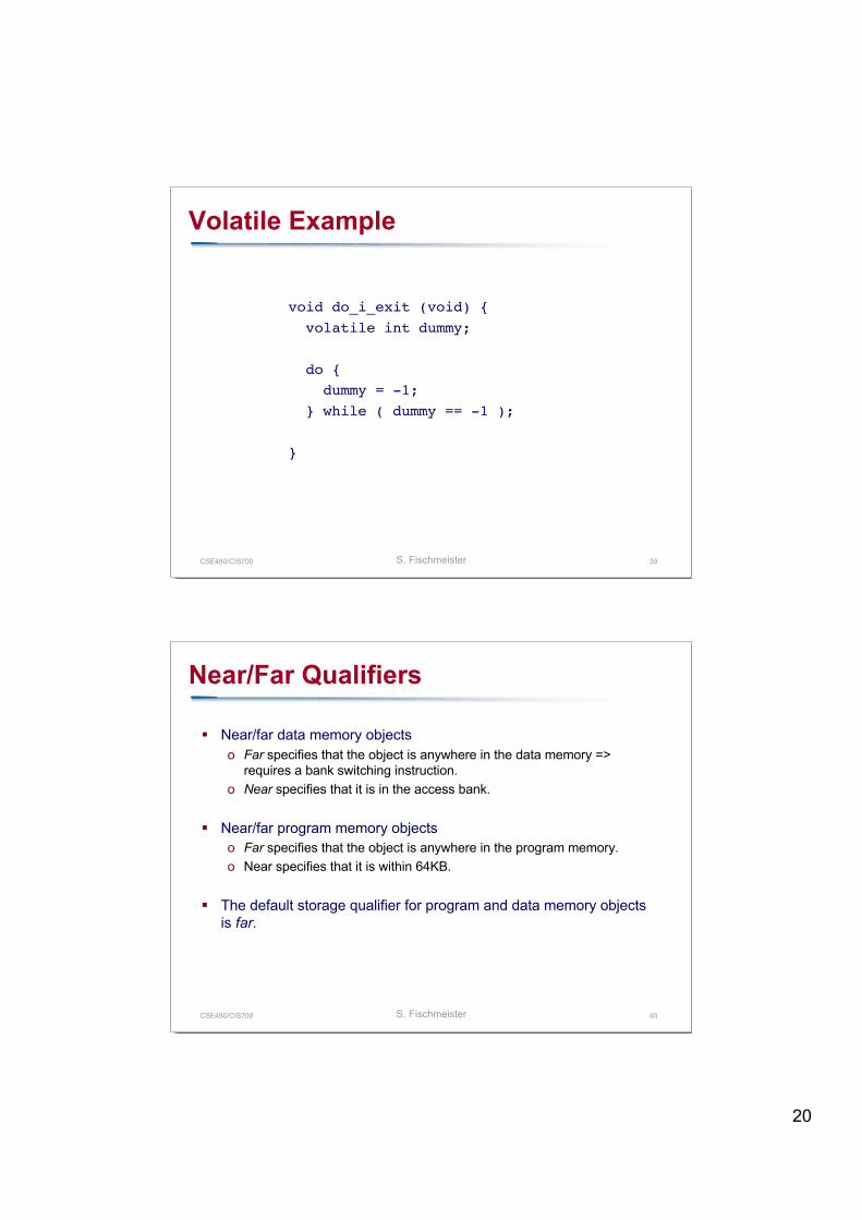
Volatile Example
void do_i_exit (void) { volatile int dummy;
do { dummy = -1; } while ( dummy == -1 );
}
CSE480/CIS700 S. Fischmeister 40
Near/Far Qualifiers
Near/far data memory objectso Far specifies that the object is anywhere in the data memory =>
requires a bank switching instruction.o Near specifies that it is in the access bank.
Near/far program memory objectso Far specifies that the object is anywhere in the program memory.o Near specifies that it is within 64KB.
The default storage qualifier for program and data memory objectsis far.
21
CSE480/CIS700 S. Fischmeister 41
Ram/Rom Qualifiers
In the Harvard architecture, program and memory space areseparated => require means to specify where to find look.
Ram qualifiero Ram specifies that the object is located in the data memory.o It is the default for variables.
Rom qualifiero Rom specifies that the object is located in the program memory.o Useful for constant data such as lookup tables.
CSE480/CIS700 S. Fischmeister 42
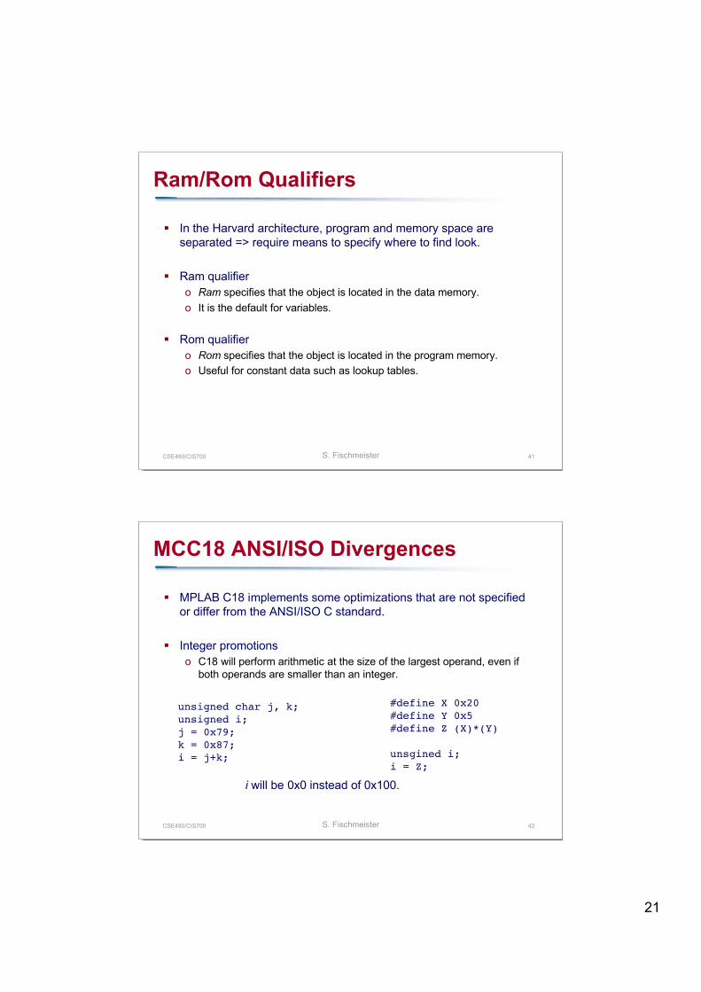
MCC18 ANSI/ISO Divergences
MPLAB C18 implements some optimizations that are not specifiedor differ from the ANSI/ISO C standard.
Integer promotionso C18 will perform arithmetic at the size of the largest operand, even if
both operands are smaller than an integer.
unsigned char j, k;unsigned i;j = 0x79;k = 0x87;i = j+k;
i will be 0x0 instead of 0x100.
#define X 0x20#define Y 0x5#define Z (X)*(Y)
unsgined i;i = Z;
22
CSE480/CIS700 S. Fischmeister 43
MCC18 ANSI/ISO Divergences
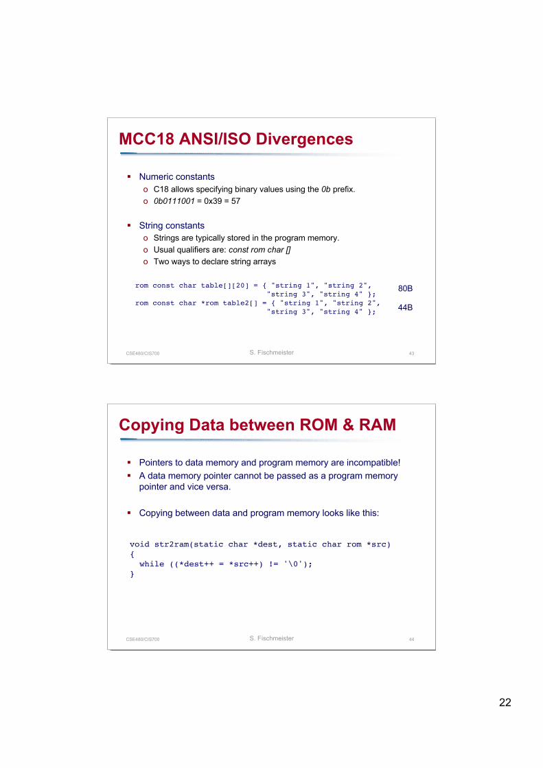
Numeric constantso C18 allows specifying binary values using the 0b prefix.o 0b0111001 = 0x39 = 57
String constantso Strings are typically stored in the program memory.o Usual qualifiers are: const rom char []o Two ways to declare string arrays
rom const char table[][20] = { "string 1", "string 2","string 3", "string 4" };
rom const char *rom table2[] = { "string 1", "string 2","string 3", "string 4" };
80B
44B
CSE480/CIS700 S. Fischmeister 44
Copying Data between ROM & RAM
Pointers to data memory and program memory are incompatible! A data memory pointer cannot be passed as a program memory
pointer and vice versa.
Copying between data and program memory looks like this:
void str2ram(static char *dest, static char rom *src){ while ((*dest++ = *src++) != '\0');}
23
CSE480/CIS700 S. Fischmeister 45
Inline Assembly
An assembly section starts with _asm and ends with _endasm.
Useful for optimization and implanting explicit code in the program(e.g., for traces or benchmarks).
Should be kept to a minimum, because it turns off compileroptimization.
_asm nop_endasm
CSE480/CIS700 S. Fischmeister 46
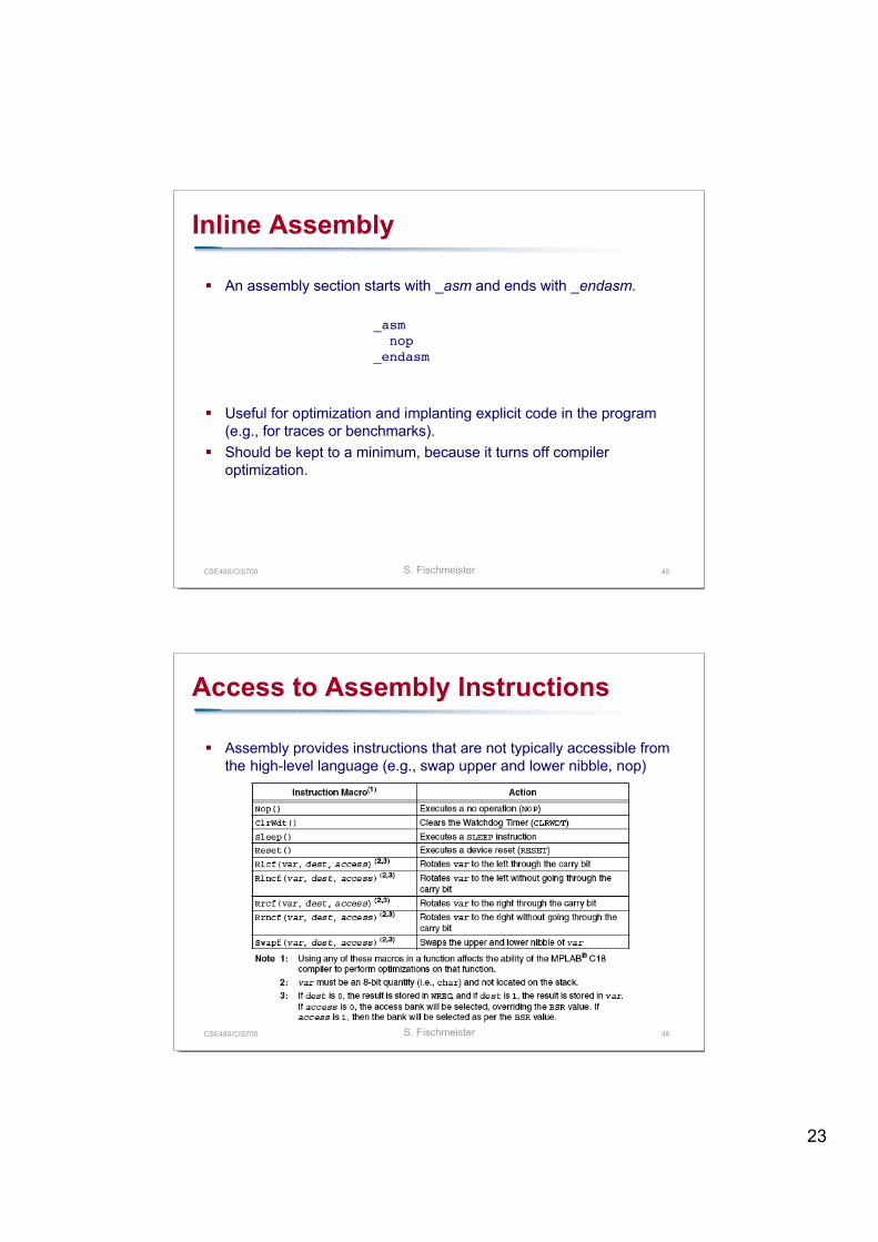
Access to Assembly Instructions
Assembly provides instructions that are not typically accessible fromthe high-level language (e.g., swap upper and lower nibble, nop)
24
CSE480/CIS700 S. Fischmeister 47
#pragma
The #pragma statement is used to manageo Program memory with #pragma code, #pragma romdatao Data memory with #pragma udata, #pragma idatao Interrupt functions with #pragma interrupto Configuration settings with #pragma config
Program memoryo #pragma code [overlay] [section-name [=address]]
Allows placing code at a specific location in the program memory. #pragma code uart_int_service = 0x08 Overlay tells the compiler to try and overlay as many sections of the
specified functions as possible.
CSE480/CIS700 S. Fischmeister 48
#pragma
Program memoryo #pragma romdata [sectionname [=address]]
Allows to place the data following the #pragma in the program memory. Useful for correlated lookup tables that can then be absolutely address from the
program code (table2_data=table1_data[i]+offset).
Data memoryo #pragma udata [attribute-list] [sectionname [=address]]
Specifies a location for the following statically allocated uninitialized data (udata). Per default, all global variables without initial value are placed in udata.
o #pragma idata [attribute-list] [sectionname [=address]] Similar to udata, but for statically allocated initialized data, only. Useful for 256B bank restriction.
o Attribute access and overlay Allows placing a specific section into the access region of the data memory
(=>ACCESSBANK) Must be declared with a near keyword.
25
CSE480/CIS700 S. Fischmeister 49
#pragma
Interrupt service routineso Interrupt service routines preempt the current execution. After finishing
the ISR complete, the execution resumes. (=> context switch)o The ISR saves a minimal context of WREG, BSR, STATUS, etc.o Interrupt functions have a separate temporary sections in memory that
are not overlaid with other sections (see the .map file).
o #pragma interrupt <fname> [tmpname] [save=<savelist>][nosave=<nosavelist]
o #pragma interruptlow <fname> [tmpname] [save=<savelist>][nosave=<nosavelist]
CSE480/CIS700 S. Fischmeister 50
#pragma
Define variable locationso #pragma varlocate bank <variable-name>o #pragma varlocate "section-name" <variable-name>o Useful to location variables in specific banks for performance reasons.
// ** place c1 into bank 1#pragma varlocate 1 c1extern signed char c1;
// ** place c2 into bank 1#pragma varlocate 1 c2extern signed char c2;
void main (void) { c1 += 5; /* No MOVLB instruction needs to be generated here. */ c2 += 5;}
26
CSE480/CIS700 S. Fischmeister 51
#pragma
Chip configurationo #pragma config <settings-list>o Allows specifying processor-specific configuration settings.o E.g.,
#pragma config WDT = ON, WDTPS = 128 #pragma config OSC = HS
52
Debugging and Emulation
27
CSE480/CIS700 S. Fischmeister 53
Introduction Debugging
Restrict the introduction of untested and flawed software(real programmer use gcc -x c - << EOF).
Identify and isolate bugs.
The standard mechanism for debugging are:o printf
Board must be connected via the serial line. Output must be redirected to the UART.
o LED blinking It shows that a certain code line has been executed. It shows an specific error status (have fun with Morse). In case of critical errors, flash all LEDs.
o Breakpoints Somewhat like LEDs but allow inspecting the chip state.
CSE480/CIS700 S. Fischmeister 54
Simulation
High-level language simulationo Test parts of the software without I/O or with simulated I/O.o Compile the binary not for the target but for the workstation.o Bind the target with specific libraries to allow scripted I/O.o Problem: what if the libraries do not behave as the real world?
Low-level simulationo Compile the binary for the target.o Load the executable in a CPU simulator and run.o CPU simulators are widespread, some with I/O support.
MPLAB supports virtually all PIC chips. Check GCC and it’s supported targets via GDB.
o Level of complexity differs: Solely CPU and memory simulation or also Cache performance, memory usage, cycle count.
28
CSE480/CIS700 S. Fischmeister 55
Onboard Debugging
Instead of simulating on the workstation, run the software on thetarget.
Special software support for debugging linked with the compiledobject files.
One way to do it (depends on the chip and the programmer):o Tweak the interrupt handler to provide your debugging features.o For a breakpoint flash the program memory and either insert a specific
breakpoint instruction or an illegal instructions (traps).o Run the program and wait for the trap signals.
JTAG is the standard, defined in 1985 as IEEE-Standard 1149.1.
CSE480/CIS700 S. Fischmeister 56
Emulation
A hardware device simulates the chip and interfaces with the target board. A very costly solution, but the way to go for efficiency and effectiveness of
the developer (compare 2,500.- for the ICE vs. 160.- for the ICD).
For example the PIC ICE allows:o Debug your application on your own hardware in real time.o Debug with both hardware and software breakpoints.o Measure timing between events using the stopwatch or complex trigger.o Set breakpoints based on internal and/or external signals.o Monitor internal file registers.o Select the oscillator source in software.o Trace data bus activity and time stamp events.o Set complex triggers based on program and data bus events, and external
inputs
29
57
Interrupt-basedInput/Output Programming
CSE480/CIS700 S. Fischmeister 58
Input/Output Programming
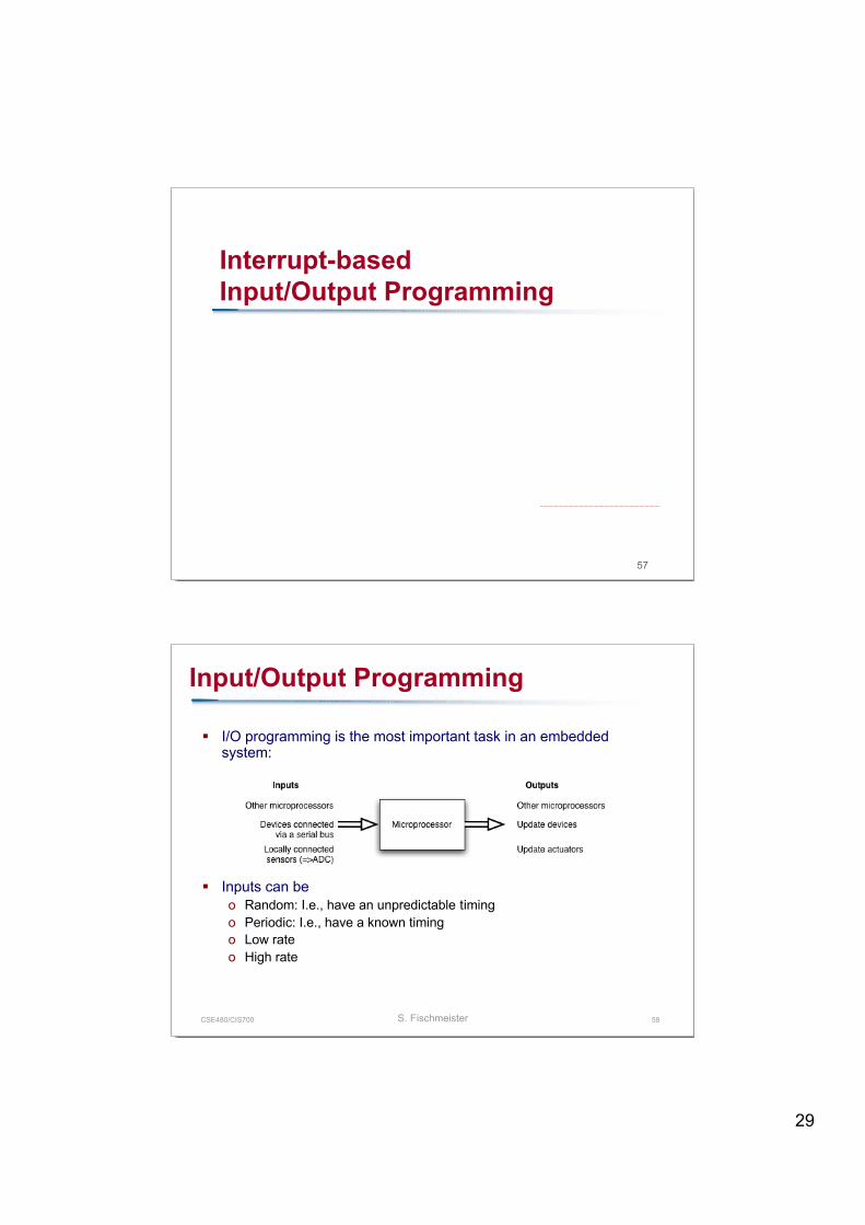
I/O programming is the most important task in an embeddedsystem:
Inputs can beo Random: I.e., have an unpredictable timingo Periodic: I.e., have a known timingo Low rateo High rate
30
CSE480/CIS700 S. Fischmeister 59
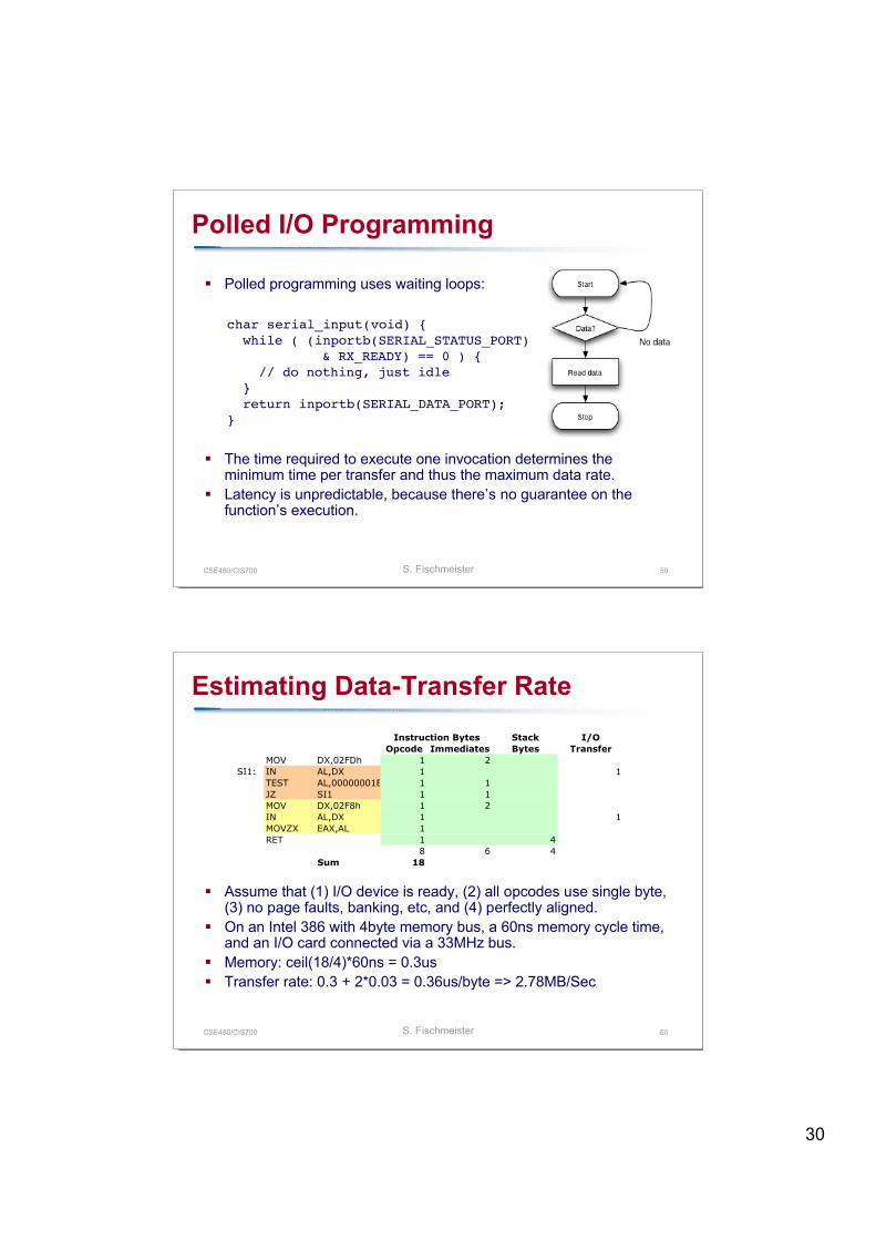
Polled I/O Programming
Polled programming uses waiting loops:
The time required to execute one invocation determines theminimum time per transfer and thus the maximum data rate.
Latency is unpredictable, because there’s no guarantee on thefunction’s execution.
char serial_input(void) { while ( (inportb(SERIAL_STATUS_PORT) & RX_READY) == 0 ) { // do nothing, just idle } return inportb(SERIAL_DATA_PORT);}
CSE480/CIS700 S. Fischmeister 60
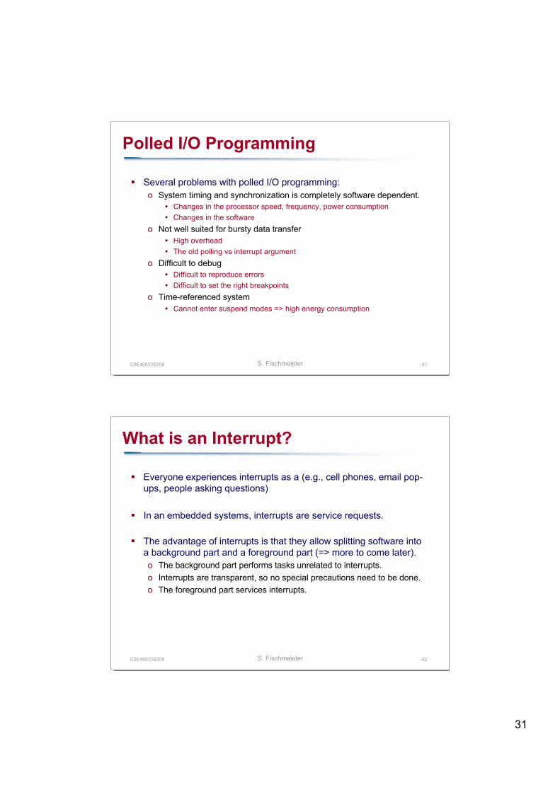
Estimating Data-Transfer Rate
Assume that (1) I/O device is ready, (2) all opcodes use single byte,(3) no page faults, banking, etc, and (4) perfectly aligned.
On an Intel 386 with 4byte memory bus, a 60ns memory cycle time,and an I/O card connected via a 33MHz bus.
Memory: ceil(18/4)*60ns = 0.3us Transfer rate: 0.3 + 2*0.03 = 0.36us/byte => 2.78MB/Sec
Stack I/O
Opcode Immediates Bytes Transfer
MOV DX,02FDh 1 2
SI1: IN AL,DX 1 1
TEST AL,00000001B 1 1
JZ SI1 1 1
MOV DX,02F8h 1 2
IN AL,DX 1 1
MOVZX EAX,AL 1
RET 1 4
8 6 4
Sum 18
Instruction Bytes
31
CSE480/CIS700 S. Fischmeister 61
Polled I/O Programming
Several problems with polled I/O programming:o System timing and synchronization is completely software dependent.
Changes in the processor speed, frequency, power consumption Changes in the software
o Not well suited for bursty data transfer High overhead The old polling vs interrupt argument
o Difficult to debug Difficult to reproduce errors Difficult to set the right breakpoints
o Time-referenced system Cannot enter suspend modes => high energy consumption
CSE480/CIS700 S. Fischmeister 62
What is an Interrupt?
Everyone experiences interrupts as a (e.g., cell phones, email pop-ups, people asking questions)
In an embedded systems, interrupts are service requests.
The advantage of interrupts is that they allow splitting software intoa background part and a foreground part (=> more to come later).o The background part performs tasks unrelated to interrupts.o Interrupts are transparent, so no special precautions need to be done.o The foreground part services interrupts.
32
CSE480/CIS700 S. Fischmeister 63
Interrupts
Sources of interrupts are:o Internal interrupts generated by the on-chip peripherals such as serial
or parallel ports, and timers.o External interrupts generated by peripherals connected to the
processor.o Exceptions thrown by the processor.o Software interrupts
Useful to steer control flow in your application. Are the source of a lot of evil, if not done right.
Non-maskable interrupts (NMI)o Most interrupts can be turned off and on (=ignored).o Some cannot be turned off and on (=non-maskable interrupts):
Reset, watchdog timer, memory parity failure (=> restart machine).
CSE480/CIS700 S. Fischmeister 64
Exceptions
Exceptions are broken down into traps, faults, and aborts.
Traps are detected and serviced immediately after the execution of theinstruction that caused the error condition (=> return address points to thenext instruction)
Faults are detected and serviced before execution of the instruction (=>return address points to the instruction causing the fault).
Aborts are similar to faults, however, the machine state cannot be restoredto the condition just prior to the exception.
Exceptions detected by the Intel Processor are for example:o Faults: divide error, invalid opcode, no math coprocessor, segment not presento Traps: Debug, breakpoint, Overflowo Aborts: double fault, failure of internal cache
33
CSE480/CIS700 S. Fischmeister 65
Recognizing an Interrupt
Internal interrupts are specified by the manufacturer as they are alreadyhardwired.
Interrupt detectiono Edge triggered: the rising edge marks an interrupt.
Latch the interrupt line. Check for interrupt. If so, start ISR.
o Level triggered: A difference in the logic level marks in interrupt. E.g., check the level after every instruction or every clock edge. Some processors require the level to be held for a minimum number of clocks or pulse
width to ignore noisy lines. Maintaining the interrupt
o When should you reset the interrupt?o Recommended practice is: after you serviced it.
Internal queuing of interruptso Strategy one: have a counter that counts how often the interrupt has been
asserted until it is serviced.o Strategy two: Ignore interrupt until it has been serviced.
CSE480/CIS700 S. Fischmeister 66
The Interrupt Mechanism
What happens after an interrupt has been asserted?o Nothing, if it the interrupt is not a fault or abort.o Start the interrupt servicing process at the instruction boundary.
Interrupt servicing processo Save processor state information related to the current execution (remember the
#pragma?).o Locate the ISR.o Start executing the ISR until hitting a return.o Restore state information and continue.
Fast interruptso The detection procedure is similar to ‘slow’ interrupts.o No context information is saved, the processor performs a jump to a specified
address (=> shadow registers).o Special return instruction (retfie).
34
CSE480/CIS700 S. Fischmeister 67
Interrupt Latency
Interrupt latency is the time it takes the processor from recognizing theinterrupt until the start of the ISR execution.
Elements that add to the interrupt latency:o Time taken to recognize the interrupt.
Reconsider multi sampling to lower faulty interrupt detection.o Time taken to complete the current instruction.
Low in RISC systems, potentially long in CISC systems. With CISC some compilers restrict use to fast instructions to reduce interrupt latency
(=> replace hardware instructions with software routines)o Time taken for the context switch.o Time taken to fetch the interrupt vector.o Time taken to start the ISR.
For the microprocessor, computing the worst case interrupt latency isdoable, but consider systems with caches, flexible interrupt vectors, largenumber of registers, deep pipelines, etc.
CSE480/CIS700 S. Fischmeister 68
Do’s and Don’ts with Interrupts
Always expect the unexpected interrupto Write a generic interrupt handler that saves the processor state for latter
analysis (e.g., in the EEPROM).
Interrupts are not negligibleo Switching to the ISR costs time.o Too many interrupts will introduce a high switching overhead.o Too long ISRs will cause starvation for other computation tasks.
Clear your interruptso Leaving them set will have the processor ignore them.
Beware false interruptso Although hardware engineers give their best, they can occur.o Design the software accordingly.
35
CSE480/CIS700 S. Fischmeister 69
Do’s and Don’ts with Interrupts
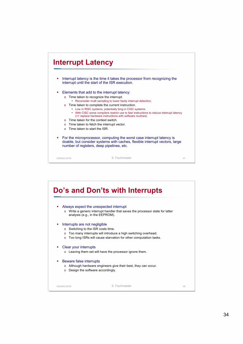
Use interrupt levelso Processors allow multiple levels of interrupts (high, med, low).o PIC18 allows two: high, low; high for fast interrupts, low for normal ones
Control resource sharing
{ read(a); a=2*a; printf("a=", a);}
Interrupt!! { mask_int(); read(a); a=2*a; printf("a=", a); unmask_int();}
CSE480/CIS700 S. Fischmeister 70
Direct Memory Access
Direct memory access (DMA) is a high-performance, low-latencyI/O data-transfer method with special hardware.
A DMA controller is attached to the processor and handles copyingdata from the peripherals into memory regions specifically reservedfor the peripherals.
For further information on DMA see your computer architecturelecture.
Related Documents