IEEE COMMUNICATIONS SURVEYS & TUTORIALS, VOL. 15, NO. 2, SECOND QUARTER 2013 701 On the Evolution of Multi-Cell Scheduling in 3GPP LTE / LTE-A Emmanouil Pateromichelakis, Mehrdad Shariat, Atta ul Quddus, and Rahim Tafazolli, Member, IEEE Abstract—This paper provides a holistic overview of multi-cell scheduling strategies in emerging wireless systems. Towards this objective, the evolution of interference management techniques is thoroughly investigated from simple inter-cell interference coordination (ICIC) techniques towards more advanced coor- dinated multipoint transmissions (CoMP), while comparing and contrasting their common features and differences. Finally CoMP is explored in detail as an advanced and challenging mechanism to fully cooperate between adjacent cells in order to have an efficient resource allocation and inter-cell interference mitigation in multi-cell environments. Index Terms—LTE, LTE-Advanced, ICIC, CoMP I. I NTRODUCTION T HE EVOLUTION of mobile wireless networks during the last several years has raised great expectations for higher data rates to the mobile users. However, the widespread demand for data in the upcoming years inevitably leads to the so-called Spectrum Crisis [1]. This crisis is foreseen as the failure to meet the drastic increase of coverage and capacity demands in wireless networks in future. Hence the evolution of 3G mobile technologies to next generation networks (4G) can be seen as a feasible remedy to this problem by increasing the spectrum re-use in conjunction with the improvement of spectral efficiency [2]. In 2008, International Telecommunication Union (ITU) has identified IMT-Advanced as a set of technical requirements [3] in order to better characterize the typical next generation can- didate system. In this direction, the Third Generation Partner- ship Project (3GPP) targeted the investigation and standardiza- tion of the candidate emerging wireless technologies that are in line with IMT-Advanced, namely Long Term Evolution (LTE) and LTE-A. The key technical components that make LTE and LTE-A superior over 3G technologies is the efficient use of Orthogonal Frequency Division Multiple Access (OFDMA) combined with Multiple-Input Multiple-Output (MIMO) smart antennas in downlink and uplink radio transmissions. Another important aspect of the aforementioned technologies is the new deployment strategy using heterogeneous networks. This deployment includes a hybrid of macro, femto and relay base- stations to improve spectral efficiency and provide a uniform broadband experience to the users throughout a network. LTE was first specified in 3GPP Release 8 [4] and can be identified as a first step towards IMT-Advanced. Later on Manuscript received 24 August 2011; revised 3 February 2012 and 15 May 2012. The authors are with the Department of Electronic Engineering, Cen- tre for Communication Systems Research (CCSR), University of Surrey, Guildford, United Kingdom. (e-mail:{e.pateromichelakis, m.shariat, a.quddus, r.tafazolli}@surrey.ac.uk). Digital Object Identifier 10.1109/SURV.2012.071812.00127 Fig. 1. Downlink Interference in a multi-cell environment 3GPP Rel. 10, LTE-A [5] came along as a further enhance- ment of LTE where it targets to outperform IMT-Advanced requirements. The enhancements of LTE-A over LTE concern the increase of capacity and spectral efficiency as well as the energy efficiency and the cost reduction for the network operator. As described above, LTE and LTE-A are envisioned as key technologies to meet the drastic coverage and capacity future demands in wireless cellular networks. However, to achieve the ambitious future targets, there are some challenging issues ahead that may slow down this migration process. A. Inter-cell Interference One of the major issues towards the deployment of LTE technology is the inter-cell interference caused by neighboring base stations (BSs) that can significantly deteriorate the per- formance of near-by mobile User Equipments (UEs). In the following example in Fig. 1 as a user approaches its cell-edge, he suffers from high inter-cell interference from neighboring cells (BS2, BS3). This happens due to the signal attenuation the user experiences in long distance from its serving BS as well as the strong interference by surrounding cells. This issue essentially requires applying efficient radio resource management strategies to decrease inter-cell interference (ICI) and alternatively convert it into useful signal by means of coordinated processing. The significance of inter-cell interference in emerging wire- less technologies has also been emphasized in recent literature [6]. As discussed there, interference can be a major challenge 1553-877X/13/$31.00 c 2013 IEEE

Welcome message from author
This document is posted to help you gain knowledge. Please leave a comment to let me know what you think about it! Share it to your friends and learn new things together.
Transcript

IEEE COMMUNICATIONS SURVEYS & TUTORIALS, VOL. 15, NO. 2, SECOND QUARTER 2013 701
On the Evolution of Multi-Cell Scheduling in 3GPPLTE / LTE-A
Emmanouil Pateromichelakis, Mehrdad Shariat, Atta ul Quddus, and Rahim Tafazolli, Member, IEEE
Abstract—This paper provides a holistic overview of multi-cellscheduling strategies in emerging wireless systems. Towards thisobjective, the evolution of interference management techniquesis thoroughly investigated from simple inter-cell interferencecoordination (ICIC) techniques towards more advanced coor-dinated multipoint transmissions (CoMP), while comparing andcontrasting their common features and differences. Finally CoMPis explored in detail as an advanced and challenging mechanismto fully cooperate between adjacent cells in order to have anefficient resource allocation and inter-cell interference mitigationin multi-cell environments.
Index Terms—LTE, LTE-Advanced, ICIC, CoMP
I. INTRODUCTION
THE EVOLUTION of mobile wireless networks duringthe last several years has raised great expectations for
higher data rates to the mobile users. However, the widespreaddemand for data in the upcoming years inevitably leads to theso-called Spectrum Crisis [1]. This crisis is foreseen as thefailure to meet the drastic increase of coverage and capacitydemands in wireless networks in future. Hence the evolutionof 3G mobile technologies to next generation networks (4G)can be seen as a feasible remedy to this problem by increasingthe spectrum re-use in conjunction with the improvement ofspectral efficiency [2].In 2008, International Telecommunication Union (ITU) has
identified IMT-Advanced as a set of technical requirements [3]in order to better characterize the typical next generation can-didate system. In this direction, the Third Generation Partner-ship Project (3GPP) targeted the investigation and standardiza-tion of the candidate emerging wireless technologies that are inline with IMT-Advanced, namely Long Term Evolution (LTE)and LTE-A. The key technical components that make LTEand LTE-A superior over 3G technologies is the efficient useof Orthogonal Frequency Division Multiple Access (OFDMA)combined with Multiple-Input Multiple-Output (MIMO) smartantennas in downlink and uplink radio transmissions. Anotherimportant aspect of the aforementioned technologies is thenew deployment strategy using heterogeneous networks. Thisdeployment includes a hybrid of macro, femto and relay base-stations to improve spectral efficiency and provide a uniformbroadband experience to the users throughout a network.LTE was first specified in 3GPP Release 8 [4] and can
be identified as a first step towards IMT-Advanced. Later on
Manuscript received 24 August 2011; revised 3 February 2012 and 15 May2012.The authors are with the Department of Electronic Engineering, Cen-
tre for Communication Systems Research (CCSR), University of Surrey,Guildford, United Kingdom. (e-mail:{e.pateromichelakis, m.shariat, a.quddus,r.tafazolli}@surrey.ac.uk).Digital Object Identifier 10.1109/SURV.2012.071812.00127
Fig. 1. Downlink Interference in a multi-cell environment
3GPP Rel. 10, LTE-A [5] came along as a further enhance-ment of LTE where it targets to outperform IMT-Advancedrequirements. The enhancements of LTE-A over LTE concernthe increase of capacity and spectral efficiency as well asthe energy efficiency and the cost reduction for the networkoperator.As described above, LTE and LTE-A are envisioned as key
technologies to meet the drastic coverage and capacity futuredemands in wireless cellular networks. However, to achievethe ambitious future targets, there are some challenging issuesahead that may slow down this migration process.
A. Inter-cell Interference
One of the major issues towards the deployment of LTEtechnology is the inter-cell interference caused by neighboringbase stations (BSs) that can significantly deteriorate the per-formance of near-by mobile User Equipments (UEs). In thefollowing example in Fig. 1 as a user approaches its cell-edge,he suffers from high inter-cell interference from neighboringcells (BS2, BS3). This happens due to the signal attenuationthe user experiences in long distance from its serving BSas well as the strong interference by surrounding cells. Thisissue essentially requires applying efficient radio resourcemanagement strategies to decrease inter-cell interference (ICI)and alternatively convert it into useful signal by means ofcoordinated processing.The significance of inter-cell interference in emerging wire-
less technologies has also been emphasized in recent literature[6]. As discussed there, interference can be a major challenge
1553-877X/13/$31.00 c© 2013 IEEE

702 IEEE COMMUNICATIONS SURVEYS & TUTORIALS, VOL. 15, NO. 2, SECOND QUARTER 2013
that degrades the overall performance in a hierarchical multi-level network. As a result, tight interference management iscrucial to increase spectral efficiency throughout the network.In general, Interference Management can be grouped to
three main categories [7] that handle ICI through differentmitigation techniques, namely ICI randomization, cancellationand coordination (avoidance). The latter is further examinedin this review paper as an effective method to mitigate ICIand to enhance the degraded users performance.
B. Motivation and Related Works
Intra-cell scheduling and resource allocation gets affectedby an external inter-cell factor, i.e. the interference that isquite dependent on the location of users and their QoSrequirements in the entire system. In a full load scenario, inter-cell interference can significantly affect the efficiency of intra-cell scheduling algorithms [8]. As a result, interference man-agement is crucial to maintain minimum service requirements.This is referred to as multi-cell scheduling, where other cellschannel knowledge and parameters are taken into account tomitigate interference. In this manner, multi-cell scheduling canbe considered as an upper layer on top of classical intra-cellscheduling strategies.Several review papers in literature [6], [9], [10] discuss
inter-cell interference coordination in the context of emergingwireless technologies. In [6], the authors described the in-terference coordination schemes and technical challenges thatarise in heterogeneous networks highlighting the impact of in-terference in deployments consisting of cells of different size.Moreover, [9] presents a survey on interference coordinationin OFDM-based multi-hop cellular networks with main focuson semi-static interference coordination schemes that could beapplied at LTE-A. Furthermore, [10] discusses in general termsscheduling through Interference Avoidance / Coordination tomitigate interference in a multi-cell environment.Hence, to the best of our knowledge, a holistic survey on
multi-cell scheduling and interference coordination with par-ticular focus on LTE /LTE-A systems is not currently available.Additionally, this survey provides an extensive evaluation ofmulti-cell scheduling and bridges the gap between ICIC andCoMP mechanisms as the key enablers in LTE and LTE-A.
C. Scope and Structure of the Survey
In this survey, Multi-cell scheduling in terms of interferencecoordination / avoidance is presented as a roadmap that beginswith the review of popular low-complexity ICI Coordination(ICIC) schemes proposed in the literature. Thereafter, it pro-ceeds through more sophisticated dynamic ICIC solutions andfinally is directed towards Coordinated Multipoint (CoMP)transmission as an advanced way of interference managementfor 4G technologies. The main focus will be on the area ofdownlink interference coordination in the context of emergingmulti-cell scheduling policies for LTE /LTE-A systems. Thescope of this survey can be highlighted using the followingaxes:
• Holistic categorization of ICIC and presenting majorproposals for LTE.
Fig. 2. Interference Coordination and Cooperation Overview
• Classification of CoMP and presenting major proposalsfor LTE and LTE-A.
• Introduction of a multi-cell scheduling framework, com-prising downlink interference coordination (ICIC) andcooperation (CoMP) mechanisms.
• Detailed exploration of Dynamic-ICIC and CoMP tech-niques as future research directions for interference mit-igation in LTE-A.
Fig. 2 provides an illustrative picture of this survey study,highlighting the structure and involved elements. Here, theevolution of ICIC towards CoMP is illustrated in terms ofcapacity versus complexity trade-off. More details on thequantification of capacity for LTE, IMT-Advanced systems canbe found in [3]. Following this gradual migration, it can beseen that simple interference coordination schemes, requiringlimited information on the control channel, have evolved intomore sophisticated cooperation schemes (coordinated Beam-forming and Joint Processing) where the level of sharing hasalso scaled up to the data channel to further enhance spectralefficiency [3].The remainder of this paper is organized as follows. In Sec-
tion II, ICIC techniques are detailed and categorized to static,semi-static and dynamic-ICIC schemes based on the time scaleof updates as well as the level of signaling involved. In SectionIII, the study is further extended into more advanced schemesbased on CoMP with particular focus on the downlink CoMPschemes where Coordinated Scheduling and Joint Processingschemes are investigated. Thereafter, in Section IV, downlinkCoMP schemes are further examined and major challengesand issues are addressed. Section V underlines the openresearch problems that arise due to interference coordinationand cooperation in future wireless cellular systems. Finally,Section VI provides a summary and conclusions of this survey.
II. INTER-CELL INTERFERENCE COORDINATION (ICIC)
In OFDM networks, ICIC has been introduced as a potentialstrategy to control the level of downlink ICI. In concept, ICICdefines a coordination mechanism among the neighboring cellsto allocate orthogonal resources to their overlapping highlyinterfered areas. In this framework, two sub-mechanisms canbe identified in each ICIC scheme, namely Frequency ReusePartitioning and Power Control.

PATEROMICHELAKIS et al.: ON THE EVOLUTION OF MULTI-CELL SCHEDULING IN 3GPP LTE / LTE-A 703
Fig. 3. Partial Frequency Reuse
In Frequency Reuse Partitioning [11], the spectrum isdivided into two or more groups of mutually exclusive setsallocated to different regions. On the other hand, Power controlin ICIC schemes provides multiple levels of transmissionpower to different cell areas, already identified by the reusepartitioning schemes. This enables the BSs to adaptively tunetheir transmit power based on the location of users. The poweradjustment provided by the BS, combined with frequencyreuse partitioning, can mitigate quite efficiently the cell-edgeICI. Considering the required level of coordination betweenBSs, two types of coordination strategies can be identified:Centralized Coordination that relies on a Centralized Con-
troller to gather channels quality information from BSs whereit allocates the spectrum to them in ways to alleviate inter-cell interference. This coordinator in the context of previoustechnologies, like HSPA, UMTS could be integrated as part ofRadio Network Controller (RNC) entity. In LTE, this legacycentralized coordination is not encouraged due to the lackof RNC, however, some resource allocation algorithms havebeen proposed for LTE by using Mobility Management Entity(MME) as the Coordinator [7].In Distributed Coordination, on the other hand, there is a
direct coordination between adjacent base stations to handleinterference and to allocate resources efficiently to the cell-edge users. This can be achieved through a new interface thatis introduced in LTE standard termed as X2 interface [5].From a different perspective, ICIC Mechanisms can be
characterized by the frequency of decisions that are made bybase stations. Based on this categorization, three distinct levelsof ICIC can be identified: Static, Semi-Static and DynamicICIC. In the following sub-section, a brief review on the stateof the art for each category is provided.
A. Static ICIC
Considering the static ICIC, resource allocation is fixed anddoes not depend on the variations of channel and traffic. Themain solutions of this category have been proposed earlier in([12]-[17]) for LTE systems and are briefly described below.Mainly, two partition-based static coordination schemes havebeen proposed, namely Partial Frequency Reuse (PFR) [12],[13] and Soft Frequency Reuse (SFR) [14], [15].A fundamental static-ICIC mechanism and promising solu-
tion for 3GPP LTE is Partial Frequency Reuse (PFR) scheme[12], [13]. PFR is a mechanism that targets the inter-cellinterference mitigation by fractionally assigning frequencysub-bands to cell sites through static frequency planning. PFR
Fig. 4. Soft Frequency Reuse N=3
shares some common features with the Fractional FrequencyReuse (FFR) concept was discussed in [11].This concept isto split the total bandwidth in two parts i.e. Cell-Center Area(CCA) and Cell-Edge Area (CEA). Users in CCA with highersignal quality and lower level of interference can use lowerreuse factor to achieve better spectral efficiency, while CEAusers with lower SINR utilize higher reuse factor to alleviateresulting ICI.In PFR, the total spectrum N is divided between cell center,
Ncenter and cell edge, Nedge such that N= Ncenter + Nedge.The Ncenter sub-bands are dedicated for cell-center users inlow power mode whereas Nedge are further partitioned basedon the sectorization of the cell-edges. As shown in Fig. 3,for 3-sectored cells, each sector utilizes Ncenter /3 of sub-bands in high power mode. This scheme manages to isolateinter-cell interference by restricting the utilization of resourcesat cell-edges. However this restriction limits the maximumthroughput available to the users since they cannot benefitfrom the utilization of the full bandwidth.On the other hand, Soft Frequency Reuse (SFR) deals with
this issue by enabling each cell to utilize the full bandwidth.SFR was first introduced for GSM and then adopted by 3GPPas an ICIC method for LTE [14]. The concept of SFR isthe division of the spectrum in N bands where cell-centerusers can utilize all the bands in low power mode (low-powerband), while the cell-edge users can utilize only 1/N of thespectrum with frequency reuse of N (high-power band). Inaddition to that, the unutilized part of high- power band inCEA can also be used by cell-center users while they do notcreate any interference to adjacent frequency bands. Hence,when compared to PFR, SFR enables the system to maximizecapacity by utilizing full bandwidth rather than restricting theutilization in a part of resources. In [14], [15] the soft reuseproposals for LTE adopted the division of the entire spectrumin N=3 bands as can be seen in Fig. 4.Another variant of SFR was presented in [16], [17] by
Alcatel where the spectrum is divided to N=7 or 9 sub-bandsin 3-sectored cells. Each sector is restricted to one sub-bandthat is orthogonal across the adjacent CEAs. This restrictioncorresponds to a power restriction for that sub-band. In thiscontext, when a user of a neighboring sector approaches theborders of its cell it is just allowed to utilize the frequency sub-band restricted to the adjacent sector. Therefore the restrictedsub-band is used only at the centre of each sector whereas

704 IEEE COMMUNICATIONS SURVEYS & TUTORIALS, VOL. 15, NO. 2, SECOND QUARTER 2013
Fig. 5. Alcatel Proposal
TABLE ISTATIC ICIC SCHEMES
Parameters
ICIC Schemes
Sub-bands Power Profile
Spectrum Utilization
CCA CEA CCA CEA CCA CEA
PFR [12,13]Low High
SFR [14,15] 3 1 Low High 100% 33%
Alcatel [16,17]1 6 Low High ~ 15% ~ 85%
*CCA = Cell Centre Area, *CEA = Cell Edge Area
N
NN edge−
N
Nedge
edgeNedgeNN −
the rest of sub-bands are allocated at the edges correspondingto the adjacent sectors restrictions. The frequency planning aswell as the power profile for this mechanism is illustrated inFig. 5.Table I shows a qualitative comparison of the three afore-
mentioned static schemes. Here, we compare all the proposalsbased on the frequency partitioning between CCA and CEAas well as the power profile and spectrum utilization incorresponding areas.As can be seen above, Alcatel proposal is a more aggressive
strategy that targets higher spectrum utilization at the celledge via sub-band restriction at the cost of partially addressinginter-cell interference. On the other hand, SFR favors the cellcenter users, by allocating entire available spectrum to the cellcenter areas. PFR can be seen as a more cautious avoidancescheme, where the spectrum is partitioned into two mutuallyexclusive parts. This is performed in a way that cell edge andcell center areas do not have any conflicts. As a result, theoverall cell utilization is affected by limiting the amount ofsub-bands that can be used in each area.
B. Semi-Static ICIC
In semi-static schemes, resource allocation is adaptive basedon the traffic changes across different areas in a cell. Thereforesignaling between BSs is exchanged semi-statically. Some
popular semi-static ICIC schemes ([18]-[23]) applied to LTEnetworks, are described below, characterizing the ICIC imple-mentations in 3GPP LTE.The first proposal [18] discusses the simplest semi-static
mechanism where in each cell, CCA and CEAs as well asCEAs of neighboring cells utilize orthogonal parts of thespectrum. Here, the spectrum is divided into N sub-bands;a sub-set of X sub-bands is allocated to cell-edge usersorthogonally across the neighboring cells whereas the rest N-3X is allocated to cell-center users. The number of sub-bandsis adjustable by BSs and depends on the traffic load. Thereforethis proposal resembles a fractional reuse partitioning methodwhereas a semi-static coordination between neighboring BSsdictates the number of resources to be allocated for eachcell-edge and thus cell-centre areas. The main drawback ofthis mechanism is related to the limitation on the maximumcapacity to be achieved by a user in this orthogonal allocation.The aforementioned proposal is illustrated in Fig. 6.Some other proposals try to rectify this drawback via
incorporating semi-static variants of SFR.Firstly, the Whispering approach [19] targets the spectrum
utilization by assigning resources at the CEAs in a way toprevent interference towards the adjacent cells. Subsequently,the relation between CCA and CEA is kept orthogonal. Thisis done by partitioning the cell-edge areas into six sectors.Here, the spectrum is divided into 4 sub-bands where multiplepower modes could be applied to each sub-band (W or S).This corresponds to the creation of eight available groups forscheduling purposes i.e. W1-W4 (Low power mode) and S1-S4 groups (High power mode).More specifically, cell-center users of each cell site can use
one band out of W1- W4 available bands in low power, whilecell edge users utilize three bands out of S1- S4 in high powermode provided that two non-adjacent sectors cannot share thesame band.To address this issue, [20] provides a centralized semi-static
ICIC solution for LTE, in which a central entity reserves avariable portion of the available sub-bands to cell-edge usersdepending upon the cell-edge traffic load. This number of the

PATEROMICHELAKIS et al.: ON THE EVOLUTION OF MULTI-CELL SCHEDULING IN 3GPP LTE / LTE-A 705
Fig. 6. Semi-static ICIC Proposal
reserved sub-bands varies from null, if traffic in cell edge isnegligible up to 1/3 of the spectrum, for the orthogonal sub-band allocation between neighbor cells, whereas users at cell-center areas can utilize all the bands in reduced power. Incase that the reserved sub-bands for all the cells are equal tothe 1/3 of the spectrum, this mechanism resembles the SoftFrequency re-use scheme that was presented in Fig. 4.In a similar manner, Softer Frequency Reuse (SerFR) is
another semi-static proposal that applies some modificationsin SFR as in [21], [22] in order to achieve more frequencyselective gain. In this proposal both cell-center and cell-edgeusers can utilize full spectrum but through various powerprofiles. Similar to SFR concept that was illustrated in Fig. 4,there are two power profiles that determine the frequency sub-bands to be used in CCAs and CEAs. However, in this schemecell-edge users can additionally utilize sub-bands in low-power profile. Here, a distinguishing factor from the previousproposals is the possibility of allocating extra resources to thecell-edge users. This has been modeled stochastically by thedefinition of a probability factor that changes gradually by thetraffic. In similar manner, cell-center users can benefit fromthis feature by additionally utilizing the high power sub-bandsbelonging to CEAs when the traffic load is unevenly lower atthe cell-edge.Another popular semi-static ICIC [23], namely Adaptive
Fractional Frequency Reuse combines soft frequency reusein a semi-static multi-mode case. This scheme can be dis-tinguished from the aforementioned semi-static schemes, asit does not divide the cell into center and edge areas. In thisscheme, each cell is divided to 3 sectored areas and each sectoris tuned in one of the four available modes. These modes, asshown in Fig. 8, represent the level of aggressiveness of eachBS towards spectrum utilization. In first mode, the defaultmode of operation, sectors utilize full spectrum (reuse 1). Inmodes 2 and 3, SFR is used with different power levels for thesoft-reused sectors. The difference of modes 2 and 3 originatesfrom the gap of power levels between high power and lowpower tones. Finally, in Mode 4, frequency reuse of three isapplied in high transmit power.Therefore, according to the level of interference, the system
can adaptively move to higher modes with lower level ofspectrum reuse to mitigate the effect of interference.In Table II, we illustrate a qualitative comparison of the
semi-static schemes presented above in similar manner as thestatic cases.
TABLE IISEMI-STATIC ICIC SCHEMES
C. Dynamic ICIC
The major issue in static and semi-static ICIC techniquesis their failure to adapt into the fast changes in operatingenvironment. Therefore, providing better data rates for cell-edge users by adopting these approaches would severelypenalize the overall performance of the system. On the otherhand, in Dynamic ICIC (D-ICIC) resources are allocated ina dynamic manner by BSs, without prior frequency planningwhere different factors like cell load, traffic distributions andQoS constraints are taken into account for a multi-cell environ-ment. There are numerous dynamic approaches in the literatureproposed to handle inter-cell interference. However, adoptingthe dynamic approaches in practice is more challenging forsystems like LTE as dynamic coordination requires heavysignaling load. This can impose more complexity into thescheduling process. At first place, the D-ICIC algorithms canbe categorized based on the level of coordination that isrequired into: Centralized D-ICIC, Semi-centralized D-ICICand De-centralized D-ICIC [24].In practice, the first two categories share some common
characteristics but can be distinguished by the level of relianceon the centralized controller for coordination between BSs.Therefore, in semi-centralized mechanisms the existence of acentral unit is necessary to handle resource conflicts betweencell sites; however the role of the central unit is secondary[24].In decentralized D-ICIC [24], the scheduling decisions are
made by means of local signaling exchange between BSswithout involving any central unit. As mentioned above,dynamic schemes should provide fast scheduling decisionswhile keeping the signaling load as low as possible. However,the iterative nature of decentralized D-ICIC algorithms, makethem less efficient to handle ICI in fast changing environments,due to extra cyclic signaling that is required and subsequentdelays compared to global coordination.1) Problem Description: As stated above, in the static
and semi-static schemes the multi-cell scheduling notion isexpressed in static or semi-static patterns of partitioning infrequency or power profile rather than global scheduling. Ingeneral terms, however, the multi-cell interference manage-ment can be seen as a multi-cell resource allocation problemthat targets the maximization of total capacity or other perfor-

706 IEEE COMMUNICATIONS SURVEYS & TUTORIALS, VOL. 15, NO. 2, SECOND QUARTER 2013
Fig. 7. Whispering
Fig. 8. Adaptive FFR modes
mance metrics in a multi-cell environment, subject to differentconstraints including interference, fairness or QoS [25].The multi-cell resource allocation problem in presence of
interference using capacity or other performance metrics as theoptimization objective is a non-convex optimization problem.Although some solutions have been presented to optimallysolve this problem via dual decomposition theory [26], still theproposed algorithms are computationally complex in particularin populated dense scenarios. Therefore, we focus on twocategories of efficient sub-optimal solutions for dynamic ICICthat are more feasible in cellular environment for differentpractical cases:2) Utility-based solutions: In literature, the problem of
resource allocation as detailed above has been mapped intoutility maximization framework [27], [28]. The network utilityfunction is quite well known in literature as an indicatorof user’s ”satisfaction”, based on different factors includingchannel quality, experienced delay and other QoS require-ments. Utility optimization in a multi-cell environment can bedefined in similar context as capacity maximization subjectto the capacity limit and interference constraints. The notionof network utility is defined as a metric to balance capacity,fairness and QoS efficiently in a multi-cell environment.In this context, each BS forms a utility matrix that embeds
the utility values corresponding to all attached users fordifferent Resource Blocks (RBs). This information dependson the channel quality experienced by each user as well as
Fig. 9. Utility-based D-ICIC proposal
the demand factor and QoS requirements imposed by userapplication. The elements of each matrix are dependent toother matrices in neighboring BSs due to interference effect.In literature ([29]-[33]), there are various proposals targetingefficient resolution of the utility matrices by taking intoconsideration the coupling effect of inter-cell interference.In some proposals, the solution can be seen as a two-stagescheduling mechanism where channel restrictions are imposedon highly coupled elements across matrices on top of intra-cellscheduling to decouple the problem. In this group of schemesthe utility matrix is initially created independently in each BSto pre-allocate resources to users based on their correspond-ing channel and QoS requirements. Thereafter, the resourceconflicts that occur between neighboring BSs are negotiatedthrough distributed signaling or in a semi-centralized mannerand finally the restrictions are imposed. Here, the restrictionsare introduced in such a way that the overall network utilityis maximized.In [29], [30], a semi-centralized scheme was proposed to
handle ICI dynamically as described above by utilizing Hun-garian Algorithm [34] for the pre-allocation phase. A generalpicture of the aforementioned procedures is illustrated inFig. 9. Following the process described above, the individualrequests for channel restrictions are conveyed to a centralunit by all the affected BSs and the central unit applies therestrictions to optimize the systems performance.Using similar concept, in [31], the utility matrix opti-
mization is solved via binary integer programming technique

PATEROMICHELAKIS et al.: ON THE EVOLUTION OF MULTI-CELL SCHEDULING IN 3GPP LTE / LTE-A 707
Fig. 10. Graph-based framework-categorization
instead of Hungarian algorithm. Here, adjacent BSs are clas-sified into interferer groups where resource preferences andallocations are optimized in the radio network controller foreach group. This scheme provides an enhancement over [30]by targeting a near-optimal solution; however this is achievedat the cost of increased complexity.The semi-centralized control as adopted in the previous
approaches may not be fully scalable as the number of theaffected BSs increases. Therefore, in such cases a distributedsolution can be advantageous even if the signaling exchangebetween the incorporating BSs rises. An example of dis-tributed coordination can be seen in [32], where a decen-tralized version of [29], [30] is introduced for LTE systems.Here, dynamic ICIC is employed across different BSs viasignaling on X2 interface rather than a centralized coordinator.In a similar manner in [33], the authors present an interestingapproach that can also be classified as utility-based proposalby the adaptation of Algorithmic Game Theory [35]. Here,a distributed coordination scheme is proposed, that enablesthe selfish behavior of each cell by maximizing its utilityfunction. The selfish allocation of resources that is subjectto the interference constraints in each cell can be seen as anon-cooperative game [35]. In this approach by assuming asimplified cellular system and using game theory concept, theauthors proved the convergence of resource allocation schemeto a Nash Equilibrium.3) Graph-based solutions: The inter-cell interference prob-
lem in cellular networks can be addressed based on graphtheory. A graph G (V, E), namely Interference Graph, consist-ing of V vertices connected through E edges, represents theinterference relationships between nodes, denoted as users, ofdifferent cells in a multi-cell environment. This graph theoreticframework comprises a multitude of different approaches thatcan be further categorized based on the way InterferenceGraphs are initially formed and interpreted.In Fig. 10, we illustrate a schematic classification of graph
theoretic solutions used in D-ICIC. Note that Graph manipu-lation techniques depend on the intended graph constructionstrategy and some manipulation categories can exclusivelydeal with a certain type of graph. In particular for vertexcoloring the literature considers both weighted and jamminggraph, whereas for the edge coloring only jamming graphsare employed. On the other hand graph partitioning strategyis only used with weighted interference graphs.
Fig. 11. Interference Graph Construction example
a) Graph Construction: Graph Theory can be seen asan interesting solution to the channel assignment problem inwireless cellular networks [36].As can be seen in Fig. 11, an interference graph G (V, E)
is composed by UEs which are denoted as nodes or vertices(V) of a graph. Furthermore, the edges (E) correspond to theinterference constraints between UEs as observed in the BSs.Here, the connection between two edges does not imply theactual interference caused between them, but is the result ofthe downlink interference caused to both of them by theirmutual interfering BSs if they utilize the same resource.We define two sub-categories of interference graphs. The
first class is called Jamming or Conflict Graphs G (V, E) [37],where the edges(E) show the critical interference between twonodes. When conflicts do not occur between two nodes, thereis no connection between them, as the edges show only criticalinterference relations.In the second class, Weighted Graphs [38] are constructed
based on their potential interference condition. Here, the nodesare the users that belong to all adjacent BSs and the edgesare weighted with a cost representing their correspondinginterference relationship. The higher the weight of the edgesthe stronger would be the interference between two connectednodes.
b) Graph Manipulation: Here the classification concernsthe method used to manipulate the graphs. As can be seenin Fig. 11, we can further classify graph-based schemes toGraph-coloring and Graph-Partitioning methods, consideringthe way the interference graphs are interpreted. At first, wepresent the Graph Coloring category that is widely used ininterference coordination and can be further divided into thefollowing sub-categories:
• Vertex Graph Coloring: In this channel assignment pol-icy, nodes are labeled with a color corresponding to aspecific channel. In this category, vertex coloring can beperformed to different types of graphs as mentioned inII.C.3.a.In Jamming graphs, graph coloring targets the maximiza-tion of total throughput. The objective here is to find theminimum number of colors required (channels) to labelthe nodes provided that two interfering nodes should notuse the same color. Fig. 12 shows a graphical represen-tation of this class for a simple scenario of a cluster of 3BSs and 5 interacting nodes. In Jamming Graphs, thereis edge connection between only two users that bothsuffer from high interference in downlink belonging toneighboring cells in close distance to each other ([37],[39]).

708 IEEE COMMUNICATIONS SURVEYS & TUTORIALS, VOL. 15, NO. 2, SECOND QUARTER 2013
Fig. 12. Graph Construction and Vertex Coloring example for JammingGraphs
In case two nodes have the same color, this implies thatthey utilize the same frequency band. Graph coloringsolves this issue by assigning different colors to highlyinterfering nodes.In [40], [41] ICI-aware resource allocation problem wasmapped to graph coloring problem using a mathematicalgraph-based framework and considering bi-directionalinterference graphs. The objective in these works isto maximize systems total throughput by assigning theoptimal number of colors to users from a color list.Generally, each BS at first calculates the total amountof interference that UEs face by other cells using SINRand path loss measurements. Thereafter, the BS blocksthe largest interferers by establishing connection edgesbetween them and applies graph coloring algorithms tosolve this problem optimally. Here, UEs of the same cellare not eligible to connect as OFDM is assumed to handleintra-cell interference by orthogonalization.On the other hand, in weighted graphs ([42], [43]), ascan be seen in Fig. 13, all the nodes are connectedvia weighted edges. The weights show the interferencecondition, allowing the BSs to allocate more than onesub-band per UE.In this category of schemes the objective is the maxi-mization of systems total throughput by minimizing thesum weights that show the level of inter-cell interference[42]. Here, the difference from the previous category isthat the number of colors is pre-defined and hence ourproblem is to allocate optimally the pre-defined colors(channels) to the nodes (UEs).
• Edge Graph Coloring: In this category, labeling of theedges defines the assignment problem. The objective ofthis problem is to minimize the number of colors so as novertex can use two edges with the same color [44][45].The literature findings in this category are relativelyless and focus more towards the TDMA-OFDM wirelessnetworks [46]. Here, the edge graph-coloring problemcan efficiently mitigate interference conflicts in differenttimeslots through Bi-partite graphs [44].One extension of the edge-coloring problem was pro-posed in [47] to cope with the issue of having manynon-utilized sub-channels per cell. In addition to thetraditional edge coloring problem defined above, a nodecan share a color (channel) with up to k adjacent nodes.Thus, the proposal namely Generalized Edge Coloring[47] allows each vertex to use up to k edges with thesame color in order to increase the spectrum utilizationper cell.
Fig. 13. Graph Construction and Vertex Coloring example for WeightedGraphs
The graph coloring solution framework discussed in theaforementioned categories deals with multi-cell channel allo-cation in a dynamic manner. However, this solution frameworkis still NP-hard in terms of complexity and remains a burdenfor practical implementations ([48], [49]). In case of multi-cellScheduling most proposals are based on algorithms derived byCombinatorial Optimization Theory [50] to provide solutionsto mitigate ICI through Interference Graphs. In that sense,some popular heuristic (D-Satur) [51] and meta-heuristic al-gorithms (Tabu search) [52] can be seen as potential near-optimal solutions to lower the computational complexity ofgraph-based D-ICIC.Another interesting Graph manipulation class is the Graph
Partitioning. The literature findings in this category are limited[38]. However, the numerical results in [38] highlight theimportance of this class of D-ICIC. The concept of this classis based on the partitioning of users (nodes) into sets (clusters)throughout the network. The users in each cluster belongto different cells and should ideally have low interferencebetween them. At the next stage, each cluster can act asa super-user representing the enclosed users. Therefore, thechannel allocation problem transforms into a resource alloca-tion problem between clusters instead of users. Accordingly,the objective here is the maximization of the sum intra-clustercapacity subject to user QoS requirements. In [38], a near-optimal heuristic algorithm was implemented to deal withthe graph-partitioning problem that can be seen as a Max-k-cut problem [53]. Here, the graph is partitioned into Kcuts in a way that no cut is smaller in size than any othercuts. Each cut results in a cluster of users and the objectiveis to provide K clusters with equally low intra-cluster sumweights, i.e. interference. Therefore, the partitioning of thegraph into clusters with almost equal sum-weights leads to afair allocation of resources to super-users.Table III provides a qualitative comparison of different
D-ICIC approaches focusing on three efficiency measuresto evaluate different interference mitigation techniques, i.e.Spectrum Utilization, Cell-edge Performance and SignalingOverhead. The comparison is between Utility based schemesand the three sub-categories of Graph-based schemes.The utility-based proposals can potentially provide high
Spectral Efficiency and Spectrum Utilization in comparisonto graph-based schemes. Graph-partitioning also provideshigh spectrum utilization by targeting full reuse of resourcesper cell. However, graph-coloring schemes provide lowerspectrum utilization to maintain better interference isolation
PATEROMICHELAKIS et al.: ON THE EVOLUTION OF MULTI-CELL SCHEDULING IN 3GPP LTE / LTE-A 709
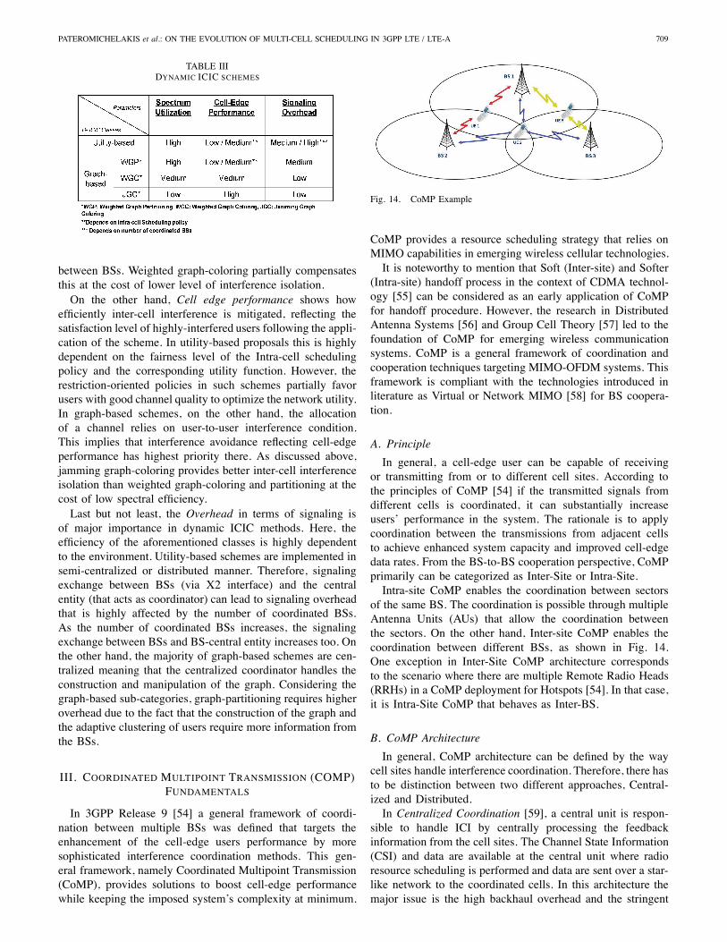
TABLE IIIDYNAMIC ICIC SCHEMES
between BSs. Weighted graph-coloring partially compensatesthis at the cost of lower level of interference isolation.On the other hand, Cell edge performance shows how
efficiently inter-cell interference is mitigated, reflecting thesatisfaction level of highly-interfered users following the appli-cation of the scheme. In utility-based proposals this is highlydependent on the fairness level of the Intra-cell schedulingpolicy and the corresponding utility function. However, therestriction-oriented policies in such schemes partially favorusers with good channel quality to optimize the network utility.In graph-based schemes, on the other hand, the allocationof a channel relies on user-to-user interference condition.This implies that interference avoidance reflecting cell-edgeperformance has highest priority there. As discussed above,jamming graph-coloring provides better inter-cell interferenceisolation than weighted graph-coloring and partitioning at thecost of low spectral efficiency.Last but not least, the Overhead in terms of signaling is
of major importance in dynamic ICIC methods. Here, theefficiency of the aforementioned classes is highly dependentto the environment. Utility-based schemes are implemented insemi-centralized or distributed manner. Therefore, signalingexchange between BSs (via X2 interface) and the centralentity (that acts as coordinator) can lead to signaling overheadthat is highly affected by the number of coordinated BSs.As the number of coordinated BSs increases, the signalingexchange between BSs and BS-central entity increases too. Onthe other hand, the majority of graph-based schemes are cen-tralized meaning that the centralized coordinator handles theconstruction and manipulation of the graph. Considering thegraph-based sub-categories, graph-partitioning requires higheroverhead due to the fact that the construction of the graph andthe adaptive clustering of users require more information fromthe BSs.
III. COORDINATED MULTIPOINT TRANSMISSION (COMP)FUNDAMENTALS
In 3GPP Release 9 [54] a general framework of coordi-nation between multiple BSs was defined that targets theenhancement of the cell-edge users performance by moresophisticated interference coordination methods. This gen-eral framework, namely Coordinated Multipoint Transmission(CoMP), provides solutions to boost cell-edge performancewhile keeping the imposed system’s complexity at minimum.
Fig. 14. CoMP Example
CoMP provides a resource scheduling strategy that relies onMIMO capabilities in emerging wireless cellular technologies.It is noteworthy to mention that Soft (Inter-site) and Softer
(Intra-site) handoff process in the context of CDMA technol-ogy [55] can be considered as an early application of CoMPfor handoff procedure. However, the research in DistributedAntenna Systems [56] and Group Cell Theory [57] led to thefoundation of CoMP for emerging wireless communicationsystems. CoMP is a general framework of coordination andcooperation techniques targeting MIMO-OFDM systems. Thisframework is compliant with the technologies introduced inliterature as Virtual or Network MIMO [58] for BS coopera-tion.
A. Principle
In general, a cell-edge user can be capable of receivingor transmitting from or to different cell sites. According tothe principles of CoMP [54] if the transmitted signals fromdifferent cells is coordinated, it can substantially increaseusers’ performance in the system. The rationale is to applycoordination between the transmissions from adjacent cellsto achieve enhanced system capacity and improved cell-edgedata rates. From the BS-to-BS cooperation perspective, CoMPprimarily can be categorized as Inter-Site or Intra-Site.Intra-site CoMP enables the coordination between sectors
of the same BS. The coordination is possible through multipleAntenna Units (AUs) that allow the coordination betweenthe sectors. On the other hand, Inter-site CoMP enables thecoordination between different BSs, as shown in Fig. 14.One exception in Inter-Site CoMP architecture correspondsto the scenario where there are multiple Remote Radio Heads(RRHs) in a CoMP deployment for Hotspots [54]. In that case,it is Intra-Site CoMP that behaves as Inter-BS.
B. CoMP Architecture
In general, CoMP architecture can be defined by the waycell sites handle interference coordination. Therefore, there hasto be distinction between two different approaches, Central-ized and Distributed.In Centralized Coordination [59], a central unit is respon-
sible to handle ICI by centrally processing the feedbackinformation from the cell sites. The Channel State Information(CSI) and data are available at the central unit where radioresource scheduling is performed and data are sent over a star-like network to the coordinated cells. In this architecture themajor issue is the high backhaul overhead and the stringent
710 IEEE COMMUNICATIONS SURVEYS & TUTORIALS, VOL. 15, NO. 2, SECOND QUARTER 2013
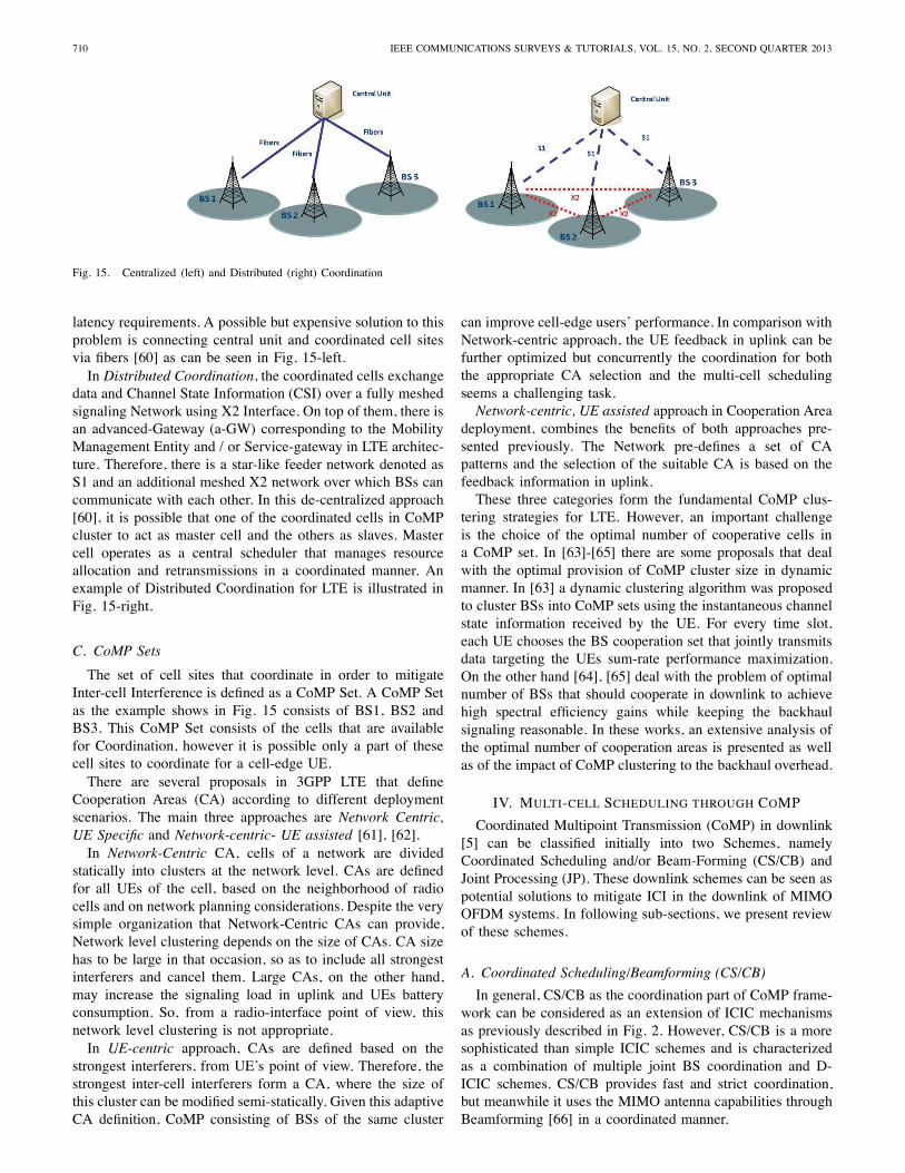
Fig. 15. Centralized (left) and Distributed (right) Coordination
latency requirements. A possible but expensive solution to thisproblem is connecting central unit and coordinated cell sitesvia fibers [60] as can be seen in Fig. 15-left.In Distributed Coordination, the coordinated cells exchange
data and Channel State Information (CSI) over a fully meshedsignaling Network using X2 Interface. On top of them, there isan advanced-Gateway (a-GW) corresponding to the MobilityManagement Entity and / or Service-gateway in LTE architec-ture. Therefore, there is a star-like feeder network denoted asS1 and an additional meshed X2 network over which BSs cancommunicate with each other. In this de-centralized approach[60], it is possible that one of the coordinated cells in CoMPcluster to act as master cell and the others as slaves. Mastercell operates as a central scheduler that manages resourceallocation and retransmissions in a coordinated manner. Anexample of Distributed Coordination for LTE is illustrated inFig. 15-right.
C. CoMP Sets
The set of cell sites that coordinate in order to mitigateInter-cell Interference is defined as a CoMP Set. A CoMP Setas the example shows in Fig. 15 consists of BS1, BS2 andBS3. This CoMP Set consists of the cells that are availablefor Coordination, however it is possible only a part of thesecell sites to coordinate for a cell-edge UE.There are several proposals in 3GPP LTE that define
Cooperation Areas (CA) according to different deploymentscenarios. The main three approaches are Network Centric,UE Specific and Network-centric- UE assisted [61], [62].In Network-Centric CA, cells of a network are divided
statically into clusters at the network level. CAs are definedfor all UEs of the cell, based on the neighborhood of radiocells and on network planning considerations. Despite the verysimple organization that Network-Centric CAs can provide,Network level clustering depends on the size of CAs. CA sizehas to be large in that occasion, so as to include all strongestinterferers and cancel them. Large CAs, on the other hand,may increase the signaling load in uplink and UEs batteryconsumption. So, from a radio-interface point of view, thisnetwork level clustering is not appropriate.In UE-centric approach, CAs are defined based on the
strongest interferers, from UE’s point of view. Therefore, thestrongest inter-cell interferers form a CA, where the size ofthis cluster can be modified semi-statically. Given this adaptiveCA definition, CoMP consisting of BSs of the same cluster
can improve cell-edge users’ performance. In comparison withNetwork-centric approach, the UE feedback in uplink can befurther optimized but concurrently the coordination for boththe appropriate CA selection and the multi-cell schedulingseems a challenging task.Network-centric, UE assisted approach in Cooperation Area
deployment, combines the benefits of both approaches pre-sented previously. The Network pre-defines a set of CApatterns and the selection of the suitable CA is based on thefeedback information in uplink.These three categories form the fundamental CoMP clus-
tering strategies for LTE. However, an important challengeis the choice of the optimal number of cooperative cells ina CoMP set. In [63]-[65] there are some proposals that dealwith the optimal provision of CoMP cluster size in dynamicmanner. In [63] a dynamic clustering algorithm was proposedto cluster BSs into CoMP sets using the instantaneous channelstate information received by the UE. For every time slot,each UE chooses the BS cooperation set that jointly transmitsdata targeting the UEs sum-rate performance maximization.On the other hand [64], [65] deal with the problem of optimalnumber of BSs that should cooperate in downlink to achievehigh spectral efficiency gains while keeping the backhaulsignaling reasonable. In these works, an extensive analysis ofthe optimal number of cooperation areas is presented as wellas of the impact of CoMP clustering to the backhaul overhead.
IV. MULTI-CELL SCHEDULING THROUGH COMP
Coordinated Multipoint Transmission (CoMP) in downlink[5] can be classified initially into two Schemes, namelyCoordinated Scheduling and/or Beam-Forming (CS/CB) andJoint Processing (JP). These downlink schemes can be seen aspotential solutions to mitigate ICI in the downlink of MIMOOFDM systems. In following sub-sections, we present reviewof these schemes.
A. Coordinated Scheduling/Beamforming (CS/CB)
In general, CS/CB as the coordination part of CoMP frame-work can be considered as an extension of ICIC mechanismsas previously described in Fig. 2. However, CS/CB is a moresophisticated than simple ICIC schemes and is characterizedas a combination of multiple joint BS coordination and D-ICIC schemes. CS/CB provides fast and strict coordination,but meanwhile it uses the MIMO antenna capabilities throughBeamforming [66] in a coordinated manner.

PATEROMICHELAKIS et al.: ON THE EVOLUTION OF MULTI-CELL SCHEDULING IN 3GPP LTE / LTE-A 711
Fig. 16. UE feedback and beam collision example in uncoordinated beam-forming
In case of beam-forming, beams of different cells mightcollide, as shown in Fig. 16. Therefore, neighboring cells haveto predict somehow the interference that will be experienced.
In CS/CB the information data are only available withinthe serving cell, but the decision can be made dynamically,after the coordination among cells in the CoMP set. Here, thebest serving set of users are selected for the construction ofthe transmitter beams based on their geographical positioning.The coordinated generation of beams and more specifically thebeam-to-resources selection manages to reduce interferenceto other neighboring users, while increasing the target userssignal strength. In that sense, CS/CB can be seen as a hybridof ICIC-CoMP techniques, since it has two parts: ICIC part,in terms of sophisticated avoidance and CoMP part in termsof strict coordination.An important aspect in downlink multi-cell scheduling is
the feedback reports sent by UE towards BS in the up-link. Feedback reports indicate the channel state information(CSI) based on their SINR [67]. In LTE MIMO systems,Linear Precoding [68] is used as a method to improve theperformance in downlink and to decrease the signaling loadbetween the cells. Therefore, a set of pre-defined precodingmatrices is used to indicate the possible channel states inboth transmitter and receiver. Thereafter, the Precoding MatrixIndex (PMI), which is defined as the index to the preferredmatrix within in a codebook matrix [69], is reported by UEtogether with Channel Quality Indicator (CQI) and MIMORank Indicator (RI). CQI and PMI are parameters determinedby UE based on pilot measurements and UEs send in uplinkthe PMIs corresponding to their serving BS and of theirstrong interferers. Moreover RI indicates the MIMO rankingi.e. the number of data streams to be transmitted in parallelfor the next transmission over the MIMO channel [70]. Theseparameters are transmitted in a quantized manner to BS soas to reduce signaling overhead. The CQI is calculated in UEcorresponding to the reported PMI. PMI indicates the channelstates of serving and strong interfering BSs as observed by theuser. Moreover, RI reflects the recommendation of UE on thenumber of data streams to be used. The Feedback sent by theUE in the uplink counts only the link between the serving celland the UE and is crucial for the BS to capture the interferenceexperienced by a UE for the coordinated scheduling and/orbeam-forming in the downlink transmission.There are numerous proposals for LTE, LTE-A that face
the problem of inter-cell beam collision and can be furthercategorized to Coordinated Beam-Switching (CBS-CoMP) and
Coordinated Scheduling (CS-CoMP) schemes, according tothe way they handle beam collisions between neighboringcells.1) CBS-CoMP: In CBS-CoMP, each cell determines a
sequence of beams over which it continuously cycles. Pro-posals of this category are distinguished from each other inthe way cells coordinate to select the corresponding beams.Most proposals ([69]-[74]) focus on distributed coordinationbetween the cell sites whereas some approaches like [75]enable centralized coordination through a master scheduler.In [69], a low complexity scheme is proposed allowing the
coordination of two sectors with direct communication. In thisface-to-face coordination, sectors agree on the way resourceallocation is handled for all possible conflicting beam pairs.This algorithm though, fails to solve the ICI problem of morethan two interfering sites.The authors in [71], [72] on the other hand, propose a cyclic
beam switching scheme that assumes a fixed beam cycledperiod for all cell sites. The basic idea of these proposalsis to make the fluctuations of interference predictable to thescheduler by examining the variability of interference for atime period when UEs are grouped by their location. UEsreport to their BS service beam, the high CQI values, andtheir sub-band and frame indices. Based on the reports foreach frame, each BS cycles through a set of preferred beamswhere the pattern of this cycle depends on the geographicaland the QoS parameters. Consequently, the coordination ofBSs is required only in the frame synchronization in the timedomain and the decision of a common cycle period.In the same philosophy, in [73], an autonomous beam
coordination scheme is proposed that targets predicting in-terference fluctuations by BSs through beam coordination infrequency domain. The cooperating BSs, using feedback in-formation by UEs, allocate beams-to-resources autonomouslyfor a group of users in dynamic manner. For the inter-siteinterference mitigation, each cell maps the possible gainsthat it could achieve by changing its allocation using thecorresponding probability of a change to occur.Furthermore, another important category of downlink
scheduling schemes that can be applied to CBS-CoMP is theapplication of a modified multi-cell Opportunistic Beamform-ing that enables the coordination between cells to mitigateinter-cell interference. Opportunistic Beam-forming (OB) inprinciple ([76]-[78]) is used to achieve multi-user diversityamong users. The rationale behind traditional OB is therandom selection of a beam out of a pre-defined set of beampatterns for the transmission of training sequence to UEs byBS. Thereafter, UEs measure and send their SNR for thecorresponding beam back and the BS schedules the user withthe highest SNR (or using another scheduling policy). Here, asshown in [74] if OB is combined with multi-cell coordinationfor the beam-to-user selection can provide an interesting multi-scheduling strategy; however literature in this area is stillnarrow.In [74], such coordination is presented for MIMO systems.
Initially, the cells collect SINR measurements by users andgenerate the pilot beams through a pre-defined algorithm thatassigns the resources to users in the Proportional Fair (PF)scheduling policy. Moreover, in this algorithm neighboring

712 IEEE COMMUNICATIONS SURVEYS & TUTORIALS, VOL. 15, NO. 2, SECOND QUARTER 2013
cells coordinate to optimally allocate beams-to-resources inorder to mitigate inter-cell interference. In [73], the existenceof a centralized scheduler is possible that coordinates the cells.However, this algorithm can be seen as semi-centralized as thedecision of resources assignment is made in each cell.In [75], a centralized method namely Collision Avoidance
Beam-forming (CA-BF) is proposed to handle inter-cell in-terference for LTE-A. The key feature of this scheme is aMaster Scheduler, which can be located within a BS. This BSschedules jointly multiple cells in a centralized manner. UEs,based on their feedback reports are divided in two classes,namely Collision Avoidance (CA) or Non-CA. CA-UEs facehigh interference and assumed to be cell-edge users. On theother hand, Non-CA UEs face lower interference. As can besummarized below, CA-BF algorithm can be divided into twosub-parts, UE-BS and Master Scheduler part.UE-BS• Non-CA UEs send the feedback consisting of the pre-ferred PMI and the CQI.
• The CA group provides to the serving cell its preferredPMI, the least interfering PMIs of neighbor cells andmultiple versions of CQI corresponding to different inter-ference scenarios. The versions of the CQIs involve theleast interference beam indices of neighboring cell.
Master Scheduler• For all the combinations of beams, the master schedulerpicks the highest priority serving sets of UEs for eachcell.
• The sum capacity is calculated for that set of UEs foreach cell and each combination.
• The beams are allocated to each set with the highest sumcapacity.
2) CS-CoMP: The other main category of downlink CoMPis Coordinated Scheduling, which enables the collaborationof multiple BSs to mitigate ICI. The most popular CS-CoMPschemes enable the Coordination of multi-cell Precoding Ma-trix Index (PMI) [79]-[81] between cooperating BSs, wherethe absence of a centralized scheduler is possible. Multi-cellPMI coordination differs from CBS-CoMP schemes in the waythe cells handle the coordination of preferred UE’s PMIs. Thisis accomplished by recommending a set of PMIs to the othercells of the CoMP set rather than restricting the use of beams-to-resources as in the case of CBS-CoMP.There are two different strategies of PMI coordination as
defined in [79] based on how feedback PMI sets are selectedby BSs
• Good-PMI feedback that is chosen when cell-edge UEsreport a set of least-interfering PMIs to the BS.
• Bad-PMI feedback that allows a cell to mitigate ICI byrestricting strongly interfering PMIs. In this case, BSdoes not require adding more scheduling restrictions toits neighbor BSs.
Fig. 17 illustrates a generic representation of the steps thatshow how PMI coordination works in a simplified case of 2BSs and 2 cell-edge UEs. These steps are explicitly describedin [81]:1) The UE sends the feedback information based on thecollaborating BSs’ reference signals. This feedback con-
Fig. 17. PMI Coordination example
sists of the reference PMIs for the interfering BSs.Moreover, it includes the recommended PMI set (bador good) as defined previously and the expected CQIimprovements in case the recommended PMIs are used.
2) The BSs exchange signaling information that indicatesthe PMI restrictions or preferences.
3) Each BS decides the precoding vectors and matrices forthe UE it serves.
4) Each BS transmits data to the UE in downlink.These steps provide a general picture of the PMI coordi-
nation process as proposed for LTE-A. However, there canbe further modifications in the way that different cell sitescooperate to mitigate interference. An interesting approachproposed in [80] provides a hybrid algorithm that combinesPMI Coordination and ICIC mechanisms, allowing CoMPto be compatible with previous Interference Coordinationschemes such as FFR. The concept of this approach [80] indi-cates that each cell can have two different roles: as a ”mastercell” for sub-bands that are used by cell-edge users or as a”slave cell” for frequency bands of cell-center users. Mastercells make the PMI recommendation requests to the neighborinterferers and the slaves try to follow these requests foreach sub-band. This method mitigates inter-cell interferenceby protecting the cell-edge UEs. Nevertheless, the freedom ofcell-center users is sacrificed, by setting PMI restrictions onlyto them. The advantage of this proposal is the low complexityin signaling between cells, but the problem of having morecell-edge UEs than cell-center was not investigated fully.
B. Joint Processing (JP)
Joint Processing (JP) ([54], [59], [82]), can be seen as an ad-vanced downlink CoMP technique that is mainly investigatedto achieve spectral efficiency requirements for LTE-A. In JP,a CoMP set consists of a number of cell-sites that coordinateto optimize the cell-edge performance by jointly processingcell-edge users data as a unique entity.Generally, JP as a terminology found in literature can be
easily misinterpreted with Joint Transmission (JT) mainly be-cause JP/JT is the most common JP-CoMP scheme. However,the term JP provides a more general framework that comprisestwo key elements.1) Processing: The basic categorization of the JP-CoMP
schemes reflects to the way data for a cell-edge UE can beprocessed before transmission. By default, the UE’s data canbe available in all BSs of the CoMP set. But there are twooptions for this data storage before transmission [83].In the first option, the user’s data are stored in all transmis-
sion points and master cell forwards all the scheduling infor-mation via X2 interface to the slave cells. The second optionis that the master cell has all the data where the scheduling

PATEROMICHELAKIS et al.: ON THE EVOLUTION OF MULTI-CELL SCHEDULING IN 3GPP LTE / LTE-A 713
decision is available. Thereafter master cell forwards the entiretransport blocks via X2 to the other cells of the cluster.Another categorization of JP-CoMP schemes that corre-
sponds to the implementation standards for MIMO-OFDMsystems, i.e. for open-loop or closed-loop MIMO, distin-guishes JP-CoMP in two types as discussed in [54], [84]-[86].Briefly, in Closed Loop Coherent- JP (Co-JP):
• The CSI Feedback consists of per sub-band PMI, CQIand wideband RI.
• Multi-cell Precoding Cooperation is performed betweencells, thus providing virtually a unique pre-coder for alltransmission points of the CoMP Set.
• The cells jointly process the PMI-to-resources allocation,based on the preferred UEs’ PMIs.
• The data transmitted in downlink are coherently com-bined at the receiver in case Joint Transmission (JT) isused.
In Open Loop Non-Coherent JP (NCo-JP)
• The CSI Feedback from UE consists of per sub-band CQIand the wideband RI.
• Single-cell Precoding is used autonomously by each siteand only CQI information is exchanged between the cells.
• The transmitted data in downlink are non-coherentlycombined at the receiver when JT is used.
The preferable implementation in downlink of LTE-A is theclosed-loop MIMO [87]. This solution provides theoreticallya high gain over open-loop as compared in [88]. The maindrawback of the closed-loop MIMO is the high signalingoverhead and transmission sensitivity to UE’s movement andtiming mismatch [84]. On the other hand the open-loopMIMOcan be used to reduce the signaling overhead by applyingsophisticated methods Space Time / Frequency block coded(STBC/SFBC) schemes [89][90] which are used to maximizetransmit diversity to cell-edge users.Finally, a cooperation technique proposed in [85] is Semi-
closed loop that enables the open-loop cooperation betweenthe cells in backhaul and closed-loop Co-JP in the linksbetween the cells and the UEs in downlink. This is a goodcompromise that can lower the signaling overhead in CoMPclusters while it benefits from the multi-cell diversity and theclosed loop gains.2) Transmission: In JP-CoMP, as described above, data can
be available throughout the CoMP clusters. However there aretwo possible ways that data are transmitted to UEs.Joint Transmission (JT) [82] is used as a method to enable
multiple transmissions of the same data by the coordinatingcells. The authors in [76] propose a centralized JP/JT ap-proach, implemented for LTE-A in which three coordinatedsectors are assumed with a master-slave hierarchy. Mastersector acts as a centralized controller in a closed-loop MIMOCo-JP. The scheduling information is distributed via the X2interface to all the transmission points that are defined as cellsthat actively transmit the physical downlink shared channel(PDSCH) to the users [5].A second category of JP transmission is Dynamic Cell
Selection (DCS) [82], [91]. In JP / DCS multiple users whichare located at the cell-edge have the opportunity to reselectserving cell through the best measured SINRs or the least
Fig. 18. JP/JT (up) and JP/ DCS (down) deployments in Inter-BS LTEarchitecture
path loss. Therefore, the cell-edge UE selects the best linkfor the next frame. For this frame period other cooperatingcells are muted for the resources this UE uses. The authorsin [91] proposed an enhanced DCS algorithm with improvedperformance that enables an adaptive muting mode selectionand power control. Fig. 18 represents these two transmissionschemes to identify the difference between JP/JT and JP/DCSwithout taking account the master/slave hierarchy in a CoMPset. In JP/DCS the data is available to all cooperating BSs, butthe UE selects dynamically the best serving BS by the pathloss measurements. Then, the new serving BS notifies via X2signaling the other BSs of the CoMP set to mute them for theresources that this UE is going to use.
C. Downlink CoMP Challenges-Issues
Downlink CoMP schemes as presented in previous sections,manage to mitigate efficiently ICI at the cell-edges. Further-more, they can provide better coverage of high data ratesand cell-edge throughput. These benefits of CoMP can befurther enhanced when Multi-user MIMO (MU-MIMO) [87]is applied. MU-MIMO allows the communication between amulti-antenna BS and multiple users by allocating differentdata streams to different users. In both CB/CS and JP, if MU-MIMO is used in the downlink instead of Single User-MIMO(SU-MIMO), systems throughput can be further enhanced.This enhancement is clearer for higher order MIMO schemes,as the BS’s transmit antennas in downlink can serve multipleUEs configured in MU-MIMO transmission mode.The major issue in case JP-CoMP is used along with MU-
MIMO, is the complexity and cost of both user handsetsand BSs. Moreover, another issue is the increased signalingoverhead between the BSs which make the high capacitybackhaul network crucial. As discussed above, the CS/CBCoMP downlink schemes are simpler, mainly because theamount of signaling overhead is kept low, as they do notrequire full CSI information at the transmitter. On the otherhand, JP-CoMP provides a more sophisticated solution withmuch better results but in practice it can be very complex forthe BS coordination.A practical implementation that was proposed for LTE-A
[92] and combine both of these types of schemes can be shownin Fig. 19. JP-CoMP can be used in Intra-BS solution betweencoordinated sectors in a centralized manner. On the otherhand, CS/CB-CoMP is used for the Inter-Site Coordination

714 IEEE COMMUNICATIONS SURVEYS & TUTORIALS, VOL. 15, NO. 2, SECOND QUARTER 2013
Fig. 19. A possible CoMP scheme for Intra-BS and Inter-BS implementationsin LTE-A
between BSs in a distributed or semi-centralized way witha master/slave hierarchy via X2 as shown previously. In thisimplementation, the authors take advantage of the benefits ofboth schemes, while keeping signaling overhead low.
V. OPEN RESEARCH DIRECTIONS
In this paper, we explored Multi-cell Scheduling in terms ofInterference Coordination and Cooperation as a walkthroughfrom simple interference avoidance schemes (static, semi-static) used in early LTE system towards dynamic coordina-tion, CoMP and in particular Joint Processing as an advancedcooperation strategy envisioned for LTE-A systems. However,there are several challenges and open research areas to beinvestigated in future, such as:Adaptive CoMP Clustering: As described above, a key
challenge in downlink CoMP implementations, especially inJP/T, is the high backhaul effort required for the BS co-operation. This issue can be seen as a burden towards theimplementation of CoMP in LTE, LTE-A systems. Therefore,an open research direction is the implementation of adaptivedynamic CoMP clustering that can potentially impact theefficiency of CoMP schemes as detailed in III.C. In thisdirection, an interesting solution could be the employment ofself-organization concept. More details on this direction canbe found in [93], where the authors propose a self-organizedclustering algorithm to dynamically adjust the CoMP Sets ina distributed manner.Energy-Efficient CoMP: The coordination and cooperation
of multiple BSs through CoMP poses another key issue thatconcerns the energy efficiency perspective as can be seen in[94] and [95]. From this point of view this can be seen a futureresearch direction of major impact towards the energy savingthrough green cellular operation.CoMP for Small Cells: Deploying HetNets in emerging
wireless cellular systems can be seen as a new challengefrom interference management perspective. In such networks,clusters of femtocells [96] and relay BSs might be includedunderneath the macro-cell traditional architecture to locally
increase the capacity and coverage via spectrum re-use. Inthis context, the management of interference is challengingdue to the density and unplanned nature of such small cells[97]-[99]. Therefore, besides improving and extending state-of-the-art algorithms for such scenarios, incorporating CoMPand optimizing the backhaul signaling of CoMP solutions arecrucial for future studies towards more applicable solutionsfor small cells.
VI. SUMMARY
Multi-cell scheduling for emerging wireless systems is aterm closely coupled to the interference management. TheICIC and CoMP mechanisms which examined in this surveyprovide a general framework of solutions that can handleefficiently inter-cell interference as one of the major issuesin the wireless networks. The ICIC mechanisms were thor-oughly investigated and categorized based on a variety of keyfeatures. As discussed, the static and semi-static solutions havethe key advantage of lower complexity. However, the staticICIC schemes are not as flexible as semi-static or dynamiccategories to adapt to the traffic variations. Nevertheless, staticSFR and PFR can be seen as the building blocks for morecomplex solutions. In this direction, semi-static algorithmspresented are more efficient variants as they can better balancethe spectrum utilization between cell-edge and cell-centerusers.On the other hand, dynamic ICIC schemes can potentially
provide near optimal solutions at the cost of high complexity.Nevertheless, by employing simplifications and more heuristicsolutions, they potentially become more feasible for practicalsystems. In this survey, we presented two popular D-ICICclasses of schemes, i.e. Utility-based and Graph-based thatcould be possible candidates for multi-cell scheduling inemerging cellular networks.Finally, CoMP was further explored as a complementary
scheme for ICIC methods by characterizing their partiallycommon features. As described, CoMP provides an advancedcoordination framework suitable for high order MIMO-OFDMsystems like LTE-Advanced. However, corresponding chal-lenges for practical implementations should be carefully con-sidered. Here, two different categories of CoMP solutionswere discussed, classified as Coordination (CS/CB) and Co-operation (JP). As mentioned, CS/CB is a simpler and morepractical solution than JP as it requires lower backhaul over-head. However, joint data processing if followed by jointtransmission can be seen as an advanced mechanism that canmark a new epoch in emerging wireless technologies like LTE-A.
ACKNOWLEDGMENT
This work has been performed in the framework of the ICTproject ICT-4-248523 BeFEMTO, which is partly funded bythe European Union. The authors would like to acknowledgethe contributions of their colleagues from the BeFEMTOconsortium.

PATEROMICHELAKIS et al.: ON THE EVOLUTION OF MULTI-CELL SCHEDULING IN 3GPP LTE / LTE-A 715
REFERENCES
[1] Cisco, “Cisco visual networking index: Global mobile data trafficforecast update, 2011-2016,” White paper, Cisco, Tech. Rep., February2012.
[2] S.-P. Yeh, S. Talwar, G. Wu, N. Himayat, and K. Johnsson, “Capacityand coverage enhancement in heterogeneous networks,” IEEE WirelessCommun., vol. 18, no. 3, pp. 32 –38, june 2011.
[3] I.-R. M.2133, “Requirements, evaluation criteria, and submissiontemplates for the development of imt-advanced,” ITU-R, Tech. Rep.,2008. [Online]. Available: http://www.itu.int/md/R07-SG05-C-0068/en
[4] 3GPP, “Evolved Universal Terrestrial Radio Access (E-UTRA)and Evolved Universal Terrestrial Radio Access (E-UTRAN);Overall description; Stage 2,” 3rd Generation PartnershipProject (3GPP), TS 36.300, Sep. 2008. [Online]. Available:http://www.3gpp.org/ftp/Specs/html-info/36300.htm
[5] , “Further Advancements for E-UTRA, Physical Layer Aspects,”3rd Generation Partnership Project (3GPP), TR 36.814 V9. 0. 0, March2010.
[6] D. Lopez-Perez, I. Guvenc, G. de la Roche, M. Kountouris, T. Quek,and J. Zhang, “Enhanced intercell interference coordination challengesin heterogeneous networks,” IEEE Wireless Commun., vol. 18, no. 3,pp. 22 –30, june 2011.
[7] F. Khan, LTE for 4G Mobile Broadband: Air Interface Technologies andPerformance. Cambridge University Press, 2009.
[8] S.-E. Elayoubi, O. Ben Haddada, and B. Fourestie, “Performanceevaluation of frequency planning schemes in ofdma-based networks,”IEEE Trans. Wireless Commun., vol. 7, no. 5, pp. 1623 –1633, may2008.
[9] K. Zheng, B. Fan, J. Liu, Y. Lin, and W. Wang, “Interference coordi-nation for ofdm-based multihop lte-advanced networks,” IEEE WirelessCommun., vol. 18, no. 1, pp. 54 –63, february 2011.
[10] R. Kwan and C. Leung, “A survey of scheduling andinterference mitigation in lte,” Journal of Electrical andComputer Engineering, vol. -, pp. 1–10, 2010. [Online]. Available:http://www.hindawi.com/journals/jece/2010/273486/
[11] S. Halpern, “Reuse partitioning in cellular systems,” in Vehicular Tech-nology Conference, 1983. 33rd IEEE, vol. 33, may 1983, pp. 322 –327.
[12] M. Sternad, T. Ottosson, A. Ahlen, and A. Svensson, “Attaining bothcoverage and high spectral efficiency with adaptive ofdm downlinks,”in Vehicular Technology Conference, 2003. VTC 2003-Fall. 2003 IEEE58th, vol. 4, oct. 2003, pp. 2486 – 2490 Vol.4.
[13] 3GPP, “OFDMA Downlink Inter-Cell Interference Mitigation,” 3rdGeneration Partnership Project (3GPP), Project Document R1-060291,February 2006.
[14] , “Soft Frequency Reuse Scheme for UTRAN LTE,” 3rd GenerationPartnership Project (3GPP), Project Document R1-050507, May 2005.
[15] , “Downlink inter-cell interference coordination /avoidance-evaluation of frequency reuse,” 3rd Generation Partnership Project(3GPP), Project Document, Ericsson R1-061374, May 2006, ericsson.
[16] , “Multi-cell Simulation Results for Interference Co-ordination innew OFDM DL,” 3rd Generation Partnership Project (3GPP), AlcatelR1-050694, August 2005.
[17] , “System Simulation Results for Downlink Interference Coordina-tion,” 3rd Generation Partnership Project (3GPP), Alcatel R1-060209,January 2006.
[18] , “Aspects of Interference Mitigation by Coordination,” 3rd Gener-ation Partnership Project (3GPP), Siemens R1-051366, November 2005.
[19] S. G. Kim, K. Cho, D. Yoon, Y.-J. Ko, and J. K. Kwon, “Performanceanalysis of downlink inter cell interference coordination in the lte-advanced system,” in Digital Telecommunications, 2009. ICDT ’09.Fourth International Conference on, july 2009, pp. 30 –33.
[20] 3GPP, “Inter-cell Interference Mitigation for E-UTRA,” 3rd GenerationPartnership Project (3GPP), Texas Instruments R1-051059, October2005.
[21] X. Zhang, C. He, L. Jiang, and J. Xu, “Inter-cell interference coordi-nation based on softer frequency reuse in ofdma cellular systems,” inNeural Networks and Signal Processing, 2008 International Conferenceon, june 2008, pp. 270 –275.
[22] 3GPP, “Further Analysis of Soft Frequency Reuse Scheme,” 3rd Gener-ation Partnership Project (3GPP), Huawei R1-050841, November 2005.
[23] , “Further Discussion on Adaptive Fractional Frequency Reuse,”3rd Generation Partnership Project (3GPP), Nortel R1-072762, June2007.
[24] D. Gonzalez G, M. Garcia-Lozano, S. Ruiz, J. Olmos, and V. Corvino,“Performance evaluation of downlink interference coordination tech-
niques in lte networks,” in Vehicular Technology Conference Fall (VTC2010-Fall), 2010 IEEE 72nd, sept. 2010, pp. 1 –5.
[25] G. Li and H. Liu, “Downlink radio resource allocation for multi-cellofdma system,” IEEE Trans. Wireless Commun., vol. 5, no. 12, pp. 3451–3459, december 2006.
[26] W. Yu and R. Lui, “Dual methods for nonconvex spectrum optimizationof multicarrier systems,” IEEE Trans. Commun., vol. 54, no. 7, pp. 1310–1322, july 2006.
[27] Y. Yi and M. Chiang, Next Generation Internet Architectures andProtocols. Cambridge University Press, 2010, ch. Stochastic networkutility maximization and wireless scheduling. [Online]. Available:http://www.cambridge.org/us/catalogue/catalogue.asp?isbn=9780521113687
[28] W.-H. Kuo and W. Liao, “Utility-based resource allocation in wirelessnetworks,” IEEE Trans. Wireless Commun., vol. 6, no. 10, pp. 3600–3606, october 2007.
[29] M. Rahman and H. Yanikomeroglu, “Interference avoidance throughdynamic downlink ofdma subchannel allocation using intercell coordi-nation,” in Vehicular Technology Conference, 2008. VTC Spring 2008.IEEE, may 2008, pp. 1630 –1635.
[30] , “Enhancing cell-edge performance: a downlink dynamic inter-ference avoidance scheme with inter-cell coordination,” IEEE Trans.Wireless Commun., vol. 9, no. 4, pp. 1414 –1425, april 2010.
[31] , “Inter-cell interference coordination in ofdma networks: A novelapproach based on integer programming,” in Vehicular TechnologyConference (VTC 2010-Spring), 2010 IEEE 71st, may 2010, pp. 1 –5.
[32] M. Rahman, H. Yanikomeroglu, and W. Wong, “Interference avoidancewith dynamic inter-cell coordination for downlink lte system,” in Wire-less Communications and Networking Conference, 2009. WCNC 2009.IEEE, april 2009, pp. 1 –6.
[33] J. Ellenbeck, C. Hartmann, and L. Berlemann, “Decentralized inter-cellinterference coordination by autonomous spectral reuse decisions,” inWireless Conference, 2008. EW 2008. 14th European, june 2008, pp. 1–7.
[34] H. Kuhn, “The Hungarian method for the assignment problem,” Navalresearch logistics quarterly, vol. 2, no. 1-2, pp. 83–97, 1955.
[35] E. T. N. Nisan, T. Roughgarden and V. Vazirani, Algorithmic GameTheory. Cambridge University Press, 2007.
[36] L. Narayanan, Channel Assignment and Graph Multicoloring.John Wiley & Sons, Inc., 2002, pp. 71–94. [Online]. Available:http://dx.doi.org/10.1002/0471224561.ch4
[37] M. C. Necker, “Scheduling constraints and interference graph propertiesfor graph-based interference coordination in cellular ofdma networks,”Mob. Netw. Appl., vol. 14, no. 4, pp. 539–550, Aug. 2009. [Online].Available: http://dx.doi.org/10.1007/s11036-009-0155-8
[38] R. Chang, Z. Tao, J. Zhang, and C.-C. Kuo, “Multicell ofdma downlinkresource allocation using a graphic framework,” IEEE Trans. Veh.Technol., vol. 58, no. 7, pp. 3494 –3507, sept. 2009.
[39] M. Necker, “A graph-based scheme for distributed interference coordi-nation in cellular ofdma networks,” in Vehicular Technology Conference,2008. VTC Spring 2008. IEEE, may 2008, pp. 713 –718.
[40] H. Zheng and C. Peng, “Collaboration and fairness in opportunisticspectrum access,” in Communications, 2005. ICC 2005. 2005 IEEEInternational Conference on, vol. 5, may 2005, pp. 3132 – 3136 Vol. 5.
[41] C. Peng, H. Zheng, and B. Y. Zhao, “Utilization and fairness inspectrum assignment for opportunistic spectrum access,” Mob. Netw.Appl., vol. 11, no. 4, pp. 555–576, Aug. 2006. [Online]. Available:http://dx.doi.org/10.1007/s11036-006-7322-y
[42] C. McDiarmid and B. Reed, “Channel assignment and weighted color-ing,” Networks, vol. 36, no. 2, pp. 114–117, 2000.
[43] A. Mishra, S. Banerjee, and W. Arbaugh, “Weighted coloring basedchannel assignment for wlans,” SIGMOBILE Mob. Comput. Commun.Rev., vol. 9, no. 3, pp. 19–31, Jul. 2005. [Online]. Available:http://doi.acm.org/10.1145/1094549.1094554
[44] M. A. Hassan and A. Chickadel, “A review of interference reduc-tion in wireless networks using graph coloring methods,” CoRR, vol.abs/1103.5791, pp. 58–67, 2011.
[45] D. Matula, G. Marble, and J. Isaacson, “Graph coloring algorithms ingraph theory and computing,” Academic Press, vol. -, pp. 104–122,1972.
[46] T. Szymanski, “Interference and power minimization in tdma-ofdmainfrastructure wireless mesh networks,” in Systems and Networks Com-munications (ICSNC), 2010 Fifth International Conference on, aug.2010, pp. 348 –355.
[47] C.-C. Hsu, P. Liu, D. wei Wang, and J.-J. Wu, “Generalized edgecoloring for channel assignment in wireless networks,” in ParallelProcessing, 2006. ICPP 2006. International Conference on, aug. 2006,pp. 82 –92.

716 IEEE COMMUNICATIONS SURVEYS & TUTORIALS, VOL. 15, NO. 2, SECOND QUARTER 2013
[48] A. Gamst and K. Ralf, “Computational complexity of some interferencegraph calculations [mobile radio],” IEEE Trans. Veh. Technol., vol. 39,no. 2, pp. 140 –149, may 1990.
[49] S. Khanna and K. Kumaran, “On wireless spectrum estimation andgeneralized graph coloring,” in INFOCOM ’98. Seventeenth AnnualJoint Conference of the IEEE Computer and Communications Societies.Proceedings. IEEE, vol. 3, mar-2 apr 1998, pp. 1273 –1283 vol.3.
[50] K. Jain, J. Padhye, V. N. Padmanabhan, and L. Qiu, “Impactof interference on multi-hop wireless network performance,” Wirel.Netw., vol. 11, no. 4, pp. 471–487, Jul. 2005. [Online]. Available:http://dx.doi.org/10.1007/s11276-005-1769-9
[51] E. Aarts and J. K. Lenstra, Eds., Local Search in CombinatorialOptimization, 1st ed. New York, NY, USA: John Wiley & Sons, Inc.,1997.
[52] D. Brelaz, “New methods to color the vertices of a graph,” Commun.ACM, vol. 22, no. 4, pp. 251–256, Apr. 1979. [Online]. Available:http://doi.acm.org/10.1145/359094.359101
[53] S. Sahni and T. Gonzalez, “P-complete approximation problems,” J.ACM, vol. 23, no. 3, pp. 555–565, Jul. 1976. [Online]. Available:http://doi.acm.org/10.1145/321958.321975
[54] 3GPP, “Mobile Broadband Innovation path to 4G: Release 9,10 andBeyond,” 3rd Generation Partnership Project (3GPP), TR, February2010.
[55] C.-C. Lee and R. Steele, “Effect of soft and softer handoffs on cdmasystem capacity,” IEEE Trans. Veh. Technol., vol. 47, no. 3, pp. 830–841, aug 1998.
[56] S. Zhou, M. Zhao, X. Xu, J. Wang, and Y. Yao, “Distributed wirelesscommunication system: a new architecture for future public wirelessaccess,” IEEE Commun. Mag., vol. 41, no. 3, pp. 108 – 113, mar 2003.
[57] M. Karakayali, G. Foschini, and R. Valenzuela, “Network coordinationfor spectrally efficient communications in cellular systems,” IEEE Wire-less Commun., vol. 13, no. 4, pp. 56 –61, aug. 2006.
[58] D. Gesbert, S. Hanly, H. Huang, S. Shamai Shitz, O. Simeone, andW. Yu, “Multi-cell mimo cooperative networks: A new look at inter-ference,” IEEE J. Sel. Areas Commun., vol. 28, no. 9, pp. 1380 –1408,december 2010.
[59] R. Irmer, H. Droste, P. Marsch, M. Grieger, G. Fettweis, S. Brueck,H.-P. Mayer, L. Thiele, and V. Jungnickel, “Coordinated multipoint:Concepts, performance, and field trial results,” IEEE Commun. Mag.,vol. 49, no. 2, pp. 102 –111, february 2011.
[60] E. Seidel, “Initial thoughts on lte advanced for 3gpp release 10,” in CTOLTE World Summit, Berlin, May 2009.
[61] 3GPP, “Downlink CoMP,” 3rd Generation Partnership Project (3GPP),Ericsson R1-090914, February 2009.
[62] , “Setup of CoMP cooperation areas,” 3rd Generation PartnershipProject (3GPP), Nokia Siemens Networks R1-090725, February 2009.
[63] A. Papadogiannis, D. Gesbert, and E. Hardouin, “A dynamic clusteringapproach in wireless networks with multi-cell cooperative processing,”in Communications, 2008. ICC ’08. IEEE International Conference on,may 2008, pp. 4033 –4037.
[64] J. Zhang, R. Chen, J. Andrews, A. Ghosh, and R. Heath, “Networkedmimo with clustered linear precoding,” IEEE Tran. Wireless Commun.,vol. 8, no. 4, pp. 1910 –1921, april 2009.
[65] J. Hoydis, M. Kobayashi, and M. Debbah, “On the optimal number ofcooperative base stations in network mimo,” CoRR, vol. abs/0912.4595,pp. –, 2009.
[66] D. N. C. Tse and P. Viswanath, “Fundamentals of wireless communica-tion (tse, d. and viswanath, p.) [book review],” IEEE Trans. Inf. Theory,vol. 55, no. 2, pp. 919–920, 2009.
[67] Agilent, M. Rumney, and A. Technologies, Lte andthe Evolution to 4g Wireless: Design and MeasurementChallenges. John Wiley & Sons, 2012. [Online]. Available:http://books.google.co.uk/books?id=jTiKZwEACAAJ
[68] M. Vu and A. Paulraj, “Mimo wireless linear precoding,” IEEE SignalProcessing Magazine, vol. 24, no. 5, pp. 86 –105, sept. 2007.
[69] P. Hosein, “Cooperative scheduling of downlink beam transmissions in acellular network,” in GLOBECOM Workshops, 2008 IEEE, 30 2008-dec.4 2008, pp. 1 –5.
[70] Z. Bai, C. Spiegel, G. Bruck, P. Jung, M. Horvat, J. Berkmann,C. Drewes, and B. Gunzelmann, “On the physical layer performancewith rank indicator selection in lte/lte-advanced system,” in Personal,Indoor and Mobile Radio Communications Workshops (PIMRC Work-shops), 2010 IEEE 21st International Symposium on, sept. 2010, pp.393 –398.
[71] P. Hosein and C. van Rensburg, “On the performance of downlinkbeamforming with synchronized beam cycles,” in Vehicular TechnologyConference, 2009. VTC Spring 2009. IEEE 69th, april 2009, pp. 1 –5.
[72] C. Van Rensburg and P. Hosein, “Interference coordination throughnetwork-synchronized cyclic beamforming,” in Vehicular TechnologyConference Fall (VTC 2009-Fall), 2009 IEEE 70th, sept. 2009, pp. 1–5.
[73] J. Ellenbeck, M. Hammoud, B. Lazarov, and C. Hartmann, “Autonomousbeam coordination for the downlink of an imt-advanced cellular system,”in Wireless Conference (EW), 2010 European, april 2010, pp. 602 –607.
[74] M. Vemula, D. Avidor, J. Ling, and C. Papadias, “Inter-cell coordination,opportunistic beamforming and scheduling,” in Communications, 2006.ICC ’06. IEEE International Conference on, vol. 12, june 2006, pp.5319 –5324.
[75] 3GPP, “Inter-Cell Interference Mitigation Through Limited Coordina-tion,” 3rd Generation Partnership Project (3GPP), Samsung R1-082886,August 2008.
[76] P. Viswanath, D. Tse, and R. Laroia, “Opportunistic beamforming usingdumb antennas,” IEEE Trans. Inf. Theory, vol. 48, no. 6, pp. 1277 –1294,jun 2002.
[77] N. Sharma and L. Ozarow, “A study of opportunism for multiple-antennasystems,” IEEE Trans. Inf. Theory, vol. 51, no. 5, pp. 1804 – 1814, may2005.
[78] J. Chung, C.-S. Hwang, K. Kim, and Y. K. Kim, “A random beamform-ing technique in mimo systems exploiting multiuser diversity,” IEEE J.Sel. Areas Commun., vol. 21, no. 5, pp. 848 – 855, june 2003.
[79] 3GPP, “CoMP Configurations and UE/eNB Behaviors in LTE-advanced,” 3rd Generation Partnership Project (3GPP), LG ElectronicsR1-090782, February 2009.
[80] , “Multi-cell PMI coordination for downlink CoMP,” 3rd Genera-tion Partnership Project (3GPP), ETRI R1-091490, March 2009.
[81] L. Liu, J. C. Zhang, J.-C. Yu, and J. Lee, “Intercell interferencecoordination through limited feedback,” International Journal on DigitalMultimedia Broadcasting, vol. 2010, p. 7, 2010.
[82] M. Sawahashi, Y. Kishiyama, A. Morimoto, D. Nishikawa, andM. Tanno, “Coordinated multipoint transmission/reception techniquesfor lte-advanced [coordinated and distributed mimo],” IEEE WirelessCommun., vol. 17, no. 3, pp. 26 –34, june 2010.
[83] S. Brueck, L. Zhao, J. Giese, and M. Amin, “Centralized scheduling forjoint transmission coordinated multi-point in lte-advanced,” in SmartAntennas (WSA), 2010 International ITG Workshop on, feb. 2010, pp.177 –184.
[84] 3GPP, “Aspects of Joint Processing in Downlink CoMP,” 3rd GenerationPartnership Project (3GPP), Tech. Rep. R1-090193, January 2009.
[85] , “Discussion and Link Level Simulation Results on LTE-A Down-link Multi-site MIMO Cooperation,” 3rd Generation Partnership Project(3GPP), Nortel R1-084465, November 2008.
[86] J. J. S. Yunfeng and H. Liujun, “Joint transmission method in coordi-nated multi-point transmission and reception systems,” ZTE Communi-cations, vol. No.1, pp. –, 2010.
[87] J. Lee, J.-K. Han, and J. Zhang, “Mimo technologies in 3gpp lteand lte-advanced,” EURASIP Journal on Wireless Communications andNetworking, vol. 2009, no. 1, p. 302092, 2009. [Online]. Available:http://jwcn.eurasipjournals.com/content/2009/1/302092
[88] C. Ball, R. Mullner, J. Lienhart, and H. Winkler, “Performance analysisof closed and open loop mimo in lte,” in Wireless Conference, 2009.EW 2009. European, may 2009, pp. 260 –265.
[89] K. Lee and D. Williams, “A space-time coded transmitter diversitytechnique for frequency selective fading channels,” in Sensor Arrayand Multichannel Signal Processing Workshop. 2000. Proc. 2000 IEEE,2000, pp. 149 –152.
[90] , “A space-frequency transmitter diversity technique for ofdm sys-tems,” in Global Telecommunications Conference, 2000. GLOBECOM’00. IEEE, vol. 3, 2000, pp. 1473 –1477 vol.3.
[91] M. Feng, X. She, L. Chen, and Y. Kishiyama, “Enhanced dynamiccell selection with muting scheme for dl comp in lte-a,” in VehicularTechnology Conference (VTC 2010-Spring), 2010 IEEE 71st, may 2010,pp. 1 –5.
[92] H. Wang, “Lte-advanced development progress,” in TTA IMT-AdvancedWorkshop, L. Huawei Technologies Co., Ed., September 2009.
[93] R. Weber, A. Garavaglia, M. Schulist, S. Brueck, and A. Dekorsy, “Self-organizing adaptive clustering for cooperative multipoint transmission,”in Vehicular Technology Conference (VTC Spring), 2011 IEEE 73rd,may 2011, pp. 1 –5.
[94] D. Cao, S. Zhou, C. Zhang, and Z. Niu, “Energy saving performancecomparison of coordinated multi-point transmission and wireless relay-ing,” in Global Telecommunications Conference (GLOBECOM 2010),2010 IEEE, dec. 2010, pp. 1 –5.
[95] E. Oh, B. Krishnamachari, X. Liu, and Z. Niu, “Toward dynamic energy-efficient operation of cellular network infrastructure,” IEEE Commun.Mag., vol. 49, no. 6, pp. 56 –61, june 2011.

PATEROMICHELAKIS et al.: ON THE EVOLUTION OF MULTI-CELL SCHEDULING IN 3GPP LTE / LTE-A 717
[96] J. Zhang, G. D. L. Roche, and G. L. D. Roche, Femtocells: Technologiesand Deployment. Wiley Online Library, 2010, vol. 54.
[97] Y. Kim, S. Lee, and D. Hong, “Performance analysis of two-tierfemtocell networks with outage constraints,” IEEE Trans. WirelessCommun., vol. 9, no. 9, pp. 2695 –2700, september 2010.
[98] D. Lopez-Perez, A. Valcarce, G. de la Roche, and J. Zhang, “Ofdmafemtocells: A roadmap on interference avoidance,” IEEE Commun.Mag., vol. 47, no. 9, pp. 41 –48, september 2009.
[99] E. Pateromichelakis, M. Shariat, A. Ul Quddus, and R. Tafazolli, “Onthe analysis of co-tier interference in femtocells,” in Personal Indoor andMobile Radio Communications (PIMRC), 2011 IEEE 22nd InternationalSymposium on, sept. 2011, pp. 122 –126.
Emmanouil Pateromichelakis received his B-Engdegree in Information and Communication SystemsEngineering from University of the Aegean, Greece,in 2008, and M.Sc. in Mobile Communications atthe University of Surrey in 2009. He is currentlystudying towards a Ph.D. degree in the Centre forCommunication Systems Research (CCSR) at theUniversity of Surrey, UK. Since 2010 he has beenactively involved in the Broadband evolved FEMTO(BeFEMTO) european project. His main researchinterests include Multi-cell scheduling and Inter-cell
Interference Management in Heterogeneous Networks (HetNets).
Mehrdad Shariat received the BSc degree in Com-munications Engineering from Iran University ofScience and Technology, Iran in 2005. He receivedhis PhD degree in Mobile Communications fromUniversity of Surrey, UK in 2010 and since then hasbeen working as a full-time research fellow in Centrefor Communication Systems Research (CCSR), UK.His research interests include Radio Resource Man-agement, Interference Management and Schedulingfor OFDMA Cellular/ Multihop Networks.
Atta ul Quddus received the B-Eng degree inComputer Engineering from National University ofSciences and Technology (NUST), Pakistan in 1999.He received the MSc degree in Satellite Commu-nications Engineering and PhD degree in MobileCommunications from University of Surrey, UKin 2000 and 2005, respectively. He is currently aSenior Research Fellow in the Centre for Commu-nication Systems Research (CCSR). His researchinterests include Channel Coding, Radio ResourceManagement, Self-Organising Radio Networks and
simulation of Communication Systems.
Rahim Tafazolli is a professor of mobile/personalcommunications and the Director of Centre forCommunication Systems Research (CCSR), Uni-versity of Surrey, United Kingdom. He has beenactive in research for more than 25years and hasauthored or co-authored more than 500 papers inrefereed international journals and conferences. Heis a consultant to many telecommunication com-panies. Prof. Tafazolli is a Fellow of the WirelessWorld Research Forum. He has lectured, chaired,and has been invited as keynote speaker to a number
of Institution of Engineering and Technology and IEEE workshops andconferences. He is the Chairman of the European Union Expert Group ofNetWorks Technology Platform.
Related Documents


