UPONOR PRESSURE SYSTEMS 167 Pressure Systems UPONOR INFRASTRUCTURE PRESSURE SYSTEMS

061pressurepipesintroduction
Mar 09, 2016
http://www.uponor.fi/~/media/countryspecific/finland/download-centre/technical-handbook-eng/061pressurepipesintroduction.pdf?version=1
Welcome message from author
This document is posted to help you gain knowledge. Please leave a comment to let me know what you think about it! Share it to your friends and learn new things together.
Transcript

uPONOr PrESSurE SySTEMS 167
Pre
ssu
re
Syst
ems
UPONOR INFRASTRUCTURE
PrESSurE SySTEMS
168 uPONOr PrESSurE SySTEMS
Pre
ssu
re
Syst
ems
Uponor Infrastructure Solutions Pressure Systems
6.1 Introduction ............................................................................................169
Uponor Pressure System – Structural design ..................................................170
Uponor Pressure Systems – Hydraulic Design .................................................178
Uponor Gas System Design .............................................................................181
Uponor Pressure Pipe System Installation – General Instructions and
Supervision ......................................................................................................183
6.2 ProFuse Pressure System – Characteristics ..........................................189
Approvals .........................................................................................................192
Markings ..........................................................................................................193
ProFuse-Pressure Pipeline Design ...................................................................195
ProFuse Pressure Pipe Installation ..................................................................196
6.3 Uponor Pressure System PVC – Characteristics ...................................209
Approvals .........................................................................................................212
Markings ..........................................................................................................213
Uponor PVC Pressure Pipe Installation ...........................................................214
6.4 Uponor Pressure System PE80 – Characteristics .................................219
Approvals ........................................................................................................ 222
Markings ......................................................................................................... 223
PE80 Pressure Pipe Installation .......................................................................224
6.5 Uponor Pressure Pipe System PE100 – Characteristics .......................227
Approvals ........................................................................................................ 230
Markings .........................................................................................................231
6.6 Uponor Pressure Fittings – Characteristics ..........................................233
Approvals & markings ................................................................................... 236
PE100 Pressure Fittings, Installation ............................................................. 238
Pre
ssu
re
Syst
ems

uPONOr PrESSurE SySTEMS 169
Pre
ssu
re
Syst
ems
uponor pressure systems are designed
for water and gas supply, and sewerage
applications. These plastic pipe systems
are used to build extremely robust and
flexible long-life networks, making them
the smart choice in terms of overall cost
effectiveness.
uponor pressure pipes are made of PE 80,
PE 100 and PVC. Primarily, the delivery
pipes are mainly of ProFuse PE 100. This
is supplemented by smaller PE 80, larger
PE 100 and PVC pressure pipes.
uponor pressure pipes are colour-coded
according to their intended application.
Small black pipes with blue-stripes, blue
ProFuse pipes and grey PVC pipes are
used for water supply.
Small black pipes with terracotta-stripes,
reddish-brown ProFuse pipes are used
for sewerage. Black pipes with yellow
stripes and yellow ProFuse pipes are
used for gas supply.
This introductory section gives general
rules for the structural and hydraulic de-
sign of pressure pipes. A working example
of water pipe hydraulic design calculation
is also given.
In the following sections, the system and
material characteristics of the individual
pipe systems are described and the cor-
responding product ranges are presented.
The table below shows the relationship
between the system type and pipe size,
and the area of application.
Systems and
pipe sizes
Application
Water supply Wastewater drainage Gas distribution
uponor PE 80 Sdr 17 40 – 63 mm
uponor PE 80 Sdr 11 20 – 63 mm
uponor Puriton 25 – 110 mm
uponor ProFuse Sdr 17 90 – 400 mm 90 – 400 mm 90 – 400 mm
uponor ProFuse Sdr 11 90 – 400 mm 90 – 400 mm 90 – 400 mm
uponor PE 100 450 – 800 mm 450 – 800 mm 32 – 90 mm
uponor PVC 110 – 400 mm
Table 6.1.1
6.1 Introduction
170 uPONOr PrESSurE SySTEMS
Pre
ssu
re
Syst
ems
The degree of pipe deformation, i.e. de-
flection, during pipe laying and backfill-
ing is influenced by the following factors:
•bearing capacity of the soil
• installation quality
•embedment and backfill material
quality
•compaction
•traffic load
Uponor Pressure System – Structural design
Plastic pipes are flexible and function
interactively with the surrounding soil.
Such pipe flexibility reduces the load on
the pipe.
Trench over-excavation replacement or
embankment installation must be carried
out in accordance with the drawings.
Riprap(stonesize≤400mm)orcom-
pactable load-bearing soil must be used
as backfill.
In embankment installations, the density
of the compacted backfill layers must
meet the following density requirements:
•densitylevel(improvedProctor)≥90%
or
•densityratio(portablefallingweight
deflectometer)≤2.8
Over-excavation and backfill quality
control is based primarily on on-site
supervision. If embankment filling is
carried out on soft silty soil, a filter layer
of sand or a non-woven fabric approved
for application area 4 must be installed
beneath the fill.
If the trench cannot be kept dry during
over-excavation and replacement, crushed
aggregate or fine chippings must be
used as the replacement fill material. The
riprap bed surface must be filled over with
smaller grade rock or coarse aggregate.
Over-excavation and replacement or embankment installation
uPONOr PrESSurE SySTEMS 171
Pre
ssu
re
Syst
ems
If the pipes are to be laid in an embank-
ment, the fill beneath them must be
compacted to the same density as the
surrounding embankment material.
riprap embankments must be filled over
with smaller grade rock and crushed
aggregate or gravel.
In the case of natural aggregates used
for plastic pipe bedding, the maximum
allowable grain size is 10% of the nomi-
nal diameter of the pipe. However, the
maximum grain size for dN < 200 pipes
and dN > 600 pipes is 20 mm and 60 mm
respectively. use of crushed aggregate is
permitted for bedding dN > 100 plastic
pipes. The maximum grain size for this
purpose is 16 mm. A bedding layer at
least 150 mm in depth, as measured from
the pipe wall, must be laid on the trench
bottom or over the over-excavation fill,
embankment fill or foundation.
The bedding compaction must meet the
following density requirements:
•densitylevel(improvedProctor)≥90%
or
•densityratio(portablefallingweight
deflectometer)≤2.8
The bedding materials' fitness for pur-
pose is verified by grain size distribution
testing, with one sample tested from
each 50 m3 or part thereof. Bedding
density is determined through measure-
ments taken at 50m intervals, with at
least one measurement taken per job
site. The density ratio of the bedding
is determined through measurements
taken every 10 m. If more measurements
than required are made, the measure-
ment average must meet the density
requirement. The minimum allowable
individual measurement result is 88%
(Proctor)fordensitylevelmeasurements,
and 3.0 for density ratio measurements
(portablefallingweightdeflectometer).
In off-street areas, the bedding may be
omitted in accordance with the drawings
or by separate agreement. In such a case,
the trench is excavated to the level of the
pipe's placement. This is done carefully,
avoiding over-excavation, to ensure a
level trench bottom. depressions are
made in the bottom to accommodate the
pipe sockets.
If more than one pipe is to be installed
on the bed, the bedding material must
meet the requirements specified for all
pipes. If the trench subsoil is suitable as
bedding material, it can be used for the
bedding layer.
172 uPONOr PrESSurE SySTEMS
Pre
ssu
re
Syst
ems
Initial backfill
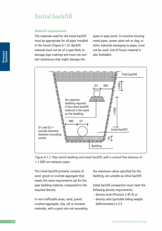
Material requirements
The materials used for the initial backfill
must be appropriate for all pipes installed
inthetrench(Figure6.1.2).Backfill
material must not be of a type likely to
damage pipe coatings and must not con-
tain substances that might damage the
pipes or pipe joints. In trenches housing
metal pipes, power plant ash or slag, or
other materials damaging to pipes, must
not be used. use of frozen material is
also forbidden.
Figure 6.1.2. Pipe trench bedding and initial backfill, with a vertical free distance of
< 1,000 mm between pipes.
Final backfill
d2 400
400 d1
Initial backfill
Bedding
No separate bedding required if the initial backfillmaterial is the same as the bedding.
d1 and d2 =outside diameterdiameter excludingsocket 50
<100
0
≥300
The initial backfill primarily consists of
sand, gravel or crushed aggregate that
meets the same requirements set for the
pipe bedding material, compacted to the
required density.
In non-trafficable areas, sand, gravel,
crushed aggregate, clay, silt or moraine
materials, with a grain size not exceeding
the maximum values specified for the
bedding, are suitable as initial backfill.
Initial backfill compaction must meet the
following density requirements:
•densitylevel(Proctor)≥95%or
•densityratio(portablefallingweight
deflectometer)≤2.5
uPONOr PrESSurE SySTEMS 173
Pre
ssu
re
Syst
ems
The initial backfill on each side of the
plasticpipe(i.e.haunching)mustbelaid
and compacted in uniform layers that are
also homogenous in the longitudinal pipe
direction. Mechanical compaction above
the pipe may be carried out only at a
backfill depth of at least 0.3 m above the
pipe crown.
The fitness for purpose of the initial
backfill materials is verified by grain size
distribution testing, with one sample
tested from each 200 m3 or part thereof.
The initial backfill density is determined
by measurements taken at 50m intervals,
with at least one measurement per
job site. The density ratio of the initial
backfill is determined by measurements
taken every 20 m. density is measured
at pipe crown height on one side of the
pipe. If more measurements than required
are made, the measurement average
must meet the density requirement. The
minimum allowable individual measure-
mentresultis93%(Proctor)fordensity
level measurements and 2.75 for density
ratiomeasurements(portablefalling
weight deflectometer).
In non-trafficable areas, the initial backfill
for pressure class PN ≥ 10 plastic pipes
can be carried out without compaction, if
so specified in the drawings.
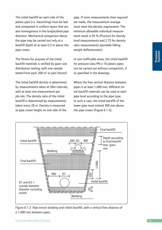
Where the free vertical distance between
pipes is at least 1,000 mm, different ini-
tial backfill materials can be used at each
pipe level according to the pipe type.
In such a case, the initial backfill of the
lower pipe must extend 300 mm above
thepipecrown(Figure6.1.3).
Figure 6.1.3. Pipe trench bedding and initial backfill, with a vertical free distance of
≥ 1,000 mm between pipes.
Final backfill
200 d2 400
400 d1
Initial backfill
Bedding
depth accordingto final backfillmax. grainsize
d1 and d2 =outside diameterdiameter excludingsocket
50
<100
0
300
Initial backfill
Final backfill
Bedding 2:1 2:1
174 uPONOr PrESSurE SySTEMS
Pre
ssu
re
Syst
ems
during all backfilling stages, the backfill
thickness must be about equal on both
sides of the pipe. The minimum initial
backfill depth above the crown of the
uppermost pipe must be equal to the
maximum stone size of the final backfill
material, however at least 300 mm.
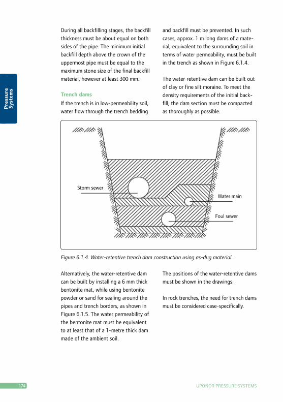
Trench dams
If the trench is in low-permeability soil,
water flow through the trench bedding
and backfill must be prevented. In such
cases, approx. 1 m long dams of a mate-
rial, equivalent to the surrounding soil in
terms of water permeability, must be built
in the trench as shown in Figure 6.1.4.
The water-retentive dam can be built out
of clay or fine silt moraine. To meet the
density requirements of the initial back-
fill, the dam section must be compacted
as thoroughly as possible.
Figure 6.1.4. Water-retentive trench dam construction using as-dug material.
Water main
Storm sewer
Foul sewer
Alternatively, the water-retentive dam
can be built by installing a 6 mm thick
bentonite mat, while using bentonite
powder or sand for sealing around the
pipes and trench borders, as shown in
Figure 6.1.5. The water permeability of
the bentonite mat must be equivalent
to at least that of a 1-metre thick dam
made of the ambient soil.
The positions of the water-retentive dams
must be shown in the drawings.
In rock trenches, the need for trench dams
must be considered case-specifically.

uPONOr PrESSurE SySTEMS 175
Pre
ssu
re
Syst
ems
Figure 6.1.5. Water-retentive trench dam construction using a bentonite mat.
Water main
Storm sewer
Foul sewer Installation direction
Bentonite mat 6 m
Bedding
Pipe hole surrounds sealed with bentonite sand
Initial backfill
Before backfilling, the pipes must be
checked to ensure that they are undam-
aged, in the correct positions and cor-
rectly installed. Trench structures must
be checked to ensure that they have
sufficient strength for backfilling. Any
ice or snow must be removed from the
trench. The trench bottom must not be
frozen or exposed to freezing. The initial
backfill material must be carefully placed
into the trench, evenly on both sides of
the pipes.
To ensure that the pipes are not dislodged
or damaged, the first backfilling stage
(haunching)mustbecarriedoutasspade
work or using an equivalent method. The
initial backfill must be carefully tamped
beneath and along the sides of the pipes,
so that the pipe height is not changed.
The initial backfill must be laid and
compacted in layers. Each compaction
layer's depth depends on the size of the
installed pipe, on the pipe material and
on the type of compactor used.

176 uPONOr PrESSurE SySTEMS
Pre
ssu
re
Syst
ems
Thermal insulation
Thermal insulation is carried out in ac-
cordance with the drawings, using either
factory pre-insulated pipes or on site us-
ing insulating boards or other insulating
materials.
unless otherwise specified in the draw-
ings, extruded plastic insulation board of
at least 35 kg/m3 bulk density must be
used. Lightweight aggregate insulation
must have a 8–20 mm grain size.
Backfill must not contain substances that
are damaging to pipes or pipe joints.
Final backfill in trafficable areas
The final backfill material must consist of
a compactable mineral soil. If the native
as-dug soil is compactable and freezable,
it may be used for the top backfill. With
respect to freezing properties, imported
backfill must correspond to the as-dug
material. The maximum stone size is 2/3
of the depth of each compacted layer,
and no more than 400 mm. If the final
backfill depth is too shallow for riprap to
be used, road sub-base material is used
for the final backfill.
In most cases, as-dug material is used for
final backfill. The maximum grain size of
final backfill material is the same as for
trafficable areas.
recycled materials such as ash and slag
can be used for backfill in accordance with
the plan specifications. The materials used
must not damage equipment or structures
in or near the trench.
If reinforcing recycled materials are used,
the chosen material strength must enable
subsequent re-excavation of the trench.
Final backfill in trafficable areas
The compaction of final backfill, carried
out using mineral soil in trafficable
areas, must meet the following density
requirements:
•densitylevel(Proctor)≥90%or
•densityratio(portablefallingweight
deflectometer)≤2.8
In trafficable areas, the final backfill
layer extends to the road's bottom
structural layer.
Final backfill
uPONOr PrESSurE SySTEMS 177
Pre
ssu
re
Syst
ems
The surface of riprap final backfill must
be filled and compacted to the same
specifications as a riprap embankment
surface. If the traffic area has a riprap
pavement structure, the final backfill and
surface layer are carried out to the same
specifications as a riprap embankment.
Final backfill in non-trafficable
areas
In non-trafficable areas, final backfilling
can be carried out without compaction, if
so specified in the drawings. The trench
must be filled to the height required to
ensure that the backfill material will set-
tle, upon subsequent compaction, at the
height specified in the drawings or, if no
such height is specified, to the height of
the surrounding soil.
The fitness for purpose of the final
backfill materials used is verified by grain
size distribution testing, using the speci-
fied sampling frequency, or by visually
monitoring the number of compactions
and layer depths.
The final backfill density is determined
by measurements taken at intervals of
50 m, with at least one measurement
per job site.
The density ratio of the final backfill is
determined by measurements taken every
20 m.
If more measurements than required are
made, the measurement average must
meet the density requirement. The mini-
mum allowable individual measurement
resultmaybe88%(Proctor)fordensity
level measurements, and 3.0 for density
ratiomeasurements(portablefalling
weightdeflectometer).
Chamber embedment
Final backfilling at the sides of cham-
bers, fire hydrants and check valves is
performed at least 0.4 m from their outer
surface, using frost-resistant material.
Filling around soakaways is done using
ahighlywater-permeablematerial(e.g.
8–32mmchipping).Ifnecessary,anon-
wovenfabric(operatingclass2)mustbe
installed against the trench walls.
In the case of supported trenches, the
trench shoring must be removed as the
final backfill proceeds, taking care to
prevent wall collapse, the loosening of
compacted backfill and the displacement
of the bedding or pipes.
178 uPONOr PrESSurE SySTEMS
Pre
ssu
re
Syst
ems
Uponor Pressure Systems – Hydraulic Design
This section describes the general rules
for the hydraulic design of pressure pipes.
Hydraulic design is intended to achieve
the most economic pipe installation
possible, in terms of construction and
operating costs.
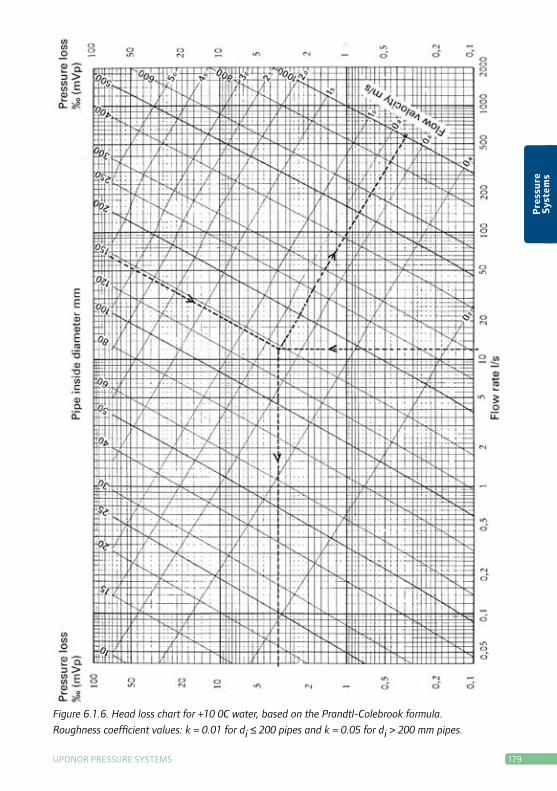
Inhydraulicdesign,aheadloss(orpres-
suredrop)chartisusedforpipesizing,
according to different operating condi-
tions. use of a head loss chart requires
that the design flow rate is known. A line
is traced from the selected pipe size to the
design flow rate value line, from which
pointthepressuredrop(headloss)value,
given in Pascal per metre, can be read
off. For technical reasons, the recom-
mended flow velocity for pressure sewers
is 0.5–1.7 m/s. No recommended flow
velocity is specified for water pipes.
Sample head loss calculation
The design water flow rate is: 12 l/s
The inside diameter of the chosen
160 x 9.5 mm PN 10 ProFuse pressure
pipe is 150 mm. From the head loss chart,
we can therefore determine that
the flow velocity will be 0.70 m/s
theheadlosswillbe3‰(3mWc/km)
uPONOr PrESSurE SySTEMS 179
Pre
ssu
re
Syst
ems
Figure 6.1.6. Head loss chart for +10 0C water, based on the Prandtl-Colebrook formula.
Roughness coefficient values: k = 0.01 for di ≤ 200 pipes and k = 0.05 for di > 200 mm pipes.
180 uPONOr PrESSurE SySTEMS
Pre
ssu
re
Syst
ems
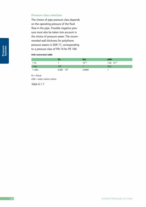
Pa bar mWc
1 Pa 1 10-5 1,02 · 10-4
1 bar 105 1 10,2
1 mWc 0,981 · 104 0,0981 1
Pa = Pascal
mWc = water column metres
Unit conversion table
Table 6.1.7
Pressure class selection
The choice of pipe pressure class depends
on the operating pressure of the fluid
flow in the pipe. Possible negative pres-
sure must also be taken into account in
the choice of pressure sewer. The recom-
mended wall thickness for polythene
pressure sewers is Sdr 17, corresponding
to a pressure class of PN 10 for PE 100.
uPONOr PrESSurE SySTEMS 181
Pre
ssu
re
Syst
ems
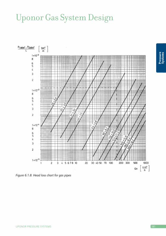
Figure 6.1.8. Head loss chart for gas pipes
Uponor Gas System Design
182 uPONOr PrESSurE SySTEMS
Pre
ssu
re
Syst
ems
Example gas system design calcula-
tion
Gas flow rate Qn = 150 nm3/h
Pipeline length = 5,000 m
Inlet pressure = 4 bar
(overpressure)
Pipe size = 63 mm
drawing a line up from 150 nm3/h to the
pipe in question on the head loss chart
gives a value on the vertical
'p1abs
2 – p2abs
2 per unit' scale of 1.2 x 10⁻³
This value is then multiplied by the pipeline length:
p1abs
2 – p2abs
2 = 5,000 x 1.2 x 10-3 = 6.0 bar2
The outlet pressure is calculated using
the following formula:
p2abs
= √ p1abs
2 – calculated value
where p1abs
= overpressure + atmospheric pressure
p1abs
= 4 bar + 0.981 bar = 4.981 bar
p2abs
= √ 4.9812 – 6.0
= 4.34 bar
The head loss for 63 mm PEH gas pipe is calculated
using the formula
p = p2abs
– p1abs
= 4.981 bar – 4.34 bar
= 0.64 bar
uPONOr PrESSurE SySTEMS 183
Pre
ssu
re
Syst
ems
Uponor Pressure Pipe System Installation – General Instructions and SupervisionPressure pipe installation follows largely
the same installation principles as for
gravity systems, for example with respect
to trench construction and backfilling, as
described in Chapter 5.1. However, there
are a number of instructions specific to
pressure pipes; these are presented in
this chapter. Installation must always be
carried out according to the drawings.
The designer must be informed of any
changes in the assumed conditions that
might affect installation in accordance
with the drawings.
Longitudinal expansion
Account must be taken of longitudinal
expansion and contraction, when handling
and installing PE pipes. PE pipes have a
relatively high heat expansion coefficient.
For this reason, a pipe laid on a hot day
can shorten by several centimetres by the
following morning.
Longitudinal expansion formula:
∆L = ∆t • L • α
where
ΔL= Longitudinalexpansionor
contraction [m]
Δt= T2-T1
T1 = Temperature upon installation
T2 = Temperature after installation
L = Pipe length [m]
α = Thermal expansion coefficient; cf.
System and Material Specifications
Table 2.2
Pipe and joint reinforcement
Pressure pipe socket joints, segment-
welded fittings, and pressure lines of over
225 mm in diameter, must be effectively
reinforced or restrained, to eliminate the
risk of pullout due to thermal expan-
sion and contraction. Injection moulded
fittings and max. 225 mm pipes do not
require reinforcement.
PE pipe systems and fittings are reinforced
by concrete encasement. PVC systems and
fittings are strengthened with mechanical
socket locks. reinforcement is carried out
before pressure testing the system.
Concrete reinforcement
Concrete reinforcement specifications
are determined according to the pipe line
pressure and surge pressure, and the
maximum bearing capacity of the soil.
Concrete reinforcements must be built
and steel reinforced in accordance with
the plan specifications, and cast so that
no additional load is exerted on the pipe
system. As necessary, the reinforce-
ment foundations must be thoroughly
compacted. Figures 6.1.9 and 6.1.10
illustrate some of the most commonly
used concrete reinforcements.

184 uPONOr PrESSurE SySTEMS
Pre
ssu
re
Syst
ems
Figure 6.1.9
≥ 2 x de
Segment-welded fittings for pressure sys-
tems must always be encased in concrete.
The size of the concrete reinforcement is
determined by the welded joints, so that
the distance between the outermost joint
weld and the edge of the reinforcement
is as follows:
•atbendsBe=min.150mm
•atjunctionsBe1 and Be
2 = min. 200 mm
The reinforcement thickness from the
pipe surface is min. 150 mm.
Figure 06.01.10
Be1
de
De
Be 2
Be
De
Socket lock reinforcement
Socket locks are used with PVC pipes and
fittings. The operating principle of socket
locks is based on transferring thrust
forces past the joint, so that the forces
are resisted by the friction between the
pipe and soil.
PVC fittings must always be locked to
prevent pullout. Bend fittings are locked at
both ends. The number of PVC pipe socket
locks depends on the installation depth
and pipe diameter. The required number of
socket locks is shown in the following table.
Depth of cover Pipe diameter
110 160 225 280 315 400
< 2 m - 1 1 2 2 3
2 – 3 m - - 1 1 1 2
3 – 4 m - - - - 1 1
> 4 m - - - - - -
Table 6.1.11. Number of socket locks required per fitting joint (pipe length 6 m)
uPONOr PrESSurE SySTEMS 185
Pre
ssu
re
Syst
ems
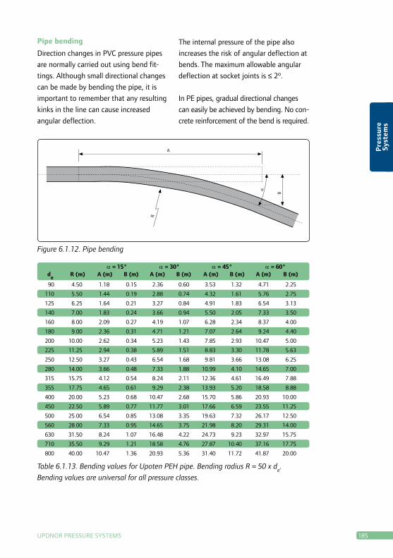
Pipe bending
direction changes in PVC pressure pipes
are normally carried out using bend fit-
tings. Although small directional changes
can be made by bending the pipe, it is
important to remember that any resulting
kinks in the line can cause increased
angular deflection.
The internal pressure of the pipe also
increases the risk of angular deflection at
bends. The maximum allowable angular
deflectionatsocketjointsis≤2º.
In PE pipes, gradual directional changes
can easily be achieved by bending. No con-
crete reinforcement of the bend is required.
Figure 6.1.12. Pipe bending
B
α
AR
α = 15° α = 30° α = 45° α = 60° d
e R (m) A (m) B (m) A (m) B (m) A (m) B (m) A (m) B (m)
90 4.50 1.18 0.15 2.36 0.60 3.53 1.32 4.71 2.25
110 5.50 1.44 0.19 2.88 0.74 4.32 1.61 5.76 2.75
125 6.25 1.64 0.21 3.27 0.84 4.91 1.83 6.54 3.13
140 7.00 1.83 0.24 3.66 0.94 5.50 2.05 7.33 3.50
160 8.00 2.09 0.27 4.19 1.07 6.28 2.34 8.37 4.00
180 9.00 2.36 0.31 4.71 1.21 7.07 2.64 9.24 4.40
200 10.00 2.62 0.34 5.23 1.43 7.85 2.93 10.47 5.00
225 11.25 2.94 0.38 5.89 1.51 8.83 3.30 11.78 5.63
250 12.50 3.27 0.43 6.54 1.68 9.81 3.66 13.08 6.25
280 14.00 3.66 0.48 7.33 1.88 10.99 4.10 14.65 7.00
315 15.75 4.12 0.54 8.24 2.11 12.36 4.61 16.49 7.88
355 17.75 4.65 0.61 9.29 2.38 13.93 5.20 18.58 8.88
400 20.00 5.23 0.68 10.47 2.68 15.70 5.86 20.93 10.00
450 22.50 5.89 0.77 11.77 3.01 17.66 6.59 23.55 11.25
500 25.00 6.54 0.85 13.08 3.35 19.63 7.32 26.17 12.50
560 28.00 7.33 0.95 14.65 3.75 21.98 8.20 29.31 14.00
630 31.50 8.24 1.07 16.48 4.22 24.73 9.23 32.97 15.75
710 35.50 9.29 1.21 18.58 4.76 27.87 10.40 37.16 17.75
800 40.00 10.47 1.36 20.93 5.36 31.40 11.72 41.87 20.00
Table 6.1.13. Bending values for Upoten PEH pipe. Bending radius R = 50 x de.
Bending values are universal for all pressure classes.

186 uPONOr PrESSurE SySTEMS
Pre
ssu
re
Syst
ems
Subsurface road and rail crossings
Pipeline installation under public roads and
railways must be performed in compli-
ance with the guidelines and regulations
of the relevant road and rail authorities. A
detailed plan for the subsurface crossing
must also be drawn up and approved by
the authorities concerned.
Subsurface crossings are normally posi-
tioned perpendicular to a road or railway.
At subsurface rail crossings, the distance
between the pipe crown and the railtrack
must be at least 1 metre.
Pipe system design must take account of
the structure, durability and deflection of
the pipeline in demanding conditions.
In the case of installations carried out
by pipe jacking, steel or concrete pipe is
normally used. In open trench installations,
SN 8 class plastic pipe can be used as a
casing pipe. Pressure pipes must always be
installed in a casing pipe. At subsurface
rail crossings, the casing pipe must
extend at least three metres from the
embankment.
The casing pipe must be designed so as
to facilitate pipe maintenance. At subsur-
face road and rail crossings, an inspection
chamber must be installed on one side
of the crossing. At subsurface crossings
for pressure pipes, one end of the casing
pipe is plugged and a chamber is installed
at the other end as a safeguard. This
ensures that, in the event of a leak, any
leakage water discharges via the chamber
into the ground, away from the road or
rail structure.
In addition, the pressure pipeline must
be equipped with a check valve on both
sides of the road/railway, as a safeguard
in the event of a pressure build-up at
both ends of the crossing.
Pipe support spacing
When supporting PE pipes, the distance
between brackets must not be too great,
as this might cause the pipe to bend. The
following tables give the bracket spacing
for uponor’s systems.
Pipe support design must take different
load factors, such as water pressure test-
ing and pressure surges, into account.
Only use brackets specially designed for
use with plastic pipes. Loose brackets al-
low axial thermal movement of the pipe.
Fixed brackets lock the pipe firmly into
place. use fixed brackets on sockets and
branch sections. Fastenings and brackets
beneath load-bearing base floors must be
made of acid-proof steel.
uPONOr PrESSurE SySTEMS 187
Pre
ssu
re
Syst
ems
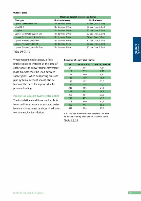
Table 06.01.14
Outdoor pipes
Maximum bracket interval (guideline)
Pipe type Horizontal sewer Vertical sewer
Uponor Sewer System PVC 10 x de (max. 3.0 m) 30 x de (max. 3.0 m)
Ultra Rib 2 10 x de (max. 2.0 m) 30 x de (max. 3.0 m)
Dupplex 10 x de (max. 2.0 m) 30 x de (max. 3.0 m)
Uponor Stormwater System DW 10 x de (max. 2.0 m) 30 x de (max. 3.0 m)
Uponor Pre-Insulated Sewer System 10 x de (max. 2.0 m) 30 x de (max. 3.0m)
Uponor Pressure System PVC 12 x de (max. 3.0 m) 30 x de (max. 3.0 m)
Uponor Pressure System PE 10 x de (max. 1.6 m) 30 x de (max. 3.0 m)
Uponor Pressure System ProFuse 10 x de (max. 1.6 m) 25 x de (max. 2.6 m)
When hanging socket pipes, a fixed
bracket must be installed at the base of
each socket. To allow thermal movement,
loose brackets must be used between
socket joints. When supporting pressure
pipe systems, account should also be
taken of the need for support due to
pressure loading.
Protection against hydrostatic uplift
The installation conditions, such as bot-
tom conditions, water currents and water
level variations, must be determined prior
to commencing installation.
de PN 10 / SDR 17 PN 16 / SDR 11
90 4,94 4,27
110 7,39 6,40
125 9,60 8,30
140 12,0 10,4
160 15,7 13,6
180 19,8 17,2
200 24,5 21,1
225 31,1 26,7
250 38,4 33,2
280 48,3 41,6
315 61,0 52,7
355 77,3 66,9
400 98,4 85,0
Buoyancy of empty pipe (kg/m)
Table 6.1.15
N.B.! The pipe material also has buoyancy. This must
be accounted for by adding 5% to the above values.
188 uPONOr PrESSurE SySTEMS
Pre
ssu
re
Syst
ems
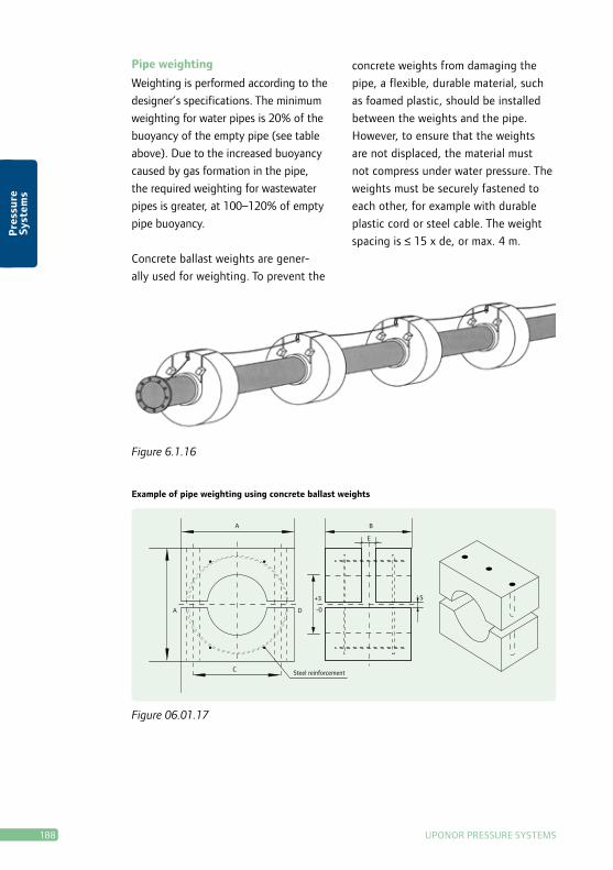
A B
E
A D
C Steel reinforcement
-0
+3 S
Example of pipe weighting using concrete ballast weights
Figure 06.01.17
Pipe weighting
Weighting is performed according to the
designer’s specifications. The minimum
weighting for water pipes is 20% of the
buoyancyoftheemptypipe(seetable
above).Duetotheincreasedbuoyancy
caused by gas formation in the pipe,
the required weighting for wastewater
pipes is greater, at 100–120% of empty
pipe buoyancy.
Concrete ballast weights are gener-
ally used for weighting. To prevent the
Figure 6.1.16
concrete weights from damaging the
pipe, a flexible, durable material, such
as foamed plastic, should be installed
between the weights and the pipe.
However, to ensure that the weights
are not displaced, the material must
not compress under water pressure. The
weights must be securely fastened to
each other, for example with durable
plastic cord or steel cable. The weight
spacing is ≤ 15 x de, or max. 4 m.