06/08/2015 Diagnostic Test Generation for Transition Delay Faults Using Two- Timeframe ATPG Model Master’s Thesis Defense Xiaolu Shi Dept. of ECE, Auburn University Thesis Advisor: Thesis Committee: Dr. Vishwani Agrawal Dr. Adit Singh Dr. Victor Nelson

06/08/2015 Diagnostic Test Generation for Transition Delay Faults Using Two-Timeframe ATPG Model Master’s Thesis Defense Xiaolu Shi Dept. of ECE, Auburn.
Dec 31, 2015
Welcome message from author
This document is posted to help you gain knowledge. Please leave a comment to let me know what you think about it! Share it to your friends and learn new things together.
Transcript

06/08/2015
Diagnostic Test Generation for Transition Delay Faults Using Two-Timeframe ATPG Model
Master’s Thesis DefenseXiaolu Shi
Dept. of ECE, Auburn University
Thesis Advisor: Thesis Committee:
Dr. Vishwani AgrawalDr. Adit SinghDr. Victor Nelson

2
Acknowledgment
• Prof. Vishwani Agrawal for his continuous guidance throughout my work, he is always encouraging and supportive
• Prof. Adit Singh and Prof. Victor Nelson for being my committee members, for their courses, and their patient guidance
3
Presentation Outline
• Background• Problem Statement • Diagnostic Automatic Test Generation System• Exclusive Test Generation for Transition Delay
Fault• Experiment Results• Conclusion and Future Work
4
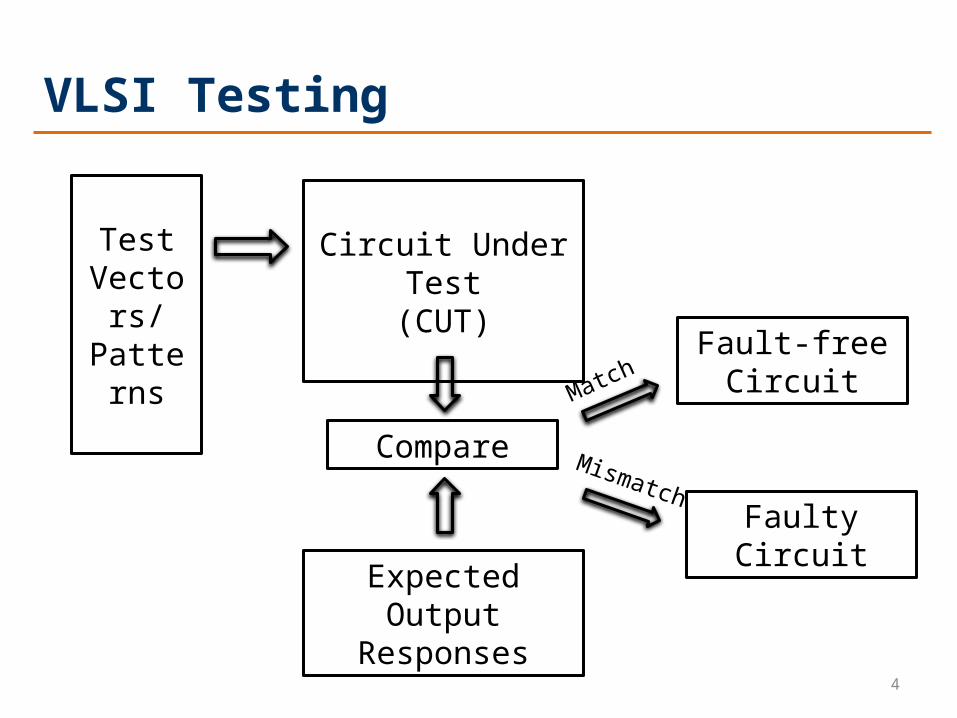
VLSI Testing
Test Vectors/Patterns
Circuit Under Test(CUT)
Compare
Expected Output Responses
Fault-freeCircuit
FaultyCircuit
Match
Mismatch

5
VLSI Diagnosis
Effect-Cause Algorithm
• Traces back the error propagation path from failing POs by multiple methods
• Fault simulation on suspected faults
• Compare the failing response and rank faults
• Remove low ranking suspects and narrow down the failure location
6
• Pre-simulated failing responses of all modeled faults stored in a dictionary
• Fault simulation on defective circuit
• Compare circuit failing response with previous stored data
• Search which fault might be the cause of the failure
Cause-Effect Algorithm
VLSI Diagnosis
7
Fault Dictionary
• Full Response Dictionary
Complete record of failing information at each output for all fault-vector pairs
• Pass/Fail Dictionary
Only stores the single pass or failing pattern index for each fault-vector pair

8
Diagnostic Metrics• Fault coverage (FC) is a quantitative measure of the
effectiveness in detection test. Fault coverage
• Diagnostic coverage (DC) metric evaluates the effectiveness of a given set for fault diagnosis.A fault group contains two or more undistinguished faults (equivalent with respect to the test vectors)
9
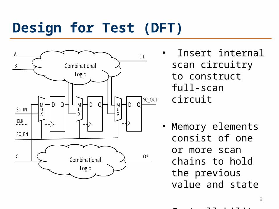
Design for Test (DFT)
• Insert internal scan circuitry to construct full-scan circuit
• Memory elements consist of one or more scan chains to hold the previous value and state
• Controllability and observability
10
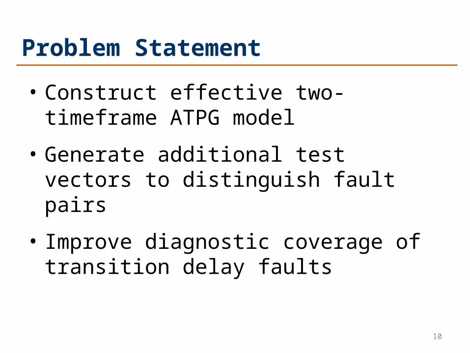
Problem Statement
• Construct effective two-timeframe ATPG model
• Generate additional test vectors to distinguish fault pairs
• Improve diagnostic coverage of transition delay faults
11
Automatic Exclusive Test Generation System

12
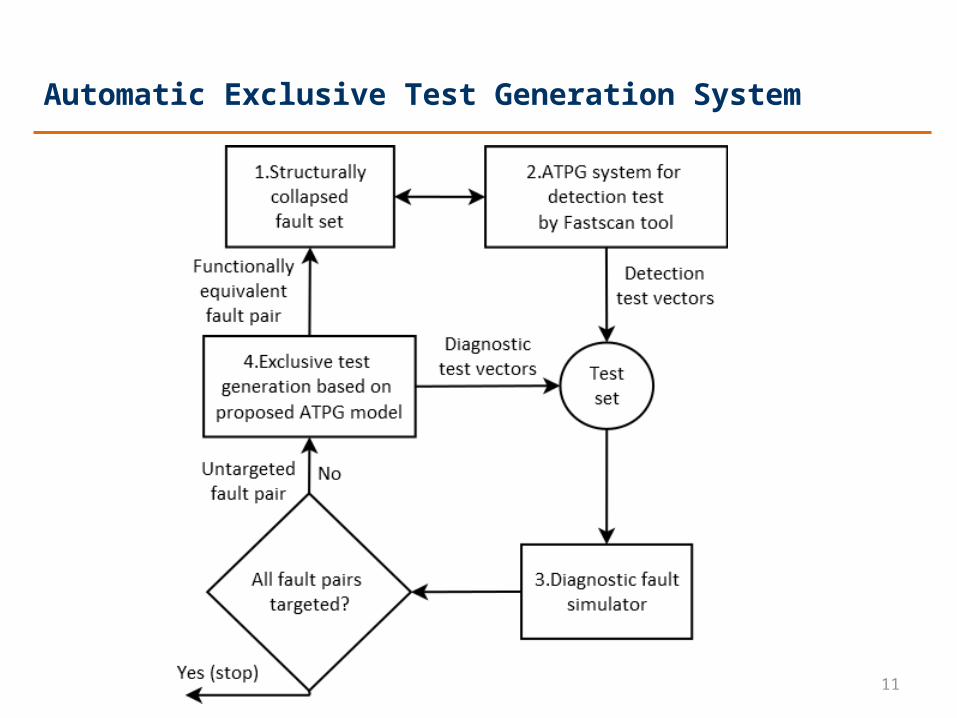
Automatic Exclusive Test Generation System (cont.)
• Blocks 1 and 2 are conventional ATPG system for detection test using Fastscan tools
Generate a detection test set
Calculate fault coverage
Construct fault dictionary.

13
Automatic Exclusive Test Generation System (cont.)
• Block 3 is diagnostic fault simulator
Group faults with same fault signature
Calculate and update diagnostic coverage (DC)
Identify undiagnosed fault groups and target fault pairs
If all faults in groups are targeted, the diagnosis will stop
14
Automatic Exclusive Test Generation System (cont.)
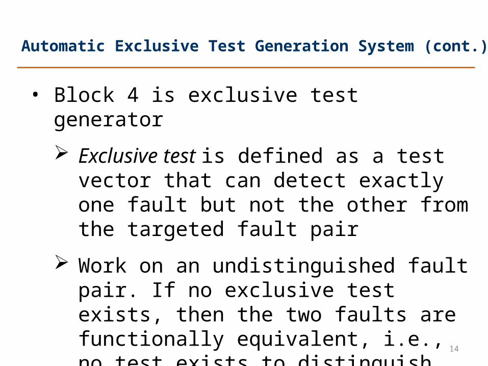
• Block 4 is exclusive test generator
Exclusive test is defined as a test vector that can detect exactly one fault but not the other from the targeted fault pair
Work on an undistinguished fault pair. If no exclusive test exists, then the two faults are functionally equivalent, i.e., no test exists to distinguish them.
15
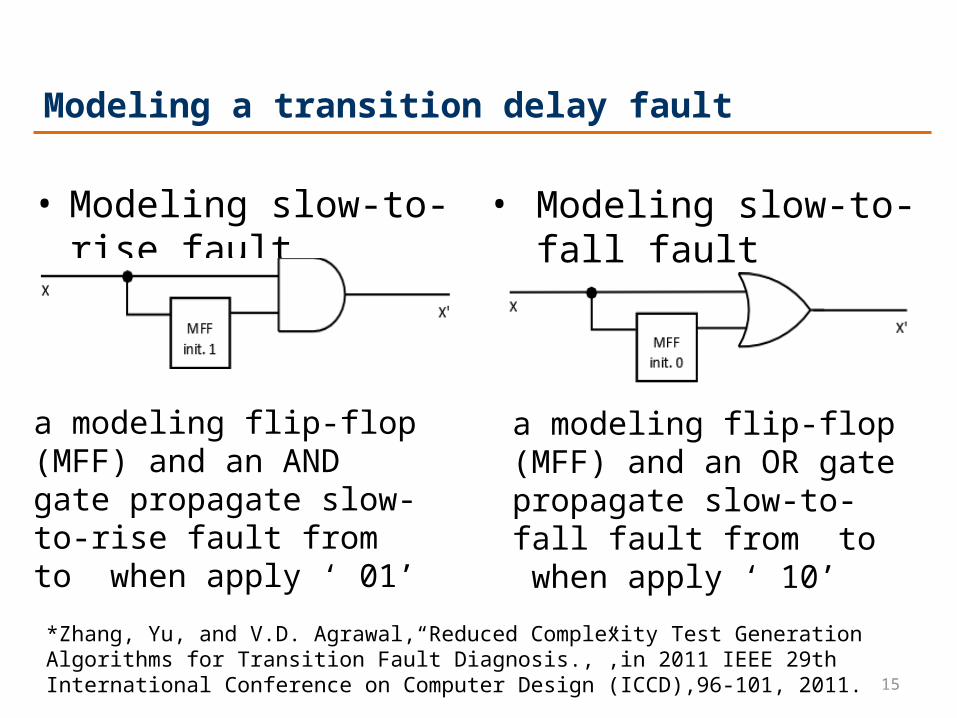
Modeling a transition delay fault
• Modeling slow-to-rise fault • Modeling slow-to-fall fault
a modeling flip-flop (MFF) and an AND gate propagate slow-to-rise fault from to when apply ‘ 01’
a modeling flip-flop (MFF) and an OR gate propagate slow-to-fall fault from to when apply ‘ 10’
*Zhang, Yu, and V.D. Agrawal,“Reduced Complexity Test Generation Algorithms for Transition Fault Diagnosis.,”,in 2011 IEEE 29th International Conference on Computer Design (ICCD),96-101, 2011.

16
Single Timeframe ATPG Model
• A single-circuit-copy ATPG model where X1 represents fault free circuit, X2 models slow-to-rise fault.
• A test for stuck-at fault on select signal line y detects the slow-to-rise fault on line x to x’.

17
Single Timeframe ATPG Model
• the test on y s-a-0/1 is an exclusive test for a transition delay fault pair

18
Sequential ATPG & Combinational ATPG• Sequential ATPG requires a sequence of vectors and is
also restricted to previous value and state.Has limited controllability and observability of internal signals.
• Combinational ATPG is able to test a single fault and generate test vector without considering the duplicated circuit with multiple faults. The complexity of a combinational ATPG for detecting redundant faults is much lower than sequential ATPG.
19
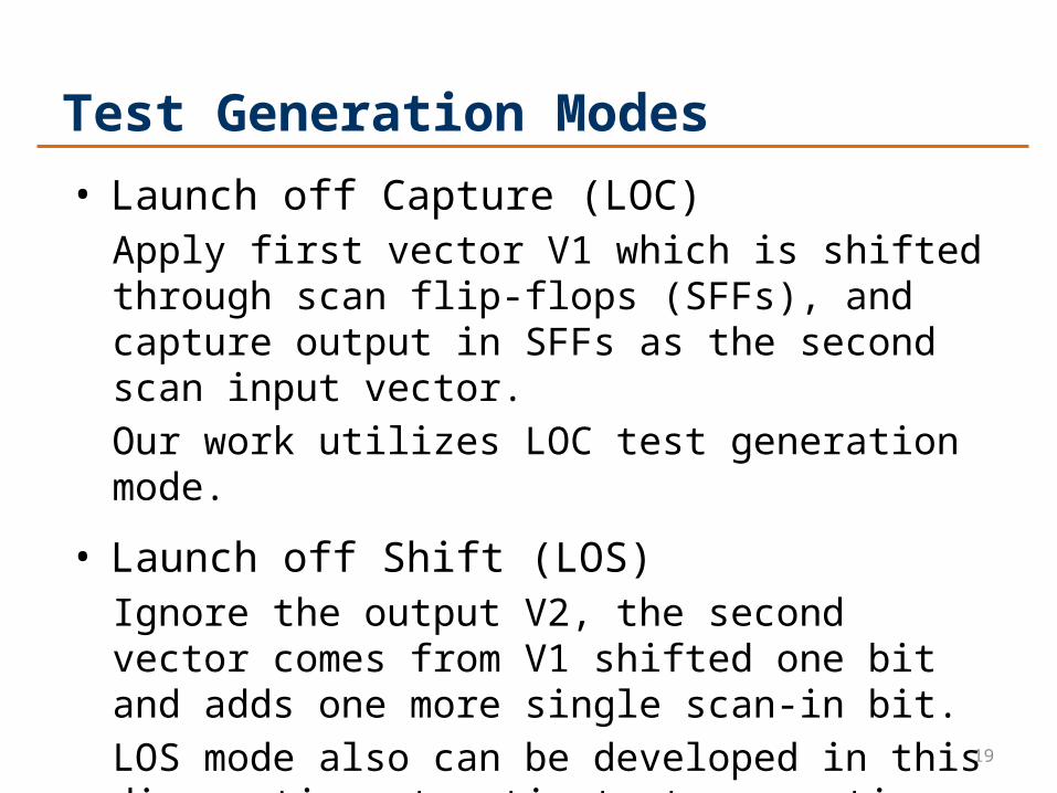
Test Generation Modes• Launch off Capture (LOC)
Apply first vector V1 which is shifted through scan flip-flops (SFFs), and capture output in SFFs as the second scan input vector.Our work utilizes LOC test generation mode.
• Launch off Shift (LOS)Ignore the output V2, the second vector comes from V1 shifted one bit and adds one more single scan-in bit.LOS mode also can be developed in this diagnostic automatic test generation system.

20
A New Two-Timeframe Model for Combinational ATPG
Two-timeframe expansion ATPG model of transition delay fault for exclusive test under LOC test mode

21
A Simplified ModelAs test vector pair under LOC transition delay test. The first vector only initializes the circuit and will not have any effect on the logic, so the model can be simplified as shown.
*LOS mode can be also developed to construct two-timeframe ATPG model*Yu Zhang, Bei Zhang, and Vishwani D. Agrawal. “Diagnostic Test Generation for Transition Delay Faults Using Stuck-At Fault Detection Tools.” J. Electron. Test. 30, no. 6 (December 2014): 763–80.
22
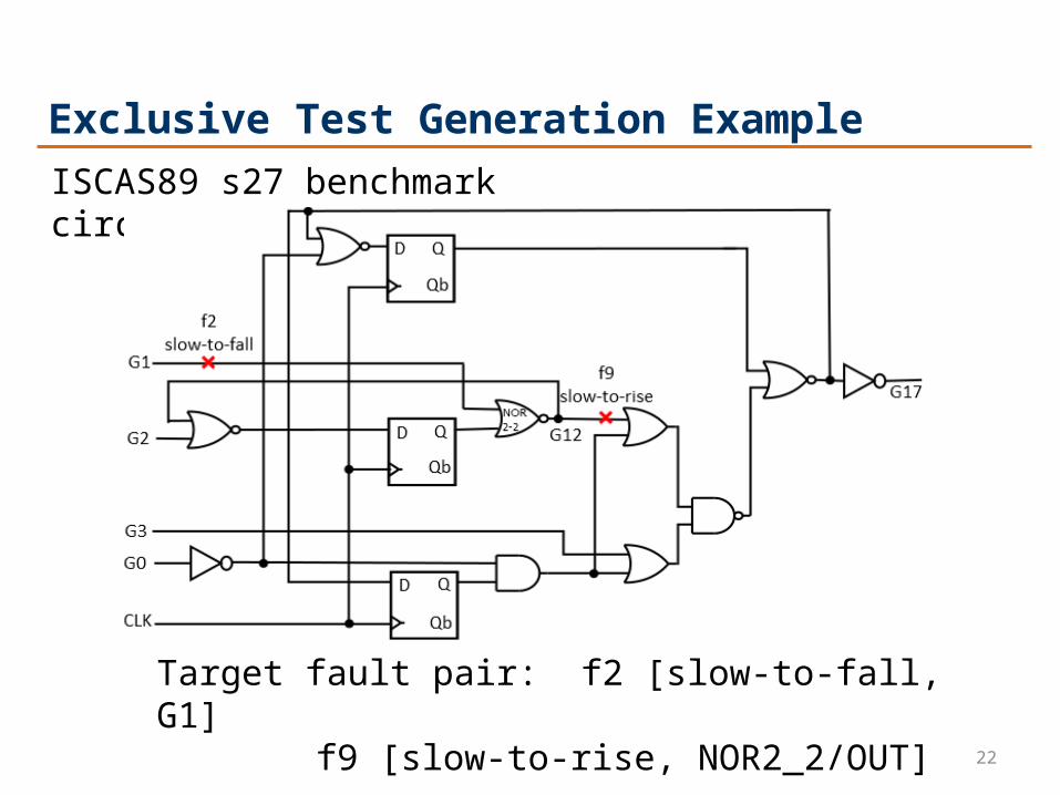
Exclusive Test Generation ExampleISCAS89 s27 benchmark circuit:
Target fault pair: f2 [slow-to-fall, G1] f9 [slow-to-rise, NOR2_2/OUT]
23
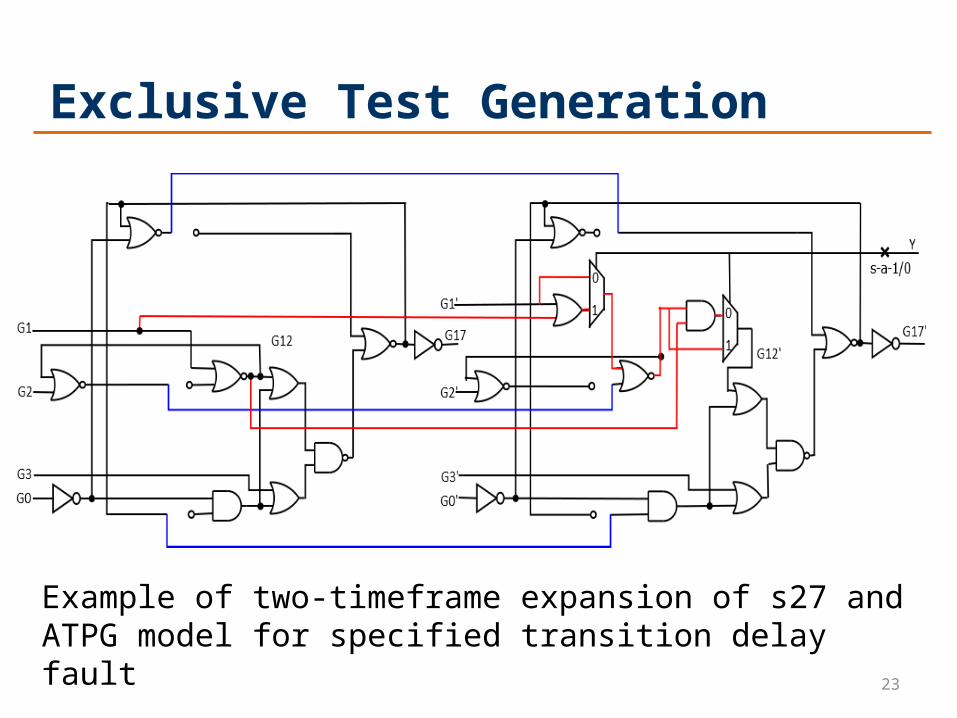
Exclusive Test Generation
Example of two-timeframe expansion of s27 and ATPG model for specified transition delay fault

24
Diagnostic Fault Simulation
• Transform the generated combinational vector into a sequential test vector-pair
• Fault simulation on original full-scan sequential benchmark circuit
• Calculate the new DC, update undistinguished groups and built a new dictionary. The diagnostic fault simulator will stop after all undistinguished fault pairs are targeted or an adequate DC has been achieved.

25
Experimental Results
Circuit
Detection Test (by Fastscan) Diagnostic Test (by Fastscan)
No. of
TDFs
No. ofDet. TestVectors
FC(%)
No. of Undist.
Pairs
DC(%)
No. of Diag. Test Vector
PairsNo. ofUndist.
Pairs
DC(%)
CPU*Time(sec.)
s27 46 11 100.0 29 54.3 17 1 100 12.9
s298 385 44 79.9 106 62.4 28 47 77.7 44.2
s420 622 113 85.4 429 54.9 47 170 81.0 155.1
s526 570 86 62.5 226 47.8 28 98 58.1 52.1
s838 1254 231 83.6 895 53.3 95 356 78.5 539.8
s1423 2199 114 92.0 355 80.5 73 199 92.1 279.3
s5378 6007 230 90.6 877 83.1 340 98 91.0 1879.8
*Hardware configuration: 2.6GHz CPU, 3.86GB RAM, Intel Core i5

26
Comparing Detection Test and Diagnosis Test
s27 s298 s420 s526 s838 s1423 s53780
100
200
300
400
500
600
700
800
900
No. of Undistin-guished Fault Pairs for Detection Test
No. of Undistin-guished Fault Pairs for Diagnostic Test
• A clear decrease of Undistinguished fault pair after two-timeframe expansion ATPG model based exclusive test generation
No.
of U
ndis
tingu
ishe
d Fa
ult P
airs
27
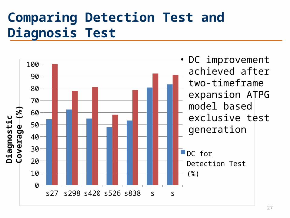
Comparing Detection Test and Diagnosis Test
s27 s298 s420 s526 s838 s1423 s53780
10
20
30
40
50
60
70
80
90
100
DC for Detection Test (%)
DC for Diagnostic Test (%)
• DC improvement achieved after two-timeframe expansion ATPG model based exclusive test generation
Dia
gnos
tic C
over
age
(%)
28
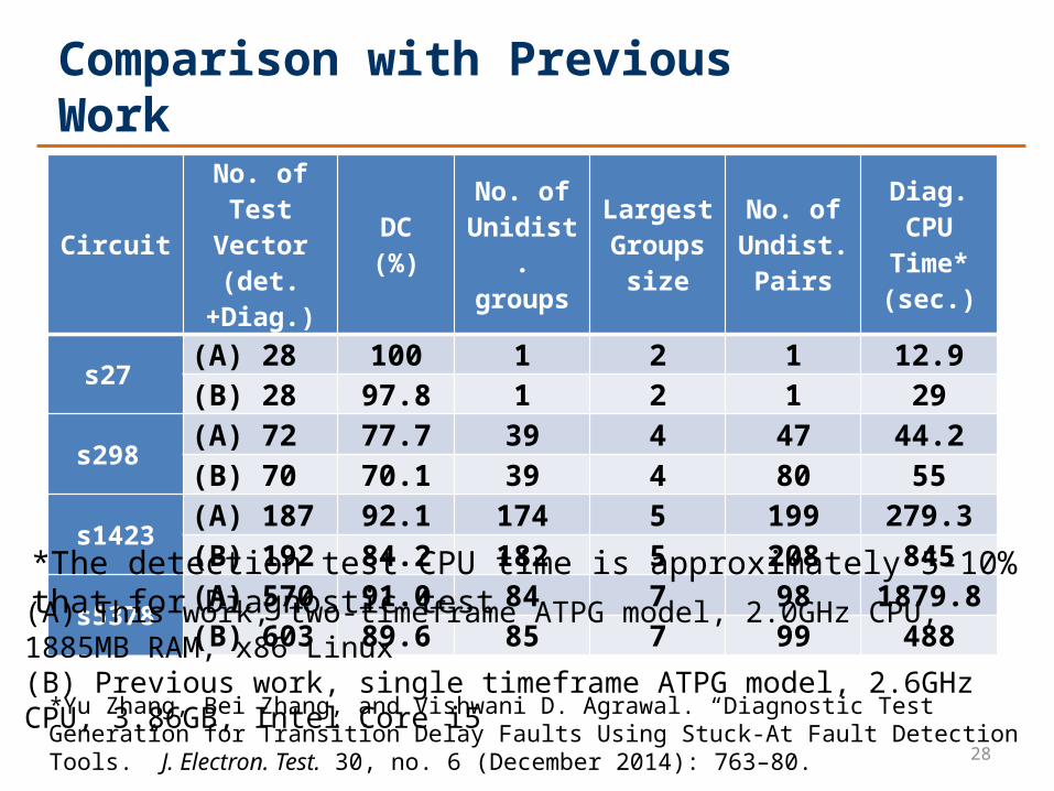
Comparison with Previous Work
CircuitNo. of
Test Vector (det.+Diag.)
DC(%)
No. ofUnidist.groups
LargestGroups
size
No. ofUndist.
Pairs
Diag. CPUTime*(sec.)
s27 (A) 28 100 1 2 1 12.9(B) 28 97.8 1 2 1 29
s298 (A) 72 77.7 39 4 47 44.2(B) 70 70.1 39 4 80 55
s1423 (A) 187 92.1 174 5 199 279.3(B) 192 84.2 182 5 208 845
s5378 (A) 570 91.0 84 7 98 1879.8(B) 603 89.6 85 7 99 488
(A) This work, two-timeframe ATPG model, 2.0GHz CPU, 1885MB RAM, x86 Linux (B) Previous work, single timeframe ATPG model, 2.6GHz CPU, 3.86GB, Intel Core i5
*Yu Zhang, Bei Zhang, and Vishwani D. Agrawal. “Diagnostic Test Generation for Transition Delay Faults Using Stuck-At Fault Detection Tools.” J. Electron. Test. 30, no. 6 (December 2014): 763–80.
*The detection test CPU time is approximately 5-10% that for Diagnostic test

29
DC (%): Comparison with Previous Work
s27 s298 s1423 s5378
97.8
70.1
84.289.6
100
77.7
92.1 91
DC for single-timeframe ATPG model (B)DC for two-timeframe ATPG model (A) • An obvious DC
improvement with two-timeframe expansion ATPG model based exclusive test generation
• Combinational ATPG has lower complexity for identifying redundant faults and generating exclusive tests
*Hardware configuration (A): 2.0GHz CPU, 1885MB RAM, x86 Linux Hardware configuration (B): 2.6GHz CPU, 3.86GB RAM, Intel Core i5

30
Conclusion
• A diagnostic automatic test generation system relies on exclusive tests to distinguish transition delay fault pairs
• Experimental results show that diagnostic coverage (DC) improves after two-timeframe expansion ATPG model for exclusive test is used
• Combinational ATPG is more effective for redundant fault identification and exclusive test generation

31
Future Work
• Implement two-timeframe model for LOS test generation mode to get higher DC
• Test set compaction to reduce test application time
• Library size reduction techniques combined with this test generation system will make delay fault diagnosis more efficient
• Utilization of this two-timeframe model to stuck open fault diagnostic test

32
• Abramovici, Miron, Melvin A. Breuer, and Arthur D. Friedman. Digital Systems Testing & Testable Design. edition 1. New York: Wiley-IEEE Press, 1994.
• Lavo, D.B., and T. Larrabee. “Making Cause-Effect Cost Effective: Low-Resolution Fault Dictionaries.” In Proc. International Test Conference, 2001, pp. 278–86.
• Zhang, Yu, and V. D. Agrawal. “A Diagnostic Test Generation System.” In Proc. International Test Conference, 2010, pp. 1–9.
• Zhang, Yu, Bei Zhang, and V. D. Agrawal. “Diagnostic Test Generation for Transition Delay Faults Using Stuck-At Fault Detection Tools.” J. Electron. Test. 30, no. 6 pp. 763–80, December 2014.
• Lavagno, Luciano, Grant Martin, and Louis Scheffer. Electronic Design Automation for Integrated Circuits Handbook - 2 Volume Set. Boca Raton, FL, USA: CRC Press, Inc., 2006.
• Grout, Ian A. Integrated Circuit Test Engineering: Modern Techniques. Springer Science & Business Media, 2005, pp. 68-70
• Agrawal, V. D., Dong Hyun Baik, Yong Chang Kim, and K. K. Saluja. “Exclusive Test and Its Applications to Fault Diagnosis.” In Proc. 16th International Conf. VLSI Design, 2003, pp. 143–48.
• M. L. Bushnell and V. D. Agrawal, Essentials of Electronic Testing for Digital, Memory & Mixed-Signal VLSI Circuits, Boston, Springer, 2000.
• Park, Intaik, and E.J. McCluskey, “Launch-on-Shift-Capture Transition Tests.,”Proc. International Test Conference, 2008, pp. 1-9.
• Higami, Y., Y. Kurose, S. Ohno, H. Yamaoka, H. Takahashi, Y. Shimizu, T. Aikyo, and Y. Takamatsu, “Diagnostic Test Generation for Transition Faults Using a Stuck-at ATPG Tool,”, Proc. International Test Conference, 2009, pp. 1-9.
References

Questions ?
Thank you!
Related Documents


