ENABLING STRUCTURES ASSIGNMENT ALUMINIUM FORMWORK FACULTY: DR. DEBASIS SARKAR MR. PARTH THAKKAR SUBMITTED BY: HELI CHOKSHI (UC 0606) 2010 22 OCT

Welcome message from author
This document is posted to help you gain knowledge. Please leave a comment to let me know what you think about it! Share it to your friends and learn new things together.
Transcript

ENABLING STRUCTURES
ASSIGNMENT
ALUMINIUM FORMWORK
FACULTY:
DR. DEBASIS SARKAR MR. PARTH THAKKAR
SUBMITTED BY:
HELI CHOKSHI (UC 0606)
2010
22 OCT

ALUMINIUM FORMWORK ENABLING STRUCTURE 1
SCHOOL OF BUILDING SCIENCE AND TECHNOLOGY, HELI CHOKSHI CEPT UNIVERSITY
TABLE OF CONTENTS
ALUMINIUM FORMWORK ...................................................................................................... 2
1. CASE STUDY OF PROJECT USING ALUMINIUM FORMWORK ................................. 2
2. DETAILS OF THE PROJECT ......................................................................................... 4
3. WHAT IS ALUMINIUM FORMWORK? ........................................................................... 5
4. COMPONENTS OF ALUMINIUM FORMWORK ............................................................ 7
5. FORMWORK ASSEMBLY ........................................................................................... 11
6. ERECTION OF FORMWORK AT SITE ........................................................................ 14
7. SEQUENCE FOR ERECTING FORMWORK FOR CONSTRUCTION ........................ 19
8. STRIKING OF FORMWORK AT SITE ......................................................................... 21
9. SALIENT FEATURES OF THE ALUMINIUM FORMWORK CONSTRUCTION
SYSTEM ...................................................................................................................... 21
10. SPEED OF CONSTRUCTION ..................................................................................... 24
11. COMPARISON BETWEEN DIFFERENT FORMWORK SYSTEMS ............................ 26
12. MERITS OF ALUMINIUM FORMWORK ...................................................................... 27
13. DEMERITS OF ALUMINIUM FORMWORK ................................................................. 27
14. REMEDIAL MEASURES .............................................................................................. 28
15. CONCLUSIONS AND INFERENCES........................................................................... 28
PHOTOGRAPHS………………………………………………………………………….…30
ALUMINIUM FORMWORK ENABLING STRUCTURE 2
SCHOOL OF BUILDING SCIENCE AND TECHNOLOGY, HELI CHOKSHI CEPT UNIVERSITY
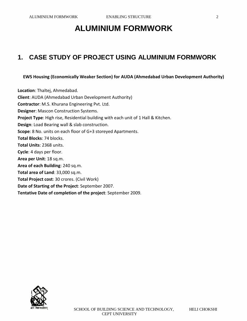
ALUMINIUM FORMWORK
1. CASE STUDY OF PROJECT USING ALUMINIUM FORMWORK
EWS Housing (Economically Weaker Section) for AUDA (Ahmedabad Urban Development Authority)
Location: Thaltej, Ahmedabad.
Client: AUDA (Ahmedabad Urban Development Authority)
Contractor: M.S. Khurana Engineering Pvt. Ltd.
Designer: Mascon Construction Systems.
Project Type: High rise, Residential building with each unit of 1 Hall & Kitchen.
Design: Load Bearing wall & slab construction.
Scope: 8 No. units on each floor of G+3 storeyed Apartments.
Total Blocks: 74 blocks.
Total Units: 2368 units.
Cycle: 4 days per floor.
Area per Unit: 18 sq.m.
Area of each Building: 240 sq.m.
Total area of Land: 33,000 sq.m.
Total Project cost: 30 crores. (Civil Work)
Date of Starting of the Project: September 2007.
Tentative Date of completion of the project: September 2009.

ALUMINIUM FORMWORK ENABLING STRUCTURE 3
SCHOOL OF BUILDING SCIENCE AND TECHNOLOGY, HELI CHOKSHI CEPT UNIVERSITY
TYPICAL FLOOR PLAN

ALUMINIUM FORMWORK ENABLING STRUCTURE 4
SCHOOL OF BUILDING SCIENCE AND TECHNOLOGY, HELI CHOKSHI CEPT UNIVERSITY
2. DETAILS OF THE PROJECT
The Low Cost Housing Units are constructed especially for the Economically Weaker Section of the
society, thus clearing the slum areas in the city & providing houses to the needy people.
The Formwork is provided such that, at any point of time, two of the cluster of buildings will be
under construction.
The speed of construction in this system is at the rate of four days per floor.
The formwork for all the components is erected at one time.
The system forms all of the concrete in the building. i.e. walls, slabs, stairs, window hoods,
cantilevered projections, etc.
The inserts are provided in the formwork at pre-determined locations to allow drainage, water pipe
lines & electrical conduits which will pass through the walls.
The construction cycling is established in such a manner that the concreting of 32 units is completed
in 16 calendar days.
Finishing work is then undertaken which consists of Flooring, Door & Window fixing, Staircase,
Parapet railing, Electrification, Sanitary, etc., which is completed in about 4-5 weeks after the
superstructure is completed.
Due to the Load Bearing Construction & Monolithic Construction possible with Aluminium
Formwork System, the structures are Box Type Structures which are highly resistant to seismic
conditions.

ALUMINIUM FORMWORK ENABLING STRUCTURE 5
SCHOOL OF BUILDING SCIENCE AND TECHNOLOGY, HELI CHOKSHI CEPT UNIVERSITY
3. WHAT IS ALUMINIUM FORMWORK?
The system of aluminum forms has been used widely in the construction of residential units and mass
housing projects. It is fast, simple, adaptable and cost – effective. It produces total quality work which
requires minimum maintenance and when durability is the prime consideration. This system is most
suitable for Indian condition as a tailor–made aluminum formwork for cast–in–situ fully concrete structure.
MODULAR ALUMINIUM FORMWORK
The Aluminium formwork system is precisely-engineered system fabricated in aluminium. Using this
system, all the elements of a building namely, load bearing walls, columns, beams, floor slabs, stairs,
balconies etc can be constructed with cast in place concrete. The resulting structure has a good quality
surface finish and accurate dimensional tolerances. Further, the construction speed is high and the work
can be done in a cost effective manner.
The modular nature of the formwork system allows easy fixing and removal of formwork and the
construction can proceed speedily with very little deviation in dimensional tolerances. Further, the system
is quite flexible and can be easily adapted for any variations in the layout.
The availability of concrete from ready mix concrete facility has augured well for the use of this work
system. However, the proliferation of RMC facilities in the cities in India and the willingness to use
mechanized means of transport and placing of concrete, the use of aluminium formwork system has
received a boost. The quality of the resulting concrete is found to be superior.
Structurally speaking, the adoption of the closed box system using monolithic concrete construction has
been found to be the most efficient alternatives. The stresses in both the concrete and steel are observed
to be much lower even when horizontal forces due to wind or earthquake are taken into consideration.
The formwork system can be used for construction for all types of concrete systems, that is, for a framed
structure involving column beam – slab elements or for box-type structure involving slab-walls combination
The panels of Aluminium Formwork are made from high strength aluminium alloy, with the face or contact
surface of the panel, made up of 4mm thick plate, which is welded to a formwork of specially designed
extruded sections, to form a robust component. The panels are held in position by a simple pin and wedge
arrangement system that passes through holes in the outside rib of each panel. The panel fits precisely,
securely and requires no bracing. The walls are held together with high strength wall ties, while the decks
are supported by beams and props.
Since the equipment is made of aluminium, it has sections that are large enough to be effective, yet light
enough in the weight to be handled by a single worker. Individual workers can handle all the elements
necessary for forming the system with no requirement for heavy lifting equipment or skilled labor. By
ensuring repetition of work tasks on daily basis it is possible for the system to bring assembly line
techniques to construction site and to ensure quality work, by unskilled or semi-skilled workers. Trial
erection of the formwork is carried out in factory conditions which ensure that all components are

ALUMINIUM FORMWORK ENABLING STRUCTURE 6
SCHOOL OF BUILDING SCIENCE AND TECHNOLOGY, HELI CHOKSHI CEPT UNIVERSITY
correctly manufactured and no components are missed out. Also, they are numbered and packed in such a
manner so as to enable easy site erection and dismantling.
LAYOUT OF ALUMINIUM FORMWORK SYSTEM

ALUMINIUM FORMWORK ENABLING STRUCTURE 7
SCHOOL OF BUILDING SCIENCE AND TECHNOLOGY, HELI CHOKSHI CEPT UNIVERSITY
4. COMPONENTS OF ALUMINIUM FORMWORK
The basic element of the formwork is the panel, which is an extruded aluminium rail section, welded to an
aluminium sheet. This produces a lightweight panel with an excellent stiffness to weight ratio, yielding
minimal deflection under concrete loading. Panels are manufactured in the size and shape to suit the
requirements of specific projects.
The panels are made from high strength aluminium alloy with a 4 mm thick skin plate and 6mm thick
ribbing behind to stiffen the panels. The panels are manufactured Once they are assembled they are
subjected to a trial erection in order to eliminate any dimensional or on site problems.
All the formwork components are received at the site whining three months after they are ordered.
Following are the components that are regularly used in the construction.
DECK COMPONENTS
1) Deck Panel: It forms the horizontal surface for casting of slabs. It is built for proper safety of workers.
2) Deck Prop: It forms a V-shaped prop head. It supports the deck and bears the load coming on the
deck panel.
3) Prop Length: It is the length of the prop. It depends upon the length of the slab.

ALUMINIUM FORMWORK ENABLING STRUCTURE 8
SCHOOL OF BUILDING SCIENCE AND TECHNOLOGY, HELI CHOKSHI CEPT UNIVERSITY
4) Deck Mid – Beam: It supports the middle portion of the beam. It holds the concrete.
5) Soffit Length: It provides support to the edge of the deck panels at their perimeter of the room.
6) Deck Beam Bar: It is the deck for the beam. This component supports the deck and beam.
WALL COMPONENTS
1) Wall Panel: It forms the face of the wall. It is an Aluminium sheet properly cut to fit the exact size of
the wall.

ALUMINIUM FORMWORK ENABLING STRUCTURE 9
SCHOOL OF BUILDING SCIENCE AND TECHNOLOGY, HELI CHOKSHI CEPT UNIVERSITY
2) Rocker: It is a supporting component of wall. It is L-shaped panel having allotment holes for stub pin.
3) Kicker: It forms the wall face at the top of the panels and acts as a ledge to support
4) Stub Pin: It helps in joining two wall panels. It helps in joining two joints

ALUMINIUM FORMWORK ENABLING STRUCTURE 10
SCHOOL OF BUILDING SCIENCE AND TECHNOLOGY, HELI CHOKSHI CEPT UNIVERSITY
OTHER COMPONENTS
1) Internal Soffit Corner: It forms the vertical internal corner between the walls and the beams, slabs,
and the horizontal internal cornice between the walls and the beam slabs and the beam soffit.
2) External Soffit Corner: It forms the external corner between the components
3) External Corner: It forms the external corner of the formwork system.
4) Internal Corner: It connects two pieces of vertical formwork pieces at their exterior intersections.

ALUMINIUM FORMWORK ENABLING STRUCTURE 11
SCHOOL OF BUILDING SCIENCE AND TECHNOLOGY, HELI CHOKSHI CEPT UNIVERSITY
5. FORMWORK ASSEMBLY
Aluminium Formwork aims in using modern construction techniques and equipment in all its projects. On
leaving the MASCON factory all panels are clearly labeled to ensure that they are easily identifiable on site
and can be smoothly fitted together using the formwork modulation drawings. All formwork begins at a
corner and proceeds from there.
Wall Assembly Details

ALUMINIUM FORMWORK ENABLING STRUCTURE 12
SCHOOL OF BUILDING SCIENCE AND TECHNOLOGY, HELI CHOKSHI CEPT UNIVERSITY
SEQUENCE ADAPTED FOR PIN & WEDGE FIXING SYSTEM

ALUMINIUM FORMWORK ENABLING STRUCTURE 13
SCHOOL OF BUILDING SCIENCE AND TECHNOLOGY, HELI CHOKSHI CEPT UNIVERSITY
ELEMENTS DEMARCATED IN PLAN

ALUMINIUM FORMWORK ENABLING STRUCTURE 14
SCHOOL OF BUILDING SCIENCE AND TECHNOLOGY, HELI CHOKSHI CEPT UNIVERSITY
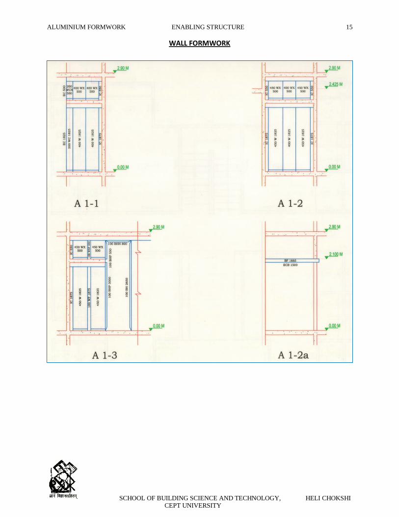
6. ERECTION OF FORMWORK AT SITE
Vertical Formwork
Wall panels are erected, in both directions, from internal corners.
Wall panels are connected using standard pins and wedges.
The wall ties and sleeves are also installed at this stage.
On completion of the wall panels, the top panels are added.
The bottom of the wall panels are lined and fixed in position using timber battens at alternative joints.
The vertically of the walls are checked.
Horizontal Formwork
Soffit lengths and soffit corners are pinned to the top of the top panels and beam sides.
A deck panel is pinned to the corners.
This gives the line of the deck beams (mid beams and end beams).
The mid beams and end beams are connected to deck prop heads and pinned to the corner deck
panel.
The remainder of the deck panels is then dropped into position between the soffit lengths and deck
beams.
Kicker Formwork
A kicker channel is fixed to the top of the external wall panels.
Two sets of kickers adopted as one set remains in place after casting to connect the next lift of wall
panels.
Kickers are checked for alignment prior to casting.
ALUMINIUM FORMWORK ENABLING STRUCTURE 15
SCHOOL OF BUILDING SCIENCE AND TECHNOLOGY, HELI CHOKSHI CEPT UNIVERSITY
WALL FORMWORK

ALUMINIUM FORMWORK ENABLING STRUCTURE 16
SCHOOL OF BUILDING SCIENCE AND TECHNOLOGY, HELI CHOKSHI CEPT UNIVERSITY
WALL FORMWORK

ALUMINIUM FORMWORK ENABLING STRUCTURE 17
SCHOOL OF BUILDING SCIENCE AND TECHNOLOGY, HELI CHOKSHI CEPT UNIVERSITY
DECK FORMWORK

ALUMINIUM FORMWORK ENABLING STRUCTURE 18
SCHOOL OF BUILDING SCIENCE AND TECHNOLOGY, HELI CHOKSHI CEPT UNIVERSITY
STAIRCASE FORMWORK

ALUMINIUM FORMWORK ENABLING STRUCTURE 19
SCHOOL OF BUILDING SCIENCE AND TECHNOLOGY, HELI CHOKSHI CEPT UNIVERSITY
7. SEQUENCE FOR ERECTING FORMWORK FOR CONSTRUCTION
The Aluminium formwork is designed using the most economical assortment of panel sizes with the help of
the state-of-the art design software. The use of the software along with the experience and skill of the
designers ensures an efficient construction process by incorporating the optimum assembly procedures,
economical panel selection and ultimately minimizing capital and operational costs.
Erection of Platform
Striking of formwork

ALUMINIUM FORMWORK ENABLING STRUCTURE 20
SCHOOL OF BUILDING SCIENCE AND TECHNOLOGY, HELI CHOKSHI CEPT UNIVERSITY
Positioning of Platform
Removal of Kicker

ALUMINIUM FORMWORK ENABLING STRUCTURE 21
SCHOOL OF BUILDING SCIENCE AND TECHNOLOGY, HELI CHOKSHI CEPT UNIVERSITY
8. STRIKING OF FORMWORK AT SITE
Vertical Formwork
Vertical Formwork can normally be struck after 12 hours.
After removal of battens and sufficient pins and wedges.
Specialist panel pullers are used to strike the wall panels.
After cleaning, the panels are moved to the next section for immediate oiling and erection.
The wall ties and sleeves are removed at this stage.
Where panels are being moved vertically up, a slot opening nominally 650 mm x 100 mm is formed in
the slab.
After the movement of the formwork, the opening is concreted.
Deck Formwork
Deck formwork can normally be struck after 36 hours.
The striking of the deck begins with the removal of a section of end beam followed by the deck panels.
End beams and mid beams are stripped leaving the prop head in constant contact with the concrete
slab.
9. SALIENT FEATURES OF THE ALUMINIUM FORMWORK CONSTRUCTION SYSTEM
ADAPTABILITY & VERSATILITY
The Architect or engineer is not required to change the building’s layout or structural design to suit the
formwork system.
The only requirement of the Aluminium Formwork system is that the dimensions of the building are to
be rounded to the nearest 25 mm.
All of the Aluminium Formwork Equipment is handheld & majority of the equipment comprises of
standard pieces of formwork.
As a result, many of the standard size formwork components used for one building layout can be
reused on a different building layout, which can be as high as 70% depending upon the building
layouts.
SIMPLICITY – PIN AND WEDGE SYSTEM
The panels are held in position by a simple pin and wedge system that passes through holes in the
outside rib of each panel.
The panels fit precisely, simply and securely and require no bracing.

ALUMINIUM FORMWORK ENABLING STRUCTURE 22
SCHOOL OF BUILDING SCIENCE AND TECHNOLOGY, HELI CHOKSHI CEPT UNIVERSITY
Buildings can be constructed quickly and easily by unskilled labour with hammer being the only tool
required.
As the erection process is manual, tower cranes are not required.
The result is a typical 4 to 5 day cycle for floor – to – floor construction.
EFFICIENT – QUICK STRIP PROP HEAD
One of the principal technical features which enables this aped to be attained using a single set of
formwork panel is the unique V shaped a prop head which allows the ‘quick strip’ to take place whilst
leaving the propping undisturbed. The deck panels can therefore be resumed immediately.
STRUCTURAL DESIGN
The structural design of the building can produce considerable cost saving up to 15% to 20%.
The Aluminium Formwork System is admirably suited to Load Bearing Wall Construction, while
Traditional Formwork consisting of Plywood and Timber is not, due to high pressures of fresh concrete
in the walls.
Although there is 50% more concrete and double area of formwork in load bearing wall construction, it
is compensated by reduction of reinforcement steel, absence of infill walls and lower cost of finishing
to the wall, foundation costs are almost halved & there is no need of ground beams.
The wall thickness in Column & Beam designed structures is of around 230 mm. This compared to the
Aluminium Formwork system of Load Bearing Walls have concrete walls of thickness 100 mm which
results in the increase in usable floor space to about 8% compared to Column & Beam system.
With load bearing wall structural design, all the walls in a room will be reinforced concrete. Since this is
a “Box Type” design, the walls give support to the super structure in two directions & therefore, it is
more resistant to seismic conditions than the Traditional Beam and Column design.
SPEED OF CONSTRUCTION
The Aluminium Formwork System routinely constructs the superstructure of multi-storey building at a
standard rate of four days per floor – regardless of floor area size.
Each of floor level is broken into four sections and all of the concrete in each floor section is poured
monolithically in one working day.
With one set of Aluminium Formwork equipments in operation, the superstructure of a four storeyed
building will be completed in 16 calendar days.
For such a project, instead of concreting one quarter of floor every day as in case on conventional
methods, one house or unit is concreted in every days work.
This unique & highly efficient daily cycle of work ensures that all trades (i.e. formwork, reinforcement,
concreting, etc.) work in a united and predetermined manner.
Thus the building is constructed at maximum efficiency & speed with minimum wastage of materials.

ALUMINIUM FORMWORK ENABLING STRUCTURE 23
SCHOOL OF BUILDING SCIENCE AND TECHNOLOGY, HELI CHOKSHI CEPT UNIVERSITY
QUALITY OF CONSTRUCTION
Precision in the fabrication of the Aluminium Formwork equipment results in the accurate, consistent
forming of the concrete, floor after floor, conforming to the most exacting standards of quality and
accuracy.
The formwork accuracy also allows plumbing and electrical fittings to be fabricated with the certain
knowledge that there will be an exact fit when assembled.
The smooth surface of the finish concrete walls reduces the need for the costly plastering.
The dimensions are accurately maintained throughout the structure irrespective of the speed or labour
employed.
DURABILITY
Using Aluminium Formwork Technology, all of the concrete in the walls and floor slabs is poured
together in one operation which results in the monolithic reinforced concrete structure without any
construction joints at the intersections.
Also if there is any sunk part, it is also concreted along with the slab and walls. Thus, there are no
construction joints in the sunk area, and no problem of leaking joints.
There is no plastering required in Aluminium Formwork system, which in case of conventional system
breaks away (i.e. cracks), which enables structure that will last for many years.
All of the aluminium used in the equipment is of high strength alloy which means that the aluminium
has not only high tensile strength, but is also very hard.
The aluminium formwork does not rust or corrode like steel; therefore, it has a longer life span than
steel.
Thus the aluminium formwork is very durable and can be reused hundreds of time with little
maintenance.

ALUMINIUM FORMWORK ENABLING STRUCTURE 24
SCHOOL OF BUILDING SCIENCE AND TECHNOLOGY, HELI CHOKSHI CEPT UNIVERSITY
10. SPEED OF CONSTRUCTION
Work Cycle:
Aluminium Formwork is a system for scheduling & controlling the work of other connected construction
trades such as steel reinforcement, concrete placements & electrical inserts. The work at site hence follows
a particular sequence. The work cycle begins with the deshuttering of the panels. It takes about 12-15 hrs.
It is followed by positioning of the brackets & platforms on the level. It takes about 10-15 hrs
simultaneously.
The deshuttered panels are lifted & fixed on the floor. The activity requires 7-10 hrs. Kicker & External
shutters are fixed in 7 hrs. The wall shutters are erected in 6-8 hrs One of the major activity reinforcement
requires 10-12 hrs. The fixing of the electrical conduits takes about 10 hrs and finally pouring of concrete
takes place in these.
This is a well synchronized work cycle for a period of 7 days. A period of 10-12 hrs is left after concreting for
the concrete to gain strength before the beginning of the next cycle. This work schedule has been planned
for 1010-1080 sq m of formwork with 72-25 cu.m. of concreting & approximate reinforcement.
The formwork assembling at the site is a quick & easy process. On leaving the MASCON factory all panels
are clearly labeled to ensure that they are easily identifiable on site and can be smoothly fitted together
using formwork modulation drawings. All formwork begins from corners and proceeds from there.
The system usually follows a four day cycle:
Day 1: The first activity consists of erection of vertical reinforcement bars and one side of the vertical
formwork for the entire floor or a part of one floor.
Day 2: The second day activity involves erection of the second side of the vertical formwork and formwork
for the floor
Day 3: Fixing reinforcement bars for floor slabs and casting of walls and slabs.
Day 4: Removal of vertical form work panels after 24hours, leaving the props in place for 7 days and floor
slab formwork in place for 2.5 days.

ALUMINIUM FORMWORK ENABLING STRUCTURE 25
SCHOOL OF BUILDING SCIENCE AND TECHNOLOGY, HELI CHOKSHI CEPT UNIVERSITY
WORK CYCLE

ALUMINIUM FORMWORK ENABLING STRUCTURE 26
SCHOOL OF BUILDING SCIENCE AND TECHNOLOGY, HELI CHOKSHI CEPT UNIVERSITY
11. COMPARISON BETWEEN DIFFERENT FORMWORK SYSTEMS
Comparison between different formwork systems
Sr.
No. Description
Conventional
Formwork
Stem
L&T DOKA
Formwork System
Tunnel form
System Aluform
System
1 Type of
construction
RCC framed
Construction
Construction
RCC shear
Wall
Construction
Cast-in-situ
Cellular
Construction
2 Main formwork
Materials
Plywood and
Silver wood
Timber and
Steel Mild steel Aluminium
3 Speed of
construction
Eight days
Cycle per floor
Of 150 m2
Six days cycle
Per floor
Of 150 2
Three days
Cycle per floor
Of 150 m2
Four days cycle
Per floor
Of 150 m2
4
Quality of
surface
Finish
Poor Uniformly
Good quality
Excellent Plastering
is
Not required
Excellent;
Plastering is not
Required
5 Reuse value Wood - 20
Steel- 100
H-beams - 80
Steel-150 800 300
6
Formwork
material
Cost
Plywood - Rs.40/ Sq. ft.
Silver wood -
Rs. 230 Cu.ft
Timber-Rs 350/Cu.ft.
Steel parts -
Rs. 60 / Kg
Rs. 6500 / m
Of shuttering area
Rs. 10,000/ m
Of shuttering
Area
7
Unit cost of
System
per sq.ft of
shuttering
area per use
Rs. 5.64
Rs. 3.80
Rs 1.50 Rs. 3.25
8
Application or
the
System
Minor
Construction
works
e.g. residential
buildings
All major Applications
e g factory buildings,
water tanks
For repetitive
Architectural
layouts e.g mass
housing
Mostly useful
For mass
Housing

ALUMINIUM FORMWORK ENABLING STRUCTURE 27
SCHOOL OF BUILDING SCIENCE AND TECHNOLOGY, HELI CHOKSHI CEPT UNIVERSITY
12. MERITS OF ALUMINIUM FORMWORK
Its erection does not depend upon heavy lifting equipments.
It can be handled by unskilled labors.
Fast construction is assured and is particularly suitable for large magnitude construction of
respective nature at one project site.
Construction carried out by this system has exceptionally good quality with accurate dimensions for
all openings to receive windows and doors, right angles at meeting points of wall to wall, wall to
floor, wall to ceiling, etc, concrete surface finishes are good to receive painting directly without
plaster.
System components are durable and can be used several times without sacrificing the quality or
correctness of dimensions and surface.
Monolithic construction of load bearing walls and slabs in concrete produces structurally superior
quality with very few constructions joined compared to the conventional column and beam slabs
construction combined with filter brick work or block work subsequently covered by plaster.
In view of the four – day cycle of casting the floor together with all slabs as against 14 to 20 – day
cycle in the conventional method, completed RCC structure is available for subsequent finish trades
much faster, resulting in a saving of 10 to 15 days per floor in the overall completion period.
As all the walls are cast monolithic and simultaneously with floor slabs requiring no further plasters
finish. Therefore the time required in the conventional method for construction of walls and
plastering is saved.
As fully completed structural frame is made available in one stretch for subsequent – finishing
items, uninterrupted progress can be planned ensuring, continuity in each trade, thereby providing
as cope for employing increased labor force on finishing item.
As the system establishes a kind of “Assembly line production” phase – wise completion in desired
groups of buildings can be planned to achieve early utilization of the buildings.
13. DEMERITS OF ALUMINIUM FORMWORK
Even though there are so many advantages of Aluminium Formwork the limitations cannot be ignored.
However the limitations do not pose any serious problems. They are as follows:
Because of small sizes finishing lines are seen on the concrete surfaces.
Concealed services become difficult due to small thickness of components.
It requires uniform planning as well as uniform elevations to be cost effective.
Modifications are not possible as all members are caste in RCC.
Large volume of work is necessary to be cost effective i.e. at least 200 repetitions of the forms
should be possible at work.

ALUMINIUM FORMWORK ENABLING STRUCTURE 28
SCHOOL OF BUILDING SCIENCE AND TECHNOLOGY, HELI CHOKSHI CEPT UNIVERSITY
The formwork requires number of spacer, wall ties etc. which are placed @ 2 feet c/c; these create
problems such as seepage, leakages during monsoon.
Due to box-type construction shrinkage cracks are likely to appear.
Heat of Hydration is high due to shear walls.
14. REMEDIAL MEASURES
In external walls, ties used in shutter connection create holes in wall after deshuttering. These may
become a source of leakage if care is not taken to grout the holes.
Due to box-type construction shrinkage cracks are likely to appear around door and window
openings in the walls. It is possible to minimize these cracks by providing control strips in the
structure which could be concreted after a delay of about 3 to 7 days after major concreting.
The problem of cracking can be avoided by minimizing the heat of hydration by using flyash.
15. CONCLUSIONS AND INFERENCES
The task of housing due to the rising population of the country is becoming increasingly monumental. In
terms of technical capabilities to face this challenge, the potential is enormous; it only needs to be
judiciously exploited.
Civil engineers not only build but also enhance the quality of life. Their creativity and technical skill help to
plan, design, construct and operate the facilities essential to life. It is important for civil engineers to gain
and harness the potent and versatile construction tools.
Traditionally, construction firms all over the world have been slow to adopt the innovation and changes.
Contractors are a conservative lot. It is the need of time to analyze the depth of the problem and find
effective solutions. Aluminium Formwork serves as a cost effective and efficient tool to solve the problems
of the mega housing project all over the world. Aluminium Formwork aims to maximize the use of modern
construction techniques and equipments on its entire project.
I thus infer that Aluminium Formwork construction is able to provide high quality construction at
unbelievable speed and at reasonable cost. This technology has great potential for application in India to
provide affordable housing to its rising population.
Thus it can be concluded that quality and speed must be given due consideration with regards to economy.
Good quality construction will never deter to projects speed nor will it be uneconomical. In fact time
consuming repairs and modification due to poor quality work generally delay the job and cause additional
financial impact on the project. Some experts feel that housing alternatives with low maintenance
requirements may be preferred even if at the slightly may preferred even if at the higher initial cost.

ALUMINIUM FORMWORK ENABLING STRUCTURE 29
SCHOOL OF BUILDING SCIENCE AND TECHNOLOGY, HELI CHOKSHI CEPT UNIVERSITY
PHOTOGRAPHS
WALL REINFORCEMENT
WALL FORMWORK
DECK REINFORCEMENT

ALUMINIUM FORMWORK ENABLING STRUCTURE 30
SCHOOL OF BUILDING SCIENCE AND TECHNOLOGY, HELI CHOKSHI CEPT UNIVERSITY
DECK FORMWORK
KICKER FORMWORK

ALUMINIUM FORMWORK ENABLING STRUCTURE 31
SCHOOL OF BUILDING SCIENCE AND TECHNOLOGY, HELI CHOKSHI CEPT UNIVERSITY

ALUMINIUM FORMWORK ENABLING STRUCTURE 32
SCHOOL OF BUILDING SCIENCE AND TECHNOLOGY, HELI CHOKSHI CEPT UNIVERSITY
STAIRCASE REINFORCEMENT
STAIRCASE FORMWORK
FIXING OF PIN & WEDGE

ALUMINIUM FORMWORK ENABLING STRUCTURE 33
SCHOOL OF BUILDING SCIENCE AND TECHNOLOGY, HELI CHOKSHI CEPT UNIVERSITY
SURFACE FINISHING
Related Documents