www.zetec.com Principles and Principles and Application Application of the TOFD of the TOFD UT Technique UT Technique Advanced NDT Training Programme, November 2004

Welcome message from author
This document is posted to help you gain knowledge. Please leave a comment to let me know what you think about it! Share it to your friends and learn new things together.
Transcript

www.zetec.com
Principles and Application Principles and Application of the TOFD UT of the TOFD UT
TechniqueTechnique
Advanced NDT Training Programme,November 2004

2
• The Diffraction Phenomenon
• Conventional Use of Diffraction
• Principles of TOFD
• Practical Implementation
• Codes and Standards
• Advantages and Limitations of TOFD
• Zetec Solution
• Demonstration
Time of Flight Diffraction TechniqueTime of Flight Diffraction Technique
3
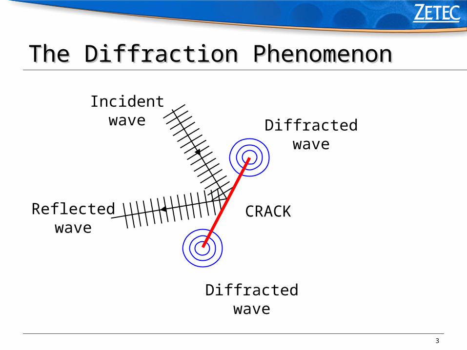
The Diffraction PhenomenonThe Diffraction Phenomenon
CRACK
Diffractedwave
Diffractedwave
Incidentwave
Reflectedwave

4
The Diffraction PhenomenonThe Diffraction Phenomenon• Huygens’ principle:
Each point of object act as new source of spherical waves
incoming wave makesobject vibrate

5
The Diffraction PhenomenonThe Diffraction Phenomenon
All directions
Low energy
Dependent of incidence angle
CRACK
Diffractedwave
Diffractedwave
Incidentwave
Reflectedwave

6
The Diffraction Phenomenon: SummaryThe Diffraction Phenomenon: Summary
• Incident wave reflected wave
• Incident wave diffracted waves emitted by defect
boundaries
• Cylindrical/spherical waves emitted in all directions
• Amplitude typically 10 to 20 dB below specular (direct)
reflection

7
• The Diffraction Phenomenon
• Conventional Use of Diffraction
• Principles of TOFD
• Practical Implementation
• Codes and Standards
• Advantages and Limitations of TOFD
• Zetec Solution
• Demonstration
Time of Flight Diffraction TechniqueTime of Flight Diffraction Technique

8
Slot or crack
• Pulse-echo tip diffraction method (satellite-pulse observation technique)
Time
Amplitude
2
2
Tip diffraction1
1
Corner reflectionTOF
Angle
TOF, ANGLE & VELOCITY HEIGHT
Conventional Use of Diffraction Conventional Use of Diffraction

9
• The Diffraction Phenomenon
• Conventional Use of Diffraction
• Principles of TOFD
• Practical Implementation
• Codes and Standards
• Advantages and Limitations of TOFD
• Zetec Solution
• Demonstration
Time of Flight Diffraction TechniqueTime of Flight Diffraction Technique

10
Transmitter Receiver
Lateral wave
Upper tip
Lower tip
Back-wall reflection
Principles of TOFD Principles of TOFD

11
Principles of TOFD : Basic Set-UpPrinciples of TOFD : Basic Set-Up
• 2 probes (transmitter, receiver)
• Wide beam, Long. waves
• Symmetrically to the weld center
• Lateral wave (sub-surface LW)
• Back-wall reflection
• Diffraction signal detection (high receiver sensitivity)

12
Transmitter ReceiverLateral wave
LW
Upper tip Lower tip
Back-wall reflection
BW
Principles of TOFD: A-Scan SignalPrinciples of TOFD: A-Scan Signal

13
Lateral wave
LW
Upper tip Lower tip
Back-wall reflection
BW+
-
+
-
Principles of TOFD: Phase DifferencesPrinciples of TOFD: Phase Differences

14
Principles of TOFD: Principles of TOFD: Flaw Depth MeasurementFlaw Depth Measurement
• Based upon:
• Accurate flight-time measurements
• Simple trigonometric equations
• Achieved by UltraVision software

15
S
Initial pulse
Transmitter ReceiverS
d
LW BW
t0 t0
t
Principles of TOFD: Principles of TOFD: Flaw Depth MeasurementFlaw Depth Measurement

16
Transmitter ReceiverS S
d
t0 t0
0
22
.2.2
tc
dSt
Principles of TOFD: Principles of TOFD: Flaw Depth MeasurementFlaw Depth Measurement

17
c
TStt B
22
0 2.2
LB tt
STSc
.22 22
Transmitter ReceiverS S
d
t0 t0
PCS
T
SPCS .2 (Probe Center Separation)
c
Stt L
.2.2 0
Principles of TOFD: Principles of TOFD: Flaw Depth MeasurementFlaw Depth Measurement

18
Transmitter ReceiverS S
d
t0 t0
220
2
.2.2
Sttc
d
Principles of TOFD: Principles of TOFD: Flaw Depth MeasurementFlaw Depth Measurement

19
Transmitter Receiver2S
d1
12 ddh
d2
Since only flight-time measurements are used to calculate the height, very accurate height sizing is possible. In practice, 1 mm accuracy on real cracks is
achievable (0.1 mm on artificial reflectors)
Principles of TOFD: Principles of TOFD: Flaw Height MeasurementFlaw Height Measurement

20
Principles of TOFD: Principles of TOFD: Flaw CharacterizationFlaw Characterization
• In most cases, no correlation between amplitude and
importance of flaw
• Typical signature for each flaw type
• Interpretation of phase variations
• (Partial) loss and/or variation of LW, BW : indication for
surface-breaking cracks

21
Transmitter Receiver
Crack tip
Back-wall reflection
BW
Lateral wave is blocked
No lateral wave
Near-Surface Breaking Cracks Near-Surface Breaking Cracks

22
Transmitter ReceiverLateral wave
LW
Tip
Back-wall echo blocked
No back-wall echo
Far-Surface Breaking Cracks Far-Surface Breaking Cracks

23
(lack of inter-run fusion, lamination)(lack of inter-run fusion, lamination)Transmitter Receiver
Lateral wave
LW
Back-wall reflection
BW
Reflected signal
Reflected signal
Horizontal Planar Defects Horizontal Planar Defects

24
Principles of TOFD : SummaryPrinciples of TOFD : Summary
• Two probes, pitch & catch configuration
• Longitudinal waves
• Lateral wave (LW), back-wall echo (BW)
• Diffracted signals from defect edges
• Phase difference between tip & bottom signals
• Flaw depth and height are determined with high accuracy, based on
flight-time calculations
• Not based on amplitude

25
• The Diffraction Phenomenon
• Conventional Use of Diffraction
• Principles of TOFD
• Practical Implementation
• Codes and Standards
• Advantages and Limitations of TOFD
• Zetec Solution
• Demonstration
Time of Flight Diffraction TechniqueTime of Flight Diffraction Technique

26
Practical ImplementationPractical Implementation
• General Set-Up
• Probe Considerations
• Data Processing and Presentation
• Manipulator
• Scanning Types

27
Position encoder
Magnetic wheels
UT probes
Weld
Z-Scan UT
Scanner
Probes
Z-Scan UT
Practical Implementation: Practical Implementation: General Set-UpGeneral Set-Up

28
• Propagation mode and angle
• Time domain resolution
• Beam characteristics
• Synthesis table
Practical Implementation: Practical Implementation: Probe ConsiderationsProbe Considerations

29
• Longitudinal Waves :
• Fastest waves, easy interpretation, no confusion with mode
converted waves (SW)
• Relation between signal phase and signal origin (tip, bottom)
• Stronger diffracted signals
Propagation ModePropagation Mode

30
• Relation between probe angle and amplitude of
generated diffracted signals
• Precision on flaw height measurement
• Inspected volume coverage
Compromise
In many cases 60 degrees is a good compromise
Probe AngleProbe Angle

31
Time Domain ResolutionTime Domain Resolution
• Measurements based on flight-time
• Requirement for short ultrasonic pulses (importance of
UT equipment : probe excitation parameters)
• Higher frequencies than standard UT (pulse-echo)
examinations

32
Beam CharacteristicsBeam Characteristics
• Wide beam to cover volume to be inspected
• High frequency small probe aperture lower
sensitivity
Compromise
Aperture
Beam Beam

33
Probe Selection TableProbe Selection Table
Wall-thickness
(mm)
Frequency
(MHz)
Diameter
(mm)
Angle
(°)
t 15 7.5 / 10 / 15 6 60 / 70
15 < t 35 7.5 / 10 6 60
35 < t 100 + 5 10 30 / 45 / 60

34
• Processing of all non-rectified signals requires powerful
computing capability
• Mass amount of complex signals requires a simple way
to visualize the data
• Calculations require easy to use tools
Practical Implementation: Practical Implementation: Data ProcessingData Processing
35
• Huge amount of data
• Need for phase information
Practical Implementation: Practical Implementation: Data ProcessingData Processing

36
Practical Implementation: Practical Implementation: PresentationPresentation
White+
Black-
Amplitude
Time
Time
One A-scan picture is replaced by one gray-coded line

37
B-scan
Near-surface Back-wall
A-scanLW
BW
Practical Implementation: Practical Implementation: PresentationPresentation

38
Practical Implementation: Practical Implementation: PresentationPresentation

39
• Flaw depth is expressed by a complex mathematical
equation
• Basic tools are needed for
• Initial calibration
• Performing depth and height measurements
Practical Implementation: Practical Implementation: PresentationPresentation

40
A-scan
B-scan
PCSt0 t0
Tc
LW BW
PCS, thickness, sound velocity, probe delay, lateral wave or back-wall flight-time
Not all parameters have to be known
Practical Implementation: Practical Implementation: CalibrationCalibration

41
Cursors
Build-in calculator
t1,t2 d1, d2 and h are automatically calculated
A-scan
B-scan
c
d1d1h
t1 t2
l
P
Practical Implementation: Practical Implementation: Measurement ToolsMeasurement Tools

42
Very simple to use
Magnetic wheels
Manual (or motorized)
One axis position encoding
Basically 2 probes, must be able to hold more (PE)
Easy and precise adjustment of probe separation is needed
Position encoder
Magnetic wheels
UT probes
Weld
Practical Implementation: Practical Implementation: ManipulatorManipulator

43
• Non-parallel, along defect axis
• Parallel, across defect axis
Practical Implementation: Practical Implementation: Scanning TypesScanning Types

44
Weld
Non-parallelscan
Perpendicularto probe beam direction
DetectionInitial sizing
High speed inspection
Most frequently used for weld inspection
Scanning Types: Scanning Types: Non-Parallel ScanNon-Parallel Scan

45
• Limitations :
• Defect depth measurement only accurate when probes are
symmetrically positioned with regard to defect
• Uncertainty on lateral position of defect results in height sizing
error
Scanning Types: Scanning Types: Non-Parallel ScanNon-Parallel Scan

46
Influence of Defect Position UncertaintyInfluence of Defect Position Uncertainty
Transmitter ReceiverS S
d
t0 t0
x

47
Influence of Defect Position UncertaintyInfluence of Defect Position Uncertainty
Transmitter ReceiverS S
t2t1
Constant timelocus
(t1+t2=ct)
dmin dmax
In practice:Maximum error on absolute depth smaller than 10%Height sizing error on internal (small) defect is negligible.Caution for small defects situated at the back-wall.

48
Parallel ScanParallel Scan
Weld
Parallel scan
Parallelto probe beam direction
Accurate sizing and positioning

49
Back-wallB-scan
Lateral waveThis type of
scan yields a typical inverted
parabola
Flight-time will be minimal when probes are positioned symmetrically over defect
Parallel ScanParallel Scan

50
Parallel Scan : LimitationsParallel Scan : Limitations
• Weld inspection: weld cap often reduces or makes
impossible the extent of the scan.

51
Practical Implementation : SummaryPractical Implementation : Summary
• Simple, light weight set-up
• High speed inspection
• L-waves, wide beam, high frequency probes
• Data visualization and analysis tools
• Two scan types : non-parallel, parallel

52
• The Diffraction Phenomenon
• Conventional Use of Diffraction
• Principles of TOFD
• Practical Implementation
• Codes and Standards
• Advantages and Limitations of TOFD
• Zetec Solution
• Demonstration
Time of Flight Diffraction TechniqueTime of Flight Diffraction Technique

53
Codes and standardsCodes and standards
• British Standard
• European Norm

54
British StandardBritish Standard
• Guide to calibration and setting-up of TOFD technique,
BS 7706 (1993)
• Detailed document with useful practical guidelines for
setting up TOFD examination
• Guide for interpretation of TOFD data
• Examples of typical weld defects

55
CENCEN
• TOFD technique as a method for defect detection and
sizing, CENV 583-6 (1997)
• Preliminary standard
• Recommended probe parameters with regard to different
wall thicknesses (frequency, crystal size, nominal angle)

56
• The Diffraction Phenomenon
• Conventional Use of Diffraction
• Principles of TOFD
• Practical Implementation
• Codes and Standards
• Advantages and Limitations of TOFD
• Zetec Solution
• Demonstration
Time of Flight Diffraction TechniqueTime of Flight Diffraction Technique
57
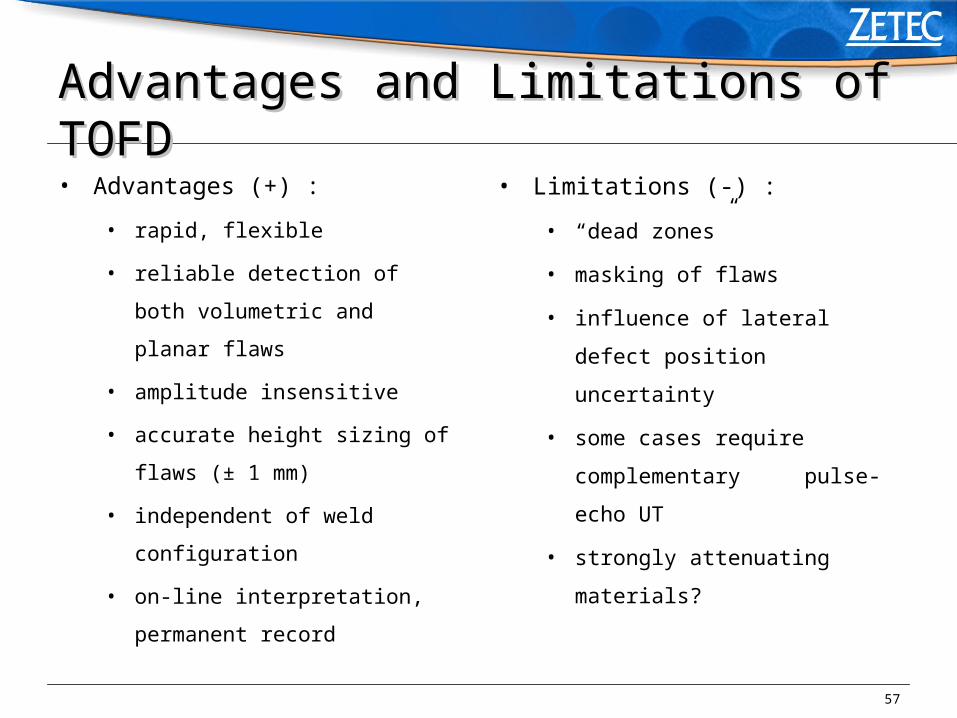
• Advantages (+) :
• rapid, flexible
• reliable detection of both
volumetric and planar flaws
• amplitude insensitive
• accurate height sizing of flaws (±
1 mm)
• independent of weld configuration
• on-line interpretation, permanent
record
• Limitations (-) :
• “dead zones”
• masking of flaws
• influence of lateral defect position
uncertainty
• some cases require
complementary pulse-echo UT
• strongly attenuating materials?
Advantages and Limitations of TOFDAdvantages and Limitations of TOFD

58
A-scan
D-scan
LW BW
Uppersurface
Back-wall
Dead Zones Dead Zones

59
• The Diffraction Phenomenon
• Conventional Use of Diffraction
• Principles of TOFD
• Practical Implementation
• Codes and Standards
• Advantages and Limitations of TOFD
• Zetec Solution
• Demonstration
Time of Flight Diffraction TechniqueTime of Flight Diffraction Technique

60
Zetec SolutionZetec Solution
• TOFD : YES
• BUT : let’s also benefit from the advantages offered by
the standard Pulse-echo (PE) technique
• SOLUTION: perform TOFD and PE simultaneously,
without reducing inspection speed

61
The Z-Scan UT system allows for simultaneous
acquisition and analysis of TOFD and PE
TOFDPE 45 SW PE 60 SW
Zetec SolutionZetec Solution

62
Zetec SolutionZetec Solution
Z-Scan UT
&
UltraVision
Software

63
• Portable system (11.7 kg)
• Multi channel data acquisition and display
• Real-time averaging
• UltraVision software supports simultaneous Pulse-Echo and
TOFD examination
• Calibration for true depth on flat and cylindrical surfaces
• Parabolic cursors for improved length sizing
• Lateral wave straightening and removal for TOFD
• SAFT processing
Zetec SolutionZetec Solution

64
• The Diffraction Phenomenon
• Conventional Use of Diffraction
• Principles of TOFD
• Practical Implementation
• Codes and Standards
• Advantages and Limitations of TOFD
• Zetec Solution
• Demonstration
Time of Flight Diffraction TechniqueTime of Flight Diffraction Technique

65
DemonstrationDemonstration
• General description
• System calibration
• Demonstrations of acquisition and analysis
Related Documents