Soportería René Becerra Matías

Welcome message from author
This document is posted to help you gain knowledge. Please leave a comment to let me know what you think about it! Share it to your friends and learn new things together.
Transcript

Soportería
René Becerra Matías
2
Soportería
Identificar las características de los soportes para cañerías.
Softwares available for flexibility calculation/stress analysis
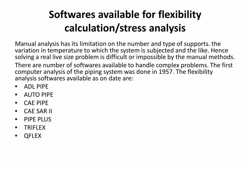
Manual analysis has its limitation on the number and type of supports. the variation in temperature to which the system is subjected and the like. Hence solving a real live size problem is difficult or impossible by the manual methods. There are number of softwares available to handle complex problems. The first computer analysis of the piping system was done in 1957. The flexibility analysis softwares available as on date are: • ADL PIPE • AUTO PIPE • CAE PIPE • CAE SAR II • PIPE PLUS • TRIFLEX • QFLEX
Softwares available for flexibility calculation/stress analysis
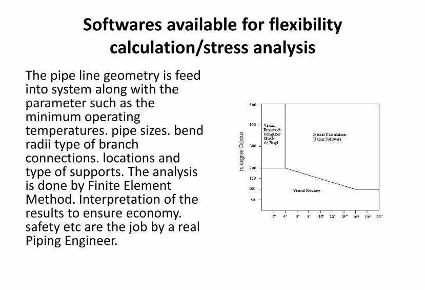
The pipe line geometry is feed into system along with the parameter such as the minimum operating temperatures. pipe sizes. bend radii type of branch connections. locations and type of supports. The analysis is done by Finite Element Method. Interpretation of the results to ensure economy. safety etc are the job by a real Piping Engineer.

Data required for flexibility calculations
The following data will be required for the flexibility calculations if it is carried out manually or by the use of software. It is therefore prudent to have this ready before starting. • The direction of coordinates is fixed as below: • Code of Practice • Basic Material of Construction of Pipe • Ambient / Installation temperature • Number of Thermal Cases • Flexibility Temperature (See Note) • Design Pressure • Outside diameter of Pipe • Type of construction of pipe • Nominal Thickness of Pipe • Manufacturing tolerance • Corrosion allowance • Pipe Weight • Insulation Weight • Specific Gravity of Contents • Young’s Modulus at Ambient/Installation Temperature • Young’s Modulus at Flexibility Temperature • Thermal Expansion at Flexibility Temperature • Allowable stress at Ambient/ Installation temperature • Allowable stress at flexibility temperature • Bend radius and type of bend • Branch connection type • Weight of attachments - Valves and Specialties • Terminal movements with directions
The basic parameters
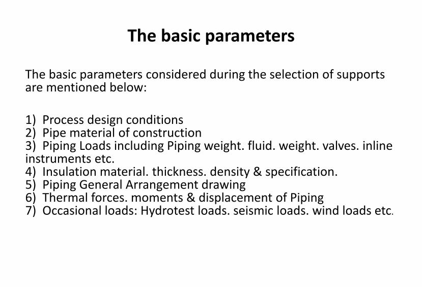
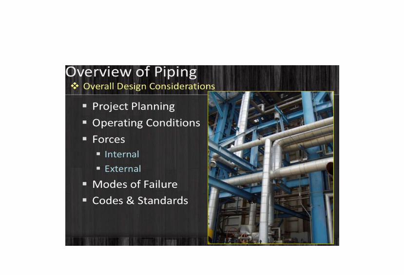
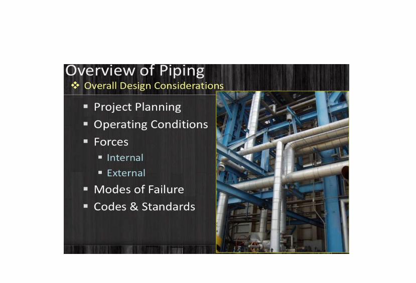
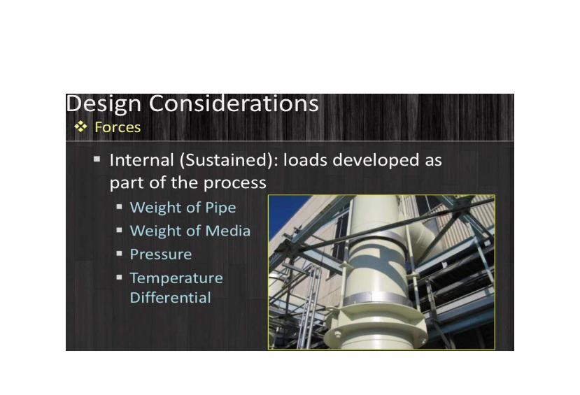
The basic parameters considered during the selection of supports are mentioned below: 1) Process design conditions 2) Pipe material of construction 3) Piping Loads including Piping weight. fluid. weight. valves. inline instruments etc. 4) Insulation material. thickness. density & specification. 5) Piping General Arrangement drawing 6) Thermal forces. moments & displacement of Piping 7) Occasional loads: Hydrotest loads. seismic loads. wind loads etc.

The objective of support design
As per clause 321.1.1 of code ASME B31.1. the objective of support design is as below: The layout and the design of the piping and its supporting elements shall be directed towards preventing the following 1. Piping stresses in excess of those permitted in the code. 2. Leakage at joints. 3. Excessive thrust and moments on connected equipment (such as pumps and turbine). 4. Excessive stresses in the supporting (or restraining) elements. 5. Resonance with impose fluid induced vibrations. 6. Excessive interference with thermal expansion and contraction in a piping system. which is otherwise adequately flexible. 7. Unintentional disengagement of piping from its supports. 8. Excessive piping sag in systems requiring drainage slope. 9. Excessive distortion or rag of piping (e.g. thermo plastics) subject to creep under conditions of repeated thermal cycling. 10. Excessive heat flow. exposing supporting elements to temperature extremes outside their design limits
The basic type of supports
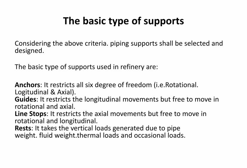
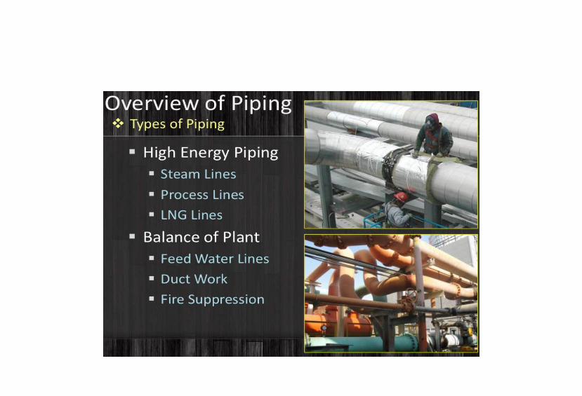
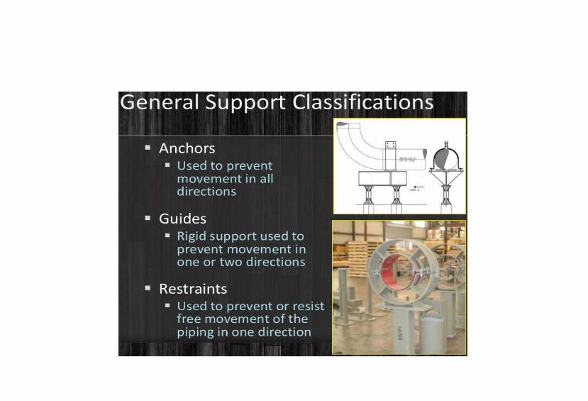
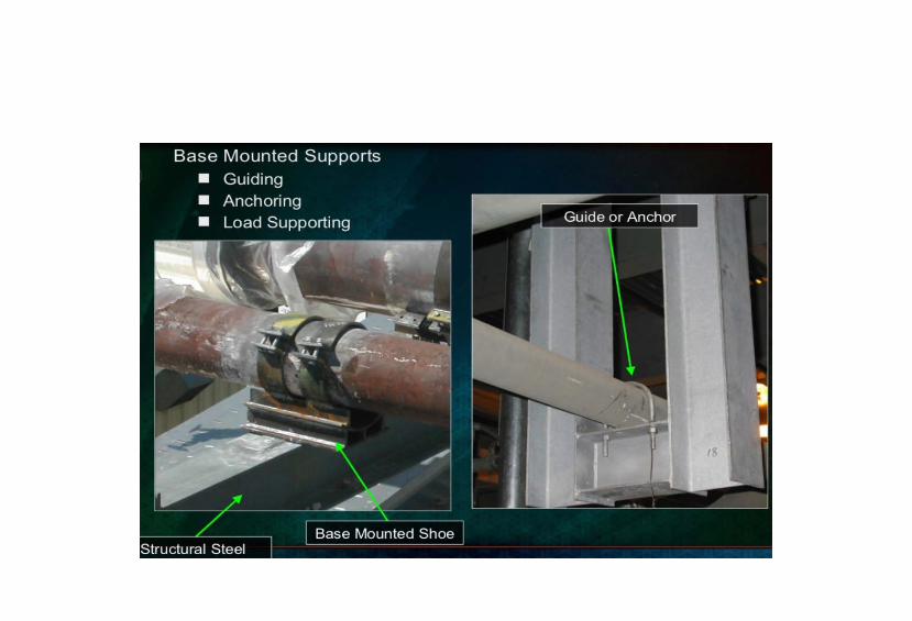
Considering the above criteria. piping supports shall be selected and designed. The basic type of supports used in refinery are: Anchors: It restricts all six degree of freedom (i.e.Rotational. Logitudinal & Axial). Guides: It restricts the longitudinal movements but free to move in rotational and axial. Line Stops: It restricts the axial movements but free to move in rotational and longitudinal. Rests: It takes the vertical loads generated due to pipe weight. fluid weight.thermal loads and occasional loads.
Classification of Pipe Supports
Broadly the pipe supports are classified in three groups as per following details / functions: – General details – Construction details – Functions ie. Purpose These are described below in brief.

1. Pipe Supports Classification as per General Details:
A pipe line needs to be supported from a foundation or a structure. The piping loads will be acting on these foundations / structures. Since these foundations / structures are built on ground. they will exert an equal and opposite reaction. while supporting the pipe. In a pipe support. there will be some parts of support arrangement which is directly attached to the pipeline and there will be some other parts which shall be directly attached to the foundation / structure supporting the pipe. As per this general detail the support is classified as:
• 1.1 Primary Supports: It is the parts of support assembly which is directly connected to the pipe. • 1.2 Secondary Supports: It is the parts of support assembly which is directly connected to the foundation / structure and is supporting the primary support attached to the pipe line.
2. Pipe Supports Classification as per Construction:
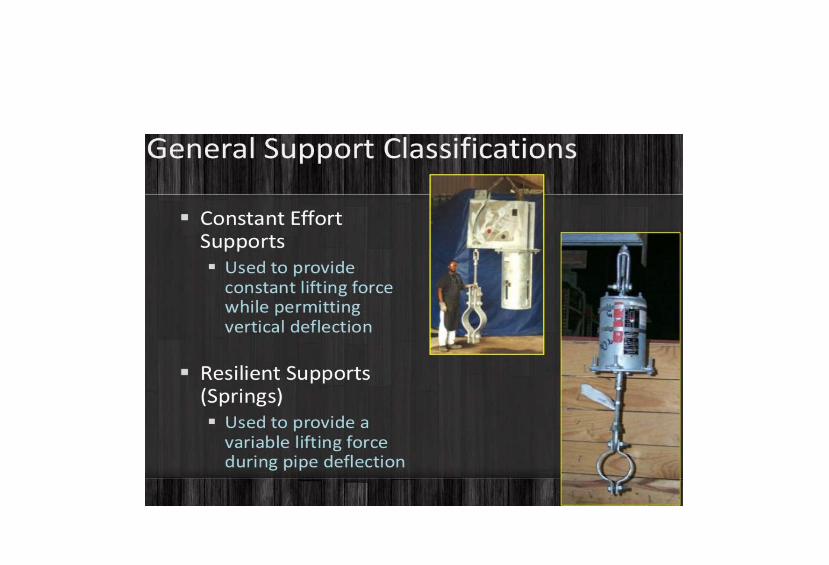
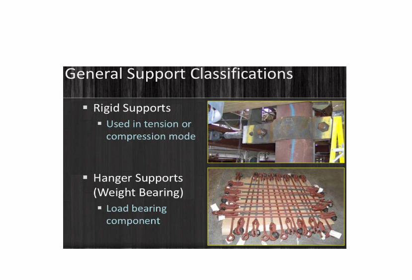
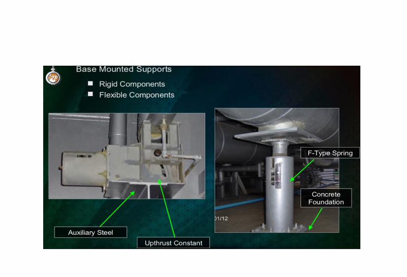
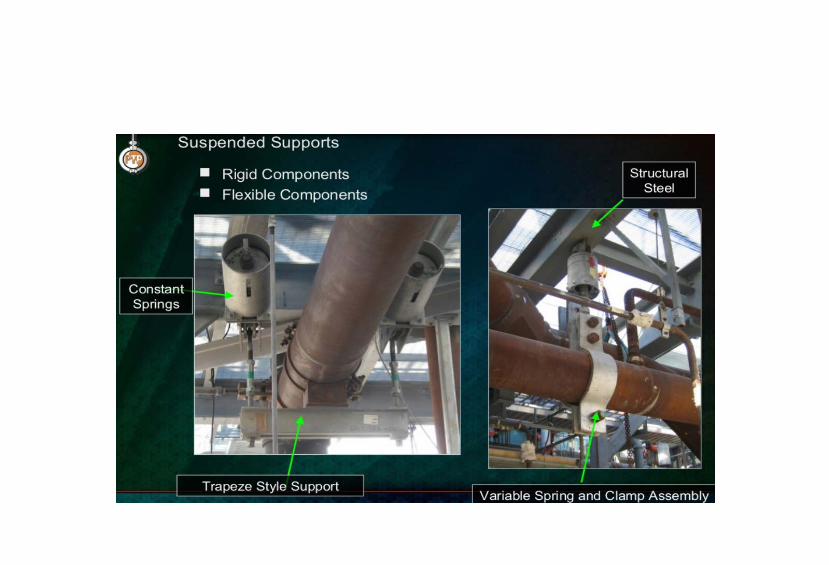
Based on construction details. pipe supports are broadly classified in three types. as – RIGID SUPPORTS – ELASTIC SUPPORTS – ADJUSTABLE SUPPORTS These are described below in brief.
2. Pipe Supports Classification as per Construction:
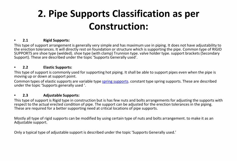
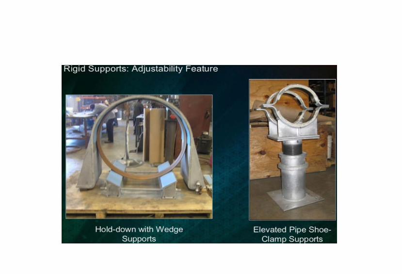
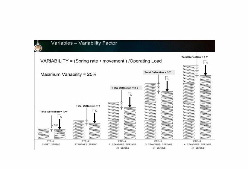
• 2.1 Rigid Supports: This type of support arrangement is generally very simple and has maximum use in piping. It does not have adjustability to the erection tolerances. It will directly rest on foundation or structure which is supporting the pipe. Common type of RIGID SUPPORTS are shoe type (welded). shoe type (with clamp) Trunnion type. valve holder type. support brackets (Secondary Support). These are described under the topic ‘Supports Generally used’. • 2.2 Elastic Supports: This type of support is commonly used for supporting hot piping. It shall be able to support pipes even when the pipe is moving up or down at support point. Common types of elastic supports are variable type spring supports. constant type spring supports. These are described under the topic ‘Supports generally used ‘. • 2.3 Adjustable Supports: This type of support is Rigid type in construction but is has few nuts and bolts arrangements for adjusting the supports with respect to the actual erected condition of pipe. The support can be adjusted for the erection tolerances in the piping. These are required for a better supporting need at critical locations of pipe supports. Mostly all type of rigid supports can be modified by using certain type of nuts and bolts arrangement. to make it as an Adjustable support. Only a typical type of adjustable support is described under the topic ‘Supports Generally used.’
3. Pipe Supports Classification as per Function (i.e. Purpose)
3. Pipe Supports Classification as per Function (i.e. Purpose)
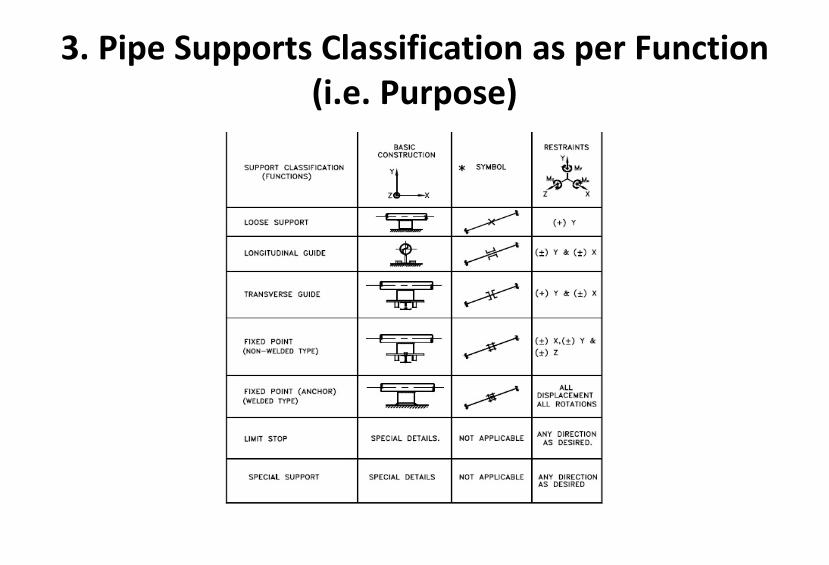
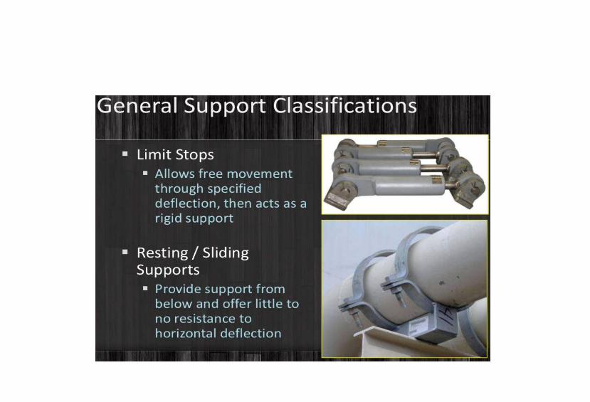
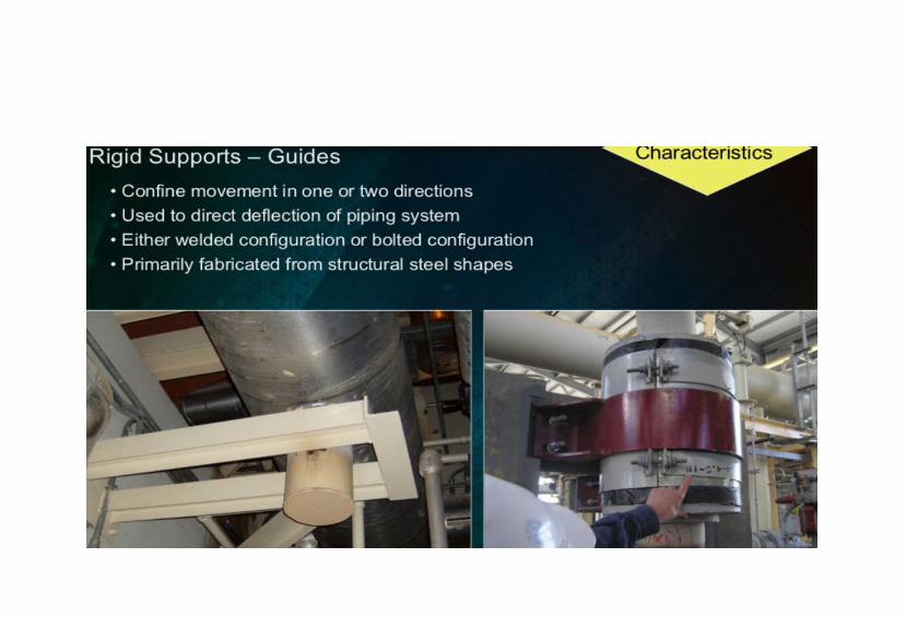
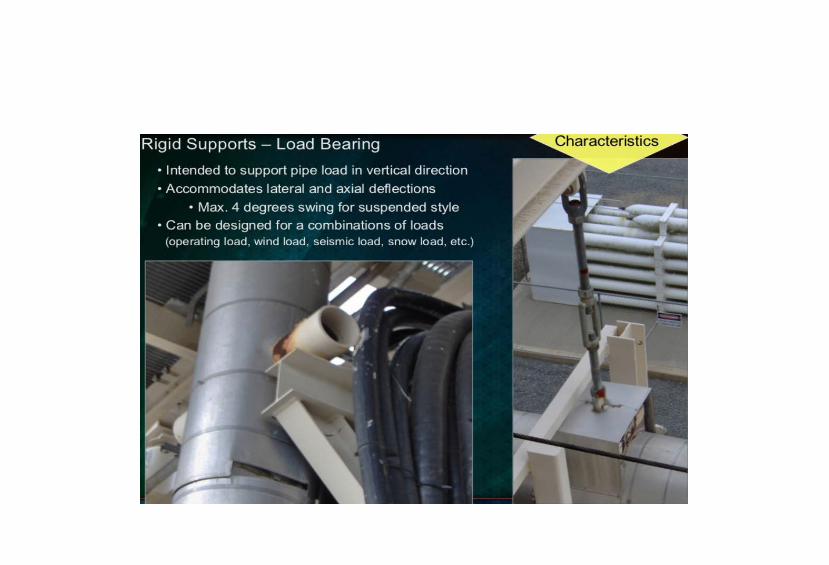
Pipe supports classified as per functions are summarized in the Table at FIG.7. These are shown along with its basic construction. the symbols generally used and type of restraints it offers to the piping system. The supports classified as per function are further described as follows: • 3.1 Loose Support: This is most commonly used support meant for supporting only the pipe weight vertically. It allows pipe to move in axial as well as transverse direction but restricts only the vertical downward movement. • 3.2 Longitudinal Guide: This type of support is used to restrict the movement of pipe in transverse direction i.e. perpendicular to length of pipe but allow movement in longitudinal direction. This is also a commonly used type of support. Generally it is used along with Loose support. • 3.3 Transverse Guide: This type of support is used to restrict the movement of pipe in longitudinal (axial) direction but allows the pipe to move in transverse direction. This is also referred as ‘AXIAL STOP’. This type is less used as compared to above two types. Generally it is used along with Loose support. • 3.4 Fixed point/Anchor: FIX POINT type of support is used to restrict movements in all three directions. ANCHOR type of support is used to restrict movement in all three directions and rotation also in these three directions. • Non-Welded Type (Fix Point): This can be considered as a combination of longitudinal and transverse guide. This type resists only the linear movements in all directions but not the rotational movements. This avoids heavy loading of support as well as pipe. Therefore this type of support is preferred over welded type. • Welded Type (Anchor) This type of support prevents total movements i.e. linear as well as rotational. This type of support is used when it is absolutely essential to prevent any moment/force being transferred further. It causes heavy loading on support as well as pipe. • 3.5 Limit Stop: As name itself indicates it allows pipe movement freely upto a certain limit and restricts any further movement. This is useful when total stops causes excessive loading on piping and support or nozzle. This type of support should be used selectively. because of stringent and complicated requirements of design. erection and operation. • 3.6 Special Supports: When we need a pipe support whose construction or functional details are different from the available details. then a special support detail sketch is prepared. The functions of this support can be any combination of above functions.
1. Purpose
The Piping Profile in general can be considered as a complex and rigid piping network consisting of various piping components. which have different diameters and weights. At the same time the above network is also subjected to temperature change while switching from installed to operating condition (and visa versa) resulting into its thermal growth in various directions in proportion to the length of pipes. The structural integrity of the above network must therefore take into account the overall weight effect of the profile besides its thermal growth. A satisfactory design of the Piping System should therefore give a careful consideration to achieve the above requirement. This is generally accomplished by providing external attachments (known as pipe supports) at various locations of the piping profile. This document deals with the basic purpose of the pipe supports. In general it deals with metallic piping systems only.

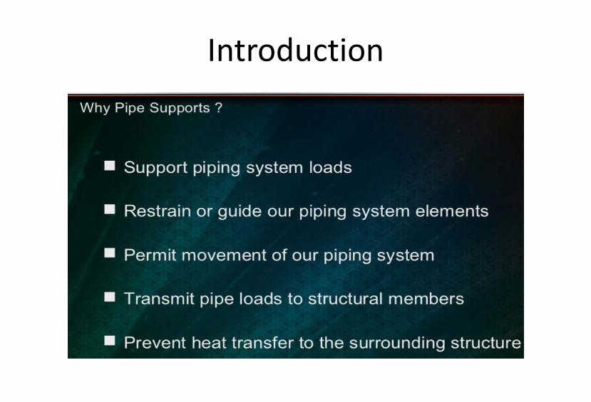
2. Purpose of Pipe Supports
A brief detail of the purpose of pipe support is described below. • 2.1 To support weight of pipe-during operation & testing Supports are required to support the line during all conditions i.e. during operation as well as during testing. In case of vapour line this difference will be very large due to hydro testing. Supports should be designed for this load (unless otherwise decided in the project). Sometimes line is capable of having longer span but load coming on the support may be very large (especially with large diameter pipe lines). Then to distribute the load uniformly. more number of supports should be provided with smaller span. Note: a. It may be noted that during testing condition there is no thermal load. b. All spring supports are locked during testing.

2. Purpose of Pipe Supports
• 2.2 To take ‘Expansion load’: Whenever thermal expansion is restricted by support. it introduces additional load on the support. Support must be designed to take this load in addition to all other loads. • 2.3 To take ‘Wind load’: Wind introduces lateral load on the line. This load is considerable especially on large diameter pipe. This tends to sway the line from its normal position and line must be supported guided against it. In case of large diameter overhead lines. supported by tall support extended from floor. wind load introduces large bending moment and should be considered critically. • 2.4 To take ‘Earth quake load’: The earthquake is normally associated with horizontal acceleration of the order of 1 to 3 m/sec2. This is around 10% to 30% of the gravitational acceleration and introduces horizontal force of about 10 to 30% of the vertical load (or supported mass). While designing support this should be taken care. • 2.5 To absorb ‘Vibration of Piping system’: When the pipe is subjected to moving machinery or pulsating flow or very high velocity flow. pipe may start vibrating vigorously and ultimately may fail. particularly if span is large. To avoid this it may be required to introduce additional supports at smaller span apart from other requirements. It may not take axial load. but must control lateral movements. • 2.6 To have ‘Noise control’: In most of the plants. noise is resulting from vibration and if such vibrations are controlled. noise is reduced to great extent. In such lines. between clamp (i.e. support) and pipe. asbestos cloth is put to absorb vibration and avoid noise. Noise due to pulsating flow can be reduced by using a silencer in the line. Still if it is not below acceptable level acoustic enclosure may be used. Insulation over line also helps in reducing the noise.
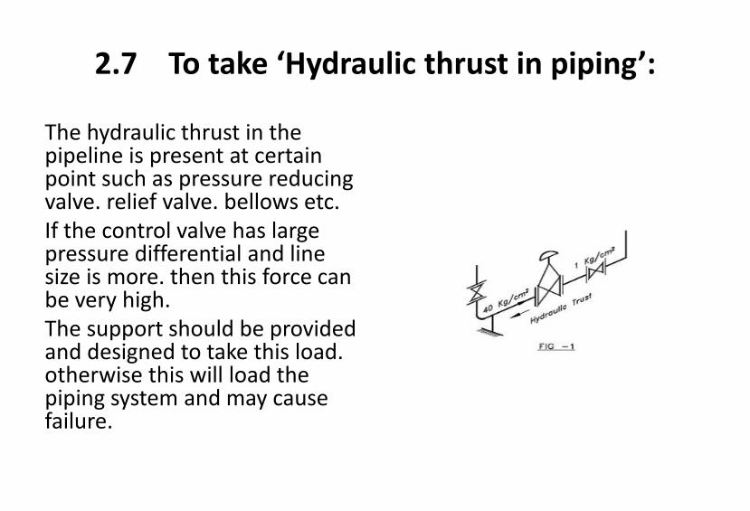
2.7 To take ‘Hydraulic thrust in piping’:
The hydraulic thrust in the pipeline is present at certain point such as pressure reducing valve. relief valve. bellows etc. If the control valve has large pressure differential and line size is more. then this force can be very high. The support should be provided and designed to take this load. otherwise this will load the piping system and may cause failure.
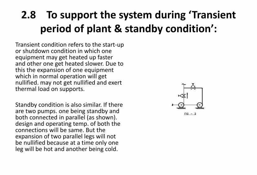
2.8 To support the system during ‘Transient period of plant & standby condition’:
Transient condition refers to the start-up or shutdown condition in which one equipment may get heated up faster and other one get heated slower. Due to this the expansion of one equipment which in normal operation will get nullified. may not get nullified and exert thermal load on supports. Standby condition is also similar. If there are two pumps. one being standby and both connected in parallel (as shown). design and operating temp. of both the connections will be same. But the expansion of two parallel legs will not be nullified because at a time only one leg will be hot and another being cold.
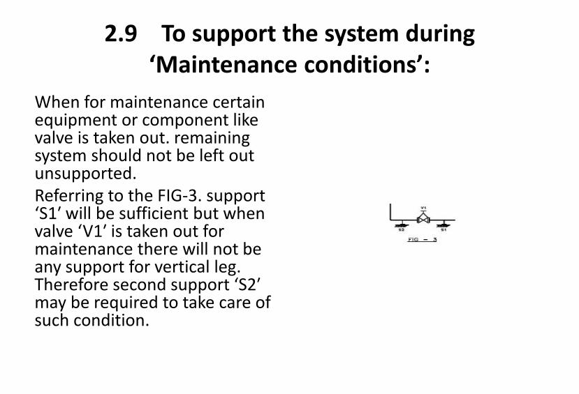
2.9 To support the system during ‘Maintenance conditions’:
When for maintenance certain equipment or component like valve is taken out. remaining system should not be left out unsupported. Referring to the FIG-3. support ‘S1′ will be sufficient but when valve ‘V1′ is taken out for maintenance there will not be any support for vertical leg. Therefore second support ‘S2′ may be required to take care of such condition.
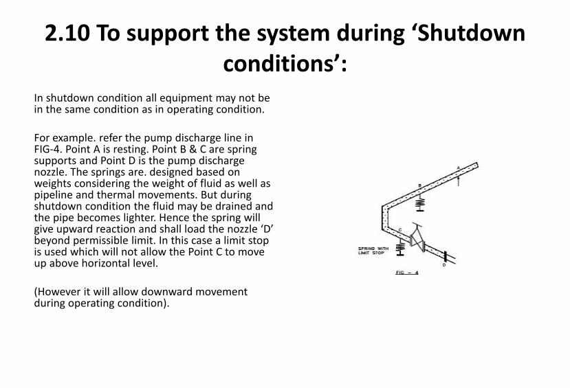
2.10 To support the system during ‘Shutdown conditions’:
In shutdown condition all equipment may not be in the same condition as in operating condition. For example. refer the pump discharge line in FIG-4. Point A is resting. Point B & C are spring supports and Point D is the pump discharge nozzle. The springs are. designed based on weights considering the weight of fluid as well as pipeline and thermal movements. But during shutdown condition the fluid may be drained and the pipe becomes lighter. Hence the spring will give upward reaction and shall load the nozzle ‘D’ beyond permissible limit. In this case a limit stop is used which will not allow the Point C to move up above horizontal level. (However it will allow downward movement during operating condition).
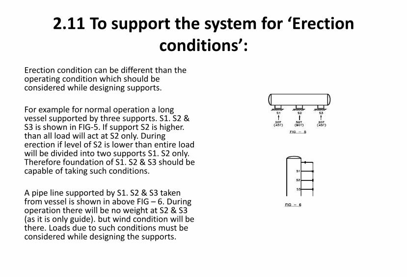
2.11 To support the system for ‘Erection conditions’:
Erection condition can be different than the operating condition which should be considered while designing supports.
For example for normal operation a long vessel supported by three supports. S1. S2 & S3 is shown in FIG-5. If support S2 is higher. than all load will act at S2 only. During erection if level of S2 is lower than entire load will be divided into two supports S1. S2 only. Therefore foundation of S1. S2 & S3 should be capable of taking such conditions. A pipe line supported by S1. S2 & S3 taken from vessel is shown in above FIG – 6. During operation there will be no weight at S2 & S3 (as it is only guide). but wind condition will be there. Loads due to such conditions must be considered while designing the supports.
An art is undoubtly abstract
• Therefore. instead of presenting principles. we willl use some specific examples to demonstrate the ideas.
The Art of Designing Piping Support Systems
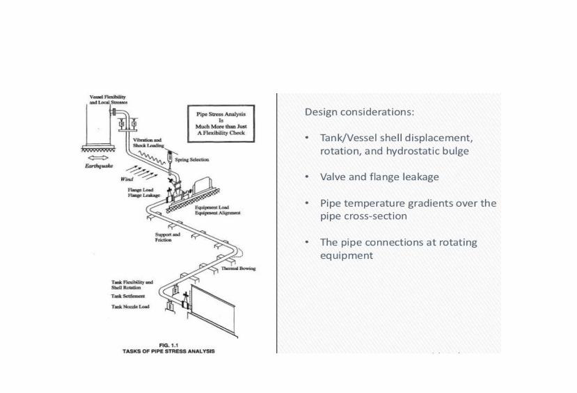
Objectives of Pipe Stress Analysis:
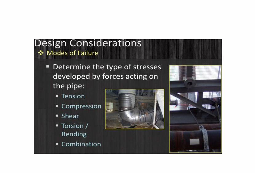
• Structural Integrity: Design adequacy for the pressure of the carrying fluid. Failure against various loading in the life cycle . Limiting stresses below code allowable. • Operational Integrity: Limiting nozzle loads of the connected equipment within allowable values. Avoiding leakage at joints. Limiting sagging & displacement within allowable values. • Optimal Design: Avoiding excessive flexibility and also high loads on supporting structures. Aim towards an optimal design for both piping and structure.


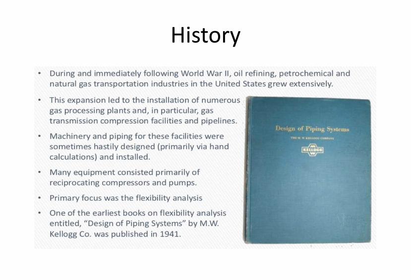
History

Importance
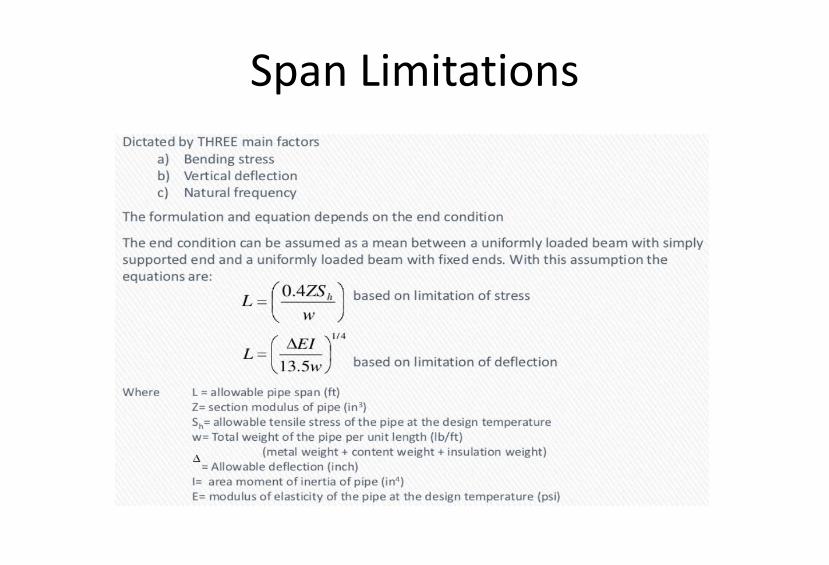
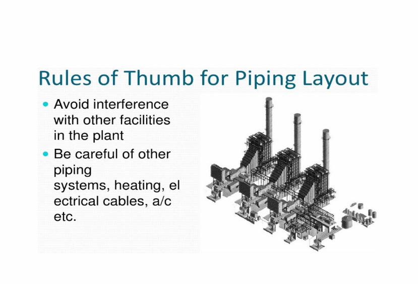
Span Limitations
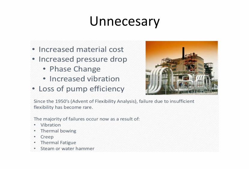
Unnecesary

Stress Analysis Basics
Stress Analysis Purpose
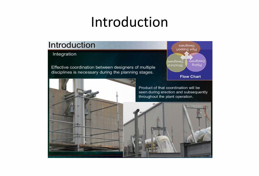
Introduction
Introduction
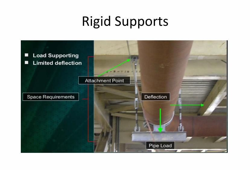
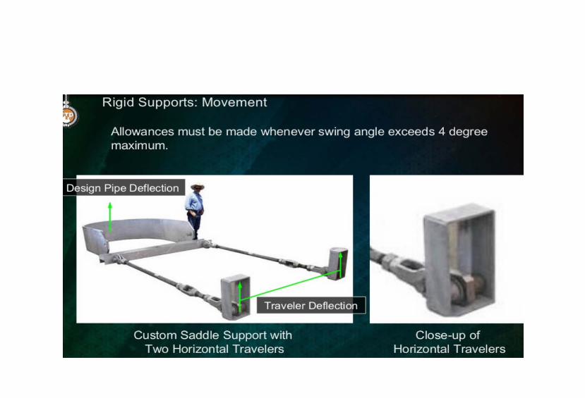
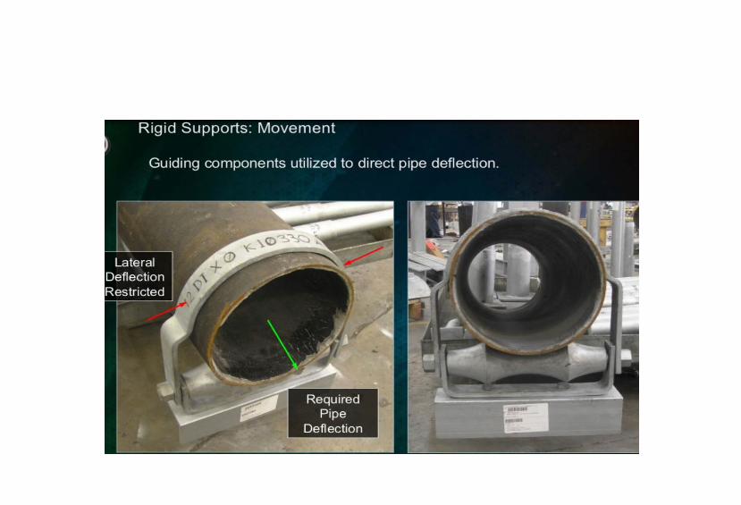
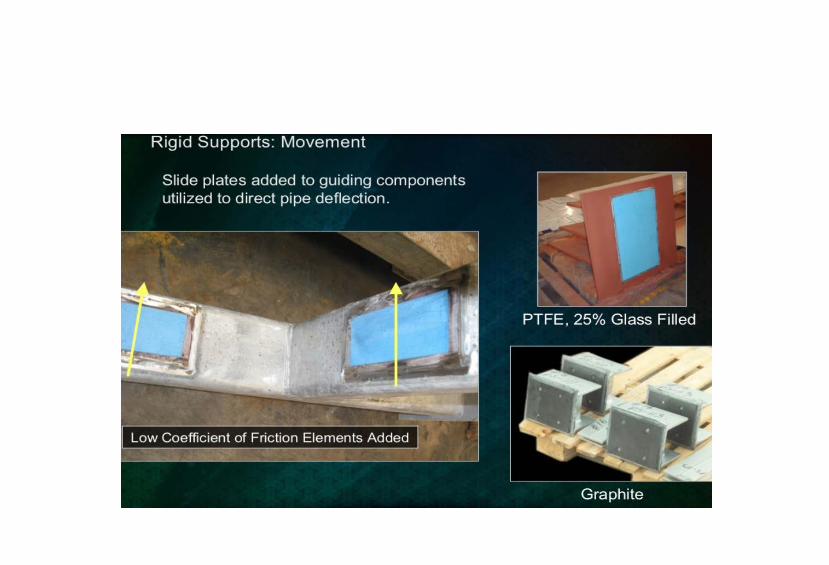
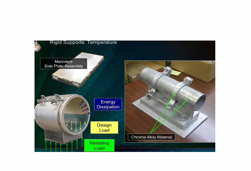
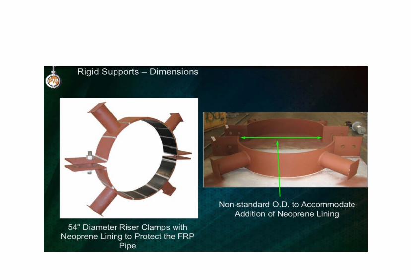
Rigid Supports

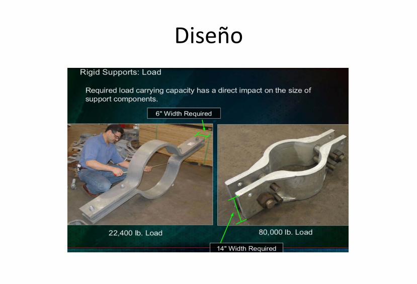
Diseño


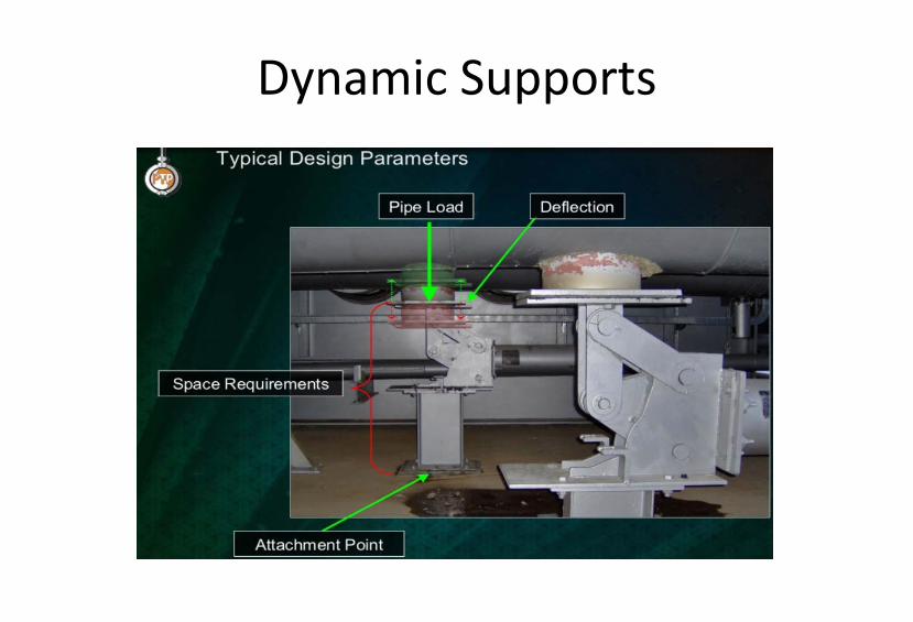
Dynamic Supports

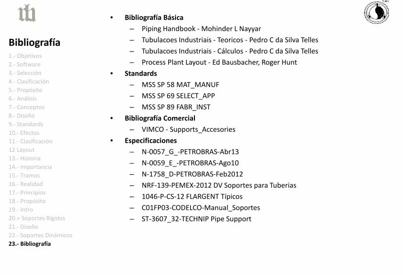
• Bibliografía Básica – Piping Handbook - Mohinder L Nayyar – Tubulacoes Industriais - Teoricos - Pedro C da Silva Telles – Tubulacoes Industriais - Cálculos - Pedro C da Silva Telles – Process Plant Layout - Ed Bausbacher, Roger Hunt
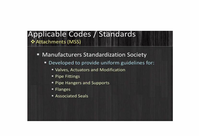
• Standards – MSS SP 58 MAT_MANUF – MSS SP 69 SELECT_APP – MSS SP 89 FABR_INST
• Bibliografía Comercial – VIMCO - Supports_Accesories
• Especificaciones – N-0057_G_-PETROBRAS-Abr13 – N-0059_E_-PETROBRAS-Ago10 – N-1758_D-PETROBRAS-Feb2012 – NRF-139-PEMEX-2012 DV Soportes para Tuberias – 1046-P-CS-12 FLARGENT Típicos – C01FP03-CODELCO-Manual_Soportes – ST-3607_32-TECHNIP Pipe Support
1.- Objetivos 2.- Software 3.- Selección 4.- Clasificación 5.- Propósito 6.- Análisis 7.- Conceptos 8.- Diseño 9.- Standards 10.- Efectos 11.- Clasificación 12 Layout 13.- Historia 14.- Importancia 15.- Tramos 16.- Realidad 17.- Principios 18.- Propósito 19.- Intro 20.+ Soportes Rígidos 21.- Diseño 22.- Soportes Dinámicos 23.- Bibliografía
Bibliografía
Related Documents