A 1" . f 1 1 K Athe flux from that pole to produce an 12 Ippication o t0e m an o torque tending to close the relay contacts, and the current in the cylinder near the P ri nci pl es to Protecti ve Rel ays E pole reacts with the flux from that pole producing an El torque tending to keep the contact open. A. R. van C. WARRINGTON In the following paragraphs, it will be MEMBER AIEE shown that the provision of what we have called polarizing poles not only overcomes THE mho relay unit was fi i.t used 15 more efficiently and others to perform the above difficulties of distance measure- years ago as the direciv ,nal unit for some new functions. In order to under- ment but provides some interesting new an early-type reactance relay. Thus it stand the operation of these new relays, it applications. Figure 3 shows the general can be said that "mho" applied to relays may be helpful first to consider briefly construction of a high-speed product-type is a new term applied to an old principle. their operation and to compare their unit, the 4-pole induction cylinder unit. The mathematical justification for the pickup characteristics on the impedance term has been given in a paper' describ- diagram. Current Polarization ing the use of the mho unit in a carrier- (Ohm Units) current relaying scheme. The mho unit Relation Between Ohm in its present form is a directional im- and Mho Units The torque is the product of the current pedance unit whose accuracy is compar- First of all, it should be understood polarizing flux times the fluxes from the able with that of the reactance ohm unit that ohm units and mho units are merely opposed I and E poles. Hence the equa- used in a distance relay. refinements of the straight impedance tion for the operating point, which deter- The mho characteristic (Figure IC) is relay. All distance relays measure the mines the pickup characteristic, is suited ideally for protecting long or distance to a fault by comparing the cur- heavily loaded transmission lines because rent in the faulted circuit with the poten- I[KI-E cos (4-0)] = 0 (1) it is much less likely to trip on power tial across it. In the impedance relay, where K is a winding constant, 4 is the swings than the cQnventional reactance or this is done by opposing the torques of phase angl o thpot c ircuit, and . D~~~~~~~~~~~~hase angle of the p rotected circuit, and impedance relays. Another desirable two electromagnets, one having a current 0 is the angle of the relay characteristic. feature is that a relay for phase faults winding and the other a potential wind- Dividing through by 12 and rearranging should operate only on faults involving ing (Figure 2A). The impedance meas- Dividing through by Z the phase pair with which the relay is ured by such a relay is not always a true th terms, the e uati ntbeomesizico associated; all other faults or system con- measurement of distance, however. On (n-0)iK Thus the current polarizing ditions should not affect it. In Figures short lines the additional potential drop winding makes the relay respond to im- 1A and 1B, the large tripping area of the in an arcing fault tends to prevent the pedance only at a particular angle whtch impedance characteristics of the imped- impedance relay from operating, and on is determined by the phase angle of the ance and reactance relays shows that these long lines, the current may be high enough potential circuit of the relay. For ex- relays are susceptible to power swings under load or power swing conditions ample, a simple 4-pole induction cylinder and faults in other phases (denoted by relative to the voltage to present to the unit with a current polarizing winding, asterisks), whereas the snug fit of the relay an impedance as low as that of a reacting with a current operating pole and mho circle around the fault area in Figure fault and cause undesirable tripping. a potential restraining pole, operates on a 1iC indicates that the mho relay effectively This difficulty can be overcome largely component of impedance 20 degrees more prevents tripping for power swings and by the use of the product-type relay leading than resistance. Such a relay for any faults but those for which the whose torques are not proportional to cur- (Figure 4) has been used as a blinder2 for relay is set to trip. rent and voltage alone but to the products preventing other protective relays from The fact that the niho unit combines of I and E with a third quantity which, tripping during very severe power swings. sensitive directional action with accurate being common to both, does not affect Two such ohm units, polarized in opposite ohmic measurement means that one mho the ratio balance E/I but provides phase- directions, can be connected through unit does what two conventional units angle discrimination. This is shown auxiliary relays so as to detect an out-of- did before. This not only eliminates the schematically in Figures 2B and 2C. step condition after the first half swing contact races that can occur between the The flux from the additional pair of period. directional element and the measuring poles (shown vertically in Figures 2B and Adding a capacitor to make the poten- element but obviously simplifies the cir- 2C) acts in much the same way as the cur- tial circuit of the aforementioned unit at cuits to which the relay is applied. rent or potential polarizing flux in a di- uinty power-factor makes 0=90 degrees With these advantages it might appear rectional ground relay, and for want of a in the pickup equation, which becomes that the mho unit should be used uni- better name it will be referred to in the (E/I) Sin =K or X=K. In other versally for all applications involving following as a polarizing flux, words, the relay operates on reactance distance measurement. This is generally The current polarizing flux in Figure (Figure 5). true, but there is a lower limit of imped- 2B goes from the upper I pole through the The reactance relay IS used where the ance for which it can be set for reasons induction cylinder and the central core discssd later Line to short for the iro stackin to the loe I pol ad in Paper 46-38, recommended by the AIEE committee mho unit still must be protected by the duces a current in the cylinder which winter946 convention t NewmYork, N.ovemJanury2 reactance ih nt lw epniua otepaeo h 945; made available for printing December 18, Several new relays will be described, paper up and down the sides of the cup 1945. some of wllich llse o is oppo e p ~~~~~~~~~tion of protective relays, General Electric Coin units to perform existing relay functions opposite the operating pole I reacts with pany, Philadelphia, Pa. 378 TRANSACTIONS Wiarringtort-Ohm and Mho Principles ELECTRICAL ENGINEERING

05059358
Dec 23, 2015
proteccion de lineas de trasmisao
Welcome message from author
This document is posted to help you gain knowledge. Please leave a comment to let me know what you think about it! Share it to your friends and learn new things together.
Transcript

A 1" . f 1 1 K Athe flux from that pole to produce an 12Ippication o t0e m an o torque tending to close the relay contacts,and the current in the cylinder near the
Principles to Protective Relays E pole reacts with the flux from that poleproducing an El torque tending to keepthe contact open.
A. R. van C. WARRINGTON In the following paragraphs, it will beMEMBER AIEE shown that the provision of what we have
called polarizing poles not only overcomesTHE mho relay unit was fi i.t used 15 more efficiently and others to perform the above difficulties of distance measure-
years ago as the direciv ,nal unit for some new functions. In order to under- ment but provides some interesting newan early-type reactance relay. Thus it stand the operation of these new relays, it applications. Figure 3 shows the generalcan be said that "mho" applied to relays may be helpful first to consider briefly construction of a high-speed product-typeis a new term applied to an old principle. their operation and to compare their unit, the 4-pole induction cylinder unit.The mathematical justification for the pickup characteristics on the impedanceterm has been given in a paper' describ- diagram. Current Polarizationing the use of the mho unit in a carrier- (Ohm Units)current relaying scheme. The mho unit Relation Between Ohmin its present form is a directional im- and Mho Units The torque is the product of the currentpedance unit whose accuracy is compar- First of all, it should be understood polarizing flux times the fluxes from theable with that of the reactance ohm unit that ohm units and mho units are merely opposed I and E poles. Hence the equa-used in a distance relay. refinements of the straight impedance tion for the operating point, which deter-The mho characteristic (Figure IC) is relay. All distance relays measure the mines the pickup characteristic, is
suited ideally for protecting long or distance to a fault by comparing the cur-heavily loaded transmission lines because rent in the faulted circuit with the poten- I[KI-E cos (4-0)] = 0 (1)it is much less likely to trip on power tial across it. In the impedance relay, where K is a winding constant, 4 is theswings than the cQnventional reactance or this is done by opposing the torques of phase angl o thpot c ircuit, and
. D~~~~~~~~~~~~haseangle of the p rotected circuit, andimpedance relays. Another desirable two electromagnets, one having a current 0 is the angle of the relay characteristic.feature is that a relay for phase faults winding and the other a potential wind- Dividing through by 12 and rearrangingshould operate only on faults involving ing (Figure 2A). The impedance meas- Dividing through by Z
the phase pair with which the relay is ured by such a relay is not always a true th terms, thee uati ntbeomesizicoassociated; all other faults or system con- measurement of distance, however. On (n-0)iK Thus the current polarizingditions should not affect it. In Figures short lines the additional potential drop winding makes the relay respond to im-1A and 1B, the large tripping area of the in an arcing fault tends to prevent the pedance only at a particular angle whtchimpedance characteristics of the imped- impedance relay from operating, and on is determined by the phase angle of theance and reactance relays shows that these long lines, the current may be high enough potential circuit of the relay. For ex-relays are susceptible to power swings under load or power swing conditions ample, a simple 4-pole induction cylinderand faults in other phases (denoted by relative to the voltage to present to the unit with a current polarizing winding,asterisks), whereas the snug fit of the relay an impedance as low as that of a reacting with a current operating pole andmho circle around the fault area in Figure fault and cause undesirable tripping. a potential restraining pole, operates on a1iC indicates that the mho relay effectively This difficulty can be overcome largely component of impedance 20 degrees moreprevents tripping for power swings and by the use of the product-type relay leading than resistance. Such a relayfor any faults but those for which the whose torques are not proportional to cur- (Figure 4) has been used as a blinder2 forrelay is set to trip. rent and voltage alone but to the products preventing other protective relays fromThe fact that the niho unit combines of I and E with a third quantity which, tripping during very severe power swings.
sensitive directional action with accurate being common to both, does not affect Two such ohm units, polarized in oppositeohmic measurement means that one mho the ratio balance E/I but provides phase- directions, can be connected throughunit does what two conventional units angle discrimination. This is shown auxiliary relays so as to detect an out-of-did before. This not only eliminates the schematically in Figures 2B and 2C. step condition after the first half swingcontact races that can occur between the The flux from the additional pair of period.directional element and the measuring poles (shown vertically in Figures 2B and Adding a capacitor to make the poten-element but obviously simplifies the cir- 2C) acts in much the same way as the cur- tial circuit of the aforementioned unit atcuits to which the relay is applied. rent or potential polarizing flux in a di- uinty power-factor makes 0=90 degreesWith these advantages it might appear rectional ground relay, and for want of a in the pickup equation, which becomes
that the mho unit should be used uni- better name it will be referred to in the (E/I) Sin =K or X=K. In otherversally for all applications involving following as a polarizing flux, words, the relay operates on reactancedistance measurement. This is generally The current polarizing flux in Figure (Figure 5).true, but there is a lower limit of imped- 2B goes from the upper I pole through the The reactance relay IS used where theance for which it can be set for reasons induction cylinder and the central corediscssd later Line to short for the iro stackin to the loe I pol ad in Paper 46-38, recommended by the AIEE committeemho unit still must be protected by the duces a current in the cylinder which winter946convention tNewmYork, N.ovemJanury2reactance ih nt lw epniua otepaeo h 945; made available for printing December 18,
Several new relays will be described, paper up and down the sides of the cup 1945.some of wllich llse o isoppo e p ~~~~~~~~~tionof protective relays, General Electric Coin
units to perform existing relay functions opposite the operating pole I reacts with pany, Philadelphia, Pa.
378 TRANSACTIONS Wiarringtort-Ohm and Mho Principles ELECTRICAL ENGINEERING

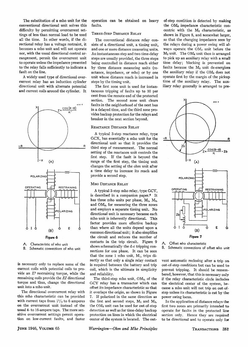
arc resistance is likely to be comparable equation and dividing through by K'EI, long enough for the time-delay backupwith the impedance of the protected sec- which gives Z= (I/K') cos (4 -0). step, but the torque can be maintained intion and hence likely to interfere with the This is the equation of a circle, of this case by adding torque caused by cur-operation of the impedance relay. The diameter 1/K', which passes through the rent alone. The functions of the thirdreactance relay ignores the arc resistance origin (Figure 6A). The impedance char- step of a distance relay are usually toand hence is indispensable for short lines acteristic of a mho relay is therefore a start carrier blocking and to control theand for protecting against ground faults. circle passing through the origin. backup time-delay trip. Memory action
The fact that the characteristic passes is used to provide initially high torque toPotential Polarization through the origin means that the unit is ensure starting carrier very promptly and(Mho Units) inherently directional. The phase angle the contacts are held closed after the
of the relay characteristic is the angle 6 expiry of the memory action by the cur-With potential polarization, the torque between the diameter of the impedance rent torque. The initroduction of the
is the product of the potential-polarizing circle and the R axis. By making 0 current torque puts the K12 term back intoflux times the fluxes from the opposed I equal to or a little less lagging than q, the equation of the mho unit, thus maklingand E poles. Hence the equation for the phase angle of the line, the circle is it the general equationpickup is made to fit very closely around the fault KI2 K'E2+EI cos ( -6) =0E[Icos (0-6)-K'E =0( (2) area so that the relay is less sensitive to
power swings and hence valuable for the (See Appendix I.)or -K'E'+EI cos (-0) - 0. D)ividing protection of long or heavily loaded lines. The offset is secured by adding to the
X X ,STARTING UNIT X* A3-
OIRECTIONAL, _ ~UNIT |-i-REACTANCEOUI
\ X 9, /o \ ~~~ ~ ~ ~~~~~~~~~~~UNITf e
\ * w FE Z \ \ S f -;___R
(A) (B) (C)
Figure 1. Tripping characteristics Figure 2 Sche- 0 CONTACTS> [IjI.]
A. Impedance unit matic diagramsnB. Redctance unit A. Impedance unit A. ImpeQancILuQZtC. Mho unitB.Omui
The relays trip in the shaded area. Crosses C. Mho unit I INDUCTION lare conditions for which tripping is undesir- CYLINDER
able(A) (B) (C)
through by E2 and putting the K' term Offset Mho Circleon the right, we get Y cos (4-) =K', SLVER
CONT7ACT SLIPwhich is a straight line on an admittance Since both the termiis of the equation of CLUTCHdiagramii and thus represents a constant the mho relay contain E, it would appear CLUTCH ALUMINUMSPRING CLNEcomponent of admittance, that is, the that the relay has zero torque when the CYLINDER
relay will pick up at a constant value of potential is zero, as for a bus fault. Thismhos at a certain angle and therefore has shortcoming is avoided in an instantane-been called a mho Unlit. This is parallel ous mho relay lw providing memlory ac- l i |to the case of the ohm unit which picks tion ini the polarizinlg circuit which main- _lup at a constant component of impedance, tains the relayr polarizinlg voltage Epo1 for -__ 'W__ .as shown in the impe(lance diagram of a few cycles after the line vroltage has dis- _,-- vFigure 4A. appeared, but does not affect the ohmiic 1' i'I
It is genlerally more convenient to plot characteristic. This wQill be apparent fromn WINDING T 3 LAMINATIONSdistance-relay characteristics on an im- the torque equation RINGSTONE-ENDSTONE~pedance diagram. The impedance equa- E 0[I cs(f-6) - K'E:] = (3) Fgr3.Schemati diagraoBE4-poltion of the mho unit iS obtained by put- iue3Scmacdarmof4plting the EI term on the right side of the Memnory action cannlot be mlade to last induction cylinder unit
JUNE 1946, VOLUME 65S TVlarr'ington-Oh.m and A/IIh Principles TRANSACTIONS 379

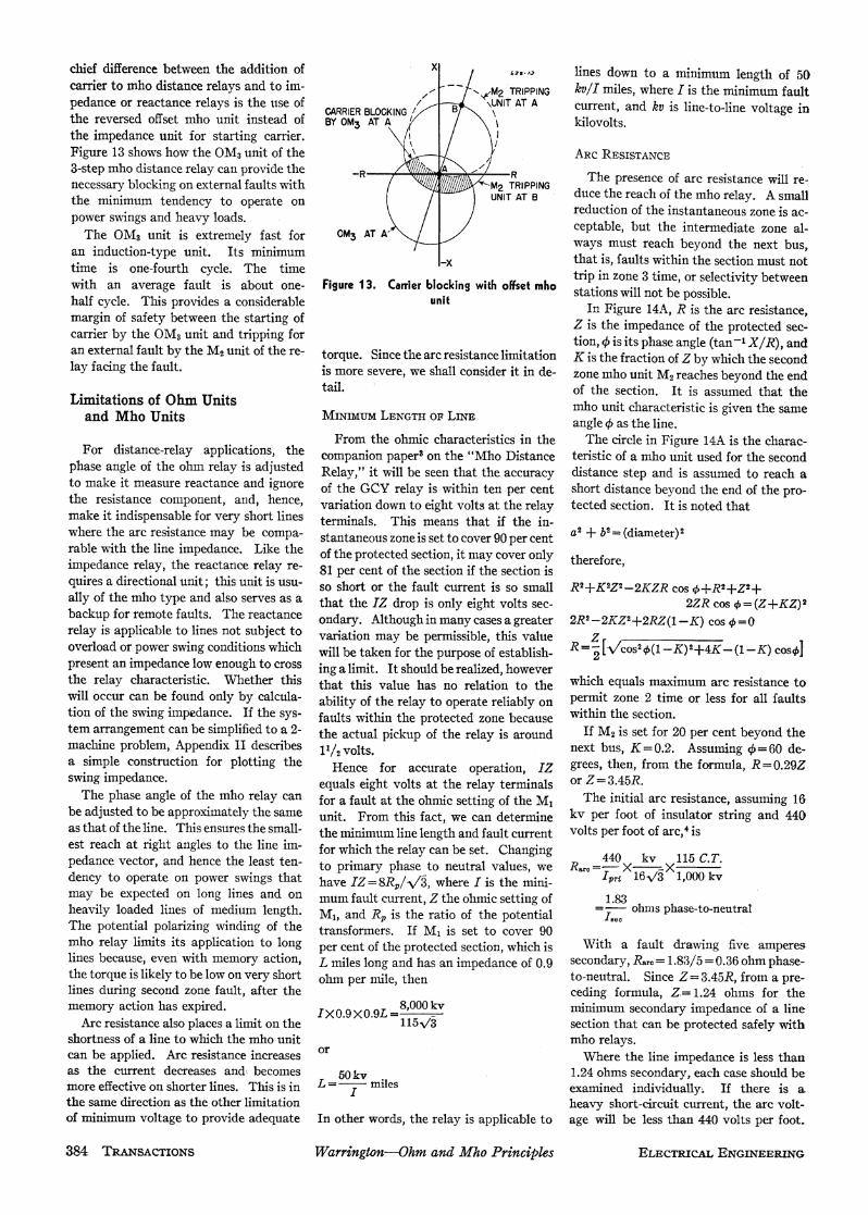
line potential a biasing potential, IZb, mary winding with few turns is in the protection for the neighborhood of theproportional to the current, which has the current circuit, and the secondary wind- next bus can be provided by the mhoeffect of moving the characteristic imped- ing with many turns is in the potential type IBCV directional overcurrent relayance circle bodily by an amount Zb. circuit. It is thus a contraction of a to be described.Substituting E+IZb for E in the equation transformer and a reactor and is called a The instantaneous tripping zone pro-for the mho relay, we get transactor. vided by the single-step mho relay is
This offset characteristic is particularly superior to that of instantaneous over--K'(E+IZb)2+(R+IZb)I COS (4+-4) useful for out-of-step blocking because, current or single-step impedance protec-
with the opening of circuit breakers after tion because:
Dividing through by 12, the equation a fault and hunting between two or more 1. It is inherently directional, so that onlybecomes groups of machines, the impedance "seen a single contact appears between the bat-
by the relay" may approach the relay tery and the trip coil, which is the ultimate-K'(Z +Zb)2+(Z+Zb) cos (0-0)=0 characteristic at almost any angle. Hence in simplicity and reliability.
the only sure way of initiating out-of- 2. It is insensitive to offset waves; henceor step blocking is by a relay whose char- it can be set to cover more of the protected
cos (p -0) acteristic entirely surrounds the charac- section without risk of overreaching.Z= K' -z; (5) teristic of the tripping relay as shown in
Figure 8A.x
Relays Using PolarizedImpedance Units
ZCOS(*oO)=K
A typical form of the polarized im- g COS(f9O)FK-R / R pedance unit is the 4-pole induction cylin- K
der unit, which is illustrated in Figure 3 -RR Rand has been used for ten years in thetype GCX reactance relay. The frontand back poles are respectively the cur-rent operating and potential restraining.The fluxes from these poles produce -x
-x (A) torque on the induction cylinder by re- (A)acting with the currents induced in thecylinder by the flux from the side poles _POLARIZING
POLARIZING which have the polarizing windings. An-other sinusoidal torque is produced by theflux from the polarizing poles reacting RESTRAINING
RESTRAINING with the currents in the cylinder inducedby the operating and restraining poles.The second torque is equal to the first OPERATI NG
OPERATING and displaced 90 degrees from it in timeso that the total torque is not sinusoidalbut continuous. This is one of the most POLARIZING(-
POLARIZING valuable features of the induction cylinderand induction dise units and is an advan-
E
I 1 1 1E tage not enjoyed by any other relay units. (5)(B) The pickup and dropout of induction Figure 5
Figure 4 cylinder units are practically the same,and their characteristic circles are very A. Characteristic of reactance unit
A. Characteristic of ohm unit (blinder) close to geometrical perfection. B. Schematic connections of reactance unitB. Schematic connections of ohm unit These units are available inthree forms:
the current polarized (ohm) unit, the 3. Its distance reach is'not affected byThis shows that the characteristic circle potential polarized (mho) unit, and the variation in generation as an overcurrent
is the same as before except moved offset mho unit in which the potential is relay would be.through an impedance Zb (see Figure 7A). biased from the current circuit. In the 4. It is relatively insensitive to power
Figure 7B shows how the offset of the following paragraphs, uses of these units swings.mho unit is obtained by introducinlg, in wilb icse.DiRECTIONAL TIME OVERCURRENT RELAYseries with the supply potential, a biasingpotential that is obtained from a reactor Applications of the Mho Unit Conventional overcurrent relays willin the current circuit. Evrery point on the not clear faults during periods of minimulmimpedance characteristic of the unit ONE-STEP D1STANcE RELAY generation if the short-circuit current then-thereby is moved through an impedance The simplest application requires a is less than the maximulm load currentequal to that of the reactor. In order to single-step mho relay, type CEY, one per with maximum generation, unless thereduce the burden imposed on the cur- phase. The mho units trip instantane- settings of the overcurrent relays arerent transformers by the reactor, it is ously and are usually set to cover 90 per changed between maximum and mini-provided with tw~o windings. The pri- cent of the protected section. Backup mum conditions.
-380 TRANSACTIONS Warrington-Ohzm and Mho Principles ELECTRICAL ENGINEERING
The substitution of a mho unit for the operation can be obtained on heavy of-step condition is detected by makingconventional directional unit solves this faults. the GM3 impedance characteristic con-difficulty by permitting overcurrent set- centric with the M2 characteristic, astings of less than normal load to be used THREE-STEP DiSTANcE RELAY shown in Figure 8, and somewhat larger,all the time. In other words, if the di- The conventional distance relay con- so that the changing impedance seen byrectional relay has a voltage restraint, it sists of a directional unit, a timing unit, the relays during a power swing will al-becomes a mho unit and will not operate and one or more distance measuring units. ways operate the OM3 unit before thenor, with the usual directional control ar- An instantaneous step and two time-delay M2 unit. The OM3 unit then is arrangedrangement, permit the overcurrent unit steps are usually provided, the three steps to pick up an auxiliary relay with a smallto operate unless the impedance presented being controlled in distance reach either time delay; blocking is prevented onto the relay falls sufficiently to indicate a by three distance measuring units (re- faults because the M2 unit de-energizesfault on the line. actance, impedance, or mho) or by one the auxiliary relay if the OM3 does notA widely used type of directional over- unit whose distance reach is increased in operate first by the margin of the pickup
current relay has an induction cylinder steps by the timing unit. time of the auxiliary relay. The aux-directional unit with alternate potential The first zone unit is used for instan- iliary relay generally is arranged to pre-and current coils around the cylinder. It taneous tripping of faults up to 10 per
cent from the remote end of the protectedsection. The second zone unit clears x
63't; faults in the neighborhood of the next busx cos(o-e) in a delayed time, and the third zone pro-
/\K' vides backup protection for the relays andbreaker in the next section beyond.
REACTANCE DISTANCE RELAY
A typical 3-step reactance relay, typeGCX, has essentially a mho unit for the -R \
\R R/directional unit so that it provides the Z
R third step of measurement. The normal ost0-0)setting of the reactance unit controls the KZbfirst step. If the fault is beyond the
X (A) range of the first step, the timing unit (A)changes the setting of the ohm unit after
- =______ a time delay to increase its reach andPOLARIZING provide a second step. POLARIZING H |
MHO DISTANCE RELAYOPERATING RESTRAINING
A typical 3-step mho relay, type GCY, OPRATING RESTRAININGis described in a companion paper.3 Ithas three mho units per phase, M1, M2,and OM3, for measuring the three zones
POLARIZING and employs a separate timing unit. No POLARIZINGdirectional unit is necessary because each Zbmho unit is inherently directional. Thisfactor provides more effective backup
I 8 ( E 0 than where all the units depend upon a 6 I (B) E(B) common directional unit; it also simplifies
Figure 6 the circuit and reduces the number of Figure 7
A. Characteristic of mho unitcontacts in the trip circuit. Figure 9 A. Offset mho characteristic
B. Schematic connections of mho unit shows schematically the d-c tripping con- B. Schematic connections of offset mho unitnections for one phase. It can be seenthat the zone 1 mho unit, MI, trips di-rectly so that only a single relay contact vent automatic reclosing after a trip on
is necessary only to replace some of the is required between the battery and trip out-of-step conditions but can be used tocurrent coils with potential coils to pro- coil, which is the ultimate in simplicity prevent tripping. It should be remem-vide an E2 restraining torque, while the and reliability. bered, however, that this is necessary onlvyremaining coils provide the EI directional The third-step mho unit, GM3, of the if the relay characteristic circle includestorque and thus, change the directional GCY relay has a transactor which can the electrical center of the system, be-unit into a mho unit, offset its impedance characteristic so that cause a uTho unit will not trip on out-of-The directional overcurrent relay with it overlaps the origin, as shown in Figure step unless its characteristic is cut by the
this mho characteristic can be provided 7. If polarized in the same direction as power swing locus.with current taps from 1'/~to 6 amperes the first and second steps, Ml and M2, In the application of distance relays theon the overcurrent unit instead of the the GM3 unit can be used for out-of-step first two zones are primarily intended tousual 4- to 16-ampere taps. The more sen- detection as well as for time-delay backup operate for faults in the protected linesitive overcurrent settings permit opera- protection on lines in which the electrical section only. Hence they are requiredtion on low-current faults, and faster center of the system is located. The out- to be directional and to operate only for
JUNE 1946, VOLUME 65 Warringtan-Ohm and Mho Principles TRANSACTrIONS 381

fault current flowing into the protected faults in lines BC or AD result in opening impedance to the fault because the powerline. line AB if these faults last for the dura- swing components of current cancel outThe third zone of the distance relay is tion of zone 3 time. In one case, a fault in the faulted phase pair because of the
used for backup protection. As such, it near C opens the breaker at A; in the double current windings of the mho unit.operates only in cases of failure to isolate other case, the breaker at B opens. In one of the two remaining phase pairs,a fault on some other line section than the It will be seen from Figure 10B that the fault current adds to the power swingone covered by zone 1 and zone 2. Past with backup provided by the relay near- current and in the other it subtracts frompractice has been to set the third zone est the fault, tap lines in the unfaulted it, so that the impedances measured willelement at A of the relays on line AB so sections will remain in service, whereas be different.that it would operate for a fault at C with the conventional method of backup, When a power swing follows a fault that(see Figure 10A). Tlis meant that the they are lost. On the other hand, it must has been cleared promptly, it presents aohmic setting has to equal the line ohms be understood that failure of the d-c balanced 3-phase condition almost at itsfrom A to C plus the apparent increase in supply or the a-c potential supply could, inception and certainly before it can op-ohms caused by any fault current fed in if it remained undetected, prevent the erate any out-of-step blocking relays.at B. Where the line AB is long in terms backup relay from operating, but the For these reasons only one out-of-stepof secondary ohms, this often resulted in conventional backup from the next sta- blocking relay is required when the sys-
tion would not be affected by this condi-tion. The degree of possibility of such a +D-C
x condition must be weighed against the I-,3 ly I advantage of improved backup operation M M3
when the d-c supply and a-c potential are Tavailable.
POWER/ / | /1,, 0 \ To summarize, with long lines, adequate T2 REC* T3SWING M2 0M3 backup coverage of the next section often T
requires such a high ohmic setting for-R R zone 3 in the conventional direction that TRIP
>< it may operate on power swings and *RECEIVER RELAY IF USED WITH CARRIERemergency overload conditions. Hence it Figure 9
-x is generally advantageous to reverse the D-c connections of 3-step distance relay(A) zone 3 unit for long lines, especially where
some of the sections have tap lines. 6XgAlso, where the mho relay is used with BACKUP
MP4 sB carrier, the OM3 unit must be polarized ZONE (A)Zin the reverse direction from the Ml and
R LZONE 1(A)M2 units because carrier blocking is re- D A B C
OM3 quired only for external faults. (A)In the case of no tapped lines and no TAP
B carrier, a check can be made graphically LINE BREAKERto determine whether the OM3 unit may TPBACKUPN TRIPPEDoperate on power swings and hence BACUP TIP GI,
(B) whether it is necessary to reverse it. D A B FAULT cThis procedure is described in Appendix
Figure 8 II. In such cases a separate offset mho TAPA. Out-of-step blocking with offset mho unit unit is required for out-of-step detection. L(NEB. D-c connections of blocking unit
OFFSET MHO RELAY Figure 10. The reversed backup characteristicThe single-step mho relay can be given A. The time zones
an ohmic setting that would not permit an offset characteristic by providing it B. Tap lines savedemergency loads to be carried. with a transactor, as described under theWith mho relays, since each unit is in- heading "Offset Mho Circle." It can be tem is protected by high-speed relays and
herently directional, the third zone trip- used for out-of-step blocking or backup breakers, and it can be connected in anyping direction may be the same as or protection in the same way as has been phase pair. On the other hand, on sys-opposite to that of zone 1 and zone 2. described for the GM3 unit of the GCY tems protected by slow-speed relays andHence where a third zone setting would be 3-step distance relay. breakers, it is advisable to connect an off-too high in ohms if set in the same direc- When line-to-line faults are not cleared set mho unit in each phase so as to ensuretion as zone 1 and zone 2, considerably promptly, a power swing may start, and recognition of the out-of-step conditionbetter settings can be obtained by revrers- until the fault is cleared, there will be an and to initiate the blocking as early asing zone 3. When this is done, the zone asymmetrical condition wherein the im- possible.3 element at B on line AB is set to operate pedance presented to the relays will befor faults at C. The setting in ohms of different in each phase. This impedance Applications of the Ohm Uniteach zone-3 element is decreased by the is a combination of the single-phase im-impedance of line AB by this reversal, pedance of the fault and the balanced 3 Bus PROTECTIONwhile the over-all protective coverage phase impedance of the swing. If the re- Where a bus section is separated fromremains the same. There is no loss of lay happens tobeconnected in the faulted other circuits by reactors, as shown inbackup protection, since in either case, pair of phases, it will measure only the Figure 1llA, reactance ohm units have
382 TRDANSACTIONS Watrrington-Ohm and Mho Principles ELECTRICAL ENGINEERING

been used to provide protection for the the other because the fault appears to it Reclosinggenerators and for the bus. Each genera- in the reverse direction.tor has a reactance ohm unit set to reach By means of auxiliary relays, reclosinginto, but not beyond, any of the bus-tie BLINDERS is prevented after a time-delay trip andor feeder reactors. A fault in a generator after a trip on loss of synchronism. Thewill be cleared immediately because its One application of the ohm unit Is to first is accomplished by an auxiliary relayohm unit will measure reactance in the extremely long lines where even the mlo who.e coil is energized whenever the
iuntis not immune to tripping on power tripping circuit is completed through thereversed dlirection. A fault on the bus swings because the mho circle has to be tiptgcruti opee hog hwill disconnect all the generators because large in order to cover the 1 as to
In timning unit contacts and whose contactsit will be within the ohm settings of their la case, tostra thelong ltne in open the reclosing circuit; the connectionsohm units. such a case, the straight line characters- of this relay are shown in Figure 5 of theThe main difficulty of conventional dif- tic of the ohm unit may be arranged par- companion paper.5 The second is accom-
ferential bus protection is the balancing of allel with the line tmpedance vector so as plished by an offset mho unit in a mannerthe current transformers in all the cir- to cut of one or both sides of the tripping already explained earlier in this papercuits around the bus to ensure that there characterinstic (Figure 12A) and confine under the heading "Mho Distance Relay."is no current to operate the relay during an the tripping zone to a strip wide enough
to permit tripping on arc resistance.This scheme was the first attack on the x
problem of relaying long or heavily loaded A B a3S-
lines2 and is applicable to any form ofFEE ERS
relay including overcurrent relays. Inmost applications only one blinder isnecessary because the major flow of powergenerally is in one direction. It is only on
ZV t | interconnections where the maximum I RCTl- p kTCT* power flow is the same in either direction,TR IP-_ -TRIP that two blinders are necessary.
OUT-OF-STEP TRIPPING
REACTANCE RELAYS When synchronism is lost, the imped-(A) ance measured by a relay will pass through A B -X
BUS- TIE the line impedance vector from right toCT REACTOR C.T(A
TRIP ncr{ E left if the relay is located at the leading or
COTL K TRIP fast end of the system and from left toPT w COI right if at the lagging end. Two blinders A B
are arranged to operate an auxiliary relay TA TBif the impedance crosses the characteristic
- + of one of them before the other, in either _Tdirection. This auxiliary relay can be B-
REACTANCE RELAYS TRIP(B) arranged to operate an alarm, trip a
TRIP
breaker, or initiate some form of control.Figure 11 The advantages of this form of out-of- TB TA
A. Ohm units protecting a bus dnd genera- step relay are:tors
B. Ohm units protecting a bus and bus-tie 1. Its operation is not affected by varia- (B)redctor tion in the location of the electrical center
of the system. Figure 1 2. Characteristics of a pair of ohmunits for out-of-step tripping
2. It will not trip under any fault condi-tio\ns.
external fault. This difficulty does notappear with the ohm units because they 3. It trips instantly after the first half cycle
are onnctedonl to he urret taof sytmoclain xsigrly e Carrier Relayingare connected only to the current trans- quire the machine to slip several poles be-
formers in the generator leads. fore they will operate.This form of protection also has been 4 Disi . b d bet The application of ohm relays to car-
used for bus-tie reactors. Each reactor is ing up and slowing down of the local gen- ierhas been discussed in previous papers.protected by two reactance ohm units eration. The use of mho relays for carrier is the(Figure 1llB) with their contacts in series, same in function, but the self-containedThe ohmn units are polarized away from A single-phase relay is adequate for directional and power swing blocking fea-the reactor so that a fault in the reactor is tripping on out-of-step because the regu- tures of the mho unit simplify the d-cin the reverse direction for both of them lar protective relays will trip during a circuits very considerably (Figure 9) andand causes them both to trip and isolate fault. If the swing continues after the minimize the possibility of sneak circuits.the reactor. A fault on the bus also fault has been cleared or if the swing was Mho carrier alone was described in ancauses them both to trip and isolate the caused by switching of load or generation earlier paper. When carrier is added toreactor. In addition, a fault on the bus without a fault, only a single-phase out- mho distance relays, it is necessary onlycauses both ohm units to operate, one of-step relay is required for tripping be- to addtworelays containing ground direc-because it is within its ohmic setting and cause all three phases act similarly. tional and carrier auxiliary elements. The
JUNE 1946, VOLUE 65 Warrington-Ohzm and Mho Principles TRANSACTIONS 383
chief difference between the addition of xl 3a-. a lines down to a miniimum length of 50carrier to mho distance relays and to im- --,2 TRIPPING ky/I miles, where I is the minimum faultpedance or reactance relays is the use of \UNIT AT A current, and kv is line-to-line voltage inCARRIER BLOCKING/ Bthe reversed offset mho unit instead of BY OM3 AT A / kilovolts.the impedance unit for starting carrier.Figure 13 shows how the OM3 unit of the / ARC RESISTANCE3-step mho distance relay can provide the _R A \ Rcnecessary blocking on external faults with M2 TRIPPING
te imorae oUNIT AT B duce the reach of the mho relay. A smalltwermwinim tendheny toaor. I reduction of the instantaneous zone is ac-power swings and heavy loadls.The GM3 unit is extremely fast for 0M3 AT A ceptable, but the intermediate zone al-Theinduction-type unit.extremelyfast minimm OIways must reach beyond the next bus,an induction-type unit. Its minimum...
time is one-fourth cycle. The time -x that is, faults within the section must not_,,, , , ~~~trip in zone 3 time, or selectivity between
with an average fault is about one- Figure 13. Carrier blocking with offset mho stationswill not be possible.half cycle. This provides a considerable unit In Figure 14A R is the arc resistancemargin of safety between the starting of Z is thei def t roectaed
carrier by the OM3unit and tripping for ~Z is the impedance of the protected see-carrier by the GM3 unit and tripping for tion, 4 is its phase angle (tan-' X/R), andan external fault by the M2 unit of the re- torque. Since the arc resistance limitation K is the fraction of Z by which the secondlay facing the fault. is more severe, we shall consider it in de- zone mho unit M2 reaches beyond the end
tail. of the section. It is assumed that theLimitations of Ohm Units mho unit characteristic is given the sameand Mho Units MINIMuM LENGTH OF LINE angle 4) as the line.
From the ohmic characteristics in the The circle in Figure 14A is the charac-For distance-relay applications, the companion paper3 on the "Mho Distance teristic of a mho unit used for the secondphase angle of the ohm relay is adjusted Relay," it will be seen that the accuracy distance step and is assumed to reach ato make it measure reactance and ignore of the GCV relay is within ten per cent short distance beyond the end of the pro-the resistance component, and, hence, variation down to eight volts at the relay tected section. It is noted thatmake it indispensable for very short lines terminals. This means that if the in-where the arc resistance may be compa- stantaneous zone is set to cover 90 per cent a2+ b2 =(diameter)2rable with the line impedance. Like the of the protected section, it may cover only thereforeimpedance relay, the reactance relay re- 81 per cent of the section if the section isquires a directional unit; this unit is usu- so short or the fault current is so small R2+K2Z2-2KZR cos +R2+Z2+ally of the mlio type and also serves as a that the IZ drop is only eight volts sec- 2ZR cos q5= (Z+KZ)2backup for remote faults. The reactance ondary. Although in many cases a greater 2R2-2KZ2+2RZ(1-K) cos4,=0relay is applicable to lines not subject to variation may be permissible, this value Zoverload or power swing conditions which will be taken for the purpose of establish- R= [v(cos2 (1-K)2+4K-(1-K) cos4,]present an impedance low enough to cross ing a limit. It should be realized, howeverthe relay characteristic. Whether this that this value has no relation to the which equals maximum arc resistance towill occur can be found only by calcula- ability of the relay to operate reliably on permit zone 2 time or less for all faultstion of the swing impedance. If the sys- faults within the protected zone because within the section.tem arrangement can be simplified to a 2- the actual pickup of the relav is around If M2 is set for 20 per cent beyond themachine problem, Appendix II describes ii/2volts next bus, K= 0.2. Assuming 4 = 60 de-a simple construction for plotting the Hence for accurate operation, IZ grees, then, from the formula, R= 0.29Zswing impedance. equals eight volts at the relay terminals or Z= 3.45R.The phase angle of the mho relay can for a fault at the ohmic setting of the M1 The initial arc resistance, assuming 16
be adjusted to be approximately the same unit. From this fact, we can determine kv per foot of insulator string and 440as that of the line. This ensures the small- the m,inimum line length and fault current volts per foot of arc, 4 isest reach at right angles to the line im- for which the relay can be set. Changing 440 kv 115 C.T.pedance vector, and hence the least ten- to primary phase to neutral values, we Rr,e X -Xdency to operate on power swings that have IZV=8Rp/V, where I is the mini- Ipri 16V/3 1,000 kvmay be expected on long lines and on mumfault current, he ohmicsettingof 1.83heavily loaded lines of medium length. M1, and R
r
is the ratio of the potential-f=I ohms phase-to-neutralThe potential polarizing winding of the transformers. If Ml is set to cover 90mho relay limits its application to long per cent of the protected section, which is With a fault drawing five ampereslines because, even with memory action, L miles long and has an impedance of 0.9 secondary, Rare = 1.83/5 = 0.36 ohm phase-the torque is likely to below on very short ohm per mile, then to-neutral. Since Z-3.45R, from a pre-lines during second zone fault, after the ceding formula, Z;=1.24 ohms for thememory action has expired. IXo.9X0.9L =8,000kv minimum secondary impedance of a line
Arc resistance also places a limit on the 115A/3 section that can be protected safely withshortness of a line to which the nmho unit mho relays.can be applied. Arc resistance increases or Where the line impedance is less thanas the current decreases and\ becomes 50kv 1.240ohms secondary, each case should bemore effective on shorter lines. This is in L= Imiles examined individually. If there is athe same direction as the other limitation heavy short-circuit current, the arc volt-of minimum voltage to provide adequate In other words, the relay is applicable to age will be less than 440 volts per foot.
384 TRANSACTIONS WatrringtonOhm and Mho Principles ELECTRICAL ENGINEERING

X 6 3 8 field for current polarized distance relays method assumes that the system can beis short lines and ground fault protection; simplified to an equivalent system of twoKzinterphase faults on long or heavily loaded machines separated by impedance. It de-
ARC/ xinterphase faults on long or heavily loaded termines the angle between the machines at/ I / RAC,/ \ lines require potential polarized (mho) which the relay will operate. Thus, it can
distance relays. be used to determine whether a reactanceor impedance relay should be replaced by a
Z mho relay, whether to reverse the third zone/, Appendix I or not, or whether a blinder is needed to
\/, / prevent the M1 and M2 units from trippingon a very severe power swing.\ /,?/ R The characteristic of any ohmic relay on Referring to Figure 16, AB is the im-
-R /R an impedance diagram is a circle. This is pedanceof th eprotected section SA is thebecause the torque from any form of electro-magnetic drive is proportional to the square
-AX of the flux or to the product of two fluxes,and the fluxes in turn are proportional to x a -I
x the currents or potentials. The torque5of a relay having current and potentialwindings must therefore be of the form
RARC,K12-K'E2+EIcos (q-O)
I I / z\ where K and K' are winding constants, q5 is +lKd<z /~~~~~~~~~~~~~~~~~~~~~~~~~~~~~~~~~~~~~2Kz/ X | the phase angle of the protected circuit,and 0 is the angle of the relay characteristic. e RKAt the balance point of the relay, the -R Rtorque is zero and the equation for balance is
-R / R KI2-K'E2+Elcos (0-0)=0This general equation of a relay has the K
-x(B) two main variables E and I, which can be Figure 15. Impedance characteristic corre-reduced to one by changing it to an im- sponding to general relay equation K12-K'E2
Figure 14 pedance diagram. ElDividing the equation through by K'I2, + cos (+ .) 0A. Arc resistance shortens redch of mho unit we getB. Effect of arc resistance reduced by lead-
K Z Cos (40Oing mho chdracteristic K'_Z2+ =0 XZK + =XK' R
Transferring K/K' to the right-hand sideOn the other hand, if the fault occurs near and adding (1/2K')2 to both sides, thisthe station, the number of insulators may equation becomes / CHARACTERISTICth in aors OF RELAY ATAbe higher and the arc resistance propor- Z Cos (0 -0)l 1 2 1+4KK' /l FB A
tionately increased; furthermore, at low K' \2K'/ (2K)2 ELECTRICALshort-circuit currents, the volts per foot Ti i CENTERmay increase to 600 or 1,000 and should vThisis/tKe whos center is 1/2K'
be checkedrom the fomula ?v, 1~+4Kff'/2K, whose center is 112.KI -t .1Kbe checked from the formula R~~0 - from the origin at an angle 0 from the refer-8,750L/T1h4 ohms, where L is the arc ence vector R (see Figure 15). e O SWINRlength in feet. The constants K and K' are functions of -R Lc .
If the arc resistance is too high for a the turns, and so forth, of the current and A RIfasnbe application, some leeway can potential windings respectively. Thesereasonable constants can be determined from the im-be obtained on highly lagging lines by pedance circle by solving for K and K' in /
setting the niho relay characteristic at a the expressions for the radius and the loca-less lagging phase angle than that of the tion of the center. For instance, a 4-ohmfline impedance. This permits more arc circle at 60 degrees with one ohm offset in s -xthe direction of the origin has a radius of-resistance anywhere in the section before two and its center is one from the origin. Figure 16. Construction for checking operat--the relay will fail to pick up (see Figure 1/2K'=1, or K'=1/2, and substituting ing point of relay on a power swing14B) or permits the normal application this value in the expression for the radius,,down to one ohm impedance. -'4./iT7k1'/2K', we get \/1+2K =2, or
K=3/2. Hence the equation issystem impedance beyond terminal A, andConclusions 3 BR is the system impedance beyond ter-
~I2 -E2+EI cos (o -60')=0mnaThe product-type impedance unit is a Draw a perpendicular thro.gh the mid-
very useful relay tool whose flexibility en- This equation is typical of the offset mho point of RS. From the point K where itables it to cover the entire field of trans- cactrsiinFgur A. cuts the relay characteristic, draw lines to. . . . . . . ~~~~~~~~~~~~~~R,S, A, and B. RKS is the angle 0s be-mission line protection with simpler cir- ~tween the generated electromotive forcescuits and better characteristics than here- Appendix 11. Power Swing at R and S at which the relay at RA willtofore. rL I trip. BKA is the angle 0 between theThe only limitations to the application vnci terminal voltages at A and B at which the
of crret ad poental olarzedunis A impe gometica costrutio ca be relay at A will trip, and AK is the imped-A simle gometicalcoIlsructon cn be ance it sees.are those which prevent either from cover- used to determine whether a relay will The power swing locus is shown as a
wing the whole range alone. The natural operate during a swing condition. This straight line. This implies equal generated
JUNE 1946, VOLUME 65 Warrington-Ohm and Mho Principles TRANSACTIONS 385
energy stored in the circuit, the actualT e Development, Design,and voltage appearing across the contacts willrise above the system voltage crest and
Performance of Magnetic TypePower oscillate about it, as can be seen on theoscillogram in Figure 1, immediately fol-lowing the current interruption. FigureCircuit Brea ers 2 shows this recovery voltage extended toa microsecond time scale. For the simplesingle frequency circuit, shown in Figure
L. J. LINDE B. W. WYMAN 3, this frequency is equal toMEMBER AIEE ASSOCIATE AIEE
Synopsis: Power circuit breakers for volt- a high value prior to current zero that arc 2x Cage services of 2,300 volts and above use re-establishment is made impossible follow-either of two basic principles to complete ing current zero. The high frequency transient recoverycircuit interruption. The more familiar Tae-sillation s rimpoed upontypes, oil breakers or compressed air break- Low-Arc-Resistance Interrupters the 60-cycle crest voltageeauses the totaners, complete their operation by maintainingth60ylecstvtaeaustetola low resistance arc until the final current voltage appearing across the contact gapzero where interruption is completed. Power circuit breakers rated 2,300 volts to approach two times the normal crestMagnetic air circuit breakers establish a and above generally have functioned as voltage on the first oscillation. A tan-high resistance arc prior to circuit interrup- low-arc-resistance interrupters. They aretions which modifies the circuit constants recognized as oil blast breakers, im- gent ereted to the first oscillation crestebefore recovery voltage is established. The pulse breakers, air blast breakers, and o r te n the"Magne-blast" breaker falls in this second forth. These breakers interrupt the cir- of rise of reeovery voltage. On the high-class of breakers. The treatment of therc est frequency circuits this rate-of-risein this breaker to obtain a high are resistance cuit by drawing a short low-resistance are tangent may equal several thousand voltsis explained in some detail. Also, design in some type of control chamber where apractices and operating characteristics of blast of insulating fluid is directed at it. P m o nthe final magnetic type breaker are re- To lt h i The fluid blast in the low-are-resistanceviewed.T complete the interrup ion at currentviewed.~~~~~~~tvype of interrupzter must increase thezero, the low resistance of the arc gap typ of inerpe. utices hinsulation strength between its contactsmust be replaced abruptly by a high- m f c
resstace ielctrc. histvp ofintr- mmediately following current zero fastN studying the various types of circuit resistance dielectric. This type of inter- enough to withstand this rate of rise of
* interrupters in power circuit breakers ruption can be understood best by refer- recovery voltage to prevent arc re-and the principles on which they operate, ence to the typical oscillograms of.a short- establishment after current zero. As theit becomes apparent that these interrup- circuit iterruption shown i Figure 1. actual rate of rise of recovery voltage en-ters can be placed in one or the other of tn ths oscillogram the b.reaker contacts countered in practical applications variestwo classes: pr ate tedand thes i cu nt between wide limits, various configura-is interrupted at tl. During the arcing toso o-r-eitneitrutrtionis of low-are-resistance interr pters.1. Low-arc-resistance interrupters whose period (to- l), the arc resistance remains e euiarc resistance is maintained low until current so small thatt fivelcit to int e the rgesqtuezero and then is transformed suddenly into fluid velocity to mterrupt the highest.-- . drop e<z- at no time rises to more than a j. *or replaced by a high-resistance dielectric. recovery-rate circuits.few per cent of the generated voltage In many breakers using low-arc-resist-
2. Hih-ar-resstane intrrupers hose (shown dotted). The introduction ofarc resistance is increased gradually to such ance interrupters in which the high-this low-arc-resistance voltage drop into
the ~cic. dosntafc .prcal velocity fluid blast bodily displaceg the.low resistance-arc gases, the resistance ofeither the magnitude or the phase angle the are gapZ rises abruprtly at current zero,of the short-circuit current.*
electromotive forces and no line capaci- For the circuit to be interrupted as the to substantially mfilnty immediatelytance. These assumptions simplify the con- following current zero. These breakersstruction and have negligible effect on the current passes through zero at ti, the fluid are capable of withstanding rates of riseangles 0 and 0, at which the relay operates, blast suddenly must increase the low re- of recovery voltage higher than any
sistance across the contact gap by cooling which can be encountered in service andor displacing the hot ionized arc products can be duplicated only in the laboratory.
References to prevent arc re-ignition as the system re- In other breakers using low-arc-resist-coverv voltage rises following current aI ance interrupters, an auxiliary resistor iS.
1. THE MHO CARRIER RELAYING SCHEME3, R. E. zero. inserted into the circuit following theCordray, A. R. van C. Warrington. AIEE TRANS- Immediately following current zero atACTIONs, volume 63, 1944, May section, pages , trrentezero to lltge t the resistrs, shune-228-35. t, the voltage across the contacts begms2. PROTECTIVE RE3LAYING FOR LONG TRANSMIS- to rise to the system-generated voltage, into the circut in paalel wihsmeprS<lOLINES,BvA. R.vancC.94Wrington. sAcIBiE TRANS5 which at this instant is at its crest (zero tion of the contaPct break, absorb PtheACINS oum 2 14,-ueseto, ae power-factor fault). Because of the o
energy o the transient voltage-oscilla-3. THH: MHO DISTANCE RELAY, R. M. Hutchinson.AIEE TRANSACTIONS, volume 65, 1946, June sec- Paper 46-42, recommended by the AIEE committee tions. Applications as now practiced are-
tion pages353-60. ~~~onprotective devices for presentation at the AIEEtin paes3360vinter convention, January 21-25, 1946. Manu-4. INTERESTING FAC:TS ABOUT POWER ARCS, A. R. script submitted November 23, 1945; made avail- *The actual inlstantaneous values of arc resistancevan C. Warrington. General Electric Company able for printing December 27, 1945. r6 are proportional to the arc length and are an in-
Relaying NewsJanuary1941. ~~~~~~~~~~~~~versefunction of arc current because the arc diam-ReaigNw, aur 91 L. J. LINDE is with the A. B. Chance Company, eter increases and decreases with current. As theA5. A CCONDENSATION OF THE THEORY OF RELAYS, Centralia, Mo.; B. W. WYMAN is with the power short-circuit current approaches zero, ra will in-A. R. van C. W-arrington. General Electric Reviewo, circuit-breaker division, General Eiectric Company, crease proportionately, but the voltage drop in thevolume 43, number 9, September 1940. Philadelphia, Pa. arc e0, which equals ia r5, will remain low.
386 TRANSACTIONS Linde, Wyma.n-Circuit Breakers ELECTRICAL ENGINEERING;