Comfort Shift, CS Description of operation 1 710 497 05:05-55 Issue 1 en © Scania AB 1997-12, Sweden

Welcome message from author
This document is posted to help you gain knowledge. Please leave a comment to let me know what you think about it! Share it to your friends and learn new things together.
Transcript
Comfort Shift, CS
Description of operation
1 710 497
05:05-55Issue 1 en
©Scania AB 1997-12, Sweden
Contents
2 © Scania CV AB 1996 05:05-55 en
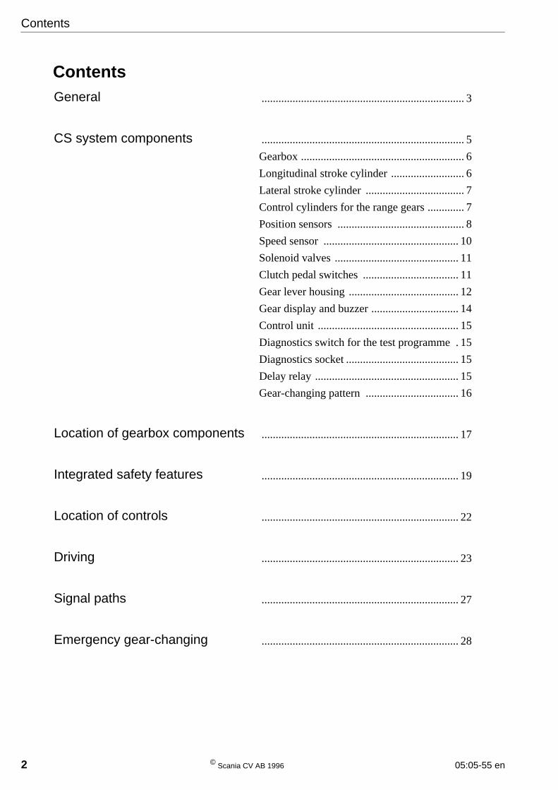
ContentsGeneral ........................................................................ 3
CS system components ........................................................................ 5
Gearbox .......................................................... 6
Longitudinal stroke cylinder .......................... 6
Lateral stroke cylinder ................................... 7
Control cylinders for the range gears ............. 7
Position sensors ............................................. 8
Speed sensor ................................................ 10
Solenoid valves ............................................ 11
Clutch pedal switches .................................. 11
Gear lever housing ....................................... 12
Gear display and buzzer ............................... 14
Control unit .................................................. 15
Diagnostics switch for the test programme . 15
Diagnostics socket ........................................ 15
Delay relay ................................................... 15
Gear-changing pattern ................................. 16
Location of gearbox components ...................................................................... 17
Integrated safety features ...................................................................... 19
Location of controls ...................................................................... 22
Driving ...................................................................... 23
Signal paths ...................................................................... 27
Emergency gear-changing ...................................................................... 28
05:05-55 en © Scania CV AB 1997, Sweden 3
General
General
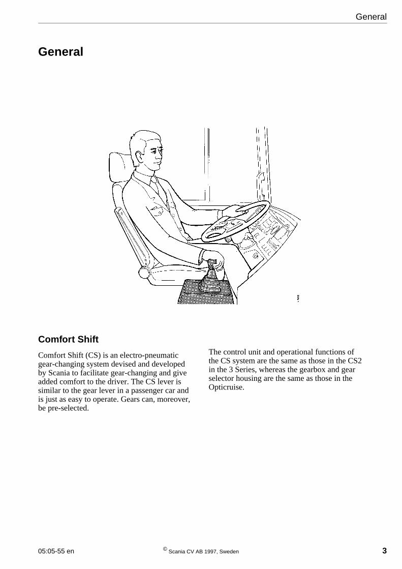
Comfort Shift
Comfort Shift (CS) is an electro-pneumaticgear-changing system devised and developedby Scania to facilitate gear-changing and giveadded comfort to the driver. The CS lever issimilar to the gear lever in a passenger car andis just as easy to operate. Gears can, moreover,be pre-selected.
The control unit and operational functions ofthe CS system are the same as those in the CS2in the 3 Series, whereas the gearbox and gearselector housing are the same as those in theOpticruise.
4 © Scania CV AB 1997, Sweden 05:05-55 en
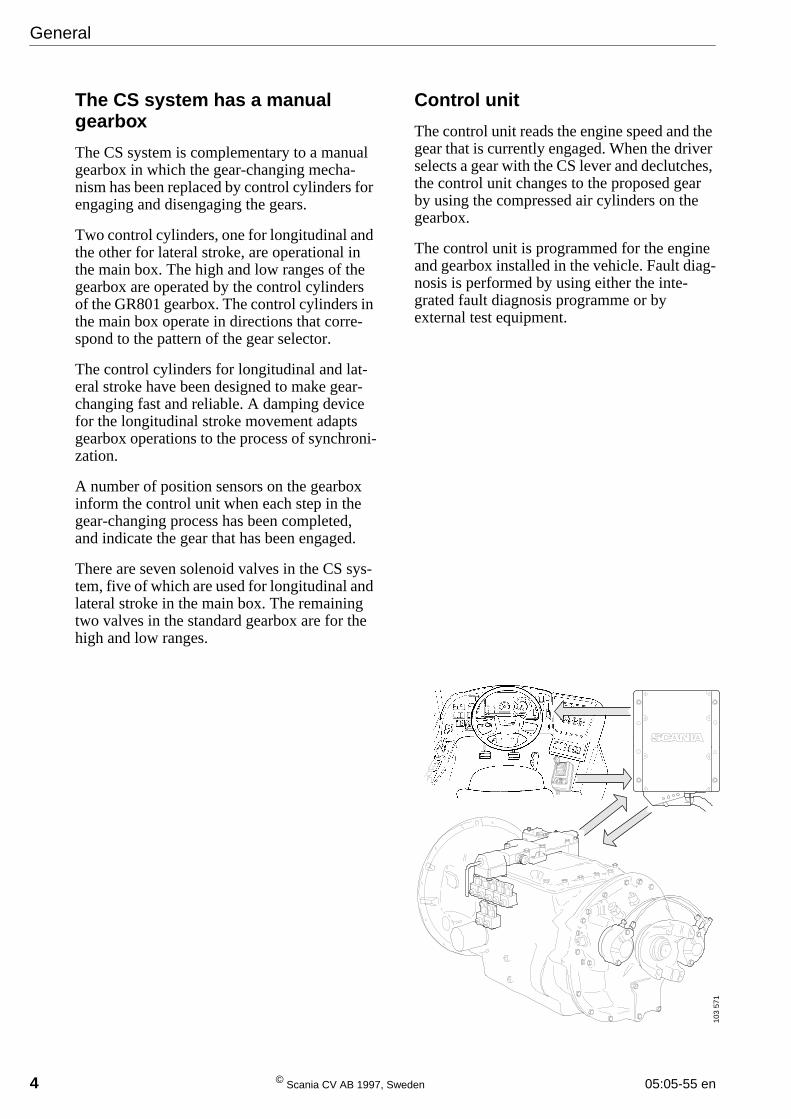
The CS system has a manualgearbox
The CS system is complementary to a manualgearbox in which the gear-changing mecha-nism has been replaced by control cylinders forengaging and disengaging the gears.
Two control cylinders, one for longitudinal andthe other for lateral stroke, are operational inthe main box. The high and low ranges of thegearbox are operated by the control cylindersof the GR801 gearbox. The control cylinders inthe main box operate in directions that corre-spond to the pattern of the gear selector.
The control cylinders for longitudinal and lat-eral stroke have been designed to make gear-changing fast and reliable. A damping devicefor the longitudinal stroke movement adaptsgearbox operations to the process of synchroni-zation.
A number of position sensors on the gearboxinform the control unit when each step in thegear-changing process has been completed,and indicate the gear that has been engaged.
There are seven solenoid valves in the CS sys-tem, five of which are used for longitudinal andlateral stroke in the main box. The remainingtwo valves in the standard gearbox are for thehigh and low ranges.
Control unit
The control unit reads the engine speed and thegear that is currently engaged. When the driverselects a gear with the CS lever and declutches,the control unit changes to the proposed gearby using the compressed air cylinders on thegearbox.
The control unit is programmed for the engineand gearbox installed in the vehicle. Fault diag-nosis is performed by using either the inte-grated fault diagnosis programme or byexternal test equipment.
General
103
571
05:05-55 en © Scania CV AB 1997, Sweden 5
Components
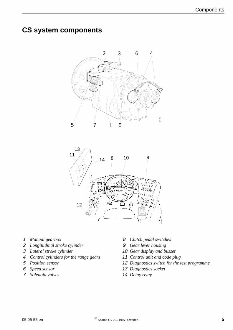
CS system components
1 Manual gearbox2 Longitudinal stroke cylinder3 Lateral stroke cylinder4 Control cylinders for the range gears5 Position sensor6 Speed sensor7 Solenoid valves
8 Clutch pedal switches9 Gear lever housing10 Gear display and buzzer11 Control unit and code plug12 Diagnostics switch for the test programme13 Diagnostics socket14 Delay relay
103
574
12
1113
14 8 10 910
3 70
2
7 1 55
2 3 6 4
6 © Scania CV AB 1997, Sweden 05:05-55 en
Components
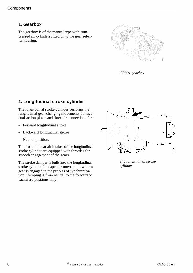
1. Gearbox
The gearbox is of the manual type with com-pressed air cylinders fitted on to the gear selec-tor housing.
2. Longitudinal stroke cylinder
The longitudinal stroke cylinder performs thelongitudinal gear-changing movements. It has adual-action piston and three air connections for:
- Forward longitudinal stroke
- Backward longitudinal stroke
- Neutral position.
The front and rear air intakes of the longitudinalstroke cylinder are equipped with throttles forsmooth engagement of the gears.
The stroke damper is built into the longitudinalstroke cylinder. It adapts the movements when agear is engaged to the process of synchroniza-tion. Damping is from neutral to the forward orbackward positions only.
GR801 gearbox
The longitudinal strokecylinder
103
572
05:05-55 en © Scania CV AB 1997, Sweden 7
Components
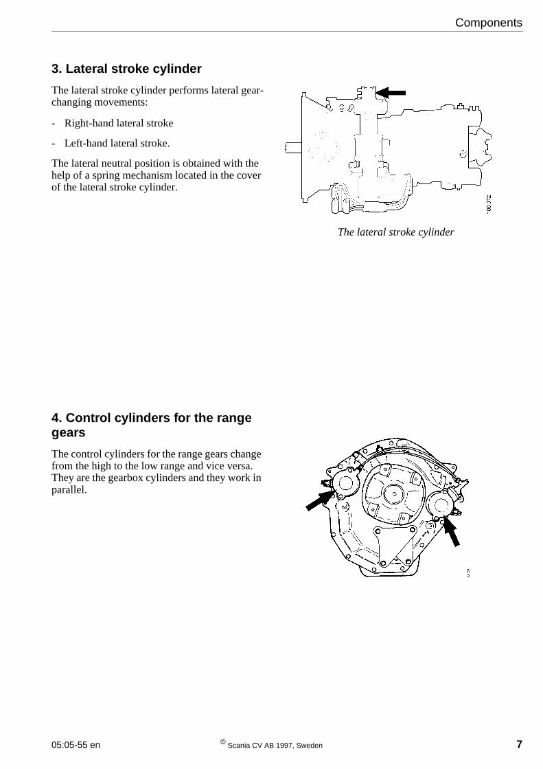
3. Lateral stroke cylinder
The lateral stroke cylinder performs lateral gear-changing movements:
- Right-hand lateral stroke
- Left-hand lateral stroke.
The lateral neutral position is obtained with thehelp of a spring mechanism located in the coverof the lateral stroke cylinder.
4. Control cylinders for the rangegears
The control cylinders for the range gears changefrom the high to the low range and vice versa.They are the gearbox cylinders and they work inparallel.
The lateral stroke cylinder
8 © Scania CV AB 1997, Sweden 05:05-55 en
Components
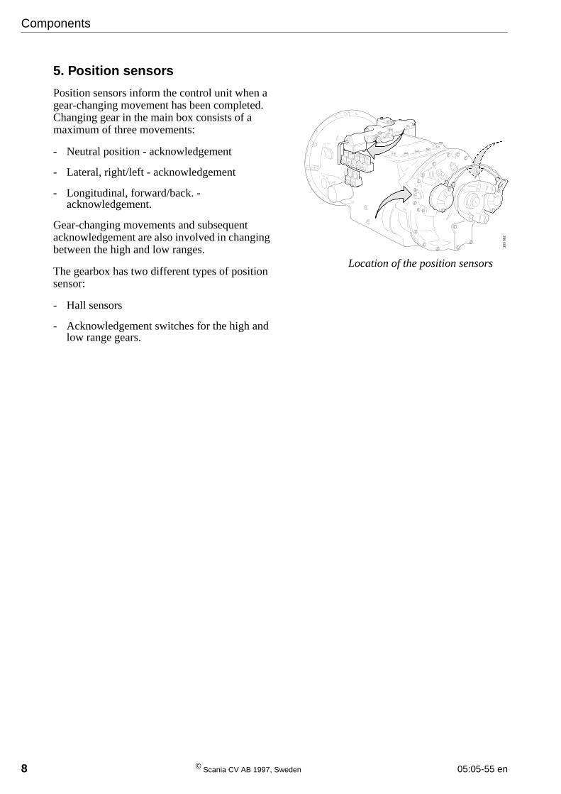
5. Position sensors
Position sensors inform the control unit when agear-changing movement has been completed.Changing gear in the main box consists of amaximum of three movements:
- Neutral position - acknowledgement
- Lateral, right/left - acknowledgement
- Longitudinal, forward/back. -acknowledgement.
Gear-changing movements and subsequentacknowledgement are also involved in changingbetween the high and low ranges.
The gearbox has two different types of positionsensor:
- Hall sensors
- Acknowledgement switches for the high andlow range gears.
Location of the position sensors
103
682
05:05-55 en © Scania CV AB 1997, Sweden 9
Components
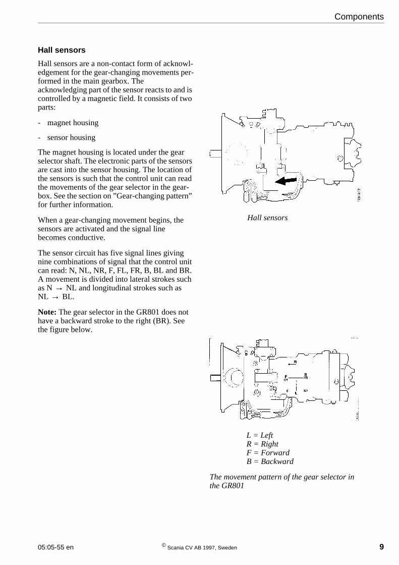
Hall sensors
Hall sensors are a non-contact form of acknowl-edgement for the gear-changing movements per-formed in the main gearbox. Theacknowledging part of the sensor reacts to and iscontrolled by a magnetic field. It consists of twoparts:
- magnet housing
- sensor housing
The magnet housing is located under the gearselector shaft. The electronic parts of the sensorsare cast into the sensor housing. The location ofthe sensors is such that the control unit can readthe movements of the gear selector in the gear-box. See the section on ”Gear-changing pattern”for further information.
When a gear-changing movement begins, thesensors are activated and the signal linebecomes conductive.
The sensor circuit has five signal lines givingnine combinations of signal that the control unitcan read: N, NL, NR, F, FL, FR, B, BL and BR.A movement is divided into lateral strokes suchas N→ NL and longitudinal strokes such asNL → BL.
Note: The gear selector in the GR801 does nothave a backward stroke to the right (BR). Seethe figure below.
Hall sensors
L = LeftR = RightF = ForwardB = Backward
The movement pattern of the gear selector inthe GR801
10 © Scania CV AB 1997, Sweden 05:05-55 en
Components
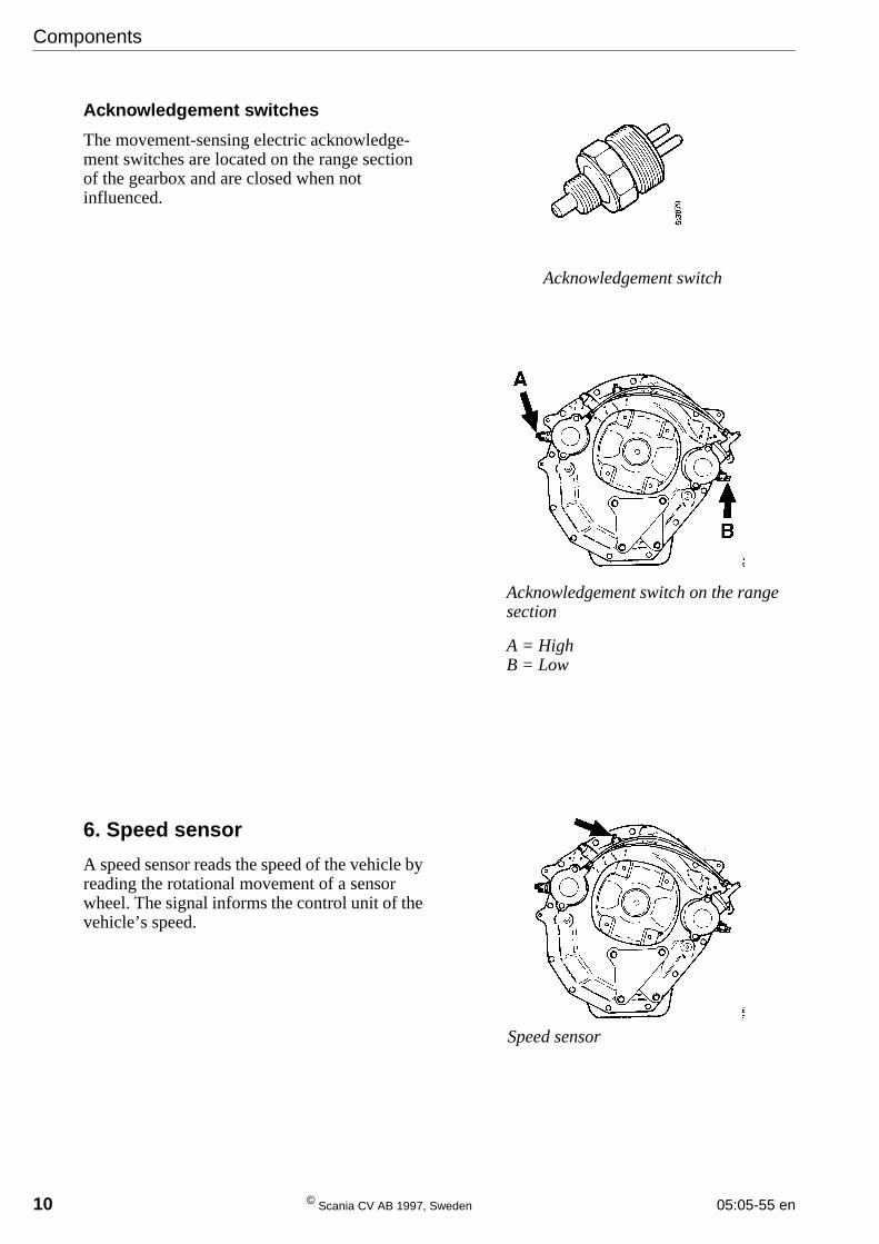
Acknowledgement switches
The movement-sensing electric acknowledge-ment switches are located on the range sectionof the gearbox and are closed when notinfluenced.
6. Speed sensor
A speed sensor reads the speed of the vehicle byreading the rotational movement of a sensorwheel. The signal informs the control unit of thevehicle’s speed.
Acknowledgement switch
Acknowledgement switch on the rangesection
A = HighB = Low
Speed sensor
05:05-55 en © Scania CV AB 1997, Sweden 11
Components
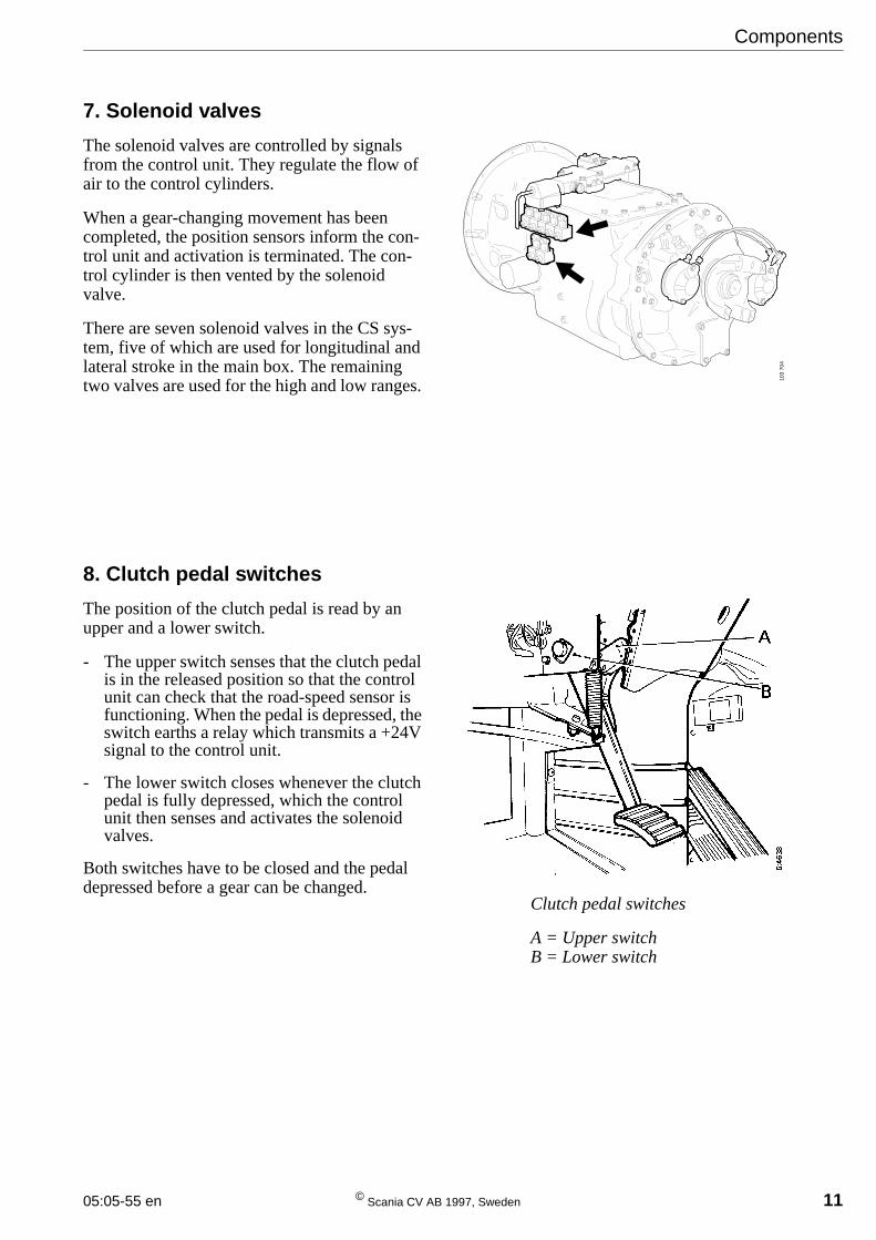
7. Solenoid valves
The solenoid valves are controlled by signalsfrom the control unit. They regulate the flow ofair to the control cylinders.
When a gear-changing movement has beencompleted, the position sensors inform the con-trol unit and activation is terminated. The con-trol cylinder is then vented by the solenoidvalve.
There are seven solenoid valves in the CS sys-tem, five of which are used for longitudinal andlateral stroke in the main box. The remainingtwo valves are used for the high and low ranges.
8. Clutch pedal switches
The position of the clutch pedal is read by anupper and a lower switch.
- The upper switch senses that the clutch pedalis in the released position so that the controlunit can check that the road-speed sensor isfunctioning. When the pedal is depressed, theswitch earths a relay which transmits a +24Vsignal to the control unit.
- The lower switch closes whenever the clutchpedal is fully depressed, which the controlunit then senses and activates the solenoidvalves.
Both switches have to be closed and the pedaldepressed before a gear can be changed.
Clutch pedal switches
A = Upper switchB = Lower switch
103
704
12 © Scania CV AB 1997, Sweden 05:05-55 en
Components
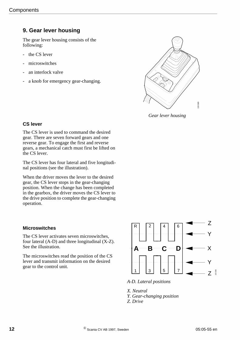
9. Gear lever housing
The gear lever housing consists of thefollowing:
- the CS lever
- microswitches
- an interlock valve
- a knob for emergency gear-changing.
CS lever
The CS lever is used to command the desiredgear. There are seven forward gears and onereverse gear. To engage the first and reversegears, a mechanical catch must first be lifted onthe CS lever.
The CS lever has four lateral and five longitudi-nal positions (see the illustration).
When the driver moves the lever to the desiredgear, the CS lever stops in the gear-changingposition. When the change has been completedin the gearbox, the driver moves the CS lever tothe drive position to complete the gear-changingoperation.
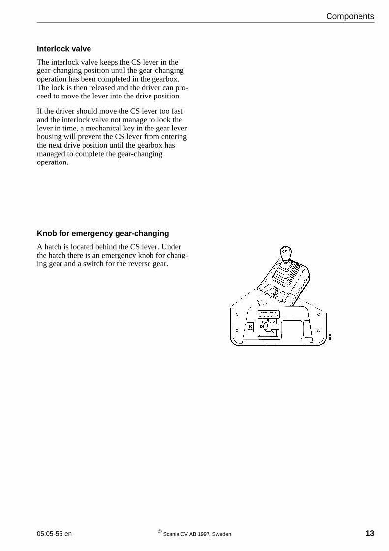
Microswitches
The CS lever activates seven microswitches,four lateral (A-D) and three longitudinal (X-Z).See the illustration.
The microswitches read the position of the CSlever and transmit information on the desiredgear to the control unit.
Gear lever housing
103
589
A-D. Lateral positions
X. NeutralY. Gear-changing positionZ. Drive
A B C D
R 2 4 6
1 3 5 7
Y
X
Z
Z
Y
103
590
05:05-55 en © Scania CV AB 1997, Sweden 13
Interlock valve
The interlock valve keeps the CS lever in thegear-changing position until the gear-changingoperation has been completed in the gearbox.The lock is then released and the driver can pro-ceed to move the lever into the drive position.
If the driver should move the CS lever too fastand the interlock valve not manage to lock thelever in time, a mechanical key in the gear leverhousing will prevent the CS lever from enteringthe next drive position until the gearbox hasmanaged to complete the gear-changingoperation.
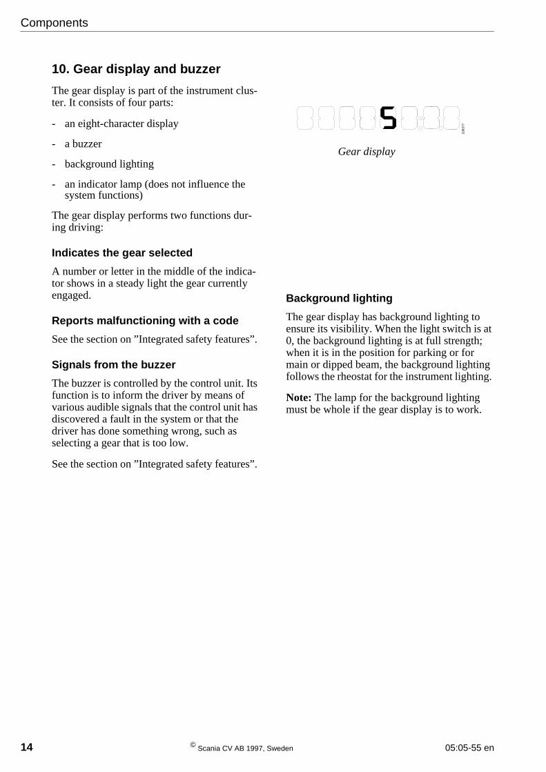
Knob for emergency gear-changing
A hatch is located behind the CS lever. Underthe hatch there is an emergency knob for chang-ing gear and a switch for the reverse gear.
Components
14 © Scania CV AB 1997, Sweden 05:05-55 en
Components
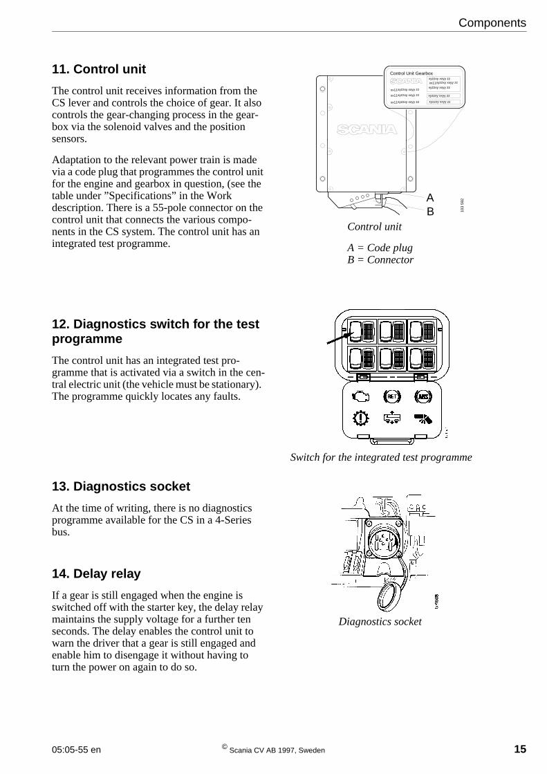
10. Gear display and buzzer
The gear display is part of the instrument clus-ter. It consists of four parts:
- an eight-character display
- a buzzer
- background lighting
- an indicator lamp (does not influence thesystem functions)
The gear display performs two functions dur-ing driving:
Indicates the gear selected
A number or letter in the middle of the indica-tor shows in a steady light the gear currentlyengaged.
Reports malfunctioning with a code
See the section on ”Integrated safety features”.
Signals from the buzzer
The buzzer is controlled by the control unit. Itsfunction is to inform the driver by means ofvarious audible signals that the control unit hasdiscovered a fault in the system or that thedriver has done something wrong, such asselecting a gear that is too low.
See the section on ”Integrated safety features”.
Background lighting
The gear display has background lighting toensure its visibility. When the light switch is at0, the background lighting is at full strength;when it is in the position for parking or formain or dipped beam, the background lightingfollows the rheostat for the instrument lighting.
Note: The lamp for the background lightingmust be whole if the gear display is to work.
Gear display
1083
77
05:05-55 en © Scania CV AB 1997, Sweden 15
Components
11. Control unit
The control unit receives information from theCS lever and controls the choice of gear. It alsocontrols the gear-changing process in the gear-box via the solenoid valves and the positionsensors.
Adaptation to the relevant power train is madevia a code plug that programmes the control unitfor the engine and gearbox in question, (see thetable under ”Specifications” in the Workdescription. There is a 55-pole connector on thecontrol unit that connects the various compo-nents in the CS system. The control unit has anintegrated test programme.
12. Diagnostics switch for the testprogramme
The control unit has an integrated test pro-gramme that is activated via a switch in the cen-tral electric unit (the vehicle must be stationary).The programme quickly locates any faults.
13. Diagnostics socket
At the time of writing, there is no diagnosticsprogramme available for the CS in a 4-Seriesbus.
14. Delay relay
If a gear is still engaged when the engine isswitched off with the starter key, the delay relaymaintains the supply voltage for a further tenseconds. The delay enables the control unit towarn the driver that a gear is still engaged andenable him to disengage it without having toturn the power on again to do so.
Control unit
A = Code plugB = Connector
Switch for the integrated test programme10
3 59
2
Control Unit Gearboxxyzzxy xxyy zzxx11xyzzxy xxyy zz
xyzzxy xxyy zz
xyzzxy xxyy zz
xyzzxy xxyy zz
xx11xyzzxy xxyy zz
xx11xyzzxy xxyy zz
xx11xyzzxy xxyy zz
AB
Diagnostics socket
16 © Scania CV AB 1997, Sweden 05:05-55 en
Gear-changing pattern
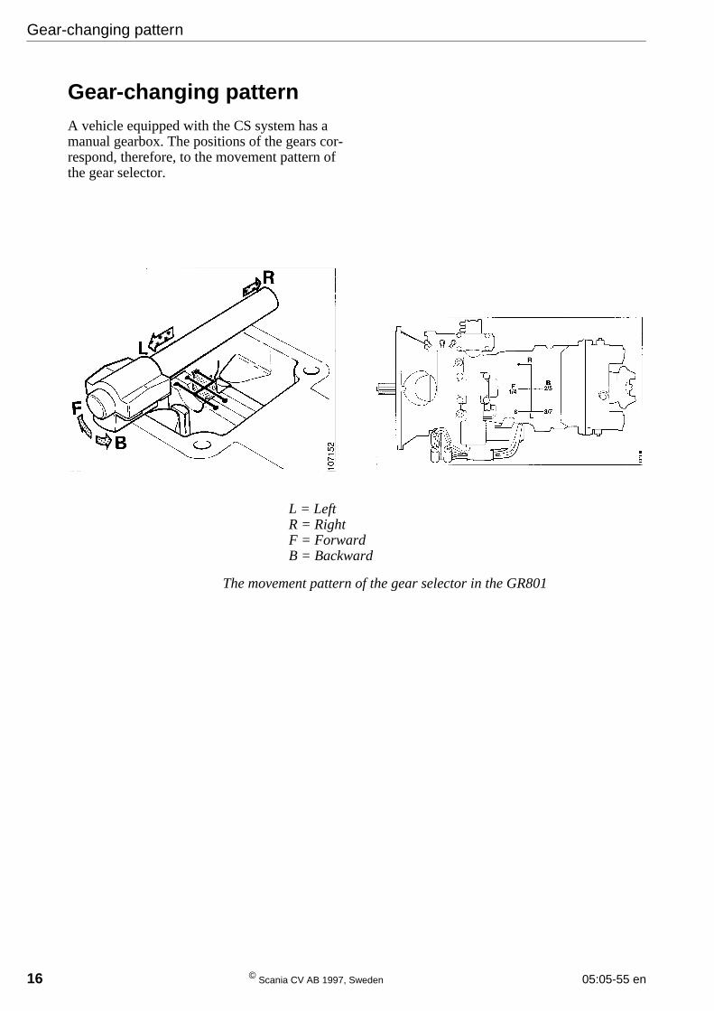
Gear-changing patternA vehicle equipped with the CS system has amanual gearbox. The positions of the gears cor-respond, therefore, to the movement pattern ofthe gear selector.
L = LeftR = RightF = ForwardB = Backward
The movement pattern of the gear selector in the GR801
05:05-55 en © Scania CV AB 1997, Sweden 17
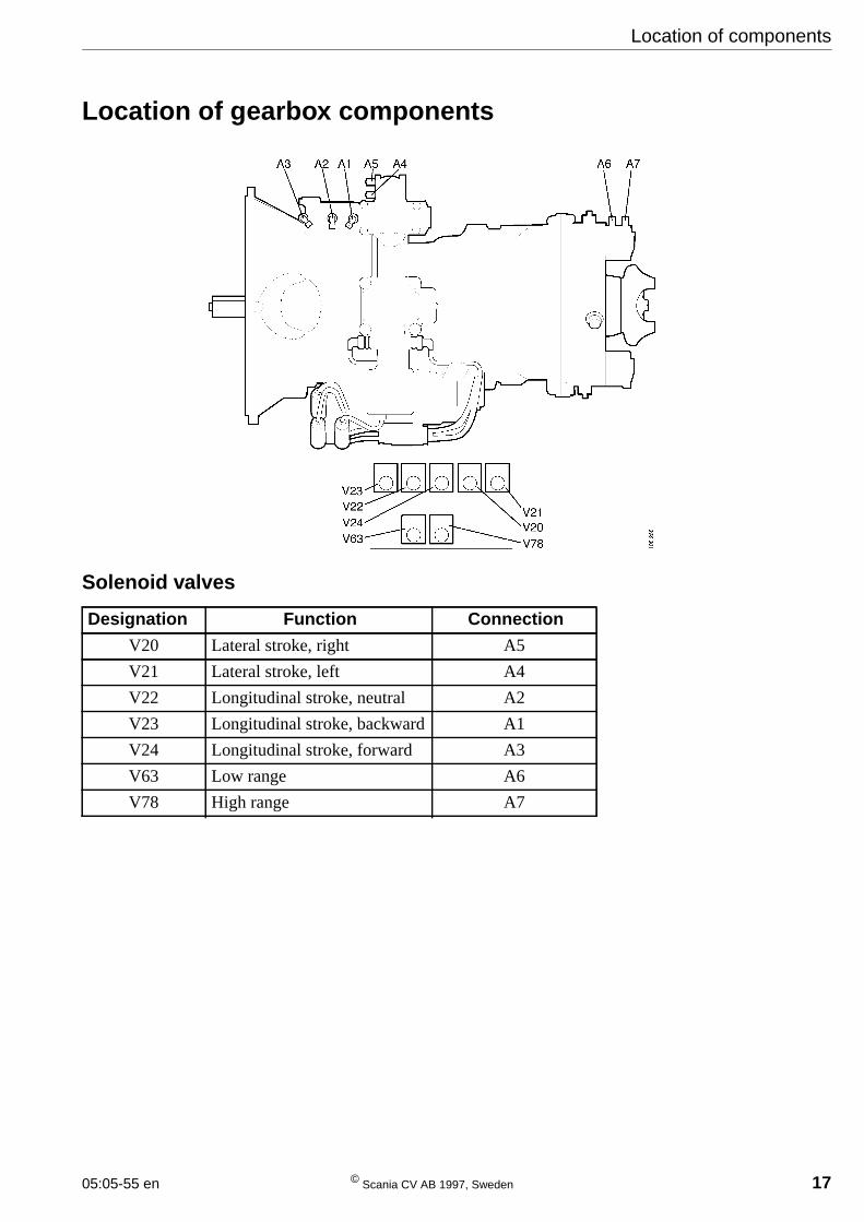
Location of gearbox components
Location of components
Solenoid valves
Designation Function Connection
V20 Lateral stroke, right A5
V21 Lateral stroke, left A4
V22 Longitudinal stroke, neutral A2
V23 Longitudinal stroke, backward A1
V24 Longitudinal stroke, forward A3
V63 Low range A6
V78 High range A7
18 © Scania CV AB 1997, Sweden 05:05-55 en
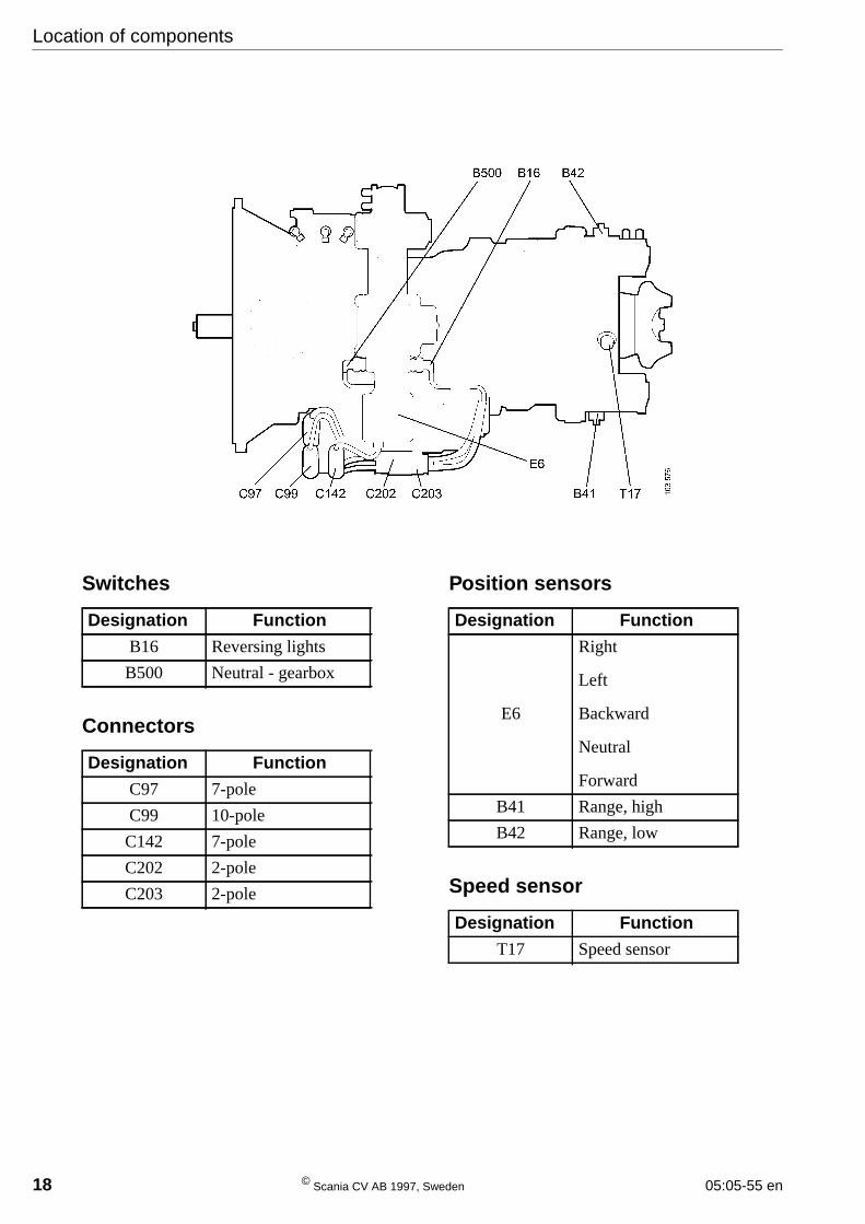
Location of components
Switches
Connectors
Position sensors
Speed sensor
Designation Function
B16 Reversing lights
B500 Neutral - gearbox
Designation Function
C97 7-pole
C99 10-pole
C142 7-pole
C202 2-pole
C203 2-pole
Designation Function
E6
Right
Left
Backward
Neutral
Forward
B41 Range, high
B42 Range, low
Designation Function
T17 Speed sensor
Integrated safety features
05:05-55 en © Scania CV AB 1996 19
Integrated safety features
Overrevving protection
Overrevving protection prevents a gear frombeing selected that is too low in relation to thespeed of the vehicle.
If the desired gear were to give the engine aspeed above 3000 rpm, the gear will not beengaged and the buzzer will sound. The buzzerswitches off when the lever is placed in neutralor the vehicle loses speed.
Monitoring road speed
Road-speed sensor
A control function in the control unit monitorsthe road speed. If the clutch is in the releasedposition and a gear with a gear ratio of lessthan 8:1 is engaged (e.g., gears 2 to 7 in theGR801), the control unit will expect the speedto be registered by the road-speed sensor.
If the reading is incorrect or is interpreted aszero by the control unit for a period of ten sec-onds, the buzzer will issue an alarm and theselection of a higher gear or neutral only willbe permitted. The fault can be due to a shortcircuit or break.
Clutch pedal switches
An upper and a lower switch are located by theclutch pedal. They inform the control unit bysignal whether the pedal is in the released ordepressed position.
Both switches must be functioning correctlyfor a gear-changing operation to be permitted.If one of them is issuing a faulty signal, chang-ing to a higher gear or neutral only will beallowed.
The upper switch registers even slight depres-sions of the clutch which means that erroneousinformation can be transmitted to the controlunit if the driver is driving with his foot on theclutch pedal.
If there is a break in one of the clutch pedalswitches it will not be possible to change gear.
To restart the control unit:
- Switch off the engine.
- Restart the engine.
Integrated safety features
20 © Scania CV AB 1996 05:05-55 en
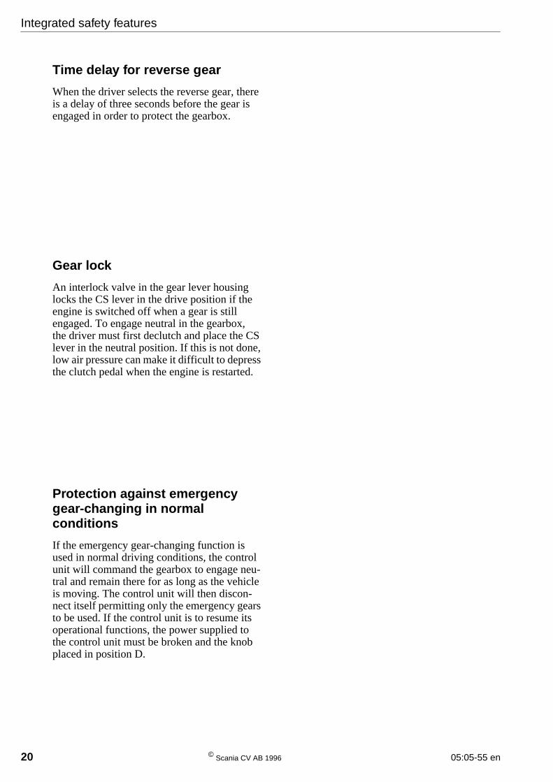
Time delay for reverse gear
When the driver selects the reverse gear, thereis a delay of three seconds before the gear isengaged in order to protect the gearbox.
Gear lock
An interlock valve in the gear lever housinglocks the CS lever in the drive position if theengine is switched off when a gear is stillengaged. To engage neutral in the gearbox,the driver must first declutch and place the CSlever in the neutral position. If this is not done,low air pressure can make it difficult to depressthe clutch pedal when the engine is restarted.
Protection against emergencygear-changing in normalconditions
If the emergency gear-changing function isused in normal driving conditions, the controlunit will command the gearbox to engage neu-tral and remain there for as long as the vehicleis moving. The control unit will then discon-nect itself permitting only the emergency gearsto be used. If the control unit is to resume itsoperational functions, the power supplied tothe control unit must be broken and the knobplaced in position D.
Integrated safety features
05:05-55 en © Scania CV AB 1996 21
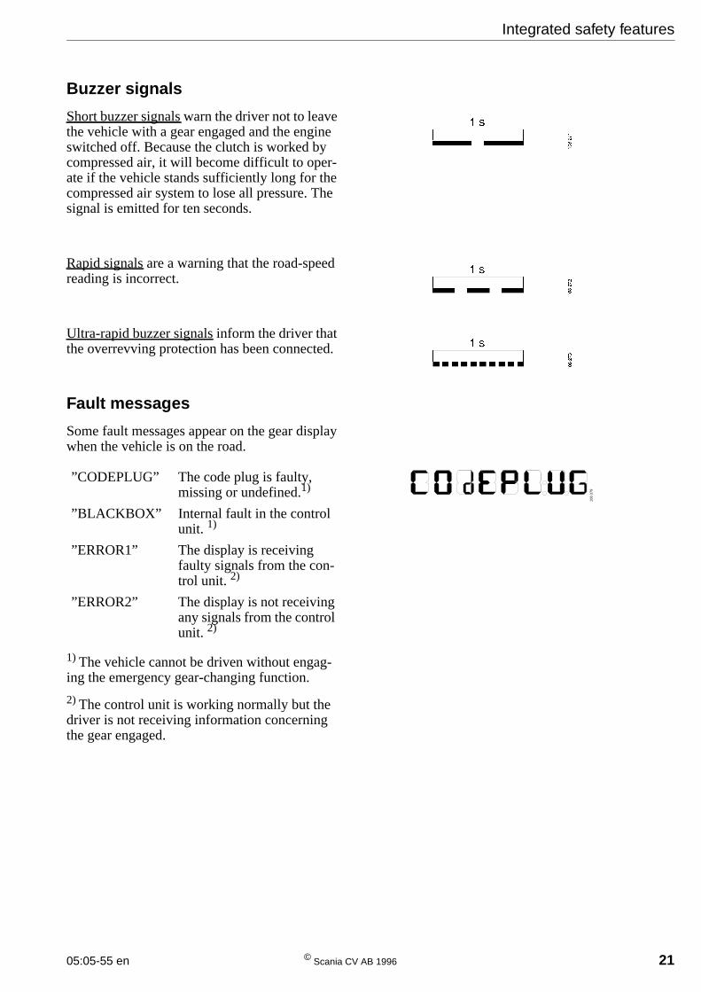
Buzzer signals
Short buzzer signals warn the driver not to leavethe vehicle with a gear engaged and the engineswitched off. Because the clutch is worked bycompressed air, it will become difficult to oper-ate if the vehicle stands sufficiently long for thecompressed air system to lose all pressure. Thesignal is emitted for ten seconds.
Rapid signals are a warning that the road-speedreading is incorrect.
Ultra-rapid buzzer signals inform the driver thatthe overrevving protection has been connected.
Fault messages
Some fault messages appear on the gear displaywhen the vehicle is on the road.
1) The vehicle cannot be driven without engag-ing the emergency gear-changing function.
2) The control unit is working normally but thedriver is not receiving information concerningthe gear engaged.
”CODEPLUG” The code plug is faulty,missing or undefined.1)
”BLACKBOX” Internal fault in the controlunit. 1)
”ERROR1” The display is receivingfaulty signals from the con-trol unit. 2)
”ERROR2” The display is not receivingany signals from the controlunit. 2)
108
379
22 © Scania CV AB 1997, Sweden 05:05-55 en
Driving
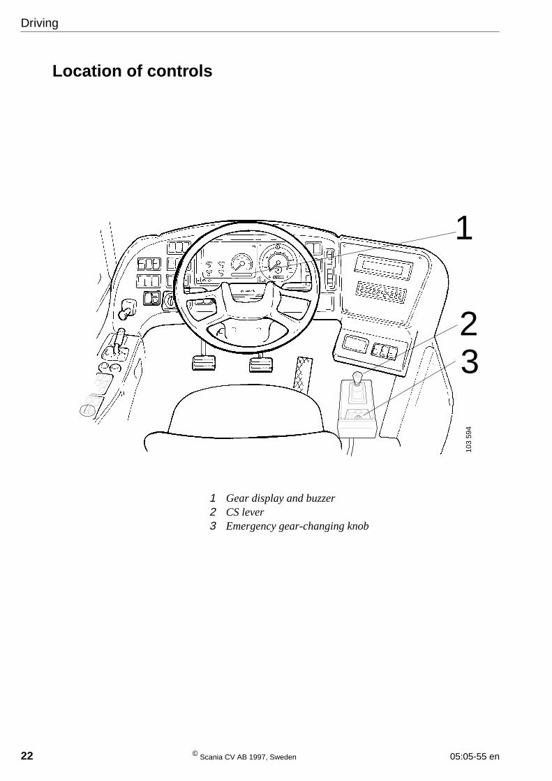
Location of controls
1 Gear display and buzzer2 CS lever3 Emergency gear-changing knob
1
23
103
594
Driving
05:05-55 en © Scania CV AB 1996 23
Driving
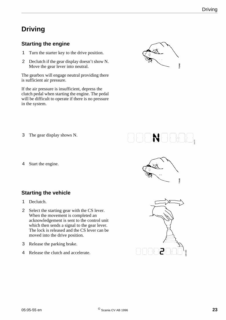
Starting the engine
1 Turn the starter key to the drive position.
2 Declutch if the gear display doesn’t show N.Move the gear lever into neutral.
The gearbox will engage neutral providing thereis sufficient air pressure.
If the air pressure is insufficient, depress theclutch pedal when starting the engine. The pedalwill be difficult to operate if there is no pressurein the system.
3 The gear display shows N.
4 Start the engine.
Starting the vehicle
1 Declutch.
2 Select the starting gear with the CS lever.When the movement is completed anacknowledgement is sent to the control unitwhich then sends a signal to the gear lever.The lock is released and the CS lever can bemoved into the drive position.
3 Release the parking brake.
4 Release the clutch and accelerate.
108
378
108
380
Driving
24 © Scania CV AB 1996 05:05-55 en
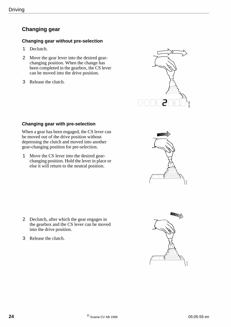
Changing gear
Changing gear without pre-selection
1 Declutch.
2 Move the gear lever into the desired gear-changing position. When the change hasbeen completed in the gearbox, the CS levercan be moved into the drive position.
3 Release the clutch.
Changing gear with pre-selection
When a gear has been engaged, the CS lever canbe moved out of the drive position withoutdepressing the clutch and moved into anothergear-changing position for pre-selection.
1 Move the CS lever into the desired gear-changing position. Hold the lever in place orelse it will return to the neutral position.
2 Declutch, after which the gear engages inthe gearbox and the CS lever can be movedinto the drive position.
3 Release the clutch.
103
596
103
597
108
380
Driving
05:05-55 en © Scania CV AB 1996 25
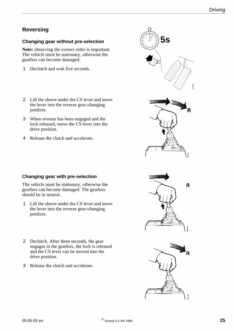
Reversing
Changing gear without pre-selection
Note: observing the correct order is important.The vehicle must be stationary, otherwise thegearbox can become damaged.
1 Declutch and wait five seconds.
2 Lift the sleeve under the CS lever and movethe lever into the reverse gear-changingposition.
3 When reverse has been engaged and thelock released, move the CS lever into thedrive position.
4 Release the clutch and accelerate.
Changing gear with pre-selection
The vehicle must be stationary, otherwise thegearbox can become damaged. The gearboxshould be in neutral.
1 Lift the sleeve under the CS lever and movethe lever into the reverse gear-changingposition.
2 Declutch. After three seconds, the gearengages in the gearbox, the lock is releasedand the CS lever can be moved into thedrive position.
3 Release the clutch and accelerate.
103
598
5s
Driving
26 © Scania CV AB 1996 05:05-55 en
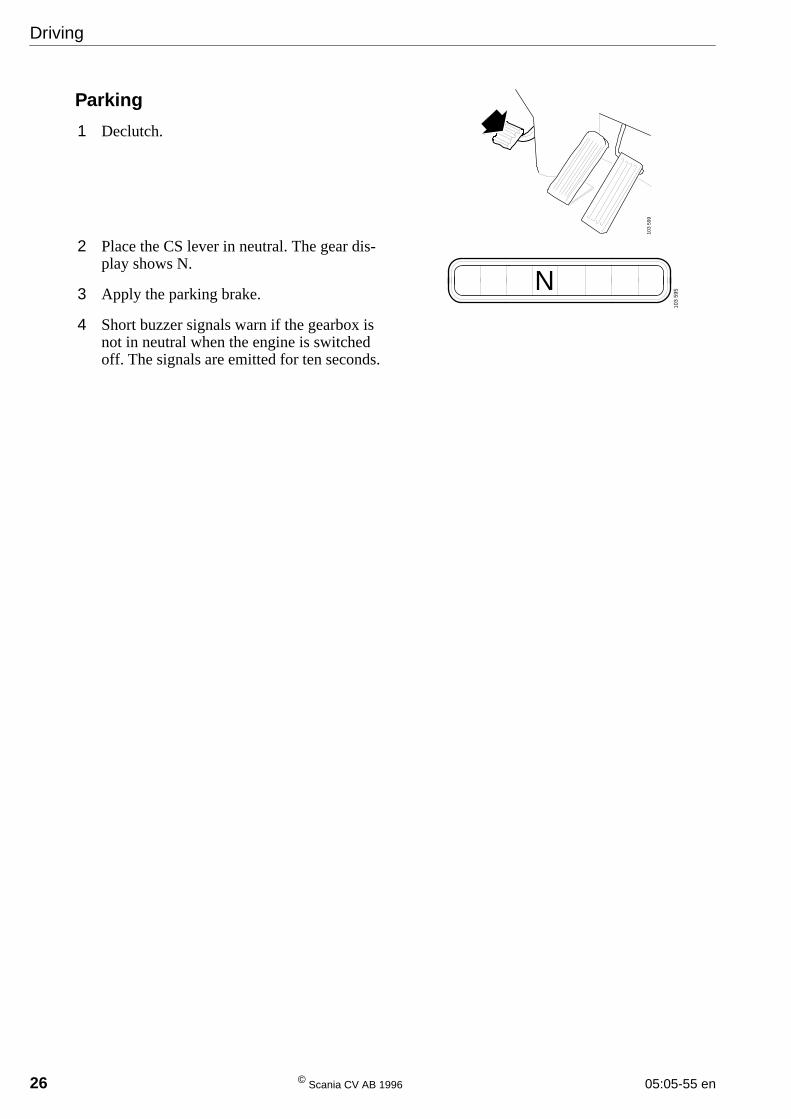
Parking
1 Declutch.
2 Place the CS lever in neutral. The gear dis-play shows N.
3 Apply the parking brake.
4 Short buzzer signals warn if the gearbox isnot in neutral when the engine is switchedoff. The signals are emitted for ten seconds.
103
599
N
103
595
Signal paths
05:05-55 en © Scania CV AB 1996 27
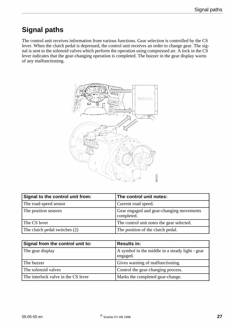
Signal pathsThe control unit receives information from various functions. Gear selection is controlled by the CSlever. When the clutch pedal is depressed, the control unit receives an order to change gear. The sig-nal is sent to the solenoid valves which perform the operation using compressed air. A lock in the CSlever indicates that the gear-changing operation is completed. The buzzer in the gear display warnsof any malfunctioning.
Signal to the control unit from: The control unit notes:
The road-speed sensor Current road speed.
The position sensors Gear engaged and gear-changing movementscompleted.
The CS lever The control unit notes the gear selected.
The clutch pedal switches (2) The position of the clutch pedal.
Signal from the control unit to: Results in:
The gear display A symbol in the middle in a steady light - gearengaged.
The buzzer Gives warning of malfunctioning.
The solenoid valves Control the gear-changing process.
The interlock valve in the CS lever Marks the completed gear-change.
103
571
Emergency gear-changing
28 © Scania CV AB 1996 05:05-55 en
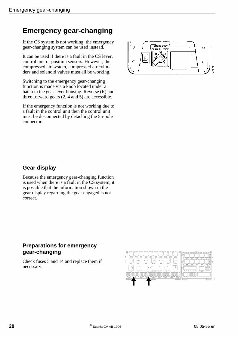
Emergency gear-changingIf the CS system is not working, the emergencygear-changing system can be used instead.
It can be used if there is a fault in the CS lever,control unit or position sensors. However, thecompressed air system, compressed air cylin-ders and solenoid valves must all be working.
Switching to the emergency gear-changingfunction is made via a knob located under ahatch in the gear lever housing. Reverse (R) andthree forward gears (2, 4 and 5) are accessible.
If the emergency function is not working due toa fault in the control unit then the control unitmust be disconnected by detaching the 55-poleconnector.
Gear display
Because the emergency gear-changing functionis used when there is a fault in the CS system, itis possible that the information shown in thegear display regarding the gear engaged is notcorrect.
Preparations for emergencygear-changing
Check fuses 5 and 14 and replace them ifnecessary.
RP14 RP15 RP16 RP17 RP18 RP19 RP20 RP21 RP22 RP23
RP7 RP8 RP9 RP10 RP11 RP12 RP13
RP1 RP2 RP3 RP4 RP5 RP6
1 2 3 4 5 6 7 8 9 10 11 12 13 14 15 16 17 18 19 20 21 22 23 24 25 26 27 28 29 30 31 32 33
RP25RP24 RP26 RP27 RP28
RP33RP32RP31RP30RP29
46
34
47 48 49 50 51
35 36 37 38 39
RP34
103
699
Emergency gear-changing
05:05-55 en © Scania CV AB 1996 29
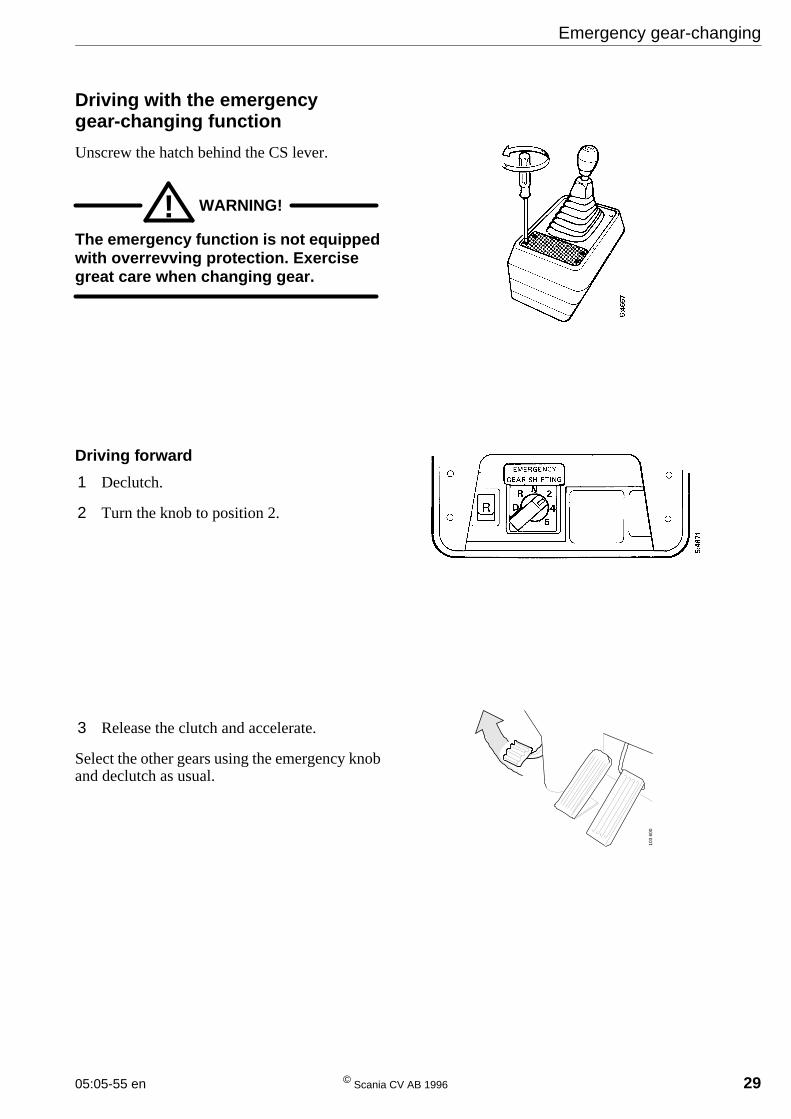
Driving with the emergencygear-changing function
Unscrew the hatch behind the CS lever.
WARNING!!The emergency function is not equippedwith overrevving protection. Exercisegreat care when changing gear.
Driving forward
1 Declutch.
2 Turn the knob to position 2.
3 Release the clutch and accelerate.
Select the other gears using the emergency knoband declutch as usual.
103
600
Emergency gear-changing
30 © Scania CV AB 1996 05:05-55 en
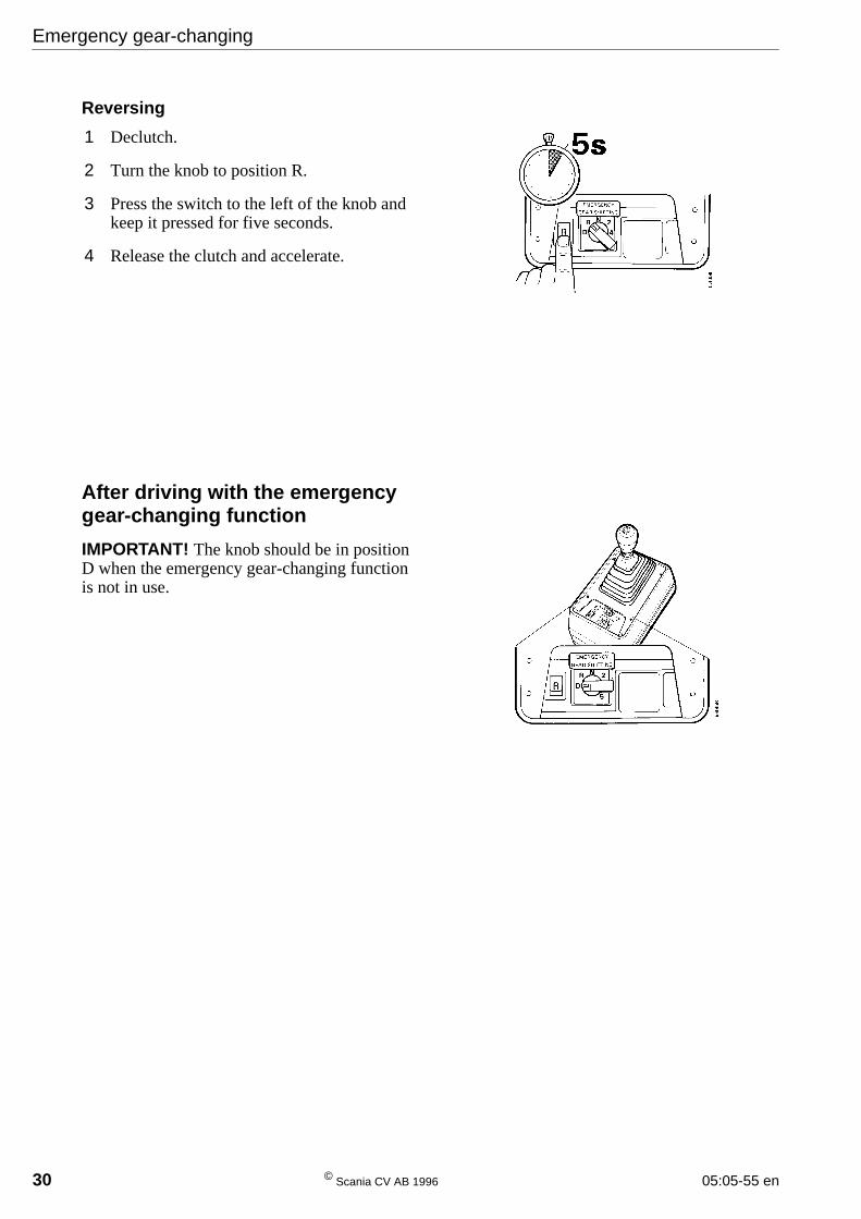
Reversing
1 Declutch.
2 Turn the knob to position R.
3 Press the switch to the left of the knob andkeep it pressed for five seconds.
4 Release the clutch and accelerate.
After driving with the emergencygear-changing function
IMPORTANT! The knob should be in positionD when the emergency gear-changing functionis not in use.
Related Documents