D-Sub connectors are an Industry Standard for cable-to-board connectivity applications. Thanks to the large variety of solutions it offers, it can be universally used as a device interface. Our customers manufacturing requirements are addressed by the comprehensive range of PCB termination styles available. It is particularly suited to configuring communication and data interfaces and is the standard for many fieldbus profiles. Solutions for the cable connector that can be easily assembled in the field are available for automation applications. 05. Subminiature D Connectors Board to Board Cable/ Wire to Board IP20 IP65 / IP67 Data Signal Power Data transfer rate Shielding Number of contacts, contact density Voltage, working current Cable termination Han- Quick Lock® IDC Crimp Screw Cage clamp Axial screw PCB termination THT SMC SMT Press-in Application standard Separate housing Integrated housing high performance Housing integration CONNECTION TYPE ENVIRONMENT APPLICATION Application profile:

Welcome message from author
This document is posted to help you gain knowledge. Please leave a comment to let me know what you think about it! Share it to your friends and learn new things together.
Transcript

D-Sub connectors are an Industry Standard for cable-to-board
connectivity applications. Thanks to the large variety of solutions it
offers, it can be universally used as a device interface. Our customers
manufacturing requirements are addressed by the comprehensive
range of PCB termination styles available. It is particularly suited to
configuring communication and data interfaces and is the standard
for many fieldbus profiles. Solutions for the cable connector that
can be easily assembled in the field are available for automation
applications.
05. Subminiature D Connectors
Boardto
Board
Cable/Wire
toBoard
IP20 IP65 / IP67
Data Signal PowerData
transfer rate
Shielding Number of contacts, contact density
Voltage, working current
Cable termination
Han- Quick Lock®
IDC Crimp
Screw Cage clamp
Axial screw
PCB termination
THT SMC SMT
Press-in
Application standard
Separate housing
Integratedhousing
high performance
Housing integration
ConneCtion type environment AppliCAtion
App l icat ion prof i le:
D-Su
b
0501
Tooling see chapter 20
05. Subminiature D Connectors
Contents Page
D-Sub connector system – introduction . . . . . . . . . . . . . . . . . . . . . . . . . . . . . . . . . . . . . . . . 05.02
D-Sub Standard connectors (D-Sub – S) . . . . . . . . . . . . . . . . . . . . . . . . . . . . . . . . . . . . . . 05.04
D-Sub High Density connectors (D-Sub – HD) . . . . . . . . . . . . . . . . . . . . . . . . . . . . . . . . . . 05.38
D-Sub Mixed connectors (D-Sub – M) . . . . . . . . . . . . . . . . . . . . . . . . . . . . . . . . . . . . . . . . . 05.50
D-Sub Filter connectors (D-Sub – F) . . . . . . . . . . . . . . . . . . . . . . . . . . . . . . . . . . . . . . . . . . 05.90
D-Sub Waterproof IP67 connectors (D-Sub – W) . . . . . . . . . . . . . . . . . . . . . . . . . . . . . . . . 05.116
D-Sub Housing range (D-Sub – H) and accessories . . . . . . . . . . . . . . . . . . . . . . . . . . . . . . 05.140
D-Sub Standard press-in connectors . . . . . . . . . . . . . . . . . . . . . . . . . . . . . . . . . . . . . . . . . 05.171
D-Sub Standard SMC connectors . . . . . . . . . . . . . . . . . . . . . . . . . . . . . . . . . . . . . . . . . . . . 05.176
D-Sub Standard SMT connectors . . . . . . . . . . . . . . . . . . . . . . . . . . . . . . . . . . . . . . . . . . . . 05.184
Cables for insulation displacement termination and cable assemblies . . . . . . . . . . . . . . . . 05.194
0502
D-Su
b
05. Subminiature D Connectors
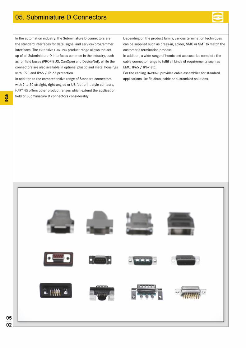
In the automation industry, the Subminiature D connectors are
the standard interfaces for data, signal and service/programmer
interfaces. The extensive HARTING product range allows the set
up of all Subminiature D interfaces common in the industry, such
as for field buses (PROFIBUS, CanOpen and DeviceNet), while the
connectors are also available in optional plastic and metal housings
with IP20 and IP65 / IP 67 protection.
In addition to the comprehensive range of Standard connectors
with 9 to 50 straight, right-angled or US foot print style contacts,
HARTING offers other product ranges which extend the application
field of Subminiature D connectors considerably.
Depending on the product family, various termination techniques
can be supplied such as press-in, solder, SMC or SMT to match the
customer’s termination process.
In addition, a wide range of hoods and accessories complete the
cable connector range to fulfil all kinds of requirements such as
EMC, IP65 / IP67 etc.
For the cabling HARTING provides cable assemblies for standard
applications like fieldbus, cable or customized solutions.

0503
D-Su
b
D-SuB – MixeD CoNNeCtorS
with nearly 20 different contact arrangements offering versatile
options for mixing power, coaxial, high voltage, signal and even
pneumatic contacts in one connector.
D-SuB – WaterProof
IP65 / IP67 connectors with 9 to 50 contacts for panel mount
to PCB or cable.
D-SuB – filter CoNNeCtorS
with 9 to 37 contacts and integrated, different filter designs,
like C, L or Pi types.
D-SuB – HigH DeNSity CoNNeCtorS
with 15 to 78 straight and right-angled contacts, exceeding
the contact capacity of the standard Subminiature D connectors
by 70 %.
Specific features of the product range
0504
D-Su
b
M FM F
M F
M F M F
D-Sub PCB solder version Technical characteristics
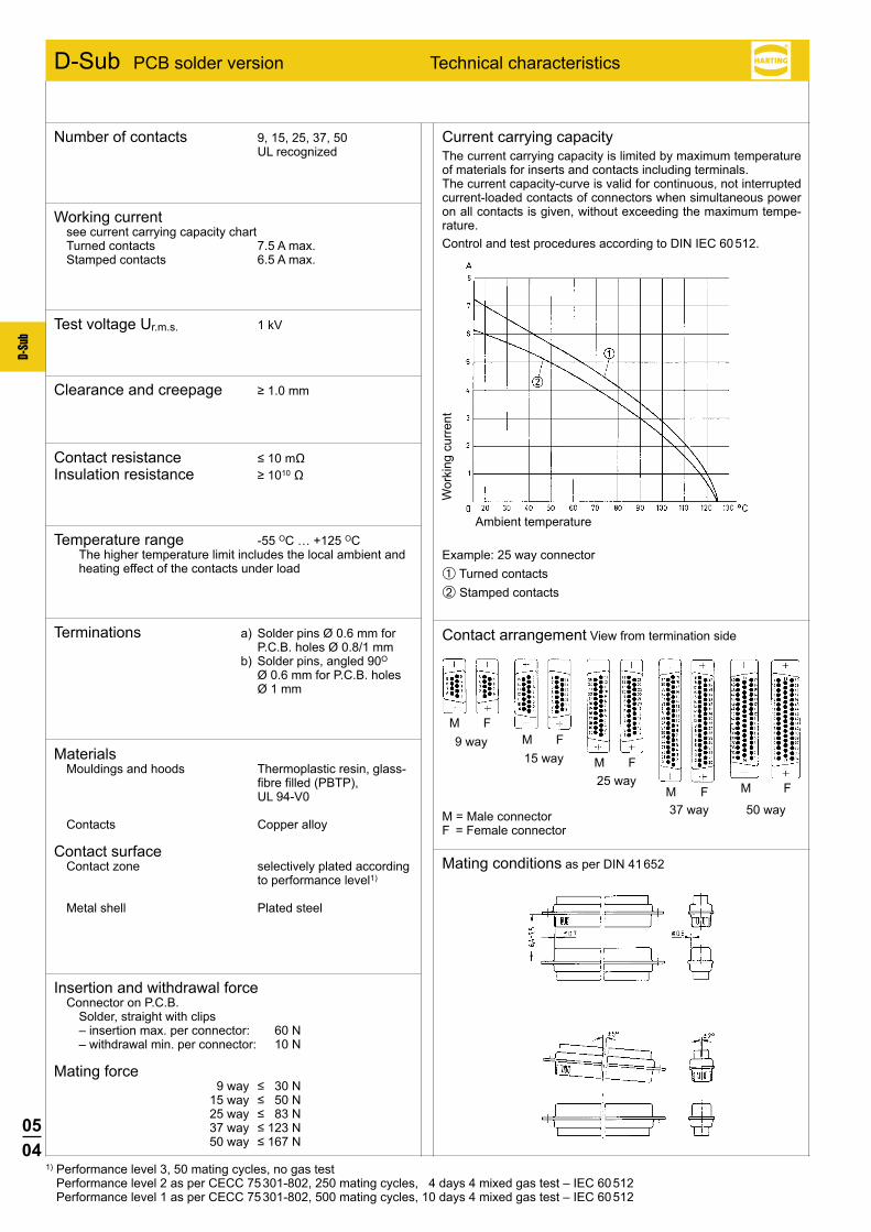
Current carrying capacityThe current carrying capacity is limited by maximum temperature of materials for inserts and contacts including terminals.The current capacity-curve is valid for continuous, not interrupted current-loaded contacts of connectors when simultaneous power on all contacts is given, without exceeding the maximum tempe-rature.Control and test procedures according to DIN IEC 60 512.
Contact arrangement View from termination side
Mating conditions as per DIN 41 652
M = Male connectorF = Female connector
37 way 50 way
Wor
king
cur
rent
Ambient temperature
Example: 25 way connector➀ Turned contacts➁ Stamped contacts
Number of contacts 9, 15, 25, 37, 50 UL recognized
Working currentsee current carrying capacity chart Turned contacts 7.5 A max. Stamped contacts 6.5 A max.
Test voltage Ur.m.s. 1 kV
Clearance and creepage ≥1.0mm
Contact resistance ≤10mΩ Insulation resistance ≥1010Ω
Temperature range -55 OC … +125 OC The higher temperature limit includes the local ambient and
heating effect of the contacts under load
Terminations a) Solder pins Ø 0.6 mm for P.C.B. holes Ø 0.8/1 mm
b) Solder pins, angled 90O Ø 0.6 mm for P.C.B. holes Ø 1 mm
MaterialsMouldings and hoods Thermoplastic resin, glass-
fibre filled (PBTP), UL 94-V0
Contacts Copper alloy
Contact surface Contact zone selectively plated according
to performance level1)
Metal shell Plated steel
Insertion and withdrawal forceConnector on P.C.B. Solder, straight with clips – insertion max. per connector: 60 N – withdrawal min. per connector: 10 N
Mating force 9way ≤30N 15way ≤50N 25way ≤83N 37way ≤123N 50way ≤167N
1) Performance level 3, 50 mating cycles, no gas test Performance level 2 as per CECC 75 301-802, 250 mating cycles, 4 days 4 mixed gas test – IEC 60 512 Performance level 1 as per CECC 75 301-802, 500 mating cycles, 10 days 4 mixed gas test – IEC 60 512
9 way15 way
25 way

0505
D-Su
b
Notes
0506
D-Su
b
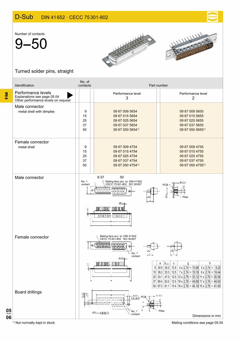
9 09 67 009 5654 09 67 009 5655 15 09 67 015 5654 09 67 015 5655 25 09 67 025 5654 09 67 025 5655 37 09 67 037 5654 09 67 037 5655 50 09 67 050 56541) 09 67 050 56551)
9 09 67 009 4754 09 67 009 4755 15 09 67 015 4754 09 67 015 4755 25 09 67 025 4754 09 67 025 4755 37 09 67 037 4754 09 67 037 4755 50 09 67 050 47541) 09 67 050 47551)
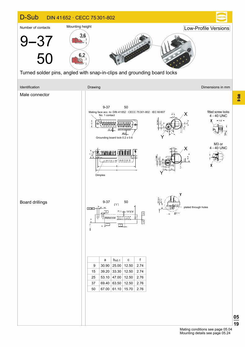
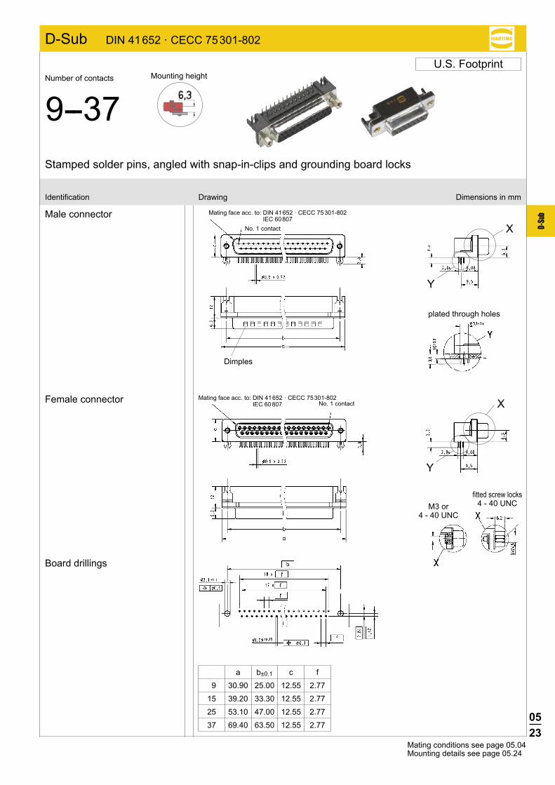
D-Sub DIN 41 652 · CECC 75 301-802
9-37 50
Pillar
1) Not normally kept in stock
Performance levelsExplanations see page 05.04 þOther performance levels on request
Male connectormetal shell with dimples
Female connectormetal shell
Male connector
Female connector
Board drillings
Performance level3
Performance level2
No. ofIdentification contacts Part number
Turned solder pins, straight
Number of contacts
9--50
Dimensions in mm
Mating conditions see page 05.04
a b ± 0.1 c g h 9 30.9 25.0 12.5 4 x 2.74 = 10.96 3 x 2.74 = 8.22 15 39.2 33.3 12.5 7 x 2.74 = 19.18 6 x 2.74 = 16.44 25 53.1 47.0 12.5 12 x 2.76 = 33.12 11 x 2.76 = 30.36 37 69.4 63.5 12.5 18 x 2.76 = 49.68 17 x 2.76 = 46.92 50 67.0 61.1 15.4 16 x 2.76 = 44.16 15 x 2.76 = 41.40
Mating face acc. to: DIN 41 652 CECC 75 301-802 · IEC 60 807
No. 1 contact
Mating face acc. to: DIN 41 652 CECC 75 301-802 · IEC 60 807
No. 1 contact
No. 1 contact
Pillar
PCB
PCB

0507
D-Su
b
9 09 66 121 770 . 09 66 121 670 . 15 09 66 221 770 . 09 66 221 670 . 25 09 66 321 770 . 09 66 321 670 . 37 09 66 421 770 . 09 66 421 670 . 50 09 66 521 770 . 09 66 521 670 .
D-Sub DIN 41 652 · CECC 75 301-802
9-37 50
X
Performance levelsExplanations see page 05.04 þOther performance levels on request
Male connectormetal shell with dimples
Please insert digit forflange thread or fittedfemale screw locks
Male connector
Board drillings
Performance level3
Performance level2
No. ofIdentification contacts Part number
Turned solder pins, straight without grounding-pins
Number of contacts
9--50
Dimensions in mm
Mating conditions see page 05.04
M3 þ 1 4-40 UNC þ 2 fitted screw locks 4-40 UNC þ 3
Mating face acc. to: DIN 41 652 CECC 75 301-802 · IEC 60 807
No. 1 contact
DimplesNo. 1 contact
M3 or 4-40 UNC
fitted screw locks 4-40 UNC
a b ± 0.1 c g h 9 30.9 25.0 12.9 4 x 2.74 = 10.96 3 x 2.74 = 8.22 15 39.2 33.3 12.9 7 x 2.74 = 19.18 6 x 2.74 = 16.44 25 53.1 47.0 12.9 12 x 2.76 = 33.12 11 x 2.76 = 30.36 37 69.4 63.5 12.9 18 x 2.76 = 49.68 17 x 2.76 = 46.92 50 67.0 61.1 15.7 16 x 2.76 = 44.16 15 x 2.76 = 41.40
available
on request

0508
D-Su
b
D-Sub DIN 41 652 · CECC 75 301-802
9 09 66 111 750 . 09 66 111 650 .
15 09 66 211 750 . 09 66 211 650 .
25 09 66 311 750 . 09 66 311 650 .
37 09 66 411 750 . 09 66 411 650 .
50 09 66 511 750 . 09 66 511 650 .
9 09 66 151 751 . 09 66 151 651 .
15 09 66 251 751 . 09 66 251 651 .
25 09 66 351 751 . 09 66 351 651 .
37 09 66 451 751 . 09 66 451 651 .
9 09 65 121 770 . 09 65 121 670 .
15 09 65 221 770 . 09 65 221 670 .
25 09 65 321 770 . 09 65 321 670 .
37 09 65 421 770 . 09 65 421 670 .
9 09 65 161 771 . 09 65 161 671 .
15 09 65 261 771 . 09 65 261 671 .
25 09 65 361 771 . 09 65 361 671 .
37 09 65 461 771 . 09 65 461 671 .
1) Fitted screw locks 4-40 UNC not normally kept in stock for performance level 3Connector dimensions see page 05.09. Mating conditions see page 05.04.
Performance levelsExplanations see page 05.04 þOther performance levels on request
Male connectormetal shell with dimples
Female connectormetal shell
Please insert digit for flange thread or fitted female screw locks
Performance level3
Performance level2
No. ofIdentification contacts Part number
Stamped solder pins, straight with/without grounding board locks
Number of contacts
9--50
Without grounding board locks
With grounding board locks
Without grounding board locks
With grounding board locks
M3 þ 1 4-40 UNC þ 2 fitted screw locks 4-40 UNC þ 3 1)
0509
D-Su
b
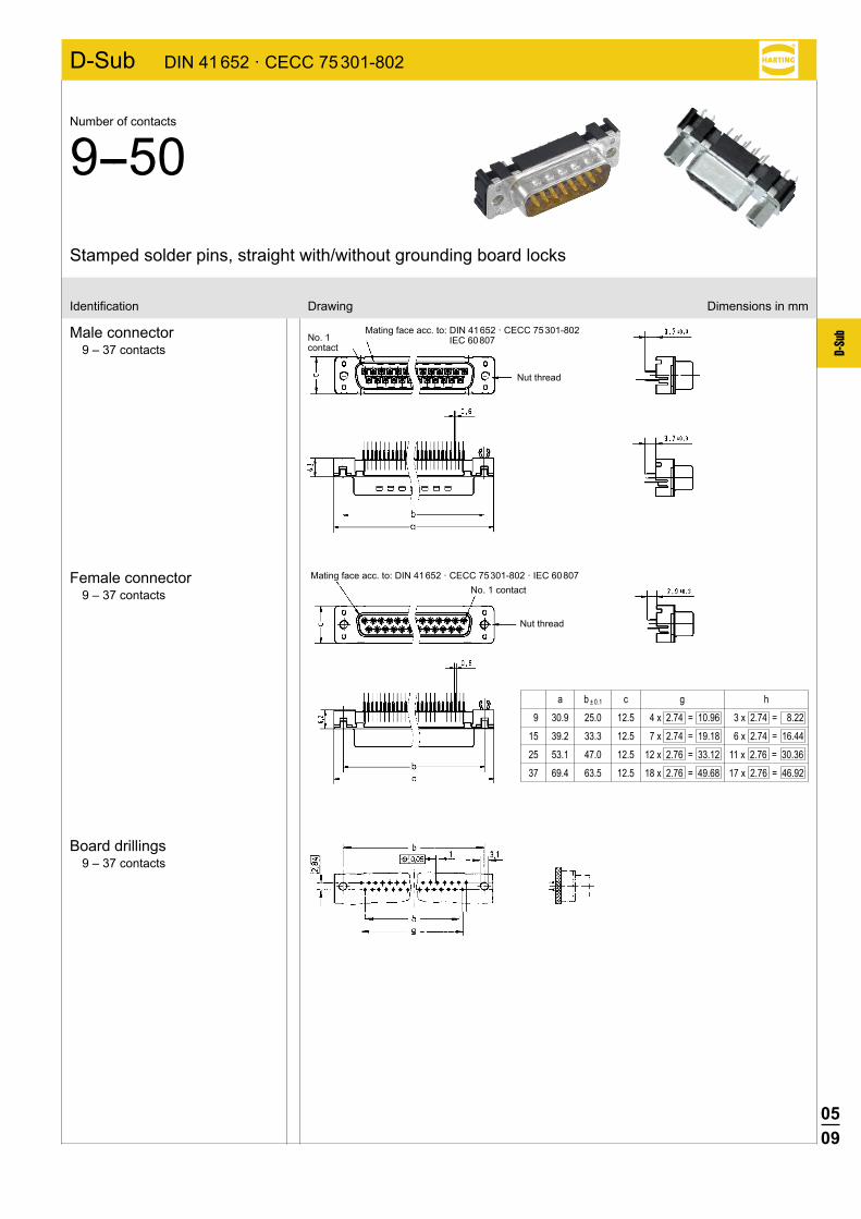
D-Sub DIN 41 652 · CECC 75 301-802
Identification Drawing Dimensions in mm
Male connector9 – 37 contacts
Female connector9 – 37 contacts
Board drillings9 – 37 contacts
Stamped solder pins, straight with/without grounding board locks
Number of contacts
9--50
a b ± 0.1 c g h
9 30.9 25.0 12.5 4 x 2.74 = 10.96 3 x 2.74 = 8.22
15 39.2 33.3 12.5 7 x 2.74 = 19.18 6 x 2.74 = 16.44
25 53.1 47.0 12.5 12 x 2.76 = 33.12 11 x 2.76 = 30.36
37 69.4 63.5 12.5 18 x 2.76 = 49.68 17 x 2.76 = 46.92
Mating face acc. to: DIN 41 652 · CECC 75 301-802 IEC 60 807No. 1
contact
Nut thread
Mating face acc. to: DIN 41 652 · CECC 75 301-802 · IEC 60 807No. 1 contact
Nut thread
0510
D-Su
b
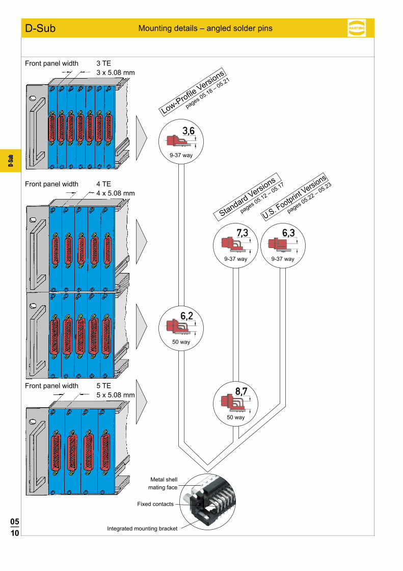
D-Sub Mounting details – angled solder pins
Front panel width 3 TE 3 x 5.08 mm
Front panel width 4 TE 4 x 5.08 mm
Front panel width 5 TE 5 x 5.08 mm
9-37 way
9-37 way 9-37 way
50 way
Metal shellmating face
Fixed contacts
Integrated mounting bracket
Low-Profile Versions
pages 05.18 – 05.21
Standard Versions
pages 05.12 – 05.17
U.S. Footprint Versions
pages 05.22 – 05.23
50 way
0511
D-Su
bDIN 41 612
DIN 41 612
DIN 41 612 DIN 41 612
D-Sub
PCBPCB
PCB PCB
Low-Profile Versions
Standard Versions US Footprint
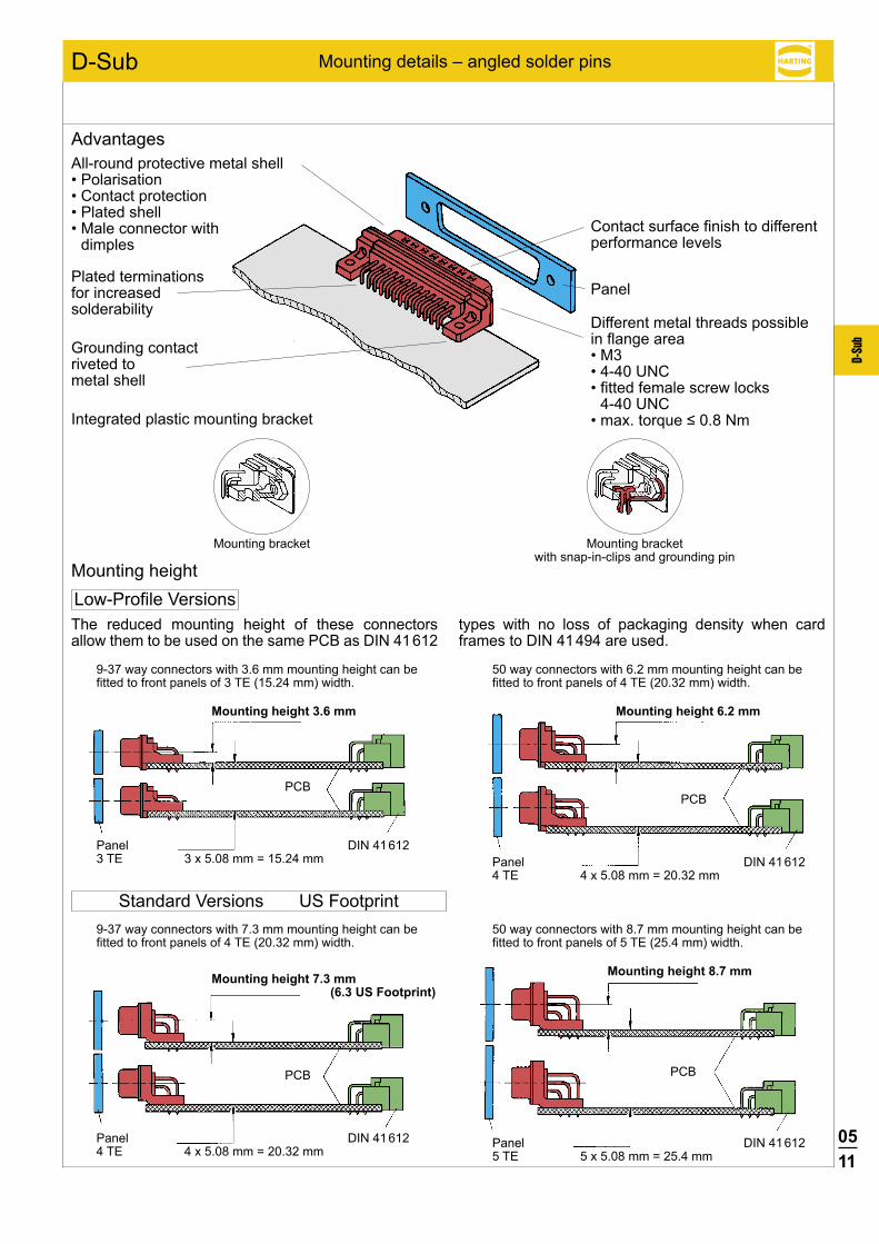
Advantages
Mounting height
All-round protective metal shell•Polarisation•Contactprotection•Platedshell•Maleconnectorwith
dimples
Plated terminations for increased solderability
Grounding contactriveted tometal shell
Integrated plastic mounting bracket
Different metal threads possible in flange area•M3•4-40UNC•fittedfemalescrewlocks
4-40 UNC•max.torque≤0.8Nm
Panel
Contact surface finish to different performance levels
Mounting bracket Mounting bracketwith snap-in-clips and grounding pin
The reduced mounting height of these connectors allow them to be used on the same PCB as DIN 41 612
types with no loss of packaging density when card frames to DIN 41 494 are used.
9-37 way connectors with 3.6 mm mounting height can be fitted to front panels of 3 TE (15.24 mm) width.
Mounting height 3.6 mm
Panel3 TE 3 x 5.08 mm = 15.24 mm
50 way connectors with 6.2 mm mounting height can be fitted to front panels of 4 TE (20.32 mm) width.
Mounting height 6.2 mm
Panel4 TE 4 x 5.08 mm = 20.32 mm
9-37 way connectors with 7.3 mm mounting height can be fitted to front panels of 4 TE (20.32 mm) width.
Mounting height 7.3 mm(6.3 US Footprint)
Panel4 TE 4 x 5.08 mm = 20.32 mm
50 way connectors with 8.7 mm mounting height can be fitted to front panels of 5 TE (25.4 mm) width.
Mounting height 8.7 mm
Panel5 TE 5 x 5.08 mm = 25.4 mm
Mounting details – angled solder pins

0512
D-Su
b
D-Sub DIN 41 652 · CECC 75 301-802
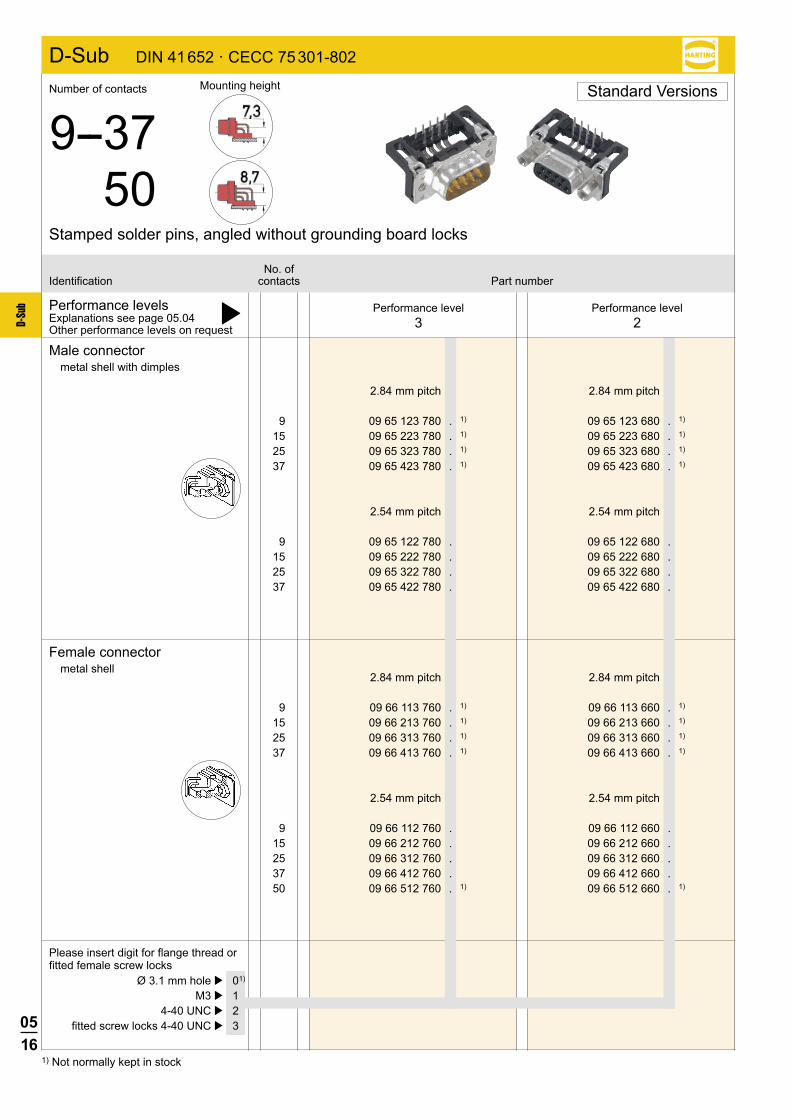
9 09 66 123 780 . 09 66 123 680 . 15 09 66 223 780 . 09 66 223 680 . 25 09 66 323 780 . 09 66 323 680 . 37 09 66 423 780 . 09 66 423 680 . 50 09 66 523 780 . 09 66 523 680 .
9 09 66 122 780 . 09 66 122 680 . 15 09 66 222 780 . 09 66 222 680 . 25 09 66 322 780 . 09 66 322 680 . 37 09 66 422 780 . 09 66 422 680 . 50 09 66 522 780 . 09 66 522 680 .
9 09 66 163 781 . 09 66 163 681 . 15 09 66 263 781 . 09 66 263 681 . 25 09 66 363 781 . 09 66 363 681 . 37 09 66 463 781 . 09 66 463 681 . 50 09 66 563 781 . 09 66 563 681 .
9 09 66 162 781 . 09 66 162 681 . 15 09 66 262 781 . 09 66 262 681 . 25 09 66 362 781 . 09 66 362 681 . 37 09 66 462 781 . 09 66 462 681 . 50 09 66 562 781 . 09 66 562 681 .
Performance levelsExplanations see page 05.04 þOther performance levels on request
With snap-in clips and grounding board locks
Male connectormetal shell with dimples
Without snap-in clips and grounding board locks
Please insert digit for flange thread or fitted female screw locks
Performance level3
Performance level2
No. ofIdentification contacts Part number
Turned solder pins, angled with/without snap-in-clips and grounding board locks
Number of contacts
9--3750
Mounting height
2.84 mm pitch 2.84 mm pitch
2.54 mm pitch 2.54 mm pitch
2.84 mm pitch 2.84 mm pitch
2.54 mm pitch 2.54 mm pitch
M3 þ 1 4-40 UNC þ 2 fitted screw locks 4-40 UNC þ 3
Standard Versions
available
on request
available
on request
0513
D-Su
b
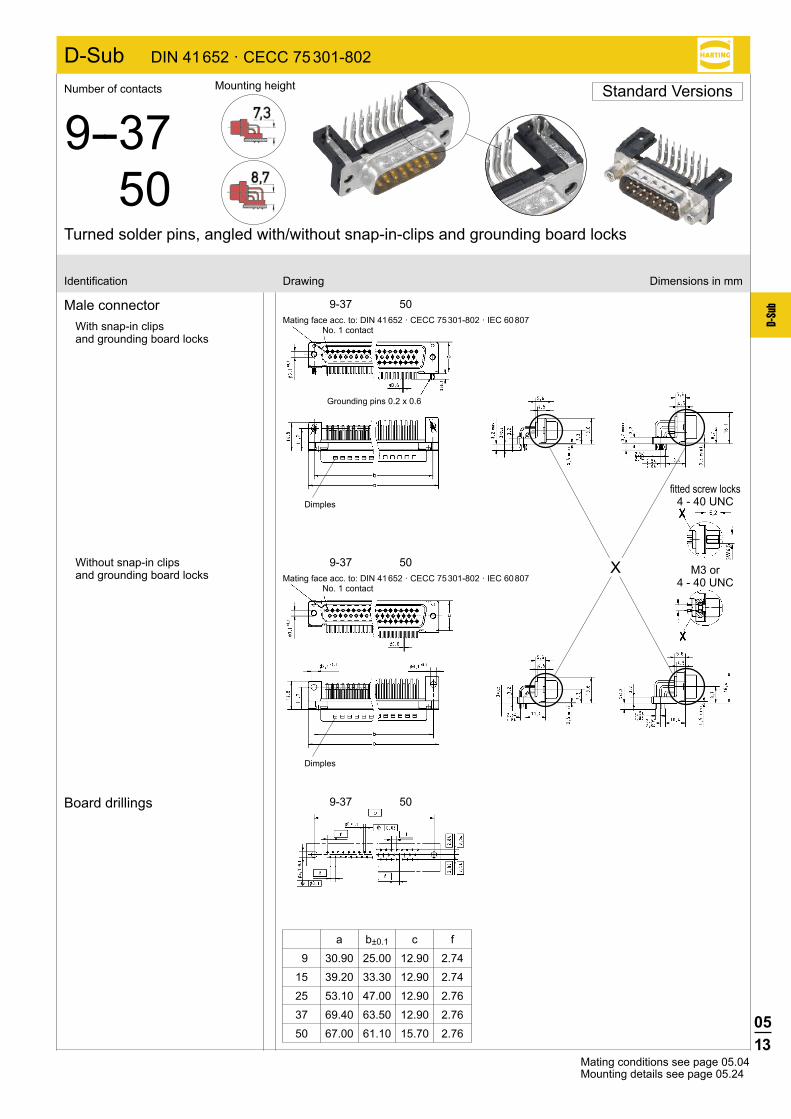
D-Sub DIN 41 652 · CECC 75 301-802
9-37 50
9-37 50
9-37 50
X Without snap-in clips and grounding board locks
a b±0.1 c f
9 30.90 25.00 12.90 2.74
15 39.20 33.30 12.90 2.74
25 53.10 47.00 12.90 2.76
37 69.40 63.50 12.90 2.76
50 67.00 61.10 15.70 2.76
Male connector With snap-in clips and grounding board locks
Board drillings
Identification Drawing Dimensions in mm
Turned solder pins, angled with/without snap-in-clips and grounding board locks
Number of contacts
9--3750
Mounting height
Mating conditions see page 05.04Mounting details see page 05.24
Dimples
Standard Versions
fitted screw locks4 - 40 UNC
M3 or 4 - 40 UNC
Mating face acc. to: DIN 41 652 · CECC 75 301-802 · IEC 60 807No. 1 contact
Mating face acc. to: DIN 41 652 · CECC 75 301-802 · IEC 60 807No. 1 contact
Grounding pins 0.2 x 0.6
Dimples

0514
D-Su
b
D-Sub DIN 41 652 · CECC 75 301-802
9 09 66 153 761 . 1) 09 66 153 661 . 1)
15 09 66 253 761 . 1) 09 66 253 661 . 1)
25 09 66 353 761 . 1) 09 66 353 661 . 1)
37 09 66 453 761 . 1) 09 66 453 661 . 1)
9 09 66 152 761 . 09 66 152 661 . 15 09 66 252 761 . 09 66 252 661 . 25 09 66 352 761 . 09 66 352 661 . 37 09 66 452 761 . 09 66 452 661 . 50 09 66 552 761 . 1) 09 66 552 661 . 1)
9 09 65 163 781 . 1) 09 65 163 681 . 1)
15 09 65 263 781 . 1) 09 65 263 681 . 1)
25 09 65 363 781 . 1) 09 65 363 681 . 1)
37 09 65 463 781 . 1) 09 65 463 681 . 1)
9 09 65 162 781 . 09 65 162 681 . 15 09 65 262 781 . 09 65 262 681 . 25 09 65 362 781 . 09 65 362 681 . 37 09 65 462 781 . 09 65 462 681 .
1) Not normally kept in stock
Performance levelsExplanations see page 05.04 þOther performance levels on request
Male connectormetal shell with dimples
Female connectormetal shell
Please insert digit for flange thread or fitted female screw locks
Performance level3
Performance level2
No. ofIdentification contacts Part number
Stamped solder pins, angled with grounding board locks
Number of contacts
9--3750
Mounting height
2.84 mm pitch 2.84 mm pitch
2.54 mm pitch 2.54 mm pitch
2.84 mm pitch 2.84 mm pitch
2.54 mm pitch 2.54 mm pitch
Ø 3.1 mm hole þ 01)
M3 þ 1 4-40 UNC þ 2 fitted screw locks 4-40 UNC þ 3
Standard Versions
0515
D-Su
b
9-37 50
9-37
50
9-37 50
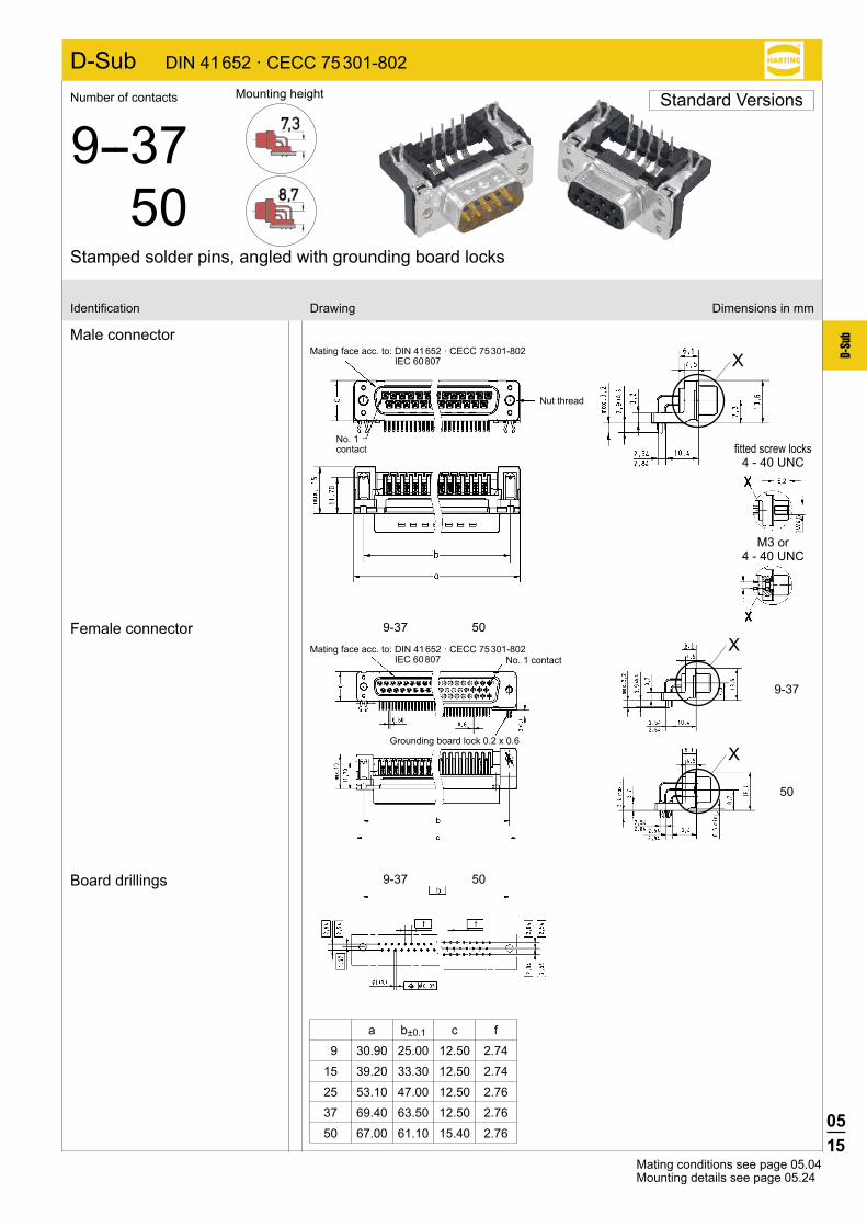
D-Sub DIN 41 652 · CECC 75 301-802
X
X
X
a b±0.1 c f
9 30.90 25.00 12.50 2.74
15 39.20 33.30 12.50 2.74
25 53.10 47.00 12.50 2.76
37 69.40 63.50 12.50 2.76
50 67.00 61.10 15.40 2.76
Male connector
Female connector
Board drillings
Identification Drawing Dimensions in mm
Mating conditions see page 05.04Mounting details see page 05.24
Mating face acc. to: DIN 41 652 · CECC 75 301-802 IEC 60 807 No. 1 contact
Grounding board lock 0.2 x 0.6
Mating face acc. to: DIN 41 652 · CECC 75 301-802 IEC 60 807
Nut thread
No. 1 contact fitted screw locks
4 - 40 UNC
M3 or 4 - 40 UNC
Stamped solder pins, angled with grounding board locks
Number of contacts
9--3750
Mounting height Standard Versions
0516
D-Su
b
D-Sub DIN 41 652 · CECC 75 301-802
9 09 66 113 760 . 1) 09 66 113 660 . 1)
15 09 66 213 760 . 1) 09 66 213 660 . 1)
25 09 66 313 760 . 1) 09 66 313 660 . 1)
37 09 66 413 760 . 1) 09 66 413 660 . 1)
9 09 66 112 760 . 09 66 112 660 . 15 09 66 212 760 . 09 66 212 660 . 25 09 66 312 760 . 09 66 312 660 . 37 09 66 412 760 . 09 66 412 660 . 50 09 66 512 760 . 1) 09 66 512 660 . 1)
9 09 65 123 780 . 1) 09 65 123 680 . 1)
15 09 65 223 780 . 1) 09 65 223 680 . 1)
25 09 65 323 780 . 1) 09 65 323 680 . 1)
37 09 65 423 780 . 1) 09 65 423 680 . 1)
9 09 65 122 780 . 09 65 122 680 . 15 09 65 222 780 . 09 65 222 680 . 25 09 65 322 780 . 09 65 322 680 . 37 09 65 422 780 . 09 65 422 680 .
1) Not normally kept in stock
Performance levelsExplanations see page 05.04 þOther performance levels on request
Male connectormetal shell with dimples
Female connectormetal shell
Please insert digit for flange thread or fitted female screw locks
Performance level3
Performance level2
No. ofIdentification contacts Part number
2.84 mm pitch 2.84 mm pitch
2.54 mm pitch 2.54 mm pitch
Ø 3.1 mm hole þ 01)
M3 þ 1 4-40 UNC þ 2 fitted screw locks 4-40 UNC þ 3
Stamped solder pins, angled without grounding board locks
Number of contacts
9--3750
Mounting height Standard Versions
2.84 mm pitch 2.84 mm pitch
2.54 mm pitch 2.54 mm pitch

0517
D-Su
b
D-Sub DIN 41 652 · CECC 75 301-802
Dimples
9-37 50
9-37 50
XFemale connector
a b±0.1 c f
9 30.90 25.00 12.50 2.74
15 39.20 33.30 12.50 2.74
25 53.10 47.00 12.50 2.76
37 69.40 63.50 12.50 2.76
50 67.00 61.10 15.40 2.76
Male connector
Board drillings
Identification Drawing Dimensions in mm
Mating conditions see page 05.04Mounting details see page 05.24
fitted screw locks4 - 40 UNC
M3 or 4 - 40 UNC
Mating face acc. to: DIN 41 652 · CECC 75 301-802 · IEC 60 807
Nut thread
No. 1 contact
Mating face acc. to: DIN 41 652 · CECC 75 301-802 · IEC 60 807No. 1 contact
Stamped solder pins, angled without grounding board locks
Number of contacts
9--3750
Mounting height Standard Versions

0518
D-Su
b
D-Sub DIN 41 652 · CECC 75 301-802
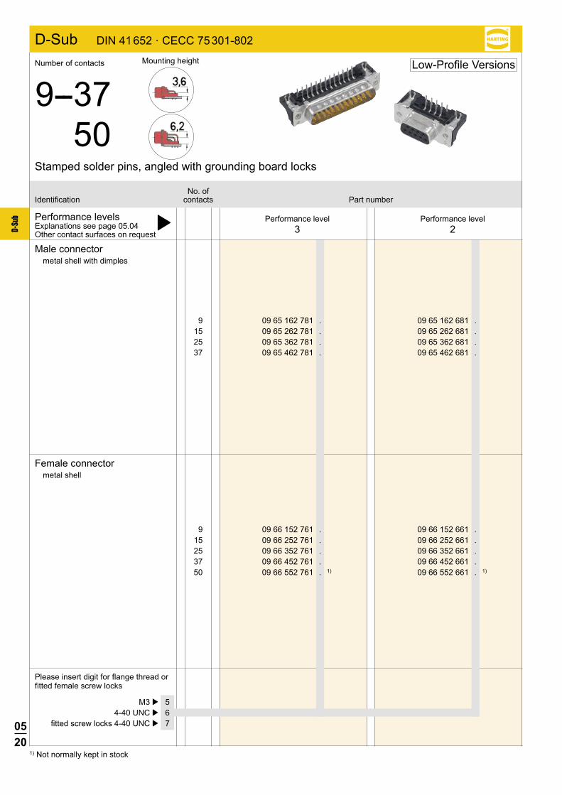
9 09 66 162 781 . 09 66 162 681 . 15 09 66 262 781 . 09 66 262 681 . 25 09 66 362 781 . 09 66 362 681 . 37 09 66 462 781 . 09 66 462 681 . 50 09 66 562 781 . 09 66 562 681 .
Turned solder pins, angled with snap-in-clips and grounding board locks
Number of contacts
9--3750
Mounting height Low-Profile Versions
Performance levelsExplanations see page 05.04 þOther performance levels on request
Performance level3
Performance level2
No. ofIdentification contacts Part number
Male connectormetal shell with dimples
2.54 mm pitch 2.54 mm pitch
Please insert digit for flange thread or fitted female screw locks
M3 þ 5 4-40 UNC þ 6 fitted screw locks 4-40 UNC þ 7
available
on request
0519
D-Su
b
D-Sub DIN 41 652 · CECC 75 301-802
9-37 50
9-37 50
X
Y
Y
X
Identification Drawing Dimensions in mm
Mating conditions see page 05.04Mounting details see page 05.24
Turned solder pins, angled with snap-in-clips and grounding board locks
Number of contacts
9--3750
Mounting height Low-Profile Versions
a b±0.1 c f
9 30.90 25.00 12.50 2.74
15 39.20 33.30 12.50 2.74
25 53.10 47.00 12.50 2.76
37 69.40 63.50 12.50 2.76
50 67.00 61.10 15.70 2.76
Male connector
Board drillings
Dimples
fitted screw locks4 - 40 UNC
M3 or 4 - 40 UNC
Mating face acc. to: DIN 41 652 · CECC 75 301-802 · IEC 60 807No. 1 contact
Grounding board lock 0.2 x 0.6
plated through holes
0520
D-Su
b
9 09 66 152 761 . 09 66 152 661 . 15 09 66 252 761 . 09 66 252 661 . 25 09 66 352 761 . 09 66 352 661 . 37 09 66 452 761 . 09 66 452 661 . 50 09 66 552 761 . 1) 09 66 552 661 . 1)
9 09 65 162 781 . 09 65 162 681 . 15 09 65 262 781 . 09 65 262 681 . 25 09 65 362 781 . 09 65 362 681 . 37 09 65 462 781 . 09 65 462 681 .
D-Sub DIN 41 652 · CECC 75 301-802
1) Not normally kept in stock
Performance levelsExplanations see page 05.04 þOther contact surfaces on request
Male connectormetal shell with dimples
Female connectormetal shell
Please insert digit for flange thread or fitted female screw locks
Performance level3
Performance level2
No. ofIdentification contacts Part number
M3 þ 5 4-40 UNC þ 6 fitted screw locks 4-40 UNC þ 7
Stamped solder pins, angled with grounding board locks
Number of contacts
9--3750
Mounting height Low-Profile Versions
0521
D-Su
b
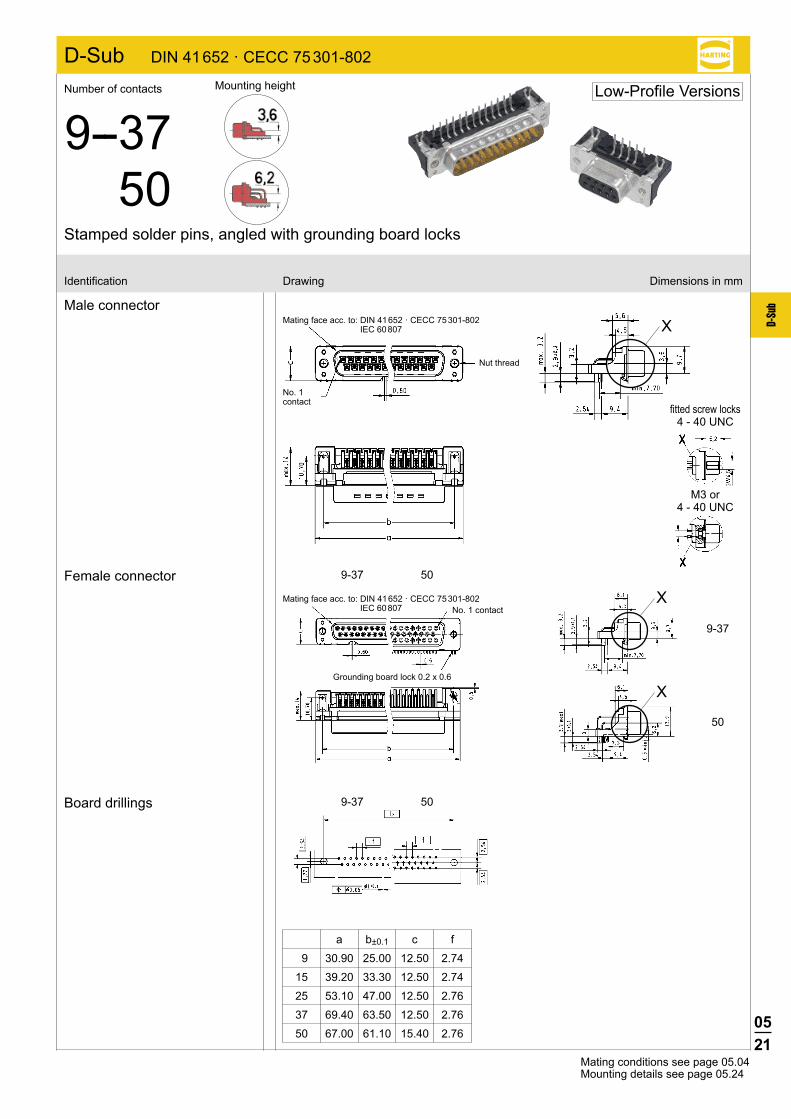
9-37 50
9-37
50
9-37 50
D-Sub DIN 41 652 · CECC 75 301-802
X
X
X
a b±0.1 c f
9 30.90 25.00 12.50 2.74
15 39.20 33.30 12.50 2.74
25 53.10 47.00 12.50 2.76
37 69.40 63.50 12.50 2.76
50 67.00 61.10 15.40 2.76
Male connector
Female connector
Board drillings
Identification Drawing Dimensions in mm
Mating conditions see page 05.04Mounting details see page 05.24
Mating face acc. to: DIN 41 652 · CECC 75 301-802 IEC 60 807 No. 1 contact
Grounding board lock 0.2 x 0.6
Mating face acc. to: DIN 41 652 · CECC 75 301-802 IEC 60 807
Nut thread
No. 1 contact
Stamped solder pins, angled with grounding board locks
Number of contacts
9--3750
Mounting height Low-Profile Versions
fitted screw locks4 - 40 UNC
M3 or 4 - 40 UNC
0522
D-Su
b
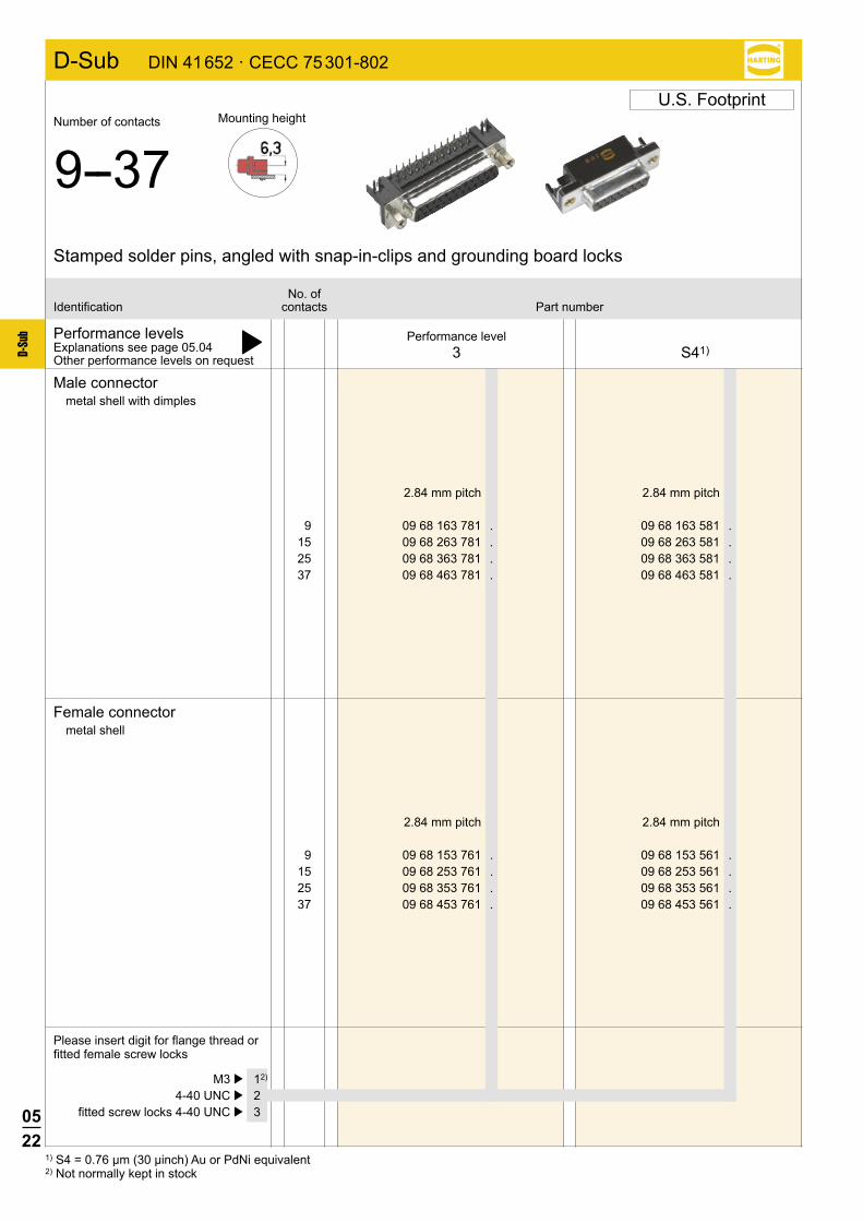
D-Sub DIN 41 652 · CECC 75 301-802
9 09 68 153 761 . 09 68 153 561 . 15 09 68 253 761 . 09 68 253 561 . 25 09 68 353 761 . 09 68 353 561 . 37 09 68 453 761 . 09 68 453 561 .
9 09 68 163 781 . 09 68 163 581 . 15 09 68 263 781 . 09 68 263 581 . 25 09 68 363 781 . 09 68 363 581 . 37 09 68 463 781 . 09 68 463 581 .
Stamped solder pins, angled with snap-in-clips and grounding board locks
Number of contacts
9--37Mounting height
U.S. Footprint
1) S4 = 0.76 µm (30 µinch) Au or PdNi equivalent2) Not normally kept in stock
Performance levelsExplanations see page 05.04 þOther performance levels on request
Please insert digit for flange thread or fitted female screw locks
Performance level3 S41)
No. ofIdentification contacts Part number
2.84 mm pitch 2.84 mm pitch
2.84 mm pitch 2.84 mm pitch
M3 þ 12)
4-40 UNC þ 2 fitted screw locks 4-40 UNC þ 3
Male connectormetal shell with dimples
Female connectormetal shell
0523
D-Su
b
D-Sub DIN 41 652 · CECC 75 301-802
X
Y
X
Y
Stamped solder pins, angled with snap-in-clips and grounding board locks
Number of contacts
9--37Mounting height
U.S. Footprint
Identification Drawing Dimensions in mm
Mating conditions see page 05.04Mounting details see page 05.24
plated through holes
Dimples
M3 or 4 - 40 UNC
fitted screw locks4 - 40 UNC
a b±0.1 c f
9 30.90 25.00 12.55 2.77
15 39.20 33.30 12.55 2.77
25 53.10 47.00 12.55 2.77
37 69.40 63.50 12.55 2.77
Male connector
Female connector
Board drillings
Mating face acc. to: DIN 41 652 · CECC 75 301-802 IEC 60 807 No. 1 contact
Mating face acc. to: DIN 41 652 · CECC 75 301-802 IEC 60 807
No. 1 contact
0524
D-Su
b
D-Sub
7,6
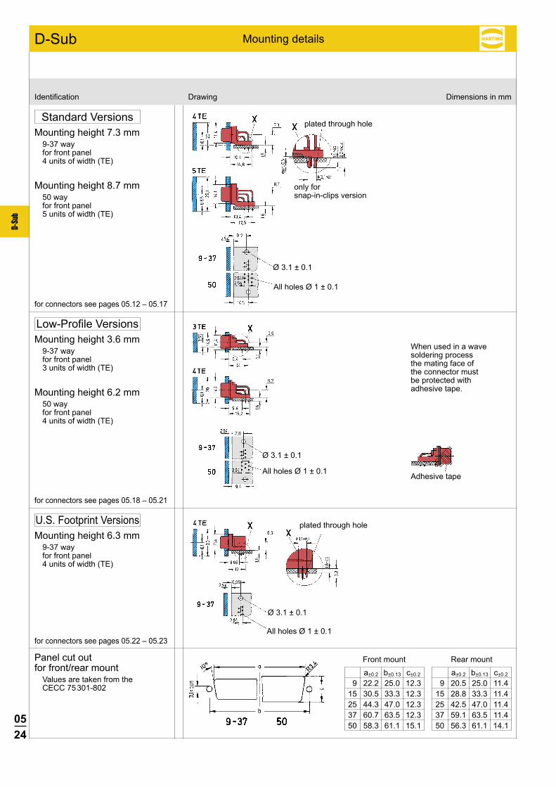
Identification Drawing Dimensions in mm
Mounting details
Standard VersionsMounting height 7.3 mm
9-37 wayfor front panel4 units of width (TE)
Mounting height 8.7 mm50 wayfor front panel5 units of width (TE)
for connectors see pages 05.12 – 05.17
Low-Profile VersionsMounting height 3.6 mm
9-37 wayfor front panel3 units of width (TE)
Mounting height 6.2 mm50 wayfor front panel4 units of width (TE)
for connectors see pages 05.18 – 05.21
U.S. Footprint VersionsMounting height 6.3 mm
9-37 wayfor front panel4 units of width (TE)
Panel cut out for front/rear mount
Values are taken from the CECC 75 301-802
for connectors see pages 05.22 – 05.23
plated through hole
only forsnap-in-clips version
When used in a wave soldering process the mating face of the connector must be protected with adhesive tape.
Adhesive tape
plated through hole
Ø 3.1 ± 0.1
All holes Ø 1 ± 0.1
Ø 3.1 ± 0.1
All holes Ø 1 ± 0.1
Ø 3.1 ± 0.1
All holes Ø 1 ± 0.1
a±0.2 b±0.13 c±0.2
9 20.5 25.0 11.4 15 28.8 33.3 11.4 25 42.5 47.0 11.4 37 59.1 63.5 11.4 50 56.3 61.1 14.1
a±0.2 b±0.13 c±0.2
9 22.2 25.0 12.3 15 30.5 33.3 12.3 25 44.3 47.0 12.3 37 60.7 63.5 12.3 50 58.3 61.1 15.1
Front mount Rear mount
0525
D-Su
b
M FM F
M F
M F M F
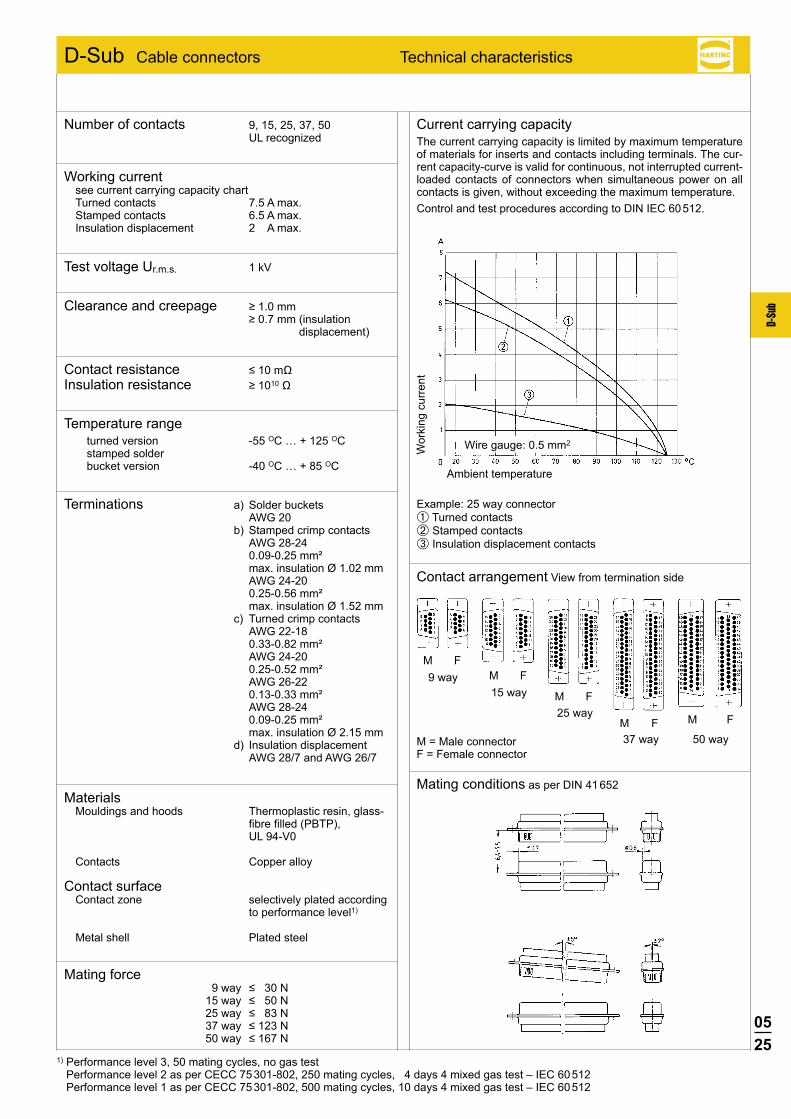
D-Sub Cable connectors Technical characteristics
Current carrying capacityThe current carrying capacity is limited by maximum temperature of materials for inserts and contacts including terminals. The cur-rent capacity-curve is valid for continuous, not interrupted current-loaded contacts of connectors when simultaneous power on all contacts is given, without exceeding the maximum temperature.Control and test procedures according to DIN IEC 60 512.
Contact arrangement View from termination side
Mating conditions as per DIN 41 652
M = Male connectorF = Female connector
Wor
king
cur
rent
Ambient temperature
Wire gauge: 0.5 mm2
Example: 25 way connector➀ Turned contacts➁ Stamped contacts➂ Insulation displacement contacts
1) Performance level 3, 50 mating cycles, no gas test Performance level 2 as per CECC 75 301-802, 250 mating cycles, 4 days 4 mixed gas test – IEC 60 512 Performance level 1 as per CECC 75 301-802, 500 mating cycles, 10 days 4 mixed gas test – IEC 60 512
37 way 50 way
9 way15 way
25 way
Number of contacts 9, 15, 25, 37, 50 UL recognized
Working currentsee current carrying capacity chart Turned contacts 7.5 A max. Stamped contacts 6.5 A max. Insulation displacement 2 A max.
Test voltage Ur.m.s. 1 kV
Clearance and creepage ≥1.0mm ≥0.7mm(insulation
displacement)
Contact resistance ≤10mΩ Insulation resistance ≥1010Ω
Temperature range turned version -55 OC … + 125 OC stamped solder bucket version -40 OC … + 85 OC
Terminations a) Solder buckets AWG 20
b) Stamped crimp contacts AWG 28-24 0.09-0.25 mm² max. insulation Ø 1.02 mm AWG 24-20 0.25-0.56 mm² max. insulation Ø 1.52 mm
c) Turned crimp contacts AWG 22-18 0.33-0.82 mm² AWG 24-20 0.25-0.52 mm² AWG 26-22 0.13-0.33 mm² AWG 28-24 0.09-0.25 mm² max. insulation Ø 2.15 mm
d) Insulation displacement AWG 28/7 and AWG 26/7
MaterialsMouldings and hoods Thermoplastic resin, glass-
fibre filled (PBTP), UL 94-V0
Contacts Copper alloy
Contact surface Contact zone selectively plated according
to performance level1)
Metal shell Plated steel
Mating force 9way ≤30N 15way ≤50N 25way ≤83N 37way ≤123N 50way ≤167N

0526
D-Su
b
9 09 67 009 5601 15 09 67 015 5601 25 09 67 025 5601 37 09 67 037 5601 50 09 67 050 5601
9 09 67 009 4701 15 09 67 015 4701 25 09 67 025 4701 37 09 67 037 4701 50 09 67 050 4701
D-Sub DIN 41 652 · CECC 75 301-802
Male connectorOrder contacts separately
metal shell with dimples
Female connectorOrder contacts separately
metal shell
Male connector
Female connector
No. ofIdentification contacts Part number
Crimp terminal
Number of contacts
9--50
Crimp contacts see pages 05.27 ffMating conditions see page 05.04
Tooling see chapter 20
Dimensions in mm
Dimples
a b ± 0.1 c 9 30.9 25.0 12.5 15 39.2 33.3 12.5 25 53.1 47.0 12.5 37 69.4 63.5 12.5 50 67.0 61.1 15.4
Panel cut out for front/rear mount
Values are taken from the CECC 75 301-802
see page 05.24

0527
D-Su
b
09 67 000 3576 09 67 000 3476 09 67 000 3676
09 67 000 8576 09 67 000 8476 09 67 000 8676
09 67 000 5576 09 67 000 5476 09 67 000 5676
09 67 000 7576 09 67 000 7476 09 67 000 7676
D-Sub DIN 41 652 · CECC 75 301-802
Standard
Wire gaugeIdentification (mm2) Part number
Turned crimp contacts
Individual contacts1)
Performance level1*
Male contacts Female contacts High-end female contacts
Performance level1*
Performance level1*
AWG22-18
0.33-0.82
AWG24-20
0.25-0.52
AWG26-22
0.13-0.33
AWG28-24
0.09-0.25
* Performance level 1 as per CECC 75 301-802, 500 mating cycles, 10 days 4 mixed gas test – IEC 60 512Use crimp tool with the part no. 09 99 000 0501 and the locator with the part no. 09 99 000 0531. Details see chapter 20
Male contacts
Female contacts
1) Minimum order 100 pieces or multiples of 100
a grooveAWG 22-18 1.34 noneAWG 24-20 1.13 1AWG 26-22 0.88 2AWG 28-24 0.64 3
High-end with groove
groove

0528
D-Su
b
09 67 000 71771) 09 67 000 71781) 09 67 000 71761)
09 67 000 7167 09 67 000 7168 09 67 000 7166
09 67 000 7157 09 67 000 7158 09 67 000 7156 09 67 000 7147 09 67 000 7148 09 67 000 7146 09 67 000 7137 09 67 000 7138 09 67 000 7136
09 67 000 81771) 09 67 000 81781) 09 67 000 81761)
09 67 000 8167 09 67 000 8168 09 67 000 8166
09 67 000 8157 09 67 000 8158 09 67 000 8156 09 67 000 8147 09 67 000 8148 09 67 000 8146 09 67 000 8137 09 67 000 8138 09 67 000 8136
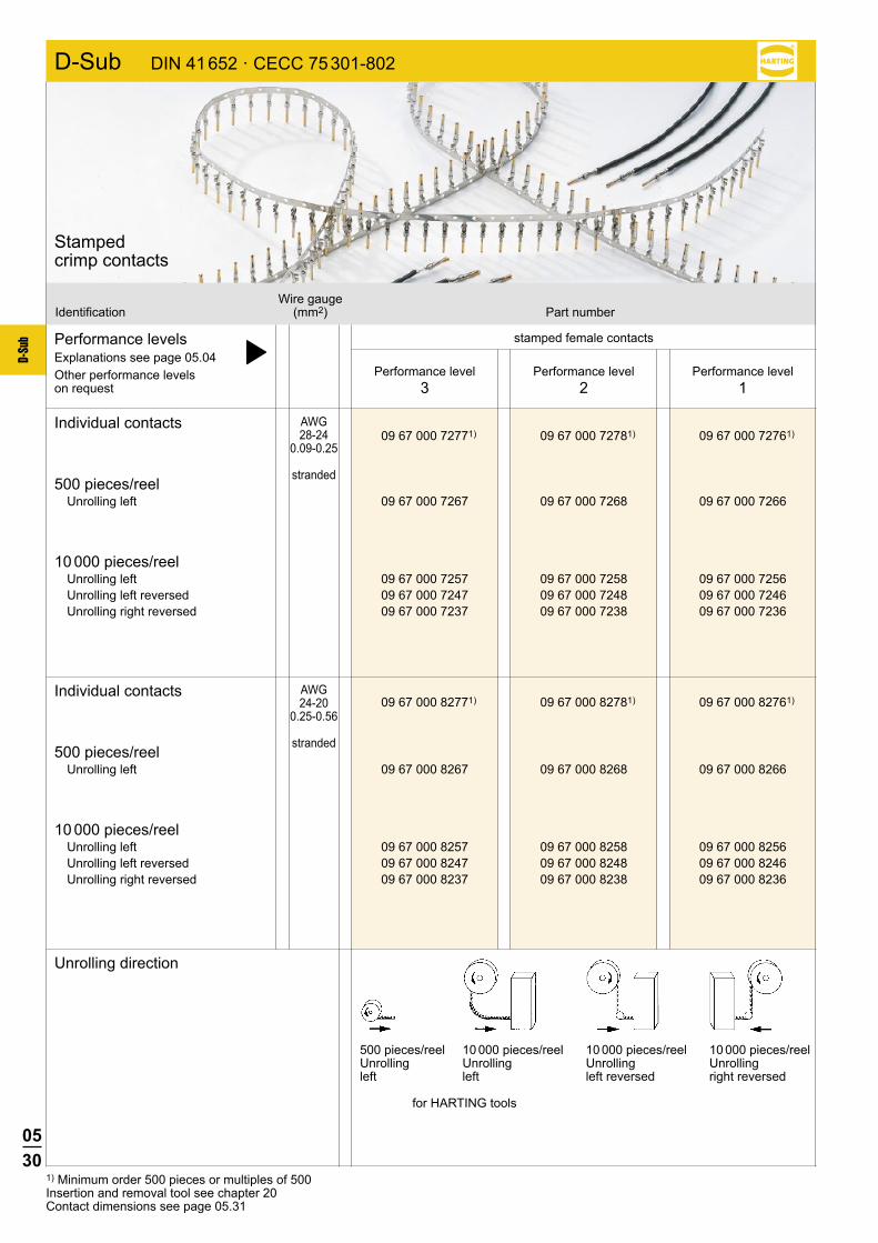
D-Sub DIN 41 652 · CECC 75 301-802
Performance level3
Performance level2
Performance level1
1) Minimum order 500 pieces or multiples of 500Insertion and removal tool see chapter 20Contact dimensions see page 05.29
Performance levelsExplanations see page 05.04 þOther performance levels on request
Individual contacts
500 pieces/reel Unrolling left
10 000 pieces/reel Unrolling left Unrolling left reversed Unrolling right reversed
Individual contacts
500 pieces/reel Unrolling left
10 000 pieces/reel Unrolling left Unrolling left reversed Unrolling right reversed
Unrolling direction
stamped male contacts
Wire gaugeIdentification (mm2) Part number
Stamped crimp contacts
AWG28-24
0.09-0.25
stranded
AWG24-20
0.25-0.56
stranded
500 pieces/reel 10 000 pieces/reel 10 000 pieces/reel 10 000 pieces/reelUnrolling Unrolling Unrolling Unrollingleft left left reversed right reversed
for HARTING tools

0529
D-Su
b
D-Sub DIN 41 652 · CECC 75 301-802
Male contacts
Identification Drawing Dimensions in mm
For bandoliered contacts only
Contact identification
AWG C D E F RA RB Contact identification 20-24 2.46 1.78 1.98 1.90 0.71 0.43 –––– 24-28 1.65 1.47 1.52 1.52 0.50 0.33 ====
Stamped crimp contacts
0530
D-Su
b
09 67 000 72771) 09 67 000 72781) 09 67 000 72761)
09 67 000 7267 09 67 000 7268 09 67 000 7266
09 67 000 7257 09 67 000 7258 09 67 000 7256 09 67 000 7247 09 67 000 7248 09 67 000 7246 09 67 000 7237 09 67 000 7238 09 67 000 7236
09 67 000 82771) 09 67 000 82781) 09 67 000 82761)
09 67 000 8267 09 67 000 8268 09 67 000 8266
09 67 000 8257 09 67 000 8258 09 67 000 8256 09 67 000 8247 09 67 000 8248 09 67 000 8246 09 67 000 8237 09 67 000 8238 09 67 000 8236
D-Sub DIN 41 652 · CECC 75 301-802
Performance level3
Performance level2
Performance level1
1) Minimum order 500 pieces or multiples of 500Insertion and removal tool see chapter 20Contact dimensions see page 05.31
Performance levelsExplanations see page 05.04 þOther performance levels on request
Individual contacts
500 pieces/reel Unrolling left
10 000 pieces/reel Unrolling left Unrolling left reversed Unrolling right reversed
Individual contacts
500 pieces/reel Unrolling left
10 000 pieces/reel Unrolling left Unrolling left reversed Unrolling right reversed
Unrolling direction
stamped female contacts
Wire gaugeIdentification (mm2) Part number
AWG28-24
0.09-0.25
stranded
AWG24-20
0.25-0.56
stranded
500 pieces/reel 10 000 pieces/reel 10 000 pieces/reel 10 000 pieces/reelUnrolling Unrolling Unrolling Unrollingleft left left reversed right reversed
for HARTING tools
Stamped crimp contacts

0531
D-Su
b
D-Sub DIN 41 652 · CECC 75 301-802
Female contacts
Identification Drawing Dimensions in mm
For bandoliered contacts only
Contact identification
AWG C D E F RA RB Contact identification 20-24 2.46 1.78 1.98 1.90 0.71 0.43 –––– 24-28 1.65 1.47 1.52 1.52 0.50 0.33 ====
Stamped crimp contacts

0532
D-Su
b
9 09 66 108 0001 09 66 108 0001 15 09 66 208 0001 09 66 208 0001 25 09 66 308 0001 09 66 308 0001 37 09 66 408 0001 09 66 408 0001
D-Sub DIN 41 652 · CECC 75 301-802
9 09 66 118 750 . 09 66 118 650 . 15 09 66 218 750 . 09 66 218 650 . 25 09 66 318 750 . 09 66 318 650 . 37 09 66 418 750 . 09 66 418 650 .
9 09 66 128 770 . 09 66 128 670 . 15 09 66 228 770 . 09 66 228 670 . 25 09 66 328 770 . 09 66 328 670 . 37 09 66 428 770 . 09 66 428 670 .
Performance levelsExplanations see page 05.04 þOther performance levels on request
Male connector 2)
pitch 1.27 mm metal shell with dimples
Female connectorpitch 1.27 mm metal shell
Please insert digit for flange thread
Performance level3
Performance level2
No. ofIdentification contacts Part number
Strain relief clampplastic for male and female connector
ø 3.1 mm hole þ 0 M3 þ 11)
4-40 UNC þ 2
Insulation displacement termination
Number of contacts
9--37
1) Not normally kept in stock2) Not released for halogen free flat cables
0533
D-Su
b
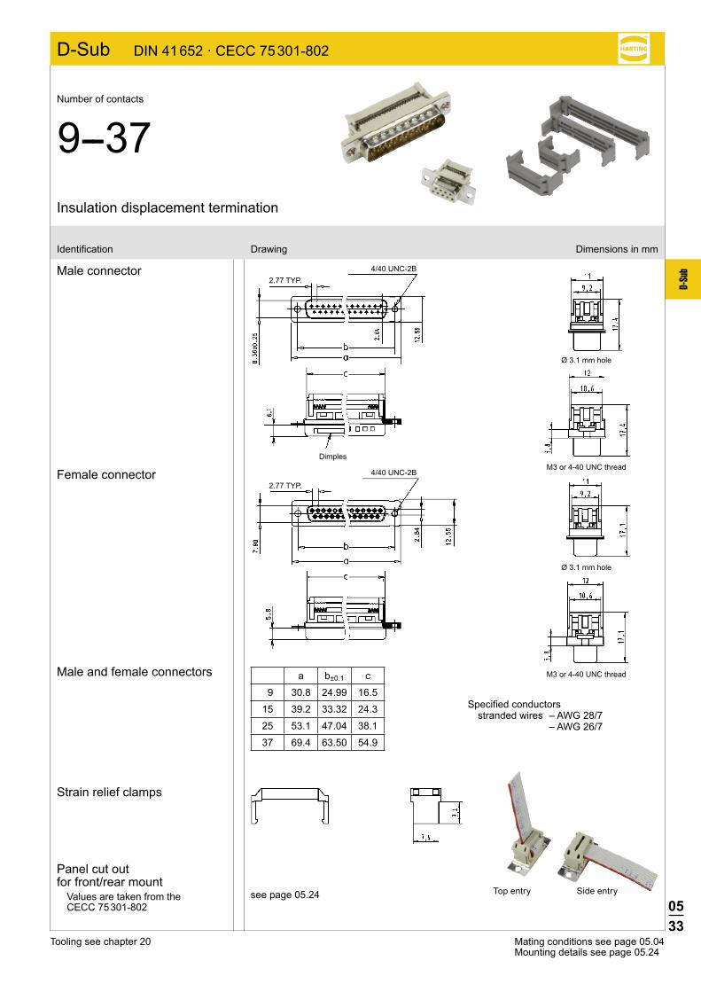
D-Sub DIN 41 652 · CECC 75 301-802
Mating conditions see page 05.04Mounting details see page 05.24
Tooling see chapter 20
Insulation displacement termination
Number of contacts
9--37
Male connector
Female connector
Male and female connectors
Identification Drawing Dimensions in mm
Specified conductorsstranded wires – AWG 28/7
– AWG 26/7
Panel cut out for front/rear mount
Values are taken from the CECC 75 301-802
see page 05.24
Strain relief clamps
a b±0.1 c
9 30.8 24.99 16.5
15 39.2 33.32 24.3
25 53.1 47.04 38.1
37 69.4 63.50 54.9
4/40 UNC-2B2.77 TYP.
Dimples
4/40 UNC-2B
2.77 TYP.
Ø 3.1 mm hole
M3 or 4-40 UNC thread
Ø 3.1 mm hole
M3 or 4-40 UNC thread
Top entry Side entry

0534
D-Su
b
D-Sub DIN 41 652 · CECC 75 301-802
9 09 67 009 4704 09 67 009 4715 15 09 67 015 4704 09 67 015 4715 25 09 67 025 4704 09 67 025 4715 37 09 67 037 4704 09 67 037 4715 50 09 67 050 4704 09 67 050 4715
9 09 67 209 4704 09 67 209 4715 15 09 67 215 4704 09 67 215 4715 25 09 67 225 4704 09 67 225 4715 37 09 67 237 4704 09 67 237 4715 50 09 67 250 4704 09 67 250 4715
9 09 67 009 5604 09 67 009 5615 15 09 67 015 5604 09 67 015 5615 25 09 67 025 5604 09 67 025 5615 37 09 67 037 5604 09 67 037 5615 50 09 67 050 5604 09 67 050 5615
9 09 67 209 5604 09 67 209 5615 15 09 67 215 5604 09 67 215 5615 25 09 67 225 5604 09 67 225 5615 37 09 67 237 5604 09 67 237 5615 50 09 67 250 5604 09 67 250 5615
Performance levelsExplanations see page 05.04 þOther performance levels on request
Male connectormetal shell with dimples
Female connectormetal shell
Performance level3
Performance level2
No. ofIdentification contacts Part number
turned contacts turned contacts
stamped contacts stamped contacts
turned contacts turned contacts
stamped contacts stamped contacts
Solder buckets
Number of contacts
9--50

0535
D-Su
b
D-Sub DIN 41 652 · CECC 75 301-802
Male connector
Female connector
Identification Drawing Dimensions in mm
Mating conditions see page 05.04
Dimples
a b ±0.1 c 9 30.9 25.0 12.5 15 39.2 33.3 12.5 25 53.1 47.0 12.5 37 69.4 63.5 12.5 50 67.0 61.1 15.4
Solder buckets
Number of contacts
9--50
Panel cut out for front/rear mount
Values are taken from the CECC 75 301-802
see page 05.24

0536
D-Su
b
D-Sub
9 09 67 009 0605 15 09 67 015 0605 25 09 67 025 0605 37 09 67 037 0605
No. ofIdentification contacts Part number
Gender changer
Number of contacts
9--37
Male / female gender changer
Dimensions
Dimensions in mm
A B C D 9 30.8 25.0 16.92 16.3515 39.2 33.3 25.25 24.725 53.05 47.04 38.96 38.437 69.4 63.5 55.42 54.8

0537
D-Su
b
Notes

0538
D-Su
b
D-Sub high density connectors Technical characteristics
1) Performance level 3, 50 mating cycles, no gas test S4, plating = 0.76 µm (30 µinch) Au or PdNi equivalent
Shell size D-Sub standard D-Sub high density1 9 152 15 263 25 444 37 625 50 78
Number of contacts in the D-Sub standard/D-Sub high density range related to the shell size.
Number of contacts 15, 26, 44, 62, 78
Working currentStamped contacts 2 A max.
Test voltage Ur.m.s. 1 kV
Clearance and creepage ≥1.0mm
Contact resistance <20mΩ <25mΩ(for right angled versions) Insulation resistance ≥5x10⁹Ω
Temperature range -40 OC … + 85 OC The higher temperature limit includes the local ambient and
heating effect of the contacts under load
Terminations a) Solder pins Ø 0.65 mm for P.C.B. holes Ø 1.0 mm
b) Crimp contacts AWG 26 - 24 0.14 - 0.22 mm² max. insulation Ø 1.38 mm
c) Solder cups AWG 24
MaterialsMouldings and hoods Thermoplastic resin, glass-
fibre filled (PBTP), UL 94-V0
Contacts Copper alloy
Contact surface Contact zone selectively plated according
to performance level1)
Metal shell Nickel plated steel
Mating force 15way ≤46N 26way ≤77N 44way ≤127N 62way ≤177N 78way ≤222N
0539
D-Su
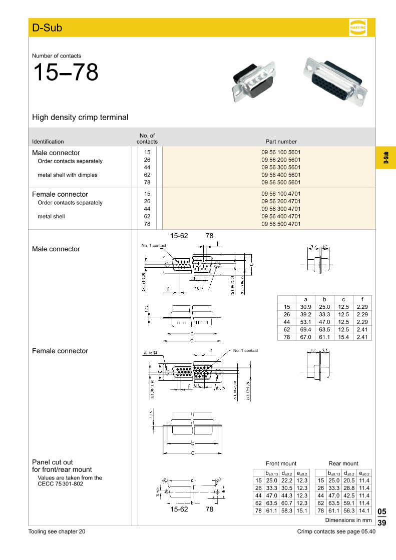
b 15 09 56 100 5601 26 09 56 200 5601 44 09 56 300 5601 62 09 56 400 5601 78 09 56 500 5601
15 09 56 100 4701 26 09 56 200 4701 44 09 56 300 4701 62 09 56 400 4701 78 09 56 500 4701
D-Sub
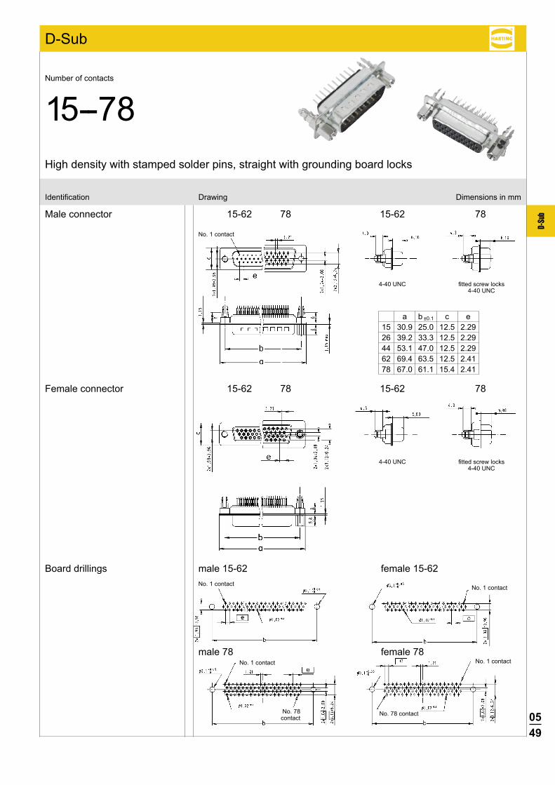
15-62 78
15-62 78
Male connectorOrder contacts separately
metal shell with dimples
Female connectorOrder contacts separately
metal shell
Male connector
Female connector
No. ofIdentification contacts Part number
High density crimp terminal
Number of contacts
15--78
Crimp contacts see page 05.40Tooling see chapter 20
Dimensions in mm
No. 1 contact
No. 1 contact
a b c f 15 30.9 25.0 12.5 2.29 26 39.2 33.3 12.5 2.29 44 53.1 47.0 12.5 2.29 62 69.4 63.5 12.5 2.41 78 67.0 61.1 15.4 2.41
Panel cut out for front/rear mount
Values are taken from the CECC 75 301-802
b±0.13 d±0.2 e±0.2
15 25.0 20.5 11.4 26 33.3 28.8 11.4 44 47.0 42.5 11.4 62 63.5 59.1 11.4 78 61.1 56.3 14.1
b±0.13 d±0.2 e±0.2
15 25.0 22.2 12.3 26 33.3 30.5 12.3 44 47.0 44.3 12.3 62 63.5 60.7 12.3 78 61.1 58.3 15.1
Front mount Rear mount

0540
D-Su
b
D-Sub
09 56 000 8167 09 56 000 8165 09 56 000 8267 09 56 000 8265
09 56 000 8177 09 56 000 8175 09 56 000 8277 09 56 000 8275
09 56 000 8157 09 56 000 8155 09 56 000 8257 09 56 000 8255
1) S4 = 0.76 µm (30 µinch) Au or PdNi equivalentContact dimensions see page 05.41
Performance levelsExplanations see page 05.04 þOther performance levels on request
500 pieces/reel Unrolling left
500 pieces/box
10 000 pieces/reel Unrolling left
Unrolling direction
Performance level3
stamped male contacts stamped female contacts
S41)Performance level
3 S41)
Wire gaugeIdentification (mm2) Part number
Crimp contacts for high density connectors
AWG26-24
0.14-0.22
stranded
500 pieces/reel 10 000 pieces/reelUnrolling Unrollingleft left
for HARTING tools

0541
D-Su
b
D-Sub
Crimp contacts for high density connectors
Male contactswire gauge AWG 26-24
Female contactswire gauge AWG 26-24
Identification Drawing Dimensions in mm

0542
D-Su
b
D-Sub
15 09 56 100 4704 09 56 100 4715 050 26 09 56 200 4704 09 56 200 4715 050 44 09 56 300 4704 09 56 300 4715 050 62 09 56 400 4704 09 56 400 4715 050 78 09 56 500 4704 09 56 500 4715 050
15 09 56 100 5604 09 56 100 5615 050 26 09 56 200 5604 09 56 200 5615 050 44 09 56 300 5604 09 56 300 5615 050 62 09 56 400 5604 09 56 400 5615 050 78 09 56 500 5604 09 56 500 5615 050
High density with stamped solder cups, straight
Number of contacts
15--78
1) S4 = 0.76 µm (30 µinch) Au or PdNi equivalent
Performance levelsExplanations see page 05.04 þOther performance levels on request
Performance level3 S41)
No. ofIdentification contacts Part number
Male connectormetal shell with dimples
Female connectormetal shell

0543
D-Su
b
D-Sub
15-62 78 15-62
78
15-62
78
15-62 78
Identification Drawing Dimensions in mm
Male connector
Female connector
High density with stamped solder cups, straight
Number of contacts
15--78
a b c d e15 30.81 25.00 16.92 19.20 16.3326 39.20 33.30 25.25 27.70 24.7044 53.05 47.00 38.96 41.10 38.4062 69.40 63.50 55.42 57.30 54.8078 67.00 61.00 52.81 55.10 52.20
0544
D-Su
b
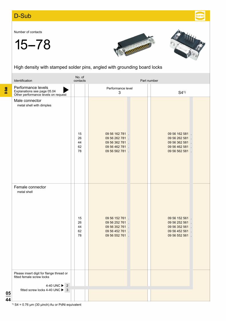
D-Sub
15 09 56 152 761 . 09 56 152 561 . 26 09 56 252 761 . 09 56 252 561 . 44 09 56 352 761 . 09 56 352 561 . 62 09 56 452 761 . 09 56 452 561 . 78 09 56 552 761 . 09 56 552 561 .
15 09 56 162 781 . 09 56 162 581 . 26 09 56 262 781 . 09 56 262 581 . 44 09 56 362 781 . 09 56 362 581 . 62 09 56 462 781 . 09 56 462 581 . 78 09 56 562 781 . 09 56 562 581 .
High density with stamped solder pins, angled with grounding board locks
Number of contacts
15--78
1) S4 = 0.76 µm (30 µinch) Au or PdNi equivalent
Performance levelsExplanations see page 05.04 þOther performance levels on request
Please insert digit for flange thread or fitted female screw locks
Performance level3 S41)
No. ofIdentification contacts Part number
4-40 UNC þ 2 fitted screw locks 4-40 UNC þ 3
Male connectormetal shell with dimples
Female connectormetal shell

0545
D-Su
b
D-Sub
15-62
15-62
78
78
15-62
15-62
78
78
Identification Drawing Dimensions in mm
Male connector
Female connector
No. 1 contact
4-40UNC
No. 1 contact
4-40 UNC fitted screw locks4-40 UNC
4-40 UNC fitted screw locks4-40 UNC
4-40 UNC
High density with stamped solder pins, angled with grounding board locks
Number of contacts
15--78
a b± 0.1 c15 30.81 24.99 12.5526 39.20 33.30 12.5544 53.05 47.04 12.5562 69.40 63.50 12.5578 67.00 61.00 15.37
0546
D-Su
b
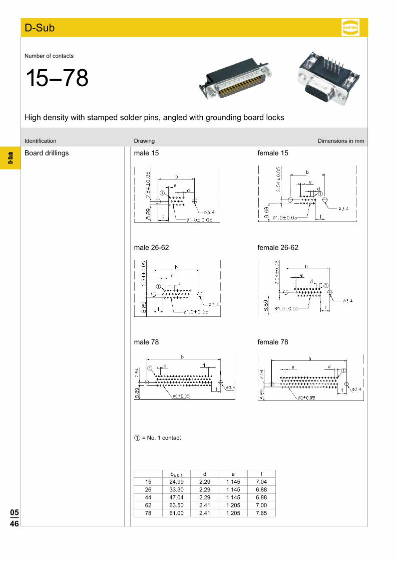
D-Sub
Identification Drawing Dimensions in mm
Board drillings
High density with stamped solder pins, angled with grounding board locks
Number of contacts
15--78
female 15
female 26-62
female 78
male 15
male 26-62
male 78
À = No. 1 contact
b± 0.1 d e f15 24.99 2.29 1.145 7.0426 33.30 2.29 1.145 6.8844 47.04 2.29 1.145 6.8862 63.50 2.41 1.205 7.0078 61.00 2.41 1.205 7.65

0547
D-Su
b
15 09 56 161 7700 09 56 161 5700 26 09 56 261 7700 09 56 261 5700 44 09 56 361 7700 09 56 361 5700 62 09 56 461 7700 09 56 461 5700 78 09 56 561 7700 09 56 561 5700
15 09 56 151 7500 09 56 151 5500 26 09 56 251 7500 09 56 251 5500 44 09 56 351 7500 09 56 351 5500 62 09 56 451 7500 09 56 451 5500 78 09 56 551 7500 09 56 551 5500
D-Sub
15-62 78 15-62 78
Dimensions in mm
1) S4 = 0.76 µm (30 µinch) Au or PdNi equivalent
Performance levelsExplanations see page 05.04 þOther performance levels on request
Male connectormetal shell with dimples
Female connectormetal shell
Male connector
Female connector
Board drillings
Performance level3 S41)
No. ofIdentification contacts Part number
High density with stamped solder pins, straight
Number of contacts
15--78
No. 1 contact
No. 1 contact
a b ±0.1 c d 15 30.9 25.0 12.5 2.29 26 39.2 33.3 12.5 2.29 44 53.1 47.0 12.5 2.29 62 69.4 63.5 12.5 2.41 78 67.0 61.1 15.4 2.41

0548
D-Su
b
D-Sub
15 09 56 151 751 . 09 56 151 551 . 26 09 56 251 751 . 09 56 251 551 . 44 09 56 351 751 . 09 56 351 551 . 62 09 56 451 751 . 09 56 451 551 . 78 09 56 551 751 . 09 56 551 551 .
15 09 56 161 771 . 09 56 161 571 . 26 09 56 261 771 . 09 56 261 571 . 44 09 56 361 771 . 09 56 361 571 . 62 09 56 461 771 . 09 56 461 571 . 78 09 56 561 771 . 09 56 561 571 .
High density with stamped solder pins, straight with grounding board locks
Number of contacts
15--78
1) S4 = 0.76 µm (30 µinch) Au or PdNi equivalent
Performance levelsExplanations see page 05.04 þOther performance levels on request
Please insert digit for flange thread or fitted female screw locks
Performance level3 S41)
No. ofIdentification contacts Part number
4-40 UNC þ 2 fitted screw locks 4-40 UNC þ 3
Male connectormetal shell with dimples
Female connectormetal shell
0549
D-Su
b
D-Sub
15-62 78 15-62 78
15-62 78 15-62 78
4-40 UNC
4-40 UNC
Identification Drawing Dimensions in mm
Male connector
Female connector
Board drillingsNo. 1 contact No. 1 contact
No. 1 contact
No. 78 contact
No. 1 contact
No. 78 contact
fitted screw locks4-40 UNC
No. 1 contact
fitted screw locks4-40 UNC
High density with stamped solder pins, straight with grounding board locks
Number of contacts
15--78
female 15-62male 15-62
female 78male 78
a b ±0.1 c e 15 30.9 25.0 12.5 2.29 26 39.2 33.3 12.5 2.29 44 53.1 47.0 12.5 2.29 62 69.4 63.5 12.5 2.41 78 67.0 61.1 15.4 2.41
0550
D-Su
b
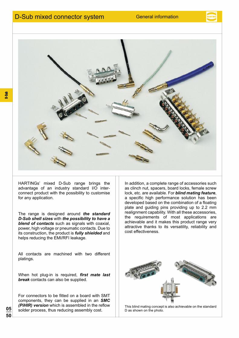
General informationD-Sub mixed connector system
HARTINGs’ mixed D-Sub range brings the advantage of an industry standard I/O inter-connect product with the possibility to customise for any application.
The range is designed around the standard D-Sub shell sizes with the possibility to have a blend of contacts such as signals with coaxial, power, high voltage or pneumatic contacts. Due to its construction, the product is fully shielded and helps reducing the EMI/RFI leakage.
All contacts are machined with two different platings.
When hot plug-in is required, first mate last break contacts can also be supplied.
For connectors to be fitted on a board with SMT components, they can be supplied in an SMC (PiHIR) version which is assembled in the reflow solder process, thus reducing assembly cost.
In addition, a complete range of accessories such as clinch nut, spacers, board locks, female screw lock, etc. are available. For blind mating feature, a specific high performance solution has been developed based on the combination of a floating plate and guiding pins providing up to 2.2 mm realignment capability. With all these accessories, the requirements of most applications are achievable and it makes this product range very attractive thanks to its versatility, reliability and cost effectiveness.
This blind mating concept is also achievable on the standard D as shown on the photo.
0551
D-Su
b
D-Sub
13W6
25W3
27W2
24W7
36W4
43W2
8W8
7W7
21WA4
2W2C
2W2
5W1
3W3
3W3C
7W2
11W1
5W5
9W4
13W3
17W2
21W1
1
1
1
2
2
2
2
3
3
3
3
3
4
4
4
4
4
4
5
5
5
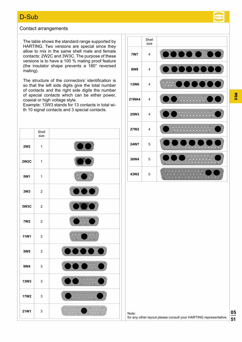
Contact arrangements
The table shows the standard range supported by HARTING. Two versions are special since they allow to mix in the same shell male and female contacts: 2W2C and 3W3C. The purpose of these versions is to have a 100 % mating proof feature (the insulator shape prevents a 180° reversed mating).
The structure of the connectors’ identification is so that the left side digits give the total number of contacts and the right side digits the number of special contacts which can be either power, coaxial or high voltage style.Example: 13W3 stands for 13 contacts in total wi-th 10 signal contacts and 3 special contacts.
Note: for any other layout please consult your HARTING representative.
Shell size
Shell size

0552
D-Su
b
D-Sub
The range of pcb connectors available at HARTING is summarised in the table under. For each of the basic connector versions, the available contact styles are documented with termination process, pitch, plating, rating for power contacts and impedance for coaxial contact etc..., as well as the accessory configuration.
Pcb connectors are delivered fully loaded thus providing a very good positioning of the contacts in their cavities for an easy and safe insertion of the pins in the pcb holes particularly crucial in the right angled versions.
Due to the numerous possibilities offered with the pcb connectors, suggested method is to contact your local HARTING representative to determine the part number to order; see customer request form on pages 05.88 and 05.89.
Connectors for pcb applications – general information
Insulator body Standard SMC: Solder Reflow Compatible
Straight Right angled Standard SMC: Solder Reflow Compatible
Signal contactsSolder termination Pitch: 2.84 mm Plating: 0.76 µm Au over Ni Pcb thickness from 1.6 to 3.2 mm
Solder termination Pitch: 2.54 mm Plating: 0.76 µm Au over Ni Pcb thickness from 1.6 to 3.2 mm
Power contacts
Solder termination Rating: 20, 30, 40 A Plating: 0.76 µm Au over Ni
Press-in termination Rating: 30 A Plating: 0.76 µm Au over Ni
Solder termination Rating: 20, 30, 40 A Plating: 0.76 µm Au over Ni
Coaxial contacts
Solder termination50or75Ω Plating:
1.3 µm Au over Ni inner conductor 0.76 µm Au over Ni outer ring
Solder termination50or75Ω Plating:
1.3 µm Au over Ni inner conductor 0.76 µm Au over Ni outer ring
Accessories
Through holeMetal bracket with board lock and through hole
Nut: M3 or UNC 4-40
Metal bracket with board lock and clinch nut M3 or UNC 4-40
Spacer: M3 or UNC 4-40
Metal bracket with board lock and female screw lock UNC 4-40
Spacer (M3 or UNC 4-40) with board lock
Spacer + board lock + female screw lock M3 or UNC 4-40

0553
D-Su
b
D-Sub
Two termination processes are available: crimp or solder
1) Coaxial contacts are provided in two versions: Inner conductor soldered and outer part crimped (solder/crimp termination) Both inner and outer part crimped (crimp/crimp termination); this version is recommended for medium or
large size volume since crimping is faster than soldering.
Connectors for cable applications – general information
Shell
Signal contacts
Power contacts
Coaxial contacts1)
High voltage contacts
Crimp termination For wire gauge: AWG 20-24 or 26-28 Plating: 0.76 µm or 0.2 µm Au over Ni
Crimp Rating: 10, 20, 30, 40 A Plating:
Mating side 0.76 µm or 0.2 µm Au Terminating side 0.2 µm Au
Solder cup Rating: 10, 20, 30, 40 A Plating:
Mating side 0.76 µm or 0.2 µm Au Terminating side 0.2 µm Au or 5 µm Sn
Solder/crimp termination resp. Crimp/crimp termination50or75Ω Plating:
Mating side 1.3 µm or 0.2 µm Au inner conductor 0.76 µm or 0.2 µm Au outer ring Terminating side 1.3 µm or 0.2 µm Au inner conductor 0.2 µm Au or 5 µm Sn outer ring Ferrule 0.2 µm Au or 5 µm Sn
Cables: RG 178, 179 …
Solder termination Plating:
1.3 µm Au over Ni terminating and mating side
Pre-mounted solder cup contacts Plating: 0.76 µm or 0.1 µm Au over Ni
Crimp Rating: 10, 20, 30, 40 A Plating:
Mating side 0.76 µm or 0.2 µm Au Terminating side 0.2 µm Au
Solder cup Rating: 10, 20, 30, 40 A Plating:
Mating side 0.76 µm or 0.2 µm Au Terminating side 0.2 µm Au or 5 µm Sn
Solder/crimp termination resp. Crimp/crimp termination50or75Ω Plating:
Mating side 1.3 µm or 0.2 µm Au inner conductor 0.76 µm or 0.2 µm Au outer ring Terminating side 1.3 µm or 0.2 µm Au inner conductor 0.2 µm Au or 5 µm Sn outer ring Ferrule 0.2 µm Au or 5 µm Sn
Cables: RG 178, 179 …
Solder termination Plating:
1.3 µm Au over Ni terminating and mating side
0554
D-Su
b
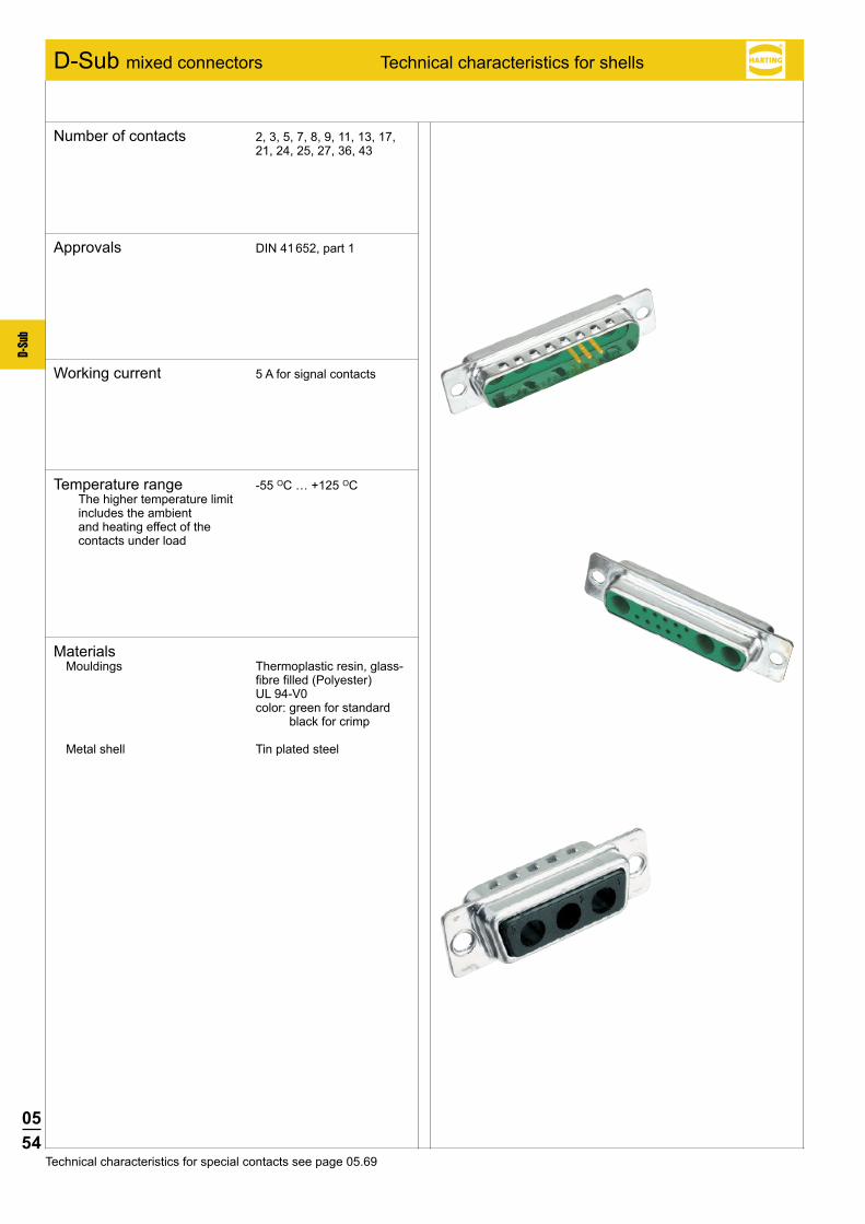
D-Sub mixed connectors Technical characteristics for shells
Number of contacts 2, 3, 5, 7, 8, 9, 11, 13, 17, 21, 24, 25, 27, 36, 43
Approvals DIN 41 652, part 1
Working current 5 A for signal contacts
Temperature range -55 OC … +125 OC The higher temperature limit
includes the ambient and heating effect of the contacts under load
Technical characteristics for special contacts see page 05.69
MaterialsMouldings Thermoplastic resin, glass-
fibre filled (Polyester) UL 94-V0 color: green for standard
black for crimp
Metal shell Tin plated steel
0555
D-Su
b
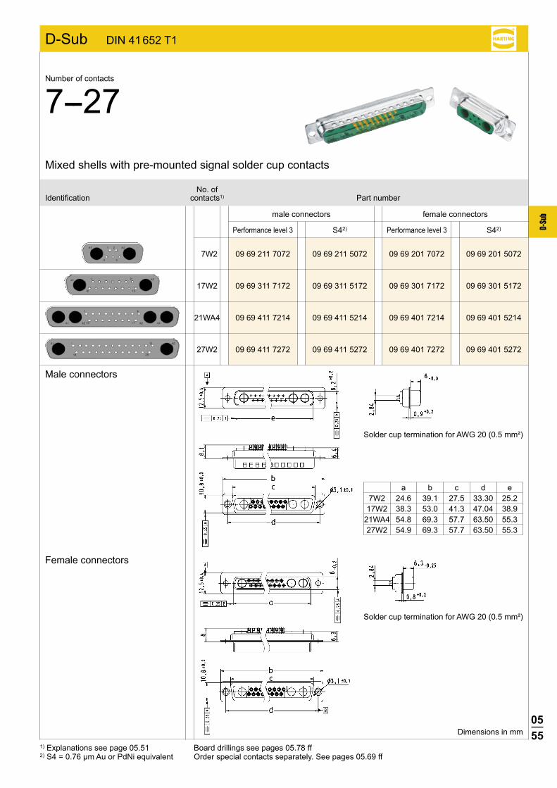
7W2 09 69 211 7072 09 69 211 5072 09 69 201 7072 09 69 201 5072
17W2 09 69 311 7172 09 69 311 5172 09 69 301 7172 09 69 301 5172
21WA4 09 69 411 7214 09 69 411 5214 09 69 401 7214 09 69 401 5214
27W2 09 69 411 7272 09 69 411 5272 09 69 401 7272 09 69 401 5272
D-Sub DIN 41 652 T1
S42) S42)
male connectors female connectors
No. ofIdentification contacts1) Part number
Mixed shells with pre-mounted signal solder cup contacts
Number of contacts
7--27
Dimensions in mm
1) Explanations see page 05.51 Board drillings see pages 05.78 ff2) S4 = 0.76 µm Au or PdNi equivalent Order special contacts separately. See pages 05.69 ff
Female connectors
Male connectors
Performance level 3 Performance level 3
Solder cup termination for AWG 20 (0.5 mm²)
Solder cup termination for AWG 20 (0.5 mm²)
a b c d e 7W2 24.6 39.1 27.5 33.30 25.2 17W2 38.3 53.0 41.3 47.04 38.9 21WA4 54.8 69.3 57.7 63.50 55.3 27W2 54.9 69.3 57.7 63.50 55.3
0556
D-Su
b
D-Sub DIN 41 652 T1
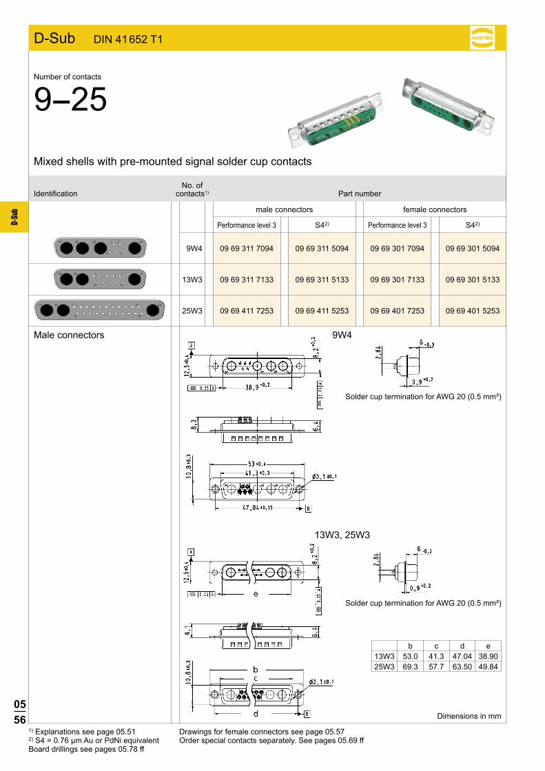
9W4
13W3, 25W3
9W4 09 69 311 7094 09 69 311 5094 09 69 301 7094 09 69 301 5094
13W3 09 69 311 7133 09 69 311 5133 09 69 301 7133 09 69 301 5133
25W3 09 69 411 7253 09 69 411 5253 09 69 401 7253 09 69 401 5253
S42) S42)
1) Explanations see page 05.51 2) S4 = 0.76 µm Au or PdNi equivalentBoard drillings see pages 05.78 ff
Drawings for female connectors see page 05.57Order special contacts separately. See pages 05.69 ff
No. ofIdentification contacts1) Part number
Mixed shells with pre-mounted signal solder cup contacts
Dimensions in mm
Male connectors
Number of contacts
9--25
Solder cup termination for AWG 20 (0.5 mm²)
Solder cup termination for AWG 20 (0.5 mm²)
b c d e 13W3 53.0 41.3 47.04 38.90 25W3 69.3 57.7 63.50 49.84
male connectors female connectors
Performance level 3 Performance level 3
0557
D-Su
b
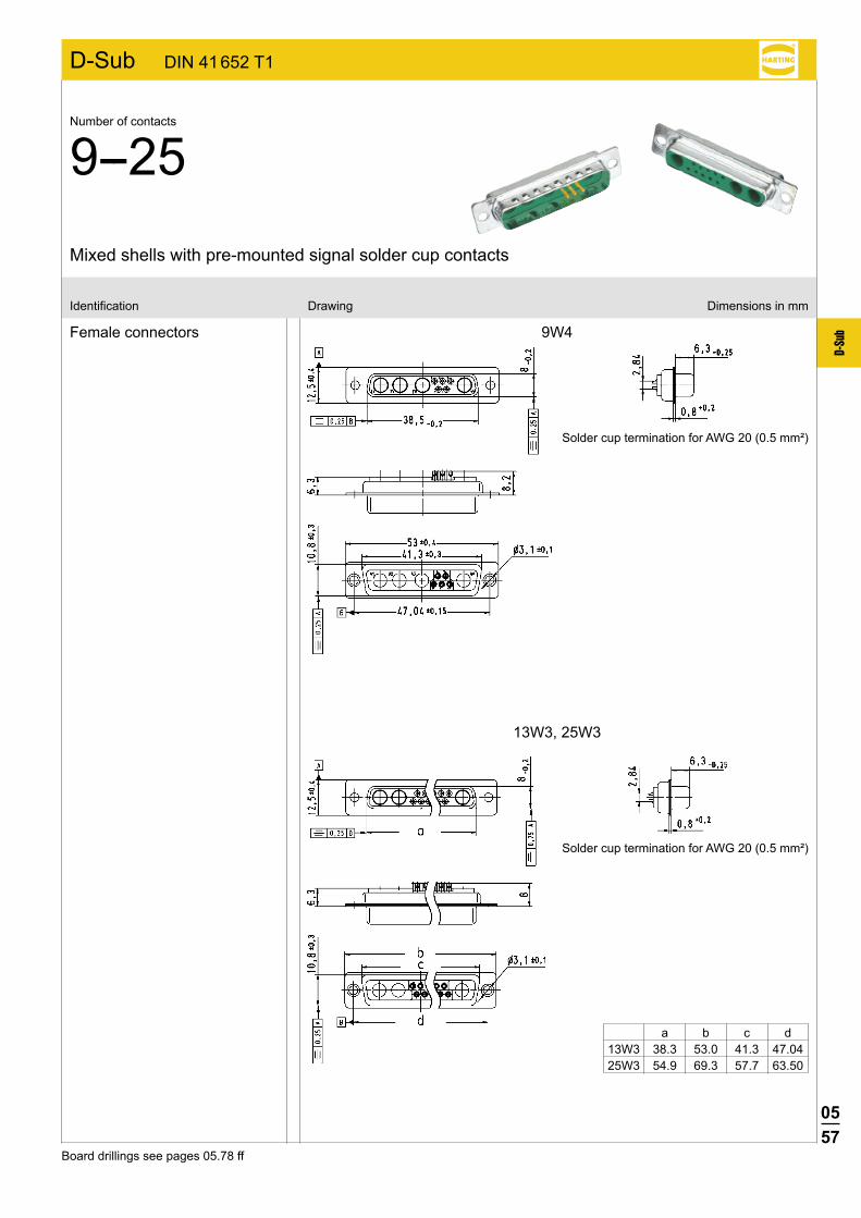
D-Sub DIN 41 652 T1
9W4
13W3, 25W3
Female connectors
Identification Drawing Dimensions in mm
Mixed shells with pre-mounted signal solder cup contacts
Solder cup termination for AWG 20 (0.5 mm²)
Solder cup termination for AWG 20 (0.5 mm²)
Board drillings see pages 05.78 ff
Number of contacts
9--25
a b c d 13W3 38.3 53.0 41.3 47.04 25W3 54.9 69.3 57.7 63.50
0558
D-Su
b
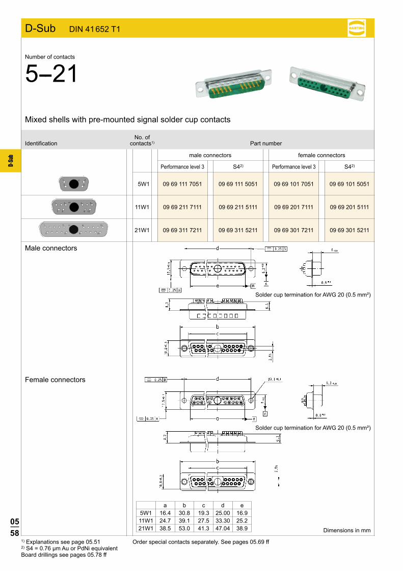
5W1 09 69 111 7051 09 69 111 5051 09 69 101 7051 09 69 101 5051
11W1 09 69 211 7111 09 69 211 5111 09 69 201 7111 09 69 201 5111
D-Sub DIN 41 652 T1
21W1 09 69 311 7211 09 69 311 5211 09 69 301 7211 09 69 301 5211
S42) S42)
male connectors female connectors
No. ofIdentification contacts1) Part number
Mixed shells with pre-mounted signal solder cup contacts
Dimensions in mm
1) Explanations see page 05.51 Order special contacts separately. See pages 05.69 ff2) S4 = 0.76 µm Au or PdNi equivalentBoard drillings see pages 05.78 ff
Performance level 3 Performance level 3
Number of contacts
5--21
Female connectors
Male connectors
Solder cup termination for AWG 20 (0.5 mm²)
Solder cup termination for AWG 20 (0.5 mm²)
a b c d e 5W1 16.4 30.8 19.3 25.00 16.9 11W1 24.7 39.1 27.5 33.30 25.2 21W1 38.5 53.0 41.3 47.04 38.9
0559
D-Su
b
D-Sub DIN 41 652 T1
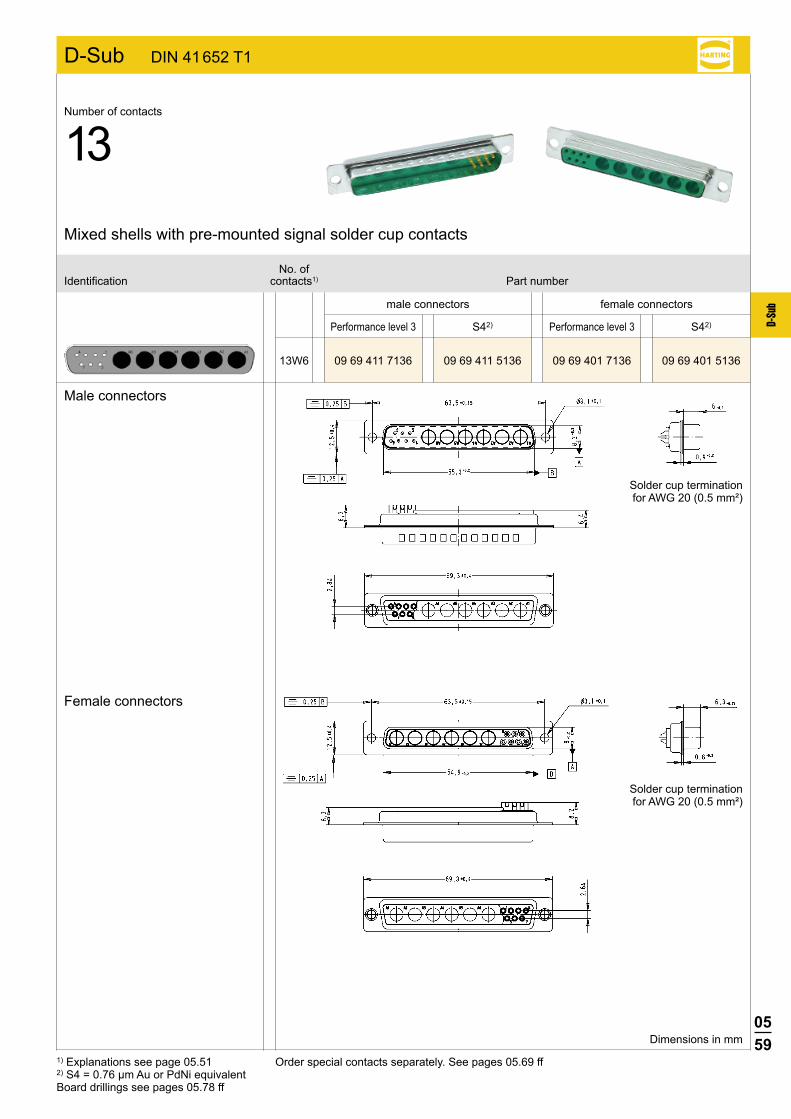
13W6 09 69 411 7136 09 69 411 5136 09 69 401 7136 09 69 401 5136
S42) S42)
1) Explanations see page 05.51 2) S4 = 0.76 µm Au or PdNi equivalentBoard drillings see pages 05.78 ff
Order special contacts separately. See pages 05.69 ff
No. ofIdentification contacts1) Part number
Mixed shells with pre-mounted signal solder cup contacts
Dimensions in mm
male connectors female connectors
Performance level 3 Performance level 3
Male connectors
Female connectors
Number of contacts
13
Solder cup termination for AWG 20 (0.5 mm²)
Solder cup termination for AWG 20 (0.5 mm²)

0560
D-Su
b
D-Sub DIN 41 652 T1
24W7 09 69 511 7247 09 69 511 5247 09 69 501 7247 09 69 501 5247
S42) S42)
1) Explanations see page 05.51 2) S4 = 0.76 µm Au or PdNi equivalentBoard drillings see pages 05.78 ff
Order special contacts separately. See pages 05.69 ff
No. ofIdentification contacts1) Part number
Mixed shells with pre-mounted signal solder cup contacts
Dimensions in mm
male connectors female connectors
Performance level 3 Performance level 3
Male connectors
Female connectors
Number of contacts
24
Solder cup termination for AWG 20 (0.5 mm²)
Solder cup termination for AWG 20 (0.5 mm²)
0561
D-Su
b
D-Sub DIN 41 652 T1
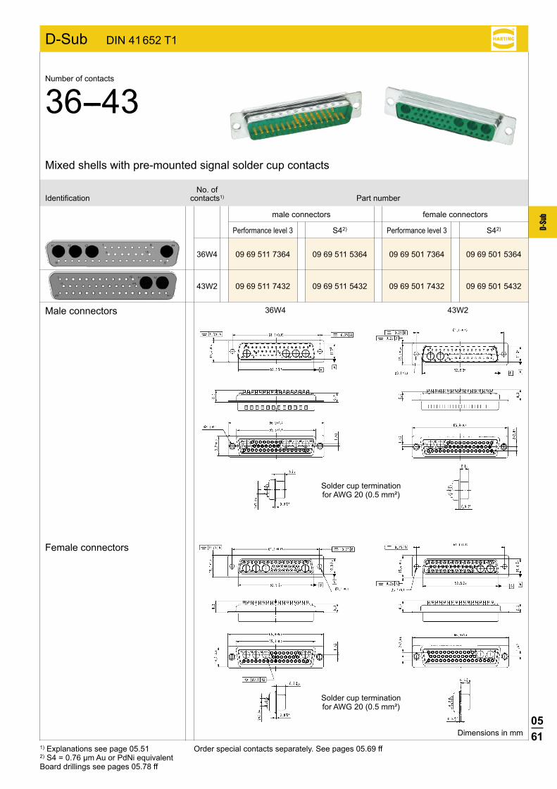
36W4 09 69 511 7364 09 69 511 5364 09 69 501 7364 09 69 501 5364
43W2 09 69 511 7432 09 69 511 5432 09 69 501 7432 09 69 501 5432
S42) S42)
36W4 43W2
1) Explanations see page 05.51 2) S4 = 0.76 µm Au or PdNi equivalentBoard drillings see pages 05.78 ff
Order special contacts separately. See pages 05.69 ff
No. ofIdentification contacts1) Part number
Mixed shells with pre-mounted signal solder cup contacts
Dimensions in mm
male connectors female connectors
Performance level 3 Performance level 3
Male connectors
Female connectors
Number of contacts
36--43
Solder cup termination for AWG 20 (0.5 mm²)
Solder cup termination for AWG 20 (0.5 mm²)

0562
D-Su
b
3W3 09 69 210 0033 09 69 200 0033
2W2 09 69 110 0522 09 69 100 0522
5W5 09 69 310 0055 09 69 300 0055
7W7 09 69 410 0077 09 69 400 0077
D-Sub DIN 41 652 T1
8W8 09 69 410 0088 09 69 400 0088
1) Explanations see page 05.51Board drillings see pages 05.78 ffOrder special contacts separately. See pages 05.69 ff
male connectors female connectors
No. ofIdentification contacts1) Part number
Shells without signal contacts for cable applications
Number of contacts
2--8
Dimensions in mm
Female connectors
Male connectors
a b c d e f g2W2 16.9 30.8 – 25.00 16.4 8.7 8.63W3 25.2 39.1 27.5 33.30 24.6 6.4 6.35W5 38.9 53.0 41.3 47.04 38.3 6.4 6.37W7 55.3 69.3 57.7 63.50 54.9 6.4 6.38W8 55.3 69.3 57.7 63.50 54.8 6.4 6.3
0563
D-Su
b
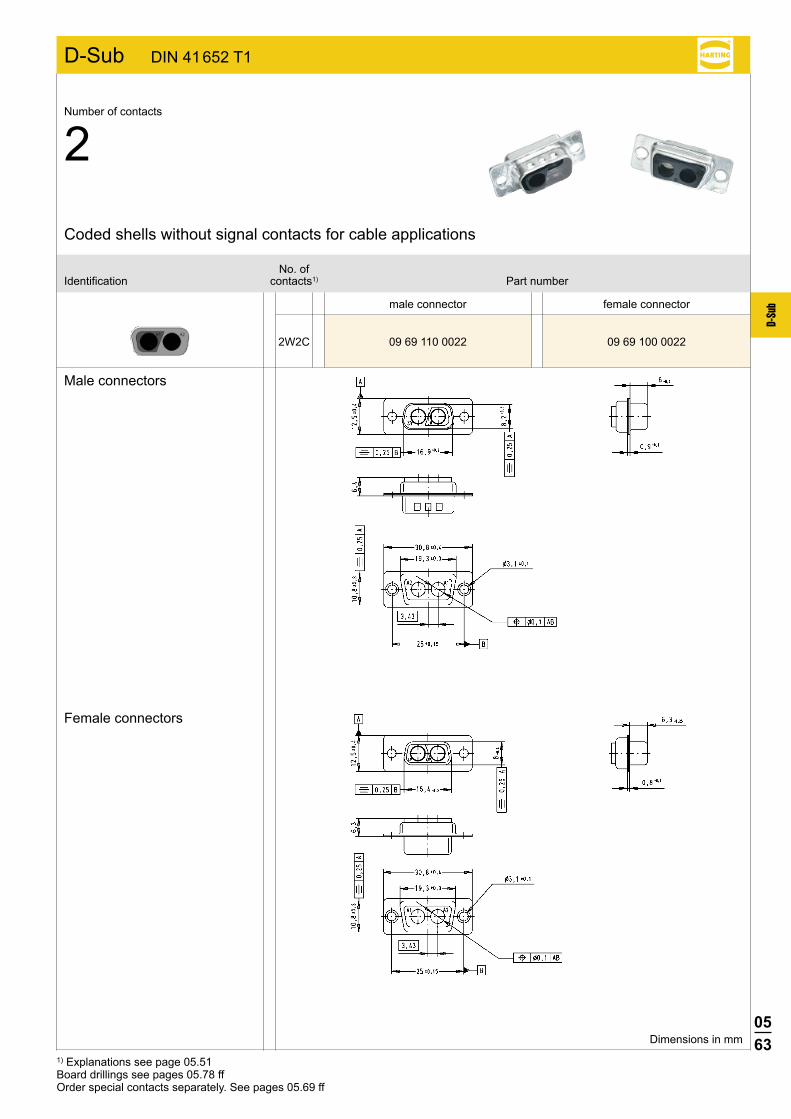
2W2C 09 69 110 0022 09 69 100 0022
D-Sub DIN 41 652 T1
1) Explanations see page 05.51Board drillings see pages 05.78 ffOrder special contacts separately. See pages 05.69 ff
Female connectors
Male connectors
male connector female connector
No. ofIdentification contacts1) Part number
Coded shells without signal contacts for cable applications
Number of contacts
2
Dimensions in mm

0564
D-Su
b
3W3C 09 69 210 0633 09 69 200 0633
D-Sub DIN 41 652 T1
1) Explanations see page 05.51Board drillings see pages 05.78 ffOrder special contacts separately. See pages 05.69 ff
Female connectors
Male connectors
male connector female connector
No. ofIdentification contacts1) Part number
Coded shells without signal contacts for cable applications
Number of contacts
3
Dimensions in mm
detail: polarization feature
detail: polarization feature

0565
D-Su
b
7W2 09 69 212 0072 09 69 202 0072
17W2 09 69 312 0172 09 69 302 0172
21WA4 09 69 412 0214 09 69 402 0214
27W2 09 69 412 0272 09 69 402 0272
D-Sub DIN 41 652 T1
1) Explanations see page 05.51Board drillings see pages 05.78 ffOrder special contacts separately. See pages 05.69 ff
Female connectors
Male connectors
male connectors female connectors
No. ofIdentification contacts1) Part number
Mixed shells for signal crimp contacts
Number of contacts
7--27
Dimensions in mm
a b c d e7W2 25.2 39.1 27.5 33.30 24.7
17W2 38.9 53.0 41.3 47.04 38.521WA4 55.3 69.3 57.7 63.50 54.927W2 56.3 69.3 – 63.50 54.9
0566
D-Su
b
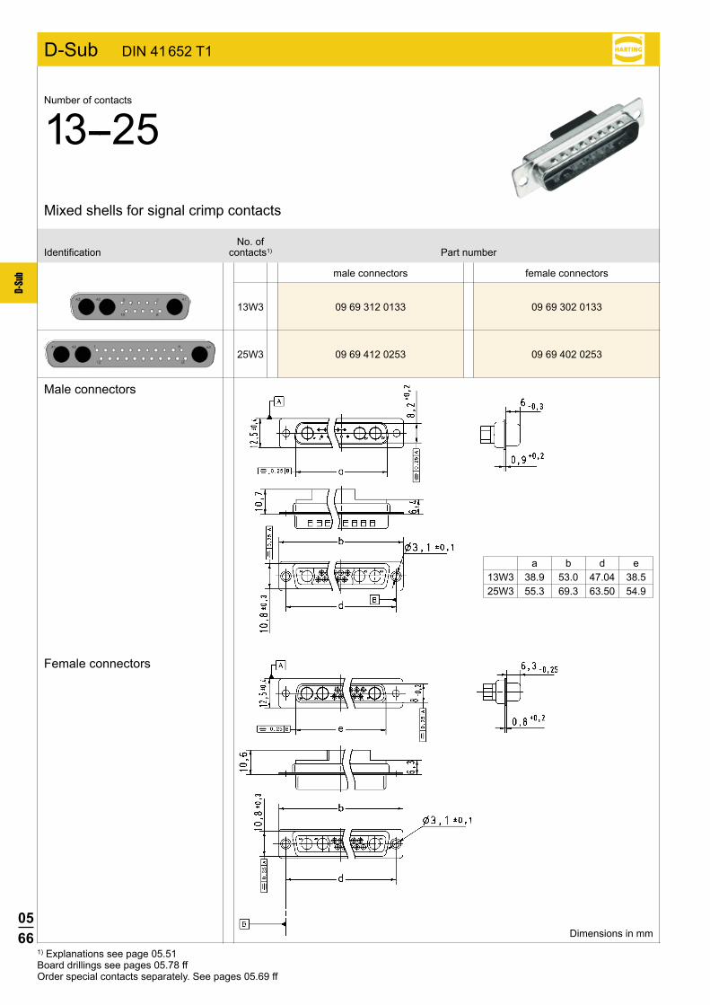
13W3 09 69 312 0133 09 69 302 0133
25W3 09 69 412 0253 09 69 402 0253
D-Sub DIN 41 652 T1
1) Explanations see page 05.51Board drillings see pages 05.78 ffOrder special contacts separately. See pages 05.69 ff
Female connectors
Male connectors
male connectors female connectors
No. ofIdentification contacts1) Part number
Mixed shells for signal crimp contacts
Number of contacts
13--25
Dimensions in mm
a b d e13W3 38.9 53.0 47.04 38.525W3 55.3 69.3 63.50 54.9
0567
D-Su
b
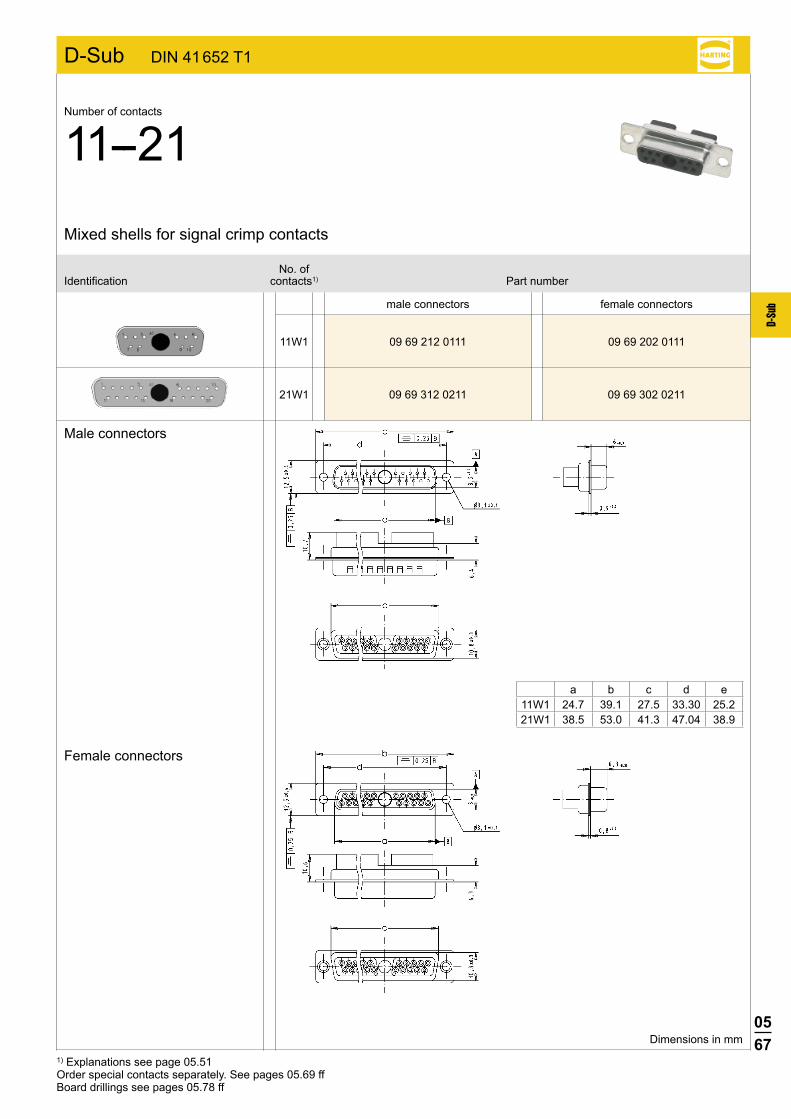
11W1 09 69 212 0111 09 69 202 0111
D-Sub DIN 41 652 T1
21W1 09 69 312 0211 09 69 302 0211
1) Explanations see page 05.51Order special contacts separately. See pages 05.69 ffBoard drillings see pages 05.78 ff
Female connectors
Male connectors
male connectors female connectors
No. ofIdentification contacts1) Part number
Mixed shells for signal crimp contacts
Number of contacts
11--21
Dimensions in mm
a b c d e11W1 24.7 39.1 27.5 33.30 25.221W1 38.5 53.0 41.3 47.04 38.9

0568
D-Su
b
36W4 09 69 512 0364 09 69 502 0364
D-Sub DIN 41 652 T1
1) Explanations see page 05.51Board drillings see pages 05.78 ffOrder special contacts separately. See pages 05.69 ff
Female connectors
Male connectors
male connector female connector
No. ofIdentification contacts1) Part number
Mixed shells for signal crimp contacts
Number of contacts
36
Dimensions in mm
0569
D-Su
b
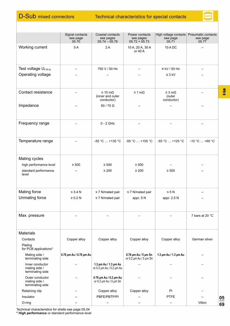
D-Sub mixed connectors Technical characteristics for special contacts
Signal contacts Coaxial contacts Power contacts High voltage contacts Pneumatic contacts see page see pages see pages see page see page 05.70 05.74 – 05.76 05.72 + 05.73 05.71 05.77
Working current 5 A 2 A 10 A, 20 A, 30 A 10 A DC – or 40 A
Test voltage Ur.m.s. – 750 V / 50 Hz – 4 kV / 50 Hz –
Operating voltage – – – ≤3kV –
Contact resistance – ≤10mΩ ≤1mΩ ≤3mΩ – (inner and outer (outer conductor) conductor)
Impedance – 50/75Ω – – –
Frequency range – 0 - 2 GHz – – –
Temperature range – -55 °C … +135 °C -55 °C … +155 °C -55 °C … +125 °C -10 °C … +60 °C
Mating cycles highperformancelevel ≥500 ≥500 ≥500 – –
standardperformance – ≥200 ≥200 ≥500 – level
Mating force ≤3.4N ≤7N/matedpair ≤7N/matedpair ≤5N –
Unmating force ≥0.2N ≤7N/matedpair appr.5N appr.2.5N –
Max. pressure – – – – 7 bars at 20 °C
Materials Contacts Copper alloy Copper alloy Copper alloy Copper alloy German silver
Plating for PCB applications*
Mating side / 0.76 µm Au / 0.76 µm Au 0.76 µm Au / 5 µm Sn 1.3 µm Au / 1.3 µm Au – terminating side or 0.2 µm Au / 5 µm Sn
Inner conductor – 1.3 µm Au / 1.3 µm Au – – – mating side / or 0.2 µm Au / 0.2 µm Au terminating side
Outer conductor – 0.76 µm Au / 0.2 µm Au – – – mating side / or 0.2 µm Au / 5 µm Sn terminating side
Retaining clip – Copper alloy Copper alloy PI –
Insulator – PBFE/PBTP/PI – PTFE –
O-ring – – – – Vitton
Technical characteristics for shells see page 05.04* High performance or standard performance level
0570
D-Su
b
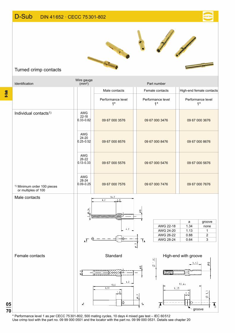
09 67 000 3576 09 67 000 3476 09 67 000 3676
09 67 000 8576 09 67 000 8476 09 67 000 8676
09 67 000 5576 09 67 000 5476 09 67 000 5676
09 67 000 7576 09 67 000 7476 09 67 000 7676
D-Sub DIN 41 652 · CECC 75 301-802
Standard
Wire gaugeIdentification (mm2) Part number
Turned crimp contacts
Individual contacts1)
Performance level1*
Male contacts Female contacts High-end female contacts
Performance level1*
Performance level1*
AWG22-18
0.33-0.82
AWG24-20
0.25-0.52
AWG26-22
0.13-0.33
AWG28-24
0.09-0.25
* Performance level 1 as per CECC 75 301-802, 500 mating cycles, 10 days 4 mixed gas test – IEC 60 512Use crimp tool with the part no. 09 99 000 0501 and the locator with the part no. 09 99 000 0531. Details see chapter 20
Male contacts
Female contacts
1) Minimum order 100 pieces or multiples of 100
a grooveAWG 22-18 1.34 noneAWG 24-20 1.13 1AWG 26-22 0.88 2AWG 28-24 0.64 3
High-end with groove
groove
0571
D-Su
b
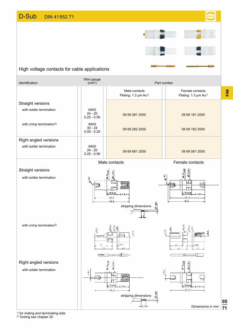
D-Sub DIN 41 652 T1
09 69 281 2550
09 69 282 2550
09 69 681 2550
09 69 181 2550
09 69 182 2550
09 69 581 2550
Straight versions
Male contactsPlating: 1.3 µm Au1)
Wire gaugeIdentification (mm²) Part number
High voltage contacts for cable applications
Female contactsPlating: 1.3 µm Au1)
AWG 24 - 20
0.25 - 0.56
AWG 30 - 24
0.05 - 0.25
with solder termination
with solder termination
with solder termination
with solder termination
with crimp termination2)
with crimp termination2)
Dimensions in mm
stripping dimensions
AWG 24 - 20
0.25 - 0.56
Right angled versions
Straight versions
Male contacts Female contacts
Right angled versions
stripping dimensions
1) for mating and terminating side2) Tooling see chapter 20
0572
D-Su
b
D-Sub DIN 41 652 T1
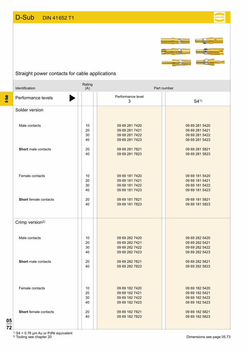
10 09 69 281 7420 09 69 281 5420 20 09 69 281 7421 09 69 281 5421 30 09 69 281 7422 09 69 281 5422 40 09 69 281 7423 09 69 281 5423
20 09 69 281 7821 09 69 281 5821 40 09 69 281 7823 09 69 281 5823
10 09 69 181 7420 09 69 181 5420 20 09 69 181 7421 09 69 181 5421 30 09 69 181 7422 09 69 181 5422 40 09 69 181 7423 09 69 181 5423
20 09 69 181 7821 09 69 181 5821 40 09 69 181 7823 09 69 181 5823
10 09 69 282 7420 09 69 282 5420 20 09 69 282 7421 09 69 282 5421 30 09 69 282 7422 09 69 282 5422 40 09 69 282 7423 09 69 282 5423
20 09 69 282 7821 09 69 282 5821 40 09 69 282 7823 09 69 282 5823
10 09 69 182 7420 09 69 182 5420 20 09 69 182 7421 09 69 182 5421 30 09 69 182 7422 09 69 182 5422 40 09 69 182 7423 09 69 182 5423
20 09 69 182 7821 09 69 182 5821 40 09 69 182 7823 09 69 182 5823
1) S4 = 0.76 µm Au or PdNi equivalent 2) Tooling see chapter 20 Dimensions see page 05.73
Performance levels þ
Solder version
Male contacts
Female contacts
Crimp version2)
Male contacts
Female contacts
Performance level3 S41)
RatingIdentification (A) Part number
Straight power contacts for cable applications
Short male contacts
Short female contacts
Short male contacts
Short female contacts

0573
D-Su
b
d max d max
c max
c max
e
d max d max
c max c max
D-Sub DIN 41 652 T1
Male contacts crimpsolder
crimpsolderFemale contacts
Identification Drawing Dimensions in mm
Straight power contacts for cable applications
stripping dimensions for male and female contacts
Rating (A) ø a -0.1 ø b ±0.05 cmax dmax e ø x -0.1 ø y ±0.05 AWG
10 1.8 2.54 7.8 23 7.5 1.7 2.6 16 - 2020 2.7 3.63 7.8 23 7.5 2.6 3.6 12 - 14
short version 20 2.7 3.63 4.7 17.4 4.5 2.6 3.6 12 - 1430 3.5 4.40 7.8 23 7.5 3.7 4.7 10 - 1240 4.8 5.50 7.8 23 7.5 4.6 5.8 8 - 10
short version 40 4.8 5.50 6.4 20 6.1 4.6 5.8 8 - 10
Rating (A) min./max. conductor ø min./max. conductor cross
section [mm²]10 0.9 to 1.7 0.64 to 2.2720 1.8 to 2.6 2.54 to 5.31
short version 20 1.8 to 2.6 2.54 to 5.3130 2.2 to 3.7 3.80 to 10.7540 2.9 to 4.6 6.61 to 16.62
short version 40 2.9 to 4.6 6.61 to 16.62
0574
D-Su
b
D-Sub DIN 41 652 T1
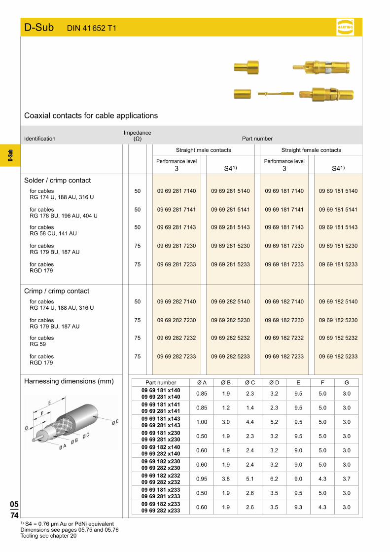
50 09 69 281 7140 09 69 281 5140 09 69 181 7140 09 69 181 5140
50 09 69 281 7141 09 69 281 5141 09 69 181 7141 09 69 181 5141
50 09 69 282 7140 09 69 282 5140 09 69 182 7140 09 69 182 5140
75 09 69 282 7230 09 69 282 5230 09 69 182 7230 09 69 182 5230
75 09 69 281 7230 09 69 281 5230 09 69 181 7230 09 69 181 5230
50 09 69 281 7143 09 69 281 5143 09 69 181 7143 09 69 181 5143
75 09 69 282 7232 09 69 282 5232 09 69 182 7232 09 69 182 5232
S41) S41)
75 09 69 281 7233 09 69 281 5233 09 69 181 7233 09 69 181 5233
75 09 69 282 7233 09 69 282 5233 09 69 182 7233 09 69 182 5233
Solder / crimp contactfor cables RG 174 U, 188 AU, 316 U
Straight male contacts Straight female contacts
ImpedanceIdentification (Ω) Partnumber
Coaxial contacts for cable applications
Performance level3
Performance level3
for cables RG 178 BU, 196 AU, 404 U
Crimp / crimp contact
Harnessing dimensions (mm)
for cables RG 174 U, 188 AU, 316 U
for cables RG 179 BU, 187 AU
for cables RG 58 CU, 141 AU
for cables RG 59
for cables RG 179 BU, 187 AU
1) S4 = 0.76 µm Au or PdNi equivalentDimensions see pages 05.75 and 05.76 Tooling see chapter 20
Part number Ø A Ø B Ø C Ø D E F G09 69 181 x140 09 69 281 x140 0.85 1.9 2.3 3.2 9.5 5.0 3.0
09 69 181 x141 09 69 281 x141 0.85 1.2 1.4 2.3 9.5 5.0 3.0
09 69 181 x143 09 69 281 x143 1.00 3.0 4.4 5.2 9.5 5.0 3.0
09 69 181 x230 09 69 281 x230 0.50 1.9 2.3 3.2 9.5 5.0 3.0
09 69 182 x140 09 69 282 x140 0.60 1.9 2.4 3.2 9.0 5.0 3.0
09 69 182 x230 09 69 282 x230 0.60 1.9 2.4 3.2 9.0 5.0 3.0
09 69 182 x232 09 69 282 x232 0.95 3.8 5.1 6.2 9.0 4.3 3.7
09 69 181 x233 09 69 281 x233 0.50 1.9 2.6 3.5 9.5 5.0 3.0
09 69 182 x233 09 69 282 x233 0.60 1.9 2.6 3.5 9.3 4.3 3.0
for cables RGD 179
for cables RGD 179
0575
D-Su
b
D-Sub DIN 41 652 T1
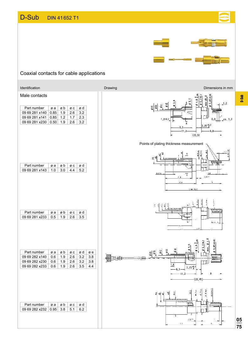
Male contacts
Identification Drawing Dimensions in mm
Coaxial contacts for cable applications
Part number ø a ø b ø c ø d09 69 281 x140 0.85 1.9 2.6 3.209 69 281 x141 0.85 1.2 1.7 2.309 69 281 x230 0.50 1.9 2.6 3.2
Part number ø a ø b ø c ø d09 69 281 x143 1.0 3.0 4.4 5.2
Part number ø a ø b ø c ø d09 69 282 x232 0.95 3.8 5.1 6.2
Part number ø a ø b ø c ø d ø e09 69 282 x140 0.6 1.9 2.6 3.2 3.809 69 282 x230 0.6 1.9 2.6 3.2 3.809 69 282 x233 0.6 1.9 2.6 3.5 4.4
Points of plating thickness measurement
Part number ø a ø b ø c ø d09 69 281 x233 0.5 1.9 2.6 3.5

0576
D-Su
b
D-Sub DIN 41 652 T1
Female contacts
Identification Drawing Dimensions in mm
Coaxial contacts for cable applications
Points of plating thickness measurement
Part number ø a ø b ø c ø d09 69 181 x140 0.85 1.9 2.6 3.209 69 181 x141 0.85 1.2 1.7 2.309 69 181 x230 0.50 1.9 2.6 3.2
Part number ø a ø b ø c ø d09 69 181 x143 1.0 3.0 4.4 5.2
Part number ø a ø b ø c ø d09 69 182 x232 0.95 3.8 5.1 6.2
Part number ø a ø b ø c ø d ø e09 69 182 x140 0.6 1.9 2.6 3.2 3.809 69 182 x230 0.6 1.9 2.6 3.2 3.809 69 182 x233 0.6 1.9 2.6 3.5 4.4
Part number ø a ø b ø c ø d09 69 181 x233 0.5 1.9 2.6 3.5

0577
D-Su
b
D-Sub DIN 41 652 T1
Dimensions in mm
Male contacts
Female contacts
Male contacts
Female contacts
Inner diameterIdentification air tube (mm) Part number
Pneumatic contacts for cable applications
2 09 69 287 0060 2.6 09 69 287 0061 3 09 69 287 0062 4 09 69 287 0063
2 09 69 187 0060 2.6 09 69 187 0061 3 09 69 187 0062 4 09 69 187 0063
Part number ø a ø b ø c ø d09 69 x87 0060 1.45 2.6 1.5 0.9509 69 x87 0061 1.65 3.1 2.0 1.6509 69 x87 0062 1.65 3.4 2.3 1.8509 69 x87 0063 1.65 4.8 3.7 2.95
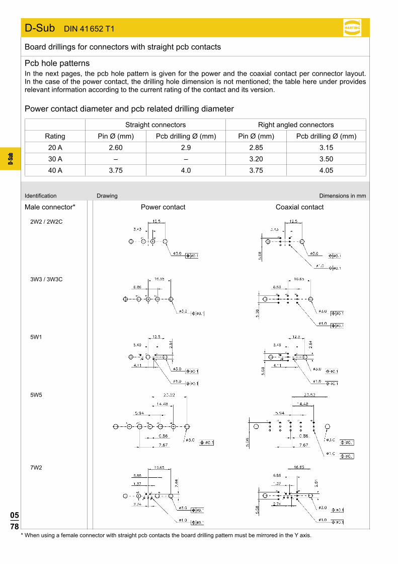
0578
D-Su
b
2W2 / 2W2C
3W3 / 3W3C
5W1
5W5
7W2
Male connector* Power contact Coaxial contactIdentification Drawing Dimensions in mm
* When using a female connector with straight pcb contacts the board drilling pattern must be mirrored in the Y axis.
Board drillings for connectors with straight pcb contacts
Pcb hole patternsIn the next pages, the pcb hole pattern is given for the power and the coaxial contact per connector layout. In the case of the power contact, the drilling hole dimension is not mentioned; the table here under provides relevant information according to the current rating of the contact and its version.
Power contact diameter and pcb related drilling diameter
Straight connectors Right angled connectorsRating Pin Ø (mm) Pcb drilling Ø (mm) Pin Ø (mm) Pcb drilling Ø (mm)20 A 2.60 2.9 2.85 3.1530 A – – 3.20 3.5040 A 3.75 4.0 3.75 4.05
D-Sub DIN 41 652 T1
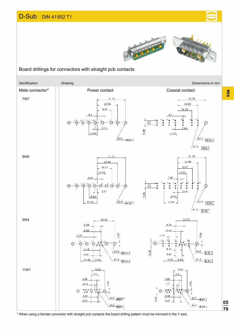
0579
D-Su
b
7W7
8W8
9W4
11W1
Male connector* Power contact Coaxial contact
Identification Drawing Dimensions in mm
* When using a female connector with straight pcb contacts the board drilling pattern must be mirrored in the Y axis.
Board drillings for connectors with straight pcb contacts
D-Sub DIN 41 652 T1

0580
D-Su
b
13W3
13W6
17W2
21W1
Male connector* Power contact Coaxial contact
Identification Drawing Dimensions in mm
* When using a female connector with straight pcb contacts the board drilling pattern must be mirrored in the Y axis.
Board drillings for connectors with straight pcb contacts
D-Sub DIN 41 652 T1

0581
D-Su
b
21WA4
24W7
25W3
Male connector* Power contact Coaxial contact
Identification Drawing Dimensions in mm
* When using a female connector with straight pcb contacts the board drilling pattern must be mirrored in the Y axis.
Board drillings for connectors with straight pcb contacts
D-Sub DIN 41 652 T1

0582
D-Su
b
27W2
36W4
43W2
Male connector* Power contact Coaxial contact
Identification Drawing Dimensions in mm
* When using a female connector with straight pcb contacts the board drilling pattern must be mirrored in the Y axis.
Board drillings for connectors with straight pcb contacts
D-Sub DIN 41 652 T1

0583
D-Su
b
2W2 / 2W2C
5W1
7W2
5W5
3W3 / 3W3C
Male connector* Power contact Coaxial contact
Identification Drawing Dimensions in mm
Board drillings for connectors with right angled pcb contacts
* When using a female connector with right angled pcb contacts the board drilling pattern must be mirrored in the Y axis.
D-Sub DIN 41 652 T1
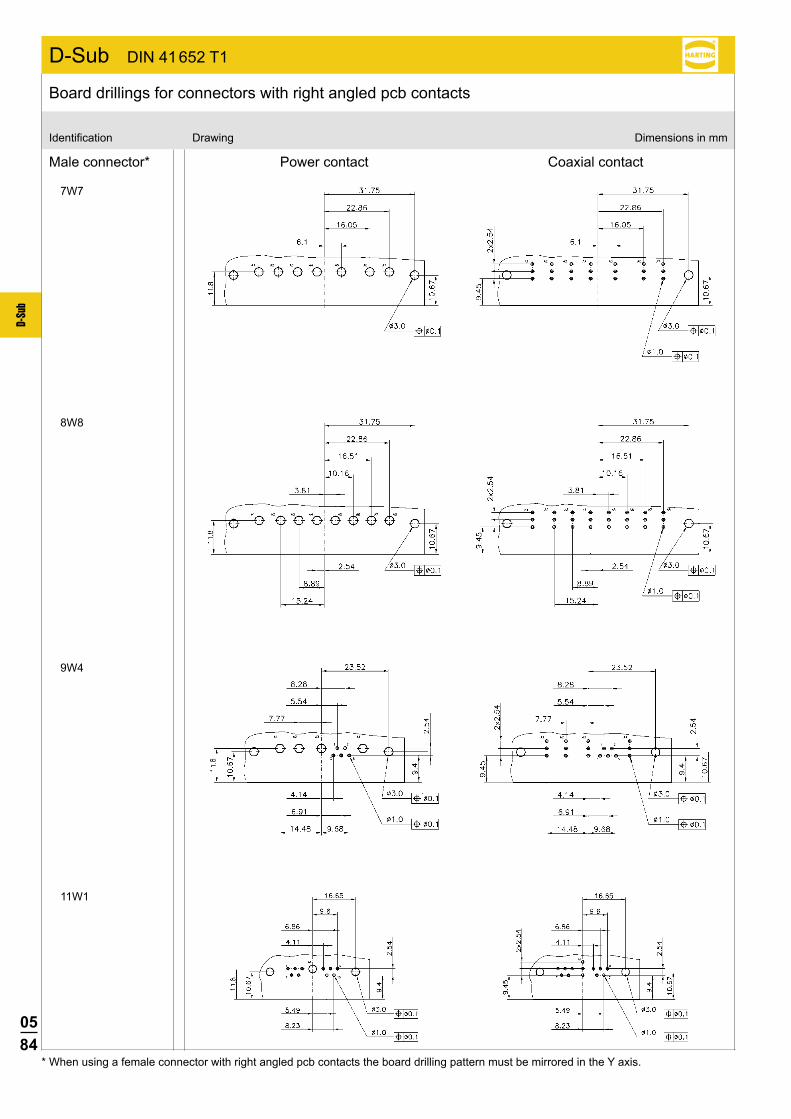
0584
D-Su
b
7W7
8W8
9W4
11W1
Male connector* Power contact Coaxial contact
Identification Drawing Dimensions in mm
Board drillings for connectors with right angled pcb contacts
* When using a female connector with right angled pcb contacts the board drilling pattern must be mirrored in the Y axis.
D-Sub DIN 41 652 T1
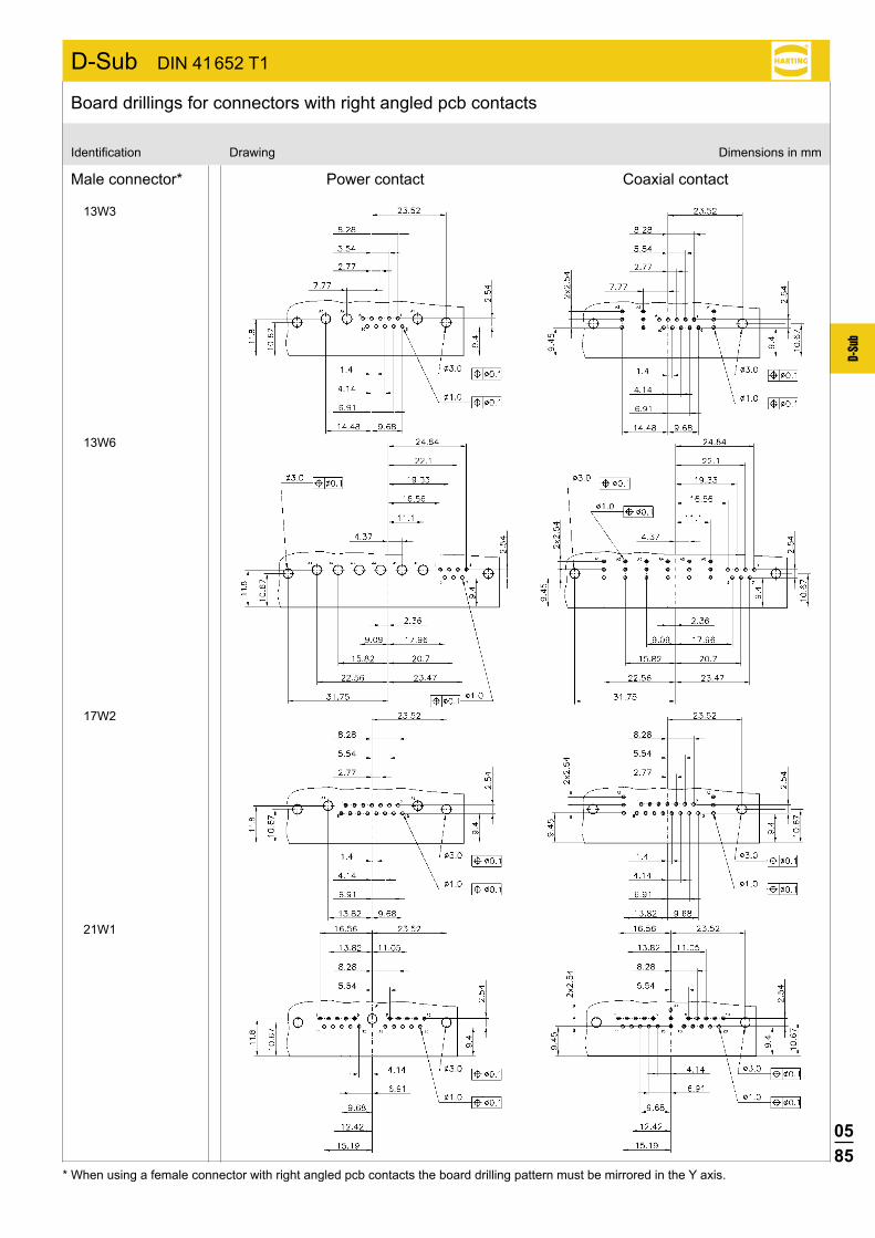
0585
D-Su
b
13W3
13W6
17W2
21W1
Male connector* Power contact Coaxial contact
Identification Drawing Dimensions in mm
Board drillings for connectors with right angled pcb contacts
* When using a female connector with right angled pcb contacts the board drilling pattern must be mirrored in the Y axis.
D-Sub DIN 41 652 T1
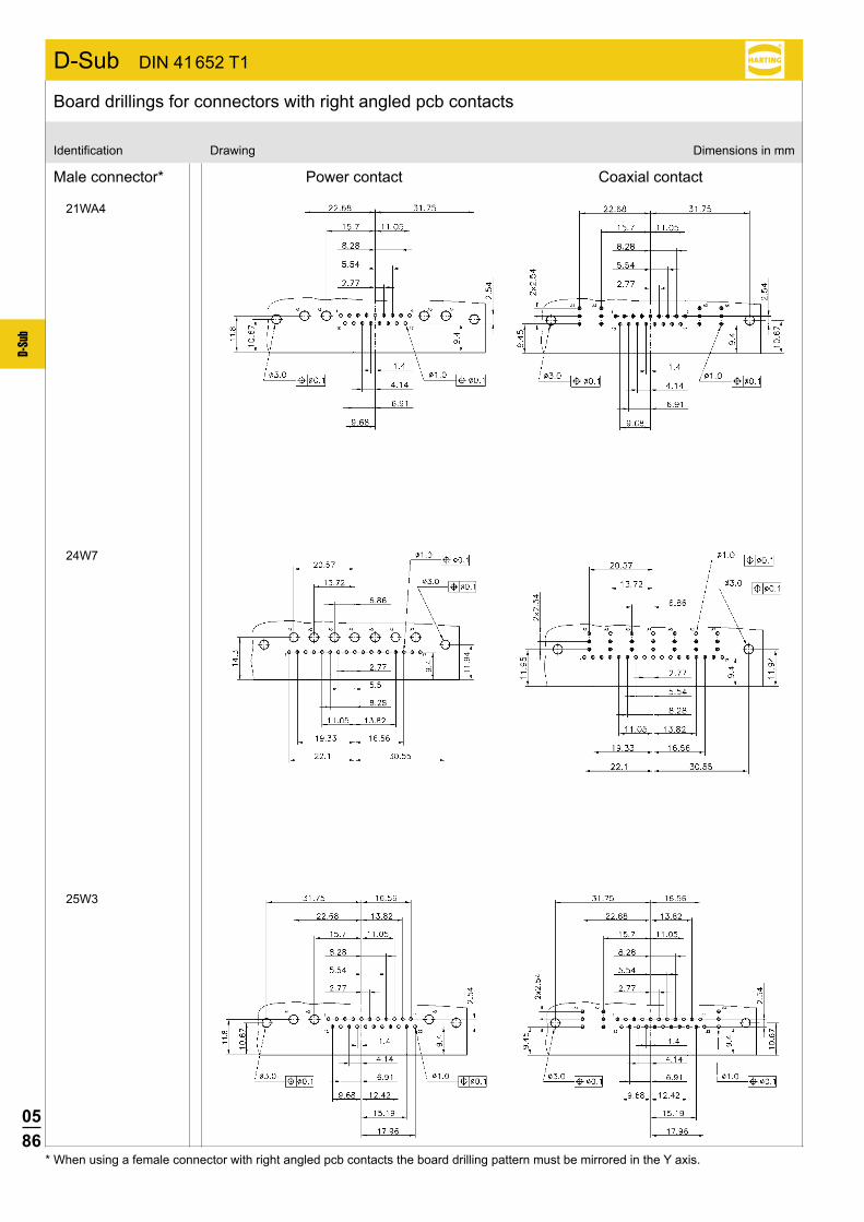
0586
D-Su
b
21WA4
24W7
25W3
Male connector* Power contact Coaxial contact
Identification Drawing Dimensions in mm
Board drillings for connectors with right angled pcb contacts
* When using a female connector with right angled pcb contacts the board drilling pattern must be mirrored in the Y axis.
D-Sub DIN 41 652 T1
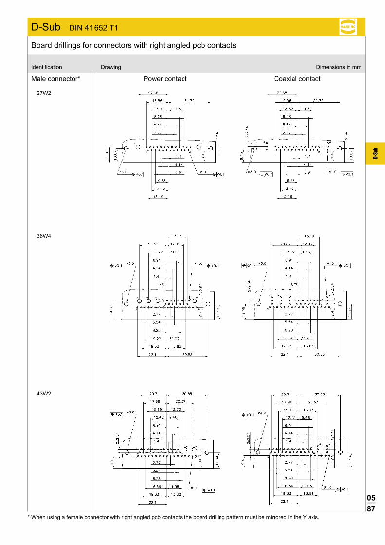
0587
D-Su
b
27W2
36W4
43W2
Male connector* Power contact Coaxial contact
Identification Drawing Dimensions in mm
Board drillings for connectors with right angled pcb contacts
* When using a female connector with right angled pcb contacts the board drilling pattern must be mirrored in the Y axis.
D-Sub DIN 41 652 T1
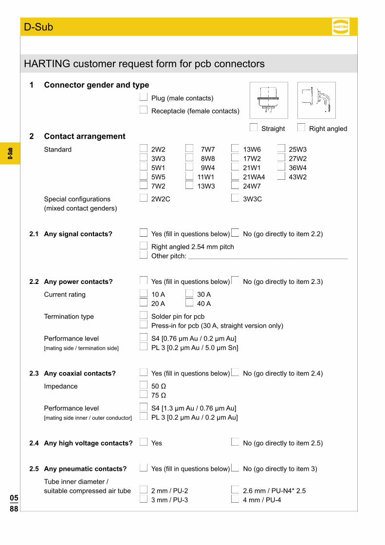
0588
D-Su
b
HARTING customer request form for pcb connectors
1 Connector gender and type Plug (male contacts)
Receptacle (female contacts)
2 Contact arrangement Standard 2W2 7W7 13W6 25W3 3W3 8W8 17W2 27W2 5W1 9W4 21W1 36W4 5W5 11W1 21WA4 43W2 7W2 13W3 24W7
Special configurations 2W2C 3W3C (mixed contact genders)
2.1 Any signal contacts? Yes (fill in questions below) No (go directly to item 2.2)
Right angled 2.54 mm pitch Other pitch: _______________________________________________________________________________________________________
2.2 Any power contacts? Yes (fill in questions below) No (go directly to item 2.3)
Current rating 10 A 30 A 20 A 40 A
Termination type Solder pin for pcb Press-in for pcb (30 A, straight version only)
Performance level S4 [0.76 µm Au / 0.2 µm Au] [mating side / termination side] PL 3 [0.2 µm Au / 5.0 µm Sn]
2.3 Any coaxial contacts? Yes (fill in questions below) No (go directly to item 2.4)
Impedance 50 Ω 75Ω
Performance level S4 [1.3 µm Au / 0.76 µm Au] [mating side inner / outer conductor] PL 3 [0.2 µm Au / 0.2 µm Au]
2.4 Any high voltage contacts? Yes No (go directly to item 2.5)
2.5 Any pneumatic contacts? Yes (fill in questions below) No (go directly to item 3)
Tube inner diameter / suitable compressed air tube 2 mm / PU-2 2.6 mm / PU-N4* 2.5 3 mm / PU-3 4 mm / PU-4
Straight Right angled
D-Sub
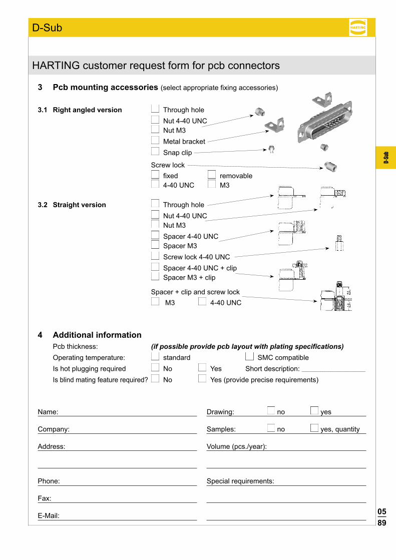
0589
D-Su
b
3 Pcb mounting accessories (select appropriate fixing accessories)
3.1 Right angled version Through hole Nut 4-40 UNC Nut M3 Metal bracket Snap clip Screw lock
fixed removable 4-40 UNC M3
3.2 Straight version Through hole Nut 4-40 UNC Nut M3 Spacer 4-40 UNC Spacer M3 Screw lock 4-40 UNC Spacer 4-40 UNC + clip Spacer M3 + clip
Spacer + clip and screw lock
M3 4-40 UNC
4 Additional information Pcb thickness: (if possible provide pcb layout with plating specifications) Operating temperature: standard SMC compatible Is hot plugging required No Yes Short description: ________________________________________
Is blind mating feature required? No Yes (provide precise requirements)
Name:
Company:
Address:
Phone:
Fax:
E-Mail:
Drawing: no yes
Samples: no yes, quantity
Volume (pcs./year):
Special requirements:
HARTING customer request form for pcb connectors
D-Sub
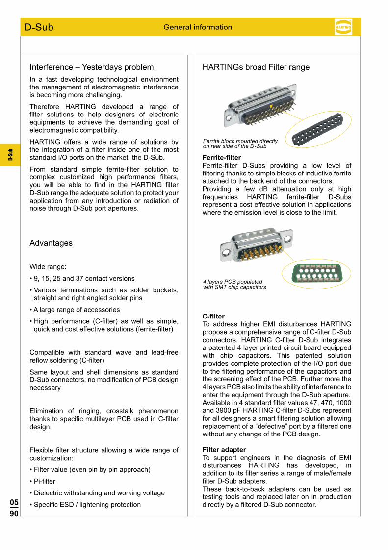
0590
D-Su
b
General information
Interference – Yesterdays problem!In a fast developing technological environment the management of electromagnetic interference is becoming more challenging.
Therefore HARTING developed a range of filter solutions to help designers of electronic equipments to achieve the demanding goal of electromagnetic compatibility.
HARTING offers a wide range of solutions by the integration of a filter inside one of the most standard I/O ports on the market; the D-Sub.
From standard simple ferrite-filter solution to complex customized high performance filters, you will be able to find in the HARTING filter D-Sub range the adequate solution to protect your application from any introduction or radiation of noise through D-Sub port apertures.
Advantages
Wide range:
•9,15,25and37contactversions
•Various terminations such as solder buckets,straight and right angled solder pins
•Alargerangeofaccessories
•High performance (C-filter) as well as simple,quick and cost effective solutions (ferrite-filter)
Compatible with standard wave and lead-free reflow soldering (C-filter)
Same layout and shell dimensions as standard D-Sub connectors, no modification of PCB design necessary
Elimination of ringing, crosstalk phenomenon thanks to specific multilayer PCB used in C-filter design.
Flexible filter structure allowing a wide range of customization:
•Filtervalue(evenpinbypinapproach)
•Pi-filter
•Dielectricwithstandingandworkingvoltage
•SpecificESD/lighteningprotection
HARTINGs broad Filter range
Ferrite-filterFerrite-filter D-Subs providing a low level of filtering thanks to simple blocks of inductive ferrite attached to the back end of the connectors.Providing a few dB attenuation only at high frequencies HARTING ferrite-filter D-Subs represent a cost effective solution in applications where the emission level is close to the limit.
C-filterTo address higher EMI disturbances HARTING propose a comprehensive range of C-filter D-Sub connectors. HARTING C-filter D-Sub integrates a patented 4 layer printed circuit board equipped with chip capacitors. This patented solution provides complete protection of the I/O port due to the filtering performance of the capacitors and the screening effect of the PCB. Further more the 4 layers PCB also limits the ability of interference to enter the equipment through the D-Sub aperture.Available in 4 standard filter values 47, 470, 1000 and 3900 pF HARTING C-filter D-Subs represent for all designers a smart filtering solution allowing replacement of a “defective” port by a filtered one without any change of the PCB design.
Filter adapterTo support engineers in the diagnosis of EMI disturbances HARTING has developed, in addition to its filter series a range of male/female filter D-Sub adapters.These back-to-back adapters can be used as testing tools and replaced later on in production directly by a filtered D-Sub connector.
D-Sub
Ferrite block mounted directly on rear side of the D-Sub
4 layers PCB populated with SMT chip capacitors
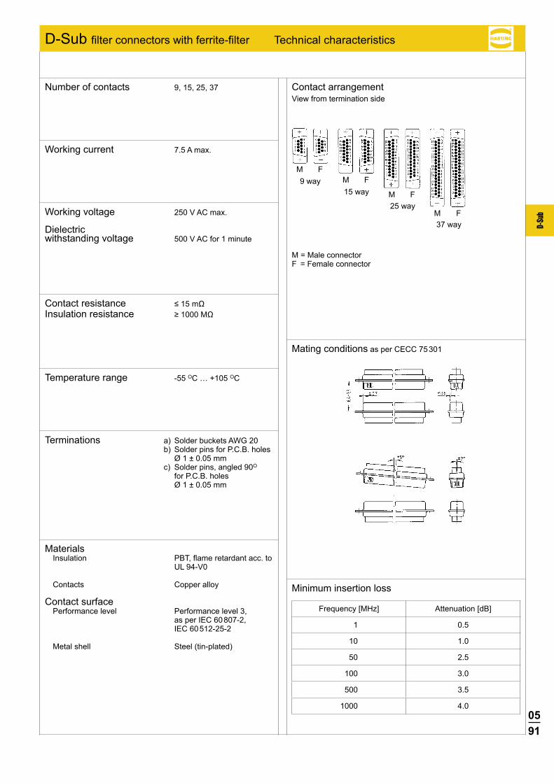
0591
D-Su
b
M FM F
M F
M F
D-Sub filter connectors with ferrite-filter Technical characteristics
Contact arrangement View from termination side
Mating conditions as per CECC 75 301
M = Male connectorF = Female connector
Number of contacts 9, 15, 25, 37
Terminations a) Solder buckets AWG 20 b) Solder pins for P.C.B. holes
Ø 1 ± 0.05 mm c) Solder pins, angled 90O
for P.C.B. holes Ø 1 ± 0.05 mm
Temperature range -55 OC … +105 OC
Contact resistance ≤15mΩ Insulation resistance ≥1000MΩ
Working voltage 250 V AC max.
Dielectric withstanding voltage 500 V AC for 1 minute
Working current 7.5 A max.
MaterialsInsulation PBT, flame retardant acc. to
UL 94-V0
Contacts Copper alloy
Contact surface Performance level Performance level 3,
as per IEC 60 807-2, IEC 60 512-25-2
Metal shell Steel (tin-plated)
37 way
9 way15 way
25 way
Minimum insertion loss
Frequency [MHz] Attenuation [dB]
1 0.5
10 1.0
50 2.5
100 3.0
500 3.5
1000 4.0
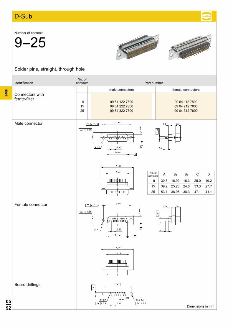
0592
D-Su
b
9 09 64 122 7800 09 64 112 7800 15 09 64 222 7800 09 64 212 7800 25 09 64 322 7800 09 64 312 7800
male connectors female connectors
No. ofIdentification contacts Part number
Connectors withferrite-filter
Male connector
Female connector
Board drillings
Solder pins, straight, through hole
Number of contacts
9--25
D-Sub
Dimensions in mm
No. of contacts A B1 B2 C D
9 30.8 16.92 16.3 25.0 19.2
15 39.2 25.25 24.6 33.3 27.7
25 53.1 38.96 38.3 47.1 41.1
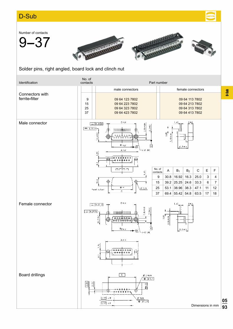
0593
D-Su
b
9 09 64 123 7802 09 64 113 7802 15 09 64 223 7802 09 64 213 7802 25 09 64 323 7802 09 64 313 7802 37 09 64 423 7802 09 64 413 7802
male connectors female connectors
No. ofIdentification contacts Part number
Connectors withferrite-filter
Male connector
Female connector
Board drillings
Solder pins, right angled, board lock and clinch nut
Number of contacts
9--37
D-Sub
Dimensions in mm
No. of contacts A B1 B2 C E F
9 30.8 16.92 16.3 25.0 3 4
15 39.2 25.25 24.6 33.3 6 7
25 53.1 38.96 38.3 47.1 11 12
37 69.4 55.42 54.8 63.5 17 18
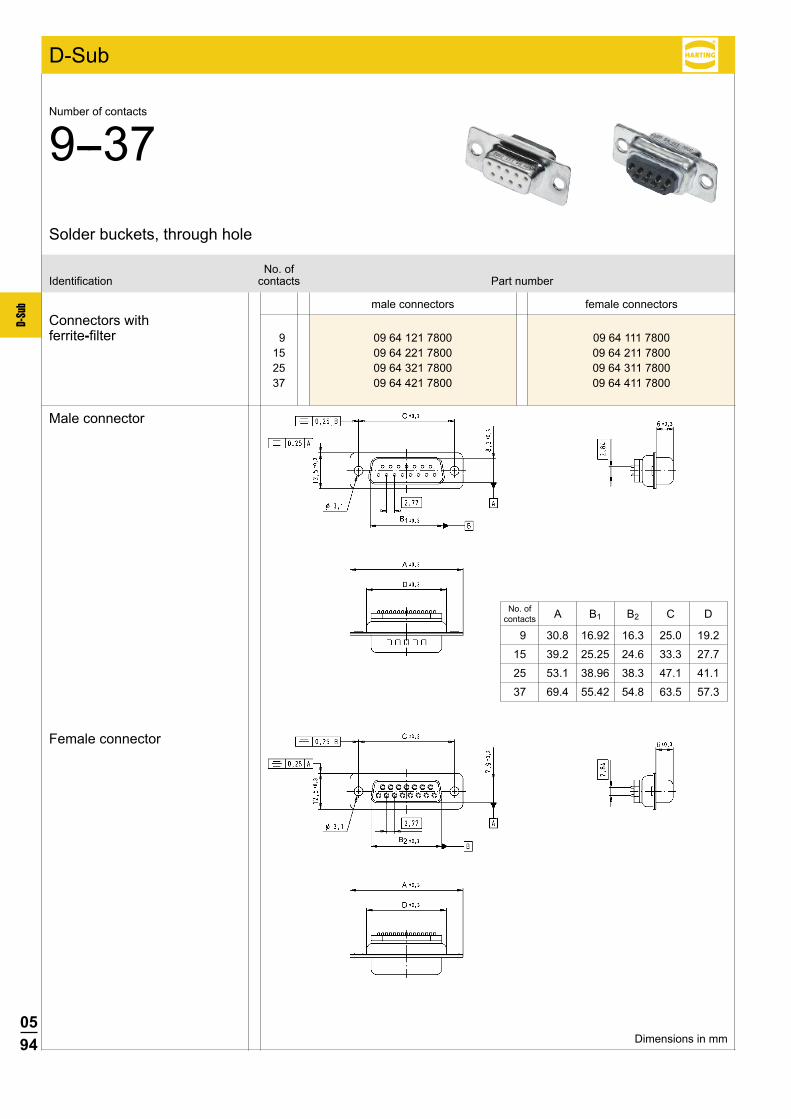
0594
D-Su
b
9 09 64 121 7800 09 64 111 7800 15 09 64 221 7800 09 64 211 7800 25 09 64 321 7800 09 64 311 7800 37 09 64 421 7800 09 64 411 7800
male connectors female connectors
No. ofIdentification contacts Part number
Connectors withferrite-filter
Male connector
Female connector
Solder buckets, through hole
Number of contacts
9--37
D-Sub
Dimensions in mm
No. of contacts A B1 B2 C D
9 30.8 16.92 16.3 25.0 19.2
15 39.2 25.25 24.6 33.3 27.7
25 53.1 38.96 38.3 47.1 41.1
37 69.4 55.42 54.8 63.5 57.3
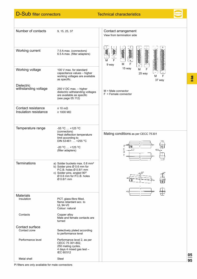
0595
D-Su
b
M FM F
M F
M F
D-Sub filter connectors Technical characteristics
Contact arrangement View from termination side
Mating conditions as per CECC 75 301
M = Male connectorF = Female connector
37 way
9 way15 way
25 way
Number of contacts 9, 15, 25, 37
Working current 7.5 A max. (connectors) 6.5 A max. (filter adapters)
Working voltage 100 V max. for standard capacitance values – higher working voltages are available as specific.
Dielectric withstanding voltage 250 V DC max. – higher
dielectric withstanding voltages are available as specific (see page 05.112)
Contact resistance ≤10mΩ Insulation resistance ≥1000MΩ
Temperature range -55 OC … +125 OC (connectors) Heat deflection temperature limit according to DIN 53 461: … +255 OC -20 OC … +125 OC (filter adapters)
Terminations a) Solder buckets max. 0.8 mm² b) Solder pins Ø 0.6 mm for
P.C.B. holes Ø 0.8/1 mm c) Solder pins, angled 90O
Ø 0.6 mm for P.C.B. holes Ø 0.8/1 mm
MaterialsInsulation PCT, glass-fibre filled,
flame retardant acc. to UL 94-V0 Colour: natural
Contacts Copper alloy Male and female contacts are
turned
Contact surface Contact zone Selectively plated according to performance level
Performance level Performance level 2, as per CECC 75 301-802, 250 mating cycles, 4 days 4 mixed gas test – IEC 60 512
Metal shell Steel
Pi filters are only available for male connectors
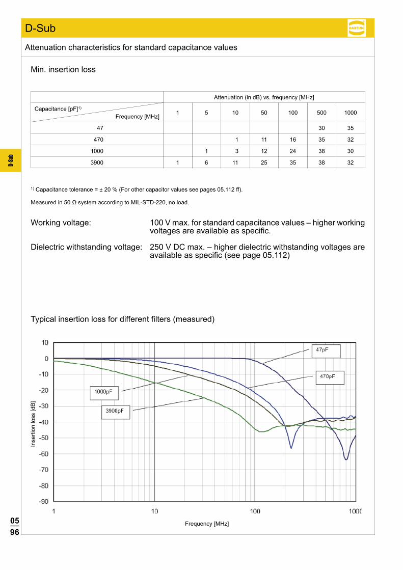
0596
D-Su
b
D-Sub
1 5 10 50 100 500 1000
30 35
1 11 16 35 32
1 3 12 24 38 30
1 6 11 25 35 38 32
47
470
1000
3900
Min. insertion loss
1) Capacitance tolerance = ± 20 % (For other capacitor values see pages 05.112 ff).
Measuredin50ΩsystemaccordingtoMIL-STD-220,noload.
Working voltage: 100 V max. for standard capacitance values – higher working voltages are available as specific.
Dielectric withstanding voltage: 250 V DC max. – higher dielectric withstanding voltages are available as specific (see page 05.112)
Inse
rtion
loss
[dB
]
Frequency [MHz]
Typical insertion loss for different filters (measured)
Attenuation characteristics for standard capacitance values
Capacitance [pF]1)
Frequency [MHz]
Attenuation (in dB) vs. frequency [MHz]
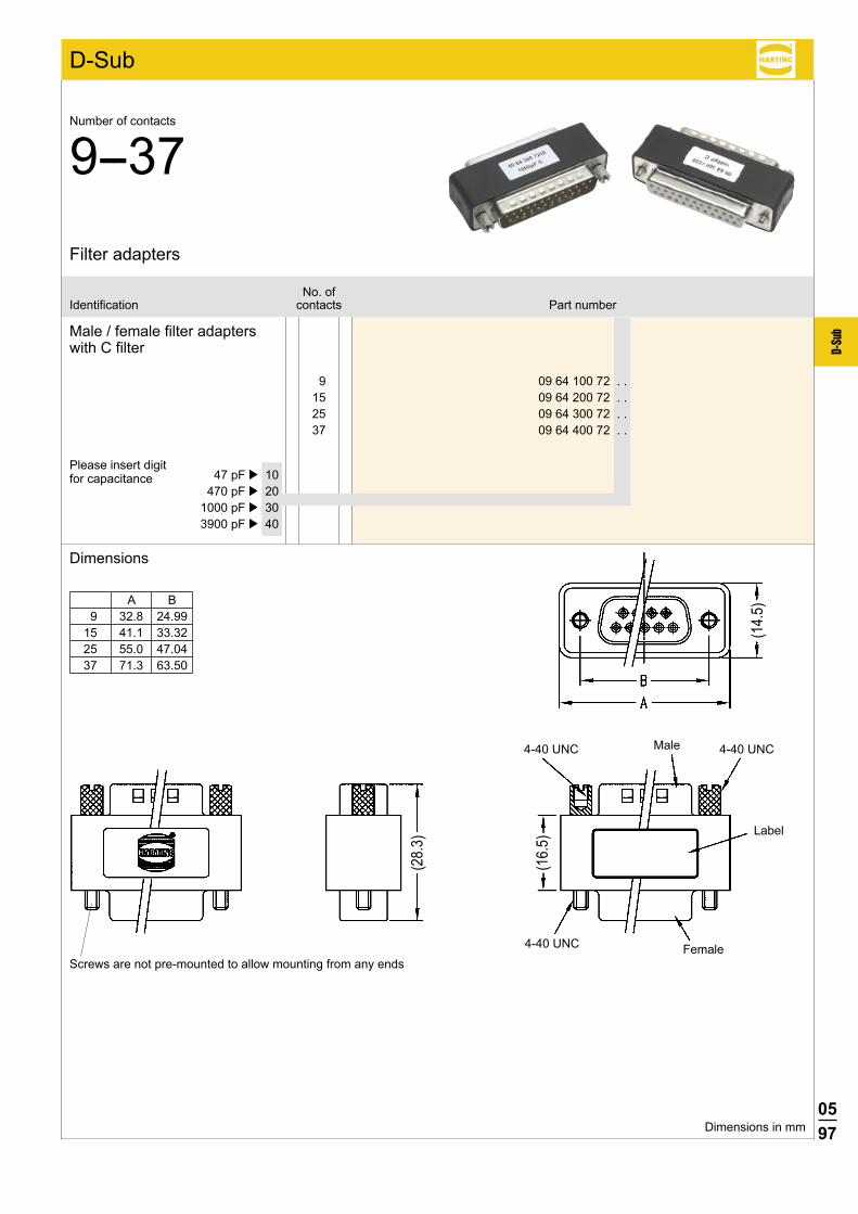
0597
D-Su
b
D-Sub
9 09 64 100 72 . . 15 09 64 200 72 . . 25 09 64 300 72 . . 37 09 64 400 72 . .
4-40 UNC
4-40 UNC 4-40 UNC
(28.
3)
(16.
5)
(14.
5)
47 pF þ 10 470 pF þ 20 1000 pF þ 30 3900 pF þ 40
No. ofIdentification contacts Part number
Filter adapters
Number of contacts
9--37
Male / female filter adapters with C filter
Please insert digit for capacitance
Dimensions
Dimensions in mm
A B 9 32.8 24.9915 41.1 33.3225 55.0 47.0437 71.3 63.50
Male
Female
Label
Screws are not pre-mounted to allow mounting from any ends
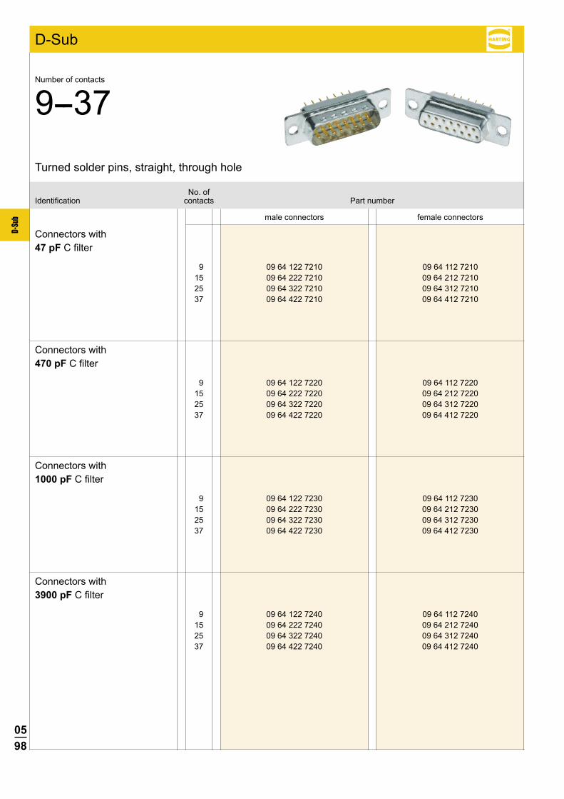
0598
D-Su
b
D-Sub
9 09 64 122 7210 09 64 112 7210 15 09 64 222 7210 09 64 212 7210 25 09 64 322 7210 09 64 312 7210 37 09 64 422 7210 09 64 412 7210
9 09 64 122 7220 09 64 112 7220 15 09 64 222 7220 09 64 212 7220 25 09 64 322 7220 09 64 312 7220 37 09 64 422 7220 09 64 412 7220
9 09 64 122 7230 09 64 112 7230 15 09 64 222 7230 09 64 212 7230 25 09 64 322 7230 09 64 312 7230 37 09 64 422 7230 09 64 412 7230
9 09 64 122 7240 09 64 112 7240 15 09 64 222 7240 09 64 212 7240 25 09 64 322 7240 09 64 312 7240 37 09 64 422 7240 09 64 412 7240
male connectors female connectors
No. ofIdentification contacts Part number
Turned solder pins, straight, through hole
Number of contacts
9--37
Connectors with47 pF C filter
Connectors with470 pF C filter
Connectors with1000 pF C filter
Connectors with3900 pF C filter
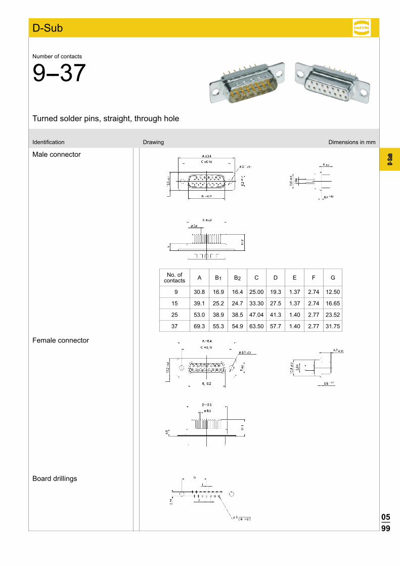
0599
D-Su
b
D-Sub
Board drillings
Male connector
Female connector
Identification Drawing Dimensions in mm
Turned solder pins, straight, through hole
Number of contacts
9--37
No. of A B1 B2 C D E F G contacts
9 30.8 16.9 16.4 25.00 19.3 1.37 2.74 12.50
15 39.1 25.2 24.7 33.30 27.5 1.37 2.74 16.65
25 53.0 38.9 38.5 47.04 41.3 1.40 2.77 23.52
37 69.3 55.3 54.9 63.50 57.7 1.40 2.77 31.75
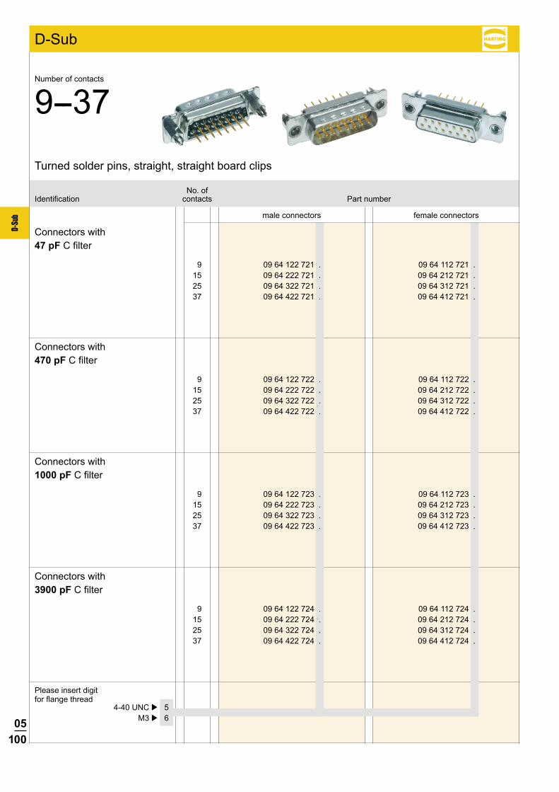
05100
D-Su
b
9 09 64 122 721 . 09 64 112 721 . 15 09 64 222 721 . 09 64 212 721 . 25 09 64 322 721 . 09 64 312 721 . 37 09 64 422 721 . 09 64 412 721 .
9 09 64 122 722 . 09 64 112 722 . 15 09 64 222 722 . 09 64 212 722 . 25 09 64 322 722 . 09 64 312 722 . 37 09 64 422 722 . 09 64 412 722 .
9 09 64 122 723 . 09 64 112 723 . 15 09 64 222 723 . 09 64 212 723 . 25 09 64 322 723 . 09 64 312 723 . 37 09 64 422 723 . 09 64 412 723 .
9 09 64 122 724 . 09 64 112 724 . 15 09 64 222 724 . 09 64 212 724 . 25 09 64 322 724 . 09 64 312 724 . 37 09 64 422 724 . 09 64 412 724 .
D-Sub
4-40 UNC þ 5 M3 þ 6
male connectors female connectors
No. ofIdentification contacts Part number
Connectors with47 pF C filter
Connectors with470 pF C filter
Connectors with1000 pF C filter
Connectors with3900 pF C filter
Turned solder pins, straight, straight board clips
Number of contacts
9--37
Please insert digit for flange thread
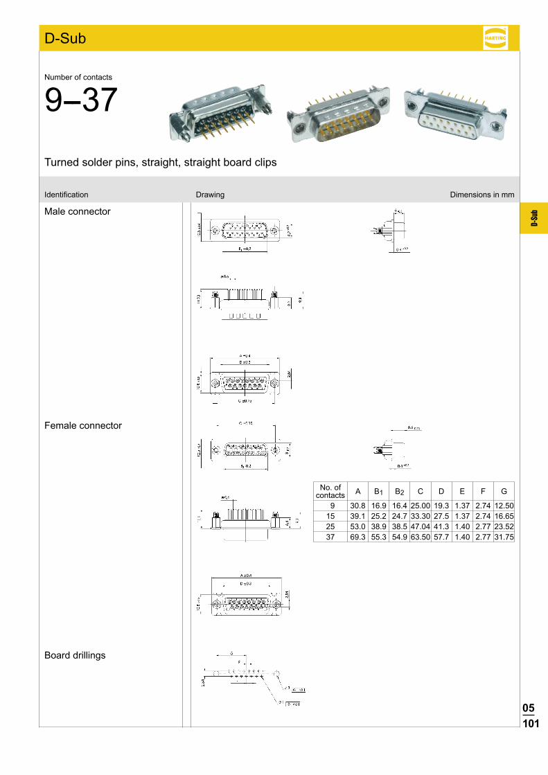
05101
D-Su
b
D-Sub
Board drillings
Male connector
Female connector
Identification Drawing Dimensions in mm
Turned solder pins, straight, straight board clips
Number of contacts
9--37
No. of A B1 B2 C D E F G contacts 9 30.8 16.9 16.4 25.00 19.3 1.37 2.74 12.50 15 39.1 25.2 24.7 33.30 27.5 1.37 2.74 16.65 25 53.0 38.9 38.5 47.04 41.3 1.40 2.77 23.52 37 69.3 55.3 54.9 63.50 57.7 1.40 2.77 31.75
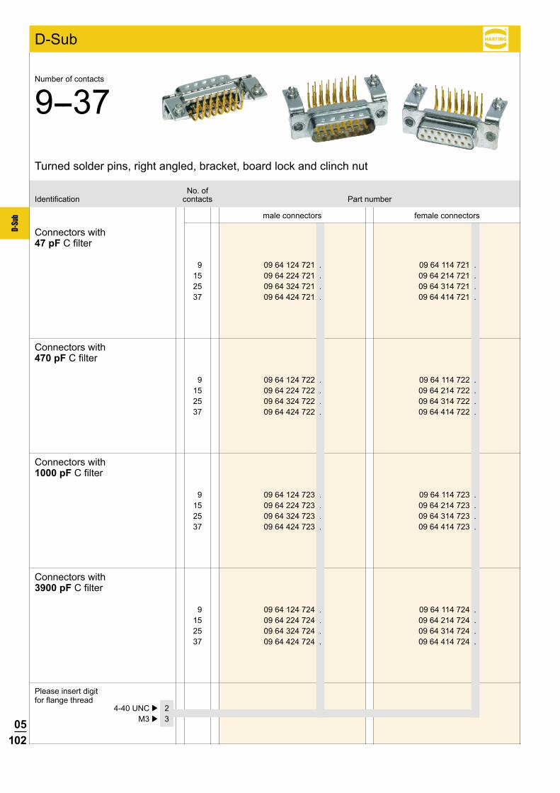
05102
D-Su
b
9 09 64 124 721 . 09 64 114 721 . 15 09 64 224 721 . 09 64 214 721 . 25 09 64 324 721 . 09 64 314 721 . 37 09 64 424 721 . 09 64 414 721 .
9 09 64 124 722 . 09 64 114 722 . 15 09 64 224 722 . 09 64 214 722 . 25 09 64 324 722 . 09 64 314 722 . 37 09 64 424 722 . 09 64 414 722 .
9 09 64 124 723 . 09 64 114 723 . 15 09 64 224 723 . 09 64 214 723 . 25 09 64 324 723 . 09 64 314 723 . 37 09 64 424 723 . 09 64 414 723 .
9 09 64 124 724 . 09 64 114 724 . 15 09 64 224 724 . 09 64 214 724 . 25 09 64 324 724 . 09 64 314 724 . 37 09 64 424 724 . 09 64 414 724 .
D-Sub
4-40 UNC þ 2 M3 þ 3
male connectors female connectors
No. ofIdentification contacts Part number
Connectors with47 pF C filter
Connectors with470 pF C filter
Connectors with1000 pF C filter
Connectors with3900 pF C filter
Turned solder pins, right angled, bracket, board lock and clinch nut
Number of contacts
9--37
Please insert digit for flange thread
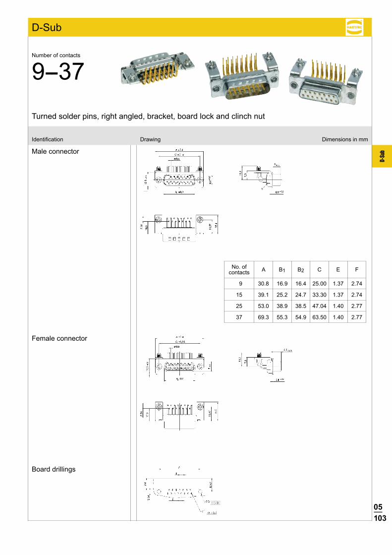
05103
D-Su
b
D-Sub
Board drillings
Male connector
Female connector
Identification Drawing Dimensions in mm
Turned solder pins, right angled, bracket, board lock and clinch nut
Number of contacts
9--37
No. of A B1 B2 C E F contacts
9 30.8 16.9 16.4 25.00 1.37 2.74
15 39.1 25.2 24.7 33.30 1.37 2.74
25 53.0 38.9 38.5 47.04 1.40 2.77
37 69.3 55.3 54.9 63.50 1.40 2.77
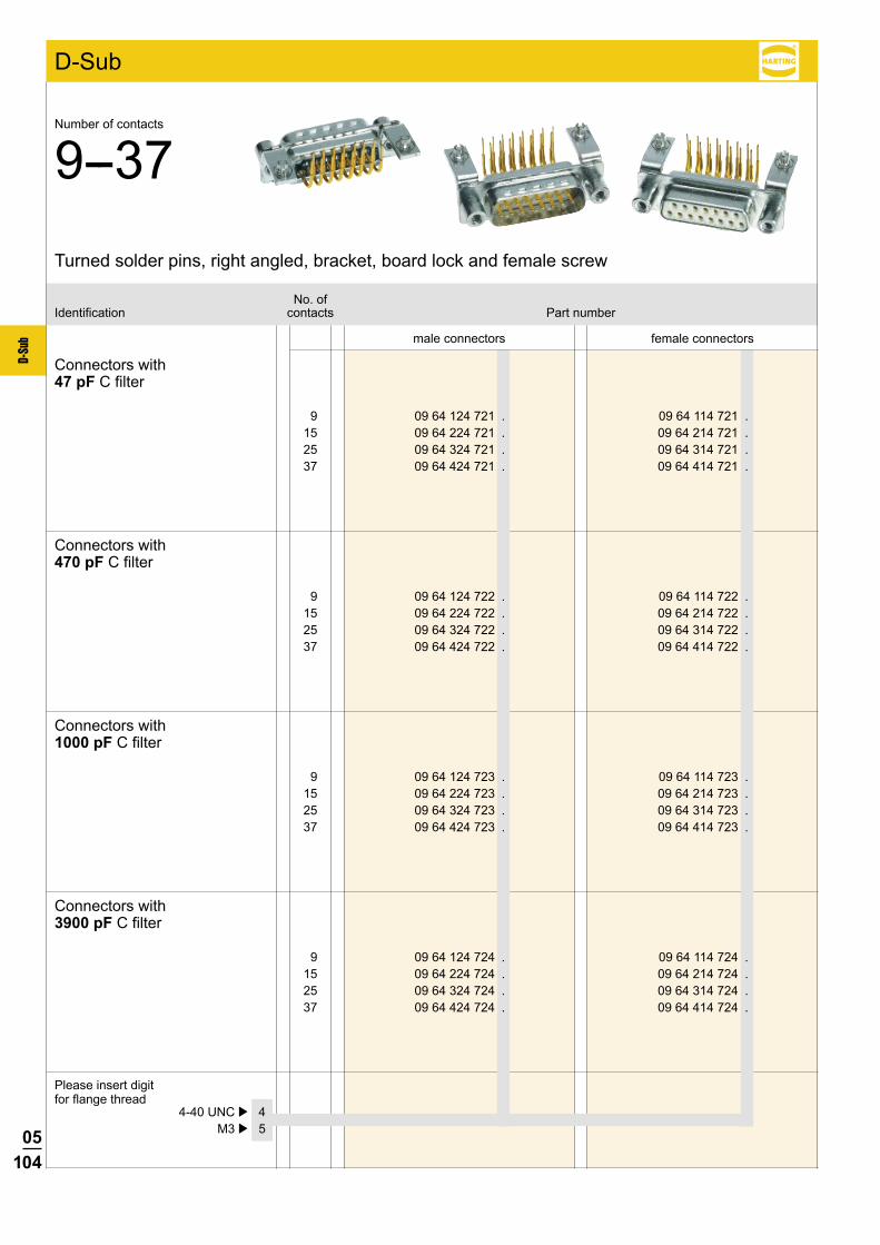
05104
D-Su
b
9 09 64 124 721 . 09 64 114 721 . 15 09 64 224 721 . 09 64 214 721 . 25 09 64 324 721 . 09 64 314 721 . 37 09 64 424 721 . 09 64 414 721 .
9 09 64 124 722 . 09 64 114 722 . 15 09 64 224 722 . 09 64 214 722 . 25 09 64 324 722 . 09 64 314 722 . 37 09 64 424 722 . 09 64 414 722 .
9 09 64 124 723 . 09 64 114 723 . 15 09 64 224 723 . 09 64 214 723 . 25 09 64 324 723 . 09 64 314 723 . 37 09 64 424 723 . 09 64 414 723 .
9 09 64 124 724 . 09 64 114 724 . 15 09 64 224 724 . 09 64 214 724 . 25 09 64 324 724 . 09 64 314 724 . 37 09 64 424 724 . 09 64 414 724 .
D-Sub
4-40 UNC þ 4 M3 þ 5
male connectors female connectors
No. ofIdentification contacts Part number
Connectors with47 pF C filter
Connectors with470 pF C filter
Connectors with1000 pF C filter
Connectors with3900 pF C filter
Turned solder pins, right angled, bracket, board lock and female screw
Number of contacts
9--37
Please insert digit for flange thread
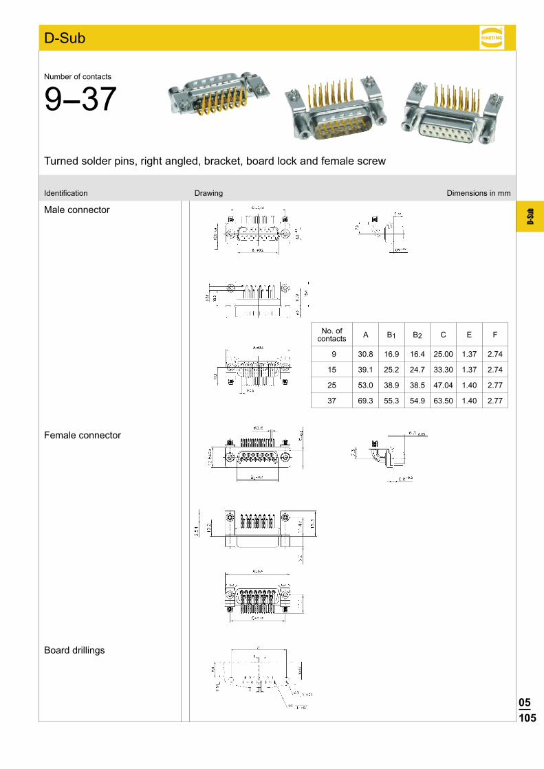
05105
D-Su
b
D-Sub
Board drillings
Male connector
Female connector
Identification Drawing Dimensions in mm
Turned solder pins, right angled, bracket, board lock and female screw
Number of contacts
9--37
No. of A B1 B2 C E F contacts
9 30.8 16.9 16.4 25.00 1.37 2.74
15 39.1 25.2 24.7 33.30 1.37 2.74
25 53.0 38.9 38.5 47.04 1.40 2.77
37 69.3 55.3 54.9 63.50 1.40 2.77
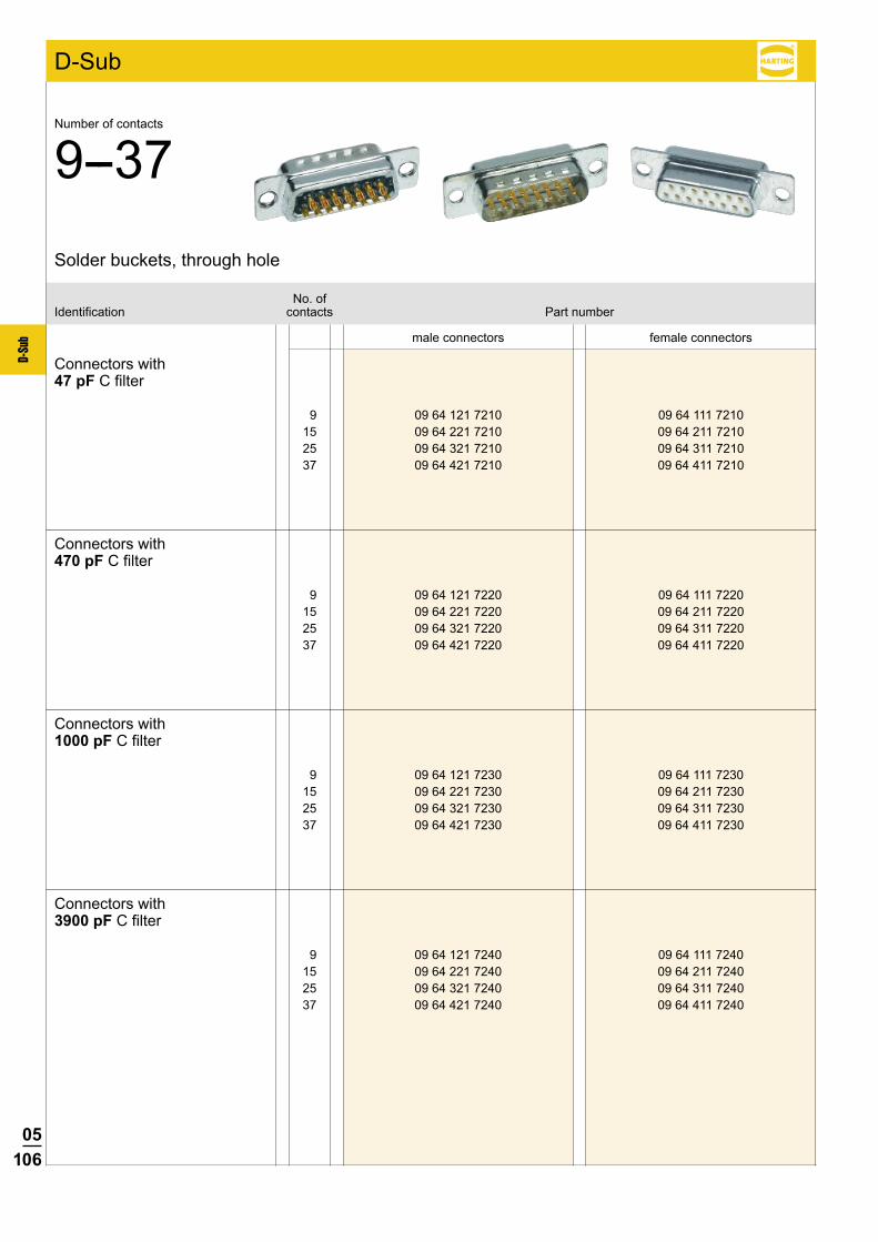
05106
D-Su
b
9 09 64 121 7210 09 64 111 7210 15 09 64 221 7210 09 64 211 7210 25 09 64 321 7210 09 64 311 7210 37 09 64 421 7210 09 64 411 7210
9 09 64 121 7220 09 64 111 7220 15 09 64 221 7220 09 64 211 7220 25 09 64 321 7220 09 64 311 7220 37 09 64 421 7220 09 64 411 7220
9 09 64 121 7230 09 64 111 7230 15 09 64 221 7230 09 64 211 7230 25 09 64 321 7230 09 64 311 7230 37 09 64 421 7230 09 64 411 7230
9 09 64 121 7240 09 64 111 7240 15 09 64 221 7240 09 64 211 7240 25 09 64 321 7240 09 64 311 7240 37 09 64 421 7240 09 64 411 7240
D-Sub
male connectors female connectors
No. ofIdentification contacts Part number
Connectors with47 pF C filter
Connectors with470 pF C filter
Connectors with1000 pF C filter
Connectors with3900 pF C filter
Solder buckets, through hole
Number of contacts
9--37

05107
D-Su
b
D-Sub
Male connector
Female connector
Identification Drawing Dimensions in mm
No. of A B1 B2 C D contacts
9 30.8 16.9 16.4 25.00 19.3
15 39.1 25.2 24.7 33.30 27.5
25 53.0 38.9 38.5 47.04 41.3
37 69.3 55.3 54.9 63.50 57.7
Panel cut outs see page 05.110
Solder buckets, through hole
Number of contacts
9--37
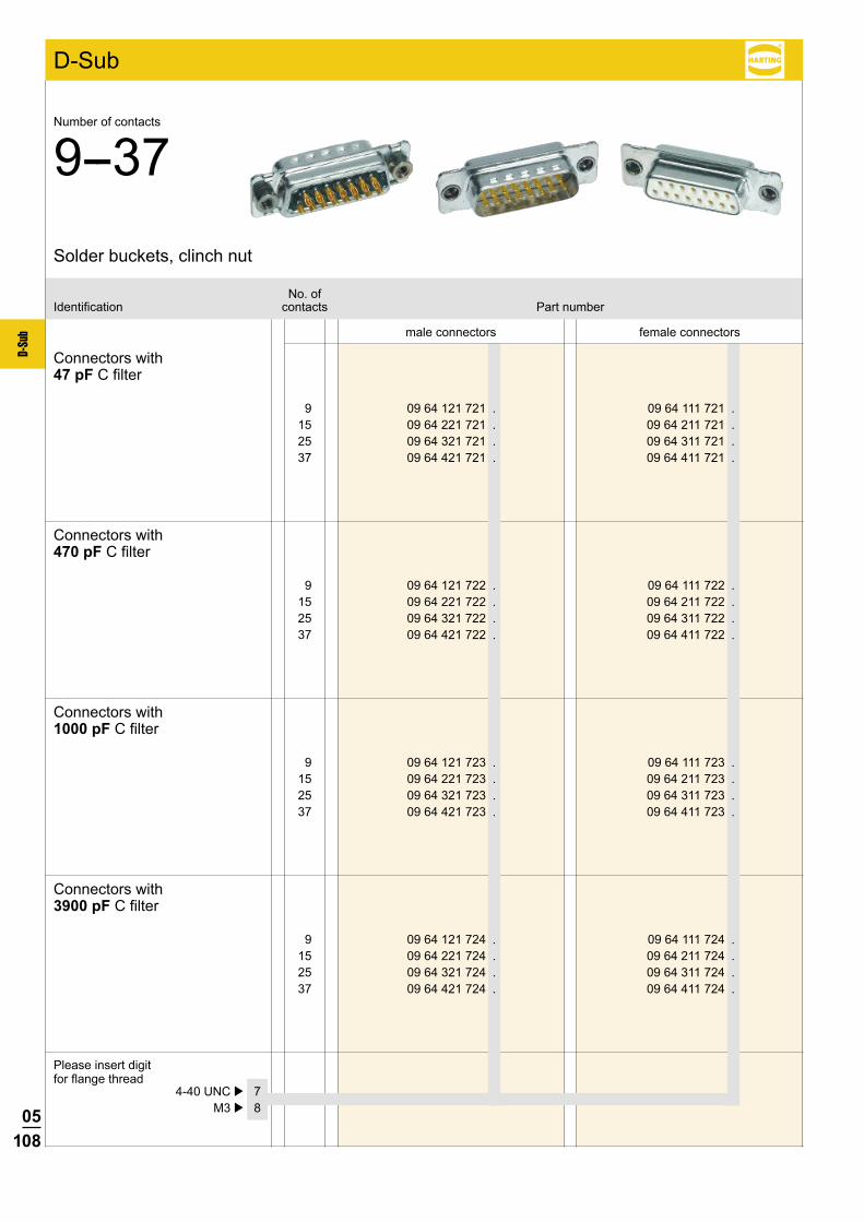
05108
D-Su
b
9 09 64 121 721 . 09 64 111 721 . 15 09 64 221 721 . 09 64 211 721 . 25 09 64 321 721 . 09 64 311 721 . 37 09 64 421 721 . 09 64 411 721 .
9 09 64 121 722 . 09 64 111 722 . 15 09 64 221 722 . 09 64 211 722 . 25 09 64 321 722 . 09 64 311 722 . 37 09 64 421 722 . 09 64 411 722 .
9 09 64 121 723 . 09 64 111 723 . 15 09 64 221 723 . 09 64 211 723 . 25 09 64 321 723 . 09 64 311 723 . 37 09 64 421 723 . 09 64 411 723 .
9 09 64 121 724 . 09 64 111 724 . 15 09 64 221 724 . 09 64 211 724 . 25 09 64 321 724 . 09 64 311 724 . 37 09 64 421 724 . 09 64 411 724 .
D-Sub
4-40 UNC þ 7 M3 þ 8
male connectors female connectors
No. ofIdentification contacts Part number
Connectors with47 pF C filter
Connectors with470 pF C filter
Connectors with1000 pF C filter
Connectors with3900 pF C filter
Solder buckets, clinch nut
Number of contacts
9--37
Please insert digit for flange thread
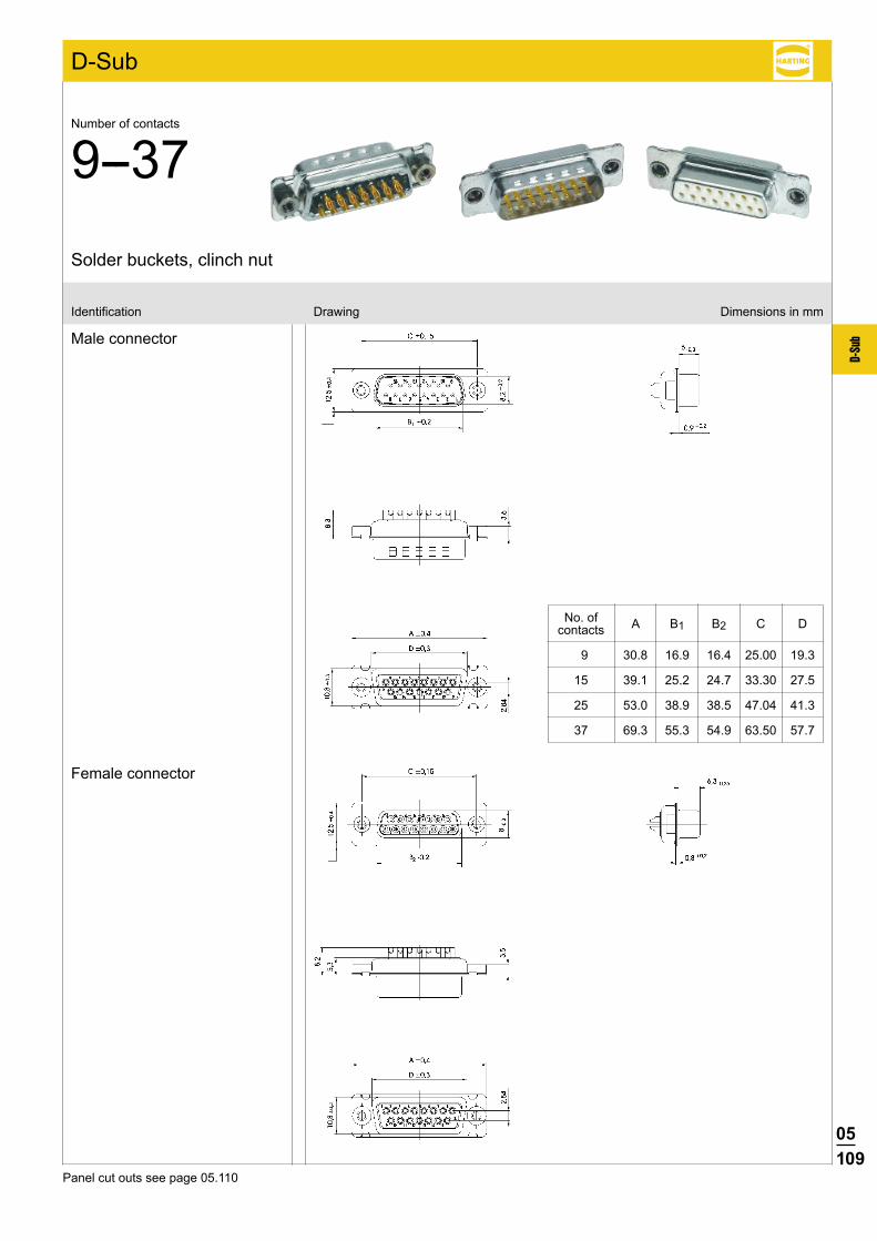
05109
D-Su
b
D-Sub
Male connector
Female connector
Identification Drawing Dimensions in mm
No. of A B1 B2 C D contacts
9 30.8 16.9 16.4 25.00 19.3
15 39.1 25.2 24.7 33.30 27.5
25 53.0 38.9 38.5 47.04 41.3
37 69.3 55.3 54.9 63.50 57.7
Panel cut outs see page 05.110
Solder buckets, clinch nut
Number of contacts
9--37
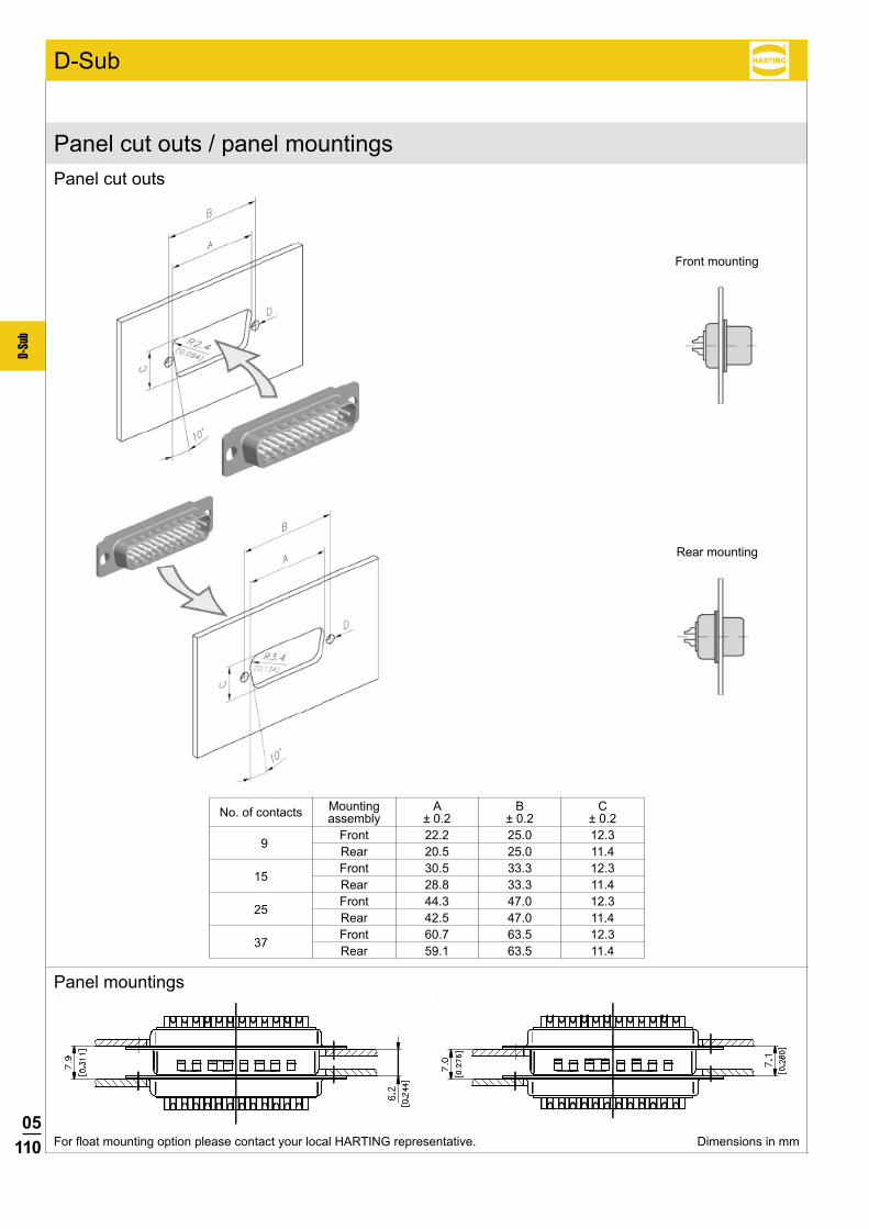
05110
D-Su
b
D-Sub
No. of contacts Mounting A B C assembly ± 0.2 ± 0.2 ± 0.2
9 Front 22.2 25.0 12.3
Rear 20.5 25.0 11.4
15 Front 30.5 33.3 12.3
Rear 28.8 33.3 11.4
25 Front 44.3 47.0 12.3
Rear 42.5 47.0 11.4
37 Front 60.7 63.5 12.3
Rear 59.1 63.5 11.4
For float mounting option please contact your local HARTING representative.
Panel cut outs
Panel cut outs / panel mountings
Panel mountings
Front mounting
Rear mounting
Dimensions in mm
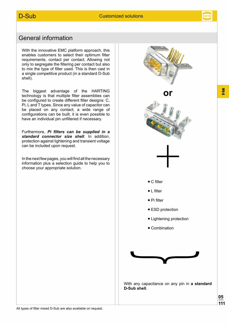
05111
D-Su
b
D-Sub
All types of filter mixed D-Sub are also available on request.
With the innovative EMC platform approach, this enables customers to select their optimum filter requirements, contact per contact. Allowing not only to segregate the filtering per contact but also to mix the type of filter used. This is then cast in a single competitive product (in a standard D-Sub shell).
The biggest advantage of the HARTING technology is that multiple filter assemblies can be configured to create different filter designs: C, Pi, L and T types. Since any value of capacitor can be placed on any contact, a wide range of configurations can be built, it is even possible to have an individual pin unfiltered if necessary.
Furthermore, Pi filters can be supplied in a standard connector size shell. In addition, protection against lightening and transient voltage can be included upon request.
In the next few pages, you will find all the necessary information plus a selection guide to help you to choose your appropriate solution.
C filter
L filter
Pi filter
ESD protection
Lightening protection
Combination
With any capacitance on any pin in a standard D-Sub shell.
or
Customized solutions
General information
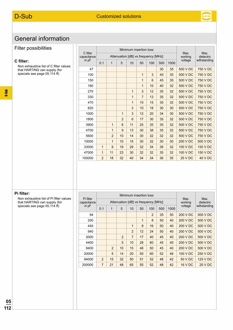
05112
D-Su
b
D-Sub
94 2 35 50 200 V DC 500 V DC
200 1 8 50 40 200 V DC 500 V DC
440 1 8 16 50 40 200 V DC 500 V DC
940 2 12 24 50 40 200 V DC 500 V DC
2000 2 7 17 40 45 40 200 V DC 500 V DC
4400 5 10 28 60 45 40 200 V DC 500 V DC
9400 2 10 15 48 50 45 40 200 V DC 500 V DC
20000 5 14 20 50 60 52 48 100 V DC 250 V DC
94000 2 15 32 50 51 52 48 42 50 V DC 125 V DC
200000 7 21 48 65 55 52 48 42 16 V DC 25 V DC
47 30 35 500 V DC 750 V DC
100 1 3 40 35 500 V DC 750 V DC
150 1 6 45 35 500 V DC 750 V DC
180 1 10 40 32 500 V DC 750 V DC
270 1 3 12 35 32 500 V DC 750 V DC
330 1 7 13 35 32 500 V DC 750 V DC
470 1 10 15 35 32 500 V DC 750 V DC
820 2 10 18 30 30 500 V DC 750 V DC
1000 1 3 12 20 34 30 500 V DC 750 V DC
1800 2 6 17 30 35 32 500 V DC 750 V DC
3900 1 6 11 25 35 35 32 500 V DC 750 V DC
4700 1 9 13 30 38 35 32 500 V DC 750 V DC
5600 2 10 14 30 32 32 32 500 V DC 750 V DC
10000 1 10 15 30 32 30 30 200 V DC 500 V DC
33000 1 9 19 29 32 34 39 32 100 V DC 150 V DC
47000 1 11 23 30 32 32 35 32 100 V DC 150 V DC
100000 2 18 32 40 34 34 36 35 25 V DC 40 V DC
Filter possibilities
Customized solutions
General information
C filter:Non exhaustive list of C filter values that HARTING can supply (for specials see page 05.114 ff)
Pi filter:Non exhaustive list of Pi filter values that HARTING can supply (for specials see page 05.114 ff)
C filter capacitance
in pF
Minimum insertion loss
Attenuation [dB] vs frequency [MHz]
0.1 1 5 10 50 100 500 1000
Max. working voltage
Max. dielectric
with standing
Pi filter capacitance
in pF
Minimum insertion loss
Attenuation [dB] vs frequency [MHz]
0.1 1 5 10 50 100 500 1000
Max. working voltage
Max. dielectric
with standing
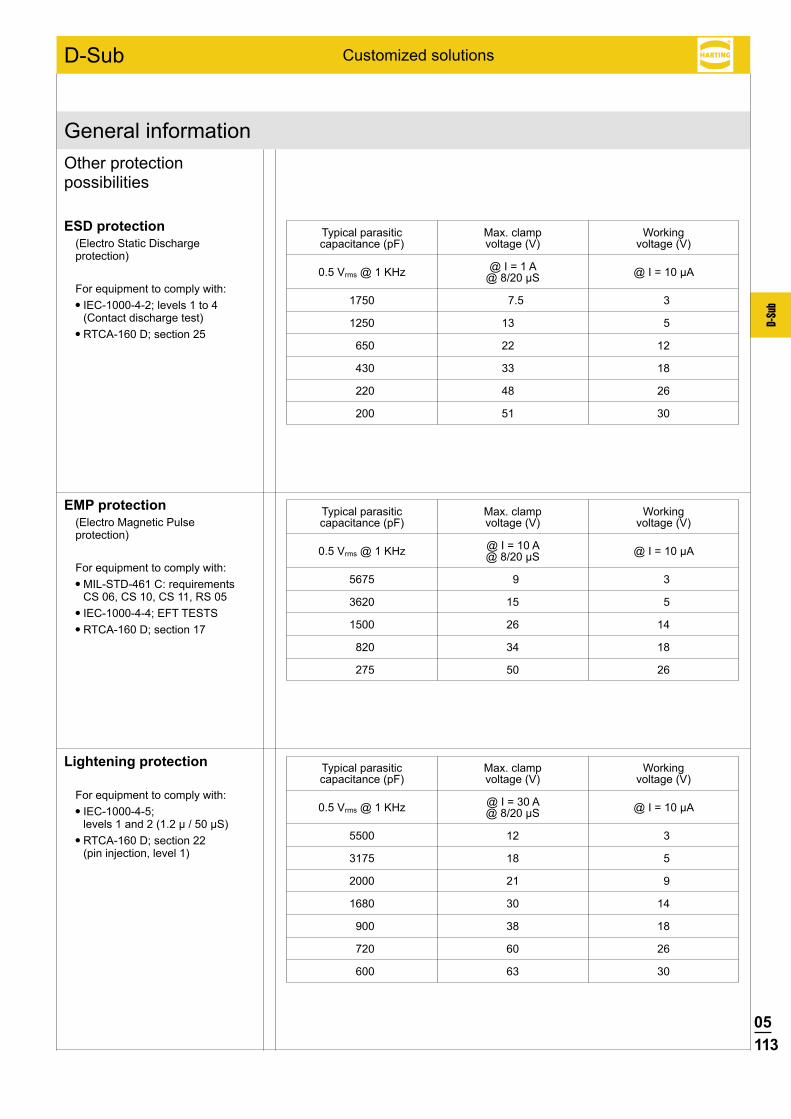
05113
D-Su
b
D-Sub
5675 9 3
3620 15 5
1500 26 14
820 34 18
275 50 26
5500 12 3
3175 18 5
2000 21 9
1680 30 14
900 38 18
720 60 26
600 63 30
ESD protection(Electro Static Discharge protection)
For equipment to comply with: IEC-1000-4-2; levels 1 to 4
(Contact discharge test) RTCA-160 D; section 25
Other protection possibilities
Customized solutions
General information
Typical parasitic Max. clamp Working capacitance (pF) voltage (V) voltage (V)
@ I = 1 A 0.5 Vrms @ 1 KHz @ I = 10 µA @ 8/20 µS
EMP protection(Electro Magnetic Pulse protection)
For equipment to comply with: MIL-STD-461 C: requirements
CS 06, CS 10, CS 11, RS 05 IEC-1000-4-4; EFT TESTS RTCA-160 D; section 17
Typical parasitic Max. clamp Working capacitance (pF) voltage (V) voltage (V)
@ I = 10 A 0.5 Vrms @ 1 KHz @ I = 10 µA @ 8/20 µS
Lightening protection
For equipment to comply with: IEC-1000-4-5;
levels 1 and 2 (1.2 µ / 50 µS) RTCA-160 D; section 22
(pin injection, level 1)
Typical parasitic Max. clamp Working capacitance (pF) voltage (V) voltage (V)
@ I = 30 A 0.5 Vrms @ 1 KHz @ I = 10 µA @ 8/20 µS
1750 7.5 3
1250 13 5
650 22 12
430 33 18
220 48 26
200 51 30

05114
D-Su
b
D-Sub
HARTING customer request form
Our innovative technology offers all the possibilities you may need.
For customer solutions, please contact your local HARTING representative.
Here is a summary of the information we need to develop a customer solution:
Connector
Standard D-Sub Gender Male Female No. of contacts 9 15 25 37 50 Termination Solder bucket Straight pcb R/A Eur, 2.54 mm R/A US, 2.84 mm
Mixed D-Sub Gender Male Female Contact arrangement 3W3 3W3C Other _______________________________________________ Power contact rating 10 A 20 A 30 A 40 A Termination Solder bucket Straight pcb R/A pcb (please specify the board drillings)
Flange thread and board locking options
Customized solutions
Right angled version Through hole
Clinch nut 4-40 UNC Clinch nut M3
Bracket
Board lock
Female screw lock 4-40 UNC Female screw lock M3
Straight version Through hole
Clinch nut 4-40 UNC Clinch nut M3
Spacer 4-40 UNC Spacer M3
Female screw lock 4-40 UNC
Spacer 4-40 UNC + board lock Spacer M3 + board lock
Spacer + board lock and female screw lock
M3 4-40 UNC

05115
D-Su
b
D-Sub
HARTING customer request from
Name:
Company:
Address:
Phone:
Fax:
E-Mail:
Drawing: no yes
Samples: no yes, quantity
Volume (pcs./year):
Special requirements:
Filter
What working voltage is used? ____________________________________________________________________________________________________________________________________________
What is the maximum dielectric withstanding voltage needed? ________________________________________________________________________________
Type of filter __________________________________________________________________________________________________________ (C filter, Pi filter*, L filter …)
Capacitance ________________________________________________________________________________________________________________________________________________________________________________
Are there other protections needed? No Yes ESD Transient EMP Lightening
If a pin-to-pin selection has to be done, please state the details Pin 1: ?, Pin 2: ?, …
___________________________________________________________________
Customized solutions
* only available for male connectors
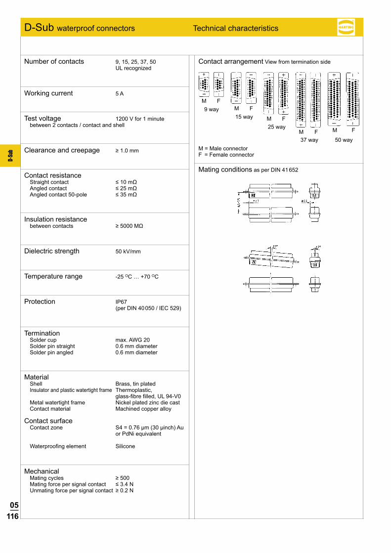
05116
D-Su
b
M FM F
M F
M F M F
D-Sub waterproof connectors Technical characteristics
Contact arrangement View from termination side
Mating conditions as per DIN 41 652
M = Male connectorF = Female connector
37 way 50 way
Number of contacts 9, 15, 25, 37, 50 UL recognized
Working current 5 A
Test voltage 1200 V for 1 minute between 2 contacts / contact and shell
Clearance and creepage ≥1.0mm
Contact resistance Straightcontact ≤10mΩ Angledcontact ≤25mΩ Angledcontact50-pole ≤35mΩ
Insulation resistance betweencontacts ≥5000MΩ
Dielectric strength 50 kV/mm
Temperature range -25 OC … +70 OC
Protection IP67 (per DIN 40 050 / IEC 529)
Termination Solder cup max. AWG 20 Solder pin straight 0.6 mm diameter Solder pin angled 0.6 mm diameter
Material Shell Brass, tin plated Insulator and plastic watertight frame Thermoplastic, glass-fibre filled, UL 94-V0 Metal watertight frame Nickel plated zinc die cast Contact material Machined copper alloy
Contact surface Contact zone S4 = 0.76 µm (30 µinch) Au
or PdNi equivalent
Waterproofing element Silicone
Mechanical Matingcycles ≥500 Matingforcepersignalcontact ≤3.4N Unmatingforcepersignalcontact ≥0.2N
9 way15 way
25 way

05117
D-Su
b
Notes

05118
D-Su
b
D-Sub
9 09 67 409 4715 15 09 67 415 4715 25 09 67 425 4715 37 09 67 437 4715 50 09 67 450 4715
9 09 67 409 5615 15 09 67 415 5615 25 09 67 425 5615 37 09 67 437 5615 50 09 67 450 5615
S41)
1) S4 = 0.76 µm (30 µinch) Au or PdNi eqivalent
Male connectormetal shell with dimples
Female connectormetal shell
No. ofIdentification contacts Part number
IP67, turned solder cups
Number of contacts
9--50
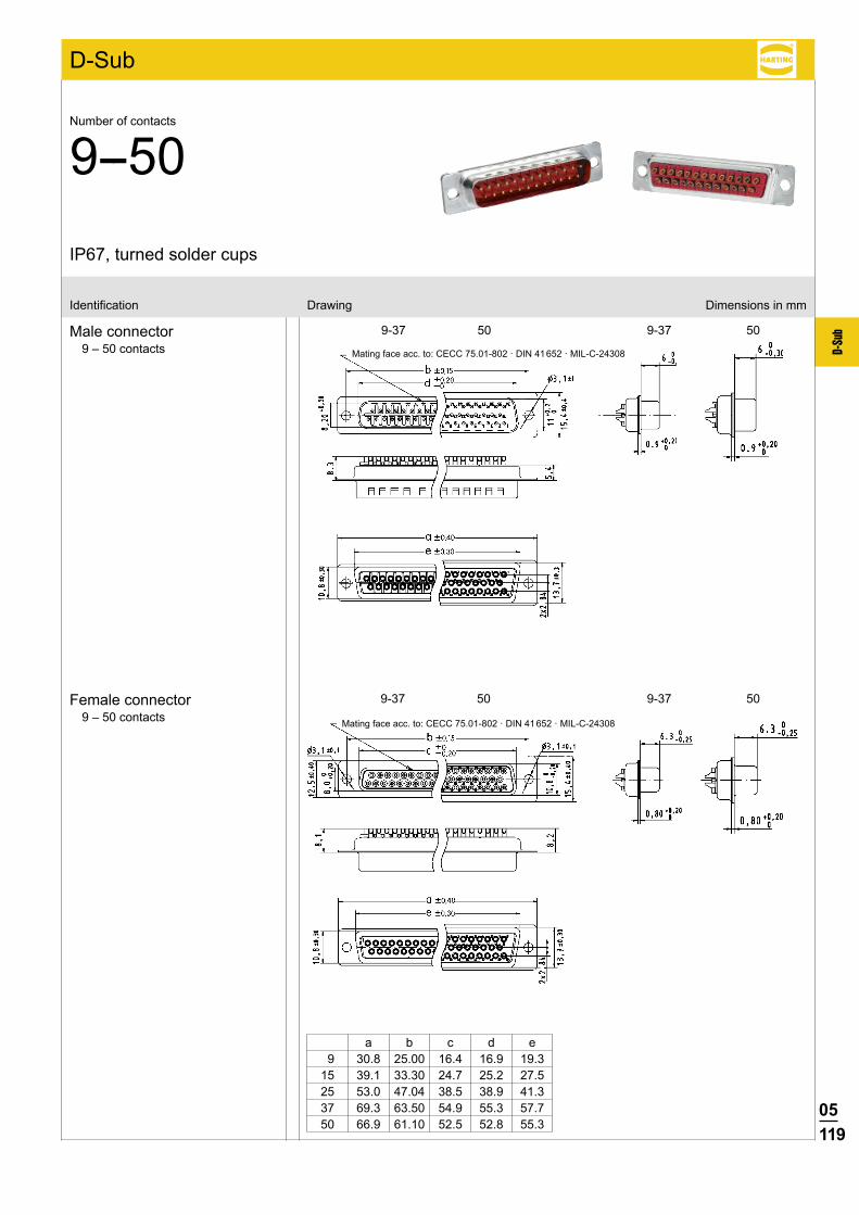
05119
D-Su
b9-37 50 9-37 50
9-37 50 9-37 50
D-Sub
Identification Drawing Dimensions in mm
Male connector9 – 50 contacts
Female connector9 – 50 contacts
IP67, turned solder cups
Number of contacts
9--50
Mating face acc. to: CECC 75.01-802 · DIN 41 652 · MIL-C-24308
Mating face acc. to: CECC 75.01-802 · DIN 41 652 · MIL-C-24308
a b c d e 9 30.8 25.00 16.4 16.9 19.3 15 39.1 33.30 24.7 25.2 27.5 25 53.0 47.04 38.5 38.9 41.3 37 69.3 63.50 54.9 55.3 57.7 50 66.9 61.10 52.5 52.8 55.3
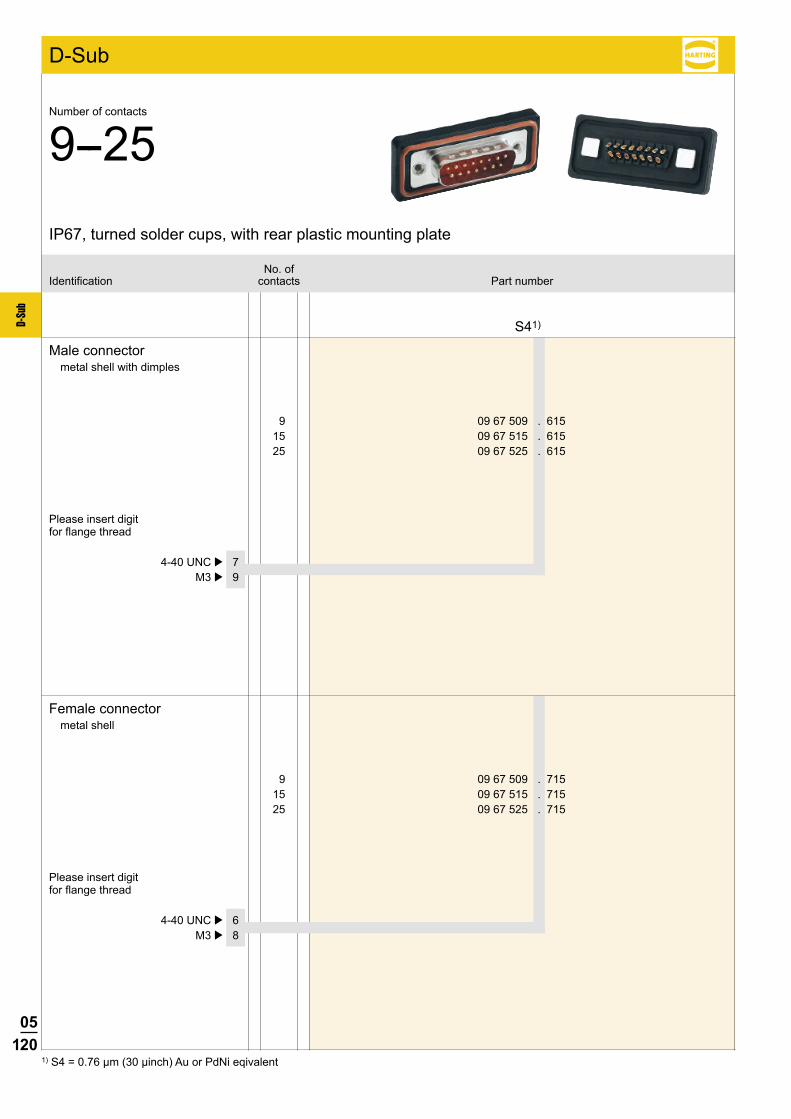
05120
D-Su
b
D-Sub
9 09 67 509 . 615 15 09 67 515 . 615 25 09 67 525 . 615
S41)
9 09 67 509 . 715 15 09 67 515 . 715 25 09 67 525 . 715
4-40 UNC þ 7 M3 þ 9
4-40 UNC þ 6 M3 þ 8
1) S4 = 0.76 µm (30 µinch) Au or PdNi eqivalent
Male connectormetal shell with dimples
Female connectormetal shell
No. ofIdentification contacts Part number
IP67, turned solder cups, with rear plastic mounting plate
Number of contacts
9--25
Please insert digit for flange thread
Please insert digit for flange thread

05121
D-Su
b
D-Sub
Identification Drawing Dimensions in mm
Male connector9 – 25 contacts
Female connector9 – 25 contacts
Mating face acc. to: CECC 75.01-802 · DIN 41 652 · MIL-C-24308
4-40 UNC or M3
4-40 UNC or M3
Mating face acc. to: CECC 75.01-802 · DIN 41 652 · MIL-C-24308
a b c d 9 40.0 25.00 16.4 16.9 15 48.3 33.30 24.7 25.2 25 62.0 47.04 38.5 38.9
IP67, turned solder cups, with rear plastic mounting plate
Number of contacts
9--25
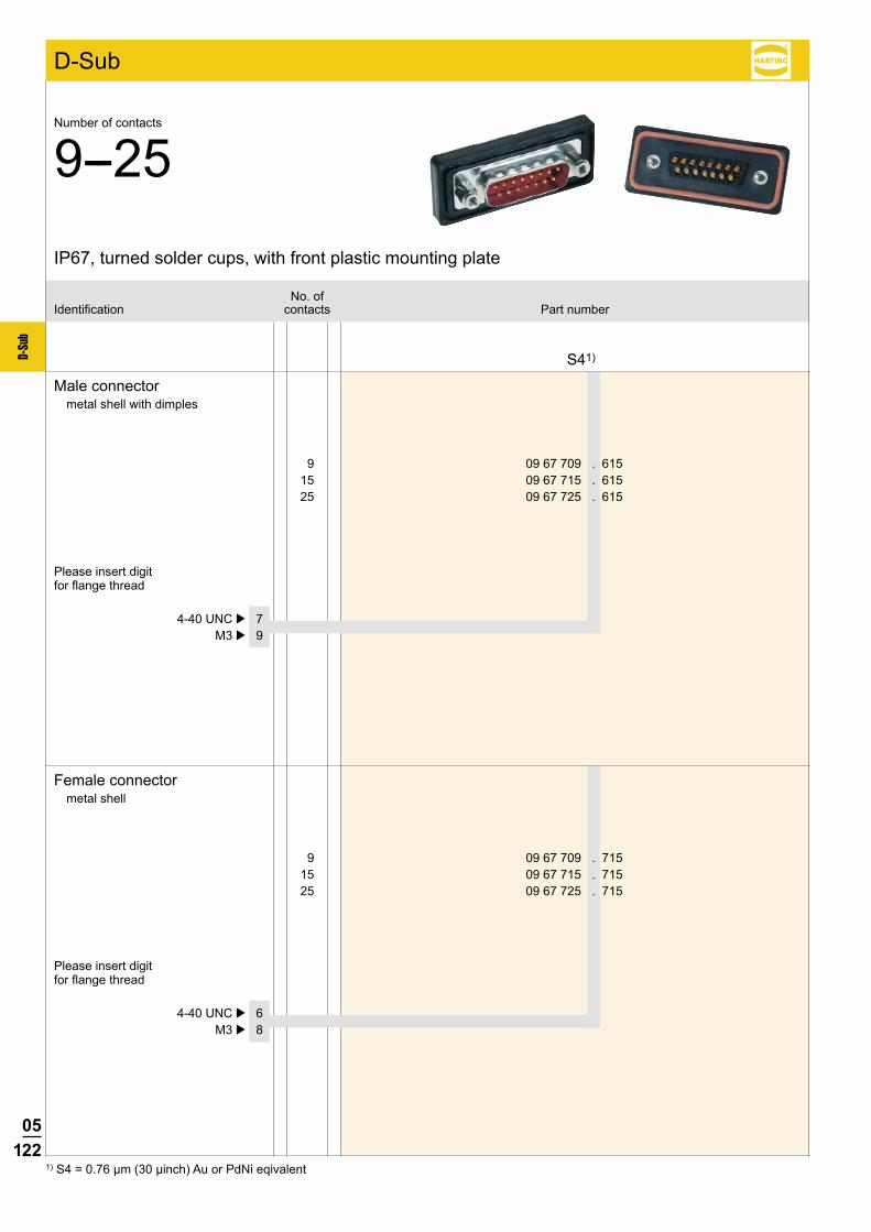
05122
D-Su
b
D-Sub
9 09 67 709 . 615 15 09 67 715 . 615 25 09 67 725 . 615
S41)
9 09 67 709 . 715 15 09 67 715 . 715 25 09 67 725 . 715
4-40 UNC þ 7 M3 þ 9
4-40 UNC þ 6 M3 þ 8
1) S4 = 0.76 µm (30 µinch) Au or PdNi eqivalent
Male connectormetal shell with dimples
Female connectormetal shell
No. ofIdentification contacts Part number
IP67, turned solder cups, with front plastic mounting plate
Number of contacts
9--25
Please insert digit for flange thread
Please insert digit for flange thread
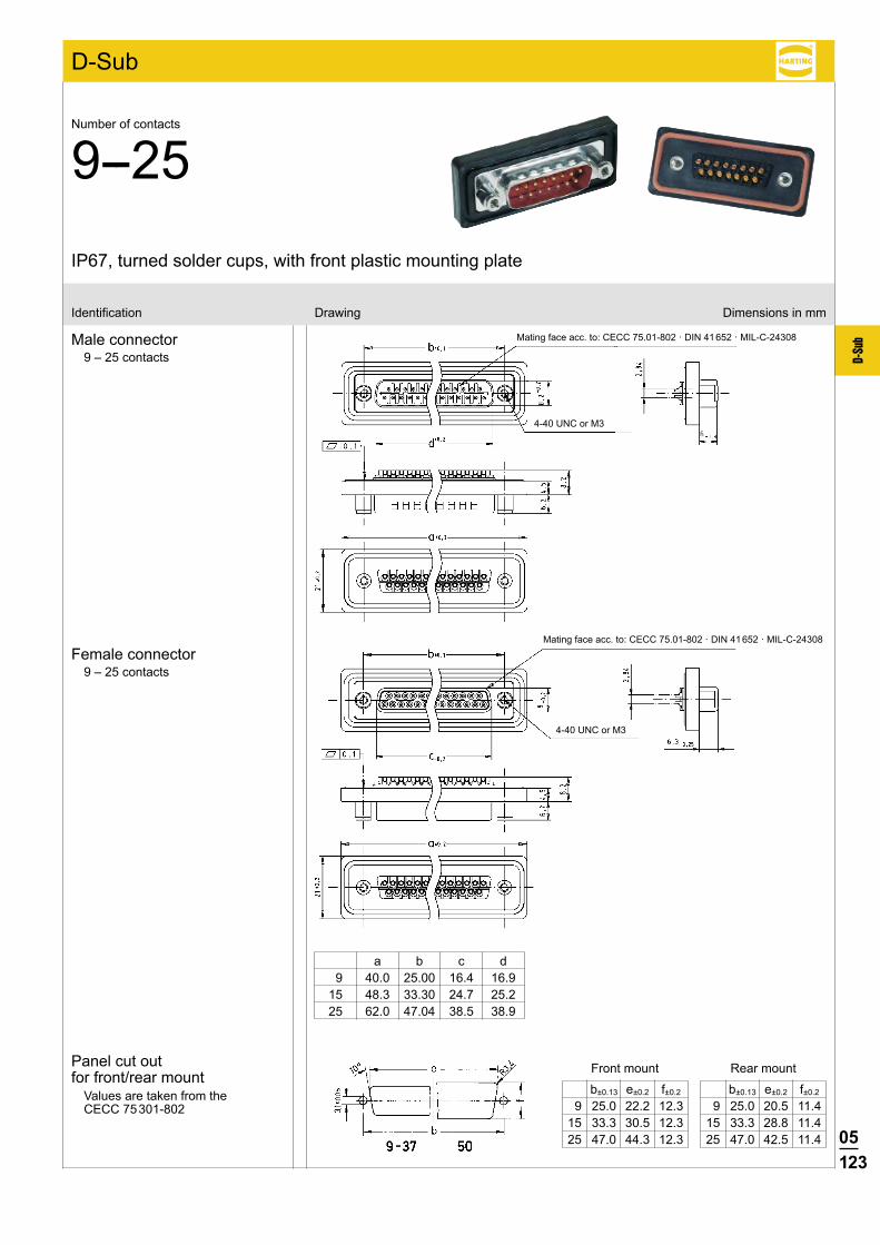
05123
D-Su
b
D-Sub
Identification Drawing Dimensions in mm
Male connector9 – 25 contacts
IP67, turned solder cups, with front plastic mounting plate
Number of contacts
9--25
Female connector9 – 25 contacts
Mating face acc. to: CECC 75.01-802 · DIN 41 652 · MIL-C-24308
4-40 UNC or M3
4-40 UNC or M3
Mating face acc. to: CECC 75.01-802 · DIN 41 652 · MIL-C-24308
a b c d 9 40.0 25.00 16.4 16.9 15 48.3 33.30 24.7 25.2 25 62.0 47.04 38.5 38.9
b±0.13 e±0.2 f±0.2
9 25.0 20.5 11.4 15 33.3 28.8 11.4 25 47.0 42.5 11.4
b±0.13 e±0.2 f±0.2
9 25.0 22.2 12.3 15 33.3 30.5 12.3 25 47.0 44.3 12.3
Panel cut out for front/rear mount
Values are taken from the CECC 75 301-802
Front mount Rear mount
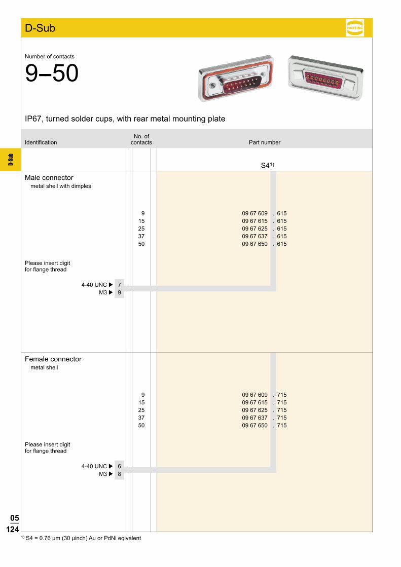
05124
D-Su
b
D-Sub
9 09 67 609 . 615 15 09 67 615 . 615 25 09 67 625 . 615 37 09 67 637 . 615 50 09 67 650 . 615
S41)
9 09 67 609 . 715 15 09 67 615 . 715 25 09 67 625 . 715 37 09 67 637 . 715 50 09 67 650 . 715
4-40 UNC þ 7 M3 þ 9
4-40 UNC þ 6 M3 þ 8
1) S4 = 0.76 µm (30 µinch) Au or PdNi eqivalent
Male connectormetal shell with dimples
Female connectormetal shell
No. ofIdentification contacts Part number
IP67, turned solder cups, with rear metal mounting plate
Number of contacts
9--50
Please insert digit for flange thread
Please insert digit for flange thread

05125
D-Su
b9-37 50 9-37 50
9-37 50 9-37 50
D-Sub
Identification Drawing Dimensions in mm
Male connector9 – 50 contacts
Female connector9 – 50 contacts
Mating face acc. to: CECC 75.01-802 · DIN 41 652 · MIL-C-24308
Mating face acc. to: CECC 75.01-802 · DIN 41 652 · MIL-C-24308
a b c d 9 40,0 25,00 16,4 16,9 15 48,3 33,30 24,7 25,2 25 62,0 47,04 38,5 38,9 37 78,5 63,50 54,9 55,3 50 76,1 61,10 52,5 52,8
4-40 UNC or M3
4-40 UNC or M3
IP67, turned solder cups, with rear metal mounting plate
Number of contacts
9--50
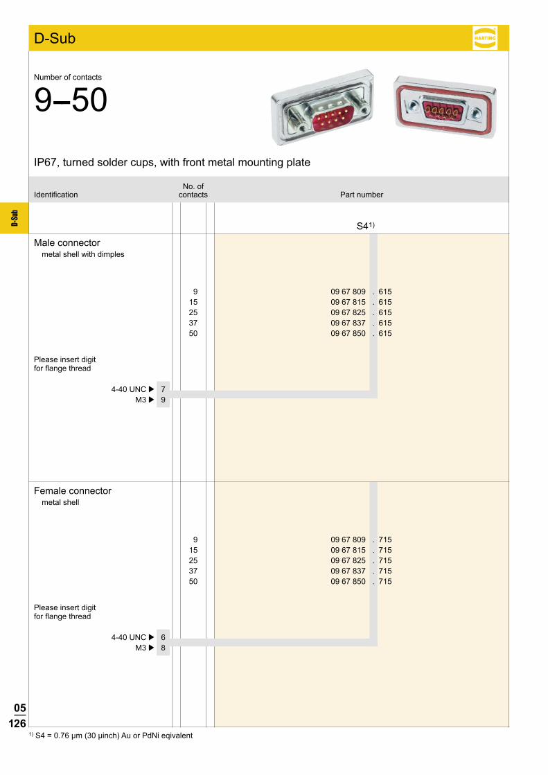
05126
D-Su
b
D-Sub
9 09 67 809 . 615 15 09 67 815 . 615 25 09 67 825 . 615 37 09 67 837 . 615 50 09 67 850 . 615
S41)
9 09 67 809 . 715 15 09 67 815 . 715 25 09 67 825 . 715 37 09 67 837 . 715 50 09 67 850 . 715
4-40 UNC þ 7 M3 þ 9
4-40 UNC þ 6 M3 þ 8
1) S4 = 0.76 µm (30 µinch) Au or PdNi eqivalent
Male connectormetal shell with dimples
Female connectormetal shell
No. ofIdentification contacts Part number
IP67, turned solder cups, with front metal mounting plate
Number of contacts
9--50
Please insert digit for flange thread
Please insert digit for flange thread

05127
D-Su
b9-37 50 9-37 50
9-37 50 9-37 50
D-Sub
Identification Drawing Dimensions in mm
IP67, turned solder cups, with front metal mounting plate
Number of contacts
9--50
Male connector9 – 50 contacts
Female connector9 – 50 contacts
Mating face acc. to: CECC 75.01-802 · DIN 41 652 · MIL-C-24308
Mating face acc. to: CECC 75.01-802 · DIN 41 652 · MIL-C-24308
a b c d 9 40.0 25.00 16.4 16.9 15 48.3 33.30 24.7 25.2 25 62.0 47.04 38.5 38.9 37 78.5 63.50 54.9 55.3 50 76.1 61.10 51.3 52.8
4-40 UNC or M3
4-40 UNC or M3
Panel cut out for front/rear mount
Values are taken from the CECC 75 301-802
b±0.13 e±0.2 f±0.2
9 25.0 20.5 11.4 15 33.3 28.8 11.4 25 47.0 42.5 11.4 37 63.5 59.1 11.4 50 61.1 56.3 14.1
b±0.13 e±0.2 f±0.2
9 25.0 22.2 12.3 15 33.3 30.5 12.3 25 47.0 44.3 12.3 37 63.5 60.7 12.3 50 61.1 58.3 15.1
Front mount Rear mount
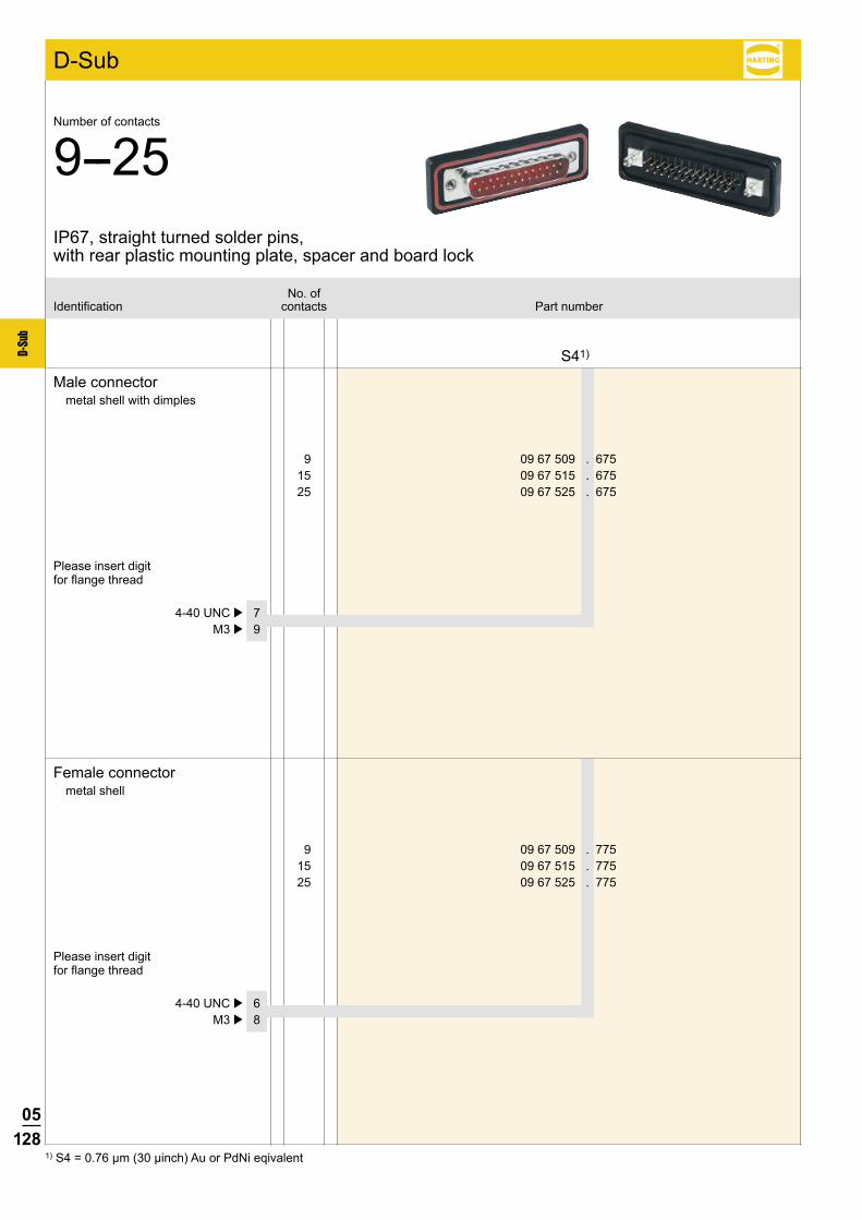
05128
D-Su
b
D-Sub
9 09 67 509 . 675 15 09 67 515 . 675 25 09 67 525 . 675
S41)
9 09 67 509 . 775 15 09 67 515 . 775 25 09 67 525 . 775
4-40 UNC þ 7 M3 þ 9
4-40 UNC þ 6 M3 þ 8
1) S4 = 0.76 µm (30 µinch) Au or PdNi eqivalent
Male connectormetal shell with dimples
Female connectormetal shell
No. ofIdentification contacts Part number
IP67, straight turned solder pins, with rear plastic mounting plate, spacer and board lock
Number of contacts
9--25
Please insert digit for flange thread
Please insert digit for flange thread

05129
D-Su
b
D-Sub
Identification Drawing Dimensions in mm
Male connector9 – 25 contacts
Female connector9 – 25 contacts
Board drillings
Mating face acc. to: CECC 75.01-802 · DIN 41 652 · MIL-C-24308
4-40 UNC or M3
4-40 UNC or M3
Mating face acc. to: CECC 75.01-802 · DIN 41 652 · MIL-C-24308
IP67, straight turned solder pins, with rear plastic mounting plate, spacer and board lock
Number of contacts
9--25
a b c d g h i
9 40.0 25.00 16.4 16.9 4 x 2.74 = 10.96 3 x 2.74 = 8.22 25.0
15 48.3 33.30 24.7 25.2 7 x 2.74 = 19.18 6 x 2.74 = 16.44 33.3
25 62.0 47.04 38.5 38.9 12 x 2.76 = 33.12 11 x 2.76 = 30.36 47.0
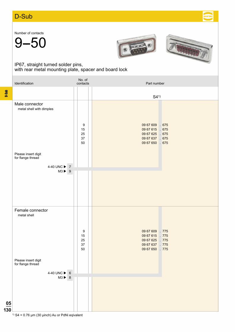
05130
D-Su
b
D-Sub
9 09 67 609 . 675 15 09 67 615 . 675 25 09 67 625 . 675 37 09 67 637 . 675 50 09 67 650 . 675
S41)
9 09 67 609 . 775 15 09 67 615 . 775 25 09 67 625 . 775 37 09 67 637 . 775 50 09 67 650 . 775
4-40 UNC þ 7 M3 þ 9
4-40 UNC þ 6 M3 þ 8
1) S4 = 0.76 µm (30 µinch) Au or PdNi eqivalent
Male connectormetal shell with dimples
Female connectormetal shell
No. ofIdentification contacts Part number
IP67, straight turned solder pins, with rear metal mounting plate, spacer and board lock
Number of contacts
9--50
Please insert digit for flange thread
Please insert digit for flange thread
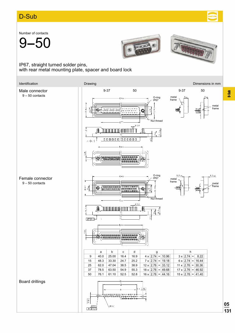
05131
D-Su
b
D-Sub
Identification Drawing Dimensions in mm
Male connector9 – 50 contacts
Female connector9 – 50 contacts
Board drillings
O-ringIP67
a b c d g h 9 40.0 25.00 16.4 16.9 4 x 2.74 = 10.96 3 x 2.74 = 8.2215 48.3 33.30 24.7 25.2 7 x 2.74 = 19.18 6 x 2.74 = 16.4425 62.0 47.04 38.5 38.9 12 x 2.76 = 33.12 11 x 2.76 = 30.3637 78.5 63.50 54.9 55.3 18 x 2.76 = 49.68 17 x 2.76 = 46.9250 76.1 61.10 52.5 52.8 16 x 2.76 = 44.16 15 x 2.76 = 41.40
IP67, straight turned solder pins, with rear metal mounting plate, spacer and board lock
Number of contacts
9--50
metalframe
metalframe
O-ringIP67
metalframe
metalframe
Nut thread
Nut thread
9-37 50 9-37 50
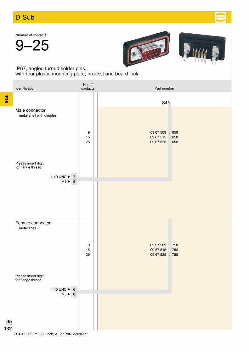
05132
D-Su
b
D-Sub
9 09 67 509 . 658 15 09 67 515 . 658 25 09 67 525 . 658
S41)
9 09 67 509 . 758 15 09 67 515 . 758 25 09 67 525 . 758
4-40 UNC þ 7 M3 þ 9
4-40 UNC þ 6 M3 þ 8
1) S4 = 0.76 µm (30 µinch) Au or PdNi eqivalent
Male connectormetal shell with dimples
Female connectormetal shell
No. ofIdentification contacts Part number
IP67, angled turned solder pins, with rear plastic mounting plate, bracket and board lock
Number of contacts
9--25
Please insert digit for flange thread
Please insert digit for flange thread
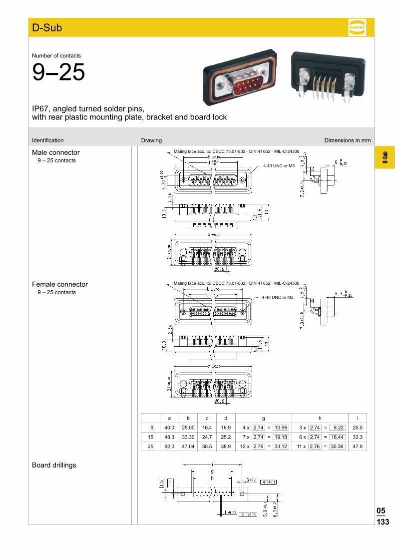
05133
D-Su
b
D-Sub
Identification Drawing Dimensions in mm
Male connector9 – 25 contacts
Female connector9 – 25 contacts
Board drillings
Mating face acc. to: CECC 75.01-802 · DIN 41 652 · MIL-C-24308
4-40 UNC or M3
4-40 UNC or M3
Mating face acc. to: CECC 75.01-802 · DIN 41 652 · MIL-C-24308
a b c d g h i
9 40.0 25.00 16.4 16.9 4 x 2.74 = 10.96 3 x 2.74 = 8.22 25.0
15 48.3 33.30 24.7 25.2 7 x 2.74 = 19.18 6 x 2.74 = 16.44 33.3
25 62.0 47.04 38.5 38.9 12 x 2.76 = 33.12 11 x 2.76 = 30.36 47.0
IP67, angled turned solder pins, with rear plastic mounting plate, bracket and board lock
Number of contacts
9--25
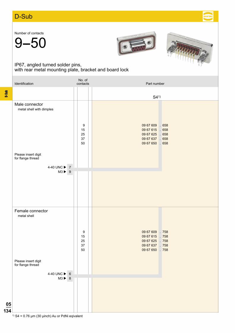
05134
D-Su
b
D-Sub
9 09 67 609 . 658 15 09 67 615 . 658 25 09 67 625 . 658 37 09 67 637 . 658 50 09 67 650 . 658
S41)
9 09 67 609 . 758 15 09 67 615 . 758 25 09 67 625 . 758 37 09 67 637 . 758 50 09 67 650 . 758
4-40 UNC þ 7 M3 þ 9
4-40 UNC þ 6 M3 þ 8
1) S4 = 0.76 µm (30 µinch) Au or PdNi eqivalent
Male connectormetal shell with dimples
Female connectormetal shell
No. ofIdentification contacts Part number
Number of contacts
9--50
Please insert digit for flange thread
Please insert digit for flange thread
IP67, angled turned solder pins, with rear metal mounting plate, bracket and board lock
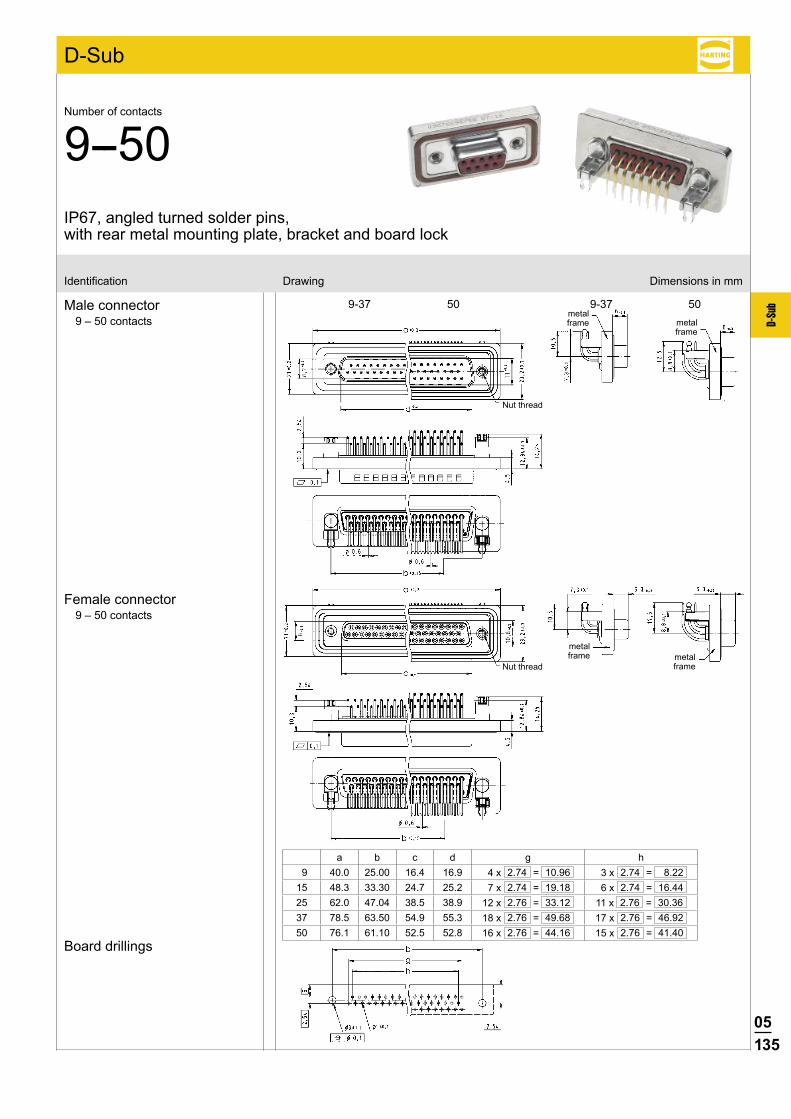
05135
D-Su
b
D-Sub
9-37 50 9-37 50
Identification Drawing Dimensions in mm
Male connector9 – 50 contacts
Female connector9 – 50 contacts
Board drillings
a b c d g h 9 40.0 25.00 16.4 16.9 4 x 2.74 = 10.96 3 x 2.74 = 8.2215 48.3 33.30 24.7 25.2 7 x 2.74 = 19.18 6 x 2.74 = 16.4425 62.0 47.04 38.5 38.9 12 x 2.76 = 33.12 11 x 2.76 = 30.3637 78.5 63.50 54.9 55.3 18 x 2.76 = 49.68 17 x 2.76 = 46.9250 76.1 61.10 52.5 52.8 16 x 2.76 = 44.16 15 x 2.76 = 41.40
metalframe
metalframe
Nut thread
Nut thread
Number of contacts
9--50IP67, angled turned solder pins, with rear metal mounting plate, bracket and board lock
metalframe metal
frame
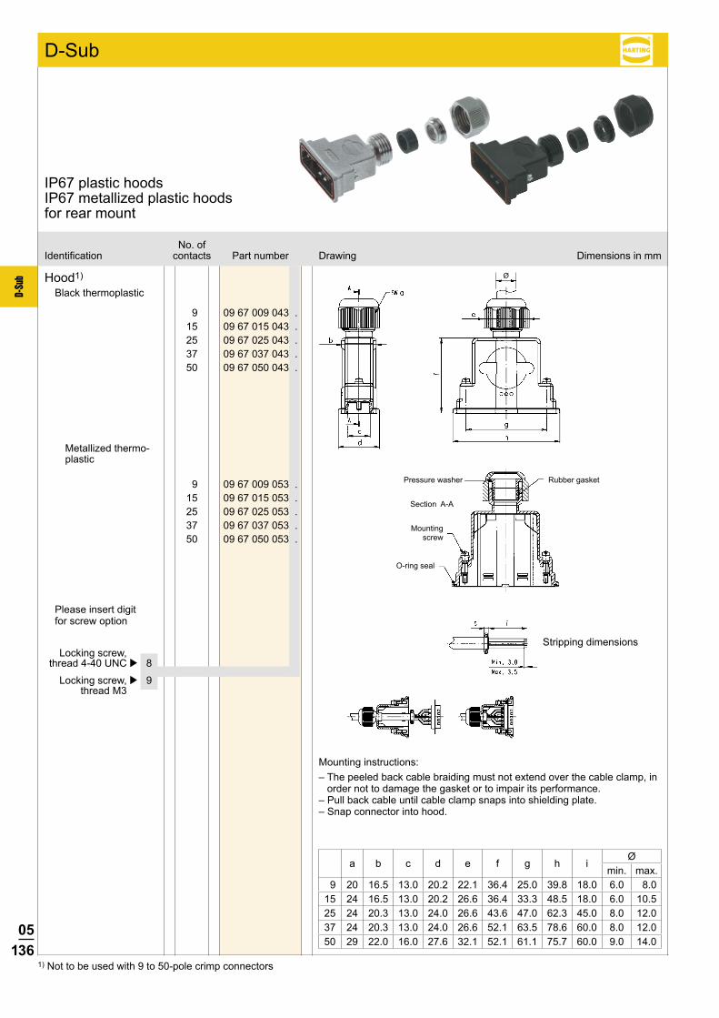
05136
D-Su
b
9 09 67 009 043 . 15 09 67 015 043 . 25 09 67 025 043 . 37 09 67 037 043 . 50 09 67 050 043 .
9 09 67 009 053 . 15 09 67 015 053 . 25 09 67 025 053 . 37 09 67 037 053 . 50 09 67 050 053 .
Ø
No. ofIdentification contacts Part number Drawing Dimensions in mm
IP67 plastic hoods IP67 metallized plastic hoodsfor rear mount
Hood1)
Black thermoplastic
Metallized thermo-plastic
Pressure washer
Mounting screw
Section A-A
O-ring seal
Rubber gasket
Mounting instructions:– The peeled back cable braiding must not extend over the cable clamp, in
order not to damage the gasket or to impair its performance.– Pull back cable until cable clamp snaps into shielding plate.– Snap connector into hood.
Stripping dimensions
D-Sub
Locking screw, thread 4-40 UNC þ 8
Locking screw, þ 9 thread M3
Please insert digit for screw option
a b c d e f g h iØ
min. max. 9 20 16.5 13.0 20.2 22.1 36.4 25.0 39.8 18.0 6.0 8.015 24 16.5 13.0 20.2 26.6 36.4 33.3 48.5 18.0 6.0 10.525 24 20.3 13.0 24.0 26.6 43.6 47.0 62.3 45.0 8.0 12.037 24 20.3 13.0 24.0 26.6 52.1 63.5 78.6 60.0 8.0 12.050 29 22.0 16.0 27.6 32.1 52.1 61.1 75.7 60.0 9.0 14.0
1) Not to be used with 9 to 50-pole crimp connectors
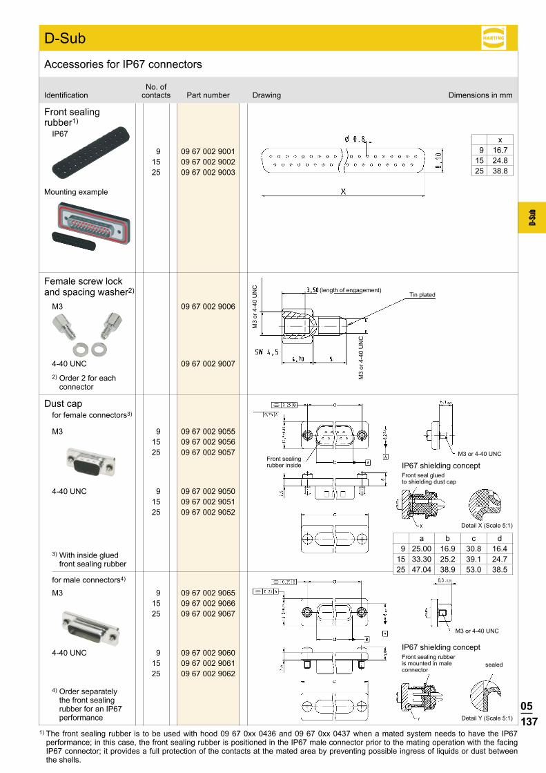
05137
D-Su
b
9 09 67 002 9001 15 09 67 002 9002 25 09 67 002 9003
09 67 002 9006
09 67 002 9007
9 09 67 002 9055 15 09 67 002 9056 25 09 67 002 9057
9 09 67 002 9050 15 09 67 002 9051 25 09 67 002 9052
9 09 67 002 9065 15 09 67 002 9066 25 09 67 002 9067
9 09 67 002 9060 15 09 67 002 9061 25 09 67 002 9062
4-40 UNC
M3
4-40 UNC
M3
4-40 UNC
M3
6,3 - 0,25
No. ofIdentification contacts Part number Drawing Dimensions in mm
Accessories for IP67 connectors
Front sealing rubber1)
IP67
Female screw lockand spacing washer2)
x 9 16.715 24.825 38.8
Mounting example
(length of engagement)Tin plated
1) The front sealing rubber is to be used with hood 09 67 0xx 0436 and 09 67 0xx 0437 when a mated system needs to have the IP67 performance; in this case, the front sealing rubber is positioned in the IP67 male connector prior to the mating operation with the facing IP67 connector; it provides a full protection of the contacts at the mated area by preventing possible ingress of liquids or dust between the shells.
Dust capfor female connectors3)
for male connectors4)
3) With inside glued front sealing rubber
2) Order 2 for each connector
4) Order separately the front sealing rubber for an IP67 performance
Front sealing rubber inside
M3 or 4-40 UNC
M3 or 4-40 UNC
a b c d 9 25.00 16.9 30.8 16.415 33.30 25.2 39.1 24.725 47.04 38.9 53.0 38.5
M3
or 4
-40
UN
C
M3
or 4
-40
UN
C
D-Sub
Detail Y (Scale 5:1)
Front sealing rubber is mounted in male connector
sealed
IP67 shielding concept
Detail X (Scale 5:1)
Front seal glued to shielding dust cap
IP67 shielding concept
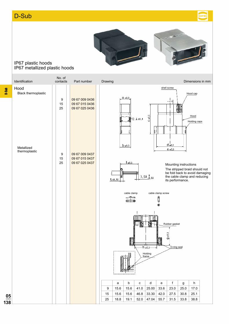
05138
D-Su
b
9 09 67 009 0436 15 09 67 015 0436 25 09 67 025 0436
D-Sub
9 09 67 009 0437 15 09 67 015 0437 25 09 67 025 0437
No. ofIdentification contacts Part number Drawing Dimensions in mm
IP67 plastic hoodsIP67 metallized plastic hoods
HoodBlack thermoplastic
a b c d e f g h
9 15.6 15.6 41.0 25.00 33.6 23.0 25.0 17.0
15 15.6 15.6 46.8 33.30 42.0 27.5 30.8 25.1
25 18.8 19.1 52.0 47.04 55.7 31.5 33.8 38.8
shell screw
Hood cap
Hood
Holding caps
Rubber gasket
Mounting instructionsThe stripped braid should not be fold back to avoid damaging the cable clamp and reducing its performance.
O-ring seal
Holding frame
cable clamp cable clamp screw
Metallized thermoplastic

05139
D-Su
b
D-Sub
09 67 002 9009
09 67 002 9008
09 67 002 9011
09 67 002 9010
09 67 002 9013
09 67 002 9012
Identification Part number Drawing Dimensions in mm
Accessories for IP67 hoods
Short locking screwM3
Short locking screw4-40 UNC
Knurled locking screw
M3
Knurled locking screw
4-40 UNC
Knurled locking screw
M3 with plastic cap
Knurled locking screw
4-40 UNC with plastic cap
Brass, Nickel plated
UN
C 4
-40
or M
3
Brass, Nickel plated knurl DIN 82, RAA 0.5
UN
C 4
-40
or M
3
Brass, Nickel plated Polyester (max. 130 °C), black
UN
C 4
-40
or M
3

05140
D-Su
b
HARTING – Guarantee a secure connectionModern electronic applications demand a high degree of mechanical and electrical security.To meet these requirements, continuous scree ning from the cable to the PCB via the connector is achieved by using state of the art components to DIN 41 652.
HARTING offer many solutions. These utilise various combinations of male and female connectors with hoods, featuring either screw locking or latching facilities.
Only 2 examples are shown:
• Continuous security screening and grounding with screw locking and metallized hood.
• Continuous grounding and vibration proof latching system with metallized hood.
Male connector with dimples
Screw lock
Cable with protectivescreen
Strain relief
Metallized hood
Female connector with protective metal shell
Spring latch
Strain relief
Cable withprotectivescreen
Metallized hood
Male connector with dimples
Grounding contact between protectivemetal shell and PCB
Female connector withprotective metal shell
D-Sub Housing range DIN 41 652 · CECC 75 301-802
Shell size D-Sub standard D-Sub high density1 9 152 15 263 25 444 37 625 50 78
Number of contacts in the D-Sub standard/D-Sub high density range related to the shell size.

05141
D-Su
b
D-Sub
Connector hoods for screw locking
Top and side entry hood
Black thermoplastic
Metallized thermoplastic
Top entry hood with knurled screws
Black thermoplastic
Metallized thermoplastic
Knurled screw
Top entry hood with short locking screws
Black thermoplastic
Metallized thermoplastic
Male screw lock
for use without hood
Female screw lock with nut
alternative
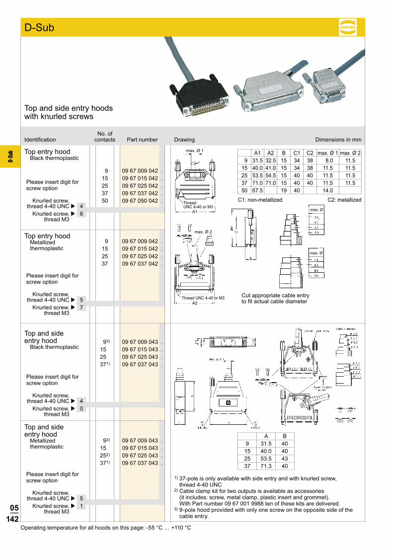
05142
D-Su
b
max. Ø 2
max. Ø 1
A1
A2
max. Ø
max. Ø
9 09 67 009 042 . 15 09 67 015 042 . 25 09 67 025 042 . 37 09 67 037 042 . 50 09 67 050 042 .
93) 09 67 009 043 . 15 09 67 015 043 . 25 09 67 025 043 . 371) 09 67 037 043 .
93) 09 67 009 043 . 15 09 67 015 043 . 252) 09 67 025 043 . 371) 09 67 037 043 .
9 09 67 009 042 . 15 09 67 015 042 . 25 09 67 025 042 . 37 09 67 037 042 .
No. ofIdentification contacts Part number Drawing Dimensions in mm
Top and side entry hoods with knurled screws
Top entry hoodBlack thermoplastic
A1 A2 B C1 C2 max. Ø 1 max. Ø 2 9 31.5 32.5 15 34 38 8.0 11.5 15 40.0 41.0 15 34 38 11.5 11.5 25 53.5 54.5 15 40 40 11.5 11.5 37 71.0 71.0 15 40 40 11.5 11.5 50 67.5 19 40 14.0
C1: non-metallized C2: metallized
D-Sub
Please insert digit for screw option
Knurled screw, thread 4-40 UNC þ 4 Knurled screw, þ 6 thread M3
Thread UNC 4-40 or M3
Top and side entry hood
Black thermoplastic
Top entry hoodMetallized thermoplastic
Top and side entry hood
Metallized thermoplastic
Cut appropriate cable entry to fit actual cable diameter
Operating temperature for all hoods on this page: -55 °C … +110 °C
1) 37-pole is only available with side entry and with knurled screw, thread 4-40 UNC
2) Cable clamp kit for two outputs is available as accessories (it includes: screw, metal clamp, plastic insert and grommet). With Part number 09 67 001 9988 ten of these kits are delivered.
3) 9-pole hood provided with only one screw on the opposite side of the cable entry.
Thread UNC 4-40 or M3
Please insert digit for screw option
Please insert digit for screw option
Please insert digit for screw option
Knurled screw, thread 4-40 UNC þ 5 Knurled screw, þ 7 thread M3
Knurled screw, thread 4-40 UNC þ 4 Knurled screw, þ 0 thread M3
Knurled screw, thread 4-40 UNC þ 5 Knurled screw, þ 1 thread M3
A B9 31.5 40
15 40.0 4025 53.5 4337 71.3 40

05143
D-Su
b
91) 09 67 009 046 . 15 09 67 015 046 . 25 09 67 025 046 . 37 09 67 037 046 .
91) 09 67 009 046 . 15 09 67 015 046 . 25 09 67 025 046 . 37 09 67 037 046 .
No. ofIdentification contacts Part number Drawing Dimensions in mm
Top and side entry hoods with short screws
D-Sub
Top and side entry hood
Black thermoplastic
Top and side entry hood
Metallized thermoplastic
Please insert digit for screw option
Please insert digit for screw option
Short screw, thread 4-40 UNC þ 3 Short screw, þ 2 thread M3
Short screw, thread 4-40 UNC þ 5 Short screw, þ 4 thread M3
1) 9-pole hood provided with only one screw on the opposite side of the cable entry.Operating temperature for all hoods on this page: -55 °C … +110 °C
A B9 31.5 40
15 40.0 4025 53.5 4337 71.3 40

05144
D-Su
b
Knurled screw M3,
beige
Knurled screw 4-40 UNC,
beige
Knurled screw M3,
black
Knurled screw 4-40 UNC,
black
Cable clamp, small
Cable clamp, large
Cable clamp screw
Metallized insert, small
Part number 09 67 002 9152 09 67 002 9081 09 67 001 9961 09 67 002 9024 09 67 002 9104 09 67 002 9106 09 67 002 9102 09 67 002 9103
09 67 009 0424 2 1 209 67 015 0424 2 1 209 67 025 0424 2 1 209 67 037 0424 2 1 209 67 050 0424 2 1 2
09 67 009 0426 2 1 209 67 015 0426 2 1 209 67 025 0426 2 1 209 67 037 0426 2 1 209 67 050 0426 2 1 2
09 67 009 0425 2 1 2 109 67 015 0425 2 1 209 67 025 0425 2 1 209 67 037 0425 2 1 2
09 67 009 0427 2 1 2 109 67 015 0427 2 1 209 67 025 0427 2 1 209 67 037 0427 2 1 2
Knurled screw M3,
beige
Knurled screw 4-40 UNC,
beige
Knurled screw M3,
black
Knurled screw 4-40 UNC,
black
Short screw M3,
18 mm
Short screw 4-40 UNC,
18 mm
Short screw M3,
12 mm
Short screw 4-40 UNC,
12 mm
Part number 09 67 002 9152 09 67 002 9081 09 67 001 9961 09 67 002 9024 09 67 002 9163 09 67 001 9979 09 67 002 9162 09 67 002 9078
09 67 009 0434 109 67 015 0434 1 109 67 025 0434 1 109 67 037 0434 1
09 67 009 0430 109 67 015 0430 1 109 67 025 0430 1 1
09 67 009 0435 109 67 015 0435 1 109 67 025 0435 1 109 67 037 0435 1
09 67 009 0431 109 67 015 0431 1 109 67 025 0431 1 1
09 67 009 0463 109 67 015 0463 209 67 025 0463 209 67 037 0463 2
09 67 009 0462 109 67 015 0462 209 67 025 0462 209 67 037 0462 2
09 67 009 0465 109 67 015 0465 209 67 025 0465 209 67 037 0465 2
09 67 009 0464 109 67 015 0464 209 67 025 0464 209 67 037 0464 2
Scope of delivery and spare parts
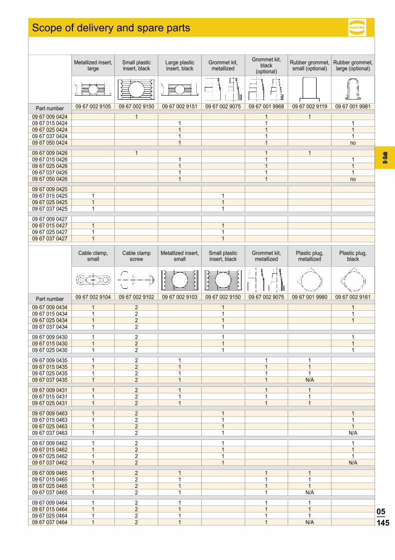
05145
D-Su
b
Metallized insert, large
Small plastic insert, black
Large plastic insert, black
Grommet kit, metallized
Grommet kit, black
(optional)Rubber grommet, small (optional)
Rubber grommet, large (optional)
Part number 09 67 002 9105 09 67 002 9150 09 67 002 9151 09 67 002 9075 09 67 001 9968 09 67 002 9119 09 67 001 9981
09 67 009 0424 1 1 109 67 015 0424 1 1 109 67 025 0424 1 1 109 67 037 0424 1 1 109 67 050 0424 1 1 no
09 67 009 0426 1 1 109 67 015 0426 1 1 109 67 025 0426 1 1 109 67 037 0426 1 1 109 67 050 0426 1 1 no
09 67 009 042509 67 015 0425 1 109 67 025 0425 1 109 67 037 0425 1 1
09 67 009 042709 67 015 0427 1 109 67 025 0427 1 109 67 037 0427 1 1
Cable clamp, small
Cable clamp screw
Metallized insert, small
Small plastic insert, black
Grommet kit, metallized
Plastic plug, metallized
Plastic plug, black
Part number 09 67 002 9104 09 67 002 9102 09 67 002 9103 09 67 002 9150 09 67 002 9075 09 67 001 9980 09 67 002 9161
09 67 009 0434 1 2 1 109 67 015 0434 1 2 1 109 67 025 0434 1 2 1 109 67 037 0434 1 2 1
09 67 009 0430 1 2 1 109 67 015 0430 1 2 1 109 67 025 0430 1 2 1 1
09 67 009 0435 1 2 1 1 109 67 015 0435 1 2 1 1 109 67 025 0435 1 2 1 1 109 67 037 0435 1 2 1 1 N/A
09 67 009 0431 1 2 1 1 109 67 015 0431 1 2 1 1 109 67 025 0431 1 2 1 1 1
09 67 009 0463 1 2 1 109 67 015 0463 1 2 1 109 67 025 0463 1 2 1 109 67 037 0463 1 2 1 N/A
09 67 009 0462 1 2 1 109 67 015 0462 1 2 1 109 67 025 0462 1 2 1 109 67 037 0462 1 2 1 N/A
09 67 009 0465 1 2 1 1 109 67 015 0465 1 2 1 1 109 67 025 0465 1 2 1 1 109 67 037 0465 1 2 1 1 N/A
09 67 009 0464 1 2 1 1 109 67 015 0464 1 2 1 1 109 67 025 0464 1 2 1 1 109 67 037 0464 1 2 1 1 N/A
Scope of delivery and spare parts

05146
D-Su
b
c bdae a
f
3)
* Not normally kept in stock1) Order knurled screw separately2) 9 way 1 per hood – 15-50 way 2 per hood
3) Screw driver type ISO PH 1 for philips screw No 1 ISO norm 4757Operating temperature for all hoods on this page: -30 °C … +100 °C
No. ofIdentification contacts Part number Drawing Dimensions in mm
Side entry hoods with knurled screws
Hood1)grey thermoplastic 9 09 67 009 0571RAL 7032 15 09 67 015 0571 25 09 67 025 0571 37 09 67 037 0571 50 09 67 050 0571
Toolingfor assembly of hoods
Top part 09 99 000 0215*Bottom part 09 99 000 0216*
grey thermoplastic with internal tin-plate screening 9 09 67 009 0573 15 09 67 015 0573 25 09 67 025 0573 37 09 67 037 0573 50 09 67 050 0573
9-37 way for packaging density of 3 TE (15.24 mm)
Knurled screw
Thread UNC 9-50
09 67 000 99712)
Thread M3 09 67 001 9965*
Thread UNC 9-50
09 67 001 9978Thread M3 09 67 001 9977
Grey head / Nickel plated steel
Full metal part
D-Sub
a max.
b min. c d e f
15 39.62 28.40 13.00 14.00 1.00 7.50
25 53.52 42.20 13.00 14.00 1.00 7.50
37 69.80 58.65 13.00 14.00 1.00 7.50
50 67.41 56.18 16.00 17.50 1.50 9.50
9 contacts
Upper hood part Lower hood part
15 – 50 contacts
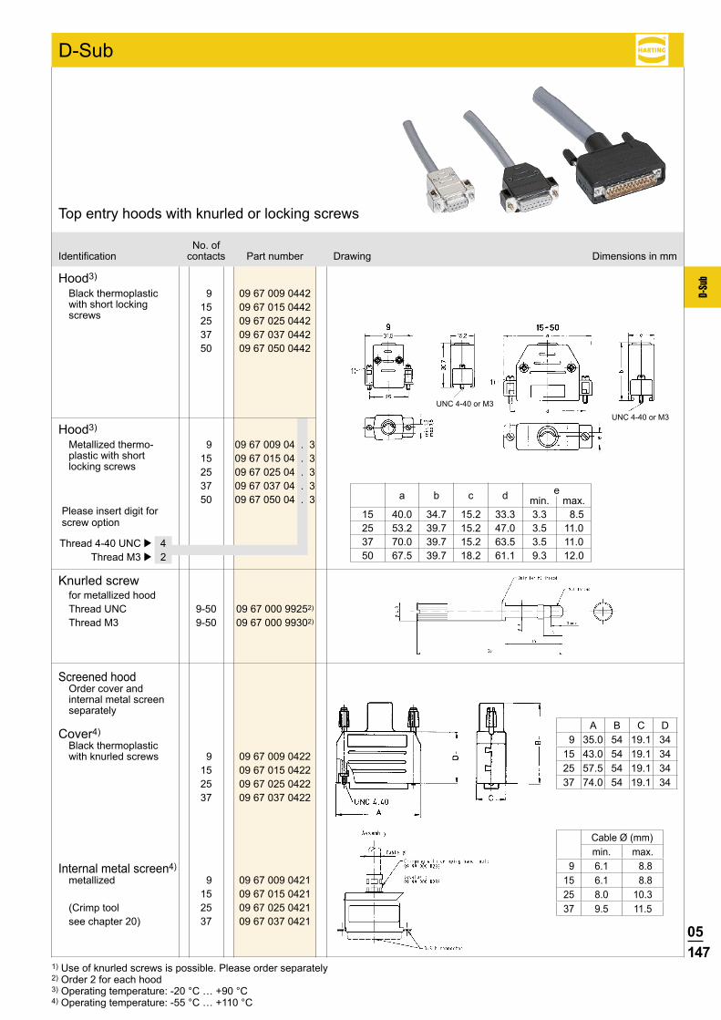
05147
D-Su
b
9 09 67 009 0442 15 09 67 015 0442 25 09 67 025 0442 37 09 67 037 0442 50 09 67 050 0442
9-50 09 67 000 99252) 9-50 09 67 000 99302)
D-Sub
e a b c d min. max.
9 09 67 009 04 . 3 15 09 67 015 04 . 3 25 09 67 025 04 . 3 37 09 67 037 04 . 3 50 09 67 050 04 . 3
No. ofIdentification contacts Part number Drawing Dimensions in mm
Top entry hoods with knurled or locking screws
Hood3)
Black thermoplastic with short locking screws
Knurled screwfor metallized hood Thread UNC Thread M3
Hood3)
Metallized thermo- plastic with short locking screws
15 40.0 34.7 15.2 33.3 3.3 8.5 25 53.2 39.7 15.2 47.0 3.5 11.0 37 70.0 39.7 15.2 63.5 3.5 11.0 50 67.5 39.7 18.2 61.1 9.3 12.0
Screened hoodOrder cover and internal metal screen separately
Cover4)Black thermoplastic with knurled screws 9 09 67 009 0422 15 09 67 015 0422 25 09 67 025 0422 37 09 67 037 0422
Internal metal screen4)metallized 9 09 67 009 0421 15 09 67 015 0421(Crimp tool 25 09 67 025 0421see chapter 20) 37 09 67 037 0421
UNC 4-40 or M3
UNC 4-40 or M3
1) Use of knurled screws is possible. Please order separately2) Order 2 for each hood3) Operating temperature: -20 °C … +90 °C4) Operating temperature: -55 °C … +110 °C
Cable Ø (mm)min. max.
9 6.1 8.815 6.1 8.825 8.0 10.337 9.5 11.5
A B C D 9 35.0 54 19.1 3415 43.0 54 19.1 3425 57.5 54 19.1 3437 74.0 54 19.1 34
Please insert digit for screw option
Thread 4-40 UNC þ 4 Thread M3 þ 2

05148
D-Su
b
9 09 67 009 0446 15 09 67 015 0446 25 09 67 025 0446 37 09 67 037 0446 50 09 67 050 0446
9 09 67 009 0448 15 09 67 015 0448 25 09 67 025 0448 37 09 67 037 0448 50 09 67 050 0448
A ± 0.3
C ± 0.3
D ± 0.3
B ±
0.3
A ± 0.3
C ± 0.3
D ± 0.3
B ±
0.3
No. ofIdentification contacts Part number Drawing Dimensions in mm
Metallized thermoplastic top and side entry hoods with short screws
Top entry hoodShort screw, thread 4-40 UNC
Side entry hoodShort screw, thread 4-40 UNC
Poles A B C DCable diameterMin. Max.
9 31.8 41.6 20.0 16.7 4.0 11.015 41.2 47.8 28.4 16.2 4.0 11.025 54.9 54.8 42.1 16.2 4.0 12.037 71.4 57.8 58.6 18.9 6.0 13.050 69.0 57.8 56.2 19.5 6.0 14.0
D-Sub
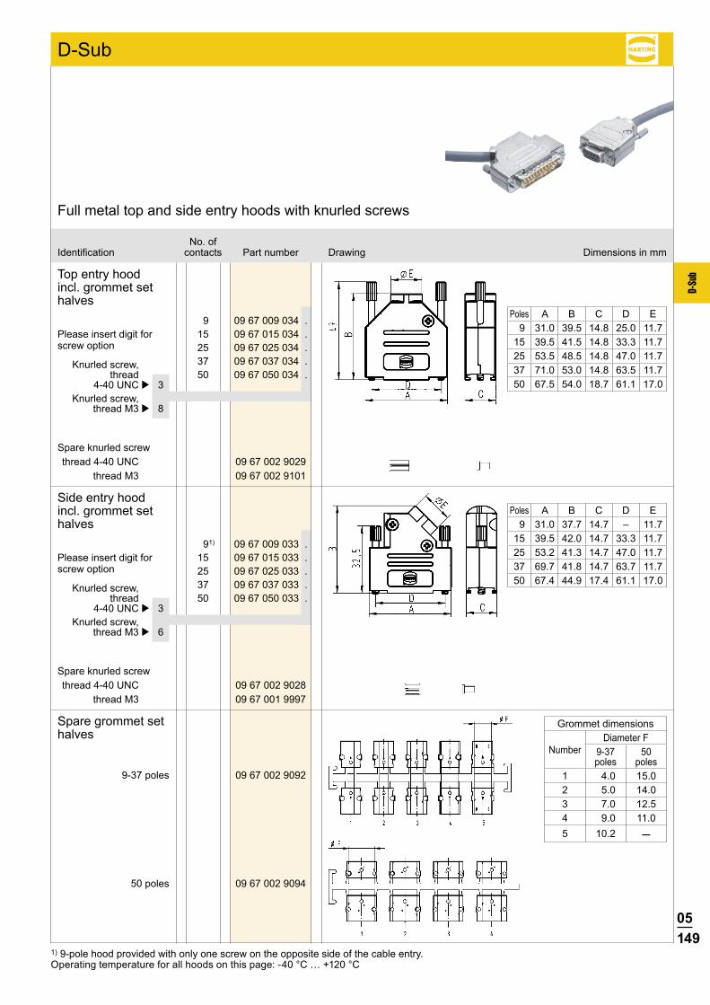
05149
D-Su
b
9 09 67 009 034 . 15 09 67 015 034 . 25 09 67 025 034 . 37 09 67 037 034 . 50 09 67 050 034 .
91) 09 67 009 033 . 15 09 67 015 033 . 25 09 67 025 033 . 37 09 67 037 033 . 50 09 67 050 033 .
09 67 002 9092
09 67 002 9094
09 67 002 9029 09 67 002 9101
09 67 002 9028 09 67 001 9997
No. ofIdentification contacts Part number Drawing Dimensions in mm
Full metal top and side entry hoods with knurled screws
D-Sub
1) 9-pole hood provided with only one screw on the opposite side of the cable entry.Operating temperature for all hoods on this page: -40 °C … +120 °C
Top entry hood incl. grommet set halves
Grommet dimensions
NumberDiameter F
9-37 poles
50 poles
1 4.0 15.02 5.0 14.03 7.0 12.54 9.0 11.05 10.2 –
Poles A B C D E 9 31.0 39.5 14.8 25.0 11.715 39.5 41.5 14.8 33.3 11.725 53.5 48.5 14.8 47.0 11.737 71.0 53.0 14.8 63.5 11.750 67.5 54.0 18.7 61.1 17.0
Poles A B C D E 9 31.0 37.7 14.7 – 11.715 39.5 42.0 14.7 33.3 11.725 53.2 41.3 14.7 47.0 11.737 69.7 41.8 14.7 63.7 11.750 67.4 44.9 17.4 61.1 17.0
Side entry hood incl. grommet set halves
Spare grommet set halves
Knurled screw, thread 4-40 UNC þ 3 Knurled screw, thread M3 þ 6
Please insert digit for screw option
Knurled screw, thread 4-40 UNC þ 3 Knurled screw, thread M3 þ 8
Please insert digit for screw option
Spare knurled screwthread 4-40 UNC
thread M3
Spare knurled screwthread 4-40 UNC
thread M3
9-37 poles
50 poles
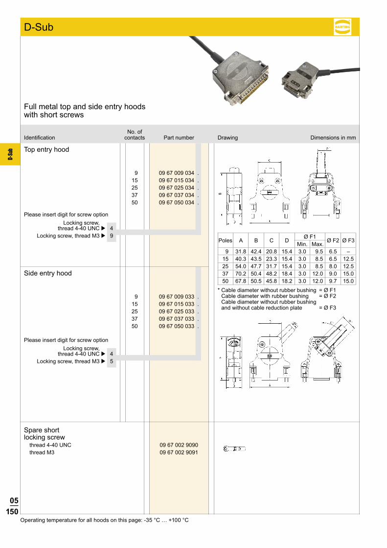
05150
D-Su
b
9 09 67 009 034 . 15 09 67 015 034 . 25 09 67 025 034 . 37 09 67 037 034 . 50 09 67 050 034 .
9 09 67 009 033 . 15 09 67 015 033 . 25 09 67 025 033 . 37 09 67 037 033 . 50 09 67 050 033 .
09 67 002 9090 09 67 002 9091
No. ofIdentification contacts Part number Drawing Dimensions in mm
Full metal top and side entry hoods with short screws
Top entry hood
Side entry hood
Locking screw, thread 4-40 UNC þ 4 Locking screw, thread M3 þ 5
Please insert digit for screw option
Locking screw, thread 4-40 UNC þ 4 Locking screw, thread M3 þ 9
Please insert digit for screw option
Poles A B C DØ F1
Ø F2 Ø F3Min. Max.
9 31.8 42.4 20.8 15.4 3.0 9.5 6.5 –15 40.3 43.5 23.3 15.4 3.0 8.5 6.5 12.525 54.0 47.7 31.7 15.4 3.0 8.5 8.0 12.537 70.2 50.4 48.2 18.4 3.0 12.0 9.0 15.050 67.8 50.5 45.8 18.2 3.0 12.0 9.7 15.0
* Cable diameter without rubber bushing = Ø F1 Cable diameter with rubber bushing = Ø F2 Cable diameter without rubber bushing and without cable reduction plate = Ø F3
D-Sub
Spare short locking screw
thread 4-40 UNCthread M3
Operating temperature for all hoods on this page: -35 °C … +100 °C
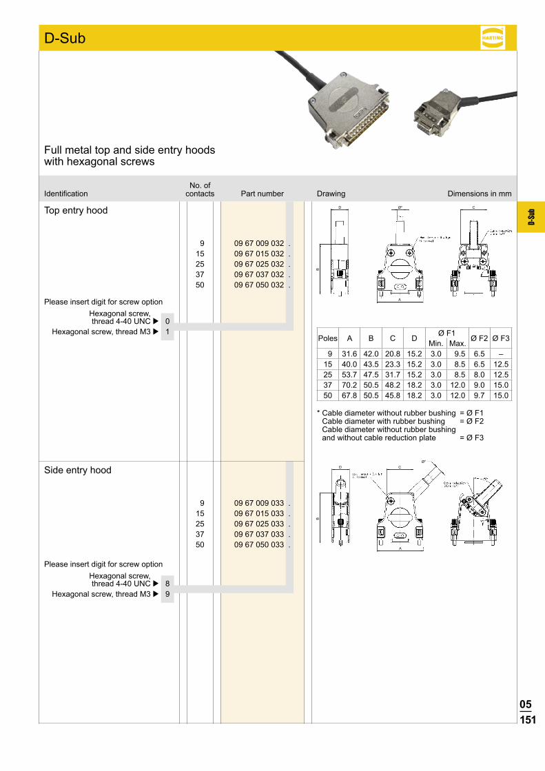
05151
D-Su
b
9 09 67 009 032 . 15 09 67 015 032 . 25 09 67 025 032 . 37 09 67 037 032 . 50 09 67 050 032 .
9 09 67 009 033 . 15 09 67 015 033 . 25 09 67 025 033 . 37 09 67 037 033 . 50 09 67 050 033 .
A
A
C
C
D
D
Ø*
Ø*
BB
* Cable diameter without rubber bushing = Ø F1 Cable diameter with rubber bushing = Ø F2 Cable diameter without rubber bushing and without cable reduction plate = Ø F3
No. ofIdentification contacts Part number Drawing Dimensions in mm
Full metal top and side entry hoods with hexagonal screws
Top entry hood
Side entry hood
Hexagonal screw, thread 4-40 UNC þ 8 Hexagonal screw, thread M3 þ 9
Please insert digit for screw option
Hexagonal screw, thread 4-40 UNC þ 0 Hexagonal screw, thread M3 þ 1
Please insert digit for screw option
Poles A B C D Ø F1 Ø F2 Ø F3Min. Max. 9 31.6 42.0 20.8 15.2 3.0 9.5 6.5 –15 40.0 43.5 23.3 15.2 3.0 8.5 6.5 12.525 53.7 47.5 31.7 15.2 3.0 8.5 8.0 12.537 70.2 50.5 48.2 18.2 3.0 12.0 9.0 15.050 67.8 50.5 45.8 18.2 3.0 12.0 9.7 15.0
D-Sub
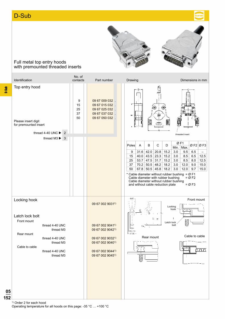
05152
D-Su
b
9 09 67 009 032 . 15 09 67 015 032 . 25 09 67 025 032 . 37 09 67 037 032 . 50 09 67 050 032 .
09 67 002 90311)
09 67 002 90411)
09 67 002 90421)
09 67 002 90321)
09 67 002 90401)
09 67 002 90441)
09 67 002 90451)
No. ofIdentification contacts Part number Drawing Dimensions in mm
Full metal top entry hoods with premounted threaded inserts
Top entry hood
thread 4-40 UNC þ 2
thread M3 þ 3
Please insert digit for premounted insert
Poles A B C DØ F1
Ø F2 Ø F3Min. Max.
9 31.6 42.0 20.8 15.2 3.0 9.5 6.5 –15 40.0 43.5 23.3 15.2 3.0 8.5 6.5 12.525 53.7 47.5 31.7 15.2 3.0 8.5 8.0 12.537 70.2 50.5 48.2 18.2 3.0 12.0 9.0 15.050 67.8 50.5 45.8 18.2 3.0 12.0 9.7 15.0
* Cable diameter without rubber bushing = Ø F1 Cable diameter with rubber bushing = Ø F2 Cable diameter without rubber bushing and without cable reduction plate = Ø F3
D-Sub
Locking hook
Latch lock boltFront mount
thread 4-40 UNCthread M3
Rear mountthread 4-40 UNC
thread M3Cable to cable
thread 4-40 UNCthread M3
Front mount
Rear mount Cable to cable
Locking hook
Latch lock bolt
1) Order 2 for each hoodOperating temperature for all hoods on this page: -35 °C … +100 °C
threaded insert
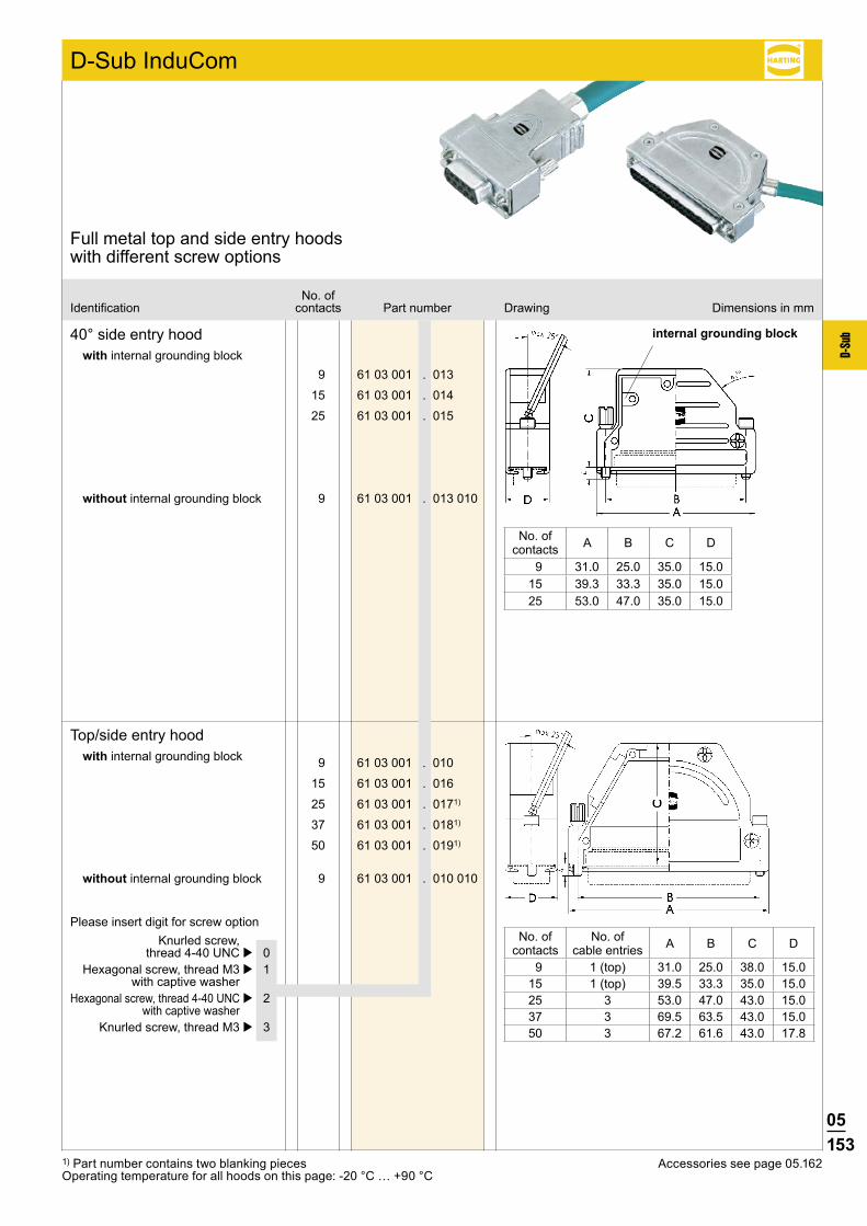
05153
D-Su
b
D-Sub InduCom
9 61 03 001 . 010
15 61 03 001 . 016
25 61 03 001 . 0171)
37 61 03 001 . 0181)
50 61 03 001 . 0191)
9 61 03 001 . 010 010
9 61 03 001 . 013
15 61 03 001 . 014
25 61 03 001 . 015
9 61 03 001 . 013 010
1) Part number contains two blanking piecesOperating temperature for all hoods on this page: -20 °C … +90 °C
No. ofIdentification contacts Part number Drawing Dimensions in mm
Full metal top and side entry hoods with different screw options
40° side entry hoodwith internal grounding block
Top/side entry hoodwith internal grounding block
No. ofcontacts A B C D
9 31.0 25.0 35.0 15.015 39.3 33.3 35.0 15.025 53.0 47.0 35.0 15.0
No. ofcontacts
No. ofcable entries A B C D
9 1 (top) 31.0 25.0 38.0 15.015 1 (top) 39.5 33.3 35.0 15.025 3 53.0 47.0 43.0 15.037 3 69.5 63.5 43.0 15.050 3 67.2 61.6 43.0 17.8
Please insert digit for screw option Knurled screw, thread 4-40 UNC þ 0 Hexagonal screw, thread M3 þ 1 with captive washer Hexagonal screw, thread 4-40 UNC þ 2 with captive washer Knurled screw, thread M3 þ 3
without internal grounding block
without internal grounding block
internal grounding block
Accessories see page 05.162

05154
D-Su
b
D-Sub InduCom
37 61 03 001 . 118
50 61 03 001 . 119
37 61 03 001 . 118 010
50 61 03 001 . 119 010
9 66 67 009 0346
9 66 67 009 0347
D EA
C
B
No. ofIdentification contacts Part number Drawing Dimensions in mm
Full metal top and side entry hoods with different screw options
5° top entry hood with 3 cable entries
with internal grounding block
No. of contacts A B C D E
37 69.5 52.0 58.2 14.8 63.550 67.1 58.0 63.6 17.6 61.1
Please insert digit for screw option Knurled screw, thread 4-40 UNC þ 0 Hexagonal screw, thread M3 þ 1 with captive washer Hexagonal screw, thread 4-40 UNC þ 2 with captive washer Knurled screw, thread M3 þ 3
without internal grounding block
Top entry hood for InduCom 9
Hexagonal screw, thread 4-40 UNC
Hexagonal screw, thread M3
2 cable entries

05155
D-Su
b
Notes
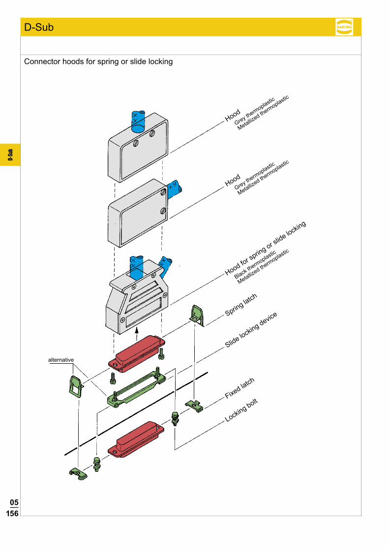
05156
D-Su
b
D-Sub
Connector hoods for spring or slide locking
HoodGrey thermoplastic
Metallized thermoplastic
HoodGrey thermoplastic
Metallized thermoplastic
Hood for spring or slide locking
Black thermoplastic
Metallized thermoplastic
Spring latch
Slide locking device
Fixed latch
Locking bolt
alternative

05157
D-Su
b
D-Sub
9 09 67 009 0411 09 67 009 0413 15 09 67 015 0411 09 67 015 0413 25 09 67 025 0411 09 67 025 0413 37 09 67 037 0411 09 67 037 0413 50 09 67 050 0411 09 67 050 0413
9 09 67 009 0511 09 67 009 0513 15 09 67 015 0511 09 67 015 0513 25 09 67 025 0511 09 67 025 0513 37 09 67 037 0511 09 67 037 0513 50 09 67 050 0511 09 67 050 0513
9 09 67 009 0452 09 67 009 0453 15 09 67 015 0452 09 67 015 0453 25 09 67 025 0452 09 67 025 0453 37 09 67 037 0452 09 67 037 0453 50 09 67 050 0452 09 67 050 0453
e a b1 b2 c d min. max.
e a c d min. max.
No. ofIdentification contacts Part number Drawing Dimensions in mm
Thermoplastic top and side entry hoods for spring or slide locking
Thermoplastic Thermoplastic grey2) metallized3)
Top entry hood
9-37 wayfor packaging densityof 3 TE (15.24 mm)
Thermoplastic Thermoplastic grey2) metallized3)
Side entry hood
Thermoplastic Thermoplastic black4) metallized4)
Top and side entry hood 1)
9-37 wayfor packaging densityof 3 TE (15.24 mm)
9 31.0 23 28 12.8 10 5.75 9.0 15 39.4 28 28 12.8 10 5.75 9.0 25 53.3 34 34 12.8 14 5.75 9.0 37 69.7 43 43 12.8 20 5.75 9.0 50 67.1 41 41 15.8 20 5.75 11.6
9 31.0 15.4 7 1.7 7.5 15 39.4 15.4 7 1.7 8.0 25 53.2 15.4 9 1.5 8.0 37 69.5 15.4 9 1.5 8.0 50 67.0 17.9 9 1.5 8.0
2) Operating temperature: -55 °C … +120 °C3) Operating temperature: -35 °C … +60 °C4) Operating temperature: -20 °C … +90 °C
Accessories see page 05.159
1) 9-poles is only side entry

05158
D-Su
b
D-Sub InduCom
9 61 03 001 00221)
15 61 03 001 00112)
25 61 03 001 00122)
37 61 03 001 00212)
50 61 03 001 00202)
No. ofIdentification contacts Part number Drawing Dimensions in mm
Full metal top and side entry hoods for spring or slide locking
Top/side entry hood with spring/slide locking
1) Part number contains one blanking piece2) Part number contains two blanking pieces
Accessories see page 05.162
No. of No. of A B C D contacts cable entries 9 2 31.0 22.6 40.0 14.8 15 3 39.0 30.6 40.0 14.8 25 3 53.0 42.6 40.0 14.8 37 3 69.5 59.2 40.0 14.8 50 3 67.0 55.0 40.0 17.6
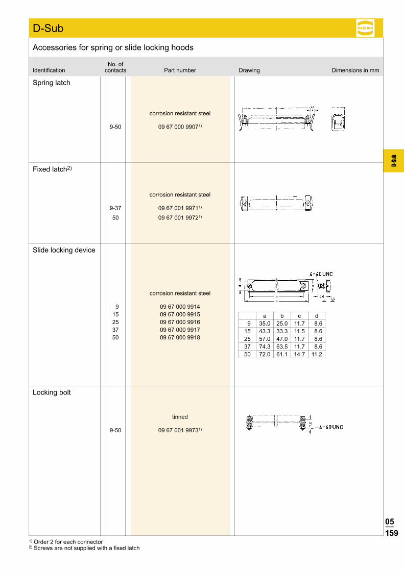
05159
D-Su
b
D-Sub
9-50 09 67 000 99071)
9 09 67 000 9914 15 09 67 000 9915 25 09 67 000 9916 37 09 67 000 9917 50 09 67 000 9918
9-37 09 67 001 99711)
50 09 67 001 99721)
9-50 09 67 001 99731)
a b c d 9 35.0 25.0 11.7 8.6 15 43.3 33.3 11.5 8.6 25 57.0 47.0 11.7 8.6 37 74.3 63.5 11.7 8.6 50 72.0 61.1 14.7 11.2
No. ofIdentification contacts Part number Drawing Dimensions in mm
Accessories for spring or slide locking hoods
corrosion resistant steel
Spring latch
corrosion resistant steel
Slide locking device
corrosion resistant steel
Fixed latch2)
tinned
Locking bolt
1) Order 2 for each connector2) Screws are not supplied with a fixed latch
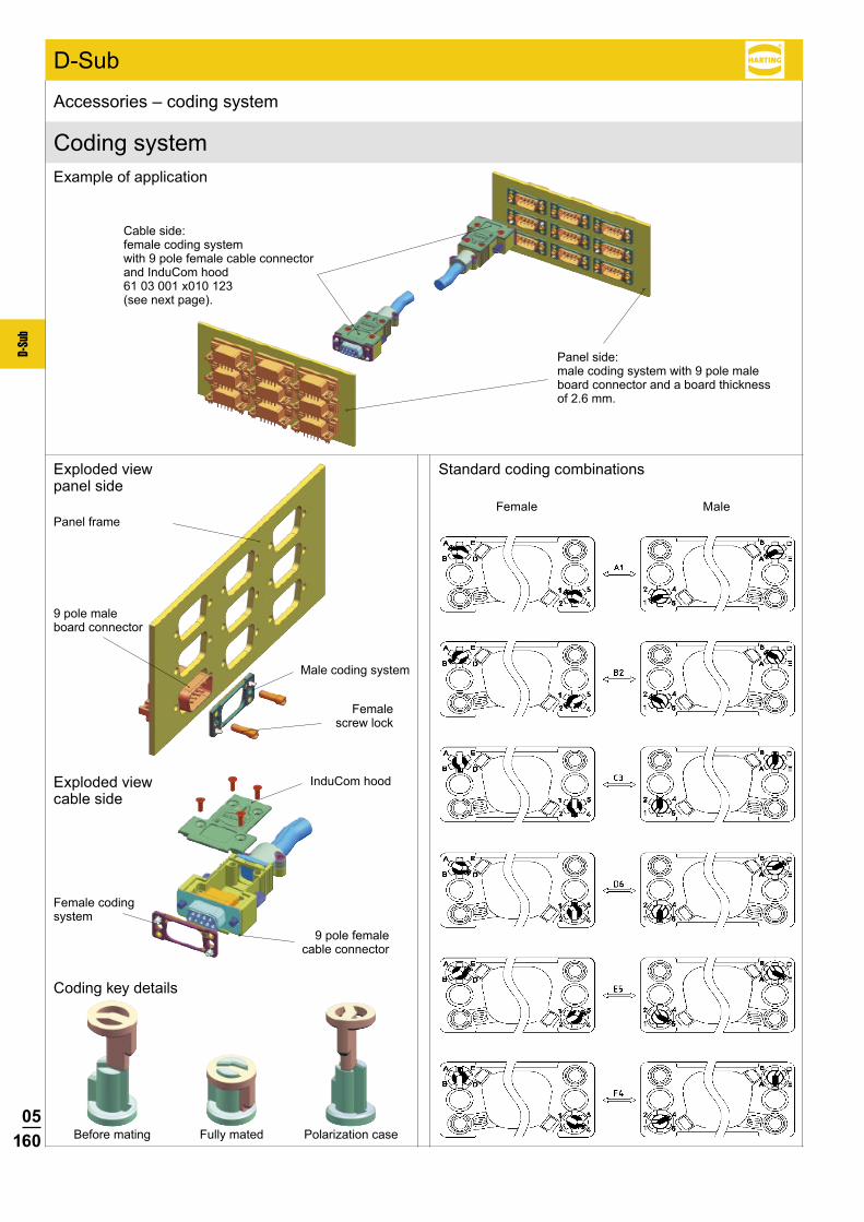
05160
D-Su
b
D-Sub
Coding system
Accessories – coding system
Exploded view panel side
Coding key details
Standard coding combinations
Female Male
Example of application
Cable side: female coding system with 9 pole female cable connector and InduCom hood 61 03 001 x010 123 (see next page).
Panel side: male coding system with 9 pole male board connector and a board thickness of 2.6 mm.
Panel frame
9 pole male board connector
Male coding system
Female screw lock
Exploded view cable side
InduCom hood
9 pole female cable connector
Female coding system
Before mating Fully mated Polarization case

05161
D-Su
b
D-Sub
09 67 002 9121 xx 109 67 002 9121 xx 209 67 002 9121 xx 309 67 002 9121 xx 4
09 67 002 9122 xx 109 67 002 9122 xx 209 67 002 9122 xx 309 67 002 9122 xx 4
61 03 001 . 010 123
A1 B1 C1 D1 E1 F1A2 B2 C2 D2 E2 F2A3 B3 C3 D3 E3 F3A4 B4 C4 D4 E4 F4A5 B5 C5 D5 E5 F5A6 B6 C6 D6 E6 F6
Accessories – coding system
2.40 - 2.60 mm3)
2.00 - 2.40 mm1.20 - 2.00 mm0.80 - 1.20 mm
2.40 - 2.60 mm3)
2.00 - 2.40 mm1.20 - 2.00 mm0.80 - 1.20 mm
Female
Male
1) MOQ = 50 pieces2) Stock items (standard versions) in bold type3) Female screw lock for straight PCB connectors on request4) Standard versions
Identification Part number Panel thickness Dimensions in mm
Coding1)
Female screw lockfor angled PCB connectors3)
Insert digits for coding configuration, e. g. "C3"
Threadinner outer
4 - 40 UNC 4 - 40 UNC 09 67 002 91234)
2.00 - 2.60 mm4 - 40 UNC M3 09 67 002 9124
M3 4 - 40 UNC 09 67 002 9125M3 M3 09 67 002 9126
4 - 40 UNC 4 - 40 UNC 09 67 002 9129
1.20 - 2.00 mm4 - 40 UNC M3 09 67 002 9130
M3 4 - 40 UNC 09 67 002 9131M3 M3 09 67 002 9132
4 - 40 UNC 4 - 40 UNC 09 67 002 9133
0.80 - 1.20 mm4 - 40 UNC M3 09 67 002 9134
M3 4 - 40 UNC 09 67 002 9135M3 M3 09 67 002 9136
9 pole InduCom top entry hood for coding
Please insert digit for screw option
Hexagonal screw, thread M3 þ 1 with captive washer
Hexagonal screw, thread 4-40 UNC þ 2 with captive washer
36 coding configurations2)
Depending on the panel thickness the suitable coding needs to be selected.
Inner thread
Outer thread
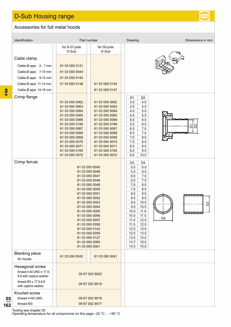
05162
D-Su
b
61 03 000 0062 61 03 000 5062 61 03 000 0063 61 03 000 5063 61 03 000 0064 61 03 000 5064 61 03 000 0065 61 03 000 5065 61 03 000 0066 61 03 000 5066 61 03 000 0166 61 03 000 5166 61 03 000 0067 61 03 000 5067 61 03 000 0068 61 03 000 5068 61 03 000 0069 61 03 000 5069 61 03 000 0070 61 03 000 5070 61 03 000 0071 61 03 000 5071 61 03 000 0165 61 03 000 5165 61 03 000 0072 61 03 000 5072
61 03 000 0141
61 03 000 0044
61 03 000 0143
61 03 000 0148 61 03 000 0145
61 03 000 0147
61 03 000 0045 61 03 000 0046 61 03 000 0047 61 03 000 0048 61 03 000 0049 61 03 000 0050 61 03 000 0051 61 03 000 0052 61 03 000 0053 61 03 000 0054 61 03 000 0055 61 03 000 0056 61 03 000 0057 61 03 000 0058 61 03 000 0142 61 03 000 0059 61 03 000 0127 61 03 000 0060 61 03 000 0061
61 03 000 0042 61 03 000 0041
D3
D4
D1
D2
09 67 002 9020
09 67 002 9019
09 67 002 9018
09 67 002 9017
Identification Part number Drawing Dimensions in mm
Accessories for full metal hoods
Crimp flange
Crimp ferrule
Cable clamp
Blanking piecefor hoods
Hexagonal screwthread 4-40 UNC x 17.5-8.8 with captive washer
Knurled screwthread 4-40 UNC
thread M3
thread M3 x 17.5-8.8 with captive washer
for 9-37-pole D-Sub
for 50-pole D-Sub
D1 D2 3.0 4.0 3.5 4.5 4.0 5.0 4.5 5.5 5.0 6.0 5.5 6.5 6.0 7.0 6.5 7.5 7.0 8.0 7.5 8.5 8.0 9.0 8.5 9.5 9.0 10.0
D3 D4 5.0 6.0 5.5 6.5 6.0 7.0 6.5 7.5 7.0 8.0 7.5 8.5 8.0 9.0 8.5 9.5 9.0 10.0 9.5 10.5 10.0 11.0 10.5 11.5 11.0 12.0 11.5 12.5 12.0 13.0 12.5 13.5 13.0 14.0 13.7 15.0 14.0 15.0
Tooling see chapter 20Operating temperature for all components on this page: -20 °C … +90 °C
D-Sub Housing range
Cable-Ø appr. 5- 7 mm
Cable-Ø appr. 7-10 mm
Cable-Ø appr. 9-12 mm
Cable-Ø appr. 11-14 mm
Cable-Ø appr. 14-16 mm
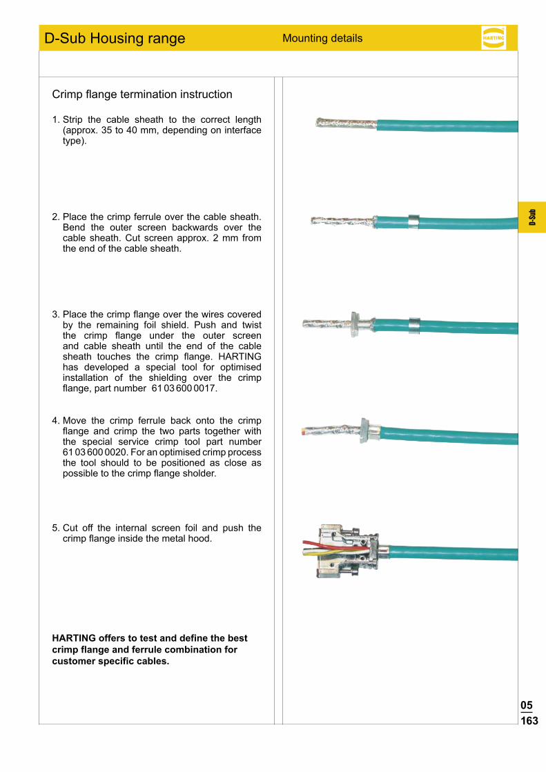
05163
D-Su
b
Mounting details
Crimp flange termination instruction
1. Strip the cable sheath to the correct length (approx. 35 to 40 mm, depending on interface type).
2. Place the crimp ferrule over the cable sheath. Bend the outer screen backwards over the cable sheath. Cut screen approx. 2 mm from the end of the cable sheath.
3. Place the crimp flange over the wires covered by the remaining foil shield. Push and twist the crimp flange under the outer screen and cable sheath until the end of the cable sheath touches the crimp flange. HARTING has developed a special tool for optimised installation of the shielding over the crimp flange, part number 61 03 600 0017.
4. Move the crimp ferrule back onto the crimp flange and crimp the two parts together with the special service crimp tool part number 61 03 600 0020. For an optimised crimp process the tool should to be positioned as close as possible to the crimp flange sholder.
5. Cut off the internal screen foil and push the crimp flange inside the metal hood.
HARTING offers to test and define the best crimp flange and ferrule combination for customer specific cables.
D-Sub Housing range

05164
D-Su
b
66 63 009 5013
66 63 009 5014
D-Sub InduCom
Further bus PCBs on request* To check compatibility with cable types and manufacturers, please contact your local HARTING representative.
InduCom 9 – Industrial bus interface system
MVB Interface
WTB Interface
Identification Part number General information
MVB backbone interface setThe Multifunctional Vehicle Bus (MVB) backbone interface is specially designed for communication cables in Train Control Networks (TCN). With this interface it is possible to realise a T-bus structure with MVB-cable with which you can disconnect the bus interface from the control unit without any interruption of the complete bus communication. On the PCB you will have load resistors and test capacitors which can be activated with solder bridges. The wires are terminated with the proven vibration resistant cage clamp technology.*
Components of the MVB interface set: 1 metal housing with 2 cable entries 2 hexagonal screws with UNC 4-40 threads 1 PCB with 9 way D-Sub male connector and cage
clamps 2 crimp flanges for the MVB cable 2 crimp ferrules for the MVB cable 1 blanking piece
WTB backbone interface setThe Wired Train Bus (WTB) backbone interface is specially designed for backbone cables in Train Control Networks (TCN). With this interface it is possible to realise a T-bus structure with WTB-cable with which you can disconnect the bus interface from the control unit without any interruption of the complete bus communication. On the PCB you will have load resistors and test capacitors which can be activated with solder bridges. The wires are terminated with the proven vibration resistant cage clamp technology.*
Components of the MVB interface set: 1 metal housing with 2 cable entries 2 hexagonal screws with UNC 4-40 threads 1 PCB with 9 way D-Sub male connector and cage
clamps 2 crimp flanges for the WTB cable 2 crimp ferrules for the WTB cable 1 blanking piece

05165
D-Su
b
D-Sub InduCom
66 63 009 6016
66 63 009 6004
InduCom 9 – Industrial bus interface system
Identification Part number General information
CAN Interface The Controller Area Network (CAN)-Interface is specially designed for usage in trains. With this interface it is possible to realise a T-bus structure with which you can disconnect the bus interface from the control unit without any interruption of the complete bus communication. On the PCB you will have a load resistor which can be activated with the switch.*
Components of the interface set:
1 metal housing with 2 cable entries
2 hexagonal screws with UNC 4-40 threads
1 PCB with 9 way D-Sub female connector and 2 cage clamps
1 blanking piece
2 crimp flanges
2 crimp ferrules
Profibus Interface The Profibus Interface is specially designed for usage in trains and in challenging engineering applications.
On the PCB you will have SMD parts which can be activated with solder bridges.
The wires are assembled with the proven vibration resistant cage clamp technology.*
Components of the interface set: 1 metal housing with 2 cable entries 2 hexagonal screws with UNC 4-40 threads 1 PCB with 9 way D-Sub female connector and
2 cage clamps 1 blanking piece
Further bus PCBs on request* To check compatibility with cable types and manufacturers, please contact your local HARTING representative.

05166
D-Su
b
D-Sub InduCom
66 63 009 5017
66 63 009 5018
InduCom 9 – Industrial bus interface system
Identification Part number General information
FIP Interface middle of the line
FIP Interface end of the line
The FIP (Factory Installation Protocol) Interface is specially designed for applications in trains. It is connected via the D-Sub. The wires are assembled with the proven vibration resistant cage clamp technology.*
Components of the interface set:l 1 metal housing with 2 cable entries l 2 hexagonal screws with UNC 4-40 threadsl 1 pcb with 9 way D-Sub female connector and
cage clamps
The FIP (Factory Installation Protocol) Interface is specially designed for applications in trains. It is connected via the D-Sub. On the pcb you will have load resistors. The wires are assembled with the proven vibration resistant cage clamp technology.*
Components of the interface set:l 1 metal housing with 2 cable entries l 2 hexagonal screws with UNC 4-40 threadsl 1 pcb with 9 way D-Sub female connector and
cage clamps l 1 blanking piece
Further bus PCBs on request* To check compatibility with cable types and manufacturers, please contact your local HARTING representative.

05167
D-Su
b
D-Sub
9-50 09 67 000 99721)
9-50 09 67 000 99741)
9-50 09 67 001 99761)
9-50 09 67 001 99741)
9-50 09 67 001 99411)
9-50 09 67 001 99541)
4-40 UNC 4-40 UNC 4-40 UNC M3
4-40 UNC 4-40 UNC 4-40 UNC M3
M3 4-40 UNC M3 M3
4-40 UNC 4-40 UNC
9-50 09 66 000 99721)
9-50 09 66 000 99741)2)
4-40 UNC 4-40 UNC 4-40 UNC M3
9-50 09 67 001 99571)
No. ofIdentification contacts Part number Drawing Dimensions in mm
Accessories
1) Order 2 for each connector 2) M3 inner thread available on request
Female screw lockswithout nut
Thread UNC/UNC Thread UNC/M3
Thread M3/UNC Thread M3/M3
Thread UNC/UNC Thread UNC/M3
for press-in connectors with grounding-pins or straight solder with grounding-clips.
Thread UNC/UNC
Thread UNC/M3
with captive washer Thread UNC/UNC
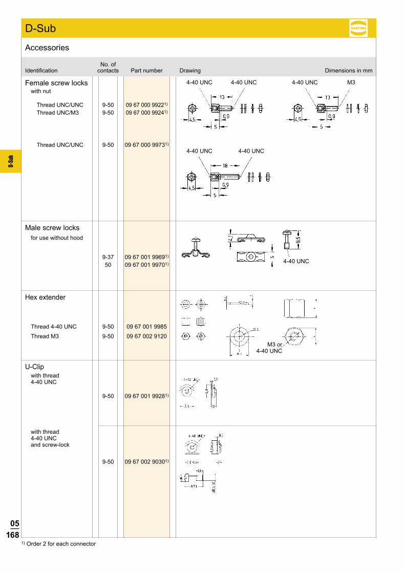
05168
D-Su
b
D-Sub
9-37 09 67 001 99691) 50 09 67 001 99701)
9-50 09 67 001 9985
9-50 09 67 002 9120
9-50 09 67 000 99221)
9-50 09 67 000 99241)
9-50 09 67 000 99731)
4-40 UNC 4-40 UNC
4-40 UNC 4-40 UNC
4-40 UNC
4-40 UNC M3
9-50 09 67 001 99281)
9-50 09 67 002 90301)
No. ofIdentification contacts Part number Drawing Dimensions in mm
Accessories
1) Order 2 for each connector
Female screw lockswith nut
Thread UNC/UNC
Thread UNC/M3
Thread UNC/UNC
Male screw locksfor use without hood
Hex extender
U-Clipwith thread 4-40 UNC
with thread 4-40 UNC and screw-lock
Thread 4-40 UNC
Thread M3M3 or
4-40 UNC

05169
D-Su
b
9 09 67 009 0611 15 09 67 015 0611 25 09 67 025 0611 37 09 67 037 0611
9 09 67 009 0711 15 09 67 015 0711 25 09 67 025 0711 37 09 67 037 0711
9 09 67 009 0612 15 09 67 015 0612 25 09 67 025 0612 37 09 67 037 0612 50 09 67 050 0612
9 09 67 009 0712 15 09 67 015 0712 25 09 67 025 0712 37 09 67 037 0712 50 09 67 050 0712
9 09 67 009 0613 15 09 67 015 0613 25 09 67 025 0613 37 09 67 037 0613 50 09 67 050 0613
9 09 67 009 0713 15 09 67 015 0713 25 09 67 025 0713 37 09 67 037 0713 50 09 67 050 0713
Dust capblack thermoplastic
for male connector
for female connector
anstistaticblack thermoplastic
for male connector
for female connector
UL 94 V0grey thermoplastic
for male connector
for female connector
No. ofIdentification contacts Part number Drawing Dimensions in mm
Accessories
D-Sub
A B 9 17.0 22.4015 25.3 30.8025 38.9 44.4037 55.4 60.75
A B 9 16.0 22.515 24.4 31.025 37.8 44.337 54.3 60.8
A B C D 9 17.7 21.8 13.2 9.115 26.0 30.0 13.2 9.125 40.0 44.2 13.2 9.137 56.4 59.8 13.2 9.150 53.9 57.8 15.9 11.7
A B C D 9 15.9 20.0 11.8 7.815 24.4 28.5 11.8 7.825 38.3 42.3 11.8 7.837 54.7 58.8 11.8 7.850 52.6 56.2 14.5 10.5
A B C D 9 17.7 21.8 13.2 9.115 26.0 30.0 13.2 9.125 40.0 44.2 13.2 9.137 56.4 59.8 13.2 9.150 53.9 57.8 15.9 11.7
A B C D 9 15.9 20.0 11.8 7.815 24.4 28.5 11.8 7.825 38.3 42.3 11.8 7.837 54.7 58.8 11.8 7.850 52.6 56.2 14.5 10.5
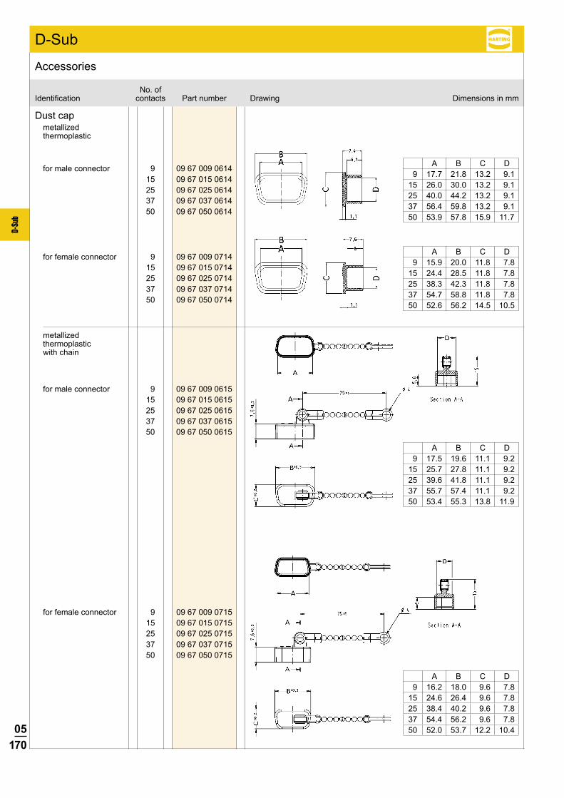
05170
D-Su
b
9 09 67 009 0714 15 09 67 015 0714 25 09 67 025 0714 37 09 67 037 0714 50 09 67 050 0714
9 09 67 009 0715 15 09 67 015 0715 25 09 67 025 0715 37 09 67 037 0715 50 09 67 050 0715
9 09 67 009 0614 15 09 67 015 0614 25 09 67 025 0614 37 09 67 037 0614 50 09 67 050 0614
9 09 67 009 0615 15 09 67 015 0615 25 09 67 025 0615 37 09 67 037 0615 50 09 67 050 0615
Dust capmetallized thermoplastic
No. ofIdentification contacts Part number Drawing Dimensions in mm
Accessories
D-Sub
A B C D 9 17.7 21.8 13.2 9.115 26.0 30.0 13.2 9.125 40.0 44.2 13.2 9.137 56.4 59.8 13.2 9.150 53.9 57.8 15.9 11.7
A B C D 9 17.5 19.6 11.1 9.215 25.7 27.8 11.1 9.225 39.6 41.8 11.1 9.237 55.7 57.4 11.1 9.250 53.4 55.3 13.8 11.9
A B C D 9 15.9 20.0 11.8 7.815 24.4 28.5 11.8 7.825 38.3 42.3 11.8 7.837 54.7 58.8 11.8 7.850 52.6 56.2 14.5 10.5
A B C D 9 16.2 18.0 9.6 7.815 24.6 26.4 9.6 7.825 38.4 40.2 9.6 7.837 54.4 56.2 9.6 7.850 52.0 53.7 12.2 10.4
metallized thermoplastic with chain
for male connector
for male connector
for female connector
for female connector

05171
D-Su
b
M FM F
M F
M F M F
D-Sub Standard press-in connectors Technical characteristics
Current carrying capacityThe current carrying capacity is limited by maximum temperature of materials for inserts and contacts including terminals.The current capacity-curve is valid for continuous, not interrupted current-loaded contacts of connectors when simultaneous power on all contacts is given, without exceeding the maximum tempera-ture.
Control and test procedures according to DIN IEC 60 512.
Contact arrangement View from termination side
Mating conditions as per DIN 41 652
M = Male connectorF = Female connector
Wor
king
cur
rent
Ambient temperature
Example: 25 way connector➀ Stamped contacts
1) Performance level 3, 50 mating cycles, no gas test Performance level 2 as per CECC 75 301-802, 250 mating cycles, 4 days 4 mixed gas test – IEC 60 512 Performance level 1 as per CECC 75 301-802, 500 mating cycles, 10 days 4 mixed gas test – IEC 60 512
37 way 50 way
9 way15 way
25 way
Number of contacts 9, 15, 25, 37, 50 UL recognized
Working currentsee current carrying capacity chart Stamped contacts 6.5 A max.
Test voltage Ur.m.s. 1 kV
Clearance and creepage ≥1.0mm
Contact resistance ≤10mΩ Insulation resistance ≥1010Ω
Temperature range -55 OC … +125 OCThe higher temperature limit includes the local ambient and heating effect of the contacts under load
Terminations Recommended PCB through holes
Materials Mouldings and hoods Liquid Crystal Polymer (LCP)
UL 94-V0Contacts Copper alloy
Contact surface
Contact zone selectively plated acc. to performance level1)
Metal shell Plated steel
Insertion and withdrawal forceConnector on P.C.B. Press-in without grounding pins – insertion max. per contact: 120 N – withdrawal min. per contact: 20 N Press-in with grounding pins – insertion max. per grounding pin: 250 N – withdrawal min. per grounding pin: 30 N
Mating force 9way ≤30N 15way ≤50N 25way ≤83N 37way ≤123N 50way ≤167N
Signal pin Grounding pin
Tin-lead plated PCB Hole 1.15-0.03 3.15±0.025 Cu 25-75 µm 25-75 µm Sn 5-15 µm 4-10 µm Plated hole 0.94-1.09 mm 3.0-3.15 mm
Chemical Hole 1.05-0.03 3.15±0.025 tin-plated PCB Cu 25-50 µm 25-50 µm Sn 0.8-1.0 µm 0.8-1.0 µm Plated hole 1.00-1.10 mm 3.0-3.15 mm
Au / Ni plated PCB Hole 1.15-0.03 3.15±0.025 Cu 25-50 µm 25-50 µm Ni 3-7 µm 4-7 µm Au 0.05-0.12 µm 0.05-0.12 µm Plated hole 1.00-1.10 mm 3.0-3.15 mm
Silver plated PCB Hole 1.15-0.03 3.15±0.025 Cu 25-50 µm 25-50 µm Ag 0.1-0.3 µm 0.1-0.3 µm Plated hole 1.00-1.10 mm 3.0-3.15 mm
OSP Hole 1.15-0.03 3.15±0.025 copper plated PCB Cu 25-50 µm 25-50 µm Plated hole 1.00-1.10 mm 3.0-3.15 mm
PCB board thickness: ≥1.6 mm

05172
D-Su
b
D-Sub DIN 41 652 · CECC 75 301-802
9 09 66 164 771 . 09 66 164 671 .
15 09 66 264 771 . 09 66 264 671 .
25 09 66 364 771 . 09 66 364 671 .
9 09 66 154 751 . 09 66 154 651 .
15 09 66 254 751 . 09 66 254 651 .
25 09 66 354 751 . 09 66 354 651 .
37 09 66 454 751 . 09 66 454 651 .
9 09 66 154 751 . 09 66 154 651 .
15 09 66 254 751 . 09 66 254 651 .
25 09 66 354 751 . 09 66 354 651 .
37 09 66 454 751 . 09 66 454 651 .
50 09 66 554 751 . 09 66 554 651 .
Performance levelsExplanations see page 05.171 þOther performance levels on request
Male connectorFlange height x = 5.7 mm
metal shell with dimples
Please insert digit for flange thread or fitted female screw locks
Performance level3
Performance level2
No. ofIdentification contacts Part number
Press-in, straight with grounding press-in board locks
Number of contacts
9--50
M3 þ 5 4-40 UNC þ 6 fitted screw locks 4-40 UNC þ 71)
Female connectorFlange height x = 5.7 mm
metal shell
Please insert digit for flange thread or fitted female screw locks
M3 þ 5 4-40 UNC þ 6 fitted screw locks 4-40 UNC þ 71)
Female connectorFlange height x = 6 mm
metal shell
Please insert digit for flange thread or fitted female screw locks
M3 þ 1 4-40 UNC þ 2 fitted screw locks 4-40 UNC þ 31)
1) Fitted screw locks 4-40 UNC not normally kept in stock for performance level 3Connector dimensions see page 05.173. Mating conditions see page 05.171.
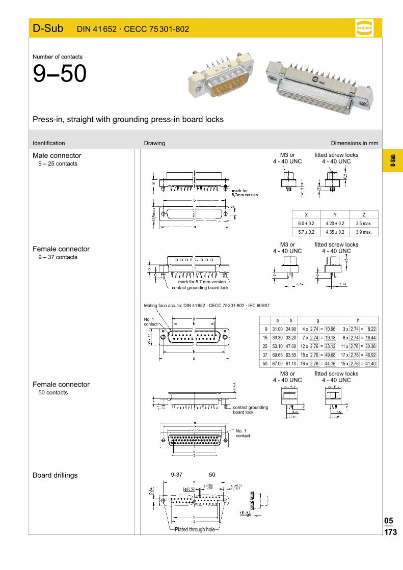
05173
D-Su
b
D-Sub DIN 41 652 · CECC 75 301-802
9-37 50
Press-in, straight with grounding press-in board locks
Number of contacts
9--50
Identification Drawing Dimensions in mm
Male connector9 – 25 contacts
Female connector9 – 37 contacts
Board drillings
a b g h
9 31.00 24.90 4 x 2.74 = 10.96 3 x 2.74 = 8.22
15 39.30 33.20 7 x 2.74 = 19.18 6 x 2.74 = 16.44
25 53.10 47.00 12 x 2.76 = 33.12 11 x 2.76 = 30.36
37 69.65 63.55 18 x 2.76 = 49.68 17 x 2.76 = 46.92
50 67.00 61.10 16 x 2.76 = 44.16 15 x 2.76 = 41.40
X Y Z
6.0 ± 0.2 4.20 ± 0.2 3.5 max.
5.7 ± 0.2 4.35 ± 0.2 3.9 max.
Female connector50 contacts
Mating face acc. to: DIN 41 652 · CECC 75 301-802 · IEC 60 807
contact grounding board lock
M3 or 4 - 40 UNC
fitted screw locks4 - 40 UNC
M3 or 4 - 40 UNC
fitted screw locks4 - 40 UNC
M3 or 4 - 40 UNC
fitted screw locks4 - 40 UNC
mark for 5.7 mm version
No. 1 contact
No. 1 contact
contact grounding board lock
Plated through hole
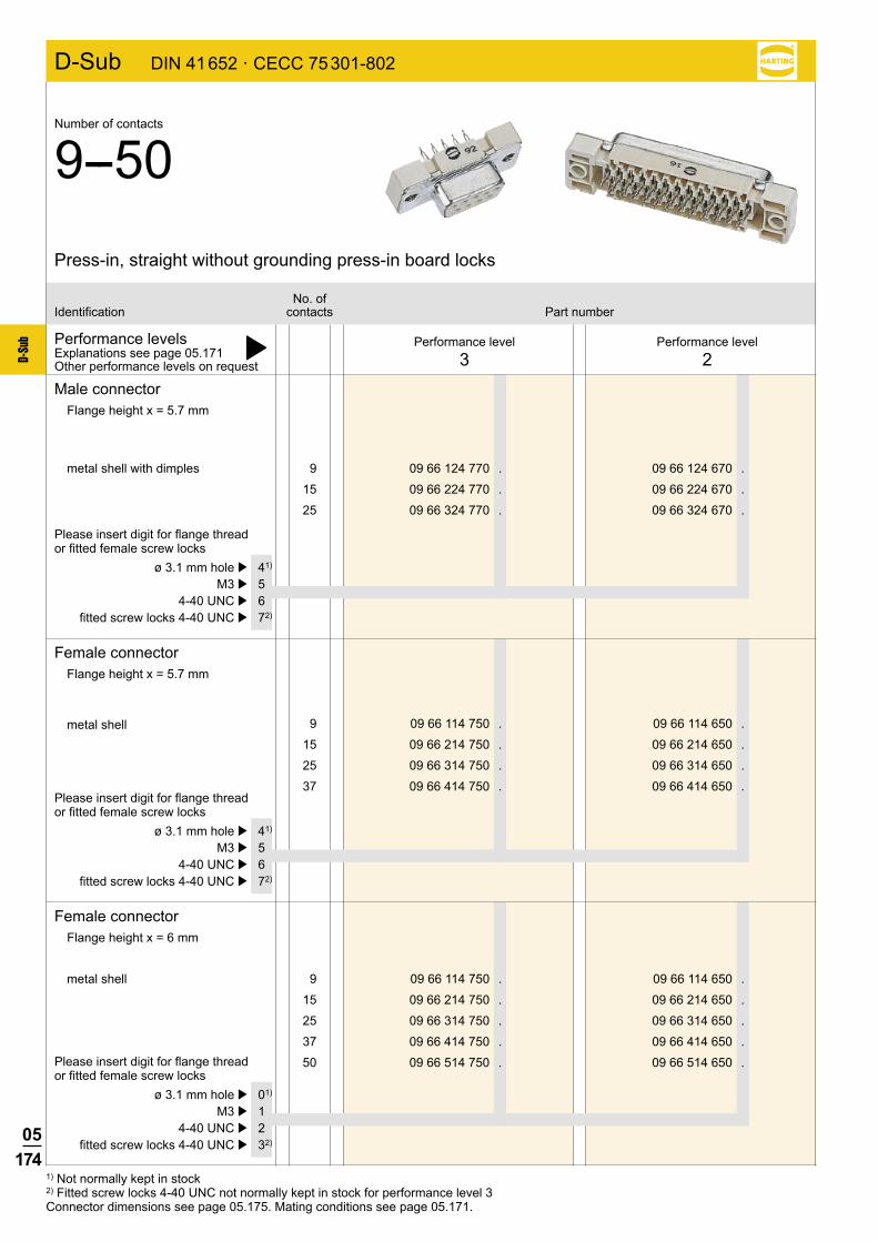
05174
D-Su
b
D-Sub DIN 41 652 · CECC 75 301-802
9 09 66 124 770 . 09 66 124 670 .
15 09 66 224 770 . 09 66 224 670 .
25 09 66 324 770 . 09 66 324 670 .
9 09 66 114 750 . 09 66 114 650 .
15 09 66 214 750 . 09 66 214 650 .
25 09 66 314 750 . 09 66 314 650 .
37 09 66 414 750 . 09 66 414 650 .
9 09 66 114 750 . 09 66 114 650 .
15 09 66 214 750 . 09 66 214 650 .
25 09 66 314 750 . 09 66 314 650 .
37 09 66 414 750 . 09 66 414 650 .
50 09 66 514 750 . 09 66 514 650 .
Performance levelsExplanations see page 05.171 þOther performance levels on request
Male connectorFlange height x = 5.7 mm
metal shell with dimples
Please insert digit for flange thread or fitted female screw locks
Performance level3
Performance level2
No. ofIdentification contacts Part number
Press-in, straight without grounding press-in board locks
Number of contacts
9--50
ø 3.1 mm hole þ 41)
M3 þ 5 4-40 UNC þ 6 fitted screw locks 4-40 UNC þ 72)
Female connectorFlange height x = 5.7 mm
metal shell
Please insert digit for flange thread or fitted female screw locks
ø 3.1 mm hole þ 41)
M3 þ 5 4-40 UNC þ 6 fitted screw locks 4-40 UNC þ 72)
Female connectorFlange height x = 6 mm
metal shell
Please insert digit for flange thread or fitted female screw locks
ø 3.1 mm hole þ 01)
M3 þ 1 4-40 UNC þ 2 fitted screw locks 4-40 UNC þ 32)
1) Not normally kept in stock2) Fitted screw locks 4-40 UNC not normally kept in stock for performance level 3Connector dimensions see page 05.175. Mating conditions see page 05.171.
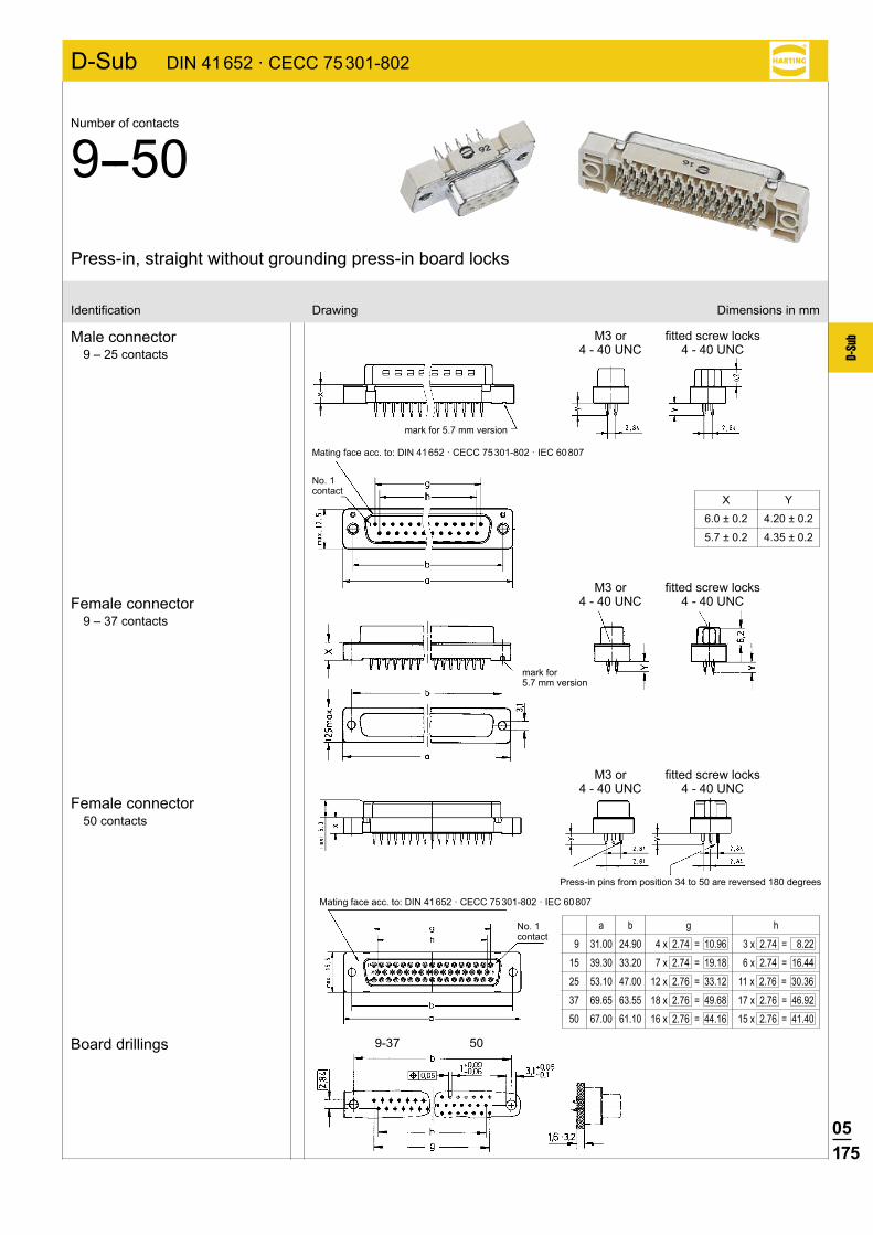
05175
D-Su
b
D-Sub DIN 41 652 · CECC 75 301-802
9-37 50
Press-in, straight without grounding press-in board locks
Number of contacts
9--50
Identification Drawing Dimensions in mm
Male connector9 – 25 contacts
Female connector9 – 37 contacts
Female connector50 contacts
Board drillings
a b g h
9 31.00 24.90 4 x 2.74 = 10.96 3 x 2.74 = 8.22
15 39.30 33.20 7 x 2.74 = 19.18 6 x 2.74 = 16.44
25 53.10 47.00 12 x 2.76 = 33.12 11 x 2.76 = 30.36
37 69.65 63.55 18 x 2.76 = 49.68 17 x 2.76 = 46.92
50 67.00 61.10 16 x 2.76 = 44.16 15 x 2.76 = 41.40
X Y
6.0 ± 0.2 4.20 ± 0.2
5.7 ± 0.2 4.35 ± 0.2
Press-in pins from position 34 to 50 are reversed 180 degrees
M3 or 4 - 40 UNC
fitted screw locks4 - 40 UNC
No. 1 contact
M3 or 4 - 40 UNC
fitted screw locks4 - 40 UNC
M3 or 4 - 40 UNC
fitted screw locks4 - 40 UNC
Mating face acc. to: DIN 41 652 · CECC 75 301-802 · IEC 60 807
Mating face acc. to: DIN 41 652 · CECC 75 301-802 · IEC 60 807
mark for 5.7 mm version
No. 1 contact
mark for 5.7 mm version
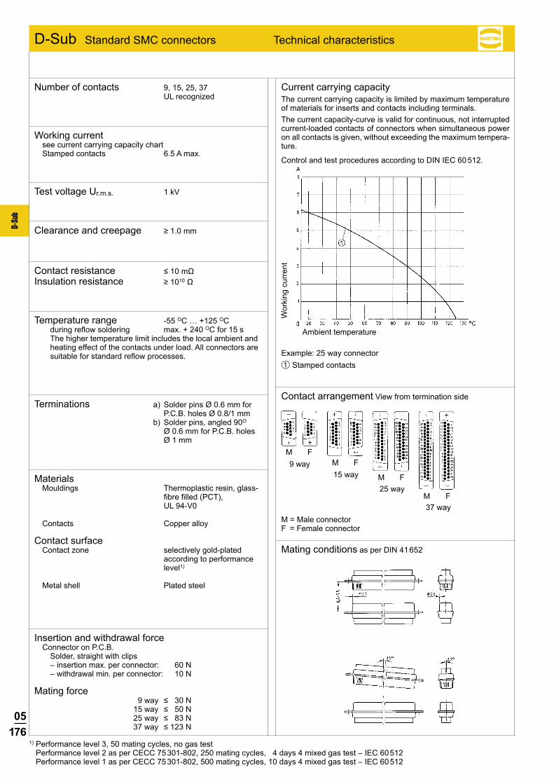
05176
D-Su
b
M FM F
M F
M F
D-Sub Standard SMC connectors Technical characteristics
Current carrying capacityThe current carrying capacity is limited by maximum temperature of materials for inserts and contacts including terminals.The current capacity-curve is valid for continuous, not interrupted current-loaded contacts of connectors when simultaneous power on all contacts is given, without exceeding the maximum tempera-ture.
Control and test procedures according to DIN IEC 60 512.
Contact arrangement View from termination side
Mating conditions as per DIN 41 652
M = Male connectorF = Female connector
37 way
Wor
king
cur
rent
Ambient temperature
Example: 25 way connector➀ Stamped contacts
1) Performance level 3, 50 mating cycles, no gas test Performance level 2 as per CECC 75 301-802, 250 mating cycles, 4 days 4 mixed gas test – IEC 60 512 Performance level 1 as per CECC 75 301-802, 500 mating cycles, 10 days 4 mixed gas test – IEC 60 512
9 way15 way
25 way
Number of contacts 9, 15, 25, 37 UL recognized
Working currentsee current carrying capacity chart Stamped contacts 6.5 A max.
Test voltage Ur.m.s. 1 kV
Clearance and creepage ≥1.0mm
Contact resistance ≤10mΩ Insulation resistance ≥1010Ω
Temperature range -55 OC … +125 OC during reflow soldering max. + 240 OC for 15 s
The higher temperature limit includes the local ambient and heating effect of the contacts under load. All connectors are suitable for standard reflow processes.
Terminations a) Solder pins Ø 0.6 mm for P.C.B. holes Ø 0.8/1 mm
b) Solder pins, angled 90O Ø 0.6 mm for P.C.B. holes Ø 1 mm
Materials Mouldings Thermoplastic resin, glass-
fibre filled (PCT), UL 94-V0
Contacts Copper alloy
Contact surface Contact zone selectively gold-plated
according to performance level1)
Metal shell Plated steel
Insertion and withdrawal forceConnector on P.C.B. Solder, straight with clips – insertion max. per connector: 60 N – withdrawal min. per connector: 10 N
Mating force 9way ≤30N 15way ≤50N 25way ≤83N 37way ≤123N
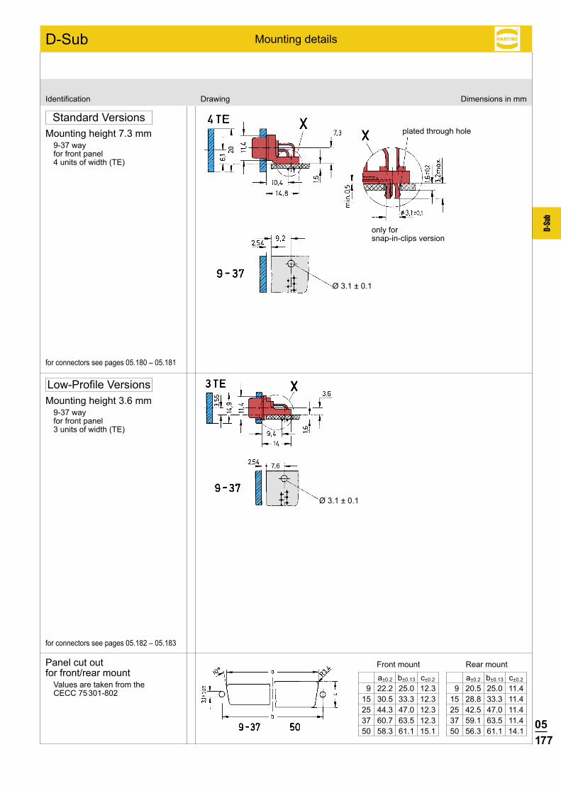
05177
D-Su
b
D-Sub
7,6
Identification Drawing Dimensions in mm
Mounting details
Standard VersionsMounting height 7.3 mm
9-37 wayfor front panel4 units of width (TE)
for connectors see pages 05.180 – 05.181
Low-Profile VersionsMounting height 3.6 mm
9-37 wayfor front panel3 units of width (TE)
for connectors see pages 05.182 – 05.183
Ø 3.1 ± 0.1
Ø 3.1 ± 0.1
plated through hole
only forsnap-in-clips version
Panel cut out for front/rear mount
Values are taken from the CECC 75 301-802
a±0.2 b±0.13 c±0.2
9 20.5 25.0 11.4 15 28.8 33.3 11.4 25 42.5 47.0 11.4 37 59.1 63.5 11.4 50 56.3 61.1 14.1
a±0.2 b±0.13 c±0.2
9 22.2 25.0 12.3 15 30.5 33.3 12.3 25 44.3 47.0 12.3 37 60.7 63.5 12.3 50 58.3 61.1 15.1
Front mount Rear mount
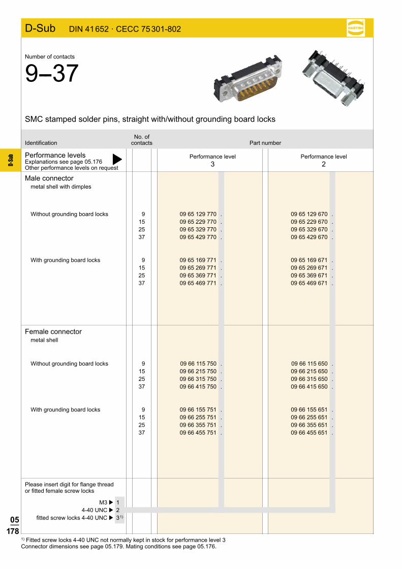
05178
D-Su
b
D-Sub DIN 41 652 · CECC 75 301-802
9 09 66 115 750 . 09 66 115 650 . 15 09 66 215 750 . 09 66 215 650 . 25 09 66 315 750 . 09 66 315 650 . 37 09 66 415 750 . 09 66 415 650 .
9 09 66 155 751 . 09 66 155 651 . 15 09 66 255 751 . 09 66 255 651 . 25 09 66 355 751 . 09 66 355 651 . 37 09 66 455 751 . 09 66 455 651 .
9 09 65 129 770 . 09 65 129 670 . 15 09 65 229 770 . 09 65 229 670 . 25 09 65 329 770 . 09 65 329 670 . 37 09 65 429 770 . 09 65 429 670 .
9 09 65 169 771 . 09 65 169 671 . 15 09 65 269 771 . 09 65 269 671 . 25 09 65 369 771 . 09 65 369 671 . 37 09 65 469 771 . 09 65 469 671 .
1) Fitted screw locks 4-40 UNC not normally kept in stock for performance level 3Connector dimensions see page 05.179. Mating conditions see page 05.176.
Performance levelsExplanations see page 05.176 þOther performance levels on request
Male connectormetal shell with dimples
Female connectormetal shell
Please insert digit for flange thread or fitted female screw locks
Performance level3
Performance level2
No. ofIdentification contacts Part number
SMC stamped solder pins, straight with/without grounding board locks
Number of contacts
9--37
Without grounding board locks
With grounding board locks
Without grounding board locks
With grounding board locks
M3 þ 1 4-40 UNC þ 2 fitted screw locks 4-40 UNC þ 3 1)

05179
D-Su
b
D-Sub DIN 41 652 · CECC 75 301-802
Identification Drawing Dimensions in mm
Male connector
Female connector
Board drillings
SMC stamped solder pins, straight with/without grounding board locks
Number of contacts
9--37
a b±0.1 c g h
9 30.9 25.0 12.5 4 x 2.74 = 10.96 3 x 2.74 = 8.22
15 39.2 33.3 12.5 7 x 2.74 = 19.18 6 x 2.74 = 16.44
25 53.1 47.0 12.5 12 x 2.76 = 33.12 11 x 2.76 = 30.36
37 69.4 63.5 12.5 18 x 2.76 = 49.68 17 x 2.76 = 46.92
Mating face acc. to: DIN 41 652 · CECC 75 301-802 IEC 60 807No. 1
contact
Nut thread
Mating face acc. to: DIN 41 652 · CECC 75 301-802 · IEC 60 807No. 1 contact
Nut thread
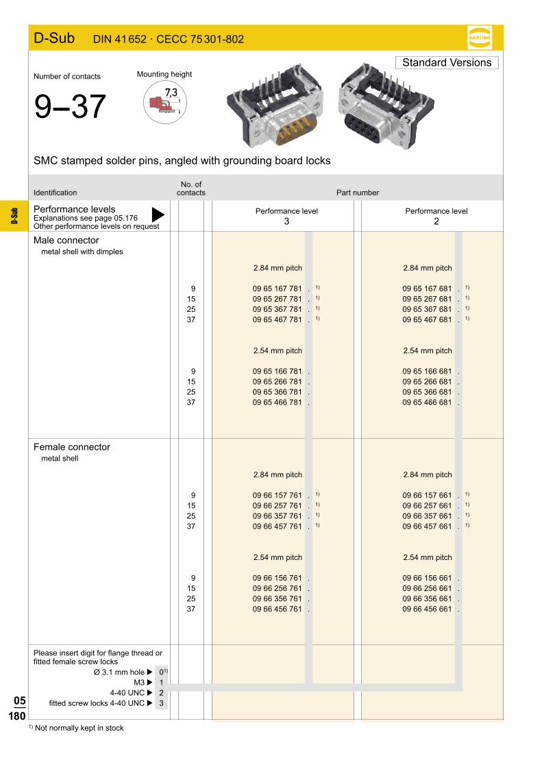
05180
D-Su
b
D-Sub DIN 41 652 · CECC 75 301-802
9 09 66 157 761 . 1) 09 66 157 661 . 1)
15 09 66 257 761 . 1) 09 66 257 661 . 1)
25 09 66 357 761 . 1) 09 66 357 661 . 1)
37 09 66 457 761 . 1) 09 66 457 661 . 1)
9 09 66 156 761 . 09 66 156 661 . 15 09 66 256 761 . 09 66 256 661 . 25 09 66 356 761 . 09 66 356 661 . 37 09 66 456 761 . 09 66 456 661 .
9 09 65 167 781 . 1) 09 65 167 681 . 1)
15 09 65 267 781 . 1) 09 65 267 681 . 1)
25 09 65 367 781 . 1) 09 65 367 681 . 1)
37 09 65 467 781 . 1) 09 65 467 681 . 1)
9 09 65 166 781 . 09 65 166 681 . 15 09 65 266 781 . 09 65 266 681 . 25 09 65 366 781 . 09 65 366 681 . 37 09 65 466 781 . 09 65 466 681 .
1) Not normally kept in stock
Performance levelsExplanations see page 05.176 þOther performance levels on request
Male connectormetal shell with dimples
Female connectormetal shell
Please insert digit for flange thread or fitted female screw locks
Performance level3
Performance level2
No. ofIdentification contacts Part number
SMC stamped solder pins, angled with grounding board locks
Number of contacts
9--37Mounting height
2.84 mm pitch 2.84 mm pitch
2.54 mm pitch 2.54 mm pitch
2.84 mm pitch 2.84 mm pitch
2.54 mm pitch 2.54 mm pitch
Ø 3.1 mm hole þ 01)
M3 þ 1 4-40 UNC þ 2 fitted screw locks 4-40 UNC þ 3
Standard Versions
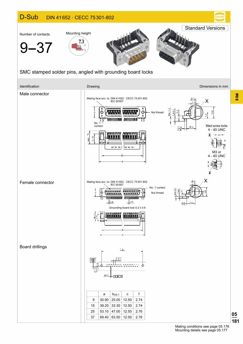
05181
D-Su
b
X
X
D-Sub DIN 41 652 · CECC 75 301-802
a b±0.1 c f
9 30.90 25.00 12.50 2.74
15 39.20 33.30 12.50 2.74
25 53.10 47.00 12.50 2.76
37 69.40 63.50 12.50 2.76
Male connector
Female connector
Board drillings
Identification Drawing Dimensions in mm
Mating conditions see page 05.176Mounting details see page 05.177
Mating face acc. to: DIN 41 652 · CECC 75 301-802 IEC 60 807
No. 1 contact
Grounding board lock 0.2 x 0.6
Mating face acc. to: DIN 41 652 · CECC 75 301-802 IEC 60 807
Nut thread
Nut thread
No. 1 contact fitted screw locks
4 - 40 UNC
M3 or 4 - 40 UNC
SMC stamped solder pins, angled with grounding board locks
Standard VersionsNumber of contacts
9--37Mounting height

05182
D-Su
b
9 09 66 156 761 . 09 66 156 661 . 15 09 66 256 761 . 09 66 256 661 . 25 09 66 356 761 . 09 66 356 661 . 37 09 66 456 761 . 09 66 456 661 .
9 09 65 166 781 . 09 65 166 681 . 15 09 65 266 781 . 09 65 266 681 . 25 09 65 366 781 . 09 65 366 681 . 37 09 65 466 781 . 09 65 466 681 .
D-Sub DIN 41 652 · CECC 75 301-802
Performance levelsExplanations see page 05.176 þOther contact surfaces on request
Male connectormetal shell with dimples
Female connectormetal shell
Please insert digit for flange thread or fitted female screw locks
Performance level3
Performance level2
No. ofIdentification contacts Part number
M3 þ 5 4-40 UNC þ 6 fitted screw locks 4-40 UNC þ 7
SMC stamped solder pins, angled with grounding board locks
Number of contacts
9--37Mounting height
Low-Profile Versions
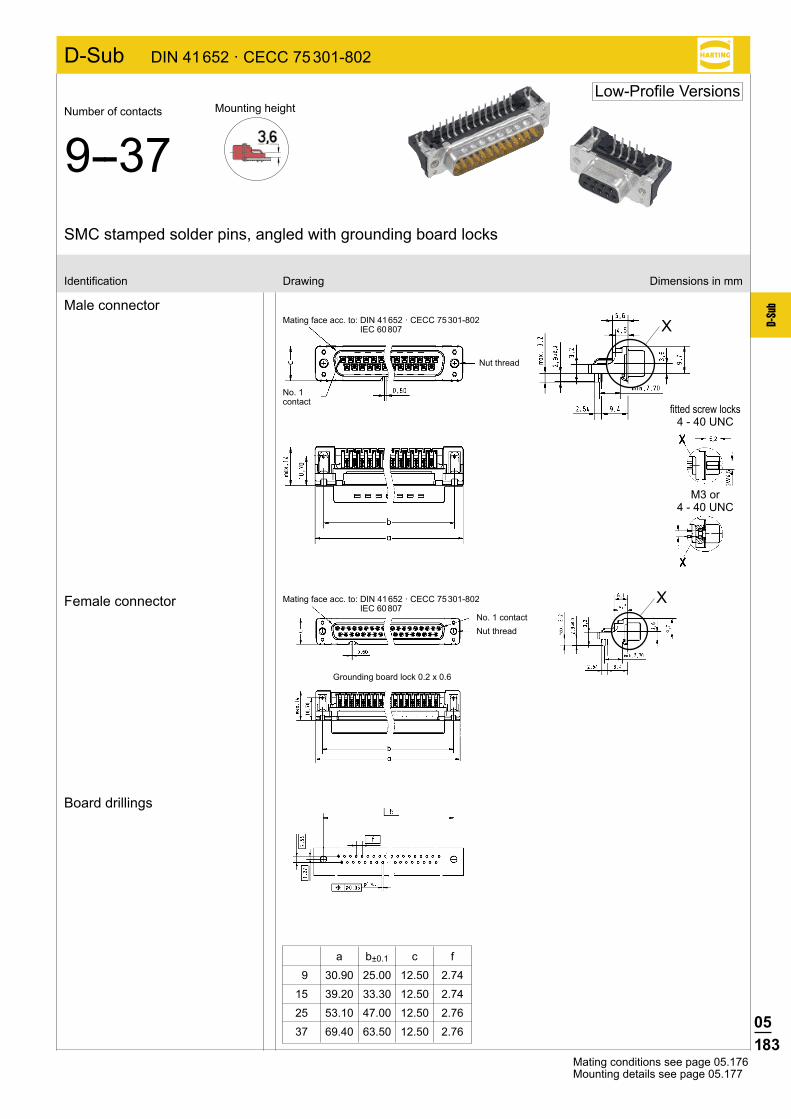
05183
D-Su
b
D-Sub DIN 41 652 · CECC 75 301-802
X
X
a b±0.1 c f
9 30.90 25.00 12.50 2.74
15 39.20 33.30 12.50 2.74
25 53.10 47.00 12.50 2.76
37 69.40 63.50 12.50 2.76
Male connector
Female connector
Board drillings
Identification Drawing Dimensions in mm
Mating conditions see page 05.176Mounting details see page 05.177
Mating face acc. to: DIN 41 652 · CECC 75 301-802 IEC 60 807
No. 1 contact
Grounding board lock 0.2 x 0.6
Mating face acc. to: DIN 41 652 · CECC 75 301-802 IEC 60 807
Nut thread
Nut thread
No. 1 contact
SMC stamped solder pins, angled with grounding board locks
Number of contacts
9--37Mounting height
Low-Profile Versions
fitted screw locks4 - 40 UNC
M3 or 4 - 40 UNC
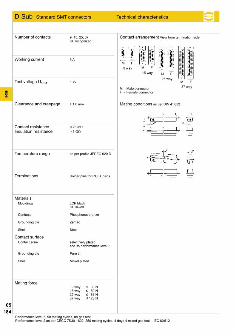
05184
D-Su
b
M FM F
M F
M F
D-Sub Standard SMT connectors Technical characteristics
Contact arrangement View from termination side
Mating conditions as per DIN 41 652
1) Performance level 3, 50 mating cycles, no gas test Performance level 2 as per CECC 75 301-802, 250 mating cycles, 4 days 4 mixed gas test – IEC 60 512
M = Male connectorF = Female connector
37 way
9 way15 way
25 way
Number of contacts 9, 15, 25, 37 UL recognized
Mating force 9way ≤30N 15way ≤50N 25way ≤83N 37way ≤123N
Materials Mouldings LCP black
UL 94-V0
Contacts Phosphorus bronze
Grounding die Zamac
Shell Steel
Contact surface Contact zone selectively plated
acc. to performance level1)
Grounding die Pure tin
Shell Nickel plated
Terminations Solder pins for P.C.B. pads
Temperature range as per profile JEDEC 020 D
Contact resistance <25mΩ Insulation resistance >5GΩ
Clearance and creepage ≥1.0mm
Test voltage Ur.m.s. 1 kV
Working current 5 A

05185
D-Su
b
Notes

05186
D-Su
b
9 09 55 166 78 . . 741 09 55 166 68 . . 741 15 09 55 266 78 . . 741 09 55 266 68 . . 741 25 09 55 366 78 . . 741 09 55 366 68 . . 741 37 09 55 466 78 . . 741 09 55 466 68 . . 741
9 09 55 166 68 . . 333 15 09 55 266 68 . . 333 25 09 55 366 68 . . 333 37 09 55 466 68 . . 333
9 09 55 156 76 . . 741 09 55 156 66 . . 741 15 09 55 256 76 . . 741 09 55 256 66 . . 741 25 09 55 356 76 . . 741 09 55 356 66 . . 741 37 09 55 456 76 . . 741 09 55 456 66 . . 741
9 09 55 156 66 . . 333 15 09 55 256 66 . . 333 25 09 55 356 66 . . 333 37 09 55 456 66 . . 333
Connector dimensions see page 05.187. Mating conditions see page 05.184.
Performance levelsExplanations see page 05.184 þOther performance levels on request
Male connectormetal shell with dimples
Male connectormetal shell with dimples
Please insert digit for flange thread or fitted female screw locks
Please insert digit for flange thread or fitted female screw locks
No. ofIdentification contacts Part number
SMT stamped solder pins, angled with grounding dies
Samples
Number of contacts
9–37
M3 þ 11 4-40 UNC þ 12 non-removable fitted screw locks M3 þ 21 non-removable fitted screw locks 4-40 UNC þ 22
4-40 UNC þ 12 non-removable fitted screw locks 4-40 UNC þ 22
Female connectormetal shell
Female connectormetal shell
Standard Versions
D-Sub
Performance level3
Performance level2
Packaging: 140 pieces on a reel
If performance level 3 is required
please order as substitute performance level 2
Packaging 9, 15 contacts: 5 samples 25, 37 contacts: 3 samples
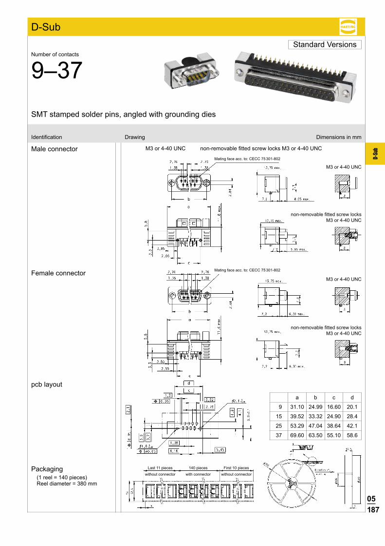
05187
D-Su
b
SMT stamped solder pins, angled with grounding dies
Identification Drawing Dimensions in mm
Male connector
Female connector
Packaging(1 reel = 140 pieces) Reel diameter = 380 mm
Number of contacts
9–37Standard Versions
pcb layout
M3 or 4-40 UNC non-removablefittedscrewlocksM3or4-40UNC
M3 or 4-40 UNC
non-removablefittedscrewlocks M3 or 4-40 UNC
M3 or 4-40 UNC
non-removablefittedscrewlocks M3 or 4-40 UNC
Mating face acc. to: CECC 75 301-802
Mating face acc. to: CECC 75 301-802
Last 11 pieceswithout connector
140 pieceswith connector
First 10 pieceswithout connector
D-Sub
a b c d
9 31.10 24.99 16.60 20.1
15 39.52 33.32 24.90 28.4
25 53.29 47.04 38.64 42.1
37 69.60 63.50 55.10 58.6

05188
D-Su
b
9 09 55 166 78 . . 741 09 55 166 68 . . 741 15 09 55 266 78 . . 741 09 55 266 68 . . 741 25 09 55 366 78 . . 741 09 55 366 68 . . 741 37 09 55 466 78 . . 741 09 55 466 68 . . 741
9 09 55 166 68 . . 333 15 09 55 266 68 . . 333 25 09 55 366 68 . . 333 37 09 55 466 68 . . 333
9 09 55 156 76 . . 741 09 55 156 66 . . 741 15 09 55 256 76 . . 741 09 55 256 66 . . 741 25 09 55 356 76 . . 741 09 55 356 66 . . 741 37 09 55 456 76 . . 741 09 55 456 66 . . 741
9 09 55 156 66 . . 333 15 09 55 256 66 . . 333 25 09 55 356 66 . . 333 37 09 55 456 66 . . 333
Number of contacts
9–37Low-Profile Versions
Connector dimensions see page 05.189. Mating conditions see page 05.184.
Performance levelsExplanations see page 05.184 þOther performance levels on request
Male connectormetal shell with dimples
Male connectormetal shell with dimples
Please insert digit for flange thread or fitted female screw locks
Please insert digit for flange thread or fitted female screw locks
No. ofIdentification contacts Part number
M3 þ 15 4-40 UNC þ 16 non-removable fitted screw locks M3 þ 19 non-removable fitted screw locks 4-40 UNC þ 20
4-40 UNC þ 16 non-removable fitted screw locks 4-40 UNC þ 20
Female connectormetal shell
Female connectormetal shell
D-Sub
Performance level3
Performance level2
Packaging: 160 pieces on a reel
If performance level 3 is required
please order as substitute performance level 2
Packaging 9, 15 contacts: 5 samples 25, 37 contacts: 3 samples
Samples
SMT stamped solder pins, angled with grounding dies

05189
D-Su
b
Identification Drawing Dimensions in mm
Male connector
Female connector
Packaging(1 reel = 160 pieces) Reel diameter = 330 mm
pcb layout
M3 or 4-40 UNCMating face acc. to: CECC 75 301-802
Mating face acc. to: CECC 75 301-802
Last 11 pieceswithout connector
160 pieceswith connector
First 10 pieceswithout connector
Number of contacts
9–37Low-Profile Versions
Both holes
M3 or 4-40 UNC
D-Sub
non-removablefittedscrewlocksM3or4-40UNC
non-removablefittedscrewlocks M3 or 4-40 UNC
M3 or 4-40 UNC
non-removablefittedscrewlocks M3 or 4-40 UNC
a b c d
9 31.10 24.99 16.60 20.1
15 39.52 33.32 24.90 28.4
25 53.29 47.04 38.64 42.1
37 69.60 63.50 55.10 58.6
SMT stamped solder pins, angled with grounding dies
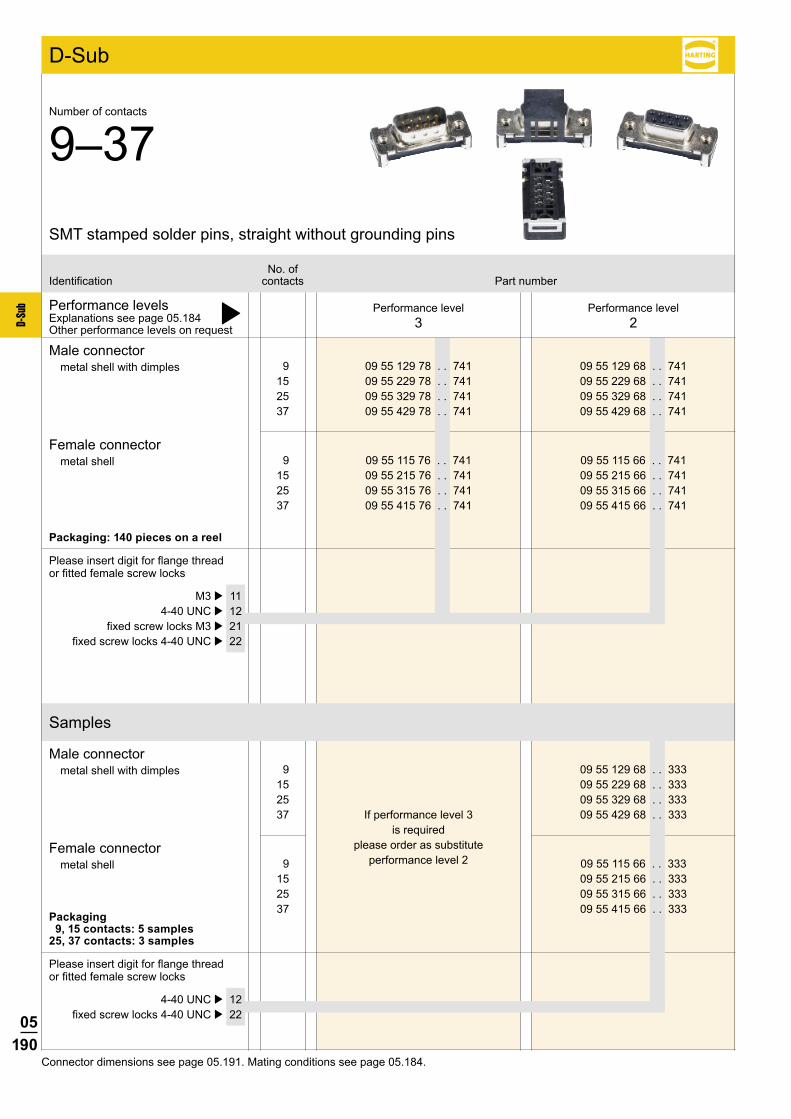
05190
D-Su
b
9 09 55 129 78 . . 741 09 55 129 68 . . 741 15 09 55 229 78 . . 741 09 55 229 68 . . 741 25 09 55 329 78 . . 741 09 55 329 68 . . 741 37 09 55 429 78 . . 741 09 55 429 68 . . 741
9 09 55 129 68 . . 333 15 09 55 229 68 . . 333 25 09 55 329 68 . . 333 37 09 55 429 68 . . 333
9 09 55 115 76 . . 741 09 55 115 66 . . 741 15 09 55 215 76 . . 741 09 55 215 66 . . 741 25 09 55 315 76 . . 741 09 55 315 66 . . 741 37 09 55 415 76 . . 741 09 55 415 66 . . 741
9 09 55 115 66 . . 333 15 09 55 215 66 . . 333 25 09 55 315 66 . . 333 37 09 55 415 66 . . 333
Connector dimensions see page 05.191. Mating conditions see page 05.184.
SMT stamped solder pins, straight without grounding pins
Number of contacts
9–37
Performance levelsExplanations see page 05.184 þOther performance levels on request
Male connectormetal shell with dimples
Male connectormetal shell with dimples
Please insert digit for flange thread or fitted female screw locks
Please insert digit for flange thread or fitted female screw locks
No. ofIdentification contacts Part number
M3 þ 11 4-40 UNC þ 12 fixed screw locks M3 þ 21 fixed screw locks 4-40 UNC þ 22
4-40 UNC þ 12 fixed screw locks 4-40 UNC þ 22
Female connectormetal shell
Female connectormetal shell
D-Sub
Performance level3
Performance level2
Packaging: 140 pieces on a reel
If performance level 3 is required
please order as substitute performance level 2
Packaging 9, 15 contacts: 5 samples 25, 37 contacts: 3 samples
Samples

05191
D-Su
b
Identification Drawing Dimensions in mm
Male connector
Female connector
Packaging(1 reel = 140 pieces) Reel diameter = 380 mm
SMT stamped solder pins, straight without grounding pins
Number of contacts
9–37
pcb layout
D-Sub
a b c d
9 31.12 25.00 25.0 31.8
15 39.45 33.33 33.3 40.1
25 53.35 47.04 47.0 53.8
37 69.62 63.50 63.5 70.3
M3 or 4-40 UNC non-removablefittedscrew locks M3 or 4-40 UNC
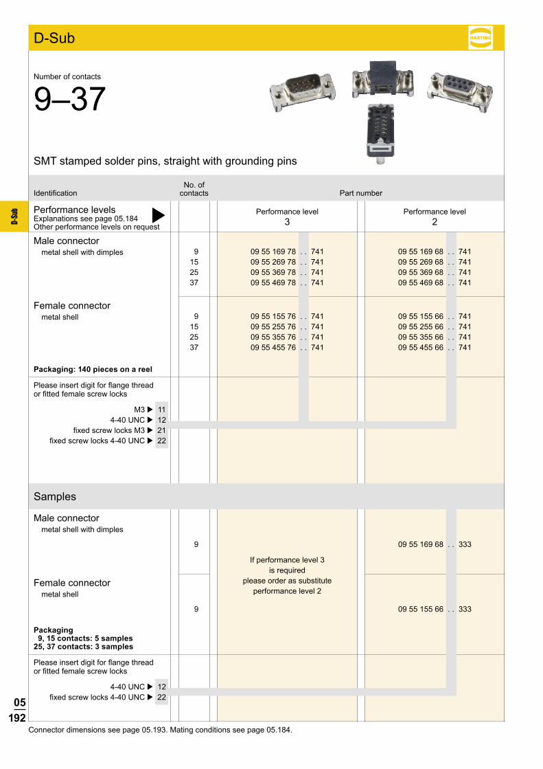
05192
D-Su
b
9 09 55 169 78 . . 741 09 55 169 68 . . 741 15 09 55 269 78 . . 741 09 55 269 68 . . 741 25 09 55 369 78 . . 741 09 55 369 68 . . 741 37 09 55 469 78 . . 741 09 55 469 68 . . 741
9 09 55 169 68 . . 333
9 09 55 155 76 . . 741 09 55 155 66 . . 741 15 09 55 255 76 . . 741 09 55 255 66 . . 741 25 09 55 355 76 . . 741 09 55 355 66 . . 741 37 09 55 455 76 . . 741 09 55 455 66 . . 741
9 09 55 155 66 . . 333
Connector dimensions see page 05.193. Mating conditions see page 05.184.
SMT stamped solder pins, straight with grounding pins
Number of contacts
9–37
Performance levelsExplanations see page 05.184 þOther performance levels on request
Male connectormetal shell with dimples
Male connectormetal shell with dimples
Please insert digit for flange thread or fitted female screw locks
Please insert digit for flange thread or fitted female screw locks
No. ofIdentification contacts Part number
M3 þ 11 4-40 UNC þ 12 fixed screw locks M3 þ 21 fixed screw locks 4-40 UNC þ 22
4-40 UNC þ 12 fixed screw locks 4-40 UNC þ 22
Female connectormetal shell
Female connectormetal shell
D-Sub
Performance level3
Performance level2
Packaging: 140 pieces on a reel
If performance level 3 is required
please order as substitute performance level 2
Packaging 9, 15 contacts: 5 samples 25, 37 contacts: 3 samples
Samples
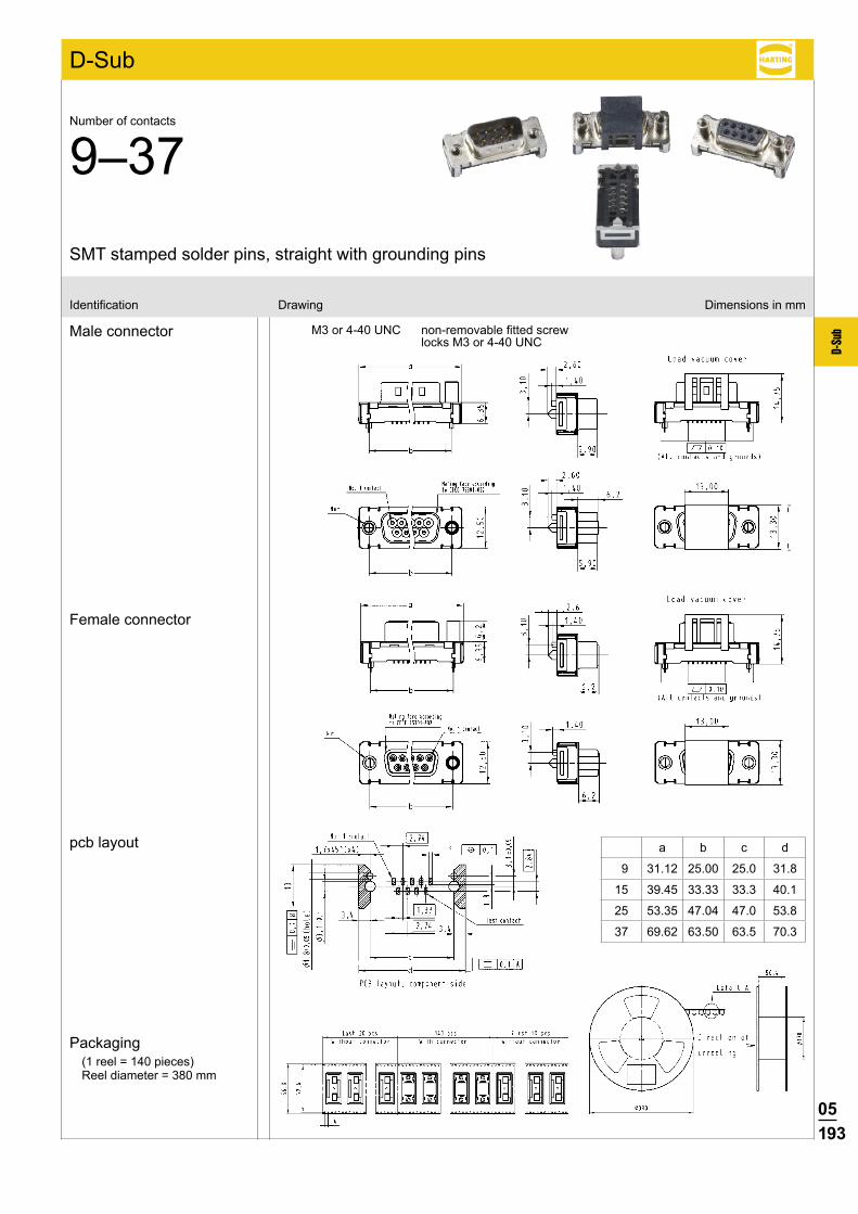
05193
D-Su
b
Identification Drawing Dimensions in mm
Male connector
Female connector
Packaging(1 reel = 140 pieces) Reel diameter = 380 mm
SMT stamped solder pins, straight with grounding pins
Number of contacts
9–37
pcb layout
D-Sub
a b c d
9 31.12 25.00 25.0 31.8
15 39.45 33.33 33.3 40.1
25 53.35 47.04 47.0 53.8
37 69.62 63.50 63.5 70.3
M3 or 4-40 UNC non-removablefittedscrew locks M3 or 4-40 UNC
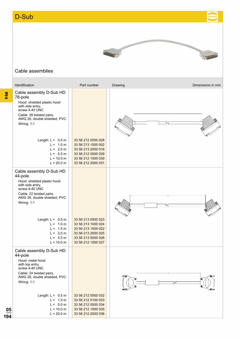
05194
D-Su
b
33 56 212 0050 028 33 56 213 1000 002 33 56 213 2000 016 33 56 212 0500 029 33 56 212 1000 030 33 56 212 2000 031
33 56 213 0500 023 33 56 213 1000 024 33 56 213 1500 022 33 56 213 2000 025 33 56 213 5000 026 33 56 212 1000 027
33 56 212 0050 032 33 56 212 0100 033 33 56 212 0500 034 33 56 212 1000 035 33 56 212 2000 036
Identification Part number Drawing Dimensions in mm
Cable assemblies
D-Sub
Cable assembly D-Sub HD 78-pole
Hood: shielded plastic hood with side entry, screw 4-40 UNCCable: 39 twisted pairs, AWG 26, double shielded, PVCWiring: 1:1
Length: L = 0.5 m L = 1.0 m L = 2.0 m L = 5.0 m L = 10.0 m L = 20.0 m
Cable assembly D-Sub HD 44-pole
Hood: shielded plastic hood with side entry, screw 4-40 UNCCable: 22 twisted pairs, AWG 26, double shielded, PVCWiring: 1:1
Length: L = 0.5 m L = 1.0 m L = 1.5 m L = 2.0 m L = 5.0 m L = 10.0 m
Cable assembly D-Sub HD 44-pole
Hood: metal hood with top entry, screw 4-40 UNCCable: 24 twisted pairs, AWG 26, double shielded, PVCWiring: 1:1
Length: L = 0.5 m L = 1.0 m L = 5.0 m L = 10.0 m L = 20.0 m

05195
D-Su
b
33 56 224 5000 001 33 56 221 0010 001 33 56 221 0020 001 33 56 221 0050 001
33 66 214 5000 058 33 66 213 1000 059 33 66 213 1500 060 33 66 213 2000 061 33 66 213 5000 062
Identification Part number Drawing Dimensions in mm
Cable assemblies
D-Sub
Cable assembly D-Sub HD 44-pole
Hood: overmoulded with side entryCable: 24 twisted pairs, solid wires, AWG 26, shielded, halogen freeWiring: 1:1
Length: L = 0.5 m L = 1.0 m L = 2.0 m L = 5.0 m
Cable assembly D-Sub 9-pole
Hood: shielded plastic hood with side entry, screw 4-40 UNCCable: 5 twisted pairs, stranded, AWG 24, shielded, PVCWiring: 1:1
Length: L = 0.5 m L = 1.0 m L = 1.5 m L = 2.0 m L = 5.0 m

05196
D-Su
b
9 09 18 009 700 15 09 18 015 700 25 09 18 025 700 37 09 18 037 700
Important: always store reel vertically
No. ofIdentification contacts Part number Drawing Dimensions in mm
Flat cablegreyUL AWM-style 2651CSA
Length per reel
30.48 m (100 feet) 1
100 m 4 (328 feet)
Conductor material _________________ Copper tinnedGauge ___________________________ AWG 28/7 0.089 mm²Voltage rating ______________________ 300 Vr.m.s.
Current rating at 25 °C ______________ 2.1 A max.Capacity unbalanced ________________ 45.9 pF/mImpedance unbalanced ______________105ΩPropagation delay __________________ 4.9 ns/m nominalInsulation material __________________ PVCTemperature rating (operating) ________ –20 °C … +105 °CTemperature rating (static) ____________ –30 °C … +105 °CFlammability rating _________________ UL: VW-1Insulation resistance ________________>100MΩ/km
greyEdge mark on first conductor
Cables for insulation displacement termination

05197
D-Su
b
9 09 18 009 7005 15 09 18 015 7005 25 09 18 025 7005 37 09 18 037 7005
Important: always store reel vertically
No. ofIdentification contacts Part number Drawing Dimensions in mm
Flat cablecolour coded
Length per reel30.48 m (100 feet)
UL AWM-style 2651
Conductor material _________________ Copper tinnedGauge ___________________________ AWG 28/7 0.09 mm²Voltage rating ______________________ 300 Vr.m.s.
Current rating at 25 °C ______________ 2.1 A max.Conductor resistance ________________221mΩ/mCapacity unbalanced ________________ 42.7 pF/mImpedance unbalanced ______________105ΩInductance unbalanced ______________ 0.68 µH/mSignal delay _______________________ 4.9 ns/mInsulation material __________________ PVCTemperature rating (operating) ________ –20 °C … +105 °CTemperature rating (static) ____________ –30 °C … +105 °CFlammability rating _________________ UL: VW 1Insulation resistance ________________100MΩ/km
Colour code sequence (in 10 steps)
brown, red, orange, yellow, green, blue, violet, grey, white, black
colour coded
Cables for insulation displacement termination

05198
D-Su
b
9 09 18 009 70 15 09 18 015 70 25 09 18 025 70 37 09 18 037 70
9 09 18 009 7008 15 09 18 015 7008 25 09 18 025 7008 37 09 18 037 7008
* Only available for 37 contactsImportant: always store reals vertically
No. ofIdentification contacts Part number Drawing Dimensions in mm
Round flat cablewith screening (shielding)
UL listed PLCC CL2 CSA certified AWM FT-1
Length per reel
30.48 m (100 feet) 07
100 m 10 * (328 feet)
without screening (shielding)
UL listed PLCC CL2 CSA certified AWM FT-1
Length per reel30.48 m (100 feet)
➀ Flat cable, AWG 28/7➁ Clear polyester➂ Outer jacket: black PVC
No. of contacts a b c 9 to 25 19.05 19.05 38.10
37 38.10 19.05 57.15
➀ Flat cable, AWG 28/7➁ Aluminium / Polyester tape (spiral wrap)➂ 85 % minimum coverage tinned copper braid➃ Outer jacket: black PVC
Edge mark on first conductor
AWG 28/7 grey
Slit section
Slit section 6.35 6.86 8.38 9.65
ø max. 6.86 7.62 9.1410.41
Conductor material _________________ Copper tinnedGauge ___________________________ AWG 28/7 0.089 mm²Voltage rating ______________________ 300 Vr.m.s.
Conductor resistance ________________225mΩ/mCapacity unbalanced ________________ 78.7 pF/mImpedance unbalanced ______________75ΩSignal delay _______________________ 5.25 ns/m nom.Insulation material __________________ PVCTemperature rating _________________ –20 °C … +105 °CFlammability rating _________________ UL: VW 1Insulation resistance ________________ 104MΩ/km
Cables for insulation displacement termination
05199
D-Su
b
Notes
Related Documents