CIVIL AND ENVIRONMENTAL ENGINEERING REPORTS ISSN 2080-5187 CEER 2014; 14 (3): 57-85 DOI: 10.1515/ceer-2014-0035 APPLICATION OF COMPOSITE STRUCTURES IN BRIDGE ENGINEERING. PROBLEMS OF CONSTRUCTION PROCESS AND STRENGTH ANALYSIS Kazimierz FLAGA, Kazimierz FURTAK 1 Cracow Uninersity of Technology, Institute of Building Engineering, Poland Abstract Steel-concrete composite structures have been used in bridge engineering from decades. This is due to rational utilisation of the strength properties of the two materials. At the same time, the reinforced concrete (or prestressed) deck slab is more favourable than the orthotropic steel plate used in steel bridges (higher mass, better vibration damping, longer life). The most commonly found in practice are composite girder bridges, particularly in highway bridges of small and medium spans, but the spans may reach over 200 m. In larger spans steel truss girders are applied. Bridge composite structures are also employed in cable-stayed bridge decks of the main girder spans of the order of 600÷800 m. The aim of the article is to present the cionstruction process and strength analysis problems concerning of this type of structures. Much attention is paid to the design and calculation of the shear connectors characteristic for the discussed objects. The authors focused mainly on the issues of single composite structures. The effect of assembly states on the stresses and strains in composite members are highlighted. A separate part of problems is devoted to the influence of rheological factors, i.e. concrete shrinkage and creep, as well as thermal factors on the stresses and strains and redistribution of internal forces. Keywords: steel-concrete composite, structures bridge, bridge desk, shrinkage, creep of concrete 1 Corresponding author: Cracow Uninersity of Technology, Institute of Building Engineering, 24 Warszawska Str., Kraków 31-155, Poland, e-mail:[email protected], tel.+48126282241

Welcome message from author
This document is posted to help you gain knowledge. Please leave a comment to let me know what you think about it! Share it to your friends and learn new things together.
Transcript

CIVIL AND ENVIRONMENTAL ENGINEERING REPORTS
ISSN 2080-5187
CEER 2014; 14 (3): 57-85 DOI: 10.1515/ceer-2014-0035
APPLICATION OF COMPOSITE STRUCTURES IN BRIDGE ENGINEERING. PROBLEMS OF CONSTRUCTION
PROCESS AND STRENGTH ANALYSIS
Kazimierz FLAGA, Kazimierz FURTAK1 Cracow Uninersity of Technology, Institute of Building Engineering, Poland
Abstract
Steel-concrete composite structures have been used in bridge engineering from decades. This is due to rational utilisation of the strength properties of the two materials. At the same time, the reinforced concrete (or prestressed) deck slab is more favourable than the orthotropic steel plate used in steel bridges (higher mass, better vibration damping, longer life). The most commonly found in practice are composite girder bridges, particularly in highway bridges of small and medium spans, but the spans may reach over 200 m. In larger spans steel truss girders are applied. Bridge composite structures are also employed in cable-stayed bridge decks of the main girder spans of the order of 600÷800 m. The aim of the article is to present the cionstruction process and strength analysis problems concerning of this type of structures. Much attention is paid to the design and calculation of the shear connectors characteristic for the discussed objects. The authors focused mainly on the issues of single composite structures. The effect of assembly states on the stresses and strains in composite members are highlighted. A separate part of problems is devoted to the influence of rheological factors, i.e. concrete shrinkage and creep, as well as thermal factors on the stresses and strains and redistribution of internal forces.
Keywords: steel-concrete composite, structures bridge, bridge desk, shrinkage, creep of concrete
1 Corresponding author: Cracow Uninersity of Technology, Institute of Building Engineering, 24 Warszawska Str., Kraków 31-155, Poland, e-mail:[email protected], tel.+48126282241
58 Kazimierz FLAGA, Kazimierz FURTAK
1. INTRODUCTION
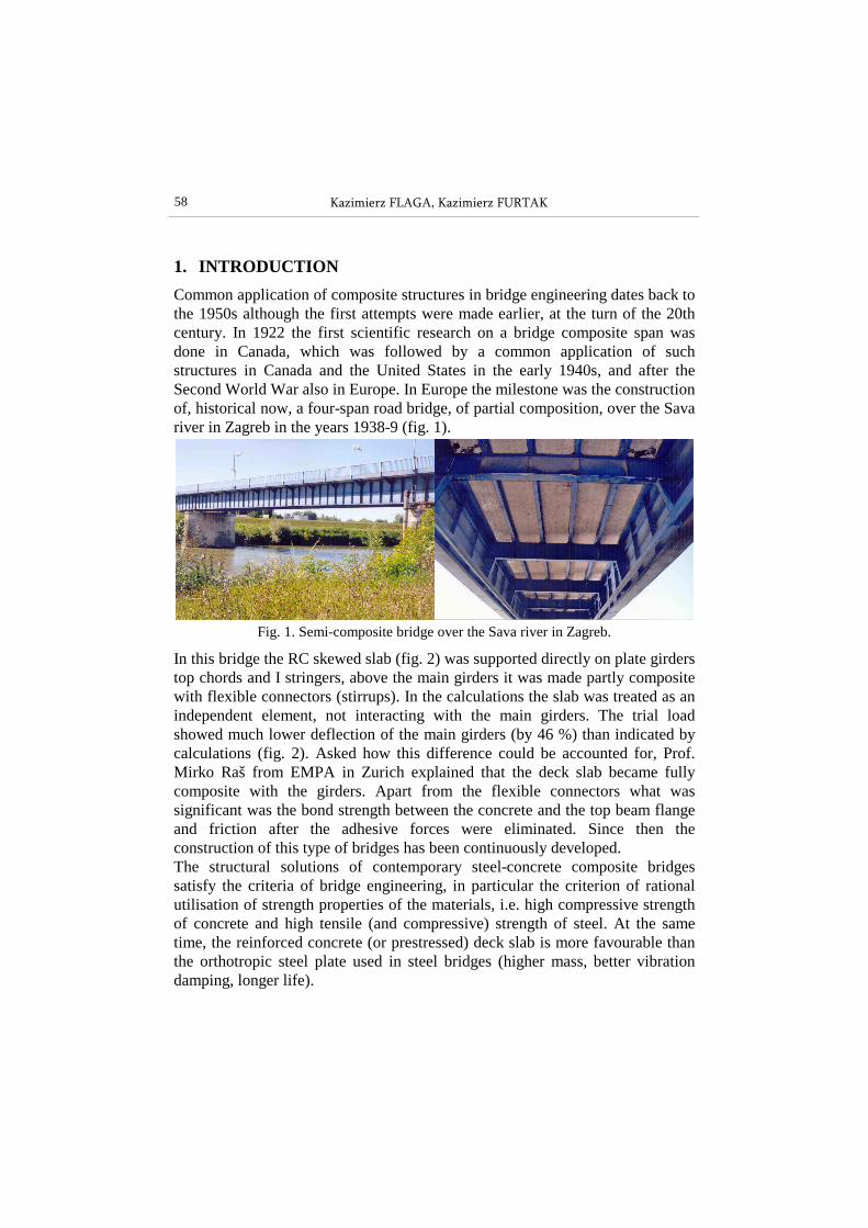
Common application of composite structures in bridge engineering dates back to the 1950s although the first attempts were made earlier, at the turn of the 20th century. In 1922 the first scientific research on a bridge composite span was done in Canada, which was followed by a common application of such structures in Canada and the United States in the early 1940s, and after the Second World War also in Europe. In Europe the milestone was the construction of, historical now, a four-span road bridge, of partial composition, over the Sava river in Zagreb in the years 1938-9 (fig. 1).
Fig. 1. Semi-composite bridge over the Sava river in Zagreb.
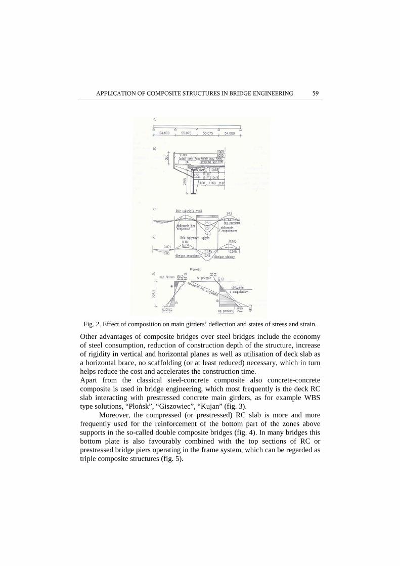
In this bridge the RC skewed slab (fig. 2) was supported directly on plate girders top chords and I stringers, above the main girders it was made partly composite with flexible connectors (stirrups). In the calculations the slab was treated as an independent element, not interacting with the main girders. The trial load showed much lower deflection of the main girders (by 46 %) than indicated by calculations (fig. 2). Asked how this difference could be accounted for, Prof. Mirko Raš from EMPA in Zurich explained that the deck slab became fully composite with the girders. Apart from the flexible connectors what was significant was the bond strength between the concrete and the top beam flange and friction after the adhesive forces were eliminated. Since then the construction of this type of bridges has been continuously developed. The structural solutions of contemporary steel-concrete composite bridges satisfy the criteria of bridge engineering, in particular the criterion of rational utilisation of strength properties of the materials, i.e. high compressive strength of concrete and high tensile (and compressive) strength of steel. At the same time, the reinforced concrete (or prestressed) deck slab is more favourable than the orthotropic steel plate used in steel bridges (higher mass, better vibration damping, longer life).
APPLICATION OF COMPOSITE STRUCTURES IN BRIDGE ENGINEERING 59
Fig. 2. Effect of composition on main girders’ deflection and states of stress and strain.
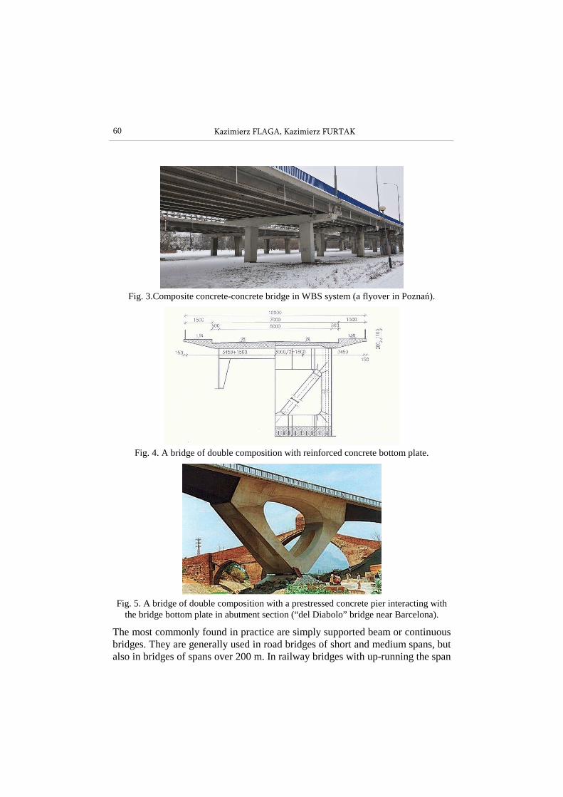
Other advantages of composite bridges over steel bridges include the economy of steel consumption, reduction of construction depth of the structure, increase of rigidity in vertical and horizontal planes as well as utilisation of deck slab as a horizontal brace, no scaffolding (or at least reduced) necessary, which in turn helps reduce the cost and accelerates the construction time. Apart from the classical steel-concrete composite also concrete-concrete composite is used in bridge engineering, which most frequently is the deck RC slab interacting with prestressed concrete main girders, as for example WBS type solutions, “Płońsk”, “Giszowiec”, “Kujan” (fig. 3).
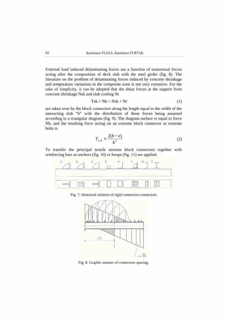
Moreover, the compressed (or prestressed) RC slab is more and more frequently used for the reinforcement of the bottom part of the zones above supports in the so-called double composite bridges (fig. 4). In many bridges this bottom plate is also favourably combined with the top sections of RC or prestressed bridge piers operating in the frame system, which can be regarded as triple composite structures (fig. 5).
60 Kazimierz FLAGA, Kazimierz FURTAK
Fig. 3.Composite concrete-concrete bridge in WBS system (a flyover in Poznań).
Fig. 4. A bridge of double composition with reinforced concrete bottom plate.
Fig. 5. A bridge of double composition with a prestressed concrete pier interacting with
the bridge bottom plate in abutment section (“del Diabolo” bridge near Barcelona).
The most commonly found in practice are simply supported beam or continuous bridges. They are generally used in road bridges of short and medium spans, but also in bridges of spans over 200 m. In railway bridges with up-running the span

APPLICATION OF COMPOSITE STRUCTURES IN BRIDGE ENGINEERING 61
can reach 80 m. At short spans the steel girders are rolled I-sections, at longer spans - plate girders of constant or variable height, at the longest spans (over 150m) truss girders. Bridge composite structures are also employed in cable-stayed bridge decks of the main girder spans of the order of 600÷800 m (fig. 6).
2. CONNECTORS
To provide a proper interaction of the deck concrete slab and the steel girder it is necessary to use connectors that integrate the two materials. This is because the sum of the concrete - steel girder flange bond is too small to transfer the shear stress (delaminating) in the contact plane, the more so that the live loads of bridges change and may induce fatigue. In the deck slab the connectors are fixed to the top flange of the steel girder, in the bottom plate - to the web plate, and infrequently, to the upper surface of the bottom flange.
Fig. 6. Cable-stayed bridge Yangpu w Shanghai with a composite deck (lmax=602m).
In the period of seventy-five year application of composite bridges the most significant changes have affected the connectors. The chief aim of research was to reduce time consumption of their fabrication and to minimise the stresses. The connectors used originally were rigid in the shape of steel block connectors (fig. 7). They provide the so-called full composite. Their height is 10÷20 cm and are welded to the steel girder flange. Their spacing results from the distribution of delaminating forces along the composite girder, these being a function of: - external loads, - concrete shrinkage, - temperature variations.
62 Kazimierz FLAGA, Kazimierz FURTAK
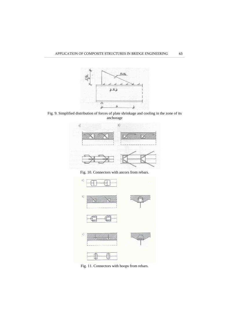
External load induced delaminating forces are a function of transversal forces acting after the composition of deck slab with the steel girder (fig. 8). The literature on the problem of delaminating forces induced by concrete shrinkage and temperature variations in the composite zone is not very extensive. For the sake of simplicity, it can be adopted that the shear forces at the support from concrete shrinkage Nsk and slab cooling Nt
Tsk = Nb = Nsk + Nt (1)
are taken over by the block connectors along the length equal to the width of the interacting slab “b” with the distribution of these forces being assumed according to a triangular diagram (fig. 9). The diagram surface is equal to force Nb, and the resulting force acting on an extreme block connector or extreme bolts is
2,1
)(2
b
ebT sk
−= (2)
To transfer the principal tensile stresses block connectors together with reinforcing bars as anchors (fig. 10) or hoops (fig. 11) are applied.
Fig. 7. Structural solution of rigid connectors connectors
Fig. 8. Graphic manner of connectors spacing.
APPLICATION OF COMPOSITE STRUCTURES IN BRIDGE ENGINEERING 63
Fig. 9. Simplified distribution of forces of plate shrinkage and cooling in the zone of its
anchorage
Fig. 10. Connectors with ancors from rebars.
Fig. 11. Connectors with hoops from rebars.

64 Kazimierz FLAGA, Kazimierz FURTAK
Fig. 12. Structural solution of flexible connectors
Another type of connectors, introduced later, but which are now used commonly, are flexible connectors. They take various forms and shapes, most frequently speigot, bolts, pins of diameter d = 8÷25 mm, (fig. 12) ended by head, hook end top. Their height is (5÷10)d. At lower values of delaminating forces
Fig. 13. Flexible connectors in the shape of anchors (a) and hoops (b).
Fig. 14. Deformation of flexible connector in ultimate limit state.

APPLICATION OF COMPOSITE STRUCTURES IN BRIDGE ENGINEERING 65
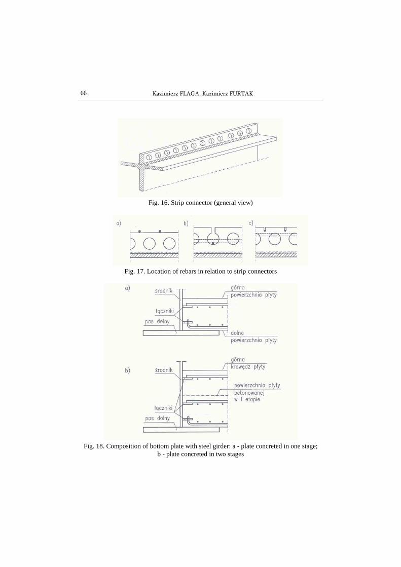
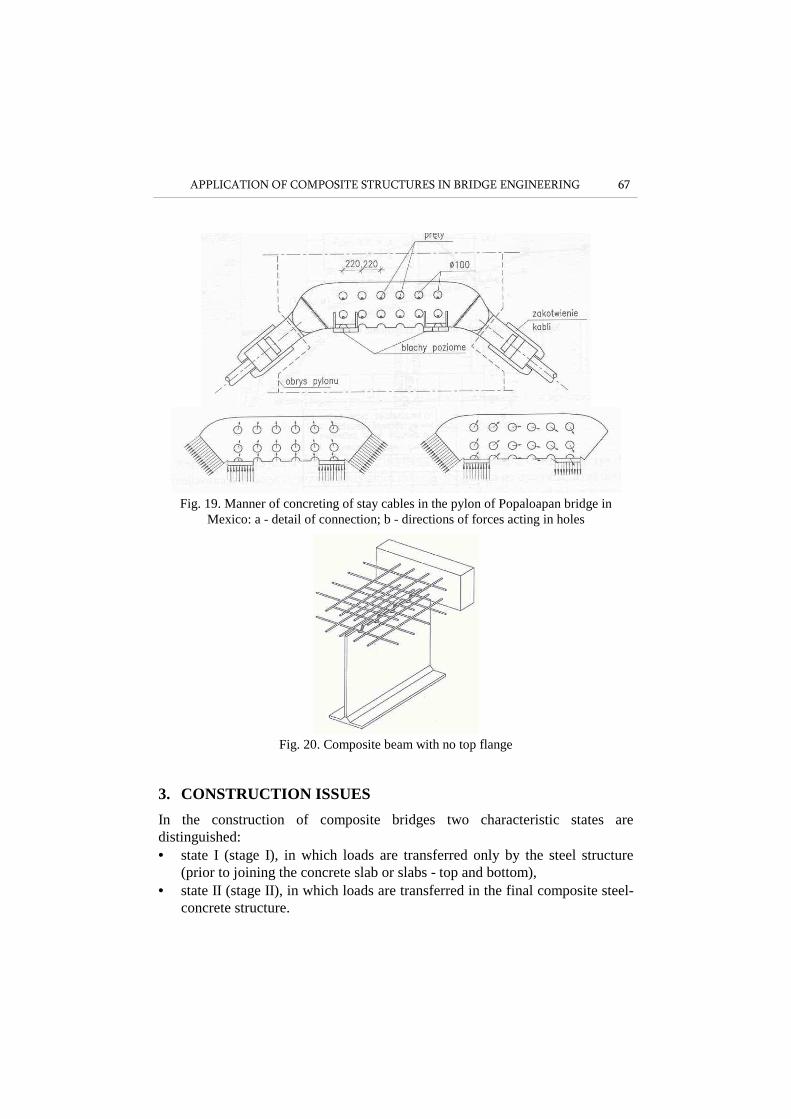
anchors or hoops from reinforcing bars are sufficient (fig. 13) The point fitting of flexible connectors does not cause significant stress or structural notches. Their main drawback is flexibility Cz = T/δ, where T denotes the force shearing the connector, and δ - a relative displacement between the concrete slab and the steel girder. This slip indicates that the principle of plane sections is not observed in the entire girder. However, the effect of slip on the useful load is so negligible that it is taken into account only in calculating deflections and disregarded in calculating the load bearing capacity. Flexible connector deformations in ultimate limit state are shown in fig. 14, the curve for shear force p vs. slip s under variable loads in fig. 15. Strip connectors (fig. 16) are the latest solution. These are steel perforated strips welded automatically to girder flanges, and the continuous longitudinal and transverse welds are more favourable than sectional longitudinal and transverse weld joining the block connectors. The application of two perfobonds is recommended to avoid the welding stress concentration above the connection of the girder top flange and the web. However, making perforations is 4 time consuming and placing the reinforcement through them is troublesome (cf. fig. 17). Strip connectors can also be used for the bottom plate - steel girder composition (cf. fig.18). There are other applications of perforated sheets in bridges, for example for the anchorage of the suspension cables in the RC pylon of the Papaloapan bridge in Mexixo (fig. 19). Similar solutions can be favourable in truss joints where the use of flexible connectors is difficult. The application of steel beams with no top flange and “embedding” the web in the deck slab (fig. 20) is troublesome during transportation and concreting the slab but it is possible now to join the deck slab and girder web in a prefabrication shop.
Fig. 15. Force P vs. slip s under variable loads: a - symmetrical loading of different signs,
b loading of one sign (pulsating).
66 Kazimierz FLAGA, Kazimierz FURTAK
Fig. 16. Strip connector (general view)
Fig. 17. Location of rebars in relation to strip connectors
Fig. 18. Composition of bottom plate with steel girder: a - plate concreted in one stage;
b - plate concreted in two stages
APPLICATION OF COMPOSITE STRUCTURES IN BRIDGE ENGINEERING 67
Fig. 19. Manner of concreting of stay cables in the pylon of Popaloapan bridge in
Mexico: a - detail of connection; b - directions of forces acting in holes
Fig. 20. Composite beam with no top flange
3. CONSTRUCTION ISSUES
In the construction of composite bridges two characteristic states are distinguished: • state I (stage I), in which loads are transferred only by the steel structure
(prior to joining the concrete slab or slabs - top and bottom), • state II (stage II), in which loads are transferred in the final composite steel-
concrete structure.
68 Kazimierz FLAGA, Kazimierz FURTAK
In both states there are also intermediate assembly states distinguished in which the particular elements of the bridge are exposed to different effort states. The division into construction stages is significant for the final effort state of the particular sections of bridge spans. This is why they must be taken into account as early as the bridge design stage. What should be considered are the static schemes and loading changing at subsequent construction stages as well as the geometric characteristics of the sections. Since particular load components affect different sections at different construction stages, the effects of these loads can be summed up only in strain and stress areas, and not bending moments or transverse forces. In this analysis the dependence of concrete modulus of elasticity on its curing time (age) as well as concrete shrinkage and creep cannot be neglected. All this makes the static-strength calculations of composite bridges complicated and time consuming.
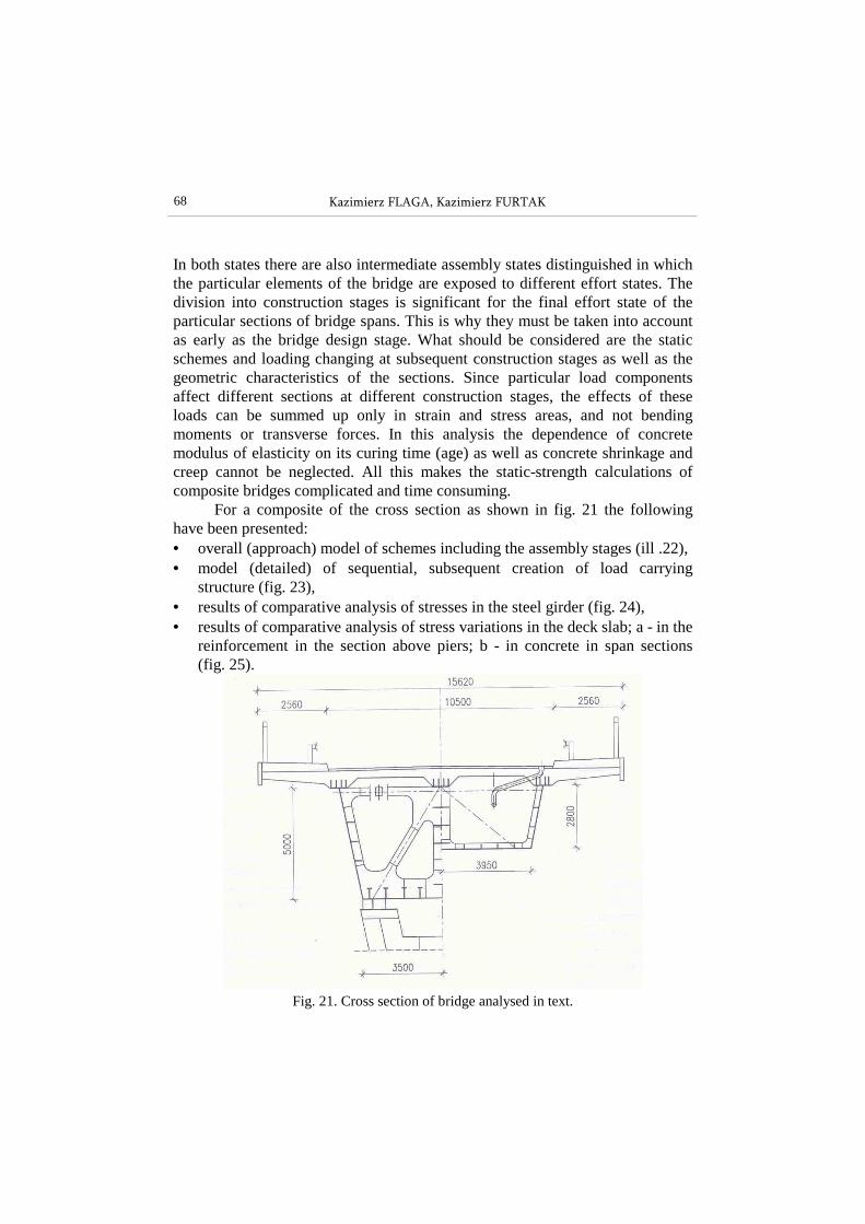
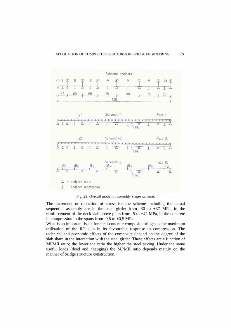
For a composite of the cross section as shown in fig. 21 the following have been presented: • overall (approach) model of schemes including the assembly stages (ill .22), • model (detailed) of sequential, subsequent creation of load carrying
structure (fig. 23), • results of comparative analysis of stresses in the steel girder (fig. 24), • results of comparative analysis of stress variations in the deck slab; a - in the
reinforcement in the section above piers; b - in concrete in span sections (fig. 25).
Fig. 21. Cross section of bridge analysed in text.
APPLICATION OF COMPOSITE STRUCTURES IN BRIDGE ENGINEERING 69
Fig. 22. Overall model of assembly stages scheme.
The increment or reduction of stress for the scheme including the actual sequential assembly are in the steel girder from -30 to +37 MPa, in the reinforcement of the deck slab above piers from -5 to +42 MPa, in the concrete in compression in the spans from -0,8 to +0,5 MPa. What is an important issue for steel-concrete composite bridges is the maximum utilisation of the RC slab in its favourable response to compression. The technical and economic effects of the composite depend on the degree of the slab share in the interaction with the steel girder. These effects are a function of MI/MII ratio; the lower the ratio the higher the steel saving. Under the same useful loads (dead and changing) the MI/MII ratio depends mainly on the manner of bridge structure construction.

70 Kazimierz FLAGA, Kazimierz FURTAK
Fig. 23. Model of assembly phases (successive creation of load-carrying structure)
Fig. 24. Results of comparative analysis of stress values in steel girder
APPLICATION OF COMPOSITE STRUCTURES IN BRIDGE ENGINEERING 71
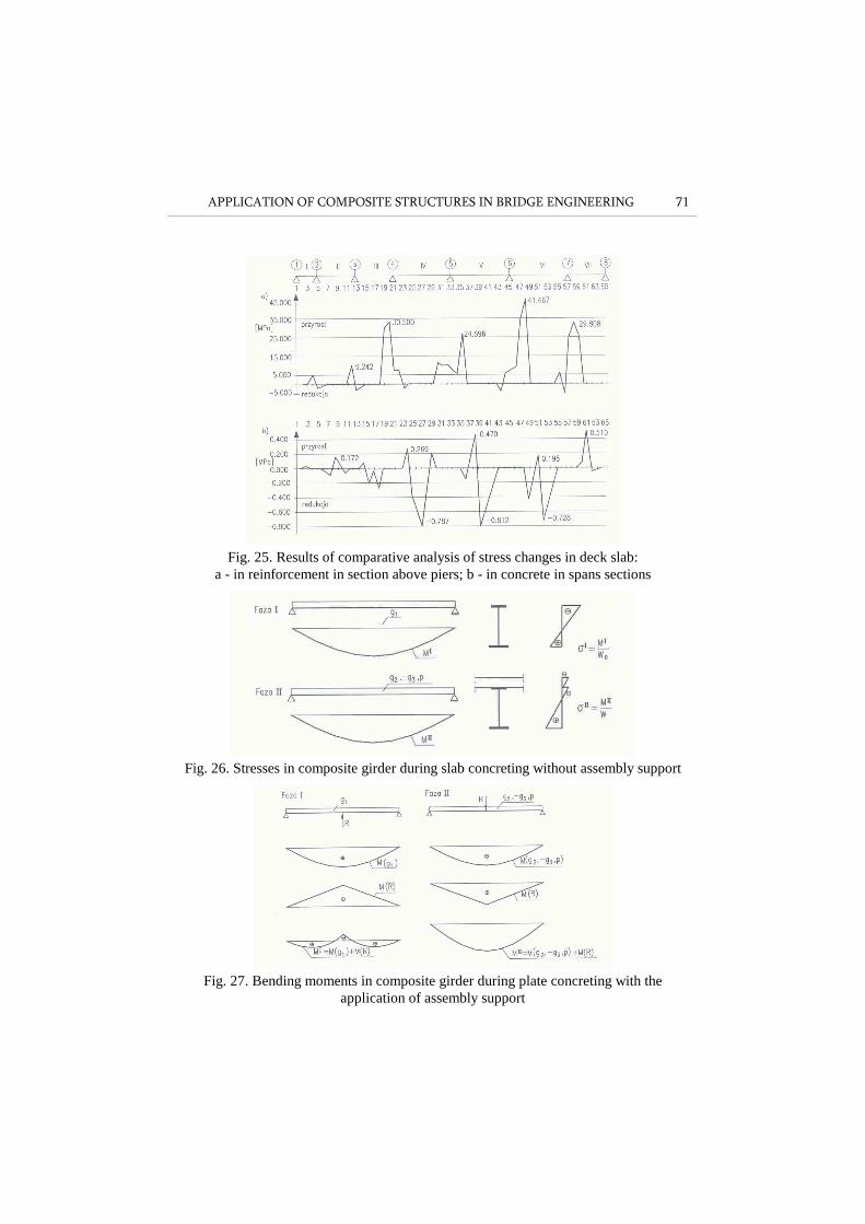
Fig. 25. Results of comparative analysis of stress changes in deck slab:
a - in reinforcement in section above piers; b - in concrete in spans sections
Fig. 26. Stresses in composite girder during slab concreting without assembly support
Fig. 27. Bending moments in composite girder during plate concreting with the
application of assembly support
72 Kazimierz FLAGA, Kazimierz FURTAK
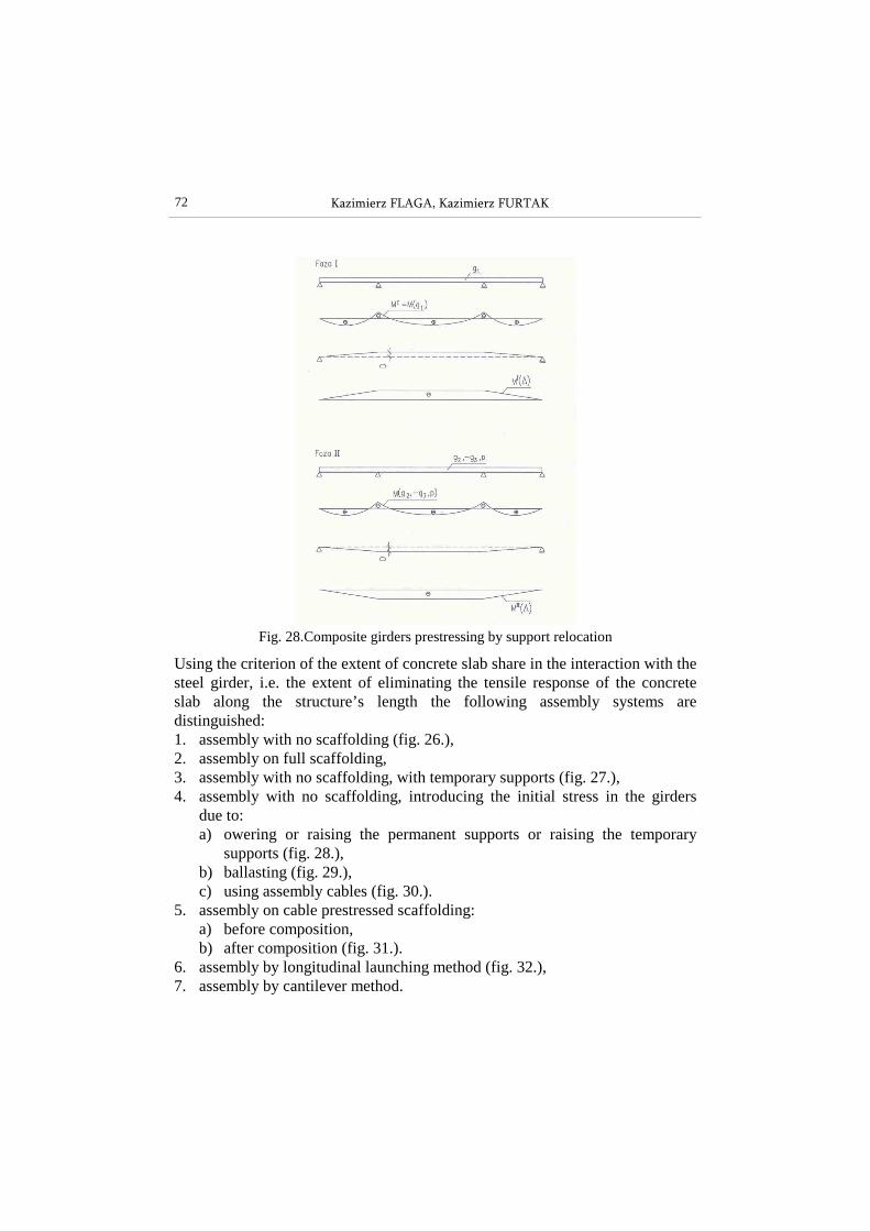
Fig. 28.Composite girders prestressing by support relocation
Using the criterion of the extent of concrete slab share in the interaction with the steel girder, i.e. the extent of eliminating the tensile response of the concrete slab along the structure’s length the following assembly systems are distinguished: 1. assembly with no scaffolding (fig. 26.), 2. assembly on full scaffolding, 3. assembly with no scaffolding, with temporary supports (fig. 27.), 4. assembly with no scaffolding, introducing the initial stress in the girders
due to: a) owering or raising the permanent supports or raising the temporary
supports (fig. 28.), b) ballasting (fig. 29.), c) using assembly cables (fig. 30.).
5. assembly on cable prestressed scaffolding: a) before composition, b) after composition (fig. 31.).
6. assembly by longitudinal launching method (fig. 32.), 7. assembly by cantilever method.
APPLICATION OF COMPOSITE STRUCTURES IN BRIDGE ENGINEERING 73
The symbols used in illustrations denote: g1 - permanent load in state I of work (dead weight of the steel structure, weight
of formwork, weight of wet concrete slab, weight of municipal installation systems, concrete prefabricated products),
g2 - additional permanent loading of the structure in state II of work (permanent useful load - weight of insulation, pavement, footpath slabs, cornices, parapets, railing, balustrades),
g3 - loss of dead weight g1 that will take place after the composition (weight of removed formwork, difference between wet and hardened concrete),
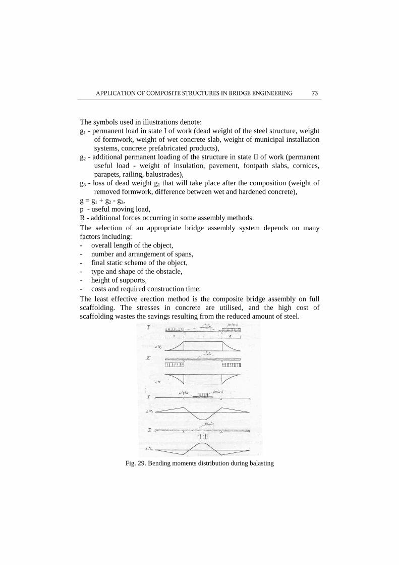
g = g1 + g2 - g3, p - useful moving load, R - additional forces occurring in some assembly methods. The selection of an appropriate bridge assembly system depends on many factors including: - overall length of the object, - number and arrangement of spans, - final static scheme of the object, - type and shape of the obstacle, - height of supports, - costs and required construction time. The least effective erection method is the composite bridge assembly on full scaffolding. The stresses in concrete are utilised, and the high cost of scaffolding wastes the savings resulting from the reduced amount of steel.
Fig. 29. Bending moments distribution during balasting

74 Kazimierz FLAGA, Kazimierz FURTAK
Fig. 30. Struts structure as an assembly support.
Fig. 31. Distribution of bending moments induced by deck slab prestressing
Fig. 32. Selected stages of assembly of the river part of steel structure
APPLICATION OF COMPOSITE STRUCTURES IN BRIDGE ENGINEERING 75
4. CALCULATION PROBLEMS
4.1. The calculation of composite girders is one of the most difficult problems in bridge engineering. This results from:
• different mechanical properties of the fundamental materials, i.e. concrete and steel,
• effect of rheological factors causing a change during strain and stress under permanent loading,
• changes in time of concrete modulus of elasticity, • effects of temperature difference between concrete slab and steel girder on
the stress state in the girder, • effect of composition vulnerability, • effect of assembly states especially at a large number of stages in particular
phases and the resulting changes of calculation schemes and elements rigidity on the same sections.
These factors may in certain circumstances affect favourably or unfavourably the strain and stress states in particular sections. They may, therefore, be an important factor of creating structural and technological solutions.
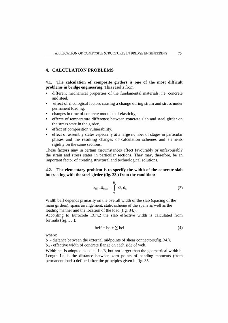
4.2. The elementary problem is to specify the width of the concrete slab interacting with the steel girder (fig. 33.) from the condition:
beff ⋅ σmax = ∫B
O
σx dx (3)
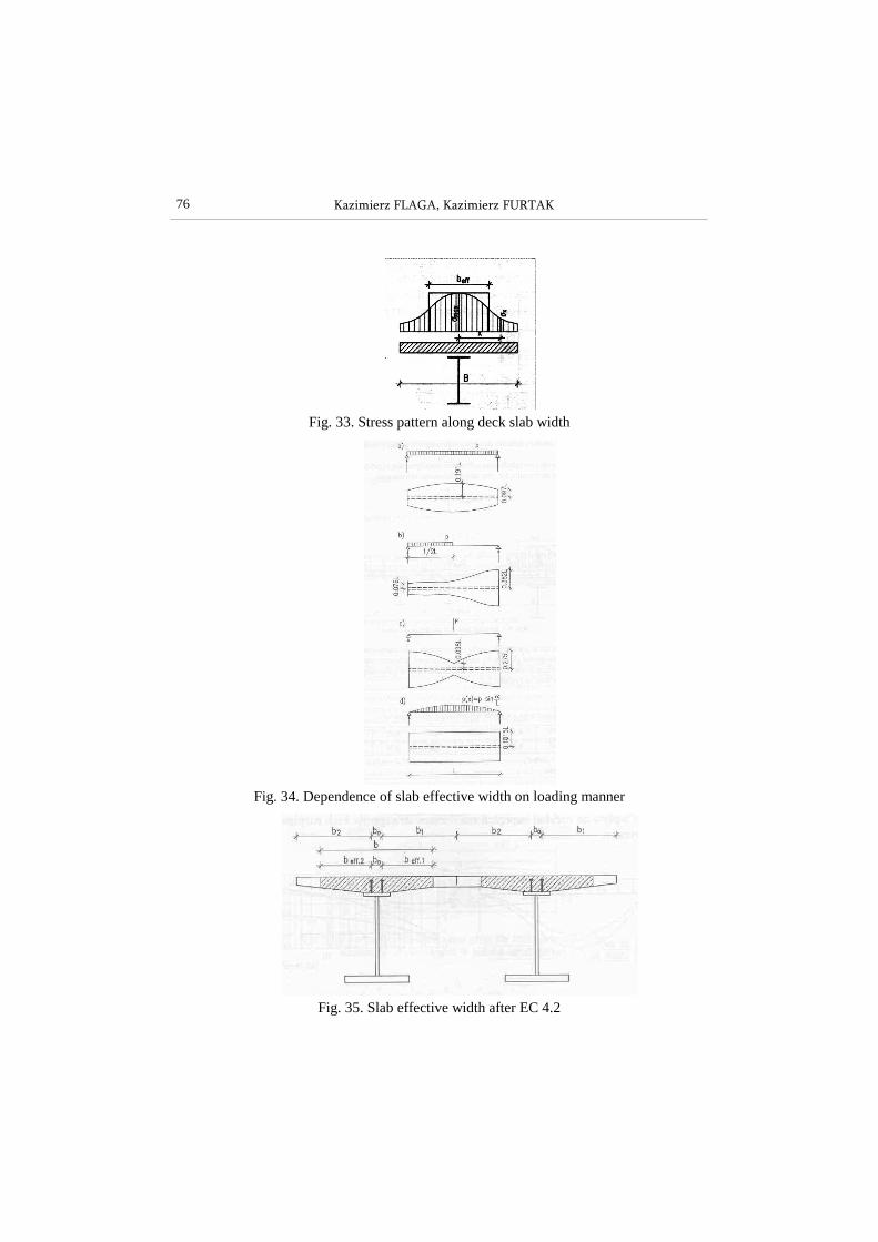
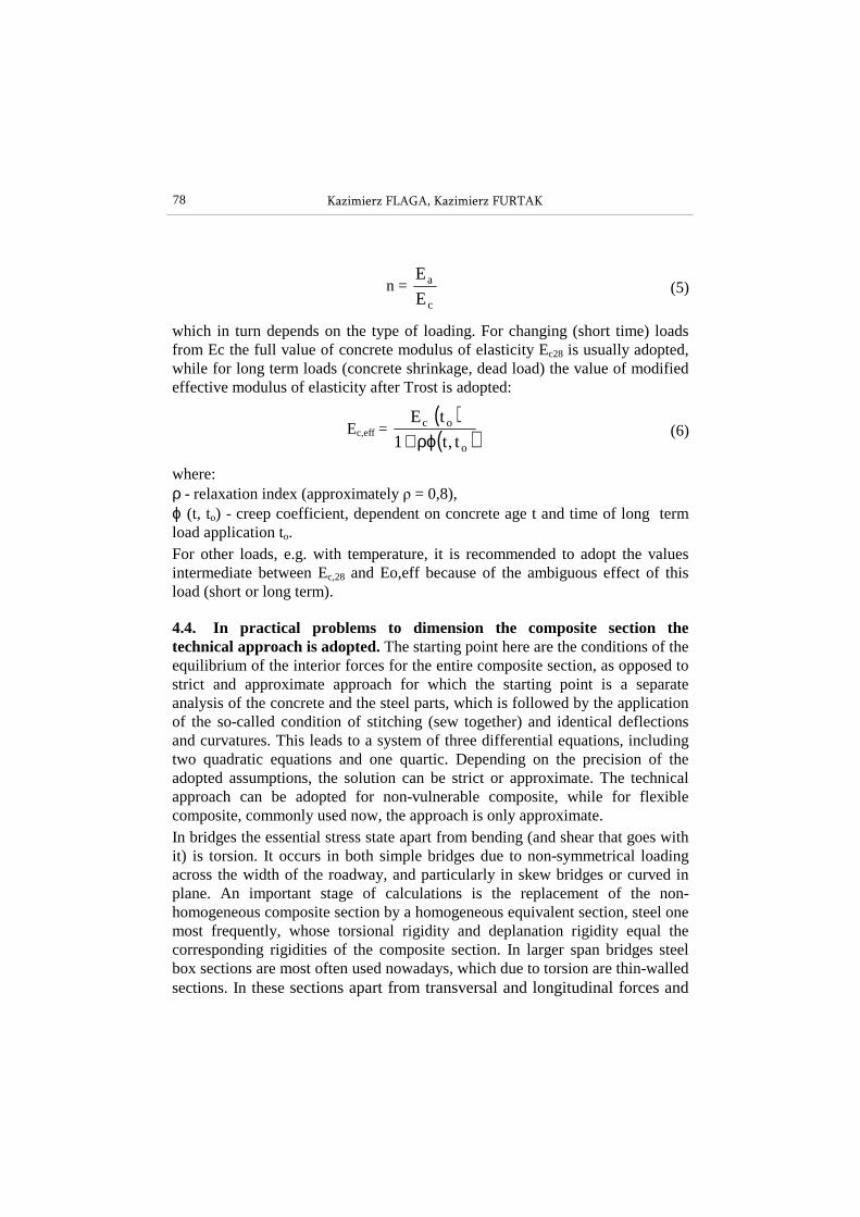
Width beff depends primarily on the overall width of the slab (spacing of the main girders), spans arrangement, static scheme of the spans as well as the loading manner and the location of the load (fig. 34.). According to Eurocode EC4.2 the slab effective width is calculated from formula (fig. 35.):
beff = bo + ∑ bei (4)
where: bo - distance between the external midpoints of shear connectors(fig. 34.), bei - effective width of concrete flange on each side of web. Width bei is adopted as equal Le/8, but not larger than the geometrical width b. Length Le is the distance between zero points of bending moments (from permanent loads) defined after the principles given in fig. 35.
76 Kazimierz FLAGA, Kazimierz FURTAK
Fig. 33. Stress pattern along deck slab width
Fig. 34. Dependence of slab effective width on loading manner
Fig. 35. Slab effective width after EC 4.2

APPLICATION OF COMPOSITE STRUCTURES IN BRIDGE ENGINEERING 77
4.3. In actual practice the normal stress distribution in the cross section of the deck slab is not a time constant value due to concrete creep and connectors flexibility. Consequently, the slab effective width changes, which, however, is not included in design. Nevertheless, the geometric and strength characteristics of composite sections are different for different work phases under different loading. The characteristics are (fig. 36.): • position of the neutral axis of composite section reduced to steel section,
Fig. 36. Composite section with low steel girder
• reduced section area
A = Aa + n
1 Ac (4b)
• reduced section moment of inertia
I = n3
bx3
+ Ia + Aa (h1 - x)2 (4c)
• section modulus for concrete top fibres “c” and steel bottom fibres “a”
Wc = x
I n; Wa =
xh
I
− (4d)
and they depend on parameter n
78 Kazimierz FLAGA, Kazimierz FURTAK
n = c
a
E
E (5)
which in turn depends on the type of loading. For changing (short time) loads from Ec the full value of concrete modulus of elasticity Ec28 is usually adopted, while for long term loads (concrete shrinkage, dead load) the value of modified effective modulus of elasticity after Trost is adopted:
Ec,eff = ( )( )o
oc
t,t1
tE
ρϕ+ (6)
where: ρ - relaxation index (approximately ρ = 0,8), ϕ (t, to) - creep coefficient, dependent on concrete age t and time of long term load application to. For other loads, e.g. with temperature, it is recommended to adopt the values intermediate between Ec,28 and Eo,eff because of the ambiguous effect of this load (short or long term).
4.4. In practical problems to dimension the composite section the technical approach is adopted. The starting point here are the conditions of the equilibrium of the interior forces for the entire composite section, as opposed to strict and approximate approach for which the starting point is a separate analysis of the concrete and the steel parts, which is followed by the application of the so-called condition of stitching (sew together) and identical deflections and curvatures. This leads to a system of three differential equations, including two quadratic equations and one quartic. Depending on the precision of the adopted assumptions, the solution can be strict or approximate. The technical approach can be adopted for non-vulnerable composite, while for flexible composite, commonly used now, the approach is only approximate. In bridges the essential stress state apart from bending (and shear that goes with it) is torsion. It occurs in both simple bridges due to non-symmetrical loading across the width of the roadway, and particularly in skew bridges or curved in plane. An important stage of calculations is the replacement of the non-homogeneous composite section by a homogeneous equivalent section, steel one most frequently, whose torsional rigidity and deplanation rigidity equal the corresponding rigidities of the composite section. In larger span bridges steel box sections are most often used nowadays, which due to torsion are thin-walled sections. In these sections apart from transversal and longitudinal forces and

APPLICATION OF COMPOSITE STRUCTURES IN BRIDGE ENGINEERING 79
bending moments as well as moments from pure unconstrained torsion, the following also occur: • bending-torsional moment Mω, inducing additional shear stress τω, • bimoment Bω, inducing additional normal stress σω. An important role in the calculation of composite bridges, box bridges in particular, is also played by crosswise bending from thermal and shrinkage effects.
4.5. One of the essential problems in composite bridges calculations is the effect of strain from long-term loads. These loads include the dead weight of the structure, weight of fittings and external elements, prestressing forces (in case of prestressing), concrete shrinkage, forces induced in the structure by rheological effects, settlement of supports in statically indeterminable structures. From among the rheological long-term effects the most significant is concrete shrinkage which causes: • in isostatic structures (statically determined) strain redistribution in
particular sections, in which part of the forces is transferred (unloading) from the concrete element (under creep) to the steel element (resistant to creep),
• in hyperstatic structures - strain redistribution in particular sections (as in isostatic structures) as well as additional responses and forced moments resulting from restricting the freedom of displacements which is manifested mainly by redistribution of bending moments along the structure. A change in concrete creep induced bending moments in a given section leads to a change in strain which, in turn, changes in time due to further creep development (and additional change in rigidity connected with it).
Including in the analysis the effect of creep in composite continuous girders, especially those of variable rigidity along the bridge length, is a very complex and time-consuming task. This is why in practical tasks (in structure design) simplified methods are used most frequently. They are based on well known concrete creep theories, although in the case of bridges the theory of inheritance has not been applied, while the theory of ageing, in the classical Dischinger approach and together with its many modifications has been quite popular. Also the theories of visco-elastic body (Arutiuniana) and more advanced ones have been used only sporadically.
80 Kazimierz FLAGA, Kazimierz FURTAK
4.6. In practical problems the method of modified effective modulus of elasticity of concrete, known as the Trost method, is widely used. In this method the physical equation of state takes the form:
( ) ( )[ ] ( ) ( )[ ] ( )tt1E
tt1
Et s
co
co
co
coc
c ε+ρϕ+σ−σ
+ϕ+σ
=ε (7)
where: εc(t) - concrete strain at instant t, σco - concrete stress at instant t = 0, Eco - concrete modulus of elasticity, φ(t) - creep coefficient by stress of σco, ρ(t) - relaxation index in which concrete creep decreasing capability is included, εs(t) - concrete shrinkage induced strain which in this method is a curve affine to concrete creep section, t - time that passed from the occurrence of stress σco, to - time when creep process started, to+t - time that passed from when concrete was incorporated.
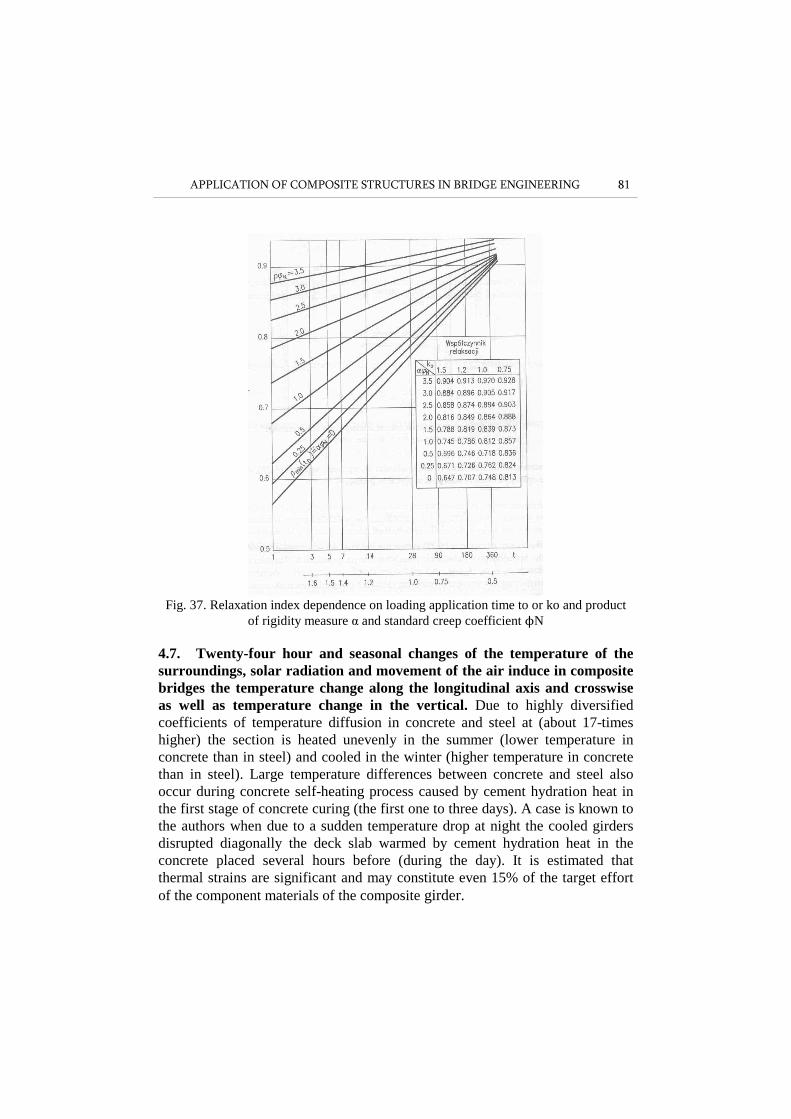
The value of relaxation index ρ depends on many factors: to as well as the product of rigidity measure LN or αM and the standard creep coefficient ϕN, which for an evenly distributed load and post-tensioning with concrete shrinkage included is shown in fig. 37. The rigidity measures are defined by the formulae
αN = 1 :
++
a
2a
aa
cco
J
aA1
AE
AE1 (8a)
αM = 1 :
+
aa
cco
JE
AE1 (8b)
where: a - distance between the centres of gravity of the concrete slab and thee steel section.
APPLICATION OF COMPOSITE STRUCTURES IN BRIDGE ENGINEERING 81
Fig. 37. Relaxation index dependence on loading application time to or ko and product
of rigidity measure α and standard creep coefficient ϕN
4.7. Twenty-four hour and seasonal changes of the temperature of the surroundings, solar radiation and movement of the air induce in composite bridges the temperature change along the longitudinal axis and crosswise as well as temperature change in the vertical. Due to highly diversified coefficients of temperature diffusion in concrete and steel at (about 17-times higher) the section is heated unevenly in the summer (lower temperature in concrete than in steel) and cooled in the winter (higher temperature in concrete than in steel). Large temperature differences between concrete and steel also occur during concrete self-heating process caused by cement hydration heat in the first stage of concrete curing (the first one to three days). A case is known to the authors when due to a sudden temperature drop at night the cooled girders disrupted diagonally the deck slab warmed by cement hydration heat in the concrete placed several hours before (during the day). It is estimated that thermal strains are significant and may constitute even 15% of the target effort of the component materials of the composite girder.
82 Kazimierz FLAGA, Kazimierz FURTAK
4.8. The effect of concrete shrinkage on the state of effort of composite girders can be reduced by producing the slab by parts (top and bottom plates) or by layers (bottom plate). Then, the load of new concrete shrinkage will act only on those parts of the composite girder on which the slab was made previously. By skilfully manoeuvring the sequence of concreting parts of the deck slab it is possible to significantly affect the final state of strain in the composite girder. The effect of shrinkage can be eliminated by the application of deck prefabricated slabs. The effect of shrinkage can be considered together with creep or separately, loading the composite girder with unit shrinkage strain along the entire length. The latter approach is simple but biased with a large error due to slab cracking in the zones of negative bending moments. It would be more accurate to take into account shrinkage load only on those girder parts which are affected by positive (ultimately) bending moments. Another difficulty in considering the effect of shrinkage in continuous composite girders separately is the necessity of treating it as a long-term load, which involves the necessity of additional considering creep.
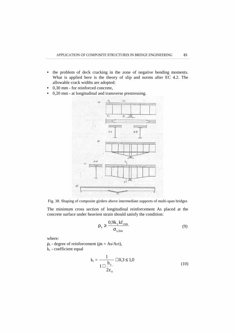
4.9. The problem of deck slab cracking above the continuous beams supports is connected with the problem of interaction between concrete and steel girder along the crack area length. As mentioned in 3 of the present article, the fundamental solution is to use a method of bridge erection that will guarantee slab compression along the slabs entire length. When this is impossible, by disregarding concrete interaction in the zone in tension it is possible to (fig. 38.): • change the steel beam section into symmetrical, without changing the beam
depth (fig. 38 a, b, c), • leave the steel beam section unchanged, but add strong longitudinal
reinforcement in the concrete slab in tension • change the section by introducing in the zone in compression an additional
interacting concrete plate (section of double or triple composition) - fig. 38d.
4.10. Other calculation problems include: • the effect of changing loading on concrete fatigue (reinforcing and
prestressing steel) and structural steel (in the girder). This problem is usually analysed separately for deck slab and steel girder using concrete (RC and prestressed) and steel bridges design and calculation norms. A similar approach is represented in Eurocode EC 4.2 with attention paid to certain differences in calculating the internal forces.
APPLICATION OF COMPOSITE STRUCTURES IN BRIDGE ENGINEERING 83
• the problem of deck cracking in the zone of negative bending moments. What is applied here is the theory of slip and norms after EC 4.2. The allowable crack widths are adopted:
• 0,30 mm - for reinforced concrete, • 0,20 mm - at longitudinal and transverse prestressing.
Fig. 38. Shaping of composite girders above intermediate supports of multi-span bridges
The minimum cross section of longitudinal reinforcement As placed at the concrete surface under heaviest strain should satisfy the condition:
lim,s
ctmcs
kfk9,0
σ≥ρ (9)
where: ρs - degree of reinforcement (ρs = As/Act), kc - coefficient equal
kc = 0,13,0
z2
h1
1
o
c≤+
+
(10)

84 Kazimierz FLAGA, Kazimierz FURTAK
k - coefficient equal 0,80, fctm - concrete mean tensile strength, σs,lim - maximum stress in steel of minimum reinforcement depending on
maximum rebars diameter φs and crack allowable width wk, Act - area of concrete of the tensile zone of effective width immediately before
crack appearance hc - concrete slab thickness (excluding ribs), zo - vertical distance between the centres of gravity of uncracked and non-
reinforced concrete slab and the centre of gravity of uncracked and non-reinforced composite section calculated for Ec = Ec,28.
• calculations of composite bridge deflection. These calculations are required due to the necessity of inducing camber in the structure , to obtain in the stage of utilisation a properly shaped longitudinal section (and the view of the bridge) as well as an appropriate grade line of the roadway and footpaths. Another aim of deflection calculations results from satisfying the requirement included in standards of obtaining sufficient rigidity of the structure under useful loads. Assembly stages and und nonloading stage, as well as the effect of time factor (rheology) are disregarded. The problem of composite girders deflections covers many parameters and is difficult to calculate accurately. This is because deflections are affected by: deck slab cracking in the zone of negative moments, slip in the contact plane in the function of connectors flexibility and changing loading, rheological effects (concrete shrinkage and creep), thermal effects, as well as increased deformability of concrete due to changing loading together with a simultaneous increase in time of concrete modulus of elasticity.
5. SUMMARY
The article presents a compendium of fundamental information on the application of composite structures in bridge engineering. Calculation and construction difficulties of this type of structures have been pointed out and a wide range of possibilities of application of these structures to form medium and long span bridges has been shown. It has also been demonstrated that the idea of steel-concrete composite bridges is far from exhausting its potential and is being continuously developed.
REFERENCES
1. Furtak K.: Mosty zespolone, Wydawnictwo PWN, Warszawa-Kraków 1999.
APPLICATION OF COMPOSITE STRUCTURES IN BRIDGE ENGINEERING 85
2. Ryżyński A., Wołowicki W., Skarżewski J., Karlikowski J.: Mosty stalowe, Wydawnictwo PWN, Warszawa-Poznań 1984.
3. Wydział Inżynierii Lądowej Politechniki Krakowskiej: Zespolone Konstrukcje Mostowe. Teoria, badania, projektowanie, realizacja, utrzymanie, wzmacnianie, Materiały konferencyjne, Wydawnictwo Politechniki Krakowskiej, Kraków 2009.
ZASTOSOWANIE KONSTRUKCJI ZESPOLONYCH W MOSTOWNICTWIE. PROBLEMY KONSTRUKCYJNE I ANALIZA WYTRZYMAŁOŚCIOWA
S t r e s z c z e n i e
Konstrukcje zespolone typu stal-beton są od dziesięcioleci chętnie stosowane w obiektach mostowych. Wynika to z racjonalnego wykorzystania cech wytrzymałościowych betonu i stali. Jednocześnie żelbetowa (lub sprężona) płyta pomostu jest korzystniejsza niż stalowa płyta ortotropowa, stosowana w mostach stalowych (większa masa, lepsze tłumienie drgań, większa trwałość). Najbardziej rozpowszechnionymi w praktyce są mosty zespolone belkowe. Są one stosowane powszechnie w mostach drogowych małych i średnich rozpiętości, ale również w mostach o rozpiętościach przęseł ponad 200 m. Przy większych rozpiętościach przęseł stosuje się dźwigary stalowe kratownicowe. Mostowe konstrukcje zespolone stosowane są również w pomostach mostów podwieszonych o rozpiętościach głównego przęsła rzędu 600÷800 m (fffig. 6). W artykule przedstawiono problemy realizacyjne I obliczeniowe związane z tego typu konstrukcjami. Wiele uwagi poświęcono konstruowaniu i obliczaniu łączników charakterystycznych dla omawianego rodzaju konstrukcji. Skupiono się głównie na konstrukcjach pojedynczo zespolonych. Zwrócono uwagę na wpływ stanów montażowych na stan odkształcenia i naprężenia w elementach zespolonych. Oddzielna grupa zagadnień dotyczyła wpływu czynników reologicznych - skurczu i pełzania betonu - oraz termicznych na wartości odkształceń i naprężeń oraz redystrybucję sił wewnętrznych.
Słowa kluczowe: konstrukcje zespolenie stal-beton, płyta pomostu, most, skurcz, pełzanie betonu
Editor received the manuscript: 8.09.2014
Related Documents
![PSPU-J706A Rev1.0 = PT32600 = [EAY40484901__EAX41678701-1__ 2300KEG026A-F] Esquema Eletrico.pdf](https://static.cupdf.com/doc/110x72/55cf9c0c550346d033a8608d/pspu-j706a-rev10-pt32600-eay40484901eax41678701-1-2300keg026a-f.jpg)