07/09/13 Wiring a Character LCD | Character LCDs | Adafruit Learning Sy stem learn.adafruit.com/character-lcds/wiring-a-character-lcd 1/13 Wiring a Character LCD Created by Ladyada Install ing the Heade r Pins OK now you've got your LCD, you'll also need a couple other things. First is a 10 K potentiometer. This will let you adjust the contrast. Each LCD will have slightly different contrast settings so you should try to get some sort of trimmer. You'll also need some 0.1" header - 16 pins long.

Welcome message from author
This document is posted to help you gain knowledge. Please leave a comment to let me know what you think about it! Share it to your friends and learn new things together.
Transcript

7/27/2019 04-Wiring a Character LCD _ Character LCDs _ Adafruit Learning System
http://slidepdf.com/reader/full/04-wiring-a-character-lcd-character-lcds-adafruit-learning-system 1/13
07/09/13 Wiring a Character LCD | Character LCDs | Adafruit Learning System
learn.adafruit.com/character-lcds/wiring-a-character-lcd 1/13
Wiring a Character LCD Created by Ladyada
Installing the Header Pins
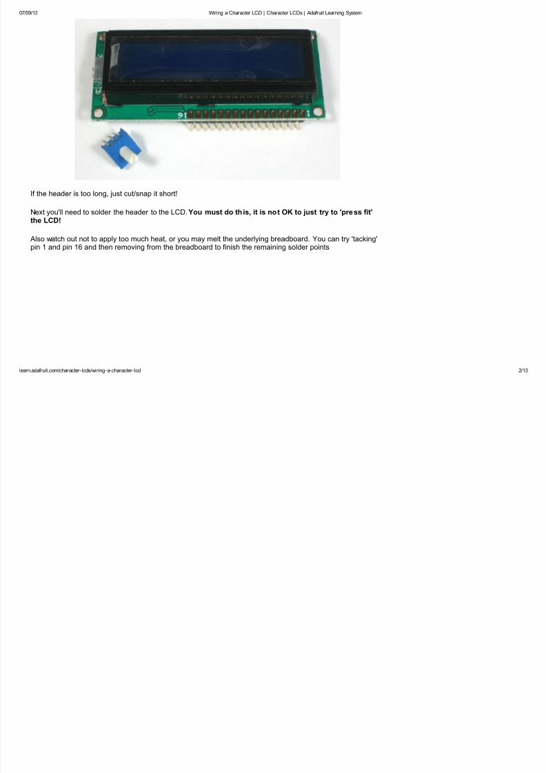
OK now you've got your LCD, you'll also need a couple other things. First is a 10 K potentiometer. This will letyou adjust the contrast. Each LCD will have slightly different contrast settings so you should try to get somesort of trimmer. You'll also need some 0.1" header - 16 pins long.
7/27/2019 04-Wiring a Character LCD _ Character LCDs _ Adafruit Learning System
http://slidepdf.com/reader/full/04-wiring-a-character-lcd-character-lcds-adafruit-learning-system 2/13
07/09/13 Wiring a Character LCD | Character LCDs | Adafruit Learning System
learn.adafruit.com/character-lcds/wiring-a-character-lcd 2/13
If the header is too long, just cut/snap it short!
Next you'll need to solder the header to the LCD. You must do this, it is not OK to just try to 'press fit'the LCD!
Also watch out not to apply too much heat, or you may melt the underlying breadboard. You can try 'tacking'pin 1 and pin 16 and then removing from the breadboard to finish the remaining solder points
7/27/2019 04-Wiring a Character LCD _ Character LCDs _ Adafruit Learning System
http://slidepdf.com/reader/full/04-wiring-a-character-lcd-character-lcds-adafruit-learning-system 3/13
07/09/13 Wiring a Character LCD | Character LCDs | Adafruit Learning System
learn.adafruit.com/character-lcds/wiring-a-character-lcd 3/13
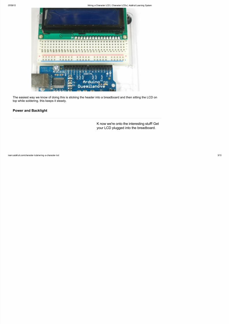
The easiest way we know of doing this is sticking the header into a breadboard and then sitting the LCD ontop while soldering. this keeps it steady.
Power and Backlight
K now we're onto the interesting stuff! Get
your LCD plugged into the breadboard.

7/27/2019 04-Wiring a Character LCD _ Character LCDs _ Adafruit Learning System
http://slidepdf.com/reader/full/04-wiring-a-character-lcd-character-lcds-adafruit-learning-system 4/13
07/09/13 Wiring a Character LCD | Character LCDs | Adafruit Learning System
learn.adafruit.com/character-lcds/wiring-a-character-lcd 4/13
Now we'll provide power to the breadboard.
Connect +5V to the red rail, and Ground tothe blue rail.

7/27/2019 04-Wiring a Character LCD _ Character LCDs _ Adafruit Learning System
http://slidepdf.com/reader/full/04-wiring-a-character-lcd-character-lcds-adafruit-learning-system 5/13
07/09/13 Wiring a Character LCD | Character LCDs | Adafruit Learning System
learn.adafruit.com/character-lcds/wiring-a-character-lcd 5/13
Next we'll connect up the backlight for the
LCD. Connect pin 16 to ground and pin 15to +5V. On the vast majority of LCDs(including ones from Adafruit) the LCD
includes a series resistor for the LEDbacklight.
If you happen to have one that does notinclude a resistor, you'll need to add onebetween 5V and pin 15. To calculate the
value of the series resistor, look up themaximum backlight current and the typicalbacklight voltage drop from the data sheet.
Subtract the voltage drop from 5 volts, thendivide by the maximum current, then roundup to the next standard resistor value. For
example, if the backlight voltage drop is
3.5v typical and the rated current is 16mA,then the resistor should be (5 - 3.5)/0.016 =
93.75 ohms, or 100 ohms when rounded upto a standard value. If you can't find the datasheet, then it should be safe to use a 220
ohm resistor, although a value this high maymake the backlight rather dim.
Connect the Arduino up to power, you'll
notice the backlight lights up.

7/27/2019 04-Wiring a Character LCD _ Character LCDs _ Adafruit Learning System
http://slidepdf.com/reader/full/04-wiring-a-character-lcd-character-lcds-adafruit-learning-system 6/13
07/09/13 Wiring a Character LCD | Character LCDs | Adafruit Learning System
learn.adafruit.com/character-lcds/wiring-a-character-lcd 6/13
Note that some low-cost LCDs dont come with a backlight. Obviously in this case you should just keep going.
Contrast Circuit
Next, lets place the contrast pot, it goes onthe side near pin 1.
7/27/2019 04-Wiring a Character LCD _ Character LCDs _ Adafruit Learning System
http://slidepdf.com/reader/full/04-wiring-a-character-lcd-character-lcds-adafruit-learning-system 7/13
07/09/13 Wiring a Character LCD | Character LCDs | Adafruit Learning System
learn.adafruit.com/character-lcds/wiring-a-character-lcd 7/13
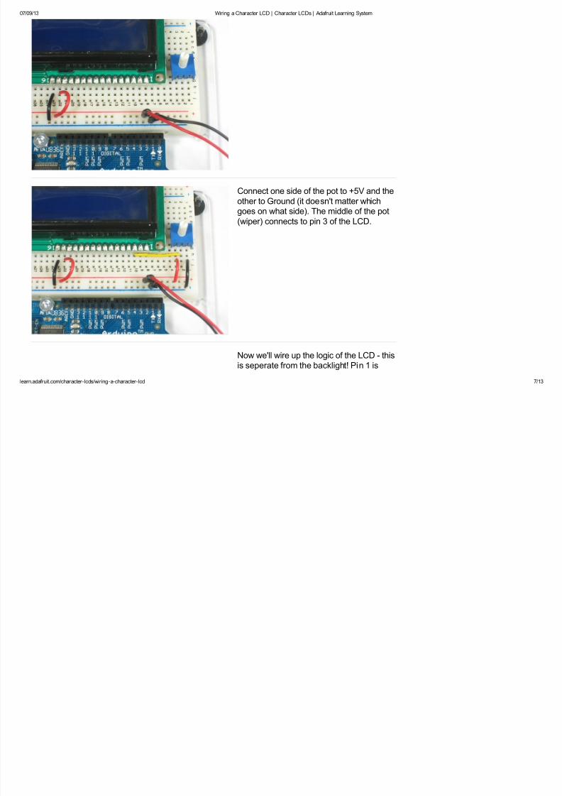
Connect one side of the pot to +5V and the
other to Ground (it doesn't matter whichgoes on what side). The middle of the pot
(wiper) connects to pin 3 of the LCD.
Now we'll wire up the logic of the LCD - thisis seperate from the backlight! Pin 1 is

7/27/2019 04-Wiring a Character LCD _ Character LCDs _ Adafruit Learning System
http://slidepdf.com/reader/full/04-wiring-a-character-lcd-character-lcds-adafruit-learning-system 8/13
07/09/13 Wiring a Character LCD | Character LCDs | Adafruit Learning System
learn.adafruit.com/character-lcds/wiring-a-character-lcd 8/13
ground and pin 2 is +5V.
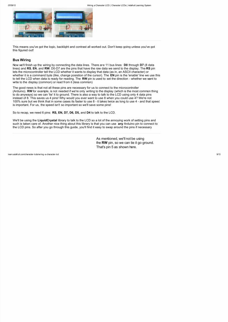
Now turn on the Arduino, you'll see the
backlight light up (if there is one), and youcan also twist the pot to see the first line of
rectangles appear.
7/27/2019 04-Wiring a Character LCD _ Character LCDs _ Adafruit Learning System
http://slidepdf.com/reader/full/04-wiring-a-character-lcd-character-lcds-adafruit-learning-system 9/13
07/09/13 Wiring a Character LCD | Character LCDs | Adafruit Learning System
learn.adafruit.com/character-lcds/wiring-a-character-lcd 9/13
This means you've got the logic, backlight and contrast all worked out. Don't keep going unless you've gotthis figured out!
Bus Wiring
Now we'll finish up the wiring by connecting the data lines. There are 11 bus lines: D0 through D7 (8 datalines) and RS, EN, and RW. D0-D7 are the pins that have the raw data we send to the display. TheRS pinlets the microcontroller tell the LCD whether it wants to display that data (as in, an ASCII character) or whether it is a command byte (like, change posistion of the cursor). The EN pin is the 'enable' line we use this
to tell the LCD when data is ready for reading. The RW pin is used to set the direction - whether we want towrite to the display (common) or read from it (less common)
The good news is that not all these pins are necessary for us to connect to the microcontroller (Arduino). RW for example, is not needed if we're only writing to the display (which is the most common thingto do anyways) so we can 'tie' it to ground. There is also a way to talk to the LCD using only 4 data pinsinstead of 8. This saves us 4 pins! Why would you ever want to use 8 when you could use 4? We're not100% sure but we think that in some cases its faster to use 8 - it takes twice as long to use 4 - and that speedis important. For us, the speed isn't so important so we'll save some pins!
So to recap, we need 6 pins: RS, EN, D7, D6, D5, and D4 to talk to the LCD.
We'll be using the LiquidCrystal library to talk to the LCD so a lot of the annoying work of setting pins andsuch is taken care of. Another nice thing about this library is that you can use any Arduino pin to connect tothe LCD pins. So after you go through this guide, you'll find it easy to swap around the pins if necessary
As mentioned, we'll not be usingthe RW pin, so we can tie it go ground.
That's pin 5 as shown here.

7/27/2019 04-Wiring a Character LCD _ Character LCDs _ Adafruit Learning System
http://slidepdf.com/reader/full/04-wiring-a-character-lcd-character-lcds-adafruit-learning-system 10/13
07/09/13 Wiring a Character LCD | Character LCDs | Adafruit Learning System
learn.adafruit.com/character-lcds/wiring-a-character-lcd 10/13
Next is the RS pin #4. We'll use a brown
wire to connect it to Arduino's digital pin #7.
Next is the EN pin #6, we'll use a white wire
to connect it to Arduino digital #8.

7/27/2019 04-Wiring a Character LCD _ Character LCDs _ Adafruit Learning System
http://slidepdf.com/reader/full/04-wiring-a-character-lcd-character-lcds-adafruit-learning-system 11/13
07/09/13 Wiring a Character LCD | Character LCDs | Adafruit Learning System
learn.adafruit.com/character-lcds/wiring-a-character-lcd 11/13
Now we will wire up the data pins. DB7 is
pin #14 on the LCD, and it connects with anorange wire to Arduino #12.

7/27/2019 04-Wiring a Character LCD _ Character LCDs _ Adafruit Learning System
http://slidepdf.com/reader/full/04-wiring-a-character-lcd-character-lcds-adafruit-learning-system 12/13
07/09/13 Wiring a Character LCD | Character LCDs | Adafruit Learning System
learn.adafruit.com/character-lcds/wiring-a-character-lcd 12/13
Next are the remaining 3 data
lines, DB6 (pin #13 yellow) DB5 (pin #12
green) and DB4 (pin #11 blue) which we
connect to Arduino #11, 10 and 9.
You should have four 'gap' pins on the
LCD between the 4 data bus wires andthe control wires.
This is what you'll have on your desk.

7/27/2019 04-Wiring a Character LCD _ Character LCDs _ Adafruit Learning System
http://slidepdf.com/reader/full/04-wiring-a-character-lcd-character-lcds-adafruit-learning-system 13/13
07/09/13 Wiring a Character LCD | Character LCDs | Adafruit Learning System
learn.adafruit.com/character-lcds/wiring-a-character-lcd 13/13
< LCD Varieties Using a Character LCD >
Related Documents