LIMITATIONS OF 17- 4 PH METALLURGICAL, MECHANICAL AND CORROSION ASPECTS T. Cassagne and M. Bonis Total Fina Elf 64018 Pau, France C. Duret Correx 42490 Fraisses, France J.L. Crolet Consultant 64140 Lons, France ABSTRACT The use of 17-4 PH in sour service started long before the establishment of MR0175, and its coverage in this document has varied widely over the years. Thus, the real significance of the statement "according to NACE" had become less and less defined. In the context of the present debate on the general acceptability of 17-4 PH in sour service, an extensive literature survey of the very complex metallurgy of this grade has been carried out following a mechanical rupture in service. In addition, three different 17-4 PH materials have been studied in terms of microstructure, mechanical properties and susceptibility to sulfide stress cracking. It is shown that the content of residual ferrite and austenite in this nominally "martensitic" grade is a key issue for its mechanical properties. Regarding sulfide stress cracking resistance, the strong dependence upon the actual stress level has been confirmed. It is concluded that, with just the broad composition range of UNS 17400 and a simplified definition of the heat treatment, the reference to MR0175 cannot as such ensure fitness for purpose. It is then the responsibility of each supplier to qualify its design and manufacturing route. Key words : 17-4 PH, martensitic stainless steel, sustained load cracking, sulfide stress cracking, microstructure, mechanical properties, ferrite, austenite, martensite.

03102 Limitations of 17-4 PH Metallurgical, Mechanical and .pdf
Dec 20, 2015
Welcome message from author
This document is posted to help you gain knowledge. Please leave a comment to let me know what you think about it! Share it to your friends and learn new things together.
Transcript
LIMITATIONS OF 17- 4 PH
METALLURGICAL, MECHANICAL AND CORROSION ASPECTS
T. Cassagne and M. BonisTotal Fina Elf
64018 Pau, France
C. DuretCorrex
42490 Fraisses, France
J.L. CroletConsultant
64140 Lons, France
ABSTRACT
The use of 17-4 PH in sour service started long before the establishment of MR0175, and its coverage inthis document has varied widely over the years. Thus, the real significance of the statement "accordingto NACE" had become less and less defined.
In the context of the present debate on the general acceptability of 17-4 PH in sour service, an extensiveliterature survey of the very complex metallurgy of this grade has been carried out following amechanical rupture in service. In addition, three different 17-4 PH materials have been studied in termsof microstructure, mechanical properties and susceptibility to sulfide stress cracking.
It is shown that the content of residual ferrite and austenite in this nominally "martensitic" grade is a keyissue for its mechanical properties. Regarding sulfide stress cracking resistance, the strongdependence upon the actual stress level has been confirmed.
It is concluded that, with just the broad composition range of UNS 17400 and a simplified definition of theheat treatment, the reference to MR0175 cannot as such ensure fitness for purpose. It is then theresponsibility of each supplier to qualify its design and manufacturing route.
Key words : 17-4 PH, martensitic stainless steel, sustained load cracking, sulfide stress cracking,microstructure, mechanical properties, ferrite, austenite, martensite.
INTRODUCTION
The martensitic precipitation hardening stainless steel UNS 17400 (17-4 PH) is one of the numerousmaterials listed in the NACE/ANSI document MR 0175. Nowadays, its legitimacy precisely comes fromthis presence in the list, through the classical magical statement "according to NACE". Historically,however, MR 0175 was established by definition in 1975, but the use of 17-4 PH had already startedmuch before. It was therefore introduced "from field experience" as a valve material into the initial NACEPublication 1F166. (In this respect, it must be kept in mind that at that time, the requirements regardingsour service conditions, working rates and risk assessment were not necessarily the same as today).Then it was naturally transposed into the very first version of the "Materials Requirements" MR 0175…that still covered only valves. Later on, when MR 0175-78 was revised and its applicability1 extended, 17-4 PH suddenly became accepted for general application, with claims having varied over the years. Mostimportant is that, at least from MR 0175-95 to 2000, a special warning in § 3.8.1 said : "…Thesematerials may, however, exhibit threshold stress levels in NACE Standard TM0177 that are lower thanthose of other materials included in this standard…". This warning actually expresses the fact that thepresent practice of sour service generally corresponds to more stringent requirements than in the 50'sor 60's. Nevertheless, for proprietary equipment and design, such a warning is of no use to an end user,and it can only be directed at suppliers. The warning was probably insufficiently appreciated, and it wasfinally proposed and balloted in 2000 to bring back 17-4 PH to its original category, with a new wordingas a § 9.5.2 (ballot item 24) : "… acceptable for non pressure containing internal valve, pressureregulator and level controller…".
Since then, there is a strong debate within NACE International on the subject of the general acceptabilityof 17-4 PH, for sour service. The proposals vary from "restriction to specific use in well defined types ofequipment and conditions of mild or intermediate severity* of sour service" to "unlimited use as ageneral purpose material".
Following the mechanical failure of a 17-4 PH component because of a defective heat treatment, abibliographical survey on the metallurgy of this grade has been carried out to understand the cause offailure. The actual metallurgy of this precipitation hardening grade appeared so complex that questionswere raised about the actual limits of use of this alloy. Consequently, an experimental study wasperformed to assess the mechanical properties and sulfide stress cracking (SSC) behavior of thismaterial compared to other properly heat treated materials.
The results of this bibliographical review and experimental study bring additional insight on the presentdebate on the definition of 17-4 PH in MR 0175 as a general purpose material, or on the recent evolutionof the wording from the 2000 revision to the 2000 ballot. In particular, they illustrate how the advantagesof a highly sophisticated and acute nominal metallurgy may turn to limitations when variations incomposition and heat treatments occur.
BASIC METALLURGICAL DATA ON 17-4 PH
The aim of this part of the paper is to review the metallurgical parameters governing the mechanicalbehavior of this alloy. According to open literature, it will be seen that rather different microstructures andmechanical properties may indeed be achieved from only minor variations in composition and heattreatment.
* according to the next ISO standard 15156-1, to be issued in 2002.
General
17-4 PH is a martensitic stainless steel containing more Cr and Ni than the usual 4xx series, forimproved corrosion resistance, and additional alloying element(s) for precipitation hardening. Highstrength is then achieved through a two step process :
• formation of a homogeneous martensitic microstructure
• aging of this martensite in a temperature domain where precipitation hardening can occur.
This combination of martensite, aging and precipitation hardening can induce mechanical properties,such that both high strength and good toughness can be obtained.
The composition range for 17-4 PH is usually that of the standardized grade UNS 17400. It is given inTable 1 together with that of 15-5 PH 2 . In both grades, copper is the element driving precipitationhardening. Niobium is added to limit grain growth during annealing treatments, but it also contributes todelay aging effects.
At the different stages of fabrication, this nominally martensitic alloy also contains some austenite, thestability of which is increased by all the alloying elements. Consequently the bainitic transformation oncooling is delayed or even avoided, and the Ms temperature (beginning of the martensitic transformation)is lowered .
From liquid metal to semi-products
The as-cast structure is essentially martensitic, due to the Cr, Ni and C contents, but some δ ?ferritemay also be present. This ferrite content can be predicted from the Fe-Cr phase diagram as well as theeffect of Ni and C on the extension of the γ domain3 (Figure 1). At the beginning of cooling, themicrostructure first evolves from pure δ ferrite to γ+δ , with a total or only partial transformation of theinitial δ phase into γ austenite.
When quenching Fe-Cr, Fe-Mo or Fe-Cr-Ni alloys, δ ferrite may display different behaviors dependingon composition : type I ferrite is transformed into austenite and then into martensite, whereas type IIferrite stays as ferrite4. Even with very high cooling rates, type I ferrite cannot be retained5. The transitionbetween type I and type II is related to the limit γ / γ+δ in Figure 1. This limit depends on alloycomposition, and especially on Ni and C contents. (As usual, C has a much higher influence than Ni).Consequently, depending on both average and local composition, 17-4 PH may contain some ferrite,and just slight differences in C, N, Ni and Cr can lead to quite different amounts of ferrite.
In this respect, segregation effects may be more or less important, depending on the solidificationprocess,. In the case of a dendritic solidification (e.g. ingot casting), interdendritic spaces are enriched inchromium, resulting in the local formation of ferrite (type II ferrite, i.e. fully stable at cooling). During hotworking, these ferrite islands are then elongated and orientated, which can significantly alter thetransverse mechanical properties of the material.
For homogenizing, a high temperature annealing treatment may be implemented (T>1100°C). As shownon the Fe-Cr pseudo-binary diagrams of Figure 1, such a treatment is carried out in the δ+γ domain, andit may modify the ferrite fraction. At these high temperatures, diffusion processes may also reduce thechemical heterogeneity related to segregation. The use of such high temperature treatments (1150 tomore than 1230°C) has been proposed essentially in the case of cast materials, and it was found to beslightly beneficial6. From an industrial point of view, however, such high temperatures were consideredas hardly applicable, and the potential benefit as too low.
Influence of chemical composition upon as-cast microstructure. As mentioned previously, the as-cast microstructure and the ferrite content are directly related to the balance between δ and γ promoteralloying elements. From the chemical composition, it is therefore possible to determine nickel andchromium "equivalent contents". Several formulas exist in the literature, dealing with different chemicalelements. These equivalents can be used for locating heats in a Ni-Cr pseudo-binary diagrams, andthus predict the microstructural transformation which will occur during cooling or heating. The Schaefflerdiagram is used for cast materials or weldments, whereas, the Pryce and Andrews diagram7 ispreferred for wrought materials8.
Among the different formulas available in the literature for defining Cr and Ni equivalent contents, thefollowing formula may be considered as the most convenient for wrought 17-4-PH 9, 10 .
Creq = Cr + 3 Si + Mo + 4 Nbeff with Nbeff = Nb((C-0.03)+N)
Nieq = Ni + 0.5 Mn + 21 C + 11.5 N
It can be seen that nitrogen and carbon are particularly strong γ-promoters.
Influence of chemical composition upon austenite stability. Austenite stability is primarily related tothe level of alloying elements. The higher the austenite stability, the lower the temperature at whichmartensite starts to form. In some cases, the martensitic transformation may even remain incomplete,and retained austenite can exist at room temperature. Formulas have also been proposed in theliterature to calculate the Ms temperature as a function of alloying elements. They allow the comparisonof different alloy compositions. The Monkman formula11 can be used for this purpose 9, 10 :
Ms (°F) = 2160 – 66 Cr – 102 Ni – 2620 (C+N)
Another aspect of austenite stability concerns its transformation into martensite when straining. TheAngel formula12 calculates a "Md30" temperature corresponding to the formation of 50% martensite upon30% strain.
Md30 (°C) = 413 – 462 (C+N) – 9.2 Si – 8.1 Mn – 13.7 Cr – 9.5 Ni – 18.5 Mo
The Ms temperature is not only important because it determines the presence of residual austenite, butalso with respect to the stresses generated in large pieces during cooling. If the Ms temperature is toolow, cracks may develop in the superficial martensite, due to high temperature gradients between skinand core and to the effects of differential dilatation. Anyhow, the final temperature after cooling needs tobe low enough to ensure that the complete martensitic transformation is achieved. This is actually thereason of one of the requirements in the NACE heat treatment sequence : "The temperature reachedafter cooling shall be lower than 32°C".
A first summary on chemical composition and semi-products, is that :
• δ ferrite can remain after the solidification process. It may evolve during the annealingtreatment but cannot be eliminated,
• This residual ferrite is then orientated by hot working, and it may seriously degrade thetransverse mechanical properties.
• Residual ferrite primarily depends on alloy composition and melting / working process, and to alesser extent on the annealing temperature. In the manufacturing route, however,(melting / working process, shape and size of the component), the annealing conditions wouldhave to be seriously tailored for effectively reducing the deleterious effect of ferrite.
It results that if ferrite is present in semi-products, its detrimental effect has to be counterbalanced bythe optimization of the microstructure in the final mechanical parts. This is achieved through thesubsequent heat treatment sequence, which is not limited to hardening.

From semi-products to mechanical parts
Unlike low alloy steels, this martensitic stainless steel is "self hardenable". This means that whatever thecooling rate, the high temperature structure (austenite) never forms ferrite nor cementite upon cooling,but only martensite. The hardness of this "as quenched" martensite is mainly related to its carboncontent. As previously mentioned, the Ms temperature is close to ambient temperature (ca 150°C for anaverage composition), even if it strongly depends on composition.
Consequently, after the stages of casting and hot working, the microstructure generally contains at leasttype II ferrite, martensite and possibly residual austenite. Subsequent heat treatments are then applied tooptimize mechanical properties. Two and sometimes three treatments are generally recommended, anda wide range of microstructures and mechanical properties may be obtained. These treatments consistin a first solution-annealing treatment followed by two aging treatments.
Annealing. The solution-annealing treatment is generally carried out in a temperature range of 1020-1050°C. The role of this treatment is to produce a relative homogenization of the material. As previouslymentioned, higher temperatures (1150°C) were used for cast materials with a beneficial effect ontoughness. A recrystallization process may also be involved during this treatment depending upon thedegree of prior hot working. However, these treatments are unable to re-dissolve niobium carbides (orcarbonitrides).
The influence of annealing temperature was studied13 in the case of martensitic 16Cr-4Ni alloy. It wasshown that the annealing temperature (in the range 950 to 1050°C), had little effect on the toughness ofthe alloy, provided that it was followed by an aging treatment carried out at 600°C. The cooling rate wasalso not critical.
In industrial conditions, the dwell time at the annealing temperature is determined from componentthickness and furnace characteristics. It is generally agreed that once the temperature of the part isreached, the dwell time should be at least a few minutes per millimeter (3 minutes is commonly applied2 ). Whereas the cooling rate is not critical, the temperature reached after cooling has to be wellcontrolled in order to avoid microstructural heterogeneity (vs austenite content) between core and skin.This control is particularly needed when the aging treatment is performed just after annealing.
After this treatment, the material is composed of martensite, ferrite and possibly "retained austenite",depending on the Ms temperature. The latter is not (or little) influenced by the annealing temperature andcooling rate, and it varies between 60 and 160-200°C within the composition range of 17-4 PH 10, 13.
Ageing. Three distinct processes take place during aging, as a function of temperature :
• martensite aging,
• Cu precipitation,
• formation of "reversion austenite".
These were studied by dilatometry, microcalorimetry and microstructural examinations (SEM and TEM)to explain the effect of temperature on the resulting microstructure.
Martensite ageing 14, 15. At low temperatures (150 to 250°C), formation of carbon aggregates occursfirst followed by carbides (Fe3C type) precipitation. Between 330 and 430°C, it seems that Cr diffusion inthe martensite could produce the precipitation of the Cr-rich α' phase. At higher temperatures(T>500°C), M23C6 carbide precipitation occurs and Cr nitrides are also formed. Nitrides are no longerobserved for aging temperatures above 650°C. The transition between Fe3C precipitation at lowtemperatures and M23C6 around 500°C is complex (dissolution of Fe3C and formation of other carbides
such as M7C3, M2C). These precipitation processes are accompanied by a decrease in the dislocationdensity.
Copper precipitation16,17. Precipitation hardening is associated with the formation of copperprecipitates. This precipitation occurs in the temperature range of 450 to 530°C. The maximum of thehardening effect takes place between 450 and 480°C as shown in Figure 2. It corresponds to theformation of coherent Cu-ε precipitates of about 2 nm in size. Over-aging produces larger incoherentprecipitates, which decrease strength.
Formation of reversion austenite. In stainless steels, the formation of austenite on heating isprogressive. It starts at a temperature called AC1 and is completed at a temperature called AC3. For 17-4PH , AC1 is close to 500°C. This means that above this temperature, aging will produce "reversionaustenite". The fraction of austenite thus formed increases with temperature from AC1 to AC3 . Due to thepartitioning effects, the austenite formed just after AC1 is enriched in alloying elements with respect tothe austenite formed close to AC3. Consequently the austenite formed near AC1 is much more stablethan the original austenite formed during annealing, and it is not transformed back into martensite aftercooling. The highest fraction of stable austenite is formed around 620°C, as illustrated in Figure 3 18. Inthe temperature range corresponding to this formation of stable austenite, it has also been shown thatincreasing the duration of the treatment results in an increase of the austenite fraction 8,19. At theopposite, AC3 is around 700°C. After the completion of the austenitic transformation, the composition ofaustenite is again that achieved after the annealing treatment. Therefore, all the austenite formed above700°C is unstable, and transformed back into new fresh martensite upon cooling (Figure 3).
Reversion austenite nucleates at lath boundaries and at carbide / matrix interfaces. The resultingmicrostructure is very fine (fine mixed laths of austenite and martensite) and can only be observed byTEM. Since reversion austenite is very finely distributed in the martensitic matrix, it has a decisive effecton impact properties, especially at low temperatures. In the presence of ferrite, a minimum content inaustenite is therefore essential to balance out the detrimental effect of ferrite on toughness.
Altogether, AC1 plays a major role with respect to the aging temperature and the resulting microstructure:
• between 460°C and 500°C, the main process is precipitation hardening with Cu –ε formation
• between 500 and 620°C, there are two competing processes: on one hand, hardening by theformation of copper precipitates and to a lesser extent by M23C6 carbide precipitation, and on theother hand, softening by the build up of austenite. Between 500 and 550°C, precipitation stillpredominates. Above 550°C, Cu-hardening is less efficient and the fraction of stable austeniteformed increases until 620°C.
• above 620°C, the additional austenite is transformed back into martensite when cooling, butnot into the same martensite as after the initial cooling.
This means that after a first aging, a second aging will significantly differ from the first one.
Double aging. After a first aging, the microstructure is made of ferrite, "primary" and "secondary"austenite (resp. the original retained austenite and the first reversion austenite) and hardened martensitewith a depleted Cu content. During a second aging, hardening will of course not resume, but additionalreversion austenite can form, thus increasing toughness.
The heat treatment sequence of MR 0175
The heat treatments recommended in MR 0175 are noted in Table 2. They are indeed designed forproducing a significant fraction of retained austenite, necessary for a good toughness. Parametricsensitivity of engineering properties is then as follows :
Hardness. During the aging treatment, the hardness first increases with temperature, reaching amaximum with the precipitation hardening due to Cu (temperature range 450-500°C). Above 500°C,hardness decreases with the formation of reversion austenite. This decrease stops when the austeniteformed at the aging temperature starts to return into martensite upon cooling. This phenomenon isobserved near 650°C. Above 650°C, hardness finally increases with increasing fresh martensite. Thisbehavior is illustrated in Figure 4 18. The difference between curve A (17-4 PH) and curve B (16Cr-4Ni)come from the copper precipitates in A, 16Cr-4Ni being copper free.
Tensile properties. A constant decrease in the values of yield strength (YS) and ultimate tensilestrength (UTS) is noticed with an increase of the aging temperature, starting from the maximum around450°C up to 625-650°C. At higher temperatures, the appearance of fresh martensite is responsible foran increase in both YS and UTS. It is quite interesting to note that in the 450-650°C range, there is animportant evolution of the YS / UTS ratio. This point is shown on Figure 5 18. The lower values of YS /UTS ratios coincides with the formation of the higher fraction of stable austenite in the material. It wasproposed by the authors that, the strain hardening could be due to the transformation of austenite inmartensite at high levels of plastic deformation, leading to an increase in the UTS.
These mechanical properties are influenced by the variations in alloying elements, such as nickel andcarbon. The influence of nickel and carbon is illustrated in Table 3 13 . Results are taken from a detailedwork performed on 16Cr-4Ni alloys . Nevertheless, they remain significant in terms of ferrite andaustenite content since copper has little effect on this feature 18. These data show that Ni, C and agingtemperature (Table 4) have a very strong influence on the final austenite content.
It can also be seen from these tables that the YS / UTS ratio is influenced by both parameters, agingtemperature and austenite content. However it seems to be more sensitive to the aging temperaturethan to the intrinsic austenite content.
The influence of copper was also investigated in the same alloys13: In optimized conditions of heattreatments (i.e. highest level of austenite content), copper increases tensile properties without asignificant loss in ductility.
Toughness. As in the previous case, data available in the literature (mostly impact test values) showa strong dependence of toughness upon composition and heat treatments 17, 18.
Compared to the as quenched state, impact energy decreases when the hardness at maximumhardening increases, the lowest values corresponding to the highest hardening effect. Impact energythen begins to increase when the annealing temperature is in the range of AC1 (≈ 500°C) and whenreversion austenite starts to form. This is illustrated on Figure 6 (data in the longitudinal direction). It isworth noting the large difference between the impact energies obtained in nearly the same heattreatment conditions for the same materials, but from different origins. One can indeed appreciate thehigh toughness values that can be achieved for optimized materials.
Longitudinal vs transverse mechanical properties. A systematic comparison between longitudinaland transverse mechanical properties was made in ref.17, including as a function of melting mode (in airand vacuum) and location of the tested specimens (center versus midradius of the bar). It was thusshown that the transverse ductility was poor compared to the longitudinal one. The same effect wasreported for toughness. The midradius position also gave better results than the more segregated center

zone. Vacuum melting improves center versus midradius and the transverse versus longitudinalproperties (mainly ductility and toughness). 17-4 PH and 15-5 PH were also compared, 15-5 PHshowing much less anisotropy than 17-4 PH. This was attributed to the presence of elongated δ ferritestringers in the case of 17-4-PH.
General conclusions on the metallurgy of 17-4 PH
This material is clearly very sensitive to minute differences in composition, melting practice and heattreatment. In addition, within the composition range of UNS 17400, it is possible to get heats with carboncontent varying from 0.025 to 0.070 % , and with differences in the Cr and Ni contents up to 2%. Thesevariations can therefore induce significant differences in microstructure, in the response to heattreatment, and also in the mechanical properties. In other words, irrespective of the C and N contents,the whole composition range of UNS 17400 may give 17.5-5 or 15.5-3 combinations, which effectivelycorrespond to the same idea of "17-4 PH", but also 15.5-5, which is the top of the official grade "15-5PH", and 17.5-3. Such high Cr low Ni variation is certainly to be avoided.
These general data indeed emphasize the well-known complexity of these alloys, and the required highdegree of metallurgical know-how for processing them. Such a level is obviously far beyond that of anyoperating company in the oil & gas industry, and it may seem optimistic to believe that statements assimple as those of MR0175 would be able to entirely define a "metallurgical state". Conversely, thismetallurgical complexity is so intimately embedded in the manufacturing process of any equipment thatthe final mechanical performance of the supplied material cannot but depend on the effectivemetallurgical expertise of the equipment supplier.
This is also true for the corrosion resistance. Complex relationships exist between microstructure andhydrogen effects. It has thus been shown that the alloy is the most susceptible to hydrogen in the peak-hardening conditions 21, 22 (higher mechanical strength related to Cu coherent precipitation around480°C, no reversion austenite). Hardness, toughness, YS, UTS may therefore be used as benchmarksfor resistance to sulfide stress cracking (SSC), even if it must always be kept in mind that in Cr-Nimartensites23, the equivalence between the popular Rockwell C (HRC), and Vickers (HV) measurementcan be shifted with respect to the usual ASTM E140. In addition, there is no direct correlation betweenthe HRC measurement used for quality control (QC), and the yield strength used for the design ofmechanical parts.
METALLURGICAL ASPECTS OF 17-4 PH LIMITATIONS
Results reported here come from the laboratories of both CORREX and Total Fina Elf in Pau (France),or from a "third party" laboratory.
Three materials were analyzed in detail as representative of the variability of delivered 17-4PH materials:the failed one (ref. A), and two other materials (ref.B and D). From the available data, it appears that Dreceived a "better" heat treatment sequence than the two other materials.
Chemical composition
Analyses were performed by emission spectrometry, or chemical analysis for C, N and S. Compositionsare given in Table 5. It is worth noting that D is closer to a 15-5 PH type alloy than a 17-4 PH. Thehydrogen content was also measured, but there was no significant difference between the threematerials (H ≈ 1.1-1.5 ppm).
The Cr and Ni equivalent contents of the three alloys were calculated using the equations of the basic
data (Table 6). The location of the heats in the Pryce and Andrews diagram is shown in Figure 7. D is inthe fully martensitic domain, but A and B are clearly in the martensite + ferrite area, with a ferrite content≈ 15 %.
The austenite stability and the Ms temperature were also compared using the above mentionedequations (Table 6). The calculated Ms are in the expected range. They show that the austenite formedin material D is more stable, as confirmed by lower Md30 values.
Mechanical properties
Tensile tests. Tensile tests were performed at room temperature on the three materials (Table 7),and the YS / U.T.S ratio was calculated. Despite the similar chemical composition (ferrite tendency andaustenite stability) of A and B, their YS / UTS ratios are quite different with a very high ratio for material A(97-98%). This should derive from different heat treatment conditions as shown on Figure 5. On thecontrary, the difference between B and D should mainly rely on chemical composition.
Toughness. Impact tests (KV) were carried out at two temperatures, ambient and - 30°C (table 8).Impact properties relate to the microstructure, through chemical composition and thermal history. Againmaterial A has a very low toughness compared to the other materials.
SEM examination of the fracture surfaces was performed for A and B. The fracture surface of A testedat - 30°C displayed essentially cleavage, whereas dimples and cleavage were associated in the case ofB. To check the possible influence of ferrite in crack propagation, a thin specimen was machined with anotch and crack propagation was forced by reverse bending. A micrographic examination of the crackpropagation was then performed by optical and scanning electron microscopy (Figure 8), but this did notshow any direct influence of ferrite in the propagation. The root cause of brittleness is therefore relatedto the matrix characteristics.
Hardness. Hardness measurements were performed by the Rockwell C and Vickers method, withHV loads of 100, 300 and 500 N (Table 8). In the case of material A, it appears that HRC slightly exceedsthe NACE limit. However, no real distinction can be made between samples as different as A, B and D. Itis therefore obvious that HRC requirements are totally unable to characterize the metallurgical state of17-4 PH
Microstructures
Metallographic cross sections of the three materials were examined with the optical microscope, usingspecific etchants. The non-metallic inclusions of the three specimens were also compared. Theseinclusions were quite different, the materials probably coming from different sources with specificelaboration practices. D contains more and coarser inclusions than the others as evaluated by theASTM E45-76 standard.
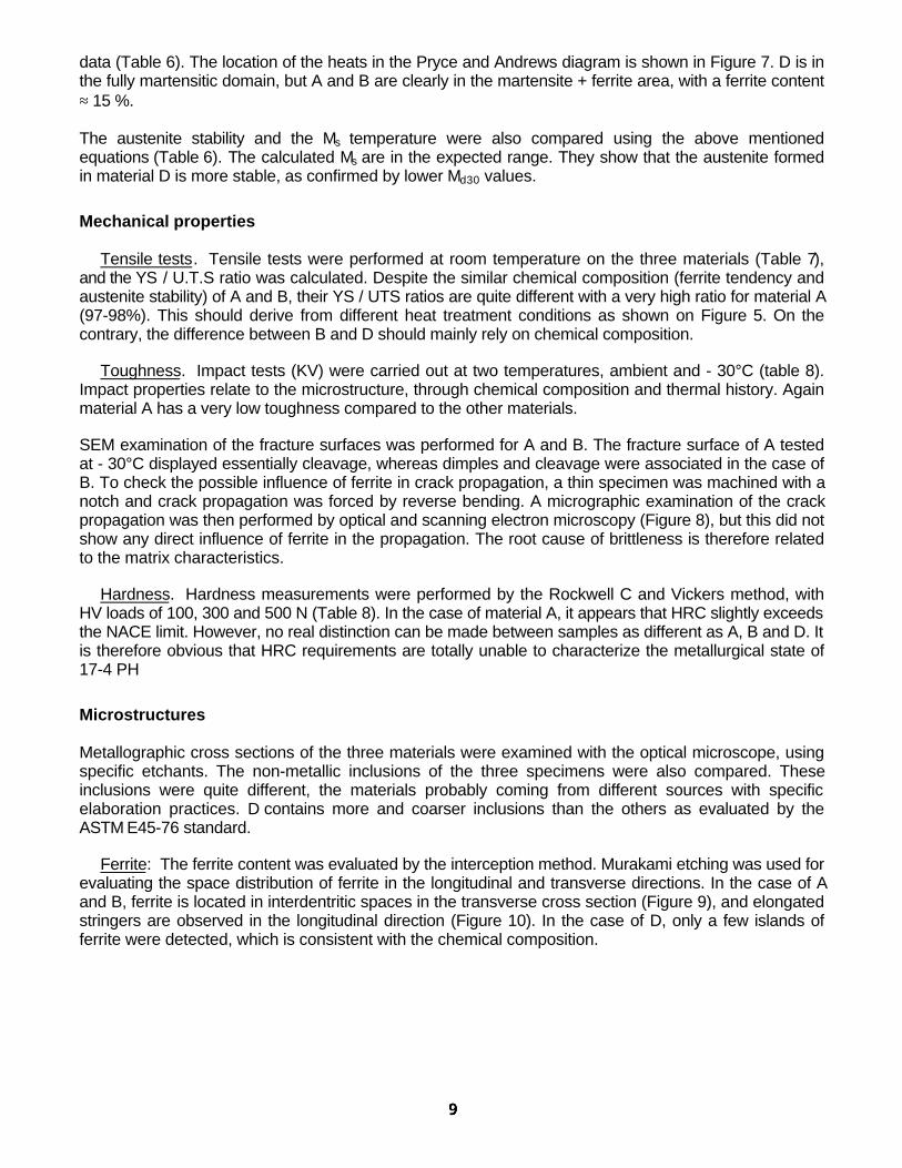
Ferrite: The ferrite content was evaluated by the interception method. Murakami etching was used forevaluating the space distribution of ferrite in the longitudinal and transverse directions. In the case of Aand B, ferrite is located in interdentritic spaces in the transverse cross section (Figure 9), and elongatedstringers are observed in the longitudinal direction (Figure 10). In the case of D, only a few islands offerrite were detected, which is consistent with the chemical composition.
Austenite: Two methods were used to estimate the austenite fraction. The first is based on amagnetic measurement, and the second on Energy Dispersive X-Ray diffraction. The values obtainedby the first method just give a ranking of the three materials. The X ray diffraction technique is morereliable, quantitatively.
Martensite: Catella etching was carried out to reveal the microstructure of the martensitic matrix.B and D showed multiple embedded lath boundaries (figure 10). A appeared to be less reactive toetching , which probably corresponds to a coarser microstructure with less lath boundaries.
All these microstructural data, including the ferrite and austenite content, are summarized on Table 9.They confirm that the high YS / UTS ratio and poor toughness of A are more related to the low austenitecontent than to ferrite. Since the aging requirements were indeed not fully met for A (treatment in factbelow 620°C), this also confirms that austenite is strongly dependent on the effective aging temperature.Unfortunately, the fact that the qualification test coupons (QTC) gave acceptable results raises manyquestions on how representative the QTC is of the actual final condition of the product. It being affectedby quality control (QC) variables such as temperature control, position of the components in the furnace,thermal inertia, emissivity, etc…
The metallurgical aspects of 17-4 PH limitations
The investigations performed after the material failure led to the conclusion that the observed poortoughness resulted from an inadequate heat treatment, especially an aging step performed at too low afinal temperature. Simultaneously, a high YS, high YS / UTS ratio, poor toughness, and low austenitecontent were found, as expected from the literature survey.
Unfortunately, none of the supposed protection of MR 0175 and standard quality control methods wereable to detect this problem.
The only real reliable method is actually a metallurgical characterization of a piece of the actual 17-4 PHcomponents. All the information reported in the present basic data chapter was actually taken from theopen literature, and a minimum of precaution could save time, effort and money. Hence, the real safetyshould be to systematically check all along the manufacturing route:
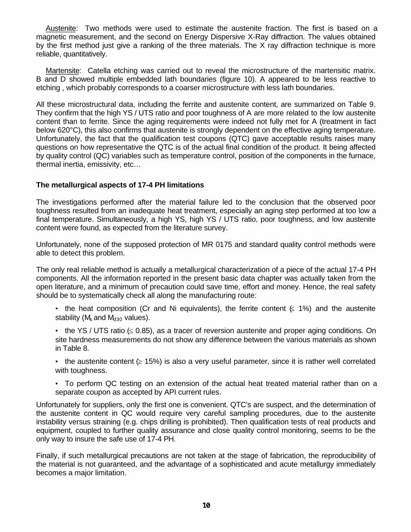
• the heat composition (Cr and Ni equivalents), the ferrite content (≤ 1%) and the austenitestability (Ms and Md30 values).
• the YS / UTS ratio (≤ 0.85), as a tracer of reversion austenite and proper aging conditions. Onsite hardness measurements do not show any difference between the various materials as shownin Table 8.
• the austenite content (≥ 15%) is also a very useful parameter, since it is rather well correlatedwith toughness.
• To perform QC testing on an extension of the actual heat treated material rather than on aseparate coupon as accepted by API current rules.
Unfortunately for suppliers, only the first one is convenient. QTC's are suspect, and the determination ofthe austenite content in QC would require very careful sampling procedures, due to the austeniteinstability versus straining (e.g. chips drilling is prohibited). Then qualification tests of real products andequipment, coupled to further quality assurance and close quality control monitoring, seems to be theonly way to insure the safe use of 17-4 PH.
Finally, if such metallurgical precautions are not taken at the stage of fabrication, the reproducibility ofthe material is not guaranteed, and the advantage of a sophisticated and acute metallurgy immediatelybecomes a major limitation.

MECHANICAL ASPECTS OF 17-4 PH LIMITATIONS
The observed poor toughness of material A was a surprise, but it was not the only one. In addition to theunusually high YS / UTS ratio, the shape of the tensile curve was also found to be unusual (Figure 11).The UTS was reached very soon after the YS, and nearly all the elongation occurred after necking (thismeans that the material is indeed more malleable than ductile).
Such a behavior is also known24 for titanium grade 5 (TA6V), which is another complex alloy mixing abrittle α phase and a ductile β phase. For this reason precisely, Ti Gr 5 suffers an exotic failure modecalled sustained load cracking (SLC). SLC is a delayed rupture, with a time to failure at constantstress24, 25. It is similar to an environmental cracking, but occurs in the absence of a corrosive medium.When stressed between YS and UTS, or even slightly below YS, the alloy undergoes microcreep, whichshould normally last indefinitely at these residual creep rates. Unfortunately, the residual creep of theductile β matrix locally induces direct mechanical interactions between some brittle α grains, whichcrack. This cracking then reinforces the creep of the surrounding β phase, which induces interactionbetween new α grains, etc. This results in the macroscopic cracking of the material.
Sustain load cracking is a little known failure mode, and it has apparently only been reported in titaniumalloys. However, due to the similarities in tensile curves, SLC tests were carried out on the three 17-4PHmaterials, with the same standard specimens previously used for tensile testing. In order to simulatestress concentration conditions, the three materials were stressed at midway between their respectiveYS and UTS , i.e. at a constant stress equal to ½ (YS + UTS). Tests were made in duplicate. The 2samples in material A failed in respectively 17 min and 3.5 hour while the other materials B and D did notfailed after 3 days.
These results indicate that the microstructure of material A, containing a rather high amount of deltaferrite but also a low amount of retained austenite is responsible for the cracking by a mechanismsimilar to the one observed on titanium alloys.
Consequently, beyond the classical risk of poor toughness, the risk of SLC in case of improper heattreatment is an additional mechanical limitation of 17-4 PH. Its prevention may be achieved by controllingthe YS / UTS ratio and extending the hydrotest duration beyond the usual few minutes.
CORROSION ASPECTS OF 17-4 PH LIMITATIONS
After the completion of the two previous studies on the metallurgical and mechanical aspects, thequestion of the real corrosion resistance was immediately raised, and especially the resistance to SSC.On one hand, the partial pressure of H2S was rather low (40 mbar), and the casing hangers had beenclaimed by the supplier to be SSC resistant . On the other hand, the warning in MR 0175 on the low levelof stress thresholds seemed to have been under-appreciated.
A first check was therefore to go back to the origin of the NACE warning. Actually, 17-4 PH wasaccepted in MR 0175 on the basis of very low stress thresholds σcrit in the TM 0177 test26 : for a "lowstrength" heat treatment, σcrit was only 26 % of the actual yield strength (AYS), i.e. only 172 MPa for anAYS of 662 MPa (25/96 ksi). For a "high strength" treatment, more corresponding to our presentspecified minimum yield strength (SMYS) of 724 MPa (105 ksi), the ratio was still less : σcrit = 15% AYS ,i.e. 122/816 in MPa (18/118 ksi). Even if the TM 0177 medium is known to be very severe, it is notobvious that this high severity will entirely compensate for the low σcrit . Therefore, an equipment suppliercannot and should not claim that its product is "SSC resistant" and fit for the purpose of a given call fororder from such a rather limited evidence, and without further verification.
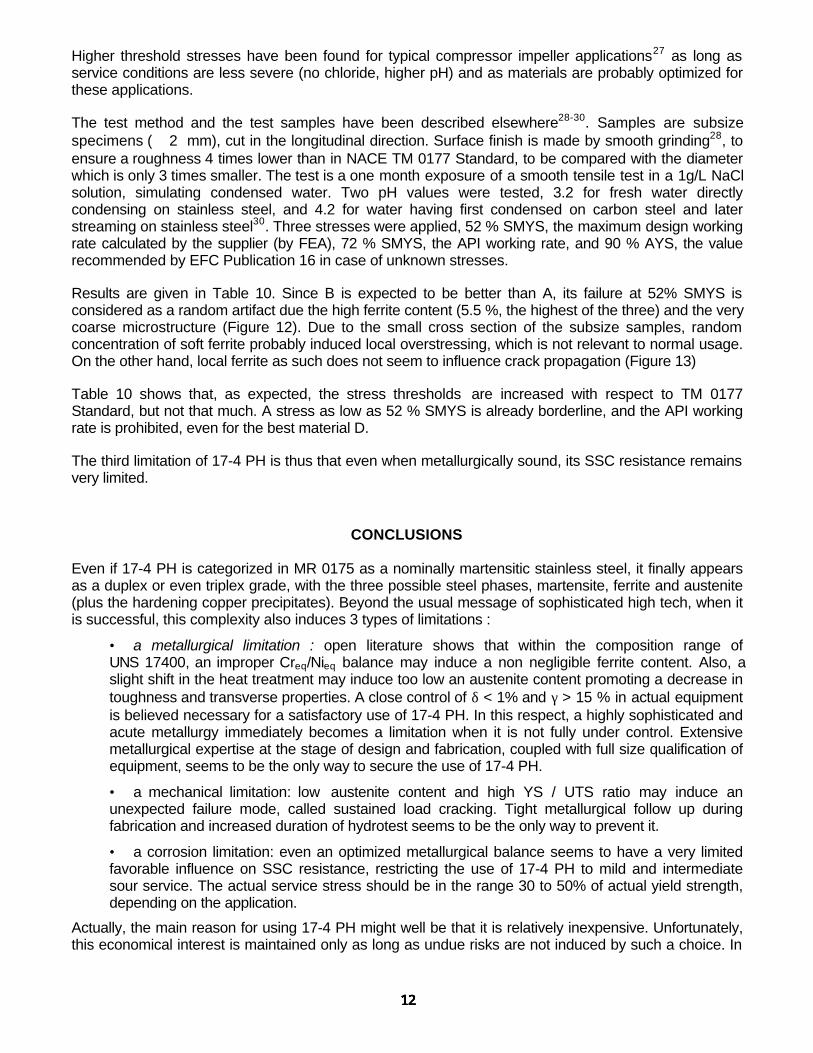
Higher threshold stresses have been found for typical compressor impeller applications27 as long asservice conditions are less severe (no chloride, higher pH) and as materials are probably optimized forthese applications.
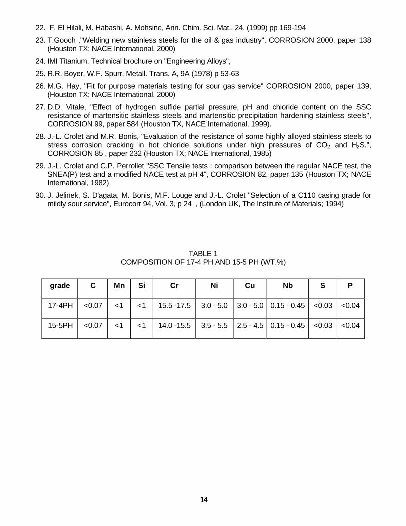
The test method and the test samples have been described elsewhere28-30. Samples are subsizespecimens (∅ 2 mm), cut in the longitudinal direction. Surface finish is made by smooth grinding28, toensure a roughness 4 times lower than in NACE TM 0177 Standard, to be compared with the diameterwhich is only 3 times smaller. The test is a one month exposure of a smooth tensile test in a 1g/L NaClsolution, simulating condensed water. Two pH values were tested, 3.2 for fresh water directlycondensing on stainless steel, and 4.2 for water having first condensed on carbon steel and laterstreaming on stainless steel30. Three stresses were applied, 52 % SMYS, the maximum design workingrate calculated by the supplier (by FEA), 72 % SMYS, the API working rate, and 90 % AYS, the valuerecommended by EFC Publication 16 in case of unknown stresses.
Results are given in Table 10. Since B is expected to be better than A, its failure at 52% SMYS isconsidered as a random artifact due the high ferrite content (5.5 %, the highest of the three) and the verycoarse microstructure (Figure 12). Due to the small cross section of the subsize samples, randomconcentration of soft ferrite probably induced local overstressing, which is not relevant to normal usage.On the other hand, local ferrite as such does not seem to influence crack propagation (Figure 13)
Table 10 shows that, as expected, the stress thresholds are increased with respect to TM 0177Standard, but not that much. A stress as low as 52 % SMYS is already borderline, and the API workingrate is prohibited, even for the best material D.
The third limitation of 17-4 PH is thus that even when metallurgically sound, its SSC resistance remainsvery limited.
CONCLUSIONS
Even if 17-4 PH is categorized in MR 0175 as a nominally martensitic stainless steel, it finally appearsas a duplex or even triplex grade, with the three possible steel phases, martensite, ferrite and austenite(plus the hardening copper precipitates). Beyond the usual message of sophisticated high tech, when itis successful, this complexity also induces 3 types of limitations :
• a metallurgical limitation : open literature shows that within the composition range ofUNS 17400, an improper Creq/Nieq balance may induce a non negligible ferrite content. Also, aslight shift in the heat treatment may induce too low an austenite content promoting a decrease intoughness and transverse properties. A close control of δ < 1% and γ > 15 % in actual equipmentis believed necessary for a satisfactory use of 17-4 PH. In this respect, a highly sophisticated andacute metallurgy immediately becomes a limitation when it is not fully under control. Extensivemetallurgical expertise at the stage of design and fabrication, coupled with full size qualification ofequipment, seems to be the only way to secure the use of 17-4 PH.
• a mechanical limitation: low austenite content and high YS / UTS ratio may induce anunexpected failure mode, called sustained load cracking. Tight metallurgical follow up duringfabrication and increased duration of hydrotest seems to be the only way to prevent it.
• a corrosion limitation: even an optimized metallurgical balance seems to have a very limitedfavorable influence on SSC resistance, restricting the use of 17-4 PH to mild and intermediatesour service. The actual service stress should be in the range 30 to 50% of actual yield strength,depending on the application.
Actually, the main reason for using 17-4 PH might well be that it is relatively inexpensive. Unfortunately,this economical interest is maintained only as long as undue risks are not induced by such a choice. In
this respect, suppliers should be better aware of the consequences of their materials choices andclaims. Due to the overwhelming role of metallurgy and mechanics, equipment must be checked in thesour service conditions in which they are supposed to work satisfactorily.
Also, the "field references" in sour service should be analyzed in greater detail. For mechanical parts innon-pressure containing equipment, failed parts are likely to be considered as replaceable and aregenerally not analyzed in detail nor publicly reported. Failures of materials used for secondary barriers(casing …) are unusual because the probability that the primary barrier has failed and that thesecondary barrier has also failed tends to zero. Most often, the lack of field failure in this case shouldtherefore mean that the secondary barrier had indeed never been exposed to H2S, and in no way that itwas SSC resistant.
To conclude, the notion of application specific testing is often considered by end users for managing thegreat variability of sour service conditions. In the case of 17-4 PH, this concept should certainly beextended to suppliers, for managing the great variability of mechanical design and manufacturing routes.
REFERENCES
1. D.H. Patrick, "MR0175 - A History And Development Study" , CORROSION 99, paper 419, (Houston,TX; NACE International, 1999)
2. ASM Handbook ,Vol. 1, 4th printing, (Metals Park, OH; ASM International ,1995)
3. M.T. Leger, Rev. Metall. CIT , 90, 10, (1993) p 1357-1365
4. M. Lacoude, C. Goux, Mem. Scient. Rev. Metall. , 63, 10, (1966) pp 805-834
5. B. Champin, C. Goux, Mem. Scient. Rev. Metall. , 66, 5, (1969) pp 375-387
6. J.A. Larson, R. Fischer, AFS Trans., Vol. 87, (1979) pp 113-126
7. L. Pryce and K.W. Andrews, J. Iron Steel Inst., 195 (1960), p 145
8. P. Lacombe, B. Baroux, G. Beranger," Stainless Steels", (Les Ulis, France; Les Editions dePhysique, 1993)
9. C.J. Novak, in "Handbook of stainless steels" B. Peckner, I.M. Bernstein Ed. (New York, McGraw Hill,1978)
10. A. Badard , private communication, ASCOMETAL-LUCCHINI Group, Hagondange (France)
11. F.C. Monkman, F.B. Cuff, N.J. Grant, Met. Prog., 73, 4 (1957), p 95
12. T. Angel, Trans. J. Iron Steel Inst. 177, (1954), p 165
13. P. Guiraldenq, B. Vieillard-Baron, J. Hochmann, Mem. Scient. Rev. Metall., 69, 12, (1972) pp 855-867
14. K.P. Balan, A. Venugopal Reddy, D.S. Sarma, Scripta Materialia, 39, 7, (1998) pp 901-905
15. H.R. Habibi Bajguirani, Journal de Physique IV – Colloque C3, supplement au Journal de Physique III,Vol. 4, C3(1994) pp-123-126
16. H.R. Habibi Bajguirani, C. Servant, G. Cizeron, Acta Metall. Mater., 41, 5, (1993) pp 1613-1623
17. H.J. Rack, D. Kalish - Met. Trans. A, 5, 7, (1974) pp 1595-1605
18. C. Leymonie, M.C. Lecocq, M.C. Ottmann, Traitement Thermique, n° 165, (1982) pp 57-62
19. C. Pichard , unpublished data, ASCOMETAL-LUCCHINI Group , Hagondange (France)
20. E.A. Lauchner , Journal of Materials, JM LSA, 5, 1, (1970) pp 129-139
21. F. El Hilali, M. Jerome, M. Habashi, A. Mohsine, J. Galland, Mat.et Tech., n° 11-12, (1998) pp 29-36
22. F. El Hilali, M. Habashi, A. Mohsine, Ann. Chim. Sci. Mat., 24, (1999) pp 169-194
23. T.Gooch ,"Welding new stainless steels for the oil & gas industry", CORROSION 2000, paper 138(Houston TX; NACE International, 2000)
24. IMI Titanium, Technical brochure on "Engineering Alloys",
25. R.R. Boyer, W.F. Spurr, Metall. Trans. A, 9A (1978) p 53-63
26. M.G. Hay, "Fit for purpose materials testing for sour gas service" CORROSION 2000, paper 139,(Houston TX; NACE International, 2000)
27. D.D. Vitale, "Effect of hydrogen sulfide partial pressure, pH and chloride content on the SSCresistance of martensitic stainless steels and martensitic precipitation hardening stainless steels",CORROSION 99, paper 584 (Houston TX, NACE International, 1999).
28. J.-L. Crolet and M.R. Bonis, "Evaluation of the resistance of some highly alloyed stainless steels tostress corrosion cracking in hot chloride solutions under high pressures of CO2 and H2S.",CORROSION 85 , paper 232 (Houston TX; NACE International, 1985)
29. J.-L. Crolet and C.P. Perrollet "SSC Tensile tests : comparison between the regular NACE test, theSNEA(P) test and a modified NACE test at pH 4", CORROSION 82, paper 135 (Houston TX; NACEInternational, 1982)
30. J. Jelinek, S. D'agata, M. Bonis, M.F. Louge and J.-L. Crolet "Selection of a C110 casing grade formildly sour service", Eurocorr 94, Vol. 3, p 24 , (London UK, The Institute of Materials; 1994)
TABLE 1COMPOSITION OF 17-4 PH AND 15-5 PH (WT.%)
grade C Mn Si Cr Ni Cu Nb S P
17-4PH <0.07 <1 <1 15.5 -17.5 3.0 - 5.0 3.0 - 5.0 0.15 - 0.45 <0.03 <0.04
15-5PH <0.07 <1 <1 14.0 -15.5 3.5 - 5.5 2.5 - 4.5 0.15 - 0.45 <0.03 <0.04

TABLE 2 NACE HEAT TREATMENTS FOR 17-4 PH STAINLESS STEEL
Conditions Objective Related problemsAnnealing
at T= 1040°C
time t to be adjusted tothe treated component
cool below 32°C
redissolve carbides in austenite (only partially for Nb(C,N) )
homogenizationrecrystallization
martensitic structure after coolingwith low retained austenite
Excessive grain growthgrain boundary segregation for high T and t
(factor of embrittlement)Retained austenite, inhomogeneity if the final
temperature not controlled
1st aging at 620°C(T>Ac1)
4 h at temperaturecool below 32°C
Hardening (Cu + carbides)Formation of reversion austenite
Importance of temperature control :if T< 620°C, higher mechanical resistance, low toughnessif T>620°C, possible fresh martensite
2nd aging at 620°C(T>Ac1)
4 h at temperaturecool below 32°C
Increase the contentin reversion austenite
carbide precipitation andcoalescence
Importance of temperature control
idem
Or1st Aging at 760°C *
(T>Ac3)2 hours
minimum*cool below 32°C
In the austenite domain
Refine the austenite structurebefore hardening treatment
more nucleation sitesfor reversion austenite
Importance of temperature control
* followed by a second aging treatment conducted at 620°C during 4 hours, as for the 1st type of aging sequence.
TABLE 3 INFLUENCE OF NI AND C CONTENT ON MECHANICAL PROPERTIES AND MICROSTRUCTURE
C(wt.%)
Ni (wt.%)
Cr(wt.%)
Y.S.(MPa)
UTS(MPa)
A%
YSUTS
austenite%
ferrite%
0.025 4 16.5 569 785 20 0.72 16 3
0.025 5 16.5 500 844 18 0.59 25 <1
0.060 4 16.5 589 912 18 0.64 13 not given
Wrought bars - 1% Mn, 0.1 to 0.2% Si - Applied thermal treatments: annealing at 1000°C then aging2 hours at 600°C - phase content evaluated by X.Ray Diffraction
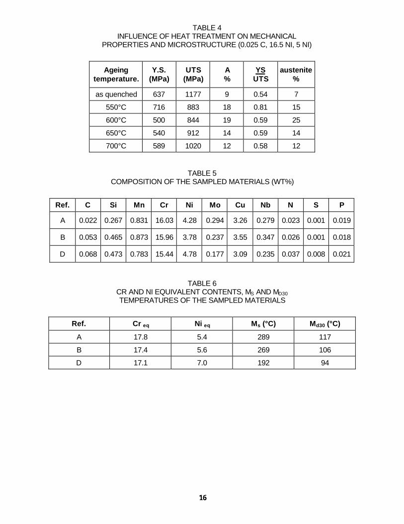
TABLE 4INFLUENCE OF HEAT TREATMENT ON MECHANICAL
PROPERTIES AND MICROSTRUCTURE (0.025 C, 16.5 NI, 5 NI)
Ageingtemperature.
Y.S.(MPa)
UTS(MPa)
A%
YSUTS
austenite%
as quenched 637 1177 9 0.54 7
550°C 716 883 18 0.81 15
600°C 500 844 19 0.59 25
650°C 540 912 14 0.59 14
700°C 589 1020 12 0.58 12
TABLE 5COMPOSITION OF THE SAMPLED MATERIALS (WT%)
Ref. C Si Mn Cr Ni Mo Cu Nb N S P
A 0.022 0.267 0.831 16.03 4.28 0.294 3.26 0.279 0.023 0.001 0.019
B 0.053 0.465 0.873 15.96 3.78 0.237 3.55 0.347 0.026 0.001 0.018
D 0.068 0.473 0.783 15.44 4.78 0.177 3.09 0.235 0.037 0.008 0.021
TABLE 6CR AND NI EQUIVALENT CONTENTS, MS AND MD30TEMPERATURES OF THE SAMPLED MATERIALS
Ref. Cr eq Ni eq Ms (°C) Md30 (°C)
A 17.8 5.4 289 117
B 17.4 5.6 269 106
D 17.1 7.0 192 94

TABLE 7MECHANICAL PROPERTIES OF THE SAMPLED MATERIALS
Ref0.2% Y.S
(MPa)0.2% Y.S.
(ksi)UTS
(MPa)UTS(ksi)
A % Y.SUTS
A 10161046
147.3151.7
10461066
152.0154.7
17.114.0
0.970.98
B 853860
123.6124.7
983989
142.5143.5
20.018.2
0.870.87
D 832835
120.5121.1
10421029
151.0149.3
21.3 0.800.81
TABLE 8HARDNESS AND TOUGHNESS
Ref. HRC HV ambientKV (J)
- 30°CKV (J)
A (long) 32 - 34.5 - 34 353 - 358 14 – 13 - 15 7 - 7 - 7
B (long) 30.5 - 32 - 33 322 - 360 - 330 - 320 51 – 45 – 59 - 59 32 - 34 - 41 - 45
D (long) 30.5 - 32 - 33 322 - 342 105 -108 76 - 78
TABLE 9MICROSTRUCTURES
Ref δ % γ % Microstructure
A 4 25*6**
elongated ferrite oriented in the direction of hot working martensite,coarse Nb(C,N) located at the ferrite/martensite boundaries and inside the
ferritecarbides at the grain boundaries
B 5.5 37*18**
elongated ferrite oriented in the direction of hot working martensite,coarse Nb(C,N) located at the ferrite/martensite boundaries and inside the ferritefiner Nb-rich carbides distributed in the martensite and at the grain boundaries
more interfaces inside the martensite – imbricated laths
D < 1 42*23**
low fraction of ferritemartensite with multiple imbricated interfaces
some areas showing segregation effects (retained austenite ?)
* magnetic; ** X ray diffraction
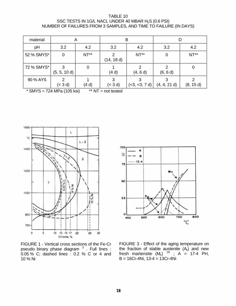
TABLE 10SSC TESTS IN 1G/L NACL UNDER 40 MBAR H2S (0.6 PSI)
NUMBER OF FAILURES FROM 3 SAMPLES, AND TIME TO FAILURE (IN DAYS)
material A B D
pH 3.2 4.2 3.2 4.2 3.2 4.2
52 % SMYS* 0 NT** 2(14, 18 d)
NT** 0 NT**
72 % SMYS* 3(5, 5, 10 d)
0 1(4 d)
2(4, 6 d)
2(6, 6 d)
0
90 % AYS 2(< 3 d)
1(4 d)
3(< 3 d)
3(<3, <3, 7 d)
3(4, 4, 21 d)
2(8, 15 d)
* SMYS = 724 MPa (105 ksi) ** NT = not tested
FIGURE 1 - Vertical cross sections of the Fe-Crpseudo binary phase diagram 3 . Full lines :0.05 % C; dashed lines : 0.2 % C or 4 and10 % Ni
FIGURE 3 - Effect of the aging temperature onthe fraction of stable austenite (As) and newfresh martensite (Mn) 18 ; A = 17-4 PH,B = 16Cr-4Ni, 13-4 = 13Cr-4Ni

FIGURE 2 - Effect of the aging temperature(2 hours) on the HV hardness
FIGURE 4 - Effect of Cu on the aging curves15
:A = 17-4 PH, B = 16Cr-4Ni
FIGURE 5 - Effect of the aging temperature onthe YS/UTS ratio15: A = 17-4 PH, B = 16Cr-4Ni
FIGURE 6 - Effect of the aging temperature onthe toughness 17-4 PH of various origin

Pryce & Andrews diagram
0
5
10
15
20
25
30
10 15 20 25 30 35
Cr eq
Ni e
q
F % %15
30
60
80
40
+ + +
BD
A
A
M+F
M A+F
F
FIGURE 7 - Position of the three materials A, Band D in the Pryce and Andrews diagram7
FIGURE 9 - Transverse cross section ofmaterial B, showing interdendritic δ ferrite(Murakami etching)
FIGURE 8 - Lack of influence of ferrite on crackpropagation in material A
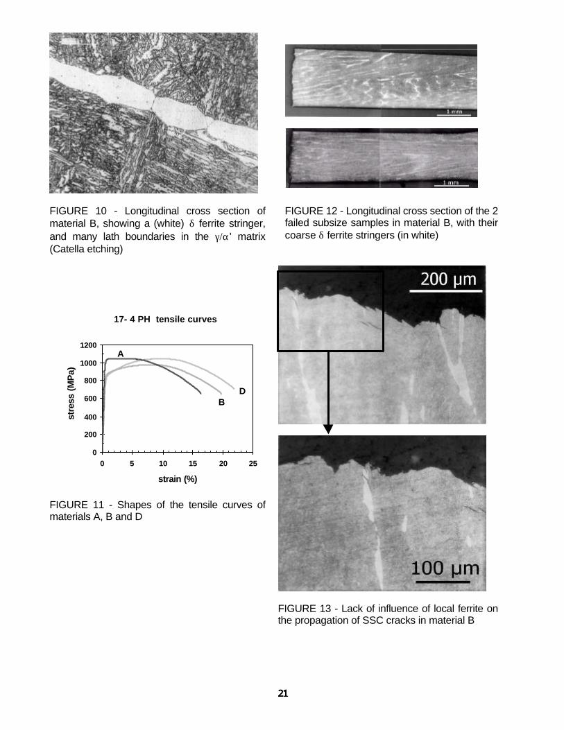
FIGURE 10 - Longitudinal cross section ofmaterial B, showing a (white) δ ferrite stringer,and many lath boundaries in the γ/α' matrix(Catella etching)
FIGURE 12 - Longitudinal cross section of the 2failed subsize samples in material B, with theircoarse δ ferrite stringers (in white)
17- 4 PH tensile curves
0
200
400
600
800
1000
1200
0 5 10 15 20 25
strain (%)
stre
ss (
MP
a)
A
BD
FIGURE 11 - Shapes of the tensile curves ofmaterials A, B and D
FIGURE 13 - Lack of influence of local ferrite onthe propagation of SSC cracks in material B
Related Documents