Routing Notes Compiled by Mr. Maloo These notes are not my original work. These notes are just a compilation of notes from different sources for my self-study. These notes are not for sale / distribution / reproduction in any form. The credit goes to the original writers of these fact sheets. Road to CCIE 8/19/2009

02 Ccnp Route 642-902 Notes by Mr. Maloo
Oct 28, 2014
Cisco Route 642-902 Exam Prep
Welcome message from author
This document is posted to help you gain knowledge. Please leave a comment to let me know what you think about it! Share it to your friends and learn new things together.
Transcript
Routing NotesCompiled by Mr. Maloo
These notes are not my original work. These notes are just a compilation of notes from different sources for my self-study. These notes are not for sale / distribution / reproduction in any form. The credit goes to the original writers of these fact sheets.
Road to CCIE8/19/2009
Routing Notes
Introduction
Before you start this course, you should have completed the following course(s) or have equivalent networking experience:
Cisco Exam 640-802 OR Cisco Exam 640-822 AND Exam 640-816
Cisco Device Icons
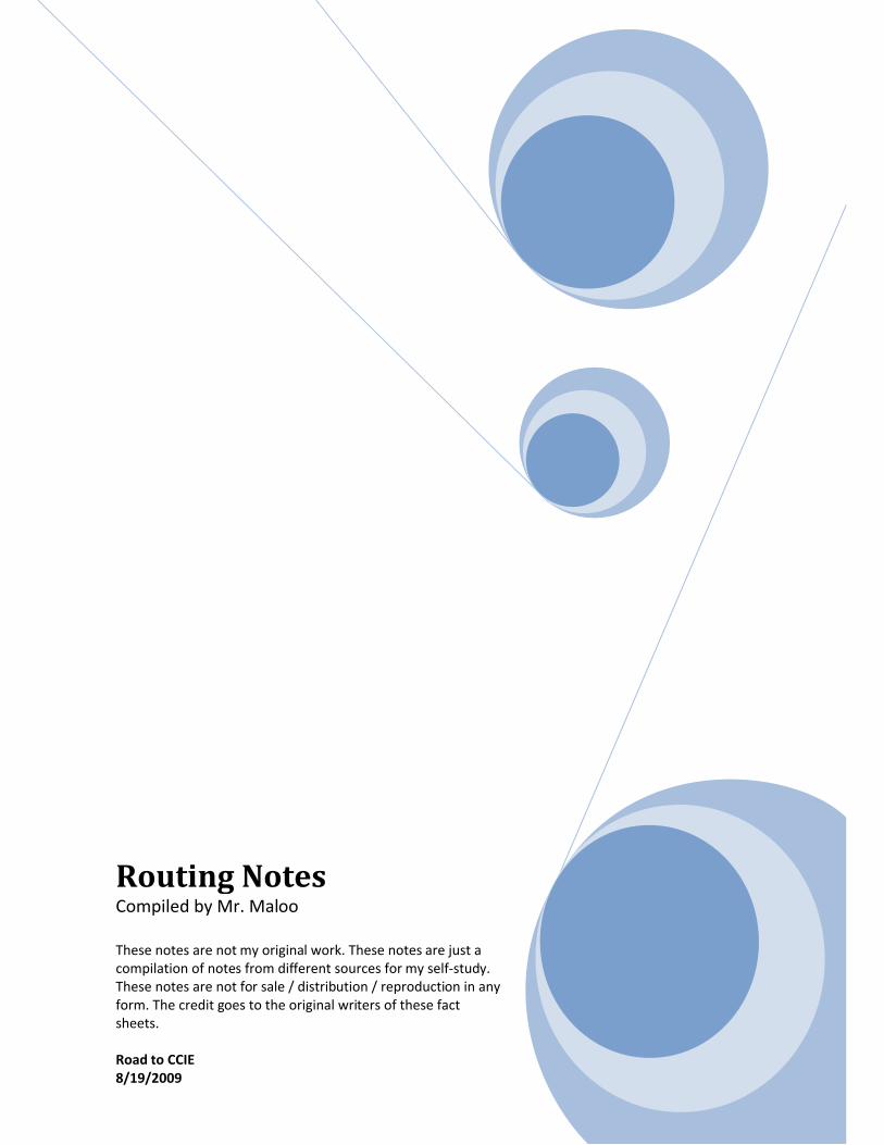
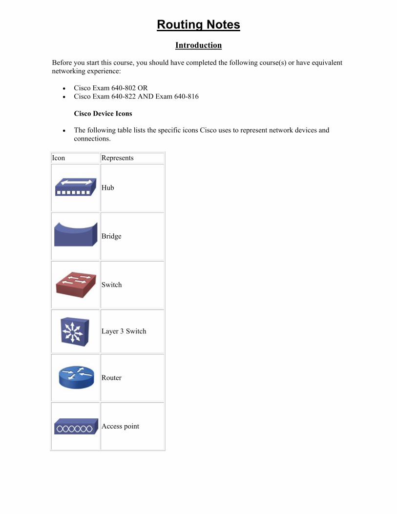
The following table lists the specific icons Cisco uses to represent network devices and connections.
Icon Represents
Hub
Bridge
Switch
Layer 3 Switch
Router
Access point
Network cloud
Ethernet connection
Serial Line connection
Wireless connection
Virtual Circuit
Static and Dynamic Routing Overview
As you study this section, answer the following questions:
Under which circumstances would you choose static routing over dynamic routing? What is the main purpose of a floating static route? What are the advantages of using On-Demand Routing (ODR)?
After finishing this section, you should be able to complete the following tasks:
Use static route configuration commands to create a static route.
Static Routing Facts
Static routing is an addressing method in which IP configuration information must be built and updated manually on each host by an administrator. Static routing:
Does not automatically update or exchange information between routers. Is optimal for use in hub-and-spoke designs in which:
o All remote sites default back to the central site. o The router(s) at the central site have a static route for all subnets at each remote site.
Use static routing:
When administrators need complete control over the routes that are used by a router. On networks with a very small number of hosts. On networks that do not change often or that will not grow. In environments with low-capacity routers that wouldn't optimally support a dynamic
routing system. To permanently assign IP addresses to hosts that must always have the same address (such
as printers, servers, or routers). For hosts that cannot accept an IP address from DHCP. To reduce DHCP-related traffic. To back up a dynamic route. On networks with slow bandwidth links (such as dial-up). In scenarios in which a route needs to appear to the router as a directly connected network.
Drawbacks to static routing are:
Static routing does not automatically adapt to topology changes on a fluid network. Static routing adds additional burden to the administrator because IP information must be
configured for every host. When a static route is created from a local host to a destination, a return route must also be
created. Static routing is very susceptible to configuration errors and duplicate IP address
configuration errors (two hosts that have been assigned the same IP address). Static routing also disables both APIPA and DHCP capabilities on the host.
The following table describes the most common types of static routes:
Static Route
Description
Default route
The most common type of static route is a default route. A default route is a route that is considered to match all destination IP addresses. With a default route, when a packet's destination IP address does not match any other routes, the router uses the default route
for forwarding the packet. You should be familiar with the following default route details:
Default routes work best when only one path exists to a part of the network. One default route in the routing table could replace hundreds of static route
entries in the routing table. When the default route is not set, the router discards packets that do not match a
route in the routing table.
Floating
A floating static route is a static route whose administrative distance has been manually configured to be greater than the administrative distance of dynamic routes; thus making it less desirable than the dynamic route it supports. This configuration:
Does not use the floating static route by default while a dynamic route is active. Enables a floating static route to automatically act as a backup for a dynamic
route if it should fail.
Dynamic Routing Facts
Dynamic routing is an addressing method that senses changes in the network topology and responds accordingly without administrator involvement. Dynamic routers:
Propagate changes and shifts in the network topology to each router in the network, causing the routing tables on each router to always be up-to-date.
Are responsible for all networks to which they are connected. Employ additional processes or services to exchange routing information between routers.
Dynamic addresses:
Are assigned when a network service establishes contact. Are released when a session ends.
The most common dynamic routing protocols are:
Border Gateway Protocol (BGP) Enhanced Interior Gateway Routing Protocol (EIGRP) Intermediate System-to-Intermediate System (IS-IS) Open Shortest Path First (OSPF) Routing Information Protocol (RIP)
The main drawback to dynamic routing is the burden it places on network bandwidth and router resources.
On-Demand Routing Facts
On-Demand Routing (ODR) uses the Cisco Discovery Protocol (CDP) to transfer network information between routers. ODR makes it possible to find the following types of characteristics about neighboring devices:
Device type IP address Cisco IOS version being run Network capabilities
ODR:
Has the ability to provide routing information without the overhead of dynamic routing or the manual configuration of static routing.
Only works in networks with a hub and spoke (sometimes called stub) topology. Does not report metric information; hub routers use a hop count of 1 as the metric for all
routes reported. Uses CDP to send IP prefix information to the hub router. Allows different subnets within the same major network to have different subnet masks,
known as Variable-Length Subnet Masking (VLSM).
In networks that employ ODR:
The stub routers send prefix information for all of their directly connected networks. The hub router sends a default route to the spokes that points back to itself. The hub router updates the stub networks reported by ODR in its routing table. Hub routers can be configured to redistribute routing information into a dynamic routing
protocol.
Classful and Classless Routing Overview
As you study this section, answer the following questions:
What is the major limitation of a classful routing environment? How does classless routing improve upon classful routing? Which routing protocols support classless routing?
After finishing this section, you should be able to complete the following tasks:
Select protocols which require manual summarization.
Classful and Classless Routing Facts
You should know the following information about classes and routing:
Classful addresses are IP addresses that use the default subnet mask. Classless addresses are those that use a custom mask value to separate network and host
portions of the IP address.
The following table describes the differences between classful and classless routing:
Routing type
Description
Classful
Classful routing protocols do not include default subnet mask information in routing updates. The default subnet mask is used to identify the network and host portions of the address. Classful routing protocols are:
Interior Gateway Routing Protocol (IGRP) Routing Information Protocol version 1(RIPv1)
Note: IGRP is not supported after Cisco ISO release 12.3.
Classful protocols:
Make it necessary for the same subnet mask to be used on all subnetworks withinthe same major network to allow routing information to be transferred correctly.
Assume that network addresses start and stop within the constraints of classful boundaries.
Do not support discontiguous subnets within networks. A discontiguous subnet is a subnet of the same major network that is separated by a different major network.
Automatically summarize networks around classful boundaries, thus causing: o Any specific or detailed subnet information to be lost in cases where
addresses have been subnetted beyond the traditional classful boundaries. o Subnets to not be advertised to different major networks. o Discontiguous networks to not be visible to one another.
Classless
Classless routing protocols use a custom mask value to separate network and host portions of the IP address. They are considered to be second-generation protocols because they improve on the limitations of classful protocols. The most common routing protocols are:
Enhanced Interior Gateway Routing Protocol (EIGRP) Intermediate System-to-Intermediate System (IS-IS) Open Shortest Path First (OSPF)
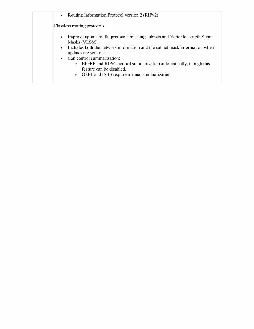
Routing Information Protocol version 2 (RIPv2)
Classless routing protocols:
Improve upon classful protocols by using subnets and Variable Length Subnet Masks (VLSM).
Includes both the network information and the subnet mask information when updates are sent out.
Can control summarization: o EIGRP and RIPv2 control summarization automatically, though this
feature can be disabled. o OSPF and IS-IS require manual summarization.
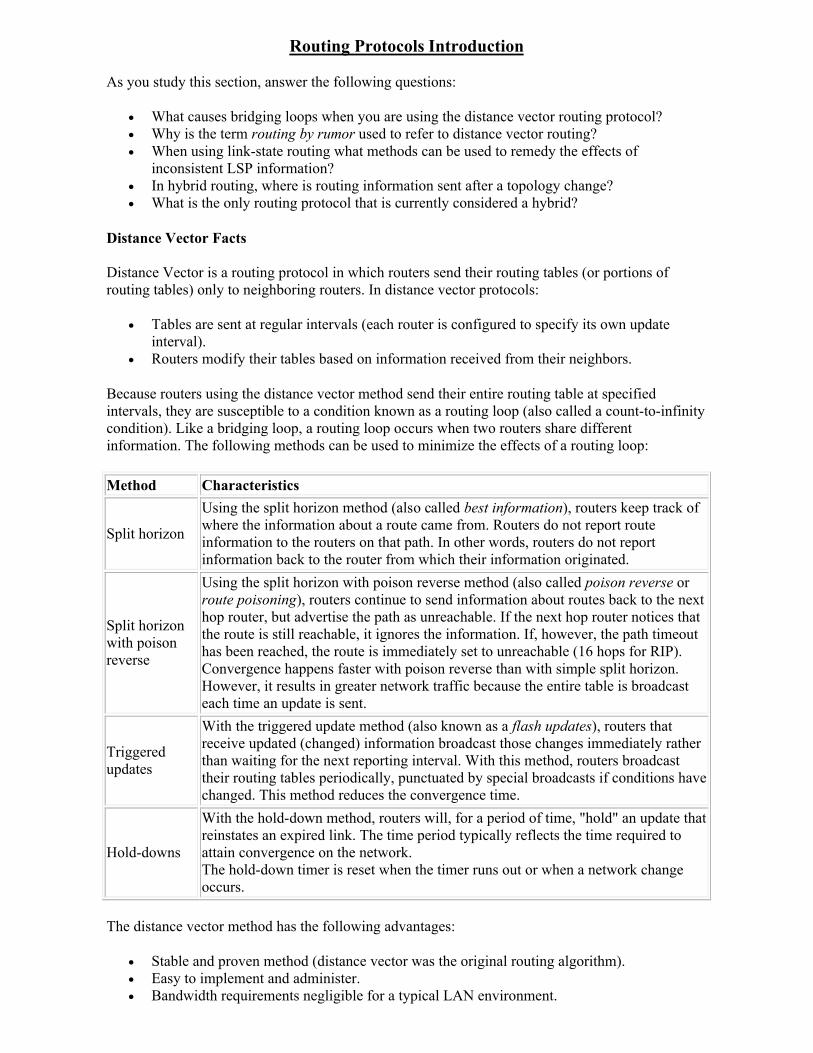
Routing Protocols Introduction
As you study this section, answer the following questions:
What causes bridging loops when you are using the distance vector routing protocol? Why is the term routing by rumor used to refer to distance vector routing? When using link-state routing what methods can be used to remedy the effects of
inconsistent LSP information? In hybrid routing, where is routing information sent after a topology change? What is the only routing protocol that is currently considered a hybrid?
Distance Vector Facts
Distance Vector is a routing protocol in which routers send their routing tables (or portions of routing tables) only to neighboring routers. In distance vector protocols:
Tables are sent at regular intervals (each router is configured to specify its own update interval).
Routers modify their tables based on information received from their neighbors.
Because routers using the distance vector method send their entire routing table at specified intervals, they are susceptible to a condition known as a routing loop (also called a count-to-infinity condition). Like a bridging loop, a routing loop occurs when two routers share different information. The following methods can be used to minimize the effects of a routing loop:
Method Characteristics
Split horizon
Using the split horizon method (also called best information), routers keep track of where the information about a route came from. Routers do not report route information to the routers on that path. In other words, routers do not report information back to the router from which their information originated.
Split horizon with poison reverse
Using the split horizon with poison reverse method (also called poison reverse or route poisoning), routers continue to send information about routes back to the next hop router, but advertise the path as unreachable. If the next hop router notices that the route is still reachable, it ignores the information. If, however, the path timeout has been reached, the route is immediately set to unreachable (16 hops for RIP). Convergence happens faster with poison reverse than with simple split horizon. However, it results in greater network traffic because the entire table is broadcast each time an update is sent.
Triggered updates
With the triggered update method (also known as a flash updates), routers that receive updated (changed) information broadcast those changes immediately rather than waiting for the next reporting interval. With this method, routers broadcast their routing tables periodically, punctuated by special broadcasts if conditions have changed. This method reduces the convergence time.
Hold-downs
With the hold-down method, routers will, for a period of time, "hold" an update that reinstates an expired link. The time period typically reflects the time required to attain convergence on the network.The hold-down timer is reset when the timer runs out or when a network change occurs.
The distance vector method has the following advantages:
Stable and proven method (distance vector was the original routing algorithm). Easy to implement and administer. Bandwidth requirements negligible for a typical LAN environment.
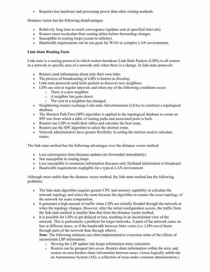
Requires less hardware and processing power than other routing methods.
Distance vector has the following disadvantages:
Relatively long time to reach convergence (updates sent at specified intervals). Routers must recalculate their routing tables before forwarding changes. Susceptible to routing loops (count-to-infinity). Bandwidth requirements can be too great for WAN or complex LAN environments.
Link-State Routing Facts
Link-state is a routing protocol in which routers broadcast Link-State Packets (LSPs) to all routers in a network or specific area of a network only when there is a change. In link-state protocols:
Routers send information about only their own links. The process of broadcasting of LSPs is known as flooding. Link-state protocols send hello packets to discover new neighbors. LSPs are sent at regular intervals and when any of the following conditions occur:
o There is a new neighbor. o A neighbor has gone down. o The cost to a neighbor has changed.
Neighboring routers exchange Link-state Advertisements (LSAs) to construct a topological database.
The Shortest Path First (SPF) algorithm is applied to the topological database to create an SPF tree from which a table of routing paths and associated ports is built.
Routers use LSPs to build their tables and calculate the best route. Routers use the SPF algorithm to select the shortest route. Network administrators have greater flexibility in setting the metrics used to calculate
routes.
The link-state method has the following advantages over the distance vector method:
Less convergence time (because updates are forwarded immediately) Not susceptible to routing loops Less susceptible to erroneous information (because only firsthand information is broadcast) Bandwidth requirements negligible for a typical LAN environment
Although more stable than the distance vector method, the link-state method has the following problems:
The link-state algorithm requires greater CPU and memory capability to calculate the network topology and select the route because the algorithm re-creates the exact topology of the network for route computation.
It generates a high amount of traffic when LSPs are initially flooded through the network or when the topology changes. However, after the initial configuration occurs, the traffic from the link-state method is smaller than that from the distance vector method.
It is possible for LSPs to get delayed or lost, resulting in an inconsistent view of the network. This is particularly a problem for larger networks, if parts of the network come on line at different times, or if the bandwidth between links varies (i.e. LSPs travel faster through parts of the network than through others). Note: The following solutions are often implemented to overcome some of the effects of inconsistent LSP information:
o Slowing the LSP update rate keeps information more consistent. o Routers can be grouped into areas. Routers share information within the area, and
routers on area borders share information between areas. (Areas logically subdivide an Autonomous System (AS), a collection of areas under common administration.)
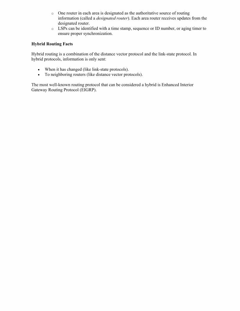
o One router in each area is designated as the authoritative source of routing information (called a designated router). Each area router receives updates from the designated router.
o LSPs can be identified with a time stamp, sequence or ID number, or aging timer to ensure proper synchronization.
Hybrid Routing Facts
Hybrid routing is a combination of the distance vector protocol and the link-state protocol. In hybrid protocols, information is only sent:
When it has changed (like link-state protocols). To neighboring routers (like distance vector protocols).
The most well-known routing protocol that can be considered a hybrid is Enhanced Interior Gateway Routing Protocol (EIGRP).
EIGRP
As you study this section, answer the following questions:
How does EIGRP minimize network bandwidth usage for routing updates? Under what circumstances are hello packets sent every 5 seconds or every 60 seconds? How do the two types of EIGRP tables differ (e.g. neighbor table vs. topology table)? What is the purpose of DUAL and what elements does it use to perform this function?
After finishing this section, you should be able to complete the following tasks:
Given a scenario, calculate the Feasible Distance and the Feasible Successor.
This section covers the following exam objectives:
101. Explain the functions and operations of EIGRP (e.g., DUAL).
EIGRP Facts
Enhanced Interior Gateway Routing Protocol (EIGRP) is a Cisco-proprietary balanced hybrid routing protocol that combines the best features of distance vector and link-state routing. EIGRP:
Maintains partial network topology information in addition to routes. Sends the subnet mask in the routing update. It supports VLSM. Supports automatic classful route summarization at major network boundaries (this is the
default in EIGRP). Manual route summarization can also be configured on arbitrary network boundaries to reduce the routing table size. Note: Autosummarization can cause problems in a network that has discontiguous subnets.
Minimizes network bandwidth usage for routing updates in the following ways: o During normal operation EIGRP transmits only hello packets across the network. o EIGRP does not send periodic routing updates like RIP and IGRP. o When change occurs, only routing table changes are propagated in EIGRP; not the
entire table. Requires less processing and memory than link-state protocols. Converges more quickly than distance vector protocols. In some cases, convergence can be
almost instantaneous because an EIGRP router stores backup routes for destinations. If no appropriate route or backup exists in the routing table, EIGRP will query the routing tables of neighbor routers to discover an alternate route. In this manner, EIGRP can quickly adapt to alternate routes when changes occur.
Exchanges the full routing table at startup, then exchanges partial routing updates each time the path or the metric for a route changes. The partial routing updates:
o Only contain the information about the changed links; not the entire routing table. o Are bounded so that they are only propagated to the routers that require the
information. Routers store their neighbor's routing tables. This allows for EIGRP routers to adapt quickly
to any changes in the network. Does not have the 16 hop limitation of RIP. Uses a composite metric (also known as K values) that can consist of bandwidth, delay,
reliability, MTU, and load; though it is recommended by Cisco to only use bandwidth and delay. The metric is expressed as the number of microseconds.
o The degree to which each value is used to calculate the metric can be customized by modifying one of five K values.
o By default, K1 and K3 are set to 1, while K2, K4, and K5 are set to 0. These settings mean that with the default configuration, only delay and bandwidth have an effect on the metric.
o On serial links, a default bandwidth of 1544 kbps is used. EIGRP does not detect the actual bandwidth on the link. You must manually configure bandwidth values for accurate metric calculations.
o On LAN-based interfaces, the speed of the interface becomes the bandwidth. Uses an Autonomous System (AS) number to identify routers that are to share EIGRP
information. All routing prefixes within the AS have the same AS number. Supports load balancing on equal-cost and unequal cost links. This means that EIGRP can
keep multiple paths to a single network, even if they have a different cost. With IOS 12.4 and above, EIGRP supports up to 16 paths (earlier versions supported up to 6), with the default being 4 equal-cost paths.
Uses Protocol-Dependent Modules (PDM) to carry out the requirements specific to independent protocols. PDMs:
o Operate completely independent of one another. o Learn from other sources to make decisions about adding routes. o Offer support for various routed protocols (e.g. IP, IPX, and AppleTalk). o Carry information from the routing table to the topology table.
Uses Transport Layer protocol 88. Has the following administrative distances:
o Summary route: 5 o Standard route: 90 o External route: 170
Uses neighbor discovery/recovery to dynamically learn about the other routers on their directly attached networks. Neighbor discovery/recovery:
o Allows routers to know when neighbors become unreachable or inoperative. o Periodically sends and receives small hello packets to and from neighboring routers.
If hello packets start to not be received from a particular router, neighbor discovery/recovery will assume that the router is not functioning.
EIGRP Packets Facts
EIGRP uses Reliable Transport Protocol (RTP) to deliver packets to neighboring routers in a guaranteed, ordered manner. EIGRP uses the following types of packets and messages:
Term Description
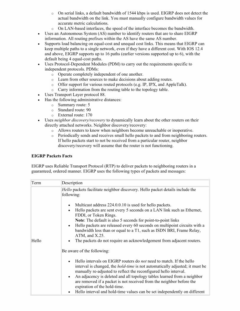
Hello
Hello packets facilitate neighbor discovery. Hello packet details include the following:
Multicast address 224.0.0.10 is used for hello packets. Hello packets are sent every 5 seconds on a LAN link such as Ethernet,
FDDI, or Token Rings.Note: The default is also 5 seconds for point-to-point links
Hello packets are released every 60 seconds on multipoint circuits with a bandwidth less than or equal to a T1, such as ISDN BRI, Frame Relay, ATM, and X.25.
The packets do not require an acknowledgement from adjacent routers.
Be aware of the following:
Hello intervals on EIGRP routers do not need to match. If the hello interval is changed, the hold-time is not automatically adjusted; it must be manually re-adjusted to reflect the reconfigured hello interval.
An adjacency is deleted and all topology tables learned from a neighbor are removed if a packet is not received from the neighbor before the expiration of the hold-time.
Hello interval and hold-time values can be set independently on different
routers.
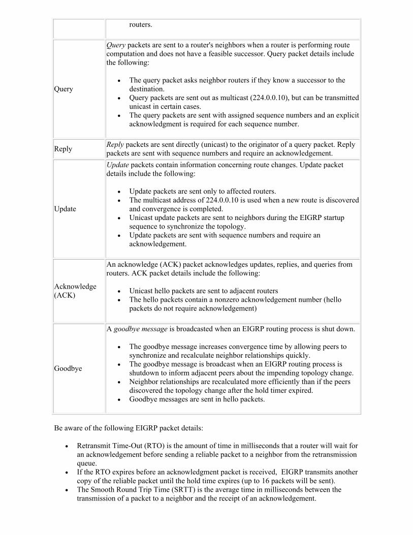
Query
Query packets are sent to a router's neighbors when a router is performing route computation and does not have a feasible successor. Query packet details include the following:
The query packet asks neighbor routers if they know a successor to the destination.
Query packets are sent out as multicast (224.0.0.10), but can be transmitted unicast in certain cases.
The query packets are sent with assigned sequence numbers and an explicit acknowledgment is required for each sequence number.
ReplyReply packets are sent directly (unicast) to the originator of a query packet. Reply packets are sent with sequence numbers and require an acknowledgement.
Update
Update packets contain information concerning route changes. Update packet details include the following:
Update packets are sent only to affected routers. The multicast address of 224.0.0.10 is used when a new route is discovered
and convergence is completed. Unicast update packets are sent to neighbors during the EIGRP startup
sequence to synchronize the topology. Update packets are sent with sequence numbers and require an
acknowledgement.
Acknowledge (ACK)
An acknowledge (ACK) packet acknowledges updates, replies, and queries from routers. ACK packet details include the following:
Unicast hello packets are sent to adjacent routers The hello packets contain a nonzero acknowledgement number (hello
packets do not require acknowledgement)
Goodbye
A goodbye message is broadcasted when an EIGRP routing process is shut down.
The goodbye message increases convergence time by allowing peers to synchronize and recalculate neighbor relationships quickly.
The goodbye message is broadcast when an EIGRP routing process is shutdown to inform adjacent peers about the impending topology change.
Neighbor relationships are recalculated more efficiently than if the peers discovered the topology change after the hold timer expired.
Goodbye messages are sent in hello packets.
Be aware of the following EIGRP packet details:
Retransmit Time-Out (RTO) is the amount of time in milliseconds that a router will wait for an acknowledgement before sending a reliable packet to a neighbor from the retransmission queue.
If the RTO expires before an acknowledgment packet is received, EIGRP transmits another copy of the reliable packet until the hold time expires (up to 16 packets will be sent).
The Smooth Round Trip Time (SRTT) is the average time in milliseconds between the transmission of a packet to a neighbor and the receipt of an acknowledgement.
Split Horizon and Poison Reverse are technologies used to prohibit a router from re-advertising a route out of the interface from which it was learned. If a route is re-advertised, it is marked as unreachable. Split Horizon:
o Is enabled on all interfaces by default. o Reduces the possibility of loops.
Stub routing is a topology in which the remote router forwards all traffic that is not local to a hub router. Be aware of the following packet details in regards to stub routing:
o Stub routers indicate a status of stub router in the hello packets sent to neighboring routers. This causes the neighbor (hub router) to not query the stub router for any routes, and answers query packets on behalf of the stub router.
o A stub router that has a stub peer does not send query packets to that peer.
EIGRP Table Facts
You should be aware of the following EIGRP tables:
Table Description
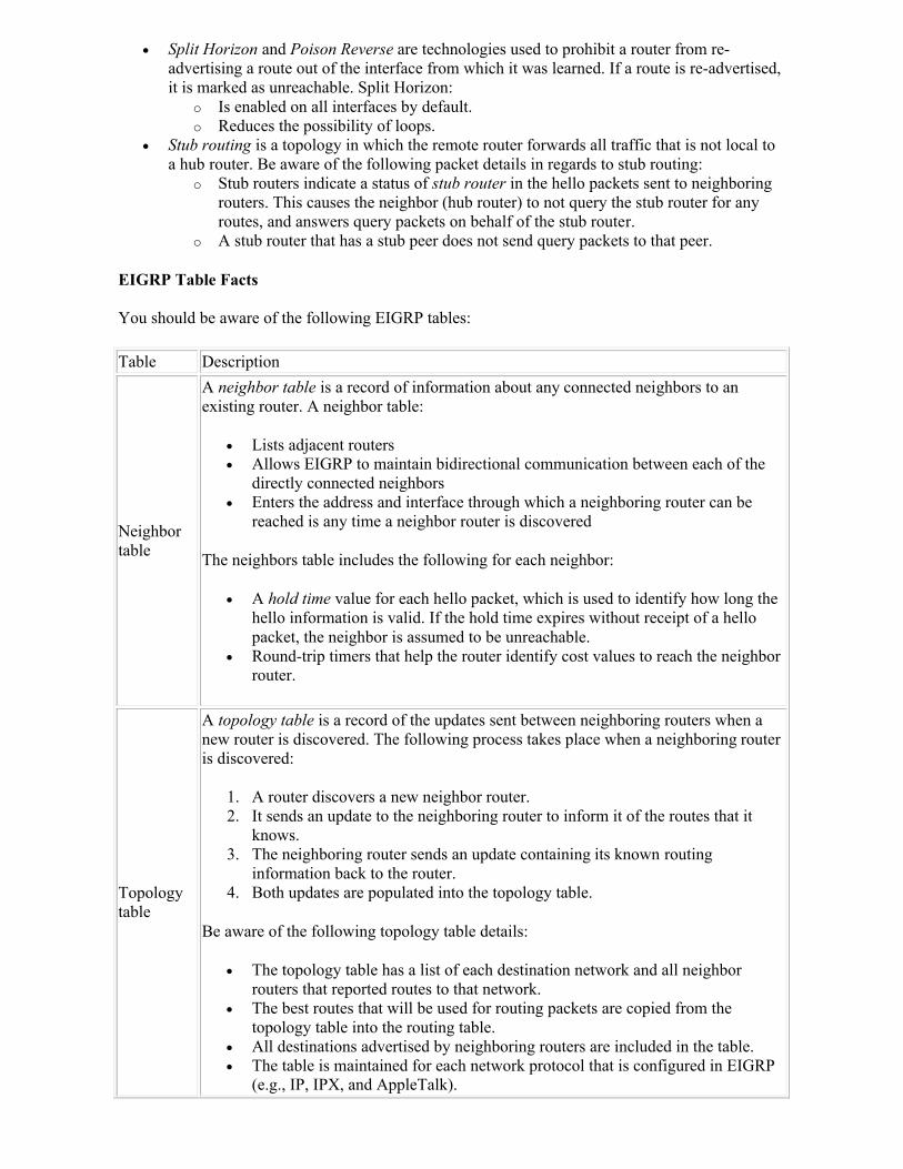
Neighbor table
A neighbor table is a record of information about any connected neighbors to an existing router. A neighbor table:
Lists adjacent routers Allows EIGRP to maintain bidirectional communication between each of the
directly connected neighbors Enters the address and interface through which a neighboring router can be
reached is any time a neighbor router is discovered
The neighbors table includes the following for each neighbor:
A hold time value for each hello packet, which is used to identify how long the hello information is valid. If the hold time expires without receipt of a hello packet, the neighbor is assumed to be unreachable.
Round-trip timers that help the router identify cost values to reach the neighbor router.
Topology table
A topology table is a record of the updates sent between neighboring routers when a new router is discovered. The following process takes place when a neighboring router is discovered:
1. A router discovers a new neighbor router. 2. It sends an update to the neighboring router to inform it of the routes that it
knows. 3. The neighboring router sends an update containing its known routing
information back to the router. 4. Both updates are populated into the topology table.
Be aware of the following topology table details:
The topology table has a list of each destination network and all neighbor routers that reported routes to that network.
The best routes that will be used for routing packets are copied from the topology table into the routing table.
All destinations advertised by neighboring routers are included in the table. The table is maintained for each network protocol that is configured in EIGRP
(e.g., IP, IPX, and AppleTalk).
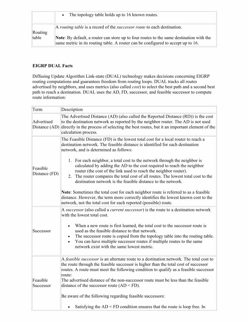
The topology table holds up to 16 known routes.
Routing table
A routing table is a record of the successor route to each destination.
Note: By default, a router can store up to four routes to the same destination with the same metric in its routing table. A router can be configured to accept up to 16.
EIGRP DUAL Facts
Diffusing Update Algorithm Link-state (DUAL) technology makes decisions concerning EIGRP routing computations and guarantees freedom from routing loops. DUAL tracks all routes advertised by neighbors, and uses metrics (also called cost) to select the best path and a second best path to reach a destination. DUAL uses the AD, FD, successor, and feasible successor to compute route information:
Term Description
Advertised Distance (AD)
The Advertised Distance (AD) (also called the Reported Distance (RD)) is the cost to the destination network as reported by the neighbor router. The AD is not used directly in the process of selecting the best routes, but it an important element of the calculation process.
Feasible Distance (FD)
The Feasible Distance (FD) is the lowest total cost for a local router to reach a destination network. The feasible distance is identified for each destination network, and is determined as follows:
1. For each neighbor, a total cost to the network through the neighbor is calculated by adding the AD to the cost required to reach the neighbor router (the cost of the link used to reach the neighbor router).
2. The router compares the total cost of all routes. The lowest total cost to the destination network is the feasible distance to the network.
Note: Sometimes the total cost for each neighbor route is referred to as a feasible distance. However, the term more correctly identifies the lowest known cost to the network, not the total cost for each reported (possible) route.
Successor
A successor (also called a current successor) is the route to a destination network with the lowest total cost.
When a new route is first learned, the total cost to the successor route is used as the feasible distance to that network.
The successor route is copied from the topology table into the routing table. You can have multiple successor routes if multiple routes to the same
network exist with the same lowest metric.
Feasible Successor
A feasible successor is an alternate route to a destination network. The total cost to the route through the feasible successor is higher than the total cost of successor routes. A route must meet the following condition to qualify as a feasible successor route: The advertised distance of the non-successor route must be less than the feasible distance of the successor route (AD < FD).
Be aware of the following regarding feasible successors:
Satisfying the AD < FD condition ensures that the route is loop free. In
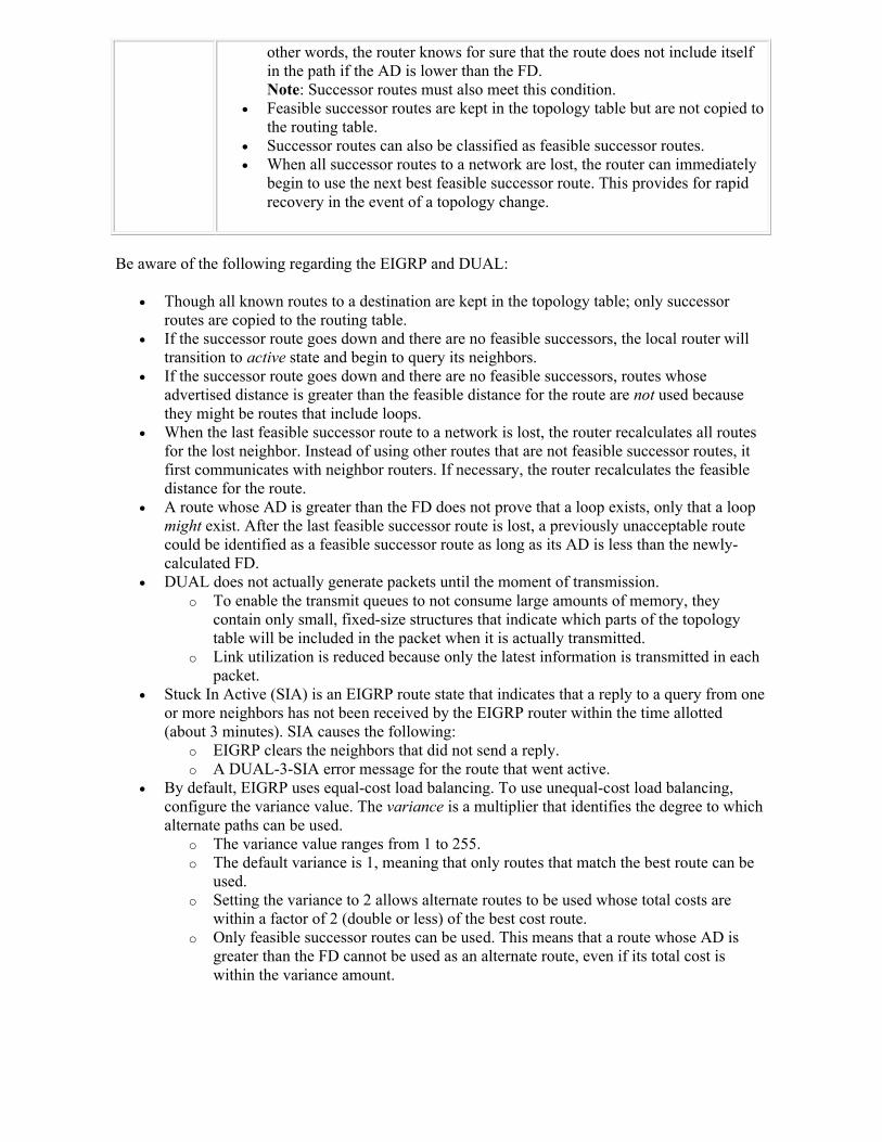
other words, the router knows for sure that the route does not include itself in the path if the AD is lower than the FD. Note: Successor routes must also meet this condition.
Feasible successor routes are kept in the topology table but are not copied to the routing table.
Successor routes can also be classified as feasible successor routes. When all successor routes to a network are lost, the router can immediately
begin to use the next best feasible successor route. This provides for rapid recovery in the event of a topology change.
Be aware of the following regarding the EIGRP and DUAL:
Though all known routes to a destination are kept in the topology table; only successor routes are copied to the routing table.
If the successor route goes down and there are no feasible successors, the local router will transition to active state and begin to query its neighbors.
If the successor route goes down and there are no feasible successors, routes whose advertised distance is greater than the feasible distance for the route are not used because they might be routes that include loops.
When the last feasible successor route to a network is lost, the router recalculates all routes for the lost neighbor. Instead of using other routes that are not feasible successor routes, it first communicates with neighbor routers. If necessary, the router recalculates the feasible distance for the route.
A route whose AD is greater than the FD does not prove that a loop exists, only that a loop might exist. After the last feasible successor route is lost, a previously unacceptable route could be identified as a feasible successor route as long as its AD is less than the newly-calculated FD.
DUAL does not actually generate packets until the moment of transmission. o To enable the transmit queues to not consume large amounts of memory, they
contain only small, fixed-size structures that indicate which parts of the topology table will be included in the packet when it is actually transmitted.
o Link utilization is reduced because only the latest information is transmitted in each packet.
Stuck In Active (SIA) is an EIGRP route state that indicates that a reply to a query from one or more neighbors has not been received by the EIGRP router within the time allotted (about 3 minutes). SIA causes the following:
o EIGRP clears the neighbors that did not send a reply. o A DUAL-3-SIA error message for the route that went active.
By default, EIGRP uses equal-cost load balancing. To use unequal-cost load balancing, configure the variance value. The variance is a multiplier that identifies the degree to which alternate paths can be used.
o The variance value ranges from 1 to 255. o The default variance is 1, meaning that only routes that match the best route can be
used. o Setting the variance to 2 allows alternate routes to be used whose total costs are
within a factor of 2 (double or less) of the best cost route. o Only feasible successor routes can be used. This means that a route whose AD is
greater than the FD cannot be used as an alternate route, even if its total cost is within the variance amount.
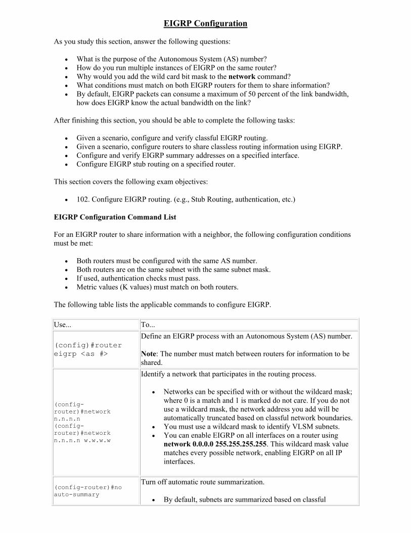
EIGRP Configuration
As you study this section, answer the following questions:
What is the purpose of the Autonomous System (AS) number? How do you run multiple instances of EIGRP on the same router? Why would you add the wild card bit mask to the network command? What conditions must match on both EIGRP routers for them to share information? By default, EIGRP packets can consume a maximum of 50 percent of the link bandwidth,
how does EIGRP know the actual bandwidth on the link?
After finishing this section, you should be able to complete the following tasks:
Given a scenario, configure and verify classful EIGRP routing. Given a scenario, configure routers to share classless routing information using EIGRP. Configure and verify EIGRP summary addresses on a specified interface. Configure EIGRP stub routing on a specified router.
This section covers the following exam objectives:
102. Configure EIGRP routing. (e.g., Stub Routing, authentication, etc.)
EIGRP Configuration Command List
For an EIGRP router to share information with a neighbor, the following configuration conditions must be met:
Both routers must be configured with the same AS number. Both routers are on the same subnet with the same subnet mask. If used, authentication checks must pass. Metric values (K values) must match on both routers.
The following table lists the applicable commands to configure EIGRP.
Use... To...
(config)#router eigrp <as #>
Define an EIGRP process with an Autonomous System (AS) number.
Note: The number must match between routers for information to beshared.
(config-router)#network n.n.n.n(config-router)#network n.n.n.n w.w.w.w
Identify a network that participates in the routing process.
Networks can be specified with or without the wildcard mask; where 0 is a match and 1 is marked do not care. If you do not use a wildcard mask, the network address you add will be automatically truncated based on classful network boundaries.
You must use a wildcard mask to identify VLSM subnets. You can enable EIGRP on all interfaces on a router using
network 0.0.0.0 255.255.255.255. This wildcard mask value matches every possible network, enabling EIGRP on all IP interfaces.
(config-router)#no auto-summary
Turn off automatic route summarization.
By default, subnets are summarized based on classful
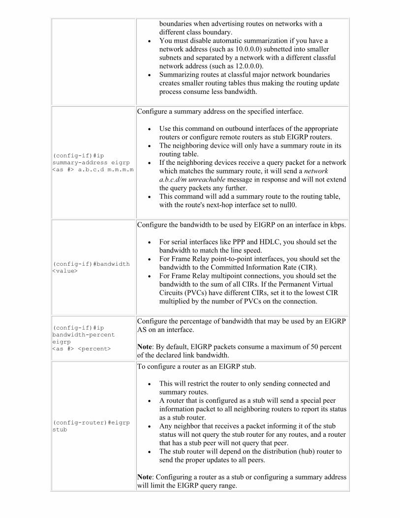
boundaries when advertising routes on networks with a different class boundary.
You must disable automatic summarization if you have a network address (such as 10.0.0.0) subnetted into smaller subnets and separated by a network with a different classful network address (such as 12.0.0.0).
Summarizing routes at classful major network boundaries creates smaller routing tables thus making the routing update process consume less bandwidth.
(config-if)#ip summary-address eigrp <as #> a.b.c.d m.m.m.m
Configure a summary address on the specified interface.
Use this command on outbound interfaces of the appropriate routers or configure remote routers as stub EIGRP routers.
The neighboring device will only have a summary route in its routing table.
If the neighboring devices receive a query packet for a network which matches the summary route, it will send a network a.b.c.d/m unreachable message in response and will not extend the query packets any further.
This command will add a summary route to the routing table, with the route's next-hop interface set to null0.
(config-if)#bandwidth <value>
Configure the bandwidth to be used by EIGRP on an interface in kbps.
For serial interfaces like PPP and HDLC, you should set the bandwidth to match the line speed.
For Frame Relay point-to-point interfaces, you should set the bandwidth to the Committed Information Rate (CIR).
For Frame Relay multipoint connections, you should set the bandwidth to the sum of all CIRs. If the Permanent Virtual Circuits (PVCs) have different CIRs, set it to the lowest CIR multiplied by the number of PVCs on the connection.
(config-if)#ip bandwidth-percent eigrp <as #> <percent>
Configure the percentage of bandwidth that may be used by an EIGRP AS on an interface.
Note: By default, EIGRP packets consume a maximum of 50 percent of the declared link bandwidth.
(config-router)#eigrp stub
To configure a router as an EIGRP stub.
This will restrict the router to only sending connected and summary routes.
A router that is configured as a stub will send a special peer information packet to all neighboring routers to report its status as a stub router.
Any neighbor that receives a packet informing it of the stub status will not query the stub router for any routes, and a router that has a stub peer will not query that peer.
The stub router will depend on the distribution (hub) router to send the proper updates to all peers.
Note: Configuring a router as a stub or configuring a summary address will limit the EIGRP query range.
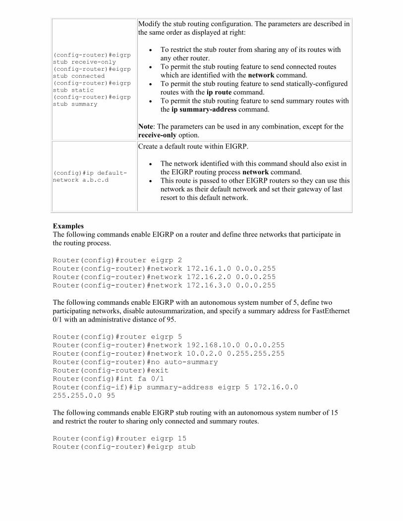
(config-router)#eigrp stub receive-only(config-router)#eigrp stub connected (config-router)#eigrp stub static (config-router)#eigrp stub summary
Modify the stub routing configuration. The parameters are described in the same order as displayed at right:
To restrict the stub router from sharing any of its routes with any other router.
To permit the stub routing feature to send connected routes which are identified with the network command.
To permit the stub routing feature to send statically-configured routes with the ip route command.
To permit the stub routing feature to send summary routes with the ip summary-address command.
Note: The parameters can be used in any combination, except for the receive-only option.
(config)#ip default-network a.b.c.d
Create a default route within EIGRP.
The network identified with this command should also exist in the EIGRP routing process network command.
This route is passed to other EIGRP routers so they can use this network as their default network and set their gateway of last resort to this default network.
ExamplesThe following commands enable EIGRP on a router and define three networks that participate in the routing process.
Router(config)#router eigrp 2Router(config-router)#network 172.16.1.0 0.0.0.255Router(config-router)#network 172.16.2.0 0.0.0.255Router(config-router)#network 172.16.3.0 0.0.0.255
The following commands enable EIGRP with an autonomous system number of 5, define two participating networks, disable autosummarization, and specify a summary address for FastEthernet 0/1 with an administrative distance of 95.
Router(config)#router eigrp 5Router(config-router)#network 192.168.10.0 0.0.0.255Router(config-router)#network 10.0.2.0 0.255.255.255Router(config-router)#no auto-summaryRouter(config-router)#exitRouter(config)#int fa 0/1Router(config-if)#ip summary-address eigrp 5 172.16.0.0 255.255.0.0 95
The following commands enable EIGRP stub routing with an autonomous system number of 15 and restrict the router to sharing only connected and summary routes.
Router(config)#router eigrp 15Router(config-router)#eigrp stub
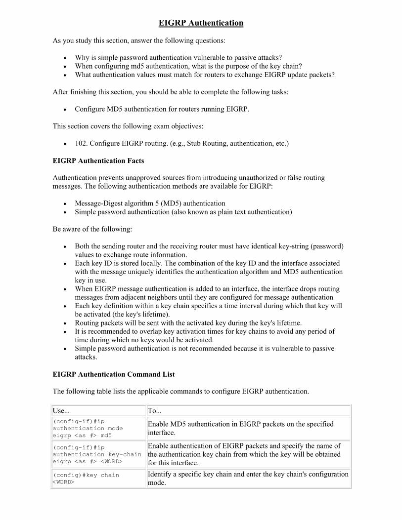
EIGRP Authentication
As you study this section, answer the following questions:
Why is simple password authentication vulnerable to passive attacks? When configuring md5 authentication, what is the purpose of the key chain? What authentication values must match for routers to exchange EIGRP update packets?
After finishing this section, you should be able to complete the following tasks:
Configure MD5 authentication for routers running EIGRP.
This section covers the following exam objectives:
102. Configure EIGRP routing. (e.g., Stub Routing, authentication, etc.)
EIGRP Authentication Facts
Authentication prevents unapproved sources from introducing unauthorized or false routing messages. The following authentication methods are available for EIGRP:
Message-Digest algorithm 5 (MD5) authentication Simple password authentication (also known as plain text authentication)
Be aware of the following:
Both the sending router and the receiving router must have identical key-string (password) values to exchange route information.
Each key ID is stored locally. The combination of the key ID and the interface associated with the message uniquely identifies the authentication algorithm and MD5 authentication key in use.
When EIGRP message authentication is added to an interface, the interface drops routing messages from adjacent neighbors until they are configured for message authentication
Each key definition within a key chain specifies a time interval during which that key will be activated (the key's lifetime).
Routing packets will be sent with the activated key during the key's lifetime. It is recommended to overlap key activation times for key chains to avoid any period of
time during which no keys would be activated. Simple password authentication is not recommended because it is vulnerable to passive
attacks.
EIGRP Authentication Command List
The following table lists the applicable commands to configure EIGRP authentication.
Use... To...(config-if)#ip authentication mode eigrp <as #> md5
Enable MD5 authentication in EIGRP packets on the specified interface.
(config-if)#ip authentication key-chain eigrp <as #> <WORD>
Enable authentication of EIGRP packets and specify the name of the authentication key chain from which the key will be obtained for this interface.
(config)#key chain <WORD>
Identify a specific key chain and enter the key chain's configuration mode.
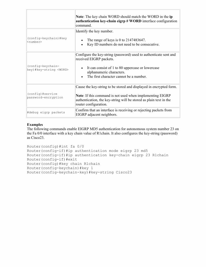
Note: The key chain WORD should match the WORD in the ip authentication key-chain eigrp # WORD interface configuration command.
(config-keychain)#key <number>
Identify the key number.
The range of keys is 0 to 2147483647. Key ID numbers do not need to be consecutive.
(config-keychain-key)#key-string <WORD>
Configure the key-string (password) used to authenticate sent and received EIGRP packets.
It can consist of 1 to 80 uppercase or lowercase alphanumeric characters.
The first character cannot be a number.
(config)#service password-encryption
Cause the key-string to be stored and displayed in encrypted form.
Note: If this command is not used when implementing EIGRP authentication, the key-string will be stored as plain text in the router configuration.
#debug eigrp packetsConfirm that an interface is receiving or rejecting packets from EIGRP adjacent neighbors.
ExamplesThe following commands enable EIGRP MD5 authentication for autonomous system number 23 on the Fa 0/0 interface with a key chain value of R1chain. It also configures the key-string (password) as Cisco23.
Router(config)#int fa 0/0Router(config-if)#ip authentication mode eigrp 23 md5Router(config-if)#ip authentication key-chain eigrp 23 R1chainRouter(config-if)#exitRouter(config)#key chain R1chainRouter(config-keychain)#key 1Router(config-keychain-key)#key-string Cisco23
EIGRP Verification and Troubleshooting
As you study this section, answer the following questions:
Which command can you use to identify why specific routes can't be seen in the routing table?
Which show command will you use to verify that two routers are configured with the same autonomous system number?
From the sh ip eigrp topology command output, what does S in front of the route indicate?
After finishing this section, you should be able to complete the following tasks:
Use show commands to display router information. Use the show ip route and show ip protocols commands to troubleshoot and verify router
information. Use ping to verify connectivity between routers.
This section covers the following exam objectives:
103. Verify or troubleshoot EIGRP routing configurations.
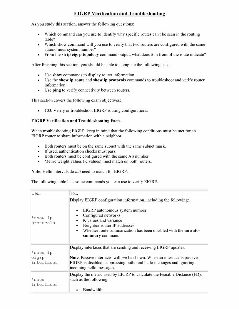
EIGRP Verification and Troubleshooting Facts
When troubleshooting EIGRP, keep in mind that the following conditions must be met for an EIGRP router to share information with a neighbor:
Both routers must be on the same subnet with the same subnet mask. If used, authentication checks must pass. Both routers must be configured with the same AS number. Metric weight values (K values) must match on both routers.
Note: Hello intervals do not need to match for EIGRP.
The following table lists some commands you can use to verify EIGRP.
Use... To...
#show ip protocols
Display EIGRP configuration information, including the following:
EIGRP autonomous system number Configured networks K values and variance Neighbor router IP addresses Whether route summarization has been disabled with the no auto-
summary command.
#show ip eigrp interfaces
Display interfaces that are sending and receiving EIGRP updates.
Note: Passive interfaces will not be shown. When an interface is passive, EIGRP is disabled, suppressing outbound hello messages and ignoring incoming hello messages.
#show interfaces
Display the metric used by EIGRP to calculate the Feasible Distance (FD), such as the following:
Bandwidth
Delay MTU Reliability Load
#show ip eigrp neighbors
Display the following information for neighbor routers:
IP address Local interface to reach the neighbor router
#show ip eigrp traffic
Display the number EIGRP hello, update, query, reply, and acknowledgment packets which have been sent and received.
#show ip eigrp topology
Display the contents of the topology table for EIGRP. Information for each known network includes:
The number of successor routes to that network. The feasible distance (FD) for the network. Feasible successors to that network.
Note: show ip eigrp topology only shows feasible success routes (routes whose AD is less than the network FD). To view all routes, including those that did not qualify as feasible successor routes, use show ip eigrp topology all-links.
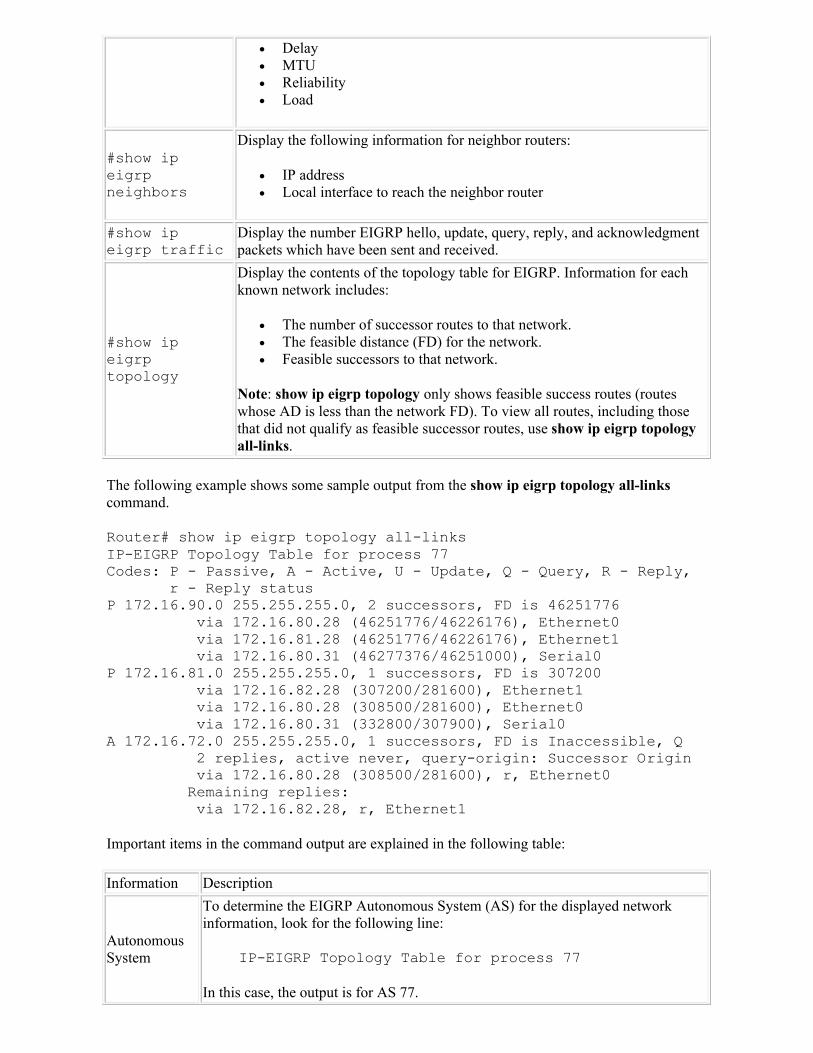
The following example shows some sample output from the show ip eigrp topology all-linkscommand.
Router# show ip eigrp topology all-linksIP-EIGRP Topology Table for process 77Codes: P - Passive, A - Active, U - Update, Q - Query, R - Reply, r - Reply statusP 172.16.90.0 255.255.255.0, 2 successors, FD is 46251776 via 172.16.80.28 (46251776/46226176), Ethernet0 via 172.16.81.28 (46251776/46226176), Ethernet1 via 172.16.80.31 (46277376/46251000), Serial0P 172.16.81.0 255.255.255.0, 1 successors, FD is 307200 via 172.16.82.28 (307200/281600), Ethernet1 via 172.16.80.28 (308500/281600), Ethernet0 via 172.16.80.31 (332800/307900), Serial0A 172.16.72.0 255.255.255.0, 1 successors, FD is Inaccessible, Q 2 replies, active never, query-origin: Successor Origin via 172.16.80.28 (308500/281600), r, Ethernet0 Remaining replies: via 172.16.82.28, r, Ethernet1
Important items in the command output are explained in the following table:
Information Description
Autonomous System
To determine the EIGRP Autonomous System (AS) for the displayed network information, look for the following line:
IP-EIGRP Topology Table for process 77
In this case, the output is for AS 77.
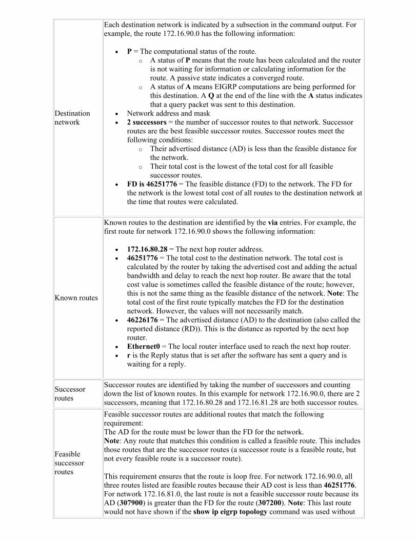
Destination network
Each destination network is indicated by a subsection in the command output. For example, the route 172.16.90.0 has the following information:
P = The computational status of the route. o A status of P means that the route has been calculated and the router
is not waiting for information or calculating information for the route. A passive state indicates a converged route.
o A status of A means EIGRP computations are being performed for this destination. A Q at the end of the line with the A status indicates that a query packet was sent to this destination.
Network address and mask 2 successors = the number of successor routes to that network. Successor
routes are the best feasible successor routes. Successor routes meet the following conditions:
o Their advertised distance (AD) is less than the feasible distance for the network.
o Their total cost is the lowest of the total cost for all feasible successor routes.
FD is 46251776 = The feasible distance (FD) to the network. The FD for the network is the lowest total cost of all routes to the destination network at the time that routes were calculated.
Known routes
Known routes to the destination are identified by the via entries. For example, the first route for network 172.16.90.0 shows the following information:
172.16.80.28 = The next hop router address. 46251776 = The total cost to the destination network. The total cost is
calculated by the router by taking the advertised cost and adding the actual bandwidth and delay to reach the next hop router. Be aware that the total cost value is sometimes called the feasible distance of the route; however, this is not the same thing as the feasible distance of the network. Note: The total cost of the first route typically matches the FD for the destination network. However, the values will not necessarily match.
46226176 = The advertised distance (AD) to the destination (also called the reported distance (RD)). This is the distance as reported by the next hop router.
Ethernet0 = The local router interface used to reach the next hop router. r is the Reply status that is set after the software has sent a query and is
waiting for a reply.
Successor routes
Successor routes are identified by taking the number of successors and counting down the list of known routes. In this example for network 172.16.90.0, there are 2 successors, meaning that 172.16.80.28 and 172.16.81.28 are both successor routes.
Feasible successor routes
Feasible successor routes are additional routes that match the following requirement: The AD for the route must be lower than the FD for the network.Note: Any route that matches this condition is called a feasible route. This includes those routes that are the successor routes (a successor route is a feasible route, but not every feasible route is a successor route).
This requirement ensures that the route is loop free. For network 172.16.90.0, all three routes listed are feasible routes because their AD cost is less than 46251776. For network 172.16.81.0, the last route is not a feasible successor route because its AD (307900) is greater than the FD for the route (307200). Note: This last route would not have shown if the show ip eigrp topology command was used without

the all-links parameter.
OSPF Overview
As you study this section, answer the following questions:
Which steps does OSPF use to select the best path in the routing database? What conditions must be met for two routers to become OSPF neighbors? What happens when a Designated Router (DR) on a LAN fails and then regains service? What are the major differences between an OPSF point-to-point and a broadcast network
type?
This section covers the following exam objectives:
201. Explain the functions and operations of multiarea OSPF.
OSPF Facts
Open Shortest Path First (OSPF) is an industry standard, link-state protocol commonly used in IP networking. OSPF:
Is well-suited for large networks. Is an interior gateway protocol. Is based on Requests For Comments (RFC) 2328. Floods Link-State Advertisement (LSA) packets across a network to build a Link-State
Database (LSDB) (also known as a topology database). LSAs contain small bits of information about routes.
Uses the LSDB to create an adjacency database, which contains all known neighbor information.
Uses the adjacency database and the Shortest Path First (SPF) algorithm to create a routing database known as the SPF tree.
Routers select the best paths from the SPF tree and place them in their routing table (also known as the forwarding database).
OSPF forces a two-layer hierarchy based on areas. Be aware of the following two-layer hierarchy details:
Area 0 (also known as a backbone area) is a transit area. o A transit area is an area that has more than one way into itself. o The transit area's primary function is quick, efficient movement of IP packets. o Transit areas interconnect with other OSPF area types. o End users generally do not reside in transit areas.
All subsequent areas, known as regular or non-backbone areas do not allow routing traffic to pass through it.
o The regular area's primary function is to connect users and resources. o Sub-types of regular areas include stub areas, where there is one way in and out of
the area, usually through the Area Border Routers (ABRs) connected to area 0. o Regular areas must connect to a transit area, such as area 0, using ABRs to reach
additional areas. o Regular areas are usually set up along geographic or functional groupings.
Using a two-layer hierarchy provides the following benefits: o Minimized routing tables o Minimized effort to update and propagate topological changes within areas o Summarization o LSA flooding is stopped at the area boundary
You should know that OSPF:
Is considered a classless routing protocol because it does not assume the default subnet masks are used.
Sends the subnet mask in the routing update Supports route summarization but does not perform it automatically. Supports VLSM. Is not susceptible to routing loops. Instead, OSPF uses built-in loop avoidance techniques.
Mechanisms such as holddown timers, split horizon, or poison reverse are not needed. Is scalable and does not have the 16 hop limitation of RIP. Uses the following multicast IP addresses to share routing information.
o 224.0.0.5 o 224.0.0.6
Uses link costs (bandwidth) as a metric for determining best routes. Supports load balancing over equal-cost paths. Up to 16 equal-cost paths can be used (the
default is 4). Sends out updated information rather than exchanging the entire routing table (under normal
conditions) Sends updates when routes change or every 30 minutes. Converges faster than a distance vector protocol. Can require additional processing power (and therefore increased system requirements). Has an administrative distance of 110. Can be configured to advertise a default route into its autonomous system.
o OSPF routers do not generate a default route into the OSPF domain by default. o Default routes can be advertised into a standard area by advertising 0.0.0.0. into the
OSPF domain. o Default routes show up in the OSPF database as external LSA type 5 routes.
Calculates a default metric for an interface according to the interface's inverse bandwidth.
OSPF Packet Facts
OSPF uses 5 types of packets, as described in the following table:
Type 1 packets are hello packets. Their purpose is to discover neighbors and build adjacencies. Hello packets include the following information:
o Hello and dead intervals o Neighbors o Area ID o Router priority o Designated Router (DR) and Backup Designated Router (BDR) IP addresses o Authentication password o Sub area flag
Type 2 packets are known as Database Description (DBD) packets. Their purpose is to check for database synchronization between routers.
Type 3 packets are Link-State Request (LSR) packets. Their purpose is to request specific link-state records from other routers.
Type 4 packets are Link-State Update (LSU) packets. Their purpose is to send link-state records that have been specifically requested.
Type 5 packets are Link-State Acknowledgement (LSAck) packets. Their purpose is to acknowledge all other types of packets.
You should know the following about OSPF packets:
All OSPF packets are directly encapsulated into an IP payload. OSPF packets do not use TCP or UDP. Because TCP is not implemented, OSPF defines its own route for acknowledgement that
uses LSAcks.
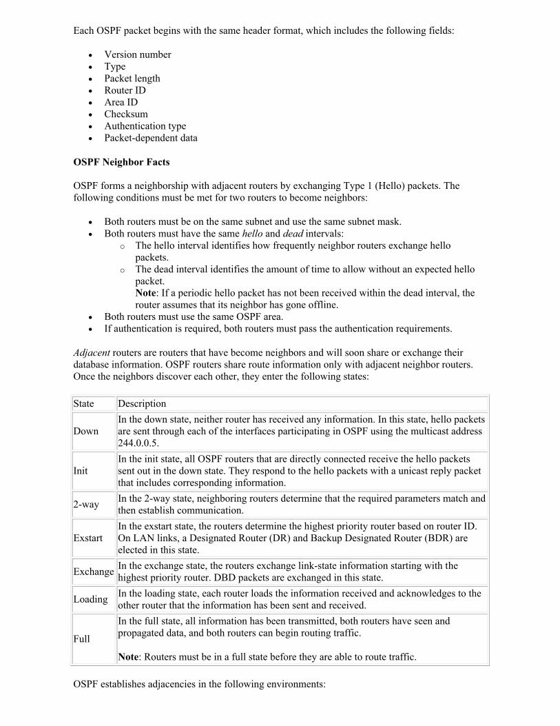
Each OSPF packet begins with the same header format, which includes the following fields:
Version number Type Packet length Router ID Area ID Checksum Authentication type Packet-dependent data
OSPF Neighbor Facts
OSPF forms a neighborship with adjacent routers by exchanging Type 1 (Hello) packets. The following conditions must be met for two routers to become neighbors:
Both routers must be on the same subnet and use the same subnet mask. Both routers must have the same hello and dead intervals:
o The hello interval identifies how frequently neighbor routers exchange hello packets.
o The dead interval identifies the amount of time to allow without an expected hello packet. Note: If a periodic hello packet has not been received within the dead interval, the router assumes that its neighbor has gone offline.
Both routers must use the same OSPF area. If authentication is required, both routers must pass the authentication requirements.
Adjacent routers are routers that have become neighbors and will soon share or exchange their database information. OSPF routers share route information only with adjacent neighbor routers. Once the neighbors discover each other, they enter the following states:
State Description
Down In the down state, neither router has received any information. In this state, hello packets are sent through each of the interfaces participating in OSPF using the multicast address 244.0.0.5.
InitIn the init state, all OSPF routers that are directly connected receive the hello packets sent out in the down state. They respond to the hello packets with a unicast reply packet that includes corresponding information.
2-way In the 2-way state, neighboring routers determine that the required parameters match and then establish communication.
Exstart In the exstart state, the routers determine the highest priority router based on router ID. On LAN links, a Designated Router (DR) and Backup Designated Router (BDR) are elected in this state.
Exchange In the exchange state, the routers exchange link-state information starting with the highest priority router. DBD packets are exchanged in this state.
Loading In the loading state, each router loads the information received and acknowledges to the other router that the information has been sent and received.
Full
In the full state, all information has been transmitted, both routers have seen and propagated data, and both routers can begin routing traffic.
Note: Routers must be in a full state before they are able to route traffic.
OSPF establishes adjacencies in the following environments:
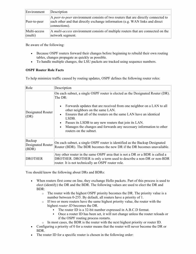
Environment Description
Peer-to-peerA peer-to-peer environment consists of two routers that are directly connected to each other and that directly exchange information (e.g. WAN links and direct connections).
Multi-access (multi)
A multi-access environment consists of multiple routers that are connected on the network segment.
Be aware of the following:
Because OSPF routers forward their changes before beginning to rebuild their own routing tables, changes propagate as quickly as possible.
To handle multiple changes, the LSU packets are tracked using sequence numbers.
OSPF Router Role Facts
To help minimize traffic caused by routing updates, OSPF defines the following router roles:
Role Description
Designated Router (DR)
On each subnet, a single OSPF router is elected as the Designated Router (DR). The DR:
Forwards updates that are received from one neighbor on a LAN to all other neighbors on the same LAN.
Ensures that all of the routers on the same LAN have an identical LSDB.
Passes its LSDB to any new routers that join its LAN. Manages the changes and forwards any necessary information to other
routers on the subnet.
Backup Designated Router (BDR)
On each subnet, a single OSPF router is identified as the Backup Designated Router (BDR). The BDR becomes the new DR if the DR becomes unavailable.
DROTHERAny other router in the same OSPF area that is not a DR or a BDR is called a DROTHER. DROTHER is only a term used to describe a non-DR or non-BDR router. It is not technically an OSPF router role.
You should know the following about DRs and BDRs:
When routers first come on line, they exchange Hello packets. Part of this process is used to elect (identify) the DR and the BDR. The following values are used to elect the DR and BDR:
o The router with the highest OSPF priority becomes the DR. The priority value is a number between 0-255. By default, all routers have a priority of 1.
o If two or more routers have the same highest priority value, the router with the highest router ID becomes the DR.
The router ID is a 32-bit number expressed in A.B.C.D format. Once a router ID has been set, it will not change unless the router reloads or
if the OSPF routing process restarts. o In most cases, the BDR is the router with the next highest priority or router ID.
Configuring a priority of 0 for a router means that the router will never become the DR or BDR.
The router ID for a specific router is chosen in the following order:
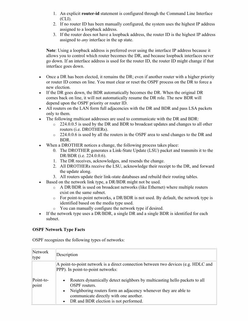
1. An explicit router-id statement is configured through the Command Line Interface (CLI).
2. If no router ID has been manually configured, the system uses the highest IP address assigned to a loopback address.
3. If the router does not have a loopback address, the router ID is the highest IP address assigned to any interface in the up state.
Note: Using a loopback address is preferred over using the interface IP address because it allows you to control which router becomes the DR, and because loopback interfaces never go down. If an interface address is used for the router ID, the router ID might change if that interface goes down.
Once a DR has been elected, it remains the DR; even if another router with a higher priority or router ID comes on line. You must clear or reset the OSPF process on the DR to force a new election.
If the DR goes down, the BDR automatically becomes the DR. When the original DR comes back on line, it will not automatically resume the DR role. The new BDR will depend upon the OSPF priority or router ID.
All routers on the LAN form full adjacencies with the DR and BDR and pass LSA packets only to them.
The following multicast addresses are used to communicate with the DR and BDR: o 224.0.0.5 is used by the DR and BDR to broadcast updates and changes to all other
routers (i.e. DROTHERs). o 224.0.0.6 is used by all the routers in the OSPF area to send changes to the DR and
BDR. When a DROTHER notices a change, the following process takes place:
0. The DROTHER generates a Link-State Update (LSU) packet and transmits it to the DR/BDR (i.e. 224.0.0.6).
1. The DR receives, acknowledges, and resends the change. 2. All DROTHERs receive the LSU, acknowledge their receipt to the DR, and forward
the update along. 3. All routers update their link-state databases and rebuild their routing tables.
Based on the network link type, a DR/BDR might not be used. o A DR/BDR is used on broadcast networks (like Ethernet) where multiple routers
exist on the same subnet. o For point-to-point networks, a DR/BDR is not used. By default, the network type is
identified based on the media type used. o You can manually configure the network type if desired.
If the network type uses a DR/BDR, a single DR and a single BDR is identified for each subnet.
OSPF Network Type Facts
OSPF recognizes the following types of networks:
Network type
Description
Point-to-point
A point-to-point network is a direct connection between two devices (e.g. HDLC and PPP). In point-to-point networks:
Routers dynamically detect neighbors by multicasting hello packets to all OSPF routers.
Neighboring routers form an adjacency whenever they are able to communicate directly with one another.
DR and BDR election is not performed.
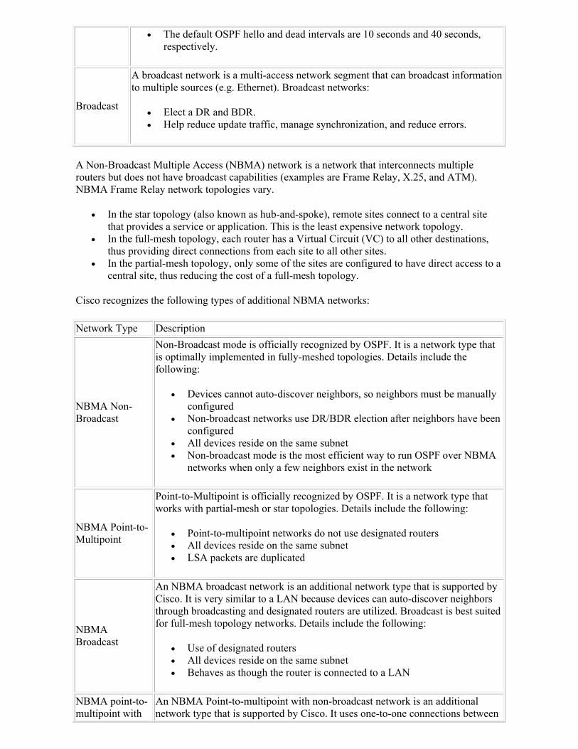
The default OSPF hello and dead intervals are 10 seconds and 40 seconds, respectively.
Broadcast
A broadcast network is a multi-access network segment that can broadcast information to multiple sources (e.g. Ethernet). Broadcast networks:
Elect a DR and BDR. Help reduce update traffic, manage synchronization, and reduce errors.
A Non-Broadcast Multiple Access (NBMA) network is a network that interconnects multiple routers but does not have broadcast capabilities (examples are Frame Relay, X.25, and ATM). NBMA Frame Relay network topologies vary.
In the star topology (also known as hub-and-spoke), remote sites connect to a central site that provides a service or application. This is the least expensive network topology.
In the full-mesh topology, each router has a Virtual Circuit (VC) to all other destinations, thus providing direct connections from each site to all other sites.
In the partial-mesh topology, only some of the sites are configured to have direct access to a central site, thus reducing the cost of a full-mesh topology.
Cisco recognizes the following types of additional NBMA networks:
Network Type Description
NBMA Non-Broadcast
Non-Broadcast mode is officially recognized by OSPF. It is a network type that is optimally implemented in fully-meshed topologies. Details include the following:
Devices cannot auto-discover neighbors, so neighbors must be manually configured
Non-broadcast networks use DR/BDR election after neighbors have been configured
All devices reside on the same subnet Non-broadcast mode is the most efficient way to run OSPF over NBMA
networks when only a few neighbors exist in the network
NBMA Point-to-Multipoint
Point-to-Multipoint is officially recognized by OSPF. It is a network type that works with partial-mesh or star topologies. Details include the following:
Point-to-multipoint networks do not use designated routers All devices reside on the same subnet LSA packets are duplicated
NBMA Broadcast
An NBMA broadcast network is an additional network type that is supported by Cisco. It is very similar to a LAN because devices can auto-discover neighbors through broadcasting and designated routers are utilized. Broadcast is best suited for full-mesh topology networks. Details include the following:
Use of designated routers All devices reside on the same subnet Behaves as though the router is connected to a LAN
NBMA point-to-multipoint with
An NBMA Point-to-multipoint with non-broadcast network is an additional network type that is supported by Cisco. It uses one-to-one connections between
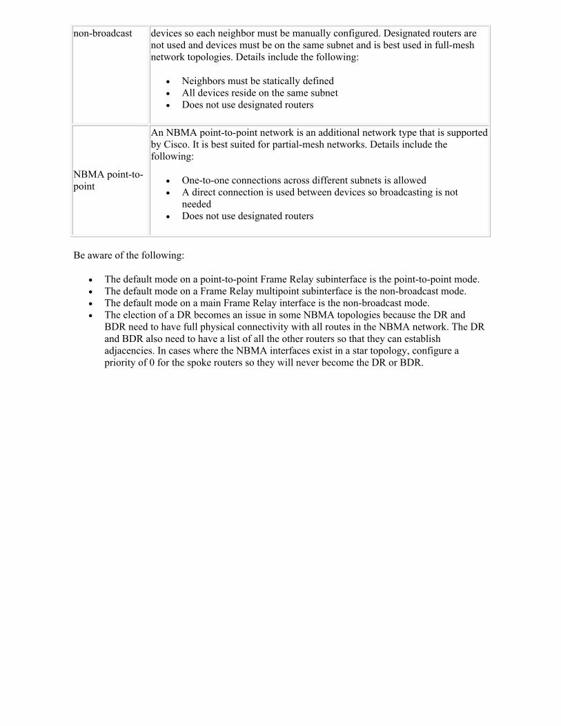
non-broadcast devices so each neighbor must be manually configured. Designated routers are not used and devices must be on the same subnet and is best used in full-mesh network topologies. Details include the following:
Neighbors must be statically defined All devices reside on the same subnet Does not use designated routers
NBMA point-to-point
An NBMA point-to-point network is an additional network type that is supported by Cisco. It is best suited for partial-mesh networks. Details include thefollowing:
One-to-one connections across different subnets is allowed A direct connection is used between devices so broadcasting is not
needed Does not use designated routers
Be aware of the following:
The default mode on a point-to-point Frame Relay subinterface is the point-to-point mode. The default mode on a Frame Relay multipoint subinterface is the non-broadcast mode. The default mode on a main Frame Relay interface is the non-broadcast mode. The election of a DR becomes an issue in some NBMA topologies because the DR and
BDR need to have full physical connectivity with all routes in the NBMA network. The DR and BDR also need to have a list of all the other routers so that they can establish adjacencies. In cases where the NBMA interfaces exist in a star topology, configure a priority of 0 for the spoke routers so they will never become the DR or BDR.
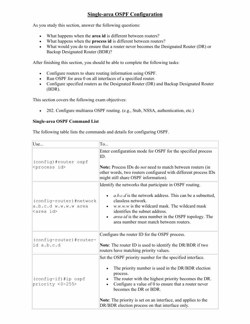
Single-area OSPF Configuration
As you study this section, answer the following questions:
What happens when the area id is different between routers? What happens when the process id is different between routers? What would you do to ensure that a router never becomes the Designated Router (DR) or
Backup Designated Router (BDR)?
After finishing this section, you should be able to complete the following tasks:
Configure routers to share routing information using OSPF. Run OSPF for area 0 on all interfaces of a specified router. Configure specified routers as the Designated Router (DR) and Backup Designated Router
(BDR).
This section covers the following exam objectives:
202. Configure multiarea OSPF routing. (e.g., Stub, NSSA, authentication, etc.)
Single-area OSPF Command List
The following table lists the commands and details for configuring OSPF.
Use... To...
(config)#router ospf <process id>
Enter configuration mode for OSPF for the specified process ID.
Note: Process IDs do not need to match between routers (in other words, two routers configured with different process IDs might still share OSPF information).
(config-router)#network a.b.c.d w.w.w.w area <area id>
Identify the networks that participate in OSPF routing.
a.b.c.d is the network address. This can be a subnetted, classless network.
w.w.w.w is the wildcard mask. The wildcard mask identifies the subnet address.
area-id is the area number in the OSPF topology. The area number must match between routers.
(config-router)#router-id a.b.c.d
Configure the router ID for the OSPF process.
Note: The router ID is used to identify the DR/BDR if two routers have matching priority values.
(config-if)#ip ospf priority <0-255>
Set the OSPF priority number for the specified interface.
The priority number is used in the DR/BDR election process.
The router with the highest priority becomes the DR. Configure a value of 0 to ensure that a router never
becomes the DR or BDR.
Note: The priority is set on an interface, and applies to the DR/BDR election process on that interface only.
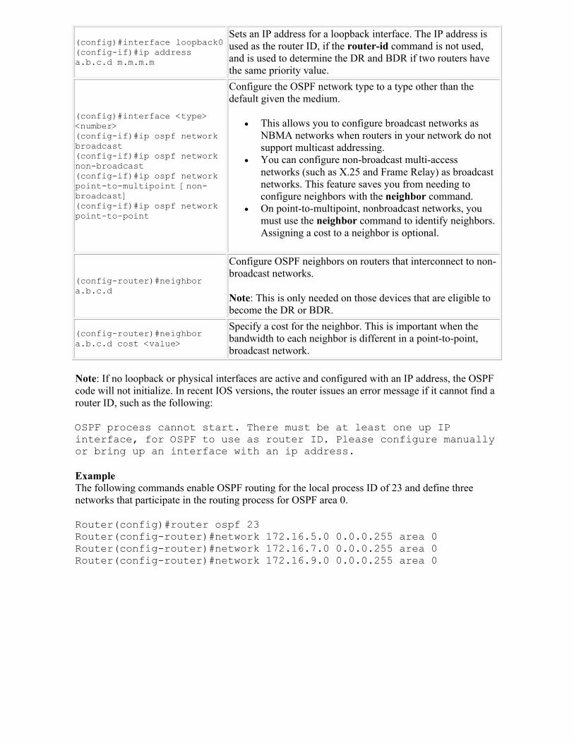
(config)#interface loopback0(config-if)#ip address a.b.c.d m.m.m.m
Sets an IP address for a loopback interface. The IP address is used as the router ID, if the router-id command is not used, and is used to determine the DR and BDR if two routers have the same priority value.
(config)#interface <type> <number>(config-if)#ip ospf network broadcast(config-if)#ip ospf network non-broadcast(config-if)#ip ospf network point-to-multipoint [non-broadcast](config-if)#ip ospf network point-to-point
Configure the OSPF network type to a type other than the default given the medium.
This allows you to configure broadcast networks as NBMA networks when routers in your network do not support multicast addressing.
You can configure non-broadcast multi-access networks (such as X.25 and Frame Relay) as broadcast networks. This feature saves you from needing to configure neighbors with the neighbor command.
On point-to-multipoint, nonbroadcast networks, you must use the neighbor command to identify neighbors. Assigning a cost to a neighbor is optional.
(config-router)#neighbor a.b.c.d
Configure OSPF neighbors on routers that interconnect to non-broadcast networks.
Note: This is only needed on those devices that are eligible to become the DR or BDR.
(config-router)#neighbor a.b.c.d cost <value>
Specify a cost for the neighbor. This is important when the bandwidth to each neighbor is different in a point-to-point, broadcast network.
Note: If no loopback or physical interfaces are active and configured with an IP address, the OSPF code will not initialize. In recent IOS versions, the router issues an error message if it cannot find a router ID, such as the following:
OSPF process cannot start. There must be at least one up IP interface, for OSPF to use as router ID. Please configure manually or bring up an interface with an ip address.
ExampleThe following commands enable OSPF routing for the local process ID of 23 and define three networks that participate in the routing process for OSPF area 0.
Router(config)#router ospf 23Router(config-router)#network 172.16.5.0 0.0.0.255 area 0Router(config-router)#network 172.16.7.0 0.0.0.255 area 0Router(config-router)#network 172.16.9.0 0.0.0.255 area 0
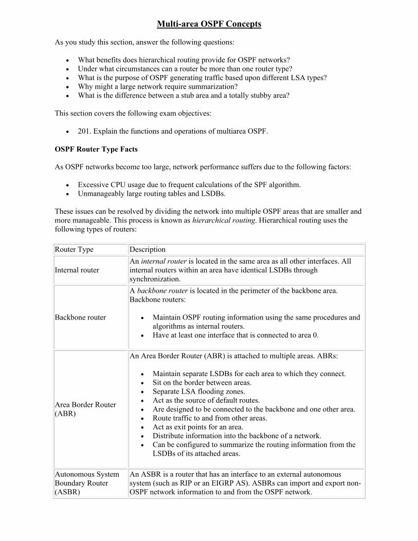
Multi-area OSPF Concepts
As you study this section, answer the following questions:
What benefits does hierarchical routing provide for OSPF networks? Under what circumstances can a router be more than one router type? What is the purpose of OSPF generating traffic based upon different LSA types? Why might a large network require summarization? What is the difference between a stub area and a totally stubby area?
This section covers the following exam objectives:
201. Explain the functions and operations of multiarea OSPF.
OSPF Router Type Facts
As OSPF networks become too large, network performance suffers due to the following factors:
Excessive CPU usage due to frequent calculations of the SPF algorithm. Unmanageably large routing tables and LSDBs.
These issues can be resolved by dividing the network into multiple OSPF areas that are smaller and more manageable. This process is known as hierarchical routing. Hierarchical routing uses the following types of routers:
Router Type Description
Internal routerAn internal router is located in the same area as all other interfaces. All internal routers within an area have identical LSDBs through synchronization.
Backbone router
A backbone router is located in the perimeter of the backbone area. Backbone routers:
Maintain OSPF routing information using the same procedures and algorithms as internal routers.
Have at least one interface that is connected to area 0.
Area Border Router (ABR)
An Area Border Router (ABR) is attached to multiple areas. ABRs:
Maintain separate LSDBs for each area to which they connect. Sit on the border between areas. Separate LSA flooding zones. Act as the source of default routes. Are designed to be connected to the backbone and one other area. Route traffic to and from other areas. Act as exit points for an area. Distribute information into the backbone of a network. Can be configured to summarize the routing information from the
LSDBs of its attached areas.
Autonomous System Boundary Router (ASBR)
An ASBR is a router that has an interface to an external autonomous system (such as RIP or an EIGRP AS). ASBRs can import and export non-OSPF network information to and from the OSPF network.
Note: Routers can be more than one router type. For instance it is possible for a router to be both an ABR and an ASBR.
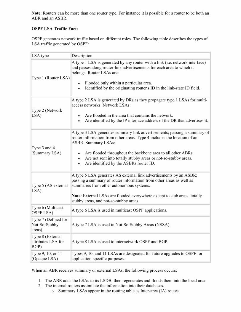
OSPF LSA Traffic Facts
OSPF generates network traffic based on different roles. The following table describes the types of LSA traffic generated by OSPF:
LSA type Description
Type 1 (Router LSA)
A type 1 LSA is generated by any router with a link (i.e. network interface) and passes along router-link advertisements for each area to which it belongs. Router LSAs are:
Flooded only within a particular area. Identified by the originating router's ID in the link-state ID field.
Type 2 (Network LSA)
A type 2 LSA is generated by DRs as they propagate type 1 LSAs for multi-access networks. Network LSAs:
Are flooded in the area that contains the network. Are identified by the IP interface address of the DR that advertises it.
Type 3 and 4 (Summary LSA)
A type 3 LSA generates summary link advertisements; passing a summary of router information from other areas. Type 4 includes the location of an ASBR. Summary LSAs:
Are flooded throughout the backbone area to all other ABRs. Are not sent into totally stubby areas or not-so-stubby areas. Are identified by the ASBRs router ID.
Type 5 (AS external LSA)
A type 5 LSA generates AS external link advertisements by an ASBR; passing a summary of router information from other areas as well as summaries from other autonomous systems.
Note: External LSAs are flooded everywhere except to stub areas, totally stubby areas, and not-so-stubby areas.
Type 6 (Multicast OSPF LSA)
A type 6 LSA is used in multicast OSPF applications.
Type 7 (Defined for Not-So-Stubby areas)
A type 7 LSA is used in Not-So-Stubby Areas (NSSA).
Type 8 (External attributes LSA for BGP)
A type 8 LSA is used to internetwork OSPF and BGP.
Type 9, 10, or 11 (Opaque LSA)
Types 9, 10, and 11 LSAs are designated for future upgrades to OSPF for application-specific purposes.
When an ABR receives summary or external LSAs, the following process occurs:
1. The ABR adds the LSAs to its LSDB, then regenerates and floods them into the local area. 2. The internal routers assimilate the information into their databases.
o Summary LSAs appear in the routing table as Inter-area (IA) routes.
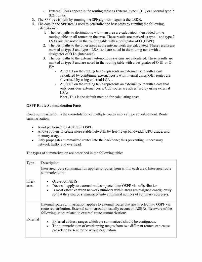
o External LSAs appear in the routing table as External type 1 (E1) or External type 2 (E2) routes.
3. The SPF tree is built by running the SPF algorithm against the LSDB. 4. The data in the SPF tree is used to determine the best paths by running the following
calculations: 1. The best paths to destinations within an area are calculated, then added to the
routing table on all routers in the area. These results are marked as type 1 and type 2 LSAs and are noted in the routing table with a designator of O (OSPF).
2. The best paths to the other areas in the internetwork are calculated. These results are marked as type 3 and type 4 LSAs and are noted in the routing table with a designator of O IA (inter-area).
3. The best paths to the external autonomous systems are calculated. These results are marked as type 5 and are noted in the routing table with a designator of O E1 or O E2:
An O E1 on the routing table represents an external route with a cost calculated by combining external costs with internal costs. OE1 routes are advertised by using external LSAs.
An O E2 on the routing table represents an external route with a cost that only considers external costs. OE2 routes are advertised by using external LSAs.Note: This is the default method for calculating costs.
OSPF Route Summarization Facts
Route summarization is the consolidation of multiple routes into a single advertisement. Route summarization:
Is not performed by default in OSPF. Allows routers to create more stable networks by freeing up bandwidth, CPU usage, and
memory usage. Only propagates summarized routes into the backbone; thus preventing unnecessary
network traffic and overhead.
The types of summarization are described in the following table:
Type Description
Inter-area
Inter-area route summarization applies to routes from within each area. Inter-area route summarization:
Occurs on ABRs. Does not apply to external routes injected into OSPF via redistribution. Is most effective when network numbers within areas are assigned contiguously
so that they can be summarized into a minimal number of summary addresses.
External
External route summarization applies to external routes that are injected into OSPF via route redistribution. External summarization usually occurs on ASBRs. Be aware of the following issues related to external route summarization:
External address ranges which are summarized should be contiguous. The summarization of overlapping ranges from two different routers can cause
packets to be sent to the wrong destination.

Note: Summary LSAs (type 3) and external LSAs (type 5) do not contain summarized routes by default. Creating internal areas and external networks with a contiguous design (i.e. ordered networks with easily groupable subnets) will facilitate OSPF summarization.
OSPF Area Type Facts
You should be familiar with the following OSPF area types:
Area Type Description
Standard A standard area allows any type of route information to enter or leave the area.
Backbone orArea 0
A backbone area (also known as area 0) acts as a hub for inter-area transit traffic and the distribution of routing information between areas. All OSPF networks have at least one backbone area. The backbone area:
Is the central entity to which all other areas are connected. Has all of the properties of a standard OSPF area.
A virtual link is a link that allows for discontinuous backbone areas to be connected (e.g. area 5 connecting to the backbone area through area 3). You should know the following about virtual links:
They should only be used for temporary connections; they are not intended to be a primary feature of a backbone.
Virtual links are comparable to standard OSPF adjacencies except they are not directly attached to neighboring routers.
Hello packets are sent at 10-second intervals over the virtual links. LSA updates on virtual links do not expire; they do not refresh every 30
minutes like they would over a standard link.
Stub
A stub area does not allow ASBR routes (type 5 external LSAs), so external routes are not transmitted into the stub area. Stub areas:
Normally use default route origination to allow information to leave the area, indicated as 0.0.0.0 in the routing table.
Cannot contain ASBRs, unless the router is also an ABR. Reduce the size of the LSDB inside an area. Are typically created using a hub-and-spoke topology. Do not allow virtual links. Cannot be the backbone area (area 0). Have an injected default route from the ABR.
Totally stubby
A totally stubby area does not allow ASBR routes (type 5 external LSAs) or inter-area routes (type 3 and 4 summary LSAs); only routes within its own specific area are allowed. Totally stubby areas:
Recognize only intra-area routes and the default route to allow information to leave the area.
Cannot contain ASBRs, unless the router is also an ABR. Each router in the totally stubby are picks the closest ABR as a gateway to
everything outside the area. Have an injected default route from the ABR.
Not-So-Stubby Area (NSSA)
A Not-So-Stubby Area (NSSA) is similar to a stub and totally stubby area in that it allows the ABR to inject a default route; however, it does allow an ASBR to be

in the areas.
When redistributing routes into a NSSA, the ASBR generates a Type 7 LSA.
A NSSA ABR translates the Type 7 LSA into a Type 5 LSA which gets flooded into the OSPF domain.
Note: NSSA routes are displayed in routing tables as O N1 and O N2 routes.
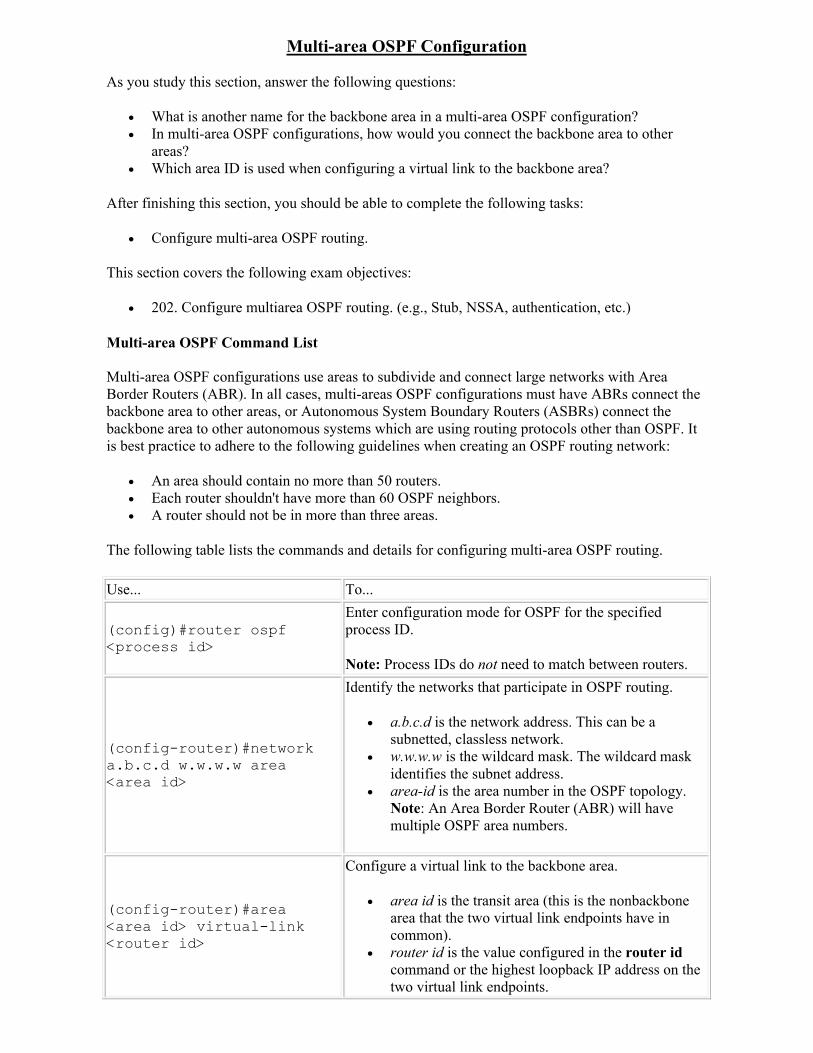
Multi-area OSPF Configuration
As you study this section, answer the following questions:
What is another name for the backbone area in a multi-area OSPF configuration? In multi-area OSPF configurations, how would you connect the backbone area to other
areas? Which area ID is used when configuring a virtual link to the backbone area?
After finishing this section, you should be able to complete the following tasks:
Configure multi-area OSPF routing.
This section covers the following exam objectives:
202. Configure multiarea OSPF routing. (e.g., Stub, NSSA, authentication, etc.)
Multi-area OSPF Command List
Multi-area OSPF configurations use areas to subdivide and connect large networks with Area Border Routers (ABR). In all cases, multi-areas OSPF configurations must have ABRs connect the backbone area to other areas, or Autonomous System Boundary Routers (ASBRs) connect the backbone area to other autonomous systems which are using routing protocols other than OSPF. It is best practice to adhere to the following guidelines when creating an OSPF routing network:
An area should contain no more than 50 routers. Each router shouldn't have more than 60 OSPF neighbors. A router should not be in more than three areas.
The following table lists the commands and details for configuring multi-area OSPF routing.
Use... To...
(config)#router ospf <process id>
Enter configuration mode for OSPF for the specified process ID.
Note: Process IDs do not need to match between routers.
(config-router)#network a.b.c.d w.w.w.w area <area id>
Identify the networks that participate in OSPF routing.
a.b.c.d is the network address. This can be a subnetted, classless network.
w.w.w.w is the wildcard mask. The wildcard mask identifies the subnet address.
area-id is the area number in the OSPF topology. Note: An Area Border Router (ABR) will have multiple OSPF area numbers.
(config-router)#area <area id> virtual-link <router id>
Configure a virtual link to the backbone area.
area id is the transit area (this is the nonbackbone area that the two virtual link endpoints have in common).
router id is the value configured in the router idcommand or the highest loopback IP address on the two virtual link endpoints.
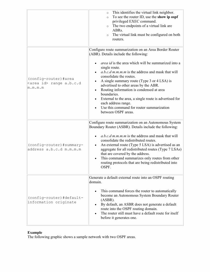
o This identifies the virtual link neighbor. o To see the router ID, use the show ip ospf
privileged EXEC command. o The two endpoints of a virtual link are
ABRs. o The virtual link must be configured on both
routers.
(config-router)#area <area id> range a.b.c.d m.m.m.m
Configure route summarization on an Area Border Router (ABR). Details include the following:
area id is the area which will be summarized into a single route.
a.b.c.d m.m.m.m is the address and mask that will consolidate the routes.
A single summary route (Type 3 or 4 LSA) is advertised to other areas by the ABR.
Routing information is condensed at area boundaries.
External to the area, a single route is advertised for each address range.
Use this command for router summarization between OSPF areas.
(config-router)#summary-address a.b.c.d m.m.m.m
Configure route summarization on an Autonomous System Boundary Router (ASBR). Details include the following:
a.b.c.d m.m.m.m is the address and mask that will consolidate the redistributed routes.
An external route (Type 5 LSA) is advertised as an aggregate for all redistributed routes (Type 7 LSAs) that are covered by the address.
This command summarizes only routes from other routing protocols that are being redistributed intoOSPF.
(config-router)#default-information originate
Generate a default external route into an OSPF routing domain.
This command forces the router to automatically become an Autonomous System Boundary Router (ASBR).
By default, an ASBR does not generate a default route into the OSPF routing domain.
The router still must have a default route for itself before it generates one.
ExampleThe following graphic shows a sample network with two OSPF areas.

Use the following commands to configure OSPF on each router:
Router Configuration
RouterA
router ospf 1network 10.0.0.0 0.0.0.255 area 0network 172.16.1.0 0.0.0.3 area 1network 172.17.1.0 0.0.0.3 area 1
RouterBrouter ospf 2network 172.16.1.0 0.0.0.3 area 1network 192.168.1.0 0.0.0.255 area 1
RouterCrouter ospf 3network 172.17.1.0 0.0.0.3 area 1network 192.168.2.0 0.0.0.255 area 1
Notice the following in the configuration:
RouterA is the Area Border Router (ABR) for both area 0 and area 1. The process ID on each router does not have to match. OSPF uses areas to identify sharing
of routes, not the process ID. You can use the subnet address with the appropriate wildcard mask, or you can use the IP
address of the router interface with a mask of 0.0.0.0. The network command identifies the subnet, wildcard mask, and the OSPF area of the
subnet. A subnet can only be in one area.
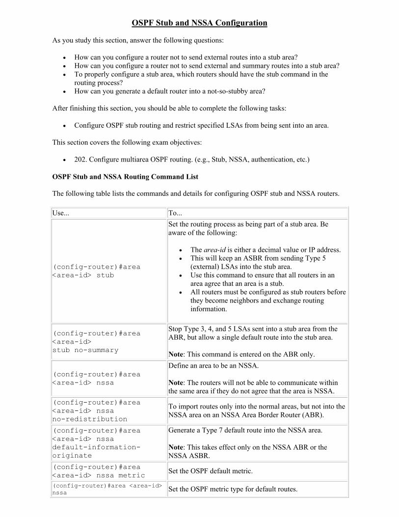
OSPF Stub and NSSA Configuration
As you study this section, answer the following questions:
How can you configure a router not to send external routes into a stub area? How can you configure a router not to send external and summary routes into a stub area? To properly configure a stub area, which routers should have the stub command in the
routing process? How can you generate a default router into a not-so-stubby area?
After finishing this section, you should be able to complete the following tasks:
Configure OSPF stub routing and restrict specified LSAs from being sent into an area.
This section covers the following exam objectives:
202. Configure multiarea OSPF routing. (e.g., Stub, NSSA, authentication, etc.)
OSPF Stub and NSSA Routing Command List
The following table lists the commands and details for configuring OSPF stub and NSSA routers.
Use... To...
(config-router)#area <area-id> stub
Set the routing process as being part of a stub area. Be aware of the following:
The area-id is either a decimal value or IP address. This will keep an ASBR from sending Type 5
(external) LSAs into the stub area. Use this command to ensure that all routers in an
area agree that an area is a stub. All routers must be configured as stub routers before
they become neighbors and exchange routing information.
(config-router)#area <area-id> stub no-summary
Stop Type 3, 4, and 5 LSAs sent into a stub area from the ABR, but allow a single default route into the stub area.
Note: This command is entered on the ABR only.
(config-router)#area <area-id> nssa
Define an area to be an NSSA.
Note: The routers will not be able to communicate within the same area if they do not agree that the area is NSSA.
(config-router)#area <area-id> nssa no-redistribution
To import routes only into the normal areas, but not into the NSSA area on an NSSA Area Border Router (ABR).
(config-router)#area <area-id> nssa default-information-originate
Generate a Type 7 default route into the NSSA area.
Note: This takes effect only on the NSSA ABR or the NSSA ASBR.
(config-router)#area <area-id> nssa metric Set the OSPF default metric.
(config-router)#area <area-id> nssa Set the OSPF metric type for default routes.

metric-type
(config-router)#area <area-id> nssa no-summary
Allow an area to be an NSSA, but not have summary routes injected into it.
ExampleThe following commands enable OSPF stub routing on an ABR for area 23 on process ID 2, and will not send external and summary LSAs.
Router(config)#router ospf 2Router(config-router)#area 23 stub no-summary
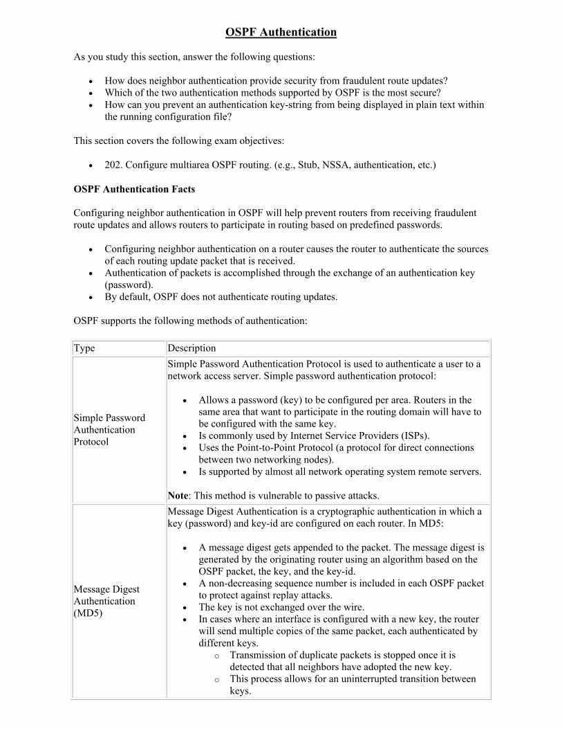
OSPF Authentication
As you study this section, answer the following questions:
How does neighbor authentication provide security from fraudulent route updates? Which of the two authentication methods supported by OSPF is the most secure? How can you prevent an authentication key-string from being displayed in plain text within
the running configuration file?
This section covers the following exam objectives:
202. Configure multiarea OSPF routing. (e.g., Stub, NSSA, authentication, etc.)
OSPF Authentication Facts
Configuring neighbor authentication in OSPF will help prevent routers from receiving fraudulent route updates and allows routers to participate in routing based on predefined passwords.
Configuring neighbor authentication on a router causes the router to authenticate the sources of each routing update packet that is received.
Authentication of packets is accomplished through the exchange of an authentication key (password).
By default, OSPF does not authenticate routing updates.
OSPF supports the following methods of authentication:
Type Description
Simple Password Authentication Protocol
Simple Password Authentication Protocol is used to authenticate a user to a network access server. Simple password authentication protocol:
Allows a password (key) to be configured per area. Routers in the same area that want to participate in the routing domain will have to be configured with the same key.
Is commonly used by Internet Service Providers (ISPs). Uses the Point-to-Point Protocol (a protocol for direct connections
between two networking nodes). Is supported by almost all network operating system remote servers.
Note: This method is vulnerable to passive attacks.
Message Digest Authentication (MD5)
Message Digest Authentication is a cryptographic authentication in which a key (password) and key-id are configured on each router. In MD5:
A message digest gets appended to the packet. The message digest is generated by the originating router using an algorithm based on the OSPF packet, the key, and the key-id.
A non-decreasing sequence number is included in each OSPF packet to protect against replay attacks.
The key is not exchanged over the wire. In cases where an interface is configured with a new key, the router
will send multiple copies of the same packet, each authenticated by different keys.
o Transmission of duplicate packets is stopped once it is detected that all neighbors have adopted the new key.
o This process allows for an uninterrupted transition between keys.

o You should remove the old key each time a new key is added. This will prevent the local router from continuing to communicate with potentially hostile systems.
o It is recommended to not keep more than one key per interface.
OSPF Authentication Command List
The following table lists the applicable commands to configure OSPF authentication.
Use... To...
(config-if)#ip ospf authentication
Enable plain-text authentication (i.e., simple password authentication) in OSPF packets on the specified interface.
(config-if)#ip ospf authentication-key <key>
Configure a plain-text password for OSPF authentication.
Note: All neighboring routers on the same network must have the same password to be able to exchange OSPF information.
(config-if)#ip ospf authentication message-digest
Enable MD5 authentication in OSPF packets on the specified interface.
(config-if)#ip ospf message-digest-key <key-id> md5 <0-7> <key>
Enable authentication of OSPF packets and specify the key number and password for the interface.
The key-id and key values must match for other OSPF neighbors on a network segment.
The key-id range is 1-255. The encryption level range is from 0 to 7:
o 0 specifies no encryption o 7 specifies a proprietary level of encryption
Configures the key (password) up to 16 bytes. It can consist of alphanumeric characters.
(config)#service password-encryption
Cause the key-string to be stored and displayed in encrypted form.
Note: If this command is not used when implementing OSPF authentication, the key-string will be stored as plain text in NVRAM.
ExamplesThe following commands enable OSPF MD5 authentication on the Fa 0/0 interface with a key chain value of R2chain. It also configures the key-string as Cisco45.
Router(config)#int fa 0/0Router(config-if)#ip ospf authentication message-digest Router(config-if)#ip ospf message-digest-key R2chain md5 Cisco45
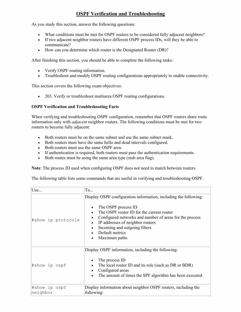
OSPF Verification and Troubleshooting
As you study this section, answer the following questions:
What conditions must be met for OSPF routers to be considered fully adjacent neighbors? If two adjacent neighbor routers have different OSPF process IDs, will they be able to
communicate? How can you determine which router is the Designated Router (DR)?
After finishing this section, you should be able to complete the following tasks:
Verify OSPF routing information. Troubleshoot and modify OSPF routing configurations appropriately to enable connectivity.
This section covers the following exam objectives:
203. Verify or troubleshoot multiarea OSPF routing configurations.
OSPF Verification and Troubleshooting Facts
When verifying and troubleshooting OSPF configuration, remember that OSPF routers share route information only with adjacent neighbor routers. The following conditions must be met for two routers to become fully adjacent:
Both routers must be on the same subnet and use the same subnet mask. Both routers must have the same hello and dead intervals configured. Both routers must use the same OSPF area. If authentication is required, both routers must pass the authentication requirements. Both routes must be using the same area type (stub area flag).
Note: The process ID used when configuring OSPF does not need to match between routers.
The following table lists some commands that are useful in verifying and troubleshooting OSPF.
Use... To...
#show ip protocols
Display OSPF configuration information, including the following:
The OSPF process ID The OSPF router ID for the current router Configured networks and number of areas for the process IP addresses of neighbor routers Incoming and outgoing filters Default metrics Maximum paths
#show ip ospf
Display OSPF information, including the following:
The process ID The local router ID and its role (such as DR or BDR) Configured areas The amount of times the SPF algorithm has been executed
#show ip ospf neighbor
Display information about neighbor OSPF routers, including the following:
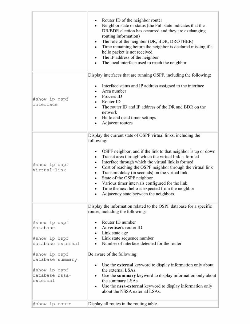
Router ID of the neighbor router Neighbor state or status (the Full state indicates that the
DR/BDR election has occurred and they are exchanging routing information)
The role of the neighbor (DR, BDR, DROTHER) Time remaining before the neighbor is declared missing if a
hello packet is not received The IP address of the neighbor The local interface used to reach the neighbor
#show ip ospf interface
Display interfaces that are running OSPF, including the following:
Interface status and IP address assigned to the interface Area number Process ID Router ID The router ID and IP address of the DR and BDR on the
network Hello and dead timer settings Adjacent routers
#show ip ospf virtual-link
Display the current state of OSPF virtual links, including the following:
OSPF neighbor, and if the link to that neighbor is up or down Transit area through which the virtual link is formed Interface through which the virtual link is formed Cost of reaching the OSPF neighbor through the virtual link Transmit delay (in seconds) on the virtual link State of the OSPF neighbor Various timer intervals configured for the link Time the next hello is expected from the neighbor Adjacency state between the neighbors
#show ip ospf database
#show ip ospf database external
#show ip ospf database summary
#show ip ospf database nssa-external
Display the information related to the OSPF database for a specific router, including the following:
Router ID number Advertiser's router ID Link state age Link state sequence number Number of interface detected for the router
Be aware of the following:
Use the external keyword to display information only about the external LSAs.
Use the summary keyword to display information only about the summary LSAs.
Use the nssa-external keyword to display information only about the NSSA external LSAs.
#show ip route Display all routes in the routing table.
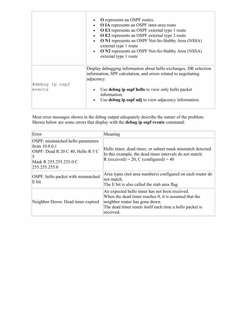
O represents an OSPF routes. O IA represents an OSPF inter-area route O E1 represents an OSPF external type 1 route O E2 represents an OSPF external type 2 route O N1 represents an OSPF Not-So-Stubby Area (NSSA)
external type 1 route O N2 represents an OSPF Not-So-Stubby Area (NSSA)
external type 1 route
#debug ip ospf events
Display debugging information about hello exchanges, DR selection information, SPF calculation, and errors related to negotiating adjacency.
Use debug ip ospf hello to view only hello packet information.
Use debug ip ospf adj to view adjacency information.
Most error messages shown in the debug output adequately describe the nature of the problem. Shown below are some errors that display with the debug ip ospf events command:
Error Meaning
OSPF: mismatched hello parameters from 10.0.0.1OSPF: Dead R 20 C 40, Hello R 5 C 5Mask R 255.255.255.0 C 255.255.255.0
Hello timer, dead timer, or subnet mask mismatch detected.In this example, the dead timer intervals do not match: R (received) = 20, C (configured) = 40
OSPF: hello packet with mismatched E bit
Area types (not area numbers) configured on each router do not match.The E bit is also called the stub area flag.
Neighbor Down: Dead timer expired
An expected hello timer has not been received. When the dead timer reaches 0, it is assumed that the neighbor router has gone down. The dead timer resets itself each time a hello packet is received.
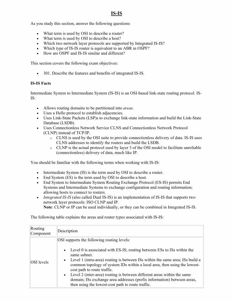
IS-IS
As you study this section, answer the following questions:
What term is used by OSI to describe a router? What term is used by OSI to describe a host? Which two network layer protocols are supported by Integrated IS-IS? Which type of IS-IS router is equivalent to an ABR in OSPF? How are OSPF and IS-IS similar and different?
This section covers the following exam objectives:
301. Describe the features and benefits of integrated IS-IS.
IS-IS Facts
Intermediate System to Intermediate System (IS-IS) is an OSI-based link-state routing protocol. IS-IS:
Allows routing domains to be partitioned into areas. Uses a Hello protocol to establish adjacencies. Uses Link-State Packets (LSP)s to exchange link-state information and build the Link-State
Database (LSDB). Uses Connectionless Network Service CLNS and Connectionless Network Protocol
(CLNP) instead of TCP/IP. o CLNS is used by the OSI suite to provide connectionless delivery of data. IS-IS uses
CLNS addresses to identify the routers and build the LSDB. o CLNP is the actual protocol used by layer 3 of the OSI model to facilitate unreliable
(connectionless) delivery of data, much like IP.
You should be familiar with the following terms when working with IS-IS:
Intermediate System (IS) is the term used by OSI to describe a router. End System (ES) is the term used by OSI to describe a host. End System to Intermediate System Routing Exchange Protocol (ES-IS) permits End
Systems and Intermediate Systems to exchange configuration and routing information; allowing hosts to connect to routers.
Integrated IS-IS (also called Dual IS-IS) is an implementation of IS-IS that supports two network layer protocols: ISO CLNP and IP.Note: CLNP or IP can be used individually, or they can be combined in Integrated IS-IS.
The following table explains the areas and router types associated with IS-IS:
Routing Component
Description
OSI levels
OSI supports the following routing levels:
Level 0 is associated with ES-IS; routing between ESs to ISs within the same subnet.
Level 1 (intra-area) routing is between ISs within the same area; ISs build a common topology of system IDs within a local area, then using the lowest-cost path to route traffic.
Level 2 (inter-area) routing is between different areas within the same domain; ISs exchange area addresses (prefix information) between areas, then using the lowest-cost path to route traffic.
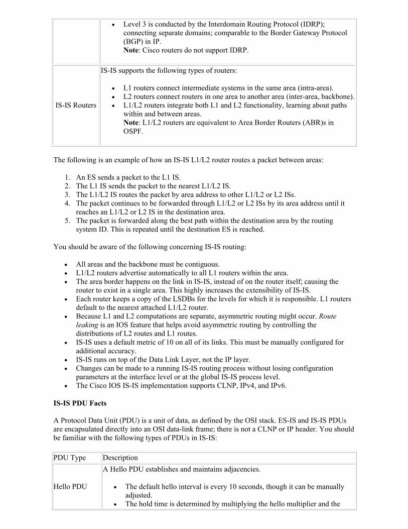
Level 3 is conducted by the Interdomain Routing Protocol (IDRP); connecting separate domains; comparable to the Border Gateway Protocol (BGP) in IP. Note: Cisco routers do not support IDRP.
IS-IS Routers
IS-IS supports the following types of routers:
L1 routers connect intermediate systems in the same area (intra-area). L2 routers connect routers in one area to another area (inter-area, backbone). L1/L2 routers integrate both L1 and L2 functionality, learning about paths
within and between areas.Note: L1/L2 routers are equivalent to Area Border Routers (ABR)s in OSPF.
The following is an example of how an IS-IS L1/L2 router routes a packet between areas:
1. An ES sends a packet to the L1 IS. 2. The L1 IS sends the packet to the nearest L1/L2 IS. 3. The L1/L2 IS routes the packet by area address to other L1/L2 or L2 ISs. 4. The packet continues to be forwarded through L1/L2 or L2 ISs by its area address until it
reaches an L1/L2 or L2 IS in the destination area. 5. The packet is forwarded along the best path within the destination area by the routing
system ID. This is repeated until the destination ES is reached.
You should be aware of the following concerning IS-IS routing:
All areas and the backbone must be contiguous. L1/L2 routers advertise automatically to all L1 routers within the area. The area border happens on the link in IS-IS, instead of on the router itself; causing the
router to exist in a single area. This highly increases the extensibility of IS-IS. Each router keeps a copy of the LSDBs for the levels for which it is responsible. L1 routers
default to the nearest attached L1/L2 router. Because L1 and L2 computations are separate, asymmetric routing might occur. Route
leaking is an IOS feature that helps avoid asymmetric routing by controlling the distributions of L2 routes and L1 routes.
IS-IS uses a default metric of 10 on all of its links. This must be manually configured for additional accuracy.
IS-IS runs on top of the Data Link Layer, not the IP layer. Changes can be made to a running IS-IS routing process without losing configuration
parameters at the interface level or at the global IS-IS process level. The Cisco IOS IS-IS implementation supports CLNP, IPv4, and IPv6.
IS-IS PDU Facts
A Protocol Data Unit (PDU) is a unit of data, as defined by the OSI stack. ES-IS and IS-IS PDUs are encapsulated directly into an OSI data-link frame; there is not a CLNP or IP header. You should be familiar with the following types of PDUs in IS-IS:
PDU Type Description
Hello PDU
A Hello PDU establishes and maintains adjacencies.
The default hello interval is every 10 seconds, though it can be manually adjusted.
The hold time is determined by multiplying the hello multiplier and the
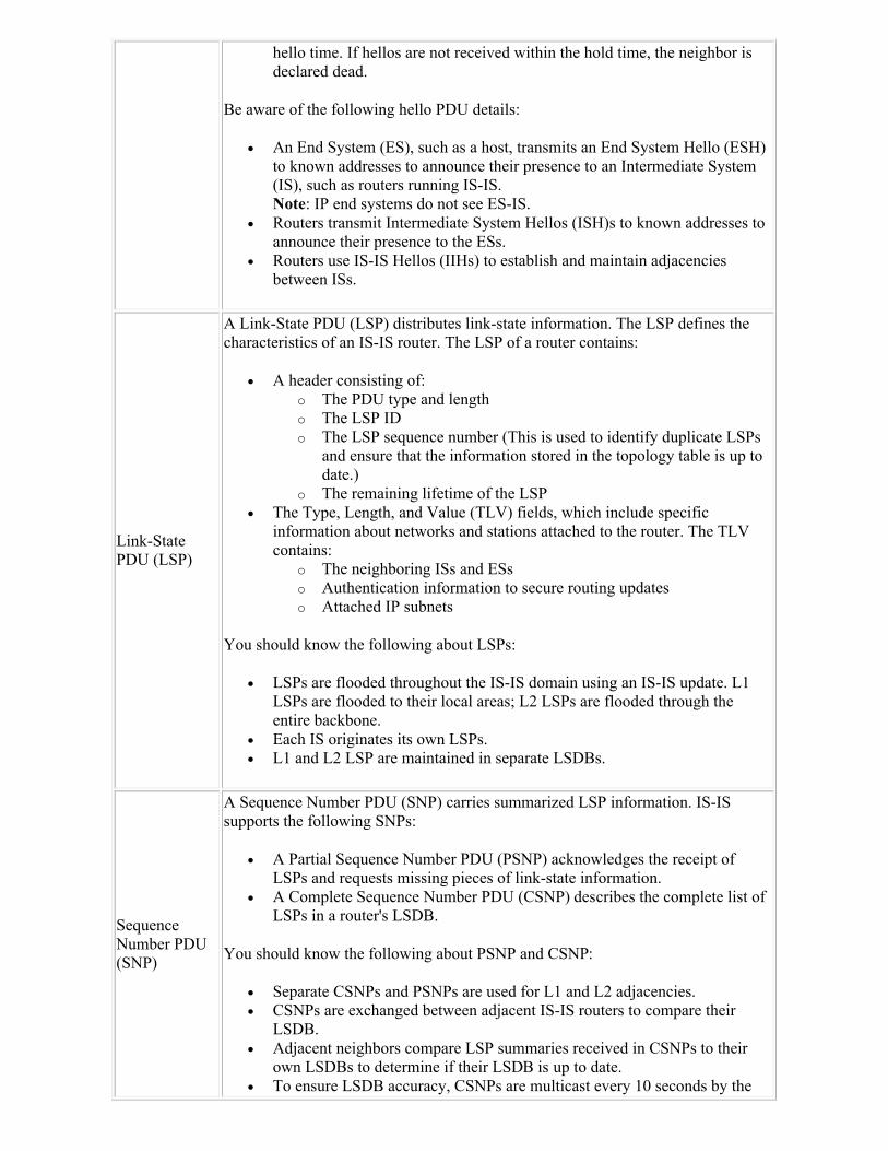
hello time. If hellos are not received within the hold time, the neighbor is declared dead.
Be aware of the following hello PDU details:
An End System (ES), such as a host, transmits an End System Hello (ESH) to known addresses to announce their presence to an Intermediate System (IS), such as routers running IS-IS.Note: IP end systems do not see ES-IS.
Routers transmit Intermediate System Hellos (ISH)s to known addresses to announce their presence to the ESs.
Routers use IS-IS Hellos (IIHs) to establish and maintain adjacencies between ISs.
Link-State PDU (LSP)
A Link-State PDU (LSP) distributes link-state information. The LSP defines the characteristics of an IS-IS router. The LSP of a router contains:
A header consisting of: o The PDU type and length o The LSP ID o The LSP sequence number (This is used to identify duplicate LSPs
and ensure that the information stored in the topology table is up to date.)
o The remaining lifetime of the LSP The Type, Length, and Value (TLV) fields, which include specific
information about networks and stations attached to the router. The TLV contains:
o The neighboring ISs and ESs o Authentication information to secure routing updates o Attached IP subnets
You should know the following about LSPs:
LSPs are flooded throughout the IS-IS domain using an IS-IS update. L1 LSPs are flooded to their local areas; L2 LSPs are flooded through the entire backbone.
Each IS originates its own LSPs. L1 and L2 LSP are maintained in separate LSDBs.
Sequence Number PDU (SNP)
A Sequence Number PDU (SNP) carries summarized LSP information. IS-IS supports the following SNPs:
A Partial Sequence Number PDU (PSNP) acknowledges the receipt of LSPs and requests missing pieces of link-state information.
A Complete Sequence Number PDU (CSNP) describes the complete list of LSPs in a router's LSDB.
You should know the following about PSNP and CSNP:
Separate CSNPs and PSNPs are used for L1 and L2 adjacencies. CSNPs are exchanged between adjacent IS-IS routers to compare their
LSDB. Adjacent neighbors compare LSP summaries received in CSNPs to their
own LSDBs to determine if their LSDB is up to date. To ensure LSDB accuracy, CSNPs are multicast every 10 seconds by the
DIS on a LAN. LSPs are sent in ranges if there are too many to include in a single CSNP.
IS-IS Addressing Facts
The ES-IS configuration protocol uses both OSI network-layer and OSI subnetwork addresses. OSI network-layer addresses identify one of the following:
Address Type
Description
Network Service Access Point (NSAP)
A Network Service Access Point (NSAP) is used to identify routers and build the topology table in IS-IS.
The NSAP is the interface between OSI Layer 3 and Layer 4. NSAP addresses are comparable to a combination of the IP address and upper-
layer protocol in an IP header. An NSAP address is up to 20 bites in size.
NSAP addresses are comprised of the following parts:
The Initial Domain Part (IDP) consists of the first 2 fields of an NSAP: o The first field of the NSAP is called the AFI, which identifies the
authority from whom the numbering scheme originates (addressing scheme). 49 indicates a local or private addressing scheme (most common).
o The second field of an NSAP is called the area. The area portion of an NSAP address is the same for all NSAP routers within an area. Each router in IS-IS only belongs to a single area.
The Domain-Specific Part (DSP) consists of the last 3 fields of an NSAP: o The third field of an NSAP identifies the High-Order Domain Specific
Part (HODSP), which subdivides the domain into areas, much like the subnet in an IP.
o The fourth field of an NSAP identifies individual OSI devices, such as the unique identifier or MAC address of the router.
o The fifth field of an NSAP address is called the NSAP-selector or an N-selector (NSEL); its function is comparable to that of a port number in IP. It is configured as 0x00 to declare the address as a router address.
Network Entity Title (NET)
When CLNS router addresses have an NSEL of 0, the entire NSAP is called a Network Entity Title (NET). The NET is the Network-layer entity in an OSI IS. NET addresses are:
Used to uniquely identify an OSI host within an IS-IS routing domain. Required even if the only protocol that is routed is IP. Used by routers to identify themselves in the LSPs; thus forming the basis for
the calculation of OSI routing.
NET addresses are comprised of the following parts (see the illustration below):
An area address, which is variable length, is composed of high order octets. It excludes the System ID and N-selector (NSEL) fields.
The system ID is 6 bytes long and must be unique throughout each area (Level 1) and throughout the backbone (Level 2). The system ID defines an end
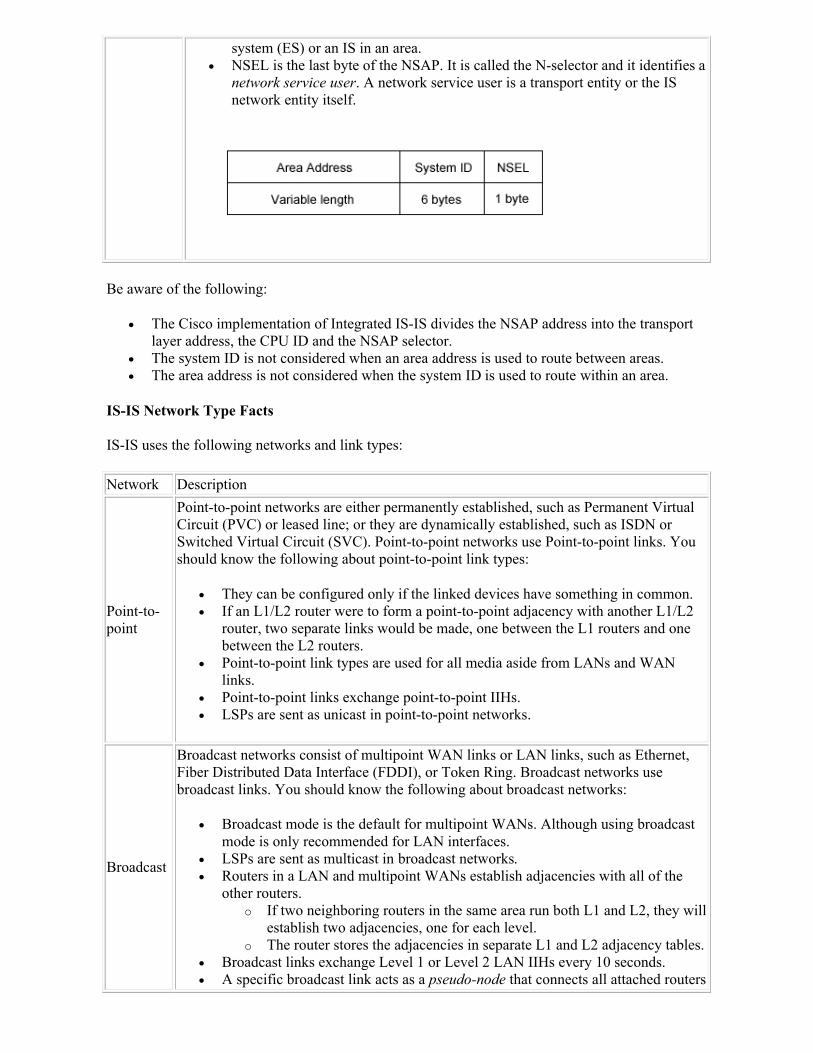
system (ES) or an IS in an area. NSEL is the last byte of the NSAP. It is called the N-selector and it identifies a
network service user. A network service user is a transport entity or the IS network entity itself.
Be aware of the following:
The Cisco implementation of Integrated IS-IS divides the NSAP address into the transport layer address, the CPU ID and the NSAP selector.
The system ID is not considered when an area address is used to route between areas. The area address is not considered when the system ID is used to route within an area.
IS-IS Network Type Facts
IS-IS uses the following networks and link types:
Network Description
Point-to-point
Point-to-point networks are either permanently established, such as Permanent Virtual Circuit (PVC) or leased line; or they are dynamically established, such as ISDN or Switched Virtual Circuit (SVC). Point-to-point networks use Point-to-point links. You should know the following about point-to-point link types:
They can be configured only if the linked devices have something in common. If an L1/L2 router were to form a point-to-point adjacency with another L1/L2
router, two separate links would be made, one between the L1 routers and one between the L2 routers.
Point-to-point link types are used for all media aside from LANs and WAN links.
Point-to-point links exchange point-to-point IIHs. LSPs are sent as unicast in point-to-point networks.
Broadcast
Broadcast networks consist of multipoint WAN links or LAN links, such as Ethernet, Fiber Distributed Data Interface (FDDI), or Token Ring. Broadcast networks use broadcast links. You should know the following about broadcast networks:
Broadcast mode is the default for multipoint WANs. Although using broadcast mode is only recommended for LAN interfaces.
LSPs are sent as multicast in broadcast networks. Routers in a LAN and multipoint WANs establish adjacencies with all of the
other routers. o If two neighboring routers in the same area run both L1 and L2, they will
establish two adjacencies, one for each level.o The router stores the adjacencies in separate L1 and L2 adjacency tables.
Broadcast links exchange Level 1 or Level 2 LAN IIHs every 10 seconds. A specific broadcast link acts as a pseudo-node that connects all attached routers
in a star-shaped topology.
A Designated Intermediate System (DIS) is elected to generate the pseudo-node LSP. The pseudo-node LSPs include neighbor advertisements for all of the ISs that operate on that network. Rather than having each router on the LAN advertise an adjacency with each router on the LAN, each router (including the DIS) advertises a single adjacency to the pseudo-node, and does not advertise any of their neighbors on the multi-access network. You should know the following about the DIS:
All routers in a LAN establish adjacencies with the DIS and with all other routers.
The DIS is selected based on the router with the highest priority and the highest SNPA (on LANs the SNPA is the MAC address).
The default priority of L1 and L2 routers is 64, but it can be manually configured to any number between 0 and 127.
If a DIS fails, another router takes over immediately; preventing the network topology from being affected.
DIS election is not permanent; if an adjacent IS has a higher priority, it will automatically assume the DIS role.
Because an interface can have different priorities for L1 and L2 , the L1 DIS and the L2 DIS on a LAN may not be the same router.
Without the reduction of a single advertised adjacency to the pseudo-node, each router would require the following amount of adjacency advertisements per level:
(n)(n-1)/2, where n equals the number of adjacent routers on the level.
Note: Generating LSPs for each adjacency creates considerable overhead in terms of LSDB synchronization.
IS-IS and OSPF Comparison Facts
IS-IS and OSPF were developed around the same time period and have many similarities and differences. You should be aware of how IS-IS compares with OSPF:
Comparison Description
Similarities
IS-IS and OSPF both:
Can perform well in even the largest, most demanding environments. Use the Shortest Path First (SPF) algorithm. Are open standard link-state routing protocols. Support Variable-Length Subnet Masks (VLSM). Converge quickly after network changes. Maintain the health of the LSDB through link-state database synchronization
and link-state ageing timers. Have similar updating, decision, and flooding processes.
Differences
Differences between IS-IS and OSPF include the following:
OSPF has more area types, such as standard, stubby, NSSA, and totally stubby.
The area border happens on the link in IS-IS, instead of on the router itself
with OSPF; the router exists in a single area. It is simple to extend the backbone with IS-IS by adding a L1/L2 or L2 router,
instead OSPF where you need to directly connect to area 0. IS-IS uses less overhead by generating fewer Link-State Packets (LSPs) than
OSPF generating many small LSAs. The IS-IS LSP contains TLV fields, and OSPF LSU contains LSAs. Because IS-IS uses less LSPs, less CPU processing is needed and there can be
more routers in an IS-IS area. IS-IS uses a default metric of 10 on all of its links, instead of OSPF's metric
which is related to the interface bandwidth. IS-IS has not been widely-adopted and is mainly used in very large service
provider networks. IS-IS runs on top of the Data Link Layer, instead of OSPF running on top of
the IP layer. IS-IS encapsulates PDUs directly into a data-link frame. When IP reachability calculations need to be made, IS-IS uses Partial Route
Calculations (PRC) instead of the whole SPF algorithm as required by OSPF. IS-IS supports CLNS and IP, whereas OSPF only supports IP. CLNS addresses are required for IS-IS even when only routing IP. On a LAN, IS-IS forms adjacencies with all neighbors, unlike OSPF where
adjacencies are formed with the DR and BDR. The Designated Intermediate System (DIS) does not have a backup, unlike
OSPF's DR and BDR.
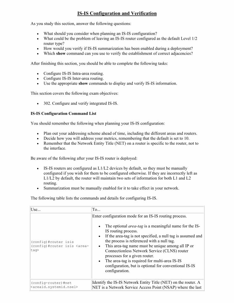
IS-IS Configuration and Verification
As you study this section, answer the following questions:
What should you consider when planning an IS-IS configuration? What could be the problem of leaving an IS-IS router configured as the default Level 1/2
router type? How would you verify if IS-IS summarization has been enabled during a deployment? Which show command can you use to verify the establishment of correct adjacencies?
After finishing this section, you should be able to complete the following tasks:
Configure IS-IS Intra-area routing. Configure IS-IS Inter-area routing. Use the appropriate show commands to display and verify IS-IS information.
This section covers the following exam objectives:
302. Configure and verify integrated IS-IS.
IS-IS Configuration Command List
You should remember the following when planning your IS-IS configuration:
Plan out your addressing scheme ahead of time, including the different areas and routers. Decide how you will address your metrics, remembering that the default is set to 10. Remember that the Network Entity Title (NET) on a router is specific to the router, not to
the interface.
Be aware of the following after your IS-IS router is deployed:
IS-IS routers are configured as L1/L2 devices by default, so they must be manually configured if you wish for them to be configured otherwise. If they are incorrectly left as L1/L2 by default, the router will maintain two sets of information for both L1 and L2 routing.
Summarization must be manually enabled for it to take effect in your network.
The following table lists the commands and details for configuring IS-IS.
Use... To...
(config)#router isis (config)#router isis <area-tag>
Enter configuration mode for an IS-IS routing process.
The optional area-tag is a meaningful name for the IS-IS routing process.
If the area-tag is not specified, a null tag is assumed and the process is referenced with a null tag.
This area-tag name must be unique among all IP or Connectionless Network Service (CLNS) router processes for a given router.
The area-tag is required for multi-area IS-IS configuration, but is optional for conventional IS-IS configuration.
(config-router)#net <areaid.systemid.nsel>
Identify the IS-IS Network Entity Title (NET) on the router. A NET is a Network Service Access Point (NSAP) where the last
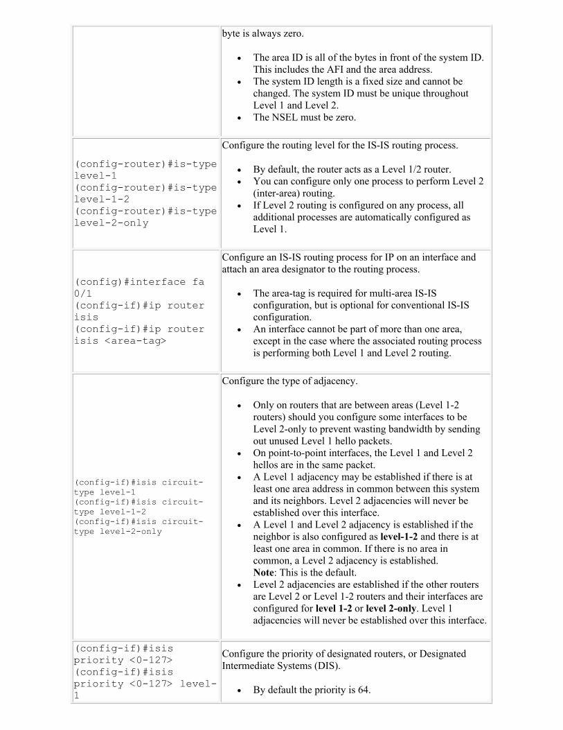
byte is always zero.
The area ID is all of the bytes in front of the system ID. This includes the AFI and the area address.
The system ID length is a fixed size and cannot be changed. The system ID must be unique throughout Level 1 and Level 2.
The NSEL must be zero.
(config-router)#is-type level-1(config-router)#is-type level-1-2(config-router)#is-type level-2-only
Configure the routing level for the IS-IS routing process.
By default, the router acts as a Level 1/2 router. You can configure only one process to perform Level 2
(inter-area) routing. If Level 2 routing is configured on any process, all
additional processes are automatically configured as Level 1.
(config)#interface fa 0/1(config-if)#ip router isis(config-if)#ip router isis <area-tag>
Configure an IS-IS routing process for IP on an interface and attach an area designator to the routing process.
The area-tag is required for multi-area IS-IS configuration, but is optional for conventional IS-IS configuration.
An interface cannot be part of more than one area, except in the case where the associated routing process is performing both Level 1 and Level 2 routing.
(config-if)#isis circuit-type level-1(config-if)#isis circuit-type level-1-2(config-if)#isis circuit-type level-2-only
Configure the type of adjacency.
Only on routers that are between areas (Level 1-2 routers) should you configure some interfaces to be Level 2-only to prevent wasting bandwidth by sending out unused Level 1 hello packets.
On point-to-point interfaces, the Level 1 and Level 2 hellos are in the same packet.
A Level 1 adjacency may be established if there is at least one area address in common between this system and its neighbors. Level 2 adjacencies will never be established over this interface.
A Level 1 and Level 2 adjacency is established if the neighbor is also configured as level-1-2 and there is at least one area in common. If there is no area in common, a Level 2 adjacency is established. Note: This is the default.
Level 2 adjacencies are established if the other routers are Level 2 or Level 1-2 routers and their interfaces are configured for level 1-2 or level 2-only. Level 1 adjacencies will never be established over this interface.
(config-if)#isis priority <0-127>(config-if)#isis priority <0-127> level-1
Configure the priority of designated routers, or Designated Intermediate Systems (DIS).
By default the priority is 64.
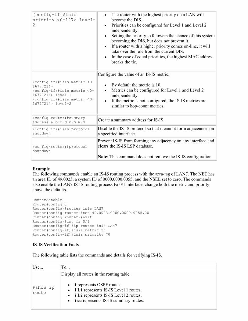
(config-if)#isis priority <0-127> level-2
The router with the highest priority on a LAN will become the DIS.
Priorities can be configured for Level 1 and Level 2 independently.
Setting the priority to 0 lowers the chance of this system becoming the DIS, but does not prevent it.
If a router with a higher priority comes on-line, it will take over the role from the current DIS.
In the case of equal priorities, the highest MAC address breaks the tie.
(config-if)#isis metric <0-16777214>(config-if)#isis metric <0-16777214> level-1(config-if)#isis metric <0-16777214> level-2
Configure the value of an IS-IS metric.
By default the metric is 10. Metrics can be configured for Level 1 and Level 2
independently. If the metric is not configured, the IS-IS metrics are
similar to hop-count metrics.
(config-router)#summary-address a.b.c.d m.m.m.m Create a summary address for IS-IS.
(config-if)#isis protocol shutdown
Disable the IS-IS protocol so that it cannot form adjacencies on a specified interface.
(config-router)#protocol shutdown
Prevent IS-IS from forming any adjacency on any interface and clears the IS-IS LSP database.
Note: This command does not remove the IS-IS configuration.
ExampleThe following commands enable an IS-IS routing process with the area-tag of LAN7. The NET has an area ID of 49.0023, a system ID of 0000.0000.0055, and the NSEL set to zero. The commands also enable the LAN7 IS-IS routing process Fa 0/1 interface, change both the metric and priority above the defaults.
Router>enable Router#config t Router(config)#router isis LAN7Router(config-router)#net 49.0023.0000.0000.0055.00Router(config-router)#exitRouter(config)#int fa 0/1Router(config-if)#ip router isis LAN7Router(config-if)#isis metric 25Router(config-if)#isis priority 70
IS-IS Verification Facts
The following table lists the commands and details for verifying IS-IS.
Use... To...
#show ip route
Display all routes in the routing table.
i represents OSPF routes. i L1 represents IS-IS Level 1 routes. i L2 represents IS-IS Level 2 routes. i su represents IS-IS summary routes.
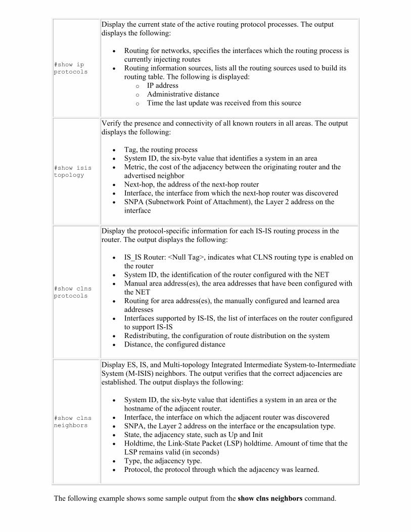
#show ip protocols
Display the current state of the active routing protocol processes. The output displays the following:
Routing for networks, specifies the interfaces which the routing process is currently injecting routes
Routing information sources, lists all the routing sources used to build its routing table. The following is displayed:
o IP address o Administrative distance o Time the last update was received from this source
#show isis topology
Verify the presence and connectivity of all known routers in all areas. The output displays the following:
Tag, the routing process System ID, the six-byte value that identifies a system in an area Metric, the cost of the adjacency between the originating router and the
advertised neighbor Next-hop, the address of the next-hop router Interface, the interface from which the next-hop router was discovered SNPA (Subnetwork Point of Attachment), the Layer 2 address on the
interface
#show clns protocols
Display the protocol-specific information for each IS-IS routing process in the router. The output displays the following:
IS_IS Router: <Null Tag>, indicates what CLNS routing type is enabled on the router
System ID, the identification of the router configured with the NET Manual area address(es), the area addresses that have been configured with
the NET Routing for area address(es), the manually configured and learned area
addresses Interfaces supported by IS-IS, the list of interfaces on the router configured
to support IS-IS Redistributing, the configuration of route distribution on the system Distance, the configured distance
#show clns neighbors
Display ES, IS, and Multi-topology Integrated Intermediate System-to-Intermediate System (M-ISIS) neighbors. The output verifies that the correct adjacencies are established. The output displays the following:
System ID, the six-byte value that identifies a system in an area or the hostname of the adjacent router.
Interface, the interface on which the adjacent router was discovered SNPA, the Layer 2 address on the interface or the encapsulation type. State, the adjacency state, such as Up and Init Holdtime, the Link-State Packet (LSP) holdtime. Amount of time that the
LSP remains valid (in seconds) Type, the adjacency type. Protocol, the protocol through which the adjacency was learned.
The following example shows some sample output from the show clns neighbors command.
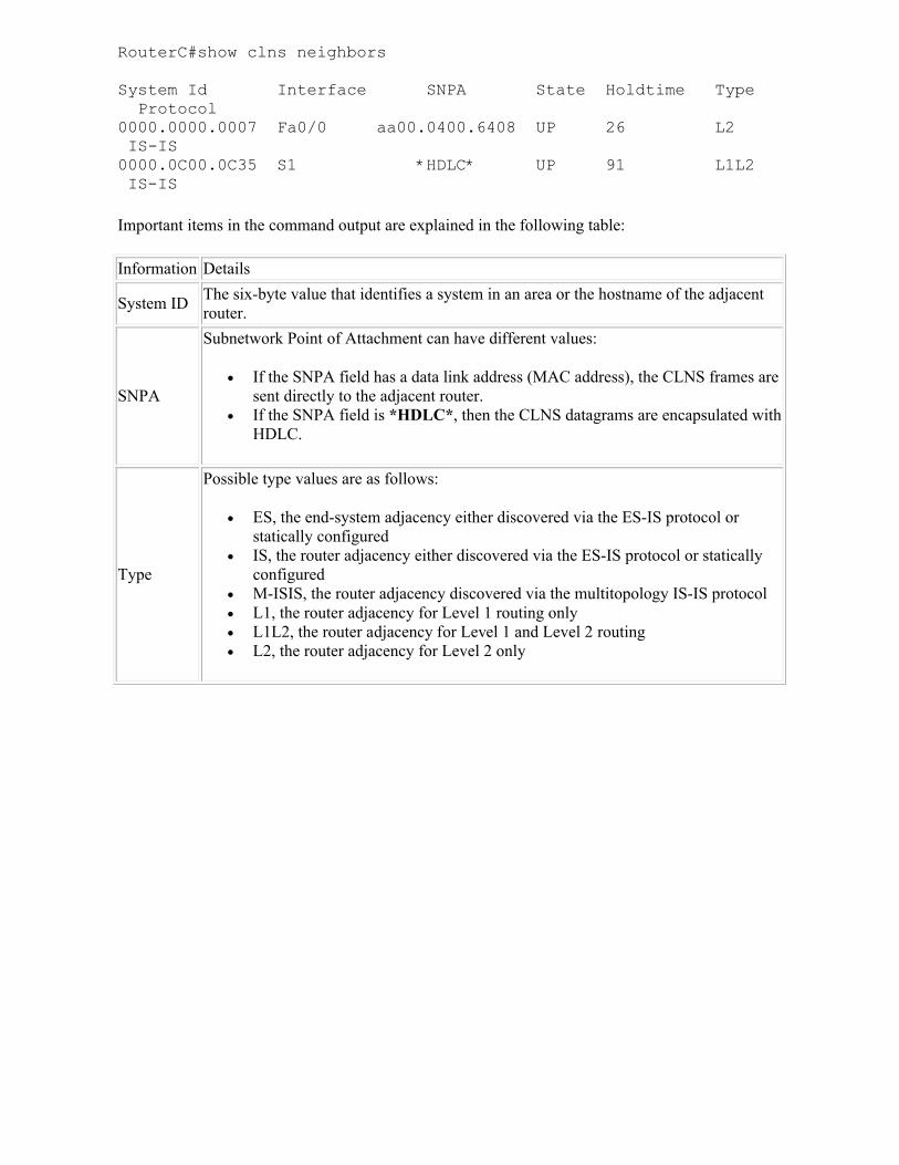
RouterC#show clns neighbors
System Id Interface SNPA State Holdtime Type Protocol0000.0000.0007 Fa0/0 aa00.0400.6408 UP 26 L2 IS-IS
0000.0C00.0C35 S1 *HDLC* UP 91 L1L2IS-IS
Important items in the command output are explained in the following table:
Information Details
System IDThe six-byte value that identifies a system in an area or the hostname of the adjacent router.
SNPA
Subnetwork Point of Attachment can have different values:
If the SNPA field has a data link address (MAC address), the CLNS frames are sent directly to the adjacent router.
If the SNPA field is *HDLC*, then the CLNS datagrams are encapsulated with HDLC.
Type
Possible type values are as follows:
ES, the end-system adjacency either discovered via the ES-IS protocol or statically configured
IS, the router adjacency either discovered via the ES-IS protocol or statically configured
M-ISIS, the router adjacency discovered via the multitopology IS-IS protocol L1, the router adjacency for Level 1 routing only L1L2, the router adjacency for Level 1 and Level 2 routing L2, the router adjacency for Level 2 only
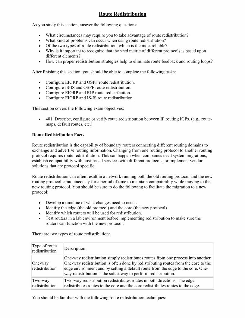
Route Redistribution
As you study this section, answer the following questions:
What circumstances may require you to take advantage of route redistribution? What kind of problems can occur when using route redistribution? Of the two types of route redistribution, which is the most reliable? Why is it important to recognize that the seed metric of different protocols is based upon
different elements? How can proper redistribution strategies help to eliminate route feedback and routing loops?
After finishing this section, you should be able to complete the following tasks:
Configure EIGRP and OSPF route redistribution. Configure IS-IS and OSPF route redistribution. Configure EIGRP and RIP route redistribution. Configure EIGRP and IS-IS route redistribution.
This section covers the following exam objectives:
401. Describe, configure or verify route redistribution between IP routing IGPs. (e.g., route-maps, default routes, etc.)
Route Redistribution Facts
Route redistribution is the capability of boundary routers connecting different routing domains to exchange and advertise routing information. Changing from one routing protocol to another routing protocol requires route redistribution. This can happen when companies need system migrations, establish compatibility with host-based services with different protocols, or implement vendor solutions that are protocol specific.
Route redistribution can often result in a network running both the old routing protocol and the new routing protocol simultaneously for a period of time to maintain compatibility while moving to the new routing protocol. You should be sure to do the following to facilitate the migration to a new protocol:
Develop a timeline of what changes need to occur. Identify the edge (the old protocol) and the core (the new protocol). Identify which routers will be used for redistribution. Test routers in a lab environment before implementing redistribution to make sure the
routers can function with the new protocol.
There are two types of route redistribution:
Type of route redistribution
Description
One-way redistribution
One-way redistribution simply redistributes routes from one process into another. One-way redistribution is often done by redistributing routes from the core to the edge environment and by setting a default route from the edge to the core. One-way redistribution is the safest way to perform redistribution.
Two-way redistribution
Two-way redistribution redistributes routes in both directions. The edge redistributes routes to the core and the core redistributes routes to the edge.
You should be familiar with the following route redistribution techniques:
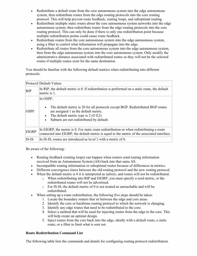
Redistribute a default route from the core autonomous system into the edge autonomous system, then redistribute routes from the edge routing protocols into the core routing protocol. This will help prevent route feedback, routing loops, and suboptimal routing.
Redistribute multiple static routes about the core autonomous system networks into the edge autonomous system, then redistribute routes from the edge routing protocols into the core routing protocol. This can only be done if there is only one redistribution point because multiple redistribution points could cause route feedback.
Redistribute routes from the core autonomous system into the edge autonomous system, using a filter to control what information will propagate into the edge.
Redistribute all routes from the core autonomous system into the edge autonomous system, then from the edge autonomous system into the core autonomous system. Only modify the administrative distance associated with redistributed routes so they will not be the selected routes if multiple routes exist for the same destination.
You should be familiar with the following default metrics when redistributing into different protocols:
Protocol Default Values
RIPIn RIP, the default metric is 0. If redistribution is performed on a static route, the default metric is 1.
OSPF
In OSPF:
The default metric is 20 for all protocols except BGP. Redistributed BGP routes are assigned 1 as the default metric.
The default metric type is 2 (O E2). Subnets are not redistributed by default.
EIGRPIn EIGRP, the metric is 0. For static route redistribution or when redistributing a route connected into EIGRP, the default metric is equal to the metric of the associated interface.
IS-IS In IS-IS, routes are introduced as level 2 with a metric of 0.
Be aware of the following:
Routing feedback (routing loops) can happen when routers send routing information received from an Autonomous System (AS) back into that same AS.
Incompatible routing information or suboptimal routes because of differences in metrics. Different convergence times between the old routing protocol and the new routing protocol. When the default metric is 0 it is interpreted as infinity, and routes will not be redistributed.
o When redistributing into RIP and EIGRP, you must specify a seed metric, or the redistributed routes will not be advertised.
o For IS-IS, the default metric of 0 is not treated as unreachable and will be redistributed.
When setting up a route redistribution, the following five steps should be taken: 1. Locate the boundary routers that sit between the edge and core areas. 2. Identify the core or backbone routing protocol to which the network is changing. 3. Identify any edge routes that need to be redistributed to the core. 4. Select a method that will be used for injecting routes from the edge to the core. This
will help create an optimal design. 5. Inject routes from the core back into the edge, ideally with a default route, a static
route, or a filter to limit what is sent out.
Route Redistribution Command List
The following table lists the commands and details for configuring routing protocol redistribution.

Use... To...(config)#router eigrp <as number>(config-router)#redistribute ospf <process id>(config-router)#redistribute ospf <process id> metric <bandwidth> <delay> <reliability> <load> <mtu>(config-router)#redistribute rip (config-router)#redistribute rip metric <bandwidth> <delay> <reliability> <load> <mtu>(config-router)#redistribute isis (config-router)#redistribute isis <level> (config-router)#redistribute isis <level> metric <bandwidth> <delay> <reliability> <load> <mtu>
Enter an EIGRP routing process and then redistribute routes into the EIGRP routing process.
When redistributing a routing process into EIGRP, you can specify the bandwidth, delay, reliability, load, and MTU metrics. Of these metrics, EIGRP only uses bandwidth and delay.
Bandwidth is the minimum bandwidth of the route in kilobytes per second. It can be from 1 to 4294967295.
Delay is the route delay in tens of microseconds. It can be 1 or any positive number that is a multiple of 39.1 nanoseconds
Reliability is the likelihood of successful packet transmission expressed as a number from 0 through 255:
o The value 255 means 100 percent reliability o 0 means no reliability
Load is the effective bandwidth of the route expressed as a number from 1 to 255. 255 is 100 percent loading.
MTU is the smallest allowed value for the Maximum Transmission Unit (MTU), expressed in bytes. It can be from 1 to 65535.
(config)#router ospf <process id>(config-router)#redistribute eigrp <as number> (config-router)#redistribute eigrp <as number> subnets (config-router)#redistribute rip (config-router)#redistribute rip metric <ospf default> (config-router)#redistribute isis (config-router)#redistribute isis <level>(config-router)#redistribute isis <level> subnets
Enter an OSPF routing process and then redistribute routes into the OSPF routing process.
If the subnets keyword is not specified, only routes that are not subnetted are redistributed.
When redistributing other processes to an OSPF process, the default metric is 20 when no metric value is specified.
(config)#router isis <area tag>(config-router)#redistribute eigrp <as number> (config-router)#redistribute eigrp <as number> <level>(config-router)#redistribute rip (config-router)#redistribute rip <level>(config-router)#redistribute ospf
Enter an IS-IS routing process and then redistribute routes into the IS-IS routing process.
The area tag is optional. You may choose to distribute the routes into specified IS-
IS levels, such as: o Level-1 o Level-1-2 o Level-2
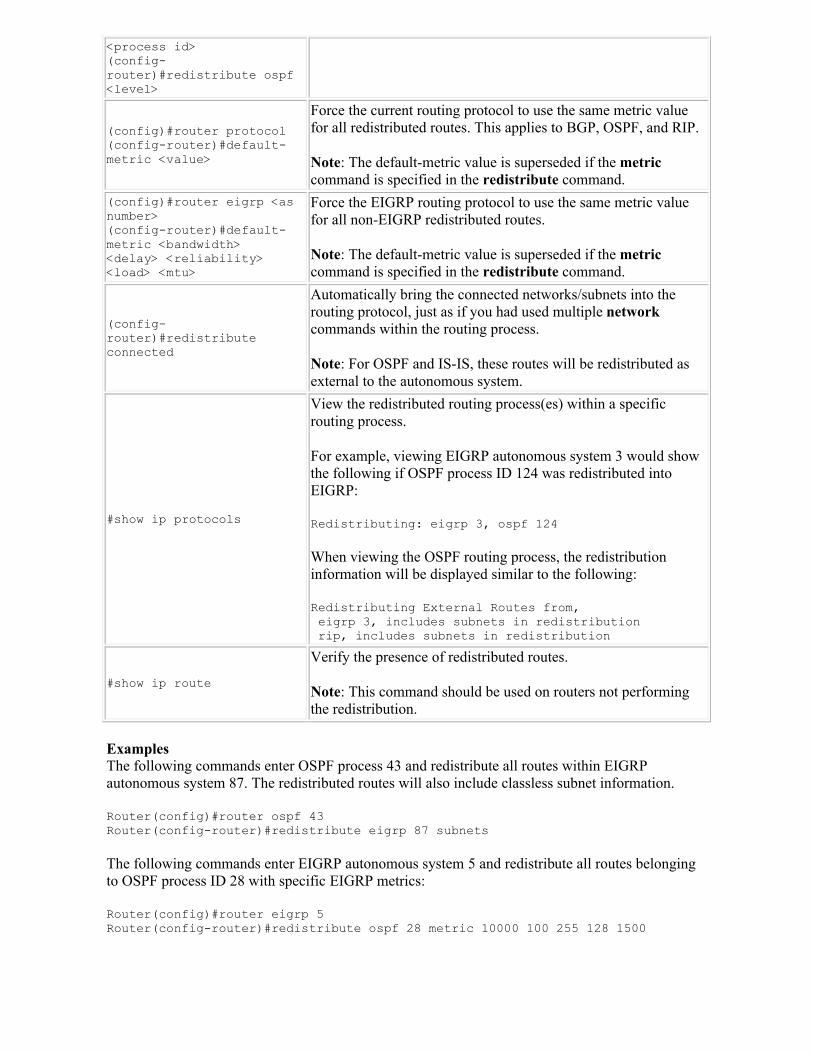
<process id>(config-router)#redistribute ospf <level>
(config)#router protocol(config-router)#default-metric <value>
Force the current routing protocol to use the same metric value for all redistributed routes. This applies to BGP, OSPF, and RIP.
Note: The default-metric value is superseded if the metriccommand is specified in the redistribute command.
(config)#router eigrp <as number>(config-router)#default-metric <bandwidth><delay> <reliability> <load> <mtu>
Force the EIGRP routing protocol to use the same metric value for all non-EIGRP redistributed routes.
Note: The default-metric value is superseded if the metriccommand is specified in the redistribute command.
(config-router)#redistribute connected
Automatically bring the connected networks/subnets into the routing protocol, just as if you had used multiple networkcommands within the routing process.
Note: For OSPF and IS-IS, these routes will be redistributed as external to the autonomous system.
#show ip protocols
View the redistributed routing process(es) within a specific routing process.
For example, viewing EIGRP autonomous system 3 would show the following if OSPF process ID 124 was redistributed into EIGRP:
Redistributing: eigrp 3, ospf 124
When viewing the OSPF routing process, the redistribution information will be displayed similar to the following:
Redistributing External Routes from,eigrp 3, includes subnets in redistributionrip, includes subnets in redistribution
#show ip route
Verify the presence of redistributed routes.
Note: This command should be used on routers not performing the redistribution.
ExamplesThe following commands enter OSPF process 43 and redistribute all routes within EIGRP autonomous system 87. The redistributed routes will also include classless subnet information.
Router(config)#router ospf 43 Router(config-router)#redistribute eigrp 87 subnets
The following commands enter EIGRP autonomous system 5 and redistribute all routes belonging to OSPF process ID 28 with specific EIGRP metrics:
Router(config)#router eigrp 5Router(config-router)#redistribute ospf 28 metric 10000 100 255 128 1500
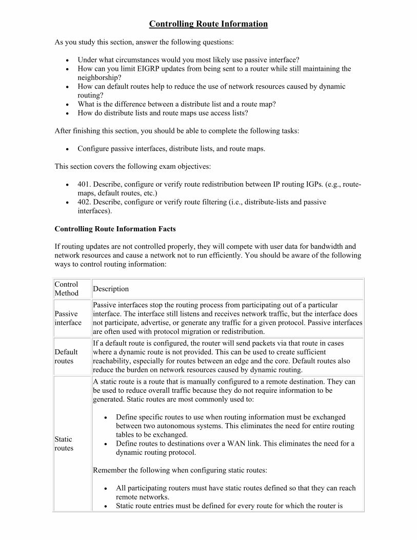
Controlling Route Information
As you study this section, answer the following questions:
Under what circumstances would you most likely use passive interface? How can you limit EIGRP updates from being sent to a router while still maintaining the
neighborship? How can default routes help to reduce the use of network resources caused by dynamic
routing? What is the difference between a distribute list and a route map? How do distribute lists and route maps use access lists?
After finishing this section, you should be able to complete the following tasks:
Configure passive interfaces, distribute lists, and route maps.
This section covers the following exam objectives:
401. Describe, configure or verify route redistribution between IP routing IGPs. (e.g., route-maps, default routes, etc.)
402. Describe, configure or verify route filtering (i.e., distribute-lists and passive interfaces).
Controlling Route Information Facts
If routing updates are not controlled properly, they will compete with user data for bandwidth and network resources and cause a network not to run efficiently. You should be aware of the following ways to control routing information:
Control Method
Description
Passive interface
Passive interfaces stop the routing process from participating out of a particular interface. The interface still listens and receives network traffic, but the interface does not participate, advertise, or generate any traffic for a given protocol. Passive interfaces are often used with protocol migration or redistribution.
Default routes
If a default route is configured, the router will send packets via that route in cases where a dynamic route is not provided. This can be used to create sufficient reachability, especially for routes between an edge and the core. Default routes also reduce the burden on network resources caused by dynamic routing.
Static routes
A static route is a route that is manually configured to a remote destination. They can be used to reduce overall traffic because they do not require information to be generated. Static routes are most commonly used to:
Define specific routes to use when routing information must be exchanged between two autonomous systems. This eliminates the need for entire routing tables to be exchanged.
Define routes to destinations over a WAN link. This eliminates the need for a dynamic routing protocol.
Remember the following when configuring static routes:
All participating routers must have static routes defined so that they can reach remote networks.
Static route entries must be defined for every route for which the router is
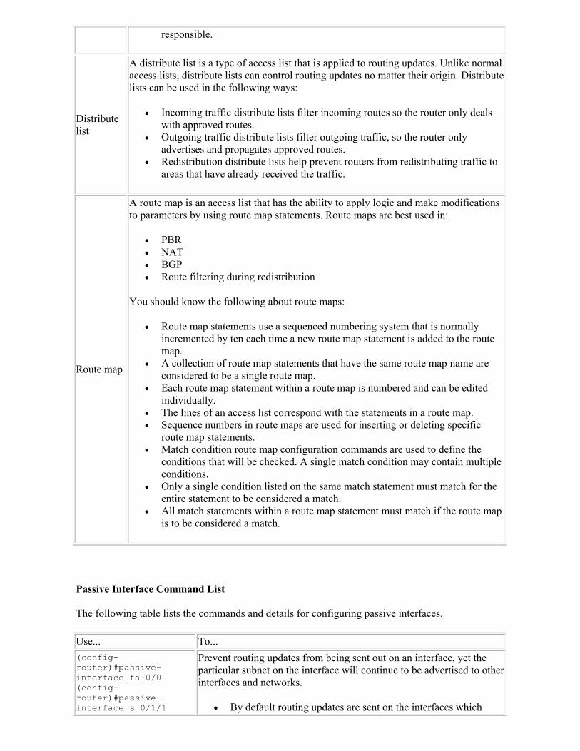
responsible.
Distribute list
A distribute list is a type of access list that is applied to routing updates. Unlike normal access lists, distribute lists can control routing updates no matter their origin. Distribute lists can be used in the following ways:
Incoming traffic distribute lists filter incoming routes so the router only deals with approved routes.
Outgoing traffic distribute lists filter outgoing traffic, so the router only advertises and propagates approved routes.
Redistribution distribute lists help prevent routers from redistributing traffic to areas that have already received the traffic.
Route map
A route map is an access list that has the ability to apply logic and make modifications to parameters by using route map statements. Route maps are best used in:
PBR NAT BGP Route filtering during redistribution
You should know the following about route maps:
Route map statements use a sequenced numbering system that is normally incremented by ten each time a new route map statement is added to the route map.
A collection of route map statements that have the same route map name are considered to be a single route map.
Each route map statement within a route map is numbered and can be edited individually.
The lines of an access list correspond with the statements in a route map. Sequence numbers in route maps are used for inserting or deleting specific
route map statements. Match condition route map configuration commands are used to define the
conditions that will be checked. A single match condition may contain multiple conditions.
Only a single condition listed on the same match statement must match for the entire statement to be considered a match.
All match statements within a route map statement must match if the route map is to be considered a match.
Passive Interface Command List
The following table lists the commands and details for configuring passive interfaces.
Use... To...
(config-router)#passive-interface fa 0/0(config-router)#passive-interface s 0/1/1
Prevent routing updates from being sent out on an interface, yet the particular subnet on the interface will continue to be advertised to other interfaces and networks.
By default routing updates are sent on the interfaces which
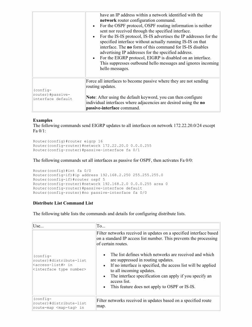
have an IP address within a network identified with the network router configuration command.
For the OSPF protocol, OSPF routing information is neither sent nor received through the specified interface.
For the IS-IS protocol, IS-IS advertises the IP addresses for the specified interface without actually running IS-IS on that interface. The no form of this command for IS-IS disables advertising IP addresses for the specified address.
For the EIGRP protocol, EIGRP is disabled on an interface. This suppresses outbound hello messages and ignores incoming hello messages.
(config-router)#passive-interface default
Force all interfaces to become passive where they are not sending routing updates.
Note: After using the default keyword, you can then configure individual interfaces where adjacencies are desired using the no passive-interface command.
ExamplesThe following commands send EIGRP updates to all interfaces on network 172.22.20.0/24 except Fa 0/1:
Router(config)#router eigrp 16Router(config-router)#network 172.22.20.0 0.0.0.255Router(config-router)#passive-interface fa 0/1
The following commands set all interfaces as passive for OSPF, then activates Fa 0/0:
Router(config)#int fa 0/0Router(config-if)#ip address 192.168.2.250 255.255.255.0Router(config-if)#router ospf 5Router(config-router)#network 192.168.2.0 0.0.0.255 area 0Router(config-router)#passive-interface defaultRouter(config-router)#no passive-interface fa 0/0
Distribute List Command List
The following table lists the commands and details for configuring distribute lists.
Use... To...
(config-router)#distribute-list <access-list#> in <interface type number>
Filter networks received in updates on a specified interface based on a standard IP access list number. This prevents the processing of certain routes.
The list defines which networks are received and which are suppressed in routing updates.
If no interface is specified, the access list will be applied to all incoming updates.
The interface specification can apply if you specify an access list.
This feature does not apply to OSPF or IS-IS.
(config-router)#distribute-list route-map <map-tag> in
Filter networks received in updates based on a specified route map.
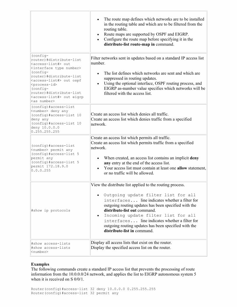
The route map defines which networks are to be installed in the routing table and which are to be filtered from the routing table.
Route maps are supported by OSPF and EIGRP. Configure the route map before specifying it in the
distribute-list route-map in command.
(config-router)#distribute-list <access-list#> out <interface type number>(config-router)#distribute-list <access-list#> out ospf <process-id>(config-router)#distribute-list <access-list#> out eigrp <as number>
Filter networks sent in updates based on a standard IP access list number.
The list defines which networks are sent and which are suppressed in routing updates.
Using the optional interface, OSPF routing process, and EIGRP as-number value specifies which networks will be filtered with the access list.
(config)#access-list <number> deny any(config)#access-list 10 deny any(config)#access-list 10 deny 10.0.0.0 0.255.255.255
Create an access list which denies all traffic.Create an access list which denies traffic from a specified network.
(config)#access-list <number> permit any(config)#access-list 5 permit any(config)#access-list 5 permit 172.18.9.0 0.0.0.255
Create an access list which permits all traffic.Create an access list which permits traffic from a specified network.
When created, an access list contains an implicit deny any entry at the end of the access list.
Your access list must contain at least one allow statement, or no traffic will be allowed.
#show ip protocols
View the distribute list applied to the routing process.
Outgoing update filter list for all interfaces... line indicates whether a filter for outgoing routing updates has been specified with the distribute-list out command.
Incoming update filter list for all interfaces... line indicates whether a filter for outgoing routing updates has been specified with the distribute-list in command.
#show access-lists#show access-lists <number>
Display all access lists that exist on the router.Display the specified access list on the router.
ExamplesThe following commands create a standard IP access list that prevents the processing of route information from the 10.0.0.0/24 network, and applies the list to EIGRP autonomous system 5 when it is received on S 0/0/1.
Router(config)#access-list 32 deny 10.0.0.0 0.255.255.255Router(config)#access-list 32 permit any
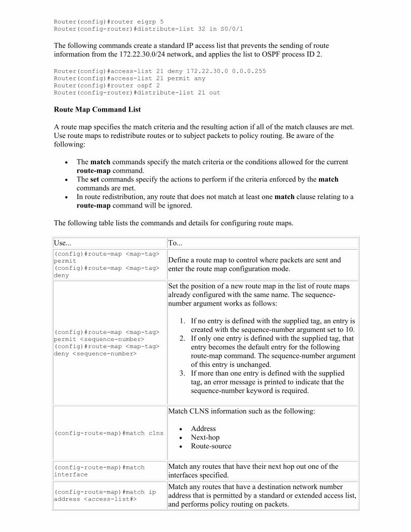
Router(config)#router eigrp 5Router(config-router)#distribute-list 32 in S0/0/1
The following commands create a standard IP access list that prevents the sending of route information from the 172.22.30.0/24 network, and applies the list to OSPF process ID 2.
Router(config)#access-list 21 deny 172.22.30.0 0.0.0.255Router(config)#access-list 21 permit anyRouter(config)#router ospf 2Router(config-router)#distribute-list 21 out
Route Map Command List
A route map specifies the match criteria and the resulting action if all of the match clauses are met. Use route maps to redistribute routes or to subject packets to policy routing. Be aware of the following:
The match commands specify the match criteria or the conditions allowed for the current route-map command.
The set commands specify the actions to perform if the criteria enforced by the matchcommands are met.
In route redistribution, any route that does not match at least one match clause relating to a route-map command will be ignored.
The following table lists the commands and details for configuring route maps.
Use... To...(config)#route-map <map-tag> permit(config)#route-map <map-tag> deny
Define a route map to control where packets are sent and enter the route map configuration mode.
(config)#route-map <map-tag> permit <sequence-number>(config)#route-map <map-tag> deny <sequence-number>
Set the position of a new route map in the list of route maps already configured with the same name. The sequence-number argument works as follows:
1. If no entry is defined with the supplied tag, an entry is created with the sequence-number argument set to 10.
2. If only one entry is defined with the supplied tag, that entry becomes the default entry for the following route-map command. The sequence-number argument of this entry is unchanged.
3. If more than one entry is defined with the supplied tag, an error message is printed to indicate that the sequence-number keyword is required.
(config-route-map)#match clns
Match CLNS information such as the following:
Address Next-hop Route-source
(config-route-map)#match interface
Match any routes that have their next hop out one of the interfaces specified.
(config-route-map)#match ip address <access-list#>
Match any routes that have a destination network number address that is permitted by a standard or extended access list, and performs policy routing on packets.
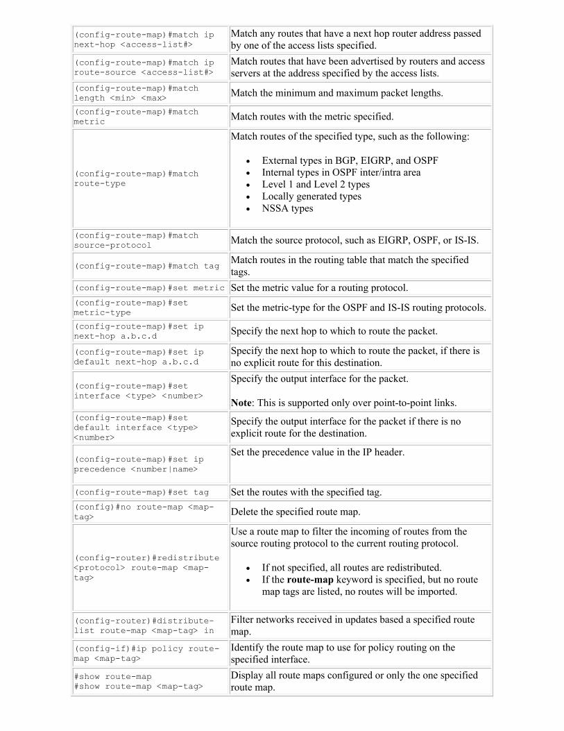
(config-route-map)#match ip next-hop <access-list#>
Match any routes that have a next hop router address passed by one of the access lists specified.
(config-route-map)#match ip route-source <access-list#>
Match routes that have been advertised by routers and access servers at the address specified by the access lists.
(config-route-map)#match length <min> <max> Match the minimum and maximum packet lengths.
(config-route-map)#match metric Match routes with the metric specified.
(config-route-map)#match route-type
Match routes of the specified type, such as the following:
External types in BGP, EIGRP, and OSPF Internal types in OSPF inter/intra area Level 1 and Level 2 types Locally generated types NSSA types
(config-route-map)#match source-protocol Match the source protocol, such as EIGRP, OSPF, or IS-IS.
(config-route-map)#match tagMatch routes in the routing table that match the specified tags.
(config-route-map)#set metric Set the metric value for a routing protocol. (config-route-map)#set metric-type Set the metric-type for the OSPF and IS-IS routing protocols.
(config-route-map)#set ip next-hop a.b.c.d Specify the next hop to which to route the packet.
(config-route-map)#set ip default next-hop a.b.c.d
Specify the next hop to which to route the packet, if there is no explicit route for this destination.
(config-route-map)#set interface <type> <number>
Specify the output interface for the packet.
Note: This is supported only over point-to-point links.(config-route-map)#set default interface <type> <number>
Specify the output interface for the packet if there is no explicit route for the destination.
(config-route-map)#set ip precedence <number|name>
Set the precedence value in the IP header.
(config-route-map)#set tag Set the routes with the specified tag.(config)#no route-map <map-tag> Delete the specified route map.
(config-router)#redistribute <protocol> route-map <map-tag>
Use a route map to filter the incoming of routes from the source routing protocol to the current routing protocol.
If not specified, all routes are redistributed. If the route-map keyword is specified, but no route
map tags are listed, no routes will be imported.
(config-router)#distribute-list route-map <map-tag> in
Filter networks received in updates based a specified route map.
(config-if)#ip policy route-map <map-tag>
Identify the route map to use for policy routing on the specified interface.
#show route-map#show route-map <map-tag>
Display all route maps configured or only the one specified route map.
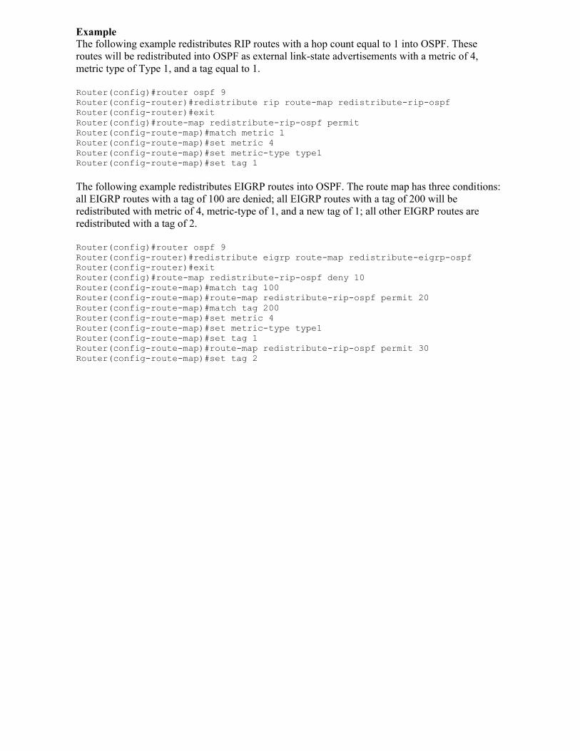
ExampleThe following example redistributes RIP routes with a hop count equal to 1 into OSPF. These routes will be redistributed into OSPF as external link-state advertisements with a metric of 4, metric type of Type 1, and a tag equal to 1.
Router(config)#router ospf 9 Router(config-router)#redistribute rip route-map redistribute-rip-ospfRouter(config-router)#exitRouter(config)#route-map redistribute-rip-ospf permit Router(config-route-map)#match metric 1 Router(config-route-map)#set metric 4 Router(config-route-map)#set metric-type type1 Router(config-route-map)#set tag 1
The following example redistributes EIGRP routes into OSPF. The route map has three conditions: all EIGRP routes with a tag of 100 are denied; all EIGRP routes with a tag of 200 will be redistributed with metric of 4, metric-type of 1, and a new tag of 1; all other EIGRP routes are redistributed with a tag of 2.
Router(config)#router ospf 9 Router(config-router)#redistribute eigrp route-map redistribute-eigrp-ospfRouter(config-router)#exitRouter(config)#route-map redistribute-rip-ospf deny 10Router(config-route-map)#match tag 100 Router(config-route-map)#route-map redistribute-rip-ospf permit 20Router(config-route-map)#match tag 200Router(config-route-map)#set metric 4Router(config-route-map)#set metric-type type1 Router(config-route-map)#set tag 1 Router(config-route-map)#route-map redistribute-rip-ospf permit 30Router(config-route-map)#set tag 2
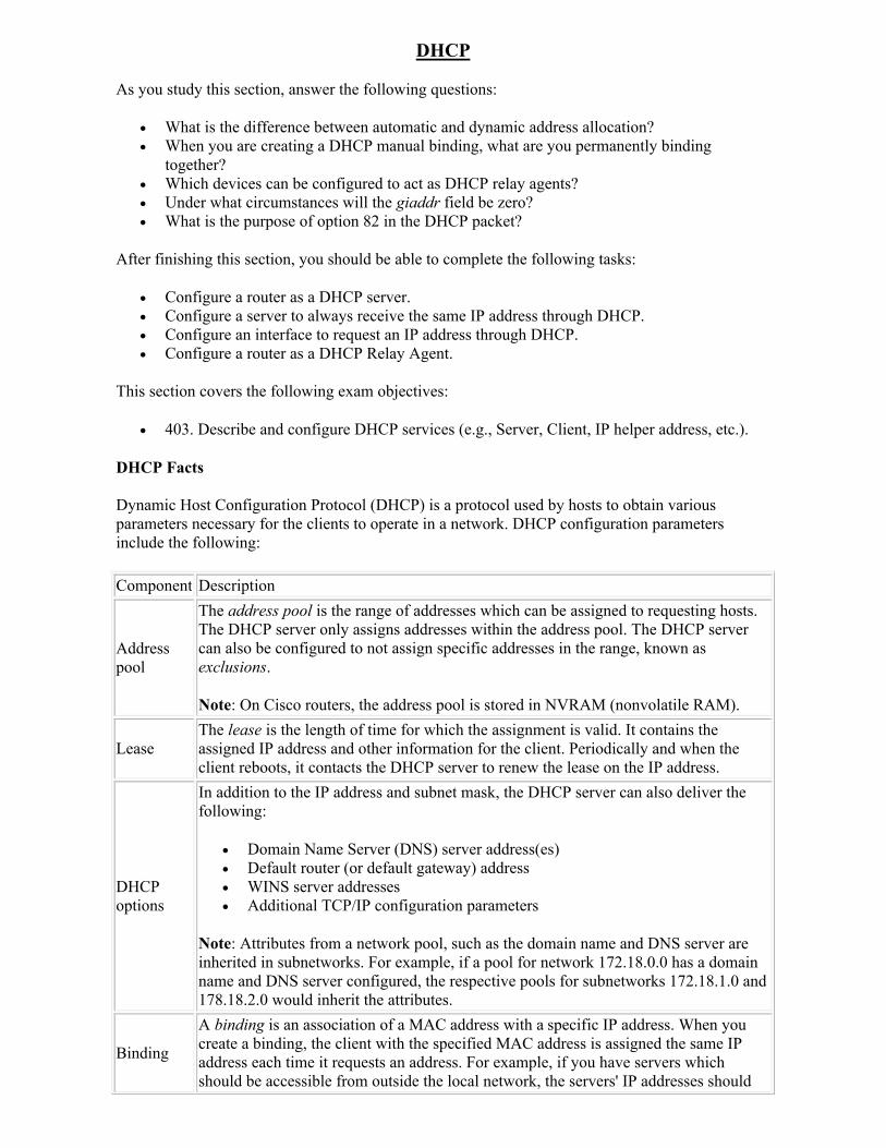
DHCP
As you study this section, answer the following questions:
What is the difference between automatic and dynamic address allocation? When you are creating a DHCP manual binding, what are you permanently binding
together? Which devices can be configured to act as DHCP relay agents? Under what circumstances will the giaddr field be zero? What is the purpose of option 82 in the DHCP packet?
After finishing this section, you should be able to complete the following tasks:
Configure a router as a DHCP server. Configure a server to always receive the same IP address through DHCP. Configure an interface to request an IP address through DHCP. Configure a router as a DHCP Relay Agent.
This section covers the following exam objectives:
403. Describe and configure DHCP services (e.g., Server, Client, IP helper address, etc.).
DHCP Facts
Dynamic Host Configuration Protocol (DHCP) is a protocol used by hosts to obtain various parameters necessary for the clients to operate in a network. DHCP configuration parameters include the following:
Component Description
Address pool
The address pool is the range of addresses which can be assigned to requesting hosts. The DHCP server only assigns addresses within the address pool. The DHCP server can also be configured to not assign specific addresses in the range, known as exclusions.
Note: On Cisco routers, the address pool is stored in NVRAM (nonvolatile RAM).
LeaseThe lease is the length of time for which the assignment is valid. It contains the assigned IP address and other information for the client. Periodically and when the client reboots, it contacts the DHCP server to renew the lease on the IP address.
DHCP options
In addition to the IP address and subnet mask, the DHCP server can also deliver the following:
Domain Name Server (DNS) server address(es) Default router (or default gateway) address WINS server addresses Additional TCP/IP configuration parameters
Note: Attributes from a network pool, such as the domain name and DNS server are inherited in subnetworks. For example, if a pool for network 172.18.0.0 has a domain name and DNS server configured, the respective pools for subnetworks 172.18.1.0 and 178.18.2.0 would inherit the attributes.
Binding
A binding is an association of a MAC address with a specific IP address. When you create a binding, the client with the specified MAC address is assigned the same IP address each time it requests an address. For example, if you have servers which should be accessible from outside the local network, the servers' IP addresses should
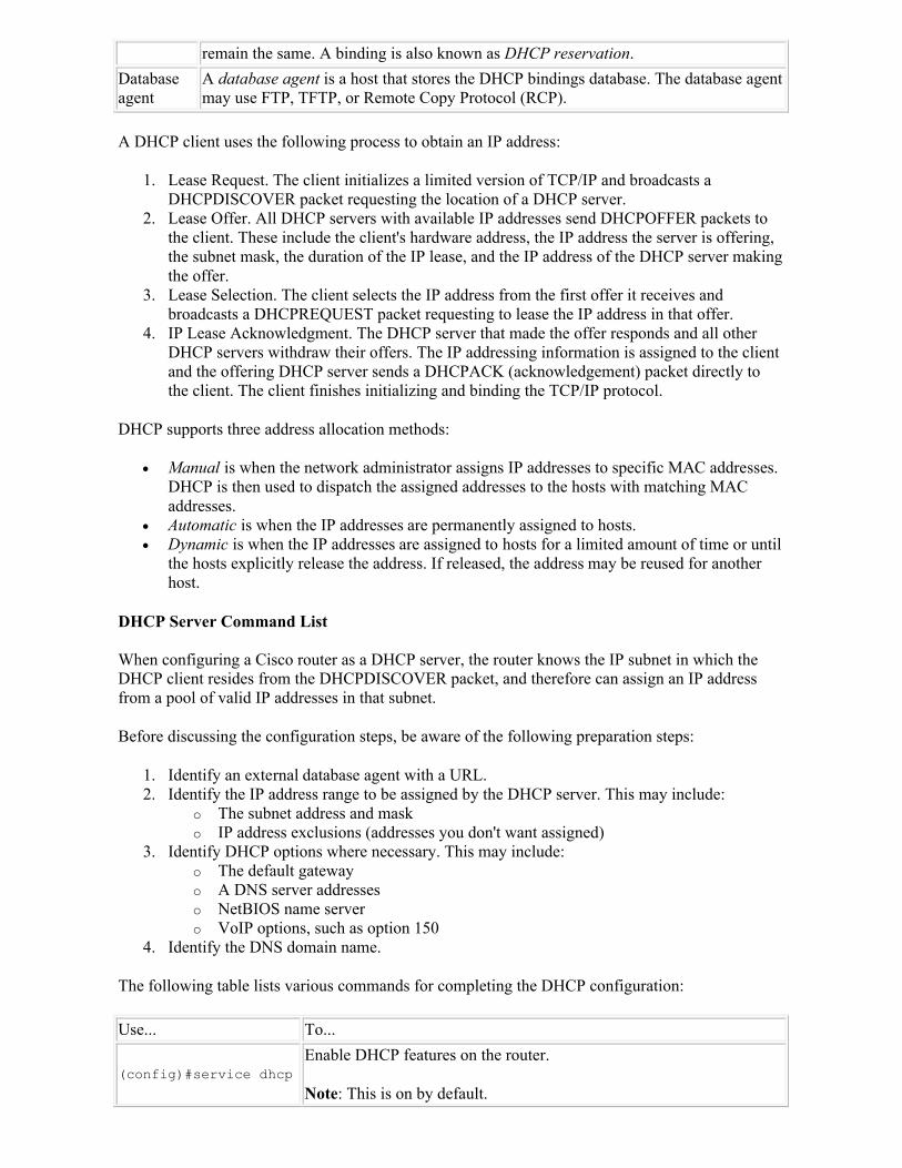
remain the same. A binding is also known as DHCP reservation.
Database agent
A database agent is a host that stores the DHCP bindings database. The database agent may use FTP, TFTP, or Remote Copy Protocol (RCP).
A DHCP client uses the following process to obtain an IP address:
1. Lease Request. The client initializes a limited version of TCP/IP and broadcasts a DHCPDISCOVER packet requesting the location of a DHCP server.
2. Lease Offer. All DHCP servers with available IP addresses send DHCPOFFER packets to the client. These include the client's hardware address, the IP address the server is offering, the subnet mask, the duration of the IP lease, and the IP address of the DHCP server making the offer.
3. Lease Selection. The client selects the IP address from the first offer it receives and broadcasts a DHCPREQUEST packet requesting to lease the IP address in that offer.
4. IP Lease Acknowledgment. The DHCP server that made the offer responds and all other DHCP servers withdraw their offers. The IP addressing information is assigned to the client and the offering DHCP server sends a DHCPACK (acknowledgement) packet directly to the client. The client finishes initializing and binding the TCP/IP protocol.
DHCP supports three address allocation methods:
Manual is when the network administrator assigns IP addresses to specific MAC addresses. DHCP is then used to dispatch the assigned addresses to the hosts with matching MAC addresses.
Automatic is when the IP addresses are permanently assigned to hosts. Dynamic is when the IP addresses are assigned to hosts for a limited amount of time or until
the hosts explicitly release the address. If released, the address may be reused for another host.
DHCP Server Command List
When configuring a Cisco router as a DHCP server, the router knows the IP subnet in which the DHCP client resides from the DHCPDISCOVER packet, and therefore can assign an IP address from a pool of valid IP addresses in that subnet.
Before discussing the configuration steps, be aware of the following preparation steps:
1. Identify an external database agent with a URL. 2. Identify the IP address range to be assigned by the DHCP server. This may include:
o The subnet address and mask o IP address exclusions (addresses you don't want assigned)
3. Identify DHCP options where necessary. This may include: o The default gateway o A DNS server addresses o NetBIOS name server o VoIP options, such as option 150
4. Identify the DNS domain name.
The following table lists various commands for completing the DHCP configuration:
Use... To...
(config)#service dhcpEnable DHCP features on the router.
Note: This is on by default.
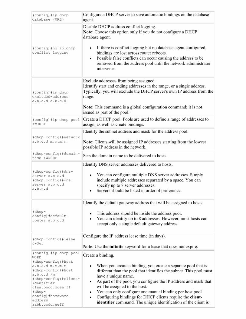
(config)#ip dhcp database <URL>
Configure a DHCP server to save automatic bindings on the database agent.
(config)#no ip dhcp conflict logging
Disable DHCP address conflict logging. Note: Choose this option only if you do not configure a DHCP database agent.
If there is conflict logging but no database agent configured, bindings are lost across router reboots.
Possible false conflicts can occur causing the address to be removed from the address pool until the network administrator intervenes.
(config)#ip dhcp excluded-address a.b.c.d a.b.c.d
Exclude addresses from being assigned.Identify start and ending addresses in the range, or a single address. Typically, you will exclude the DHCP server's own IP address from the range.
Note: This command is a global configuration command; it is not issued as part of the pool.
(config)#ip dhcp pool <WORD>
Create a DHCP pool. Pools are used to define a range of addresses to assign, as well as create bindings.
(dhcp-config)#network a.b.c.d m.m.m.m
Identify the subnet address and mask for the address pool.
Note: Clients will be assigned IP addresses starting from the lowest possible IP address in the network.
(dhcp-config)#domain-name <WORD> Sets the domain name to be delivered to hosts.
(dhcp-config)#dns-server a.b.c.d (dhcp-config)#dns-server a.b.c.d a.b.c.d
Identify DNS server addresses delivered to hosts.
You can configure multiple DNS server addresses. Simply include multiple addresses separated by a space. You can specify up to 8 server addresses.
Servers should be listed in order of preference.
(dhcp-config)#default-router a.b.c.d
Identify the default gateway address that will be assigned to hosts.
This address should be inside the address pool. You can identify up to 8 addresses. However, most hosts can
accept only a single default gateway address.
(dhcp-config)#lease 0-365
Configure the IP address lease time (in days).
Note: Use the infinite keyword for a lease that does not expire.(config)#ip dhcp pool WORD(dhcp-config)#host a.b.c.d m.m.m.m(dhcp-config)#host a.b.c.d /m(dhcp-config)#client-identifier 01aa.bbcc.ddee.ff(dhcp-config)#hardware-address aabb.ccdd.eeff
Create a binding.
When you create a binding, you create a separate pool that is different than the pool that identifies the subnet. This pool must have a unique name.
As part of the pool, you configure the IP address and mask that will be assigned to the host.
You can only configure one manual binding per host pool. Configuring bindings for DHCP clients require the client-
identifier command. The unique identification of the client is
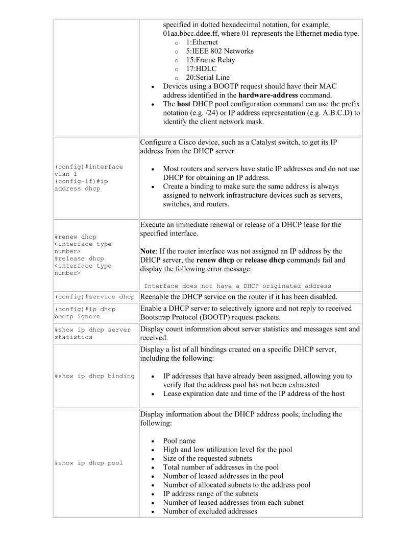
specified in dotted hexadecimal notation, for example, 01aa.bbcc.ddee.ff, where 01 represents the Ethernet media type.
o 1:Ethernet o 5:IEEE 802 Networks o 15:Frame Relay o 17:HDLC o 20:Serial Line
Devices using a BOOTP request should have their MAC address identified in the hardware-address command.
The host DHCP pool configuration command can use the prefix notation (e.g. /24) or IP address representation (e.g. A.B.C.D) to identify the client network mask.
(config)#interface vlan 1 (config-if)#ip address dhcp
Configure a Cisco device, such as a Catalyst switch, to get its IP address from the DHCP server.
Most routers and servers have static IP addresses and do not use DHCP for obtaining an IP address.
Create a binding to make sure the same address is always assigned to network infrastructure devices such as servers, switches, and routers.
#renew dhcp <interface type number>#release dhcp <interface type number>
Execute an immediate renewal or release of a DHCP lease for the specified interface.
Note: If the router interface was not assigned an IP address by the DHCP server, the renew dhcp or release dhcp commands fail and display the following error message:
Interface does not have a DHCP originated address
(config)#service dhcp Reenable the DHCP service on the router if it has been disabled.
(config)#ip dhcp bootp ignore
Enable a DHCP server to selectively ignore and not reply to received Bootstrap Protocol (BOOTP) request packets.
#show ip dhcp server statistics
Display count information about server statistics and messages sent and received.
#show ip dhcp binding
Display a list of all bindings created on a specific DHCP server, including the following:
IP addresses that have already been assigned, allowing you to verify that the address pool has not been exhausted
Lease expiration date and time of the IP address of the host
#show ip dhcp pool
Display information about the DHCP address pools, including the following:
Pool name High and low utilization level for the pool Size of the requested subnets Total number of addresses in the pool Number of leased addresses in the pool Number of allocated subnets to the address pool IP address range of the subnets Number of leased addresses from each subnet Number of excluded addresses
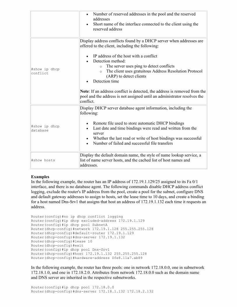
Number of reserved addresses in the pool and the reserved addresses
Short name of the interface connected to the client using the reserved address
#show ip dhcp conflict
Display address conflicts found by a DHCP server when addresses are offered to the client, including the following:
IP address of the host with a conflict Detection method:
o The server uses ping to detect conflicts o The client uses gratuitous Address Resolution Protocol
(ARP) to detect clients Detection time
Note: If an address conflict is detected, the address is removed from the pool and the address is not assigned until an administrator resolves the conflict.
#show ip dhcp database
Display DHCP server database agent information, including the following:
Remote file used to store automatic DHCP bindings Last date and time bindings were read and written from the
server Whether the last read or write of host bindings was successful Number of failed and successful file transfers
#show hostsDisplay the default domain name, the style of name lookup service, a list of name server hosts, and the cached list of host names and addresses.
ExamplesIn the following example, the router has an IP address of 172.19.1.129/25 assigned to its Fa 0/1 interface, and there is no database agent. The following commands disable DHCP address conflict logging, exclude the router's IP address from the pool, create a pool for the subnet, configure DNS and default gateway addresses to assign to hosts, set the lease time to 10 days, and create a binding for a host named Dns-Srv1 that assigns that host an address of 172.19.1.132 each time it requests an address.
Router(config)#no ip dhcp conflict loggingRouter(config)#ip dhcp excluded-address 172.19.1.129Router(config)#ip dhcp pool SubnetARouter(dhcp-config)#network 172.19.1.128 255.255.255.128Router(dhcp-config)#default-router 172.19.1.129Router(dhcp-config)#dns-server 172.19.1.132Router(dhcp-config)#lease 10Router(dhcp-config)#exitRouter(config)#ip dhcp pool Dns-Srv1Router(dhcp-config)#host 172.19.1.132 255.255.255.128Router(dhcp-config)#hardware-address 0fe8.11a7.ab89
In the following example, the router has three pools: one in network 172.18.0.0, one in subnetwork 172.18.1.0, and one in 172.18.2.0. Attributes from network 172.18.0.0 such as the domain name and DNS server are inherited in the respective subnetworks.
Router(config)#ip dhcp pool 172.18.0.0Router(dhcp-config)#dns-server 172.18.1.132 172.18.2.132
Router(dhcp-config)#domain-name westsim.comRouter(dhcp-config)#exitRouter(config)#ip dhcp pool 172.18.1.0Router(dhcp-config)#network 172.18.1.100 /24Router(dhcp-config)#default-router 172.18.1.29Router(dhcp-config)#exitRouter(config)#ip dhcp pool 172.18.2.0Router(dhcp-config)#network 172.18.2.100 /24Router(dhcp-config)#default-router 172.18.2.29
DHCP Relay Agent Facts
A DHCP relay agent is any host that forwards DHCP packets between clients and servers. DHCP clients use User Datagram Protocol (UDP) broadcasts to send their initial DHCPDISCOVER messages. If the client is on a network segment that does not include a server, the UDP broadcasts normally are not forwarded because routers are typically configured to not forward broadcast traffic. Relay agents are used to forward requests and replies between clients and servers when they are not on the same physical subnet.
Be aware of the following relay agent details:
Cisco routers and other devices, such as a Windows server, can be configured to act as a DHCP relay agent.
Relay agents receive broadcast DHCP messages and then generate a new unicast DHCP message to send out on another interface to the DHCP server.
The relay agent sets the gateway IP address in the giaddr field of the DHCP packet. o When a router is acting as the relay agent, the giaddr field contains the IP address of
the interface which received the client's broadcasted DHCPDISCOVER message. o In contrast, if the client is directly connected to a router acting as the DHCP server,
the giaddr field will be zero. If configured, the relay agent also adds the relay agent information option (option 82) in the
packet. o Option 82 is necessary to further determine which IP addresses to allocate in some
networks. o By default, if a relay agent receives a message from another relay agent that already
contains option 82 relay information, the relay information from the previous relay agent is replaced. The configuration can be changed.
By default, when an interface is configured as a relay agent, it forwards packets sent to all the well-known UDP ports that may be included in a UDP broadcast message. You can configure the relay agent to eliminate specific ports from the forwarding service. The well-known UDP broadcast ports include the following:
o 37: Time o 49: TACACS o 53: DNS o 67: BOOTP/DHCP Server o 68: BOOTP/DHCP Client o 69: TFTP o 137: NetBIOS Name Service o 138: NetBIOS Datagram Service
From the illustration below, observe the following:
Clients in 192.168.10.0 network broadcast DHCP messages throughout the LAN. With default configurations, RouterB will drop the DHCP broadcasts received on Fa 0/0.
If RouterB's interface is configured to forward the DHCP broadcast messages, it will place 192.168.10.254 in the giaddr field of the unicast DHCP packets addressed to 172.17.10.20.
When RouterA receives the unicast DHCP packets, it forwards them to the DHCP server.
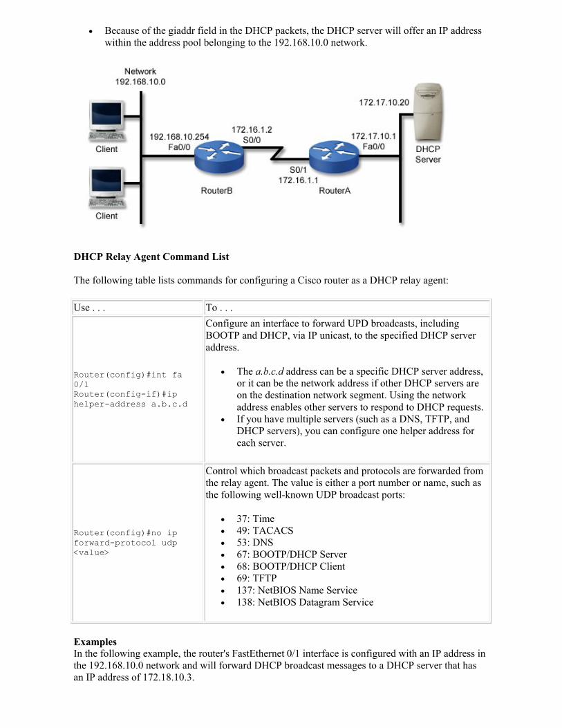
Because of the giaddr field in the DHCP packets, the DHCP server will offer an IP address within the address pool belonging to the 192.168.10.0 network.
DHCP Relay Agent Command List
The following table lists commands for configuring a Cisco router as a DHCP relay agent:
Use . . . To . . .
Router(config)#int fa 0/1Router(config-if)#ip helper-address a.b.c.d
Configure an interface to forward UPD broadcasts, including BOOTP and DHCP, via IP unicast, to the specified DHCP server address.
The a.b.c.d address can be a specific DHCP server address, or it can be the network address if other DHCP servers are on the destination network segment. Using the network address enables other servers to respond to DHCP requests.
If you have multiple servers (such as a DNS, TFTP, and DHCP servers), you can configure one helper address for each server.
Router(config)#no ip forward-protocol udp <value>
Control which broadcast packets and protocols are forwarded from the relay agent. The value is either a port number or name, such as the following well-known UDP broadcast ports:
37: Time 49: TACACS 53: DNS 67: BOOTP/DHCP Server 68: BOOTP/DHCP Client 69: TFTP 137: NetBIOS Name Service 138: NetBIOS Datagram Service
ExamplesIn the following example, the router's FastEthernet 0/1 interface is configured with an IP address in the 192.168.10.0 network and will forward DHCP broadcast messages to a DHCP server that has an IP address of 172.18.10.3.

Router(config)#int fa 0/1Router(config-if)#ip address 192.168.10.254 255.255.255.0Router(config-if)#ip helper-address 172.18.10.3
In the following example, the router's FastEthernet 0/0 interface is configured with an IP address in the 172.16.10.0 network and will forward DHCP broadcast messages to a DHCP server that has an IP address of 172.31.1.1. It will also not forward packets sent to the NetBIOS ports.
Router(config)#int fa 0/0Router(config-if)#ip address 172.16.10.254 255.255.255.0Router(config-if)#ip helper-address 172.31.1.1Router(config-if)#no ip forward-protocol udp 137Router(config-if)#no ip forward-protocol udp 138
IP Multicast
As you study this section, answer the following questions:
When would you choose to use multicast over broadcast transmission? Which packet distribution model is best for a video distribution scenario? What services does IGMP Snooping provide? Which multicast protocol is most commonly used as a multicast switching solution? What is the multicast address range available for Internet use with multicast groups?
This section covers the following exam objectives:
601. Describe IP Multicast (e.g., Layer-3 to Layer-2 mapping, IGMP, etc.).
IP Multicast Facts
Multicast sends information only to a specified subset of nodes in a network. This is more efficient than broadcast transmission, which transmits data from a single device to all other devices in a given address range. Broadcast transmissions typically reach all hosts on the subnet, all subnets, or all hosts on all subnets. Multicast:
Is optimal for transmitting voice and video applications and streaming video. Sends data from the sources as a single stream. Replicates data only on downstream devices where receiving hosts exist. Is significantly more efficient than unicast, which sends packets to a single receiver at a
time. Uses one of the following models for distributing packets:
o In one-to-many applications, data is sent by a single sender to two or more servers. This is optimal for distribution scenarios such as video distribution, announcements, and push-media.
o In many-to-many applications, data is sent by any number of hosts to the same multicast group. This is optimal for distribution scenarios such as collaborations, distributed simulations, and concurrent processing.
Frequently consists of User Datagram Protocol (UDP) -based applications.
The following table outlines the advantages and disadvantages of multicast:
Multicast Description
Advantages
The advantages of multicast are:
Network bandwidth is used efficiently because multiple streams or data are replicated with a single transmission.
CPU and server loads are reduced. Multicast eliminates traffic redundancy. High scalability enables the implementation of a wide range of applications.
Disadvantages
The disadvantages of multicast are:
Multicast applications that employ UDP need to be designed to overcome the following limitations caused by UDP:
o The best-effort delivery methods of UDP occasionally result in packet drops.
o UDP has a minimal ability to detect or avoid congestion. When multicast network topologies change, duplicate packets may
occasionally be generated or packets might arrive out of sequence.
IP Multicast Protocol Facts
Multicast applications need to learn what type of information is available on the network and which sessions are used to retrieve it. This can be done with:
Predefined groups with static entry. Directory services running on networks. Following URLs that lead to the location of specific information sessions.
The following table contains protocols used by multicast to locate and transmit multicast traffic:
Multicast Protocol Description
Session Description Protocol (SDR)
Session Description Protocol (SDR) is an application tool that is commonly used to find multicast traffic by querying directories or listening to announcements. SDR encapsulates the following protocols:
Session Directory Protocol (SDP) Session Announcement Protocol (SAP)
SDR allows the:
Description and announcement of a session. Transportation of a session announcement via well-known multicast
groups. Creation of new sessions.
Note: In Cisco documentation, SDR represents SDP/SAP; however, other resources use the acronym SDP to represent Session Description Protocol.
Internet Group Management Protocol (IGMP)
Internet Group Management Protocol (IGMP) is a protocol that minimizes multicast bandwidth by working between the local host (i.e. workstation) and the local router. Only multicast traffic requested by the local host is transmitted by the router across the network. IGMP details include the following:
IGMP facilitates IP hosts and adjacent multicast routers to establish multicast group memberships using messages.
o Multicast routers send host membership query messages (host-query messages) to discover which multicast groups have members on the attached networks of the router.
o Hosts respond with host membership report messages indicating that they want to receive multicast packets for specific groups. The host membership report message is also sent when a host joins a multicast group to declare membership in a specific host group.
o A leave group membership message is sent by a host when they leave a host group and are the last member of that group on the network segment.
o Host-query messages are addressed to the all-hosts multicast group, which has the address 224.0.0.1, and has an IP Time-To-Live (TTL) value of 1.
o The designated router for a LAN is the only router that sends IGMP host-query messages:
For IGMP version 1, the designated router is elected
according to the multicast routing protocol that runs on the LAN.
For IGMP versions 2 and 3, the designated querier is the highest IP-addressed multicast router on the subnet.
IGMP is implemented as a host side and a router side. o The host side reports group membership to its local router. o The router side listens to reports from hosts and periodically
sends out queries. IGMP is a Layer 3 protocol; Layer 2 switches do not participate in
IGMP. IGMP messages are IP datagrams with the protocol value of 2.
Cisco Group Management Protocol (CGMP)
Cisco Group Management Protocol (CGMP) is a Cisco proprietary protocol that works between the router and the switch. In CGMP, the switch only allows multicast traffic to flow through specific ports according to client data from the router instead of flooding data across all ports. CGMP:
Enables routers to inform each of their directly-connected switches of IGMP registrations from hosts accessible through the switch.
Forwards multicast traffic only to ports on which the requesting routersare located.
Is the most common multicast switching solution. Is based on a client/server model in which the router acts as a server and
the switch acts as a client.
IGMP Snooping enables a switch to detect multicast patterns and multicast traffic in the overall traffic flow on a network; thus making a switch aware of Layer 3. IGMP Snooping listens to multicast join and remove messages to:
Restrict unwanted traffic flow by preventing hosts on a local network from receiving traffic for a multicast group they have not explicitly joined
Allow traffic to flow to the optimal ports.
Note: A switch that does not IGMP snoop will flood multicast traffic to all the ports in a broadcast domain (or the VLAN equivalent).
Distance Vector Multicast Routing Protocol (DVMRP)
DVMRP is a protocol that shares information between routers to transport IP Multicast packets among networks. DVMRP:
Builds a parent-child database using a constrained multicast model. This is used to create a forwarding tree that is rooted at the source of the multicast packets.
Floods multicast packets down the source tree; ignoring redundant paths.
Forwards packets until prune messages are received on those parent-child links.
Uses IGMP messages to exchange information, such as routing diagrams, with other routers.
IP Multicast Address and Scope Facts
Multicast IP addresses fall within the Class D address range which includes 224.0.0.0 through 239.255.255.255. Multicast protocols are defined by the following subranges:
Address Range Description
233.0.0.0/8
This range includes Glop Addresses that are reserved for statically defined addresses. These addresses:
Are created by organizations that have reserved AS numbers. Embed the AS number of the domain into the second and third
octets of the address.
224.0.0.0 through 224.0.0.255
This range includes Reserved Link Local Addresses. This IP range is:
Reserved by IANA (Internet Assigned Numbers Authority) for use in multicast routing protocols.
Always transmitted with a Time-To-Live of 1-1 and are never forwarded by a router.
Commonly used by network protocols for automatic router discovery and router information communication.
Be aware of the following IP addresses in the Reserved Link Local address range:
224.0.0.1 is for all hosts on the subnet. 224.0.0.2 is for all routers on the subnet, such as routers using
IGMP. 224.0.0.4 is for Distance Vector Multicast Routing Protocol
(DVMRP). 224.0.0.5 is for Open Shortest Path First (OSPF). 224.0.0.6 is for OSPF designated and backup designated routers. 224.0.0.9 is for Routing Information Protocol version 2 (RIPv2). 224.0.0.10 is for Enhanced Interior Gateway Routing Protocol
(EIGRP). 224.0.0.13 is for Protocol Independent Multicast (PIMv2). 224.0.0.22 is for Internet Group Management Protocol
(IGMPv3).
224.0.1.0 through 238.255.255.255
This range includes Globally Scoped Addresses. This IP range is:
Available for internet use with multicast groups. Partially reserved for us by multicast applications through
IANA.
Note: 224.0.1.1 is reserved for Network Time Protocol (NTP).
239.0.0.0 through 239.255.255.255
This range includes Limited Scope Addresses. This IP range:
Is reserved for administratively scoped addresses. Is used for private domains within a local group or organization. Can be further subdivided within an AS or domain to define
more specific multicast boundaries.
IP Multicast MAC Address Mapping Facts
Workstations are not usually configured to listen for multicast. Multicast addresses and sessions are dynamically handled from the source of information (e.g. URLs, links within emails, predefined
static entries, directory services, etc.). The following concepts are important to understand in regard to mapping multicast IPs to MAC Addresses:
A Media Access Control (MAC) address is a 48-bit (12 hexadecimal digits) identifier assigned to network adapters or network interface cards (NICs) by the manufacturer for identification purposes. In multicasting, MAC addresses are used to pull information from the physical layer (i.e. from the wire).
In both unicast and multicast protocols, IP addresses must be mapped with the workstation's MAC address to receive data.
Multicast addresses map to a block of Ethernet MAC addresses provided by the Internet Assigned Numbers Authority (IANA). The first hexadecimal of IANA addresses is 01:00:5E.
The network cards on multicast workstations have multiple MAC addresses defined to enable them to receive a variety of multicast packets and information in transit on the network. Multicast MAC addresses can be mapped to 32 overlapping IP addresses for the following reasons:
o Of the 32 available bits in a multicast IP address, 4 bits are tied to the multicast Class D IP range (i.e. 224 through 229).
o Of the remaining 28 available bits in the multicast IP address, only 23 bits can be mapped to the lowest 23 bits of the MAC address.
o The remaining 5 unmapped bits result in 32 (or 25) possible multicast IP addresses that can be mapped to the MAC address.
Layer 2 multicast MAC addresses are translated to IP multicast addresses by mapping the low-order 23 bits of the IP (Layer 3) multicast address into the low-order 23 bits of the MAC (Layer 2) address.
The following is an example of mapping a Layer 2 multicast MAC address 01:00:5EE0.A0A0 to a single multicast IP address.
1. Convert the MAC address to the 48 bits: 01:00:5EE0.A0A0 is 00000001.00000000.01011110.11100000.10100000.10100000
2. Identify on the lower-order 23 bits of the MAC address (indicated in red):00000001.00000000.01011110.11100000.10100000.10100000
3. Place the lower-order 23 bits of the MAC address (indicated in red) with higher-order 9 bits of a Class D IP address (indicated in blue): 11100000.01100000.10100000.10100000
4. Convert all of the bits into the single multicast IP address: 11100000.01100000.10100000.10100000 is 224.96.156.156
Note: To map the lowest 16 multicast IP addresses for a single Layer 2 multicast MAC address, change the lowest bits in the first octet within the Class D address range:
11100000.01100000.10100000.10100000 is 224.96.156.15611100001.01100000.10100000.10100000 is 225.96.156.15611100010.01100000.10100000.10100000 is 226.96.156.15611100011.01100000.10100000.10100000 is 227.96.156.156...11101111.01100000.10100000.10100000 is 239.96.156.156
Note: To map the highest 16 multicast IP addresses for a single Layer 2 multicast MAC address, change the highest-order bit in the second octet, and then change bits in the first octet within the Class D address range:
11100000.11100000.10100000.10100000 is 224.220.156.15611100001.11100000.10100000.10100000 is 225.220.156.15611100010.11100000.10100000.10100000 is 226.220.156.15611100011.11100000.10100000.10100000 is 227.220.156.156

...11101111.11100000.10100000.10100000 is 239.220.156.156
Protocol Independent Multicast (PIM)
As you study this section, answer the following questions:
What is the difference between PIM Sparse mode and PIM Sparse-Dense mode? What is the purpose of the PIM group modes? In what situation would you select source distribution trees over shared distribution trees?
This section covers the following exam objectives:
602. Describe, configure, or verify IP multicasting routing (i.e., PIM Sparse-Dense Mode).
PIM Facts
Protocol Independent Multicast (PIM) is a family of multicast routing protocols that provide one-to-many and many-to-many data distributions. Protocol-independent part refers to the router ignoring unicast routing protocols, such as EIGRP and OSPF. PIM:
Uses the routing table that is populated by the unicast routing protocol in its multicast routing calculations.
Does not send routing updates between PIM routers.
You should be aware of the following terms in relation to PIM:
Term Description
Distribution tree
A distribution tree shows the source of multicast information and the path that multicast traffic use across the network infrastructure. There are two types of distribution trees:
Source distribution trees (also called Shortest Path Trees) use one tree for each source of information. Packets are forwarded along the tree according to the source (S) and group (G) address pair; commonly notated as (S,G).
o A single source tree is built for every source (S) sending to a group (G).
o The main advantage to a source distribution tree is that the tree created for each application can be specifically configured to benefit the application optimally.
Shared distribution trees use one tree for all sources of information. In shared distribution trees:
o Packets are forwarded down the shared distribution tree to the receivers.
o The start of a shared tree points to a Rendezvous Point (RP). o Shared trees are commonly notated as (*,G); * acting as a
wildcard and G representing the group.
Note: The main advantage of a shared distribution tree is decreased overhead and maintenance because only a single tree exists.
Reverse Path Forwarding (RPF)
RPF routes traffic away from the source rather than to the receiver. RPF:
Considers source and destination addresses of packets. Uses the distribution tree to forward packets away from the source
toward their destination. Uses the unicast routing table to determine the upstream (toward the
source) and downstream (away from the source) neighbors. Using the
unicast routing table avoids routing loops. Ensures that only one interface on the routers is considered to be an
incoming interface for data from a specific source.
PIM Source Specific Multicast (PIM-SSM)
PIM-SSM builds trees that are rooted in just one source. PIM-SSM:
Sources (S) transmit an IP datagram to an SSM destination address (G). Receivers can receive data by subscribing to channel (S,G).
Rendezvous Point Facts
A Rendezvous Point (RP) is a temporary connection between a multicast receiver and an existing shared multicast tree. When a volume of traffic crosses a threshold, the receiver is joined to a source-specific tree, and the feed through the RP is dropped. You should be familiar with the following concepts connected to RPs:
Multicast Description
Auto-RP
Auto-RP automatically distributes RP address information for various multicast groups to routers. Cisco routers automatically listen for this information. Auto-RP:
Simplifies the use of multiple RP's for different multicast group ranges. Avoids manual configuration inconsistencies. Allows for multiple RPs to act as backups to each other. Relies on a router designated as an RP mapping agent using the
following process: 1. Potential RPs announce themselves to the mapping agent 2. The mapping agent resolves any conflicts. 3. The mapping agent sends out the multicast group-RP mapping
information to the other routers.
Generally Auto-RP is used with sparse-dense mode to allow the Auto-RP information to be propagated in dense mode. If a router's interface is configured with pure sparse-mode, then the shift to sparse-dense-mode can be made.
Bootstrap Router (BSR)
A Bootstrap Router (BSR) is a capability that was added in PIM version 2 to automate and simplify the Auto-RP process. It is enabled by default in Cisco IOS releases supporting PIMv2.
The combination of PIMv1 and Auto-RP can perform the same tasks as BSR, but Auto-RP is Cisco proprietary, whereas PIMv2 with BSR is an IETF standards track protocol (meaning it can interoperate with routers from other vendors).
Multicast Source Discovery Protocol (MSDP)
MSDP is a mechanism that connects multiple PIM-SM domains; allowing the discovery of multicast sources in other domains. In MSDP:
Multicast sources for a group are known to all (RPs) in different domains.
Each PIM-SM domain uses its own RPs; they don't depend on RPs in other domains.
MSDP is run by an RP over TCP to discover multicast sources in other domains.
An RP in one domain has an MSDP peering relationship with MSDP-
enabled routers in another domain.
Anycast RP
Anycast RP is an intradomain feature that provides redundancy and load-sharing capabilities for MSDP. Anycast RP:
Is typically used to configure a Protocol Independent Multicast Sparse Mode (PIM-SM) network to meet fault tolerance requirements within a single multicast domain.
Configures two or more RPs with the same IP address on loopback interfaces.
Loopback addresses are configured with a 32-bit mask to specify them as a host address.
In Anycast RP:
All downstream routers are aware that the Anycast RP loopback address is the IP address of their local RP.
IP routing automatically selects the topologically closest RP for each source and receiver.
An equal number of sources will register with each RP, assuming that the sources are evenly spaced around the network. This causes the process of registering the sources to be shared equally by all the RPs in the network.
PIM Mode Facts
PIM uses the following multicast modes:
Mode Description
PIM Sparse Mode (PIM-SM)
PIM-SM is a client-initiated pull method to get multicast information. PIM-SM:
Is used when there are few sources of information. Uses a shared tree. Requires a Rendezvous Point (RP) to be defined. Requires multicast sources and receivers to register with their local RP.
In sparse mode, the focus of operation centers around a single unidirectional shared tree with the RP as the root.
If a source wishes to get their multicast traffic to flow down the shared tree using the RP, it must register with the RP first.
The registration of a source triggers a Shortest Path Tree (SPT) Join message to be sent by the RP toward the source if there are active receivers for the group in the network.
The explicit join model of interaction is implemented by the sparse mode group.
Sparse mode groups can have different RPs. Multicast traffic packets only flow down the shared tree to the receivers
that have explicitly requested to receive the traffic.
PIM Dense Mode (PIM-DM)
PIM-DM is a push method controlled by the source to push multicast information. PIM-DM:
Is used when there are many clients requesting the same multicast information.
Builds shortest-path trees by flooding multicast traffic domain wide, then prunes back the branches of the tree where no receivers are present.
Generally has poor scaling properties. The (S,G) state exists in every router. This is not affected by the
presence Reverse Path Forwarding (RPF).
In dense mode, the broadcast (flood) and prune model is implemented.
Dense mode interfaces are always added to the table when the multicast routing table is populated.
Multicast traffic is forwarded to all of the interfaces contained in the outgoing interface list.
The process of pruning entails the removal of interfaces from the outgoing interface list. The following situations would result in pruning:
o The interface does not have any directly connected receivers. o Multicast traffic is received on a non-RPF interface.
Pruned interfaces can be reestablished to allow the flow of multicast traffic to be restored with minimal delay.
PIM Sparse-Dense mode
PIM Sparse-Dense mode allows the router to operate in Sparse mode for Sparse mode groups (those with known RPs) and in Dense mode for other groups. PIM Sparse-Dense mode:
Supports automatic selection of RPs for each multicast source. Resorts to the Dense mode if an RP is not discovered.
Note: Cisco recommends PIM Sparse and PIM Sparse-Dense Mode instead of Dense mode by itself.
Bidirectional PIM
Bidirectional PIM explicitly builds shared bi-directional trees. Bidirectional PDM:
Never builds a shortest path tree. May have longer end-to-end delays than PIM-SM. Is scalable because it needs no source-specific state.
In bidirectional mode, traffic is only routed along a bidirectional shared tree whose root is located at the Rendezvous Point (RP) for the group.
Routers establish a loop-free spanning tree topology by using the IP address of the RP.
The address of the RP does not need to be a router. It can be any unassigned IP address on a network that is reachable throughout the PIM domain.
A new member of a bidirectional group is signaled via explicit Join messages.
Traffic from sources is unconditionally: o Transmitted down the shared tree toward the receivers located
on the tree's branches. o Transmitted up the shared tree toward the RP.
PIM Source Specific Multicast (PIM-SSM)
In PIM-SSM mode, an IP multicast receiver host must use IGMP version 3 (IGMPv3) to subscribe to a channel. In this mode, the host indicate that they want to receive traffic only form particular sources within a multicast group.
Group address allocation within the network is not required in PIM-SSM mode.
Different SSM groups must be used by different applications running on the same source host.
SSM group addresses can be arbitrarily reused by different applications running on different source hosts without causing any excess traffic on the network.
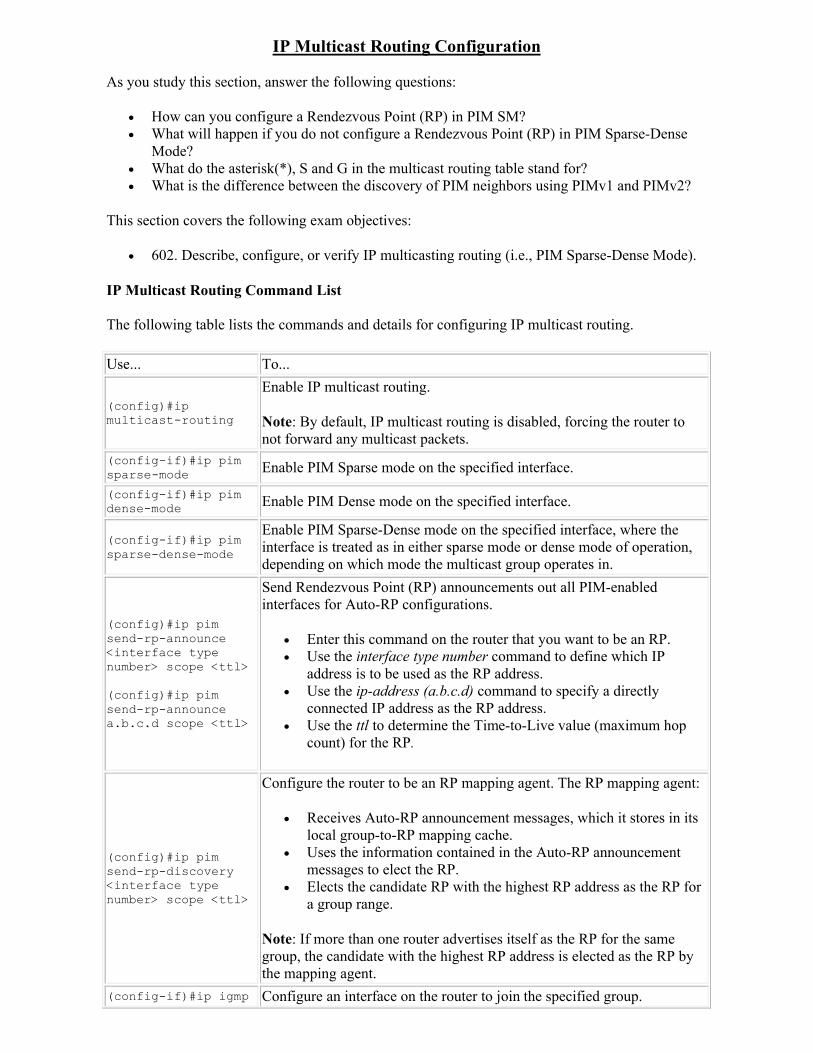
IP Multicast Routing Configuration
As you study this section, answer the following questions:
How can you configure a Rendezvous Point (RP) in PIM SM? What will happen if you do not configure a Rendezvous Point (RP) in PIM Sparse-Dense
Mode? What do the asterisk(*), S and G in the multicast routing table stand for? What is the difference between the discovery of PIM neighbors using PIMv1 and PIMv2?
This section covers the following exam objectives:
602. Describe, configure, or verify IP multicasting routing (i.e., PIM Sparse-Dense Mode).
IP Multicast Routing Command List
The following table lists the commands and details for configuring IP multicast routing.
Use... To...
(config)#ip multicast-routing
Enable IP multicast routing.
Note: By default, IP multicast routing is disabled, forcing the router to not forward any multicast packets.
(config-if)#ip pim sparse-mode Enable PIM Sparse mode on the specified interface.
(config-if)#ip pim dense-mode Enable PIM Dense mode on the specified interface.
(config-if)#ip pim sparse-dense-mode
Enable PIM Sparse-Dense mode on the specified interface, where the interface is treated as in either sparse mode or dense mode of operation, depending on which mode the multicast group operates in.
(config)#ip pim send-rp-announce<interface type number> scope <ttl>
(config)#ip pim send-rp-announcea.b.c.d scope <ttl>
Send Rendezvous Point (RP) announcements out all PIM-enabled interfaces for Auto-RP configurations.
Enter this command on the router that you want to be an RP. Use the interface type number command to define which IP
address is to be used as the RP address. Use the ip-address (a.b.c.d) command to specify a directly
connected IP address as the RP address. Use the ttl to determine the Time-to-Live value (maximum hop
count) for the RP.
(config)#ip pim send-rp-discovery<interface type number> scope <ttl>
Configure the router to be an RP mapping agent. The RP mapping agent:
Receives Auto-RP announcement messages, which it stores in its local group-to-RP mapping cache.
Uses the information contained in the Auto-RP announcement messages to elect the RP.
Elects the candidate RP with the highest RP address as the RP for a group range.
Note: If more than one router advertises itself as the RP for the same group, the candidate with the highest RP address is elected as the RP by the mapping agent.
(config-if)#ip igmp Configure an interface on the router to join the specified group.
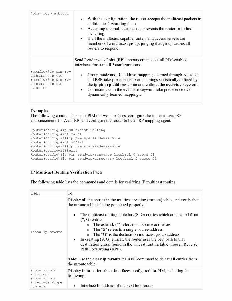
join-group a.b.c.d
With this configuration, the router accepts the multicast packets in addition to forwarding them.
Accepting the multicast packets prevents the router from fast switching.
If all the multicast-capable routers and access servers are members of a multicast group, pinging that group causes all routers to respond.
(config)#ip pim rp-address a.b.c.d(config)#ip pim rp-address a.b.c.d override
Send Rendezvous Point (RP) announcements out all PIM-enabled interfaces for static RP configurations.
Group mode and RP address mappings learned through Auto-RP and BSR take precedence over mappings statistically defined by the ip pim rp-address command without the override keyword.
Commands with the override keyword take precedence over dynamically learned mappings.
ExamplesThe following commands enable PIM on two interfaces, configure the router to send RP announcements for Auto-RP, and configure the router to be an RP mapping agent.
Router(config)#ip multicast-routingRouter(config)#int fa0/1Router(config-if)#ip pim sparse-dense-modeRouter(config)#int s0/1/1Router(config-if)#ip pim sparse-dense-modeRouter(config-if)#exitRouter(config)#ip pim send-rp-announce loopback 0 scope 31Router(config)#ip pim send-rp-discovery loopback 0 scope 31
IP Multicast Routing Verification Facts
The following table lists the commands and details for verifying IP multicast routing.
Use... To...
#show ip mroute
Display all the entries in the multicast routing (mroute) table, and verify that the mroute table is being populated properly.
The multicast routing table has (S, G) entries which are created from (*, G) entries.
o The asterisk (*) refers to all source addresses o The "S" refers to a single source address o The "G" is the destination multicast group address
In creating (S, G) entries, the router uses the best path to that destination group found in the unicast routing table through Reverse Path Forwarding (RPF).
Note: Use the clear ip mroute * EXEC command to delete all entries from the mroute table.
#show ip pim interface#show ip pim interface <type number>
Display information about interfaces configured for PIM, including the following:
Interface IP address of the next hop router
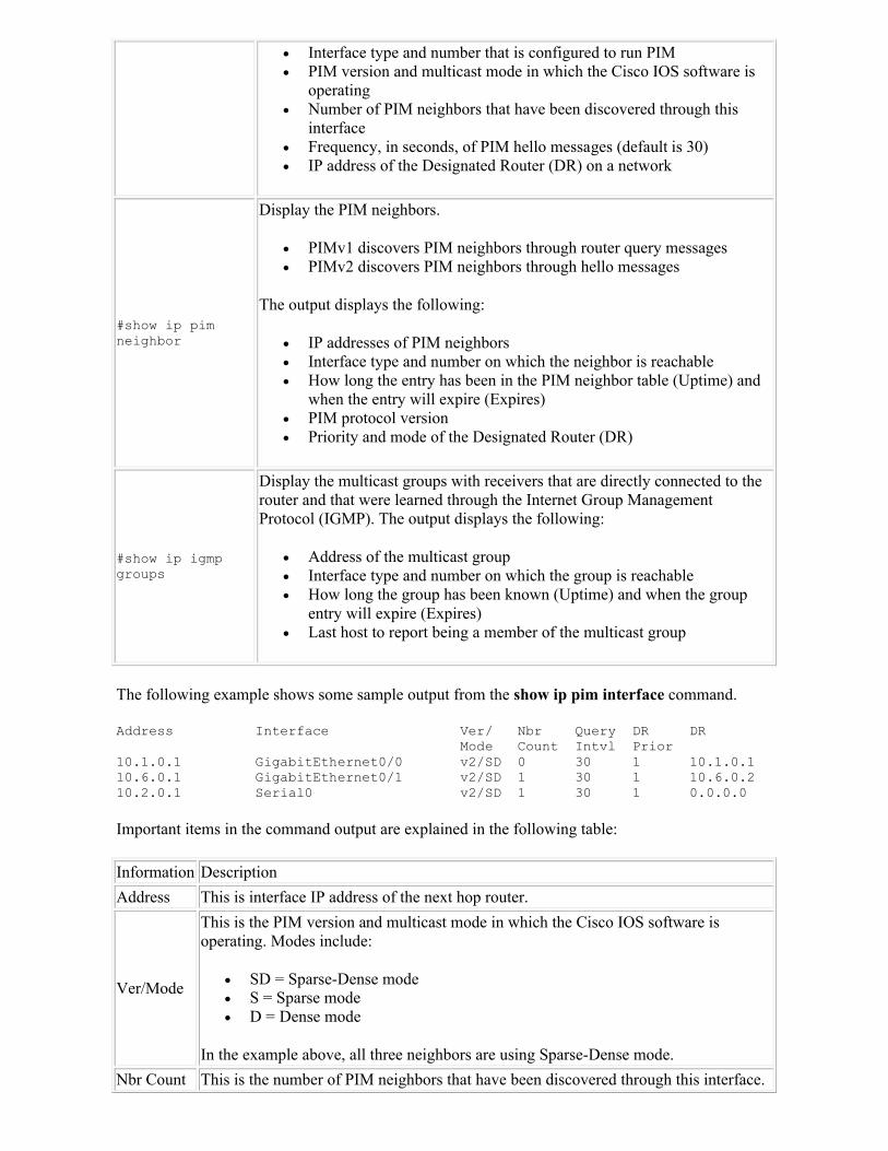
Interface type and number that is configured to run PIM PIM version and multicast mode in which the Cisco IOS software is
operating Number of PIM neighbors that have been discovered through this
interface Frequency, in seconds, of PIM hello messages (default is 30) IP address of the Designated Router (DR) on a network
#show ip pim neighbor
Display the PIM neighbors.
PIMv1 discovers PIM neighbors through router query messages PIMv2 discovers PIM neighbors through hello messages
The output displays the following:
IP addresses of PIM neighbors Interface type and number on which the neighbor is reachable How long the entry has been in the PIM neighbor table (Uptime) and
when the entry will expire (Expires) PIM protocol version Priority and mode of the Designated Router (DR)
#show ip igmp groups
Display the multicast groups with receivers that are directly connected to the router and that were learned through the Internet Group Management Protocol (IGMP). The output displays the following:
Address of the multicast group Interface type and number on which the group is reachable How long the group has been known (Uptime) and when the group
entry will expire (Expires) Last host to report being a member of the multicast group
The following example shows some sample output from the show ip pim interface command.
Address Interface Ver/ Nbr Query DR DR Mode Count Intvl Prior10.1.0.1 GigabitEthernet0/0 v2/SD 0 30 1 10.1.0.110.6.0.1 GigabitEthernet0/1 v2/SD 1 30 1 10.6.0.210.2.0.1 Serial0 v2/SD 1 30 1 0.0.0.0
Important items in the command output are explained in the following table:
Information Description
Address This is interface IP address of the next hop router.
Ver/Mode
This is the PIM version and multicast mode in which the Cisco IOS software is operating. Modes include:
SD = Sparse-Dense mode S = Sparse mode D = Dense mode
In the example above, all three neighbors are using Sparse-Dense mode.
Nbr Count This is the number of PIM neighbors that have been discovered through this interface.

Note: If the Neighbor Count is 1 for a DVMRP tunnel, the neighbor is active (receiving probes and reports).
DR
This is the IP address of the Designated Router (DR) on a network. Point-to-point interfaces do not have designated routers, so the IP address would be shown as 0.0.0.0.
In the example above, the first two interfaces, the DR is identified. The third must be a point-to-point interface.
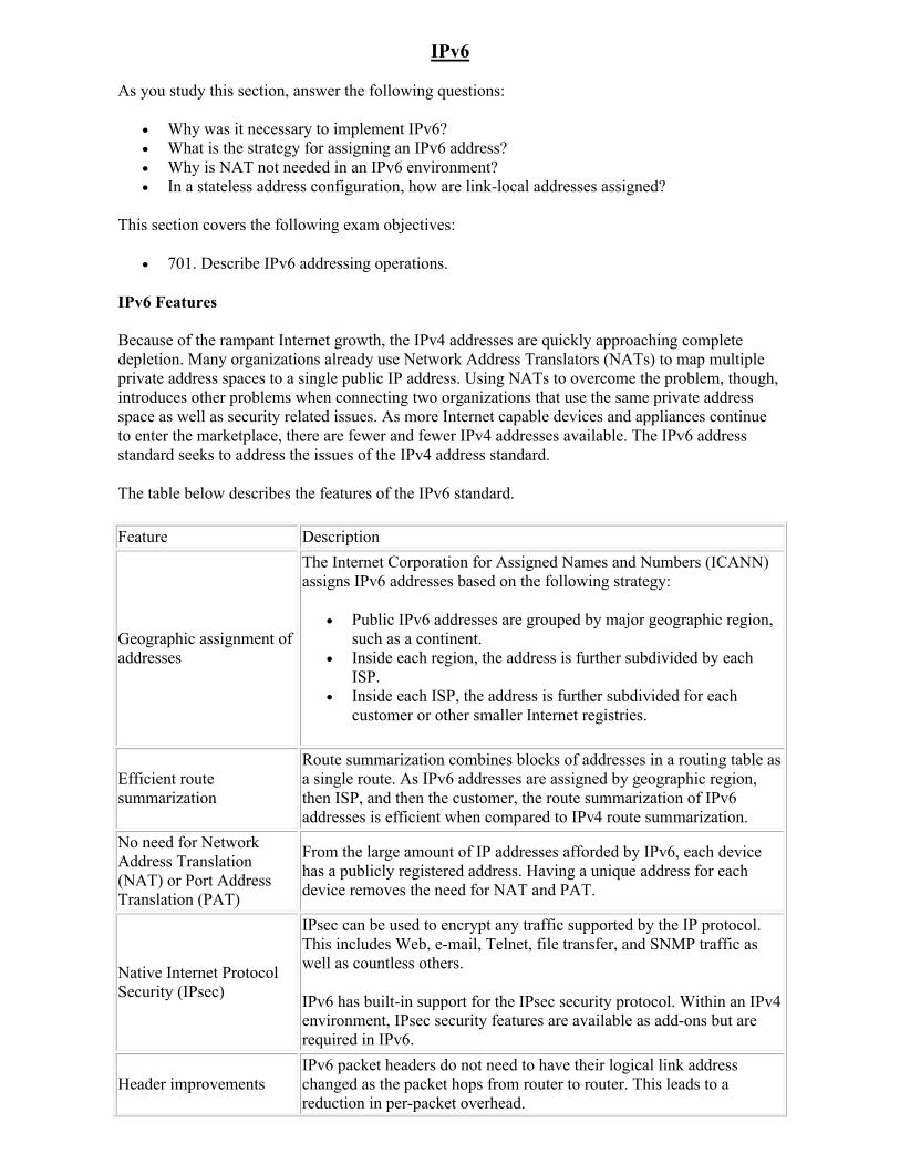
IPv6
As you study this section, answer the following questions:
Why was it necessary to implement IPv6? What is the strategy for assigning an IPv6 address? Why is NAT not needed in an IPv6 environment? In a stateless address configuration, how are link-local addresses assigned?
This section covers the following exam objectives:
701. Describe IPv6 addressing operations.
IPv6 Features
Because of the rampant Internet growth, the IPv4 addresses are quickly approaching complete depletion. Many organizations already use Network Address Translators (NATs) to map multiple private address spaces to a single public IP address. Using NATs to overcome the problem, though, introduces other problems when connecting two organizations that use the same private address space as well as security related issues. As more Internet capable devices and appliances continue to enter the marketplace, there are fewer and fewer IPv4 addresses available. The IPv6 address standard seeks to address the issues of the IPv4 address standard.
The table below describes the features of the IPv6 standard.
Feature Description
Geographic assignment of addresses
The Internet Corporation for Assigned Names and Numbers (ICANN) assigns IPv6 addresses based on the following strategy:
Public IPv6 addresses are grouped by major geographic region, such as a continent.
Inside each region, the address is further subdivided by each ISP.
Inside each ISP, the address is further subdivided for each customer or other smaller Internet registries.
Efficient route summarization
Route summarization combines blocks of addresses in a routing table as a single route. As IPv6 addresses are assigned by geographic region, then ISP, and then the customer, the route summarization of IPv6 addresses is efficient when compared to IPv4 route summarization.
No need for Network Address Translation (NAT) or Port Address Translation (PAT)
From the large amount of IP addresses afforded by IPv6, each device has a publicly registered address. Having a unique address for each device removes the need for NAT and PAT.
Native Internet Protocol Security (IPsec)
IPsec can be used to encrypt any traffic supported by the IP protocol. This includes Web, e-mail, Telnet, file transfer, and SNMP traffic as well as countless others.
IPv6 has built-in support for the IPsec security protocol. Within an IPv4 environment, IPsec security features are available as add-ons but are required in IPv6.
Header improvementsIPv6 packet headers do not need to have their logical link address changed as the packet hops from router to router. This leads to a reduction in per-packet overhead.
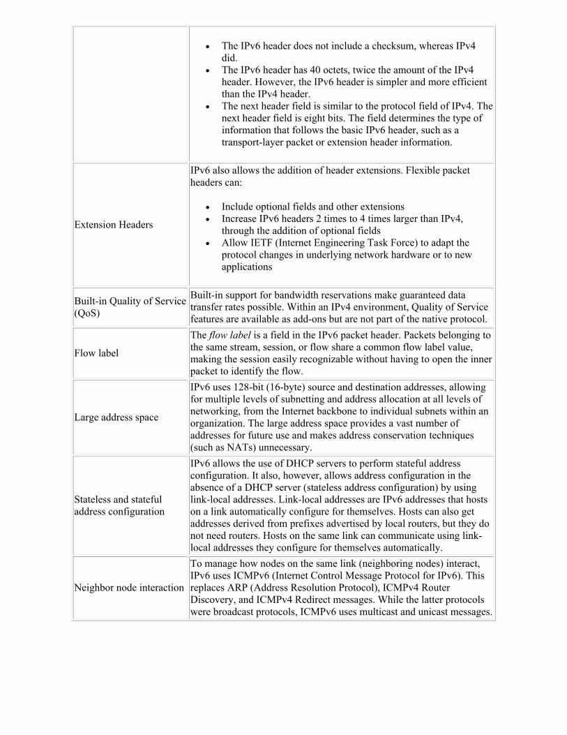
The IPv6 header does not include a checksum, whereas IPv4 did.
The IPv6 header has 40 octets, twice the amount of the IPv4 header. However, the IPv6 header is simpler and more efficient than the IPv4 header.
The next header field is similar to the protocol field of IPv4. The next header field is eight bits. The field determines the type of information that follows the basic IPv6 header, such as a transport-layer packet or extension header information.
Extension Headers
IPv6 also allows the addition of header extensions. Flexible packet headers can:
Include optional fields and other extensions Increase IPv6 headers 2 times to 4 times larger than IPv4,
through the addition of optional fields Allow IETF (Internet Engineering Task Force) to adapt the
protocol changes in underlying network hardware or to new applications
Built-in Quality of Service (QoS)
Built-in support for bandwidth reservations make guaranteed data transfer rates possible. Within an IPv4 environment, Quality of Service features are available as add-ons but are not part of the native protocol.
Flow label
The flow label is a field in the IPv6 packet header. Packets belonging to the same stream, session, or flow share a common flow label value, making the session easily recognizable without having to open the inner packet to identify the flow.
Large address space
IPv6 uses 128-bit (16-byte) source and destination addresses, allowing for multiple levels of subnetting and address allocation at all levels of networking, from the Internet backbone to individual subnets within an organization. The large address space provides a vast number of addresses for future use and makes address conservation techniques (such as NATs) unnecessary.
Stateless and stateful address configuration
IPv6 allows the use of DHCP servers to perform stateful address configuration. It also, however, allows address configuration in the absence of a DHCP server (stateless address configuration) by using link-local addresses. Link-local addresses are IPv6 addresses that hosts on a link automatically configure for themselves. Hosts can also get addresses derived from prefixes advertised by local routers, but they do not need routers. Hosts on the same link can communicate using link-local addresses they configure for themselves automatically.
Neighbor node interaction
To manage how nodes on the same link (neighboring nodes) interact, IPv6 uses ICMPv6 (Internet Control Message Protocol for IPv6). This replaces ARP (Address Resolution Protocol), ICMPv4 Router Discovery, and ICMPv4 Redirect messages. While the latter protocols were broadcast protocols, ICMPv6 uses multicast and unicast messages.
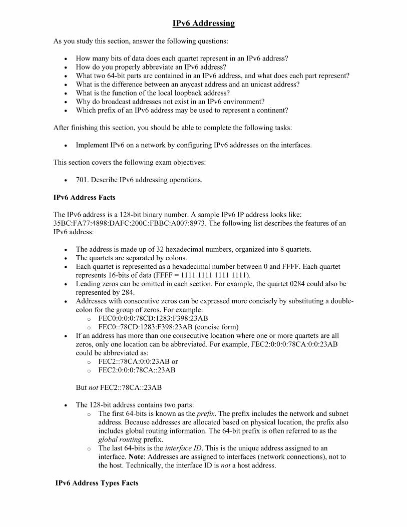
IPv6 Addressing
As you study this section, answer the following questions:
How many bits of data does each quartet represent in an IPv6 address? How do you properly abbreviate an IPv6 address? What two 64-bit parts are contained in an IPv6 address, and what does each part represent? What is the difference between an anycast address and an unicast address? What is the function of the local loopback address? Why do broadcast addresses not exist in an IPv6 environment? Which prefix of an IPv6 address may be used to represent a continent?
After finishing this section, you should be able to complete the following tasks:
Implement IPv6 on a network by configuring IPv6 addresses on the interfaces.
This section covers the following exam objectives:
701. Describe IPv6 addressing operations.
IPv6 Address Facts
The IPv6 address is a 128-bit binary number. A sample IPv6 IP address looks like: 35BC:FA77:4898:DAFC:200C:FBBC:A007:8973. The following list describes the features of an IPv6 address:
The address is made up of 32 hexadecimal numbers, organized into 8 quartets. The quartets are separated by colons. Each quartet is represented as a hexadecimal number between 0 and FFFF. Each quartet
represents 16-bits of data (FFFF = 1111 1111 1111 1111). Leading zeros can be omitted in each section. For example, the quartet 0284 could also be
represented by 284. Addresses with consecutive zeros can be expressed more concisely by substituting a double-
colon for the group of zeros. For example: o FEC0:0:0:0:78CD:1283:F398:23AB o FEC0::78CD:1283:F398:23AB (concise form)
If an address has more than one consecutive location where one or more quartets are all zeros, only one location can be abbreviated. For example, FEC2:0:0:0:78CA:0:0:23AB could be abbreviated as:
o FEC2::78CA:0:0:23AB oro FEC2:0:0:0:78CA::23AB
But not FEC2::78CA::23AB
The 128-bit address contains two parts: o The first 64-bits is known as the prefix. The prefix includes the network and subnet
address. Because addresses are allocated based on physical location, the prefix also includes global routing information. The 64-bit prefix is often referred to as the global routing prefix.
o The last 64-bits is the interface ID. This is the unique address assigned to an interface. Note: Addresses are assigned to interfaces (network connections), not to the host. Technically, the interface ID is not a host address.
IPv6 Address Types Facts
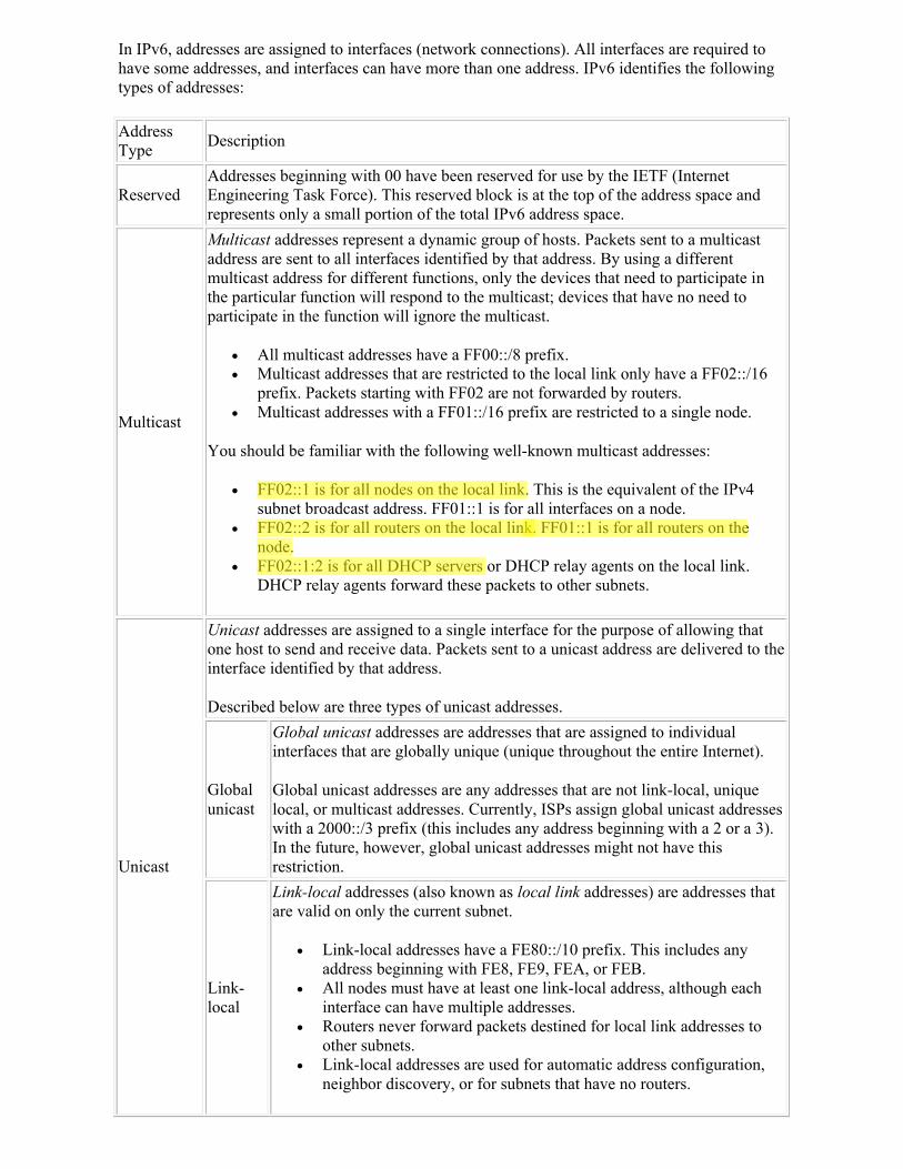
In IPv6, addresses are assigned to interfaces (network connections). All interfaces are required to have some addresses, and interfaces can have more than one address. IPv6 identifies the following types of addresses:
Address Type
Description
ReservedAddresses beginning with 00 have been reserved for use by the IETF (Internet Engineering Task Force). This reserved block is at the top of the address space and represents only a small portion of the total IPv6 address space.
Multicast
Multicast addresses represent a dynamic group of hosts. Packets sent to a multicast address are sent to all interfaces identified by that address. By using a different multicast address for different functions, only the devices that need to participate in the particular function will respond to the multicast; devices that have no need to participate in the function will ignore the multicast.
All multicast addresses have a FF00::/8 prefix. Multicast addresses that are restricted to the local link only have a FF02::/16
prefix. Packets starting with FF02 are not forwarded by routers. Multicast addresses with a FF01::/16 prefix are restricted to a single node.
You should be familiar with the following well-known multicast addresses:
FF02::1 is for all nodes on the local link. This is the equivalent of the IPv4 subnet broadcast address. FF01::1 is for all interfaces on a node.
FF02::2 is for all routers on the local link. FF01::1 is for all routers on the node.
FF02::1:2 is for all DHCP servers or DHCP relay agents on the local link. DHCP relay agents forward these packets to other subnets.
Unicast
Unicast addresses are assigned to a single interface for the purpose of allowing that one host to send and receive data. Packets sent to a unicast address are delivered to the interface identified by that address.
Described below are three types of unicast addresses.
Global unicast
Global unicast addresses are addresses that are assigned to individual interfaces that are globally unique (unique throughout the entire Internet).
Global unicast addresses are any addresses that are not link-local, unique local, or multicast addresses. Currently, ISPs assign global unicast addresses with a 2000::/3 prefix (this includes any address beginning with a 2 or a 3). In the future, however, global unicast addresses might not have this restriction.
Link-local
Link-local addresses (also known as local link addresses) are addresses thatare valid on only the current subnet.
Link-local addresses have a FE80::/10 prefix. This includes any address beginning with FE8, FE9, FEA, or FEB.
All nodes must have at least one link-local address, although each interface can have multiple addresses.
Routers never forward packets destined for local link addresses to other subnets.
Link-local addresses are used for automatic address configuration, neighbor discovery, or for subnets that have no routers.
Owner
Highlight
Owner
Highlight
Owner
Highlight
Owner
Highlight
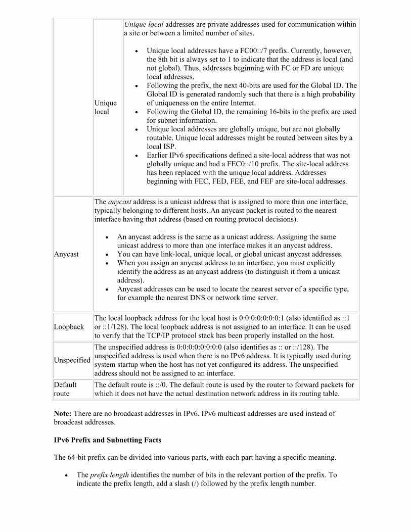
Unique local
Unique local addresses are private addresses used for communication within a site or between a limited number of sites.
Unique local addresses have a FC00::/7 prefix. Currently, however, the 8th bit is always set to 1 to indicate that the address is local (and not global). Thus, addresses beginning with FC or FD are unique local addresses.
Following the prefix, the next 40-bits are used for the Global ID. The Global ID is generated randomly such that there is a high probability of uniqueness on the entire Internet.
Following the Global ID, the remaining 16-bits in the prefix are used for subnet information.
Unique local addresses are globally unique, but are not globally routable. Unique local addresses might be routed between sites by a local ISP.
Earlier IPv6 specifications defined a site-local address that was not globally unique and had a FEC0::/10 prefix. The site-local address has been replaced with the unique local address. Addresses beginning with FEC, FED, FEE, and FEF are site-local addresses.
Anycast
The anycast address is a unicast address that is assigned to more than one interface, typically belonging to different hosts. An anycast packet is routed to the nearest interface having that address (based on routing protocol decisions).
An anycast address is the same as a unicast address. Assigning the same unicast address to more than one interface makes it an anycast address.
You can have link-local, unique local, or global unicast anycast addresses. When you assign an anycast address to an interface, you must explicitly
identify the address as an anycast address (to distinguish it from a unicast address).
Anycast addresses can be used to locate the nearest server of a specific type, for example the nearest DNS or network time server.
LoopbackThe local loopback address for the local host is 0:0:0:0:0:0:0:1 (also identified as ::1 or ::1/128). The local loopback address is not assigned to an interface. It can be used to verify that the TCP/IP protocol stack has been properly installed on the host.
Unspecified
The unspecified address is 0:0:0:0:0:0:0:0 (also identifies as :: or ::/128). The unspecified address is used when there is no IPv6 address. It is typically used during system startup when the host has not yet configured its address. The unspecified address should not be assigned to an interface.
Default route
The default route is ::/0. The default route is used by the router to forward packets for which it does not have the actual destination network address in its routing table.
Note: There are no broadcast addresses in IPv6. IPv6 multicast addresses are used instead of broadcast addresses.
IPv6 Prefix and Subnetting Facts
The 64-bit prefix can be divided into various parts, with each part having a specific meaning.
The prefix length identifies the number of bits in the relevant portion of the prefix. To indicate the prefix length, add a slash (/) followed by the prefix length number.
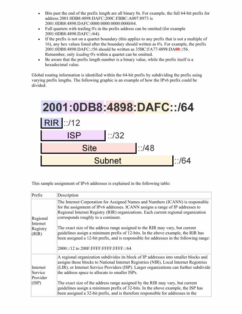
Bits past the end of the prefix length are all binary 0s. For example, the full 64-bit prefix for address 2001:0DB8:4898:DAFC:200C:FBBC:A007:8973 is 2001:0DB8:4898:DAFC:0000:0000:0000:0000/64.
Full quartets with trailing 0's in the prefix address can be omitted (for example 2001:0DB8:4898:DAFC::/64).
If the prefix is not on a quartet boundary (this applies to any prefix that is not a multiple of 16), any hex values listed after the boundary should written as 0's. For example, the prefix 2001:0DB8:4898:DAFC::/56 should be written as 35BC:FA77:4898:DA00::/56. Remember, only leading 0's within a quartet can be omitted.
Be aware that the prefix length number is a binary value, while the prefix itself is a hexadecimal value.
Global routing information is identified within the 64-bit prefix by subdividing the prefix using varying prefix lengths. The following graphic is an example of how the IPv6 prefix could be divided:
This sample assignment of IPv6 addresses is explained in the following table:
Prefix Description
Regional Internet Registry (RIR)
The Internet Corporation for Assigned Names and Numbers (ICANN) is responsible for the assignment of IPv6 addresses. ICANN assigns a range of IP addresses to Regional Internet Registry (RIR) organizations. Each current regional organization corresponds roughly to a continent.
The exact size of the address range assigned to the RIR may vary, but current guidelines assign a minimum prefix of 12-bits. In the above example, the RIR has been assigned a 12-bit prefix, and is responsible for addresses in the following range:
2000::/12 to 200F:FFFF:FFFF:FFFF::/64
Internet Service Provider (ISP)
A regional organization subdivides its block of IP addresses into smaller blocks and assigns those blocks to National Internet Registries (NIR), Local Internet Registries (LIR), or Internet Service Providers (ISP). Larger organizations can further subdivide the address space to allocate to smaller ISPs.
The exact size of the address range assigned by the RIR may vary, but current guidelines assign a minimum prefix of 32-bits. In the above example, the ISP has been assigned a 32-bit prefix, and is therefore responsible for addresses in the
following range:
2001:0DB8::/32 to 2001:0DB8:FFFF:FFFF::/64
Site
Individual companies and other organizations request blocks of IP addresses from an ISP for use in their private networks. Each network organized by a single entity is often called a site, although the exact definition of the term is under debate.
Although the exact size of the address range assigned to a site may vary, by convention, each site is assigned a 48-bit site ID. In the above example, the site is responsible for managing the addresses in the following range:
2001:0DB8:4898::/48 to 2001:0DB8:4898:FFFF::/64
ISPs typically follow these guidelines for assigning address ranges to sites:
By default, all sites that represent a network, including home networks, get an address with a 48-bit prefix.
Sites that require an address space larger than this might be assigned two consecutive blocks, or might be allocated an address with a 47-bit prefix.
If the network is known to have only a single subnet, the ISP might assign a 64-bit prefix. This is typically used for mobile devices.
If the network is known to have only a single device, such as a dialup connection, the ISP might assign a 128-bit prefix.
Subnet ID
Most networks receive an address range identified with a 48-bit prefix. The remaining 16-bits in the global routing prefix are then used by the local network administrator for creating subnets. In the example above, the site has received the prefix of 2001:0DB8:4898::/48. The following list shows some of the subnets that could be created by the administrator using a 64-bit prefix: 2001:0DB8:4898:0001::/642001:0DB8:4898:0002::/642001:0DB8:4898:0003::/64. . .2001:0DB8:4898:FFFD::/642001:0DB8:4898:FFFE::/642001:0DB8:4898:FFFF::/64
IPv6 Interface ID Facts
In most cases, individual interface IDs are not assigned by ISPs, but are rather generated automatically or managed by site administrators. Interface IDs must be unique within a subnet, but can be the same if the interface is on different subnets. All addresses that identify a single interface, except those that start with 000 binary, use a 64-bit interface ID that follows the modified EUI-64 format. On Ethernet networks, the modified EUI-64 format interface ID can be automatically derived from the MAC address using the following process:
1. The MAC address is split into 24-bit halves. 2. The hex constant FFFE is inserted between the two halves to complete the 64-bit address.
For example, 20-0C-FB-BC-A0-07 becomes:200C:FBFF:FEBC:A007.
3. The seventh bit of the MAC address (reading from left to right) is set to binary 1. This bit is called the universal/local (U/L) bit.
o Modifying the seventh binary bit modifies the second hex value in the address.
o For a MAC address of 20-0C-FB-BC-A0-07, the first two hex values translate to the following binary number: 0010 0000
o Setting the seventh bit to 1 yields 0010 0010, which translates into 22 hex.
In this example, the MAC address of 20-0C-FB-BC-A0-07 in modified EUI-64 format becomes: 220C:FBFF:FEBC:A007 (portions in red indicate modified values).
IPv6 Address Assignment Methods
IPv6 configuration information can be configured on a host using one of the following methods:
Method Description
Static full assignment
Static full assignment is where the entire 128-bit IPv6 address (prefix and interface ID) and all other configuration information (default gateway and DNS IP address) is statically assigned to the host.
Static partial assignment
Static partial assignment is where the prefix is statically assigned and the interface ID is automatically generated, using either a randomly-generated value or the modified EUI-64 format derived from the MAC address. You are not assigning the default gateway nor the DNS IP address (you can configure the client to receive these from a stateless DHCP server).
Stateless autoconfiguration
Stateless autoconfiguration is where clients automatically generate the interface ID, and learn the subnet prefix and default gateway through the Neighbor Discovery Protocol (NDP). NDP uses the following messages for autoconfiguration:
Router solicitation (RS) is a message sent by the client to request that routers respond.
Router advertisement (RA) is a message sent by the router periodically and in response to RS messages to inform clients of the IPv6 subnet prefix and the default gateway address. The RA contains two flags that indicate how the client should obtain configuration information:
o The M flag (Managed Address Configuration) identifies how prefix and interface ID information is configured.
o The O flag (Other Stateful Configuration) identifies how other information, such as the default gateway and DNS server addresses, is received.
Note: The RA also contains lifetimes for the prefix.
o The valid lifetime is how long the prefix remains valid for onlink determination.
o The preferred lifetime is how long the prefix generated by stateless autoconfiguration remains preferred.
Note: Even though NDP provides enough information for the addressing of the client and for clients to learn the addresses of other clients on the network, it does not provide the client with DNS server information or other IP configuration information besides the IP address and the default gateway.
NDP is also used by hosts to discover the addresses of other interfaces on the network, replacing the need for Address Resolution Protocol (ARP).
DHCPv6IPv6 uses an updated version of DHCP (called DHCPv6) that operates in one of two different modes:
Stateful DHCPv6 is when the DHCP server provides each client with the IP address, default gateway, and other IP configuration information (such as the DNS server IP address). The DHCP server tracks the status (or state) of the client.
Stateless DHCPv6 does not provide the client an IP address and does not track the status of each client, but rather is used to supply the client with the DNS server IP address. Stateless DHCPv6 is most useful when used in conjunction with stateless autoconfiguration.
When a host starts up, it uses the following process to configure the IPv6 address for each interface:
1. The host generates an IPv6 address using the link-local prefix (FE80::/10) and modifying the MAC address to get the interface ID. For example, if the MAC address is 20-0C-FB-BC-A0-07, the link-local address for the interface would be: FE80::220C:FBFF:FEBC:A007.
2. The host then sends a neighbor solicitation (NS) message addressed to its own link-local address to see if the address it has chosen is already in use.
o If the address is in use, the other network host responds with a neighbor advertisement (NA) message. The process stops and manual configuration of the host is required.
o If the address is not in use (no NA message), the process continues. 3. The host waits for a router advertisement (RA) message from a router to learn the prefix.
o If an RA message is not received, the host sends out a router solicitation (RS) message addressed to all routers on the subnet using the multicast address FF02::2.
o The router sends out an RA message addressed to all interfaces on the subnet using the multicast address FF02::1.
o If no routers respond, the host attempts to use stateful DHCPv6 to receive configuration information.
4. The RA message contains information that identifies how the IPv6 address and other information is to be configured. Possible combinations are:
Configuration Method Description
Use stateful autoconfiguration
Obtain the interface ID, subnet prefix, default gateway, and otherconfiguration information from a DHCPv6 server.The host sends out a REQUEST message addressed to the multicast address FF02::1:2 to request this information from the DHCPv6 server.
Use stateless autoconfiguration
Set the interface ID automatically.Get the subnet prefix and default gateway from the RA message.Get DNS and other configuration information from a DHCPv6 server. The host sends out an INFORMATION-REQUEST message addressed to the multicast address FF02::1:2 to request this information from the DHCPv6 server.
5. If a manual address or stateful autoconfiguration is used, the host sends an NS message to make sure the address is not already in use. If stateless autoconfiguration is used, the NS message at this step is unnecessary because the interface ID has already been verified in step 2.
IPv6 Address Command List
The following table lists the commands and details for configuring IPv6 addresses.
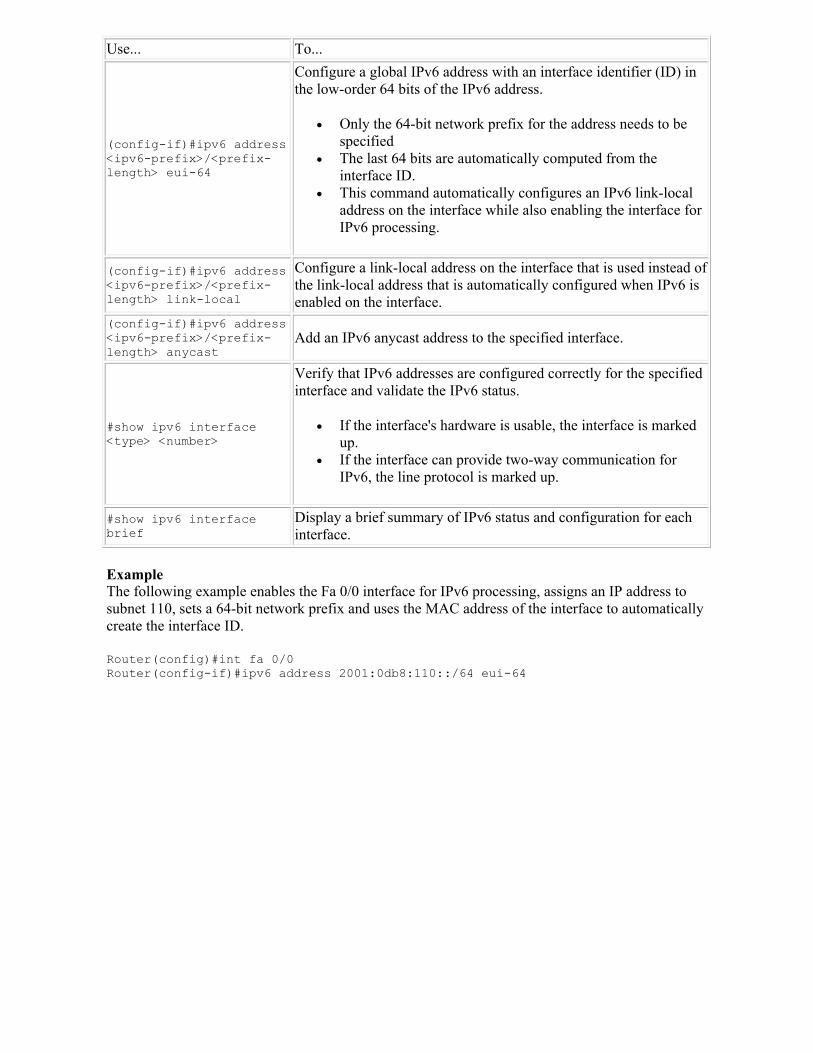
Use... To...
(config-if)#ipv6 address <ipv6-prefix>/<prefix-length> eui-64
Configure a global IPv6 address with an interface identifier (ID) in the low-order 64 bits of the IPv6 address.
Only the 64-bit network prefix for the address needs to be specified
The last 64 bits are automatically computed from the interface ID.
This command automatically configures an IPv6 link-local address on the interface while also enabling the interface for IPv6 processing.
(config-if)#ipv6 address <ipv6-prefix>/<prefix-length> link-local
Configure a link-local address on the interface that is used instead of the link-local address that is automatically configured when IPv6 is enabled on the interface.
(config-if)#ipv6 address <ipv6-prefix>/<prefix-length> anycast
Add an IPv6 anycast address to the specified interface.
#show ipv6 interface <type> <number>
Verify that IPv6 addresses are configured correctly for the specified interface and validate the IPv6 status.
If the interface's hardware is usable, the interface is marked up.
If the interface can provide two-way communication for IPv6, the line protocol is marked up.
#show ipv6 interface brief
Display a brief summary of IPv6 status and configuration for each interface.
ExampleThe following example enables the Fa 0/0 interface for IPv6 processing, assigns an IP address to subnet 110, sets a 64-bit network prefix and uses the MAC address of the interface to automatically create the interface ID.
Router(config)#int fa 0/0Router(config-if)#ipv6 address 2001:0db8:110::/64 eui-64
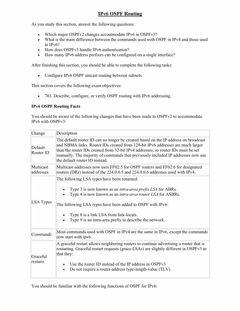
IPv6 OSPF Routing
As you study this section, answer the following questions:
Which major OSPFv2 changes accommodate IPv6 in OSPFv3? What is the main difference between the commands used with OSPF in IPv4 and those used
in IPv6? How does OSPFv3 handle IPv6 authentication? How many IPv6 address prefixes can be configured on a single interface?
After finishing this section, you should be able to complete the following tasks:
Configure IPv6 OSPF unicast routing between subnets.
This section covers the following exam objectives:
703. Describe, configure, or verify OSPF routing with IPv6 addressing.
IPv6 OSPF Routing Facts
You should be aware of the following changes that have been made to OSPFv2 to accommodate IPv6 with OSPFv3:
Change Description
Default Router ID
The default router ID can no longer be created based on the IP address on broadcast and NBMA links. Router IDs created from 128-bit IPv6 addresses are much larger than the router IDs created from 32-bit IPv4 addresses, so router IDs must be set manually. The majority of commands that previously included IP addresses now use the default router ID instead.
Multicast addresses
Multicast addresses now uses FF02:5 for OSPF routers and FF02:6 for designated routers (DRs) instead of the 224.0.0.5 and 224.0.0.6 addresses used with IPv4.
LSA Types
The following LSA types have been renamed:
Type 3 is now known as an intra-area prefix LSA for ABRs. Type 4 is now known as an intra-area router LSA for ASBRs.
The following LSA types have been added to OSPF with IPv6:
Type 8 is a link LSA from link-locals. Type 9 is an intra-area prefix to describe the network.
CommandsMost commands used with OSPF in IPv4 are the same in IPv6, except the commands now start with ipv6.
Graceful restarts
A graceful restart allows neighboring routers to continue advertising a router that is restarting. Graceful restart requests (grace-LSAs) are slightly different in OSPFv3 in that they:
Use the router ID instead of the IP address in OSPFv3 Do not require a router-address type-length-value (TLV).
You should be familiar with the following functions of OSPF for IPv6:
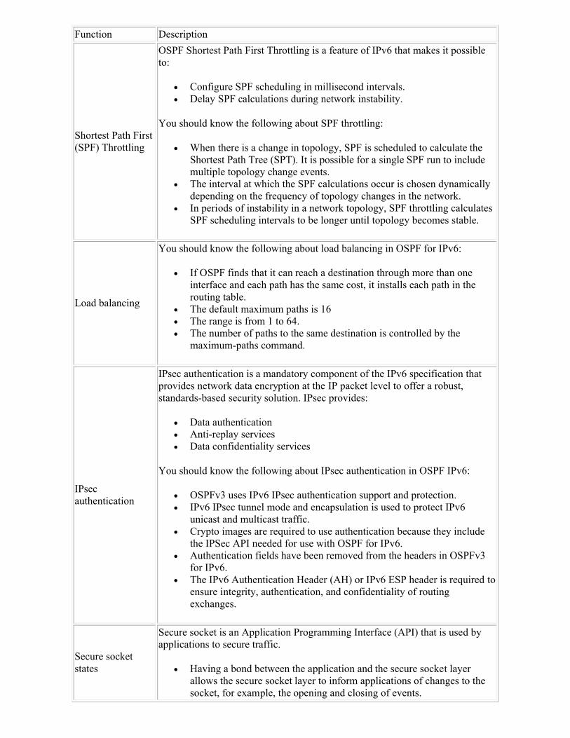
Function Description
Shortest Path First (SPF) Throttling
OSPF Shortest Path First Throttling is a feature of IPv6 that makes it possible to:
Configure SPF scheduling in millisecond intervals. Delay SPF calculations during network instability.
You should know the following about SPF throttling:
When there is a change in topology, SPF is scheduled to calculate the Shortest Path Tree (SPT). It is possible for a single SPF run to include multiple topology change events.
The interval at which the SPF calculations occur is chosen dynamically depending on the frequency of topology changes in the network.
In periods of instability in a network topology, SPF throttling calculates SPF scheduling intervals to be longer until topology becomes stable.
Load balancing
You should know the following about load balancing in OSPF for IPv6:
If OSPF finds that it can reach a destination through more than one interface and each path has the same cost, it installs each path in the routing table.
The default maximum paths is 16 The range is from 1 to 64. The number of paths to the same destination is controlled by the
maximum-paths command.
IPsec authentication
IPsec authentication is a mandatory component of the IPv6 specification that provides network data encryption at the IP packet level to offer a robust, standards-based security solution. IPsec provides:
Data authentication Anti-replay services Data confidentiality services
You should know the following about IPsec authentication in OSPF IPv6:
OSPFv3 uses IPv6 IPsec authentication support and protection. IPv6 IPsec tunnel mode and encapsulation is used to protect IPv6
unicast and multicast traffic. Crypto images are required to use authentication because they include
the IPSec API needed for use with OSPF for IPv6. Authentication fields have been removed from the headers in OSPFv3
for IPv6. The IPv6 Authentication Header (AH) or IPv6 ESP header is required to
ensure integrity, authentication, and confidentiality of routing exchanges.
Secure socket states
Secure socket is an Application Programming Interface (API) that is used by applications to secure traffic.
Having a bond between the application and the secure socket layer allows the secure socket layer to inform applications of changes to the socket, for example, the opening and closing of events.
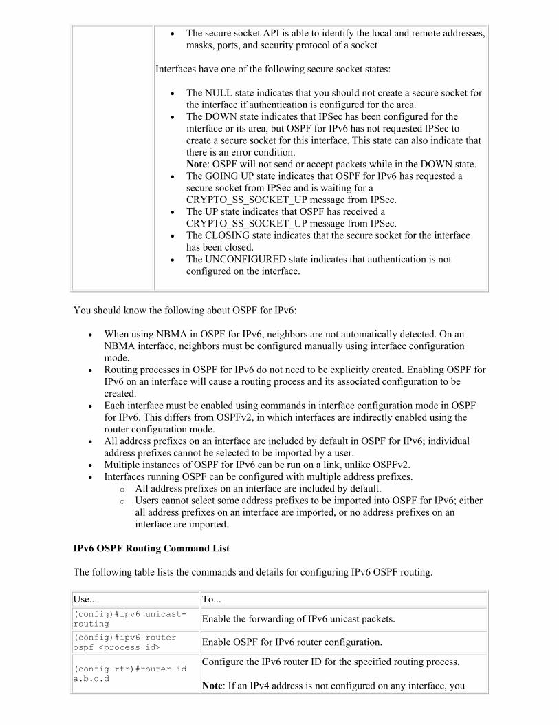
The secure socket API is able to identify the local and remote addresses, masks, ports, and security protocol of a socket
Interfaces have one of the following secure socket states:
The NULL state indicates that you should not create a secure socket for the interface if authentication is configured for the area.
The DOWN state indicates that IPSec has been configured for the interface or its area, but OSPF for IPv6 has not requested IPSec to create a secure socket for this interface. This state can also indicate that there is an error condition.Note: OSPF will not send or accept packets while in the DOWN state.
The GOING UP state indicates that OSPF for IPv6 has requested a secure socket from IPSec and is waiting for a CRYPTO_SS_SOCKET_UP message from IPSec.
The UP state indicates that OSPF has received a CRYPTO_SS_SOCKET_UP message from IPSec.
The CLOSING state indicates that the secure socket for the interface has been closed.
The UNCONFIGURED state indicates that authentication is not configured on the interface.
You should know the following about OSPF for IPv6:
When using NBMA in OSPF for IPv6, neighbors are not automatically detected. On an NBMA interface, neighbors must be configured manually using interface configuration mode.
Routing processes in OSPF for IPv6 do not need to be explicitly created. Enabling OSPF for IPv6 on an interface will cause a routing process and its associated configuration to be created.
Each interface must be enabled using commands in interface configuration mode in OSPF for IPv6. This differs from OSPFv2, in which interfaces are indirectly enabled using the router configuration mode.
All address prefixes on an interface are included by default in OSPF for IPv6; individual address prefixes cannot be selected to be imported by a user.
Multiple instances of OSPF for IPv6 can be run on a link, unlike OSPFv2. Interfaces running OSPF can be configured with multiple address prefixes.
o All address prefixes on an interface are included by default. o Users cannot select some address prefixes to be imported into OSPF for IPv6; either
all address prefixes on an interface are imported, or no address prefixes on an interface are imported.
IPv6 OSPF Routing Command List
The following table lists the commands and details for configuring IPv6 OSPF routing.
Use... To...(config)#ipv6 unicast-routing Enable the forwarding of IPv6 unicast packets.
(config)#ipv6 router ospf <process id> Enable OSPF for IPv6 router configuration.
(config-rtr)#router-id a.b.c.d
Configure the IPv6 router ID for the specified routing process.
Note: If an IPv4 address is not configured on any interface, you
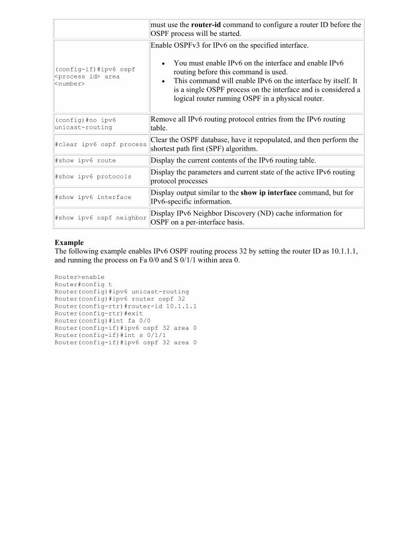
must use the router-id command to configure a router ID before the OSPF process will be started.
(config-if)#ipv6 ospf <process id> area <number>
Enable OSPFv3 for IPv6 on the specified interface.
You must enable IPv6 on the interface and enable IPv6 routing before this command is used.
This command will enable IPv6 on the interface by itself. It is a single OSPF process on the interface and is considered a logical router running OSPF in a physical router.
(config)#no ipv6 unicast-routing
Remove all IPv6 routing protocol entries from the IPv6 routing table.
#clear ipv6 ospf processClear the OSPF database, have it repopulated, and then perform the shortest path first (SPF) algorithm.
#show ipv6 route Display the current contents of the IPv6 routing table.
#show ipv6 protocolsDisplay the parameters and current state of the active IPv6 routing protocol processes
#show ipv6 interfaceDisplay output similar to the show ip interface command, but for IPv6-specific information.
#show ipv6 ospf neighborDisplay IPv6 Neighbor Discovery (ND) cache information for OSPF on a per-interface basis.
ExampleThe following example enables IPv6 OSPF routing process 32 by setting the router ID as 10.1.1.1, and running the process on Fa 0/0 and S 0/1/1 within area 0.
Router>enable Router#config t Router(config)#ipv6 unicast-routingRouter(config)#ipv6 router ospf 32Router(config-rtr)#router-id 10.1.1.1Router(config-rtr)#exitRouter(config)#int fa 0/0Router(config-if)#ipv6 ospf 32 area 0Router(config-if)#int s 0/1/1Router(config-if)#ipv6 ospf 32 area 0
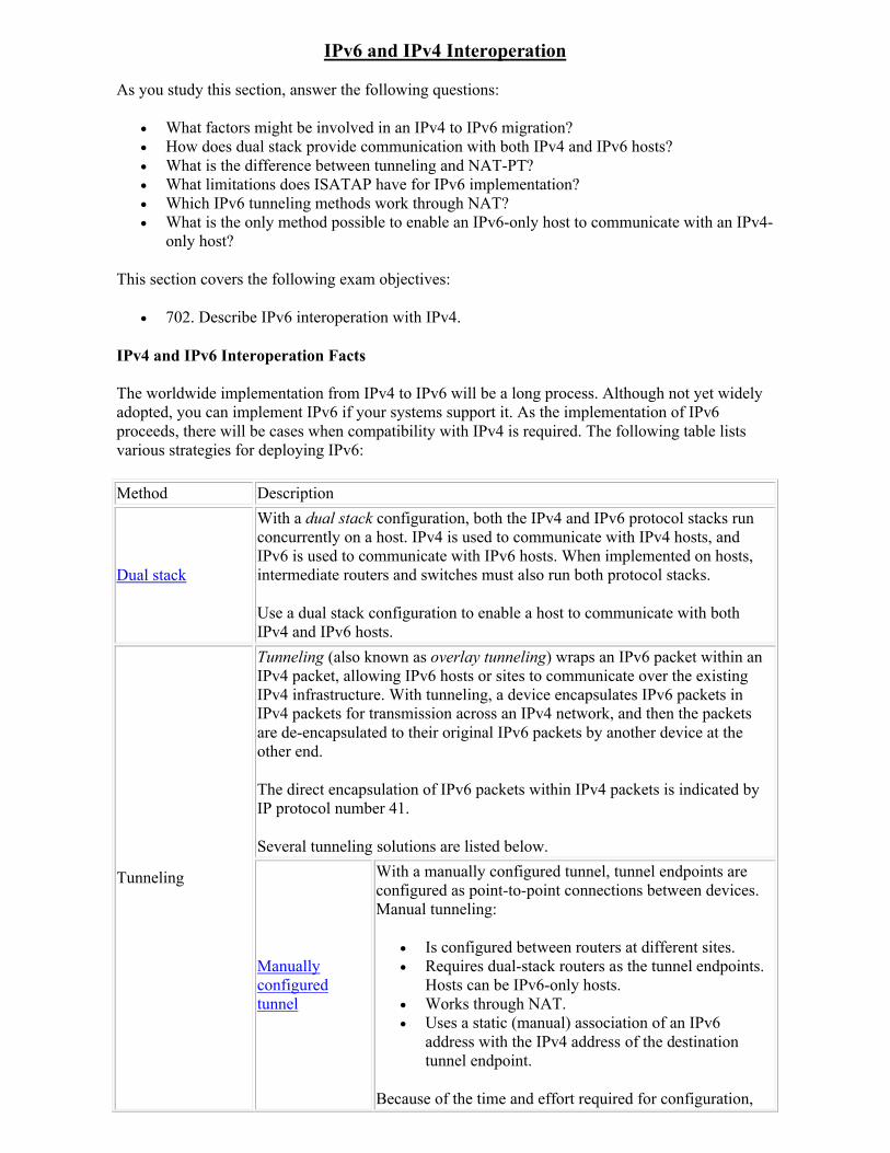
IPv6 and IPv4 Interoperation
As you study this section, answer the following questions:
What factors might be involved in an IPv4 to IPv6 migration? How does dual stack provide communication with both IPv4 and IPv6 hosts? What is the difference between tunneling and NAT-PT? What limitations does ISATAP have for IPv6 implementation? Which IPv6 tunneling methods work through NAT? What is the only method possible to enable an IPv6-only host to communicate with an IPv4-
only host?
This section covers the following exam objectives:
702. Describe IPv6 interoperation with IPv4.
IPv4 and IPv6 Interoperation Facts
The worldwide implementation from IPv4 to IPv6 will be a long process. Although not yet widely adopted, you can implement IPv6 if your systems support it. As the implementation of IPv6 proceeds, there will be cases when compatibility with IPv4 is required. The following table lists various strategies for deploying IPv6:
Method Description
Dual stack
With a dual stack configuration, both the IPv4 and IPv6 protocol stacks run concurrently on a host. IPv4 is used to communicate with IPv4 hosts, and IPv6 is used to communicate with IPv6 hosts. When implemented on hosts, intermediate routers and switches must also run both protocol stacks.
Use a dual stack configuration to enable a host to communicate with both IPv4 and IPv6 hosts.
Tunneling
Tunneling (also known as overlay tunneling) wraps an IPv6 packet within an IPv4 packet, allowing IPv6 hosts or sites to communicate over the existing IPv4 infrastructure. With tunneling, a device encapsulates IPv6 packets in IPv4 packets for transmission across an IPv4 network, and then the packets are de-encapsulated to their original IPv6 packets by another device at the other end.
The direct encapsulation of IPv6 packets within IPv4 packets is indicated by IP protocol number 41.
Several tunneling solutions are listed below.
Manually configured tunnel
With a manually configured tunnel, tunnel endpoints are configured as point-to-point connections between devices. Manual tunneling:
Is configured between routers at different sites. Requires dual-stack routers as the tunnel endpoints.
Hosts can be IPv6-only hosts. Works through NAT. Uses a static (manual) association of an IPv6
address with the IPv4 address of the destination tunnel endpoint.
Because of the time and effort required for configuration,
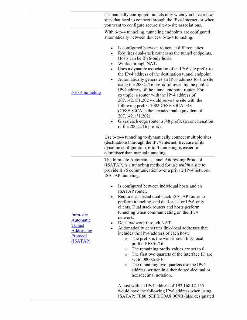
use manually configured tunnels only when you have a few sites that need to connect through the IPv4 Internet, or when you want to configure secure site-to-site associations.
6-to-4 tunneling
With 6-to-4 tunneling, tunneling endpoints are configured automatically between devices. 6-to-4 tunneling:
Is configured between routers at different sites. Requires dual-stack routers as the tunnel endpoints.
Hosts can be IPv6-only hosts. Works through NAT. Uses a dynamic association of an IPv6 site prefix to
the IPv4 address of the destination tunnel endpoint. Automatically generates an IPv6 address for the site
using the 2002::/16 prefix followed by the public IPv4 address of the tunnel endpoint router. For example, a router with the IPv4 address of 207.142.131.202 would serve the site with the following prefix: 2002:CF8E:83CA::/48 (CF8E:83CA is the hexadecimal equivalent of 207.142.131.202).
Gives each edge router a /48 prefix (a concatenation of the 2002::/16 prefix).
Use 6-to-4 tunneling to dynamically connect multiple sites (destinations) through the IPv4 Internet. Because of its dynamic configuration, 6-to-4 tunneling is easier to administer than manual tunneling.
Intra-site Automatic Tunnel Addressing Protocol (ISATAP)
The Intra-site Automatic Tunnel Addressing Protocol (ISATAP) is a tunneling method for use within a site to provide IPv6 communication over a private IPv4 network. ISATAP tunneling:
Is configured between individual hosts and an ISATAP router.
Requires a special dual-stack ISATAP router to perform tunneling, and dual-stack or IPv6-only clients. Dual stack routers and hosts perform tunneling when communicating on the IPv4 network.
Does not work through NAT. Automatically generates link-local addresses that
includes the IPv4 address of each host: o The prefix is the well-known link-local
prefix: FE80::/16. o The remaining prefix values are set to 0. o The first two quartets of the interface ID are
set to 0000:5EFE. o The remaining two quartets use the IPv4
address, written in either dotted-decimal or hexadecimal notation.
A host with an IPv4 address of 192.168.12.155 would have the following IPv6 address when using ISATAP: FE80::5EFE:C0A8:0C9B (also designated
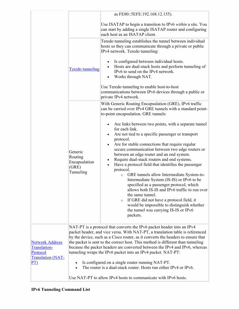
as FE80::5EFE:192.168.12.155).
Use ISATAP to begin a transition to IPv6 within a site. You can start by adding a single ISATAP router and configuring each host as an ISATAP client.
Teredo tunneling
Teredo tunneling establishes the tunnel between individual hosts so they can communicate through a private or public IPv4 network. Teredo tunneling:
Is configured between individual hosts. Hosts are dual-stack hosts and perform tunneling of
IPv6 to send on the IPv4 network. Works through NAT.
Use Teredo tunneling to enable host-to-host communications between IPv6 devices through a public or private IPv4 network.
Generic RoutingEncapsulation(GRE) Tunneling
With Generic Routing Encapsulation (GRE), IPv6 traffic can be carried over IPv4 GRE tunnels with a standard point-to-point encapsulation. GRE tunnels:
Are links between two points, with a separate tunnel for each link.
Are not tied to a specific passenger or transport protocol.
Are for stable connections that require regular secure communication between two edge routers or between an edge router and an end system.
Require dual-stack routers and end systems. Have a protocol field that identifies the passenger
protocol. o GRE tunnels allow Intermediate System-to-
Intermediate System (IS-IS) or IPv6 to be specified as a passenger protocol, which allows both IS-IS and IPv6 traffic to run over the same tunnel.
o If GRE did not have a protocol field, it would be impossible to distinguish whether the tunnel was carrying IS-IS or IPv6 packets.
Network Address Translation-Protocol Translation (NAT-PT)
NAT-PT is a protocol that converts the IPv6 packet header into an IPv4 packet header, and vice versa. With NAT-PT, a translation table is referenced by the device, such as a Cisco router, as it converts the headers to ensure that the packet is sent to the correct host. This method is different than tunneling because the packet headers are converted between the IPv4 and IPv6, whereas tunneling wraps the IPv6 packet into an IPv4 packet. NAT-PT:
Is configured on a single router running NAT-PT. The router is a dual-stack router. Hosts run either IPv4 or IPv6.
Use NAT-PT to allow IPv4 hosts to communicate with IPv6 hosts.
IPv6 Tunneling Command List
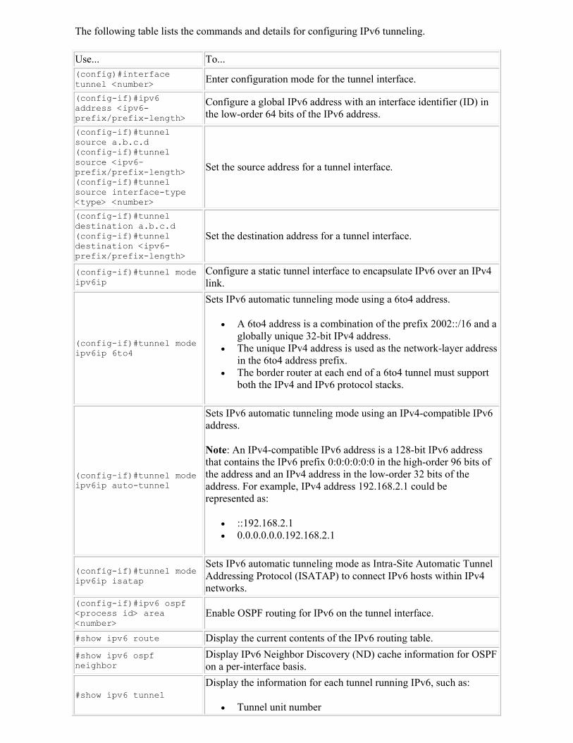
The following table lists the commands and details for configuring IPv6 tunneling.
Use... To...(config)#interface tunnel <number> Enter configuration mode for the tunnel interface.
(config-if)#ipv6 address <ipv6-prefix/prefix-length>
Configure a global IPv6 address with an interface identifier (ID) in the low-order 64 bits of the IPv6 address.
(config-if)#tunnel source a.b.c.d(config-if)#tunnel source <ipv6-prefix/prefix-length>(config-if)#tunnel source interface-type <type> <number>
Set the source address for a tunnel interface.
(config-if)#tunnel destination a.b.c.d(config-if)#tunnel destination <ipv6-prefix/prefix-length>
Set the destination address for a tunnel interface.
(config-if)#tunnel mode ipv6ip
Configure a static tunnel interface to encapsulate IPv6 over an IPv4 link.
(config-if)#tunnel mode ipv6ip 6to4
Sets IPv6 automatic tunneling mode using a 6to4 address.
A 6to4 address is a combination of the prefix 2002::/16 and a globally unique 32-bit IPv4 address.
The unique IPv4 address is used as the network-layer address in the 6to4 address prefix.
The border router at each end of a 6to4 tunnel must support both the IPv4 and IPv6 protocol stacks.
(config-if)#tunnel mode ipv6ip auto-tunnel
Sets IPv6 automatic tunneling mode using an IPv4-compatible IPv6 address.
Note: An IPv4-compatible IPv6 address is a 128-bit IPv6 address that contains the IPv6 prefix 0:0:0:0:0:0 in the high-order 96 bits of the address and an IPv4 address in the low-order 32 bits of the address. For example, IPv4 address 192.168.2.1 could be represented as:
::192.168.2.1 0.0.0.0.0.0.192.168.2.1
(config-if)#tunnel mode ipv6ip isatap
Sets IPv6 automatic tunneling mode as Intra-Site Automatic Tunnel Addressing Protocol (ISATAP) to connect IPv6 hosts within IPv4 networks.
(config-if)#ipv6 ospf <process id> area <number>
Enable OSPF routing for IPv6 on the tunnel interface.
#show ipv6 route Display the current contents of the IPv6 routing table.
#show ipv6 ospf neighbor
Display IPv6 Neighbor Discovery (ND) cache information for OSPF on a per-interface basis.
#show ipv6 tunnelDisplay the information for each tunnel running IPv6, such as:
Tunnel unit number
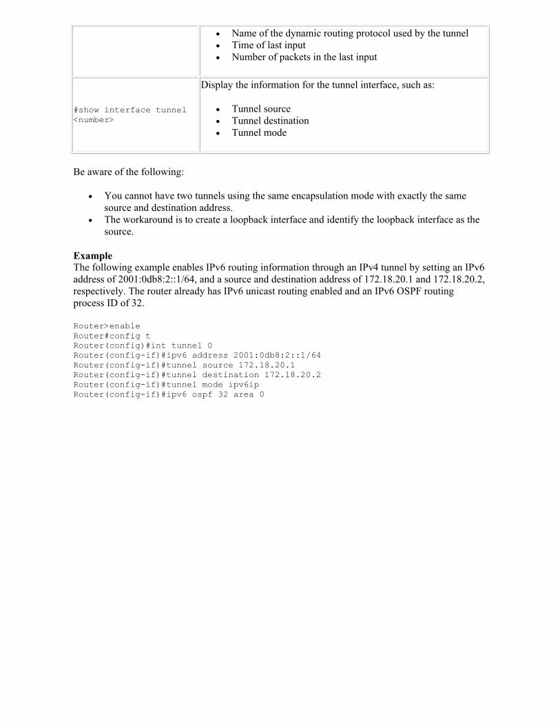
Name of the dynamic routing protocol used by the tunnel Time of last input Number of packets in the last input
#show interface tunnel <number>
Display the information for the tunnel interface, such as:
Tunnel source Tunnel destination Tunnel mode
Be aware of the following:
You cannot have two tunnels using the same encapsulation mode with exactly the same source and destination address.
The workaround is to create a loopback interface and identify the loopback interface as the source.
ExampleThe following example enables IPv6 routing information through an IPv4 tunnel by setting an IPv6 address of 2001:0db8:2::1/64, and a source and destination address of 172.18.20.1 and 172.18.20.2, respectively. The router already has IPv6 unicast routing enabled and an IPv6 OSPF routing process ID of 32.
Router>enable Router#config t Router(config)#int tunnel 0Router(config-if)#ipv6 address 2001:0db8:2::1/64Router(config-if)#tunnel source 172.18.20.1Router(config-if)#tunnel destination 172.18.20.2Router(config-if)#tunnel mode ipv6ipRouter(config-if)#ipv6 ospf 32 area 0
BGP
As you study this section, answer the following questions:
Why is BGP the protocol used between Internet Service Providers (ISPs)? What allows for the configuration of BGP policies on a per-address family basis? What are the BGP address families? What types of messages does BGP use to communicate between devices? When performing a session reset, what is the difference between a hard reset and a soft
reset? Why has the BGP synchronization rule been disabled by default?
This section covers the following exam objectives:
501. Describe the functions and operations of BGP.
BGP Facts
Border Gateway Protocol (BGP) is a policy-based, inter-autonomous system routing protocol. You should be familiar with the following terms related to BGP:
An Autonomous System (AS) is a set of routers under a common administration and with common routing policies. Each Autonomous System (AS) in BGP appears to other autonomous systems to have a single coherent interior routing plan.
Interior Gateway Protocol (IGP) is a routing protocol that exchanges information within an autonomous system and can be controlled by the system in which they operate. The most common examples of IGPs are Routing Information Protocol (RIP), Open Shortest Path First (OSPF), Intermediate System-Intermediate System (IS-IS), and Enhanced Interior Gateway Routing Protocol (EIGRP).
Exterior Gateway Protocol (EGP) is a routing protocol that exchanges routing information between autonomous systems. BGP is the most common EGP protocol.
BGP:
Is an advanced distance vector protocol that provides inter-domain routing. Uses the Transmission Control Protocol (TCP) port 179 as a transport protocol to provide
reliability. Note: BGP is the only IP routing protocol to use TCP at the Transport Layer.
Is the protocol used between Internet Service Providers (ISP). Is a very robust and scalable routing protocol. Supports Message Digest 5 (MD5) neighbor authentication. Maintains a local routing table that contains information about paths to destination
networks. This routing table is kept separate from the IP routing table in the router and is used by BGP to determine the easiest way in which networks among ASs can be reached.
Maintains a neighbor table that contains a list of neighbors with which it has a BGP connection.
Does not require a hierarchical topology, unlike OPSF and IS-IS. Does not use traditional IGP metrics. BGP makes routing decisions based on path, network
policies, and rule sets. Was created to replace the EGP routing protocol. Can only advertise the routes that it uses.
BGP version 4 (BGP-4) is the only acceptable version of BGP available for use on the public Internet. BGP-4:
Carries a network mask for each advertised network.
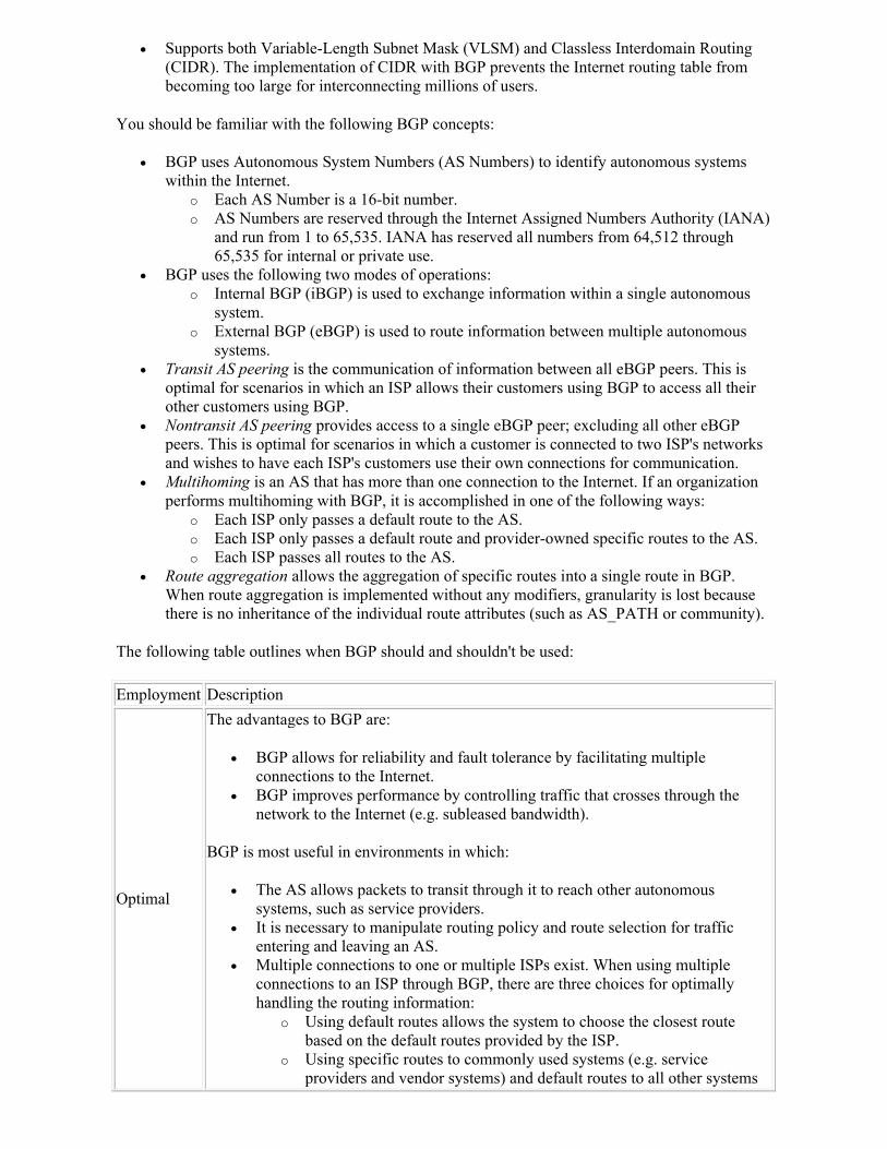
Supports both Variable-Length Subnet Mask (VLSM) and Classless Interdomain Routing (CIDR). The implementation of CIDR with BGP prevents the Internet routing table from becoming too large for interconnecting millions of users.
You should be familiar with the following BGP concepts:
BGP uses Autonomous System Numbers (AS Numbers) to identify autonomous systems within the Internet.
o Each AS Number is a 16-bit number. o AS Numbers are reserved through the Internet Assigned Numbers Authority (IANA)
and run from 1 to 65,535. IANA has reserved all numbers from 64,512 through 65,535 for internal or private use.
BGP uses the following two modes of operations: o Internal BGP (iBGP) is used to exchange information within a single autonomous
system. o External BGP (eBGP) is used to route information between multiple autonomous
systems. Transit AS peering is the communication of information between all eBGP peers. This is
optimal for scenarios in which an ISP allows their customers using BGP to access all their other customers using BGP.
Nontransit AS peering provides access to a single eBGP peer; excluding all other eBGP peers. This is optimal for scenarios in which a customer is connected to two ISP's networks and wishes to have each ISP's customers use their own connections for communication.
Multihoming is an AS that has more than one connection to the Internet. If an organization performs multihoming with BGP, it is accomplished in one of the following ways:
o Each ISP only passes a default route to the AS. o Each ISP only passes a default route and provider-owned specific routes to the AS. o Each ISP passes all routes to the AS.
Route aggregation allows the aggregation of specific routes into a single route in BGP. When route aggregation is implemented without any modifiers, granularity is lost because there is no inheritance of the individual route attributes (such as AS_PATH or community).
The following table outlines when BGP should and shouldn't be used:
Employment Description
Optimal
The advantages to BGP are:
BGP allows for reliability and fault tolerance by facilitating multiple connections to the Internet.
BGP improves performance by controlling traffic that crosses through the network to the Internet (e.g. subleased bandwidth).
BGP is most useful in environments in which:
The AS allows packets to transit through it to reach other autonomous systems, such as service providers.
It is necessary to manipulate routing policy and route selection for traffic entering and leaving an AS.
Multiple connections to one or multiple ISPs exist. When using multiple connections to an ISP through BGP, there are three choices for optimally handling the routing information:
o Using default routes allows the system to choose the closest route based on the default routes provided by the ISP.
o Using specific routes to commonly used systems (e.g. service providers and vendor systems) and default routes to all other systems
allows increased performance with the commonly used systems while minimizing resource overhead.
o Using BGP for all routes allows the system to choose the most optimal routes.Note: This method is very resource intensive.
Suboptimal
The disadvantages to BGP are:
BGP requires robust routers that can handle heavy workloads. A high level of routing expertise is necessary to properly configure and
maintain BGP.
BGP should not be implemented in environments in which:
Only a single connection to a single ISP exists. Establishing a default route would be sufficient in this scenario.
There is not sufficient memory or processor power on routers to support BGP. The administrators of the network have a limited understanding of route
filtering and the path-selection process employed by BGP.
Multiprotocol BGP Facts
Multiprotocol BGP is an enhanced extension of BGP that has the ability to carry IP multicast routes.
Multiprotocol BGP carries two sets of routes, one set for unicast routing and one set for multicast routing.
Protocol Independent Multicast (PIM) uses the routes associated with multicast routing to build data distribution trees.
The Cisco BGP Address Family Identifier (AFI) model was introduced with multiprotocol BGP. It is designed to be scalable and modular, and to support multiple AFI and Subsequent Address Family Identifier (SAFI) configurations. You should understand the following about BGP and AFI/SAFI:
Multiprotocol BGP routing information is carried in the AFI model as appended BGP attributes (multiprotocol extensions).
Each address family maintains a separate BGP database, which allows the configuration of BGP policies on a per-address family basis.
SAFI configurations are subsets of the parent AFI. SAFIs can be used to refine BGP policy configurations. The AFI model in multiprotocol BGP:
o Supports multiple AFIs and SAFIs. o Supports all NLRI-based commands and policy configurations. o Is backward compatible with routers that support only the NLRI format.
BGP Address Family Facts
The BGP address family model consists of the following address families:
Family Description
Internet Protocol version 4 (IPv4)
IPv4 is an address family that is used to identify routing sessions for protocols that use standard IP version 4 address prefixes, such as BGP. In the IPv4 address family:
Unicast or multicast address prefixes can be specified. Unicast routing information is advertised by default when a BGP peer
is configured unless the advertisement of unicast IPv4 information is explicitly turned off.
Internet Protocol version 6 (IPv6)
IPv6 is an address family that is used to identify routing sessions for protocols that use standard IPv6 prefixes, such as BGP.
Connectionless Network Service (CLNS)
CLNS is an address family that is used to identify routing sessions for protocols that use standard Network Service Access Point (NSAP) address prefixes, such as BGP.
When NSAP address prefixes are configured, unicast address prefixes are the default.
CLNS routes are used in networks where CLNS addresses are configured, such as a telecommunications Data Communications Network (DCN).
Update messages contain CLNS routes.
Virtual Private Network Version 4 (VPNv4)
VPNv4 is an address family that is used to identify routing sessions for protocols that use standard VPN Version 4 address prefixes, such as BGP.
When VPNv4 address prefixes are configured, unicast address prefixes are the default.
VPNv4 routes are the same as IPv4 routes, except that VPNv4 routes have a Route Descriptor (RD) that allows replication of prefixes.
It is possible to associate every different RD with a different VPN. Each VPN needs its own set of prefixes. By design, the VPN address space is isolated from the global address
space. BGP uses the VPNv4 multiprotocol extensions to distribute
reachability information for VPN-IPv4 prefixes for each VPN. This ensures that the routes for a given VPN are learned only by other members of that VPN, enabling members of the VPN to communicate with each other.
Layer 2 Virtual Private Networks (L2VPN)
L2VPN is an address family that consists of a secure network that operates inside an unsecured network by using an encryption technology such as IP Security (IPSec) or Generic Routing Encapsulation (GRE).
The L2VPN address family is configured under BGP routing configuration mode.
The VPLS subsequent address family identifier (SAFI) is supported within the L2VPN address family.
A BGP-based autodiscovery mechanism is used to distribute L2VPN endpoint provisioning information.
A separate L2VPN Routing Information Base (RIB) is used by BGP to store endpoint provisioning information, which is updated each time any Layer 2 VFI is configured.
Prefix and path information allows BGP to make best-path decisions. This information is stored in the L2VPN database.
When endpoint provisioning information is distributed by BGP in an update message to all its BGP neighbors, the endpoint information is
used to set up a pseudowire mesh to support L2VPN-based services.
BGP Message and State Facts
You should know the following about the implementation of BGP:
BGP implements the neighbor/peer model: o A BGP speaker is any router that runs BGP. o A BGP peer (also called a neighbor) is a BGP speaker that is explicitly configured
to form a neighbor relationship with another BGP speaker. Neighbor relationships allow BGP speakers to directly exchange BGP routing information with one another.
o A BGP peer group consists of the neighbors of a router that is being configured. All routers in a BGP peer group have the same update policies; thus allowing updates to be generated only once for the entire peer group.
BGP is TCP-based; it uses TCP port 179 to communicate with its peers or neighbors. For two routers to exchange BGP routing updates, a TCP three-way handshake must be
successfully established before BGP can be initiated. Because TCP ensures the delivery of every packet, the BGP TCP sessions are unicast and
cannot be multicast or broadcast. eBGP neighbors have the following characteristics:
o They are usually directly connected with each other. o They are in different autonomous systems. o The neighbor's IP address is used to establish the TCP connection, and must be
reachable without using an IGP. A static route or directly connected network may be used to reach the eBGP neighbor.
o IGP routing information is not exchanged with eBGP neighbors. iBGP neighbors have the following characteristics:
o They do not have direct connections to each other. o They can reach each other through static routes, connected networks, or an internal
routing protocol. o Loopback IP addresses are usually used to establish iBGP sessions.
Full-mesh iBGP is an iBGP network in which each BGP speaker has a neighbor statement containing updated information for all other iBGP speakers in the AS.
o When a change is received from an external AS, the BGP router for the local AS is responsible to inform all other iBGP neighbors. The iBGP neighbors do not forward the change, because they assume that the sending iBGP neighbor (or the router with firsthand knowledge) is fully meshed with all other neighbors.
o To avoid routing loops, the routes that are learned through iBGP are never propagated to other iBGP peers. This is sometimes known as the BGP Split Horizon rule.
o All routers in a transit path (the path between iBGP neighbors within an AS) must be running BGP to ensure that iBGP is fully-meshed. If they are not, the IGP may not have the correct routes, and will discard transit traffic.
BGP uses the following messages and types to communicate between devices:
Type Description
Open
The first message sent by each side of an established TCP session is an open message. Open messages exchange information on how to set up a session, such as:
Version number of BGP; the highest common version supported by both of the routers is used. This is 8-bits.
The Autonomous System (AS) number; the AS number is verified by the peer router. If the AS number does not match the information in the peer router's
tables, the BGP session terminates. This is 16-bits. Hold time is the maximum number of seconds that can elapse between the
successive keepalive or update messages from the sender. This is 16-bits. Router ID is an IP address determined at startup that is assigned to that router.
This is 32-bits. Optional parameters which are Type, Length, and Value (TLV) -encoded.
Keepalive
Keepalive messages act as hello packets to ensure that routers are still responsive. Keepalive messages:
Reset the hold down timer, causing it to remain active Consist of only a header Are sent every 60 seconds by default
Update
Update messages notify all routers in a network of any updates that have been made within the network. Update messages may contain information regarding:
Withdrawn routes Path attributes Network layer reachability information
Notification
Notification messages are transmitted when errors have been detected.
Note: BGP routers close the BGP connection immediately after sending notification messages.
Because BGP is a state process, it will transition through multiple states or modes with peers or potential peers. You should be familiar with the following BGP states:
State Description
Idle
The idle state is when the BGP routing process is enabled or when the router is reset.
In this state, the router waits for a start event, such as a peering configuration with a remote peer.
After the router receives a TCP connection request from a remote peer, the router initiates another start event to wait for a timer before starting a TCP connection to a remote peer.
If the router is reset then the peer is reset and the BGP routing process returns to the idle state.
ConnectThe connect state is when the BGP routing process detects a peer's attempt to establish a TCP session.
Active
The active state is when the BGP routing process tries to establish a TCP session with a peer router using the ConnectRetry timer.
Start events are ignored while the BGP routing process is in the active state. The BGP routing process will release system resources and return to an idle
state if the BGP routing process is reconfigured or if an error occurs.
OpenSent
The open confirm state is when the BGP routing process sends an OPEN message to the remote peer.
This state happens after the TCP connection is established.
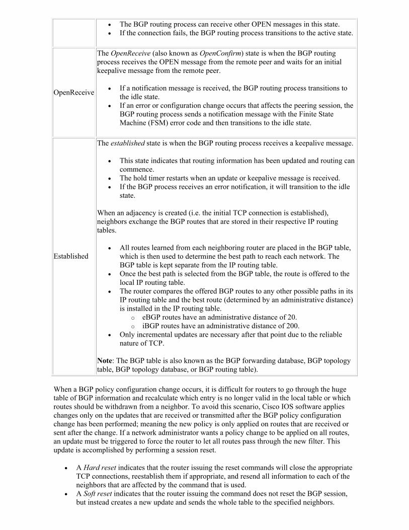
The BGP routing process can receive other OPEN messages in this state. If the connection fails, the BGP routing process transitions to the active state.
OpenReceive
The OpenReceive (also known as OpenConfirm) state is when the BGP routing process receives the OPEN message from the remote peer and waits for an initial keepalive message from the remote peer.
If a notification message is received, the BGP routing process transitions to the idle state.
If an error or configuration change occurs that affects the peering session, the BGP routing process sends a notification message with the Finite State Machine (FSM) error code and then transitions to the idle state.
Established
The established state is when the BGP routing process receives a keepalive message.
This state indicates that routing information has been updated and routing can commence.
The hold timer restarts when an update or keepalive message is received. If the BGP process receives an error notification, it will transition to the idle
state.
When an adjacency is created (i.e. the initial TCP connection is established), neighbors exchange the BGP routes that are stored in their respective IP routing tables.
All routes learned from each neighboring router are placed in the BGP table, which is then used to determine the best path to reach each network. The BGP table is kept separate from the IP routing table.
Once the best path is selected from the BGP table, the route is offered to the local IP routing table.
The router compares the offered BGP routes to any other possible paths in its IP routing table and the best route (determined by an administrative distance) is installed in the IP routing table.
o eBGP routes have an administrative distance of 20. o iBGP routes have an administrative distance of 200.
Only incremental updates are necessary after that point due to the reliable nature of TCP.
Note: The BGP table is also known as the BGP forwarding database, BGP topology table, BGP topology database, or BGP routing table).
When a BGP policy configuration change occurs, it is difficult for routers to go through the huge table of BGP information and recalculate which entry is no longer valid in the local table or which routes should be withdrawn from a neighbor. To avoid this scenario, Cisco IOS software applies changes only on the updates that are received or transmitted after the BGP policy configuration change has been performed; meaning the new policy is only applied on routes that are received or sent after the change. If a network administrator wants a policy change to be applied on all routes, an update must be triggered to force the router to let all routes pass through the new filter. This update is accomplished by performing a session reset.
A Hard reset indicates that the router issuing the reset commands will close the appropriate TCP connections, reestablish them if appropriate, and resend all information to each of the neighbors that are affected by the command that is used.
A Soft reset indicates that the router issuing the command does not reset the BGP session, but instead creates a new update and sends the whole table to the specified neighbors.
A Route refresh provides support for dynamic soft resets of inbound BGP routing table updates that are not dependent on stored routing table update information.
o Route refresh must first be advertised through BGP capability negotiation between peers.
o All BGP routers must support the route refresh capability.
BGP Synchronization Facts
The BGP synchronization rule states that a BGP router cannot use or advertise a route that it has learned from internal BGP (iBGP) to an external neighbor unless it has also been established through an internal gateway protocol, such as RIP or OSPF. Since ISO 12.2.8T, the BGP synchronization rule has been disabled by default; allowing BGP to advertise external BGP routes that are learned from an iBGP neighbor even if the route isn't in the local routing table.
You should know the following about disabled synchronization:
It is safe to keep synchronization disabled only if all routers in the AS transit path are running full-mesh BGP.
Disabled synchronization allows the routers to carry fewer routes in IGP and allows BGP to advertise routes as soon as they are learned. This leads to a quick convergence.
You should know the following about enabled synchronization:
When synchronization is enabled, BGP should not advertise a route from one AS to another before all routers in the originating AS have learned about the route via IGP. BGP and IGP must be synchronized before networks learned from an iBGP neighbor can be used.
Enabled synchronization delays convergence because a router learning a route via iBGP must wait until the IGP has propagated the route within the AS before advertising the route to external peers.
Synchronization should be enabled if there are routers in the BGP transit path in the AS that are not running BGP.
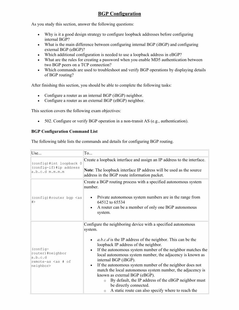
BGP Configuration
As you study this section, answer the following questions:
Why is it a good design strategy to configure loopback addresses before configuring internal BGP?
What is the main difference between configuring internal BGP (iBGP) and configuring external BGP (eBGP)?
Which additional configuration is needed to use a loopback address in eBGP? What are the rules for creating a password when you enable MD5 authentication between
two BGP peers on a TCP connection? Which commands are used to troubleshoot and verify BGP operations by displaying details
of BGP routing?
After finishing this section, you should be able to complete the following tasks:
Configure a router as an internal BGP (iBGP) neighbor. Configure a router as an external BGP (eBGP) neighbor.
This section covers the following exam objectives:
502. Configure or verify BGP operation in a non-transit AS (e.g., authentication).
BGP Configuration Command List
The following table lists the commands and details for configuring BGP routing.
Use... To...
(config)#int loopback 0(config-if)#ip address a.b.c.d m.m.m.m
Create a loopback interface and assign an IP address to the interface.
Note: The loopback interface IP address will be used as the source address in the BGP route information packet.
(config)#router bgp <as #>
Create a BGP routing process with a specified autonomous system number.
Private autonomous system numbers are in the range from 64512 to 65534
A router can be a member of only one BGP autonomous system.
(config-router)#neighbor a.b.c.d remote-as <as # of neighbor>
Configure the neighboring device with a specified autonomous system.
a.b.c.d is the IP address of the neighbor. This can be the loopback IP address of the neighbor.
If the autonomous system number of the neighbor matches the local autonomous system number, the adjacency is known as internal BGP (iBGP).
If the autonomous system number of the neighbor does not match the local autonomous system number, the adjacency is known as external BGP (eBGP).
o By default, the IP address of the eBGP neighbor must be directly connected.
o A static route can also specify where to reach the
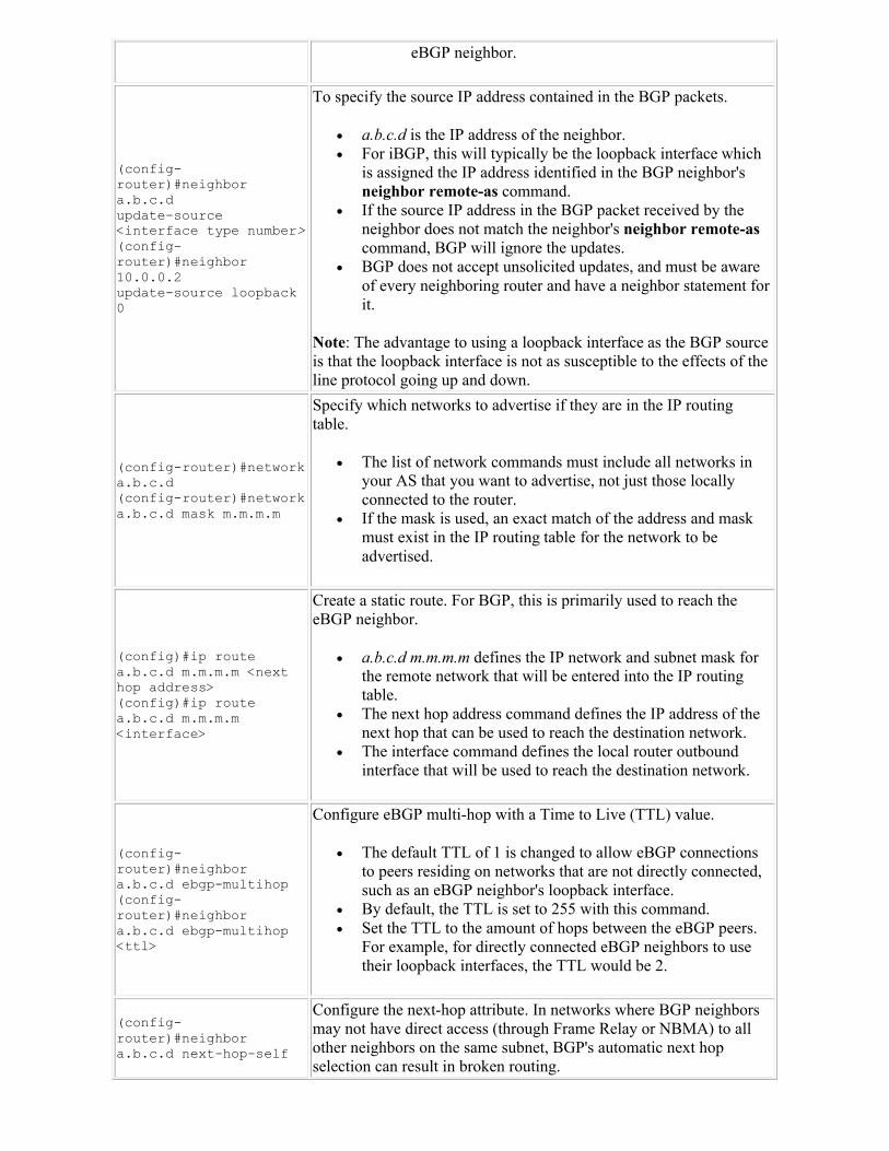
eBGP neighbor.
(config-router)#neighbor a.b.c.d update-source <interface type number>(config-router)#neighbor 10.0.0.2 update-source loopback 0
To specify the source IP address contained in the BGP packets.
a.b.c.d is the IP address of the neighbor. For iBGP, this will typically be the loopback interface which
is assigned the IP address identified in the BGP neighbor's neighbor remote-as command.
If the source IP address in the BGP packet received by the neighbor does not match the neighbor's neighbor remote-ascommand, BGP will ignore the updates.
BGP does not accept unsolicited updates, and must be aware of every neighboring router and have a neighbor statement for it.
Note: The advantage to using a loopback interface as the BGP source is that the loopback interface is not as susceptible to the effects of the line protocol going up and down.
(config-router)#network a.b.c.d(config-router)#network a.b.c.d mask m.m.m.m
Specify which networks to advertise if they are in the IP routing table.
The list of network commands must include all networks in your AS that you want to advertise, not just those locally connected to the router.
If the mask is used, an exact match of the address and mask must exist in the IP routing table for the network to be advertised.
(config)#ip route a.b.c.d m.m.m.m <next hop address>(config)#ip route a.b.c.d m.m.m.m <interface>
Create a static route. For BGP, this is primarily used to reach the eBGP neighbor.
a.b.c.d m.m.m.m defines the IP network and subnet mask for the remote network that will be entered into the IP routing table.
The next hop address command defines the IP address of the next hop that can be used to reach the destination network.
The interface command defines the local router outbound interface that will be used to reach the destination network.
(config-router)#neighbor a.b.c.d ebgp-multihop(config-router)#neighbor a.b.c.d ebgp-multihop <ttl>
Configure eBGP multi-hop with a Time to Live (TTL) value.
The default TTL of 1 is changed to allow eBGP connections to peers residing on networks that are not directly connected, such as an eBGP neighbor's loopback interface.
By default, the TTL is set to 255 with this command. Set the TTL to the amount of hops between the eBGP peers.
For example, for directly connected eBGP neighbors to use their loopback interfaces, the TTL would be 2.
(config-router)#neighbor a.b.c.d next-hop-self
Configure the next-hop attribute. In networks where BGP neighbors may not have direct access (through Frame Relay or NBMA) to all other neighbors on the same subnet, BGP's automatic next hop selection can result in broken routing.
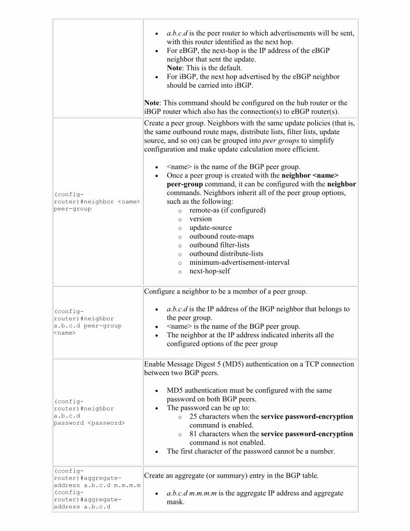
a.b.c.d is the peer router to which advertisements will be sent, with this router identified as the next hop.
For eBGP, the next-hop is the IP address of the eBGP neighbor that sent the update. Note: This is the default.
For iBGP, the next hop advertised by the eBGP neighbor should be carried into iBGP.
Note: This command should be configured on the hub router or the iBGP router which also has the connection(s) to eBGP router(s).
(config-router)#neighbor <name> peer-group
Create a peer group. Neighbors with the same update policies (that is, the same outbound route maps, distribute lists, filter lists, update source, and so on) can be grouped into peer groups to simplify configuration and make update calculation more efficient.
<name> is the name of the BGP peer group. Once a peer group is created with the neighbor <name>
peer-group command, it can be configured with the neighborcommands. Neighbors inherit all of the peer group options, such as the following:
o remote-as (if configured) o version o update-source o outbound route-maps o outbound filter-lists o outbound distribute-lists o minimum-advertisement-interval o next-hop-self
(config-router)#neighbor a.b.c.d peer-group <name>
Configure a neighbor to be a member of a peer group.
a.b.c.d is the IP address of the BGP neighbor that belongs to the peer group.
<name> is the name of the BGP peer group. The neighbor at the IP address indicated inherits all the
configured options of the peer group
(config-router)#neighbor a.b.c.d password <password>
Enable Message Digest 5 (MD5) authentication on a TCP connection between two BGP peers.
MD5 authentication must be configured with the same password on both BGP peers.
The password can be up to: o 25 characters when the service password-encryption
command is enabled. o 81 characters when the service password-encryption
command is not enabled. The first character of the password cannot be a number.
(config-router)#aggregate-address a.b.c.d m.m.m.m(config-router)#aggregate-address a.b.c.d
Create an aggregate (or summary) entry in the BGP table.
a.b.c.d m.m.m.m is the aggregate IP address and aggregate mask.
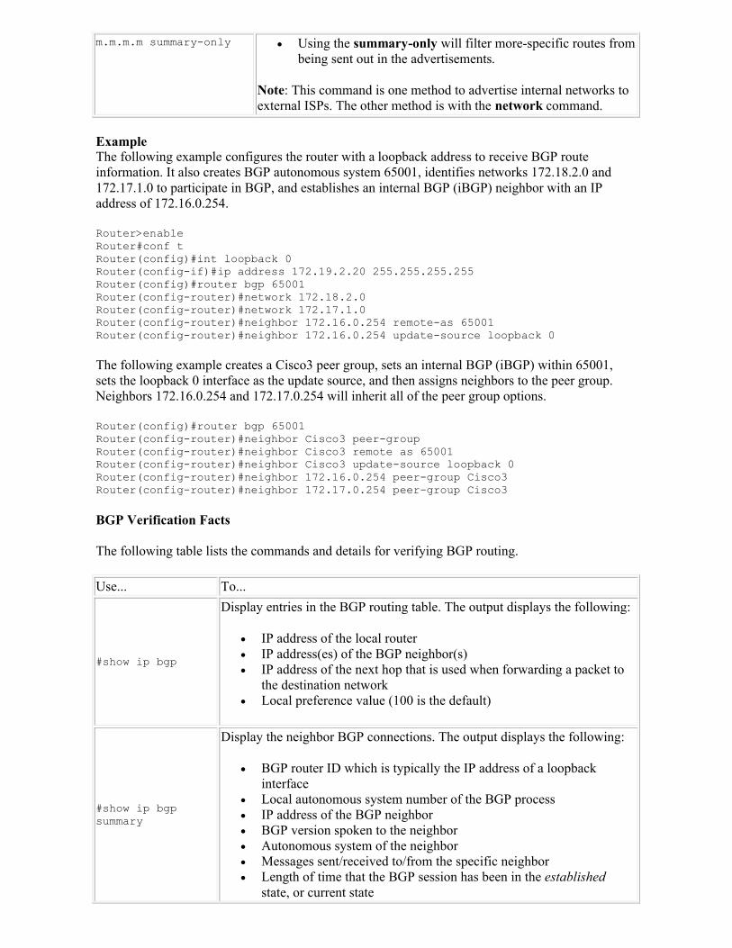
m.m.m.m summary-only Using the summary-only will filter more-specific routes from being sent out in the advertisements.
Note: This command is one method to advertise internal networks to external ISPs. The other method is with the network command.
ExampleThe following example configures the router with a loopback address to receive BGP route information. It also creates BGP autonomous system 65001, identifies networks 172.18.2.0 and 172.17.1.0 to participate in BGP, and establishes an internal BGP (iBGP) neighbor with an IP address of 172.16.0.254.
Router>enable Router#conf tRouter(config)#int loopback 0Router(config-if)#ip address 172.19.2.20 255.255.255.255Router(config)#router bgp 65001 Router(config-router)#network 172.18.2.0 Router(config-router)#network 172.17.1.0 Router(config-router)#neighbor 172.16.0.254 remote-as 65001Router(config-router)#neighbor 172.16.0.254 update-source loopback 0
The following example creates a Cisco3 peer group, sets an internal BGP (iBGP) within 65001, sets the loopback 0 interface as the update source, and then assigns neighbors to the peer group. Neighbors 172.16.0.254 and 172.17.0.254 will inherit all of the peer group options.
Router(config)#router bgp 65001 Router(config-router)#neighbor Cisco3 peer-groupRouter(config-router)#neighbor Cisco3 remote as 65001Router(config-router)#neighbor Cisco3 update-source loopback 0Router(config-router)#neighbor 172.16.0.254 peer-group Cisco3Router(config-router)#neighbor 172.17.0.254 peer-group Cisco3
BGP Verification Facts
The following table lists the commands and details for verifying BGP routing.
Use... To...
#show ip bgp
Display entries in the BGP routing table. The output displays the following:
IP address of the local router IP address(es) of the BGP neighbor(s) IP address of the next hop that is used when forwarding a packet to
the destination network Local preference value (100 is the default)
#show ip bgp summary
Display the neighbor BGP connections. The output displays the following:
BGP router ID which is typically the IP address of a loopback interface
Local autonomous system number of the BGP process IP address of the BGP neighbor BGP version spoken to the neighbor Autonomous system of the neighbor Messages sent/received to/from the specific neighbor Length of time that the BGP session has been in the established
state, or current state
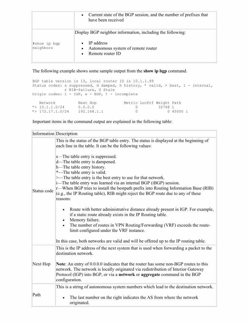
Current state of the BGP session, and the number of prefixes that have been received
#show ip bgp neighbors
Display BGP neighbor information, including the following:
IP address Autonomous system of remote router Remote router ID
The following example shows some sample output from the show ip bgp command.
BGP table version is 13, local router ID is 10.1.1.99Status codes: s suppressed, d damped, h history, * valid, > best, i - internal, r RIB-failure, S StaleOrigin codes: i - IGP, e - EGP, ? - incomplete
Network Next Hop Metric LocPrf Weight Path*> 10.1.1.0/24 0.0.0.0 0 32768 i*> 172.17.1.0/24 192.168.1.1 0 0 45000 i
Important items in the command output are explained in the following table:
Information Description
Status code
This is the status of the BGP table entry. The status is displayed at the beginning of each line in the table. It can be the following values:
s—The table entry is suppressed.d—The table entry is dampened.h—The table entry history.*—The table entry is valid.>—The table entry is the best entry to use for that network.i—The table entry was learned via an internal BGP (iBGP) session. r—When BGP tries to install the bestpath prefix into Routing Information Base (RIB) (e.g., the IP Routing table), RIB might reject the BGP route due to any of these reasons:
Route with better administrative distance already present in IGP. For example, if a static route already exists in the IP Routing table.
Memory failure. The number of routes in VPN Routing/Forwarding (VRF) exceeds the route-
limit configured under the VRF instance.
In this case, both networks are valid and will be offered up to the IP routing table.
Next Hop
This is the IP address of the next system that is used when forwarding a packet to the destination network.
Note: An entry of 0.0.0.0 indicates that the router has some non-BGP routes to this network. The network is locally originated via redistribution of Interior Gateway Protocol (IGP) into BGP, or via a network or aggregate command in the BGP configuration.
Path
This is a string of autonomous system numbers which lead to the destination network.
The last number on the right indicates the AS from where the network originated.

There can be one entry in this field for each autonomous system in the path. A question mark (?) means that the original BGP process cannot absolutely
verify this network's availability, because it is redistributed from an IGP into the BGP process.
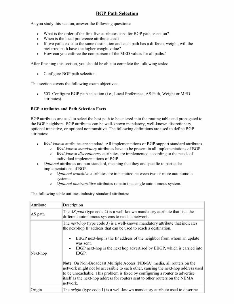
BGP Path Selection
As you study this section, answer the following questions:
What is the order of the first five attributes used for BGP path selection? When is the local preference attribute used? If two paths exist to the same destination and each path has a different weight, will the
preferred path have the higher weight value? How can you enforce the comparison of the MED values for all paths?
After finishing this section, you should be able to complete the following tasks:
Configure BGP path selection.
This section covers the following exam objectives:
503. Configure BGP path selection (i.e., Local Preference, AS Path, Weight or MED attributes).
BGP Attributes and Path Selection Facts
BGP attributes are used to select the best path to be entered into the routing table and propagated to the BGP neighbors. BGP attributes can be well-known mandatory, well-known discretionary, optional transitive, or optional nontransitive. The following definitions are used to define BGP attributes:
Well-known attributes are standard. All implementations of BGP support standard attributes. o Well-known mandatory attributes have to be present in all implementations of BGP. o Well-known discretionary attributes are implemented according to the needs of
individual implementations of BGP. Optional attributes are non-standard, meaning that they are specific to particular
implementations of BGP. o Optional transitive attributes are transmitted between two or more autonomous
systems. o Optional nontransitive attributes remain in a single autonomous system.
The following table outlines industry-standard attributes:
Attribute Description
AS pathThe AS path (type code 2) is a well-known mandatory attribute that lists the different autonomous systems to reach a network.
Next-hop
The next-hop (type code 3) is a well-known mandatory attribute that indicates the next-hop IP address that can be used to reach a destination.
EBGP next-hop is the IP address of the neighbor from whom an update was sent.
IBGP next-hop is the next hop advertised by EBGP, which is carried into IBGP.
Note: On Non-Broadcast Multiple Access (NBMA) media, all routers on the network might not be accessible to each other, causing the next-hop address used to be unreachable. This problem is fixed by configuring a router to advertise itself as the next-hop address for routers sent to other routers on the NBMA network.
Origin The origin (type code 1) is a well-known mandatory attribute used to describe
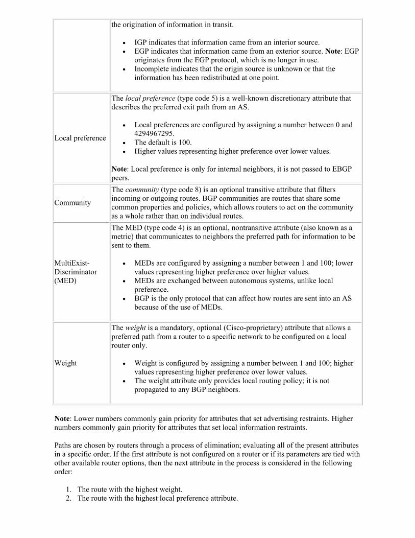
the origination of information in transit.
IGP indicates that information came from an interior source. EGP indicates that information came from an exterior source. Note: EGP
originates from the EGP protocol, which is no longer in use. Incomplete indicates that the origin source is unknown or that the
information has been redistributed at one point.
Local preference
The local preference (type code 5) is a well-known discretionary attribute that describes the preferred exit path from an AS.
Local preferences are configured by assigning a number between 0 and 4294967295.
The default is 100. Higher values representing higher preference over lower values.
Note: Local preference is only for internal neighbors, it is not passed to EBGP peers.
Community
The community (type code 8) is an optional transitive attribute that filters incoming or outgoing routes. BGP communities are routes that share some common properties and policies, which allows routers to act on the community as a whole rather than on individual routes.
MultiExist-Discriminator (MED)
The MED (type code 4) is an optional, nontransitive attribute (also known as a metric) that communicates to neighbors the preferred path for information to be sent to them.
MEDs are configured by assigning a number between 1 and 100; lower values representing higher preference over higher values.
MEDs are exchanged between autonomous systems, unlike local preference.
BGP is the only protocol that can affect how routes are sent into an AS because of the use of MEDs.
Weight
The weight is a mandatory, optional (Cisco-proprietary) attribute that allows a preferred path from a router to a specific network to be configured on a local router only.
Weight is configured by assigning a number between 1 and 100; higher values representing higher preference over lower values.
The weight attribute only provides local routing policy; it is not propagated to any BGP neighbors.
Note: Lower numbers commonly gain priority for attributes that set advertising restraints. Higher numbers commonly gain priority for attributes that set local information restraints.
Paths are chosen by routers through a process of elimination; evaluating all of the present attributes in a specific order. If the first attribute is not configured on a router or if its parameters are tied with other available router options, then the next attribute in the process is considered in the following order:
1. The route with the highest weight. 2. The route with the highest local preference attribute.
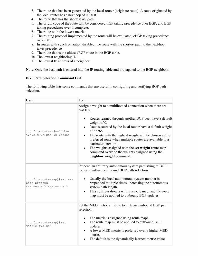
3. The route that has been generated by the local router (originate route). A route originated by the local router has a next hop of 0.0.0.0.
4. The route that has the shortest AS path. 5. The origin code of the route will be considered; IGP taking precedence over BGP, and BGP
taking precedence over incomplete. 6. The route with the lowest metric. 7. The routing protocol implemented by the route will be evaluated; eBGP taking precedence
over iBGP. 8. In routes with synchronization disabled, the route with the shortest path to the next-hop
takes precedence. 9. The route that is the oldest eBGP route in the BGP table. 10. The lowest neighboring ID. 11. The lowest IP address of a neighbor.
Note: Only the best path is entered into the IP routing table and propagated to the BGP neighbors.
BGP Path Selection Command List
The following table lists some commands that are useful in configuring and verifying BGP path selection.
Use... To...
(config-router)#neighbor a.b.c.d weight <0-65535>
Assign a weight to a multihomed connection when there are two IPs.
Routes learned through another BGP peer have a default weight of 0.
Routes sourced by the local router have a default weight of 32768.
The route with the highest weight will be chosen as the preferred route when multiple routes are available to a particular network.
The weights assigned with the set weight route-map command override the weights assigned using the neighbor weight command.
(config-route-map)#set as-path prepend <as number> <as number>
Prepend an arbitrary autonomous system path string to BGP routes to influence inbound BGP path selection.
Usually the local autonomous system number is prepended multiple times, increasing the autonomous system path length.
This configuration is within a route map, and the route map must be applied to outbound BGP updates.
(config-route-map)#set metric <value>
Set the MED metric attribute to influence inbound BGP path selection.
The metric is assigned using route maps. The route map must be applied to outbound BGP
updates. A lower MED metric is preferred over a higher MED
metric. The default is the dynamically learned metric value.
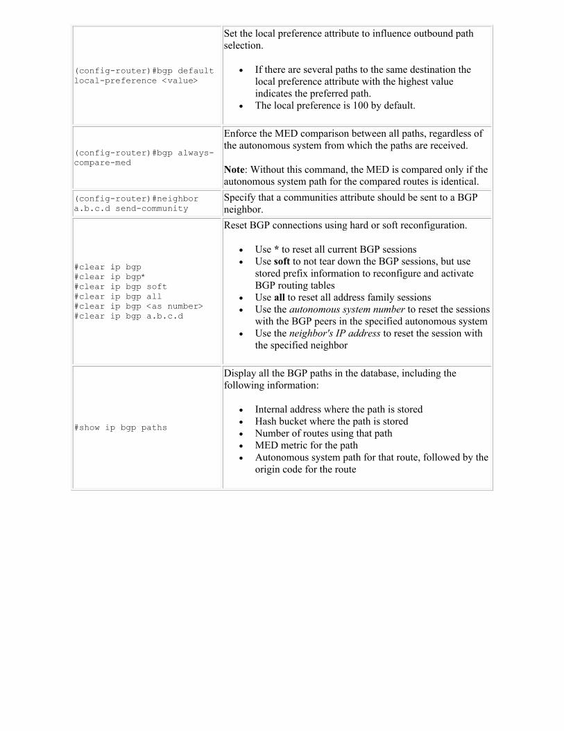
(config-router)#bgp default local-preference <value>
Set the local preference attribute to influence outbound path selection.
If there are several paths to the same destination the local preference attribute with the highest value indicates the preferred path.
The local preference is 100 by default.
(config-router)#bgp always-compare-med
Enforce the MED comparison between all paths, regardless of the autonomous system from which the paths are received.
Note: Without this command, the MED is compared only if the autonomous system path for the compared routes is identical.
(config-router)#neighbor a.b.c.d send-community
Specify that a communities attribute should be sent to a BGP neighbor.
#clear ip bgp #clear ip bgp* #clear ip bgp soft#clear ip bgp all#clear ip bgp <as number>#clear ip bgp a.b.c.d
Reset BGP connections using hard or soft reconfiguration.
Use * to reset all current BGP sessions Use soft to not tear down the BGP sessions, but use
stored prefix information to reconfigure and activate BGP routing tables
Use all to reset all address family sessions Use the autonomous system number to reset the sessions
with the BGP peers in the specified autonomous system Use the neighbor's IP address to reset the session with
the specified neighbor
#show ip bgp paths
Display all the BGP paths in the database, including the following information:
Internal address where the path is stored Hash bucket where the path is stored Number of routes using that path MED metric for the path Autonomous system path for that route, followed by the
origin code for the route
Related Documents