RA41231EN06GLA1 LTE/EPS overview 1

01_RA41231EN06GLA1_Review of LTE_EPC Network Architecture
Dec 06, 2015
01_RA41231EN06GLA1_Review of LTE_EPC Network Architecture
Welcome message from author
This document is posted to help you gain knowledge. Please leave a comment to let me know what you think about it! Share it to your friends and learn new things together.
Transcript
RA41231EN06GLA1
LTE/EPS overview
1

RA41231EN06GLA1
LTE/EPS overview
2

RA41231EN06GLA1
LTE/EPS overview
4
RA41231EN06GLA1
LTE/EPS overview
5

RA41231EN06GLA1
LTE/EPS overview
6

RA41231EN06GLA1
LTE/EPS overview
7
Over the last several decades, technological advancements have had a huge impact on the telecom industry as well as the consumer. Consumers are moving from the traditional “fixed” wire line or mobile experience toward fixed/mobile convergence, an expectation that services and information are available anytime, anywhere.
This expectation has forced changes in carrier business plans and services: fixed-line operators are expanding their boundaries outside the home or business, while mobile operators are moving into the fixed line voice and broadband business. The goal of both is to capture maximum revenue while trying to meet the customer’s needs with what is referred to as Quadruple Play: TV, Internet, Telephone, and Mobility.
Carrier success depends on providing Quadruple Play services with a low cost per bit, higher (broadband) capacity, increased flexibility, and with global appeal.

RA41231EN06GLA1
LTE/EPS overview
8

RA41231EN06GLA1
LTE/EPS overview
9
Formalized in December 1998, the 3rd Generation Partnership Project (3GPP) is a group of telecommunications associations whose main goal is to make globally applicable specifications for Third Generation (3G) mobile phone systems.
3GPP is responsible for developing global standards for Global System for Mobile Communication (GSM) and all of its subsequent releases; General Packet Radio Service (GPRS), Enhanced Data rates for GSM Evolution (EDGE), High-Speed Downlink Packet Access (HSDPA), High-Speed Uplink Packet Access (HSUPA), and Long Term Evolution (LTE).

RA41231EN06GLA1
LTE/EPS overview
10
The Participant Guide is not a technical book in the traditional, analytical sense. The material and information contained here is subject to change. The following references were used in the development of this course and should be used for most current information.
RA41231EN06GLA1
LTE/EPS overview
11

RA41231EN06GLA1
LTE/EPS overview
12

RA41231EN06GLA1
LTE/EPS overview
13
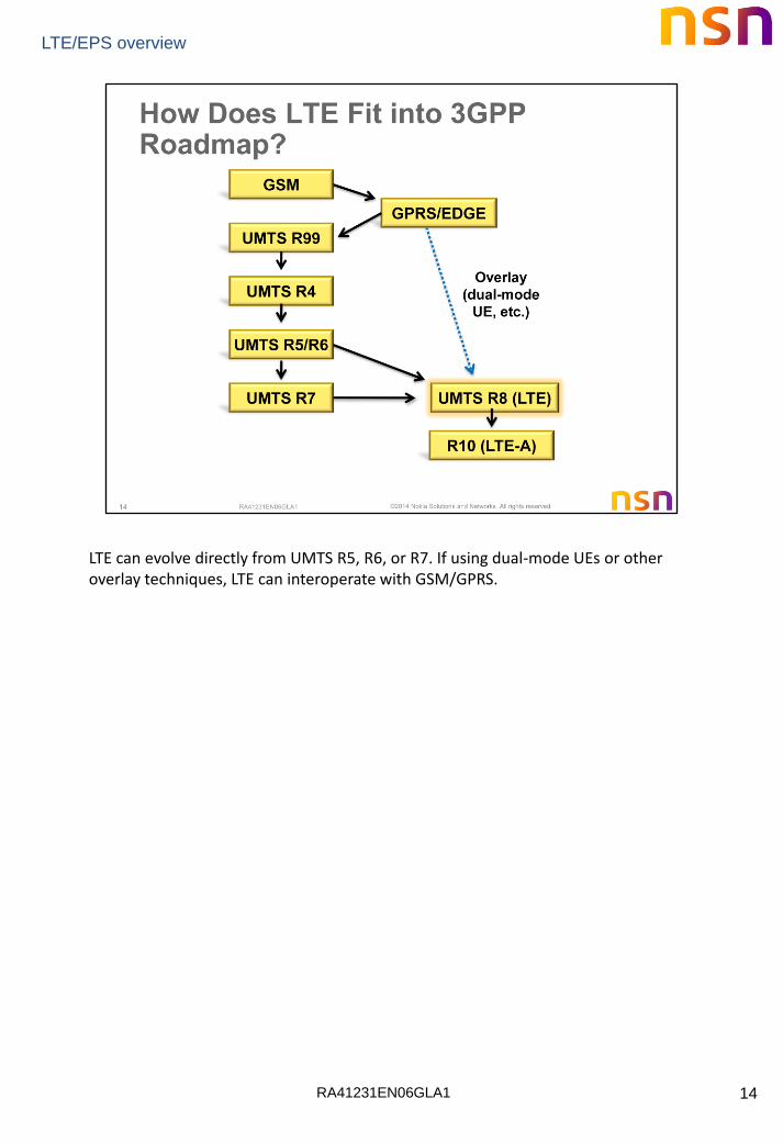
To understand where LTE fits into the GSM/UMTS network, let’s look at the evolution of GSM and UMTS networks.
RA41231EN06GLA1
LTE/EPS overview
14
LTE can evolve directly from UMTS R5, R6, or R7. If using dual-mode UEs or other overlay techniques, LTE can interoperate with GSM/GPRS.

RA41231EN06GLA1
LTE/EPS overview
15
SAE: System Architecture Evolution
SAE GW: Serving Gateway +PDN Gateway
RA41231EN06GLA1
LTE/EPS overview
16

RA41231EN06GLA1
LTE/EPS overview
17
The UMTS Release 8 architecture consists of the EPC, E-UTRAN, and user entities (UEs).The Evolved Universal Terrestrial Radio Access Network (E-UTRAN) is defined by UMTS Release 8 as Long Term Evolution (LTE).
System Architecture Evolution (SAE) defines the Evolved Packet Core (EPC). The EPC is an all IP, packet switched network.
The Evolved Packet System (EPS) includes the EPC, LTE, and the end-user terminals called User Entities or User Equipment (UE).

RA41231EN06GLA1
LTE/EPS overview
18

RA41231EN06GLA1
LTE/EPS overview
19
E-UTRAN air interface changes include new Physical Layer multiplexing, FDD and TDD duplexing, and Multiple Input Multiple Output (MIMO) antennas
The LTE air interface uses Orthogonal Frequency Division Multiple Access (OFDMA) in the downlink and Single Carrier Frequency Division Multiple Access (SC-FDMA) in the uplink. It also supports both Frequency Division Duplex (FDD) and Time Division Duplex (TDD) schemes.
MIMO antenna systems are also now fully employed. MIMO uses multiple antennas at both the transmitter and receiver, improving the network efficiency.

RA41231EN06GLA1
LTE/EPS overview
20
These are L1 transport data rates not including the different protocol layers overhead. Depending on cell BW, cell load, network configuration, the performance of the UE used, propagation conditions, etc. practical data rates will vary.
The 3.0 Gbit/s / 1.5 Gbit/s data rate specified as Category 8 is near the peak aggregate data rate for a base station sector. A more realistic maximum data rate for a single user is 1.2 Gbit/s (downlink) and 600 Mbps (uplink). Nokia Solutions and Networks has demonstrated downlink speeds of 1.4 Gbps using 100 MHz of aggregated spectrum.

RA41231EN06GLA1
LTE/EPS overview
21
The eNodeB controls the air interface and all DL and UL scheduling. The UE reacts to instructions from the eNodeB.
3GPP TS 36.101 User Equipment (UE) Radio Transmission and Reception
RA41231EN06GLA1
LTE/EPS overview
22
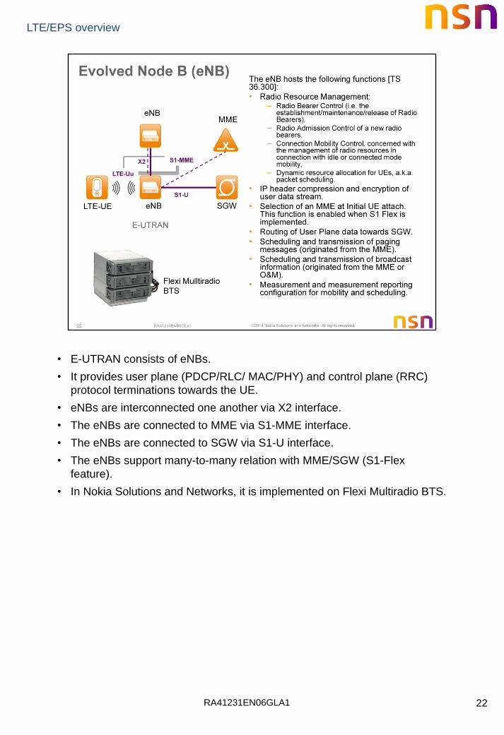
• E-UTRAN consists of eNBs.
• It provides user plane (PDCP/RLC/ MAC/PHY) and control plane (RRC)
protocol terminations towards the UE.
• eNBs are interconnected one another via X2 interface.
• The eNBs are connected to MME via S1-MME interface.
• The eNBs are connected to SGW via S1-U interface.
• The eNBs support many-to-many relation with MME/SGW (S1-Flex
feature).
• In Nokia Solutions and Networks, it is implemented on Flexi Multiradio BTS.
RA41231EN06GLA1
LTE/EPS overview
23

RA41231EN06GLA1
LTE/EPS overview
24
The Evolved Packet Core network is an all IP, packet switched network. The EPC consists of:
• Mobility Management Entity (MME) – key control node for the LTE access network
• Serving Gateway (S-GW) – routes and forwards data packets
• Packet Data Network Gateway (P-GW) – provides connectivity to external packet data networks

RA41231EN06GLA1
LTE/EPS overview
25
• It is a pure signaling entity inside the EPC.
• MME is connected to eNB via S1-MME interface.
• MME controls one or several SGWs via S11 interface
• MME is connected to HSS via S6a interface
• MME can be connected to SGSNs via S3 interface
• MMEs are interconnected via the S10 interface
• In Nokia Solutions and Networks, it is implemented on Flexi Network
Server.

RA41231EN06GLA1
LTE/EPS overview
26
• It manages the user data path (EPS bearers) within EPC.
• It transmits and receives packet data to and from eNB via the S1-U
interface.
• SGW is controlled by one or more MMEs via S11 interface.
• For interworking to other 3GPP RATs, it can be connected to SGSNs via S4
interface or to RNC via S12 interface (when Direct Tunnel feature is
implemented).
• It relays the packet data to or from the PDN gateway via the S5/S8
interface.
• In Nokia Solutions and Networks, it is implemented as standalone or
combined network element based on Flexi Network Gateway.

RA41231EN06GLA1
LTE/EPS overview
27
• PGW provides connectivity toward PDN (e.g. Company intranet, internet
and IMS) via SGi interface.
• It is comparable to GGSN.
• A major functionality provided by a PGW is the QoS coordination between
the external PDN and EPC.
• PGW can be connected to a PCRF via Gx interface.
• In Local Breakout scenario, PGW transmits and receives packet data from
Home SGW via S8 interface.
• In Nokia Solutions and Networks, it is implemented as standalone or
combined network element based on Flexi Network Gateway.

RA41231EN06GLA1
LTE/EPS overview
28
For EPS, the HSS data may contain,
• IMSI
• IMEI
• MME Address
• EPS subscribed charging characteristics (e.g. prepaid, normal, flat-rate etc.)
• Subscribed UE-AMBR. It determines Aggregate Maximum Bit Rate per subscriber.
• PDN address
• APN
• EPS subscribed QoS profile, etc.
Diameter is defined in many IETF and 3GPP specifications. The technical specifications listed below are a good starting point for understanding Diameter.
IETF RFC 3588 Diameter Base Protocol
IETF RFC 3589 Diameter Command Codes for 3GPP R5
3GPP TS 29.230 Diameter Applications; 3GPP Specific Codes and Identifiers

RA41231EN06GLA1
LTE/EPS overview
29
• PCRF is responsible for negotiating QoS Policy and Charging Policy on a
per-flow basis.
• The PCRF major functionality is the Quality of Service (QoS) coordination
between the external PDN and EPC.
• Therefore the PCRF is connected via Rx+ interface to the external Data
network (PDN)
• This function can be used to check and modify the QoS associated with a
SAE bearer setup from SAE or to request the setup of a SAE bearer from
the PDN.
• This QoS management resembles the policy and charging control
framework introduced for IMS with UMTS release

RA41231EN06GLA1
LTE/EPS overview
30

RA41231EN06GLA1
LTE/EPS overview
31
• S1-MME – Supports the control plane between E-UTRAN and MME
• S1-U – Supports the bearer plane between E-UTRAN and S-GW for the per-user tunnelling and inter-eNodeB path switching during handover
• S5 – Supports the bearer plane between an S-GW and P-GW in the same network
• S8 – Supports the bearer plane between an S-GW and P-GW in different networks
• S10 – Supports transfer of context and other information between MMEs
• S11 – Supports information transfer between MME and S-GW for session management functions
• SGi – Connects the P-GW to an external data network
• Uu – Air interface between eNodeB and UE
• X2 – The X2 interface is defined between adjacent eNodeBs. The X2 is used for mobility control, bearer forwarding, and load management

RA41231EN06GLA1
LTE/EPS overview
32
Packet Lawful Intercept Gateway (P-LIG)
The P-LIG provides the interfaces between the LTE/EPC network and Law Enforcement Agencies (LEAs), enabling the LEAs to intercept UE communications.
• Communicates with the HSS, MME, S-GW, and P-GW over the X1, X2, and X3 interfaces
• The P-LIG X2 interface is different from the eNodeB X2 interface

RA41231EN06GLA1
LTE/EPS overview
33

RA41231EN06GLA1
LTE/EPS overview
34
RA41231EN06GLA1
LTE/EPS overview
35
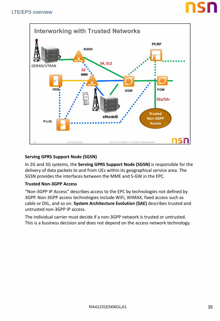
Serving GPRS Support Node (SGSN)
In 2G and 3G systems, the Serving GPRS Support Node (SGSN) is responsible for the delivery of data packets to and from UEs within its geographical service area. The SGSN provides the interfaces between the MME and S-GW in the EPC.
Trusted Non-3GPP Access
“Non-3GPP IP Access” describes access to the EPC by technologies not defined by 3GPP. Non-3GPP access technologies include WiFi, WiMAX, fixed access such as cable or DSL, and so on. System Architecture Evolution (SAE) describes trusted and untrusted non-3GPP IP access.
The individual carrier must decide if a non-3GPP network is trusted or untrusted. This is a business decision and does not depend on the access network technology.
RA41231EN06GLA1
LTE/EPS overview
36
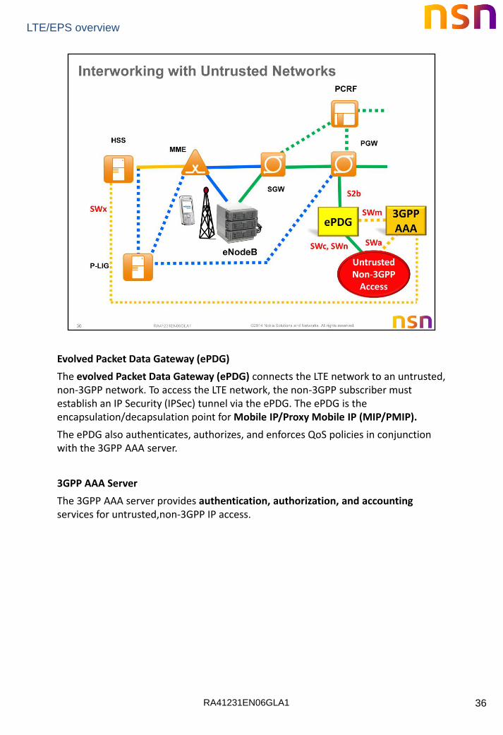
Evolved Packet Data Gateway (ePDG)
The evolved Packet Data Gateway (ePDG) connects the LTE network to an untrusted, non-3GPP network. To access the LTE network, the non-3GPP subscriber must establish an IP Security (IPSec) tunnel via the ePDG. The ePDG is the encapsulation/decapsulation point for Mobile IP/Proxy Mobile IP (MIP/PMIP).
The ePDG also authenticates, authorizes, and enforces QoS policies in conjunction with the 3GPP AAA server.
3GPP AAA Server
The 3GPP AAA server provides authentication, authorization, and accounting services for untrusted,non-3GPP IP access.

RA41231EN06GLA1
LTE/EPS overview
37
RA41231EN06GLA1
LTE/EPS overview
38
RA41231EN06GLA1
LTE/EPS overview
39

RA41231EN06GLA1
LTE/EPS overview
40

RA41231EN06GLA1
LTE/EPS overview
41
RA41231EN06GLA1
LTE/EPS overview
42
RA41231EN06GLA1
LTE/EPS overview
43
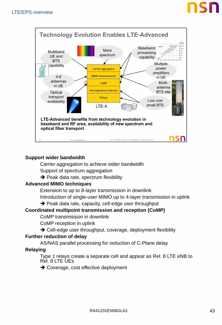
Support wider bandwidth
Carrier aggregation to achieve wider bandwidth
Support of spectrum aggregation
Peak data rate, spectrum flexibility
Advanced MIMO techniques
Extension to up to 8-layer transmission in downlink
Introduction of single-user MIMO up to 4-layer transmission in uplink
Peak data rate, capacity, cell-edge user throughput
Coordinated multipoint transmission and reception (CoMP)
CoMP transmission in downlink
CoMP reception in uplink
Cell-edge user throughput, coverage, deployment flexibility
Further reduction of delay
AS/NAS parallel processing for reduction of C-Plane delay
Relaying
Type 1 relays create a separate cell and appear as Rel. 8 LTE eNB to Rel. 8 LTE UEs
Coverage, cost effective deployment
RA41231EN06GLA1
LTE/EPS overview
44

RA41231EN06GLA1
LTE/EPS overview
45

RA41231EN06GLA1
LTE/EPS overview
46

RA41231EN06GLA1
LTE/EPS overview
47
• Uplink MIMO for up to 4 UE antennas
Increase peak data rate, and average and the cell edge throughput
Fall back to TX diversity available for data and control (use the power
amplifiers of all antennas even if multi-stream doesn’t work)
Advancements in reference signal structure, channel sounding and
feedback
• DL MIMO for 8 TX antennas
Increase peak data rate, and average and the cell edge throughput
Release 8 LTE UEs support up to 4 TX antennas (which are actually
combinations of the 8 physical antennas)
Improved reference signal design, scheduling and feedback schemes

RA41231EN06GLA1
LTE/EPS overview
48

RA41231EN06GLA1
LTE/EPS overview
49
• Joint Processing (JP):
data is available at each cell in the CoMP set
As if all sites formed a single multi antenna base station
• Coordinated Scheduling/Beamforming (CS/CB):
data only at the serving cell
scheduling coordinated among cells
• Standardization will be done in Rel. 11
Utilizing enhanced reference schemes introduced for MIMO enhancements,
which were already done forward looking to CoMP applications
RA41231EN06GLA1
LTE/EPS overview
50
RA41231EN06GLA1
LTE/EPS overview
51
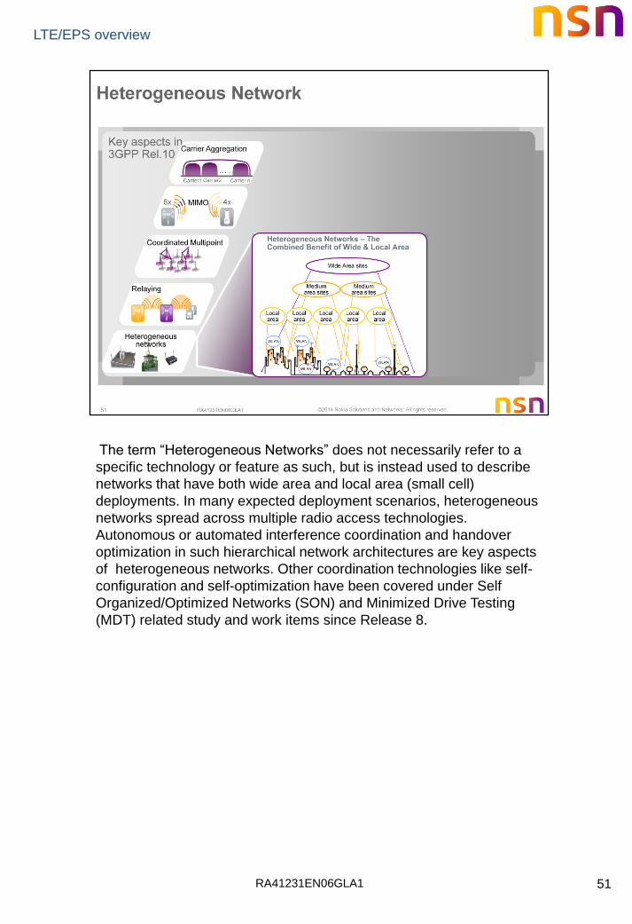
The term “Heterogeneous Networks” does not necessarily refer to a
specific technology or feature as such, but is instead used to describe
networks that have both wide area and local area (small cell)
deployments. In many expected deployment scenarios, heterogeneous
networks spread across multiple radio access technologies.
Autonomous or automated interference coordination and handover
optimization in such hierarchical network architectures are key aspects
of heterogeneous networks. Other coordination technologies like self-
configuration and self-optimization have been covered under Self
Organized/Optimized Networks (SON) and Minimized Drive Testing
(MDT) related study and work items since Release 8.

RA41231EN06GLA1
LTE/EPS overview
52

RA41231EN06GLA1
LTE/EPS overview
53
LTE-A enables a smooth and backward compatible evolution of LTE towards
true 4G performance
• LTE-A comprises of various tools to enhance mobile broadband user
experience and network efficiency
• There are serious interdependencies between network implementation and
the various tools of LTE-A, which require an experienced partner when
planning and implementing LTE-A
• Nokia Solutions and Networks has always been at the forefront of LTE-A
research and development, with a strong focus on real operator
opportunities in terms of efficiency and user experience
RA41231EN06GLA1
LTE/EPS overview
54
RA41231EN06GLA1
LTE/EPS overview
55
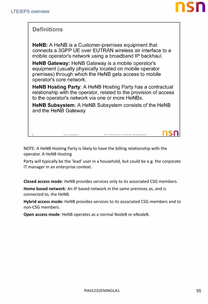
NOTE: A HeNB Hosting Party is likely to have the billing relationship with the operator. A HeNB Hosting
Party will typically be the 'lead' user in a household, but could be e.g. the corporate IT manager in an enterprise context.
Closed access mode: HeNB provides services only to its associated CSG members.
Home based network: An IP based network in the same premises as, and is connected to, the HeNB.
Hybrid access mode: HeNB provides services to its associated CSG members and to non-CSG members.
Open access mode: HeNB operates as a normal NodeB or eNodeB.
RA41231EN06GLA1
LTE/EPS overview
56
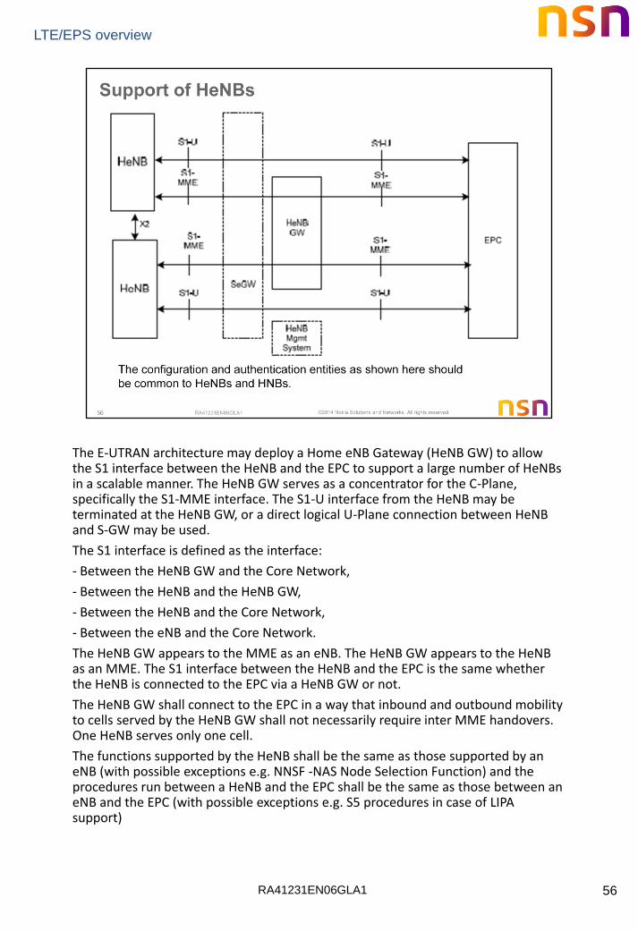
The E-UTRAN architecture may deploy a Home eNB Gateway (HeNB GW) to allow the S1 interface between the HeNB and the EPC to support a large number of HeNBs in a scalable manner. The HeNB GW serves as a concentrator for the C-Plane, specifically the S1-MME interface. The S1-U interface from the HeNB may be terminated at the HeNB GW, or a direct logical U-Plane connection between HeNB and S-GW may be used.
The S1 interface is defined as the interface:
- Between the HeNB GW and the Core Network,
- Between the HeNB and the HeNB GW,
- Between the HeNB and the Core Network,
- Between the eNB and the Core Network.
The HeNB GW appears to the MME as an eNB. The HeNB GW appears to the HeNB as an MME. The S1 interface between the HeNB and the EPC is the same whether the HeNB is connected to the EPC via a HeNB GW or not.
The HeNB GW shall connect to the EPC in a way that inbound and outbound mobility to cells served by the HeNB GW shall not necessarily require inter MME handovers. One HeNB serves only one cell.
The functions supported by the HeNB shall be the same as those supported by an eNB (with possible exceptions e.g. NNSF -NAS Node Selection Function) and the procedures run between a HeNB and the EPC shall be the same as those between an eNB and the EPC (with possible exceptions e.g. S5 procedures in case of LIPA support)

RA41231EN06GLA1
LTE/EPS overview
57
A HeNB subsystem consists of a HeNB, optionally a HeNB GW and optionally a Local GW.
The Local IP Access function is achieved using a Local GW (L-GW) collocated with the HeNB.
The HeNB subsystem is connected by means of the standard S1 interface to the EPC (Evolved Packet Core), more specifically to the MME (Mobility Management Entity) by means of the S1-MME interface and to the Serving Gateway (S-GW) by means of the S1-U interface. When LIPA is activated, the L-GW has a S5 interface with the S-GW.
The Local GW is the gateway towards the IP networks (e.g. residential/enterprise networks) associated with the HeNB.
The Local GW has the following PDN GW functions:
− UE IP address allocation;
− DHCPv4 (server and client) and DHCPv6 (client and server) functions;
− Packet screening;
− Functionality as defined in RFC 4861 .
Additionally, the Local GW has the following functions:
− ECM-IDLE mode downlink packet buffering;
− ECM-CONNECTED mode direct tunneling towards the HeNB.

RA41231EN06GLA1
LTE/EPS overview
58
X2-based HO between HeNBs is allowed if no access control at the MME is needed, i.e. when the handover is between closed/hybrid access HeNBs having the same CSG ID or when the target HeNB is an open access HeNB.
This version supports direct X2-connectivity between HeNBs, independent of whether any of the involved HeNBs is connected to a HeNB GW.
Only if the HeNB supports the LIPA function, it shall support an S5 interface towards the S-GW and an SGi interface towards the residential/IP network.

RA41231EN06GLA1
LTE/EPS overview
59
Local IP Access provides access for IP capable UEs connected via a H(e)NB (i.e. using H(e)NB radio access) to other IP capable entities in the same residential/enterprise IP network. Data traffic for Local IP Access is expected to not traverse the mobile operator’s network except mobile operator network components in the residential/enterprise premises. Signaling traffic will continue to traverse the mobile operator network. The residential/enterprise IP network itself and the entities within that network are not within the scope of 3GPP standardization.
3GPP TS 22.220 Home eNodeB (HeNB)

RA41231EN06GLA1
LTE/EPS overview
60
For a LIPA PDN connection, the HeNB sets up and maintains an S5 connection to the EPC. The S5 interface does not go via the HeNB GW even when present.
The HeNB may reuse the IP address used for S1 interface for this S5 interface in order to reuse the S1 IPSEC tunnel or it may also use another IP address which would result in the establishment of another IPSEC tunnel.
The mobility of the LIPA PDN connection is not supported in release 10 of the specification. The LIPA connection is always released at outgoing handover as described in TS23.401 . The L-GW function in the HeNB triggers this release over the S5 interface.
In case of LIPA support, the HeNB supports the following additional functions, regardless of the presence of a HeNB GW:
− Transfer of the collocated L-GW IP address of the HeNB over S1-MME to the EPC at every idle-active transition,
− Transfer of the collocated L-GW IP address of the HeNB over S1-MME to the EPC within every Uplink NAS Transport procedure,
− Support of basic P-GW functions in the collocated L-GW function such as support of the SGi interface corresponding to LIPA,
− Additional support of first packet sending, buffering of subsequent packets, internal direct L-GW - HeNB user path management and in sequence packet delivery to the UE,
RA41231EN06GLA1
LTE/EPS overview
61
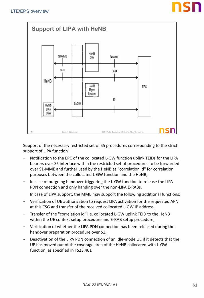
Support of the necessary restricted set of S5 procedures corresponding to the strict support of LIPA function
− Notification to the EPC of the collocated L-GW function uplink TEIDs for the LIPA bearers over S5 interface within the restricted set of procedures to be forwarded over S1-MME and further used by the HeNB as "correlation id" for correlation purposes between the collocated L-GW function and the HeNB,
− In case of outgoing handover triggering the L-GW function to release the LIPA PDN connection and only handing over the non-LIPA E-RABs.
In case of LIPA support, the MME may support the following additional functions:
− Verification of UE authorization to request LIPA activation for the requested APN at this CSG and transfer of the received collocated L-GW IP address,
− Transfer of the "correlation id" i.e. collocated L-GW uplink TEID to the HeNB within the UE context setup procedure and E-RAB setup procedure,
− Verification of whether the LIPA PDN connection has been released during the handover preparation procedure over S1,
− Deactivation of the LIPA PDN connection of an idle-mode UE if it detects that the UE has moved out of the coverage area of the HeNB collocated with L-GW function, as specified in TS23.401
RA41231EN06GLA1
LTE/EPS overview
62
RA41231EN06GLA1
LTE/EPS overview
63
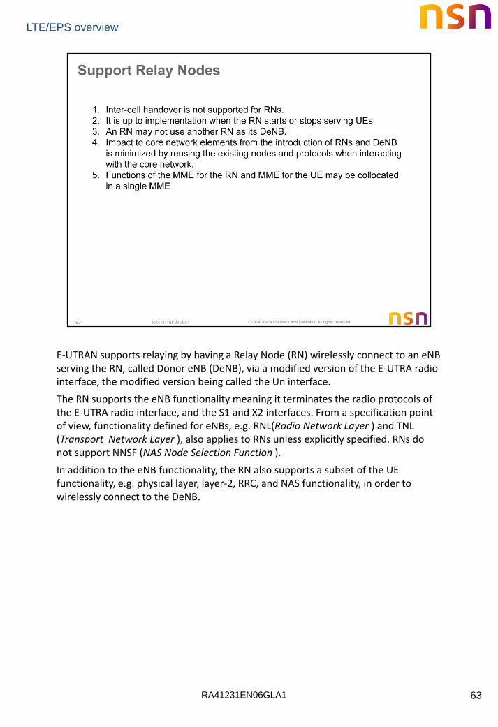
E-UTRAN supports relaying by having a Relay Node (RN) wirelessly connect to an eNB serving the RN, called Donor eNB (DeNB), via a modified version of the E-UTRA radio interface, the modified version being called the Un interface.
The RN supports the eNB functionality meaning it terminates the radio protocols of the E-UTRA radio interface, and the S1 and X2 interfaces. From a specification point of view, functionality defined for eNBs, e.g. RNL(Radio Network Layer ) and TNL (Transport Network Layer ), also applies to RNs unless explicitly specified. RNs do not support NNSF (NAS Node Selection Function ).
In addition to the eNB functionality, the RN also supports a subset of the UE functionality, e.g. physical layer, layer-2, RRC, and NAS functionality, in order to wirelessly connect to the DeNB.

RA41231EN06GLA1
LTE/EPS overview
64
The architecture for supporting RNs is shown. The RN terminates the S1, X2 and Un interfaces. The DeNB provides S1 and X2 proxy functionality between the RN and other network nodes (other eNBs, MMEs and S-GWs). The S1 and X2 proxy functionality includes passing UE-dedicated S1 and X2 signaling messages as well as GTP data packets between the S1 and X2 interfaces associated with the RN and the S1 and X2 interfaces associated with other network nodes. Due to the proxy functionality, the DeNB appears as an MME (for S1-MME), an eNB (for X2) and an S-GW (for S1-U) to the RN.
In phase II of RN operation, the DeNB also embeds and provides the S-GW/P-GW-like functions needed for the RN operation. This includes creating a session for the RN and managing EPS bearers for the RN, as well as terminating the S11 interface towards the MME serving the RN.
The RN and DeNB also perform mapping of signaling and data packets onto EPS bearers that are setup for the RN.
The mapping is based on existing QoS mechanisms defined for the UE and the P-GW.
In phase II of RN operation, the P-GW functions in the DeNB allocate an IP address for the RN for the O&M which may be different than the S1 IP address of the DeNB.
If the RN address is not routable to the RN O&M domain, it shall be reachable from the RN O&M domain (e.g. via NAT).

RA41231EN06GLA1
LTE/EPS overview
65
The relaying function enables an operator to improve and extend the coverage area by having a Relay Node (RN) wirelessly connected to an eNB serving the RN, called Donor eNB (DeNB), via a modified version of the E-UTRA radio interface called the Un interface as specified in TS 36.300.
The relaying function and use of RN/DeNB entities in a network is transparent to the operations of the UEs connected to it and associated core network entities (e.g. MME, S/P-GW, PCRF etc.) for the UEs.
The RN supports the eNB functionality like termination of the radio protocols of the E-UTRA radio interface and the S1 and X2 interfaces. The RN also supports a subset of the UE functionality and protocols to wirelessly connect to the DeNB.
In addition to supporting eNB functionality, the DeNB also embeds and provides the S-GW/P-GW-like functions needed for the RN operation. This includes creating a session for the RN and managing EPS bearers for the RN, as well as terminating the S1-AP and S11 interfaces towards the MME serving the RN. Due to the proxy functionality, the DeNB appears as an MME (for S1), an eNB (for X2) and an S-GW to the RN.
The RN and DeNB also perform mapping of signaling and data packets onto EPS bearers that are setup for the RN.
The mapping is based on existing QoS mechanisms defined for the UE and the P-GW and are described in TS 36.300.
RA41231EN06GLA1
LTE/EPS overview
66
Related Documents