PCS Compact Workstation Fluid Lab ® - PA Handling description

Welcome message from author
This document is posted to help you gain knowledge. Please leave a comment to let me know what you think about it! Share it to your friends and learn new things together.
Transcript
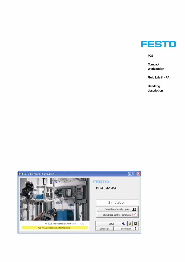
PCS
Compact Workstation
Fluid Lab ® - PA
Handling description
Order no.:
Description: PCS Compact Workstation – Fluid Lab ® - PA
Designation: Handling description
Status: 02/2007
Author: Wolfgang Eckart, ADIRO Automatisierungstechnik GmbH
Graphics: Wolfgang Eckart, ADIRO Automatisierungstechnik GmbH
Layout: Festo Didactic GmbH & Co
© Festo Didactic GmbH & Co., D-73770 Denkendorf, 2007
Internet: www.festo.com/didactic http://www.festo.com/didactic/de/ProcessAutomation
e-mail: [email protected]
All rights reserved, including translation rights. No part of this publication may be reproduced or
transmitted in any form or by any means, electronic, mechanical, photocopying, or otherwise, without
the prior written permission of Festo.
© Festo Didactic GmbH & Co. • PCS - Fluid Lab ® - PA 3
Table of Contents _______________________________________________________ 3
Introduction_________________________________________________________ 7
Introduction____________________________________________________________ 7
Training contents ____________________________________________________ 8
Important notes______________________________________________________ 9
Safety instructions __________________________________________________10
Fluid Lab®–PA general information _____________________________________11
Software Installation ___________________________________________________13
1. Installation of Fluid Lab®–PA _________________________________13
1.1 User name and license key __________________________________14
1.2 Change the text appearance _________________________________15
2. Preparation of the workstation________________________________17
Workstation set-up _____________________________________________________17
2.1 Connection of the EasyPort DA________________________________17
2.2 Fill up the tank 101 _________________________________________18
2.3 Close of the manual hand valves ______________________________19
2.4 Start Fluid Lab®–PA and definition of the serial port ______________20
3. Test the process with the Setup menu _________________________25
Table of Contents
Table of Contents
4 © Festo Didactic GmbH & Co. • PCS - Fluid Lab ® - PA
Test the process _______________________________________________________25
3.1 Test the level control process_________________________________27
3.2 Test the flow control process _________________________________28
3.3 Test the flow control process via the proportional valve ___________30
3.4 Test the pressure control process _____________________________31
3.5 Test the temperature control process __________________________32
4. Test the control process with the Measuring and Control window ___33
4.1 Test the level control process_________________________________34
4.2 Test the flow control process _________________________________38
4.3 Test the flow control process via the proportional valve ___________44
4.4 Test the pressure control process _____________________________49
4.5 Test the temperature control process __________________________52
5. Definition of the factors for the process variables ________________59
Definition of process variables ___________________________________________59
5.1 Adjustment of the ultrasonic sensor ___________________________60
5.2 Definition of the flow rate factor ______________________________63
5.3 Definition of the maximum flow rate using the proportional valve___66
5.4 Definition of the pressure rate factor___________________________68
5.5 Definition of the temperature factor ___________________________70
© Festo Didactic GmbH & Co. • PCS - Fluid Lab ® - PA 5
2-Step Control_________________________________________________________71
6. Level control by a 2-step controller ____________________________71
Continuous Control_____________________________________________________75
7. Continuous control of level, flow and pressure process ___________75
7.1 Continuous level control _____________________________________76
7.2 Continuous flow control _____________________________________87
7.3 Continuous pressure control _________________________________98
7.4 Continuous control evaluation _______________________________108
Simulation ___________________________________________________________109
8. Simulation _______________________________________________109
8.1 Simulation of the 2-step control _____________________________113
8.2 Simulation of the continuous control _________________________119
8.2.1 Simulation of the continuous level control_____________________120
8.2.2 Simulation of the continuous flow control _____________________128

Table of Contents
6 © Festo Didactic GmbH & Co. • PCS - Fluid Lab ® - PA
© Festo Didactic GmbH & Co. • PCS - Fluid Lab ® - PA 7
The Festo Didactic learning system for process automation is designed to meet a number of different training and vocational requirements. The systems and stations of the learning system for process automation facilitate industry-orientated vocational and further training and the hardware consists of didactically suitable industrial components.
The Compact Workstation of the learning system for process automation provides you with an appropriate system for practice-orientated tuition of the following key qualifications
Social competence, Technical competence and Methodological competence
Moreover, training can be provided to instill team spirit, willingness to cooperate and organisational skills.
Actual project phases can be taught by means of training projects, such as:
Planning, Assembly, Programming, Commissioning, Operation, Maintenance and Trouble Shooting
Introduction
Introduction
Introduction
8 © Festo Didactic GmbH & Co. • PCS - Fluid Lab ® - PA
Training contents covering the following subjects can be:
Process Engineering – Reading and drawing of flow charts and technical documentation Electrical technology – Correct wiring of electrical components Sensors – Correct use of sensors – Measuring of non-electrical, process and control variables Closed-loop control technology – basics of closed-loop control technology – Extension of measuring chains into closed control loops – Analyze a closed-loop system – P, I, D-control – Optimize a closed-loop system Closed-loop controller – Configuration, assigning operation parameters and optimization of a closed-loop controller Commissioning – Commissioning of a closed-loop system – Commissioning of a process engineering system Trouble Shooting – Systematic trouble shooting on a process engineering system – Maintenance of a process engineering system – Operation and observation of a process
Training contents
Introduction
© Festo Didactic GmbH & Co. • PCS - Fluid Lab ® - PA 9
The basic requirement for safe use and trouble-free operation of Fluid Lab®–PA is to observe the fundamental safety recommendations and regulations.
These operating instructions contain important notes concerning the safe operation of Fluid Lab®–PA.
The safety recommendations in particular must be observed by anyone working on Fluid Lab®–PA as well as for the used hardware.
Furthermore, the rules and regulations for the prevention of accidents applicable to the place of use must be observed.
Important notes
Introduction
10 © Festo Didactic GmbH & Co. • PCS - Fluid Lab ® - PA
General
Participants must only work on the station under the supervision of an instructor. Observe the data in the data sheets for the individual components, in particular all notes on safety!
Electrics
Electrical connections and dis-connections are only allowed when when the power is disconnected! Use only low voltage of up to 24 V DC.
Pneumatics
If you use pneumatic components within your system, please do not exceed the permissible pressure of 8 bar (800 kPA). Do not switch on compressed air until you have established and secured all tubing connections. Do not disconnect air lines under pressure. Particular care is to be taken when switching on the compressed air. Cylinders may advance or retract as soon as the compressed air is switched on.
Mechanics
Securely mount all components on the plate. No manual intervention unless the system is in Stop mode. The pump can be mounted horizontally or vertically. If mounted, the output of the pump must point upwards. For further information please refer to the corresponding data sheet of the pump.
Process engineering
• Before filling the tanks with water, switch of the 24 VDC power supply and disconnect the 220 (230) VAC power from the socket • The use of tap water in quality of drinking water (recommended), ensures a prolonged maintenance-free operation of the system (proportional valve and pump). • The maximum operating temperature of the tanks must not exceed +50 °C. • Do not operate the heating unit unless the heating element is fully immersed in fluid. • Do not operate the piping system with a system pressure higher than 0,5 bar. • Do not operate the pump without fluid, running dry or used for sea water or contaminated fluids. • Please empty fluids from the system (tanks, piping, close valves) before you make changes at the piping system. • It is possible to drain the fluids inside the Fluid Lab®–PA by opening the manual hand valve V105
Safety instructions
Introduction
© Festo Didactic GmbH & Co. • PCS - Fluid Lab ® - PA 11
The Fluid Lab®–PA software in combination with the EasyPort digital/analog offers you the possibility to measure and analyze the signals of 8 digital and 4 analog inputs.
The electrical control interface (E/A Syslink and analog terminal) is the same like for MPS.
Three main functions are integrated in Process Lab:
M as in measurement, for signal detection and analysis of 8 digital/4 analog input signals C as in open loop control, for binary or continuous control of 8 digital/2 analog outputs R as in regulate a closed-loop system, free selectable closed-loop control elements for 2-point, P, I, PI and PID
With the Compact Workstation of the learning system for process automation you have the possibility to work with the following closed loop process:
• level controlled system • flow rate controlled system • pressure controlled system • temperature controlled system
By using the simulation environment with the continuous loop control you can simulate the following functions:
• level controlled system • flow rate controlled system
Fluid Lab®–PA general information

Introduction
12 © Festo Didactic GmbH & Co. • PCS - Fluid Lab ® - PA
© Festo Didactic GmbH & Co. • PCS - Fluid Lab ® - PA 13
Please insert the Fluid Lab®–PA CD in the drive and start the setup. Please follow the instructions on the screen to install the following software packages in different languages:
• Fluid Lab®–PA program files • EzOCX driver (Third party distributor files) • LabVIEW© Runtime environment (Version 7.1) (Third party distributor files)
The EcOCX driver
The EcOCX driver is needed for the communication between Fluid Lab®–PA software and EasyPort digital/analog via the serial interface RS 232.
During the installation process you are prompted whether to install EzOCX or not. If you choose “no”, you are able to run the installation process of EzOCX manually by opening the Setup.exe in EzOCX sub-folder.
LabVIEW© Runtime environment
Because Fluid Lab®–PA is developed with LabVIEW© of National Instruments© the software uses a runtime environment to be executed on your system.
During the installation process you are prompted whether to install the LabVIEW© Runtime Environment or not. If you choose “no”, you are able to run the installation process of LabVIEW© runtime environment manually by clicking the “LVRunTimeEng.exe” in “Runtime-Engine 71” sub-folder.
Software Installation
1. Installation of Fluid Lab®–PA
Software installation
14 © Festo Didactic GmbH & Co. • PCS - Fluid Lab ® - PA
On the back side of the CD there is a sticker which mentiones the exact user name and license key which have to be inserted into the corresponding installation window.
Please make sure, that you put the exact phrase of the user name. For example the sticker looks like:
User name: License 2#4 for GUC, Cairo, Egypt License key: 20FG1
you must put the entire phrase of License 2#4 for GUC, Cairo, Egypt as the user name.
You are able to change the license status by editing the “FGB.ini” file manually with Notepad.exe e.g. after the successful installation of Fluid Lab®–PA. This file can be found in the main installation folder.
The file has to be layouted as follows:
First line: License name + carriage return Second line: License key
and save the file.
1.1 User name and license key
Software installation
© Festo Didactic GmbH & Co. • PCS - Fluid Lab ® - PA 15
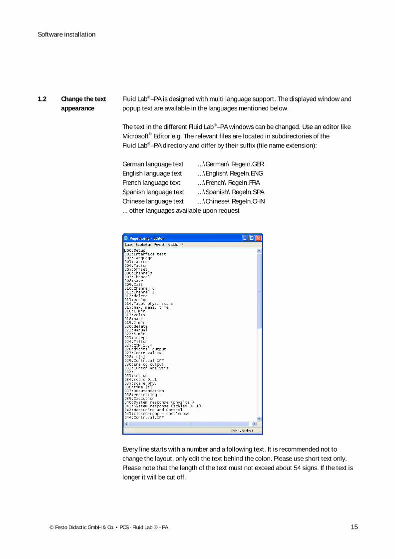
Fluid Lab®–PA is designed with multi language support. The displayed window and popup text are available in the languages mentioned below.
The text in the different Fluid Lab®–PA windows can be changed. Use an editor like Microsoft© Editor e.g. The relevant files are located in subdirectories of the Fluid Lab®–PA directory and differ by their suffix (file name extension):
German language text ...\German\ Regeln.GER English language text ...\English\ Regeln.ENG French language text ...\French\ Regeln.FRA Spanish language text ...\Spanish\ Regeln.SPA Chinese language text ...\Chinese\ Regeln.CHN ... other languages available upon request
Every line starts with a number and a following text. It is recommended not to change the layout. only edit the text behind the colon. Please use short text only. Please note that the length of the text must not exceed about 54 signs. If the text is longer it will be cut off.
1.2 Change the text appearance
Software installation
16 © Festo Didactic GmbH & Co. • PCS - Fluid Lab ® - PA
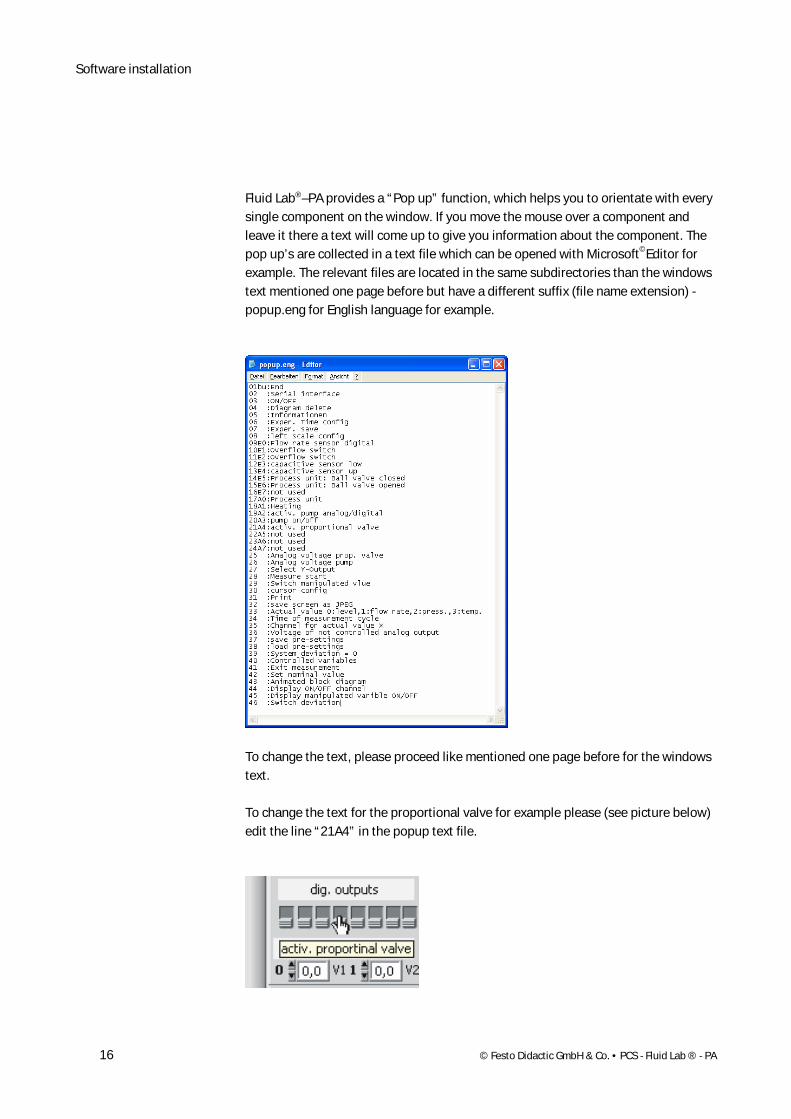
Fluid Lab®–PA provides a “Pop up” function, which helps you to orientate with every single component on the window. If you move the mouse over a component and leave it there a text will come up to give you information about the component. The pop up’s are collected in a text file which can be opened with Microsoft©Editor for example. The relevant files are located in the same subdirectories than the windows text mentioned one page before but have a different suffix (file name extension) - popup.eng for English language for example.
To change the text, please proceed like mentioned one page before for the windows text.
To change the text for the proportional valve for example please (see picture below) edit the line “21A4” in the popup text file.
© Festo Didactic GmbH & Co. • PCS - Fluid Lab ® - PA 17
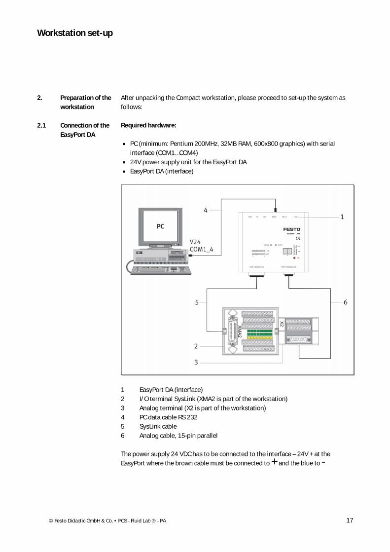
After unpacking the Compact workstation, please proceed to set-up the system as follows:
Required hardware:
• PC (minimum: Pentium 200MHz, 32MB RAM, 600x800 graphics) with serial interface (COM1…COM4) • 24V power supply unit for the EasyPort DA • EasyPort DA (interface)
1 EasyPort DA (interface) 2 I/O terminal SysLink (XMA2 is part of the workstation) 3 Analog terminal (X2 is part of the workstation) 4 PC data cable RS 232 5 SysLink cable 6 Analog cable, 15-pin parallel
The power supply 24 VDC has to be connected to the interface – 24V + at the EasyPort where the brown cable must be connected to + and the blue to -
2. Preparation of the workstation
Workstation set-up
2.1 Connection of the EasyPort DA
Workstation set-up
18 © Festo Didactic GmbH & Co. • PCS - Fluid Lab ® - PA
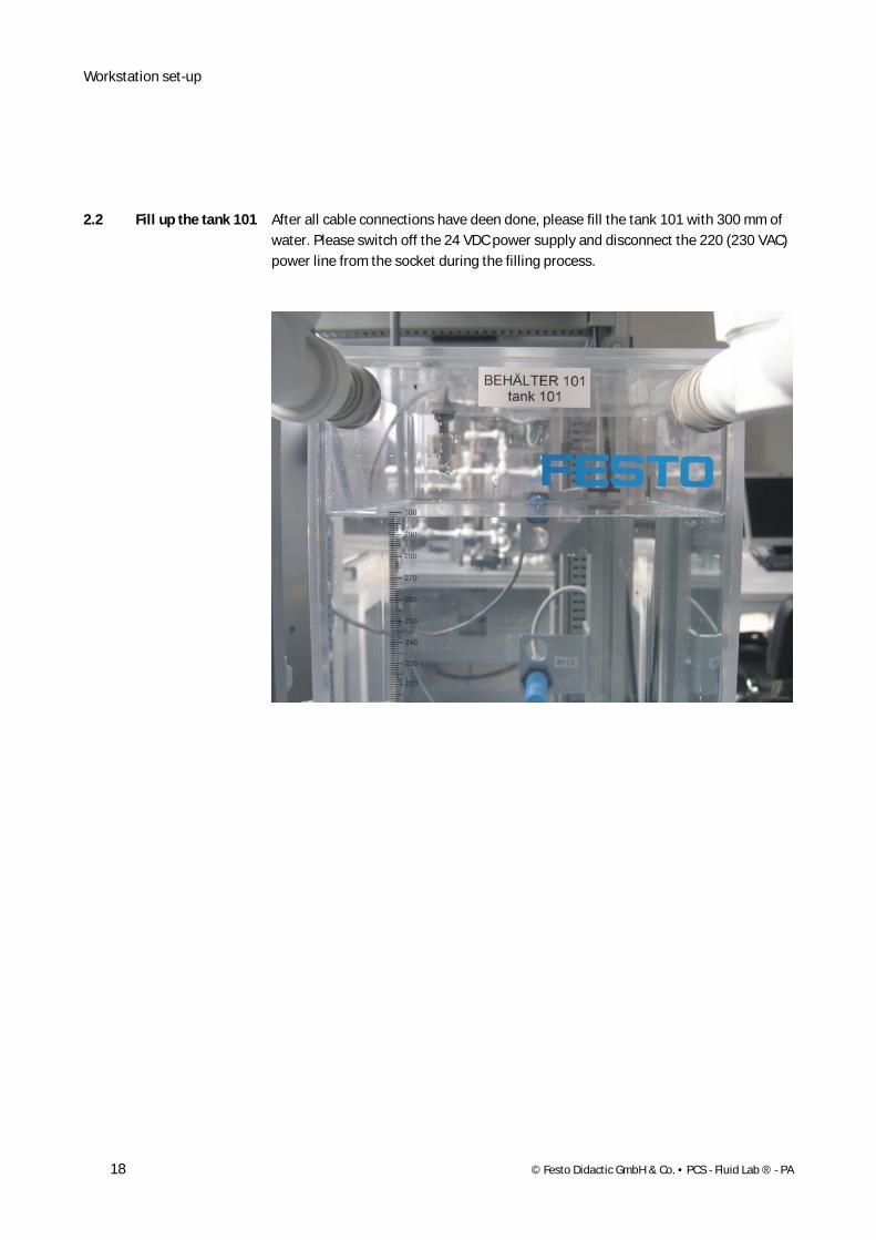
After all cable connections have deen done, please fill the tank 101 with 300 mm of water. Please switch off the 24 VDC power supply and disconnect the 220 (230 VAC) power line from the socket during the filling process.
2.2 Fill up the tank 101
Workstation set-up
© Festo Didactic GmbH & Co. • PCS - Fluid Lab ® - PA 19
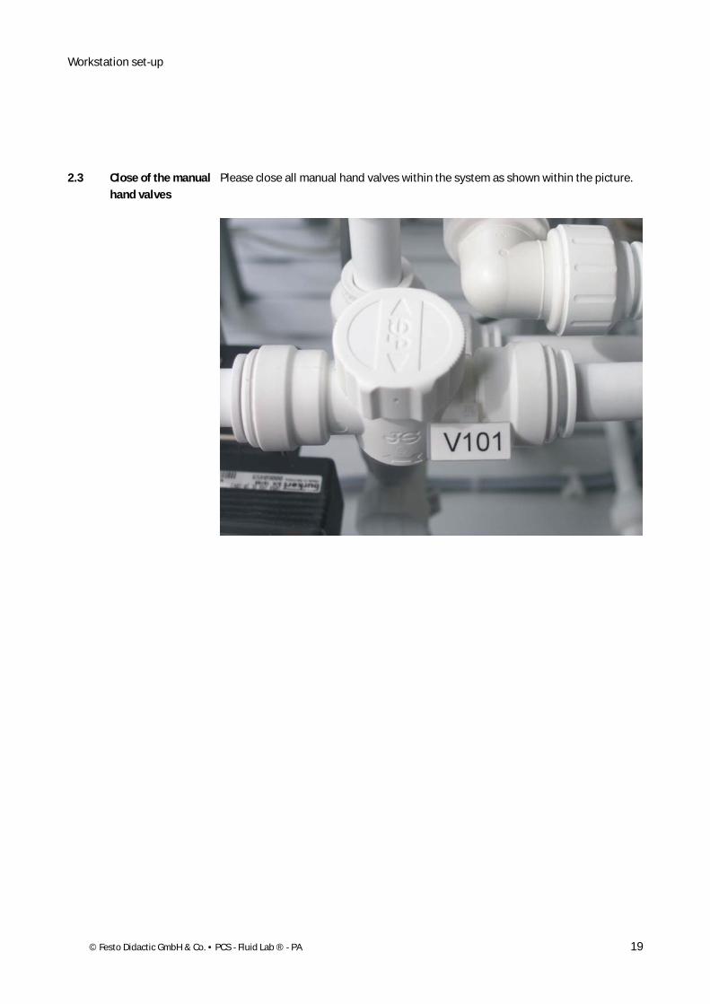
Please close all manual hand valves within the system as shown within the picture.
2.3 Close of the manual hand valves
Workstation set-up
20 © Festo Didactic GmbH & Co. • PCS - Fluid Lab ® - PA
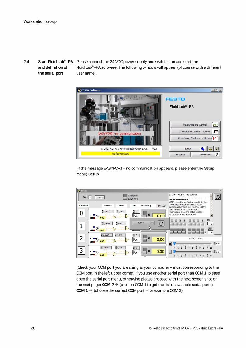
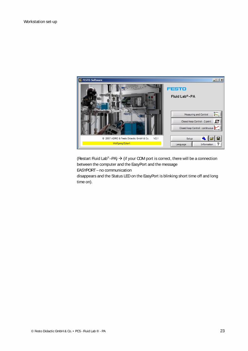
Please connect the 24 VDC power supply and switch it on and start the Fluid Lab®–PA software. The following window will appear (of course with a different user name).
(If the message EASYPORT – no communication appears, please enter the Setup menu) Setup
(Check your COM port you are using at your computer – must corresponding to the COM port in the left upper corner. If you use another serial port than COM 1, please open the serial port menu, otherwise please proceed with the next screen shot on the next page) COM ? (click on COM 1 to get the list of available serial ports) COM 1 (choose the correct COM port – for example COM 2)
2.4 Start Fluid Lab®–PA and definition of the serial port
Workstation set-up
© Festo Didactic GmbH & Co. • PCS - Fluid Lab ® - PA 21
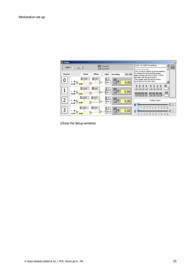
(Close the Setup window)
Workstation set-up
22 © Festo Didactic GmbH & Co. • PCS - Fluid Lab ® - PA
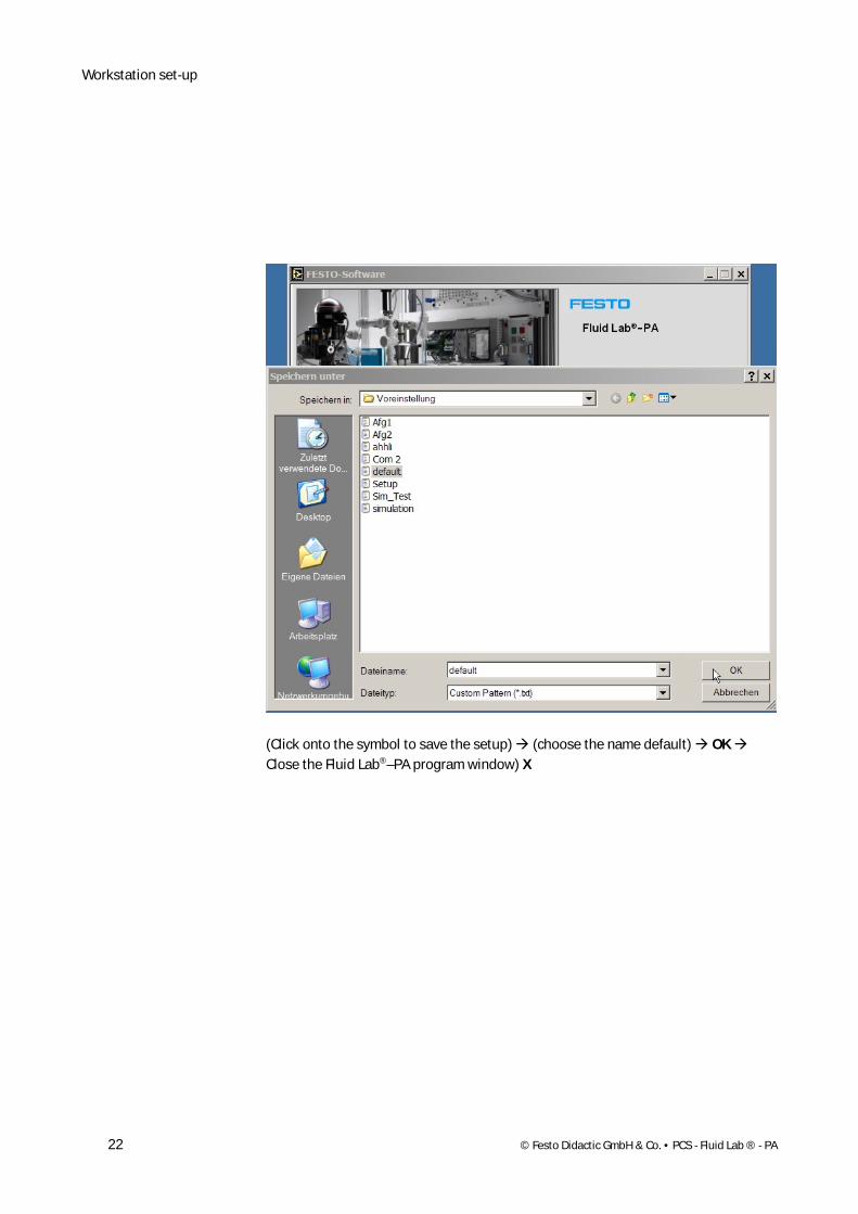
(Click onto the symbol to save the setup) (choose the name default) OK Close the Fluid Lab®–PA program window) X
Workstation set-up
© Festo Didactic GmbH & Co. • PCS - Fluid Lab ® - PA 23
(Restart Fluid Lab®–PA) (if your COM port is correct, there will be a connection between the computer and the EasyPort and the message EASYPORT – no communication disappears and the Status LED on the EasyPort is blinking short time off and long time on).

Workstation set-up
24 © Festo Didactic GmbH & Co. • PCS - Fluid Lab ® - PA
© Festo Didactic GmbH & Co. • PCS - Fluid Lab ® - PA 25
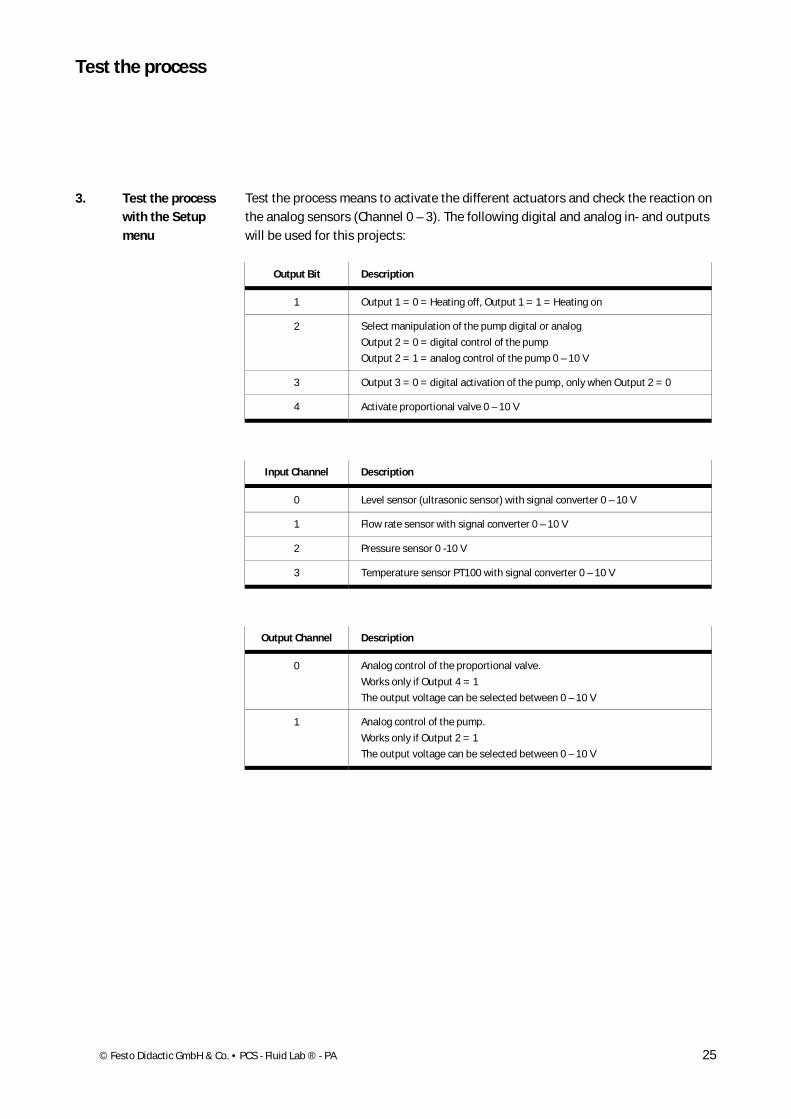
Test the process means to activate the different actuators and check the reaction on the analog sensors (Channel 0 – 3). The following digital and analog in- and outputs will be used for this projects:
Output Bit Description
1 Output 1 = 0 = Heating off, Output 1 = 1 = Heating on
2 Select manipulation of the pump digital or analog
Output 2 = 0 = digital control of the pump
Output 2 = 1 = analog control of the pump 0 – 10 V
3 Output 3 = 0 = digital activation of the pump, only when Output 2 = 0
4 Activate proportional valve 0 – 10 V
Input Channel Description
0 Level sensor (ultrasonic sensor) with signal converter 0 – 10 V
1 Flow rate sensor with signal converter 0 – 10 V
2 Pressure sensor 0 -10 V
3 Temperature sensor PT100 with signal converter 0 – 10 V
Output Channel Description
0 Analog control of the proportional valve.
Works only if Output 4 = 1
The output voltage can be selected between 0 – 10 V
1 Analog control of the pump.
Works only if Output 2 = 1
The output voltage can be selected between 0 – 10 V
3. Test the process with the Setup menu
Test the process
Test the process
26 © Festo Didactic GmbH & Co. • PCS - Fluid Lab ® - PA
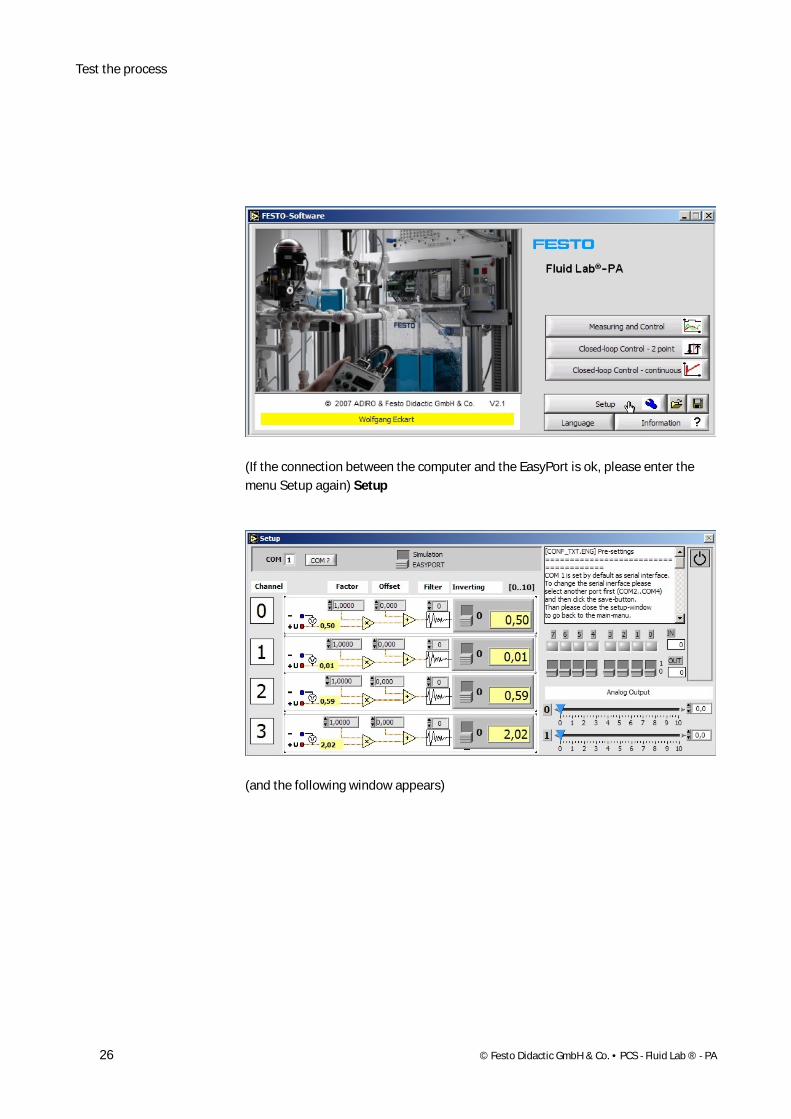
(If the connection between the computer and the EasyPort is ok, please enter the menu Setup again) Setup
(and the following window appears)
Test of the process
© Festo Didactic GmbH & Co. • PCS - Fluid Lab ® - PA 27
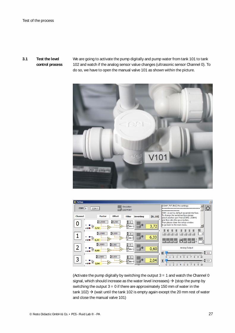
We are going to activate the pump digitally and pump water from tank 101 to tank 102 and watch if the analog sensor value changes (ultrasonic sensor Channel 0). To do so, we have to open the manual valve 101 as shown within the picture.
(Activate the pump digitally by switching the output 3 = 1 and watch the Channel 0 signal, which should increase as the water level increases) (stop the pump by switching the output 3 = 0 if there are approximately 150 mm of water in the tank 102) (wait until the tank 102 is empty again except the 20 mm rest of water and close the manual valve 101)
3.1 Test the level control process
Test the process
28 © Festo Didactic GmbH & Co. • PCS - Fluid Lab ® - PA
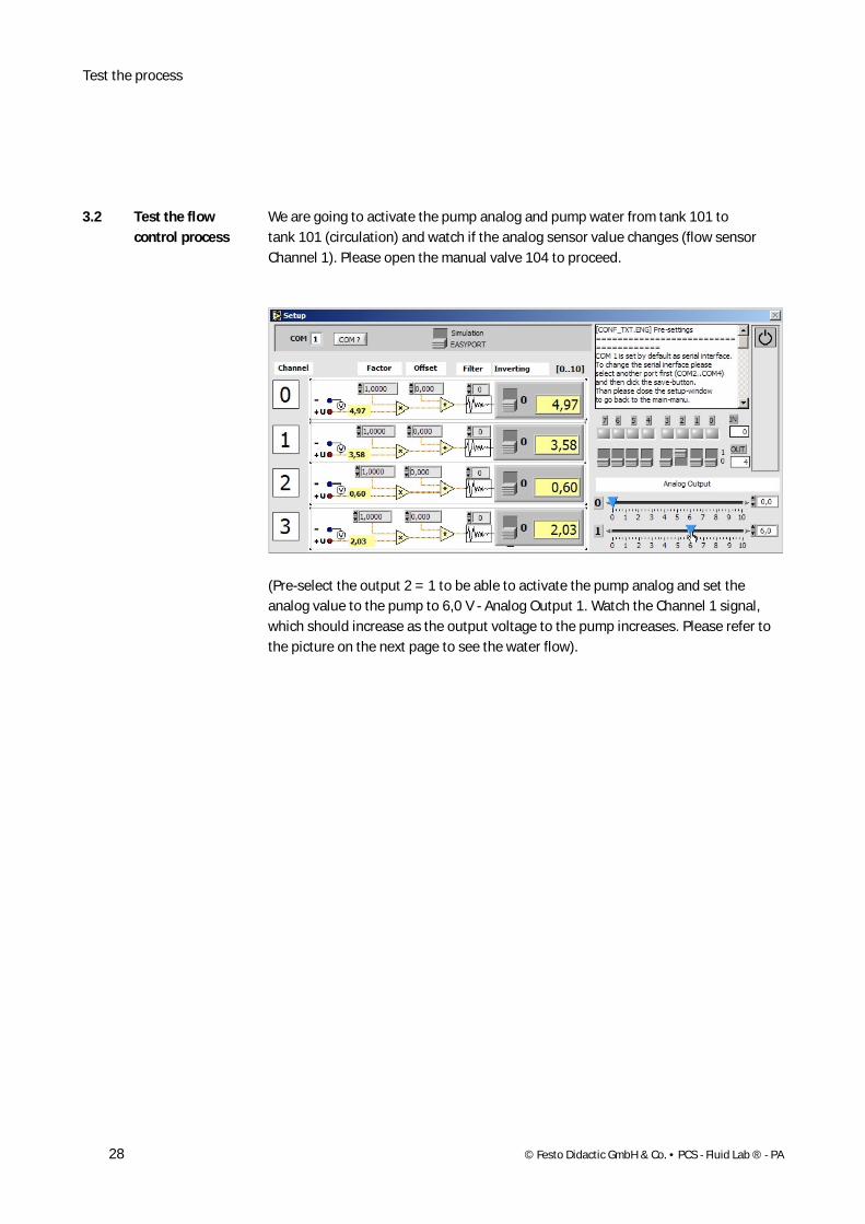
We are going to activate the pump analog and pump water from tank 101 to tank 101 (circulation) and watch if the analog sensor value changes (flow sensor Channel 1). Please open the manual valve 104 to proceed.
(Pre-select the output 2 = 1 to be able to activate the pump analog and set the analog value to the pump to 6,0 V - Analog Output 1. Watch the Channel 1 signal, which should increase as the output voltage to the pump increases. Please refer to the picture on the next page to see the water flow).
3.2 Test the flow control process
Test of the process
© Festo Didactic GmbH & Co. • PCS - Fluid Lab ® - PA 29
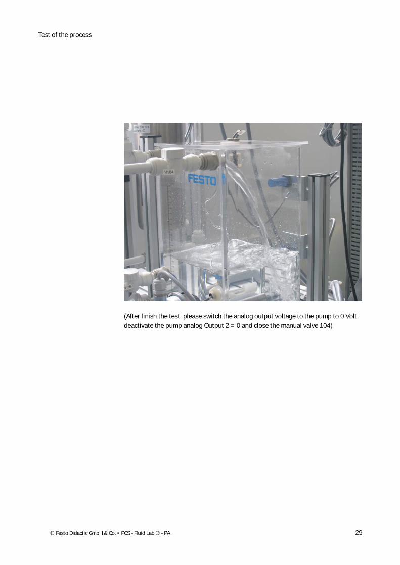
(After finish the test, please switch the analog output voltage to the pump to 0 Volt, deactivate the pump analog Output 2 = 0 and close the manual valve 104)
Test the process
30 © Festo Didactic GmbH & Co. • PCS - Fluid Lab ® - PA
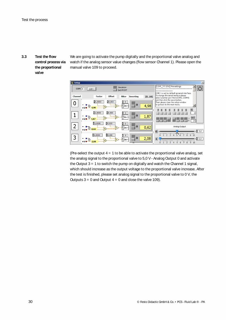
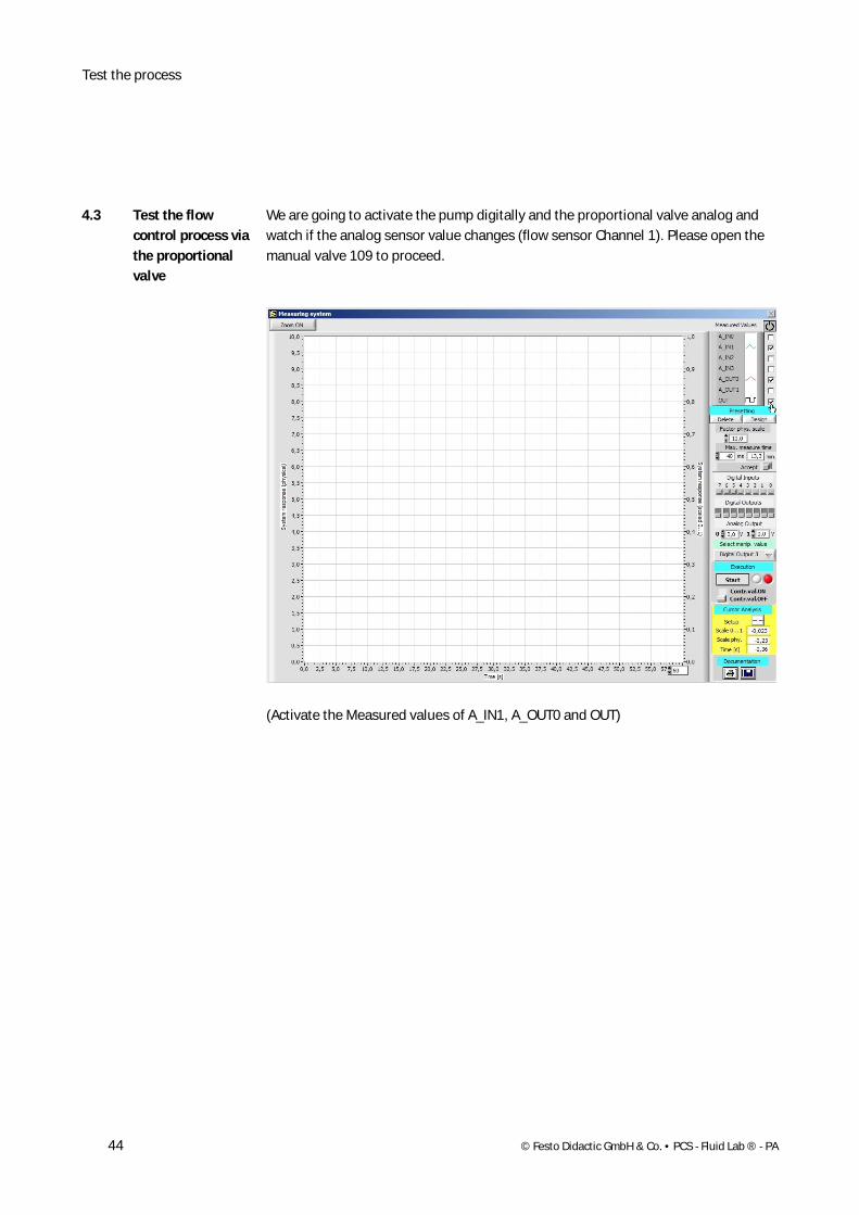
We are going to activate the pump digitally and the proportional valve analog and watch if the analog sensor value changes (flow sensor Channel 1). Please open the manual valve 109 to proceed.
(Pre-select the output 4 = 1 to be able to activate the proportional valve analog, set the analog signal to the proportional valve to 5,0 V - Analog Output 0 and activate the Output 3 = 1 to switch the pump on digitally and watch the Channel 1 signal, which should increase as the output voltage to the proportional valve increase. After the test is finished, please set analog signal to the proportional valve to 0 V, the Outputs 3 = 0 and Output 4 = 0 and close the valve 109).
3.3 Test the flow control process via the proportional valve
Test of the process
© Festo Didactic GmbH & Co. • PCS - Fluid Lab ® - PA 31
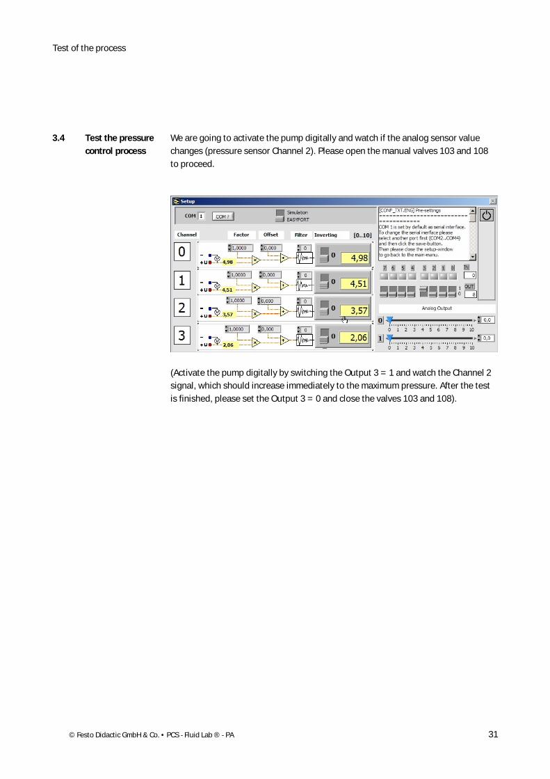
We are going to activate the pump digitally and watch if the analog sensor value changes (pressure sensor Channel 2). Please open the manual valves 103 and 108 to proceed.
(Activate the pump digitally by switching the Output 3 = 1 and watch the Channel 2 signal, which should increase immediately to the maximum pressure. After the test is finished, please set the Output 3 = 0 and close the valves 103 and 108).
3.4 Test the pressure control process
Test the process
32 © Festo Didactic GmbH & Co. • PCS - Fluid Lab ® - PA
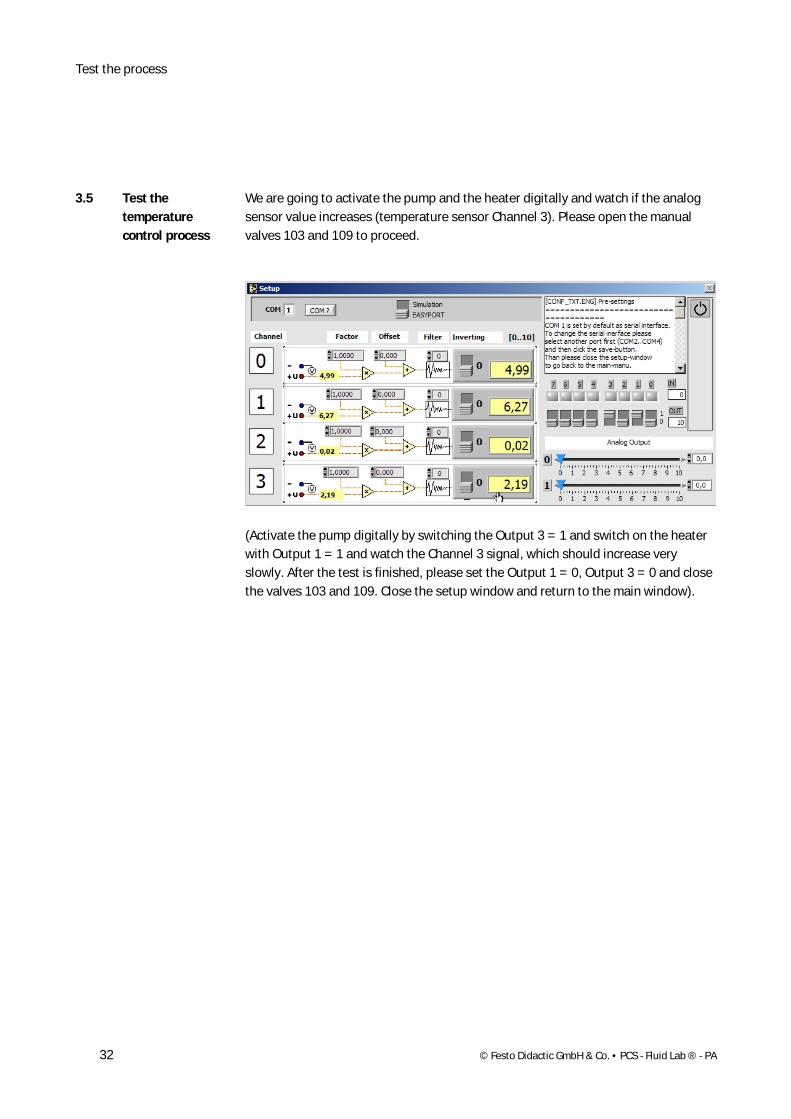
We are going to activate the pump and the heater digitally and watch if the analog sensor value increases (temperature sensor Channel 3). Please open the manual valves 103 and 109 to proceed.
(Activate the pump digitally by switching the Output 3 = 1 and switch on the heater with Output 1 = 1 and watch the Channel 3 signal, which should increase very slowly. After the test is finished, please set the Output 1 = 0, Output 3 = 0 and close the valves 103 and 109. Close the setup window and return to the main window).
3.5 Test the temperature control process
Test of the process
© Festo Didactic GmbH & Co. • PCS - Fluid Lab ® - PA 33
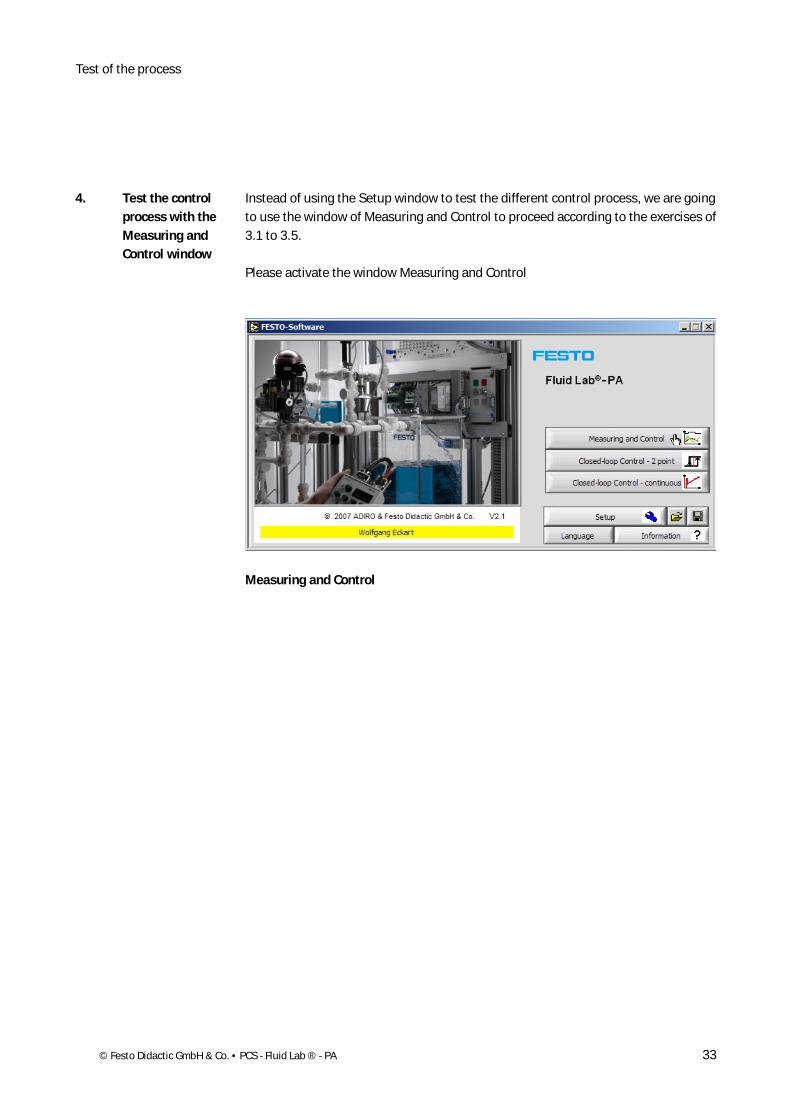
Instead of using the Setup window to test the different control process, we are going to use the window of Measuring and Control to proceed according to the exercises of 3.1 to 3.5.
Please activate the window Measuring and Control
Measuring and Control
4. Test the control process with the Measuring and Control window

Test the process
34 © Festo Didactic GmbH & Co. • PCS - Fluid Lab ® - PA
We are going to activate the pump digitally and pump water from tank 101 to tank 102 and watch if the analog sensor value changes (ultrasonic sensor Channel 0). To do so, we have to open the manual valve 101).
(Activate the Measured values of A_IN0 and OUT)
4.1 Test the level control process
Test of the process
© Festo Didactic GmbH & Co. • PCS - Fluid Lab ® - PA 35
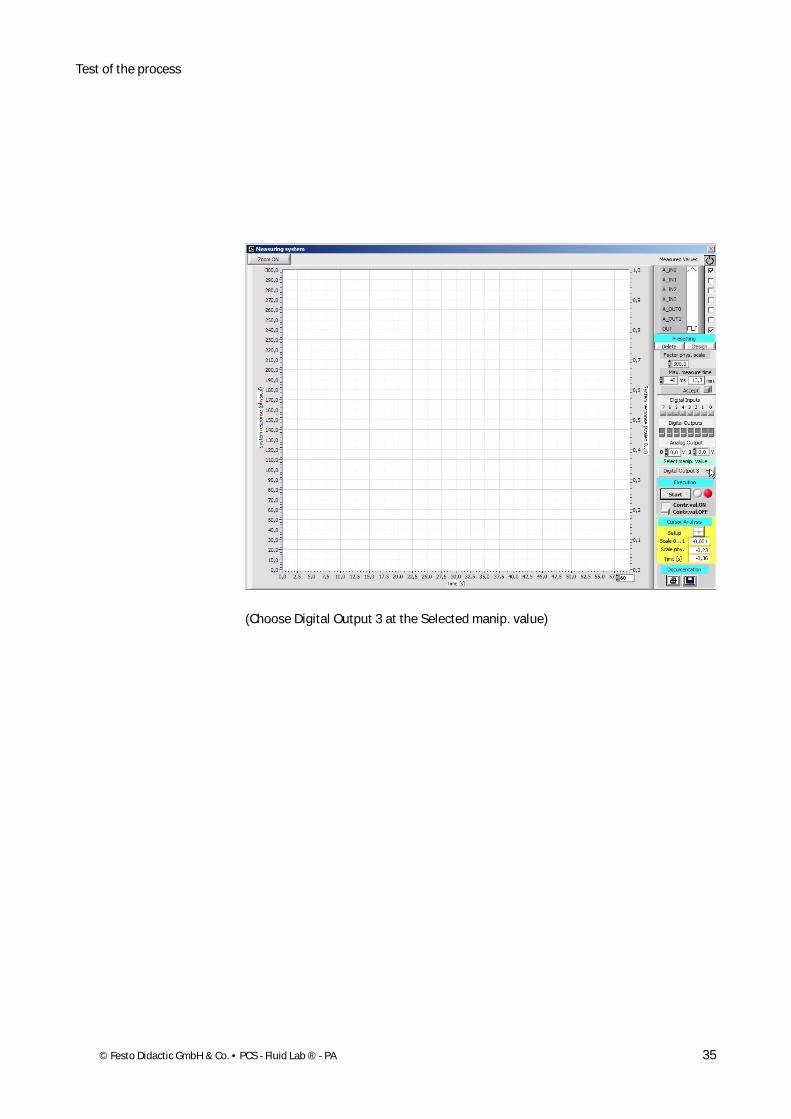
(Choose Digital Output 3 at the Selected manip. value)
Test the process
36 © Festo Didactic GmbH & Co. • PCS - Fluid Lab ® - PA
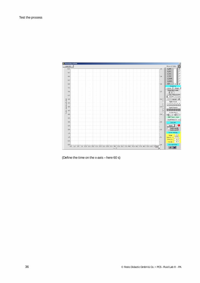
(Define the time on the x-axis – here 60 s)
Test of the process
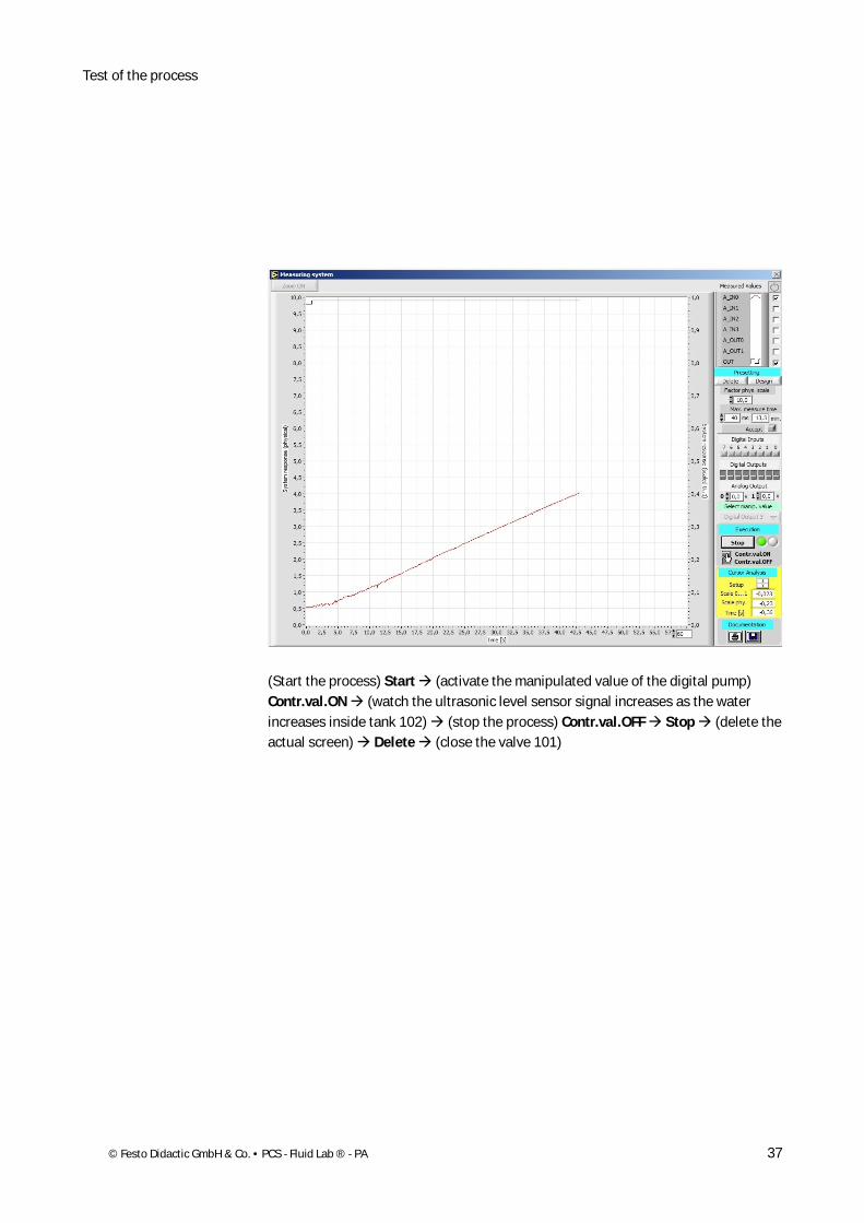
© Festo Didactic GmbH & Co. • PCS - Fluid Lab ® - PA 37
(Start the process) Start (activate the manipulated value of the digital pump) Contr.val.ON (watch the ultrasonic level sensor signal increases as the water increases inside tank 102) (stop the process) Contr.val.OFF Stop (delete the actual screen) Delete (close the valve 101)

Test the process
38 © Festo Didactic GmbH & Co. • PCS - Fluid Lab ® - PA
We are going to activate the pump analog and pump water from tank 101 to tank 101 (circulation) and watch if the analog sensor value changes (flow sensor Channel 1). Please open the manual valve 104 to proceed.
(Activate the Measured values of A_IN1 and A_OUT1)
4.2 Test the flow control process
Test of the process
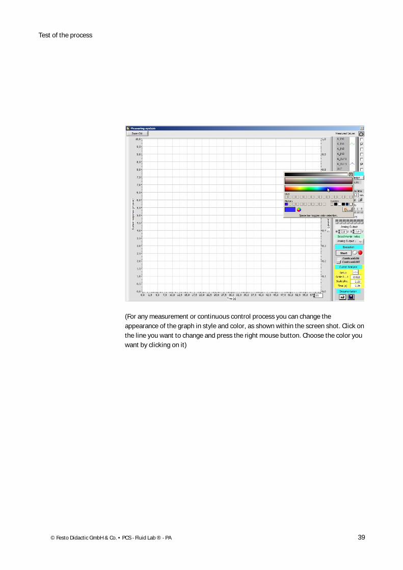
© Festo Didactic GmbH & Co. • PCS - Fluid Lab ® - PA 39
(For any measurement or continuous control process you can change the appearance of the graph in style and color, as shown within the screen shot. Click on the line you want to change and press the right mouse button. Choose the color you want by clicking on it)
Test the process
40 © Festo Didactic GmbH & Co. • PCS - Fluid Lab ® - PA
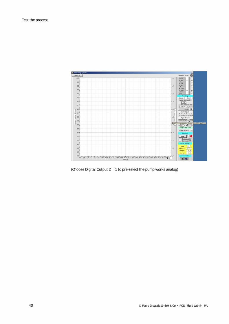
(Choose Digital Output 2 = 1 to pre-select the pump works analog)

Test of the process
© Festo Didactic GmbH & Co. • PCS - Fluid Lab ® - PA 41
(Pre-set the value to the pump to 5,0 V at the Analog Output 1)

Test the process
42 © Festo Didactic GmbH & Co. • PCS - Fluid Lab ® - PA
(Choose Analog Output 1 at the Selected manip. value)
Test of the process
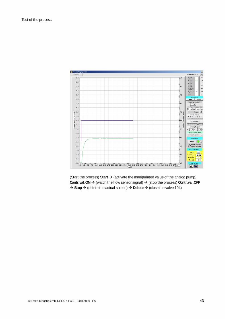
© Festo Didactic GmbH & Co. • PCS - Fluid Lab ® - PA 43
(Start the process) Start (activate the manipulated value of the analog pump) Contr.val.ON (watch the flow sensor signal) (stop the process) Contr.val.OFF
Stop (delete the actual screen) Delete (close the valve 104)
Test the process
44 © Festo Didactic GmbH & Co. • PCS - Fluid Lab ® - PA
We are going to activate the pump digitally and the proportional valve analog and watch if the analog sensor value changes (flow sensor Channel 1). Please open the manual valve 109 to proceed.
(Activate the Measured values of A_IN1, A_OUT0 and OUT)
4.3 Test the flow control process via the proportional valve
Test of the process
© Festo Didactic GmbH & Co. • PCS - Fluid Lab ® - PA 45
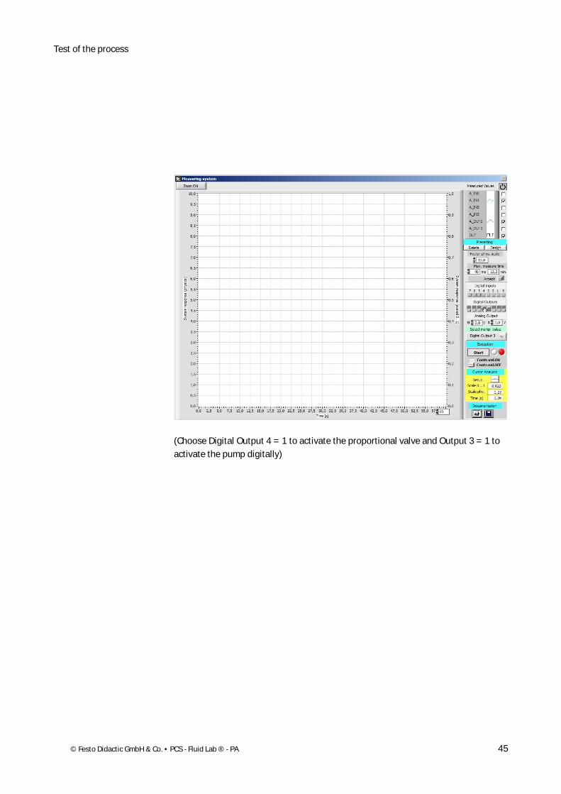
(Choose Digital Output 4 = 1 to activate the proportional valve and Output 3 = 1 to activate the pump digitally)
Test the process
46 © Festo Didactic GmbH & Co. • PCS - Fluid Lab ® - PA
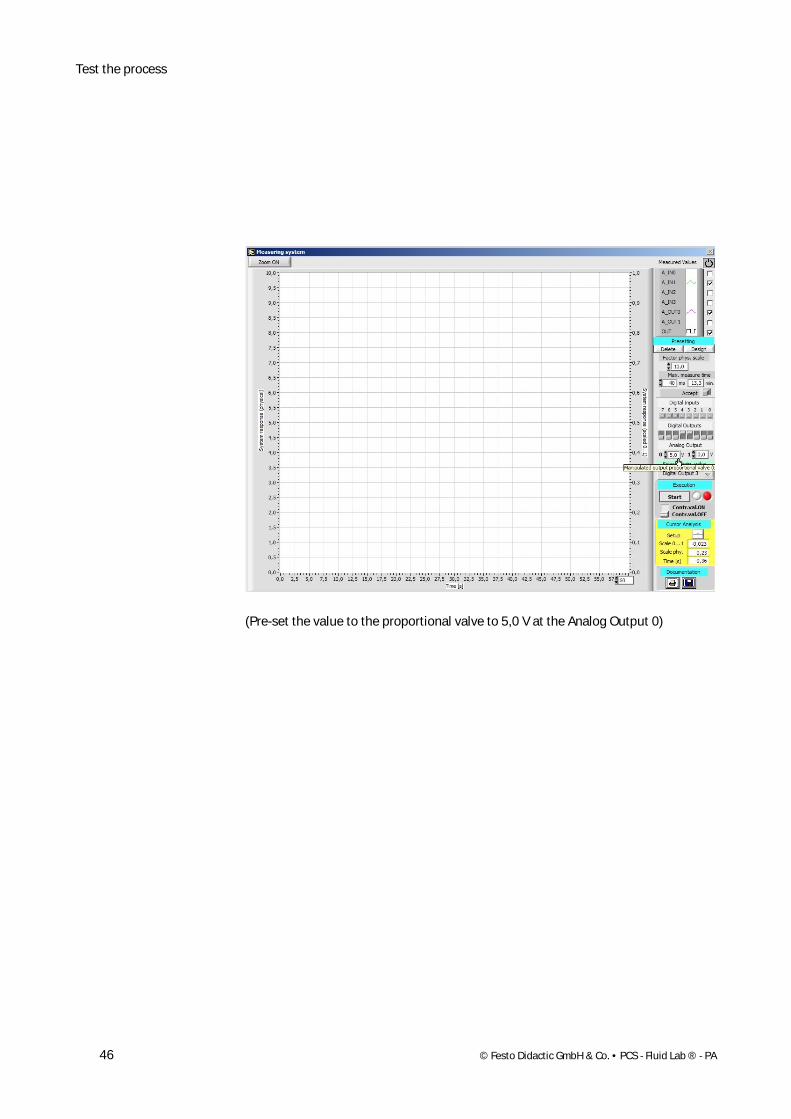
(Pre-set the value to the proportional valve to 5,0 V at the Analog Output 0)

Test of the process
© Festo Didactic GmbH & Co. • PCS - Fluid Lab ® - PA 47
(Choose Analog Output 0 at the Selected manip. value)
Test the process
48 © Festo Didactic GmbH & Co. • PCS - Fluid Lab ® - PA
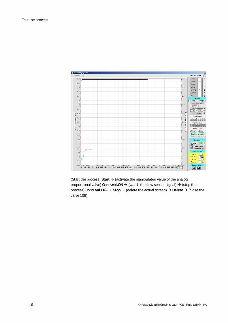
(Start the process) Start (activate the manipulated value of the analog proportional valve) Contr.val.ON (watch the flow sensor signal) (stop the process) Contr.val.OFF Stop (delete the actual screen) Delete (close the valve 109)
Test of the process
© Festo Didactic GmbH & Co. • PCS - Fluid Lab ® - PA 49
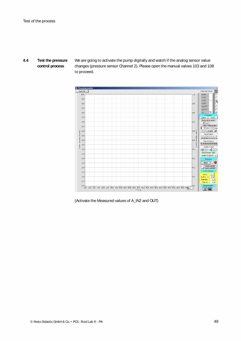
We are going to activate the pump digitally and watch if the analog sensor value changes (pressure sensor Channel 2). Please open the manual valves 103 and 108 to proceed.
(Activate the Measured values of A_IN2 and OUT)
4.4 Test the pressure control process

Test the process
50 © Festo Didactic GmbH & Co. • PCS - Fluid Lab ® - PA
(Choose Digital Output 3 at the Selected manip. value)
Test of the process
© Festo Didactic GmbH & Co. • PCS - Fluid Lab ® - PA 51
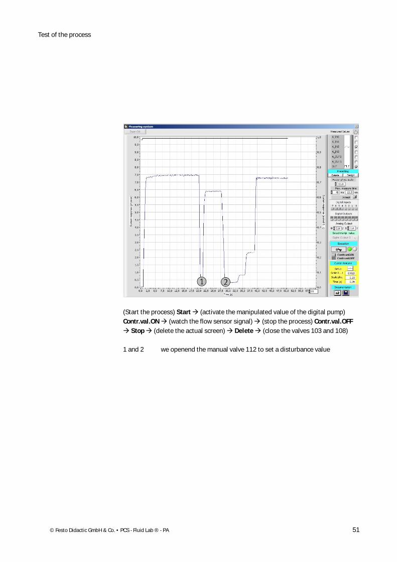
(Start the process) Start (activate the manipulated value of the digital pump) Contr.val.ON (watch the flow sensor signal) (stop the process) Contr.val.OFF
Stop (delete the actual screen) Delete (close the valves 103 and 108)
1 and 2 we openend the manual valve 112 to set a disturbance value
Test the process
52 © Festo Didactic GmbH & Co. • PCS - Fluid Lab ® - PA
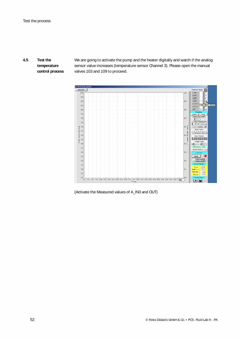
We are going to activate the pump and the heater digitally and watch if the analog sensor value increases (temperature sensor Channel 3). Please open the manual valves 103 and 109 to proceed.
(Activate the Measured values of A_IN3 and OUT)
4.5 Test the temperature control process

Test of the process
© Festo Didactic GmbH & Co. • PCS - Fluid Lab ® - PA 53
(Choose Digital Output 3 = 1 to activate the pump digitally)
Test the process
54 © Festo Didactic GmbH & Co. • PCS - Fluid Lab ® - PA
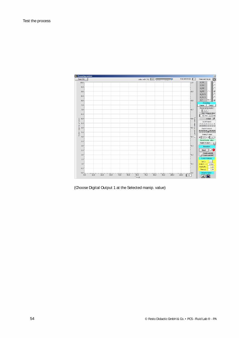
(Choose Digital Output 1 at the Selected manip. value)
Test of the process
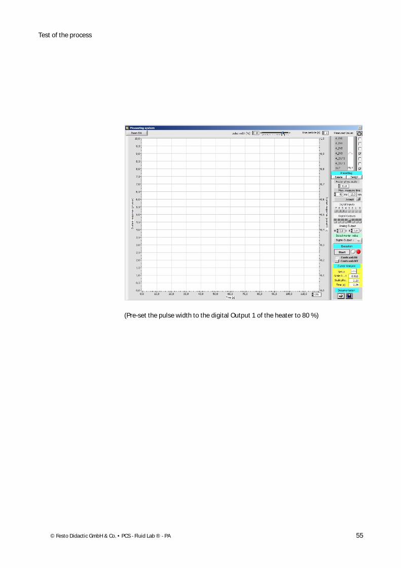
© Festo Didactic GmbH & Co. • PCS - Fluid Lab ® - PA 55
(Pre-set the pulse width to the digital Output 1 of the heater to 80 %)

Test the process
56 © Festo Didactic GmbH & Co. • PCS - Fluid Lab ® - PA
(Change the length of the time on the x-axis to 300 s)
Test of the process
© Festo Didactic GmbH & Co. • PCS - Fluid Lab ® - PA 57
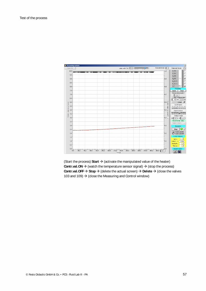
(Start the process) Start (activate the manipulated value of the heater) Contr.val.ON (watch the temperature sensor signal) (stop the process) Contr.val.OFF Stop (delete the actual screen) Delete (close the valves 103 and 109) (close the Measuring and Control window)

Test the process
58 © Festo Didactic GmbH & Co. • PCS - Fluid Lab ® - PA
© Festo Didactic GmbH & Co. • PCS - Fluid Lab ® - PA 59
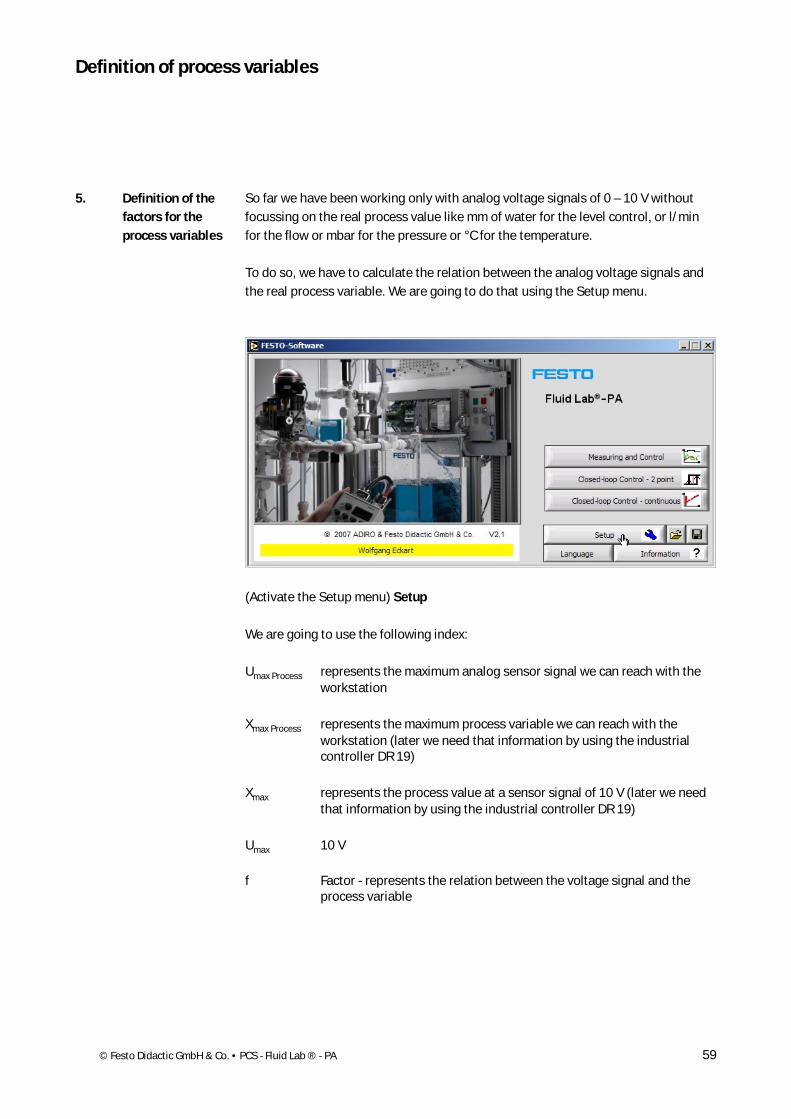
So far we have been working only with analog voltage signals of 0 – 10 V without focussing on the real process value like mm of water for the level control, or l/min for the flow or mbar for the pressure or °C for the temperature.
To do so, we have to calculate the relation between the analog voltage signals and the real process variable. We are going to do that using the Setup menu.
(Activate the Setup menu) Setup
We are going to use the following index:
Umax Process represents the maximum analog sensor signal we can reach with the workstation
Xmax Process represents the maximum process variable we can reach with the workstation (later we need that information by using the industrial controller DR 19)
Xmax represents the process value at a sensor signal of 10 V (later we need that information by using the industrial controller DR 19)
Umax 10 V
f Factor - represents the relation between the voltage signal and the process variable
5. Definition of the factors for the process variables
Definition of process variables
Definition of process variables
60 © Festo Didactic GmbH & Co. • PCS - Fluid Lab ® - PA
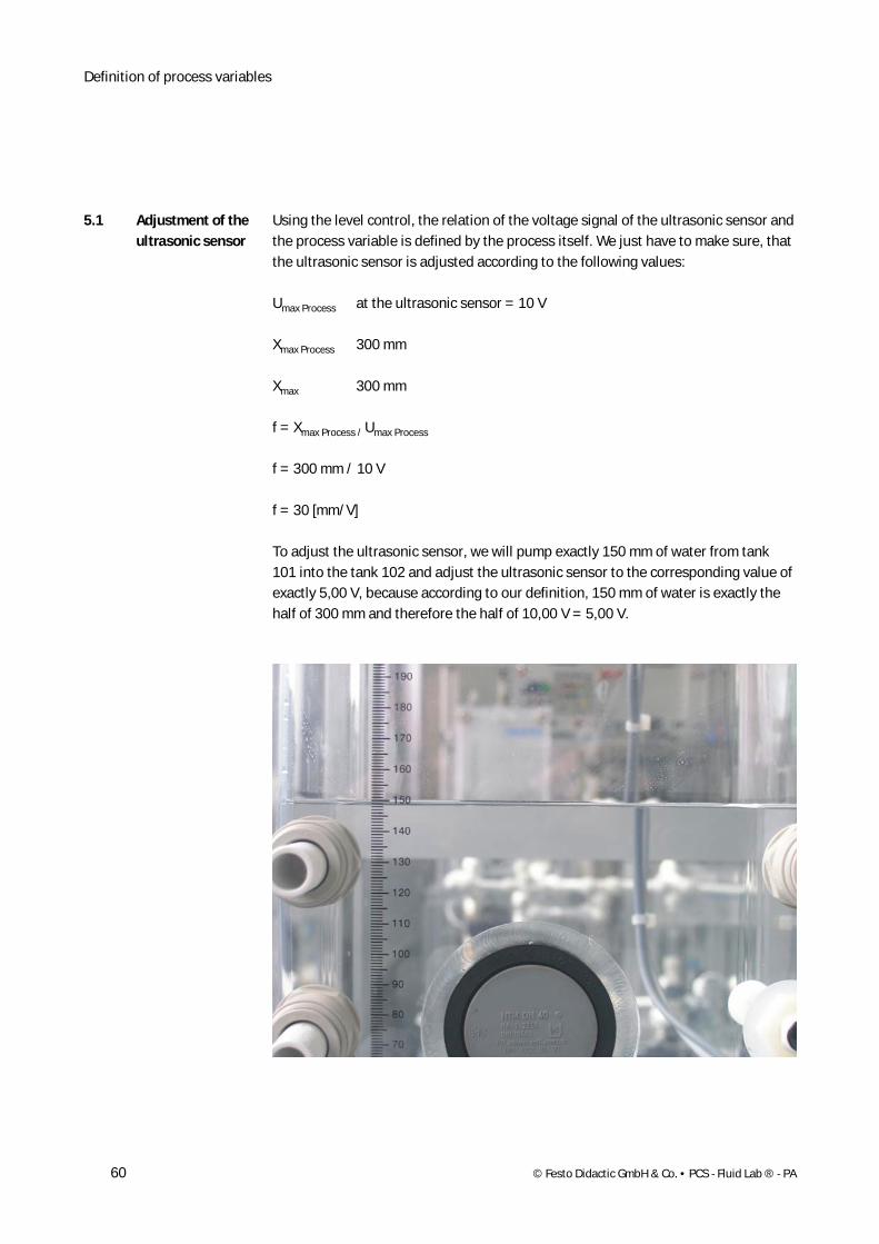
Using the level control, the relation of the voltage signal of the ultrasonic sensor and the process variable is defined by the process itself. We just have to make sure, that the ultrasonic sensor is adjusted according to the following values:
Umax Process at the ultrasonic sensor = 10 V
Xmax Process 300 mm
Xmax 300 mm
f = Xmax Process / Umax Process
f = 300 mm / 10 V
f = 30 [mm/V]
To adjust the ultrasonic sensor, we will pump exactly 150 mm of water from tank 101 into the tank 102 and adjust the ultrasonic sensor to the corresponding value of exactly 5,00 V, because according to our definition, 150 mm of water is exactly the half of 300 mm and therefore the half of 10,00 V = 5,00 V.
5.1 Adjustment of the ultrasonic sensor
Definition of process variables
© Festo Didactic GmbH & Co. • PCS - Fluid Lab ® - PA 61
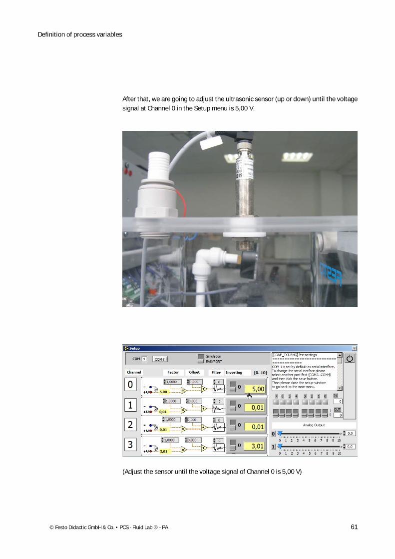
After that, we are going to adjust the ultrasonic sensor (up or down) until the voltage signal at Channel 0 in the Setup menu is 5,00 V.
(Adjust the sensor until the voltage signal of Channel 0 is 5,00 V)
Definition of process variables
62 © Festo Didactic GmbH & Co. • PCS - Fluid Lab ® - PA
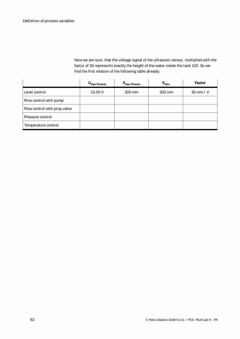
Now we are sure, that the voltage signal of the ultrasonic sensor, multiplied with the factor of 30 represents exactly the height of the water inside the tank 102. So we find the first relation of the following table already:
Umax Process Xmax Process Xmax Factor
Level control 10,00 V 300 mm 300 mm 30 mm / V
Flow control with pump
Flow control with prop.valve
Pressure control
Temperature control
Definition of process variables
© Festo Didactic GmbH & Co. • PCS - Fluid Lab ® - PA 63
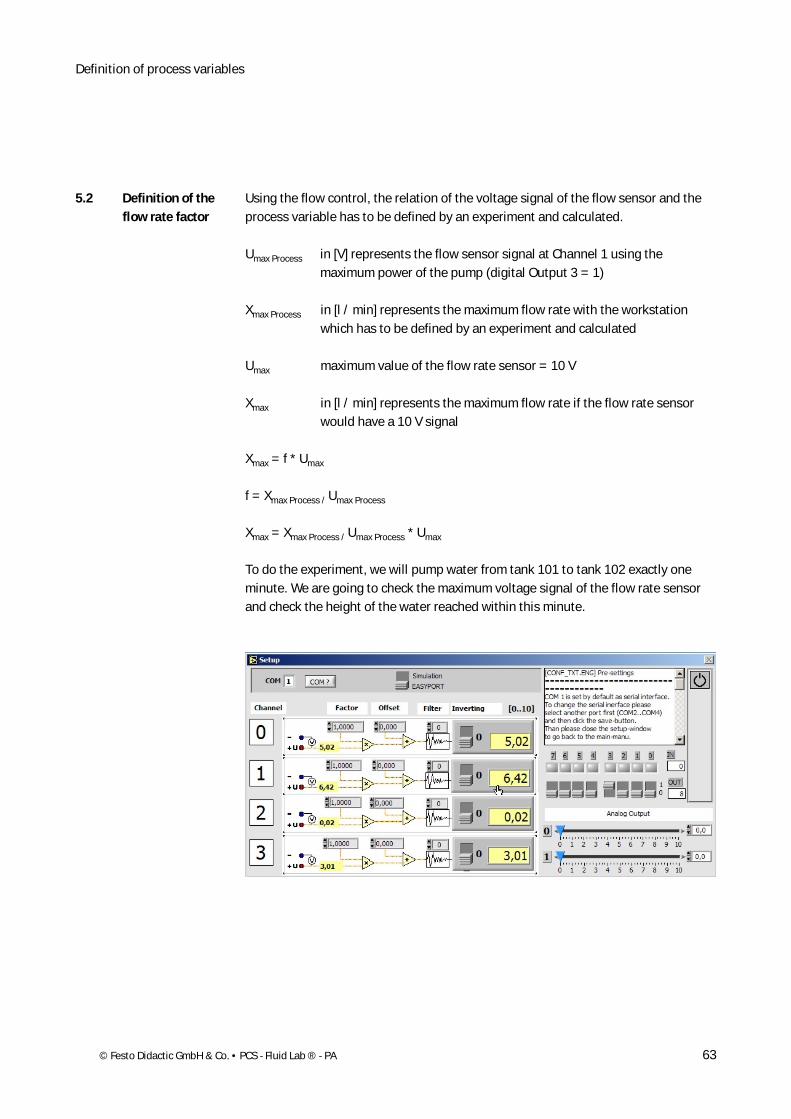
Using the flow control, the relation of the voltage signal of the flow sensor and the process variable has to be defined by an experiment and calculated.
Umax Process in [V] represents the flow sensor signal at Channel 1 using the maximum power of the pump (digital Output 3 = 1)
Xmax Process in [l / min] represents the maximum flow rate with the workstation which has to be defined by an experiment and calculated
Umax maximum value of the flow rate sensor = 10 V
Xmax in [l / min] represents the maximum flow rate if the flow rate sensor would have a 10 V signal
Xmax = f * Umax
f = Xmax Process / Umax Process
Xmax = Xmax Process / Umax Process * Umax
To do the experiment, we will pump water from tank 101 to tank 102 exactly one minute. We are going to check the maximum voltage signal of the flow rate sensor and check the height of the water reached within this minute.
5.2 Definition of the flow rate factor
Definition of process variables
64 © Festo Didactic GmbH & Co. • PCS - Fluid Lab ® - PA
The mathematical conditions are as follows:
Xmax = f * Umax
f = Xmax Process / Umax Process
Xmax = Xmax Process / Umax Process * Umax
We will calculate Xmax Process first with the following values:
l = 17,5 cm = 1,75 dm (length of the tank 102)
w = 19,0 cm = 1,9 dm (width of the tank 102)
V = l * w / [dm2]
m = 149 mm / min = 1,49 dm / min (measurement of the water height in 1 minute)
Xmax Process = V * m
Xmax Process = l * w * m
Xmax Process = 1,75 dm * 1,9 dm * 1,49 dm /min
Xmax Process = 4,95 l / min
The value for Umax Process we found by the experiment (signal at Channel 1):
Umax Process = 6,42 V
The maximum voltage is fixed to 10 V
Umax = 10 V
Now we can calculate the value of Xmax and f:
Xmax = Xmax Process / Umax Process * Umax
Xmax = 4,95 l / min / 6,42 V * 10 V
Xmax = 7,7 l / min
f = 4,95 l / min / 6,42 V
f = 0,77 l / min / V
Definition of process variables
© Festo Didactic GmbH & Co. • PCS - Fluid Lab ® - PA 65
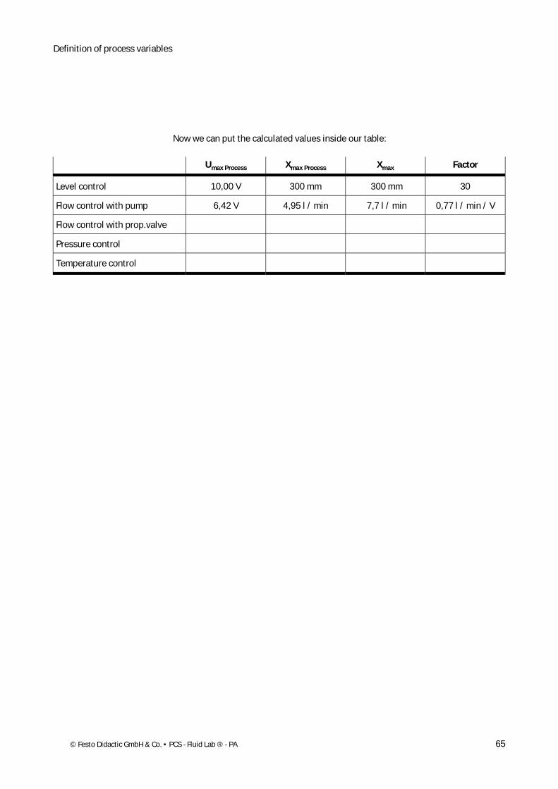
Now we can put the calculated values inside our table:
Umax Process Xmax Process Xmax Factor
Level control 10,00 V 300 mm 300 mm 30
Flow control with pump 6,42 V 4,95 l / min 7,7 l / min 0,77 l / min / V
Flow control with prop.valve
Pressure control
Temperature control
Definition of process variables
66 © Festo Didactic GmbH & Co. • PCS - Fluid Lab ® - PA
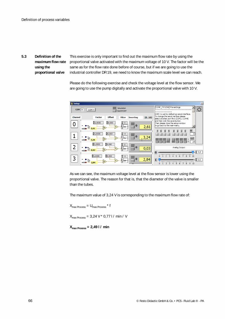
This exercise is only important to find out the maximum flow rate by using the proportional valve activated with the maximum voltage of 10 V. The factor will be the same as for the flow rate done before of course, but if we are going to use the industrial controller DR 19, we need to know the maximum scale level we can reach.
Please do the following exercise and check the voltage level at the flow sensor. We are going to use the pump digitally and activate the proportional valve with 10 V.
As we can see, the maximum voltage level at the flow sensor is lower using the proportional valve. The reason for that is, that the diameter of the valve is smaller than the tubes.
The maximum value of 3,24 V is corresponding to the maximum flow rate of:
Xmax Process = Umax Process * f
Xmax Process = 3,24 V * 0,77 l / min / V
Xmax Process = 2,49 l / min
5.3 Definition of the maximum flow rate using the proportional valve
Definition of process variables
© Festo Didactic GmbH & Co. • PCS - Fluid Lab ® - PA 67
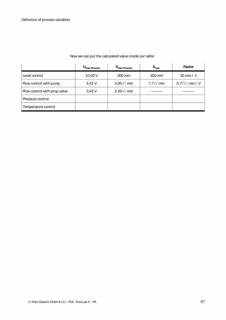
Now we can put the calculated value inside our table:
Umax Process Xmax Process Xmax Factor
Level control 10,00 V 300 mm 300 mm 30 mm / V
Flow control with pump 6,42 V 4,95 l / min 7,7 l / min 0,77 l / min / V
Flow control with prop.valve 3,42 V 2,49 l / min ---------- ----------
Pressure control
Temperature control
Definition of process variables
68 © Festo Didactic GmbH & Co. • PCS - Fluid Lab ® - PA
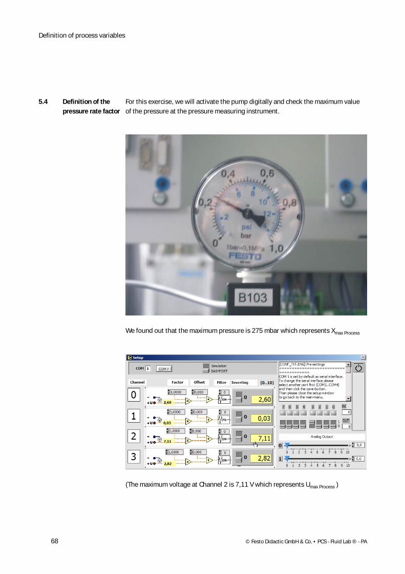
For this exercise, we will activate the pump digitally and check the maximum value of the pressure at the pressure measuring instrument.
We found out that the maximum pressure is 275 mbar which represents Xmax Process
(The maximum voltage at Channel 2 is 7,11 V which represents Umax Process )
5.4 Definition of the pressure rate factor
Definition of process variables
© Festo Didactic GmbH & Co. • PCS - Fluid Lab ® - PA 69
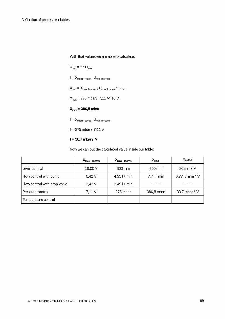
With that values we are able to calculate:
Xmax = f * Umax
f = Xmax Process / Umax Process
Xmax = Xmax Process / Umax Process * Umax
Xmax = 275 mbar / 7,11 V* 10 V
Xmax = 386,8 mbar
f = Xmax Process / Umax Process
f = 275 mbar / 7,11 V
f = 38,7 mbar / V
Now we can put the calculated value inside our table:
Umax Process Xmax Process Xmax Factor
Level control 10,00 V 300 mm 300 mm 30 mm / V
Flow control with pump 6,42 V 4,95 l / min 7,7 l / min 0,77 l / min / V
Flow control with prop.valve 3,42 V 2,49 l / min ---------- ----------
Pressure control 7,11 V 275 mbar 386,8 mbar 38,7 mbar / V
Temperature control
Definition of process variables
70 © Festo Didactic GmbH & Co. • PCS - Fluid Lab ® - PA
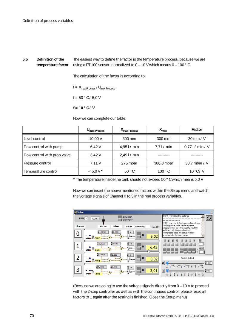
The easiest way to define the factor is the temperature process, because we are using a PT 100 sensor, normalized to 0 – 10 V which means 0 – 100 ° C.
The calculation of the factor is according to:
f = Xmax Process / Umax Process
f = 50 ° C / 5,0 V
f = 10 ° C / V
Now we can complete our table:
Umax Process Xmax Process Xmax Factor
Level control 10,00 V 300 mm 300 mm 30 mm / V
Flow control with pump 6,42 V 4,95 l / min 7,7 l / min 0,77 l / min / V
Flow control with prop.valve 3,42 V 2,49 l / min ---------- ----------
Pressure control 7,11 V 275 mbar 386,8 mbar 38,7 mbar / V
Temperature control < 5,0 V * 50 ° C 100 ° C 10 °C / V
* The temperature inside the tank should not exceed 50 ° C which means 5,0 V
Now we can insert the above mentioned factors within the Setup menu and watch the voltage signals of Channel 0 to 3 in the real process variables.
(Because we are going to use the voltage signals directly from 0 – 10 V to proceed with the 2-step controller as well as with the continuous control, please reset all factors to 1 again after the testing is finished. Close the Setup menu)
5.5 Definition of the temperature factor
© Festo Didactic GmbH & Co. • PCS - Fluid Lab ® - PA 71
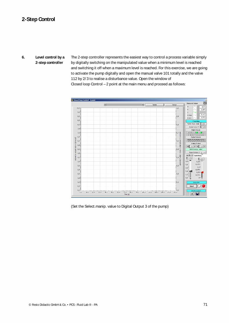
The 2-step controller represents the easiest way to control a process variable simply by digitally switching on the manipulated value when a minimum level is reached and switching it off when a maximum level is reached. For this exercise, we are going to activate the pump digitally and open the manual valve 101 totally and the valve 112 by 2/3 to realise a disturbance value. Open the window of Closed loop Control – 2 point at the main menu and proceed as follows:
(Set the Select.manip. value to Digital Output 3 of the pump)
6. Level control by a 2-step controller
2-Step Control
2-Step Control
72 © Festo Didactic GmbH & Co. • PCS - Fluid Lab ® - PA
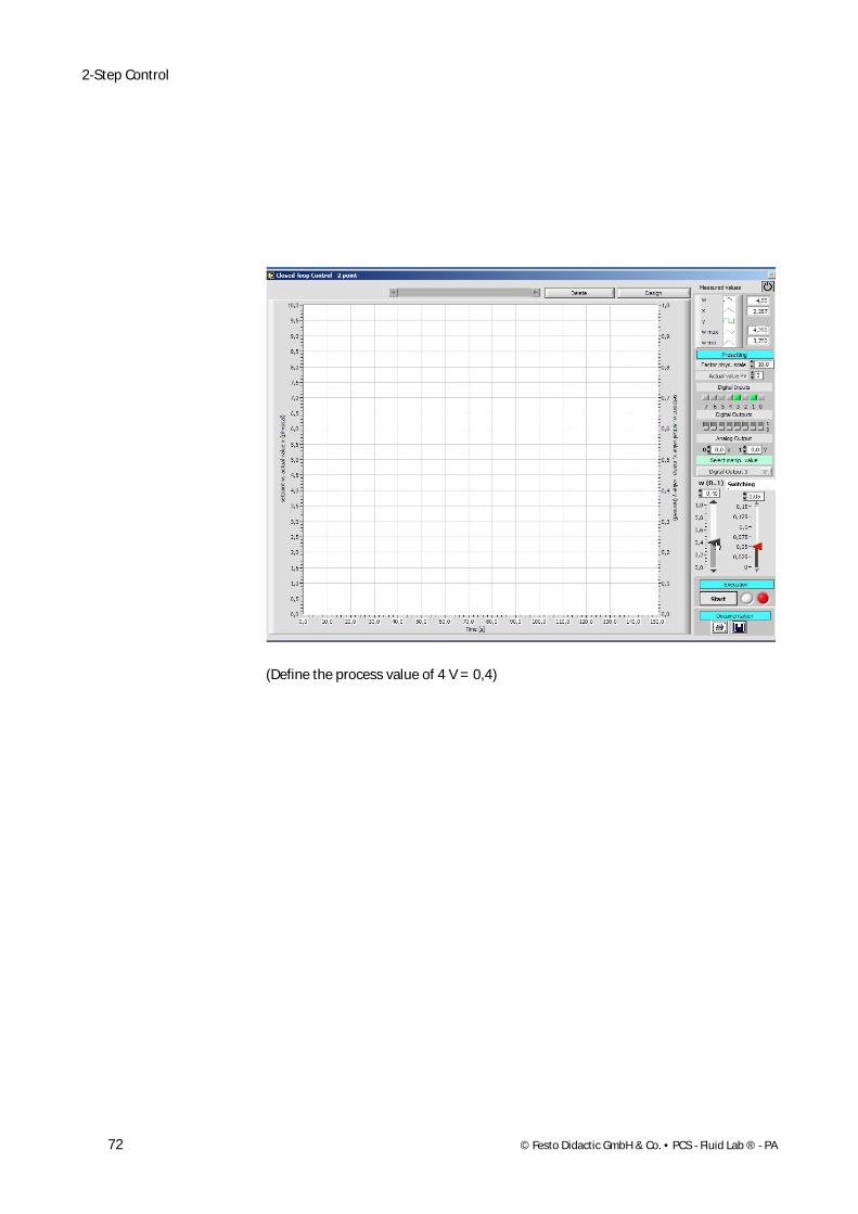
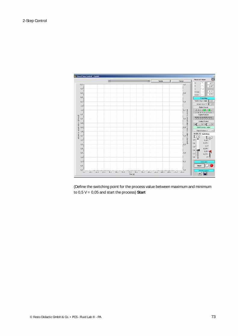
(Define the process value of 4 V = 0,4)
2-Step Control
© Festo Didactic GmbH & Co. • PCS - Fluid Lab ® - PA 73
(Define the switching point for the process value between maximum and minimum to 0,5 V = 0,05 and start the process) Start
2-Step Control
74 © Festo Didactic GmbH & Co. • PCS - Fluid Lab ® - PA
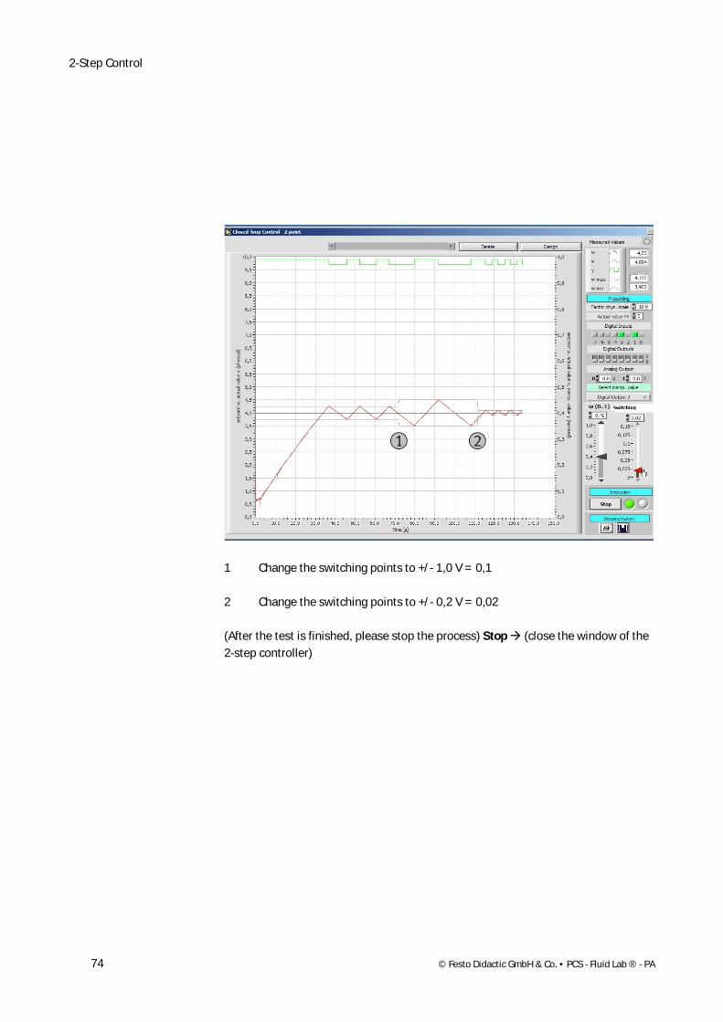
1 Change the switching points to +/- 1,0 V = 0,1
2 Change the switching points to +/- 0,2 V = 0,02
(After the test is finished, please stop the process) Stop (close the window of the 2-step controller)
Continuous control
© Festo Didactic GmbH & Co. • PCS - Fluid Lab ® - PA 75
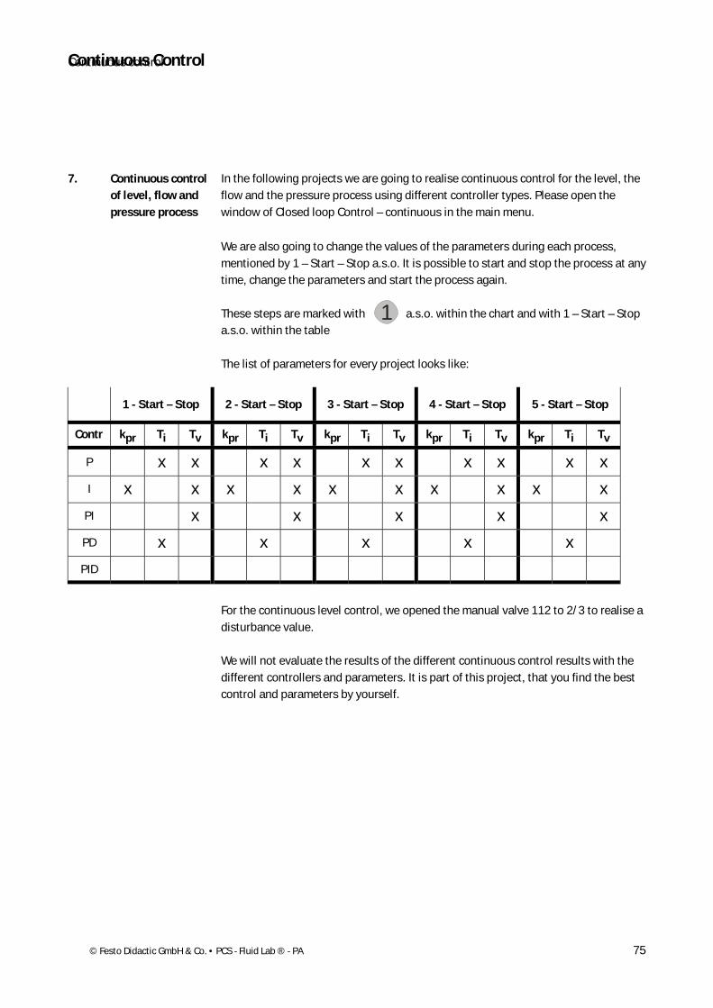
In the following projects we are going to reaIise continuous control for the level, the flow and the pressure process using different controller types. Please open the window of Closed loop Control – continuous in the main menu.
We are also going to change the values of the parameters during each process, mentioned by 1 – Start – Stop a.s.o. It is possible to start and stop the process at any time, change the parameters and start the process again. These steps are marked with a.s.o. within the chart and with 1 – Start – Stop a.s.o. within the table
The list of parameters for every project looks like:
1 - Start – Stop 2 - Start – Stop 3 - Start – Stop 4 - Start – Stop 5 - Start – Stop
Contr kpr Ti Tv kpr Ti Tv kpr Ti Tv kpr Ti Tv kpr Ti Tv
P x x x x x x x x x x
I x x x x x x x x x x
PI x x x x x
PD x x x x x
PID
For the continuous level control, we opened the manual valve 112 to 2/3 to realise a disturbance value.
We will not evaluate the results of the different continuous control results with the different controllers and parameters. It is part of this project, that you find the best control and parameters by yourself.
7. Continuous control of level, flow and pressure process
Continuous Control
1
Continuous Control
76 © Festo Didactic GmbH & Co. • PCS - Fluid Lab ® - PA
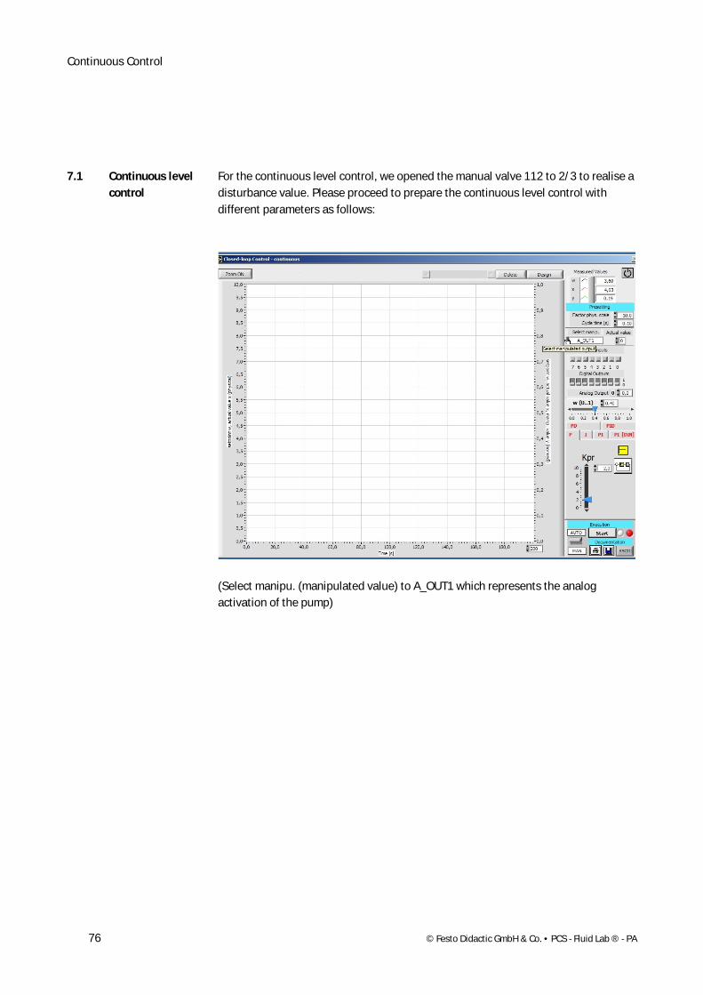
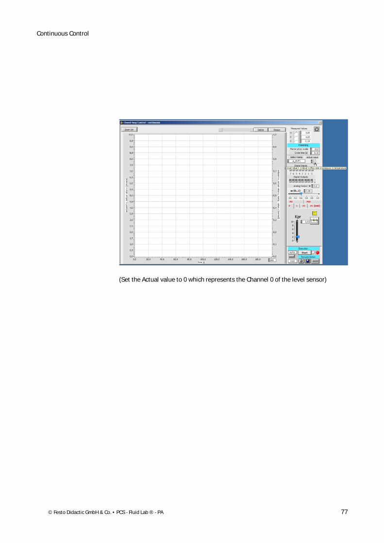
For the continuous level control, we opened the manual valve 112 to 2/3 to realise a disturbance value. Please proceed to prepare the continuous level control with different parameters as follows:
(Select manipu. (manipulated value) to A_OUT1 which represents the analog activation of the pump)
7.1 Continuous level control
Continuous Control
© Festo Didactic GmbH & Co. • PCS - Fluid Lab ® - PA 77
(Set the Actual value to 0 which represents the Channel 0 of the level sensor)
Continuous Control
78 © Festo Didactic GmbH & Co. • PCS - Fluid Lab ® - PA
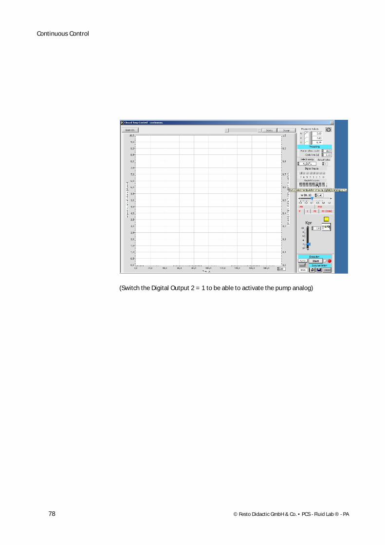
(Switch the Digital Output 2 = 1 to be able to activate the pump analog)
Continuous Control
© Festo Didactic GmbH & Co. • PCS - Fluid Lab ® - PA 79
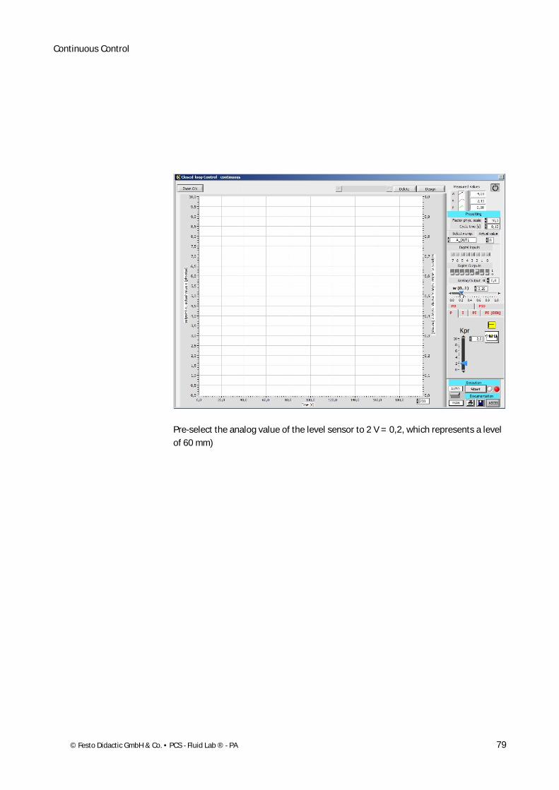
Pre-select the analog value of the level sensor to 2 V = 0,2, which represents a level of 60 mm)

Continuous Control
80 © Festo Didactic GmbH & Co. • PCS - Fluid Lab ® - PA
(Choose the P-controller)

Continuous Control
© Festo Didactic GmbH & Co. • PCS - Fluid Lab ® - PA 81
(Define the first kpr parameter – here to 2,0)
Continuous Control
82 © Festo Didactic GmbH & Co. • PCS - Fluid Lab ® - PA
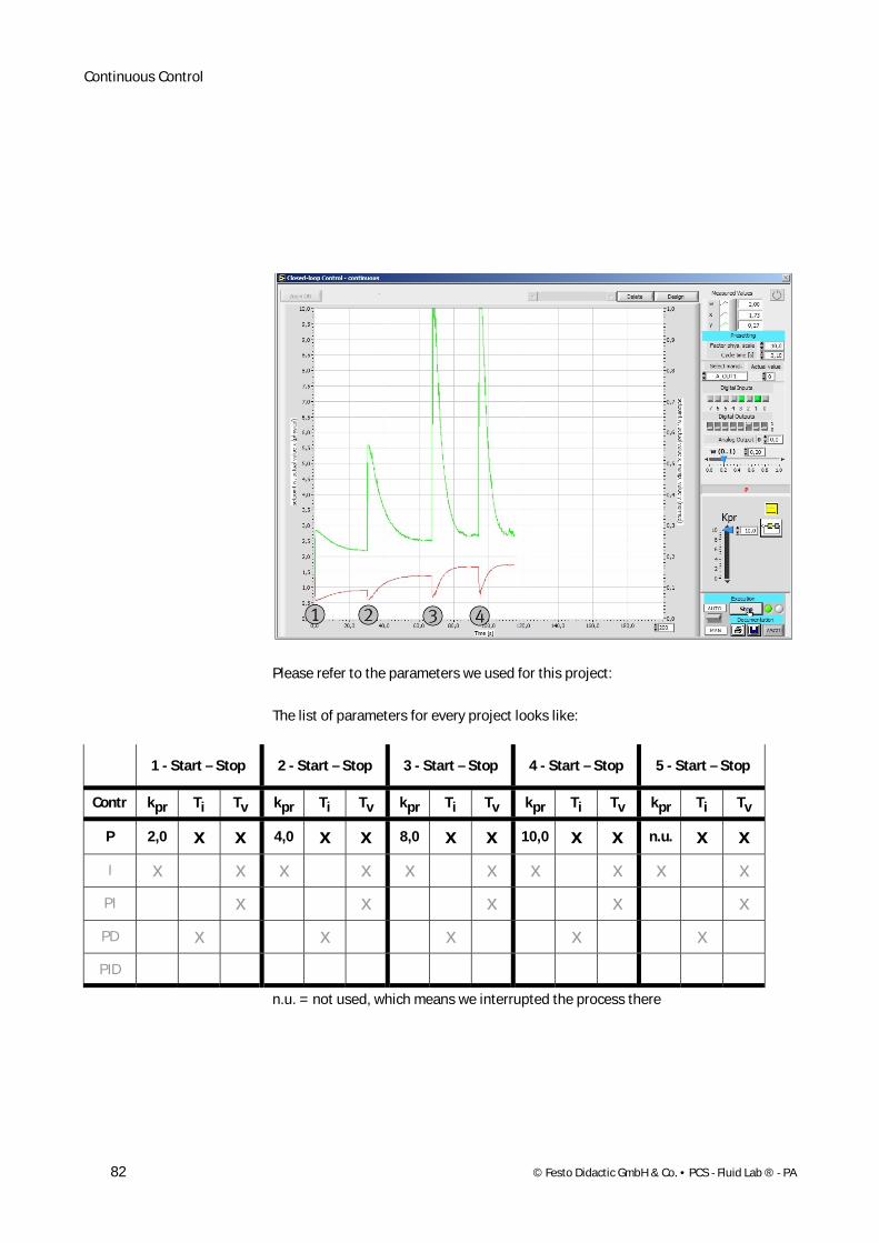
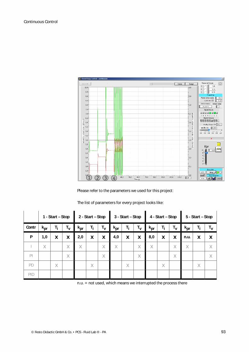
Please refer to the parameters we used for this project:
The list of parameters for every project looks like:
1 - Start – Stop 2 - Start – Stop 3 - Start – Stop 4 - Start – Stop 5 - Start – Stop
Contr kpr Ti Tv kpr Ti Tv kpr Ti Tv kpr Ti Tv kpr Ti Tv
P 2,0 x x 4,0 x x 8,0 x x 10,0 x x n.u. x x
I x x x x x x x x x x
PI x x x x x
PD x x x x x
PID
n.u. = not used, which means we interrupted the process there
Continuous Control
© Festo Didactic GmbH & Co. • PCS - Fluid Lab ® - PA 83
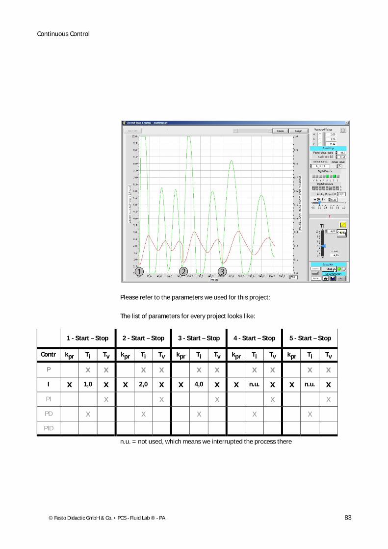
Please refer to the parameters we used for this project:
The list of parameters for every project looks like:
1 - Start – Stop 2 - Start – Stop 3 - Start – Stop 4 - Start – Stop 5 - Start – Stop
Contr kpr Ti Tv kpr Ti Tv kpr Ti Tv kpr Ti Tv kpr Ti Tv
P x x x x x x x x x x
I x 1,0 x x 2,0 x x 4,0 x x n.u. x x n.u. x
PI x x x x x
PD x x x x x
PID
n.u. = not used, which means we interrupted the process there
Continuous Control
84 © Festo Didactic GmbH & Co. • PCS - Fluid Lab ® - PA
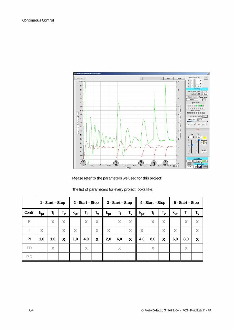
Please refer to the parameters we used for this project:
The list of parameters for every project looks like:
1 - Start – Stop 2 - Start – Stop 3 - Start – Stop 4 - Start – Stop 5 - Start – Stop
Contr kpr Ti Tv kpr Ti Tv kpr Ti Tv kpr Ti Tv kpr Ti Tv
P x x x x x x x x x x
I x x x x x x x x x x
PI 1,0 1,0 x 1,0 4,0 x 2,0 6,0 x 4,0 8,0 x 6,0 8,0 x
PD x x x x x
PID
Continuous Control
© Festo Didactic GmbH & Co. • PCS - Fluid Lab ® - PA 85
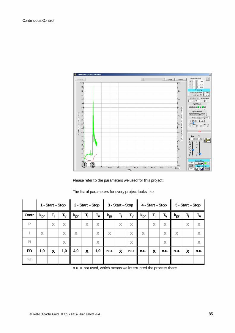
Please refer to the parameters we used for this project:
The list of parameters for every project looks like:
1 - Start – Stop 2 - Start – Stop 3 - Start – Stop 4 - Start – Stop 5 - Start – Stop
Contr kpr Ti Tv kpr Ti Tv kpr Ti Tv kpr Ti Tv kpr Ti Tv
P x x x x x x x x x x
I x x x x x x x x x x
PI x x x x x
PD 1,0 x 1,0 4,0 x 1,0 n.u. x n.u. n.u. x n.u. n.u. x n.u.
PID
n.u. = not used, which means we interrupted the process there
Continuous Control
86 © Festo Didactic GmbH & Co. • PCS - Fluid Lab ® - PA
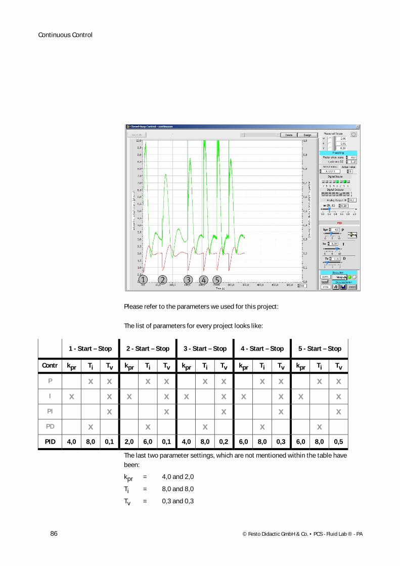
Please refer to the parameters we used for this project:
The list of parameters for every project looks like:
1 - Start – Stop 2 - Start – Stop 3 - Start – Stop 4 - Start – Stop 5 - Start – Stop
Contr kpr Ti Tv kpr Ti Tv kpr Ti Tv kpr Ti Tv kpr Ti Tv
P x x x x x x x x x x
I x x x x x x x x x x
PI x x x x x
PD x x x x x
PID 4,0 8,0 0,1 2,0 6,0 0,1 4,0 8,0 0,2 6,0 8,0 0,3 6,0 8,0 0,5
The last two parameter settings, which are not mentioned within the table have been:
kpr = 4,0 and 2,0
Ti = 8,0 and 8,0
Tv = 0,3 and 0,3
Continuous Control
© Festo Didactic GmbH & Co. • PCS - Fluid Lab ® - PA 87
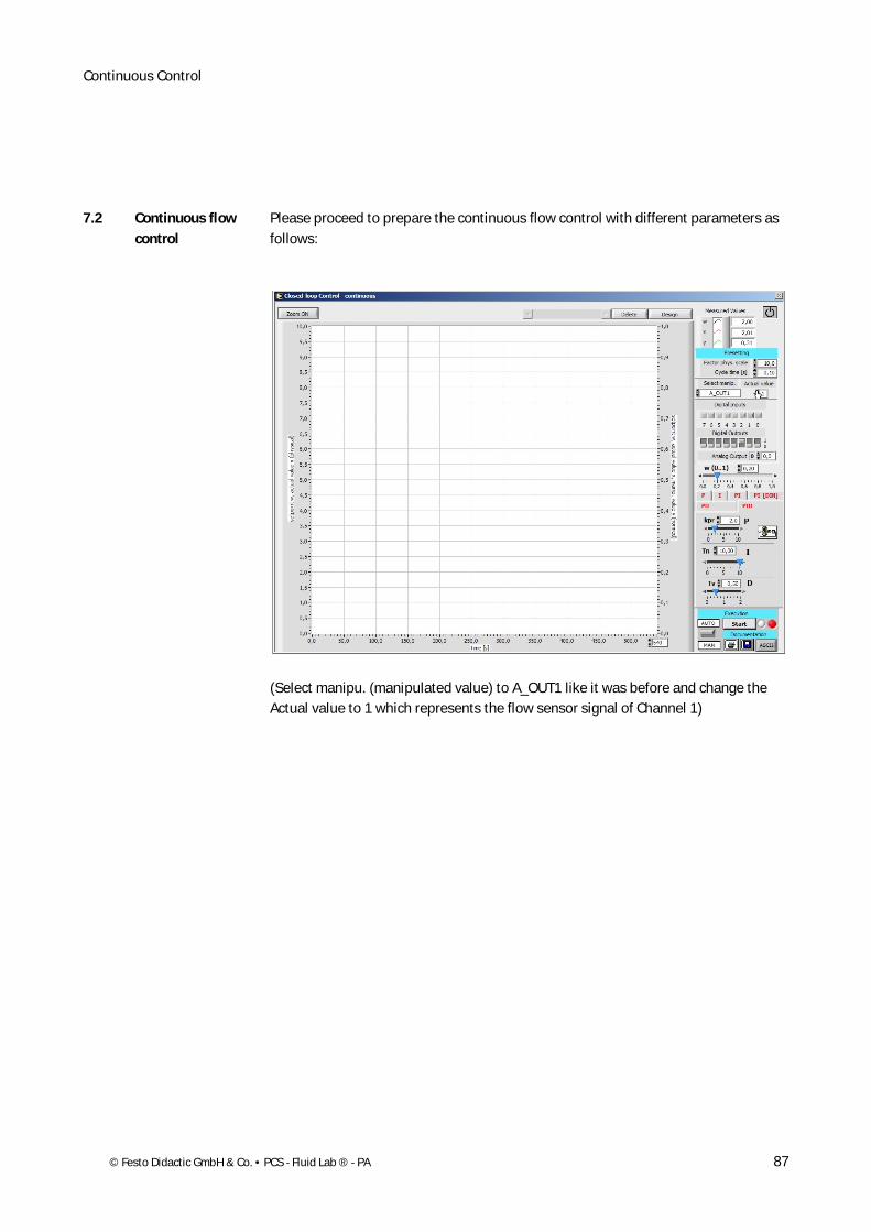
Please proceed to prepare the continuous flow control with different parameters as follows:
(Select manipu. (manipulated value) to A_OUT1 like it was before and change the Actual value to 1 which represents the flow sensor signal of Channel 1)
7.2 Continuous flow control
Continuous Control
88 © Festo Didactic GmbH & Co. • PCS - Fluid Lab ® - PA
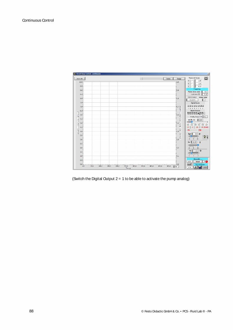
(Switch the Digital Output 2 = 1 to be able to activate the pump analog)
Continuous Control
© Festo Didactic GmbH & Co. • PCS - Fluid Lab ® - PA 89
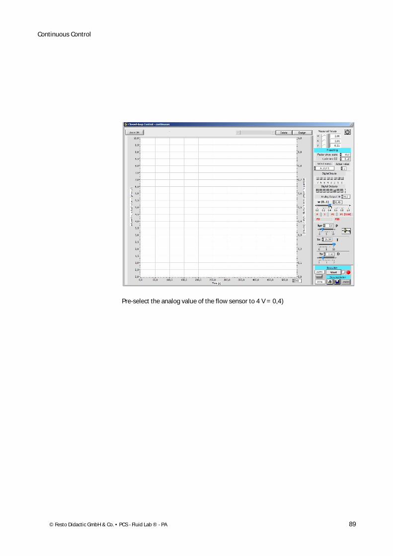
Pre-select the analog value of the flow sensor to 4 V = 0,4)
Continuous Control
90 © Festo Didactic GmbH & Co. • PCS - Fluid Lab ® - PA
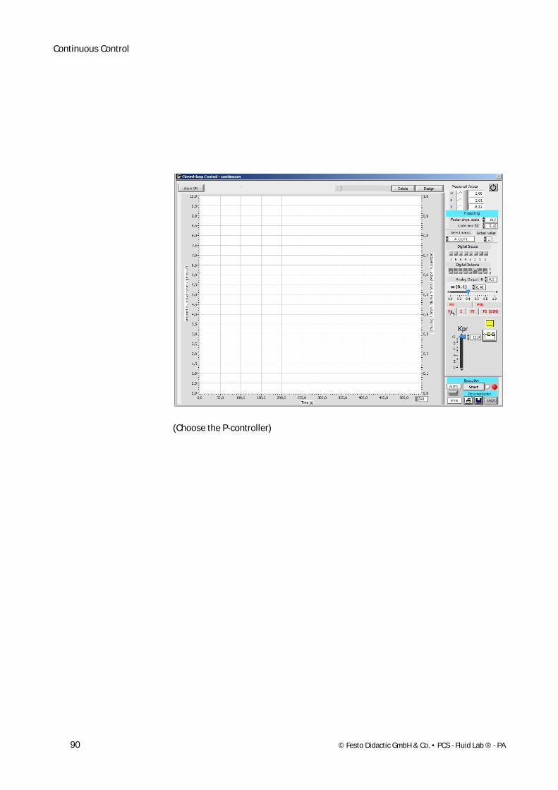
(Choose the P-controller)

Continuous Control
© Festo Didactic GmbH & Co. • PCS - Fluid Lab ® - PA 91
(Define the first kpr parameter – here to 1,0)

Continuous Control
92 © Festo Didactic GmbH & Co. • PCS - Fluid Lab ® - PA
(Change the time on the x-axis to 120 s)
Continuous Control
© Festo Didactic GmbH & Co. • PCS - Fluid Lab ® - PA 93
Please refer to the parameters we used for this project:
The list of parameters for every project looks like:
1 - Start – Stop 2 - Start – Stop 3 - Start – Stop 4 - Start – Stop 5 - Start – Stop
Contr kpr Ti Tv kpr Ti Tv kpr Ti Tv kpr Ti Tv kpr Ti Tv
P 1,0 x x 2,0 x x 4,0 x x 8,0 x x n.u. x x
I x x x x x x x x x x
PI x x x x x
PD x x x x x
PID
n.u. = not used, which means we interrupted the process there
Continuous Control
94 © Festo Didactic GmbH & Co. • PCS - Fluid Lab ® - PA
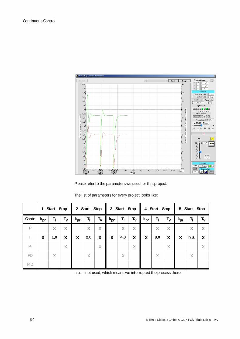
Please refer to the parameters we used for this project:
The list of parameters for every project looks like:
1 - Start – Stop 2 - Start – Stop 3 - Start – Stop 4 - Start – Stop 5 - Start – Stop
Contr kpr Ti Tv kpr Ti Tv kpr Ti Tv kpr Ti Tv kpr Ti Tv
P x x x x x x x x x x
I x 1,0 x x 2,0 x x 4,0 x x 8,0 x x n.u. x
PI x x x x x
PD x x x x x
PID
n.u. = not used, which means we interrupted the process there
Continuous Control
© Festo Didactic GmbH & Co. • PCS - Fluid Lab ® - PA 95
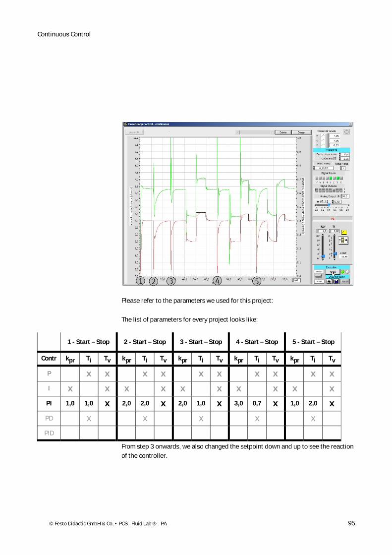
Please refer to the parameters we used for this project:
The list of parameters for every project looks like:
1 - Start – Stop 2 - Start – Stop 3 - Start – Stop 4 - Start – Stop 5 - Start – Stop
Contr kpr Ti Tv kpr Ti Tv kpr Ti Tv kpr Ti Tv kpr Ti Tv
P x x x x x x x x x x
I x x x x x x x x x x
PI 1,0 1,0 x 2,0 2,0 x 2,0 1,0 x 3,0 0,7 x 1,0 2,0 x
PD x x x x x
PID
From step 3 onwards, we also changed the setpoint down and up to see the reaction of the controller.
Continuous Control
96 © Festo Didactic GmbH & Co. • PCS - Fluid Lab ® - PA
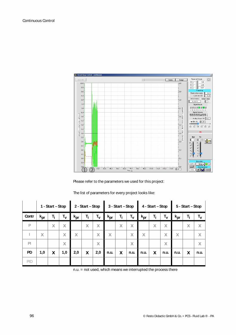
Please refer to the parameters we used for this project:
The list of parameters for every project looks like:
1 - Start – Stop 2 - Start – Stop 3 - Start – Stop 4 - Start – Stop 5 - Start – Stop
Contr kpr Ti Tv kpr Ti Tv kpr Ti Tv kpr Ti Tv kpr Ti Tv
P x x x x x x x x x x
I x x x x x x x x x x
PI x x x x x
PD 1,0 x 1,0 2,0 x 2,0 n.u. x n.u. n.u. x n.u. n.u. x n.u.
PID
n.u. = not used, which means we interrupted the process there
Continuous Control
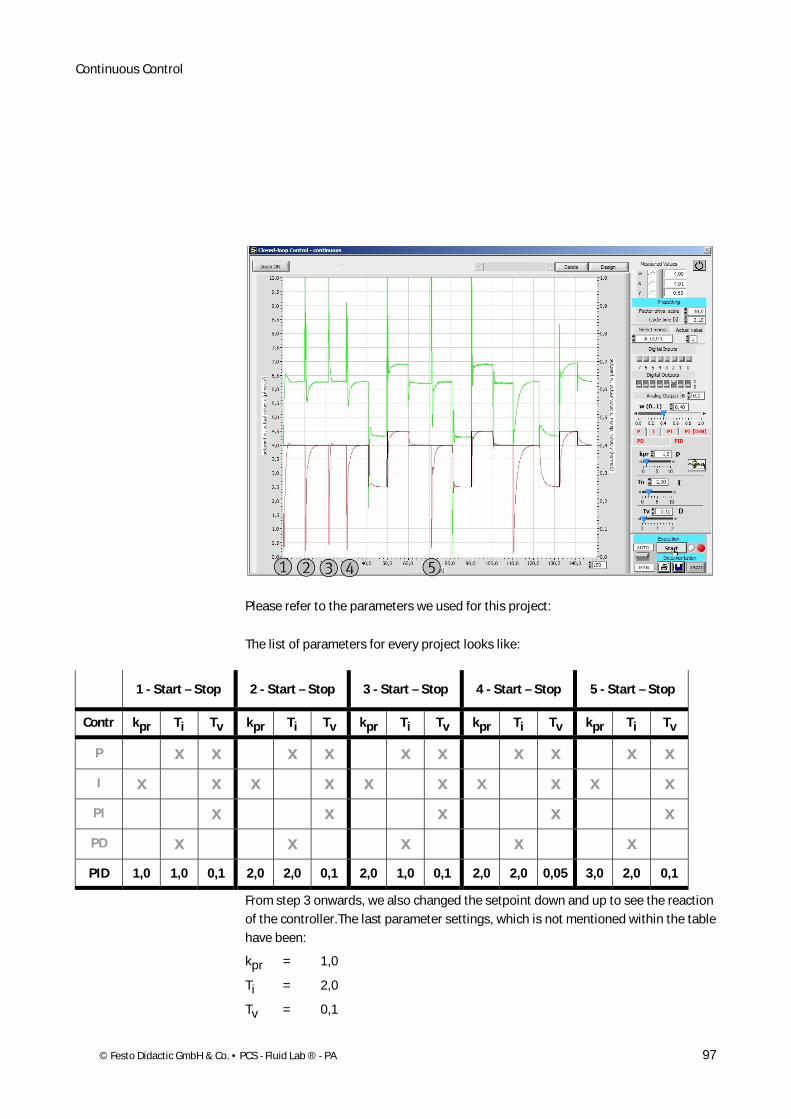
© Festo Didactic GmbH & Co. • PCS - Fluid Lab ® - PA 97
Please refer to the parameters we used for this project:
The list of parameters for every project looks like:
1 - Start – Stop 2 - Start – Stop 3 - Start – Stop 4 - Start – Stop 5 - Start – Stop
Contr kpr Ti Tv kpr Ti Tv kpr Ti Tv kpr Ti Tv kpr Ti Tv
P x x x x x x x x x x
I x x x x x x x x x x
PI x x x x x
PD x x x x x
PID 1,0 1,0 0,1 2,0 2,0 0,1 2,0 1,0 0,1 2,0 2,0 0,05 3,0 2,0 0,1
From step 3 onwards, we also changed the setpoint down and up to see the reaction of the controller.The last parameter settings, which is not mentioned within the table have been:
kpr = 1,0
Ti = 2,0
Tv = 0,1
Continuous Control
98 © Festo Didactic GmbH & Co. • PCS - Fluid Lab ® - PA
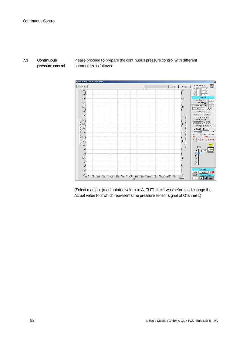
Please proceed to prepare the continuous pressure control with different parameters as follows:
(Select manipu. (manipulated value) to A_OUT1 like it was before and change the Actual value to 2 which represents the pressure sensor signal of Channel 1)
7.3 Continuous pressure control
Continuous Control
© Festo Didactic GmbH & Co. • PCS - Fluid Lab ® - PA 99
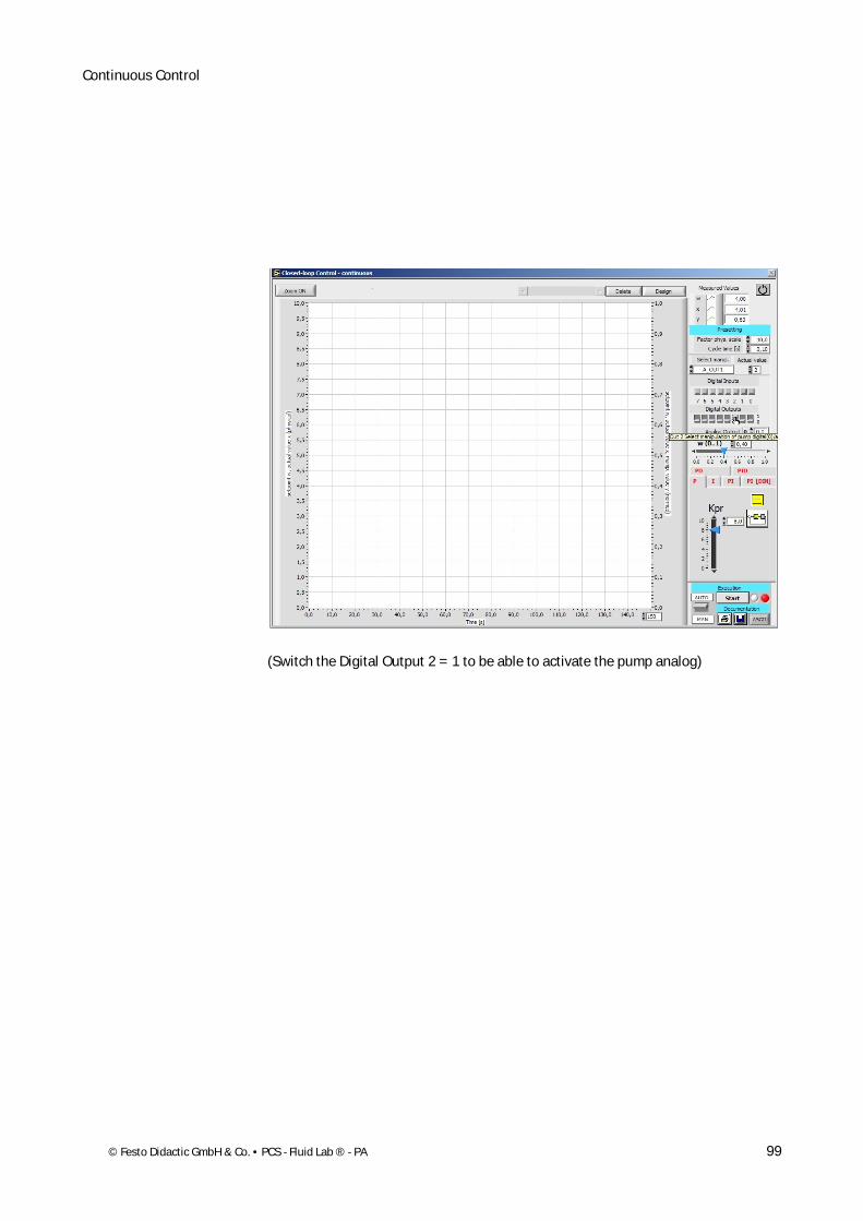
(Switch the Digital Output 2 = 1 to be able to activate the pump analog)

Continuous Control
100 © Festo Didactic GmbH & Co. • PCS - Fluid Lab ® - PA
Pre-select the analog value of the pressure sensor to 4 V = 0,4)
Continuous Control
© Festo Didactic GmbH & Co. • PCS - Fluid Lab ® - PA 101
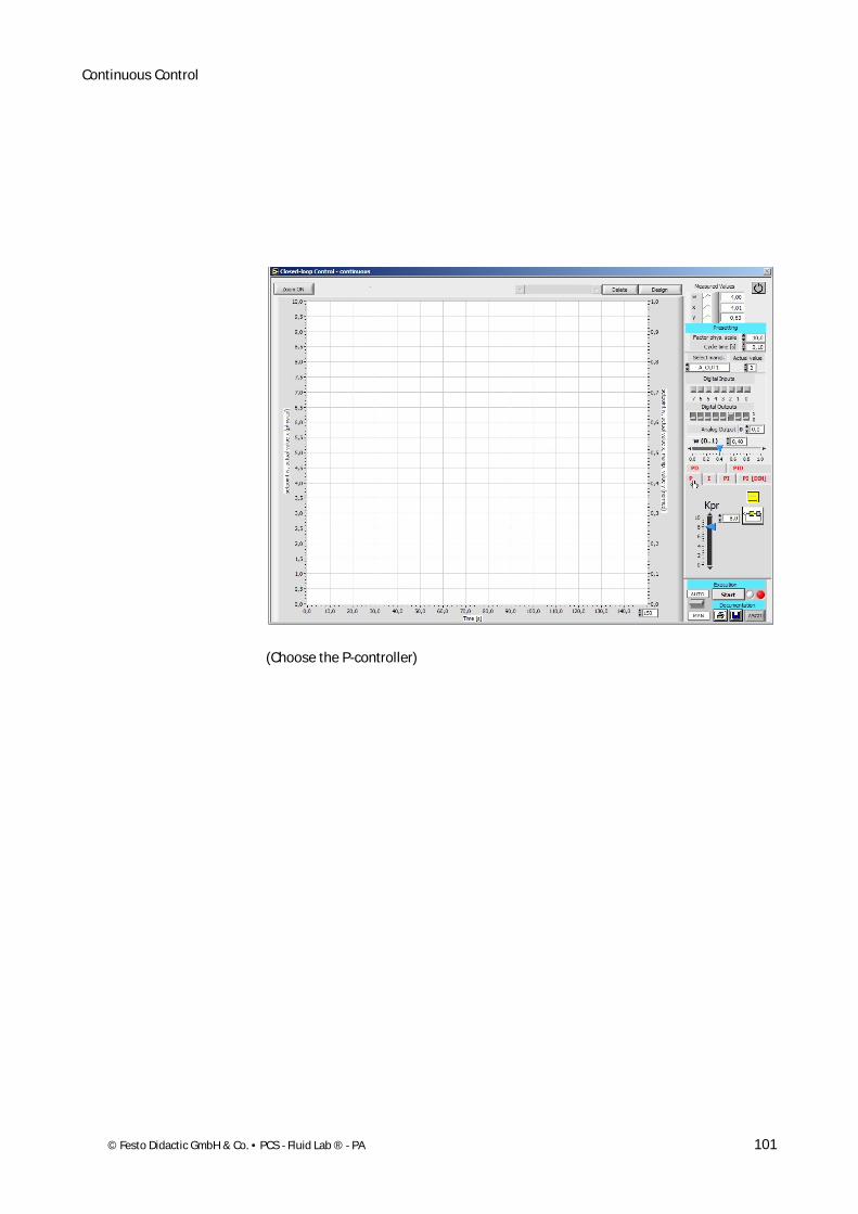
(Choose the P-controller)
Continuous Control
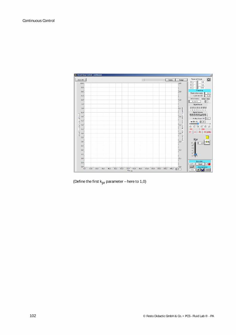
102 © Festo Didactic GmbH & Co. • PCS - Fluid Lab ® - PA
(Define the first kpr parameter – here to 1,0)

Continuous Control
© Festo Didactic GmbH & Co. • PCS - Fluid Lab ® - PA 103
(Change the time on the x-axis to 60 s)
Continuous Control
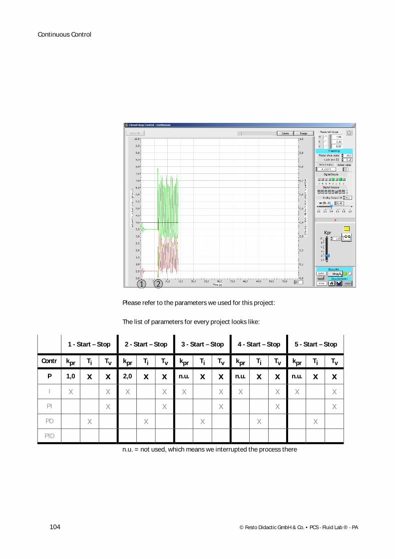
104 © Festo Didactic GmbH & Co. • PCS - Fluid Lab ® - PA
Please refer to the parameters we used for this project:
The list of parameters for every project looks like:
1 - Start – Stop 2 - Start – Stop 3 - Start – Stop 4 - Start – Stop 5 - Start – Stop
Contr kpr Ti Tv kpr Ti Tv kpr Ti Tv kpr Ti Tv kpr Ti Tv
P 1,0 x x 2,0 x x n.u. x x n.u. x x n.u. x x
I x x x x x x x x x x
PI x x x x x
PD x x x x x
PID
n.u. = not used, which means we interrupted the process there
Continuous Control
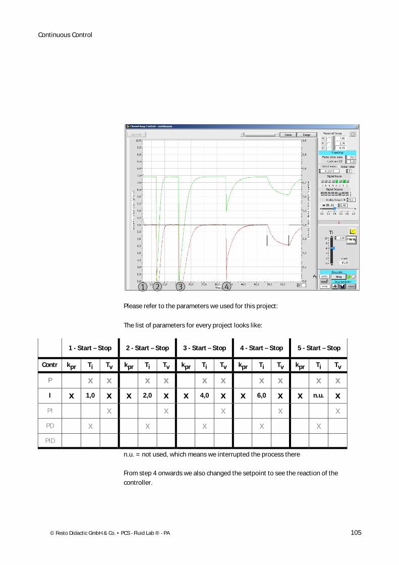
© Festo Didactic GmbH & Co. • PCS - Fluid Lab ® - PA 105
Please refer to the parameters we used for this project:
The list of parameters for every project looks like:
1 - Start – Stop 2 - Start – Stop 3 - Start – Stop 4 - Start – Stop 5 - Start – Stop
Contr kpr Ti Tv kpr Ti Tv kpr Ti Tv kpr Ti Tv kpr Ti Tv
P x x x x x x x x x x
I x 1,0 x x 2,0 x x 4,0 x x 6,0 x x n.u. x
PI x x x x x
PD x x x x x
PID
n.u. = not used, which means we interrupted the process there
From step 4 onwards we also changed the setpoint to see the reaction of the controller.
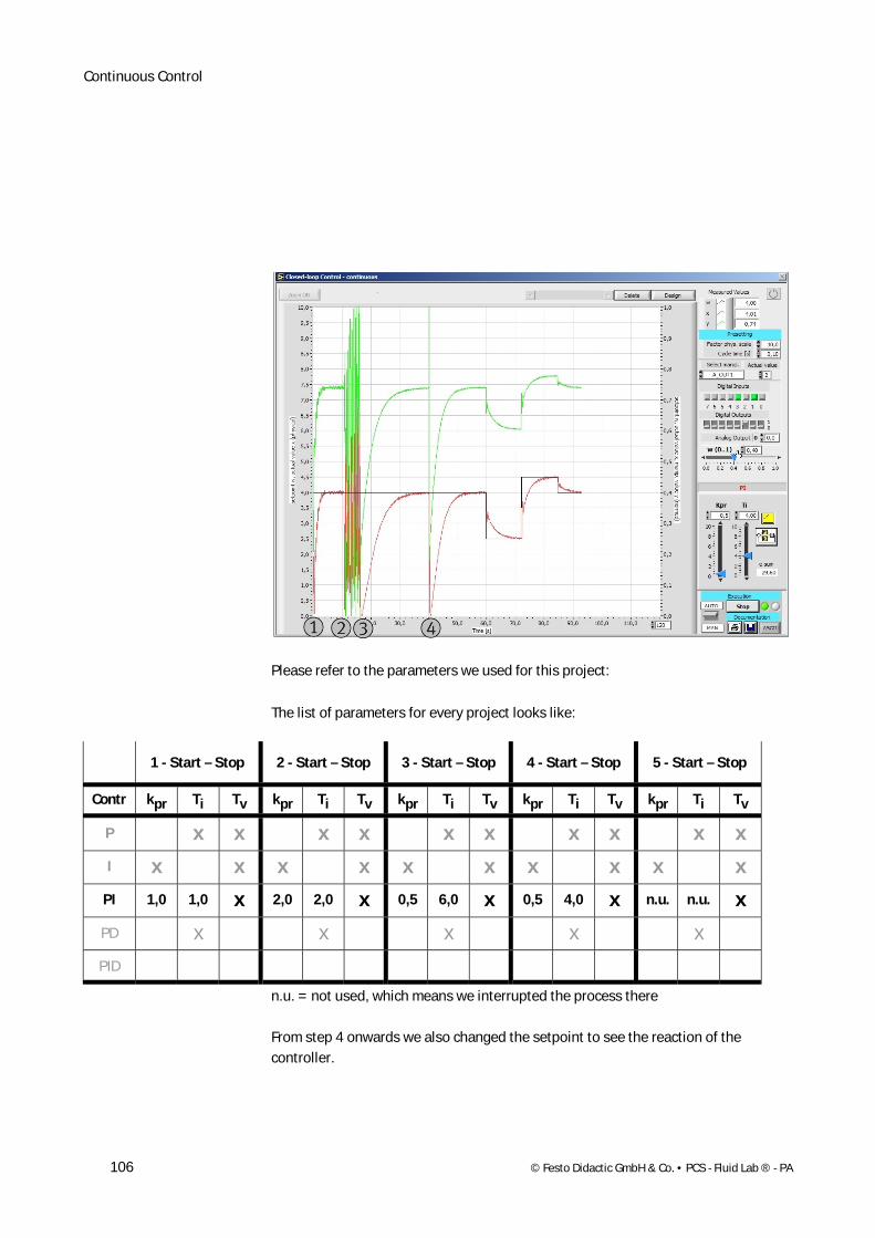
Continuous Control
106 © Festo Didactic GmbH & Co. • PCS - Fluid Lab ® - PA
Please refer to the parameters we used for this project:
The list of parameters for every project looks like:
1 - Start – Stop 2 - Start – Stop 3 - Start – Stop 4 - Start – Stop 5 - Start – Stop
Contr kpr Ti Tv kpr Ti Tv kpr Ti Tv kpr Ti Tv kpr Ti Tv
P x x x x x x x x x x
I x x x x x x x x x x
PI 1,0 1,0 x 2,0 2,0 x 0,5 6,0 x 0,5 4,0 x n.u. n.u. x
PD x x x x x
PID
n.u. = not used, which means we interrupted the process there
From step 4 onwards we also changed the setpoint to see the reaction of the controller.
Continuous Control
© Festo Didactic GmbH & Co. • PCS - Fluid Lab ® - PA 107
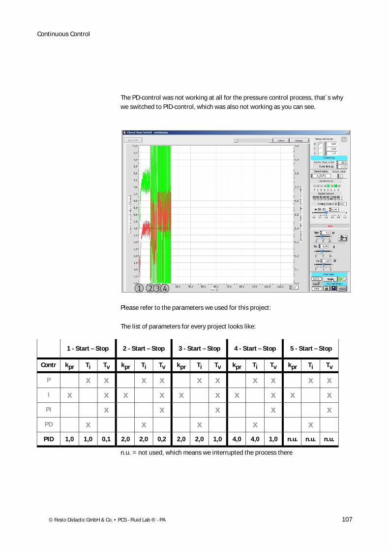
The PD-control was not working at all for the pressure control process, that´s why we switched to PID-control, which was also not working as you can see.
Please refer to the parameters we used for this project:
The list of parameters for every project looks like:
1 - Start – Stop 2 - Start – Stop 3 - Start – Stop 4 - Start – Stop 5 - Start – Stop
Contr kpr Ti Tv kpr Ti Tv kpr Ti Tv kpr Ti Tv kpr Ti Tv
P x x x x x x x x x x
I x x x x x x x x x x
PI x x x x x
PD x x x x x
PID 1,0 1,0 0,1 2,0 2,0 0,2 2,0 2,0 1,0 4,0 4,0 1,0 n.u. n.u. n.u.
n.u. = not used, which means we interrupted the process there
Continuous Control
108 © Festo Didactic GmbH & Co. • PCS - Fluid Lab ® - PA
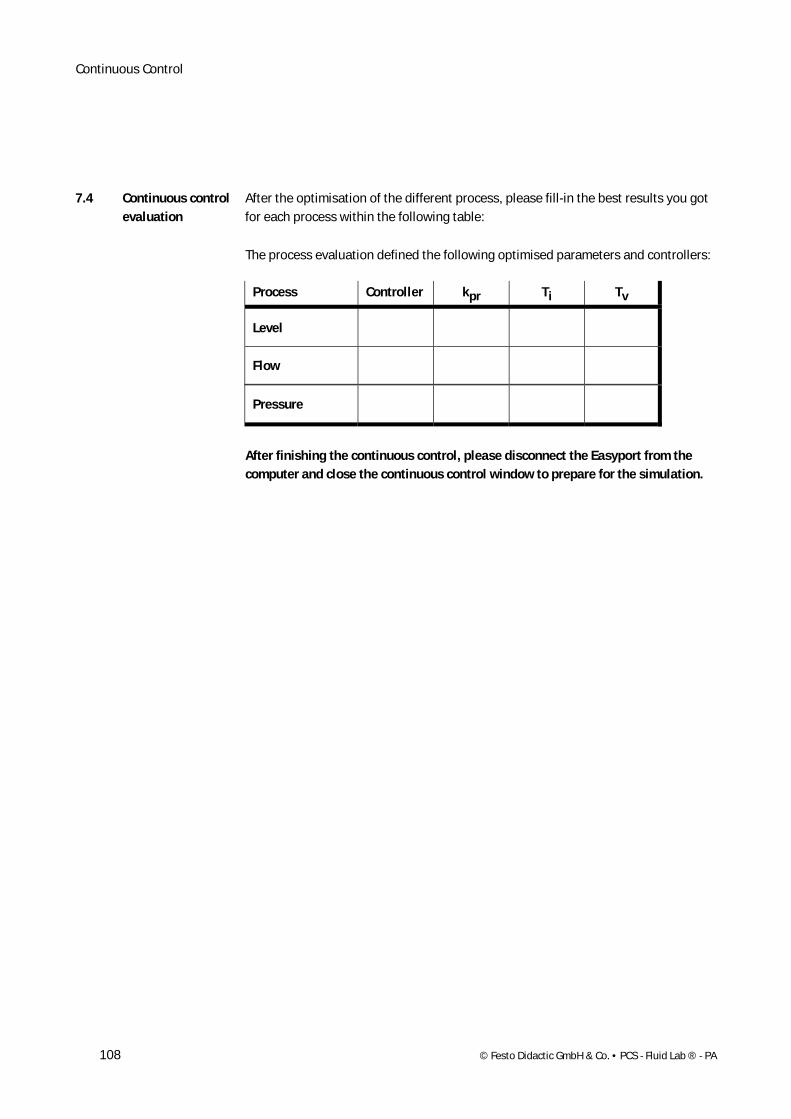
After the optimisation of the different process, please fill-in the best results you got for each process within the following table:
The process evaluation defined the following optimised parameters and controllers:
Process Controller kpr Ti Tv
Level
Flow
Pressure
After finishing the continuous control, please disconnect the Easyport from the computer and close the continuous control window to prepare for the simulation.
7.4 Continuous control evaluation
© Festo Didactic GmbH & Co. • PCS - Fluid Lab ® - PA 109
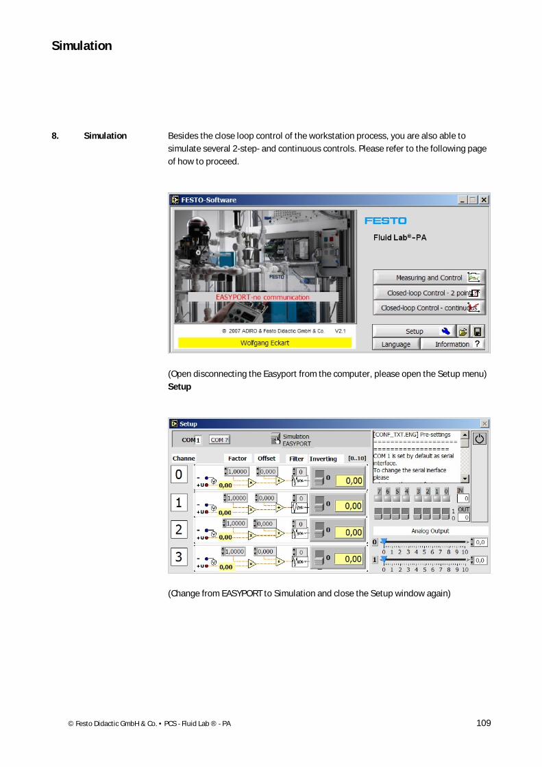
Besides the close loop control of the workstation process, you are also able to simulate several 2-step- and continuous controls. Please refer to the following page of how to proceed.
(Open disconnecting the Easyport from the computer, please open the Setup menu) Setup
(Change from EASYPORT to Simulation and close the Setup window again)
Simulation
8. Simulation
Simulation
110 © Festo Didactic GmbH & Co. • PCS - Fluid Lab ® - PA
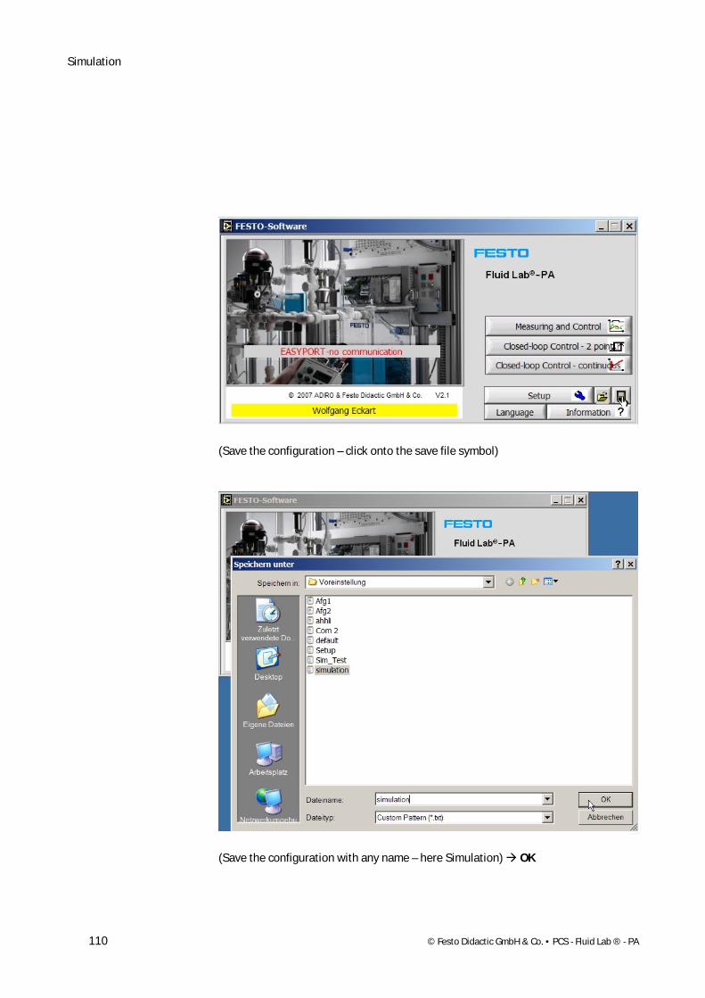
(Save the configuration – click onto the save file symbol)
(Save the configuration with any name – here Simulation) OK
Simulation
© Festo Didactic GmbH & Co. • PCS - Fluid Lab ® - PA 111
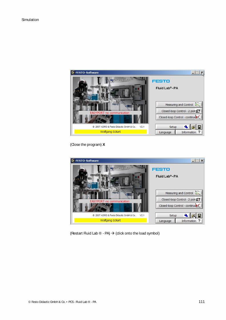
(Close the program) X
(Restart Fluid Lab ® - PA) (click onto the load symbol)
Simulation
112 © Festo Didactic GmbH & Co. • PCS - Fluid Lab ® - PA
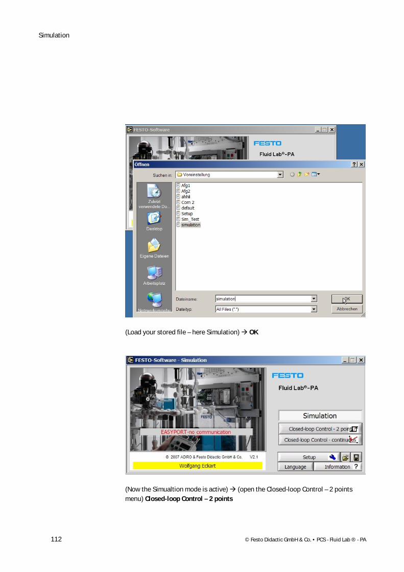
(Load your stored file – here Simulation) OK
(Now the Simualtion mode is active) (open the Closed-loop Control – 2 points menu) Closed-loop Control – 2 points
Simulation
© Festo Didactic GmbH & Co. • PCS - Fluid Lab ® - PA 113
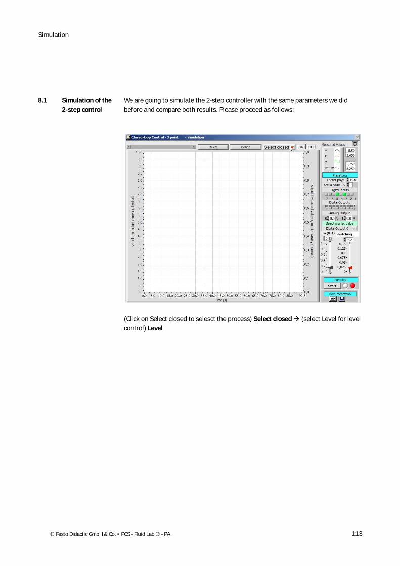
We are going to simulate the 2-step controller with the same parameters we did before and compare both results. Please proceed as follows:
(Click on Select closed to selesct the process) Select closed (select Level for level control) Level
8.1 Simulation of the 2-step control

Simulation
114 © Festo Didactic GmbH & Co. • PCS - Fluid Lab ® - PA
(Activate the simulated process) ON arrange the windows like shown within the screen shot)
Simulation
© Festo Didactic GmbH & Co. • PCS - Fluid Lab ® - PA 115
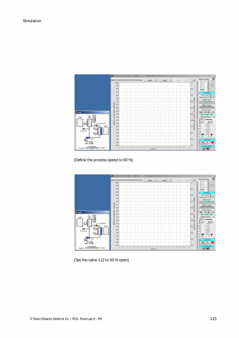
(Define the process speed to 50 %)
(Set the valve 112 to 50 % open)
Simulation
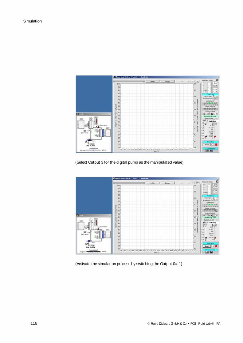
116 © Festo Didactic GmbH & Co. • PCS - Fluid Lab ® - PA
(Select Output 3 for the digital pump as the manipulated value)
(Activate the simulation process by switching the Output 0= 1)
Simulation
© Festo Didactic GmbH & Co. • PCS - Fluid Lab ® - PA 117
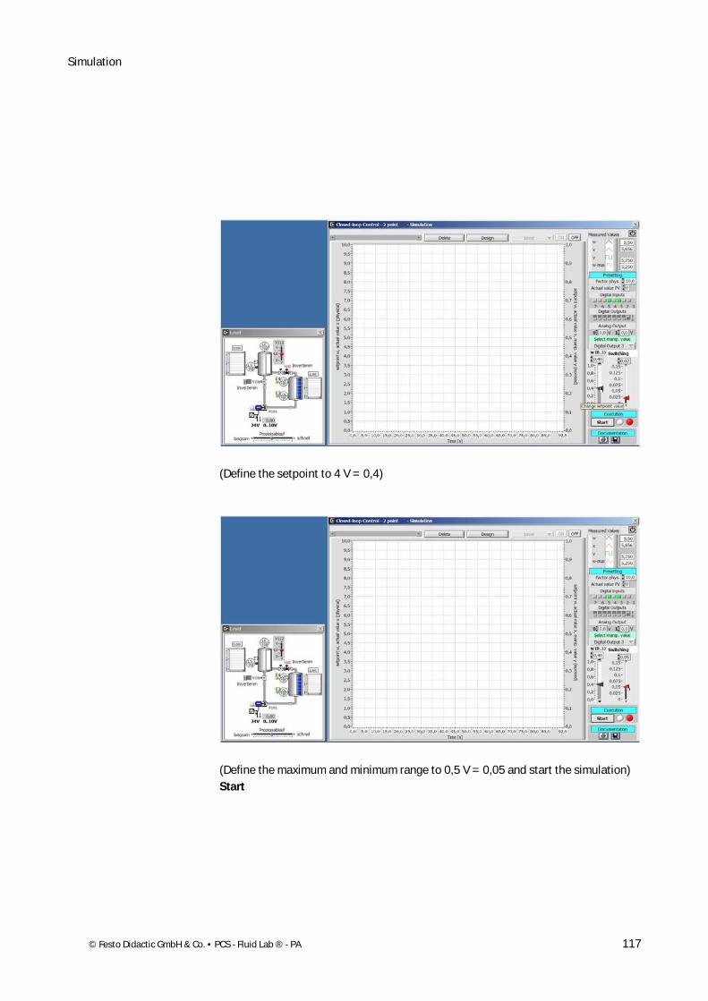
(Define the setpoint to 4 V = 0,4)
(Define the maximum and minimum range to 0,5 V = 0,05 and start the simulation) Start
Simulation
118 © Festo Didactic GmbH & Co. • PCS - Fluid Lab ® - PA
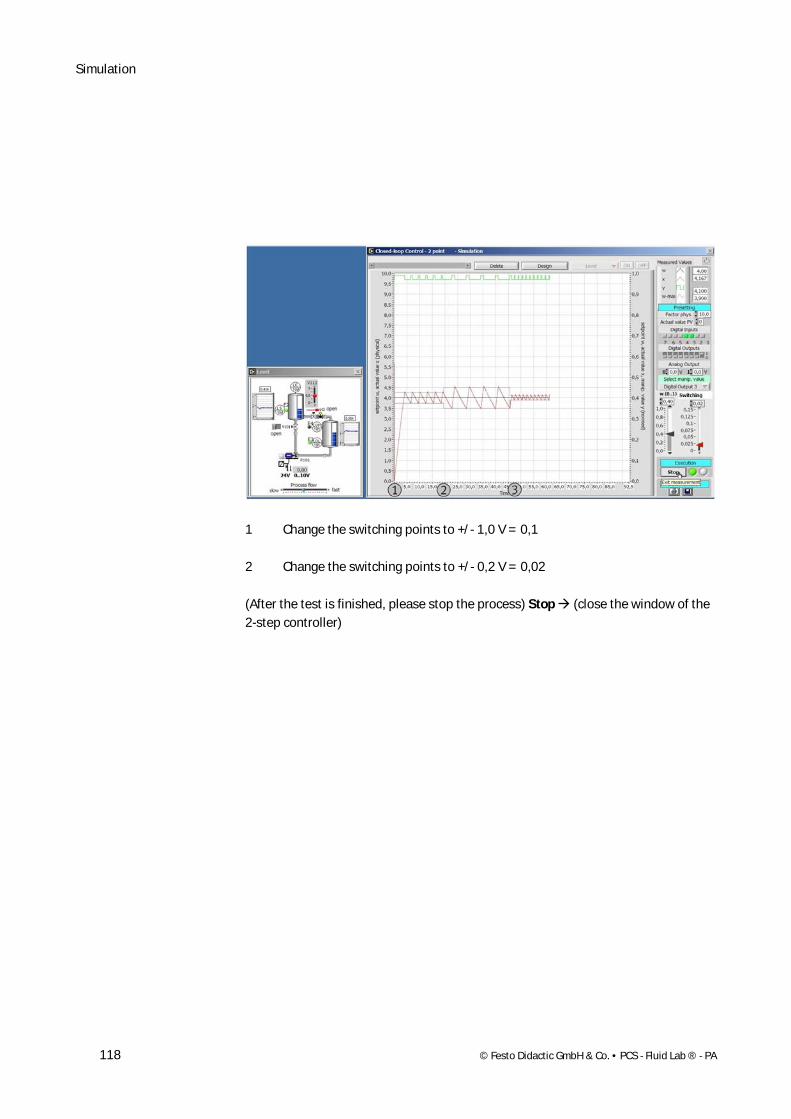
1 Change the switching points to +/- 1,0 V = 0,1
2 Change the switching points to +/- 0,2 V = 0,02
(After the test is finished, please stop the process) Stop (close the window of the 2-step controller)
Simulation
© Festo Didactic GmbH & Co. • PCS - Fluid Lab ® - PA 119
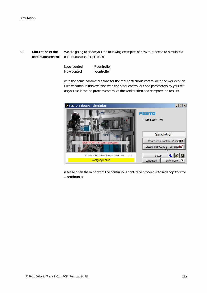
We are going to show you the following examples of how to proceed to simulate a continuous control process:
Level control P-controller Flow control I-controller
with the same parameters than for the real continuous control with the workstation. Please continue this exercise with the other controllers and parameters by yourself as you did it for the process control of the workstation and compare the results.
(Please open the window of the continuous control to proceed) Closed loop Control – continuous
8.2 Simulation of the continuous control
Simulation
120 © Festo Didactic GmbH & Co. • PCS - Fluid Lab ® - PA
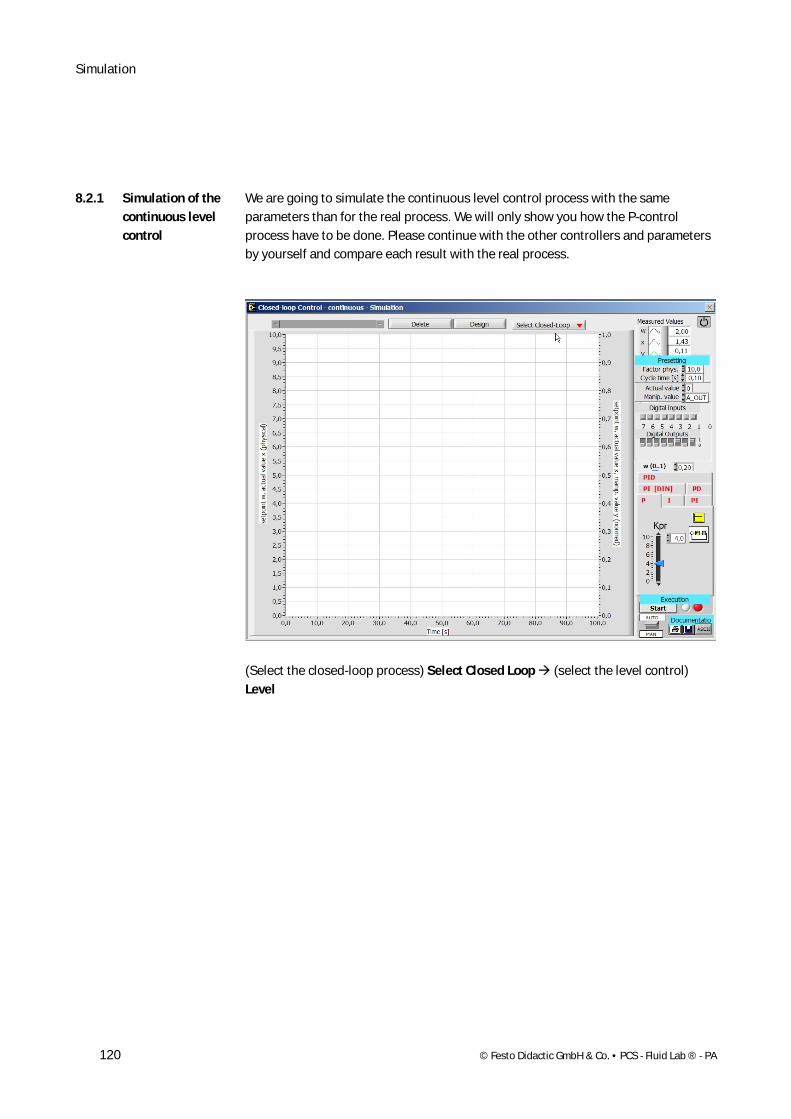
We are going to simulate the continuous level control process with the same parameters than for the real process. We will only show you how the P-control process have to be done. Please continue with the other controllers and parameters by yourself and compare each result with the real process.
(Select the closed-loop process) Select Closed Loop (select the level control) Level
8.2.1 Simulation of the continuous level control
Simulation
© Festo Didactic GmbH & Co. • PCS - Fluid Lab ® - PA 121
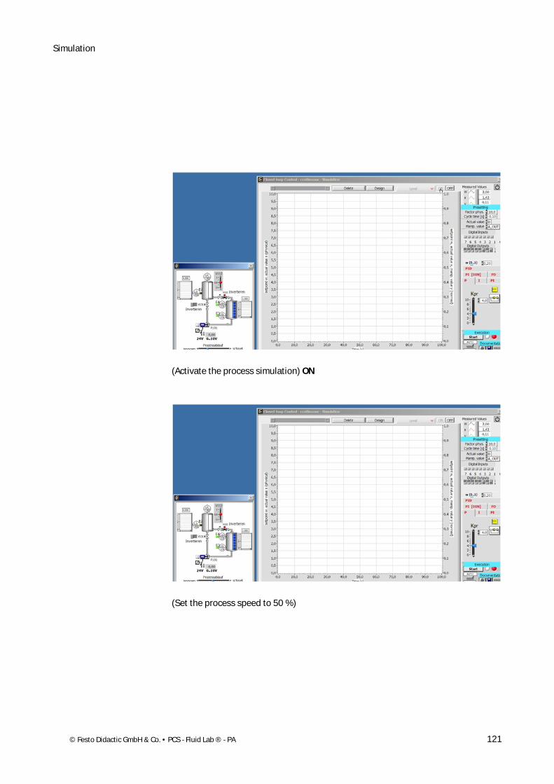
(Activate the process simulation) ON
(Set the process speed to 50 %)

Simulation
122 © Festo Didactic GmbH & Co. • PCS - Fluid Lab ® - PA
(Open the valve 112 approx. 75 %)
(Activate the simulation process by switching the Output 0= 1)
Simulation
© Festo Didactic GmbH & Co. • PCS - Fluid Lab ® - PA 123
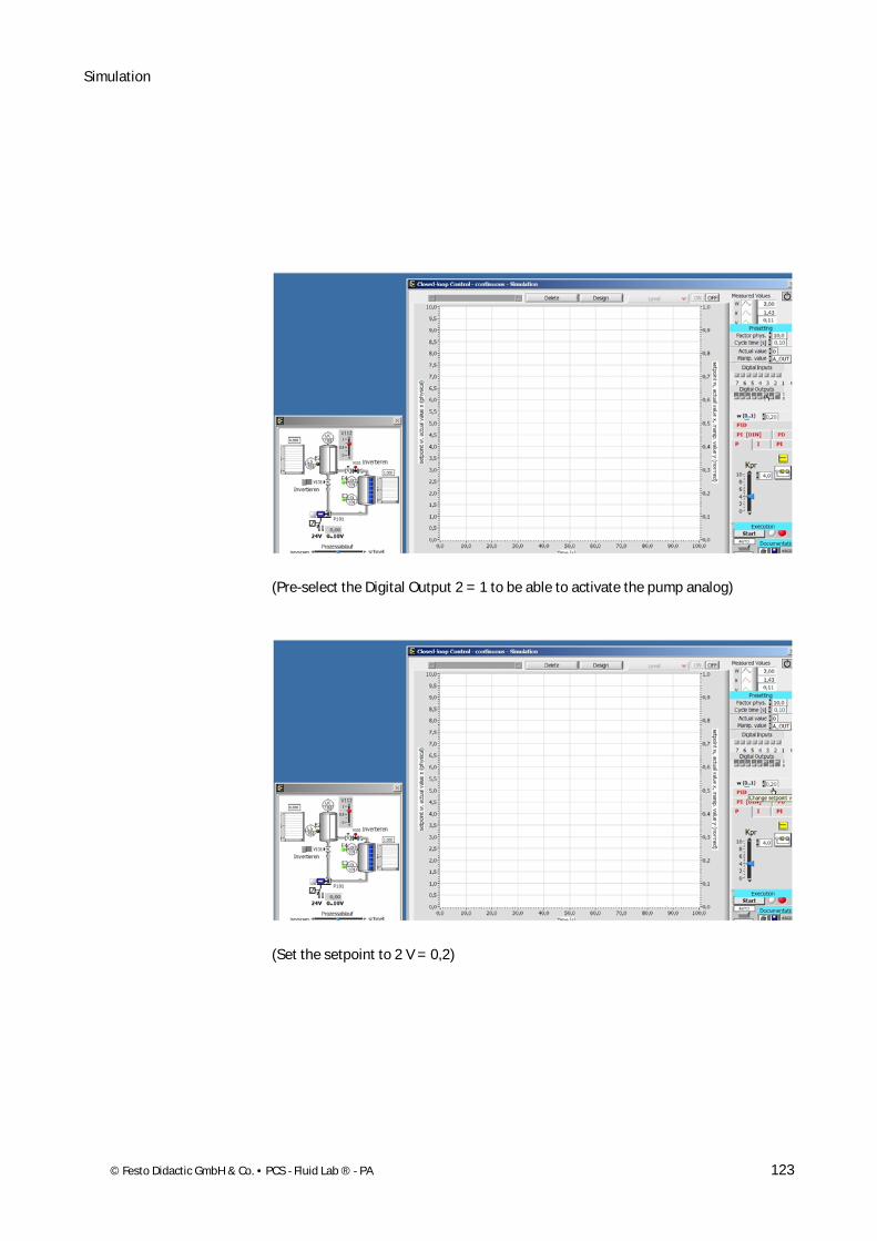
(Pre-select the Digital Output 2 = 1 to be able to activate the pump analog)
(Set the setpoint to 2 V = 0,2)
Simulation
124 © Festo Didactic GmbH & Co. • PCS - Fluid Lab ® - PA
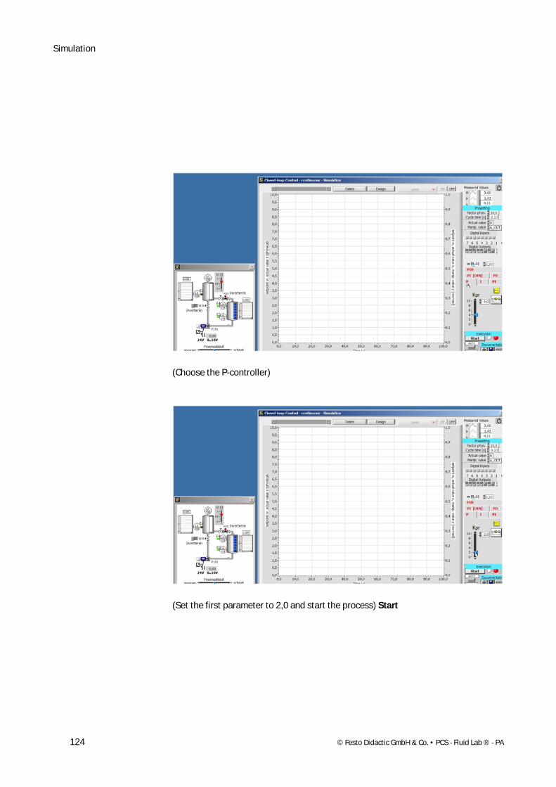
(Choose the P-controller)
(Set the first parameter to 2,0 and start the process) Start
Simulation
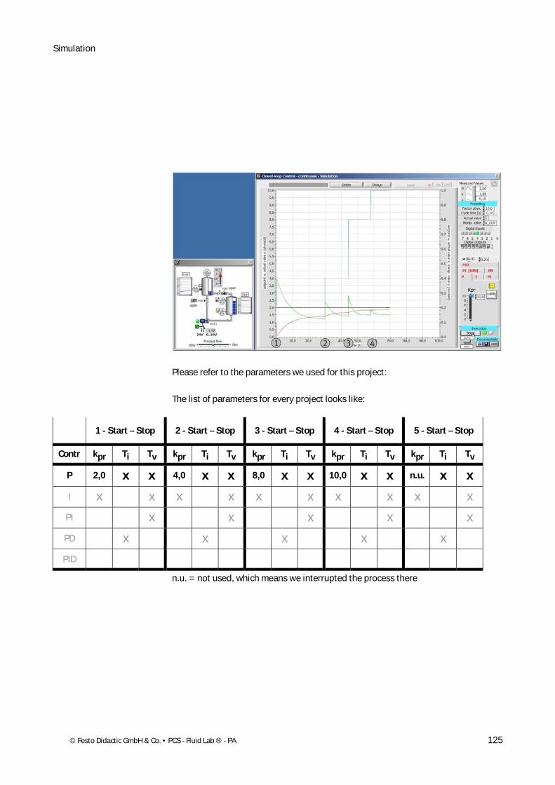
© Festo Didactic GmbH & Co. • PCS - Fluid Lab ® - PA 125
Please refer to the parameters we used for this project:
The list of parameters for every project looks like:
1 - Start – Stop 2 - Start – Stop 3 - Start – Stop 4 - Start – Stop 5 - Start – Stop
Contr kpr Ti Tv kpr Ti Tv kpr Ti Tv kpr Ti Tv kpr Ti Tv
P 2,0 x x 4,0 x x 8,0 x x 10,0 x x n.u. x x
I x x x x x x x x x x
PI x x x x x
PD x x x x x
PID
n.u. = not used, which means we interrupted the process there
Simulation
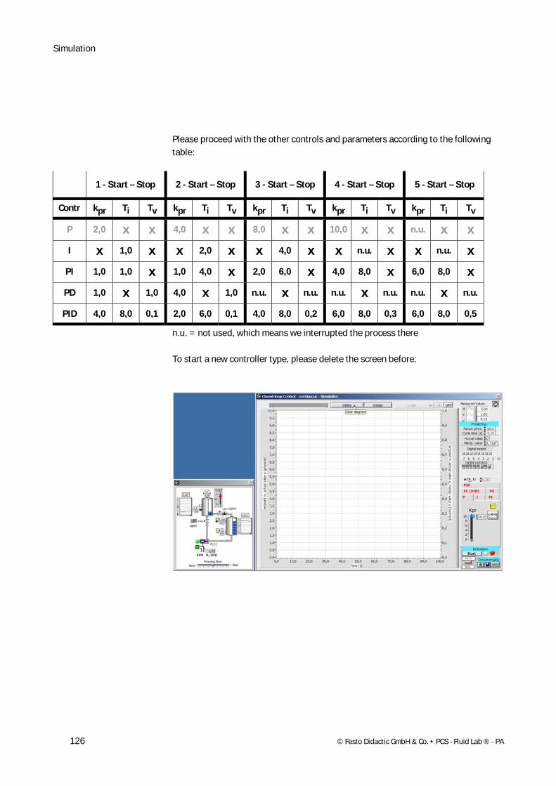
126 © Festo Didactic GmbH & Co. • PCS - Fluid Lab ® - PA
Please proceed with the other controls and parameters according to the following table:
1 - Start – Stop 2 - Start – Stop 3 - Start – Stop 4 - Start – Stop 5 - Start – Stop
Contr kpr Ti Tv kpr Ti Tv kpr Ti Tv kpr Ti Tv kpr Ti Tv
P 2,0 x x 4,0 x x 8,0 x x 10,0 x x n.u. x x
I x 1,0 x x 2,0 x x 4,0 x x n.u. x x n.u. x
PI 1,0 1,0 x 1,0 4,0 x 2,0 6,0 x 4,0 8,0 x 6,0 8,0 x
PD 1,0 x 1,0 4,0 x 1,0 n.u. x n.u. n.u. x n.u. n.u. x n.u.
PID 4,0 8,0 0,1 2,0 6,0 0,1 4,0 8,0 0,2 6,0 8,0 0,3 6,0 8,0 0,5
n.u. = not used, which means we interrupted the process there
To start a new controller type, please delete the screen before:
Simulation
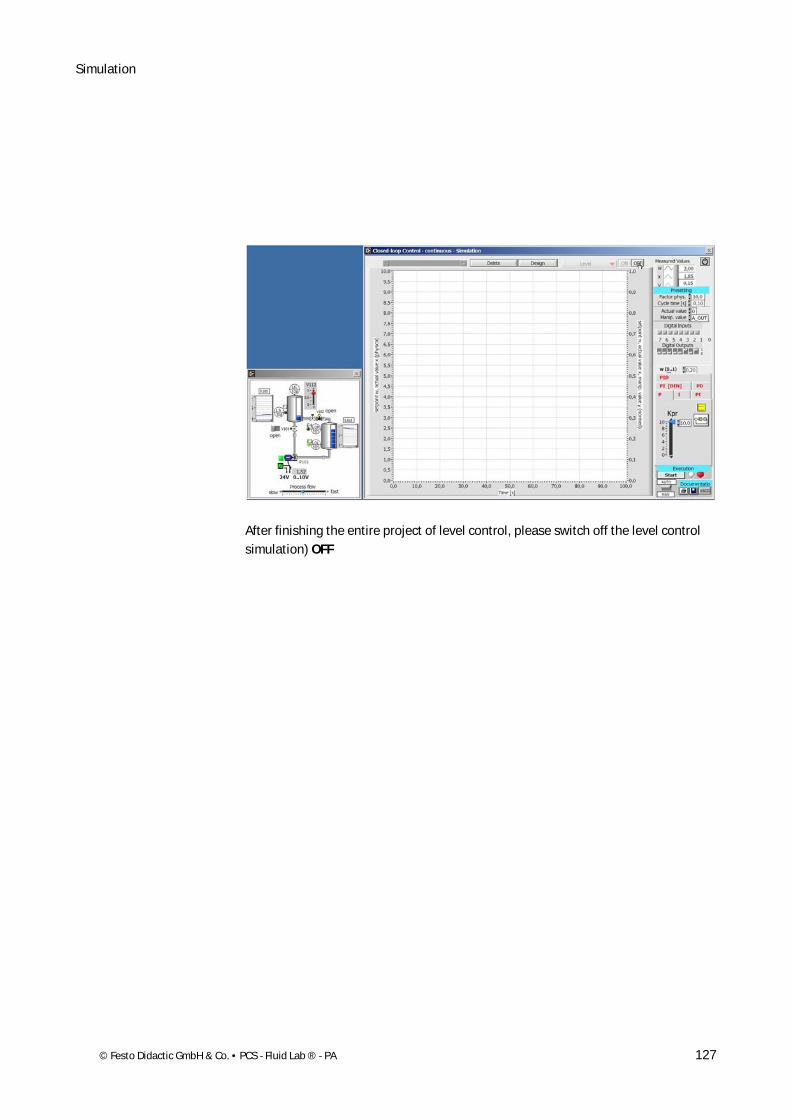
© Festo Didactic GmbH & Co. • PCS - Fluid Lab ® - PA 127
After finishing the entire project of level control, please switch off the level control simulation) OFF
Simulation
128 © Festo Didactic GmbH & Co. • PCS - Fluid Lab ® - PA
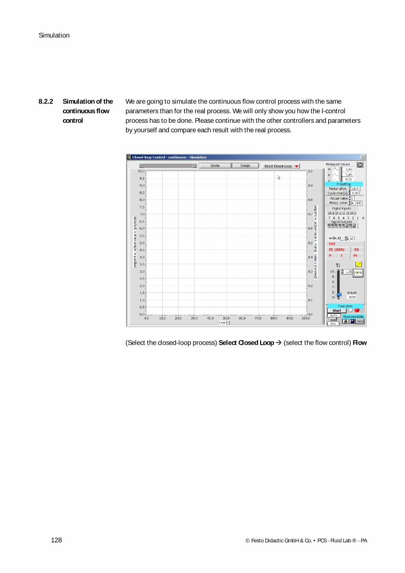
We are going to simulate the continuous flow control process with the same parameters than for the real process. We will only show you how the I-control process has to be done. Please continue with the other controllers and parameters by yourself and compare each result with the real process.
(Select the closed-loop process) Select Closed Loop (select the flow control) Flow
8.2.2 Simulation of the continuous flow control
Simulation
© Festo Didactic GmbH & Co. • PCS - Fluid Lab ® - PA 129
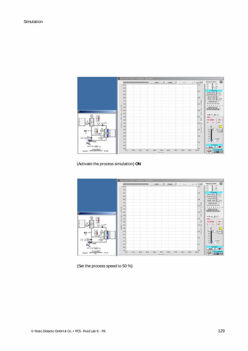
(Activate the process simulation) ON
(Set the process speed to 50 %)
Simulation
130 © Festo Didactic GmbH & Co. • PCS - Fluid Lab ® - PA
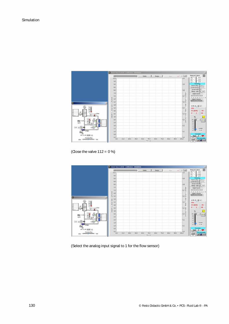
(Close the valve 112 = 0 %)
(Select the analog input signal to 1 for the flow sensor)

Simulation
© Festo Didactic GmbH & Co. • PCS - Fluid Lab ® - PA 131
(Activate the simulation process by switching the Output 0= 1 and Output 2 = 1))
(Set the setpoint to 4 V = 0,4)

Simulation
132 © Festo Didactic GmbH & Co. • PCS - Fluid Lab ® - PA
(Choose the I-controller)
(Set the first parameter to 1,0 and start the process) Start
Simulation
© Festo Didactic GmbH & Co. • PCS - Fluid Lab ® - PA 133
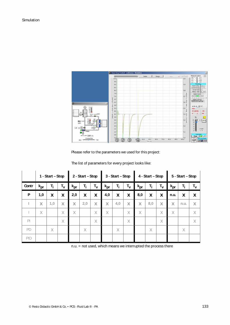
Please refer to the parameters we used for this project:
The list of parameters for every project looks like:
1 - Start – Stop 2 - Start – Stop 3 - Start – Stop 4 - Start – Stop 5 - Start – Stop
Contr kpr Ti Tv kpr Ti Tv kpr Ti Tv kpr Ti Tv kpr Ti Tv
P 1,0 x x 2,0 x x 4,0 x x 8,0 x x n.u. x x
I x 1,0 x x 2,0 x x 4,0 x x 8,0 x x n.u. x
I x x x x x x x x x x
PI x x x x x
PD x x x x x
PID
n.u. = not used, which means we interrupted the process there
Simulation
134 © Festo Didactic GmbH & Co. • PCS - Fluid Lab ® - PA
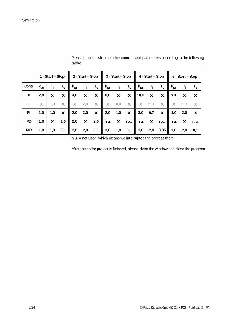
Please proceed with the other controls and parameters according to the following table:
1 - Start – Stop 2 - Start – Stop 3 - Start – Stop 4 - Start – Stop 5 - Start – Stop
Contr kpr Ti Tv kpr Ti Tv kpr Ti Tv kpr Ti Tv kpr Ti Tv
P 2,0 x x 4,0 x x 8,0 x x 10,0 x x n.u. x x
I x 1,0 x x 2,0 x x 4,0 x x n.u. x x n.u. x
PI 1,0 1,0 x 2,0 2,0 x 2,0 1,0 x 3,0 0,7 x 1,0 2,0 x
PD 1,0 x 1,0 2,0 x 2,0 n.u. x n.u. n.u. x n.u. n.u. x n.u.
PID 1,0 1,0 0,1 2,0 2,0 0,1 2,0 1,0 0,1 2,0 2,0 0,05 3,0 2,0 0,1
n.u. = not used, which means we interrupted the process there
After the entire project is finished, please close the window and close the program.