SEC. PAGE SM1A • Thermal trip adjustme nt ranges 9-32A (5 choic es) • Breaking capaci ty Icu at 400V: – 50kA • Suitable for mounting in consumer switchboards with minimum 58mm depth. PAGE 1-2 SM1B • Thermal trip adjus tment ranges 0.1-32A (15 choices) • Breaking capac ity Icu at 400V: – 100kA (ranges 0.1-10A) – 25kA (ranges 9-32A) • Suitable for mounting i n consumer switchboards with minimum 58mm depth. PAGE 1-2 SM1C • Same characteristics per SM1B breaker • Suitable for mounting in consumer switchboards with minimum 45mm depth. PAGE 1-2 SM2A • Thermal trip adjus tment ranges 28-50A (3 choices) • Breaking capac ity Icu at 400V: – 50kA. PAGE 1-3 SM3A • Thermal trip adjustme nt ranges 45-100A (4 choices) • Breaking capacity Icu at 400V: – 50kA. PAGE 1-3 LMS25 • Thermal trip adjus tment ranges 0.1-25A (13 choices) • Breaking capac ity Icu at 400V: – 100kA (ranges 0.1-6.3A) – 6kA (ranges 6.3-10A) – 4kA (ranges 10-25A) • Suitable for mounting i n consumer switchboards with minimum 45mm depth. PAGE 1-10 1 Wide adjustment range 0.1 to 100A Breaking capacity Icu 50kA (400V) up to 100A Suitable for isolation Comprehensive line of accessories Front mount contacts Automatic trip indicators High reliability and accuracy of tripping. MOTOR PROTECTION CIRCUIT BREAKERS P L A N E T S W I T C H Motor protection circuit breakers Breakers SM1A, SM1B and SM1C . . . . . . . . . . . . . . . . . . . . . . . . . . . . . . . . . . . 1- 2 Breakers SM2A and SM3A . . . . . . . . . . . . . . . . . . . . . . . . . . . . . . . . . . . . . . . . . 1- 3 Add-on blocks and accessories for SM1A, SM1B and SM1C . . . . . . . . . . . . . . . 1- 4 Add-on blocks and accessories for SM2A and SM3A . . . . . . . . . . . . . . . . . . . . 1- 8 Starters LMS25 . . . . . . . . . . . . . . . . . . . . . . . . . . . . . . . . . . . . . . . . . . . . . . . . . 1- 10 Add-on blocks and accessories for LMS25 . . . . . . . . . . . . . . . . . . . . . . . . . . . . 1- 11 Short-circuit tripping indicator, standard supplied on all circuit breakers, type SM1. Reset the indicator, as illustrated, to restore the breaker.

Welcome message from author
This document is posted to help you gain knowledge. Please leave a comment to let me know what you think about it! Share it to your friends and learn new things together.
Transcript

8/8/2019 01 Motor Protection Circuit Breakers
http://slidepdf.com/reader/full/01-motor-protection-circuit-breakers 1/11
SEC. PAGE
SM1A
• Thermal trip adjustment ranges 9-32A(5 choices)
• Breaking capacity Icu at 400V:
– 50kA
• Suitable for mounting in consumerswitchboards with minimum 58mm depth.
PAGE 1-2
SM1B
• Thermal trip adjustment ranges 0.1-32A(15 choices)
• Breaking capacity Icu at 400V:
– 100kA (ranges 0.1-10A)
– 25kA (ranges 9-32A)
• Suitable for mounting in consumerswitchboards with minimum 58mm depth.
PAGE 1-2
SM1C
• Same characteristics per SM1B breaker
• Suitable for mounting in consumerswitchboards with minimum 45mm depth.
PAGE 1-2
SM2A
• Thermal trip adjustment ranges 28-50A(3 choices)
• Breaking capacity Icu at 400V:
– 50kA.
PAGE 1-3
SM3A
• Thermal trip adjustment ranges 45-100A(4 choices)
• Breaking capacity Icu at 400V:
– 50kA.
PAGE 1-3
LMS25
• Thermal trip adjustment ranges 0.1-25A(13 choices)
• Breaking capacity Icu at 400V:
– 100kA (ranges 0.1-6.3A)
– 6kA (ranges 6.3-10A)
– 4kA (ranges 10-25A)
• Suitable for mounting in consumerswitchboards with minimum 45mm depth.
PAGE 1-10
1
Wide adjustment range 0.1 to 100A
Breaking capacity Icu 50kA (400V) up to 100A
Suitable for isolation
Comprehensive line of accessories
Front mount contacts
Automatic trip indicators
High reliability and accuracy of tripping.
MOTOR PROTECTION CIRCUIT BREAKERS
P L A N
E T - S W I T C H
Motor protection circuit breakersBreakers SM1A, SM1B and SM1C . . . . . . . . . . . . . . . . . . . . . . . . . . . . . . . . . . . 1- 2
Breakers SM2A and SM3A . . . . . . . . . . . . . . . . . . . . . . . . . . . . . . . . . . . . . . . . . 1- 3
Add-on blocks and accessories for SM1A, SM1B and SM1C . . . . . . . . . . . . . . . 1- 4
Add-on blocks and accessories for SM2A and SM3A . . . . . . . . . . . . . . . . . . . . 1- 8
Starters LMS25 . . . . . . . . . . . . . . . . . . . . . . . . . . . . . . . . . . . . . . . . . . . . . . . . . 1 - 1 0
Add-on blocks and accessories for LMS25 . . . . . . . . . . . . . . . . . . . . . . . . . . . . 1 - 1 1
Short-circuit tripping indicator, standard suppliedon all circuit breakers, type SM1.Reset the indicator, as illustrated, to restore thebreaker.

8/8/2019 01 Motor Protection Circuit Breakers
http://slidepdf.com/reader/full/01-motor-protection-circuit-breakers 2/11
General characteristicsThe SM1 is a modern series of circuit breakers withthermal and magnetic trip releases and high breakingcapacity. Motor control and protection, up to 15kW at400V, are possible by choosing the suitable adjustmentrange, 0.1 to 32A.
A magnetic trip indicator integrated on the SM1 breakersavoids dangerous closing operations during short-circuitconditions, previously disconnected by the breaker.The SM1 types are suitable for isolation according toIEC/EN 60947 standards.Their high breaking capacity consents to excludeprotection fuses on the majority of the installations.
Operational characteristics– Rated insulation voltage Ui: 690V– Rated impulse withstand voltage: 6kV– Rated frequency: 50/60Hz– Maximum rated current: 32A– Number of adjustment ranges:
SM1A: 5 (9 to 32A)SM1B: 15 (0.1 to 32A)SM1C: 15 (0.1 to 32A)
– Breaking capacity: see table below– Power dissipation: 2.2-9.7W– Magnetic tripping: 12In max– Thermal tripping class: 10A– Phase failure sensitive– Mechanical life: 100,000 cycles– Electrical life: 100,000 cycles– Mounting on 35mm DIN rail (IEC/EN 60715)– Mounting position: Any– Utilisation category: A– Degree of protection: IP20.
Certifications and complianceCertifications obtained: cULus; GOST and CCC for SM1Btype only.Compliant with standards: IEC/EN 60947-1,IEC/EN 60947-2, IEC/EN 60947-4-1.
Motor protection circuit breakersWith thermal and magnetic trip releases
1-2
Motor protectioncircuit breakers SM1up to 32A
❶ The SM1C version consents to the mounting in enclosures and modularconsumer switchboards with minimum depth of at least 45mm betweenthe DIN rail and the opening. See page D-2 for exact breaker dimensions.
No front-mount auxiliary contacts 11 SMX11... can be used.
electric
Technical characteristicspage TC-2
Dimensionspage D-2
Wiring diagramspage W-2
Add-on blocks/Accessoriespages 1-4 to 7
Order Thermal Short circuit Qty Wtcode trip breaking per
adjustment capacity pkgrange at 400V
Icu Ics
[A] [kA] [kA] n° [kg]
Breaking capacity Icu 50kA at 400V.
11 SM1A 40 9-14 50 25 5 0.270
11 SM1A 44 13-18 50 25 5 0.270
11 SM1A 48 17-23 50 25 5 0.270
11 SM1A 52 20-25 50 25 5 0.270
11 SM1A 56 24-32 50 25 5 0.270
Breaking capacity Icu 100kA (0.1-10A) / 25kA (9-32A) at 400V.
11 SM1B 00 0.1-0.16 100 100 5 0.270
11 SM1B 04 0.16-0.25 100 100 5 0.270
11 SM1B 08 0.25-0.4 100 100 5 0.270
11 SM1B 12 0.4-0.63 100 100 5 0.270
11 SM1B 16 0.63-1 100 100 5 0.270
11 SM1B 20 1-1.6 100 100 5 0.270
11 SM1B 24 1.6-2.5 100 100 5 0.27011 SM1B 28 2.5-4 100 100 5 0.270
11 SM1B 32 4-6.5 100 100 5 0.270
11 SM1B 36 6.3-10 100 100 5 0.270
11 SM1B 40 9-14 25 12.5 5 0.270
11 SM1B 44 13-18 25 12.5 5 0.270
11 SM1B 48 17-23 25 12.5 5 0.270
11 SM1B 52 20-25 25 12.5 5 0.270
11 SM1B 56 24-32 25 12.5 5 0.270
Breaking capacity Icu 100kA (0.1-10A) / 25kA (9-32A) at 400V.Suitable for mounting in modular consumer switchboards ❶.
11 SM1C 00❶ 0.1-0.16 100 100 5 0.270
11 SM1C 04❶ 0.16-0.25 100 100 5 0.270
11 SM1C 08❶ 0.25-0.4 100 100 5 0.270
11 SM1C 12❶
0.4-0.63 100 100 5 0.27011 SM1C 16❶ 0.63-1 100 100 5 0.270
11 SM1C 20❶ 1-1.6 100 100 5 0.270
11 SM1C 24❶ 1.6-2.5 100 100 5 0.270
11 SM1C 28❶ 2.5-4 100 100 5 0.270
11 SM1C 32❶ 4-6.5 100 100 5 0.270
11 SM1C 36❶ 6.3-10 100 100 5 0.270
11 SM1C 40❶ 9-14 25 12.5 5 0.270
11 SM1C 44❶ 13-18 25 12.5 5 0.270
11 SM1C 48❶ 17-23 25 12.5 5 0.270
11 SM1C 52❶ 20-25 25 12.5 5 0.270
11 SM1C 56❶ 24-32 25 12.5 5 0.270
11 SM1B...
11 SM1C...
11 SM1A...
Type Rated short-circuit breaking capacity [kA] Protection fuses when I > Icu(gL or gG fuses) ❷
230V 400V 500V 690V 230V 400V 500V 690V
Icu Ics Icu Ics Icu Ics Icu Ics [A] [A] [A] [A]
SM1A 40 100 100 50 25 10 5 4 2 ▲ 100 80 63
SM1A 44 - 56 100 100 50 25 10 5 4 2 ▲ 125 80 63
SM1B 00 - 20 100 100 100 100 100 100 100 100 ▲ ▲ ▲ ▲
SM1C 00 - 20
SM1B 24 - 28 100 100 100 100 100 100 8 8 ▲ ▲ ▲ 35SM1C 24 - 28
SM1B 32 / SM1C 32 100 100 100 100 100 100 8 8 ▲ ▲ ▲ 40
SM1B 36 / SM1C 36 100 100 100 100 42 21 8 8 ▲ ▲ 63 50
SM1B 40 / SM1C 40 100 100 25 12.5 10 5 2 2 ▲ 80 63 50
SM1B 44 - 56 100 100 25 12.5 4 2 2 2 ▲ 100 80 63SM1C 44 - 56
Breaking capacity
❷ Fuses are used only in those cases when the value of short-circuit current at the breaker installation point exceeds the breaking capacity of the breaker.▲ Fuse not required.
NOTE: When more than one breaker are mounted, side by side, withoutleaving space between each to consent free air circulation on thebreaker sides, and have simultaneous operation, the thermal tripadjuster must be positioned at a value 15% higher than the ratedmotor current.
®
TES T
ovato
max 2.3 Nm
max 1Nm
max 1Nm
TES T
Lova
to
L

8/8/2019 01 Motor Protection Circuit Breakers
http://slidepdf.com/reader/full/01-motor-protection-circuit-breakers 3/11
1
Motor protection circuit breakersWith thermal and magnetic trip releases
1-3
General characteristicsThe SM2A and SM3A types are circuit breakers with awide adjustment range, 28 to 100A, in only two framesizes enabling motor control and protection up to 45kW(400V).A magnetic trip indicator and padlockable operating
handle are integrated on the SM2A and SM3A breakers.Both are suitable for isolation according to IEC/EN 60947standards.Their high breaking capacity consents to excludeprotection fuses on the majority of the installations.
Operational characteristics– Rated insulation voltage Ui: 690V– Rated impulse withstand voltage: 6kV– Rated frequency: 50/60Hz– Maximum rated current: 50A (SM2A) and 100A (SM3A)– Number of adjustment ranges:
SM2A: 3 (28 to 50A)SM3A: 4 (45 to 100A)
– Breaking capacity: See table below– Power dissipation:
SM2A: 7.1-20WSM3A: 10-38W
– Magnetic tripping: 13In max– Thermal tripping class: 10– Phase failure sensitive– Life (cycles): Mechanical Electrical (Ie AC3)
SM2A 50,000 25,000SM3A 50,000 25,000
– Mounting:SM2A - Screw fixing or on 35mm DIN rail
(IEC/EN 60715)SM3A - Screw fixing or on DIN rail 35mm
(IEC/EN 60715) or 75mm (IEC/EN 60715)– Mounting position: Any– Utilisation category: A– Degree of protection: IP00.
Certifications and complianceCertifications obtained: GOST; cULus, CSA.
Compliant with standards: IEC/EN 60947-1,IEC/EN 60947-2, IEC/EN 60947-4-1.
NOTE: When more than one breaker are mounted, side by side, withoutleaving space between each to consent free air circulation on thebreaker sides, and have simultaneous operation, the thermal tripadjuster must be positioned at a value 15% greater than the ratedmotor current.
Order Short circuit Short circuit Qty Wtcode thermal breaking per
trip capacity pkgadjustment at 400Vrange Icu Ics
[A] [kA] [kA] n° [kg]
Breaking capacity Icu 50kA at 400V.
11 SM2A 68 28-40 50 25 1 0.960
11 SM2A 72 36-45 50 25 1 0.960
11 SM2A 76 40-50 50 25 1 0.960
Breaking capacity Icu 50kA at 400V.
11 SM3A 84 45-63 50 25 1 2.100
11 SM3A 88 57-75 50 25 1 2.100
11 SM3A 92 70-90 50 25 1 2.100
11 SM3A 96 80-100 50 25 1 2.100
Motor protectioncircuit breakersSM2A - SM3Aup to 100A
electric
Technical characteristicspage TC-2
Dimensionspage D-3
Wiring diagramspage W-2
Add-on blocks/Accessoriespages 1-8 and 9
11 SM2A...
11 SM3A...
Type Rated short-circuit breaking capacity [kA] Protection fuses when I > Icu(gL or gG fuses) ❶
230V 400V 500V 690V 230V 400V 500V 690V
Icu Ics Icu Ics Icu Ics Icu Ics [A] [A] [A] [A]
SM2A 68 / SM2A 72 100 100 50 25 10 5 4 2 ▲ 160 100 63
SM2A 76 100 100 50 25 10 5 4 2 ▲ 160 100 80
SM3A 84 100 100 50 25 12 6 6 3 ▲ 160 100 80
SM3A 88 100 100 50 25 8 4 5 3 ▲ 160 125 100
SM3A 92 / SM3A 96 100 100 50 25 8 4 5 3 ▲ 160 125 125
Breaking capacity
❶ Fuses are used only in those cases when the value of short-circuit current at the breaker installation point exceeds the breaking capacity of the breaker.▲ Fuse not required.

8/8/2019 01 Motor Protection Circuit Breakers
http://slidepdf.com/reader/full/01-motor-protection-circuit-breakers 4/11
General and operational characteristicsADD-ON AUXILIARY BLOCKS– Snap on to the front or the right side of the breaker– Maximum combination: 6 auxiliary contacts of which
2 on front (SM1C excluded) and 4 on the side(2 normal contacts and 2 indicators)
– Conventional free air thermal current Ith:6A (2.5A for SMX11...)
– Rated insulation voltage Ui: 690V (250V for SMX11...)– Designation according to IEC/EN 60947-5-1:
C600 Q600 (C300 R300 for SMX11...)– Conductor cross section minimum-maximum
(1 or 2 wires): 0.75-2.5 mm2 or 18/14 AWG– Width of side-mount auxiliary contacts equal to 0.5
standard DIN 46880 module.
UNDERVOLTAGE TRIP RELEASE– Connectable to the left side of the breaker– Consumption in-rush/holding: 12/3.5VA– Drop-out voltage: 0.35-0.7Us– Pick-up voltage: 0.85-1.1Us– Conductor cross section minimum-maximum
(1 or 2 wires): 0.75-2.5mm2 or 18/14 AWG.
SHUNT TRIP RELEASE– Connectable to the left side of the breaker– In-rush consumption: 20VA– Operating limits: 0.7-1.1Us– Conductor cross section minimum-maximum
(1 or 2 wires): 0.75-2.5mm2 or 18/14 AWG.
THREE-PHASE CONNECTION BUSBAR– Imax 63A– SMX90 3... 45mm spacing to reduce the width to the
minimum– SMX90 4... 54mm spacing to consent to fit one
side-mount auxiliary contact block on the breaker– Conductor cross section minimum-maximum
connectable to terminal block for busbar supply:4-25mm2 or 10/4 AWG.
TERMINAL BLOCK FOR BUSBAR SUPPLY– Imax 63A– Conductor cross section minimum-maximum:
4-25mm2 or 10/4 AWG.
Certifications and complianceCertifications obtained: GOST; cULus for auxiliarycontacts, releases and padlockable attachment foroperating lever; CCC for SMX12... and SMX13 11auxiliary contacts.Compliant with standards: IEC/EN 60947-1,IEC/EN 60947-5-1.
Order code Characteristics Qty Wtperpkg
n° [kg]
Add-on auxiliary contacts.
11 SMX11 20❶ Front mount 2NO 10 0.01011 SMX11 11❶ Front mount 1NO+1NC 10 0.010
11 SMX12 11 Side mount 1NO+1NC 10 0.045
11 SMX12 02 Side mount 2NC 10 0.045
11 SMX12 20 Side mount 2NO 10 0.045
11 SMX13 11 Side-mount indicator 10 0.045contacts for thermal andmagnetic tripping1NO+1NC❷
Undervoltage trip releases.
11 SMX14 BC 110VAC 50/60Hz 5 0.100
11 SMX14 CL 230VAC 50/60Hz 5 0.100
11 SMX14 EA 400VAC 50/60Hz 5 0.100
11 SMX15 CL 230VAC 50/60Hz 5 0.100
with early-make contacts11 SMX15 EA 400VAC 50/60Hz 5 0.100
with early-make contacts
Shunt trip releases.
11 SMX16 AF 24VAC 50/60Hz 5 0.100
11 SMX16 BC 110VAC 50/60Hz 5 0.100
11 SMX16 CL 230VAC 50/60Hz 5 0.100
11 SMX16 EA 400VAC 50/60Hz 5 0.100
Padlockable attachment for operating lever.
11 SMX18 10 3 padlocks max Ø 5mm 1 0.021
Adjuster sealing kit.
11 SMX18 12 For all types 1 0.003
Padlockable door coupling handle.
11 SMX18 14 3 padlocks maximum 1 0.720IP65. Yellow/red colour
11 SMX18 15 3 padlocks maximum 1 0.710IP65. Black colour
Terminal block for busbar supply.
11 SMX90 30 For all types 10 0.033
Safety cover.
11 SMX90 31 For unused busbar terminals 10 0.005
Three-phase connection busbars 45mm spacing.
11 SMX90 32 For 2 breakers without 10 0.027side-mount contacts
11 SMX90 33 For 3 breakers without 10 0.048side-mount contacts
11 SMX90 34 For 4 breakers without 10 0.068side-mount contacts
11 SMX90 35 For 5 breakers without 10 0.090side-mount contacts
Three-phase connection busbars 54mm spacing.
11 SMX90 42 For 2 breakers complete with 10 0.034side-mount contacts
11 SMX90 43 For 3 breakers complete with 10 0.054side-mount contacts
11 SMX90 44 For 4 breakers complete with 10 0.078side-mount contacts
11 SMX90 45 For 5 breakers complete with 10 0.103side-mount contacts
❶ Not suitable for fixing on SM1C types.❷ Tripping is indicated by flag indicator on front.
Motor protection circuit breakersAdd-on blocks and accessories for SM1 types
1-4electric
Technical characteristicspage TC-2
Dimensionspage D-2 and 3
Wiring diagramspage W-2
Add-on blocks andaccessories
11 SMX11... 11 SMX12...
11 SMX13 11
11 SMX15... 11 SMX16...
11 SMX90 3...
11 SMX90 4...
11 SMX90 30 11 SMX90 31
11 SMX14...
11 SMX18 10

8/8/2019 01 Motor Protection Circuit Breakers
http://slidepdf.com/reader/full/01-motor-protection-circuit-breakers 5/11
Motor protection circuit breakersAdd-on blocks and accessories for SM1 types
1-5
General and operational characteristicsSM1 - CONTACTOR CONNECTIONThe SMX90 03, SMX31 41 and SMX32 41 rigidconnections electrically and mechanically fasten thebreaker together with the contactor forming a single-unitstarter for quick installation on 35mm DIN rail (IEC/EN
60715).
STARTER ASSEMBLY ADAPTER PLATESThe elements consent to preassemble starters and toform trim and compact single-unit equipment for quickand easy installation.The starter adapter plates install on 35mm DIN rail(IEC/EN 60715).
SURFACE MOUNT ENCLOSURE– Top or bottom entry:
• PG16 threaded knockouts for SMX17 10• 22.5mm knockouts for SMX17 11
– Rear entry:• 22.5mm knockouts
– Holds a SM1 breaker equipped with one side-mountcontact block, one front-mount block (except forSM1C) and either one shunt or undervoltage release
– Earth terminal included– Operating temperature: -5...+40°C– Storage temperature: -50...+80°C.
FLUSH MOUNT ENCLOSURE– Use with breaker, complete with 1 front-mount
(except for SM1C) and 1 side-mount blocks and oneshunt or undervoltage release
– Earth terminal included– 102x142.8mm cutout– Operating temperature: -5...+40°C– Storage temperature: -50...+80°C.
ENCLOSURE ACCESSORIESPADLOCKABLE ROTARY ACTUATOR:– Suitable for SMX17 10 or SMX17 20 type only– Raises the degree of protection of the enclosure to
IP65– 3 padlocks maximum.
ACTUATOR WITH EMERGENCY PUSH-BUTTON:– Suitable for SMX17 11 only– Raises the degree of protection of the enclosure to
IP65.
Certifications and complianceCertifications obtained: GOST; cULus for SMX90 03,SMX31 41 and SMX32 41 connections.Compliant with standards: IEC/EN 60947-1.
Order code Characteristics Qty Wtperpkg
n° [kg]
Rigid SM1 breaker-contactor connections.
11 SMX90 03 For SM1 breaker with BG 10 0.020mini-contactor.
SMX31 41 For SM1 breaker with 10 0.042BF09A-BF25A contactor.Complete with cover
SMX31 42 For SM1 breaker with 10 0.052BF9D-BF25D andBF9L-BF25L contactor.Complete with cover
SMX32 41 For SM1 breaker with 10 0.053BF26A-BF38A contactor.Complete with cover
Adapter plates.
11 SMX90 10 Adapter plate for 1 0.052direct-on-line starter (SM1breaker and BG or
BF09A-BF38A contactors)11 SMX90 12 Adapter plate for reversing 1 0.078
contactor assembly (SM1breaker and BG orBF09A-BF38A contactors)
11 SMX90 14 Adapter plate for star-delta 1 0.104starter (SM1 breaker and45mm wide contactorsBF09A-BF38A)
11 SMX90 18 35mm DIN rail 1 0.088(IEC/EN 60715) for cablebypass of contactor usedwith SMX90 14 plate
11 SMX90 19 35mm DIN rail extension for 1 0.00455mm wide contactors
Surface mount enclosures.
11 SMX17 10 IP40. 100mm wide 1 0.295
11 SMX17 11❶ IP40. 85mm wide 1 0.250
Flush mount enclosure.
11 SMX17 20 IP40. 102mm wide 1 0.230
ACCESSORIES FOR ENCLOSURES.Padlockable rotary actuator.
11 SMX17 30❷ IP65. Grey/black colour. 1 0.110For SMX17 10 andSMX17 20 enclosures
11 SMX17 35❷ IP65. Red-yellow colour. 1 0.110For SMX17 10 andSMX17 20 enclosures
Actuator with emergency stop button.
11 SMX17 40❷ IP65. For SMX17 11 10 0.100
enclosureIP65 membrane complete with rim.
11 SMX17 45 For SMX17 11 enclosure 10 0.010
Neutral connection.
11 SMX17 50 For SMX17 10 and 10 0.015SMX17 20 enclosures only
Pilot light.
23 NEONV❸V Green 10 0.006
23 NEONR❸V Red 10 0.006
Marking elements.
BFX30 Blank label for writing 50 0.001
❶ To obtain IP65 degree of protection, mount the 11 SMX17 45 membrane.❷ The device obtained with this actuator is not suitable for isolation per
IEC/EN 60947-2 standards.❸ Complete with required voltage.
Available voltages: 24 / 110 / 220 / 380VAC.
electric
Technical characteristicspage TC-2
Dimensionspage D-2 and 3
Wiring diagramspage W-2
11 SMX17 40
11 SMX17 10
11 SMX17 11
11 SMX17 20
11 SMX17 35
11 SMX17 45
SMX31 41
SMX31 42
SMX32 41
11 SMX90 10 11 SMX90 12
11 SMX90 14
11 SMX90 03
1

8/8/2019 01 Motor Protection Circuit Breakers
http://slidepdf.com/reader/full/01-motor-protection-circuit-breakers 6/11
Motor protection circuit breakersAdd-on blocks and accessories for SM1 types
1-6electric
Technical characteristicspage TC-2
Dimensionspage D-2
Wiring diagramspage W-2
CombinationsFront-mount contacts. Side-mount contacts.
Undervoltage trip release.Shunt trip release.
Side-mount contacts.Undervoltage trip release with auxiliarycontacts.
❶ Not suitable for use with SM1C type.❷ Only one add-on block can be fixed on the left side of the breaker.❸ One of the following combinations can be mounted on the right side of the breaker:
– One each of SMX13 11 and SMX12...or one only SMX13 11or one only SMX12 ...
TEST
TEST
TEST
TEST
TEST
TEST
TEST
TEST
TEST
TEST
®
®
®
®
®
®
®
®
®
®
TEST
TEST
TEST
TEST
TEST
TEST
TEST
TEST
TEST
TEST
®
®
®
®
®
®
®
®
®
Three-phase connection busbars
Three-phase connectionbusbar, 54mm spacing(breakers with add-onblocks).
Three-phase connection busbar,45mm spacing (breakers
without add-on blocks).
SMX90 32SMX90 33
SMX90 34
SMX90 30 SMX90 35
SMX90 31
SMX90 42
SMX90 43
SMX90 44
SMX90 30
SMX90 45
SMX90 31
TES T
®
SMX11...❶
SMX14...❷SMX16...❷
SMX1311❸ SMX12...❸
SMX15
SMX1311❸ SMX12...❸

8/8/2019 01 Motor Protection Circuit Breakers
http://slidepdf.com/reader/full/01-motor-protection-circuit-breakers 7/11
Motor protection circuit breakersAdd-on blocks and accessories for SM1 types
1-7electric
Technical characteristicspage TC-2
Dimensionspage D-2
Wiring diagramspage W-2
CombinationsRigid breaker-contactor connection and protection cover
TEST
®
TEST
SMX31 41❶
SMX31 42❷
TEST
SMX32 41
SM1...
SMX90 03
SM1...SM1...
BG...BF09-BF25
BF26A-BF38A
®
®
Surface mount enclosure SMX17 10 or SMX17 11
Flush mount enclosure SMX17 20
Padlockable attachmentfor operating lever
Adjuster sealing ki t Padlockable door coupling handle
SMX18 10
®
TES T
SMX14...
SMX16...SMX15...
SMX13 11
SMX12...
SMX11...
SMX17 11
SMX17 40
®
®
Surface mount enclosure SMX17 11 complete withemergency stop button SMX17 40.
SMX18 12
❸
SMX18 14SMX18 15
❶ For BF09A-BF25A contactors.❷ For BF09D-BF25D and BF09L-BF25L contactors.❸ One only add-on block can be mounted on each
side of the breaker.
1

8/8/2019 01 Motor Protection Circuit Breakers
http://slidepdf.com/reader/full/01-motor-protection-circuit-breakers 8/11
General and operational characteristicsADD-ON AUXILIARY BLOCKS– Insert on the top front or snap on the left side of the
breaker– Maximum combination: 8 auxiliary contacts of which
2 on front and 6 on the sides (2 normal contacts and
4 indicators)– Conventional free air thermal current Ith:
10A (2.5A for SMX21 11)– Rated insulation voltage Ui:
690V (250V for SMX20... and SMX21...)– Designation according to IEC/EN 60947-5-1:
A600 Q300 (C300 R300 for SMX20... and SMX21...)– Conductor cross section minimum-maximum
(1 or 2 wires): 0.5-2.5mm2 or 18/14 AWG.
UNDERVOLTAGE TRIP RELEASE– Snap on to the right side of the breaker– Consumption inrush/holding: 20.2/7.2 VA; 13/2.4 W– Drop-out voltage: 0.35-0.7Us– Pick-up voltage: 0.85-1.1Us– Conductor cross section minimum-maximum
(1 or 2 wires): 0.5-2.5mm2 or 18/14 AWG.
SHUNT TRIP RELEASE– Snap on to the right side of the breaker– In-rush consumption: 20.2VA; 13W– Operating voltage: 0.7-1.1Us– Conductor cross section minimum-maximum
(1 or 2 wires): 0.5-2.5mm2 or 18/14 AWG.
Certifications and complianceCertifications obtained: GOST; cULus and CSA forauxiliary contacts and releases.Compliant with standards: IEC/EN 60947-1,IEC/EN 60947-5-1.
Order code Characteristics Qty Wtperpkg
n° [kg]
Add-on auxiliary contacts.
11 SMX20 11 Front mount 1 changeover 10 0.01611 SMX21 11 Front mount 1NO+1NC 10 0.018
11 SMX22 02 Side mount 2NC 2 0.046
11 SMX22 11 Side mount 1NO+1NC 2 0.046
11 SMX22 20 Side mount 2NO 2 0.046
11 SMX23 11 Side-mount indicator 1 0.092contacts (1NO+1NC) forthermal trip and (1NO+1NC)for magnetic trip ❶
Undervoltage trip releases.
11 SMX24 BC 110VAC 50/60Hz 1 0.135
11 SMX24 CL 230VAC 50/60Hz 1 0.135
11 SMX24 EA 400VAC 50/60Hz 1 0.135
11 SMX25 CL 230VAC (50/60Hz) 1 0.135
with early-make contacts11 SMX25 EA 400VAC (50/60Hz) 1 0.135
with early-make contacts
Shunt trip releases.
11 SMX26 AF 24VAC 50/60Hz 1 0.135
11 SMX26 BC 110VAC 50/60Hz 1 0.135
11 SMX26 CL 230VAC 50/60Hz 1 0.135
11 SMX26 EA 400VAC 50/60Hz 1 0.135
Padlockable door coupling rotary actuator.
11 SMX28 05 IP65. 3 padlocks maximum. 1 0.100Black colour
11 SMX28 10 IP65. 3 padlocks maximum. 1 0.100Red/yellow colour
❶ See diagram on p. W-2 for the exact operation.
Motor protection circuit breakersAdd-on blocks and accessories forSM2A and SM3A types
1-8electric
Technical characteristicspage TC-2
Dimensionspage D-3
Wiring diagramspage W-2
11 SMX20 11
11 SMX21 11
11 SMX22...
11 SMX23 11
11 SMX24...
11 SMX25...
11 SMX26...
Add-on blocks andaccessories

8/8/2019 01 Motor Protection Circuit Breakers
http://slidepdf.com/reader/full/01-motor-protection-circuit-breakers 9/11
Motor protection circuit breakersAdd-on blocks and accessories forSM2A and SM3A types
1-9electric
Technical characteristicspage TC-2
Dimensionspage D-3
Wiring diagramspage W-2
Lovato
L
Combinations
Padlockable door coupling rotary actuator SMX28 05 - SMX28 10
SMX24...SMX25...SMX26...
SMX20 11SMX21 11
SMX22...
SMX23 11
Lovato
L
max.¿ 8 mmmax Ø 8mm
1
8/8/2019 01 Motor Protection Circuit Breakers
http://slidepdf.com/reader/full/01-motor-protection-circuit-breakers 10/11
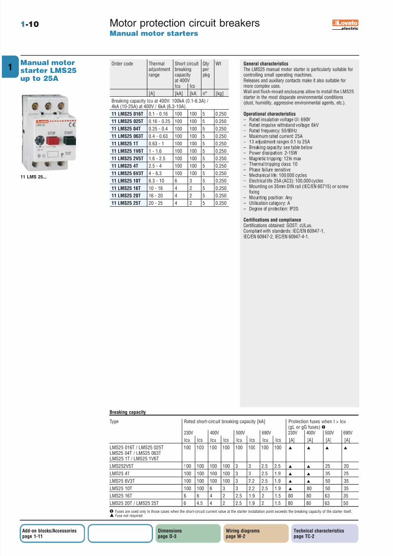
General characteristicsThe LMS25 manual motor starter is particularly suitable forcontrolling small operating machines.Releases and auxiliary contacts make it also suitable formore complex uses.Wall and flush-mount enclosures allow to install the LMS25
starter in the most disparate environmental conditions(dust, humidity, aggressive environmental agents, etc.).
Operational characteristics– Rated insulation voltage Ui: 690V– Rated impulse withstand voltage: 6kV– Rated frequency: 50/60Hz– Maximum rated current: 25A– 13 adjustment ranges 0.1 to 25A– Breaking capacity: see table below– Power dissipation: 2-15W– Magnetic tripping: 12In max– Thermal tripping class: 10– Phase failure sensitive– Mechanical life: 100,000 cycles– Electrical life 25A (AC3): 100,000 cycles– Mounting on 35mm DIN rail (IEC/EN 60715) or screw
fixing– Mounting position: Any– Utilisation category: A– Degree of protection: IP20.
Certifications and complianceCertifications obtained: GOST; cULus.Compliant with standards: IEC/EN 60947-1,IEC/EN 60947-2, IEC/EN 60947-4-1.
Order code Thermal Short circuit Qty Wtadjustment breaking perrange capacity pkg
at 400VIcu Ics
[A] [kA] [kA] n° [kg]
Breaking capacity Icu at 400V: 100kA (0.1-6.3A) / 4kA (10-25A) at 400V / 6kA (6.3-10A).
11 LMS25 016T 0.1 - 0.16 100 100 5 0.250
11 LMS25 025T 0.16 - 0.25 100 100 5 0.250
11 LMS25 04T 0.25 - 0.4 100 100 5 0.250
11 LMS25 063T 0.4 - 0.63 100 100 5 0.250
11 LMS25 1T 0.63 - 1 100 100 5 0.250
11 LMS25 1V6T 1 - 1.6 100 100 5 0.250
11 LMS25 2V5T 1.6 - 2.5 100 100 5 0.250
11 LMS25 4T 2.5 - 4 100 100 5 0.250
11 LMS25 6V3T 4 - 6.3 100 100 5 0.250
11 LMS25 10T 6.3 - 10 6 3 5 0.250
11 LMS25 16T 10 - 16 4 2 5 0.250
11 LMS25 20T 16 - 20 4 2 5 0.25011 LMS25 25T 20 - 25 4 2 5 0.250
Motor protection circuit breakersManual motor starters
1-10
Manual motorstarter LMS25up to 25A
Type Rated short-circuit breaking capacity [kA] Protection fuses when I > Icu(gL or gG fuses) ❶
230V 400V 500V 690V 230V 400V 500V 690V
Icu Ics Icu Ics Icu Ics Icu Ics [A] [A] [A] [A]
LMS25 016T / LMS25 025T 100 100 100 100 100 100 100 100 ▲ ▲ ▲ ▲
LMS25 04T / LMS25 063TLMS25 1T / LMS25 1V6T
LMS252V5T 100 100 100 100 3 3 2.5 2.5 ▲ ▲ 25 20
LMS25 4T 100 100 100 100 3 3 2.5 1.9 ▲ ▲ 35 25
LMS25 6V3T 100 100 100 100 3 2.2 2.5 1.9 ▲ ▲ 50 35
LMS25 10T 100 100 6 3 3 2.2 2.5 1.9 ▲ 80 50 35
LMS25 16T 6 6 4 2 2.5 1.9 2 1.5 80 80 63 35
LMS25 20T / LMS25 25T 6 4.5 4 2 2.5 1.9 2 1.5 80 80 63 50
Breaking capacity
❶ Fuses are used only in those cases when the short-circuit current value at the starter installation point exceeds the breaking capacity of the starter itself.▲ Fuse not required.
electric
Technical characteristicspage TC-2
Dimensionspage D-3
Wiring diagramspage W-2
Add-on blocks/Accessoriespage 1-11
11 LMS 25...

8/8/2019 01 Motor Protection Circuit Breakers
http://slidepdf.com/reader/full/01-motor-protection-circuit-breakers 11/11
Related Documents