H3C MSR Series Routers Fundamentals Command Reference Hangzhou H3C Technologies Co., Ltd. http://www.h3c.com Document Version: 20101020-C-1.08 Product Version: MSR-CMW520-R2104

01-Fundamentals Command Reference
Nov 28, 2014
Welcome message from author
This document is posted to help you gain knowledge. Please leave a comment to let me know what you think about it! Share it to your friends and learn new things together.
Transcript

H3C MSR Series Routers
Fundamentals Command Reference
Hangzhou H3C Technologies Co., Ltd. http://www.h3c.com Document Version: 20101020-C-1.08 Product Version: MSR-CMW520-R2104
Copyright © 2006-2010, Hangzhou H3C Technologies Co., Ltd. and its licensors
All Rights Reserved
No part of this manual may be reproduced or transmitted in any form or by any means without prior written consent of Hangzhou H3C Technologies Co., Ltd.
Trademarks
H3C, , Aolynk, , H3Care,
, TOP G, , IRF, NetPilot, Neocean, NeoVTL, SecPro, SecPoint, SecEngine, SecPath, Comware, Secware, Storware, NQA, VVG, V2G, VnG, PSPT, XGbus, N-Bus, TiGem, InnoVision and HUASAN are trademarks of Hangzhou H3C Technologies Co., Ltd.
All other trademarks that may be mentioned in this manual are the property of their respective owners.
Notice
The information in this document is subject to change without notice. Every effort has been made in the preparation of this document to ensure accuracy of the contents, but all statements, information, and recommendations in this document do not constitute the warranty of any kind, express or implied.

Preface
The H3C MSR documentation set includes 17 command references, which describe the commands and command syntax options available for the H3C MSR Series Routers.
The Fundamentals Command Reference describes the configuration commands for CLI, Logging In to the Device, FTP and TFTP, File Management, Configuration File Management, Software Upgrade, Device Management, and so on.
This preface includes:
Audience
Conventions
About the H3C MSR Documentation Set
Obtaining Documentation
Documentation Feedback
Audience
This documentation is intended for:
Network planners
Field technical support and servicing engineers
Network administrators working with the MSR series
Conventions
This section describes the conventions used in this documentation.
Command conventions
Convention Description
Boldface Bold text represents commands and keywords that you enter literally as shown.
italic Italic text represents arguments that you replace with actual values.
[ ] Square brackets enclose syntax choices (keywords or arguments) that are optional.
{ x | y | ... } Braces enclose a set of required syntax choices separated by vertical bars, from which you select one.
[ x | y | ... ] Square brackets enclose a set of optional syntax choices separated by vertical bars, from which you select one or none.
{ x | y | ... } * Asterisk marked braces enclose a set of required syntax choices separated by vertical bars, from which you select at least one.
[ x | y | ... ] * Asterisk marked square brackets enclose optional syntax choices separated by vertical bars, from which you may select multiple choices or none.
&<1-n> The argument or keyword and argument combination before the ampersand (&) sign can be entered 1 to n times.
# A line that starts with a pound (#) sign is comments.

Symbols
Convention Description
Means reader be extremely careful. Improper operation may cause bodily injury.
Means reader be careful. Improper operation may cause data loss or damage to equipment.
Means an action or information that needs special attention to ensure successful configuration or good performance.
Means a complementary description.
Means techniques helpful for you to make configuration with ease.
About the H3C MSR Documentation Set
The H3C MSR documentation set includes:
Category Documents Purposes
MSR 900 Routers Marketing brochures
MSR 20-1X Routers Marketing brochures
MSR 20-2X[40] Routers Marketing brochures
MSR 30 Routers Marketing brochures
Product description and specifications
MSR 50-40[60] Routers Marketing brochures
Describe product specifications and benefits.
MSR 900 Routers Installation guide
MSR 20-1X Routers Installation guide
MSR 20-2X[40] Routers Installation guide
MSR 30 Routers Installation guide
MSR 50 Routers Installation guide
Hardware specifications and installation
MSR Series Routers Interface Module Manual
Provides a complete guide to hardware installation and hardware specifications.
MSR Series Routers Configuration guides Describe software features and configuration procedures.
MSR Series Routers Command references Provide a quick reference to all available commands. Software configuration
MSR Series Routers Web Configuration guides
Describe Web software features and configuration procedures.
MSR Basic Series Routers Release notes
Operations and maintenance MSR Standard Series Routers Release
notes
Provide information about the product release, including the version history, hardware and software compatibility matrix, version upgrade information, technical support information, and software upgrading.

Obtaining Documentation
You can access the most up-to-date H3C product documentation on the World Wide Web at http://www.h3c.com/.
Click the links on the top navigation bar to obtain different categories of product documentation:
[Technical Support & Documents > Technical Documents] – Provides hardware installation, software upgrading, and software feature configuration and maintenance documentation.
[Products & Solutions] – Provides information about products and technologies, as well as solutions.
[Technical Support & Documents > Software Download] – Provides the documentation released with the software version.
Documentation Feedback
You can e-mail your comments about product documentation to [email protected].
We appreciate your comments.

i
Table of Contents
1 CLI Configuration Commands··················································································································1-1 CLI Configuration Commands·················································································································1-1
command-alias enable ····················································································································1-1 command-alias mapping ·················································································································1-1 command-privilege level··················································································································1-2 display clipboard······························································································································1-3 display command-alias····················································································································1-4 display history-command·················································································································1-5 display hotkey··································································································································1-5 hotkey ··············································································································································1-6 quit ···················································································································································1-7 return ···············································································································································1-7 screen-length disable ······················································································································1-8 super················································································································································1-9 super authentication-mode··············································································································1-9 super password ·····························································································································1-10 system-view···································································································································1-11
2 Logging In to the Router Commands ······································································································2-1 Logging In to the Router Commands······································································································2-1
acl (user interface view)···················································································································2-1 activation-key···································································································································2-2 auto-execute command···················································································································2-3 authentication-mode························································································································2-5 command accounting ······················································································································2-6 command authorization ···················································································································2-6 databits ············································································································································2-7 display ip http···································································································································2-8 display ip https·································································································································2-9 display user-interface ····················································································································2-10 display users··································································································································2-12 escape-key ····································································································································2-13 flow-control ····································································································································2-14 free user-interface ·························································································································2-16 history-command max-size ···········································································································2-17 idle-timeout ····································································································································2-17 ip http acl ·······································································································································2-18 ip http enable ·································································································································2-19 ip http port······································································································································2-20 ip https acl ·····································································································································2-20 ip https certificate access-control-policy························································································2-21 ip https enable ·······························································································································2-22

ii
ip https port····································································································································2-23 ip https ssl-server-policy················································································································2-23 lock ················································································································································2-24 parity ··············································································································································2-25 protocol inbound ····························································································································2-26 redirect disconnect ························································································································2-26 redirect enable·······························································································································2-27 redirect listen-port··························································································································2-28 redirect refuse-negotiation·············································································································2-28 redirect refuse-teltransfer ··············································································································2-29 redirect return-deal from-telnet······································································································2-30 redirect return-deal from-terminal··································································································2-31 redirect timeout······························································································································2-32 screen-length·································································································································2-33 send···············································································································································2-33 set authentication password··········································································································2-35 shell ···············································································································································2-36 speed (user interface view) ···········································································································2-36 stopbit-error intolerance·················································································································2-37 stopbits ··········································································································································2-38 telnet ··············································································································································2-39 telnet client source·························································································································2-40 telnet ipv6 ······································································································································2-40 telnet server enable ·······················································································································2-41 terminal type ··································································································································2-41 user privilege level·························································································································2-42 user-interface·································································································································2-43
3 Device Management Commands ·············································································································3-1 Device Management Commands············································································································3-1
card-mode ·······································································································································3-1 clock datetime··································································································································3-2 clock summer-time one-off ··············································································································3-3 clock summer-time repeating ··········································································································3-4 clock timezone·································································································································3-5 configure-user count························································································································3-6 copyright-info enable ·······················································································································3-7 display clock ····································································································································3-8 display configure-user ·····················································································································3-9 display cpu-usage··························································································································3-10 display cpu-usage history··············································································································3-11 display current-configuration ·········································································································3-13 display device ································································································································3-15 display device manuinfo ················································································································3-16 display diagnostic-information ·······································································································3-18 display environment (advanced) ···································································································3-19

iii
display environment (basic)···········································································································3-20 display fan ·····································································································································3-21 display job······································································································································3-22 display memory ·····························································································································3-23 display power·································································································································3-24 display reboot-type ························································································································3-24 display rps ·····································································································································3-25 display schedule reboot·················································································································3-26 display system-failure ····················································································································3-26 display this·····································································································································3-27 display transceiver·························································································································3-28 display transceiver alarm···············································································································3-30 display transceiver diagnosis ········································································································3-33 display transceiver manuinfo·········································································································3-34 display version·······························································································································3-36 header ···········································································································································3-36 job ··················································································································································3-38 nms monitor-interface····················································································································3-38 reboot·············································································································································3-39 reset unused porttag······················································································································3-40 schedule reboot at ·························································································································3-41 schedule reboot delay ···················································································································3-42 shutdown-interval ··························································································································3-43 sysname ········································································································································3-44 system-failure ································································································································3-45 temperature-limit (basic)················································································································3-45 time················································································································································3-46 view················································································································································3-49
4 Configuration File Management Commands ··························································································4-1 Configuration File Management Commands ··························································································4-1
archive configuration ·······················································································································4-1 archive configuration interval···········································································································4-1 archive configuration location··········································································································4-2 archive configuration max················································································································4-3 backup startup-configuration ···········································································································4-4 configuration encrypt ·······················································································································4-5 configuration replace file··················································································································4-5 display archive configuration ···········································································································4-6 display saved-configuration·············································································································4-7 display startup ·································································································································4-9 reset saved-configuration ··············································································································4-10 restore startup-configuration ·········································································································4-11 save ···············································································································································4-11 startup saved-configuration ···········································································································4-13
iv
5 File Management Commands···················································································································5-1 File Management Commands·················································································································5-1
cd·····················································································································································5-1 copy ·················································································································································5-2 delete···············································································································································5-3 dir·····················································································································································5-3 display nandflash file-location ·········································································································5-4 display nandflash badblock-location································································································5-5 display nandflash page-data ···········································································································5-6 execute ············································································································································5-7 file prompt········································································································································5-8 fixdisk···············································································································································5-9 format···············································································································································5-9 mkdir ··············································································································································5-10 more···············································································································································5-11 mount·············································································································································5-11 move··············································································································································5-12 pwd ················································································································································5-13 rename ··········································································································································5-13 reset recycle-bin ····························································································································5-14 rmdir···············································································································································5-16 umount···········································································································································5-16 undelete·········································································································································5-17
6 FTP Configuration Commands·················································································································6-1 FTP Server Configuration Commands····································································································6-1
display ftp-server ·····························································································································6-1 display ftp-user ································································································································6-2 free ftp user ·····································································································································6-3 ftp server acl ····································································································································6-3 ftp server enable······························································································································6-4 ftp timeout········································································································································6-5 ftp update·········································································································································6-5
FTP Client Configuration Commands ·····································································································6-6 ascii··················································································································································6-6 binary···············································································································································6-7 bye···················································································································································6-7 cd·····················································································································································6-8 cdup·················································································································································6-8 close ················································································································································6-9 debugging········································································································································6-9 delete·············································································································································6-11 dir···················································································································································6-11 disconnect ·····································································································································6-13 ftp···················································································································································6-13 ftp client source ·····························································································································6-14

v
ftp ipv6 ···········································································································································6-15 get··················································································································································6-16 lcd ··················································································································································6-16 ls ····················································································································································6-17 mkdir ··············································································································································6-18 open···············································································································································6-19 open ipv6 ·······································································································································6-19 passive ··········································································································································6-20 put··················································································································································6-21 pwd ················································································································································6-21 quit ·················································································································································6-22 remotehelp·····································································································································6-22 rmdir···············································································································································6-24 user················································································································································6-25 verbose··········································································································································6-26
7 TFTP Configuration Commands ··············································································································7-1 TFTP Client Configuration Commands···································································································7-1
tftp-server acl···································································································································7-1 tftp····················································································································································7-2 tftp client source ······························································································································7-3 tftp ipv6 ············································································································································7-4
8 License Management Configuration Commands···················································································8-1 License Management Configuration Commands····················································································8-1
display license ·································································································································8-1 license register ································································································································8-2
9 Software Upgrade Commands ·················································································································9-1 Software Upgrade Commands················································································································9-1
boot-loader ······································································································································9-1 bootrom ···········································································································································9-2 display boot-loader ··························································································································9-4 display patch information·················································································································9-5 patch active ·····································································································································9-6 patch deactive ·································································································································9-6 patch delete ·····································································································································9-7 patch install······································································································································9-7 patch load ········································································································································9-8 patch location ··································································································································9-9 patch run··········································································································································9-9
10 Index ·······················································································································································10-1

1-1
1 CLI Configuration Commands
CLI Configuration Commands
command-alias enable
Syntax
command-alias enable
undo command-alias enable
View
System view
Default Level
2: System level
Parameters
None
Description
Use the command-alias enable command to enable the command alias function.
Use the undo command-alias enable command to disable the command alias function.
By default, the command alias function is disabled, which means you cannot configure command aliases.
Examples
# Enable the command alias function. <Sysname> system-view
[Sysname] command-alias enable
# Disable the command alias function. <Sysname> system-view
[Sysname] undo command-alias enable
command-alias mapping
Syntax
command-alias mapping cmdkey alias
undo command-alias mapping cmdkey
View
System view
Default Level
2: System level
1-2
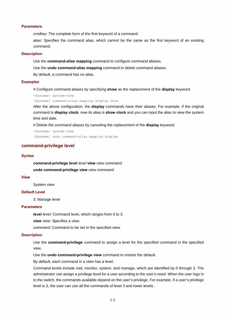
Parameters
cmdkey: The complete form of the first keyword of a command.
alias: Specifies the command alias, which cannot be the same as the first keyword of an existing command.
Description
Use the command-alias mapping command to configure command aliases.
Use the undo command-alias mapping command to delete command aliases.
By default, a command has no alias.
Examples
# Configure command aliases by specifying show as the replacement of the display keyword. <Sysname> system-view
[Sysname] command-alias mapping display show
After the above configuration, the display commands have their aliases. For example, if the original command is display clock, now its alias is show clock and you can input the alias to view the system time and date.
# Delete the command aliases by canceling the replacement of the display keyword. <Sysname> system-view
[Sysname] undo command-alias mapping display
command-privilege level
Syntax
command-privilege level level view view command
undo command-privilege view view command
View
System view
Default Level
3: Manage level
Parameters
level level: Command level, which ranges from 0 to 3.
view view: Specifies a view.
command: Command to be set in the specified view.
Description
Use the command-privilege command to assign a level for the specified command in the specified view.
Use the undo command-privilege view command to restore the default.
By default, each command in a view has a level.
Command levels include visit, monitor, system, and manage, which are identified by 0 through 3. The administrator can assign a privilege level for a user according to the user’s need. When the user logs in to the switch, the commands available depend on the user’s privilege. For example, if a user’s privilege level is 3, the user can use all the commands of level 3 and lower levels.

1-3
You are recommended to use the default command level or modify the command level under the guidance of professional staff. An improper command level change may bring inconvenience to your maintenance and operation, or even potential security problems.
The command specified in the command-privilege command must be complete, and has valid arguments. For example, the default level of the tftp server-address { get | put | sget } source-filename [ destination-filename ] [ source { interface interface-type interface-number | ip source-ip-address } ] command is 3. After the command-privilege level 0 view shell tftp 1.1.1.1 put a.cfg command is executed, when users with the user privilege level of 0 log in to the switch, they can execute the tftp server-address put source-filename command (such as the tftp 192.168.1.26 put syslog.txt command), but cannot execute the command with the get, sget or source keyword, and cannot specify the destination-filename argument.
The command specified in the undo command-privilege view command can be incomplete. For example, after the undo command-privilege view system ftp command is executed, all commands starting with the keyword ftp (such as ftp server acl, ftp server enable, and ftp timeout) are restored to their default level. If you have modified the level of commands ftp server enable and ftp timeout, and you want to restore only the ftp server enable command to its default level, you should use the undo command-privilege view system ftp server command.
If you modify the command level of a command in a specified view from the default command level to a lower level, remember to modify the command levels of the quit command and the corresponding command that is used to enter this view. For example, the default command level of commands interface and system-view is 2 (system level); if you want to make the interface command available to the users with the user privilege level of 1, you need to execute the following three commands: command-privilege level 1 view shell system-view, command-privilege level 1 view system interface GigabitEthernet 3/0/1, and command-privilege level 1 view system quit, so that the login users with the user privilege level of 1 can enter system view, execute the interface ethernet command, and then return to user view.
Examples
# Set the command level of the interface command to 0 in system view. <Sysname> system-view
[Sysname] command-privilege level 0 view system interface
display clipboard
Syntax
display clipboard [ | { begin | exclude | include } regular-expression ]
View
Any view
Default Level
1: Monitor level
Parameters
|: Filters command output by specifying a regular expression. For more information about regular expressions, see CLI in the Fundamentals Configuration Guide.
begin: Displays the first line that matches the specified regular expression and all lines that follow.

1-4
exclude: Displays the lines that do not match the specified regular expression.
include: Displays all lines that match the specified regular expression.
regular-expression: Specifies a regular expression, which is a case sensitive string of 1 to 256 characters.
Description
Use the display clipboard command to view the contents of the clipboard.
To copy the specified content to the clipboard:
Move the cursor to the starting position of the content and press the <Esc+Shift+,> combination (“,” is an English comma).
Move the cursor to the ending position of the content and press the <Esc+Shift+.> combination (“.” is an English dot) to copy the specified content to the clipboard.
Examples
# View the content of the clipboard. <Sysname> display clipboard
---------------- CLIPBOARD-----------------
display current-configuration
display command-alias
Syntax
display command-alias [ | { begin | exclude | include } regular-expression ]
View
Any view
Default Level
1: Monitor level
Parameters
|: Filters command output by specifying a regular expression. For more information about regular expressions, see CLI in the Fundamentals Configuration Guide.
begin: Displays the first line that matches the specified regular expression and all lines that follow.
exclude: Displays the lines that do not match the specified regular expression.
include: Displays all lines that match the specified regular expression.
regular-expression: Specifies a regular expression, which is a case sensitive string of 1 to 256 characters.
Description
Use the display command-alias command to display defined command aliases and the corresponding commands.
Examples
# Display the defined command aliases and the corresponding commands. <Sysname> display command-alias
Command alias is enabled
index alias command key
1 show display

1-5
display history-command
Syntax
display history-command
View
Any view
Default Level
1: Monitor level
Parameters
None
Description
Use the display history-command command to display commands saved in the history command buffer.
The system saves up to 10 latest executed commands in the history command buffer by default. To set the size of the history command buffer, use the history-command max-size command. For more information, see Logging In to the Router in the Fundamentals Command Reference.
Examples
# Display history commands in current user view. <Sysname> display history-command
display history-command
system-view
vlan 2
quit
display hotkey
Syntax
display hotkey
View
Any view
Default Level
1: Monitor level
Parameters
None
Description
Use the display hotkey command to display hotkey information.
Examples
# Display hotkey information. <Sysname> display hotkey
----------------- HOTKEY -----------------
=Defined hotkeys=

1-6
Hotkeys Command
CTRL_G display current-configuration
CTRL_L display ip routing-table
CTRL_O undo debug all
=Undefined hotkeys=
Hotkeys Command
CTRL_T NULL
CTRL_U NULL
=System hotkeys=
Hotkeys Function
CTRL_A Move the cursor to the beginning of the current line.
CTRL_B Move the cursor one character left.
CTRL_C Stop current command function.
CTRL_D Erase current character.
CTRL_E Move the cursor to the end of the current line.
CTRL_F Move the cursor one character right.
CTRL_H Erase the character left of the cursor.
CTRL_K Kill outgoing connection.
CTRL_N Display the next command from the history buffer.
CTRL_P Display the previous command from the history buffer.
CTRL_R Redisplay the current line.
CTRL_V Paste text from the clipboard.
CTRL_W Delete the word left of the cursor.
CTRL_X Delete all characters up to the cursor.
CTRL_Y Delete all characters after the cursor.
CTRL_Z Return to the User View.
CTRL_] Kill incoming connection or redirect connection.
ESC_B Move the cursor one word back.
ESC_D Delete remainder of word.
ESC_F Move the cursor forward one word.
ESC_N Move the cursor down a line.
ESC_P Move the cursor up a line.
ESC_< Specify the beginning of clipboard.
ESC_> Specify the end of clipboard.
hotkey
Syntax
hotkey { CTRL_G | CTRL_L | CTRL_O | CTRL_T | CTRL_U } command
undo hotkey { CTRL_G | CTRL_L | CTRL_O | CTRL_T | CTRL_U }
View
System view
Default Level
2: System level
Parameters
CTRL_G: Associates hot key Ctrl+G to the specified command.

1-7
CTRL_L: Associates hot key Ctrl+L to the specified command.
CTRL_O: Associates hot key Ctrl+O to the specified command.
CTRL_T: Associates hot key Ctrl+T to the specified command.
CTRL_U: Associates hot key Ctrl+U to the specified command.
command: The command line associated with the hot key.
Description
Use the hotkey command to associate a hot key to a command.
Use the undo hotkey command to restore the default.
By default, Ctrl+G, Ctrl+L and Ctrl+O are associated to corresponding commands, but others are not.
Ctrl+G corresponds to display current-configuration.
Ctrl+L corresponds to display ip routing-table.
Ctrl+O corresponds to undo debugging all.
You can modify the associations as needed.
Examples
# Associate the hot key Ctrl+T to the display tcp status command. <Sysname> system-view
[Sysname] hotkey ctrl_t display tcp status
quit
Syntax
quit
View
Any view
Default Level
0: Visit level (in user view)
2: System level (in other views)
Parameters
None
Description
Use the quit command to return to a lower-level view. If the current view is user view, the quit command terminates the current connection and reconnects to the switch.
Examples
# Switch from GigabitEthernet 3/0/18 interface view to system view, and then to user view. [Sysname-GigabitEthernet3/0/18] quit
[Sysname] quit
<Sysname>
return
Syntax
return

1-8
View
Any view except user view
Default Level
2: System level
Parameters
None
Description
Use the return command to return to user view from the current view, as you do with the hot key Ctrl+Z.
Related commands: quit.
Examples
# Return to user view from GigabitEthernet 3/0/18 view. [Sysname-GigabitEthernet3/0/18] return
<Sysname>
screen-length disable
Syntax
screen-length disable
undo screen-length disable
View
User view
Default Level
1: Monitor level
Parameters
None
Description
Use the screen-length disable command to disable the multiple-screen output function.
Use the undo screen-length disable command to enable the multiple-screen output function.
By default, a login user uses the settings of the screen-length command. The default settings of the screen-length command are: multiple-screen output is enabled and 24 lines are displayed on the next screen. (For more information about the screen-length command, see Logging In to the Router in the Fundamentals Command Reference.)
This command is applicable to the current user only. When a user re-logs in, the settings restore to their default values.
Examples
# Disable multiple-screen output for the current user. <Sysname> screen-length disable
1-9
super
Syntax
super [ level ]
View
User view
Default Level
0: Visit level
Parameters
level: User level, which ranges from 0 to 3 and defaults to 3.
Description
Use the super command to switch from the current user privilege level to a specified user privilege level.
Without a level specified, the command switches the current user privilege level to 3.
Login users are classified into four levels that correspond to the four command levels. After users at different levels log in, they can only use commands at their own level, and lower levels.
Note that:
A user can switch to a lower privilege level unconditionally. A logged-in AUX or VTY user must input the switching password set with the super password command to switch to a higher privilege level. If the entered password is incorrect or no password is configured, the switching operation fails. Therefore, before switching to a higher user privilege level, you must configure the switching password.
Related commands: super password.
Examples
# Switch to user privilege level 2 (The current user privilege level is 3.). <Sysname> super 2
User privilege level is 2, and only those commands can be used
whose level is equal or less than this.
Privilege note: 0-VISIT, 1-MONITOR, 2-SYSTEM, 3-MANAGE
# Switch the user privilege level back to 3 (switching password 123 has been set. If no password is set, the user privilege level cannot be switched to 3.). <Sysname> super 3
Password:
User privilege level is 3, and only those commands can be used
whose level is equal or less than this.
Privilege note: 0-VISIT, 1-MONITOR, 2-SYSTEM, 3-MANAGE
super authentication-mode
Syntax
super authentication-mode { local | scheme } *
undo super authentication-mode
View
System view
1-10
Default Level
2: System level
Parameters
local: Authenticates a user by using the local password set with the super password command. In this case, when no password is set with the super password command, privilege level switch succeeds if the user is logged in through the console port (the console port or the AUX port used as the console port), and the switch fails if the user is logged in through any of the AUX, TTY, or VTY user interfaces or inputs an incorrect switch password.
scheme: AAA authentication. For more information about AAA, see AAA in the Security Configuration Guide.
local scheme: First local and then scheme, which means to authenticate a user by using the local password first, and if no password is set, for the user logged in through the console port, the privilege level switch succeeds; for the user logged in through any of the AUX, TTY, or VTY user interfaces, the AAA authentication is performed.
scheme local: First scheme and then local, which means that AAA authentication is performed first, and if the AAA configuration is invalid (domain parameters or authentication scheme are not configured) or the server does not respond, local password authentication is performed.
Description
Use the super authentication-mode command to set the authentication mode for user privilege level switch.
Use the undo super authentication-mode command to restore the default.
By default, the authentication mode for user privilege level switch is local.
Related commands: super password.
Examples
# Set the authentication mode for user privilege level switch to local. <Sysname> system-view
[Sysname] super authentication-mode local
# Set the authentication mode for user privilege level switch to scheme local. <Sysname> system-view
[Sysname] super authentication-mode scheme local
super password
Syntax
super password [ level user-level ] { simple | cipher } password
undo super password [ level user-level ]
View
System view
Default Level
2: System level
Parameters
level user-level: User privilege level, which ranges from 1 to 3 and defaults to 3.

1-11
simple: Plain text password.
cipher: Cipher text password.
password: Password, a case-sensitive string of characters.
A simple password is a string of 1 to 16 characters.
A cipher password is a string of 1 to 16 characters in plain text or 24 characters in cipher text. For example, the simple text “1234567” corresponds to the cipher text “(TT8F]Y\5SQ=^Q`MAF4<1!!”.
Description
Use the super password command to set the password used to switch from the current user privilege level to a higher one.
Use the undo super password command to restore the default.
By default, no password is set for switching to a higher privilege level.
Use the simple keyword to set a simple-text password.
Use the cipher keyword to set a cipher-text password.
A cipher-text password is recommended because a simple-text password easily gets cracked.
During authentication, you must input a simple-text password regardless of the password type you set.
Examples
# Set simple-text password abc for switching to user privilege level 3. <Sysname> system-view
[Sysname] super password level 3 simple abc
Display the configured password for level switching. [Sysname] display current-configuration
#
super password level 3 simple abc
# Set cipher-text password abc for switching to user privilege level 3. <Sysname> system-view
[Sysname] super password level 3 cipher abc
Display the configured password for level switching. [Sysname] display current-configuration | include super
#
super password level 3 cipher ;)<01%^&;YGQ=^Q`MAF4<1!!
system-view
Syntax
system-view
View
User view
Default Level
2: System level
Parameters
None

1-12
Description
Use the system-view command to enter system view from the current user view.
Related commands: quit, return.
Examples
# Enter system view from the current user view. <Sysname> system-view
System View: return to User View with Ctrl+Z.
[Sysname]

2-1
2 Logging In to the Router Commands
Logging In to the Router Commands
acl (user interface view)
Syntax
To use a basic ACL:
acl [ ipv6 ] acl-number { inbound | outbound }
undo acl [ ipv6 ] acl-number { inbound | outbound }
To use a WLAN or Ethernet frame header ACL:
acl acl-number inbound
undo acl acl-number inbound
View
VTY user interface view
Default Level
2: System level
Parameters
ipv6: When this keyword is present, the command supports IPv6; otherwise, it supports IPv4.
acl-number: Number of the access control list (ACL). The value range is as follows:
100 to 199 are the WLAN ACL numbers
2000 to 2999 are the basic ACL numbers
4000 to 4999 are the Ethernet frame header ACL numbers
inbound: Restricts Telnet or SSH connections established in the inbound direction through the VTY user interface. If the received packets for establishing a Telnet or SSH connection are permitted by an ACL rule, the connection is allowed to be established. When the device functions as a Telnet server or SSH server, this keyword is used to control access of Telnet clients or SSH clients.
outbound: Restricts Telnet connections established in the outbound direction through the VTY user interface. If the packets sent for establishing a Telnet connection are permitted by an ACL rule, the connection is allowed to be established. When the device functions as a Telnet client, this keyword is used to define Telnet servers accessible to the client.
Description
Use the acl command to reference ACLs to control access to the VTY user interface.
Use the undo acl command to cancel the ACL application. For more information about ACL, see ACL in the ACL and QoS Configuration Guide.
By default, access to the VTY user interface is not restricted.
If no ACL is referenced in VTY user interface view, the VTY user interface has no access control over establishing a Telnet or SSH connection.

2-2
If an ACL is referenced in VTY user interface view, the connection is permitted to be established only when packets for establishing a Telnet or SSH connection match a permit statement in the ACL.
The system regards the basic/advanced ACL with the inbound keyword, the basic/advanced ACL with the outbound keyword, WLAN ACL, and Ethernet frame header ACL as four different types of ACLs, which can coexist in one VTY user interface. The match order is WLAN ACL, basic/advanced ACL, Ethernet frame header ACL. At most one ACL of each type can be referenced in the same VTY user interface, and the last configured one takes effect.
Examples
# Allow only the user with the IP address of 192.168.1.26 to access the device through Telnet or SSH. <Sysname> system-view
[Sysname] acl number 2001
[Sysname-acl-basic-2001] rule permit source 192.168.1.26 0
[Sysname-acl-basic-2001] quit
[Sysname] user-interface vty 0
[Sysname-ui-vty0] acl 2001 inbound
After your configuration, user A (with IP address 192.168.1.26) can telnet to the device while user B (with IP address 192.168.1.60) cannot telnet to the device. Upon a connection failure, a message appears, saying "%connection closed by remote host!"
# Allow only the WLAN client with the SSID of Admin to access the device through VTY 0. <Sysname> system-view
[Sysname] acl number 100
[Sysname-acl-wlan-100] rule permit ssid Admin
[Sysname-acl-wlan-100] quit
[Sysname] user-interface vty 0
[Sysname-ui-vty0] acl 100 inbound
activation-key
Syntax
activation-key character
undo activation-key
View
User interface view
Default Level
3: Manage level
Parameters
character: Shortcut key for starting a terminal session, a single character (or its corresponding ASCII code value that ranges from 0 to 127) or a string of 1 to 3 characters. However, only the first character functions as the shortcut key. For example, if you input an ASCII code value 97, the system uses its corresponding character a as the shortcut key. If you input string b@c, the system uses the first character b as the shortcut key.
Description
Use the activation-key command to define a shortcut key for starting a terminal session.
2-3
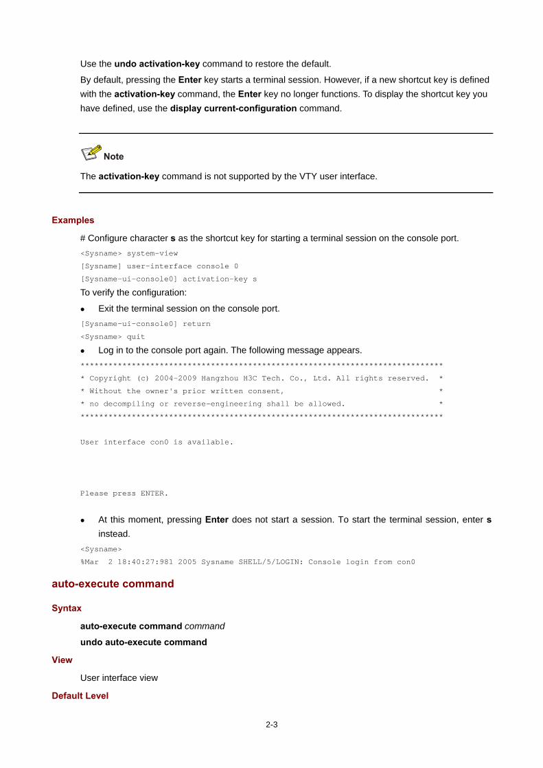
Use the undo activation-key command to restore the default.
By default, pressing the Enter key starts a terminal session. However, if a new shortcut key is defined with the activation-key command, the Enter key no longer functions. To display the shortcut key you have defined, use the display current-configuration command.
The activation-key command is not supported by the VTY user interface.
Examples
# Configure character s as the shortcut key for starting a terminal session on the console port. <Sysname> system-view
[Sysname] user-interface console 0
[Sysname-ui-console0] activation-key s
To verify the configuration:
Exit the terminal session on the console port. [Sysname-ui-console0] return
<Sysname> quit
Log in to the console port again. The following message appears. ******************************************************************************
* Copyright (c) 2004-2009 Hangzhou H3C Tech. Co., Ltd. All rights reserved. *
* Without the owner's prior written consent, *
* no decompiling or reverse-engineering shall be allowed. *
******************************************************************************
User interface con0 is available.
Please press ENTER.
At this moment, pressing Enter does not start a session. To start the terminal session, enter s instead.
<Sysname>
%Mar 2 18:40:27:981 2005 Sysname SHELL/5/LOGIN: Console login from con0
auto-execute command
Syntax
auto-execute command command
undo auto-execute command
View
User interface view
Default Level

2-4
3: Manage level
Parameters
command: Specifies a command to be automatically executed.
Description
Use the auto-execute command command to specify a command to be automatically executed when a user logs in to the current user interface.
Use the undo auto-execute command command to remove the configuration.
By default, command auto-execution is disabled.
The auto-execute command command is not supported by the console port, or the AUX port when the device has only one AUX port and no console port.
The system automatically executes the specified command when a user logs in to the user interface, and tears down the user connection after the command is executed. If the command triggers another task, the system does not tear down the user connection until the task is completed.
A good example is configuring the auto-execute command telnet command to let users automatically telnet to the specified host.
The auto-execute command command may disable you from configuring the system through the user interface to which the command is applied. Therefore, before configuring the command and saving the configuration (by using the save command), make sure that you can access the device through VTY, TTY, console, or AUX interfaces to remove the configuration when a problem occurs.
Examples
# Configure the device to automatically telnet to 192.168.1.41 after a user logs in to interface VTY 0. <Sysname> system-view
<Sysname> system-view
[Sysname] user-interface vty 0
[Sysname -ui-vty0] auto-execute command telnet 192.168.1.41
% This action will lead to configuration failure through ui-vty0. Are you sure?
[Y/N]:y
[Sysname-ui-vty0]
To verify the configuration:
Telnet to 192.168.1.40. The device automatically telnets to 192.168.1.41. The following output is displayed: C:\> telnet 192.168.1.40
******************************************************************************
* Copyright (c) 2004-2010 Hangzhou H3C Tech. Co., Ltd. All rights reserved. *
* Without the owner's prior written consent, *
* no decompiling or reverse-engineering shall be allowed. *
******************************************************************************
<Sysname>

2-5
Trying 192.168.1.41 ...
Press CTRL+K to abort
Connected to 192.168.1.41 ...
******************************************************************************
* Copyright (c) 2004-2010 Hangzhou H3C Tech. Co., Ltd. All rights reserved. *
* Without the owner's prior written consent, *
* no decompiling or reverse-engineering shall be allowed. *
******************************************************************************
<Sysname.41>
This operation equals directly logging in to the device at 192.168.1.41. If the telnet connection to 192.168.1.41 is broken down, the telnet connection to 192.168.1.40 breaks down at the same time.
authentication-mode
Syntax
authentication-mode { none | password | scheme }
undo authentication-mode
View
User interface view
Default Level
3: Manage level
Parameters
none: Performs no authentication.
password: Performs local password authentication.
scheme: Performs AAA authentication. For more information about AAA, see AAA in the Security Configuration Guide.
Description
Use the authentication-mode command to set the authentication mode for the user interface.
Use the undo authentication-mode command to restore the default.
By default, the authentication mode is password for VTY and AUX user interfaces, and is none for console and TTY user interfaces.
Related commands: set authentication password.
Examples
# Specify that no authentication is needed for VTY 0. (This mode is insecure.) <Sysname> system-view
[Sysname] user-interface vty 0
[Sysname-ui-vty0] authentication-mode none
# Use password authentication when users log in to the device through VTY 0, and set the authentication password to 321. <Sysname> system-view
[Sysname] user-interface vty 0
[Sysname-ui-vty0] authentication-mode password
[Sysname-ui-vty0] set authentication password cipher 321

2-6
# Authenticate users by username and password for VTY 0. Set the username to 123 and the password to 321. <Sysname> system-view
[Sysname] user-interface vty 0
[Sysname-ui-vty0] authentication-mode scheme
[Sysname-ui-vty0] quit
[Sysname] local-user 123
[Sysname-luser-123] password cipher 321
[Sysname-luser-123] service-type telnet
[Sysname-luser-123] authorization-attribute level 3
command accounting
Syntax
command accounting
undo command accounting
View
User interface view
Default Level
3: Manage level
Parameters
None
Description
Use the command accounting command to enable command accounting.
Use the undo command accounting command to restore the default.
By default, command accounting is disabled. The accounting server does not record the commands that users have executed.
When command accounting is enabled and command authorization is not, every executed command is recorded on the HWTACACS server.
When both command accounting and command authorization are enabled, only the authorized and executed commands are recorded on the HWTACACS server.
Examples
# Enable command accounting on VTY 0. Then the HWTACACS server records the commands executed by users that have logged in through VTY 0. <Sysname> system-view
[Sysname] user-interface vty 0
[Sysname-ui-vty0] command accounting
command authorization
Syntax
command authorization
undo command authorization

2-7
View
User interface view
Default Level
3: Manage level
Parameters
None
Description
Use the command authorization command to enable command authorization.
Use the undo command authorization command to restore the default.
By default, command authorization is disabled. Logged-in users can execute commands without authorization.
With command authorization enabled, users can perform only commands authorized by the server.
Examples
# Enable command accounting for VTY 0 so that users logging in from VTY 0 can perform only the commands authorized by the HWTACACS server. <Sysname> system-view
[Sysname] user-interface vty 0
[Sysname-ui-vty0] command authorization
databits
Syntax
databits { 5 | 6 | 7 | 8 }
undo databits
View
User interface view
Default Level
2: System level
Parameters
5: Sets 5 data bits for each character.
6: Sets 6 data bits for each character.
7: Sets 7 data bits for each character.
8: Sets 8 data bits for each character.
Description
Use the databits command to set data bits for each character.
Use the undo databits command to restore the default.
By default, 8 data bits are set for each character.

2-8
The command is only applicable to asynchronous serial interfaces (including AUX and console ports).
The data bits setting must be the same for the user interfaces of the connecting ports on the device and the terminal device for communication.
Examples
# Specify 5 data bits for each character. <Sysname> system-view
[Sysname] user-interface aux 0
[Sysname-ui-aux0] databits 5
display ip http
Syntax
display ip http [ | { begin | exclude | include } regular-expression ]
View
Any view
Default Level
1: Monitor level
Parameters
|: Filters command output by specifying a regular expression. For more information about regular expressions, see CLI in the Fundamentals Configuration Guide.
begin: Displays the first line that matches the specified regular expression and all lines that follow.
exclude: Displays the lines that do not match the specified regular expression.
include: Displays all lines that match the specified regular expression.
regular-expression: Specifies a regular expression, which is a case sensitive string of 1 to 256 characters.
Description
Use the display ip http command to display HTTP information.
Examples
# Display information about HTTP.. <Sysname> display ip http
HTTP port: 80
WLAN ACL: 100
Basic ACL: 2222
Current connection: 0
Operation status: Running
Table 2-1 display ip http command output descriptionField Description
HTTP port Port number used by the HTTP service
WLAN ACL WLAN ACL associated with the HTTP service (whether this field is displayed depends on the device model)
2-9
Field Description
Basic ACL Basic ACL number associated with the HTTP service
Current connection Number of current connections
Operation status Operation status, which takes the following values:
Running: The HTTP service is enabled. Stopped: The HTTP service is disabled.
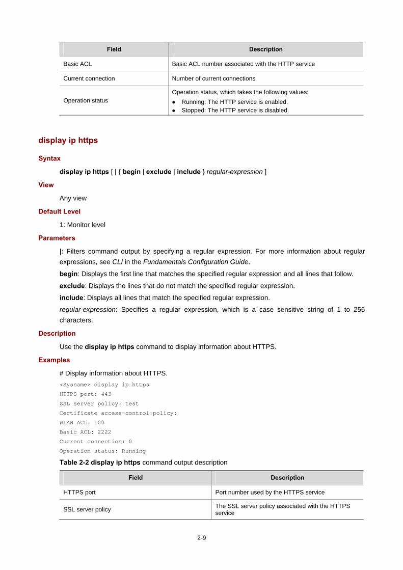
display ip https
Syntax
display ip https [ | { begin | exclude | include } regular-expression ]
View
Any view
Default Level
1: Monitor level
Parameters
|: Filters command output by specifying a regular expression. For more information about regular expressions, see CLI in the Fundamentals Configuration Guide.
begin: Displays the first line that matches the specified regular expression and all lines that follow.
exclude: Displays the lines that do not match the specified regular expression.
include: Displays all lines that match the specified regular expression.
regular-expression: Specifies a regular expression, which is a case sensitive string of 1 to 256 characters.
Description
Use the display ip https command to display information about HTTPS.
Examples
# Display information about HTTPS. <Sysname> display ip https
HTTPS port: 443
SSL server policy: test
Certificate access-control-policy:
WLAN ACL: 100
Basic ACL: 2222
Current connection: 0
Operation status: Running
Table 2-2 display ip https command output description
Field Description
HTTPS port Port number used by the HTTPS service
SSL server policy The SSL server policy associated with the HTTPS service

2-10
Field Description
Certificate access-control-policy The certificate attribute access control policy associated with the HTTPS service
WLAN ACL WLAN ACL number associated with the HTTPS service (whether this field is displayed depends on the device model)
Basic ACL The basic ACL number associated with the HTTPS service
Current connection Number of current connections
Operation status Operation status, which takes the following values:
Running: The HTTPS service is enabled. Stopped: The HTTPS service is disabled.
display user-interface
Syntax
display user-interface [ num1 | { aux | console | tty | vty } num2 ] [ summary ] [ | { begin | exclude | include } regular-expression ]
View
Any view
Default Level
1: Monitor level
Parameters
num1: Absolute number of a user interface. The value range varies with devices, and typically starts from 0.
num2: Relative number of a user interface. The value range varies with devices.
summary: Displays summary about user interfaces.
|: Filters command output by specifying a regular expression. For more information about regular expressions, see CLI in the Fundamentals Configuration Guide.
begin: Displays the first line that matches the specified regular expression and all lines that follow.
exclude: Displays the lines that do not match the specified regular expression.
include: Displays all lines that match the specified regular expression.
regular-expression: Specifies a regular expression, which is a case sensitive string of 1 to 256 characters.
Description
Use the display user-interface command to display information about the specified or all user interfaces.
If the summary keyword is not included, the command displays the type of the user interface, the absolute or relative number, the transmission rate, the user privilege level, the authentication mode, and the access port.
If the summary keyword is included, the command displays all user interface numbers and types.

2-11
Examples
# Display information about user interface 0. <Sysname> display user-interface 0
Idx Type Tx/Rx Modem Privi Auth Int
+ 0 CON 0 9600 - 3 N -
+ : Current user-interface is active.
F : Current user-interface is active and work in async mode.
Idx : Absolute index of user-interface.
Type : Type and relative index of user-interface.
Privi: The privilege of user-interface.
Auth : The authentication mode of user-interface.
Int : The physical location of UIs.
A : Authentication use AAA.
L : Authentication use local database.
N : Current UI need not authentication.
P : Authentication use current UI's password.
Table 2-3 display user-interface command output description
Field Description
+ The current user interface is active.
F The current user interface is active and works in asynchronous mode.
Idx Absolute number of the user interface.
Type Type and relative number of the user interface.
Tx/Rx Transmission/Receive rate of the user interface
Modem Whether the modem is allowed to dial in (in), dial out (out), or both (inout) By default, the character - is displayed to indicate that this function is disabled.
Privi Indicates the command level of a user under that user interface
Auth Authentication mode for the users, which can be A (AAA authentication), P (password authentication), L (local authentication), and N (none authentication).
Int The physical port that corresponds to the user interface. (The detailed port information is available for TTY user interfaces. For user interfaces of console ports, AUX ports, and VTY interfaces, - is displayed.)
A AAA authentication with the authentication mode of scheme.
L Local authentication (not supported at present)
N No authentication with the authentication mode of none.
P Password authentication with the authentication mode of password.
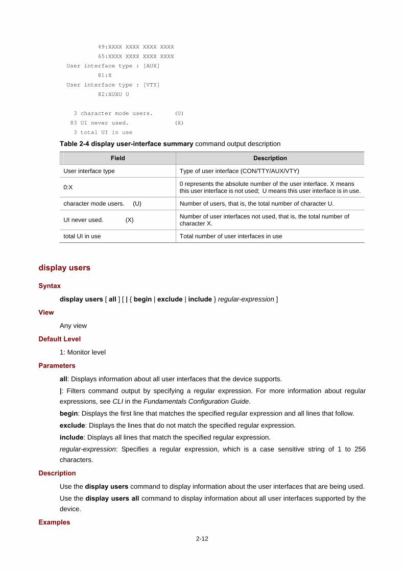
# Display summary about all user interfaces. <Sysname> display user-interface summary
User interface type : [CON]
0:X
User interface type : [TTY]
1:XXXX XXXX XXXX XXXX
17:XXXX XXXX XXXX XXXX
33:XXXX XXXX XXXX XXXX
2-12
49:XXXX XXXX XXXX XXXX
65:XXXX XXXX XXXX XXXX
User interface type : [AUX]
81:X
User interface type : [VTY]
82:XUXU U
3 character mode users. (U)
83 UI never used. (X)
3 total UI in use
Table 2-4 display user-interface summary command output description
Field Description
User interface type Type of user interface (CON/TTY/AUX/VTY)
0:X 0 represents the absolute number of the user interface. X means this user interface is not used; U means this user interface is in use.
character mode users. (U) Number of users, that is, the total number of character U.
UI never used. (X) Number of user interfaces not used, that is, the total number of character X.
total UI in use Total number of user interfaces in use
display users
Syntax
display users [ all ] [ | { begin | exclude | include } regular-expression ]
View
Any view
Default Level
1: Monitor level
Parameters
all: Displays information about all user interfaces that the device supports.
|: Filters command output by specifying a regular expression. For more information about regular expressions, see CLI in the Fundamentals Configuration Guide.
begin: Displays the first line that matches the specified regular expression and all lines that follow.
exclude: Displays the lines that do not match the specified regular expression.
include: Displays all lines that match the specified regular expression.
regular-expression: Specifies a regular expression, which is a case sensitive string of 1 to 256 characters.
Description
Use the display users command to display information about the user interfaces that are being used.
Use the display users all command to display information about all user interfaces supported by the device.
Examples

2-13
# Display information about the user interfaces that are being used. <Sysname> display users
The user application information of the user interface(s):
Idx UI Delay Type Userlevel
+ 178 VTY 0 00:00:00 TEL 3
179 VTY 1 00:02:34 TEL 3
Following are more details.
VTY 0 :
Location: 192.168.1.54
VTY 1 :
Location: 192.168.1.58
+ : Current operation user.
F : Current operation user work in async mode.
The output shows that at present two users have logged in to the device. The one with IP address 192.168.1.54 uses VTY 0, and the other with IP address 192.168.1.58 uses VTY 1.
Table 2-5 display users command output description
Field Description
Idx Absolute number of the user interface
UI Relative number of the user interface. The first column, for example, VTY, represents user interface type, and the second column, for example, 0, represents the relative number of the user interface.
Delay Time elapsed since the user's last input, in the format of hh:mm:ss.
Type User type, such as Telnet, SSH, or PAD
Userlevel User level: 0 for visit, 1 for monitor, 2 for system, and 3 for manage.
+ Current user
Location IP address of the user
F The current user works in asynchronous mode
escape-key
Syntax
escape-key { default | character }
undo escape-key
View
User interface view
Default Level
3: Manage level
Parameters
character: Specifies the shortcut key for terminating a task, a single character (or its corresponding ASCII code value in the range 0 to 127) or a string of 1 to 3 characters. Only the first character of a string functions as the shortcut key. For example, if you enter an ASCII code value of 113, the system uses its

2-14
corresponding character q as the shortcut key. If you enter the string q@c, the system uses the first character q as the shortcut key.
default: Restores the default escape key combination of Ctrl+C.
Description
Use the escape-key command to define a shortcut key for terminating a task.
Use the undo escape-key command to disable the shortcut key for terminating tasks.
By default, a task is terminated by pressing Ctrl+C.
After you define a new shortcut key by using the escape-key command, the new shortcut key is used to terminate a task. To display the shortcut key you have defined, use the display current-configuration command.
If you set the character argument in a user interface of a device, when you use the user interface to log in to the device and then telnet to another device, the character argument can be used as a control character to terminate a task rather than used as a common character. For example, if you specify character e in VTY 0 user interface of Device A, when you log in to Device A by using VTY 0 from a PC (Hyper Terminal), you can input e as a common character on the PC, and you can also use e to terminate the task running on Device A. If you telnet to Device B from Device A, however, you can only use e to terminate the task running on Device B, rather than use e as a common character. Therefore, you are recommended to specify character as a key combination.
Examples
# Define key a as the shortcut key for terminating a task. <Sysname> system-view
[Sysname] user-interface console 0
[Sysname-ui-console0] escape-key a
To verify the configuration:
# Ping the IP address of 192.168.1.49 and use the -c keyword to specify the number of ICMP echo packets to be sent as 20. <Sysname> ping -c 20 192.168.1.49
PING 192.168.1.49: 56 data bytes, press a to break
Reply from 192.168.1.49: bytes=56 Sequence=1 ttl=255 time=3 ms
Reply from 192.168.1.49: bytes=56 Sequence=2 ttl=255 time=3 ms
# Enter a. The task terminates immediately and the system returns to system view. --- 192.168.1.49 ping statistics ---
2 packet(s) transmitted
2 packet(s) received
0.00% packet loss
round-trip min/avg/max = 3/3/3 ms
<Sysname>
flow-control
Syntax
flow-control { hardware | none | software }
flow-control hardware flow-control-type1 [ software flow-control-type2 ]
flow-control software flow-control-type1 [ hardware flow-control-type2 ]
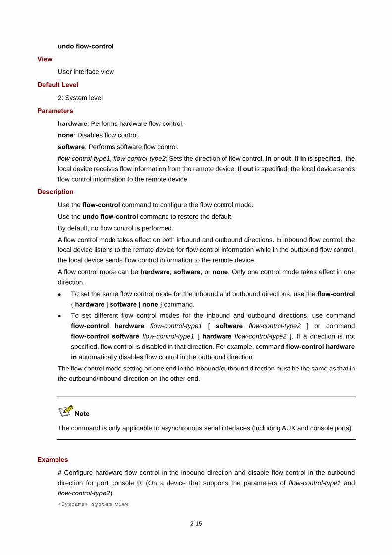
2-15
undo flow-control
View
User interface view
Default Level
2: System level
Parameters
hardware: Performs hardware flow control.
none: Disables flow control.
software: Performs software flow control.
flow-control-type1, flow-control-type2: Sets the direction of flow control, in or out. If in is specified, the local device receives flow information from the remote device. If out is specified, the local device sends flow control information to the remote device.
Description
Use the flow-control command to configure the flow control mode.
Use the undo flow-control command to restore the default.
By default, no flow control is performed.
A flow control mode takes effect on both inbound and outbound directions. In inbound flow control, the local device listens to the remote device for flow control information while in the outbound flow control, the local device sends flow control information to the remote device.
A flow control mode can be hardware, software, or none. Only one control mode takes effect in one direction.
To set the same flow control mode for the inbound and outbound directions, use the flow-control { hardware | software | none } command.
To set different flow control modes for the inbound and outbound directions, use command flow-control hardware flow-control-type1 [ software flow-control-type2 ] or command flow-control software flow-control-type1 [ hardware flow-control-type2 ]. If a direction is not specified, flow control is disabled in that direction. For example, command flow-control hardware in automatically disables flow control in the outbound direction.
The flow control mode setting on one end in the inbound/outbound direction must be the same as that in the outbound/inbound direction on the other end.
The command is only applicable to asynchronous serial interfaces (including AUX and console ports).
Examples
# Configure hardware flow control in the inbound direction and disable flow control in the outbound direction for port console 0. (On a device that supports the parameters of flow-control-type1 and flow-control-type2) <Sysname> system-view

2-16
[Sysname] user-interface console 0
[Sysname-ui-console0] flow-control hardware in
# Configure hardware flow control in the inbound direction and software flow control in the outbound direction for port console 0. (On a device that supports the parameters of flow-control-type1 and flow-control-type2) <Sysname> system-view
[Sysname] user-interface console 0
[Sysname-ui-console0] flow-control hardware in software out
free user-interface
Syntax
free user-interface { num1 | { aux | console | tty | vty } num2 }
View
User view
Default Level
3: Manage level
Parameters
num1: Absolute number of a user interface. The value range varies with devices, and typically starts from 0.
num2: Relative number of a user interface. The value range varies with devices.
Description
Use the free user-interface command to release the connection(s) established on the specified user interface.
This command cannot release the connection that you are using.
Examples
# Display the connection established on user interface VTY 1. <Sysname> display users
The user application information of the user interface(s):
Idx UI Delay Type Userlevel
+ 82 VTY 0 00:00:00 TEL 3
83 VTY 1 00:00:03 TEL 3
Following are more details.
VTY 0 :
Location: 192.168.1.26
VTY 1 :
Location: 192.168.1.20
+ : Current operation user.
F : Current operation user work in async mode.
// You can display information about the users that are using the device. <Sysname> free user-interface vty 1
Are you sure to free user-interface vty1? [Y/N]:y
// To make configurations without interruption from the user using VTY 1, you can release the connection established on VTY 1.

2-17
history-command max-size
Syntax
history-command max-size size-value
undo history-command max-size
View
User interface view
Default Level
2: System level
Parameters
size-value: Specifies the maximum number of history commands that the buffer can store. The value ranges from 0 to 256.
Description
Use the history-command max-size command to set the size of the history command buffer of the current user interface.
Use the undo history-command max-size command to restore the default.
By default, the buffer saves 10 history commands.
The history command buffer saves executed history commands per user interface and buffers for different user interfaces do not affect each other. To display the commands that are stored in the history buffer, use the display history-command command. To view the recently executed commands, press the ↑ or ↓ key. For more information about the display history-command command, see CLI in the Fundamentals Command Reference.
After you terminate the current session, the system automatically removes the commands saved in the corresponding history buffer.
Examples
# Set the buffer to store 20 history commands at most. <Sysname> system-view
[Sysname] user-interface console 0
[Sysname-ui-console0] history-command max-size 20
idle-timeout
Syntax
idle-timeout minutes [ seconds ]
undo idle-timeout
View
User interface view
Default Level
2: System level
Parameters

2-18
minutes: Specifies the timeout time in minutes, which ranges from 0 to 35791, and defaults to 10 minutes.
seconds: Specifies timeout time in seconds, which ranges from 0 to 59, and defaults to 0 seconds.
Description
Use the idle-timeout command to set the idle-timeout timer.
Use the undo idle-timeout command to restore the default.
The default idle-timeout is 10 minutes.
The system automatically terminates the user’s connection(s) if there is no information interaction between the device and the users within the idle timeout time.
Setting idle-timeout to zero disables the timer. In this case, connections are maintained unless you terminate them.
Examples
# Set the idle-timeout timer to 1 minute and 30 seconds. <Sysname> system-view
[Sysname] user-interface console 0
[Sysname-ui-console0] idle-timeout 1 30
ip http acl
Syntax
For devices supporting both WLAN ACL and basic ACL:
ip http acl acl-number
undo ip http acl acl-number
For devices supporting basic ACL only:
ip http acl acl-number
undo ip http acl
View
System view
Default Level
2: System level
Parameters
acl-number: ACL number. A WLAN ACL ranges from 100 to 199, and a basic IPv4 ACL ranges from 2000 to 2999.
Description
Use the ip http acl command to associate the HTTP service with an ACL.
Use the undo ip http acl command to remove the association.

2-19
By default, the HTTP service is not associated with any ACL.
After the HTTP service is associated with an ACL, only the clients permitted by the ACL can access the device through HTTP.
The HTTP service can be associated with a WLAN ACL and a basic ACL, and the two types of ACLs will not overwrite each other. However, ACLs of the same type will overwrite each other. In other words, if you execute the ip http acl command multiple times to associate the HTTP service with the same type of ACLs, the HTTP service is only associated with the last specified ACL.
When the HTTP service is associated with a WLAN ACL, the HTTP service uses this ACL to filter wireless clients only, and does not filter wired clients with this ACL.
Related commands: display ip http (in Logging In to the Router in the Fundamentals Command Reference) and acl number (in ACL in the ACL and QoS Command Reference).
Examples
# Associate the HTTP service with ACL 100 to allow only the wireless client with the SSID user-ssid-name to access the device through HTTP. <Sysname> system-view
[Sysname] acl number 100
[Sysname-acl-wlan-100] rule permit ssid user-ssid-name
[Sysname-acl-wlan-100] quit
[Sysname] ip http acl 100
# Associate the HTTP service with ACL 2001 to only allow the clients within the 10.10.0.0/16 network to access the device through HTTP. <Sysname> system-view
[Sysname] acl number 2001
[Sysname-acl-basic-2001] rule permit source 10.10.0.0 0.0.255.255
[Sysname-acl-basic-2001] quit
[Sysname] ip http acl 2001
ip http enable
Syntax
ip http enable
undo ip http enable
View
System view
Default Level
2: System level
Parameters
None
Description
Use the ip http enable command to enable the HTTP service.
Use the undo ip http enable command to disable the HTTP service.
The device can act as the HTTP server that can be accessed only after the HTTP service is enabled.
Related commands: display ip http.

2-20
Examples
# Enable the HTTP service. <Sysname> system-view
[Sysname] ip http enable
# Disable the HTTP service. <Sysname> system-view
[Sysname] undo ip http enable
ip http port
Syntax
ip http port port-number
undo ip http port
View
System view
Default Level
3: Manage level
Parameters
port-number: Port number of the HTTP service, which ranges from 1 to 65535.
Description
Use the ip http port command to configure the port number of the HTTP service.
Use the undo ip http port command to restore the default.
By default, the port number of the HTTP service is 80.
This command does not check whether the configured port number conflicts with that of an existing service. Therefore, ensure that the port number is not used by another service.
Related commands: display ip http.
Examples
# Configure the port number of the HTTP service as 8080. <Sysname> system-view
[Sysname] ip http port 8080
ip https acl
Syntax
For devices supporting both WLAN ACL and basic ACL:
ip https acl acl-number
undo ip https acl acl-number
For devices supporting basic ACL only:
ip https acl acl-number
undo ip https acl
View
System view

2-21
Default Level
3: Manage level
Parameters
acl-number: ACL number. A WLAN ACL ranges from 100 to 199, and a basic IPv4 ACL ranges from 2000 to 2999.
Description
Use the ip https acl command to associate the HTTPS service with an ACL.
Use the undo ip https acl command to remove the association.
By default, the HTTPS service is not associated with any ACL.
After the HTTPS service is associated with an ACL, only the clients permitted by the ACL can access the device.
The HTTPS service can be associated with a WLAN ACL and basic ACL, and the two types of ACLs will not overwrite each other. However, ACLs of the same type will overwrite each other, that is, if you execute the ip https acl command multiple times to associate the HTTPS service with the same type of ACLs, the HTTPS service is only associated with the last specified ACL.
When the HTTPS service is associated with a WLAN ACL, the HTTPS service uses this ACL to filter wireless clients only, and does not filter wired clients with this ACL.
Related commands: display ip https (in Logging In to the Router in the Fundamentals Command Reference) and acl number (in ACL in the ACL and QoS Command Reference).
Examples
# Associate the HTTPS service with ACL 100 to only allow the wireless client with the SSID user-ssid-name to access the device through HTTP. <Sysname> system-view
[Sysname] acl number 100
[Sysname-acl-wlan-100] rule permit ssid user-ssid-name
[Sysname-acl-wlan-100] quit
[Sysname] ip https acl 100
# Associate the HTTPS service with ACL 2001 to only allow the clients within the 10.10.0.0/16 network segment to access the HTTPS server through HTTP. <Sysname> system-view
[Sysname] acl number 2001
[Sysname-acl-basic-2001] rule permit source 10.10.0.0 0.0.255.255
[Sysname-acl-basic-2001] quit
[Sysname] ip https acl 2001
ip https certificate access-control-policy
Syntax
ip https certificate access-control-policy policy-name
undo ip https certificate access-control-policy
View
System view

2-22
Default Level
3: Manage level
Parameters
policy-name: Name of the certificate attribute access control policy, a string of 1 to 16 characters.
Description
Use the ip https certificate access-control-policy command to associate the HTTPS service with a certificate attribute access control policy.
Use the undo ip https certificate access-control-policy command to remove the association.
By default, the HTTPS service is not associated with any certificate attribute access control policy.
Association of the HTTPS service with a certificate attribute access control policy can control the access rights of clients.
Related commands: display ip https (in Logging In to the Router in the Fundamentals Command Reference) and pki certificate access-control-policy (in PKI in the Security Command Reference).
Examples
# Associate the HTTPS server to certificate attribute access control policy myacl. <Sysname> system-view
[Sysname] ip https certificate access-control-policy myacl
ip https enable
Syntax
ip https enable
undo ip https enable
View
System view
Default Level
3: Manage level
Parameters
None
Description
Use the ip https enable command to enable the HTTPS service.
Use the undo ip https enable command to disable the HTTPS service.
By default, the HTTPS service is disabled.
The device can act as the HTTP server that can be accessed only after the HTTP service is enabled.
Enabling the HTTPS service triggers an SSL handshake negotiation process. During the process, if the local certificate of the device exists, the SSL negotiation succeeds, and the HTTPS service can be started normally. If no local certificate exists, a certificate application process will be triggered by the SSL negotiation. Because the application process takes much time, the SSL negotiation often fails and the HTTPS service cannot be started normally. In that case, you need to execute the ip https enable command multiple times to start the HTTPS service.
Related commands: display ip https.
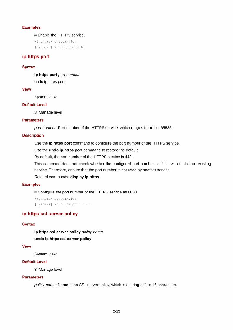
2-23
Examples
# Enable the HTTPS service. <Sysname> system-view
[Sysname] ip https enable
ip https port
Syntax
ip https port port-number
undo ip https port
View
System view
Default Level
3: Manage level
Parameters
port-number: Port number of the HTTPS service, which ranges from 1 to 65535.
Description
Use the ip https port command to configure the port number of the HTTPS service.
Use the undo ip https port command to restore the default.
By default, the port number of the HTTPS service is 443.
This command does not check whether the configured port number conflicts with that of an existing service. Therefore, ensure that the port number is not used by another service.
Related commands: display ip https.
Examples
# Configure the port number of the HTTPS service as 6000. <Sysname> system-view
[Sysname] ip https port 6000
ip https ssl-server-policy
Syntax
ip https ssl-server-policy policy-name
undo ip https ssl-server-policy
View
System view
Default Level
3: Manage level
Parameters
policy-name: Name of an SSL server policy, which is a string of 1 to 16 characters.

2-24
Description
Use the ip https ssl-server-policy command to associate the HTTPS service with an SSL server-end policy.
Use the undo ip https ssl-server-policy to remove the association.
By default, the HTTPS service is not associated with any SSL server-end policy.
The HTTPS service can be enabled only after this command is configured successfully.
You cannot modify the associated SSL server-end policy or remove the association between the HTTPS service and the SSL server-end policy after the HTTPS service is enabled.
Related commands: display ip https (in Logging In to the Router in the Fundamentals Command Reference) and ssl server-policy (in SSL in the Security Command Reference).
Examples
# Associate the HTTPS service with SSL server-end policy myssl. <Sysname> system-view
[Sysname] ip https ssl-server-policy myssl
lock
Syntax
lock
View
User view
Default Level
3: Manage level
Parameters
None
Description
Use the lock command to lock the user interface. This method prevents unauthorized users from using the user interface.
When entering the lock command, you are asked to input a password (up to 16 characters) and then confirm it by inputting the password again. After locking the user interface, you must press Enter and input the correct password next time you enter this user interface.
By default, this function is disabled.
Examples
# Lock the current user interface. <Sysname> lock
Please input password<1 to 16> to lock current user terminal interface:
Password:
Again:

2-25
locked !
Password:
<Sysname>
parity
Syntax
parity { even | mark | none | odd | space }
undo parity
View
User interface view
Default Level
2: System level
Parameters
even: Performs even parity checks.
mark: Performs mark parity checks.
none: Performs no parity check.
odd: Performs odd parity checks.
space: Performs space parity checks.
Description
Use the parity command to set a parity check method.
Use the undo parity command to restore the default.
By default, no parity check is performed.
The command is only applicable to asynchronous serial interfaces (including AUX and console ports).
The parity check setting must be the same for the user interfaces of the connecting ports on the device and the target terminal device for communication.
Examples
# Configure the AUX port to perform odd parity check. <Sysname> system-view
[Sysname] user-interface aux 0
[Sysname-ui-aux0] parity odd

2-26
protocol inbound
Syntax
protocol inbound { all | pad | ssh | telnet }
View
VTY interface view
Default Level
3: Manage level
Parameters
all: Supports all the three protocols, Telnet, SSH, and PAD.
pad: Supports PAD only.
ssh: Supports SSH only.
telnet: Supports Telnet only.
Description
Use the protocol inbound command to enable the current user interface to support either Telnet, PAD, SSH, or all of them.
By default, all the three protocols are supported.
The configuration takes effect next time you log in.
Before configuring a user interface to support SSH, set the authentication mode to scheme for the user interface; otherwise, the protocol inbound ssh command fails. For more information, see authentication-mode.
By default, the authentication mode of the Telnet protocol is password.
Examples
# Enable the VTYs 0 through 4 to support SSH only. <Sysname> system-view
[Sysname] user-interface vty 0 4
[Sysname-ui-vty0-4] authentication-mode scheme
[Sysname-ui-vty0-4] protocol inbound ssh
redirect disconnect
Syntax
redirect disconnect
View
User interface view
Default Level

2-27
2: System level
Parameters
None
Description
Use the redirect disconnect command to manually terminate redirected telnet connection(s).
The redirect disconnect commands are supported by the AUX and TTY user interfaces only.
This command is applicable to user interfaces on which redirection is enabled. To enable redirection on a user interface, use the redirect enable command.
Examples
# Manually terminate redirected Telnet connection(s). <Sysname> system-view
[Sysname] user-interface tty 1
[Sysname-ui-tty1] redirect disconnect
redirect enable
Syntax
redirect enable
undo redirect enable
View
User interface view
Default Level
2: System level
Parameters
None
Description
Use the redirect enable command to enable redirection on an asynchronous serial interface.
Use the undo redirect enable command to disable this function.
By default, the redirection function is disabled.
The redirect enable commands are supported by the AUX and TTY user interfaces only.
Before using the redirection function or configuring redirection service related parameters, use this command to enable redirection.

2-28
The stop bit setting must be the same for the user interfaces of the connecting ports on the device and the target terminal device for communication. Before enabling redirection, use the stopbit-error intolerance command to check their settings.
Related commands: telnet, display tcp status.
Examples
# Enable redirection on user interface TTY 7. <Sysname> system-view
[Sysname] user-interface tty 7
[Sysname-ui-tty7] redirect enable
redirect listen-port
Syntax
redirect listen-port port-number
undo redirect listen-port
View
User interface view
Default Level
2: System level
Parameters
port-number: Number of the listening port, in the range 2000 to 50000.
Description
Use the redirect listen-port command to specify a listening port for redirected Telnet connections.
Use the undo redirect listen-port command to restore the default listening port.
The default number of the listening port for redirected Telnet connections equals the absolute user interface number plus 2000.
The redirect listen-port command is supported by the AUX and TTY user interfaces only.
This command is applicable to user interfaces on which redirection is enabled. To enable redirection on a user interface, use the redirect enable command.
Examples
# Configure port 3000 as the listening port for the redirected Telnet connections. <Sysname> system-view
[Sysname] user-interface tty 1
[Sysname-ui-tty1] redirect listen-port 3000
redirect refuse-negotiation

2-29
Syntax
redirect refuse-negotiation
undo redirect refuse-negotiation
View
User interface view
Default Level
2: System level
Parameters
None
Description
Use the redirect refuse-negotiation command to disable Telnet option negotiation when the device is establishing a redirected Telnet connection.
Use the undo redirect refuse-negotiation command to enable Telnet option negotiation when the device is establishing a redirected Telnet connection.
By default, Telnet option negotiation is enabled.
The redirect refuse-negotiation command is supported by the AUX and TTY user interfaces only.
This command is applicable to user interfaces on which redirection is enabled. To enable redirection on a user interface, use the redirect enable command.
Examples
# Disable Telnet option negotiation when the device is establishing a redirected Telnet connection. <Sysname> system-view
[Sysname] user-interface tty 1
[Sysname-ui-tty1] redirect refuse-negotiation
redirect refuse-teltransfer
Syntax
redirect refuse-teltransfer
undo redirect refuse-teltransfer
View
User interface view
Default Level
2: System level
Parameters
None

2-30
Description
Use the redirect refuse-teltransfer command to configure not to convert the ASCII characters of 0xff to 0xff 0xff when the user interface is establishing a redirected Telnet connection.
Use the undo redirect refuse-teltransfer command to restore the default.
By default, the ASCII characters of 0xff are converted to 0xff 0xff when the user interface is establishing a redirected Telnet connection.
The device filters the characters of 0xff sent by the Telnet client when establishing a redirected Telnet connection. To make these characters forwarded to the Telnet server, 0xff needs to be converted to 0xff 0xff so that the device filters one string of 0xff and forwards the other string to be forwarded.
If the Telnet client does not send the characters of 0xff, execute the command to configure the user interface not to perform the conversion.
The redirect refuse-teltransfer command is supported on AUX and TTY user interfaces only.
This command is applicable to user interfaces on which redirection is enabled. To enable redirection on a user interface, use the redirect enable command.
Examples
# Configure the user interface not to convert the ASCII characters of 0xff to 0xff 0xff when establishing a redirected Telnet connection. <Sysname> system-view
[Sysname] user-interface tty 1
[Sysname-ui-tty1] redirect refuse-teltransfer
redirect return-deal from-telnet
Syntax
redirect return-deal from-telnet
undo redirect return-deal from-telnet
View
User interface view
Default Level
2: System level
Parameters
None
Description
Use the redirect return-deal from-telnet command to enable the device to process the carriage returns sent by Telnet clients. In other words, the device substitutes 0x0d for 0x0d 0x0a and 0x0d 0x00.
Use the undo redirect return-deal from-telnet command to restore the default.
By default, carriage returns sent by Telnet clients are not processed.

2-31
The redirect return-deal from-telnet command is supported on the AUX and TTY user interfaces only.
This command is applicable to user interfaces on which redirection is enabled. To enable redirection on a user interface, use the redirect enable command.
Examples
# Enable the device to process carriage returns sent by Telnet clients. <Sysname> system-view
[Sysname] user-interface tty 1
[Sysname-ui-tty1] redirect return-deal from-telnet
redirect return-deal from-terminal
Syntax
redirect return-deal from-terminal
undo redirect return-deal from-terminal
View
User interface view
Default Level
2: System level
Parameters
None
Description
Use the redirect return-deal from-telnet command to enable the user interface to process the carriage returns sent by terminals (a PC connected to the console port for example) when the user interface is redirecting a telnet connection. In other words, the device substitutes 0x0d for 0x0d 0x0a and 0x0d 0x00.
Use the undo redirect return-deal from-terminal command to restore the default.
By default, the carriage returns sent by terminals are not processed, but forwarded by the user interface that is redirecting a telnet connection.
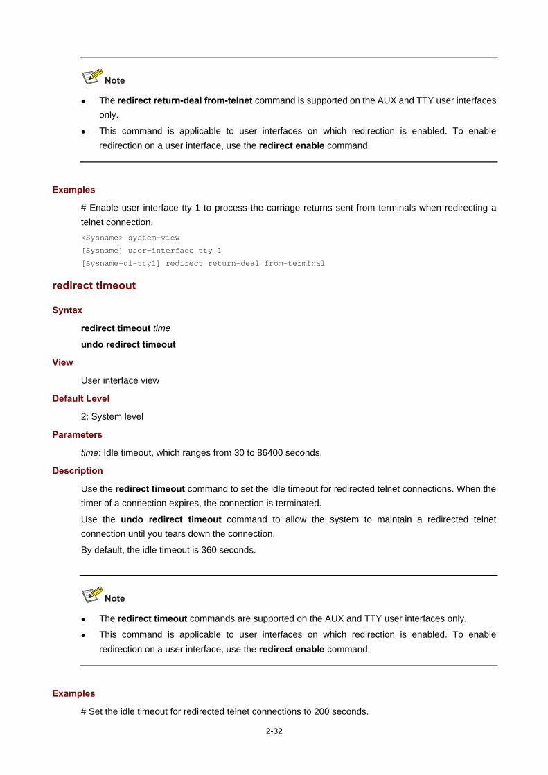
2-32
The redirect return-deal from-telnet command is supported on the AUX and TTY user interfaces only.
This command is applicable to user interfaces on which redirection is enabled. To enable redirection on a user interface, use the redirect enable command.
Examples
# Enable user interface tty 1 to process the carriage returns sent from terminals when redirecting a telnet connection. <Sysname> system-view
[Sysname] user-interface tty 1
[Sysname-ui-tty1] redirect return-deal from-terminal
redirect timeout
Syntax
redirect timeout time
undo redirect timeout
View
User interface view
Default Level
2: System level
Parameters
time: Idle timeout, which ranges from 30 to 86400 seconds.
Description
Use the redirect timeout command to set the idle timeout for redirected telnet connections. When the timer of a connection expires, the connection is terminated.
Use the undo redirect timeout command to allow the system to maintain a redirected telnet connection until you tears down the connection.
By default, the idle timeout is 360 seconds.
The redirect timeout commands are supported on the AUX and TTY user interfaces only.
This command is applicable to user interfaces on which redirection is enabled. To enable redirection on a user interface, use the redirect enable command.
Examples
# Set the idle timeout for redirected telnet connections to 200 seconds.

2-33
<Sysname> system-view
[Sysname] user-interface tty 1
[Sysname-ui-tty1] redirect timeout 200
screen-length
Syntax
screen-length screen-length
undo screen-length
View
User interface view
Default Level
2: System level
Parameters
screen-length: Number of lines on the next screen, which ranges from 0 to 512. The value of 0 disables pausing between screens of output.
Description
Use the screen-length command to set the number of lines on the next screen.
Use the undo screen-length command to restore the default.
By default, the next screen displays 24 lines.
When screen output pauses, press the Space key to display the next screen. Not all terminals support this command setting. For example, assume that you set screen-length to 40, but the terminal can display 24 lines in one screen at most. When you press Space, the device sends 40 lines to the terminal, but the next screen displays only lines 18 through 40. To view the first 17 lines, you must press the page up or page down key.
To disable multiple-screen output of the current user interface, use the screen-length disable command. For more information about the screen-length disable command, see CLI in the Fundamentals Command Reference.
Examples
# Set the next screen of the user interface of console port 0 to display 30 lines. <Sysname> system-view
[Sysname] user-interface console 0
[Sysname-ui-console0] screen-length 30
send
Syntax
send { all | num1 | { aux | console | tty | vty } num2 }
View
User view
Default Level
1: Monitor level
Parameters

2-34
all: Sends messages to all user interfaces.
num1: Absolute number of a user interface. The value range varies with devices, and typically starts from 0.
num2: Relative number of a user interface. The value range varies with devices.
Description
Use the send command to send messages to the specified user interfaces.
To end message input, press Ctrl+Z. To cancel message input and return to user view, press Ctrl+C.
Examples
# Send message hello abc to the user interface of console port 0. <Sysname> send console 0
Enter message, end with CTRL+Z or Enter; abort with CTRL+C:
hello abc^Z
Send message? [Y/N]:y
<Sysname>
***
***
***Message from con0 to con0
***
hello abc
<Sysname>
# Assume you are using VTY 0. Before you restart the device, to inform users that are accessing the device through other user interfaces, follow the steps below.
Display information about all users <Sysname> display users
The user application information of the user interface(s):
Idx UI Delay Type Userlevel
+ 82 VTY 0 00:00:00 TEL 3
83 VTY 1 00:00:03 TEL 3
Following are more details.
VTY 0 :
Location: 192.168.1.26
VTY 1 :
Location: 192.168.1.20
+ : Current operation user.
F : Current operation user work in async mode.
// The output above shows that a user is using VTY 0. <Sysname> send vty 1
Enter message, end with CTRL+Z or Enter; abort with CTRL+C:
Note please, I will reboot the system in 3 minutes!^Z
Send message? [Y/N]:y
// A message is sent to VTY 1, telling that the system will reboot in 3 minutes.

2-35
If a user is trying to log in through VTY 1, the message appears. (VTY 1 receives the message from VTY 0 when the interface ethernet command is input.)
[Sysname] interface eth
***
***
***Message from vty0 to vty1
***
Note please, I will reboot the system in 3 minutes!
set authentication password
Syntax
set authentication password { cipher | simple } password
undo set authentication password
View
User interface view
Default Level
3: Manage level
Parameters
cipher: Cipher text password.
simple: Plain text password.
password: A case sensitive string. If the password format is simple, the password argument must be in plain text, and the configuration file saves the password in plain text. If the format is cipher, password can be either in cipher text or in plain text, and the configuration file always saves the password in cipher text. A plain text password can be a string of no more than 16 characters, 1234567 for example. A cipher text password or the encrypted version of the plain text password comprises 24 characters, such as _(TT8F]Y\5SQ=^Q`MAF4<1!!.
Description
Use the set authentication password command to set an authentication password.
Use the undo set authentication password command to remove the local authentication password.
By default, no local authentication password is set.
No matter whether the password format is plain text or cipher text, you must type the password in plain text during authentication.
A plain text password easily gets cracked. Therefore, a cipher text password is recommended.
Related commands: authentication-mode.
Examples
# Set the local authentication password for the user interface of console port 0 to hello. <Sysname> system-view
[Sysname] user-interface console 0
[Sysname-ui-console0] authentication-mode password
[Sysname-ui-console0] set authentication password cipher hello
Next time you enter the system, the password is required.

2-36
shell
Syntax
shell
undo shell
View
User interface view
Default Level
3: Manage level
Parameters
None
Description
Use the shell command to enable terminal services on the current user interface.
Use the undo shell command to disable terminal services on the current user interface.
The console user interface does not support the undo shell command.
The AUX user interface does not support the undo shell command when the device has only one AUX port and no console port.
You cannot disable the terminal services on the user interface through which you are logged in.
By default, terminal services are enabled on all user interfaces.
Examples
# Disable terminal services on the VTYs 0 through 4, which means you cannot log in to the device through VTYs 0 through 4. <Sysname> system-view
[Sysname] user-interface vty 0 4
[Sysname-ui-vty0-4] undo shell
% Disable ui-vty0-4 , are you sure? [Y/N]:y
[Sysname-ui-vty0-4]
The following message appears when a terminal tries to telnet to the device: The connection was closed by the remote host!
speed (user interface view)
Syntax
speed speed-value
undo speed
View
User interface view
Default Level
2: System level
Parameters
speed-value: Transmission rate in bps.

2-37
The transmission rates available with asynchronous serial interfaces include:
300 bps
600 bps
1200 bps
2400 bps
4800 bps
9600 bps
19200 bps
38400 bps
57600 bps
115200 bps
The transmission rate varies with devices and configuration environment.
Description
Use the speed command to set the transmission rate on the user interface.
Use the undo speed command to restore the default transmission rate.
By default, the transmission rate is 9600 bps.
The command is only applicable to asynchronous serial interfaces (including AUX and console ports).
The transmission rate setting must be identical for the user interfaces of the connecting ports on the device and the target terminal device for communication.
Examples
# Set the transmission rate on the user interface AUX 0 to 19200 bps. <Sysname> system-view
[Sysname] user-interface aux 0
[Sysname-ui-aux0] speed 19200
stopbit-error intolerance
Syntax
stopbit-error intolerance
undo stopbit-error intolerance
View
User interface view
Default Level
2: System level
Parameters
2-38
None
Description
Use the stopbit-error intolerance command to enable the interface to detect the stop bits.
Use the undo stopbit-error intolerance command to restore the default.
By default, the stop bits are not detected.
This command is only applicable to asynchronous serial interfaces (including AUX and console ports).
Examples
# Configure user interface AUX 0 to detect the stop bits. <Sysname> system-view
[Sysname] user-interface aux 0
[Sysname-ui-aux0] stopbit-error intolerance
stopbits
Syntax
stopbits { 1 | 1.5 | 2 }
undo stopbits
View
User interface view
Default Level
2: System level
Parameters
1: One stop bit.
1.5: One and a half stop bits.
2: Two stop bits.
Description
Use the stopbits command to set the number of stop bits transmitted per byte.
Use the undo stopbits command to restore the default.
By default, the stop bit is one.
2-39
The command is only applicable to asynchronous serial interfaces (including AUX and console ports).
The stop bits setting must be the identical for the user interfaces of the connecting ports on the device and the target device for communication.
Examples
# Set the stop bits on the user interface AUX 0 to 1.5. <Sysname> system-view
[Sysname] user-interface aux 0
[Sysname-ui-aux0] stopbits 1.5
telnet
Syntax
telnet remote-host [ service-port ] [ vpn-instance vpn-instance-name ] [ source { interface interface-type interface-number | ip ip-address } ]
View
User view
Default Level
0: Visit level
Parameters
remote-host: IPv4 address or host name of a remote host, which is a case insensitive string of 1 to 20 characters.
service-port: TCP port number of the Telnet service on the remote host. It ranges from 0 to 65535 and defaults to 23.
vpn-instance vpn-instance-name: Specifies a VPN instance. vpn-instance-name is the name of a VPN instance, which is a case-sensitive string of 1 to 31 characters.
source: Specifies the source interface or source IPv4 address of Telnet packets.
interface interface-type interface-number: Specifies the source interface. The source IPv4 address of the Telnet packets sent is the IPv4 address of the specified interface. interface-type interface-number represents the interface type and number.
ip ip-address: Specifies the source IPv4 address of Telnet packets.
Description
Use the telnet command to telnet to a remote host.
To terminate the current Telnet connection, press Ctrl+K or use the quit command.
The source IPv4 address or source interface specified by this command is applicable to the current Telnet connection only.
Examples
# Telnet to the remote host 1.1.1.2, specifying the source IP address of Telnet packets as 1.1.1.1. <Sysname> telnet 1.1.1.2 source ip 1.1.1.1

2-40
telnet client source
Syntax
telnet client source { interface interface-type interface-number | ip ip-address }
undo telnet client source
View
System view
Default Level
2: System level
Parameters
interface interface-type interface-number: Specifies the source interface. The source IPv4 address of the Telnet packets sent is the IPv4 address of the specified interface. interface-type interface-number represents the interface type and number.
ip ip-address: Specifies the source IPv4 address of Telnet packets.
Description
Use the telnet client source command to specify the source IPv4 address or source interface for sending telnet packets when the device serves as a telnet client.
Use the undo telnet client source command to remove the source IPv4 address or source interface for sending telnet packets.
By default, no source IPv4 address or source interface for sending telnet packets is specified. The source IPv4 address is selected by routing.
The source IPv4 address or source interface specified by this command is applicable all Telnet connections.
If you use both this command and the telnet command to specify the source IPv4 address or source interface, the source IPv4 address or interface specified by the telnet command takes effect.
Related commands: display telnet client configuration.
Examples
# specify the source IPv4 address for sending telnet packets when the device serves as a telnet client as 1.1.1.1. <Sysname> system-view
[Sysname] telnet client source ip 1.1.1.1
telnet ipv6
Syntax
telnet ipv6 remote-host [ -i interface-type interface-number ] [ port-number ]
View
User view
Default Level
0: Visit level

2-41
Parameters
remote-host: IP address or host name of a remote host, which is a case insensitive string of 1 to 46 characters.
-i interface-type interface-number: Specifies the outbound interface for sending Telnet packets, where interface-type interface-number represents the interface type and number. If the destination address is a link-local address, provide the –i interface-type interface-number argument.
port-number: TCP port number for the remote host to provide the Telnet service. It ranges from 0 to 65535 and defaults to 23.
Description
Use the telnet ipv6 command to telnet to a remote host in an IPv6 network. To terminate the current Telnet connection, press Ctrl+K or use the quit command.
Examples
# Telnet to the remote host with the IPv6 address 5000::1. <Sysname> telnet ipv6 5000::1
telnet server enable
Syntax
telnet server enable
undo telnet server enable
View
System view
Default Level
3: Manage level
Parameters
None
Description
Use the telnet server enable command to enable the Telnet server.
Use the undo telnet server enable command to disable the Telnet server.
The Telnet server is disabled by default.
Examples
# Enable the Telnet server. <Sysname> system-view
[Sysname] telnet server enable
terminal type
Syntax
terminal type { ansi | vt100 }
undo terminal type
View

2-42
User interface view
Default Level
2: System level
Parameters
ansi: Specifies the terminal display type as ANSI.
vt100: Specifies the terminal display type as VT100.
Description
Use the terminal type command to configure the type of terminal display of the current user interface.
Use the undo terminal type command to restore the default.
By default, the terminal display type is ANSI.
The device supports two types of terminal display: ANSI and VT100. It is recommended to set the display type of both the device and the client to VT100. If the device and the client use different display types (for example, hyper terminal or Telnet terminal) or both are set to ANSI, when the total number of characters of the currently edited command line exceeds 80, an anomaly such as cursor corruption or abnormal display of the terminal display may occur on the client.
Examples
# Set the terminal display type to VT100. <Sysname> system-view
[Sysname] user-interface vty 0
[Sysname-ui-vty0] terminal type vt100
user privilege level
Syntax
user privilege level level
undo user privilege level
View
User interface view
Default Level
3: Manage level
Parameters
level: Specifies a user privilege level, which ranges from 0 to 3.
User privilege levels include visit, monitor, system, and manage, represented by the number 0, 1, 2 and 3 respectively. The administrator can change the user privilege level when necessary.
Description

2-43
Use the user privilege level command to configure the user privilege level. Users logging into the user interface are assigned a user privilege level.
Use the undo user privilege level command to restore the default.
By default, the default command level is 3 for the console user interface and 0 for other user interfaces.
Examples
# Set the command level for users logging in through VTY 0 to 0. <Sysname> system-view
[Sysname] user-interface vty 0
[Sysname-ui-vty0] user privilege level 0
After you telnet to the device through VTY 0, the terminal only displays commands of level 0 in the help information: <Sysname> ?
User view commands:
cluster Run cluster command
display Display current system information
ping Ping function
quit Exit from current command view
rsh Establish one RSH connection
ssh2 Establish a secure shell client connection
super Set the current user priority level
telnet Establish one TELNET connection
tracert Trace route function
user-interface
Syntax
user-interface { first-num1 [ last-num1 ] | { aux | console | tty | vty } first-num2 [ last-num2 ] }
View
System view
Default Level
2: System level
Parameters
first-num1: Absolute number of the first user interface. The value range varies with devices, and typically starts from 0.
last-num1: Absolute number of the last user interface. The value range varies with devices, and typically starts from 0, but cannot be smaller than the first-num1.
first-num2: Relative number of the first user interface. The value range varies with devices.
last-num2: Relative number of the last user interface. The value range varies with devices, but cannot be smaller than first-num 2.
Description
Use the user-interface command to enter a single or multiple user interface views.
In a single user interface view, the configuration takes effect in the user view only.
In multiple user interface views, the configuration takes effect in these user views.
Examples

2-44
# Enter the console user interface view. <Sysname> system-view
[Sysname] user-interface console 0
[Sysname-ui-console0]
# Enter the user interface views of VTYs 0 to 4. <Sysname> system-view
[Sysname] user-interface vty 0 4
[Sysname-ui-vty0-4]
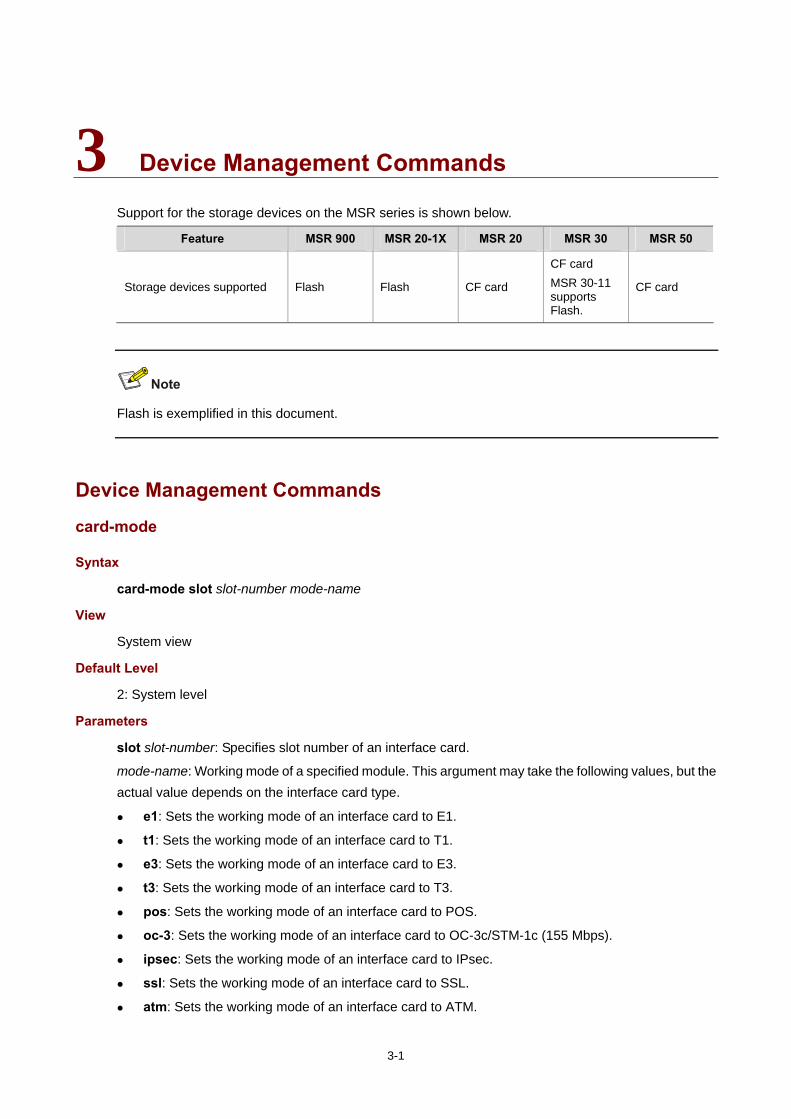
3-1
3 Device Management Commands
Support for the storage devices on the MSR series is shown below.
Feature MSR 900 MSR 20-1X MSR 20 MSR 30 MSR 50
Storage devices supported Flash Flash CF card
CF card MSR 30-11 supports Flash.
CF card
Flash is exemplified in this document.
Device Management Commands
card-mode
Syntax
card-mode slot slot-number mode-name
View
System view
Default Level
2: System level
Parameters
slot slot-number: Specifies slot number of an interface card.
mode-name: Working mode of a specified module. This argument may take the following values, but the actual value depends on the interface card type.
e1: Sets the working mode of an interface card to E1.
t1: Sets the working mode of an interface card to T1.
e3: Sets the working mode of an interface card to E3.
t3: Sets the working mode of an interface card to T3.
pos: Sets the working mode of an interface card to POS.
oc-3: Sets the working mode of an interface card to OC-3c/STM-1c (155 Mbps).
ipsec: Sets the working mode of an interface card to IPsec.
ssl: Sets the working mode of an interface card to SSL.
atm: Sets the working mode of an interface card to ATM.

3-2
auto: Sets the working mode of an interface card to Auto.
efm: Sets the working mode of an interface card to Ethernet first mile (EFM).
Description
Use the card-mode command to set the working mode of an interface card.
Support for this command on the MSR series is shown below.
Command MSR 900 MSR 20-1X MSR 20 MSR 30 MSR 50
card-mode No No Yes Yes Yes
Command Parameter MSR 900 MSR 20-1X MSR 20 MSR 30 MSR 50
card-mode slot No No Yes Yes Yes
Examples
# Set the working mode of the interface card in slot 2 to E3. <Sysname> system-view
[Sysname] card-mode slot 2 e3
Info: Please reboot or hot-swap the board or card (if supported) to make the configuration take effect.
# Set the working mode of the ATM interface card in slot 0 to EFM. <Sysname> system-view
[Sysname] card-mode slot 0 efm
clock datetime
Syntax
clock datetime time date
View
User view
Default Level
3: Manage level
Parameters
time: Configured time, in the format of HH:MM:SS, where HH is hours that ranges from 00 to 23, MM is minutes that ranges from 00 to 59, and SS is seconds that ranges from 00 to 59. The first zero in the HH, MM, or SS value can be omitted. If the value of SS is 00, the time argument can be represented in the format of HH:MM. If both the values of MM and SS are 00s, the time argument can be represented in the format of HH.
date: Configured date, in the format of MM/DD/YYYY or YYYY/MM/DD. MM is the month of the year that ranges from 1 to 12, DD is the day of the month that varies with months, and YYYY is a year that ranges from 2000 to 2035.
Description
Use the clock datetime command to set the current time and date of the device.

3-3
The current time and date of the device must be set in an environment that requires the acquisition of absolute time.
You may choose not to provide seconds when inputting the time parameters.
Related commands: clock summer-time one-off, clock summer-time repeating, clock timezone, and display clock.
Examples
# Set the current system time to 14:10:20 08/01/2005. <Sysname> clock datetime 14:10:20 8/1/2005
# Set the current system time to 00:06:00 01/01/2007. <Sysname> clock datetime 0:6 2007/1/1
clock summer-time one-off
Syntax
clock summer-time zone-name one-off start-time start-date end-time end-date add-time
undo clock summer-time
View
System view
Default Level
3: Manage level
Parameters
zone-name: Name of the daylight saving time, which is a case sensitive string of 1 to 32 characters.
start-time: Start time, in the format of HH:MM:SS (hours/minutes/seconds). The zeros in the argument can be omitted except for indicating 0 hours.
start-date: Start date, in the format of MM/DD/YYYY (months/days/years) or YYYY/MM/DD.
end-time: End time, in the format of HH:MM:SS (hours/minutes/seconds). The zeros in the argument can be omitted except for indicating 0 hours.
end-date: End date, in the format of MM/DD/YYYY (months/days/years) or YYYY/MM/DD.
add-time: Time added to the standard time of the device, in the format of HH:MM:SS (hours/minutes/seconds). The zeros in the argument can be omitted except for indicating 0 hours.
Description
Use the clock summer-time one-off command to adopt daylight saving time from the start-time of the start-date to the end-time of the end-date. Daylight saving time adds the add-time to the standard time of the device.
Use the undo clock summer-time command to cancel the configuration of the daylight saving time.
By default, daylight saving time is configured on the device, and the universal time coordinated (UTC) time zone is applied.
To view your configuration after it takes effect, use the display clock command. In addition, the time of the log or debug information is the local time of which the time zone and daylight saving time have been adjusted.
Note that:

3-4
The time range from start-time in start-date to end-time in end-date must be longer than one day and shorter than one year. Otherwise, the argument is considered as invalid and the configuration fails.
If the standard time of the device is in the time range specified with this command, the system time automatically adds “add-time” after the execution of this command.
Related commands: clock datetime, clock summer-time repeating, clock timezone, and display clock.
Examples
# For daylight saving time in abc1 between 06:00:00 on 08/01/2006 and 06:00:00 on 09/01/2006, set the system clock ahead one hour. <Sysname> system-view
[Sysname] clock summer-time abc1 one-off 6 08/01/2006 6 09/01/2006 1
clock summer-time repeating
Syntax
clock summer-time zone-name repeating start-time start-date end-time end-date add-time
undo clock summer-time
View
System view
Default Level
3: Manage level
Parameters
zone-name: Name of the daylight saving time, which is a string of 1 to 32 characters.
start-time: Start time, in the format of HH:MM:SS (hours/minutes/seconds). The zeros in the argument can be omitted except for indicating 0 hours.
start-date: Start date, which can be set in two ways:
Enter the year, month and date at one time, in the format of MM/DD/YYYY (months/days/years) or YYYY/MM/DD.
Enter the year, month and date one by one, separated by spaces. The year ranges from 2000 to 2035; the month can be January, February, March, April, May, June, July, August, September, October, November or December; the start week can be the first, second, third, fourth, fifth or last week of the month; the start date is Sunday, Monday, Tuesday, Wednesday, Thursday, Friday, Saturday.
end-time: End time, in the format of HH:MM:SS (hours/minutes/seconds). The zeros in the argument can be omitted except for indicating 0 hours.
end-date: End date which can be set in two ways:
Enter the year, month and date at one time, in the format of MM/DD/YYYY (months/days/years) or YYYY/MM/DD.
Enter the year, month and date one by one, separated by spaces. The year ranges from 2000 to 2035; the month can be January, February, March, April, May, June, July, August, September, October, November or December; the end week can be the first, second, third, fourth, fifth or

3-5
last week of the month; the end date is Sunday, Monday, Tuesday, Wednesday, Thursday, Friday, Saturday.
add-time: Time added to the standard time of the device, in the format of HH:MM:SS (hours/minutes/seconds). The zeros in the argument can be omitted except for indicating 0 hours.
Description
Use the clock summer-time repeating command to adopt the daylight saving time repeatedly.
Use the undo clock summer-time command to cancel the configuration of the daylight saving time.
By default, daylight saving time is configured on the device, and the UTC time zone is applied.
For example, when start-date and start-time are set to 2007/6/6 and 00:00:00, end-date and end-time to 2007/10/01 and 00:00:00, and add-time to 01:00:00, it specifies to adopt daylight saving time from 00:00:00 of June 6 until 00:00:00 of October 1 each year from 2007 (2007 inclusive). The daylight saving time adds one hour to the standard time of the device.
To view the result after the configuration takes effect, use the display clock command. The information such as log file and debug adopts the local time modified by time-zone and daylight saving time.
Note that:
The time range from “start-time” in “start-date” to “end-time” in “end-date” must be longer than one day and shorter than one year. Otherwise, the argument is considered as invalid and the configuration fails.
If the standard time of the device is in the time range specified with this command, the system time automatically adds “add-time” after the execution of this command.
Related commands: clock datetime, clock summer-time one-off, clock timezone, and display clock.
Examples
# For the daylight saving time in abc2 between 06:00:00 on 08/01/2007 and 06:00:00 on 09/01/2007 and from 06:00:00 08/01 to 06:00:00 on 09/01 each year after 2007, set the system clock ahead one hour. <Sysname> system-view
[Sysname] clock summer-time abc2 repeating 06:00:00 08/01/2007 06:00:00 09/01/2007 01:00:00
clock timezone
Syntax
clock timezone zone-name { add | minus } zone-offset
undo clock timezone
View
System view
Default Level
3: Manage level
Parameters
zone-name: Time zone name, which is a case sensitive string of 1 to 32 characters.
add: Adds a specified offset to UTC time.

3-6
minus: Subtracts a specified offset to UTC time.
zone-offset: Offset to the UTC time, in the format of HH/MM/SS (hours/minutes/seconds), where HH is hours that ranges from 0 to 23, MM is minutes that ranges from 0 to 59, and SS is seconds that ranges from 0 to 59. The zeros in the argument can be omitted except for indicating 0 hours.
Description
Use the clock timezone command to set the local time zone.
Use the undo clock timezone command to restore the local time zone to the default UTC time zone.
By default, the local time zone is UTC zone.
To view the result after the configuration takes effect, use the display clock command. The information such as log file and debug adopts the local time modified by time-zone and daylight saving time.
Related commands: clock datetime, clock summer-time one-off, clock summer-time repeating, and display clock.
Examples
# Set the name of the local time zone to Z5, five hours ahead of UTC time. <Sysname> system-view
[Sysname] clock timezone z5 add 5
configure-user count
Syntax
configure-user count number
undo configure-user count
View
System view
Default Level
2: System level
Parameters
number: Number of users. The value range varies with devices.
Description
Use the configure-user count command to configure the number of users allowed to enter system view at the same time.
Use the undo configure-user count command to restore the default.
Two users are allowed to configure in system view by default.
Related commands: display configure-user.

3-7
When multiple users enter system view to configure certain attribute, only the last configuration applies.
When the number of users has already reached the limit, other users can not enter system view.
Examples
# Configure the limit of users as 4. <Sysname> system-view
[Sysname] configure-user count 4
copyright-info enable
Syntax
copyright-info enable
undo copyright-info enable
View
System view
Default Level
3: Manage level
Parameters
None
Description
Use the copyright-info enable command to enable the display of copyright information.
Use the undo copyright-info enable command to disable the display of copyright information.
By default, the display of copyright information is enabled.
Examples
# Enable the display of copyright information. <Sysname> system-view
[Sysname] copyright-info enable
If a user logs in to the device through Telnet, the following information is displayed: **************************************************************************
* Copyright (c) 2004-2009 Hangzhou H3C Tech. Co., Ltd. All rights reserved.*
* Without the owner's prior written consent, *
* no decompiling or reverse-engineering shall be allowed. *
****************************************************************************
<Sysname>
If a user has already logged in through the console port, and then quits user view, the following information is displayed:
**************************************************************************

3-8
* Copyright (c) 2004-2009 Hangzhou H3C Tech. Co., Ltd. All rights reserved.*
* Without the owner's prior written consent, *
* no decompiling or reverse-engineering shall be allowed. *
****************************************************************************
User interface con0 is available.
Please press ENTER.
# Disable the display of copyright information. <Sysname> system-view
[Sysname] undo copyright-info enable
If a user logs in to the device through Telnet, the following information is displayed: <Sysname>
If a user has already logged in through the console port, and then quits user view, the following information is displayed:
User interface con0 is available.
Please press ENTER.
display clock
Syntax
display clock [ | { begin | exclude | include } regular-expression ]
View
Any view
Default Level
1: Monitor level
Parameters
|: Filters command output by specifying a regular expression. For more information about regular expressions, see CLI in the Fundamentals Configuration Guide.
begin: Displays the first line that matches the specified regular expression and all lines that follow.
exclude: Displays the lines that do not match the specified regular expression.
include: Displays all lines that match the specified regular expression.
regular-expression: Specifies a regular expression, which is a case sensitive string of 1 to 256 characters.
Description
Use the display clock command to view the current system time and date.
The current system time and date are decided by the clock datetime, clock summer-time one-off (or clock summer-time repeating), and clock timezone commands. For more information about how the system time and date are decided, see Device Management in the Fundamentals Configuration Guide.

3-9
Related commands: clock datetime, clock summer-time one-off, clock summer-time repeating, and clock timezone.
Examples
# Display the current time and date. <Sysname> display clock
09:41:23 UTC Thu 12/15/2005
display configure-user
Syntax
display configure-user [ | { begin | exclude | include } regular-expression ]
View
Any view
Default Level
1: Monitor level
Parameters
|: Filters command output by specifying a regular expression. For more information about regular expressions, see CLI in the Fundamentals Configuration Guide.
begin: Displays the first line that matches the specified regular expression and all lines that follow.
exclude: Displays the lines that do not match the specified regular expression.
include: Displays all lines that match the specified regular expression.
regular-expression: Specifies a regular expression, which is a case sensitive string of 1 to 256 characters.
Description
Use the display configure-user command to display the users that have logged in to the device and are not in user view.
Related commands: configure-user count.
Examples
# Display the users entering system view at the same time. <Sysname> display configure-user
The information of current configuration user(s):
Idx UI Delay Type Userlevel
+ 178 VTY 0 01:10:16 TEL 3
+ 179 VTY 1 00:00:00 TEL 3
Following are more details.
VTY 0 :
Location: 192.168.1.59
VTY 1 :
Location: 192.168.1.54
+ : User-interface is active.
F : User-interface is active and work in async mode.

3-10
display cpu-usage
Syntax
display cpu-usage [ number [ offset ] [ verbose ] [ from-device ] ] [ | { begin | exclude | include } regular-expression ]
View
Any view
Default Level
1: Monitor level
Parameters
number: Number of entries to be displayed, which ranges from 1 to 60.
offset: Offset between the serial number of the first CPU usage statistics record to be displayed and that of the last CPU usage record to be displayed. It ranges from 0 to 59. For example, the idx of the latest statistics record is 12, if the offset is set to 3, the system will display the statistics records from the one with the idx of 9. idx represents the serial number of the period for the statistics, and its value ranges from 0 to 60 cyclically. The system makes CPU usage statistics periodically; after each period, the system records the average CPU usage during this period, and the idx value is added by 1 automatically.
verbose: Displays detailed information of CPU usage statistics. If this keyword is not provided, the system displays the brief information of the CPU usage statistics; if this keyword is provided, the system displays the average CPU usage statistics for each task in the specified period.
from-device: Displays the external storage medium such as a flash or hard disk. The device currently does not support the from-device keyword.
|: Filters command output by specifying a regular expression. For more information about regular expressions, see CLI in the Fundamentals Configuration Guide.
begin: Displays the first line that matches the specified regular expression and all lines that follow.
exclude: Displays the lines that do not match the specified regular expression.
include: Displays all lines that match the specified regular expression.
regular-expression: Specifies a regular expression, which is a case sensitive string of 1 to 256 characters.
Description
Use the display cpu-usage command to display the CPU usage statistics.
The system takes statistics of CPU usage at intervals (usually every 60 seconds) and saves the statistical results in the history record area. The maximum number of records that can be saved depends on your device model. display cpu-usage entry-number indicates the system displays entry-number records from the newest (last) record. display cpu-usage entry-number offset indicates the system displays number records from the last but offset record.
Examples
# Display information of the current CPU usage statistics. <Sysname> display cpu-usage
Unit CPU usage:

3-11
1% in last 5 seconds
1% in last 1 minute
1% in last 5 minutes
Table 3-1 display cpu-usage command output description
Field Description
Unit CPU usage CPU usage statistics
1% in last 5 seconds After the device boots, the system calculates and records the average CPU usage in every five seconds. This field displays the average CPU usage in the last five seconds.
1% in last 1 minute After the device boots, the system calculates and records the average CPU usage in every one minute. This field displays the average CPU usage in the last minute.
1% in last 5 minutes After the device boots, the system calculates and records the average CPU usage in every five minutes. This field displays the average CPU usage in the last five minutes.
CPU usage info (no: idx:)
Information of CPU usage records (no: The (no+1)th record is currently displayed. no numbers from 0, a smaller number equals a newer record. idx: index of the current record in the history record table). If only the information of the current record is displayed, no and idx are not displayed.
CPU Usage Stat. Cycle CPU usage measurement interval, in seconds. For example, if the value is 41, it indicates that the average CPU usage during the last 41 seconds is calculated. The value range of this field is 1 to 60.
CPU Usage Average CPU usage in a measurement interval, in percentage
CPU Usage Stat. Time CPU usage statistics time in seconds, that is, the system time when the command is executed
CPU Usage Stat. Tick System runtime in ticks, represented by a 64-bit hexadecimal. CPU Tick High represents the most significant 32 bits and the CPU Tick Low the least significant 32 bits.
Actual Stat. Cycle
Actual CPU usage measurement interval in ticks, represented by a 64-bit hexadecimal. CPU Tick High represents the most significant 32 bits and the CPU Tick Low the least significant 32 bits. Owing to the precision of less than one second, the actual measurement periods of different CPU usage records may differ slightly.
display cpu-usage history
Syntax
display cpu-usage history [ task task-id ] [ | { begin | exclude | include } regular-expression ]
View
Any view
Default Level
1: Monitor level
Parameters
task task-id: Displays the history statistics of the CPU usage of the specified task, where task-id represents the task number. If the task-id argument is not provided, the system displays the history

3-12
statistics of the CPU usage of the entire system (the CPU usage of the entire system is the sum of CPU usages of all tasks).
|: Filters command output by specifying a regular expression. For more information about regular expressions, see CLI in the Fundamentals Configuration Guide.
begin: Displays the first line that matches the specified regular expression and all lines that follow.
exclude: Displays the lines that do not match the specified regular expression.
include: Displays all lines that match the specified regular expression.
regular-expression: Specifies a regular expression, which is a case sensitive string of 1 to 256 characters.
Description
Use the display cpu-usage history command to display the history statistics of the CPU usage in a chart.
If no argument is provided, the system displays the CPU usage of the whole system.
The system takes statistics of the CPU usage at an interval and saves the statistical results in the history record area. You can use the display cpu-usage history command to display the CPU usage statistics records in the last 60 minutes. The statistical results are displayed through geographical coordinates. In the output information:
Latitude indicates the CPU usage, which is displayed based on the step. For example, if the step of the CPU usage is 5%, then the actual statistics value 53% is displayed as 55%, and actual statistics value 52% is displayed as 50%.
Longitude indicates the time.
Consecutive pond marks (#) indicate the CPU usage at a certain moment. The value of the latitude corresponding to the # mark on the top of a moment is the CPU usage at this moment.
Examples
# Display the CPU usage statistics of the whole system. <Sysname> display cpu-usage history
100%|
95%|
90%|
85%|
80%|
75%|
70%|
65%|
60%|
55%|
50%|
45%|
40%|
35%|
30%|
25%|
20%|
15%| #
10%| ### #

3-13
5%| ########
------------------------------------------------------------
10 20 30 40 50 60 (minutes)
cpu-usage last 60 minutes(SYSTEM)
The above output information indicates the CPU usage of the whole system (with the task name SYSTEM) in the last 60 minutes: 5% in the twelfth minute, 10% in the thirteenth minute, 15% in the fourteenth minute, 10% in the fifteenth minute, 5% in the sixteenth and seventeenth minute, 10% in the eighteenth minute, 5% in the nineteenth minute, and 2% or lower than 2% at other times.
# Display the CPU usage statistics of task 6. <Sysname> display cpu-usage history task 6
100%|
95%|
90%|
85%|
80%|
75%|
70%|
65%|
60%|
55%|
50%|
45%|
40%|
35%|
30%|
25%|
20%|
15%|
10%|
5%| #
------------------------------------------------------------
10 20 30 40 50 60 (minutes)
cpu-usage last 60 minutes(T03M)
The above output information indicates the CPU usage of task 6 (with the task name T03M) in the last 60 minutes: 5% in the twentieth minute, and 2% or lower than 2% at other times.
display current-configuration
Syntax
display current-configuration [ [ configuration [ configuration ] | controller | interface [ interface-type ] [ interface-number ] | exclude modules ] [ by-linenum ] [ | { begin | exclude | include } regular-expression ] ]
View
Any view
Default Level
2: System level

3-14
Parameters
configuration [ configuration ]: Specifies to display non-interface configuration. If no parameter is used, all the non-interface configuration is displayed; if parameters are used, display the specified information. For example:
isis: Displays the isis configuration.
isp: Displays the ISP configuration.
post-system: Displays the post-system configuration.
radius-template: Displays the Radius template configuration.
system: Displays the system configuration.
user-interface: Displays the user interface configuration.
controller: Displays the controller configuration (For example, CE1/PRI interface. For related information, see WAN Interface in the Interface Configuration Guide).
interface [ interface-type ] [ interface-number ]: Displays the interface configuration, where interface-type represents the interface type and interface-number represents the interface number.
exclude modules: Displays the configuration information of the modules other than the specified modules. You can specify multiple modules at one time, with spaces to separate them. For example, the display current-configuration exclude a b command displays the configuration information of the modules other than modules a and b. Currently, the modules argument can be acl and acl6. You can specify either or both of them to display the configuration information of modules other than the ACL module, the IPv6 ACL module, or both of them.
by-linenum: Displays the number of each line.
|: Filters command output by specifying a regular expression. For more information about regular expressions, see CLI in the Fundamentals Configuration Guide.
begin: Displays the first line that matches the specified regular expression and all lines that follow.
exclude: Displays the lines that do not match the specified regular expression.
include: Displays all lines that match the specified regular expression.
regular-expression: Specifies a regular expression, which is a case sensitive string of 1 to 256 characters.
Description
Use the display current-configuration command to display the current validated configuration of a device.
To view the currently validated configuration, use the display current-configuration command. A parameter is not displayed if it has the default configuration. If the validated parameter is changed, although you have configured it, the validated parameter is displayed. For example, ip address 11.11.11.11 24 has been configured on a Loopback interface. In this case, if you execute the display current-configuration command, ip address 11.11.11.11 255.255.255.255 is displayed, meaning the validated subnet mask is 32 bits.
Related commands: save, reset saved-configuration, and display saved-configuration.
Examples
# Display the configuration of all controllers on the devices (the output information depends on your device model and the current configuration).

3-15
<Sysname> display current-configuration controller
#
controller E1 6/0
#
controller E1 6/1
pri-set
#
controller E1 6/2
pri-set
#
controller E1 6/3
using e1
#
return
# Display the configuration from the line containing “user-interface” to the last line in the current validated configuration (the output information depends on your device model and the current configuration). <Sysname> display current-configuration | begin user-interface
user-interface con 0
user-interface aux 0
user-interface vty 0 4
authentication-mode none
user privilege level 3
#
return
# Display the current valid SNMP configuration on the device (the output information depends on your device model and the current configuration). <Sysname> display current-configuration | include snmp
snmp-agent
snmp-agent local-engineid 800063A203000FE240A1A6
snmp-agent community read public
snmp-agent community write private
snmp-agent sys-info version all
undo snmp-agent trap enable ospf 100
display device
Syntax
display device [ cf-card | usb ] [ slot slot-number | verbose ] [ | { begin | exclude | include } regular-expression ]
View
Any view
Default Level
2: System level
Parameters
cf-card: Displays information of a CF.
usb: Displays information of a device connected with the universal serial bus (USB) interface.
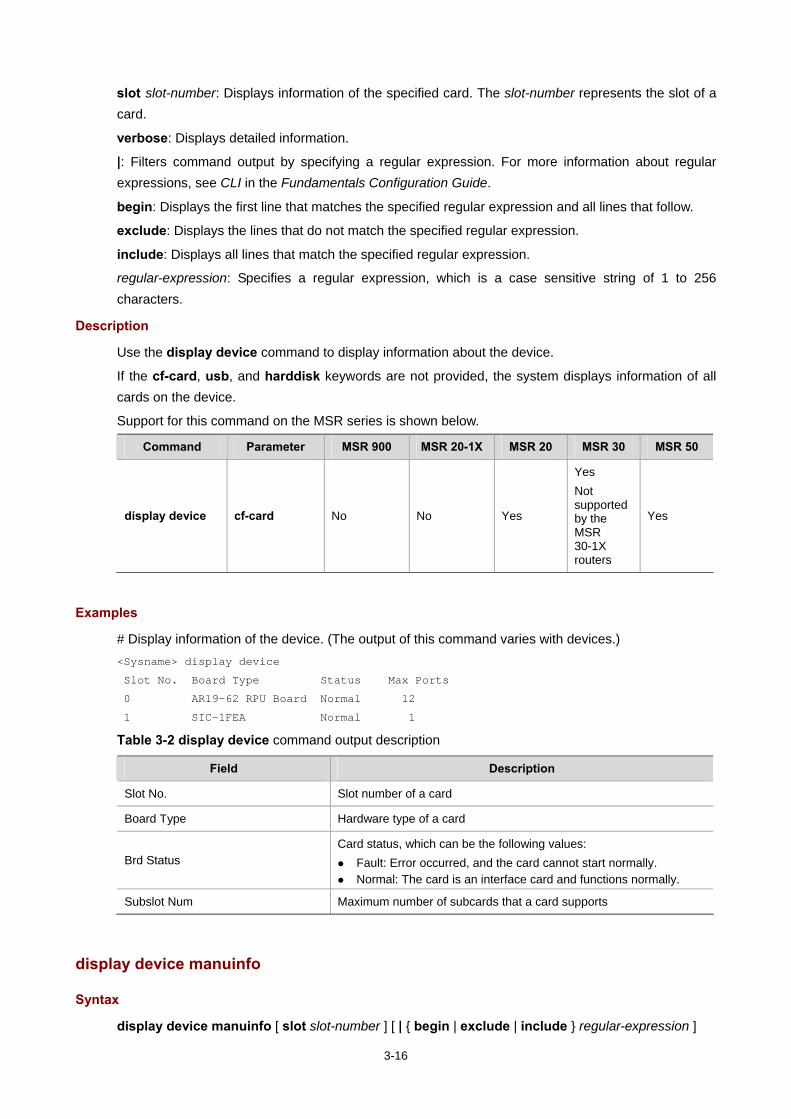
3-16
slot slot-number: Displays information of the specified card. The slot-number represents the slot of a card.
verbose: Displays detailed information.
|: Filters command output by specifying a regular expression. For more information about regular expressions, see CLI in the Fundamentals Configuration Guide.
begin: Displays the first line that matches the specified regular expression and all lines that follow.
exclude: Displays the lines that do not match the specified regular expression.
include: Displays all lines that match the specified regular expression.
regular-expression: Specifies a regular expression, which is a case sensitive string of 1 to 256 characters.
Description
Use the display device command to display information about the device.
If the cf-card, usb, and harddisk keywords are not provided, the system displays information of all cards on the device.
Support for this command on the MSR series is shown below.
Command Parameter MSR 900 MSR 20-1X MSR 20 MSR 30 MSR 50
display device cf-card No No Yes
Yes Not supported by the MSR 30-1X routers
Yes
Examples
# Display information of the device. (The output of this command varies with devices.) <Sysname> display device
Slot No. Board Type Status Max Ports
0 AR19-62 RPU Board Normal 12
1 SIC-1FEA Normal 1
Table 3-2 display device command output description
Field Description
Slot No. Slot number of a card
Board Type Hardware type of a card
Brd Status Card status, which can be the following values:
Fault: Error occurred, and the card cannot start normally. Normal: The card is an interface card and functions normally.
Subslot Num Maximum number of subcards that a card supports
display device manuinfo
Syntax
display device manuinfo [ slot slot-number ] [ | { begin | exclude | include } regular-expression ]
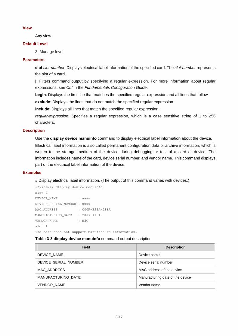
3-17
View
Any view
Default Level
3: Manage level
Parameters
slot slot-number: Displays electrical label information of the specified card. The slot-number represents the slot of a card.
|: Filters command output by specifying a regular expression. For more information about regular expressions, see CLI in the Fundamentals Configuration Guide.
begin: Displays the first line that matches the specified regular expression and all lines that follow.
exclude: Displays the lines that do not match the specified regular expression.
include: Displays all lines that match the specified regular expression.
regular-expression: Specifies a regular expression, which is a case sensitive string of 1 to 256 characters.
Description
Use the display device manuinfo command to display electrical label information about the device.
Electrical label information is also called permanent configuration data or archive information, which is written to the storage medium of the device during debugging or test of a card or device. The information includes name of the card, device serial number, and vendor name. This command displays part of the electrical label information of the device.
Examples
# Display electrical label information. (The output of this command varies with devices.) <Sysname> display device manuinfo
slot 0
DEVICE_NAME : aaaa
DEVICE_SERIAL_NUMBER : xxxx
MAC_ADDRESS : 000F-E26A-58EA
MANUFACTURING_DATE : 2007-11-10
VENDOR_NAME : H3C
slot 1
The card does not support manufacture information.
Table 3-3 display device manuinfo command output description
Field Description
DEVICE_NAME Device name
DEVICE_SERIAL_NUMBER Device serial number
MAC_ADDRESS MAC address of the device
MANUFACTURING_DATE Manufacturing date of the device
VENDOR_NAME Vendor name
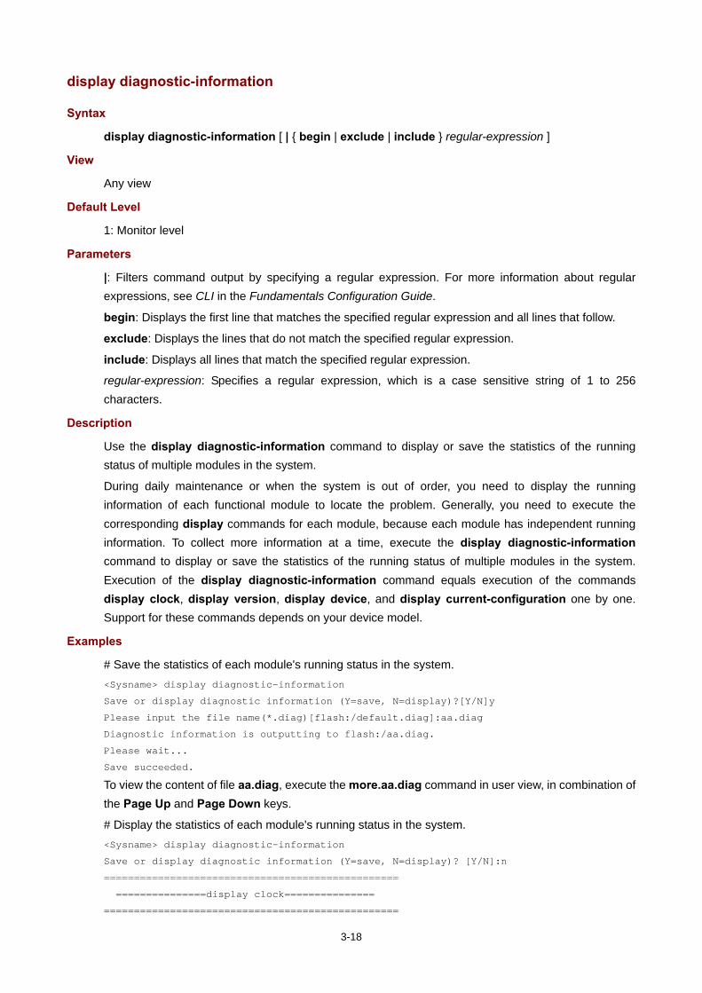
3-18
display diagnostic-information
Syntax
display diagnostic-information [ | { begin | exclude | include } regular-expression ]
View
Any view
Default Level
1: Monitor level
Parameters
|: Filters command output by specifying a regular expression. For more information about regular expressions, see CLI in the Fundamentals Configuration Guide.
begin: Displays the first line that matches the specified regular expression and all lines that follow.
exclude: Displays the lines that do not match the specified regular expression.
include: Displays all lines that match the specified regular expression.
regular-expression: Specifies a regular expression, which is a case sensitive string of 1 to 256 characters.
Description
Use the display diagnostic-information command to display or save the statistics of the running status of multiple modules in the system.
During daily maintenance or when the system is out of order, you need to display the running information of each functional module to locate the problem. Generally, you need to execute the corresponding display commands for each module, because each module has independent running information. To collect more information at a time, execute the display diagnostic-information command to display or save the statistics of the running status of multiple modules in the system. Execution of the display diagnostic-information command equals execution of the commands display clock, display version, display device, and display current-configuration one by one. Support for these commands depends on your device model.
Examples
# Save the statistics of each module's running status in the system. <Sysname> display diagnostic-information
Save or display diagnostic information (Y=save, N=display)?[Y/N]y
Please input the file name(*.diag)[flash:/default.diag]:aa.diag
Diagnostic information is outputting to flash:/aa.diag.
Please wait...
Save succeeded.
To view the content of file aa.diag, execute the more.aa.diag command in user view, in combination of the Page Up and Page Down keys.
# Display the statistics of each module's running status in the system. <Sysname> display diagnostic-information
Save or display diagnostic information (Y=save, N=display)? [Y/N]:n
=================================================
===============display clock===============
=================================================

3-19
08:54:16 UTC Fri 11/15/2008
===================================================
===============display version===============
===================================================
……Omitted……
display environment (advanced)
Syntax
display environment [ | { begin | exclude | include } regular-expression ]
View
Any view
Default Level
1: Monitor level
Parameters
|: Filters command output by specifying a regular expression. For more information about regular expressions, see CLI in the Fundamentals Configuration Guide.
begin: Displays the first line that matches the specified regular expression and all lines that follow.
exclude: Displays the lines that do not match the specified regular expression.
include: Displays all lines that match the specified regular expression.
regular-expression: Specifies a regular expression, which is a case sensitive string of 1 to 256 characters.
Description
Use the display environment command to display the temperature information of the device, including the current temperature and temperature thresholds.
Support for this command on the MSR series is shown below.
Command MSR 900 MSR 20-1X MSR 20 MSR 30 MSR 50
display environment No No Yes Yes Yes
Examples
# Display the temperature information of the device. <Sysname> display environment
System temperature information (degree centigrade):
-----------------------------------------------------------------------------
Slot Sensor Temperature LowerLimit WarningLimit AlarmrLimit ShutdownLimit
Vent outflow 1 38 10 40 50 70
0 inflow 1 27 -10 50 70 100
0 hotspot 1 53 10 50 80 100

3-20
Table 3-4 display environment command output description
Field Description
sensor
Temperature sensor hotspot: A hotspot sensor. inflow: An air intake sensor. outflow: An air exhaust sensor.
Temperature Current temperature
LowerLimit Temperature lower limit
WarningLimit Warning temperature threshold
AlarmLimit Alarming temperature threshold
ShutdownLimit Shut-down temperature threshold. When the sensor temperature reaches this limit, the device shuts down automatically.
display environment (basic)
Syntax
display environment [ cpu ] [ | { begin | exclude | include } regular-expression ]
View
Any view
Default Level
1: Monitor level
Parameters
cpu: Displays temperature information of the CPUs on the device.
|: Filters command output by specifying a regular expression. For more information about regular expressions, see CLI in the Fundamentals Configuration Guide.
begin: Displays the first line that matches the specified regular expression and all lines that follow.
exclude: Displays the lines that do not match the specified regular expression.
include: Displays all lines that match the specified regular expression.
regular-expression: Specifies a regular expression, which is a case sensitive string of 1 to 256 characters.
Description
Use the display environment command to display the temperature information, including the current temperature and temperature thresholds of cards.
Use the display environment cpu command to display the temperature information of all CPUs on the device. The displayed information depends on your device model.
Support for this command on the MSR series is shown below.
Command MSR 900 MSR 20-1X MSR 20 MSR 30 MSR 50
display environment cpu No No No No Yes

3-21
Examples
# Display the temperature information of the device. (The output of this command varies with devices.) <Sysname> display environment
System Temperature information (degree centigrade):
----------------------------------------------------
SlotNo Temperature Lower limit Upper limit
0 41 5 60
Table 3-5 display environment command output description
Field Description
System Temperature information (degree centigrade) Temperature information of system cards (degree centigrade)
CPU Temperature information (degree centigrade) Temperature information of cards of the system (degree centigrade)
Temperature Current temperature
Lower limit Lower limit of temperature
Upper limit Upper limit of temperature
display fan
Syntax
display fan [ fan-id ] [ | { begin | exclude | include } regular-expression ]
View
Any view
Default Level
1: Monitor level
Parameters
fan-id: Displays the operating state of the specified fan, where fan-id represents the built-in fan number.
|: Filters command output by specifying a regular expression. For more information about regular expressions, see CLI in the Fundamentals Configuration Guide.
begin: Displays the first line that matches the specified regular expression and all lines that follow.
exclude: Displays the lines that do not match the specified regular expression.
include: Displays all lines that match the specified regular expression.
regular-expression: Specifies a regular expression, which is a case sensitive string of 1 to 256 characters.
Description
Use the display fan command to display the operating state of built-in fans.
Support for this command on the MSR series is shown below.
Command MSR 900 MSR 20-1X MSR 20 MSR 30 MSR 50
display fan No No Yes Yes Yes

3-22
Command Parameter MSR 900 MSR 20-1X MSR 20 MSR 30 MSR 50
display fan fan-id No No Yes It takes 1.
Yes It takes 1.
Yes It takes 1.
Examples
# Display the operating state of all fans in a device. <Sysname> display fan
Fan 1 State: Normal
display job
Syntax
display job [ job-name ] [ | { begin | exclude | include } regular-expression ]
View
Any view
Default Level
1: Monitor level
Parameters
job-name: Specifies the task name, which is a string of 1 to 32 characters.
|: Filters command output by specifying a regular expression. For more information about regular expressions, see CLI in the Fundamentals Configuration Guide.
begin: Displays the first line that matches the specified regular expression and all lines that follow.
exclude: Displays the lines that do not match the specified regular expression.
include: Displays all lines that match the specified regular expression.
regular-expression: Specifies a regular expression, which is a case sensitive string of 1 to 256 characters.
Description
Use the display job command to display the detailed information of the scheduled tasks to be automatically executed.
Details about all the scheduled tasks are displayed if no argument is specified.
Related commands: job, time, and view.
Examples
# Display detailed information of the scheduled task saveconfig. <Sysname> display job saveconfig
Job name: saveconfig
Specified view: monitor
Time 1: Execute command save 1.cfg after 40 minutes
As shown above, current configurations will be automatically saved to the configuration file 1.cfg forty minutes later.
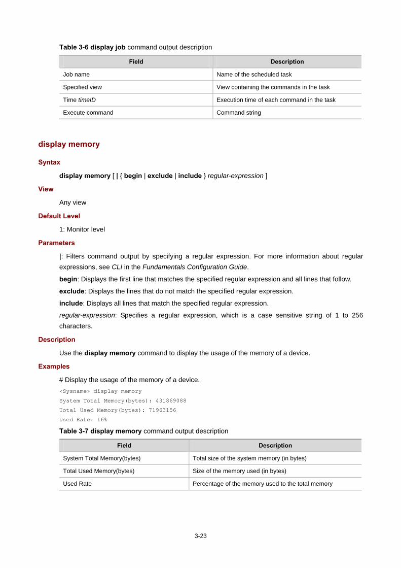
3-23
Table 3-6 display job command output description
Field Description
Job name Name of the scheduled task
Specified view View containing the commands in the task
Time timeID Execution time of each command in the task
Execute command Command string
display memory
Syntax
display memory [ | { begin | exclude | include } regular-expression ]
View
Any view
Default Level
1: Monitor level
Parameters
|: Filters command output by specifying a regular expression. For more information about regular expressions, see CLI in the Fundamentals Configuration Guide.
begin: Displays the first line that matches the specified regular expression and all lines that follow.
exclude: Displays the lines that do not match the specified regular expression.
include: Displays all lines that match the specified regular expression.
regular-expression: Specifies a regular expression, which is a case sensitive string of 1 to 256 characters.
Description
Use the display memory command to display the usage of the memory of a device.
Examples
# Display the usage of the memory of a device. <Sysname> display memory
System Total Memory(bytes): 431869088
Total Used Memory(bytes): 71963156
Used Rate: 16%
Table 3-7 display memory command output description
Field Description
System Total Memory(bytes) Total size of the system memory (in bytes)
Total Used Memory(bytes) Size of the memory used (in bytes)
Used Rate Percentage of the memory used to the total memory
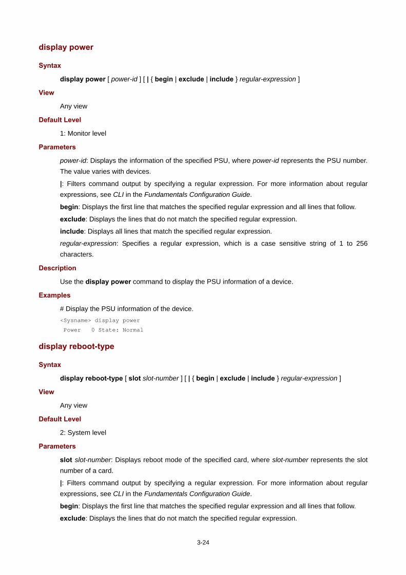
3-24
display power
Syntax
display power [ power-id ] [ | { begin | exclude | include } regular-expression ]
View
Any view
Default Level
1: Monitor level
Parameters
power-id: Displays the information of the specified PSU, where power-id represents the PSU number. The value varies with devices.
|: Filters command output by specifying a regular expression. For more information about regular expressions, see CLI in the Fundamentals Configuration Guide.
begin: Displays the first line that matches the specified regular expression and all lines that follow.
exclude: Displays the lines that do not match the specified regular expression.
include: Displays all lines that match the specified regular expression.
regular-expression: Specifies a regular expression, which is a case sensitive string of 1 to 256 characters.
Description
Use the display power command to display the PSU information of a device.
Examples
# Display the PSU information of the device. <Sysname> display power
Power 0 State: Normal
display reboot-type
Syntax
display reboot-type [ slot slot-number ] [ | { begin | exclude | include } regular-expression ]
View
Any view
Default Level
2: System level
Parameters
slot slot-number: Displays reboot mode of the specified card, where slot-number represents the slot number of a card.
|: Filters command output by specifying a regular expression. For more information about regular expressions, see CLI in the Fundamentals Configuration Guide.
begin: Displays the first line that matches the specified regular expression and all lines that follow.
exclude: Displays the lines that do not match the specified regular expression.

3-25
include: Displays all lines that match the specified regular expression.
regular-expression: Specifies a regular expression, which is a case sensitive string of 1 to 256 characters.
Description
Use the display reboot-type command to display the reboot mode of the device.
If no keyword is provided, the system displays the reboot mode of the device.
Examples
# Display the reboot mode of the device. <Sysname> display reboot-type
The rebooting type this time is: Cold
The above information indicates that the last reboot mode of the device is Cold boot (cold boot is to restart a device by powering it on). (The display of Warm represents a warm boot, which means to restart a device by using the commands like reboot).
display rps
Syntax
display rps [ rps-id ] [ | { begin | exclude | include } regular-expression ]
View
Any view
Default Level
1: Monitor level
Parameters
rps-id: Displays the status of the specified RPS, where rps-id represents the RPS number.
|: Filters command output by specifying a regular expression. For more information about regular expressions, see CLI in the Fundamentals Configuration Guide.
begin: Displays the first line that matches the specified regular expression and all lines that follow.
exclude: Displays the lines that do not match the specified regular expression.
include: Displays all lines that match the specified regular expression.
regular-expression: Specifies a regular expression, which is a case sensitive string of 1 to 256 characters.
Description
Use the display rps command to display status of the RPS.
Support for this command on the MSR series is shown below.
Command MSR 900 MSR 20-1X MSR 20 MSR 30 MSR 50
display rps No No No Yes Not supported by the MSR 30-1X routers
No

3-26
Examples
# Display RPS status of the device. (The output of this command varies with devices.) <Sysname> display rps
RPS 2 State: Normal
The above output information indicates that RPS 2 works normally.
display schedule reboot
Syntax
display schedule reboot [ | { begin | exclude | include } regular-expression ]
View
Any view
Default Level
3: Manage level
Parameters
|: Filters command output by specifying a regular expression. For more information about regular expressions, see CLI in the Fundamentals Configuration Guide.
begin: Displays the first line that matches the specified regular expression and all lines that follow.
exclude: Displays the lines that do not match the specified regular expression.
include: Displays all lines that match the specified regular expression.
regular-expression: Specifies a regular expression, which is a case sensitive string of 1 to 256 characters.
Description
Use the display schedule reboot command to display the device reboot time set by the user.
Related commands: schedule reboot at and schedule reboot delay.
Examples
# Display the reboot time of a device. <Sysname> display schedule reboot
System will reboot at 16:00:00 03/10/2006 (in 2 hours and 5 minutes).
The above information indicates the system will reboot at 16:00:00 on March 10, 2006 (in two hours and five minutes).
display system-failure
Syntax
display system-failure [ | { begin | exclude | include } regular-expression ]
View
Any view
Default Level
3: Manage level

3-27
Parameters
|: Filters command output by specifying a regular expression. For more information about regular expressions, see CLI in the Fundamentals Configuration Guide.
begin: Displays the first line that matches the specified regular expression and all lines that follow.
exclude: Displays the lines that do not match the specified regular expression.
include: Displays all lines that match the specified regular expression.
regular-expression: Specifies a regular expression, which is a case sensitive string of 1 to 256 characters.
Description
Use the display system-failure command to display the exception handling method.
Related commands: system-failure.
Examples
# Display the exception handling method. <Sysname> display system-failure
System failure handling method: reboot
display this
Syntax
display this [ by-linenum ] [ | { begin | exclude | include } regular-expression ]
View
Any view
Default Level
1: Monitor level
Parameters
by-linenum: Specifies to display the number of each line.
|: Filters command output by specifying a regular expression. For more information about regular expressions, see CLI in the Fundamentals Configuration Guide.
begin: Displays the first line that matches the specified regular expression and all lines that follow.
exclude: Displays the lines that do not match the specified regular expression.
include: Displays all lines that match the specified regular expression.
regular-expression: Specifies a regular expression, which is a case sensitive string of 1 to 256 characters.
Description
Use the display this command to display the validated configuration information under the current view.
To check whether your configuration takes effect, use the display this command.
Note that:
The validated configuration that is the same as the default is not displayed.
The invalidated configuration is not displayed.

3-28
Execution of this command in any user interface view displays the valid configuration in all the user interfaces.
Execution of this command in any VLAN view displays the configurations of all the created VLANs.
Examples
# Display the valid configuration information on interface Ethernet 1/1 (the output information depends on the current configuration of the device). <Sysname> system-view
[Sysname] interface ethernet 1/1
[Sysname-Ethernet1/1] display this
#
interface Ethernet1/1
port link-mode bridge
port link-type hybrid
undo port hybrid vlan 1
port hybrid vlan 2 to 4 untagged
port hybrid pvid vlan 2
#
return
# Display the valid configuration information of all user interfaces (the output information depends on the current configuration of the device). <Sysname> system-view
[Sysname] user-interface vty 0
[Sysname-ui-vty0] display this
#
user-interface con 0
user-interface vty 0
history-command max-size 256
user-interface vty 1 4
#
return
display transceiver
Syntax
display transceiver { controller [ controller-type controller-number ] | interface [ interface-type interface-number ] } [ | { begin | exclude | include } regular-expression ]
View
Any view
Default Level
2: System level
Parameters
controller [ controller-type controller-number ]: Displays main parameters of the pluggable transceiver plugged in the specified controller interface. controller-type controller-number represents controller interface type and controller interface number. If it is not specified, the command displays main parameters of the pluggable transceiver(s) plugged in all the controller interfaces.
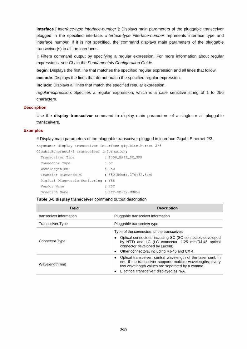
3-29
interface [ interface-type interface-number ]: Displays main parameters of the pluggable transceiver plugged in the specified interface. interface-type interface-number represents interface type and interface number. If it is not specified, the command displays main parameters of the pluggable transceiver(s) in all the interfaces.
|: Filters command output by specifying a regular expression. For more information about regular expressions, see CLI in the Fundamentals Configuration Guide.
begin: Displays the first line that matches the specified regular expression and all lines that follow.
exclude: Displays the lines that do not match the specified regular expression.
include: Displays all lines that match the specified regular expression.
regular-expression: Specifies a regular expression, which is a case sensitive string of 1 to 256 characters.
Description
Use the display transceiver command to display main parameters of a single or all pluggable transceivers.
Examples
# Display main parameters of the pluggable transceiver plugged in interface GigabitEthernet 2/3. <Sysname> display transceiver interface gigabitethernet 2/3
GigabitEthernet2/3 transceiver information:
Transceiver Type : 1000_BASE_SX_SFP
Connector Type : LC
Wavelength(nm) : 850
Transfer Distance(m) : 550(50um),270(62.5um)
Digital Diagnostic Monitoring : YES
Vendor Name : H3C
Ordering Name : SFP-GE-SX-MM850
Table 3-8 display transceiver command output description
Field Description
transceiver information Pluggable transceiver information
Transceiver Type Pluggable transceiver type
Connector Type
Type of the connectors of the transceiver: Optical connectors, including SC (SC connector, developed
by NTT) and LC (LC connector, 1.25 mm/RJ-45 optical connector developed by Lucent).
Other connectors, including RJ-45 and CX 4.
Wavelength(nm)
Optical transceiver: central wavelength of the laser sent, in nm. If the transceiver supports multiple wavelengths, every two wavelength values are separated by a comma.
Electrical transceiver: displayed as N/A.

3-30
Field Description
Transfer distance(xx)
Transfer distance, with xx representing km for single-mode transceivers and m for other transceivers. If the transceiver supports multiple transfer medium, every two values of the transfer distance are separated by a comma. The corresponding transfer medium is included in the bracket following the transfer distance value. The following are the transfer media:
9 um: 9/125 um single-mode fiber 50 um: 50/125 um multi-mode fiber 62.5 um: 62.5/125 um multi-mode fiber TP: Twisted pair CX4: CX4 cable
Digital Diagnostic Monitoring Whether the digital diagnosis function is supported, where:
YES: supported NO: not supported
Vendor Name
Vendor name or name of the vendor who customizes the transceiver:
H3C customized anti-spoofing transceiver: H3C is displayed. Other transceivers: The vendor name is displayed.
Ordering Name Pluggable transceiver model
display transceiver alarm
Syntax
display transceiver alarm { controller [ controller-type controller-number ] | interface [ interface-type interface-number ] } [ | { begin | exclude | include } regular-expression ]
View
Any view
Default Level
2: System level
Parameters
controller [ controller-type controller-number ]: Displays the current alarm information of the pluggable transceiver plugged in the specified controller interface. controller-type controller-number represents controller interface type and controller interface number. If it is not specified, the command displays the current alarm information of the pluggable transceiver in all the controller interfaces.
interface [ interface-type interface-number ]: Displays the current alarm information of the pluggable transceiver plugged in the specified interface. interface-type interface-number represents interface type and interface number. If it is not specified, the command displays the current alarm information of the pluggable transceiver in all the interfaces.
|: Filters command output by specifying a regular expression. For more information about regular expressions, see CLI in the Fundamentals Configuration Guide.
begin: Displays the first line that matches the specified regular expression and all lines that follow.
exclude: Displays the lines that do not match the specified regular expression.
include: Displays all lines that match the specified regular expression.

3-31
regular-expression: Specifies a regular expression, which is a case sensitive string of 1 to 256 characters.
Description
Use the display transceiver alarm command to display the current alarm information of a single or all transceivers.
If no error occurs, None is displayed.
Table 3-9 shows the alarm information that may occur for the four types of commonly used transceivers.
Table 3-9 display transceiver alarm command output description
Field Remarks
GBIC/SFP
RX loss of signal Incoming (RX) signal is lost.
RX power high Incoming (RX) power level is high.
RX power low Incoming (RX) power level is low.
TX fault Transmit (TX) fault
TX bias high TX bias current is high.
TX bias low TX bias current is low.
TX power high TX power is high.
TX power low TX power is low.
Temp high Temperature is high.
Temp low Temperature is low.
Voltage high Voltage is high.
Voltage low Voltage is low.
Transceiver info I/O error Transceiver information read and write error
Transceiver info checksum error Transceiver information checksum error
Transceiver type and port configuration mismatch Transceiver type does not match port configuration.
Transceiver type not supported by port hardware Transceiver type is not supported on the port.
XFP
RX loss of signal Incoming (RX) signal is lost.
RX not ready RX is not ready
RX CDR loss of lock RX clock cannot be recovered.
RX power high RX power is high.
RX power low RX power is low.
TX not ready TX is not ready.
TX fault TX fault
TX CDR loss of lock TX clock cannot be recovered.
TX bias high TX bias current is high.
TX bias low TX bias current is low.

3-32
Field Remarks
TX power high TX power is high.
TX power low TX power is low.
Module not ready Module is not ready.
APD supply fault APD (Avalanche Photo Diode) supply fault
TEC fault TEC (Thermoelectric Cooler) fault
Wavelength unlocked Wavelength of optical signal exceeds the manufacturer’s tolerance.
Temp high Temperature is high.
Temp low Temperature is low.
Voltage high Voltage is high.
Voltage low Voltage is low.
Transceiver info I/O error Transceiver information read and write error
Transceiver info checksum error Transceiver information checksum error
Transceiver type and port configuration mismatch Transceiver type does not match port configuration.
Transceiver type not supported by port hardware Transceiver type is not supported on the port.
XENPAK
WIS local fault WIS (WAN Interface Sublayer) local fault
Receive optical power fault Receive optical power fault
PMA/PMD receiver local fault PMA/PMD (Physical Medium Attachment/Physical Medium Dependent) receiver local fault
PCS receive local fault PCS (Physical Coding Sublayer) receiver local fault
PHY XS receive local fault PHY XS (PHY Extended Sublayer) receive local fault
RX power high RX power is high.
RX power low RX power is low.
Laser bias current fault Laser bias current fault
Laser temperature fault Laser temperature fault
Laser output power fault Laser output power fault
TX fault TX fault
PMA/PMD receiver local fault PMA/PMD receiver local fault
PCS receive local fault PCS receive local fault
PHY XS receive local fault PHY XS receive local fault
TX bias high TX bias current is high.
TX bias low TX bias current is low.
TX power high TX power is high.
TX power low TX power is low.
Temp high Temperature is high.

3-33
Field Remarks
Temp low Temperature is low.
Transceiver info I/O error Transceiver information read and write error
Transceiver info checksum error Transceiver information checksum error
Transceiver type and port configuration mismatch Transceiver type does not match port configuration.
Transceiver type not supported by port hardware Transceiver type is not supported on the port.
Examples
# Display the alarm information of the pluggable transceiver plugged in interface GigabitEthernet 2/1. <Sysname> display transceiver alarm interface gigabitethernet 2/1
GigabitEthernet2/1 transceiver current alarm information:
RX loss of signal
RX power low
Table 3-10 display transceiver alarm command output description
Field Description
transceiver current alarm information Current alarm information of the transceiver
RX loss of signal Incoming (RX) signal is lost.
RX power low Incoming (RX) power level is low.
display transceiver diagnosis
Syntax
display transceiver diagnosis { controller [ controller-type controller-number ] | interface [ interface-type interface-number ] } [ | { begin | exclude | include } regular-expression ]
View
Any view
Default Level
2: System level
Parameters
controller [ controller-type controller-number ]: Displays the currently measured value of digital diagnosis parameters of the H3C customized anti-spoofing pluggable optical transceiver plugged in the specified controller interface. controller-type controller-number represents controller interface type and controller interface number. If it is not specified, the command displays the currently measured value of digital diagnosis parameters of H3C customized anti-spoofing pluggable optical transceivers in all the controller interfaces.
interface [ interface-type interface-number ]: Displays the currently measured value of digital diagnosis parameters of the H3C customized anti-spoofing pluggable optical transceiver plugged in the specified interface. interface-type interface-number represents interface type and interface number. If it is not
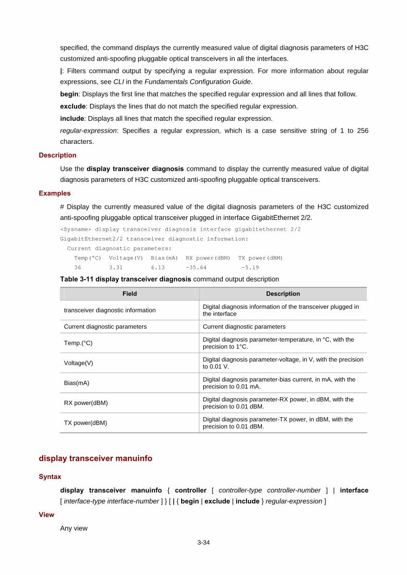
3-34
specified, the command displays the currently measured value of digital diagnosis parameters of H3C customized anti-spoofing pluggable optical transceivers in all the interfaces.
|: Filters command output by specifying a regular expression. For more information about regular expressions, see CLI in the Fundamentals Configuration Guide.
begin: Displays the first line that matches the specified regular expression and all lines that follow.
exclude: Displays the lines that do not match the specified regular expression.
include: Displays all lines that match the specified regular expression.
regular-expression: Specifies a regular expression, which is a case sensitive string of 1 to 256 characters.
Description
Use the display transceiver diagnosis command to display the currently measured value of digital diagnosis parameters of H3C customized anti-spoofing pluggable optical transceivers.
Examples
# Display the currently measured value of the digital diagnosis parameters of the H3C customized anti-spoofing pluggable optical transceiver plugged in interface GigabitEthernet 2/2. <Sysname> display transceiver diagnosis interface gigabitethernet 2/2
GigabitEthernet2/2 transceiver diagnostic information:
Current diagnostic parameters:
Temp(°C) Voltage(V) Bias(mA) RX power(dBM) TX power(dBM)
36 3.31 6.13 -35.64 -5.19
Table 3-11 display transceiver diagnosis command output description
Field Description
transceiver diagnostic information Digital diagnosis information of the transceiver plugged in the interface
Current diagnostic parameters Current diagnostic parameters
Temp.(°C) Digital diagnosis parameter-temperature, in °C, with the precision to 1°C.
Voltage(V) Digital diagnosis parameter-voltage, in V, with the precision to 0.01 V.
Bias(mA) Digital diagnosis parameter-bias current, in mA, with the precision to 0.01 mA.
RX power(dBM) Digital diagnosis parameter-RX power, in dBM, with the precision to 0.01 dBM.
TX power(dBM) Digital diagnosis parameter-TX power, in dBM, with the precision to 0.01 dBM.
display transceiver manuinfo
Syntax
display transceiver manuinfo { controller [ controller-type controller-number ] | interface [ interface-type interface-number ] } [ | { begin | exclude | include } regular-expression ]
View
Any view

3-35
Default Level
2: System level
Parameters
controller [ controller-type controller-number ]: Displays part of the electrical label information of the H3C customized anti-spoofing pluggable transceiver plugged in the specified controller interface. controller-type controller-number represents controller interface type and controller interface number. If it is not specified, the command displays part of the electrical label information of the H3C customized anti-spoofing pluggable transceiver(s) plugged in all the controller interfaces.
interface [ interface-type interface-number ]: Displays part of the electrical label information of the H3C customized anti-spoofing pluggable transceiver plugged in the specified interface. interface-type interface-number represents interface type and interface number. If it is not specified, the command displays part of the electrical label information of the H3C customized anti-spoofing pluggable transceiver(s) in all the interfaces.
|: Filters command output by specifying a regular expression. For more information about regular expressions, see CLI in the Fundamentals Configuration Guide.
begin: Displays the first line that matches the specified regular expression and all lines that follow.
exclude: Displays the lines that do not match the specified regular expression.
include: Displays all lines that match the specified regular expression.
regular-expression: Specifies a regular expression, which is a case sensitive string of 1 to 256 characters.
Description
Use the display transceiver manuinfo command to display part of the electrical label information of a single or all H3C customized anti-spoofing pluggable transceivers.
Examples
# Display the electrical label information of the H3C customized anti-spoofing pluggable transceiver plugged in interface GigabitEthernet 2/4. <Sysname> display transceiver manuinfo interface gigabitethernet 2/4
GigabitEthernet2/4 transceiver manufacture information:
Manu. Serial Number : 213410A0000054000251
Manufacturing Date : 2006-09-01
Vendor Name : H3C
Table 3-12 display transceiver manuinfo command output description
Field Description
Manu. Serial Number Serial number generated during debugging and testing of the customized transceivers
Manufacturing Date Debugging and testing date. The date takes the value of the system clock of the computer that performs debugging and testing.
Vendor Name Name of the vendor who customizes the transceiver, that is, H3C.

3-36
display version
Syntax
display version [ | { begin | exclude | include } regular-expression ]
View
Any view
Default Level
1: Monitor level
Parameters
|: Filters command output by specifying a regular expression. For more information about regular expressions, see CLI in the Fundamentals Configuration Guide.
begin: Displays the first line that matches the specified regular expression and all lines that follow.
exclude: Displays the lines that do not match the specified regular expression.
include: Displays all lines that match the specified regular expression.
regular-expression: Specifies a regular expression, which is a case sensitive string of 1 to 256 characters.
Description
Use the display version command to view system version information.
By viewing system version information, you can learn about the current software version, rack type and the information related to the main board and interface boards.
Examples
# Display system version information (The system version information varies with devices.). <Sysname> display version
header
Syntax
header { incoming | legal | login | motd | shell } text
undo header { incoming | legal | login | motd | shell }
View
System view
Default Level
2: System level
Parameters
incoming: Sets the banner displayed when a user interface is activated by a Modem user. If authentication is needed, the incoming banner is displayed after the authentication is passed.
legal: Sets the license information banner before a user logs onto the terminal interface. The legal banner is displayed before the user inputs the username and password.
login: Sets the login banner at authentication.
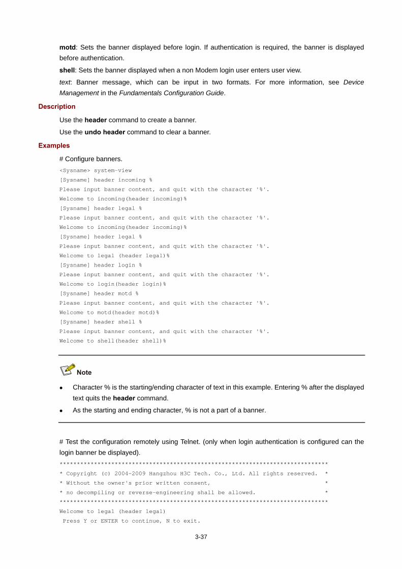
3-37
motd: Sets the banner displayed before login. If authentication is required, the banner is displayed before authentication.
shell: Sets the banner displayed when a non Modem login user enters user view.
text: Banner message, which can be input in two formats. For more information, see Device Management in the Fundamentals Configuration Guide.
Description
Use the header command to create a banner.
Use the undo header command to clear a banner.
Examples
# Configure banners. <Sysname> system-view
[Sysname] header incoming %
Please input banner content, and quit with the character '%'.
Welcome to incoming(header incoming)%
[Sysname] header legal %
Please input banner content, and quit with the character '%'.
Welcome to incoming(header incoming)%
[Sysname] header legal %
Please input banner content, and quit with the character '%'.
Welcome to legal (header legal)%
[Sysname] header login %
Please input banner content, and quit with the character '%'.
Welcome to login(header login)%
[Sysname] header motd %
Please input banner content, and quit with the character '%'.
Welcome to motd(header motd)%
[Sysname] header shell %
Please input banner content, and quit with the character '%'.
Welcome to shell(header shell)%
Character % is the starting/ending character of text in this example. Entering % after the displayed text quits the header command.
As the starting and ending character, % is not a part of a banner.
# Test the configuration remotely using Telnet. (only when login authentication is configured can the login banner be displayed). ******************************************************************************
* Copyright (c) 2004-2009 Hangzhou H3C Tech. Co., Ltd. All rights reserved. *
* Without the owner's prior written consent, *
* no decompiling or reverse-engineering shall be allowed. *
******************************************************************************
Welcome to legal (header legal)
Press Y or ENTER to continue, N to exit.

3-38
Welcome to motd(header motd)
Welcome to login(header login)
Login authentication
Password:
Welcome to shell(header shell)
job
Syntax
job job-name
undo job job-name
View
System view
Default Level
3: Manage level
Parameters
job-name: Specifies name of the scheduled task, a string of 1 to 32 characters.
Description
Use the job command to create a scheduled task and enter job view, or enter this view directly if a task is ready.
Use the undo job command to remove the task.
By default, no scheduled task is created.
After creating a scheduled task, you can configure the task in job view. For example, you can specify the execution time for the commands in the task.
This command can be repeatedly executed to create multiple independent scheduled tasks.
Related commands: view and time.
Examples
# Create a scheduled task or enter the scheduled task saveconfiguration. <Sysname> system-view
[Sysname] job saveconfiguration
[Sysname-job-saveconfiguration]
nms monitor-interface
Syntax
nms { primary | secondary } monitor-interface interface-type interface-number
undo nms { primary | secondary } monitor-interface
View
System view
Default Level
3: Manage level

3-39
Parameters
primary: Specifies the primary monitored interface for a network management station (NMS).
secondary: Specifies the secondary monitored interface for the NMS.
interface-type interface-number: Type and number of the interface to be monitored.
Description
Use the nms primary monitor-interface command to configure the primary monitored interface for an NMS.
Use the nms secondary monitor-interface command to configure the secondary monitored interface for an NMS.
Use the undo nms monitor-interface command to remove the configurations.
By default, an NMS does not monitor any interface on the device.
If you configure only the primary monitored interface or the secondary monitored interface, the device monitors the IP address of the configured interface. If the interface gets or changes its IP address when the interface status is up, the device sends traps to the NMS to inform it of the available IP address.
If you configure both the primary and secondary monitored interfaces, the device monitors the primary one first.
Support for this command on the MSR series is shown below.
Command MSR 900 MSR 20-1X MSR 20 MSR 30 MSR 50
nms monitor-interface Yes Yes No No No
Examples
# Configure Ethernet 1/1 as the primary monitored interface for an NMS <Sysname> system-view
[Sysname] nms primary monitor-interface ethernet 1/1
reboot
Syntax
reboot [ slot slot-number ]
View
User view
Default Level
3: Manage level
Parameters
slot subslot-number: Specifies the slot number of a card.
Description
Use the reboot command to reboot the device of the specified subcard.

3-40
Device reboot may result in the interruption of the ongoing services. Use these commands with caution.
If a main boot file fails or does not exist, the device cannot be rebooted with the reboot command. In this case, you can re-specify a main boot file to reboot the device, or you can power off the device, then power it on and the system automatically uses the backup boot file to restart the device.
If you are performing file operations when the device is to be rebooted, the system does not execute the command for the sake of security.
Examples
# Reboot the device. <Sysname> reboot
reset unused porttag
Syntax
reset unused porttag
View
User view
Default Level
1: Monitor level
Parameters
None
Description
Use the reset unused porttag command to clear the 16-bit index saved but not used in the current system.
A confirmation is required when you carry out this command. If you fail to make a confirmation within 30 seconds or enter “N” to cancel the operation, the command will not be carried out.
Support for this command on the MSR series is shown below.
Command MSR 900 MSR 20-1X MSR 20 MSR 30 MSR 50
reset unused porttag No No Yes Yes Yes
Examples
# Clear the 16-bit index saved but not used in the current system. <Sysname> reset unused porttag
Current operation will delete all unused port tag(s). Continue? [Y/N]:y
<Sysname>

3-41
schedule reboot at
Syntax
schedule reboot at hh:mm [ date ]
undo schedule reboot
View
User view
Default Level
3: Manage level
Parameters
hh:mm: Reboot time of a device, in the format of hh:mm (hours:minutes). The value of the hh argument ranges from 0 to 23, and the value of the mm argument ranges from 0 to 59.
date: Reboot date of a device, in the format mm/dd/yyyy (month/day/year) or in the format yyyy/mm/dd (year/month/day) The yyyy value ranges from 2000 to 2035, the mm value ranges from 1 to 12, and the dd value depends on a specific month.
Description
Use the schedule reboot at command to enable the scheduled reboot function and specify a specific reboot time and date.
By default, the scheduled reboot function is disabled.
If no specific reboot date is specified:
When the specified reboot time is later than the current time, the device will be rebooted at the reboot time of the current day.
When the specified reboot time is earlier than the current time, the device will be rebooted at the reboot time the next day.
If you are performing file operations when the device is to be rebooted, the system does not execute the command for the sake of security.
The precision of the device timer is 1 minute. One minute before the reboot time, the device will prompt “REBOOT IN ONE MINUTE” and will be rebooted in one minute.
The difference between the reboot date and the current date cannot exceed 30 x 24 hours (namely, 30 days).
After you execute the above command, the device will prompt you to confirm the configuration. You must enter Y or y to make the configuration take effect. The original configuration will be overwritten at the same time.
If a date (month/day/year or year/month/day) later than the current date is specified for the schedule reboot at command, the device will be rebooted at the reboot time.
If you use the clock command after the schedule reboot at command to adjust the system time, the reboot time set by the schedule reboot at command will become invalid.

3-42
This command reboots the device in a future time, thus resulting in service interruption. Please use it with caution.
Examples
# Configure the device to reboot at 12:00 AM (supposing that the current time is 11:43). <Sysname> schedule reboot at 12:00
Reboot system at 12:00 06/06/2006(in 0 hour(s) and 16 minute(s))
confirm? [Y/N]:
# If you have used the terminal logging command to enable the log display function on the terminal before setting a reboot time, the system will automatically display related log information after you enter <y>. By default, the log display function is enabled. <Sysname>
%Jun 6 11:43:11:629 2006 Sysname CMD/4/REBOOT:
vty0(192.168.1.54): Set schedule reboot parameters at 11:43:11 06/06/2006, and system will reboot at 12:00 06/06/2006.
schedule reboot delay
Syntax
schedule reboot delay { hh:mm | mm }
undo schedule reboot
View
User view
Default Level
3: Manage level
Parameters
hh:mm: Device reboot wait time, in the format of hh:mm (hours:minutes). The value of the hh argument ranges from 0 to 720, and the value of the mm argument ranges from 0 to 59, and the value of the hh:mm argument cannot exceed 720:00.
mm: Device reboot wait time in minutes, which ranges from 0 to 43,200.
Description
Use the schedule reboot delay command to enable the scheduled reboot function and set a reboot wait time.
By default, the scheduled reboot function is disabled.
The reboot wait time can be in the format of hh:mm (hours:minutes) or mm (absolute minutes). The absolute minutes cannot exceed 30 x 24 x 60 minutes, namely, 30 days.
The precision of the device timer is 1 minute. One minute before the reboot time, the device will prompt “REBOOT IN ONE MINUTE” and will be rebooted in one minute.

3-43
After you execute the above command, the device will prompt you to confirm the configuration. You must enter <Y> or <y> to make the configuration take effect. The original configuration will be overwritten at the same time.
If you use the clock command after the schedule reboot delay command to adjust the system time, the reboot wait time set by the schedule reboot delay command will become invalid.
If you are performing file operations when the device is to be rebooted, the system does not execute the command for the sake of security.
This command reboots the device after the specified delay time, thus resulting in service interruption. Please use it with caution.
Examples
# Configure the device to reboot in 88 minutes (supposing the current time is 11:48). <Sysname> schedule reboot delay 88
Reboot system at 13:16 06/06/2006(in 1 hour(s) and 28 minute(s)). confirm? [Y/N]:
# If you have used the terminal logging command to enable the log display function on the terminal before setting a reboot time, the system will automatically display related log information after you enter y. By default, the log display function is enabled on the terminal. <Sysname>
%Jun 6 11:48:44:860 2006 Sysname CMD/4/REBOOT:
vty0(192.168.1.54): Set schedule reboot parameters at 11:48:44 06/06/2006, and system will reboot at 13:16 06/06/2006.
shutdown-interval
Syntax
shutdown-interval time
undo shutdown-interval
View
System view
Default Level
2: System level
Parameters
time: Detection interval in seconds, which ranges from 0 to 300.
Description
Use the shutdown-interval command to set a detection interval.
Use the undo shutdown-interval command to restore the default.
By default, the detection interval is 30 seconds.

3-44
Some protocol modules may shut down ports under specific circumstances. For example, an MSTP module will automatically shut down a port that receives configuration messages after the BPDU guard function is enabled on the port. Then, the MSTP module enables a detection timer and detects the status of the port. If the port is still down when the detection timer times out, the MSTP module will automatically bring up the port.
If you change the detection interval to T1 during port detection, the interval from when you change the interval to the time when the protocol module shuts down the port is T. If T<T1, the port which is down will be brought up after T1-T time; if T>=T1, the port which is down will be brought up immediately. For example, if the detection interval is set to 30 seconds and you change it to 10 seconds (T1=10) two seconds after the port is shut down (T=2), this port will be brought up 8 seconds later; if the detection interval is set to 30 seconds and you change it to 2 seconds ten seconds after the port is shut down, this port will be brought up immediately.
If the detection interval is set to 0, the protocol module will never automatically recover the port. You need to manually bring up the port by using the undo shutdown command or change the detection interval to a non-zero value.
Examples
# Set the detection interval to 100 seconds. <Sysname> system-view
[Sysname] shutdown-interval 100
sysname
Syntax
sysname sysname
undo sysname
View
System view
Default Level
2: System level
Parameters
sysname: Name of the device, which is a string of 1 to 30 characters.
Description
Use the sysname command to set the name of the device.
Use the undo sysname demand to restore the device name to the default.
The default name varies with devices.
Changing device name affects the prompt of the CLI. For example, if the device name is Sysname, the prompt of user view is <Sysname>.
Examples
# Set the name of the device to R2000. <Sysname> system-view
[Sysname] sysname R2000
[R2000]

3-45
system-failure
Syntax
system-failure { maintain | reboot }
undo system-failure { maintain | reboot }
View
System view
Default Level
3: Manage level
Parameters
maintain: Specifies that when the system detects any software abnormality, it maintains the current situation, and does not take any measure to recover itself.
reboot: Specifies that when the system detects any software abnormality, it recovers itself through automatic reboot.
Description
Use the system-failure command to configure the exception handling method.
By default, the system adopts the reboot method to handle exceptions.
Examples
# Set the exception handling method to reboot. <Sysname> system-view
[Sysname] system-failure reboot
temperature-limit (basic)
Syntax
temperature-limit slot-number lower-value upper-value
undo temperature-limit slot-number
View
System view
Default Level
2: System level
Parameters
slot-number: Slot number of a card.
lower-value: Lower temperature limit in Celsius degrees.
upper-value: Upper temperature limit in Celsius degrees.
The upper-value argument must be larger than the lower-value argument.
Description
Use the temperature-limit command to set the temperature alarm threshold on a card.
Use the undo temperature-limit command to restore the temperature alarm threshold to the default.
By default, the temperature alarm threshold depends on device models.

3-46
Support for some commands on the MSR series is shown below.
Command MSR 900 MSR 20-1X MSR 20 MSR 30 MSR 50
temperature-limit (basic) No No Yes Yes Yes
Command Parameter MSR 900 MSR 20-1X MSR 20 MSR 30 MSR 50
temperature-limit lower-value No No
Yes It ranges from 0 to 30.
Yes It ranges from 0 to 30.
Yes It ranges from 0 to 30.
temperature-limit upper-value No No
Yes It ranges from 40 to 90.
Yes It ranges from 40 to 90.
Yes It ranges from 40 to 90.
Examples
# Set the lower temperature limit on card 1 to 10 Celsius degrees and the upper temperature limit to 75 Celsius degrees. <Sysname> system-view
[Sysname] temperature-limit 1 10 75
Setting temperature limit succeeded.
time
Syntax
time timeID at time1 date command command
time timeID { one-off | repeating } at time1 [ month-date month-day | week-day week-daylist ] command command
time timeID { one-off | repeating } delay time2 command command
undo time timeID
View
Job view
Default Level
3: Manage level
Parameters
timeID: Time index, an integer that ranges from 1 to 10.
at time1: Specifies the execution time, in the format of hh:mm (hour:minute), where hh ranges from 0 to 23 and mm ranges from 0 to 59.
date: Specifies the execution date, in the format of MM/DD/YYYY (month/date/year) or YYYY/MM/DD (year/month/date), where the year ranges from 2000 to 2035, the month ranges from 1 to 12, and the date range depends on the specified month. Note that the specified execution date must be ahead of the current date.
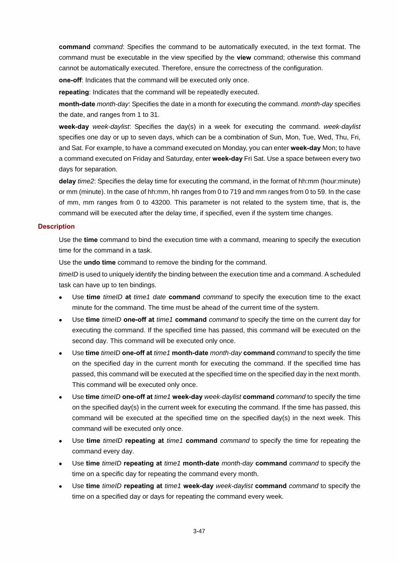
3-47
command command: Specifies the command to be automatically executed, in the text format. The command must be executable in the view specified by the view command; otherwise this command cannot be automatically executed. Therefore, ensure the correctness of the configuration.
one-off: Indicates that the command will be executed only once.
repeating: Indicates that the command will be repeatedly executed.
month-date month-day: Specifies the date in a month for executing the command. month-day specifies the date, and ranges from 1 to 31.
week-day week-daylist: Specifies the day(s) in a week for executing the command. week-daylist specifies one day or up to seven days, which can be a combination of Sun, Mon, Tue, Wed, Thu, Fri, and Sat. For example, to have a command executed on Monday, you can enter week-day Mon; to have a command executed on Friday and Saturday, enter week-day Fri Sat. Use a space between every two days for separation.
delay time2: Specifies the delay time for executing the command, in the format of hh:mm (hour:minute) or mm (minute). In the case of hh:mm, hh ranges from 0 to 719 and mm ranges from 0 to 59. In the case of mm, mm ranges from 0 to 43200. This parameter is not related to the system time, that is, the command will be executed after the delay time, if specified, even if the system time changes.
Description
Use the time command to bind the execution time with a command, meaning to specify the execution time for the command in a task.
Use the undo time command to remove the binding for the command.
timeID is used to uniquely identify the binding between the execution time and a command. A scheduled task can have up to ten bindings.
Use time timeID at time1 date command command to specify the execution time to the exact minute for the command. The time must be ahead of the current time of the system.
Use time timeID one-off at time1 command command to specify the time on the current day for executing the command. If the specified time has passed, this command will be executed on the second day. This command will be executed only once.
Use time timeID one-off at time1 month-date month-day command command to specify the time on the specified day in the current month for executing the command. If the specified time has passed, this command will be executed at the specified time on the specified day in the next month. This command will be executed only once.
Use time timeID one-off at time1 week-day week-daylist command command to specify the time on the specified day(s) in the current week for executing the command. If the time has passed, this command will be executed at the specified time on the specified day(s) in the next week. This command will be executed only once.
Use time timeID repeating at time1 command command to specify the time for repeating the command every day.
Use time timeID repeating at time1 month-date month-day command command to specify the time on a specific day for repeating the command every month.
Use time timeID repeating at time1 week-day week-daylist command command to specify the time on a specified day or days for repeating the command every week.

3-48
Use time timeID one-off delay time2 command command to specify the time delay for executing the command. This command will be executed only once.
Use time timeID repeating delay time2 command command to specify the time interval for executing the command periodically.
Use undo time timeID to remove the specified execution time.
Examples
# Configure to save the configuration file a.cfg at 24:00 on May 18, 2009. <Sysname> system-view
[Sysname] job saveconfig
[Sysname-job-saveconfig] view monitor
[Sysname-job-saveconfig] time 1 at 24:00 2009/05/18 command save a.cfg
# Configure to save the configuration file at 12:00 every day. <Sysname> system-view
[Sysname] job saveconfig
[Sysname-job-saveconfig] view monitor
[Sysname-job-saveconfig] time 1 repeating at 12:00 command save a.cfg
# Configure to save the configuration file at 8:00 AM on 5th in the current month, which may be executed in the second month if the time has passed. <Sysname> system-view
[Sysname] job saveconfig
[Sysname-job-saveconfig] view monitor
[Sysname-job-saveconfig] time 1 one-off at 8:00 month-date 5 command save a.cfg
# Configure to save the configuration file at 8:00 AM on 5th every month. <Sysname> system-view
[Sysname] job saveconfig
[Sysname-job-saveconfig] view momitor
[Sysname-job-saveconfig] time 1 repeating at 8:00 month-date 5 command save a.cfg
# Configure to save the configuration file at 8:00 AM on Friday and Saturday in the current week, which may be delayed to the next week if the time has passed. <Sysname> system-view
[Sysname] job saveconfig
[Sysname-job-saveconfig] view monitor
[Sysname-job-saveconfig] time 1 one-off at 8:00 week-day fri sat command save a.cfg
# Configure to save the configuration file at 8:00 on Friday and Saturday every week. <Sysname> system-view
[Sysname] job saveconfig
[Sysname-job-saveconfig] view monitor
[Sysname-job-saveconfig] time 1 repeating at 8:00 week-day fri sat command save a.cfg
# Configure to save the configuration file five minutes later than the current system time. <Sysname> system-view
[Sysname] job saveconfig
[Sysname-job-saveconfig] view monitor
[Sysname-job-saveconfig] time 1 one-off delay 5 command save a.cfg
# Configure to save the configuration file every five minutes. <Sysname> system-view
[Sysname] job saveconfig
[Sysname-job-saveconfig] view monitor

3-49
[Sysname-job-saveconfig] time 1 repeating delay 5 command save a.cfg
view
Syntax
view view-name
undo view
View
Job view
Default Level
3: Manage level
Parameters
view-name: specifies name of the view in which commands in the scheduled task are executed. A view name is a string of 1 to 90 characters.
Description
Use the view command to specify the view in which the commands contained in the scheduled task are automatically executed.
Use the undo view command to remove the configuration.
By default, no view is specified for the scheduled task.
Only one view can be specified for a scheduled task, that is, all the commands in the task are automatically executed in the specified view. If different views are specified by executing the view view-name command repeatedly, only the last configuration takes effect.
The view must be currently supported by the system, with its name specified using its complete format but not an abbreviation. Most commonly used view names include: monitor for user view, system for system view, Etherentx/x/x for Ethernet interface view, and Vlan-interfacex for VLAN interface view.
Related commands: job and time.
Examples
# Configure a task to be automatically executed in system view. <Sysname> system-view
[Sysname] job creatvlan
[Sysname-job-creatvlan] view system

4-1
4 Configuration File Management Commands
Configuration File Management Commands
archive configuration
Syntax
archive configuration
View
User view
Default Level
3: Manage level
Parameters
None
Description
Use the archive configuration command to manually save the current running configuration.
With this command executed, the system saves the current running configuration with the specified filename (filename prefix + serial number) to the specified path.
Before executing the archive configuration command, you must configure the filename prefix and path for saving configuration files by using the archive configuration location command.
Examples
# Save the current running configuration manually. <Sysname> archive configuration
Warning: Save the running configuration to an archive file. Continue? [Y/N]: Y
Please wait...
Info: The archive configuration file myarchive_1.cfg is saved.
archive configuration interval
Syntax
archive configuration interval minutes
undo archive configuration interval
View
System view
Default Level
3: Manage level

4-2
Parameters
minutes: Specifies the interval for automatically saving the current running configuration, in minutes. The value ranges from 10 to 525,600 (365 days).
Description
Use the archive configuration interval command to enable the automatic saving of the current running configuration and set the interval.
Use the undo archive configuration interval command to restore the default.
By default, the system does not automatically save the current running configuration.
With this command executed, the system saves the current running configuration with the specified filename to the specified path at a specified interval (the value of the minutes argument).
Configure an automatic saving interval according to the storage medium performance and the frequency of configuration modification:
If the configuration of the router does not change frequently, you are recommended to save the current running configuration manually as needed
If a low-speed storage medium (such as a flash) is used, you are recommended either to save the current running configuration manually, or to configure automatic saving with an interval longer than 1,440 minutes (24 hours).
If a high-speed storage medium (such as a CF card) is used and the configuration of the router changes frequently, you are recommended to set a shorter saving interval.
Before executing the archive configuration interval command, you must configure the filename prefix and path for saving configuration files by using the archive configuration location command.
Examples
# Configure the system to save the current running configuration every 60 minutes. <Sysname> system-view
[Sysname] archive configuration interval 60
Info: Archive files will be saved every 60 minutes.
archive configuration location
Syntax
archive configuration location directory filename-prefix filename-prefix
undo archive configuration location
View
System view
Default Level
3: Manage level
Parameters
directory: The path of the folder for saving configuration files, a case insensitive string of 1 to 63 characters, in the format of storage medium name:/[folder name]/subfolder name. The folder must be created before the configuration.
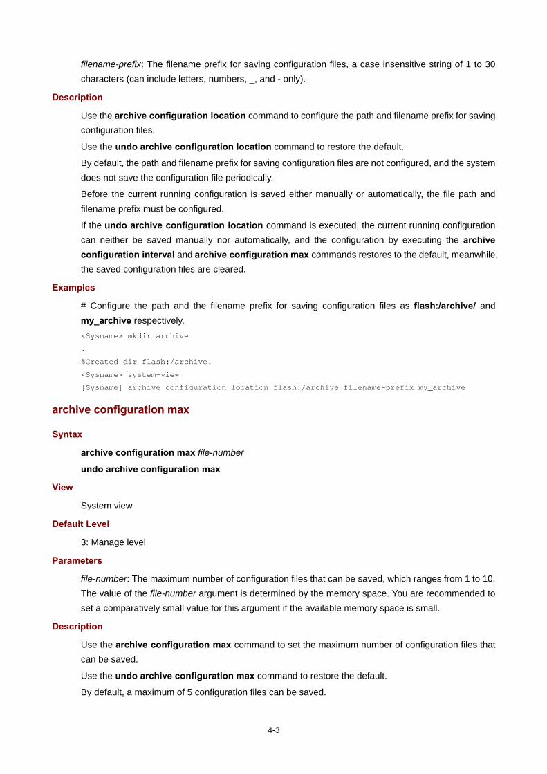
4-3
filename-prefix: The filename prefix for saving configuration files, a case insensitive string of 1 to 30 characters (can include letters, numbers, _, and - only).
Description
Use the archive configuration location command to configure the path and filename prefix for saving configuration files.
Use the undo archive configuration location command to restore the default.
By default, the path and filename prefix for saving configuration files are not configured, and the system does not save the configuration file periodically.
Before the current running configuration is saved either manually or automatically, the file path and filename prefix must be configured.
If the undo archive configuration location command is executed, the current running configuration can neither be saved manually nor automatically, and the configuration by executing the archive configuration interval and archive configuration max commands restores to the default, meanwhile, the saved configuration files are cleared.
Examples
# Configure the path and the filename prefix for saving configuration files as flash:/archive/ and my_archive respectively. <Sysname> mkdir archive
.
%Created dir flash:/archive.
<Sysname> system-view
[Sysname] archive configuration location flash:/archive filename-prefix my_archive
archive configuration max
Syntax
archive configuration max file-number
undo archive configuration max
View
System view
Default Level
3: Manage level
Parameters
file-number: The maximum number of configuration files that can be saved, which ranges from 1 to 10. The value of the file-number argument is determined by the memory space. You are recommended to set a comparatively small value for this argument if the available memory space is small.
Description
Use the archive configuration max command to set the maximum number of configuration files that can be saved.
Use the undo archive configuration max command to restore the default.
By default, a maximum of 5 configuration files can be saved.

4-4
Because excessive configuration files occupy large memory space, you can use this command to control the number of the files. After the maximum number of configuration files is saved, the system deletes the oldest files when the next file is saved (either automatically or manually). When you change the maximum number of configuration files that can be saved, the exceeded files are not deleted. If the number of the existing configuration files is larger than or equal to the newly configured upper limit, the system deletes the oldest n files when the next file is saved, where n = the current number - the newly configured number + 1, for example: if the number of configuration files that have been saved is 7, and the newly configured upper limit is 4, when there is a new configuration file to be saved, the system deletes 4 oldest files, where 4 = 7-4+1.
Before executing this command, configure the path and filename prefix of a saved configuration file by using the archive configuration location command; otherwise, the execution of this command fails.
If the undo archive configuration location command is executed, the maximum number of configuration files that can be saved also restores to the default.
Examples
# Set the maximum number of configuration files that can be saved to 10. <Sysname> system-view
[Sysname] archive configuration max 10
backup startup-configuration
Syntax
backup startup-configuration to dest-addr [ dest-filename ]
View
User view
Default Level
2: System level
Parameters
dest-addr: IP address or name of a TFTP server. The address cannot be an IPv6 address.
dest-filename: Target filename used to save the startup configuration file for the next system startup on the server.
Description
Use the backup startup-configuration command to back up the startup configuration file (used at the next system startup) to a specified TFTP server. If you do not specify this filename, the original filename is used.
For a router that has main and backup startup configuration files, this command only backs up the main startup configuration file.
Presently, the router uses TFTP to back up configuration files.
Examples
# Back up the startup configuration file of the router to the TFTP server with IP address 2.2.2.2, using filename 192-168-1-26.cfg. <Sysname> display startup
Current startup saved-configuration file: flash:/config.cfg

4-5
Next startup saved-configuration file: flash:/test.cfg
<Sysname> backup startup-configuration to 2.2.2.2 192-168-1-26.cfg
Backup next startup-configuration file to 2.2.2.2, please wait…finished!
<Sysname>
After the above operation, the router backs up file test.cfg to TFTP server 2.2.2.2, where the file is saved as 192-168-1-26.cfg.
configuration encrypt
Syntax
configuration encrypt { private-key | public-key }
undo configuration encrypt
View
System view
Default Level
3: Manage level
Parameters
private-key: Encrypts a configuration file with a private key. The encrypted configuration file can only be decrypted and recognized by the local router.
public-key: Encrypts a configuration file with a public key. The encrypted configuration file can be decrypted and recognized by all routers supported the configuration file encryption function.
Description
Use the configuration encrypt command to enable configuration file encryption.
Use the undo configuration encrypt command to restore the default.
By default, configuration file encryption is disabled, that is, the current valid configurations are directly saved to the configuration file.
Examples
# Encrypt the configuration file with a public key before saving it. <Sysname> system-view
[Sysname] configuration encrypt public-key
configuration replace file
Syntax
configuration replace file filename
View
System view
Default Level
3: Manage level
Parameters
filename: Specifies the name of the replacement configuration file for configuration rollback.

4-6
Description
Use the configuration replace file command to set configuration rollback.
With this command executed, the current running configuration rolls back to the configuration state based on the specified configuration file (filename).
The configuration file specified with the configuration replace file filename command can only be a configuration file in simple text. Otherwise, errors may occur in configuration rollback.
Examples
# Roll back from the current running configuration to a previous configuration state based on a saved configuration file my_archive_1.cfg. <Sysname> system-view
[Sysname] configuration replace file my_archive_1.cfg
Info: Now replacing the current configuration. Please wait...
Info: Succeeded in replacing current configuration with the file my_archive_1.cfg.
display archive configuration
Syntax
display archive configuration [ | { begin | exclude | include } regular-expression ]
View
Any view
Default Level
1: Monitor level
Parameters
|: Filters command output by specifying a regular expression. For more information about regular expressions, see CLI in the Fundamentals Configuration Guide.
begin: Displays the first line that matches the specified regular expression and all lines that follow.
exclude: Displays the lines that do not match the specified regular expression.
include: Displays all lines that match the specified regular expression.
regular-expression: Specifies a regular expression, which is a case sensitive string of 1 to 256 characters.
Description
Use the display archive configuration command to display information about configuration rollback.
Examples
# Display information about configuration rollback. <Sysname> display archive configuration
Location: flash:/archive
Filename prefix: my_archive
Archive interval in minutes: 120
Maximum number of archive files: 10
Saved archive files:
No. TimeStamp FileName
1 Aug 05 2007 20:24:54 my_archive_1.cfg
2 Aug 05 2007 20:34:54 my_archive_2.cfg

4-7
# 3 Aug 05 2007 20:44:54 my_archive_3.cfg
‘#’ indicates the most recent archive file.
Next archive file to be saved: my_archive_4.cfg
Table 4-1 display archive configuration command output description
Field Description
Location Absolute path of the saved configuration files
Filename prefix Filename prefix of the saved configuration files
Archive interval in minutes Configuration file saving interval, in minutes. If the automatic saving is disabled, this field is not displayed.
Filename Filename of the saved configuration files, with path excluded.
display saved-configuration
Syntax
display saved-configuration [ by-linenum ] [ | { begin | exclude | include } regular-expression ]
View
Any view
Default Level
2: System level
Parameters
by-linenum: Identifies each line of displayed information with a line number.
|: Filters command output by specifying a regular expression. For more information about regular expressions, see CLI in the Fundamentals Configuration Guide.
begin: Displays the first line that matches the specified regular expression and all lines that follow.
exclude: Displays the lines that do not match the specified regular expression.
include: Displays all lines that match the specified regular expression.
regular-expression: Specifies a regular expression, which is a case sensitive string of 1 to 256 characters.
Description
Use the display saved-configuration command to display the contents of the configuration file saved for the next startup of the router.
During router management and maintenance, you can use this command to check whether important configurations are saved to the configuration file to be used at the next startup of the router.
For a router supporting main and backup configuration files, this command displays the main configuration file to be used at the next system startup.
If the system is not specified with a configuration file to the used at the next startup or the specified configuration file does not exist, the display saved-configuration command displays the default configuration file of the router. If the default configuration file does not exist, the system prompts “The config file does not exist!”.
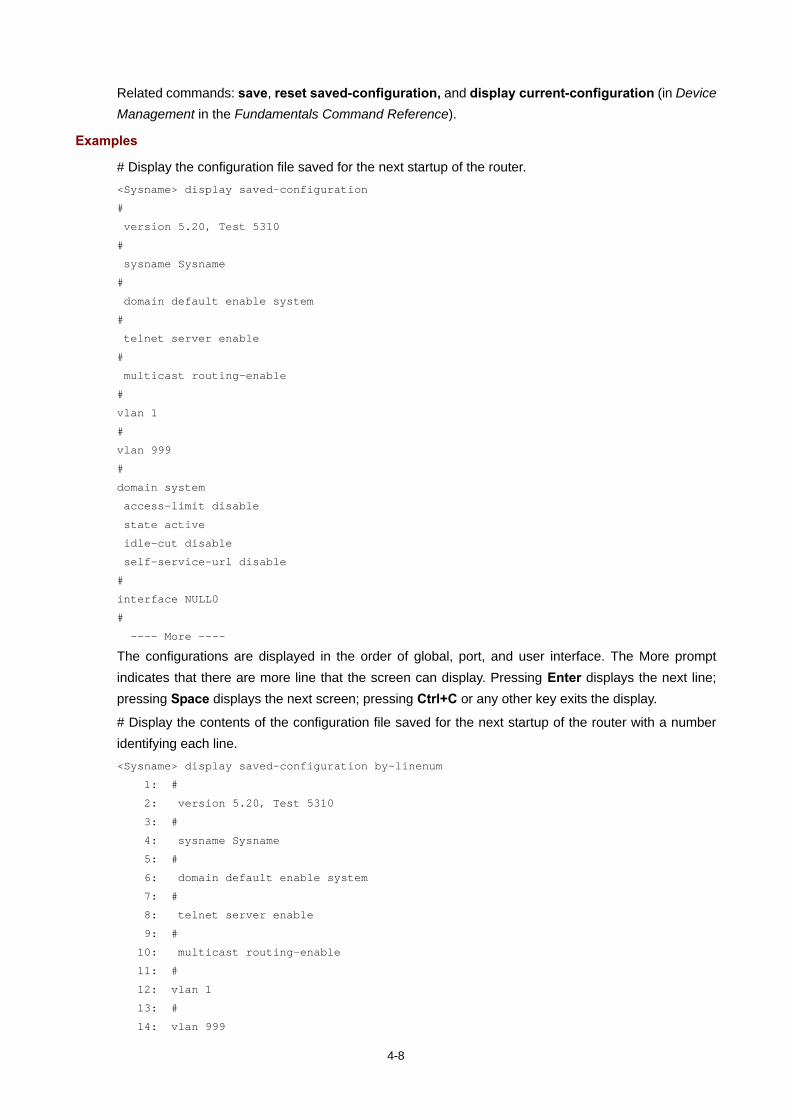
4-8
Related commands: save, reset saved-configuration, and display current-configuration (in Device Management in the Fundamentals Command Reference).
Examples
# Display the configuration file saved for the next startup of the router. <Sysname> display saved-configuration
#
version 5.20, Test 5310
#
sysname Sysname
#
domain default enable system
#
telnet server enable
#
multicast routing-enable
#
vlan 1
#
vlan 999
#
domain system
access-limit disable
state active
idle-cut disable
self-service-url disable
#
interface NULL0
#
---- More ----
The configurations are displayed in the order of global, port, and user interface. The More prompt indicates that there are more line that the screen can display. Pressing Enter displays the next line; pressing Space displays the next screen; pressing Ctrl+C or any other key exits the display.
# Display the contents of the configuration file saved for the next startup of the router with a number identifying each line. <Sysname> display saved-configuration by-linenum
1: #
2: version 5.20, Test 5310
3: #
4: sysname Sysname
5: #
6: domain default enable system
7: #
8: telnet server enable
9: #
10: multicast routing-enable
11: #
12: vlan 1
13: #
14: vlan 999

4-9
15: #
16: domain system
17: access-limit disable
18: state active
19: idle-cut disable
20: self-service-url disable
21: #
22: interface NULL0
23: #
---- More ----
The More prompt indicates that there are more line that the screen can display. Pressing Enter displays the next line; pressing Space displays the next screen; pressing Ctrl+C or any other key exits the display.
display startup
Syntax
display startup [ | { begin | exclude | include } regular-expression ]
View
Any view
Default Level
1: Monitor level
Parameters
|: Filters command output by specifying a regular expression. For more information about regular expressions, see CLI in the Fundamentals Configuration Guide.
begin: Displays the first line that matches the specified regular expression and all lines that follow.
exclude: Displays the lines that do not match the specified regular expression.
include: Displays all lines that match the specified regular expression.
regular-expression: Specifies a regular expression, which is a case sensitive string of 1 to 256 characters.
Description
Use the display startup command to display the configuration files used at the current system startup and the configuration file(s) to be used at the next system startup.
Related commands: startup saved-configuration.
Examples
# Display the configuration file used at the current system startup and the one to be used at the next system startup (main/backup keyword is supported). <Sysname> display startup
Current startup saved-configuration file: flash:/config.cfg
Next main startup saved-configuration file: flash:/config.cfg
Next backup startup saved-configuration file: flash:/config2.cfg
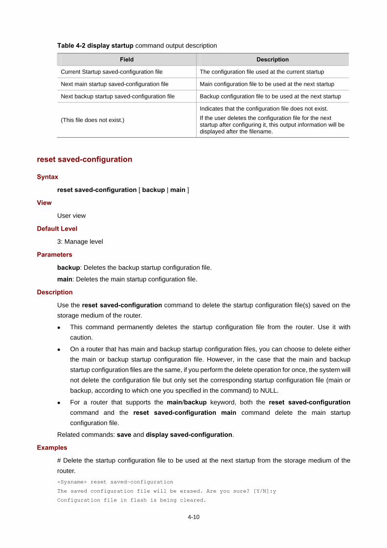
4-10
Table 4-2 display startup command output description
Field Description
Current Startup saved-configuration file The configuration file used at the current startup
Next main startup saved-configuration file Main configuration file to be used at the next startup
Next backup startup saved-configuration file Backup configuration file to be used at the next startup
(This file does not exist.)
Indicates that the configuration file does not exist. If the user deletes the configuration file for the next startup after configuring it, this output information will be displayed after the filename.
reset saved-configuration
Syntax
reset saved-configuration [ backup | main ]
View
User view
Default Level
3: Manage level
Parameters
backup: Deletes the backup startup configuration file.
main: Deletes the main startup configuration file.
Description
Use the reset saved-configuration command to delete the startup configuration file(s) saved on the storage medium of the router.
This command permanently deletes the startup configuration file from the router. Use it with caution.
On a router that has main and backup startup configuration files, you can choose to delete either the main or backup startup configuration file. However, in the case that the main and backup startup configuration files are the same, if you perform the delete operation for once, the system will not delete the configuration file but only set the corresponding startup configuration file (main or backup, according to which one you specified in the command) to NULL.
For a router that supports the main/backup keyword, both the reset saved-configuration command and the reset saved-configuration main command delete the main startup configuration file.
Related commands: save and display saved-configuration.
Examples
# Delete the startup configuration file to be used at the next startup from the storage medium of the router. <Sysname> reset saved-configuration
The saved configuration file will be erased. Are you sure? [Y/N]:y
Configuration file in flash is being cleared.

4-11
Please wait ...........
Configuration file is cleared.
restore startup-configuration
Syntax
restore startup-configuration from src-addr src-filename
View
User view
Default Level
3: Manage level
Parameters
src-addr: IP address or name of a TFTP server. The address cannot be an IPv6 address.
src-filename: Filename of the configuration file to be downloaded from the specified server.
Description
Use the restore startup-configuration command to download a configuration file from the specified TFTP server to the router and specify the configuration file as the startup configuration file to be used at the next startup of the router.
The file downloaded is set as the main startup configuration file to be used at the next system startup. (routers supporting main/backup configuration file)
Examples
# Download configuration file test.cfg from the TFTP server whose IP address is 2.2.2.2, and the configuration file is to be used at the next startup of the router. <Sysname> restore startup-configuration from 2.2.2.2 test.cfg
Restore next startup-configuration file from 2.2.2.2. Please wait..............
finished!
save
Syntax
save file-url
save [ safely ] [ backup | main ] [ force ]
View
Any view
Default Level
2: System level
Parameters
file-url: File path, where the extension of the file name must be .cfg.
safely: Sets the configuration saving mode to safe. If this argument is not specified, the configuration file is saved in fast mode.

4-12
backup: Saves the current configuration to the startup configuration file specified in the interactive mode, and specifies the file as the backup startup configuration file to be used at the next startup of the router.
main: Saves the current configuration to the main startup configuration file specified in the interactive mode, and specifies the file as the main startup configuration file to be used at the next startup of the router.
force: Saves the current configuration to the configuration file for the next startup of the router, and the system does not output any interaction information. By default, when you execute the save command, the system asks you to input Y or N to confirm your operation. If you do no confirm your operation within 30 seconds, the system automatically quits the operation. If you provide the force keyword when executing the save command, the system directly saves the current configuration, not requiring any confirmation.
Description
Use the save file-url command to save the current configuration to the specified configuration file, but the system does not specify the file as the startup configuration file to be used at the next system startup. If the file specified by file-url does not exist, the system creates the file and then saves the configuration to the file.
Use the save [ safely ] [ backup | main ] [ force ] command to save the current configuration to the root directory of the storage medium, and specify the file as the startup configuration file to be used at the next system startup.
Related commands: reset saved-configuration, display current-configuration, and display saved-configuration.
Examples
# Save the current configuration file to the specified directory, but do not specify the configuration file as the startup configuration file to be used at the next startup. <Sysname> save test.cfg
The current configuration will be saved to flash:/test.cfg. Continue? [Y/N]:y
Now saving current configuration to the device.
Saving configuration flash:/test.cfg. Please wait...
............
Configuration is saved to flash successfully.
# Save the current configuration file to the root directory of the storage medium, and specify the configuration file as the startup configuration file to be used at the next startup. <Sysname> display startup
Current startup saved-configuration file: flash:/hmr.cfg
Next main startup saved-configuration file: flash:/aa.cfg
Next backup startup saved-configuration file: NULL
// The above information indicates that the main startup configuration file to be used at the next system startup is aa.cfg. <Sysname> save
The current configuration will be written to the device. Are you sure? [Y/N]:y
Please input the file name(*.cfg)[flash:/aa.cfg]
(To leave the existing filename unchanged, press the enter key):startup.cfg
Validating file. Please wait............
Configuration is saved to device successfully.

4-13
<Sysname> display startup
Current startup saved-configuration file: flash:/hmr.cfg
Next main startup saved-configuration file: flash:/startup.cfg
Next backup startup saved-configuration file: NULL
// The above information indicates that the main startup configuration file to be used at the next system startup is changed to startup.cfg.
# Save the current configuration to the main configuration file to be used at the next startup of the router, without any confirmation required. <Sysname> save force
Validating file. Please wait....
Configuration is saved to device successfully.
startup saved-configuration
Syntax
startup saved-configuration cfgfile [ backup | main ]
undo startup saved-configuration
View
User view
Default Level
3: Manage level
Parameters
cfgfile: Configuration file name. The file must be a file with an extension .cfg stored in the root directory of the storage medium.
backup: Sets the configuration file as the backup startup configuration file to be used at the next startup of the router.
main: Sets the configuration file as the main startup configuration file to be used at the next startup of the router.
Description
Use the startup saved-configuration command to specify a startup configuration file to be used at the next system startup.
Use the undo startup saved-configuration command to configure the system to start up with the null configuration, that is, the factory configuration.
When a router supports main/backup keyword:
The startup saved-configuration and startup saved-configuration main commands have the same effect: Both of them are used to specify the main startup configuration file.
The main and backup startup configuration files can be specified as the same file. However, it is recommended you use different files, or, save the same configuration as two files using different file names, one specified as the main startup configuration file, and the other specified as the backup.
If you execute the undo startup saved-configuration command, the system sets the main and backup startup configuration file as NULL, but does not delete the two configuration files.
Related commands: display startup.

4-14
Examples
# Specify a startup configuration file to be used at the next system startup. <Sysname> startup saved-configuration testcfg.cfg
Please wait ....
... Done!

5-1
Support for the following feature on the MSR series is shown below.
Feature MSR 900 MSR 20-1X MSR 20 MSR 30 MSR 50
Storage devices supported
Flash USB disk
Flash USB disk
CF card USB disk
CF card MSR 30-11 supports flash only. USB disk
CF card USB disk (MSR 50-06 does not support USB disk)
5 File Management Commands
The current working directory is the root directory of the storage medium on the router in the examples in this manual.
For the qualified filename formats, see File Management.
File Management Commands
cd
Syntax
cd { directory | .. | / }
View
User view
Default Level
3: Manage level
Parameters
directory: Name of the target directory, in the format of [drive:/]path. For the detailed introduction to the drive and path arguments, see File Management in the Fundamentals Configuration Guide. If no drive information is provided, the argument represents a folder or subfolder in the current directory.
..: Returns to an upper directory. If the current working directory is the root directory, or no upper directory exists, the current working directory does not change when the cd .. command is executed. This argument does not support command online help.
/: Returns to the root directory of the storage medium. The keyword does not support command line online help.

5-2
Description
Use the cd command to change the current working directory.
Examples
# Enter the test folder after logging in to the router. <Sysname> cd test
# Return to the upper directory (Remember to enter a space after the keyword cd). <Sysname> cd ..
# Return to the root directory. <Sysname> cd /
After you change the current directory using the cd command, you can use the pwd command to view the path of the current working directory.
copy
Syntax
copy fileurl-source fileurl-dest
View
User view
Default Level
3: Manage level
Parameters
fileurl-source: Name of the source file.
fileurl-dest: Name of the target file or folder.
Description
Use the copy command to copy a file.
If you specify a target folder, the system copies the file to the specified folder and uses the name of the source file as the file name.
Examples
# Copy file testcfg.cfg in the current folder and save it as testbackup.cfg. <Sysname> copy testcfg.cfg testbackup.cfg
Copy flash:/test.cfg to flash:/testbackup.cfg?[Y/N]:y
....
%Copy file flash:/test.cfg to flash:/testbackup.cfg...Done.
# Copy file 1.cfg in the test folder on the flash to the testbackup folder in the CF card, and save it as 1backup.cfg. <Sysname> copy flash:/test/1.cfg cfa0:/testbackup/1backup.cfg
Copy flash:/test/1.cfg to cfa0:/testbackup/1backup.cfg?[Y/N]:y
%Copy file flash:/test/1.cfg to cfa0:/testbackup/1backup.cfg...Done.

5-3
delete
Syntax
delete [ /unreserved ] file-url
View
User view
Default Level
3: Manage level
Parameters
/unreserved: Permanently deletes the specified file, and the deleted file can never be restored.
file-url: Name of the file to be deleted. Asterisks (*) are acceptable as wildcards. For example, to remove files with the extension of .txt in the current directory, you may use the delete *.txt command.
Description
Use the delete file-url command to temporarily delete a file. The deleted file is saved in the recycle bin. To restore it, use the undelete command.
The dir /all command displays the files deleted from the current directory and moved to the recycle bin. These files are enclosed in pairs of square brackets. To remove the files from the recycle bin, use the reset recycle-bin command.
The delete /unreserved file-url command permanently deletes a file, and the deleted file cannot be restored. Use it with caution.
If you delete two files in different directories but with the same filename, only the last one is retained in the recycle bin.
Examples
# Remove file tt.cfg from the current directory. <Sysname> delete tt.cfg
Delete flash:/tt.cfg? [Y/N]:y
.
%Delete file flash:/tt.cfg...Done.
dir
Syntax
dir [ /all ] [ file-url ]
View
User view
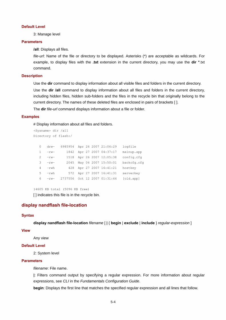
5-4
Default Level
3: Manage level
Parameters
/all: Displays all files.
file-url: Name of the file or directory to be displayed. Asterisks (*) are acceptable as wildcards. For example, to display files with the .txt extension in the current directory, you may use the dir *.txt command.
Description
Use the dir command to display information about all visible files and folders in the current directory.
Use the dir /all command to display information about all files and folders in the current directory, including hidden files, hidden sub-folders and the files in the recycle bin that originally belong to the current directory. The names of these deleted files are enclosed in pairs of brackets [ ].
The dir file-url command displays information about a file or folder.
Examples
# Display information about all files and folders. <Sysname> dir /all
Directory of flash:/
0 drw- 6985954 Apr 26 2007 21:06:29 logfile
1 -rw- 1842 Apr 27 2007 04:37:17 mainup.app
2 -rw- 1518 Apr 26 2007 12:05:38 config.cfg
3 -rw- 2045 May 04 2007 15:50:01 backcfg.cfg
4 -rwh 428 Apr 27 2007 16:41:21 hostkey
5 -rwh 572 Apr 27 2007 16:41:31 serverkey
6 -rw- 2737556 Oct 12 2007 01:31:44 [old.app]
14605 KB total (5096 KB free)
[ ] indicates this file is in the recycle bin.
display nandflash file-location
Syntax
display nandflash file-location filename [ | { begin | exclude | include } regular-expression ]
View
Any view
Default Level
2: System level
Parameters
filename: File name.
|: Filters command output by specifying a regular expression. For more information about regular expressions, see CLI in the Fundamentals Configuration Guide.
begin: Displays the first line that matches the specified regular expression and all lines that follow.

5-5
exclude: Displays the lines that do not match the specified regular expression.
include: Displays all lines that match the specified regular expression.
regular-expression: Specifies a regular expression, which is a case sensitive string of 1 to 256 characters.
Description
Use the display nandflash file-location command to display the location of the specified file in the NAND flash memory.
The displayed information includes all the physical pages corresponding to the logical pages of the specified file.
Support for this command on the MSR series is shown below.
Command MSR 900 MSR 20-1X MSR 20 MSR 30 MSR 50
display nandflash file-location No No No
Supported on the MSR 30-1X routers only
No
Examples
# Display the location of the file test.cfg in the NAND flash memory. <Sysname> display nandflash file-location test.cfg
Logical Chunk Physical Page
---------------------------
chunk(0) 1234
chunk(1) 1236
chunk(2) 1235
filename: test.cfg
Table 5-1 display nandflash file-location command output description
Field Description
Logic Chunk Serial number of the logical pages
Physical Page Serial number of the physical pages
chunk(0) 1234 The first logical page of this file corresponds to the 1234th physical page on the router.
display nandflash badblock-location
Syntax
display nandflash badblock-location [ | { begin | exclude | include } regular-expression ]
View
Any view
Default Level
2: System level

5-6
Parameters
|: Filters command output by specifying a regular expression. For more information about regular expressions, see CLI in the Fundamentals Configuration Guide.
begin: Displays the first line that matches the specified regular expression and all lines that follow.
exclude: Displays the lines that do not match the specified regular expression.
include: Displays all lines that match the specified regular expression.
regular-expression: Specifies a regular expression, which is a case sensitive string of 1 to 256 characters.
Description
Use the display nandflash badblock-location command to display the number and location of bad blocks in the NAND flash memory.
Support for this commands on the MSR series is shown below.
Command MSR 900 MSR 20-1X MSR 20 MSR 30 MSR 50
display nandflash badblock-location No No No
Supported on the MSR 30-1X routers only
No
Examples
# Display the number and location of bad blocks in the NAND flash memory. <Sysname> display nandflash badblock-location
No Physical block
------------------------------
badblock(0) 1234
badblock(1) 1235
badblock(2) 1236
3200 block(s) total, 3 block(s) bad.
Table 5-2 display nandflash badblock-location command output description
Field Description
No Serial number of the bad blocks
Physical block Serial number of the physical pages on which there are bad blocks
3200 block(s) total, 3 block(s) bad. Total number of blocks and bad blocks in the NAND flash memory
display nandflash page-data
Syntax
display nandflash page-data page-value [ | { begin | exclude | include } regular-expression ]
View
Any view
Default Level
1: Monitor level

5-7
Parameters
page-value: Serial number of a physical page.
|: Filters command output by specifying a regular expression. For more information about regular expressions, see CLI in the Fundamentals Configuration Guide.
begin: Displays the first line that matches the specified regular expression and all lines that follow.
exclude: Displays the lines that do not match the specified regular expression.
include: Displays all lines that match the specified regular expression.
regular-expression: Specifies a regular expression, which is a case sensitive string of 1 to 256 characters.
Description
Use the display nandflash page-data command to display the data on the specified physical page in the NAND flash memory.
This command is always used in combination with the display nandflash file-location command to check the correctness of the data in the NAND flash memory.
Support for this command on the MSR series is shown below.
Command MSR 900 MSR 20-1X MSR 20 MSR 30 MSR 50
display nandflash page-data No No No
Supported by the MSR 30-1X routers only
No
Examples
# Display the content of the file test.cfg which is saved in the NAND flash memory. <Sysname> display nandflash file-location test.cfg
Logical Chunk Physical Page
---------------------------
chunk(0) 1234
chunk(1) 1236
chunk(2) 1235
filename: test.cfg
<Sysname> display nandflash page-data 1236
0000: 0D 0A 23 0D 0A 20 76 65 72 73 69 6F 6E 20 35 2E ..#.. version 5.
0010: 32 30 2C 20 41 6C 70 68 61 20 31 30 31 31 0D 0A 20, Alpha 1011..
0020: 23 0D 0A 20 73 79 73 6E 61 6D 65 20 48 33 43 0D #.. sysname H3C.
0030: 0A 23 0D 0A 20 70 61 73 73 77 6F 72 64 2D 63 6F .#.. password-co
...Omitted...
execute
Syntax
execute filename
View
System view

5-8
Default Level
2: System level
Parameters
filename: Name of a batch file with a .bat extension. You can use the rename command to change the suffix of the configuration file to .bat to use it as a batch file.
Description
Use the execute command to execute the specified batch file.
Batch files are command line files. Executing a batch file is to execute a set of command lines in the file.
You should not include invisible characters in a batch file. If an invisible character is found during the execution, the batch process will abort and the commands that have been executed cannot be cancelled.
Not every command in a batch file is sure to be executed. For example, if a certain command is not correctly configured, the command will fail to be executed, and the system will skip this command and go to the next one.
The configuration generated after a batch file is executed will not be backed up to the standby main board automatically.
Each configuration command in a batch file must be a standard configuration command, meaning that the valid configuration information can be displayed with the display current-configuration command after this command is configured successfully; otherwise, this command may not be executed correctly.
Examples
# Execute the batch file test.bat in the root directory. <Sysname> system-view
[Sysname] execute test.bat
file prompt
Syntax
file prompt { alert | quiet }
View
System view
Default Level
3: Manage level
Parameters
alert: Enables the system to warn you about operations that may bring undesirable results such as file corruption or data loss.
quiet: Disables the system from warning you about any operation.
Description
Use the file prompt command to set a prompt mode for file operations.
By default, the prompt mode is alert.

5-9
When the prompt mode is set to quiet, the system does not warn for any file operation. To avoid undesirable consequences resulting from misoperation, you are recommended to use the alert mode.
Examples
# Set the file operation prompt mode to alert. <Sysname> system-view
[Sysname] file prompt alert
fixdisk
Syntax
fixdisk device
View
User view
Default Level
3: Manage level
Parameters
device: Storage medium name.
Description
Use the fixdisk command to restore the space of a storage medium when it becomes unavailable because of some abnormal operation.
Examples
# Restore the space of the flash. <Sysname> fixdisk flash:
Fixdisk flash: may take some time to complete...
%Fixdisk flash: completed.
format
Syntax
format device [ FAT16 | FAT32 ]
View
User view
Default Level
3: Manage level
Parameters
device: Name of a storage medium (for example cfa0).
FAT16: Formats a storage medium using the FAT16 format. FAT16 does not support Tab matching but needs to be input completely if used, and is not applicable to a flash card.
FAT32: Formats a storage medium using the FAT32 format. FAT32 does not support Tab matching but needs to be input completely if used, and is not applicable to a flash card.

5-10
Description
Use the format command to format a storage medium.
Support for this command on the MSR series is shown below.
Command Parameter MSR 900 MSR 20-1X MSR 20 MSR 30 MSR 50
format device Flash Flash CF card
CF card The MSR 30-11 only supports flash.
CF card
Formatting a storage medium results in loss of all the files on the storage medium and these files cannot be restored. In particular, if there is a startup configuration file on a storage medium, formatting the storage medium results in loss of the startup configuration file.
Examples
# Format the flash. <Sysname> format flash:
All data on flash: will be lost, proceed with format? [Y/N]:y
./
%Format flash: completed.
mkdir
Syntax
mkdir directory
View
User view
Default Level
3: Manage level
Parameters
directory: Name of a folder.
Description
Use the mkdir command to create a folder under a specified directory on the storage medium.
The name of the folder to be created must be unique in the specified directory. Otherwise, you will fail to create the folder in the directory.
To use this command to create a folder, the specified directory must exist. For instance, to create folder flash:/test/mytest, the test folder must exist. Otherwise, you will fail to create folder mytest.
Examples
# Create a folder named test in the current directory.
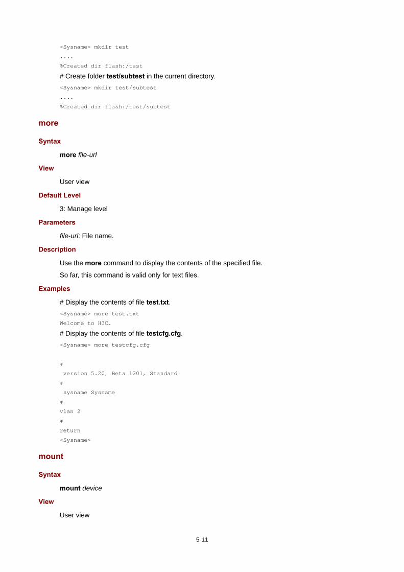
5-11
<Sysname> mkdir test
....
%Created dir flash:/test
# Create folder test/subtest in the current directory. <Sysname> mkdir test/subtest
....
%Created dir flash:/test/subtest
more
Syntax
more file-url
View
User view
Default Level
3: Manage level
Parameters
file-url: File name.
Description
Use the more command to display the contents of the specified file.
So far, this command is valid only for text files.
Examples
# Display the contents of file test.txt. <Sysname> more test.txt
Welcome to H3C.
# Display the contents of file testcfg.cfg. <Sysname> more testcfg.cfg
#
version 5.20, Beta 1201, Standard
#
sysname Sysname
#
vlan 2
#
return
<Sysname>
mount
Syntax
mount device
View
User view

5-12
Default Level
3: Manage level
Parameters
device: Name of a storage medium (for example flash or cf).
Description
Use the mount command to mount a hot swappable storage medium, such as a CF card, a USB device, etc (excluding flash). This command is effective only when the router is in unmounted state.
By default, a storage medium is automatically mounted and in the mounted state after connected to the router, which means you can use it without mounting it.
Do not remove the storage medium or swap a card when mounting or unmounting the router, or when you are processing files on the storage medium. Otherwise, the file system could be damaged.
When a storage medium is connected to a lower version system, the system may not be able to recognize the router automatically, and you need to use the mount command for the storage medium to function normally.
Before removing a mounted storage medium from the system, you should first unmount it to avoid damaging the router.
Related commands: umount.
Support for this command on the MSR series is shown below.
Command MSR 900 MSR 20-1X MSR 20 MSR 30 MSR 50
mount Yes Yes Yes Yes (Not supported on the MSR 30-11)
Yes
Examples
# Mount a CF card. <Sysname> mount cfa0:
% Mount cf: successfully.
%Apr 23 01:50:00:628 2008 Sysname VFS/0/LOG:
Cfa0: mounted into slot 0.
move
Syntax
move fileurl-source fileurl-dest
View
User view
Default Level
3: Manage level
Parameters
fileurl-source: Name of the source file.
fileurl-dest: Name of the target file or folder.

5-13
Description
Use the move command to move a file.
If you specify a target folder, the system will move the source file to the specified folder, with the file name unchanged.
You cannot move files between storage media of different types or between different partitions of a CF card.
Examples
# Move file flash:/test/sample.txt to flash:/, and save it as 1.txt. <Sysname> move test/sample.txt 1.txt
Move flash:/test/sample.txt to flash:/1.txt?[Y/N]:y
...
% Moved file flash:/test/sample.txt to flash:/1.txt
# Move file b.cfg to the subfolder test2. <Sysname> move b.cfg test2
Move flash:/b.cfg to flash:/test2/b.cfg?[Y/N]:y
.
%Moved file flash:/b.cfg to flash:/test2/b.cfg.
pwd
Syntax
pwd
View
User view
Default Level
3: Manage level
Parameters
None
Description
Use the pwd command to display the current path.
Examples
# Display the current path. <Sysname> pwd
flash:
rename
Syntax
rename fileurl-source fileurl-dest
View
User view

5-14
Default Level
3: Manage level
Parameters
fileurl-source: Name of the source file or folder.
fileurl-dest: Name of the target file or folder.
Description
Use the rename command to rename a file or folder.
The target file name must be unique in the current path.
Examples
# Rename file sample.txt as sample.bat. <Sysname> rename sample.txt sample.bat
Rename flash:/sample.txt to flash:/sample.bat? [Y/N]:y
% Renamed file flash:/sample.txt to flash:/sample.bat
reset recycle-bin
Syntax
reset recycle-bin [ /force ]
View
User view
Default Level
3: Manage level
Parameters
/force: Deletes all files in the recycle bin, including files that cannot be deleted by the command without the /force keyword.
Description
Use the reset recycle-bin command to permanently delete the files in the recycle bin in the current directory.
If a file is corrupted, you may not be able to delete the file using the reset recycle-bin command. In this case, you can use the reset recycle-bin /force command, which can delete all the files in the recycle bin forcibly.
The delete file-url command only moves a file to the recycle bin, and the file still occupies the memory space. To delete the file in the recycle bin, you need to execute the reset recycle-bin command in the original directory of the file.
The reset recycle-bin command deletes files in the current directory and in the recycle bin. If the original path of the file to be deleted is not the current directory, use the cd command to enter the original directory of the file, and then execute the reset recycle-bin command.
Examples
# Delete file b.cfg in the current directory and in the recycle bin.
Display all the files in the recycle bin and in the current directory.

5-15
<Sysname> dir /all
Directory of flash:/
0 -rwh 3080 Apr 26 2008 16:41:43 private-data.txt
1 -rw- 2416 Apr 26 2008 13:45:36 config.cfg
2 -rw- 8036197 May 14 2008 10:13:18 main.app
3 -rw- 2386 Apr 26 2008 13:30:30 back.cfg
4 drw- - May 08 2008 09:49:25 test
5 -rwh 716 Apr 24 2007 16:17:30 hostkey
6 -rwh 572 Apr 24 2007 16:17:44 serverkey
7 -rw- 2386 May 08 2008 11:14:20 [a.cfg]
8 -rw- 3608 Dec 03 2007 17:29:30 [b.cfg]
14605 KB total (6730 KB free)
//The above information indicates that the current directory is flash:, and there are two files a.cfg and b.cfg in the recycle bin.
Delete file b.cfg in the current directory and in the recycle bin. <Sysname> reset recycle-bin
Clear flash:/~/a.cfg ?[Y/N]:n
Clear flash:/~/b.cfg ?[Y/N]:y
Clearing files from flash may take a long time. Please wait...
......
%Cleared file flash:/~/b.cfg...
In directory flash:, check whether the file b.cfg in the recycle bin is deleted. <Sysname> dir /all
Directory of flash:/
0 -rwh 3080 Apr 26 2008 16:41:43 private-data.txt
1 -rw- 2416 Apr 26 2008 13:45:36 config.cfg
2 -rw- 8036197 May 14 2008 10:13:18 main.app
3 -rw- 2386 Apr 26 2008 13:30:30 back.cfg
4 drw- - May 08 2008 09:49:25 test
5 -rwh 716 Apr 24 2007 16:17:30 hostkey
6 -rwh 572 Apr 24 2007 16:17:44 serverkey
7 -rw- 2386 May 08 2008 11:14:20 [a.cfg]
14605 KB total (6734 KB free)
// The above information indicates that file flash:/b.cfg is deleted permanently.
# Delete file aa.cfg in the subdirectory test and in the recycle bin.
Enter the subdirectory <Sysname> cd test/
Check all the files in the subfolder test. <Sysname> dir /all
Directory of flash:/test
0 -rw- 2161 Apr 26 2000 21:22:35 [aa.cfg]
14605 KB total (6734 KB free)

5-16
// The above information indicates only one file exists in the folder, and the file has been moved to the recycle bin.
Permanently delete file test/aa.cfg. <Sysname> reset recycle-bin
Clear flash:/test/~/aa.cfg ?[Y/N]:y
Clearing files from flash may take a long time. Please wait...
..
%Cleared file flash:/test/~/aa.cfg...
rmdir
Syntax
rmdir directory
View
User view
Default Level
3: Manage level
Parameters
directory: Name of the folder.
Description
Use the rmdir command to remove a folder.
The folder must be an empty one. If not, you need to delete all files and subfolders under it with the delete command.
After you execute the rmdir command successfully, the files in the recycle bin in the folder will be automatically deleted.
Examples
# Remove folder mydir. <Sysname> rmdir mydir
Rmdir flash:/mydir?[Y/N]:y
%Removed directory flash:/mydir.
umount
Syntax
umount device
View
User view
Default Level
3: Manage level
Parameters
device: Name of a storage medium (for example flash or cf).

5-17
Description
Use the umount command to unmount a hot swappable storage medium, such as a CF card or a USB device, excluding flash. This command is effective only when the storage medium is in mounted state.
By default, a storage medium is automatically mounted and in the mounted state. You need to unmount it before removing it from the router.
When mounting or unmounting a storage medium, or performing file operations on it, do not unplug or switchover the storage medium or the card where the storage medium resides. Otherwise, the file system could be damaged.
When a storage medium is connected to a lower version system, the system may not be able to recognize the router automatically, and you need to use the mount command for the storage medium to function normally.
Before removing a mounted storage medium from the system, you should first unmount it to avoid damaging the router.
Related commands: mount.
Support for this command on the MSR series is shown below.
Command MSR 900 MSR 20-1X MSR 20 MSR 30 MSR 50
umount Yes Yes Yes Yes (Not supported on the MSR 30-11)
Yes (Not supported on the MSR 50-06)
Examples
# Unmount a CF card. <Sysname> umount cf:
% Umount cfa0: successfully.
%Apr 23 01:49:20:929 2008 Sysname VFS/5/LOG:
Cfa0: umounted from slot 0.
undelete
Syntax
undelete file-url
View
User view
Default Level
3: Manage level
Parameters
file-url: Name of the file to be restored.
Description
Use the undelete command to restore a file from the recycle bin.
If another file with the same name exists in the same path, the system prompts you whether overwrite the original file.
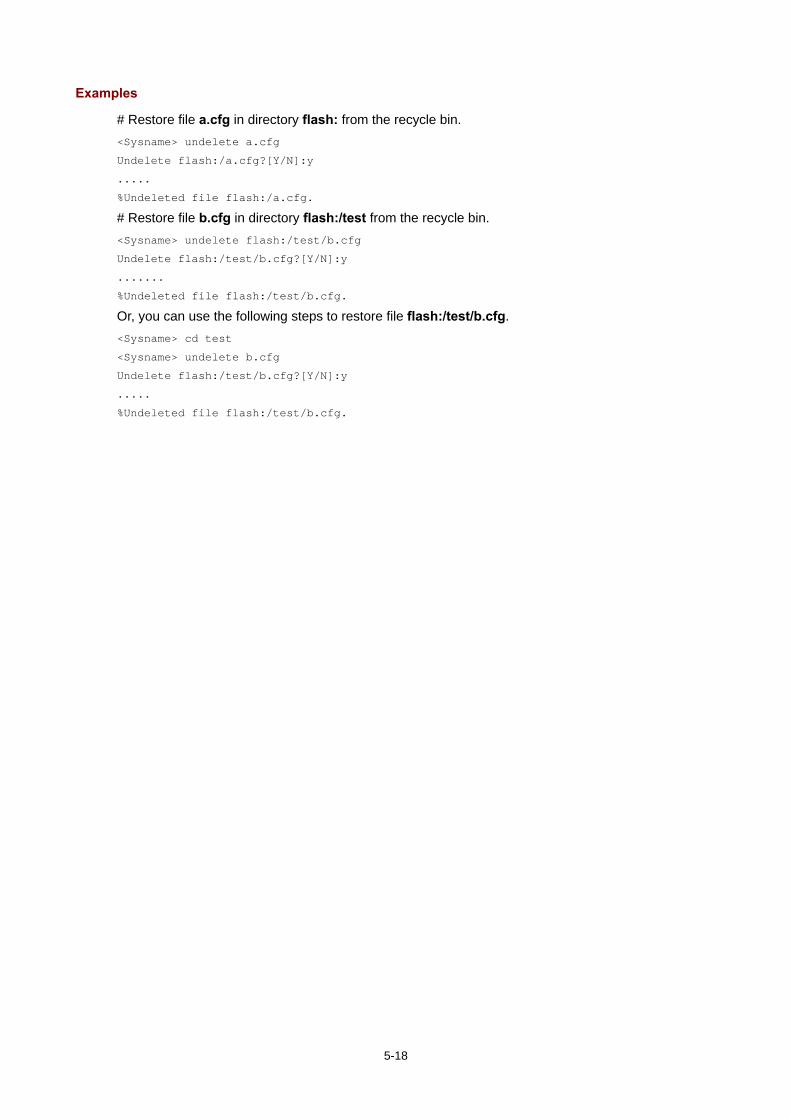
5-18
Examples
# Restore file a.cfg in directory flash: from the recycle bin. <Sysname> undelete a.cfg
Undelete flash:/a.cfg?[Y/N]:y
.....
%Undeleted file flash:/a.cfg.
# Restore file b.cfg in directory flash:/test from the recycle bin. <Sysname> undelete flash:/test/b.cfg
Undelete flash:/test/b.cfg?[Y/N]:y
.......
%Undeleted file flash:/test/b.cfg.
Or, you can use the following steps to restore file flash:/test/b.cfg. <Sysname> cd test
<Sysname> undelete b.cfg
Undelete flash:/test/b.cfg?[Y/N]:y
.....
%Undeleted file flash:/test/b.cfg.

6-1
6 FTP Configuration Commands
FTP Server Configuration Commands
display ftp-server
Syntax
display ftp-server [ | { begin | exclude | include } regular-expression ]
View
Any view
Default Level
3: Manage level
Parameters
|: Filters command output by specifying a regular expression. For more information about regular expressions, see CLI in the Fundamentals Configuration Guide.
begin: Displays the first line that matches the specified regular expression and all lines that follow.
exclude: Displays the lines that do not match the specified regular expression.
include: Displays all lines that match the specified regular expression.
regular-expression: Specifies a regular expression, which is a case sensitive string of 1 to 256 characters.
Description
Use the display ftp-server command to display the FTP server configuration.
After configuring FTP server parameters, you may verify them with this command.
Related commands: ftp server enable, ftp timeout, and ftp update.
Examples
# Display the FTP server configuration. <Sysname> display ftp-server
FTP server is running
Max user number: 1
User count: 1
Timeout value(in minute): 30
Put Method: fast
Table 6-1 display ftp-server command output description
Field Description
Max user number Maximum number of login users at a time
User count Number of the current login users

6-2
Field Description
Timeout value (in minute) Allowed idle time of an FTP connection. If there is no packet exchange between the FTP server and client during the whole period, the FTP connection will be disconnected.
Put Method File update method of the FTP server, including:
fast: Fast update normal: Normal update
display ftp-user
Syntax
display ftp-user [ | { begin | exclude | include } regular-expression ]
View
Any view
Default Level
3: Manage level
Parameters
|: Filters command output by specifying a regular expression. For more information about regular expressions, see CLI in the Fundamentals Configuration Guide.
begin: Displays the first line that matches the specified regular expression and all lines that follow.
exclude: Displays the lines that do not match the specified regular expression.
include: Displays all lines that match the specified regular expression.
regular-expression: Specifies a regular expression, which is a case sensitive string of 1 to 256 characters.
Description
Use the display ftp-user command to display the detailed information of current FTP users.
Examples
# Display the detailed information of FTP users. <Sysname> display ftp-user
UserName HostIP Port Idle HomeDir
ftp 192.168.1.54 1190 0 flash:
# If the name of the logged-in user exceeds 10 characters, the exceeded characters will be displayed in the next line and right justified, for example, if the logged-in user name is administrator, the information is displayed as follows: <Sysname> display ftp-user
UserName HostIP Port Idle HomeDir
administra
tor 192.168.0.152 1031 0 flash:
Table 6-2 display ftp-user command output description
Field Description
UserName Name of the currently logged-in user

6-3
Field Description
HostIP IP address of the currently logged-in user
Port Port which the currently logged-in user is using
Idle Duration time of the current FTP connection, in minutes
HomeDir Authorized path of the present logged-in user
free ftp user
Syntax
free ftp user username
View
User view
Default Level
3: Manage level
Parameters
username: Username. You can use the display ftp-user command to view the logged-in user name of the current FTP connection.
Description
Use the free ftp user command to manually release the FTP connection established with the specified username.
By using this command, the FTP connection established with username username will be released.
Note that if the user to be released is transmitting a file, the connection between the user and the FTP server is released after the file transmission.
Examples
# Manually release the FTP connection established with username ftpuser. <Sysname> free ftp user ftpuser
Are you sure to free FTP user ftpuser? [Y/N]:y
<Sysname>
ftp server acl
Syntax
ftp server acl acl-number
undo ftp server acl
View
System view
Default Level
3: Manage level

6-4
Parameters
acl-number: Basic access control list (ACL) number, in the range 2000 to 2999.
Description
Use the ftp server acl command to control FTP clients’ access to the device using an ACL.
Use the undo ftp server acl command to restore the default.
By default, no ACL is used to control FTP clients’ access to the device.
Associated with an ACL, the FTP server can deny the FTP requests of some FTP clients and only permit the access of clients allowed by the ACL rules. This configuration only filters the FTP connections to be established, and has no effect on the established FTP connections and operations. If you execute the command for multiple times, the last specified ACL takes effect.
Examples
# Associate the FTP service with ACL 2001 to allow only the client 1.1.1.1 to access the device through FTP. <Sysname> system-view
[Sysname] acl number 2001
[Sysname-acl-basic-2001] rule 0 permit source 1.1.1.1 0
[Sysname-acl-basic-2001] rule 1 deny source any
[Sysname-acl-basic-2001] quit
[Sysname] ftp server acl 2001
ftp server enable
Syntax
ftp server enable
undo ftp server
View
System view
Default Level
3: Manage level
Parameters
None
Description
Use the ftp server enable command to enable the FTP server and allow the login of FTP users.
Use the undo ftp server command to disable the FTP server.
By default, the FTP server is disabled.
Examples
# Enable the FTP server. <Sysname> system-view
[Sysname] ftp server enable

6-5
ftp timeout
Syntax
ftp timeout minute
undo ftp timeout
View
System view
Default Level
3: Manage level
Parameters
minute: Idle-timeout timer in minutes, in the range 1 to 35791.
Description
Use the ftp timeout command to set the idle-timeout timer.
Use the undo ftp timeout command to restore the default.
By default, the FTP idle time is 30 minutes.
After you log in to an FTP server, if the connection is disrupted and the FTP server is not notified, the system will maintain the connection, which will cause the occupation of the system resources and affect the login of other FTP users. To address this problem, you can set an idle-timeout timer so that the FTP server can disconnect from the user if no information is received or/and transmitted before the timer expires.
Examples
# Set the idle-timeout timer to 36 minutes. <Sysname> system-view
[Sysname] ftp timeout 36
ftp update
Syntax
ftp update { fast | normal }
undo ftp update
View
System view
Default Level
3: Manage level
Parameters
fast: Fast update.
normal: Normal update.
Description
Use the ftp update command to set the file update mode that the FTP server uses while receiving data.
Use the undo ftp update command to restore the default, namely, the normal mode.

6-6
Examples
# Set the FTP update mode to normal. <Sysname> system-view
[Sysname] ftp update normal
FTP Client Configuration Commands
In this section, the configuration procedure of entering FTP client view is omitted. You must use the ftp command to enter FTP client view for configurations under this view. For more information, see ftp.
Before executing the FTP client configuration commands in this section, make sure you have configured the proper authority for users on the FTP server, such as view the files under the current directory, read/download the specified file, create directory/upload files, rename/remove files, and so on.
The prompt information in the examples of this section varies with FTP server types.
ascii
Syntax
ascii
View
FTP client view
Default Level
3: Manage level
Parameters
None
Description
Use the ascii command to set the file transfer mode to ASCII.
By default, the file transfer mode is ASCII.
The carriage return characters vary with operating systems. For example, to indicate the end of a line and transfer to the next line, the H3C device system and Windows system use characters /r/n, and the Linux system uses characters /n. Therefore, after the file transmission between two systems that use different carriage return characters, such as Linux system and H3C device system, the FTP transmission mode must be applied to ensure the correct resolution of the files.
FTP transfers files in two modes:
Binary mode: for program file or picture transmission.
ASCII mode: for text file transmission.

6-7
Related commands: binary.
Examples
# Set the file transfer mode to ASCII. [ftp] ascii
200 Type set to A.
binary
Syntax
binary
View
FTP client view
Default Level
3: Manage level
Parameters
None
Description
Use the binary command to set the file transfer mode to binary (also called flow mode).
By default, the transfer mode is ASCII mode.
Related commands: ascii.
Examples
# Set the file transfer mode to binary. [ftp] binary
200 Type set to I.
bye
Syntax
bye
View
FTP client view
Default Level
3: Manage level
Parameters
None
Description
Use the bye command to disconnect from the remote FTP server and return to user view. If the device establishes no connection with the remote FTP server, you will return to user view directly.
Related commands: close, disconnect, and quit.
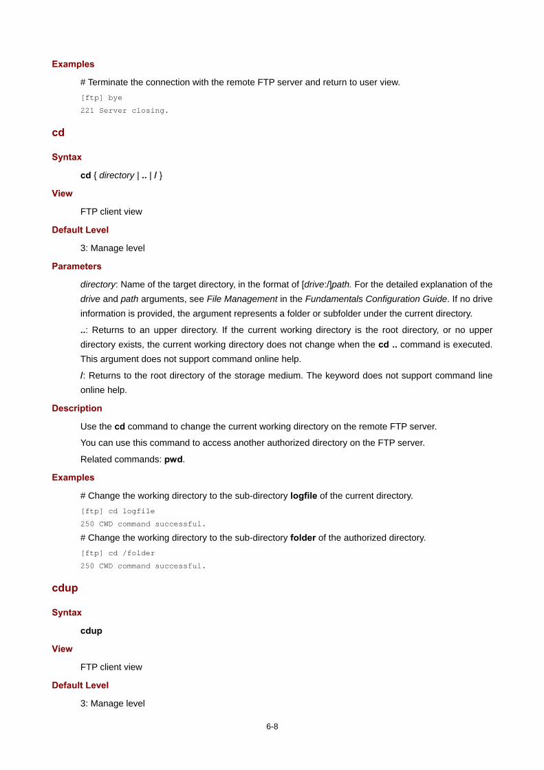
6-8
Examples
# Terminate the connection with the remote FTP server and return to user view. [ftp] bye
221 Server closing.
cd
Syntax
cd { directory | .. | / }
View
FTP client view
Default Level
3: Manage level
Parameters
directory: Name of the target directory, in the format of [drive:/]path. For the detailed explanation of the drive and path arguments, see File Management in the Fundamentals Configuration Guide. If no drive information is provided, the argument represents a folder or subfolder under the current directory.
..: Returns to an upper directory. If the current working directory is the root directory, or no upper directory exists, the current working directory does not change when the cd .. command is executed. This argument does not support command online help.
/: Returns to the root directory of the storage medium. The keyword does not support command line online help.
Description
Use the cd command to change the current working directory on the remote FTP server.
You can use this command to access another authorized directory on the FTP server.
Related commands: pwd.
Examples
# Change the working directory to the sub-directory logfile of the current directory. [ftp] cd logfile
250 CWD command successful.
# Change the working directory to the sub-directory folder of the authorized directory. [ftp] cd /folder
250 CWD command successful.
cdup
Syntax
cdup
View
FTP client view
Default Level
3: Manage level

6-9
Parameters
None
Description
Use the cdup command to exit the current directory and enter the upper directory of the FTP server.
Execution of this command will not change the working directory if the current directory is already the authorized directory (that is, work-directory).
Related commands: cd and pwd.
Examples
# Change the current working directory path to the upper directory. [ftp] pwd
257 "/ftp/subdir" is current directory.
[ftp] cdup
200 CDUP command successful.
[ftp] pwd
257 "/ftp" is current directory.
close
Syntax
close
View
FTP client view
Default Level
3: Manage level
Parameters
None
Description
Use the close command to terminate the connection to the FTP server, but remain in FTP client view.
This command is equal to the disconnect command.
Examples
# Terminate the connection to the FTP server and remain in FTP client view. [ftp] close
221 Server closing.
[ftp]
debugging
Syntax
debugging
undo debugging
View
FTP client view

6-10
Default Level
3: Manage level
Parameters
None
Description
Use the debugging command to enable FTP client debugging.
Use the undo debugging command to disable FTP client debugging.
By default, FTP client debugging is disabled.
Examples
# The device serves as the FTP client. Enable FTP client debugging and use the active mode to download file sample.file from the current directory of the FTP server. <Sysname> terminal monitor
<Sysname> terminal debugging
<Sysname> ftp 192.168.1.46
Trying 192.168.1.46 ...
Press CTRL+K to abort
Connected to 192.168.1.46.
220 FTP service ready.
User(192.168.1.46:(none)):ftp
331 Password required for ftp.
Password:
230 User logged in.
[ftp]undo passive
FTP: passive is off
[ftp] debugging
FTP: debugging switch is on
[ftp] get sample.file
---> PORT 192,168,1,44,4,21
200 Port command okay.
The parsed reply is 200
---> RETR sample.file
150 Opening ASCII mode data connection for /sample.file.
The parsed reply is 150
FTPC: File transfer started with the signal light turned on.
FTPC: File transfer completed with the signal light turned off.
.226 Transfer complete.
FTP: 3304 byte(s) received in 4.889 second(s), 675.00 byte(s)/sec.
[ftp]
Table 6-3 debugging command output description
Field Description
---> PORT Give an FTP order, with data port numbers being…

6-11
Field Description
The parsed reply is The received reply code, which is defined in RFC 959.
---> RETR Download the file
FTPC: File transfer started with the signal light turned on. File transfer starts, and the signal light is turned on.
FTPC: File transfer completed with the signal light turned off.
File transfer is completed, and the signal light is turned off.
delete
Syntax
delete remotefile
View
FTP client view
Default Level
3: Manage level
Parameters
remotefile: File name.
Description
Use the delete command to permanently delete a specified file on the remote FTP server. A deleted file cannot be restored.
To do this, you must be a user with the delete permission on the FTP server.
Examples
# Delete file temp.c. [ftp] delete temp.c
250 DELE command successful.
dir
Syntax
dir [ remotefile [ localfile ] ]
View
FTP client view
Default Level
3: Manage level
Parameters
remotefile: Name of the file or directory on the remote FTP server.
localfile: Name of the local file to save the displayed information.

6-12
Description
Use the dir command to view the detailed information of the files and subdirectories under the current directory on the remote FTP server.
Use the dir remotefile command to display the detailed information of the specified file or directory on the remote FTP server.
Use the dir remotefile localfile command to display the detailed information of the specified file or directory on the remote FTP server, and save the displayed information into a local file specified by the localfile argument.
You can use the dir command to display the folder- and file-related information, such as the size, and the date they were created. If you only need to view the name of all the files and subdirectories under the current directory, you can use the ls command.
Examples
# View the detailed information of the files and subdirectories under the current directory on the remote FTP server. [ftp] dir
227 Entering Passive Mode (192,168,1,46,5,68).
125 ASCII mode data connection already open, transfer starting for /*.
drwxrwxrwx 1 noone nogroup 0 Aug 08 2006 logfile
-rwxrwxrwx 1 noone nogroup 20471748 May 11 10:21 test.app
-rwxrwxrwx 1 noone nogroup 4001 Dec 08 2007 config.cfg
-rwxrwxrwx 1 noone nogroup 3608 Jun 13 2007 startup.cfg
drwxrwxrwx 1 noone nogroup 0 Dec 03 2007 test
-rwxrwxrwx 1 noone nogroup 299 Oct 15 2007 key.pub
226 Transfer complete.
FTP: 394 byte(s) received in 0.189 second(s), 2.00K byte(s)/sec.
[ftp]
# View the information of the file ar-router.cfg, and save the result to aa.txt. [ftp] dir ar-router.cfg aa.txt
227 Entering Passive Mode (192,168,1,50,17,158).
125 ASCII mode data connection already open, transfer starting for /ar-router.cfg.
....226 Transfer complete.
FTP: 67 byte(s) received in 4.600 second(s), 14.00 byte(s)/sec.
# View the content of aa.txt. [ftp] quit
<Sysname> more aa.txt
-rwxrwxrwx 1 noone nogroup 3077 Jun 20 15:34 ar-router.cfg

6-13
disconnect
Syntax
disconnect
View
FTP client view
Default Level
3: Manage level
Parameters
None
Description
Use the disconnect command to disconnect from the remote FTP server but remain in FTP client view.
This command is equal to the close command.
Examples
# Disconnect from the remote FTP server but remain in FTP client view. [ftp] disconnect
221 Server closing.
ftp
Syntax
ftp [ server-address [ service-port ] [ vpn-instance vpn-instance-name ] [ source { interface interface-type interface-number | ip source-ip-address } ] ]
View
User view
Default Level
3: Manage level
Parameters
server-address: IP address or host name (a string of 1 to 20 characters) of a remote FTP server.
service-port: TCP port number of the remote FTP server, in the range 0 to 65535. The default value is 21.
vpn-instance vpn-instance-name: Specifies the MPLS L3VPN that the FTP server belongs to, where vpn-instance-name is a case sensitive string of 1 to 31 characters. If the FTP server is on the public network, do not specify this keyword and argument combination.
source { interface interface-type interface-number | ip source-ip-address } ]: Specifies the source address used to establish an FTP connection.
interface interface-type interface-number: Specifies the source interface by its type and number. The primary IP address configured on this interface is the source address of the transmitted FTP packets. If no primary IP address is configured on the source interface, the connection fails.
ip source-ip-address: The source IP address of the transmitted FTP packets. This source address must be the one that has been configured on the device; otherwise, the connection fails.

6-14
Description
Use the ftp command to log in to the remote FTP server and enter FTP client view.
Note that:
This command applies to IPv4 networks.
If you use this command without specifying any parameters, you will simply enter the FTP client view without logging in to the FTP server.
If you specify the parameters, you will be prompted to enter the username and password for accessing the FTP server.
Examples
# Log in from the current device Sysname1 to the device Sysname2 with the IP address of 192.168.0.211. The source IP address of the packets sent is 192.168.0.212. <Sysname> ftp 192.168.0.211 source ip 192.168.0.212
Trying 192.168.0.211 ...
Press CTRL+K to abort
Connected to 192.168.0.211.
220 FTP Server ready.
User(192.168.0.211:(none)):abc
331 Password required for abc
Password:
230 User logged in.
[ftp]
ftp client source
Syntax
ftp client source { interface interface-type interface-number | ip source-ip-address }
undo ftp client source
View
System view
Default Level
2: System level
Parameters
interface interface-type interface-number: Specifies the source interface for establishing FTP connections. The primary IP address of the source interface is used as the source IP address of packets sent to an FTP server. If the source interface has no primary IP address specified, no FTP connection can be established.
ip source-ip-address: Specifies the source IP address of packets sent to an FTP server, which is one of the IP addresses configured on the device.
Description
Use the ftp client source command to specify the source IP address of packets sent to an FTP server.
Use the undo ftp client source command to restore the default.
By default, the source IP address is determined by the route from the FTP client to the FTP server.
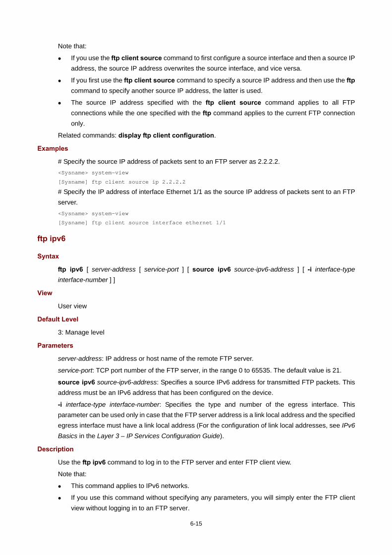
6-15
Note that:
If you use the ftp client source command to first configure a source interface and then a source IP address, the source IP address overwrites the source interface, and vice versa.
If you first use the ftp client source command to specify a source IP address and then use the ftp command to specify another source IP address, the latter is used.
The source IP address specified with the ftp client source command applies to all FTP connections while the one specified with the ftp command applies to the current FTP connection only.
Related commands: display ftp client configuration.
Examples
# Specify the source IP address of packets sent to an FTP server as 2.2.2.2. <Sysname> system-view
[Sysname] ftp client source ip 2.2.2.2
# Specify the IP address of interface Ethernet 1/1 as the source IP address of packets sent to an FTP server. <Sysname> system-view
[Sysname] ftp client source interface ethernet 1/1
ftp ipv6
Syntax
ftp ipv6 [ server-address [ service-port ] [ source ipv6 source-ipv6-address ] [ -i interface-type interface-number ] ]
View
User view
Default Level
3: Manage level
Parameters
server-address: IP address or host name of the remote FTP server.
service-port: TCP port number of the FTP server, in the range 0 to 65535. The default value is 21.
source ipv6 source-ipv6-address: Specifies a source IPv6 address for transmitted FTP packets. This address must be an IPv6 address that has been configured on the device.
-i interface-type interface-number: Specifies the type and number of the egress interface. This parameter can be used only in case that the FTP server address is a link local address and the specified egress interface must have a link local address (For the configuration of link local addresses, see IPv6 Basics in the Layer 3 – IP Services Configuration Guide).
Description
Use the ftp ipv6 command to log in to the FTP server and enter FTP client view.
Note that:
This command applies to IPv6 networks.
If you use this command without specifying any parameters, you will simply enter the FTP client view without logging in to an FTP server.

6-16
If you specify the parameters, you will be asked to enter the username and password for accessing the FTP server.
Examples
# Log in to the FTP server with IPv6 address 3000::200. <Sysname> ftp ipv6 3000::200
Trying 3000::200 ...
Press CTRL+K to abort
Connected to 3000::200.
220 Welcome!
User(3000::200:(none)): MY_NAME
331 Please specify the password.
Password:
230 Login successful.
[ftp]
get
Syntax
get remotefile [ localfile ]
View
FTP client view
Default Level
3: Manage level
Parameters
remotefile: Name of the file to be downloaded.
localfile: File name used after a file is downloaded and saved locally. If this argument is not specified, the file is saved locally using the source file name to the current working directory, namely the directory where the user executes the ftp command.
Description
Use the get command to download a file from a remote FTP server and save it.
Examples
# Download file testcfg.cfg and save it as aa.cfg. [ftp] get testcfg.cfg aa.cfg
227 Entering Passive Mode (192,168,1,50,17,163).
125 ASCII mode data connection already open, transfer starting for /testcfg.cfg.
.....226 Transfer complete.
FTP: 5190 byte(s) received in 7.754 second(s), 669.00 byte(s)/sec.
lcd
Syntax
lcd

6-17
View
FTP client view
Default Level
3: Manage level
Parameters
None
Description
Use the lcd command to display the local working directory of the FTP client.
Examples
# Display the local working directory. [ftp] lcd
FTP: Local directory now flash:/clienttemp.
The above information indicates that the working directory of the FTP client before execution of the ftp command is flash:/clienttemp.
ls
Syntax
ls [ remotefile [ localfile ] ]
View
FTP client view
Default Level
3: Manage level
Parameters
remotefile: Filename or directory on the remote FTP server.
localfile: Name of a local file used to save the displayed information.
Description
Use the ls command to view the information of all the files and subdirectories under the current directory of the remote FTP server. The file names and subdirectory names are displayed.
Use the ls remotefile command to view the information of a specified file or subdirectory.
Use the ls remotefile localfile command to view the information of a specified file or subdirectory, and save the result to a local file specified by the localfile argument.
The ls command can only display the names of files and directories on the FTP server, whereas the dir command can display other related information of the files and directories, such as the size, and the date they were created.

6-18
Examples
# View the information of all files and subdirectories under the current directory of the FTP server. [ftp] ls
227 Entering Passive Mode (192,168,1,50,17,165).
125 ASCII mode data connection already open, transfer starting for /*.
ar-router.cfg
logfile
mainar.app
arbasicbtm.app
ftp
test
bb.cfg
testcfg.cfg
226 Transfer complete.
FTP: 87 byte(s) received in 0.132 second(s) 659.00 byte(s)/sec.
# View the information of directory logfile, and save the result to file aa.txt. [ftp] ls logfile aa.txt
227 Entering Passive Mode (192,168,1,46,4,3).
125 ASCII mode data connection already open, transfer starting for /logfile/*.
....226 Transfer complete.
FTP: 20 byte(s) received in 3.962 second(s), 5.00 byte(s)/sec.
# View the content of file aa.txt. [ftp] quit
<Sysname> more aa.txt
.
..
logfile.log
mkdir
Syntax
mkdir directory
View
FTP client view
Default Level
3: Manage level
Parameters
directory: Name of the directory to be created.
Description
Use the mkdir command to create a subdirectory under the current directory on the remote FTP server.
To do this, you must be a user with the permission on the FTP server.
Examples
# Create subdirectory mytest on the current directory of the remote FTP server. [ftp] mkdir mytest
257 "/mytest" new directory created.

6-19
open
Syntax
open server-address [ service-port ]
View
FTP client view
Default Level
3: Manage level
Parameters
server-address: IP address or host name of a remote FTP server.
service-port: Port number of the remote FTP server, in the range 0 to 65535, with the default value of 21.
Description
Use the open command to log in to the IPv4 FTP server under FTP client view.
At login, you will be asked to enter the username and password for accessing the FTP server. If your input is correct, the login succeeds; otherwise, it fails.
If you have logged in to the IPv4 FTP server currently, you cannot use the open command to log in to another server. You need to disconnect with the current server first, and then try to connect with another one.
Related commands: close.
Examples
# In FTP client view, log in to the FTP server with the IP address of 192.168.1.50. <Sysname> ftp
[ftp] open 192.168.1.50
Trying 192.168.1.50 ...
Press CTRL+K to abort
Connected to 192.168.1.50.
220 FTP service ready.
User(192.168.1.50:(none)):aa
331 Password required for aa.
Password:
230 User logged in.
[ftp]
open ipv6
Syntax
open ipv6 server-address [ service-port ] [ -i interface-type interface-number ]
View
FTP client view
Default Level
3: Manage level

6-20
Parameters
server-address: IP address or host name of the remote FTP server.
service-port: Port number of the remote FTP server, in the range 0 to 65535. The default value is 21.
-i interface-type interface-number: Specifies the egress interface by its type and number. This parameter can be used only in case that the FTP server address is a link local address and the specified egress interface must have a link local address (For the configuration of link local addresses, see IPv6 Basics in the Layer 3 – IP Services Configuration Guide).
Description
Use the open ipv6 command to log in to the IPv6 FTP server in FTP client view.
At login, you will be asked to enter the username and password for accessing the FTP server. If your input is correct, the login succeeds; otherwise, it fails.
Related commands: close.
Examples
# Log in to the FTP server (with IPv6 address 3000::200) in FTP client view. <Sysname> ftp
[ftp] open ipv6 3000::200
Trying 3000::200 ...
Press CTRL+K to abort
Connected to 3000::200.
220 Welcome!
User(3000::200:(none)): MY_NAME
331 Please specify the password.
Password:
230 Login successful.
passive
Syntax
passive
undo passive
View
FTP client view
Default Level
3: Manage level
Parameters
None
Description
Use the passive command to set the data transmission mode to passive.
Use the undo passive command to set the data transmission mode to active.
The default transmission mode is passive.
Data transmission modes fall into the passive mode and the active mode. The active mode means that the data connection request is initiated by a server. The passive mode means that the data connection

6-21
request is initiated by a client. This command is mainly used in conjunction with a firewall to restrict the FTP session connection between private and public network users.
Examples
# Set the data transmission mode to passive. [ftp] passive
FTP: passive is on
put
Syntax
put localfile [ remotefile ]
View
FTP client view
Default Level
3: Manage level
Parameters
localfile: Name of the local file to be uploaded.
remotefile: File name used after a file is uploaded and saved on the FTP server.
Description
Use the put command to upload a file on the client to the remote FTP server.
If no name is assigned to the file to be saved on the FTP server, the name of the source file is used by default. After a file is uploaded, it will be saved under the user’s authorized directory, which can be set with the authorization-attribute command.
Examples
# Upload source file cc.txt to the remote FTP server and save it as dd.txt. [ftp] put cc.txt dd.txt
227 Entering Passive Mode (192,168,1,50,17,169).
125 ASCII mode data connection already open, transfer starting for /dd.txt.
226 Transfer complete.
FTP: 9 byte(s) sent in 0.112 second(s), 80.00 byte(s)/sec.
pwd
Syntax
pwd
View
FTP client view
Default Level
3: Manage level
Parameters
None

6-22
Description
Use the pwd command to display the currently accessed directory on the remote FTP server.
Examples
# Display the currently accessed directory on the remote FTP server. [ftp] cd servertemp
[ftp] pwd
257 "/servertemp" is current directory.
The above information indicates that the servertemp folder under the root directory of the remote FTP server is being accessed by the user.
quit
Syntax
quit
View
FTP client view
Default Level
3: Manage level
Parameters
None
Description
Use the quit command to disconnect from the remote FTP server and exit to user view.
Examples
# Disconnect from the remote FTP server and exit to user view. [ftp] quit
221 Server closing.
<Sysname>
remotehelp
Syntax
remotehelp [ protocol-command ]
View
FTP client view
Default Level
3: Manage level
Parameters
protocol-command: FTP command.

6-23
Description
Use the remotehelp command to display the help information of FTP-related commands supported by the remote FTP server.
If no argument is specified, FTP-related commands supported by the remote FTP server are displayed.
Examples
# Display FTP commands supported by the remote FTP server. [ftp] remotehelp
214-Here is a list of available ftp commands
Those with '*' are not yet implemented.
USER PASS ACCT* CWD CDUP SMNT* QUIT REIN*
PORT PASV TYPE STRU* MODE* RETR STOR STOU*
APPE* ALLO* REST* RNFR* RNTO* ABOR* DELE RMD
MKD PWD LIST NLST SITE* SYST STAT* HELP
NOOP* XCUP XCWD XMKD XPWD XRMD
214 Direct comments to H3C company.
# Display the help information for the user command. [ftp] remotehelp user
214 Syntax: USER <sp> <username>.
[ftp]
Table 6-4 remotehelp command output description
Field Description
214-Here is a list of available ftp commands The following is an available FTP command list.
Those with '*' are not yet implemented. Those commands with “*” are not yet implemented.
USER Username
PASS Password
CWD Change the current working directory
CDUP Change to parent directory
SMNT* File structure setting
QUIT Quit
REIN* Re-initialization
PORT Port number
PASV Passive mode
TYPE Request type
STRU* File structure
MODE* Transmission mode
RETR Download a file
STOR Upload a file
STOU* Store unique
APPE* Appended file
ALLO* Allocation space

6-24
Field Description
REST* Restart
RNFR* Rename the source
RNTO* Rename the destination
ABOR* Abort the transmission
DELE Delete a file
RMD Delete a folder
MKD Create a folder
PWD Print working directory
LIST List files
NLST List file description
SITE* Locate a parameter
SYST Display system parameters
STAT* State
HELP Help
NOOP* No operation
XCUP Extension command, the same meaning as CUP
XCWD Extension command, the same meaning as CWD
XMKD Extension command, the same meaning as MKD
XPWD Extension command, the same meaning as PWD
XRMD Extension command, the same meaning as RMD
Syntax: USER <sp> <username>. Syntax of the user command: user (keyword) + space + username
rmdir
Syntax
rmdir directory
View
FTP client view
Default Level
3: Manage level
Parameters
directory: Directory name on the remote FTP server.
Description
Use the rmdir command to remove a specified directory from the FTP server.
Note that only authorized users are allowed to use this command.
Note that:
6-25
The directory to be deleted must be empty, meaning you should delete all files and subdirectories under the directory before you delete a directory. For the deletion of files, see the delete command.
After you execute the rmdir command successfully, the files in the remote recycle bin under the directory will be automatically deleted.
Examples
# Delete the temp1 directory from the authorized directory on the FTP server. [ftp] rmdir /temp1
200 RMD command successful.
user
Syntax
user username [ password ]
View
FTP client view
Default Level
3: Manage level
Parameters
username: Login username.
password: Login password. You can input this argument after the username argument plus a space; or you can input this argument when the “Password:” prompt appears after you input the username and then press Enter.
Description
Use the user command to relog in to the currently accessed FTP server with another username.
Before using this command, you must configure the corresponding username and password on the FTP server; otherwise, your login fails and the FTP connection is closed.
Examples
# User ftp1 has logged in to the FTP server. Use username ftp2 to log in to the current FTP server. (Suppose username ftp2 and password 123123123123 have been configured on the FTP server).
Method 1 [ftp] user ftp2
331 Password required for ftp2.
Password:
230 User logged in.
[ftp]
Method 2 [ftp] user ftp2 123123123123
331 Password required for ftp.
230 User logged in.
[ftp]
6-26
verbose
Syntax
verbose
undo verbose
View
FTP client view
Default Level
3: Manage level
Parameters
None
Description
Use the verbose command to enable the protocol information function to display detailed prompt information.
Use the undo verbose command to disable the protocol information function.
By default, the protocol information function is enabled.
Examples
# Enable the protocol information function. [ftp] verbose
FTP: verbose is on
# Disable the protocol information function and perform the Get operation. [ftp] undo verbose
FTP: verbose is off
[ftp] get startup.cfg bb.cfg
FTP: 3608 byte(s) received in 0.052 second(s), 69.00K byte(s)/sec.
[ftp]
# Enable the protocol information function and perform the Get operation. [ftp] verbose
FTP: verbose is on
[ftp] get startup.cfg aa.cfg
227 Entering Passive Mode (192,168,1,46,5,85).
125 ASCII mode data connection already open, transfer starting for /startup.cfg.
226 Transfer complete.
FTP: 3608 byte(s) received in 0.193 second(s), 18.00K byte(s)/sec.

7-1
7 TFTP Configuration Commands
TFTP Client Configuration Commands
tftp-server acl
Syntax
tftp-server [ ipv6 ] acl acl-number
undo tftp-server [ ipv6 ] acl
View
System view
Default Level
3: Manage level
Parameters
ipv6: References an IPv6 ACL. If it is not specified, an IPv4 ACL is referenced.
acl-number: Number of a basic ACL, in the range 2000 to 2999.
Description
Use the tftp-server acl command to control the device’s access to a specific TFTP server using an ACL.
Use the undo tftp-server acl command to restore the default.
By default, no ACL is used to control the device’s access to TFTP servers.
You can use the rules in an ACL to allow or permit the device’s access to a specific TFTP server in a network.
For more information about ACL, see ACL in the ACL and QoS Configuration Guide.
Examples
# Allow the device to access the TFTP server with the IP address of 1.1.1.1 only (in IPv4 networking environment). <Sysname> system-view
[Sysname] acl number 2000
[Sysname-acl-basic-2000] rule permit source 1.1.1.1 0
[Sysname-acl-basic-2000] quit
[Sysname] tftp-server acl 2000
# Allow the device to access the TFTP server with the IP address of 2001::1 only (in IPv6 networking environment). <Sysname> system-view
[Sysname] acl ipv6 number 2001
[Sysname-acl6-basic-2001] rule permit source 2001::1/128
[Sysname-acl6-basic-2001] quit
[Sysname] tftp-server ipv6 acl 2001

7-2
tftp
Syntax
tftp server-address { get | put | sget } source-filename [ destination-filename ] [ vpn-instance vpn-instance-name ] [ source { interface interface-type interface-number | ip source-ip-address } ]
View
User view
Default Level
3: Manage level
Parameters
server-address: IP address or host name of a TFTP server.
get: Downloads a file in normal mode.
put: Uploads a file.
sget: Downloads a file in secure mode.
source-filename: Source file name.
destination-filename: Destination file name.
vpn-instance vpn-instance-name: Specifies the MPLS L3VPN that the TFTP server belongs to, where vpn-instance-name is a case sensitive string of 1 to 31 characters. If the TFTP server is on the public network, do not specify this keyword and argument combination.
source: Configures parameters for source address binding.
interface interface-type interface-number: Specifies the source interface by its type and number. The primary IP address configured on the source interface is the source IP address of the packets sent by TFTP. If no primary IP address is configured on the source interface, the transmission fails.
ip source-ip-address: Specifies the source IP address for the current TFTP client to transmit packets. This source address must be an IP address that has been configured on the device.
Description
Use the tftp command to upload files from the local device to a TFTP server or download files from the TFTP server to the local device.
If no destination file name is specified, a file is saved using the same name as that on the remote TFTP server to the current working directory of the user (namely, the working directory where the tftp command is executed).
This command applies to IPv4 networks.
Examples
# Download the config.cfg file from the TFTP server with the IP address of 192.168.0.98 and save it as config.bak. Specify the source IP address to be 192.168.0.92. <Sysname> tftp 192.168.0.98 get config.cfg config.bak source ip 192.168.0.92
...
File will be transferred in binary mode
Downloading file from remote TFTP server, please wait....
TFTP: 372800 bytes received in 1 second(s)
File downloaded successfully.

7-3
# Upload the config.cfg file from the local device to the default path of the TFTP server with the IP address of 192.168.0.98 and save it as config.bak. Specify the source IP interface to be Ethernet 1/1. <Sysname> tftp 192.168.0.98 put config.cfg config.bak source interface ethernet 1/1
File will be transferred in binary mode
Sending file to remote TFTP server. Please wait...
TFTP: 345600 bytes sent in 1 second(s).
File uploaded successfully.
tftp client source
Syntax
tftp client source { interface interface-type interface-number | ip source-ip-address }
undo tftp client source
View
System view
Default Level
2: System level
Parameters
interface interface-type interface-number: Specifies the source interface for establishing TFTP connections. The primary IP address of the source interface is used as the source IP address of packets sent to a TFTP server. If the source interface has no primary IP address specified, no TFTP connection can be established.
ip source-ip-address: Specifies the source IP address of packets sent to a TFTP server, which is one of the IP addresses configured on the device.
Description
Use the tftp client source command to specify the source IP address of packets sent to a TFTP server.
Use the undo tftp client source command to restore the default.
By default, the source IP address is determined by the route from the TFTP client to the TFTP server.
Note that:
If you use the tftp client source command to first configure a source interface and then a source IP address, the source IP address overwrites the source interface, and vice versa.
If you first use the tftp client source command to specify a source IP address and then use the tftp command to specify another source IP address, the latter is used.
The source IP address specified with the tftp client source command applies to all TFTP connections while the one specified with the tftp command applies to the current TFTP connection only.
Related commands: display tftp client configuration.
Examples
# Specify the source IP address of packets sent a TFTP server as 2.2.2.2. <Sysname> system-view
[Sysname] tftp client source ip 2.2.2.2

7-4
# Specify the IP address of interface Ethernet 1/1 as the source IP address of packets sent to a TFTP server. <Sysname> system-view
[Sysname] tftp client source interface ethernet 1/1
tftp ipv6
Syntax
tftp ipv6 tftp-ipv6-server [ -i interface-type interface-number ] { get | put } source-file [ destination-file ]
View
User view
Default Level
3: Manage level
Parameters
tftp-ipv6-server: IPv6 address or host name (a string of 1 to 46 characters) of a TFTP server.
-i interface-type interface-number: Specifies the egress interface by its type and number. This parameter can be used only in case that the TFTP server address is a link local address and the specified egress interface must have a link local address (For the configuration of link local address, see IPv6 Basics in the Layer 3 – IP Services Configuration Guide).
get: Downloads a file.
put: Uploads a file.
source-file: Source filename.
destination-file: Destination filename. If not specified, this filename is the same as the source filename.
Description
Use the tftp ipv6 command to download a specified file from a TFTP server or upload a specified local file to a TFTP server.
This command applies to IPv6 networks.
Examples
# Download filetoget.txt from the TFTP server. <Sysname> tftp ipv6 fe80::250:daff:fe91:e058 -i ethernet 1/1 get filetoget.txt
...
File will be transferred in binary mode
Downloading file from remote TFTP server, please wait....
TFTP: 411100 bytes received in 2 second(s)
File downloaded successfully.

8-1
8 License Management Configuration Commands
License Management Configuration Commands
display license
Syntax
display license [ | { begin | exclude | include } regular-expression ]
View
Any view
Default Level
1: Monitor level
Parameters
|: Filters command output by specifying a regular expression. For more information about regular expressions, see CLI in the Fundamnetals Configuration Guide.
begin: Displays the first line that matches the specified regular expression and all lines that follow.
exclude: Displays the lines that do not match the specified regular expression.
include: Displays all lines that match the specified regular expression.
regular-expression: Specifies a regular expression, which is a case sensitive string of 1 to 256 characters.
Description
Use the display license command to display the system software registration information.
Support for this command on the MSR series is shown below:
Command MSR 900 MSR 20-1X MSR 20 MSR 30 MSR 50
display license No No Yes Yes Yes
Examples
# Display the system software registration information. <Sysname> display license
Software license information
----------------------------
Serial Number: VZa47-6AbBh-gtO9c-K47A0-F79D8-dE84O-tg2j0
Register Date: 2006-10-10 15:50:28
Trade Code : 121234A757C06A000693
Table 8-1 display license command output description
Field Description
Software license information System software license information

8-2
Field Description
Serial Number Serial number of a device
Register Date Register date and time
Trade Code Trade code (that is, manufacturing serial number)
license register
Syntax
license register serial-number
View
User view
Default Level
3: Manage level
Parameters
serial-number: Serial number of a license, in the format of XXXXX-XXXXX-XXXXX-XXXXX-XXXXX-XXXXX-XXXXX, where X represents a character. Valid characters include letters (case sensitive), digits, plus signs (+), and forward slashes (/).
Description
Use the license register command to register the system software for a device.
Before registering the system software, you must purchase a system software license.
Be sure to enter the serial number in the correct format.
Support for this command on the MSR series is shown below:
Command MSR 900 MSR 20-1X MSR 20 MSR 30 MSR 50
license register No No Yes Yes Yes
Examples
# Register the system software. The serial number here is only for illustration. You must use a valid system software serial number. <Sysname> license register aaaaa-bbbbb-ccccc-ddddd-eeeee-fffff-ggggg
Register successfully!

9-1
9 Software Upgrade Commands
Software Upgrade Commands
boot-loader
Syntax
boot-loader file file-url { main | backup }
View
User view
Default Level
3: Manage level
Parameters
file file-url: Specifies a file name, a string of 1 to 63 characters. If you enter a relative path here, the system automatically converts it to an absolute path. The absolute path should contain no more than 63 characters; otherwise, the command cannot be successfully executed. The file name is in the format of [drive:/]file-name, where
The items in square brackets [ ] are optional.
drive specifies the storage medium of the file. The value is the name of the storage medium. If a router has only one storage medium, you can execute this command without providing this argument.
file-name specifies the filename, which is usually suffixed by .bin.
main: Specifies a file as a main boot file.
backup: Specifies a file as a backup boot file. A backup boot file is used to boot a router only when a main boot file is unavailable.
Description
Use the boot-loader command to specify a boot file to be used at the next boot.
To execute the boot-loader command successfully, save the file to be used at the next router boot in the root directory of the storage medium.
Related commands: display boot-loader.
Examples
# Specify the main boot file for the next router boot as test.bin. (The output of this command varies with routers.) <Sysname> boot-loader file test.bin main
This command will set the boot file. Continue? [Y/N]:y
The specified file will be used as the main boot file at the next reboot on slot 0!
9-2
bootrom
Syntax
bootrom { backup | read | restore | update file file-url } [ slot subslot-number-list ] [ all | part ]
View
User view
Default Level
3: Manage level
Parameters
read: Reads Boot ROM, or in other words, copies the Boot ROM program from the normal partition of the Boot ROM memory to the flash as the backup, which will be used to restore the Boot ROM when the Boot ROM memory is broken.
restore: Restores Boot ROM, or in other words, restores the Boot ROM codes from the backup partition to the normal partition of the Boot ROM memory. When the current Boot ROM is broken, and you have backed up the codes, you can restore the Boot ROM by performing the restore operation.
backup: Backs up Boot ROM, or in other words, backs up the Boot ROM codes in the normal partition to the backup partition of the Boot ROM memory. When the current Boot ROM is broken, you can restore the Boot ROM program from the backup partition. You are recommended to back up the Boot ROM before upgrading it.
update file file-url: Upgrades Boot ROM, where file-url is a string of 1 to 63 characters and represents name of the file to be upgraded. For more information about the file-url argument, see boot-loader.
slot slot-number-list: Specifies a list of slot numbers of cards, in the format of { slot-number [ to slot-number ] }&<1-7>. The slot-number argument represents the slot number of a card. &<1-7> indicates that you can specify up to seven lists of slot numbers.
all: Operates all contents of Boot ROM. All contents of the Boot ROM file are operated if the all and part keywords are not specified.
part: Operates only the extension part of Boot ROM (Boot ROM includes the basic part and the extension part, the basic part provides the basic operation items and the extension part provides more Boot ROM operation items). All contents of the Boot ROM file are operated if the all and part keywords are not specified.
Description
Use the bootrom command to read, restore, back up, or upgrade the Boot ROM program on a router(s) or subcard(s).
To execute the bootrom command successfully, you must first save the Boot ROM program in the root directory of the storage medium.
Examples
# Read the Boot ROM program. <Sysname> bootrom read all
Now reading bootrom, please wait...
Read bootrom! Please wait...
Start reading basic bootrom!
Read basic bootrom completed!

9-3
Start reading extended bootrom!
Read extended bootrom completed!
Read bootrom completed! Please check the file!
After the Boot ROM program is read, you will find that files extendbtm.bin and basicbtm.bin are generated on the storage medium of the router. <Sysname> dir
Directory of cfa0:/
0 drw- - Jul 07 2009 21:09:12 logfile
1 -rw- 15074620 Aug 08 2008 13:03:44 test.bin
2 -rw- 139 Sep 24 2008 06:51:38 system.xml
3 -rw- 524288 Aug 13 2008 17:07:18 extendbtm.bin
4 -rw- 524288 Aug 13 2008 17:07:18 basicbtm.bin
5 -rw- 4232 Sep 24 2008 06:51:40 startup.cfg
250088 KB total (223700 KB free)
File system type of cfa0: FAT16
# Back up the Boot ROM program. <Sysname> bootrom backup all
Now backuping bootrom, please wait...
Backup bootrom! Please wait...
Read normal basic bootrom completed!
................................................
Backup normal basic bootrom completed!
Read normal extended bootrom completed!
................................................
Backup normal extended bootrom completed!
Backup bootrom completed!
# Restore the Boot ROM program. <Sysname> bootrom restore all
This command will restore bootrom file, Continue? [Y/N]:y
Now restoring bootrom, please wait...
Restore bootrom! Please wait...
Read backup basic bootrom completed!
................................................
Restore basic bootrom completed!
Read backup extended bootrom completed!
................................................
Restore extended bootrom completed!
Restore bootrom completed!
# Use the a.btm file to upgrade the Boot ROM program on the router. (The output of this command varies with routers.) <Sysname> bootrom update file a.btm
This command will update bootrom file, Continue? [Y/N]:y
Now updating bootrom, please wait...
Updating basic bootrom!
................................
Update basic bootrom success!
Updating extended bootrom!
........................
9-4
Update extended bootrom success!
Update bootrom success!
display boot-loader
Syntax
display boot-loader [ | { begin | exclude | include } regular-expression ]
View
Any view
Default Level
2: System level
Parameters
slot slot-number: Displays boot file information of the specified card, where slot-number represents the slot number of a card.
|: Filters command output by specifying a regular expression. For more information about regular expressions, see CLI in the Fundamentals Configuration Guide.
begin: Displays the first line that matches the specified regular expression and all lines that follow.
exclude: Displays the lines that do not match the specified regular expression.
include: Displays all lines that match the specified regular expression.
regular-expression: Specifies a regular expression, which is a case sensitive string of 1 to 256 characters.
Description
Use the display boot-loader command to display information of the boot file.
Related commands: boot-loader.
Examples
# Display the file adopted for the current and next boot of the router. (The output of this command varies with routers.) <Sysname> display boot-loader
The boot file used at this reboot:flash:/test.bin attribute: main
The boot file used at the next reboot:flash:/test.bin attribute: main
The boot file used at the next reboot:flash:/test.bin attribute: backup
Failed to get the secure boot file used at the next reboot!
Table 9-1 display boot-loader command output description
Field Description
The boot file used at this reboot File used for the current boot of the system
attribute Attributes of a boot file:
main backup
The boot file used at the next reboot Boot file used for the next boot of the router
Failed to get the secure boot file used at the next reboot!
If the main boot file and the backup boot file are not available or damaged, the secure boot file will be used for the boot of the router
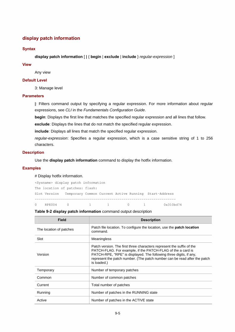
9-5
display patch information
Syntax
display patch information [ | { begin | exclude | include } regular-expression ]
View
Any view
Default Level
3: Manage level
Parameters
|: Filters command output by specifying a regular expression. For more information about regular expressions, see CLI in the Fundamentals Configuration Guide.
begin: Displays the first line that matches the specified regular expression and all lines that follow.
exclude: Displays the lines that do not match the specified regular expression.
include: Displays all lines that match the specified regular expression.
regular-expression: Specifies a regular expression, which is a case sensitive string of 1 to 256 characters.
Description
Use the display patch information command to display the hotfix information.
Examples
# Display hotfix information. <Sysname> display patch information
The location of patches: flash:
Slot Version Temporary Common Current Active Running Start-Address
----------------------------------------------------------------------
0 RPE004 0 1 1 0 1 0x310bd74
Table 9-2 display patch information command output description
Field Description
The location of patches Patch file location. To configure the location, use the patch location command.
Slot Meaningless
Version
Patch version. The first three characters represent the suffix of the PATCH-FLAG. For example, if the PATCH-FLAG of the a card is PATCH-RPE, "RPE" is displayed. The following three digits, if any, represent the patch number. (The patch number can be read after the patch is loaded.)
Temporary Number of temporary patches
Common Number of common patches
Current Total number of patches
Running Number of patches in the RUNNING state
Active Number of patches in the ACTIVE state

9-6
Field Description
Start-Address Starting address of the memory patch area in the memory
patch active
Syntax
patch active patch-number
View
System view
Default Level
3: Manage level
Parameters
patch-number: Sequence number of a patch. The valid values of this argument depend on the patch file used.
Description
Use the patch active command to activate the specified patch, namely, the system will run the patch.
After you execute the command, all the DEACTIVE patches before the specified patch are activated.
The command is applicable to only patches in the DEACTIVE state.
After a system reboot, the original ACTIVE patches change to DEACTIVE and become invalid. To make them effective, you need to activate them again.
Examples
# Activate patch 3 and all the DEACTIVE patches before patch 3. <Sysname> system-view
[Sysname] patch active 3
patch deactive
Syntax
patch deactive patch-number
View
System view
Default Level
3: Manage level
Parameters
patch-number: Sequence number of a patch. The valid values of this argument depend on the patch file used.
Description
Use the patch deactive command to stop running the specified patch and all the ACTIVE patches after the specified patch, and the system will run at the original software version.

9-7
All the ACTIVE patches (including the specified patch) turn to DEACTIVE state.
This command is not applicable to the patches in the RUNNING state.
Examples
# Stop running patch 3 and all the ACTIVE patches after patch 3. <Sysname> system-view
[Sysname] patch deactive 3
patch delete
Syntax
patch delete patch-number
View
System view
Default Level
3: Manage level
Parameters
patch-number: Sequence number of a patch. The valid values of this argument depend on the patch file used.
Description
Use the patch delete command to delete the specified patch and all the patches after the specified patch.
This command only removes the patches from the memory patch area, and it does not delete them from the storage medium. The patches are in the IDLE state after execution of this command.
Examples
# Delete patch 3 and all the patches after patch 3. <Sysname> system-view
[Sysname] patch delete 3
patch install
Syntax
patch install patch-location
undo patch install
View
System view
Default Level
3: Manage level
Parameters
patch-location: A string consisting of 1 to 64 characters. It specifies the directory where the patch file locates. Typically, it is the root directory of a storage medium.
9-8
Description
Use the patch install command to install all the patches in one step.
Use the undo patch install to remove the patches.
When you execute the patch install command, message "Do you want to continue running patches after reboot? [Y/N]:" is displayed.
Entering y or Y: All the specified patches are installed, and turn to the RUNNING state from IDLE. This equals execution of the commands patch location, patch load, patch active, and patch run. The patches remain RUNNING after system reboot.
Entering n or N: All the specified patches are installed and turn to the ACTIVE state from IDLE. This equals execution of the commands patch location, patch load and patch active. The patches turn to the DEACTIVE state after system reboot.
If the storage medium is a CF card with partitions, the patch files must be in the root directory of the first partition.
The patch install command changes the patch file location specified with the patch location command to the directory specified by the patch-location argument of the patch install command. For example, if you execute the patch location xxx command and then the patch install yyy command, the patch file location automatically changes from xxx to yyy.
Examples
# Install the patches located on the flash. <Sysname> system-view
[Sysname] patch-install flash:
Patches will be installed. Continue? [Y/N]:y
Do you want to run patches after reboot? [Y/N]:y
Installing patches…
Installation completed, and patches will continue to run after reboot.
[Sysname]
patch load
Syntax
patch load
View
System view
Default Level
3: Manage level
Parameters
None
Description
Use the patch load command to load the patch file on the storage medium (such as the flash or the CF card) to the memory patch area.

9-9
If the router is mounted with multiple storage media, the system loads the patch file from the flash by default. If the system cannot find the patch file on the flash, it will try to load the patch file from the CF card.
Before using the command, save the patch file to the root directory of the storage medium.
Examples
# Load the patch file. <Sysname> system-view
[Sysname] patch load
patch location
Syntax
patch location patch-location
View
System view
Default Level
3: Manage level
Parameters
patch-location: Specifies the patch file location. It is a string of 1 to 64 characters. It can be a root directory of a storage medium or be in the format of "root directory + patch file name".
Description
Use the patch location command to configure the patch file location.
By default, the patch file location is flash:.
If you save the patch files to other storage media except the flash on the router, you need to specify the directory where the patch files locate with the patch-location argument. Then the system loads the appropriate patch files in the specified directory. If the router has only one storage medium, the patch file is saved to a specific location and you do not need to execute this command.
The patch install command changes the patch file location specified with the patch location command to the directory specified by the patch-location argument of the patch install command. For example, if you execute the patch location xxx command and then the patch install yyy command, the patch file location automatically changes from xxx to yyy.
Examples
# Configure the root directory of the CF card as the patch file location. <Sysname> system-view
[Sysname] patch location cf:
patch run
Syntax
patch run patch-number
View
System view
9-10
Default Level
3: Manage level
Parameters
patch-number: Sequence number of a patch. The valid values of this argument depend on the patch file used.
Description
Use the patch run command to confirm the running of the specified patch and all the ACTIVE patches before the specified patch.
This command is applicable to patches in the ACTIVE state only.
If the running of a patch is confirmed, after the system reboots, the patch will still be effective.
Examples
# Confirm the running of patch 3 and all the ACTIVE patches before patch 3. <Sysname> system-view
[Sysname] patch run

10-1
10 Index
A B C D E F G H I J K L M N O P Q R S T U V W X Y Z
A
acl (user interface view) 2-1
activation-key 2-2
archive configuration interval 4-1
archive configuration location 4-2
archive configuration max 4-3
archive configuration 4-1
ascii 6-6
authentication-mode 2-5
auto-execute command 2-3
B
backup startup-configuration 4-4
binary 6-7
boot-loader 9-1
bootrom 9-2
bye 6-7
C
card-mode 3-1
cd 5-1
cd 6-8
cdup 6-8
clock datetime 3-2
clock summer-time one-off 3-3
clock summer-time repeating 3-4
clock timezone 3-5
close 6-9
command accounting 2-6
command authorization 2-6
command-alias enable 1-1
command-alias mapping 1-1
command-privilege level 1-2
configuration encrypt 4-5
configuration replace file 4-5
configure-user count 3-6
copy 5-2
copyright-info enable 3-7
D
databits 2-7
debugging 6-9
delete 5-3
delete 6-11
dir 5-3
dir 6-11
disconnect 6-13
display archive configuration 4-6
display boot-loader 9-4
display clipboard 1-3
display clock 3-8
display command-alias 1-4
display configure-user 3-9
display cpu-usage history 3-11
display cpu-usage 3-10
display current-configuration 3-13
display device manuinfo 3-16
display device 3-15
display diagnostic-information 3-18
display environment (advanced) 3-19
display environment (basic) 3-20
display fan 3-21
display ftp-server 6-1
display ftp-user 6-2
display history-command 1-5

10-2
display hotkey 1-5
display ip http 2-8
display ip https 2-9
display job 3-22
display license 8-1
display memory 3-23
display nandflash badblock-location 5-5
display nandflash file-location 5-4
display nandflash page-data 5-6
display patch information 9-5
display power 3-24
display reboot-type 3-24
display rps 3-25
display saved-configuration 4-7
display schedule reboot 3-26
display startup 4-9
display system-failure 3-26
display this 3-27
display transceiver alarm 3-30
display transceiver diagnosis 3-33
display transceiver manuinfo 3-34
display transceiver 3-28
display user-interface 2-10
display users 2-12
display version 3-36
E
escape-key 2-13
execute 5-7
F
file prompt 5-8
fixdisk 5-9
flow-control 2-14
format 5-9
free ftp user 6-3
free user-interface 2-16
ftp client source 6-14
ftp ipv6 6-15
ftp server acl 6-3
ftp server enable 6-4
ftp timeout 6-5
ftp update 6-5
ftp 6-13
G
get 6-16
H
header 3-36
history-command max-size 2-17
hotkey 1-6
I
idle-timeout 2-17
ip http acl 2-18
ip http enable 2-19
ip http port 2-20
ip https acl 2-20
ip https certificate access-control-policy 2-21
ip https enable 2-22
ip https port 2-23
ip https ssl-server-policy 2-23
J
job 3-38
K
L
lcd 6-16
license register 8-2
lock 2-24
ls 6-17
M
mkdir 5-10
mkdir 6-18
more 5-11
mount 5-11
move 5-12
N
nms monitor-interface 3-38

10-3
O
open ipv6 6-19
open 6-19
P
parity 2-25
passive 6-20
patch active 9-6
patch deactive 9-6
patch delete 9-7
patch install 9-7
patch load 9-8
patch location 9-9
patch run 9-9
protocol inbound 2-26
put 6-21
pwd 5-13
pwd 6-21
Q
quit 1-7
quit 6-22
R
reboot 3-39
redirect disconnect 2-26
redirect enable 2-27
redirect listen-port 2-28
redirect refuse-negotiation 2-28
redirect refuse-teltransfer 2-29
redirect return-deal from-telnet 2-30
redirect return-deal from-terminal 2-31
redirect timeout 2-32
remotehelp 6-22
rename 5-13
reset recycle-bin 5-14
reset saved-configuration 4-10
reset unused porttag 3-40
restore startup-configuration 4-11
return 1-7
rmdir 5-16
rmdir 6-24
S
save 4-11
schedule reboot at 3-41
schedule reboot delay 3-42
screen-length disable 1-8
screen-length 2-33
send 2-33
set authentication password 2-35
shell 2-36
shutdown-interval 3-43
speed (user interface view) 2-36
startup saved-configuration 4-13
stopbit-error intolerance 2-37
stopbits 2-38
super authentication-mode 1-9
super password 1-10
super 1-9
sysname 3-44
system-failure 3-45
system-view 1-11
T
telnet client source 2-40
telnet ipv6 2-40
telnet server enable 2-41
telnet 2-39
temperature-limit (basic) 3-45
terminal type 2-41
tftp client source 7-3
tftp ipv6 7-4
tftp 7-2
tftp-server acl 7-1
time 3-46
U
umount 5-16
undelete 5-17
user privilege level 2-42
user 6-25

10-4
user-interface 2-43
V
verbose 6-26
view 3-49
W
X
Y
Z
Related Documents