OM-E0798E 000

Welcome message from author
This document is posted to help you gain knowledge. Please leave a comment to let me know what you think about it! Share it to your friends and learn new things together.
Transcript
OM-E0798E 000
1
Eng
lish
Thank you for purchasing VIVA ace Basic Set.
This product is a Portable Dental Treatment Unit used for on-site patient treatment.
Please read this Operation Manual carefully before use so that you can use it safely to come through a correct use.
Keep this Operation Manual within easy reach of users for future reference.
1. User and Indications for Use .......................................... 2 2. Precautions for handling and operation ............................... 2 3. Package Contents ......................................................... 6 4. Part Names ................................................................... 8 4-1 Control unit .................................................................................8
4-2 Control Panel ............................................................................10
5. Preparation for Use ......................................................12 5-1 Preparation of Control Unit .........................................................12
5-2 Connecting the Syringe .............................................................13
5-3 Connecting the Motor ................................................................14
5-4 Connecting the Scaler ...............................................................14
5-5 Installing the Vacuum Bottle .......................................................15
5-6 Installing the Vacuum Hose ........................................................16
5-7 Installing the Water Bottle ..........................................................16
5-8 Connecting the Foot control .......................................................17
5-9 Connecting the AC Power Cord ..................................................17
5-10 Check before treatment .............................................................18
6. Operation Procedure ..............................................................19 6-1 Motor ........................................................................................19
6-2 Motor <Endodontic treatment> .................................................20
6-3 Ultrasonic Scaler .......................................................................22
6-4 Vacuum ....................................................................................23
6-5 Light Probe ...............................................................................24
6-6 3way Syringe ............................................................................24
6-7 When the Water Bottle is empty or the Vacuum Bottle is
filled with liquid during use ........................................................25
6-8 Sound Volume ...........................................................................26
6-9 Last Memory Function ...............................................................27
6-10 Initialization Program (Factory Setting) .......................................27
6-11 Protection Circuit .......................................................................28
7. Post-use Maintenance ................................................. 29 7-1 Preparation ...............................................................................29
7-2 Maintenance for Between Each Patient ......................................30
7-3 Maintenance After Close ...........................................................33
7-4 Sterilization ...............................................................................43
7-5 Maintenance Before Use ............................................................44
7-6 Maintenance of the Water Line ..................................................45 8. Storage Procedure .................................................................48 9. Transportation .......................................................................50
10. Maintenance ........................................................................50 10-1 Replacing the gasket (Water Bottle) .......................................50
10-2 Replacing the filter, gasket, O-ring (Vacuum Bottle) ...............51
10-3 Replacing the O-rings (Vacuum Valve) ....................................51
10-4 Replacing the O-rings (Vacuum Hose) ....................................51
10-5 Replacing the O-ring (Vacuum Connector) ..............................51
10-6 Replacing the O-ring (Syringe) ...............................................52
10-7 Replacing the fuse ................................................................52
10-8 Drainage of Air Filter .............................................................53
10-9 Replacing the Water Plug ......................................................53
10-10 Periodical Maintenance Checks .............................................54
11. Troubleshooting .................................................................. 55 11-1 Error Code .............................................................................55
11-2 Problems and Solutions..........................................................57
12. Specifications ......................................................................58 12-1 Specifications ........................................................................58
12-2 Classification of Equipment ....................................................58
12-3 Symbol ................................................................................ 59
13. After-sales Service ..............................................................60 13-1 Warranty ...............................................................................60
13-2 Spare Parts List .....................................................................60
13-3 Option Parts List ....................................................................61
13-4 Disposing product ..................................................................61
14. EMC Information (Electromagnetic Compatibility Information) ....................................62
* The basic function of this product is Vacuum and Syringe.
Additional function is available by purchasing optional parts (VIVA ace Motor Kit, VIVA ace Scaler Kit).
Refer to the attached Operation manuals for further information.
Operation procedure of this product is introduced in a movie.
Check the URL or the QR Code.
URL
http://www.nsk-dental.com/support/videos/
Contents
English
2
User and Indications for Use1
Precautions for handling and operation2
User : Dentist, Dental hygienist
Indications for Use : The device is a dental suction system intended for dental treatment. The device is equipped with the functions of vacuum
and irrigation and used by connecting motor and ultrasonic scaler.
The motor is intended for teeth and denture cutting, polishing and root canal treatment.
The ultrasonic scaler is intended for use in dental applications such as scaling, root canal treatment, periodontal and cavity preparation by
generating ultrasonic waves.
Please read these precautions carefully and use only as intended or instructed.
Safety instructions are intended to avoid potential hazards that could result in personal injury or damage to the device.
Safety instructions are classified as follows in accordance with the seriousness of the risk.
DANGERHazard that could result in personal death or serious injury if the safety instructions are not correctly
followed.
Class Degree of Risk
WARNINGHazard that could result in serious injury or damage to the device if the safety instructions are not
correctly followed.
CAUTIONHazard that could result in light or moderate injury or damage to the device if the safety instructions
are not correctly followed.
NOTICEGeneral product specification information highlighted to avoid product malfunction and performance
reduction.
3
Eng
lish
Precautions for handling and operation
DANGER
• To prevent secondary infection due to droplet/air of the Vacuum do not use these products for patients with significant infection.
• Do not attempt to disassemble the product nor tamper with the mechanism except as recommended by NSK in this Operation Manual.
This may result in an injury, electric shock or fire.
• Do not handle the power cord, motor cord and scaler cord with wet hands. Wet hand contact with electricity may result in an electric shock.
• Do not use power cords other than genuine products made by NSK. Use of other cords may result in electric shock, fire or breakdown.
Do not connect any other accessories that are not specified by NSK.
• Stop using the product and contact your Authorized NSK Dealer immediately if deformation, damage, or discoloration of the exterior of the
control unit is observed. This may result in an electric shock and fire.
• If the product overheats or smells of burning, immediately turn off the power and disconnect the AC power cord.
Contact your Authorized NSK Dealer. This may result in an electric shock and fire.
• Take care not to get water or liquid disinfectant in the control unit during use. This could cause short circuits and lead to an electric shock.
• Always check the Vacuum operates thoroughly and test suctioning. Adjust the suction force and the water amount according to
the patient’s condition. Refer to P58 “12-1 Specifications” for the suction force and suction amount for the Vacuum.
WARNING
• Do not use the product when the patient or the operator is using cardiac pacemakers as there is a danger that it may affect the pacemaker.
• Keep away from explosive substances and flammable materials. Also, keep away from patients whom a flammable anesthetic
(eg. laughing gas) is administered as this may cause fire.
• Keep away from devices that generate electromagnetic waves as electromagnetic waves may cause malfunction of the product.
Turn off the product around ultrasonic generators (excluding the product) or electrical scalpels.
Keep away from communication equipment or elevators that generate electromagnetic waves.
• Do not turn the lighting of the handpiece, motor cord, or scaler cord directly to the eyes of the patients or the operators.
There is a danger that this may damage the eyes.
• Never touch the connecting parts (the terminal parts) of the scaler handpiece, scaler cord, motor, motor cord, and control unit.
This could cause an electric shock.
• This product is a precision instrument. During transportation of the product, do not allow any strong impact or shock to the product, or do
not drop the product. This may cause product breakage, leading to an electric shock or failure.
• Before replacing the fuse, be sure to turn off the power switch and remove the AC Power Cord. (Reference:10-7 Replacing the fuse)
If you touch the patient and the contact point inside the fuse insertion port simultaneously without taking the procedures above,
it may lead to an electric shock.
4
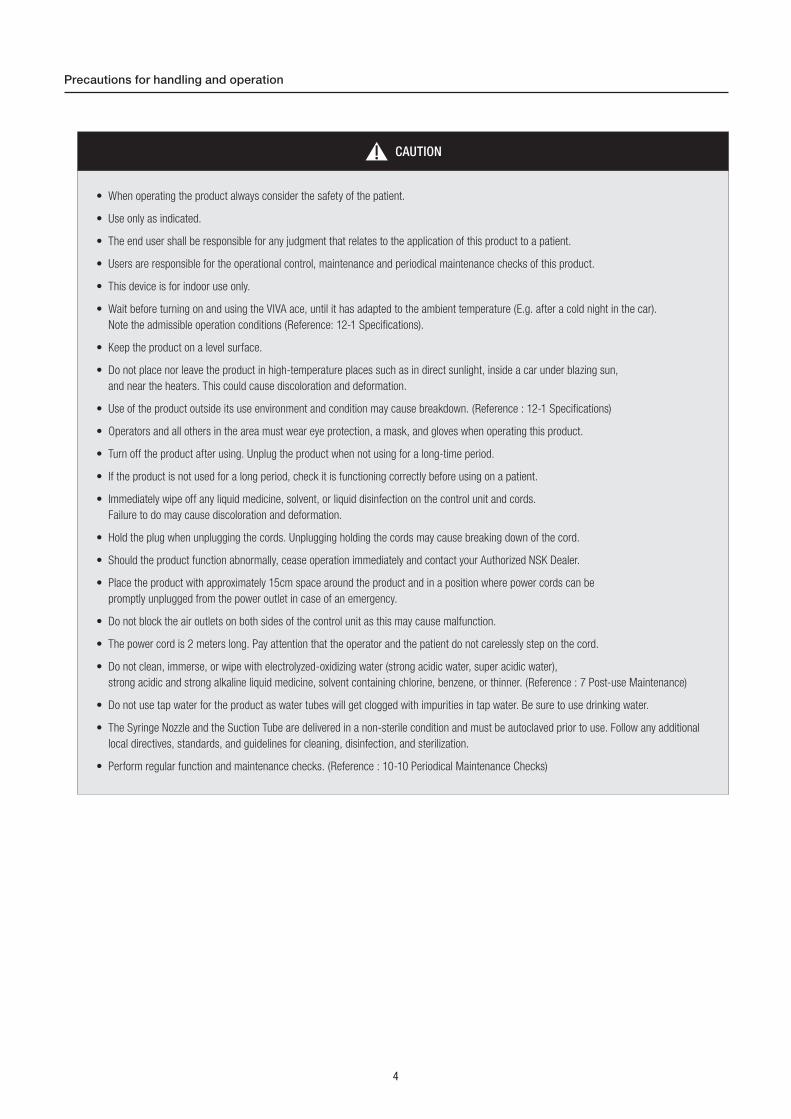
CAUTION
• When operating the product always consider the safety of the patient.
• Use only as indicated.
• The end user shall be responsible for any judgment that relates to the application of this product to a patient.
• Users are responsible for the operational control, maintenance and periodical maintenance checks of this product.
• This device is for indoor use only.
• Wait before turning on and using the VIVA ace, until it has adapted to the ambient temperature (E.g. after a cold night in the car).
Note the admissible operation conditions (Reference: 12-1 Specifications).
• Keep the product on a level surface.
• Do not place nor leave the product in high-temperature places such as in direct sunlight, inside a car under blazing sun,
and near the heaters. This could cause discoloration and deformation.
• Use of the product outside its use environment and condition may cause breakdown. (Reference : 12-1 Specifications)
• Operators and all others in the area must wear eye protection, a mask, and gloves when operating this product.
• Turn off the product after using. Unplug the product when not using for a long-time period.
• If the product is not used for a long period, check it is functioning correctly before using on a patient.
• Immediately wipe off any liquid medicine, solvent, or liquid disinfection on the control unit and cords.
Failure to do may cause discoloration and deformation.
• Hold the plug when unplugging the cords. Unplugging holding the cords may cause breaking down of the cord.
• Should the product function abnormally, cease operation immediately and contact your Authorized NSK Dealer.
• Place the product with approximately 15cm space around the product and in a position where power cords can be
promptly unplugged from the power outlet in case of an emergency.
• Do not block the air outlets on both sides of the control unit as this may cause malfunction.
• The power cord is 2 meters long. Pay attention that the operator and the patient do not carelessly step on the cord.
• Do not clean, immerse, or wipe with electrolyzed-oxidizing water (strong acidic water, super acidic water),
strong acidic and strong alkaline liquid medicine, solvent containing chlorine, benzene, or thinner. (Reference : 7 Post-use Maintenance)
• Do not use tap water for the product as water tubes will get clogged with impurities in tap water. Be sure to use drinking water.
• The Syringe Nozzle and the Suction Tube are delivered in a non-sterile condition and must be autoclaved prior to use. Follow any additional
local directives, standards, and guidelines for cleaning, disinfection, and sterilization.
• Perform regular function and maintenance checks. (Reference : 10-10 Periodical Maintenance Checks)
Precautions for handling and operation
5
Eng
lish
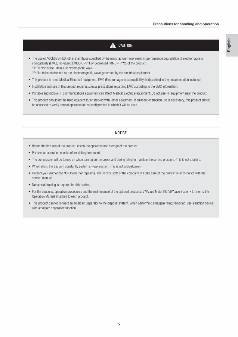
CAUTION
• The use of ACCESSORIES, other than those specified by the manufacturer, may result in performance degradation of electromagnetic
compatibility (EMC), increased EMISSIONS*1 or decreased IMMUNITY*2, of the product.
*1: Electric noise (Mainly electromagnetic wave)
*2: Not to be obstructed by the electromagnetic wave generated by the electrical equipment.
• This product is rated Medical Electrical equipment. EMC (Electromagnetic compatibility) is described in the documentation included.
• Installation and use of this product requires special precautions regarding EMC according to the EMC information.
• Portable and mobile RF communications equipment can affect Medical Electrical equipment. Do not use RF equipment near the product.
• This product should not be used adjacent to, or stacked with, other equipment. If adjacent or stacked use is necessary, this product should
be observed to verify normal operation in the configuration in which it will be used.
NOTICE
• Before the first use of the product, check the operation and storage of the product.
• Perform an operation check before visiting treatment.
• The compressor will be turned on when turning on the power and during idling to maintain the setting pressure. This is not a failure.
• When idling, the Vacuum constantly performs weak suction. This is not a breakdown.
• Contact your Authorized NSK Dealer for repairing. The service staff of the company will take care of the product in accordance with the
service manual.
• No special training is required for this device.
• For the cautions, operation procedures and the maintenance of the optional products; VIVA ace Motor Kit, VIVA ace Scaler Kit, refer to the
Operation Manual attached to each product.
• This product cannot connect an amalgam separator to the disposal system. When performing amalgam filling/removing, use a suction device
with amalgam separation function.
Precautions for handling and operation

6
Package Contents3

7
Eng
lish
No. Part Name Order Code Quantity Remarks
1 Top Case Cover - 1 -
2 AC Power Cord U439550 1 -
3 Top Case - 1 -
4 Foot Control Z1008006 1 FC-70S (For Vacuum)
5 Foot Control Z1082005 1 FC-76S (For Motor and Scaler)
6 Vacuum Bottle Set U1146070 1 -
7 Vacuum Cap A U1144750 1 White, Convex shape
8 Vacuum Cap B U1144751 1 White, Concave shape
9 Water Bottle Set U1146080 1 -
10 Control Unit - 1 -
11 3way Syringe - 1 -
12 3way Syringe Nozzle U1144046 1 Sterilizable
13 Vacuum Junction Hose U1144753 1 -
14 Vacuum Hose U1144076 1 -
15 Hose Cap U1144752 1 Black
16 Vacuum Valve U1144079 1 -
17 Suction Tube - 10 Sterilizable
18 Spanner Z103119 1 -
19 Shoulder Belt U1144370 1 With a pad
20 Cleaning Adaptor U1144097 1 -
21 Quick Operation Guide - 1 *Not in the illustration.
22 Operation Manual - 1 *Not in the illustration.
Package Contents
Please specify the order code listed above when ordering the spare parts. Other spare parts are listed on Page 60.
(Reference : 13-2 Spare Parts List)
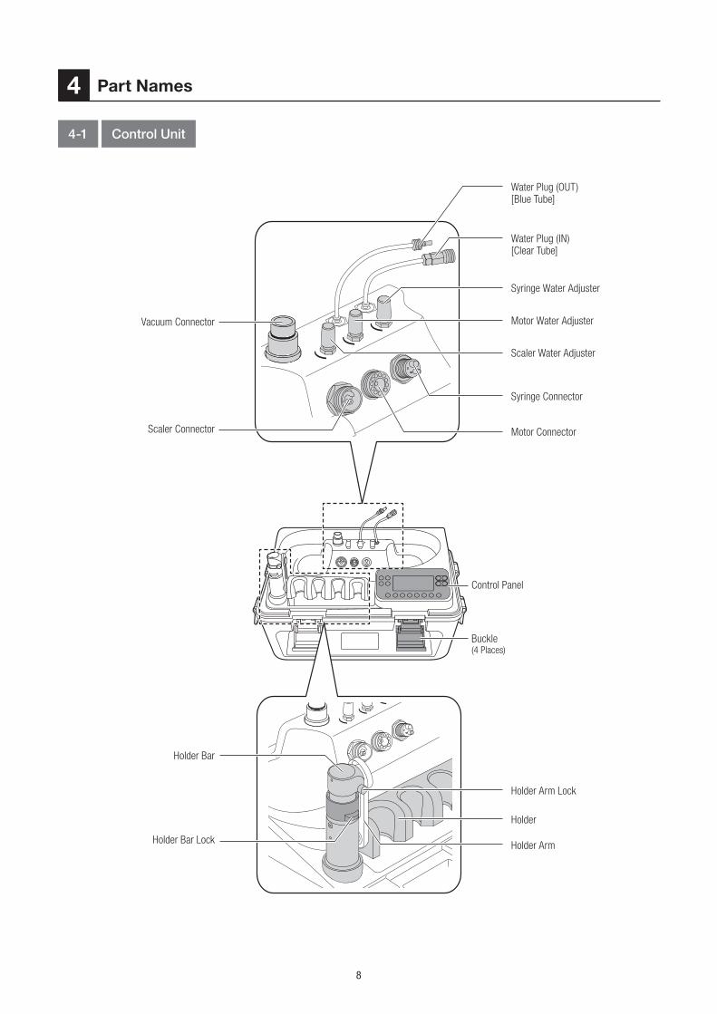
8
Water Plug (OUT)[Blue Tube]
Water Plug (IN)[Clear Tube]
Syringe Water Adjuster
Motor Water AdjusterVacuum Connector
Scaler Connector
Holder Bar
Holder Bar Lock
Scaler Water Adjuster
Holder Arm Lock
Syringe Connector
Holder
Control Panel
Motor Connector
Holder Arm
Buckle(4 Places)
4-1 Control Unit
Part Names4

9
Eng
lish
Power Inlet
Latch(2 Places)
Shoulder Belt
Belt Hook(4 Places, For Shoulder Belt)
Power Switch
Fuse Holder
Foot Control Connector(For Vacuum)
Foot Control Connector(For Motor/Scaler)
Handle
Outlet(For internal cooling)
*The outlet on the other
side is for Vacuum
Part Names

10
Keys of the Control Panel
Liquid Crystal Display of the Control Panel
*The illustration above shows all the marks.
NOTICE
• A protective sheet is applied on the liquid crystal display to prevent flaws during shipping. Remove the sheet before using the product. When
removing the sheet, minor change on the liquid crystal display may be noticed. It will soon get back to normal. This is not a failure.
Part Names
4-2 Control Panel
11
Eng
lish
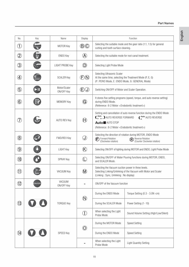
No. Key Name Display Function
MOTOR KeySelecting the suitable mode and the gear ratio (1:1, 1:5) for general
cutting and tooth surface cleaning.
ENDO Key Selecting the suitable mode for root canal treatment.
LIGHT PROBE Key Selecting Light Probe Mode
SCALER Key
Selecting Ultrasonic Scaler
At the same time, selecting the Treatment Mode (P, E, G)
(P : PERIO Mode, E : ENDO Mode, G : GENERAL Mode)
Motor/Scaler
ON/OFF KeySwitching ON/OFF of Motor and Scaler Operation.
MEMORY Key
It stores five setting programs (speed, torque, and auto reverse setting)
during ENDO Mode.
(Reference : 6-2 Motor <Endodontic treatment>)
AUTO REV Key
Setting and cancellation of auto reverse function during the ENDO Mode
AUTO REVERSE FORWARD AUTO REVERSE
AUTO STOP
(Reference : 6-2 Motor <Endodontic treatment>)
FWD/REV KeySelecting the direction of rotation during MOTOR, ENDO Mode
Forward Rotation Reverse Rotation (Clockwise rotation) (Counter Clockwise rotation)
LIGHT Key Selecting ON/OFF of lighting during MOTOR and ENDO, Light Probe Mode
SPRAY KeySelecting ON/OFF of Water Pouring functions during MOTOR, ENDO,
and SCALER Mode.
VACUUM Key
Selecting the Vacuum suction power in three levels.
Selecting Linking/Unlinking of the Vacuum with Motor and Scaler
(Linking : Sync, Unlinking : No display)
VACUUM
ON/OFF KeyON/OFF of the Vacuum function
TORQUE Key
During the ENDO Mode Torque Setting (0.3 - 3.0N ·cm)
During the SCALER Mode Power Setting (1 - 10)
When selecting the Light
Probe ModeSound Volume Setting (High/Low/Silent)
SPEED Key
During the MOTOR Mode Speed Setting
During the ENDO Mode Speed Setting
When selecting the Light
Probe ModeLight Quantity Setting
Part Names
12
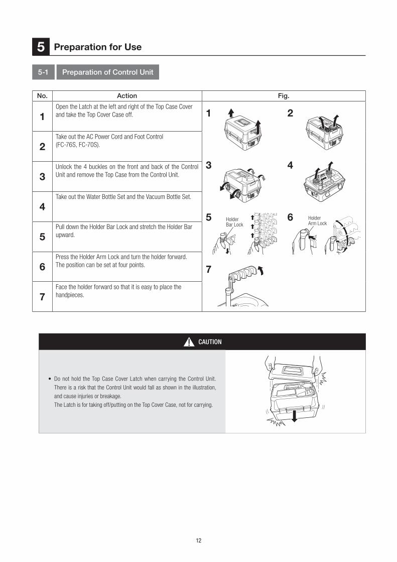
No. Action Fig.
1Open the Latch at the left and right of the Top Case Cover
and take the Top Cover Case off.
2Take out the AC Power Cord and Foot Control
(FC-76S, FC-70S).
3 Unlock the 4 buckles on the front and back of the Control
Unit and remove the Top Case from the Control Unit.
4Take out the Water Bottle Set and the Vacuum Bottle Set.
5Pull down the Holder Bar Lock and stretch the Holder Bar
upward.
6Press the Holder Arm Lock and turn the holder forward.
The position can be set at four points.
7Face the holder forward so that it is easy to place the
handpieces.
43
6
7
21
Preparation for Use5
5-1 Preparation of Control Unit
5 Holder Bar Lock
Holder Arm Lock
CAUTION
• Do not hold the Top Case Cover Latch when carrying the Control Unit.
There is a risk that the Control Unit would fall as shown in the illustration,
and cause injuries or breakage.
The Latch is for taking off/putting on the Top Cover Case, not for carrying.

13
Eng
lish
Preparation for use
CAUTION
• Be careful not to get fingers caught when turning the holder
while pressing the Holder Arm Lock. It may cause injuries.
• The holder cannot be turned to the direction shown in the
illustration. Turning by force could cause breakage and
deformation.
• Do not put excessive load to the holder to prevent from breaking down and deformation.
5-2 Connecting the Syringe
No. Action Fig.
1Aligning the mark of the syringe hose plug and the shape
of the terminal as shown below, insert the plug deep into the
syringe connector.
2Turn the Plug Cover for tightening.
3
Insert the syringe nozzle firmly until a clicking sound is
heard.*The syringe nozzle has already been inserted at the shipping.
Move on to the next step.
4Pull and push the syringe nozzle to confirm it is surely
connected.
5Place the Syringe on the Holder.*For easy handling, avoid pushing in the syringe when placing.
53
21
CAUTION
• Be sure to tighten the plug cover firmly. If tightening is insufficient, water and air will leak and the compressor will not stop.
• If the syringe nozzle comes out easily when connecting to the syringe, stop operating and replace the O-rings.Continuous use of the syringe
nozzle in the above conditions could cause the nozzle to stick out. (Reference: 10-6 Replacing the O-ring (Syringe) )
Loosen
Tighten
mark
14
Preparation for use
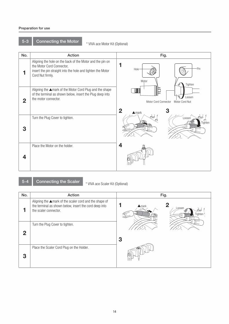
* VIVA ace Motor Kit (Optional)5-3 Connecting the Motor
No. Action Fig.
1
Aligning the hole on the back of the Motor and the pin on
the Motor Cord Connector,
insert the pin straight into the hole and tighten the Motor
Cord Nut firmly.
2
Aligning the mark of the Motor Cord Plug and the shape
of the terminal as shown below, insert the Plug deep into
the motor connector.
3
Turn the Plug Cover to tighten.
4
Place the Motor on the holder.
32
1Hole Pin
MotorTighten
Loosen
Motor Cord NutMotor Cord Connector
4
mark
* VIVA ace Scaler Kit (Optional)5-4 Connecting the Scaler
No. Action Fig.
1
Aligning the mark of the scaler cord and the shape of
the terminal as shown below, insert the cord deep into
the scaler connector.
2
Turn the Plug Cover to tighten.
3
Place the Scaler Cord Plug on the Holder.
21
3
mark
Tighten
Loosen
Tighten
Loosen
15
Eng
lish
Preparation for use
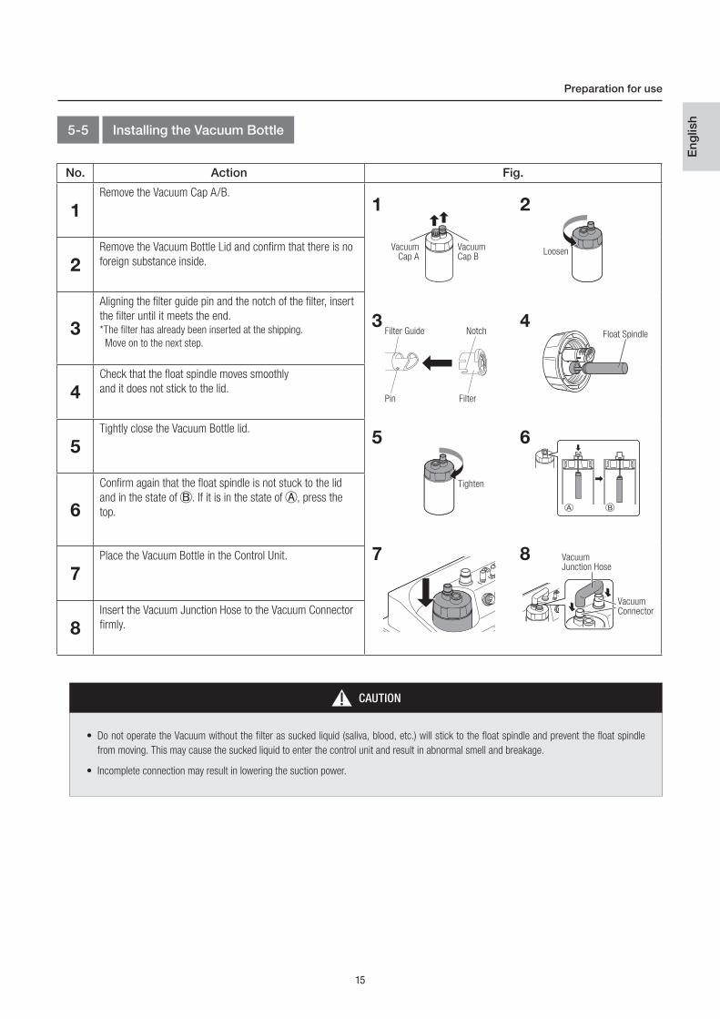
5-5 Installing the Vacuum Bottle
No. Action Fig.
1Remove the Vacuum Cap A/B.
2Remove the Vacuum Bottle Lid and confirm that there is no
foreign substance inside.
3
Aligning the filter guide pin and the notch of the filter, insert
the filter until it meets the end.*The filter has already been inserted at the shipping.
Move on to the next step.
4Check that the float spindle moves smoothly
and it does not stick to the lid.
5Tightly close the Vacuum Bottle lid.
6
Confirm again that the float spindle is not stuck to the lid
and in the state of . If it is in the state of , press the
top.
7Place the Vacuum Bottle in the Control Unit.
8 Insert the Vacuum Junction Hose to the Vacuum Connector
firmly.
21
4
6
8
3
5
7
VacuumCap B
LoosenVacuum
Cap A
Filter Guide
Pin
Notch
Filter
Float Spindle
Tighten
CAUTION
• Do not operate the Vacuum without the filter as sucked liquid (saliva, blood, etc.) will stick to the float spindle and prevent the float spindle
from moving. This may cause the sucked liquid to enter the control unit and result in abnormal smell and breakage.
• Incomplete connection may result in lowering the suction power.
VacuumJunction Hose
VacuumConnector
16
CAUTION
• Incomplete connection may cause the leakage of sucked liquid (saliva, blood, etc.)
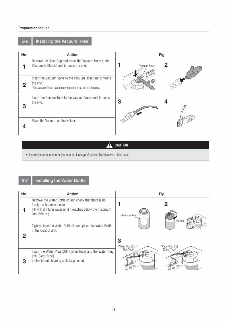
5-6 Installing the Vacuum Hose
Preparation for use
No. Action Fig.
1Remove the Hose Cap and insert the Vacuum Hose to the
Vacuum Bottle Lid until it meets the end.
2
Insert the Vacuum Valve to the Vacuum Hose until it meets
the end.
*The Vacuum Valve has already been inserted at the shipping.
3
Insert the Suction Tube to the Vacuum Valve until it meets
the end.
4Place the Vacuum on the Holder.
21
43
Vacuum Hose
5-7 Installing the Water Bottle
No. Action Fig.
1
Remove the Water Bottle lid and check that there is no
foreign substance inside.
Fill with drinking water until it reaches below the maximum
line (350 ml).
2
Tightly close the Water Bottle lid and place the Water Bottle
in the Control Unit.
3
Insert the Water Plug (OUT) [Blue Tube] and the Water Plug
(IN) [Clear Tube]
to the lid until hearing a clicking sound.
21
3
Maximum line
Tighten
Water Plug (OUT)[Blue Tube]
Water Plug (IN)[Clear Tube]
17
Eng
lish
Preparation for use
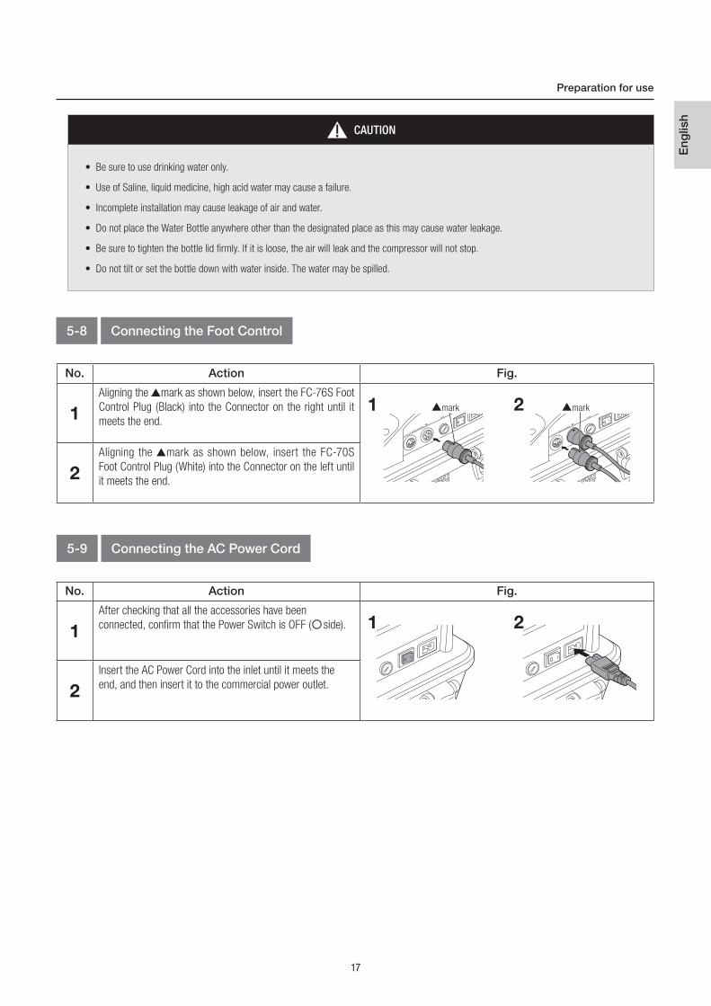
CAUTION
• Be sure to use drinking water only.
• Use of Saline, liquid medicine, high acid water may cause a failure.
• Incomplete installation may cause leakage of air and water.
• Do not place the Water Bottle anywhere other than the designated place as this may cause water leakage.
• Be sure to tighten the bottle lid firmly. If it is loose, the air will leak and the compressor will not stop.
• Do not tilt or set the bottle down with water inside. The water may be spilled.
5-8 Connecting the Foot Control
5-9 Connecting the AC Power Cord
No. Action Fig.
1
Aligning the mark as shown below, insert the FC-76S Foot
Control Plug (Black) into the Connector on the right until it
meets the end.
2
Aligning the mark as shown below, insert the FC-70S
Foot Control Plug (White) into the Connector on the left until
it meets the end.
21 mark mark
No. Action Fig.
1
After checking that all the accessories have been
connected, confirm that the Power Switch is OFF ( side).
2
Insert the AC Power Cord into the inlet until it meets the
end, and then insert it to the commercial power outlet.
21

18
Perform the following checks before using the product on a patient to confirm that there are no abnormalities. If abnormal vibration, noise, or
overheating is detected, stop using the product and contact your Authorized NSK Dealer.
Preparation for use
5-10 Check before treatment
CAUTION
• Wait before turning on and using the VIVA ace, until it has adapted to the ambient temperature (E.g. after a cold night in the car). Note the
admissible operation conditions (Reference: 12-1 Specifications).
• If the power switch is turned on without connecting the syringe to the control unit, water and air will blow out from the syringe connector.
Be sure to turn on the power switch after connecting.
No. Action
1 Check that there is no abnormal deformation or damage in the appearance.
2 Supply drinking water into the Water Bottle.
3 Confirm that all the accessories are properly connected.
4 Turn the Power Switch ON (l side), and confirm that the product is in the state of stand-by as defined below.
• The compressor is activated and stops after a few seconds.
• The liquid crystal display of the control panel lights and notification sound rings.
5 Start the Vacuum and confirm that it vacuums.
6 Activate the Syringe for about 5 seconds by pressing both the air button and the water button.
7 If VIVA ace Motor Kit (optional) is connected, connect the handpieces to the motor, attach the bur, and then activate the
motor for about 10 seconds while applying water. Also, confirm the points below.
• Check if there is any abnormal vibration, noise or overheating.
• Check that the handpiece supplies water properly.
• Check that the light on the motor is on.
8 If VIVA ace Scaler Kit (optional) is connected, connect the handpieces to the scaler cord plug, attach the tip, and then
activate the scaler for about 10 seconds while applying water. Also, confirm the points below.
• Check that the tip is vibrating properly.
• Check if there is any abnormal looseness, vibration, noise, or overheating with the tip.
• Check that the tip supplies water properly.
• Check that the light on the handpiece is on.
19
Eng
lish
Interval (min-1)
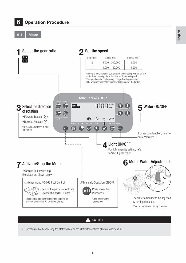
5,000
1,000
1:5
1:1
5,000 - 200,000
1,000 - 40,000
*When the motor is running, it displays the actual speed. When the
motor is not running, it displays the maximum set speed.
*The speed can be continuously changed during operation.
(The value increases/decreases by holding down the button.)
*This can be switched during
operation.
*This can be adjusted during operation
*The speed can be controlled by the stepping-in
pressure when using FC-76S Foot Control.
*Long press works
only for ON
• Forward Rotation
• Reverse Rotation
Two ways to activate/stop
the Motor are shown below:
When using FC-76S Foot Control Manually Operation ON/OFF
Step on the pedal Activate
Release the pedal Stop
Press more than
2 seconds
Light ON/OFFFor light quantity setting, refer
to “6-5 Light Probe”
The water amount can be adjusted
by turning the knob.
For Vacuum function, refer to
“6-4 Vacuum”
Motor Water Adjustment6
Operation Procedure6
Select the gear ratio
Select the direction of rotation
Activate/Stop the Motor
Water ON/OFF
Set the speed Gear Ratio Speed (min
-1)
CAUTION
• Operating without connecting the Motor will cause the Motor Connector to blow out water and air.
6-1 Motor
1 2
3 5
4
7

20
*This can be switched during operation
• Forward Rotation
• Reverse Rotation
*The speed can be controlled by the stepping-in
amount when using FC-76S Foot Control.
* Long press works
only for ON
When using FC-76S Foot Control Manually Operation ON/OFF
Step on the pedal Activate
Release the pedal Stop
Press more than
2 seconds
*This can be adjusted during operation
The water amount can be adjusted
by turning the knob.
NOTICE
• The Memory function does not work when
the direction of rotation is set R: Reverse
Rotation.
Operation Procedure
6-2 Motor <Endodontic treatment>
<Memory Function>
Various settings (speed, torque, and auto reverse setting) can be saved to
a memory number by pressing the Memory Key. 5 programs can be stored
during the ENDO Mode.
1. Press the MEMORY Key to show the number that is wished to be stored.
2. Select various setting (speed, torque, and auto reverse setting).
3. Long press the MEMORY Key for more than 1 second, the storing is finished
when the notification sound rings.
Interval (min-1)
50
100
100 - 1,000
1,000 - 5,000
*When the motor is running, it displays the actual speed. When the motor is not running, it displays the maximum set speed.
*The speed can be continuously changed during operation. (The value increases/decreases by holding down the button.)
Speed SettingChange to ENDO Mode
Select the program
Torque Setting
Light ON/OFF
Motor Water Adjustment
Select Auto Reverse function
Water ON/OFF
Select the direction of rotation
Activate/Stop the Motor
5 programs can be
stored.
Torque Setting :
0.3 - 3.0 N·cm
For light quantity setting,
refer to “6-5 Light Probe”
For Vacuum function, refer
to “6-4 Vacuum”
Speed (min-1)
31
24
7
9
58
6
Two ways to activate/stop the Motor
are shown below:
10
*Interval : 0.1 N·cm
21
Eng
lish
Operation Procedure
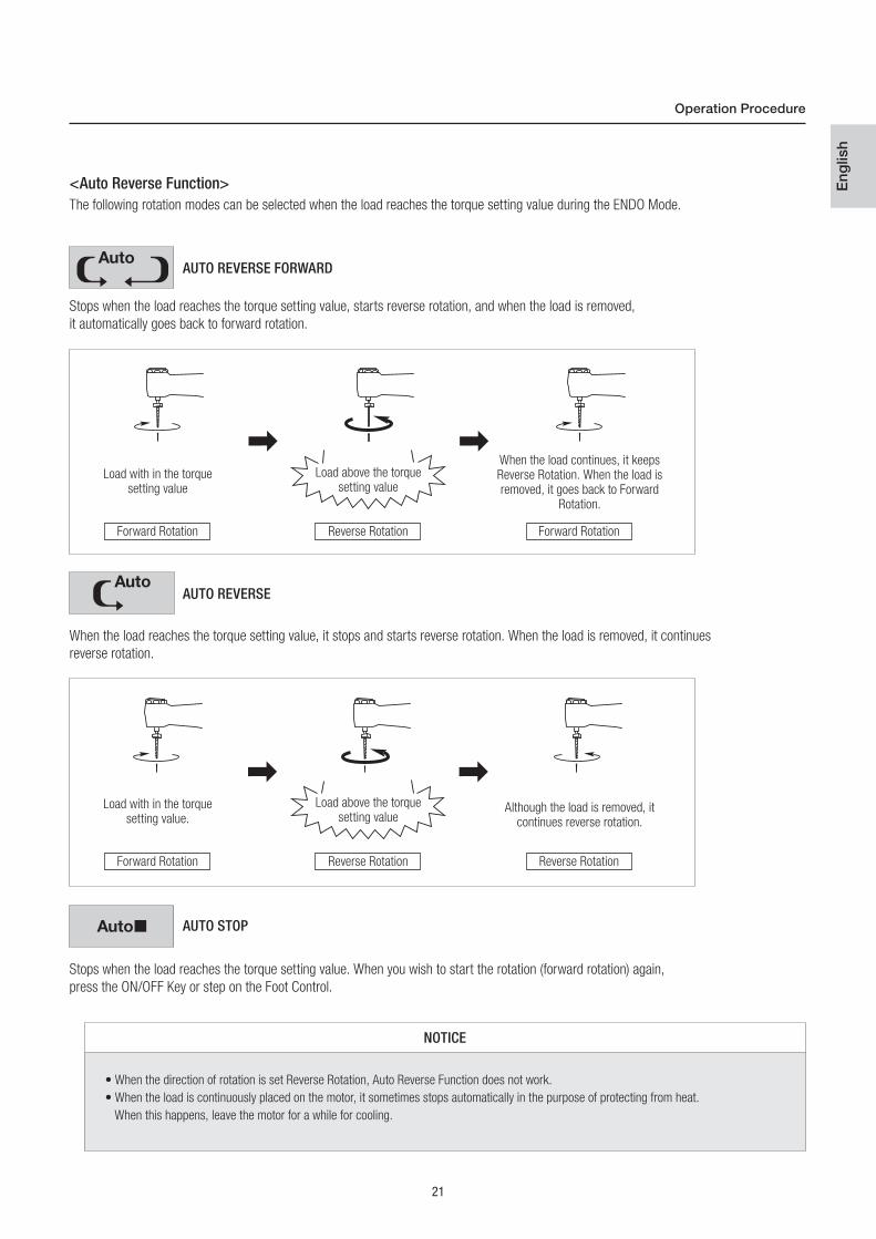
<Auto Reverse Function>
NOTICE
• When the direction of rotation is set Reverse Rotation, Auto Reverse Function does not work.
• When the load is continuously placed on the motor, it sometimes stops automatically in the purpose of protecting from heat.
When this happens, leave the motor for a while for cooling.
The following rotation modes can be selected when the load reaches the torque setting value during the ENDO Mode.
Stops when the load reaches the torque setting value, starts reverse rotation, and when the load is removed,
it automatically goes back to forward rotation.
When the load reaches the torque setting value, it stops and starts reverse rotation. When the load is removed, it continues
reverse rotation.
Stops when the load reaches the torque setting value. When you wish to start the rotation (forward rotation) again,
press the ON/OFF Key or step on the Foot Control.
AUTO REVERSE FORWARD
AUTO REVERSE
AUTO STOP
Load with in the torquesetting value
Load with in the torque setting value.
Forward Rotation
Forward Rotation
Reverse Rotation
Reverse Rotation
Forward Rotation
Reverse Rotation
Load above the torquesetting value
Load above the torquesetting value
When the load continues, it keepsReverse Rotation. When the load isremoved, it goes back to Forward
Rotation.
Although the load is removed, itcontinues reverse rotation.
22
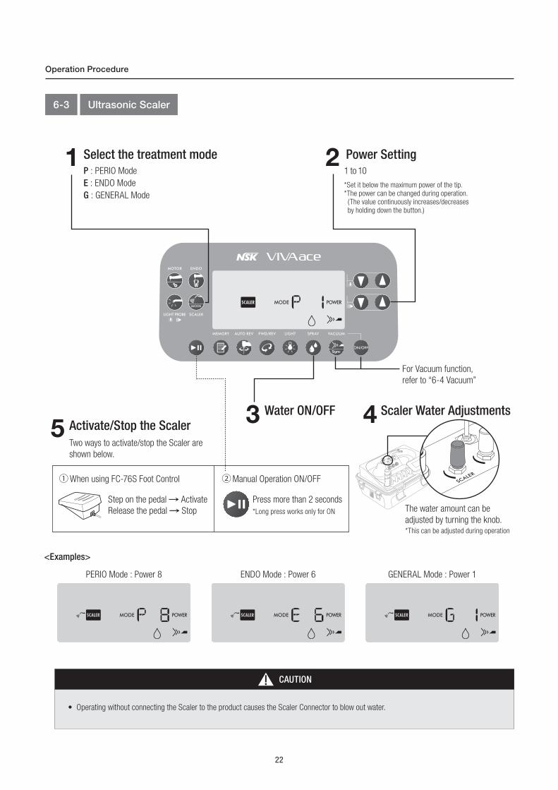
When using FC-76S Foot Control Manual Operation ON/OFF
Step on the pedal Activate
Release the pedal Stop
Press more than 2 seconds
*Long press works only for ON
*This can be adjusted during operation
The water amount can be
adjusted by turning the knob.
For Vacuum function,
refer to “6-4 Vacuum”
<Examples>
PERIO Mode : Power 8 ENDO Mode : Power 6 GENERAL Mode : Power 1
Operation Procedure
6-3 Ultrasonic Scaler
CAUTION
• Operating without connecting the Scaler to the product causes the Scaler Connector to blow out water.
Select the treatment mode
Activate/Stop the ScalerWater ON/OFF Scaler Water Adjustments
Power SettingP : PERIO Mode
E : ENDO Mode
G : GENERAL Mode
Two ways to activate/stop the Scaler are
shown below.
1 to 10
*Set it below the maximum power of the tip.
*The power can be changed during operation.
(The value continuously increases/decreases
by holding down the button.)
1
53 4
2

23
Eng
lish
The Vacuum can be synchronized with the Motor and the Scaler (except during Light Probe Mode). It can be set individually at each
Mode (MOTOR, ENDO, and SCALER), however the suction force value will remain the same.
Sync Mode (Synchro Mode)
Operation Procedure
6-4 Vacuum
DANGER
• Always check the Vacuum operates properly and perform suctioning accordingly. Adjust the suction force and the water amount according to
the patient’s condition. Refer to P58 “12-1 Specifications” for the suction force and suction amount for the Vacuum.
When the motor and the scaler are activated,
the Vacuum will be activated in conjunction.
Select the suction force
Long press the VACUUM Key
(More than 1 second)
Activate/Stop the Vacuum
Vacuum ON/OFFDuring treatment
Weak/Medium/Strong
Two ways to activate/stop the Vacuum
are shown below.
Linked
Not Linked
Suctioning stops by closing the
Vacuum Valve Lever.
VacuumValve Lever
Open
Close
1
2
3
When using FC-70S Foot Control
Manual Operation ON/OFF
Step on the pedal Activate
Release the pedal Stop

24
Pressing the both buttons at the
same time provides spray water.
The water amount can be adjusted by
turning the knob.
*This can be adjusted during operation
Operation Procedure
NOTICE
• Do not suck exceeding the maximum line (300 ml) of the Vacuum Bottle. Sucked liquid (saliva, blood, etc.) may get into the Control Unit
and cause abnormal smell or malfunction. When the device is operating normally, the Float Spindle controls the suctioning to prevent over
suctioning. Note that there is a risk that the float spindle may not work and over suctioning may occur in the case of abnormality. The device
should be placed on the level surface. If not, there is a risk that the sucked liquid may enter the Control Unit even when the device is
operating normally and the float spindle is working.
• Do not tilt or set the Vacuum Bottle down with sucked liquid inside. The liquid may be spilled.
• The Vacuum cannot be operated in other ways during the Sync Mode. The Vacuum stops a few seconds after the Motor and the Scaler stop.
6-5 Light Probe
6-6 3way Syringe
Syringe Water Adjustment Syringe ON/OFF1 2
Water ButtonWater comes out
when pressed
Air ButtonAir comes out
when pressed.
Connect the Light Probe
Light Quantity Setting
Light ON/OFFSelect the Light Probe Mode
Connect the isoE-LUX to
the MotorAdjustments can be made
in increments and is directly
reflected in the light quantity
of the MOTOR Mode
The light is automatically turned on.
1 3
42

25
Eng
lish
Operation Procedure
NOTICE
• When removing the Water Bottle, be sure to remove the Water Plug (IN) [Clear Tube] first.
• Note that if the Water Plug (OUT) [Blue Tube] is removed first, the water in the bottle will blow out for a moment. (Reference: 7-1 Preparation)
• When the Water Bottle (IN) [Clear Tube] is removed, the air in the bottle bursts out and makes a noise. This is not a failure.
6-7 When the Water Bottle is empty or the Vacuum Bottle is filled with liquid during use
WARNING
• Pay close attention when blowing air from the syringe nozzle toward the patient's gingiva because procedural accidents such as
subcutaneous emphysema could be caused. If any abnormality is detected, stop using the product and take appropriate procedures.
Turn off the Power Switch ( side).
Dispose of the sucked liquid (saliva, blood, etc.) in the Vacuum Bottle.
(Reference: 7-2-1 Cleaning (Vacuum Hose) )
Remove the Water Bottle and fill it with water.
1
2
3
• If the Air Button is pressed while residual water is inside the Syringe
Nozzle, the water will be mixed in the supplied air.
Before you use air supply only, gently shake the Syringe while
pressing the Air Button to thoroughly drain the residual water inside
the Syringe Nozzle.
NOTICE
26
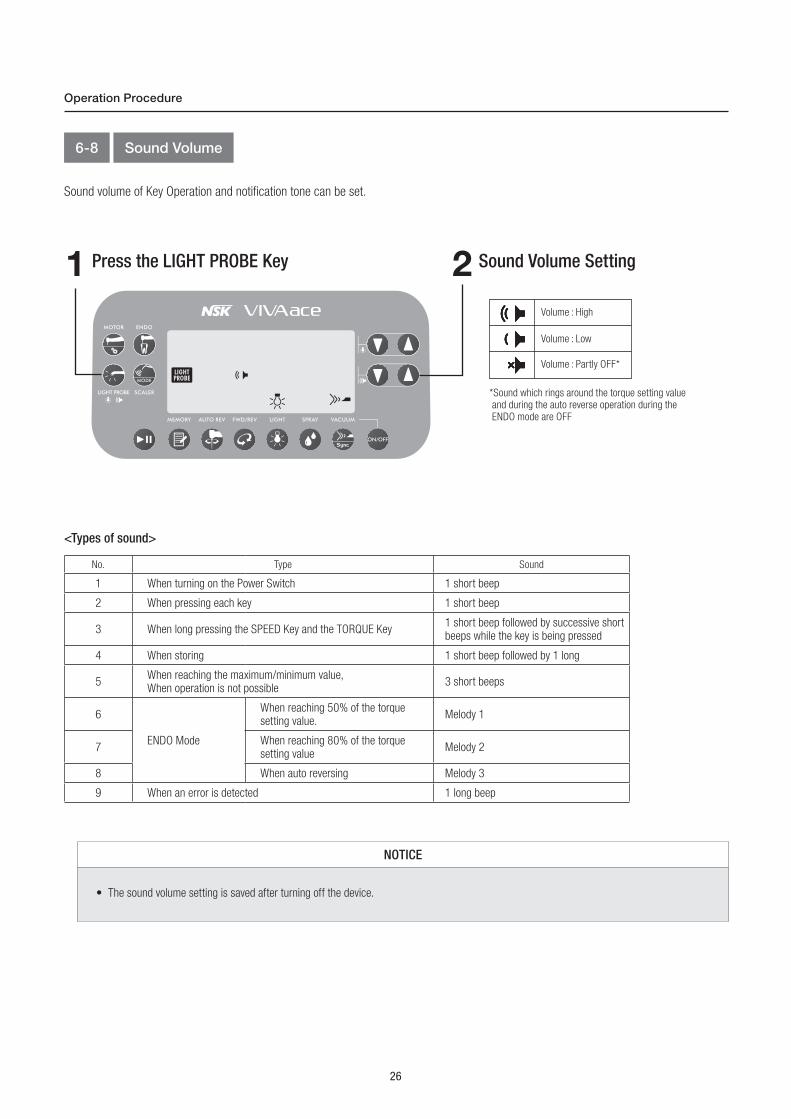
<Types of sound>
No. Type Sound
1 When turning on the Power Switch 1 short beep
2 When pressing each key 1 short beep
3 When long pressing the SPEED Key and the TORQUE Key1 short beep followed by successive short beeps while the key is being pressed
4 When storing 1 short beep followed by 1 long
5When reaching the maximum/minimum value, When operation is not possible
3 short beeps
6
ENDO Mode
When reaching 50% of the torque setting value.
Melody 1
7When reaching 80% of the torque setting value
Melody 2
8 When auto reversing Melody 3
9 When an error is detected 1 long beep
*Sound which rings around the torque setting value
and during the auto reverse operation during the
ENDO mode are OFF
Operation Procedure
6-8 Sound Volume
Sound volume of Key Operation and notification tone can be set.
NOTICE
• The sound volume setting is saved after turning off the device.
Volume : High
Volume : Low
Volume : Partly OFF*
Press the LIGHT PROBE Key Sound Volume Setting1 2

27
Eng
lish
<Factory Settings>
ModeSpeed
(min-1)
Torque
(N·cm)
PowerWater
Light
ON/OFF
Direction of
Rotation
Auto Reverse
Mode
Vacuum
suction
force
Sound
Volume Mode
MOTOR1,000
(Gear Ratio 1 : 1)- - OFF ON F : Forward
rotation
-
Strong
High
ENDO100
*All memories
together
0.3 *All memories
together
- OFF ON F : Forward rotation
AUTO REVERSE FORWARD
SCALER - -Power : 1
ON - - -Mode : P
LIGHT PROBE
- - - - ON - -
Operation Procedure
6-9 Last Memory Function
6-10 Initialization Program (Factory Setting)
About setting of the each mode after the Main Power was turned off.
In case of each mode (MOTOR, ENDO, SCALER, LIGHT PROBE):
-The setting will be back to an initial state, when turning on the Main power.
In case of light quantity, sound volume, and the Vacuum suction force:
-The last settings are saved.
The setting can be restored to the Factory Settings.
NOTICE
• Take note of present settings before initialization if needed.
• The setting of light quantity before initialization is kept.
NOTICE
• Settings other than the setting of light quantity, sound volume and the Vacuum suction force, go back to default every time the device is
turned on.
Turn off the Power Switch.
Turn on the Power Switch while pressing the MEMORY Key.
When a beep sound rings, initialization is finished.
1
2

28
The protection circuit will be activated and stop the device to prevent from danger and breakage when the device is operated with the load
exceeding its maximum value. The error code will be displayed in the display panel. (Reference:11-1 Error Code)
<Motor>The Motor will stop automatically due to failure, excessive load, disconnection and incorrect usage of the device. Protection function will work
and control the torque automatically to prevent the overheating of Motor Coil caused by excessive load.
flickers on the occasion.
When the protection function is released, the torque will automatically recover. During the MOTOR Mode, turns off, and during the
ENDO Mode, stops flickering.
<Scaler>When using exceeding the power 7 of the G Mode, and the inside being heated by long-time use, protection function will be activated and
lower the power automatically.
flickers on the occasion.
When protection function is released, flickering will be turned off. However, the power will not automatically go up over 8 for safety reasons.
Increase the power manually when needed.
Operation Procedure
6-11 Protection Circuit
NOTICE
• <Scaler>
While the protection function is working, ( flickering) it is not possible to higher the power over 7.
29
Eng
lish
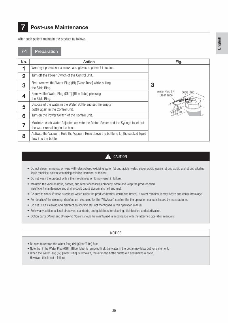
No. Action Fig.
1 Wear eye protection, a mask, and gloves to prevent infection.
2 Turn off the Power Switch of the Control Unit.
3First, remove the Water Plug (IN) [Clear Tube] while pulling
the Slide Ring.
4Remove the Water Plug (OUT) [Blue Tube] pressing
the Slide Ring.
5Dispose of the water in the Water Bottle and set the empty
bottle again in the Control Unit.
6 Turn on the Power Switch of the Control Unit.
7Maximize each Water Adjuster, activate the Motor, Scaler and the Syringe to let out
the water remaining in the hose.
8Activate the Vacuum. Hold the Vacuum Hose above the bottle to let the sucked liquid
flow into the bottle.
After each patient maintain the product as follows.
Post-use Maintenance7
7-1 Preparation
NOTICE
• Be sure to remove the Water Plug (IN) [Clear Tube] first.
• Note that if the Water Plug (OUT) [Blue Tube] is removed first, the water in the bottle may blow out for a moment.
• When the Water Plug (IN) [Clear Tube] is removed, the air in the bottle bursts out and makes a noise.
However, this is not a failure.
CAUTION
• Do not clean, immerse, or wipe with electrolyzed-oxidizing water (strong acidic water, super acidic water), strong acidic and strong alkaline
liquid medicine, solvent containing chlorine, benzene, or thinner.
• Do not wash the product with a thermo-disinfector. It may result in failure.
• Maintain the vacuum hose, bottles, and other accessories properly. Store and keep the product dried.
Insufficient maintenance and drying could cause abnormal smell and rust.
• Be sure to check if there is residual water inside the product (bottles, cords and hoses). If water remains, it may freeze and cause breakage.
• For details of the cleaning, disinfectant, etc. used for the "VIVAace", confirm the the operation manuals issued by manufacturer.
• Do not use a cleaning and disinfection solution etc. not mentioned in this operation manual.
• Follow any additional local directives, standards, and guidelines for cleaning, disinfection, and sterilization.
• Option parts (Motor and Ultrasonic Scaler) should be maintained in accordance with the attached operation manuals.
Water Plug (IN)[Clear Tube]
Slide Ring
3
30
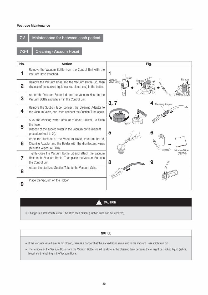
No. Action Fig.
1Remove the Vacuum Bottle from the Control Unit with the
Vacuum Hose attached.
2Remove the Vacuum Hose and the Vacuum Bottle Lid, then
dispose of the sucked liquid (saliva, blood, etc.) in the bottle.
3Attach the Vacuum Bottle Lid and the Vacuum Hose to the
Vacuum Bottle and place it in the Control Unit.
4Remove the Suction Tube, connect the Cleaning Adaptor to
the Vacuum Valve, and then connect the Suction Tube again.
5
Suck the drinking water (amount of about 200mL) to clean
the hose.
Dispose of the sucked water in the Vacuum bottle (Repeat
procedure No.1 to 2.).
6Wipe the surface of the Vacuum Hose, Vacuum Bottle,
Cleaning Adaptor and the Holder with the disinfectant wipes
(Minuten Wipes: ALPRO).
7Tightly close the Vacuum Bottle Lit and attach the Vacuum
Hose to the Vacuum Bottle. Then place the Vacuum Bottle in
the Control Unit.
8Attach the sterilized Suction Tube to the Vacuum Valve.
9Place the Vacuum on the Holder.
7-2 Maintenance for between each patient
7-2-1 Cleaning (Vacuum Hose)
Post-use Maintenance
NOTICE
• If the Vacuum Valve Lever is not closed, there is a danger that the sucked liquid remaining in the Vacuum Hose might run out.
• The removal of the Vacuum Hose from the Vacuum Bottle should be done in the cleaning tank because there might be sucked liquid (saliva,
blood, etc.) remaining in the Vacuum Hose.
CAUTION
• Change to a sterilized Suction Tube after each patient (Suction Tube can be sterilized).
Tighten
VacuumValve Lever
CloseRemove
1
3, 7
Minuten Wipes
(ALPRO)
6
Cleaning Adaptor4
8 9
5
Remove
Tighten
31
Eng
lish
Operation Procedure
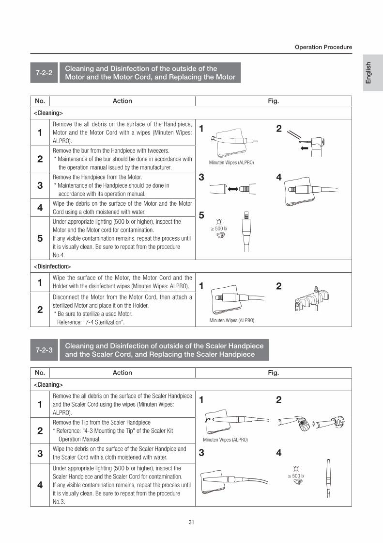
7-2-2Cleaning and Disinfection of the outside of the Motor and the Motor Cord, and Replacing the Motor
No. Action Fig.
<Cleaning>
1Remove the all debris on the surface of the Handipiece,
Motor and the Motor Cord with a wipes (Minuten Wipes:
ALPRO).
2Remove the bur from the Handpiece with tweezers.
* Maintenance of the bur should be done in accordance with
the operation manual issued by the manufacturer.
3Remove the Handpiece from the Motor.
* Maintenance of the Handpiece should be done in
accordance with its operation manual.
4Wipe the debris on the surface of the Motor and the Motor
Cord using a cloth moistened with water.
5
Under appropriate lighting (500 lx or higher), inspect the
Motor and the Motor cord for contamination.
If any visible contamination remains, repeat the process until
it is visually clean. Be sure to repeat from the procedure
No.4.
<Disinfection>
1Wipe the surface of the Motor, the Motor Cord and the
Holder with the disinfectant wipes (Minuten Wipes: ALPRO).
2
Disconnect the Motor from the Motor Cord, then attach a
sterilized Motor and place it on the Holder.
* Be sure to sterilize a used Motor.
Reference: "7-4 Sterilization".
1 2
3 4
5
1 2
7-2-3Cleaning and Disinfection of outside of the Scaler Handpiece and the Scaler Cord, and Replacing the Scaler Handpiece
No. Action Fig.
<Cleaning>
1Remove the all debris on the surface of the Scaler Handpiece
and the Scaler Cord using the wipes (Minuten Wipes:
ALPRO).
2Remove the Tip from the Scaler Handpiece
* Reference: "4-3 Mounting the Tip" of the Scaler Kit
Operation Manual.
3Wipe the debris on the surface of the Scaler Handpice and
the Scaler Cord with a cloth moistened with water.
4
Under appropriate lighting (500 lx or higher), inspect the
Scaler Handpiece and the Scaler Cord for contamination.
If any visible contamination remains, repeat the process until
it is visually clean. Be sure to repeat from the procedure
No.3.
≥ 500 lx
1 2
3 4
Minuten Wipes (ALPRO)
≥ 500 lx
≥ 500 lx
Minuten Wipes (ALPRO)
Minuten Wipes (ALPRO)

32
Action Fig.
Objects: Control Unit, Top Case, Top Cover Case, Shoulder Belt,
Spanner.
Turn off the power switch of the Control Unit and take out all the
accessories. After wiping the water with wrung out cloth, wipe with
the disinfectant wipes (Minuten Wipes: ALPRO).
No. Action Fig.
<Cleaning>
1
Remove the Syringe Nozzle from the Syringe Body.
Syringe Body: Proceed to the procedure No.2
Syringe Nozzle: Proceed to the "7-3-9 Cleaning and
Disinfection (Syringe, Syringe Nozzle)".
2Remove the debris on the surface of the Syringe Body with a
plastic brush (do not use the wire brush.).
3Wipe the Syringe Body with a cloth moistened with water.
4
After cleaning, under appropriate lighting (500 lx or higher),
inspect the Syringe Body for contamination.
If any visible contamination remains, repeat the process until
it is visually clean. Be sure to repeat from the procedure No. 2.
<Disinfection>
1Wipe the surface of the Syringe Body with the disinfectant
wipes (Minuten Wipes: ALPRO).
2
Attach a sterilized Syringe Nozzle to the Syringe Body and
place it on the Holder.
* Be sure to sterilize a used Syringe Nozzle, refer to section
"7-4 Sterilization".
Post-use Maintenance
7-2-3Cleaning and Disinfection of outside of the Scaler Handpiece and the Scaler Cord, and Replacing the Scaler Handpiece (continued)
No. Action Fig.
<Disinfection>
1Wipe the surface of the Scaler Handpiece and the Scaler
Cord with the disinfectant wipes (Minuten Wipes: ALPRO).
2
Disconnect the Scaler Handpiece from the Scaler Cord,
then attach a sterilized Scaler Handpiece and place it on the
Holder.
* Be sure to clean, disinfect and sterilize a used Scaler
Handpiece and the Tip. Reference: Scaler Kit Operation
Manual.
21
7-2-4 Cleaning (Syringe) and Replacing of the Syringe Nozzle
7-2-5 Cleaning (Control Unit etc.)
1
Minuten Wipes (ALPRO)
4
1
≥ 500 lx
Minuten Wipes (ALPRO)
33
Eng
lish
No. Action Fig.
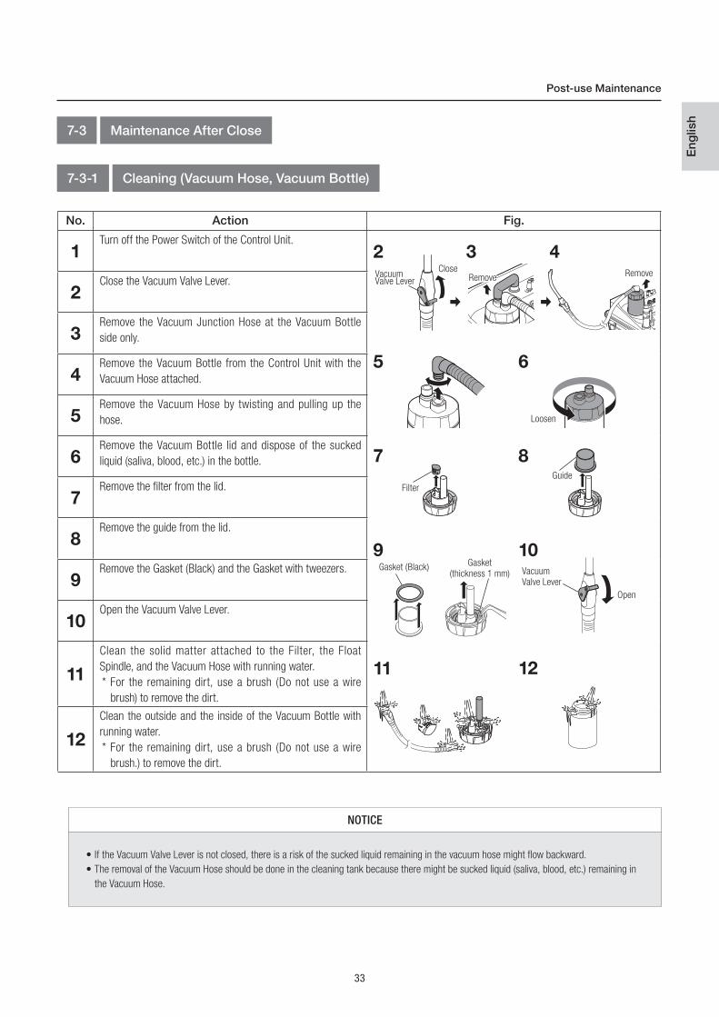
1Turn off the Power Switch of the Control Unit.
2Close the Vacuum Valve Lever.
3Remove the Vacuum Junction Hose at the Vacuum Bottle
side only.
4Remove the Vacuum Bottle from the Control Unit with the
Vacuum Hose attached.
5Remove the Vacuum Hose by twisting and pulling up the
hose.
6Remove the Vacuum Bottle lid and dispose of the sucked
liquid (saliva, blood, etc.) in the bottle.
7Remove the filter from the lid.
8Remove the guide from the lid.
9Remove the Gasket (Black) and the Gasket with tweezers.
10Open the Vacuum Valve Lever.
11
Clean the solid matter attached to the Filter, the Float
Spindle, and the Vacuum Hose with running water.
* For the remaining dirt, use a brush (Do not use a wire
brush) to remove the dirt.
12
Clean the outside and the inside of the Vacuum Bottle with
running water.
* For the remaining dirt, use a brush (Do not use a wire
brush.) to remove the dirt.
Post-use Maintenance
7-3 Maintenance After Close
7-3-1 Cleaning (Vacuum Hose, Vacuum Bottle)
VacuumValve Lever
CloseRemove
2 3 4
NOTICE
• If the Vacuum Valve Lever is not closed, there is a risk of the sucked liquid remaining in the vacuum hose might flow backward.
• The removal of the Vacuum Hose should be done in the cleaning tank because there might be sucked liquid (saliva, blood, etc.) remaining in
the Vacuum Hose.
Gasket (Black)Gasket
(thickness 1 mm)
65
8Guide
109
1211
Loosen
7
Filter
Vacuum
Valve Lever
Open
Remove
34
1
Gasket (Black)16
Post-use Maintenance
No. Action Fig.
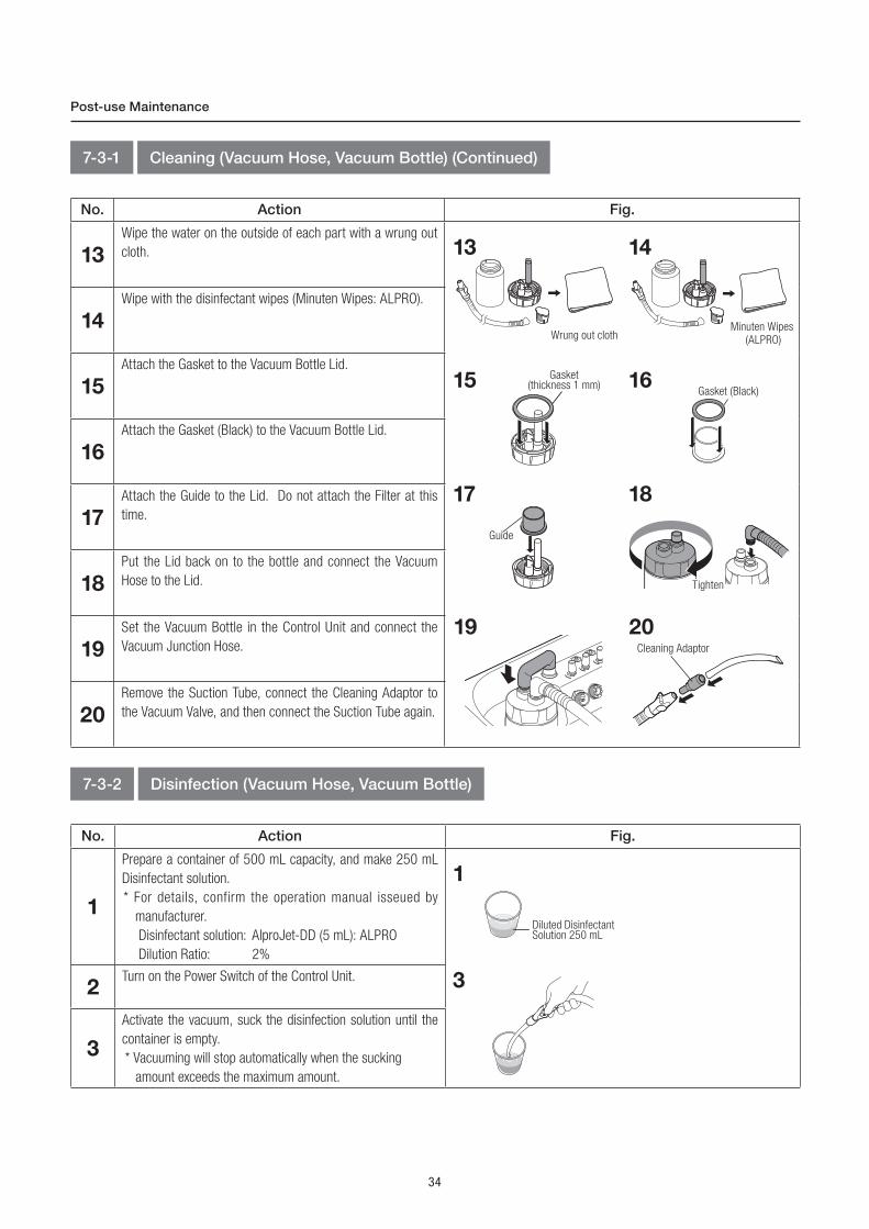
13
Wipe the water on the outside of each part with a wrung out
cloth.
14
Wipe with the disinfectant wipes (Minuten Wipes: ALPRO).
15
Attach the Gasket to the Vacuum Bottle Lid.
16
Attach the Gasket (Black) to the Vacuum Bottle Lid.
17
Attach the Guide to the Lid. Do not attach the Filter at this
time.
18
Put the Lid back on to the bottle and connect the Vacuum
Hose to the Lid.
19
Set the Vacuum Bottle in the Control Unit and connect the
Vacuum Junction Hose.
20
Remove the Suction Tube, connect the Cleaning Adaptor to
the Vacuum Valve, and then connect the Suction Tube again.
7-3-1 Cleaning (Vacuum Hose, Vacuum Bottle) (Continued)
13 14
Wrung out cloth
15 Gasket(thickness 1 mm)
Guide
17
Tighten
18
19Cleaning Adaptor
20
7-3-2 Disinfection (Vacuum Hose, Vacuum Bottle)
No. Action Fig.
1
Prepare a container of 500 mL capacity, and make 250 mL
Disinfectant solution.
* For details, confirm the operation manual isseued by
manufacturer.
Disinfectant solution: AlproJet-DD (5 mL): ALPRO
Dilution Ratio: 2%
2Turn on the Power Switch of the Control Unit.
3
Activate the vacuum, suck the disinfection solution until the
container is empty.
* Vacuuming will stop automatically when the sucking
amount exceeds the maximum amount.
Diluted Disinfectant Solution 250 mL
3
Minuten Wipes
(ALPRO)

35
Eng
lish
Post-use Maintenance
CAUTION
• Do not attach the Filter to the Vacuum Bottle Lid, when disinfecting the Vacuum Hose and the Vacuum Bottle with the Alpro Jet-DD (ALPRO).
No. Action Fig.
4Close the Vacuum Valve Lever.
5Stop VACUUM and then turn off the Power Switch of the
Control Unit.
6Remove the Vacuum Junction Hose from the Vacuum Bottle
side only.
7Remove the Vacuum Bottle from the Control Unit with the
Vacuum Hose attached.
8Remove the Vacuum Hose by twisting and pulling up the
Vacuum Hose.
9Remove the Vacuum Bottle Lid and dispose the sucked
disinfectant solution of the inside of the bottle.
10Open the Vacuum Valve Lever.
11Remove the Suction Tube and the Cleaning Adaptor.
12Clean the Vacuum Hose, Vacuum Bottle, Suction Tube,
Vacuum Valve, and the Cleaning Adaptor under running
water.
13Wipe the water on the surface of the Vacuum Hose, Vacuum
Bottle, Suction Tube, Vacuum Valve and the Cleaning Adaptor
with a wrung out cloth.
14Remove the Guide from the Lid.
15Remove the Gasket (Black) and the Gasket with tweezers.
16
Prepare an empty container and make the Disinfectant
Solution.
*For details, confirm the operation manual issued by
manufacturer.
Disinfectant solution: AlproJet-DD (ALPRO)
Dilution Ratio: 2%
17
Soak the Guide, Lid, Gasket (black), Gasket (Thickness
1mm), Filter, Vacuum Cap A/B, Hose Cap, Vacuum Bottle,
Vacuum Hose, Suction Tube and Cleaning Adaptor in the
Disinfectant Solution for a night.
VacuumValve Lever
CloseRemove
4 6 7
8
Loosen
9
VacuumValve Lever
10Cleaning Adaptor
Gasket (Black)Gasket
(thickness 1mm)
Diluted Disinfectant solution
11
12
15
14
16
Guide
17
NOTICE
• If the Vacuum Valve Lever is not closed, there is a danger that the disinfectant solution remaining in the Vacuum hose might flow backward.
36
Post-use Maintenance
7-3-3 Cleaning (Water Bottle)
7-3-4 Cleaning and Disinfection of the outside of the Motor and the Motor Cord
No. Action Fig.
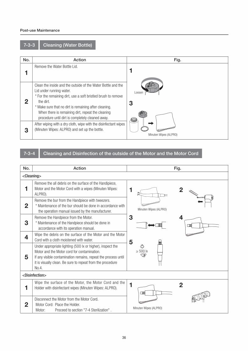
1
Remove the Water Bottle Lid.
2
Clean the inside and the outside of the Water Bottle and the
Lid under running water.
* For the remaining dirt, use a soft bristled brush to remove
the dirt.
* Make sure that no dirt is remaining after cleaning.
When there is remaining dirt, repeat the cleaning
procedure until dirt is completely cleaned away.
3
After wiping with a dry cloth, wipe with the disinfectant wipes
(Minuten Wipes: ALPRO) and set up the bottle.
1
3
Loosen
Minuten Wipes (ALPRO)
No. Action Fig.
<Cleaning>
1Remove the all debris on the surface of the Handipiece,
Motor and the Motor Cord with a wipes (Minuten Wipes:
ALPRO).
2Remove the bur from the Handpiece with tweezers.
* Maintenance of the bur should be done in accordance with
the operation manual issued by the manufacturer.
3Remove the Handpiece from the Motor.
* Maintenance of the Handpiece should be done in
accordance with its operation manual.
4Wipe the debris on the surface of the Motor and the Motor
Cord with a cloth moistened with water.
5
Under appropriate lighting (500 lx or higher), inspect the
Motor and the Motor cord for contamination.
If any visible contamination remains, repeat the process until
it is visually clean. Be sure to repeat from the procedure
No.4.
<Disinfection>
1Wipe the surface of the Motor, the Motor Cord and the
Holder with disinfectant wipes (Minuten Wipes: ALPRO).
2Disconnect the Motor from the Motor Cord.
Motor Cord: Place the Holder.
Motor: Proceed to section "7-4 Sterilization" .
1 2
3 4
5
1 2
Minuten Wipes (ALPRO)
Minuten Wipes (ALPRO)
≥ 500 lx

37
Eng
lish
Post-use Maintenance
No. Action Fig.
<Cleaning>
1Remove the all debris on the surface of the Scaler Handpiece
and the Scaler Cord with the wipes (Minuten Wipes: ALPRO).
2
Remove the Tip from the Scaler Handpiece.
Remove the Scaler Handpiece from the Scaler Cord.
* Reference "4-3 Mounting the Tip" of the Scaler Kit
Operation Manual.
* Maintenance of the Tip and the Tip Wrench, refer to the
Scaler Kit Operation Manual.
3
Clean the surface of the Scaler Handpiece under running
water with a soft bristled brush for more than 20 seconds.
Water temperature: 38C° or less
Water quality: Water available as drinking water
Water amount: 3.5L/min or more
4Wipe the residual moisture on the surface of the Scaler
Handpiece with a dry cloth.
5
After cleaning, under appropriate lighting (500 lx or higher),
inspect the Scaler Handpiece for contamination.
If any visible contamination remains, repeat the process until
it is visually clean. Be sure to repeat from the procedure No. 3.
1 2
7-3-5 Cleaning of the outside of the Scaler Handpiece
3
Minuten Wipes (ALPRO)
4
5
≥ 500 lx
7-3-6Cleaning and Disinfection of the inside of the Scaler Handpiece (Including the Water Line)
CAUTION
• Be sure to perform Cleaning and Disinfection the "7-3-5 Cleaning of the outside of the Scaler Handpiece" before "7-3-6 Cleaning and
Disinfection of the inside of the Scaler Handpiece (Including the Water Line)"
• After disinfection, be sure to sterilize the Scaler Handpiece. Reference: "7-4 Sterilization".
• When using the each Spray (ALPRO), be sure to cover the tip of the Scaler Handpiece with a cloth, etc. to prevent the dispersal of the
cleaning solution and the disinfecting solution in the surrounding area. It is recommended to use a Spray Mist Absorber (Y900084).

38
No. Action Fig.
1Attach the WL-Adapter 01 (ALPRO) to the WL-clean (ALPRO) and contact the
Water Connector on the Scaler Handpiece to the end of the WL-Adapter 01
(ALPRO).
2
Spray the WL-clean (ALPRO) to the Water Connector on the Scaler Handpiece
with hold the Scaler Handpiece and the WL-clean (ALPRO), clean the inside of
Water Line.
For details, confirm the operation manuals issued by manufacturer.
Spray time: 2 seconds
Number of spray: 3 times
3
Release the Water Connector on the Scaler Handpiece from the WL-Adapter 01
(ALPRO) and remove the WL-Adapter 01 (ALPRO) from the WL-clean (ALPRO).
Place the Scaler Handpiece onto the tray for at least 1 minute to take effect.
4
Wipe the surface of the Scaler Handpiece with the
disinfectant wipes ( Minuten Wipes: ALPRO).
5
Attach the WL-Adapter 01 (ALPRO) to the WL-cid (ALPRO) and contact the Water
Connector on the Scaler Handpiece to the end of the WL-Adapter 01 (ALPRO).
6
Spray the WL-cid (ALPRO) to the Water Connector on the Scaler Handpiece with
hold the Scaler Handpiece and the WL-cid (ALPRO), disinfect the inside of Water
Line.
For details, confirm the operation manuals issued by manufacturer.
Spray time: 3 seconds
Number of spray: 1 time
7
Release the Water Connector on the Scaler Handpiece from the WL-Adapter 01
(ALPRO) and remove the WL-Adapter 01 (ALPRO) from the WL-cid (ALPRO).
Place the Scaler Handpiece onto the tray for at least 2 minutes to take effect.
8
Attach the WL-Adapter 01 (ALPRO) to the WL-dry (ALPRO) or the WL-Blow
(ALPRO) and contact the Water Connector on the end of the Scaler Handpiece to
the end of the WL-Adapter 01 (ALPRO).
7-3-6-1Manual Cleaning and Disinfection (Including the Water line) (In case of connecting to the adapter)
WL-Adapter 01 (ALPRO) is to be prepared by customers.
Cleaning and Disinfection should be done in the cleaning tank.
Post-use Maintenance
1, 5 Water Connector
WL-Adapter 01(ALPRO)
2, 6
3, 7
4
Minuten Wipes (ALPRO)
8 · When using the WL-dry (ALPRO):
Water Connector
WL-Adapter 01(ALPRO)
· When using the WL-Blow (ALPRO):
Water Connector
WL-Adapter 01(ALPRO)
WL-dry (ALPRO)
WL-Blow (ALPRO)

39
Eng
lish
Post-use Maintenance
No. Action Fig.
9
Discharge the disinfectant solution from the Water Line on the Scaler Handpiece.
For details, confirm the operation manuals issued by manufacturer.
· When using the WL-dry (ALPRO):
Spray time: 3 seconds
Number of spray: 1 time
· When using the WL-Blow (ALPRO):
Air blow time: 3 seconds
Number of blast: 1 time
10
Release the Water Connector on the Scaler Handpiee from the WL-Adapter 01
(ALPRO) and remove the WL-Adapter 01 (ALPRO) from the WL-dry (ALPRO) or
the WL-Blow (ALPRO).
11
Proceed to section "7-3-7 Cleaning of the Glass Rod" and "7-4 Sterilization".
9 · When using the WL-dry (ALPRO):
· When using the WL-Blow (ALPRO):
10 · When using the WL-dry (ALPRO):
· When using the WL-Blow (ALPRO):
CAUTION
• Be sure to discharge the remained solution from the inside of the Scaler Handpiece with the WL-dry (ALPRO) or the WL-Blow (ALPRO), after
cleaning and disinfection with the WL-clean (ALPRO) and the WL-cid (ALPRO).
• After cleaning and disinfection of the Scaler Handpiece, be sure to clean the Glass Rod and sterilize the Scaler Handpiece. Reference: "7-3-7
Cleaning of the Glass Rod" and "7-4 Sterilization".
WL-dry (ALPRO)
WL-Blow (ALPRO)
WL-dry (ALPRO)
WL-Blow (ALPRO)
40
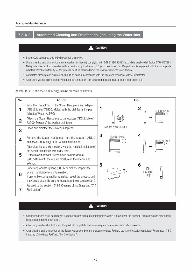
No. Action Fig.
1Wipe the contact part of the Scaler Handpiece and adapter
(ADS 2: Miele/ 73900: Melag) with the disinfectant wipes
(Minuten Wipes: ALPRO).
2Attach the Scaler Handpiece to the Adapter (ADS 2: Miele/
73900: Melag) of the washer-disinfector.
3Clean and disinfect the Scaler Handpiece.
4Remove the Scaler Handpiece from the Adapter (ADS 2:
Miele/73900: Melag) of the washer-disinfector.
5
After cleaning and disinfection, wipe the residual moisture of
the Scaler Handpiece with a dry cloth.
Or the blow it off with filtered clean compressed air
(≤0.35MPa) until there is no moisture in the interior and
exterior.
6
Under appropriate lighting (500 lx or higher), inspect the
Scaler Handpiece for contamination.
If any visible contamination remains, repeat the process until
it is visually clean. Be sure to repeat from the procedure No. 2.
7Proceed to the section "7-3-7 Cleaning of the Glass and "7-4
Sterilization".
Post-use Maintenance
Adapter (ADS 2: Miele/73900: Melag) is to be prepared customers.
7-3-6-2 Automated Cleaning and Disinfection (Including the Water line)
CAUTION
• Scaler Cord cannot be cleaned with washer-disinfector.
• Use a cleaning and disinfection device (washer-disinfector) complying with DIN EN ISO 15883 (e.g. Miele washer-disinfector G7781/G7881;
Melag Melatherm), that operates with a maximum pH value of 10.5 (e.g. neodisher, Dr. Weigert) and is equipped with the appropriate
adapters. Proof of suitability for the process must be obtained from the washer-disinfector manufacturer.
• Automated cleaning and disinfection should be done in accordance with the operation manual of washer-disinfector.
• After using washer-disinfector, dry the product completely. The remaining moisture causes internal corrosion etc.
Minuten Wipes (ALPRO)
1
5 6
2ISO 15883-1
4ISO 15883-1
3 ISO 15883-1
≥ 500 lx
CAUTION
• Scaler Handpiece must be removed from the washer-disinfector immediately (within 1 hour) after the cleaning, disinfecting and drying cycle
is complete to prevent corrosion.
• After using washer-disinfector, dry the product completely. The remaining moisture causes internal corrosion etc.
• After cleaning and disinfection of the Scaler Handpiece, be sure to clean the Glass Rod and sterilize the Scaler Handpiece. Reference: "7-3-7
Cleaning of the Glass Rod" and "7-4 Sterilization".
41
Eng
lish
Post-use Maintenance
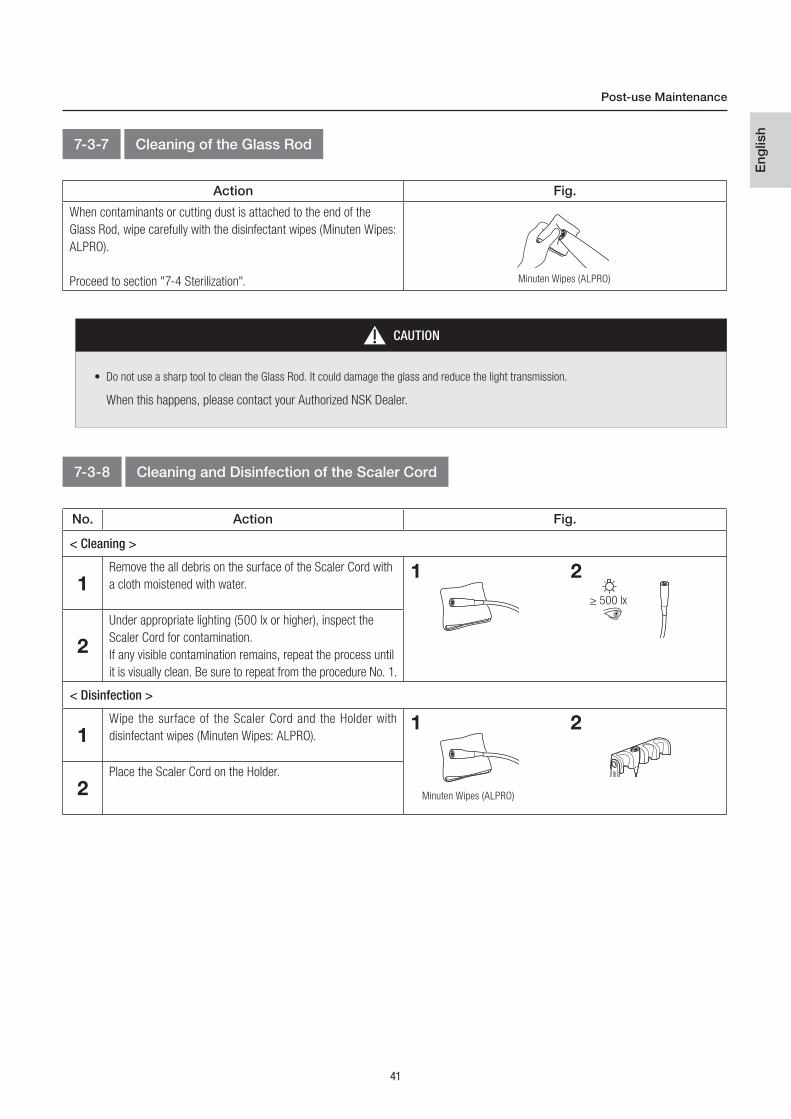
7-3-7 Cleaning of the Glass Rod
Action Fig.
When contaminants or cutting dust is attached to the end of the
Glass Rod, wipe carefully with the disinfectant wipes (Minuten Wipes:
ALPRO).
Proceed to section "7-4 Sterilization". Minuten Wipes (ALPRO)
CAUTION
• Do not use a sharp tool to clean the Glass Rod. It could damage the glass and reduce the light transmission.
When this happens, please contact your Authorized NSK Dealer.
7-3-8 Cleaning and Disinfection of the Scaler Cord
No. Action Fig.
< Cleaning >
1Remove the all debris on the surface of the Scaler Cord with
a cloth moistened with water.
2
Under appropriate lighting (500 lx or higher), inspect the
Scaler Cord for contamination.
If any visible contamination remains, repeat the process until
it is visually clean. Be sure to repeat from the procedure No. 1.
< Disinfection >
1Wipe the surface of the Scaler Cord and the Holder with
disinfectant wipes (Minuten Wipes: ALPRO).
2Place the Scaler Cord on the Holder.
1 2
2
≥ 500 lx
1
Minuten Wipes (ALPRO)
42
Post-use Maintenance
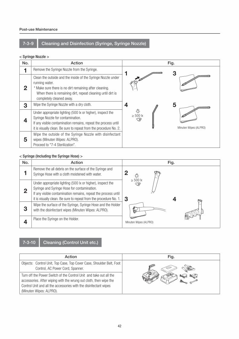
No. Action Fig.
1 Remove the Syringe Nozzle from the Syringe.
2
Clean the outside and the inside of the Syringe Nozzle under
running water.
* Make sure there is no dirt remaining after cleaning.
When there is remaining dirt, repeat cleaning until dirt is
completely cleaned away.
3 Wipe the Syringe Nozzle with a dry cloth.
4
Under appropriate lighting (500 lx or higher), inspect the
Syringe Nozzle for contamination.
If any visible contamination remains, repeat the process until
it is visually clean. Be sure to repeat from the procedure No. 2.
5Wipe the outside of the Syringe Nozzle with disinfectant
wipes (Minuten Wipes: ALPRO).
Proceed to "7-4 Sterilization".
1 3
4
7-3-9 Cleaning and Disinfection (Syringe, Syringe Nozzle)
< Syringe Nozzle >
≥ 500 lx
5
Minuten Wipes (ALPRO)
No. Action Fig.
1Remove the all debris on the surface of the Syringe and
Syringe Hose with a cloth moistened with water.
2
Under appropriate lighting (500 lx or higher), inspect the
Syringe and Syringe Hose for contamination.
If any visible contamination remains, repeat the process until
it is visually clean. Be sure to repeat from the procedure No. 1.
3Wipe the surface of the Syringe, Syringe Hose and the Holder
with the disinfectant wipes (Minuten Wipes: ALPRO).
4Place the Syringe on the Holder.
< Syringe (Including the Syringe Hose) >
4
Minuten Wipes (ALPRO)
3
7-3-10 Cleaning (Control Unit etc.)
Action Fig.
Objects: Control Unit, Top Case, Top Cover Case, Shoulder Belt, Foot
Control, AC Power Cord, Spanner.
Turn off the Power Switch of the Control Unit and take out all the
accessories. After wiping with the wrung out cloth, then wipe the
Control Unit and all the accessories with the disinfectant wipes
(Minuten Wipes: ALPRO).
2≥ 500 lx
43
Eng
lish
Post-use Maintenance
7-4 Sterilization
Autoclave the Suction Tube and the Syringe Nozzle. Sterilization of the Handpieces, the Motor, the Scaler Handpieces, the Tips and the Tip
Wrench should be done in accordance with each operation manual. After each patient, sterilize the parts as follows.
Type Gravity DisplacementPre-Vacuum
(Dynamic Air Removal)
Temperature 121°C (0 / +4°C) 132°C (0 / +4°C) 134°C (0 / +4°C)
Full Cycle Time 20 min or longer 15 min or longer 3-18 min
Drying Time 30 min or longer 30 min or longer 30 min or longer
< Motor / Scaler Handpiece / Syringe Nozzle >
< Suction Tube >
TypePre-Vacuum
(Dynamic Air Removal)
Temperature 134°C (0 / +1°C)
Full Cycle Time 3-18 min
Drying Time 30 min or longer
Store the product in a place where it is kept clean and keep it in a sterilization pouch until it is used next.
Insert the autoclavable products and parts individually into a sterilization case or sterilization pouch that conform to ISO 11607-1, and seal the
pouch or use the sterilization cassette.
In case of sterilization cassette, insert the Scaler Handpiece, Tip and the Tip Wrench individually into a sterilization cassette then insert the
sterilization cassette into a sterilization pouch that conform to ISO 11607-1, and seal the pouch.
Perform autoclave sterilization as follows.
7-4-1 Preparation before sterilization
7-4-2 Sterilization
44
Post-use Maintenance
CAUTION
• Only the Suction Tube and the Syringe Nozzle can be sterilized. No other parts can be sterilized.
Option parts (Motor and Ultrasonic Scaler) should be maintained in accordance with the attached operation manuals.
• Do not autoclave the product with other instruments even when it is in a pouch. This is to prevent possible discoloration and damage to
the product from chemical residue on other instruments.
• Do not heat or cool the product too quickly. Rapid change in temperature could cause damage to the product.
• To avoid product failure, do not use a sterilizer that exceeds a cycle temperature of 138°C, including the dry cycle.
In some sterilizers, the chamber temperature may exceed 138°C. Contact the sterilizer manufacturer for detailed information about cycle
temperatures.
• Keep the product in suitable atmospheric pressure, temperature, humidity, ventilation, and sunlight. The air should be free from dust,
salt and sulphur.
• Do not touch the product immediately after autoclaving as it will be very hot and must remain in a sterile condition.
• Autoclave sterilization is recommended for the product. The validity of other sterilization methods is not confirmed.
• Ultraviolet sterilization is not recommended. This could cause discoloration.
<Suction Tube>
• The expected lifetime may vary by the use condition; approximate lifetime is about 20 sterilizations.
• Be careful not to exceed 135˚C during the drying process. It may cause deformation.
7-4-2 Sterilization (Continued)
7-5 Maintenance before Use.
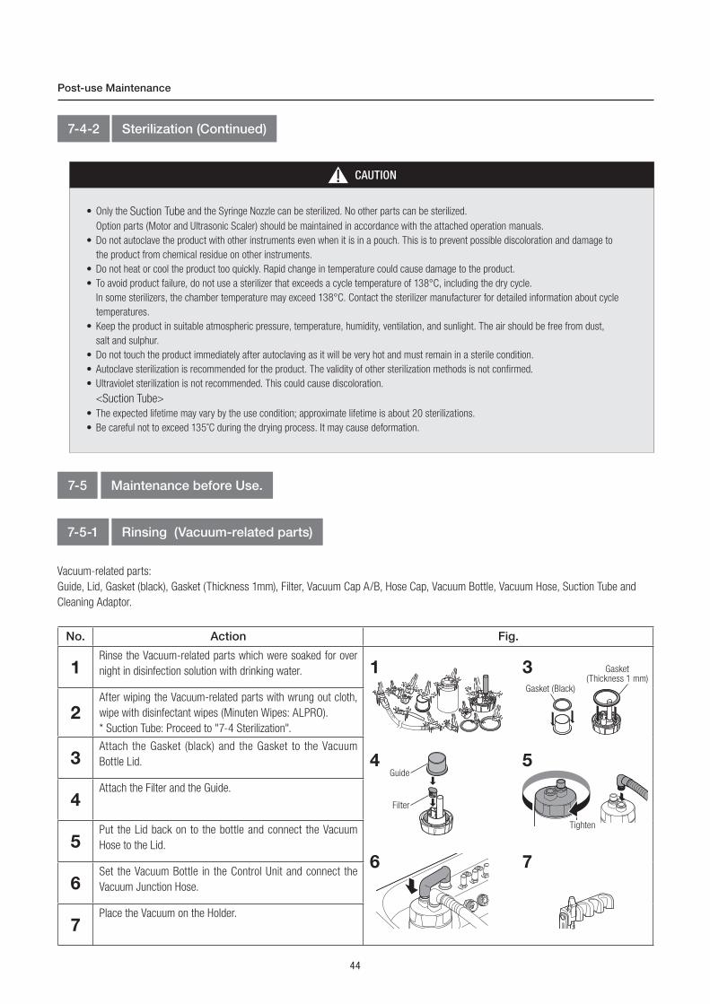
7-5-1 Rinsing (Vacuum-related parts)
Vacuum-related parts:
Guide, Lid, Gasket (black), Gasket (Thickness 1mm), Filter, Vacuum Cap A/B, Hose Cap, Vacuum Bottle, Vacuum Hose, Suction Tube and
Cleaning Adaptor.
No. Action Fig.
1Rinse the Vacuum-related parts which were soaked for over
night in disinfection solution with drinking water.
2After wiping the Vacuum-related parts with wrung out cloth,
wipe with disinfectant wipes (Minuten Wipes: ALPRO).
* Suction Tube: Proceed to "7-4 Sterilization".
3Attach the Gasket (black) and the Gasket to the Vacuum
Bottle Lid.
4Attach the Filter and the Guide.
5Put the Lid back on to the bottle and connect the Vacuum
Hose to the Lid.
6Set the Vacuum Bottle in the Control Unit and connect the
Vacuum Junction Hose.
7Place the Vacuum on the Holder.
1
6 7
3
54
Gasket (Black)
Gasket(Thickness 1 mm)
Guide
Filter
Tighten
45
Eng
lish
Post-use Maintenance
No. Action Fig.
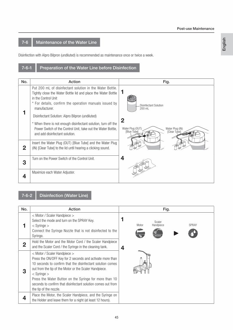
1
Put 200 mL of disinfectant solution in the Water Bottle.
Tightly close the Water Bottle lid and place the Water Bottle
in the Control Unit
* For details, confirm the operation manuals issued by
manufacturer.
Disinfectant Solution: Alpro Bilpron (undiluted)
* When there is not enough disinfectant solution, turn off the
Power Switch of the Control Unit, take out the Water Bottle,
and add disinfectant solution.
2Insert the Water Plug (OUT) [Blue Tube] and the Water Plug
(IN) [Clear Tube] to the lid until hearing a clicking sound.
3Turn on the Power Switch of the Control Unit.
4Maximize each Water Adjuster.
1
4
7-6 Maintenance of the Water Line
Disinfection with Alpro Bilpron (undiluted) is recommended as maintenance once or twice a week.
7-6-1 Preparation of the Water Line before Disinfection
Disinfectant Solution 200 mL
2
Water Plug (OUT)[Blue Tube]
Water Plug (IN)[Clear Tube]
7-6-2 Disinfection (Water Line)
No. Action Fig.
1
< Motor / Scaler Handpiece >
Select the mode and turn on the SPRAY Key.
< Syringe >
Connect the Syringe Nozzle that is not disinfected to the
Syringe.
2Hold the Motor and the Motor Cord / the Scaler Handpiece
and the Scaler Cord / the Syringe in the cleaning tank.
3
< Motor / Scaler Handpiece >
Press the ON/OFF Key for 2 seconds and activate more than
10 seconds to confirm that the disinfectant solution comes
out from the tip of the Motor or the Scaler Handpiece.
< Syringe >
Press the Water Button on the Syringe for more than 10
seconds to confirm that disinfectant solution comes out from
the tip of the nozzle.
4Place the Motor, the Scaler Handpiece, and the Syringe on
the Holder and leave them for a night (at least 12 hours).
Motor SPRAYScaler
Handpiece
1
4
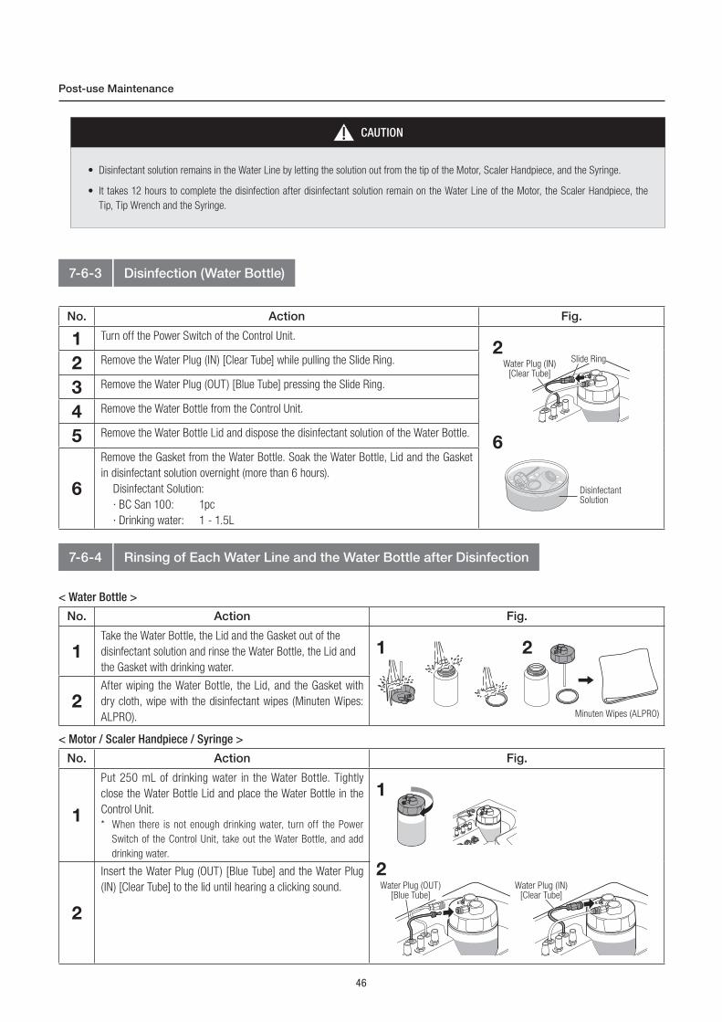
46
Post-use Maintenance
CAUTION
• Disinfectant solution remains in the Water Line by letting the solution out from the tip of the Motor, Scaler Handpiece, and the Syringe.
• It takes 12 hours to complete the disinfection after disinfectant solution remain on the Water Line of the Motor, the Scaler Handpiece, the
Tip, Tip Wrench and the Syringe.
7-6-3 Disinfection (Water Bottle)
No. Action Fig.
1 Turn off the Power Switch of the Control Unit.
2 Remove the Water Plug (IN) [Clear Tube] while pulling the Slide Ring.
3 Remove the Water Plug (OUT) [Blue Tube] pressing the Slide Ring.
4 Remove the Water Bottle from the Control Unit.
5 Remove the Water Bottle Lid and dispose the disinfectant solution of the Water Bottle.
6
Remove the Gasket from the Water Bottle. Soak the Water Bottle, Lid and the Gasket
in disinfectant solution overnight (more than 6 hours).
Disinfectant Solution:
· BC San 100: 1pc
· Drinking water: 1 - 1.5L
2
6
Water Plug (IN)[Clear Tube]
Slide Ring
Disinfectant Solution
7-6-4 Rinsing of Each Water Line and the Water Bottle after Disinfection
< Water Bottle >
< Motor / Scaler Handpiece / Syringe >
No. Action Fig.
1Take the Water Bottle, the Lid and the Gasket out of the
disinfectant solution and rinse the Water Bottle, the Lid and
the Gasket with drinking water.
2After wiping the Water Bottle, the Lid, and the Gasket with
dry cloth, wipe with the disinfectant wipes (Minuten Wipes:
ALPRO).
1 2
Minuten Wipes (ALPRO)
No. Action Fig.
1
Put 250 mL of drinking water in the Water Bottle. Tightly
close the Water Bottle Lid and place the Water Bottle in the
Control Unit.
* When there is not enough drinking water, turn off the Power
Switch of the Control Unit, take out the Water Bottle, and add
drinking water.
2
Insert the Water Plug (OUT) [Blue Tube] and the Water Plug
(IN) [Clear Tube] to the lid until hearing a clicking sound.
1
2Water Plug (OUT)
[Blue Tube]Water Plug (IN)
[Clear Tube]

47
Eng
lish
Post-use Maintenance
No. Action Fig.
3 Turn on the Power Switch of the Control Unit.
4 Maximize each Water Adjuster.
5
< Motor / Scaler Handpiece >
Select the mode and turn on the SPRAY Key.
< Syringe >
Make sure that the Syringe Nozzle is attached.
6Hold the Motor and the Motor Cord / the Scaler Handpiece and the Scaler
Cord / Syringe in the cleaning tank.
7
< Motor / Scaler Handpiece >
Press the ON/OFF Key for 2 seconds and activate for more than 10 seconds
to confirm that drinking water comes out from the tip of the Motor or the
Scaler Handpiece.
< Syringe >
Press the Water Button on the Syringe for more than 10 seconds to confirm
that drinking water comes out form the tip of the Syringe Nozzle.
8Wipe the surface of the Motor, Scaler Handpiece, Syringe Nozzle and the
each Cord with disinfectant wipes (Minuten Wipes: ALPRO).
9
<Motor>
Disconnect the Motor from the Motor Cord then attach the sterilized Motor to
the Motor Cord and place it on the Holder.
* Be sure to sterilize the rinsed Motor (Including Water Line) before use.
Reference: "7-4 Sterilization.
<Scaler>
Disconnect the Scaler Handpiece from the Scaler Cord then attach the
sterilized Scaler Handpiece to the Scaler Cord and place it on the Holder.
* Be sure to sterilize the rinsed Scaler Handpiece (Including Water Line)
before use. Reference: "7-4 Sterilization".
<Syringe>
Disconnect the Syringe Nozzle from the Syringe then attach the sterilized
Syringe Nozzle to the Syringe and place it on the Holder.
* Be sure to sterilize the rinsed Syringe before use. Reference: "7-4
Sterilization.
8
4
Motor SPRAYScaler
Handpiece
5
Minuten Wipes (ALPRO)
CAUTION
• After rinsing, be sure to sterilize the Motor, the Scaler Handpiece, and the Syringe Nozzle. Referens "7-4 Sterilization".
9

48
No. Action Fig.
1Turn off the Power and pull the AC Power Cord and the Foot
Control Cord.
2Close the Vacuum Valve Lever.
3Remove the Handpiece, the Syringe Nozzle, and the Suction
Tube and place them in the Holder.
4Place the Water Bottle and the Vacuum Bottle in the
designated position of the Control Unit.
5If there is water in the Water Bottle, connect the Water Plug
to prevent the water to spill.
6
Store the Vacuum Bottle after disposing of the sucked
liquid (saliva, blood, etc.). When storing without disposing
of the sucked liquid, put caps on the Vacuum Bottle and the
Vacuum Hose.
7
After dropping the root part of the cords and hoses into the
storage part of the Control Unit, wind the rest of the cords
and hoses clockwise.Point 1
Drop the bundled cords and hoses along the right wall.
Point 2
Wind the rest of the cords and hoses clockwise.
7Point 1 Point 2
Storage Procedure8
2
CAUTION
• Check that the Vacuum Valve Lever is not wet.
If it is stored wet, it causes the product to become rusty.
• If stored without caps, the sucked liquid (saliva, blood, etc.) may enter the Control Unit because of the vibration while being carried, and may
cause abnormal smell and breakage.
3
54
6 Vacuum Cap B
VacuumCap A
Hose Cap
VacuumValve Lever

49
Eng
lish
No. Action Fig.
8
Release the Holder Arm Lock, support the Holder to prevent
the cords and hoses from dropping, and then turn the Holder
slowly until it reaches its lowest to lock.
9
Pull down the Holder bar slowly while supporting the Holder
to prevent the cords and hoses from dropping.
10
Set the Top Case on the Control Unit and lock the Buckles
(4 places).
11
Store the Foot Control and the Power Cords as in the
illustration below.
12
Put the Top Cover Case on.
8
12
9
1110
Storage Procedure
NOTICE
• Follow <Point 1> and <Point 2> to store the cords and hoses smoothly.
• Storage of cords and hoses is introduced in a video. Check the URL or the QR code below.
URL
http://www.nsk-dental.com/support/videos/
CAUTION
• Be careful not to get the cords and hoses caught in when storing. It may cause damage and breakdown. Also, there is a risk
that the Top Case cannot be firmly locked.

50
No. Action Fig.
1
Confirm that the buckles (4 places) in the front and the back
of the Control Unit are firmly locked.
2
Set the Shoulder Belt securely to the Belt Hook.
3
Carry the device hung the Shoulder Belt on the shoulder.
1 2
3
Transportation9
Check
• If the buckles are not locked firmly the device may drop during transportation and
result in a failure and injuries.
• Do not hold the Top Case Cover Latch when carrying
the Control Unit. There is a risk that the Control Unit
would fall as shown in the illustration, and cause
injuries or breakage.
The Latch is for taking off/putting on the Top Cover
Case, not for carrying.
CAUTION
10-1 Replacing the gasket (Water Bottle)
Maintenance10
No. Action Fig.
1Take off the Water Bottle Lid.
2Remove the filter from the lid, and then remove the gasket
using tweezers.
3Place a new Gasket.
1 2
Loosen
Gasket(Thickness 3 mm)
NOTICE
• The order codes for the filter, the Gasket, and the O-ring are on P60. (Reference: 13-2 Spare Parts List)
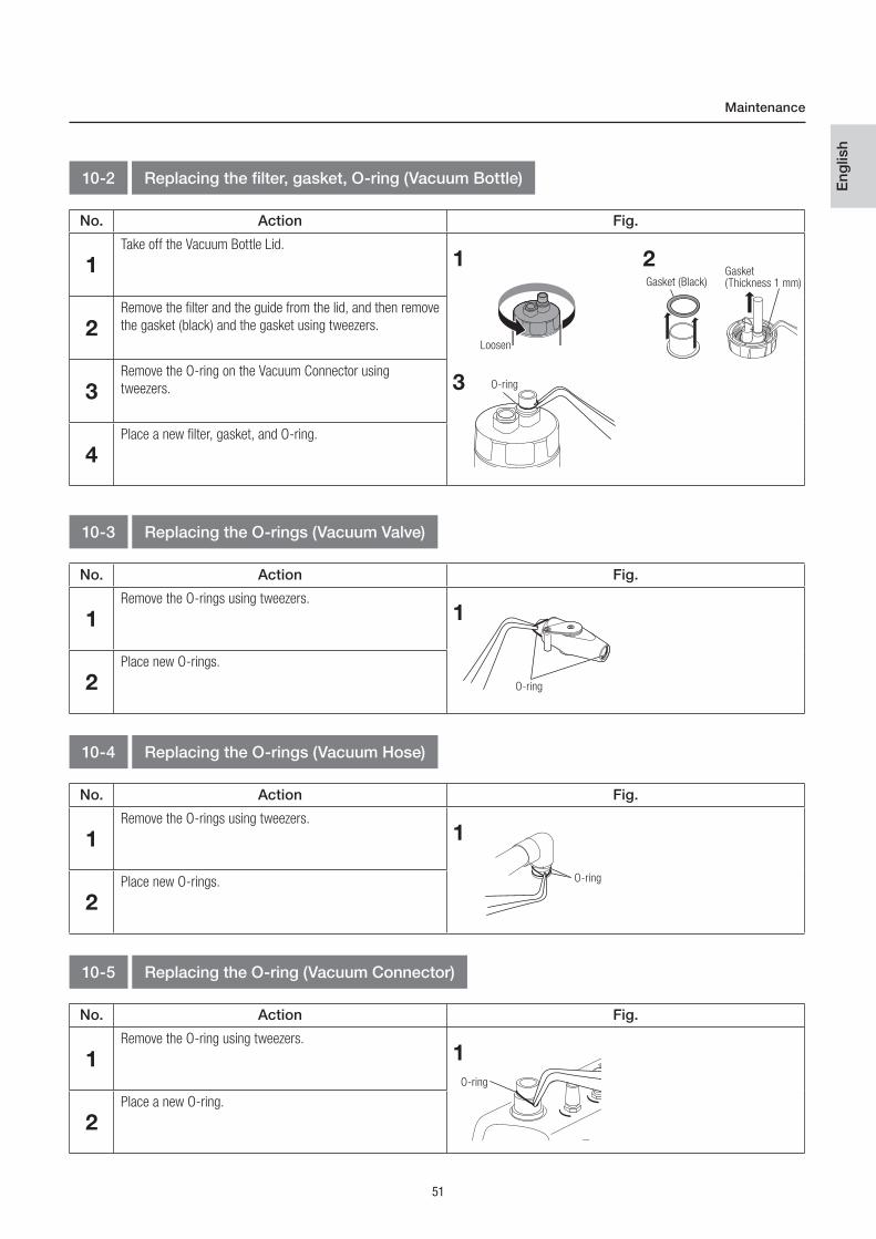
51
Eng
lish
No. Action Fig.
1Remove the O-rings using tweezers.
2Place new O-rings.
1
No. Action Fig.
1Take off the Vacuum Bottle Lid.
2Remove the filter and the guide from the lid, and then remove
the gasket (black) and the gasket using tweezers.
3Remove the O-ring on the Vacuum Connector using
tweezers.
4Place a new filter, gasket, and O-ring.
1 2
3
10-2 Replacing the filter, gasket, O-ring (Vacuum Bottle)
Gasket (Black)
Loosen
O-ring
Gasket(Thickness 1 mm)
10-3 Replacing the O-rings (Vacuum Valve)
10-4 Replacing the O-rings (Vacuum Hose)
10-5 Replacing the O-ring (Vacuum Connector)
No. Action Fig.
1Remove the O-rings using tweezers.
2Place new O-rings.
1
Maintenance
O-ring
No. Action Fig.
1Remove the O-ring using tweezers.
2Place a new O-ring.
1
O-ring
O-ring
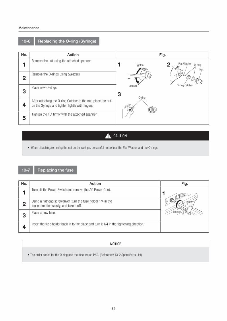
52
Maintenance
10-6 Replacing the O-ring (Syringe)
10-7 Replacing the fuse
No. Action Fig.
1Remove the nut using the attached spanner.
2Remove the O-rings using tweezers.
3Place new O-rings.
4After attaching the O-ring Catcher to the nut, place the nut
on the Syringe and tighten lightly with fingers.
5Tighten the nut firmly with the attached spanner.
1 2
3
O-ringFlat Washer
O-ring catcher
Tighten
Loosen
Nut
O-ring
CAUTION
• When attaching/removing the nut on the syringe, be careful not to lose the Flat Washer and the O-rings.
No. Action Fig.
1Turn off the Power Switch and remove the AC Power Cord.
2Using a flathead screwdriver, turn the fuse holder 1/4 in the
loose direction slowly, and take it off.
3Place a new fuse.
4Insert the fuse holder back in to the place and turn it 1/4 in the tightening direction.
1
Tighten
Loosen
NOTICE
• The order codes for the O-ring and the fuse are on P60. (Reference: 13-2 Spare Parts List)

53
Eng
lish
Maintenance
10-8 Drainage of Air Filter
10-9 Replacing the Water Plug
No. Action Fig.
1Using a cross-head screw driver, remove the filter
cover at the bottom of the control unit.
2Press the end part of the air filter for drainage. Prepare for
the drainage because the drained water contains air and may
spray out onto surrounding objects.
3Put the Filter Cover back in place.
1 2
Loosen Tighten
Bottom of the Control Unit
Bottom of the Control Unit
No. Action Fig.
1Pull out the Tube while pressing the Connector Ring.
2Insert the new Water Plug tube until it meets the end. Be
sure to place the clear tube on the right and the blue tube
on the left.
3Check by pulling and pushing that the tube is securely set.
1 2Water Plug (OUT)
[Blue Tube]
Water Plug(IN)
[Clear Tube]Connector Ring

54
Maintenance
10-10 Periodical Maintenance Checks
Every 3 months perform periodical maintenance checks, referring to the check sheet below. If any abnormalities are found, contact your
Authorized NSK Dealer.
Points to check
Control Unit, Top Case, Top Case Cover
Operation of the Control Unit
Drainage of Air Filter
Vacuum Bottle
Syringe
Drain the Air Filter.(Reference : 10-8 Drainage of Air Filter)
Check that there is no foreign substance such as chip powder is gathered inthe filter and the float spindle on the lid.
Vacuum
Connecting and Disconnecting the cords and hoses
Watering
Check if there is no discoloration, deformation, or breakage.
Water and air operates properly.
No abnormal noise is heard.
The Nut on the syringe is not loose.
No major rattling or looseness is noticed.
The Syringe Nozzle is not loose.
Display panel displays the information properly.
They can be connected securely without any rattling and looseness.
No leakage when water is applied.
Suctioning operates properly.
Details

55
Eng
lish
11-1 Error Code
In the case of abnormalities an Error Code will be displayed in the display panel. Immediately stop all the devices when an error code is
displayed. Press Motor/Scaler ON/OFF Key or step on the foot control (FC-76S) again or turn on the device again to see if the error is canceled.
If the error code is displayed again, refer to the following table and take appropriate actions.
When the error is not eliminated, a failure of this device is suspected. Contact your Authorized NSK Dealer.
ObjectError Code
Err 01
Err 16
Err 17
Err 09
Exceeding the maximum set torque value
Abnormal electric current flows into the motor and the circuit
Much electricity has flown for an extended period
Overcurrent detected in the motor driver
Using the motor for an extended period
Too much voltage is applied to the control unit
Error in Motor output circuit
Used in an extended period exceeding the set value
Insufficient connection of the motor cord
The electric circuit broke down
Voltage reduction of the LED lamp
Communication abnormality inside the motor
Err 00
Err 05
Err 10
Err 03
Err 07
Err 02
Err 06
Err 12
Err 14
Err 04
Err 08
Err 13 Load on the motor, Power failure
Failure in the parts that record the set value
Vacuum Motor abnormality.
Compressor abnormality(Open phase, low voltage, excessive load)
Too much voltage is applied from the internal circuit
Cool down the motor.
Contact your authorized NSK Dealer.
Remove the load from the motor and thehandpiece, then release the foot control.
Check that the motor is correctly connected to the motor cord.
Turn off the Power Switch and turn it on again while pressing the Air Button on the syringe. Then keep pressing the Air Button for 3 minutes. If the error is not eliminated after the procedure above, repeat the procedure a few times.When the error continues to appear, a failure of the device is suspected. Contact your Authorized NSK Dealer.
Check that the syringe hose is not twisted orstepped on.
Contact your Authorized NSK Dealer.
Motor
Vacuum
Compressor
Release the motor from the load.
Contact your Authorized NSK Dealer.
Cause of the Error Remedy
Troubleshooting11
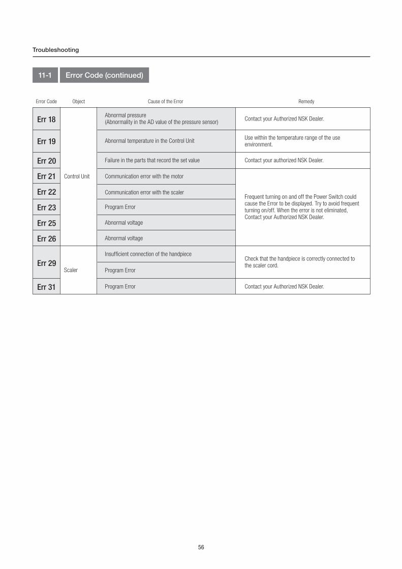
56
Troubleshooting
11-1 Error Code (continued)
ObjectError Code
Err 19
Err 18
Err 29
Abnormal temperature in the Control Unit
Abnormal pressure (Abnormality in the AD value of the pressure sensor)
Use within the temperature range of the useenvironment.
Check that the handpiece is correctly connected to the scaler cord.
Control Unit
Scaler
Contact your Authorized NSK Dealer.
Err 23
Err 21
Err 26
Err 20
Err 25
Err 22
Err 31
Failure in the parts that record the set value
Communication error with the motor
Communication error with the scaler
Program Error
Abnormal voltage
Insufficient connection of the handpiece
Program Error
Program Error
Abnormal voltage
Contact your Authorized NSK Dealer.
Contact your authorized NSK Dealer.
Frequent turning on and off the Power Switch could cause the Error to be displayed. Try to avoid frequent turning on/off. When the error is not eliminated, Contact your Authorized NSK Dealer.
Cause of the Error Remedy

57
Eng
lish
Troubleshooting
11-2 Problems and Solutions
Problem
Fuse blown
Insufficient connection of the power cord.
No display when turning on the switch.
The Motor/Scaler does not function. Itfunctions by operating the control panel, however not by the foot control.
The Motor/Scaler does not function. Itdoes not function by both control paneland foot control operations.
Water force is not enough when using the Motor/Scaler.
The Vacuum does not suck.
Water is not enough.
No water/air is supplied from the Syringe.
Air force from the Syringe is weak, or there is no air from the Syringe
Replace the fuse.
Failure in Foot Control.
Failure in Motor/Scaler or Control Unit.
Water is stagnating in the Air Filter
Failure in Compressor.
The Air Filter clogging.
Water is stagnating in the Air Filter
Stretch the bend of the hose, or remove the foreign substance.
Looseness of the Vacuum Bottle Lid.
The Vacuum Bottle is filled.
Failure in Vacuum.
Vacuum Junction Hose is not connected properly.
Foreign substance has entered the Vacuum.
Water Supply Plug/Air supply Plugis not connected properly.
The syringe hose is bent, or foreign substance entered.
Foreign substance has entered water the circuit.
Water Supply Plug/Air supply Plugis not connected properly.
Securely connect the Vacuum junction hose.(Reference : 5-6 Installing the Vacuum Hose)
Drain the Air Filter.(Reference : 10-8 Drainage of Air Filter)
Contact your Authorized NSK Dealer.
Remove the foreign substance.
Securely close the lid.
Dispose of the sucked liquid.
Check the connection of the Water Plug.
Check the connection of the Water Plug.
Drain the Air Filter.(Reference : 10-8 Drainage of Air Filter)
Contact your Authorized NSK Dealer.
Check the connection.
Contact your Authorized NSK Dealer
Cause Remedy
When a problem is detected, check the following again before requesting a repair.
If none of these is applicable or if the trouble is not remedied even after an action has been taken, a failure of this product is suspected.
Contact your Authorized NSK Dealer.
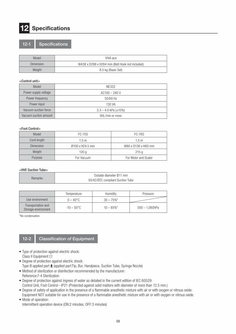
58
• Type of protection against electric shock:
Class II Equipment
• Degree of protection against electric shock:
Type B applied part (applied part:Tip, Bur, Handpiece, Suction Tube, Syringe Nozzle)
• Method of sterilization or disinfection recommended by the manufacturer:
Reference:7-4 Sterilization
• Degree of protection against ingress of water as detailed in the current edition of IEC 60529:
Control Unit, Foot Control ··· IP21 (Protected against solid matters with diameter of more than 12.5 mm.)
• Degree of safety of application in the presence of a flammable anesthetic mixture with air or with oxygen or nitrous oxide:
Equipment NOT suitable for use in the presence of a flammable anesthetic mixture with air or with oxygen or nitrous oxide.
• Mode of operation:
Intermittent operation device (ON:2 minutes, OFF:3 minutes)
12-1 Specifications
12-2 Classification of Equipment
Specifications12
Model
Model
Model
Weight
Power input
<Foot Control>
<Control unit>
VIVA ace
FC-70S
NE322
FC-76S
Temperature Humidity Pressure
120 g
130 VA
215 g
W438 x D298 x H284 mm (Belt Hook not included)
1.5 m
AC100 – 240 V
1.5 m
0 – 40°C 30 – 75%*
For Vacuum
3.3 – 4.0 kPa (±10%)
90L/min or more
For Motor and Scaler
8.5 kg (Basic Set)
Ø100 x H24.5 mm
50/60 Hz
W80 x D136 x H60 mm
-10 – 50°C 10 – 85%* 500 – 1,060hPa
Dimension
Cord length
Power-supply voltage
Use environment
Purpose
Vacuum suction force
Vacuum suction amount
Weight
Dimension
Power frequency
Transportation and Storage environment
*No condensation
RemarksOutside diameter Ø11 mm
93/42/EEC compliant Suction Tube
<HVE Suction Tube>

59
Eng
lish
Specifications
12-3 Symbol
This product is Autoclavable up to Max. 135ºC.
Conforms to CE European Directive of “Medical device directive 93/42/EEC.”
This product can be cleaned using washer-disinfector.
Manufacturer.
Authorized representative in the European community.
Follow the waste of electric and electronic equipment (WEEE) Directive (2012/19/EU) for product and accessory disposal.
Consult operation instructions.
Caution, Refer to attached instructions.
Class II equipment.
Type B applied part.
Protected against solid matters with diameter of more than 12.5 mm.
Marking on the outside of Equipment or Equipment parts that include RF transmitters or that apply RF electromagnetic energy for diagnosis or treatment.
TUV Rheinland of North America is a Nationally Recognized Testing Laboratory (NRTL) in the United States and is accredited
by the Standards Council of Canada to certify electro-medical products with Canadian National Standards.
Caution: U.S. Federal law restricts this device to sale by or on the order of a licensed physician.
Serial No.

60
13-1 Warranty
13-2 Spare Parts List
NSK products are warranted against manufacturing errors and defects in materials. NSK reserves the right to analyze and determine the
cause of any problem. Warranty is voided should the product be not used correctly or for the intended purpose or has been tampered with by
unqualified personnel or has had non NSK parts installed. Replacement parts are available for seven years beyond discontinuation of the model.
After-sales Service13
<Vacuum>
<Vacuum Bottle>
<Syringe>
<Water Bottle>
<Control Unit>
Model
Model
Model
Model
Model
Order Code
Order Code
Order Code
Order Code
Order Code
Remarks
Remarks
Remarks
Remarks
Remarks
V-ace Vacuum Hose Set
Water Plug Set
O-ring Set
O-ring
Gasket
V-ace 3 way Syringe Set
Gasket
Thickness 1 mm
O-ring
Gasket (Black)
O-ring Set
Flat Washer
-
O-ring
Fuse
Filter -
O-ring For Vacuum Connector and Control Unit
U1144074
Y1003730
Y1003572
D0312130100
U1144636
D0312107150
Z1137352
D0312100150
D1202231510
U1144727
U1144040
U1144729
A set of Syringe and Syringe Nozzle
Thickness 3 mm
D0312130100
Y1003573
U1144430
A set of 2 (large and small), For Syringe
For Syringe
A set of Vacuum Valve, Vacuum Hose, O-rings, and Hose Cap.
A set of Water Bottle (IN) [Clear Tube] andWater Bottle (OUT) [Blue Tube]
A set of 2, For Vacuum Hose
For Vacuum Connector
For Suction Tube side of the Suction Tube
For Vacuum hose side of the Suction Tube
T3.15AH 250V
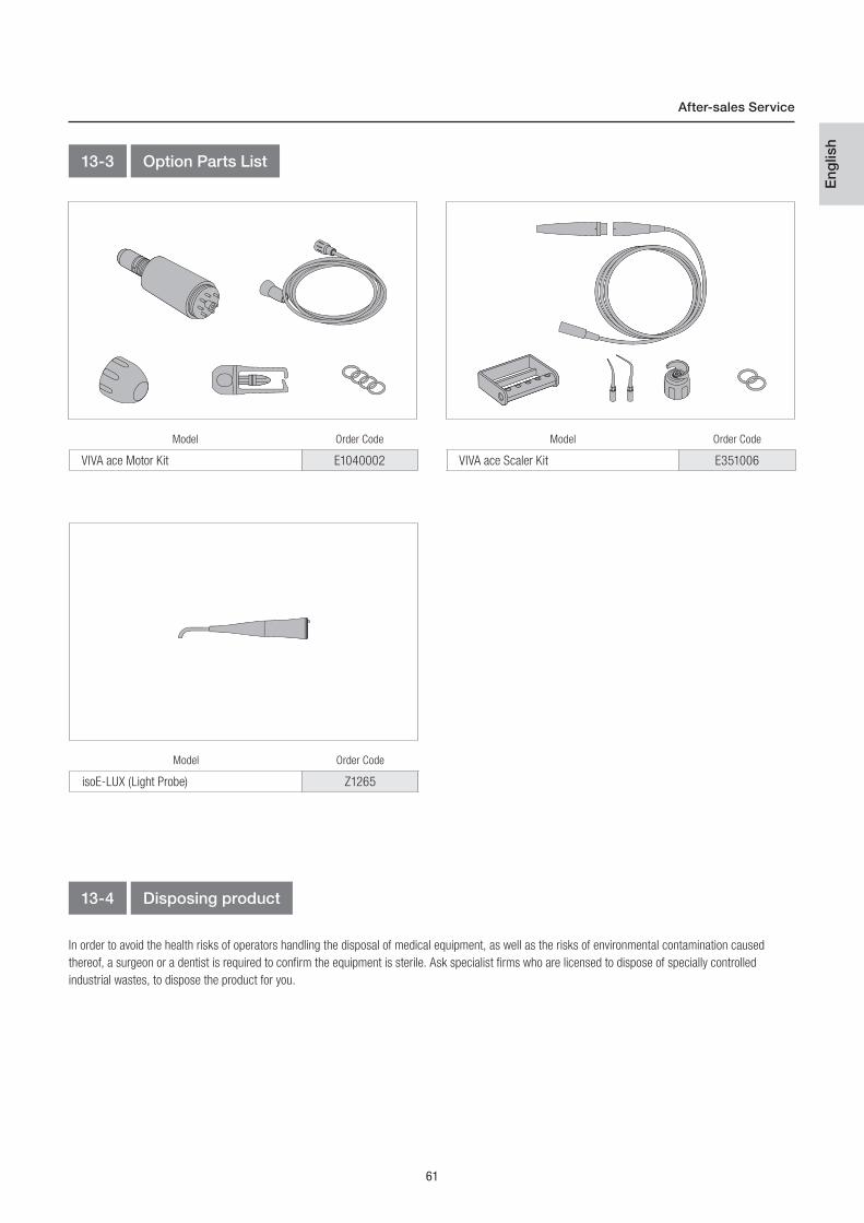
61
Eng
lish
In order to avoid the health risks of operators handling the disposal of medical equipment, as well as the risks of environmental contamination caused
thereof, a surgeon or a dentist is required to confirm the equipment is sterile. Ask specialist firms who are licensed to dispose of specially controlled
industrial wastes, to dispose the product for you.
Model Order Code
VIVA ace Scaler Kit E351006
Model Order Code
VIVA ace Motor Kit E1040002
Model Order Code
isoE-LUX (Light Probe) Z1265
After-sales Service
13-3 Option Parts List
13-4 Disposing product

62
Guidance and manufacturer's declaration - Electromagnetic Emissions
Guidance and manufacturer's declaration - Electromagnetic Immunity
The product is intended for use in the electromagnetic environment specified below. The customer or the user of the product should assure that it is used in such an environment.
The product is intended for use in the electromagnetic environment specified below. The customer or the user of the product should assure that it is used in such an environment.
RF emissionsCISPR11/EN55011
Electrostatic discharge (ESD)IEC61000-4-2
±6kV contact
±8kV air
The product uses RF energy only for its internal function.Therefore, its RF emissions are very low and are not likely to cause any interference in nearby electronic equipment.
±6kV contact
±8kV air
±2kV for power supply lines±1kV for input/output lines
Floors should be wood, concrete or ceramic tile. If floors are covered with synthetic material, the relative humidity should be at least 30%.
Mains power quality should be that of a typical commercial or hospital environment.
Mains power quality should be that of a typical commercial or hospital environment.
Mains power quality should be that of a typical commercial or hospital environment. If the user of the product requires continued operation duringpower mains interruptions, it isrecommended that the product be powered from an uninterruptible power supply or a battery.
The product is suitable for use in all establishments, including domestic establishments and those directly connected to the public low-voltage power supply network that supplies buildings used for domestic purposes.
<5% Ut(>95% dip in Ut)for 0.5 cycles40% Ut(60% dip in Ut)for 5 cycles70% Ut(30% dip in Ut)For 25 cycles<5% Ut(>95% dip in Ut)for 5 sec
<5% Ut(>95% dip in Ut)for 0.5 cycles40% Ut(60% dip in Ut)for 5 cycles70% Ut(30% dip in Ut)For 25 cycles<5% Ut(>95% dip in Ut)for 5 sec
Group 1
Class B
±2kV for power supply lines±1kV for input/output lines
±1kV line(s) to line(s)±2kV line(s) to earth
±1kV line(s) to line(s)±2kV line(s) to earth
Class A (except 120V)
Complies (except 120V)
RF emissionsCISPR11EN55011
Electrical fasttransient/burstIEC61000-4-4
Harmonic emissionsEN/IEC61000-3-2
SurgeIEC61000-4-5
Power frequency (50/60Hz)magnetic fieldIEC61000-4-8
3 A/m 3 A/m
Power frequency magnetic fields should be at levels characteristic of a typical location in a typical commercial or hospital environment.
NOTE : ‘Ut’ is the AC mains voltage prior to application of the test level.
Voltage fluctuations/flicker emissionsEN/IEC61000-3-3
Voltage dips, shortinterruptions and voltagevariations on power supplyinput linesIEC61000-4-11
Emissions test
Immunity test
Compliance
EN/IEC60601 test level
Electromagnetic environment - guidance
Compliance level Electromagnetic environment - guidance
EMC Information (Electromagnetic Compatibility Information)14
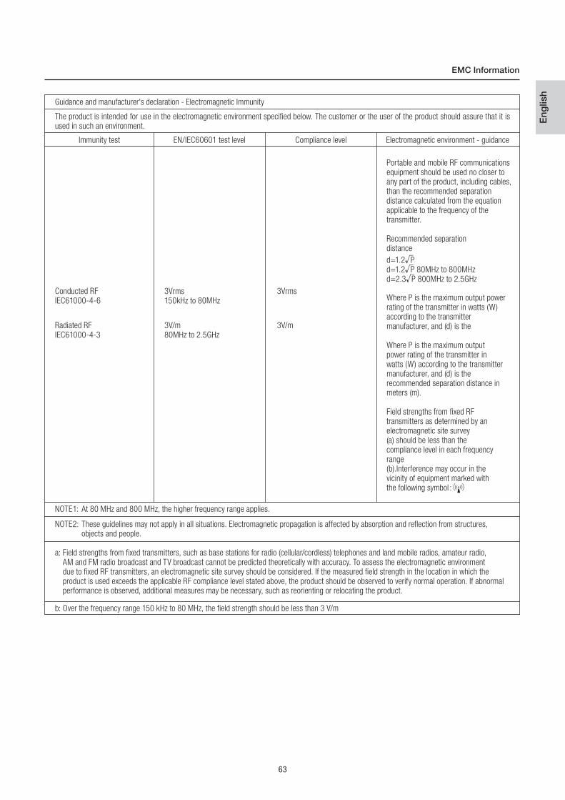
63
Eng
lish
EMC Information
Guidance and manufacturer's declaration - Electromagnetic Immunity
The product is intended for use in the electromagnetic environment specified below. The customer or the user of the product should assure that it is used in such an environment.
Conducted RFIEC61000-4-6
3Vrms
Portable and mobile RF communications equipment should be used no closer toany part of the product, including cables, than the recommended separationdistance calculated from the equation applicable to the frequency of the transmitter.
Recommended separationdistance
d=1.2 Pd=1.2 P 80MHz to 800MHzd=2.3 P 800MHz to 2.5GHz
Where P is the maximum output power rating of the transmitter in watts (W)according to the transmittermanufacturer, and (d) is the
Where P is the maximum outputpower rating of the transmitter inwatts (W) according to the transmittermanufacturer, and (d) is therecommended separation distance inmeters (m).
Field strengths from fixed RFtransmitters as determined by anelectromagnetic site survey(a) should be less than thecompliance level in each frequencyrange(b).Interference may occur in thevicinity of equipment marked withthe following symbol :
3Vrms150kHz to 80MHz
3V/m80MHz to 2.5GHz
3V/m
NOTE1: At 80 MHz and 800 MHz, the higher frequency range applies.
b: Over the frequency range 150 kHz to 80 MHz, the field strength should be less than 3 V/m
NOTE2: These guidelines may not apply in all situations. Electromagnetic propagation is affected by absorption and reflection from structures, objects and people.
a: Field strengths from fixed transmitters, such as base stations for radio (cellular/cordless) telephones and land mobile radios, amateur radio, AM and FM radio broadcast and TV broadcast cannot be predicted theoretically with accuracy. To assess the electromagnetic environment due to fixed RF transmitters, an electromagnetic site survey should be considered. If the measured field strength in the location in which the product is used exceeds the applicable RF compliance level stated above, the product should be observed to verify normal operation. If abnormal performance is observed, additional measures may be necessary, such as reorienting or relocating the product.
Radiated RFIEC61000-4-3
Immunity test EN/IEC60601 test level Compliance level Electromagnetic environment - guidance
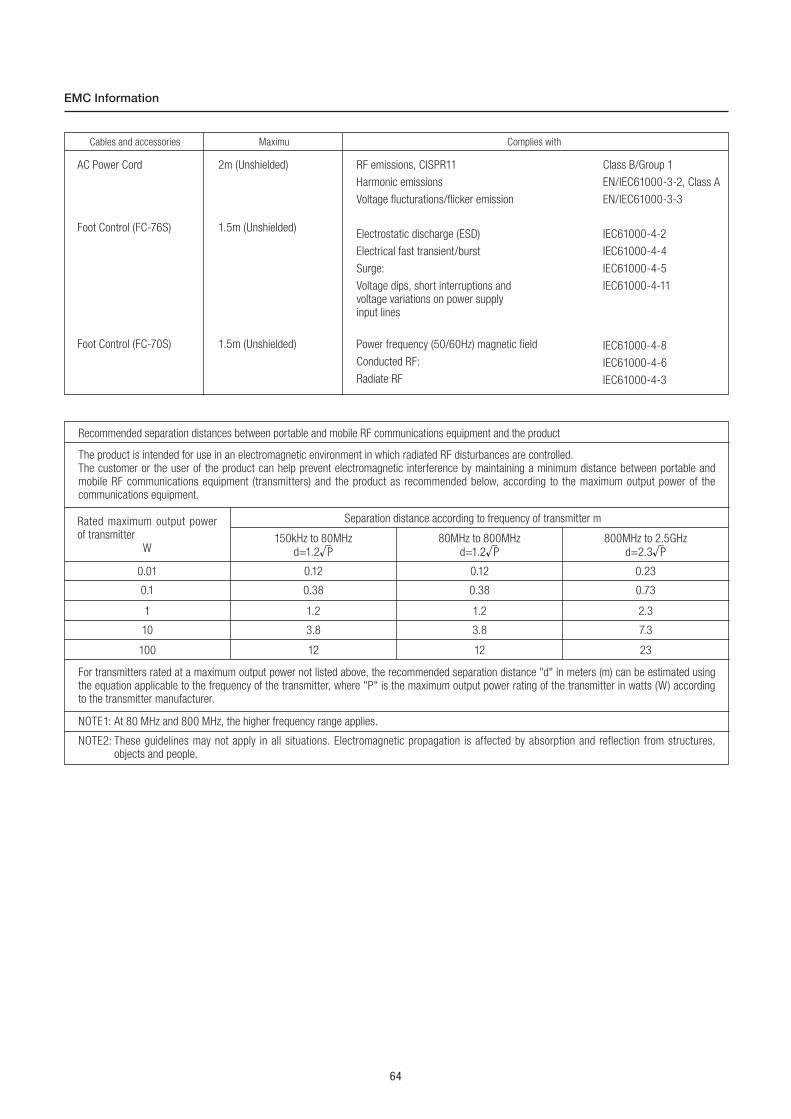
64
EMC Information
Recommended separation distances between portable and mobile RF communications equipment and the product
0.01 0.12 0.12 0.23
1 1.2 1.2 2.3
100 12 12 23
0.1 0.38 0.38 0.73
10 3.8 3.8 7.3
The product is intended for use in an electromagnetic environment in which radiated RF disturbances are controlled. The customer or the user of the product can help prevent electromagnetic interference by maintaining a minimum distance between portable and mobile RF communications equipment (transmitters) and the product as recommended below, according to the maximum output power of the communications equipment.
NOTE2: These guidelines may not apply in all situations. Electromagnetic propagation is affected by absorption and reflection from structures, objects and people.
For transmitters rated at a maximum output power not listed above, the recommended separation distance "d" in meters (m) can be estimated using the equation applicable to the frequency of the transmitter, where "P" is the maximum output power rating of the transmitter in watts (W) according to the transmitter manufacturer.
NOTE1: At 80 MHz and 800 MHz, the higher frequency range applies.
Rated maximum output power of transmitter
W80MHz to 800MHz
d=1.2 P
800MHz to 2.5GHz
d=2.3 P
150kHz to 80MHz
d=1.2 P
Separation distance according to frequency of transmitter m
Cables and accessories
AC Power Cord 2m (Unshielded)
Foot Control (FC-76S) 1.5m (Unshielded)
Foot Control (FC-70S) 1.5m (Unshielded)
Maximu Complies with
RF emissions, CISPR11
Harmonic emissions
Voltage flucturations/flicker emission
Electrostatic discharge (ESD)
Electrical fast transient/burst
Surge:
Voltage dips, short interruptions andvoltage variations on power supplyinput lines
Power frequency (50/60Hz) magnetic field
Conducted RF:
Radiate RF
Class B/Group 1
EN/IEC61000-3-2, Class A
EN/IEC61000-3-3
IEC61000-4-2
IEC61000-4-4
IEC61000-4-5
IEC61000-4-11
IEC61000-4-8
IEC61000-4-6
IEC61000-4-3

S2018.08.10 002
Related Documents