P ● A ● R ● T ● 8 HYDROTREATING Source: HANDBOOK OF PETROLEUM REFINING PROCESSES Downloaded from Digital Engineering Library @ McGraw-Hill (www.digitalengineeringlibrary.com) Copyright © 2004 The McGraw-Hill Companies. All rights reserved. Any use is subject to the Terms of Use as given at the website.

Welcome message from author
This document is posted to help you gain knowledge. Please leave a comment to let me know what you think about it! Share it to your friends and learn new things together.
Transcript
P ● A ● R ● T ● 8
HYDROTREATING
Source: HANDBOOK OF PETROLEUM REFINING PROCESSES
Downloaded from Digital Engineering Library @ McGraw-Hill (www.digitalengineeringlibrary.com)Copyright © 2004 The McGraw-Hill Companies. All rights reserved.
Any use is subject to the Terms of Use as given at the website.

HYDROTREATING
Downloaded from Digital Engineering Library @ McGraw-Hill (www.digitalengineeringlibrary.com)Copyright © 2004 The McGraw-Hill Companies. All rights reserved.
Any use is subject to the Terms of Use as given at the website.

CHAPTER 8.1
8.3
CHEVRON LUMMUS GLOBAL RDS/VRDSHYDROTREATING—
TRANSPORTATION FUELSFROM THE BOTTOM OF
THE BARREL
David N. BrossardChevron Lummus Global
Richmond, California
INTRODUCTION
The Chevron Lummus Global (CLG) Residuum Desulfurization (RDS) and VacuumResiduum Desulfurization (VRDS) Hydrotreating processes are used by refiners to pro-duce low-sulfur fuel oils, and to prepare feeds for vacuum gas oil (VGO) fluid catalyticcrackers (FCCs), residuum FCCs (RFCCs), visbreakers, and delayed cokers. Over half ofthe fixed-bed residuum hydrotreaters in operation use CLG’s RDS/VRDS Hydrotreatingtechnology.
RDS/VRDS Hydrotreaters upgrade residual oils by removing impurities and crackingheavy molecules in the feed to produce lighter product oils. Early applications of CLG’sresiduum hydroprocessing technology were used to remove sulfur from atmosphericresidues (ARs) and vacuum residues (VRs), hence the term desulfurization. Today,RDS/VRDS Hydrotreaters perform equally well removing nitrogen, carbon residue (see“Process Chemistry” section), nickel, and vanadium from the oil and cracking heavy VRmolecules to VGO, distillates, and naphtha products. The amount of impurities removeddepends on the feed and on the product specifications desired by the refiner. Sulfurremoval greater than 95 percent, metal removal (primarily nickel and vanadium) greaterthan 98 percent, nitrogen removal greater than 70 percent, carbon residue reduction greaterthan 70 percent, and cracking of vacuum residue (538°C+ material converted to 538°C�)as high as 60 liquid volume percent (LV%) have been commercially demonstrated.RDS/VRDS Hydrotreating uses fixed beds of catalyst that typically operate at moderatelyhigh pressures [150 to 200 atm (2133 to 2850 lb/in2)] and temperatures [350 to 425°C
Source: HANDBOOK OF PETROLEUM REFINING PROCESSES
Downloaded from Digital Engineering Library @ McGraw-Hill (www.digitalengineeringlibrary.com)Copyright © 2004 The McGraw-Hill Companies. All rights reserved.
Any use is subject to the Terms of Use as given at the website.

(662–797°F)] in a hydrogen-rich atmosphere (80 to 95 mol % hydrogen at the reactorinlet) to process the oil feed. The feed to a VRDS Hydrotreater is generally the VR from acrude unit vacuum column with a typical starting true boiling point (TBP) cut point of538°C (1000°F), although cut points of 575°C (1067°F) and higher are feasible. The feedto an RDS Hydrotreater is generally AR from a crude unit atmospheric column with a typ-ical starting TBP cut point of 370°C (698°F). Other feeds (such as solvent deasphalted oil,solvent deasphalter pitch, vacuum gas oil, and cracked gas oils from visbreakers, FCCs,RFCCs, and cokers) can also be processed in either RDS or VRDS Hydrotreaters.
Residua from many crudes have been successfully processed in RDS and VRDSHydrotreaters. Table 8.1.1 shows a partial list of crudes that have been commerciallyprocessed in CLG RDS/VRDS Hydrotreaters.
The range of feeds which can be economically processed in RDS/VRDS Hydrotreatersexpands significantly when On-Stream Catalyst Replacement (OCR) technology is addedto the unit. OCR technology allows spent catalyst to be removed from a guard reactor andbe replaced by fresh catalyst while the reactor remains in service. This enables the refinerto process heavy, high-metal feeds or to achieve deeper desulfurization from a fixed-bedresiduum hydrotreater (see Chap. 10.1).
HISTORY
Hydrotreating of residual oils was a natural extension of hydrotreating distillate oils andVGOs to remove sulfur.1,2,3 CLG’s first commercial RDS Hydrotreater was commissionedin 1969. Typical of many early residuum hydrotreaters, CLG’s first RDS Hydrotreater wasdesigned to remove sulfur to produce low-sulfur fuel oil (LSFO). CLG’s first VRDSHydrotreater, commissioned in 1977, was also designed to produce LSFO.
In 1984 Okinawa Sekiyu Seisei, a Japanese refiner, first reported4 the operation of aCLG RDS Hydrotreater in “conversion mode.” In this operation, the reactor temperature
8.4 HYDROTREATING
TABLE 8.1.1 RDS/VRDS Hydrotreater Feedstocks That HaveBeen Commercially Processed
A.A. Bu KhooshAlaskan North SlopeAlgerianArabian BerriArabian HeavyArabian LightArabian MediumBasrah LightCabindaColombian LimonDubaiDuriEl ChaureGipslandIndonesianIranian HeavyIranian LightIsthmusKhafjiKirkuk
KuwaitLagunaMargham C.MayaMina SaudMinasMurbanOguendjoOmanQatar LandQatar MarineRussianShengli No. 2StatfjordSuezTia Juana PesadoUmm ShaifWest Texas IntermediateWest Texas SourZakum
CHEVRON LUMMUS GLOBAL RDS/VRDS HYDROTREATING—TRANSPORTATIONFUELS FROM THE BOTTOM OF THE BARREL
Downloaded from Digital Engineering Library @ McGraw-Hill (www.digitalengineeringlibrary.com)Copyright © 2004 The McGraw-Hill Companies. All rights reserved.
Any use is subject to the Terms of Use as given at the website.
was raised fairly high early in the run—much higher than required to simply produce low-sulfur fuel oil—and held high until the end of run. This operation hydrocracked as muchVR as possible to lighter boiling products (VR was “converted” to light products). It alsoshortened the run length because of higher catalyst deactivation from coke deposited onthe catalyst through more of the run. Conversion mode operation has been favored bymany RDS/VRDS Hydrotreater operators in recent years to minimize the production offuel oil.
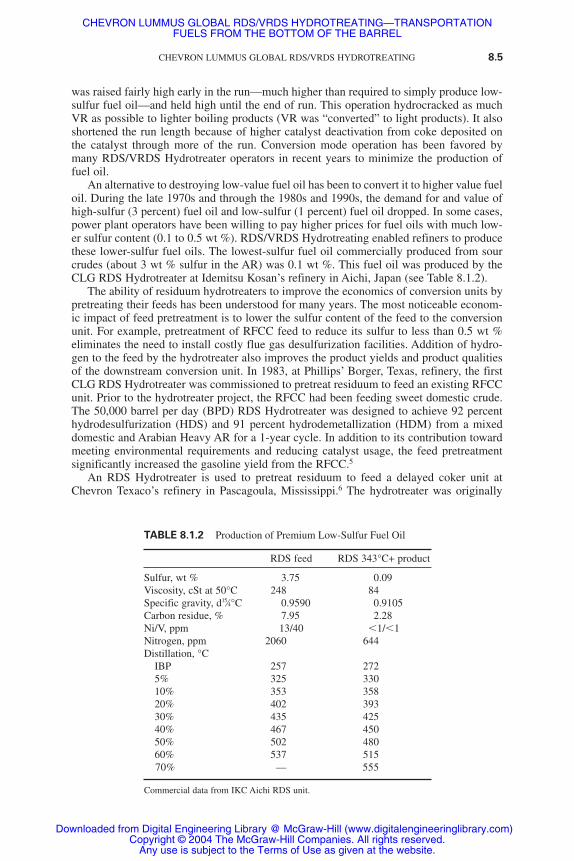
An alternative to destroying low-value fuel oil has been to convert it to higher value fueloil. During the late 1970s and through the 1980s and 1990s, the demand for and value ofhigh-sulfur (3 percent) fuel oil and low-sulfur (1 percent) fuel oil dropped. In some cases,power plant operators have been willing to pay higher prices for fuel oils with much low-er sulfur content (0.1 to 0.5 wt %). RDS/VRDS Hydrotreating enabled refiners to producethese lower-sulfur fuel oils. The lowest-sulfur fuel oil commercially produced from sourcrudes (about 3 wt % sulfur in the AR) was 0.1 wt %. This fuel oil was produced by theCLG RDS Hydrotreater at Idemitsu Kosan’s refinery in Aichi, Japan (see Table 8.1.2).
The ability of residuum hydrotreaters to improve the economics of conversion units bypretreating their feeds has been understood for many years. The most noticeable econom-ic impact of feed pretreatment is to lower the sulfur content of the feed to the conversionunit. For example, pretreatment of RFCC feed to reduce its sulfur to less than 0.5 wt %eliminates the need to install costly flue gas desulfurization facilities. Addition of hydro-gen to the feed by the hydrotreater also improves the product yields and product qualitiesof the downstream conversion unit. In 1983, at Phillips’ Borger, Texas, refinery, the firstCLG RDS Hydrotreater was commissioned to pretreat residuum to feed an existing RFCCunit. Prior to the hydrotreater project, the RFCC had been feeding sweet domestic crude.The 50,000 barrel per day (BPD) RDS Hydrotreater was designed to achieve 92 percenthydrodesulfurization (HDS) and 91 percent hydrodemetallization (HDM) from a mixeddomestic and Arabian Heavy AR for a 1-year cycle. In addition to its contribution towardmeeting environmental requirements and reducing catalyst usage, the feed pretreatmentsignificantly increased the gasoline yield from the RFCC.5
An RDS Hydrotreater is used to pretreat residuum to feed a delayed coker unit atChevron Texaco’s refinery in Pascagoula, Mississippi.6 The hydrotreater was originally
CHEVRON LUMMUS GLOBAL RDS/VRDS HYDROTREATING 8.5
TABLE 8.1.2 Production of Premium Low-Sulfur Fuel Oil
RDS feed RDS 343°C+ product
Sulfur, wt % 3.75 0.09Viscosity, cSt at 50°C 248 84Specific gravity, d15⁄4°C 0.9590 0.9105Carbon residue, % 7.95 2.28Ni/V, ppm 13/40 �1/�1Nitrogen, ppm 2060 644Distillation, °C
IBP 257 2725% 325 33010% 353 35820% 402 39330% 435 42540% 467 45050% 502 48060% 537 51570% — 555
Commercial data from IKC Aichi RDS unit.
CHEVRON LUMMUS GLOBAL RDS/VRDS HYDROTREATING—TRANSPORTATIONFUELS FROM THE BOTTOM OF THE BARREL
Downloaded from Digital Engineering Library @ McGraw-Hill (www.digitalengineeringlibrary.com)Copyright © 2004 The McGraw-Hill Companies. All rights reserved.
Any use is subject to the Terms of Use as given at the website.
designed to remove sulfur and metals from the feed to the coker so that the coke wouldhave less sulfur and metals and be easier to sell. Since its commissioning in 1983, the RDSunit has provided significant economic benefit to the refinery. Coke production has beenreduced and the proportion of light products is higher than it would have been without theRDS. This includes converting VR (which would otherwise be fed to the coker) to VGO,diesel, and naphtha in the RDS Hydrotreater. In addition, the hydrotreated VR from theRDS produces lower weight percent coke in the coker than the straight-run VR. Both ofthese effects lead to lower coke production and more light products from the refinery. TheRDS Hydrotreater at Pascagoula remains the largest residuum hydrotreater in the world at96,000 BPD.
Refiners have been hydrotreating residuum for over 25 years. In that time, residuumhydrotreating has changed with the needs of refiners from its initial function of removingsulfur from fuel oil to converting residuum directly and to improving the economics ofdownstream conversion units. Fixed-bed residuum hydrotreating continues to be a popularroute to residuum conversion.
PROCESS DESCRIPTION
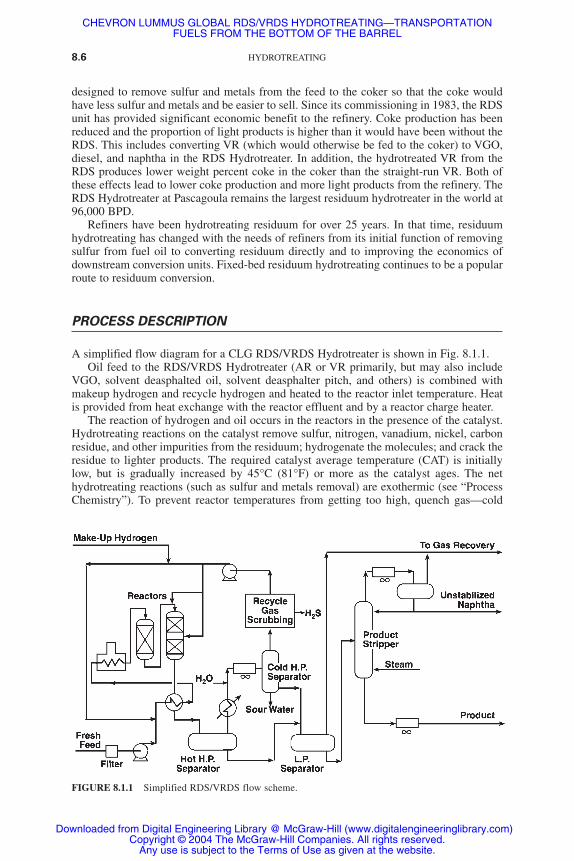
A simplified flow diagram for a CLG RDS/VRDS Hydrotreater is shown in Fig. 8.1.1.Oil feed to the RDS/VRDS Hydrotreater (AR or VR primarily, but may also include
VGO, solvent deasphalted oil, solvent deasphalter pitch, and others) is combined withmakeup hydrogen and recycle hydrogen and heated to the reactor inlet temperature. Heatis provided from heat exchange with the reactor effluent and by a reactor charge heater.
The reaction of hydrogen and oil occurs in the reactors in the presence of the catalyst.Hydrotreating reactions on the catalyst remove sulfur, nitrogen, vanadium, nickel, carbonresidue, and other impurities from the residuum; hydrogenate the molecules; and crack theresidue to lighter products. The required catalyst average temperature (CAT) is initiallylow, but is gradually increased by 45°C (81°F) or more as the catalyst ages. The nethydrotreating reactions (such as sulfur and metals removal) are exothermic (see “ProcessChemistry”). To prevent reactor temperatures from getting too high, quench gas—cold
8.6 HYDROTREATING
FIGURE 8.1.1 Simplified RDS/VRDS flow scheme.
CHEVRON LUMMUS GLOBAL RDS/VRDS HYDROTREATING—TRANSPORTATIONFUELS FROM THE BOTTOM OF THE BARREL
Downloaded from Digital Engineering Library @ McGraw-Hill (www.digitalengineeringlibrary.com)Copyright © 2004 The McGraw-Hill Companies. All rights reserved.
Any use is subject to the Terms of Use as given at the website.

recycled hydrogen gas—is added between reactors and between catalyst beds of multiple-bed reactors to maintain reactor temperatures in the desired range.
Reactors in hydrotreating service have carefully designed internals to assure good dis-tribution of gas and liquid. In multiple-bed reactors, quench spargers disperse the quenchgas evenly across the reactor to maintain even reactor temperatures. CLG provides bothsingle-bed and multiple-bed RDS/VRDS reactors, depending on the needs of the refiner.Single-bed reactors are relatively small, typically 400,000 to 900,000 kg in weight, andtherefore single-bed reactors are easier to install and to unload catalyst from than multi-ple-bed reactors. Multiple-bed reactors tend to be larger, 600,000 to 1,200,000 kg, but takeup less plot space in a refinery compared to several single-bed reactors. This is very impor-tant in refineries where space is limited.
The reactor effluent is cooled (by heat exchange with the reactor feed) to recover theheat released from the hydrotreating reactions. This heat exchange helps to reduce the fuelrequired in the feed heater. After cooling, the reactor effluent is flashed in the hot, high-pressure separator (HHPS) to recover hydrogen and to make a rough split between lightand heavy reaction products. The reactor effluent heat exchange maintains the HHPS at aconstant temperature, which is important in protecting the reaction products. If the HHPStemperature is too high, thermal cracking and coking reactions might take place in theHHPS (in the absence of catalyst) and downstream (in the absence of hydrogen and cata-lyst) and might degrade the oil. The liquid from the HHPS is let down in pressure, sent tothe low-pressure separators, and then on to the product fractionator.
The HHPS vapor is cooled and water is injected to absorb hydrogen sulfide (H2S) andammonia (NH3) produced in the reactors by the hydrotreating reactions. The mixture isfurther cooled to condense the product naphtha and gas oil and is flashed in the cold, high-pressure separator (CHPS). The CHPS separates the vapor, liquid water, and the liquidlight hydrocarbons. The hydrocarbon liquid is let down in pressure and sent to the low-pressure separators. The water is sent to a sour water recovery unit for removal of thehydrogen sulfide and ammonia.
The hydrogen-rich gas from the CHPS flows to the H2S absorber. There the H2S thatwas not removed by the injected water is removed through contact with a lean amine solu-tion. The purified gas flows to the recycle compressor where it is increased in pressure sothat it can be used as quench gas and recombined with the feed oil.
Hydrogen from the reactors is purified and recycled to conserve this expensive rawmaterial. Recycling the hydrogen is also important to provide high gas flow rates. Highgas-to-feed-oil ratios provide a desirable excess of hydrogen in the reactors (see “ProcessChemistry” section) and ensure good gas and liquid flow distribution in the reactors. Therecycle hydrogen gas is also used for reactor quench.
Liquid from the low-pressure separators is fed to the atmospheric fractionator, whichsplits the hydroprocessed oil from the reactors into the desired final products.
PROCESS CHEMISTRY
Heteroatoms
Any atom in a crude oil molecule which is neither hydrogen nor carbon is called aheteroatom. Heteroatoms include sulfur, nitrogen, oxygen, nickel, vanadium, iron, sodium,calcium, and other less common atoms.
Carbon Residue
Carbon residue is a measurement of the tendency of a hydrocarbon to form coke.Expressed in weight percent, carbon residue is measured by microcarbon residue (MCR;
CHEVRON LUMMUS GLOBAL RDS/VRDS HYDROTREATING 8.7
CHEVRON LUMMUS GLOBAL RDS/VRDS HYDROTREATING—TRANSPORTATIONFUELS FROM THE BOTTOM OF THE BARREL
Downloaded from Digital Engineering Library @ McGraw-Hill (www.digitalengineeringlibrary.com)Copyright © 2004 The McGraw-Hill Companies. All rights reserved.
Any use is subject to the Terms of Use as given at the website.
American Society for Testing and Materials specification ASTM D4530), by Conradsoncarbon residue (CCR; ASTM D189), a considerably older test, or by Ramsbottom carbonresidue (RCR; ASTM D524). MCR is the preferred measurement technique because it ismore accurate than the other methods and requires a smaller sample. Instruments thatmeasure MCR are very inexpensive. MCR is roughly equivalent to CCR and both corre-late well to RCR. Carbon residue is useful in predicting the performance of a hydrocarbonin a coker or FCC unit. While carbon residue is not a direct measure, it does correlate wellwith, the amount of coke formed when the oil is processed in cokers or FCCs.
Asphaltenes
Residual oil is composed of a broad spectrum of molecules. The number of specific mol-ecules in residual oil is too large to classify, and therefore researchers have developed ana-lytical techniques for separating these molecules for better understanding. The mostcommon separation of residual oils is into asphaltenes and maltenes. This is done by dilut-ing the residue with large quantities of normal paraffins such as n-heptane or n-pentane.The maltene fraction will remain in solution with the paraffin phase while the asphaltenefraction will form a separate phase. This is the principle behind the refinery process calledsolvent deasphalting (SDA).
The molecules in the maltene fraction can be further separated into fractions of vary-ing polarity by being passed over columns packed with different adsorbents. A full descrip-tion of these separation techniques is provided by Speight.7
There is considerable disagreement about what constitutes an asphaltene moleculebeyond its insolubility in a paraffinic solvent. Still, the subject of asphaltenes is important.The high concentration of heteroatoms in the asphaltenes requires that at least some of theasphaltene molecules be hydrotreated to have high removals of the heteroatoms. In addi-tion, the hydrogen content of asphaltene molecules must be increased if they are to betransformed to transportation fuels.
Converting asphaltene molecules to nonasphaltene molecules is a major challenge forrefiners. As processing VR or AR becomes more severe, coke is formed (in FCCs or cok-ers, for example) or the asphaltenes become insoluble in the processed residuum and pre-cipitate out in a sticky, equipment-plugging material commonly referred to as dry sludge.Of course, the asphaltenes were soluble in the maltenes in the original residuum, so theprocessing must have caused some change to the maltenes, or to the asphaltenes, or toboth. Dry sludge formation usually limits the practical severity in which residuum can beprocessed in many conversion units including residuum hydroprocessing units (see “DrySludge Formation” below).
Hydroprocessing Reactions
Reactions in an RDS or VRDS Hydrotreater take place in the liquid phase, since much ofthe residual feed and product molecules do not vaporize at reactor pressure and tempera-ture. The oil in the reactor is saturated with hydrogen gas because the partial pressure ofhydrogen is very high and hydrogen is available in great excess (typically 10 to 30 molesof hydrogen for each mole of oil feed). The oil and hydrogen reactant molecules diffusethrough the liquid oil filling the catalyst pores and adsorb onto the catalyst surface wherethe hydrotreating reactions take place. Larger molecules tend to adsorb more strongly ontothe catalyst surface than smaller molecules. This means that the large VR molecules tendto dominate the reactions on the catalyst when they can successfully diffuse into the cata-lyst pores. The product molecules must then desorb from the catalyst surface and diffuseout through the liquid that fills the catalyst pores.
8.8 HYDROTREATING
CHEVRON LUMMUS GLOBAL RDS/VRDS HYDROTREATING—TRANSPORTATIONFUELS FROM THE BOTTOM OF THE BARREL
Downloaded from Digital Engineering Library @ McGraw-Hill (www.digitalengineeringlibrary.com)Copyright © 2004 The McGraw-Hill Companies. All rights reserved.
Any use is subject to the Terms of Use as given at the website.

On the catalyst surface, sulfur, nitrogen, nickel, and vanadium atoms are removed fromthe residual molecules, and carbon-to-carbon bonds are broken. These reactions generallylead to cracking the original oil molecules to smaller molecules, which boil at a lower tem-perature. As a result the viscosity of the oil is also reduced. When the product is used asfuel oil, less volume of expensive cutter stock (such as jet or diesel) is required to meet agiven viscosity specification.
Hydrotreating is very exothermic. The heat produced by the reactions causes the gasand oil to increase in temperature as they pass down through the catalyst beds. The tem-perature in the reactors is controlled by the addition of hydrogen quench gas between reac-tors and between catalyst beds within a reactor. The heat produced by the reactions isrecovered in the reactor effluent heat exchangers and used to preheat the feed upstream ofthe feed furnace.
There are fundamental differences between the removal of the different impurities,largely because of the structure of the molecules in the residuum. Sulfur atoms tend to bebound in the oil as “sulfur bridges” between two carbon atoms or to be contained in a sat-urated ring structure (see Fig. 8.1.2). Removal of these sulfur atoms usually requires onlythe breaking of the two sulfur-carbon bonds per sulfur atom and the subsequent additionof four atoms of hydrogen to cap the ends of the bonds that were broken. When the part ofthe molecule that contains the sulfur can access the catalyst surface, sulfur removal is rel-atively easy. Figure 8.1.3 shows the hydroprocessing reactions of dibenzothiophene as anexample of a sulfur-bearing petroleum molecule. The reaction pathway to produce phenyl-benzene is favored because it does not require the saturation of an aromatic ring structure.
Nitrogen atoms tend to be bound in the aromatic rings in the residual molecules (seeFig. 8.1.4). It is usually necessary to saturate the aromatic ring that contains the nitrogenatom with hydrogen before the nitrogen-carbon bonds can be broken and the nitrogenremoved. This requirement to saturate aromatic rings makes the removal of nitrogen muchmore difficult than the removal of sulfur. Figure 8.1.5 shows the hydroprocessing reactionsof quinoline as an example of a nitrogen-bearing petroleum molecule. The first step alongany reaction pathway toward removal of the nitrogen atom is the saturation of an aromat-
CHEVRON LUMMUS GLOBAL RDS/VRDS HYDROTREATING 8.9
FIGURE 8.1.2 Typical petroleum molecules that contain sulfur atoms.Sulfur atoms usually have simple chemical bonds in petroleum.
CHEVRON LUMMUS GLOBAL RDS/VRDS HYDROTREATING—TRANSPORTATIONFUELS FROM THE BOTTOM OF THE BARREL
Downloaded from Digital Engineering Library @ McGraw-Hill (www.digitalengineeringlibrary.com)Copyright © 2004 The McGraw-Hill Companies. All rights reserved.
Any use is subject to the Terms of Use as given at the website.

ic ring structure. The amount of nitrogen removed is almost always lower than that of sul-fur because of the relative difficulty of the reactions. Also, high levels of removal of nitro-gen require high hydrogen partial pressure and catalysts with very high hydrogenationactivity.
Nickel and vanadium atoms are generally bound into a porphyrin structure in theresidue. Figure 8.1.6 shows a typical vanadyl-porphyrin molecule. These structures arequite flat, and the metals are relatively easy to remove if the catalyst has sufficiently largepores to accommodate the large molecules that contain them. Vanadium tends to be mucheasier to remove than nickel.
The removed sulfur and nitrogen are converted into hydrogen sulfide and ammoniagases. The hydrogen sulfide and ammonia diffuse out of the catalyst pore with the oth-er reactants. The removed nickel and vanadium are bound up with sulfur and remain onthe catalyst surface. Fresh hydrotreating catalyst undergoes a very rapid fouling as itsfresh active metals are covered with a layer of nickel and vanadium from the crude.Fortunately, nickel and vanadium are themselves catalytic metals (although much lessactive than the original catalytic metals), therefore the catalyst surface retains someactivity, though considerably less than the fresh catalyst. Eventually, however, the nick-el and vanadium sulfide molecules fill up the catalyst pores and reduce the ability of thelarge residuum molecules to diffuse through the liquid filling the pores. When access ofthe residuum molecules to the catalyst surface becomes severely restricted, the catalysthas lost its hydrotreating activity (see “Catalysts” below).
Other undesirable side effects of the hydroprocessing reactions occur if some of thehigh molecular weight residuum molecules that adsorb onto the catalyst surface react withother oil molecules instead of with hydrogen. This is a particular problem when the hydro-
8.10 HYDROTREATING
FIGURE 8.1.3 Typical desulfurization reaction. Sulfur can usually be removed without having tosaturate aromatic rings.
CHEVRON LUMMUS GLOBAL RDS/VRDS HYDROTREATING—TRANSPORTATIONFUELS FROM THE BOTTOM OF THE BARREL
Downloaded from Digital Engineering Library @ McGraw-Hill (www.digitalengineeringlibrary.com)Copyright © 2004 The McGraw-Hill Companies. All rights reserved.
Any use is subject to the Terms of Use as given at the website.

gen partial pressure in the reactor is low. In this case, the molecules grow larger. If theygrow large enough they may not readily desorb from the catalyst surface, but remain onthe catalyst surface as coke. The coke formed in this fashion leads to a severe deactivationof the catalyst.
Dry Sludge Formation
One other undesirable effect of hydroprocessing reactions is that the solubility of theasphaltenes usually decreases with increased processing of the residue. This occurs even
CHEVRON LUMMUS GLOBAL RDS/VRDS HYDROTREATING 8.11
FIGURE 8.1.4 Typical petroleum molecules thatcontain nitrogen atoms. Nitrogen atoms usuallyhave complex, aromatic bonds in petroleum.
FIGURE 8.1.5 Typical denitrification reaction. Nitrogen can seldom be removed without saturating aro-matic rings.
CHEVRON LUMMUS GLOBAL RDS/VRDS HYDROTREATING—TRANSPORTATIONFUELS FROM THE BOTTOM OF THE BARREL
Downloaded from Digital Engineering Library @ McGraw-Hill (www.digitalengineeringlibrary.com)Copyright © 2004 The McGraw-Hill Companies. All rights reserved.
Any use is subject to the Terms of Use as given at the website.

though the quantity of asphaltenes is reduced during the hydroprocessing. Unfortunately,while the asphaltenes are destroyed by being hydrogenated and cracked, the maltene fractionof the residue is also being hydrogenated and cracked—usually more severely than theasphaltenes. Since the maltenes are generally smaller molecules, it is easy for them to diffuseinto the catalyst pores and be hydrotreated. In this hydrotreatment, aromatic rings are hydro-genated and aliphatic side chains are removed by cracking. These reactions reduce the abilityof the maltene fraction to solubilize the asphaltenes. Usually, the loss of solubility of themaltenes for the asphaltenes occurs faster than the asphaltenes can be converted and theasphaltenes drop out of solution. The precipitated asphaltenes create dry sludge, which plugsup equipment, and, at its worst, can deposit in the catalyst and eventually form coke. This rap-idly deactivates the catalyst. Even when the dry sludge does not deactivate the catalyst orcause operating problems by plugging equipment in the residuum hydrotreater, it can causeproblems in the downstream processing units or make the product fuel oil unsalable.
Conversion
Hydrocracking is the transformation of larger, high-boiling-point hydrocarbons into small-er, lower-boiling-point hydrocarbons in the presence of hydrogen. In residuum hydrotreat-ing, this transformation can take place because of the breaking of a carbon-to-carbon bondor because of the removal of a heteroatom that was bonding to two otherwise unconnect-ed pieces of hydrocarbon. Since many of the carbon atoms in VR are in aromatic rings, itis necessary to hydrogenate the molecules and saturate the rings before bonds can be bro-ken and the molecules cracked.
In residuum hydroprocessing, it is common to refer to the hydrocracking of the residueas conversion. In this usage, conversion is defined as the destruction of residue boilinghigher than a certain true boiling point temperature [usually 538°C (1000°F)] to productboiling lower than that temperature. Conversion can be calculated as (FT+ � PT+)/FT+,where FT+ is the volume fraction of the feed boiling above temperature T and PT+ is thevolume fraction of the product boiling above temperature T. The hydroprocessing of theresidue and conversion of the residue are linked; it is not possible to do one without doingthe other. For most conventional residuum hydrotreating catalysts, conversion is primarilya function of the catalyst temperature and the space velocity.
It has been noted4 that the formation of dry sludge is related to the level of conversionof the residuum hydrotreater. This is certainly true when the catalyst and feed are not
8.12 HYDROTREATING
FIGURE 8.1.6 Typical vanadyl-por-phyrin molecule. Porphyrin structuresare very flat and vanadium is easilyremoved—if the molecules can diffusethrough the catalysts’ pores.
CHEVRON LUMMUS GLOBAL RDS/VRDS HYDROTREATING—TRANSPORTATIONFUELS FROM THE BOTTOM OF THE BARREL
Downloaded from Digital Engineering Library @ McGraw-Hill (www.digitalengineeringlibrary.com)Copyright © 2004 The McGraw-Hill Companies. All rights reserved.
Any use is subject to the Terms of Use as given at the website.

changed significantly. The presence of VGO in the feed can lower the conversion at whichsludge formation becomes a problem (because of the poor ability of hydroprocessed VGOto solubilize asphaltenes). Small-pore, high-surface-area catalysts can also have a delete-rious effect on product stability because they can selectively hydroprocess maltene mole-cules without destroying any asphaltene molecules. Generally, fixed-bed residuumhydrotreaters achieve conversions between 20 and 60 LV % at normal operating conditionsand the onset of dry sludge occurs generally between 45 and 60 LV % conversion depend-ing on the feed, processing conditions, and catalyst system.
Note that the VGO in the feed to an RDS Hydrotreater is a very poor solvent forasphaltenes—particularly after it becomes highly hydrogenated. VRDS Hydrotreaters,therefore, can operate at 5 to 10 percent higher cracking conversion than RDSHydrotreaters before the onset of dry sludge formation.
CATALYSTS
Designing residuum hydroprocessing catalyst for high activity is a compromise. Early cat-alysts, which had been developed to hydrotreat light oils, had pore sizes that were toosmall to hydrotreat residuum; The catalyst pores became plugged with metals and coke andwere very quickly deactivated. Catalysts were modified for AR and VR hydroprocessingby increasing their pore sizes, but this led to less active surface area and much lower activ-ity for hydroprocessing reactions.
Fixed-bed residuum hydrotreating catalysts are generally small, extruded pellets madefrom an alumina base. The pellets are impregnated with catalytic metals—often calledactive metals—that have good activity for hydrogen addition reactions. Active metals thatare used for RDS/VRDS Hydrotreater catalysts include cobalt, nickel, molybdenum, andother more proprietary materials. The catalyst pellets are usually small, 0.8 to 1.3 mm indiameter, because the reaction kinetics are usually diffusion-limited; a small catalyst pel-let with high surface-to-volume ratio has better diffusion for the relatively large residuummolecules, and this leads to better reactivity. Different shapes of extruded pellets are oftenused to take advantage of the high surface-to-volume ratio of some shaped pellets whilestill maintaining reasonable reactor pressure drop.
The pore diameters of residuum hydrotreating catalysts need to be quite large, relativeto catalysts found in other refinery processes, to accommodate the large residuum mole-cules that need to be treated. Unfortunately, as the size of the pores increases, the surfacearea decreases and so does the catalyst activity. Another complication is that, as the nick-el and vanadium atoms are removed from the residuum, they form nickel and vanadiumsulfides that deposit on the catalyst surface. The metal sulfides build up on the active sur-face and fill up the catalyst pores. The metal sulfides tend to deposit near the openings ofthe catalyst pores and plug these pore openings. This is because the residuum moleculesthat contain nickel and vanadium are quite large and do not diffuse far into the catalystpores before they are removed. The diffusion of the large residuum molecules is reducedeven further by the plugging of the pore openings by the metal sulfides. If the large mole-cules cannot enter the pores and thus have no access to the active catalyst surface, they can-not be hydrotreated.
To overcome the limitations of the small pore versus large pore trade-off, CLGdesigns systems of catalyst that are layered such that catalyst activity increases as theresiduum moves through the reactor. The catalysts that the residue first contacts havelarge pores to successfully remove the vanadium and nickel from the large molecules thatcontain these impurities and to resist deactivation (due to pore plugging) from theseremoved metals. Later catalysts, which see lower nickel- and vanadium-content oil, canhave smaller pores and higher surface activity to perform more hydrotreating reactions.
CHEVRON LUMMUS GLOBAL RDS/VRDS HYDROTREATING 8.13
CHEVRON LUMMUS GLOBAL RDS/VRDS HYDROTREATING—TRANSPORTATIONFUELS FROM THE BOTTOM OF THE BARREL
Downloaded from Digital Engineering Library @ McGraw-Hill (www.digitalengineeringlibrary.com)Copyright © 2004 The McGraw-Hill Companies. All rights reserved.
Any use is subject to the Terms of Use as given at the website.

CLG’s RDS and VRDS catalysts are developed and produced by advanced RefiningTechnology (ART), a joint venture of Chevron Texaco and Grace Division. CLG general-ly calls its most metal-tolerant metal-removal catalysts hydrodemetallization catalysts.However, CLG’s HDM catalysts also promote hydrodesulfurization, hydrodenitrification(HDN), and other conversion reactions. Catalysts which have higher activity for HDS reac-tions and carbon residue reduction, and less tolerance for metals, are called hydrodesulfu-rization catalysts. HDS catalysts also have good reactivity for HDM and HDN reactionsand cracking conversion in addition to being somewhat metal-tolerant (although not asmetal-tolerant as HDM catalysts). Finally, CLG has a few catalysts that have very highactivity for HDN reactions. They are the most difficult reactions to achieve in anRDS/VRDS Hydrotreating unit. HDN catalysts are also very active for HDS, carbonresidue reduction, and cracking conversion. They tend to have little demetallization activ-ity and are not very tolerant to metal poisoning.
Selecting the amounts and types of catalysts for an RDS/VRDS Hydrotreater requiresextensive pilot plant data, commercial plant data, and a good reactor kinetics model.
VRDS HYDROTREATING
In many countries the demand for gasoline relative to middistillate is much lower than thetypical product slate from a refinery that relies on an FCC for its conversion capacity.Many projects have relied on VGO hydrocracking to give high yields of top-quality mid-dle distillates (see Chap. 7.2).
Given the attractiveness of using the VGO component as hydrocracker feed, it hasbecome an important consideration that the residuum hydrotreater be capable of efficient-ly processing 100 percent VR. CLG VRDS Hydrotreating has been successfully process-ing this difficult feedstock since 1977.
The characteristics of an acceptable RFCC feedstock are as shown in Table 8.1.3. Theserequirements are readily obtained by CLG RDS units and can be met in a CLG VRDS forVRs derived from Arabian Heavy, Arabian Light, and Kuwait as well as most other popu-lar crude oils.
VR is more difficult to hydrotreat than AR because there is no easily processed VGOin the feed. Therefore, VRDS relies heavily on the ability of catalysts to upgrade the heavycompounds found in the VR. CLG and ART have tailored catalysts for use in either RDSor VRDS service. Catalysts designed for RDS operation are not necessarily effective forVRDS service and vice versa.
The effectiveness of the catalyst for upgrading VR is indicated by the amount of demet-allization, asphaltene removal, and desulfurization achieved while still producing a stableproduct (no solid or asphaltene precipitation). Table 8.1.4 shows an example of VRDSpilot plant processing of an Arabian Heavy/Kuwait VR mixture to 99 percent HDM, 97percent HDS, and 82 percent carbon residue reduction. While such high severity is seldomrequired, it clearly illustrates the capability of the VRDS process.
8.14 HYDROTREATING
TABLE 8.1.3 RFCC Feed Targets
Sulfur 0.5% max. to avoid flue gas desulfurization in the RFCCCarbon residue 7–10% max. to limit catalyst cooling requirementsNickel + vanadium 5–25 ppm to limit RFCC catalyst consumptionCrackability A combination of hydrogen content, boiling range, and viscosity that
promotes vaporization and cracking at the injection point
CHEVRON LUMMUS GLOBAL RDS/VRDS HYDROTREATING—TRANSPORTATIONFUELS FROM THE BOTTOM OF THE BARREL
Downloaded from Digital Engineering Library @ McGraw-Hill (www.digitalengineeringlibrary.com)Copyright © 2004 The McGraw-Hill Companies. All rights reserved.
Any use is subject to the Terms of Use as given at the website.

VRDS reactors must handle very viscous feeds relative to RDS reactors. The unusual two-phase flow reactor hydrodynamics encountered with VR feeds dictate special design consid-erations to avoid unreasonably high and unstable reactor pressure drops. This was the subjectof a considerable amount of pilot plant and scaleup testing prior to the start-up of the firstVRDS Hydrotreater in 1977 at Chevron Texaco El Segundo refinery. Experience gained onprocessing 100 percent VR at El Segundo, together with data from the earlier laboratory study,were the basis for the design of a VRDS Hydrotreater for the Nippon Petroleum RefiningCompany that was started up at their Muroran, Japan, refinery in 1982.8 Extensive experiencewith 100 percent VR has enabled CLG to produce a trouble-free technology.
Converting RDS to VRDS
The RDS Hydrotreater at the Mizushima refinery of the Japan Energy Company (former-ly the Nippon Mining Company) operated with AR for several years and was successfullyconverted to process VR in 1981.9 For the next few catalyst cycles following the conver-sion to VRDS, the unit gradually increased the fraction of VR in its feed until 100 percentVR was processed over the entire run.
FEED PROCESSING CAPABILITY
Handling Impurities
In addition to the high concentrations of impurities that have already been discussed (sul-fur, nitrogen, carbon residue, nickel, and vanadium), residues also contain high concentra-tions of particles such as iron sulfide scales and reservoir mud. If fed directly to a fixed-bedRDS/VRDS Hydrotreater, these particles would be filtered out by the small catalyst pel-lets and would form a crust. This crust would cause the pressure drop across the catalystbed to increase dramatically, disturb the even distribution of oil and gas in the reactor, andeventually force a plant shutdown because of excessive pressure drop.
The first line of defense against particles in an RDS/VRDS Hydrotreater is the feedfilter. These filters have small openings, commonly 25 microns, which allow the filteredoil to pass but retain the larger particulates. When the pressure drop across the filters
CHEVRON LUMMUS GLOBAL RDS/VRDS HYDROTREATING 8.15
TABLE 8.1.4 Chevron VRDS Pilot Plant Performance
VRDS Feed* VRDS Product
Boiling range, °C 538+ 343+Gravity, °API 4.6 18.1CCR, wt % 23.1 5.7Sulfur, wt % 5.3 0.24Nitrogen, wt % 0.42 0.15Nickel+ vanadium, ppm 195 3Viscosity, cSt at 100°C 5500 32538°C+ conversion, LV % 54.2343°C+ yield, LV % 81.4H2 consumption, SCFB 1650
*Arabian Heavy/Kuwait in 50/50 volume ratio.Note: °API � degrees on American Petroleum Institute scale;
SCFB � standard cubic feet per barrel.
CHEVRON LUMMUS GLOBAL RDS/VRDS HYDROTREATING—TRANSPORTATIONFUELS FROM THE BOTTOM OF THE BARREL
Downloaded from Digital Engineering Library @ McGraw-Hill (www.digitalengineeringlibrary.com)Copyright © 2004 The McGraw-Hill Companies. All rights reserved.
Any use is subject to the Terms of Use as given at the website.

becomes excessive, they are automatically removed from service and briefly back-washed with oil. The particles that the feed filters remove would cause a very severeincrease in pressure drop across the reactors, and therefore feed filtration is required forall residuum hydrotreaters. Even so, small particles pass on to the catalyst beds.
Some of the particles that pass through the feed filters are small enough to pass throughthe catalyst in the reactors as well. These particles do not affect the operation of theRDS/VRDS Hydrotreater. However, some particles are small enough to pass through the feed filters, but large enough to be trapped by the catalyst beds. These particles fill upthe spaces between the catalyst and lead to increasing reactor pressure drop. This increasedpressure drop is especially severe when the particles are all removed at one point in the reac-tor system. A large pressure drop increase can cause the refiner to decrease the feed rate orshut down the plant before the catalytic activity of the catalyst has been expended.
In addition to particles, high-reactivity metals such as iron can cause considerable oper-ating difficulty for a fixed-bed residuum hydrotreater. Oil-soluble iron is highly reactiveand is easily removed right on the outside of very active catalyst pellets. The removed ironquickly fills up the area between the catalyst pellets and leads to pressure drop increase.Oil-soluble calcium is also present in some crudes and can cause pressure drop increasesand catalyst poisoning.
Catalyst Grading to Prevent Pressure Drop Increase
In the early development of residuum hydroprocessing, the high levels of insoluble andsoluble iron in some California crudes caused Chevron to develop top bed grading tech-nology10 to minimize problems associated with these metals. Chevron was the first com-pany to use a catalyst grading system in a commercial hydrotreater, in 1965. Specialcalcium removal catalysts have been applied in a VRDS Hydrotreater where the feed con-tained more than 50 wt ppm calcium. Effective catalyst grading combines physical grad-ing of the catalyst by size and shape and grading of the catalyst by activity.
The goal of physical grading is to filter out particles in the grading catalyst that wouldotherwise plug the top of the smaller active catalyst pellets. By carefully changing the sizesand shapes of the physical grading catalyst, one can remove particles over several layersand therefore reduce their tendency to cause the pressure drop to increase.
Grading catalyst by activity means to gradually increase the surface activity of the cat-alyst down the reactor system. The oil is then exposed first to catalyst with very low activ-ity that forces the reactive metals (iron and calcium, for example) to penetrate into thecatalyst. There the removed metals do not fill up the space between pellets and pressuredrop increase is avoided. The catalyst activity is increased in subsequent layers until all ofthe reactive metals have been removed.
Catalyst grading for preventing pressure drop increase cannot be accurately simulatedon a small (pilot plant) scale because the flow regimes are much different. Extensive refin-ery experience forms the basis for the catalyst grading techniques used by CLG and ART.This experience includes data from a commercial unit feeding deasphalted oil that con-tained particulate and soluble iron, as well as very reactive nickel and vanadium. Propercatalyst grading techniques allow RDS/VRDS Hydrotreaters to run until catalyst activityis used up rather than shut down prematurely due to excessive pressure drop.
Feed Flexibility
Many types of feeds have been processed in RDS/VRDS Hydrotreaters. Successful pro-cessing of VR feeds as viscous as 6000 centistokes at 100°C have been commerciallydemonstrated.6 Feeds containing up to 500 wt ppm Ni+V have also been commerciallyprocessed11 in a fixed-bed RDS Hydrotreater.
8.16 HYDROTREATING
CHEVRON LUMMUS GLOBAL RDS/VRDS HYDROTREATING—TRANSPORTATIONFUELS FROM THE BOTTOM OF THE BARREL
Downloaded from Digital Engineering Library @ McGraw-Hill (www.digitalengineeringlibrary.com)Copyright © 2004 The McGraw-Hill Companies. All rights reserved.
Any use is subject to the Terms of Use as given at the website.

Chevron catalyst systems can tolerate average feed metals over 200 wt ppm Ni+Vwhile maintaining a 1-year run length. Feeds with considerably higher than 200 wt ppmNi+V can be processed with at least a 1-year run length before catalyst replacement isrequired if the feed is pretreated in an On-Stream Catalyst Replacement reactor. By low-ering the metals in the feed to processable levels, OCR increases the refiner’s flexibility torun less expensive high-metal feeds (see Chap. 10.1).
COMMERCIAL APPLICATION
The use of residuum hydrotreatment to produce LSFO for power plants still continues ascountries adopt stricter environmental regulations. More commonly, however, the refinerwishes to reduce fuel oil yield and have the flexibility to prepare feedstock for a down-stream conversion unit.
Figure 8.1.7 shows a simple scheme for converting residuum to motor gasoline(mogas) using an RFCC. In this scheme, the RDS Hydrotreater significantly upgradesthe RFCC feed. Pretreating the residuum feed increases its hydrogen content andreduces its impurities. For many crudes this upgrade is necessary for the RFCC to beoperable. For other crudes, whose AR could be fed directly to the RFCC, RDSHydrotreating improves the economics of the conversion project and increases the yieldof market-ready light products.
In some residuum upgrading projects, middle distillates are more desirable productsthan mogas. In these projects, CLG’s Isocracking process is the preferred processing routeto produce high-quality middle distillates from the VGO. Figure 8.1.8 shows a scheme inwhich the AR is sent to a vacuum tower to prepare VGO feed for an Isocracker. Theremaining VR is then sent to a VRDS Hydrotreater to be pretreated for an RFCC. High-severity VRDS Hydrotreating has been shown12 to prepare suitable feedstock for an RFCC.This scheme provides the optimal usage of hydrogen for upgrading the residuum. Thehydrogen required by the Isocracker is just the amount necessary to convert the VGO tomiddle distillates. The hydrogen required by the VRDS Hydrotreater is just enough toimprove the volatility and hydrogen content of the VR to be satisfactory for RFCC feed.
CHEVRON LUMMUS GLOBAL RDS/VRDS HYDROTREATING 8.17
FIGURE 8.1.7 Simple residuum conversion. A low cost project to convert residuum into maximummogas.
CHEVRON LUMMUS GLOBAL RDS/VRDS HYDROTREATING—TRANSPORTATIONFUELS FROM THE BOTTOM OF THE BARREL
Downloaded from Digital Engineering Library @ McGraw-Hill (www.digitalengineeringlibrary.com)Copyright © 2004 The McGraw-Hill Companies. All rights reserved.
Any use is subject to the Terms of Use as given at the website.

Many residue upgrading projects need to vary the relative production of gasoline andmiddle distillates with market demands. Figure 8.1.9 shows a scheme where the vacuumcolumn cut point is varied between 425°C (797°F) to produce maximum mogas and565°C (1049°F) to produce maximum middle distillates. Again, the addition of hydro-gen is adjusted to just satisfy the hydrogen upgrading requirements of the product slate.
Finally, some projects need to be installed in phases. Figure 8.1.10 shows the hypotheti-cal transition from a simple upgrading project to a complete and flexible upgrading projectin four phases. Phase 1 consists of an RDS Hydrotreater to reduce the quantity and improvethe quality of fuel oil produced. Phase 2 sees the installation of an RFCC to completelydestroy the residuum. Phase 3 further extends the project by adding a vacuum column witha variable VGO cut point and an Isocracker to make high-quality middle distillates from theVGO. The RDS Hydrotreater processes either AR that has a higher starting cut point than itsoriginal design or pure VR (in the case that all of the VGO is routed to the Isocracker). It isimportant that the residuum hydrotreater in phase 1 be designed with the flexibility toprocess either AR or VR. Finally, phase 4 adds an OCR onto the RDS/VRDS Hydrotreaterto provide greater flexibility to process inexpensive, high-metal crudes.
Example Yields and Product Properties
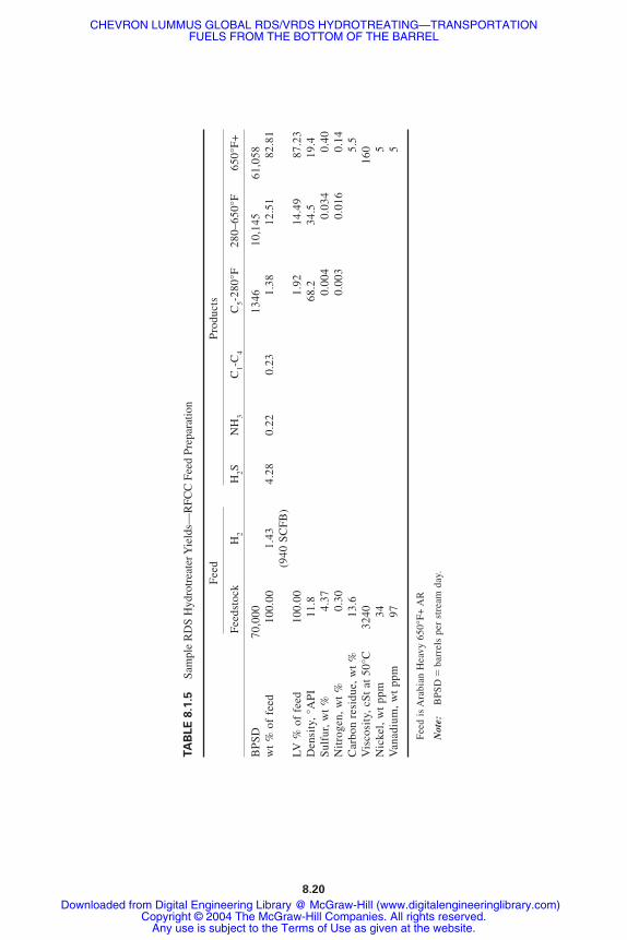
Table 8.1.5 shows the yields and product properties from a sample RDS Hydrotreaterpreparing high-quality RFCC feed (0.4 wt % sulfur) from Arabian Heavy AR (650°F+)
Investment and Utility Consumption Information
Table 8.1.6 shows the estimated investment costs for the RDS Hydrotreater whose yieldsand product properties are given in Table 8.1.5. These estimated costs are based on simi-lar projects executed by Chevron in its refineries.
8.18 HYDROTREATING
FIGURE 8.1.8 Residuum conversion to middle distillate and mogas. Converting the RDS to acceptvacuum residuum and adding an Isocracker enables refiners to produce market-ready middle distillates.
CHEVRON LUMMUS GLOBAL RDS/VRDS HYDROTREATING—TRANSPORTATIONFUELS FROM THE BOTTOM OF THE BARREL
Downloaded from Digital Engineering Library @ McGraw-Hill (www.digitalengineeringlibrary.com)Copyright © 2004 The McGraw-Hill Companies. All rights reserved.
Any use is subject to the Terms of Use as given at the website.

Table 8.1.7 summarizes typical running costs (per stream day and per barrel processed)for the 70,000-BPD RDS Hydrotreater whose yield and product properties are shown inTable 8.1.5. Utility estimates are based on Chevron’s operating experience. The costs inTable 8.1.7 include no capital charges, either for the RDS Hydrotreater or a hydrogen plant(in the event one is required).
Table 8.1.8 summarizes typical total processing costs for the same 70,000 BPD RDSHydrotreater. This estimate includes charges for capital for the RDS Hydrotreater at 25percent of the estimated on-plot and off-plot charges. The charge of $2.50 per thousandcubic feet of hydrogen includes the capital charges for a new hydrogen plant as well as theoperating and raw material costs of producing hydrogen.
CHEVRON LUMMUS GLOBAL RDS/VRDS HYDROTREATING 8.19
FIGURE 8.1.9 Middle distillate to mogas flexibility with VRDS/RFCC. Refiners can respond tochanging demands for mogas and middle distillates by changing VGO cut point in the vacuum tower.
FIGURE 8.1.10 Phased implementation of a residuum conversion project. Chevron’s hydroprocessingtechnologies enable refiners to phase in residuum conversion projects as market demands change.
CHEVRON LUMMUS GLOBAL RDS/VRDS HYDROTREATING—TRANSPORTATIONFUELS FROM THE BOTTOM OF THE BARREL
Downloaded from Digital Engineering Library @ McGraw-Hill (www.digitalengineeringlibrary.com)Copyright © 2004 The McGraw-Hill Companies. All rights reserved.
Any use is subject to the Terms of Use as given at the website.
TA
BL
E 8
.1.5
Sam
ple
RD
S H
ydro
trea
ter Y
ield
s—R
FCC
Fee
d Pr
epar
atio
n
Fee
dP
rodu
cts
Fee
dsto
ck
H2
H2S
NH
3C
1-C
4C
5-28
0°F
280–
650°
F65
0°F
+
BP
SD
70,0
0013
4610
,145
61,0
58w
t %
of
feed
100.
001.
434.
280.
220.
231.
3812
.51
82.8
1(9
40 S
CF
B)
LV %
of
feed
100.
001.
9214
.49
87.2
3D
ensi
ty,°
AP
I11
.868
.234
.519
.4S
ulfu
r,w
t %
4.37
0.00
40.
034
0.40
Nit
roge
n,w
t %
0.30
0.00
30.
016
0.14
Car
bon
resi
due,
wt
%13
.65.
5V
isco
sity
,cS
t at
50°
C32
4016
0N
icke
l,w
t pp
m34
5V
anad
ium
,wt
ppm
975
Fee
d is
Ara
bian
Hea
vy 6
50°F
+ A
R
Not
e:B
PS
D�
barr
els
per
stre
am d
ay.
TABLE 8.1.5
8.20
CHEVRON LUMMUS GLOBAL RDS/VRDS HYDROTREATING—TRANSPORTATIONFUELS FROM THE BOTTOM OF THE BARREL
Downloaded from Digital Engineering Library @ McGraw-Hill (www.digitalengineeringlibrary.com)Copyright © 2004 The McGraw-Hill Companies. All rights reserved.
Any use is subject to the Terms of Use as given at the website.

THE FUTURE
Interest in RDS/VRDS Hydrotreating will continue to expand as environmental restric-tions tighten. This is particularly true in developing countries where energy requirementsare growing rapidly and shifting away from fuel oil to transportation fuels.
Continuously improving catalysts and process technology have enabled RDS/VRDSHydrotreating to adapt to refiners’ changing requirements. Future demands will be placedon RDS/VRDS Hydrotreating to yield products with lower levels of impurities in the faceof increasing impurities in feedstocks. New technologies, such as OCR, are expected tomake major contributions to these residuum hydrotreaters of the future.
REFERENCES
1. H. A. Frumkin and G. D. Gould, “Isomax Takes Sulfur Out of Fuel Oil,” AIChE Meeting, NewOrleans, March 16–20, 1969.
2. A. G. Bridge, E. M. Reed, P. W. Tamm, and D. R. Cash, “Chevron Isomax Processes DesulfurizeArabian Heavy Residua,” 74th National AIChE Meeting, New Orleans, March 11–15, 1973.
3. A. G. Bridge, G. D. Gould, and J. F. Berkman, “Residua Processes Proven,” Oil and Gas Journal,85, January 19, 1981.
4. K. Saito, S. Shinuzym, F. Fukui, and H. Hashimoto, “Experience in Operating High ConversionResidual HDS Process,” AIChE Meeting, San Francisco, November 1984.
5. J. B. Rush and P. V. Steed, “Refinery Experience With Hydroprocessing Resid for FCC Feed,”49th Midyear Refinery Meeting, API, New Orleans, May 16, 1984.
6. B. E. Reynolds, D. V. Law, and J. R. Wilson, “Chevron’s Pascagoula Residuum HydrotreaterDemonstrates Versatility,” NPRA Annual Meeting, San Antonio, March 24–26, 1985.
7. J. G. Speight, The Chemistry and Technology of Petroleum, 2d ed., Marcel Dekker, New York,1991.
8. H. Kanazawa and B. E. Reynolds, “NPRC’s Success With Chevron VRDS,” NPRA AnnualMeeting, San Antonio, March 25–27, 1984.
CHEVRON LUMMUS GLOBAL RDS/VRDS HYDROTREATING 8.21
TABLE 8.1.6 Estimated Investment Summary for RDSHydrotreater to Prepare RFCC Feed
Feed Rate, BPSD 70,000Run length, days 335Operating factor 0.92On-plot investment, million $U.S.:
Major materials 107.2Reactors 73.3Other reactor loop 22.5Fractionation 4.8Makeup compression 6.6
Installation cost 79.3Engineering cost 17.9Indirect cost 29.8Total on-plot cost 234.2
Total off-plot cost (30% of on-plot), million $U.S. 70.3Catalyst cost per charge, million $U.S. 8.8
Basis: second quarter 1995, U.S. Gulf Coast.
CHEVRON LUMMUS GLOBAL RDS/VRDS HYDROTREATING—TRANSPORTATIONFUELS FROM THE BOTTOM OF THE BARREL
Downloaded from Digital Engineering Library @ McGraw-Hill (www.digitalengineeringlibrary.com)Copyright © 2004 The McGraw-Hill Companies. All rights reserved.
Any use is subject to the Terms of Use as given at the website.

TA
BL
E 8
.1.7
Util
ity a
nd R
unni
ng C
ost S
umm
ary
for
70,0
00-B
PD R
DS
Hyd
rotr
eate
r to
Pre
pare
RFC
C F
eed*
Item
Uni
t cos
t†R
ate‡
$/St
ream
day
$/B
bl F
F
Uti
liti
es:
Fuel
$20.
00/E
FO-b
bl27
2 E
FO-B
PD5,
440)
0.07
8)(6
mil
lion
Btu
)Po
wer
$0.0
5/kW
h27
,000
kW
32,4
00)
0.46
3)40
0 lb
/in2ga
ge s
team
$2.0
0/kl
b�
22 k
lb/h
(1,0
56)
(0.0
15)
150
lb/in
2ga
ge s
team
$3.2
5/kl
b11
6 kl
b/h
9,04
8)0.
129)
Coo
ling
wat
er$0
.05/
kgal
8,20
0 ga
l/min
590)
0.00
8)Pr
oces
s in
ject
ion
wat
er$5
.40/
kgal
66 g
al/m
in51
3)0.
007)
Boi
ler
feed
wat
er$6
.30/
kgal
85 g
al/m
in77
1)0.
011)
Con
dens
ate
$5.4
0/kg
al(1
76)
gal/m
in(1
,369
)(0
.020
)
Tota
l Util
ities
46,3
37)
0.66
1)
Hyd
roge
n$0
.85/
kSC
F71
.7 m
illio
n SC
FD60
,945
)0.
871)
Cat
alys
t$8
.80
mill
ion/
year
26,2
06)
0.37
4)O
pera
ting
labo
r$0
.20
mill
ion/
year
/shi
ft2
shif
t pos
ition
s1,
191)
0.01
7)Su
perv
isio
n+su
ppor
t lab
or(5
0% o
f op
erat
ing
labo
r)59
6)0.
009)
Mai
nten
ance
$6.0
9 m
illio
n/ye
ar2%
of
(on
plot
+of
f pl
ot)
18,1
35)
0.25
9)Ta
xes+
insu
ranc
e$3
.13
mill
ion/
year
1% o
f (o
n pl
ot+
off
plot
+ca
taly
st)
9,33
0)0.
133)
Tota
l ru
nnin
g co
st16
2,74
0)2.
324)
*Fee
d is
Ara
bian
Hea
vy 6
50°F
+ A
R.
†Typ
ical
cos
ts b
ased
on
Che
vron
’s o
pera
ting
expe
rien
ce.
‡Pos
itive
num
ber
is c
onsu
mpt
ion
or c
ost,
nega
tive
(in
pare
nthe
ses)
is p
rodu
ctio
n or
cre
dit.
Not
e:E
FO�
equi
vale
nt f
uel o
il; S
CF
�st
anda
rd c
ubic
fee
t; SC
FD�
stan
dard
cub
ic f
eet p
er d
ay; F
F�
fres
h fe
ed.
8.22
CHEVRON LUMMUS GLOBAL RDS/VRDS HYDROTREATING—TRANSPORTATIONFUELS FROM THE BOTTOM OF THE BARREL
Downloaded from Digital Engineering Library @ McGraw-Hill (www.digitalengineeringlibrary.com)Copyright © 2004 The McGraw-Hill Companies. All rights reserved.
Any use is subject to the Terms of Use as given at the website.

TA
BL
E 8
.1.8
Util
ity a
nd T
otal
Cos
t Sum
mar
y fo
r 70
,000
-BPD
RD
S H
ydro
trea
ter
to P
repa
re R
FCC
Fee
d*
Fuel
Uni
t cos
t†R
ate‡
$/St
ream
day
$/bb
l FF
Util
ities
:Fu
el$2
0.00
/EFO
-bbl
272
EFO
-BPD
5,44
0)0.
078)
(6 m
illio
n B
tu)
Pow
er$0
.05/
kWh
27,0
00 k
W32
,400
)0.
463)
400
lb/in
2ga
ge s
team
$2.0
0/kl
b�
22 k
lb/h
(1,0
56)
(0.0
15)
150
lb/in
2ga
ge s
team
$3.2
5/kl
b11
6 kl
b/h
9,04
8)0.
129)
Coo
ling
wat
er$0
.05/
kgal
8,20
0 ga
l/min
590)
0.00
8)Pr
oces
s in
ject
ion
wat
er$5
.40/
kgal
66 g
al/m
in51
3)0.
007)
Boi
ler
feed
wat
er$6
.30/
kgal
85 g
al/m
in77
1)0.
011)
Con
dens
ate
$5.4
0/kg
al(1
76)
gal/m
in(1
,369
)(0
.020
))
Tota
l Util
ities
46,3
37)
0.66
1)
Hyd
roge
n$2
.50/
kSC
F71
.7 m
illio
n SC
FD17
9,25
0)2.
561)
Cat
alys
t$8
.80
mill
ion/
year
26,2
06)
0.37
4)O
pera
ting
labo
r$0
.20
mill
ion/
year
/shi
ft2
shif
t pos
ition
s1,
191)
0.01
7)Su
perv
isio
n+su
ppor
t lab
or(5
0% o
f op
erat
ing
labo
r)59
6)0.
009)
Mai
nten
ance
$6.0
9 m
illio
n/ye
ar2%
of
(on
plot
+of
f pl
ot)
18,1
35)
0.25
9)Ta
xes+
insu
ranc
e$3
.13
mill
ion/
year
1% o
f (o
n pl
ot+
off
plot
+ca
taly
st)
9,33
0)0.
133)
Cap
ital c
harg
e$7
6.12
mill
ion/
year
25%
of
(on
plot
+of
f pl
ot)
226,
691)
3.23
8)
Tota
l pr
oces
sing
cos
t50
7,73
6)7.
252)
*Fee
d is
Ara
bian
Hea
vy 6
50°F
+ A
R.
†Typ
ical
cos
ts b
ased
on
Che
vron
’s o
pera
ting
expe
rien
ce.
‡Pos
itive
num
ber
is c
onsu
mpt
ion
or c
ost,
nega
tive
(in
pare
nthe
ses)
is p
rodu
ctio
n or
cre
dit.
8.23
CHEVRON LUMMUS GLOBAL RDS/VRDS HYDROTREATING—TRANSPORTATIONFUELS FROM THE BOTTOM OF THE BARREL
Downloaded from Digital Engineering Library @ McGraw-Hill (www.digitalengineeringlibrary.com)Copyright © 2004 The McGraw-Hill Companies. All rights reserved.
Any use is subject to the Terms of Use as given at the website.
9. N. E. Kaparakos, J. S. Lasher, S. Sato, and N. Seno, “Nippon Mining Company Upgrades VacuumTower Bottoms in Gulf Resid HDS Unit,” Japan Petroleum Institute Petroleum Refining Conf.,Tokyo, October 1984.
10. C. Hung, H. C. Olbrich, R. L. Howell, and J. V. Heyse, “Chevron’s New HDM Catalyst Systemfor a Deasphalted Oil Hydrocracker,” AIChE 1986 Spring National Meeting, April 10, 1986,paper no. 12b.
11. B. E. Reynolds, D. R. Johnson, J. S. Lasher, and C. Hung, “Heavy Oil Upgrading for the Future:The New Chevron Hydrotreating Process Increases Flexibility,” NPRA Annual Meeting, SanFrancisco, March 19–21, 1989.
12. B. E. Reynolds and M. A. Silverman, “VRDS/RFCC Provides Efficient Conversion of VacuumBottoms Into Gasoline,” Japan Petroleum Institute Petroleum Refining Conf., Tokyo, October18–19, 1990.
13. B. E. Reynolds and D. N. Brossard, “RDS/VRDS Hydrotreating Broadens Application of RFCC,”ATI Quarterly, Winter 1995/1996.
14. B. E. Reynolds, J. L. Rogers, and R.A. Broussard, “Evolution of Resid Conversion Options,”NPRA Annual Meeting, San Antonio, March 16–18, 1997.
15. B. E. Reynolds, D. R. Cash, and M. J. Armstrong, “VRDS for Conversion to Middle Distillate,”NPRA Annual Meeting, San Francisco, March 15–17, 1998.
8.24 HYDROTREATING
CHEVRON LUMMUS GLOBAL RDS/VRDS HYDROTREATING—TRANSPORTATIONFUELS FROM THE BOTTOM OF THE BARREL
Downloaded from Digital Engineering Library @ McGraw-Hill (www.digitalengineeringlibrary.com)Copyright © 2004 The McGraw-Hill Companies. All rights reserved.
Any use is subject to the Terms of Use as given at the website.