IEEE TRANSACTIONS ON PATTERN ANALYSIS AND MACHINE INTELLIGENCE, VOL. 20, NO. 8, AUGUST 1998 777 Fingerprint Image Enhancement: Algorithm and Performance Evaluation Lin Hong, Student Member, IEEE, Yifei Wan, and Anil Jain, Fellow, IEEE Abstract—A critical step in automatic fingerprint matching is to automatically and reliably extract minutiae from the input fingerprint images. However, the performance of a minutiae extraction algorithm relies heavily on the quality of the input fingerprint images. In order to ensure that the performance of an automatic fingerprint identification/verification system will be robust with respect to the quality of input fingerprint images, it is essential to incorporate a fingerprint enhancement algorithm in the minutiae extraction module. We present a fast fingerprint enhancement algorithm, which can adaptively improve the clarity of ridge and valley structures of input fingerprint images based on the estimated local ridge orientation and frequency. We have evaluated the performance of the image enhancement algorithm using the goodness index of the extracted minutiae and the accuracy of an online fingerprint verification system. Experimental results show that incorporating the enhancement algorithm improves both the goodness index and the verification accuracy. Index Terms—Biometrics, fingerprint, minutiae, enhancement, Gabor filters, performance evaluation. ——————————F—————————— 1 INTRODUCTION INGERPRINT identification is one of the most impor- tant biometric technologies which has drawn a sub- stantial amount of attention recently [12], [15]. A finger- print is the pattern of ridges and valleys (also called fur- rows in the fingerprint literature [14]) on the surface of a fingertip. Each individual has unique fingerprints. The uniqueness of a fingerprint is exclusively determined by the local ridge characteristics and their relationships [12], [14]. A total of 150 different local ridge characteristics (islands, short ridges, enclosure, etc.) have been identi- fied [14]. These local ridge characteristics are not evenly distributed. Most of them depend heavily on the impres- sion conditions and quality of fingerprints and are rarely observed in fingerprints. The two most prominent local ridge characteristics, called minutiae, are 1) ridge ending and 2) ridge bifurcation. A ridge ending is defined as the point where a ridge ends abruptly. A ridge bifurcation is defined as the point where a ridge forks or diverges into branch ridges. A good qual- ity fingerprint typically contains about 40–100 minutiae. Examples of minutiae are shown in Fig. 1. Automatic fingerprint matching depends on the com- parison of these local ridge characteristics and their rela- tionships to make a personal identification [12]. A critical step in fingerprint matching is to automatically and reliably extract minutiae from the input fingerprint images, which is a difficult task. The performance of a minutiae extraction 0162-8828/98/$10.00 © 1998 IEEE ²²²²²²²²²²²²²²²² • The authors are with Pattern Recognition and Image Processing Labora- tory, Department of Computer Science, Michigan State University, East Lansing, MI 48824. E-mail: {honglin,wanyifei,jain}@cps.msu.edu. Manuscript received 6 Oct. 1997; revised 18 May 1998. Recommended for accep- tance by K. Bowyer. For information on obtaining reprints of this article, please send e-mail to: [email protected], and reference IEEECS Log Number 107077. F (a) (b) Fig. 1. Examples of minutiae. (a) A minutiae can be characterized by its position and its orientation. (b) Minutiae overlaid on a fingerprint image.

Welcome message from author
This document is posted to help you gain knowledge. Please leave a comment to let me know what you think about it! Share it to your friends and learn new things together.
Transcript

IEEE TRANSACTIONS ON PATTERN ANALYSIS AND MACHINE INTELLIGENCE, VOL. 20, NO. 8, AUGUST 1998 777
Fingerprint Image Enhancement:Algorithm and Performance Evaluation
Lin Hong, Student Member, IEEE, Yifei Wan, and Anil Jain, Fellow, IEEE
Abstract—A critical step in automatic fingerprint matching is to automatically and reliably extract minutiae from the input fingerprintimages. However, the performance of a minutiae extraction algorithm relies heavily on the quality of the input fingerprint images. Inorder to ensure that the performance of an automatic fingerprint identification/verification system will be robust with respect to thequality of input fingerprint images, it is essential to incorporate a fingerprint enhancement algorithm in the minutiae extractionmodule. We present a fast fingerprint enhancement algorithm, which can adaptively improve the clarity of ridge and valley structuresof input fingerprint images based on the estimated local ridge orientation and frequency. We have evaluated the performance of theimage enhancement algorithm using the goodness index of the extracted minutiae and the accuracy of an online fingerprintverification system. Experimental results show that incorporating the enhancement algorithm improves both the goodness index andthe verification accuracy.
Index Terms—Biometrics, fingerprint, minutiae, enhancement, Gabor filters, performance evaluation.
——————————���F���——————————
1 INTRODUCTION
INGERPRINT identification is one of the most impor-tant biometric technologies which has drawn a sub-
stantial amount of attention recently [12], [15]. A finger-print is the pattern of ridges and valleys (also called fur-rows in the fingerprint literature [14]) on the surface of afingertip. Each individual has unique fingerprints. Theuniqueness of a fingerprint is exclusively determined bythe local ridge characteristics and their relationships [12],[14]. A total of 150 different local ridge characteristics(islands, short ridges, enclosure, etc.) have been identi-fied [14]. These local ridge characteristics are not evenlydistributed. Most of them depend heavily on the impres-sion conditions and quality of fingerprints and are rarelyobserved in fingerprints. The two most prominent localridge characteristics, called minutiae, are
1)� ridge ending and2)� ridge bifurcation.
A ridge ending is defined as the point where a ridge endsabruptly. A ridge bifurcation is defined as the point wherea ridge forks or diverges into branch ridges. A good qual-ity fingerprint typically contains about 40–100 minutiae.Examples of minutiae are shown in Fig. 1.
Automatic fingerprint matching depends on the com-parison of these local ridge characteristics and their rela-tionships to make a personal identification [12]. A criticalstep in fingerprint matching is to automatically and reliablyextract minutiae from the input fingerprint images, whichis a difficult task. The performance of a minutiae extraction
0162-8828/98/$10.00 © 1998 IEEE
²²²²²²²²²²²²²²²²
•� The authors are with Pattern Recognition and Image Processing Labora-tory, Department of Computer Science, Michigan State University, EastLansing, MI 48824.E-mail: {honglin,wanyifei,jain}@cps.msu.edu.
Manuscript received 6 Oct. 1997; revised 18 May 1998. Recommended for accep-tance by K. Bowyer.For information on obtaining reprints of this article, please send e-mail to:[email protected], and reference IEEECS Log Number 107077.
F
(a)
(b)
Fig. 1. Examples of minutiae. (a) A minutiae can be characterized by itsposition and its orientation. (b) Minutiae overlaid on a fingerprint image.

778 IEEE TRANSACTIONS ON PATTERN ANALYSIS AND MACHINE INTELLIGENCE, VOL. 20, NO. 8, AUGUST 1998
algorithm relies heavily on the quality of the input finger-print images. In an ideal fingerprint image, ridges and val-leys alternate and flow in a locally constant direction andminutiae are anomalies of ridges, i.e., ridge endings andridge bifurcations. In such situations, the ridges can be eas-ily detected and minutiae can be precisely located from thethinned ridges. Fig. 1b shows an example of good qualitylive-scan fingerprint image. However, in practice, due tovariations in impression conditions, ridge configuration,skin conditions (aberrant formations of epidermal ridgesof fingerprints, postnatal marks, occupational marks), ac-quisition devices, and noncooperative attitude of subjects,etc., a significant percentage of acquired fingerprint im-ages (approximately 10 percent according to our experi-ence) is of poor quality. The ridge structures in poor-qualityfingerprint images are not always well-defined and, hence,they cannot be correctly detected. This leads to followingproblems:
1)�a significant number of spurious minutiae may becreated,
2)�a large percent of genuine minutiae may be ignored,and
3)� large errors in their localization (position and orienta-tion) may be introduced.
Examples of fingerprint images of very poor quality, inwhich ridge structures are completely corrupted, are shownin Fig. 2. In order to ensure that the performance of the mi-nutiae extraction algorithm will be robust with respect tothe quality of input fingerprint images, an enhancementalgorithm which can improve the clarity of the ridge struc-tures is necessary.
A fingerprint expert is often able to correctly identifythe minutiae by using various visual clues such as localridge orientation, ridge continuity, ridge tendency, etc., aslong as the ridge and valley structures are not corruptedcompletely. It is possible to develop an enhancement algo-rithm that exploits these visual clues to improve the clar-ity of ridge structures in corrupted fingerprint images.Generally, for a given digital fingerprint image, the regionof interest can be divided into the following three catego-ries (Fig. 3):
(a) (b)
Fig. 2. Fingerprint images of very poor quality.
(a) (b) (c)
Fig. 3. Fingerprint regions. (a) Well-defined region. (b) Recoverable corrupted region. (c) Unrecoverable corrupted region.

HONG ET AL.: FINGERPRINT IMAGE ENHANCEMENT: ALGORITHM AND PERFORMANCE EVALUATION 779
•� Well-defined region, where ridges and valleys areclearly differentiated from one another such that aminutiae extraction algorithm is able to operate rea-sonably.
•� Recoverable corrupted region, where ridges and valleysare corrupted by a small amount of creases, smudges,etc. But, they are still visible and the neighboring re-gions provide sufficient information about the trueridge and valley structures.
•� Unrecoverable corrupted region, where ridges and val-leys are corrupted by such a severe amount of noiseand distortion that no ridges and valleys are visibleand the neighboring regions do not provide sufficientinformation about the true ridge and valley structureseither.
We refer to the first two categories of regions as recover-able and the last category as unrecoverable. The goal of anenhancement algorithm is to improve the clarity of ridge struc-tures of fingerprint images in recoverable regions and toremove the unrecoverable regions. Since the objective of afingerprint enhancement algorithm is to improve the clarityof ridge structures of input fingerprint images to facilitatethe extraction of ridges and minutiae, a fingerprint en-hancement algorithm should not result in any spuriousridge structures. This is very important because spuriousridge structure may change the individuality of input fin-gerprints.
Fingerprint enhancement can be conducted on either
1)�binary ridge images or2)�gray-level images.
A binary ridge image is an image where all the ridge pixelsare assigned a value one and nonridge pixels are assigned avalue zero. The binary image can be obtained by applying aridge extraction algorithm on a gray-level fingerprint image[6]. Since ridges and valleys in a fingerprint image alternateand run parallel to each other in a local neighborhood, anumber of simple heuristics can be used to differentiate thespurious ridge configurations from the true ridge configu-rations in a binary ridge image [5]. However, after applyinga ridge extraction algorithm on the original gray-level im-ages, information about the true ridge structures is oftenlost depending on the performance of the ridge extractionalgorithm. Therefore, enhancement of binary ridge imageshas its inherent limitations.
In a gray-level fingerprint image, ridges and valleys in alocal neighborhood form a sinusoidal-shaped plane wavewhich has a well-defined frequency and orientation. Anumber of techniques that take advantage of this informa-tion have been proposed to enhance gray-level fingerprintimages [2], [16], [8], [20], [21]. However, they usually as-sume that the local ridge orientations can be reliably esti-mated. In practice, this assumption is not valid for finger-print images of poor quality, which greatly restricts the ap-plicability of these techniques. Hong et al. [4] proposed adecomposition method to estimate the orientation fieldfrom a set of filtered images obtained by applying a bank ofGabor filters on the input fingerprint images. Although thisalgorithm can obtain a reliable orientation estimate even forcorrupted images, it is unsuitable for an on-line system be-
cause it spends a significant amount of efforts in local ori-entation estimation from the filtered images which is com-putationally expensive. We present a fast enhancement al-gorithm which is able to adaptively enhance the ridge andvalley structures using both the local ridge orientation andlocal frequency information. Instead of using a computa-tional expensive method to precisely estimate the localridge orientation, a simple but efficient method is used. Inaddition, since this algorithm is designed to be integratedin an online system, a computationally efficient filteringtechnique is used.
In the following sections, we will describe in detail ourfast fingerprint enhancement algorithm. Section 2 addressesthe main steps of our algorithm. A goal-directed perform-ance evaluation of the implemented fingerprint enhance-ment algorithm on fingerprint databases is described inSection 3. Section 4 contains the summary and discussion.
2 FINGERPRINT ENHANCEMENT
A fingerprint image enhancement algorithm receives aninput fingerprint image, applies a set of intermediate stepson the input image, and finally outputs the enhanced im-age. In order to introduce our fingerprint image enhance-ment algorithm, a list of notations and some basic defini-tions are given below.
2.1 NotationA gray-level fingerprint image, ,, is defined as an N ¥ N ma-trix, where ,(i, j) represents the intensity of the pixel at theith row and jth column. We assume that all the images arescanned at a resolution of 500 dots per inch (dpi), which isthe resolution recommended by FBI. The mean and varianceof a gray-level fingerprint image, ,, are defined as
MN
i jj
N
i
N
, ,0 5 1 6==
-
=
-
ÂÂ12
0
1
0
1
, (1)
and
VARN
i j Mj
N
i
N
, , ,0 5 1 6 0 53 8= -=
-
=
-
ÂÂ12
2
0
1
0
1
, (2)
respectively.An orientation image, 2, is defined as an N ¥ N image,
where 2(i, j) represents the local ridge orientation at pixel(i, j). Local ridge orientation is usually specified for a blockrather than at every pixel; an image is divided into a set ofw ¥ w nonoverlapping blocks and a single local ridge ori-entation is defined for each block. Note that in a fingerprintimage, there is no difference between a local ridge orienta-tion of 90o and 270o, since the ridges oriented at 90o and theridges oriented at 270o in a local neighborhood cannot bedifferentiated from each other.
A frequency image, ), is an N ¥ N image, where )(i, j) rep-resents the local ridge frequency, which is defined as the fre-quency of the ridge and valley structures in a local neigh-borhood along a direction normal to the local ridge orien-tation. The ridge and valley structures in a local neighbor-hood (Fig. 4) where minutiae or singular points [9] appeardo not form a well-defined sinusoidal-shaped wave. Insuch situations, the frequency is defined as the average

780 IEEE TRANSACTIONS ON PATTERN ANALYSIS AND MACHINE INTELLIGENCE, VOL. 20, NO. 8, AUGUST 1998
frequency in the neighborhood of block (i, j). Like orienta-tion image, frequency image is specified block-wise.
The region mask, 5, is defined as an N ¥ N image with5(i, j) indicating the category of the pixel. A pixel could beeither
1)�a non-ridge-and-valley (unrecoverable) pixel (withvalue zero) or
2)�a ridge-and-valley (recoverable) pixel (with value one).
Region mask is also specified block-wise.
2.2 AlgorithmThe flowchart of the fingerprint enhancement algorithm isshown in Fig. 5. The main steps of the algorithm include:
1)�Normalization: An input fingerprint image is normal-ized so that it has a prespecified mean and variance.
2)�Local orientation estimation: The orientation image isestimated from the normalized input fingerprint im-age.
3)�Local frequency estimation: The frequency image is com-puted from the normalized input fingerprint imageand the estimated orientation image.
4)�Region mask estimation: The region mask is obtained byclassifying each block in the normalized input finger-print image into a recoverable or a unrecoverableblock.
5)�Filtering: A bank of Gabor filters which is tuned to localridge orientation and ridge frequency is applied to theridge-and-valley pixels in the normalized input fin-gerprint image to obtain an enhanced fingerprintimage.
2.3 NormalizationLet ,(i, j) denote the gray-level value at pixel (i, j), M andVAR denote the estimated mean and variance of ,, respec-tively, and *(i, j) denote the normalized gray-level value atpixel (i, j). The normalized image is defined as follows:
*,
,
,i j
M i j M
M
VAR i j M
VAR
VAR i j M
VAR
,,
,
,1 6 1 61 63 8
1 63 8=
+ >
-
%&K
'K
-
-
0
0
02
02
if
otherwise
(3)
(4)
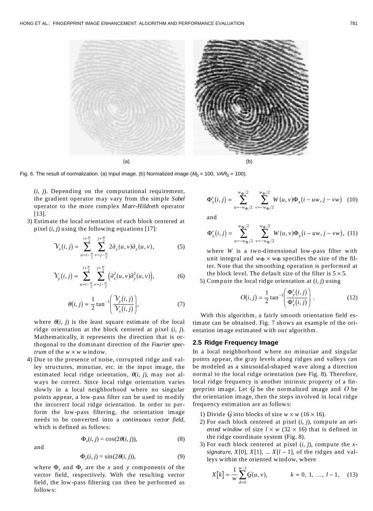
where M0 and VAR0 are the desired mean and variance val-ues, respectively. Normalization is a pixel-wise operation. Itdoes not change the clarity of the ridge and valley struc-tures. The main purpose of normalization is to reduce thevariations in gray-level values along ridges and valleys,which facilitates the subsequent processing steps. Fig. 6shows an example of image normalization.
2.4 Orientation ImageThe orientation image represents an intrinsic property ofthe fingerprint images and defines invariant coordinates forridges and valleys in a local neighborhood. By viewing afingerprint image as an oriented texture, a number ofmethods have been proposed to estimate the orientationfield of fingerprint images [11], [17], [10], [1]. We have de-veloped a least mean square orientation estimation algo-rithm. Given a normalized image, *, the main steps of thealgorithm are as follows:
1)�Divide * into blocks of size w ¥ w (16 ¥ 16).2)�Compute the gradients ∂x(i, j) and ∂y(i, j) at each pixel,
Fig. 4. Ridge and valley structures in a local neighborhood of minutiae.
Fig. 5. A flowchart of the proposed fingerprint enhancement algorithm.
HONG ET AL.: FINGERPRINT IMAGE ENHANCEMENT: ALGORITHM AND PERFORMANCE EVALUATION 781
(i, j). Depending on the computational requirement,the gradient operator may vary from the simple Sobeloperator to the more complex Marr-Hildreth operator[13].
3)�Estimate the local orientation of each block centered atpixel (i, j) using the following equations [17]:
9xu i
i
v j
j
x yi j u v u vw
w
w
w
, , ,1 6 0 5 0 5= ∂ ∂= -
+
= -
+
 Â2
2
2
2
2 , (5)
9yu i
i
v j
j
x yi j u v u vw
w
w
w
, , ,1 6 0 5 0 54 9= ∂ ∂= -
+
= -
+
 Â2
2
2
22 2 , (6)
q i ji j
i jy
x
, tan,
,1 6 1 6
1 6=���
���
-12
1 9
9, (7)
where q(i, j) is the least square estimate of the localridge orientation at the block centered at pixel (i, j).Mathematically, it represents the direction that is or-thogonal to the dominant direction of the Fourier spec-trum of the w ¥ w window.
4)�Due to the presence of noise, corrupted ridge and val-ley structures, minutiae, etc. in the input image, theestimated local ridge orientation, q(i, j), may not al-ways be correct. Since local ridge orientation variesslowly in a local neighborhood where no singularpoints appear, a low-pass filter can be used to modifythe incorrect local ridge orientation. In order to per-form the low-pass filtering, the orientation imageneeds to be converted into a continuous vector field,which is defined as follows:
Fx(i, j) = cos(2q(i, j)), (8)and
Fy(i, j) = sin(2q(i, j)), (9)
where Fx and Fy are the x and y components of thevector field, respectively. With the resulting vectorfield, the low-pass filtering can then be performed asfollows:
¢ = - -=- =-Â ÂF F
F
F
F
F
xu w
w
v w
w
xi j W u v i uw j vw, , ,1 6 0 5 1 62
2
2
2
(10)
and
¢ = - -=- =-Â ÂF F
F
F
F
F
yu w
w
v w
w
yi j W u v i uw j vw, , ,1 6 0 5 1 62
2
2
2
, (11)
where W is a two-dimensional low-pass filter withunit integral and wF ¥ wF specifies the size of the fil-ter. Note that the smoothing operation is performed atthe block level. The default size of the filter is 5 ¥ 5.
5)�Compute the local ridge orientation at (i, j) using
2 i ji j
i jy
x
, tan,
,1 6 1 6
1 6=¢¢
���
���
-12
1 FF
�. (12)
With this algorithm, a fairly smooth orientation field es-timate can be obtained. Fig. 7 shows an example of the ori-entation image estimated with our algorithm.
2.5 Ridge Frequency ImageIn a local neighborhood where no minutiae and singularpoints appear, the gray levels along ridges and valleys canbe modeled as a sinusoidal-shaped wave along a directionnormal to the local ridge orientation (see Fig. 8). Therefore,local ridge frequency is another intrinsic property of a fin-gerprint image. Let * be the normalized image and 2 bethe orientation image, then the steps involved in local ridgefrequency estimation are as follows:
1)�Divide * into blocks of size w ¥ w (16 ¥ 16).2)�For each block centered at pixel (i, j), compute an ori-
ented window of size l ¥ w (32 ¥ 16) that is defined inthe ridge coordinate system (Fig. 8).
3)�For each block centered at pixel (i, j), compute the x-signature, X[0], X[1], ... X[l - 1], of the ridges and val-leys within the oriented window, where
X k w u v k ld
w
= = -=
-
Â10 1 1
0
1
* , , , , ,0 5 K , (13)
(a) (b)
Fig. 6. The result of normalization. (a) Input image. (b) Normalized image (M0 = 100, VAR0 = 100).

782 IEEE TRANSACTIONS ON PATTERN ANALYSIS AND MACHINE INTELLIGENCE, VOL. 20, NO. 8, AUGUST 1998
u i dw
i j kl
i j= + -���
��� + -
���
���2 2cos , sin ,2 21 6 1 6 , (14)
v j dw
i jl
k i j= + -���
��� + -
���
���2 2sin , cos ,2 21 6 1 6 . (15)
If no minutiae and singular points appear in the ori-ented window, the x-signature forms a discrete sinu-soidal-shape wave, which has the same frequency asthat of the ridges and valleys in the oriented window.Therefore, the frequency of ridges and valleys can beestimated from the x-signature. Let 7(i, j) be the aver-age number of pixels between two consecutive peaksin the x-signature, then the frequency, W(i, j), is com-puted as: W(i, j) = 1/7(i, j). If no consecutive peaks canbe detected from the x-signature, then the frequency is
assigned a value of -1 to differentiate it from the validfrequency values.
4)�For a fingerprint image scanned at a fixed resolution,the value of the frequency of the ridges and valleys ina local neighborhood lies in a certain range. For a500dpi image, this range is [1/3, 1/25]. Therefore, ifthe estimated value of the frequency is out of thisrange, then the frequency is assigned a value of -1 toindicate that a valid frequency cannot be obtained.
5)�The blocks in which minutiae and/or singular pointsappear and/or ridges and valleys are corrupted do notform a well-defined sinusoidal-shaped wave. The fre-quency values for these blocks need to be interpolatedfrom the frequency of the neighboring blocks whichhave a well-defined frequency. The interpolation isperformed as follows [19]:
(a) (b)
Fig. 7. Comparison of orientation fields using the method proposed in [17] (a) and our method; w = 16 and wF = 5 (b).
Fig. 8. Oriented window and x-signature.

HONG ET AL.: FINGERPRINT IMAGE ENHANCEMENT: ALGORITHM AND PERFORMANCE EVALUATION 783
(i) For each block centered at (i, j),
¢ =W i j,1 6W W
W
W
W
W
W
W
W
W
W
W
i j i j
u w
w
gv w
w
u w
w
gv w
w
W u v i uw j vw
W u v i uw j vw
, ,
, ,
, ,
1 6 1 60 5 1 63 8
0 5 1 63 8
if
otherwise
π -%
&KK
'KK
=- =-
=- =-
 Â
 Â
- -
- - +
1
2
2
2
2
2
2
2
2
1
m
d
where
m x xx0 5 = £%&'0 0if
otherwise
d x x0 5 = £%&'0 01
if otherwise
Wg is a discrete Gaussian kernel with mean andvariance of zero and nine, respectively, and wW = 7is the size of the kernel.
(ii) If there exists at least one block with the frequencyvalue of -1, then swap W and ¢W and go to step (i).
6)�Interridge distances change slowly in a local neigh-borhood. A low-pass filter can be used to remove theoutliers in ¢f :
F i j W u v i uw j vwu w
w
v w
w
l
l l
, , ,1 6 0 5 1 6= ¢ - -=- =-Â Â
W W
W2
2
2
2
, (17)
where Wl is a two-dimensional low-pass filter withunit integral and wl = 7 is the size of the filter.
2.6 Region MaskAs mentioned early, a pixel (or a block) in an input finger-print image could be either in a recoverable region or anunrecoverable region. Classification of pixels into recover-able and unrecoverable categories can be performed basedon the assessment of the shape of the wave formed by thelocal ridges and valleys. In our algorithm, three features areused to characterize the sinusoidal-shaped wave: amplitude(a), frequency (b), and variance (g). Let X[1], X[2], ..., X[l] bethe x-signature of a block centered at (i, j). The three fea-tures corresponding to pixel (block) (i, j) are computed asfollows:
1)�a = (average height of the peaks - average depth ofthe valleys).
2)�b = 1/T(i, j), where T(i, j) is the average number ofpixels between two consecutive peaks.
3)� g = -���
���
���
���==
ÂÂ1 1
11
2
l X i l X ii
l
i
l
.
We selected several typical fingerprint images where bothrecoverable and unrecoverable regions were manually la-beled and computed the three features for those regions. Atotal of 2,000 three-dimensional patterns were obtained. Inorder to find representative patterns for the two classes, wefed the 2,000 patterns to a squared-error clustering algo-rithm and identified six clusters. Four of these clusters cor-respond to recoverable regions and the remaining two cor-respond to unrecoverable regions. The six prototypes (cor-
responding to the six cluster centers) were used in an one-nearest neighbor (1NN) classifier to classify each w ¥ wblock in an input fingerprint image into a recoverable or anunrecoverable block. If a block centered at (i, j) is recover-able, then 5(i, j) = 1, else 5(i, j) = 0. After the image 5 isobtained, the percentage of recoverable regions is com-puted. If the percentage of recoverable regions is smallerthan a threshold, Grecoverable = 40, then the input fingerprintimage is rejected. An accepted image is then passedthrough the filtering stage.
2.7 FilteringThe configurations of parallel ridges and valleys with well-defined frequency and orientation in a fingerprint imageprovide useful information which helps in removing unde-sired noise. The sinusoidal-shaped waves of ridges andvalleys vary slowly in a local constant orientation. There-fore, a bandpass filter that is tuned to the correspondingfrequency and orientation can efficiently remove the unde-sired noise and preserve the true ridge and valley struc-tures. Gabor filters have both frequency-selective and ori-entation-selective properties and have optimal joint resolu-tion in both spatial and frequency domains [3], [7]. There-fore, it is appropriate to use Gabor filters as bandpass fil-ters to remove the noise and preserve true ridge/valleystructures.
The even-symmetric Gabor filter has the general form [7]
h x y fx y
fxx y
, : , exp cosfd d
pf ff2 7 4 9= - +
�!
"$##
%&K'K
()K*K
12 2
2
2
2
2 , (18)
xf = x cos f + y sin f, (19)
yf = -x sin f + y cos f, (20)
where f is the orientation of the Gabor filter, f is the fre-quency of a sinusoidal plane wave, and dx and dy are thespace constants of the Gaussian envelope along x and yaxes, respectively. The modulation transfer function (MTF)of the Gabor filter can be represented as
H u v f( , : , ) =f
2pd dd d
f fx y
u v
u u v vexp -
-+
-�
!
"
$###
%&K'K
()K*K
+12
0
2
20
2
2
4 9 4 9
2pd dd d
f fx y
u v
u u v vexp -
++
+�
!
"
$###
%&K'K
()K*K
12
0
2
20
2
2
4 9 4 9, (21)
uf = u cos f + v sin f, (22)
vf = -u sin f + v cos f, (23)
u f0
2=
p fcos, (24)

784 IEEE TRANSACTIONS ON PATTERN ANALYSIS AND MACHINE INTELLIGENCE, VOL. 20, NO. 8, AUGUST 1998
v f0
2=
p fsin, (25)
where du = 1/2pdx and dv = 1/2pdy. Fig. 9 shows an even-symmetric Gabor filter and its MTF.
To apply Gabor filters to an image, three parametersmust be specified:
1)� the frequency of the sinusoidal plane wave, f,2)� the filter orientation, and3)� the standard deviations of the Gaussian envelope, dx
and dy.
Obviously, the frequency characteristic of the filter, f, iscompletely determined by the local ridge frequency and theorientation is determined by the local ridge orientation. Theselection of the values of dx and dy involves a trade-off. Thelarger the values, the more robust to noise the filters are butthe more likely the filters will create spurious ridges andvalleys. On the other hand, the smaller the values of dx anddy, the less likely the filters will create spurious ridges andvalleys; consequently they will be less effective in removingthe noise. The values of dx and dy were set to 4.0 and 4.0,respectively based on empirical data. Let * be the normal-ized fingerprint images, 2 be the orientation image, ) bethe frequency image, and 5 be the recoverable mask, theenhanced image ( is obtained as follows:
( i j,1 6 =
255 0
2
2
2
2if
otherwise
5
2 ) *
i j
h u v i j i j i u j vu w
w
v w
w
g
g
g
g
,
, : , , , ,
1 61 6 1 63 8 1 6
=
- -
%&KK
'KK =- =-
 Â(26)
where wg = 11 specifies the size of the Gabor filters.
3 EXPERIMENTAL RESULTS
The purpose of a fingerprint enhancement algorithm is toimprove the clarity of ridges and valleys of input finger-
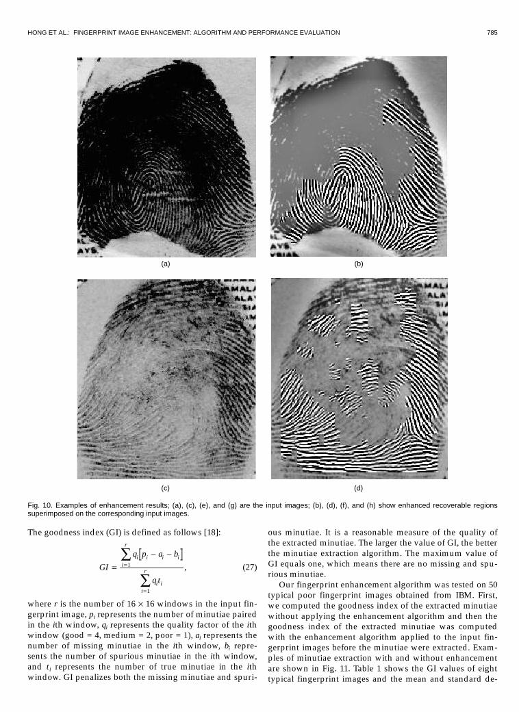
print images and make them more suitable for the minu-tiae extraction algorithm. The ultimate criterion for evalu-ating such an enhancement algorithm is the total amountof “quality” improvement when the algorithm is appliedto the noisy input fingerprint images. Such an improve-ment can be assessed subjectively by a visual inspection ofa number of typical enhancement results. However, a pre-cise and consistent characterization of the quality im-provement is beyond the capability of subjective evalua-tion. Examples of the enhancement results are shown inFig. 10. From these examples, we can see that our en-hancement algorithm does improve the clarity of the ridgeand valley structures of input fingerprint images.
A goal-directed performance evaluation assesses theoverall improvement in the system performance that in-corporates the enhancement module as a component.Therefore, it is capable of providing a more reliable as-sessment of the performance benchmark and is directlyassociated with the ultimate goal of the system [22]. In thefollowing, we present the results of the goal-directed per-formance evaluation of our enhancement algorithm.
3.1 Evaluation Using Goodness IndexWe have used the goodness index (GI) of the extracted minu-tiae to quantitatively assess the performance of our finger-
print enhancement algorithm. Let M f f fd d d dn= 1 2, , ,K4 9 be
the set of n minutiae detected by the minutiae extraction
algorithm and M f f fe e e em= 1 2, , ,K4 9 be the set of m minutiae
identified by human expert in an input fingerprint image.We define the following terms:
•� Paired minutiae (p): Minutiae fd and fe are said to bepaired if fd is located in a tolerance box centered aroundfe. In this evaluation, the tolerance box size is 8 ¥ 8.
•� Missing minutiae (a): A minutiae that is not detectedby the minutiae extraction algorithm.
•� Spurious minutiae (b): A minutiae that is detected bythe minutiae extraction algorithm, but which is not inthe tolerance box of any minutiae, fe.
(a) (b)
Fig. 9. An even-symmetric Gabor filter. (a) The Gabor filter with f = 10 and f = 0. (b) The corresponding MTF.
HONG ET AL.: FINGERPRINT IMAGE ENHANCEMENT: ALGORITHM AND PERFORMANCE EVALUATION 785
The goodness index (GI) is defined as follows [18]:
GI
q p a b
q t
i i i ii
r
i ii
r=- -
=
=
Â
Â1
1
, (27)
where r is the number of 16 ¥ 16 windows in the input fin-gerprint image, pi represents the number of minutiae pairedin the ith window, qi represents the quality factor of the ithwindow (good = 4, medium = 2, poor = 1), ai represents thenumber of missing minutiae in the ith window, bi repre-sents the number of spurious minutiae in the ith window,and ti represents the number of true minutiae in the ithwindow. GI penalizes both the missing minutiae and spuri-
ous minutiae. It is a reasonable measure of the quality ofthe extracted minutiae. The larger the value of GI, the betterthe minutiae extraction algorithm. The maximum value ofGI equals one, which means there are no missing and spu-rious minutiae.
Our fingerprint enhancement algorithm was tested on 50typical poor fingerprint images obtained from IBM. First,we computed the goodness index of the extracted minutiaewithout applying the enhancement algorithm and then thegoodness index of the extracted minutiae was computedwith the enhancement algorithm applied to the input fin-gerprint images before the minutiae were extracted. Exam-ples of minutiae extraction with and without enhancementare shown in Fig. 11. Table 1 shows the GI values of eighttypical fingerprint images and the mean and standard de-
(a) (b)
(c) (d)
Fig. 10. Examples of enhancement results; (a), (c), (e), and (g) are the input images; (b), (d), (f), and (h) show enhanced recoverable regionssuperimposed on the corresponding input images.

786 IEEE TRANSACTIONS ON PATTERN ANALYSIS AND MACHINE INTELLIGENCE, VOL. 20, NO. 8, AUGUST 1998
viation of GI values for all the 50 images. The GI valuesafter applying the enhancement algorithm are always largerthan that without the enhancement algorithm. Thus, we canconclude that our fingerprint enhancement algorithm doesimprove the quality of the fingerprint images, which, inturn, improves the accuracy and reliability of the extractedminutiae.
3.2 Evaluation Using Verification PerformanceThe performance of the enhancement algorithm was alsoassessed on the first volume of the MSU fingerprint da-tabase (700 live-scan images; 10 per individual) using theverification accuracy of an online fingerprint verificationsystem [6]. We demonstrated that incorporating the en-hancement algorithm in the fingerprint verification sys-tem improves the system performance. In the first test,
the fingerprint enhancement algorithm was not applied.Each fingerprint image in the data set was directlymatched against the other fingerprint images in the da-tabase. In the second test, the fingerprint enhancementalgorithm was applied to each fingerprint image in thedata set. Then, the verification was conducted on theenhanced fingerprint images. The receiver operatingcurves (ROC) resulting from these two tests are shown inFig. 12. From these experimental results, we can observethat the performance of the fingerprint verification sys-tem is significantly improved when our fingerprint en-hancement algorithm is applied to the input fingerprintimages. In particular, the enhancement algorithm sub-stantially reduced the false reject rate while maintainingthe same false accept rate.
(e) (f)
(g) (h)
Fig. 10. Continued.

HONG ET AL.: FINGERPRINT IMAGE ENHANCEMENT: ALGORITHM AND PERFORMANCE EVALUATION 787
In order to incorporate the enhancement algorithm intoan online fingerprint verification/identification system, thewhole enhancement process should take only a few sec-onds. Table 2 shows the wall time for different stages of theenhancement algorithm and the total time.
4 SUMMARY AND CONCLUSIONS
We have developed a fast fingerprint enhancement algo-rithm which can adaptively improve the clarity of ridgeand valley structures based on the local ridge orientationand ridge frequency estimated from the inputed image. Theperformance of the algorithm was evaluated using thegoodness index of the extracted minutiae and the perform-ance of an online fingerprint verification system which in-corporates our fingerprint enhancement algorithm in itsminutiae extraction module. Experimental results show that
(a) (b)
(c) (d)
Fig. 11. Examples of minutiae extraction with and without enhancement; (a) and (c) show the extracted minutiae without applying the enhance-ment algorithm; (b) and (d) show the extracted minutiae after applying the enhancement algorithm.
TABLE 1THE GI VALUES OF EIGHT TYPICAL FINGERPRINT IMAGES
AND THE MEAN AND STANDARD DEVIATIONOF 50 IBM FINGERPRINT IMAGES
Goodness Index (GI)
Image # Without Enhancement With Enhancement1 0.46 0.552 0.38 0.523 0.29 0.424 0.26 0.395 0.21 0.356 0.12 0.317 0.11 0.268 0.10 0.29
mean 0.24 0.39std 0.05 0.04

788 IEEE TRANSACTIONS ON PATTERN ANALYSIS AND MACHINE INTELLIGENCE, VOL. 20, NO. 8, AUGUST 1998
our enhancement algorithm is capable of improving boththe goodness index and the verification performance. Thealgorithm also identifies the unrecoverable corrupted re-gions in the fingerprint and removes them from furtherprocessing. This is a very important property because suchunrecoverable regions do appear in some of the corruptedfingerprint images and they are extremely harmful to mi-nutiae extraction. These properties suggest that our en-hancement algorithm should be integrated into an onlinefingerprint verification/identification system.
The global ridge and valley configuration of fingerprintimages presents a certain degree of regularity. A globalmodel of the ridges and valleys that can be constructedfrom partial “valid” regions can be used to correct the er-rors in the estimated orientation images, which, in turn,will help the enhancement. Currently, we are investigatingsuch a model-based enhancement algorithm.
The configurations of ridges and valleys within a localneighborhood vary with the quality of input fingerprintimages, so a well-defined sinusoidal-shaped waves ofridges and valleys may not always be observed. Globalfeatures are needed for a more precise region mask classi-fication.
ACKNOWLEDGMENTS
We gratefully acknowledge our many useful discussionswith Ruud Bolle, Sharath Pankanti, and Nalini Ratha of theIBM T. J. Watson Research Lab.
REFERENCES
[1]� T. Chang, “Texture Analysis of Digitized Fingerprints for Singu-larity Detection,” Proc. Fifth ICPR, pp. 478-480, 1980.
[2]� P.E. Danielsson and Q. Z. Ye, “Rotation-Invariant Operators Ap-plied to Enhancement of Fingerprints,” Proc. Ninth ICPR, pp. 329-333, Rome, 1988.
[3]� J.G. Daugman, “Uncertainty Relation for Resolution in Space,Spatial-Frequency, and Orientation Optimized by Two-Dimensional Visual Cortical Filters,” J. Optical Soc. Am., vol. 2, pp.1,160-1,169, 1985.
[4]� L. Hong, A.K. Jain, S. Pankanti, and R. Bolle, “Fingerprint En-hancement,” Proc. First IEEE WACV, pp. 202-207, Sarasota, Fla.,1996.
[5]� D.C. Huang, “Enhancement and Feature Purification of Finger-print Images,” Pattern Recognition, vol. 26, no. 11, pp. 1,661-1,671,1993.
[6]� A. Jain, L. Hong, and R. Bolle, “On-Line Fingerprint Verification,”IEEE Trans. Pattern Analysis and Machine Intelligence, vol. 19, no. 4,pp. 302-314, 1997.
[7]� A.K. Jain and F. Farrokhnia, “Unsupervised Texture SegmentationUsing Gabor Filters,” Pattern Recognition, vol. 24, no. 12, pp. 1,167-1,186, 1991.
[8]� T. Kamei and M. Mizoguchi, “Image Filter Design for FingerprintEnhancement,” Proc. ISCV’ 95, pp. 109-114, Coral Gables, Fla.,1995.
[9]� K. Karu and A.K. Jain, “Fingerprint Classification,” Pattern Recog-nition, vol. 29no. 3, pp. 389-404, 1996.
[10]� M. Kass and A. Witkin, “Analyzing Oriented Patterns,” ComputerVision, Graphics, and Image Processing, vol. 37, no. 4, pp. 362-385,1987.
[11]� M. Kawagoe and A. Tojo, “Fingerprint Pattern Classification,”Pattern Recognition, vol. 17, no. 3, pp. 295-303, 1984.
[12]� H.C. Lee and R.E. Gaensslen, Advances in Fingerprint Technology.New York, NY: Elsevier, 1991.
[13]� D. Marr, Vision. San Francisco, Calif.: W.H. Freeman, 1982.[14]� A. Moenssens, Fingerprint Techniques. London: Chilton Book
Company, 1971.[15]� E. Newham, The Biometric Report. New York, NY: SJB Services,
1995.
Fig. 12. Receiver Operating Curves (ROC); the ROC shows the improvement in verification performance using the enhancement algorithm.
TABLE 2THE WALL TIME OF THE ENHANCEMENT ALGORITHM ON A PENTIUM 200MHZ PC
Normalization Orientation Frequency Region Mask Filtering Total(seconds) (seconds) (seconds) (seconds) (seconds) (seconds)
0.11 0.14 0.09 0.07 2.08 2.49
HONG ET AL.: FINGERPRINT IMAGE ENHANCEMENT: ALGORITHM AND PERFORMANCE EVALUATION 789
[16]� L. O’Gorman and J.V. Nickerson, “An Approach to FingerprintFilter Design,” Pattern Recognition, vol. 22, no. 1, pp. 29-38, 1989.
[17]� A. Rao, A Taxonomy for Texture Description and Identification. NewYork, NY: Springer-Verlag, 1990.
[18]� N. Ratha, S. Chen, and A.K. Jain, “Adaptive Flow OrientationBased Feature Extraction in Fingerprint Images,” Pattern Recogni-tion, vol. 28, no. 11, pp. 1,657-1,672, 1995.
[19]� G. Sapiro and A. Bruckstein, “A B-Spline Based Affine InvariantMultiscale Shape Representation,” Proc. Seventh Int’l Conf. ImageAnalysis and Processing III, pp. 20-22, Monopoli, Italy, 1993.
[20]� D. Sherlock, D.M. Monro, and K. Millard, “Fingerprint Enhance-ment by Directional Fourier Filtering,” IEE Proc. Visual Image Sig-nal Processing, vol. 141, no. 2, pp. 87–94, 1994.
[21]� A. Sherstinsky and R.W. Picard, “Restoration and Enhancement ofFingerprint Images Using M-Lattice: A Novel Non-Linear Dy-namical System,” Proc. 12th ICPR-B, pp. 195–200, 1994.
[22]� O. Trier and A. Jain, “Goal-Directed Evaluation of BinarizationMethods,” IEEE Trans. Pattern Analysis and Machine Intelligence,vol. 17, no. 12, pp. 1,191–1,201, 1996.
Lin Hong received the BS and MS degrees incomputer science from Sichuan University,China, in 1987 and 1990, respectively. He iscurrently a PhD student in the Department ofComputer Science at Michigan State University.His research interests include pattern recogni-tion, image processing multimedia, biometrics,computer graphics, and computer vision applica-tion.
Yifei Wan received the BSc degree in electricalengineering from Shanghai Jiao Tong Universityin 1994. He is currently pursuing his MSc degreein computer science at Michigan State Univer-sity. His research interests include pattern rec-ognition and image processing.
Anil Jain is a University Distinguished Professorand Chair of the Department of Computer Sci-ence at Michigan State University. His researchinterests include statistical pattern recognition,Markov random fields, texture analysis, neuralnetworks, document image analysis, fingerprintmatching, and 3D object recognition. He re-ceived the best paper awards in 1987 and 1991,and certificates for outstanding contributions in1976, 1979, 1992, and 1997 from the PatternRecognition Society. He also received the 1996
IEEE Transactions on Neural Networks Outstanding Paper Award. Hewas the Editor-in-Chief of the IEEE Transactions on Pattern Analysisand Machine Intelligence (1990-1994). He is the coauthor of Algo-rithms for Clustering Data, Prentice-Hall, 1988, and coedited thebooks, Analysis and Interpretation of Range Images, Springer-Verlag,1989, Markov Random Fields, Academic Press, 1992, Artificial NeuralNetworks and Pattern Recognition, Elsevier, 1993, 3D Object Recogni-tion, Elsevier, 1993, and BIOMETRICS: Personal Identification in Net-worked Society to be published by Kluwer in 1998. He is a fellow of theIEEE and IAPR, and has received a Fulbright research Award.