© 2017 Schneider Electric. All rights reserved. All trademarks are owned by Schneider Electric Industries SAS or its affiliated companies. August, 2017 tc Document Number: F-11331-12 www.schneider-electric.com schneider-electric.com | 1 Installation Instructions MC-9000 and MP-9000 High Torque, Oil-Submerged Actuators These electric actuators can be used to control dampers, valves, or other devices that require high torque. These instructions are concerned with all MC and MP-9000 actuators. PRE-INSTALLATION The MC and MP-9000 are shipped without mounting hardware or linkage. In damper applications, crank arms (AM-392) and connecting links (AM-394) will be required. In valve applications a valve body and AV linkage will be required. Before installing the actuator, check for bent or broken parts and oil leaks. Actuators may be connected to power supply to check operation prior to installation. See CHECKOUT. Potentiometer: Only MP-9000 series actuators include a potentiometer. Standard resistance is 100 ohms. The active winding of the potentiometer is normally spread over 180° or 90° depending upon the limits of shaft rotation. The wiper arm of the potentiometer is connected to the main output shaft through a slip clutch arrangement. When the shaft travels beyond the spread of the potentiometer winding, the wiper arm will cease to rotate once it has hit the stop. It is not damaged, and will instantly start moving in the opposite direction when the shaft reverses direction. INSTALLATION Requirements Preferred mounting for the actuator is in the upright position, but other positions are acceptable. Allow 10 inches clearance above the actuator wiring compartment. The base of the actuator may be used as a template for marking mounting holes. The current draw of MP actuators with a second digit of 2,4,6, or 8 is greater than the Microtherm contact rating. Therefore, a (AM-345) relay is required. See Figure-5 for typical wiring. Procedure Make all electrical connections in accordance with the job wiring diagrams and in compliance with national and local electrical codes. Low and line voltage: All wiring to actuator and inside wiring compartment must be connected per Class 1 circuits. For 24 Vac power wiring to H and G terminals, use No. 14 wire on runs up to 64 feet and No. 12 wire up to 100 feet. For longer runs or runs to more than one actuator, select wire size for maximum drop of 1.2 volts. Figure-2 Linkage: For linkage where the actuator is 180° and the driven stroke 90°, proceed as follows: (See Figure-6). 1. Mount crank arm on the driven shaft so the linkage connector, in full closed and full opened positions (points C1 and C), will fall on a straight line through the center of the actuator shaft. 2. Secure one end of the connecting link in the driven linkage connector. 3. With crank arm mounted loosely on actuator shaft and actuator at closed position, fasten linkage connector at about mid-position, of crank arm slot. Move driven crank arm between full open and full closed positions. If radius of actuator crank is 0.707 times the radius of driven crank, 180° movement of actuator crank arm will position driven shaft 90°. Figure-1

Welcome message from author
This document is posted to help you gain knowledge. Please leave a comment to let me know what you think about it! Share it to your friends and learn new things together.
Transcript

© 2017 Schneider Electric. All rights reserved. All trademarks are owned by Schneider Electric Industries SAS or its affiliated companies. August, 2017 tcDocument Number: F-11331-12
www.schneider-electric.com
schneider-electric.com | 1Installation Instructions
MC-9000 and MP-9000
High Torque, Oil-Submerged Actuators
Printed in U.S.A. 4/10 © Copyright 2010 Schneider Electric All Rights Reserved. F-11331-11
These electric actuators can be used to control dampers, valves, or other devices that require high torque. These instructions are concerned with all MC and MP-9000actuators.
PRE-INSTALLATIONThe MC and MP-9000 are shipped without mounting hardware or linkage. In damper applications, crank arms (AM-392) and connecting links (AM-394) will be required. Invalve applications a valve body and AV linkage will be required.
Before installing the actuator, check for bent or broken parts and oil leaks. Actuators may be connected to power supply to check operation prior to installation. See CHECKOUT.
Potentiometer: Only MP-9000 series actuators include a potentiometer. Standard resistance is 100 ohms. The active winding of the potentiometer is normally spread over 180° or 90° depending upon the limits of shaft rotation. The wiper arm of the potentiometer is connected to the main output shaft through a slip clutch arrangement. When the shaft travelsbeyond the spread of the potentiometer winding, the wiper arm will cease to rotate once it has hit the stop. It is notdamaged, and will instantly start moving in the opposite direction when the shaft reverses direction.
INSTALLATION
RequirementsPreferred mounting for the actuator is in the upright position, but other positions are acceptable. Allow 10 inches clearance above the actuator wiring compartment. The base of theactuator may be used as a template for marking mounting holes. The current draw of MP actuators with a second digit of 2,4,6, or 8 is greater than the Microtherm contact rating. Therefore, a (AM-345) relay is required. See Figure-5 fortypical wiring.
ProcedureMake all electrical connections in accordance with the jobwiring diagrams and in compliance with national and localelectrical codes.
Low and line voltage: All wiring to actuator and inside wiringcompartment must be connected per Class 1 circuits.
For 24 Vac power wiring to H and G terminals, use No. 14 wire on runs up to 64 feet and No. 12 wire up to 100 feet. For longer runs or runs to more than one actuator, select wire size for maximum drop of 1.2 volts.
Figure-1
Figure-2
Linkage: For linkage where the actuator is 180° and the drivenstroke 90°, proceed as follows: (See Figure-6).
1. Mount crank arm on the driven shaft so the linkageconnector, in full closed and full opened positions (pointsC1 and C), will fall on a straight line through the center ofthe actuator shaft.
2. Secure one end of the connecting link in the drivenlinkage connector.
3. With crank arm mounted loosely on actuator shaft andactuator at closed position, fasten linkage connector atabout mid-position, of crank arm slot. Move driven crankarm between full open and full closed positions. If radiusof actuator crank is 0.707 times the radius of drivencrank, 180° movement of actuator crank arm will positiondriven shaft 90°.
MC-9000 and MP-9000
High Torque, Oil-Submerged ActuatorsGeneral Instructions

2 | schneider-electric.com Installation Instructions
August, 2017 tc © 2017 Schneider Electric. All rights reserved. All trademarks are owned by Schneider Electric Industries SAS or its affiliated companies. Document Number: F-11331-122 © Copyright 2010 Schneider Electric All Rights Reserved. F-11331-11
4. Move driven crank arm to the closed position and holdfirmly in place. Secure crank on actuator shaft (point A)and linkage connector so that points A, B, and C1 are ina straight line.
5. Check adjustment for proper operation by runningactuator and driven shaft several times between openedand closed positions.
Note: If driven crank arm does not provide tight closing, run actuator a few degrees away from closed position and reset connecting link in driven linkage connector. Driven crank arm will then provide closing under slight pressure. Never attempt to turn the actuator shaft with a wrench or a crank - this may damage actuator gears.
Figure-3 Two-Position Three Wire Oil-Submerged Actuator for On-Off Control.
Figure-4 Proportional Oil-Submerged Line Actuators with Internal Transformer (Controller by Microtherm).
Figure-5 Proportional High Torque Industrial Actuators (Controlled by a Microtherm).
Auxiliary switch terminals are C1, B1, R1 on MC units and 1, 5, 6 on MP units except on 5 position units.
Figure-6
Figure-7
Electrical Rating forAuxiliary Switch
120Volts
240Volts
Running Current 5.8 2.9
Locked Rotor 34.8 17.4
Non-Inductive 12 6
schneider-electric.com | 3Installation Instructions
© 2017 Schneider Electric. All rights reserved. All trademarks are owned by Schneider Electric Industries SAS or its affiliated companies. August, 2017 tcDocument Number: F-11331-12
F-11331-11 © Copyright 2010 Schneider Electric All Rights Reserved. 3
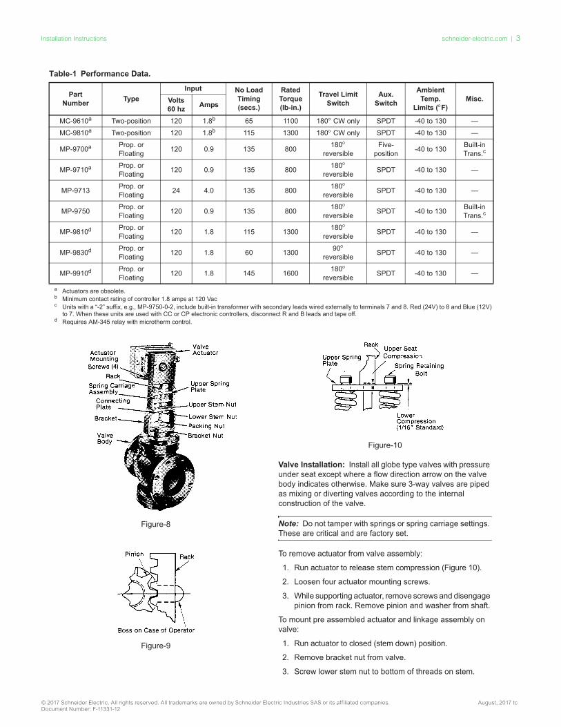
Figure-8
Figure-9
Figure-10
Valve Installation: Install all globe type valves with pressure under seat except where a flow direction arrow on the valve body indicates otherwise. Make sure 3-way valves are piped as mixing or diverting valves according to the internal construction of the valve.
Note: Do not tamper with springs or spring carriage settings. These are critical and are factory set.
To remove actuator from valve assembly:
1. Run actuator to release stem compression (Figure 10).
2. Loosen four actuator mounting screws.
3. While supporting actuator, remove screws and disengagepinion from rack. Remove pinion and washer from shaft.
To mount pre assembled actuator and linkage assembly on valve:
1. Run actuator to closed (stem down) position.
2. Remove bracket nut from valve.
3. Screw lower stem nut to bottom of threads on stem.
Table-1 Performance Data.
PartNumber Type
Input No LoadTiming(secs.)
RatedTorque(lb-in.)
Travel LimitSwitch
Aux.Switch
AmbientTemp.
Limits (°F)Misc.Volts
60 hz Amps
MC-9610a Two-position 120 1.8b 65 1100 180° CW only SPDT -40 to 130 —
MC-9810a Two-position 120 1.8b 115 1300 180° CW only SPDT -40 to 130 —
MP-9700a Prop. orFloating 120 0.9 135 800 180°
reversibleFive-
position -40 to 130 Built-inTrans.c
MP-9710a Prop. orFloating 120 0.9 135 800 180°
reversible SPDT -40 to 130 —
MP-9713 Prop. orFloating 24 4.0 135 800 180°
reversible SPDT -40 to 130 —
MP-9750 Prop. orFloating 120 0.9 135 800 180°
reversible SPDT -40 to 130 Built-inTrans.c
MP-9810d Prop. orFloating 120 1.8 115 1300 180°
reversible SPDT -40 to 130 —
MP-9830d Prop. orFloating 120 1.8 60 1300 90°
reversible SPDT -40 to 130 —
MP-9910d Prop. orFloating 120 1.8 145 1600 180°
reversible SPDT -40 to 130 —
a Actuators are obsolete.b Minimum contact rating of controller 1.8 amps at 120 Vacc Units with a “-2” suffix, e.g., MP-9750-0-2, include built-in transformer with secondary leads wired externally to terminals 7 and 8. Red (24V) to 8 and Blue (12V)
to 7. When these units are used with CC or CP electronic controllers, disconnect R and B leads and tape off.d Requires AM-345 relay with microtherm control.

4 | schneider-electric.com Installation Instructions
August, 2017 tc © 2017 Schneider Electric. All rights reserved. All trademarks are owned by Schneider Electric Industries SAS or its affiliated companies. Document Number: F-11331-12
4 © Copyright 2010 Schneider Electric All Rights Reserved. F-11331-11
4. Place complete actuator and linkage assembly over valve stem and bonnet until stem extends through hole inconnecting plate. Rotate actuator and linkage assemblyto desired position and secure with bracket nut.
5. Tighten lower stem nut up against connecting plate.
6. Set compression.
To set compression:
1. If upper stem nut is on valve, loosen or remove. Runactuator clockwise to closed position. Tighten lower stemnut up against connecting plate taking up all play inlinkage.
2. Screw upper stem nut on stem 1-1/16-inch fromconnecting plate for compression on lower seat.
3. Run actuator counterclockwise until connecting plate istight against upper stem nut. Secure lower stem nutagainst connecting plate.
To mount linkage assembly on valve:
1. Remove bracket nut from valve and screw lower stem nutdown to bottom of threads on stem.
2. Place rack and spring carriage in bracket such that stemextends through connecting plate.
3. Align bracket so position indicator faces desired direction; then tighten bracket nut.
4. See actuator mounting instructions for furtherinstructions.
To mount actuator on linkage assembly:
1. Determine lift of valve by measuring total movement ofstem.
2. Set shaft travel to correspond with valve lift. (Note: Onedegree of shaft rotation is equal to 0.011 inch of stem lift.)Set shaft travel by inserting screwdriver in hole in front ofterminal block and engage with notched cam. Turningcam clockwise, as seen from front of actuator, increasesshaft rotation. Each click of cam representsapproximately 3° shaft rotation. On 3-way valves only,add 5° rotation to total shaft travel to provide compression on upper seat.
3. With actuator in full clockwise (closed) position, rotatemotor pinion until a pinion tooth lines up with center linesof boss (Figure-9) on actuator case; slide washer andpinion on shaft. Mark this tooth for future reference.
4. Looking at front of linkage (position indicator side), rotaterack until teeth point to the left.
5. Align actuator so that marked tooth of pinion engageswith third tooth space from top of rack. Mount actuator tolinkage with the actuator mounting screws (4). Apply“locktite”, Grade CV, to screw threads.
6. If necessary to mount indicating strip on bracket, align“CLOSED” position with pointer when actuator is in fullclosed position. Run actuator full open. Cut out centersection of indicator strip so that the “OPEN” position isaligned with pointer.
CHECKOUTAfter the entire system has been installed, the following checks for proper system operation may beused.
1. Be sure that the system power is connected and on.
2. Turn the thermostat to call for heat. Actuator should rotatefrom clockwise to counterclockwise end of travel and turn on heating media. Direction of rotation of the actuator isdetermined by looking at the end of the output shaft.Actuator is at full clockwise position when the mark on theshaft is at the nine o’clock position.
3. To check actuator operation, disconnect controller andproceed as follows:
MC-9000 — Connect terminal C to B and actuator should runclockwise to end of travel (usually 180°). Connect terminal Cto R and actuator should run from 180° to 360° (or 0). Caution: 120 volts, Figure-11.
Figure-11 Two-Position (MC Type).

schneider-electric.com | 5Installation Instructions
© 2017 Schneider Electric. All rights reserved. All trademarks are owned by Schneider Electric Industries SAS or its affiliated companies. August, 2017 tcDocument Number: F-11331-12
F-11331-11 © Copyright 2010 Schneider Electric All Rights Reserved. 5
Figure-12 Proportional and Floating (All MP except -9700 Series). Internal wiring.
MP-9700 Series — Connect terminal 2 to case ground and actuator should run clockwise to end of travel. Connect terminal 3 to case ground and actuator should run counterclockwise to end of travel, Figure-12.
MP-98xx and MP-99xx Series — Apply rated line voltage to terminal L2 and terminal 2 for clockwise end of travel. Apply rated line voltage to L2 and terminal 3 for counterclockwise travel to end, Figure-13.
Figure-13 Proportioning and Floating (MP-98xx or MP-99xx Series Only). Internal Wiring.
4. To check compression - Lower Seat: Run actuator to full closed (clockwise) position. Measure distance between head of spring retaining bolt and upper spring plate. Upper Seat (3-way valves only): Run actuator to full open(counterclockwise) position. Measure distance between bottom of rack and upper spring plate. To change compression on upper seat, adjust travel of actuator shaft. Standard spring compression is 1/16".
RUN/ADJUSTInternal Wiring Information
AdjustmentsActuator variations are shown in the internal diagrams (see Figures-11, 12, and 13).
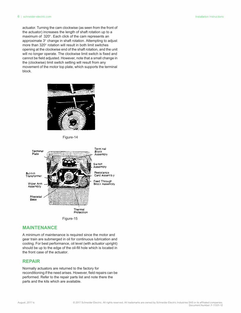
Auxiliary Switch Adjustment: The adjustable built-in SPDTswitch is actuated by the cam nearest the back of the actuator.It is factory set to operate at the clockwise end but may bechanged by inserting a screwdriver through the opening in the top plate directly behind the terminal block, and engaging thescrewdriver with a gear-like plastic disc (Figure-14). Turning the disc clockwise (as seen from the front of the actuator)causes the switch to operate nearer the counterclockwise endof shaft rotation. Each click of the cam represents an approximate 3° change in operating point. Auxiliary switch electrical rating is shown on the Switch Performance Chart.
Note: When shaft travel has been increased beyond 180°the auxiliary switch may, depending on its actuating point, operate twice in a given shaft stroke. For this reason, the auxiliary switch should be employed with extreme caution where more than 180° of shaft rotation is used.
Limit Switch Adjustment: The counterclockwise limit switch of all actuators is adjustable. Factory setting is usually for 180°of shaft rotation. This setting can be changed in the field by inserting a screwdriver through the opening in the top plate directly ahead of the terminal block and engaging the screwdriver with the notched cam nearest the front of the
6 | schneider-electric.com Installation Instructions
August, 2017 tc © 2017 Schneider Electric. All rights reserved. All trademarks are owned by Schneider Electric Industries SAS or its affiliated companies. Document Number: F-11331-12
6 © Copyright 2010 Schneider Electric All Rights Reserved. F-11331-11
actuator. Turning the cam clockwise (as seen from the front of the actuator) increases the length of shaft rotation up to a maximum of 320°. Each click of the cam represents an approximate 3° change in shaft rotation. Attempting to adjust more than 320° rotation will result in both limit switches opening at the clockwise end of the shaft rotation, and the unit will no longer operate. The clockwise limit switch is fixed and cannot be field adjusted. However, note that a small change in the (clockwise) limit switch setting will result from any movement of the motor top plate, which supports the terminal block.
Figure-14
Figure-15
MAINTENANCEA minimum of maintenance is required since the motor andgear train are submerged in oil for continuous lubrication andcooling. For best performance, oil level (with actuator upright)should be up to the edge of the oil-fill hole which is located inthe front case of the actuator.
REPAIRNormally actuators are returned to the factory forreconditioning if the need arises. However, field repairs can be performed. Refer to the repair parts list and note there theparts and the kits which are available.
Related Documents