Iflü PTD-MT-2.4-2^19-7 O Ci àft 00 t> FOREIGN TECHNOLOGY DIVISION CQ Is* fi STATICS OP THIN-WALLED SHELLS OP REVOLUTION by V. S. Chemina Approved for public re. ase; distribution unlimited. Reproduced by NATIONAL TECHNICAL INFORMATION SERVICE Springfield, V». Î.UI1

Welcome message from author
This document is posted to help you gain knowledge. Please leave a comment to let me know what you think about it! Share it to your friends and learn new things together.
Transcript

Iflü
PTD-MT-2.4-2^19-7 O
Ci àft 00
t> FOREIGN TECHNOLOGY DIVISION CQ Is*
fi
STATICS OP THIN-WALLED SHELLS OP REVOLUTION
by
V. S. Chemina
Approved for public re. ase; distribution unlimited.
Reproduced by
NATIONAL TECHNICAL INFORMATION SERVICE
Springfield, V». Î.UI1
UNCLASSIFIED
(Security t<»««
i o*i«ik*tim* Aenviry (Ctpf*
D0CUM1NT CONTROL DATA -RAD ,/ ,,.(MCI ,IM/ /n,«»lw, mnoftle* mull X wiMcri »>■«. th, ovmrall "port I.
Foreign Technology Division Air Force Systems Command II. S. Air Force-
. *«POHT itCUWITV CLAMIUCATION
^TMHT.ASPi TFIED -_
». mtPonr titlc
STATICS OF THIN-WALLED SHELLS OF REVOLUTION
4. OKSCRlPTn I (Typ* •! ripft né inn tu* Ir* éaM)
Chemina, V. S, le nlPOMT DA T®
1968 ,, CONTHAC T O A 0«ANT NO.
1569 b. bnOJKCT NO.
TA. TOTAL NO. OP PAO**
jm
17b. NO. O* NEF*
177 „ M. oniaiNATon** numb««»*»
FTD-MT-24-249-70 M. OTMC« «I«0«T NOIII (Any o»,r
Hil» fpport)
r* «Ml «r à* miiltnmd
10 OltTRIBUTION »TATtMtNT
Approved for public release; distribution unlimited,
’NOT«,
TTTtfeTSÄcr-
la. »«ONiORINB MILITABV AC Tl VII V
Foreign Technology Division Wright-Patterson AFB, Ohio
a
Triis book is devoted to,xhe theory and design of thin-walled shells of revolution, ¿The basic equations of the theory are derived in an eleroentary\form for a shell of revolution sub¬ jected to arbitrary landing. The deformations of cylindrical, conical, spherical, and toroidal shells are analyzed in detail under axisymmetrical and bending loads. The book is intended for design engineers and scientific workers engaged in design¬ ing machines and structures for strength.A 9rig. art. has: 52 figures, 9 tables which illustrate the text|*in which many samples analyses are included. [AM9OO8876^
DD ..1473 UNCLASSIFIED Security Classification
I
V
f UNCLASSIFIED
Security CUasiltcaitOfi
hit «enea LMK *
net «J «T
link e
noce
lim» c
«OL«
Shell Design Shell of Revolution Shell Bückling
J
UNCLASSIFIED lecurity CUattrication
edited machine translation
STATICS OF THIN-WALLED SHELLS OF REVOLUTION
By: V. S. Chemina
English pages : 488
SOURCE: Statika Tonkostennykh Obolochek Vrashcheniya. Izd-vo Nauka, Moscow, I968, pp. 1-455.
This document is a SYSTRAN machine aided edited for technical accuracy by: K. L.
translation, post- Dion.
U Approved for public release; distribution unlimited.
THIS TRANSLATION IS A REK OITION OR THE o«ici nal foreign text without ant analyÏÎcÎÎ «
FREFaREO RYi
translation oivision ^oreign TECHNOLOGY oivisk W-AFR, OHIO.
/ Sl.
FTP-MT- 24-249-70
Translator's note: On several occasions, symbols
found in formulae and calculations appear to have
been rendered incorrectly in the original document.
They will be shown exactly as they appear in
the original.
TABLE OF CONTENTS «
í U. S. Board on Geographic Names Transliteration System.
Designations of the Trigonometric Functions.
Editors’ Foreward.
Introduction.
Chapter I. Fundamental Equations of the Theory of Shells of Revolution...
§ 1. Geometry of a Surface of Revolution.
§ 2. Deformation of a Surface of Revolution.
§ 3. Deformation of a Shell of Revolution.
§ if. The Stressed State in a Shell.
§ 5. Potential Energy of Deformation and Elasticity Relationships.....
§ 6. Total System of Equations Describing Shell Equilib¬ rium. Boundary Conditions.
§ 7. Static-Geometric Analogy Stress Functions.
Chapter II. Equilibrium of an Elastic Shell of Revolution
Subjected to Axisymmetric and Bending Loads.
§ 8. Method of Separation of Variables.
§ 9- System of Basic Equations in Canonic Form.
§ 10. Twisting the Shell.
§ 11. Axisymmetric Deformation.
§ 12. Meissner Equations.
§ 13- Boundary Conditions. Determination of Displacements..
§ 121 ‘ LoadImatl0n °f a She11 Under the Action of a Bending
§ 15. First Integrals of Equations of Equilibrium and Equations of Continuity.
vil
vlil
ix
xii
1
1
15
22
32
¿J5
50
59
63
o3
71
72
75
77
81
85
88
FTD-MT-2ff-2ff9-70 I
5 16. Derivation of Meissner Type Equations.!02
§ 17. Boundary Conditions. .
§ 18. Determination of Displacements. r the stressed State of a Shell During
§ 19* Axisymmetric and Bending Loads.* ..
S 20. Temperature Stresses. Formulation of the Problem.....
5 21. Linear Distribution of Temperature. Determlnatl. ^
of Displacements. s 22. Particular Solution of Meissner Equations Considering^ ^
an Axisymmetric Temperature Field.
§ 23. Equations of Meissner Type with a -Température. ^ , Distribution Varying as cos 4> [433, ^
° P ; 24. The Total System of Equations of a Randomly_Loadedn___ ^ ^
Cylindrical Shell. , iU4
§ 25. Axisymmetric Deformation of a Cylindrlca
5 26. Deformation of a Shell Under the ^ ^. 151 Symmetric Bending Load.
5 27. Stressed State of a Long Axlsymmetrlcally Loaded. ^
5 28 A^Cylinde^wlth^Rigid'Bottoms Under Internal Pressure. 166
i 29. cylindrical Shell Loaded In Middle Section by. iiQ
Normal Load... 172
I 30. Shell Equipped with a Ring of Rigidity .
S 31. Shell Loaded In the Middle Section by Distribute. m
Bending Moments. s 32. Deformations of a Welded Heterogeneous Cyllndri. ^
Shell. , . ... s 33. cylindrical Shell Under the Action of Hydrostatl. m
Prôss^rô #••••••••••••***** I 3It. Long Cylindrical Shell Under the Action of a Bending ^ ^
Load. . § 35. cylindrical Shell Loaded on the Circumference by ^ ^ ^ ,
Bending Load. § 36. Stresses and Displacements in a Shell with.^g. l88
ä 37. Axlaymmètric' Deformaiion* of * a' Short* Cylindrical Shell. 192
33. Examples of the Calculation of a Short Shell . 1
5 35. calculation of a Short Shell for Bending Load. 200
§ 40. Shells with Rigid Edges.
FTD-MT-24-249-70 ii
§ 53.
§ 54.
§ 55.
§ 56.
Chapter V.
§ 57.
§ 58.
§ 59.
§ 60.
§ 61.
§ 62.
§ 63.
§ 64.
§ 65.
§ 66.
Distribution.State Durlne Asymmetric Temperature _ . 205 Temperature Distribution Proportional to cos *. 210
Cylindrical Shell of Varying Thickness. 213 The Conical Shell. . 222
Thick“«!'!?.C0nical She11 of' instant
Particuiar Soiution of Meissner Equations for Different Forms of Distributed Load. 224
Solution of Uniform Meissner Equations. 22y
Conical Shell with Concentrated Force in the Vertex.. 233 Truncated Conical Shell
Combining a Cone and Cylinder. 2^Q
Truncated Cone Compressed by Axial Forces. 2H3
Conical Compensator Gear. ************•••••••••••# 25I
Bendlng^oad?????.?????,?????.???#??????.°^ "
Approximate Solution of Meissner Type Equations. 26O
Determination of Constants of Integration. 265
Determination of Displacements. 258
the^Meridian3^1 Thl0kness “nearly Changing Along . 270
The Spherical Shell... . 273
Axisymmetric Deformation of a Spherical Shell 273
DÄ^f10" °f MelSSner E’Uati°“ T. n 276
^Su??.“?!??™.^!--:. . 278 Deformation of a Spherical Dome.... 281j
Shell!?8.a Hemlsphere wlth a Long Cylindrical . 289
pherical Dome with Concentrated Force in the Top.... 291 Stressed State of a Spherical Strip. 293
Sman“?u?ef0r"atl0n °f 3 ^erical Sh¡ü'¡f. _ . 298 Forces and Moments in the Center and ai- * an Axisymmetrically Arched Shell of Small Cur^fture.. 305
o?fa™eÎdïïg0LadSPheri<:â:1 $> JU Under the . 309
FTD-MT-24-24 9-7 0 iii
§ 67- Particular Solution of Equations of Meissner Type.... 312
§ 68. Solution of Uniform Résolvant Equation. 315
§ 69. Determination of Constants of Integration. . 318
§ 70 The Stressed State of a Heavy Hemisphere with Horizontal Axis. 319
§ 71. A Spherical Dome Under the Action of Concentrated Force and Bending Moment in the Pole. 321
§ 72. Consideration of the Mutual Influence of the Edge of the Dome and a Concentrated Effect Applied in the Pole. 328
§ 73. Weakly Distorted Circular Plate Under the Action of a Bending Load. 331
§ 74. The Bending of a Vertical Weakly Distorted Plate by Its Own Weight. 338
§ 75. Weakly Distorted Circular Plate with Concentrated Tangential Force and Bending Moment in the Center.... 3^1
§ 76. Deformation of a Spherical Dome Under a Self- Balancing Load on the Edge. 3^9
§ 77. "Zero-Moment" and "Purely Moment" Solution of the Basic Equations for a Sphere k > 2. 355
§ 78. Deformation of a Spherical Shell at k = 2. 361
§ 79. A Spherical Shell Under Action of Concentrated Normal Force in an Arbitrary Point 0 = 0^, <J> = 0. 367
§ 80. Equilibrium of a Finite Part of a Dome During the Action of a Normal Concentrated Force Applied in an Arbitrary Point. 372
§ 81. Representation of the Solution in the Form of a Trigonometric Series in the Coordinate <j>. Conditions on the Edge. 375
§ 82. A Spherical Shell Loaded Along the Parallel by a Distributed Normal Load of Constant Intensity. 377
§ 83. Example of Calculation by Formulas (82.6). 382
§ 84. A Shell Loaded Along the Parallel by a Normal Load Varying According to the Law of cos k<p. 385
§ 85. A Shell Loaded Along Parallel by Bending Moments of Intensity and cos <f>. 386
Chapter VI. A Torus-Shaped Shell. 391
§ 86. Solving the Equation of the Problem About the Equilibrium of a Circular Torus-Shaped Shell During Axisymmetric and Bending Loads. 391
§ 87. Periodic Particular Solution of Equation (86.11). Axial Extension of a Tubular Compensator. 399
FTD-MT-24-249-7 0 iv
§ 88. Periodic Particular Solution of Equation (86.25)..
§ 89. Solution of Basic Equations (86.11), (.86.25) for
the Case >> 1...
§ 90. Elongation and Bjnd of a Tubular Compensator.
§ 91. Stressed State of a Quarter-Torus.
§ 92. Coupling a Quarter-Torus with Two Long Cylindrical Shells. The End Walls.
§ 93* Extension of the Lens Compensator. 2
§ 9^. Torus-Shaped Shell with Parameters >> 1, X < 1
(Pig. 50).
Chapter VII. Internal Stresses in Shells of Revolution.
§ 95. Formulation of the Problem.
§ 96. The First Case of an Axisymmetric Stressed State..
§ 97. The Second Case of an Axisymmetric Stressed State. Meissner Equations.
§ 98. The Stressed State Proportional to cos 4> (sin ¢)..
§ 99. Internal Stresses in Cylindrical, Conic and Spherical Shells.
Appendix.
Table 1.
Table 2.
Table 3.
Table 4 .
Table 5.
Values of Functions <j>, ip, 0, ç.
Values of Functions x^j X2> .
Values of Functions ^2, and Their
Derivatives.
Values of Airy Functions h,(iy).h,(iy) and Their
Derivatives **1 at z=«/y. dz Jz
Values of Functions ?0(/y) and *1 Uy).
406
409
423
427
432
439
451
458
458
461
463
466
467
470
470
471
471
472
474
Table 6.
Table 7.
Table 8.
«
Values of /,(ö)= f_Lj^EL—df J Kl +l-'sln/
Values of I, 1^1 — Ã*1 sin/
di
n _
Values of /,(0)= f ^sln* ^ J lO. + sln/
476
476
476
FTD-MT-24-249-70 V

EDITOR'S POREWARD
This work does not purport to give a survey of the multiplicity
of directions of contemporary shell theory. It is devoted to only
one section of this theory - to the stressed state of a shell of
revolution, which historically earlier than other applications formed
and has the largest domain in the problems of heavy and chemical
machine building, ship building and construction.
In a comparatively small space V. S. Chemina managed to give
an account of this subject with sufficient completeness. The content'
of this book do not conform to the traditional problem of axisymmetri,
loading of a shell of revolution; much space is allotted to the
problem of flexure, in the development of which a great contribution
was made by the works of V. S. Chemina herself. The difficulties
which were anticipated here, have more of a technical than theoretical
racter, since the procedures of asymptotic Integration of basic
equations already developed for the case of axlsymmetric loading are applicable. e
he restriction to the case of a shell of revolution made it
lisM \k° fmPUfy the presentatl0" Chapter I, devoted to estab- hing the initial geometric and static dependences. In Chapter II
UC °n ° the problem to systems of conventional differential
qua xons Oi Ue eighth order was carried out. Cases of axlsymmetric
: /rral def0™atl°" subjected to a detailed discussion,
when the use of the first integrais make it possible to reduce t e
order of the systems to the fourth order and with the aid of a cental
FTD-MT-2‘4 -2^9-70 ix
procedure to arrive at the problem of asymptotic integration of one
(complex) differential equation of the second order - to a Meissner
equation and to an equation of the "Meissner type". Much space in
Chapter II was allotted to the problem of temperature stresses in a
shell of revolution; its presentation to a considerable extent is
also based on the work of V. S. Chemina.
Chapters III-VI contain solutions of problems pertaining to
shells of revolution of discrete geometric shapes - circular cylindri¬
cal, conical, spherical, torus-shaped. It is natural that much space
is allotted to the circular cylindrical shell as the most common type
of shell designs in mechanical engineering. This problem was
and continues to be the theme of numerous works, but the author of
the foreward is not aware of so simple, and moreover successful
examination of the important problem of the flexure of a cylindrical shell.
In the final chapters formulations of the problems of conical,
spherical, and torus-shaped shells are completely presented; expres¬
sions of the particular solutions for methods of loading encountered
in practice are given and asymptotic presentations of the solutions
of homogeneous Meissner equations are throughly developed.
In the final chapter a method of calculating dislocational
stresses in a shell of revolution, rapidly leading to a solution,
is demonstrated. The problem of flexure of a circular plate with a
small initia] curvature, which occupies a considerable part of the
chapter on the spherical shell, is enriched with new results, which •
will find a place in the practice of strength ratings.
The examples illustrating the general methods have a special
value; each of them has an independent significance, as a scheme
invariably arising in a strength rating. Many of the examples pre
sented were drawn by V. S. Chemina from her personal experience.
It is possible to anticipate with confidence that the work of
V. S. Chemina will find its place as a reference manual of design
FTD-MT-24-249-70 X
.. --. ; -
U. S. BOARD ON GEOGRAPHIC NAMES TRANSLITERATION SYSTEM
Block Italic Transliteration
Zh, zh
Block P P
Italic P 9 C T y 0 X u V n ut T> hi b 3 K) M
Transliteration R, r S, B
T, t U, u F, f Kh, kh Ts, ts Ch, ch Sh, sh Shch, shch it
Y, y «
E, e ,ru, yu - Ya, ya
* ye initially, after vowels> and after i, t; £ elsewhere. wKen written as ë in Russian, transliterate as yë or ë. The use of diacritical marks is preferred, but such marks may be omitted when expediency dictates.
-24-249-70 vii
engineers in the design offices of factories and scientific-research institutes.
A. I. Lur'ye
> .. t %
; -:½¾
ft-. j"..
A i FTD-MT-24-249-70
INTRODUCTION
A shell of revolution Is a common element of mechanical engineer¬
ing design, precision Instruments, and construction engineering. In
order to design an operationally effective structure, it is necessary
to know how to calculate the stressed state of the elements, under a
given load, which are included in it.
The present book, as is clear from its title, is devoted to the
rating of shells of revolution for a static load. All the problems
are solved in linear formulation of the basis of the technical theory
of shells assuming ideal elasticity of the material and smallness of
the deformations (strains).
The derivation of the basic equations of the theory directly
for a shell of revolution with an arbitrary shape of the meridan is
given in Chapter I. it is analogous to the conventional derivation
of the basic equations for an arbitrary shell, which can be found in
many books and monographs, devoted to this theme [3], [5], [21]; how¬
ever it makes it possible to avoid the excesses of cumbersome notation
and it does not require from the reader great knowledge in the field
of differential geometry, since the geometry of a surface of revolu¬
tion and accordingly the geometry of a shell of revolution are com¬
paratively simple.
All the equations are »ritten In a geographical coordinate system
(0, ¢) and only the shells of revolution enclosed In a circumferential
FTD-MT-2¿l-2¿19-70 xli

direction are examined, (the shells) limited by two boundaries, co¬
inciding with the coordinate lines 0 = const. The complete system
of equations, describing the equilibrium of a shell of revolution, is
a system of differential equations in partial derivatives (§ 6).
Chapter II gives an account of the method of separating variables
(5 8) and a system of conventional differential equations is extracted
to the solution of which the problem of determining the stressed state
is reduced, having in the circumferential direction the rule of
variation of the type cos k<p, sin fe<J>. In the general case, (fe — is
any whole number) this system has an eighth order. Eight boundary
conditions are attached to it - four on each of the parallel circles
limiting the shell. When fe = 0.1 the order of the system can be
reduced by one half (due to the obtaining of the two first static
integrals and the integrals of the equations of compatibility
of the deformations) and the solution of the problem is considerably
simplified. The basic contents of this book are devoted to an exami¬
nation of these two cases: 1) the load on a shell is axisymmetric
(fe = 0), 2) the shell is deformed under the effect of a flexural load
(fe = 1). A profound analogy is traced between both cases.
In §§ 10-13 of Chapter II the axisymmetric deformation of a shell
of revolution with an arbritrary shape of the meridan is examined, in
§§ 14-18 - the deformation under a flexural load.
The solution of the axisymmetric problem reduces to a system of
Meissner resolvent equations. For the case of the problem fe = 1
analogous equations are obtained, which are subsequently called equa¬
tions of the Meissner type. The presentation results in conventional
variables of the theory of shells (forces, moments, deformations),
without reverting to complex combinations of these magnitudes. The
complex combination of the desired unknown quantities is introduced
only in the final stage of the solution, i.e., after obtaining the
two Meissner resolvent equations (or of the Meissner type), possessing
a specific symmetry.
í
mv-Æ' .. m
Sections 10-13 and 1^-18 of Cnapter II are the main point of the
book. In reading any of the subseouent chapters, devoted to conical
(Chapter IV), spherical (Chapter V), or torus-shaped (Chapter VI),
shells, it is necessary to turn to the basic equations obtained in
these sections. Chapter III is an exception. It can be read indepen¬
dently, since in view of the comparative simplicity of the geometry
of the cylindrical shell and the already formed tradition, the deri¬
vation of the basic resolvent equations for fe = 0.1 is given in it
directly for a cylindrical shell without turning to the corresponding
sections of Chapter II.
Chapter VII is devoted to internal stresses. In it are examined
internal stressed states of the type cos k<p, sin fe<J> (fe = 0.1). The
dislocation parameters, which characterize these states, are constants^
of integration in the first integrals of the system of differential
equation connecting the components of "elastic" deformation.
By it contents and method of presentation the present book
is very close to the well-known monograph of A. I. Lur'ye "Statics
oi thin-walled elastic shells". Since the time when it was issued
approximately twenty years have passed. The mentioned monograph,
in which with comprehensive clarity the theory of axisymmetric defor¬
mation of thin-walled shells of revolution is examined, had great
effect on the author of these lines and aroused interest in this
theme. This interest has not subsequently diminished in connection
with the abundance of problems, which have confronted the author in
his chosen profession.
The present book was conceived as a certain analog of A. I.
Lur'ye's monograph, in which, from a unique point of view, the defer
mat ion of shells of revolution under axisymmetric and flexural loads
is examined, since both the indicated cases are identically and
frequently encountered in practice, and the methods of solving the
problems arising here possess a great deal in common.
-,
Over a period of many years the corresponding member of the
Academy of Sciences of the USSR, Professor A. I. Lur'ye manifested
FTD-MT-24-2^9-70 xiv

constant attention to the works of the author, and now has agreed to
assume the task of editing this book and has rendered the author the
honor of introducing this work to the reader. I now consider it
my earnest duty to express to the dear reader - Anatoly Isakovich
Lur'ye - my profound gratitude.
The author wishes to express his sincere appreciation to
A. K. Kibyanskaya for her assistance in preparing the manuscript for
printing.
*
FTD-MT-24-2ÍI9-70 XV

BLANK PAGE
.’
‘ï. •'
CHAPTER i
FUNDAMENTAL EQUATIONS OP THE THEORY OP ¿»HELLS OP REVOLUTION
§ 1- —of a ÏMÎms. of Rev.l,.»^
fundamentally dlfferent^thod0":‘WthTfLst" aS5lgned by two
by assignment of coordinates of the point Í ^ “ 1S detern’lned system, connected with the cm n & certain coordinate
Position of the same point is dT^ ^ SPaCe; by the second ~ the
where lines a = const! a » cLt ^ (a’ 6)’
lines, located on the surface itself. °f curvllinear coordinat.
methods can be carried out in a countie ■ b natural that both these
us examine the surface of revoluti /6 QUantlty 0f varlants. Let
curve f around axis .n "1 ^ by rotati- of some curve f, around axis nn «i , . ” UA öome 00,, along Which axis 0Z is directed (Pig. d
5 dpf:Ar»nví i_ & J The position of T“ “ 15 dlrec
sume point 0 of space to the glven^olnt '* draWn ^
system of rectangular coordinates Wz ti seíelL0;"::::
Xi+ YJ+ Zk. (1.1)
where i, j. k — +-
equation of the surfacTor^vo^UoTi"10"8 ^ ^ The can be written in the form " COOrdinate astern x, y, Z
5S-;,v.,.f --,-f MS-
PTD-MT-24-2^9-70
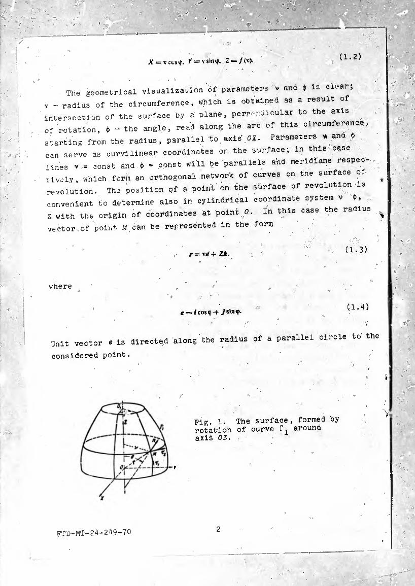
(1.2) X = \ ¿cs<|\ K = V sin«f, 2*=/(v).
. i
The geometrical visualization ôf parameters - and ♦ Is clear;
V - radius of the circumference, which is obtained as a result of Intersection of the surface by a plane, perpendicular to the axis of rotation, * - the angle, read along the arc of this circumference,
starting from the radius, parallel to axis' OX. Parameters . ana « can serve as curvilinear coordinates on the surface; in this case Unes V = const and * = const will be parallels arid meridians respec-
tivaly, which form an orthogonal network of curves on tne surface of
revolution. The position of a point on the surface of revolution is convenient to determine also In cylindrical coordinate system v ¢, 2 with the origin of coordinates at point 0. In this case the radius
vector.of point Mean be represented in the form
r = vtf + Z*. (1.3)
where
e = /cos«i-t /sinq». (1.4)
Unit vector e is directed alongthe radius of a parallel circle to the
considered point.
Fig. 1. The surface, formed by rotation of curve around axis OZ. ■
FTD-MT-2M-249-70 2
Let us introduce unit vectors of tangents to the meridian and
to parallel circle at the given point
_ — *■ _ dr »» — Ti r • *2 = (1.5)
where d-^s - element of length of the arc of meridian, d0a - element
of length of the arc of parallel circle. Vectors T ^ and are
mutually perpendicular, inasmuch as the meridians and parallels form
an orthogonal network of curves on the suiface of revolution. To
r the movement of the end of radius vector r from the given point M to
the point of surface infinitely close to it M' corresponds to quantity
(1.6)
d-,3
Prom (1.6) it is simple to conclude that relation determines the
direction of ouch movement. When d-^s = 0, ^28 ^ 0 we obtain movement
along parallels d2r = 12d2s, when d^ / 0, d2s = 0 movement of the
end of radius vector occurs along meridian d^ = The unit
vector of the tangent at point M to some curve r on the surface is
equal to
# — *L —T d'S ' r d*S (1.7)
where de — element of length of the arc of line F. Vectors t at the
given point are arranged in a tangent plane to the surface at this
point. The position of the tangent plane is entirely determined by
the assignment of two ncnparallel tangent vectors, for example and
. At point M let us construct a normal to the surface, having
determined the unit vector of normal n as the vector product of vectors
and x2
FTD-MT-24-249-70 3

« = T, X »2-
,
(1.8)
Lot us agree to always use a right-handed coordinate system. Three
vectors T , t2 « ?orm a trihedron of orthogonal axes . In view of
the symmetry of rotation all the normals to the surface at points
located on one parallel intersect at one point on the axis of rotation
and form a cone with angle of opening 20. Being limited to the
examination of only such surfaces, on which the setting of angle 9
uniquely determines the parallel circumference, Just as the setting
of angle $ determines the meridian, let us take system (0, ♦) as the
basic system of curvilinear coordinates on our surface. In accordance »
with the terminology accepted in the theory of surfaces [25] we call
the curve, which is obtained as a result of intersection of the ^
surface by a plane, passing through the normal at point M, the
normal section of the surface. Through any point of the surface it
is possible to draw an infinite set of normal sections, to each of
which corresponds its vector of tangent t..
Fig. 2. The meridional section of the surface of revolution: a) normal to the surface and normal to curve coincide,
b) normals have opposite-direc-
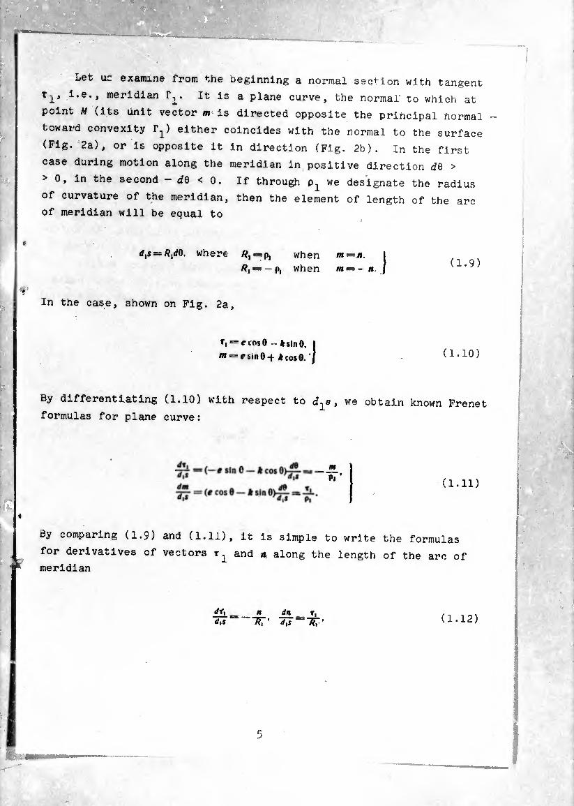
Let uc examine from the beginning a normal section with tangent
T-p i.e., meridian . It is a plane curve, the normal to which at
point M (its Unit vector m is directed opposite the principal normal
toward convexity 1^) either coincides with the normal to the surface
(Fig. 2a), or is opposite it in direction (Fig. 2b). In the first
case during motion along the meridian in positive direction <¿9 >
> 0, in the second - ¿0 < 0. If through we designate the radius
of curvature of the meridian, then the element of length of the arc of meridian will be equal to
= where /?, =p, when nt—n. /?, = —p, when «* = - n (1.9)
In the case, shown on Fig. 2a
t, = e tos 0 - * sin 0.
m = esinO-|- *cos0. ' I (1.10)
By differentiating Cl.10) with respect to d-^s, we obtain known Frenet
formulas for plane curve:
m Pi *
(1.11)
By comparing (1.9) and (1.11), it is simple to write the formulas
for derivatives of vectors r^ and a along the length of the arc of meridian
ÍÍL <¡\S d\S Äi' ’ (1.12)
__
or
(1.13)
In formulas (1.13) there are Introduced partial derivatives, since
on the surface vectors r^, n are functions of coordinates 0,
<}). Let us set a goal to obtain the remaining formulas of differentia¬
tion of vectors n with respect to coordinates. For this let
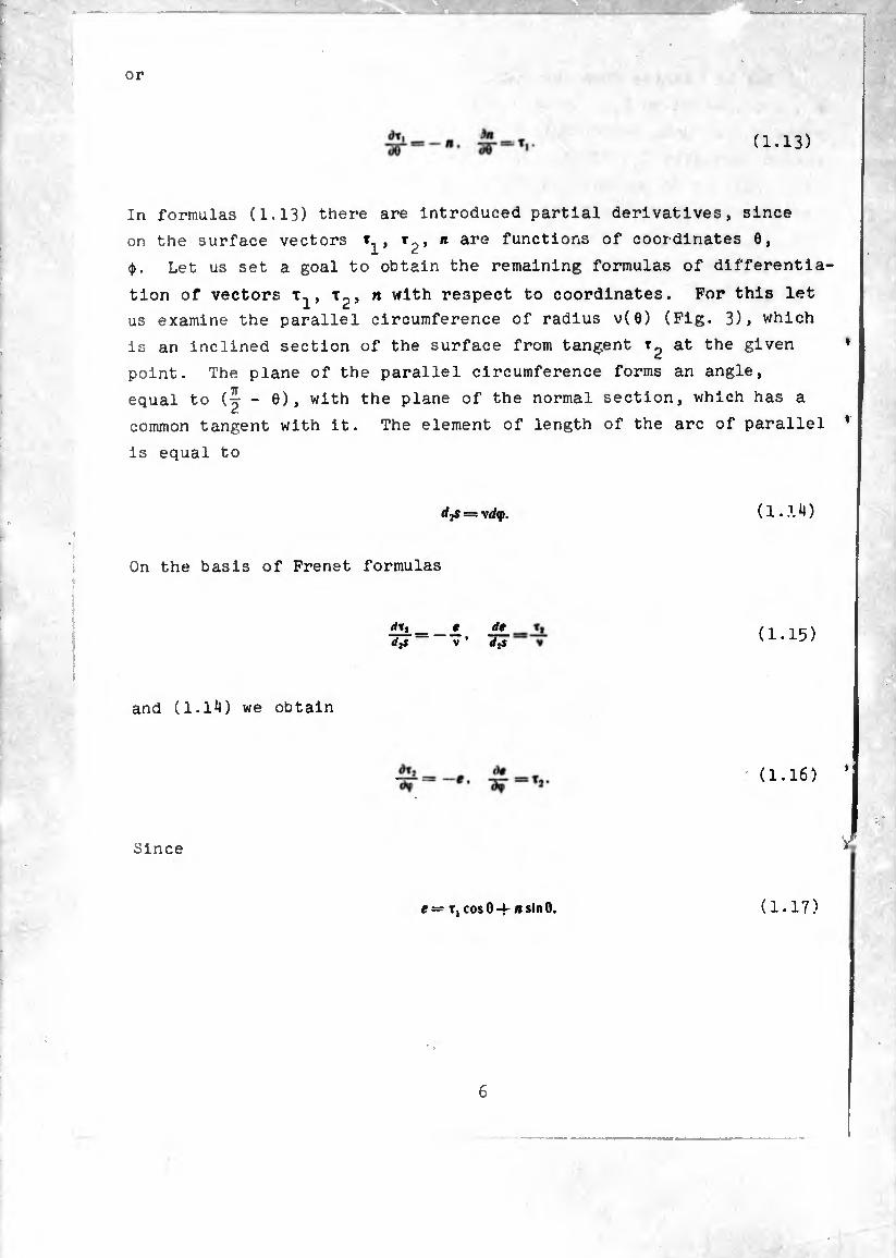
us examine the parallel circumference of radius v(0) (Fig. 3), which
is an inclined section of the surface from tangent at the given
point. The plane of the parallel circumference forms an angle,
equal to (j - 0), with the plane of the normal section, which has a
common tangent with it. The element of length of the arc of parallel
is equal to
(1..-U)
On the basis of Frenet formulas
dtj _» de_ d3s V ’ djt (1.15)
and (1.14) we obtain
(1.16)
Since
i = T| cos 0 -f- »sinO. (1.17)

tnen the second relationship (1.16) can be rewritten so;
i)T, ~àv cosO fin.
lAf slnO tj. (1.18)
By scalar multiplication of both sides of equality (1.18) by n and
taking into consideration that l^.a) = 0 (which is simple to
check by differentiation of equality '(«•».) = l), we obtain that
0, i.e., vector does not have a component along axis n.
dTl Since also d°es not have a component along axis r,., then — =
ût2. Analogously, by scalar multiplication of (1.18) by t,. ^we
ensure that = o and consequently, || - it.,. By turning again
to equality (1.13), we find that It can be performed Identically only with a = cos 0, = sin 0 and therefore
d<t T20, -^ = T,sin0. (1.19)
By differentiating scalar products (V«) = 0 and <vt,) = q with
respect to 0 and taking into account formula (1.13), we ensure that
and (¾-^)=0.
whence follows obvious formula ^=0. As a result the following
derivation formulas are obtained:
dr, 'Sf = T:>cos O.
<^1 _
ill Off
— n. dr, Û6 = 0.
dn W = Ti*
= — T, cos0~«sinO, dn I ^ = TiSin0. J (1.20)
<*
7
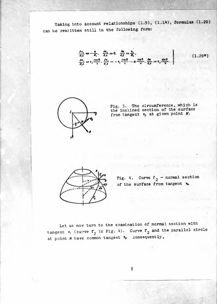
Taking into account relationships (1.9), (1.1*0» formulas (1.20)
can be rewritten still in the following form:
¿T, « lh, _ ()/1 T,
tm““- 77=°1 à.T=Trr (ït, COS0 fc'». _ COS0 _ *lnO
SJ cm 9 ùi • _
= *2— • Tt - ~ Ti
dn sin 0 dT “ T-‘ v”
(1.20*)
Fig. 3. The circumference, which is the inclined section of the surface from tangent tj at given point M.
Fig. 4. Curve r2 — normal section
of the surface from tangent t*.
Let us now turn to the examination of normal section with
tangent r. (curve ?2 in Fig. 4). Curve r2 and the parallel circle
at point M have common tangent fj. consequently,
8
(1.21)
where through de there Is designated the differential of arc 1'
By using the first Frenet formula for the parallel and for cur
we obtain
m Aï-
(1.22)
where /?2 - the radius of curvature of normal section r?. By scalar
multiplication of both relationships (1.22) by n. we will have
(1.23)
From (1.21) and (1.23) follows
sin 8 V (1.2U)
Relationship (1.24) indicates that the center of curvature of normal
section r2, which at the given point has common tangent with a
parallel, is projected to the center of the parallel circumference
and, consequently, is located on the axis of rotation. This assumption
is a consequence of the Meusnier theorem, known in the theory of
surfaces, according to which the curvature of the curve on the
surface and the curvature of the normal section, which has a common
tangent with the given curve, are connected according to the following
law: the curvature of a curve is equal to the curvature of a normal
section, multiplied by the cosine of the angle between the osculating
plane of the curve and the plane of the normal section.
9
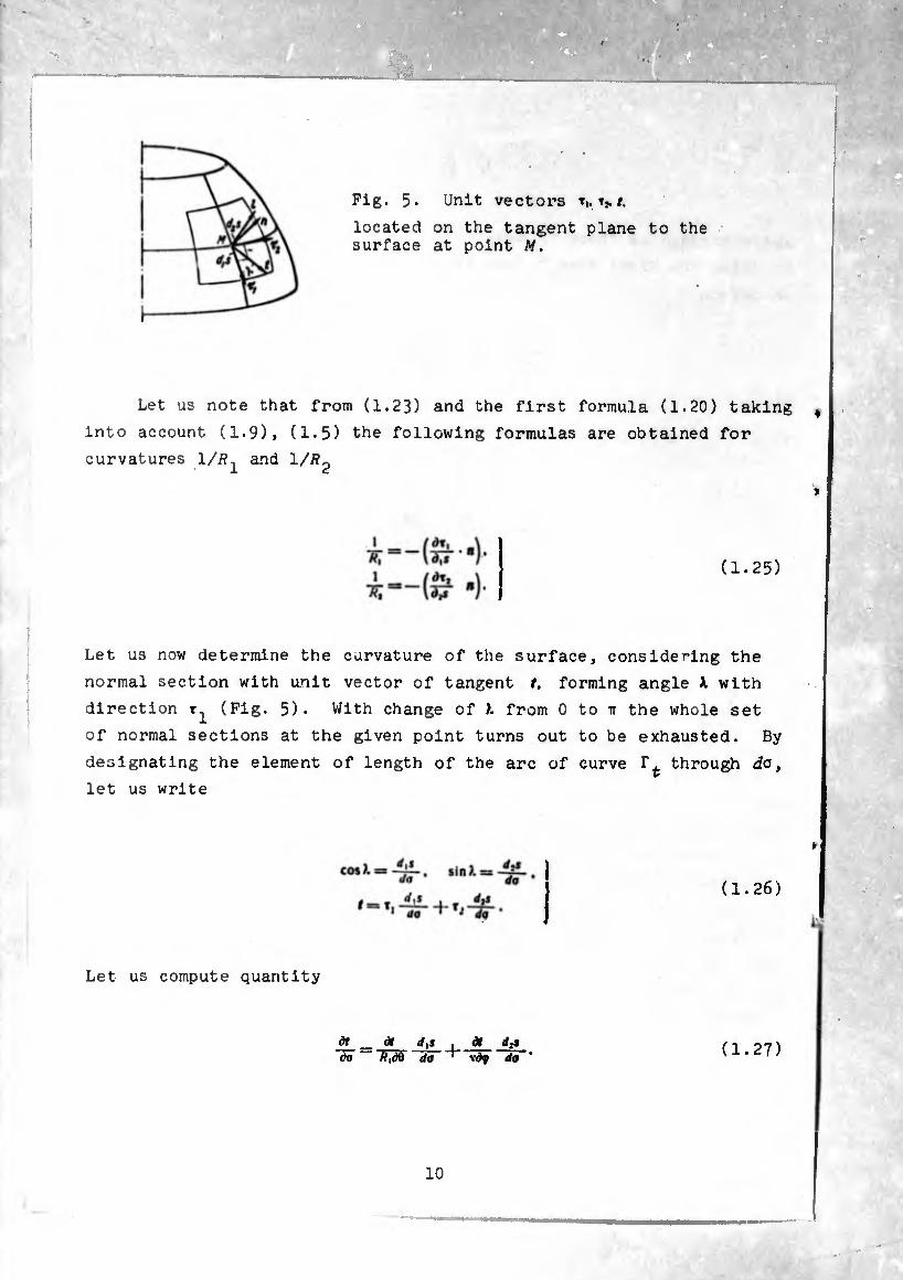
Fig. 5. Unit vectors »i. t,. #.
located on the tangent plane to the surface at point M.
Let us note that from (1.23) and the first formula (1.20) taking f
into account (1.9), (1.5) the following formulas are obtained for
curvatures 1/R^ and 1/^
»
(1.25)
Let us now determine the curvature of the surface, considering the
normal section with unit vector of tangent t. forming angle X with
direction (Fig. 5). With change of X from 0 to tt the whole set
of normal sections at the given point turns out to be exhausted. By
designating the element of length of the arc of curve through do,
let us write
»
(1.26)
Let us compute quantity
dr_= d» rf,» . at d* òa /?,dÔ da ' vdy do (1.27)
By using derivation formulas (1.20) and formulas (1.26), we obtain
Hi ! co*»>. sin*i \ , .MlnicosO . dX\ (1.28) To =(-ST-R¡-!a+l(~ ^ «r
where ( sin X + t2 cos X - the unit vector, perpendicular to
vector t and located in tangent plane.
Let us compute the curvature of the surface in direction t by
formula
By using in this case the expression for £ according to (1.28) and
taking into consideration that (<•*) = 0, we obtain
1 cos*X , *ln*X (1.30) —1—'RT'
From (1.30) and (1.26) follows important formula
l 1 -Rt-%
(1.31)
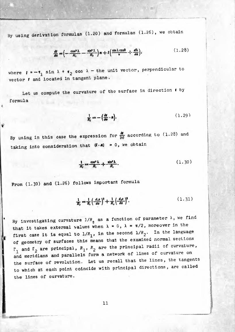
By investigating curvature ]/St as a function of parameter X, we find
that it takes extermal values when X - 0, X - e/2, moreover in the
first case it is equal to 1/S1, in the second l/»2- In the language
of geometry of surfaces this means that the examined normal sections
f and r are principal, Bj are the principal radii of curvature,
and meridians and parallels form a network of lines of curvature on
the surface of revolution. Let us recall that the lines, the tangents
to which at each point coincide with principal directions, are called
the lines of curvature.
11
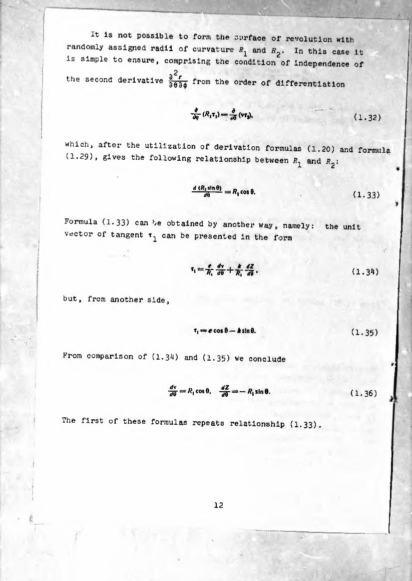
It is not possible to form the surface of revolution with
randomly assigned radii of curvature ^ and /?2. In this case it
is simple to ensure, comprising the condition of independence of
a2r the second derivative from the order of differentiation
(1.32)
which, after the utilization of derivation formulas (1.20) and formula
(1.29), gives the following relationship between /?^ and i?2:
d (/?, sln0) rfO = /?, COS 0. (1.33)
Formula (1.33) can he obtained by another way, namely: the unit
vector of tangent can be presented in the form
T'-7?r-55- + 7?7-5S- (1.34)
but, from another side,
Tj = £ cos 0 — k sin 0. (1.35)
From comparison of (1.34) and (1.35) we conclude
■^- = /?,cos0. = -fl|S|ne. (1.36)
The first of these formulas repeats relationship (1.33).
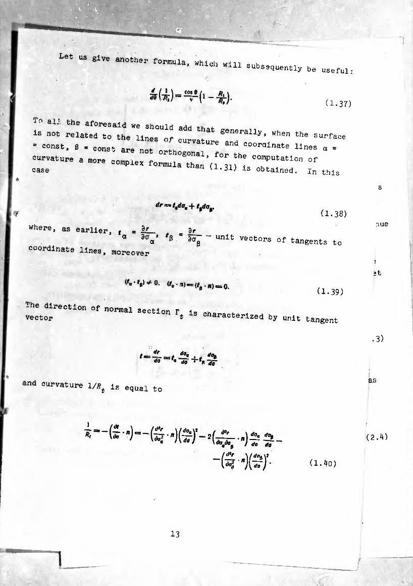
Let us give another formula, which wi 11 subsequently be useful:
(1.37)
To all the aforesaid we should add that-
is not related to the lines o-f cu e senerally> when the surface
= -st, 3 = const are nt o^ho n^“ =
curvature a more co.piea formula than (Í 31 ^ case vJ-O-U is obtained, in this
dr — tadoa + ttdOp (1.38)
where, as earlier, f = ÍL_ , dr
° 3\’ 6 “ 557 “ Unlt vect0^ °f tangents to coordinate lines, moreover
nue
et
l'a-t,)+0. (t„ -*)=*(/ . n)t==0 # (1.39)
The direction of normal section f is rha vector * characterized by unit tangent
i=*, da, da a Jo -jj-
.3)
and curvature 1/Æ ia equal t< a£
ï—£■•)■
-(5-K?/' (1.^0)
(2.4)
13
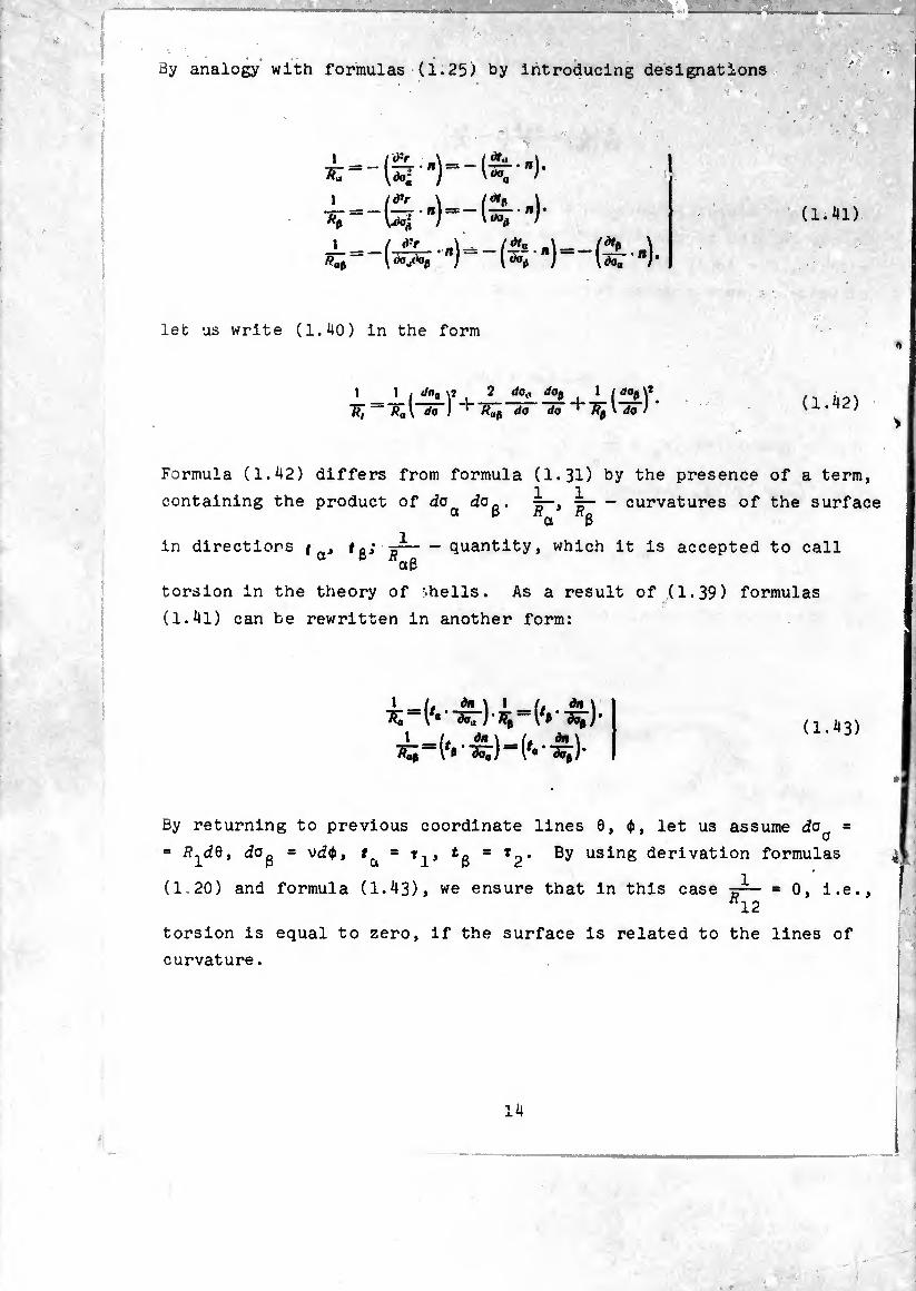
By analogy with formulas (1.25) by introducing designations
i| 1 m
> ■
V
1
i (l.U)
let us write (1.40) in the form
1 1 ¡ Joa ÿ i 2 rfo,, rfop i I [ dap Y TT, da ) do (1.42)
Formula (1.42) differs from formula (1.31) by the presence of a term,
containing the product of do do . i- curvatures of the surface 0t p n Hq a p
in directions f . ^- quantity, which it is accepted to call a P Äct3
torsion in the theory of -.hells. As a result of (1.39) formulas
(1.4l) can be rewritten in another form:
(1.43)
By returning to previous coordinate lines 0, ¢, let us assume daa =
= i?1d0, dOg = vd<f>, = r1, By using derivation formulas
(1 20) and formula (1.43), we ensure that in this case 12
torsion is equal to zero, if the surface is related to the lines of
curvature.
14
alas 4
, i.e.,
——
-
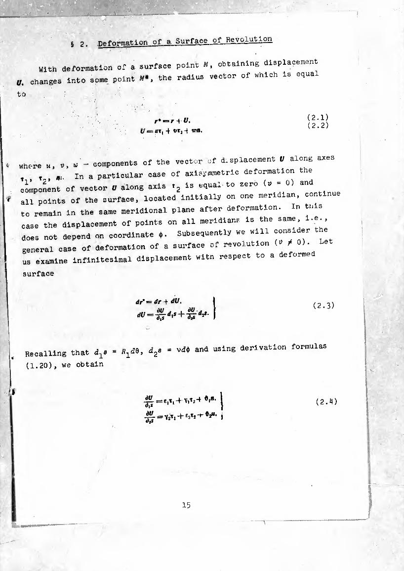
§ 2. reformation of 9 Surface, of Revolution
With deformation of a surface point », obtaining displacement
U. changes into some point «*, the radius vector of which is equa*
to
r* = r i 1/. = 4 t/Tj 4 ten.
(2.1) (2.2)
where u, V, w - components of the vector of déplacement V along axes
, , t., » m a particular case of axisymmetric deformation the
component of vector U along axis »2 is equal to zero (r * 0)
all points of the surface, located initially on one meridian, continue
to remain in the same meridional plane after deformation. In this
case the displacement of points on all meridians is the same, i.e.,
does not depend on coordinate ♦. Subsequently we will cons.de,
general case of deformation of a surface of revolution (» W >.
us examine infinitesimal displacement witn respect to a deformed
surface
</r* = dr + dU.
“U =
(2.3)
Recalling that = ^¿0, d2s = vd* and using derivation formulas
(1.20), we obtain
(2.4)
-
-:. ..
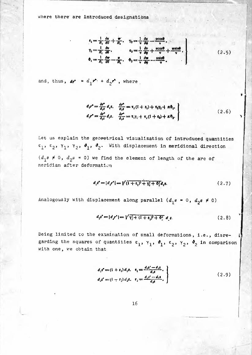
where there are introduced designations
1 du #Td<r+7?r- V
! du vcosO
v _ I
1 dtt
V dip
1 dv . V df ^ 1 dw
V ucosO trsinfl
V üsln9
V « i «WP m A id*
and * thus, dr9 = + d /* , where
rfir‘ “ 17 rf‘*- Ä Ti (1 ei> + T*Vi ^ »•i*
^ = -37=1 T.Y.-4 Ml + ea)+ *#,.
(2.5)
(2.6)
Let us explain the geometrical visualization of introduced quantities
el’ ’ Y1J y2’ ^1’ ^2’ displacement in meridional direction
(d^s ¿ 0, d^s = 0) we find the element of length of the arc of
meridian after deformation
<// = ; rf,r* I = /(1+e^+Yi+^rf,». ( 2.7 )
Analogously with displacement along parallel (d-j^s = 0, d^s / 0)
djs* = Id/1 = /yH (1 4-e/4 «; rfi (2.8)
Being limited co the examination of small deformations, i.e., disre- 4
garding the squares of quantities y1, e , y2, in comparison
with one, we obtain that
.-04.1
j • j. , vj —d,* d/= (1+£,)//,!. e, = 1 v
= (,1 t r:)<i\s, r¿ (¡¡S' — il .J
d;* ’ (2.9)
16
whence It le clean that tj, e2 are relative elongations In meridional
and circumferential directions. The vector, of tangents to coordinate
lines on a deformed surface have the form
. _ dr* _ 1 . . 1 - 0,sm - T+TT ,T| ( + fi>+ t2Yi 4 rtd,] ^ T, -+ t2v, -+ T*—dr' 1
* d,s* ~ 1 4-r, ItiY2.4 ^ -r fj)-} «ô2| =& T|y24 t2-}- nf>7. (2.10)
l:cr;fhand r? are n0t 0rth0g0nal t0 ea^ other. Which is simple to check, by calculating their scalar product
(TI ' t2) — V2 + Yj = Y- (2.11)
Of initially right l V ^ t0 the ^^lon Shear In f e“8 VeCt0rS h and *2 *"d is called shear. In fact. If Y Is small, then cos (tj, Y t 00s (£ _ Y,.
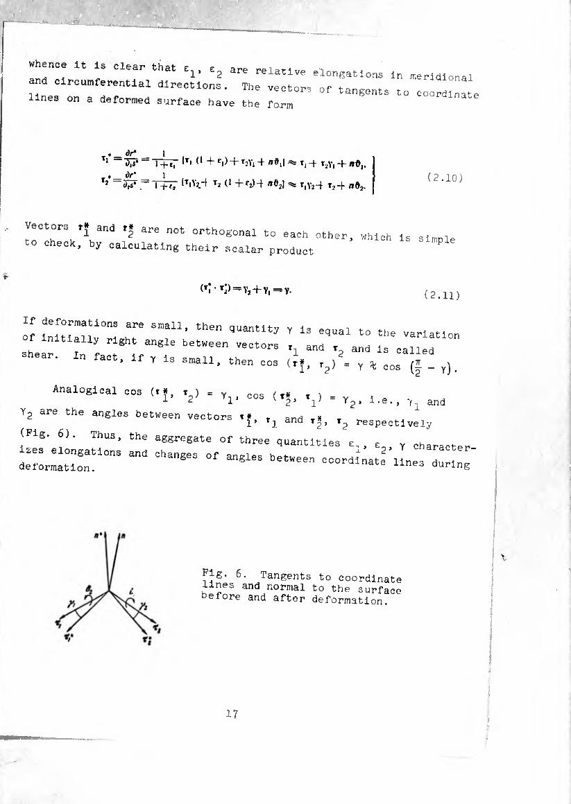
Analogical cos (.., W cos(t., V = ^, 1 ,e., and
y2 are the angles between vectors ,., tl and ,., t? respectlve'ly
(Pig. 6). Thus, the aggregate of three quantities e,, e Y character
^LlaZ“0"3 and ChanSeS °f — coordinate lines during'
Pig. 6. Tangents to coordinate lines and normal to the surface Defore and after deformation.
17

Let us explain the geometrical visualization of quantities ^ and
t>2 (formula (2.5)). Let us determine the vector of the normal to
deformed surface n* as vector product
tnen, using formulas (2.10), we ootain
„* «= /1 — ó,!, - V,
and
cos(n'. t,) =— O, cos•
COS (1* Xj) = — Ô, ^ cos 4" (>2) •
i and &2 represent the angles of rotation of the normal to
the surface around axes t2 and ^ respectively (see Fig. 6). Let
us introduce vector
11 =x OoTj — 0,1/ + 0*. (2.1
where
0 = 7 (Y, — Y2)* (2.15)
then relationship (2.13) can be rewritten in this form:
n* — « = Q X *•
18

Moving ahead, let us call Q the rotation vector. If we take into
account the meaning of quantities #2 and take quantity 6 for
the characteristic of rotation of the element of the middle surface
around the normal, then such a name is natural. In § 3 there will be
shown that with acceptance of Kirchhoff-Love geometric hypotheses
vector Q is equal to the value on the middle surface of the rotation
vector, common in the theory of deformations of continuous medium.
Let us now turn to the study of the curvature of a deformed
surface. For this, by using formulas (2.10), (1.25) and (2.13), and
also formulas of differentiation of unit vectors t^, n (1.20), let us compute quantities
dx\ IT
1 rí!.* 4.1 * -l/ > , i i r*: l^rT'+'sris'T*+( - T?:+) " ] • dA __ i 17 c
ïTïrll-- co$0 , 1 à\'t
t-st )t.+(- cos e #, sin 0
t2 +
+(7^-^)4
(2.16)
1 ãT
1
-(â-'l-Ÿ 1 *♦,
~R;~srt
(l—tj) slnO 1 d0j 0,cos0 V
By introducing designations
v _ 1 00. ‘ *1'
01 CO» 0 1 00, 7-3* •
19
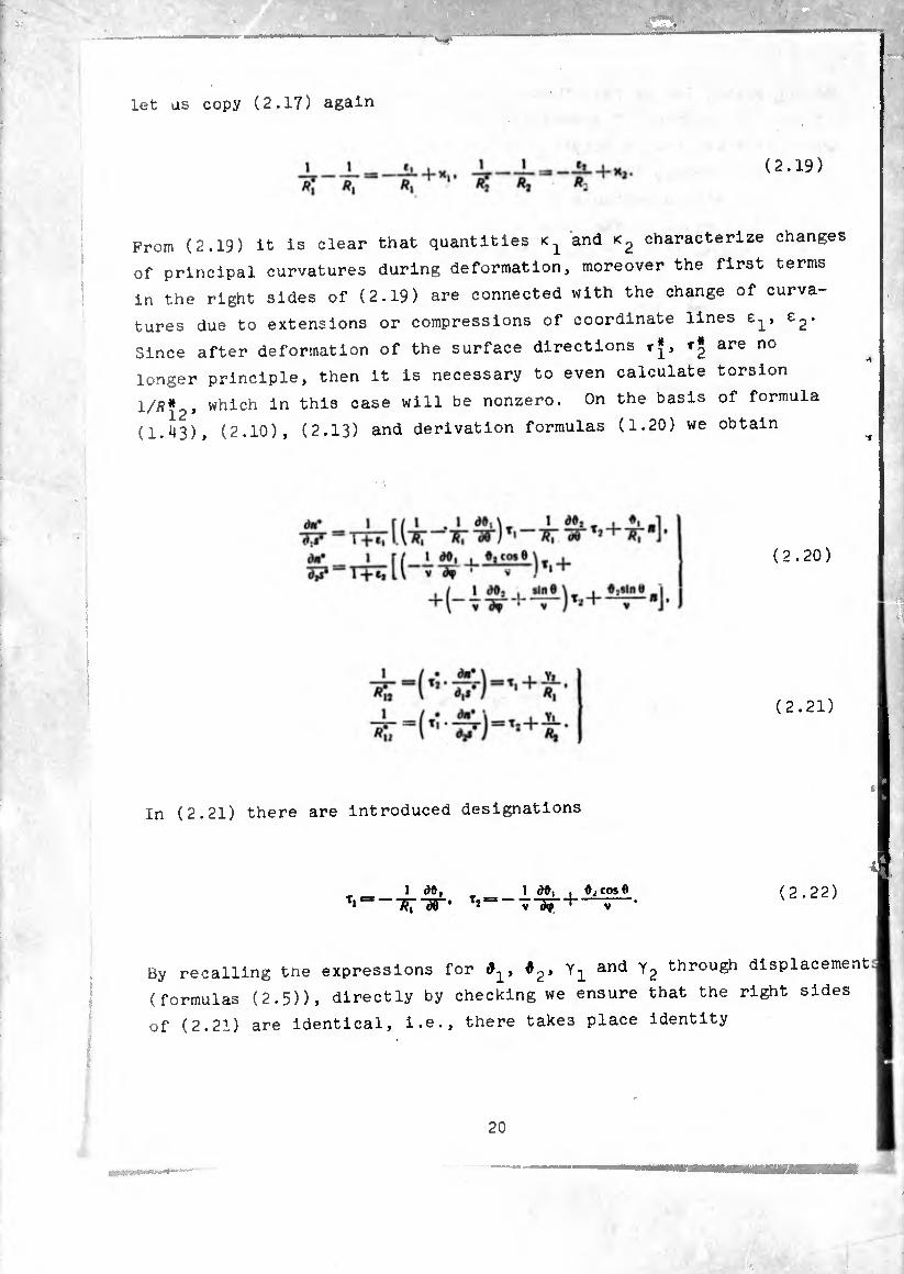
let as copy (2.17) again
(2.19)
From (2.19) it is clear that quantities and characterize changes
of principal curvatures during deformation, moreover the first terms
in the right sides of (2.19) are connected with the change of curva¬
tures due to extensions or compressions of coordinate lines e2-
Since after deformation of the surface directions t|, are no
longer principle, then it is necessary to even calculate torsion
1/Ä* , which in this case will be nonzero. On the basis of formula
(1.43), (2.10), (2.13) and derivation formulas (1.20) we obtain
(2.20)
(2.21)
In (2.21) there are introduced designations
!<)#,_ 1 â9, , ÛjCosQ r¡^~7^~sr' -V ( 2.2 2 )
By recalling tne expressions for #2> Y1 and y2 through displacement
(formulas (2.5)), directly by checking we ensure that the right sides
of (2.21) are identical, i.e., there takes place identity
20
(2.23)
Let us also note incidentally tne following identities, which will be
subsequently useful:
* 5¾¾ i _ 1 àt, y cos 8 Ä| ÒÒ V ¿ip V (2.2¾)
-^- + 0,5100 = -6, COS0 + -i-^il. (2.25)
*
By designating torsion 1/Ļ2 by the letter r. for it we have two
equivalent expressions
(2.26)
Tnus, the change of surface curvature with deformation is characterized
by three quantities <2 and t.
In conclusion let us compute the derivatives from the rotation
vector Q., On the basis of (2.14), by using derivation formulas
(1.20) and taking into account (2.~2), we will have
(2.27)
where through and ç2 there are designated quantities
r _ I ói , i ¿a 0, sin 0 V (2.28)

By using identities (2.23), (2.24), (2.25), and also taking into
consideration that 6 = - Y2), Y = Y,. + Y2» let us convert the
right sides of (2.2?) so that only quantities e2, y, <2, r
and their derivatives would enter them. For example,
1 m tt,_ l I <*, •. i f/u vj i t/| i C/) j I* j
«7 “ 2«; W — Ä7 d5" ~ 7?7 “ 1 ây , y cos 8 1 dt,
2Ä, TSF "f* V y *
etc .
Finally we obtain
(2.29)
where C-^, C2 are converted to the form
1 A*. .. a t
(2.30) I cos 0 , 1 t) (Vf,) ■ _ r 1 v _| « V
2v iAf V r vTF, ~3S •
§ 3« Deformation of a Shell of Revolution
The position of a point on a surface of revolution is governed
by two curvilinear coordinates 9, ¢. To determine the position of
a point not on the involved surface, it is necessary to give three
numbers or three curvilinear spatial coordinates. If point N of
the space is not far from the surface, then the position of If
22
elatlve to the latter la 3imply determined by a section of normal to the surface drawn to the point Th! T which the position of the given oolnr , SUJ-face relative to
reference surface. Coordinate: I T T 0311 the
normal from the reference surface’to’theV^n^ilTT" curvilinear coordinates of a point in s 1 are no"
positive if POint y ls on the plui e ::::-o/:“6 5 is conswered opfioslte case ç Is a negativ» >, d f the normal> in the » nGgtí.çi.v6 number i forms an equidistant surface all nol n » 8 °f POintS C ' 00ns,: from the reference A hod k 1 8 °f WhlCh ai'e e<lultilstant , +* an„ ! ! y Und by two distant surfaces t=±7 and by two cones 0=0,.0 = 6,. Is closed in ,h ,
01osed in the circumference (0<?<2a) of a shell of revol nt-i or, ^
can also Imagine a shell of valable th'lT“' thlCkneSS ^ ^ in this instance the surfaces bl^ln Tl ^ from the reference surface, and we have the“eUMo^hr“1?- where ^ is a known function of 0. in bofh PS C=
^ = ftre;; the reference surface goes in th ^ = C°nSt and bounding surfaces and is called the MddÎeacl
z; ** .....
... .. ...u
characterizing the thin-wall asn V * ^ tlan 0ne‘ A Parameter
nesa to the total merldlL Lc L^th^o^t0^6 ^
clrcle of the extreme section of the shell. °f 3 Parallel
We designate through « the radius-vector of point « of the shell
# = /■+&». (3.1)
where r is the radius-vector nr
reference surface (* and :°L:i::h:nrr:::rng point w °n th8
surface 7TZT “ lnfinlteSlmally diaPla=ement on equidistant
dJl^dr + ldn. (3.2)
23

With the aid of formulas (1.6), (1.20) we calculate
+ = *i(,+r2(i(3.3)
Designating through rf,o. dp elements of arcs of coordinate lines on
an equidistant surface after comparison of (3.3) with (1.6), we find
^=(1 T-L-W (3.4)
Let us note, furthermore, that unit vectors of the tangentials to
meridians and parallels on equidistant surface T T and the vector
of normal N are equal to
Introduced system of curvilinear coordinates 0, ¢, ç is orthogonal,
and that is why an area element of the equidistant surface and a
volume element of the shell are defined easily as
= (3.6)
^=^0^:=(1-1--^)(1 + ^-)/?,v (/«(/?</:. (37)
Let us turn now to shell deformation. It is assumed that the shell
is so thin-walled that during deformation: 1) all points which be¬
fore deformation were on one normal tv the middle surface will be on
the normal to a deformed middle surface; 2) there is no extension or
compression of the normals. These hypotheses are the basis of the
theory of thin-walled plates and shells by Kirchhoff and Love.
Here we give only the kinematic ocmponent of the Kirchhoff-Love
hypothesis. Usually added is the static assumption about the smallness
24
mtr 4P
■ -
■ 3HB ■ '
of normal stress Oj on the areas c = const. The last assumptlon
means that during calculation of deformations e., e? In terms of
values of stress of u2> <,3 the quantity o can be neglected
(see formulas (5.7). The Introduction of Mnematic hypotheses
a lows describing the deformation cf a three-dimensional continuum
such as a shell, with the aid of quantities characterizing the '
deformation of a middle surface, l.e., reducing a three-dimensional
problem to a two-dimensional. Let us note that for the glven
kinematic picture of shell deformation all equations which are
o tamed In this section are accurate within the framework of the
linear theory of small deformations. Therefore It Is possible to
speak of inaccuracies of the Klrchhoff-Love hypotheses only for
the following reasons: 1) neglect of the quantity o, i„ deriving
elast-clty relationships and 2) the distributed and boundary load
on the shell can have such a character that the accepted picture of
deformations is not satisfactory.
The amount of error In the Klrchhoff-Love hypotheses has been studied in [6], [16], [24], [!] and others.
With several stipulations it can be considered that In most case,
acceptance of these hypotheses leads an error of the order of ft/if
in comparison with unity. In any case, this gives to us the right
to make all practical calculations dropping terms of the order
h/R in comparison with unity. Inasmuch as the error of the basic
hypotheses Is not less, but sometimes can be even considerably greater [6]. J
of 7!’ t0 the Klrchhoff-Love hypotheses the radlus-vectc of Point y , which point s of the shell becomes during deformation, has the form ’
(3.8)
ere ' " radlus-v«tor of a point on the deformed middle surface
y .1) equal to r+l/. Designating by lA> the displacement vecto
ofjoint » of the shell at deformation, from (3.1) and (3.8) „e
25
(3.9)
From (3.9) and (2.13) it follows that components of displacement
vector = i>í;'t2+w(:)b along axes V Ta* " are
«<;) = « — #£, v*;’= i» — OjC. v^ = w. (3.10)
On the basis of (3.8), using equations (2.6) and (2.20), we compute
+--¾ ^)+" ('+ ir) *'] Ç d#i , cos 9 \ V dy +
+ t,(i +^+^-^-4^’)+.(i+^)»,]^.
(3.11)
Remembering the expressions for ><i. Ti and ^2 (formulas (2.18),
(2.22)) and introducing instead of dis, d.2s elements of arcs dla, d2a
using formulas (3-^) > we will rewrite (3.11) again
<*,*• = + + + 1 (3.12) (i2R* = It,ü)2 -}- Tj (1 -(- e2) -(- rt&jl djQ* J
where
£i + ïj-J-Çxj ’ 2 ~'-t- v#ï ’
0, -= h+¿T' (0 -= Vl±?I* w* 1 +nRi ’ 0)2 r+w
(3.13)
Elements of arcs d{a\ d2o' on an equidistant surface after deformation
are equal to
rf.o* = /(1 + i,)2 r 4- öj dxa ^ (1 -f rf,o.
d2a’ = /u24- (1 4- t2f 4- #|rf2o ^ (1 -+ f2) dp. (3.14)
Expressions
elongations
equidistant
(3.14) indicate that quantities e^, are the relative
of elements of arcs of meridians and parallels of the
surface ç = const at deformation. We form vectors of

the tangentiale to coordinate Unes and normals to an eouidistant
surface after deformation
7- , I ^ = 2^*-= +
7-— W = «0,. f (3.15)
= = ôlT. _ a2T2 I
Using (3.15), it is simple to see that the changes
angles between vectors ^ and N at deformation in initially right
(shears), are
*12 ~~ (ri' *v) — + w, = Ö.
*23*=(^ (3.16)
the last two equalities of (3.16) are of course corollaries of the
accepted kinematic hypotheses. Elongation of » i„ the direction of
the normal is also equal to zero because of the inextensibility of ti
normals. Let us show also that acceptance of the Klrchhoff-Love
hypotheses leads to the equality
I (rot =
where rof£/° designates doubled vector of
continuous medium at deformation, and Q
Ctjced in § 2.
rotation of an element of
vector of rotation, intro™
T r i" ¿
Projections of the vector roti/,:' onto orthogonal directions
N is computed using known equations of vectorial calculus
[11], in which for a selected coordinate grid 0, ¢, ç it is necessary
to set Lame' coefficients equal to (l-K7?,)v. lr faking 1nto
account equation (3.10), we obtain
27
(,otu':’),=r—Vr-f-w—■^K' +i;)(”-s>)]}' l,+Wv .,
(rot If'X = [(R\ 4-1) (“ — ^1^)1 — dtf f •
__S_
^+ö(l+ir) (rot = —r—TT {W [(1 + ^-)v (v "
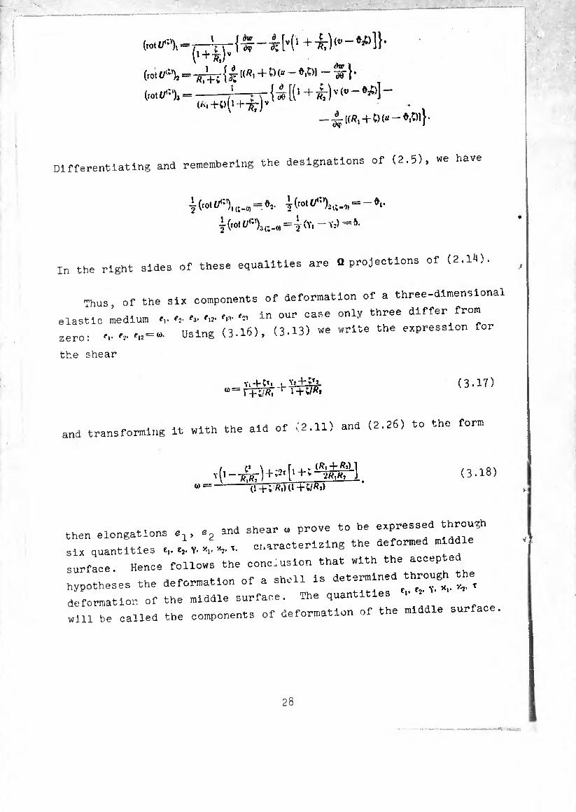
Different iating and remembering the designations of (2.5), we have
I (rot i/(;')3 = 4-(Y,
in the right sides of these equalities are Q projections of (2.1*0.
Thus of the six components of deformation of a three-dimensional
elastic medium <v ^ 'u- in our case only three differ from
. ,,. ,2. ,12 = u>. Using (3.16), (3.13) we write the expression for zero
the shear
<3-17)
and transforming it with the aid of (2.11) and (2.26) to the form
... r /0-1- P.\ 1
(3.18) 10 ==
! 'Cr
*■* i^*
i I+;2t|
(i+;K.>U-K/K*>
then elongations e, and shear » prove to be expressed throng
six quantities .,. «, V. t characterizing the deformed m ddle
surface. Hence follows the conc.uslon that with the accepted
hypotheses the deformation of a shell is determined «rough the
deformation of the middle surface. The quantities r .
will be called the components of deformation of the middle sur
28
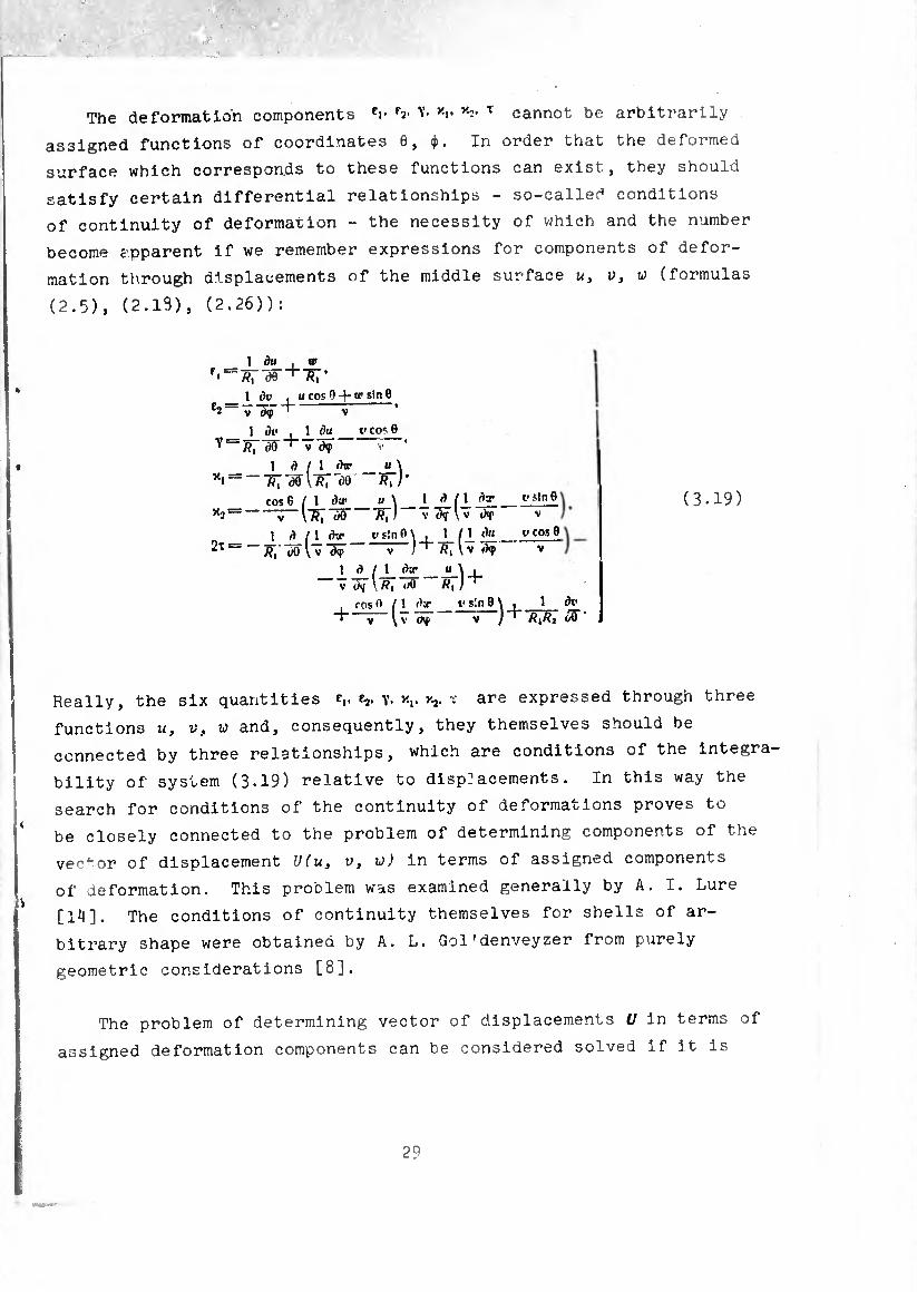
The deformation components er f2- Y. V *:• T cannot be arbitrarily
assigned functions of coordinates 0, ¢. In order that the deformed
surface which corresponds to these functions can exist, they should
satisfy certain differential relationships - so-called conditions
of continuity of deformation - the necessity of which and the number
become apparent if we remember expressions for components of defor¬
mation through displacements of the middle surface u, v, w (formulas
(2.5), (2.19), (2.26)):
1 du . w «Tæ R, '
u cos 0 -4- «' sin 9 _ 1 <h^ e2 V
1 dv . 1 du__v cor 9 Y v
1 <4_ / J_ dtr_u_\ xi “ —æ \/?, 5)9 /?,;*
cos 9/1 dtr_u_\_1 (1 x2— — v Ò0 Af, / v (>T \ v tKf
1 d ( \ dv t>s!nO\ . 1 M du 2x-d<p v
t> sin 9 v
veos 9 v
1 jd_ / J_ jtr_u \ i V ()¾ \ /?! (/0 /?, /
, COS» / 1 (’a- _ t- s!n 9 \ ,_]_ dv_ ' V \ V CKf v / R1R2 iß
(3.19)
Really, the six quantities e,. y. xj. ï are expressed through three
functions u, v, w and, consequently, they themselves should be
connected by three relationships, which are conditions of the integra-
bility of system (3.19) relative to disp]acements. In this way the
search for conditions of the continuity of deformations proves to
be closely connected to the problem of determining components of the
ver1-or of displacement U(u, v, w) in terms of assigned components
of deformation. This problem was examined generally by A. I. Lure
[14]. The conditions of continuity themselves for shells of ar¬
bitrary shape were obtained by A. L. Gol'denveyzer from purely
geometric considerations [8].
The problem of determining vector of displacements U in terms of
assigned deformation components can be considered solved if it is
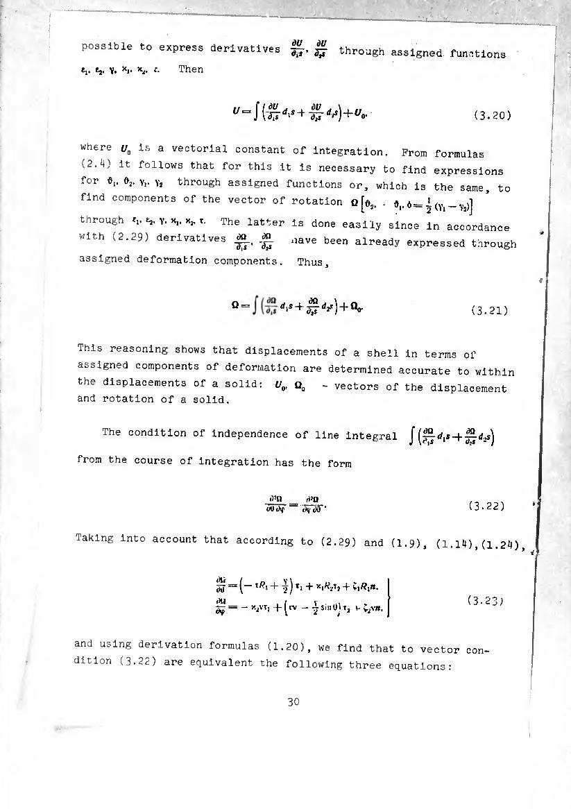
possible to express derivatives ^ through assigned functions
e,. e,, y, xt. *2. c. Then
"=i( dU dU dtid'S+ -g-^) + ^0- (3.20)
where uo is a vectorial constant of integration. Prom formulas
(2.4) it follows that for this it is necessary to find expressions
for ó,. d2. y,. v2 through assigned functions or, which is the same, to
find components of the vector of rotation qJû2 - ô 0_J. (y _y^j
through t,. t,. Y. T. The latter Is done easily since In accordance
With (2.29) derivatives £, «L nave been already expressed through
assigned deformation components. Thus,
Q = rf's+|r^)+öo- (3.21)
This reasoning shows that displacements of a shell in terms of
assigned components of deformation are determined accurate to within
the displacements of a solid: U0. Q0 - vectors of the displacement
and rotation of a solid.
The condition of independence of line integral ¡ [^dis ^jjdis)
from the course of integration has the form
();n _ rt}n Oil ihf ' ( 3 • 22 )
Taking into account that according to (2.29) and (1.9), (1.14),(1.24)
( 3 ~= - x2vt, f ^rv - ^ sill tíj t2 V- {.2vn,
and using derivation formulas (1.20), we find that to vector con
dition (3.22) are equivalent the following three equations:
30

¿e - X,fl|Cüi0 _ o 1 dy o. dx, Ô "V 7c/v £vv = 0.
' O, * (t»)-/í,t cose+v^o+iy^ÿ^ sine=o
-(Sifi)=0 (3.2^)
Tne condition of independence fr nm tv,
(3.20) IO,n the c-our^ of integration Integral
d7t>' _ _d*U ó9(hf cv ¡3e
«o rewrite in another for,. Introducing auxiliar, vectora
(3.25)
1/ ÓU rx V"'= TT ~ ö X Ti^i.
V'2' = - ü X TjV. (3.26)
instead of (3.25) we wlu have
. àü ~£- + ~X j D ~ 0K(2. , àQ o, t- cp X T,/?, - -or-h-^XTi
since on the basis of (i 20)
(3.27)
Of =
Turning to equations (1 n i
is simple to explain that (ectórs ( (J’13)’ (2-15>- ^
tU1 Plane “<* -IV deformation c^taTH ^
V(l) = ^iTj + ~ /?jYTj,
t» I »(-•,—-vyr, 4 vcjT2. (3.28)
Taking into account (3.23^ anri ( ? oq\
three conditions: (3.28), instead of (3.27) -,e obtain
31
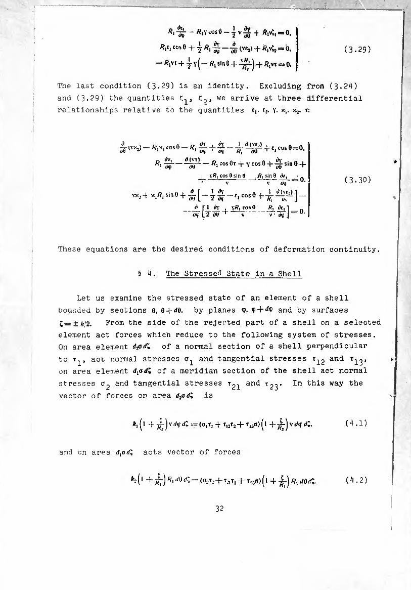
(3.29) /?,£, COS 0 -(- I ^ ^ (VCj) + /?,v^ =* 0.
— tf,VT + "jY^— /?jSln0-f- -I^lJ -j. ^jVX =a 0.
The last condition (3.29) is an identity. Excluding from (3.2*0
and (3.29) the quantities ç2, we arrive at three differential
relationships relative to the quantities fp ^ x,. r:
g- (W-j) — /ï,x, cos 0 — /? 01 <0 I d (ve,) (/0 CN ‘ wj //,
^ —/?,cosOtt-YcosO-i-^-sinO-f
, \R, cos 0 sin tf /?, sin0 dr
T c, COS 0=0.
d\
sv.,4 x^sinO-l-
_ n^v i on 00 r
V
1 i)(vr5)
— 0.
n , I o(vr5)l r, cosO —
_A V df J ò r 1 ch' i y/?i cos 0 R, <)e,
(3.30)
These equations are the desired conditions of deformation continuity.
§ 4. The Stressed State in a Shell
Let us examine the stressed state of an element of a shell
bounded by sections 0. 0-}-</0. by planes <p. <F-M<P and by surfaces
C=±A/2. From the side of the rejected part of a shell on a selected
element act forces which reduce to the following system of stresses.
On area element djjdl of a normal section of a shell perpendicular
to r^, act normal stresses and tangential stresses and
on area element c/,od* of a meridian section of the shell act normal
stresses and tangential stresses r21 and t2^. In this way the
vector of forces on area d2adl is
^(1 + 77:)vrf<fi=(oiTi4 ti2t2+ti3/»)(1 (4.1)
and on area </,oí/; acts vector of forces
*- (1 + /^r)R1 </0 ^ ^ (0-,T-’ + t.m + ( 1 -f i-) /?, jo dl ( 4.2 )
32
'*•
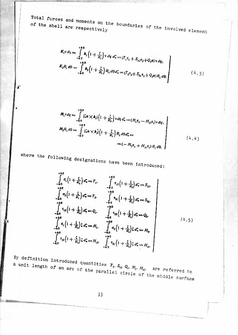
Total forces and moments on tu
Of the Shell ar.* the boundarles of fK 1 are r«pectively °f the involved element
+ */■3 KjJif </0 == (bit, * \
^~512T2+<?,/I)v</ç,
^0. (^-3)
Mtrt
+ *J 1
— (~ M2t, +//^)^40. I
U’+V«-'- T-CHy-,. + A/Í -*2 ' *»/ 12
■'(’.t)«-., r-i^iy-s,
fa,
1
-A/2 + A/2
1 4 A/2
i 4 A/3
(4.4)
(4.5)
a^unlTr1“!” lntroduce<i Quantities r c
n8 °f an arC °f Parallel to °f the middle surface
33

f statically equivalent to the stresses In the of the force and »0- ular co the direction of the
normal section of the s P r ç o. M*. Hn ls the same "
meridian. The meaning of quan " :;rldlan of the middle
referred to a unit length of an «= 0 alent t0 stress m
surface of the force and moment s^lcaj ^ correspondingly
the normal section oalled the meridian and neighboring
quantities T-^, an 2’ 2 . 0 an¿ q are the j tv,e bending moments. The quan 1 2
tensions and the be S tangential forces and torsional shearing forces ; 5,,. S2J. Hl2. «
moments. Their directions are shown PlS-
Fig. 7- Positive di¬ rections of forces and moments acting on an element from -,-, jected part Ox the shell ^
^ +-hA shell element, by
Replacing the system ^ m0ments actually allows
a statically equivalent sys e about the equilibrium of
reducing the ^^^"“^rthe^wo-dimensional problem about the
a volume element of the she surface_ Suoh an approach
equilibrium of an elemen ' dl completely agrees with
to the study of the ^ess^ at - o * sh deformaUon> as a result
the earlier “ed formation of a shell is described Of which it turns out that t SUIface. However,
by six components of deforma ^o . there are ten static
in the given case Instea^of^slx quan ^ ^ ^ note that al-
:::r--y o; -ell deformation assumed that shifts ^23
3*,
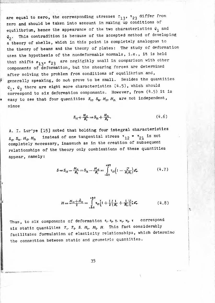
are equal to zero, the corresponding stresses dlf,i,er f1*0111
zero and should be taken Into account In making up conditions of
equilibrium, hence the appearance of the two characteristics and
Q2. This contradition is because of the accepted method of developing
a theory of shells, which in this point is completely analogous to
the theory of beams and the theory of plates: The study of deformation
uses the hypothesis of the nondeformable normals, i.e., it is held
that shifts e1^, e23 are negligibly small in comparison with other
components of deformation, but the shearing forces are determined
after solving the problem from conditions of equilibrium and,
generally speaking, do not prove to be small. Besides the quantities
Q2 there are eight more characteristics (4.5), which should
correspond to six deformation components. However, from (4.5) it is
easy to see that four quantities 5,,. S2I, //,, are not independent,
since
O t H11 _ Ç I ^»1
òi2+-/jr- —¿21 (4.6)
A. I. Lur'ye [15] noted that holding four integral characteristics
S So //,2. //•>, Instead of one tangential stress T12 = T21 ls not
completely necessary, inasmuch as in the creation of subsequent
relationships of the theory only combinations of these quantities
appear, namely:
S = J'M'-TPtK -A 2
. +A/2
-A*
Thus, to six components of deformation f,. f2. Y* v-v x2- T correspond
six static quantities Tr T2. S. Mt. M2. H This fact considerably
facilitates formulation of elasticity relationships, which determine
the connection between static and geometric quantities.
\
35
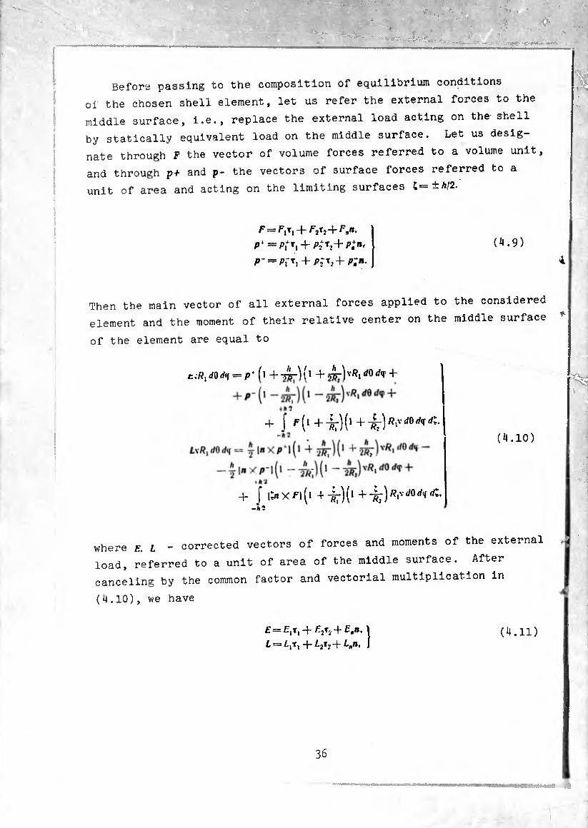
Before passing to the composition of equilibrium conditions
of the chosen shell element, let us refer the external forces to the
middle surface, i.e., replace the external load acting on the shell
by statically equivalent load on the middle surface. Let us desig¬
nate through F the vector of volume forces referred to a volume unit,
and through p+ and p- the vectors of surface forces referred to a
unit of area and acting on the limiting surfaces t=±A/2.
P* =/^1 + /^2+^ p-=*PfT, + P2-T2+p;ii.
(4.9)
Then the main vector of all external forces applied to the considered
element and the moment of their relative center on the middle surface
of the element are equal to
t.P.dOrff (l +-¿r)(l +575:)^1^^ +
+ I + ++(1++^0 (4.10)
+ J \^XF)(\ +-^)(1 +-^)/^0^
where E L - corrected vectors of forces and moments of the external
load, referred to a unit of area of the middle surface. After
canceling by the common factor and vectorial multiplication in
(4.10), we have
After
E— £+1 + /^2*;+ Fntl L — L¡x¡ + ¿2t2 + L„n.
(4.11)
36
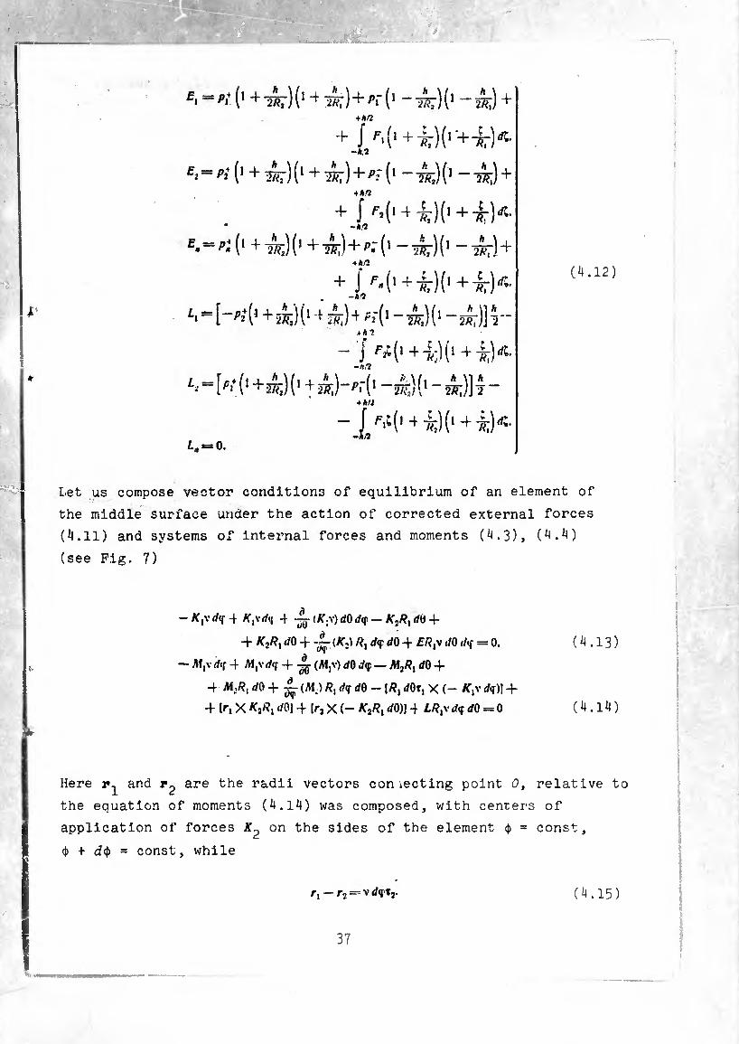
“wK1 ~Ä;) + •mn
+ J ^ + 47)(^+¼)^ -h.V
^=^(1 + ^7)(1 + -^7)+^(1 -^)(1 -2^)+ inn
1^(14 Í7K1 +~k)dl' -h?
E'=p¡(1 + ^)(1 + 2^)+^(1 -^7)(1 -4r)4 ■>*/2
+ J M14 ^)(1+^7)^1 -h?
Li ^ [ -p2+ (1 + 2¾) (14 é;)4 ^2*(1 - ¿) (1 - 2^7)] 1 -
- J + ^ -/i,i
-+^)-^-(1 -^)(1-à?;)] 7- *hU
- + tlO +1)«-
£, = 0.
0.12)
Let us compose vector conditions of equilibrium of an element of
the middle surface under the action of corrected external forces
(4.11) and systems of Internal forces and moments (4.3), (4.4)
(see Fig. 7)
- K¡\ dif 4 K^-dn 4 -Jj- <K;v) dO d<r — d« 4-
4- K,RX dO + ~ (K2) /?, d<r dO 4- f/?,v </0/^ = 0. ( 4.13 )
— AfjV d«f 4 /M|Vd(f 4- (M,v) dO d<p — M2/?, dO 4-
4 M:R] dO 4- ^ (Ai.) Rx d<r d0 - |/î, dOt, X (- /(,'• dç)] +
4 Ir, X ^2^ rfO] + [rj X (- KjRt </0)| 4 LR^ dç dO = 0 ( 4.14 )
Here and are the radii vectors con lecting point 0, relative to
the equation of moments (4.14) was composed, with centers of
application of forces on the sides of the element $ = const,
<t> + d4> = const, while
r, — r2 — V dqTj. (4.15)
37

„„ account (4.15) and of driva alnllar tarns. « raduca
(4.14) to the form
I- (M2) 4- (T, X *|) VÄ, + (Tj X #fj)+ Ml “ 0
(4.16), (4.17) after substltu^im
4) and differentiating with form
ns of equilibrium of the element
of (4.18) because of ^.o; is
iat equilibrium equations (4.18) c
Hl5. W« only in combinations (4.7)
first equation and transform it i
The sixth equatiui
is easy to show t!
and moments S,j. Sn.
as an example the
manner:
where we
fourth equation of
nly through S and H however.
4*
38
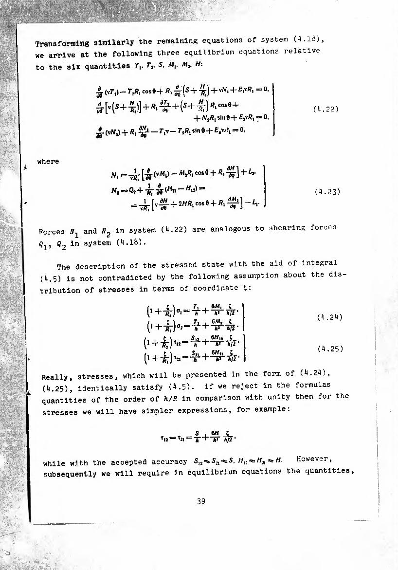
Transforming similarly the remaining equations of system (4.1Ò),
we arrive at the following three equilibrium equations relative
to the six quantities r,. Tt. S. A!,. M7. H:
£ (vT*,)— n/?, cosö-t ^ ^ -r 7í¡j 0 -t- • Í-S -f -Tjj) 4-
à ['■ (s+^']+s' +(s+-" )R' C0‘9+ 4-/y2/í,siii0-i-f2v/í,=*o.
W + ^ Sin 9 + £-V/ '> “ °-
(4.22)
where
N, « -3Ç- (VvM,) " C0Í 9 + + ^
Ni^Qi+-j^ ¿-(Hji — Wjj)*» (4.23)
forces and in system (4.22) are analogous to shearing forces
Q-p Q2 in system (4.18).
The description of the stressed state with the aid of integral
(4.5) is not contradicted by the following assumption about the dis¬
tribution of stresses in terms of coordinate ç:
/ t \ T. , «-M, ; (1 +T*r)0‘“;'ir+-/ir'Ã7r
/, , s \« - r* I 6M» C
+ 7?r) ,s * Ä3T *7?*
(l +-»:)Ta“'
(4.24)
(4.25)
Really, stresses, which will be presented in the form of (4.24),
(4.25), identically satisfy (4.5). if we reject in the formulas
quantities of the order of h/R in comparison with unity then for the
stresses we will have simpler expressions, for example:
S ,6H c T«I=Tii = T + **r Ä/I’
while with the accepted accuracy S^S^^S. H. However,
subsequently we will require in equilibrium equations the quantities.
39
S, H, introduced using equations (^.7), (4.8), since this gives
greater order to the basic equations.
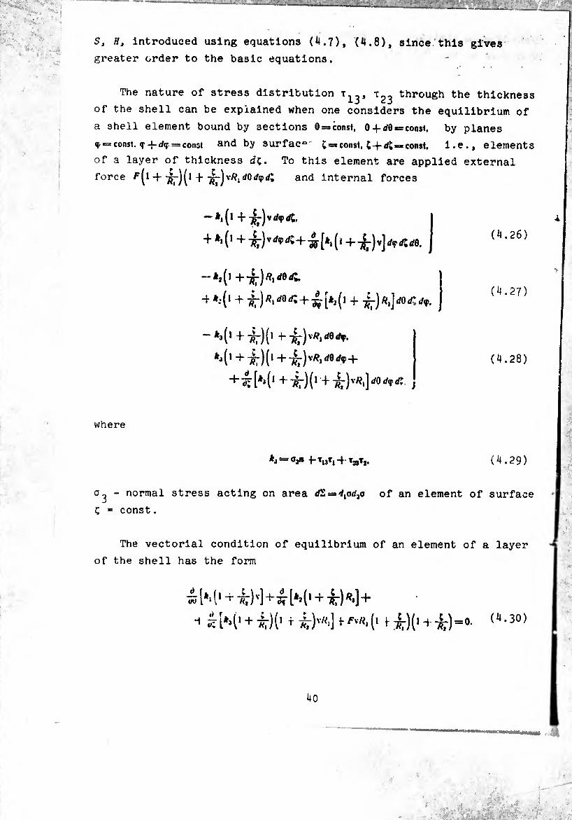
The nature of stress distribution t13, through the thickness
of the shell can be explained when one considers the equilibrium of
a shell element bound by sections O^const, 0 + d0*= const. by planes
Ç. = const. == const and by surfac0' £=»const, const. i.e., elements
of a layer of thickness dç. To this element are applied external
force ^(1 + ( 1dûrfç</; and internal forces
-^(1 +
-1 *.*(l + + -I-
*" ^(1 + 7^)(1 +■
*j(' + 7^)(1 +7^)v/?irf0</,P +
+ ^^3(1 +^-)(* +-^-)v#,]dOd<f<tt
(4.26)
(4.27)
(4.28)
where
*J = °3» +-T13T, + TaT,. (4.29)
o^- normal stress acting on area </S = d,od2o of an element of surface
ç = const.
The vectorial condition of equilibrium of an element of a layer
of the shell has the form
¿ (1 ^ 7Í7)v]+^- [** (1 + *lr) +
43».-i .
i
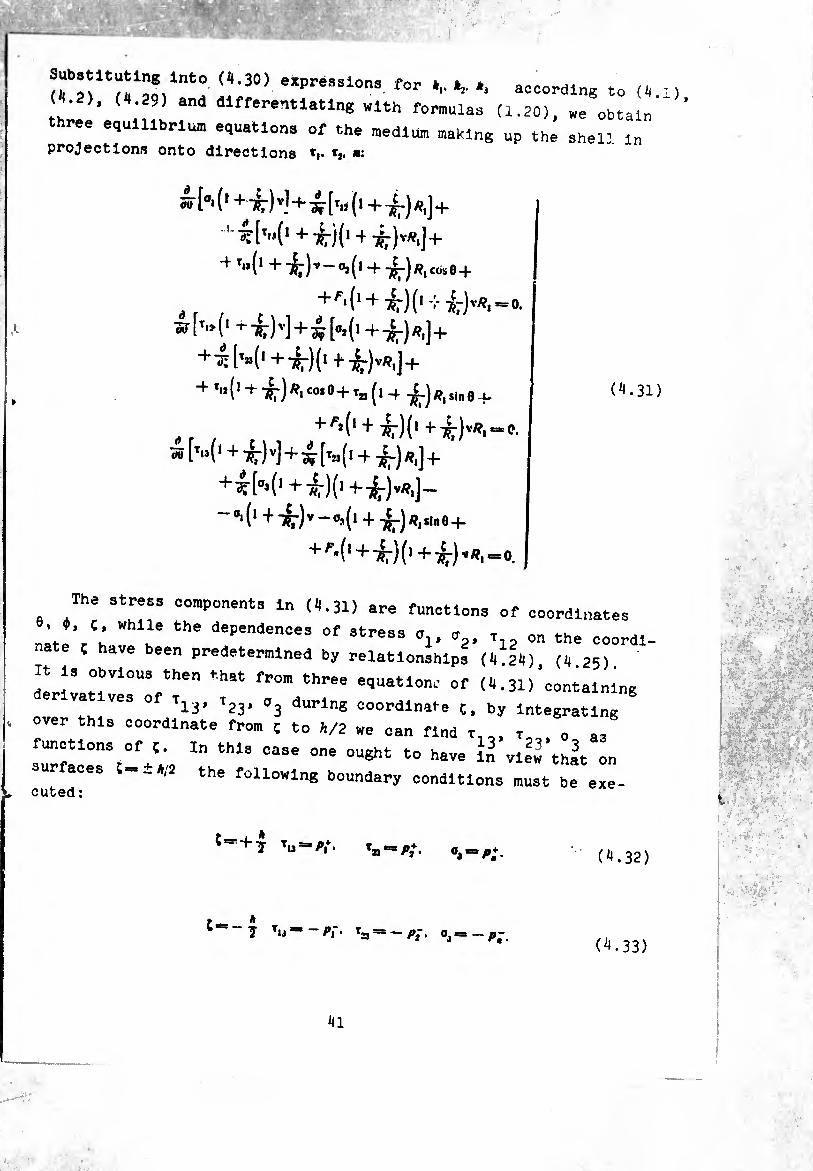
<T,\ T* Z ( •30) eltPre33l0nS for *■• *»• *- according to (^ , th ’ ; differentiating with formulae (1.20), we obtain ' ' three equilibrium equatlona of the medium making up the shell In projections onto directions *|. *j. »:
oo h (r+-k)v]+£ h (>+^-) /?,]+
1 ^W1 +^)(1+ ^)v/i«]+
+ T.3 (1 +-^)v - O, ( I cos e+
[^(1+-^-)(1 -li-^-)v/?I]+
^0 + -^)^^0+^2,(1+ ^)^,510 0 .U
+ ^(1+ ^)(1 +^)v/?,«C.
^ [^(1 + i)v)+ih3(i + -^)^,)+
+^(03(1 + -^)(1+^.^,)-
-0.(1+ +
•(, +^)0+71-)^1-0.
+
+ (^.31)
+/=-.
The stress components In (4.31) are functions of coordinates
nlJ’/ú Wh? the dependen0es of stresa V V T on the coordl. nate ç have been predetermined by relationships (4.24) (4 25)
It 1, obvious then that from three equation.- of (4.31)'containing
va ves 0 T1;j, Tjj, Oj during coordinate ç, by Integrating
over this coordinate from ç to 4/2 we can find t , t 0 a-
sfu“fl°snMf+';2 In thl3 Ca3e °ne °U8ht t0 haTC ^ view 'that » - the following boundary conditions must be exe-
cuted:
Çsr+ . ‘u ' Pi- Pi ’ i 0 + I’m • (^.32)
:-- 7 Tu=“ - P\ • T23 = — ?2 • PÛ (^.33)
41
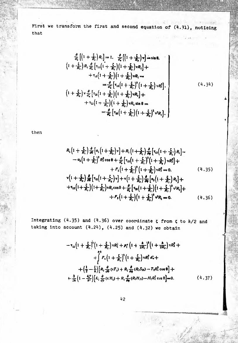
First we transform the first and second equation of (4.31), noticing
that
^ [(1 3t[(! +t^‘)v]=sssj,,&.
+^^+
= +-^) V/??].
4-Tjj(l -r-jl-)(l + -4-) v/i, sin 0 =
4o»(i+i)o+ir^].
(4.34)
then
«'(' + ^¿hO+^^+^O+iríil^^ + içr)^]- -0,(1 + -¿r),«îc°se +[t„(i 4-^)*(l + 7^) V/??] +
+ ^.(1 + = 0. (4.35)
"i1 +-^)w W1+-*7)*]+v(‘ + ^)^h(! + 757)^)+
+'‘,(1+i:)(l+ir)vR'‘o’0+|‘[,»(,+-if7)(1+-s7)’'''*.]+
+/’>{,+-k)(' 0. (4.36)
Integrating (4.35) and (4.36) over coordinate ç from ç to h/2 and
taking into account (4.24), (4.25) and (4.32) we obtain
-’»(* + •*:)’(' + i)'«i +'t(> 4 wr)’(' + 7Ä7)vr!+
+J f'('+'*7),(i + '¿')tR'í:+ ;
+ ("J — i") [^1 W ^ + ^àit co* ®] “H
+ à (1 - ^) h i <vM>)+w W'hú-au-rí' CÜS 0]=°- (4.37)
42
-’■í'+^rK1 +¿)’’■'«i+#.•(> + ^-)(1 + ^-)1 v’/?, + A/9
+ (ï 4) [v W +v^(7‘í^i) + sn^iv co* 0] 4-
1 á' (1 [v-á ^t>>+v ^ (^*Äi)+HnvRl coi 0]^. (4.38)
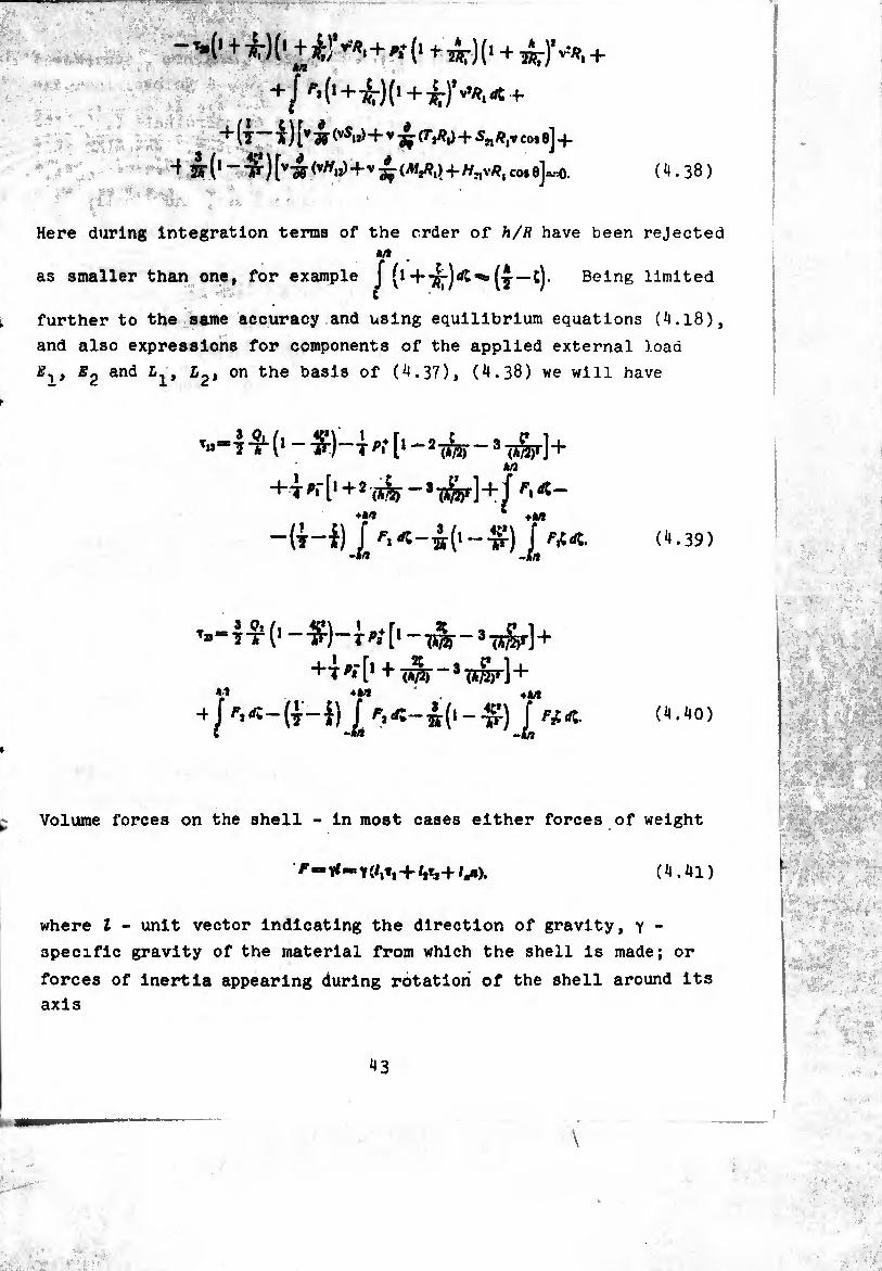
Here during integration terms of the order of h/R have been rejected */»
as smaller than one, for example /(•+TÍr)*-*(j-t) Being limited
further to the same accuracy and using equilibrium equations (4.18),
and also expressions for components of the applied external load
E^t E2 and Llt L2, on the basis of (4.37), (4.38) we will have
^-4^0
*M * +M
-(t-Í) / '’.«-¿('“TÍ) / '’í«. (4.39) -M -*/l
t»“|-îl(,-Tf)-T<’.*['“wlr~,uSr] +
+T«'[,+l$f-,(í^r] + Ä»9 ♦á/f 4. A/l
-tj /’.«-(j-í) (4.40)
Volume forces on the shell - in most cases either forces of weight
-»(/,», +/,¾+/^). (4.41)
where l - unit vector indicating the direction of gravity, y -
specific gravity of the material from which the shell is made; or
forces of inertia appearing during rotation of the shell around its
axis
43
\
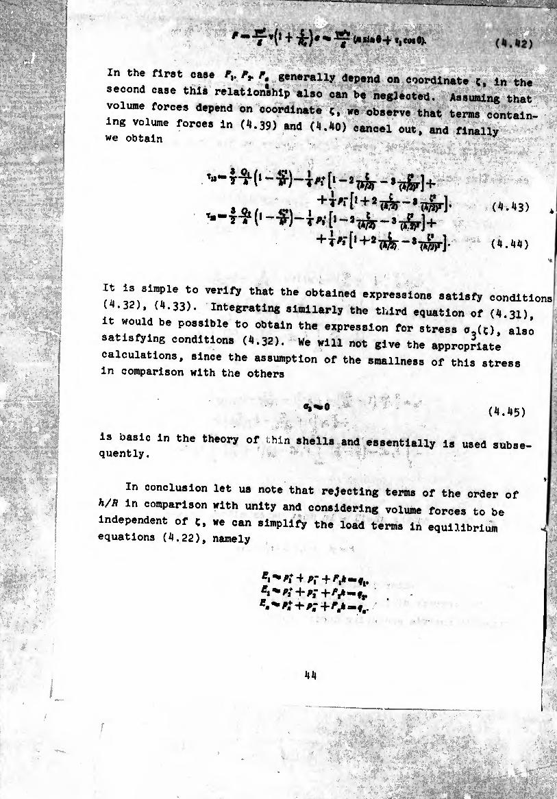
In the first case Fv Fr F generally depend on coordinate ç, in the fl A IO A A n W J A ^ A_ M ™ * A _
second case thl. rel.tionihlp .Lo can be neglected. Assuming that
volume forces depend on coordinate ¢, we ob.erve that terms contain- -- --- VWUÍ0 WV1
ing volume force, in (4.39) and (4.40) cancel out, and finally we obtain
Aí, «2\ , » ( T«[‘-í'Ji^--í-¡i5¡r]+ %-7
(4.43) *
(4.44)
it ve,31?!’1* !° Verlfy that the obt*lned expressions satisfy conditions 11.32), (4.33). Integrating similarly the third equation of (4 31)
it would be possible to obtain the expression for stress o,(C), also
satisfying condition. (4.32). We will not give the appropriate
calculations, since the assumption of the smallness of this stress in comparison with the others
(*M5)
is basic in the theory of thin shells and essentially is used subse- quently.
In conclusion let us note that rejecting terms of the order of
4/A in comparison with unity and considering volume forces to be
independent of ¢, we can simplify the load terms in equilibrium
equations (4.22), namely 1 ,'A,*4r,-4A^-fr
Í ■;
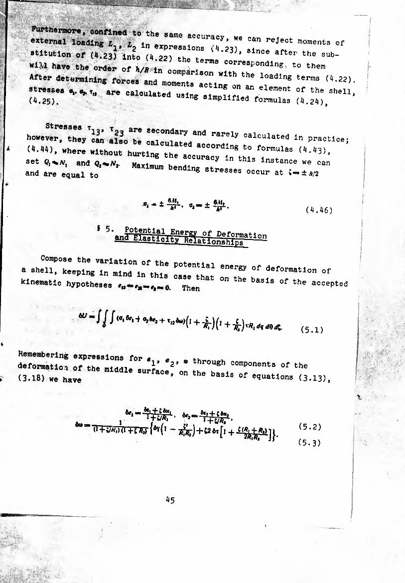
Furthermore, confined to the same accuracy we can r , , external loading 1,, L ., y’ i:an reJect moments of
stltutlon of (4.23) Into (4 22) theTe ' after the sub' W1U have the order of H/l if 111 «"«Ponding. to them
After determining forcee andlomfifâclf^ loadlng terms ^-22) »tre.se. v ^ are calculated using slmnlfî ,a" element of the (il,25). ® simplified formulas
., ‘t- ■■ ..-J*
however, they can also be lalluUted*1"1 <:alculated ln Practice;
(A-A'O, where without hurting the accurfylflll™“133
::: ^ oirr:::;;“ - h2 . Oa-± -J3-. (4.46)
8 Compose the variation of the ootenMai
» »neu, keeping In mind in this 1,, fl T °f defo™atl°n kinematic hypotheses Then ^ basis of the accepte
ÒU
¿UOdl (5a)
Remembering expressions for e *> +u
deformation of the middle sur^'o" fT,"f0"6"13 °f (3.18) we have * th b iS 0f e<ïuations (3.13),
«Or - îàr)+{2ôT[« +1¾^]}.
(5.2)
(5.3)

Substituting (5.2), (5-3) into (5.1) and Integrating over coordinate ç taking into account formulas (4.5), (4.7), (4.8), we Obtain
where
7^08,+Aíjéxj + AijÔJtj + Sôy^tfftT.
Requiring that 01^ be the total differential
we obtain equations analogous to the Oreen equations in the theory of elasticity:
Thus far there have been no assumptions about the character of
the physical connection between stresses and deformations in-^i shell.
This connection within the framework of the theory of shells should
be expressed in the form of relationship between power characteristics (7*!. r2. S. ,li,, ¿i,, //), on one hand and deformation components (^. ** v* *i« **• *)•
on the other. Meanwhile the introduction of such relationship is
necessary, since without them the problem of calculating the shell
is statically indefinable: the three of equilibrium equations (4.22) use six unknown power factors. Assuming that the shell is made from
elastic isotropic material, and ignoring stress in comparison with other stresses, we write Hoake's law in the form
46
(5.7)
umwffytmm;. .,., - ...
'1 - T*0« -14^ M ^ T(0' - »*«»>• • ■
. 1
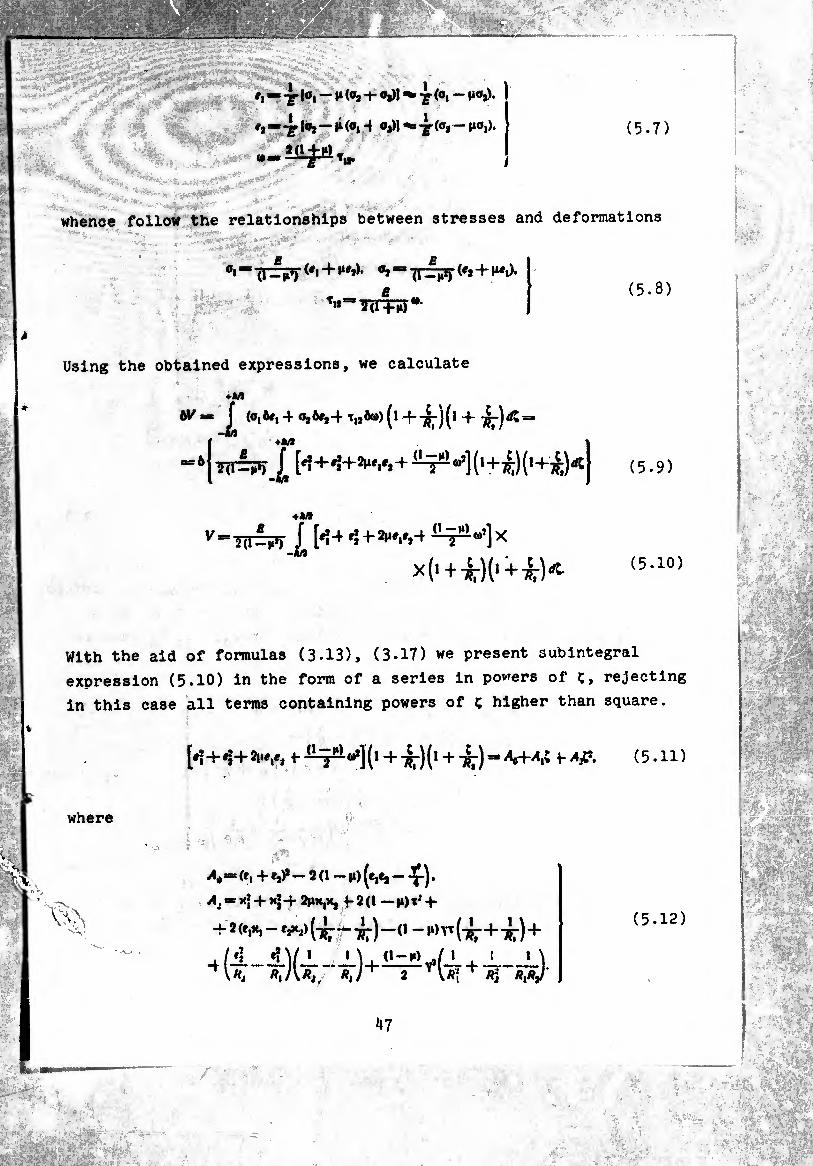
whence follow the relationships between stresses and deformations
gi-'(T-i?) (#i+1*»,), o»—TT^T(f*4-f“.)- (5.8)
Using the obtained expressions, we calculate
+M
W~1 ^ 4 o,ée,4 T|,Ä®) (l 4 TÇJ")^ ^ 1*M
5(1=P) J* [#? 4- ^4- 2»!«/, 4 “1 (1+^) (14-¾) ^ (5.9)
¿ [*Í4r*42MV,4
X(l+ ^)(1^ ^r)^ (5.10)
With the aid of formulas (3.13), (3.17) we present subintegral
expression (5.10) in the form of a series in powers of ç, rejecting
in this case all terms containing powers of ç higher than square.
[♦?4*^42lwi*, 447-)(1 4=»^o44,C 4(5.11)
where
A.« ('. 4 e,)*- Î (1 - |i) (¾¾ - x).
^,-^4^4¾^ 42(1 -)1)4 4
4 2 (»,*, — tft2) (-^-— —(1 — n) yx (7- 4 7-) 4
/4 4V > » \. <i-i*)^/1 . i 1 \
(5.12)
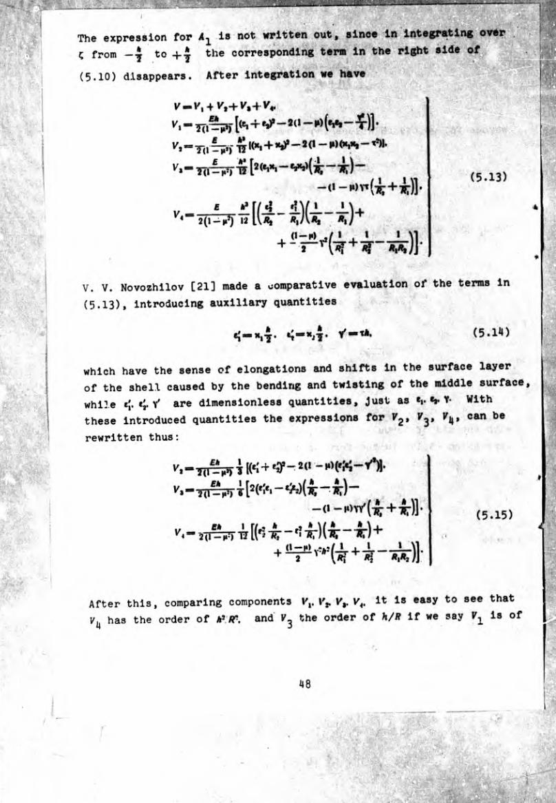
1 is not written out, since in integrating ovér
the corresponding term in the right side of
'
After integration we have (5.10) disappears
[(¾ + «*P—9 (1 — I») (*!*»—‘T)] *
+ - MKXjH, - t5)|,
TÎ [2(«i»*. - V»>(¿ ~ T?:)-
V. V. Novozhilov [21] made a comparative evaluation of the terms in
(5.13), introducing auxiliary quantities
see that
the order of unity and assume that deformations *|. Y. '[■ rr v' are
quantities of one order. In the same case, when (*,. tv y)<C(*¡- fÍ-y').
the inequality V^cV*. exists; if, however, it is the reverse
(e;. ej. ^<^(*1- *!• ^ then VitC.Vl. In all following assumptions relative
to quantities ¢,. V Y and *i- *»• Y/ and and ViCiYx + vj and in
(5.13) we can reject the terms V^t
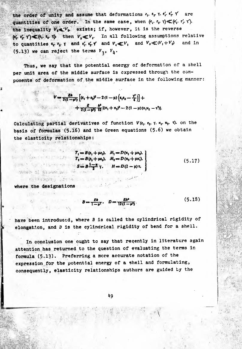
Thus, we say that the potential energy of deformation of a shell
per unit area of the middle surface is expressed through the com¬
ponents of deformation of the middle surface in the following manner:
^ ^ 7( j~r¡¡») [(^1+^-2(1 — m) (*!*!— -^-)] 4*
Calculating partial derivatives of function ^(¢,. e,. v- xr T)- on the
basis of formulas (5.16) and the Green equations (5.6) we obtain
the elasticity relationships:
r, = ß(e, +1»*,). Mx = D(x, + Jixj).
S = B-L^ y /í = 0(!-m)t. (5.17)
where the designations
« Ck ~ Eh* D“W=P)
(5.13)
have been introduced, where B is called the cylindrical rigidity of
elongation, and D is the cylindrical rigidity of bend for a shell.
In conclusion one ought to say that recently in literature again
attention has returned to the question of evaluating the terms in
formula (5.13). Preferring a more accurate notation of the
expression for the potential energy of a shell and formulating,
consequently, elasticity relationships authors are guided by the
49
Equilibrium Boundary Conditions
uouaxiy tne problem or shell calculation involves
placements and the stressed state In a shell for a pr
ternal load (surface and volume forces) and preassign,
fixing the edges of the shell. The total system of e<
describe shell equilibrium is three differential equi:
equations in six static quantities (f,. r,. 5. Aiv mv H). ,
relationships, which connect the static quantities ant
components (et> r* y. x* t). and slx differi,nce relation«
aid of which the deformation components are expressed
placements u, v, w. The number of equations is fifte«
cides with the number of unknowns. Of all possible sc
this system it is necessary to find such which satisfi
conditions on the shell edges. Hence we see the neces
lating the conditions of fixing of the edges of the sh
which corresDond to int-.rvsH.,,4-..4.4.._
50
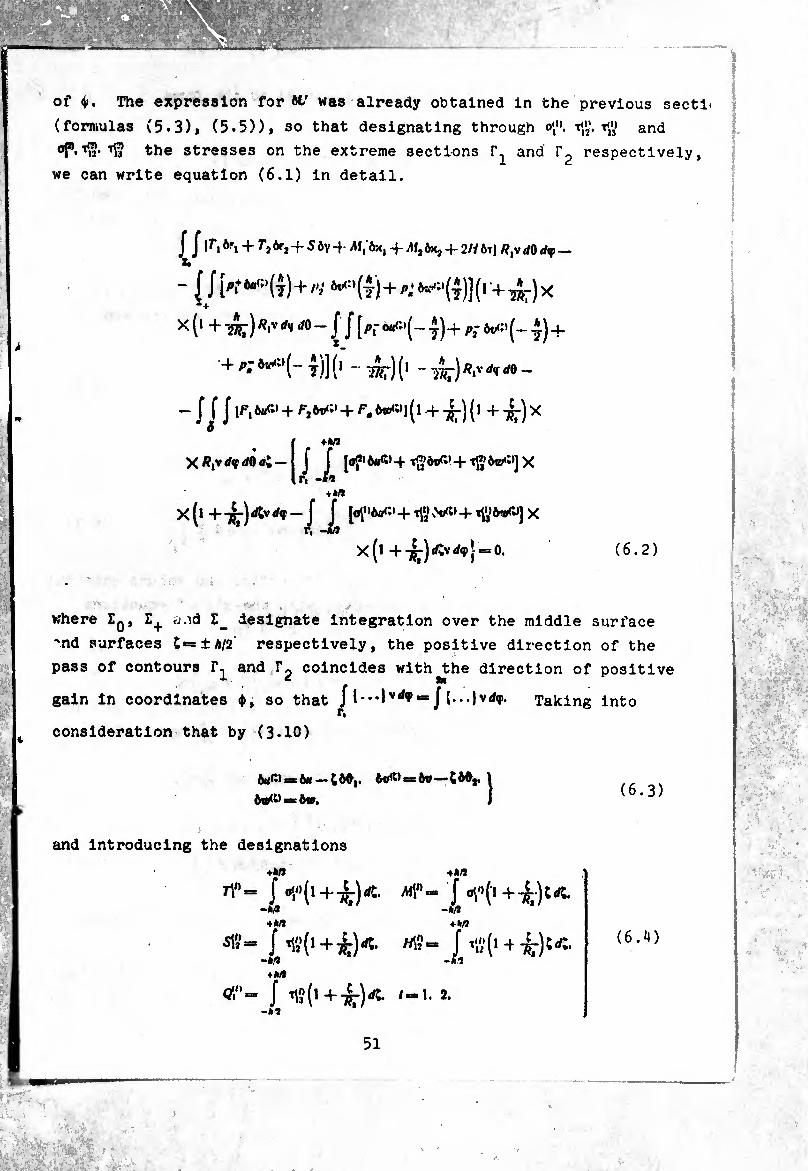
of 4». The expression for ét' was already obtained in the previous sect!
(formulas (5.3), (5.5)), so that designating through o\'K tß» and
of».''S the stresses on the extreme sections and respectively,
we can write equation (6.1) In detail.
J J|f,*i + r,òrí-fSôy-f./Wlôx1-Mf|èx3 + 2/íÔT) R^dOdff —
- {Jk^*(4)+/v ^7)x
x (1 + '¿Sr) ^ -1J [pf ^(- 4)4- Pj 1) 4- 4- p; 4)] (l -^-)(1 - ^RtrdiCdO -
J J J 4" 4- ^ 4- -^) (l 4 -^-) X
Ü+M
j [of>é«<5>4- tgôt^*4- tg6®»ï)J X
\hn
X(l [0^6004- T<y 4- TfllrvO] X
x(l 4--^)^^1==0. (6.2)
where Zq, E+ u.id Z_ designate Integration over the middle surface
-nd surfaces C*=±a/2 respectively, the positive direction of the
pass of contours f1 and r2 coincides with^the direction of positive
gain In coordinates ♦, so that j| •* J {...Jvd^p. Taking into
consideration that by (3.10)
Aii(î)sb6(( — 6®^* *=6®“"CéOj, (6.3)
and introducing the designations
«•M
rl"= J ^(1 + 4)^- «!"= J ^(-1+4)^ +hfl
-w 4M
-M 4M
ns- f n','(i+4H m?= J .»(1 + 4):«. —ip -k!7 4M
O'/'“ J ^(14--3^)^. /-1. 2.
(6.4)
51
we transform the contour integrals In (6.2) to the form V#* • Î ' ■
'01
tA[n «(-1)' J £ ^6w<*»] X
x(l 4-^)^^-(-^./1^6.4^4 * ~/U'/'ôéj-rt'/jWilvrff.
V.-4
-Wû
(6.5)
On edge = const variation ftO, is not independent; really, from
(2.5) it is easy to see that the form of functions «(f). v(v)> «(f) at this edge entirely determines 0f(f). consequently,
ôd,_l!i£L_-jV (6.6)
(6.5) one ought to rewrite thus:
1)1 J [t^0ba4 4 +
4(^4 7^)^]^^^ /-IS* (6*7)
The terms in (6.2) which are the work of surface and volume external
forces on variations of displacements, with the aid of equations
(6.3) and designations (4.12) are transformed to
(6.8)
But on the basis of (2.5) variations ôO,. 00, are expressed through three independent variations é». 6t>. to
Mi -1J {Pt M»4 ^Mi»4 Pi too»] (1 4. ^-) (1 4 ¿-) X
X V rffrfO f IJ [PÏ to:» 4 Pi WÜ4 Pi too] (1 - iÄr)x
x(l /1^,to»4to®4X
X(,+TB(,+TW*,vrff<W*“£
4 f, to — ¿j 60,4 ¿, 60,) /?,v d<f </8.
(6.9)
therefore the last two terms in the right side of (6.8) must be
rewritten In the following manner:
J J J J¿7-¿(Mvd0¿<r4- 4 j J UbuvdQd't.
u J J 60,/?,v </«1 rfO =- j J ¿i #, ¿O *P - — J J t, sin 0 bvR¡ dO d<f.
(6.10)
Integrating by parts and noticing that
H, 7* J J "3S Ow) dO d(f ■— f J ^ (¿jVÔw)</0</ç = = J LjVÔtprff — J Ljxbwdy,
(1,«, 6w) </0</«(= J It,/?, ftw)^ </0 = 0
(in view of the periodicity of the external loading and variations
of displacements in coordinate ¢), we will have
— J J ¿,ò0,/?,v</<í </0= J ¿jòtwdç— j* ¿jò«rv</ç4 X» r r,
J J [-^7 1 7?*' ft"] J J £,60^?,vi/0rff=»
— — J J[l-^ji6tM </«</<(.
(6.11)
Taking into account of the calculations, we find that the right side
of (6.8) is equal to
53
We
- ( J {(*> + -£> + (*,- +
transform also the expression for
(6.12)
+ ^, + /11,^+2//61)^ «oing from variations of deformation components
to tu. tu. te, U3lng formulas (2.5), (2.16), (2.26). Make the nece3sary calculations:
//r.ôe.rflo« / /^[-¿.^(6«)+ s* •, «
•> *" = // -^(T^òaydOdff— J J ¿(r,v)6«<ffrfe +
*, 11
+ J* J f, 6w dOd<f= J r, — J r, òvTiff+
4 / /1¾ 7¿r Ä<r»v)4«] z>
* . î* / J Aí, 6x, œ— J J A1¡ -Jj- (6d,) /?,V </0 dy mm
- — j Mtft9xdf^ j j ¿(-M.vJX*
X (iJr ^)rf0rf,f “ - J [ji,ò*i- +
+ J [¿I, 60, - ^ (/M,v)6ip] v^-
“//{^¿[■¿T á(l,‘v)]Aa' + W6*}
After analogous calculations we have
/ / ò”ÓYrf-u= J Sbvvdq — J Sbwtftf — " / J l¿ á 6v^ 1 ^ (SRjbu f lîjîl 6v] rfl8
J J r!!érs^ ^ J J [t?Î7 ^ (M|)^ 4- Air -f- ôtp] ** Z» ''»J
J - J Mn cos 0 ôt-v df -f f Af3 cos 0 terv dç -f-
*• r- r'
+ JJ {-¿T W iAÎ> ct’s 0) ^ * 7¿7 [t <^.)] -
\ àÿ (AWi) à*’ ~h ~7fy~ to I
j^o-h
sln8 à vUT
»(AO V ^
L*-*r'
cos 8
X.
J J «fialôo.-iiçii.+^.íiía v»r
+^ir--F]^ àvjvdf —
-2 J(i« to+«ÍÜ ôtrjvtff —
-IJ X» '
Now we can write equation (6.2) in the following form:
J^J I[~ US',riv)4- f|/?ico*0 - — 2-^- + ^0058-
~ *r ^ Mf’v> - - *.'•*.] *« + [- R^-SRt cos e - I « IS
_<1 (5v) tm
sin 8 à Ó8 ^ **n 0) “ * // co* 0 — // —*- cos 0 sin 0 —
^ TV ^ + i,#, .1. 9 - £Av] V +.
4[_ w(v+4í1«2'-,,,>cot,,^cj»)—
-s(7a'"*>+«-^+AfL +tlÄ1)+
+ 7-,.+ ^,.1,0- £,«,.] ^10+^(-7-, + ^)6.+
+f- (s+^-)++ g)}*+f- l™+^Çïl_
- c.+(«"+7^)]»* +(«,-00,},^- -i/{(-r, + ^o.+[-(í+»)+(sS+í0]t.+
+ («i1' + 7 -(+-)] to + («, _ /,1^60, jvi, „0.
55
(6.13)
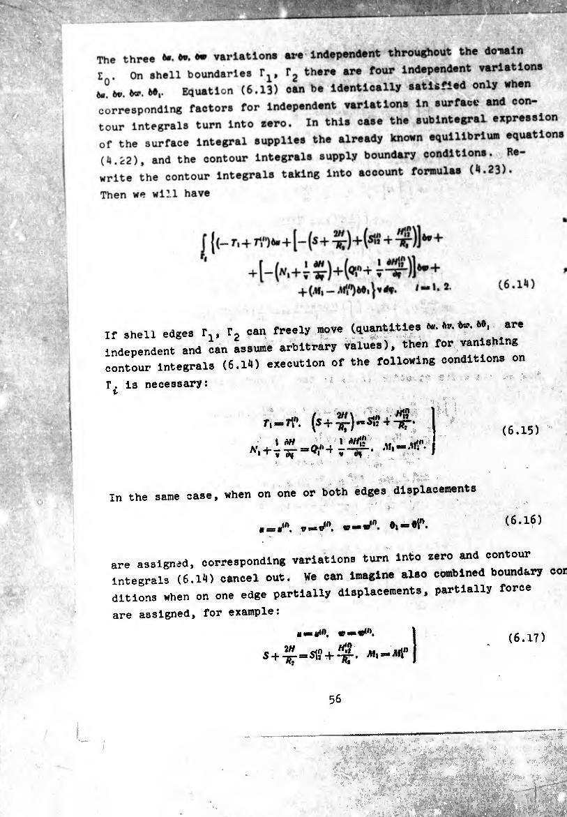
’ V. .. . ; ’ mm -■■i
'0 I i
S'&h.V:- • * •.«•‘"I
-
The three O’- variations are independent throughout the donain
Z . On shell boundaries F,. T, there are four independent variations
J?to. ta1. M>1- Equation (6.13) oan be identically satisfied only when
corresponding factors for independent variations in surface and con¬
tour integrals turn into zero. In this case the subintegral expression
of the surface integral supplies the already known equilibrium equations
(4.12), and the contour Integrals supply boundary conditions. Re¬
write the contour Integrals taking into account formulas (4.23).
Then we will have
:
f {(- n+n") »•+[- (s+^-)+i*1«+x-)] ^+
r' +[_(„,+i £)+(«,+iif)) ftr+ /-1. 2. (6.14)
If shell edges f,, f2 can freely move (quantities to. to. hv. 60, are
independent and can assume arbitrary values), then for vanis ng
contour Integrals (6.14) execution of the following conditions on
r. is necessary: t
r,—tY\ (s + T£-)«s»? + -¿T' (6.15)
In the same case, when on one or both edges displacements J
v**Jn. w-Jn’ (6,l6)
are assigned, corresponding variations turn into zero and contour
integrals (6.14) cancel out. We can imagine also combined boundary con
dit ions when on one edge partially displacements, partially force
are assigned, for example:
* —*<n. w—*n,
s+^.=sKf+^. (6.17)

etc. One ought to note that although the stressed state of the
edge Is characterized by five static quantities S'/,1. ■M1/'. H\‘!-
torsional moment W# is in (6,.15) only in combination with shearing
force and tangential force and correspondingly the number of boundary
conventions is not five, but four. A lack of an independent boundary
condition for ff12 means that on the section of the boundary
system of forces
(6.18)
is replaced by a statically equivalent system consisting of
J V iff = J AlJ'hjV <fq> (6.19)
two concentrated forces on the ends of the interval (Tn. fy). directed
along the normal to the shell and equal in magnitude to MV [-*19]*
(Fig 8). The static equivalency of both systems is checked easily
directly. First let us note that
and taking into account formulas (1.20) and (1.24), we obtain derive
(6.20)
57

44» à
Pig. 8. System of forces and moments on the edge of a shell
then
J itfN ¿<P -t- — [Wl2*]tl *= J*#rtftV rf(p,
J Mi'^v </<F + (r X M?*],. — [r X M?»]». r.
tff + Jr X + J (Mi'’+ Miti) Ye
-r [r X M*«],, — (r X M?»]»,
rX^,,,vrf«H-
vrff 4*
Calculating the second Integral of the right side of (6.22) with
using the integration by parts and taking into consideration that 1 dr Vd*“*1» and TiX» — »». we obtain
J [r X 4 AC] V dn 4 [r x /#15«]^— [r X «
“ / lrXArt"-t
58

Therefore on the basis of (6.21), (6.23) we can write
J rf<r = J tf/'v dff,
r# r/ (6.24)
5 7. Static-Geometric Analo^y. Stress Functions
System of equilibrium equations (4.22), (4.23) connects six
static quantities (Tv and components of load £t. fj. £j.
In the absence of a distributed external load the corresponding uni¬
form system of equations has
Tj. S, AI,, Afj, H)a (xT,) — A,?tcos6-{-
i o ^ i_ o àH i 1 d(vAf|) tâ a ä + -Alj::;0 = O.
Mr,, fj. 5, Al,, Al2. /■/)==/?i -jj~ co* o ■+■
■ 2//cos 0 4-2 sin 0 + 2// /?, diif, Ä 7?r-3r“0*
La(Tv M ^2* cosG4~j -j- , d \dH , 2HRX COS0 , P.dAM * ^ . „„ + -ï-l-Vip]-vri-*>s,i'or>=0-
(7.1)
Comparing (7.1) with equations (3.30), it is easy to see that the
left sides of the equations of continuity and uniform equations of
statics contain the same differential operators M ¿2. ¿j and the
quantities
(7,. xj. (2//. Y). (TV X,), (Al,, tj).
(S. - T). (Al,. - e,) (7.2)
are in these equations identically. This fact bears name static-
geometric analogy. In a new form of notation the equations of con¬
tinuity (3.30) look thus:
-¾. j)- 0. /=»1. 2. 3. (7.3)
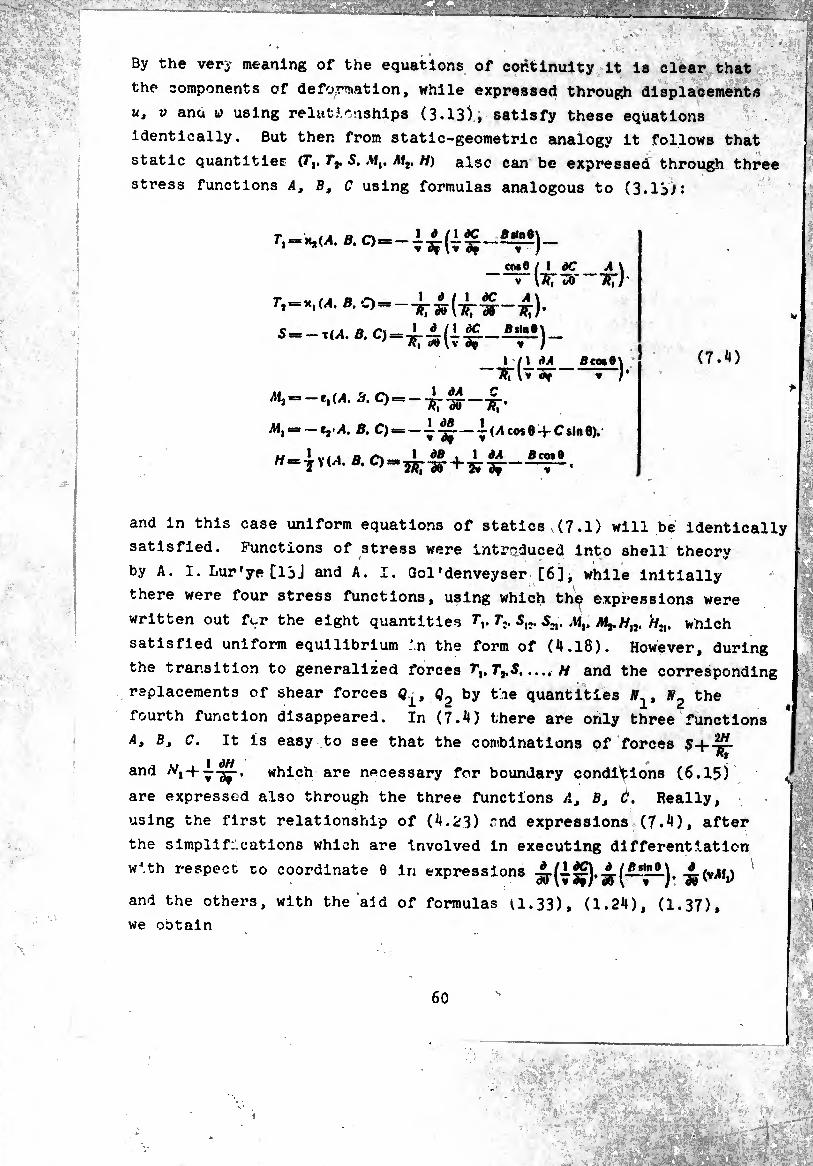
By the very meaning of the equations of continuity it is clear that
the components of deformation, while expressed through displacements
u, V ana w using relutJ.rnships (3.13), satisfy these equations
identically. But then from static-geometric analogy it follows that
static quantities (Tl, Tf. S, Mt, M2, H) also can be expressed through three
stress functions A, Bt C using formulas analogous to (3.13):
r.“*»«''•»O— .ÎS*)_
CM 6 / ! dC A \ \TTxiÃf-ii;)
5=-x(A ß. 0 =
1/1 dA -■sriT^r-
iM2 ■= (A, 3, O — — .
B. 0«=-l~—l(y1co*e-f Csinö).
Bco*Q\ —
W = -j Y (^1. B, O: l dB , \ dA ScotO
(7.¾)
and in this case uniform equations of statics , (7.1) will be identically
satisfied. Functions of stress were introduced into shell theory
by A. I.Lur'ye[13J and A. I. Gol'denveyser [6]i while initially
there were four stress functions, using which th^ expressions were
written out fur the eight quantities f,. 7\. 5^. S^. Ai,. Hn. which
satisfied uniform equilibrium in the form of (^.16). However, during
the transition to generalized forces T+S,.... H and the corresponding
replacements of shear forces Q0 by the quantities N2 the
fourth function disappeared. In (7.¾) there are only three functions ■2H A, Bj c. It is easy to see that the combinations of forces
1 ÕH * and <vi + 7-g^-. which are necessary for boundary conditions (6.15)
are expressed also through the three functions At Bt Ò. Really,
using the first relationship of (¾.^) rnd expressions (7^), after
the simplifications which are involved in executing differentiation
with respect to coordinate 9 in expressions ^.(1^),^.(1^11), -¿(vAf,)
and the others, with the aid of formulas U.33), (1.2¾). (1.37),
we ootain
60
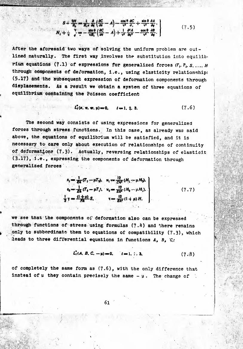
co» ft dC , »In 9 âA V* V* àif ’
1 â*A co» 9 ¿S V* Af* V* ^ '
(7.5)
After the aforesaid two ways of solving the uniform problem are out¬
lined naturally. The first way involves the substitution into equilib¬
rium equations (7.1) of expressions for generalized forces .h
through components of deformation, i.e., using elasticity relationship:
(5.17) and the subsequent expression of deformation components through
displacements. As a result we obtain a system of three equations of
equilibrium containing the Poisson coefficient
L](a. *. w. n)**0, /=1. ?. 3. (7.6)
The second way consists of using expressions for generalized
forces through stress functions. In this case, as already was said
above, the equations of equilibrium will be satisfied, and it is
necessary to care only about execution of relationships of continuity
of deformations (7.3). Actually, reversing relationships of elasticit
(3.17), i.e., expressing the components of deformation through
generalized forces
•i “ Kt “ (^i ~
*j =*-gj (7* — p7Y>. ^ = (7.7)
we see that the components of deformation also can be expressed
through functions of stress using formulas (7-4) and there remains
only to subbordinate them to equations of compatibility (7.3), which
leads to three differential equations in functions A, Bt V.:
lUa. b. c. —|i)=o. /=1. :. 3, (7.8)
of completely the same form as (7.6), with the only difference that
instead of u they contain precisely the same - y. The change of
61
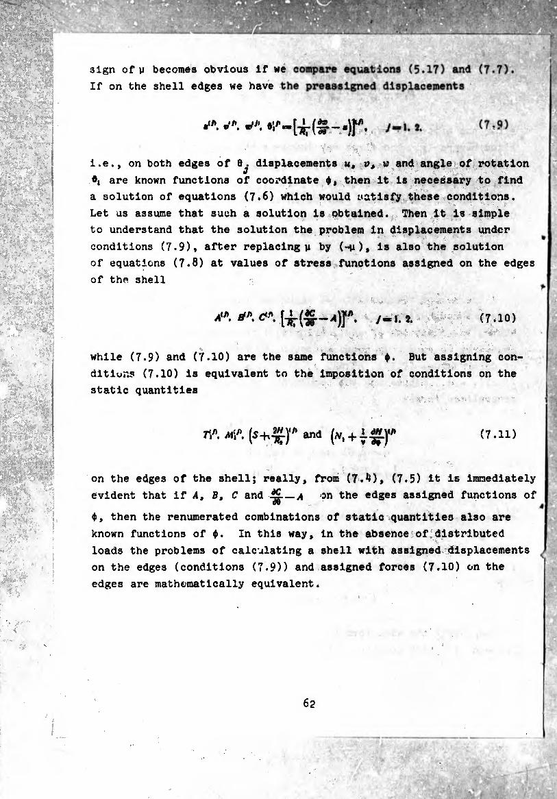
sign of y becomes obvious if we
If on the shell edges we have
i.e., on both edges of 0^. displacements m, v, w and angle of rotation
0| are known functions of coordinate ¢, then it is necessary to find
a solution of equations (7.6) which would satisfy these conditions.
Let us assume that such a solution is obtained. Then it is simple
to understand that the solution the problem in displacements under
conditions (7.9), after replacing y by (-y), is also the solution
of equations (7.8) at values of stress functions assigned on the edges
of the shell
A1*, fl"*. C* 7-1.¾ (7.10)
while (7.9) and (7.10) are the same functions ¢. But assigning con¬
ditions (7.10) is equivalent to the imposition of conditions on the
static quantities
7V>. Mi*. (5*™)"’ and (at, + ±"Lf* (7.11)
on the edges of the shell; really, from (7.¾), (7.5) it is immediately
evident that if A, B, C and ■§—A on the edges assigned functions of
$, then the renumerated combinations of static quantities also are
known functions of ¢. In this way, in the absence of distributed
loads the problems of calculating a shell with assigned displacements
on the edges (conditions (7.9)) and assigned forces (7.10) on the
edges are mathematically equivalent.
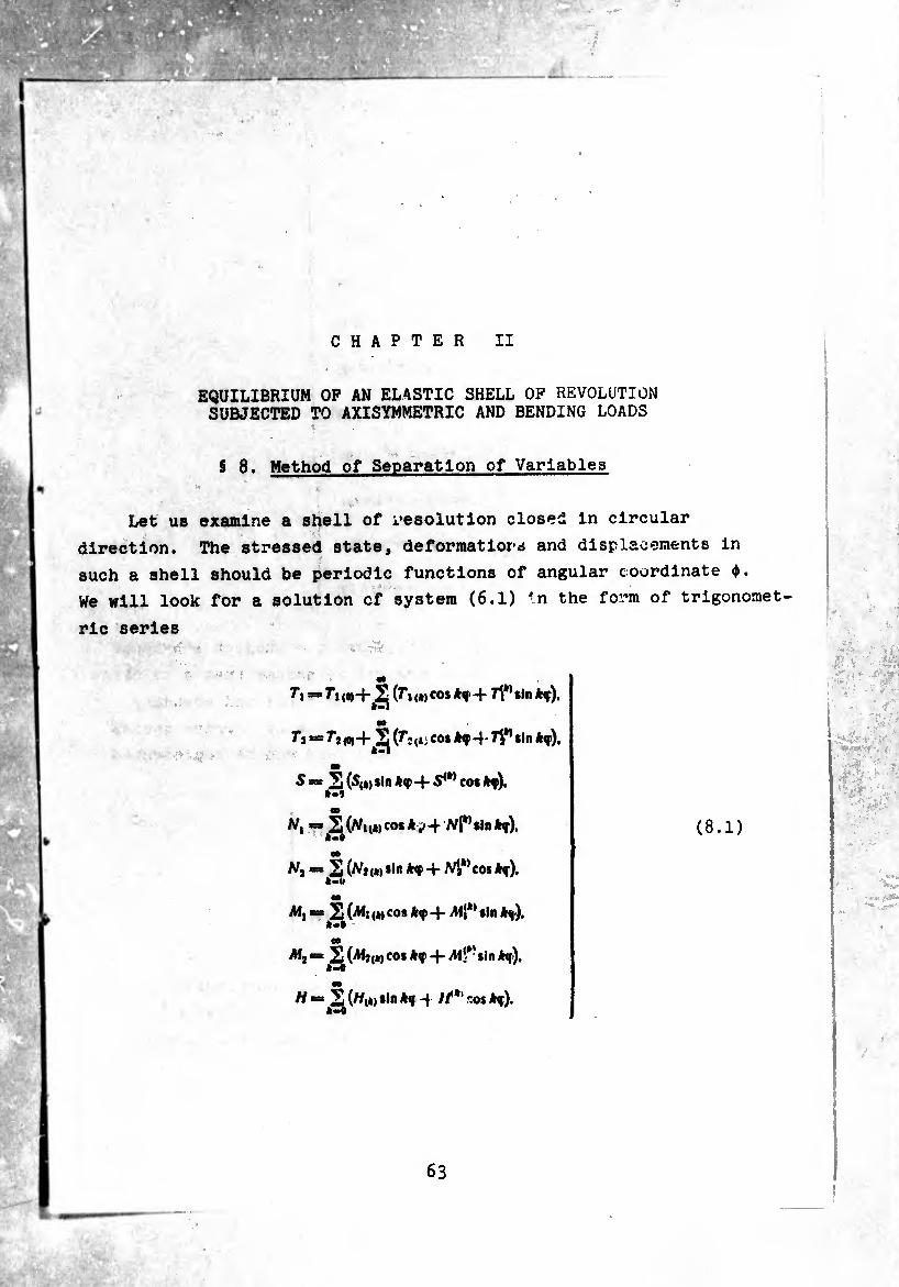
EQUILIBRIUM OP AN ELASTIC SHELL OF REVOLUTION SUBJECTED TO AXISYMMETRIC AND BENDING LOADS
8 8. Method of Separation of Variables
Let us examine a shell of Resolution closed in circular
direction. The stressed state, deformatiors and displacements in
such a shell should be periodic functions of angular coordinate ¢.
We will look for a solution cf system (6.1) <n the form of trigonomet¬
ric series
TI = (r » (ft) CO* + IT sin **).
f j — (^*2(*5 cothf-\- TV* *ln *f),
m
S *= 2 {${*) *1" Af-f- S(k) co* *f),
Nl —Q(Nmca% *v4 M*’*!"*t).
Nt = (Nj ,*, *ln -f M*’ co* kn).
= (Mi ,*, cos 4- AfJ*’ sin kn),
"■-.S'* (ft) co* -+- iM‘*’*in k%),
H ■“^(//(ft)*ln 4 /f*1 r.os kq).

. :
ib
f * " ,5 (*« i«co* +*i* *,n *?> «o
e* =,¾ (e2,*)COÍ *f + «i*1*»« *f>
O»
T = 2o(Vi*) sin -j~ eos *f ),
00
x' xíw*ín*f). OP
^ =,¾ K(*,co* *f + »4W «in *f).
T == ^(T(*) *,n *f +14*» eos Af).
m =^^(^1(4) eos *f-|- Oi^sInAf),
m
eos *f). i»
" — So(«(») coiAf-f «<»> Sin Af),
m V — jSí^i*) *ln Af -j- w“* eos Af ),
O»
* = ^(»(WcosAç-f «K*»sin Af).
(8.2)
(8.3)
Coefficients of serles (8.1)-(8.3) are the subject attribute
functions of coordinate 0. It is natural to assume that a solution
In such form can be found if the load on the shell and boundary
conditions contain functions also representable by Fourier series.
And namely, components of the distributed load can be represented
by an expansion of the form
f,(0. T) “ S(f,cos Af + *1*» sin Af),
OÙ
faC*. V)^(?l(t)sinAf-f ff>cosAfj.
er
*.(«. 0-,2(¾ {t) cus Af + f4*>sla Af).
(8.4)
i
«
<
where f,,*,. ?2(t). V,,,,. ?<*>. are known functions of coordinate 0, and on
th° edges 0 = Oj (/=1. 2) are preassigned displacements uin. t/0. v,n. el0 or
force of T\n. , (a/,-f7-^r)<0.Ai\n. or their combinations, also
representable in the form
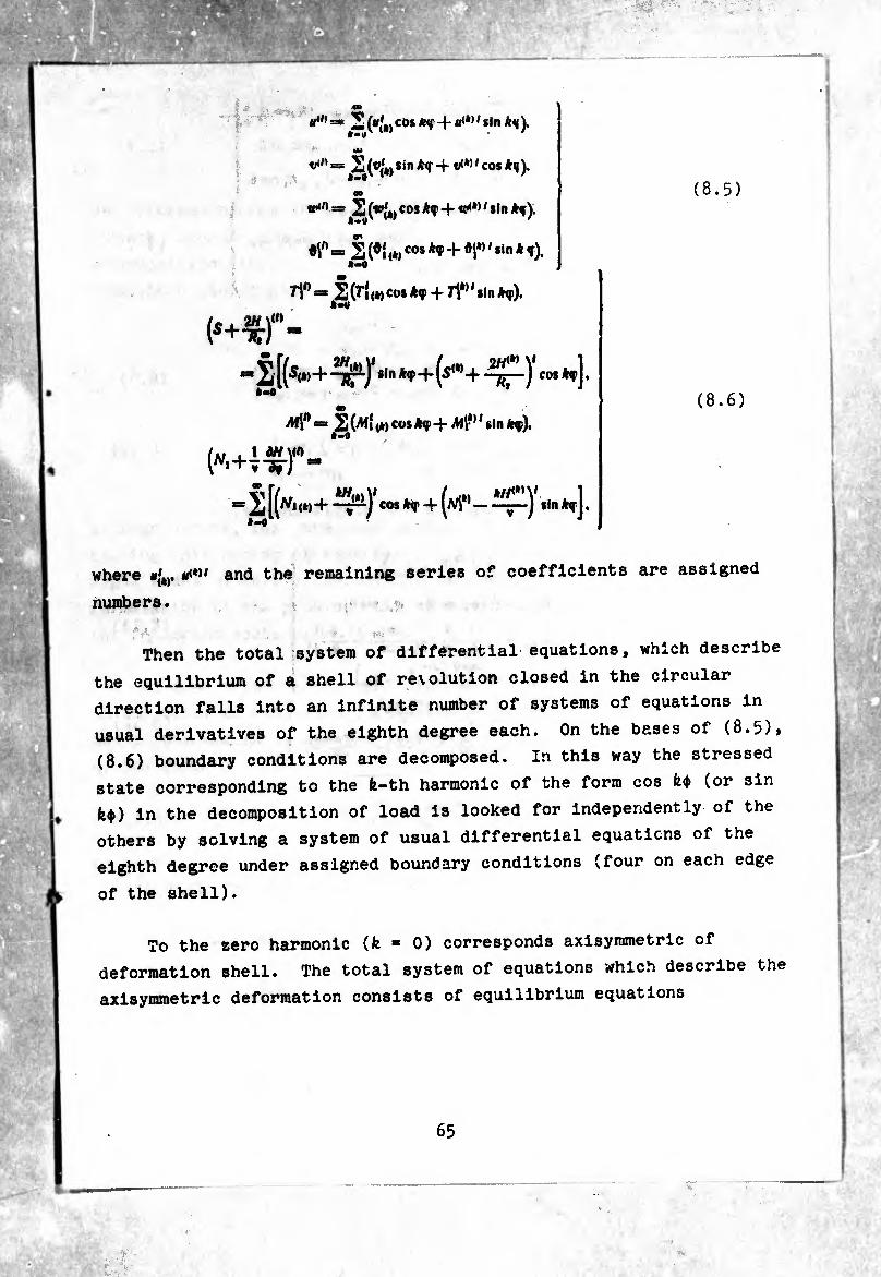
2 ("f»)cos *<T + ' sln ),
u»
= 2 (®(*) sin *<r -j- tK*> ' cos *q),
OB
tpin cs 2 (*(â, cos *q>+se^*> ' sin *q).
•V — 2 (*í <*)cos ^+♦í*’ 'sin * f).
=* 2(^{(*)Cü**SP + *f)«
(*+^r-
* S [(SW+-¾1)4 *,n *f-f-(sW+ -Ç-)1 cos *t] . â«#
s=s 2 (Aíí (*) cos -j- MV*11 sin ).
{»Mzr- *”
£[(«.,« + ^)' co. H + (m*1 -^.1- »,]. *-#
(8.6)
where *'4). ire*»' and the remaining series of coefficients are assigned
numbers.
Then the total system of differential equations, which describe
the equilibrium of a shell of revolution closed in the circular
direction falls into an infinite number of systems of equations in
usual derivatives of the eighth degree each. On the bases of (8.5),
(8.6) boundary conditions are decomposed. In this way the stressed
state corresponding to the fe-th harmonic of the form cos H (or sin fe$) in the decomposition of load is looked for independently of the
others by solving a system of usual differential equations of the
eighth degree under assigned boundary conditions (four on each edge
of the shell).
To the zero harmonic (fe ■ 0) corresponds axisymmetric of
deformation shell. The total system of equations which describe the
axisymmetric deformation consists of equilibrium equations
65
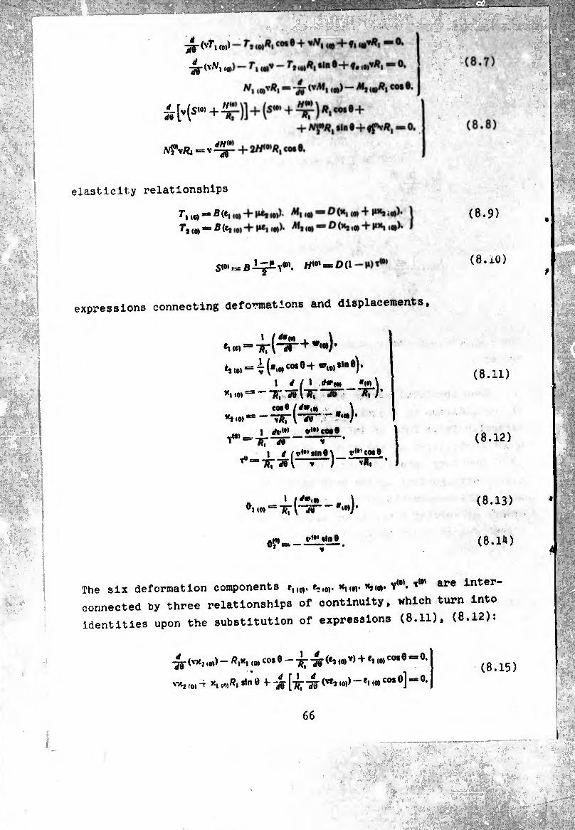
SW^bIçJLy«”.
expressions connecting deformations and displacements.
-ff (vT, (0I) - r, ,wä, «o* e + »A/, ,0 4- ¢, — o.
■4r (vN, io,) — f, (Wv — f* ,0)^, «inô-Hç, ,0,*/?, *= 0, tm
N, wxRx = ff (vAf, ,0,) - AI, ,o)#i co. 6.
w Ks“’+tt)]+(sm+t»t) *• co,'+
A^v/Î, = V Iff- + 2/i<0*«, co* 0.
elasticity relationships
r, (0, == B (e, ,0, -+* P*j io»)* AIhoj =» O (H, ,0,4 P** ¡o))* |
7,,0, = 5(^,0)+^1(0))- (o) = D (^ i» + M’S i«)* Í
e»««=æ‘ir(“3ÏL+w‘*)*
1 / 1 (Hr,* «(.) \ *1 (0) •
*J.0)S
*401.
\-i5--
i Tfr“25"
1 d l f**'»Int\ 57wl“r~J' TTTS
„(•I COO # *“vÂÎ
(8.9)
(S.xO)
(8.11)
(8.12)
» /*».•) M to) — TT l ju -( *»0) )’
Of. t-W olo 0
(8.13)
(8.14)
The six deformation components r,,M. e,,0>. *mw’W ^ ^ are inter
connected by three relationships of continuity, which turn into
identities upon the substitution of expressions (8.11), (8.12):
ff (V*2,«) - Rl*l <0) CO* ® (*9 (0)V) + el 10) COS Ó = 0.
yy-2 (o) 4 *i ir»Rt 0 +" isr [t^ W(vej ‘0,) “ *'<0> co# °] “ 0’
(8.15)
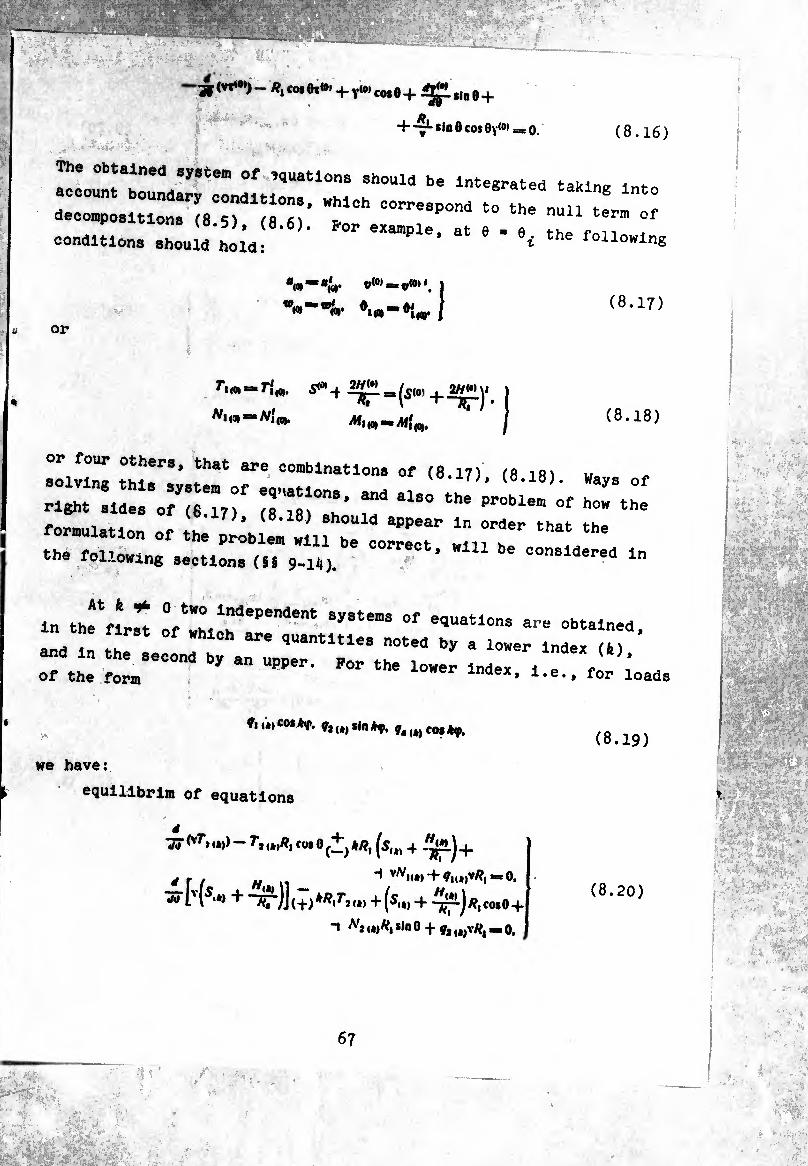
^ (vi«”) - /?, cm Or»» -f- Y10’ co* 0 -f- S|q g _j_
H—^-«inôcofOv^ŒO. (8.16)
The obtained system of equations should be Integrated taking into
account boundary conditions, which correspond to the „un 1
decompositions (8.5), (8.6). for example at e . „ 2 r™ conditions should hold: ’ 64 6 oUowlne
©W* *= p(Ot
'I«
1
I (8.17)
or
71(0, = 71
A/j (3) mm M{
5^4
1(0,-
W<»> ~^r
(8.18)
solving rr;;.r r COmblnatl0nS °f (S.IS). ways of
right sides of (6 17) (s'le)0"^’ iT ^ Pr°blem of how the
formulation of 0^ ^ntV^d“6 the following sections (i, 9-14). ’ be C°nSldered ln
in the r, t e Independent systems of equations are obtained in the first of which are quantities noted by a lower Index H
and in the second by an upper. Por the lower Index 1er of the form r lndex* for loads
ViwCMAv, fcwsin*ç, falt)co$*ip. (8.19)
we have:
equlllbrlm of equations
«« ivr, ,*») — 7j co« 0 ¢+) */?, fs,t) 4 -^ÍLj 4.
äf/ tf __ “i vA/i<*, + V1(*,v/?,-0.
« rl5« + Trjj.ñ*#/.!.*+(^.,+-^-)4,:0.8+
t *ino +*4*^=0,
(8.20)
1 MÆâtd.
67
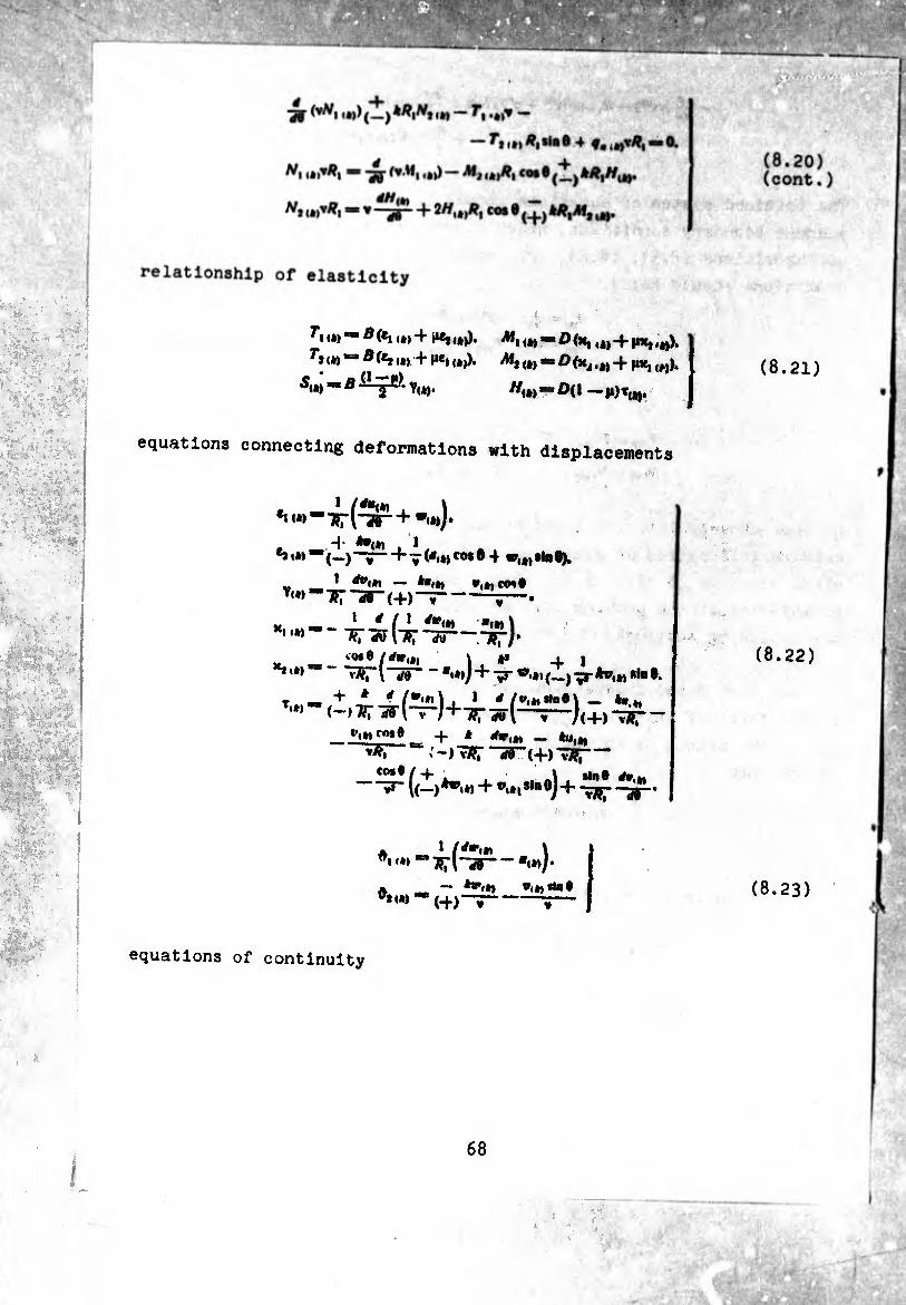
-+- (mN HR .N, 'h lã íi») 11»
— rii*)Â,*l«Ô 4
Mj ,*,/?, CO* ®
,/?, cos e ^ kR^lj tÄ,
(8.20) (cont.)
A/ VÄ fv.M »>) I l»l (*)•
(•) 2// vP *<»> 29
äiw
|*y'
relationship of elasticity
Ti.»)- Ä(«, U)4 ^<â)). iM, 1W -flíx, ,«)-f »Mi.*»).
^ (»» *= Ä (e, l#) + M», ,*>). AI, ,*,-/) (Xj lW 4 M«,,»).
Sit) - B Tw. hw . D(| _
equations connecting deformations with displacements
*i (») , 1 /*«<*) ■»rr pi*) )•
*»«*>■“(—)~~ï f"V(*■*)co*® 4 »u,«ta®V
Y«*>”Tf7^®-(4)~7- *.*,co»S
Ki i»)1
y •«*)\ I * / i #w(W
T;iã\ir,~
I» „ c<*9 /rfg<»i \ , 4i ^l*> ^rl“25” - *i»)j+vT ».».(Ijp-*»,*,»In®.
•n.*, *i», (—)Ü71^1 y « /(4-) f(+>“WT t,'»» fo,0_ 4 * *»,*> -
«-)^T-29-(4) T3?¡-
A „ 1 /rf,r«»*
^*U) - *»!»»
(■+>~r"
■«»»)• •.««ne
equations of continuity
(8.21)
(8.22)
(8.23)
mm
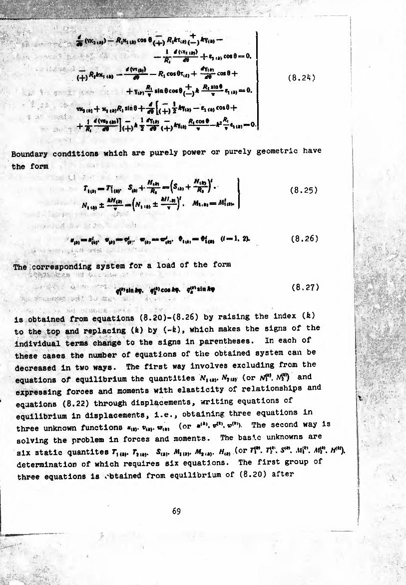
Æ,k,iwc°* Ö(+) Ä|*Ti*>(—)*Y<»
1 <f(v«t4at) — 7?7 55 f-«!.*» co* 0=0.
(+)- 'y-^0.01,,)4- Í^Lco*0 +
+ —Cn»)“®»
u)^i*,0®+'ar [(+)7^—** <*)cosö+
, 1 *(»«n*»ïl — ,. 1 *Ti*» — R,co»9 ¡jRi. _n + T?T ”"50 " J(+)* T TT <+>**'•> Í * „ «ï w*50
(8.2ÍÍ)
Boundary conditions which are purely power or purely geometric have
the form
Tnm—Ti <*»’ , w«*i U . W«*»V
N,± <•» ± Ai,.**-*
(8.25)
*<*)“*/«• v0)^*1»'.' *'(»»“■*#«* “h 2)* (8.26)
The corresponding system for a load of the form
4*>*lnftf. (8.27)
is obtained from equations (8.20)-(8.26) by raising the index (fe)
to the top and replacing (fe) by (-fe)» which makes the signs of the
individual terms change to the signs in parentheses. In each of
these cases the number of equations of the obtained system can be
decreased in two ways. The first way involves excluding from the
equations of equilibrium the quantities AT,,,,. N,m (or N\k\ M**) and
expressing forces and moments with elasticity of relationships and
equations (8.22) through displacements, writing equations of
equilibrium in displacements, i.e., obtaining three equations in
three unknown functions w,*, (or v**'. w(*’)- The second way is
solving the problem in forces and moments. The basic unknowns are
six static quantités TIW. Tim. S,,,. MIW. Miity H{t) (or A". Ak\ .»«1*'. M*'. //*’). determination of which requires six equations. The first group of
three equations is obtained from equilibrium of (8.20) after

excluding Nl{t). Nut)(N\ \ the second of three equatlon8 can
be obtained by writing equations of continuity (8.24) in forces and
moments, which is easily done with elasticity of relationships.
In both cases a system of usual differential equations of the
eighth degree is obtained in rather complex form. However, at fe - 0.1
there is no reason to solve the problem in these ways, since it turns
out that in these cases the degree of system of equilibrium of
equations (8.7), (8.20) and continuity of equations (8.15) and
(8.24) can be lowered, whereupon obtaining resolvent equations is
facilitated by introducing special unknown functions [49], [50], [12],
[42], [44], [21]. Decreasing the order of the system of differential
equations by m units is possible if m first integrals of the system
can be found. The first integrals of the system of equilibrium
equations have a simple mechanical sense: they are the conditions
of equilibrium of the finite part of the shell contained between
extreme section 0i (i - 0 or 1) and flow section 0. At fe - 0 the
load on the shell and the condition of fastening are axisymmetric.
For the finite part of the shell contained between extreme section 0.
and flow section 0, two conditions of statics should be executed:
1) the sum of the projections of all interval force onto axis of
revolution OZ should be equal to zero, 2) the sum of the moments of
all forces causing twisting around axis OZ also should be equal to
zero. External forces refer to all loads applied to the shell and
its edge 0i; the internal refer to forces 8U, Q and moments # ,
#12 acting in section 0 ■ const. 1
Loads of the form
fi <»«>»?. Vj(i)«inf, (I) cotf,
vy»co«f. rf'>slnf
(8.28)
(8.29)
subsequently will be called bending, since they tend to bend the
shell like a beam. Load (8.28) give rise to a bend in plane ¢-0
and a distribution of forces and moments symmetric in this plane.
Load (8.29) give rise to a bend of the shell in the plane perpendic¬
ular to 0 = o, and stress distribution of antisymmetric in this
70
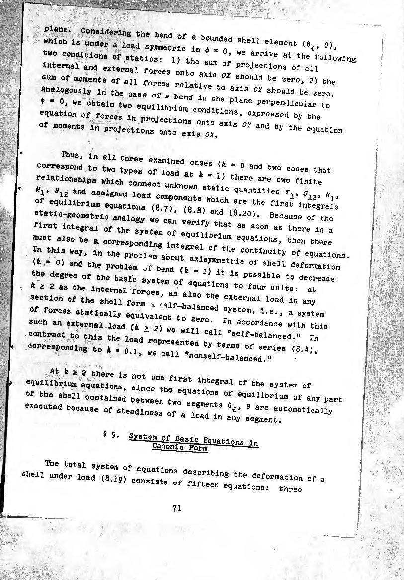
‘’“.7» :,rr ;;rrr r- >•«. •>. sum of moments of all fnrces relativeSh0UlCi ^ Zer°’ 2) the Analogously l„ the oase 0, a t0 " should be 2ero.
♦ * 0, we obtain two egulllbri,, ^ Plane perPendl™lar to
equation of forces In projections' expressecl by the
°f —» « projections ::“ :;,::;Mia oy an<: by the
“ «“:rcr.rr: ■1 -...... relationships which connect unknow . there are tK0 flnlte
*1> *12 and assigned lnT, Statlc quantities r , s „ «i 1¿ o«»J-Knea load components 1 12* »
°f equilibrium eguatlons (8.: :: ?* ths flrst ^tegraÍs
static-geometric analogy we c» the
first integral of the system of equliLri “ S°0n 38 ^61-6 18 a
r; alS° be a c°rrespondlng Integral oTtT eqUatl°nS> the" there In this way, l„ the problem about «,i.:Lt :°ntlnUlty °f equations.
. ’ 0) an<i the problem of bend (fc - i) if T ° °f She31 llefor”'atlon the degree of the basic system of . I Possible to decrease
fe ¿ 2 as the internal forces, as also^8 !° UnltS: at
section of the shell form , '.lf 1" 6 l0ad ln
Of forces statically equivalent t'o LT IT"' ^ auuh an external load (É > 2) w. in ao<:ordance with this
contrast to this the load’represented "Seif'balanceii-" In
corresponding to A . 0.1 we can » y te™S °f serle3 t8-1*), • we call nonself-balanced.»
equilibrium ZlTllT °f the ayata” ^
of the .hell contained between tw^8“:; ^ eqUlUbrlU" of a"y Part
executed because of steadiness of a lo^dt ^ ^^-to-aticaUy
S 9. ^^l^llf&âtlons^
eben under load (a-iq)1-:::;:;:::;::1"8 the deformati°n °f a fifteen equations: three
71
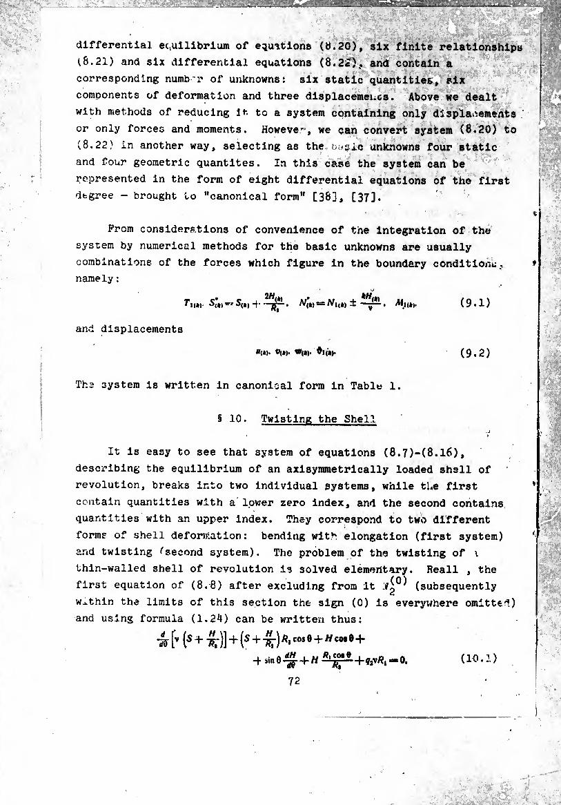
,,ÄMI
differential equilibrium of equations (tí.20), six finite relationships
(8.21) and six differential equations (8.22), and contain a
corresponding numbr of unknowns: six static quantities, six
components of deformation and three dlsplacemencs. Above we dealt
with methods of reducing It to a system containing only displacements
or only forces and moments. However, we can convert system (8.20) to
(8.22) in another way, selecting as the basic unknowns four static
and four geometric quantités. In this case the system can be
represented in the form of eight differential equations of the first
degree - brought to "canonical form" [36], [37].
Prom considerations of convenience of the integration of the
system by numerical methods for the basic unknowns are usually
combinations of the forces which figure in the boundary conditions,
namely :
fi<*) W(*) = A/j,„ ± —Af|<„. (9.1)
and displacements
«(*)• «(*)• •<*)• (9.2)
The system is written in canonical form in Table 1.
§ 10. Twisting the Shell
It is easy to see that system of equations (8.7)-(8.16),
describing the equilibrium of an axisymmetrically loaded shell of
revolution, breaks into two individual systems, while the first
contain quantities with a lower zero index, and the second contains
quantities with an upper index. They correspond to two different
forms of shell deformation: bending with elongation (first system)
ar¿d twisting fsecond system). The problem of the twisting of \
thin-walled shell of revolution is solved elementary. Reall , the
first equation of (8.8) after excluding from it -i^0^ (subsequently
within the limits of this section the sign (0) is everywhere omitted)
and using formula (1.24) can be written thus:
-Jj- [v -)- 7^-)] + (5 4- j Ri cos 0 + ^ cos 6 +
■qa\Rl=‘0. (10.1)
72
, ,_a dH , u Ä,co»e
; ■
■
'
'T
■
xm-rn *0
7
,, M
——
■ .
- — ..— -.-.-.—.
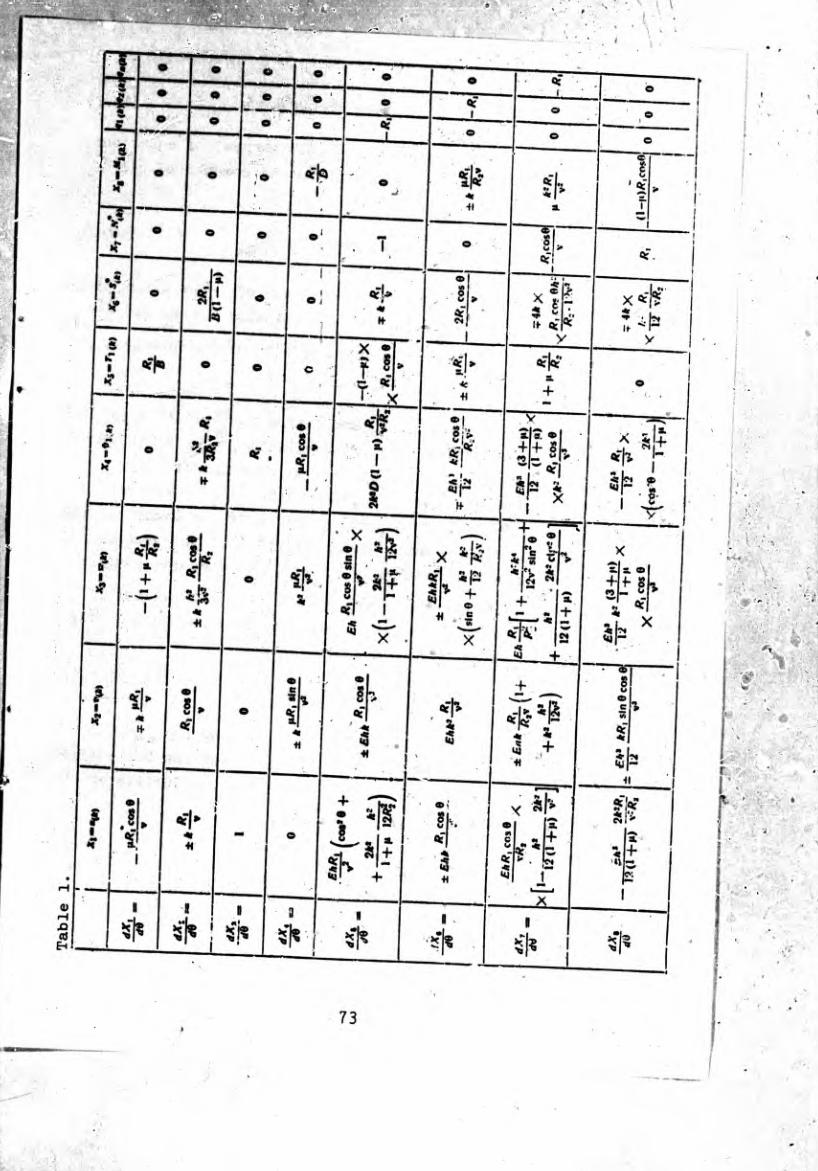
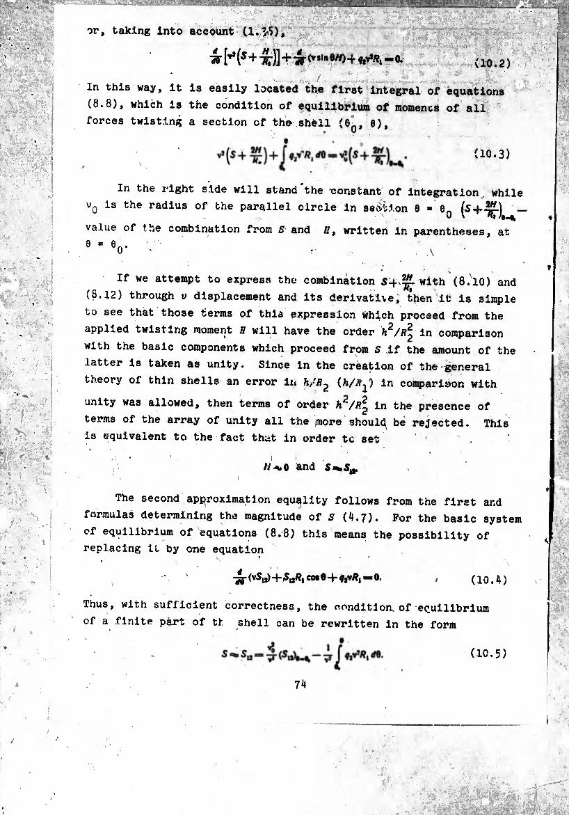
or, taking into account (l.^S)
W [** (5 + 7^)]+-ar(v*in0")-f ç,v*Af, « 0. (10.2)
In this way, it is easily located the first Integral of equations
(8.8), which is the condition of equilibrium of moments of all
forces twisting a section of the shell (6n, 6), • >/
(10.3)
In the right side will stand the constant of integration, while
v0 is the radius of the parallel circle in section 0 - 0g (S+T¡f-) -
value of the combination from s and ff, written in parentheses, at
9*0 A
If we attempt to express the combination S-fwith (8.10) and
(8.12) through v displacement and its derivative, then it is simple
to see that those terms of this expression which proceed from the
applied twisting moment H will have the order h2/R^ in comparison
with the basic components which proceed from S if the amount of the
latter is taken as unity. Since in the creation of the general
theory of thin shells an error in h/R¿ in comparison with
unity was allowed, then terms of order h^/R^ in the presence of
terms of the array of unity all the ¡more should^ be rejected. This
is equivalent to the fact that in order tc set 1
ii and 5g.
The second approximation equality follows from the first and
formulas determining the magnitude of S (4.7). For the basic system
of equilibrium of equations (8.8) this means the possibility of
replacing it by one equation
-35-(^0)+¾¾ cote+ftv#,—0. (10.4)
Thus, with sufficient correctness, the nonditloa of equilibrium
of a finite part of th shell can be rewritten in the form
(10.5)
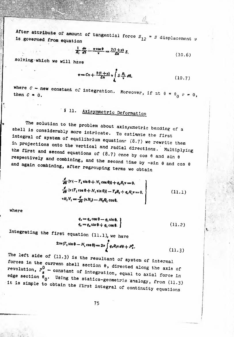
«ter attribute or amount of tangential force 5 , s dism is governed from on,io*--i_ 12 s displacement v governed from equation
. ST&-—= -¾^.
solving which we will have
i»
(10.6)
(10.7)
where C - new constant of integration m then <7 - 0. integration. Moreover, if at 6 = 0 y = 0>
5 11 * Axipymmetric Deformation
:r t irr.“ “ nr.r r;:;r:;r,r:;;rr * r;sL:;.r:" t““' ----
the first and second quations of (8 n MUltlPlyine
respectively and combining, and the second time" bT Lnl ^ '
and again combining, after regrouping terms we obtain “ 9
4 Ha Iv(— sin 0 -f .V| cos 0)J -f- ^/?,v = o.
4-iv <rico* 8 + Af, sin 8)| - r,/?, 4 =, o.
v^|‘Vi = ~Í¡Q (v.M,) — Afj/?, cos 0.
(11.1)
where
coso —sine. 1 ?. = y.sin0-f Çjcose. J (11.2)
Integrating the first equation (11.1), we have
2.1V (T, sin e - yvk cos 0)=2.-1/ **lV rf0+/¾.
¿ (11.3) The left side of ill 3 ï i «s forces in the resultant of system of Internal i orces in the current shell section ft
revolution, p° - constant of 1 1- * cted alonS the axis of edge section I Us nTth e^al to axial force in
It is simple to obtain thé*« tT'8e0"etrlC ‘ fr°” <U-3) obtain the Urst integral of continuity equations
75
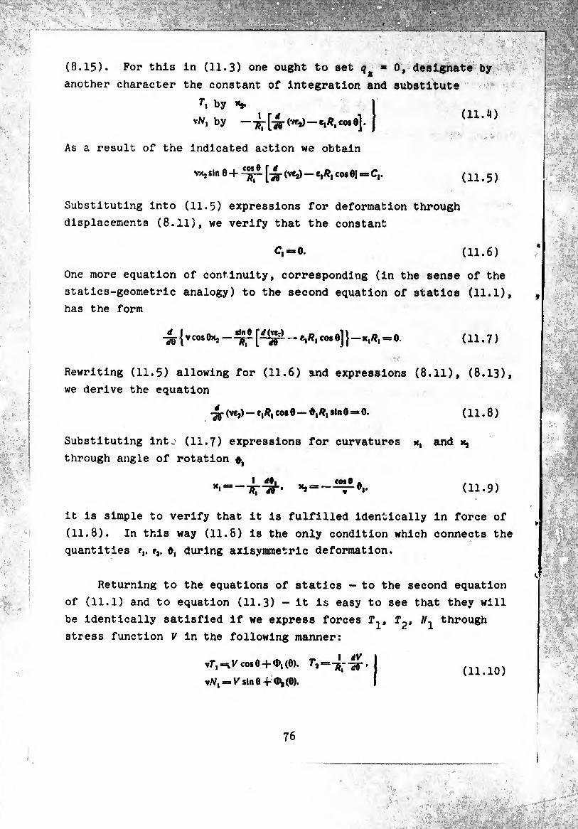
(8.15). For this in (11.3) one ought to set q ■
another character the constant of integration and
by **.
v/v, by —(7¾)-*1^,co*e].
As a result of the indicated action we obtain
vx2 sin 0 + ^ \~2ti' ^ve*) ““ *1^1co* ®l ^
Substituting into (11.5) expressions for deformation through
displacements (8.11), we verify that the constant
ci“=0. (11.6)
One more equation of continuity, corresponding (in the sense of the
statics-geometric analogy) to the second equation of statics (11.1),
has the form
-^{vcosO>^ —e,/?, cose] (11.7)
Rewriting (11.5) allowing for (11.6) and expressions (8.11), (8.13),
we derive the equation
•jj- (ve,) — e,/?, cos 0 — 0,#, sin 0 *» 0. ( 11.8 )
Substituting int.' (11.7) expressions for curvatures x, and x,
through angle of rotation #,
yli ~R7~W' ’‘s“-(11.9)
it is simple to verify that it is fulfilled identically in force of
(11.8). In this way (11.6) is the only condition which connects the
quantities r,. e,. 0, during axisymmetric deformation.
Returning to the equations of statics - to the second equation
of (11.1) and to equation (11.3) — it is easy to see that they will
be identically satisfied if we express forces T^t through
stress function V in the following manner:
vT", V cos O + ^i (Ô). T'a = •
\Nl = K sin 0 -i- <bj(0). (11.10)
0, designate by
substitute
(11.¾)
(11.5)
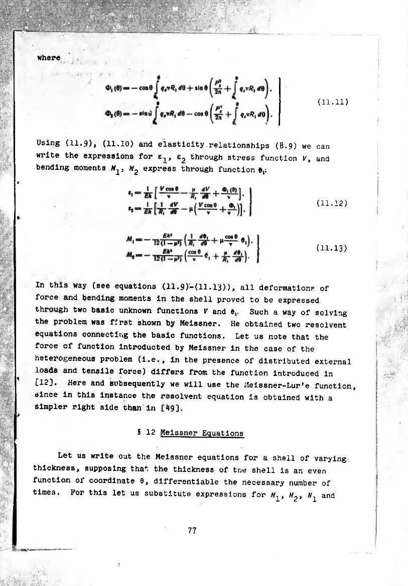
where
(11.11)
Using (11.9), (11.10) and elasticity relationships (8.9) we can
write the expressions for e1, e2 through stress function V, and
bending moments M2 express through function 0,:
(11.12)
(11.13)
In this way (see equations (11.9)-(11.13)), all deformations of
force and bending moments in the shell proved to be expressed
through two basic unknown functions V and 0,. Such a way of solving
the problem was first shown by Meissner. He obtained two resolvent
equations connecting the basic functions. Let us note that the
force of function introducted by Meissner in the case of the
heterogeneous problem (i.e., in the presence of distributed external
loads and tensile force) differs from the function introduced in
[12]. Here and subsequently we will use the ¿leissner-Lur*e function,
since in this instance the resolvent equation is obtained with a
simpler right side than in [49].
§ 12 Meissner Equations
Let us write out the Meissner equations for a shell of varying
thickness, supposing that the thickness of tne shell is an even
function oi coordinate 9, differentiable the necessary number of
times. For this let us substitute expressions for , and
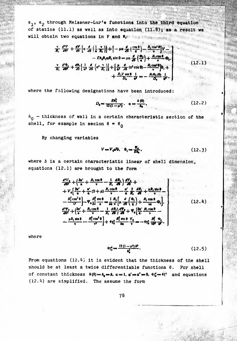
■•:*'*?* *¡ pMri'. Mié
méi-
e-p e2 through Meissner-Lur’e functions into the third equation
of statics (11.1) as well as into equation (11.8); as a result we
will obtain two equations in V and
V I/’I' , rfK rf /1 V VI , r á (f0»e\ /?,cos*01,, ■*;-*¥ ^irh^iïTçrjJ—~-\v~
— Ek(fitaHt *ln 0 = |ia J -f- ¢,,
+^i—
where the following designations have been introduced:
„ MO) ^W-l*7)’ ““IT*
(12.1)
(12.2)
- thickness of wall in a certain characteristic section of the
shell, for example in secion 8-0..
By changing variables
v-iV*. 0,--¾. (12.3)
where fc is a certain characteristic linear of shell dimension,
equations (12.1) are brought to the form
tf*l\ , /3a' , /?, cos 6 “rf5i"+\"r+ y—
+ ^,(^-+4-(2 + ^
I áR, \ iV% , ■»nr)^r+ cost a' 2 i*x | nig,Wat
* to,2«] P| iln0 1 Ä,f rf , ^cost^l v° iv ~ã~ gTi^iy yj-J+—s - 0«J » R, co* 0
‘¡S' 1 rf*A<rr, , IB r3a' R, to,«
-
I1r4-Í- V* J+^ to a ^»3 vi* qí '
« TJT"*#' ’ » R, co*(
|i/?i sin «
(12.4)
where
12 (i — ti1)«*
*î (12.5)
From equations (12.4) it is evident that the thickness of the shell
should be at least a twice differentiable functions 0. For shell
of constant thickness A(0) = A, — *, a = 1, a'«*a'«*0. 4^==4^ and equations
(12.4) are simplified. The assume the form
78
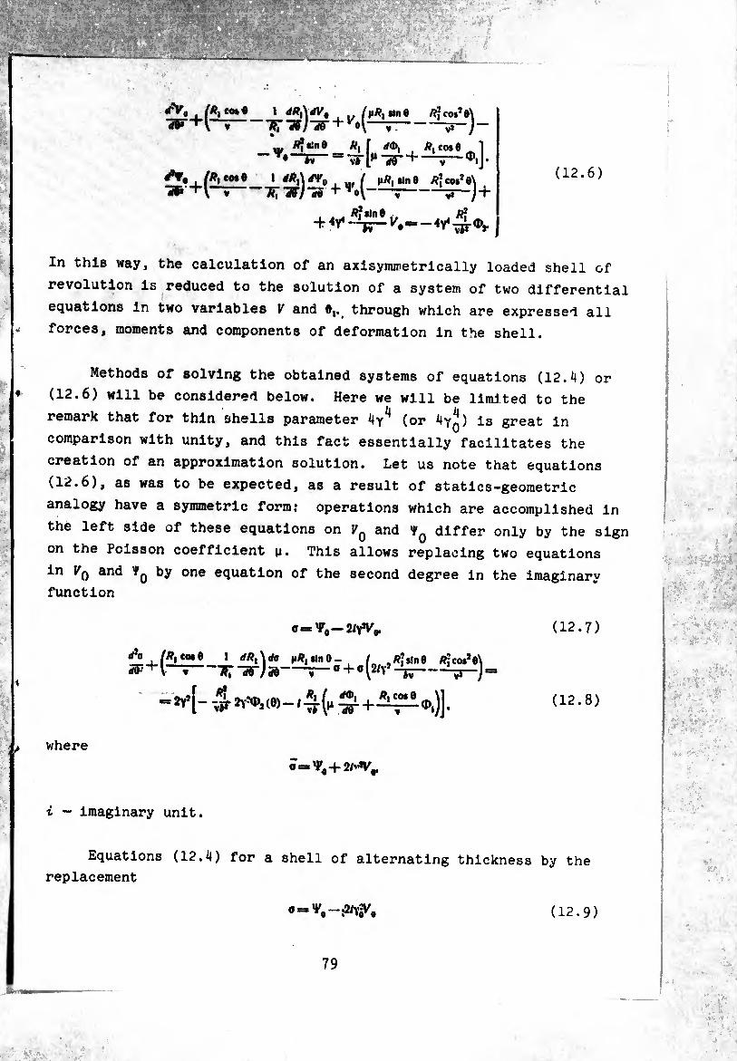
_i:
rfVg IR, co»« 1 rfÄ,w0 tine Ä?co»?e\ •3F+V“^-’»r^-sr + M-r-iT-j-
«, Ä*«ine Ä, f ,/(6, /?, cote i - = TT l»1-50-+ —T-J • rf*»0l/P,cosO |»/Î, tin 6 /??cos*e\ (12.6) ■»+l~—7fr^-3? -V-j-^
, , ^ /i*ln« ... /?*
In this way, the calculation of an axisyminetrically loaded shell of
revolution is reduced to the solution of a system of two differential
equations in two variables V and ©j. through which are expressed all
forces, moments and components of deformation in the shell.
Methods of solving the obtained systems of equations (12.4) or
(12.6) will be considered below. Here we will be limited to the
remark that for thin shells parameter 4y^ (or 4yq) is great in
comparison with unity, and this fact essentially facilitates the
creation of an approximation solution. Let us note that equations
(12.6) , as was to be expected, as a result of statics-geometric
analogy have a symmetric form: operations which are accomplished in
the left side of these equations on F0 and 'VQ differ only by the sign
on the Poisson coefficient u. This allows replacing two equations
in Kq and Ÿq by one equation of the second degree in the imaginary
function
0 = ^-2/7%.
A i (Rtc<*6 1 dR^da nR, tin 0 - / _/?;sl„e /??cos*e\ ¿v + -~w) 50-- ° + 0 i2'Y3 -½-V-J!
(12.7)
(12.8)
where
i - imaginary unit.
0 =
Equations (12.4) for a shell of alternating thickness by the
replacement
o = V#-W. (12.9)
79
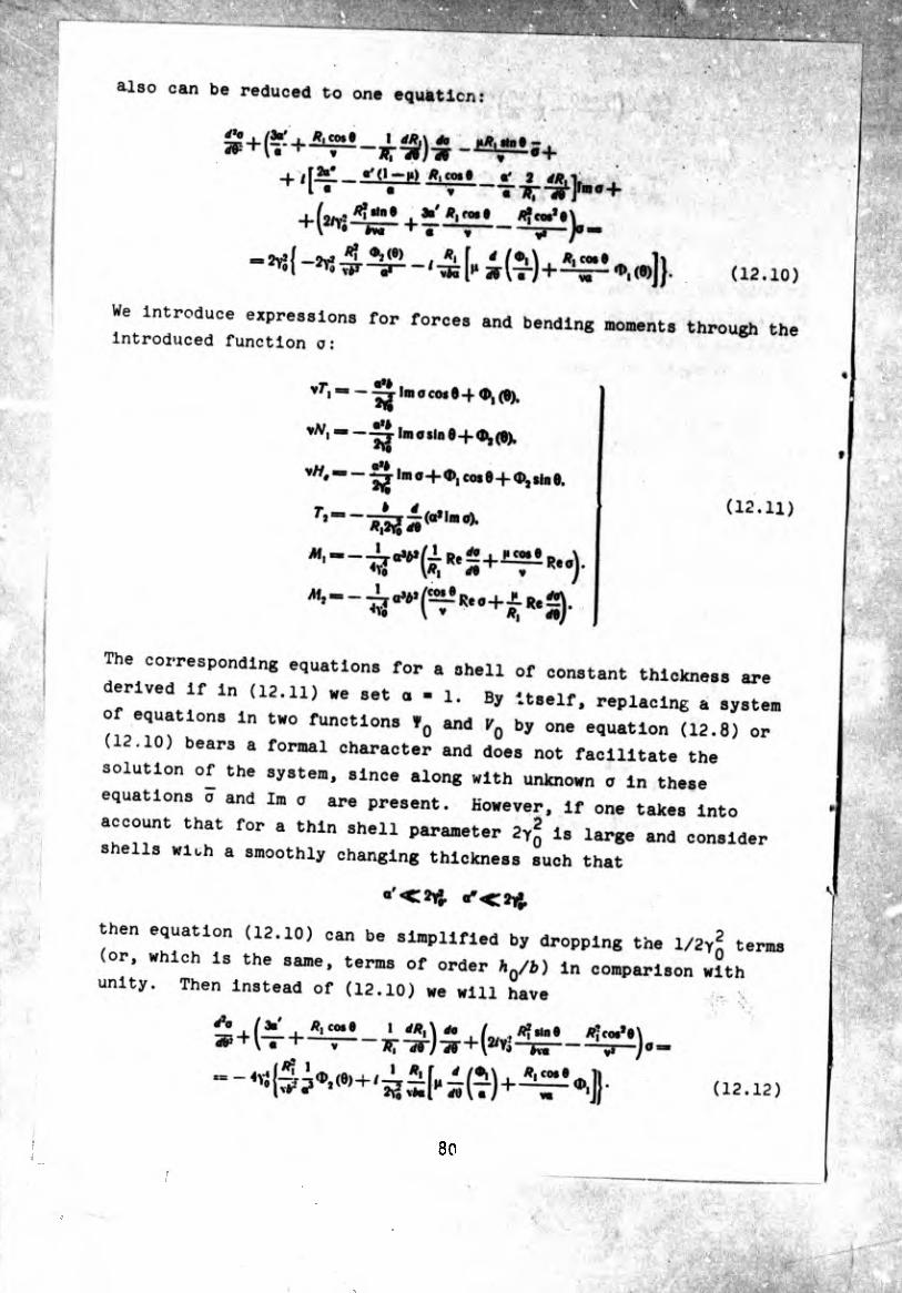
also can be reduced to one equfcticn
3b rot t /ifcw*«
We Introduce «pressione for forces and bending comente through the introduced function o:
Imocoi 0-(-0),(0).
-^ylmosme+^O). aH
Imo-fO), coi 0-(-0), sin 0,
csoonuxng equations for a shell of constant thickness
derived If in (12.11) we set o - 1. By itself, replacing a s
of equations m two functions *„ and V0 by one equation (12.8 (12.10) bears a formal character and does not facilitate the
solution of the system, since along with unknown a In these
equations o and Im o are present. However, If one takes Int.
account that for a thin shell parameter 2Yij Is large and cons:
shells With a smoothly changing thickness such that
80
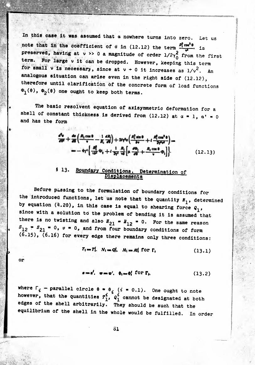
In this case It was assumed that a nowhere turns into zero. Let us
note that in the coefficient of c in (12.12) the term is
preserved, having at v » 0 a magnitude of order l/2y* from the firs
term. Por large v it can be dropped. However, keeping this term
for small v is necessary, since at v - 0 it increases as 1/v2. An
analogous situation can arise even in the right side of (12.12),
therefore until clarification of the concrete form of load functions
^(9)one ouSht to keep both terms.
The basic resolvent equation of axisymmetric deformation for a
shell of constant thickness is derived from (12.12) at; a » 1 a* = 0 and has the form
(12.13)
5 iS. Boundary Conditions. Determination of
Before passing to the formulation of boundary conditions for
the introduced functions, let us note that the quantity y , determined
by equation (i».20), in this case is equal to shearing force Q ,
since with a solution to the problem of bending it is assumed^hat
there is no twisting and also *21 - a12 - 0. For the same reason
512 “ 521 " °* y " °» and from f°ur boundary conditions of form
(6.15), (6.16) for every edge there remains only three conditions:
h — rí. .V, » Q{. .w, = All for r, (13.1)
or
0,.=0,1 for r,. (13.2)
where rf - parallel circle 6 -0( (( . o.l). One ought to note . t ï
however, that the quantities fj, cannot be designated at both
edges of the shell arbitrarily. They should be such that the
equilibrium of the shell in the whole would be fulfilled. In order
Ö1
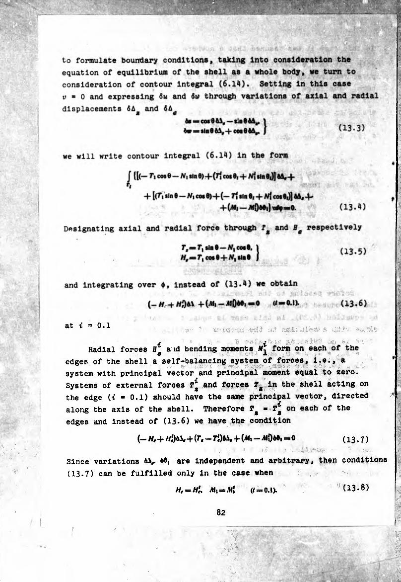
to formulate boundary conditions, taking Into consideration the
equation of equilibrium of the shell as a whole body, we turn to
consideration of contour integral (6.1^1). Setting in this case
r a 0 and expressing 6u and through variations of axial and radial
displacements 6A and ÓA
Designating axial and radial force through f and B respectively
6« — COS0 fiA,—«ia ® 1
6«3ssin06A,-HcosO6A,. ) (13.3)
we will write contour integral (6.14) in the form
J ll(— fl co*e-Ni Sin 0)+(7| cos 0|+M sin 8|)J 6A*4- ■■¡rm
+ [(f, sin e- /V, cos 6)+(- 71 slne, + cos6<)] 6A,4-
(13.4)
l#,j»r,cos6+W,
and integrating over ♦, instead of (13.4) we obtain „ • \ , ÛÎÏ
(_ h, + H$b\ + (Ali - A|Qò6i -0 (/-0.1).
at i a 0.1
i i Radial forces H* a id bending moments form on each of the
edges of the shell a self-balancing system of forces, i.e., a
system with principal vector and principal moment equal to zero.
Systems of external forces and forces T* in the shell acting on
the edge (i ■ 0.1) should have the same principal vector, directed
along the axis of the shell. Therefore T* • T* on each of the
edges and instead of (13.6) we have the condition
(- //,+ //,061. + (7.-7^+(^1 - MÖ66, -0 (13.7)
Since variations 66, are independent and arbitrary, then conditions
(IB.7) can be fulfilled only in the case when
//,=//;. .41,=.)1( (/=0.1). (13.8)
!
/
82
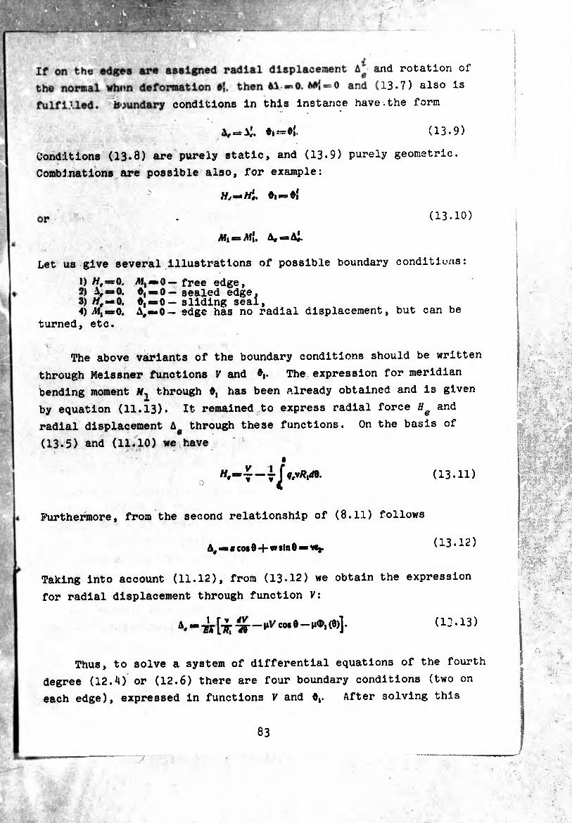
If on the edges are assigned radial displacement A* and rotation of
the normal when deformation 0|. then W{ = 0 and (13*7) also is
fulfilled. Boundary conditions in this instance have.the form
(13-9)
Conditions (13.8) are purely static, and (13-9) purely geometric.
Combinations are possible also, for example:
HjmtHi, =
(13.10)
Mi-M{. A.-Ai.
Let us give several illustrations of possible boundary conditions:
1) H,—0. Mt — 0— free edge, 2) A,*=0. 0, = 0- sealed edge. 3) //,=0. 0, = 0-sliding seal, 4) AfjnO. A,=0— edge has no radial displacement, but can be
turned, etc.
The above variants of the boundary conditions should be written
through Meissner functions V and The expression for meridian
bending moment M1 through 0, has been already obtained and is given
by equation (11.13).
radial displacement A
It remained to express radial force and
through these functions. On the basis of
(13.5) and (11.10) we have
qt\Rld9. (13.11)
Furthermore, from the second relationship of (8.11) follows
A,=« cot 0 4-** sin 0=**. (13.12)
Taking into account (11.12), from (13.12) we obtain the expression
for radial displacement through function V :
^CM 0 ” (0)] ’ (13.13)
Thus, to solve a system of differential equations of the fourth
degree (12.4) or (12.6) there are four boundary conditions (two on
each edge), expressed in functions V and 0,. After solving this
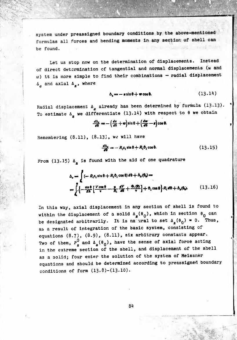
system under preassigned boundary conditions by the above-mentioned
formulas all forces and bending moments in any section of shell can
be found.
Let us stop now on the determination of displacements. Instead
of direct determination of tangential and normal displacements (u and
w) it is more simple to find their combinations - radial displacement
A and axial A , where e a
A4 — « sin 6-f w cos 0. (13.14)
Radial displacement Ag already has been determined by formula (13.13).
To estimate A we differentiate (13.14) with respect to 6 we obtain z
-¾ = — + *) *in e+("S'“ cos ®*
Remembering (8.11), (8.13), will have
From (13.15) A is found with the aid of one quadrature
Af = J (— Äjt, sin 0 + Ä,0| cos 0) </0 A, (0q) =*
(13.15)
(13.16)
In this way, axial displacement in any section of shell is found to
within the displacement of a solid A^(9q), which in section can
be designated arbitrarily. It is na ural to set Aa(6Q) = 0. Thus,
as a result of integration of the basic system, consisting of
equations (8.7), (8.9), (8.11), six arbitrary constants appear.
Two of them, P° and A (6n), have the sense of axial force acting
in the extreme section of the shell, and displacement of the shell
as a solid; four enter the solution of the system of Meissner
equations and should be determined according to preassigned boundary
conditions of form (13.8)-(13.10).
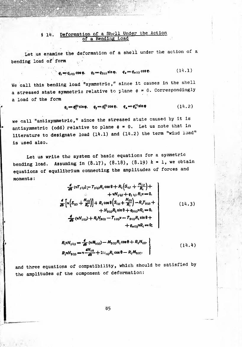
g ii|. Deformation of a Shell Under the Action of a Bending Load
Let us examine the deformation of a shell under the action of a
bending load of' form
= “"f- ?. = ?-n)cosf- (1^.1)
We call this bending load "symmetric," since it causes in the shell
a stressed state symmetric relative to plane ¢) = 0. Correspondingly
a load of the form
q^^slntf. Çjesçÿ'coif. f,*=s«2,,|n? (1*4.2)
we call "antisymmetric," since the stressed state caused by it is
antisymmetric (odd) relative to plane <J) = 0. Let us note that in
literature to designate load (14.1) and (14.2) the term "wind load
is used also.
Let us write the system of basic equations for a symmetric
bending load. Assuming in (8.17)» (8.18), (8.19) k * i» we obtain
equations of equilibrium connecting the amplitudes of forces and
moments :
-ft 1 <»>) — T2 <1)^1 C0* Ö-f A, (S»|5 + +
+ vA7| (|) + (i> ^iv ^
w [v (su> + ät)] 4 co*0 (s«'»+tt) + -j-ATjdj/îjSinO + Çjdjv/?, = 0.
(14.3)
-Jg- (^1(1))+ ÄjAfjU) — fl(l)V sin® +
= -Jg- (vAl1(I))- Aij(,)Ä, COS 0
dH V~5F' + 2//‘»Ä> ¢08 0-^2(15-
and three equations of compatibility, which should be satisfied by
the amplitudes of the component of deformation:
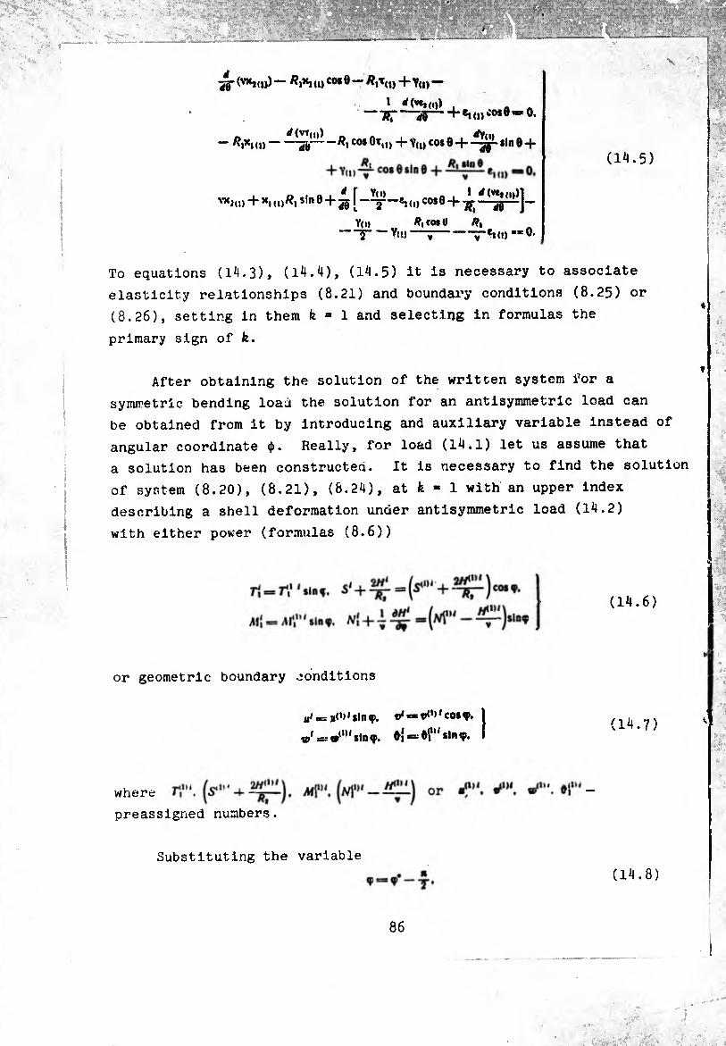
X
^-(VXjd))— /?1*1 (!) co*Ö — 4- Y(|) —
TíT À h «KD ¿o*ö «*0.
— ^>xki)-üë /?] co* 0Ttl> + V(i) cos 8+sin 8 -f -^X.(D-&-#,coiOt(1) (1^.5)
'’’‘in) + kki)^i sin®+ 2(j [ co*® + Tjj—
V(i) Ä, co* e /9, —5-Vl’)—V-T*»«» ‘=0-
To equations (14.3), (14.4), (14.5) it is necessary to associate
elasticity relationships (8.21) and boundary conditions (8.25) or
(8.26), setting in them fe = 1 and selecting in formulas the
primary sign of fe.
After obtaining the solution of the written system for a
Symmetrie bending load the solution for an antisymmetric load can
be obtained from it by introducing and auxiliary variable instead of
angular coordinate ¢. Really, for load (14.1) let us assume that
a solution has been constructed. It is necessary to find the solution
of system (8.20), (8.21), (8.24), at fe * 1 with an upper index
describing a shell deformation under antisymmetric load (14.2)
with either power (formulas (8.6))
or geometric boundary conditions
u1 = «f’i'ilnç, ®|=*t»<,,,co*f,
io‘ =z «(1,< sin <p. <►{ =* M'* * *•" 9» (14.7)
where
preassigned numbers.
Substituting the variable
(14.8)
86
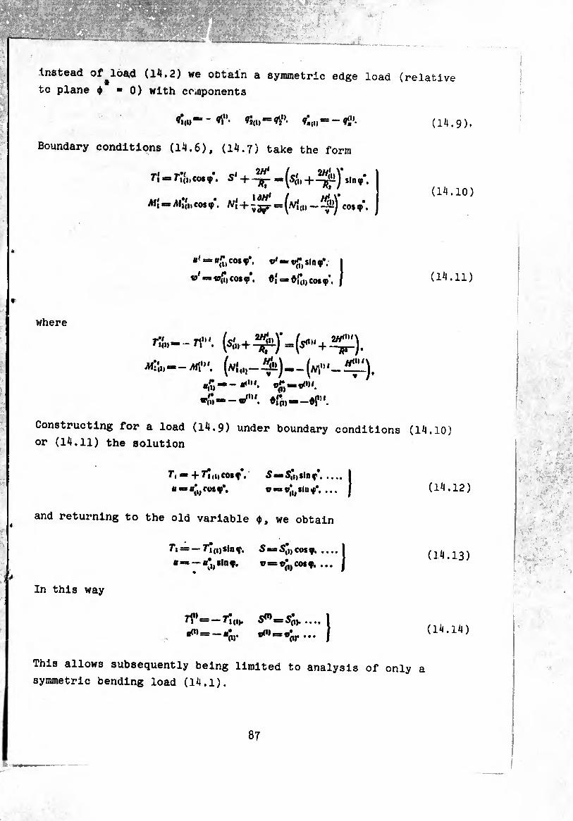
Instead of load (14.2) we obtain a symmetric edge load (relative
to plane $ “0) with components
fî<i) “ " ?j(i) *= fli1'- ^,i, = - fi,1’. ( 14.9 ),
Boundary conditions (14.6), (14.7) take the form
t\ - rí(i,cosf. + .(14.10)
All = <,CO,V. ^ + =
= cos f*. o'-tftsin f*. I
w' — w^cosœ. cos«P*. / (14.11)
where
—mi"'. (k„-^í)—(m"‘-^111). 4““ ^1.
Constructing for a load (14.9) under boundary conditions (14.10)
or (14.11) the solution
and returning to
In this way
T, * + fim cosq- • «■»«^rosf*.
the old variable
fi = —r*{i)Sinf.
»Inf.
5«BS|,i)Sinf.I
o-aw^slnf*, ... I
<Pt we obtain
¿«¿^cos?. .... 1
v^r’jcosf. ... j
(14.12)
(14.13)
(14.14)
This allows subsequently being limited to analysis of only a
symmetric bending load (14.1).
87
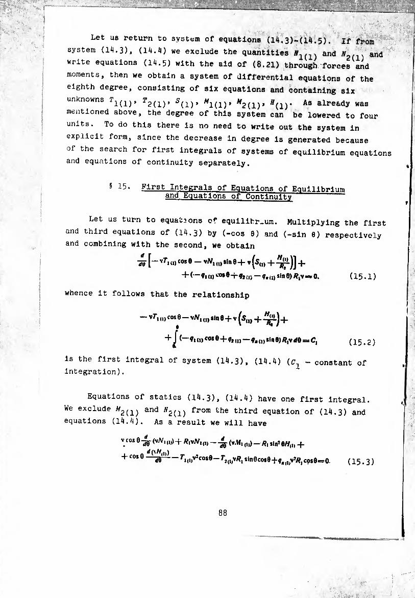
Let us return to system of equations (1^.3)-(1^.5). If from
system (14.3), (14.4) we exclude the quantities #1(1) and 0 . . and
write equations (14.5) with the aid of (8.21) through forces and
moments, then we obtain a system of differential equations of the
eighth degree, consisting of six equations and containing six
unknowns T2(i)> 5(i)* M2(l)> Ä(l)* As alretdy was
mentioned above, the degree of this system can be lowered to four
units. To do this there is no need to write out the system in
explicit form, since the decrease in degree is generated because
of the search for first integrals of systems of equilibrium equations
and equations of continuity separately.
5 15• First Integrals of Equations of Equilibrium and Equations of Continuity
Let us turn to equations of equilibrium. Multiplying the first
and third equations of (14.3) by (-cos 0) and (-sin 6) respectively
and combining with the second, we obtain
'S» [— v^» (D cos ® v^i<n sl# 0+ V^S(1, -f- +
+ (— ¢, (I) CO*e-r CD - CD sin 0) #,v « 0. ( 15.1 )
whence it follows that the relationship
- v7'i CD cos 0 - vAf, (l) «in 0+V (s(|) +-^)+
fl (1) cos Ö+ŸJ (I) — 9« (d *•# fi) *,v ,0
is the first integral of system (14.3), (14.4) (C^
integration).
= ci (15.2)
- constant of
Equations of statics (14.3), (14.4) have one first integral.
We exclude ^2(1) and ^2(1) ^°111 the third equation of (14.3) and
equations (14.4). As a result we will have
V cos 0 (vA/, ,„) + R^N, (l) _ Jç (v.M, (1)) _ slni e//(|> +
+10* 5S ri(i)V7co»8— sinOcosO+0,^,»*/?,cos0==O ( 15.3 )
88
Excluding from (15.3) and the first equation of (14.3) force ^(i)»
we obtain
— V*cot0 7*1(1) — V sin0-^ (vf,d,)-}- Ri\Nnu — vWi(d *in0-}-
+ Vcot0(vJV,„(v.M,(,,)- /?, tin50//,,, + cos0 -
v/?, sin 0 |S(„ + + V*/?, (¢, cos 0 — ÿ, o, sin 0) s 0. ( 15.4 )
In (15.4) regrouping terms with the aid of identities
— V2 cos Of, („ — V sin 0 —y (v7*, ,„) =■
= — -jy (V* sin 07*, (,,) -f- 7*, ,|)V/?| sin 0 cos 8.
v cos 0 (vA/, („) — vW, (,, sin 0 4- /?,vA/, «
= -jy (v4 cos 0A/, (,p + Ä,vN, sin2 0.
we have a
ae (- ^s,n 07,i (i) + v*co* (,, - ViM, „, + v//„, cos0)+
4 R, sin efvr, cos 0 4 vA/, sin 0 - v (5,,,4 +
+ ^1 (¢, („ cos 0 - y, sin 0) = 0.
(15.5)
(15.6)
Prom (15.6), taking into account (15.2), we obtain the desired
relationship:
—v* sin Of, („ + vW, („ cos 0 — vAf, „, 4 v//,,, cos 0 4
^ Ä.slnoj^J (— 9,(,,cos04¢,(„ — sin0)R,v</0J</04
f 6 + ^ (7- (i) co* 8 - f, sin 0) Rtv- dO « C, 4 C, ^ Rt sin 0 dO.
+ s
(15.7)
In order to establish the meaning of relationships (15.2) and (15.7)
and determine the constants of integration £?2, let us compose
the condition of equilibrium of a finite element of the shell
contained between section 60 and flow section 6 (Fig. 9). Let
section 0Q be applied to an external load, statically equivalent
to force P and to moment M . In section 0 * const on an element of X y arc vJç acts forces and moment Mpdy. equal to
#f,v </q> — (r,T, 4 ^12T2 + Q,*) v <fq> = = <ri („ co*»T,4^12 („SinqiT24 Q, (n cosç/i) v</q>. (15.8)
89
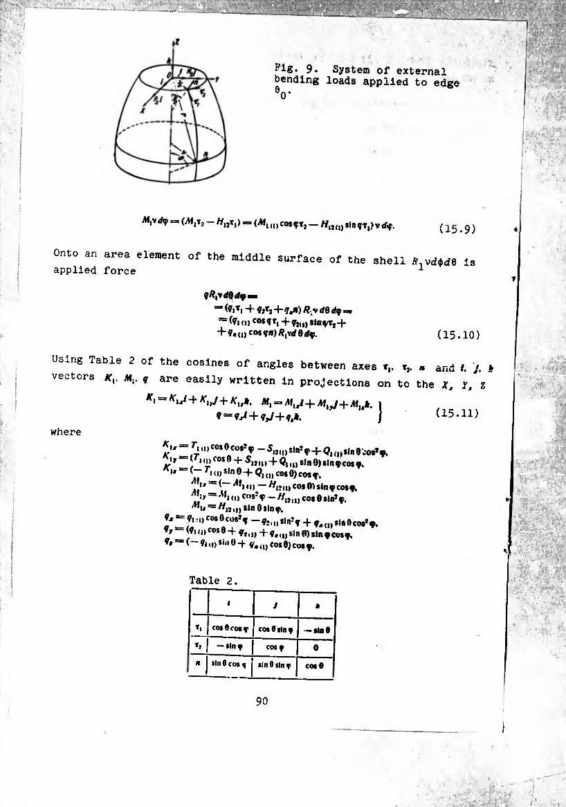
pig. 9. System of external bending loads applied to edge
V
(Mtt, H,,!,! (vM, djCOIÇTj — *lDTT,)VlAf. ¢15.9)
Onto an area element of the middle surface of the shell ff,vdM6 Is applied force L
qRtVdQd«pxmm
- (?iTi + Í2tj+7«*) Ry dQdq>= ~ (ft (d cos ft, -j- ^j(1) sinqiTj-f + 7«(l) COSW^YdÕâf. (15.10)
Using Table 2 of the cosines of angles between axes « and I. J. »
vectors m,. q are easily written in projections on to the X, Yt l
(15.11)
where
f,(l)co,0cüs*ç _S|J(1)Slnîf+ (?i<i)„ne,0$,ft
K1 1 r C0Sft + + 10 #,n0)Sinocosf. '* ' r«<i)s,"0-|-Q1(I)co$0)cosf,
u — (— „) — //,},„ cos sin f cosy.
358 «■) CHSÎV - «mo cos 0 sin7 f. '"u — «lío) sin Osinf,
7x = 7,;ocos0cos*f _ÇîiI)l,nÎT + f-a)i|nftço#Ifi
y (7i «o cos 0-J- 7,,,)-1- 7at„sin0)sin9cosf, 7#**(—7i,i)si,,0-f 7«,,) eos Ó) eos 7.
Table 2.
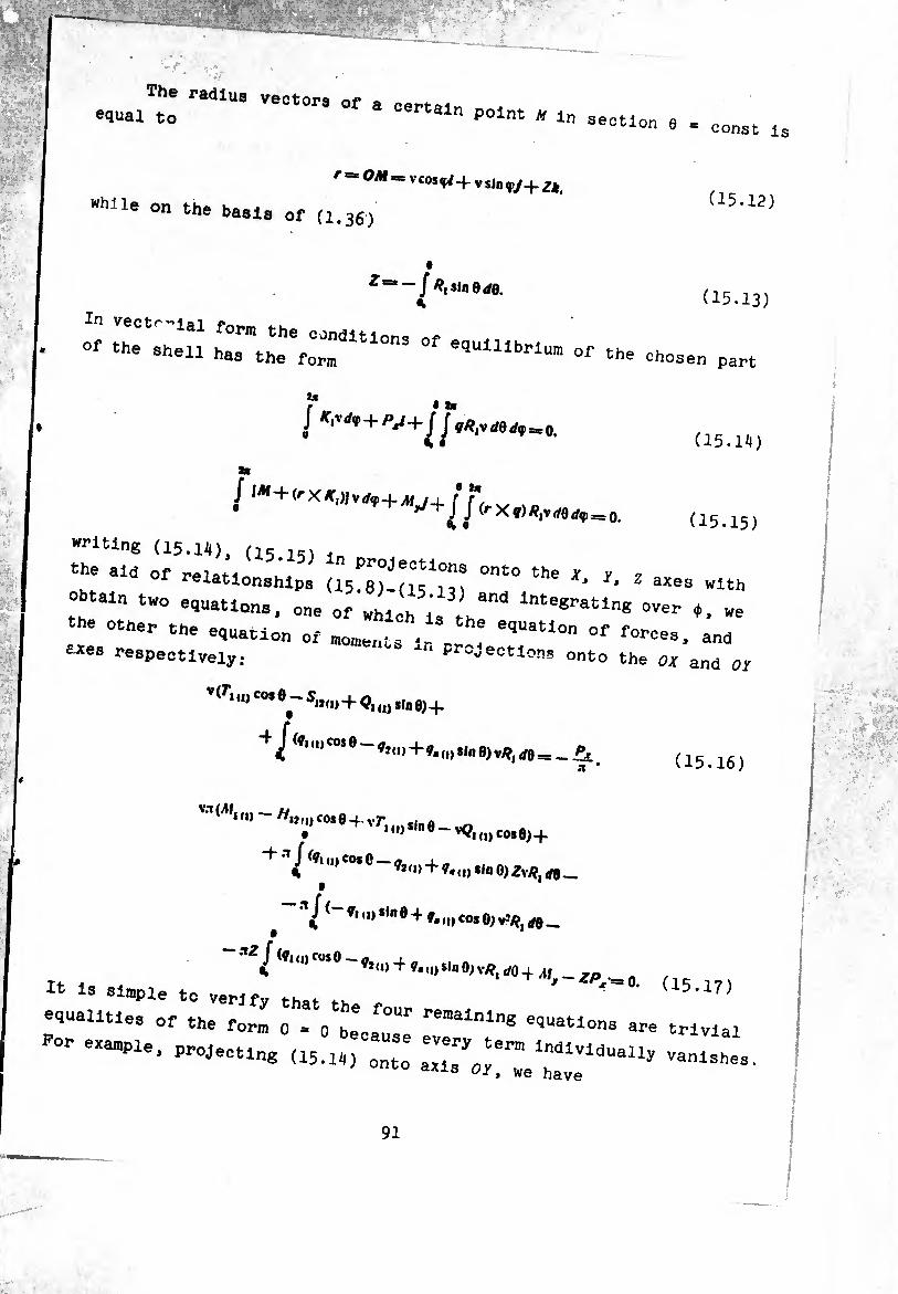
The radius vectors of a certain equal to certain point m in
r ~ OM = Vcos<fiV sjnfy+ Zk
“hUe on the basis of (1.35,
—/*i!lnes8. i.
section 0 * const i
(15.12)
(15.13)
s thTsTeíí r\refruions °f e9uiiibri“ ^ ch0Se„ Part
(15.1H)
(15.15 writing (15.14), (15 , .
the ald of relationships (15^-(15^ the ^ ^ z «es „ith
obtain two stations, one of whl h n h ^ *. we
the other the equation of rao„e„ts 1 -! ! e9Uatl°n °f for=«. ano eues respectively; “ ^“sections onto the ox and 0.
v<ri id cm e-s1J(|)+Qt (|) 8ln e)+
+^<Wo.e-ft(„+f<ii)Iln9)vSii((=_£ a516)
”IAI‘ ~ H”! “* 9 4 vr' "> Sl" ' - *9| („ CM », +
J (ft id cos 0 — a % ^*ii)+ sin O)Zv^,rf0_
^ '^1 ?i ">ilnö^ f. (I) cos 0) v-£/¡ tfÿ __
/»IUI 1|,~»1(||4 II
« 13 simple to verify that th r ' (15•17,
equalities of the form 0 - o becaÚ“1- renlalnlng e<l“atlons are trivial
por eiampie* pr°j— (15.11) ) onto ;;;r0:;:ervlduaiiy vanishas
ri(1)cos04 5ia (1)-+- ‘•]) *ln0)vsinf C0*çrff-f
■+ j (?iu,cos0+ ?j(i)4 f« in »ln 6) sin ç co*ç rfçj #,v</0=0. m&ï\:
wÊÊma&mâiï m WD:-
In the second term of the left side of (15.17) integrating in parts
and taking into account (15-13), we rewrite (15-17) in the form
V (M, „, - Hl2 (1) cos 8 + vf, sin 0 - vQ,,,, cos 0) 4-
4 I Ä,sln0[ J (?, „J cos 0 — q. ,, 4 q, (1) sln0)vfl, doj ¿0 — ^ «jSlnej^íf,,
— ^[(f «u, co* 0-^(1,5100)^,1/04---4--^-^ /?, sin 0(/0r=O. (15-18)
Witn the aid of formulas (4.7), (4.8), (4.20) and relationships (8.1), ♦
we express the connection between amplitudes of forces ^2(1)
§1(1), moment ^12(i) and amplitudes of the corrected quantities
5(i), Ni(i) and H(i)> then we obtaln
^(1)^^0)4—»
vQ, —\Nl 4- y (//„ _ Hu
"»> “ I (Hn (i) 4" Mtuu)
(15.19)
consequently,
— 5. //.i i: <s) 4* Q} (o sin 0 — S,„ 4 (j) «In 0-.
wi*u)4 ''Oui)’ ’i ui 4 H«> (15-20)
Using (15.20), we write conditions (15-16), (15-18) in fina1 form:
— v (^i (i)cos ® 4 (i)*ln 8 — Su) —jfj^) 4-
(15-21)
— v-M, „, — v^,(„ sin 04 ^,,,, COS04 v//,„cos04
4 J /?, sinO [/ ( fid)cos04 f2„, — ga (1)sin0) /?,vrfôj (/04
• Af * 4 J (f, a)cos 0 - fui)si» 8)v1/?, (/0 = -14 /?, sin 3 (/0. (15-22)
92
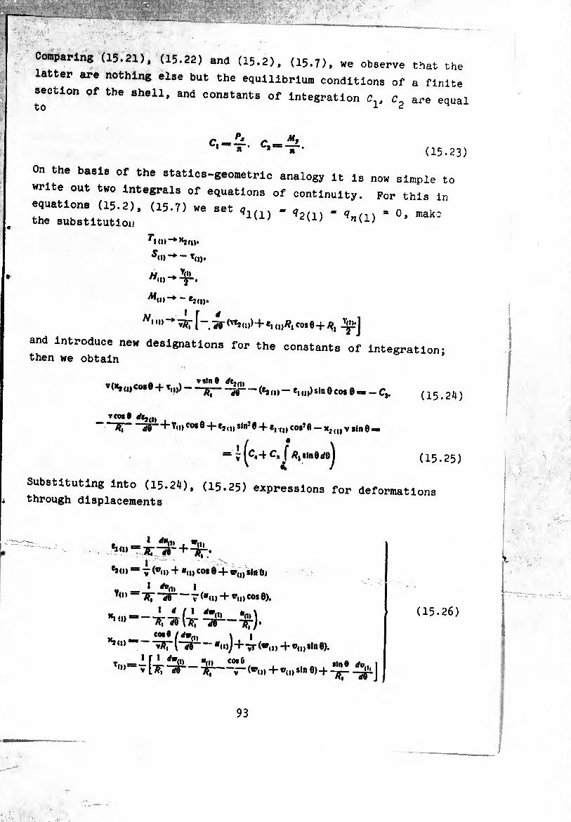
Comparing (15.21). (15.22) and (15.2), (15.7). we observe that the
latter are nothing else but the equilibrium conditions of a finite
section of the shell, and constants of integration ¢7., c- are equal to 12
c^ff. c My 1 * • c»*=-¡r- (15.23)
On the basis of the statics-geometric analogy it is now simple to
write out two Integrals of equations of continuity. For this in
equation. (15.2). (15.7) we set , . < , = 0> mak;
the substitution K
^Kn-♦»‘am. “♦ — ’ci)*
"♦ -y-.
N‘ '■» ■* -wr r.-k <'*>«)+., .0.8+«,
and introduce new designations for the constants of integration- then we obtain
a . vsln® rfe,(ll (>4u)«o*® + W--— (e,(|) - e, 0psin 0 co$ 6 — - C,.
V cos 0 ‘~TT, S5“ ^'i)co* ®-J-**(,»s,n3 ®+ cos*fl — x2(l,v sin 0=»
(15.2^
V «4 /?, sin0rfej (15.25
Substituting into (15.24). (15.25) expressions for deformations through displacements
i 1 - *»<»■* 7 («id + *u) cos 0 4- w(l) sin 61
V(i»! I rfr. Oi 1
TfT “W T (“u» vii> co* ®).
d/ô" Tfr/'
^ ~ ^ (-¾1 - «a»)+4-
T,»>*s V "3r — -v~ (®(D -I- ®(I) si" 0)4 J
\i> +®<i)»l®0).
(15.26)
93
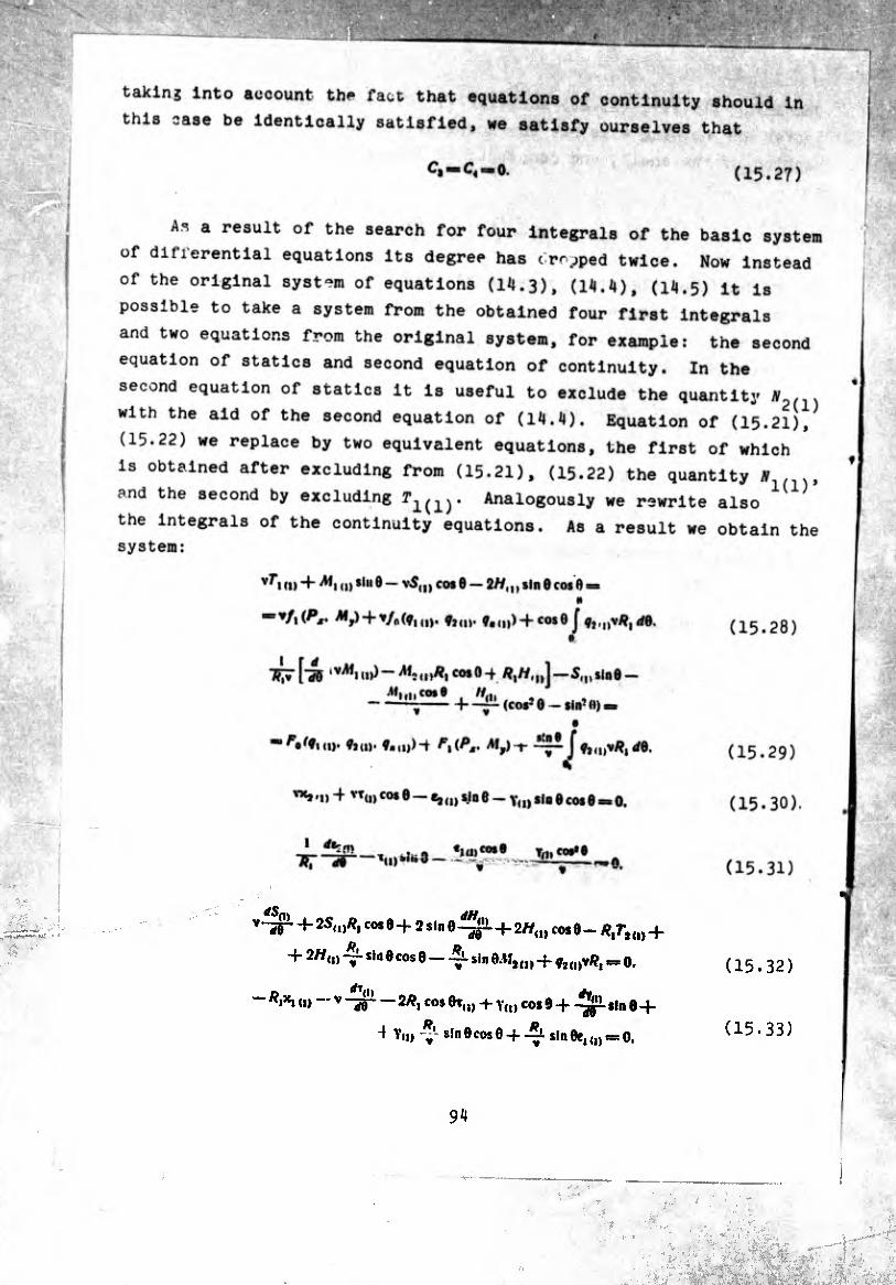
taklnj into account the fact that equations of continuity should in
this case be identically satisfied, we satisfy ourselves that
‘ C« =*> 0. (15.27)
Ax a result of the search for four integrals of the basic system
of differential equations its degree has cropped twice. Now instead
of the original system of equations (U.3), (14.4), (14.5) it is
possible to take a system from the obtained four first integrals
and two equations from the original system, for example: the second
equation of statics and second equation of continuity. In the
2(1) second equation of statics it is useful to exclude the quantity
with the aid of the second equation of (14.4). Equation of (15.21)/
(15.22) we replace by two equivalent equations, the first of which
is obtained after excluding from (15.21), (15.22) the quantity y
and the second by excluding T1(1). Analogously we rewrite also
the integrals of the continuity equations. As a result we obtain the
system:
v^*i <« + a) *iu9 — v5(I) cot 0 — 2//,,, sin 0 cos 0 = «I
“ Y/i (^r* My) + */o(ÿi o). Vim* ?■(!))+ cosO J 11,v/?, rf0. (15.28)
hæ lvA,ni>>- cos0-+ #,//,,,)--5,,^100-
sin’ft) —
i f J fï<i)V#,</0. 'Çj«). 9„H))-i /^,(PM. My) sin 9
V
vxj4 VT(I) cos 0 — e,,,, sin 0 - y,,, sin 0 cos0 « 0.
tJiyco,9.. Jn>a*e
(15.29)
(15.30) .
(15.3D
v“lr + 2S<»*i c°*Ö-f 2 sin 0+ 2//,,, cos 0- #,7-,,,, +
+ 2//,,, 4- *»- 0cos0 - A sin0.MJ(J>4 gjti)VR¡ = o,
“ *1*1 (1) - V -jjr — 2#, cos 0t„, 4 y,,, cos 9 4 -¾1 sin 0-4 . ■ no
^ Veo V sin Ocos 0 4 A sin 0e, « = 0.
(15.32)
(15.33)
lipf S
IK
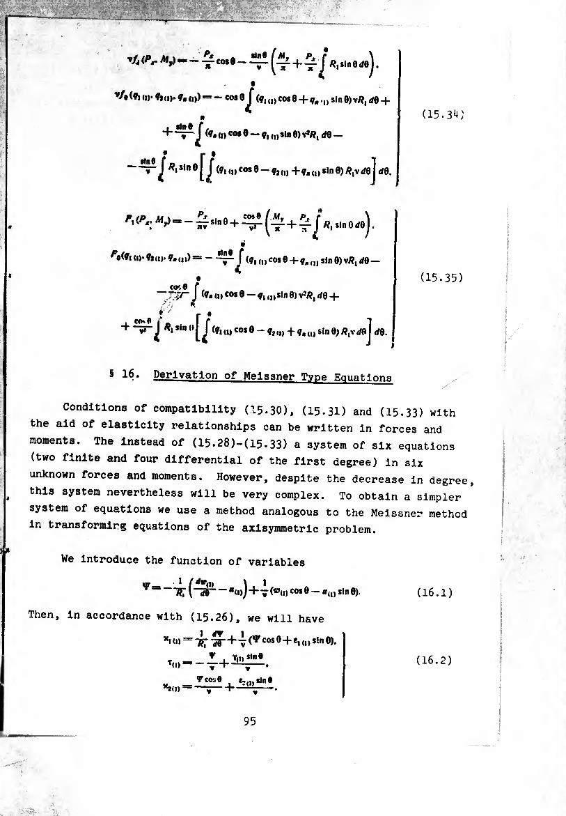
"A ~ cote - ^ ^J /îjsinerfej.
v/»(ft II»* «lui»«.(,)) = — cot oj" (¢,(|) COS0 + <7, .u Sin 0)v/?, dB-f
n i sin Q C * _ + ~J (I) cos 0 — „) sin 0) vJ/?, d0 _
-^/^»‘noQ (ql cos 0 - ç, (1) + ?a (J) sin 0) /?,v J0 j dB.
(15.34)
Fi Pr sin 0 + ^ ^ 4. ~j^ /?, sin 0 rffl j.
^•(«I »)• fcu>. «. („) = - (¢, (|) COS B + qH (I) Sin 0) vÄ, dB —
J (?.<„ cosO-ÿ, insin0) v1/?, ¿04-
* 7 s
«.sinil^cç, d) cos B ~ qt „j 4 qm U) sin 0) R, t,vdB dB. J I
(15.35)
§ 16. Derivation of Meissner Type Equations
Conditions of compatibility (15-30), (15.3D and (15-33) with
the aid of elasticity relationships can be written in forces and
moments. The instead of (15.28)-(15.33) a system of six equations
(two finite and four differential of the first degree) in six
unknown forces and moments. However, despite the decrease in degree,
this system nevertheless will be very complex. To obtain a simpler
system of equations we use a method analogous to the Meissner method
in transforming equations of the axisymmetric problem.
We introduce the function of variables
v— 1 M*Vi> ï . 1 7?T l“S5 *<i>J+v (®<i>co* ® — *(0 s,n ®)
Then, in accordance with (15.26), we will have
~^cos0 + *!<•>s,n0)*
(16.1)
Ml»1
«Id»1
y , Vo»*"» v «
Tcou« t ¿.'„sine M “l ~
(16.2)
95
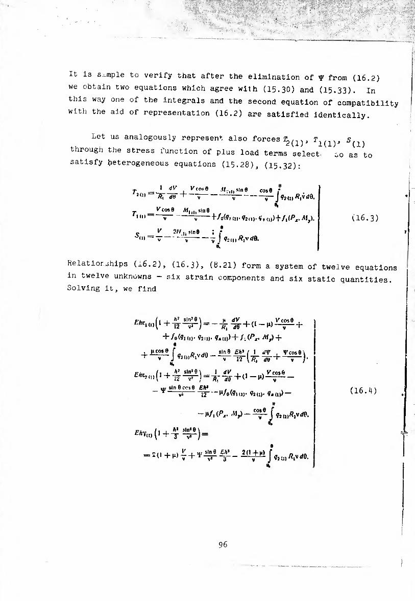
It is s..niple to verify that after the elimination of Y from (16.2)
we obtain two equations which agree with (15.30) and (15.33). In
this way one of the integrals and the second equation of compatibility
with the aid of representation (16.2) are satisfied identically.
Let us analogously represent also forces ^1(1)^ 5(i)
through the stress function of plus load terms select. so as to
satisfy heterogeneous equations (15.28), (15.32):
T _ 1 V'fosO If..,, sin 0 cos0 ,* 'J»> - ÄT rf«- + ---7- J /?,vd0.
T _ Vcos9 sin 0 id) v - ^/0(^1(1,.92(1)-41,1))+/,(^.^,).
S -L 7H"i!n6 ; t d) V V V I 42(1,
i
(16.3)
Relatior ships (x6.2), (I6.3), (8.21) form a system of twelve equations
in twelve unknowns - six strain components and six static quantities.
Solving it, we find
fÄei<n(l 4 h1 slnJ8 \ I* dV i k cos 0 , ) T2 + ——-r
+ Io(9ki). 92(,). 44(1))+/-.(^. ^/) + e
. t „ n..xo sin 0 Eh* [ 1 dV , VcosÔi
V cos ft Pmo fi i Ä slnJ0\ I dV , ,. ^(,,(1+10-^) = ^-^-+(1-)1)
ur sin 0 cos 0 Eh* ^/0(4,(,). 42(,). 44(,)) — 12
-h
cos 0 , _ ~~ J 42(„VrfP. -)1/,(^. .Vf,)
(16.il)
96
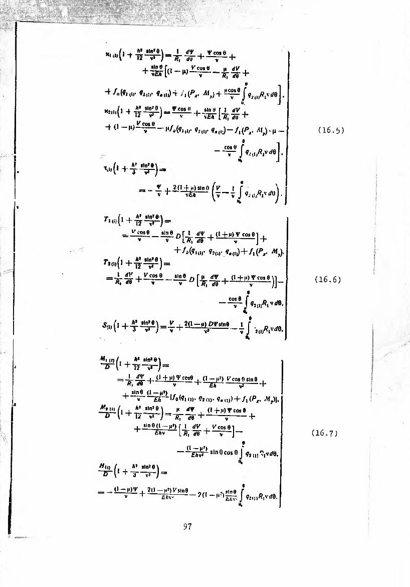
VáKf; jr: ... % ^iffiß$&ßäijRß&■ i ■; >•■' ^ • .' ^ . •■ .-ic-.í■■ííSSí.-ii^r^^-r -.'‘y&tsifc"'r-QÜfö;”r" 5 i'fi/'V. ;c- •A ---—--¿_
■':: -
(^1 tD’ fill)’ ?»<d)T j'i(Px. Aíyj+~*e
» , J ?í(i>^iv<^®j •
-t 0-W y cos O
V ^/(1(01,1,- ?i(!,' ?« <!;) ~ A (^jr- ^íy)’H —
® -,
+T-^) =
_v , 2(1 f ¡Osmo ir _ \ V ■<-\Ei- [ÿ-ÿ J 0,0^^-
T í i i h* sln’O \ r,(,H,+T2—?“) =
+4(»iui' »KU- í.(,0+/i(p,- -«J. r,m(.+^^í) =
O [-J;^-+-íl±tíf^)]-
COS0 ,Vrf0.
j 0Í(D^1
5íI)(, +^i!^)=£+2ib^^e._i J , (iAvde
i
**i (o /, , ** 9ln*0> o l ^ 12
= -1--0+10^cose , (1-|I=) V^cosOslne . V 1 £ã-V1-\
, sin 6 (1-M») ^ V ZÃ l/o(0KI)- 02(|). iWp),
4*
^O./, , ** sin,e\ 1« rfv (i+M)Vcose ( ^ i¿ V» y--«; -dé
■ sin 6(1 — n») r 1 dy t+cosei £*v Lä, dtí ^ ÿ \~
» (I - l£Î) J* -£ÃW-SÍn0cOS°J ÍJdí^Vrftí.
«(,) / A» j|nJ0\
“B“l, + X—j =
_Ü-^M)_y , 2(l->»;)^sln0 0/I , ,i„e T V • £/,v ~?(I J 02,l)^|VrfO.
(16.5)
(16.6)
(16.7)
97
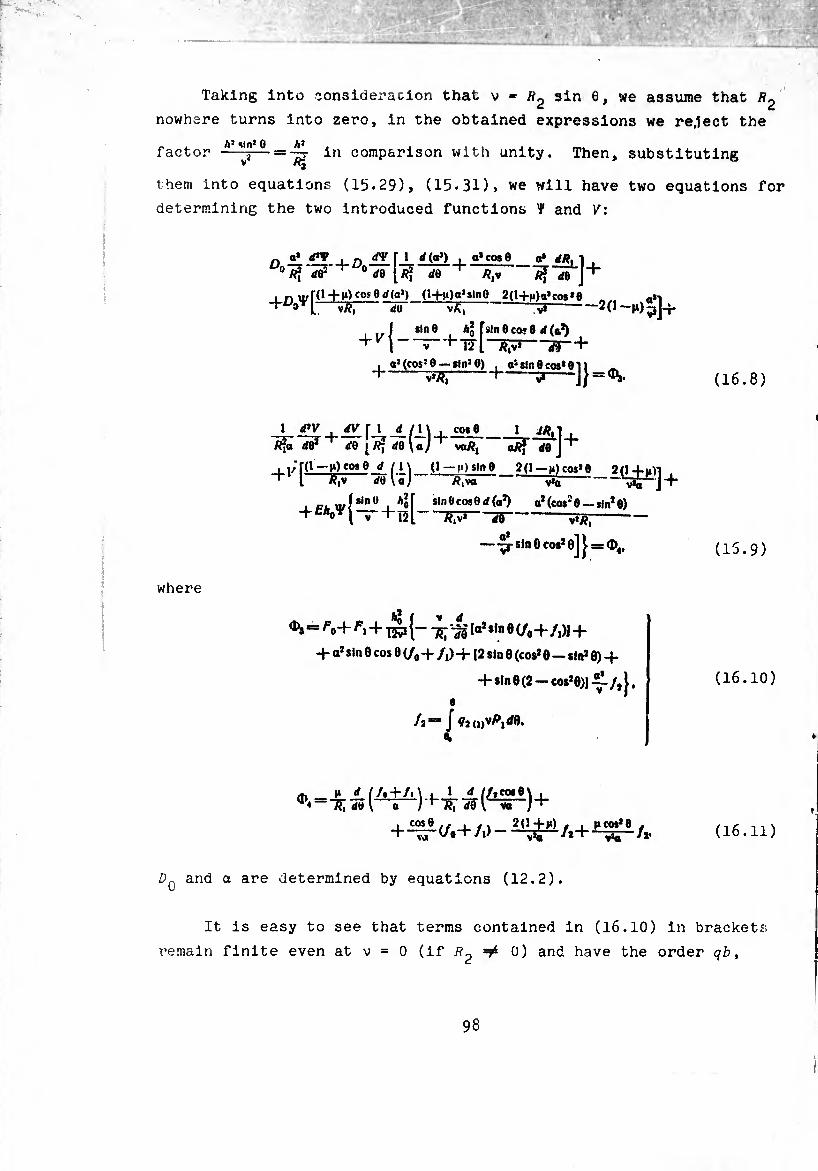
imum
1111
1111
111. ...
hu
iniu
^
...
ip«w
«.<
ji^ mw
...
pin
iiii
uini
iii.m
ppi
Taking into consideración that v = i?2 sin 6, we assume that
nowhere turns into zero, in the obtained expressions we re.lect the
A} «in1 0 A1 factor -j— — in comparison with unity. Then, substituting V Äj
them into equations (15.29), (15.31), we will have two equations for
determining the two introduced functions Ÿ and V:
n 0’ ***_ i n T J_ (a1) , a1 cos 9 0 y?? 'do2' ^ 0 </e [âî de ä,v
I r, \irr(l+l*)fOí0d(aJ) (i-t-M)aJsln0 2(H-n)a,cos*6 .. -n I ^ d5 ^ Iß-2(1-1*)^-
, „ j *me , A* fsln0co<0 d(a*) .
+ V\-— + -d¥~ + . o1(cos10 — «in10)
H-^- o1 sin 0 cos* 01 ) -5*-JJ = ^
1 d»V dV f 1 d /1\ co«8 1 d^-|
de'1 de ^/Î* deloJ“h VOÄ, ^ dej
i i/'ri1—^'0*0 d (l\ ^ [ Äjv deU;'
(1 — n) sin 6_ /?iva
sin 0 cos 0 día1)
+
2(> —>») cos10 2(1 vJa v*a
a,(cosî0 — sin2 9)
v*ÏÏ,
í*]+
w
~slnöcos2ej j. = d),
where
^1=5 ^0+ + la2*«"eC/04-/i)J +
+ a* sin 6 cos 0 (/0 + /,) +12 sin 0 (cos* 0 — sin* 0) + + sin 0 (2-cos*0)]-£/,}.
/2— J ¢2(1)^1^8. 01
to i* rf //«+/. \ , 1 d //,co«e\ , ^ =-s; dê l—i-)+7?r w I vT")+
+^(/0+A>-
D„ and a are determined by equations (12.2).
(16.8)
(15.9)
(16.10)
(16.11)
It is easy to see that terms contained in (16.10) in brackets;
remain finite even at v = 0 (if ^ 0) and have the order qb,
98
------
-.
' ..
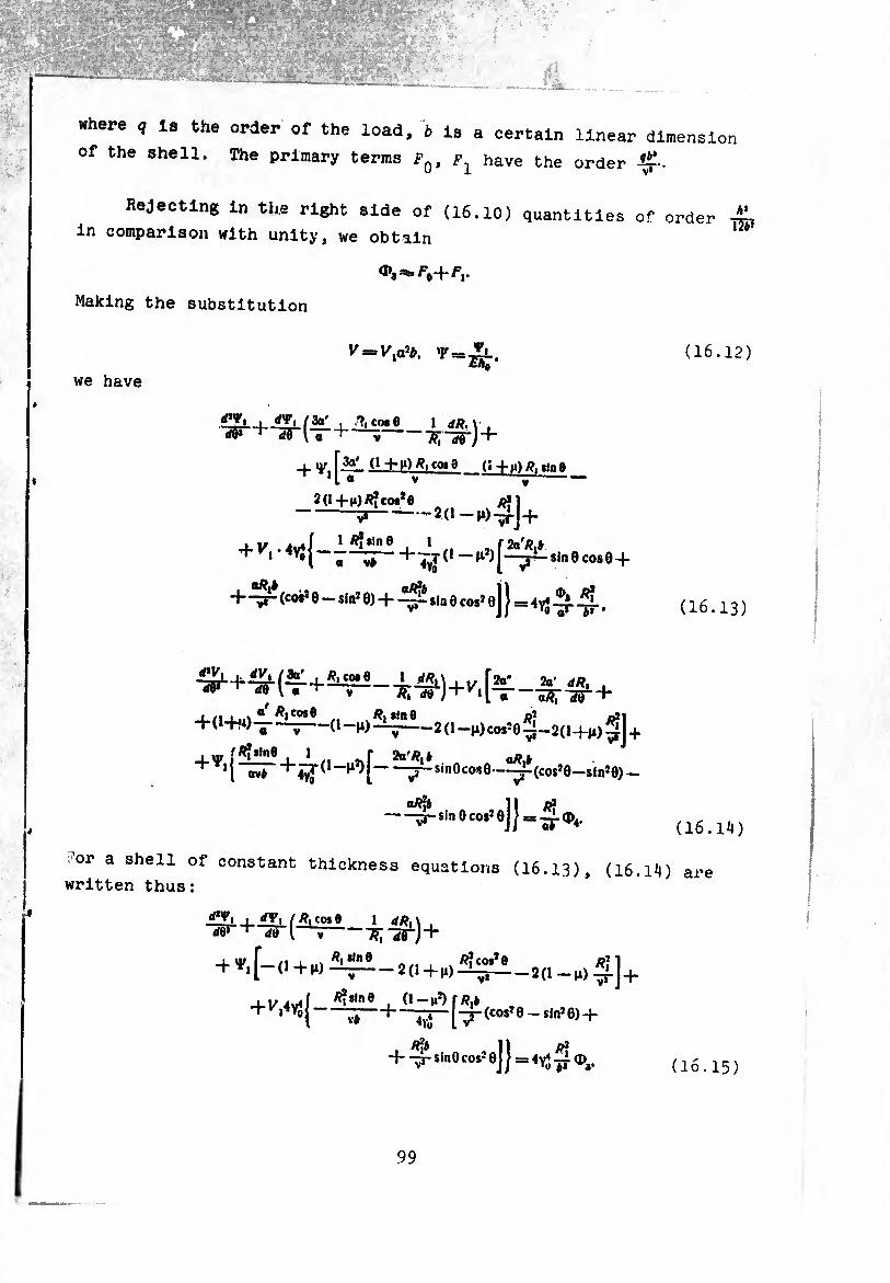
where q is the order of the load, b is a certain linear dimension
of the shell. The primary terms fi have the order i£-.
Rejecting in the right side of (16.10) quantities of order
in comparison with unity, we obtain 12*’
Making the substitution
we have
^ /3a' , ?, C0.8 1 —;- 1
_i_ y [3a* (1 -hn) coi 6 ‘1 « V v
2(l+^)Ä»co#*0 _ -5*---2(1-,»)-^].
_(« +m)>?i sln8 _ _ ..
+ 2(1 ~n) j _j_
J-K .ív4!_1 1 rZa'/^* + i *yo[ B-^—*+-Tvy(,~,i,[~7-8,neco80+
+-^ (coi* e ~ sin* 0) + ^ sla e eos* e] } = 4vJ.
(16.12)
(16.13)
+ + _IÄ4-1/ 2a' dR, , ** ^ v ’S; rfö }+v'r¿—-53T de' +
_l/i i ..\ a/Äico*® .. .Ä,sln0 /î? oil +(1+,i)T~7--2(l-M)cosî09-2(H-n)g] +
fÂÎiln0 1 r aa^j ^ + «vé +4^(I”^[-^-sinOcosO—^-(cos^-sin^)-
oâJj sin 0 cos2 0
(16.1^)
.-'or a shell of constant thickness equations (16.13), (16.14) are written thus:
ä'Vi I rfV, / R, cos o 1 dR
+ *,[-<,+,, 2(1+rt ^i_2(l ^]+
+^{-^+i^[V(co„e_iln!6)+
/}¾ II p2 4- -^r sinO cos2 0j J = 4yJ <I>3. (16.15)
99
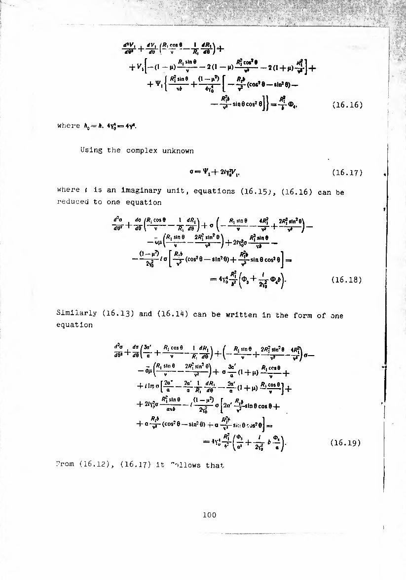
nw dV, ^R, rf>*0 1 dRx' db \ V 7?;4r)+
(cos* 8 —sin* 8)—
where h — h. 4^ = 4^.
Ä?* sin 0 cos2 8 114-. (16.16)
Using the complex unknown
0=^+2^,. (16.17)
where i is an Imaginary unit, equations (16.15.), (16.16) can be
reduced to one equation
d f’o ( do (Rt cos 9 1 , Ä, sin 6 4Ä? . 2/??sln2e\
(tí* ^ </0 \ V ~ÏÏ[ d9 a \ V "t-v3-) — - /«,5100 2«isin20\ «Jsme
-+ -
I-^-(cos28 — sln20)-f —j-sln0cos20 I =*
=^4(^+4^)- (16.18)
Similarly (I6.I3) and (16.14) can be written in the form of one
equation
d7o do 13a' /?, cos 0
(Í0* ' Sil a "f"’ V r,-di)+[-——i— «,510 0 ( 2Rj sln20 4«f
“v*
- («i stn 0 2«?sln!0\ 3c'
-—)+a!T V ., , % «i CCI0 0+^)-^:- +
2Vo
+ a Rtb
a\b
(cos2 0 — sin2 0) 4- a ¿¡b 1 ~j~ Si :• 0 JS2 0J =
'U »- U* + 2>î « J' (16.19)
Trom (16.12), (16.17) it "ollows that
100
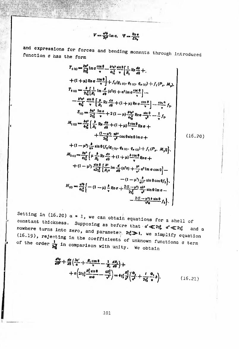
V = %rlmo. V =
and expressions for forces
function o has the fo™ 8
CObO
f . („ - S In, o'-ai - s? "»! rj. s, ^ * «vi V 1«, K ñ5+-
+0 +(i)R«oiaî]+/t(fi(i) ?i() ^
r’"’ ,m M (a’”)+«!i">«~] - _ sin e r u „ ¿a < V [/?, ReH5"f(I + WReoi2~J-
JM,,,,=^{ÍR*$+(1+i‘>íf-,R.« +
, 0-M») a¿» T -^-cos0sin01mo-f
+(1 - s,n 0 I/o d,, ÿî („. gK ,„) + /, (P,. (M,)| J,
+ 0-^-^0 f^.,n)^(a?0)+MaiIni0coso]
~(1-M^^rsinecosO/^,
■M-
(16.20)
v*a
constantithl1k'20) “ = 1’ We oan obtalu equations for a shell of
::::!::\:iokin;;:-Zers:pprs as befcre that - (16.19), rejecting In he“ e o^' ^ S“n
- - order £ In coroparlso„ ““ iT^0"0 °
(! + »2« t R? *in 6
ovÿ
4/?f
(16.21)
101
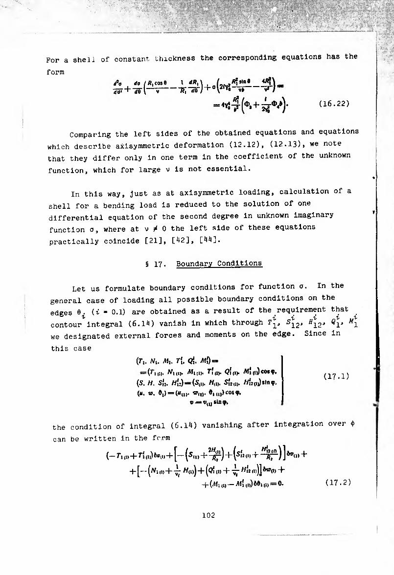
For a shell of constant thickness the corresponding equations has the
form
'Ä'™e
(¢,+ ^/)- (16.22)
rf5«j da I i \ / . sin
Comparing the left sides of the obtained equations and equations
which describe axisymmetric deformation (12.12), (12.13)> we note
that they differ only in one term in the coefficient of the unknown
function, which for large v is not essential.
In this way, just as at axisymmetric loading, calculation of a
shell for a bending load is reduced to the solution of one
differential equation of the second degree in unknown imaginary
function o, where at v / 0 the left side of these equations
practically coincide [21], [^2], [44].
§ 17. Boundary Conditions
Let us formulate boundary conditions for function o. In the
general case of loading all possible boundary conditions on the
edges (t = 0.1) are obtained as a result of the requirement that
contour integral (6.14) vanish in which through Äi2-* ^l-* ?12J "12J *1' we designated external forces and moments on the edge. Since in
this case
(T*,. Ni. ¿1,. Ti, Q[. íMD-
= (7-,,,,. Af,,,,. T"*,,,. <?{„). /Wj(j))cosq>,
(S, H. S,j. /7{;) = (St„. /7,„. 5(2,,,. HU ,iJ sirup,
(li. w, 0,) = («„>. wd)* (»)cos 9* v = sin 9.
(17.1)
the condition of integral (6.14) vanishing after integration over 4>
can be written in the form
(— T”, ,1, + 7-, „)) òu„, 4- [— (^,,, + -t- (5,2 o, -j ßf—) ] *0(„ +
+ [- - (^1 ,i) + ± /7,,,) + ((?{„, -f ^ /7Í2 „,)] ^,,, + 4-(^,,,,— ,„)ftd,,,, = 0. (17.2)
102
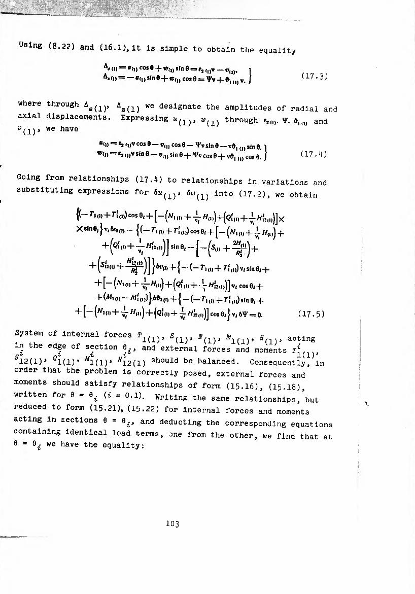
Using (8.22) and (16.1), it is simple to obtain the equality
(1) = «<!) cos e + sin e = r, (l)v -1»(1), 1
A#(i)= +«(,) cosÔ = Vv-(-^1(1)vt / (17.3)
where through Ae(1), Aa(1) we designate the amplitudes of radial and
axial displacements. Expressing u(1), ü(1) through e,V. d,and
(1) we have
#<I) — i„v cos e — r(I) cos 0 — Tv sin 0 — v-0, (I) sin 0.
w(i) = ¾ <i)v sin Ö — v„) sin 0 -f 'Fv cos 0 -f (I) cos 0. ) (17.4)
Going from relationships (17.4) to relationships in variations and
substituting expressions for 6u(1), 6w{1) into (17.2), we obtain
{(- r, (I)+T[ (1)) cos 0,+[- (n, (I)+j- h{1))+(q‘
X sin 0/ J V, 6e2 (I) -1(-7, (1) 4. r{,,,) cos 0, + [— (w,,,, 4- J- /y(1)J 4.
+ (<?i ,i) + «i, („jJ sin 0, _ 4- 4.
+í5»«1» + ^r1)] } 4- { - (- Tt (1, + 7(,,,) Vi sin 0,4-
-j- [— (|, 4- ~//(1)j + ^QÍ(1)4--1- //{2(i,jj V/ cos 0( 4-
+ (AI. (,) - ¿1} ,,,)100, ,,,4-1-(-7, „, 4- ri ,„) Sin 0( 4-
+ [~ (tf ! (D + -^-//(1,) + (<?i 4- //Í2 ,„)] COS 0( } V( = 0. ( 17 • 5 )
System of internal forces T, ,, . £, v jv m u 1(1)> ¿(i)> wi(i)> acting
in the edge of section +, and external forces and moments
512(1)» Çl(l)» ^1(1)» ffi2(l) should be balanced. Consequently, in
order that the problem is correctly posed, external forces and
moments should satisfy relationships of form (15.I6), (15.18),
written for 6 » (7 = 0.1). Writing the same relationships, but
reduced to form (15.21), (15.22) for internal forces and moments
acting in sections 0 = e¿, and deducting the corresponding equations
containing identical load terms, one from the other, we find that at
0 = 0£ we have the equality:
103
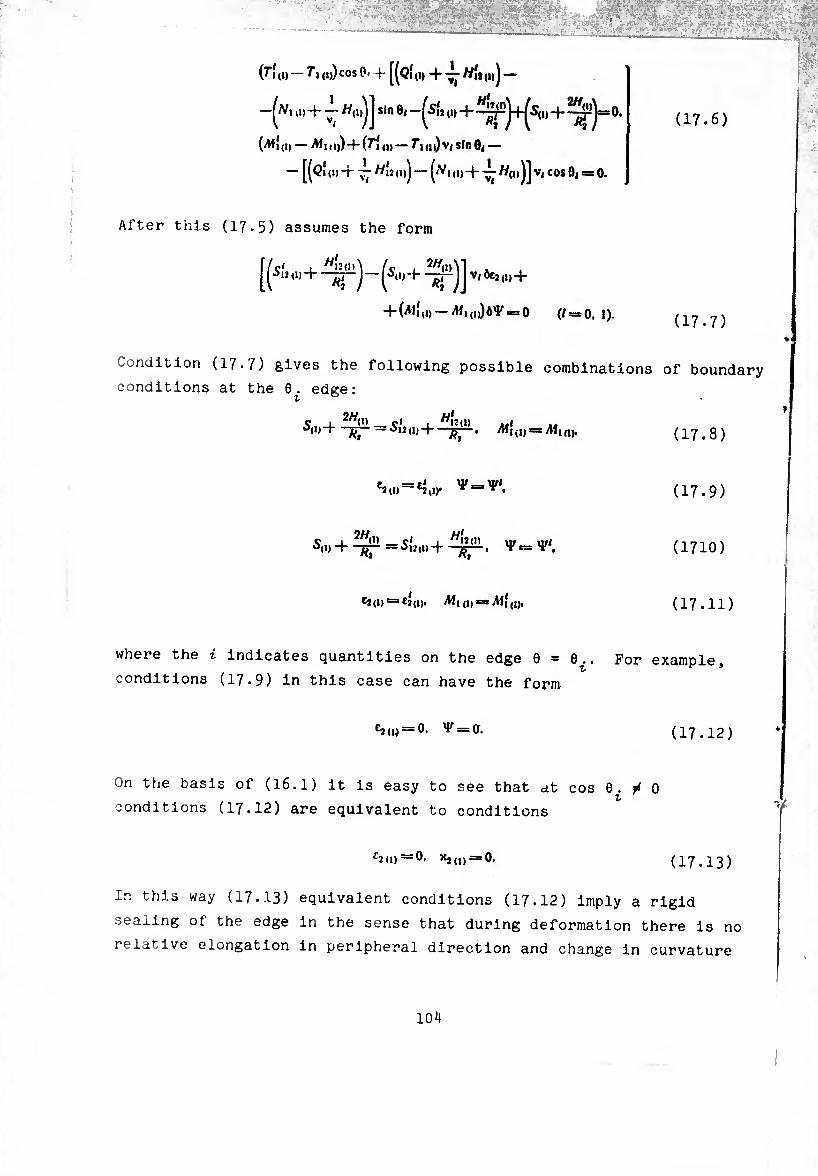
(17.6)
(7l(i) —<i)) cos 0< ^[(¢1(1) + -^-7/11,^1-
—^i d) + — 7/(i)jJ sin 0, -^5(2 (i) —^j+^5,1, -f- ^-'1=0.
(^♦í (i) — >W i, i)) -f- (Tl ,i) — 71] (d) V( stn 0, —
— [(Qi (i) + ~ Hu djj — ((V, (D -f- J- 7/(i) jj V( cos 0( « 0.
After this (17.5) assumes the form
[(5Í2 (,,+ -^j-(5,,,-f ^^,062,1) +
+ 0^1(1) — AíiiuJô^scsO (/=*0,1). (17.7)
Condition (17.7) gives the following possible combinations of boundary
conditions at the 0. edge:
Ç. J_ _ C< i 7/(2,1) „( ^+-^=¿12,1,+ -^-. .Mi(„ = yM,„v (17.8)
C2(t) —£2,1). ^
ç i ^7/,1) _çt t //12 (i) iff/ ^11)+-^-=^^0)-1-YssT*.
*2(1) = *2(1). Afi(i,=: Al}(„,
(17.9)
(1710)
(17.11)
where the i Indicates quantities on the edge 9 — 0.. For example,
conditions (17.9) in this case can have the form
*2 (1) = 0. v = 0. (17.12)
On the basis of (I6.I) it is easy to see that at cos 0./0 z
conditions (17.12) are equivalent to conditions
C2(l)—0, X2,,) = 0. (17.13)
In this way (17.13) equivalent conditions (17.12) imply a rigid
sealing of the edge in the sense that during deformation there is no
relative elongation in peripheral direction and change in curvature
104
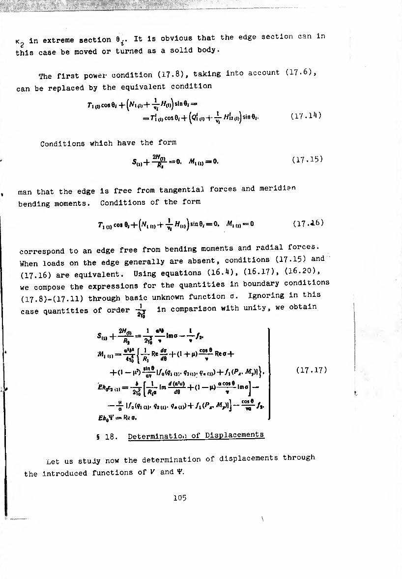
K in extreme section 0.. It is obvious that the edge section can in 2 ^
this case be moved or turned as a solid body.
The first power condition (17.8), taking into account (17-6),
can be replaced by the equivalent condition
Ti („ cos 8, + (^, + Jj- «(u) sin 8, =
= T\ (i) cos 0/ -)- ^Qi (i) -)•• — H12 (i)j sin 8|. ( 1 /. 1 ^ )
Conditions which have the form
5,,,+ ^2.=0. «„„=0. (17*15)
man that the edge is free from tangential forces and meridian
bending moments. Conditions of the form
7,u) cos 8| + (tf,+ «(,>)sin8, = 0. ^1(1) = 0 (17 .A6)
correspond to an edge free from bending moments and radial forces.
When loads on the edge generally are absent, conditions (17.15) and
(17.16) are equivalent. Using equations (16.4), (16.17), (16.20),
we compose the expressions for the quantities in boundary conditions
(17.8)-(17.11) through basic unknown function 0. Ignoring in this
case quantities of order in comparison with unity, we obtain
‘»(D
A*.«.)
2//.,, 1 0«* . )-dlL ——imo-
"2^ Rf *Y0
a*¿* f 1
■/*•
( “¿T "tr 4“ 0 +11) Re 0 -|-
+ (1 —1‘*)—l/o(7i(i)-?2(i>. ^(1))+/1(^1 Af,)]!.
]- = f-i-lm ^!îi + (1 _o
¡7 l/o(?l (1)' ?2 (1)' ?» (1))+ /1 (^,. A1j,)lJ w /j.
EhaV = Re 0.
(17.17)
§ 18. Determination of Displacements
net us study now the determination of displacements through
the introduced functions of V and

On the basis of the fourth relationship of (15.26) we determine
angle of notation ^ °"e ^adratnre
t
<0 =23 — J ^lxJ (I) +D1* (18.1)
where k,n - known function of V and Y (see (16.5)), ^ " constant
of integration. After defining 0UI) of the amplitude of axial
displacement As(1) easily is found using the second equation of
(17.3)
Ai(I) = v^-J/?,»», +Div- (18.2)
Excluding from the second and third relationships of (15-26) dis¬
placement vn), we find the expression for av(l>
dQ through Yu). «íu). (!)•
which are already known functions of V' and
1 dv
whence by one integration we determine
AXJ1)SSne (3 8.3)
nn 'f«i(Yu,+«*<»)cos 0 “ &i<1'7~~)d0 + °2 (18.4)
on the basis of (17-3) we find the amplitude of radial displacement
\ (0 = ve2 (I) - J (yu> +¾ (»>c0* 6 " ^T“) dQ ~ Dr
Thus, as a result of integration of a basic system of the eighth
degree (8.20), (8.25) at fe = 1 the solution contains eight arbitrary
constants. Two of them (Px and M ) have the sense of total shearing
force and bending moment in section 60, two (£^, D2) appear during
determination of displacements with respect to the found functions o
V and Ÿ. The remaining four enter the solution of equation (1 .21)
and should be determined according to boundary conditions of form
(17.8)-(17.11).
106
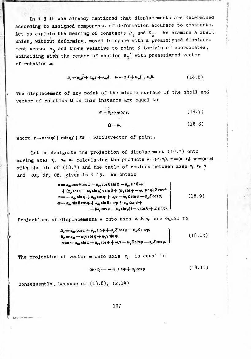
i iiiiuiiü
In § 3 it was alreaay mentioned that displacements are determined
according to assigned components o^ deformation accurate to constants.
Let us explain the meaning of constants and We examine a shell
which, without deforming, moved in space with a preassigned displace¬
ment vector Uq and turns relative to point 0 (origin oí coordinates,
coinciding with the center of section 0O) with preassigned vector
of rotation «•:
u0^=«oJ-t “oyj + u^k. a> = <û,l-fwy./-+<»,*• (18.6)
The displacement of any point of the middle surface of the shell and
vector of rotation Q in this instance are equal to
B °o • X f. ( 18.7 )
Q = c», ( 18.8 )
where r=vcos(p/+vsintf</-fZ*— radiusvector of point.
Let us designate the projection of displacement (18.7) onto
moving axes ». calculating the products « —(« t,). v = (« • tj). = (b • »)
with the aid of (18.7) and the table of cosines between axes t,. t,. a
and OX, OY, OZ, given in § 15. We obtain
B==H<uC0S®C0S<P -4- **oy cos 6 sin <p - j/q, sin 0-)-- -)- (oy cos sin ç) V sin 0 -) (öy cos — a* sin q*) Z cos 0.
® = — «(j, sin ç a0y cos ç -)- — <o,Z sin q> — w^Z cos ç.
* = sin 0 cos q)-)-fl0y sin 0 sin q>-)-«o, cos 0-)-
-)- (o), cos q> — a,, sin q>) (— V cos 0 -f- Z sin 0).
(18.9)
Projections of displacements « onto axes e, k, t, are equal to
A, — Um cos <p 4- B0y sin ç -)- ayZ cos <p — a^Z sin <p.
A, = Bq, — ayv cos q> -)- axv sin <p.
t» = — Bar sin Ç 4 B0y cos ç 4 wjv — sin «p — axZ cos <p.
The projection of vector © onto axis r2 is equal to
(a • tj) = — ax sin ç -)- ay cos <p
(18.10)
(18.11)
consequently, because of (18.8), (2.14)
107
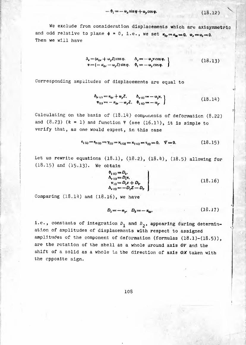
—ü)xsin<p-fwycos<j>. (18.12)
We exclude from consideration displacements which are axisymmetric
and odd relative to plane <f> = 0, i.e., we set «o, = «o, = 0. 0, = 0, = 0.
Then we will have
= (“w •+ cos ‘P* Ax = —o>yvcos«p. 1 t> = (— «(j, — oyZ) $ln <f. ö, = —oy cos <p. J
(18.13)
Corresponding amplitudes of displacements are equal to
Ar(H = «ar-f-V- 1 (18.14)
Calculating on the basis of (18.14) components of deformation (8.22)
and (8.23) (k = 1) and function f (see (16.1)), it is simple to
verify that, as one would expect, in this case
^0) *2 (1) ~ Y(l) = *1 (1) = *2 (I) = T(,) = 0. ^ = 0. (18.15)
Let us rewrite equations (I8.I), (18.2), (18.4)
(I8.I5) and (15.13). We obtain
io = IV A* to = °iv> Vil)** Dig + Dr
A«(i)at—^1^ — D*
Comparing (18.14) and (I8.I6), we have
(18.5) allowing for
(18.16)
0,= -O,. (18.17)
i.e., constants of integration and D^, appearing during determin¬
ation of amplitudes of displacements with respect to assigned
amplitudes of the component of deformation (formulas (18.1)-(18.5)),
are the rotation of the shell as a whole around axis OK and the
shift of a solid as a whole In the direction of axis OX taken with
the opposite sign.
i
*7
108
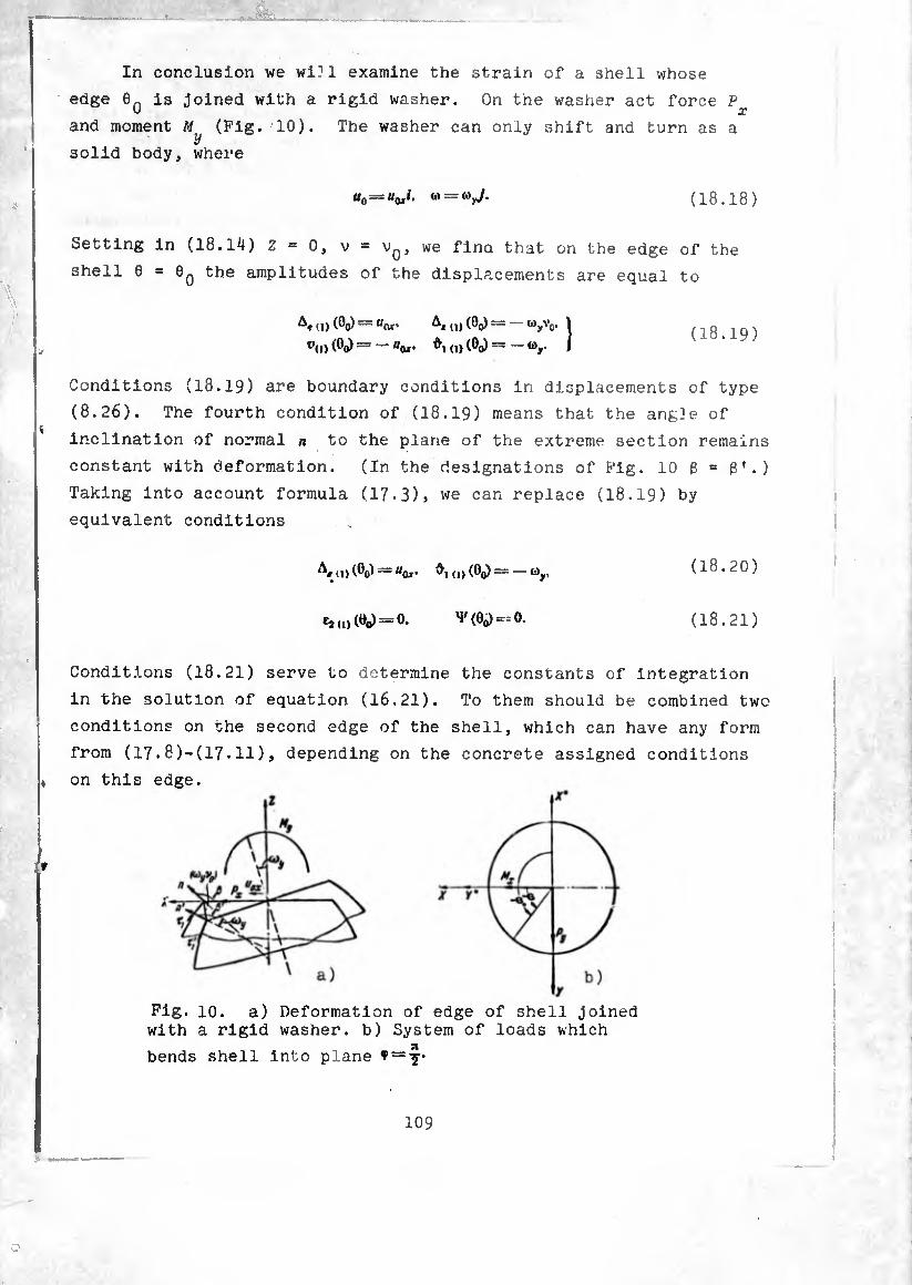
In conclusion we wi?! examine the strain of a shell whose
edge 0n is joined with a rigid washer. On the washer act force P
and moment M (Fig. 10). The washer can only shift and turn as a y
solid body, where
= “ax1' = ‘V- (18.18)
Setting in (18.14) Z = 0, v = we fino that on the edge of the
shell 0 = 0Q the amplitudes of the displacements are equal to
id (0O) — ui ax'
7(i) <0o) = ^OlT '
* a) (0o) —
I (O (0o)
= - <V’o- 1 = -0),. J
(18.19)
Conditions (18.19) are boundary conditions in displacements of type
(8.26). The fourth condition of (18.19) means that the angle of
inclination of normal n to the plane of the extreme section remains
constant with deformation. (In the designations of Fig. 10 ß = ß’.)
Taking into account formula (17.3), we can replace (18.19) by
equivalent conditions
(1) (0(>) UQjr’ 0( 0)(0())-wy.
^0)(00) = 0- v (00)==0-
(18.20)
(18.21)
Conditions (18.21) serve to determine the constants of integration
in the solution of equation (16.21). To them should be combined two
conditions on the second edge of the shell, which can have any form
from (17.8)-(17.11), depending on the concrete assigned conditions
on this edge.
Fig. 10. a) Deformation of edge of shell joined with a rigid washer, b) System of loads which
bends shell into plane ^ =
109
Let the second edge of the shell 0 = be sealed into a rigid
wall, i.e., it remains motionless and not deformable. For simplicity
it can be considered that there are no distributed loads on the
shell. The shell is an overhang loaded by an assigned force and
moment F , M . It is necessary to designate shift and rotation
U Ü) of edge 0 . On edge 0 = 0, we have conditions in displacements: Ox’ y 0‘ t
A,(.»(Öl)“0- A.0)(0.)-O- \ (18.22) V,.) (0.) = 0- O.i.) (0.) = 0- )
On the basis of formulas (17-3) they can be replaced by the equivalent ,
conditions :
A, (0 (0.) = 0- 0. <» (0.) - °-
e, ,,)(0,) = 0- ^(0,) = 0-
Conditions (18.21), (18.24) serve for determining of constants
of integration in the general solution of equations of Meissner (type
equations (16.13), (16.14) or equation (16.21)). Since these
constants have been defined and the solution of equation (16.21)
satisfying assigned boundary conditions has been constructed, we
can consider as known all components of deformation *,(,)• **<,>• Y,»•*,,„• *2<,)•
x(1) and the function of Y in any section of the shell. Let us
remember that they linearly depend on loads Pj. My. assigned on the
edge, since the right side of (16.21) is a linear function of these
quantities. Conditions (18.20) serve for determination of constants
of integration £>2, figuring in equations (I8.I), (18*5).
Setting 0 = 0Q, we find
D, =3 — or 'D2 =» — «o,. (I8.25)
i.e., constants Z?1, Z>2 are the desired unknowns. We require now
the execution of conditions (18.23). Setting in (I8.I), (18.5) 6 = Q1
and taking into account (18.2), (18.25), we obtain
(18.23)
(18.24)
J Ä,X, u) ¢/6 4-0), = 0.
v¿5 „) (ö,) - J [y,d + ¾ (1) cos Ö - 'Ir sin 0 4- e.
4- sin G j /?, xt (1) dû 4- o), sin 0 /?, dG -f- = 0. e. J
(18.26)
From (18.26) we find
wy — — J Rfà (1) 8l e,
"ox = ®y J ^1sin 0 dG — vej (1) (G,) 4- e e, 9
+ J V(i)4_e2 (j) cos 6—'F sin G-j-sin G J ^x, ()) dG /?, e, L e, J
d0.
(18.27)
The case of a rigidly sealed edge loaded by force P and with moment y * *
M is considered analogously. Really , introducing new axes OX , OY
(Fig. 10b), we find
p\--=-py. m;=
"Ox V wy = ®x
and all previous arguments are repeated in curvilinear coordinates
0, (j> , whereupon we can return to previous coordinates 0. <p = ^4^-5-)-
111

§ 19. Character of the Stressed State of a Shell During Ax 1 symmetric and ken'dlng Leads
In §§12 and 16 of this chapter It was shown that the problem
about the equilibrium of a shell which undergoes to action of non
self-balancing loads reduces to the solution of the equation
(19.1)
during axisymmetric loading and the equation
¿ (o)-l-2«Y5 ffjsme iR\
b\a 0 — I s[< ¢3(0) R*
(19.2)
during a bending load, where
¿(0): d*o , do /?, cos 0 V
_L dRt\ R, d6 )'
(19.3)
‘î’i. ‘Î'î and are known functions of the load and can be cal¬
culated according to formulas (11.11), (I6.IO), (I6.II) a = —
relative thickness of shell, b - certain characteristic dimension
of shell (for example, b can be the radius of curvature in extreme
section ÆÎ or /$•
2yS=1/12(1-h*>-£. (19.4)
- large parameter.
The left sides of equations (19.1) and (19.2) differ from
another in only one term In the coefficient of unknown function a,
which has no essential value if v=jfeO and parameter 2y* is great in
comparison with unity.
112

The general solution of equation (19.1) or (19.2) Is made up
from the general solution of the corresponding uniform equation and
a certain particular solution of an equation with a non-zero right
~ide. Let us show that in certain cases the particular solution of
these equations can be the approximate solution of the initial system
of equations of the theory of snells, the so-called solution to the
zero-moment" theory. In calculation from the zero-moment theory
it is assumed that amounts Mjb. M2¡b, H/b, Nv N2 are small in comparison
with forces T^, and S and in accordance with this in equations of
statics (^.22) they are dropped. "Zero-moment" forces T?t S
depend on three simplified equations (4.22). By the found forces
with the aid of three elasticity relationships (15.17) deformations
£,. e,. Y. are determined, then integration the first three relation¬
ships of (3.19) to the displacements which correspond to the zero-
moment state. The zero-moment theory of shells and questions connected
with the satisfaction of boundary conditions within the framework of
this theory have been comprehensively examined in monograph [5].
We will stop first on constructing a particular solution to
equation ( ^9.1). We look for it in the form of a series in degrees
1. (or, which is the same, in degrees A®. [12] 2v* b
(w.s)
Substituting (19.5) into (19.1) and equating terms with identical quantities 1/2yJ, we obtain
0,« = 2Y’{c
¢,(9) b sin 6
«g*e
«» ’
1>,(fl) va va K] sin»
1 r rf / ¢,
MM?) 1 _ [ sin da5 J (19.6)
etc.
113
\
Since in deriving resolvent equations (19.1), (19.2) terms of
degree ha'b in comparison with unity were dropped, then in developing
a solution it is natural to be limited to the same correctness. In
this way, the particular solution of (19.1) can be taken in the form
(19.7)
Tne particular solution of equation (19.2), constructed analogously
has the form of
(19.8)
It is necessary, however, to emphasize that in dropping small
terms in the course of deriving equations(19.1), (19.2), and also in
developing a particular solution, one ought to see that the dropped
terms nowhere turn into infinity, as happens at y = 0 or sin 6=0.
Because of this the constructed particular solutions are adequate
only in the vicinity of the change of 0, rather far from points
0 = 0, or y = 0. By formulas §§ 12 and 16 we will find the forces
and moments which correspond to particular solutions (19.7), (19.8).
For and axisymmetrically loaded shell on the basis of (19.7)
and (12.11) we have
(19.9)
Ny = /Mj — /Mj = 0.
The stressed state corresponding to particular solution (19.7) is
zero-moment — shear forces and bending moments in the shell are
equal to zero. By a direct check one can ascertain that forces
(19.9) satisfy equations of equilibrium of the zeio-moment theory,
»hich are derived from formulas (11.1) at = ThereiuI.e
subsequently particular solution (19.7) will be called the zero- ‘
moment solution, a- i forces (19.9) are the forces found from zero- moment theory.
force"ster a bendlne l0ad by <19’8> and (16'M) We tbe following
^ ~ OT (^o+^i) + C/o 4- /,).
■p _ V COS 0
T5T53T (^0+- Jf—rg (/.+/,) (19.10)
where ^'’e/e/../, are functions of the external load, designated bv formulas (15.30), (15.35), (16.10), designated by
If we calculate according to formulas (16.20) and (19 8) (IK m moments and forces« « ' (1+0),(14.4)
md* ™2<\)* then we obtain, ß:eneral"l\; speaking, quantities differing from zero, but small: having the
order of ^ of forces multiplied by dimension 2, for moments, and
the order of of forces for shear forces. Therefore at the sub¬
stitution of the obtained expressions into equilibrium equations the quantities should be droppe<J lp com_
parison „ith the corresponding terms containing 7-,,,,. f,,,,. 5,,,. Substi.
ng forces (19.10) into equations (15.28), (15.29) and the third
veri y°that h = „e verify that they are satisfied. This implies that the basic equilib-
; r,:rr °f Zer0"n0,nent the0ry’ Whl°h are drived from system ( .3) in the absence of moments and shear forces, are satisfied also.
to no ft n°u t0 the SOlUtlon ro the unlforr" equation which corresponds o (19.1). We need to transform this equation to the form
jzr + /(x)x = o.

which makes possible the application of several asymptotic methods
of integration [4?], [45], [12]. Let us replace the independent
variable
(19.11)
Having in view that
<¡*0
</0*
da _ da dx da I?,
¿0 ~ dx dO dx ŸT
dó d^x d^a sln0
/?•
dx dO* dx* »
da d
va dx dó
we derive the equation
d*o
d¿ da td'x . /3a' , Ä.cosO dR,\ dx I fcva ,
dd ) rfoj sln0 ^
-f 2¿Y?o — ftacos*e vsInO
0.
It is known that in an equation of the second degree by a special
replacement of variables it is always possible for the coefficient
of the first derivative to turn into zero, for example, setting
0== TO,
where t - new unknown function. Taking into account that
da dx , du d'à _ d*x . „ iT.^r- 1-=-« + T-57. -dZ-'d*u + 2dxdx+xdx*
dx du <Pu
;,‘ay
116
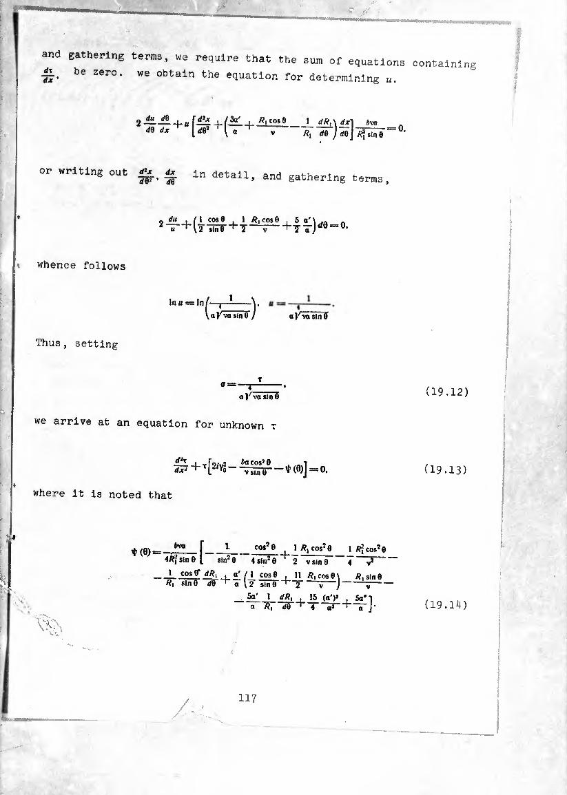
and gathering terms, we require that the sum of equations
77- be Zero- we obtain the aquation for determining
_ </U (/0 2 —-|_H dO dx -(-
R, cos 0 1 dR, \ dx") bva
Ä, do ) daj-^Tiñe^ ‘
or writing out ^ dx dO1 ’ 1Õ in detail, and gathering terms.
o 11,1 i 11 cos A u ' \2 sin0
1 cos 0 J—— +4^)^0 = 0.
whence follows
Inu = In t-r1—} \aKvasin0 / a)Avã sin0
Thus, setting
al^vâsïïTS
we arrive at an equation for unknown t
S+T[2^-(0)]=o.
where it is noted that
t(0) = M'a
4/?jsin0 [ sin2 0 4 sln20
i cos 0* <//?, ^a' (l cos 0 R, sln0 sin0 “’"T
_ 5a' 1 dR¡ , " R, dO ‘
cos2© 1/?, cos20 1 fl2cos2e
2 V sin 0
11 R, cos 0 j
15 (a')*
Ri sin 0
containing
(19.12)
(19.13)
(19.1^)
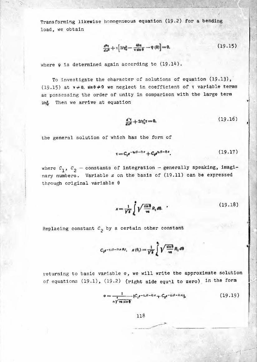
transforming likewise homogeneous equation (19.2) for a bending -
load, we obtain
(19.15)
where is determined again according to (19.1*0.
To investigate the character of solutions of equation (19.13),
(19.15) at V =#0. sin0^O we neglect in coefficient of x variable terms
as possessing the order of unity in comparison with the large term
2/Yq- Then we arrive at equation
(19.16)
the general solution of which has the form of
(19.17)
where - constants of integration - generally speaking, imagi¬
nary numbers. Variable x on the basis of (19.11) can be expressed
through original variable 0
(19.18)
Replacing constant by a certain other constant
returning to basic variable 0, we will write the approximate solution
of equations (19.1), (19.2) (right side equal to zero) To™
0 = (19.19)
118
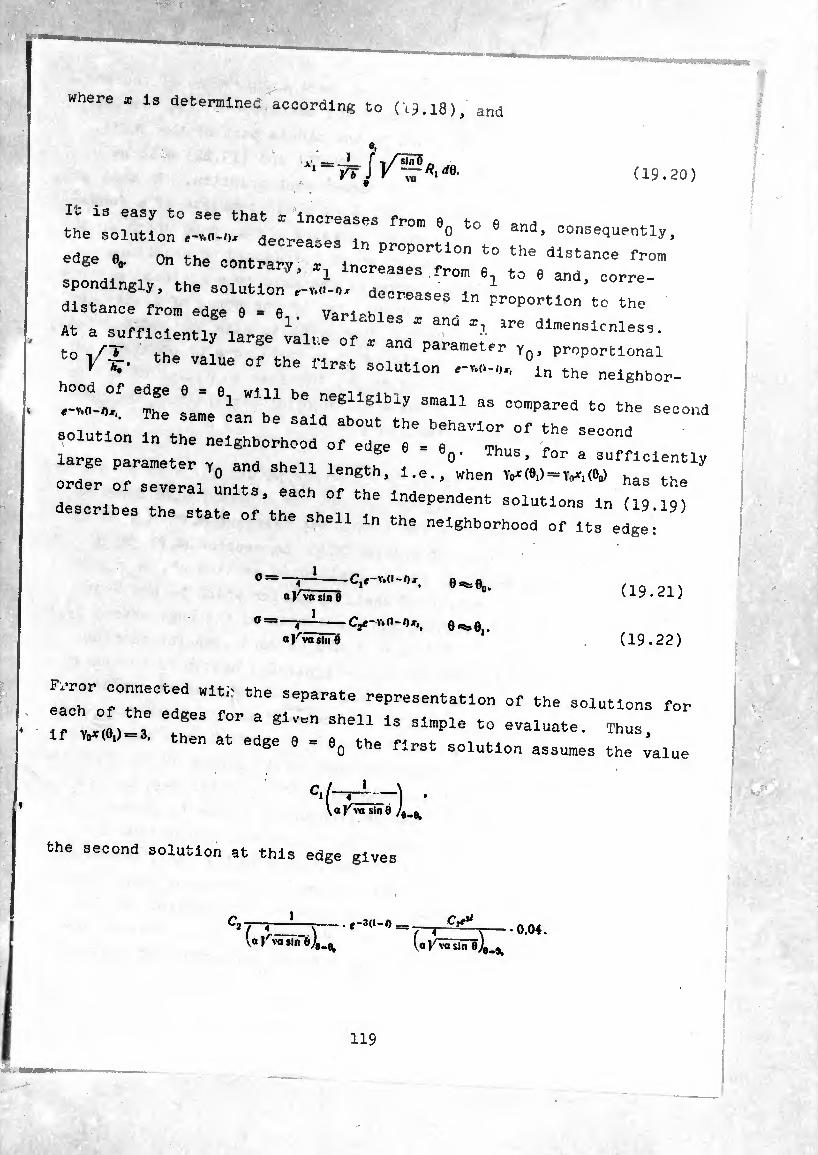
where a is determined according to (c9.l8). and
Vb /V? (19.20)
It is easy to see that * increases from 0 to 0 the solution decrees . ° ’ COnSe^^tly, edge e On th* , deCrea"es in Proportion to the distance from edge 0, On the contrary, *1 increases .from 6, to 6 and corre¬
spondingly, the solution e-v.o-o* decreases in
«stance from edge e = e, . Variables ! aL FrOPOrtl0n t0 the
At a sufficiently large íalue of'And . to * the vai e +- parameter y^, proportional
V V the val- «>e first solution °in the nelghbor,
At,0/ eTe Lt1 Wlbn be negllEibly s”a11 a= spared to the second
-ution At^eXhAAAtr/r^ur rseoond large parameter y0 and shell length, i.e./when
des^ih T™' UnitS, eaCh °f the indePeodent solutions in (19 19) describes the state of the shell in the neighborhood of its edge
4 a J' va sin 0
Cjí-Vsd-Ox 9<^e
— -C2g-Y.(l-0x,, eess0i «Kva sin e
(19.21)
(19.22)
lA/rrr Wl/ the Separate rePrdeentatlon of the solutions for
if »Ait T Ta given 3he11 ls slraple tu evaiuata- Th-. W ' thSn at edSe 0 = 90 ttla «’’at solution assumes the value
C, l~^~~-) * VoKw sin 0 /# »
the second solution at this edge gives
C’ rjrzrr— ■ = T-rC'\ - ■ 0.04. V« rva sin o)9mBt (a KÂTê], .
119
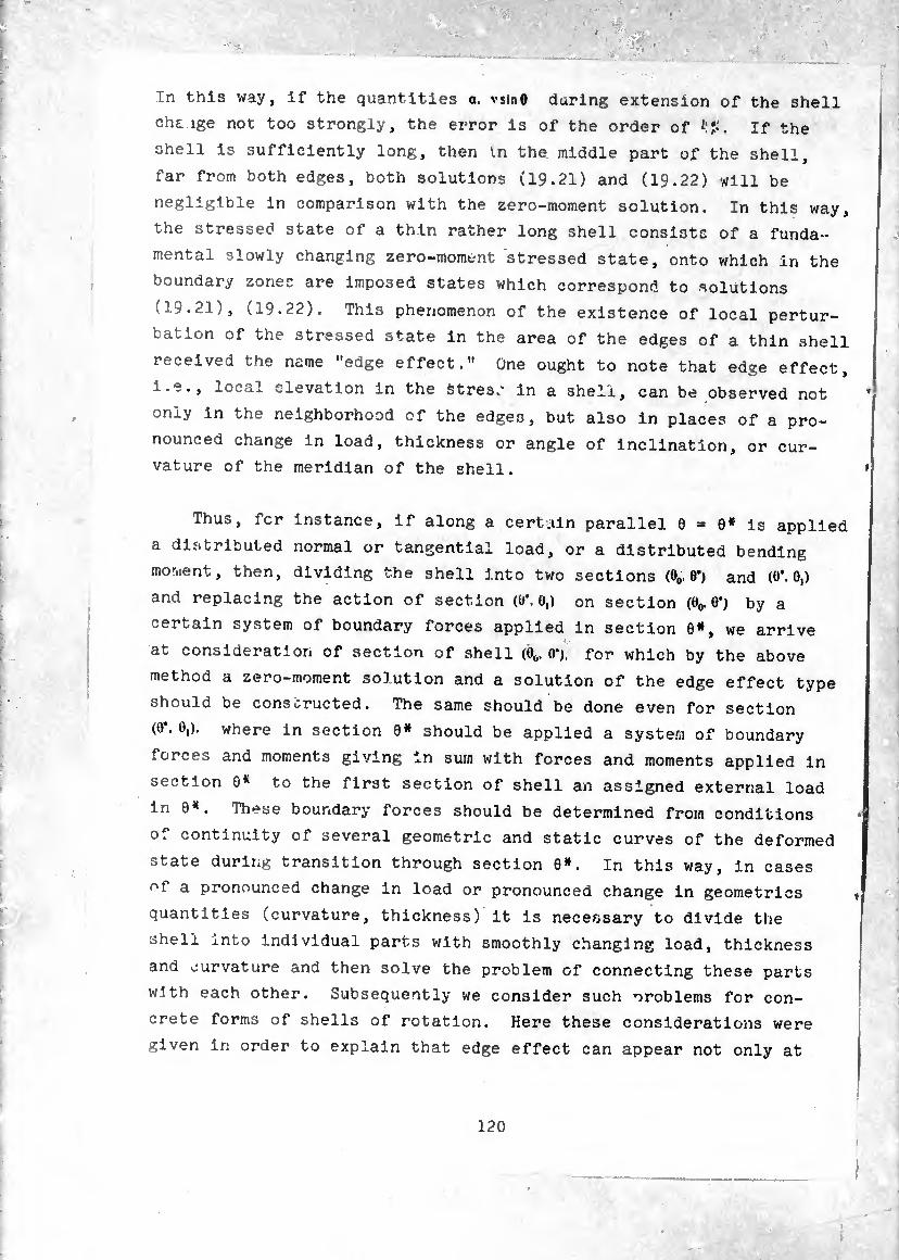
In this way, if the quantities a. vsinö daring extension of the shell
chE. ige not too strongly, the error is of the order of il?. If the
shell is sufficiently long, then in the middle part of the shell,
far from both edges, both solutions (19.21) and (19.22) will be
negligible in comparison with the zero-moment solution. In this way,
the stressed state of a thin rather long shell consists of a funda¬
mental slowly changing zero-moment stressed state, onto which in the
boundary zones are imposed states which correspond to solutions
(19.21), (19.22). This phenomenon of the existence of local pertur¬
bation of the stressed state in the area of the edges of a thin shell
received the name "edge effect." One ought to note that edge effect,
i.e., local elevation in the stress in a shell, can be observed not
only in the neighborhood of the edges, but also in places of a pro¬
nounced change in load, thickness or angle of inclination, or cur¬
vature of the meridian of the shell.
Thus, fer instance, if along a certain parallel 0 = 6# is applied
a distributed normal or tangential load, or a distributed bending
moment, then, dividing the shell into two sections (00.6*) and (O’. 0,)
and replacing the action of section (0*. 0,) on section (e0. O’) by a
certain system of boundary forces applied In section 6», we arrive
at consideration of section of shell (0o. O'), for which by the above
method a zero-moment solution and a solution of the edge effect type
should be conscructed. The same should be done even for section
(0*. 0,). where in section 0# should be applied a system of boundary
forces and moments giving In sum with forces and moments applied in
section 0* to the first section of shell an assigned external load
in 0*. These boundary forces should be determined from conditions
of continuity of several geometric and static curves of the deformed
state during transition through section 0*. In this way. In cases
of a pronounced change in load or pronounced change in geometries
quantities (curvature, thickness) it is necessary to divide the
shell into individual parts with smoothly changing load, thickness
and curvature and then solve the problem of connecting these parts
with each other. Subsequently we consider such oroblems for con¬
crete forms of shells of rotation. Here these considerations were
given in order to explain that edge effect can appear not only at
120

the edge as such, but also In places of a pronounced change in load
or geometric curves of the shell.
§ 20. Temperature Stresses. Formulation of the Problem
In a shell a stressed state can arise not only from the influence
of external forces, but also as a result of nonuniform distribution of
temperature. Let us assume that there are no external loads, and
edge of the shell can freely move. Because of nonuniform heating
individual elements of the shell tend to broaden also unevenly, and
since they are interconnected, in the shell appears a stressed state.
Forces and moments statically equivalent to this internal stressed
< state satisfy uniform equilibrium equations. Forces and moments at
the edges of the shell are equal to zero. In this case the zero
stressed state (7, = ^ = 5=^1, = ^^ = // = 0.1 is statically possible, i.e.,
satisfies equilibrium equations and power boundary conditions. But
it can be realized only for definite conditions imposed on temperature
distribution. To determine a non-zero internal stressed state it
is necessary to add physical and geometric relationships to the
equations of equilibrium.
Total relative elongations of elements of an elastic body are
made up of temperature elongations and elongations connected with
internal stress by Hooke's law [39]. Components of deformation are
expressed through displacements by the usual method. Taking these
positions, we need to write out the total system of equations
describing the deformation of a shell during nonuniform temperature
distribution.
We assume that with respect to the thickness of the wall tem¬
perature changes linearly, i.e.
*(0. ?) == (0.?)+ jA/(0, q>), (20.1)
where C- - distance from middle surface, read along the normal, tm
— average temperature of wall. A/ — drop in temperature with respect
121

to depth. If we designate temperature of the external (t = + A/2)
and internal (C = -A/2) surfaces of the shell through and r. then
A/^f+-r. (20.2)
The components of deformation of an element of the shell lying on
layer t = const, are equal to
*i = («i — >«4) + ß*.
» = (20 3)
here ß - coefficient of linear temperature expansion. It is a physical
constant of the material from which the shell is made. Solving
equation (20.3) in «r <h- V». we obtain
°i = -H I‘'î - (•-f J»)
^ = (20.^)
Ignoring In equations (3.13), (3.18) the quantities £ and £ In
comparison with unity, we find that elongations and shear In Surface
points ( = cons! are expressed through components of deformation of
the middle surface In the following manner:
*1= ei ~r C54!* ^ = + 1
ci = Y + ;2t. ) (20.5)
Substituting expressions (20.5) Into formulas (20.lt) and using
simplified expressions to calculate forces and bending moments (In
formulas (4.5), Just as In (3.13), we can neglect quantities of
the order of i'S, and Cm, In comparison with unity), we obtain
122
I«,-Hlie, —(I H-n)pr|. ^ Ie*-h M*, — (1 +-11)^].
[x, +-J1XJ — (1 +n)p^.j>
^«Oh + Mx.-O -+-jx)p^.],
H = D(\ —h)t,
where we have introduced the designations
(20.6)
(20.7)
Components of deformation of the middle surface are connected with
displacements u, v, w by the formulas (3.19). Equations of equilib¬
rium, elasticity relationships (20.6), (20.7) and expressions (3.19) form the total system of equations for determining forces, moments
and displacements in a shell for an assigned temperature distribution
It is necessary to combine it with the boundary conditions, which in
the considered case, when external forces are absent, are uniform
static conditions.
In conclusion let us note that relationships (20.6), (20.7) can be rewritten in the form
where
e,=-EÎ + eJ. +
^=fî+e2- *2 Y = Y' +- Y'. T = T' +- T',
Eh (^i
-^(r2—nr,).
2(1+-M) O ËK~0'
“î“-EST
T,_ 12(1+;.)^ Ëh n'
(20.8)
(20.9)
• _./ OJm I e, =ej=sß/ . xp / :Xj: . o
PIT1 (20.10)
The quantities in (20.9) are given an e to show that they are
connected with forces and moments by elasticity relationships of the
usual form.
The total components of deformation (20.8) should satisfy equations
of continuity (3-30). Since A/ are assigned functions of coordi¬
nates 0. q\ and «Í.T' are expressed through forces and moments by
(20.9), then the equations of continuity after substituting into
them expressions (20.8) will turn into three heterogeneous differen¬
tial equations in six unknown forces and moments. Together with
the equations of equilibrium they form a system of six differential
equations of the eighth degree in T,. S. 41,. H with uniform
static boundary conditions. This system of equations in heterogeneous
because of the equations of continuity. If the distribution of tem¬
perature is such that deformation components fi- EJ.T' identically
satisfy the continuity equations, then in this instance the equations
of continuity in forces and moments will have free terms Identical
equal to zero. To attribute forces and moments (7*,. T,.S. 41,. A12.//)
we derive a uniform system of six equations with uniform boundary
conditions. The solution of this system is identically zero, and a
stressed state does not appear in the shell. This case exists for
a linear distribution of temperature in the space taken by the shell.
§ 21. Linear Distribution of Temperature. Petermination of Dlsolacements
Let us examine a linear distribution of temperature
A
t = K i-A^Z + A^X+AV'Y. (»I (21.1)
where X. Y. Z are the Cartesian coordinates of an arbitrary point of
the shell. They can be expressed through curvilinear coordinates
0. <p. ; in the following manner (see Pig. 1 and formulas § 1):
• . -1 124
X = (y -(-tsln0)cos<p. K««(v 4-tsio0)sinq>.
(21.2) 7,= - [ /?, sm 0 ¿0 Htcos 0-
i'
where v. /?, are known functions of coordinate 0.
Taking Into account (21.2), we will rewrite (21.1) In the form
(21.3) -H /1(,, (V 4-1 sin 0) cos <p -H (v -f Ç Sin 0) sin <r
Comparing (21.3) and (20.1), we find that In the considered case
e r = K - A(0) J /?, sin 0 «/0 -H i4(1) v cos<p -f ¿(»v sin q>.
(21.4) a.
= /1(0) cos 0 -H 4(„ sin 0 cos <p 4- sin 0sinç.
It Is simple to verify that In accordance with the general law of
the theory of elasticity stresses in a free shell during linear
temperature distribution (21.1) or, which is the same (21.3), are
equal to zero.
By (21.4) and (20.10) we have
ej =e' = e¡0) + ej,, cos <r -f a0’ 'sin ?•
xj =r xj n= x'^ -H xJjj COS <p 4- »C<,, ' Sin Ç.
y' = t' = 0.
(21.5)
where we introduced the designations
*0 = 0K — M(0( J /?, sin 0 d0. (21.6)
-<i> —
e<»< = X'»' = JM“* sin 0.
Let us examine deformation during axisymmetric temperature distri¬
bution (first term in formulas (21.5)). To realize the statically
possible zero stressed state it is necessary that the components of strain
• ■' ' ■ V,
ei(o) ~ e.',o) = EiV ^=0.
1(UJ
ho»* T<0> (21.9)
Identically satisfy equations of continuity (8.15), (8.16). It is
clear that equation (8.16), connecting only y*0’. t“». is satisfied in
§ 11 it was shown that equations of continuity (8.15) allow one first
integral (formulas (11.5),(11.6)). Therefore (8.15) can be replaced by the equations:
1 1
yxj (0) sin 0 -f- (ve, (0)) c, (0)Rl cos 0J = 0.
1 d ¿0 (VX, (¢))-(0) cos 0 — ^ (^2(0)) + CJ (P) cos 0 = 0
(21.10)
Substitution of expressions (21.9), (21.6) into (21.10) turns (21.10)
into identities. We will examine now temperature distribution
proportional to cosv- Corresponding amplitudes of deformations are equal to
e.So, = Y(
» (D -’d) '
d)'
(I)’ *(l)‘
0.
0. (21.11)
They should satisfy equations of compatibility (8.24), which, as
shown in § 15, can be replaced by equations (15.30), (15.31), (15.33)
Substituting into these equations components of strain (21.11), we have
126
OllJ
HM
j
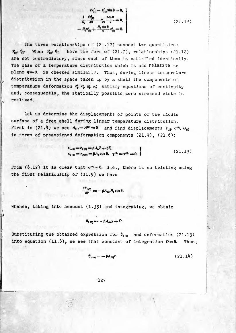
V*Íl>-C(!)SÍn0~°-
1 *<'»_,' Iose_n Ä, </6 E(1» V —U, (21.12)
The three relationships of (21.12) connect two quantities:
’‘óv e<V When *{„• e{i) have the form of (21.7), relationships (21.12)
are not contradictory, since each of them is satisfied identically.
The case of a temperature distribution which is odd relative to
plane q> = 0. is checked similarly. Thus, during linear temperature
distribution in the space taken up by a shell the components of
temperature deformation ¢{. cj. x{. x' satisfy equations of continuity
and, consequently, the statically possible zero stressed state js
realized.
Let us determine the displacements of points of the middle
surface of a free shell during linear temperature distribution.
First in (21.4) we set = and find displacements h(0). u(0)
in terms of preassigned deformation components (21.9), (21.6):
ei (o) — f-2 (o) — P40Z 4- pK. »h (o) = *2 to) = Mo cos 0. y'0' = ■c*0' = 0. Î (21.13)
From (8.12) it is clear that v*u* = 0, i.e., there is no twisting using
the first relationship of (11.9) we have
whence, taking into account (1.33) and integrating, we obtain
(0) = — P4(0,v 4- D.
Substituting the obtained expression for 0,,0, and deformation (21.13)
into equation (11.8), we see that constant of integration D = 0. Thus,
0, to) — P4(0)V. (21.14)
127

iSä
Now the déterminâtior of axial and radial displacements can be con¬
ducted according to the system given in § I3. By equations (13.12),
(13.15) we derive
\e = ßv (/C -f A(0)Z).
^ = — P(K + A(U)Z) R^inQ — ßi4(0)v cos 0/?,. (21.15)
Integrating the second relationship of (21.15), we find
f V*—V* A,-DI-ßJ (K+^ZJtf.sInede-ß/l«,,—(21.16)
e.
Note that A, can be represented also in the form of [12]
e
\ = D2-fij rf0 + vß(/f-p/»(o)Z)clg0. (21.17)
Really, differentiating (21.17) and comparing the result with the
right side of the second equation of (21.15), it is simple to verify
the identity of (21.16) and (21.17).
For temperature distribution according to the law
/ = (V-)-;s'.n0) cosif
the amplitudes of deformations in a free shell aie equal to
Y(i) = 0. ï (21.18) Xl{l)!=:X2(l)==P/^(l)Sln01 ^(l)0^* )
The determination of displacements we begin again from angle of
rotation d,(l). According to (8.23), (8.22) (A = l) we have
-¾1 = - *i*> d) = - MuA s«n 0. ( 21.19 )
128
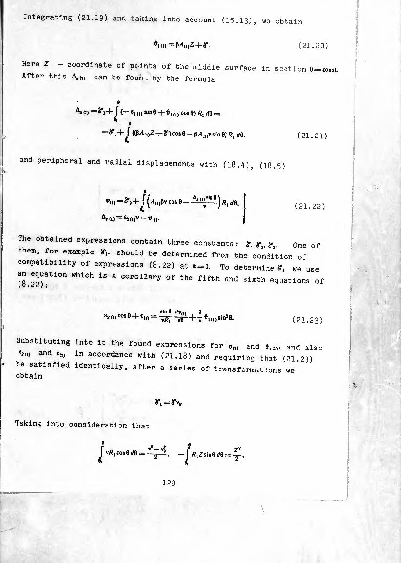
Integrating (21.19) and taking into account (15.13), we obtain
(d - MoiZ+ir (21.20)
Here Z coordinate of points of the middle surface in section 0 = const.
After this Aa<l) can be foun^ by the formula
Aid) = ^i+ J (— e, (1) sin 0-f- Û, (I) cos 0) /?, dQ =
=^1+/ l(ß^(,)Z + g=) cos 0 - ß/lu)v sin 0] d0. (21.21)
and peripheral and radial displacements with (18.4), (18.5)
a
"(I, =8Vf f (>»(i)pv cos 0 - —l'^lnej /?, </9.
A«(l) V(l)-
(21.22)
The obtained expressions contain three constants : ?. *■, one of
then,, for example if,, should be determined from the condition of
compatibility of expressions (8.22) at *=1. To determine?, we use
an equation which Is a corollary of the fifth and sixth equations of
sin 0 1 *2 („ cos e + T(1) = ^+ _ (1) sin7 e.
(21.23)
Substituting into it the found expressions for o(U and and also
and x(I) in accordance with (21.18) and requiring that (21 23)
be satisfied identically, after a series of transformations we obtain
Taking into consideration that
f j , • v/?, cosOrfO = — /?,Zsin0rf0:
129
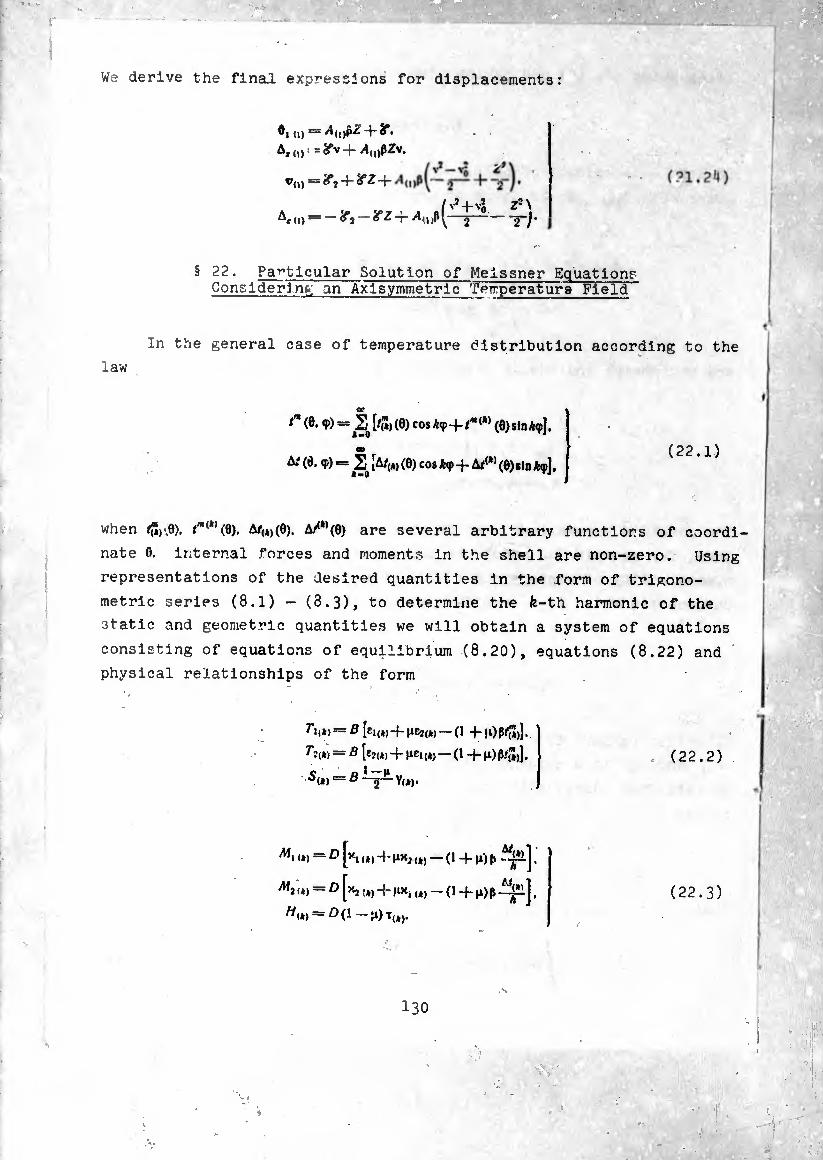
We derive the final expressions for displacements:
§
d) — •
A«<o: =ifv-}- i4(1)pZv,
®(D = + if 2-r
*<(i) — <^2 ~~ -r j- ( v*-H ZJ\
T-j-
22. Particular Solution of Meissner Equations Considering«; an Axlsymmetric Terrperature Field
In the general case of temperature distribution according to the
law
or
tm (0. q>) = [/<") (0) cos A(p 4- tm (*) (0) sin Ä<p].
CD
At (0. <p) = 2o [A/(*, (0) cos A<p + At<k> (0)sln fcp].
when $)\0). i'"“’(0). ^/(4)(0), (0) are several arbitrary functions of coordi¬
nate 0. internal forces and moments in the shell are non-zero. Using
representations of the desired quantities in the form of trigono¬
metric series (8.1) — (8.3), to determine the fe-th harmonic of the
static and geometric quantities we will obtain a system of equations
consisting of equations of equilibrium (8.20), equations (8.22) and
physical relationships of the form
Tu*) —ß [ei<»)4-HC2<*) —(1 -HOP#)].
Tit»» = ß [c?<*) 4- urn (*>—O 4- >0 P#J.
ß<*) = ß^-y-Y<*).
(22.2)
<*) — £ [*1 (4) 4- nx2 — (1 4- n) f) f^îlj,
A!, „J = D [x, r*j 4- fix, U) _ (1 4. p f
//(4) = 00-^)^4,.
(22.3)
• V
130

For * 0, 1. in the same way as ln II 12, 16, „e can obtain Meissner
equations, in the right side of which will now stand specific tem¬
peratures functions, which can be considered as a certain fictitious
temperature" load.
Let us examine the stressed state of a shell during preassigned
axlsymmetric temperature distribution <*-01 |I2|. Tangential forces
In the shell do not appear, since it experiences in this case only
axlsymmetric curvature and elongation.
Since the shell is free of external loads, equations of equilib¬
rium (11.1) m this instance will be uniform. The first two of them
are satisfied if we set
= vA/|(0) = V’slnO. f,
Prom (22.4) and (22.2) it's simple to find
through function
(22.4)
expressions for c,(0), e3 (0,
e* «»“-¿t V cos 8 (i dV
]+P/,'3,. . _ if 1 dV V cos 91 , m
82 (0> - "EÃ [ IT u ~~r~\ + P/S- (22.5)
Bending moments are expressed now through angle of rotation * m
with „he aid of relationships which come from (11.9) and (22.3):
M ,(0):
^2(0) =
£!>• r 1 f w^ri7?r-
W-e') [~7~ 4i ¡1) + Tj- -¾1 +(1+11)(1 ^2.].
(22.6)
Substituting (22.4), (22.5), (22.6) into the third equation of
equilibrium (11.1) and equation (11.8), we derive the desired equation!
°r an 1(()) functions for preassigned temperature distribution
/(0,(0). A/(O)(0):
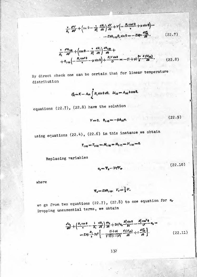
V +fco Ä, M2 \
i9_ rf0 ) ¿0 ^ \ V /
..... dtñ — EAôi ,<,)/?! sin 0 = - f Aßv -^- (22.7)
^-sr+(“se-^-5r)-¿r+
/ «,£05*0 -\ . «>Vslne
+ (0) [ — H sin oj -
pv d(St{0i)
!—O+^X ¿0 (22.8)
By direct check one can he certain that for linear temperature
distribution
far^K-M(0, [ «, s«n 0 ¿0. ^(0) = *10)A co* 6>
0.
equations (22.7), (22-8) have the solution
y=o. ♦no)“-?*«)»»
(n>o (22 6) in this instance we obtain using equations (22.4), 111
T, ,o) = Ti (0) = <o) “ M* '» = N« “ 0-
(22.9)
Replacing variables
(22.10)
where
y0^Ehòuo).
4-4 o (oo 7) (22 8) to one equation for o,- we go from two equations (22.7) > v
Dropping unessential terms, we obtain
Ehf> ■ J (1 + )0
^ d0 de J (22.11)
132
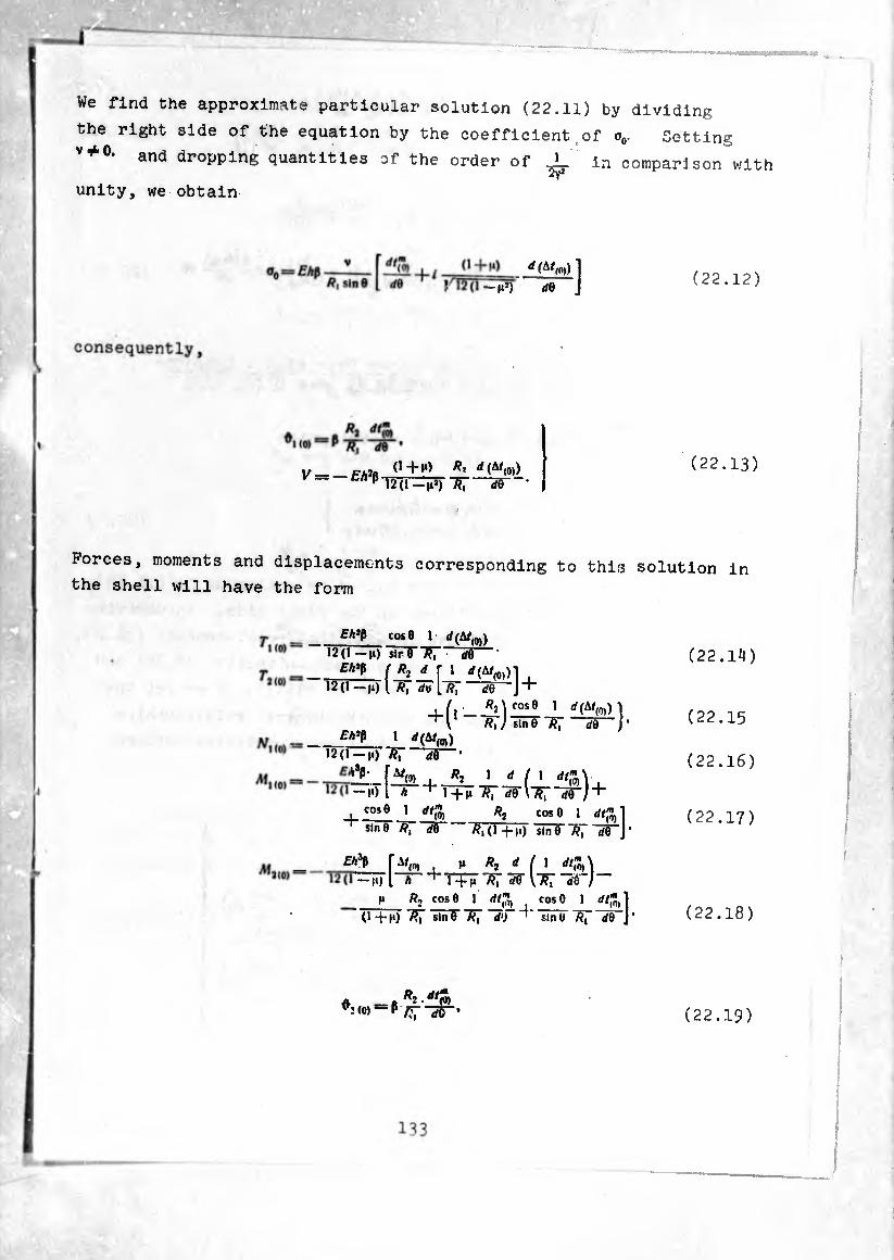
ÄM.» 'rÂffiWW
We find the approximate particular solution (22.11) by dividing
the right side of the equation by the coefficient of o0. Setting
v*°- and dropping quantities of the order of in comparison with
unity, we obtain
1/_ FAJfl 1*^ ^ (^(0))
1 »**) rfe J (22.12)
(22.13)
Forces, moments and displacements corresponding to this solution in
the shell will have the form
(22.14)
cos 0 1 </(Af(0))
12(1 — n) sir 0 7?¡ d¥~~
Eh’t f *2 d \ I , i2 d - ».i i w ¿o J+
Eh't 1 '(¿*(0)) 12(1-,,) 7?T
1 ^(0)) \ Ä,y sine 'ST do j’
[^0) i ^ i d ( i — M) l h “^l+M R, W\~Rï~d$~)
+ cose i at” I -- • -(0) ”2 cose 1 dtfa]
^slnOÄ.-rfT ^,(1+,,)
^ r^o,. h i M <0)\ —io l * i +n "ET ¿e \~F¡ rfe )
cos 0 1 ]
e Ä, rfe J*
(22.15
(22.16)
(22.17)
cos 0 1 rff,"
(1 + ,i) 7?T slnT*S7 W) slnt (22.18)
. A _« ï ■ PO ^(0)-Py^ (22.19)
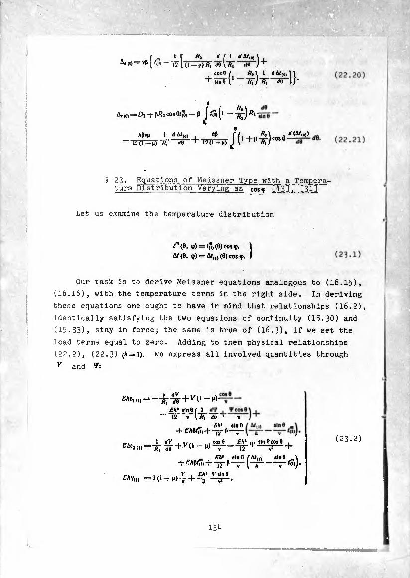
V m- V
Í m f Ä* d ( 1 dejlt)\ t A, ,0, = vß —5«-j +
co*e/t ä2\ I rfA/(#)T\
+ Ime I1 - âT/âT-rfö-]/*
e R
(0) = D2 "4“ cos iO) — ß J" *(<>) (^ ~ "ï?ï")
hiv 1 ¿A/(c, _*ß_ ffi+n Mcosö^^ — Í2(l-j»)^ ¿0 + 12(1-H) J V
§ 23. Equations of Meissner Type with a Tempera¬ tura Distribution Varying as cos? [^3], t3l]
Let us examine the temperature distribution
av Ehti u) “ — 7^ “¿flf + y (1 — n)
E/jEj 0)=3 Ä, JU
/-(0, <P) = ^,(0) COS f. 1
8®. J A/(0, ®) = A/(I) (0) cos ®
Our task is to derive Meissner equations analogous to (16.15),
(I6.I6), with the temperature terms in the right side. In deriving
these equations one ought to have in mind that relationships (16.2),
identically satisfying the two equations of continuity (15.30) and
(15.33), stay in force; the same is true of (I6.3), if we set the
load terms equal to zero. Adding to them physical relationships
(22.2), (22.3) (*=1). we express all involved quantities through
v and V:
Eh* s!n8/ 1 12 V IÄ,
Tcose </0 * y
_ Eh* slnO 4- £*ßf(i) + “¡y ß —y
EAYu, =2(14-^)-7 +
' 12 sin C
T2+~v~ Eh* V sin 0
Eh* w, sin 0 cos 8 . * -3-)
4-fÄß/U)+T5“ß (“ (D sin 8
/(Î) )•
(23.2)
131!
-J

Kl (1) 1 np Rt dd
Vcose
^(1)
Ml)
+^,^+
^ + ^(0-,)^0,0^-) +
Sln0,m\ "T~M«)j.
+^(7) sin 9 sin* 0 A* ^A/(l)
.^ i 1/ 2(1-f-}i) sln0 “ + ^ £Ãv>-
12 ^' JT sin 0
-/(7, ■)•
' 1U)S
V
y cose Dsln0
r*<«> = -^-55-+
’(i)
Eh* + 721
I </Vr . V'cos© ösinO V v~
Eh* 12 (1 —n)
V sine
[■ir ir+i1+,)--^)+
.., £A’ Psin© / A/,,, sin© _\ + 12-0^0-(-^1 —<?)).
+
= ^-+0-2(1-)0
A 7-M'l;
ßslnP f A/(l) sin 0 \
V [~T ^-/(«)]•
(23.3)
■**1(1) 1 ‘/V , . V cos 0 “5~--^-^+() + ,)——
(1—I»*) KslnOcosB
Ih V*-1"
I1 , D --^1^0+0+,)
(1—I**) sln0
+ (• +M)ß^
Veos© .
I /,7, si" 0
r—2T
"(,) ~(T = -0-10-1- + 2(1-^/s,ne
^1(,) = - T, d)
V
COS0 »<■)
sin 0 sin 0
£Av*
"«,)
+)■
(x^+^)+<.+^(^-^).
(23.4)
Equations for the determination of V and ¥ are derived by
substituting the expressions for forces, moments and deformations
into uniform equation (15.29) and equation of compatibility (15.31).
Writing these equations in variables
=£AŸ, Vl = -£. (23.5)
135

we will have two equations which differ from (16.15) and (16.
only in the right sides. The right side of (16.15) is replaced by
the right side of (I6.I6) by 1¾
(23.7)
Going to complex functions ^ = ^1 + 2/7%. Instead of two equations in
V', and Y, we obtain one
*r ,Ä?sine
-v"]0,=*
“-0 ^sme _ u0)
V ï )]- — 2/V* —wv“;-
(23.8)
where ¿ is a differential operator
a* , //?,co*e 1 *Ä,\ * ¿ = -T?r"5r)iy
On making this change, just as in § l6, we dropped quantities of
the order of -^r in comparison with unity. The reverse change from
(23.8) to two equations gives a result which differs from the original,
namely :
. ... 4Ä? Ä? sin 0
. ,., #?slne L(Vx)-r^Vl^l ÒV
.ft- <
-(,+,)£W^[i(^-^)]. (23.9)
(23.10)
136
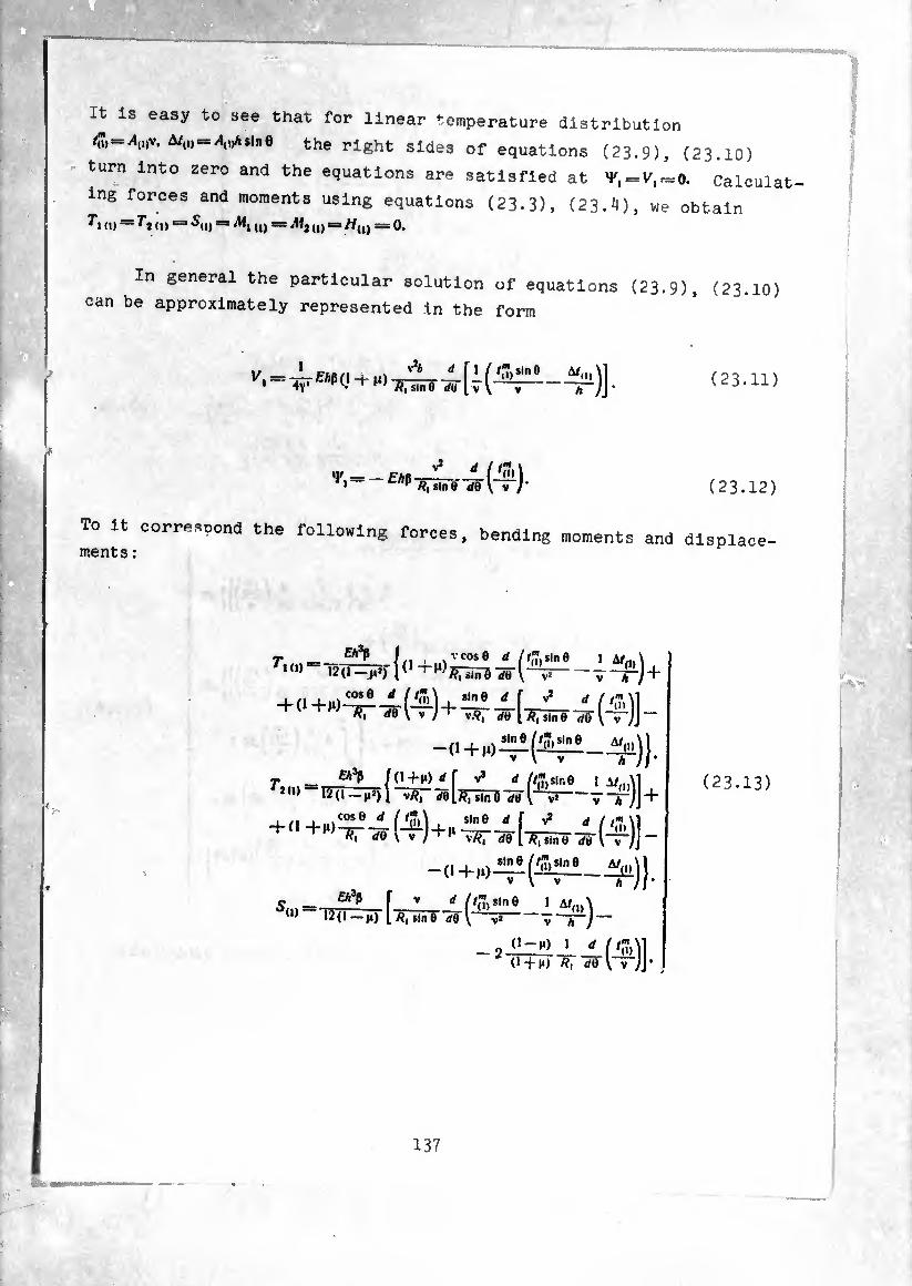
It is easy to see that for linear temperature distribution
A»v. A/,,,«sine the right sides of equations (23.9), (23.10)
turn into zero and the equations are satisfied at = Calculât,
ing forces and moments using equations (23-3), (23.4), we obtain o) = d) = 5u) = u) = Mt d) = A/u) = 0.
In general the particular solution of equations (23.9), (23.10) can be approximately represented in the form
(23.11)
To it correspond the following forces, bending moment ments:
(23.12)
s and displace-
rK!) Äi<'
Eh*fi ÍO-t-HMf V3 rf //,7,sir.0 1 A/..A1
(I —M3) I VÄ, de [ft, sine V V* + '2(1) —12(1
"f ^ ' /'m\l V V vft, de [ ft,sine de v“;]-
1,,, sin 0
dO
*(1) £a3P I
í^- 1 f/,", Sin 0 1 A/,,,'
12(1 — i») 1 L ft| sin e d0 ' ( V h ,
, "-x ■ < f^l (1 + M) d0 \ y ))’
(23.13)
I ■
^ I m
I ‘i . i
137

.
/'■'í i
i
■ ,fs
L i
I
O-H) M co.*0 «.sme -/el—+
+ î rfë [^TüiTÍ ^-(-T1)]} ^0.
A, (I)-= g’v - (^2.) 4
v v M l ~/?i sin tí lo \~jJ / rf®*
J /,7, /?! cos 0 rfO 4 J /?, sin 6 ^/ ^LÍni ¿0j dQ _
- J ^ sin 0 /1 ^(5»)]rf0rfe I f
A/ ,ii — Cj(l)v —1>{1, c=sß/J7,v - ç(n.
Por linear temperature distribution, the displacements computable
using formulas (23.16) agree with (21.24).
138
a m i
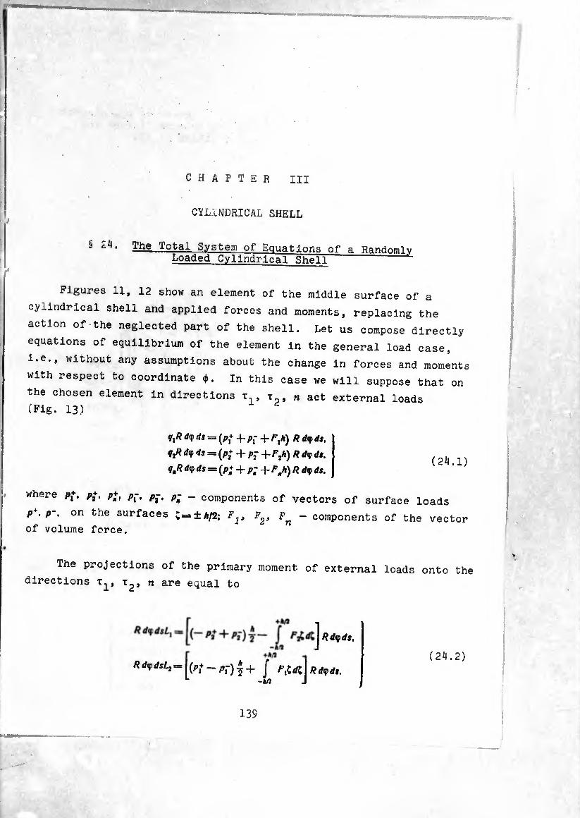
CHAPTER HI
CYLINDRICAL SHELL
§ cii‘ The Total System of Equations of a Randomly Loaded Cylindrical Shell
Figures 11, 12 show an element of the middle surface of a
cylindrical shell and applied forces and moments, replacing the
action of the neglected part of the shell. Let us compose directly
equations of equilibrium of the element in the general load case,
i.e., without any assumptions about the change in forces and moment
with respect to coordinate ¢. in this case we will suppose that on
the chosen element in directions x x n act external loads (Fig. 13)
</i* d(f ds = (P,+ + Pf + /=•,*) R dif ds.
dy 4s = (p2+ + p- -I- Fjh) R dy dt.
qmR d<( ds = (p; -f p; -1- FJ) R </<p ds. (24.1)
where p{. p+. p*, p-, p-, p-
p+. p-. on the surfaces
of volume force.
- components of vectors of surface loads
»±A/2; Flt F2, Fn - components of the vector
The projections of the primary moment of external loads onto the
directions x^, n are equal to
Rd(fds,
(24.2) RdqidsLj = [(p+ pf) J F¿d: R d(p ds.
139
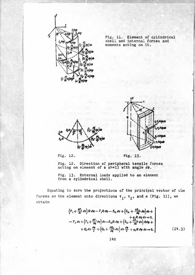
I
r
Fig. 11. Element of cylindrical shell and internal forces and moments acting on it.
Fig. 12. Direction of peripheral tensile forces acting on element of a shell with angle d$.
Fig. 13. External loads applied to an element from a cylindrical shell.
Equating to zero the projections of the principal vector of tiie
forces on the element onto directions t^, and n H)> we
obtain
dsj R dy TXR (/qi — S3l ds -j- |S2, </<f j dt-f-
+ Qjds-y- -{-(Qj ds -j- -f- (/?Rd<f ds — 0, (24.3)
140
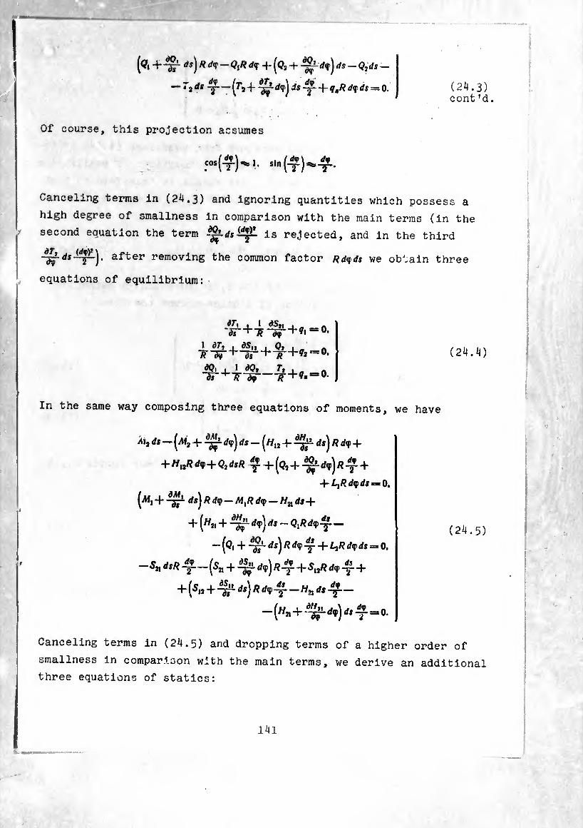
(<?« +~ärds)Ä rf<r - ^+(q2-Q2ds-
— T3ds -J-—(r, -f- -^r + ?,/? rf? * = o. (24.3) cont ?d.
Of course, this projection assumes
Cosf-Ç-J^l, sin (-y) ^-^-
Canceling terms in (24.3) and ignoring quantities which possess a
high degree of smallness in comparison with the main terms (in the
second equation the term is rejected, and in the third
~àjrds^r~)' aft61, removing the common factor /fdqds we obtain three
equations of equilibrium:
dr, , 1 AS,, , -S-+7?-3f+* 0.
dS, i dr, # d<f ^ ds
dQ, , 1 dQ, ds ^ dy
Q, R
T,
•?2-=0.
?. = 0.
(24.4)
In the same way composing three equations of moments, we have
M2 ds — + ds — (^« 4- ds^ Rd<f +
+ HttRd<f+QidsR ?4-(Q,4--^-^)/2-^4-
-\- Lfidyds — O,
(^i 4- -¾1 rfs) /? rf<P - /M, /? </«j> - Hn ds +
4- (^ji 4- ds — Q,Rd<f^-—
— (^1 '^L ^s) ^ ■y' 4* LiR d<f ds = 0.
-S* dsR -(¾ 4- ^*p)Ä44-S»Rd<P4J- +
4- (¾ + ^ds)Rd<p“—Hnds%—
-(Hn+d^-dv)ds^0.
(24.5)
Canceling terms in (24.5) and dropping terms of a higher order of
smallness in comparison with the main terms, we derive an additional
three equations of statics:
l4l
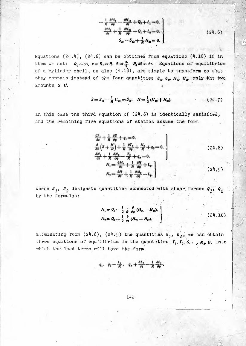
(24.6)
S2i — 5i2+ Hn = 0-
Equations (24.4), (24.6) can be obtained from equations (4.18) if in
them vif set: /?, —oo. 6 = rfc. Equations of equilibrium
of a cylinder shell, as also (4.18), are simple to transform so u.’iat
they contain instead of tre four quantities 5,,. 5,,. //,s. Hn. only tha two amounts S. H,
(24.7) S ~ h2i — Sn, H — y (^IJ-|-/Í2l)•
In this case the third equation of (24.6) is identically satisfied;,
and the remaining five equations of statics assume the form
(24.8)
(24.9)
where designate quantities connected with shear forces
by the formulas:
(24.10)
Eliminating from (24.8), (24.9) the quantities we can obtain
three equations of equilibrium in the quantities Tl,Tv S.Jt,MiKH, Into
which the load terms will have the form
142

Sincé h., L9 have the order of load multiplied by shell thickness,
it js eu.sy to see that the quantities 7^-^- in these equations
can be neglected if the ratio of the thickness of the shell to its
other linear dimensions (length or radius) is small, and moments L^,
Li¿ have a definite derivative. Therefore subsequently in (2^.9) we
neglect L , L^.
' él ft : /7 : ^ In view of the simplicity of the geometric shape of the involved
shell, expressions for components of deformation of the middle surface
through displacements w, u, w are considerably simplified. These
expressions can be obtained with formulas (3*19) if in them we set
/îjde s=di. 0 = y. /?,= 00./?j —v = /?. Having done this, we will have
du *1“ di *1=* — ds* *
w . l dv
dv , 1 du Y=dT+Ädf T=s- I à ( dw
R2 d<f \ (Mf i dîg» R dif £j
vY 1 do R ~dT‘
(24.11)
Here e^, e^, Y - relative e].ongations and shear of the middle surface
caused by shifts of the middle surface u, u, w; , <0 - changes in
curvatures of rectilinear generatrix and parallel circle during
strain; t - twisting. Angles of rotation of normal n around axes
t2> during strain are equal to
0,=
-d
! 1
dw
Ô9 ST'
IrW V
R (24.12)
Since because of the Kirchhoff-Lovë hypothesis tne normal during
deformation keeps its perpendicularity to the middle surface, then
— d, is at the same time the angle of rotation of the generatrix
around axis x2, and angle 02 is the angle of rotation of the
tangential to the parallel circle around ^.xis T-^. Changes in curva¬
tures <^, <2 and twisting x can be expressed through angles of rota¬
tion — and ôj. Really, taking into account. (24.. 12), from (24.11)
we obtain
.
N ' --( .Ví
The six components of deformation e,. r2. y. x,. x2. are connected with
the six static quantities Tv T,. S. Aí,. Mr H by relationships expressing
Hooke's law for a thin shell:
el — £f(^ ' ~ t'^)* "£Ã* (^1—^l)’
¢5 = -^-(^2-^1). X2 = -~-(aÍj —HiM,).
.r _ 2(1+^) 0 . 12(1 +1») u Eh T=:-£Ã*-
Relationships (24.8), (24.9), (24.11), (24.14) form the total
system of equations which describes the equilibrium of a randomly
loaded cylindrical shell, to which it is necessary to add only the
boundary conditions.
§ 25. Axlsymmetric Deformation of a Cylindrical Shell
Let us examine the simplest load case of a shell: the axisym-
metric load. Let us assume that the conditions of the fastening of
the edges also possess symmetry relative to the axis of revolution
of the shell. In this instance the forces, moments, components of
déformât'on and displacements in the shell are not a function of
144
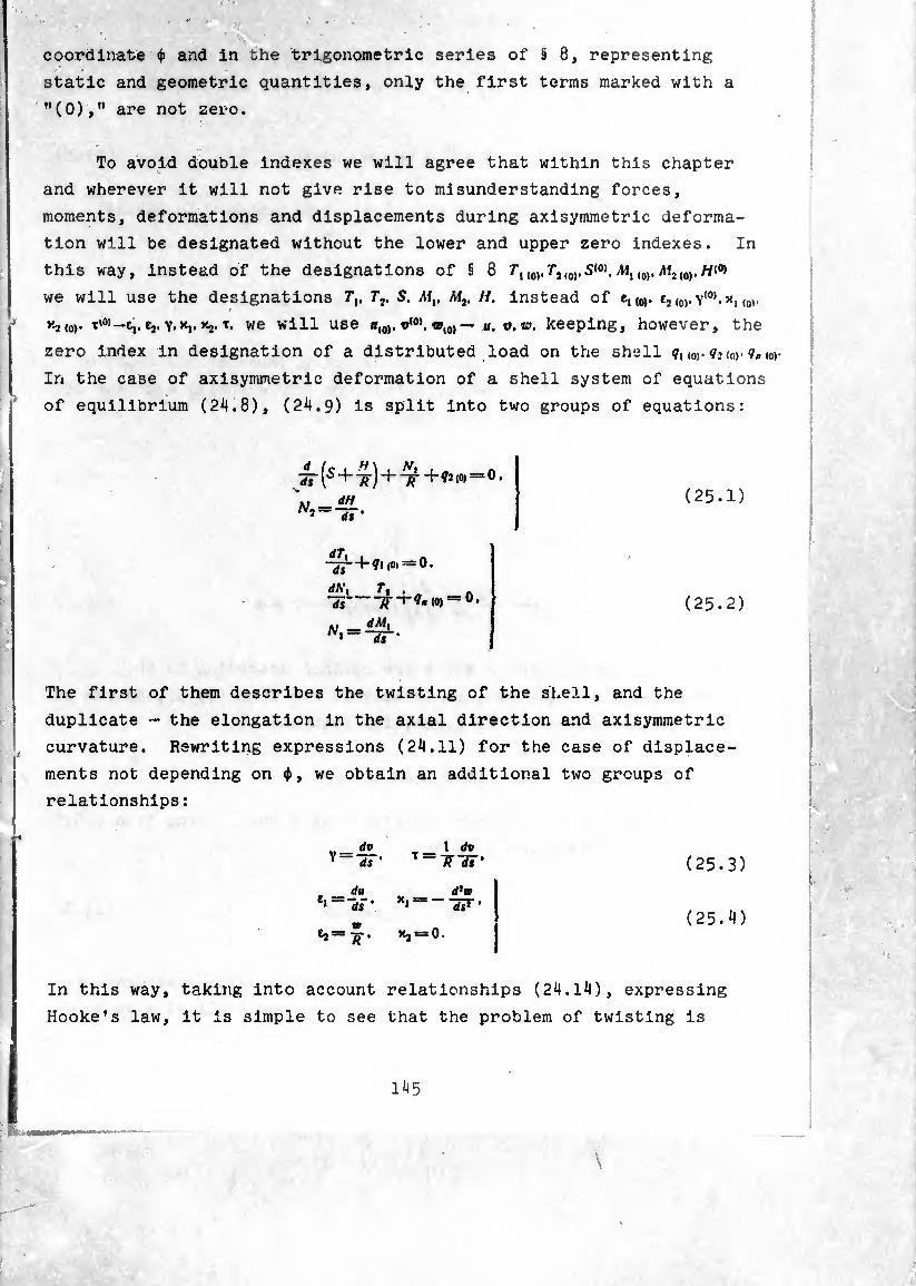
coordinate <i> and in the trigonometric series of § 8, representing
static and geometric quantities, only the first terms marked with a
"(0)," are not zero.
To avoid double indexes we will agree that within this chapter
and wherever it will not give rise to misunderstanding forces,
moments, deformations and displacements during axisymmetric deforma¬
tion will be designated without the lower and upper zero indexes. In
this way, instead of the designations of § 8 Tx,0,.(0).5<0).(0).M2,0).
we will use the designations 7*,, Tv S. Mv M2, II. instead of e1(0). t¡(0).y(0).x, (0),
^-2(0)- t'0)—e,. tj. ’'-j-■*. we will use h(0). «(0) — u. t>. o. keeping, however, the
zero index in designation of a distributed load on the shell <o). <?.> (nr
In the case of axisymmetric deformation of a shell system of equations
of equilibrium (24.8), (24.9) is split into two groups of equations:
ds (■S 4- + 4-(o» = 0, dH ds ’
-¿l—K?! («1 = 0.
dNy Tt . ~7i-(0) = °*
Nlz=±p-. 1 ds
(25.1)
(25.2)
The first of them describes the twisting of the shell, and the
duplicate - the elongation in the axial direction and axisymmetric
I curvature. Rewriting expressions (24.11) for the case of displace¬
ments not depending on <j>, we obtain an additional two groups of
relationships :
In this
Hooke * s
Y ds ' T =
• dU e» ~~ hi ’ *1 —~
h—%' >«2 = 0.
1 dv ~ÏÏ ds '
d*w ds2
(25.3)
(25.4)
way, taking into account relationships (24.14), expressing
law, it is simple to see that the problem of twisting is

completely isolated ana is solved elementarily; actually, from (25-1)
after the elimination of N^ and integration over e we obtain
(25.5)
where A is the constant of integration. Expressing with (24.14),
(25-3) S and H through we obtain
Substituting (25.6) into (25.5) and dropping terms of the order of
h2/R¿ in comparison with unity, obtain one differential equation of
the first degree for the determination of v
>1 EH dv (25.7) <¡2 {0)ds + ^ = 0. 2(1+n) ds
from which it follows that
t M
Constants of integration A and B are defined according to the
boundary conditions, where, as is easy to see from (25.5), on one of
the boundaries force can be given, for example:
when s — 0 S=5°.
then, dropping 2H/R in comparison with S as a small term, from (25.5)
when s = 0 vie obtain S°-± A=:0 and
(25.9)
Displacement v is defined from relationship (25*8) accurate to
a constant B, characterizing the rotation of the shell as a whole
around axis 0Z.
146
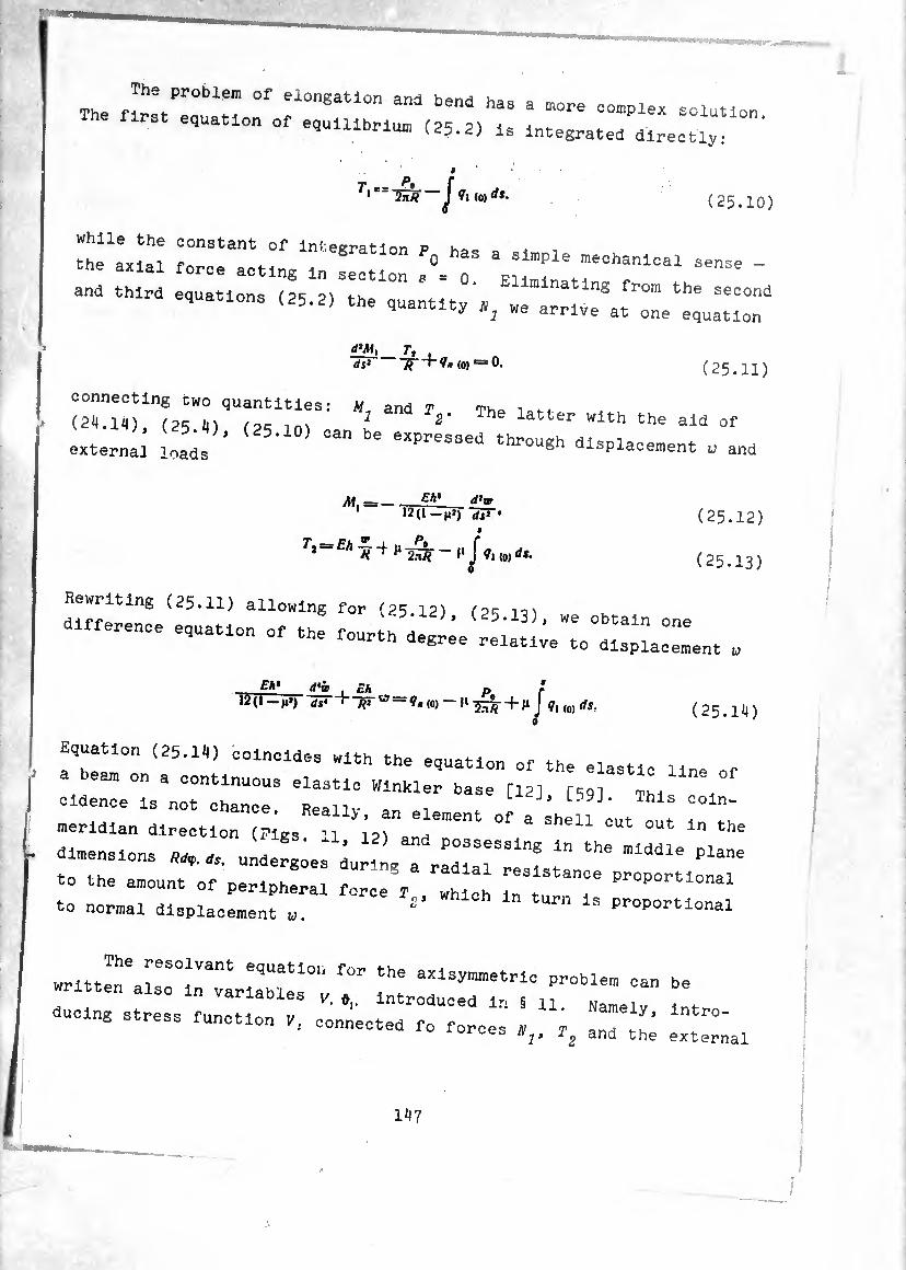
The «rltTT 0f el0ngatl0n and beniS has ^ complex solution first equation of equilibrium (25.2) is i„tegrated directly:
(25.10)
while the constant of Intégration p hoc e ,
the axial force acting in section a°= o ^1136 ~
and third equations (25.2, the quantity'y we arr ve'at ^ n2 we arrive at one equation
£ÜÎi_Zl4_, ds1 /? i (0) = 0, (25.n:
connecting cwo quantities: M and T Th0 i 4-4
(211.14), (25 i,) (2R Jn, I 2' Th latter "ith the aid of
external loa^s ’ a^pressed through displacement o and
M. =-g** ä’* 12(1—as* •
7* = -t H 2¾ - |i j<ti (0) ds.
(25.12
(25.13;
Rewriting (25.11) allowing for (25 12) fPR
d— ~ - -a -:h5;S;e(:^;;:::;:;—nt „
Eh* !Í*Íb [ £/¾ PC 1¿(1 —n*) ds* "R ft* (0) — M 2^-4- H J
(0) ds. (25.1H
quation (25.14) coincides with the equation of the elastic line
beam on a continuous elastic Winkler base [12] [59] Th. ,
cidence is not chance. Really, an element of a shell cut out 1 in meridian direction (Pies M 101 e 11 6 * ln the
dimensions uL^es ; i gTrL0:;:3;:!;'1 the middie piane to the amount of peripheral force /, „h h // PrOPOrtl°nal to normal displacement u. ‘ 1S eroP°rtl°nal
r ~ t—*“ - »•
Emotion ,, eónñé.teO ’r.TJ.l', 1J J2 and the externa]
1^7
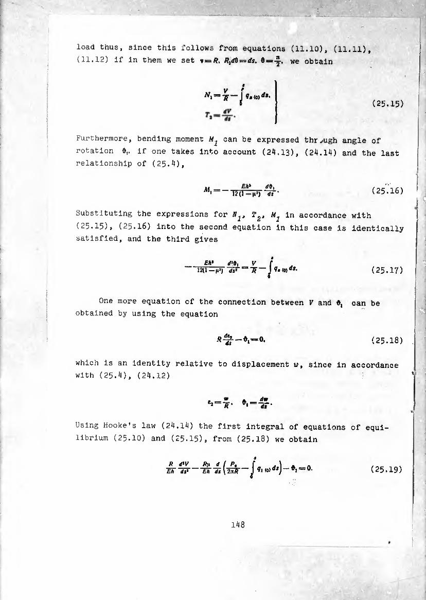
■
load thus, since this follows from equations (11.10), (11.11),
(11.12) if in them we set v*=R. R^Q — ds. 6 = -y. we obtain
9
V r =37J- — J V,io)dt’
(25.15)
Furthermore, bending moment M1 can be expressed thrjugh angle of
rotation 0,. if one takes into account (24,13), (24.14) and the last
relationship of (25.4),
Eh* rfO, T2U-H») d$ • (25.16)
Substituting the expressions for in accordance with
(25.15), (25.16) into the second equation in this case is identically
satisfied, and the third gives
eh* V C ds* ~"7F~ J (25.17)
One more equation of the connection between V and #, can be
obtained by using the equation
V=o. (25.18)
which is an identity relative to displacement w, since in accordance
with (25.4), (24.12)
t^ ~R’ *inrm
Using Hooke's law (24.14) the first integral of equations of equi¬
librium (25.IO) and (25.15), from (25.18) we obtain
9
R d*V R\k d ( Pt f ^ \ A Ä -Sir—etTil2^-J (25.19)
148
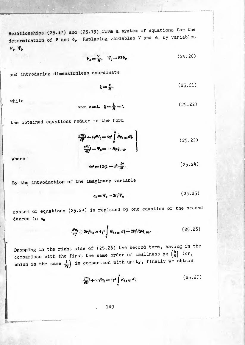
Relationships (25.17) and (25.19).form a system of equations for the
determination of 7 and 0,. Replacing variables 7 and 0, by variables
(25.20)
and introducing dimensionless coordinate
(25.21)
while
when i = L, = (25.22)
the obtained equations reduce to the form
/
i Sp'+.vH'.-V f
where Ä*
(25.23)
(25.24)
By the introduction of the imaginary variable
00-^,,-2.7% (25.25)
system of equations (25.23) is replaced by one equation of the second
degree in o0
I $:• + 2/\7o0 - J /??. (0) rf; + 2/Y7*M, (0,.
* A
(25.26)
Dropping in the right side of (25-26) the second term, having in the
comparison with the first the same order of smallness as (^) (or,
which is the same ±) in comparison with unity, finally we obtain
i
-S? + 2/^0 = 4^ Í R<1' «0) di * n
(25.27)
149
The particular solution of this equation can be approximately written
in the form
t <j0= — /2v* J ( 25 • 28 )
0
Separating the real and imaginary parts, we have
(25.29)
To particular solution (25.29) corresponds the zero-moment state of
a cylindrical shell. Really, by formulas (25.20), (25.16), (25.15),
(25.10) we obtain
K R df,
4? *6 — 0.
(25.30)
The obtained particular solution is sufficiently accurate if load qt(0)
changes smoothly, i.e., if is little. Really, let us substi¬
tute
0O=0 —
then instead of (25.27) we will have the equation for the determina¬
tion of a
= (25.31)
At the particular solution of this heterogeneous equation is
also approximately equal to zero and ò0 has the form (25.28).
150
°an benfloÍut^7(^5^8,3 °han^ ^ load the particuiar , Rou,o \ o. 2o ), corres pond imr <-„ .. ^ lcuiar solution However, as wUl be shown sufcseqPuent1iny8 ---moment state.
and approach can Jead t„ „ m certain cases such errors of We order of l/2T
Wlth Unlt dUr1^ determination of stress at th COmParÍSOn the edges of the shell.
When nrt+.
approximately e,ual to t!,e Partl=ulah solution of (25.3a) ls
thus o^/? -í?íi?
*1
To this value nf « ue 01 °o correspond
di Rq.^di. C25.32)
== /? W C; / ^.(0) ¿1-
(25.33)
ÏT we keep also the sennnn 4- second tenm "in p,_ ,
solution should be taken in the form ^ °f (25‘26). then the
(25.34)
Considering the déformât inn r bending load of fora (8.28) °f a sheH ander the action of a
amplitudes of forces and »olentÏ loi ^ deslS"ation of example, *e win r r oase Latin characters, for
the limits of this chapter and^subsM'"*! In thlS ‘ within
"HI be caused instead of the designati" ^ n° mlsun,äe-"ttanding
-,,. introduced in § 8, we Klu usHha^^^^ X,„.
«P f}. #,.
:he
5)
tor
e
hat
le
151

/n,. m2, A|, /i,. n2. The subscripts (1) in the designations for amplitudes
of deformations, displacements and components of external loading
are kept. The dependences of static and geometric curves on coordi¬
nate <j) in the involved case have the form
(7*j. Mv M2* tj. in,, ntj* rtj)cosip,
(e,. e2, X,. xj. 0,, h. w) =
= (eior e2(i)’ xi(ir ’So»* ^1 (i»* «o,* c°sf.
for Vj^fouiy V.oOcosf.
(5. H. Nj. y. T. Oj. V. qj=*
= (*,. A,. nv Y(U. t,,,, 02(n, v(U, 72,,,) sin <P- (26.1)
After singling out cos ¢, sin <J> from (24.8), (24.9) we will
obtain the following equations of equilibrium for the amplitudes of
forces and moments
f,. S* *,• nr 'S* mr "S* *i:
(26.2)
(26.3)
In this case, just as in § 25, moments of distributed loads and L2
are dropped.
System of equations (26.2), (26.3) allows a decrease in degree
by two. Actually, subtracting the second equation of (26.2) from the
third and integrating, we obtain
#
+**•)=■- (^(D-^o))*- (26.4)
where P1 is the constant of integration, equal in magnitude to the
primary vector of the edge loads acting in section e = 0 (Pig. 15).
152
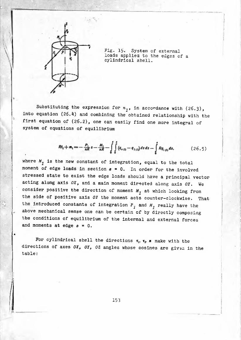
Z
Y Fig. 15. System of external loads appliea to the edges of a cylindrical shell.
Substituting the expression for n^, in accordance with (26.3),
into equation (26.4) and combining the obtained relationship with the
first equation of (26.2), one can easily find one more integral of
system of equations of equilibrium
(26.5)
where MJ is the new constant of integration, equal to the total
moment 01 edge loads in section a = 0. In order for the involved
stressed state to exist the edge loads should have a principal vector
acting along axis OX, and a main moment directed along axis OY. We
consider positive the direction of moment at which looking from
the side of positive axis OY the moment acts counter-clockwise. That
the introduced constants of integration P.^ and M1 really have the
above mechanical sense one can be certain of by directly composing
the conditions of equilibrium of the internal and external forces
and moments at edge s = 0.
For cylindrical shell the directions t,. t2. n make with the
directions of axes 0Xt OY, OZ angles whose cosines are givsn in the table :

rt.-.J,
1 J »
»1 0 0 -1
*» — Slfif cos 9 0
* cos 9 sin 9 0
In section s = const on a certain elementary arc Rdy act internal
force
and moment
/f/? = (7, T, 4-S^Tj-f <?,/»)/? rfç =
= (/, cos (ft, +5,2,,) sin<fT2-f Q, cos (fit) R <Up
MR dq = (/M,t2 - //,jT,) /? rfç = (m, cos <| t2 - Hi2,,, sin r,) /? dy.
Their projections onto axes OX, OY> OZ are equal to
KXR dq = (_ SI2 sin? q f Q, cos» R dq,
KyR dq = (5,2,j) sin cosq; + Q, cos q sinç) R dq.
K,R dq = — /, cosqR dq,
MsRdq = (— m, cos ç sin <f — Hl2 sin q. cos$)/?<ty,
MyRdq = (m, cos2 <f) R dq.
MtR dq — //,2 (1) sin ç R dq.
The principal vector and principal moment of external load and Af^
should be equal in magnitude and opposite in sign to the principal
vector and moment of internal forces in section 8=0. It is easy
to see that the principal vector and principal moment of the system
of internal forces in any section have components equal to zero along
axes 0Yt OZ and OX, OZ respectively. For example, at s = 0 we have
In In
J /(,/?«> = /? J (5,2,,) + 0, ,„) sin <p cos qxf<p = 0, o o
2ft
J (^i+ KyR cos q — >Cx/?sin<{')/?</<p = o
In
= J l^iiu)sinq) + (S,2,,, + 0,,I))/?sin(pcos?9 + ( I
+ 5,2,,, /?sin19 —Q,,,)/? cos^sinip]/? 1/9 = 0
15^
±n this way there exist the equalities
Pi = ~ f • ' 0
2ji
' o
After integration we obtain
Taking into consid°rati on fkq+- la.ration that according to (24.7), (24.10)
— p'~, -
5»(1) — S, +
Al = 2 (^2, <!*+^12(,,).
we rewrite the obtained relationships in the for.
(26-5) » ■ o- «—a6aln at the same
equations In six unknown forces and nom ^ S °f thl
nl and »s have been determined aceo Under fche ««dltlon that
two first Integrals of this h h 8 t0 tomnl¡ís since
astern consisting of (2 ^ ^611 f0Und' ^ ^ -placed by a
Eliminating from these thr« u« onTfo"6 e9Uatl°n °f (26'2 (26.3), we obtain °eS ^ wlth the aid of
155
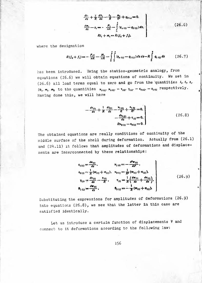
(26.6)
ds_ ds
dm i
ds
dh, /» i _
«
*l*=- J (1)) rfs- «I
Rtl -+•/«! = /? (/0 -+- /j).
where the designation
« « •
Æ(/o +/)) = -ÍíT^—~ J —Î2<i))rfsû,—^ J fio»** (26.7) OU U
has been introduced. Using the statico-geometric analogy, from
equations (26.6) we will obtain equations of continuity. We set in
(26.6) all load terms equal to zero and go from the quantities tv t,. sr
2/r,. m,. mj to the quantities x,u). - iU). Yuj- - eau)* — £ni) respectively.
Having done this, we will have
Í!íli ds
‘ rfY(„ R ds
i (i)
-RT = 0.
~R
rfe2(t> i - _ n —U.
—*2(1) = ^-
(26.8)
The obtained equations are really conditions of continuity of the
middle surface of the shell during deformation. Actually from (26.1)
and (24.11) it follows that amplitudes of deformations and displace¬
ments are interconnected by these relationships:
</«„> _ ¿»»o) ei<»——SJ-* xki)— dSt •
~ 7r(®(,>~t~ *<*>)• +
*»(,) «(!) _ _ 1 (dwU) , rfv(i)\ (26.9 Y(i) — -55 R ’ T“i —TTV ds"^ ds )'
(i) “ “¿T- • o> =* ~ T? (wo)+•«>)•
Substituting the expressions for amplitudes of deformations (26.9)
into equations (26.8), we see that the latter in this case are
satisfied identically.
Let us introduce a certain function of displacements ¥ and
connect to it deformations according to the following law:
156
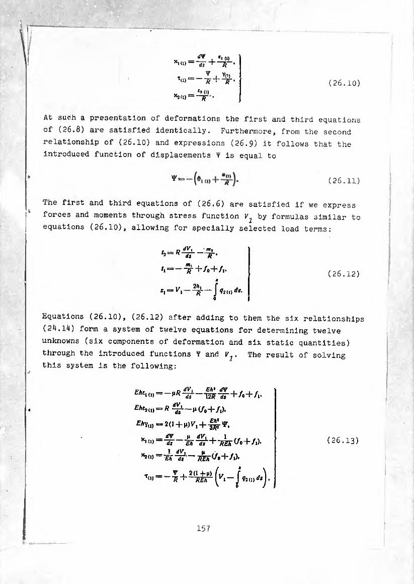
(26.10)
« — ^ i *• <0 *1(1)H—3-.
T_y,,, T(0- ~n .
h (i) *2(1) =-£-'•
At such a presentation of deformations the first and third equations
of (26.8) are satisfied Identically. Furthermore, from the second
relationship of (26.10) and expressions (26.9) it follows that the
introduced function of displacements T Is equal to
(26.11)
The first and third equations of (26.6) are satisfied if we express
forces and moments through stress function VJ by formulas similar to
equations (26.10), allowing for specially selected load terms:
„ äV, m, -IT
= —77 +/0+/1.
M
s, = K, — — J i2(lj ds.
(26.12)
Equations (26.10), (26.12) after adding to them the six relationships
(24.14) form a system of twelve equations for determining twelve
unknowns (six components of deformation and six static quantities)
through the introduced functions ¥ and V1. The result of solving
this system is the following:
Ehtx (,)-
^Ac2„) = R rfV,
dVx Eh* (TV ds
ds
12/? ds
H (/0 + /1).
4-/0 + /1.
£h ~ds~'~^Eh^0~\~/i).
—7&r(/o+/,).
Tu) = - 20+M) Weh •
(26.13)
15 7
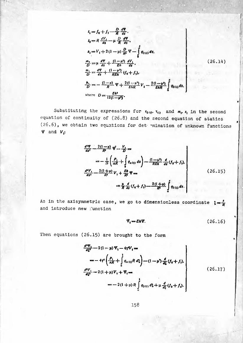
*i = /o + /r
dt
D dV ir dt • D dV
^irir
*i — + p) ^<Jux)ds.
üi-,, rfy . n-i*’) “v, D ^ dt ^ Th dt'
m, dV ~D dt
■ O-M1) ,, ,f.
A. _ ~D-~
(1-M> /?_ M'-+
2(l-»>) „ £ä« r »
where D = Eh* —p*) *
2(1-M») ~^W~
(26.14)
Substituting the expressions for £j)iv tu) and m,. i, in the second
equation of continuity of (26.8) and the second equation of statics
(26.6), we obtain two equations for det -mination of unknown functions
V and V,:
d*V 2(1 —n) ,If* y, IF-—W
-^ (iSr + J <n dsj — (/o+/i).
d*Vt 2(1+^)., , Eh v ds* & '^Tp
S
_ P rf , 2(14-p) f "F * W w J toind*-
(26.15)
As in the axisymmetric case, we go to dimensionless coordinate i=-g
and introduce new function
•P, = EAV.
Then equations (26.15) are brought to the form
^-20-,0^-4^,-
(26.16)
1 ~ 4v< J n)^ —Í1 — i1’) (/0+/1).
^-2(1+,,)^ + *,,
t
' +1‘)^ J^1(0^+^^(/0 + /1)-
(26.17)
158
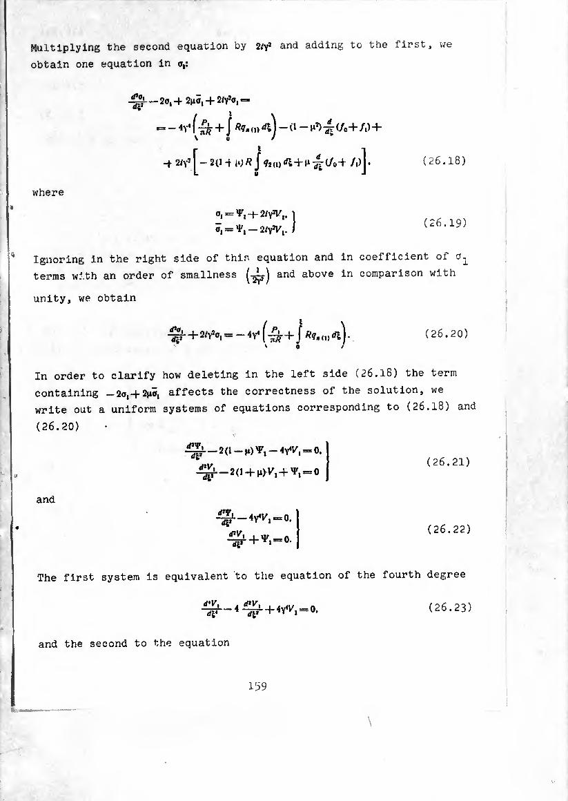
Multiplying the second equation by 2/yj and adding to the first, we
obtain one equation in o,:
- 2o, -f 2no, + 2/y’o, =
*= — f + f (i) ] — (1 C/®4- /t) + \ u / *
|^— 2(1 -t H)/? j ?2(1) dl+Jl -¿r-i/o-f /l)j* -t 2/v1 (26.18)
where
0, = ^,-(-2^%. J
Õ, = — 2ly1Vl. I (26.19)
Ignoring in the right side of this equation and in coefficient of
terms with an order of smallness ("^r) an^ above in comparison with
unity, we obtain
■^r + 2/Y2o, = — + J /??, (,) d|V '0 /
In order to clarify how deleting in the left side (26.18) the
containing -20,-1-21*0, affects the correctness of the solution,
write out a uniform systems of equations corresponding to (26
(26.20)
-^-2(1-10^,-4^, = 0. d'V,
and
^-2(1 + ^,+ ^ = 0
4^1.-4^1/, = 0.
(26.20)
term
we
.18) and
(26.21)
(26.22)
The first system is equivalent to the equation of the fourth degree
^--4^ + 4^, = 0. (26.23)
and the second to the equation
159

(26.24)
Hoots of the corresponding characteristic equations
k* — 4k7 -+* 4Y4 = 0 (26.25)
and (26.26)
have a magnitude of order y and differ from one another only in terms
of the order 1/y [57].
The detailed analysis of the stressed state of a closed cylin¬
drical shell at different loads of form (8.4) conducted in monograph «
[5] indicates that in the case of a nonsymmetric load (fe * 1) for the
approximate creation of an edge effect we can use equation (26.26).
In finding the particular solution of heterogeneous equation (26.18) ,
the deletion of the quantity (-20,+ 2^,) in comparison with 2iy\ is
possible only when the right side of (26.18) is a slowly changing
function of coordinate £.
To the simplifications made during the transition from (26.18)
and (26.20) corresponds the following variant of relationships (26.13)>
(26.14):
(26.27)
£7ie, (,) —
(26.28)
Equation (26.20) differs from equation of axisymmetric deformation
(25.26) only in the right side. In exactly the same way as was done .
in the case of axisymmetric deformation, the particular solution of
equation (26.20) can be approximately found by dividing the right
side by the coefficient of o,
(26.29)
or
160
(26.30) *,==0' ^ = ^ +
As follows from equations (?fi 7>i\ +-^ 4 aucuns to It corresponds the
stressed state of a shell zero-moment
*1-/0+/1 . ’ V • # i
= — _ Af, f r t
(O» M i
f' “•Ä + J^^.(i)
rn, = mj = Í, = 0. «J =Q,
(26.31)
Stressed state (26 31) ^ (7-0 ,,. * * exclude from consideration ?. and set ¢1 o) — 0. coincides with the stressed state in a h .
section, loaded on the edge a = 0 by force P and^ ^°33
distributed transverse load of intensity ' ^ "2 ^ by
^“(i.O) — ?Î(,))JIÂ. (26.32)
The bending moment in a certain out of beam a = const is equal t,
«
M,-J 9(s¡)(s_s¡)ds¡ ==_PiS_Mt_ j ' Ç dsds.
0 0 (26.33)
It is balanced by moment of interior stress c=i. equal to it
a
2 j* (t) (26.3^)
Equating expressions (26.33) and (26.34), we arrive at the , equation of (26 a -, * arrive at the first
• Analogously, composing the expression fnr. v, force and equatinc: it tn fho -xpresslon for shear w. , . resultant of tangential forces t«=A
obtain the third equation of (26.31). k '
161
§ 27• Stressed State of a Long Axisymmetrlcally Loaded Cylindrical Shell
In §§ 25, 26 it was shown that the calculation of a cylindrical
shell for axisymmetric and bending loads under known conditions is
reduced to the solution of the same equation in complex function
or o-^, but with different right sides. Let us examine the uniform
equation
^7 + 2^-0. (27.1)
Particular solutions of equation (27.1) have the form
#-yIcosy|, «"v*slnY&. Î «vi cos Yfc. sin Yl- Í ( 27.2 )
Solutions written in the first line decrease with an increase of £,
i.e., going from edge £ = 0 to edge Ç = Xt on the contrary, the
solutions in the second line decrease with a decrease of Ç, i.e. going
from edge Ç = Z to edge £ = 0. In this way each pair of solutions
(27.2) describes the stressed state of a shell in the neighborhood
oi its edge. This leature of the solutions of uniform equation (27.2)
is called the edge effect. We introduce along with variable Ç,
changing from 0 to Z going from edge s = 0 to edge s — L. another
variable
(27.3)
which changes from 0 to Z from edge s = L to edge a = 0. Then the
general solution of equation (27.1) can be written in the form
O = (M,-/fl,)|0(yS) + it(Yl)l+{A2-/flj,[6(Yi,)4 /t(Yl,)l. (27.4)
where by 0, ç we designate functions [59], [12]
0 (*) = *-•* cos Jr, C(x)=.«-«Sinx. (27.5)
Subsequently more combinations of these functions will be required
(p(x)=e(x)-K(x).
162
(27.6)
and their derivatives
0' (*) = _ (f (X). t'(*) = *(*).
O" (je) = 2C (X) = -<p' (X). C" (X) = -26 (X) = V (X).
The values of functions 0, C. <P and if are given in Table 1 of the
appendix. Solutions 0(yö.C(yI) decrease with distance from edge s = 0,
and solutions 6(^,). CivW decrease with distance from edge s = L. As the
tables show, 0(x). C(x) already at x = .n have the order 0.04. This means
that already at V'==-i the influence of edge a - 0 on the stressed
state in the given section of shell can be neglected. Using (25.22),
(25.24) we can calculate the absolute length of the generatrix e which
corresponds to the value fc=—î
t = Ü* = .-7=== 1/5 V V3(l — H*) I Ä
In this way if the total length of a cylindrical shell l exceeds
2AŸRh. then the determination of arbitrary constants and
B solution (27.4) can be done separately by the conditions on each
of the edges. In writing the conditions on edge a = 0 it is possible
to set Aj — B2 = 0, and during the determination of constants AB2
from conditions on edge s — L consider /4, = 0, = 0.
Let us turn to consideration of different conditions and to the
determination of the constants of integration in solution (27.4) for
an axisymmetrically loaded shell. In this instance the total solution
r of equation (25.27) is composed as the sum of solution (27.4) and the
particular solution of the heterogeneous equation determined from
formula (25.28). Separating the real and imaginary parts, we obtain
« V0=Ehöl = /4,0(yD4 £¿<yI)4 ¿20(Yi,) + B¿(Yli).
t
y0=- -¿-[¿¿(Yl) - B,0(Yl)4 (Yl,)-020(Yi.)l + J
Further using equations (25.10), (25.15)» (25.16) we have
»
’•.“âí-í II
(27.7)
(27.8)
163
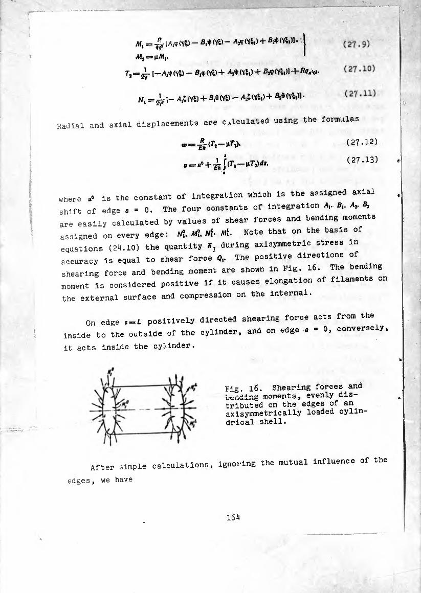
Ai, = ¡<Yl) - (Yi) - ¿A (Yli) + ßJ+ Wli)l. I
Aij^nM,. '
r, = ^- [—A,iJ> (Yl) — ß,<P (Yl) + (Vli) -+• B#<Vl,)l + ^.'o).
A/i = ^ (Yl) + Bfi (Yl) - A£ (Yl,) + B.ß(yI,)1 •
Radial and axial displacements are calculated using the formulas
w =* (Ti ^^i)»
ê
H *= «° 4" J(7*1 — liT’jJrfí.
where «” Is the constant of integration which is the assigned axiai
shift of edge a = 0. The four constants of integration *i- B,, d,. B,
are easily calculated by values of shear forces and bending moments
assigned on every edge: Ni. Mi. Ni’ Alí- Note that on the basis
equations (24.10) the quantity *, during axisymmetrlc stress in
accuracy is equal to shear force The positive directions of
shearing force and bending moment are shown in Fig. 16. The ben ng
moment is considered positive if it causes elongation of filaments on
the external surface and compression on the Internal.
On edge .=1 positively directed shearing force acts from the
inside to the outside of the cylinder, and on edge a = 0, conversely,
it acts inside the cylinder.
Pig. 16. Shearing forces and bending moments, evenly dis¬ tributed on the edges of an axisymmetrically loaded cylin¬ drical shell.
After simple calculations, ignoring the mutual influence of the
edges, we have
(27.12)
(27.13) »
16A
(27.14)
(27.15) (27.16)
(27.17)
Th (Tl) + 'M?0(Vs) + iVf«f(vli) — ^ Aif0(vii)]. (27.18)
= - ïr [^0 (YD + i Mît (Yl) - Affe (vS,) +
(27.19)
Calculating by these formulas the forces, moments and displacements
in the neighborhood of one of the edges, it is necessary to drop the
quantities which belong to the other edge. For example, in the
neighborhood of Ç = 0 Calculation of peripheral force r2 must be done
by the formula
r, = -2v [iV?9 (vl) 4- -¾ (vl)] + Rq," .
but in the neighborhood of ^ = /(^, = 0) by the formula
2Y[-A/f 0 (vl.) + (vl,)] + Rqm
Proceeding in this way it is easy to obtain expressions for the
angle of rotation and normal displacement of the edge of a shell
loaded only by shearing forces and bending moments at this edge.
(27.20)
(27.21)
As one would expect, following the principle of reciprocity of
displacements, the shift from the action of a unit bending moment
proved to be equal to the angle of rotation under the action of
rotation under the action of unit shearing force. The inversion of
equations (27.20), (27.21) gives
165
(27.22)
,.o Eh o , EHR „o ^1= + -ö^-öi •
Ni = - Eh o —ZT*
V« Eh
«I
Eh 2v3 £A
Alf = -s-i- W EhR "2V £A
ef.
tn ¿ c« A¿ AÍ.=W® - V ô>-
(27.23)
From the previous reasoning and from equations (27.8), (27.1^)-(27.16)
it follows that if the edges of the shell are free, i.e., at the
edges the following conditions hold:
N? = Al? = 0. Ni = Alf =0. (27.24)
and the distributed loads are smooth functions of coordinate a, then
the shell is in the zero-moment stressed ¡state (25.30). If edge
conditions differ from (27.24), then on the zero-moment state is
imposed an edge effect. We can give different variants of the edge
conditions. For example, to the supported edge correspond the
condí tions
Al? ” 0, «° = 0. (27.25)
and to the fixed edge — the conditions
¢^ = 0. wo==0- (27.26)
Conditions (27.26) can be expressed aleo through Aft AlJ. as directly
follows from (27.20). For example, the first condition (27.26) can
be written in the form
/V?+^Al?-a (27.27)
In the following sections (§§ 28-33) we will examine the simplest
examples of calculating a shell for different edge conditions and
loads.
§ 28. A Cylinder with Rigid Bottoms Under Interrial Pressure
1. Let us examine a cylinder with rigid bottoms which is under
internal presaure , [12]. The bottoms permit axial elongation of the
cylinder. In this instance
¢1 (0) — 0. = p. P0=- pxfft (28.1)
and on t,e edges the conditions of zero angle of rotation and radial
displacement should be held. Consequently, shearing forces and
bending moments on edge s = 0 should satisfy condition (27.27) and
on edge s — L the analogous relationship
(28.2)
Radial displacement in this case ii
^ - Trl1 - t)—sr Wh - -vf» «,)). ( 2 8.3 )
and from the condition of 0 turning Into zero at £-0.^0 is obtained
' (28.8)
Using formulas (27.18)-(27.16) and (28.4), („.27), (28.2), we
wizl make up the expressions for forces and moments:
7-,=r«ji - ■S^S.[,(V£| + T, = fi,
M' ” ' 17 (ïi) -1 (v£,)|. M, = jilf. (28.5)
the calcu-ation of forces using these formulas In the neighborhood
O edge s - 0 we consider only terms depending on 4. and In tne area
of edge —t only quantities depending on 6,. At a sufficiently
large distance from the edges exists the zero-moment stressed state The stresses of this state
0, =. L - _ T, Ã ^=-IT (28.6)
we assume as nominal of. of. estimating stresses in the edge cones in
comparison with them. In the given problem
167

,N.-pL —IJL h — îh ' A "
(28,7)
Maximum stresses from the bending moment, computable using formula
(4,46), exist on the edges of the shell, for example, at Ç = 0
Ol 6Af®
*=±-^= + 3(2-^ P*1 tyh‘
or, taking into account (25.24),
qf=+ (2-j!¿g^-3.1cf (28.8) + Vl-VL* '
at ji*=0.1.
In these formulas the upper sign is put on to the external, and
the lower on the internal surfaces of the shell. In this way, on the
external surface in section s = 0 we have compressive stresses oi = of-f
4-o?= —2.10? = —l.OSo?. and on the internal surface tensile stress
Oi = 4,lo? = 2,05o?.
The maximum tangential stress in section 8=0 exists at Ç = 0 and
can be determined according to formula (4.43)
_3 AT, __3. (2-lQ T> “* 2 "A — 2 yA 2
ÍH* = 0.1).
Hence it follows that tangential stresses have the order in 4
comparison with the nominal if the latter hold quantities of the
order of unity. In this way tangential stresses are small in com¬
parison with the stresses of the zero-moment state, and even more in
comparison with the stresses of edge effect. An increase in stresses
connected with the beginning of edge effect, bears a clearly expressed
local character. Thus, in the examined example the amount of flexural
stress from moment in section Ç will be
of =+1.55 o?*(YÜ.
168

i.e., already at ,1-0.0 I of I-e 0.52 < Por a thin ahell (£=0.01) such a
drop of flexural stress Is achieved at a length of the order of
several shell thicknesses (i =¾0,0465/?-¾5*).
If, besides Internal pressure, the cylinder experiences axial
ensule forces from forces p applied to the bottoms, then
and
p
=’2ñ7? ' po — P*#1+P (28.9)
N°\ = —/Vf = (1 — Ü P Y V ’ 2/ TTyi-Â’
When r=o the Increase In stresses on the edge of the shell Is com- paratively small:
when ^ = 0.1,
—V p
^ = 0.580(1^ (28.10)
2. Assume now rigid diaphragms on the ends of a cylinder which
is under the action of internal pressure such that they do not admit
“-:L-d*spu!ement.of the ends- const-‘ ^ ^ estañe should be determined from the condition
L
hich gives
(28.11)
^ (v£, t ^+A-f j ç (vi,) v tfs]. (28.12)
AS it is easy to see from the previous example, terms containing ^ A
m the right parts of (28.12) „m be entities of order 1/v i!
comparison with the basic quantities, taken as unity. Propping them,
169
P0 = n2np/?J. Tx*=\ïpR. (28.13)
Radial displacement is equal to
«-=U - -fk K» (YÜ - ^^(YW] . (28.14)
Since w should turn into zero on the ends of the cylinder,
^ = = (28.15)
Hence it is apparent that bending stresses in this Instance will be
altogether only times greater than bending stresses in a
cylinder with shifting ends.
§ 29. Cylindrical Shell Loaded in the Middle Section by a Normal Load
Let us examine a cylinder of considerable length, loaded on the
middle section by forces of constant intensity q (kg/cm) and directed
as shown in Fig. l?a [12]. For that part of the cylinder on the
right of loaded section 4=0 we have from conditions of symmetry
<tf = 0. A/? = -§- (29.1)
when 4 = 0.
On the basis of (27.27) we determine
iW? = - 4v
using formulas (27.14)-(27.19) we fine
A/, = ^ v8 (y4\ ^ ^ (\4).
= — y ?VT (VS). ^ = - T(Yl).
(29.2)
(29.3)
Maximum raaial displacement exists in a loaded cut and is
170

<jfty 2Eh •
(29.4)
Fig. 17. Cylindrical shell: a) loaded on the middle section by compressive normal forces, b) shell with ring fit onto it.
b)
Using the solution to this problem, one can determine pressure g,
induced by the influence of an elastic ring fit onto the cylinder in
the hot state (Fig. 17b). The radius of the cold ring is less than
the external radius of the cylinder by an amount 6. Under the action
of a normal tensile load q elastic displacement of the ring with
transverse section F. made from a material with Young’s modulus £,.
is equal to
(29.5)
and the displacement of the cylinder under a compressive load of the
same amount is equal to the right part of (29.4) with the opposite V .
* sign. The sum of these displacements is equal to
whence
(29.6)
171

If a cylinder with closed heads is under the action of Internal
pressure and has in a certain section far from the ends a circular
rib of rifidity, then force of interaction of the cylinder with the
rib also can be determined according to previous formula we se
a 2—h P* (29-7) 0 = r~ tã- ■
since namely such would be the radial displacement 1" »»e glven^
section of cylinder in the absence of a stiffening r .
in this instance pR 2 —)t
?=* Y ' (29-8)
At an increase in the rigidity of the rib to infinity ¢,-0)
and the values of shearing fr-ce and bending moment in this section
coincide with those which were obtained earlier for a fixed section
(§ 28).
§ 30. Shell Equipped with a Rlnp; of
In practice frequently we find shells strengthened on the ends ^
by reinforcing rings. Let us examine examine the coupling of a shell
with ring (Pig. 18) on which act compressive forces .V and twistl g
— s i,! referred to a unit length of the middle line of the ring.
The ring. Just as the shell, is considered to be ^ ^
possible to set that the radius of the shell is equal ^radius
of the middle line of the ring. The forces of interaction of th -i i-» M0 Under the action of an applied
shell with the ring we designate Ni. W- unaer tne
system of forces the ring will receive radial displacement
0,- — N*) RT (30.1)
172
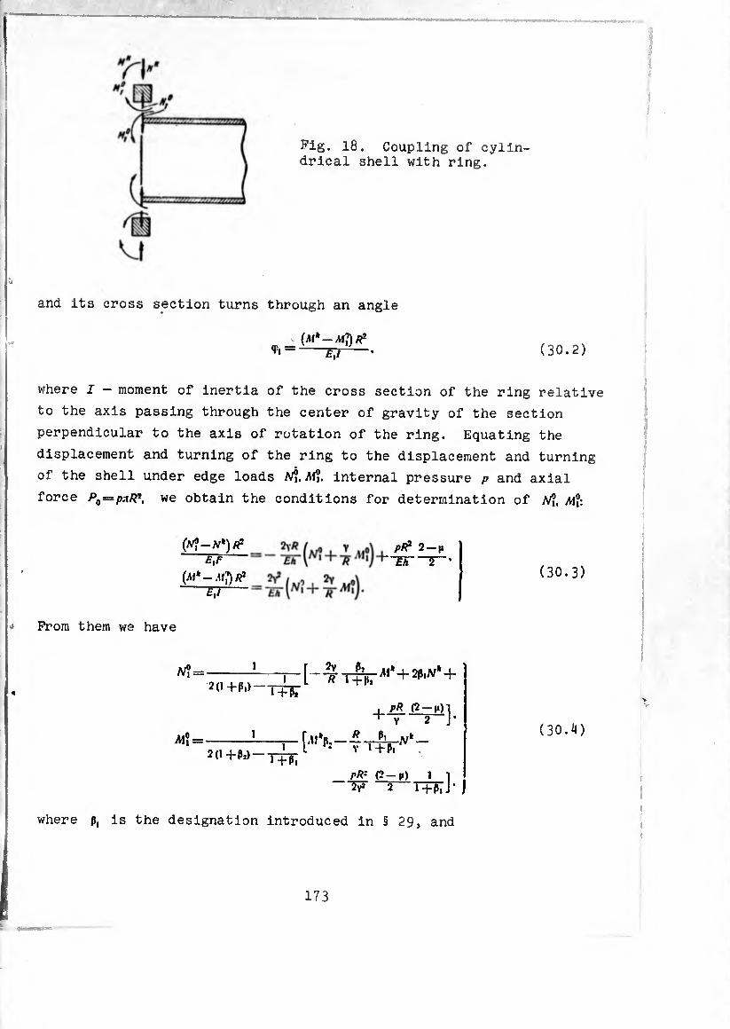
Fig. 18. Coupling of cylin¬ drical shell with ring.
and its cross section turns through an angle
*> =-FT2—- (30.2)
where I - moment of inertia of the cross section of the ring relative
to the axis passing through the center of gravity of the section
perpendicular to the axis of rotation of the ring. Equating the
displacement and turning of the ring to the displacement and turning
of the shell under edge loads /V?. M?. internal pressure p and axial
force P0=s¡kiR*, we obtain the conditions for determination of Ni, M°:
(frf — AT*) Ä* E,F
(M'-AtyR1
P# 2-|i £r~2~
From them we have
(30.3)
2(1+ß,) 1+ß*
iM? = 1
pR (2 — m) 1 V “2—J-
R Pi »;*
' l+l>'
pR: (2-n) i i 2 T+K J •
where ß, is the designation introduced in § 29, and
(30.4)
173
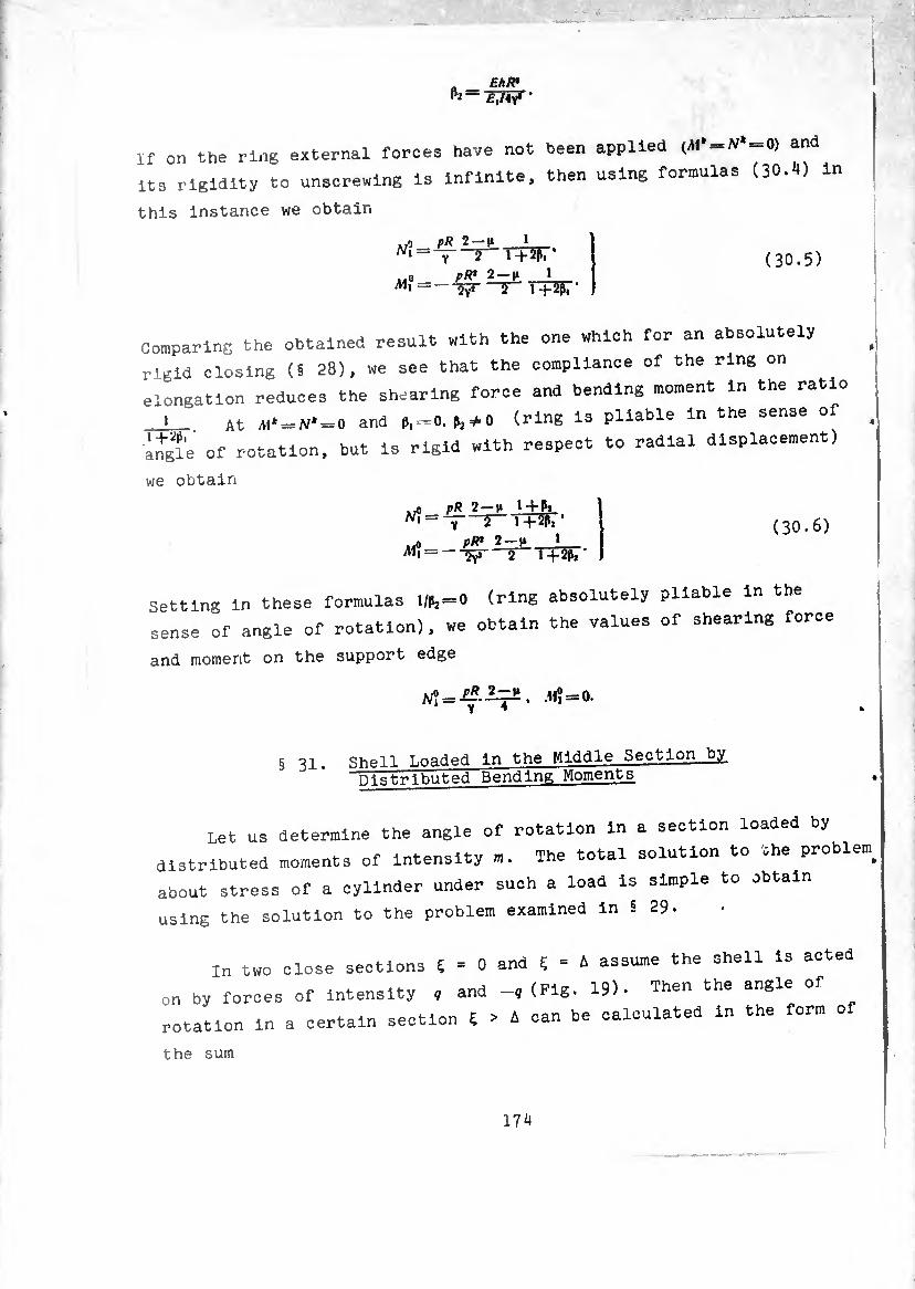
ft Eh* ^ £,/4y* ‘
If on the ring external forces have not been applied (AI> = N*-0) and
its rigidity to unscrewing is infinite, then using formulas (30.H) in
this instance we obtain
i-j. !
Ai?
y T'TTîpr* p R' 2 —n 1 "îÿ* T~ T + 2P, -
(30.5)
Comparing the obtained result with the one which for an absolutely
rigid closing (§ 28), we see that the compliance of the ring on
elongation reduces the shearing force and bending moment in the ratio
i At A1» = N* = 0 and p,-0. p2*0 (ring is pliable in the sense of
angle of rotation, but is rigid with respect to radial displacement)
we obtain
irn t)R 2 — |t 1+Pj —r-T+wr pR* 2-1* 1
1 + 2ß, ' Al? = 'W' 2
(30.6)
Setting in these formulas 1/^==0 (ring absolutely pliable in the
sense of angle of rotation), we obtain the values of shearing force
and moment on the support edge
§ 31. Shell Loaded in the Middle Section by t~hgt-.ri huted Bending Moments
Let us determine the angle of rotation in a section loaded by
distributed moments of Intensity m. The total solution to the probier»
about stress of a cylinder under such a load is simple to obtain
using the solution to the problem examined in 5 29-
In two close sections Ç = 0 and Ç = A assume the shell is acted
on by forces of intensity , and -, (Fig. 19). Then the angle of
rotation in a certain section Ç > A can be calculated in the form o
the sum
174
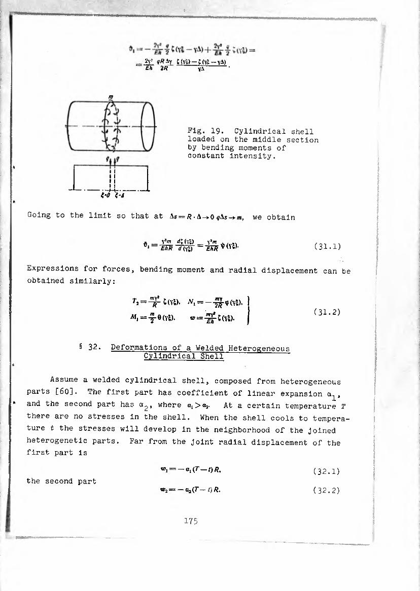
= 2v^ C(v;)-;(Vt-yA) Eh 2R vA
m
Fig. 19. Cylindrical shell loaded on the middle section by bending moments of constant intensity.
i i
i :
Going to the limit so that at =/? • A->o we obtain
Expressions for forces, bending moment and radial displacement can be
obtained similarly:
uv«. *«=—gkíYS). (31.2)
=-J- 0 (yd. w=i?3r £ (vi).
§ 32. Deformations of a Welded Heterogeneous Cylindrical Shell
Assume a welded cylindrical shell, composed from heterogeneous
parts [60]. The first part has coefficient of linear expansion c^,
and the second part has ot?j, where a, >02. At a certain temperature T
there are no stresses in the shell. When the shell cools to tempera¬
ture t the stresses will develop in the neighborhood of the joined
heterogenetic parts. Far from the joint radial displacement of the
first part is
tff, = -a, (32.1) the second part
^2=-0,(7^- t) (32.2)
175
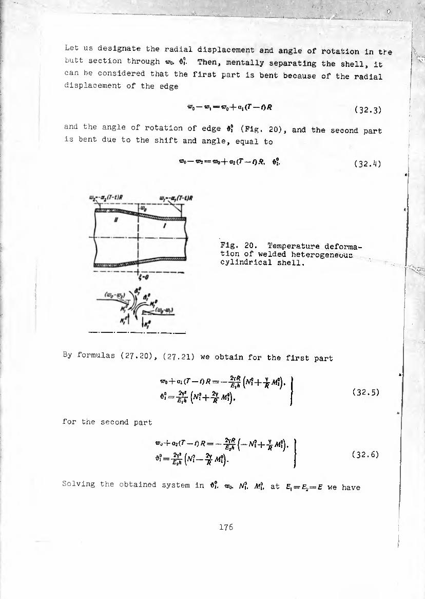
Let us designate the radial displacement and angle of rotation in the
butt section through w0, 0?. Then, mentally separating the shell, it
can be considered that the first part is bent because of the radial
displacement of the edge
®o “’i — wo+ai (T — OR (32.3)
and the angle of rotation of edge 0? (Pig. 20), and the second part
is bent due to the shift and angle, equal to
i»o —«»J == w0-fa2 (7-/).9, 0?. (32.¾)
Fig. 20. Temperature deforma¬ tion of welded heterogeneous cylindrical shell.
By formulas (27.20), (27.21) we obtain for the first part
«•0 + «i(7-O/? = —JJ
= ("?+£"?)•
(a'i + tJ-jW?).
(32.5)
for the second part
+a2(7-/)* = _-g* JV? +Af?),
^ = ¾ ("?->?)• (32.6)
Solving the obtained system in 0?. w0. JV?. Ml at Ex = E2t=E we have
176

(32.7)
= -Aí? = 0.
w0=-^±pJ(T-t)R,
ô? = — (a, — a2) (T — /).
Computing Tj. /M, with the aid of formulas (2.15), (2.16), we find that
the peripheral force suffers a discontinuity at the joint, and the
bending moment is everywhere continuous:
Tj — (a, - oj) (T — t) e(vi).
Ti-g" (a, — a2) (7" — /)0 (y£, ).
= -(a, - a,) (r -/) UYl).
(32.8)
(32.9)
The bending moment becomes greatest in absolute value in the section
Flexural stresses in this section are equal to
^ = t!" T ^ - “2) (r - '>0-322-
at n? = o,i
of = 0.294£(ai - a2)(r—¿). (32.10)
Peripheral stresses are the greatest at the joint. They are
r ' (0) i °2 = —×= T f (“i — “a) (r — *>•'
7-11(0) j (32.11 a2 = —^—=—jE(al — a1)(r — f).
5 33. Cylindrical Shell Under the Action of Hydrostatic Pressure
In all earlier examined examples load ^(0) did not change along
the cylinder and the particular solution of the basic résolvant
equation (25.27) did not differ from the zero-moment solution.
177

Let us examine the case of a load changing along the axis [12].
A vertical container is filled to the top with water. The lower edge
of the container is rigidly fixed, the upper is free. In this way,
at the edges the following conditions should hold:
1 (33.1) MÍ =* A/f «= 0. J
The load has the form
(33.2)
The particular solution of the basic equation is determined now using
formulas (25.33)
í0=.-pRi. V>„ = j pR> (I - Ü <<S - pR’ ('1 - y ) ■ (33'3)
To this solution correspond the following forces, moments and dis
placements :
0. fj*=
^,-0.
P** •£Ã*
.pRHi-V ■I. - PÄ* (/-1) « = —gj
(33.4)
(33 * 5)
Let us determine shearing force and bending moment in the fixed
section. On edge 5=0 the angle of rotation and displacement
corresponding to the above particular solution are equal to
- p/W. W=-Eir-
Substituting in formulas (27.22)
to0 by IP0 — pR*L
(33.6)
assuming ^ = 01=^0. we obtain
The calculation of these quantities on the basis of the zero-moment
solution
leads to the values
Ai? = p/?*¿ jyO 1 y * (33.8)
which differ from those obtained above in terms of order
comparison with unity.
I R V L
in
In this way, utilization of the zero-moment solution leads in
> thls case to error of the order ^ in comparison with unity during
the determination of local stresses near the edge.
§ 34. Long Cylindrical Shell Under the Action of a Bending Load
Considering the deformation of a shell under the action of a
bending load (Pig. 21), we will make use of simplified résolvant
equation (26.20). The solution of the corresponding uniform equation
is again taken in form (27.4). Taking into account (26.19), we obtain
y, = EhW = /1,0 (Yi) + (y*) + A2Ü (Y&,) -)- B¿ (vs,). )
2V% “ (Yt) - Bfi (YÜ + (Vii) - fl2Ö (YÊ,)- | ( 3 4.1 )
To get the general solution to (34.1) it is necessary to add the
particular solution of heterogeneous equation (26.20). As such one
could use zero-moment solution (26.30)
a
¢,-0. fy.djrfl- (34.2)
In the example of an axisymmetrically loaded shell it was shown that
calculation of the particular solution on the basis of zero—moment
theory in certain cases can introduce into the determination of local
stress error of the order j/qj- in comparison with unity. Solution
179
0
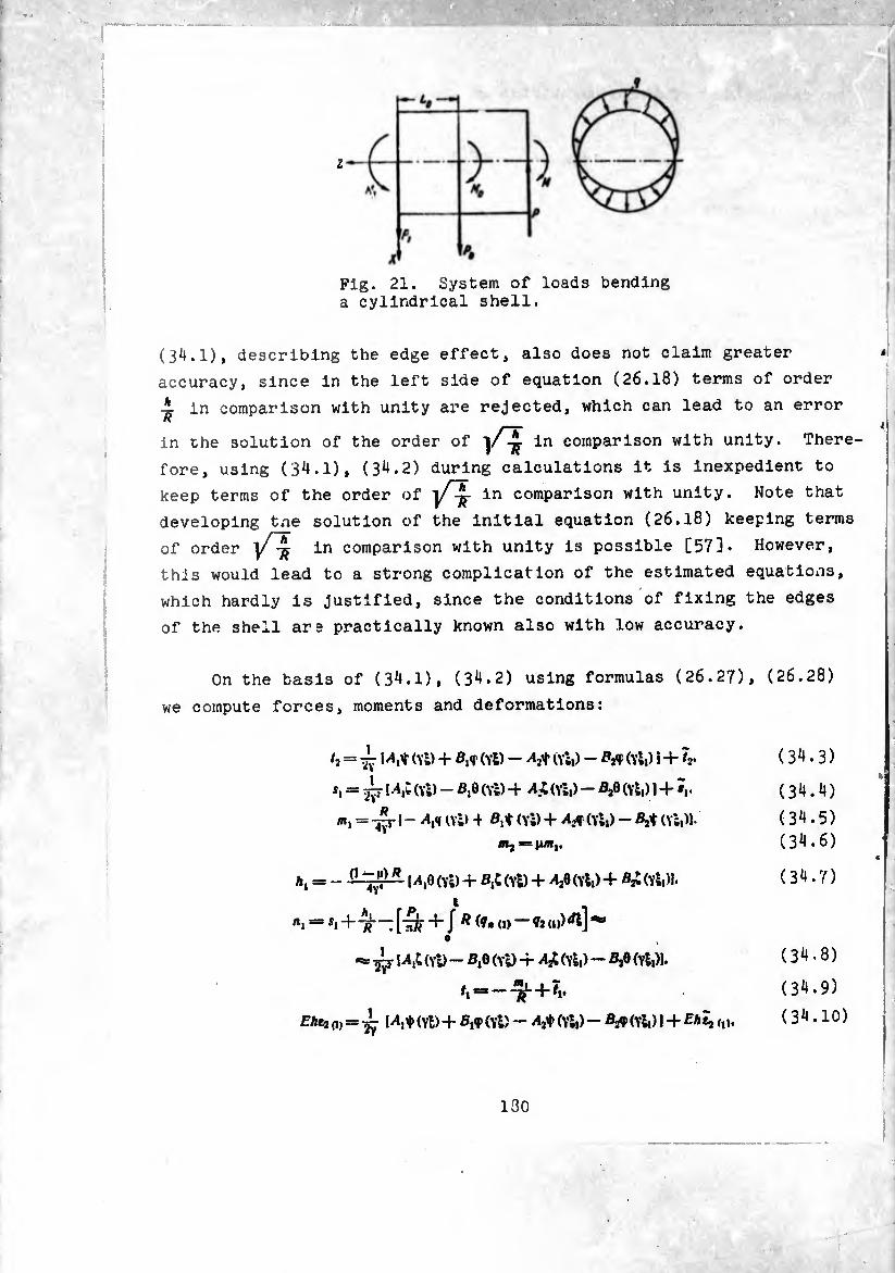
Z
Fig. 21. System of loads bending a cylindrical shell.
(34.1), describing the edge effect, also does not claim greater
accuracy, since in the left side of equation (26.18) terms of order
A in comparison with unity are rejected, which can lead to an error
in the solution of the order of in comparison with unity. There¬
fore, using (34.1), (34.2) during calculations it is inexpedient to
keep terms of the order of /t in comparison with unity. Note that
developing tne solution of the initial equation (26.18) keeping terms
of order in comparison with unity is possible [57]. However,
this would lead to a strong complication of the estimated equations,
which hardly is justified, since the conditions of fixing the edges
of the shell are practically known also with low accuracy.
On the basis of (3^.1), (3^.2) using formulas (26.27), (26.28)
we compute forces, moments and deformations:
h = ^ (Vi) + fl,<r (vt) - 0¾) - (Yl,) ¡ + tr
*. = ¿ (Vi) - 0,0 (Vi) -+ A.i (vi,) - ß2e (vi,) )+Ï,.
= -^rl— Afl ni) + (Yi) + A#(Yi,) - (Yi,)|.
A, = - \Afi (Yi) + (Yl) + AJÍ (Yl,) + Ai (Yl,)). *
«, = «,4--^-—;[-^ +J ^ (?• O) fnip^l]^’
(Yl) - 0,9 (Yl) + A¿ (vi,) - ß20 (Yl,)l.
—-5r + ?i.
Ehtj = (Yl) +- Bftf (Yl) — (Yl,) Bjf (Yl,) 1 -+ Ehtj,,,.
(34.3)
(3^.4) (3^.5)
(3^.6)
(34.7)
(34.8)
(34.9)
(34.10)
130
where (A,4-/i) is a known function of external loads (¿6.7), the
quantities tl,73.sl are determined according to formulas (26.31), and
®*(,) <i>—^(/o+/,)¡ (34.11)
is peripheral deformation, which corresponds to the zero-moment state.
Axial displacement is determined by.the first formula of
(26.9):
Here u0 constant of integration, characterizing angular displacement
('if) edSe * —0 as a whole,
- or.. Vi' ■Wdi (34.13)
is the displacement corresponding to the zero-moment stressed state.
Furthermore, in conformity with (26.27) in (34.12) we accept /,=7,.
On the basis of (17.3), (18.5), assuming in them RldQ = dt, v = /?. 0 = 4-. we have 2
and
where w«, - displacement of edge * = 0 in the direction of axis OX.
Using this formula we compute the displacement of the zero-moment state
(34.14)
Rewrite formula (26.11) in the following form:
(34.15)
l8l
Separating the left ana right parts, corresponding to the zero-moment
solution, we obtain
Assuming in this equality ¢==0, we find
i = J [/?¥-! “(i)]v(i)« (3^.16)
where «>,„ is determined according to formula (34.14). Note that if
we simply used formula (34.15) for determination of zero-moment
displacement ¿(I), assuming in this case ¢=0. then we would obtain
the result
I
•(!)=■“/•(!)A* (34.17) 0
which differs from (34.14). Such a difference is explained by the
fact that the zero-moment solution ¢ = 0. ^, = 17, does not satisfy
accurately the second equation of (26.15)» which is the condition of
compatibility of deformations.
Peripheral displacement t>(„ is easily found without integration.
On the basis of (26.9) we have
'’(i) <0 — •(«)• (34.18)
I
At the end of § 26 it was shown that the zero-moment stressed
state 7,. s, coincides with the stressed state in a beam. Relative to
displacements we can say the following. If in formula (34.13) we set 4
H = 0 and then determine displacement on the basis of (34.17)» then
we obtain the expression
®u) == -jly ^1 + J J J J VW1?* dsdtdsj, ( 34.19) also coinciding with the deflection of a beam of tubular cross
section (/=.7^3 - moment of inertia of cross section of beam, q(s) is
I82
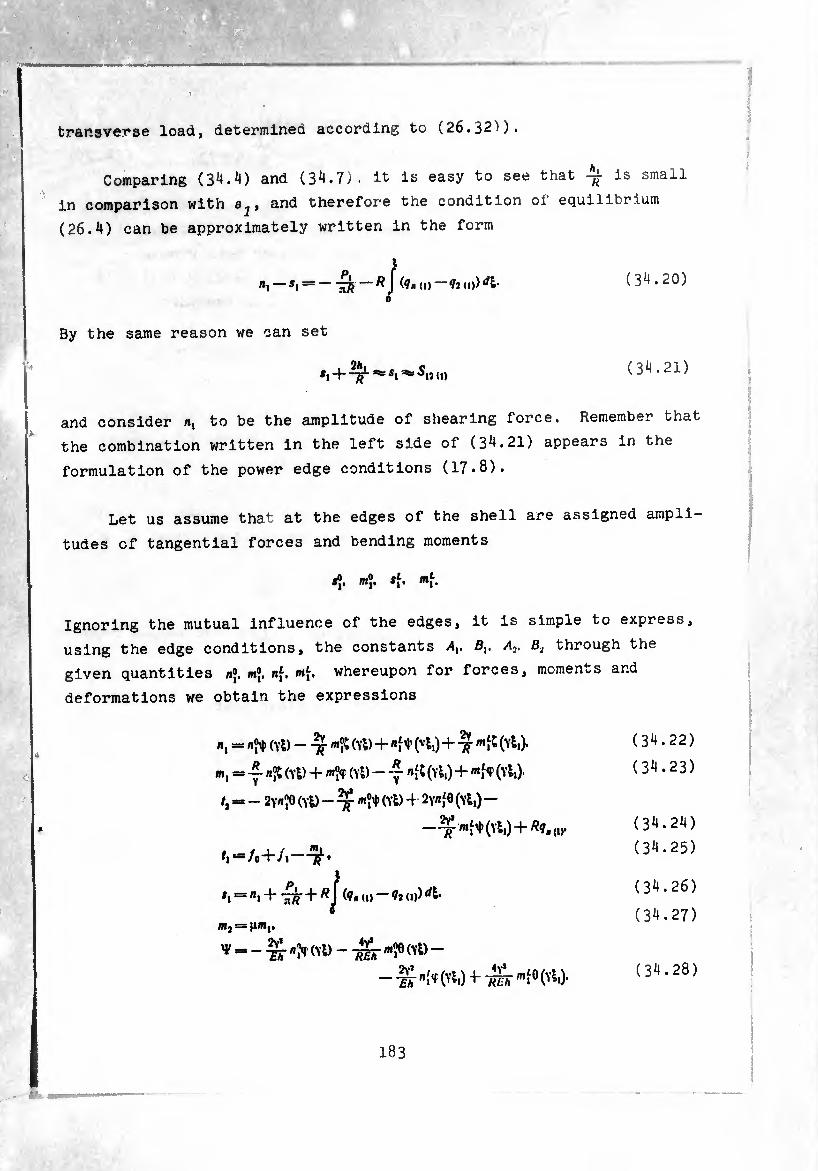
mÊÊÊÊfÊÊÊ
transverse load, determined according to (26.32^).
Comparing (34.4) and (34.7). It Is easy to see that is small
in comparison with and therefore the condition of equilibrium
(26.4) can be approximately written in the form
n, — >i = ~ ^ (9, (,) — 92(1))^1- ( 34.20) 0
By the same reason we can set
(34.21)
and consider «i to be the amplitude of shearing force. Remember that
the combination written in the left side of (34.21) appears in the
formulation of the power edge conditions (17.8).
Let us assume that at the edges of the shell are assigned ampli¬
tudes of tangential forces and bending moments
j®. m®. t[. *f.
Ignoring the mutual influence of the edges, it is simple to express,
using the edge conditions, the constants Sj. ^ through the
given quantities n®. m®. nf. <. whereupon for forces, moments and
deformations we obtain the expressions
«I = (Vi) — (Yl) + "ft (vli) + -¾- (Yli)*
m, = n®t (Yl) + (Yl) - ~ »^(Vl,) + «ff (Yl,).
/, = - 2Y^ (Yl) - ^ *?♦ (Yl) 4 SYflfe (Yl,) -
—Tf mí^ (Yl,) 4- Ä9, (1).
<,*=/04-/,-
*, = «, + -¿fc 4 (9« (,) — 9? (,)) rfl*
|R]B> )UR|.
V —■g-«>r(YD--^-«îe(Yü-
Th (Y^i) Tffii
(34.22)
(34.23)
(34.24)
(34.25)
(34.26)
(34.27)
(34.28)
I83
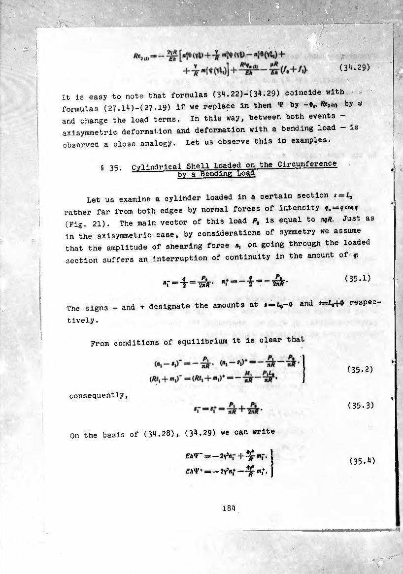
(3^.29)
It is easy to note that formulas (34.22)-(34.29) coincide with
formulas (27.14)-(27.19) if we replace in them V by -*,./&,(.> by w
and change the load terms. In this way, between both events -
axisymmetric deformation and deformation with a bending load - is
observed a close analogy. Let us observe this in examples.
§ 35. Cylindrical Shell Loaded on the Circumference bv a Bending Load
Let us examine a cylinder loaded in a certain section s = L0
rather far from both edges by normal forces of intensity ?, = ?cos<r
(Fig. 21). The main vector of this load P, is equal to m,R. Just as
in the axisymmetric case, by considerations of symmetry we assume
that the amplitude of shearing force «, on going through the loaded
section suffers an interruption of continuity in the amount of q.
The signs - and + designate the amounts at 5 = 1,-0 and 5-1,+0 respec¬
tively .
From conditions of equilibrium it is clear that
(35.2)
consequently,
(35.3)
On the basis of (34.28), (34.29) we can write
EA'P" = - 2yV + wf.
EhV* = - 2yV — Tp «,+. (35.4)
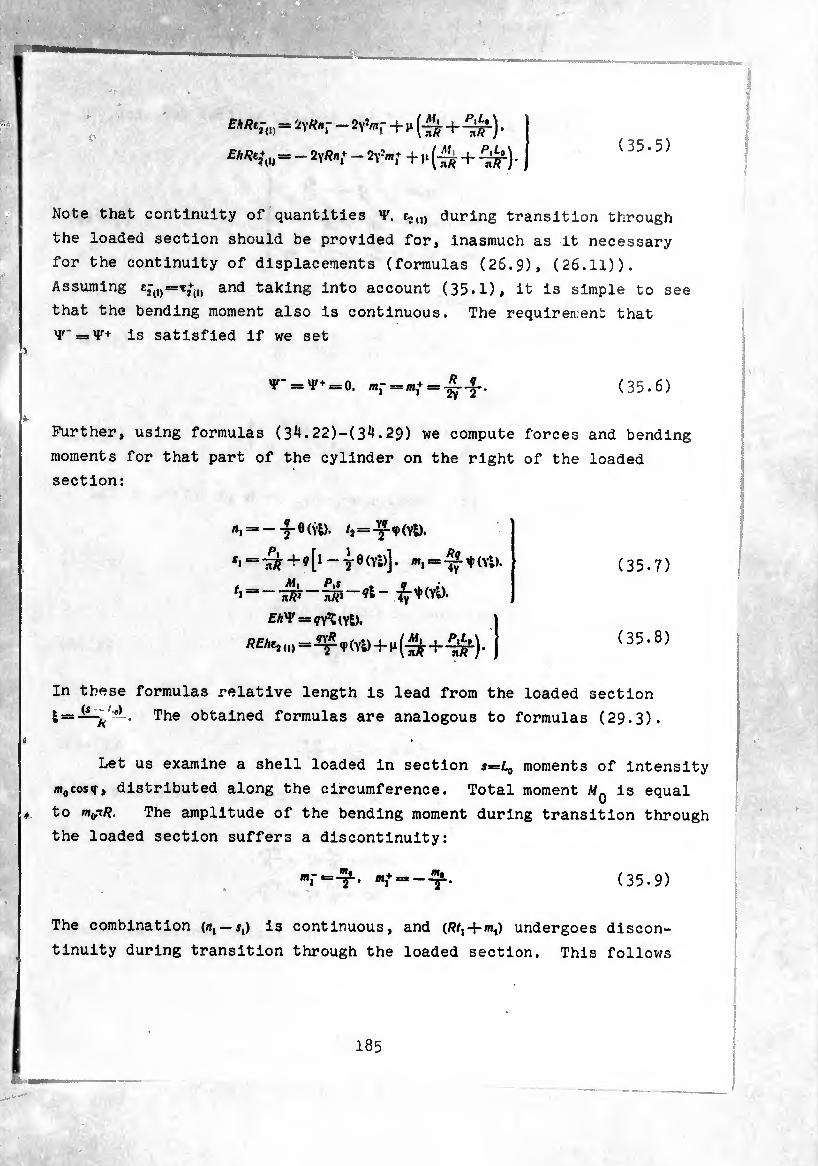
(35.5)
fASe-n = 2v*»r - 2Y^r + ^ (¾ + ^) •
£■///?€+(,j =. - 2yRn+ — 2fm* + ji -+-
Note that continuity of quantities V. t,,,, during transition through
the loaded section should be provided for, inasmuch as it necessary
for the continuity of displacements (formulas (26.9), (26.11)).
Assuming and taking into account (35*1), it is simple to see
that the bending moment also is continuous. The requirement that
^-=^+ is satisfied if we set
^- = ^+ = 0. «,- = *+=-*.-«-. (35.6)
Further, using formulas (3^.22)-(3^.29) we compute forces and bending
moments for that part of the cylinder on the right of the loaded
section:
«i = - -j- Ö (Yl). /2 = -y- ^ (Yl).
*i—+?[* — 76(Y!)]. «i = -^-t(Yl).
EhV=x çy^iYl).
(0 =-2^ 9 (Yl) + »1 (-¾ +-¾^).
In these formulas relative length is lead from the loaded section
l — —The obtained formulas are analogous to formulas (29.3).
Let us examine a shell loaded in section s=L0 moments of intensity
m0cos<r, distributed along the circumference. Total moment MQ is equal
to mgn/i. The amplitude of the bending moment during transition through
the loaded section suffers a discontinuity:
mf ■=-?■• ":*“--?• (35.9)
The combination (n, — s,) is continuous, and (/?/, + «,) undergoes discon¬
tinuity during transition through the loaded section. This follows
(35.7)
(35.8)
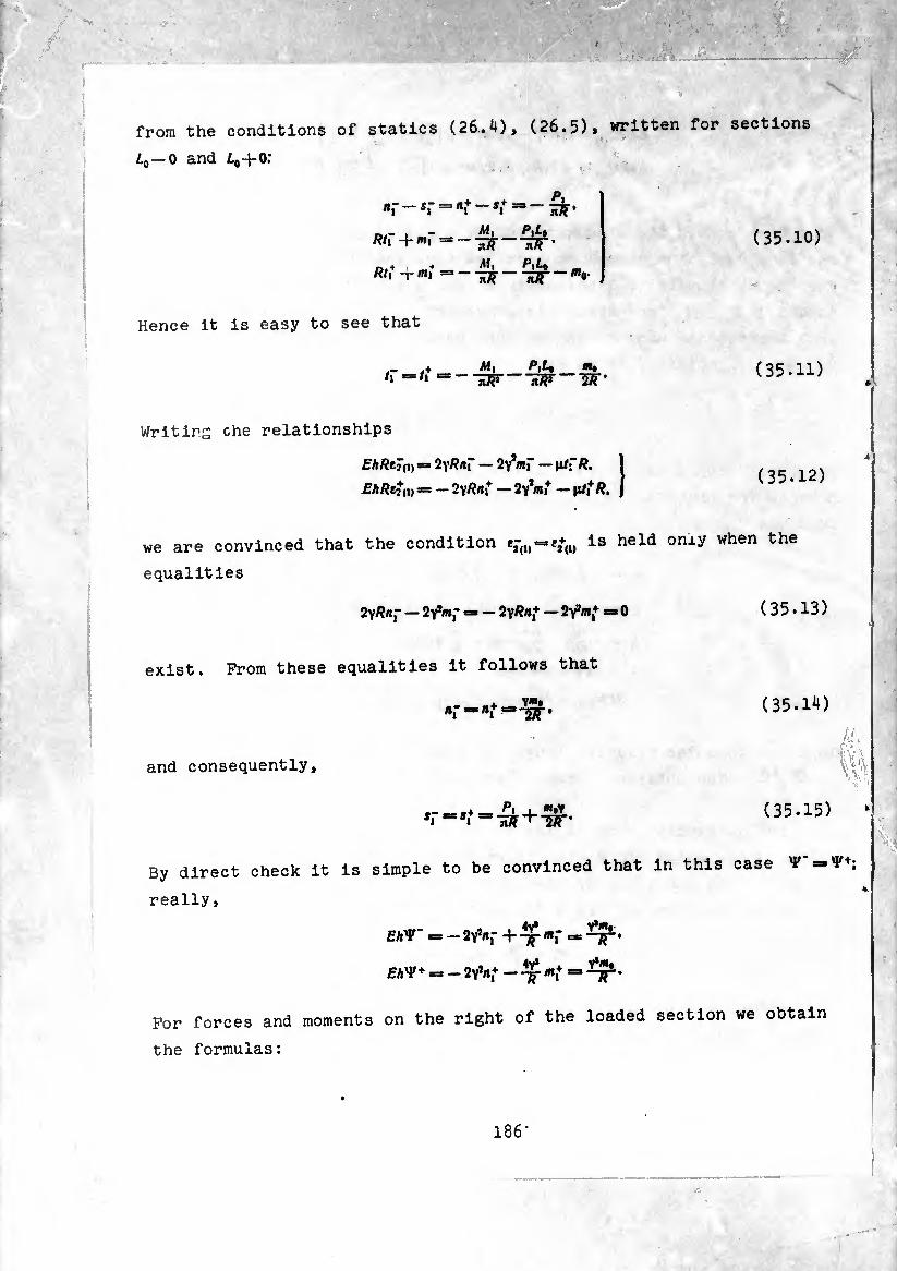
from the conditions of statics (26.4), (26.5), written for sections
¿0 —0 and ¿0-i-0;
n- _ Sf =,,+ _ t* P, HM'
Rt\ + mf PiLt
TR ñF ’
n.+ ■''il P\^-* _ Äh -rmi
(35.10)
Hence it is easy to see that
= - M, w
«i» W~57r
(35.11)
Writirs che relationships
EhRtî(l) = 2yRnr — 2Y*mr —
E/tRefu) = — 2yRiti — 2y,«i+ — |i/i+ Ä. (35.12)
we are convinced that the condition Is held onxy when the
equalities
2y Ra~ — 2Yîmf == — 2y/?»1+ — 2Y*m,+ = 0 (35.13)
exist. From these equalities it follows that
V*. *» Bi 2Ä *
(35.14)
and consequently,
- ? : V 'v
a‘
.. _ /’i . "*y •i +
(35.15)
By direct check it is simple to be convinced that in this case ¥
really,
EA'F" = — 2Y*«,- + mf =
= — 2y1«^ ^ mi+ =
For forces and moments on the right of the loaded section we obtain
the formulas:
186-
ni — T (Yl>. <2= - ^Uvl).
*1 ^ ^ + -^TT(v|). «1 = -- -y- 0(Yi)- V«#
^ ^ ~ life _ +-¾ 6 ÍYl). -J 7T
(35.16)
the same formulas could he obtained directly by using (35.7), (35.8)
and carrying out the limit transition just as was done in § 31.
187
§ 36. Stressec and Dlsplacemerrcs In a Shell with RlKld Bottoms
-.:- '.V. •; • --
È; . - iiimdMÍ&fvri
Let us determine stresses In a long shell loaded as shown in
Fig. 15 at Pq = o, considering that the extreme sections of a shell
are connected wiun rigid diaphragms and can only be turned and
dislocated as a whole. On edges £ = 0 and ^ = 0 (s = £) the
following conditions should be executed:
^(1, = ^ = 0. = ^ =
On the basis of (3^.28), (3^.29) we obtain
"!--S’"?' “ T [^- m — 1' (/«+/.),.,]•
Ilf » — 1 V y [^« (» ^(/0+ /lX.il*
(36.1)
(36.2)
where
M, (/o+/i)*-o=*—
I/0+f 1),.1 = At, PtL
— ^ J J (?» (I) - <h (1)) ¿Idl-j Ç, dt.
Conditions of equilibrium of the shell as a whole is
L
“ Tiff ~ J<» ~ ?» (i))+ = 0,
L I L ai> Pit. ft. . . . M r in? inr—J J to« id—<n) * d» —j /ty, dt=o.
(36.3)
(36.4)
whence it follows that
In this way.
</o+/i)i.‘¿='—
m1-
Mil m{ — — R r 2)3
(36.5)
Par from ends of the cylinder exists the zero-moment state:
0 0 0 (36.6)
» 9
= 7¾ + J (i) * — J fj<i) *• 0
The stresses calculated according to forces of the zero-moment state
we take as the nominal, where
(36.7)
One ought to have in mind that amplitudes of stresses or the maximum
stresses which exist in points ¢) = 0 have been here written out.
Stresses in points <f> = tt are equal in magnitude and opposite in sign.
In order to find stresses at arbitrary ¢, it is sufficient to
multiply the amplitude values by cos <J>. It is easy to see that the N
amplitude of stress is equal in magnitude to the maximum stress
in a beam of tubular cross section (the moment of mass inertia of
the section of the beam relative to axis 0Y is equal to I = nfí-^h
and stresses a *= Af/?//=. The amplitudes of bending stress max “K"/
from an edge load and from distributed pressure we compute using the
formula
(36.8)
for example. *
(36.9)
where the upper sign is taken during the calculation of stresses in
filaments of the external surface of the shell; the lower sign
refers to fibers of the internal surface. In this way, flexural
stresses from internal pressure on the edge of the shell amount to
189
“(I) “o»
(36.10)
I , ,/-5-.,,3)- fi«“ral sVresses from the edge liad " OT (when n* — 0.i. )/ ï_)iï ^í.83;*
, to „•/ZETof.O.sroo-r. Comparing these results vith the
wi are equal t0 ln the stress of a rigMly fixed edge of estimate of local incre . • see that an axisymmetrically loaded shell (S 28), it
quantitatively they agree.
Let us turn to the determination of displacements. On the
oasis of formulas (31-12) and (31.21) we fin
-■jJrj [iv*!« (vl,) --7Tmt* (ví>)l i*+“V
Let us integrate taking into consideration that
J,(x)ix--7'H')- i+(x)2x..t(x).
J ;<*)<*--f»(x). J fix)lx-<>(*)•
then we obtain
[* (vo-<(«,)) - -¾ «ítw>-t(YS,)l}+*J,
0 „g This means that there is no Subsequently we will set u(1) * Setting in (36.11) 5 « 1 rotation of section s = 0 ar°^ *X 8 ln comparison with r , 0 and igi.orins the quantities UV)
unity, we find the displacement on the seco
(36.11)
*
Calculating the integrals
(36.1?)
+1 (Yy + (YÜ- UH- 4M
—^-IçíyO—<P(Yli)l}*
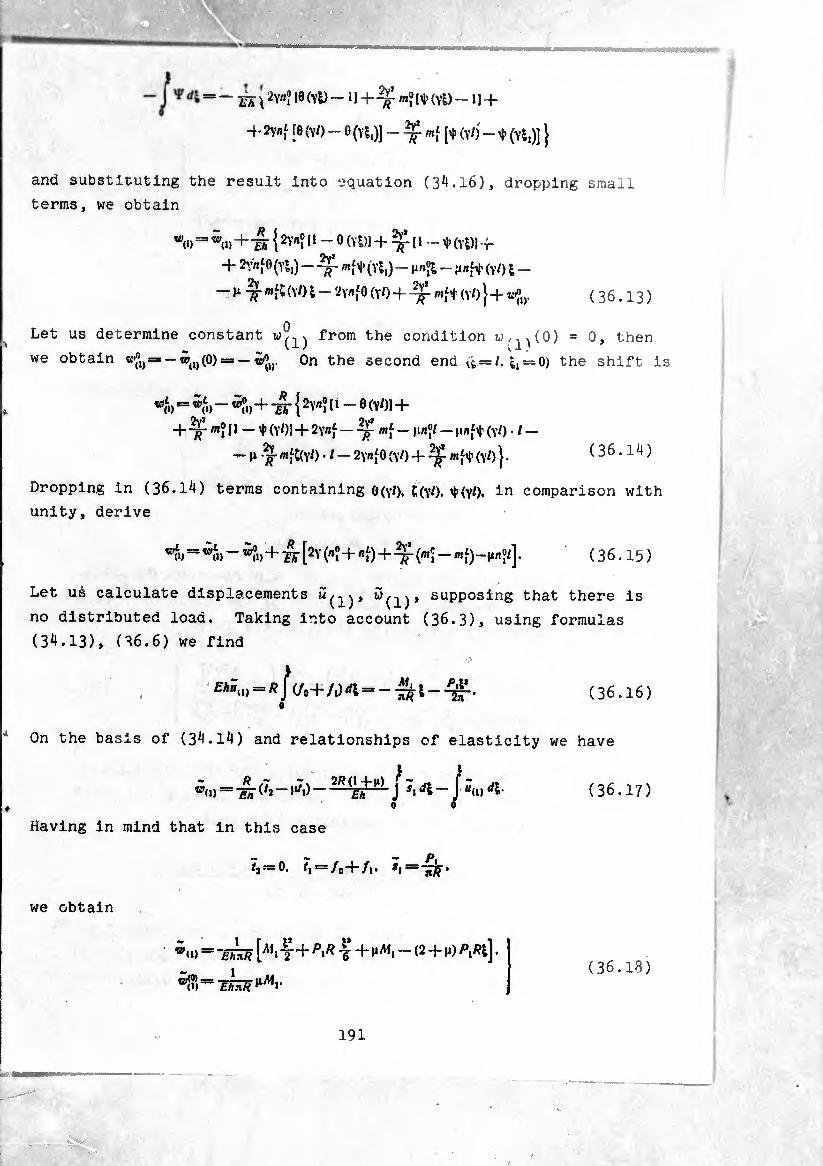
$ • r\'-
0;
Û \ 2vnî 10 (Yl) - 1 H- ^ mj Ht» (vi) -11 +
-t- i8 (YO - O (Y*,)] - X mí (YO -1 (Yt,)]}
and substituting the result into equation (3^.16), dropping small
terms, we obtain
w(» = *<.> + 4 {11 - 0 (Yi)l 4-^(1-* (Yt)l + + Z’.’nf 0 (Yl,) — -Tf «ít (Yl,) — Mnjl — H«ft (YO I —
— ^ «fC (YO l — 2YflfO (YO + «ft (YO )+^,,. ( 3 6.13 )
Let us determine constant from the condition w/;p(0) = 0, then
we obtain tp(1)(p)=» —wjy. On the second end (j = /, ^ = 0) the shift is
wí) = «f» - ^»+ 2Yrti I » - 0 (V01 +
+ -^- «? 11 — t (YO) + 2Y«f — «f — |1/IJ/ — M"ft (YO • I —
— H /f «fC(Y0 • t — 2y«Í0 (yO + ^ «ft (YO } • (36.14)
Dropping in (36.14) terms containing 6(yO. t(Y0. t(Y0. in comparison with unity, derive
«il, = + [2Y K+«0+^ K - «O-ii«?/]. ( 3 6.15 )
Let us calculate displacements supposing that there is
no distributed load. Taking into account (36.3), using formulas
(3^.13), (36.6) we find
£Au U) =«Jv.+/,mí=--Sí--Ç£. (36.16)
On the basis of (3^.14) and relationships of elasticity we have
L ~ _ R ,7 .J, 2/?(1+m) j W<i)~£rt (^-£ft J Sl
o —J“<1> *1 (36.17)
Having in mind that in this case
P, t2x=0. /, = /„+/,. *1==-^
we obtain
w«»> ~ ~EimR [A,‘ T + T + VM1 — (2 + M) . (36.18)
191
f-Æ
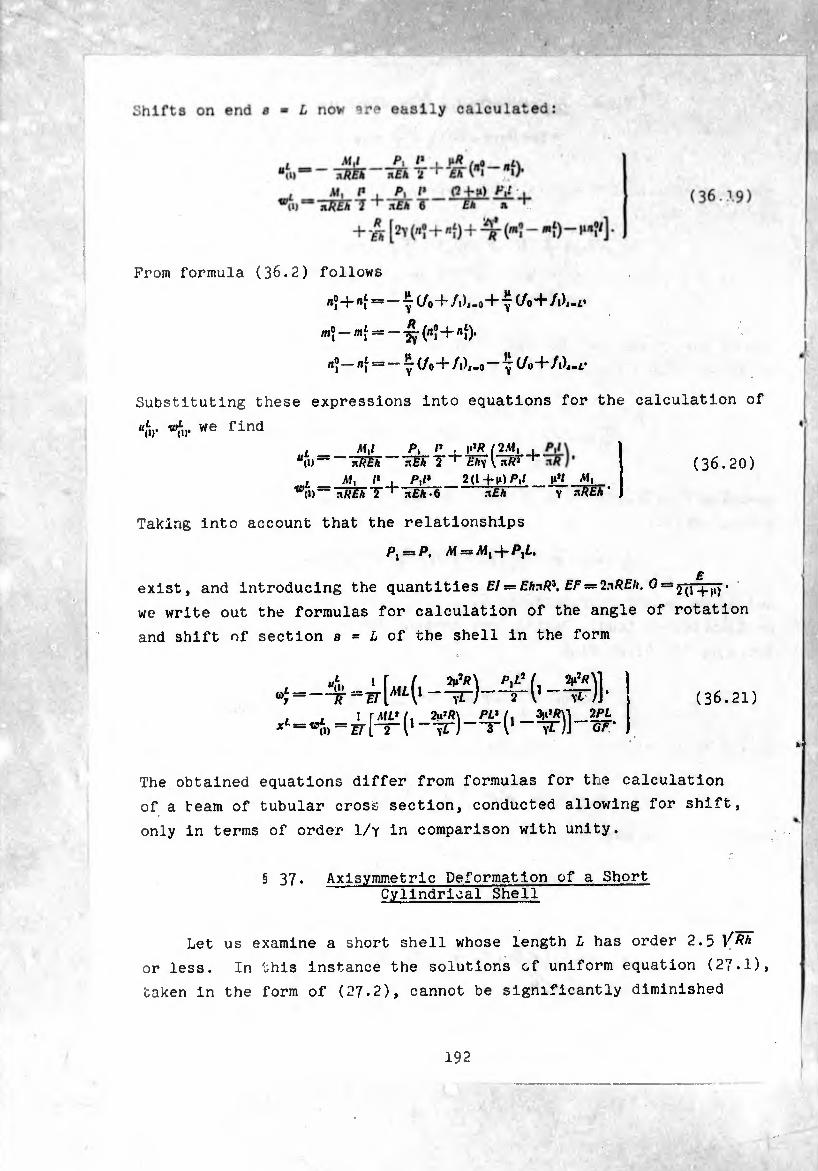
From formula (36.2) follows
*?+^-=-^7(/0+/1^-0+ ^ (/o+/A-i*
m? —(rt?+ni)*
«ï - < = - V i/o+/1),-0 -7(/0+/i)«-r
Substituting these expressions into equations for the calculation of
“fiy «fi,* we find , M,l P, /* ,.*Ä/2Af,
BU> nREk ãÈh 7 + Eh\ \ nk3
mL - l' I JV* 2(»+M)P.f W(i) — nP£A T + nfiA • 6 n£A
M, " Y ."»/?£* ’
(36.20)
Taking into account that the relationships
Pj = P, A! = A!|-|-P|£.
exist, and introducing the quantities f/= fAn/?3. EF = 2.-\REh. 0 = j(ij.
we write out the formulas for calculation of the angle of rotation
and shift of section s = L of the shell in the form
“Í =-^ -ÿt) 2~v \L )]• 1 rML't. 2u’P\ PL* f. 3,,»p\l 2P£ zirri1--^)—3-I1-yt)]^ = X iD
(36.21)
The obtained equations differ from formulas for the calculation
of a team of tubular cross section, conducted allowing for shift,
only in terms of order 1/y in comparison with unity.
§ 37. Axlsymmetrlc Deformation of a Short Cylindrical Shell
Let us examine a short shell whose length L has order 2.5 V^h
or less. In this instance the solutions of uniform equation (27.1),
taken in the form of (27.2), cannot be significantly diminished
192
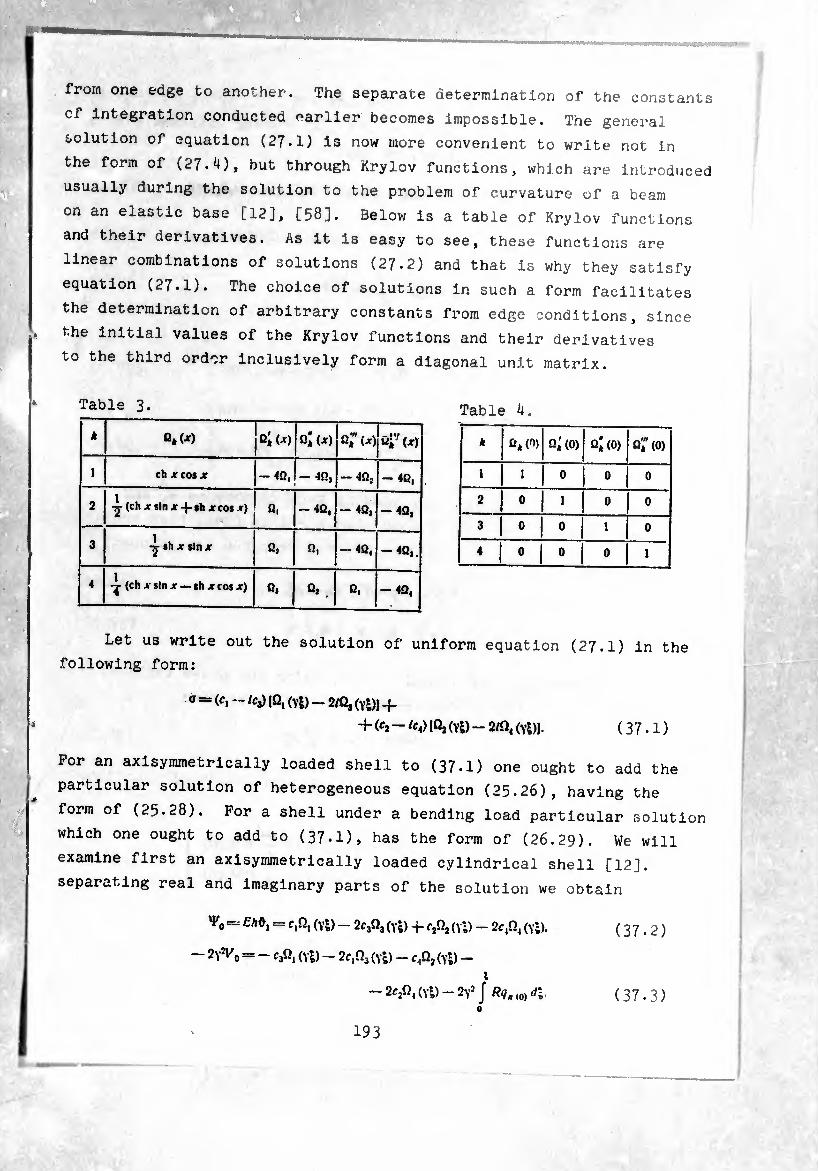
mmmmam
• * . i
Vm
from one edge to another. The separate determination of the constants
of integration conducted earlier becomes impossible. The general
solution of equation (27.1) is now more convenient to write not in
the form of (27.4), but through Krylov functions, which are introduced
usually during the solution to the problem of curvature of a beam
on an elastic base [12], [58], Below is a table of Krylov functions
and their derivatives. As it is easy to see, these functions are
linear combinations of solutions (27.2) and that is why they satisfy
equation (27.1). The choice of solutions in such a form facilitates
the determination of arbitrary constants from edge conditions, since
the initial values of the Krylov functions and their derivatives
to the third order inclusively form a diagonal unit matrix.
Table 3. Table 4.
k 0,(JT) q;<*) ßl (■») Gïix) Ú¿"(jr)
l ch X cos X -4Q, - -»n, — 4Qj -4ß,
2 — (ch X sin jr -|- sh jr cos x) -4Û, -4Q, — 4Q,
3 sh * sin x q2 0, — 4Û, 40,.
4 (ch x sin jr — sh jc cos jr) 0, Q>. Û. -4Q,
k £f,(0) Q'k(0) £>;«» o;<o)
1 1 0 0 0
2 0 1 0 0
3 0 0 1 • 0
4 0 0 0 1
Let us write out the solution of uniform equation (27.1) in the
following form:
O = (c, ~ /Cj) (fij (Yy _ 2/0, (ydj _|_
+ (¾—fc«) [fij (Vl) - 2/Q, (Yl)J. (37.1)
For an axisymmetrically loaded shell to (37-1) one ought to add the
particular solution of heterogeneous equation (25.26), having the
form of (25.28). For a shell under a bending load particular solution
which one ought to add to (37-1), has the form of (26.29). We will
examine first an axisymmetrically loaded cylindrical shell [12].
separating real and imaginary parts of the solution we obtain
- m, = c.n, (y£) - 2C3Q3 (yd 4- (vl) - 2c a (vl).
— 2y% = - CjQ, (Yl) - 2c A (vl) - cA (Yl) - l
-2cA(YI)-2y!J Rq'(0)d\. 0
193
(37.2)
(37.3)
Substituting (37.2), (37-3) into formulas (25.20), (25.15), (25.16)
and taking into account (25-21) and differentiating with tne aid of
the table of Krylov derivatives, we have
[4c.Q4(vD-c2Q, (Yl) + 2cA(Yi) + 2C4Q3(yDI.
. ; ?<• ; >Í -¾¾ ; ‘
T2 = l/r# = é|2flQj (Ys)+2f A(Yl)-4f3Q4 (Yl) + (yDH-/??, (o>.
^1 = 2^-J (o)Ärfl-
=^o- /^.(0) ^=51 0
= ¿ |Í3Q| (Yi) + 2c,Q3(Yi) + (Yl) + 2cjQ4 (Y*t)l.
" = W |2CjQ3 (Yl) + 2f2Q3 (Yl) - 4csQ4 (yD + c4Q, (yl)] +
^ «o — + »» j Rft (0) ¿ij •
(37.^)
(37.5)
(37.6)
(37-7)
(37.8)
If on edge s = 0 the shell is loaded by bending moments and
shearing forces /1/°, and the second edge e = L is free, then arbitrary
constants c^, c2, ashould be defined frora the conditions:
s = 0. A(, = A(?.
s = /., A/, = 0. M, = 0.
(37-9)
(37.10)
According to (37-9), (37-^) and (37-7), using the above table of
initial values of Krylov functions, immediately we find
es *= 2y5^. = — AÍ®, (37.11)
Conditions (37-10) allowing for (37.11) give a system of equations
for determination of ¢-^,
2<r ,0, (y0 + e4Ü, (yl) = - 2yî/V®Q, (yl) + ^ AiJQ4 (y0.
4fA (Y0 + 2c4Q, (Y/) = - 4YW°Q2 (y/) - íf AfJQ, (Y/). (37.12)
Solving (37-12), we obtain
C, = ijf Mfa (yl) + 2YIA^Oi (y0.
4V* i,..,X ^
(37.13)
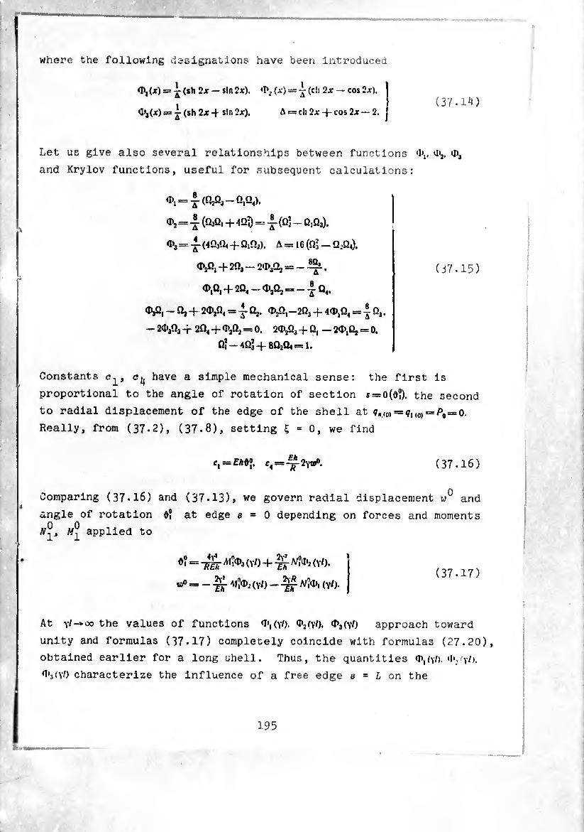
where the following designations have been introduced
= i (sh 2x — sin 2x), »P2 (x) = ~ (ch 2x — cos 2x),
a»j(x) = i (sh 2x 4 sin 2x). A = ch 2x -j- cos 2x — 2. (37.14)
Let us give also several relationships between functions U>2. *I>a
and Krylov functions, useful for subsequent calculations:
<D2 = (QaQ, + 40¾ = i- (Q] - 0|Q3),
a>3 = -J- (4O3Q4 + Q1Q3). A = 16 (O3 — Q..Q4).
0),0, + 203-2)1)3^ = -^.
¢),0, + 20,-0),0, = -10,.
0),0, -0,+ 2<D,Q, =10,. ¢),0,-203 + 40),0, = 103.
- 2<D303 + 20, + ¢,0, = 0. 20),03 + 0, — 20),0, = 0.
0, — 4Q3 + 8Q2Q4 = 1.
(37.15)
Constants have a simple mechanical sense: the first is
proportional to the angle of rotation of section s = o(ô?). the second
to radial displacement of the edge of the shell at ¢..(0) = ^1(0) = ^0 = 0.
Really, from (37*2), (37.8), setting £ = 0, we find
¢, = £A0J, ci~~ 2yvfi. (37.16)
Comparing (37.16) and (37*13)» we govern radial displacement and
angle of rotation d? at edge s = 0 depending on forces and moments
N®, applied to
^ = W ¿toa (VO + Nfa (Y/). I, n * n (37.17) ^=-¾. 4IÎ0), (Y/> - A/Î0), (Y/>.
At \l~*oo the values of functions 0*,(yO. ^(yO. ^(yO approach toward
unity and formulas (37.17) completely coincide with formulas (27.20),
obtained earlier for a long shell. Thus, the quantities ¢),()0- 'I+vh.
0‘3(y0 characterize the influence of a free edge s = L on the
195
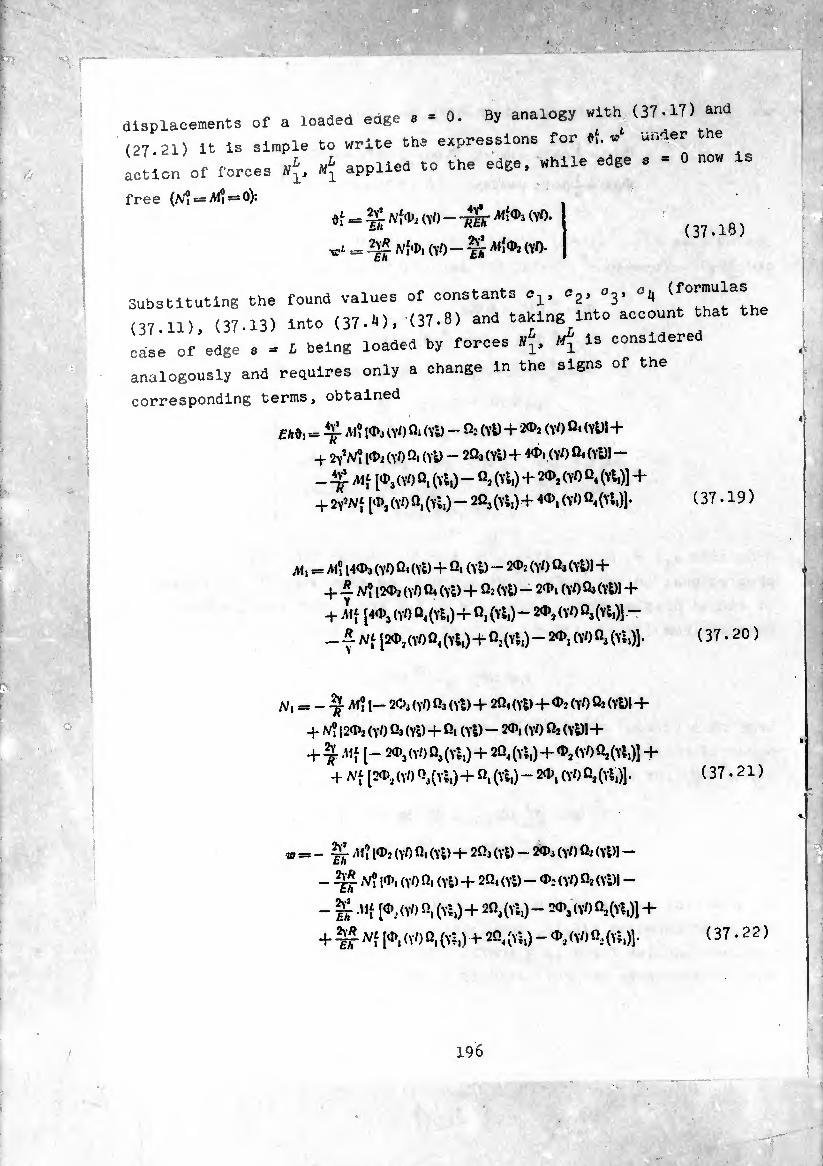
displacements of a loaded edge a - 0. By analogy with (37.17) ^
(27 21) it is simple to write the expressions for »,.<■- under the
action of forces applied to the edge, while edge e - 0 now is
free (N? = /W? = o):
= % Ufa (\’0 - -^5¡- (VO.
t « 2v« (Y/) _ ^ Al{(P3 (VO- (37.18)
, o2, Ö3, (formulas Substituting the found values of constants
(37 11), (37.13) into (37.1), (37.8) and taking into account that the
cali of edge a - 1 being loaded by forces ¢, is considered
analogously and requires only a change in the signs of the
corresponding terms, obtained
£/,0, *= M? lOd (yl) fli (Yl) — q2 (yD + (YO q< (YD1 +
+ 2yX ld>2 (VO Qi (Yl) - 2¾ (Yl) + 4<D, (YO (Yl)l —
(YO Q, (Yl,) - «i (Yl,) + 20), (VO Û, (Yl,)] +
+ 2y!NÍ [^(YOfi.ÍYl,)- 2Q3(yI,)+ 4d)1(Y0«,(Yl,)].
Al, = M® I4«t>3 (YO ß< (Yl) + Qi (Yl) — 2$î (yl) ß3 (Yl)l +
-f —N? [20)2 (YO (Yl) + Ö2 (Yl) - 2‘Pi (\l) Ö3 (Yl)! +
+ .Mf [40>3(Y/)Q4(Yl,)+Q,(Yl,)-20>2(Y/)Q3(Yl,)] -
A/, = - M? I- 2O3 (YO ß3 (Yl) + 2Q,(Yl) + (YO ß2 (Yl)l +
+ V? [20), (YO Ö3 (Yl) + ßi (Yl) - 20), (\l) 02 (Yl)l +
+ 20)3 (Y/) ß3 (Yl,) + 2Q, (Y ■,) + % (YO Ö, (Yl,)] +
+ N[ [2O)2(Y0ß3(Yl,)+ ß,(Yl,)-2O)|(Y-0ß,(Yl,)].
= - /M? [0)2 (yO ßi (Yl) + 2fij (Yl) - 20)3 (\l) Q2 (Yl)l —
[0), (yO Ö, (Yl) + 2Q, (Yl) - 0); <y0 Ö2 (Yl)) -
- IJ.Mf [0).,(Y/)ß,(Y‘i,)+2ß3(Yl,)- 2O)3(y0Qj(yI,)] +
+ TF (O’,(yOQ,(Yl,) +• 2ß4(Y*,)- ^(YOÛ^Yl,)].
196
(37.19)
[20)j(V/)Q4(Yl,)4- ßj(Yl,) — 20>, (yl)ß3 (Yl,)]. ( 37 • 20 )
(37.21)
(37.22)

In the formulas relative coordinate ^ Is read from edge s-l'i, <-i>
It is necessary to Keep in mind that if besides edge loads, the snelo
experiences distributed loads ¢.,0. »no and tension r0, then in the
right side of (37-22) should be terms which correspond to these
loads, the same as in formula (37.8). Force f2 is easily calculated
if we multiply the right side of (37.22) by ^ and to the result of
the multiplication add Ä,„(0). Using supplementary relationships
(37.15). it is simple to be convinced of the validity of the obtained
formulas. For example, setting in (37.21) Î = 0, 51 - I, wc ,inj
that ir the right side of (37.21) all terms except the second turn
into ¿ero and the value of shearing force on edge s = 0 is really
equal to U°. With the aid of the same supplementary formulas fron
(37 19), (37.22) we obtain expressions for «Î. v" and «Í. «/ under the
combined action of edge loads «?, »J, tension i>0 and
distributed load qn^0y ^i(o):
0° = - iUÎOa (VO + S <Y0 - TO ^ -
, 16v* x,tP»(VO ' A(yO’
¢^ = -¾ Ä (VO
16v« k,l Qi(yO ~ïïrNl a(yo •
(37.23)
/. 16V» „oO>(YO , QjM —
16v» ,.o Q,(V/) , 16y*m?Qi(V0_ + ^ 1 A (v0
— (VO + S (Y0-
Here the following designations have been introduced:
^ (tw1--ã)*
(37.24)
= ■" "JJ ^7*<o) — 2.i/i J •
(37.25)
Considering (37-23), (37.24) as a system of equations for defining
,0 .,0 ..L ..L r M" iVV, W 1, iVtJ according to assigned values of the quantities
ÔÏ. w'\ 0i. v>u and solving it, we have
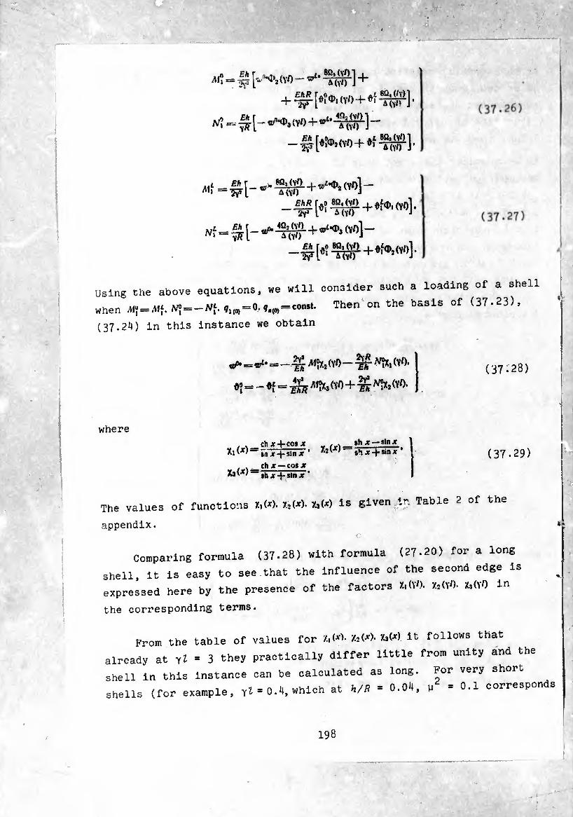
^ = (VO-^^1 +
-f[.>.(VO + »f^f].
«Í
^-^1-^^+^^1-
-wKw+^H-
Using the above equations, we will consider such a loading of a shell
when NÎ-Wf-»,«-<•• ».m=«o“1- Then on the baslS °f (37,23)’
(37.24) in this instance we obtain
itP* = wLt — —rr- AÍÍX, (YO - (YO. ’ £ÏT 4y* = - = (YO + ¾^ (YO
(37.28)
where
, , chx + cosjt M . ^ th* —Hnx Xi(jt) — rnx + slnT’ X2() s*i Jf + sin7
, . ch jt — cos je sh jt + sln Jt '
(37.29)
The values of functions X,(*). X2(*). XsW is given in Table 2 of the
appendix. 1
Comparing formula (37.28) with formula (27-20) for a long
shell, it is easy to see that the influence of the second edge is
expressed here by the presence of the factors X,(V). X2(yO. XafiO in
the corresponding terms.
Prom the table of values for U<"'• &<*>• k<x) ll; follows that
already at vl - 3 they practically differ little from unity and the
shell in this instance can be calculated as long. For very short
shells (for example, YI * 0.Ü, which at »,/S - 0.04, u = 0.1 corresponds
198
......-
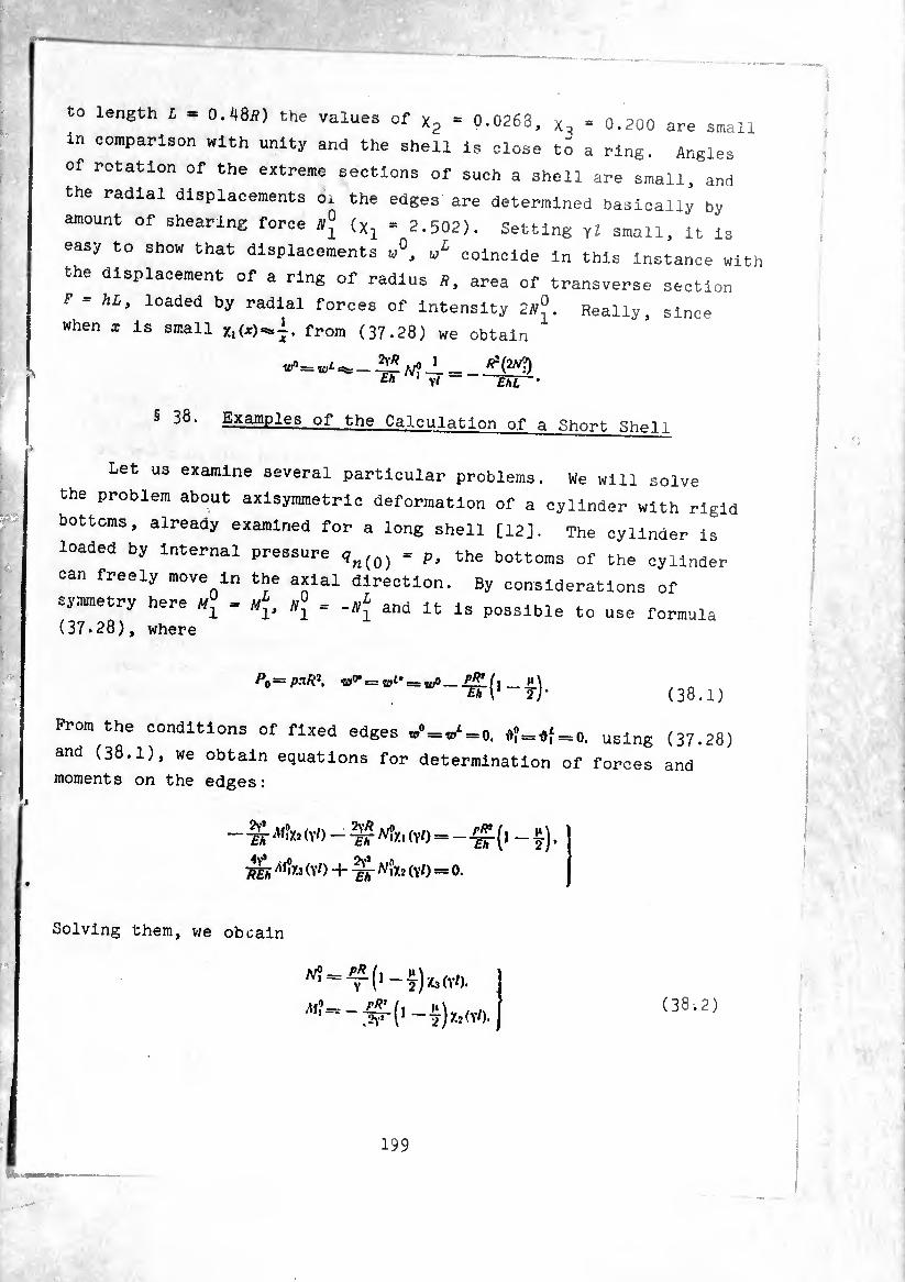
to length L * 0.48Ä) the values of x2 = 0.0263, = 0.200 are small
in comparison with unity and the shell Is close t¿ a ring. Angles
of rotation of the extreme sections of such a shell are small, and
the radial displacements o. the edges are determined basically by
amount of shearing force N* (Xl = 2.502). Setting yl small, it is
easy to show that displacements u°, wL coincide in this instance with
the displacement of a ring of radius /?, area of transverse section
F = hL, loaded by radial forces of intensity 2A^. Really, since
when X Is small from (37.28) we obtain
^=wiSS:;_^ J /^(2^ Eh yl EhL
^ Examples of the Calculation of a Short Shell
Let us examine several particular problems. We will solve
the problem about axlsymmetric deformation of a cylinder with rigid
bottoms, already examined for a long shell [12], The cylinder is
loaded by internal pressure , Pl the bottoms of the cylinder
can freely move in the axial direction. By considerations of
symmetry here . ^ , and it is possible to use formula (37.28), where
Po=pxR2. to0’ = = _ P#!. /, _ jM M1 2 j* (38.1)
Prom the conditions of fixed edges ,,<W=0. *¡=»f=o. using (37.28)
and (38.1), we obtain equations for determination of forces and
moments on the edges:
- -g Mil. (Vb - ^ <Y0=-gp (l-I). Tjli '"’fc (Y0 + -¾ NÎX1 (Y<) = o.
Solving them, we oboain
(38-.2)
199
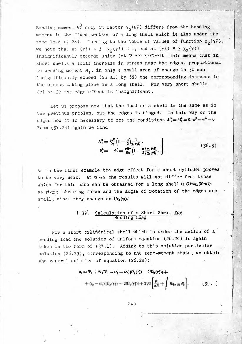
Bending moment only ir* tactor x2^^) differs from the bending
moment in .he fixed section of p. long shell which is also under the
same load (§ ¿8). Turning to the table of values of function x2^z)»
we note that at (yl) < 3 < i» an(i at ) = 3 X2(y¿)
insignificantly exceeds unity (at V' +=« /.2(V/)->l)- This means that in
short shells a local increase in stress near the edges, proportional
to bending moment /W1 , in only a small area of change in yl can
insignificantly exceed (in all by 6?) the corresponding increase in
the stress taking place in a long shell. For very short shells
{yl << 3) the edge effect is insignificant.
Let us propose now that the load on a shell is the same as in
the previous problem, but the edges is hinged. In this way on the
edges now it is necessary to set the conditions ^11 = ^ = 0.^ = ^ = 0.
From (37.28) again we find
As in the first example the edge effect for a short cylinder proves
to be very weak. At the results will not differ from those
which for this case can be obtained for a long shell C/.i(-)^=/.2(5)^1):
at shearing force and the angle of rotation of the edges are
small, since they change as l/Xi(Y0-
§ 39. Calculation of a Short Shell for Bending Load
For a short cylindrical shell which is under the action of a
bending load the solution of uniform equation (26.20) is again
taken in the form of (37-1). Adding to this solution particular
solution (26.29), corresponding to the zero-moment state, we obtain
the general solution of equation (26.20):
o, = -f 2/y‘V, = (c, - lc3) IQ, (vs) - 2/Q, (Ys)| +
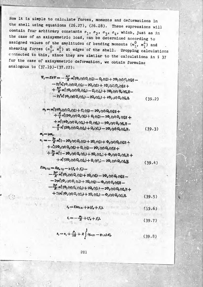
'
Now it is simple to calculate forces, moments and deformations in
the shell using equations (26.27), (26.28). These expressions will
contain four arbitrary constants which, just as in
the case of an axisymmetric load, can be determined according to
assigned values of the amplitudes of bending moments (mj, mL) and
shearing forces («J, nj) at edges of the shell. Dropping calculations
connected to this, since they are similar to the calculations in § 37
for the case of axisymmetric deformation, we obtain formulas
analogous to (37-19)-(37.22):
»F, - -m? I«>3 (y/) 0, (y-) - Q, (Y;) + 2'I*2 (Y0 (yS)J
" 24^n‘ 1^2 (VO fi, (Yi) - 2Q3 (Yj) + id;, (YJ)] + L ' 1 «VIS/ÍT
(YO Ö, (Yi,) - 02 (’, Î,) + 20»J (V/) Q, (y*;,)) - ~ 2 / . __ 2Y*«f |0)2 (YO £?, (Yi,) - 2Q3 (Yi,) -f 4<D, vV0 Q4 (Yi,)).
m. : m' l4<1>3(YO Ö4(Yi) + c, (Yi) - 20>2 (YO Û3(Yi)) +
+ T"‘ l?Ü)2(YOÛ4(Yt)+ fi2(Yi)- 20», (Y/)Qj (Yi)) +
4-mf [40*3 (YO «4 (YÎ,) + », (YÍ,) - 20>2 (yl) (¾ (yj,)]
— j ni [2d>j (yO £2, (Yi,) + Q2 (yi,) — 20), (Y0 Q3 (YÍ,)|.
«2 = Ji«,,
«, = - m? [- 20>3 (yO £23 (Yi) -f 2£24 (yj) + d>2 (Y/) Q2 (Y‘;)) JL
+ /-”|20)2 (yO Qj (Yi) + Ö, (Yi) - 20», (yO Q, (Y‘)l +
+ «f I- 20*3 (YO Q3 (Yi,) -f- 2Q, (yj,) + 0>2 (Y0 £22 (Yl,)) -f
+ nf [20)2 (yO £23 (Yi,)4 Q, (V*,) - 20>, (yh Q2(-^,)).
Eht2 — n (/0 -f- /,) _
- w? [0>2 (YO £2, (Yi) 4 2Q3 (y|) - 20»s (yO £2, (Y|)I -
- 2Y«? [0), o’/) £2, (yï) 4 2Q4 (y|) - 0)2 (yl) fi, (yj)J _
“mí (YO f‘. (YÍ,) 4 2£2j (yl,) - 20)j (yO £2I (Y|,)! 4
4- f.Y«í [O*, (y/) £2, (Y|,) 4 2£2, (Y|,) - 0*2 (yl) Q2 (Y|,)l.
t2 — £Zie2<,)4h(/o-4/,).
0 = --^4^0+/,).
s, = », 4 4 /? f (?, („ — qj ,„) rf|.
201
(39-2)
(39-3)
(39.4)
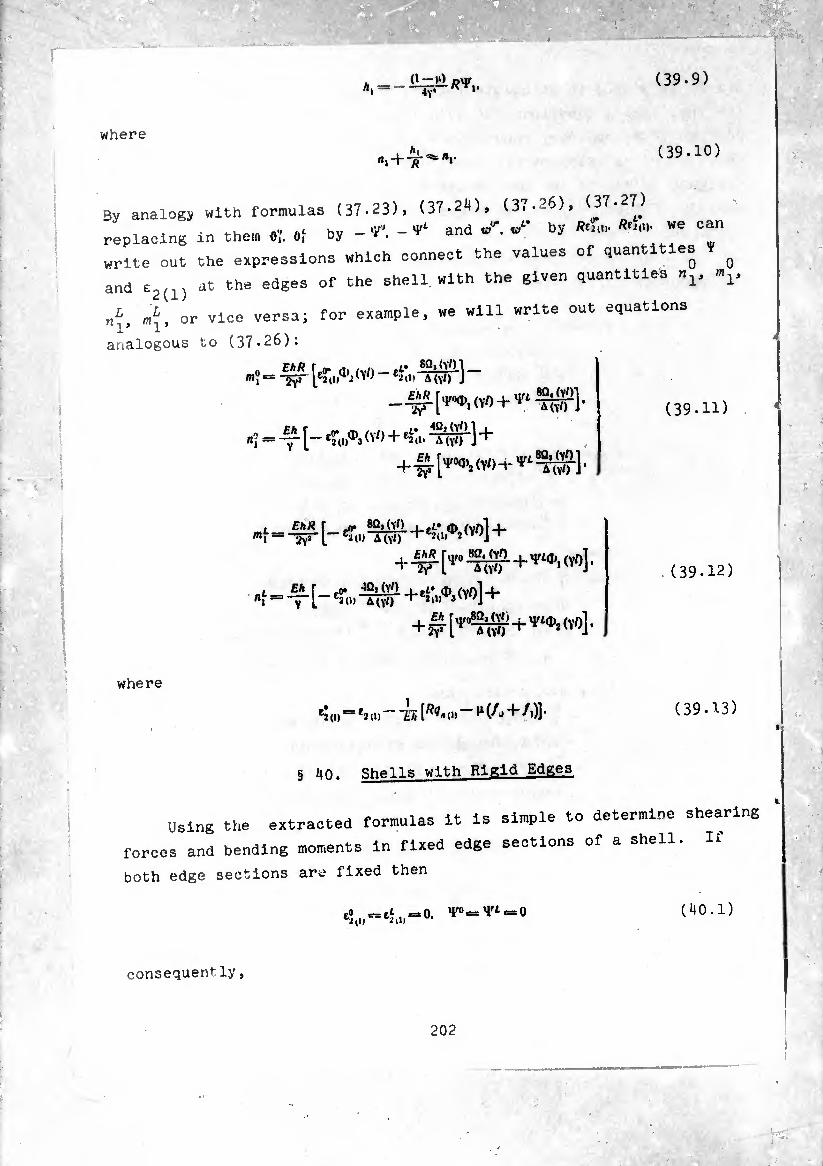
O—>») dut *1 =-ï? * »•
(39.9)
where (39.10)
3y analogy with formulas (37-23), (37.24), (37-26), (37.27.) ,, Ac hv _ _ y1- and vfr. w¿' by Rfnu. Äfj(i). we can
replacing in them 0,. Of by-*. ^ anu w .
write out the expressions which connect the values of quantities ^
and e2(1) at the edges of the shell with the given quantities V
„1, or vice versa; for example, we will write out equations
analogous to (37-26):
m _m.[4wp,(v0 + vlMjW],
»; =-y-[-•'o.'1’.'v') + <>• + 4-f-
++^^1-
[-^,,^+^.^1+
+1^¾¾^
(39.11)
£/i Y
(39.12)
where
eí a)=*2,1, - ir, ,)] • (39.13)
C« jT= ef , 0. f0 = 4a = 0 62(|, (40.1)
§ 40. Shells with Rigid Edges
Using the extracted formulas It is simple to determine shearing
forces and bending moments In fixed edge sections of a shell. It
both edge sections are fixed then
consequently,
202
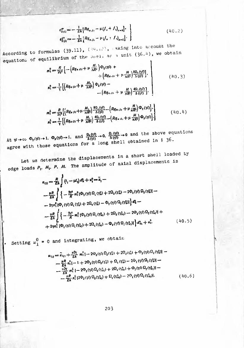
(40.2)
e2*U) Th [Äi« '»< ” M T f
/OO vn ( í.q. ,tM , ■ ^King Into account the According to formulas (39- , unlt (36.M, we obtain equations of equilibrium of the an-1. ^
' , M \ 8Q1 (vOl + ^/?<7«.i«+ >l nfi¡) \ (vO J’
ft‘-\L\ 9"( , M \ 4Q:(Y01
(40.3)
[(«,. ,„+u + ^ <'")' ' (40.4)
, ^ O,(Y0 5dïü-->0 and the above equations
At „-.co «'»‘V'l-l- long "shell obtained in i 36. agree with those equations for
,,,,. ». «»— w , * D M p M The amplitude of axiai u-l^h edge loads Pv Aij.
-Tnrjl'Tr*'1*’(Y0 °l (Yl)+2Qa <vl) “ (Y° ^(Yl)1 ~
- 2yn°: l«I>, (VO Ö, (YD + 2Q4 (Yl) - ^ <V0 (YÍ)1} ^ -
__ j j _ mf 10)2 (Y/) n, (Yl,) + 2«3 (Yl,) - 2*3 (YO qî (yI.)I +
+ 2Yrtfl*, (Y0 Q, (Yl.) + 20, (Yl,) - *2 <'■0 Q- (^«)1} + ““ (40.5)
Setting u* = 0 and integrating, we obtain
B(i)== J,n4.jg- m?l-2«i>,(Y/)03(Yl) -)-2Q4(Yl) -|-*2 (YO fi2 (yDI u<D~r £h 1 * J ’ . j_ 1 + 2<I>2(\/)Qj(Yl) + Q, (Yl) - 2a’i (YO Qs (YD! -
_ "í¡- m[ l— (y0 í)3 (Yl,) + 2Q« (Yl,) + *2 (YO Q2 (Yl,)l -
12<1>2 (YO ”3 (Yl,) •+*ß, (Yl,) - *''i (Y0 "2 (Yl,))- Eh
(40.6)
203
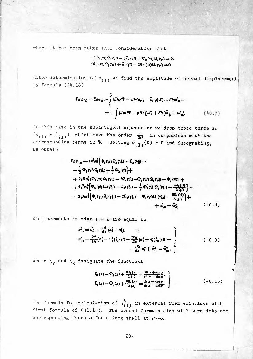
where it has been taken JnLo consideration that
- 2'1'j (YO Os (yO 4 2Q4 (yO + 0>2 (YO Qj <y/) = 0.
21»2 (YO fi3 <Y/) + Q, (YO - 2<D, (yO Qj (YO = 0.
After determination of we find the amplitude of normal displacement
Displacements at edge a = L are equal to
by formula (34.16)
£7w(l) = J [EhR^-^- Eh (a0) — 2,,,)] 0% -f f Aa»®,= o
a = - J (£A«V-j- )*/?«?)di + £A(5,,,4- «»,).
In this case in the subintegral expression we drop those terms in
(^(1) - which have the order in comparison with the
corresponding terms in V. Setting «^^(0) = 0 and integrating,
we obtain
EAt*,,, = 4y*«? [O, (YO Qj (Yl) — Qj (YÖ—
-.j©,(Y/)Q,(Yl)4-7<I>,(Y0] +
■4 2Y«n? |02 (yO Q, (Yl) - 2Q4 (Yl)-®, (YO Q, (Yl)4- (VOI +
4 4y*«Í [% (YO Oj(Ylt) - Qj (Yl,)(VO Q, (Yl,) - -
- 2y«/»Í [<I>j (YO Qj (Yl,) - 2Q« (Yl,) - <J>, (VOQ, (Yl,) - 4"
(40.8)
“o.+'SrC 0» b® — nh
= -¾ (m? - '"f) ^ (YO + ^(«?4- «f)Ca (YO -
£A (I)’
(40.9)
where anh designate the functions
L¡ (x) = <I>, ix) 4 8Q| = ,h 4 «!" * »J V ; j V J -t ¿ ih * — sin jr *
r , 8ß.(Jf) char —cos/- ^(X) = <P, (X) + = -¿-J-t|n<t. (40.10)
The formula for calculation of in external form coincides with
first formula of (36.19).
:
The second formula also will turn into the
corresponding formula for a long shell at \l-+oo.
204
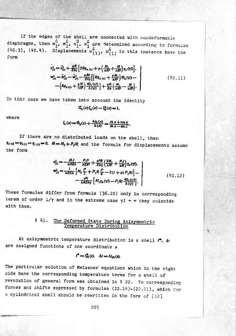
■
'■■y *
If the edges of the shell are connected with nondeformable
diaphragms, then m1, are determined according to formulas
(40.3), (40.4). Displacements u^y in this instance have the
form
“o) ~ “o>+ TW [2/?<7* « >+ ^ (^7P+Æ) Xs (V/)].
»■ <» ‘ W
(d~ , , nR I M, M\ r?-(.»+w] -Kwr\+-êãI-stf - ^)-
(40.11)
In this case we have taken into account the identity
2C, (*){,(*)-C*(x)-1.
where —c«»x + co,x
A(X) lb X — Sin i-
If there are no distributed loads on the shell, then
^*(0(»“0. M =3Ai,-f-/y/? and the formula for displacements assume
the form
ul i “(1)
«f.)'
——_L »***/2jW, , p,l\ ïvm ^m+Th^[-^r+isr) ^(v/).
: [^. f+^- 2 o+M) p,/?/] _
~ 1&7 K*» (vo - p,p/ .
(40.12)
These formulas differ from formula (36.20) only in corresponding
tersm of order 1/y and in the extreme case yl + °° they coincide
with them.
§ 41. The Deformed State During Axlsymmetrlc Temperature Distribution
At axisymmetric temperature distribution in a shell /*. A'
are assigned functions of one coordinate e
tm =31") (<), A/ = A/(0) (i).
The particular solution of Meissner equations which in the right
side have the corresponding temperature terms for a shell of
revolution of general form was obtained in § 22. To corresponding
forces and shifts expressed by formulas (22.14)-(22.21), which for
a cylindrical shell should be rewritten in the form of [12]
205

T =0.
T,
N,
Eh’fiR <P ,Ki % T2(1-'m) 1*
12(1—j.) dt (atW'
Mx
AU
Eh^ (U0) t R 12(l-i«) V A ^ TflT ds* J’
Ert (U,* , ‘ ^ TÎTT^ïïr + TTï ’
-A-Pfti/" ft/? fWgíl A, _ /?ß ^o) 12(1—(t) ds* ]’
. ^ ^PÂ d(A/w) mftm^ \=C- 15(1 ZTjl)' —di-ßj A»)*.
o.“ß*-dir
(41.1)
(41.2)
(41.3)
In a rather long shell forces and moments far from the edges of the
shell can be determined according to the equations written out above
In the area of the edges appear additional stresses of the edge
effect. For calculation of temperature stresses allowing for edge
effect we can use formulas obtained in §§ 27, 37 of this chapter,
having in mind that now instead of the particular solution,
which corresponds to zero-moment state under stress, we take the
solution presented by formulas (41.1)-(41.3)• In the determination
of forces and moments according to displacements assigned on the
edge in formulas (27.22), (27-23), (37-26), (37-27) it is necessary
to replace Eh^P (\t[
—10 \~
(41.4)
-+vp[/¾-•
(41.5)

Let us consider several examples.
1. In a tree shell during linear distribution of temperature along the axis
'<" (i) — /°-f £ (/A __ /0) A/(o) ^ 0
stress do not appear, and the displacement are equal to
Af = -|p¿(/o+/i)
(^1.6)
Here 4{ designates the displacement of edge s - L with respect to
e ge s - o In the direction of axis 0Z. a;>o at a shortening of the shell length.
If the edges of the shell are rigidly fixed, then In the
neighborhood of edges appear shearing forces and bending moments,
which for a long shell can be calculated using formulas (27.22),
27.23). In this, case It is necessary to replace u°, a1 by -W. —Rlu1 respectively, and 0?. bv —
* 1 , Dy TV “H- Doing this, we obtain
«f—
Ni
(41.8)
M’ ^ f m'3re’ the edges of the cylinder abut against rigid walls,
P 6 aXlal elon«atlOh. then this Is equivalent to the action
on .he shell of an axial compressive force. The amount of this force
is determined from the equation
2 (/°J^—nTjds^O, (41.9)
where = /»o_ axial force.

As was shown in Example 2 § 28, neglecting in comparison
2’1 during the^calculation of axial displacement gives an err<
e order of f/ * in comparison with unity. Limited to this
accuracy, we obtain
¿0 = — xRfiE/i (/°-4- tL).
The action of axial force PQ give rise to additional moments and
shearing forces in the fixed edge sections :
(41.10)
2. Let us examine a local rise in stress in a shell, one
component of which has constant temperature tb, while the temperature
of another component of the shell changes linearly from tb In section o-A 4- ~ -l-U J __^ , - -- s = b to t in section s = 0 [27],
/* at 4>é. A/,0, (*) = 0.
(4l.ll)
If we mentally cut the shell along section s = every component of
the shell will be free from stress. The end of the left part of
the shell {s = b) will have displacement and angle of rotation equal to
=*?.(/»_ /0)( w - _ (41.12)
the adjacent end of the right part has displacements
(41.13)
In order to remove the discontinuity in the angle of rotation, it
is necessary to apply to both shell components bending moment Aff.
which causes a rotation of the edge of the left part of the shell
through an angle ¢,-*f and the edge of the second part through an
angle ¢,-¢7. where ¢,- actual angle of rotation in section s = b.
Using formulas (27.22), (27.23) and setting n\ = 0, we obtain
208
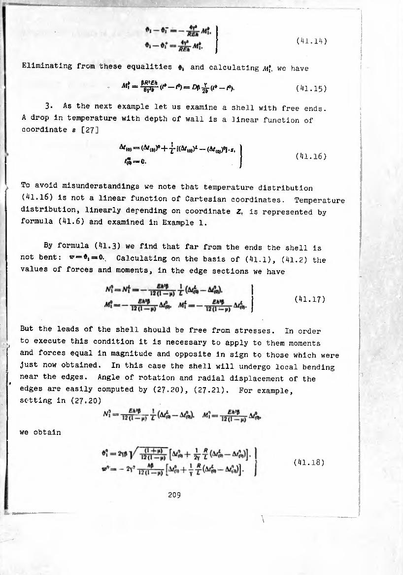
(ill.14)
Eliminating from these equalities and calculating m¡. we have
(41.15)
3. As the next example let us examine a shell with free ends.
A drop in temperature with depth of wall is a ]inear function of
coordinate s [27]
^(o) — (A*«»)0 + -J- l(A/(0))¿ — (A/(0))°J • s. (41.16)
To avoid misunderstandings we note that temperature distribution
(4l.l6) is not a linear function of Cartesian coordinates. Temperature
distribution, linearly depending on coordinate Z. is represented by
formula (41.6) and examined in Example 1.
By formula (41.3) we find that far from the ends the shell is
not bent: ^ = 0,=0., Calculating on the basis of (41.1), (41.2) the
values of forces and moments, in the edge sections we have
(41.17)
But the leads of the shell should be free from stresses. In order
to execute this condition it is necessary to apply to them moments
and forces equal in magnitude and opposite In sign to those which were
just now obtained. In this case the shell will undergo local bending
near the edges. Angle of rotation and radial displacement of the
edges are easily computed by (27.20), (27.21). For example
setting in (27.20)
we obtain
209
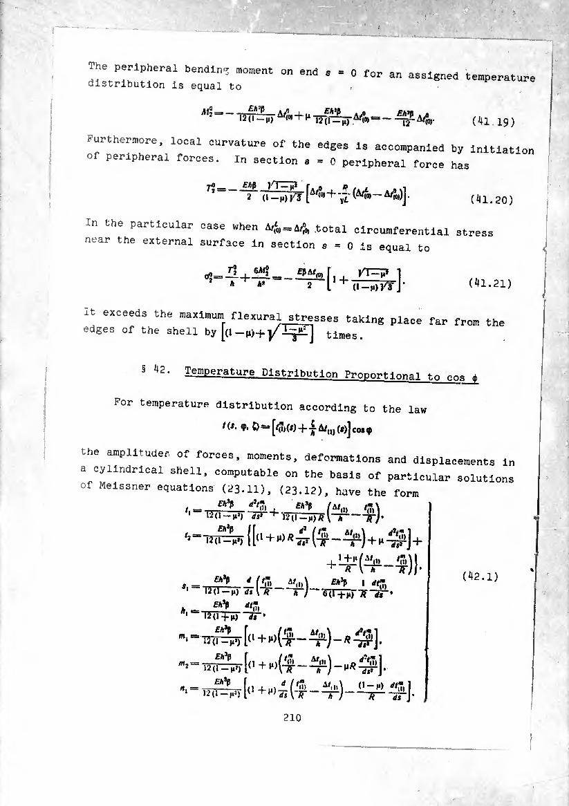
The peripheral bending moment on end s
distribution is equal to 0 for an assigned temperature
Mi = — —— A/l 4- u - ,Eh,t a .0 £A*p A « 12(1 — n) (til1 i¿^(0) =-jy A/Jo). (^41.19)
Furthermore, local curvature of the edges is accompanied by initiation
of peripheral forces. In section a = 0 peripheral force has
^ 2ß 'u-mJKJ [A/(0(,, + 'yI (^<0) — A/®0,)]. (^41.20)
In the particular case when A/f0) = A/(00) .total circumferential stress
near the external surface in section a = 0 is equal to
6A!J=s_ip^r 1
* ** 2 11 + ïï^ïï7fJ- (441.21)
it exceeds the maximum flexural stresses taking place far from the
edges of the shell by tlrnes>
§ 42‘ Leggerature Distribution Proportion«! t-.n f
For temperature distribution according to the law
ns. <p. Ö — [/(î)(i)+ — A/(1J (»)] co* 9
the amplitudes of forces, moments, deformations and displacements in
a cylindrical shell, computable on the basis of particular solutions
of Meissner equations (23.11), (23.12), have the form
_ ^ AT) f*sP fu,» 12(1 —j»*) ds* 12(1 \h~ n
’ 1 ~F4/r0)_^)] I
•2(1-1*) d$ \~w Ã~y~ 671+1 1 dtk
A, Eh^ dt”
--1-. _ü -t-H) Tflff
'(I) ^2(1 +(i) ~3?
£A*P f
12(1-^1) 1' (•+!») ‘m 7T
(442.1)
210
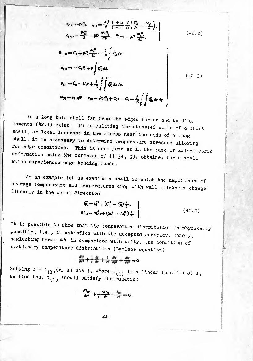
(42.2) “im-nr-w^û-. 'i'-.-pííá. i/S
«,.„■= C, + (R "' ’
f
1
J f”>ds.
a(i)-CjÆ + P J /(7)^, # #
«<!> *= C» - Cl*+-¾ J J 4* ds ds,
• t
w(>) “ ** («^—va) -= + C,i - C, - ^ J J fm ds ds.
(42.3)
In a long thin shell far from the edges forces and bending
moments (42.1) exist. In calculating the stressed state of a short
shell, or local Increase In the stress near'the ends of a long
shell. It Is necessary to determine temperature stresses allowing
for edge conditions. This is done Just as in the case of axisymmetri
deformation using the formulas of §§ 34, 39, obtained for a shell which experiences edge bending loads.
As an example let us examine a shell in which the amplitudes of
average temperature and temperatures drop with wall thickness change
linearly in the axial direction
A/,1, = A/,0,, -|- (A/f„ — A/J,,) -j-.
It is possible to show that the temperature distribution is physically
possible, i.e., it satisfies with the accepted accuracy, namely,
neglecting terms h¡R in comparison with unity, the condition of"
stationary temperature distribution (Laplace equation)
=»0.
Setting t - t(1)(r., s) cos ¢, where i(1) is a linear function of a
we find that tshould satisfy the equation
d,/o) , i àt(i) dr* ‘ 7 ~dT 0.
211
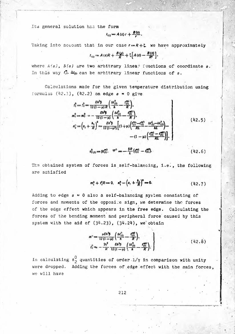
ltd general solution has the form
Taking into account that in our case r =/?-f-j, we have approximately
where A's), B(s) are two arbitrary linea~ functions of coordinate s.
In this way A/(i) can be arbitrary linear functions of s.
Calculations made for the given temperature distribution using
formulas (42.1), (42.2) on edge 8=0 give
(42.5)
(42.6)
The obtained system of forces is self-balancing, i.e., the following
are satisfied
(42.7)
Adding to edge s = 0 also a self-balancing system consisting of
forces and moments of the opposite sign, we determine the forces
of the edge effect which appears in the free edge. Calculating the
forces of the bending moment and peripheral force caused by this
system with the aid of (34.23), (34.24), we'obtain
In calculating quantities of order .1/y in comparison with unity
were dropped. Adding the forces of edge effect with the main forces,
we will have
212
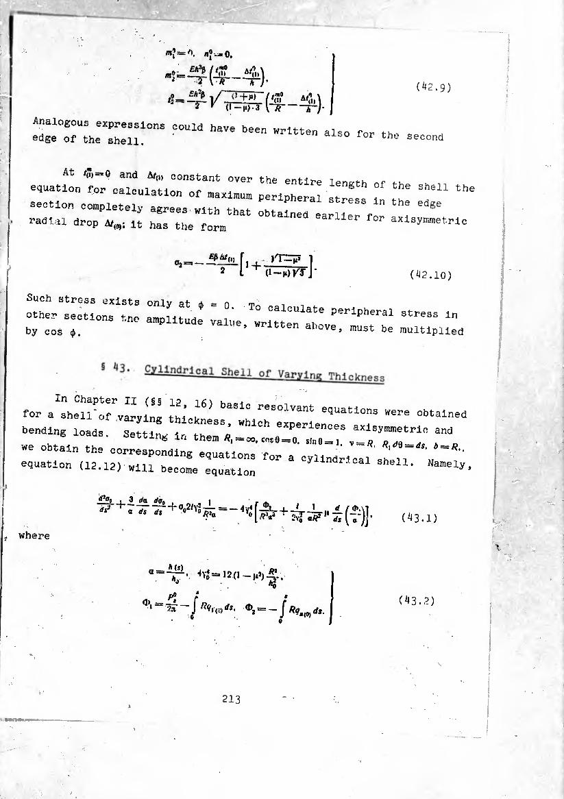
m! «J-^0.
(^2.9)
Analogous expressions could have been written r ^ edge of the shell. ' written also for the second
At /JJ)«0 and A/(i, constant over the n
equation for oaiculatlon of maxlmum peripheral atreas T th"
section completely agrees with that obtained earner f t ^ radial drop a,,»; lt has tlle torm for axlaymmetrlo
I*“m f. >r=p 2 L + (I-míKI ]• (42.10)
Such stress exists only at d> = n ^ ,, other sections tne amplitude v i' oaloulate Peripheral stress In by cos ¢. Va l!0’ wrltten al>ove, must be multiplied
for a^shell"ofVarying thi ^81° reS°1Vant e«uatl°na »ere obtained
bending loads. Setting IrAh^Ä eXPerlen°e8 a;Ilay™etric and
we obtain the oorrespo^rC V“"' equation (12.12) wni beoome equatlon ndr'°al sheil- "“ely,
where
rftg» i_ 3 Sa tf<j0 . „1 ta
(43.1)
**Yj= 12(1 ’X
i ^ r * ^ ‘ ~ ~~ J JS' ^2=-/ ^.(0) dS.
213
(43.2)
X.
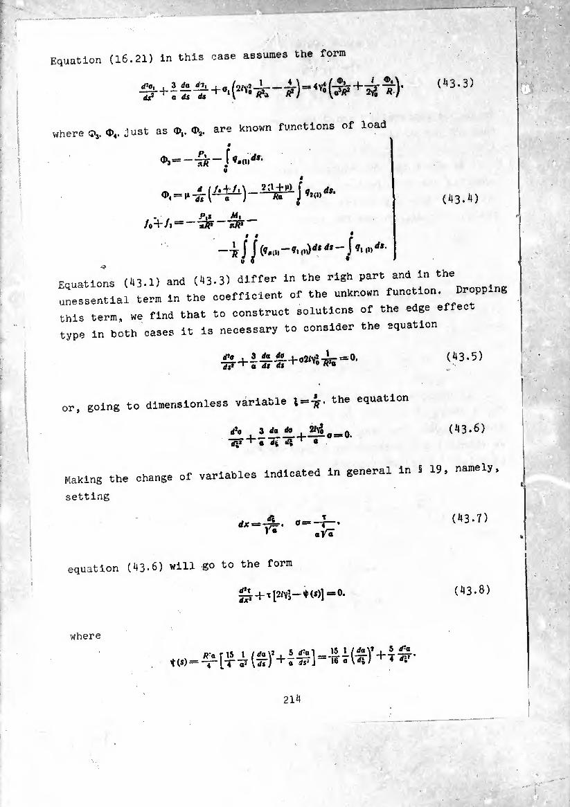
(43.3)
Equation (16.21) in this case assumes the form :- ■ . " V ' / •'
4V}(^ ^).
where C»3. just as 0,.0¼. are known functions of load
9
V
. ■ p.j AÍ, /o"HA "»7?
» « ¿
—ff J J’■m'''-
Equations (43.1) and (43.3) differ in the rlgh part and in the
unessential ter. in the coeffiolent of the untren function. Dropping
this term, we find that to construct solutions of the edge effec.
type in both cases it is necessary to consider the equation
(43.4)
(43.5)
or going to dimensionless variable S=-ff. the equation
A . i* *+®i,_0. rfî» "i" a dfe «/I «
(43.6)
Making the change of variables Indicated in general ln S 19, namely,
setting
(43.7) dx —-^=-. o=-T— ^ aVT
equation (43-6) will go to the form
0 + t12/YÎ-*(«>]=O. (43.8)
where
Paris 1 /rfa\* , 5£al 15I(jta\’ + 4.g. i(S)= "J" a d,i ^ löaWs/ 4 rf4
214
If the thickness oí th° rheül a «r» u "iej.1 is a so slowly changing function of coordinate that the inequalities
(^3.9)
hold, then the tern, ♦(,) can be neglected In comparison with 2.¾ and
instead of (43-8) thus we obtain the equation
-0 + 2/Y’t = O. (43.10)
As already it was indicated earlier, particular solutions of this equation can be taken in the form
i*v.*cosYo*. f^sinvo*. (43.11)
respectively particular solutions (.)3.5) are functions
3 e± ^cos YqX, —j— e* V»» sin y^x.
•Ví aVã (43.12)
where
- [ JL Kõ ' («3.13)
In the particular case when thickness is a linear function of
coordinate s or, which is the same, a linear function of coordinate {,
«(l) = l-M&. (43.14)
equation (41.5) is integrated accurately. Really, Introducing new variable 16
y=i+*l.
instead of (43.5) we obtain the equation
i 3 </g 2/^ a ay1 ^ y dy y ~ 0.
(43.15)
(43.16)
215

which with the aid of transformation of dependent and Independan
variables
tas Y2/y ^¡¡~ • °y (43.17)
becomes Bessel equation
(43-18)
As the particular linearly Independent solutions of this equation we
•ake the Bessel and Hankel functions of the first kind, second or er.
in this way, the general solution of (43-18) Is written in the form
.,=0,/,(0+^(0- (43-19)
where C2 - arbitrary constants, generally speaking, imaginary
numbers.
For large values of the argument, which takes place when
W'20)
these functions can be represented by an asymptotic decomposition,
the first terms of v'hich have the form
X [“• (¾1 ^ - Î) - (-¾1 ^ _ t)] • (43.2X)
«?'(t -X
x[*i» (^VT+t)-u°’(t ^+t)1-
Taking into account these representations, and also that in this case
y s= a, 0 «
and
s//rU * ^
(43.22)
(43.23)
216

it is easy to see that the real and imaginary parts of the expressions
(43.24)
for a large value of the modulus of the argument are linear combin¬
ations of functions (43.12). In this way the correctness of approxi¬
mate solution (43.12) agrees with that which we have on replacing
the accurate values of functions ,f2(0. H$\t) by the first terms of their
asymptotic representations. With a more complex law of change of a
depending on Ç accurate integration of equation (43.6) is difficult.
However, on the basis of the comparison we will assume that also in
this instance tne correctness of solution (43.12) is practically
satisfactory if only conditions (43.9) hold.
Let us make use of the obtained approximate solution for a
description of edge effect in a long axisymmetrically loaded
cylindrical shell. Repeating the reasoning conducted in § 27, we
derive criteria for the determination of shell length. Namely, we
will consider the shell to be long if
(43.25)
or L
In carrying out this condition it is convenient to represent the
solution of uniform equation (43.6) in the form
o0=- IBX) —J— [6 (Y**)+/; (Yo*)] + •in
-f (A2 — IBJ —I—10 (Yo*,)+/; (Yo*|)l. ajn
(43.26)
where
(43.27)
At a —1. x —fc. solution (43.26) agrees with the earlier solution
for a long shell of constant thickness.
217
Separating the real and imaginary parts of oQ, we have
V0=Reo0 = —!— ^(Vo*0+ • oV7
— 2^0^0 = Imo0 =
= Î M1C(YoJf)-fl10(Yo^)+ ^(YoJf|)-fljö(Yo*|)J- (^3.28)
i orces, moments and displacements are determined through function 0
using equations which can be obtained from (12.11) by the corresponding
writing for a cylindrical shell:
AT, = <D, (s). ri — — ■— (o’ Im Oj).
ÄiVi= ~ TTT ,m Oo+^jW. A*
(^3.29)
A*=~ J ïb-i7*» “ *•
(**3.30)
The particular solution of equation (*43.1) is obtained by
dividing the right part of the equation by the coefficient of a.
Then after eliminating quantities of the order of 1/2Y* in comparison
with unity we will have
- l*'[a »-‘^rJ *.(o> (^3.31)
To it corresponds the zero-moment stressed state
r,~injr J <o> ^=^.(0)- 0
Af¡ =0, Afj = Mj — 0.
«i
(43.32)
Displacements of the zero-moment state are calculated using formula
(43.30) for values of forces (43.32).
In direct calculation of forces and moments by formula (^3.29)
it is necessary to differentiate expressions (43.28). In this case
one should bea” in mind that in accordance with the correctness of
the solution itself (43.28) variable coefficient —during
differentiation can be considered as constant. For example.
where, as earlier, the prime indicates differentiation with respect
to the argument indicated in brackets.
Taking into account the above and ignoring mutual influence of
the edges during determination of constants of integration /^,3,
A2* ß2* ^ s;I-mPle to write the expressions for forces and dis¬
placements in a shell of varying thickness, analogous to (27.14) to
(27.19):
^ = - 2YoP' • M + Tf- Mk (Vox) -
— (aL) '• ATfaiVo*,) + (o*)*’• (Yjpc,)] + (43.33)
Ni == o,/4 [wfo (Vox) — ^Ai?C(yffx)+
+ (oO"*“Ni* M Mfovo*,)].
.M, = av* [.Mi<p (V) + ~ N% (YVc) +
+(ot)'v‘ ^f«p (Yo*i) - ^ («‘■r'*' Nil (Yo*,)]. (43.35)
[^?Ç (Yq*) + /M?0 (YoJt)+
+ (ot)",/' NÍ<f (Yo*i) - X (a1)"7* ^ífe (Y0jc,)] . (43*36)
- (a*)' v< A^f 0 .V.) + -¾. (ai)-* AJÍ* (Yox,)] +
I ^«(0) ( p] f \ ^~Eh¿~ ÏÂ^-Eïff-j ?i,o,*J- (^3.37)
and a! a o 33)-(.3.37), setting that dlstritutea ioad axial force are absent, we easily obtain equations for figuring
...» on tne edges of tbe shell. Namely> at x_0. lgnorl
influence of edge x,=o. we have
ÖJ .
(^3.38)
Correspondingly for edge x,«0(^ = 1) we obtain
N'-ir rt). (^3.39)
where a¿ = A¿/A°.
under "the'actio0" °f 3 lon« she11 °i varying thickness n o a bending load can be examined in exactly the
17 7; ^ ‘Ws case ^ calculation of forces, moments and ormations the following equations are derived:
+ (a1) 4 [— fynfBfox,) + «ft(Yux,)]}.
«|-aV.{*>(Ycx)+^ÄjC(v)+
** “a’ ‘ {^ *?:(y0x)+
220
(^3.^0)
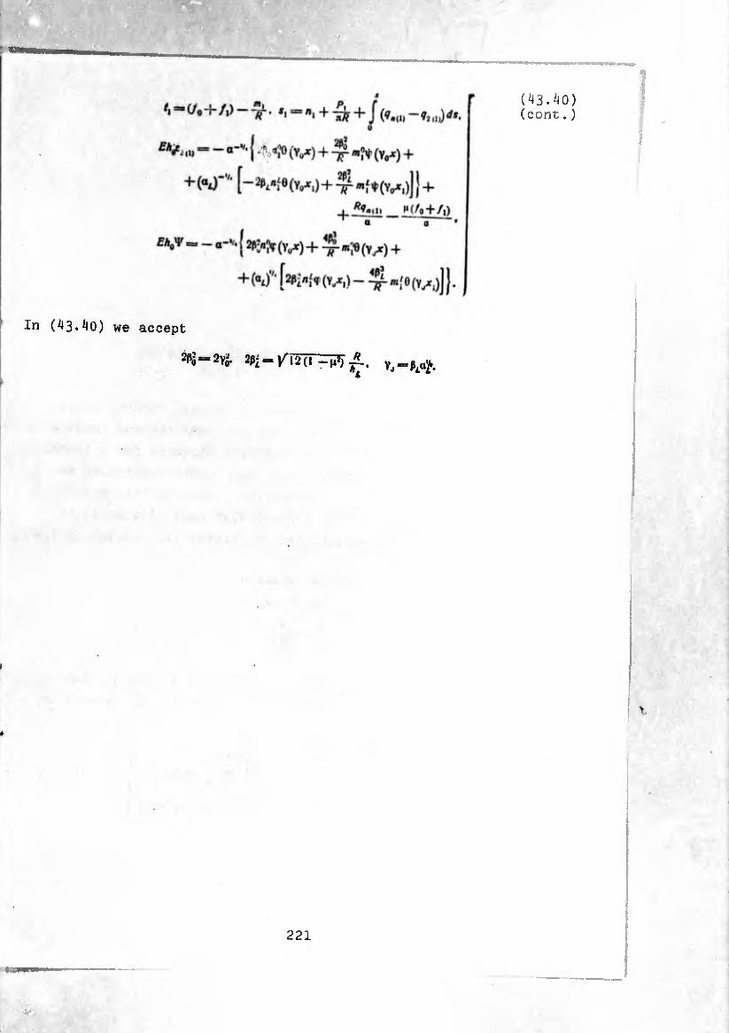
(43.40) (cont.)
In (43.40) we accept
2P¿ 2P¿=/I2(l
221
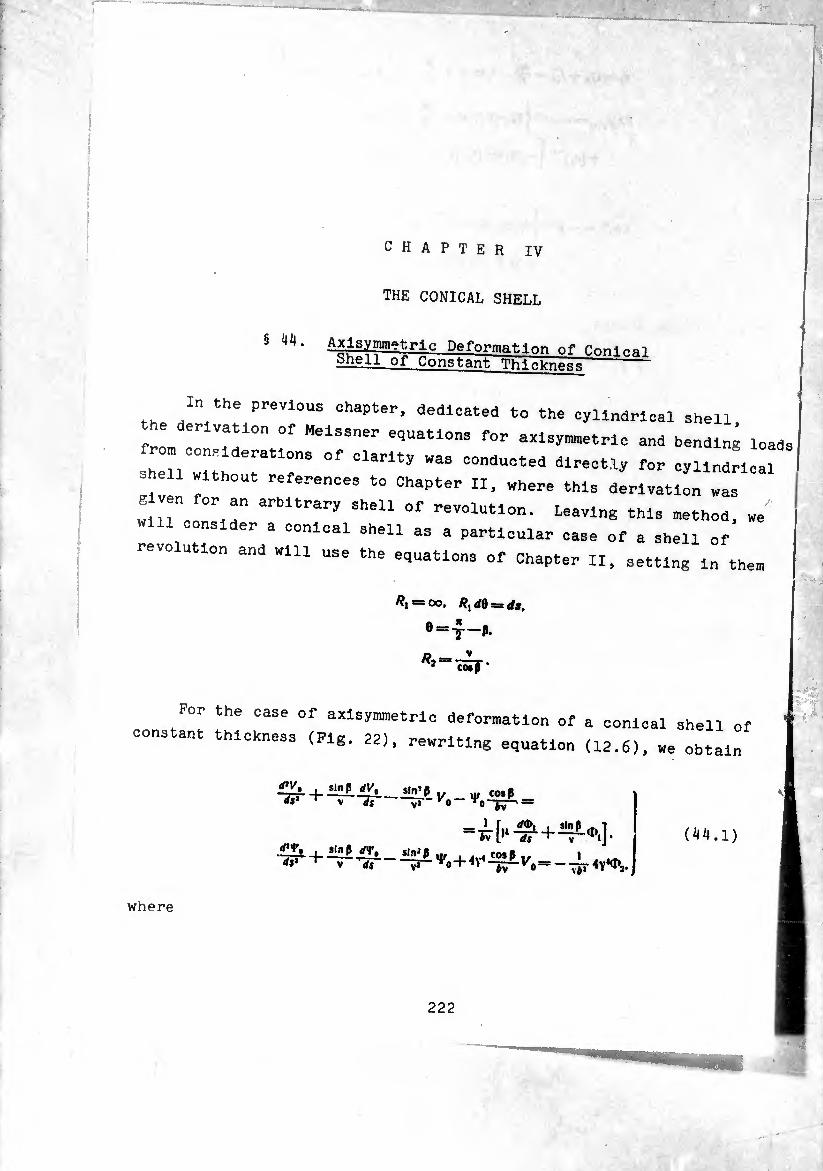
CHAPTER IV
THE CONICAL SHELL
§ 44. A^lBymmetrlG Deformation of Conl^i Shell or constant Thickness-
the Z" th!(Pl-eVl0US 0haPter’ dedlcated to cylindrical shell,
fri H MelS3ner for axisymnetrlc and bending loads rrrr °f ciarity was consudted di-=‘^ oyundLai .h-n withOdt references to Chapter II, „here this derivation was e ven for an arbitrary shell of revolution. Leaving this nethod, we'
will consider a conical shell as a particular case of a shell of
revolution and will use the equations of Chapter II, setting in them
#1 = 00. /?, </0 s- dt.
e=T-*
*2- V CO* f *
For the case of axlsymmetric deformation of a conical shell of
constant thicKness (Pig. 22), rewriting equation (12.6), we obtain
W' , sin p dVt dp -r— JT 1/ vir COsß
VJ — ' 0 * n—S-i =
d'y, , slnp rf<rB ds* '
““Sv“
*v l*4 dt sin ß
ds UnLtyr , w co»P »
V* 0 + tv Vo
(44.1)
where
9
i
222
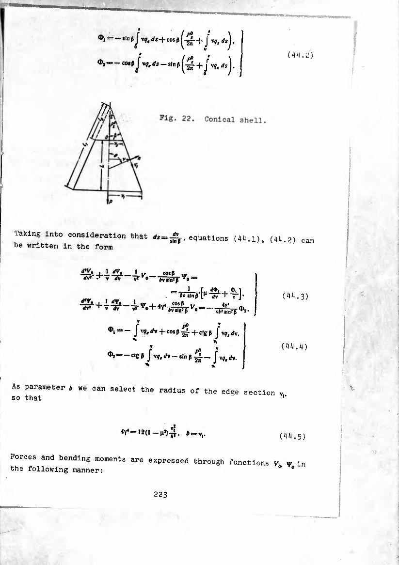
Taking into consideration that * = , equations (44.1),
be written in the form (44.2) can
SV, .lav, i Jill __Li/ cosp d^~ M dy Uvo— Ÿo =
1 r.. ¢, I ¿v sin .6 [f1 jv
j 1 ^_Lur _i j.u cosp ,, 4v< ¿v* +v rfv v.
0,=*- J vçtdy -j-cosp -f-clgp Jyqtdy,
V# V. V -. I1! ^
®, = -c|gP J Vf, Í/v - sin P ¿i— J Vf, rfv. %»- •
(44.3)
(44.4)
As parameter » we ean select the radius of the edge section , so that l'
b = yv (44.5)
Forces and bending moments are expressed through functions V. y in the following manner: 0 0
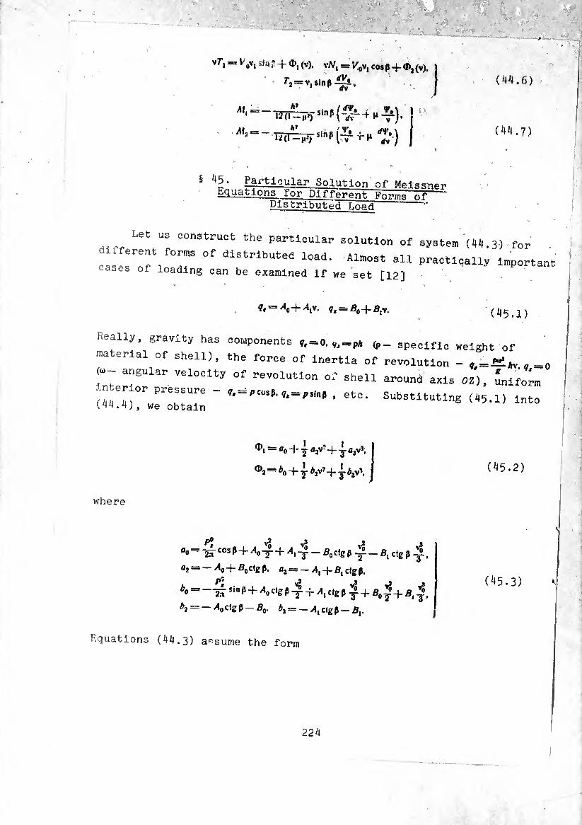
vT-j-lv, sir,; -f d», (V). vW, = '/„v, cos p + O), (v).
r3Bxv,sinp <tv •
(44.6)
(44.7)
§ • gf i'tlcular Solution of MelsRnPr> Equations for Dlfferpnt.~Vnr,n,o -
Distributed T.narf
Let us construct the particular solution of system (4H.3) for
caseToT/T 0f dlStrlbUted l0ad- Almost practically important ca.es of loading can be examined If we set [12]
?, = A>+V- <tM = B0+BlV. (45.1)
Really, gravity has components ?,_0, ,,=p* specific weight of
material of shell), the force of inertia of revolution - , =f^»v .=
(W angular velocity of revolution of shell around axis OZ), inifo™ n.er or pressure - .,-a,cos,. , et0. Substltutlng ^
( ^^ • 4 ), we obtain
where
— ao 4- ajV? -(- y a3vJ.
= *0 + y t>2\7 4- y b3\\
fl0— 2,-t cosP+^o'y + ^1-^ —B0cfgß Tp —ß, ctg jl-y-,
a2 = _/lo4-ßoctgß. û3 =-/1,4-fl, dg ß.
ßo==_1isinß + >lodgß-^ + ^,dgß^4-fl0^-ffli|i
^2 = —^0C*gß-S0- *3 = -w4,dgß-fl,.
Equations (44.3) assume the form
(45.2)
(45.3) ^
224
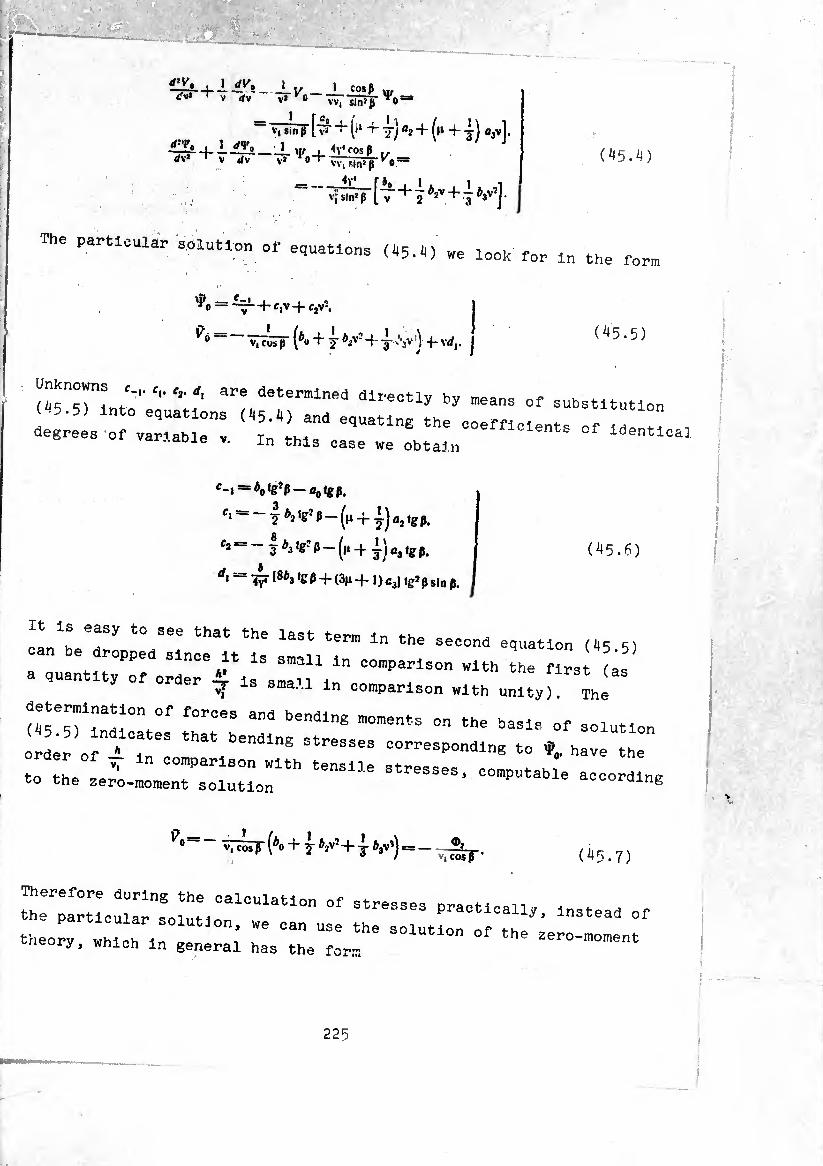
,Lll. + ±±v>_ ±v _ 1 COSP y,
- V. Sin P" [~ + (i‘ + jj a2 + (f‘ + -i) û3v].
-- rf,'l> __L <|f i cos P ,, V* 0 ' VV. sin» H —
rf’T, </v» V Jv VV, sin*P K0:
4V1 vj sln? p
-^_[i+iv+i4)V,]
(.^)
The particular solution of equations (45.«) „e look for in the fo™
— --1 + f,v -j- c2\-.
9° ^oTF (*u + J 6-iv‘ + J 'V) +- Vrf,. (^5.5)
(45 M i :- C'' Cl- are deter”,ine‘S dlI'e<:«y »y nieans of substitution (45.5) into equations («5.4) and equating the coefficients o' ZlT, degrees of variable ,. i„ this case we obtain idéntica.
c~i — à0ig-p~a0tgpi
fi — — y P21gJ p — ^ j 0j ig p
* = " +¿)a,tgp. (^5.6)
4y4 I8¿3 ‘g P +- (3n -f-1) Cj) tg?p sin p.
It is easy to see that the last term in the second equation ^
can be dropped since it is snail in comparison with the firs as
a quantity of order - is small in comparison with unity,! Íhl
determination of forces and bending moments on the basis of solution
order of -i^c Stresses dd^responding to ¢, have the
- rieLir“ rtensiie 8t— 9 — • 1
0-V— , cos p (*o + T ^-+ J V1) = -,7¾ F (45.7)
Therefore during the calculation of stresses practical!, m t h .
“rc:::; mr^
225
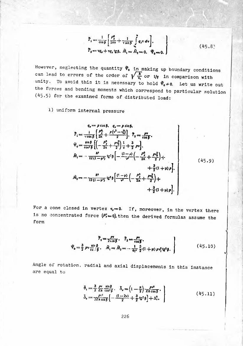
.J cos (} ¿nv T- y sin ß j “v j • n J »• —
/ù, =3 pij=o, ¢ =0.
However, neglecting the quantity ¢, In making up boundary conditions
can lead to errors of the order of or 1/v ln comparison with
unity. To avoid this it is necessary to hold tf0*o. Let us write out
the forces and bending moments which correspond to particular solution
(^5.5) for the examined forms of distributed load:
1) uniform internal pressure
?, = /»cosß, ff, = />$inß.
»-L_[.g I f _ rv 1 vcosß 2 J’ —
Uf __^ 0 COSJ ß
sinß T/ />’ 13 1
ll-2^ + -^7+TH’ A*
- 12 (1 — n*) '^[--^(-4+4)+
m2= 12 (i -M*) g pl V» \--ST-+ 2~/ +
+-5-0 +l*)p].
(^5.9)
For a cone closed in vertex v0=0. If, moreover, in the vertex there
is no concentrated force (/¾ = 0). then the derived formulas assume the form
f — pv ' 1 —
m 3 sir ß 'í'n = D\— Cl
___ f — P* 2T3ï]r*
°' l^co ß* - 4^-5-(1+M)pv*lg*ß 4 Y4 (^5.10)
Angle of rotation, radial and axial displacements in this instance are equal to
0.
Ã.
3 /»v sinß 2 £/t cos' ß ’ — \
py’ r (1 —2m) i sin ß ( 2
5. = fl - 2 J Eh cos ß ’
2Eh> + J •g5 ß] + AÎ, (45.11)
226

where Aj— displacement o±' shell as a whole along axis OZ;
2) rotating shell
^ = 0. f,= ^ = (3 + ^)«gP^
^, = -
Ãíj —
(3 +10 (2 + n) sln’P pu2/iv*v 4y‘ cosß g *
(3 + (i) (1 -f 2>i) sin1 p r®1*''*''
COSjJ
A.= F«1 ~£s ^(1 +-dW)(vS“v^+A*:
(45.12)
3) gravity
f __ P* (v*-vfl_ 1 V sin fi 2 cos p
f, = —pAvtgp,
*i*=t(»1+7-t‘8,p)v
P* (¿-'o) sin 2p V
P 1 £ 2 cos’p V
(45.13
For a shell closed in vertex (v0 = 0). there exist
= + ^—7 p) v*
- - i P'i / 1 3 , \ . ÂÍ, = Alj = — —g- (1 + n) + 7 — 7 ’gJ PJ sin P* (45.14)
§ 46. Solution of Uniform Meissner Equations
Turn to the solution of the system of uniform equations which
correspond to (44.3). In § 19 it was shown that the solution of
uniform equations which describe axisymmetric deformation and deforma
tion under bending load have the character of an edge effect. At the
same time the transformation of these equations given in § 19, and
227
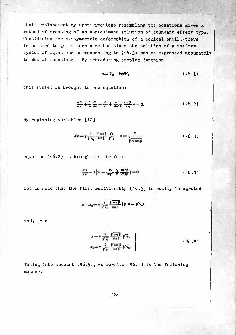
their replacement by approximations resembling the equations gives a
method of creating of an approximate solution of boundary effect type.
Considering the axisymmetric deformation of a conical shell, there
is no need to go to such a method since the solution of a uniform
system of equations corresponding to (44.3) can be expressed accurately
in Bessel functions. By introducing complex function
(46.1) 0 = ^-2/^
this system is brought to one equation:
d2a . 1 da_a_ . 2/y* cosß d\* ' \ dv Va ' sin’P w,
(46.2)
By replacing variables [12]
1 I'cosp rfv (46.3)
equation (46.2) is brought to the form
15 sin? ~ I6vr ~ cos (46.4)
Let us note that the first relationship (46.3) is easily integrated
2
and, thus
(46.5)
Taking into account (46.5), we rewrite (46.4) in the following
manner :
228

(46.6)
It is known that the obtained equation is integrated accurately. Its
solution has the form
T = V* k,/a(* V^) + cjñ'ix /¾)]. (46 * ? )
where /,. Bessel function and Hankel function of the first kind
of second order.
Taking into account equations which connect these functions with
zero-order functions
iM'D—[^= VT)+/„(i /7)]-
Hi"(, /7)- - W /7) + Í4"(« V7)]'
while the prime designates the derivative of the argument shown in
brackets, and introducing the designations
/ofoY7)—Vf*+'♦*»>• /7)-1,(¢)4-/♦,(?).
/7 /j(<? /7) — tí (?) + (t: (?)•
/7 (¢/7) = t'Aq) + it\ (q).
(46.9)
we obtain
Re/,(jt/2¡)= - [*, U /2)+ l^lj.
!„/,(*/5)--[«.U/2)--Ç tlU/2)]. i (. . iu ;
Re «!(" (jf /2/) = - [t3 (•* / 2) + ♦í U /¾] •
Im M” (x /2/) = - [t4 (x /2) - tí (x /¾].
Since the introduced functions ti(<7). ti(?) and V’ai?). t<(?) are the real and
imaginary parts of solutions of the zero-order Bessel equation,
229
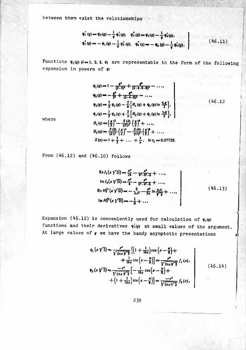
between then exist the relationships
^ (¢) —-jrti (?). tí (¢) = ¢4 (q) — i tá (?).
tí (?) =. _ t, (?) - i tí (?). tí (?)=»- t* (?) - -J- tí (?)• (46.11)
Functions t<(?) (/=1. 2.3.4) are representable in the form of the following
expansion in powers of ?:
t,(?)“l (2-4-0-4)1
where
ÍI g* r+'jjTjTjjr— •••*
(?) =* 71, (?)-“■ [«, (?) + (?) In ^].
(?) “ 7 (?) + [^a (?) + ¢1 (?) In •
*.(?)“(!)’-f$r(í)'+ ••••
“w (7)4
5(n)
(46.12
1 + 7+ + Í
From (46.12) and (46.10) follows
5(4) /?\* , liTFlT) +
In Yi: 0.57722.
Rc^~ 6»-4»-S + *•••
lm/,(x 1/2/)=»-^ 2» TIT. 6 + ••••
(46.13)
Expansion (46.12) is conveniently used for calculation of t(?)
functions and their derivatives t/(?) at small values of the argument.
At large values of ? we have the handy asymptotic presentations «
t,(*y>
fa (*/2)
Vfcür V~2 [(1 + T5jr)cos (x~î) +
+¿iln (x- i)] ° vém!'w- — r*
Y 2.-ijr V~i
[_TBIC0S(Jf“i) + Y 2.1X Kl
+ (1 + TSi)sin (x - t)] = ÿ^f A W-
(46.14)
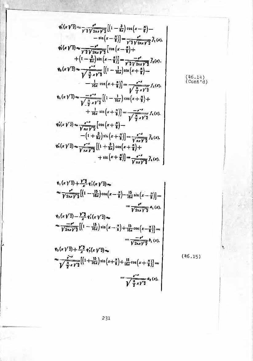
/1 w. V2nx Kl
+(1-ij),"1(*-t)]“p117¿^7,w.
♦*<^'7^ [('-^)-(^^)-
TSj- «»(^+í)]= -^2==./,(4:),
[(1 ~t¿t) cos(*+j)-f
(x + -s)] =
U /¾
/4 (X). }f~xV2
^ t)-
-(i+¿)si,.(4+|)] = _^;|Wé
*+ sin (*+ j)] Vnxl^l
?i (*)'
♦.(^/2)+-Ç-tí(xVD^
'=7éñl(' —ík)“’^-?)-^51"^—í)]=
= Vlxr 1^' a‘ (X)‘
t,(xVl)—^tí(x/2)^
^ y^Tf K1 ~ sin (x ~ î)+ifecos (x-t)]=
ta (jf K ^ (x |/^) =¾
•-*
‘02(X), / 1 7X^
(46.14) (Cont ’el)
(46.15)
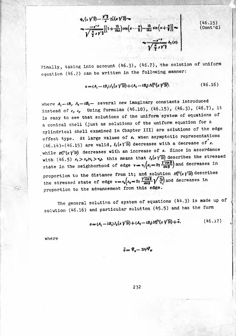
- -7== [(>+TS) Sln (*+t)] ' Vi*/3
— # b,(x).
(46.15) (Cont’d)
finally, taking into account (46.3), (46.7), the solution of uniform
equation (46.2) can be written in the following manner:
0 = 04,-/23,)/, (x + (A2 - /a,) M" (jc V7«)- (46.16)
0 = 04,-/a,) /,(je /2/) + (44,-/8^ M"(jc /2/) + a. (46.17)
where /4,-/8,. /4,-/8,— several new imaginary constants Introduced
Instead of r,. c,. Using formulas (46.10), (46.15), (46.3), (46.7), it
is easy to see that solutions of the uniform system of equations of
a conical shell (just as solutions of the uniform equation for a
cylindrical shell examined in Chapter III) are solutions of the edge
effect type. At large values of *. when asymptotic representations
(46.14)-(46.15) are valid, /,(*/2/) decreases with a decrease of *.
while «'¿"(x/2/) decreases with an increase of x. Since in accordance
with (46.5) *,>*4<t,>V. this means that /,(*/2/)_describes the stressed
state in the neighborhood of edge v = v,(*, = 2yand decreases in
proportion to the distance from it; and solution /^»(x/ãt) describes
the stresses state of edge deceases In
proportion to the advancement from this edge.
The general solution of system of equations (44.3) is made up of ,
solution (46.16) and particular solution (45-5) and has the form
where
5=^,-2^0
232
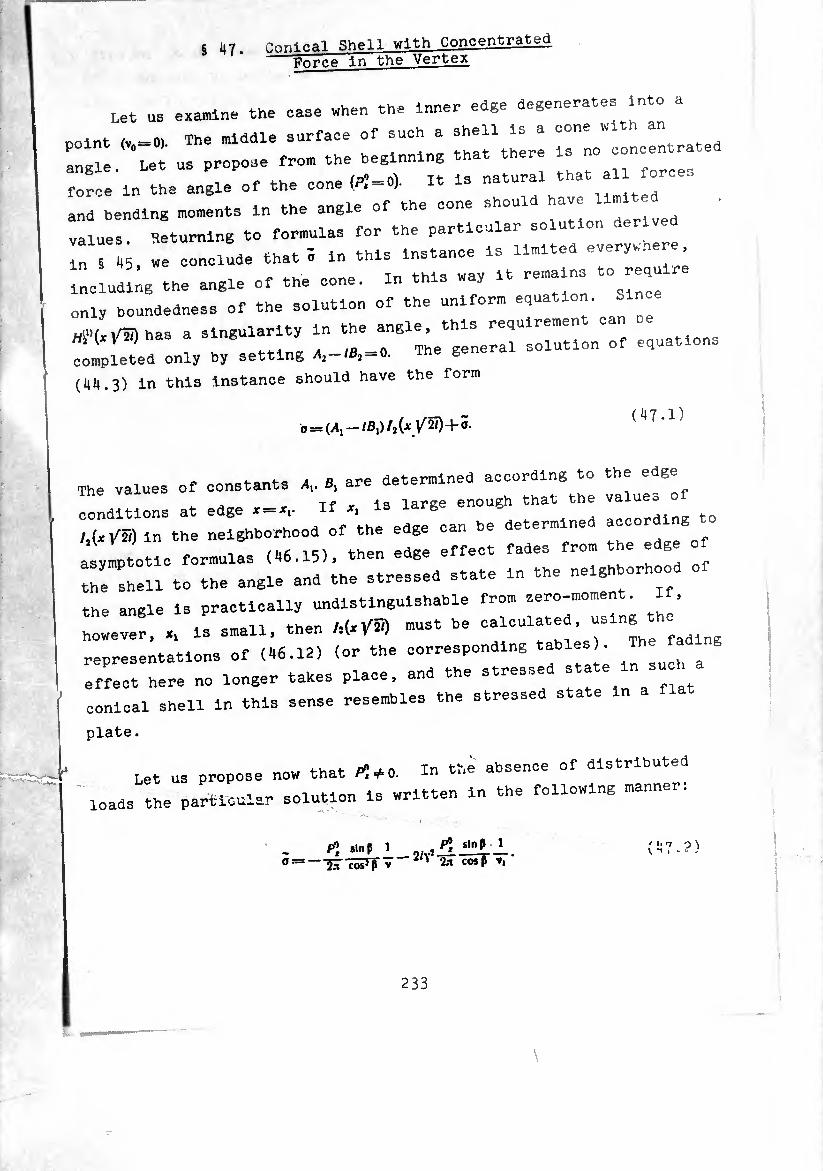
_ -■ .. -
s 47 Conical Shell with Concentrated -Force In the Vertex
Let us examine the ease when the inner edge degenerates into a
point (,,=0). The middle surface of such a “^concentrated
angle. Let us propose from the hegi g all foroes
force in the angle of the cone (/>, = 0). It is natura
and bending moments in the angle of the cone should have
values. Returning to formulas for the particular so u on
ln 8 45, „e conclude that 5 in this Instance is limited everywhere
including the angle of the cone. In this way it remains to require
only houndedness of the solution of the uniform equation. Since
has a singularity in the angle, this requirement can oe M ' * ' _ . The general solution of equations completed only by setting A,-18, = 0. The gene
(44.3) in this instance should have the form
0 = (Al-lBl)/t{xy2Í)+ã. (47.1)
w. . . . o orp determined according to the edge The values of constants Av B, are determine
conditions at edge * = *,. If ^ large enough that the ^ ^
,,(^5) in the neighborhood of the edge can be determined accordlng^o
asymptotic formulas (46.15), then edge effect fades from
the shell to the angle and the stressed state in the neigh or oo
the angle is practically undlstingulshable from zero-moment. If,
however, x, is small, then M*^) must be
representations of (46.12) (or the ^ * state ln such a
effect here no longer takes place, and the st
conical shell in this sense resembles the stressed state
plate.
Let us propose now that * + <,. In the absence of distributed
loads the particular solution is written in the following manner:
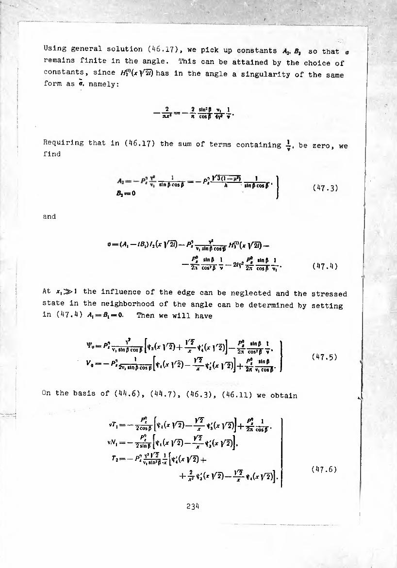
Using general solution (^6.17), we pick up constants A2, Bt so that o
remains finite in the angle. This can be attained by the choice of
constants, since M”(-^ has in the angle a singularity of the same
form as a. namely:
2 2 sln»p V, jut1 Ji cos ß iv4 » *
Requiring that in (46.17) the sum of terms containing -i, be zero, we
find
1 sin ß cos ß
Bj~0
n'VàQ-H’) i A sin ß cos ß '
(47.3)
and
.=M. - /fl.) /,(x /5!)- « /5) -
^ 1 -,r. ^ “»K I 2.1 coslß V ' ÍT cosß V| ’ (47.4)
At the influence of the edge can be neglected and the stressed
state in the neighborhood of the angle can be determined by setting
in (47.4) .4, = 0, = 0. Then we will have
)^+il t; (, r*)]- v- = - [f.(* )-2)]
slnß I 2T cos:ß T’
P? sin ß ' "5n V, cos ß *
(^7.5)
On the basis of (44.6), (44.7), (46.3), (46.11) we obtain
v7\
v.V, =
r2= 1 +
+Jr«;(, /2)-i3:t,(,)^)]. (47.6)
234
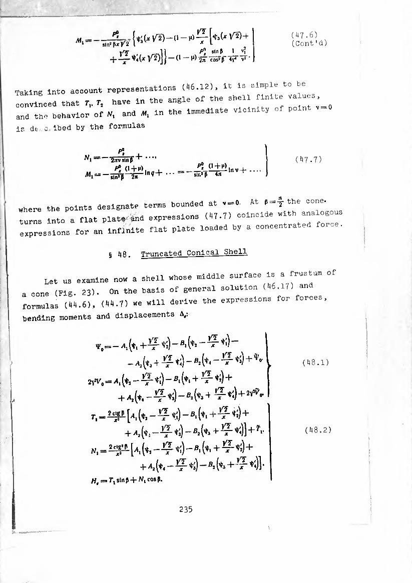
>
,. ,-vl 1 sln P 1 v> + -^-^(^^2)11-(1-H)2ír73i?p-4v4 V»
(47.6) (Cont’d)
Taking into account representations (46.12), it is simple to Pe
"nvincea tnat r„ r, have in the angle of the shell Tinite va ues ^
and the behavior of N, and M, in the Immediate vicinity of p
is de o., ibed by the formulas
W,=- P»
'SavÎlïïî4'
0 + M),_i_ -sï??-ir-ln^+
P°, 0+M> sir.* P 4ji Inv +-
(47.7)
where the points designate terms bounded at v-O. At ¢-+ the cone,
turns into a flat plate-énd expressions (47.7) coincide "lth “al0g°
expressions for an infinite flat plate loaded by a concentrated for-e.
§ 48. Truncated Conical Shell
Let us examine now a shell whose middle surface is a frustum of
a cone (Fig. 23). On the basis of general solution (46.17) and
formulas (44.6), (44.7) we will derive the expressions for forces,
bending moments and displacements A,:
v,=- /'.(♦i +TT
+'‘’» A ( 4 8.1 )
w =» x, - (♦.+^ *;)+
+ -4,(^--^^)-8.(¾ +^^)1+-1.-
N,=1^[+ (♦, - t;) - 8, (¾+TT +;) +-
++, (<. - Ç +;) - ®> (+. +- -+- +.)1 ■ Ht = Tls\nt+Nl cosp.
(48.2)
235

- ¿ ^ +,)+ Ai (+;+!♦;—*?■ +«) -
^=^ [+; -T " -^(+.+T +;)]+
+8,(+5-^0-^(+,--^+1))+
++(+1--^-0-^(+,+-^+:)1+
-'• ,AJ -)(+,-^+:)))+-
i/'t / i/T
1- fi2 ['i i — -^¡r (1 — M) ^-4 — — H 3; J / T +-
4- “i¿OT=k [ ^ [+:-0++) -?(+,- ^ +(
- 8, [+: - 0+M) -Ç- (+,++;)]+
++(+:-0+^)-^(+,--^+:))-
/ i/T \1
-I-
> i r-/ jf y»4 x .jyj
sivh3 + ^+)]} + 5,.
(48.2) (Cont'd)
(48.3) -w- x
In these equations ¢,. ¢) designate functions from the argument XV2.
Fig. 23. Frustum of a cone.
The calculation of the shell becomes comparatively simple if
the form and dimensions are such that in formulas (48.2) functions
<1+. +|'[ can be calculated using asymptotic representations (46.14),
(46.15). We will shew that even for a flat cone, close in shape to
a plate (6 is near ¿j. this is admissible if the ratio % is large
enough. Transform (46.5) to the form
:V5
2 V 12(1 - ft») sinß Vi-
236
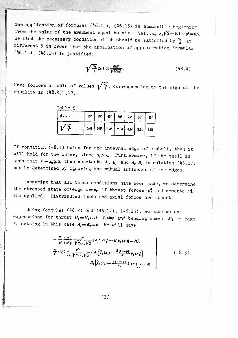
The application of formuxas (46.1^), (46.15) is admissible beginning
from the value of the argument equal to six. Setting ^0/2 = 6.1-^=0.9.
we find the necessary condition which should be satisfied by at
different 3 in order that the application of approximation formulas
(46.14), (46.15) is justified:
/?>,œ7Sfr- («•'o
Here follows a table of values jAj-. corresponding to the sign of the
equality in (48.4) [12].
Table 5.
?. 15* 30° 45° 60° 75° 80’ 85°
/?• • • • 0.44 0.80 ¡.38 2.03 3.14 3,91 5,57
If condition (48.4) holds for the internal edge of a shell, then it
will hold for the outer, since v,>v0. Furthermore, if the shell is
such that then constants Alt Bl and Av ß2. in solution (46.17)
can be determined by ignoring the mutual influence of the edges.
Assuming that all these conditions have been made, we determine
the stressed state of»edge * = *,. if thrust forces H\ and moments M\.
are applied. Distributed loads and axial forces are absent.
Using formiuas (48.2) and (46.14 ), (46.15), we make up the
expressions for thrust cosß -h 7y$inp and bending moment Ai, at edge
*1 setting in this case æ> = 5, = 0. We will have
2 cos p e*‘
7, +B‘a‘
(48.5)
231
3
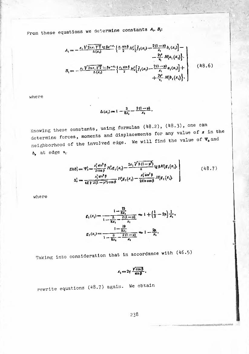
Prom these equations we determine constants B,:
A _ *. V2*x<Vï «RPr_‘ J i> "ES w: ( -
Ã(Jt|) ! 2 I J
- (*.)}«
_ j £ji!ES Wi [/, (>:,) _ a, (X,)]+ (48.6)
where
Knowing these constants, using formulas (48.2), (48.3), one can
determine forces, moments and displacements for any value of x^in^
neighborhood of the involved edge. We will find the va.
A, at edge v,.
*! - < ■= h;î ' W - >M'e-('■> (48.7)
where
1 —
g\(x\)— ~ 3; 2(1—u) l — Tît^ô-^'+iï-5^
bJf| Jf| 19 1 — »xt
g?(xt) “3 2(i_)t) 1 —
>-*• *i Bx»
Taking into cons ideration that in accordance with (46.5)
KcosP '«-^-ïïïïr
rewrite equations (48.7) again. We obtain
238
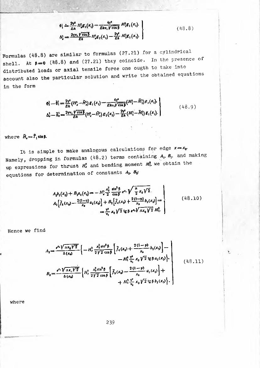
(148.8) «! WO-7.¾
4, _ ^ «¡i, (^,)-
Pormulas (48.8) are similar to formulas (27.21) for a cylindrical
shell. At ¢=0 (48.8) and (27.21) they coincide. In the presence o
distributed loads or axial tensile force one ougth to take Into
account also the particular solution and write the obtained equations
in the form
*i -SI=
Ai — Si == (//i - H\) S.2 (X.) -(* ¡ - *1Í) (*.)• (48.9)
where W, = f1slnp.
It is simple to make analogous calculations for edge x = x0.
Namely, dropping in formulas (48.2) terms containing .4,. 8,. and making
up expressions for thrust HÎ and bending moment «?. we obtain the
equations for determination of constants A2. B3:
a AW + Vi M “ ^ T isf ^ i *« I
a, [A ^ «, w] + «. [/. w+w] “
_ JC0 /2 tg P nx0 /2 A1?.
(48.10)
Hence we find
2 a(jt,) l 2y2 cos? L *• J
—A*?-~2foV^,ßPai(xo)r vl 9
■ ¡„I<«<)] + \ 2 )r2 cos pi x* ■*
-i All-£-*0^2 'gP^(->co)}- A(Jfo)
(48.11)
where
239

Formulas for calculation of the angle of rotatioi and radial
displacement of edge jt0 have the form
(48.12)
where
§ 49. Combining a Cone and Cylinder
As an example of the application of formulas obtained in the
previous section we will determine the radial force and bonding
moment acting at the junction of a long cylindrical shell with a
conical bottom (Fig. 24). The shell is loaded by internal pressure
of intensity p. Since then
2y> = 2Y; = 2v2 = /12(1-n5) -£ •
Fig. 24. Junction of a cone and cylinder.
For a cylindrical shell at the place "f coupling we have
240
(49.1)
An . 2V* rfi i ^V* 14° TKÏÏ
=- ¥0"-^"?-
I
The connection between <h\ AÍ and H\. at rather large values of *,12
is determined by formulas (48.9), which for a given concrete load
(uniform internal pressure) assume the form
o! 3 pv,
(49.2)
At the junction of the shells displacements and forces should be
continuous
01=0?, a1=a;. w1=Q°. Al} = Ai?. (49.3)
Using these conditions and (49.1), (49-2), we derive two equations
for determination of Q°. Aft
_ ^ [i+s.(*,)] «• - ¥ U - w] «î=
_ Æ AiliüL igî p g. (je.). Eh 4y2 ^
(49.4)
Dropping in the right side of the first equation the second and third
terms and in the right side of the second equation the last term, as
terms small in comparison with the remaining (as or ^ in comparison
with unity), and setting, for simplicity of calculations,
241

(i = 0,25, fi (X,) = 1.
we find
Alî = pR*
~ 4v gP \+V^}'
QO = _l^ 1 — COS P
8 2v 11 4-)^05^^(^1)1005 p
^tgP/cos^gatx,) 2 1-f l^rp^j^,)
(49.5) I ]
Substituting the obtained expressions in the second formula of (49.1),
we calculate radial displacement and peripheral force in the abutting
section of cylindrical shell
.a PR2 .. û' 2Eh ' 1 + l^cõip ’
£Ä tgPjfwT? ^ 2 v 14-
(49.6)
in In the calculations for simplicity we dropped terms of order \
comparison with unity. Calculating on the basis of (49-5) and (49.6)
flexural and peripheral stresses and referring them to the nominal
(where o? = . o* =*) t we obtain
O? -Is
a fH Vcosß ^-= + 2.3 y
o2 /~~R )/cõs? 5—»“l/T^-rppsr 2
(49.7)
Stresses at the junction depend on the angle of conicity of the bottom,
at p = 0 the cone degenerates into a cylinder and o0 = o» = 0. At P*0
and large £ stresses can become large and considerably exceed, for
example, flexural stresses in a rigidly fixed section of cylindrical
shell ( § 28).
With the aid of formulas (49.2) it is simple to find the values
of M\ and Hi in the edge section of a complete conical shell loaded
by pressureV with the following attachments of the edge:
a) fixed edge 01-^==0.
b) supported edge Al} = Ai — 0.
Dropping small terms and setting as before »=0.25. (M*,)-'.
1 —We h3Ve f0r O flXed eiÍSe
„1 __ £1l ttrfi — — ^-( 1 4- —\, 1 H*~~ o tgP 8 y (cos P),/l \ ^ Xi) !
^ = - ¿iVÍ1 +t)* I
(49.8)
for a supported edge
h\ = *sP—
Al} = 0.
16 TicosPPi»^») (49.9)
Bending stresses at the edge of a fixed conical shell, computable
according to bending moment (49.8)j are equal to
(49.10)
§ 50. Truncated Cone Compressed b^ Axial Forces
As a second illustration let us examine a truncated cone contained
between two even plane surfaces, compressed by forces P [12]. The
surfaces do not prevent radial displacement and turning in the edge
sections , i.e.,
when x = x0
W° = ¿l? = 0. (50.1)
when Jt = x,
h\—m\ = o.
243
Determine displacements A". AJ and turning angles 0?. $\. the particular
solution of the basic equations :44.3) for a given load we obtain
using formulas (45.8), setting in them = — P. qe — qt — 0:
f_ü_ * 2nv cos ß
H- sêr'e")
0. = /(1, = ^ = 0. Ã, }
p a I £/i 2ncosß )
(50.2)
In formulas (48.8), (48.12) we replace
H\ ty + ^
£ by
uO V.. u> , P H' by +
Eh 2.1 cos ß ’
^tgß
(50.3)
whereupon, taking into account boundary conditions (50.1), we obtain
^ 2y’ Pigß „ 1 —Th~^Tg^Xl)' J
»1 H P , Y PlRßl^cosß I A' = £Ä2S7^ß+fJT-5 I
tl=-EhH^rg3^-
(50.4)
(50.5)
A° _ >* — Ti _ P Y £A 2.1 cos ß £/i
^ PtRß^W^ J
ß.
í42
b2
- -%f - ^ ^ «■>] ■
(50.6)
Subsequently for calculation of displacements the quantities ,4,. 8,. /1,. B2 ,
will be needed also. By formulas (48.6), (48.11), using in them also
substitution (50.3) and taking into account (50.1), we obtain
244
Let us determine the values of forces Tt, T2 and moments Ai2 at
the edges of the shell. Solving these equations
r?wnp + yv?cosp = 0.
T'i cos p — N'l sin p == — 2nv, ’
(50.7)
we find
77=-. cosp. (50.8)
Analogously
7" = 2nv, COS p.
Forces T], Tl are simple to find knowing the quantities T\. rj and A?. Aj.
For example, using the formula
7-3 = ,,77+4* ü. vo
we obtain
Tj-» g,W, n y VqV| (50.9)
In exactly the same manner we find that
(50.10)
We determine All Al\ according to (44.7), taking into consideration
that because of edge conditions (50.1) between the derivative of the
angle of rotation and the value of d, on the edges exists the
relationship
7,-=-11 AT- (50.11)
2^5
In this way the values of *«. ■'<! can be
calculated by the formula
Mi=*— 12 - sin p (v = v0. Vj).
fen i?'! the values of ac Substituting into (50.12) the
(50.5). we have
«2= 6 v0V| 2.n cos p
6 v{ 2n cos P
(50.12)
cordance with (50.4),
(50.13)
Remembering that We
from tension
determine circumferential stresses
ro ptgp^cosP {/SO - ^4(X0> 1 ( 50.14 )
_
T> PtgP^t0SP 1/ \A3(1 -1Aj)?2(x0 J 1=-4 = --^ r h “î-* fc
from the bending moment
1
0«= ± + 1 .1 - P sln2P „ t*\
. 6A1» _ xi/ãTT—tstb
(50.15)
h*
p slnJ P
^2ñv^ "cosT
of tension have an order larger
ft iS eaSy t0fSe/lTendiengStsrterSeSsses and they are in this case by an order of y h
estimated.
ovial displacement of the edges of
Let us calculate the rela v sag of the truncated cone
the truncated cone or, in other 'ive forces P. In accordance
under the action of preasslgne axial displacement
,,, lfi, if we set in them 8-2 with (13.16), It «a to
section IS in a certain insoanx.
246

(50.16) \ = J (— «i cosf$-f O, slnp)rfs -|- C.
Constant of integration C^O. assuming that edge section s = l0 (x = xb)
remains s tationary. Then sag of the truncated cone <J in absolute
value will be equal to the displacement of edge $ = = Or, taking
into consideration that —.. sin p
6 = \(*i) = { (— «iCtgß + ôprfv. (50.17)
Since on the basis of (M.4), (^4.6)
= cos p. <I)2 = sin p.
y IlIÎÜlL — N Infi_p sln,P 0 V 1 ^ 2nv cos p ‘
(50.18)
which can be written
ei ~ TÁ- — v^-ù
^ ¿- [ - £i,‘ ¿ (iSf + C0S P) + N',g p] ■ (50.19)
Angle of rotation
= ©I +
where 0’ corresponds to solution of uniform equation in the form of
(46.16), and
s _ P sin p I 1 2nfA cos'P v"'
Let us note that during the calculation of stress we used the zero-
moment solution 0,=0. We can verify that use of the accurate solution
would give in this instance only insignificatn corrections of the
order of \ in comparison with the basic terms. However, while
247

figuring the axial displacement, as win be exnlMn.a h , change of the particular solution t-„ -IHl’ below, such a
in terms of order Jr in col ^ W°Uld —« y , in comparison with the basic, i.e., alreadv in
those terms. Which thus far during calculations we have kept,
we obtain * a000'mt ^ -Pf-^ons for ^ and
»I 6= j rilv'C05P </v» , p : . V i . J l f-h rfv + 2.1 E/I v'sin fl eos* If + ~ -gj-J dy :
— MV| cos P
(50.20)
Note that from (1+4.6) and (44.4) at <,-n if e -,, + vriS,„,_v In thls Kayj unde l’;:: : 010“3 tet v'Vos
there exist the equalitlel ^ C°nditlü"3 «0.1
(50.
ti ?::rie5 and ^in ^ w.n) ^ <«.6) 0, -¿T Re [(A, - IB,) h (x /2/) + {At - iß2) ///*(x /¾)]. '
Jpf-1™ [(M, - iB,)J2 (or /¾) + (Ai-iB2) HÇ'( x /¾)). _ V| cosp
V (50.2
tHerrn """T5011 ^ ^636 « 1* easy to see t th. term i„ subintegral expression (50.20) Is negligible in comparison with ¢. Therefore
. P i ~%iîEF tin fl cot* ß InjL+j1
V,
Sinca
V, tin* (» TFT^ir***-
248
j t,(x\rü)xdx. j HÏ(xV2)xdx.
Using formulas (46.8), (46.9) and noticing that
we find
j fordidz/i(2)« — zIq(z),
j tf'zds** - 1/4"' (z).
&| :¾-¾. g .
J Ç ♦,(, ^-)] _
J «?'(*/S)x,x_(4I[t;u /7) - ,^]_
- ^ir1 < [*: i* /n _ .Ç- tj ,rf)j j';
or, ignoring the mutual influence of the edges.
J Mx^7)x4x = ^[t;(xi ti(li
, I'?)
i (,./7)]+
+'^[«(x./î)-^*,(x.n)].
In this way, on the basis of (50.22), (50.24) we obtain
,,, A %- ^ ' -.- - l ■_v ■■ -i rv ^ . . . . . . » • , V '.
I-a
S"'V) /• rí ■
(50.2^)
/ -,i ZIT. ZZT " ' “ “ “ »-* »• -- - «
■ .-
K|’‘‘ ”*
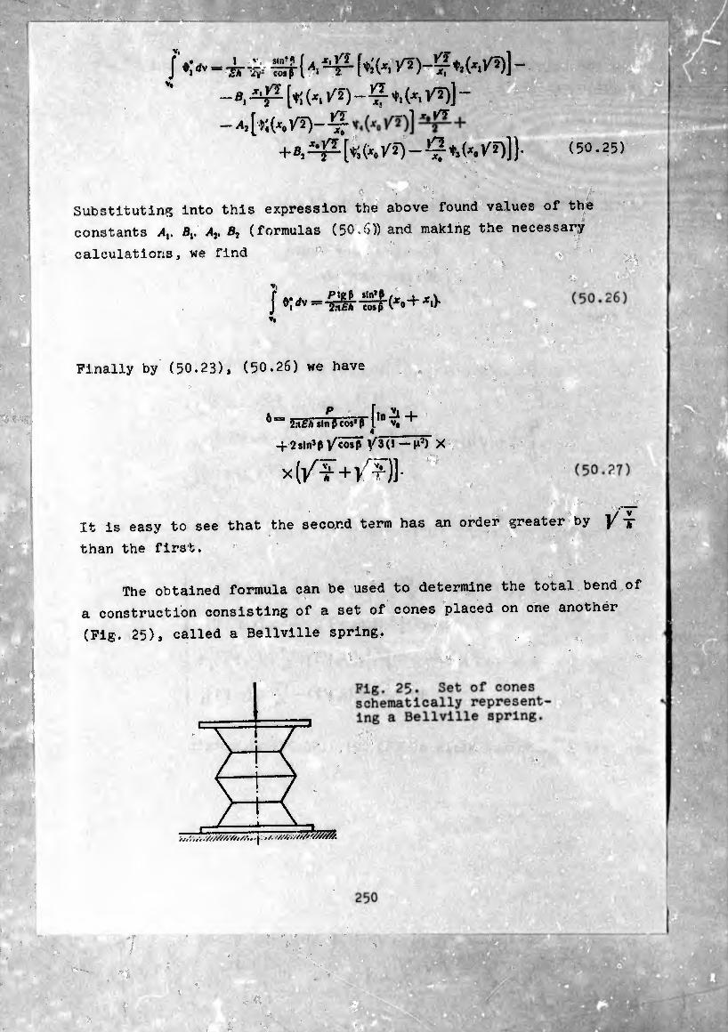
'
/*>iSf {».*£- [♦;('. — a, X'l^- [*¡ ("i V'2 ) - -77- 't, (XI /î)] —
r 1/75- _ 1 _
+a, t31 [*;(*. /2) - Ç ♦,(«. V21] )■ (50.25)
Substituting into this expression the above found values of the
constants A,. B¡, Aj. B2 (formulas (50-(5)) sod making the necessary
calculations, we find
»,
1& ^f(Xo+ •*')'
Finally by (50.23), (50.26) we have
6 slnßcosiTf10^ +
-f 2stn3p /cõsT \/3(l — H2jT X
X (/¥+/^)1-
t /////A//,/.-... j.. '////■v/zJ/wM}/.
. m i • • ■ ■ '
-V.- -: jçVi-X ■ '•* 1 *'
^ i
-
.,Í.T r
^ fi&i
It is easy to see that the second term has an order greater by ]/ *
than the first.
The obtained formula can be used to determine the total bend of
a construction consisting of a set of cones placed on one another
(Fig. 25), called a Bellville spring.
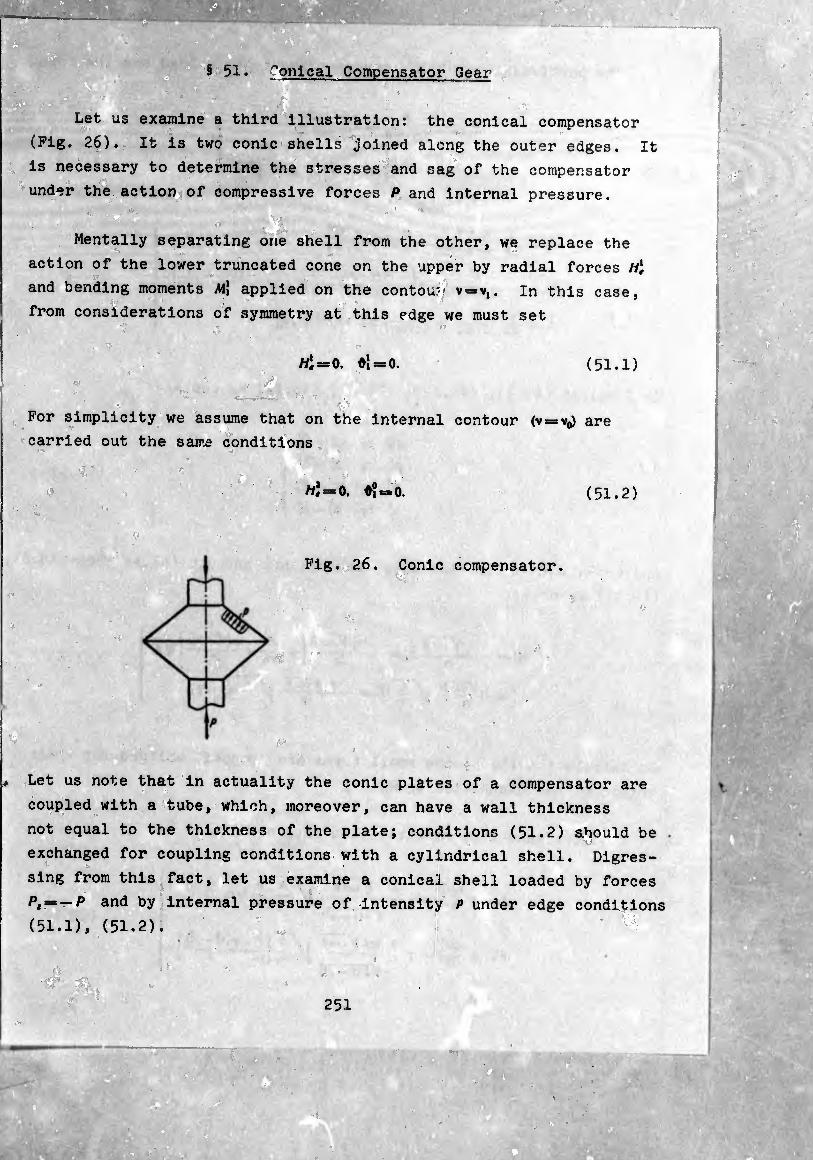
I
;:tä
§ 51. Conical Compensator Gear
Let us examine a third illustration: the conical compensator
(Pig. 26). It is two conic shells joined along the outer edges. It
is necessary to determine the stresses and sag of the compensator
under the action of compressive forces P and internal pressure.
Mentally separating one shell from the other, we replace the
action of the lower truncated cone on the upper by radial forces h\
and bending moments /W| applied on the contou?- v = v,. In this case,
from considerations of symmetry at this edge we must set
Hlt = 0, ¢1 = 0. (51.1)
For simplicity we assume that on the internal contour (v = v0) are
carried out the same conditions
111 =*0, G? =* 0.
Fig. 26. Conic compensator,
(51.2)
Let us note that in actuality the conic plates of a compensator are
coupled with a tube, which, moreover, can have a wall thickness
not equal to the thickness of the plate; conditions (51.2) should be
exchanged for coupling conditions with a cylindrical shell. Digres¬
sing from this fact, let us examine a conical shell loaded by forces
P, = — P and by internal pressure of intensity p under edge conditions
(51.1), (51.2).
251
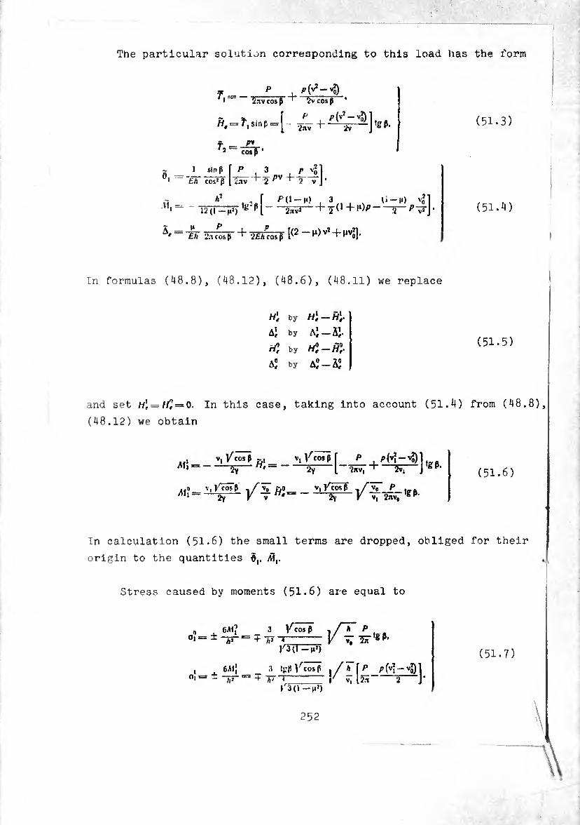
The particular solution corresponding to this load has the form
f_P , 1 2.1V cos ß 2v cos ß '
r,= r>
~ 1 sin
1 ¿A cosJ nß f . 3 , r 'o
+ +T~
h2 f />(1 —H> 3 U—M) v*l
^ - - w^) 'g n~ “5Sv*~ +2^+ l‘)P- -2->^J•
= + 2FaW [(2-^vJ + ^1] ■
(51.3)
(51-^)
In formulas (48.8), (48.12), (48.6), (48.11) we replace
H't by
Ai by Ai-ii-
ril by H0e-H°t.
a; by a"-ã;
(51.5)
and set H'f=He — 0. In this case, taking into account (51.4) from (48.8)
(48.12) we obtain
. v^cosßj-, V,/cosß Ali --öS- “í = — 2V ~W
„o V, J/cÖTß t/ vo £>o _ V, Ÿ cos ß ,/v0 P - V Tw'=-2Ÿ-V vT 2«v7,g^
(51.6)
In calculation (51.6) the small terms are dropped, obliged for their
origin to the quantities d,, ÂÏ,.
Stress caused by moments (51.6) aie equal to
0 ^ 631? _ 3 y'cos ß ! /T* P ^ a °i — - /,2 ==+/,: 4 y V, "Sir g
1^3(1-M»)
I . 63lJ _ 3 tgßl^cosß ,/ä 0| — - h* ^ * h' * V V, 12.1 2 J"
>3(1 -nh
(51.7)
252
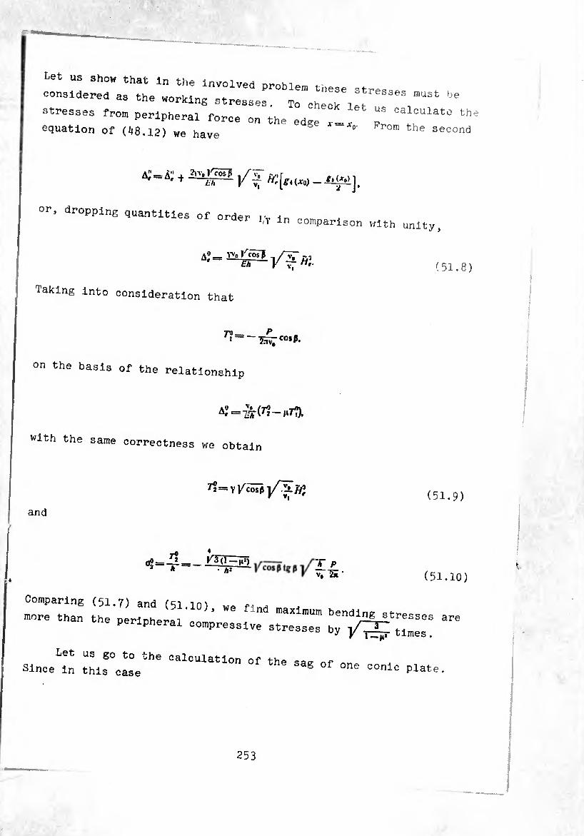
must be et us show that in the involved proMera tnese stre,» »
considered as the working stresses. To cheok let
stresses from perlpherai force on the edge T th equation of (48.12) we have °' Prom the second
t /it
or, dropping quantities of order i;v in comparison with unity.
A0= Videos? r—
£* V H'
Taking into consideration that
(51.8)
7¾_ P . '~~25^co*P.
on the basis of the relationship
A' = ÍT^~M7t).
With the same correctness we obtain
and
(51.9)
oo=IÍ = _ÍSS!l 2 A HS» A P V, 2n (51.:
Comparing (51.7) and (51.10) we find ,
more than the peripheral compressive stresses ^
Since in this case^6 CalCUlatÍOn of the sag of one conic plate.
253

(51.11) = - cos0.
P p v? —vj
then using (^4.6) in the same way as in the previous illustration we
can write
PI V2 — Vo r, = tg P -^ + p cos P-JÇ-.
T»“ v,sinp-^! .
— e^igp —— /V, + 5^ snr-p *» » ï 7
p cos^P V — V() ,
sin p 2v '
«
t !*v»cosP-rf7
(51.12)
and
Vi
{,= I [- e, clgP + ^l + fri)l Vr
f • P « vi P 3sln»P — cos»P „7\_i_ -¾ J P, rfv + ^¿h sln ^ cosJ jj- «” Vi + 4£A S|„ p cos’ p V ' «
' 2£AsmpcosJp V, 1 £* (51.13)
Taking into consideration that
V2 — vj
vH, = Vj^o — p dg p —J—.
because of edge conditions (51.1)> (51.2) we have
v*_v2 v,yo(V,)= PCtgP-l-JI-• v|ï'0(Vo)=*0.
In this way
6= J Pi dv + ¿É/, sinVcos’f (4+/,V»),n vl +
V* riv2-v^i .. . 3sin2P — cos*P^
+ T^iniTTcos^ + 2cos»r-“) (51.14)
254
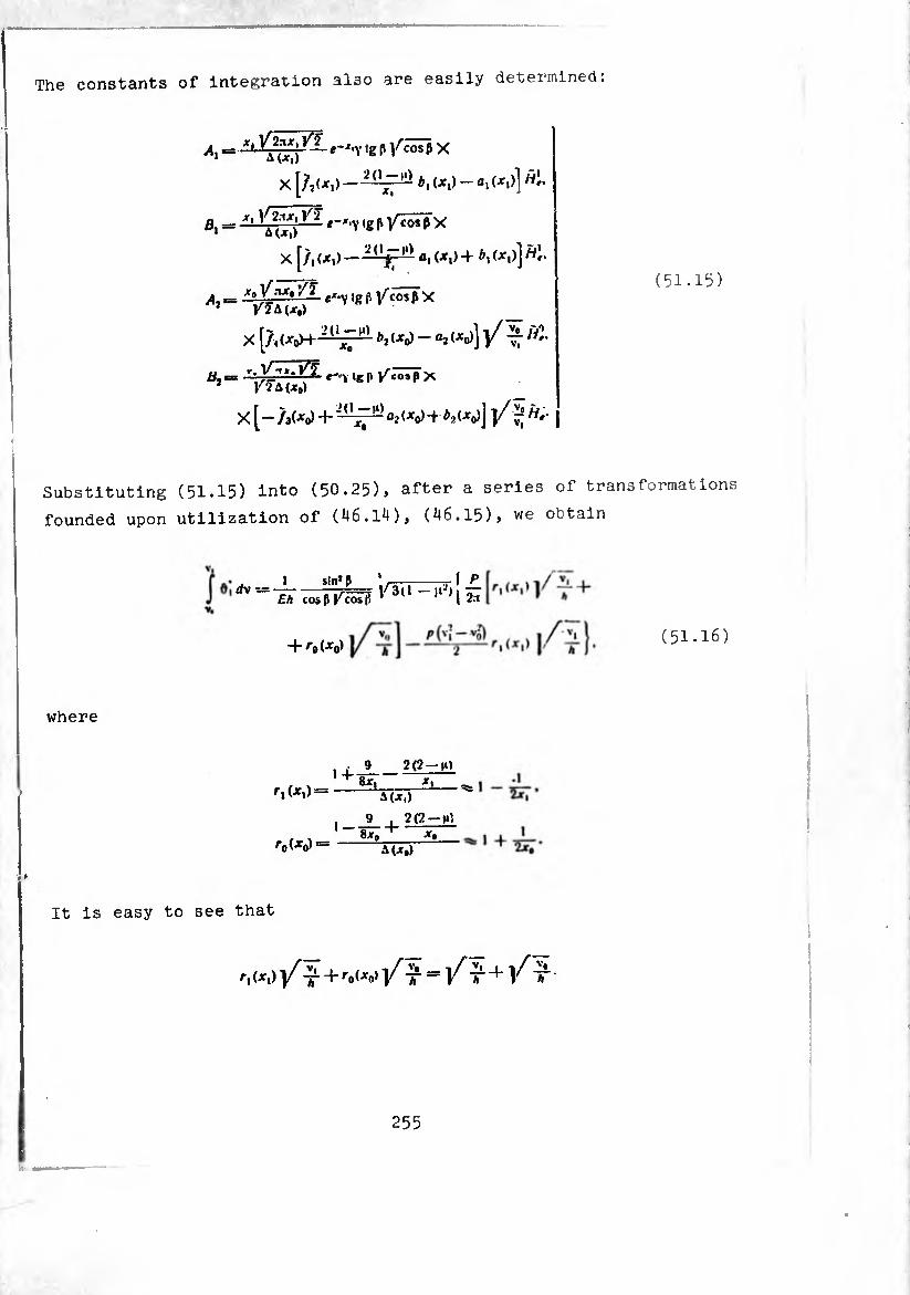
The constants of integration also are easily determined:
Ai “x> '"'"i,g p ^cos ^x
X [/^.) -—r1 M
ß, = ‘-' V »ß P VC0* P
X J/, (X,) — 2(ljr — fl| (X|) + (X,)] H'f
.r—fK \_ (51.15)
^=^lg M/cos ß x
X [Àt^oH- -1;— >1<XJ - °2 <*<>)]}/ T7
X [- /3(^0) + «2 <^o) -t ^(^0)] )/ 7° ”*■
Substituting (51.15) into (50.25), after a series of transformations
founded upon utilization of (46.14), (46.15), we obtain
I sin* P Eh cos p f^cos fi
+ /-0(^0) (51.16)
where
2(2—m
A(x.)
^(Xo)^
9 ■ 2(2 —
Bjc, + X, A(Jr.)
It is easy to see that
ri(jr.)|/lL + ro(x°,V^ T^Y T +/ X-
255

Thus, displacement of half the compensator is determined by the
formula
ÎETisWî (4 + Í&I (^ +
9/:A COS P > COS P ' Jf, / I * 2£A
(51.17)
Petting in (51.17) P-0, we find sag only under the action of compressive
force :
^ 2n£ft sin p cos* fl ^
x['n-^ + sin1M^^ip /1»! -^(V T + V^t)] (51.18)
Comparing (50.27) and (50.18), we note that because of the lack of
angles of rotation of the edges (ôî = ôi =u) the sag of the truncated
cone was diminished by almost twice.
§ 52. Truncated Conical Shell Under the Action of a Bending Load
In 5 52 and subsequent sections of this chapter we will be
limited to consideration of the strain of a truncated conical shell
under a bending load. Apropos of the calculation of a conical shell
containing an angle we must note the following: the question about
the applicability of equations (16,13). (16.1^) in this instance
requires special analysis. The fact is that in
the left part of formulas (16.4)-(16.6) the term l2 v, l2 v,
dropped, which at .-0 is infinitely large. In order to evaluate
the error made in this case, it is necessary to derive again the
Meissner-type equations keeping tnese terms. It is only when the
obtained equations will differ from (16.13), (16.14) only because
of terms of a higher order of smallness, will it be possible to say
that equations (16.13), (16.14) are adequate for the calculation o a
shell with an angle.
256
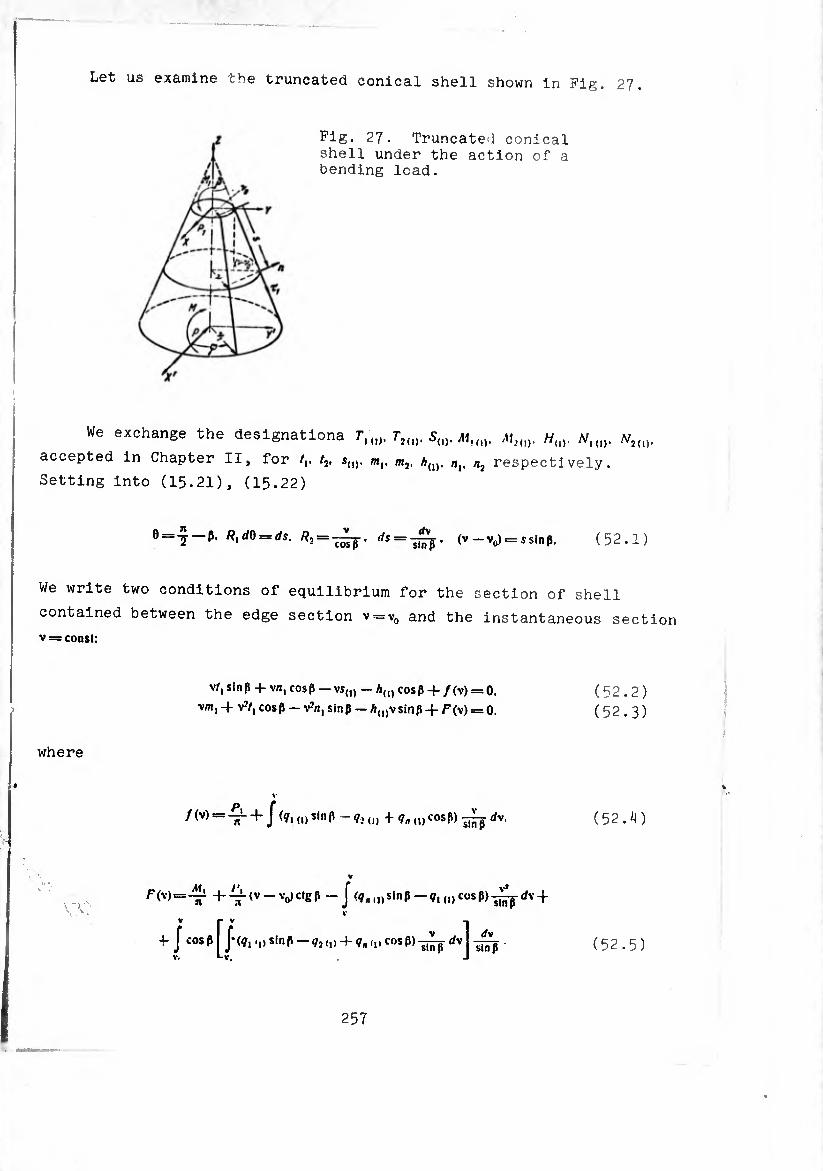
Let us examine the truncated conical shell shown in Fig. 27.
Fig. 27. Truncated conical shell under the action of a bending load.
We exchange the designationa Tl{]). TiU), Sw. Mun. m2(]). W(), .vM1). NUl).
accepted in Chapter II, for /,. /2. s(J). m,, m2. a(1), n{. n2 respectively.
Setting into (15.21), (15.22)
0—2 ¢. R^db — ds. R, = -~, <1$=:-^, (v-v0)=rssinp. (52.1)
We write two conditions of equilibrium for the section of shell
contained between the edge section v = v0 and the instantaneous section
v = const:
v/.sinp + vn.cosß —vs(]) —Ä(1)cosp + /(v) = 0, (52.2)
vm, 4 V2/, cosp — v2n, sinp — A(l)vsiriP +/=^) = 0. (52.3)
where
/ (V) = A 4 J (ç, (1) si,, P - ,,, + ,u c°sP) 1¾ tfv. ( 52 . ¿I )
= -h-^-tv-VctgP - Jsinp—¢,,,,cosP)+ V
4 «sP)7¾ (52.5)
V p V
J cosp J*(¢,, V» *-V<
,, sinp <72 (,)
257

Making the same transformations in expressions (15.3*0 > (15.35) and
comparing the result with (52.4), (52.5), it is simple to conclude
that functions /(\).F(\) are connected with the functions of external
loads fo-fi-Fo-introduced in § 15, in the following manner:
/cosß fslnh F0+ Fi~-y-'-~
. . , /slnp F cos fi /0 + /1- \ V*
(52.6)
The left part of equation (52.2) is the sum of projections of all
forces on section of shell <v0. v). onto axis OX. the left part of
equation (52.3) is the sum of rhe moments of all forces relative to
the axis passing into the plane of section v = const parallel to OY
(Fig. 27). In accordance with this load functions /(v). F(y) can be
presented in the form of the following sums:
/(v)= i-(P,+ /»,). (52.7)
f (v) == -i (Ai, — .P,Z + Al,).
where
Z = (v0—v)dgpi
PvMi— force and moment on section
(52.8)
Rolling the loads to be known functions of variable v. P#(v). A1,(v)
are easily found from equations
/y v) = n J (¢, + g, (t) ctg P) v dv.
V,
V
.'A, (v) = — n J (q„ (,)—?, (,) ctg P) v» dv 4- V«
\ V
•fcigp J J (?,,,, sin p - ftcos P)vdvifr
V. V,
(52.9)
258
External loads applied to the shell as a whole should satisfy finite
equilibrium relationships
+ />,£ + Af, (V,) - AÍ = 0 (£ = (V, - v0) ctg p), ,1 (52.10)
Where L— height of truncated cone, P. M— resultant and total moment
of loads applied to edge v=v,.
From (52.7), (52.9), (52.10) it follows that
If the the intensities of loads f,,». ?2<,)* ?«<i> are constants, then Pr Mg
has the form
(52.12) = — n (?„ (l) — <ii „) c‘g P)-6
+.'XCtgp^1(1) — + ?»(,) ctg p) ) (v+2Vo)'
For a shell of constant thickness an illustration of such a load can
be a weight load (axis OX is directed along the vertical to the
ground)
9i(ii==?sinP' fío»“-
Everything above refers to the equilibrium of a finite element of
the shell.
The differential equations describing the equilibrium of a
conical shell of varying thickness are derived from (16.13), (16.14),
setting in them
259
VT Rl dB — ds, ¿ = v,. 4yJ = 12 (1 — n2) -4-,
e = i-p, /?,: 00.
(52.13)
Wo have
</ dsJ !!qr, rf1!', I 3 da . sin P \ . isJ ' as \ a ds ' V j-1"
r 3 ¿a (1 fn)slnP 2(l-fn)sln;ß 2(1-^1 . + 1»L'ï'rf7' V V» v* j'r
_i_V 4v4| 1 cos ß . (1 —^) f 2 co;. P sin ßv, da i* l’*ü » —- '
Jl a w, [J <Yo I ^
-|- a cos ß sii
ds +
rf’V, ds»
, dV, /3 da . slnß \ , "r" ds \a ds ' V J“
'■^3h 4VJ
^1/(2^0 1 da ..¾ s,n P 2(l-|t) sin» P _ "1" Hö" ds» _h a ds U'*"W V V»
- a cos p sin2 p ¿-O»«.
(52.14)
where
a = Mv)
h0— thickness of wall of shell in section v — <I>a, <I)4 are determined
by formulas (16.10), (13.11), where, inasmuch as the angle of the
truncated cone is excluded from consideration, we can set
‘Pj = /^0 + ^1* (52.15)
§ 53. Approximate Solution of Meissner Type Equations
Introducing a complex combination of functions ’K,. V',
0, = ^, + 2/^, (53.1)
260
taking into account that ds=Jy_
equation of the second order “'m!! SySte'n (52al,> to °ne terms (the order of -i- i. , ' 3 er rejecting second-order
vj ,. comparison with unity) is wrUten t,u_
d'o Jv v* + rfv (v + ï + Yu?—£2i?__0 ,
« OV/ u uvv, Sin*/1
- u « 'vj sin^ß (53.2)
The expressions for forces sna k
r5/rion we obtain °n - -;;d:;g(—s r;oush the — (52.1) and uropping quantities of order ’ E lnt° acceunt
er^ In comparison with unity:
where
sin ß
tl~2^TlmC>Sin^fo-h/l.
2^[ Í- —Imo.sinßJ
— v« o* , 1 J
^==--Trc ^°1 _l_/l V s,nP ' 4v2 +
+ (1 -(12)32?!
)
U
fin
m
m,
Adi
_ “V f (--3- ! i 4v¿ iMRe7T+(1+^^««o,-
■ (/0+/1)].
_ °M r 44 I
-(I - (I»)- ovJ
(»-»<),. 2(l_M2)co,p • Reo,
<rv2
sin p cos ß f j
aJ.
(53.3)
i A = J = J,:ni,A
Let US note that the l0ad terms ln tu can also be eliminated, since the be 1 eiIpre«ions for moments
"ln have an °rder i lower than tenslQlnS StreSSes ^om these terms
In the expressions for forces mhe 63365 ^ ‘he same term-
(53.2) we look for i„ the fo™ SOlUtl0n °f quation
261
(53.4) 0, = 01 + 5,.
where oj— solution of the uniform equation, 5,— particular solution
of the equation with a nonzero right side.
As the particular solution let us take the zero-moment solution
0, = -<2Y¿ V (^0+^,) a'cospv, * (53.5)
Separating the real and imaginary parts (53.5), we obtain
o _ ’ 1 a’cosßv, (53.6)
The forces of the zero-moment state have the form
/, = -(^0+^,)^ + (/0+/,) V
*o, = — (^0+^,)
T_ COSI
r v*cos| *
V
J_ f y?(n V J sir
vrfv FW slop (53.7)
After separating the zero-moment part of the solution formulas (53.3)
can be rewritten in the following fern:
(53.8)
262
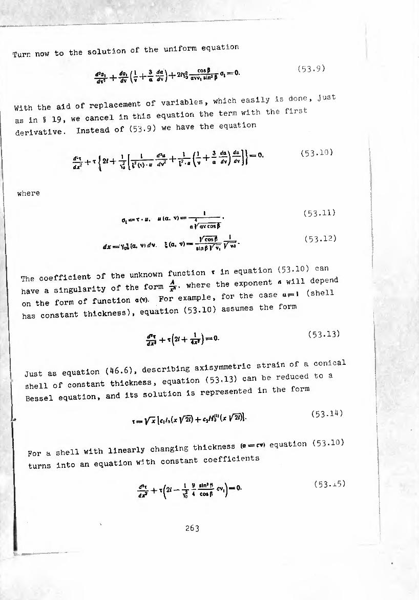
Turr now to the oolution of the uniform equation
rf’o. , /1 —-os^jx Oi~0- W- + -37lv+T^) + ^a«vvlS.n’jl ' (53.9)
With the aid of replacement of variables, which easiiy is Just
as ms 19, we cancel in this equation the term with the first
derivative. Instead of (53.9) we have the equation
S+,!2,+i[7MV^'+t’1-“lv+a dx- \
(53.10)
where
0, e= T • 11. « (O- V> — —4 a av co*F
v _ ifx = Yol(«• v)rfv l(a' V)“ sinß V^i ^VJ
(53.11)
(53-12)
The coefficient of the unknown function . in equation (53.») ^
nave a sin.uiarity of the form where -e exponen .
on the form of function a(v). For example, for the ^ -
has constant thldcness), equation (53.10) assumes the form
</*T TZ + t(í(+¿r)-0.
(53.13)
just as equation (46.6), describing axlsymmetric strain of a conical
1 f onstant thicKness, equation (53-13) can be reduced to a
Bessel equation, and its solution is represented in the form
, = Ici/oU /¾) + (53.1^)
For a shell with linearly changing thickness (a cv> equation (53-10)
turns into an equation with constant coefficients
d¿ \ Yo 4 C0*P / ( 53 • J-5)
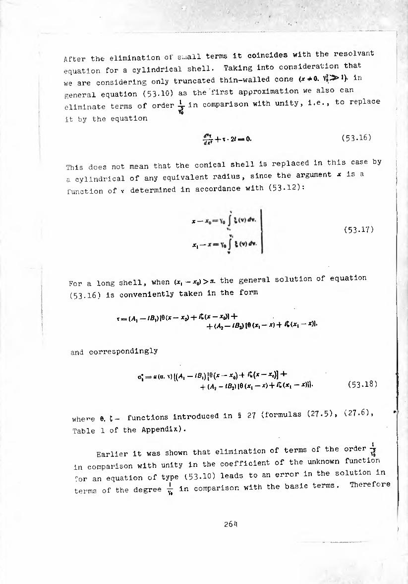
After the elimination of s^all terms it coincides with the résolvant
equation for a cylindrical shell. Taking into consideration that
we are considering only truncated thin-walled cone <x *0. yS^> l). in
general equation (53-10) as the first approximation we also can
eliminate terms of order in comparison with unity, i.e., to replace
it by the equation
dx* + 1-2/ = 0. (53.16)
This does not mean that the conical shell is replaced in this case by
a cylindrical of any equivalent radius, since the argument * is a
function of v determined in accordance with (53-12):
X
*1
(53.17)
For a long shell, when the general solution of equation
(53.16) is conveniently taken in the form
t = (,4, -/ß,) [8 (* - *0) + Æ(* - *o)l + + (A2 - /ßj) 18 (X, - X) -f /t (X, - X)].
and correspondingly
= u (a. V) ((^1-/ B\) [8 (•* — *0) ^ *<>)] + (A; - /ß2)l0(x,-x)+£(x, -x)1). (53.18)
whe-e 0. C- functions introduced in § 27 (formulas (27.5), (27-6),
Table 1 of the Appendix).
Earlier It was shown that elimination of terms of the order
in comparison with unity In the coefficient of the unknown function
'or an equation of type (53.10) leads to an error In the solution in
terms of the degree ¿ in comparison with the basic terms. Therefore

upon replacing equation (53-10) by equation (53.16) in the solution
of the latter we deprive ourselves of the possibility of keeping terms
of such an order. This means that in making up the derivative of o*.
and also during the integration of oj function u(a. v) should be
considered as a constant coefficient.
In this way we obtain
Re 17*= Yo*(v>“<v)l— — *0) + M<* - *0) +
lm
4 Aj(p(x, - X) — Btf (X, - x)j.
-57- = Vol (V) « (v) IM (X - Xo) + 0,<P (X — Xo) —
— ^(x, — X) — ß2<r(xt — x)].
By (53.8), (53*18) and (53*19)» ignoring quantities of order in
comparison with unity, we obtain the following expressions for forces
and bending moments:
/, -/,r= A- a? sln-£ U (a. v)|/lIÇ (x-x0)-Bie(x-x0) + 2Vo v
4 (X| — x) — BjO (x, x)),
/,-/,= sin pa (a. v) l<v) (x - x,,) +
4- (x — Xq) — Atf (x, - X) — ß,q>(x, - x0)l.
r.. — = “ (“• v> — -^o) — ßi° (x—*o) + tD («I 2vS v
+ (x, — x) — B20 (x, x)|.
aV m, = —slnpa(a. v)i(v)[- i4,<p(x — x^-l-
4- Brf (x - x,,) 4- A/p (x, - x) — (x, — x)).
/Hq 2=1
(53*20)
§ 54. Determination of Constants of Integration
Arbitrary constants Ax% Bx, a2, B2, figuring in (52.18), should be
defined from the edge conditions. Let us assume that on the edges ('2h \ V + ir1)
equal to i0. s> respectively, and moments m,. equal to m" and m\. Let us
note that on the basis of formulas (53*8) we can set
265
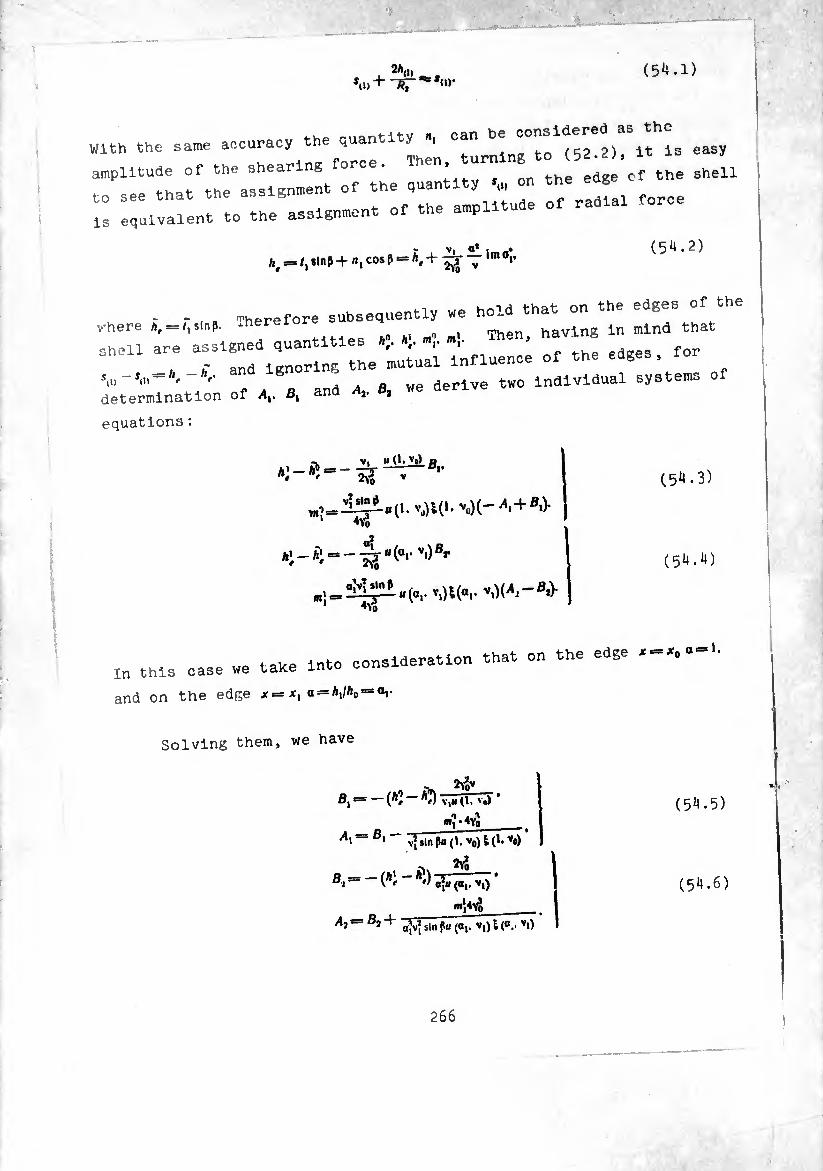
(5*1.1) 2*(J)
With the same accuracy the .uantity n, can ^ easy amplitude of the shearing force. Then urnin to (52^ . i
to see that the assignment of the quantity •«, on the edge ' equivalent to the assignment of the amplitude of radial force
h, = /, slnp + n, cos p = À, + lm 0Î- (54.2)
- -,, perore subsequently we hold that on the edges of th where -here havlng in mind that shell are assigned quantities «,■
, and ignoring the mutual influence of the edges , - V g d we derlve two individual systems of
determination of /,, ß, ana * *
equations :
- V. « (1. vt) a fc 1 _ ft» _-=5-DV n* ' 2vo v
^ = — ^ . (ar vi) ®r
(54.3)
(54.4)
:n this case we take into consideration that on the edge —o«-*-
ind on the edge x, a = VAo = al•
Solving them, we have
2v*v
<"Î-4y3 — öi vî sin ßu (1. v0) I (1. *o)
Bt = — (Ai “* *r) a*B («,, V,) '
Ai- B2+ a|v{ sin fu (a,, v,) i (o.. *{)
(54.5)
(54.6)

up
Substituting the obtained values of constants into formulas (53.20),
we obtain the final expressions for forces and moments. In order to
give the equations symmetric form, we introduce new designations:
202-=/12(1-^) 20(=/12(1 (5^.7)
where A0. A, — values of wall thickness cn edges x0 and xx. Making the
necessary calculations, we have
m« = “"‘i (t)/4 [(a’-*Í) VcosP C(^-^o)4- «^(^-^o)] +
(54.8)
Using (54.5), (54.6), (53.19), (53.20), we will write out also the
expressions for quantities e2(1) and ^ = Let us note that with
accepted correctness of calculations it can be considered that
»Ia* *1(1) ** fo"“*»)-
In this way we have
^o(e2(l) *2(1))
= - a',/,{(-?),/‘ [(A2 - Al) 2po 0 (X - X0)+
+<v1t(JC-Jco)]+ar,/‘(4rx
X [- (Ai - Ai)2Pi 0(X, -.»0+ - *)}} • (54.9)

= - c_,/* { (~]U [(*2 “ ÃJ) Wl* (x - *o)+
+»ï^re(‘-^]+^fx x [(»: - *;) 2KÍP (*, - *) - »i 9 ('*-')] ) ■
(5^.9) (Cont’d)
On the edges exist the relationships :
2ß2
25,,,)=-(*:- *3 ^ VWÏ - V 4ßJ
=-. - « - «s suã+»! ■ £*, («!„, -'«i„o=(*; - *:) », -îf
4ßl Eh^ « - (AJ - Ai) + «î ’ cos
(5^.10)
(54.11)
If the edges of the shell are connected with rigid diaphragms, these
equalities should hold:
Relationships (51.10), (54.11) allow easily finding forces and moments
appearing in this case in the edge sections of the shell
^Vap) o ¿VW« is--
i^ip) A' = Ã1--r • * * Pi V cos ß
m ßk^djV,
2ßi
(54.12)
(54.1?)
§ 55. Determination of Displacements
Prom the found strains (54.9) it is easy to determine displace¬
ments in any section of the shell using two quadratures. Rewrite
formulas (18.2), (18.5) allowing for (52.1). We obtain
NoTSt)-'-0,''.
r/ a.,,,cosß \ rfv A„i, = ve2(1)- J (V(,) + e2(1)sinP - )-^ + D7-
V«
268
(55.1)
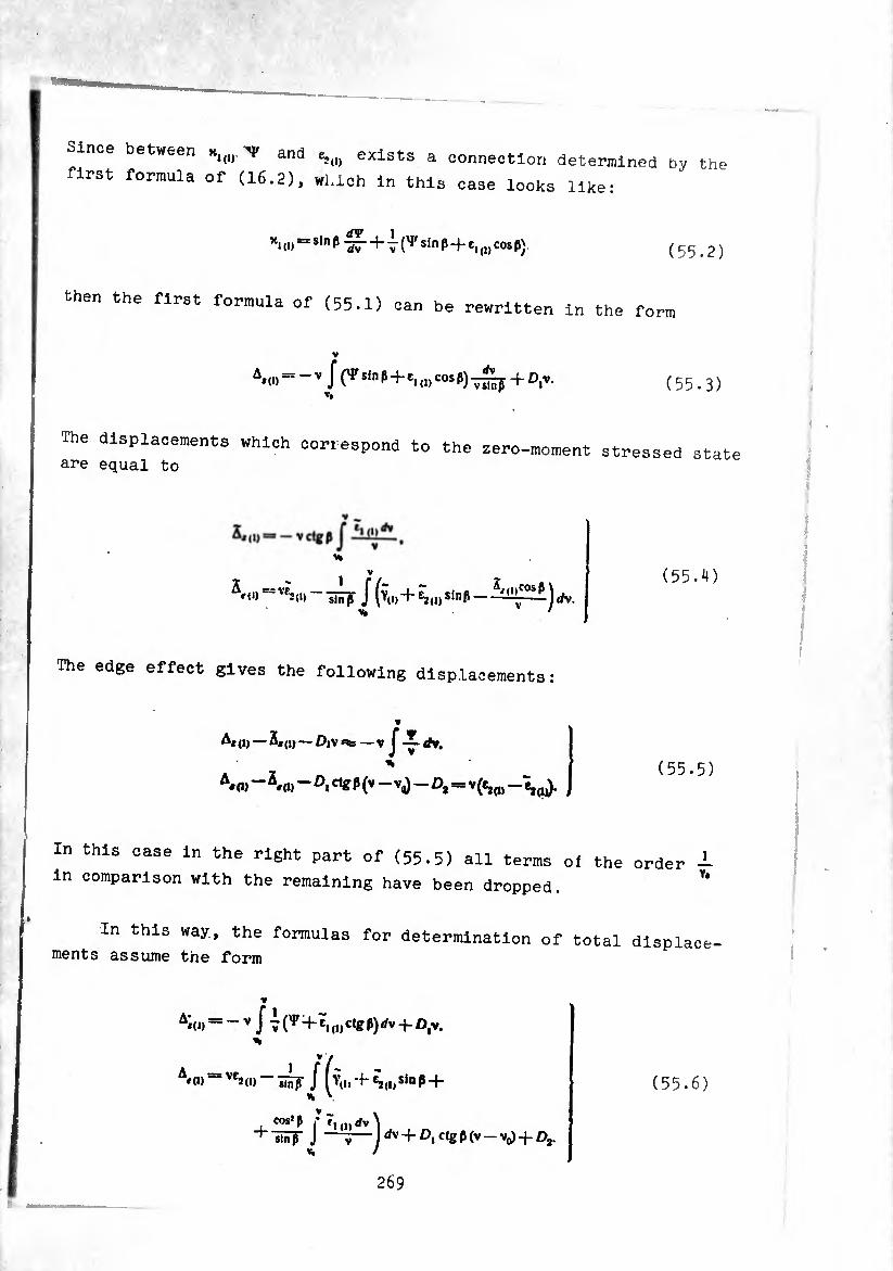
between x1(1),''P and e2<1) exists a connection determined by the
first formula of (16.2), which in this case looks like:
wur 1 xid) = sinß dT+ sinp + e1(I)cosß) (55.2)
then the first formula of (55.1) can be rewritten in the form
V
A*0) = - v { C1'sln p + ei ,1, cos ß)^—p + D,v. ( 5 5.3 ) V#
The displacements which correspond to the zero-moment stressed state are equal to
V
= J (y(I) + e?(|) ilnß - ~1>C0$P- ) rfv.
The edge effect gives the following displacements:
(55.4)
A* (i) — 5,(1, — Div *%s — V J -ï- rfv, %
In this case in the right part of (55.5) all terms oí the order
in comparison with the remaining have been dropped.
In this way, the formulas for determination of total displac ments assume the form
ce-
y
Ít/(y,., +v'“ß+
f (1)rfv \ J —7—Mv+ß, Ctgß(v — ¢. /
A#(1) — VC2
cos}ß
+ inrr
(55.6)
269
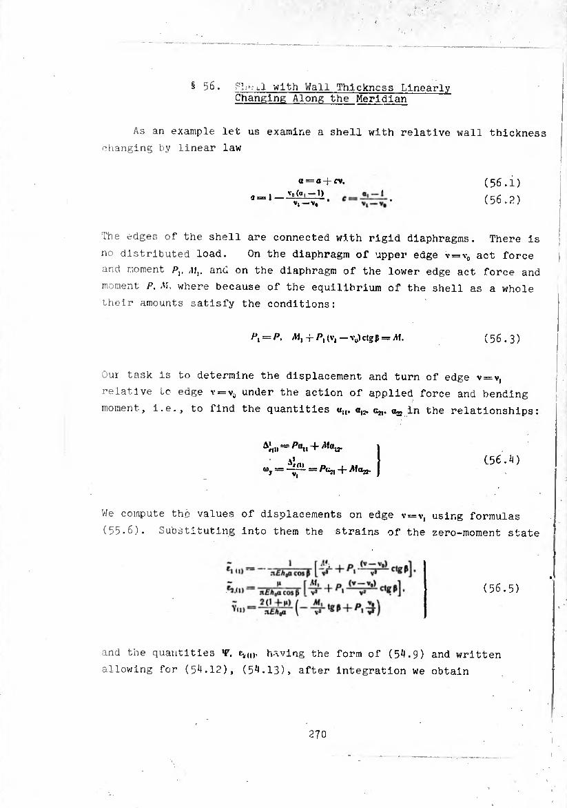
§ 56. ¿.i with Wall Thickness Linearly Changing Along the Meridian
As an example let us examine a shell with relative wall thickness
changing by linear law
(56.1) (56.2)
a_l _ Vo(Q,-l) V|—V,
The edges of the shell are connected with rigid diaphragms. There is
no distributed load. On the diaphragm of upper edge v=v0 act force
and moment />,. /if,, and on the diaphragm of the lower edge act force and
moment P. A!. where because of the equilibrium of the shell as a whole
their amounts satisfy the conditions:
Pl=P. 4-P, (V, — vu) ctg p = Ah (56.3)
Our task Is to determine the displacement and turn of edge v = v,
relative to edge \ — \s¡ under the action of applied force and bending
moment, i.e., to find the quantities «5,. a12. c^. ^ in the relationships:
Ai,i> = Pan + 'Mair (56.4)
We compute the values of displacements on edge v = v, using formulas
(55.6). Substituting into them the strains of the zero-moment state
and the quantities «F. e.,,,,. having the form of (54.9) and written
allowing for (54.12), (54.13)» after integration we obtain
270
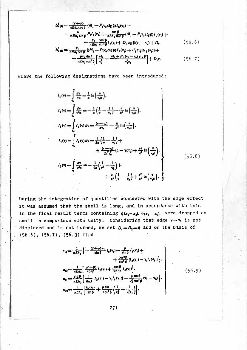
A'<» = »i£ok ^ w W -
~ ISÂTsln> />,/' (V‘)+ .t/Csln^ (Af» ~ PivoCW)/i(Vi) +
+ ¿Éht +c,&P(vi - vo> + O,.
A'(,) = xÊhl'un $ - P's'o c<g P) fi (vi) + ctg ß/2 (v,)l -f I nv,smp r^f,_^I+P, (V,—V0)cigß1
nEh0 cos2ß [ V* vjfa, J 1
(56.6)
(56.7)
where the following designations have been introduced:
Vt
í.M-J/.(v)*-=.¿(-J—^-)+
+7(7-¿)+ír,n (-^)-
(56.8)
During the integration of quantities connected with the edge effect
it was assumed that the shell is long, and in accordance with this
in the final result terms containing $(*,—x0). «(.*, — jr0). were dropped as
small in comparison with unity. Considering that edge v = v0 is not
displaced and is not turned, we set £^¢=0,=0 and on the basis of
(56.6), (56.7), (56.3) find
aii!
a„
Uj,
+ s°n> Jj (Mvi) ~ v/«<vi'l} •
teh;[ Hif ^]+/<(v,)] *
: -¾ ( ^ (v> >- v,/s (Vl )] “ <Vl “Vo)} ’
nfÄj [ slnß ccs^ß \vj vio,yj
(56.9)
271
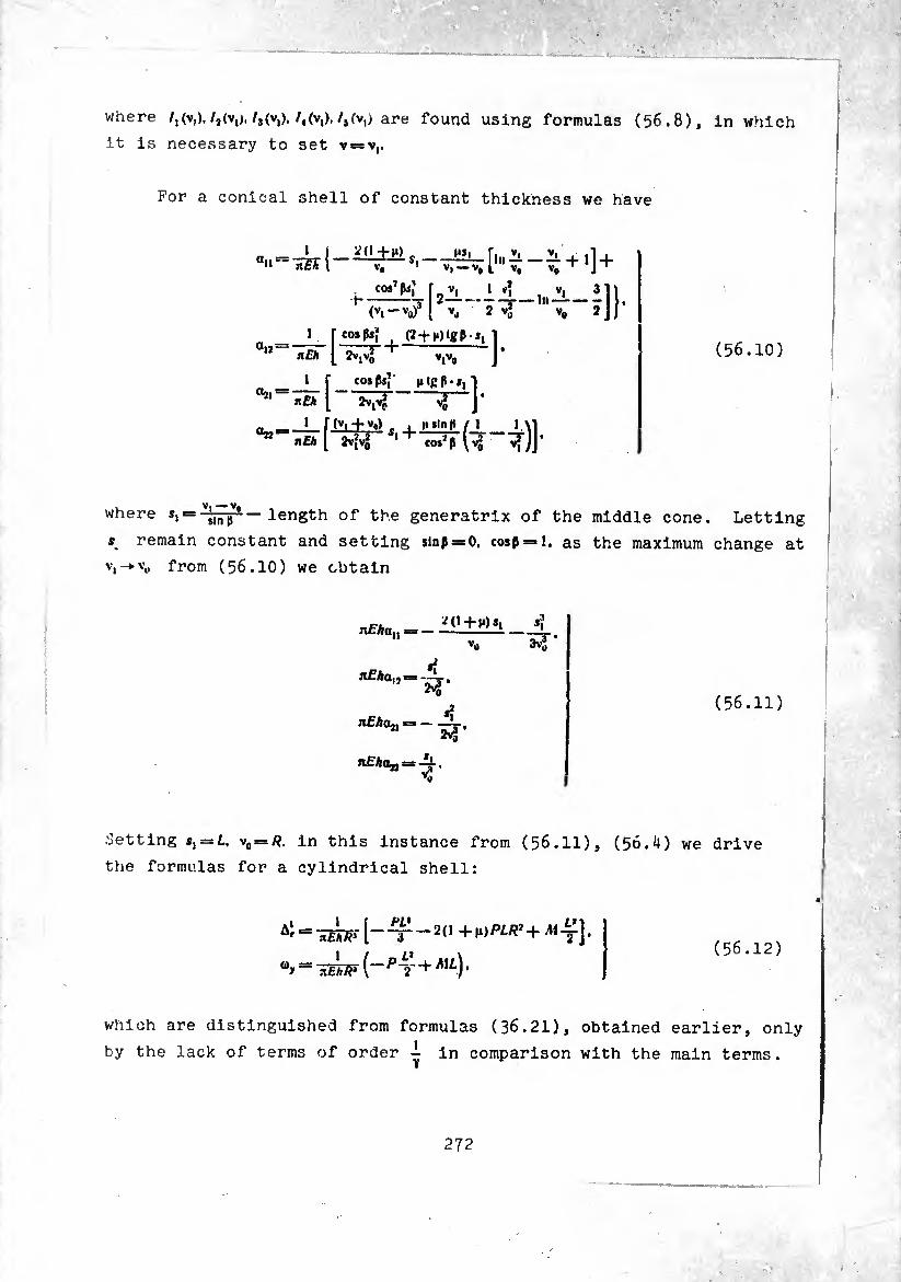
where /.(v,)./jív,),/jív,)./4(v,)./5iv,> are found using formulas (56.8), in which
it is necessary to set v = v,.
For a conical shell of constant thickness we have
a,.^= 1ŒK ^(1 -f M)
«12
«21
i r cosps,
nEh [ 2v,Vq
-—[ nEh [
co»^;
(vl-v0?
* (2 + H)lgM,
Vj V, 2JJ
v,v. ro ]'
V* J ’ n i— 1 f(vl+v»)- ■ |l Sin p / 1 1 VI
n£A ( 2v^ 1 cos^p (vj v2)J,
(56.10)
where s,«= — length of the generatrix of the middle cone. Letting
* remain constant and setting sinß=»0, cospel, as the maximum change at
V,->v0 from (56.10) we obtain
n£han = — *(! + »») *i
3vS
n£Aa,, : «Í
nfAoj, = — S|
nfAojj = . *0
(56.11)
•letting = v0 = /?. in this instance from (56.11), (56.4) we drive
the formulas for a cylindrical shell:
, ,, . (56.12) “y = HEhJF (-PT + ML)•
which are distinguished from formulas (36.21), obtained earlier, only
by the lack of terms of order -i in comparison with the main terms.

CHAPTER V
the spherical shell
§ 57* Axisymmetrlc Deformst:inn a SpherlcaI~~ShëTT-
Let us examine a shell of constam- is spherical The n-Mn ^ , thickness ^hose middle surface
^lexical. The principal radii of curvature of fn
constant and mutually equal: ^ °f U,l£ SUrface are
?, = /?2 = /?. (57.1)
or the^mlddlê surfarwhLVbeÍonVtl ZTliT 2 °f P°lnti - system of e00rdlnates shoBn ^ ^
v*/?sine, Z = —^(i_cos0). (57.2)
On the shell acts an axlsymmetrlc load. In Chaote- tt ,,-
that the calculation of a shell of revolution for a Í ^ Sh0Kn
load is reduced to solving system of equation (12 6)“
condition of equilibrium of the finite side or l, ' between two parallel sections fin, 6 00ntained
Por a spherical shell it ’ 0 (c0ndltion (11-3)) is also there, opuericai shell it assumes the form
r'6—C0! 0=Wars + wr f ,i » o »,
The condition of equilibrium of the shell as a whole is by the equality
(57.3)
expressed
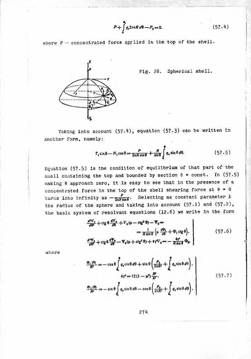
/>+J f,2.-n*</e-/>0=o. (57• *0 o
where P - concentrated force apjrlied in the top of the shell.
z
p Fig. 28. Spherical shell.
r
Taking into account (57^), equation (57.3) can be written in
another form, namely:
(57.5)
Equation (57.5) is the condition of equilibrium of that part of the
shell containing the top and bounded by section 9 = const. In (57*5)
making 9 approach zero, it is easy to see that in the presence of a
concentrated force in the top of the shell shearing force at 9 = 0
turns into infinity as - Selecting as constant parameter b
the radius of the sphere and taking into account (57-1) and (57-2),
the basic system of résolvant equations (12.6) we write in the form
~d¥ Htg 0 ^ - Vo +cig5 9)+4 Ao = - ^ ot.
where
27 ^
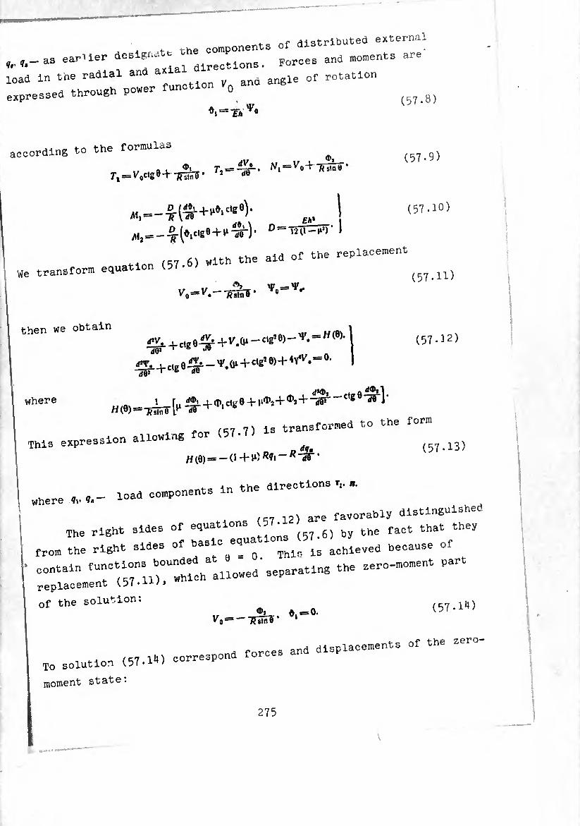
r . tt the components of distributed externa
earner desiste th^^^_ ^ moments are
load ln tne radial an ano angle of rotation expressed through power function 0
(57.8)
according to the formulas
1/ , 72 = -¾^ N\==V^‘R^' 7i = VVtg0-t-TW j 4,0
(57.9)
«, = -T^+,‘<,'C’í9)' I ^2==-^■^lC‘ge+^l¾^)• D '‘20-^) 1
r.T 6) With the aid Of the replacement We transform equation (57-
(57.10)
then we obtain
dO*
(57.11)
(57-12)
where H(9)=1¿y[^+d-,c%« + ^+*.+ J^-t,íe^l
ion allowing for (57-7) Is transformed to the form This expression a . (57.13)
where „ ^ad components in the directions ,. «.
12) are favorably distinguished
The right sides of (57.6) by the fact that they
from the right sides of basi d ^ ls achleved because of
• contain ^““““"t^allo'wed'separating the sero-moment part
replacement
Of the solution: (57.iX)
n forces and displacements of the zero- To solution (57.IX) correspond
moment state:
275
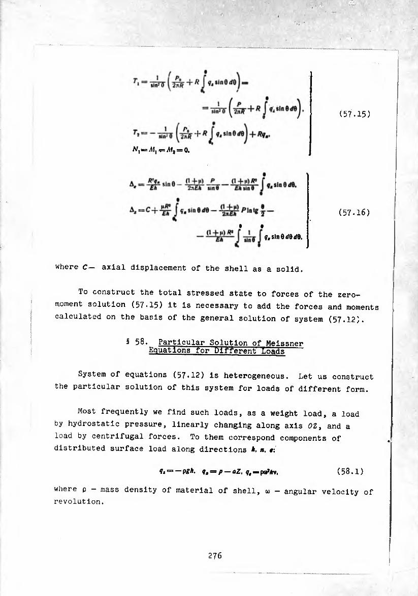
(57.16)
• •
^sinOí/O </0.
where C— axial displacement of the shell as a solid.
To construct the total stressed state to forces of the zero-
moment solution (57.15) it is necessary to add the forces and moments
calculated on the basis of the general solution of system (57.12).
§ 58. Particular Solution of Meissner Equations for Different Loads
System of equations (57.12) is heterogeneous. Let us construct
the particular solution of this system for loads of different form.
Most frequently we find such loads, as a weight load, a load
by hydrostatic pressure, linearly changing along axis 0Z, and a
load by centrifugal forces. To them correspond components of
distributed surface load along directions *. 1». #:
(58.1) = p — aZ, q, = pœ5/rv,
where p - mass density of material of shell, u> - angular velocity of
revolution.
276
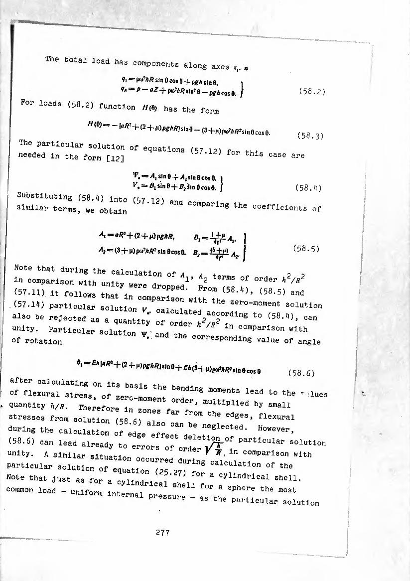
The total load has components along axes ,,. „
¢, - pw’A/? sin0 cos 0-f-p£A sin0. j
^/»-aZ+pc^Atfsm’e-p^^ / (58.2)
For loads (58.2) function *(e> has the form
Hm '*«’+(ä+M)pm|Slne-(3+|1)|w,w,s(„6t0f8
particular solution of equations (57.12) for this needed in the form [12] ' f0r thls case are
(58.3)
— A, sin 0-j- Aj sin 6 cos 6.
s*n 0 + Jin e cos e. } (58.4) Substituting (58.4) into (57 12) similar terms, we obtain * comParing the coefficients of
=» a/?1 -f (2 -f p) pgM/i, b -. jj-.P A I 1 1’ I
= (3 -J- p) çxnyhR7 sin e cos e. ^ | (58.5)
Note that during the calculation oí a a term e 2 2 in comparison with unit- ^ te ms of order h2/R2
it \ with unity were dropped. Prom (58 4) iqfi ^ , (57.11) It follows that In comparison with the ’
.(57.14) particular solution w , zero-moment solution
aleo he rejected as a quan«^ o" 2T/JT" ^ ^
oT::¿atiP:;tlcuiar—^
», - £*!.«.+ 0+(.)^),,.,+ £*(3+M)p^w,sln ,CM „ (58.6)
lues ;*■ ,h* —« —■...... ». quantity ,/,. .. ...11
stresses from solution (58 6) alS ^ ^ edges* flexural
during the calculation of ed^e H—>
(58.6) can lead already to errors of order PartlCUlar solution
particular solution of IquItioTTaranT8 Cal0Ulatl°n " Note that Just as for a cvllndrl J or a cylindrical shall.
common load - uniform Internal prLsurl1- as^th ^ pressure - as the particular solution
277
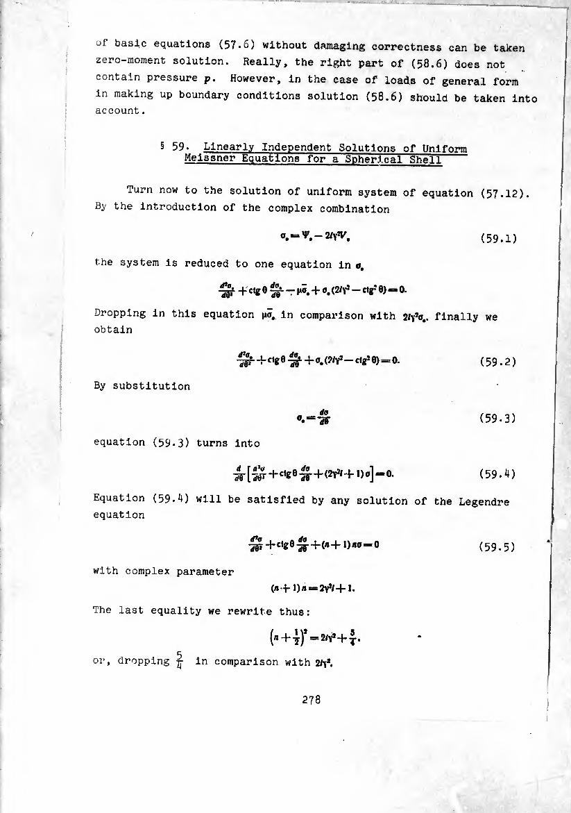
ü" basic equations (57.G) without damaging correctness can be taken
zero-moment solution. Really, the right part of (58.6) does not
contain pressure p. However, in the case of loads of general form
in making up boundary conditions solution (58.6) should be taken into
account.
§ 59. Linearly Independent Solutions of Uniform Meissner Equations for a Spherical Shell
Turn now to the solution of uniform system of equation (57.12).
By the introduction of the complex combination
0.=V.-2/yV. (59.D
the system is reduced to one equation in a,
-¾ + e fr ” m«.+o. (2/y* - ctr" e>=o.
Dropping in this equation no, in comparison with 2^0,. finally we
obtain
-^0-^+0.(2/^-^) = °. (59.2)
By substitution
a —da ®.=-sr (59.3)
equation (59-3) turns into
(59.4)
Equation (59.4) will be satisfied by any solution of the Legendre
equation
(59.5)
with complex parameter
(n f 1)« = 2y*/+1.
The last equality we rewrite thus:
(B+-f) =2/Y* + j.
5 or, dropping ^ in comparison with 2/Ya.
278

(*-f y)* = 2/Y*.
The general solution of equation (59.5) can be re can be represented In the form
a « AP* (cos 0) -}- BHm (co j 0),
where P,(cos0)- solution of Legendre eauaMnr
the sphere, i.e., at 0 = 0 [1^2] h < ’ regular ln t^e pole of
the solution P.icosO) and a Len^P à " C0S } s a ^near combination from «vwsu; ana a Lengendre function or
having singularity In the top ni klnd
//.(CO, Ö) = P' (COÏ d) — ~Q' (co, Qy
Substituting (59.7) Into (59.3), we obtain
<CM •, +s h <C« « - f - «: <«* i»]=
— AP\ (cos 0) -J- BN1,, (cos 0), J
-ere co.,. Oi(co.0)_ flr3t assoclated
(59.8)
(59.9)
Pi (cos 0) =
Q¿.(cos 0) =
^i (cos 0)
— sin 0PÍ (cos 0),
-sln0<?i(cos0).
— sin0A/i(cos0). (59.10)
the prime Indicates differentiation with respect to tw parentheses. Solution (59 9) ,, , he ar«“ent In
calculations, since there ari II ZZZTl Z
a complex parameter. Therefore usually to fa^UitL'^'l^r ^
USe an aPProximate representation of solution 59 9 Cal;UlaU°nS “e
the fact that for thin-walled shells parameter y a^ ^
the modulus of the parameter is jJL ln " Y’ “ COnSe9uent^>
The behavior of Legendre functions at haTb "
be expressed by the relationships: StUdled an<S °an
[,"P¡ („,!)]_
Urn [,-1¾ (to, (59.11)
taLVilWa=count tMt"1 ^ fUnCtl°nS °f the
A (a) + IN i (a) =, /yj1» ^
279 . «WMH
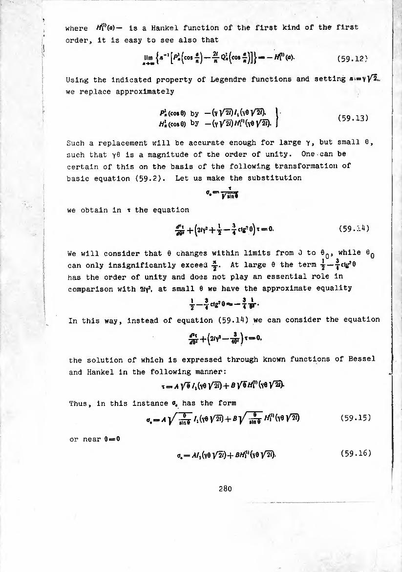
where is a Hanke 1 function of the first kind of the first
order, it is easy to see also that
A- (cos Qi (co# 7)] }-^ <a>- ( 5 9.12 )
Using the indicated property of Legendre functions and setting
we replace approximately
Piicose) by -(y/2Ï)/,(y0/w). 1 , ,
//1(00*6) by — (vV^M’Hve/S). I oy.id/
Such a replacement will be accurate enough for large y» but small 0,
such that Y0 Is a magnitude of the order of unity. One can be
certain of this on the basis of the following transformation of
basic equation (59.2). Let us make the substitution
/sTiri
we obtain in * the equation
£+(2<*’+T-Tc,*’6),=0' (59.5-4)
We will consider that 6 changes within limits from 0 to 60, while 0q 3
can only insignificantly exceed -y. At large 0 the term y—-j-ctj^ö
has the order of unity and does not play an essential role in
comparison with Hyp. at small 0 we have the approximate equality
___.ctg?0ss — -j-gr¬
in this way, instead of equation (59.1^) we can consider the equation
the solution of which is expressed through known functions of Bessel
and Hankel in the following manner:
t = a/0 /^6 /2/)+ B /6 M0 (y6 /¾).
Thus, in this instance o, has the form
(59.15)
or near 6 = 0
0.= /4/,(70/2/)+^(^6/25). (59.16)
280
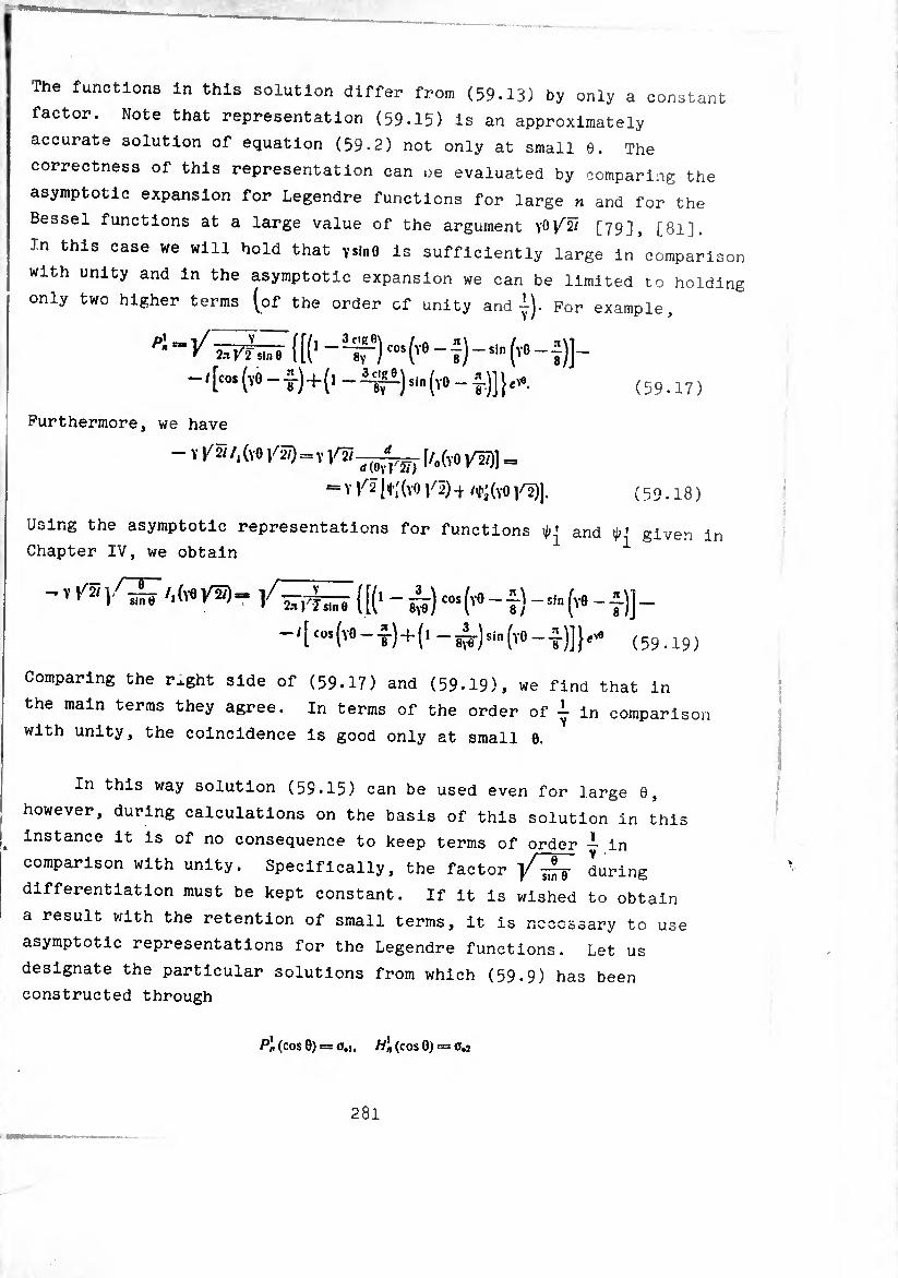
The functions In this solution differ from (59.13) by only a constant
factor. Note that representation (59.15) Is an approximately
accurate solution of equation (59-2) not only at small 6. The
correctness of this representation can ue evaluated by comparing the
asymptotic expansion for Legendre functions for large n and for the
Bessel functions at a large value of the argument V'O[79], [8l].
In this case we will hold that Ysin0 is sufficiently large in comparison
with unity and in the asymptotic expansion we can be limited to holding
only two higher terms (of the order of unity and j). For example,
P'-V ÍT?T¿¡f {[(1 - Tr) cos ('e - ?) -si” (*> - f )]- -1 [“» (vO - t)+(1 - -er-)sl" ('» - t)] } ( 5 9.17 )
Furthermore, we have
- ï ^/.(vo /5) = V [/„(vO /5)1 =
= Y V2 11|’;(Y0 Y2) -+ /+' (Y0 1^2)]. ( 5 9.18 )
Using the asymptotic representations for functions and ip* given in
Chapter IV, we obtain ^
/iS (it1 - è) - t) -('e - +)] - -/[ COI (Y0--1) + (1 _ ^) sin (yo--1)])^ (59.19)
Comparing the rxght side of (59.17) and (59.19), we find that in
the main terms they agree. In terms of the order of i in comparison
with unity, the coincidence is good only at small 0.
In this way solution (59.15) can be used even for large 6,
however, during calculations on the basis of this solution in this
Instance it is of no consequence to keep terms of order — in
comparison with unity. Specifically, the factor during
differentiation must be kept constant. If it is wished to obtain
a result with the retention of small terms, it is necessary to use
asymptotic representations for the Legendre functions. Let us
designate the particular solutions from which (59.9) has been
constructed through
p], (cos 0) = 0.1, wi (COS O) = 0.J
281
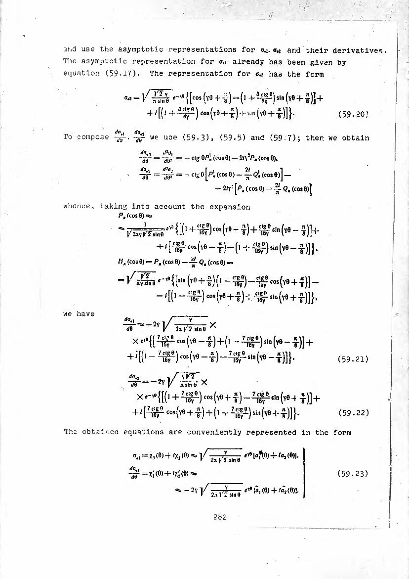
*:
and use the asymptotic representations for o.¡. and their derivatives
The asymptotic representation for o.i already has been given by
equation (59.17). The representation for o.¿ has the form
0,2 = #~'e {[cos (Y° + "8 )-(1 + 3~^T')s,n (y0 + j)]+
+ /[(> + ~^) cos(Y0+ sin (vO + t)]}* (59-20)
dn . do.-, To compose we use (59.3) > (59.5) and (59-7); then we obtain
do., aJ0| ~dV ~~W
do,., d’o,
~dí~ ~
— Ctg 0/>i (cos 0) — 2t\7Pa (cos 0).
- cig 0 (pi (cos 0 ) (cos 0)J —
- 2<y- [Pa ( cos 0) — ~Q, (cos 0)]
whence, taking into account the expansion Pt feos 6) =¾
+'[#™(ve-f)-(M-^)Si.(ve-J)]}.
H, (cos 0) = P. (cos Q)-~Q, (cos 9) =
= /^«-'•{[«" (vo + ?)(> -W-IW ‘4*+Î)] -
-iff) cos(y0+t)*: -iffsin(Y0 + t)]}*
we have do,
dB e 2y / 2jt ^ $|n 0 X
-(v« -t)+(' -4^)^(^-1)1 +
+4-4^)4^--5-)-41-49^)]}.
da.
dB sin b ^
X.-4I(1+4^)cos(,9 + i)-I^is1.(v04l)] +
+ '[4r-(v9+4) + (' + ^)»'»(v9 + l)]}.
(59.21)
(59.22)
The obtained equations are conveniently represented in the form
0.1 = X, (6) 4 % (0) ^ V j-yl s|n Q lo^O) + ta2 (0)1.
do I -^ = XÍ (0)4^(0)^
=¾ - 2y l/-—- e* [à, (0) 4 ffl-j (0)1. » 2.1 Ki sln8 11 2W
(59.23)
282
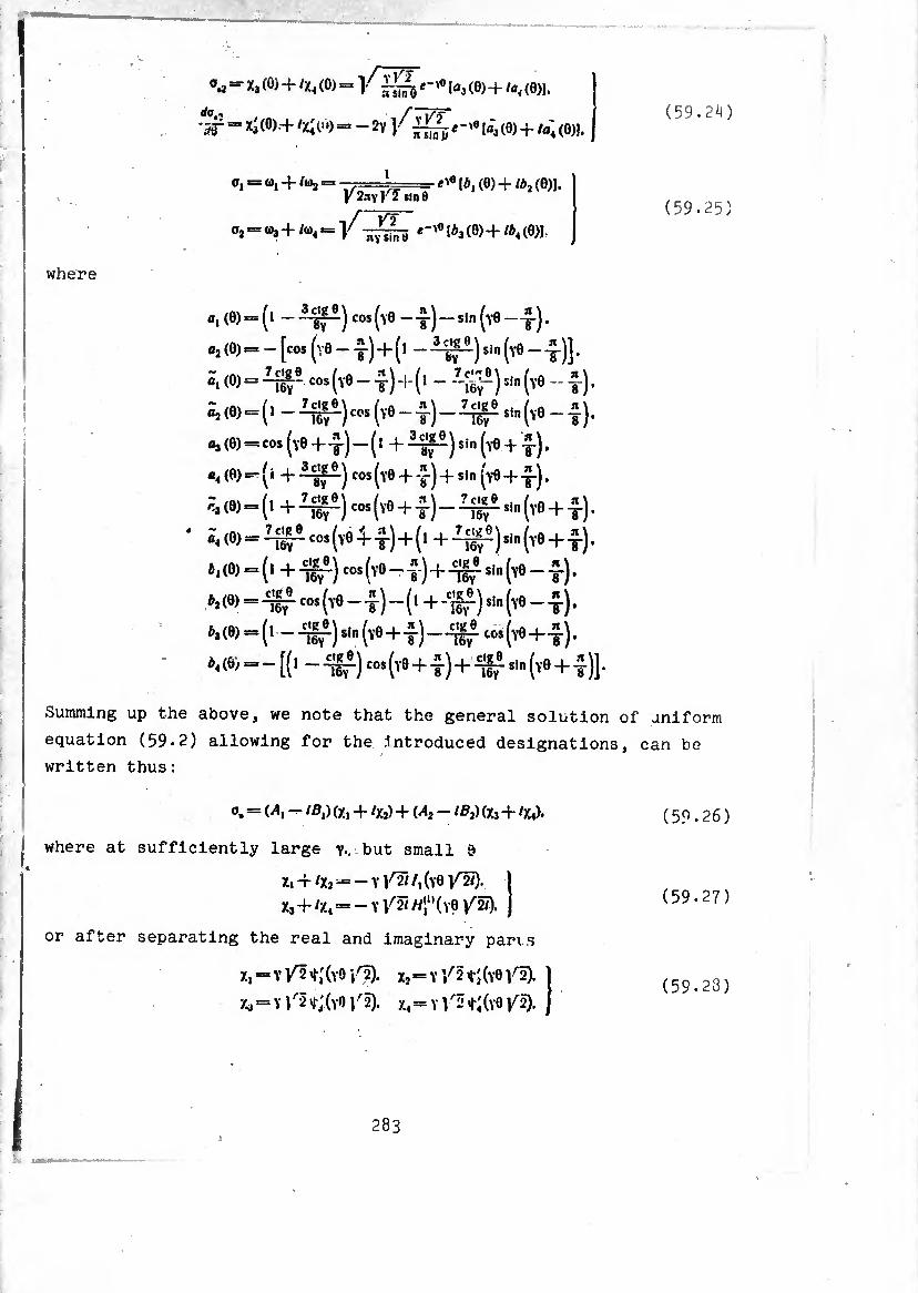
where
=• h (°> + 'x« (0) = 1-¾¾ la, (0) -f la, (0)].
‘Ir “ *3 <°)+ '/>)= —2y l^^i-'ela,(0) + /fl'4(0)).
g, o, -t- /¾ =« —=■ [¢, (0) + ib2 (8)1. V 2.1Y F 2 sln 0
0,-03+/«, = -j/-jJ^L [A, (0) + /a, (0)j.
(59.2^)
(59.25)
0,(0)
flj(O)
a, (0)
ôj (0)
03(0)
«4(0)
r-i (0)
à, (0)
¿,(0)
¿,(0)
*3(0)
*4 (0)
= (1 -¾1) cos(Y0—£-)-sln(Y0—£).
=('-^)-(^-1)-¾5 "»(vo-i).
‘cos (y0 + t) “ (1 + ^71)sin (y0 + t) • r ( j + j cos (Y0 + -J-) 4- sin ^Y0 + -y-j.
= -¾1 co» (v0 -^1-) + (^ -¾1)sin (y0 + t)*
= (1+lT)-(Y0-T) + ^1^(Y0-f).
+ffcos (Y0-7)-(^ 'w)sin (Y0 _ t) •
-llf)s!n (y0 + 7) - 757 t0s (VÔ + t) ’ -(1 — 757 )sln (y0 + t)-¡57
-“[(i-^)-(v0 + 7)+1Í7*‘»(y0 + Í)].
Summing up the above, we note that the general solution of uniform
equation (59.2) allowing for the .Introduced designations, can be
written thus:
o, = M, - IB,) ft, + /X2) + (A3 - IBj) (X, + /X,).
where at sufficiently large v., but small $
X, + /X2--Y/2//,()-0 /2/)-
X3+/X4 = -Y/2/WiU(Y0 /27).
or after separating the real and imaginary pans
X, = y/2*í(y9/2). X, = y/2*;(y0/2).
X, = Y /2 1;(y0\% x4= Y 1"2 T/yO /¾.
(59.26)
(59.27)
(59.23)
283
where *,(*). t2W. *3^). are the real and imaginary parts of
functions /0UVT)- Their representations in the form of a
series are given in Chapter IV, § 46. ■ v
For large values of VÖ.
/., = Y ]/ ÍÎ (YO /2)-
(59>29)
/3 “ V 1^2 ^3(y® /2).
where in asymptotic expansion for functions tj. tj> now one ou8ht
to keep only the main terms, of the order of unity. If it is
desired to retain in calculations terms of order 1/v in comparison
with unity at sufficiently large y sin 6 the solution must be taken
in the form of (59-23)» (59-24).
§ 60. Deformation of a Spherical Dome
Let us propose now that the zero-moment solution and general
solution of system of equations (57-12) in some form have been
constructed. Let us derive the formulas for calculation of forces
and displacements in a spherical shell, not loaded in the top by a
concentrated force, i.e., the case of a dome with summit at P = 0.
In the neighborhood of the summit /j-Mx, behaves as i.e.,
turns into infinity at 6 = 0 as 1/0. In the absence of concentrated
force in the summit the solution should be finite at 6 = 0. Therefore
we must set /l2 = fl2 = 0 and
= + (60.1)
In this case on the basis of formulas (57-8), (57-9), (57-10), (57-11)
we obtain the following expressions for forces and moments:
284
(60.2)
Tx = 7i —¿-«fiOM.X,-Bitx). Nx =
//, = r, cos 0 + TV, sin 0 = f, cos 0 -5^ (/i,x2 - fl.X,).
= - -sjr (^»y.i - ^,7.0-
Ai>=~ 1? I'4» (yí+11 c,e °Xi) + ß, (x(+J» ctg ox2)] -f .
^ = ~ IF Ml (c,s 0¾ + MZÍ) + ß, (Ctg Ox, -f MX')] +1»\
where through f,t f, we designate forces of the zero-moment state,
determined according to (57-15) at P = 0; -if,. /f,_ bending moments from
particular solution (58.it), (58.5), computable using the formulas
According to the above we ignored during calculation of forces the
particular solution V, (the second equation of (58.it)). After
determination of forces we easily find the displacements
= + -J-ßiXj). (60.5)
A« = sr - l^sr Ml (XÍ - c,g fl/j) - B1 (XÍ - M ctg c>:,)]. ( 6 0.6 )
A* = A* “ lïîk j [AI fa c,2 0 - wQ - ß, (X, Ctg 0 - MX,^)] sinOdO —
R ? ~Ih\ MiXi + ßjXjicosedO+C. (60.7)
where \ designates radial displacement in the zero-moment stressed
state, computable in accordance with (57-16) at />=0.5, is the sum of
displacement in the zero—moment state and displacement corresponding
to particular solution (58.4)
* J V„sin0rfO * r\
Eh J » cos 0 20. (60.8)
(60.3)
(60.4)
285
C - constant having the meaning of rigid displacement.
In the right side of (60.7) we can neglect the second term in
comparison with the third. In this way, finally axial displacement
assumes the form
Apropos of the
the following.
A, =■■ 5, — j MiXi + ®iXj) co* 0 </6 + C.
calculation of the integrals in (60.9),
Since V _ y - d<a}
(60.S)
we can say
then J Xicos0í/0 = cí), COS0+ J co,sin0(/0.
J x2 cos 0 —11¼ cos 0 + J cOjSinOdO.
But o, satisfies equation (59*5) and, consequently,
(b -f-1) BOj sin 0 = — -jg- |sin0
J«Mco.eje=.1co.9-7^5^.
In the last expression the second term in comparison with the first
is a quantity of order -J-* since during differentiation -¾ can
increase as yl- If we disregard this term, then we obtain
consequently,
J 0,1 COS 0 </0 Sis Oj cos 0
J Xi cos 0 ¿0 =¾ a, cos 0, J Xj cos 0 </0 =¾ a2 cos 0. (60.10)
In this way during calculations in the first approximation, i.e.,
rejecting terms of orderin comparison with unity, the slowly
changing coefficients of 0,.0, during integration, just as during
differentiation, can be considered as constants.
As an example of the application of the obtained equations we
will examine the dome shown in Fig. 29. Let us propose from the
beginning that there are no distributed loads, and the dome is
loaded only along the edge by distance forces H? and bending
moments ,M°. Then forces of the zero-moment state and the particular
286
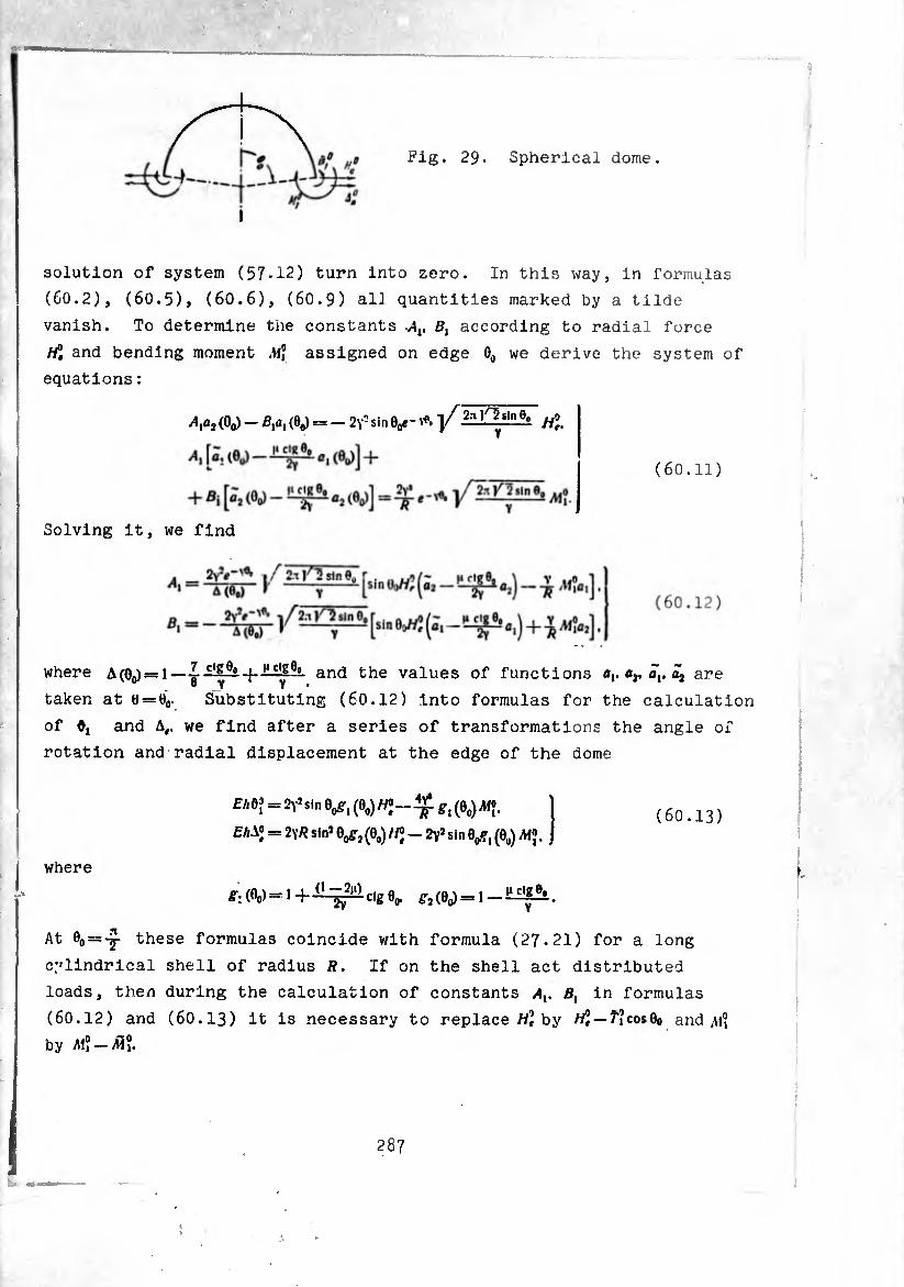
Pig. 29. Spherical dome.
solution of system (57-12) turn into zero. In this way, in formulas
(60.2), (6O.5), (60.6), (60.9) alJ quantities marked by a tilde vanish. To determine the constants v4lt ß, according to radial force
«2 and bending moment Af® assigned on edge 0„ we derive the system of
equations :
Afr (0o) - (0^ = - 2y3 sin 0/- ]/,2:t l^sln e°
(60.11)
Solving it, we find
where A(0o)=l —and the values of functions alt a2, ãv are «- B y V • taken at t) = e0. Substituting (60.12) into formulas for the calculation
of and A,, we find after a series of transformations the angle of
rotation and radial displacement at the edge of the dome
£Ad? = 2Y3sin 0^, (0o)/yo„ +£ ^
£AAJ = 2\R sin* 0^, (00) fP - 2Y* sin 0^, (0U) AiJ. (60.13)
where
e-.(0(,)=10,). ^(00) = 1-^^1^
At 0o = -j these formulas coincide with formula (27.21) for a long
cylindrical shell of radius R. If on the shell act distributed
loads, then during the calculation of constants Av Bx in formulas
(60.12) and (6O.I3) it is necessary to replace tf? by //J —f?cos0o and ¿1? by A1?-AÏ?.
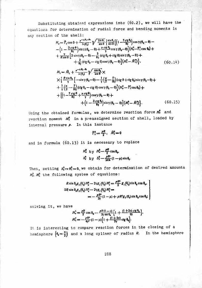
Substituting obtained expressions into (60.2), we will have the
equations for determination of radial force and bending moments in
any section of the shell:
Hl = Tl cosO
_ (, sin y ( 0o - 0) + co, y (0,,-6)] (tf-f ? co, *) +
4 -¿Õ [2 sin Y(0O — 0) — (cts 0o + clg 0) sin y (0o — 0) 4-
4- (c|g 0O — :,S °)cos Y (0O — °)] OM? — ^>) } • (60.14)
/1, = .fl, -f 1 -TÄ-e» /~ÏTÎS~ Asín tí,
y iíííFx
[—sin Y (0o-0) — y (y—¿) (ctg 0 4 ctg 0O) sin Y (0o-0)+
4 Ÿ - (c,g eo — clg 0)cos Y (0O — 0)] W — Ti cos 0o) 4-
4^-^4-^)^(00-0)+
4-(l -slnY(0O- 0)]ÇW?-Æ?)}. (60.15)
Using the obtained formulas, we determine reaction force «Î and
reaction moment MÏ in a preassigned section of shell, loaded by
internal pressure p- In this instance
= Æ?=0
and in formula (60.13) it is necessary to replace
by «S-^p-coseo.
AÎ by Aj —— |i)sin0o.
Then, setting A;^d? = 0., we obtain for determination of desired amounts
Hi M°i the following system of equations :
R sin 0^, (0o) HI - 2Y^1 (00) = (0O)sin 0Ocos 0O.
2R sin Qçgj (0O) W2 - 2ygl (0O) A!J -
= — -^- ( 1 - n) 4- pR7gi (0o) s*n 0O cos 0O:
solving it, we have .y> pR pRd-\i)[. . <t42i*)ctge0i H'= T cos0o--^—e;-[i 4--% J.
^ = -»*)[» 4-
It is interesting to compare reaction forces in the closing of a
hemisphere (00 = -5) and a long cyliner of radius R. In the hemisphere
288
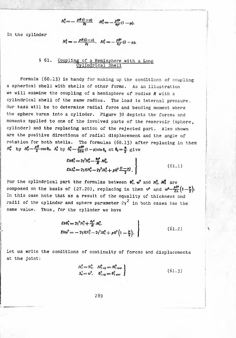
In the cylinder
§ 61. Coupling of a Hemisphere with a Long Cylindrical Shell
Formula (60.13) is handy for making up the conditions of coupling
a spherical shell with shells of other forms. As an illustration
we will examine the coupling of a hemisphere of radius R with a
cylindrical shell of the same radius. The load is internal pressure.
Our task will be to determine radial force and bending moment where
the sphere turns into a cylinder. Figure 30 depicts the forces and
moments applied to one of the involved parts of the reservoir (sphere,
cylinder) and the replacing action of the rejected part. Also shown
are the positive directions of radial displacement and the angle of
rotation for both shells. The formulas (60.13) after replacing in them
(61.1)
For the cylindrical part the formulas between 0?. t»0 and A!? are
composed on the basis of (27-20), replacing in them vP and ^rf1—y)-
In this case note that as a result of the equality of thickness and
radii of the cylinder and sphere parameter 2y2 in both cases has the
same value. Thus, for the cylinder we have
£A0? = 2yX + ^<
£W= _ 2Y/?;V? - 2\7M°i -f- pR7 (l - y)- (61.2)
Let us write the conditions of continuity of forces and displacements
at the joint:
(61.3)
289

Fig. 30. Forces, moments and displacements at the junction of a hemisphere with a cylin¬ drical shell.
t (61 1) (61.2). conditions (61.3) can be considere Taking into account (61. ), f determlnlng the four as a system of four algebraic equations
Ml solving which, we obtain quantities trt. Ni.
M? = mu == I ( 61.4 )
w!=h:=^. I
. „„a anule of rotation at the connection are Radial displacement and angl
equal to
raf* nnint A of the reservoir
we determin the axial Setting In (60.9), (60.8) relative to the connecting sectl oondltlon that
0 = e„ = f we find constant of Integration C from
the connecting section has cero displacement, *.(7)-0.
c—^(t)“0-
Displacement in the angle of the sphere is equal to
M0) = 4,(0) + M,®,®) + ^, (°>'•
, ,0, o and, furthermore, -q contains small factor . Since 10,(0)=1. 0,,(0)=0 ana, i
wo finally find
nR, (61.6) Ä, (0) =¾ \ (0) = -fgj- (1 — n)-
290
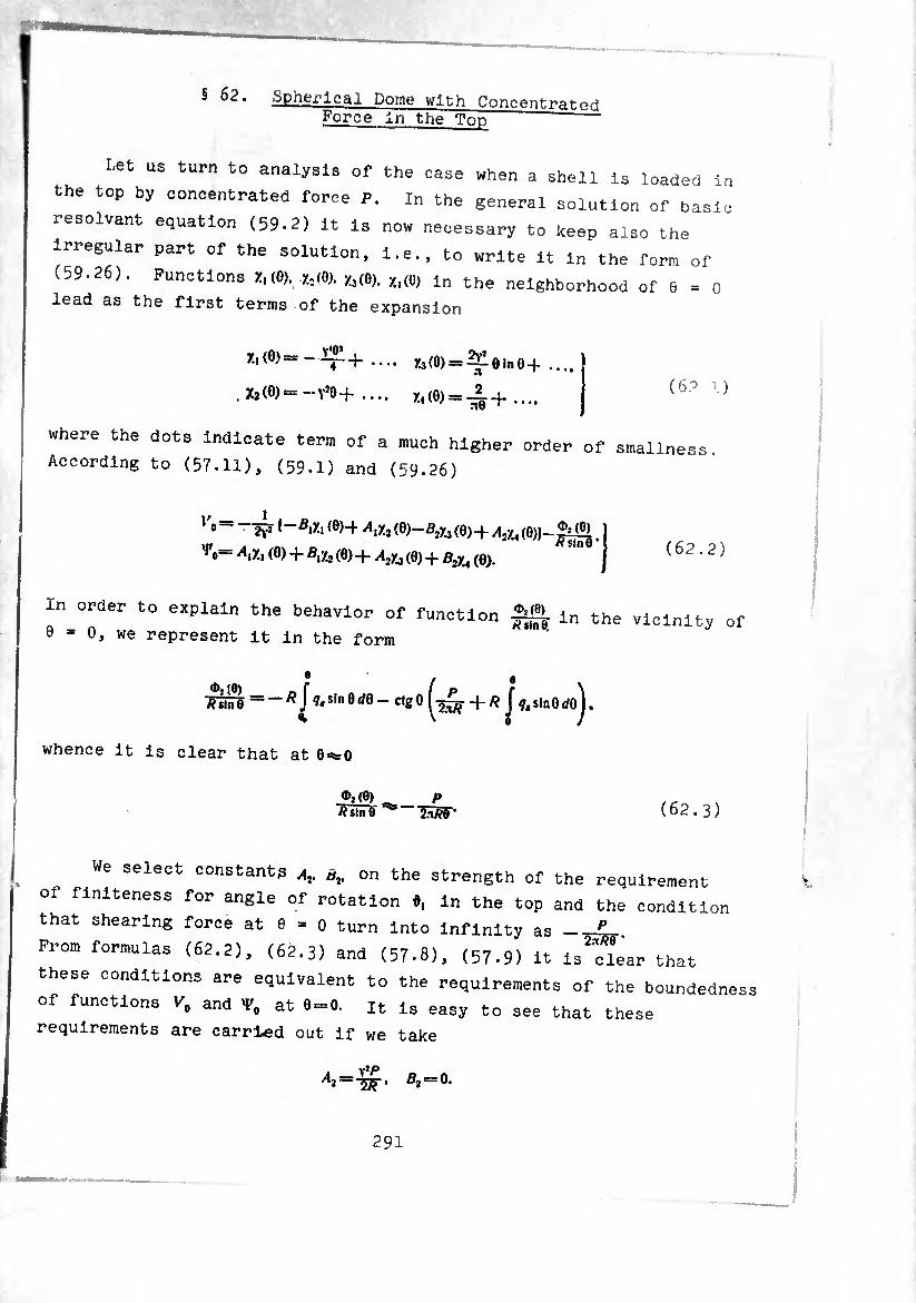
® • Spherical Dome with Concentratpri Force In the Top
I.et us turn to analysis of the case when a shell is loaded In
the top by concentrated force P. In the general solution of basic
résolvant equation (59.2) it is now necessary to keep also the
irregular part of the solution, i.e., to write it in the forr, of
(59.26). Functions ):,(0). *(0). Zl(0,. x,(0, i„ the neighborhood of 6 = 0
lead as the first terms of the expansion
Xi(0)-X3(O) = ^Í0lnO+ .... •%
Xj (0, *=—y’o + .... x«(e) = ^+.... (6.° l)
where the dots indicate term of a much higher order of smallness
According to (57.11), (59.1) and (59.26)
l'o- 1-B.X, (0)4 (0)-ßiXj{0)+ A¡Xi(0))-.
’^0= X, (0) 4 £,Xj (0) 4 Aj/j (0) 4 B2Xi (0). (62.2)
In order to explain the behavior of function Ä. in the vicinity o
9 = 0, we represent it in the form
A sin 0 = — ^ J Í* s,n 0 ¿0 — clg 0 J sin0 ^ • whence it is clear that at 0steO
<M0) A sin 9
P 2-iW (62.3)
e select constants A,. at. on the strength of the requirement
of finiteness for angle of rotation *, In the top and the condition
that shearing force at e = 0 turn Into infinity as_£-
From formulas (62.2), (62.3) and (57.8), (57.9) it isTlear that
these conditions are equivalent to the requirements of the boundednes
of functions F. and V. at 9=0. « is easy to see that these
requirements are carried out if we take
ßi = 0-
291
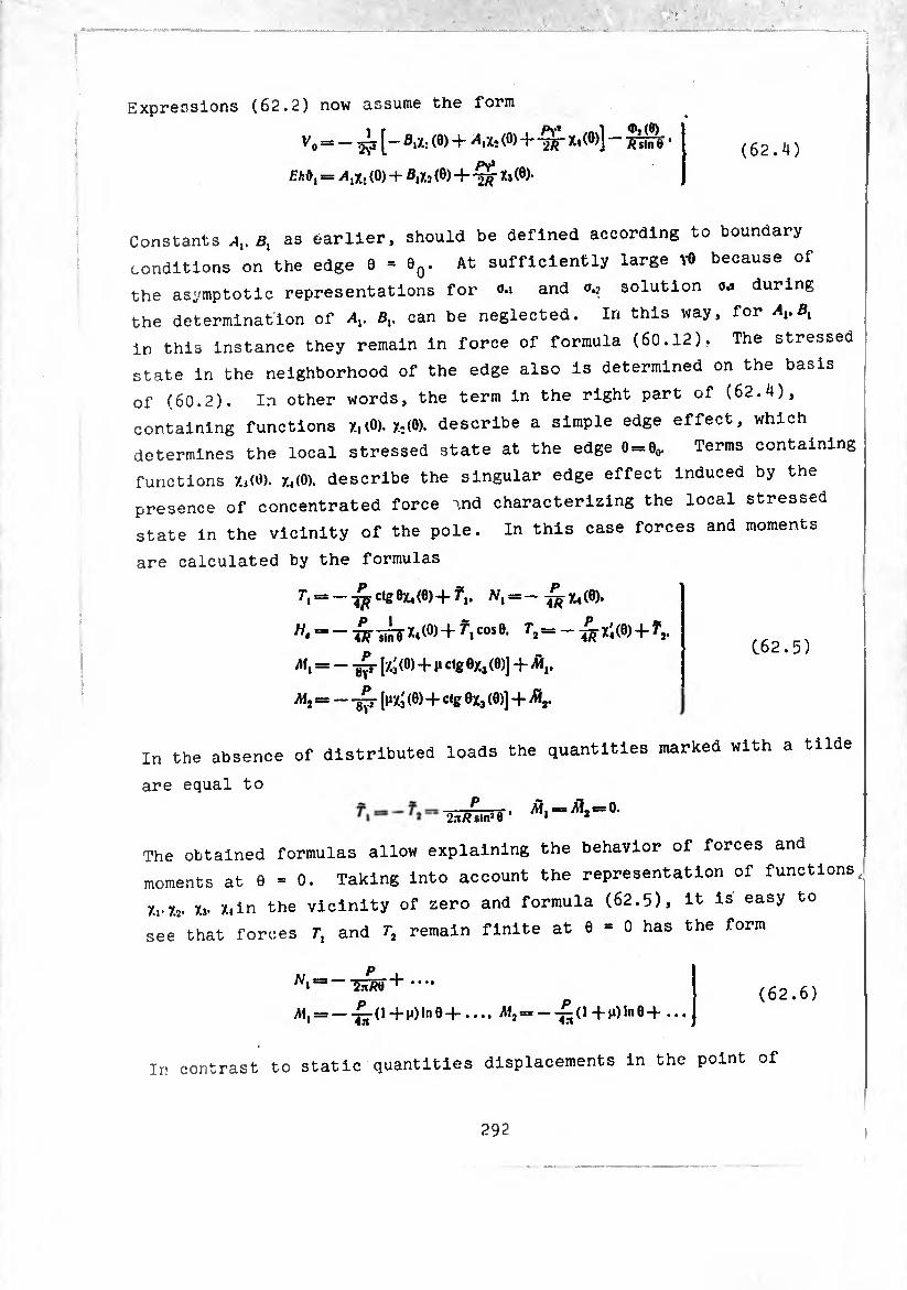
(62.4)
Expressions (62.2) now assume the form
^0=- [—fliX:(0)+ ^iXj (0) + 3U(e>] — ft jin e *
Eh&l == A#. (0) + 0,/.2 (9) + ^ Xj(6)-
Constants Av Bl as earlier, should be defined according to boundary
conditions on the edge 0 = 9q. At sufficiently large YÖ because of
the asymptotic representations for <m and solution oj during
the determination of Av Bv can be neglected. In this way, for AvBl
in this instance they remain in force of formula (60.12). The stressed
state in the neighborhood of the edge also is determined on the basis
of (60.2). In other words, the term in the right part of (62.4),
containing functions 7.,(0). X;(0). describe a simple edge effect, which
determines the local stressed state at the edge 0 = eo. Terms containing
functions 7..,(0). 7.,(0). describe the singular edge effect induced by the
presence of concentrated force md characterizing the local stressed
state in the vicinity of the pole. In this case forces and moments
are calculated by the formulas
T\ = — ctg 0X4(6)+ A/, = — ~ 7.4(6).
^ = -¿--¿fX4(0)+^icose. ^2=-:^(0)+^. p > (.62.5)
AI, = — -g^r [Xj (0) + H ctg 0x3 (0)] + A*,.
Alj = — -gp- [nxá (0) + ctg 0X3 (0)] + K
In the absence of distributed loads the quantities marked with a tilde
are equal to p
2.-i/?sin2Ô ’ Ai, a1,=o.
The obtained formulas allow explaining the behavior of forces and
moments at 0 = 0. Taking into account the representation of functions
7.,.7.2. Xj* X,in the vicinity of zero and formula (62.5), it is easy to
see that forces r, and 7-, remain finite at 0 = 0 has the form
A1, = —-£¿-(1+101110+.... AI, = --£(l+|O1n0+ ... (62.6)
Ir< contrast to static quantities displacements in the point of
292
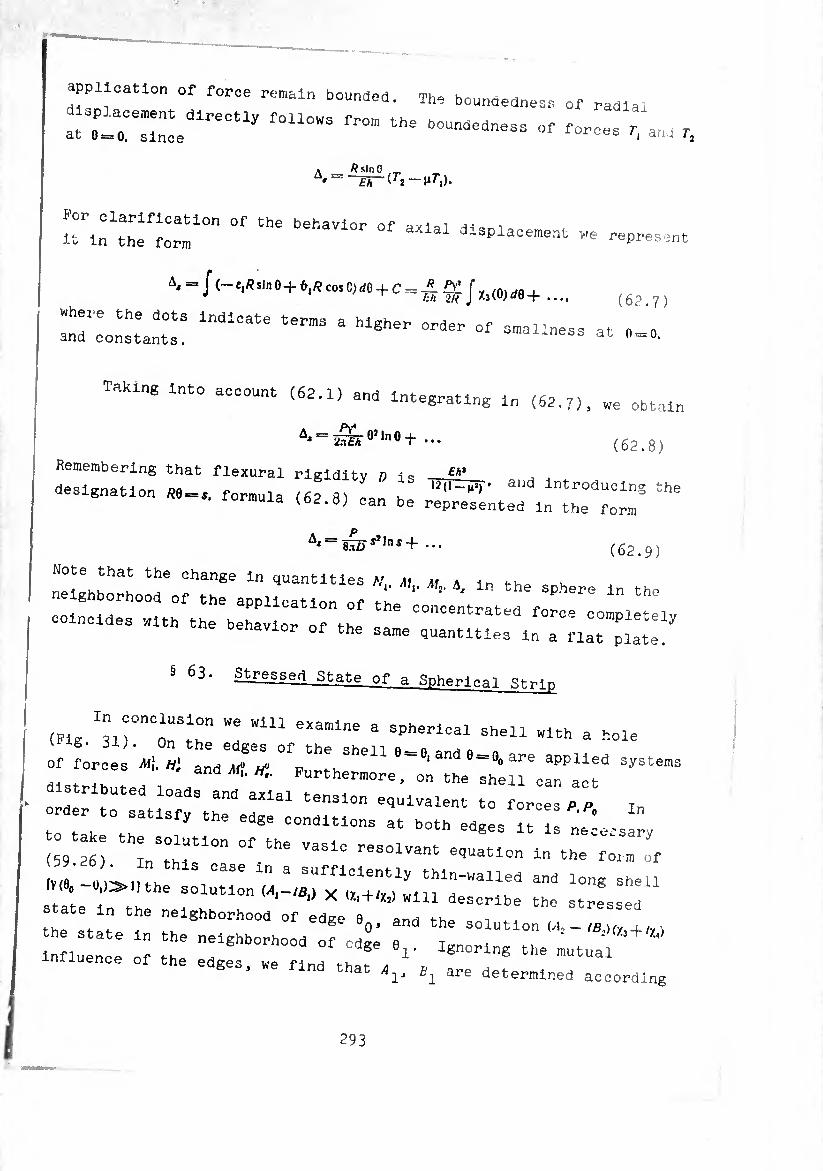
application of force romain Pounded. The boundedness of radial
attar:;::edireotiy rou°“s ^ ^ ~ - —es, aM r,
A _ ft Sin 9 /T. • Eh —M^i).
Por clarification of the behavior of axial -n=. i it in the form -splacement we represent
A* = J Mcos0)d0-fc=j?. ££ fy /nwfl , * T th -2R J X3(O)ff0-f .... (62
:rio::a:;:: lndICate termS a Mgher — - — at „ = 0.
Taking into account (62.1) and Integrating m (62.7), we obtaln
(62.8) A‘ = JSroi,"0+ ... Remembering that flexural rigidity D is £A>
designation ^0 = ,. formula (62 na k introducing the iormula (62.8) can be represented in the form
Af = 8njsí,ní + (62.9)
Note that the change in quantities y m u \ < . .
neighborhood of the application of t-ho P" th “ --—-:: rzrrrñnr 5 ®3. Stressed State of a Spherical .Strip
(Pig VrTT "I WiU eXamlne a SPherlCal Shali «« a hole
: Lceli:; :;;ge;°vh:hsheue=8'ande=8»are -stems
distributed loads and ax'ial te 1°1-6^ ^611 Can aCt 4- axial tension equivalent to forces P p in
: im:6 ed8e conditions at both ad-a - - iocs ;
9 n : r n °f the VaSlC reSOlVant et!Uatl- ln Torrn of IV, ' H °aSe ‘ a SUfriclent- thin-walled and dong shell me. -»,)»!, the solution ía,-ib¡) x ,Zl + %) wln descrlbe the
ate in the neighborhood of edge e0, and the solution ,4,-,S (1
I,: ::: lnr :hhe -^^a^od Of edge e,. Ignoring the mutual
the edges, we find that 4,, Bl are determined according
293

Pig. 31. Evenly distributed forces and moments applied to the edges of a spherical strip.
according to the formulas of (60.12). Correspondingly
(60.13), (Ó0.14), (60.15) are valid. To determine a^j
the equations
(0,) - B2a3 (0,) = - 2Yj sin 0,r*. ]///J.
2 p3 (0.) - “I11 «3 (0,)] + B2 [a, (0,) - (0,)] «
K r y J' 2
Solving them, we have
formulas
52 we obtain
(63.1)
Here
(63.2)
A(0,)-1-(-lclg°' l'clgei 8y y
and fl3. û3. o,. ã4 express the values of these functions at 0 = 0,. In the
presence of distributed loads and axial forces in (63.2) it is
necessary to replace H'e by wj—fJcosO,. M\ by jM, — ÆJ. Forces, moments and
angle of rotation 0, in edge 0, after determination of constants
A2* B2 should be calculated according to the formulas which easily
are obtained from (60.2) by the replacement ö,->ö2. Xi-»-Xj. Xj-»X4-
For example.
= 2^r c*s 0 (^2X4 — ^2X3).
etc .
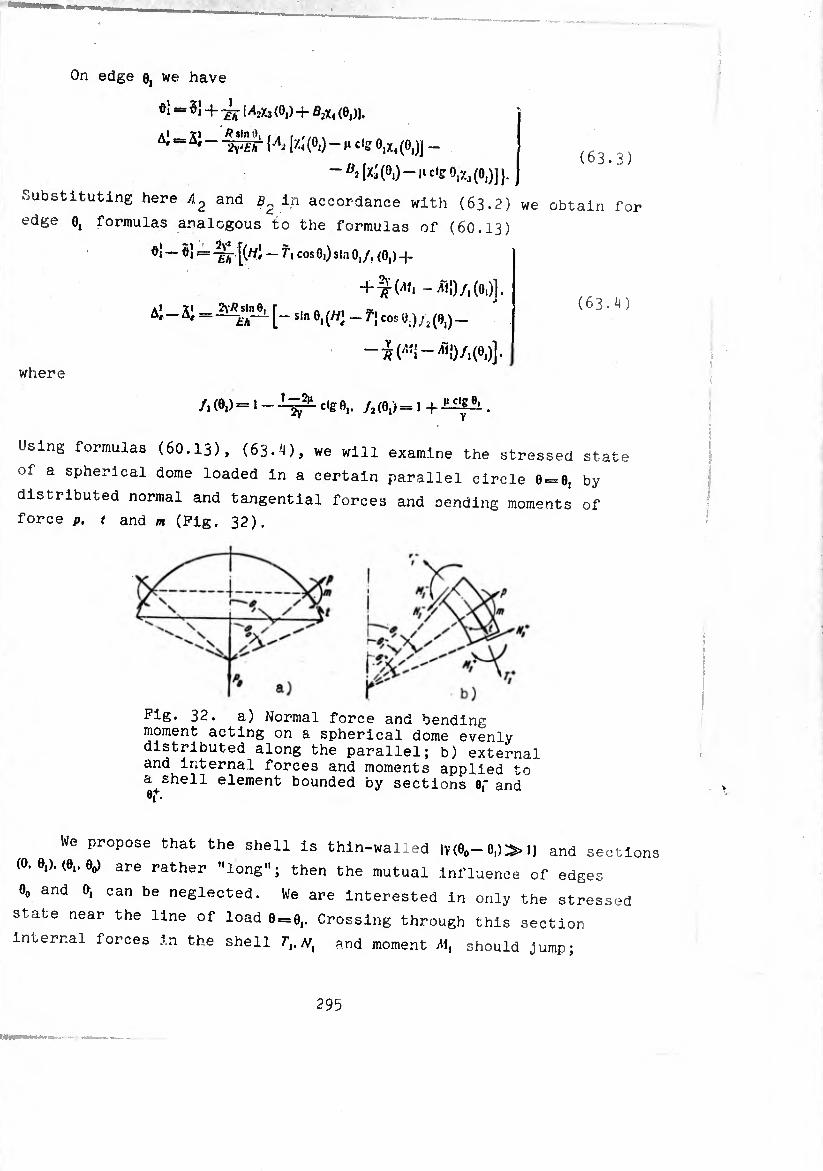
(63.3)
On edge e, we have
¢1 «= 5{ -f ¿j- |/l2y.3(0,) + B2xa (0,)].
A' “ “ -tyW [At 1¾ (°i) - I1 C,S 0,x4 (OJj _
Substituting here and b2 In accordance with (63.2) we obtain for
edge o, formulas analogous to the formulas of (6C.13)
0} — ö) == [(wi — f, cos 0,) sin 0,/, (0,) -j.
+ -^-(^, - All)/,(0,)].
Al -SJ = [- sin 0,(/y; _ f> cos 0,)/,(0,)-
-^(^1-^1)/,(0,)].
where
(63.^)
/,(0,)=,-1^.^0,. /,(0,)=,+1^
Using formulas (60.13), (63.4), we will examine the stressed state
of a spherical dome loaded in a certain parallel circle 0 = 0, by
distributed normal and tangential forces and oending moments of
force p. t and m (Fig. 32).
32. a) Normal force and bending moment acting on a spherical dome evenly distributed along the parallel; b) external and internal forces and moments applied to a shell element bounded by sections 0f and e,+.
We propose that the shell is thin-walled lY(eo-0,)»l) and sections
(O.e,).(0,.0o) are rather ’'long”; then the mutual influence of edges
0O and 0, can be neglected. We are interested in only the stressed
state near the line of load 0 = 0,. Crossing through this section
infernal forces in the shell f,.//, and moment M, should jump;
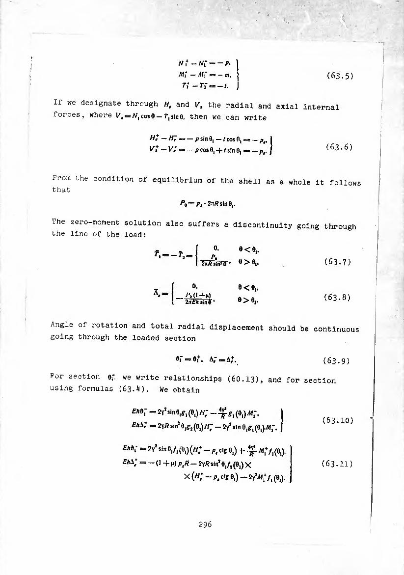
1
N i — Nî =
Aíi — ==
Tí -77-
— P-
— ni,
— t. (63.5)
If we designate through H. and V/f the radial and axial internai
forces, where = cos0 —7*,sin0. then we can write
H? — HJ — — psInO, — /cos0, = — pt, I
Vt — Vi — — p cos 0, -f- / sjn 0, = — pt. J (63.6)
From the condition of equilibrium of the shell as a whole it follows that
po~Pt- 2*/? sin 0,.
The zero-moment solution also suffers a discontinuity going through
the line of the load:
0. e<0,. r 0
¿n/? sin1 Ô ’ ö>öi. (63.7)
0.
2n£A sin Ô
O<0,.
o>0,. (63.8)
Angle of rotation and total radial displacement should be continuous
going through the loaded section
0.- = 07. a; = a,\ (63.9)
For section of we write relationships (60.13), and for section
using formulas (63.4). We obtain
f A0- = 2v*sin 0,^, (0,) //; - (0,)/Mf.
£AA'* = 2y* sin* 0.^(0.)^7 - 2y* sin 0,^-, (0,)
Eh*; = 2y2 sin 0,/, (0,) (w; - p¡ dg 0,) f Ai+/,(0,).
CAA; = --(1+h) p,/?-2y/? sin* 0,/2 (0,) X
X W - A, cfg 0,) - 2Y?Af,V, (0,).
(63.10)
(63.11)
296
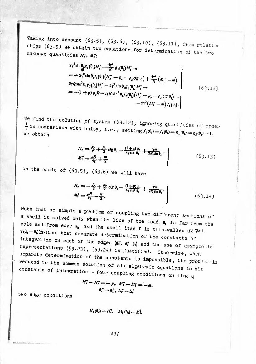
Taking Into account (6j.S), (63.6), (63.10) (631]) n ships (63.9) wp nhi-aik, a. ’ ^03.11), from relation ^ 3 y; we obtain two equations for determination of fn
unknown quantities HJ, MÎ: 1 the two
2Y*sine{iri(0l)//;__4v.^i(0i)Afr =
■=+afsln 8,/,(8,)(//,- — - pjCie o) + V. (i)|- _ m)
- « (63.12) — (■ + k) P,R ~ 2\R sin* 0,/,(0,)(//^ c,COi) _
We find the solution of svsfpm (£,? ^
¿in comparison with uni tv ) ’ ,Uantltles °-)e we Obtain 3011 lng^“A(»i)=f,(0,) = s,(0,) =,.
on the basis of (63.5), (63.6) we „111 have
(63.13)
ctge , ^ 2 b 1 sin3 0, t-
/M,+=.£*_«. 4y 2 *
Y« 2// sin 8,
(63.14)
Note that so simple a problem of coupling two dlff» .
a shell is solved only when the line of the ) . sections of
pole and from edge » md tw u °ad 9i ls from the Vie —el's.» !„ *• the She11 Uself la thin-walled W,»,
intgrauótSÕn eaaV0rrate dete™lnatl® °f «e constants of
reprfsentlo s O .: ,th;5r::; ™ "" «^0«.
separate ^etermlnatlon of the^constant^is^impossibleW^th*
~roïhL~ rrn of six a— -----em 1 ntegration - four coupling conditions on line e,
two edge conditions
H' ~~ — Pt. Mf —Mi
K = 0¡. = ■■—m.
(Oj) = ^,(0o) = iM?.
297
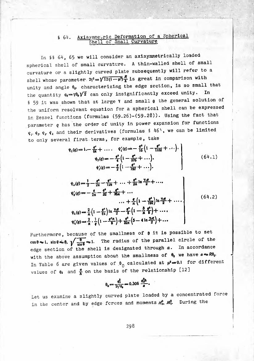
§ 64. Axisymmetric Deformation of a Spherical Shell of"Small Curvature
In §§ 64, 65 we will consider an axisymmetrically loaded
spherical shell of small curvature. A thin-walled shell of small
curvature or a slightly curved plate subsequently will refer to a
shell whose parameter ^ = Is great in comparison with
unity and angle 00. characterizing the edge section, is so small that
the quantity ?o=y0oV'2 can only insignificantly exceed unity. In
§ 59 it was shown that at large Y and small 0 the general solution of
the uniform résolvant equation for a spherical shell can be expressed
In Bessel functions (formulas (59*26)-(59.28)). Using the fact that
parameter q has the order of unity in power expansion for functions
'Tj. »fy and their derivatives (formulas § 46', we can be limited
to only several first terms, for example, take
*,(?)=i*-lr + •••• *i(?)=- 15-(1 -TÏ52 +
¢2(9)=--7-(1 ~•••)•
¢((9) = -7(1 —•••)•
¢,(9)=7-£—&+
¢3(9)=-57-321+15^-+ •••
...+4(1-w),n^+••••
¢4(9)=1^-^)^^-^(1 —!£)+ ••••
¢: (9)=I • 7 (1 —Ç-)+ár (5 -41 n +—
Furthermore, because of the smallness of 0 it is possible to set
cose^l. sln0*¿e. The radius of the parallel circle of the
edge section of the shell is designated through a. In accordance
with the above assumption about the smallness of 0O we have o«s»/?0o-
In Table 6 are given values of 0q calculated at ^ = 0.1 for different
values of 9„ and £ on the basis of the relationship [12]
(64.1)
(64.2)
0O= -0.306
Let us examine a slightly curved plate loaded by a concentrated force
in the center and by edge forces and moments A!?. During the
298
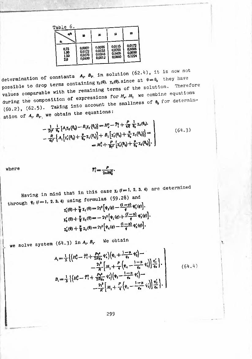
Table 6.
0.75 1.00 1.50 2.0
» 20 IS 10
0.0069 0,0122 0.0276 0.0190
0.0086 0.0153 0,0313 0.0612
0,0115 0.0205 0,0105 0.0880
0.0172 0,0306 0.0690 0.1224
. X 8 in solution (62.1). it 1= now not determination of constants .. .. <. lnoe at 0 = 8. they have
possible to drop terms of the solution. Therefore
values comparable with the rem ,or « M we combine equations
" rriirrrrrs^ass Of e. for .etermm- (60.2), (62.5)- iaKiriK . ation of 8.. 8., we obtain the equations.
- i l-** W - 8* Wl="Î - ^ + ^ ^ ?-<9^
' = m!+T?- [tí W+K *■ wl '
(64.3)
where r_ P . 1 2nP0j
4 rase h 2. 3. 4) are determined Having in mind that in this case ï, <
V, * i/-l 2 3 4) using formulas (59-28) and through ’W (* '• 2> 3’ & r
XÍ (6) + %h W = 2yS [*'(q) ~ i" (i)l *
x( (6) + i X3 (0) = 2V3 [^4 (¢) “ ^ (?)1 ’
we solve system (64.3) in Av Bv We
+4(4.-^4^)- (61.1)
^,+4(4.-^4^)-
299
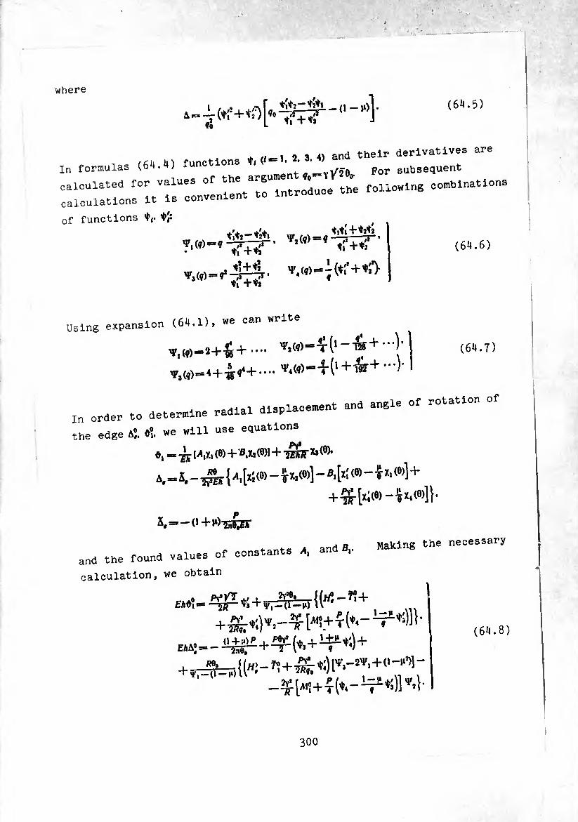
where
(64.5)
. * ,/«i 2 3. 4) and their derivatives are In formulas (64.4) funct ons , * . «_YÿTe p0r subsequent
calculated for values of the ^ °e foUowi„g combinations calculations it is convenient to introduc
of functions ^
IfTtT’ ( 9 tf+ti .♦* + ♦* V (a\ e= — (♦(’ +
♦i +«
(64.6)
Jslng expansion (64.1), we can wri
(64.7)
■n onder to determine radial displacement and angle of rotation of
;he edge a",. ȕ. we will use equations
», = -jjy l-v, (8) + 8,1, («)!+-& *• <6)- ^(0)-^,(8)1-8,^(6)-^1,^1 +
+^-[i¡(e)-ix.(6)]l
ï,=-o+rt-sçBr
, and B„ Making the necessary and the found values of constants ,4, and ,
calculation, we obtain
(64.8)
300
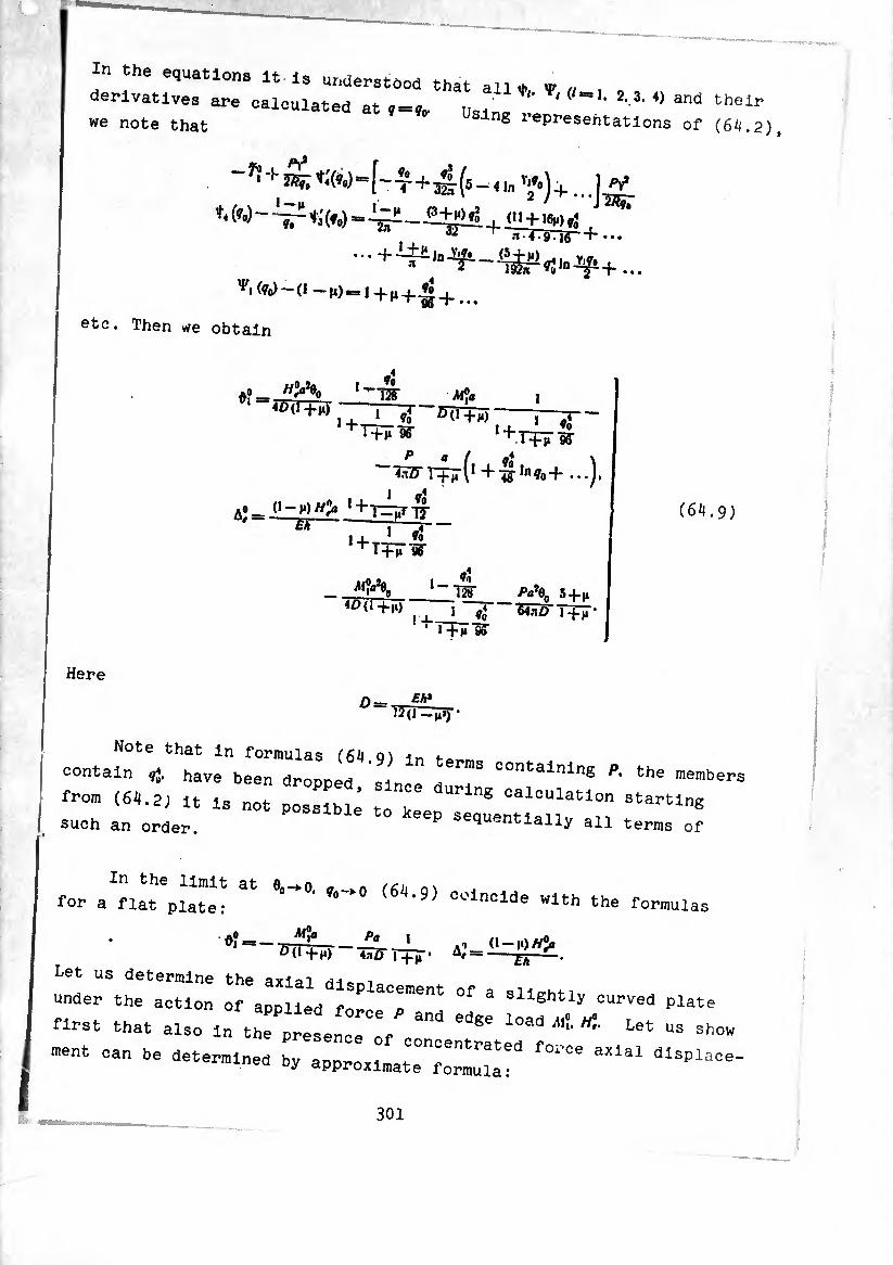
In the equations it is understood that all ♦, V . , , ,
derivatives are calculated at * = *«, Usjlni, , ‘( ‘ * and their we note that ng represeiltations of (6^.2),
,, 32 —h...
'»'iW-(l-U)=l+M+ri+ _
etc. Then we obtain
A? 1 W+ÏÔ
1 — lo 1ÏÏ _M’ja
, _l I ¢0 50+0 l+rHr?r
I
H 1 Ú + TTF9S-
Îïsrr+ÏTV + 4g-,nio+ ...J.
A»-0 —y)//> ^T—r-S-
i a* i _i_ * ft , + T+F8g-
40 (1+,,,
VÎ w
ffo
Here
‘ ’ T+ir 9Î
Eh*
Pa\ 5 + 4 ^4nO 1 +4 *
(6+9)
^1-4^
Note that in formulas (6^1.9) jn for.™ contain »J. have been dropped since du S COntainln8 Pk the •“embers f-om (64.2, it ls not possibi; to ;ee "U1;lnS 0aloula«on starting such an order. ^ ^squentially all terms of
In the limit at eft->o „ a /¿i, for a flat plate: ^ ’ 9) Coinclde ^th the formulas
_L_ AO (1-10/^ ^d+l») 4nD 1+4’ A' =--.
underSthe‘action of'appUed^°f 3 SllShtly °UrVed plate
nrst that also in the prlLee'o'f eoT T ^ ^ “ Sh» -nt can be determined ^ ap^l^d^
301
Af «s ^ (/?í>, cos 0 .. + ^1
4 jw+saw+Tfc— *;w]<«+c- (64.10)
For this let us write out the term eliminated in subintegral expression!
— /?e, sin 0 =¾ — Refi = --^ ~ "g- X*) —
— -¿7 B, (mXÎ - -g X,) + - VÏ7 - TR (^XÎ - ¿ Xí)] =
= ~'W [ I?" Ai (^x2 ~-gXj)—-¿r fli (wí — T X!)] +
+ {d + (¢)- +1^3(?)}• (64.11)
Comparing (64.11) with the subintegral expression in (64.10), we are
convinced that /?e,0 is a quantity of order in comparison with /?0,.
if we take the latter as unity. With the accepted correctness of
calculations this confirms approximation equation (64.10). Reading
axial displacement from the edge of the plate 0 = 00. we set C = 0 and,
integrating, we obtain
A, = (¢, (7) -1, (?o)l + Bl [t2 (?) - tí M +
+ -ffir Ita (?) — 'ta (7o)) }• ( 6 4.12 )
Displacement in the center of the plate, i.e., at 0==0. is equal to
A, (0) = 1 11 — 11 (?°)1 — fliti(?o)l + Sã [t — ’•'a (?o’J • ( 6 4.13 )
4
Here is is taken into account that
^ (0) = 0. ti(0) == 0. ts(0) — -j •
Substituting into (64.13) expressions for the constants of integration
in accordance with (64.4), we have
(0) = -^T + 2ÂÍ, y,—(1—J»)
2Y}r..„. P[^ i—_V i yip 11 lt.\ 4 r4 ?( ^3) M) ^ 2£A \2 'sj*
(64.14)
302
Here also the-values of all functions and their derivatives
should be calculated at for small </0- using expansion (64.2) and
making the necessary calculations, we obtain
A, (0) = - 320(1+M)
5 + J» Aiy 1 - »S
20(1+1«) Ÿo ^7+7^ 1+i+iiW
1 *»’ 3+n r 11(1+1«) 4lngl 576(3+¡í)^ln?»J- (64.]¾)
Axial displacement in the center of a circular flat plate is found
by setting in (64.15) ?o = 0*
My Pa2 3+n (0) = 2D(1 +n) ■> 16nô l+l*'
In conclusion let us note that at very small ?o and 00 in
equations for angle of rotation and axial displacement it is possible,
keeping terms containing H%. to eliminate everywhere higher orders
of q in comparison with unity. Formulas (64.9)> (64.15) then will
take the form
Afy ( Pa2 3 + 1* H?a\ 5 + n
(°) = 2Ò(1 +1.) + T6ÏÏÔ T+l* “ 320 l+i*'
(64.16)
In order to understand the meaning of the simplification, turn to the
basic résolvant equation (59-2). Let us assume that angle 0 (even its
maximum value 60) is so small that despite the considerable magnitude
of parameter 2y*. the following holds:
2y* <C c*g* »• (64.17)
In this instance, if we eliminate the term 2/y2 in the coefficient of
0>, we find that equation (59-2) breaks into two independent equations,
each of which will contain only one unknown function V,. This
will correspond to replacing the shell by completely flat plate and
to consideration separately of the plane problem and the assignment
303
Of bend. However, not always does replacing the shell by a flat plate
espite satisfying condition (61..17), glve acceptable results It
: toFtake int° a~ of g shell. For example. In a rotating shell the centrifugal
Thl "orceTuVtri1"!? ^ h°M S"a11 curvature.
-sse0;0":: :: rh!:-™: rrrof the piane
he :: 1:wuratjre c85]-in tM5 case (m-s) =^med m t^o h ? nanner' SUbStltutl"e It the expression for «
li;"::: :rrry parts °f thi3 functi™ -—
in oomp^Lr^r^3^6:::10:oniy the quantity ^ mK * naving kept, however, the terra en we obtain the following two equations in and V,:
d*V dV ~w-+cts*-dr—v. c<gJ o=o.
d*r dv -7$r+ctg 0-^—v. ct** 0-f-4y«V, = o.
:r:t::nvariabie v, and setting ^0^^6^^.0=1.,.,,6=6.^^=^,
d*V. 1 dV. ^=0. dr* ~T7~d7 .
d^v. , 1 <n'_ V Bk ~d^ + 7-7r~-pr+~-Vt = o. (6^1.18)
he first equation of (66.18) describes the plane stressed state the
econd corresponds to the problem of bend allowing f0r the plane
termSSV r\Sl-"e fUnCMOn ^ PlayS ^ the role of t»« load „ J!: Jf “e t0 the baslo oyotom of equations which describe
the T r 0 f0rD,ati°n °f a shell Of revolution (11.1) (u 3)
hen n accordance with the Indicated approach In the se^o d ¡q Itlon
and 1 '.. e l ? 1311°11 “at aab «,=«. ^0 = ,,. cosol ,mol. obtai t lnS e9Uatl0"s of equilibrium take ,1,,0 = 6. Then we
lelllpUMlT1!’ t0 Kh"h “ - - - either They will have the form “ aPPrOX:traate oppressions for deformations
dr (rT0 = 0, ¿^8,).-6,==0.
T, = Eh
da „ 17' t2~ — <
(6H.19)
304
(64.20)
Tr {rMù — Mi = rNv 7,6-^, = 0. Ai,-Dix, + Mx,). ^î==D(x2-|-mh,).
x, = -^L. x,^-^. di==^.
nirnrr: <6,,'19) represents °f the Plane problem
--;.u::micbr^ zrx0: Ttin8“ of the term r.e. Introducing stress fu„otlon v by ^la^"™06
r>-T- t.-£.
systems (6^9). (6t.2o, are reduced to two resoivant eouations.-
fV I 1 dV V dr* r dr 77=0.
dr ^ r dr 7> ~7U' (64.21)
Sol^tequations (6..21) under the edge conditions on the edge of
7, = /yJ. Af, = M°t
taking into account the requirement of boundedness of forces and
::: :; r:hoidatlrtln the center’we arrive for - a ohed plate to the already obtained formulas (6..16).
We determine forces and moments in the center and af fh
weakiy arched plat loaded by edge loads tf. Ml There are no 6 6 ^ ^
aocepT d" I“)"! ^ ^ diStrlbUted ^ds. With the relitionships^ Sl"Pllfi°“ ^ — of the shell exist of
Tfa-Atf^o. Tj -j- A^i'Oo ■* //¡i
hence, ignoring the quantity m comparison with unity, we obtain
H^Tl NÏ^H'Oj. (65.1)
305

^rom the relationshio
we find that
^ =7^-,7?)
~i ri , Eh^
(65.2)
In exactly the same manne-, replacing in relationships (57.10) cosO
by 1 and sine by 9 we obtain the expression for M'i through known quantities M? and d?
gie?. (65.3)
Substituting into (65.2), (65.3) the quantities < < determined by
formulas (6H.9), and setting P = o. we will have
1+T 1 1-1*
12(1+,,) 1
1+^ 96
— Tp-'llîûOjO — (!) 1 - lo
128
1+M 96
(65.4)
Al? = Mn, (1 —1‘) (1+1«) %
1 + I 1-(-^ 96
//>0 —í-d 10
Jo_ ' 128
1 + 1 ¢3
l+j, 96 (65.5)
Using formulas (60.2), (62.5) and (62.1), we find that forces
and bending moments in the center of the plate are equal to
T, (0) = 7-j(0) = A 1
^(0) = ^(0) = ^(1+^, j \ (65.6)
Remembering the expressions for/1,. according to (6H.10, „e can write
306
r> (0>=23¾) h «+V1 f; w] -
- -fi -^1 (q,i) h loi (¢0) ’
M, (0) - 4A ¿T y 3(1¾ ! *1 ¢0) - ~ *:(?„)]
— i±^ a.,° ^^0) Vo ^ (9a) "
2-Air
Substituting Into (65.7) expansion (64.1), we obtain
(65.7)
, _ Vn (3-f-H) 7/?<
7-,(0) = /y;—üUI±g , /^) rXeg , . i ?0 K i+M "2ft-j—nr. 1+thT96 i-f- ' 4«
l+n 96
(65. )
(0) = ">,)<3 + M) ,_25 + 7m VÍ __i + M T® + M,
>■+
\-H± 96
96 i + 1 __ Vo
1+H 96
(65.9)
We determine with the aid of th^ . fon-e ,r , he ob,'alned «quations the bend and
Plate on a ^ °f 3 ^ a smooth base. On the plate acts distributed load
—— pA,
where p - specific weight of material.
(65.10)
By formulas (57.15) we calculate forces of ^ and radial displaeement zero-moment state
_ p///? (ros 0 — ]) sin116
p/»/?
Yn pA/? A. -= _ <1"R .. , 2£ (I ~ I')- j
( 6 5.11 )
Since on the edge of thp oiat-ra t0 ^ p n Plate T^i—/7, = 0. then from (57.3) (57 ¡1) -tt follows that Shearing force on the edge is 3), (57.4) it
?_phR0t TV =
During the calculations Aj and Aß by formulas (64.9) and (65 5) -t Is
not necessary to replace A? by A°-Ã" H' hv/7° ^ 5’5 ^ 1 in them h'» u- n a by/7,-7-,. and after this set in tnem //, = ,«, = 0. As a result we obtain
307
(65.12)
Ao= fyH)0 (1-,,») 74.u , .6£A‘ 1 n ---y-,
1 + T-— „ p. 1+M 96
A?=- P_aSd»i>-Ms) 7-l-u . a -Í6×ttît-~r.
f4 +TT¡T96
Aí5= - (J _ J _ ^1¾ 8 rj- --T-.
] -4--— *0
Axial displacement in the center of th* -, formuJa (6^.15) ^ Plate is determined by the
4,(0) = . pAa« 54-u i
-Kr Î+T-—-St (65.13)
The minus sign ln th« ^
positive direction of A hasTle^ ^ eXPlalned by the fact that a
load - 1„trlnsl0 weight*—^is irrred aione mis ^ ^
fiat —■ « have 0:;r::;::cí;the -• - a
A, —0. 7^=0. A,(Q^_ggl 5 + n 640 r+jr*
’rr'jrr.^rr r- "•* *• ---- ,+_L«! circumferential bending moment by a factor of - i-f-1> 96
1-4- an axlal displaceinebt by a factor of (,., ' ¢)
rnh* 1 ihere is also a deernac-o u
Really, replacing in (65.8) (65^9) "T^V" 0enter ^ the plat and setting «,’=,„?=0 we fln(j ' T>«>> by 7,(0)-^(0).,^ by
7*2 (0) = —- í£ü» (4 + >0(1-u> 16A , -j- .
1+—L ^ +T+3T^6
25 -f- 7p 0^ A1, (0) = /11,(0) = - i^üi+p) ilTfïT ñk
16 ~
J+T^-—~ Km 96
while in a flat piat(
r2 = 0. ,lf2(0)Œ _ pAa»(34.lQ 16
(65.14)
308

The deformation of an arh-tt-
action of a bending l0ad of form °f revolatlon under the
COS <p,
ft ~ lid) sin T. ?/i = 9,(1) cos (J) (66.1)
-as considered ln 5S li|-18 of f.h .
tr°m the designations r,,,, T s IU' Subsequently let us pass
quantities in Chapter II to th« 1 ,,u’ .use^ Tor the a’ t0 the designations * „
Conditions of eouliih«-,
«hell contained between edgeTe^t 6 °f the sPhe^cal
are obtained from (i5.21)j a¡ 2 “ and Instantaneous section 8.
and have the form * f ln them we set /?, = /?. v=/?s/ne
/^sln0coS0 + n/?sin20_
«i/?!sinjeCoS04_ hiRsinQcosQ ^mfis~Ql2in 9+/ (0) = °' j
where we have introduced the d ^ ucea the designations
(66.2)
/(0) =
^(0) =
ft n
iii .-1
P<(0)
po(Z~Z0) t M(/ (e)
31 R— (66.3)
^(0) =
^,(0)=
e. e
id cos 0 — ^u) + 9,(I)sinO)/?2sln0tf0.
/ /Ji (0)^5(0 0^0-- 0.
~ -7 / (?„ ,1) cos 0 - 7, (I) sin 0; /?1sin:0 ^
~^(i —CCSÛ), z _ Dit 1 -/?(I_cos0o)>
(66.H)
309

M«). «,(0) resultant and composite moment of distributed external
Joad (66.1), applied on shell section (¾. 9). calculated relative to *he axes parallel to ox and OY In section „ . T native to the
-lu sectLon 0 = consl. In order that t-ho
^.-^0 + ^(0) = 0. -^.+ ^0 + ^0+^,
’v (0) = 0. I
(0) = 0. / (66.5)
;,°n0entrated a0ti0ns the Pole (Pig. 33). Taking Into
funct'onl (66 U 13 ‘o calculate the values of iunctj.ons (66.3) at 8 = 0:-
/(0) = -^-. r(0) = ^is- (66.6)
equations T'lT ^ <16-15)- (16-16> (Meissner quations type, for a spherical shell of constant thickness have the
+ ^0-1^(^5--3) = 4,11).(9).
^■ + c1£9Ä. + p1(,_(1__4t) + Vi
_Uf (I — H?) / 2 \ 1 <v‘ l sinj e — 3) — R®* (0)-
12(1-4’)*» r-h>-
(66.7)
Lead funcMons ^(0) + ^(9)./o(0)+/i(0)i use^ ln §§ 15j l6 (formulas (15<3i|
simpi; z;;zt;;: wlth the newiy tntroduced functiMs --
^(0)+^.(0) = -^11211-/(6)^^0 /.fm R' s.n! 0 ^
/n(0)+ ^(0^--^(6)+/(8)^0050 COS 0 #Jsin0 ■* sin i®)-
(66.8)
where
/î(0) — R? J f2l¡)'!n6dd. (66.9)
ihe right side of equations (66.7) are equal to
310
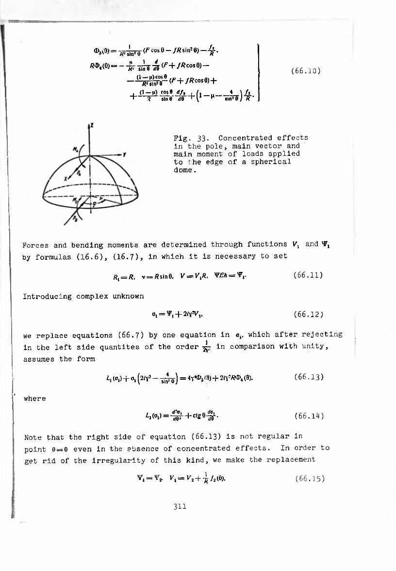
(66.10)
= T/T^rë co:» 0 - //? sinï 0) - .
/?0)4(0)= - -¡¡ç (^+ //?cos0) —
Fig. 33. Concentrated effects in the pole, main vector and main moment of loads applied to the edge of a spherical dome .
Forces and bending moments are determined through functions Vl and Y,
by formulas (16.6), (16.7), in which it is necessary to set
Rl==R. v = flsin0. V = IV?. VfA = 'P,. (66.11)
Introducing complex unknown
0, = ^, + 2^,. (66.12)
we replace equations (66.7) by one equation in o,. which after rejecting
in the left side quantités of the order in comparison with unity,
assumes the form
/-, (0,) + o, (2/Y1 - -¿j) = /ft)+2/y3/W>4 (0). ( 6 6.13 )
where
/■i(oi)=4ën + cl20'^- (66.14)
Note that the right side of equation (66.13) is not regular in
point 0 = 0 even in the absence of concentrated effects. In order to
get rid of the irregularity of this kind, we make the replacement
= (66.15)
311

then relative to
we will have the equation
(66.16)
(66.17)
h , 4 \ ,, ■ f ¢05 8-//3^8 i /., (03) + o2p/Yv - 7i7¡rg-) = 4' /i*5ln>I h
(1—ti)cose , jR cos 0) _ cos 0 (1 + H)] • R2 sinJ 0 ' 1 ^
To the simplifications made ion
Xm^pLl: Tfono«ing variant of expressions for forces
and moments through introduced functions 1 «V 1
/l = V2ctg0-7¿ff(f+//ícos0) VÏF vur
V, ctg 0 + â?î a» sin 0 - -¾^ “5T (66.18 )
¿0
«i
■ 4y* Tmg
17(ípL + 2c,e0^""'&)‘
(66.19)
§ 67. Particular Solution of Equations ?X - Meissner Type
Let US rewrite the right term of elation (66.17), changing in
it only the order of the terms. We will have
,v, _ 2,,1(1 _,,) 7¾¾ - WO - P) +
+ Ä^ + 0 + '»■ 4
4 /¿7 -n is ereat in comparison with the At large 0 the first term n • essential
a 1 nine as 2V in comparison with unity, and is the only remaining, as A ^ necessary to estimate (67.1) term. When 0 is close to zero, it is necessa V ^ ^ ^ remalns
more thoroughly. The last term in the _ However, i 4-v,q eirst three turn into infinity as J
bounded, and the quantity of order W the third term is in comparison with the
312
, o- fi - 0 and therefore always can be dropped. In
: :::- =.. 3lmPn«e, an.
in the form / 4 \ . . FcosQ — fR sin’ 0
(o2) + °2 ^2/\' — S|n! e ) * ' R- sin10 (67.2)
At small 6 we can use the equation
Ll (Oj) + sin’f) - (f)7 . fcos6-/«sln’e _,^Z£2L®. (Oi-o;
= 4Y4-RFüHTe-2 v ( l ) Ttsi*1
Within the limits of this section we wiii he ii.itea to lan.e^ and
Will construct the particular solution —ti° ^
simplify the form of the right side of (67.2)
substitution of variables:
\p2=_\jr3_.lu (feos 8 — /R sin16). — ^s’
-^(f cosO —/Äsin^). o,= o3
(67•^ )
where 0,= ^,+ 2^1- Then we 0l>taln
1,(0,)+0,(2^-^)=2^^+
where
G (0) = l/7 (0)cos8 — /(OîÂsln’O],
(67.5)
(67.6)
“ " :rr rJzxzzz? us examine the part)icuxui e + a+ipallv
r :?0 ;:::t i1::—::. 1,
rcrnrtererc: ;.... in the pole, in this instance function
0(0) has the form
0(0) = -/i + ß“'5 0-
, \'P. o_ A =-—ff • B — a \ RJ ^ R I
(67.7)
(67.8)
We are looking for the particular solution of
the right side of (67.7) is far from the pole m
313

^=fl.+ *sfr+*'cos0+-%Knr
t, . . „ . . co*0 rj=c'^ i^h' + rf‘cos0 +
(67.9)
Substituting the above expressions into equation (67.5) and comparing
coefficients of like terms, we derive a system of algebraic equations
for determination of the unknown coefficients:
0, = ,4. — 2cj—4c,-M2 = 0.
ft, — 2dx — B, —4(/,-1-^2 = 0,
— 4^c, = 0. — 2q>¿ — 4a, — 4y<C2 = 0.
— 2ft, — 4y4(/, = 0, — 4ft, — 4y4</j = 0.
(67.10)
Solving it, we have
a, = A. a„ = 24
t>x B
1+^T rfl— - 4yi
l + T (67.11)
c2 — 44
('+-?)
, ft~—; — 2Ö
C,=0. d2 = ~
'+-7
7(¾)
Dropping — in comparison with unity, we obtain V 2B cos 0
’ y4 sin2 0 ' B cos 0 Y sin2 0 *
y__1 v*~ y' stu20 2y4
cosO
or
o3 ^ (4-f ß cos 0) ( 1 -f 2^rii]srõ) • (6' .12)
It is easy to see that we can come to the same result if during
differentiation we consider 4-f-ßcosO as constant. We can assert
that for any slowly changing function 0(0) the particular solution
can be taken in the form
°3 --0(fl)(l 4- 2(y- sin: 0 ) ’
V* „ m i/ * fcosO—/Afsln2©
(67.13)
The quantities a2 corresponding to this solution is
, fcosO — //isIn-O O, — — *iY ßi sln: e (67.14)
314

Solution (67.14) is marked by a tilde % to indicate that it gives the
zero-moment stressed state. Really, substituting (67.14) into
equations (66.18), (66.19), we obtain
7 _ rm ~ _ F ^ sin1 e ’ -
^ = «1
cos e —//? «ln» 9 Ã1 sln»e *
/Wj " hl •— /1J (67.15)
In this way we arrived at the conclusion that far from places of
pronounced change in loads, i.e., smoothly changing right side, as
the particular solution of the basic résolvant equation (67.2) we
can take zero-moment solution (67.14). Note that when there are no
concentrated effects in the pole (P.=/W. = 0). and there are only a
distributed load and load on edge 0^, zero-moment solution (67.14)
and forces (67.15) because of (66.6) remain bounded even at 0 = 0.
In this instance zero-moment solution (67.14) can be used as the
particular solution of the basic equations also for small 0.
® * Solution of Uniform Résolvant Equation
Let us pass now to the solution of uniform equation
4^+^0^ + ^(2^--^) = 0. (68.1)
By the substitution
°2 == "iTnW <T*' = * Í* + 1).
ideóse.
it can be brought to the Legendre equation
— 1) y" + 2!y' — n(n-f-l)y = 0.
Use of Legendre functions with a complex parameter can be avoided if,
in the same way as in § 59 in examining axisymmetric deformation, we
approximately express the solution of the involved equation through
Bessel functions. Setting
°3 — T/l^sin 0.
instead of (68.1), we obtain
15 cos'„ 4 lln* 0 j ~ 0
(68.2)
(68.3)
315

Then with the substitution
ros’0
we bring (68.3) to the Bessel equation
rf’T. ..IÜJL-Ut.ÍI-AWo.
(68.4)
(68.5)
the general solution of which can be taken In the form
T,=so r. vo)+<*-'*> <68-6>
Tn this way, the general solution (68.1) Is approximately representable
thus : „ _ ./ZtlM.-lfloMVä ,0)+(4,-18,) H?’ (1¾ )0)] ■ 02_" V sine lv
(68.7)
. , ... of the representation of solutions of the Legendre ihe corree n leading to it) through Bessel functions equation (or equa Ion (68.1)^ ^ ^ smaU e soiutlon (68.7)j
WaSId^b^used for calculation, holding In this case terms of order -,- could be used for ca retention of these terms in comparison with unity. At la g Y
becomes inadmissable.
Let us examine a spherical shell without an opening In the ;
summit of the shell there are no concentrated effects^ =4, «
The shell is thin-walled and the value of ang ch^ract
ir.:r. rr; “.r.:1“.“’.“"'.!:* d— »,
pole, we set 4, = 8,--0. In this way.
,,=(4,-,8,)^(0)+^(8)1. (68-8)
where we have introduced the designations _
ti(0)=/^Rt/,(,^,0). (68.9)
We use the asymptotic representations for ^notions / (^,)8) and Its
derivative given in Chapter IV (formulas <06.10 . 06.15), (06.9)),
keeping in them only principal terms; then we obta n
316
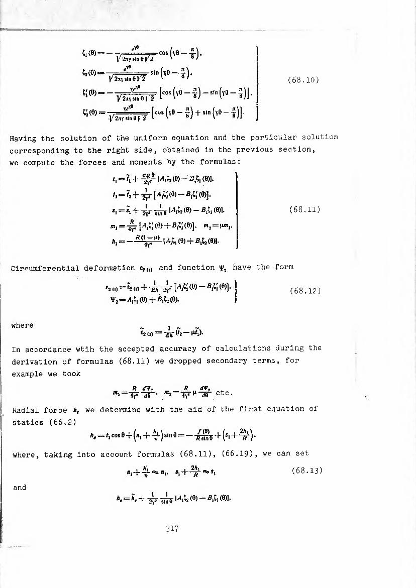
(68.10)
¢,(0)=- y 2nY*mej/2
-cos Kt)-
¢2 (0) =-77==^=== sin y 2.1VSin eil
^=- ttos ('° - ï) -sln (l0 - y)J •
55 (0) “ tÄt H (v0 - ï) +si" ('° - ï)) -
Having the solution of the uniform equation and the particular solution
corresponding to the right side, obtained in the previous section,
we compute the forces and moments by the formulas:
/, = ^ + -1^1^(0)-^ (0)1.
/2=/2+-^-1^(8)-^(0)].
*, = ï, +- -¿r -¡¡ie (8) - (8)1- ( 6 8.11 )
^, = -^-1+,^(8)+-^(8)]. m2 = \unv
A, = - Ri\~A (9) -+ (0)).
Circumferential deformation Cj,,) and function have the form
e2 (1) — *2 (1) "+ £/T l^T [^,^2 (8) (8)] ’
^2 = ^,(0)+-^(9)-
(68.12)
where h (i) — ~£k (¾ — ^,).
In accordance wtih the accepted accuracy of calculations during the
derivation of formulas (68.11) we dropped secondary terms, for
example we took
R (TV, R dVt — '"a“ l^lg- etc •
Radial force A, we determine with the aid of the first equation of
statics (66.2)
A, =/, cos 0 + (h, 4-sin 0 = --^¡V + (5> + ^) *
where, taking into account formulas (68.11), (66.19), we can set
and
8,-+-^-^/,,. i,H if"1,0
a, = Ã, + -¿r ~\A& (0) - fl.t, (0)1.
(68.13)
317
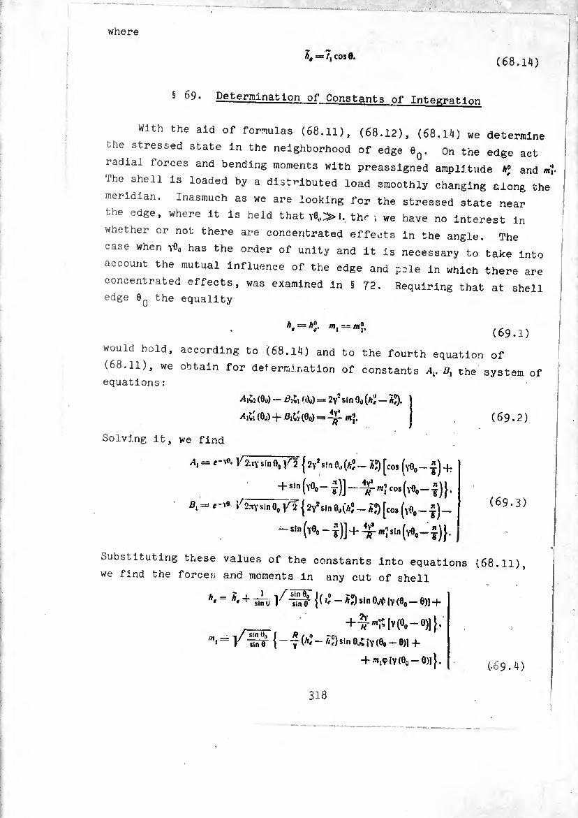
where
h, ==7, cos 0. (68.14)
§ 69* Determination of Constants of Integration
With the aid of formulas (68.11), (68.12), (68.14) we determine
the stressed state In the neighborhood of edge dQ. On the edge act
radial forces and bending moments with preassigned amplitude A« and ml
The shell is loaded by a distributed load smoothly changing along the
meridian. Inasmuch as we are looking for the stressed state near
the edge, where it is held that I. thr i we have no interest in
whether or not there are concentrated effects in the angle. The
case when ïOo has the order of unity and it Is necessary to take into
account the mutual influence of the edge and pole in which there are
concentrated effects, was examined in § 72. Requiring that at shell
edge 00 the equality
would hold, according to (68.14) and to the fourth equation of
(68.11), we obtain for determination of constants At. Z/, the system of
equations :
(Go) - i?,<du) = 2\’2Sin 90 W - ÀJ).
^(00) + 0,^(00) = -¾^.
Solving it, we find
A = { 2y*sin Oo (A,0 _ ÀJ) [co, (y0# _ * ) +
_+sin (Y°o- co*(yOo-i)}.
ß, = /2.TYsln0o V2 12Y,sin 0o(h°t _ ÂJ) [cos (Y0O_ £)_
- sin (Y0o - y)] + m'¡ sin (Y0O - -J)}.
Substituting these values of the constants into equations
we find the forces and moments in any cut of shell
h‘= **+ TirTv {(¿-À?)sinOot(V(»0-0)) +
__ +ÏSqv(0o-0)][.
/n'= r "Sr {~y(/!'~ sin0>¿iv(¾-0» +
+ ^,917(00-0)11.
(69.2)
(69.3)
(68.11),
(-69.4)
318
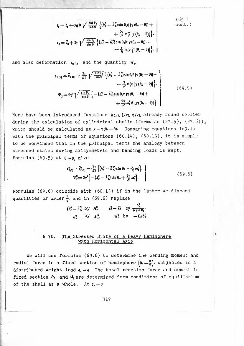
*, = ?, + cge ]/ {{li°t - hl)sin M» IV (Oo - 0)1 +
+^™;;iY(e0-e)]}.
=?2+2Y W -^'Jn 0-°IV(0j-0)1 - [)-(0,-0)]}.
and also deformation e,<,) and the quantity 'F,:
u. = î. u, + 1 /!t 1« - ÏS-I» »-0 IV(fc - 0)1-
-im>|ï(0.-0)]}.
= 2y- }f ~0- { - (/'2 - *2) sin OjT IV (00 - 0)1 +
+ ^m?OKY)(Oo-0)]}-
(69*4 cont.)
(69.5)
Here have been introduced functions 0(x). £(*). $(x). already found earlier
during the calculation of cylindrical shells (formulas (27*5), (27.6)),
which should be calculated at x=*Y(0o —0)- Comparing equations (69.4)
with the principal terms of equations (60.14), (6O.15), it is simple to be convinced that in the principal terms the analogy between
stressed states during axisymmetric and bending loads is kept.
Formulas (69.5) at 0 = 0O give
e2,.)- = T¡r [(^ - Ä«)sln ö» - -¾ mï] •
^-^[-W-Sasineo+ÿ«;]. I <69-6)
Formulas (69.6) coincide with (60.13) if in the latter we discard quantities of ordery. and in (69.6) replace
(¿2-£2) by w2- by
m? by AfJ, vf2 by -£A0?
§ 70. The Stressed State of a Heavy Hemisphere with Horizontal Axis
We will use formulas (69.6) to determine the bending moment and radial force in a fixed section of hemisphere ^0o = -£j. subjected to a
distributed weight load qx — q- The total reaction force and moment in
fixed section and jM0 are determined from conditions of equilibrium
of the shell as a whole. At qs = q
319
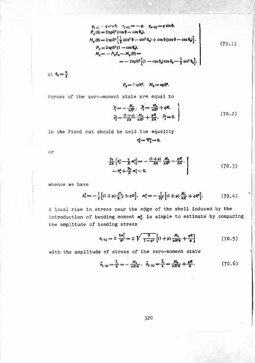
at G0 = y
Vl „ V-:. q cos 0. 7, (1) = — Ç. ?.(« = ? sine.
Pq (0) = ‘IxqR1 (cos 0 — cos Bq).
M' (0) = 2*qR} ^ (sin! 0 — sin10^ + cos 0 (cos 0 — cos B^j.
P0 — 2aqR* ( 1 — cos Oq).
M0 =-^^-^,(0) =
= — 2nqR* ^(1 — cos Oq) cos 0o— -j sin’ 0oj.
P0=?u7«î. M0=nqR*.
Forces of the zero-moment state are equal to
!!=-&• ¡5“^+**-
In the fixed cut should be held the equality
^=^ = 0.
or
2y /.-, y o\_+i*) M* Eh r* ~k i)~ Eh JÍF
qR ~eT
■Aî+^*î-°.
(70.1)
(70.2)
(70.3)
whence we have
AÎ=-^[o+H)^V+^]. ^ = + (70-4)
A local rise in stress near the edge of the shell induced by the
introduction of bending moment m®. is simple to estimate by comparing
the amplitude of bending stress
,i <n . G'"? ,/3( Mo
— - “hT = í K T^¡T l(1+^-53^+-^-] (70.5)
with the amplitude of stress of the zero-moment state
o, Mr.
1 (1) = -/-- TfFh' °2<»—T —* '
Ma 1* (70.6)
320
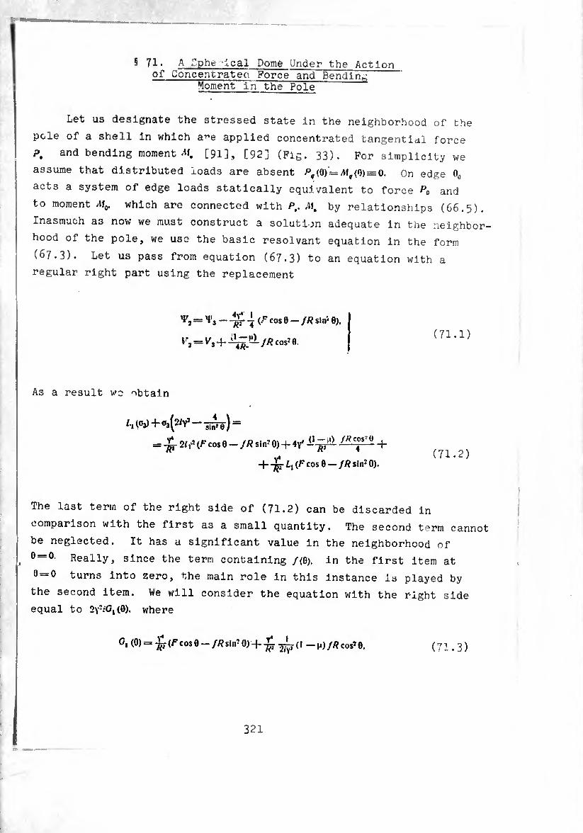
§ 71. A Cphe leal Dome Under the Action of Concentrateo Force and Bending
Moment in the Pole
Let us designate the stressed state In the neighborhood of the
pole of a shell In which a^e applied concentrated tangential force
P, and bending moment M. [91], [92] (Fig. 33). For simplicity we
assume that distributed loads are absent /^(0) = ^(0)==0. On edge 0O
acts a system of edge loads statically equivalent to force and
to moment M0. which are connected with P,. M, by relationships (66.5).
Inasmuch as now we must construct a solution adequate in the neighbor¬
hood of the pole, we use the basic résolvant equation in the form
(67.3). Let us pass from equation (67.3) to an equation with a
regular right part using the replacement
— jjT 4 cos b — fR sin- 0).
(71.1)
As a result wo obtain
/.,(0,)+0,(2^-5^) =
= 2/f* (F cos 0 - JR sin’ 0) + + ^ ^ (71.2)
+ -^-1,(5005 0-/^51^0).
The last term of the right side of (71.2) can be discarded in
comparison with the first as a small quantity. The second term cannot
be neglected. It has a significant value in the neighborhood of
0==0- Really, since the term containing /(0), in the first item at
0=0 turns into zero, the main role in this instance is played by
the second item. We will consider the equation with the right side
equal to 2y?/0,(0). where
(O) = -£(5cos0-//?ita*O + -j£ ^(i -^/flcos’O. (71.3)
321
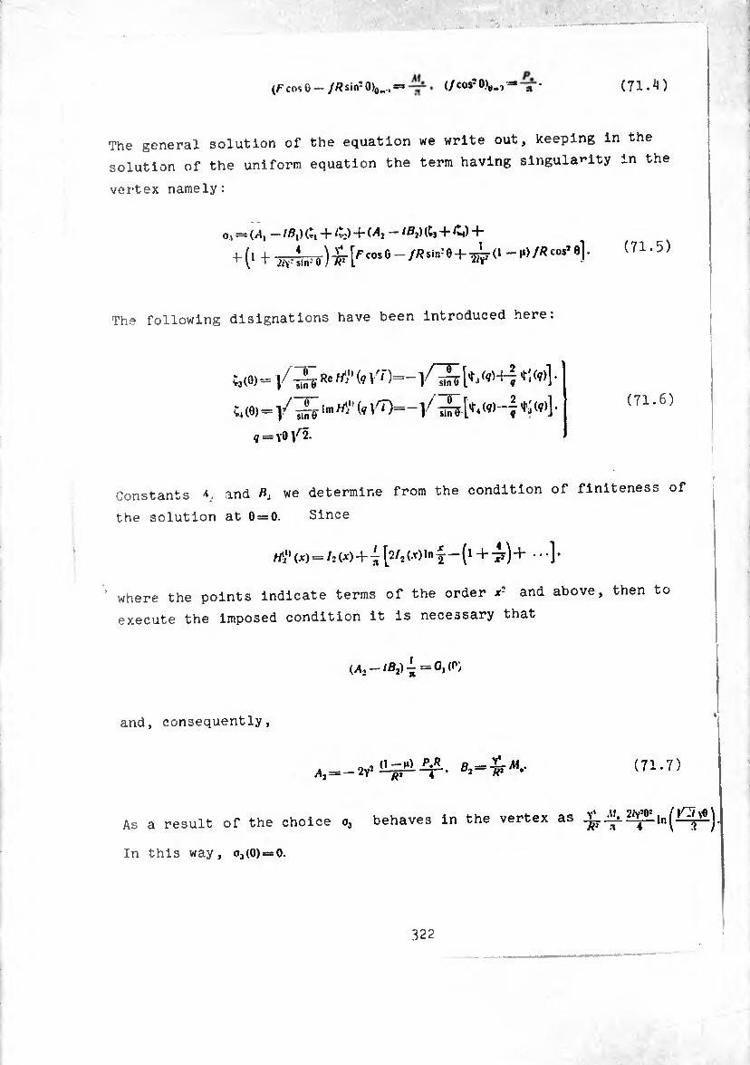
(71.4) (F cos û — JR sin- 0)o„ . — (/cos10),,..,-= n
The general solution of the equation we write out, keeping in the
solution of the uniform equation the term having singularity in the
vertex namely:
o, = (/), — + ^*2) -f* Mi /52)(Cj + C4) "I-
^-(1 + ily SÏF?) [r C°S ° ~ ÍR SÍn: 9 + W 0 -rtf*™' 4 (71.5)
The following disignations have been introduced here:
;3(0)«}/ Re ^ ^ *'*(v)] *
;4(0)=]/ V^)=-]/
? = Y0/2.
Constants and P, we determine from the condition of finiteness of
the solution at 0 = 0. Since
rti,) (X) = /;(X) + ¡2/2(*)In J — ( 1 + tf) + •••].
where the points indicate terms of the order x- and above, then to
execute the imposed condition it is necessary that
M2-/ß2>^=0'(r)
and, consequently,
(71.7)
As a result of the choice o3 behaves in the vertex as Jk 2/^lnJ£7v« j
In this way, o3(0) = 0.
322

! Returning to variabxes V v it- u v3, it can be said, that
* * 2 ' 1/?* (71.8)
Taking Into account this, on the basis of (66 18) <f ^
that f0r0eS and bendlr'g “S - - ^ve 3ing;iai.i¿;9s o" t“entif0rm
(3-fM) p.
_ >-)» p,
' "" *• t . (1_ll)
nPS-^ •••• (71.9)
m, = - ÍL-H') ». 1 4.1AU ■+* •••
1 4.1¾¾ ^ • • • •
«,= -ܱü!ií. i I a*ku -r - ... ;
J (71.10)
In expressions (71.9) terms of the form •« k
-t, since for their consecutive calLLttn it7
In the right side of (66.17) the term neCeSSar'1, t0 k^P
non-slmplified variant of the e ^ ^ 3 “T and v.. por example XpresBlo"s ^ forces through functions
. 1 r ¿nr
' wh/fT + d +M)~ V2] -f VfjCtg0 _
S. = —-Î- -L 7(1 -^) yf sin U * 2
_cose PJ sin Ö
etc.
Then in expressions for /, t s wm _ '2' s> w111 appear the terms
inTo7hp:nn;sst7quaBtyio?:r(6sr:rtutlon of the p~s
- -se terms in the 0^0:77:77^::7:110^ is satisfied accurately
323
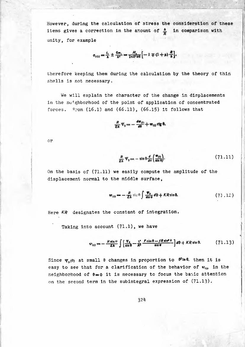
However, during the calculation of stress the consideration of these
items gives a correction in the amount of in comparison with
unity, for example
[-iTO+io-J]. it J. —T ± T> 2*WhÒ.
therefore keeping them during the calculation by the theory of thin
shells is not necessary.
We will explain the character of the change in displacements
in the neighborhood of the point of application of concentrated
forces, s'rom (16.1) and (66.11), (66.15) it follows that
or
(71.11)
On the basis of (71.11) we easily compute the amplitude of the
displacement normal to the middle surface,
R W<|> ^~Th
^,/0+«sine. (7) .i:)
Here KR designates the constant of integration.
Taking into account (71.1), we have
£ Fcòit-fRttfai d9 4 KR s|n n (71.13) H2 wn 9 J
sin I» WU) — £Ã
Since »i'3(0) at small 0 changes in proportion to (PinO. then it is
easy to see that for a clarification of the behavior of «•„, in the
neighborhood of 0«o it is necessary to focus the ba'iic attention
on the second term in the subintegral expression of (71.13).
324
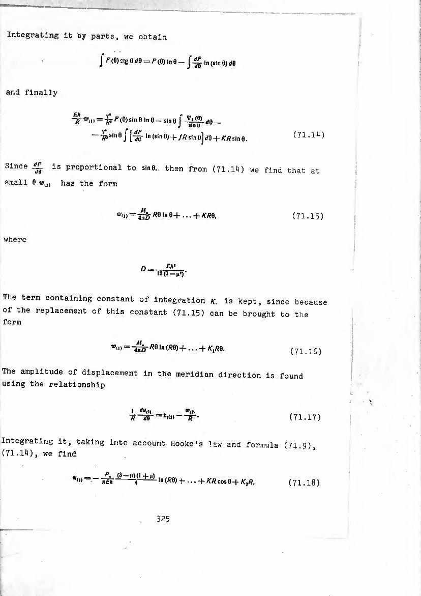
Integrating it by parts, we obtain
Jf (O)ctg0¿0 = /^(0)|„ 0 _ ln (sinQ)dQ
and finally
= (O)sinO|n0_sln0 I dQ — ^ J sin«
— sin 0 j [-^r In (sin 0) -f //? sin üj dO -f KR sin 0. (71.1^)
Slnce is Proportional to sin0. then from (71.14) we find that at
small 0 wu) has the form
tc- M <»> = TÎF/Î0ln0+--+^0. (71.15)
where
o = Eh* 12(1 —n*)'
The term containing constant of integration /f. is kept, since becaus<
of the replacement of this constant (71.15) can be brought to the form
m M <l> 4n¿) 1*1 (^0)+...-J-/fj/?0.
(71.16)
The amplitude of displacement in the meridian direction is found
using the relationship
1 du0) __ *(I, 7? de —em> ~TT (71.17)
Integrating it, taking into account Hooke’s law and formula (71.9),
(71.14), we find
4,(0 r= nEh ~ In (RO) ... -f /C/? cos 0 + R2R, (71.18)
325
where K<¡ new constant of integration.
The amplitude of radial displacement is calculated easily using
the first formula of (17.3)
\n)==“<i)cos0 + ti'«nsin0==
= — n)(l -f n)ln(/?0)-r ... -4-K7?-}-Ky?co*0. (71.19)
The amplitude of circumferential displacement has the form
(71.20) V«,=*2U, « sin 0 - A,u) = -¿inr (3 - 11X1 -Hi) m m + ...
For clarification of the sense of the constants of integration K
and K2 we compute even axial displacement
A*<n = ü<i)cos0 _ sin 0 = 4¾ ^0 ,n (Ä0)+
(3 - ji) (1 + H) «O ln (RQ) + ... —K2R sin 0.
From (71.19), (71.20) it is clear that K2 is the rigid rotation of
the shell around axis OY. and constant KR is rigid displacement
in the direction of axis OX (see § 18).
Introducing the designation we note that in expansions
(71.9), (71.10), (71.18), (71.20) the main terms coincide with anal
ogous expressions for forces, moments and displacements in the
plane problem and the problem of bending for a flat plate during th
action in one case a concentrated force in the plane of the plate,
and in the other of the concentrated moment causing its bend. For
both a sphere and plate is obtained
326
We examined the behavior of the solution (71 s') 'n fh 0 = 0. Tt . -Lutxon ((1.5) xn the neighborhood
It is not necessary to speak of the behaves at a great dis
tance fro» the top. At iarge vO functions decrease „l n
an increase In 0 as .-. and the particular solution dl , on
the zero-moment solution by only a small member. Really the J tlcular solution Is equal to "eally, the par-
°i=-pr(f to. 6-/« sit,! 0)-(1
cos e-//?sini0 , V L FTÍÍPll-(I -íl)¿/cos50j. (71.21)
Oolng to function o,. on the basis of (71.1) obtain
o,=
-(1 -H)4S-. V. = -l£?.s*-/Ksin'e Äsin~ü * ^lüiîë—•
~ (1 ~ 1°- 2/Y? ^O-^sInie ^sln-0 > /?• sinJ 0
When sin0^>0 (71 21) h^ U1.21) d-ffers from o, by only the small term.
eonditlons^^the^dg^'t) ==e SOlUtl°n (71-5) determined from
describes the edge effect connected „1th edge f Thl
represents a singular edge effect In the neighborhood of o-o
The strÏ the PreSen0e °f -- -‘-n in the ^ .
effectsT , 3 Very thln and T0" iS rather lar^> the edge , „ loeallze themselves each in their neighborhood, m this
-ns anee constants A,. B, can be determined by setting .(6)-.,6)-0
anuythe stressed state In the neighborhood of edge 0 = C “c“a ‘ “ '
computed, with the formula of (69.11).
327

§ 72. Consideration of the Mutual Influence of the-EdKe of the Dome and a Concentrated -Effect Applied in the Foie
Por a shell which is insufficiently thin (y small) or flat
(0 is small) the determination of constants A,. *», from the edge
conditions at 8 = 0, must use the general solution In the form
O3 = + 2/v^3 = Ml - lB¿ (£. + £*) +
-f 2y2(1 —
+ ■£('+ WITn’T) [f “» e - /« sln*9 + •
(72.1)
With the aid of (71.1) going to functions «F,. VV we have
\y2 = A& + - 2y2 (1 - JO -4^ 5» +
+ -^^).54-(1 •*) KkinJ0 /co** 0
(72.2)
2Y2V, = - Ö,;, - 2y2(1 - J») ^-5, -
- i {F (0) C0S ° “ 7 (0) R SÍn? 01
(72.3)
Apropos of the last member In the right side of (72.2) we can say
the following. It is essential only in the neighborhood of 0 = 0
at />.*0. At large 9 and no tangential force this member in compari
with the zero-moment solution is small, as ¿ in comparison with
unity. This lets us, without hurting the correctness, replace in
this case
w ' -«or. n*’ r ifh in the neighborhood of 0=^0 one In examining the hanavior o. ^
should bear in mind that at Ai. —o. .
has the mechanical sense of moment of force ¿V calculated
relative to the center of instanraneous section 0 —const. Therefore
at 6 = 0 this quantity is identical to zero. To avoid misunderstand¬
ings it is convenient to combine the last two members in the right
side of (72.3). Taking into account our remarks, we have
y2=A&(6) + 0,^(0; + -¾ M.C, (0) -
(72.4) 2yV, = ¿¿2 (0) - ß.C, (0) - 2yj (1 -10 ^ ^ 0) -
— -jïïtô [^r si"5 0;3 (0) 4- (/7 cos 0 — ;sin2 0)J.
In this case it is useful to remember that in the neighborhood of
0 = 0 exist the representations
On the basis of (72.4) and quantities (66.l8), (66.19) let us compute
forces and bending moments in the shell. In this case in quantities
(66.18) we discard the terms and JL. since when 0 i <5 ./A 4v' //A ’ 0 4v‘ «0 4y4 «/O ' -1-0
small, they are of the order of in comparison with the basic
terms, taken as unit. In either case, taking into account the
correctness of the solution, they cannot be held.
We have
(0) - ß,;, (0) - 2y; (1 - ||> -¾ Ç4 (0> —
cos 0 —//?sin?Gyj| — (72.5)
F -\- f R cos 0 H: sin b
329

h — A\ -V 1*=»- 4
(î-M) 4Ä
0) + ::(0)ci£0] — B, ^5 [;i ,0) -f- C, (0) cig fl] -
(0) -h clg «. (0)] — ;li< [ç' (0) + c<g o;, (0)j +
m* = 17 { -4i [Ci (0) + (1 + H)ctg o:, (0)] 4-
4- Ai [C2(0) + (!4-ji)rg0;2(0)]4-
+ [Ci (0) + (1 4-n) cig 0U0)] —
( 1 ~ M)-^r[C3(0) 4-(1 +M)ctg 0^(0)] 4-
/? Í r ^ mj=iF i-41»*« (0> +0+1*) c<g o;, (O)] +
+ fli [»‘Ci (0)4 (ï+M) cig o;2(0)] +
+ ^-^. [mCÎ (0) + (1 + }1) cig 0^ (0)] _
— 2y? (1 —A (0) + (i 4- ji) cig o;3 (0)] +
+<I-w4[^-(1 + W-£WÎ]}.
íy* km U (0) + Ôiîj (0> + ^Ç, (0) —
-ÎV’O
Let us stop in more detail on the calculation of shearing
On the basis of (66.19), taking into account differential
(63.17), we can write
^ + to, 0-/., iln’0, + i («CÜ -¾. +^1).
Substituting into this formula the expressions for Vt, Vj
accordance with (72.4), and dropping unessential members i
example, A.[rt<»ir'/m _i. 2M°>1 , , «v4 l ,g0,1 w + J in comparison with ^4,^(0) etc
obtain
(72.5)
(72.6)
force nr
equation
in
f 'r
• j) » we
330

(72.7)
«. * ¿3 v8) - ß.C, (0)] - (i _^^(0) _
Functions C,(0) and ÇÍ(0) are expressed through (g). ^(¢) (y = Y0Vr2)
(/=1. 2. 3. 4) in the following manner:
(72.8)
§ 73» Weakly Distorted Circular Plate Under the Action of a Bending Load
In §§ 64 and 65 we considered the deformation of a thin spherical
shell of small curvature during the action of an axlsymmetric load.
With the same assumptions in geometric dimensions we will find the
stressed state and deformation of shells under bending load. Let
us assume that the shell is loaded by distributed load
9,(l,cosq>. i2(i>sin<P' and by edge effects, equivalent to force *Y
and to moment A concentrated influence in the center is absent
(^.= ^1. = 0)- On edge O = 0o are assigned the amplitudes of radial
force and bending moment
(73.1)
331
F

The basic functions V2. 4'„. through which are expressed all forces
and moments (formulas (66.18), (66.19), have the form
2 = ,;,(0) - 0,:, (0) -f 2vîV?a. (73.2;
where V'j is the zero-moment solution computable by (67.1^), (66.16),
functions C¡. :, are determined by the expressions (72.8), in which
now we can set /0>in0^1. and constants -V Æ, are determined according
to boundary conditions on the edge 0==0,,. Setting cos0=sb1. sinO^O. We
have
m, = —I- W — ^i£i2 (?)!• (73.3)
ft, = A, + 2^5-1 - ¿1*21 (?) + fli*22(7>l.
(73.4)
where 7, is calculated using the first formula of (67.15). Note
that load functions /^0). /(0). determined by the relationships (66.3),
(66.4), in the involved case use differences of close amounts.
Therefore during the calculation of load terms more accurate repre- 02 01
sentations of cos0=l—^-4-....5::10 = 0-^754-...
Edge conventions (73.1) give for determination of Bt the
system of equations
¿,*,1 (?0> + bi8u (7o) =* - «?.
(73.5)

where
'YOg/2. À'sïs- * nX'0¿
MtR 3iaJ (73.6)
Solving it, we have
" 'ïttJ [~ 7¾ W - « - *9 2> V„ (¾)] •
S| mÍõ [(*’ ~ *!) (».) - -¡^ «;«„ («,)].
^ (<7o) “ ^11 (?0) ^22 (io) + ^12 (9o) ^21 Í7o)-
(73.7)
When ç. insignificantly exceeds unity, using expansion (64.1) it is
simple to calculate that
rr (0)-y’-Ste + M) ■ VT-4(9-fn) *uW^ 2* • 4l • 3 +2^^6^78175+ ••••
el2 (9)-
^2i(?) =
y (3 -H M) i 4* • 3 (7 -{- (i) 2?.2
4* ’ 2^77
2*.4».6*7T~' _«•■s
^22 (i)- ^‘■4_ 2* ■ 4* • 6».8».5 *
^) = !Íí3 + mW, + _Ü_£±!í\ W 5» r ^ 4».6* S-t-i»;’
(73.8)
In terms of the found values of constants /1,.5, we compute the values
of function and circumferential deformation t,,,, 0n the
edge 0 = eo using formula (73.2) and the formula
fACj,,, — E/iZ, -f 1 [Ci (0) + ^ C: (0)] —
-5,^(0) + -^=^^,(0)]}. (73.9)
where
Ç (0)-^ (l-M) :,(0)=
= - V ^ - iii!i ,, + lil+ï! (?)] ^
¢:,0)+^^(8)= (73.10)
Cî'l)— -¿(/,—Jl^).
ç ffo we have
VJ/O _ mja 013+1Ï)-
'-¡-TW W-ÜTl.’e. 1 + 4 i+4ttü *; 5+7-
e? ^ (i>
576 3 -j-|i
mia' ¿¿>(3+ ,.)/?
> + *o 960
376 Í+]T
, , ffí 5+l» 1 + 37bTTiT
+(^«-«'+4^4 £A T» c í—*•
II fo 5 + H + 3t6 T+]T
Relationships (7í n} r»an i , p wj.ii ) can be solved in m®. aJ—ã«;
--
(73.10
cont’d)
(73.11)
Fkf.» ro \ i _l íoW+l») i^jüj lia) 1±W(3+iõ L
,ír'" ~rfTií?-+ ^ 288 ~gi-Hr
»o(9 + 2m)
1T(3^
9ò 26 — J» — n*
. , lí 15-M1’ ,+M-rqrr
• ~rinn^?-+ + 288 -9trj¡r
, j Íc(9 + 2h)
288 T— u«-
(73.12
-----•>—......... example, for a rigidly flxe! “ ^ Reformation of the edge. Por
rigidly fixed edge, when ¢,,,=1-.= 0. We have
334
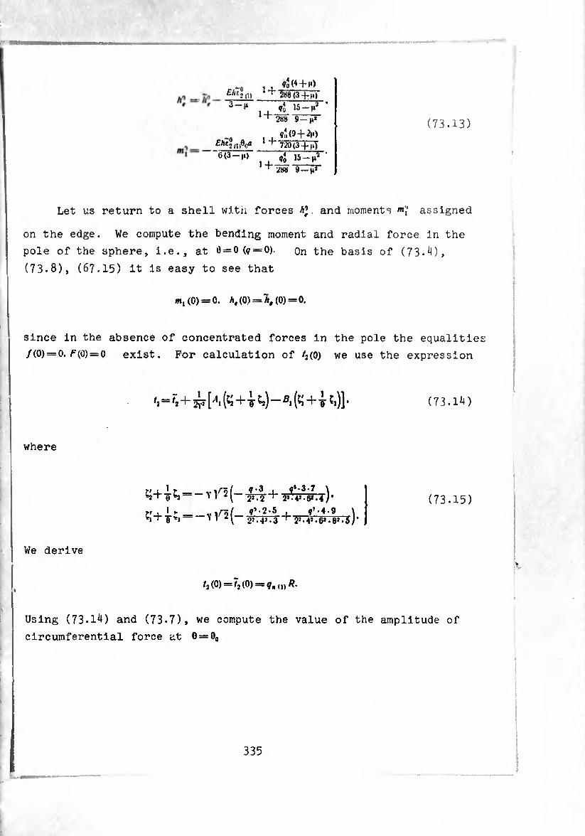
figo, 3—H
£Atj "6(3 —(i)
H
1 +
?2(4 + m) ’ 288(3 + !.)"
ffo 15-|i2 288 9 — n*
. , ¢:,0 + ^) + 7¿0(3-fiQ
, , <lo I5“t*2 '+WTrïïr
(73.13)
Let us return to a shell with forces A’, and moments assigned
on the edge. We compute the bending moment and radial force in the
pole of the sphere, i.e., at 0 = 0(0 = 0). on the basis of (73.4),
(73.8), (67.15) it is easy to see that
m, (0) = 0. A, (0) = A, (0) = 0.
since in the absence of concentrated forces in the pole the equalities
/(0)-0. /7(0) = 0 exist. For calculation of ^(0) we use the expression
*2£i)]*
where
We derive
= ~ V /2(-
= — Y Y2(— y.-p .-g- +
q • 3 FT
0'-37 2». 4». 6*. 4 )• _<?T-4-9 \ i1 • 4* • 61 • 8* • 5 / '
(73.14)
(73.15)
1,(0)=7,(0) q.^R.
Using (73*14) and (73*7), we compute the value of the amplitude of
circumferential force at 0 = Oo
335
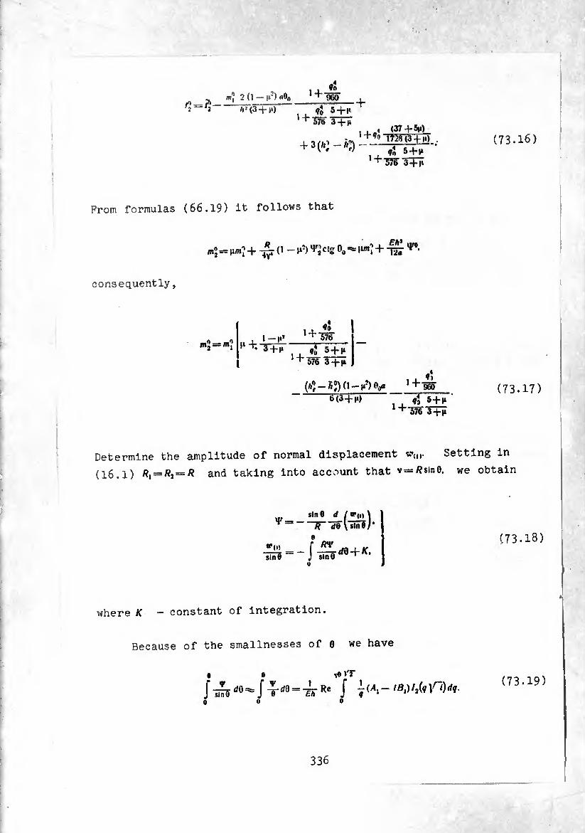
(73.16)
'j ml 2(l-n-) a%
/^(3+7)
1 + «0
960
., ÍÍ 5 + »t ,+3rë J+ïï
, , 4 (37+St» , Tí’S (3 -t- II)
+3K_»3. L±J.
,+3^ 3TÎÎ
From formulas (66.19) it follows that
«s+ ^ ci2 oa ^ |1«Ï+-^^-
consequently,
m2 = m? f‘+. l-l.» 3 -+•>*
1 + io 576
Í + «î 5 + 1» 576 3 + (»
6(3 + n)
» + ♦1 960
1 + Í3 m 5 + 1* 3+1*
(73.17)
Determine the amplitude of normal displacement Setting in
(16.1) R1 = R2 = R and taking into account that v=/*sinO, we obtain
*<i> sind
sin0 d ( W(i* \ “TTTõl sind/’
(73.18)
where K — constant of Integration.
Because of the smallnesses of 6 we have
V0 »T
J "T■¿rRe J jlAi— (¡0
(73.19)
336
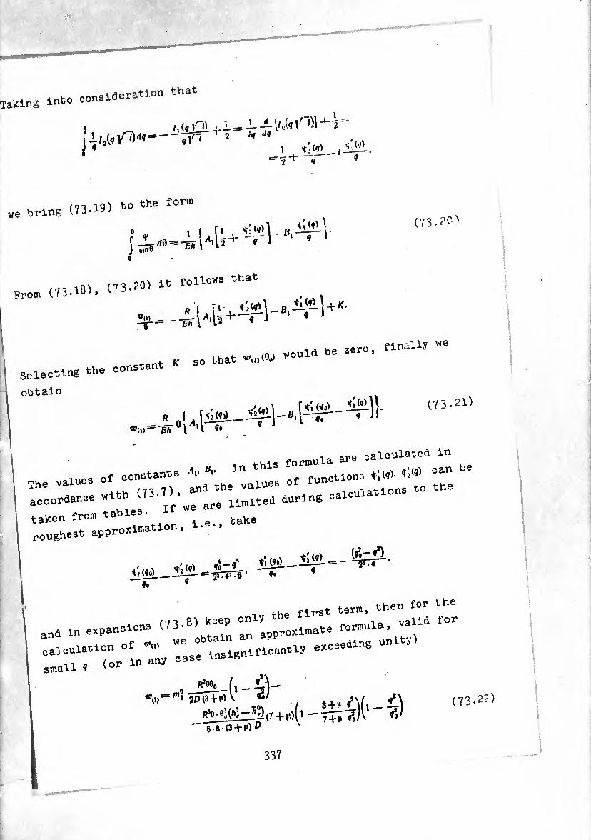
Taking int0 consideration that
« _ /■ (q 4-- = qV'i 2 !
, it\ 19) to the form we bring (73.
J_i- \iSqY iq
\ iUn) — q q
;* « i,lu (73.20^
l8, (73.20) It follows that Prom (73.i°> > v'
» . f / -i
rr
«.. »« r‘“iu ” Selecting the constant *
obtain
* .1, (73.21)
are calculated in
;he values of constants ^8" "functions ^ tS
iccondance with (73.7),^ durlng calculations
taKen from tables. I roughest approximation, 1--.
.,,,. ri-ji íím-íír—^^- it tfo) __-1Í-4--= irrpTe • i* q ~1T ’
_ the first term, then for the /71 Q) keep only ^ne 1 valid for
and in expansions (73- approximate formula,
calculation of «* ° lnsignlfl0antly exceeding un V
small 1 (or « any
IdõVv) _îî?î_(i - 4V 20(3 + ^ V «0/ 3 + ,, t\
(7+1’-)(1 - ^)v «*»' — - “ 7^1 n N
r 7? .22)
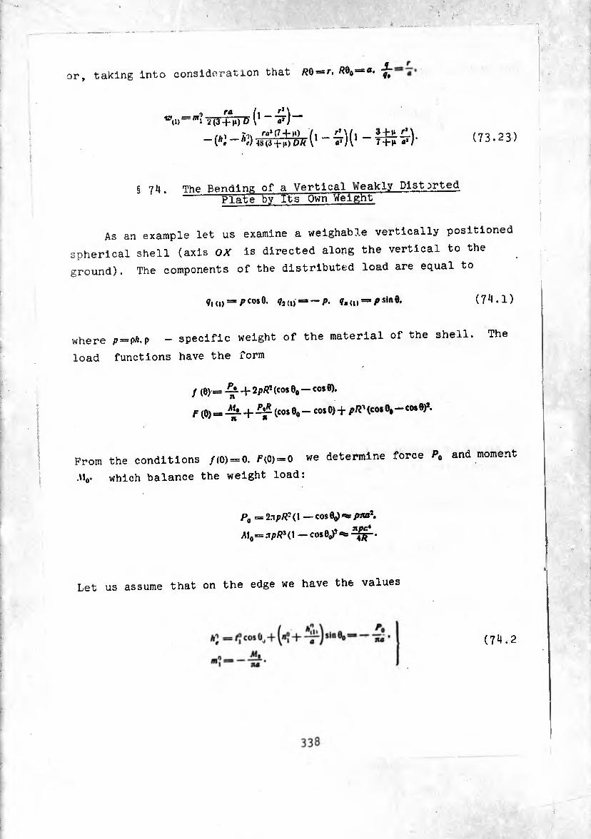
or, taking into considération that /?0 = r. Ä0O=«.
2(3-i-m)0 (1 «’)
-W-*3^Âî('-■&)('- 3+1» £\ 7+h a*)' (73.23)
§ 74. The Bending of a Vertical Weakly Distorted Plate by Its Own Weight
As an example let us examine a weighable vertically positioned
spherical shell (axis OX is directed along the vertical to the
ground). The components of the distributed load are equal to
ç,(1) = pc°sO. ¢,(,,=3-/>. f„(U = />sln9. (74.1)
where p = ph.p - specific weight of the material of the shell. The
load functions have the form
y (e) == + (cos e0 — CO* 0).
f (0) = + (cos 0O — cos 0) + pR' (COS 0,—cos 0)*.
From the conditions /(0) = 0. F(0) = 0 we determine force P0 and moment
.\10. which balance the weight load:
P0 = 2a pR-(\ — cos 0o) =¾ pivP.
M0—XpR3(\ — COS 0o)3 ate
Let us assume that on the edge we have the values
(74.2

These conditions mean that a reaction force on the edge - is
created only because of the radial forces A^cos<p.
2n j A’cosç • cos «fa </ç = — P9 u
and reaction moment M<¡ is created only because of tending moments
«?cos?- From equality (66.2) and conditions (7^.2) it follows that
in this case on the edge the combination of tangential force and
twisting the edge is equal to zero-moment.
and the amplitude of the axial force
(^ + 4)^0-^00 = 0-
Thus, it is necessary to calculate the shell under a load (74.1) and
edge conditions (74.2). In the pole of the shell forces and moments
are equal to zero
(0) = (2 (0) = m, (0) = 0.
Circumferential force and circumferential bending moment in section
e = 0o is computed according to (73-16), (73-17). In this case one
ought to have in mind that in the involved case
pa. hV M'R aa’
Pa 4 K- ■hi¬
nt 0-3, _ pa* TÏÏ <$■ aa* 5
pa = pa.
Taking into consideration that
12(l-nha,e. -4 Rh*
339
ami assuming
we have
i + «2(37 + 51»)
1728(34 M)
VÍ 5 + 1*
fj 22+* '' + mssir-
/0=.-pa [l «2 5-1.1
384 3+hJ* (74.3)
m'i , 1-H*\ , P<? , «2(2-1») 1
““ur 8« T+îrl1 + i440(a+R)J- (74.4)
As a second example let us examine the same shell loaded by
load (74.1), but fixed at the edge. Reaction forces A,' and moments«“
are determined from formulas (73-13). Taking into consideration that
*§<i>==,'¿rJT'(5+,A)*
we obtain
n Ipa (t 5 + 1» «J
]» "2304 )•
m: o__ , . «2(9 + 21»)
pa* 5 + n 720f-1 '-ui
W3irir . . »0 15-.r* + ^588 9 —i»1
(74.5)
(74.6)
The obtained results mean that apart from radial force and bending
moment in the fixed section there also appear-tangential and axial
forces equal to
„ , 2A? , ,n />a(!-|»)T. , 5 + 1» *i + T = ^ ^ = 3 -h 11 + (3 — t»)(l —V) TW.
9o (74.7)
340
I . h\\ ptP m0¡
+ T jcos eo - ^ $in eo = -W -1- T =
/><»*(13 —7n) ( (5 1<) (21 6n — n*) 1
“ 24/?(3-n) 1'(13 —7(1)(9 — ns) 1440J’ (7'4.8)
§ 75• Weakly Distorted Circular Plate with Concentrated Tangential Force and Bending Moment In the Center
In §§ 73 and 7^ we considered a shell not loaded by concentrated
loads In the center. Now let M0*o. l.e.. In the center are
applied concentrated a tangential force and concentrated bending
moment. We will solve the problem approximately by dividing it
in half: 1) the solution to the plane problem, 2) the solution
to the bending problem allowing for the presence of the plane
stressed state [9*0. The correctness of such a solution was already
discussed during analysis of axisymmetric deformation (§ 6*1).
The equations of equilibrium of the plane problem have the form
of
(rti) — “T‘ + <0 f = 0'
+ si ~ ^ + Ÿ2 id r =
Forces V t7, are connected with deformations by Hooke's law
e2‘|> = T^^î —e'—— ^ £a** (75.2)
Deformations are expressed through displacements in the following
manner:
¿»(d _ «(i) + w(i) ei(i) —-5T’> *2(1)— F
rft>(l) «(„ + «>,,) -1)--57-r •
(75.3)
System of equilibriun: equations (75*1) admits a decrease in order
by one unit. Really, from (75.1) it follows that

r ((i ~ si)+/ (0 =* 0. (75.4)
where
f
/(r)satlT+ ¡('"»-Itirfrdr. m (75.5)
r t0 the flrst
<«-) », ln the exP;e:sl50TL ;1 ;:er; equation or
th- they will coincide with (7 , T75 ^ 7 (75.D now we can consider, for example, thL’Jste”' °f
dr (r/l) — t3+sl+qi (i)r =, q.
r (^i *,) ~i~/(r) = 0. (75.6)
~ :: “ ---- --
rtl=y-/w.
rst = V. (75.7)
The elation of continuity of deformations Is derived easily from
dr ("î (1)) — V(1) + e, (I) -I- e, (1), (75.8)
moreover with the aid of (75 2) u- u U5.2) it can be written in forces
¿r ("j ^,)-2(1+^),, _(, _„)(/i +/f)w0 (75.9)
Substituting expressions for forces (7* 7\ v
the equation for determination ^
342
■ ■‘5 . *
d*V . dV
'—0 - M) / (0 - ^ - r [-^ (¾ (,/1) - (1 -fi) ff, (1)r]. (75.10)
Equation (75.10) must be solved under the edge condition
(75.11)
where <? is a given value.
If «¡ = 0. then this implies that total force is realized only
fromU(7i°Mtangentlal f0rCeS ^ the am0Unt °f Whl0h ls sl,nple t0 flnd from (75.4), setting r««,
forces0nditlOR (75'1:L) eaSlly Can be exPressed through function of
V{a)*=V0=:afix+I±. (75.12)
ty ZZT\TT0n We haVe the requirement boundedness of write the solution of equation (75.10) for a particular
form of distributed load Particular
01(1) = 0. 02(1) = -0.
The right side of (75.10) in this instance 1 s equal to
The general solution of (75.10) has the form
Setting C, = o and satisfying edge conaition (75.12), obtain
K-ÍÍ1+V . JLzjI p. Í, » ^ + 4 ITl1 -
(75.13)
(75.14)
343
Hence, taking into account the condition of equilibrium (75.13), we
obtain expressions for forces:
t —¡or (3+i*) p (1_M h ri a »U UJ'
/2==/î‘T' + ï(3 + ^‘^rr + il — ^
'.=<Î7 + Â+<'
(75.15)
In the particular case when concentrated force is absent P.**0,
P0= pna*. under the edge condition
(which corresponds to condition (74.2) for a shell) using formulas
(75.15) obtain
to=*-po. *î*=0. \ (75.16)
/® = — pa. /, (0)-=^(0) = *, (0) = 0. j
Comparing (75.16) with (74.3), it is easy to see that the absolute
value of the amplitude of circumferential stretching forces on the
edge of the shell amounts to (.-4¾) °f ^ ^ ^ a
flat plate. When the edge of the plate Is fixed, the following con
dition should hold
/® — (I/J 0.
I *-
Forces on the edge are equal to
•i (1-1») (75.17)
It is easy to see that the right parts of (75.17) coincide with the
principal problems in (74.5), (74.7). In the last equations members
containing < are the correction to the plane stressed state which
corresponds to consideration of curvature.
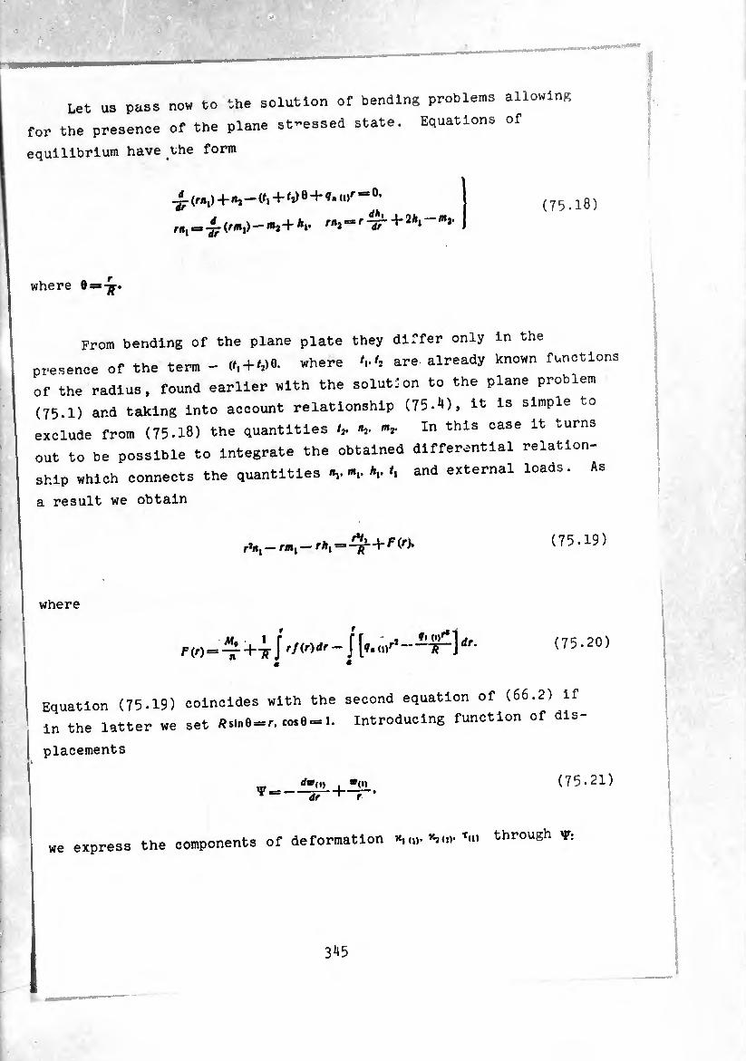
Let us pass now to the solution of bending problems allowing
for the presence of the plane st-essed state. Equations of
equilibrium have the form
where 0> 'IT
(r»») + «a - (/i+ ^ 0 + <,>f “ 0' = m2+Ai. rn^^r -¡f -t* 2Aj «j.
(75.18)
From bending of the plane plate they differ only in the
presence of the term - + where '..'2 are already known functions
of the radius, found earlier with the solution to the plane problem
(75.1) and taking into account relationship (75.4), it is simple to
exclude from (75.18) the quantities /,. «2- In this case it turns
out to be possible to integrate the obtained differential relation¬
ship which connects the quantities A,./, and external loads. As
a result we obtain
r*«, — m, — rA, = + F (r>. (75.19)
where
F(r)> !^rIrf(r)dr ~ Í [*•,,>r* dr' (75.20)
Equation (75.19) coincides with the second equation of (66.2) if
in the latter we set /?sin6 = r. cos0 = 1. Introducing function of dis¬
placements
¿•o, , ®<n dr f-T
(75.21)
we express the components of deformation *, (0. t(I) through V:
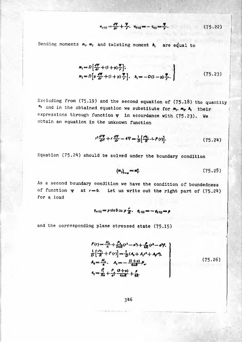
<rv <» — "Sr + T’ K9«i)“'”t(
w (n = 7* (75.22)
Bending moments m,. m2 and twisting moment A, are equal to
= D [£+(1+107.];
*í“0[|*£+(14m)Í-]. A, = -D(1-h)I.. (75.23)
Excluding from (75.19) and the second equation of (75.18) the quantity
and in the obtained equation we substitute for «j. Aj their
expressions through function y in accordance with (75.23). We
obtain an equation in the unknown function
'•£+'£-*■+[++'(4 (75.24)
Equation (75.24) should be solved under the boundary condition
(75.25)
As a second boundary condition we have the condition of boundedness
of function 4/ at /- = 0. Let us write out the right part of (75.24)
for a load
and the corresponding plane stressed state (75.15)
¿-[4 + f<,)] =75^+ V+V5. 0+M) 0
A —‘l I P. . P
(75.26)
346
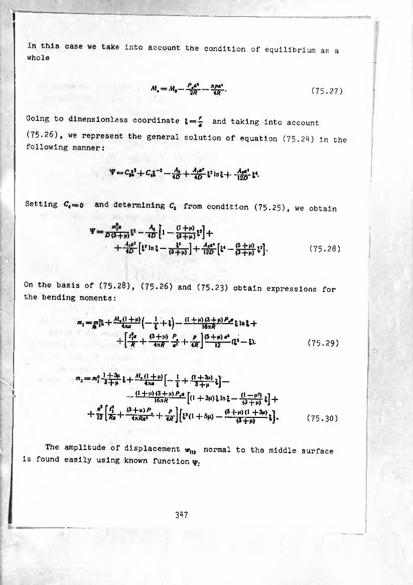
In this case we take into account the condition of equilibrium as a whole
^ apa* ur (75.27)
Going to dimensionless coordinate & = £ and taking into account
(75.26), we represent the general solution of equation (75.24) in the
following manner:
1' = C4,+C.r,-^ + ^i>lni+
Setting C4B=o and determining C, from condition (75.25), we obtain
XU- m?a tJ ^ t, O+M).,!. w-FWTF)1 —4Õ-11 ~ (Thó^JH-
(75.28)
On the basis of (75.28), (75.26) and (75.23) obtain expressions for
the bending moments:
, f/?a , (3 + m> P. , P „ +lir + _E3rii- + -wJ~T5—^ (75.29)
m, == «? 6 + 1 â-t-M 4n« L i + 6j —
(1 +M) (3 + 1») P.a
+ 17(75-
0^(0+3-,1,-1-¾^
1 C..V (5+f)(l +3m).T (75.30)
The amplitude of displacement u»(l, normal to the middle surface
is found easily using known function y.
347

(75.31)
in this case rigid rotation of the plate as a whole is selected in
such a way that w„) it would turn into zero at r = e. Substituting
(75.28) into (75.31) and integrating, we obtain
At />. = m# = o. assuming in (75.28) and (75.29) t=*l. we obtain
expressions for the circumferential bending moment and function y
on the edge of the plate
(75.33
The right side of formulas (75-33) coincide with the principal
terms of the right parts of (73.11), (73.17). Formula (75-32) at
p. = ¿I. = o completely coincides with (73.23). Figure 34 depicts
a normal bend ^ = taking place along the vertical diameter of
a welghable spherical shell, calculated by formula (75.32). On the
lower half of the diameter ® =*wu). 0n the upper half-^= — t»,,,.
The shell had dimensions and load: sin0o ==^ =0.344. 0o=O.351, qt = q = ph.
or
QBaxqa* - general weight of shell.
348
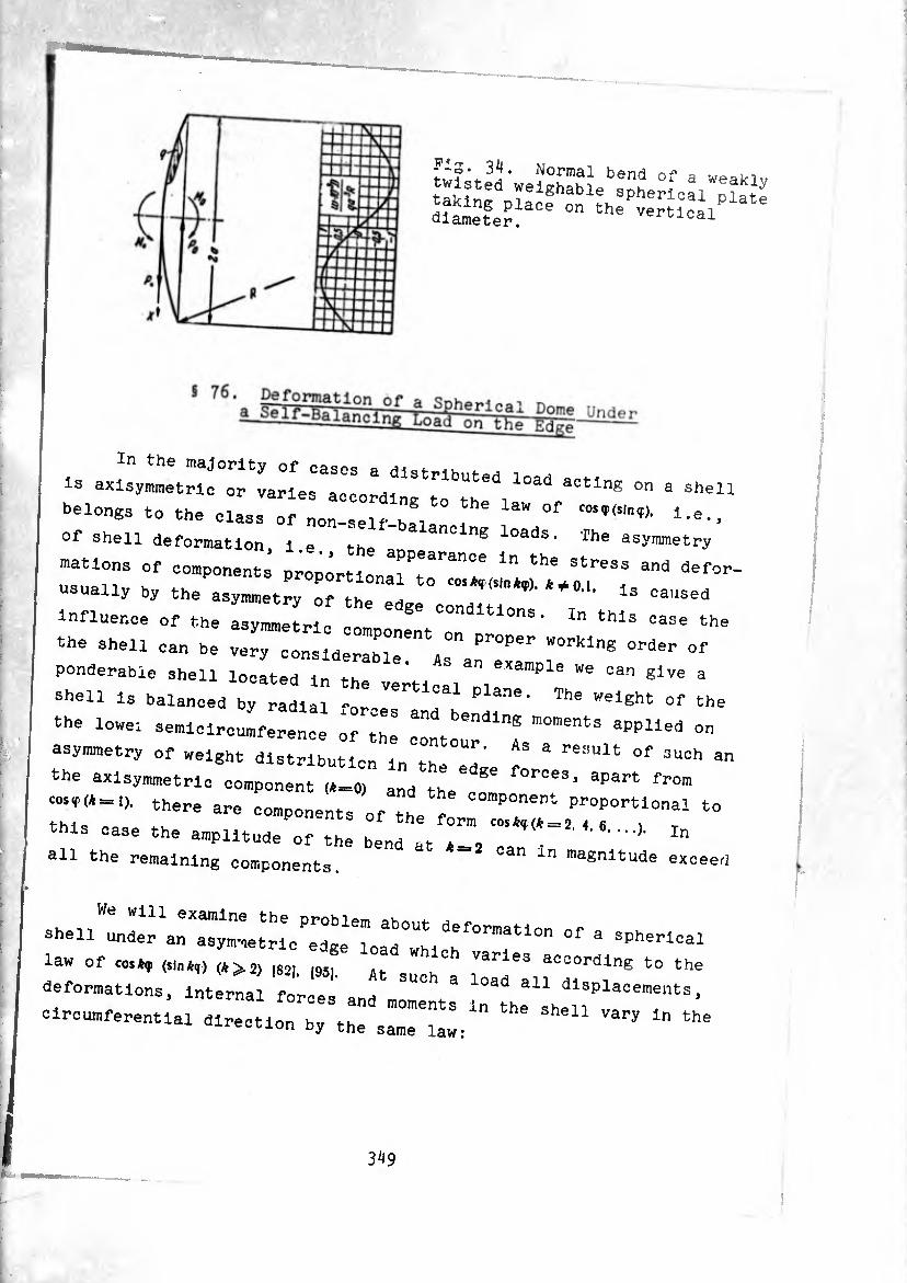
diameter^306 the w«-lPlate
is on a shen
o^r^/irr;^ ^ mations of components proportlonllT^T ^ ^°°° and defcr-
usually by the asymmetry of the eL ' U ^
influence of the asymmetric mp 11 ^ ^ ^
‘he shell can he very consiaeratle A a lir1"® OTder °f ponderable shell located in the vertical Dl ^ °an glVe 3
shell is balanced by radial forces and h a, Welght °f the the lowei semicircumference of the * ^ ^ aPPUed on
asymmetry of weight distribution in^h OUh’ ^ & °f 3UCh an the axisymmetric component (A =,0) and ^ f°rces* aPart from
r- the- - components of the 0^3::::/::°^0^1 " this case the amplitude of the bend • ^ / , C°S*,(*-2- 4’ 6‘ In
all the remaining components. * ** Can ln magnltude exceed
».u«.
law of coskf (sin*,) ,*>2) |82J |95J At su ar eS aocordlng to the
deformations. Internal forces and . ^ * dlsplacements.
circumferential direction by the sameTaw:'" ^
3^9
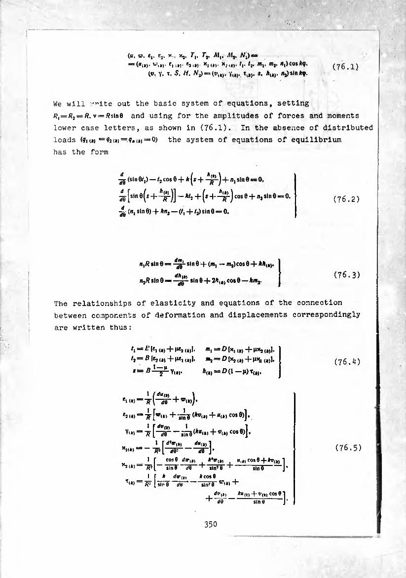
(f!t W, Cp Cjt ^ t Kj, Tt, /"jt fWj* ^|)=a
~(uià)‘ vi»)- tM*>- fii») Xn*)- x¿i*c ^i- ^2- mt' mr ni)cosky, (V. y. *. 5. rt. /Vj)»=(t»u,. YU). tlâ). i. AU). /ij) sin ky.
(76.1)
We will v’^ite out the basic system of equations, setting
/?i = /<2 = R, V = /?sin0 and using for the amplitudes of forces and moments
lower case letters, as shown in (76.1). In the absence of distributed
loads (<¡i (*) — ?2<*) ~?•(*) = 0) the system of equations of equilibrium
has the form
(sin 0q) — /j cos 0 A |s + ~jp~) nisin 0 = 0*
^ ^sin 0^s + ~^)] -^2 + (^ + cos 0 -)- n, sin 0 = 0.
4(, («, sin 0) -)- An, — (/, 4- /,) sin 0 = 0.
(76.2)
«,# sin 0 = sin 0-f-(«, —/»,)cos 0 + AA(j>t
rt,/?sin0: dh (*) sin 0 -)- 2A,4) cos 0 — A/«,.
(76.3)
The relationships of elasticity and equations of the connection
between components of deformation and displacements correspondingly
are written thus :
IE1 I») + 11¾ (*)!•
(*)!•
Y(*j*
m,
*(*)■
!Olxi ! D1¾ i») 4- (*)!•
■D(l —
1 tduw *><*>“-TT\ </e
^ I») Ä "/f [w(*> + + «<*) COS 0)j ,
1 \dvw 1 1
Yi*) [“2S— ¡nr3(*“<»>+’’i*)cos 0)J*
'1(4) j f f/ff(4) 1 "ÄH dV “Wj’
1 f COS0 </»•„, ( A*«’,*, f cos0 4At>(„ ] ^(4)-4- slnj0 H J.
I r * rftr,,,
T<*) TV l sin 0 d\>
4cos0 lïï^5~w<»>
+-d<r-
4-
{4)+0(4) cosO sin 0 ]•
(76.4)
(76.5)
350
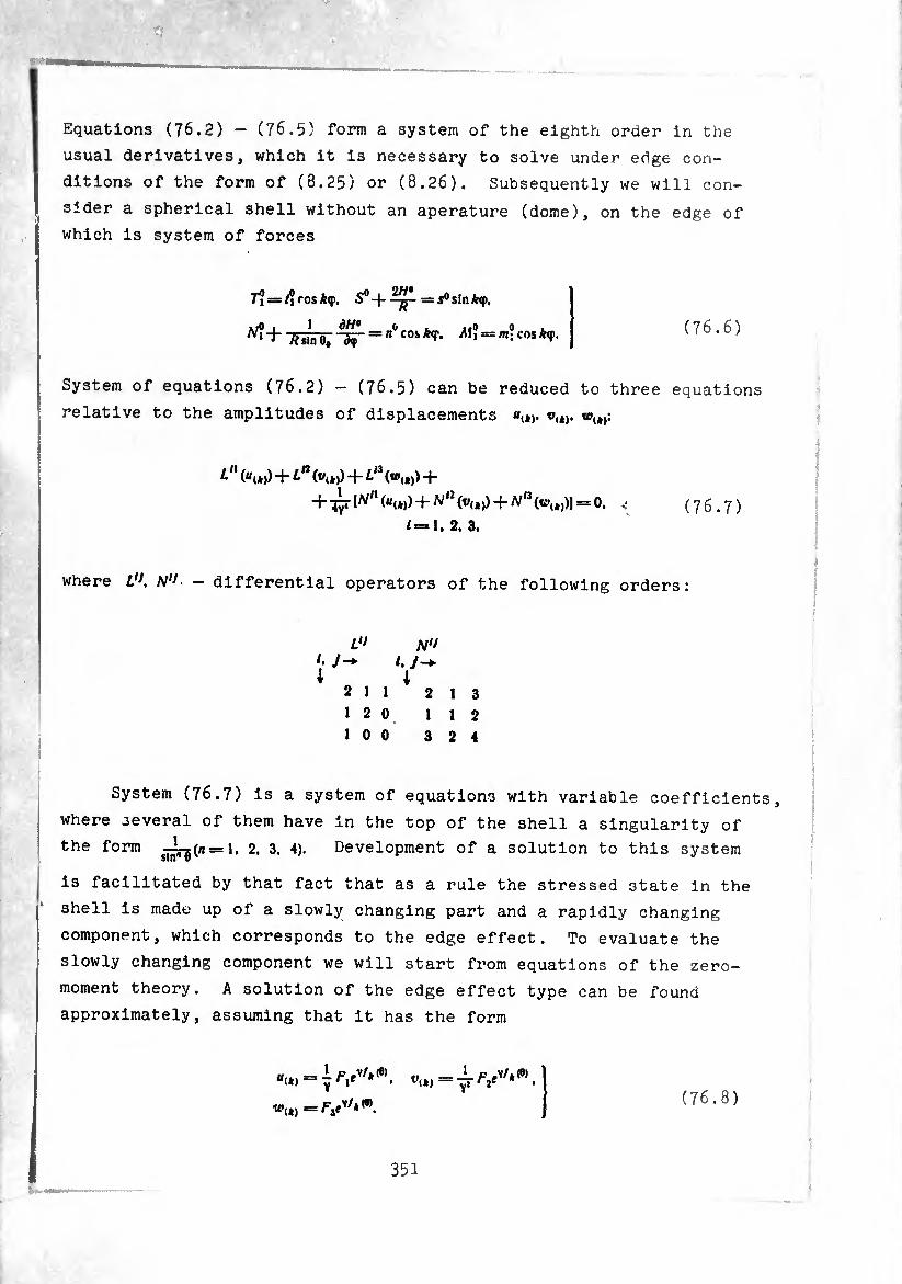
Equations (76.2) - (76.5) form a system of the eighth order in the
usual derivatives, which it is necessary to solve under edge con¬
ditions of the form of (8.25) or (8.26). Subsequently we will con¬
sider a spherical shell without an aperature (dome), on the edge of
which is system of forces
r? = f?ros*q>. = s°sintop.
.,0 , 1 dH9 o . ,.o o . W + TTÜÏÏë; "3ir = n cos M^m‘‘cos *?•
(76.6)
System of equations (76.2) — (76.5) can be reduced to three equations
relative to the amplitudes of displacements t\*j. w(t):
¿<l (ttt*)) + Ln + L13 -|-
l^n (*<»))+Nn -j- N13 = 0. ^ (76.7)
/=1. 2. 3.
where UK N1* - differential operators of the following orders:
U> N‘J i- J-+ i. y-*. i 0 i
2 11 2 13
12 0 112
1 0 0 3 2 4
System (76.7) is a system of equations with variable coefficients,
where several of them have in the top of the shell a singularity of
the form ¿j^rg(«=l. 2. 3. 4). Development of a solution to this system
is facilitated by that fact that as a rule the stressed state in the
shell is made up of a slowly changing part and a rapidly changing
component, which corresponds to the edge effect. To evaluate the
slowly changing component we will start from equations of the zero-
moment theory. A solution of the edge effect type can be found
approximately, assuming that it has the form
«•„, = V'.» (76.8)
351
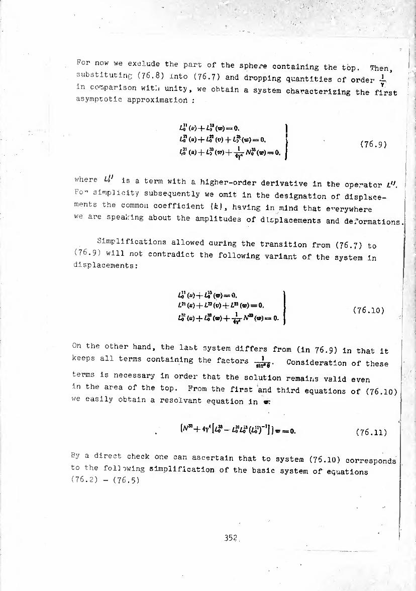
For now we exclude the part of the sphere containing the top. Then,
substituting (76.8) into (76.7) and dropping quantities of order
in comparison with unity, we obtain a system characterizing the first asymptotic approximation :
¿0 (u) -j- ¿J* (w) = 0. J ^(^)4-^(^) + /.^(01)==0. i (n£ r\\
31 33 1 33 I (76.9) 4o («) + /.3 (w) + "^rA/o (tp) = 0, j
where W is a term with a higher-order derivative in the operator Lu.
Fo^ 3lrriP^icity subsequently we omit in the designation of displace¬
ments the common coefficient (fe), having in mind that e-erywhere
we are spealing about the amplitudes of displacements and deformations.
Simplifications allowed auring the transition from (76.7) to
(76.9) will not contradict the following variant of the system in displacements :
41 («) 4-/^(00=0.
¿»(«)+ ^(0) +/.°(t») = 0. frj, . ( /0.10 )
¿3' («)+¿? («)+-¿j- /V" («) = o.
On the other hand, the last system differs from (in 76.9) in that it
keeps all terms containing the factors Consideration of these
terms is necessary in order that the solution remains valid even
in the area of the top. Prom the first and third equations of (76.10) we easily obtain a résolvant equation in vr.
[N* + 4/- tfL? wr'l }®=0. (76.11)
By a direct check one can ascertain that to system (76.10) corresponds
to the following simplification of the basic system of equations (76.2) - (76.5)
352
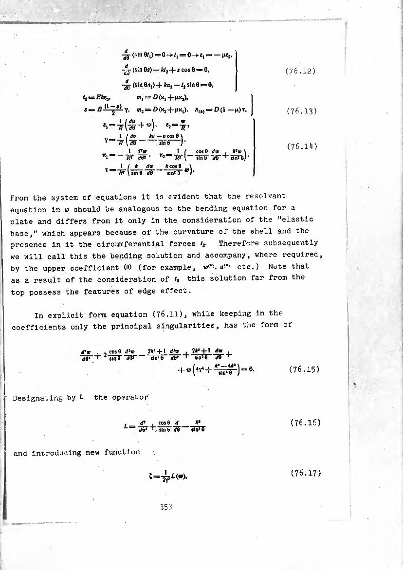
(76.12) -*j (sin 0s) — £/2 + s cos 0 = 0.
(sin0rt,)-f An2 —/2sln0 = O,
t¡ = Ehtj. m, = D (X, + nx,).
S= glL-JÜ-y. ffij^DíXj-f-HX!). A(i) = 0(1 —Ji)t,
\ ( du , \ w
1 I dv *« -j- V cos 8 \ Y==irlw-inre—]•
1 d1» „ _ 1 / cos 0 rftr , *}a> \ x‘— W d& ' sin 8 </r + slnjej'
1 / * rftr *cos8 _\ T — 'SrU‘nö de sin» 3
(76.13)
(76.1^)
Prom the system of equations it Is evident that the résolvant
equation in w should be analogous to the bending equation for a
plate and differs from it only in the consideration of the "elastic
base," which appears because of the curvature of the shell and the
presence in it the circumferential forces /,• Therefore subsequently
we will call this the bending solution and accompany, where required,
by the upper coefficient (“) (for example, u,a> etc.) Note that
as a result of the consideration of t7 this solution far from the
top possess the features of edge effect.
In explicit form equation (76.11), while keeping in the
coefficients only the principal singularities, has the form of
d'w , 0 cos 0 d3w ■¡hF”*' ¿ sme de3
2*» + l d2w . 2** + l dm . sin2 0 dS» ' sin9 8 " "29”
+ w(4v4-' -^ÏÏFT1)”0- (76.15)
Designating by L the operator
f d* i cos 6 d *’ de» ' sin b d0 sln»0
(76.16)
and introducing new function
(76.17)
35:.
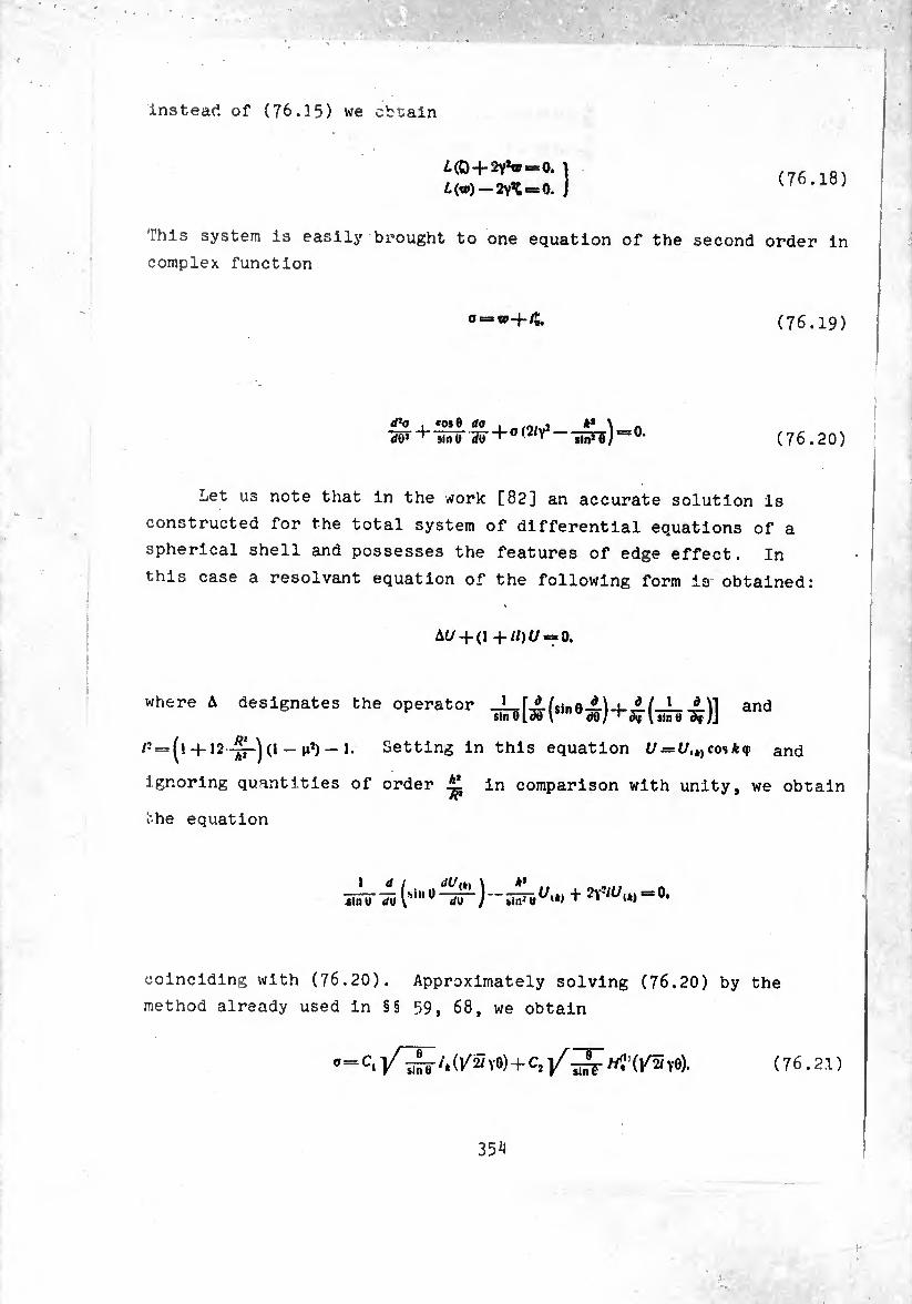
instead of (76.35) we obtain
¿(0 + 2Y*W“0. ï
¿(w)-2Y*t = 0. J (76.18)
This system is easily brought to one equation of the second order in
complex function
o = w+i& (76.19)
rf’o ~d¥
*os8 da sin 0 dti + 0(2/7* «¡ñnu
o. (76.20)
Let us note that in the work [82] an accurate solution is
constructed for the total system of differential equations of a
spherical shell and possesses the features of edge effect. In
this case a résolvant equation of the following form is obtained:
Ai/ 4-(1 -)-//)(/ = 0.
where A designates the operator ^)] and
/3 = (!-f 12-p-j (l - n2) — 1. Setting in this equation U = U,k)cosk<f and
ignoring quantities of order in comparison with unity, we obtain
the equation
1 dl «dU'"\ “'ii «mu </UVS,nü </U /■“«In*«1''*»
= 0.
coinciding with (76.20). Approximately solving (76.20) by the
method already used in §§ 59, 68, we obtain
o — C, /,(/2/ y0) -f )/^//?’(]/2/ Y0). (76.21)
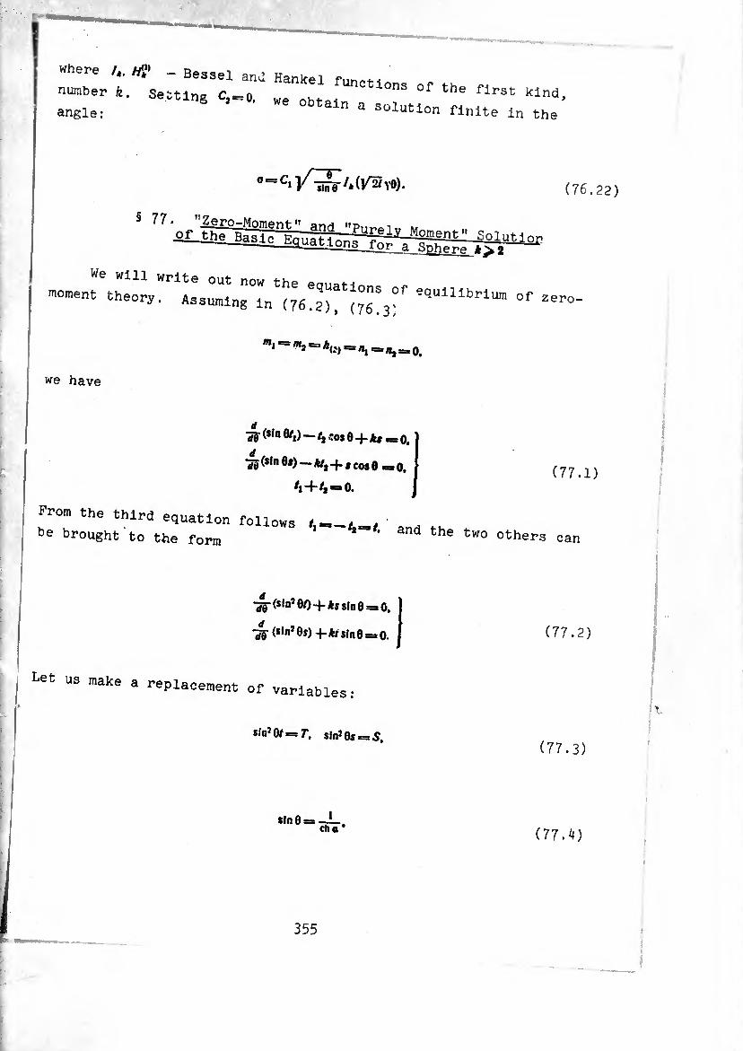
where /*. /yj» _ Bessel and Hankel fnn^-n
number k. Setting C^o. we ob °nS 0f the flrst Kind, angle: n a s°iution finite In the
moment theory. ' ^111^ of
(76.22)
zero-
:«i = 0.
we have
IS ($,n ^l) ~ ^ "OS e -f. 0.
•55($lnes)-.Aya^.tcosg œ0>
4-/1^0.
(77.1)
Prom the third equation follows __
be brought to the form ' and the two others can
-j§- (slns 8Q -f ks sin 6 = 0.
~SS (s*n*®J) 4-*rsln6 = o. (77.2)
Let us make a replacement of variables :
sin3 0/ = T, sin3 0s =, 5, (77.3)
sin0: cha ' (11.k)
355
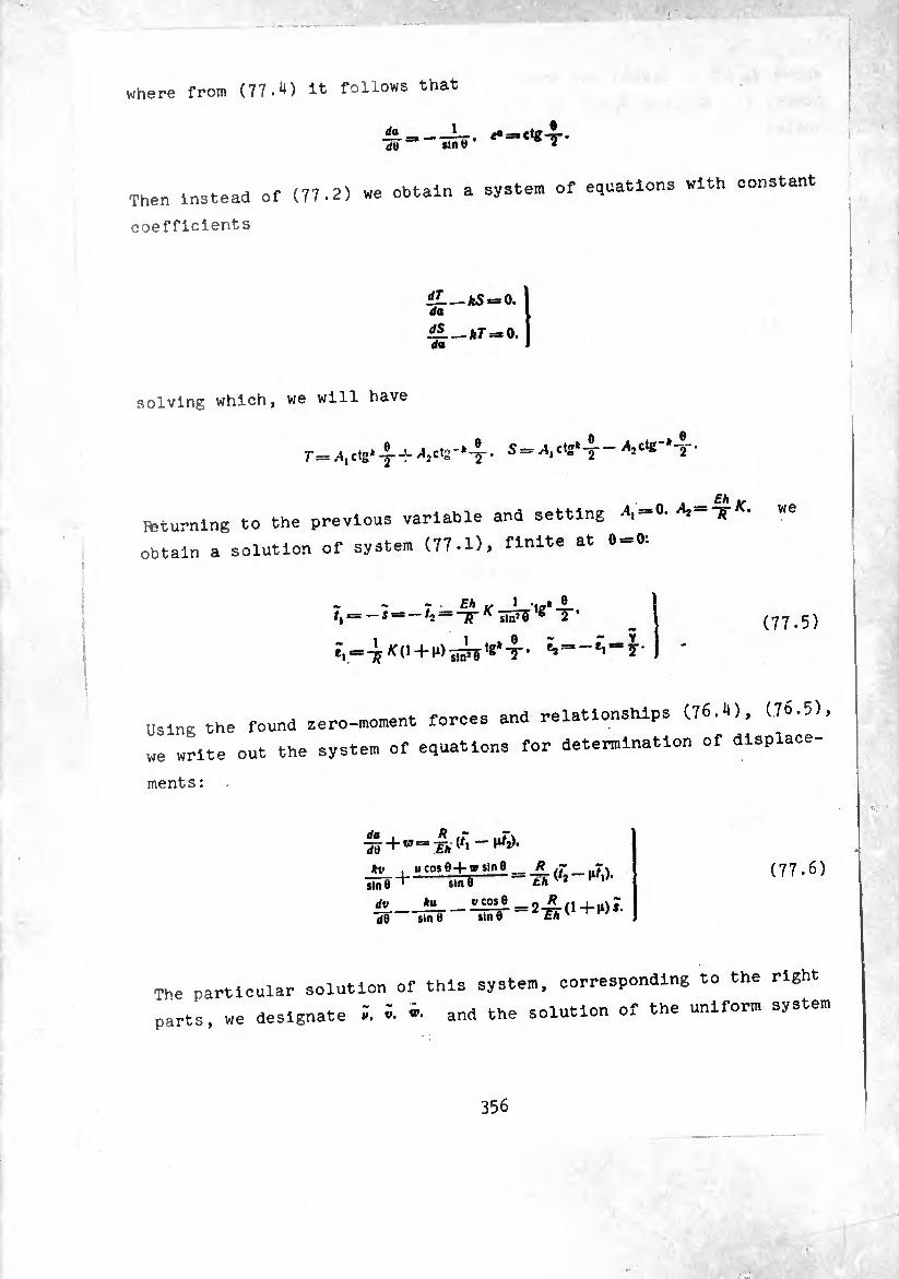
where from (77.^) it follows that
da dO sin U
1 ,
Then instead ef (77.2) we obtain a system of equations with constant
coefficients
£L_as=o. da
da
solving which, we will have
r= .4,ctg* -5--Î- ¿¡¡ctg-*-!' • 5=wí,ctg* 2 ^Ctg 2
a —Eh K Fteturning to the previous variable and setting -4,== . Tp •
obtain a solution of system (77.1), finite at 6 = 0:
—-5 = -7, = ^-^âPî'8* 2 '
7, = -^(1 + 1.)^ **-5- 5,-e"'“5"
(77.5)
Using the found zero-moment forces and relationships (76.1), (.76.5),
we write out the system of equations for determination of displace-
ments:
^ + w==Th{t'-^‘ u cos 8 + tg sin e __ R (f rf),
,me^ slnO ^
dv »«_ dO sin Ü sin 0
Eh
V cos ® __ 2 (1 -(- (i) s.
(77.6)
The particular solution of this system, corresponding to the right
parts, we designate ï. ï. and the solution of the uniform system
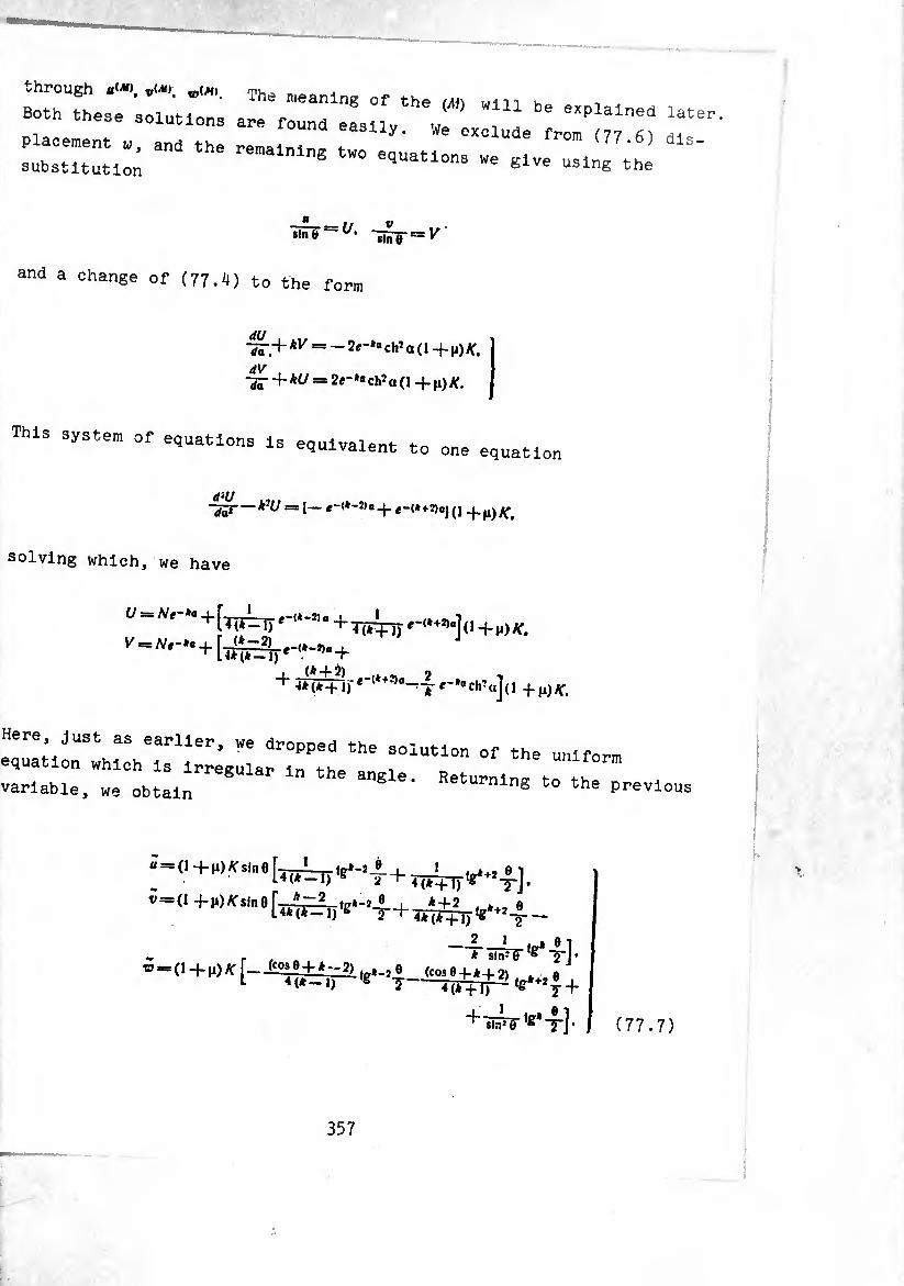
ztzzz .T,z:r.,:rr r - --- >•»
sin ? = i/, slnö = v
and a change of (77.4) to the form
dV -fa- + *i/ = 2,~*. ch* a (1 +\i)K.
This system of equations is equivalent tn equivalent to one equation
d‘U — -J_ e-(*+5)aj (1 + H)
solving which, we have
t/ = ^e“*» + +Wpt—"](i+M)Ar.
+4^)---4--^^,, +|1)^
Here, just as earlier, we dropped the solution of the uniform equation which is irreeular in th= „ , uniform variable, we obtain 6 e' ReturnlnS to the previous
0+M,Ar s,n 9 [70417^-4 + 44^)^-4-] • »=0 +u)^,„a[^,e..^ + TM^_ie„^_
TüPF^t]’ w =
(77.7)
357
U(M) — V(M) = V sin 6 tg* ,
^ =3 ~ cos 0) tg* -|- (77.8)
Displacements (77.8) cause a purely moment stressed state in the
shell, since they satisfy the equations
ei = e, = Y = 0
and to them correspond the zero values of forces. Calculating the
changes in curvatures corresponding to (77.8), we have
on the basis of the relationships the elasticity obtain
(77.9)
Substituting these expressions into (76.3), we are convinced that
In this way, with displacements (77.8) in the shell there exists
a purely moment stressed state. In accordance with this displace¬
ments (77.8) are noted by (AI). Note that, having taken for the
basic displacements (77.8), we made the actual calculation of
deformations and then forces and moments. In this case it turns
out that the equations of statics (76.2) - (76.3) are satisfied.
This means that the quantities with (.11) give an accurate particular
solution of total system of equations (76.2) - (76.5). At *=0.1
a purely moment state in the shell does not appear, since in this instance we have
358
Displacements (77.8) now are the displacements of a solid. Really,
at A = 0
ii<ao = ==Nsin0. ®<*> = — AT cos 0.
Calculating axial displacement, we have
Ai*0 = w(*° cos 0 — b(*° sin 0 ^ — N.
Circumferential displacement
determines the rotation around axis OZ through an angle At
= = —cos 0). ®i^ = — Wsin0.
The amplitudes of axial and radial displacements are equal to
Ai*{i) = — A/sin 0,
Ai*?) = «líf» cos 0 -f- sin 0 = — A^(l —* cos 0).
The displacements themselves along axes OZ and OX are equal to
Ai*l)=»---^vcos<p,
A^*0 = Ai*° cos "9 — v,M' sin<f = — (1 — cos 0) R.
It is easy to see that such displacements appear during the rotation
of the shell as a whole through an angle around axis OK, passing
through the center of the sphere.
Returning to the case of ft>2. we note that finally displace¬
ments of the shell should be calculated as the sum of three displace¬
ments
359
U = «*■> 4- « 4- ulMi,
c-f
w = tO(*> -f-tà-J- W(M)
As already was Indicated, displacements t»(*> are the accurate
particular solution of a system of equations in displacements (76.7).
To them correspond the deformation and forces
fi==ei==Y = 0.
x, = -xî=-t = AJ »(*»-!) sin3 0
m, /»2 —I — O (1-M) /?3 sin3 0
/,=./2==5 = 0. n, = /12 = 0.
(77.10)
Using a static-geometric analogy, we note that there should exist
also an accurate solution of the basic system, possessing the form
xj-x, —T —0. a, — n, =s 0.
(77.11)
Comparing (77-11) and zero-moment solution (77-5), we observe that
the expressions for forces and deformations in them coincide.
Consequently, they can differ from one another only in state•(77.10).
In this way, zero-moment solution for a spherical shell is the second
accurate particular solution of the basic system of equations.
Displacements b(,). are calculated on the basis of solution
(76.22) by the approximate relationships (76..14), (76.13), and
forces and moments satisfy the simplified equations of statics
(76.12). In the left part of the edge conditions (76.6) are the
sum magnitudes from three stressed states — bending, zero-moment and
purely moment — while the solution contains a sufficient number of
arbitrary constants (one complex constant C and two real —K, N) to
satisfy all four edge conditions. Calculation of the flexural
component of the solution does not give rise to doubts when 9 is
sufficiently large. We can verify the contribution of this component
in the general solution when 6 is small. If we calculate on the
basis of (76.22), (76.12)-(76.14) forces and moments of the "flexural
state," using because of the smallness of 0 the following approxi¬
mate equality:
360
WÑYoKe»-*^.
and keep in the zero-moment and purely moment solutions, having
decomposed them preliminarily in a series in powers of 6, also
only the first terms, then it is simple to obtain the corresponding
expressions for forces and moments, valid in the neighborhood of
0^0. On substituting these expressions into the first equation of
equilibrium (76.2) we see that it is satisfied in the main terms
because of the zero-moment solution. The same can be said even
about the second equation. In the third equation of statics the
principal terms will be members which correspond to the f exu'al
solution, while the equation also is satisfied. This fact will
agree with the fact that in the neighborhood of the angle a certain
part of the sphere behaves as a flat plate in which there is a
breakdown of the stressed state into the purely flexural and plane
state. To determine the boundary of this part of the sphere one
could use equation (76.20), from which it follows that upon execution of inequality
-ïïhr»2»1
we can neglect curvature and consider the sphere as a flat plate.
§ 73* Deformation of a Spherical Shell at
Let us examine in more detail the case of ft=2 [92]. On the
basis of (76.22), (76.19) we have
»=(-/(,+«,)/,(, vT). ,=v8VT.
^ “Reo=^ [+, <*>+!+; (9)]+
+ß. [^)-7+»'(*>])• c = Irn 0 = {/4, [fj (q) - i- (¢)] —
For calculation of forces and bending moments on the
(76.12)-(76.1^) we derive the formulas:
(78.1)
basis of (78.I),
361
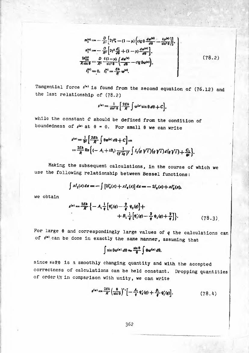
(78.2)
:
"l" f) (C<E «
flf«)—*_® íoyt d+ I ft ..\ du¿a) 1
o i(l-M) /</»<•> \ = -ctg Oto<“)J,
/^ = 0. =
sln’d )]•
Tangential force s<al is found from the second equation of (76.12) and
the last relationship of (78.2)
^^ siiJi f-ÿ?- J +
while the constant C should be defined from the condition of
boundedness of $<«' at 6 = 0. For small 0 we can write
*“’=^[nrje®<',‘,0+c]=
=^R*{(- A.+.BOj^rj /,(, yTIfevTM*//!+£}.
Making the subsequent calculations, in the course of which we
use the following relationship between Bessel functions:
I x/2(x)dx = -j [2/; (X) + x/, (x)J dx = -21, (X)-f x/; (X).
we obtain
,(.. = i« {_ ± [t; (,) _ A (,)]+
+ (78.3,
For large 0 and correspondingly large values of q the calculations can
of ««"» can be done in exactly the same manner, assuming that
f sin f 0w(,></0,
since sinO.'O is a smoothly changing quantity and with the accepted
correctness of calculations can be held constant. Dropping quantities
of order 1/v in comparison with unity, we can write
/jLy>r_A (wê + TrM ’ (78.4)
362
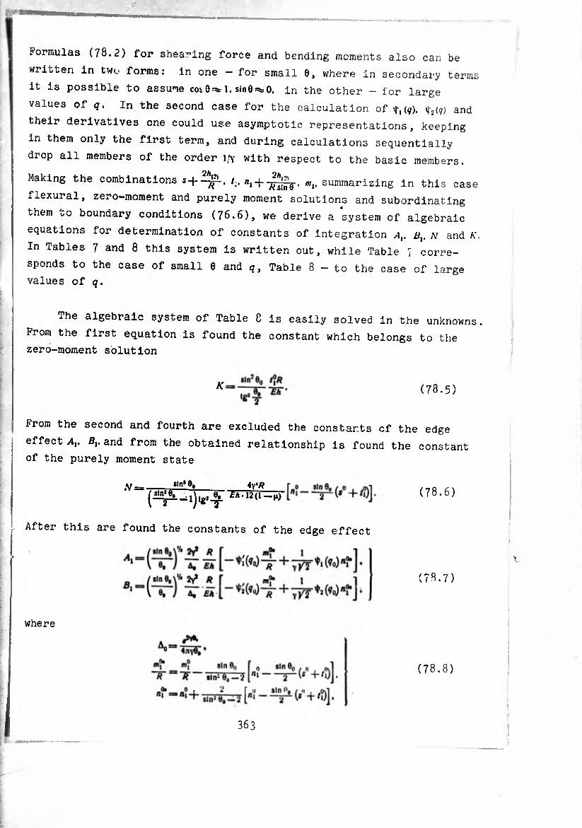
Formulas (78.2) for shea-ing force and bending moments also can be
written in two forms: in one - for small 6, where in secondary terms
it is possible to assume coi0¾ 1. sinO^O. in the other - for large
values of q. In the second case for the calculation of ^(¢). i2(q) and
their derivatives one could use asymptotic representations, keeping
in them only the first term, and during calculations sequentially
drop all members of the order l/Y with respect to the basic members.
Making the combinations 4 + /., /»,-f . m¡, summarizing in this case
flexural, zero-moment and purely moment solutions and subordinating
them to boundary conditions (76.6), we derive a system of algebraic
equations for determination of constants of integration ax, bv N and K.
In Tables 7 and 8 this system is written out, while Table 7 corre¬
sponds to the case of small 0 and q. Table 8 - to the case of large
values of q.
The algebraic system of Table C is easily solved in the unknowns.
From the first equation is found the constant which belongs to the
zero-moment solution
K (78.5)
From the second and fourth are excluded the constants of the edge
effect Av Bv and from the obtained relationship is found the constant
of the purely moment state
.V = «In' 9. 4y«/?
w-ud-i.)
After this are found the constants of the edge effect
(78.6)
(78.7)
where
(78.8)
363
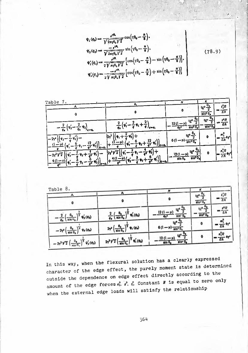
V?o)077¿ ■ cos (yÖo-t)*
*:W“2-7Ä^W^-t)- sin -J-sin
(v%-t)]'
[yQo —t)]
(78.9)
Table 7. A,_
0
_ a,_
0
_N
0
-üT
K
tg’-Sf
sin» 00 0o I
t'lR =mr
-£1^—i*’),-..
ti»*-f 12U-l‘) h ¿ ««‘T
s“W “"ET
— ‘ 4v‘ sin* 0,, sln'Ool
it [ («I+4^)+ tg*4
slnJ0o 0
m'i
q \ ' <i 1
[(*;-{«»+•£*')- tgi
12(1-n) e 2 — sin 0, Sin'll
0 lih Y
this way, when the flexural solution has a clearly expressed
aracter of the edge effect, the purely moment state Is determln
tside the dependence on edge effect directly according to the
ount of the edge forces»!. /. -!• Constant * is equal to zero on y
.en the external edge loads will satisfy the relationship
5611
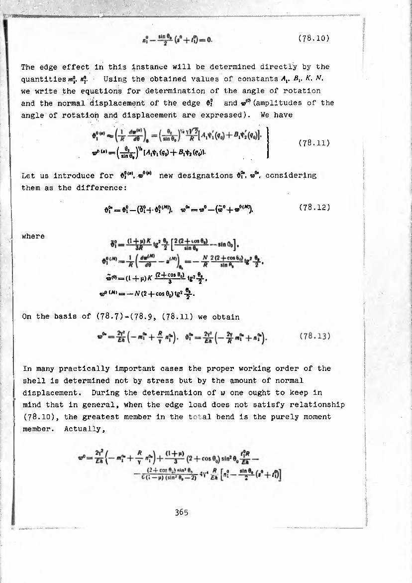
(78.10)
The edge effect in this instance will be determined directly by the
quantitiesni- Using the obtained values of constants Bt. K. N.
we write the equations for determination of the angle of rotation
and the normal displacement of the edge 6? and «/0) (amplitudes of the
angle of rotation and displacement are expressed). We have
(78.11)
(-¡¡yA <?o)+(?o»
Let us introduce for O?"0, w01“* new designations df. w0*. considering
them as the difference:
(78.12) t»0*■= «0—(v°-fw0,Ä)).
where
¿(0)=(1-f^) a: tgj .
(^) = — N(2 cos Oq) lg2 4r-* — A/ (2 -j- cos Oq) tg2 -y-.
On the basis of (78.7)-(78.9, (78.11) we obtain
In many practically important cases the proper working order of the
shell is determined not by stress but by the amount of normal
displacement. During the determination of w one ought to keep in
mind that in general, when the edge load does not satisfy relationship
(78.10), the greatest member in the total bend is the purely moment
member. Actually,
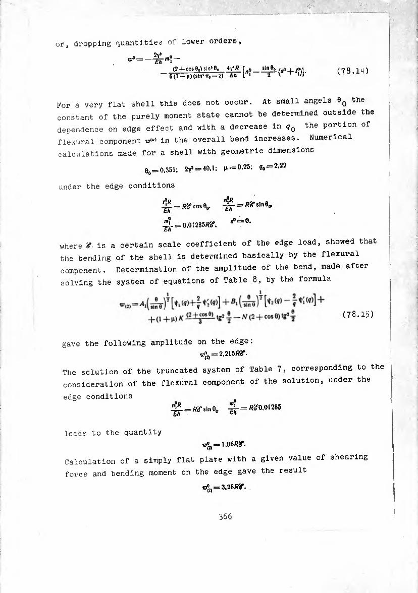
or, dropping quantities of lower orders,
w° ~ ' ith m° ~~ (24-cose0)sin50O [«o sin®o_l #o\i 6(1—m) (s!n' o»—~tir[ni—r-r+/>)l- (78.14)
For a very flat shell this does not occur. At small angels 60 the
constant of the purely moment state cannot be determined outside the
dependence on edge effect and with a decrease in (Jq the portion of
flexural component zv,u) in the overall bend increases. Numerical
calculations made for a shell with geometric dimensions
e0 = 0.351; 2yî = 40.1; 0.25; 70 = 2.22
under the edge conditions
^ = ^ cos e0. = W s*n®o*
^- = 0.01285^.
where '<f is a certain scale coefficient of the edge load, showed that
the bending of the shell is determined basically by the flexural
component. Determination of the amplitude of the bend, made after
solving the system of equations of Table 8, by the formula
gave the following amplitude on the edge:
«,^ = 2.215/??. (2)
The solution of the truncated system of Table 7, corresponding to the
consideration of the flexural component of the solution, under the
edge conditions
^- = ^0.01285
leads to the quantity
w^=1.96RSr.
Calculation of a simply flat plate with a given value of shearing
force and bending moment on the edge gave the result
cf2) = 3.28/?ír.
366
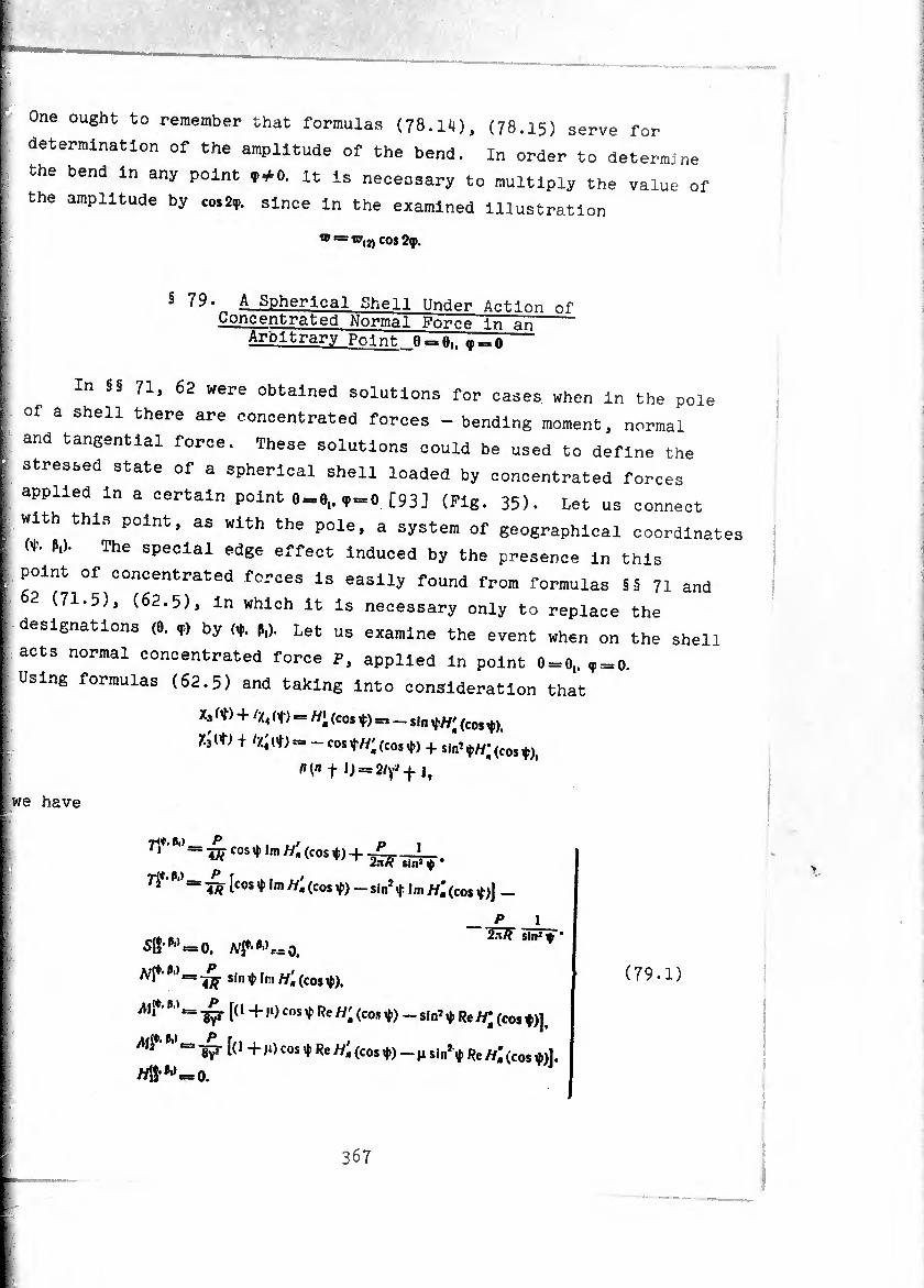
One ought to remember that formulas (78.14), (78.15) serve for
determination of the amplitude of the bend. In order to determine
the bend In any point **<>. It Is necessary to multiply the value of
the amplitude by co.29. since In the examined Illustration
W = W, J, cos 2<p.
§ 79• A Spherical Shell Under Action of Concentrated Normal Force In an
Arbitrary Po-int ,,,= 0
In §§ 71, 62 were obtained solutions for cases when In the pole
of a shell there are concentrated forces - bending moment, normal
and tangential force. These solutions could be used to define the
stressed state of a spherical shell loaded by concentrated forces
applied in a certain point 0 = 0,. «p = 0 [93] (Pig. 35). Let us connect
with this point, as with the pole, a system of geographical coordinates
(¢. P,). The special edge effect induced by the presence in this
point of concentrated forces is easily found from formulas §5 71 and
2 (71.5), (62.5), in which it is necessary only to replace the
designations (0. q>) by (¢. ß,). Let us examine the event when on the shell
acts normal concentrated force F, applied in point 0 = 0,. ¢ = 0.
Using formulas (62.5) and taking into consideration that
X3 W + 'X< (t) = (cos if) = - sin if//' (cos $),
*3 + % It) = - cos (cos $) + sin* $//; (Cos $),
n\n -f- 1) = 2/y* $- l,
we have
^ P'> ~ cos tlm H', (cos $) -f- -JL —? ** 2nR sin1 $ *
Tf’p,> = ^ [cos $ Im hi', (cos $) - sin* $ lm //' (cos $)] —
P 1 2:i/? sin1 $ *
Sl$,Ai = 0. A^’w=0.
P,) ~Tr sin*,m (cos $).
P,) *= -g^- i( 1 +11)cos v Re H'. (cos $) - sin* $ Re //* (cos $)],
M?‘ P',E= ^ cos $ Re H'. (cos $)-^ sin’ $ Re H'. (cos $)1.
(79.1)
367
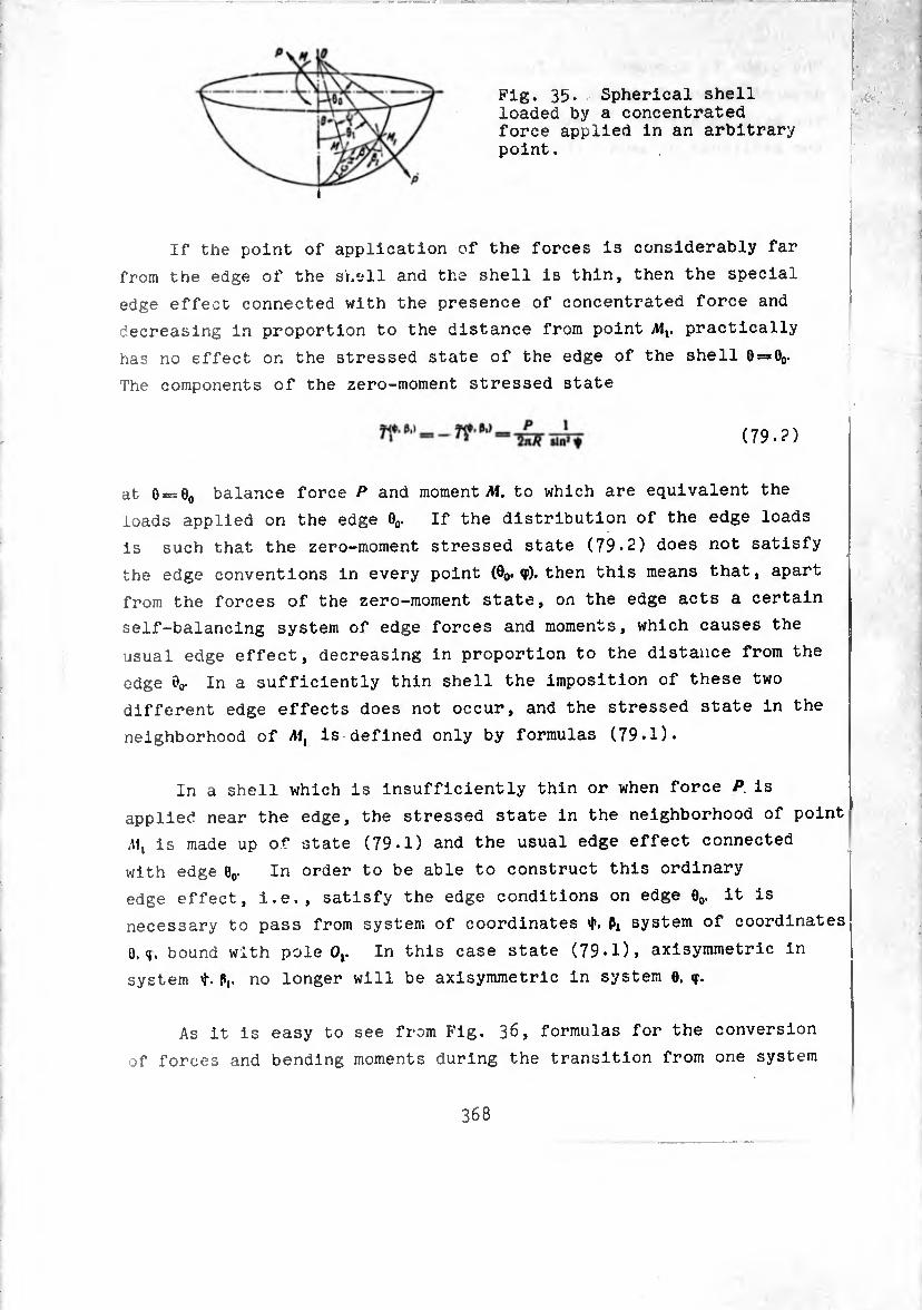
Fig« 35« Spherical shell loaded by a concentrated force applied in an arbitrary point.
If the point of application of the forces is considerably far
from the edge of the snell and the shell is thin, then the special
edge effect connected with the presence of concentrated force and
decreasing in proportion to the distance from point AI,, practically
has no effect on the stressed state of the edge of the shell 0 = Oo.
The components of the zero-moment stressed state
(79.?)
at 0 = 0O balance force P and moment AI. to which are equivalent the
loads applied on the edge 0O. If the distribution of the edge loads
is such that the zero-moment stressed state (79.2) does not satisfy
the edge conventions in every point (0o* V). then this means that, apart
from the forces of the zero-moment state, on the edge acts a certain
self-balancing system of edge forces and moments, which causes the
usual edge effect, decreasing in proportion to the distance from the
edge 0Q- In a sufficiently thin shell the imposition of these two
different edge effects does not occur, and the stressed state in the
neighborhood of AI, is defined only by formulas (79.1).
In a shell which is insufficiently thin or when force P is
applied near the edge, the stressed state in the neighborhood of point
is made up of state (79.1) and the usual edge effect connected
with edge 0O. In order to be able to construct this ordinary
edge effect, i.e., satisfy the edge conditions on edge 0o. it is
necessary to pass from system of coordinates Pi system of coordinates
O.q. bound with pole 0,. In this case state (79-1), axisymmetric in
system Pi- no longer will be axisymmetric in system 0. <f.
As it is easy to see from Fig. 36, formulas for the conversion
of forces and bending moments during the transition from one system
368
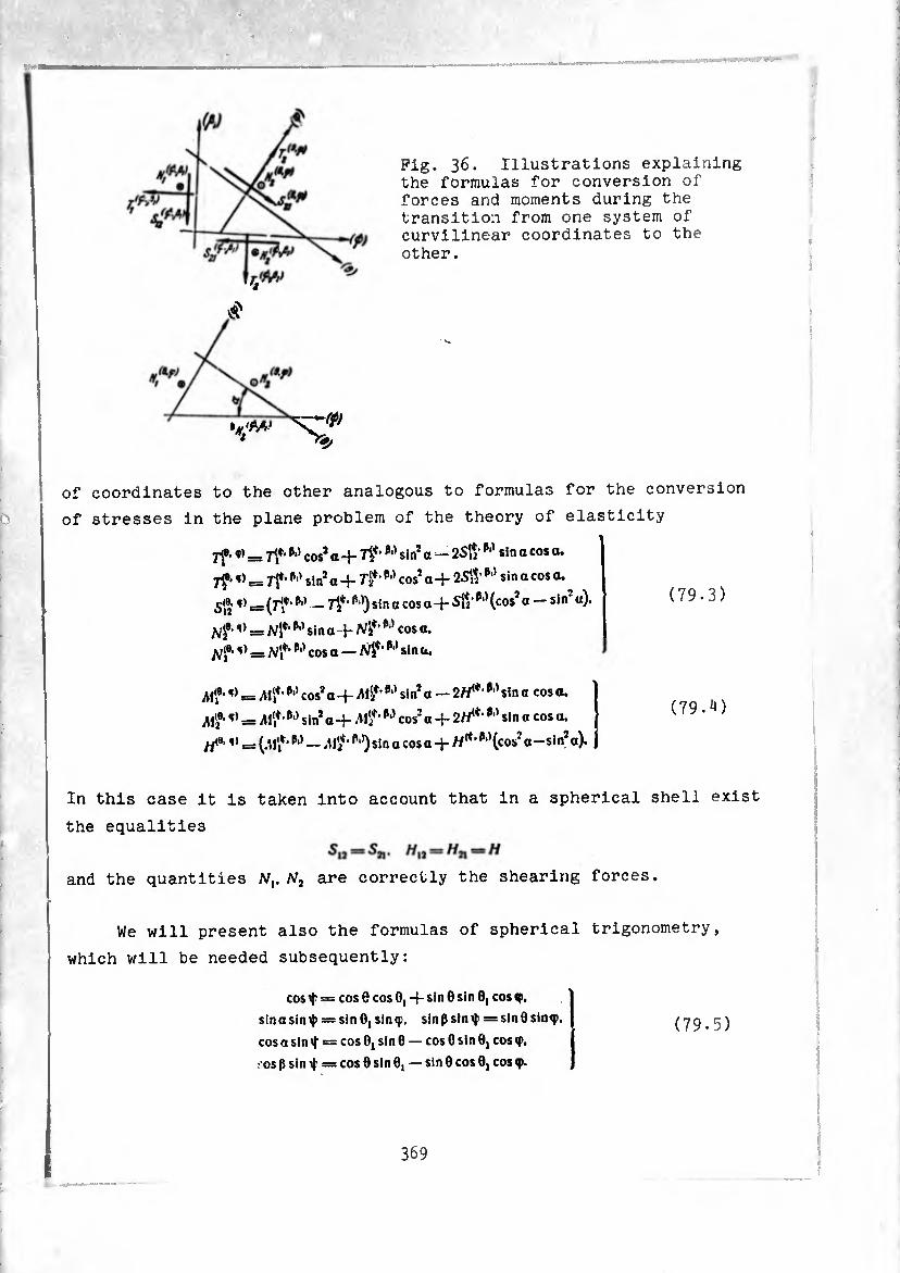
Pig. 36. Illustrations explaining the formulas for conversion of forces and moments during the transition from one system of curvilinear coordinates to the other.
.„■w sr«*' *
of coordinates to the other analogous to formulas for the conversion
of stresses in the plane problem of the theory of elasticity
7f ■ = 7?1 w cos* a + 7f’p,) sin* a — 25¾1 w sin a cos 0.
7f• = 7f*pl) sin* a -f 7f’cos* a -f 25¾1 ^11 sin a cos a.
Sj®1 ,) = (rîf*Pl> — p‘)) sin a cos a + Su W (cos 0 sin u)
Hf-V r= Ni*1 p,) sin a+M*’M cos a. s) __ P‘' cos o _ N$‘w sin a.
iUlf ■ = ¿l',*’p,) cos* a + itl?’ P'* sin* a — 2H(t> sin a cos a.
¿I'®-,) = iM',*’ P1' sin*a + ^1*/’ P“’ cos* 0 4- 2^*' P'1 sin a cos a.
/y<®; = (.Mf1 P*’ — P*’) sin a cos a + W*' P'^cos* o-sin’a).
In this case it is taken into account that in a spherical shell exist
the equalities
and the quantities Nv N2 are correctly the shearing forces.
We will present also the formulas of spherical trigonometry,
which will be needed subsequently:
cos = cos 8 cos 0, -j- sin 0 sin 0, cos
sinasiniji = sin 0, sinç. sinß sin>l> = sin8sinip. (79.5) cos a sin ^ = cos 0, sin 0 — cos 0 sin 0, cos <p,
• os ß sin if = cos 0 sin 0, — sin 0 cos 0, cos 9.
369
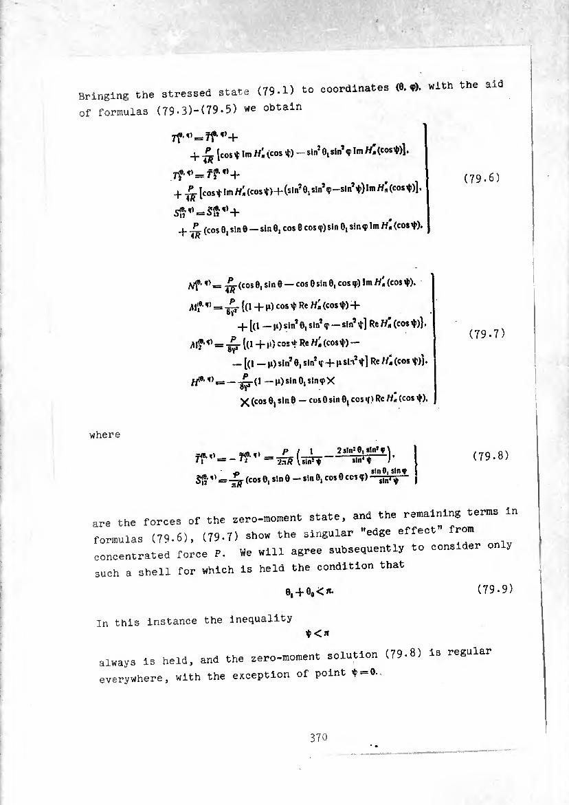
Bringing the stressed state (79-1) to coordinates <«.?). with the aid
of formulas (79-3)-(79-5) we obtain
+ [cosi 1m Wiícos Í) - sin*OjSin*<p I in Tí» (cos
7f^=f?'T,+
+ [cos^ !m/fi (cos t)+(sin? 0, sln,<P-sin^),,n W-^05^1
5»f)05§t)+
_L L (cos 0, Sin 0 — sin 0, cos 0 cos <r) sin 0, sin <p Im (cos¢), 4a
(79-6)
(cos 0, si n 0 — cos 0 sin 0, cos ç) Im Wi (cos ¢). 4a
^ = {(i -f Ji) cos Í Re W« (cos ¢) +
—^sin^sin*«!' —sln’rf] Re«»(cos¢)).
M? " = -£r Í(1 + »O cos tRe H- (cos^ —
_ [(1 _ j!) sin* 0, sin*<f + i‘ Re H» (cos 'f)!*
/Z0’T, = —-^-(1 — ii)sinO,sin«rX
X (cos 0j sin 0 — cos 0 sin 0j cos »( i Re «* (cos ¢),
(79-7)
where
f<e.o_f?«* 71 = - 'i IñT? Vsin5
2sln50| sin5 T \ ^ sin4 i /
sinOi slny = (cos 0, sin 0 - sin 0, cos 0 cos ç) sln, $— ,
(79-8)
are the forces of the zero-moment state, and the remaining terms in
formulas (79-6), (79-7) show the singular "edge effect" from
concentrated force P. We will agree subsequently to consider
such a shell for which Is held the condition that
e, + 0o<*- (79-9)
In this instance the inequality $ <ji
always is held, and the zero-moment solution (79-8) is regular
everywhere, with the exception of point ¢ = 0.
370 • •
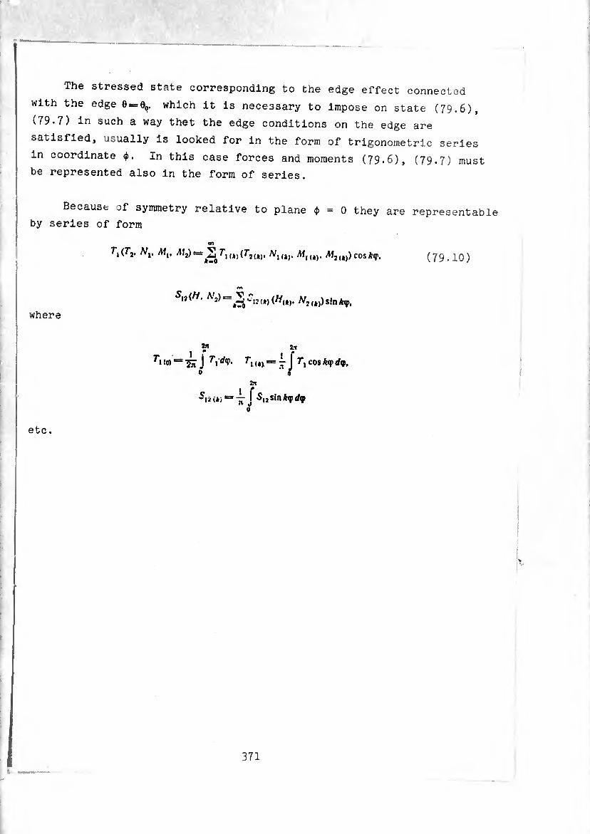
The stressed state corresponding to the edge effect connected
with the edge 0 = 0O. which it is necessary to impose on state (79.6),
(79*7) in such a way thet the edge conditions on the edge are
satisfied, usually is looked for in the form of trigonometric series
in coordinate ¢. In this case forces and moments (79.6), (79.7) must
be represented also in the form of series.
Because of symmetry relative to plane ¢=0 they are representable
by series of form
on
Ti(r2’ Mv ^2)= (f2(*). N|<*). Af2(4)) cosAip. (79.10)
on
where
T\ (0) = ^ J T\ dtV- T'i (*v = j J f, cos Af rf<p. 0 ‘ 0
2a
su U> = ^-,1 5,2 sin A<p </9 0
etc.
371
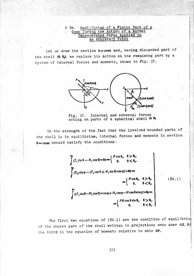
§ 80. ' Equilibrium of a Finite Part of a Dome During the Action of a Normal
Concentrated Force Applied In an Arbitrary Point
Let us draw the section 0 —const and, having discarded part of
the shell (0. 6o). we replace its action on the remaining part by a
system of internal forces and moments, shown in Fig. 37-
Fig'. 37. Internal and external forces acting on parts of a spherical shell (¾ ®)-
On the strength of the fact that the involved bounded parts of
the shell is in equilibrium, internal forces and moments in section
Q_const should satisfy the conditions.
iP cos 6,. 0>01. jV, Sin 0-N, COS 0i Q<ei,
1«
J |S„ sinq> — (7*, cos 0 + N, sin 0) cos <pl v dq> -
f P sin 0,. 0 > 0(. t 0. 0 < 0j.
in f i(r,sln0—N, cosO)vcosç+v1I,cos«p—Wcos0sin(f]v</<p=
0 f pp cos Osin 0,. 0>0i.
0. 0<0,.
(80.1)
The first two equations of (80.1) are the condition of equilibria
of the chosen part of the shell written in projections onto axes OZ. O;
the third is the equation of moments relative to axis OK.
372
Taking into account expansion (79.10), from (8o.l ) we obtai n
(o)sin 0 — NU0) cos 0 Pcos0,
■ °>0|.
0- 0<0,.
Ti (I) cos 0 -f w, (I) sin 0 - (I) = Pslnô, xR sin 0 ’ 0 > 01-
°- 0 < 0,. (N,(l) cos 0 — 7*1,,, sin 0) V - Mt (1) -j. H(l) cos 0 =
_ P cos 6 sin 8, ñ sin 8 '
0. 0>0,.
0<O,.
(80.2)
It Is easy to show that conditions (80.2) should satisfy the zero
I™ "t Part of the solution ta.en individually. i.e.. aí any »the • following should be valid:
(0) s*n 0 —
/,d,sin 0 • v =
Pcos 8, 2n/?sind ’ 8 > “i»
«<»cos0-S,t(I)Ä
0- 0 < 0,. Pslndi nÄsinG
0. _ Pcos G sin 8,
nsin8 '
0.
0 > 0,.
0< 0,.
0 > 0,.
O<0,.
(80.3)
This means that the remaining part of the solatia », u , (79 6) (70 71 w. V. olution, which is equations a self bala'^1 corresponds to a special edge effect, is-
Slice t"ir ?Vtre35ed State’ Phy8lcally thl= 13 completely clear from the -oi-t nr e^effe0t fa(ies ln Proportion to the distance rom tne point of application of force and cannot take part in
providing equilibrium of finite shpii oio far from 0 TM* e . ^ 8 is considerably
,• his fact may also be formally verified. Por example comparing the expression (T ici Q », example, and taw no- i 4- ( 0> r*<o>)sin9-^ito)co*0. using (79.5) and (79.6) and taking into consideration that '
-Hn (cos S) _ dH,, (cos t) d (cos t) , df d (cos V) dÿ— = — sin 0 sin 0, sin <fHn (cos ¢).
373
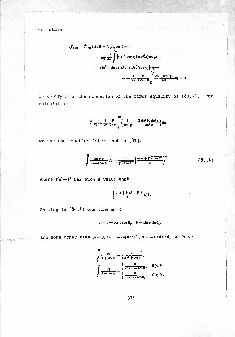
we obtain
(Tuq) ^*1 (0))5^0 A/, (O)COS0 — it
= l¿r W J isin 01 cos TI,n icos V) “ 0
— siif 0,5*110sin2ç lm//ü (cos=
= _f *2:,<i{cos*±d<t = 0. Tin 4/7 sin 9 J dv* w
o
We verify also the execution of the first equality of (80.3!
calculation
2jv 2slnJ0, sin1 q>
sin’^ sin4i|i )</,
we use the equation introduced in [8l].
f COS my . _ -1 (-a + Va>-b*\m J a-|-icos y J'o2 —i* \ b J
where Ytf — b* has such a value that
-a-fra’-*1 <!•
Setting in (80.4) one time m = 0.
c = 1-(-cos 0 cos 0,. ¿i = sin 6 sin 0,,
aird some other time m = 0. û = 1 —cosOcosO,. £ = —sinOsInO,, we have
f d<f _ n J 1 -(-cosy cos8-fcos0, *
r dw COS 0,-0050 * 0>e‘* J i — cos y
COS 0 — COS 0i ’
For
(80.4)
0<o,.
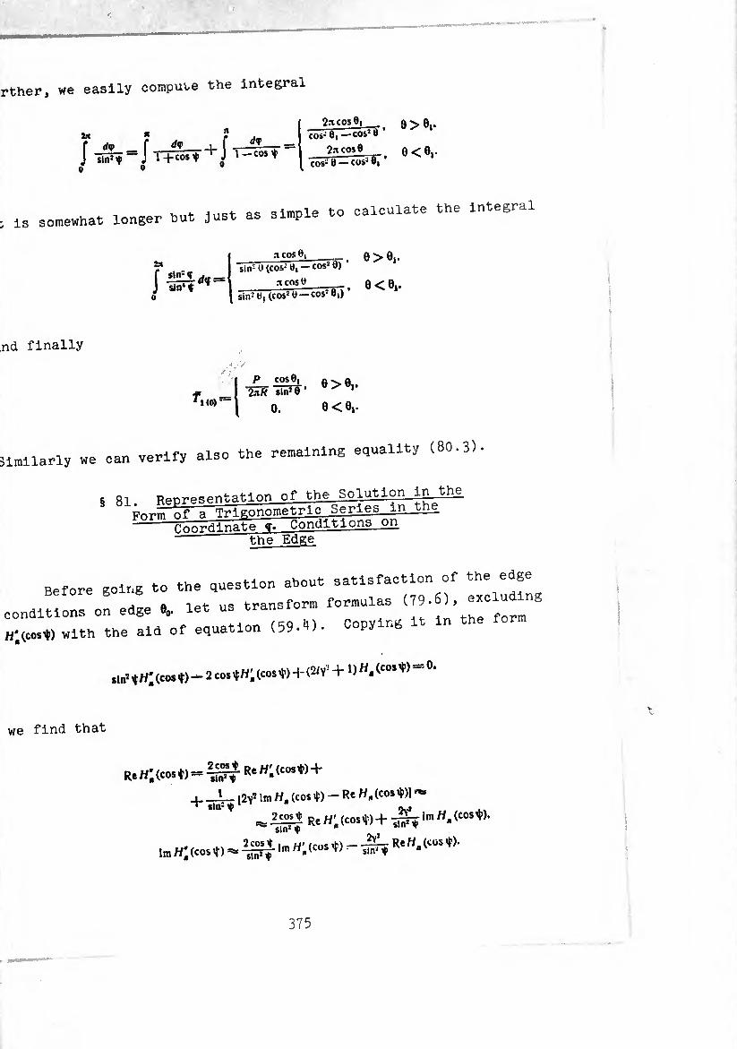
urther, we easily compute the integral
:t is somewhat longer but Just as simple to calculate the Integral
f « f * = J inî^ = J thstf+J l -co^
9>el. cos-' 0| —co&: *
2nco»9 O<01. — cos5 8| cos- 8
m
Í iliLlrfif« sin*« ^
.-i cose, 0>0,. sin- 0 (cos-' tí, — cos2 0)
.i cos e sin2 tí, (cos2 e —COS2 8,) T5“\ • 0<0i-
and finally
(0) •—
0 > 0j. 2aÄ sin2 8 • ^ 1
0. 0 < «i-
Similarly we can verify also the remaining equality (80.3)
5 81. neoresentatlon of the Solution In the of a Tr-i p-onometrlc Series in the -=- ,a t.i ons on Form Pnnrdinate «T. Conditions ori
the Edge
Before going to the question about satisfaction of the edge
editions on edge e0. let us transform formulas (79.6) erciu ng
j;(Co,« with the aid of equation (59.10. Copying it in the
,1»-íh;(c«s*)-2coS*h;(cos'I')+(2H,+ 1>H*ícm*,'=0,
we find that
Re H'n (cos t) = R« H* icos ^ +
i_L_ [2y2 \m Ha (cosí) — Re H.icosty] "*> ^ sin- ^
1C21Í Re H'n(cosí)-f -¾ ¡m H,
Im W* (cos i ) =¾
sin2 i
2 cos * Imw; (cos Í) - -¾ Re (CÜS
375
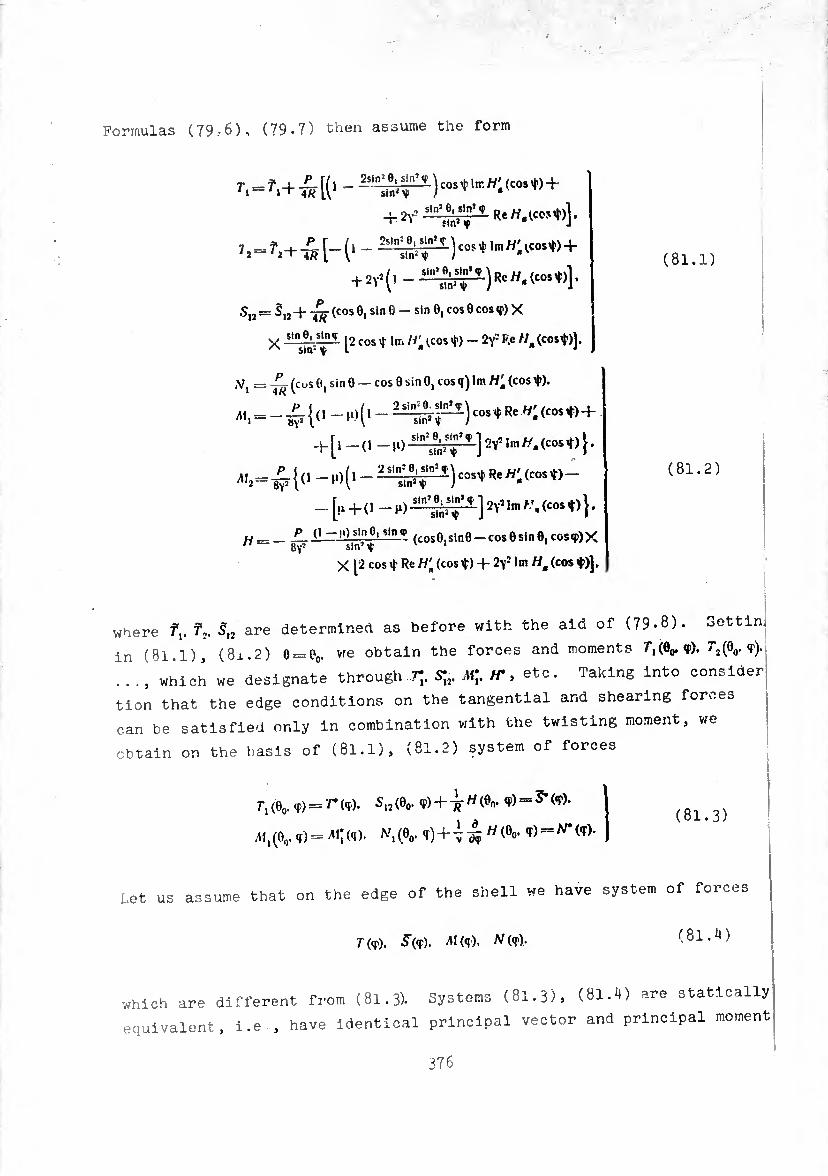
Formulas (79.-6), (79*7) then assume the form
r>=f.+w [(1 - -t&t1) CM,t l,r H'- ^+ + 2r,
Ji-n+wH1 ~
+ 2v>(.-Ü^p-)to».(co‘«)l-
.s,2 = 5I2 + (cos 0, sin 6 - Sin 0, cos 0 cos <r) X
x -ln^a-^--- [2 cos * In. Ht (cos $) - 2\- P.e /7, (cost)].
(81.1)
*,= ~ (cus e, sin 0 — cos 0 sin 0, cos q) 1m rt' (cos ¢).
-£{« +
+[| -(, -rt 5ln,¿r^]ir In,((.(-<))■
i ( d -j“** »: <c»s ♦» -
w-^ jOsinMinjP (COS0 Sin0 —cos0sin8,cosq))X “ 8yj sin’V
X [2 cos t Re H'n (cos xt) + 2f- 1m Ha (cos ♦)].
(81.2)
where f,. 7,. S,2 are determined as before with the aid of (79-8). Settln,
in (81.1), (8x.2) 0 = 0O. v;e obtain the forces and moments 7”i(0o. <?)•
..., which we designate through TJ. S;,. M\, H* » etc. Taking into consider
tion that the edge conditions on the tangential and shearing forces
can be satisfied only In combination with the twisting moment, we
obtain on the basis of (81.1), (81.2) system of forces
7-,(00^) = ^)- 512(0O. (¢) + ^77(00. = (8i 3)
,A1j(0o. q)r= ,Ai;(q). h\(0O. «í)-f W(0°’ ¢) = ^^)-
Let us assume that on the edge of the shell we have system of forces
T ((f). 5(f). M(f). 77(f), (81.4)
which are different from (81.3). Systems (81.3), (81.4) are statically
equivalent, i.e , have Identical principal vector and principal moment
376
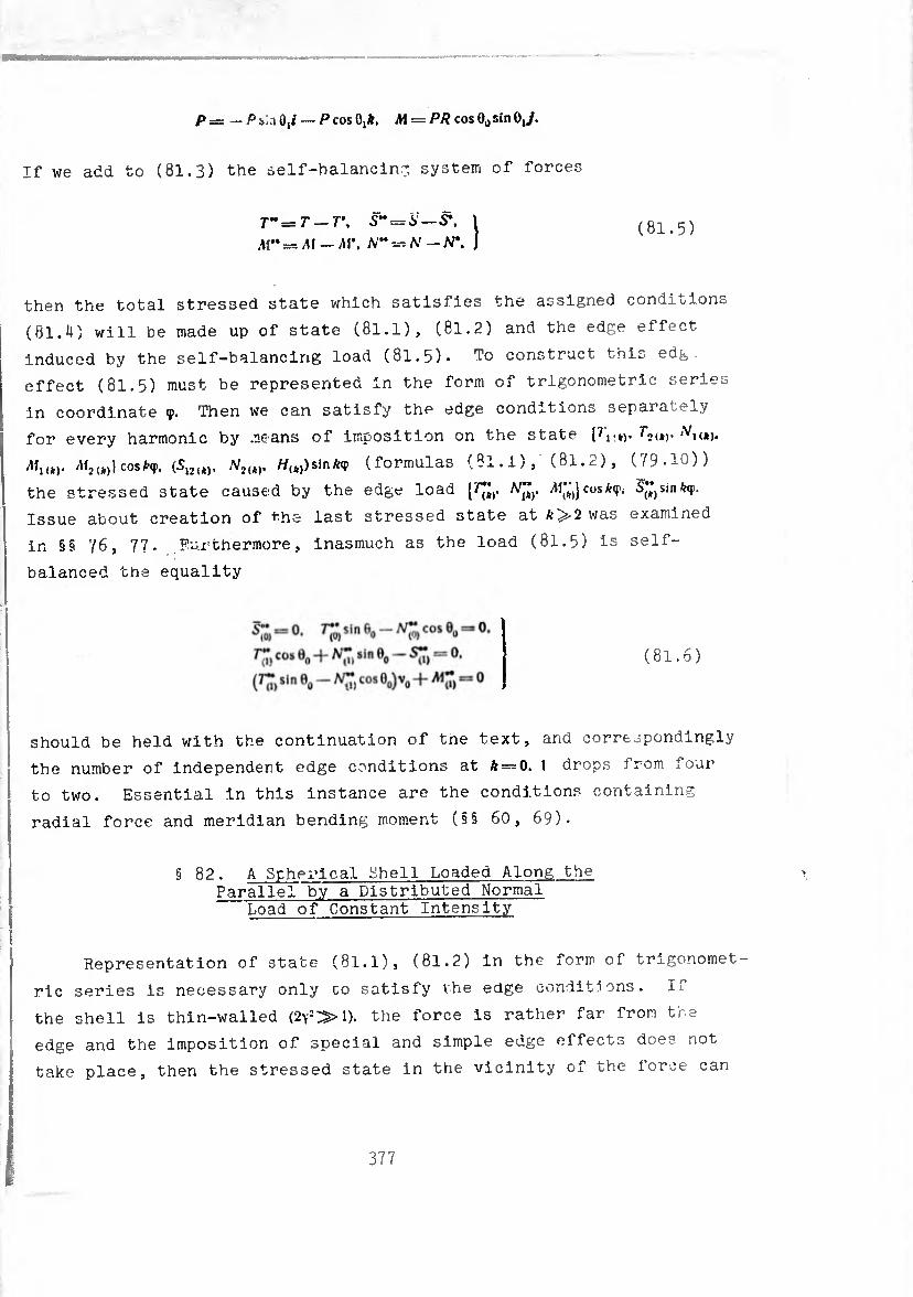
P = — P sia 0,/ — P cos 0!*. M = PÆ cos 0o sin OJ.
If we add to (81.3) the ¿elf-balancing, system of force
T" = T — T\ S" = 6 — <S*.
,11^= ¿AI — /U*. N-^N -tP, ,} (81.5)
then the total stressed state which satisfies the assigned conditions
(81.4) will be made up of state (81.1), (81.2) and the edge effect
induced by the self—balancirig load (81.5)- To construct this edg
effect (81.5) must be represented in the form of trigonometric series
in coordinate <p. Then we can satisfy the edge conditions separately
for every harmonic by means of imposition on the state ¡7'i■»)• Psi*)-
All,,). Al,,*)) cos *<ï>. (S,,,*). NUk). //,,)) sin A-«}) (formulas (8l.i), (81.2), (79-10))
the stressed state caused by the edge load {^. N¡;y Al")cos*¥>. S^sinfop.
Issue about creation of the last stressed state at £>2 was examined
in §§ 76, 77- Furthermore, inasmuch as the load (81.5) is self-
balanced the equality
(81.6)
should be held with the continuation of tne text, and correspondingly
the number of independent edge conditions at ft —0. 1 drops from four
to two. Essential in this instance are the conditions containing
radial force and meridian bending moment (§§ 60, 69)-
§ 82. A Spherical Shell Loaded Along the Parallel by a Distributed Normal
Load of Constant Intensity
Representation of state (81.1), (81.2) in the form of trigonomet¬
ric series is necessary only co satisfy the edge conditions. If
the shell is thin-walled (2\2»1). the force is rather far from the
edge and the imposition of special and simple edge effects does not
take place, then the stressed state in the vicinity of the force can
377

be directly calculated on the basis of (81.1), (81.2) or, which is
even simpler, according to (.79.1).
However, expansion in a series can prove to be useful also for
other purposes. Taking into account formal expansion of the delta
function in a trigonometric series
P ô (<p — 0) = />0-|- 2 /»* cos top. *-i
P _P ~ 2.1 R sin Ô, * “ nPsinft,"
I
(82.1)
and using the expansion of stressed state (81.1), (81.2) in a series
(79-10), it is simple to obtain a solution to the problem about a
spherical shell loaded along the parallel 0==0, by a normal linear
load of intensity pAcostor. Thus, for instance, the zero harmonic in
the expansion of forces and moments (81.1), (81.2) in a series in <r
will describe the stressed state in a shell loaded along the parallel 9
by vn axisymmetrically distributed normal linear load of intensity
2.i/?inrör- (82.2)
This load is balanced by a system of edge loads with principal vector
P cos 0, k.
Let uo assume that the external loads assigned on edge 0O. also
have axisymmetric distribution and the edge conditions have the form
of
». «o, = Tx (0) cos 0O+(0) sin 0O = p, .
M j(0, = 0. (82.3)
On the basis of the first equality of (80.3) it is easy to see
that the zero-moment axisymmetric state satisfies conditions (82.3).
We will explain now the character of the fading effect of the
axisymmetric component of the remaining part of the solution,
373
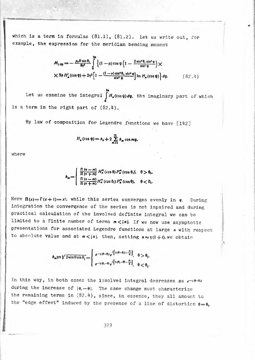
which is a term in formulas (8l.l), (81.2). Let us write out, for
example, the expression for the meridian bending moment
(1 — tiln*n>' sin’ X ReA/;(cost) + 2vî[î - ’Jim//„(costJ))}</<p. (82.4)
Let us examine the integral J (cos\J>)</ç, the Imaginary part of which o
is a term in the right part of (82.4).
By law of composition for Legendre functions we have [142]
H, (cos ip) = A0 -{- 2 2 hm cos m<p.
where
ITfr hmi "7 (¿os 9) P? (cos 0,)-. 8>e,.
nrr-f S^^50-)^^050)» 0<e«-
Here ri(Ar) = r(x-f 1) = jc!. while this series converges evenly in <r. During
integration the convergence of the series is not impaired and during
practical calculation of the involved definite integral we can be
limited to a finite number of terms m<¡n|. If we now use asymptotic
presentations for associated Legendre functions at large n with respect
to absolute value and at then, setting n=*s\(\-\-i).we obtain
In this way, in both cases the involved integral decreases as e-vie-o.i
during the increase of |e, —0|. The same change must characterize
the remaining terms in (82.4), since, in essence, they all amount to
the "edge effect" induced by the presence of a line of distortion 0 = 0,.
379
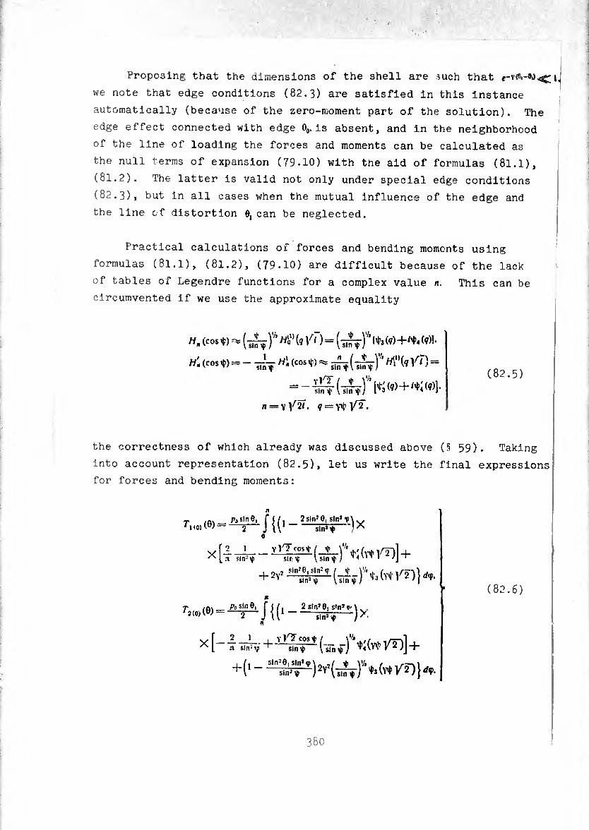
Proposing that the dimensions of the shell are such that i,
we note that edge conditions (82.3) are satisfied in this instance
automatically (because of the zero-moment part of the solution). The
edge effect connected with edge 0O. is absent, and in the neighborhood
of the line of loading the forces and moments can be calculated as
the null terms of expansion (79.10) with the aid of formulas (81.1),
(81.2) . The latter is valid not only under special edge conditions
(82.3) , but in all cases when the mutual influence of the edge and
the line of distortion 0, can be neglected.
Practical calculations ox forces and bending moments using
formulas (81.1), (81.2), (79.10) are difficult because of the lack
of tables of Legendre functions for a complex value n. This can be
circumvented if we use the approximate equality
H. (cos ¢) Hi"(, Y‘ .) = (îî^f)1'' »3(«)+'».<»>!•
Híleoste - Hf (,1^) =
n=vŸ2î. ?=Ytyr•
(82.5)
the correctness of which already was discussed above (§ 59). Taking
into account representation (82.5), let us write the final expressions
for forces and bending moments:
_IW sln»+ }*
X [2 I vlTcosif i i \ [.t sin2 Y sir-Y ' l sin tf /
M T cni.i 2 sln'O, s'n’\ . . ' 2(0)(0)- J J U1-*¿4- >•
n
X [-4 ¿T,- tff ♦ito W)] + +(,- 5in?8| sin* <p
sin2 ÿ
(82.6)
380
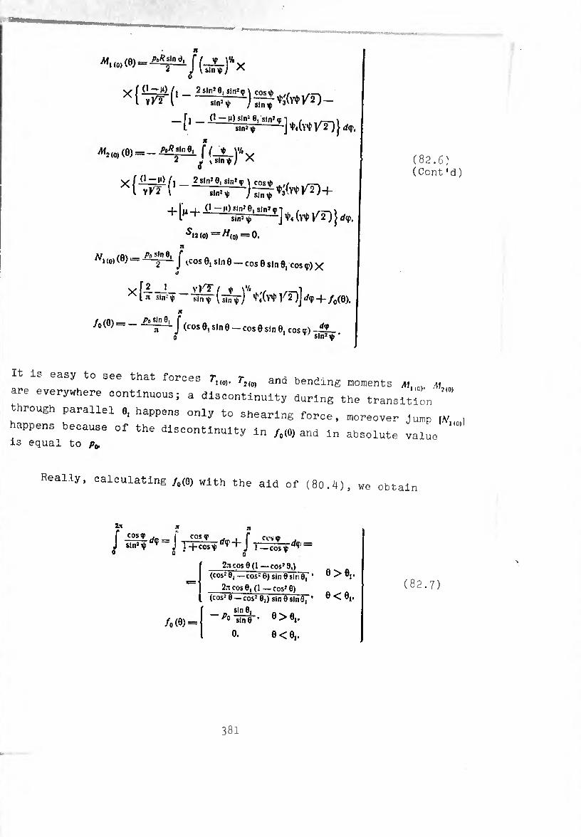
/ ILt i*) í i Sslníe, sln=(p\ cosib ./ _ l yrt r
«1(Í)W.^J(_2_)*X
X l YKZ
— fi ■■ (1 — M)sln; 6, sln’oi 1 , __ l síñ^ j d<f,
^2,0,(0)--0¾^ f (_!L_yAy 2 J ¡slntJ *
^12(0) =^(0) = 0. Jl
a; /n\ _ Ai sin 8, f /V, (0) («) ----J ^cos 0I sin e _ cos e sjn 01 cos ^ x
if
vÍA_J_ vK? i Ÿ \'l> ., ,-,1 ^ l « sin^' « - Uínp [ 1'2jj rfç + /o(0).
n f /A\_ Pu sin 0, r /0 (ü)--— J (COS 0, sin 0 _ eos 0 sin 0, cos ç) - .
sin’Ç
(82.6) (Cent 'd)
It is easy to see that forces 7-,,,,. r,,,, and bending moments n , „
are everywhere continuous; a discontinuity during the transition
through parallel e, happens only to shearing force, moreover Jump
happens because of the discontinuity in /,(0) and in absolute value is equal to p*
Really, calculating /o(0) with the aid of (80.4), we obtain
2.1
J sln4^“J TÄ^ + J T^co%-^ =
/(,(0) =
2n cos 9(1— cos^ 9,, (cos:e,—cos10)sinösir0, * 0 > 0i-
2n cos 0, (1 — cos» 0) (cos2 0 — cos3 0,) sine sin 37’ 6 < 0j-
sin 0, „ Pü sin0 ’ 0>0i-
o. 0 < 0,.
(82.7)
381

§ 83. Example cf Calculation by Formulas (82.6)
The definite integrals in (82.6) can be calculated by any formula
for approximate calculation. In this case it is essential that the
subintegral expressions in formulas for forces are always finite,
even at ^ = 0. and in the formulas for moments contain only logarithmic
singularities of the form -In¢. it is simple to be satisfied
in this if one considers that in the neighborhood of ? = *|;yV"2r=0
¢3(9)-^4(^) and their derivatives have representations (64.2), and
Because of the presence of a logarithmic singularity in the subintegral
expressions for moments, during the calculation of it is
necessary to break the interval of integration in half:
and take into account that
0
since when 0 = 0, and q> is small there exists the equality
tt1 ¾ sin 0, •• <p.
The choice of <p, should conform to the correctness of calculations.
As an example let us calculate the bending moment in section 0, for
a shell with parameters y V? 20. h = 0.25. 0o=60s. loaded along the parallel
circle 0, = 211(^0, = 0.342) by normal forces of intensity p0.
At «r, = 0,015. Y'f. )^2 = 0.100
(1 +(0 v,^ ) ~ 0.015(0.577 — 2.995) = 0.0145.
382
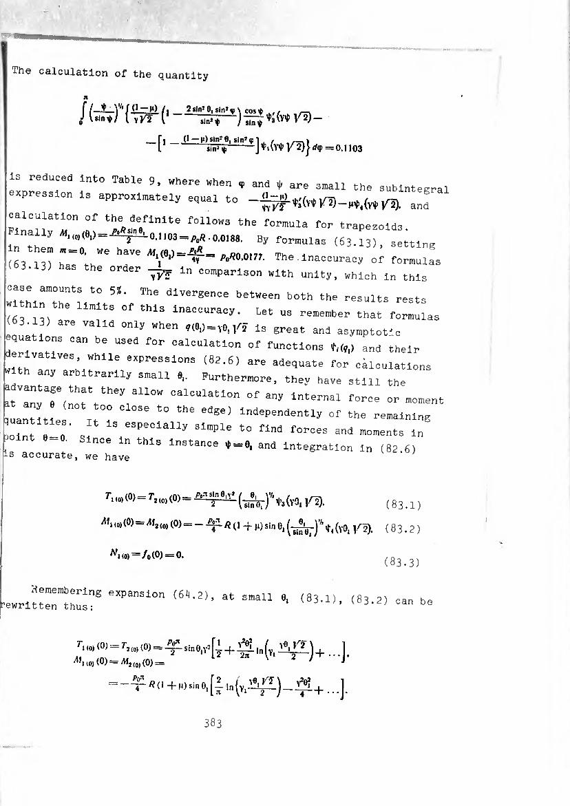
mmmmm
The calculation of the quantity
n
( I-*—)'1' f (1 -jO /. 2sln»eisln*ç\ cos^ ,, ^ Jl«»W (tftC—
-[' (ï* 1^=0,,03
need Into Table 9, where when ç and ¢/ are small the subintegral expression Is approximately equal to and
PinlllTl0" f f0ll0WS the f0™Ula for trapezoids. "®< ^ s ' 0,1103 pç/i.0,0188. By formulas (63.13), setting
63 n) h7°;.hWe 7e M,r=^ ^ 0m- The of formulas (63.13) has the order ln comparison with unity, which In this
:ÎthlnmtTll75*'f The dlVereen0e betWeen b0th rests ,, m s o this Inaccuracy. Let us remember that formulas (3.13) are valid only when ¢(8.) = ,6,/2 is great and asymptot'c
deriva«5 ^ 0al0UlatlOn °f *■«,> and their erivatlves, while expressions (82.6) are adequate for calculations
»1th any arbitrarily small 6, Furthermore, they have still the
3tVany7(notYheyiallOW CalCUlatl°n °f ^‘-"al force or moment Ln«t (not too close to the edge) Independently of the remaining
Lint 7:.' s 1S,e3PeClally f°-es and moments in . n0e n thls instance ¢-8, and integration In (82.6) is accurate, we have
Wo>= ^,(0).,,5). (831)
M, m(0)=/11, (0) = - Ai « (I + ,,) si„ 0i t, (v0l /2). ( 8 3.2 )
^,,.,=/.(8) = °. (83^3)
Remembering expansion (68.2), at small 0, (83.1), (83 2) can b, rewritten thus: can b<
i ^ (0) (0) - T2 (0) (0) = ^ sin 0,[i + In (Yl ^21) + .. 1
1,mo)(0) —)M2(0)(0)= J
- -T1 /? ( J + M) Sin 0, [i In (Yl^l) - ...].
383

Table 9.
» CO»* cniibr.coiip +
+ cu»> 0,(1-coif) ♦ «. (re Ki)
^ ^ ' flojiMirrcrpMbiiot BMpAMCHHC
ip,—i0,0i5 099989 0.99999 -0,005 0.100 -0,0929 —1.541 1,062 f. J «(<p)rf<p-0.0145
0
0,055
0,095
0,135
0,175
0,99849
0,99549
0,99090
0,98473
0.99982
0,99947
0.99895
0.99823
0,019
0.0320
0,0458
0.0595
0,380
0,652
0,910
1,190
-0,1932
-0,2248
-0,2273
-0,2136
-0,707
-0,397
-0,223
-0,107
0,558
0,374
0,2-13
0,162
0,171 J fl((p)rf(p-
* , = ^■0,040(1,082 +
4-2(0,558 4-0,374-4- 4-0,243)4-0,1621 -
= 0,0720
0.349
0))23
0,098
0,9397
0.8GG
0,706
0,9929
0.9843
0.9726
0,119
0,177
0.235
2,38
3.54
4,70
-0,105
-0,031
-0,002
0
0
0,042
0,033
0,011
0
0
0,044
0,015
0,003
0
0
n
j a (f ) d<f —
o*176
“TTri0,162*4* 4-2(0,044 4-0.015)4-
+ 0,003] = 0.0238
KEY: (1) Subintegral expression.
Subtending the circumference of the load in point 0 = 0. i.e., making
9 ^ in (83.I), (83.2) approach zero, so that sin 0, would give P.
as the passage to the limit we obtain the same result which can be
reached on the basis of formulas (62.5):
PvJ T1 (0) = ^2(0) = ^-.
r p / ve, V? Y1 (0) = M2(0) = [- 4* O + Ü) I" (—2—
In order to explain the speed of the tendency to infinity of the
quantity jVuo)(0), it is necessary to use now the expression for /(0)
at 0 > 0, Then we obtain
Po sin 8, sin 6 L =-(
0.->O
p 2nR sin Ö
384
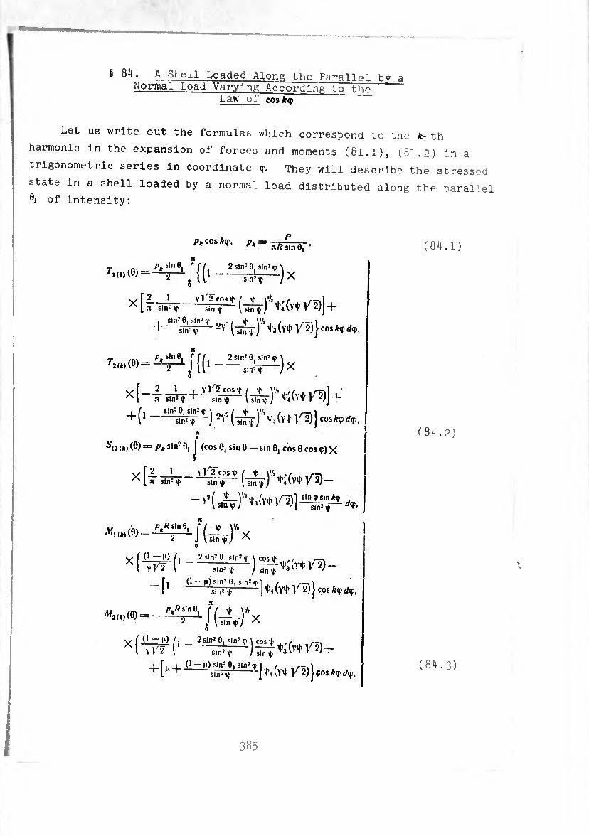
§ 84. A Shexl Loaded Along the Parallel bv a Normal Load Varying According to the
Law of cosk(f
Let us write out the formulas which correspond to the k- th
harmonic in the expansion of forces and moments (81.1), (81.2) in a
trigonometric series in coordinate They will describe the stressed
state in a shell loaded by a normal load distributed along the parallel
öi of intensity:
sin16
_i^)x
X [-1 ( vO)]+
+(1 ) líjeos»»*,. n
Si2 (*) (0) = Pu sin10, J (cos 0, sin 0 — sin 0, cos 0 cos <p) X o
y r 2 1_Y ]rT cos tf Í t \'l, ir, ^ L51 sin:f sinv> (sin^) —
sin2 ^ dip.
^.^(0) = 2 J lliiTt/ X í O — I1) /, 2 sin2
xl77r(' ; sin2 >{•
_fi (• — !Osin20, sln2<rT . /• L -J (V4’ V 2)} cos kip dip.
0 \/ f (i M) /, 2 sin2 9, sin2 «r \ cos \fc ../ ,-, Xl Vl'î ('-+
sin2 if j (y^ V 2) j ¢08 kip dip.
(84.1)
(84.2)
(84.3)
385
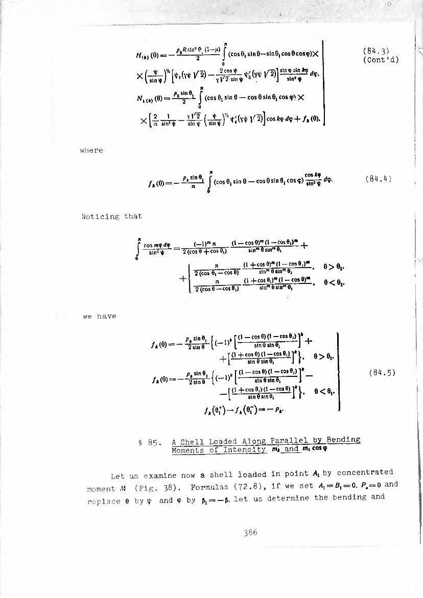
where
H{t) (0) = — PkRMn ¿ ‘(t — J (cosOjSinO—slnO,cos8co8«p)X
n
Nx lk) (0) r= J (cos 0, sin 0 — cos 0 sin 0, cos q>> X o
X Îi!rf {t&ïT'tft* '/5)] «***<+
(84.3) (Cont’d)
c. Q r COS*? fk (0) = _ J (cos 0! sin 0 — cos 0 sin 0, cos ç) </<p. (84.4)
Noticing that
Í cos m<f d<f sin2
(_l)m rt (1 — cos e)"* (1—cosS;)» , ~ 2 (cos 0+cos 0,) sin™ 0 sin’" 0,
n (1 +cos0),B(l — C05'e»)"' 2 (cos 0) — cos 0) si nm 0 slnm 0,
rt (1 4-cos 0,r(l —cosO)"1 '2(cos0 —cos0,T sinm0sin,n01
0>«|.
0 < öj.
we have
/* (0) —
+r+cÆ—]'}■
f- f(l+CO5 0|>O-cos 0)1*1 0<0 [ sin0sln0| J I
/* (0) — 2 sin 0 (84.5)
§ 85. A Shell Loaded Along Parallel by Bending Moments of Intensity w»» and >»i cosy
Let us examine now a shell loaded in point A, by concentrated
moment A1 (Fig. 38). Formulas (72.8), if we set /i, = ß, = 0. P. = 0 and
replace 0 by t and <p by ß^-ß. let us determine the bending and
386
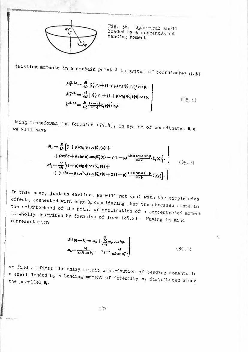
Pig- 38. Spherical shell loaded by a concentrated bending moment.
twisting moments In a certain point /1 in system of coordinates (t. p,)
^ li? 1¾ M + (1 -t g) Ctg tj'C4 (4i)J cos ß.
^ P ~~ÃH [,lN + (1 4 10 cig (t)l cos ß.
M (1 -(1) y ,..
4/ï ‘sln<»
(85.1)
Using transformation formulas (7Q t) in ov^t- o we will have W..0), In system of coordinates 6. ç
[(14-(*) cig 4 cos pç, (¢) 4-
+ (cos2 a + fi Si n2 a) cos ßi' (^) — 2 ( 1 g) ?in a cos a sir. ß
sin 4
+ (sin2a + ncos2a)cosß^(*) + 2(1 -n)- slnP ^(^)]
M2 — [(1 “t g) ctg t COS ßi4 (¢) -f- (85.2)
.foot, connect.. wlthttÍcenttnrtt'ch1'Y,le ^
‘:,ri ■’ y bcriDecl by formulas of form (8S uo,.- representation J' HaVlng ln mInd
>U¿(e 0) — m0-j-2 m. cos lip,
M 2.t/? sin O, '
*-i
mb = . M aRsinfi. ' 1
( 8 5.3 )
rUen TJal¡VTZTmetI'U dlStrlbUti™ °f moments In -LUdue.a by a bending moment of intensitv m a ? ^ . the parallel e„ mten.-lty n,„ distributed along
387

Writing out the zero term in the expansion of moments (85*2) in
a trigonometric series in <p and expressing M through mc using the
second formula of we obtain
M, m - -=^ j {<1+10 S&[«>*,<«+t]+
11 _ ( 1 — n) Sin2 aj cos pc; (♦) —
- ^ <*)+t] ? ^+f■ '« <»>• (85.4)
= J {<1+10¾ [»*«.<♦>+■?]+ + + — n) sin2 aj cos pt; (t)+
+ 2 (1 - n) [i, W)++'■t (•) (°)-
ri <o) (8) —
w0 sin 6, B
fJ (0) —
m0 sin 0| --ST"
J [i‘ - rtsinacosaS^j^T o
f [<’* + »*> S|-+2 0 ” ^ *,n °cos a S']d*-
(85.5)
Calculating the integrals
N » J .5251.^ — J IJ{|r^ (cos 0 s<n 0i — sin 0 cos eicos V)d*
0. n
sin é| ’
••
/ . s,n P slnacosa7iïïV T
= J (sin2 0 sinÖ, cos 0, sin2q» —
n sln8|
— sin2 0, sin 0 cos 6 sin2 <p cos <p) dy = TIW 0,
0>e,.
e<«l.
o>o,.
©<©».
we obtain
'i (o;(0) =
ra(( (6) =
(!->») m0 sin’ 0, 2 sin* Ö '
-(H-ii)-X.
-(1-,1) m0 sln’0| 2 lîü*T’
0>©i.
e<0,.
e>e,.
e<e,.
(85.6)
388
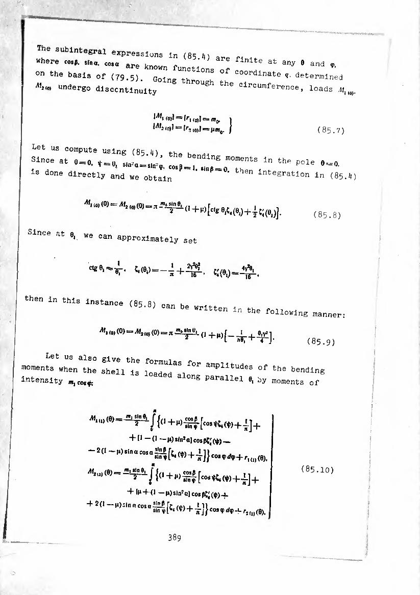
The subintegral expressifs In (65./,) are n ,, where cosp. sino, cosa are knnwn . 6 finlte at any 0 and <p.
on the basis of (79.5) OolngTh °f C°0rdlnate T- determined
undergo dlsccntl^lty ^ ^-“mference, toads
Wi (0)! = f/-, (0)11= mg. 1
«0)1 = kj (0)] ss ¡¡My I (85.7)
Let us compute using m k
Since at 0 = 0. t = o'"0"6’’18 ^ the P°le 0“°- ls d°ne directly and we obtain ’ Integration In (85.il)
^1 (a)(0) = M}(n)(0) = T sln®i y. i .r i (o)W
Since at 0J we can
(85.8)
approximately set
then In this Instance (85.8) can be written m th e written in the following manner:
^.(0) (O) = Alí(o)(0) = flj&4jne,.(1 r_l 0|YÎ1 2 i^r+T-J- (85.9)
moments when the shell Is loIdeTallng ^^1^1^ intensity ^cosç: g parallel e, oy moments of
^1(1)(0)= '2 ' J{0+M)-g|-[cos^«,) + !] +
+ [* -(1 — Hjsin'aJcospC^Ÿ) —
- 2 (1 - M) sl„ 0 cos o^fí, (W + 4]} «» 9rf9+ (»),
,(^^^(,+wSA[colW)(t)+|]+
+ It*+ (1 — n) sinJ aj cos ßj' (¢) 4.
+ 2(1—fi)sinncosaiíiíirt i*! 1 111 sm * T* W + ITJ J cos V ¿«P -1- ri(u (0),
(85.10)
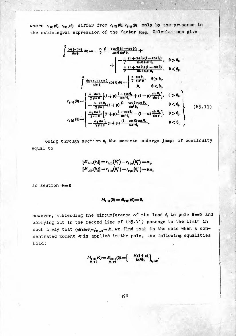
where /-,,,,(0)./-^,,(0) differ from /-,,0,(0). r,(0,(6) only by the presence in
the subintegral expression of the factor cosç. Calculations give
¡ ,,n* n (1 -(-cos
~tln 0 sin1 A, —^ t vp- im V sin* u,
(J + cos 0,)(1—cos 8) -slndsIn’O,- * ö<ö»'
n Í sin a cos a sin P_ -r—-— COS « aç s
sin f T T
n sln0, n
o. e < 6,.
^11,)(0) =
f2,„(0) =
e<e„
6>0'- e < e,.
W|Sln?lfn 1 -n) 2sind T w sln}0, 1
m, sin 3, .. , ..x (1—cose)cos0, -TiiñflT + W üüîë; •
(8b.11)
Going through section 6, the moments undergo jumps of continuity
equal to
l^*i (D (®i)] — ri (i)(®i ) r\ 0)(®i ) — mv
í^i O, (0i)] == rj d, (®i+) —'j (8, ) = H«*,
In section 0 = 0
^1 (I) (®) ^ (I) (®) =
however, subtending the circumference of the load 0, to pole 0=*O and
carrying out in the second line of (85.11) passage to the limit in
such u way that (n/?sin0,«,)^o«-iM. we find that in the case when a con¬
centrated moment ¿fis applied in the pole, the following equalities
,1) (0) 0,-*.O
^211)(0) = (
hold :
CHAPTER VI
A TORUS-SHAPED SHELL
§ 86. S£lvl^ the Equation of the Problem About thP Equilibrium of^jL-Clrcuiar Torus-Shappri
Shell During Axisymmetrlc and Benling Loads
Torus-shaped shell (Pig. 39) dlffers fl.0D, the prevlous cyUnc|rl_
eal, eonlo and spherical shells by the fact that Its geometry Is
characterized by two essential parameters: ratio of the radius of
the generatrix of the circumference to the thickness of the shell ‘
and by the ratio of the radii f. In accordance with this the basic
resolyant solving equation for a torus-shaped shell during axisymmetrlc
and bending loads will also contain two parameters:
(86.1)
(86.2)
The first of them characterizes the relative shell thickness, and the
second essentially characterizes the middle surface: at ?. = 0 the
suriace Is spherical, at ?.->«, it becomes a circular cylindrical surface. ^ lcai
The princ'pal radii of curvature and the radius of the parallel
circle of the middle surface of a torus-shaped shell are equal to
a /> l + fln0 R'~a' R'=a—ä^r-
v = a (¾. -j~ sin 0). (86.3)
391
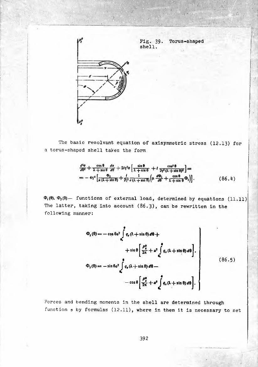
Pig. 39. Torus-shaped shell.
The basic résolvant equation of axisymmetric stress (12.13) for
a torus-shaped shell takes the form
d'-o JW
cos 8 do X^psírTÕ" d&
sin 8 -J-sInO
(X -j- sin 0) l 1 ^«(X-^-slnö) (86.4)
^1(0). ^2(0)- functions of external load, determined by equations (11.11)
The latter, taking into account (86.3), can be rewritten in the
following manner:
d», (0) = — cos 0fl* J ?,(?. + sin 0) </0 -|-
+ sin0
<I>2(0)= — sin0fl* J (X-f-sin 0) dQ — %
— COS0 slnOjdol.
■sr+i J ?,(X-f sln0)</0j.
(86.5)
Forces and bending moments in the shell are determined through
function n by formulas (12.11), where in them it is necessary to set
392

b = a. ii— 1 (a shell of constant thickness is considered) and to take
into account formulas (86.3)*
The character of the solution of the basic résolvant equation
depends on the relationship between parameters (86.1), (86.2) ard on
the amount of parameter ).. When the shell is thin-walled and the
ratio
the solution of the uniform résolvant equation can be constructed by
the asymptotic method, where it will be useful both in the vicinity
of 0 = o(?i), and also far from it (§ 89). A'. ).^>\ the solution and the
working formulas are considerably simplified, since terms of order r
in comparison with unity can be neglected. For sufficiently smooth
loads the solution of the résolvant equation with the right side non¬
zero, at also can be constructed by the asymptotic method.
This solution has a comparatively simple form and on its basis can be
obtained convenient working formulas for determination of displacements
and stresses in different constructions containing torus-shaped shell:
in the end walls (§§ 91, 92), in tubular and lens compensators (§§ 90,
93). When the right side of the résolvant equation is a periodic
function of coordinate 0. the particular solution corresponding to
this right side can be constructed in the form of a trigonometric
series. The coefficients of this series are determined from an
unbounded system of algebraic equations. For a simple right side
(for example, of the form of cos0) the solution of this system is
expressed through unbounded chain fractions, which are calculated
more easily the greater the relative shell thickness. On the basis of
this solution simple working formulas also are obtained for a tubular
compensator compressible by an axial force (§ 8?) and bending moment
(§ 88). In § 94 a thin torus-shaped shell intersecting the
axis of revolution (Jt<l) is considered.
Returning to equation (86.4), we introduced instead of o new
function
0(,= -0. (86.6)
393
where õ=*V04-2#yV#. Having replaced in (86.4), I by —/ and o by o.
taking into account (86.6), we obtain
(Pa, ~W~
= 4^
cos 6 da, -.,. »me cos* _ "T+sinGHfr '2' í o X + sinÔ °» (ï. + sin
¢, « 1 / d&i i cose \ «(X + stnÓ)'_2ÿ< a (X + sinÖ) \P ~W X + slne ^‘J*
(86.7)
Let us examine a load of the following particular form:
9. = P (fc = ,..ne.*»pco,e).| (86.8) ¢, = 0. /»ÍnfcO. Í
in order to simplify the left and right sides of (86.7), we will
again replace the basic variable:
(X + sin I) + 2<Yj a gin« 2^0 (X -f sin 0) sin Ö ‘ (86.9)
(86.10)
here v0— radius of the parallel circle of edge section 0,.
To determine o, we obtain the equation
(X+sin 0) - cos 0 - 2^, sin 0 + o, sin 0 =»
= - 4y«Co cos 0 - 2/\!« [-Ç-+ C(1+n)] cos 0
or, dropping in comparison with unity
(X-}-sin 0)COS0-^-2/^0,8100 =-4^« cos 0. (86.11)
We hold (86.11) to be the basic résolvant equation of the axisymmetrl
problem. Forces, moments and displacements are expressed through o,
in the following manner:
394
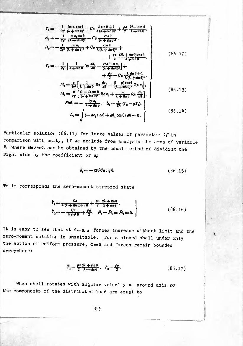
Tf-
A',=
//,=
T*-
\ Ima, COS0
2yí (Ã-fsinÔ)1“1
1 Im o, sin 0 ‘¿y* (X + sinO)2
1 Imo, ‘ îy2 (X, + sln0)J “
Ca *(A. + sln0)2
pa V. -f - tin 0 2 X + sln0
• Ca COS0
x+smo ‘m ao
(X-fsinO)* ’ r„_cos e i Cfl X (X -(-sin 0)« +
, pa (2X + sin 0) cos 0 2 3T-fsln0
COS0 Im o, 1 , (X -f sin 0)* J
da,
M
, pa X sin 0 4-1 ' 2-Cûr(f-i-sln0)» 1
— a f 1 Pr rfq» (1—|s)co»0 n- -1 • ” iy4 U-f sin© Ke dQ ~~ (X + smejî-Re 0iJ*
m — _£_fO—pe„ _u il_p.ííl1 2 4y4 L (X + sin 0)* Ke °1 + X 4- sln « Re <i0 J * EH*' “ ~ T+t\n 6 ' ^ =
A, = J (— ae, sin 0 + ad, cos 0) </0 -f K. A.
(86.12)
(86.13)
(86.14)
Particular solution (86.11) for large values of parameter 2v2 in
comparison with unity, if we exclude from analysis the area of variable
0. where sinO^O, can be obtained by the usual method of dividing the
right side by the coefficient of o,:
õj = — i2y*Cactg 0. (86.15)
To it corresponds the zero-moment stressed state
T,
r, X(X-j*sin0)sin0 *•”
— Ca \ pa X sin* 0
pa 2X + sin 0 2 X+sin0 *
«=0. (86.16)
It is easy to see that at 0 = 0. n forces increase without limit and the
zero—moment solution is unsuitable. For a closed shell under only
the action of uniform pressure, C — 0 and forces remain bounded
everywhere :
pa 2X -f- sin 0 IT X-j-sln0 ’
f — Pa /,--5-. (86.17)
When shell rotates with angular velocity 0 around axis oz,
the components of the distributed load are equal to
395
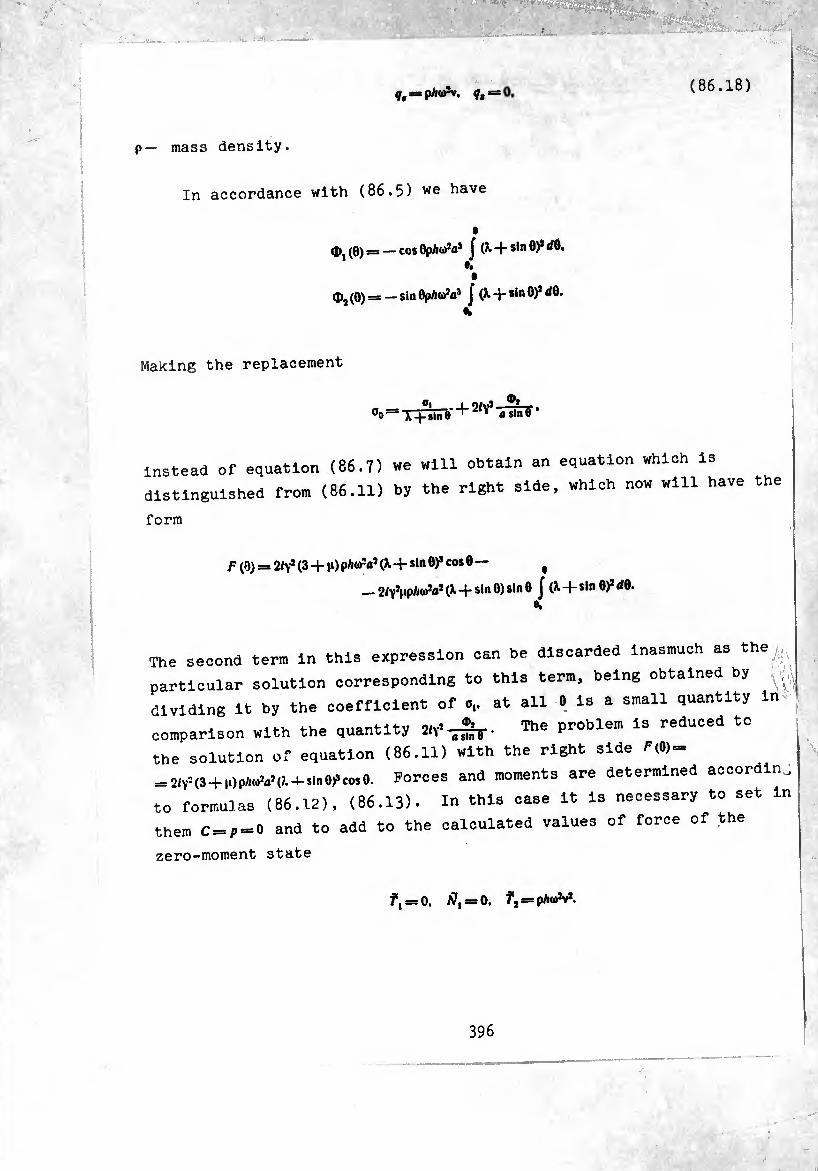
mass density. P —
¢, = p/l«*. ¢,
In accordance with (86.5) we have
(pj (0) = — cos 0pA(i)!üs J (¾. + sin 0)2 dO. h t
d>2 (0) = — sin Ophtfa3 J (X. + sin 6)2 dô- •k
(86.18)
Making the replacement
oo=x+°inre + ^‘nuTf •
instead of equation (86.7) we will obtain an equation which is
distinguished from (86.11) by the right side, which now will have the
form
f (0) = 2/yJ (3 + p) pAtfrV (X-+sin 8)* cos 0 — t
_2/yînpA(oîaî (X + sin 0) sin 0 j (X + sin 0)2 dQ.
The second term in this expression can be discarded inasmuch as the.
particular solution corresponding to this term, being obtained by
dividing it by the coefficient of o,. at all 0 is a small quantity in
comparison with the quantity The problem is reduced to
the solution of equation (86.11) with the right side P(0) =
_ 21V’ <3+1.) pW.’ <>. -mn Of CO* 0. Forces and moments are determined accordin
to formulas (86.12), (86.13). In this case it is necessary to set in
them C=p = 0 and to add to the calculated values of force of the
zero-moment state
/, = 0. $, = 0. f, = pAö*v*.
396
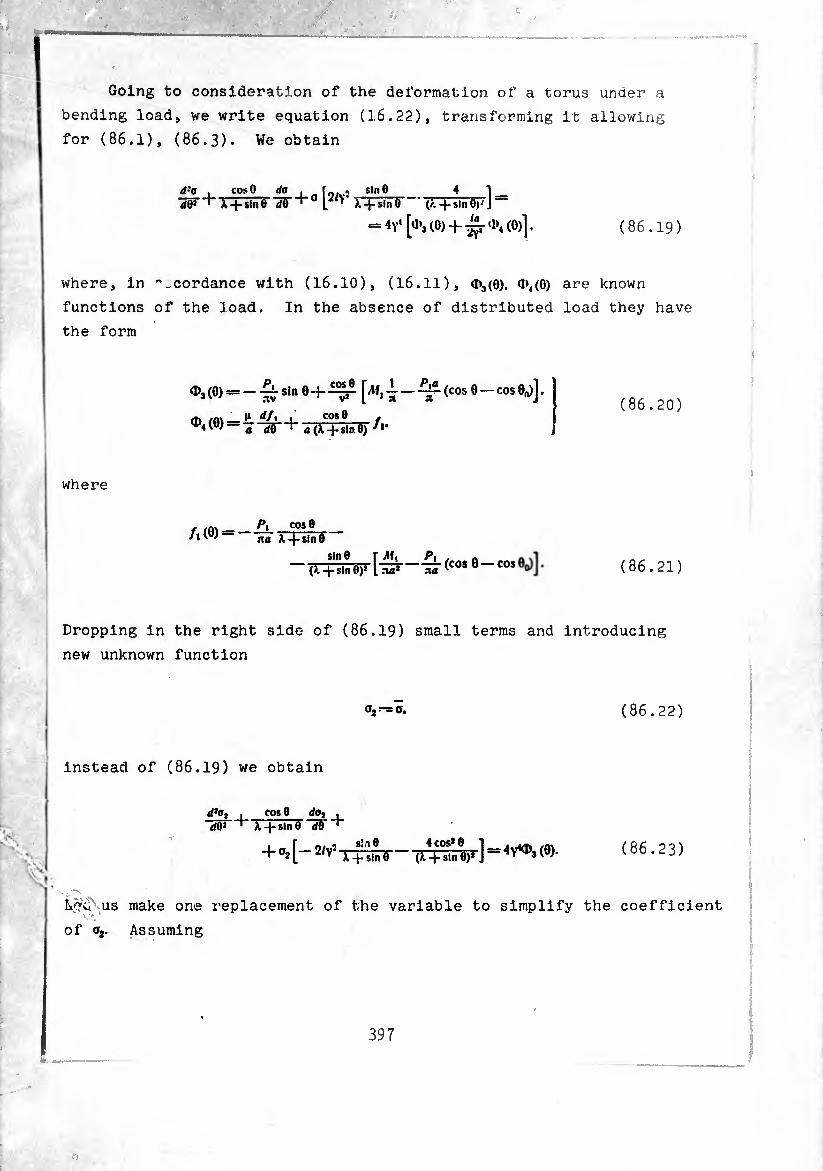
Going to consideration of the deformation of a torus under a
bending load, we write equation (16.22), transforming it allowing
for (86.1), (86.3). We obtain
d:a , cos® rfo , _ fni,.1» $,n® 4 1 X + Hn® W*1" L V r+jíñT ' (/. -)-sin0)' J
= 4Y‘[a»3(0>-f^-«l>4(0)]. (86.19)
where, in cordance with (16.10), (16.11), ¢3(0). <1>4(0) are known
functions of the load. In the absence of distributed load they have
the form
°3 <°> = - Sin 0 + IT - ^(cos 0 -cos M •
^ /m ^ I» df, , COS® ,
^(0) - T "ST + « (X+slier f *’
(86.20)
where
/1 (0) = P, cos® jxa X-fsin®
sin 8 r Mt _ (X-^-sin®)1 I .¾2 tux
(cos 0—cos (86.21)
Dropping in the right side of (86.19) small terms and introducing
new unknown function
(86.22)
instead of (86.19) we obtain
d20, <f®2
cos® da, , A -f- sin 6 d®
+ o2[-2/Y2 T+slnTF 4 cos2 Ö
(>. -f sin 0)2 ] = 4^3 (0). (86.23)
us make one replacement of the variable to simplify the coefficient
of oa. Assuming
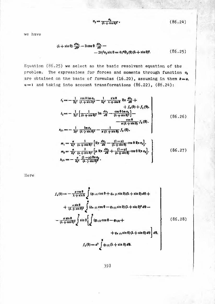
(86.24) _O» _ (). -f sin 0)*' *
we have
(X + sin 0) -jgf — 3 cos 0
— 2ly-a3 sin 0 = (0)(X-t- sin 0)». (86.25)
Equation (86.25) we select as the basic résolvant equation of the
problem. The expressions for forces and moments through function Oj
are obtained on the basis of formulas (16.20), assuming in them b = o,
u—\ and taking into account transformations (86.22), (86.24):
*1=*
sii> =3
1 cos B Im o, 1 s!n8 ¿Y3 -|-sln 8)1 Ay* X sin 0
4 /„(«>+A <«. 1 I- 1 , day cosOImo,!
lTr+sIñ?F,m dB (À -(-sin 0)1 J
i Im Oy __i_ »
(X-j-sinfl)* n(X“hsin6) *'
m = 17 7MHw[Re (ÍFÍ«r“s6R‘”s]- a 1 r _ dOi . (1 — ih « n 1
m2 —
Ä(i) =
a i r„ p. fot i (i • 4V4 (X + sln 0)» K ¿9 ‘ (X +
(86.26)
(86.27)
Here
/0(Ö) = —JT^TànG Í (ŸHDCOS0-1-?,, (1)sin0)(X + sln0)</0+
+ (X~!f¿iñV í (í* C0S 9~Vl (i) Si" 9) ^ + Sln d% — %
e p •
- (xtÍt-rV Jsin ° i J (i* <•>cos 8 - a. La.
+ í« ui sln 0) (X + sln 0) </0
/2(0) = 01 J ?2(i)(X4-sln0)d0.
rf0.
(86.28)
393
-n the absence of distributed loads /,=/,.0 and the amplitude of
13 °0nneCted Wlth by the relatlonsWP resulting
1 * ~ na X + $m e + ^1)- (86.29
By division of the right side of (86.25) by the coefficient of
we obtain the zero-moment solution
(¾ ma I2y* (A-4- Sin 0J*«
In the absence of distributed loads it has the form
oa = t2f dg 0 (A. -f stn 6) — (X -j. siP ©)*—
(86.30)
P, ITT ctS 0 + sin 0) (cos 0 _ cos 0O)].
(86.31)
To it correspond forces of the zero- moment state
/, :=— JUi_?__ I Pj_ cos6 —cose, Tia' sit! 0 (>. -j- sin 8)* aa slnU(/.-J-sIn^’’
J _ ¿>i — P,a (cos 9 — cos 6,) 2 na* slnJ 0 (/. + sin 6) *
Sim ______--Píateos 6 —cos 0,) xa (?. + sin 8) na2 (¾ _|_ sin - ctg 0.
£ — Mi— Pia (cos 8 — cos 8.¾ * aa* (X -j- sin 0)J ctf®*
(86.32)
(86.33)
§ 87. Periodic Particul^Solutl.on of Equation .(ob. 11). Axial Extension of a ^
Tubular Compensator
(86 in)' “"I5 3h0Wn ln the PreVl0US Se0tl™. zero-moment solution 6.15 cannot serve as the particular solution of résolvant equation
( .11), since it turns into infinity in points 6 = 0.,,. It is possible
owever, to build the particular solution of this equation which
possesses the feature of periodicity and is fm-.e everywhere. We
look for it in the form of a series [114]
399
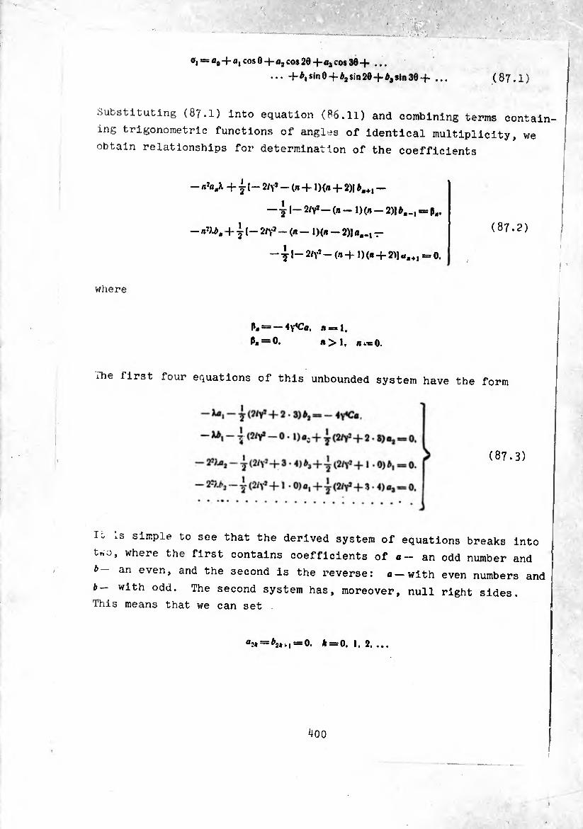
°I = flo+«1 cos 0 4- û2 cos 20 -f- «3 cos 30 + ...
... -M,sin0 +é2sin20-M,sin30+ (87.1)
Substituting (87.1) Into equation (86.11) and combining terms contain
ing trigonometric functions of angles of identical multiplicity, we
obtain relationships for determination of the coefficients
- + 2 l~ 2/Y’-(n + W« + 2)1 *.+1 -
—j I- 2/y* — (n -1)(/1-2)1 ¢,., -= p,.
- n'U. + 1(- 2iy> -(/1-1)(/,- 2)J -
- 41“ 2/V7 - (« + 0 (« + 2>1 u,+1 = 0.
(87.2)
where
P« = — ty'Ca, Aral.
P« = 0. A>1, *«0.
ihe first four equations of this unbounded system have the form
(87.3)
T“ simple to see that the derived system of equations breaks into
Uo, where the first contains coefficients of an odd number and
an even, and the second is the reverse: «-with even numbers and
with odd. The second system has, moreover, null right sides.
This means that we can set
a2* = ^»M=0. * = 0,1.2,
400
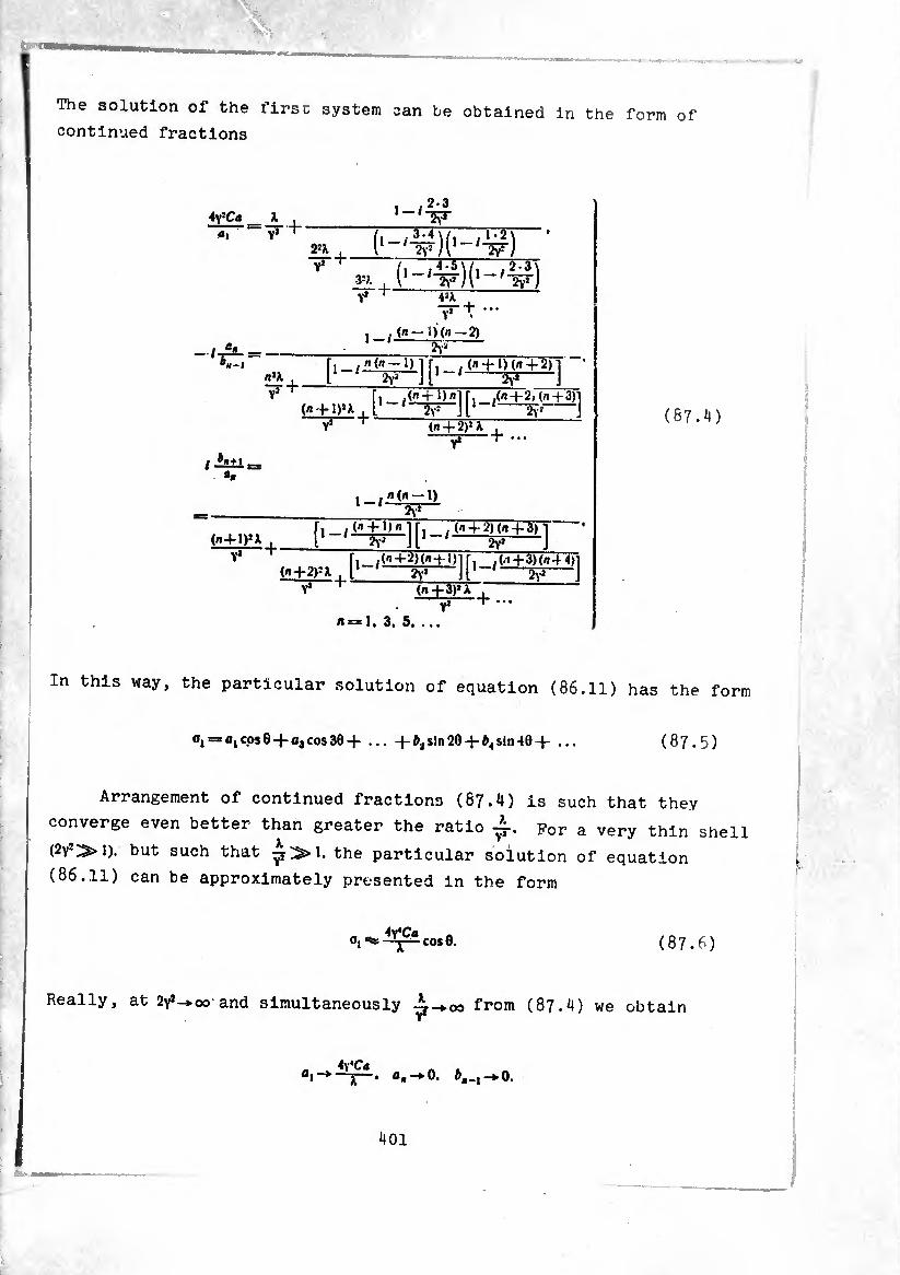
The solution of the firsc system can be obtained in the form of continued fractions
2-3
ai Y* ^ i 2JX , \ '^)l [■- * 1 V). , 1
vt 1 [-4 f)
t .(/,-1)(/,-2)
1
(n + l)(n + 2)l W J
1 ' ! (n -f 1)U , 1
i
[l /^ + ^^ + 3)]
a.
i —1) 1 '—5T»— (n -f- 1) n '
.
("+2>=X . 1 /<?+2Ha + l)] , ,(.143)(/.4 4)1
2vJ J Y* (/•+3)»
—— -+ ...
1. 3. 5. ..
(87.4)
In this way, the particular solution of equation (86.11) has the form
°i= flic.os6 + fl*cos30 + 4-sin20+ ^sin*104- ... (87.5)
Arrangement of continued fractions (87.4) is such that they
converge even better than greater the ratio For a very thin shell
(2y*^>1). but such that ^^»1. the particular solution of equation
(86.11) can be approximately presented in the form
«1 COS 0. (87.6)
Really, at 2y,->cx5 and simultaneously 4-*°o from (87.4) we obtain
«I-*-
401
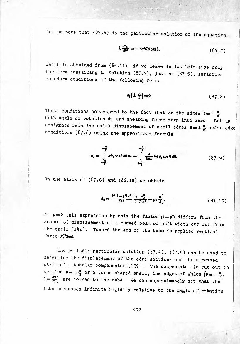
et us note that (87.6) is the particular solution of the equation
== —4Y4C«cos0. (87.7)
which is obtained from (86.11), if we leave in its left side only
the term containing X. Solution (87.7), just as (87.5), satisfies
boundary conditions of the following form:
1(±y)=°. (87.8)
These conditions correspond to the fact that on the edges e=
ooth angle of rotation d,. and shearing force turn into zero.
+ " ± T
designate relative axial displacement of shell edges 0==
conditions (87.8) using the approximate formula
Let us
±-5- under edge
Jl “T J Û0,cos0(/0¾—• J -£££-Reo,cos0</0.
*T ♦T (87.9)
On the basis of (87.6) and (86.10) we obtain
A i2(i-Mvr* ^ . «i ** Ih*-l7^i5r + ^flTj (87.10)
At p — 0 this expression by only the factor (1 —n*) differs from the
amount of displacement of a curved beam of unit width cut out from
the shell [141]. Toward the end of the beam is applied vertical
force Pl/inaL
The periodic particular solution (87.4), (87.5) can be used to
determine the displacement of the edge sections and the stressed
state of a tubular compensator [139]. The compensator is cut out in
section 0 = -.2- of a torus-shaped shell, the edges of which (o = —JL
0=-y) are joined to the tube. We can appioximately set that the
tube possesses infinite rigidity relative to the angle of rotation
402
!
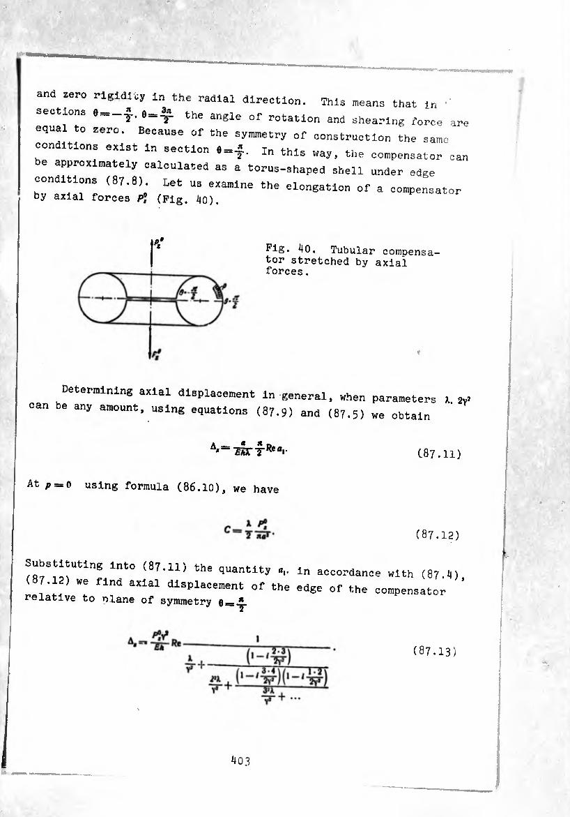
and zero rigidity in the radial direction. This n,eans that in ■' sections e-$. the angle of rotation and shearing force are equal to zero. Because of the symnetry of construction the same
conditions exist in section 8=f. In this way. the compensator can be approximately calculated as a torus-shaped shell under edge
conditions (87.8) Let us examine the elongation of a compensator by axial forces P? (Pig. i|0).
Pig. ^0. Tubular compensa¬ tor stretched by axial forces .
♦
Determining axial displacement in general, when parameters 1. « can be any amount, using equations (87.9) and (87.5) we obtain
C87.ll)
At p == 0 using formula (86.10), we have
(87.12)
Substituting into (87.11) the quantity .,. m accordanc
(87.12) we find axial displacement of the edge of the relative to plane of symmetry q— ^
e with (87.4)
compensator
(87.13)
Substituting solution (87.S) into the first formula of (86.13), we determine the bending moment
X R*I o,sin0 — 3fljsin304- ... +2^03 20 + 4^05 404- ... (1—h)co!>9 „
30 ^ -+^^^20 + ^4^^+ -.)1^ (•87.1^)
At ).^>\ expression (8?• 1*0 can be simplified and brought to the form
A4, (0) =
3aâs,n30— ••• + 2¾co*20+4¾cos40+■...). (87.15)
i.t 0—on the basis of (87.15) we find that the bending moment in
this section is equal to
Af (87.16)
If the relationships of dimensions ar such that during the calculation
of the first continued fractions in (87.15) we can be limited to two
steps, making subsequent calculations also with the corresponding
correctness, i.e., assuming
4y»C« _ X 1-/ 23
V* IF
TT1
F"+-3¾-
«i 2»X , (1-^)(1-^)
1-/ 21
— / *7 W~'
ai—b»c 0.
(87.17)
then it is easy to see that in this instance (at X^>1

for calculation of the approximate formula ^ m°ment ln section 0=^. we derive the
(tJ * ~ vT (1 + ^—J Re
Meridian streaaaa from thls moment at <>_o ^
I JfLf,, V- A I W jiA*y* \ 2>-3X.tJy^^e-
-+ V* *
I
7-/2^ ' 'w- ? iJESES •+i—(87.16:
V*
Using (87.13) and (87 ifiï ,,
in section 0=»‘ ln a tubuie G°mpUte axlal displacement and stress
and having ^dimensions: "" COmPenSat0r Wretched by forces P?
d = 22.8 cm.
^ = 8,14. a = 2.8 cm. * = 0,2 cm,
2Ys = «.3. ^- = 0.353.
f—2.1.10* kg/cm2 (1 = 0,3.
Calculating the amount of first
within the third Signifloant aleit . ^ 4\-Ca ~V~ “ 0.924 — /0.0465.
At />2 = 935 kg
I A, I /^-46.3 1
2-2,1-10*.()3-Õ33- ~T68ÕÕ = 0.A95.10~4 cm.
The axial displacement of the whoi tne whole compensator is equal to
P°. Ai,~ irob-^J.is- io-4 cm.
>105
Stresses in filiaments of the external surface in section e = i at
p] = 935 kg are equal to
in\ 6• 935• 0.707 /,, 1 \ 1 __ \ 4 j 0^.3.14 -4^11 ' 12 • 0,35^/ 0.924
— 1220 kg/cm 2
§ 88. Periodic Particular Solution of Equation (86.25)
The particular solution of basic résolvant equation (86.25) at a
bending load of the form P,=0. Aij^O also can be looked for in the
form of (87.5). The right term of equation (86.25) in this instance
has the form
i4lcose+ßasin2e. (88.1)
where
4y<X. ï- (88.1) [sic]
To determine the coefficients of series (87*5) now we obtain the
system:
- 1*0,1 -jb3 (2/y*+2 • 5) = Av
- 2V - -j a, (2/y* - 1 • 2) + -y 0,(2^+3 • 6) = Br
-3^1+^2/^-2-1)-^(2/^+4-7) = 0. (88.2)
- 4V - y aj (2/Y* - 3 0) + Oj (2/y* + 5 • 8) = 0.
- 5*0,1 + ^-5,(2/y* + 4 • 1)-y (2/Y1+6 - 9) = 0.
Prom (88.2) we find recurrent formulas for the coefficients
406

(88.3)
For example, at /. = 2 we have
-ir'= '+0'-ST
TTT "2? H. yl I •••
¡ (‘ ' ^)(1 +/_5Í) w I m----L-L
(88.il)
^nstea^o^it^the seoon<1 quation of (88.2), „e obtain 0 f U °ne eqUatlon containing two unknown coefficients- »
(88.2) we^find thT ^ second ecu^ion’of vuu.t; we lina the numerical valuer nf « * ¿ x. dxueo oi a,, b3, and then, usine: (fifi ^ compute the subsequent coefficients. At sufficiently lange 1 „ä ein approximately set B * we can
^2*^0.
Then, to determine a,. we obtain the continued fraction:
(88.5)
iJ07
atisfies the conditions The solut3.cn s
ox*, because of substitutions (86
(16.12), the conditions
.22), (86.24) and relationships (16.17)
v(± t)-#-
Let us determine angular displacement of section e=-j- of^the
Shell relative to the middle section 6 =+ T under the act
external bending moment Mx
--a
'(-t)
By formula (18.2) we have
A« (H V
«
.V- a) dO + fV n T
Assuming 4.,,,(^)-0 and taking into
(88.7), we find that Dt = 0 and
account the first condition of
_2L 4.„,(-j)= J
.1 T
Since
i f r o, 1 i co>8g» \
taking into account the edge conditions for «, finally we ottair then ,

(d. J £A(X + sin0)'
Re Oí eos O Eh).* 2ÂXTRea-
« « ínt-n this formula we find Substituting the value of Re., into
<.,=-sSc?ReT 4+-—m?+^
(88.9)
To determine meridian bending stress In b* llmlted to the
„hen during caleuUtlon of so u a formula analogous to
first three terms of the sene ,
(87.18)»
.,^)=±4r^r(> XRe — PíSEEEM
-+ V* ^
(88.10)
1PÏ + ..•
Formulas (38.9), (88.10)^ ^^“^or uhich is subjected to rigidity and stresses in a tuhuiar
bending by external moments Ai.
§ 89 . Solutlon^oX-B^gj^--*1--^0ng ('86 ‘ 11~^' (86.25) for the Case_ -¾-^5,'
torus-shaped shell during axlsymme r coefficient of the one another only in the cons a t actor The
first derivative and ty ^ the char,acter 0f edge
of the corresponding uniform equ ^ that area of change effects, about which we spoke in S 9,^^ _ At 6_0. „
in 8. in which the values o s" ter », in these equations vanish.
the terms in Equations (19-13), ( — » In accordance with ^nis
in these points assumes ac unbounded large value and cannot be dropped
in comparison with the first term, containing the parameter 2v3. It
is necessary to build such solutions of uniform equations (86.11),
(86.25) which, remaining limited in the vicinity of points 0 = 0. n.
with sufficient distance from them would assume the character of edge
effects .
There are a great many works [113], [132], [167], •••, which
consider equations of the fo^'m
-Ir k »> +[t * ^ -t- ' (0>]0='(6)- (89-1)
r(e)_ actual functions which do not possess singularities on the
section of change in 0 [a, b], where p(0) does not turn into zero in any
point of the section, ?(0) has a simple zero in point 0 = 0. Parameter e
can have both real and imaginary values and
Equations (86-11), (86.25), which are of interest to us, easily can
be brought to the form of (89.1). The large parameter in the involved
case has the value
i_2M /U3 U3_ V (89.3) T-JT-
Method [132], which will be stated below is suitable for calculation
of shells whose geometric dimensions satisfy th-. equirement
^ = /12(1(.89.4)
The concrete notation of equations (86.11) and (86,25) in the form
of (89.1) gives for the axisymmetric case
410

«‘«“õ+tsW.
i<1,
(89.5)
(89.6)
for the case of a bending load
p (0)-. 1
(1 -(-a sin 0)
#-(0) = 0. /(0) =
7- ¢(0) =
(1 -)-a sin U)*
sln0 (l -f-a sin 0)= ’
(89.7)
Here Ft and Ft— the right parts of (86.11) and (86.25).
Let us examine the interval By replacement of the
dependent and independent variables
0=1)10, 10! a7: 1 Vpis
u — u0 (0) 4- £«, (0) -f e3u2 (0) -)-
¢0 55*
equation (89.1) is brought to the form
(89.8)
(89.9)
where
pu' w o'
(89.10)
Assuming >1(0) = .; and equating terms with identical powers of e, we find
the relationships for determination of «<>.«,, etc.
“o“ _?(8) P(0)uf
V \rv -I- (pv'/l. (89.11)
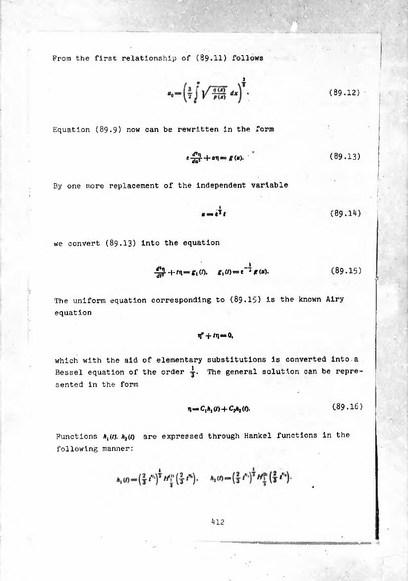
From the first relationship of (89.11) follows
3
(89,12)
F.quation (89.9) now can be rewritten in the form
e-^r-+-«ti= *(«). (89.13)
By one more replacement of the independent variable
(89.1*0
we convert (89.13) into the equation
= = /?(«). (89.15)
The uniform equation corresponding to (89.15) is the known Airy
equation
if+ /T1 = 0,
which with the aid of elementary substitutions is converted into a
Bessel equation of the order -y. The general solution can be repre¬
sented in the form
11=0,^(/)+^(/). (89.16)
Functions *,(/;. h2(t) are expressed through Hankel functions in the
following manner:
¿412
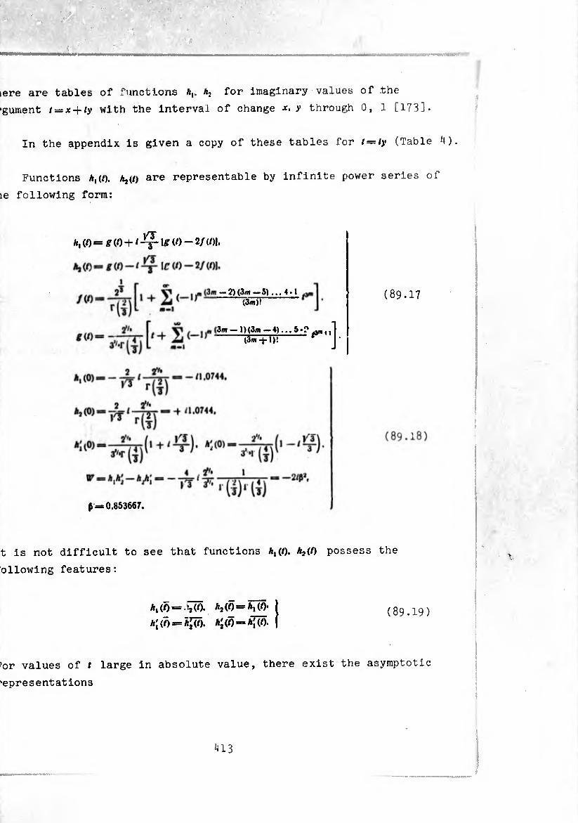
pîere are tables of functions A,. a2 for imaginary values of the
rgument t — x-riy with the interval of change x. y through 0, 1 [173].
In the appendix is given a copy of these tables for t = iy (Table 4).
Functions h^t). Aj(/> are representable by infinite power series of
Ihe following form:
A, (/) = £ (O -h / —j—1£ (O — 2/ (/)1,
. . «i (3m — 1 ) (3<n — 4)... 5 » f*
t-1' (3m-(-1)!
— 2)(3m — 5) ... 4-1
(3m)! (89.17
0,853667.
It is not difficult to see that functions A,(/). MO possess the
following features:
MO = ^(0. M0=M0- (89.19) = Aj(/) «=* Aj (/).
For values of / large in absolute value, there exist the asymptotic
representations
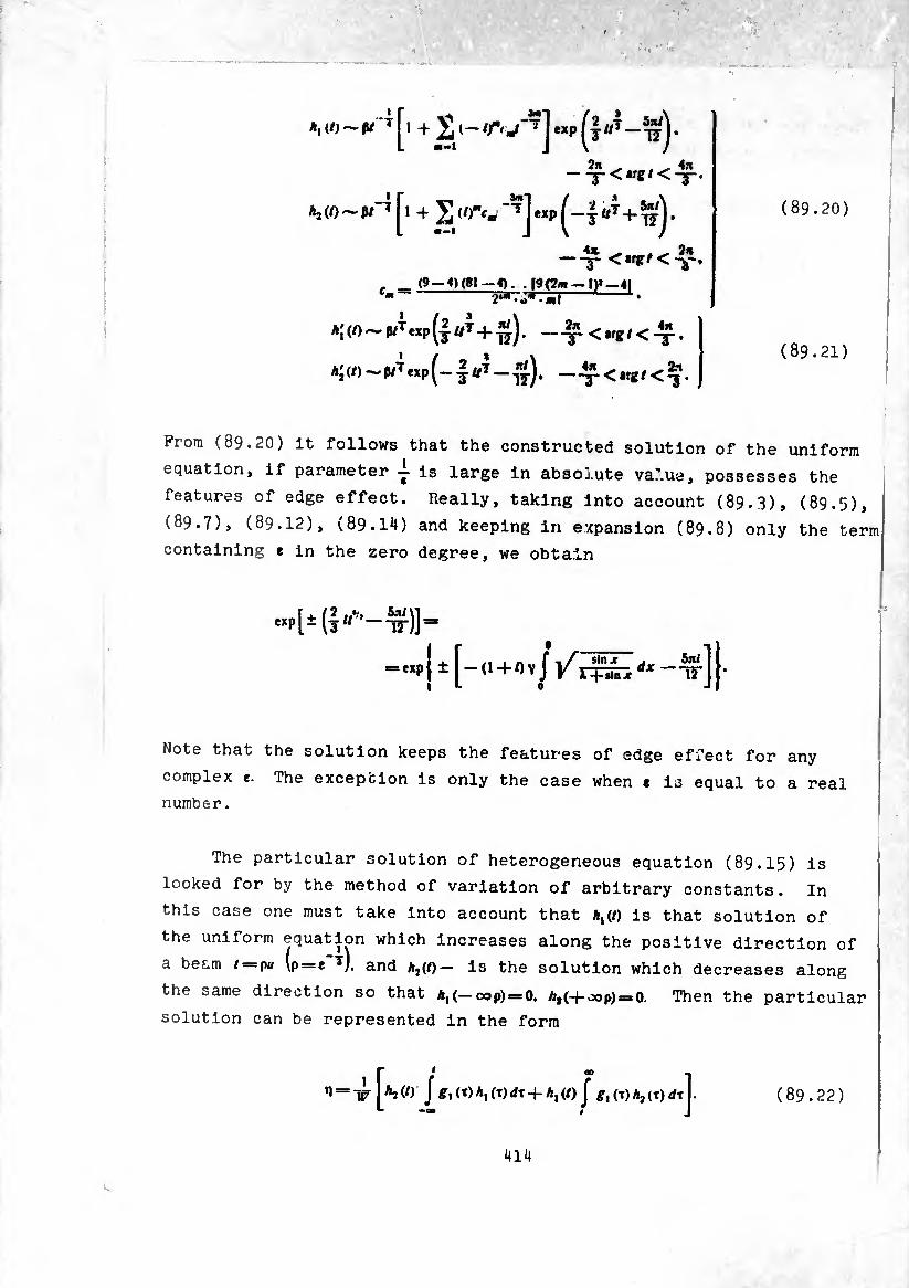
(89.20)
A, </) ~ ß/ T T1 + £ <- exp «7 _.
-■y-<«*/<-£.
AaW-p/'^l + J (/>"c- _??J exP (~T U* + Jlj •
ÂJÊ 9m
. _ (9-4)(81-4). . f9{2* —I)*-41 ¢--2«*.o*-«r —1 •
A;(0~(MTexp(4«7 + ^). X < •rf # < X *
Ai(/)^^exp(-4^-^). —x<ir*/<3*
From (89.20) it follows that the constructed solution of the uniform
equation, if parameter -i is large in absol.ute va7.ua, possesses the
features of edge effect. Really, taking into account (89.3), (89.5),
(89.7), (89.12), (89.14) and keeping in expansion (89.8) only the term
containing e in the zero degree, we obtain
Mpfi (7 a*'’—!*■)]=■
=,,P j ± [—a-M , -tt] |-
Note that the solution keeps the features of edge effect for any
complex e. The exception is only the case when t is equal to a real
number.
The particular solution of heterogeneous equation (89.I5) is
looked for by the method of variation of arbitrary constants. In
this case one must take into account that *,(/) is that solution of
the uniform equation which increases along the positive direction of
a beam i = pu (p = c *), and Aj(/)— is the solution which decreases along
the same direction so that a,(—oop) = 0, AtH-oop)=*0. Then the particular
solution can be represented in the form
n = x I J £, <■*) Aj (T) dx + A, (/) J gt (T) Aj <T) ¿TI. (89.22)
;
(89.21)
414 I
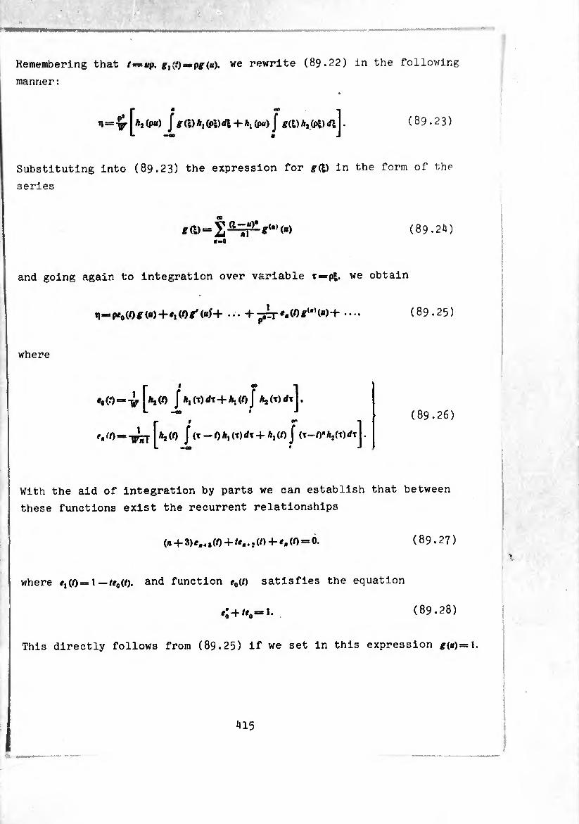
m
Remembering that = p^(«). we rewrite (89.22) in the following
manner :
W Aj (pu) f g ft) A, (pi) <ft + A, (pa) J ift) A, (pi) ftj . (89.23)
Substituting into (89.23) the expression for ^ft) in the form of the
series
jkJ nl c-0
(89.24)
and going again to integration over variable t=pi. we obtain
i¡>^pe0(0£(ii) + «i(Ot(«f+ ••• + .••. (89.25)
where
*o(0 = -¿ [aj(0 J A.Mdt+AjioJ A,(T)rftj. fß(0 = j (0 J(T—0*iW¿t4-A|(0 J (t—0"Aj(t)</t|.
(89.26)
With the aid of integration by parts we can establish that between
these functions exist the recurrent relationships
(b 3)^-4>(0 "t" f*«. j(0 -R (() ®* (89.27)
where ¢,(0= 1 —te0(t). and function e0(t) satisfies the equation
.:+/..-1. (89.28)
This directly follows from (89.25) If we set in this expression g(u)= I
!
415

Function e0(t) is connected with the known Loirjnel function of the
second kind and order 0, 1/3 by such a relationship:
(t)V’( 2 (89.29)
Let us remember that the Lommel function of order »i. v is a function
wich satisfies the equation [79]
x'y +*/(89.30)
so that function So../, (Just as the function of the first kind
is the solution of equation (89.30) at v = ^., n = o.
When V is fractional the function of the first kind Vv has the
expression
v — 2sinnv I (■*) J ^ /-»(, / r/v(l)rflj.
Fu. thermore, it is represented by a power series
m-0
(-1)" (t) 2« + J
i r| (£í1+7)rl :^+4) r( -+«• +«+7)
if (Ji + v) or (n-v) are not equal to an odd negative number.
Function of the second kind is connected with the function
of the first kind by the relationship
X [cos ( nJ /_v (X) _ COS (n) /, (X)]
416

(v is fractional).
Using the written out expressions and (89.29), we obtain
ejO) ¿rr (1) =1 ^28789^ ‘Ó (0) == -3-vr = _o, 938893.
It is simple to write out a direct representation of function ,.(()
in the form of a series in powers of /
+,:(0,/(1 - ’/3+ ...)+
(89.31)
On the condition that
for e0(/) there exists the integral representation
(89.32)
For large |/| from (89.32) we obtain the asymptotic expansion
oo
^0(0-^7 + 2 *-1
(-I)»(3»-l)t
(*—l)!3*-'/»*+i ' (89.33)
Using expression (89.32) and the formula for the Fourier cosine
transformation, applicable to the function /(x)
= 4 Jcoiajrrfa j r»COiatdt’ (89.34)
417
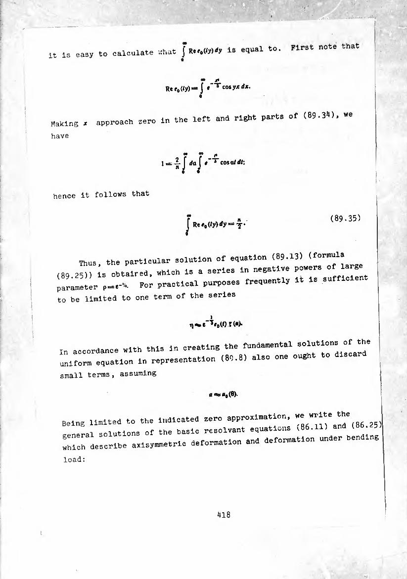
it is easy to calculate what J Re#*(iy)*y Is equal to. First note that 0
* ■
• * Re MW“ J *'"reo»yjtrfjf-
Making * approach zero in the left and right parts of <89.3«), we
have
00 00
4M t~ 3 cosa/rf/:
hence it follows that
CO
/ ReMW^y = T’ (89.35)
Thus, the particular solution of equation (89.13)
(89 25)) is obtaired. which is a series in negative powers
parameter ,=.-, For practical purposes frequently it is sufficient
to be limited to one term of the series
i
In accordance with this in creating the fundamental 30“s °f the
uniform equation in representation (89.8) also one ought to
small terms, assuming
a «=HO(0).
Being limited to the indicated zero approximation, «e write t^
general solutions of the basic résolvant equations (Be.U) and (86
which describe axisymmetric deformation and deformation under
load:
418
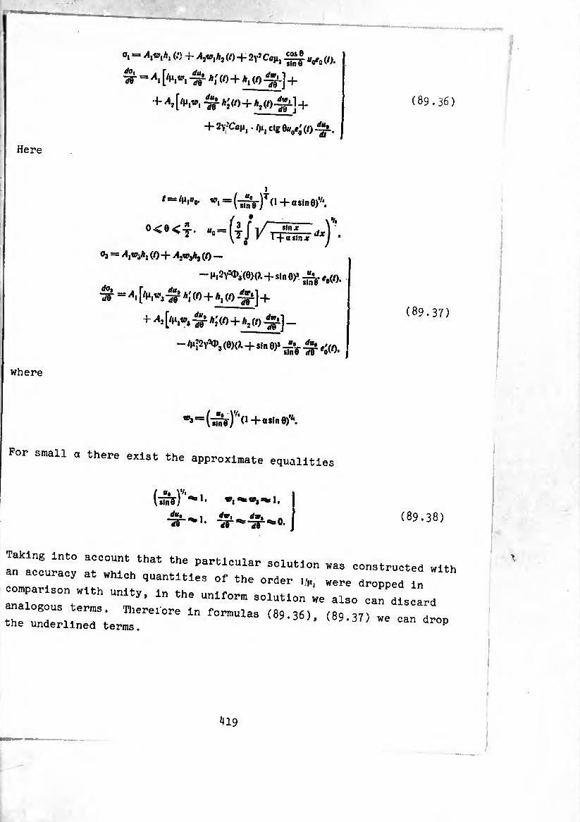
Here
°> “ Aiwih> « + W+VCûji, Vo(o.
^ = [/»i,«', a; (/) + A, (0^]+
H- 2>fCaMj. /ji| ctg 0tfoí¿ (/)
/ = /M,«o. «’■^(li^Vfd + dsin^.
o<e<£.
°3 = (0 + A^jAj (0 —
-^,2^,(0)(). +sin 0)3 ^e0(t).
^¡■=Al a; (/) + A, (/) ^i] +
+ *2 [/I*,«, A' (/) + A, (/)-^1] _
- ^2y^3 (0)().+s.n 0)*
(89.36)
(89.37)
where
For small a there exist the approximate equalities
■Sr*
>1.
i.
‘Wj’*» 1.
>0. (89.38)
In ao! I00“”1 that the Partlculai- s°lu«°n was conatructed „J an accuracy at which entities of the order were dropped In
comparison with unity. In the uniform solution we also can discard
analogous terms. Therefore In formulas (89.36), (89.37) we can dro the underlined terms. v we can dro
419
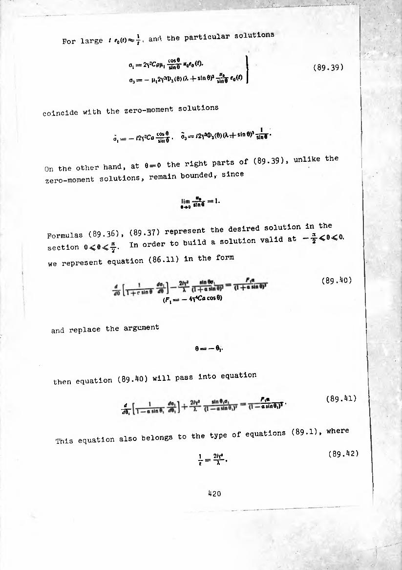
For large t e0(t) I. anr>. the particular solutions
o, = 2yîC<ïh, “o'oW.
o3 = - n^Y^a (8) a + s¡n 0)* -¿¡fy ‘o(0 (89.39)
coincide with the zero-moment solutions
¿( Ä _ /2Y*Co . 33= /2^,(8)(^+si"
On the other hand, at 8 = 0 the
zero-moment solutions, remain
right parts of (89.39)» unlike the
bounded, since
lim -rrn = 1. e-»a sin 8
Formulas (89.36),
section 0<8<y.
(89.37) represent the desired solution in the
In order to build a solution valid at -t<e<0'
„e represent equation (86.11) in the form
(fj = — 4y*Ca COS0)
(89.40)
and replace the argument
0 = -0,.
then equation C89.W) «m P«ss lnt0 e1uatlon
d dd,
r,a a sin Si)11 '
(89.41)
This equation also belongs to the type of equations (89.1), where
1 2/v* 7=1--
(89.42)
420

(89.43) ; —aslnè, ’ (i—osinè,)*
/(öl)= ^1«
(1 —asinOj)* *
Large parameter (89.42) is obtained from (89.3) by the replacement of
I by —and formulas (89.43) differ from formulas (89-5) only by the
sign on ot in the denominators. In accordance with this the desired
solution is obtained from (89.36) (the same applies even to (89-37))
by replacing
t by /,=,- -^0(01). l
<*1 by <*, = .(-¿V)TO - o sin 0,)*'*.
i .
t®3 by ^3 = (-5^^(1 — aslne,)''*.
(89.44)
Making the indicated replacing, we obtain expressions for a,, a, and
their derivatives, valid at —•y<0<O:
0, = Biwlhl (/,)+ fljTO1Aj(/I)-l-2YîCflfi1 o0*0(/,).
«3 = Bl^A (/,) + fl2«3A2 (!l) —
- (0) (X+sin 0)» e0(i,).
dVm = (^)-257 + ^1^3^2^0^17 —
- 4^3 i0> (?-+sin ^ 7¾ e5 (M ^7 •
(89.45)
(89.46)
Since at 0 = 0 , or, which the same, at 0, = 0. the values of w, , ip,, t
and /,.-¾5 and ^ in both cases coincide, then it is easy to see
that at
£| — Ax% Âj Ai (89.47)
i
i
solution (89.45) is an analytic extension of solution (89.36). In
exactly the same manner (89.46) is an analytic extension of (89.37)
from the domain 0<e<^. into the domain —•5-<0<O.
Let us imagine a torus-shaped shell bounded by the edges e* 0k.
where
— y<0o<O. -y>e*>0.
Remembering the features of functions *,(/), a2(/), expressed by formulas
(89.19), and asymptotic representations of these functions, existing
for large values of the argument, we come to the conclusion that
function
A. ¢,) = ^(/(1,1¾). .0o<0<O.
A, (/) = A, (/^«o). 0*>0>O.
in ab- •'lute value decreases in proportion to the distance from edge 0O
to edge 04.' and the function
«2 (6) = Aj (/,) = A, (/(i,«o).
Aà (/) = hi (/(1,11o).
0O<0<O. 0*>0>O.
in absolute value increases when 0 from 0O to 0*. In this way, that
part of solutions (89.36), (89.37) and (89.45), (89.46), (89.47),
which contains constant ¿4,. describes the stressed state of edge 0O,
and the term containing A3, describes the. stressed state of edge 0*. 1
In the uppendix are given tables for calculation of the integrals e_ f -1/"—Üîi£—dx at different values of a = T-. and also tables of function
J I 1 ± osinx A
e0{t) and *£(/)•
422

§ 9O. Elongation and Bend of a Tubular Compensator
In an axisymmetrically loaded shell, bounded by sections e0= — 84 = + -5- under the edge conditions
(90.1) hI=0. of == //Î=0
edge effects are absent. Constants ¿4,.-4, in solutions (89.36), (89.^5
are equal to zero. The stressed state is described by the particular
solution
2^,-Sr?-WO. o<e.
e<0. (90.2)
e1=- 0.
ctg 0«o-^ e'Q (0. 0 < 8.
(90.3)
since v0 = fl(}.—1).
Let us examine a tubular compensator stretched by force P%.
in the presence of internal pressure p- Prom considerations of
symmetry in section 0 = +y conditions (90.1) should be held. We
consider that they exist also in section 0«—y.
The bending moment in instantaneous section 0 we compute using
the approximation formula
(90.4)
Substituting into (90.4) the expression for at 0>O. we ootaln
The imaginary part of function e¿(/) has a maximum for the value t — f**
= 1.225/:
maxime'(/) = 0.753.
1 99S To the value of f* corresponds to angular coordinate e* = -:—. Since
i*i parameter n, is great in comparison with unity, this means that 0*
is small and we can take
Taking into account everything we said, we obtain
Af' ^ - -¿r [“- + pa2 (2>. - 1)] 0.753.
Maximum bending stresses are equal to
^l0'753- (90 - 5)
At p = 0 formula (90.5) can be represented in the form
o,= + (±>2.99(1 -i»V*(x]T**3rL-. (90.6)
p? where "¿-i~ tensile stress in a cylindrical tube of radius a with
wall thickness h. In formulas (90.5)» (90.6) the upper sign refers
to stresses in the filaments of the external surface, and the lower
sign refers to stresses in filaments of the internal surface. The
signs in parentheses should be taken during the calculation of stresse
in section 0= —o*.
Calculating circumferential forces using the corresponding
formulas (86.12), on the basis of solution (90.2), (90.3) we obtain
du« T. * - XfTtnë CaMïc;g °“a IT Ree'o(0 + -Tf —
OH?
). sin 9 + 1 A. (X 4- sin 0)*
~ — ctg 0«d Re <(/) |^r+p(2X-l)
i<24

they have a maximum value at 0 = 0.
in this section are equal to
Circumferential tensile stresses
C90.7)
where Ref'(0) = — 0.S39. At /» = 0 we have *
(90.8)
Let us determine the axial displacement of the compensator under the
action of stretching forces in the presence of interior pressure p.
The displacement of section 0 = const relative to fixed section 0 = y
is equal to
^,(0)¾ J Û0, -o$0</0. Hit
Relative displacement of edges 0==-^., 0=^L is calculated by the
formula
A 2a
+Hfl
J Re q, cos 8 X +• tin 0
dQ>
4^* r f* , , ifcos’e „ ~E¡T IñS» + P (2)’ ~ J "tinF Re '0 (A»!«,)) *0.
since Rei0(/M,«0) = Ree0(—/n,«,,). u0*av0. For large values of parameter the
integral in the right side of this equation is approximately calculated
with the aid of (89.35)
Jl4 CD
J Sr «0 Re fo J Re e0 (ly) dy n T-
^25

Relative axial displacement of the edges of the compensator is
A, = y 12(1 -|iJ) + P™ (2X-*>]• (90.9)
Under bending load A!*0. P = 0 the particular solution of equation
(86.25), possessing the form
—11,2^3(0) (i+stn 9)3 "inf®e^' ®>0,
— + s,n-»iñV 'o^l)* ®<®*
— /11^^3(6)(^ + s1"0)3 7¾ 'ÓW* 8 >0-
-/gfiV^ji0)^ H sln0>1liiV ^ 0^0,
. . . a .a. cos 8 satisfies the conditions o3^±yj=*0. since in this instance <P3(0)*= n ^
Using this solution to determine angular displacement of half the
tubular compensator under the action of bending moment M, we obtain
—jl/2
»,= f tos>e^R...(0míe.
nit 0
Calculating the integral Just as was done above, finally we have
<0^12(1 (90.10)
The angular displacement of the edge sections relative to one another
is
2o)y== aEh>fr At (90.11)
Maximum bending stresses occur in planes » = <>.* at e== 1.225',», and are
calculated using the formula
°| him 4. IT»«
± »» •
426
where
In this way, finally
<»,»„= ±0.955(1 JL
h) K d'h ’ (90.12)
The formulas for calculation of the compensator given in this section
are simpler, and handier than the corresponding formulas obtained in
§§ 87, 88. However, one ought to have in mind that the applicability
of these formulas Is limited by an essential requirement:
§ 91. Stressed State of a Quarter-Torus
Using the asymptotic solution introduced in § 89, we will examine the stressed state of a quarter of a torus-shaped shell
(Pig. *11), loaded by uniform internal pressure Pî, by axial force p
and by edge forces and moments distributed along the parallel circle
(e0) and (0*) with constant intensity Hi Afi. Hkt, M? [31]. We will hold
that the parameter |ii is so big that during determination of the
arbitrary constants in solution (89.36), the mutual influence of
the edges can be neglected. Then during determination of the stressed
state in the vicinity of edge 0o«o we can set /t2=;0. i.e., write the
solution in the form
0, = Axv>xhx if) 4- 2Y*Cfl|i, -‘" g- h/0 (0.
='Vh«’! 4ïr Aí 2y!/»iîc« cig e'(f). (91.1)
Separating the real and imaginary parts, we have
Re <j, = tOj [Re Ax Re A, (/) — Im Ax Im A, (0) +
4- îy’Cflii, «o Re e0(0.
Imo, = 10, [Re Ax Im A,(/)4- Im ^4, Re A,(01 +
+ 2Y’c«l‘i «o,ra '0 (0. (91.2)
*127
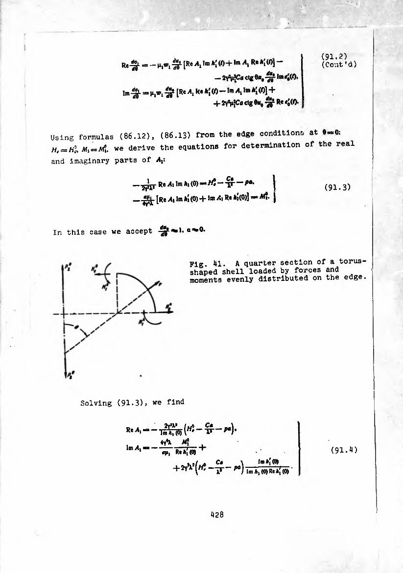
Re^ = - n,«, ^ [Re Ax in. A((0+1« R**i W] ~
— ctg 8«, 1m «¿(0.
1m -¾. = ti,», [Re \ R« *[ (/) - Im Ax Im *[ (/)] +
+ 2Y*|i|C« e^g ®*o "^T R* #o W-
(91.2) (Cont* d)
Using formulas (86.12), (86.13) from the edge condition at 0-0:
= M, == Al», we derive the equations for determination of the real
and imaginary parts of Af
—WRei4‘ I® MO)-
[R* Ax Im h[ (0)+ Im Ax Re *i(0)] — M?-
(91.3)
In this case we accept |f 1, a^O.
Pig. 41. A quarter section of a torus¬ shaped shell loaded by forces and moments evenly distributed on the edge.
Solving (91.3), we find
Re A,
Im Ax «A A«? , flji, Re A| (0)
Im A, (0)ReA, (0)
(91.4)
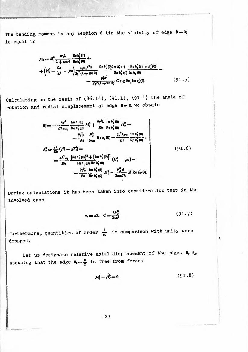
The bending moment in any section 0 (in the vicinity of edge 0 0)
is equal to
.. „u , x + t,ne Re*¡(0) n
/•■0 ^ r# “"F ~ ^)27^ +»ln 6)
C« \ Re*j (0) In» h[ (f) - Re *¡ (/) Im *{(0)
Re*; (0) 1m/1,(0)
(91.5)
Calculating on the basis of (.86.14), (91.1), (91.4) the angle of
rotation and radial displacement at edge 6 = 0. we obtain
,,_í¡LJíí^^+í^ií4®«; ' Eha\i) Re h[ (0) Eh Re*i(0)
Eh Xia Eh Re h[ (0) ’
aj=^f(.1-iiJi)=
_ *lVl lSf*i Wl’l- [lm(0)]] fu, _ )_ “ ' 1m hl (0) Re Aj (0) Eh
Eh Re h\ (0) InaEh
(91.6)
During calculations it has been taken into consideration that in the
involved case
vn — ai, C = XE\ Zia1
(91.7)
furthermore, quantities of order in comparison with unity were
dropped.
Let us designate relative axial displacement of the edges 0O. 0*.
assuming that the edge 0, = -3- is free from forces
m*=w;=o. (91.8)
429
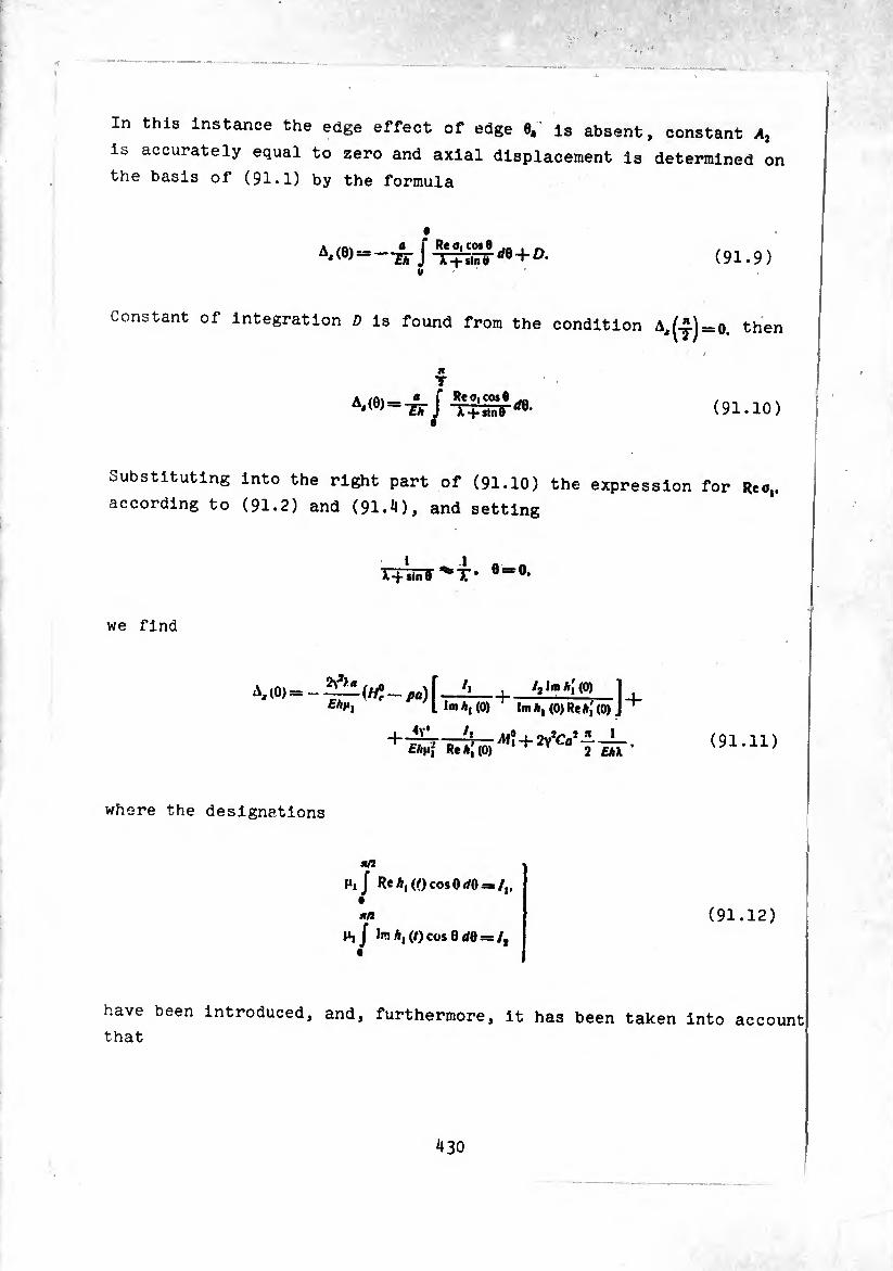
In this instance the edge effect of edge 0*’ is absent, constant At
is accurately equal to zero and axial displacement is determined on
the basis of (91.1) by the formula
m.9> V
Constant of integration D is found from the condition A,(-J) = 0. then
M
A'(0)==-¿rJ rffl- (91.10)
Substituting into the right part of (91.10) the expression for Reo,,
according to (91.2) and (91.4), and setting
I _ ■ 1 A r-Minè T* 8 = 0>
we find
A, (0) =-pa) f—Í!-¡-7»lm (0) ] ^•*1 I lm A, (0) lm A, (0) Re A,' (0) J +
£A|i¡ Re A,' (0) MÏ+rfCa i * 1
2 £AA (91.11)
where the designations
a/3
Ml / Re A, (0 cos 0//0 = /,,
a/»
hj lm A, (/)^5 01/0 = /, (91.12)
have been introduced, and, furthermore, it has been taken into account
that
430
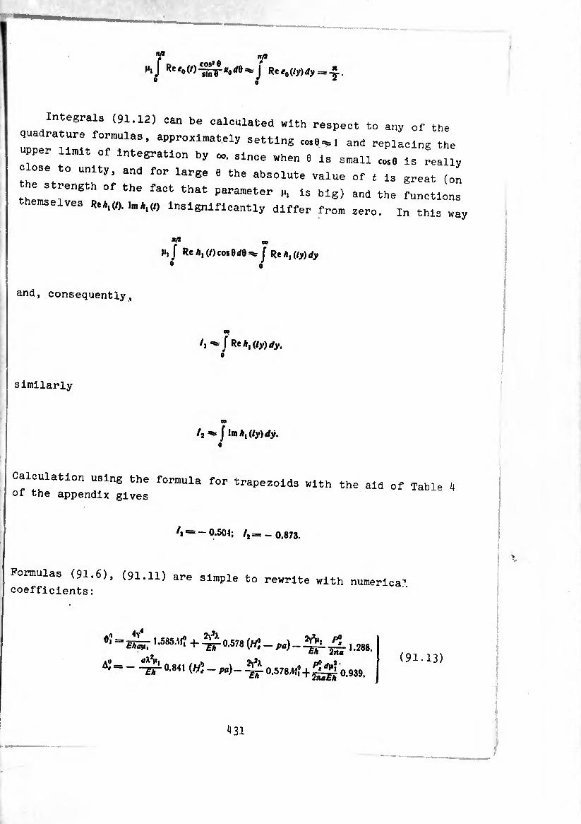
«/*
h/Re nfl r
ro(/)^F*orfe^ j Re *o = 4- o ^
Integrals (91.12) can be calculated with respect to any of the
quadrature formulas, approximately setting co.9^1 and replacing the
upper limit of Integration by since when 9 Is small [os„ i3 really
= ose to unity, and for large e the absolute value of t is great (on
the strength of the fact that parameter p, Is big) and the functions
emselves Re*,«). ta*l(„ Insignificantly differ from zero. In this way
^ to
M, J Rc A, (/) cos 0(/0¾ J Rth,(iy)dy
and, consequently.
/j J ReAji/y)^.
similarly
/j ^ J !m A, (ly) dy.
Calculation using the formula for trapezoids with the aid of Table 4 of the appendix gives
A == - 0.504; /2= _ 0.873.
Formulas (91.6), (91.li) are simple to rewrite with coefficients :
numérica?.
=í£¡7 '•«»»? + ^0.578 M 4., ,28i,
TT-0'811 (^-^)--^-0.578^ + ^^0.939.
(91.13)
^31
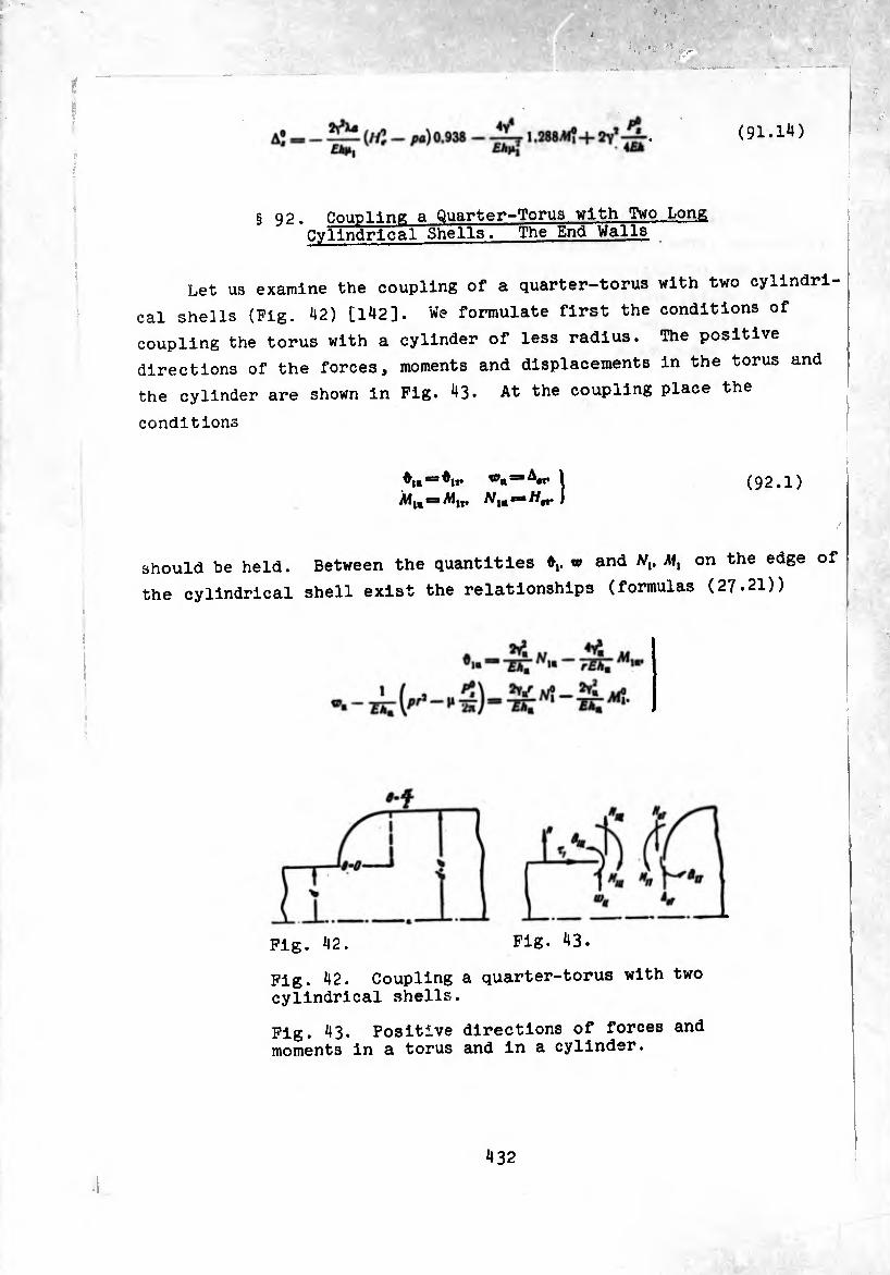
(91.11*)
§ 92. Coupling a Quarter-Torus with Two Long Cylindrical Shells. The End Walls
Let us examine the coupling of a quarter-torus with two cylindri¬
cal shells (Fig. 42) [142]. We formulate first the conditions of
coupling the torus with a cylinder of less radius. The positive
directions of the forces, moments and displacements in the torus and
the cylinder are shown in Fig. 43. At the coupling place the
conditions
Alw •=■ AJ1t, Nlm (92.1)
should be held. Between the quantities v> and Nv Ml on the edge of
the cylindrical shell exist the relationships (formulas (27.21))
Fig. 42. Fig. 43.
Fig. 42. Coupling a quarter-torus with two
cylindrical shells.
Fig. 43. Positive directions of forces and moments in a torus and in a cylinder.
4 32
Subsequently we assume that the thicknesses of the walls of the shells
are identical: An = AT Substituting the expressions for angle of
rotation and radial displacement in the torus and in the cylinder,
expressed by formulas (92.2), (91.6) through and , into the first
two conditions of (92.1) and taking into consideration that by the
remaining two conditions (92.1) Aí,B=iM,T = yM?. we obtain two
equations for determination of the moment and radial force at the
place of the connection:
»f !m h\ (0) 1 KM- r Mj* ImA.CO)]
p ft* -Ml Rte0(0)-^
H° Í t 1 [Re *í(0)]2+[»"« »i (0)1* 1 I 1m a/(0) Re h\ (0) )
mJ'* f, Im h[ (0) 1 0 n ,
R*(0) J ^= 2arf FIRe'o(0)'
)uring the composition of equations (92.3) It was taken into account
that
4YÍ — 4YÍ**
quantities of the order of — in comparison with unity also are
dropped. If we discard also quantities of order i ftr in comparison with
unity, then system (92.3) is still more simplified1 and the solution
assumes the form
M. I Re e0 (0) Re h[ (0) P]
1HT* Im h, (0)
_ ,, P'l f Reeu(0) [Re*; (0)-Im AÍ (0)] Re ^(0)1
‘‘•‘înrfj VI Im A| (0) »O 1'
(9^.4)
Substituting (92.4) into formula (91.14), it is easy to see that the
first term in the right part of (91.14) will be proportional to the pO
quantity 2Y’2HkMl*. and the second term to a quantity greater by a fac-
itor of M^ . In this way, with the accepted correctness of calculations

during the determination of Aj (and also during the determination of
Ai!, ôî) instead of (92.4) we can set
0 1 Rt e0 (0) Re (0) 1 = |i| 1m A, (0) ¿ni *
«, = 0.
I >
(92.5)
With the aid of the first formula of (91.6) it is simple to be
convinced that such a bending moment has under the edge conditions
0?=0. (92.6)
Considering the coupling of a torus with a cylinder of greater radius
(0 = -y' r=:a^*+,))< it is possible to arrive at the conclusion that also
in this instance the conditions of the coupling of the torus with the
cylinder can be approximately replaced by edge conditions of the form
0* = 0. //,* = 0. (92.7)
Note that under the conditions (92.7) the edge effect of edge 0*=«-£
is absent. The stressed state in the vicinity of this edge is
described by the particular solution which for large p, practically
coincides with the zero-moment solution. In this way, the end wall
shown in Fig. 44a can be approximately calculated as a quarter-torus
under edge conditions (92.6), (92.7).
Let us determine the maximum bending moment (it is equal to
41,(0) = Al?) and the axial displacement of the end wall (Fig. 44a). The
axial force acting in section 0 = 0. is equal to
P] = px = (tf - - J). (92.8)
where v.— radius of the thickening, while
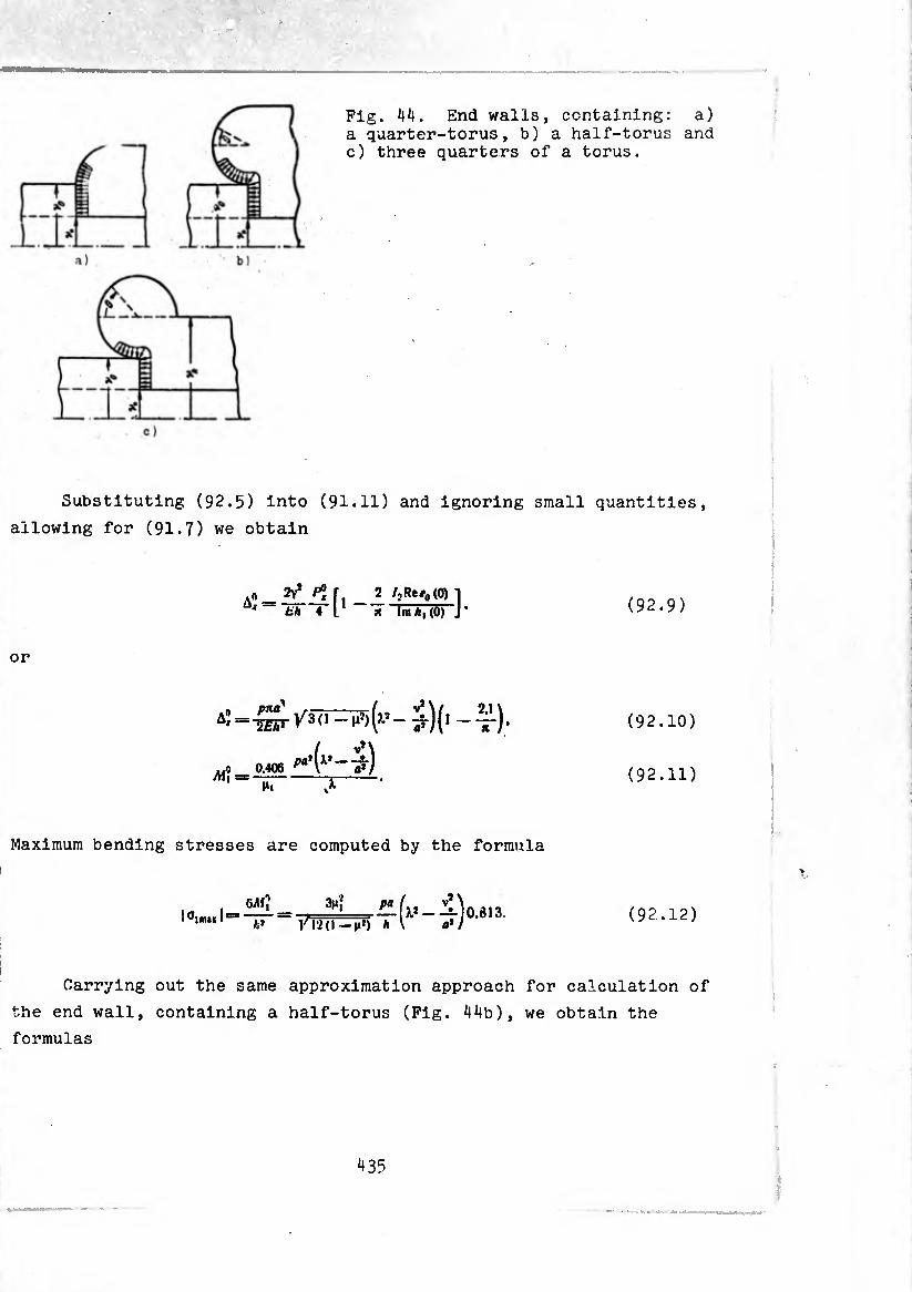
Fig. 44. End walls, containing: a) a quarter-torus, b) a half-torus and c) three quarters of a torus.
Substituting (92.5) into (91.11) and ignoring small quantities,
allowing for (91.7) we obtain
.0 Pj~ I- 2 /;Re<0(0) x 4 l * n Im A| (0) J ’ (92.9)
or
(‘•4) 4)-
Mi 0.406
Mi
(92.10)
(92.11)
Maximum bending stresses are computed by the formula
6AI? Jlmai I
fc* jiJ) h
3|«î pa (i*-^0.813. (92.12)
Carrying out the same approximation approach for calculation of
the end wall, containing a half-torus (Fig. 44b), we obtain the
formulas
43?
p¡ pn(y]~ v^.
c-Aí^v’-v!)
"W V^ãfi -- (i*) (xj -
(92.13)
(92.14)
(92.15)
Maximum bending stresses occur at g= + o (ft I,225\ and J and are equal to
I - _ ^'i pa „ V* \
T l!,l-„r, Tr íj0''“ (92.16)
r:«”“ •““* **•
During calculation of the litt ^arter-torua (length $<U<,). ration of the latter we must assume that on section
V. it* — at) Is applied an axial stretching force />, ,., , way, on this part of the torus v^. In this
1-4(4+(,-4),(-4,(,-¾
the axial displacement of this nart 4 (92.10). The total disnia l determined again using formul
total displacement of the wall is equal to
W /30 -^(x* -ÿj (92.17)
Bending stresses in sección fl=+fl
according to formula (92 161 aV ^ deterrnined (92.16), and stresses in section a 4-1-
place of coupling with th^ nui-i a \ ,=‘n (&t the that practlcllll til 0yll"der> formula (92.12). Note
carried e PllnS °f the t0rus «“h the cylinder Is carried out smoothly and the stress peak 1n th,. , „
AS the working stresses therefore we use tie It ^ ltS6] 0=16,. We use the stresses in sections
436

Let us compare the rigidity and the stressed state of end walls
of different form at an identical shell thickness h and constant
radij. Vq and v* (Pig. Í15). wall 1 is formed by a torus-shaped shell with the parameters
«<!) =3 —. =
j v> -f- V.
^ Œ V*—V« * ^<l) “-«(I)*«).
The axial displacement of the wall
in it are equal to
Pig. 45. End walls of different forms, which couple two cylinders of pre¬ assigned radius.
and the maximum bending stresses
A?* = _(_v*-Vq) r <v* + v#)’ ,1 Eh* 2 [ 4-
.20-^ .¾ W,_vD°'753'
Wall 2 contains a torus which possesses the dimensions
aW = V* - Vo. d{J) SB Vp.
*<»■* V*-V, • ^ = .
(92.18)
V* — V, *
according to (92.10), (92.12),
&
°î?„s
, ^ (i -¾.).
'»“(Vis«-,*))1'' 4^ W»-^8'3- (92.19)
Wall 3, containing a torus with aperture angle equal to -y-. has the
dimensions
fl(J) ■“ Vâ — V0- diS) =* V4. m, .
the axial displacement and maximum stresses in it are equal to
- Hr /30=7)(V. - v0)« - ^)(4 _ (92.20)
Let us make up the ratio of axial displacements
A^sA^îA?»-
, , j-Qn-fv.)» - »:] > [«-o 0 - ¥)]=[m - -
This ratio shows that of the examined three walls the most advantage©
with respect to rigidity (i.e., giving the least axial displacement)
is wall 2. Really, we minimize the values of first and third terms
of the ratio, replacing in them v4 by V then we get the ratio
from which it is clear that the displacement of wall 2 is less than
any of the minimized displacements of walls 1 and 3.
438

Comparing the ratio of maximum stresses, we have
Since
C(2) =
X<»> _ V* ^<S) V, ’
fl(3) = 2fl(l).
*(») _ v* ^õT v*+v* *
this ratio can be rewritten thus:
00):0^:0^ =
= [2''- - 'à 0.9Î6] : [(ff (4 - vD] : (<& - *D
In every concrete case it is simple to calculate the ratio of maximum
stresses in the walls of the involved types. For example, at
V* = 96 CM. V0 = 47.5 cm. v. = 26.5 cm
the ratio proves to be the following:
4000 : 2480: 8500 = 1.61 :1 : 3.43.
Wall 2 is in this instance the most advantageous with respect to
stress .
§ 93. Extension of the Lens Compensator
Let us examine the lens compensator, the half-lens of which
consists of two sections of a torus-shaped shell [1^0] (Fig. ^6).
439

¿
Fig. 46. The composition of edge conditions and coupling conditions of two sections of a torus-shaped shell forming the half-lens of a compensator.
Length I of the shell is characterized by a change in angular
coordinate 0 within limits from 0 to in section II 6 changes from
Ti to T . The directions of the normal and tangential vectors <«. r)
and positive directions of forces and moments are shown in the same
Place (Pig. 46). Formulas (86.12)-(86.14) and résolvant equation
(86.11) are adequate for a description of the stressed state of the
shell in section II. it is necessary only to take into account that
of the loads - pressure and axial force - have in this section
directions which are opposite those which were accepted earlier in
§ 86. In this way, instead of (86.11)-(86.14) we have
, ¿’o!' do" + s,n °> -553-cos 0 -rfT - 2ifai sin 0 = 4v4Ca cos 6.
7*11 __1 Fiwg,1 cos 8 r X.slne+1 pa 2l + s\n0 2y’ (/. + »10 0)» rd+smé)*-—rT-j-siné •
• Fm . Il _
rll 1 f ï 2 ~ W lr+i r+siné ,m*är
da\' cos 6 Im oj1 (). + sln
«i'l ■»FJ-
P& 1 /-»Ä X sin 0 -f-1 "r+Car(rf»ina)^
M;i_ • ffj1 *,n ® , cos 0 1 — V (Ä. + sin 0)* + Ca (X -f sin ö)i *
Ht — A/}1 sin 0 -j- 711 cos 0. = sin 0 -J- T*}1 cos 0.
w» a T * _ ^î* (1—|i)cos0 slnT^"^ TT+sInO)* Reo!']‘
Ai'«»* J fl«!1 cosOrfO + K,.
(93.1)
(93.2)
(93.3)
(93.4)
440
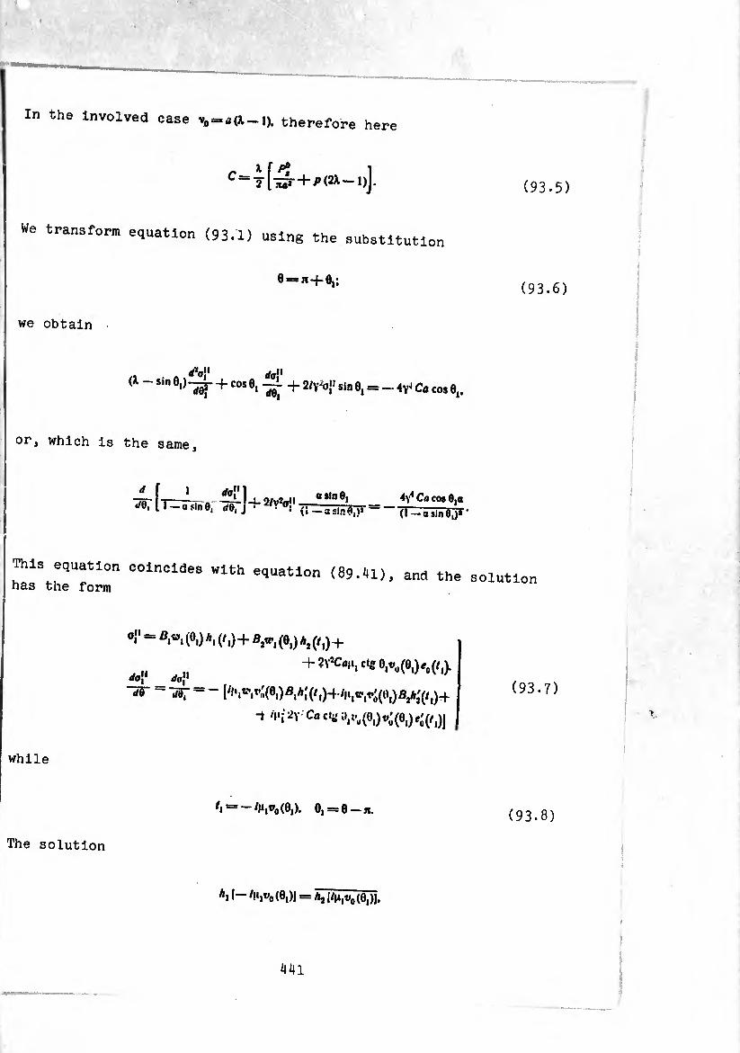
In the involved case v0 = a(X_i). therefore here
C = T [5* + ^ (2^-1)].
We transform equation (93.1) using the substitution
0==»+®,;
we obtain
(X sin 0,)-^- + cos 6,--+ 2/v-oJ' sin 0, = - Ca cos 0j,
or, which is the same.
_L d0" 1. ¢/, o„ii osinO, ^5T11 - a sin e, rfe, j + 2/V o!1 (l _a£|nA.,*
4y4 Ca cos 0,0 (1 — asinO,)*
This equation coincides with equation (89.41), and the has the form
0." = (0,) A, (M+v-, (0,) a2 (/,)+
dg[l +^^,0^0,^(0,)^(/,),
[^.^(0.)^^^,)+^,^(0,)^(/,)+
ï Co cl« 0,^(0,)^(0,)^(/,))
while
/, = -/M,oo(0,). 0, = 0 — n.
The solution
A, 1-4.,^(0,)) = ^^(0,)1.
(93.5)
(93.6)
solution
(93.7)
(93.8)
441
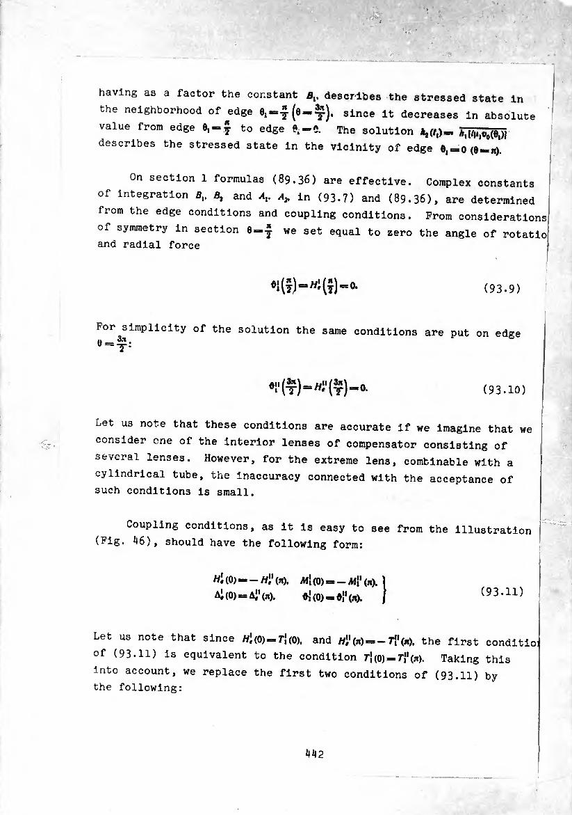
having as a factor the constant Bv describes the stressed state in
the neighborhood of ^edge 6, = 1(6 = ^). since it decreases in absolute '
value from edge 0, = j to edge 0.=5. The solution *,(/,)». ^[/^,^(0,)1
describes the stressed state in the vicinity of edge 0, = 0(0 = ^).
On section 1 formulas (89.36) are effective. Complex constants
of integration Bv Bt and Av a}. in (93.7) and (89.36), are determined
from the edge conditions and coupling conditions. Prom considerations
of symmetry in section 0 = ¾ we set equal to zero the angle of rotatio
and radial force
♦HîMHî)“0- (93.9)
For simplicity of the solution the same conditions are put on edge
(93.10)
Let us note that these conditions are accurate if we imagine that we
consider one of the interior lenses of compensator consisting of
several lenses. However, for the extreme lens, combinable with a
cylindrical tube, the inaccuracy connected with the acceptance of
such conditions is small.
Coupling conditions, as it is easy to see from the illustration
(Fig. ^16), should have the following form:
H* (0) - - W" (*). M\ (0) = - Ail1 (»). I
Ai (0) = A" (jx). ¢{(0) = ^(71). J (93.11)
Let us note that since //1(0) = 71(0). and //^) = -7^00, the first conditioi
of (93.11) is equivalent to the condition 7’}(0) = r”(n). Taking this
into account, we replace the first two conditions of (93.11) by
the following:
442
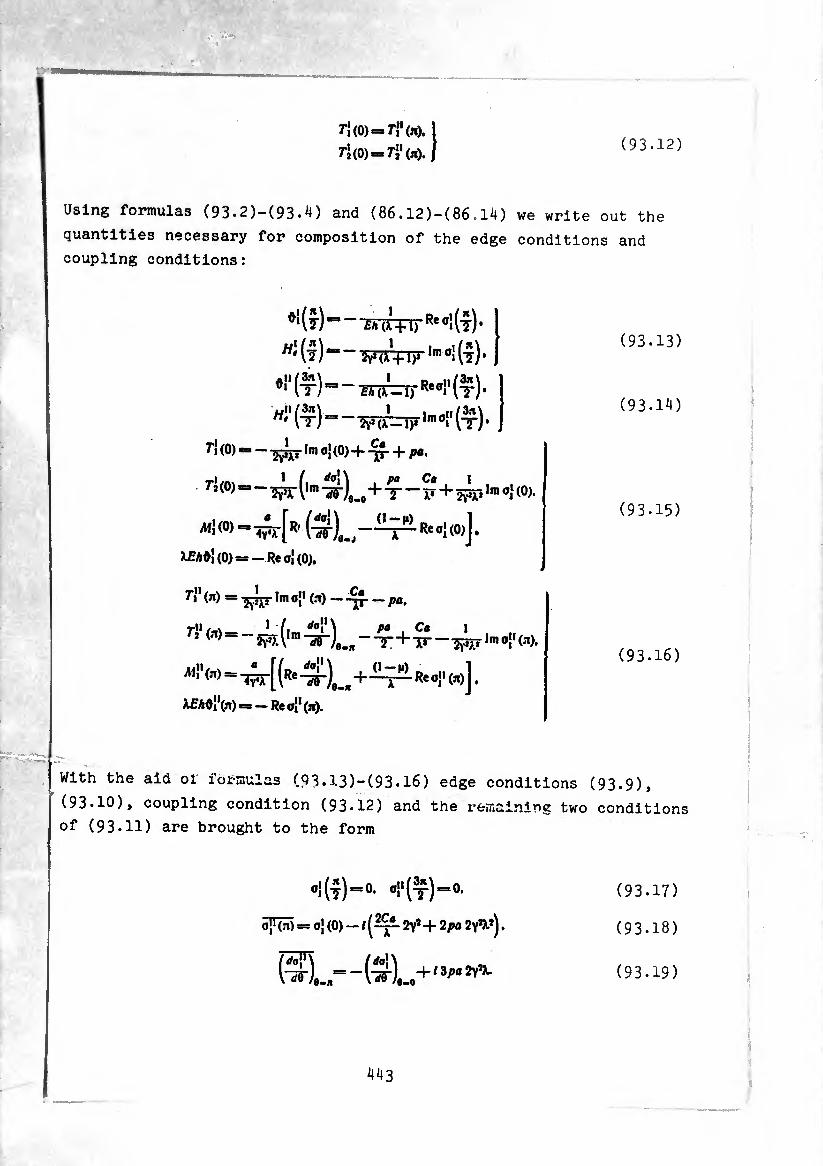
ri (0)-71'(io. 1
ri (0)-ri1 (n). I (93.12)
Using formulas (93.2)-(93.4) and (86.12)-(86.14) we write out the
quantities necessary for composition of the edge conditions and
coupling conditions:
- W-M)'Re °i (t) •
(-j) = — Tpjrpjr ,m °i (¾ •
H"(ir)—w=nF,mo"(x)‘,
r» (0) — —Im o{ (0)-f-+ ;>«,
ri (°) « - (,m +Ç - ^+_i_ Ini 0j (0).
M'(0) “ vr[R' (ir),.,""* k ^ Re 01 (°>J •
X£A0i(0)*=-Reoi(0).
rj1 (n) = Im oj1 (a) — — pa,
T"(n)ilm Ç+$ - w,m 0i'(a)-
XfAOiVn) — — Re a" (a).
d-n) Reo»(a)J,
(93.13)
(93.14)
(93.15)
(93.16)
With the aid of formulas (93.13)-(93.16) edge conditions (93.9),
(93.10), coupling condition (93.12) and the remaining two conditions
of (93.11) are brought to the form
°i(t)“0, ‘»"(t)“0’ (93.17)
5^ = 05(0)-/(^2-2^+2^ 2YW). (93.18)
(^5")e-,= “ fö'l-o4'1 *pa ^ (93.19)
443
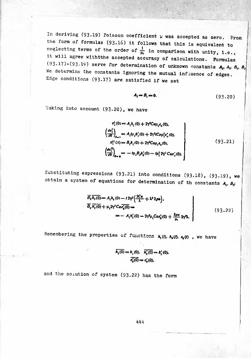
In deriving (93.19) Poisson coefficient y was accepted as zero. Prom
the form of formulas (93.1C) it follows that this is equivalent to
neglecting terms of the order of ¿ in comparison with unity, i.e.,
it will agree withtthe accepted accuracy of calculations. Formulas
(93.17)-(93.19) serve for determination of unknown constants Ay Bx, b2
We determine the constants ignoring the mutual influence of edges.
Edge conditions (93.17) are satisfied if we set
(93.20)
laking into account (93*20), we have
0¡ (0) = Alhx (0) + 2YîCayIe0 (0),
“ 'VMi (°) + (0).
0» (n) = B/ix(0) 4- 2vîCay1eo(0).
(w)#.!,“ ~ 2y2 Cfli'(0).
(93.21)
Substituting expressions (93.21) into conditions (93.18), (93.I9), we!
obtain a system of equations for determination of th constants Ax. B¿ j
B7hM-Axhx (0)-/2Y*(^f-4-X*2po).
m + y^Ca^õ) = ( 9 3.22 )
= - Axh[ (0) - 2YJM,Ca«'(0) + 2YJX. Pi
Remembering the properties of functions *i (O. Ai(*0. tf0(0 » we have
*2(0) = *,«)). Ã[(Õ) = a;(0).
íJ(Õ) = íó(0).
and i/he soxution of system (93.22) has the form
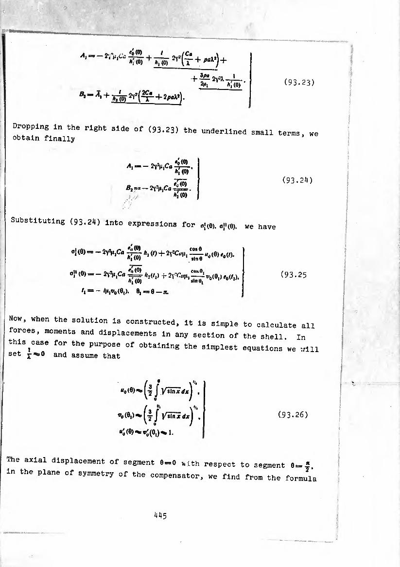
(93.23) ^_ Ä,(0)
Dropping i„ the right side of (93.23) the underlined small terms, we obtain finally
A,
! - 2yViC«
! — 2y3iI|&>
'o(O)
*Tw
ÏÏw’
(93.2^1)
Substituting (93.24) into expressions for o}(0). oj'(0). we have
o}(0). ~ 2Y'V,Cû A>(/) + ^ wo(0) e0(t).
o}' (0) - - 2V*n|Ca ~ Äjt/,) r 2^,^0(0,) A,(0)
- (0,). 0, =0 —n.
(93.25
Now, when the solution is constructed, it is simple to calculate al]
forces, moments and displacements in any section of the shell In
this ^case for the purpose of obtaining the simplest equations we wil
set and assume that
«o (0) ^ J Vslnjc dx^ ,
®o(0,)^(4j KslHTrfxj ’.
«ó (0)«^®'(0,)^1.
(93.26)
The axial displacement of segment 0 = 0 v* Lth respect to segment 0=-
in the plane of symmetry of the compensator, we find from the formi
445
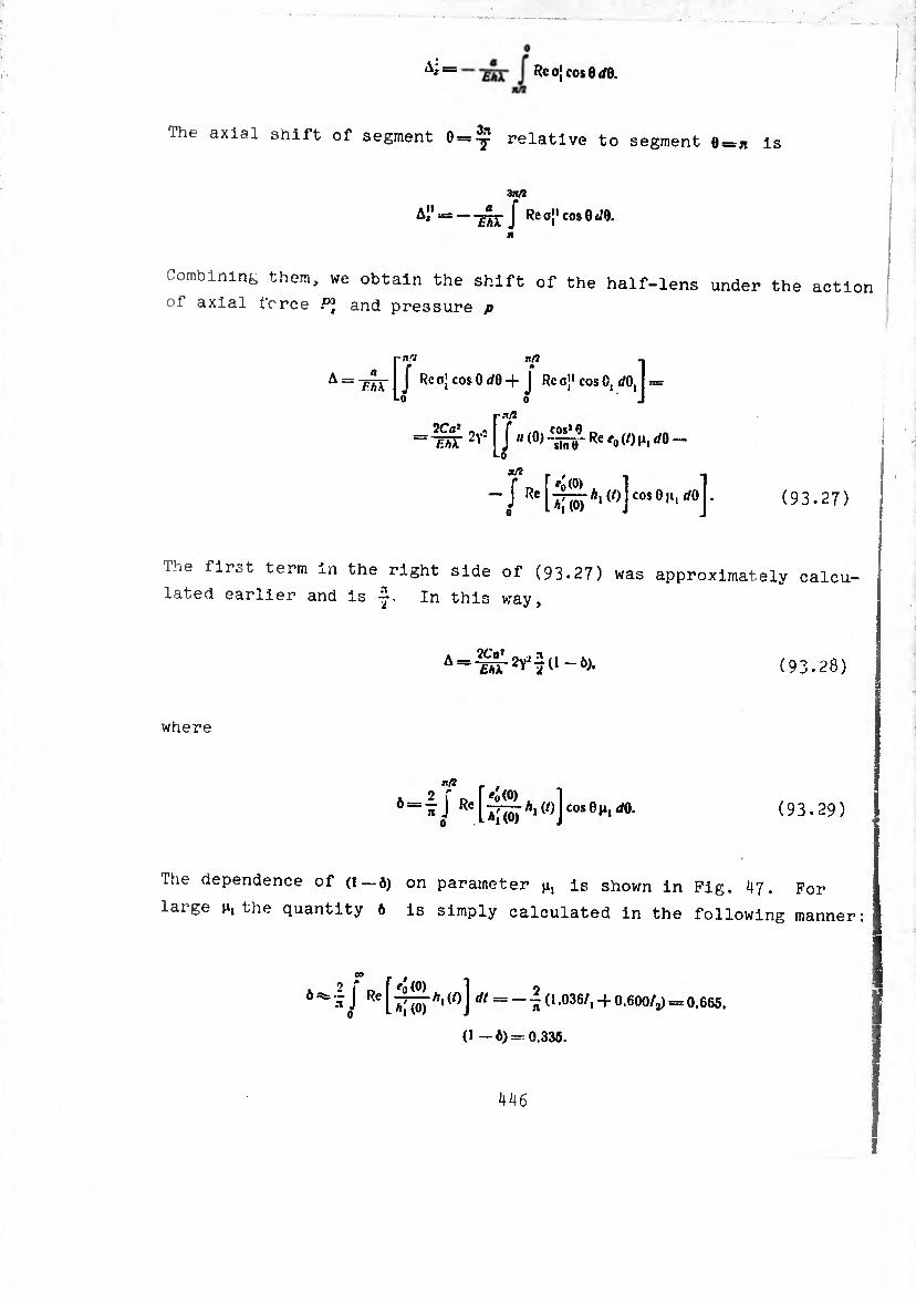
n is
A i I Rcojcos8d0.
The axial shift of segment 0 = ^ relative to segment 0 =
'■inti
A" = — J Re oj1 cos 0 </0.
Combining them, we obtain the shift of the half-lens under the action
of axial force P] and pressure p
IT * i = Re°lcoSOrf0+J Reoj1 cosO, </0,1 ==
= w 2v2 [ J « (°) Re 'o (0 Ih rfo -
-J Re[^A*(/)]cos0'‘-rf0]- (93.27)
The first term in the right side of (93.27) was approximately calcu¬
lated earlier and is -j- In this way,
A=m-2Yi^l-ò>« (93.28)
where
*/2 j. ,
0 = 1 j Re[-^Al(o]COse^dO. (93.29)
The dependence of (1—6) on parameter n, is shown in Pig. ^7. For
large n, the quantity 6 is simply calculated in the following manner:
, 2 r\ [So(0) i o ^ J Re l A* J ^ = - ^ o .036/, -f 0.600/j) = 0.665.
(1 —0)-0,335.

Fig. ¿47. Dependence (l-¿) from param eter m-
The relative deviation of the edges of the whole compensator,
consisting of two half-tenses, is equal to
2A = [pj. + p:^ (2).- 1)] (1 - Ò). (93.30)
Ca.lculating the derivatives . -^g-. and from them bending moments
/Mi' and bending stresses, we obtain
’ o{ = ± 6A1Ï
2ft r12(1
„ 6< O' = I-==
1 ^ ft*
'-—— -+- p (2X — 1 ) I Ac (0). 2(1 —1*0 L rt*»’ J
€n?a f P? 1 (93.31)
(93.32)
where
* (0) = e0(9) dg 0 Im c'(/) + 1.04 Im Aj (0 - 0.600 Re A[ (/).
/ = /jii«o(0).
A (0i) — “o (0i) ciZ 0ilm < (0 + 1 -04 Im A,' (0 ~ 0.600 Re Aj (/). / = /H,flo(0,).
In writing formulas (93-31), (93.32) it has been taken into
account that on part II of the half lens the bending moment is
considered positive, if it causes elongation of the interior filament 6A(H
Therefore stresses were calculated here using the formula 0,--= + -^,
in order that in both formulas the upper sign referred to stresses
in the external filaments of the half-lens and the lower to stresses
in interior filaments.
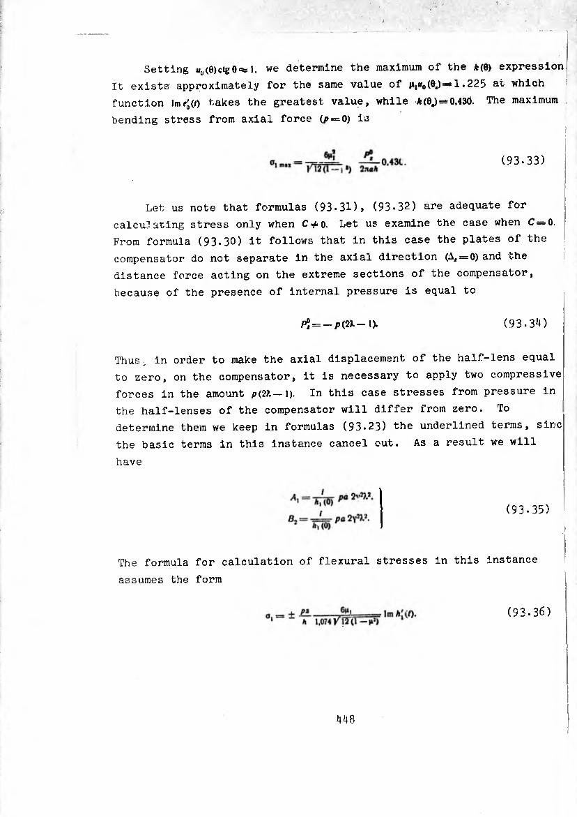
Setting uu(0)ctg0 =¾ 1, we determine the maximum of the *(6) expression
It exists approximately for the same value of 11,^(6.)=1.225 at which
function lmf'(0 takes the greatest value, while A(0J = 0,430. The maximum
bending stress from axial force (p — 0) is
(93.33)
Let us note that formulas (93.31), (93-32) are adequate for
calculating stress only when C*o. Let us examine the case when C = 0.
From formula (93-30) it follows that in this case the plates of the
compensator do not separate in the axial direction (^ = 0) and the
distance force acting on the extreme sections of the compensator,
because of the presence of internal pressure is equal to
(93.3*0 P°i = -P(2l- 1).
Thus . in order to make the axial displacement of the half-lens equal
to zero, on the compensator, it is necessary to apply two compressive
forces in the amount p(2?.— l). In this case stresses from pressure in
the half-lenses of the compensator will differ from zero. To
determine them we keep in formulas (93.23) the underlined terms, sine
the basic terms in this instance cancel out. As a result we will
have
(93.35)
The formula for calculation of flexural stresses in this instance
assumes the form
(93.36)
448
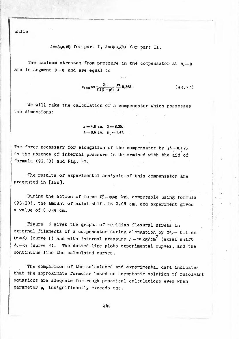
while
'=--'M,tfo(°) for* Part I, / = /(.^0,) for part II.
The maximum stresses from pressure in the compensator at A^o
are in segment e==o and are equal to
"'■““TsferT0-365- (93.37)
We will make the calculation of a compensator which possesses
the dimensions:
a = 4,8 cm. A, = 8,35.
h = 0.6 cm. p, = 1,47.
The force necessary for elongation of the compensator by 2\ = 0.l cm
in the absence of internal pressure is determined with the aid of
formula (93-30) and Pig. 47.
The results of experimental analysis of this compensator are
presented in [122].
During the action of force p” = 365C kg, computable using formula
(93-30), the amount of axial shift is 0.04 cm, and experiment gives
a value of 0.039 cm.
Figure 3 gives the graphs of meridian flexural stress in
' external filaments of a compensator during elongation by 2A,= o.l cm ÍP — 0) (curve 1) and with internal pressure /> = 20 kg/cm2 (axial shift
A, = 0) (curve 2). The dotted line plots experimental curves, and the
continuous line the calculated curves.
The comparison of the calculated and experimental data indicates
that the approximate formulas based on asymptotic solution of résolvant
equations are adequate for rough practical calculations even when
parameter n, insignificantly exceeds one.

Fig. 48. Meridia. flexural stress in external filaments of a compensator during elonga¬ tion by 0.1 cm (curve 1) and with internal pressure />*20
kg/cm^ (curve 2).
At the end of i 90 of this chatter on the basis of the asymptotlij
solution a tubular compensator was examined. Let us compare tubular
and lens compensators which possess an identical radius of the torus
a and identical radius of the tube (Pig. 49a, b).
Fig. 49. Lens (a) and tubular (b) Compensators, having identical radius of the torus and radius of the tube.
Comparing formulas (93-30) and f90.9), we see that at an assignee
force p* (p — 0) the shift of the lens comp nsator will be (1-0)=0.335
of the shift of a tubular compensator. Assuming that both compensator
must pick up the same temperature elongation or shortening of the
tube A, we find that in this case 0.335. From comparison of
formulas (90.5) and (93.33) at /» = 0 it follows that for equal A the
ilexural stresses in the lens compensator exceed stresses in a tubular
compensator, namely:
450
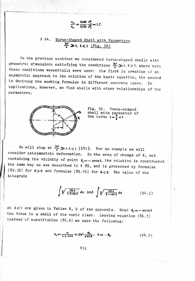
®L 0,430 /’J
~ ÕJ53 ~ ’7’
§ 9^. Torus-Shaped Shell with Parametprs 2v*
>.<1 (Fl^. 50)
In the previous sections we considered torus-shaped shells with
geometric dimensions satisfying the conditions ?.>1. where both
these conditions essentially were used: the first in creation of an
asymptotic approach to the solution of the basic equation, the second
in deriving the working formulas in different concrete cases. In
applications, however, we find shells with other relationships of the
parameters .
Fig. 50. Torus-shaped shell with parameter of the torus *- - < t.
We will stop at [i4l]. For an example we will
consider axisymmetric deformation. In the area of change of 0, not
containing the vicinity of point 0, = -arcsin?., the solution is constructed
the same way as was described in § 89, and is presented by formulas
(89.36) for 0>0 and formulas (89.^5) for e<0. The value of the
integrals
//4® dx and
8 _ f -,/ sln-r J V T^IÏÏTÏ dx (94.1)
at >.<1 are given in Tables 8, 9 of the appendix. Near 0, = -arcsin?.
the torus is a shell of the conic class. Leaving equation (86.7)
instead of substitution (86.9) we make the following:
°°=T+%¡nr (94.2)
45I

Then for determination of o, „e obtain the equation
where
(X~S,n°l)J^L +CO$0> ^ + 2^,510 0,-^(8,). (94.3)
^ co,0i . ^ cose, . 1 « l
+ 5I" - y ^S^-j + + (1-sin 0,)1-j ,.1¾ +(l_ .,,0,)-
■I 3 , COS e, \
nî-vJ
(94.4)
the orderfofavVinhc °f 0btalned equation we drop terms of X «nH comparison with unity. We introduce new variable«
T> COnneCted to 9l and o, by the relationships
*-/ Vr~- «*■ o,=tí*=ííí£;. B| ^ — ilnf (sin e,)1'-
in this case we find that , should satisfy the equation
d-t{2/v2+ 7+-1 An»j£Ä-LCOS*r is 1
+ A Az:iln 0| ] I — t(9.) 16 J/ (sme,)’
(94.5)
nr*
i 1 « sln>e. (94.6)
Improper integral (94.5) converges, since with the ; _ i ,) n , . , 6 * aince, with the exception of ' ' U-T- when T'ls =10^ to 0,.. the condition
V îlny 4|. +Ç , —f ^
sin y ! . — sinç I/ ~ V 2 _ * *
<i/HS_'_ ,/ã^r i 1 ^¡e^ST <*<o,.).
13 executed. "here is a bound quantity.
(90.7)
452

öi.. we can write Since when 01 is close to
* sin 0, _ sin 0,. - sin 0, ^ (0,. _ 0,) cos ^
^2(0,.-0,/^^,
then, in this case
. , n 1 cos* 0,. (9^.8)
form118 lnt0 aCC0Unt (9i|,8)» we wln rewrite equation (94.6) in the
</*T
dJC* + T[2/Y,-Ä + =
2ÍV2 p°t co>e, /i co*Je, \"v*
a 2a (Sln0,)’* 1,4 sin 0,. ) '
•).
»« = (94.9)
In the 1 , gnate termS “ntalnlnS higher positive powers ,,=,.
and the006, T"* ^ term °0ntalnlnS large parameter V is kept
in r alem0a ntrnrlarlty ^ SeParated> “^“ising the amo nt o ' increase of the function when 6,-.0,.. Let us note that the term - JL
when o,«»,. strongly differs from the corresponding term -J* «4'
n equation (96.6), however, inasmuch as in this case it is ' smln'Tn""'’'
comparison with W. this difference has no value. The equation
0+,(av’-£)=o" (94.10)
we call the »standard" with respect to uniform equation (96 6) un erstandlng by thls that the soiuMon of equatJon (;,<o9 • ;
cally approaches the solution of equation (94.6) with an IncreLe 0 parameter 2v- Eauatlnn roü -in\ i<-rease oi calculation of q !°n (94'10) consldered in s 66 during the calculation of a conic shell. Its solution has the form
y = *' • [CiMv* \ 2l) r C,htl (yx | J7)J.
453
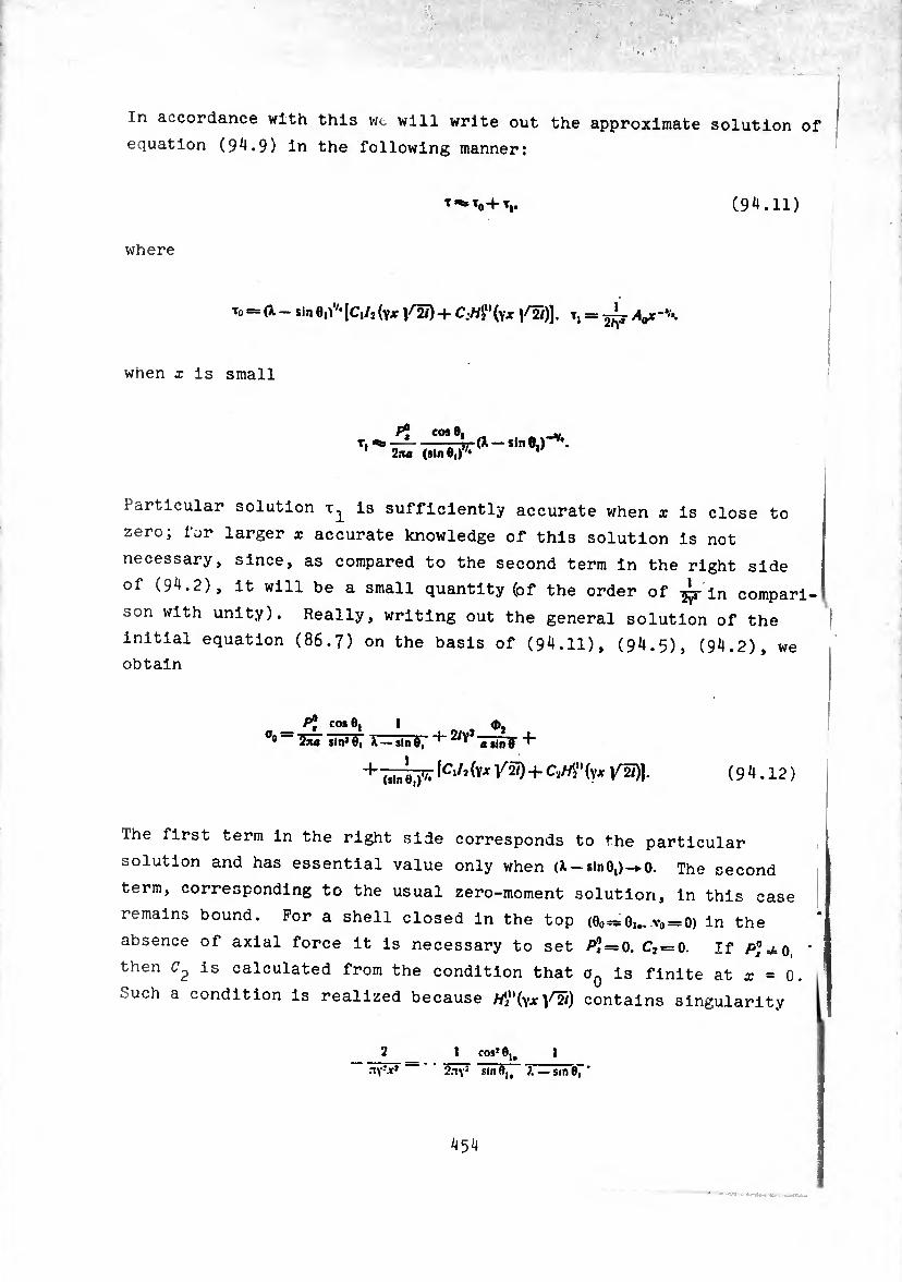
In accordance with this wt will write out the approximate solution of
equation (9^.9) in the following manner:
(9*1.11)
where
To = (i - Sin e,)*'* IC,/2 (YJf 1^5) + CM"(vx /2/)] • T, = A^k
when X is small
cos 0
2na (sin 0,)
Particular solution is sufficiently accurate when x is close to
zero; for larger x accurate knowledge of this solution is not
necessary, since, as compared to the second term in the right side
of (9^.2), it will be a small quantity (of the order of ¿-in compari¬
son with unity). Really, writing out the general solution of the
initial equation (86.7) on the basis of (94.11), (94.5), (94.2), we obtain
pj CO* 0, 1 <D,
0° ~ ina sin* 0, K — sin 0, a sln0 ^
+ lCl/î hx V*1) + (YJf /¾)]- ( 9 4.12 )
The first term in the right side corresponds to the particular
solution and has essential value only when (1 — sin-*• 0. The second
term, corresponding to the usual zero-moment solution, in this case
remains bound. Por a shell closed in the top (0O =¾0i*..v0 = 0) in the
absence of axial force it is necessary to set P] = 0, C2 = o. If ’
then C2 is calculated from the condition that a0 is finite at x = 0.
Such a condition is realized because (Yx/2/) contains singularity |

Satisfying the requirement that 0,,(0)13 bounded, we have
» a (sin co* 0U (9^.13)
As an example let us examine a closed shell when there is no
concentrated force in the top. From conditions of symmetry in segment
"j we place the conditions
0, = 0. /y,=o.
Ignoring the mutual influence of the edges 0 = —p and 0 = — , on th
basis of these conditions in solution (89.36) we set >42 = o and for
the area of change of 6, not containing the top, we write out the
solution of equation (86.11) in the form
°i = A\v\^\ (0.+ 2y2Cû|i, u¿0(t),
(1 +01511)0)^, / = /ji,tf(0). O<0<J.
a, = (/,) + 2v2Cfln, V(/o (/i).
= - 0 sin tf'' =* - 'hwoiß.).
0, = -0. 0,C0<O.
(9+14)
According to (86.9) the following solution of the initial equation (86.7) corresponds to it:
0° (X + sin 6) (^1¾) + 2y2Cûh| Uçfi0 (/)J 4.
■ W®, ' a sin 0 0<9<^.
°0 = (X —sin 0,) (— + 2y2Cû(i, ~|i t»0<r0 (- +
+ -¾¾ + ~(X+ ¿InO) slnS~ • 0. « 0 < 0 COS0
(94.15)
where P” = 0. v0 = 0 and
455
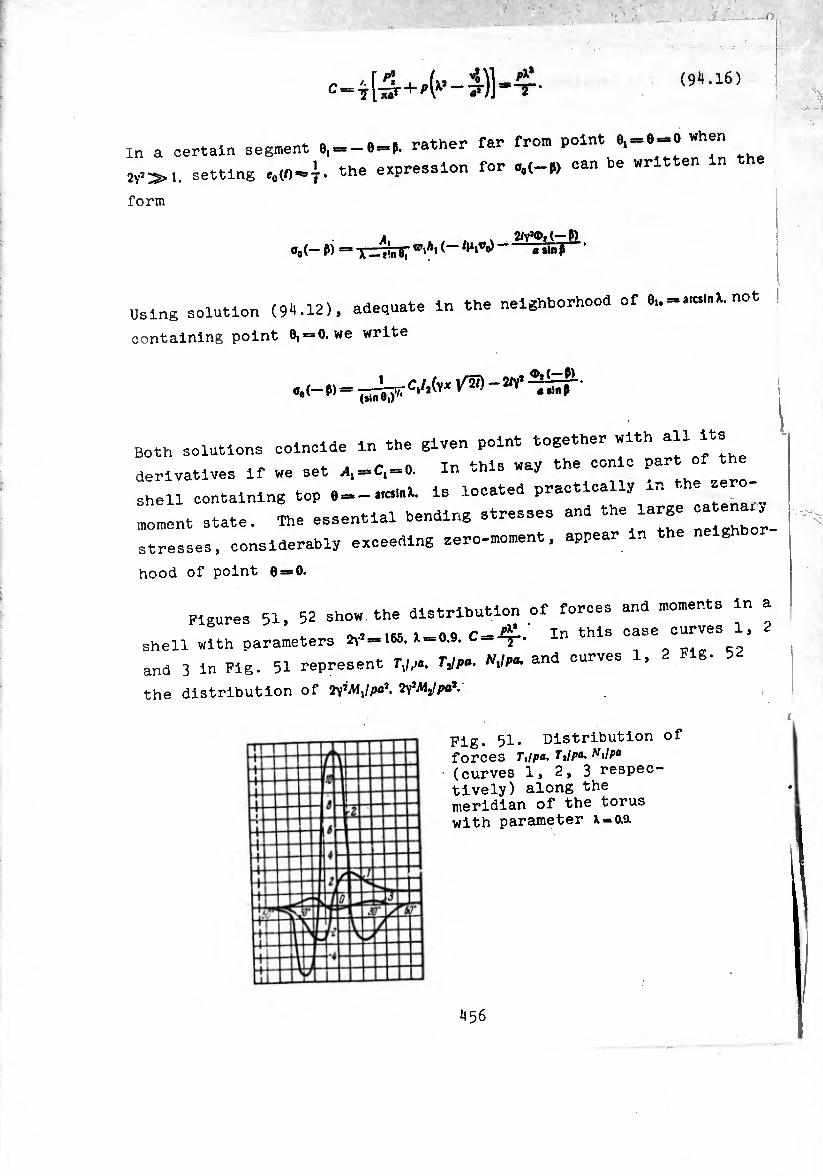
I
C = 7[4+'(1’-£)]' “T* (9^.16)
in a certain segment 6,—e = P. rather far from P°lnt the
2v^i. setting M0-|. the expression for o0(-W can be written in
form
A, . , . s g/Y^.C-P) o0(-“ P) = X —f'.nfi7 W‘A' ««»np ’
I
Using solution (94.12), adequate in the neighborhood of 0,. = . rami, not
containing point 0, = 0. we write
1
Both solutions coincide in the given point together with all its
derivatives if we set ^, = 0, = 0. In this way the conic part of
shell containing top , = -.^ is located practically in the zero-
moment state. The essential bending stresses and <*e large «
stresses, considerably exceeding zero-moment, appear in the neighbor
hood of point 8 = 0.
Figures 51, 52 show the distribution of forces and moments in a
-, lfic ,_0Q In this case curves 1, 2 shell with parameters = 165. X-0.9. C
and 3 in Fig. 51 represent T^a. TJpa. NJpa, and curves 1,
the distribution of Ty'MJpa'. tpMJpa*.
I
Fig. 51. Distribution of forces ft//»«. Ttlpa, Nilpa (curves 1, 2, 3 respec¬ tively) along the meridian of the torus with parameter x-o.a
456
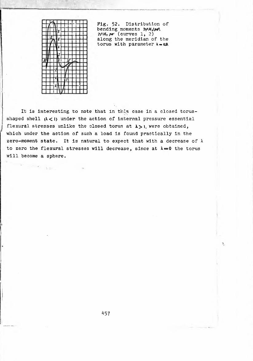
Fig. 52. Distribution of bending moments WMjpa*. WM, pa' (curves i, 2) along the meridian of the torus with parameter A.-.0.9.
■ i
It is interesting to note that in this case in a closed torus¬
shaped shell (X<l) under the action of internal pressure essential
flexural stresses unlike the closed torus at A.>i, were obtained,
which under the action of such a load is found practically in the
zero-moment state. It is natural to expect that with a decrease of X
to zero the flexural stresses will decrease, since at X = 0 the torus
will become a sphere.
i
iJ57
CHAPTER VII
internal stresses in shells op revolution
s 95- Formulation nf the
appeaLheinPraTlLsatbl0:tb:::ermdinatl0n °f -- ^e wMoh
-cea is the PnohleTo^'theM10: ^ total system of equations of í-h ° ^ °f elasticity* The
equations which eollct LlsL: “7 ^ expressed through dlsplacemeni- components of deformations
boundary 00.1^^^^
is considered). The eauattnn, e boundary conditions
(and perhaps also others) contal eqUlIlbrlum or boundary conditions
on the assigned externa i d
satisfy uniform differential elatT °f
which are Identities relative to the"3 eqUatl°nS or 0o»Patlbillt
On solving the problem under stresses^Tt ^ ^ consisting of eouatione e » * be system of equations
also „ritten in stresses” J he^rog^neoTeíthe'r^ 00mPatlblllty-
equations of equilibrium, or because of the ^^ilr
or eq“ î:„r:rbhLho„îni::si:: o“;probiem’the totai b-b»
and uniform static boundary conditlons,nbut0rheterogí°nS °f equations relative to the eo„„ , but heterogeneous differential
the components of s re b The“ T def0™atl0"- connected with
differential relation hlos b t ^ th-e now should be called eauati th6 COmponents of deformation
called equations of »Incompatibility, of deformations, j
^58

V.
«on If “h Pr m 13 °alled the dlsl0Mtl°" problem. An lllustra- lon of such a problem la the problem of the determination of
internal stresses In a body free from external forces during nonlinear
emperaure distribution In the space occupied by the body.8 7
H 20-23 the problem of determination of temperature stresses In a
ree shell of revolution was considered. The components of Internal
! of II“!.“3/"6 COnne°ted ln thlS lnStanCe Òy Unlf0™ j equilibrium, and they should satisfy uniform boundary conditions
e components of deformation consist of two members: the first
members are connected with forces and moments by the usual Hooke's
law (we call them conditionally the "elastic" tiont,') ^ . elastic components of deforma-
are 7 teL t “S U5 0311 the members) ta,nParatUre elon8atlons which would take place In the
dividual shell elements, are not connected with each other. The
total components of deformation should, of course, satisfy the
equations of compatibility, which now turn Into nonuniform differential
equations relative to the "elastic" components. The right part of
byetSLeqUT°nI deflne the inoompatiblIlty of the deformations Induced y the assigned temperature distribution.
formed dlal00atl0n «^nts of deformation In general can be
menls „Uh IT 7^3 eXPreSSlng ^formations through dlsplace-
formally thl lt t " fUnCtl0n’ “hlCh posses-s
th a L t r Ure a Ve°t0r °f dlsp1“—However, unlike the actual displacement, the potential function Is a multiple- valued vectorial function.
For the shells of revolution in which It appears an Internal
sxlsymmetrlc stressed state or a state which varies according to the
aw of cos * (sin ¢), let us formulate such a dislocation problem.
two :71,6 ?Xl3t Unif0r,n eqUations of statics. They admit the first n egra s. In which the constants of Integration are equal to
zero since external forces are absent. There exist also uniform
equations of compatibility. However, the constants of Integration
n the first two integrals of the equations of compatibility, unlike
the usual problem, now are not equal to zero. Internal fo7s and
459
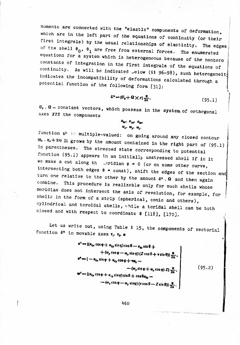
rr ar? COnr!eCted WUh the ,,ela5tl0” o°”P-ents of deformation,
«■irst H Tt left Part °f the eqUatlons of contlnuity (or their - Integrals) by the usual relationships of elasticity. The edges
I :/-1 V »1 are -ae from external forces. The Numerated
IstLts oTi/e^IuonTthi T^— ^ ^ ^ e integrals of the equations of i
on inulty As „in be indicated .elo„ (SS 96-98), such heterogeneltj
dica es the incompatibility of deformations calculated through a ’
potential function of the following form [31]:
</4 = (i/o+QXr]£, (95.1)
I" Hr3" VeCt0rS, WhlCh P0ssess in the system, of orthogonal axes xiz the components tt0x’ udy Uoi.
’s-
multiple-valued: on going around any closed contour
. • . .•» it grows by the amount contained in the right part of (95.1)
parentheses. The stressed state corresponding to potential
function (95.1) appears In an Initially unstressed shell if m it
we make a cut along th .aridlan 0 - 0 (or on some other curve,
r, ersecting both edges 6 » const), shift the edges of the section andl
turn one relative to the other by the amount ^.0 and then again ^
combine. This procedure is realizable only for such shells whose
meridian does not Intersect the axis of revolution, for example, for
shells in the form of a strip (spherical, conic and others),
cylindrical and toroidal shells, »hile a torldal shell can be both
c .osed and with respect to coordinate 0 [118], [170].
Let us write out, using Table § 15, the components of vectorial function £/* in movable axes t,. r2. *
“* “ K“«* cos ^ + "o, sin Ç.) cos 0 — sin e +
+ (a, cos <p — 0, sin ç) (Z cos 0+ v sin 0)J
“ I “ox sin ç + u0y cos <p vu»,_ ^
— (©ysin<p + ôxcosç)ZJ-^., (95.2) = I(«oxcosç + u,y sinqi)sin0 4 cos©«* —
— (wy cos 9 — w, sinç) (v cos 0 — Z sin 0)] .
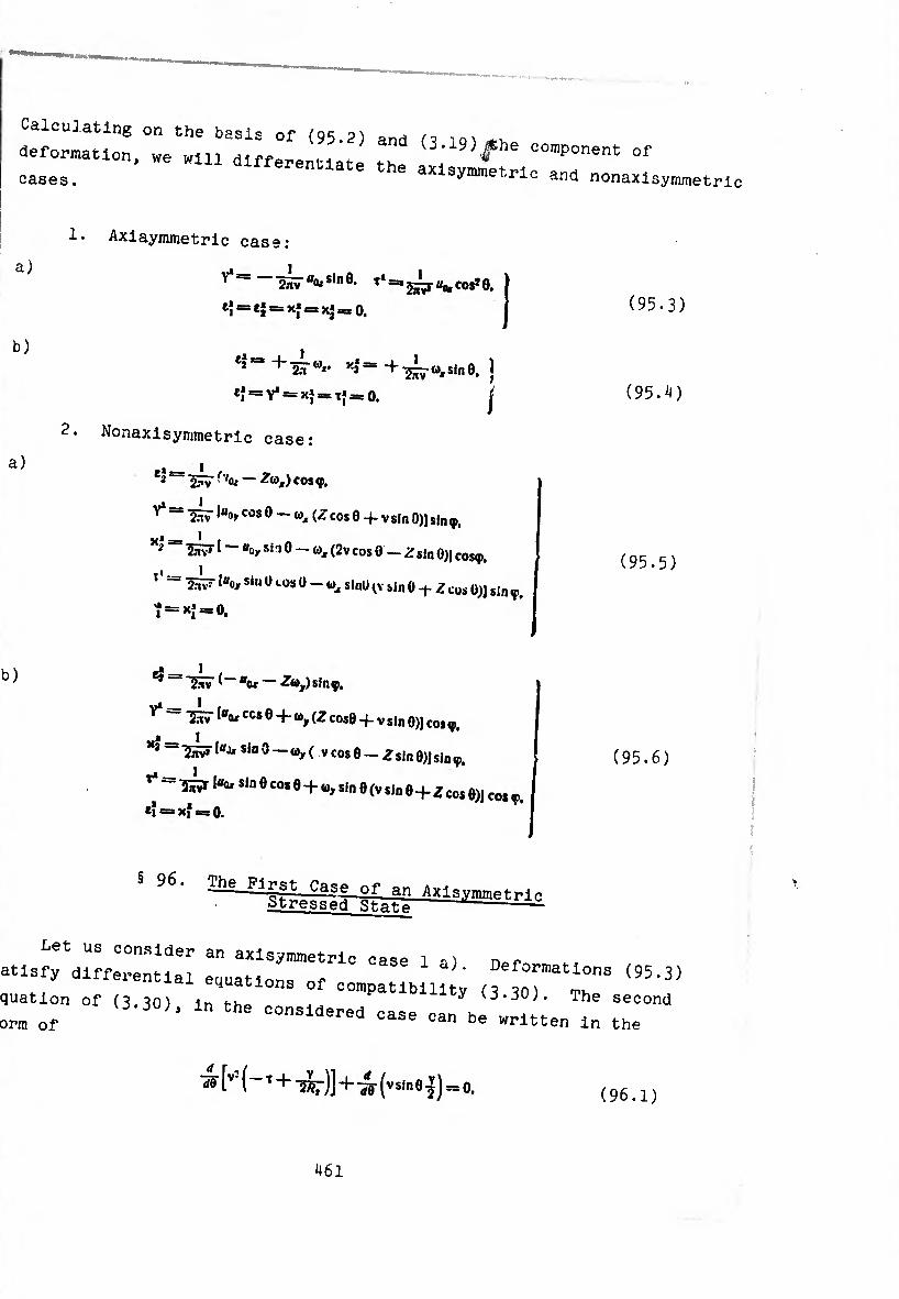
Calculating on the bas^s of . ^ deformation, „e wln dlfferenUate t" (3-19)fhe component of cases. ate the “isymmetrlc and nonaxlsymmetri,
1.
a)
b)
a)
b)
Axiaynunetric case:
^ 2ñ7®0ísln0. T* co*» 0,
e} = ej = xj = xj=0.
e2,=S+2H'Ö*• + w, sln0, j
ef = Y* *= = tJ = 0. J
Nonaxisymmetric case:
*a — < / 2 2^7 t<¡* ~ cos <f,
^ “ 2â7 •"»ycos 0 — «X (■? cos 0 4- y sin 0)1 sin ç.
** ~ 2S^71 — «o, sn O — ft), (2v cos 0 — Z $in 0)) Cos<p, 1
2nv! ‘“o, sin (Kos 0 - w, sinU (V sin 0 -t- Z cos 0)J sin V.
^ = ^ =
gt_ I Jiiv ' u0j ^Wyjsing),
^ = 1^7 •“or CCS 0 4- Ö, (Z cose -f V sin 0)J cos ç.
*3 = ^ 1“^ sJo 0 — ©, ( y cos 8 - Z sin 0)] sin <p.
^ =[«(u sin 0 cos 0 + sin 0 (y sin 0 + z cos 0)J cos ç.
(95.3)
(95.^)
(95.5)
(95.6)
Cl = xf = 0.
§96,
equation of (3.30) m tl -^«Wllty (3.30). The second form of (3-30)’ ln the considered case can be written in the
^H-' + Ty + wfvsIne^o. (96.1)
¿161
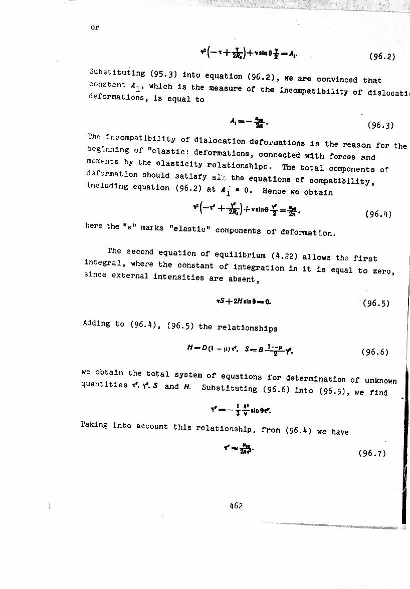
¢96.2)
Substituting (95.3) into equation (96.2), we are convinced that
Cons ant which Is the measure of the Incompatibility of dlslocatlt deformations, is equal to uisiocatiq
4 = - (96.3)
The incompatibility of dislocation deformations is the reason for the
-g nn ng of elastic: deformations, connected with forces and
moments by the elasticity relatlonshlpc. The total components of
ormatlon should satisfy all, the equations of compatibility.
Including equation (96.2) at ^ . 0. Hence we obtain
+^)+-^-9-5-=¾.
here the "e" matks »elastic» components of deformation.
(96.4)
The second equation of equilibrium (4.22) allows the first
n egral, where the constant of Integration In It Is equal to zero
since external Intensities are absent.
vS-{-2//sin 0>sO. (96.5)
Adding to (96.4), (96.5) the relationships
// = 0(1-,0^, 5 = Y*. (96.6)
quantities^6°f eqUatl0M f0r ^termination of unknown i and substituting (96.6) Into (96.5), we find
y*a~ j-^slnOt*.
laking into account this relationship, from (96.l|) We have

Internal force and twisting moment are equal to
S £ h* n(l l5v* sin Akq,.
V.
(96.8)
u Eh A* n «24(1 +n) "vT ■Of- (96.9)
The greatest tangential stress appear from the twisting moment
1½)I-¡r-r- (96.10)
§ 97• The Second Case of an Axlsymmetric Stressed State. Meissner Equations
We will consider axlsymmetric case 1 b) (§ 95). Substituting
deformations (95.4) into equations of continuity (11.5) and (11.7),
we find that (11.7) is satisfied Identically, and constant in the right part of (11.5), characterizing the incompatibility of dislocation deformations, is equal to
(97.1)
Deformations noted by "e" should satisfy the equations
vxî sin 0 + ~jï~ [■jg- (ve0 — *i^i cos aJ = —jjj-.
^ IV cos 0j(í— (ve0 - tiRi cot a] ¡ — xj«, = 0.
í Equations (97-2) express fact that total deformations (e' + eí). (eí-Mí) etc., satisfy equations (11.5), (11.7) at C1 = 0.
Adding to (97.2) uniform equations of statics, which are obtained from (11.1), (11.3) at ç,«=0. PÎ=»0.
lv (f, cos A + /V, sin 0)1 — 7*,*, «= 0.
^sinO —cos 0 = 0, (97.3)
(97.2)
463
(97.4) v/?iA'i=-¡s <v'M») - aí,#, cos e
and relationships of elasticity
^“-KTÍAÍj-üAf,). (97.5)
we obtain the total system of equations for determination of all
unknowns. Exactly as for the case of the usual axisymmetric problem,
we introduce function of stresses V and the function of displacements
With the aid of representations
vf.-rVcose. r,-,
•y/Vj « Vslni. (97.6)
XÍ:
XÎ:
s_ 1 ** ,_•, ~äS~ ‘ Jn^sln* 0
* ibtvsiat * i e* cos e = T sla6
(97.7)
(97.8)
equation of statics (97-3) and equation (97.2) are identically
satisfied.
Expressing ej. ej and Mt. Af, through functions V and V with the aid
of Hooke's law and formulas (97.6), (97.7), we obtain
.» _ 1 f V cot 9 tl 'Eh ( V
H dV\ TiTTr;*
eî= * / ÏÂ-l7?T d9 ** V )•
(97.9)
M, = — d(-J— 4- iL£21?_ 'i'1) _i_ n •« I 1 u \ « 17?T rfe ^ +
\ * 7?T^®/+ íã(tin1 e vsiae )’ Ai,= (97.10)
Substituting (97.9) into (97.8) and (97.10) into (97.4), taking into
account in this case (97-6), we obtain two equations for the
464
rrr10"of unknom functi°ns ^ -30Clated
(97.11)
(97.12)
^0 = 7-.
jffo ,/Äico^ ) rf/Urf» V ^ _20'j~5S“ +
_i_ur / »‘Ä,ilne Ä?cos*e\ . ä? + M V-^r-J + ^^-*in0Ko«
4. / r i f \ « \-j
i_jocoseß—n) / i , i \ j
Jy (R „ \ + £l± 1 ^|CQ»fl 1 áRx\ dVK
-^r"5rj"3r+
-f i/f^i*1"6 ^?to»>e\ fifsme °\ V-ïr~J-Y0=o.
It Is easy to see that the left parts of io? -i:n exoectPri , P °r (97-12), as was to be
The right parts of°(97 iJ)Ware ^ eqUatl°ns (12-6)‘ possess singularities if in e T fUnCtlonS> "hlch not turn into zero WUh the f ‘onsllered interval does not
ro. with these conditions, setting
0«Vo_2/v%.
it Is simple to find the approximate particular solution r (97.12). It has the form solution of system
o =
V tin3 0
-^,,= Reí ==0.
(97.13)
the“" (97-13) 00rresp0nds purely -ment stressed state of
Æ =-[- f i ,,1 ^ Xt 4y^ sin» eiT?7
Âi- = -[- / n j i * ^-»•«v’sin’e (97.1^)
since the forces f,. f„ computable by this solution, have an order
of magnitude of -ï* and stress fr01n the for¡;es
comparison with stresses from jñ m aa h/h i * Sma11 in Af,. Afj as h/b is small in comparison
465
with unity,
to setfj^fj In this way, with sufficient correctness it is possible 0. or
o. (97.15)
Let us note that the same solution can be
(97.2) eí = cí = o. The simplified equations
representations (97.7) at ¥=*<).
constructed by setting in
(97.2) are satisfied using
ne constructed solution does not satisfy conditions on the
edges e = const, which should be free from streses. The first
formula of (97.14) in this case gives us
Aï! (97.16)
In order to satisfy the edge conditions, for the obtained solution
it is necessary to supplement solutions of the edge effect or type
which satisfy the following requirements:
Al? — Æ?. 1
MΫ-Àïi. /*1 = 0. I (97.17)
§ 98* The Stressed State Proportional to cos (sin é)
Let us consider the event 2 a) (S 95). The amplitude of the
total components of deformation («!„,+<;,„). should satlsfv
equations of continuity (15.24), (15.25), (15.33) atcs=C,=o.
Taking into account formulas (95.5), we cttain the following
differential equations which connect the "elastic" components:
V W ,1, 9 + _ JÇi iÿ. _
—(*5(1) —*i ,1,) sin 0 ¢010 = 4-.¾. t
vcwe rfe* “S; '<»»cos 0 + e? in * 8 + eî(1) cos*0 -
X2 (I) V Sin 6 = — -i-(«0y — ¿ttjf). (98.1) JIV
- ^(1, - V 2/?, COS Or', + cos 0 4.
466
Excluding the domain 0 = o as thí» i
^ purely :™;r “ °r ~
we obtain
¿ . __ 1 , ‘11 ’ avA, *in» 0 ^Oy ^
;» i / 2 (I> Jív» sin 6 'Uj» — ^®x).
(98.2)
(98.3)
To 30lutl0„ (98.3) corresponds the purely _ stressed state
fit, av sin»
^ ( ^ I* \ Ky - ^).
m _ ï / |i i % 2 " av sïî?T J («0, — Z<ax),
r r - v J *1 =/2 = Ä, = 0.
(98.
Near the edges of the shell to state (98 if i the stressed state of edite effect t 9 ’ ’ 11 ls »«ossary to add conditions * tyPe Whl°h saMsfy ^e edge
«i = —/»,. A® ==0.
«! = —mj, aJ: >0. (98.5)
§ "* Ií?ternal Stresses in CyHnHr»^ni ^onlc and Spherical Shells L
Let us write out the equations for calculation of , , ,
formulas ^7^^00^7°^646 ^ P°r 3 ^^"^ica/s^ll
stressed state, assume the^orm ^ PUrely m0ment axlsy,n,netri':
M,
M3
t__»EhR -
(99.1)
getting =
determine the forces and moments of the edge effect ^
467
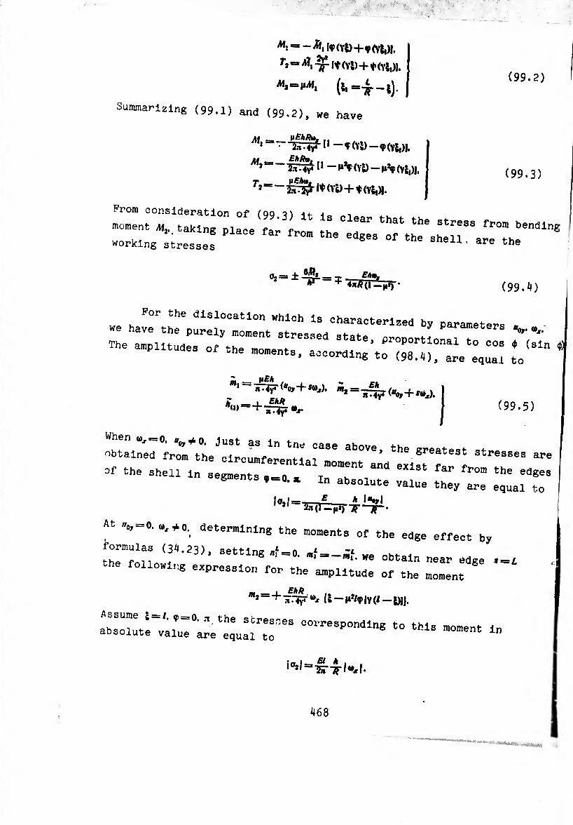
(99.2)
[SP(Yl)+f (Vii)!.
Summarizing (99.1) and (99.2), we have
Ai* I* — Ÿ(Yl) —ç(YÍ,)J. M __EhPv,
* "in-V 11 (Vl) — |i^p (Y5,)J,
T*==~ïÊ!ï}i- w (vy+fiYU- From consideration of (QQ it- -to „i
^ *b* - ~—
(99.3)
(99.4)
we have°rthehe dlS'O0atiOn ^1°11 ls characterized by parameters * „ have the purely moment stressed statP nr-^r.« 4-^ -, "
The amplitudes of ^he mom. , Proportional to cos <J> (sin ¢) .he moments, according to (98.il), are equ¡u to 1
Z _ (i£A , _ • iriyrK+s»,).
(99.5)
"::ir ir^e^«!:^:;^86 above> th—- — - of the shell m sel'“ . 7 t"0"6"1 ^ fr°” the
segments In absolute value they are equal to
10,1=-— A I"tyI
At V=0.-,4 0. determining the moments of the edge effect by
formulas (34.23), setting .f =.. ./ = _Ä. we obtaln near f_£
following expression for the amplitude of the moment
m — e/,fi m2“+7r.TiT®, U-iiJ/<p(Y(/-i)jj.
;rr- ■»-»• ■» i0il=sw^-l^l-
468
i

As we see from the considered illustration, edge effect has a
secondary value. Therefore for conic and spherical shells we will be
limited to the determination of stresses by the purely moment state.
Formulas (97.14), (98.4), allowing for the designations of § 44 for
a conic shell assume the form
I 6.0,
1 W
1 f
1- £ *, 1 1 4.t(l — h’) vcosß 1
i.. 1^1 2.1 (1 — [»*) vJ co» ß ^
(99.6)
For a spherical shell we have
Mt>
», «fe *«>
. 0(1—1») _
- :5£,¿ñig l«0y-R<cos0-co*0.)“xl.
Ä (cos 0 — COS 0,) 0,) —
jM,
»
•tÄ I
(99.7)
Io,j = Io,I =1^1 = •
1I “ 10JI = I -JT I = 2n (1 + n) ^ sin* e I “o» _ ^ (cos ® — cos 0,) ®x I*
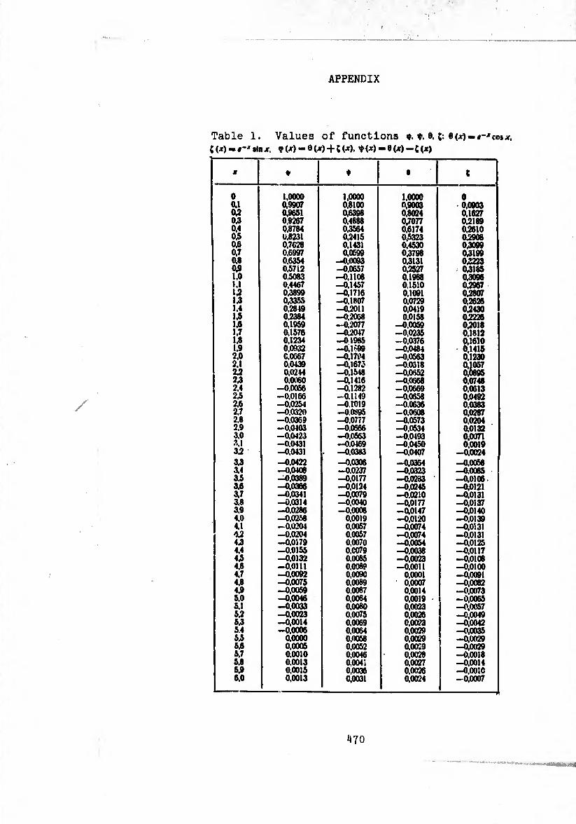
APPENDIX
Table 1. Values of functions cos CW-f-'rtnjr, <y(jr)-e(jr) + t(jt). t(jr)-0(x)-CW
M ♦ ♦ • (
0 <w W 0,3 0.4 0.5 04 0.7 0.8 04 1.0 U U U 1.4 14 14 1.7 14 1.9 2.0 2.1 24 24 2.4 24 24 2.7 2.8 2.9 3.0 3.1 34
34 3.4 3.5 3.6 V 3.8 3.9 4.0 4.1 44 44 4.4 44 44 4.7 4.8 44 5.0 5.1 54 54 5.4 54 5.6 5.7 5.8 5.9 6.0
1,0000 0,9907 0.9651 0,9267 0,8784 0.8231 0,7628 0,6997 0,6354 0.5712 0.5083 0.4467 0,3899 0,3355 0.2849 04384 0,1959 0,1576 0,1234 0,0932 0,0067 0,0439 0,0244 0.0080
-0.0056 -0.0166 -0.0254 -0,0320 -0.0369 -0.0403 -0,0423 -0.0131 -0,0431
-0.0422 -0,0106 -0,0389 -0.0366 -0,0341 -0,0314 -0.0286 -0.0258 —0.0201 -0.0204 -0,0179 -0.0155 —0,0132 -0.0111 -0,0092 -0,0075 -0,0059 -0.0046 -0.0033 -0,0023 -0.0014 -0.0006
0,0000 0.0005 0.0010 0.0013 0,0015 0,0013
1,0000 0,8100 0,6398 0,4888 0,3564 0,2415 0.1431 0.0599
-0,0093 -0,0657 -0,1108 -0,1457 -0,1716 -0.1807 -0.2011 -0.2068 -0,2077 -04047 -01985 -0.1 >99 —0,1794 —0,1673 -0,1548 -0,1416 -0,1282 -0.1149 -0.1019 -0.0895 -0.0777 -0.0666 -0,0563 -0.0469 -0.0383
-0.0306 -0,0237 -0,0177 -0.0124 -0,0079 -0,0040 -0.0008
0,0019 0,0057 0.0057 0.0070 0,0079 0.0085 0.0089 0,0090 0,0089 0,0087 0,0084 0,0080 0,0075 0,0069 0,0064 0,0058 0,0052 0,0046 0.0041 0,0036 0,0031
1,0000 0,9003 0,8024 0,7077 0.6174 0.5323 0,4530 0,3798 04131 04527 0,1988 0,1510 0,1091 0,0729 0,0419 0.0158
-0.0059 -0,0235 -0,0376 -0,0484 -0,0563 -0.0318 -0.0652 -0,0668 -0,0669 -0,0658 -0.0636 -0,0608 -0,0573 -0,0534 -0,0493 -0.0450 -0,0407
-0.0364 -0,0323 -0.0283 -0,0245 -0.0210 -0,0177 -0,0147 -0,0120 -0.0074 -0,0074 -0,0054 -0,0038 -0,0023 -0.0011
0,0001 0,0007 0,0014 0,0019 0,0023 0,0026 0,0023 0,0029 0,0029 0.0029 0,0028 0,0027 0,0026 0,0024
0 0,0903 0.1627 04189 0,2610 0,2908 0,3099 04199 04223 04185 0,3096 0,2967 0,2807 0,2626 04430 04226 04018 0,1812 0,1610 6,1415 0,1230 » 0,0748 0,0613 0,0492 0,0383 0,0287 0,0204 0.0132 0,0071 0,0019
-0,0024
-0,0058 -0.0065 -0,0106 -0,0121 -0,0131 -0,0137 -0.0140 -0,0139 -0.0131 -0,0131 -0,0125 -0,0117 -0,0108 -0,0100 -0,0091 -0,0082 —0,0073 -0,0065 -0,0057 —0,0049 -0,0042 -0,0035 -0,0029 -0,0029 -0,0018 -0,0014 -0,0010 -0,0007
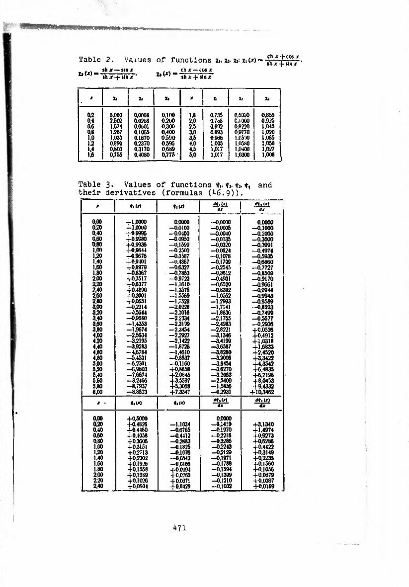
MKMMMMntMHH
Table 2. Values of functions Xi. Xj. x>- tiW
Xi W »hx—sin.» th X -j- »ln X ’
,, ch X — cos X *»(*>--,hx-Hlnx-
ch X -}-cos X »h X + sin X
jr X. x> Xi X. Xi Xi
os 0.4 0.6 0.8 1.0 IS 1.4 1£
5,003 2.502 1.674 1.267 1.033 0.690 0,803 0.755
0.0068 0.0268 0.0601 0.1065 0,1670 0.2370 0.3170 0,4080
o.ioo 0.200 0.300 0,400 0.500 0.596 0,689 0,775
1.8 2.0 2.5 3.0 3.5 4.0 4.5 5.0
0.735 0,7.58 0,802 0.893 0.966 1,005 1,017 1,017
0,5050 C.i.000 0.8220 0.9770 1,0530 1.0580 1.0400 1,0300
0.855 0.925 1.045 1,090 1.085 1.050 1,027 1,008
Table 3* Values of functions ÿi. ÿj. *j. t* and their derivatives (formulas (46.9)).
jr t.W ♦l(X> <*♦. (») dx dx
0,00 0,20 0,40 0,60 0.80 1.00 1.20 1.40 1,60 1,80 2.00 2,20 2.40 2,60 2,80 3,00 3.20 3.40 3.60 3.80 4,00 4.20 4.40 4.60 4.80 5,00 5.20 5.40 5.60 5.80 6.00
+1,0000 -1-1,0000 +0.9996 +0.9980 +0,9936 -1-0,9844 +0.9676 +0,9401 +0,8979 +0,8367 +0.7517 +0.6377 +0.4890 +0.3001 +0.0651 -0,2214 -0.5644 -0.9680 -1.4353 -1.9674 -2.5634 —3.2195 -3,9283 -4.6784 -5,4531 -6.2301 -6,9803 -7,6674 -8.2466 -8,7937 -8.8523
0.0000 -0,0100 —0.0400 —0.0950 —0,1599 -0.2500 -0.3587 -0.4867 -0.6327 -0.7853 -0.9723 -1.1610 -1,3575 -1,5569 -1.7529 -2,0228 -2.1016 -2.2334 -2.3199 -2.3454 —2,2927 -2,1422 —1.8726 —1,4610 —0,8837 -0,1160 +0,8658 +2.0845 +3.5597 +5,3068 +7.3347
—0,0000 -0,0005 -0,0040 -0,0135 -0,0320 -0.0624 -0,1078 -0,1709 -0,2545 -0,3612 -0,4931 -0,6520 -0.8392 -1,0552 -1.2993 —1,7141 -1,8636 -2.1755 -2,4983 -2,8221 —3.1346 -3,4199 -3.6587 -3,8280 -3,9006 -3.8454 -3,6270 -3,2063 -2,5409 -1,5856 —0,2931
0,0000 -0,1000 -0.2000 -0,3000 —0,3991 -0.4974 -0,5935 -0.6860 —0,7727 -0,8509 -0,9170 -0,9661 -0,9944 -0,9943 -0,9589 -0,8223 -0,7499 -0,5577 -0.2936 +0.0526 +0,4912 +1,0318 +1,6833 +2,4520 +3,3422 +4,3542 +6,4835 +6.7198 +8.0453 +9,4332
+10,3462
jr • ♦i<X) t.(x> *r,ui
0,00 0,20 0,40 0.60 0.80 1.00 150 1.40 1.60 1.80 2.00 2.-20 2.40
+0,5000 +0.4826 +0.4480 +0.4058 +0.3606 +0.3151 +0,2713 +0.2302 -f 0,1926 +0,1558 +0,1289 +0.1026 +O.0SO4
-1.1034 -0,6765 -0.4412 -0.2883 -0.1825 -0,1076 —0.0542 -0.0166 +0.0094 +0,0265 +0,0371 +0.0429
0,0000 -0,1419 -0,1970 -0,2216 -0.2286 -0,2243 -0,2129 -0,1971 -0.1788 -0.1594 -0,1399 -0.1210 —0,1032
+3,1340 +1.4974 +0,9273 +0,6286 +0.4422 +0.3149 +0,2235 +0.1560 +0,1056 +0.0679 +0,0397 +0,0189
471

Table 3« (cont'd.)
X t.U) 4<(') (*>
ax
2,60 2.60 3,00 3.20 3.40 3.60 3.80 4,00 4.20 4.40 4.60 4.80 5,00 5.20 5.40 5.60 5.80 6.00
+0,0314 +0,0455 +0,0326 +0,0220 T 0.0137 +0.CO72 +0,0022 -0,0014 -0,0039 -0 0056 -0,0066 -0,0071 -0.0071 -0 0069 -0,0065 —0,0059 -0,0053 —0.0046
+0,0446 +00447 +0.0427 +0,0394 +0,0356 +0,0314 +0.0260 +00230 +0,0192 +0.0156 +0.0125 +0.0097 +0,0073 +0,0053 +0,0037 +0,0023 +0,0012 +0,0004
-0.0868 -0,0719 -0,0586 -0,0459 -0.0369 -0,0284 -0,0212 -0.0152 -0,0104 -0.0065 -0,0035 -0,0012 +0.0005 +0,0017 +0,0025 40,0030 +0,0033 +0,0033
+0.0039 +0,0065 —0,0137 —0,0137 —0.02C4 —0,0213 —0,0210 -0,0200 -0,0185 -0,0268 -0,0148 -0.0129 -0,0109 -0,0091 -0,0075 -0.0060 —0,0047 -0,0036
Table b. Values of Airy functions *,</>•).M/y)
and their derivatives ^’^7 at !wmlr
1 Rt A, lm A. Rc*[ im *(
0 0.1 02 0.3 0.4 0.5 0.6 07 ‘JA 0.9 1.0 1.1 1.2 1.3 1.4 1.5 1.6 1.7 1.8 1.9 2.1 +1 2,2 2.3 2.4 2* 2.6 2.7 2.8 2.9 3.0 3.1 3.2 3.3 3.4 3.5 3.6 3.7 3.8 3.9 4.0 4.1 4.2 4.3
-0.000000 -0,039000 -0.077000 -0.11311» -0.146600 -0,177000 —0.203600 -0,-226200 -0.244600 -0.238700 -0,268400 -0,273800 -0,275300 -0,272900 -0.267200 —0.258300 -0.240800 -0,233100 -0.217600 -0.200600 —0,183200 -0.163100 -0.146800 -0,128000 -0,111500 -0,094930 -0.079330 -0,065020 -0.051950 -0,040250 -0,029950 -0,021030 —0,013470 -0,007192 -0,002114
0.001867 0,004665 0,006999 0,008389 0.009155 0.009412 0,009265 0,008813 0.008143 1
-1,974000 —1.007000 —0.936800 -0.871100 —0,803900 -0,737200 —0,671400 —0,606800 —0.543800 -0.482800 —0,424100 -0.368100 —0,315000 —0.26Ò300 -0,219200 —0,176700 —0.138100 -0,103500 -0,072650 —0.046100 —0,023160 —0,003660 +0.011940 +0,024530 -4 0.034160
0.041110 0,045690 0,048210 0,046970 0,046280 O.C46410 0,043659 0.040230 0,036380 0,f32280 0,028120 0.024010 0,020080 0.016410 0,013053 0,010053 0,007429 0,005182 0,003305
0,678300 0,678200 0.677300 0.674900 0,670300 0.6G3030 0,652400 0.636400 0,620700 0.599300 0,574200 0.545700 0.514100 0,4798(.0 0,443300 0,405200 0,366000 0,326400 0,287000 0,248300 0,210800 0,175100 0,141600 0,110600 0,082410 0.057160 0,034970 0,015870
-0,000170 -0.013260 -0.023580 -0.031310 -0,036700 - 0.01'.»20 -0.041540 -0,041550 -0.040330 -0,038140 -0,035230 -0,031830 -0,028,50 -0,024360 -0,020600 -0,016990
0.3916C0 0,386500 0.371900 0.349400 0.320100 0.285500 0,246800 0.205300 0.162300 0.118700 0.075700 0.034200
- 0.005000 -0,041200 -0,073900 - 0,102500 - 0.126800 - 0,146600 -0,162000 -0.172S00 - 0.179600 - 0.182300 - 0.181300 - 0,177200 - 0,170200 -0.160900 —0.149800 -0.137300 -0,123900 —0,110000 -0,096050 -0.08-2290 -0,059070 -0.056620 —0,045120 -0,034700 -0.925460 -0,017420 -0,010590 -0,004929 —0,000379
0,003146 0,005718 0.007537
bi2
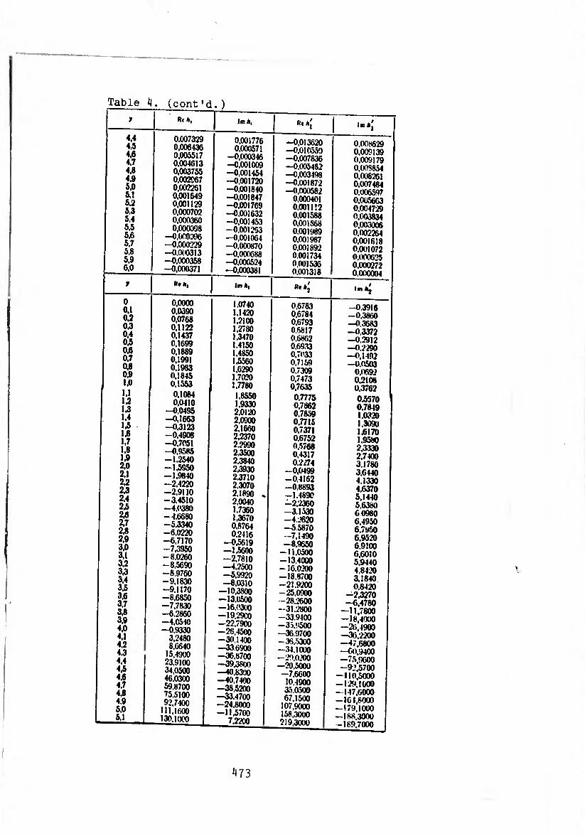
Table 4. (cont'd. )
y R< A, Jm A, Rt A.' 1 Im a|
4.4 4.5 4.6 4.7 4.8 4.9 5.0 5.1 5.2 5.3 5.4 5.5 5.6 5.7 5.8 5.9 6.0
0,007329 0,006436 0,005517 0.004613 0,003755 0,002567 0,002261 0.001649 0.001129 0,000702 0,000360 0.000098
-0,000096 -0,000229 —0.000313 -0,000358 -0.000371
0,001776 0,000571
-0,000346 -0,001009 -0,001454 -0,001720 -0,001840 -0.001847 -0,001769 -0.001632 -0,001453 -0.001203 -0,001064 —0,000870 —0,000688 —0,000524 —0,000381
-0,013620 -0.010550 —0.007836 -0,005482 -0,003498 -0,001872 -0,000582
0,000401 0.001112 0,001588 0,001868 0.001989 0.001987 0,001892 0.001734 0.001536 0,001318
0,008629 0,009139 0.009179 0.Ü0S854 0,008261 0,007484 0.006597 0,005663 0.004729 0,003834 0,003006 0.002264 0,001618 0,001072 0,000625 0.000272 0,000004
y R* A, Im A, Re Aj Im A^
0 0.1 0.2 0.3 0.4 0,5 0.6 0.7 0.8 0.9 1.0
U U U 1.4 U 1,6 1.7 1.8 1.9 2.0 2.1 22 22 2.4 2.5 2.6 2.7 2.8 2.9 3.0 3.1 3.2 3.3 3.4 3.5 3.6 3.7 3.8 3.9 4.0 4.1 4.2 4.3 4.4 4.5 4.6 4.7 4.8 4.9 5.0 5.1
0.0000 0.0390 0.0768 0,1122 0.1437 0,1699 0,1889 0.1991 0,1983 0.1845 0,1553 0,1084 0.0410
—0,0495 —0,1663 -0.3123 -0.4908 -0.7051 -0.9585 -1.2540 -1.5950 -1,9840 -2.4220 -2.9110 -3.4510 -4,0380 -4.6680 -5,3340 -6,0220 -6,7170 -7,3950 -8.0260 -8.5690 -8,9760 -9,1830 -9.1170 -8,6850 -7,7830 -6.2860 -4,0510 —0,9330
3,2480 8,6640
15,4900 23,9100 34,0500 46,0300 59,8700 75.5100 92,7400
111,1600 130,1000
1.0740 1.1420 1.2100 1.2780 1.3470 1.4150 1,4850 1.5560 1,6290 1.7020 1.7780
1.8550 1,9330 2.0120 2,0900 2,1660 2,2370 2.2990 2.3500 2.3840 2,3930 2.3710 2,3070 2,1890 .
2.0040 1.7360 1.3670 0.8764 0.2416
—0,5619 —1.5600 —2,7810 —4,2500 —5,9920 —8,0310
—10,3800 —13,0500 —16.0300 —19.29C0 -22,7900 -26,4500 -30,1400 —336900 —36.8700 -39,3800 —40,8300 —40,7400 —38,5200 —33.4700 —24,8000 -11,5700
7.2200
0,6783 0,6784 0.6793 0.6817 0,6862 0,69.33 0,7033 0.7159 0,7309 0,7473 0,7635
0,7775 0.7862 0.7859 0.7715 0,7371 0.6752 0,5768 0.4317 0.2274
-0.0499 -0,4162 -0,8893 -1.4890 -2.2360 -3.1530 -4.2620 -5 5870 -7,1490 -8,9650 -11,0500 -13.4000 - 16.0200 -18,8700 -21.9200 -25,0900 -28,2600 -31.2800 -33,9400 -35.9500 -36 9700 -36,5300 -34.1000 —29.0200 -•20.5000 -7,6600
10.1900 30,0500 67,1500
107.9000 158.3000 219.3000
-0.3916 —0.3860 —0.3683 —0,3372 -0.2912 -0.2290 —0,1492 -0,0503
0.0692 0.2108 0.3762
0.5370 1 0.7849 1,0320 1,3090 1.6170 1.9580 2.3330 2,7400 3.1780 3,6440 4.1330 4,6370 5.1440 5,6380 6 0980 6,4950 6,7950 6.9520 6.9100 6.6010 5,9440 4,8420 3,1840 0,8420
-2.3270 -6,4780
—11,7800 -18,4000 —26.4900 —36.2200 —47,6800 -60.9400 -75.9600 -92.5700 -110.5000 -129.1000 -147,6000 -161,8000 —179,1000 — 188,3000 -189,7000
^73
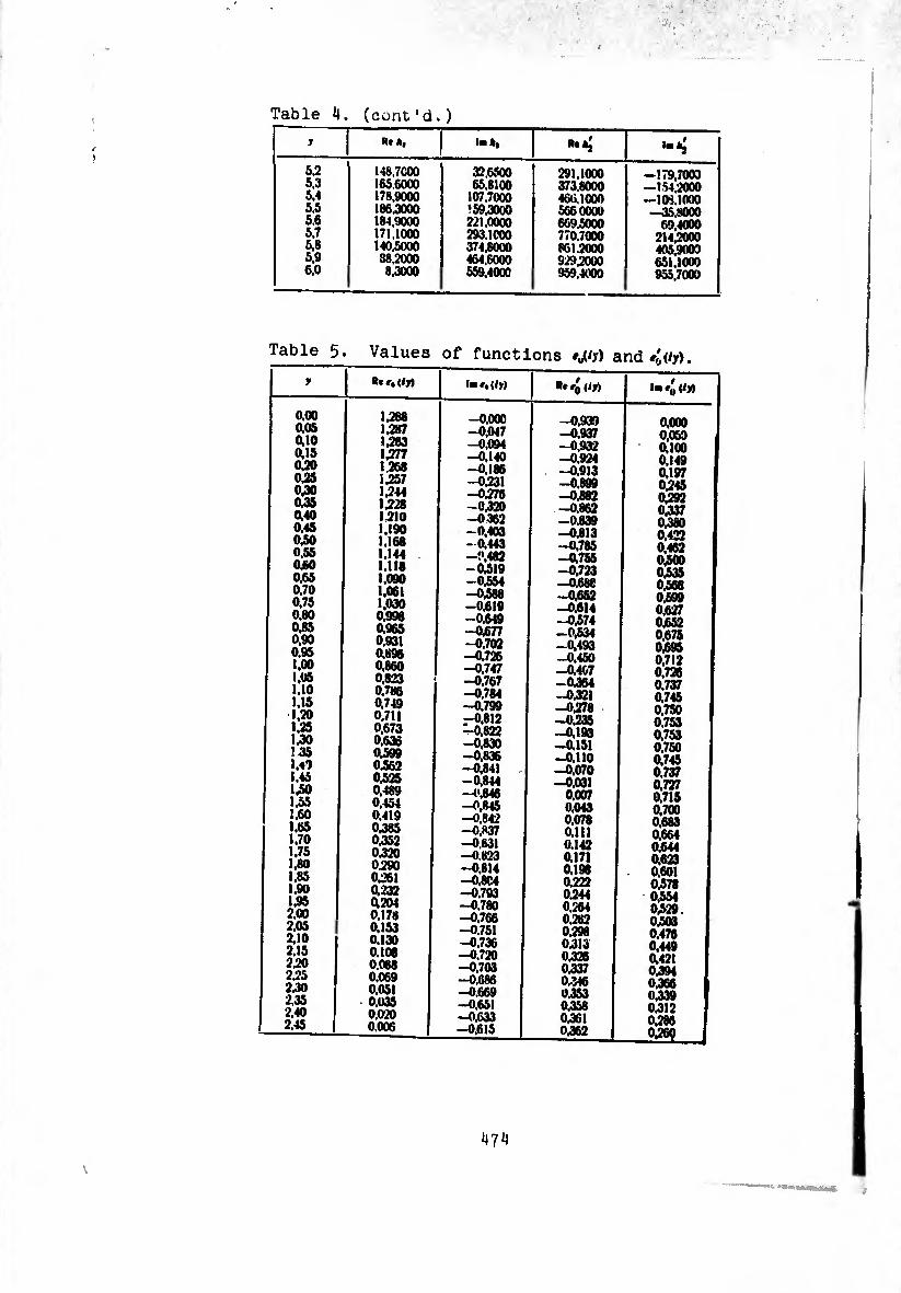
Table A. (cont'd.)
y Rt A, la A, R.AÍ ï •T
.
Ò2 5.3 5.4 5.5 5.6 5.7 5.8 5.9 6.0
148.7COO 165.6000 178.9000 186.3000 184.9000 171.1000 140.5000 38.2000 8,3000
32.6500 65.8100
107.7000 159,3000 221.0000 293,1000 374.8000 464.6000 556.4000
291.1000 373.8000 466.1000 5660000 669,5000 770.7000 861.2000 929,2000 959.4000
-179,7000 —154.2000 —108.1000 -35.8000
69,4000 214,2000 405,9000 651.1000 955.7000
Table 5. Values of functions t¿iy) and *£</y).
y *« (<jr) j !■».«») !■ 'ó M
0.00 0.05 OHO 0.15 0.20 0,25 0^0 0.35 0140 0.45 0^0 0.55 0^0 0,65 0,70 0.75 0,80 0.85 0,90 0.95 1.00 1.05 1.10 1.15 1.20 1.25 1.30 135 1.49 1.45 1.50 1.55 1.60 1.65 1.70 1.75 1,80 1.85 1.90 1.95 2,00 2.05 2.10 2.15 2.20 2,25 230 2.35 2.40 2.45
1.288 1387 1,283 1377 1.268 1357 1344 1328 1310 1.190 1.168 1.144 1.118 1.090 1.061 1.030 0.996 0.965 0.931 0.896 0.860 0.823 0.786 0.749 0.711 0.673 0.636 0.599 0,562 0525 0.489 0.454 0.419 0385 0352 0320 0.290 0.261 01232 0.204 0.178 0.153 0.130 0.108 0.068 0.069 0.051 O.U35 0.020 0.006
-0,000 -0.047 -0.094 -0.140 -0,186 -0331 -0376 -0.320 -0362 -0.403 -0,443 -0,482 -0519 -0554 -0588 -0519 -0.649 -0577 -4).702 -0.726 -0.747 -0,767 -4).784 -0.799 -0.812 -0.822 -0.830 -0.836 -0.841 -0.844 -0,846 —0,845 -0.842 —O.R37 -0.831 -0.823 -0.814 -4).804 -4).793 -0.780 -0.766 -0.751 -0.736 -4).720 -0,703 -0.686 -0.669 -0.651 -4).633 -0.615
-0.930 -0.937 -0,932 -0.924 -0,913 -0.899 -0582 -0.862 -0.839 -0313 -4).785 —0J55 -0.723 -0588 -0.652 -0.614 -0574 -0534 -0.493 -0.450 -0,407 -0364 -0521 -0378 -0335 -0.193 -0.151 -0.110 -0.070 -0,031
0,007 0.043 0,078 0.111 0.142 0.171 0.198 0.222 0.244 0364 0382 0.296 0313 0326 0337 0546 0353 0358 0361 0362
0,000 0,050 OllOO 0,149 0,197 0345 0392 0337 0380 0.422 0,462 0500 0535 0568 0599 0,627 0552 0,675 0595 0.712 0,726 0,737 0,745 0.750 0.753 0.753 0,750 0.745 0,737 0.727 0.715 0,700 0,683 0.664 0.644 0.623 0,601 0578 0.554 0529.
0503 0.476 0,449 0.421 0394 0366 0339 0312 0386 0360
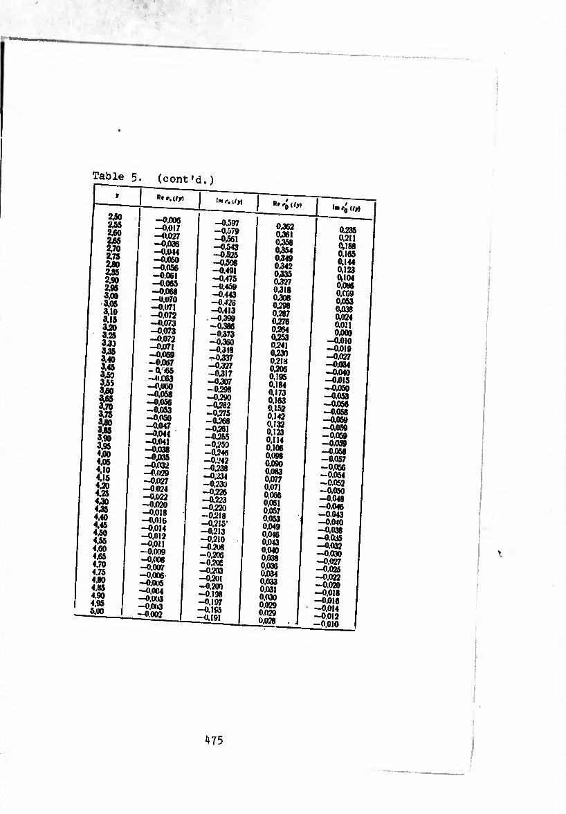
Table (cont'd.)
R*
—0,008 -0.017 -0.027 -0.036 -0.044 —0,050 -0.056 -0.061 -0.065 -0.068 -0.070 -0.071 -0.072 -0.073 -0.073 -0.072 -0.071 -0.069 -0.067 -01-65 —O.C63 -0,060 -0.058 -0.056 -0.053 -0,050 -0.047 -0.044 -0.041 -0.038 -0.035 -0.032 —0,029 -0.027 -0.024 —O.Ü22 -0.020 -0.018 -0.016 -0.014 -0.012 -0,011 -0.009 -0.008 -0.007 -0,006 -0,0(6 -0.004 -0.003 -0,003 —0.002
(m r, (/y)
—0,597 —0,579 —0,561 -0.543 -0,525 -0,508 -0.491 -0.475 -0.459 -0.443 -0.428 -0.413 -0.399 -0.386 —0,373 -0,360 -0.318 -0^37 -0.327 —0,317 -0307 -0.298 -0390 -0,282 -0.275 -0.268 -0361 -0355 -0350 -0346 -0.242 -0,238 -0334 -0,230 -0.226 -0,223 -0,220 -0318 —03I5"
—0,213 -0.210 -0.208 -0.206 -0.2«
-0.203 -0.201 -0.200 -0.198 -0.197 —0.1S5 -0.191
0.362 0361 0358 0354 0349 0342 0335 0.327 0,318 0,308 0398 0387 0376 0364 0353 0341 0330 0,218 0.206 0.195 0.184 0.173 0.163 ai52 0.142 0.132 0.123 0.114 0.106 0.098 0.090 0.083 0.077 0.071 0.066 0.061 0.057 0.053 0.049 0.016 0.043 0.040 0.038 0.036 0.034 0.033 0.031 0.030 0.029 0.029 0,028
0.235 0,211 (U 88 0.165 <M44 0,123 4104 0,086 0,CG9 0,053 4038 4024 0,011 0.000
-0,010 -0.019 -0.027 -0,034 -0.040 -0015 -0.050 -0.053 -0056 -0.058 -4059 -0.059 -0.059 -0.059 -0.058 -4057 -0.056 -0.054 -0.052 -0.050 -0.048 -0.046 -0.043 -0.040 —0,038 —0.035 -0.032 -0.030 -0.027 -0.025 -0.022 -0.020 -0.018 -0.016 -0.014 -0012 -0,010
475
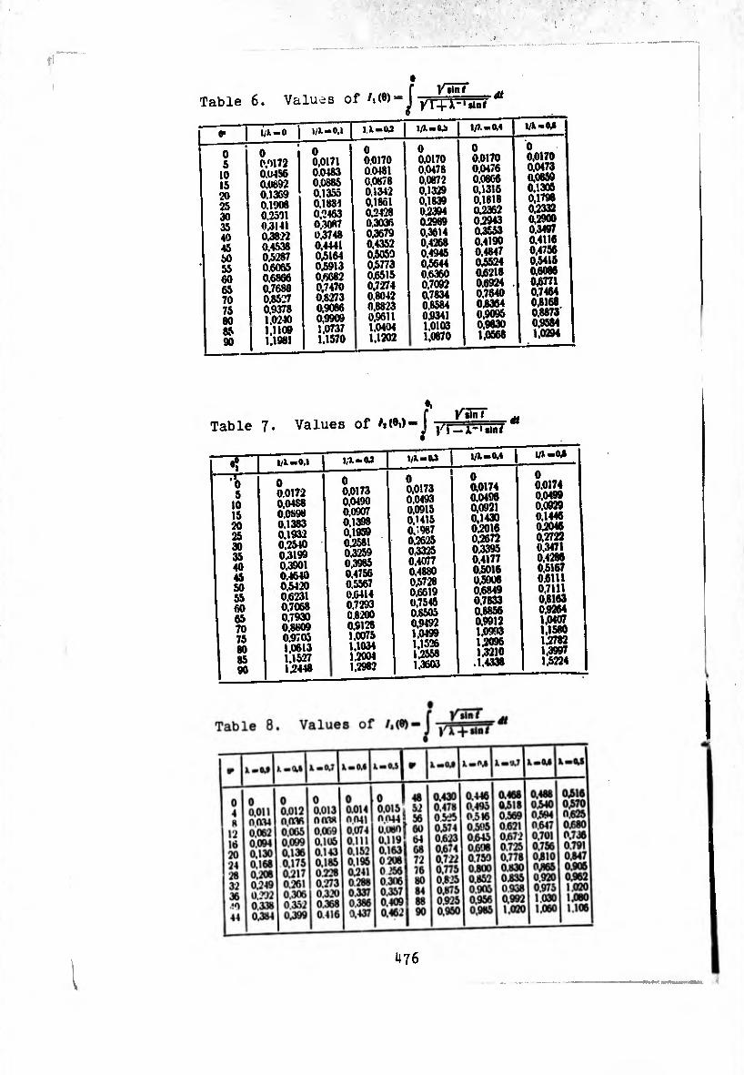
Table 6. Values of /,<»>-
"• 1 i/lmO J I/J.—0.I 1 Il-(U l/X-0¿ 1 5
• 2
1A-M
0 5
10 15 20 25 30 35 40 45 50 55 60 65 70 75 80 85 90
•
0 0,9172 0.U4S6 0.0892 0.1369 0,1908 0,2591 0.3141 0,3822 0.4538 0.5287 0.6065 0.6866 0,7688 0.8527 0.9378 1.0240 1,1109 1,1981
0 0,0171 0.0483 0,0885 0.1355 0.1881 0,2463 0.3087 0.3748 0,4441 0,5164 0,5913 0,6682 0,7470 0.8273 0.9086 0,9909 1.0737 1.1570
0 0.0170 0.0481 0.0878 0,1342 0.1861 022428 0.3036 0,3679 0,4352 0,5059 0,5773 06515 0,7274 0,8042 0,8823 0.9611 1.0404 1,1202
0 0.0170 0,0478 0.0872 0,1329 0,1839 0,2394 0.2989 0,3614 0,4268 0.4945 0,5644 0.6360 0.7092 0.7834 0.8584 0.9341 1.0103 1.0670
0 0.0170 0,0476 0,0866 0,1318 0.1818 0,2362 0.2943 0,3553 0.4190 0,4847 0,5524 021218 0.6924 . 0,7640 0.8364 0.9095 0,9630 1,0568
0 0.0170 0.0473 0,0859 0,1305 0.1796 0,2332 0,2900 0.3497 0.4116 0,4756 0,5415 0,6086 0J6771 0.7464 03168 0,8873 0.9584 1.0294
Table 7. Values of M®i> YiXni f /5
“jTr^x '•in/
^ I I/X-.0.1 \ U-M j I l/»-W
-7¾ 5
10 15 20 25 30 35 40 45 50 55 60 65 70 75 80 85 90
0 0.0172 0.04S8 0.0898 0.1383 0,1932 0,2540 0.3199 0,3901 0.4640 0.5420 0.6231 0.7068 0.7930 0,8809 0.9705 1,0613 1.15-27 1.2448
0 0,0173 0,0490 0.0907 0.1398 0,1959 0.2581 0.3259 0.3985 0.4756 0.5567 0.6414 0,7293 0.8200 0.9128 1.0075 1.1034 1.2004 1.2982
0 0,0173 0.0493 0.0915 O.Mt5 0.-987 0,2625 0.3325 0.4077 0,4880 0.57-28 0.6619 0,7545 0.8505 0,9492 1,0499 1,1526 1.2558 1.3603
0 0,0174 0.0496 0,0921 0,1430 0,2016 0.2672 0.3395 0.4177 0.5016 0,5908 0.6849 0,7833 0.8856 0,9912 1.0993 1,2096 1,3210
.1.4338
0 0,0174 0.0499 0,0929 0,1446 0,2046 0.2722 0,3471 0.4286 0,5167 0.6111 0,7111 0,8163 0,9264 1,0407 1,1580 1.2782 1,3997 1,5224
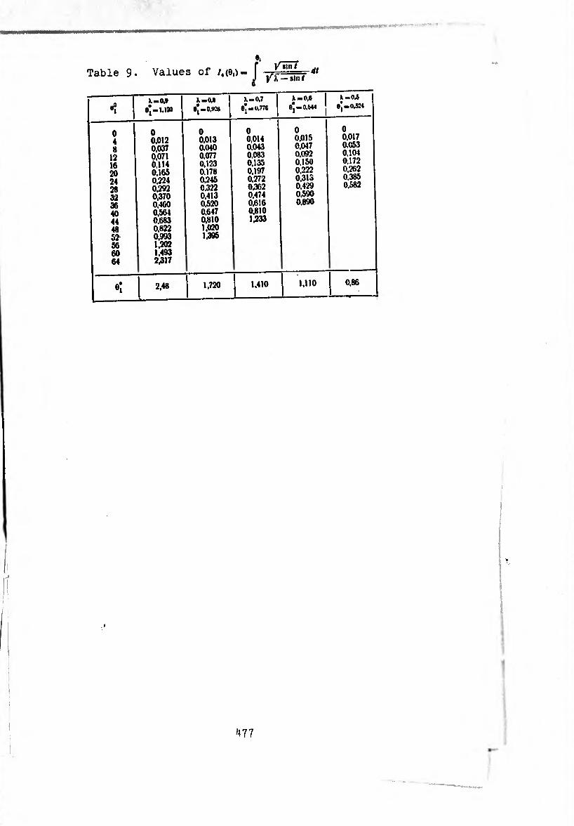
1 Table 9* Values of /,(8,)- I - dt
—sin/
-ï
Il-O.»
9*-1.1»
X —o,s I e'-o.wa
X —0,7 I 9*-0.776
X-0,6
8| — 0,644
X-O.S 9,-0.524
0 4 8
12 16 20 24 28 32 36 40 44 48 52 56 60 64
0 0,012 0,037 0,071 0,114 0,165 0,224 0,292 0^70 0,460 0,564 0,683 0,822 0,993 1,202 1,493 2,317
0 0,013 0.040 0,077 0,123 0.178 0,245 0,322 0,413 0,520 0,647 0,810 1,020 1,395
0 0,014 0,043 0.083 0,135 0,197 0,272 0.362 0,474 0,616 0,810 1,233
0 0,015 0,047 0,092 0,150 0,222 0,315 0,429 0,590 0,890
0 0,017 0.053 0.104 0,172 0,262 0,385 0,582
«î 2,48 1,720 1,410 1,110 0,86
477

list op designations
1 ^7’
0X 0, 02 ~ lolUZtS a Carteslan -«anguaar 3ystem of
" * ' Unlt veotors> ««oted aiong axes ox.or.oz
X Ÿ z -n Hi Veet°r °f a certaln point » on a middle surface * - coordinates a point in a paT,f0D< sun ace
system of coordinates Cartesian rectangular
P' “ curvilinear surface coordinates
e'f" rS?at1iaonee°eraPhl0al C00rdlnat^ on a surface of
v - radius of a parallel circle
'' " paraile^clrcle tangent t0 a -rldlan and
* - unit vector of the normal to a surface
revolution1*1"01”31 ourvatur®o of a surface of
* “ Unlt Ve0tor of a no™al to a parallel circle unit vector of a tangent to a certain curve on a
: : ii:::s0;veth of an arc °f neridia- a-d— , tinúrfãce g °f a" arC or 3 «“«in curve on
’ I* ourvature of a certain curve on the surface
v-â=a rvîÂ-dai^efra — - unit vectors of tangents to coordinate lines aft
' surface0durlngddeformatlon °f 3 ”0l"‘ 3 — •v projections of a vector nf -i 0_n
axes t, ,, ector of displacement u onto
^T'
478
A,. A,
/-
n* .
x,* ■
rf,i* .
-4.-4 »
-*i. «,
'V \j
*'• e*’ V. X,. Kj, t .
0 .
— #|. ô -
A -
R -
C -
rfl •
dU-
m-).
u(*). o(5>, WC) _
RT -
K r;. at* «
*b *}. *> —
®i. a, —
'l*. Tj, ,
*1. *, •
K: M,. M} -
S'* <?.. M„ //l5>_
- radial and axial comoonent ,,
■ radius vector of , < f displacement deformation “ POlnt of a “«die surface after
vector of normal to deformed surface
deformat iontan?ent 8 to -Jinete lines after
deformation lengths of arc3 of coordinate lines after
*- curvature and twisting of SUrfn
“ angles of rotation of no ^ & ter deformatlon during deformation t0 surface around axes
- angles between vectors r,. T; and r •
- components of deformation of mJ, * reSpectlve^
• vector of rotation of an pi 1G SUrface of shcll medium during deformation lement °f a continuous
‘ Projections of vector. 0
thickness of shell a**s T|. *
_ ^adlUS veotor of a point of a shell
' n°rmalCe fr0” surface, read on the side of a
oñ0L0reBqu0ifditaatnStntsSuí?ac|0rdlnate lines “d normals
: vtlTel::; area °f “ surface
Zf lv lylng 0n ‘he
-i:: :::0^ ^ ont° vectors of tangents^nd' ^ * ^11 deformatlon surface after dePo^foS0™31 °n an eialdlstant
_ "r?aceeduil0ifde?S™at“0nhear °n an eWidistant
normal stress on areas perpendicular to vectors ,,
- tangential stress in these areas
,1,.,'°rS °f atress areas perpendlcuiar to vectors
edges^f°a chos^n^mlnrofTs^eíi3'’13116'* to the internal forces Qri(j
surface!10 °f the ParauJf ci^^M tV^ddlê8“1
t79
T* s~" Q* H:\ ~ internal forces and moments referred to a unit length of an arc of the meridian of the middle surface
s. H— applied tangential force and twisting moment
Nu A’, — applied shearing forces, vector of volume forces referred to a unit of volume
H, — raaial force
F - vector of volume forces referred to a unit of volume
p+. P - vectors of surface forces referred to a unit of area (external and internal respectively)
E. L — applied vectors of forces and moments of external forces, referred to a unit of area of the middle surface
FV Fr F,. P¡ , p¡ . />;. PÎ. pj, p~, £, » qv E2 E.s: qm
ti. projections of vectors F, p+. p-, e, L onto axes t». t* <•,
B — tensile rigidity
D- cylindrical or flexural rigidity
E— Young's modulus
»*. - Poisson's coefficient
a, B, C — stress functions
^ (*-J. 2. 3....)- coefficients of the expansion of meridian force T1 in a trigonometric series in coordinate <}>
r*(0>- Fjiny , fpM, H^y *, jQj, t] iiy .. . Tjjj,
*1 (0)' *!(»)• <"1*'. Of. «2 (*>■ «i*’. ■(*). .«“(»r ^ fi «a»
9u*y i\).?» (<')• ?» (*)• íí* — analogous meaning
px. Py. p„ mx, MrMt - projections of principal vector and principal moment of external loads applied to one edge of a shell
- Meissner functions in the axisymmetric problem
h\ V - Meissner-type functions in the problem of deformation of a shell under a bending load
0 — with different inde:- - is used for a complex combination from Meiss er functions and Meissner- type functions
. 12(1—n»)** F parameter characterizing relative thickness of
of shell, b - certain characteristic geometric dimension
Mi - basic parameter of asymptotic integrating of the equation of deformation of a toroidal shell
« - radius of the forming circumference of a torus
of the
temPeratUre - - function of confinâtes average wall temperature
!eaPeratUre dr0P Wlth sheU thickness
'Ã * ^ ^ - oZZTnt^otTJeTlTo^Tl10" mm j. m. In a trigonometric '■jerie^i0^ ^unct:ion /* and
«r*. «i'1.... in coordinate
«1». «T. ,Z °f "ela3tlC'’ ^°™tlon Note. The lise doe °f dlslocal;ion deformation.
dfhißn?tlon ofn®Pe°ialU^nctionsarR designatlons or the others ). Both the basi so inS a (Bf?,Sel* Leg^re and explained in the text of the book?Xiliary desl8nations are

BIBLIOGRAPHY
To Chapter I
1. AMÖapuy v*h C. X-. TeopH« nm.oiponHUX oóaiooex. •lUiutiM. M,
2. B^h p rep H. A.. Kp>™ue iuikthhi« h oöawiKH »pmeHH«, OfiopoHna.
3. BÎÎITo* B. 3., Ofituan wopH* oOwumv a «« npiwoateaiia a maaua,
4 rTïïïYî o H" Ctitmk* ynpyroro tm«. OHTH. 19M. •_ 5. f ó51le hP.«I ,.p Ä!7!Pt«,p». ynpyrax io««.* o6aioW rom»-
6. f oníièÍícísep A. J\.. Vp..««.«» rwpaa Toaaax oBoaoaea. HMM 4.
7. ?oVka?i»eft»ep A. ^^
104CK C6 «n.ltCTMHKH M OfcOklOSKH», lOCCTpOfiHMâT, 1KW. r o¿aieH • e ft seP A. /1. 0 norpeuiHOCTax * nuu ftJVvinveK N B03MO)KNOCT^X et yTWMCHMIK IlMM 2t, XÄ 4 |1WK)|. na-.TcM.rrrà-o.ï *«*.»HKa oea^oM«.
KoCHAH.yE:CBmopB¿¿9ícMHCieHHe a a.au. reaxopaoro acaacie-aa.
J^y^pae* A M^Cwaaa TOHaocTeaaux ynpyrw oöaiowa. rocTexMxaiT,
/1. — M., oowaa teopiia ynpyTHx Toaaax oöMoaea, FIMM 4, M 2 13 /lypae
M /lyjle A. M., Onpeawcaae nep^aemeaaft no saaauaoay xeaxopy ae^op-
,5 W7;?Tl»0¿ JÍÍSUaax oömeft teopaa ynpyrax o6aW.a. HMM
16 .VyïVe A9»'; Paaaoaccae ynpyroft caaMatpaMao aarpyaceaaoft c(j).paaa-
17. .i?p?ÍAMH'.nóVCTl;«ao-6r¿a.TÍ»a«aoft aHa-iorim a teopaa ofiawaa.
18 .1 a a Au iMaTfMXTiHccKaa Teopaa ynpyrocta, ncpea. c aan^ rTTH, ^
19 M>muTapa N. M., 06 o6.Tacrii npaaeaaMocra .•»aacftaoft Teopaa ynpyrax
20 Myln'ra pa X C>V.P W «ÂiacTa npaMeamwcra npa6.iM*caaoft Teopaa
-V- "• »SJ22: r« «m. «K» 21 11 oboa a.T oa B B.. Teopaa tobkbx oOawiea. Foc. hm ao cjAocTp. upoMuiu.icaaocTa, 1931.
22. Hoaoxn/ioa B B.. Heaoropy« laaeaaaaa ao aoaoi}- Teopaa o6o.io-
23. B. B . Ò norpemaocra oaaofi aa rnnoîea Teopaa o6oaoqea,
SI Ho*, oí1; J S £ B.6«! a « « « •’a “ ' ' * ■£ 0 "“B"”“™
» pKr,1f. : .’T-'Ä" nr«. M. 1939.
26 PaOoTHOi K). H., Ocnobhuc ypaiHcaaa Tcopm oôaios«. AAH, bob. cep. 47, 2 *(1945).
27. Thmouchko C. H, BoñHOBCKHñ-Kpnrep C., rLiacTBHXB b 060- .10HKII, r.l. DCA <f>H3.*MBT. .IHT-pM H3A. «HayKB», M, 1966.
28. O.iwrre B., Ctbthkb h AMHauiiKâ oôaiOMCK. nepcB. c ncm, Ctpohhjabt, AV.. 1961.
29. 3KCTpeM Abc. 3., Tohkoctchhuc cmmmctphihuc Kynaia, Toc. uayaao- Te.\H. H3A-BO VKoaHHU, XapbxOB — Kmcb, 1936.
30. M e p h u X K. 4>., AimeAHaa leopiix oôanoseic. %. I, IIja-bo A TV, 1962. 31. Mepaux K. AiiHeAHBN Teopiin oôo.iohck, <l II, Hsa-bo ATV, 1964. 32. Kirch hoff G., Vorlesungen über mathematische Physik, Bd. I, Me¬
chanik, 1876. 33. N a g h d y P. M., Foundations of Elastic Shell Theory. «Progress in Solid
Mechanics» 4, M 2, p. 1—90.
To Chapter II
34. Bum HK M. H., AwcrepBBB Jl. A., Pery.iapaoe auponcAenue a no- rpamiMHuA enoft aas ahmcAhux AHAd)epeuuiia.ikaux ypaaneuiiA c MaauM napsMCTpoM, VMH 12, X» 5 (1957).
35. ro.ibAeaaeAsep A. A., FeoMerpHiecKHA apaiepicA OeaMOMCHiHocra HanpaaceuHoro coctoshhs ynpyroA tohmoA o6aiosKH. C6. «npo6.icMu Me- xauiiKii cnnouiHoA cpeAU», Hsa-bo AH CCCP, M, 196I.
36. roAbAeuaeAsep A. /1., HexoTopue uaTCMaiHiecKiie upo&ieMU ahhcA- hoA Teopim ynpyrnx toiikhx oOojiomck, VMH IS,.Vi 5 (I960).
37. T p h r o p e ¡i K o B. M., 06 ypaaneHiiax uiiK-iimecKii-ciiMMerpimHoro rep- MOHanpaaceMHoro coctoshhs oòaioMCK apaiucHus nepeMeiiHoA acecrsocTH. C6. «Tennoaue Hanpawemta a aneMeurax KoacrpyKUHA», «Hayaoaa AyMxa», Khcb, 1965.
38. K a .1 h h h c A., Hcc.ifAoaauHe o6o.iomck apauteniia npn acActbim chmmct- dhuioA h HecuMMerpHHKoA MsrpysoK. Ilpumi. mcx (leans. ASME, Ser. E), At 3 (1964).
39. M a A s e .1 b B M., TeMnepaiypHaa saAasa ttopun ynpyrocTH, Hsa-bo AH VCCP. Khcb, 1951.
40. P a 6 o T h o a K). H., Ochobnuc ypaaHeHHa reopua oôaioieic, AAH CCCP, XVII, At 2 (1945).
si. PeAccHep E., Hexoropue npoOneMW reopux oöaioserr. C6. «VnpyrHe oGo-iomkh», HA. M.. 1962.
42. Me pH ti h a B. C., O chctcmc AHi)HpepeHUHa.ibHux ypaaHeHHA paaHoaecHa oôono'CKH apauieHHH, hoabcpmchhoA HiniftaiouteA narpysxe, DMM 23, >3 2 Il9üeÿ|«
43. MepHiiHs B. C., Hanpax.eHHoe cocToamie ofiaioqxH apauitHiia npn ne- ooecHMMerpHiHOM pacnpejc.ieHHH TCMmparypu, Tp. Afllf. .\t 252 (1965).
44. M e p H u X K. ¢.. ypaaiicHii* MeAcucpa a c.iysac oCpoiHoA cHMueipunHoA HsrpyiKH, Maa. AH CCCP, OTH, Mexanuxa u ManiHHOcrpoeHiie 6 (1959).
45. UlraepMaH 11. B., O npiiMCHCHHH ueiona acnunTOTimecxoro miTerpiipo- aaHiia x pacnery ynpyrux oOaioxex, Usa. Khcbcic. nonuiexa. a cenbxoa. HH-TS (1924).
46. UlTTepMSH H. B.. O npH6.iHHteHHOM HHTerpHpoaaiiiiH jiKjxJiepeHuiia.ib- Hux h HHierpaibHux ypaaKemiA. Bicri Kniacucoro nonirexa. iHCTHtyry, 1926-1927. â. , , ,
47. Blumen thaï O., Ueber asymptotische Integration von Differentialglei¬ chungen mit Anwendung auf die Berechnung von Spannungen in Kugel¬ schalen. Z. f. Math. u. Phys., 62 (1914).
48. C a s a c c i S. E., Flexion des coques de revolution soumises a des champs axisymmetriques des forces at de temperatures. Pubis scient, et techn. Ministère air. Ni 382, 1962.
49. Meissner E-, Das ElastixMitsproblem für dünne Schalen von Ringfla¬ chen, Kugel, oder KegeHorm. Phys. Z. 14, M 8 (1913).
50. Meissner E., Ober Elastizitit und Festigkeit dünner Schalen, Viuiel- jahrschrlft der Maturforschenden Gesellschaft in Zürich. Jahrgang 60.
WS- „ . u .. 51. Havers A„ Asymptotische Biegetheorie der unbelasteten KugelschalL
Ingenieur-Archiv VI, H. 4 (1935).

To Chapter III
52. A M 6 a p a y u « ■ C À., K aonpocy nocrpoeniw npH&iMwcHRUx rcopaft pacxera naiorHX muiHHapHsecKiu oûo.ioweK. flMM 18, St 3 (1954).
53. A»iCapuyMHa C A., O npeatiax npHUCHHMocTii hckotodux fhnafta H*opiiH TOHKHx uH.iMiiapMiacKMx oóo.iCMíK, Mia. AH CCCP, OTH, 8 (1954).
54. B .1 a c o a B 3., KotuaKiaue sajatn no reopaa o6aiOMca a Toaaocrcaawi citpiKHcA. Hat. AH CCCP. OTH, to 6 (1949).
f«5 F a .1 e p a h h B. P.. K reopaa ynpyroA uHJiaaApHtecaoA ofionosaa, AAH CCCP 4, to 5-6 (1934).
56. A a p e a c k h A B. M., Pcuichhc HCKoiopux aonpocoa reopaa aaaaaApata- ckoA oóonoMKH. flMM 16, to 2 (1952).
57. KoiuyrHH M. 11., 3aaami H3rn6a uhjihhaphwckoA ofiaiosaa, Tp. JHIH, .Vi 192 (1958).
58. Kp ia .10 a A. H., 0 pacMere 6a/ioK. jiewauinx aa ynpyroa ocaoaanaa. Co6p. rpyaoa axaa. A. H Kpu-iosa, r. V, Haa-ao AH CCCP, 1937.
59. T h m o tu e h k o C II., CoiipoTHa.ieHHC narepiia.ioa, a. II, PITH, 1933. 60. 4 e p h h h a B. C„ ynpyro n.iaciimecKad Ac^optiauiia caapaoA paanopoA-
iioi'i uti.iiiHApii'iecKoft o6o.iomkii. Hsb. AH CCCP. MexamiKa a MauiKHOcrp. I (I960).
61. MsCalley R. B., Ir. Kelly R. 0., Tables ol functions for short cylin¬ drical shells. Paper Amer. Soc. Mech. Eng., to F-5. 1956.
62. Con wav H. D., On an Axially Symmetrically Loaded Circular shell ol Variable Thickness. ZAMM 38, Heft 1/2, 1958.
63. F a \ r e H. Contribution a l'étude des coques cylindriques d'epaisseur variable. Bull. Techn. Suisse romande 82, to 23 (1956), 419—427; to 24. 431-437.
64. F e d e r h o I e r K.. Zusammenfarsende Darstellung Entwicklung der Statik und Dynamik der Kreisiylinderschalen. Stahlbau 24, to 9 (1955).
65 Hampe E. Statik rotationssvmmrtrischer Flächentragwerke. Bd. 2, Kreiszylinderschal, Berlin. VEB Verl. Bauwesen, 1964.
66. Havllcek Vlad., HAschl Cyril., Dclormace ter.kostennych ro- tacnich shorepin, soumerne zatizenich. Priklad pouzite tabulek. Stroiiren- stvi 5, to 9 (1955) Tabulky II 1/31-111/34. J
67. Hol and !.. Tables for the analysis of cvlindrical tanks or tubes with Viiri*b,e thickness, Mcrn. Assos. internal, ponts el charpenters
21 (1961). 1 68 R o a : k R. I, Formulas lor stress and strain. Me Graw-Hill, New York,
London. 1941
69. V a I e n t a !.. Theoretische Lösung der dünnwandigen Zylinderschale veränderlicher Dicke, Bul. Inst. Politehn. Jasi 7, to 3—4 (1961).
70 De Schwarz M. )., Gründzüge eines Leitfades zur praktischen Be¬ rechnung von Kreiszylinderschalen. ZAMM 34, A» 8/9 (1954).
To Chapter IV
71. PptiropeuKO B. M., AHTHCHMMeTpimmii HanpyweiniA cran Koalsna 060- «iohkii 3MÍHHOÍ TOBUiHHH, flpiix.iaaHa MexaHiKa 6, Xt 4 (I960).
72. KoBa.icHKo A. A.. P p nropenxo B. .loÔKoaa H. À., Pacrer KOHimecKiix o6o.iohck .laHeAHO-nepeMeaaoA Taïuuiaai, Hsa-ao AH VCCP, Khcb, 1961.
73 k'oBa.ieHKo A. A-, PpHropeMKo B. M., H .i a m h A. Æ, Teopaa TOHKiix KOHiiMCCKiix oóo.iomck, Msj-bo AH VCCP, Khcb, 1961
74. Koraa P. M., Pacier KommecKoA o6o.iohkh nocrosHNoA tojiuzhhu npa ocecHMMerpimHOM HarpyaceHHit a t«6.ihhhux SHateanaz ÿyHKunA Tomcohs, Tp. Bcecowan. HHI1 iHjpoMauiHHorrp^ 81 (1962).
75. K o p o.i e b h m 10. C., AciiMniorimecKoe peuieaiie aaaaan chmmctphmhoA jeit>opMauiiii KOHimecKofi oôoiomkh c .iiihcAho HSHCHsnuteAca raïuiHHoA CTCHKH, ripiiK.iaaHa MexaniKa S, .V» I (1959).
76. 4> p a h k - K a m e HeuKii A P. X.. ripuueaeiuie teopiiH oprorponaux n.ia- CTiiH h oCaioseK k pacMciy HCKOTopux jersieA nuporypöiiH. Aaccepiauas, AeHiiHrpaj, 1964.
77. X.ieönoA B. ¢.. PIpaKTHHecKiiii weroa pacnera ocecHMxierpHMHoA kohh- lecKoft o6o.io'ikii c nepeMCHHOH îo.iuihhoA ctchkh, Tp. Mock, hhzk.-ctpout. HH-ia 17 (1957).
78. M e p h h h a B. C.. K pacHery oGoaoick apauiemia Ha cn.iouiHOM ynpyroa ocHOBaHHH, Haa. AH CCCP, OTH, Mexamixa h Mauirnocrp. 5 (1962).
484
To Chapter V
79. B a T c o H P. H.. Tcopna 6ecce.it.anx tpvHKmtft, M., H/l, 1939. 80. raaTiixia B. M., Daiora r^epimua oöaioMxa nia aie» aocepeaxccHHX
CH.1. 36. do6¡t acnipaHTia MexaH.-»iaTe»i.' Ha-T>- 4»ii. $aic. JlbaiacbK. ya-Ta, ■un. I, 1961. . _ ..
81 ro6con E. B., Tcopna ctpei-'iecaux n »ji.iHncoHaa.ibHux çyHKUHft, M., ‘ HJ1. 1952. . n „
82. ro.ibaenaeftaep A. 71.. Hctieacaanne HanpamenHoro coctoxhhh c«J>e- miMCCKOH oCaio’iKH. nMM 8 (1944).
83. M a e h h t o a 71. B., ripnaeneaiie Teopnn ÿyHKUHft KOMn.icacHoro nepeacH- hoto K peuiemt» ciaTimccKii Heonpeae.maux saaai 6cïaoMciiTHoft Tcopim abepimeckoA 06&10MKH. C6. «Teopna tuacinn h oôo.iomck». Knea. AH yCCP. 1962.
84. Koaa.ienno A. il., Peuietuin ■ cneuiia.ibHux tpyHKimax saaaa o ne- CHMMCTpimHoA ae^opaannn no/iorux ctpepiiiecKofi h kohiihcckoA o6o.io>ick. Tp. KoHijiepeiiUHH no Teopnn n.iacrnn 11 oôo.io«ick, Kasanb, I960.
85. .Typbe A. H-, K aaaaee 0 paanonecHH naacTHnu nepeaennoA to.iiuhhu. Tp. 7H1H 8 (1936).
86. Ho a ont n .10 b B. B., Pscier Hanpa*fHitA a toiikoA ctpepHMCCKoA 060.101- KC npn npoiuaaibnoA Hirpysne. AAH CCCP 27 (1940).
87. Il ui en m hob T. H., Paciei ômmovchthoA oJiepmecKoA o6o.iomkh Ha Beipoayio narpvaxy, 11h*. Htypna.i I. Ns 3 (1961).
88. Pen a a n K). B., Paciei cÿepimecKiix oCo-ioick no momchihoA reopmi Ha HeciiaaeTpiiiHyio Harpyiny. C6. «n.iacTiiHKn n 060.101K11». roccipoAniaar, I93B.
89. Co ko a ob ex h ft B. B., Paciei cÿepmecKHX oôo.tomck. AAH CCCP I«. M 1 (1937).
«0. Cth.i. HecnnuerpHinue aeÿop «bbhh xynaiooôpasnux o6o.ioick apaine- hhn. DpniwiaaHan uexamiKa, Tp. Aaepna. o6-aa HH*eHcp0B-McxaHHK0». M., HA. Xt 2 (1962).
91. MepHHBa B. C.. Aetopaaiina cÿepmKKoA oCaioiKH noa acAcranen inrii6aioiucA narpyjKit. Haa. AH CCCP. OTH, Mexamina 4 (1963).
92. Hepnnna B. C. K paciery c^epHiecKoA o6aioiKH npn acAcraiiH cocpe- jotoichhoA TaHrenuiia.ibHoA ch.iu, Has. AH CCCP S (I965).
93. MepHHBa B. C. HanpnweHHoe cocioaiuie nponsao.ibHo narpyntenHoA cÿepuiecKoA oôo.iomkii. Haa. AH CCCP, Mexannna 3 (1965).
94. MepnHBa B. C, Ae^opaauHa BepriiKa.ibHO pacnoioxccHHoro aepxa.ia re- .iccKona noa acAciaiiea coOcxaeHuoro aeca. Has. TAO ■ riyjinoae 24, fi I (I9M).
95 Mepnnna B. C. Ae^opaauM c$epniecxoro «ynona no» acAcTanen ca- MoypaaHoaeuieHHoA KpaeaoA HarpyaKH, Tp. TIIIH, fi 235 (1964).
96. BHKC E. ■ 9uae 4».. Ta6.imia ♦ymunA c ÿopuyaaMH h kphbumh. M, OHaMamia, 1949.
97. khino Ichiro, Takahashi Hiroshi. Theory nonsymmetrical bending state for spherical shell. Bull. ISME 7, fi 25 (!v54).
98. P a n c Vladimir, Das Randstorungsproblem der antisymmetrisch belasteten Kugclschale. Ing. Arch. 31, fi 6 (1962).
99. Pane Vladimir, Der Spannungszustand einer in der verticalen Ebene gestützten Kugelshall. Acta Techn. CSAV 7, JA 4 (1962).
100. Reismann H.. Thurston G. A.. Holston A. A.. The shallow spherical shell subjected to point load or hot spot. ZAMM 48, fi 2/3
101. ¿'eîs^sner E, On asymptotic solutions for nonsymmctric deformations of shallow shells of revolution. Internat, 1. Ingng Sei. 2, .V» I (1964).
102. Reuss E.. Thamm F., Der Membranspannungszustand in einer Kugel¬ schale in der Umgebung eines konzertrierten Momentes, Period, poly- techn. Engng 4. .V» 3 (I960).
103. Steel C R.. Hartung R. F„ Symmetrie loading of orthotropic shells of revolution Trans. ASME, E 32, JA 2 (1965).
To Chapters VI and VII
134 A idiyTOB H. A.. Pacier ojHOC.ioAnoro cinuJ'OHa ueroaon Pnrua, Hh*. c6. AH CCCP 15 (1953).
105 B y .i r a K 0 ■ B. M.. TopoUa.ibHa oôaioHxa nia aie» aiaueHrpoBHx cwi. flpiiK.iaaHa uexaHiKs 3, fi 2 (1957).
106. B V .1 r a k 0 B B. H., 3Kcnepii»ieHTa.ibHoe onpeae.icmie Hanpa^cHHA a 6ucr- poapaiuanmeAcn TopooöpasHoA o6o.ioiKe. C6. xpyaoa 71a6op. niapaaa. msuiiih AH VCCP. X* 7 (1958).
107 By.iraKOB B. H., npiisieneime iiic.ieiiHbix mcto.iob k paeiery tmoh- ■ juibHUx o6o.ioieK, Tp. KOH$. no Teopnn miacniH 11 o6o.ioieK. Kafaub,
1961.
FTD-MT-2ÍI-249-70
108. ByJiriKO* B H.. Cm,,« topca^« o^no^. Haa-o AH VCCP.
,W S'vSomLkcJ ?oT«e!"l»a,AHTcCrS««"
„0 &. A. H.. Onpor^H-ie ^a^oÄ 1962)1.
»o6oww’-MM,# ah VCCP, Ki.rt.l962. n A awcTMHM h o6o.iohki». HtOfi myKM,
U2 Se°Ä.M.H*U AH CCCP. M-. 19Ä
ms a.^ ”'.r»
"5 !í;¿r, ’ .“*¡SC¡ÍJU, „„„J p—TI
"c V"i BtiS.“'’«?“ ‘ W ''
M- íteSTu1***— '^“T.issr- “
S“£‘£^”“ Ä-
U0. KÒpoflí» B. Hc’ pH,,íp«C)«HH«r0coc?OTH‘n«'TOfKJHaMbHoro* conpiimeHH«.
121 npoiî«?».*B., 0 ioj>io)«iiocni
CKO« MaiUHHOCTWjeMVl« y odOCHOBlHHe «.03«0)KH0CT« P*c-
123 Ï„°.P “ Te0pMM* BKT Mry’ Ä
,24 íífylio. B. K- Ptcier creRK« xopnyc. n.po.oA typ«-«.. Tp. Jl«. «o-
■ £86.1. H« ia M (l«4). B THOe „anpaxcHHO« cociofiHiit Topoiai.ik-
125 » w~~ ■ “ '• m n” ¡VΫ.»« t apS- <>"“■ ■“““*Topo‘ “““* *
,s, KC“i?Î,‘c"ï'* W. Pío— >• "K"-'“ • • r 11. Marnrna. 19» ß H H8np**eHHoe coctmhh« • Topooö-
“ .°jr; rfr”cTÍ.---“'Sr-^ ■ •
“ &=rfSSrS'Sg * S.—Sr-Ä^s^TS»
23, .\i G (1959). n u T86.1HUW o6o6m«HH«* «pynxUH» 133 K'xiVacRMnioiHsecKOro p^mi ypa.Hrt..#.
CKHU aieToaoM. OOopoiirHi. 1940. - jilAoho«) B H, K pic.ery “P"*»
,x ^¿ÎÎU'ÎC’W» — ^
,37 O.'-f ». C. Hinp.»«.w* WCTW.j— «g»»» P-
"•* ™.T1U«.»-X» j(H.^2n"tp™mro KO-.IHC.TOP. .« P'""*““ ■ »39. M « P H H R a B. C.. ^ pacMery ipyj«
HirHÖ. SHeproMauiHnocTportHe a O^ nHH3oaoro KOMne.caTopa, ,40 MepHRHâ B. C. «»"P"*?“"0*
SHepronaiuHHOCTpoiHH« 7 (1961,.
FTD-MT-24-249-70 486
Ml. q.j,B. Ç. K «»«*•»•» •*«-* AH OTH, Mm.. 1 (Wj;_ «-ctkoctb «opnyco» napowx typ«««. Tpy6«-
ah vccp. *,«.
I^mTp-bo B. C.. Ä ■MX creHOK Kopnyco» napoaux typo j, _ TOpoo6piiNux o6o.ioMeK. 1.
,w ^s^j^sJSPiiSS- «•
e*ä" o. w« ^ »' »heUa. Quart. AppLMath. I0.M4 (KW). c bend| of nearly cv-
SÄ *-• ^ M“h (1955). o « i « « n » r E On axial! v symmetric bending of nearly
I» ffiífí ’ÂlrÂ^ÆÂS problems, Q«i.rt. Appl.
»'fî.iS’* VÄr -»H i-"!* '■ *«"■M“* •'• -14 ’ » ÍÂ' Á 'v”Æp!S: IH S!B- Tl T..M.I -«Il «M»"-“ HW- J. Appl M«h. » » «
w. Í »?»', I- s B.S«r
I». in toroidal shells. J. Appl. M«h. *. • " .. . . .. j -„j.
WO.O.II.11,0 0 Edp 1^^-1.^¾¾ M p??., tive Gaussion curvature. Paper, «nier. .»»»_
,.,.ffl;.., ' »ÂÆ z'^XITS' m. M" •* "**• m KÍírpXTo^^Âfpa,.. T«nmi«lt «»,« in«..
,« ÍÂ/ÍT.“...'«»*"«» «' “» surized torus. IAS Pape.- 14 (IWl). ^ circular tubes with
165. K a IV a P. G- Dunn >1. B Sbffn^s oi cun ^ ^ (1955) internal pressure. Paper r mcr. t(gr loroid,, $ben 0(
ÂÎ-à^Â’i«çVi» 5ASÄ «n!Ä “Änä SL K>i.ii»
168 M*.?.ÍÜTbr'sy^of’oi.^' stress distribution ol the rotating dr- cular ring type sheïl. IaMM 12 ({^j, j Toroidal shells under
Io®. Rossetios John N-. zanders J. LyeM ^ ^ J() (ig65)
170. 01 a" ,nCOmP,ete
m- Ï^^VasttsîiriMu^tlfh v^riabVtlficUne«. Qua, Appl. Rath. 1I.M 2 (1957).
FTD-MT-24-249-70 487
1¾¾¾ K Dfr Sp*nnun«m‘«»<i *in*r Krcisringxhalcn. I„g Arch
- P'^UÄ.1
in. Wi0ij,,krëSr h S'1* 9' iweLVyPOCe Vnej,i «'«'»‘«ny «kumulacnlho cerpadli.
bei» an der ¿dg^TÂ^HShSS1
FTD-MT-2^-249-70 488
Related Documents


