i MPO -11Bill°11" II IIII 09053471 DFO - Library C. DOEKES F. W. DEYS L!":73r.1RV ( . 7H .: 17 . - ANC:1,31, APHY MAR 2 0 1985 Mi. 10. :H;:.Q1JE INSTITU: (),:r.:ANCGAPHIQUE DE 13:DORD 0 TECHNICAL NOTE SERIES 79-1 1* Fisheries and Environment Canada HP-9825A - INTERDATA MODEL 70 DATA TRANSFER LINK RESEARCH AND OCEAN AND AQUATIC SCIENCES CENTRAL REGION CANADA CENTRE FOR INLAND WATERS BURLINGTON, ONTARIO

Welcome message from author
This document is posted to help you gain knowledge. Please leave a comment to let me know what you think about it! Share it to your friends and learn new things together.
Transcript

i MPO -11Bill°11" II IIII 09053471
DFO - Library
C. DOEKES F. W. DEYS
L!":73r.1RV
( .7H .: 17.- ANC:1,31, APHY
MAR 2 0 1985 Mi.10.:H;:.Q1JE
INSTITU: (),:r.:ANCGAPHIQUE DE 13:DORD
0
TECHNICAL NOTE SERIES 79-1
1* Fisheries and Environment Canada
HP-9825A - INTERDATA MODEL 70 DATA TRANSFER LINK
RESEARCH AND
OCEAN AND AQUATIC SCIENCES CENTRAL REGION
CANADA CENTRE FOR INLAND WATERS BURLINGTON, ONTARIO
March, 1979
HP-9825A - INTERDATA MODEL 70
DATA TRANSFER LINK
by
C. Doekes
and
F. Deys
This is an internal technical report which has received only limited circulation. On citing this report the reference should be followed by the words "UNPUBLISHED MANUSCRIPT."
P.O. Box 5050 Burlington, Ontario L7R 4A6
ABSTRACT
This report describes the link between the HP-9825A
Calculator and the Interdata Model 70 Computer, which was developed
to effect the transfer of CTD (Conductivity, Temperature, Depth) profile
data from HP cartridges to 7-track magnetic tape. Included are program
documentation, listings, sample output and operating instructions.
i

ii

ACKNOWLEDGMENTS
The authors wish to thank the Ocean Instrumentation and
Survey Electronics Sections for the technical aid provided in developing
this project, J. Fiddes for typing, and E.O. Lewis for editorial assistance
and reviewing the final manuscript.
iii

iv
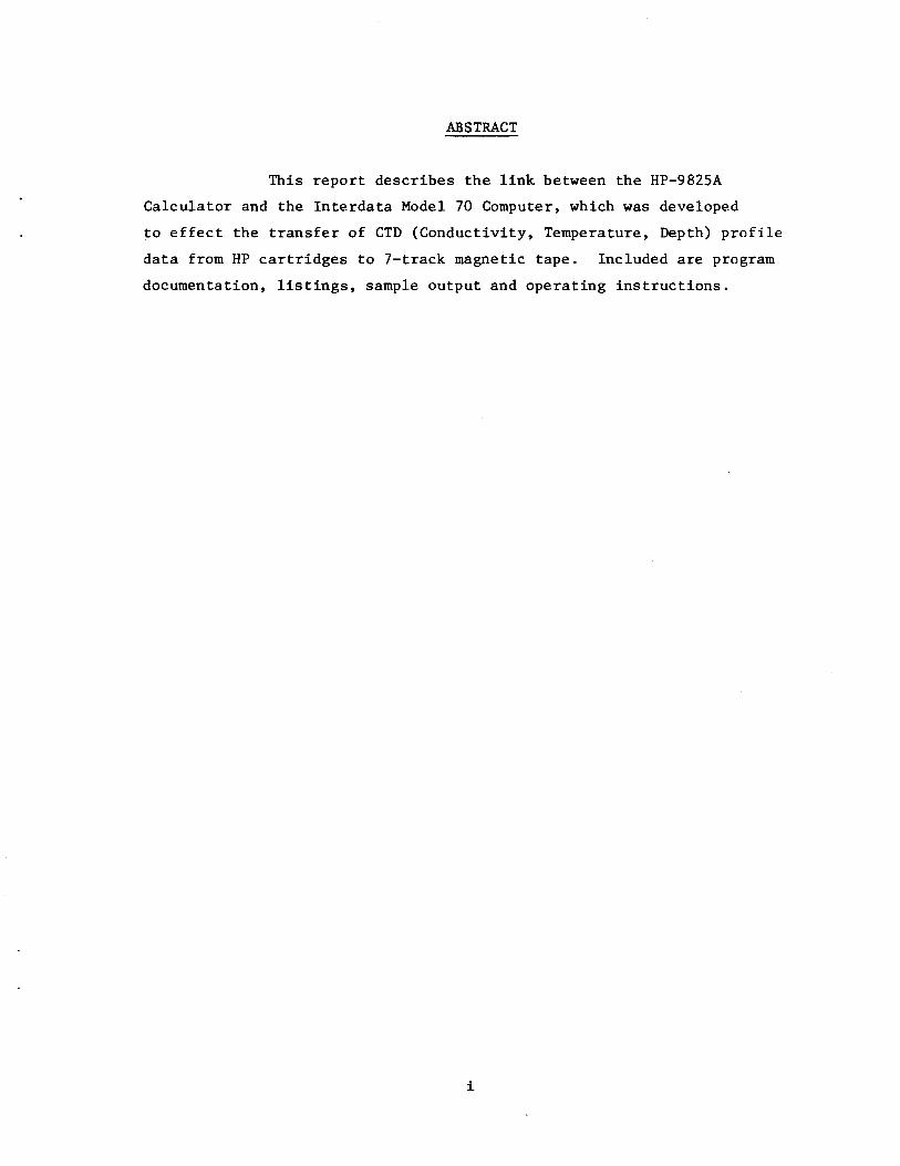
TABLE OF CONTENTS
ABSTRACT ...•
ACKNOWLEDGMENTS
TABLE OF CONTENTS
LIST OF FIGURES
INTRODUCTION AND GENERAL OVERVIEW
HardwarE;! ••
Software •
CONCLUSION • .
REFERENCES .
. .
APPENDIX A: FILE DOCUMENTATION
APPENDIX B : PROGRAM DOCUMENTATION AND SAMPLE OUTPUT •
APPENDIX C: OPERATING INSTRUCTIONS
APPENDIX D: PROGRAM LISTINGS
TRANSFER
RDP001
RDP002
APPENDIX E: USE OF THE HP-98036A INTERFACE
v
iii
v
vii
1
1
3
5
7
9
13
23
27
29
31
38
41

V.:(
LIST OF FIGURES
Figure 1: R&D Division Minicomputer System
Figure 2: Data Transfer System Flowchart •.
Figure 3: HP-98036A Interface Registers
vii
Page
2
4
45

viii
INTRODUCTION AND GENERAL OVERVIEW
In 1978, the Research and Development Division began CTD
(conductivity, temperature and depth) data reduction, error checking,
editing and plotting in the field using an HP-9825A programmable calcu
lator (Deys, 1978). This meant that data was returned from the field on
Hewlett-Packard (HP) cartridge tape in a form readable by only the
HP-9825A. Further analysis, plotting and archiving, of the data has
normally been carried out on the CDC 3170 computer at.CCIW. Consequently,
it was necessary to develop a system for the transfer of da~a from HP
cartridge tape to 7-track (~11 ) magnetic tape.
One approach considered was to interface a 7-track tape drive
to the calculator resulting in a compact, easy-to-use transcription facility.
However, since 7-track tape drives were already installed in the in-house
Interdata computer system, it was decided, instead, to interface the
calculator to the computer and develop the appropriate software to effect
the transfer.
Hardware
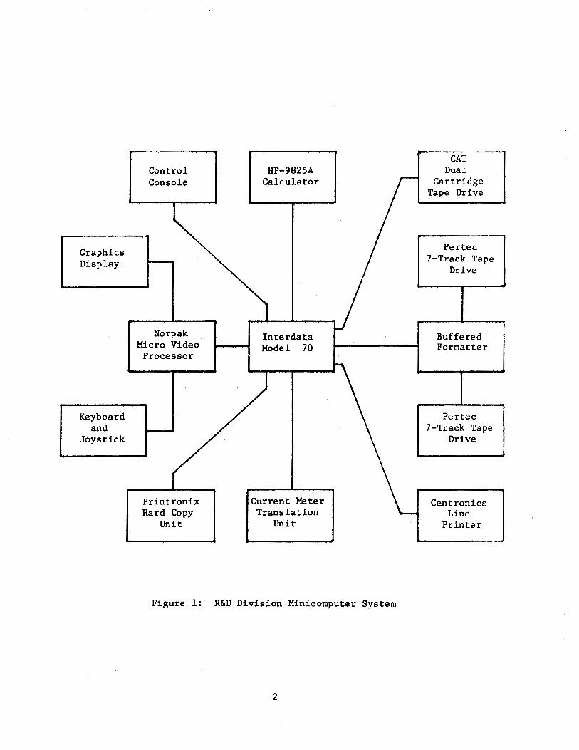
A block diagram of the R&D computer system is shown in Figure 1.
The HP-9825A is interfaced to the Interdata Model 70 via a standard EIA ·
interface and data is transferred one character (8 bits ASCII) at a time
under program control. Data is listed on the line printer and written
to magnetic tape. The function of the buffered formatter is to control
the synchronous tape drives and to facilitate double buffered I/0.
1
Graphics Display
Keyboard and
Joystick
Control Console
Norpak Micro Video Processor
Printronix Hard Copy
Unit
HP-9825A Calculator
lnterdata Model 70
Current Meter Translation
Unit
Figure 1: R&D Division Minicomputer System
2
CAT Dual
Cartridge Tape Drive
Per tee 7-Track Tape
Drive
Buffered · Formatter
Per tee 7-Track Tape
Drive
Centronics Line
Printer
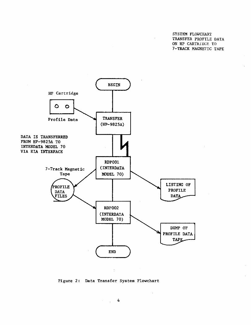
Software
Three computer programs were developed for this system
These are: TRANSFER, an HP-9825A program which reads profile data from
HP cartridge tapes and transfers it to the Interdata computer one
character (byte) at a time. RDPOOl, a program to read data from the
HP-9825A (one byte at a time, using the Operating System EIA driver),
convert it to standard ASCII, list it on the line printer, and write it
to 7-track magnetic tape in BCD format. RDP002, a utility program, dumps
profile data files from magnetic tape to the line printer. TRANSFER is
written in HPL while RDPOOl and RDP002 are written in Int~rdata Assembly
Language.
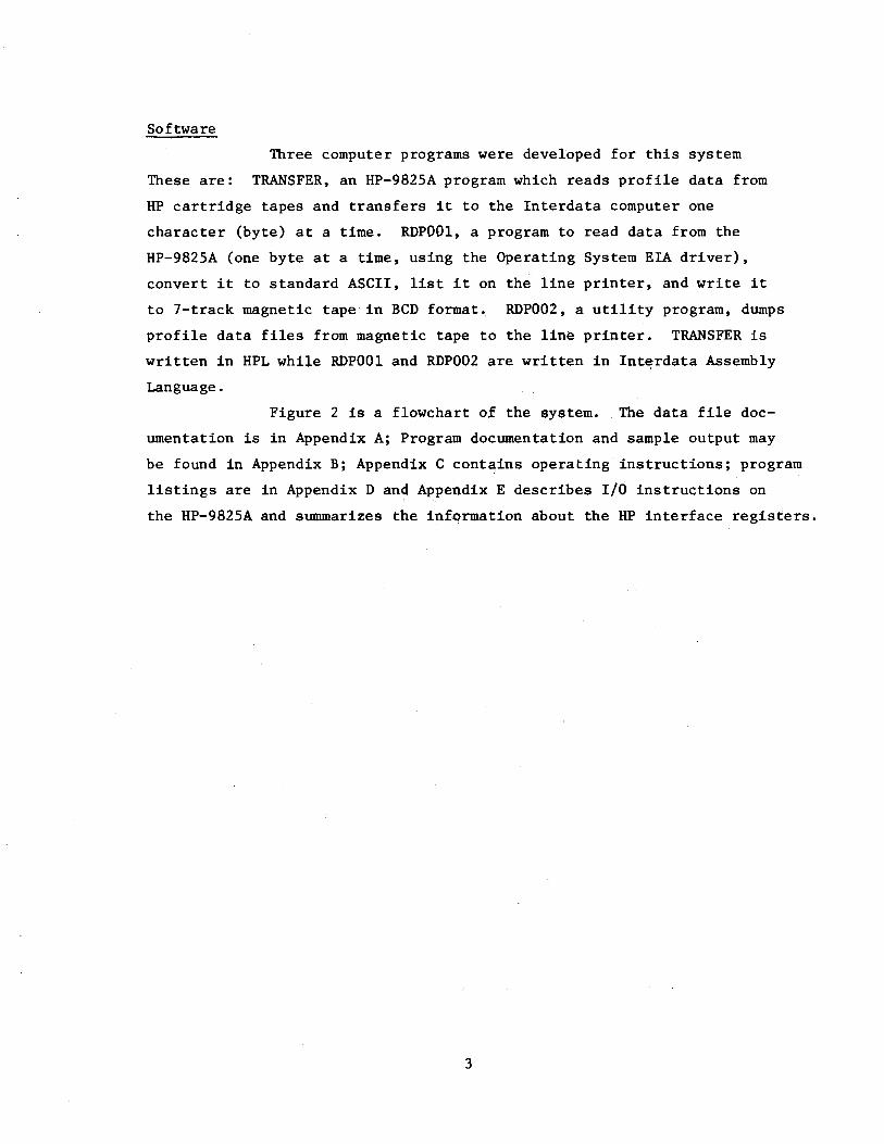
Figure 2 is a flowchart ot the system. The data file doc
umentation is in Appendix A; Program documentation and sample output may
be found in Appendix B; Appendix C contains operating instructions; program
listings are in Appendix D and Appendix E describes I/0 instructions on
the HP-9825A and summarizes the information about the HP interface registers.
3
HP Cartridge
0 0
Profile Data
DATA IS !RANSFERRED FROM HP-9825A TO INTERDATA MODEL 70 VIA EIA INTERFACE
7-Track Magnetic Tape
BEGIN
TRANSFER (HP-9825A)
RDPOOl (INTERDATA MODEL 70)
RDP002 (INTERDATA MODEL 70)
END
Figure 2: Data Transfer System Flowchart
4
SYSTEM FLOWCHART TRANSFER PROFILE DATA ON liP CARTRIDGE TO 7-TRACK MAGNETIC TAPE
LISTING OF
CONCLUSION
The HP-Interdata link has been successfully used to
transfer Arctic 1978 CTD profile data from HP cartridge to 7-track
magnetic tape, thereby allowing further processing on the CDC 3170.
With relatively few modifications, the link will be used for further
CTD data transfers and also for general communication between the
calculator and the computer.
5

6
REFERENCES
Deys, F.W. 1978. Arctic CTD Data Processing System. ~Technical Report Series, Ocean and Aquatic Sciences, Central Region, Department of Fisheries and Oceans, Burl:Lngton, Ontario.
Hewlett-Packard. HP-9825A Calculator, General and Extended I/0 Programming Manuals.
Hewlett-Packard. HP-98036A Serial I/0 Interface installation and Service Manual.
7

8

APPENDIX A: FILE DOCUMENTATION
9

10
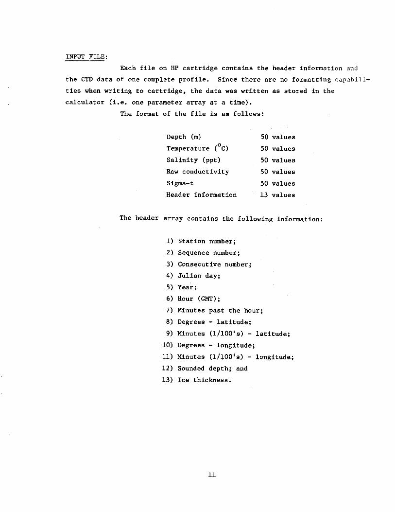
INPUT FILE:
Each file on HP cartridge contains the header information and
the CTD data of one complete profile. Since there are no formatting capabili
ties when writing to cartridge, the data was written as stored in the
calculator (i.e. one parameter array at a time).
The format of the file is as follows:
Depth (m) 50 values
Temperature (oC) 50 values
Salinity (ppt) 50 values
Raw conductivity 50 values
Sigma-t 50 values
Header information 13 values
The header array contains the following information:
1) Station number;
2) Sequence number;
3) Consecutive number;
4) Julian day;
5) Year;
6) Hour (GMT);
7) Mi:nutes past the hour;
8) Degrees - latitude;
9) Minutes (1/lOO's) - latitude;
10) Degrees - longitude;
11) Minutes (1/lOO's) - longitude;
12) Sounded depth; and
13) Ice thickness.
11
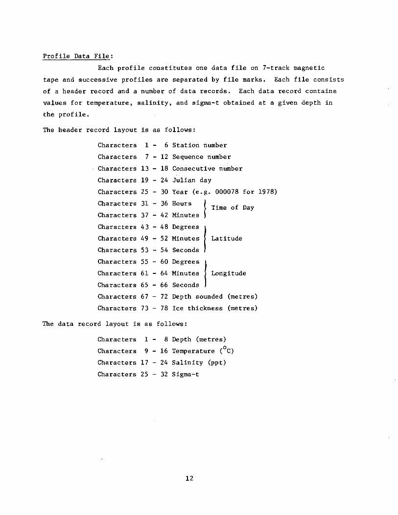
Profile Data File:
Each profile constitutes one data file on 7-track magnetic
tape and successive profiles are separated by file marks. Each file consists
of a header record and a number of data records. Each data record contains
values for temperature, salinity, and sigma-t obtained at a given depth in
the profile.
The header record layout is as follows:
The data
Characters 1 - 6 Station number
Characters 7 - 12 Sequence number
Characters 13 - 18 Consecutive number
Characters 19 - 24 Julian day
Characters 25 - 30 Year (e.g. 000078 for 1978)
Characters 31 - 36 Hours
~ Characters 37 - 42 Minutes Time of Day
Characters 43 - 48 Degrees
I Characters 49 - 52 Minutes
Characters 53 - 54 Seconds
Latitude
Characters 55 - 60 Degrees I Longitude Characters 61 - 64 Minutes
Characters 65 - 66 Seconds
Characters 67 - 72 Depth sounded (metres)
Characters 73 - 78 Ice thickness (metres)
record layout is as follows:
Characters 1 - 8 Depth (metres)
Characters 9 - 16 Temperature (oC)
Characters 17 - 24 Salinity (ppt)
Characters 25 - 32 Sigma-t
12

APPENDIX B: PROGRAM DOCUMENTATION AND SAMPLE OUTPUT
13

14
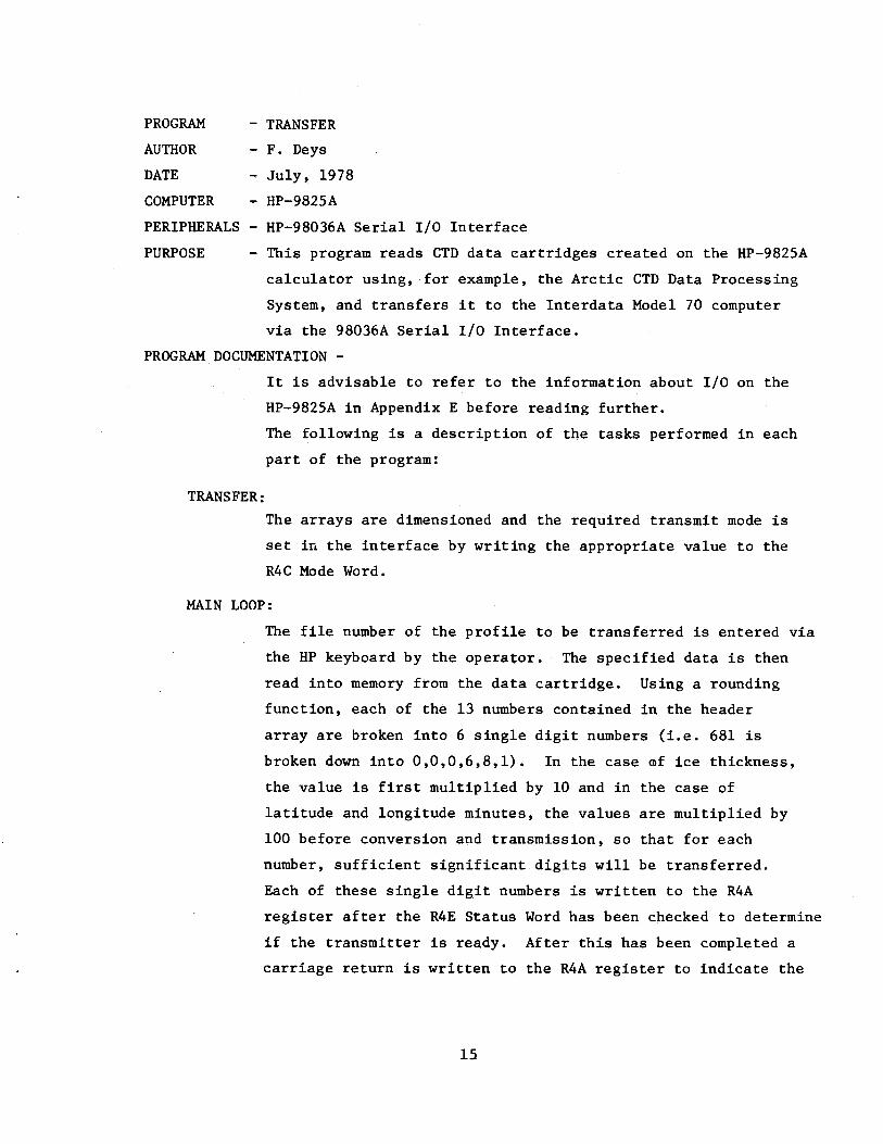
PROGRAM
AUTHOR
DATE
COMPUTER
- TRANSFER
- F. Deys
- July, 1978
~ HP-9825A
PERIPHERALS - HP-98036A Serial I/O Interface
PURPOSE - This program reads CTD data cartridges created on the HP-9825A
calculator using, for example, the Arctic CTD Data Processing
System, and transfers it to the Interdata Model 70 computer
via the 98036A Serial I/O Interface.
PROGRAM DOCUMENTATION -
TRANSFER:
It is advisable to refer to the information about I/O on the
HP-9825A in Appendix E before reading further.
The following is a description of the tasks performed in each
part of the program:
The arrays are dimensioned and the required transmit mode is
set in the interface by writing the appropriate value to the
R4C Mode Word.
MAIN LOOP:
The file number of the profile to be transferred is entered via
the HP keyboard by the operator. The specified data is then
read into memory from the data cartridge. Using a rounding
function, each of the 13 numbers contained in the header
array are broken into 6 single digit numbers (i.e. 681 is
broken down into 0,0,0,6,8,1). In the case mf ice thickness,
the value is first multiplied by 10 and in the case of
latitude and longitude minutes, the values are multiplied by
100 before conversion and transmission, so that for each
number, sufficient significant.digits will be transferred.
Each of these single digit numbers is written to the R4A
register after the R4E Status Word has been checked to determine
if the transmitter is ready. After this has been completed a
carriage return is written to the R4A register to indicate the
15
DONE:
OUTPUT:
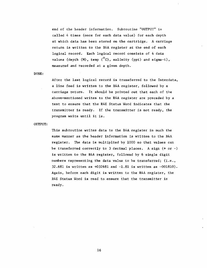
end of the header information. Subroutine "OUTPUT" is
called 4 times (once for each data value) for each depth
at which data has been stored on the cartridge. A carriage
return is written to the R4A register at the end of each
logical record. Each logical record consists of 4 data 0 values (depth (M), temp (C), salinity (ppt) and sigma-t),
measured and recorded at a given depth.
After the last logical record is transferred to the Interdata,
a line feed is written to the R4A register, followed by a
carriage return. It should be pointed out that each of the
above-mentioned writes to the R4A register are preceded by a
test to ensure that the R4E Status Word indicates that the
transmitter is ready. If the transmitter is not ready, the
program waits until it is.
This subroutine writes data to the R4A register in much the
same manner as the header information is written to the R4A
register. The data is multiplied by 1000 so that values can
be transferred correctly to 3 decimal places. A sign (+or -)
is written to the R4A register, followed by 6 single digit
numbers representing the data value to be transferred; (i.e.,
32.681 is written as +032681 and -1.81 is written as -001810).
Again, before each digit is written to the R4A register, the
R4E Status Word is read to ensure that the transmitter is
ready.
16
PURPOSE
AUTHOR
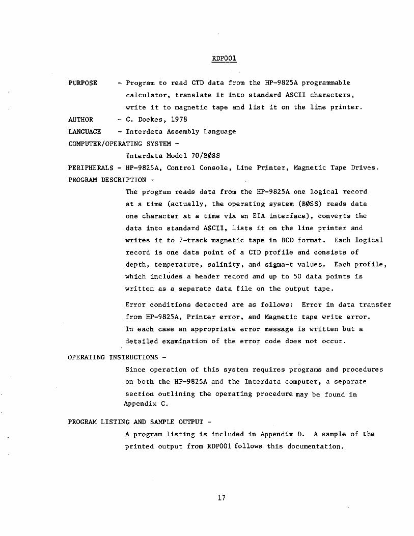
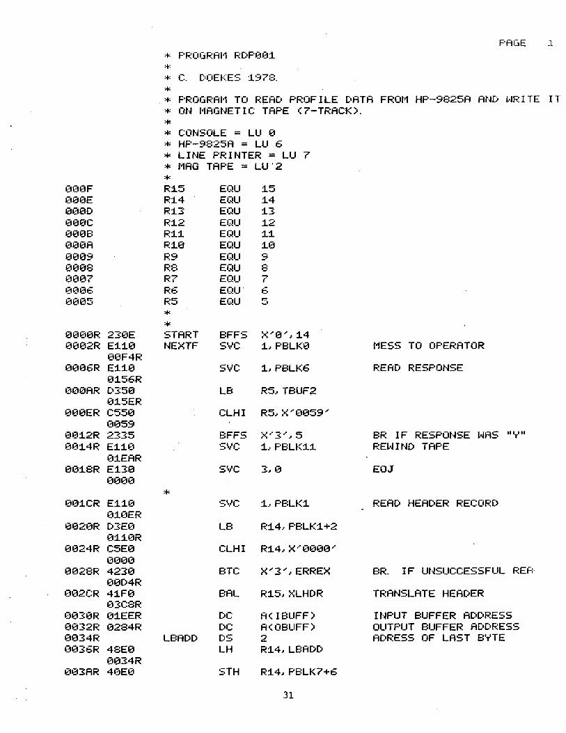
RDPOOl
- Program to read CTD data from the HP-9825A programmable
calculator, translate it into standard ASCII characters,
write it to magnetic tape and list it on the line printer.
- C. Doekes, 1978
LANGUAGE - Interdata Assembly Language
COMPUTER/OPERATING SYSTEM -
Interdata Model 70/B0SS
PERIPHERALS - HP-9825A, Control Console, Line Printer, Magnetic Tape Drives.
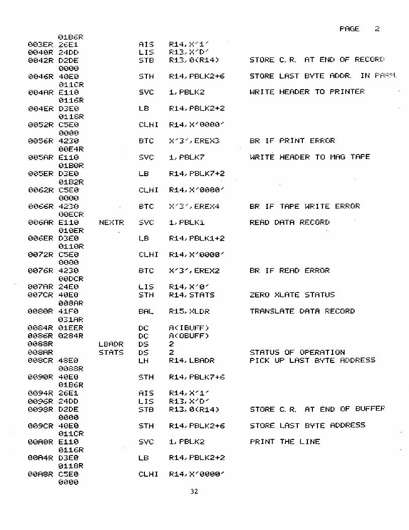
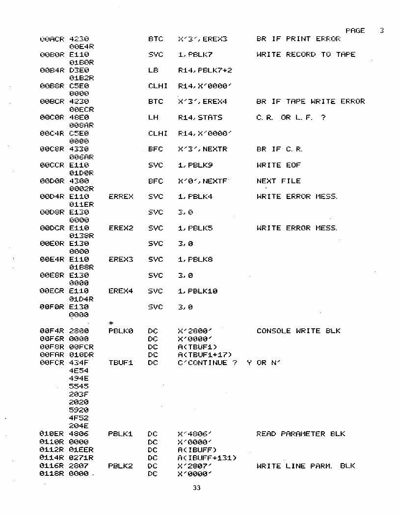
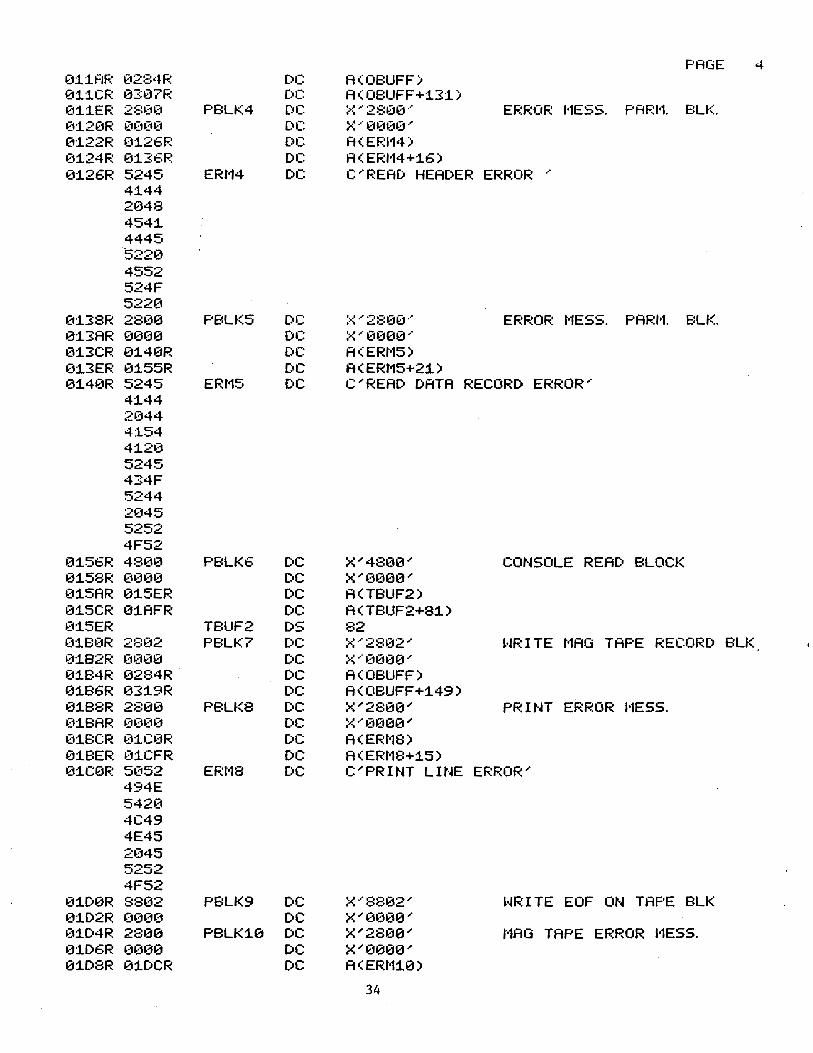
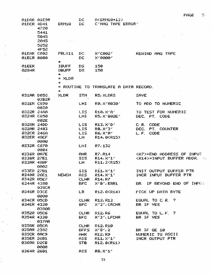
PROGRAM DESCRIPTION -
The program reads data from the HP-9825A one logical record
at a time (actually, the operating system (B0SS) reads data
one character at a time via an EIA interface), converts the
data into standard ASCII, lists it on the line printer and
writes it to 7-track magnetic tape in BCD format. Each logical
record is one data point of a CTD profile and consists of
depth, temperature, salinity, and sigma-t values. Each profile,
which includes a header record and up to 50 data points is
written as a separate data file on the output tape.
Error conditions detected are as follows: Error in data transfer
from HP-9825A, Printer error, and Magnetic tape write error.
In each case an appropriate error message is written but a
detailed examination of the error code does not occur.
OPERATING INSTRUCTIONS -
Since operation of this system requires programs and procedures
on both the HP-9825A and the Interdata computer, a separate
section outlining the operating procedure may be found in Appendix C.
PROGRAM LISTING AND SAMPLE OUTPUT -
A program listing is included in Appendix D. A sample of the
printed output from RDPOOl follows this documentation.
17

The first line is the header record and is followed by a
number of data points. Note that because of space limit
ations, the whole header record is not shown. The file
and record format is described in Appendix A (File Docu
mentation).
18
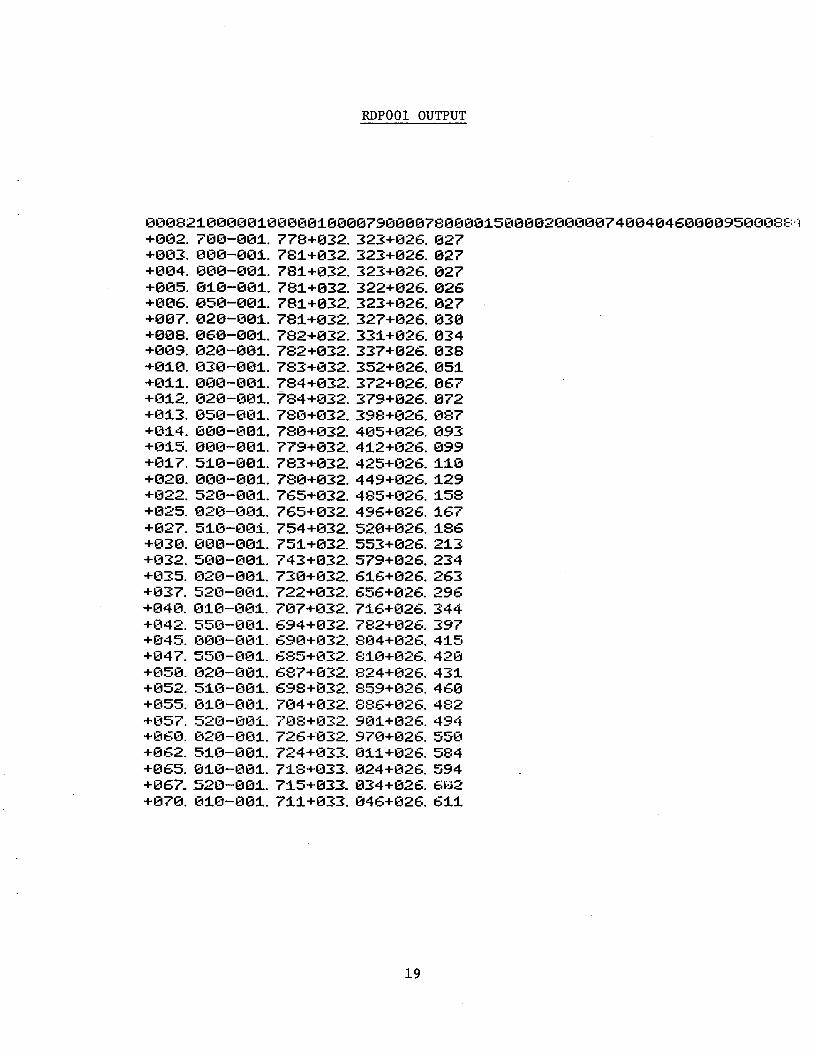
RDPOOl OUTPUT
00082~00000~00000~0000790000780000~5000020000074004046000095000881 +002. 700-00~. 778+032. 323+026. 027 +003. 000-00~. 78~+032. 323+026. 027 +004. 000-00~. 78~+032. 323+026. 027 +005. 0~0-00~. 78~+032. 322+026. 026 +006. 050-00~. 78~+032. 323+026.027 +007. 020-00~. 78~+032. 327+026.030 +008. 060-00~ 782+032. 33~+02& 034 +009. 020-00~. 782+032. 337+026. 038 +0~0. 030-00~. 783+032. 352+026. 05~ +0~~- 000-00~. 784+032. 372+026.067 +012. 020-001. 784+032. 379+026.072 +013. 050-001. 780+032. 398+026. 087 +014. 000-001. 780+032. 405+026. 093 +015. 000-001. 779+032. 412+026. 099 +017. 510-001. 783+032. 425+026. 110 +020. 000-001. 780+032. 449+026. 129 +022. 520-001. 765+032. 485+026. 158 +025. 020-001. 765+032. 496+026. 167 +027. 510-001. 754+032. 520+026. 186 +030. 000-001. 751+032. 553+026. 213 +032. 500-001. 743+032. 579+026. 234 +035. 020-001. 730+032. 616+026.263 +037. 520-001. 722+032. 656+026. 296 +040. 010-001. 707+032. 716+026. 344 +042. 550-001. 694+032. 782+026. 397 +045. 000-001. 690+032. 804+026. 415 +047. 550-001. 685+032. 8~0+026. 420 +050. 020-001. 687+032. 824+026. 43~ +052. 510-00~. 698+~32. 859+026. 460 +055. 010-001. 704+032. 886+026. 482 +057. 520-00~. 708+032. 90~+026. 494 +060. 020-001. 726+032. 970+026. 550 +062. 5~0-001. 724+033. 0~~+026. 584 +06~ 010-001. 718+033. 024+02~ 594 +067 . .520-00.1.. 7:15+033. 034+026. E:•:l2 +070. 010-001. 71:1+033. 046+026. 6~1
19
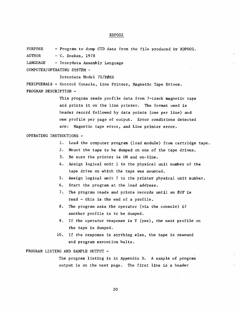
RDP002
PURPOSE - Program to dump CTD data from the file produced by RDPOOl.
AUTHOR - C. Doekes, 1978
LANGUAGE - Interdata Assembly Language
COMPUTER/OPERATING SYSTEM -
Interdata Model 70/B0SS
PERIPHERALS - Control Console, Line Printer, Magnetic Tape Drives.
PROGRAM DESCRIPTION -
This program reads profile data from 7-track magnetic tape
and prints it on the line printer. The format used is
header record followed by data points (one per line) and
one profile per page of output. Error conditions detected
are: Magnetic tape error, and Line printer error.
OPERATING INSTRUCTIONS -
1. Load the computer program (load module) from cartridge tape.
2. Mount the tape to be dumped on one of the tape drives.
3. Be sure the printer is ON and on-line.
4. Assign logical unit 1 to the physical unit number of the
tape drive on which the tape was mounted.
5. Assign logical unit 7 to the printer physical unit number.
6. Start the program at the load address.
7. The program reads and prints records until an EOF is
read - this is the end of a profile.
8. The program asks the operator (via the console) if
another profile is to be dumped.
9. If the operator response is Y (yes), the next profile on
the tape is dumped.
10. If the response is anything else, the tape is rewound
and program execution halts.
PROGRAM LISTING AND SAMPLE OUTPUT -
The program listing is in Appendix D. A sample of program
output is on the next page. The first line is a header
20

record and the remainder are data records (1 data
point/line). Note that the header record is truncated
because of lack of space on the page. The section on file
documentation (Appendix A) describes the header and data
records in detail.
21
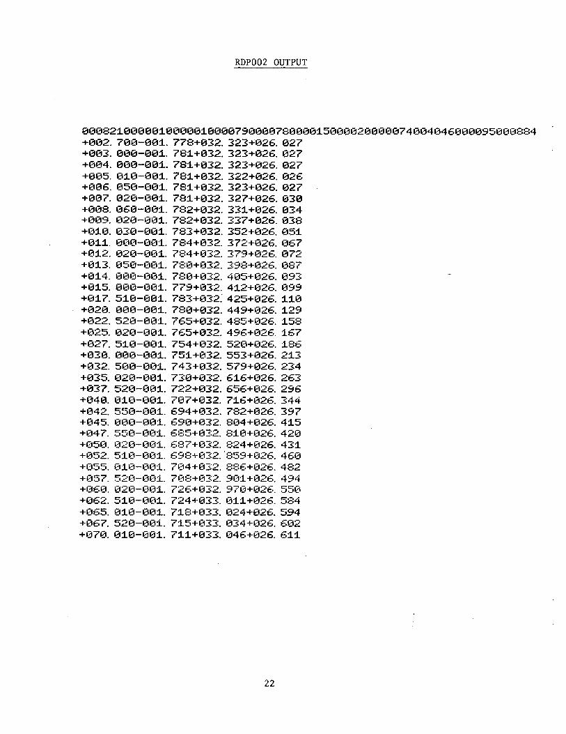
RDP002 OUTPUT
00082~00000~000001000079000078000015000020000074004046000095000884 +002. 700-00~. 778+032. 323+026. 027 +003. 000-001. 78~+032. 323+026. 027 +004. 000-00~. 78~+032. 323+026. 027 +005. 0~0-00~. 781+032. 322+026. 026 +006. 050-001. 781+032. 323+026. 027 +007. 020-00~. 781+032. 327+026. 030 +008. 060-001. 782+032. 33~+026. 034 +009. 020-00~. 782+03~ 337+026. 038 +010. 030-001. 783+032. 352+026. 05~ +011. 000-001. 784+032. 372+026. 067 +0~2. 020-001. 784+032. 379+026. 072 +013. 050-001. 780+032. 398+026. 087 +0~4. 000-001. 780+032. 405+026. 093 +015. 000-001. 779+032. 412+026. 099 +017. 510-001. 783+03~425+026 1~0 +020. 000-001. 780+032. 449+026. ~29 +022. 520-001. 765+032. 485+026. 158 +025. 020-001. 765+032. 496+026. 167 +027. 510-001. 754+032. 520+026. 186 +030. 000-001. 751+032. 553+026. 213 +032. 500-001. 743+032. 579+026. 234 +035. 020-00~. 730+032. 616+026. 263 +037. 520-001. 722+032. 656+026. 296 +040. 010-001. 707+032. 716+026. 344 +042 550-001. 694+032. 782+026. 397 +045. 000-001. 690+032 804+026. 415 +047. 550-001. 685+032. 810+026 420 +050. 020-001. 687+032. 824+026. 431 +~352. 51(1-001. 69E:+(G2. "859H326. 460 +055. 010-001. 704+032. 886+026. 482 +057. 520-001. 708+032. 901+026. 494 +060. 020-001. 726+032. 970+026. 550 +062. 510-001. 724+033. 011+026. 584 +065. 010-001. 718+033. 024+026. 594 +067. 520-001. 715+033. 034+026. 602 +070. 010-001. 711+033. 046+026. 611
22
APPENDIX C: OPERATING INSTRUCTIONS
23

24
OPERATING INSTRUCTIONS
It is assumed that the reader is familiar with the operation
of the HP-9825A and the Interdata Model 70/B~SS Operating System.
1. Connect the HP-9825A to the appropriate EIA interface cable on
the Interdata.
2. Turn on the calculator and the computer and peripheral devices to be
used.
3. Load program "TRANSFER" from HP cartridge into the calculator memory.
4. Insert the HP cartridge containing the data to be transferred into
the calculator tape drive.
5. Load program RDPOOl from cartridge into the Interdata computer.
6. Assign physical unit numbers to logical unit numbers as follows:
X'OB' to 06, X'62' to 07 and X'2A' or X'6A' (depending on which
magnetic tape drive is used) to 02.
7. Mount a 7-track magnetic tape on one of the Pertec tape drives. Be
sure that a write ring was inserted.
8. Press "RUN" on the HP-9825A and enter the nutnber of the file containing
the data to be transferred.
9. Start execution of RDPOOl at the load address. The profile data will
be read from the HP-9825A and written to the line printer and to mag
netic tape. If any errors occur during this process, the transfer halts
and an appropriate error message is printed.
10. When the transfer is complete, a message asking if any more data is
to be transferred is displayed on the control console and a message
asking for the next file number is displayed on the calculator display.
If the operator enters "Y" to the Interdata and a file number to the
HP-9825A, the next profile is transferred to magnetic tape. If the
operator enters anything else on the console, the magnetic tape is
rewound and program execution halts.
25

26

APPENDIX D: PROGRAM LISTINGS
TRANSFER
RDPOOl
RDP002
27

28
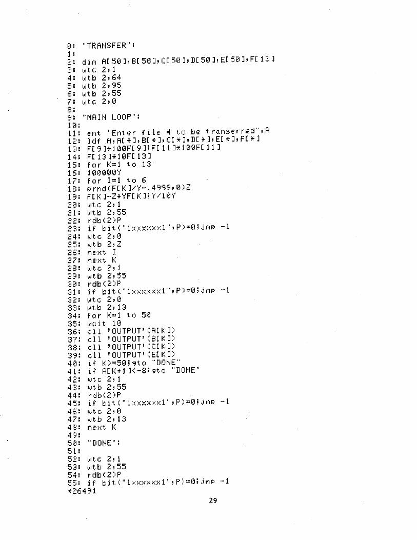
~.3: "TF.:At·lSFEF.:": 1 :
~;: I.•JtC. 2' 1 4: ll,lt.b 2,64 5: la.ltb 2,95 6: l.a.lt.b 2,55 7: l,1,1t.c. 2,0 C• • I.J '
9: "t1Alt~ LOOP": 1[1:
11: 12: 1 ::::: 14: 15: 16: 17:
e·nt. "Ent. ~::· r f i 1 e· # t.. c1 be t.. rc1.n::.e· r re·d"' A 1 df A, AC * J, E:C * J, CC * J' DE ·* J' EC * J, FC * J
19: 2~Zn 21: .... , ...... .:::..:::.• ·~·-· . .:::. .;) . 24: 25: 26: 27: 2a: 29: :::: ~z1 : 31: .... , ...... . .:a.::, • ·-:.·-::·· ........... ~:4: :35: :36: :37: ·":~•:• . .......... :3'51: 4~]:
41: 42: 4::::: 44: 45: 46: 47: 48: 4 13: 5~Zn 51:
F[ 151 ]* 100FC 13 H FC 11 H 1 £1t1F[ 11 J FC 1:3 H10FC 1:::: J fc1r ~::=1 t.o 1:::: 1 t1t100t1 1
'1~ f'c1r I=1 t.l) 6 PrndCFCKJ/Y-.4999,0)2 FCKJ-Z*YFCKJ;Y/10Y l,1,lt. C. 2' 1 l~.lt.b 2, 55 rdb(2)P if bit. (II 1 ::.::::.::>::::.::::.::::.:: 1 11
' p) =0; ,j (I'IP -1 l,~lt,.C. 2,0 l~ltb 2' z r1 e· :)~ t, I ne·:x:t. f( '·~'t.e 2, 1 la.lt..b ;2,55 rdb(2)P if' bit. (" 1 ::<>::::<>::>::::< 1 "' p) =0; .j I'I'IP -·1 '·~' t.. c. 2 , ~z1 l,1,1t,.b 2,13 f'c1r 1<=1 tc1 5£1 l,1,ll:l i t,. 1 f:J ell 'OUTPUT'CA[I<J) e 11 'OUTPUT' ( BC f::: J) ell 'OUTPUT'CCCKJ) ell 'OUTPUT' CEC f( J) if f0=50; o:,t. c1 "DOt·lE" if' AC K+l J<-:3; o:,t.c1 "Dot·lE" l1.1t.c. 2, 1 l,a,lt,.b 2' 55 rdb(2)P if' bit. (II 1 ::<::<>::::.::::<::.:: 1 ,, 'p) =~Z1; ,j (•'IP ·-1
l,1,l t. (, 2 ' t~ l~lt.b ;2, 13 n e· ::< t. f:::
"Dot~E":
52: l,aJt.l:. 2' 1 5:3: l.~lt.b 2,55 54: rdb(2)P 55: if' bit (" 1 ::.::::<::<)<>::>:: 1" 'F') ='J j .j (''IP -·1 *26491
29
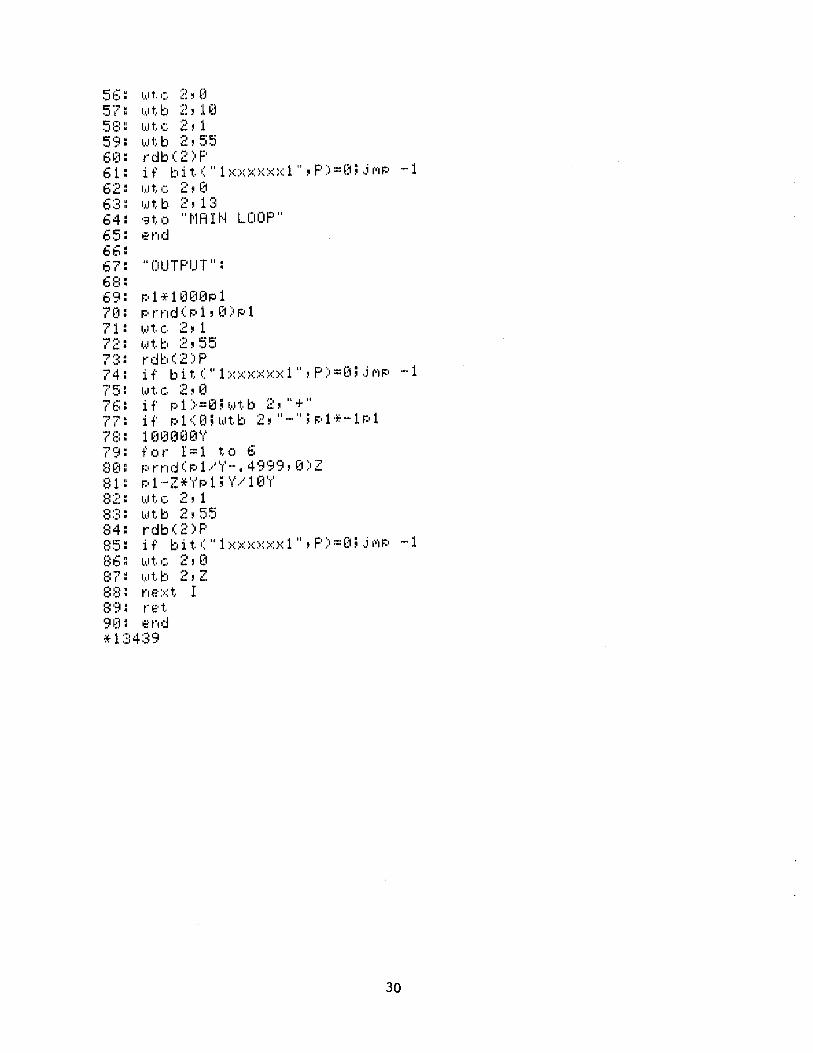
c· ...... ._11::·. 5?: 5:::: 59: 6~H 61: 62: 6:;:: 64: 65: 66: 67: 6E:: 6'3: 7~~1: 71: 72: ..., •"'I • I' .,:1 •
74: ?5: -!1 .....
( 1:::1. '? 7: ?:::: ?·~: ::: ~~~ : ::: 1 :
s:;:: :34: :::5: :::6:
I.~Jtc ~~,o l,1,i"t,.b ~~, :l~~
l,aJt.C. ~:, l. 1 •• ,11;. b 2' 5!=5 rdb(2)F' if bit. (II 1 ::-::::-::::-::::-::::-::::< 1 '', p) ='J; ,j f1'1P -·1 l,.,lt,. c 2, ~:l
I,,Jtb 2,1:3 ·::~t.. 0 II ti1A H~ LOOP II
.::·nd
II OUTPUT II:
P1*1~)[10P1 Prnc:I(P1, ~~1)pl l,1,lt,.c, 2,1 l,1,lt,.b 2, 5~i rdb(2)F' if' bit,. (II 1 ::-::::-::::·::::·::::·::::< 1 11
, p) =0; ,j f1'1P -1 1,1.1 t. c. 2 ' ~) u pl >==e:n 1,~.1t.b 2, 11 + 11
if p1([q1,1Jt..b 2,~~-~~;pp:·-1P1
1 [1 ~) ~) ~1 [1 1'1"
f',)t" I=l t..c, 6
r:~ 1·-Z*~'f'~-:.1; ~.f~ ..... l [1 1'1'
1
l,l,lt,. c. 2, 1 ~~Jt.b ~~,~55 rdb(2)F' if' bit. (II 1 ::·::::<::·::::<>::::< 1 11
, p) :::[1; ,j f1'1P -·1 1,1.11:. c. 2' [1 1.~.1tb 2,z n~::·::-::t.. I t">.E•t.
e·nd
30
~Zt~::u:tF
~::n3~::1E
0~30D
~::n30C
~3008
0~30A
~3009
~3008 ~3007
~3~3~36
(1(105
0000R 231Z1E 0002R E:1.1.0
~30F4R €1006R E:1.:10
IZ11.56R ~300AR D350
IZ1:1.5ER 000ER C550
~::1059
€1(1:12R 2335 ~::n3:14R E:1:1.(1
~3:1EAR
00:18R E:130 0000
0~3:1CR E:1:1.~3
~::11.0ER
0~320R D3E(1 0:1.:10R
€n324R C5E0 0~300
0028R 4230 (10D4R
002CR 4:1.F0 03CSR
~3030R 01.EER ~::1032R 0284R (1034R (1036R 48E0
(1034R (103AR 4~3E0
:+: PF.:OGF.:AI·1 F.:DP~30:1
* * C. DOEKES :197::3.
*
PAGE J.
* PF.:OC:iRAI•1 TO F~EAD PROFILE C:•ATA FROI1 HP-9825A AND ~·JF.: I TE IT * ON MAGNETIC TAPE <7-TRACK).
* * CONSOLE = LU 0 * HP-9825A = LU 6 * LINE PRINTER = LU 7 *MAG TAPE = LU'2
* R:1.5 EI:;"J.U :1.5 R:14 EI).U :1.4 R:13 E•).U :1.3 R:1.2 E@J :12 R1.:1. EI).U 1.:1 R:l0 EQU :1.0 F.:9 EG!U 9 R8 EI).U 8 R7 EI:;"J.U 7 R6 EI).Ll 6 ~~5 EG!U "" ._I
* * START BFFS X..-0 ... )1.4 NEXTF svc 1.JPBLK0
svc L PBLK6
LB R5JTBUF2
CLHI R5) X,. (1059 ...
BFFS :X:.-"3-' .. 5 s .... •c: L PBLK:1.:1.
svc 3) 0
* S'·lC L PBLK:1.
LB F.::1.4) PBLK1. +2
CLHI R:1.4) X ... (1IZ100 ...
BTC X..-3..-)ERREX
BAL R:1.5~ r~LHDR
DC A<IBUFF) [.'C A<OBUFF)
LBADD DS 2 LH R1.4~LBADD
STH R:1.4~PBLK7+6
31
MESS TO OPERATOR
F.:EAD RESPONSE
BR IF RESPONSE l•JAS II., II F~El·J I ND TAPE
EOJ
READ HEADER RECORD
BR IF UNSUCCESSFUL REA
TRANSLATE HEADER
INPUT BUFFER ADDRESS OUTPUT BUFFER ADDRESS ADRESS OF LAST BYTE
PAGE 2 ~::nB6R
~303:EF.: 26Ei AIS F.:14~ ~< .·· i .·· (U~14~~1R 24DD LIS R13~ ::< ·' ['J ·'
(1042R D2l)E STB R1.3: .. (1 ( Ri4) STORE c. R. AT END OF RECOFW 0000
(U)46R 40E(1 STH F.::l4, PBLK2+6 STORE LAST B'T'TE A[1DR. IN PA~:H.
OiiCR ~)(14AR E110 S'v'C L PBLK2 l.JRITE HEADER TO PRINTEF.:
~3116R
~304ER D3E(1 LB F.::l4~PBLK2+2 0118R
(1052R C5E~3 CLHI F.::l4, ::<,. (1(1(1(1,. (1(1(1(1
0(156R 4230 BTC ::< ··· 3 ··· .. EF.:EX3 BR IF PRINT ERF.:OR (1(tE4R
0~~15AR E11~3 S'v'C L PBLK7 l.JRITE HEA[)EF~ TO 1·1AG TAPE ~~t180R
~)(t5ER D3E(t LB R:l4~PBLK7+2
0182R 0062R C5E0- CLHI R14~ X·'0000 ...
(1~)~~1(1
(U366R 42:~(1 BTC :=< ... 3: ..... E~:E~·!.4 E:f;: IF TAPE l·JF.: I TE ERF~OR
OOECR ~~u)6AR E110 NE::<TR S\··c: L PBLKi READ DATA RECORD
010ER 0~36ER D3E0 LB F.:1.4, PBLK1.+2
~311.~3R
~3072R C5E0 CLHI R14~ X,. (1000 ... ~~U~1(1(1
0076R 4230 BTC X ... 3 ... ~EREX2 BR IF READ ERROR (t(tDCR
007AR 24E0 LIS R14~ X·'0 ... ~)(t7CR 40E0 STH R14~STATS ZERO X LATE STATUS
(108AR ~~t080R 41F0 BAL R1.5, ~<LDR TRANSLATE DATA RECORD
031AR (t084R ~31EER DC A<IBUFF) 0086R ~3284R DC A<:OBUFF) ~~U388R LBADR DS 2 ~~108AR STATS DS 2 STATUS OF OPEf;:AT I ON O~~t8CR 4::::E(t LH R1.4,LBADR PICK UP LAST B'T'TE ADC•F~ESS
~:308BR
0090R 40E0 STH R14,PBLK7+6 0186R
(n394R 26E1. AIS F~1.4, X ... 1 ... 0~396R 24DD LIS R1.3,X_..D ... 0098R D2DE STB R1.3,0(R1.4) STORE C. R. AT END OF BUFFEP
0000 ~3(t9CR 40E0 STH R1.4,PBLK2+6 STORE LAST BYTE ADDRESS
~31.1.CR (h3A(tR E110 S\•'C 1.,PBLK2 PRINT THE LINE
01.16R 00A4R D3E0 LB R:l4,PBLK2+2
01.18R ~~t0A8R C5E0 CLHI R1.4,X ... 0000 ...
0000 32
PAGE 7 ...>
OOACF~ 423:(1 BTC ::< ,. 3 ··· ~ E~:EX3: BR IF PRit·n E~:~:OI':
~10E4R
0080~: E:1:V3 s··lC L PBLK7 ~·JRITE RECO~:D TO TAPE €1:1BOR
~U~184F~ [,'J:EO LB R:14~PBLK7+2
~3:182R
(1~18E:R C5E0 CLHI R:14~X,..0000,.
0~3~3~~1
~~U38C~: 423(1 BTC X ... 3 ... ~ ERE?-~4 BR IF TAPE l>t~:ITE E~:~:OR
00ECR 00C0R 48E0 LH R:14~STATS c. R. OR L. F. ?
~308AR
(n3C4R C5E€1 CLHI ~:1.4. x···~3~3eo-·
~~1 ~~1(1 ~~1
~3~3C8R 433(1 BFC X ... 3:,..~NEXTR BR IF C. R. (H36AR
00CCR E:1:10 svc 1.~PBLK9 lo.IRITE EOF 01.D0R
€1€1DOR 4300 BFC X ... 0 .... ,NEXTF NEXT FILE (U302R
~~10D4R E1.1.0 ERF~EX S'v'C 1.,PBLK4 l·JRI TE ERROR 11ESS. 01.1.E~:
0€1D8R E1.30 svc 3, (1
(U)(10 OODCR E1.1.0 EREX2 svc 1.~PBLK5 lo.IRITE ERROR 11ESS.
01.38R 00EOR E1.30 svc 3,(1
0000 00E4R E1.1.0 EREX3 svc L PBLK8
01.88R 00E8R E1.30 svc 3~ 0
~3(100
(1(1ECR E1.1.0 EREX4 svc 1.~PBLK1.0 ~31.D4R
€10FOR E1.30 svc 3~0 0~~1(1(1
* 00F4R 2800 PBLK0 DC ~< .... 2800" CONSOLE l.JRI TE BLK 0~3F6R 00~30 DC X"(H300" ~30FE:R 00FCR DC A<TBUF1.) ~3~~1FAR 01.0DR DC A(TBUF1.+1.7) (10FCR 434F TBUF1. r}c C .... COt·H I NUE ? ..,. OR N ...
4E54 494E 5545 203F 2020 5920 4F52 204E
~31.0ER 4806 PBLK1. DC X·' 48~~16 ·' ~:EAD PARA1·1ETER BLK 01.:i0R (H)00 DC X·'00~30"'
01.1.2R 01.EER DC A<IBUFF) 01.:14R 027:1R DC A<IBUFF+:13:1) ~31.:16R 2807 PBLK2 DC X,..2807"' l.JRITE LINE PARI•1. BLK 0:1:18R 0000 . DC X"'0000"
33
PAGE 4 0:1:1fiR 02:3.:tR DC A<OBUFF) 0:1:1CR 03:07R oc A<OBUFF+:13:1) (1:1:1ER 2:=:~~1~~1 PBLK4 DC :~~ ... 2E:~30 ··· EF':ROR 1·1ESS. PAF.:I•1. BLK. (1:120R oo~:::1~:::1 DC X,. c.:u:::u:::n3 ·' 0:122R 0:126R DC A<EF~I14)
C.:11.24F~ (1:13:6F.: DC A ( ERI•14+1.6) 01.26R 5245 ERt14 DC C ... READ HEADER ERROR .··
4:144 2048 4541. 4445 5220 4552 524F 5220
01.38R 2800 PBLK5 DC ::-~ ... 2:=:00 ,.• ERROF': t·1ESS. PAF.:I1. 8LK 01.3AR 0000 DC X ··· €1000 ,. 01.3CR 01.40R DC A(ERt·15) 01.3EF': 01.55R (JC A< ERt15+21. > ~31.40R 5245 ERt·15 DC C ... READ DATA F':ECORD ERROR ...
41.44 ~~044
4:154 4:120 5245 434F 5244 2045 5252 4F52
01.56R 480~3 PBLK6 DC X..-4800 ... CONSOLE READ BLOCK 01.58R (1(100 DC X ... 0~300 ... 01.5AR 01.5ER DC A<TBUF2> 01.5CR 01.AFR DC A<TBUF2+81.) ~Z1:15ER TBUF2 DS 82 (1:180R 2C:02 PBLK7 DC x .. ·2:=:e2"' ~·JRI TE t·1AG TAPE RECORD BLK 01.82R ~3(100 DC X,. €11:"::100·' (11.84R 0284R DC A<OBUFF> 01.86R 031.9R DC A<OBUFF+1.49) 01.88R 2:::00 PBLK8 C•C X..-2800 ... PRINT ERROR 1·1ESS. (1:18AR (1(1(1(1 DC ::-:: ·' (UZ100..-01.BCR ~Z1:1C(tR DC A<ERt·18) 0:1BER ~3:1CFR DC A ( ERt·18+1.5) 01.C0F.: 51:"::152 ERt-18 DC C ... PRINT LINE ERROR ...
494E 5420 4C49 4E45 2045 5252 4F52
01.DOR 8802 PBLK9 DC ::-:: ,. 8802 ... ~·JRITE EOF ON TAPE BLK 0:1D2R (n300 DC X..-0€100/ ~31.D4R 2800 PBLK1.0 DC X/2800/ t··1AG TAPE ERROR 1·1ESS. ~3:1D6R ~3000 DC X/0000/ 01.D8R 0:1DCR DC A<ERt11.0)
34
PAGE r:-
·-· ~::H.L•AF<: 0:1E9R I)C A< ERI·1i~3+:13:) (1 :1. L• C F~ 4D4:1. ERt1:10 DC c--l·lAG TAPE EF$:Or;;:-·
4720 544:1. 5045 2045 5252 4F52
0:1EAF<: C002 PBU<i:l DC X,...C002" REl..JIND NAG TAPE 0:1ECR 0000 C•C X..-0000"
* 0:1.EER I BUFF [>S :1.50 ~3284R OBUFF DS :1.50
* * XLDR
* * ROUTINE TO TRANSLATE A DATA RECORD.
* €13:1.AR D€15C. XLDR STt·l R5~XLDRS SAVE 03B2F<:
03:1.ER C890 LHI F<:9~ X,. 003:0,. TO ADD TO NUI·lERIC (U)3:~3
(13:22R 24AA LIS R:l.e~ x···A-· TO TEST FOR I·~UI·lER I C ~3324R C850 LHI RS~ X,. 002E ... DEC. PT. CODE
002E 0328R 24DD LIS R:1.3~X,.D" c. R. CODE 032AR 2483 LIS R8~X"3,. DEC. PT. COUNTER 032CR 246A LIS R6~X"A" L. F. CODE 032ER 48EF LH R:1.4J0(R:1.5)
(10(10 0332R C870 LHI R7~:1.32
0084 0336R 0A7E AHR R7JR:1.4 <R7>=END ADDRESS OF It·~PU1
0338R 27E:1. SIS R:1.4JX":l." <R:14)=INPUT BUFFER AD DR. 033AR 48BF LH F<::l.:ll 2 ( F<::1.5)
~z1~z1~Z12
~333ER 27B:l. SIS F~:1:1.~ X,. :1.,. INIT OUTPUT BUFFER PTR 0340R 26E:1. NEl..JCH AIS R:1.4~ X" :1" INCR INPUT BUFFER PTR £1342R 05E7 CLHR R:1.4~R7
0344R 43::::e BFC X"8"JERR:1. BR. IF BE'T'OND END OF INPt: i
~338CR
0348F<: D3CE LB F<::12J 0 ( R:1.4) PICK UP DATA BYTE 0000
034CR 05CD CLHR R:12~R:1.3 EG!UAL TO c. R. ? 034ER 4330 BFC X·'3", CRCHR BR IF 'T'ES
~3380R
0352R 05C6 CLHR R:12~R6 EQUAL TO L. F. ? 0354R 4330 BFC X"3"~LFCHR BR IF YES
037AR 0358R 05CA CLHR R:1.2~R:1.0 ~335AR 2382 BFFS X"8,.~2 BR IF GE :1.0 035CR 0AC9 AHR R:1.2~R9 NUt·lERIC TO ASCII 035ER 268:1. AIS R:l:l~X":l" INCR OUTPUT PTR 0360R D2CB STB R:1.2~0<R:1.:1.)
0(100 0364R 268:1. AIS R8~ X":t."
35
PAGE 6 ~:::c~66R C:58~~1 CLHI R8, :>=: ··· (10€17 ,.
0007 ~:::G6A~: 4230 BTC ::< ,. 3 ··· .• NEl·KH BR IF t·m DEC. PT. TO BE..
€134~:::1~:
036EF~ 268:1 AIS R:1:1, X··· :1 ··· 037~Z1R D258 STB R5,0(R:1:1) STORE DEC. PT.
0(1(1(1 €G74R 248~:::1 LIS R8, x ... ~:;:1-·
€G76R 430~:::1 BFC X''0·', NEHCH 03:4£1R
€G7AR 249:1 LFCHR LIS R9,X"':1"' €G7CR 4(19F STH F-:9, 6<R:15) SET STATUS FOR LINE FEE~'
(1(1~::16
€G8€1R 4€18F CF.:CHR 5TH R:1:1,4(R:15) SET LAST B'T'TE ADDRESS I:':U:::1 (14
€G84R D:15€1 U·1 ~:5, :x:LDRS F.:ESTORE €G82F.:
0388R 43~Z1F BFC x.-0-·. 8<R:15> RETURt~ ~30~)€:
~Z138CF~ E:1:10 EF.:R:1 S'·IC :1,PBLKA PRINT ERROR NESS. ~339.:~R
039€1R E:13:~:::1 s• ... •c: 3:, (1 EXIT OO€n:;:i
* 0394R 2800 PBLKA DC x .. ·2:=:~.Z10 ... ERROR t·1ESS. PARI'l. BLK 0396F.: (1(100 ['JC :...;-·(1000"' €G9E:R ~)3:9CR DC A<ERHA> €139AF~ €G8€1F~ DC A<ERt·1A+20) 039C~: 494E ERt·lA DC c-· INPUT BUFFER OVERFLOl.J ...
5(155 542~)
4255 4646 4552 2~:::14F
5645 5246 4C4F 5720
* ~)382F.: ::-::LC•RS DC .-.. -. -· .:::..::.
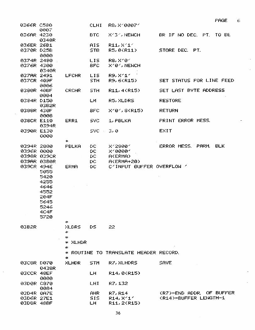
* * * XLHDR
* * ROUTINE TO TF.:ANSLATE HEADER RECORD.
* 03(~:3R D070 XLHDR STt'l R7, ::<LHDRS SAVE
0438R 03CCF~ 48EF LH R:14,0<R:15)
00~:::1(1
~)3[:•0F.: C870 LHI ~:7. :132 ~)(184
~Z13D4R 0A7E AHR R7,R:14 (R7)=END A[)DR. OF BUFFER (($D6R 27E:1 SIS R:14,X"':1"' (R:14)=8UFFER LEHGTH-:1 03DE:~: 488F LH R:1:1. 2 ( R:15)
36
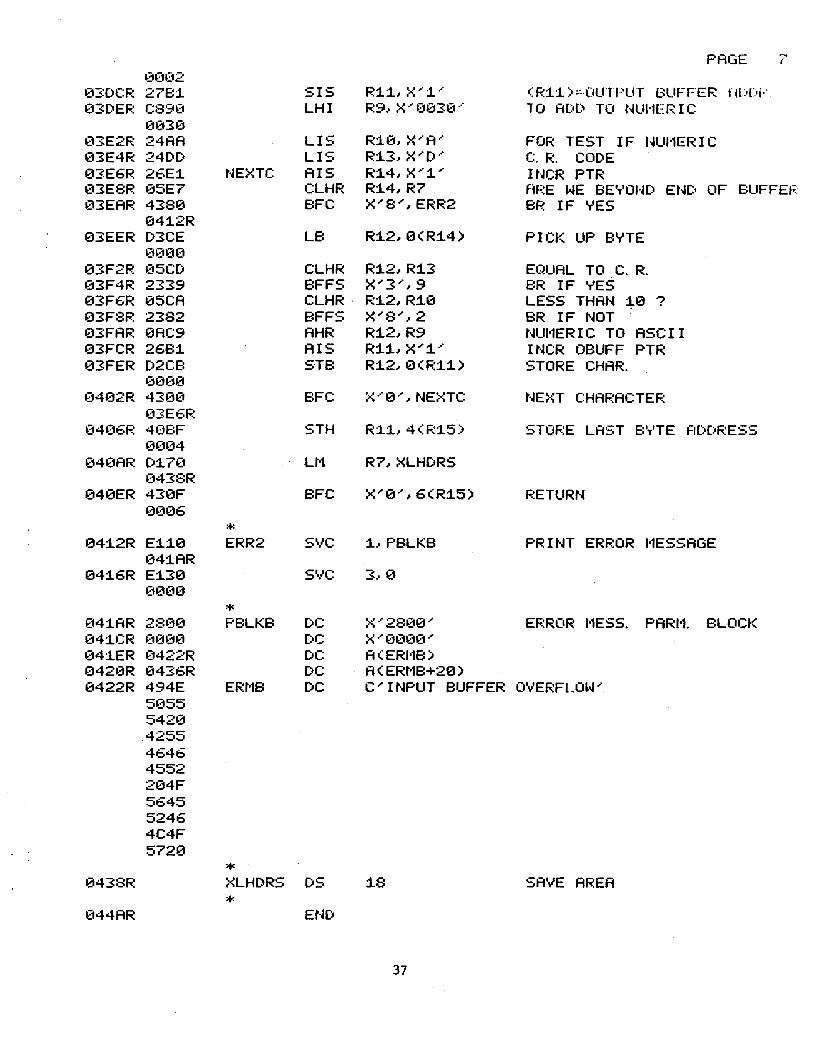
PAGE 7 (1(1(12
€13:DCR 2781. SIS R1.1., X ,.1. ··· ( R:t.1.) :::-OUTPUT BUFFER Hl:O[ol,' 03DER C890 LHI R9, ~< ·' 003~1··· TO AO(:t TO NUI·1ERIC
0030 03E2R 24AA LIS R:t.0, X,. A·' FOR TEST IF I~UI·1ERIC 03E4R 24DD LIS R1.3, X ... [)·' c. R. CODE 03:E6R 26E1. NEXTC AIS R1.4, X'"1. ... IUCR PTR 03E8R 05E7 CLHR R1.4,R7 f1f•:E WE ,BE','OI·~[) ENC• OF BUFFEF. 03EAR 4380 BFC X ... 8 ... ,ERR2 BR IF YES
041.2R 03EER D3CE LB R1.2,0(R1.4) PICK UP BYTE
~3(1~:::1(1
03F2R 05CD CLHR R1.2,R1.3 EC"~UAL TO C. R. ~33F4R 2339 BFFS X ... 3 ... , 9 BR IF 'T'ES 03F6R 05CA CLHR · R1.2,R1.0 LESS THAH ~0 ? 03F8R 2382 BFFS x ... a ... , 2 BR IF NOT 03FAR 0AC9 AHR R1.2,R9 NUI·1ERIC TO ASCII ~33FCR 2681. AIS R1.1.,X"1. ... INCR OBUFF PTR 03FER D2CB STB R1.2, 0 ( Fi:1.1.) STORE CHAR.
~3000
~3402R 430(1 BFC x···e·', NEXTC NE>~T CHAF.:ACTEF.: 03E6F.:
(1406R 4EmF STH R1.L 4 ( R1.5) STOF.:E LAST B','TE fiDDRESS ~3(104
040AR D1.70 Lt1 R7,XLHDRS 0438Fi:
040ER 430F BFC X"0",6(R1.5) RETURN ~3(1(16
* 041.2R E1.1.0 ERR2 svc 1. .. PBLKB PRINT ERROR 1·1ESSAGE ~341.AR
041.6R E1.30 svc 3 .. e (1(1(10
* €141AR 28~30 PBLKB DC X..-28(10 ... EF.:ROR l•1ESS. PARI1. BLOCK 041CR (1(1~3(1 DC X..-0~300"
~341ER 0422R DC A(ERI•18) 0420R 0436R DC A ( ERt·1B+20) 0422R 494E ERI'1B DC C"INPUT BUFFER O'v'ERFL .OW ...
5(155 542~3
4255 4646 4552 204F 5645 5246 4C4F 5720
* 0438R r~LHDRS DS 1.8 SAVE AREA
* (144AR END
37
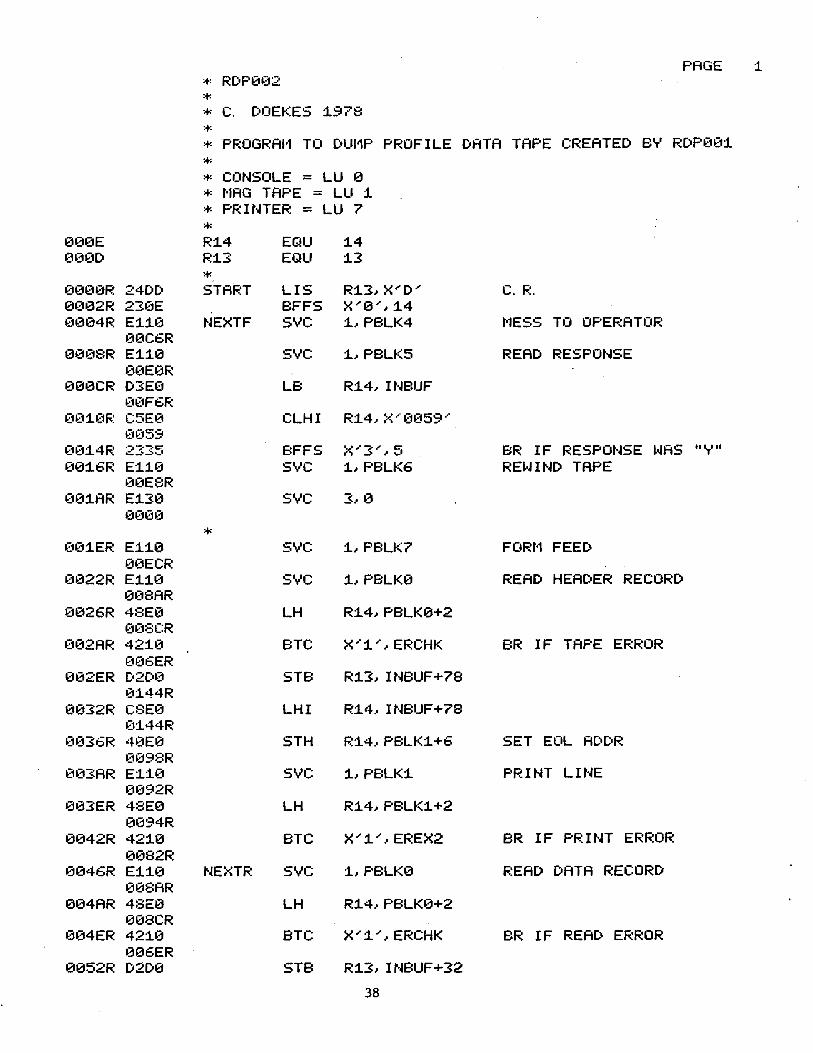
PAGE :1. :+: ~:DP0~32
* * c. [:oOEKES :1978
* * PROGRAI·1 TO DUI1P PROFILE DATA TAPE CREATED B'T' RDP0~3:1
* * CONSOLE = LU 0
* t·1AG TAPE = LU :1
* PRINTER = LU 7
* 000E R:14 EQU :1.4 0~30D R:13 EQU :1.3
* 0~3€10R 24DD START LIS R:1.3~ X""' D,. C. R. 0~302R 230E BFFS X"0,.~:1.4
(U304R E1:1.0 NEXTF svc :1.~PBLK4 t·1ESS TO OPE~:ATOF~
00C6R 00€18R E:1.:10 svc :1.~PBLK5 READ RESPONSE
0~3E0R 000CR D3E€1 LB R:1.4~ INBUF
t10F6R tn31~~1~: C5E0 CLHI R:14~ X··· €1059 ···
0059 00:14~: ?-::·..,·c::"
--'~·-· BFFS ~<"3 ... ~ 5 BR IF RESPONSE ~o.IAS II 'T' II 00:1.6R E:1:10 svc :1.~PBLK6 RE~o.IIND TAPE
00E8R €n3:1.AR E:1.30 svc :s~ 0
0000
* €n3:1.ER E1:1.0 svc :1~PBLK7 FORt1 FEED 00ECR
~~n322R E:1.:1.0 svc :1~PBLK0 READ HEADER RECORD 0~38AR
0026R 48E0 LH R:1.4~PBLK0+2 0~38CR
€102AR 42:1.~3 BTC X":1'·~ ERCHK BR IF TAPE EF~ROR
(n36ER 002ER D2D0 STB R:1.3~ INBUF+78
0:144R 0032R C8E0 LHI R:14~ INBUF+78
(11.44R ~3~336R 4~~1E0 5TH R1.4~PBLK1+6 SET EOL ADI)R
(1098R (103AR E:1:10 svc 1.~PBLK:1. PRINT LINE
0092R 003ER 48E0 LH R1.4~PBLK1.+2
0fJ94R 0042R 421.0 BTC X"1."~EREX2 BR IF PRINT ERROR
0082R 0046R E:110 NEXTR svc 1.~PBLK0 READ DATA RECORD
008AR 004AR 48E0 LH R1.4~PBLK0+2
008CR 0l34ER 4210 BTC X"'i."~ERCHK BR IF READ ERROR
006ER 0052R D2D0 STB R1.3~ INBUF+32
38
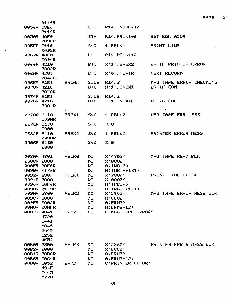
PAGE .-., .:..
0:1:16R ~3056R C8E(1 LHI F.::14, I NE:UF + 32
0:1:16R 005AR 4~3E~~ STH R:14,PBLK:1+6 SET EOL ADDR
0098R 005EF~ E:1:10 svc :1,PBLK1 PRINT LINE
a~:::192R
~:::n362R 48E(1 LH R:14,PBLK:1+2 e~~94R
~~06t·R 42:10 BTC >~ .. · :1 "' I EREX2 BR IF PRINTER ERROR 0082R
~3~36AR 430~~ E:FC x-·a···, NEXTR NEXT RECORD (1(146F~
006ER 9:1E3 ERCHK SLLS R:14,3 t·1AO TAPE ERROR CHECKING (1070R 42:1~~ BTC ~-~"' :t··· I EREX:1 BR IF EOt'1
~307AR
0074R 9:1E:1 SLLS R:14,:1 0076R 42:10 BTC X"':1."',NEXTF BR IF EOF
0(104R
* ~:::n~7AR E:1:10 EREX:1 svc :1,PBLK2 t'1AG TAPE ERR 11ESS
~309AR (n37EF~ E:130 s• ... •c: 3. 0
0(1(10 0082R E:1:10 EF~EX2 svc: :1,PE:LK3 PRINTER ERROR t'1ESS
~3080R
0086R E:130 svc 3. 0 0000
* 0~38AR 480:1 PBLK0 DC X"'480:1"' t•1AG TAPE READ BLK ~308CR 0000 DC X"'0000"' 008ER 00F6R DC A<INBUF) 0090R 0:179R DC A<INBUF+:13:1) 0092R 2807 PBLK:1 DC X·'2807~ PRINT LINE BLOCK 0094R 0000 DC X ... 0(H30 ... (n396R ~3~:::1F6R DC fi( INBUF) ~:::1098R 0:179R DC A<INBUF+:13:1) 0~39AR 2800 PBLK2 DC X"'2800"' t·1AG TAPE ERROR 1•1ES5 BLK 009CR 0(100 DC X''(U300"' ~:::1(19ER 00A2R DC A<ERI'12) ~3(1A0R 0~3AFR DC A<ERI'12+:13) 0~3A2R 4D4:1 ERI•12 DC c··'I1AG TAPE ERROR"
4720 544:1. 5~345
2045 5252 4F52
~30B0R 2800 PBLK3 DC X"2800"' PRINTER ERROR t1ESS BLK 0~382R 0000 DC X"'0(100"' ~3084R 0088R DC A<ERt'13) 00B6R 00C4R DC A<ERI'13+12) 00B8R 5052 ERt'13 DC C"PRINTER ERROR"
494E 5445 5220
39
PAGE 3: 4552 524F 5220
0€1C6R 2800 PBLK4 [)C x···2s0~:::1··· t1ESS TO OPERfiTOR BU( 00C8R 0000 DC X''0000 ... 00CAR '.K1CER DC A<fo1E554) 00CCR 00DFR DC A< l•1ESS4+:l7) 00CER 434F t·1E554 DC C ... CONTINUE ? y OR N ...
4E54 494E 5545 2~33F
2~320
5920 4F52 204E
€1€1E0R 4800 PBLI<5 DC X..-48~30 ... READ CONSOLE BLK 00E2R 0000 DC x-·00~3£1 ... 0€1E4R 0£1FGR DC A<INBUF) 00E6R 0:l46R DC A<INBUF+80) ~30E8R c0~3:1 F'BLK6 DC ;x; ··· C€10:1 ··· RE~o.IIHD 1·1AG TAPE BLI< 0£1EAR (1(1(10 DC :=< ... €1(1(1(1 ,. (10ECR 2807 F'BLK7 DC ;-~ .. · 2::::a.::17 .. · FO~:I•1 FEED BLI< (n3EER 0(U)0 DC >~ ... 0000 ... 0(1F0R 0€1F4R DC A<F'BUFF) ~30F2R 00F5R DC A<PBUFF+1.) 00F4R 0C0D PBUFF DC X ... 0C0D ...
* 00F6R INBUF DS 1.32
* 01.7AR END
40

APPENDIX E: USE OF THE HP-98036A INTERFACE
41
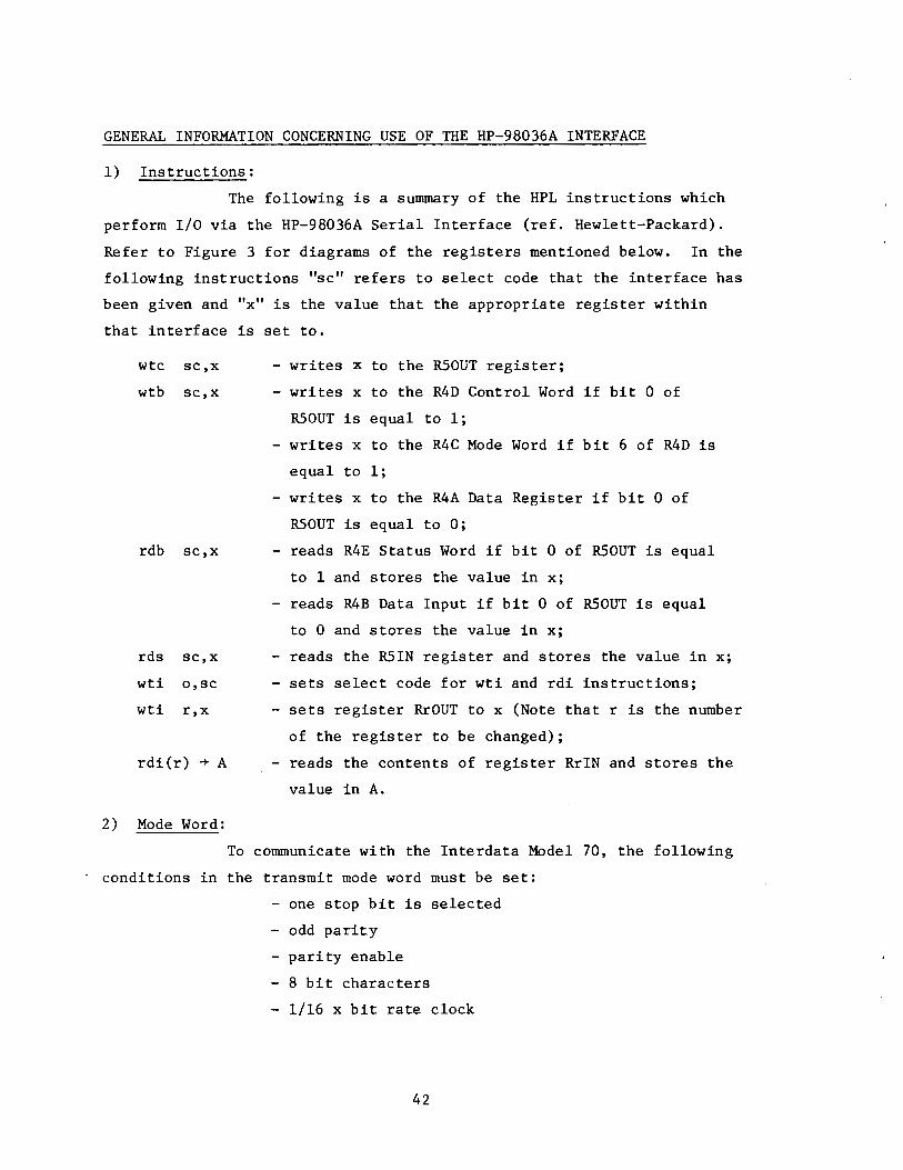
GENERAL INFORMATION CONCERNING USE OF THE HP-98036A INTERFACE
1) Instructions:
The following is a summary of the HPL instructions which
perform I/O via the HP-98036A Serial Interface (ref. Hewlett-Packard).
Refer to Figure 3 for diagrams of the registers mentioned below. In the
following instructions "sc" refers to select code that the interface has
been given and "x" is the value that the appropriate register within
that interface is set to.
wtc sc,x
wtb sc,x
rdb sc,x
rds sc,x
wti o,sc
wti r,x
rdi(r) -+ A
2) Mode Word:
- writes x to the RSOUT register;
- writes x to the R4D Control Word if bit 0 of
RSOUT is equal to 1;
writes x to the R4C Mode Word if bit 6 of R4D is
equal to 1;
- writes x to the R4A Data Register if bit 0 of
RSOUT is equal to 0;
- reads R4E Status Word if bit 0 of RSOUT is equal
to 1 and stores the value in x;
reads R4B Data Input if bit 0 of RSOUT is equal
to 0 and stores the value in x;
- reads the RSIN register and stores the value in x;
- sets select code for wti and rdi instructions;
- sets register RrOUT to x (Note that r is the number
of the register to be changed);
- reads the contents of register RriN and stores the
value in A.
To communicate with the Interdata Model 70, the following
- conditions in the transmit mode word must be set:
- one stop bit is selected
- odd parit.y
- parity enable
- 8 bit characters
- 1/16 x bit rate clock
42

To achieve this, bits 0,1,2,3,4 and 6 of the R4C Mode Word register
must be set to 1 and the others must be 0. This is done by setting
the R4C register to OlOlllllz or 951o·
The R4C Mode Word can be changed in the following 2 ways:
1) By physically changing the Mode Word register in the interface.
Since this will result in a different power up default value, using
software to change the mode word is preferable.
2) By using software to change the Mode Word as follows:
i) set bit 0 of RSOUT to enable writing to the R4D
USART Control Word;
ii) set bit 6 of the R4D USART Control to permit
modification of the R4C Mode Word;
iii) set the R4C Mode Word to a new value (Note that
x is the new value, in decimal, of the Mode
Word).
wtc sc,l
wtb sc,64
wtb sc,x
Again, the "sc" refers to the select code of the interface.
To find the decimal value to be written to a register, perform these
steps:
1) determine which bits are to be set to 1 and which will be
set to 0;
2) the values of these bits determine a unique binary number with
bit 0 being the least significant bit and bit 7 the most signif-
icant; and
3) convert the binary number which was determined in step 2 to its
decimal equivalent. This decimal number can be written to the
appropriate register to set the bits which were decided on in
step 1).
For example, suppose it is determined that bits 0, 1, 3, and 6 are to be
set to 1 in a certain register. The binary number 01001011 represents
the register contents if these bits are set. Since 010010llz = 2 6 +2 3+2 1+2° = 75, a 75 should be written to the appropriate register to
set the bits.
43
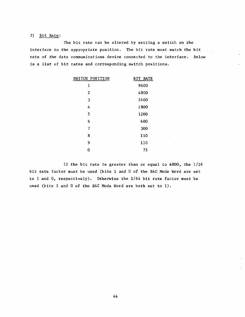
3) Bit Rate:
The bit rate can be altered by setting a switch on the
interface to the appropriate position. The bit rate must match the bit
rate of the data communications device connected to the interface. Below
is a list of bit rates and corresponding switch positions.
SWITCH POSITION BIT RATE
1 9600
2 4800
3 2400
4 1800
5 1200
6 600
7 300
8 150
9 110
0 75
If the bit rate is greater than or equal to 4800, the 1/16
bit rate factor must be used (bits 1 and 0 of the R4C Mode Word are set
to 1 and 0, respectively). Otherwise the 1/64 bit rate factor must be
used (bits 1 and 0 of the R4C Mode Word are both set to 1).
44
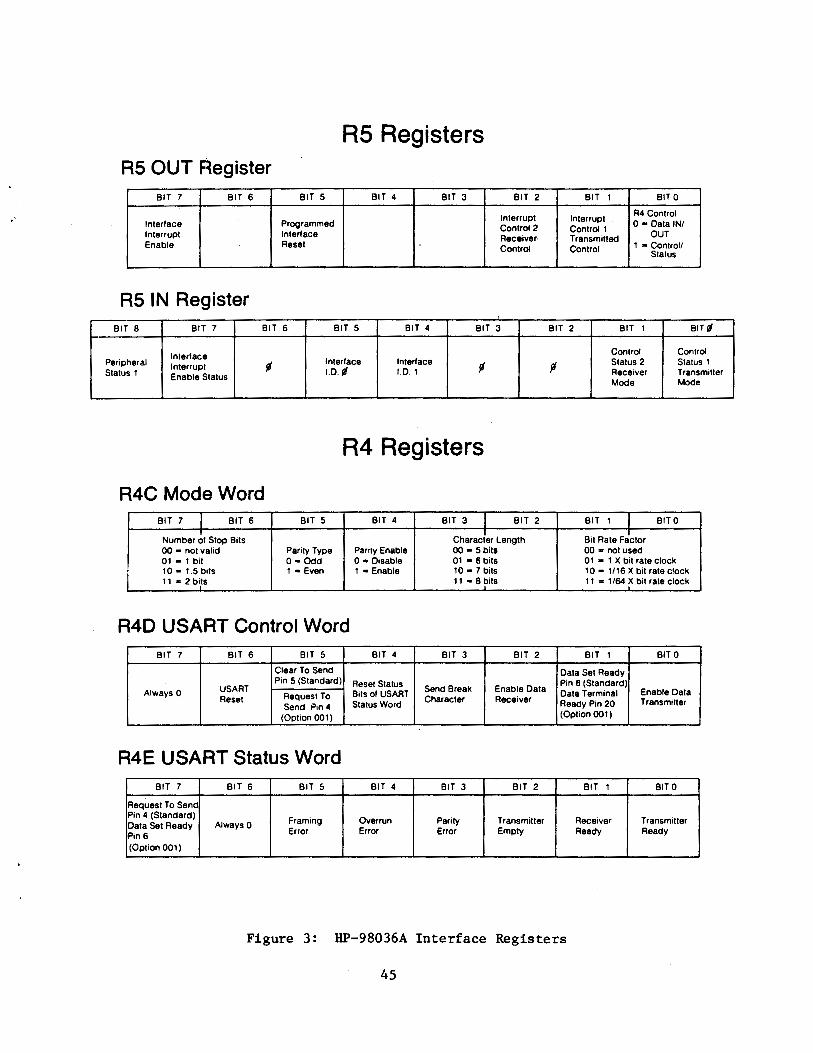
R5 Registers AS OUT F~egister
BIT 7 BIT 6 BIT 5 BIT 4 BIT 3 BIT 2 BIT 1 BIT 0
Interrupt Interrupt R4 Control
Interface Programmed Control2 Control! 0 • Data IN/ Interrupt Interface Receiver· Transmitted OUT Enable Reset Control Control 1 • Control/
Status
AS IN Register BIT 8 BIT 7 BIT 6 BIT 5 BIT 4 BIT 3 BIT 2 BIT 1 BITt
Interface Control Control Peripheral Interrupt f1 Interface Interface
f1 ~ Status 2 Status 1
Status 1 I.D.t I.D.1 Receiver Transmitter Enable Status Mode Mode
R4 Registers
R4C Mode Word BIT 7 I BIT 6 BIT 5 BIT 4 BIT 3 I BIT 2 BIT 1 1 BITO
Number of Stop Bits Characler Length Bit Rate Fictor 00 • not valid Parity Type Parity Enable 00 • 5bits 00 a not used 01- 1 bit 0 • Odd 0 • Disable 01 • 6bits 01 • 1 X bit rate clock 10- 1.5 bits 1 • Even 1 • Enable 10•7bits 10 • 1/16 X bit rate clock 11-2 bits 11 • 8 bits 11 = 1/64 X bit rate clock
R4D USART Control Word BIT 7 BIT 6 BIT 5 BIT 4 BIT 3 BIT 2 BIT 1 BIT 0
Clear To Send Data Set Ready
USART Pin 5 (Standard) Reset Status Pin 6 (Standard)
Always 0 Bits of USAAT Send Break Enable Data Data Terminal Enable Data Reset Request To
Status Word Character Receiver Ready Pin 20 Transmitter Send Pin 4
(Option 001) (Option 001)
R4E USART Status Word BIT 7 BIT 6 BIT 5 BIT 4 BIT 3 BIT 2 BIT 1 BITO
Request To Send Pin 4 (Standard)
Framing Overrun Parity Transmitter Receiver Transmitter Data Set Ready AlwaysO Pin 6 Error Error Error Empty Ready Ready
(Option 001)
Figure 3: HP-98036A Interface Registers
45
Related Documents