•'• $ US Army Corps of Engineers Construction Engineering Research Laboratory TECHNICAL REPORT M-85/05 December 1984 Improved and New Roofing for Military Construction 0> in in < i O < SLOPED ROOF CONVERSIONS FOR SMALL, FLAT-ROOF BUILDINGS by Myer J. Rosenfield Carter Doyle DTIC ELECTE JUN4 1985 Approved for public release; distribution unlimited. 85 5 07 032 <? !. v ftS3^ft&3:t&^^^

Welcome message from author
This document is posted to help you gain knowledge. Please leave a comment to let me know what you think about it! Share it to your friends and learn new things together.
Transcript

•'• $
US Army Corps of Engineers Construction Engineering Research Laboratory
TECHNICAL REPORT M-85/05 December 1984
Improved and New Roofing for Military Construction
0>
in
in
< i
O <
SLOPED ROOF CONVERSIONS FOR SMALL, FLAT-ROOF BUILDINGS
by Myer J. Rosenfield Carter Doyle
DTIC ELECTE JUN4 1985
Approved for public release; distribution unlimited.
85 5 07 032
<? !. v ftS3^ft&3:t&^^^

s
The contents of this report are not to be used for advertising, publication, or promotional purposes. Citation of trade names does not constitute an official indorsement or approval of the use of such commercial products. The findings of this report are not to be construed as an official Department of the Army position, unless so designated by other authorized documents.
DESTROY THIS REPORT WHEN IT IS NO I ONGER NEEDED
DO NOT RETURN IT TO THE ORIGIN A TOR
UNCLASSIFIED TY CLASSIFICATION OF THIS PAGE (When Date Entered)
REPORT DOCUMENTATION PAGE 'ORT NUMBER
L-TR-M-85/05
2. GOVT ACCESSION NO
i_E fand Subtitle)
PED ROOF CONVERSIONS FOR SMALL, T-ROOF BUILDINGS
HORf«;
r J. Rosenfield ter Doyle
(FORMING ORGANIZATION NAME AND ADDRESS
. ARM? CONSTRUCTION ENGINEERING RESEARCH ABORATORY I. BOX 4005, CHAMPAIGN, IL 61820-1305
NTROLLING OFFICE NAME AND ADDRESS
51 ITORING AGENCY NAME ft ADDRESSfH dtUetent from Controlling Oliice)
rRIBUTION STATEMENT (at thle Report)
READ INSTRUCTIONS BEFORE COMPLETING FORM
3. RECIPIENT'S CATALOG NUMBER
S. TYPE OF REPORT ft PERIOD COVERED
Final 6. PERFORMING ORG. REPORT NUMBER
8. CONTRACT OR GRANT NUMBERf»)
10. PROGRAM ELEMENT. PROJECT, TASK AREA ft WORK UNIT NUMBERS
4A162731AT41-A-044
12. REPORT DATE
December 1984 13- NUMBER OF PAGES
101 15. SECURITY CLASS, (i' thle report)
Unclassified 15a. DECLASSIFICATION/DOWNGRADING
SCHEDULE
roved for public release; distribution unlimited.
JTRIBUTION STATEMENT (ol the ebetreet entered In Block 20, II dlUerent from Report)
•PLEMENTARY NOTES
ies are available from the National Technical Information Service Springfield, VA 22161
Y WORDS fContinue en revet ee tide II neeeeeery end Identify by block number)
cfs of conversion oped roofs at rocfs
ITU ACT (Ceatimuo em rewerme «M» » ■I Identify by Meek number)
This study examines the cost-effectiveness of converting flat-roofed dings to sloped-roof buildings as an alternative to repair or replacement he existing roof. Projects were located, and designers, contractors, and rs were interviewed. This report includes case studies portraying ods, systems, materials, and costs for this type of reroofing. -;
'^(continued)
JJJJT, 1473 l EDITION OF I NOV SS IS OBSOLETE UNCLASSIFIED
SECURITY CLASSIFICATION OF THIS PAGE (When Dim Entered)
fim^::%KK->y:-::^
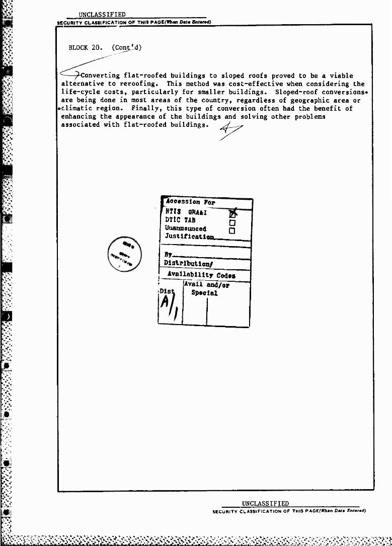
UNCLASSIFIED
m
SECURITY CLASSIFICATION OF THIS PAOEftWmn Datm Entend)
BLOCK 20. (Contld)
—^Converting flat-roofed buildings to sloped roofs proved to be a viable alternative to reroofing. This method was cost-effective when considering the life-cycle costs, particularly for smaller buildings. Sloped-roof conversions* are being done in most areas of the country, regardless of geographic area or •climatic region. Finally, this type of conversion often had the benefit of enhancing the appearance of the buildings and solving other problems associated with flat-roofed buildings. g£—-yr
recession For
MTIS QR/fcl DltC TAB
Unannounced Justifieatl«
a
By- Distnbution/
j Availability Codes AvailTänd/or
Special
UNCLASSIFIED SECURITY CLASSIFICATION OF THIS PAGEr**»" Dalm Enfr»d)
•". "* v* ^~»*^ JL"JL^'.J
FOREWORD
This investigation was performed for the Assistant Chief of Engineers, Office of the Chief of Engineers (OCE), under Project 4A162731AT41, "Military Facilities Engineering Technology"; Task A, "Facilities Planning and Design"; Work Unit 044, "Improved and New Roofing for Military Construction." The OCE Technical Monitor was Joel Seifer, DAEN-ZCF-B.
This study was performed by the Engineering and Materials Division (EM), U.S. Army Construction Engineering Research Laboratory (USA-CERL).
Myer J. Rosenfield was the USA-CERL project coordinator. Carter Doyle is a Research Associate at the Building Research Council, University of Illinois at Urbana-Champaign, D. E. Brotherson, AIA, Director.
Dr. R. Quattrone is Chief of USA-CERL-EM. COL Paul J. Theuer is Commander and Director of USA-CERL, and Dr. L. R. Shaffer is Technical Director. .......
Mj$mm$&m
CONTENTS
Page
DD Form 1473 1 FOREWORD 3 LIST OF TABLES AND FIGURES 5
1 INTRODUCTION 9 Background Objective Approach .lode of Technology Transfer
2 FRAME ROOF CONVERSION SYSTEMS 11 Discussion Wood Frame Systems Metal Conversion Systems
3 CASE STUDIES 17
4 COST ANALYSES 64 Construction Costs Life-Cycle Cost Analysis
5 EFFECT OF REGIONAL AND CLIMATIC CONDITIONS 74 Regional Effects Conversions in Various Climates
6 ECONOMIC CRITERIA FOR SIZE LIMITATIONS 78 Other Factors Affecting Cost Cost Per Sq Ft of Various Roof Conversion Systems Compared to Building Size
7 CONCLUSIONS AND RECOMMENDATIONS , 85
REFERENCES 86
APPENDIX: Costs For Five Common Truss Types 87
DISTRIBUTION
r-> *t3> * Wf * * "* '■
L...,-...«..•••...■ •--■ . . ... .Vi., .-■... ^ iaw^^awa^a^a^ata

TABLES
Number Page
1 Construction Costs for Roof Conversions 68
2 Roof Replacement Cost For the Remaining 25 Years of Life For the Building in Case Study No. 1 70
3 Net Present Worth (NPW) of Roofing Systems for Case Study No. 1 (For a 25-Year Life) 71
4 Life-Cycle Cost Compared 73
5 Lists of Contacts Involved in Roof Conversion Projects 75
FIGURES
1 Roof Forms 12
2 Roof Framing Systems 13
3 Roof Framing Plan, Case Study No. 1 19
4 Section Through Building, Case Study No. 1 20
5 View Looking Under Framing, Case Study No. 1 21
6 General View of Framing, Case Study No. 1 21
7 Completed Roof From the Front, Case Study No. 1 22
8 Completed Roof From the Rear, Case Study No. 1 22
9 Roof Plan, Case Study No. 2 24
10 Longitudinal Section Through the Roof, Case Study No. 2 25
11 View on Top of Roof During Beginning Construction Stage, Case Study No. 2 26
12 Front View, Case Study No. 2 26
13 View of the Beginning of Construction, Case Study No. 2 27
14 Completed Roof Conversion, Case Study No. 2 27
15 Roof Plan, Case Study No. 3 29
16 Typical Cornice Detail, Case Study No. 3 30
17 Section Through Roof, Case Study No. 3 30
'&&&£^^

18 f?VS m fi>y> 19 Eft ran &
20
i 21
22 ► '0
23 Ss NSr 24
m 25 gk
26
27
28 ■s.v. LfJV >\%
29
'.'■V 30
31
w 32
5nJ 33 V"
iV- A Ft • 34 •«> ■«"«"■ jap 35
h J ■ J. 36 A» «» ig>j "•"."-'
37
A. LVwj 38 V" * . *
39 '•/" fjv ':< 40
FIGURES (Cont'd)
Number Page
View of Roof Top Before Conversion, Case Study No. 3 31
View of Front of Building Before Conversion, Case Study No. 3 31
Completed Roof Conversion, Case Study No. 3 32
Roof Plan, Case Study No. 4 34
Diagrammatic Isometric of Roof Framing, Case Study No. 4 35
Roof Edge Detail, Case Study No. 4 36
Section Through Roof, Case Study No. 4 36
Detailed Section Through Roof, Case Study No. 4 37
General Front View Before Conversion, Case Stud> ». 4 38
Close-up Front View Before Conversion, Case Study No. 4 38
Side View Completed, Case Study No. 4 39
Front View Completed, Case Study No. 4 39
Section Through Roof, Case Study No. 5 41
Roof Plan, Case. Study No. 5 41
View Under Construction, Case Study No. 5 42
View of Completed Roof, Case Study No. 5 42
View of Trusses in Place During Construction, Case Study No. 5 43
Rear View Completed, Case Study No. 5 43
Premodified Roof Plan of Camden County College Complex, Case Study No. 6a and 6b 46
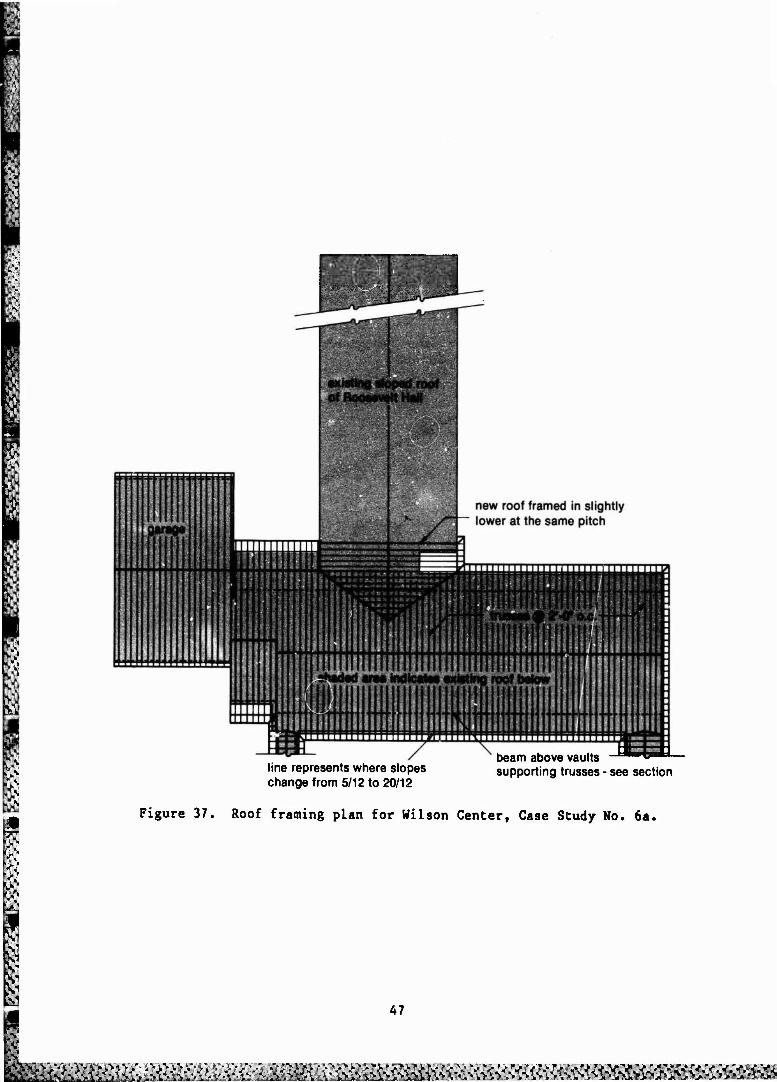
Roof Framing Plan for Wilson Center, Case Study No. 6a 47
Section Through Roof Edge, Case Study No. 6a 48
View of Wilson Center Before Construction, Case Study No. 6a 49
Detail of Stub Column Supporting Beam Above Barrel Vaulte, Case Study No. 6a 49
41 View of Trusses Being Erected, Case Study No. 6a 50
6
wVCv Mim^^^m&^&mä:

/'I *C::
A] Number
•to
42
43 •"y
44
«.•„■ 45
1 46
47
48
49
3 50 >1
51
52
{", 53 V>
8 V".
54 fit
55
5 56
FIGURES (Cont'd)
57
58
59
60
61
62
63
64
View of Finished Roof of Wilson Center, Case Study No. 6a
Inside Wilson Center Looking Out, Case Study No. 6a
Roof Framing Plan for Wilson West, Case Study No. 6b
Section Through Wilson West, Case Study No. 6b
View of Wilson West Before Construction, Case Study No. 6b
View of Roof of Wilson West During Construction, Case Study No. 6b
Completed View of Wilson West, Case Study No. 6b
General View of Completed Roof Conversion of Camden County College, Blackwood, New Jersey, Case Study No. 6
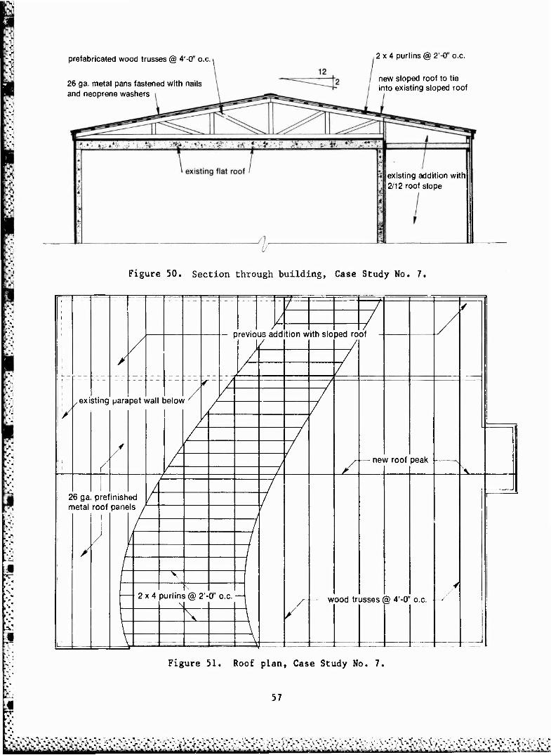
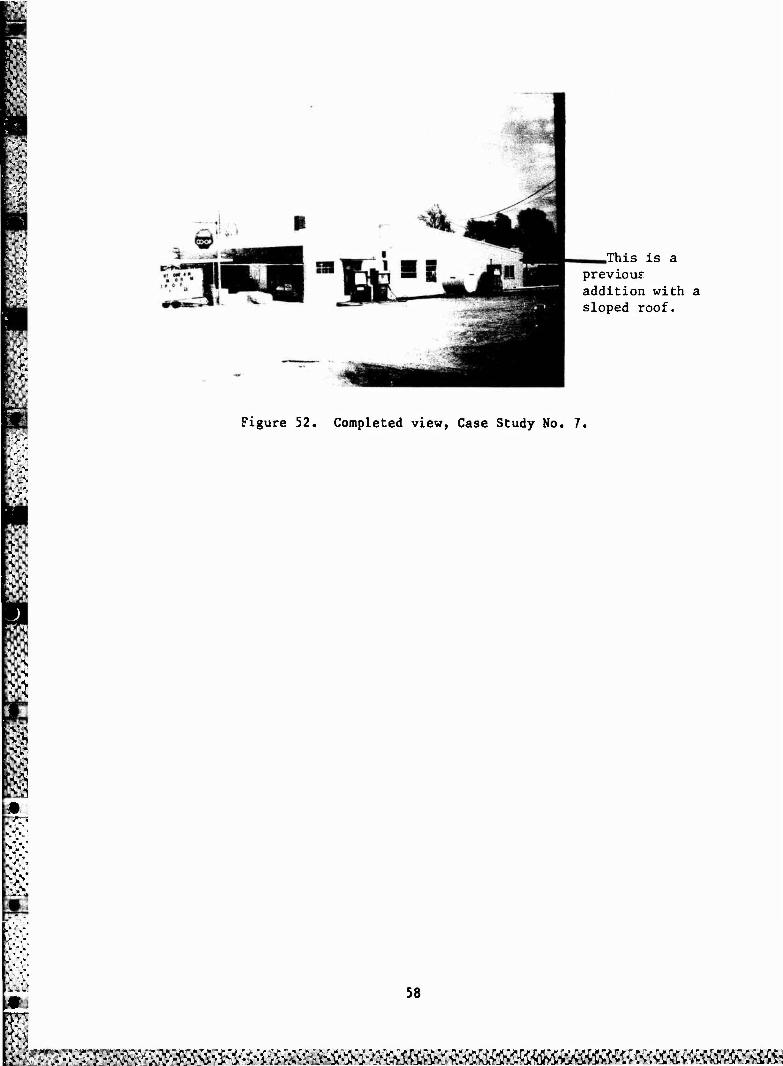
Section Through Building, Case Study No. 7
Roof Plan, Case Study No. 7
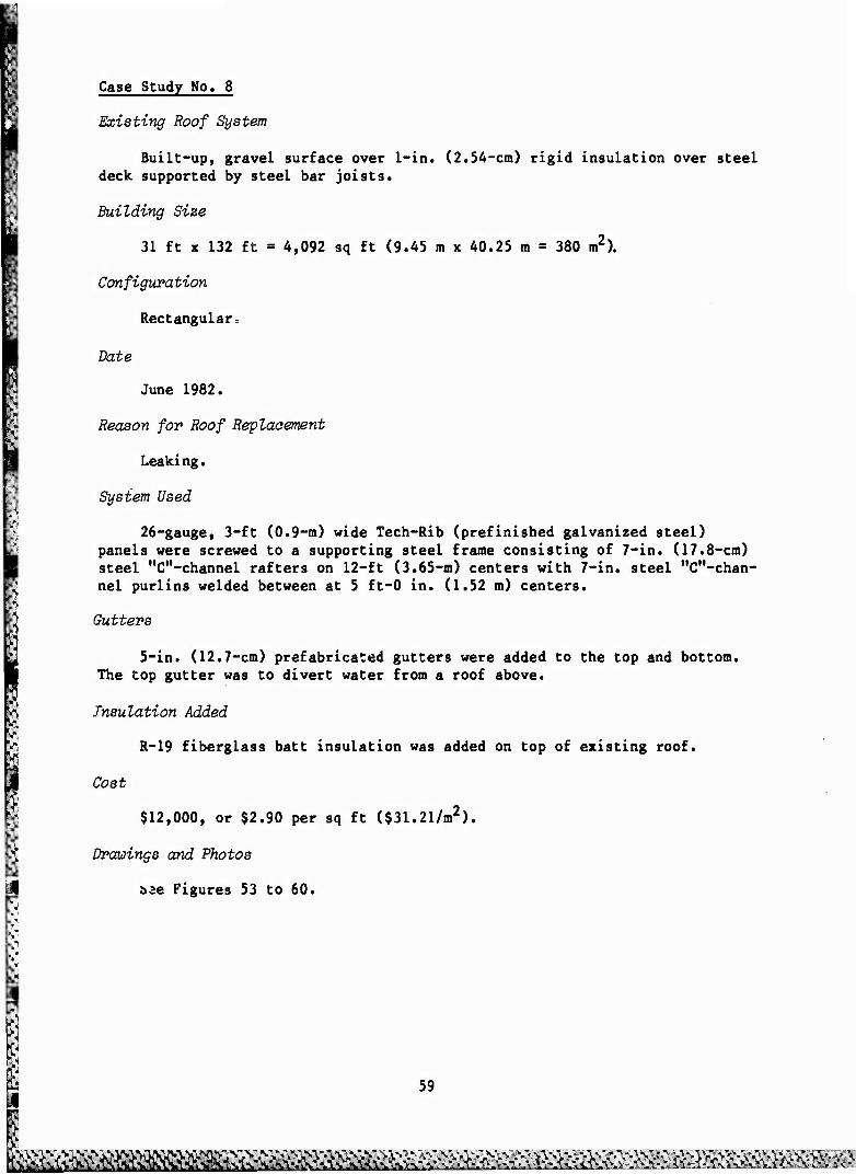
Completed View, Case Study No. 7
Section Through Roof, Case Study No. 8
Roof Plan, Case Study No. 8
View of Framing, Case Study No. 8
Detail of Column Connection to the Existing Roof, Case Study No. 8
View During Application of 3-Ft Wide by 31-Ft Long White Tech-Rib Metal Roofing, Case Study No. 8
View of Completed Roof, Case Study No. 8
Completed View From the Front, Case Study No. 8
Edge Detail at the Rear of the Building, Case Study No. 8
Step-Down Hip System
Dutch Hip System
Terminal Hip System
Common Trussed/Conventional Framing Hip System
Page
50
51
53
53
54
54
55
55
57
57
58
60
60
61
61
62
62
63
63
65
66
66
67
7
;^&:£v^^
FIGURES (Cont'd)
Number
65
66
67
68
69
Examples of the Retroframe System
Comparison of Cost Per Square Foot Vs. the Size of the Roof Replacement
Cobt Per Square Foot Vs. the Size of a Building for Southern Loading Conditions
Cost Per Square Foot Vs. the Size of a Building for Intermediate Loading Conditions
Co9t Per Square Foot Vs. the Size of a Building for Northern Loading Conditions
Page
77
81
82
83
84
■ "w * • * "k ■* V * ■»""J* ■*• WJp&v :-K

SLOPED ROOF CONVERSIONS FOR SMALL FLAT-ROOF BUILDINGS
I INTRODUCTION
Background
Leaks in flat roofs are a source of many problems, costing the Army mil- lions of dollars each year in repairs and replacement. The approach in the past has been to patch or reroof flat-roof buildings, but that has rarely been a permanent solution. However, the construction of a superstructure over the existing roof to provide an adequate slope for positive drainage appears to be gaining popularity, because it finally solves the leakage problem inherent in flat roofs. Sloped roof conversions, while initially costly, may prove to be a more practical solution to leaks on flat-roofed Army buildings than indefinite reroofing and repair.
Very little has been published on this approach, probably because it is only recently that this method has been used extensively.
This method of reroofing has several benefits. In addition to solving leakage problems, the building's energy efficiency can often be improved because of the ease of adding insulation, and overhangs can be easily provided for summer shading of window areas. Depending on the treatment used and the situation, other problems sometimes can be solved. For example, one-story schools often have problems with "foot traffic" on the flat roofs, but sloped roofs generally do not have this problem. In addition, careful treatment of * roof conversion can often enhance the building's appearance.
Objective
The objectives of this study were (1) to determine the cost-effectiveness of converting flat-roofed buildings to sloped roofs, particularly for use on U.S. Army buildings, and (2) to determine the effect of regional or climatic conditions on the decision to make this type of conversion.
Approach
A literature search was conducted, and titles of articles which discuss this form of reroofing are listed in the References section. Nearly 100 ques- tionnaires were sent to wood truss manufacturers, major metal roofing manufac- turing companies, and metal component manufacturers. About 20 percent of the questionnaires were returned, but only four respondents knew of, or participated in, roof conversions. These people were contacted and questioned about methods and materials. Also, a letter requesting information about roof conversion was sent to all of the Truss Plrte Institute (TPI) engineers requesting information about roof conversion; no responses were received.
k>&ftftfr#&fr&frft^^

A notice requesting information was published in Peaks, a quarterly news- letter for the wood truss industry, distributed by the Lumbermate Company. It is unclear how many responses resulted directly from this publication. Other information was gained from members of the Building Research Council who made inquiries at meetings and conferences within the construction industry, requesting knowledge of roof conversions.
Mode of Technology Transfer
It is recommended that instructions for this method of reroofing small buildings be included in Army Technical Manual 5-617, "Maintenance and Repair of Roofs."
10
B^WS^rf^^^

2 FRAME ROOF CONVERSION SYSTEMS
Discussion
In the case of retrofitting a sloped roof onto a flat roof, there is an existing structural system in place. The first step is to analyze that system to determine whether the building, which is designed for a specific set of loads that are already in place, can support an additional set of dead loads created by the new framing and roofing system. It must also be determined how to distribute the new set of loads to the existing structural system.
Roofs for conversions are constructed in the same basic shapes as any other sloped roof: gabled, hipped, shed, mansard, butterfly, and gambrel (Figure 1). With the possible exception of concrete (due to weight) most structural materials can be used to frame roof conversions. Converting a flat roof to a sloped roof allows the application of roofing materials such as wood or asphalt shingles or metal pans.
Wood Frame Systems
Because they are available, familiar, and economical, wood and steel are the most commonly used materials, and wood is the most popular choice. Roofs are built with one of these three basic systems: roof trusses, post and beam, and conventional framing (rafters and joists) (Figure 2). Each of these systems has distinct advantages, disadvantages, and applications.
Wood framing systems are covered with a variety of sheathing materials. The framing members usually are closely spaced (16-in. or 24-in. o.e.) (40 cm or 61 cm) and covered with plywood and shingles. Another commonly usei system is wider spaced members (4 ft-0 in. [1.219 m] o.e.) and 2x4 in. (S x 10 cm) purlins on top of the rafters. The purlins are normally spaced 2 ft-0 in. (61 cm) o.e. This system lends itself to covering with either plywood and shingles or some type of light-gauge metal roofing.
Truss Method
A truss is described by Webster as "an assemblage of members (beams, bars, rods) typically arranged in a triangle or combination of triangles to form a rigid framework (supporting a load over a wide area) that cannot be de- formed by application of exterior forces without deformation of one or more of its members." The chief characteristic of a truss is that it is able to span large areas while being constructed with relatively small members. Trusses offer a lightweight, economical framing system and are in wide use in all facets of small-scale construction.
Since the advent of pressed galvanized-metal-plate connectors, wood trus- ses have proven very economical for most roof configurations. Wood trusses are generally fabricated in a shop or factory and trucked to the site. Wood trusses have been fabricated for spans up to 100 ft (30.5 m) long, but are normally limited in length and height by transportation restraints. The ship- ping height of wood trusses is limited to about 12 ft (3.66 ta). When the de- sired slope or height of the truss exceeds this dimension, solutions
11
^&^&5&^^

HIP MANSARD
GABLE BUTTERFLY
SHED GAMBREL
Figure 1. Roof forms.
12
#mm m&tm&vm^

CONVENTIONAL FRAMING
Figure 2. Roof framing systems.
13
Sfc&yj&fe^^ &m$?mm;iy&

m like superimposing one truss on top of another can be used. The normal eco- nomical spans used range from 20 ft (6.1 m) to 60 ft (18.3 m) for wood trusses.
There are certain building types where trusses are required. A truss re- solves all the horizontal loads within its members (primarily in the tensioned bottom chord), thus exerting only vertical loads on the structure below. This characteristic is essential in roof conversion for certain types of buildings. For example, a common type of flat-roof construction employs peri- meter masonry bearing walls with parapets supporting wood joists or steel bar joists framed between the walls. In this case, conventional framing would ap- ply excessive lateral or horizontal loads to the top of the parapet. Conven- tional framing would require that the parapets be torn down flush with the roof or that a horizontal tie be added that would restrain the lateral loads. In this case, trusses are the only logical and economical choice. Similarly, where the clear span exceeds the capacity of conventional framing, trusses would be required.
Post and Beam Method
Another type of roof construction system is post and beam. No examples were found of roof conversions using this system, although it could be used under certain rare conditions. The building would have to be capable of sup- porting a concentrated load at each end under the beam as well as uniform loads along both side walls. The deciding factor would be the beam spans. For most buildings, even small single-family residences, a single-span beam would be very large and therefore high in cost. If short spans are possible, post-and-beam framing might be acceptable.
Conventional Framing
The third basic roof system is conventional framing (rafters and joists). For this type of roof conversion, the existing flat roof joist can be used. The existing joists restrain the horizontal thrust caused by the rafters, so construction becomes a matter of erecting the rafters and tying them to the existing joists.
The usual way to attach the rafters to the joists is to fasten a wood plate around the perimeter. The plate is nailed or bolted into the existing joists and deck. The rafters can either rest on top of the plate or notch over it, forming a more secure connection.
Flat roofs often have one or more inches of rigid insulation on the structural deck below the roofing material. Various contractors treat this differently. Some fasten the plates on top of the existing roofing, through the insulation and into the joist and deck. Other contractors and architects feel this practice is unsatisfactory, because the insulation, which is a com- pressible material, could deform under long-term loading« Also, they feel it could deform unevenly from the amount of moisture in the insulation and different thicknesses. Their solution is to remove the roofing and insulation down to the structural deck. The plates can then be fastened directly to the existing deck.
14
topyg^gjvss^^^^ : ^i^Mxäffi^ii&iaäffi
This method assures secure fastening of the plates but creates another problem. To fasten the plates, a path several inches wider than the plate must be cut away to insure the plate will be straight and true. Depending on the complexity of the roof, it could be several weeks before the work is com- pleted, during which time the building interior is extremely vulnerable to the weather. Temporary closures must be used, which add to the cost. The same problem occurs with similar applications of truss roofs, but is somewhat lessened due to the shorter time required for truss erection.
One of the major determinants indicating whether this system can be used is the length of the span to be covered. The size of the rafters and their spacing dictate the allowable span: the larger the rafter, the longer it will span. Similerly, the larger the piece of dimension lumber, the greater its cost per board foot. Thus, there is a point at which a truss system might prove less expensive. For example, with a 40 psf (193.7 kg/or) live load (L.L.) requirement, 2 x 10's (5 x 25 cm) spaced at 16 in. (40 cm) o.e. will span about 15 ft (4.57 m). Therefore, the maximum building width would be less than 30 ft (9.15 m).
If the building has intermediate supports, then the roof framing may not be limited to a single simple span. In small-scale frame construction there are often interior bearing walls. Bearing walls will support knee walls, which in turn can support the rafters, reducing their span. With a series of knee walls, the framing members can be small and cover fairly large areas. This makes a very economical system.
The dead loads imposed on a structure by this type of framing (wood raf- ters covered with shingles) are relatively light. Consequently, many types of existing structural systems can support the dead loads created by the roof conversion without the need for bearing walls beneath the knee walls. For example, a precast concrete deck (Case Study No. 1, Chapter 4) can support the relatively light loads imposed by knee walls.
The discussion of knee walls has been in regard to supporting rafters at about mid-span. Another situation arises in certain building types which re- quire knee walls. Some flat-roofed buildings cantilever the roof out to form overhangs. The new rafters then concentrate a cantilevered load on the outer- most point of the joists. Therefore, it is necessary to place a supporting knee wall above the exterior wall to take most of the rafter load. Then the only load carried by the existing cantilevered joist would be one-half the overhang load of the new roof.
Metal Conversion Systems
Several contractors used metal members to frame roof conversions. Although this approach is not as common as wood framing, the contractors that used this system used it almost exclusively.
Metal framing systems are generally covered with light-gauge metal roof- ing materials. Metal roofing is attached with sheet metal screws and neoprene washers. Metal framing members most often used were lightweight members such as rolled "c"-sections, bolted or welded together. The job-built metal fram- ing is characterized by different spacing than wood. The rafters were
15
föMä^^^ß^i^
n $

I".1
commonly 10 ft to 20 ft (3.05 m to 6.1 m) o.e. purlins were normally 5 ft-1 in. (1.52 m) o.e.
The intermediate members or
The metal framing systems are generally characterized by lower roof slopes than wood framing systems. Metal framing systems with metal roofing materials normally range between 1/4 in 12 and 2 in 12 roof slope. Wood fram- ing systems covered with metal roofing were found to slope from 2 to 12 and up. Wood framing covered with nonmetal roofing, like asphalt or wood shingles, generally began at 4 in 12 slopes. There are several reasons for this:
1. Asphalt shingles are not recommended (by their manufacturers) for use at slopes less than 2 in 12.
2. It is more advantageous to use metal on low-sloped roofs. The steep- er the slope, the more roofing material required to cover it. The concern in metal roofing is not all economical. The longer the piece of metal, the more it expands and contracts from temperature change. This movement enlarges the holes around the securing screws or nails and can eventually cause leaks.
3. Covering a steep slope requires longer framing members, increasing the cost when metal framing is used.
4. It is difficult to restrain the lateral loads with metal framing sys- tems. (This is not a problem with the lower slopes [1/4 in 12] because the horizontal components of the loads are small.)
Metal trusses have many of the same properties as wood trusses. They are fabricated in a shop or factory and delivered to the job site. They can span large areas exerting only vertical loads at their end points. The members are generally steel angles bolted or welded together, but a variety of standard steel shapes can be used. They can be used in conjunction with wood or metal purlins to support plywood and shingles or metal roofing material.
Steel is generally preferred over wood for long-span trusses, but steel trusses are more complicated and require more fabrication time, thereby increasing their cost. Also, the attachment of the steel trusses is a more complicated process in the field. In general, trusses using light-gauge sec- tions are less expensive than trusses that use heavy rolled sections.
16
rffö&frk&^ftü J:Stf>S£SSS3;
3 CASE STUDIES
Case Study No. 1
Type of Construction
10-ft (3-m) concrete block bearing walls with precast concrete (Plexicore) deck, no parapets.
Existing Roof System
Built-up, gravel surface over 1 in. (2.54 cm) of rigid insulation.
Building Size
108 ft x 33 ft = 3,564 sq ft (33 m x 10 m = 330 m2)
Configuration
Two identical apartment buildings separated by a 12-ft (3.66 m) light well. At the roof level, the two buildings are connected at each end by a strip of roof 2 ft-6 in. (76.2 cm) wide. Only one roof has been cor /erted at this time, but the owners plan to change the other roof at a later uate.
Date
Construction begun January 15, 1983; completed February 15, 1983.
Reason for Roof Replacement
Leaking.
System Used
Two- by four-in. (5- x 10-cm) rafters at 2 ft-0 in. (61 cm) o.e. to create a hip roof with a slope of 4 in 12. The rafters are supported by 2- x 4-in. (5- x 10-cm) knee walls at the midpoint of their span. The existing built- up roofing and the rigid insulation were cut away from the precast concrete deck around the perimeter and under the supporting 2- x 4-in. (5- x 10-cm) knee walls to provide positive fastening of the 2- x 4-in. (5- x 10-cm) plates. One- by six-in. (2.5- to 15-cm) redwood fascia was fastened directly to the existing metal fascia, so there is no soffit.
Attic Ventilation
The attic space is ventilated with a continuous ridge vent. Ten circular mushroom vents were used at the base of the roof around the building.
Gutters
No gutters were used at this time, and the gutter remains.
One long wall was previously guttered
17
mm^^mM M^M^M^^^^^rt^^
Insulation Added
Unknown.
Cost
$8,068.84, or $2.26 per sq ft ($24.30/m2).
drawings and Photos
See Figures 3 to 8.
18
A£U S£&&3^^

o z
3 4J CO
(U 01 «0 u
§ r-l a. 00 c
§
O o 06
01 u 3 00
19
£^ftra»aasa%aBB« .mfr^sKj^^wxsMXM

<2\ ■
I
o
1
CO
u
3
9 o J2 4J
U o <u to
0»
3 00
20
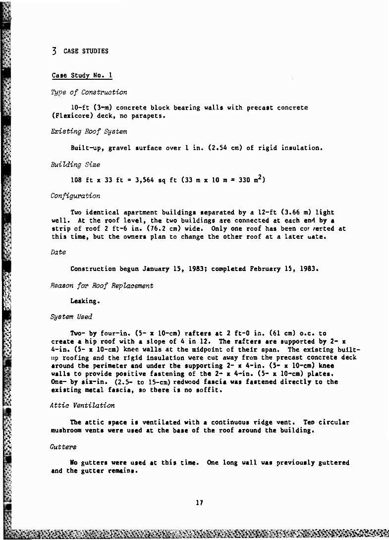
Figure 5. View Looking under framing, Case Study No. 1. The job was done during February so the knee walls were temporarily supported until it was completely roofed. Later the roofing and insula- tion on the existing roof were cut away to allow the 2- x 4-in. (5- x 10-cm) plates to be fastened.
jtwgflj 1 ■ ̂̂̂ H ̂ M HH *v,i'Jr>raP ^^H ̂ ^^^^^H ̂ H 2*^
.'**■ ■ ■ Qfiyr
1 -- 1
< >
M _
1 fcV
's^'s ' ' ' / ''* ;,*/> > /L4A/ / ***"* ^
£&Zr*C ^_ t-Xz^z'r. A-
■V A v.
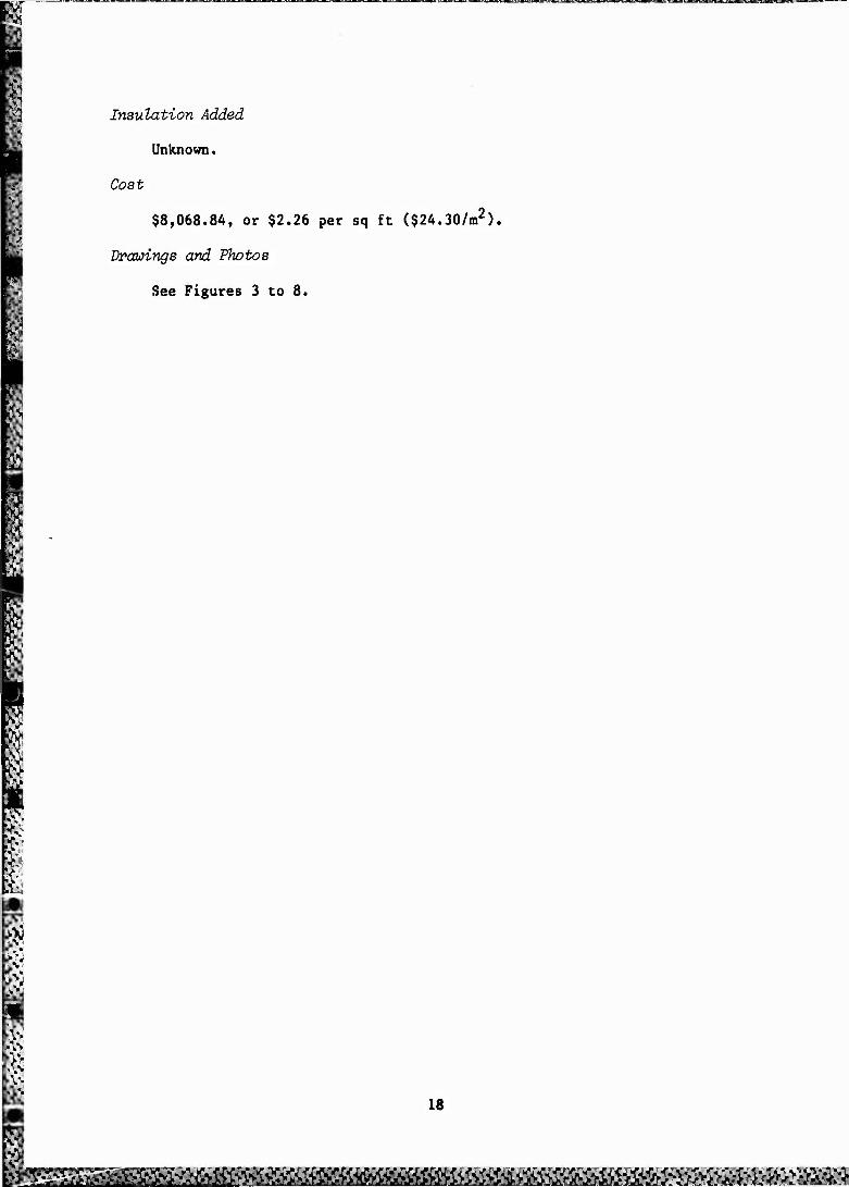
Figure 6. General view of framing, Case Study No. 1,
21
<•■"■•-
.:-J*.«,rJ..-if-.c,..»:.v~f:.,.:_«:..'.v. v.^1—»'^JL. v- .'-«"- -!~-J-R- -T- -.-»..-.-. ..•■■,. •..•■ a. .>.".-«J--.•■-.--.•-_*-. -.'•.'-. i •■ -..-, -..- (.•.',.ii

Figure 7. Completed roof from the front, Case Study No. 1.
U , t
Vi
Pigure 8. Completed roof from the rear, Case Study No. 1,
22

Case Study No. 2
Type of Construction
Haydite concrete block bearing walls supporting steel bar joists and metal deck.
Existing Roof System
Built-up gravel surface over 1-in. (2.54-cmj insulation.
Building Size
52 ft x 32 ft - 1,662 sq ft (15.84 m x 9.75 m - 154.4 m2).
Configuration
The main roof is rectangular. Also, a smaller roof (elevated 3 ft-6 in. or 1.07 m above main roof) covering an exterior loading dock.
Date
Work started February 7, 1983; completed February 18, 1983.
Reason for Roof Replacement
Leaking.
System Used
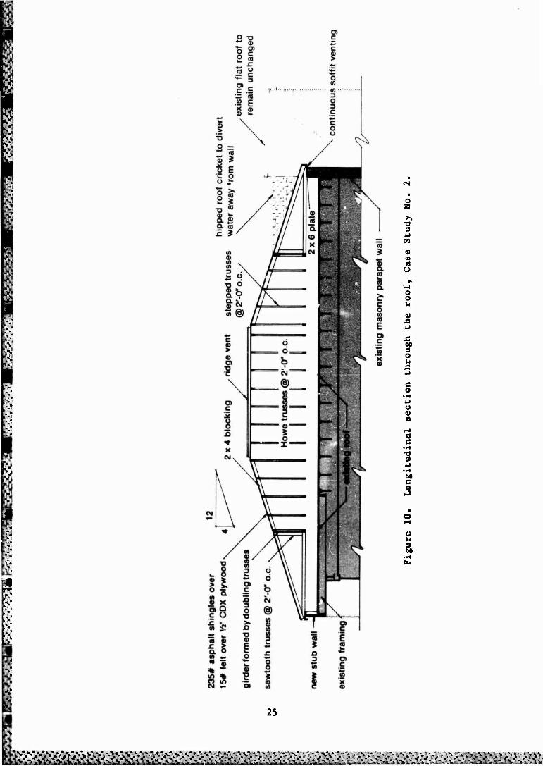
Two- x four-in. (5- x 10-cm) prefabricated step-down hip truss system. Existing roof left intact, as trusses were supported on a 2- x 6-in. (5- x 15- cm) plate anchored to the top of the parapet wall.
Attic Ventilation
Continuous ridge vent, 6-in. (16-cm) vent soffit (aluminum) around entire perimeter of building. Roof extended 6 in. beyond outer wall.
Gutters
5-in. (12.7-cm) aluminum (seamless).
Note
There are six similarly designed Post Office buildings in this area. Three of the buildings have been reroo">d with sloped systems and the remain- ing three will be converted soon.
Cost
$6,277.08, or $3.74 per sq ft ($40.26/m2).
Drawings and Photos
See Figures 9 to 14.
23
:v:>«v^^^^^¥<^^^^s<i<<n:s-x-:.

:•-.
CM
O 55
a o w
u
e
o o
OS
a» a» u 3 «0
24
Dft
^^^•a^>^^a
CJ
o z
T3 3 u
CO
a) 01
o
14-1 o o u eg
J5 w
60 3 O
XS
e o
o
«9 e
? 3
V
3 00
25

Figure 11. View on top of roof during beginning construction stage, Case Study No. 2. Note the 2- x 4-in. (5- x 10-cm) plate bolted to the top of the parapet wall and the allowable clear area for adding insulation.
Figure 12. Front view, Case Study No. 2.
26
tim^^mmMmmmm^mmmmmmssmmmsmsmm

Figure 13. View of the beginning of construction, Case Study No. 2. One full-length stepped truss and the front sawtooth trusses are in place.
Figure 14. Completed roof conversion, Case Study No. 2.
27
R8&&KSI 4 • *. fc. " » \ .

0 * -*r>
Case Study No. 3
Type of Construction
Wood frame; brick veneer and panel exterior, wood roof deck.
'Existing Roof System
Built-up, gravel surface o/er 1-in. (2.54-cm) roof insulation.
Building Size
50 ft x 71 ft = 3550 sq ft (15.24 m x 21.64 m = 329.8 m2).
Configuration
Rectangular with notches cut out at the corners and centered on one axis.
Date
Construction started February 20, 1983; completed March 30, 1983.
Reason for Roof Replacement
Leaking.
System Used
Two- x eight-in. (5- x 20-cm) rafters framed on 24 in. (61 cm) centers creating a hip roof with a slope of 4 in 12, covered with 1/2-in. (1.27-cm) wafer board, 15-lb felt under 235-lb asphalt shingles. Two- x four-in. (5- x 10-cm) knee walls were used fot support at the mid-span of the rafters.
Attic Ventilation
Eighteen mushroom vents at the base of the roof and 20 lin ft (6.1 m) of ridge vent.
Gutters
Four-in. (10-cm) seamless gutter added around the perimeter.
Insulation Added
Six-in. (15-cm) of paper-faced fiberglass instated on top of existing roof.
Cost
$13,504, or $3.80 per sq ft ($40.95/m2).
Drawings and Photos
See Figures 15 to 20.
28

* 0 0) .a CO
(0
5
CO
E CO k. co ffl k. o CO c
CO c o
o T3
3 a. i c
k. CO
c r
s CO u
o o k.
c 3 o k. CO
T5
I k. S 3 (0 o o eo *" O k.
a a a 3
CO
b O)
CO
as (0 U
1 £ .c (0 CO c a o £ CO •* X to t (0 CO
X X b X X CM CM CO CO CM c o
en
o z
TJ 3
CO
V 01
u
c (0
<+4 o
k§
m
v k. 3 00
3fe?fl^ra>K^^^
235# shingles over 15# felt on
W wafer board with metal clips @ 2'-0" o.e.
edge metal
1 x 8 redwood
remove existing roofing to
provide secure plate fastening
existing roof edge detail
Figure 16. Typical cornice detail, Case Study No* 3.
continuous ridge vent
2x8 rafters @ 2'-0* o.e.
mechanical equipment mushroom vents @ 9'-0" o.e.;
Figure 17. Section through roof, Case Study Mo. 3«
30
«I^>^^V&*tttt ^^^^^Ä^^^^^iC^?, ^S^NW^V^
Figure 18. View of roof top before conversion, Case Study No. 3.
Figure 19. View of front of building before conversion, Case Study No. 3,
31
&PS£^g^&^^^
Ill Si
Figure 20. Completed roof conversion, Case Study No. 3.
32
£S£1»&^&*^^

Case Study No. 4
Type of Construction
Masonry bearing walls supporting a wood frame roof.
Existing Roof System
Built-up, gravel surface.
Building Size
4,882 sq ft (454 m2).
Configuration
L-shaped.
Date
Winter of 1982-83.
Reason for Roof Replacement
Leaking.
System 'used
A combination of wood scissors trusses, conventional framing, and Howe trusses was used because of the existing conditions and the design solution. The existing building had a portion of the roof raised to provide clerestory windows. The scissors trusses and conventional framing were used to raise the roof over this rather than removing it. Conventional Howe trusses were used elsewhere. The final 5 in 12 slope was covered with fiberglass-reinforced as- phalt shingles.
Attic Ventilation
Continuous ridge vent and soffit vents were used.
Gutters
A complete new guttering system was added.
Insulation Added
Unknown.
Cost
$25,609, or $5.25 per sq ft ($56.50/m2).
Drawings and Photos
See Figures 21 to 29.
33

I
ü ö b CM
® CO CD 10 10 3
C CD
-■»*■
~
* ■ ■ i
— — "-"*»»--*« •: •
, ■
->—T"
• - ■ ■■'■» »» w ■ »t« w lit..
"1
54 C"'
§
■»— ■•>■»■ i^win
** *■»■—■■ ■ ■' » f ■ «»■■■■■II— I I !■ I I
p"fv : " - t* *• ' *—<B8
ü Ö
b CM
® CO (1) CO CO
1_ ■*->
<D
o X CM CM
(0 CD CO CO 3
CO k_ O CO (0 Ü co
c 1 CO
CO c o c > c o Ü
CO > «♦- o o .Q O CO «-
C o> « .E CX ?! w .2 o x
to
«
c <0
o
CN
<0 U 3 00
Ü
Ö
<§)
34
&?£££?%^^

w tV.' H
o 53
CO
V
cd o
2
•8 o
o
<u
CM «M
0)
00
X CD
d) (0 10 .«£
5 3 35
&&tä&&ä^^^

235#asphait shingles over 15# feit over V2" CDX plywood
trusses @ 2'-0" o.e.
pW3«^
new soffit with a continuous vent
■
Figure 23. Roof edge detail, Case Study No. 4.
Vi x 8 beveled cedar siding
fiberglass shingles on 15# felt on V? CDX plywood
wood scissors trusses @ 2'-0" o.e.
existing outside masonry walls
Figure 24. Section through roof, Case Study No. 4,
36
s^ii^^^^aMss^M^

T3 0 O O 5 O ^ 3
i_ a +-» co X M— a o ü o
£ O) c c o o *-< a a> a
H— 3
* CO
in ~ T- CO
C £ o a> CO 0) c
.* O) C ■t
x: X CO CM CO co CO O) l_ a) 13
o SB
co
a> en
o
m o o u
ja 00 3 O u A
% • H 4-1 O u eg
0)
<d 4J
m tN
« 3 06
AAi -^ -^ >•. v. v- . ■ - . .' •-. -■■ ■•- ■*. ■'- -•■ .V»'. •?•- V->> rc^Äftk^Ätf:^

■r
Figure 26. General front view before conversion, Case Study No. 4.
i öSf
Figure 27. Close-up front view before conversion, Case Study Mo. 4.
38
lkiFE3^tf£^:»tt^^^

m
V
Figure 28. Side view completed, Case Study No. 4.
Figure 29. Front view completed, Case Study No. 4.
39

i
m
Case Study No. 5
Type of Construction
12-ft (3.65-m) concrete bearing walls and wood ceiling joists framed be- tween parapet walls.
Existing Roof System
Built-up, gravel surface.
Building Size
1,620 sq ft (150.5 m2).
Configuration
Basically rectangular, with various offsets.
Date
February 1983.
Reason for Roof Replacement
Leaking.
System Usea
Wood trusses at 2 ft-0 in. (61 cm) o.e. bearing on 2- x 4-in. (5- x 10-cm) plates attached to the top of the parapet walls. A parapet was on the back side to provide for drainage. A wood frame wall was constructed to the same level as the parapet walls to provide bearing for the trusses. The final 4 in 12 sloped roof was covered with asphalt shingles. The gables, soffit and facia
were covered with prefinished aluminum.
Attic Ventilation
The attic space was ventilated with gable louver vents.
Gutters
Unknown.
Insulation Added
Unknown,
Cost
$7,614, or $4.70 per sq ft ($50.59/m2).
Drawings and Photos
See Figures 30 to 35.
40
^mmi^m^. M^^^^^mmmssi^m^^^mfrM^Mmtmm

roof trusses asphalt shingles
i; '"
Figure 30. Section through roof, Case Study No. 5.
Figure 31. Roof plan, Case Study No. 5.
41
Kl^I»imiÄii«M

Figure 32. View under construction, Case Study No. 5.
;:>
Figure 33. View of completed roof, Case Study No. 5.
42
2££&£^

1 ^
Figure 34. View of trusses in place during construction, Case Study No. 5. Note the frame wall; it is necessary for truss construc- tion that supporting walls are level.
Figure 35. Rear view completed, Case Study No. 5.
A3
v/.-.y.y-Y a.->^.-% ■.M-..J.V.VLV^
>"-.'••."• •.•.f^V-V-V-i.'-V" IN .M> - -1>'> >.* v VV». ■ '..•>*• - v«,- *- > y-fiy ■•>>>,• ;;-?> »>*>■>>».• ?> v W V W !V V ".«
Case Study No. 6
Type of Construction
This project is part of Camden County College, Blackwood, NJ, and consists of five separate buildings linked together. The buildings are different sizes and shapes, and are constructed from different materials. Several of the buildings had leakage problems. The architects proposed converting to sloped roofs on all of the buildings. Two of the buildings (Wilson West and East) are steel frame with concrete roof decks. Two other buildings (garage and Roosevelt Hall) have masonry bearing walls with wood frame roof structures. Wilson Center has steel columns supporting concrete barrel vaults.
Existing Roof System
Built-up, gravel surface was used on the garage, Wilson East, and Wilson West. Roosevelt Hall, which already had a sloped roof was reroofed with asphalt shingles. Since each building was slightly different, several will be looked at individually in more depth.
Building Size
See Case Studies 6a and 6b.
Configuration
Rectangular.
Date
Unknown.
Reason for Roof Replacement
Leaking.
Attic Ventilation
All buildings were provided with continuous soffit vent and gable vents or ridge vents.
Gutters
All buildings were guttered completely.
Insulation Added
Unknown.
Cost
Total $204,457, or $5.25 per sq ft ($56.50/m2) for all three buildings.
44

Case Study No. 6a
Building
Wilson Center, Camden County College, Blackwood, NJ.
Type of Construction
Steel columns supporting a series of concrete barrel vaults.
Existing Roof System
A liquid-applied product that forms a membrane on the concrete.
Reason for Roof Replacement
Leaking.
Configuration
Rectangular.
Date
Unknown
System Used
Columns were located on the concrete roof directly above the existing structural columns supporting the roof. The new columns carry a beam running perpendicular to the vaults. The beam is made of four parallel-chord trusses tied together at the top with plywood. The two beams (one on each side of the building) in turn support the trusses which run parallel to the vaults.
Building Size
64 ft x 150 ft = 9,600 sq ft (19.5 m x 45.7 m = 891 m2).
Attic Ventilation
Continuous ridge and soffit vents.
Gutters
Guttered completely.
Insulation Added
Unknown.
Drawings and Photos
See Pigures 36 to 43.
45

is UJ
z O
D
D
D
D
D
D
D
D
D
D
D
D
XI
c CO
CO
O 55
>» •O 3 AJ CO
0) en to U
X <0
f-l o. E o o 0) 00
o
c 3 o Ü
§ 1 3 o
§
§ V I-
0)
00
46
ß&^gs3asa^fti^s^>ra^
.-.'■ . - .
beam above vaults -™*P" line represents where slopes supporting trusses - see section change from 5/12 to 20/12
Figure 37. Roof framing plan for Wilson Center, Case Study No. 6a.
47
iS^llMl&ii&^^

M
, 235# asphalt shingles over 15# felt over W CDX plywood
4 horizontal wood trusses tied together together at the top with %" plywood to support wood truss @ 2'-0" o.e.
2x4 members framed in to change slope of roof
Figure 38. Section through roof edge, Case Study No. 6a.
48

S3* .--.-,„,:.-.-- *"-*£• f »>"*, .-'S
Figure 39. View of Wilson Center before construction, Case Study No. 6a.
Figure 40. Detail of stub column supporting beam above barrel vaults, Case Study No. 6a.
49
, .VVS .S -,u.Vt% > ;A .,....., -.V'... .•..', a.^_-^iÄV „.:,^...c^ -T.i..,'.^...*^

1 ■gii
Figure 41. View of trusses being erected, Case Study No. 6a. Note piggy- back trusses were used because a single full height truss would have been too tall to transport.
. '-X*. ■*
Figure 42. View of finished roof of Wilson Center, Case Study No. 6a.
50

Figure 43. Inside Wilson Center looking out, Case Study No. 6a. Note, the soffit aligns with existing transom. The glass above the transom remains in place; it is painted black.
51
Case Study No. 6b
Building
Wilson West, Camden County College, Blackwood, NJ.
Type cf Construction
Steel frame with concrete roof deck.
Existing Roof System
Built-up, gravel surface.
Building Size
56 ft x 184 ft = 10,304 sq ft (17 m x 56 m
Configuration
= 957 m2),
Date
Rectangular.
Unknown.
Reason for Roof Replacement
Leaking.
System Used
Wood trusses at 2 ft-0 in. (61 cm) on center bearing on 2- x 8-in. (5- x 20-cm) plates fastened through the roof. Due to the width of the building and a line of skylights running down the center of the building, two trusses v3re used. The two trusses were connected at the peak after they were in place. This solution allowed the skylights to remain (see building section). One- piece trusses would have required removal <-f the skylights and would have cost more.
Attic Ventilation
Continuous soffit vents, ridge vents, and gable vents.
Gutters
Guttered completely.
Insulation Added
Unknown.
Drawings and Photos
See Figures 44 to 49.
52

change in slope from 2/12 to 20/12
m
Figure 44. Roof framing plan for Wilson West, Case Study No. 6b.
two separate trusses joined at the peak
235# asphalt shingles over
15# felt over W CDX plywood pre-engineered wood trusses
2x8 plates bolted to existing roof
Figure 45. Section through Wilson West, Case Study No. 6b.
53

Figure 46. View of Wilson West before construction, Case Study No. 6b.
• '-fir.V '"-'/».'
Figure 47. View of roof of Wilson West during construction, Case Study No. 6b. Two trusses joined at the ridge. Continuous bottom chords would conflict with the series of skylights down the center of the building.
54
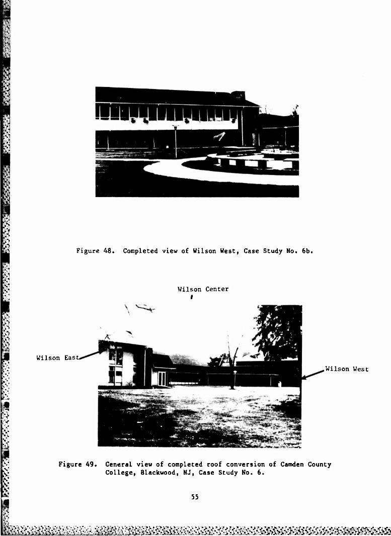
Figure 48. Completed view of Wilson West, Case Study No. 6b.
Wilson East,
Wilson Center I
■• 'JMM£S^! ..„,; __
Wilson West
«£
Figure 49. General view of completed roof conversion of Camden County College, Blackwood, NJ, Case Study No. 6.
55
&a&£tök#:^^^
&
s
$
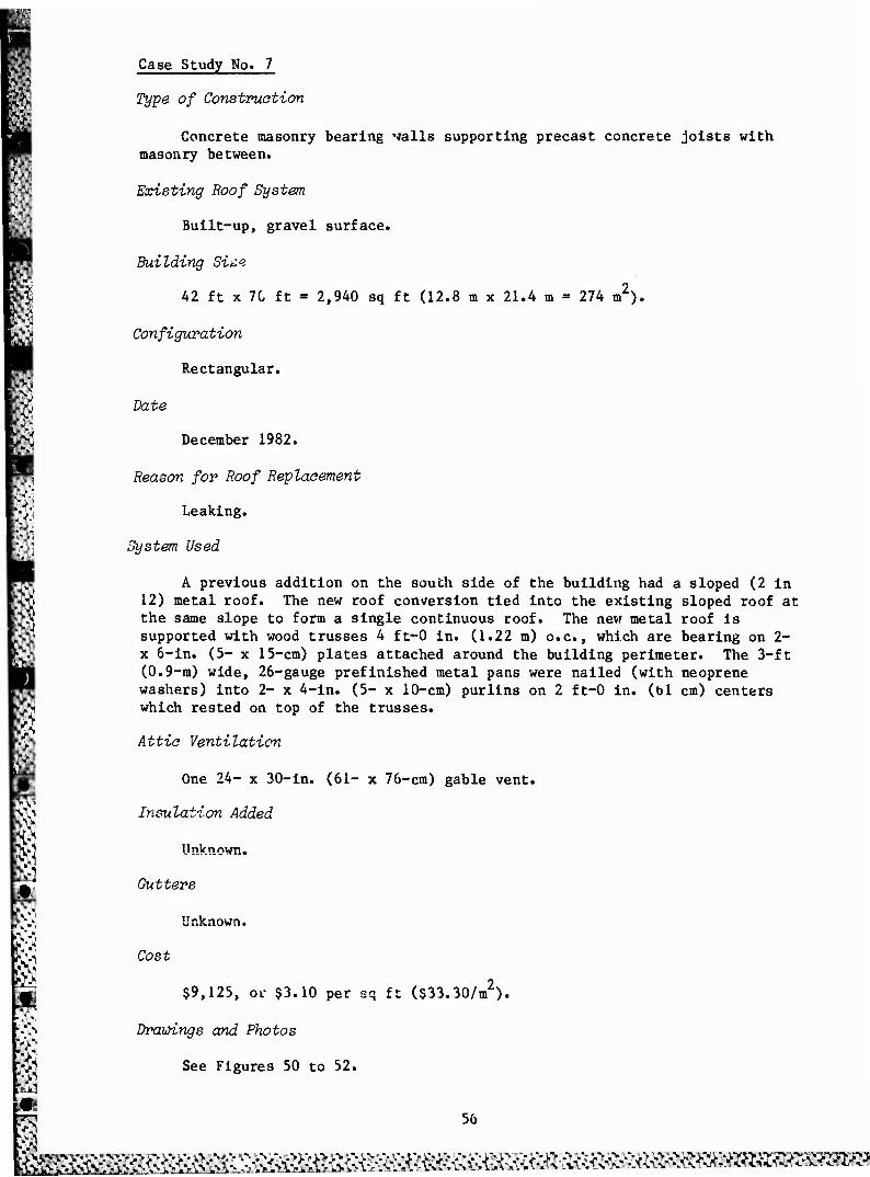
Case Study No. 7
Type of Construction
Concrete masonry bearing walls supporting precast concrete joists with masonry between.
Existing Roof System
Built-up, gravel surface.
Building Si^e
42 ft x 70 ft = 2,940 sq ft (12.8 m x 21.4 m = 274 m2).
Configuration
Rectangular.
Date
December 1982.
Reason for Roof Replacement
Leaking.
System Used
A previous addition on the south side of the building had a sloped (2 in 12) metal roof. The new roof conversion tied into the existing sloped roof at the same slope to form a single continuous roof. The new metal roof is supported with wood trusses 4 ft-0 in. (1.22 m) o.e., which are bearing on 2- x 6-in. (5- x 15-cm) plates attached around the building perimeter. The 3-ft (0.9-m) wide, 26-gauge prefinished metal pans were nailed (with neoprene washers) into 2- x 4-in. (5- x 10-cm) purlins on 2 ft-0 in. (61 cm) centers which rested on top of the trusses.
Attio Ventilation
One 24- x 30-in. (61- x 76-cm) gable vent.
Insulation Added
Unknown.
Gutters
Unknown.
Cost
$9,125, or $3.10 per sq ft ($33.30/m ).
Drawings and Photos
See Figures 50 to 52.
56
&££J&£££&^^^
prefabricated wood trusses @ 4'-0" o.e.
26 ga. metal pans fastened with nails and neoprene washers
2x4 purlins @ 2'-0" o.e.
new sloped roof to tie into existing sloped roof
existing addition with 2/12 roof slope
V; Figure 50. Section through building, Case Study No. 7.
/
,existing parapet wall below
(
E y-
- previous addition with sloped roof I/
new roof peak
/
26 ga. prefinished metal roof panels
/
V
2x4 purlins @ 2'-0" o.e.
s: wood trusses @ 4'-0" o.e.
Figure 51. Roof plan, Case Study No. 7.
57
ftv1"&}ft2di!V&£H>s& *">>*-'.>-->>.-»VAANUV^VA-A-A^VC >V-VV>%^SVAVAVV/-.«i A\ AAtVi-A-A-A-. ., .\-Av\*A A - ' N^"- t - VV"
1
ö
&
,This is a previous" addition with a sloped roof.
-J
Figure 52. Completed view, Case Study No. 7.
58
>ir->>i.v3 BSffifö&t!^^
Case Study No. 8
Existing Roof System
Built-up, gravel surface over 1-in. (2.54-cm) rigid insulation over steel deck supported by steel bar joists.
Building Size
31 ft x 132 ft = 4,092 sq ft (9.45 m x 40.25 m = 380 m2).
Configuration
Rectangular=
Date
June 1982.
Reason for Roof Replacement
Leaking.
System Used
26-gauge, 3-ft (0.9-m) wide Tech-Rib (prefinished galvanized steel) panels were screwed to a supporting steel frame consisting of 7-in. (17.8-cm) steel "C"-channel rafters on 12-ft (3.65-m) centers with 7-in. steel "(^'-chan- nel purlins welded between at 5 ft-0 in. (1.52 m) centers.
Gutters
5-in. (12.7-cm) prefabricated gutters were added to the top and bottom. The top gutter was to divert water from a roof above.
Insulation Added
R-19 fiberglass batt insulation was added on top of existing roof.
Cost
$12,000, or $2.90 per sq ft ($31.21/m2).
Drawings and Photos
sae Figures 53 to 60.
59

continuous dbl. 7" galv. C-channel rafters @ 12'-0" o.e.
gutter ~(E«=
screened opening
T galv. C-channels @ 5'-0" o.e.
1
ill
existing wall '
\
vent with bird scr
T galv. C-post above' columns below
existing flat built-up roof - '-"Sä«^
Figure 53. Section through roof, Case Study No. 8.
7" galv. C-channels framed between @ 5'-0" o.e.
existing wall
V
existing roof line below
3' wide white tech ribbed panels fastened with screws and neoprene washers
dbl. 7" galv. C-channels @ 12*-(T o.e.
Figure 54. Roof plan, Case Study No. 8.
gutter
60
^££2S^:^^ BiSKKStt'S

7-in. channels framed between rafter @ 5-ft-0-in. o.e.
Double 7-in. channel rafters @ 12-ft-0-in. o.e.
Figure 55. View of framing, Case Study No. 8.
Figure 56. Detail of column connection to the existing roof, Case Study No. 8.
61
'M mM&&&& mmmmm&x

Figure 57. View during application of 3-ft wide by 31-ft long white Tech- Rib metal roofing, Case Study No. 8.
ftfi «man
■v
\
Figure 58. View of completed roof, Case Study No. 8.
62
<\-S>K^S^A-fX\ mmj^ :• tf^^tecv« -s-;

Figure 59. Completed view from the front, Case Study No. 8. Note the wide fascia covering the low sloped metal roof behind.
£
Figure 60. Edge detail at the rear of the building, Case Study No. 8, showing how fascia covers sloped roof and how roof drains to the rear.
63
^2^&&&M£M^

Z| COST ANALYSES
Construction Costs
The final cost of any construction work, including roof conversions, depends greatly on the type of work and each area's unique situation. The costs depend on many variables, such as the labor situation, price of materials, the distance materials have to be transported, and the nature and size of the work.
When wood was used for the structural material, for either trusses or conventional framing, the job was normally under the control of a general con- tractor or carpenter. In almost all cases the labor was nonunion and often by fairly small companies. Many of the larger jobs required prevailing wages be paid, but the construction companies were still nonunion. Sometimes the shingling was subcontracted to roof contractors; at other times it was done by the general contractor. In most cases, asphalt shingles were used instead of other coverings, presumably because of lower cost.
Conventional job-built wood frami nomical. The most economical methods rafters could be reduced to 2 x 4's (5 case (see Case Study No. 1) was comple ranged upward to $5.25/sq ft ($56/m2). this approach averaged about $3.00/sq new sloped roof at the top of the exis down. This eliminated any soffit and looked less like a conversion and more that way.
ng superstructure proved to be very eco- used knee walls so that the size of the - x 10-cm) or 2 x 6's (5- x 15-cm). One ted for $2.26/sq ft ($24.30/m2). Others
The price most often encountered for ft ($32.30/m2). Ending the top of the ting fascia probably helped keep costs fascia work. Also, the final product as if it had originally been designed
In general, conventionally framed conversions are less expensive than us- ing trusses, but the local labor situation should be taken into account. The trusses themselves cost more than the material required to frame a roof conventionally; however, since trusses can be erected more quickly, the con- struction labor costs are lower. Consequently, in areas where labor costs are very high (and providing it is a simple roof) trusses might prove more economical.
A wood truss system costs less if identical trusses can be used. A greater number of truss types causes the price per truss to go up. When a building deviates from simple shapes such as a rectangle, the cost of the truss system begins to rise. When a reroofing job becomes a series of complex shapes, conventional wood framing probably will be less costly.
The most economical type of roof generally is a hip roof. The only areas to be finished (excluding the roofing material) are the soffit and fascia, and even these may not need replacement. A hip roof can be conventionally framed, or a wood truss system can be used. Four wood truss systems can generate a hip rcof: step-down system, Dutch hip system, terminal hip system, and a com- bination of common trusses with conventional framing.
A step-down hip system (Figure 61) seems to be the most frequently used. It employs three types of trusses: a common truss, a step-down truss,
64

Figure 61. Step-down hip system.
and a mono truss (sometimes called a half or sawtooth truss), trusses are used to frame the main body of the roof. The step the same span as the common truss but is truncated at the top crease in height to form a sloping hip. A series of step-down between the common trusses and the step-down girder. The step (two or more step-down trusses combined) carried the mono trus out the bottom of the roof (see Case Study No. 2). The cost o truss system in roof conversions generally averages between $3 ft ($32.30 to $43/m ) with simple rectangular shapes.
The common -down truss is to gradually de- trusses is used
-down girder ses which finish f the step-down .00 to $4.00/sq
The Dutch hip system (Figure 62) combines a hip end and a gable end. The gable can be for a louver or for appearances. This system uses common and mono trusses. The small hipped area is normally conventionally framed with a hip rafter and jack rafters. The cost of a Dutch hip system generally is slightly more than the step-down system because of the louver and/or gable finishes.
The terminal hip system (Figure 63) can be used for small span applica- tion only—32-ft (9.75 m) maximum. This system combines common trusses (for the main body) and long bottom chord mono trusses for the same application as jack rafters in conventionally framed hips. The hip rafter is a conventional- ly framed rafter and not a truss. The bottom chord of the mono truss is longer on one side of the hip rafter than the other, and the top chords are beveled to tie into the hip rafter. No examples were found using this system for a roof conversion, so costs are unknown.
6S
. -vv - ■ »v»» ."»■ -•."- v-- I.« _ j.......^.. - *.l A , ... *~J...
."* ."•■'."-*.~
-^- .'■..•..'.•.,./Jv. ■ -'- *>'- «■"-
■ >> .- ■.--.-- .-• .--I-- .■•;-.• .--.- (,*• ^ .- -•>> .-• .--:-*• .■- -"- .• ."* i> >>"v'- LVJ> y> ."• .*
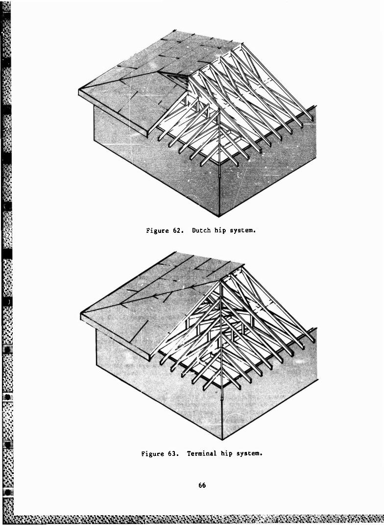
Figure 62. Dutch hip system.
1 1
Figure 63. Terminal hip system.
66
ö$a$£&&^^

The combination of common trusses and conventional framing (Figure 64) in some respects offers the best of both systems. Since common trusses are used to frame the main body of the roof, economy is maintained through the repeti- tion. At the point where the hip begins, the trusses stop and the convention- al framing begins. The hip rafter and the jack rafters are conventionally framed. This system is particularly economical for long roofs in which many identical trusses can be used. When the number of trusses is reduced, some of the economy is lost. Average cost of this system is $3.00/sq ft ($32.30/m ).
Builders using metal as the framing material devised their own subpurlin structures to create a slope. Various light-gauge sections can be used, including hat sections, tubes, furring tubes, angles, "C's," and "C's" with flange tracks. Standing seam or some other type of lightweight metal roofing can then be attached to the frame. Various low-sloped framing systems were encountered. One of the systems used the members much the same as wood fram- ing (see Case Study No. 8) using rafters and purlins. Another system ran a series of continuous purlins perpendicular to the metal roofing without any rafters. These job-built metal framing systems proved very cost-effective, generally averaging about $3.007sq ft ($32.30/m ). Average costs and comparison costs between wood and steel conversion systems can be found in Table 1.
Figure 64. Common trussed/conventional framing hip system.
67
^fe&te>&^^

0
'•V
Table 1
Construction Costs for Roof Conversions
DESCRIPTION OF SYSTEMS
Wood Framing Systems
Conventional jrh-built wood framing with dimension lumber, covered with plywood sheathing and asphalt shingles
Wood Truss Systems
Hip root systems covered with plywood sheathing and asphalt shingles. Trusses are spaced on 2 ft-0 in. centers
step-down hip system
Dutch hip system
terminal hip system
combination of common trusses with conventional framing
Gable roof system covered wth plywood sheathing and asphalt shingles. Trusses spaced at 2 ft-0 in. o.e. Gable ends finished with siding.
Wood trusses spaced at 4 ft-0 in. o.e. with 2x4 purlins and covered with light-gauge prefinished metal roofing
Metal Framing Systems
Job-built framing system using light- gauge (16 gauge or lighter) standard sections bolted or welded together. Framing covered with lightweight metal or standing seam roofing.
Steel trusses with members consisting of standard rolled sections (angles). Truss spacing at 20 ft-0 in. centers with standard rolled section (channel) purlins supporting roofing material consisting of light-gauge metal (prefinished galvanized or standing seam roofing).
Range of Costs/Sq Ft (C^'ts/m2)
$2.20-$4.00 ($23.70-843.05)
$3.00-$4.00 ($32.30-$43.05) $3.25-$4.25
($34.98-$45.75) costs unknown
$3.00-$4.00 ($32.30-$43.05)
$3.50-$5.00 ($37.67-$53.82)
$2.00-$4.00 ($21.53-$43.05)
$2.00-$3.50 ($21.53-$37.67)
Average Cost/Sq Ft (Cost/m2)
$3.00 ($32.30)
$3.50 ($37.67)
$3.00 ($32.30)
$3.00 ($32.30)
$4.25 ($45.75)
$3,00 ($32.30)
$3.00 ($32.30)
$5.00 ($53.82)
68
&^^oa&&^^ &&£&£&^«tt
Only one case was found employing steel trusses to create a substruc- ture. The roof was 42,000 sq ft (3,902 m2). The prefabricated steel trusses were located on 20-ft (6.1-m) centers with "C"-channel purlins framed between at 5-ft (1.5-m) centers. Standing seam metal roofing with battens covered the 1/4 to 12 slope. The system cost $5.80/sq ft ($62.40/m2). The contractor was unhappy with the system. He cited the inability to speed up the truss erection process as the major drawback. Insulation and roofing were removed under the trusses, leaving the existing structure vulnerable to water intrusion. The long erection time led to serious rain damage to the building and to a lawsuit.
Life-Cycle Cost Analysis
i
Case Study No. 1 was chosen as the model in this analysis primarily because the owner took competitive bids on several different systems, so accu- rate cost information is available for comparison. Cost will vary from area to area; however, it is assumed that local variations in labor and material costs will apply equally to roof conversions and conventional builtup roofing so that the comparison made in this example will remain valid.
lilding in Case Study No. 1 is 33 ft x 108 ft = 3,564 sq ft (10 m x m2).
The bui] 33 m = 330 m ). Before conversion the existing roofing system was a built-up system with gravel over 1 *n. (25 mm) of rigid insulation. The roof structure is precast concrete deck supported by masonry bearing walls. There are no parapet walls. The edge detail consists of a sheet metal gravel stop. The rcof had leaked for some time, so presumably the insulation was wet and needed replacment. With built-up roof replacement, the roofing and insulation would have to be torn off down to the structural deck before reroofing.
The building is about 15 years old. The Corps of Engineers projects a life expectancy of a building (for life cycle cost purposes) of 25 years; for this case, it is assumed the 25-year period begins with the application of the new roof. The possible roofing systems available for this building are. roof conversion-asphalt shingles, conventional built-up roofing, or a single ply system. Asphalt shingles can normally be expected to last for 15 years of trouble-free service. Built-up roofing v't.h a gravel surfacing has a life expectancy of 15 years according to a recent ASTM-STP study. Single ply roofing systems are relatively new and quantitative data are not yet readily available. A 15-year life expectance is assumed.
The owners took competitive bias for different single-ply roofing systems and a roof conversion. Carlisle'?, single-ply roofing system, a 45-mil (1.14 mm) ballasted synthetic rubber membrane, was estimated at $2.36/sq ft ($25.40/m ). The owners had so much trouble with the existing built-up roof- ing system they would not consider using a built-up system again.
1 Durability of Building Materials and Components, Special Technical Publication 691, First International Conference on Building Materials and Components, Ottawa, 1978 (American Society for Testing and Materials, 1980), p 652.
69
^m^mmmm^mmmm
85
The owners selected the roof conversion system because it soLved their problems and had the lowest initial cost. However, maintenance costs for the remaining 25 years of building life must be considered. Presuming that asphalt shingles last 15 years, they will need to be replaced only once after the conversion; similarly, so would the other systems.
Today's cost of asphalt shingle replacement = $0.60/sq ft.
Today's cost of single-ply replacement = $2.36/sq ft.
For comparison of Case Study No. 1 at today's cost, see Table 2.
To set up a fair life cycle cost model, built-up roofing should also be considered (see Table 3). According to the 1983 Means Cost Data2 using the correct area multiplier, 3-ply built-up roofing with 2 in. of insulation cost $1.98/sq ft plus an estimated $0.75/sq ft for removal of existing roofing which totals $2.73/sq ft.
Today's cost of built-up replacement = $2.73/sq ft.
Normally when determining the life-cycle cost, a discount rate is employ- ed. Often it is set by the prime lending rate. The discount rate set by the Army for military construction projects is equal to 10 percent. Money spent at some future date is worth less than money spent today. Therefore, the Net Present Worth (NPW) needs to be calculated. The NPW discounts future expendi- tures to today's terms by numerically prorating the future spending by the amount of 10 percent.
Table 2
Roof Replacement Cost For the Remaining 25 Years of Life For the Building in Case Study No. 1
Roof Conversion
$8,070.84
Single Ply Roofing
$8,410
Built-up Roofing
$9,730
First Replacement in 15 Years
(Excluding inflation)
$2,140
$8,410
$9,730
Total
$10,210
$16,820
$19,460
Building Construction Cost Data 1983, 41st Annual Edition (Robert Snow Means Co., Inc., 1983), p 139.
70
SSM^^^iK^^^I^M^ kM&t&K&tt^&Kä^^

Table 3
Net Present Worth (NPW) of Roofing Systems for Case Study No. 1 (For a 25-Year Life)
8£SM
*-> Initial Roof NPW of First Replacement Total NPW of •So
Roof
Replacement in 15 Years Replacement
Conversion $8,070 $ 510 $ 8,580
Single-Ply $8,410 $2,010 $10,420
VVj Built-Up $9,730 $2,330 $12,060
The formula isJ
P = F x ,N (1 + I)
where P = the present value of the money spent in the future
F = the known (or approximated) future expenditure
I = 10.0 percent (standard discount rate used by the Army)
N = number of periods in years
NPW = INITIAL EXPENDITURE + Pj
where Pj = present value of first roof replacement
Roof Conversion
Px = $2,140 x 1
(1 + 0.10) 15
Px = $510
NPW = INITIAL COST + Pj
NPW = $8,070 + $510
NPW = $8,580
71
1
Single-Ply System
Pl = $8,410 x 1
(1 + 0.10) 15
Px = $2,010
NPW = INITIAL COST + P1
NPW = $8,410 + $2,010
NPW = $10,420
Built-Up System
Px = $9,730 x 1
(1 + 0.10) 15
1
Px = $2,330
NPW = INITIAL COST + P
NPW = $9,730 + $2,330
NPW = $12,060
Roofs require maintenance and repair which represents an expense over the life of the building; consequently, these costs should be incorporated into the life cycle cost analysis. The maintenance and repair cost for a conven- tional BUR roof is generally assessed at $C.02/sq ft annually. Single ply systems have not been around long enough to have quantitative data, so it will be assumed to be approximately the same value as BUR ($0.02/sq ft annually). Asphalt shingles have exceedingly low maintenance and repair cost, but a certain amount of inspection is necessary» this expense is estimated at 25 percent of the cost of BUR; therefore, $0.005/sq ft annually. The roof's size for Case Study No. 1 is 3,564 sq ft. Therefore, the annual costs of maintenance and repair are:
BUR
Single Ply
Conversion (asphalt shingles)
$0,020 [3,564 sq ft] = cost of M & R/year = $71.28
$0,020 [3,564 sq ft] = cost of M & R/year = $71.28
$0,005 [3,564 sq ft] = cost of M & R/year = $17.82
Because maintenance and repair costs are in the future, the expenditures must be discounted to today's value. It is assumed these occur at mid year for each of the 25 years.
Discount Factor = 1.0492
= 1.0491
1 k=25 E
k=1 (l.l)k
x 9.077 = 9.524
72
•«1 :^^:2^£&S^^
where 1.0492 adjusts end of year factors to mid year, set at 10 percent (0.10). The results are:
BUR $680
Single Ply $680
Asphalt Shingles $170
Table 4 is a life-cycle comparison of all factors.
Table 4
Life-Cycle Cost Compared
The discount rate is
Initial NPW of Replacement Cost Cost in 15 yrs
Roof Conversion 8,070
Single Ply 8,410
Built-up 9,730
510
2,010
2,330
NPW of M&R Cost Total NPW of for 25 yr life Roofing System
170 8,750
680 11,100
680 12,740
gj
73
m V' m
5 EFFECT OF REGIONAL AND CLIMATIC CONDITIONS
Regional Effect9
One of the objectives of this research was to determine if regional or climatic conditions affect the frequency of these roof conversions. For example, are conversions done more in colder areas because they allow insula- tion to be added? The answer is inconclusive. Insulation was added in some projects in the northern, intermediate, and southern climates. Its use appeared to depend on the type of building rather than geographic location. For example, private residences normally added insulation, while rental properties did not. Public projects such as schools said they planned to add insulation at some future date, but because of budgetary constraints, the re- roofing was all they were going to do that fiscal year. In all cases, roof leaks were cited as ■ e reason for reroofing. Roof conversions appear to be used in most areas of the country; evidently flat roofs are a problem every-
| where.
Conversions in Various Climates
In addition to the eight case studies described in Chapter 4, many other reroofing projects were investigated. Table 5 is a comprehensive list of the projects; the following text summarizes some of the findings.
In most cases the reroofing conversions were executed by general contrac- tors who did all kinds of construction, not simply roof conversions. Several builders were found who did this type of work as their only business. Several others said roof conversions represented over 50 percent of their work.
One metal building contractor in southern Georgia has completed about 30 roof conversions over the past 5 or 6 years. They were all job-built framing systems using galvanized lightweight metal "C"-channels as rafters and purlins. Most of the roofs were covered with 26-gauge prefinished metal, screwed into the "C"-channels with neoprene washers. Over a dozen schools in this area, as well as commercial and residential buildings, have been convert- ed. The firm, Metal Building Inc., does all its own design, engineering, fab- rication, and construction. The costs range between $2.00 and $3.50/sq ft ($21.53 to $37.68/« ) for completed roof conversions.
Another building contractor, based in Salt Lake City, UT, does only roof conversions. Most of this work is residential and is subcontracted through a very large Salt Lake City roofing business. This contractor frames the super- structures conventionally with wood then applies either asphalt or wood shingles as the roofing material. The firm does five to eight conversions a month at costs between $2.75 to $3.50/sq ft ($29.60 to $37.68/m ). Insulation is added to most roof conversions afterwards.
The architectural firm of Goettelman and Associates has coordinated several larger scale roof conversions in the Philadelphia area (Case Study No. 6). They have done about a dozen school buildings using wood trusses and as- phalt shingles. Their technique includes trying co solve other, unrelated

Table 5
List of Contacts Involved in Roof Conversion Projects
California AEP-Span, San Diego
Florida Duval County School Board, Jacksonville Gang-Nail Systems, Inc., Miami Metal Sales, Inc., Jacksonville R. B. Gay Construction Co., Jacksonville
Georgia Metal Buildings, Inc., Thomasville South Georgia Natural Gas Co., Thomasville Thomasville High School, Thomasville
Illinois Okaw Building Co., Chesterville Scott Buildings, Greenup Richard Carr Construction Co., Dieterich Doyle/Brotherson Arch., Savoy Stanhke Construction, Champaign Isaksen and Matzdorff Arch., Urbana Royse and Brinkmeyer Real Estate, Inc., Champaign Rantoul Public Library, Rantoul Dieterich Post Office, Dieterich Martinsville Post Office, Martinsville Andrews Lumber Co., Greenup Kurasek Construction Co., Champaign Doyle Construction Co., Savoy
Indiana Dye Lumber Co., Monon Hendrix County Farm Building Coop., Danville Lumbermate Truss Co., Remington River City Builders, West Lafayette
New Jersey Avon Elementary School, Camden Camden County College, Blackwood Culbertson Elementary School, Haddonfield Goettelman Associates, Haddonfield Perma-Clad Products, Tinton Falls
Ohio Gene Scherzinger Builder, Miamitown Retroframe Co., Randolph Wood Truss Co., Miamitown
Pennsylvania Joseph Callaghan, P.E., Philadelphia
Utah
Great Basin Roofing Co., Salt Lake City Mike Florlio Builder, Salt Lake City
75

problems along with the roof conversions. For example, Goettelman's solutions normally provide maintenance-free finishes, properly designed overhangs (to give summer shading and winter penetration of sunlight), and a means to keep children off the roofs. This is done by drastically increasing the roof slope near the edge to about 20 in 12 (see Case Study No. 6). Most of their design solutions attempt to make the conversions appear as though they had always been there. This is done in part by attention to details, such as bringing the soffits in flush with the top of the window heads.
Yet another American firm, The Retroframe Co. of Randolph, OH, has developed a roof conversion system that is being marketed in the United States. The system, called the Retroframe Roof Retrofit, Facade and Re-side Components System, was invented by a metal building contractor and is competi- tively priced. It consists of 16-gauge galvanized framing components covered with a 16-gauge standing seam roof. The framing consists of a series of sub purlins (knee walls) running perpendicular to the new roof slope on 5 ft (1.5 m) centers. The different height knee walls are then diagonally braced. The framing is constructed from hat sections, tubes, furring angles, "C's," "C's" with flange tracks, and eight different connectors to provide the flexibility to cope with most situations.
The Retroframe system is particularly good for industrial and large-scale applications. The use of 1/4 in 12 slopes allows coverage of lar«e areas eco- nomically. The system adds less than 3 lb/sq ft (15 kg/m ) of dead load, which is about a third of the weight of a comparable wood oy3tem. The owner/- inventor states the total installed costs range between $2.75 to $3.50/sq ft ($29.60 to $37.68/m ). The range of installed price varies, depending on the area labor costs.
The job-built framing system is fastened together with no. 12 self-drill- ing screws. The knee walls are constructed from hat sections for the top and bottom plates, and tubes as the vertical support members. A heavy layer of roofing cement is applied under the bottom hat section to provide a gasketing effect when the bottom plate is fastened to the existing roof. This technique helps eliminate leaking during construction. The whole system is prepunched for faster erection time. Standing seam clips are pre-attached on 2-ft (61-cm) centers. A 4-in. (10-cm) diameter air opening is provided in the rake trim, covered with bird screening, to provide ventilation. Examples of construction using the Retroframe system are seen in Figure 65.
76
^foh?ä^^

Figure 65. Examples of the Retroframe system.
77
•^■...•.j.-L«-' .■»_-■ •-'■ •^l,>A.».^x.,..^l-.-. ■ „. C ^. .-_',»,' .-.' ,-_.i. ■_', ■_ «L* -l.1-w-"'-'—- ■■ -_ ,1:. ■■.',«.', •-', _'.--'..

5 ECONOMIC CRITERIA FOR SIZE LIMITATIONS
This chapter discusses the cost of roof conversion in relation to the size of the building being covered. Certain conversion systems shown in this report cost the same per square foot whether they are covering a large or small building while others vary in relation to the size of the building.
Cost Per Square Foot of Various Roof Conversion Systems Compared to Building Size
Roof conversions framed with light gauge rolled metal components covered with metal roofing panels at a very low slope (1/4 to 12) cost basically the same per square foot for large or small applications. This system can be framed either like conventional rafters or in a series of knee walls and can virtually go on forever, which is why this system is normally used for very large applications, such as factories. One of the reasons for this system's cost stability is its adaptability to multiple ridges and valleys; conse- quently, the work is always at a convenient height for the workmen. Because of the very low slopes attainable, there is a minimum amount of framing materials used below the roof. Most of the other systems' cost increase on larger buildings is because the new roof becomes too high above the existing roof; consequently, more labor is required, as well as more materials to support the new roof. Metal-framed conversions use basically the same system and amount of labor and materials for large or small buildings, which is the key to their economy for different sized jobs.
Roof conversion employing steel trusses as a superstructure have already been shown to be costly and impractical for any size building, so there is no point discussing them any further.
Job-built wood-framed conversions, covered with either plywood and shingles or light gauge metal panels, have economic limits in terms of size. These systems are very economical for small buildings but become expensive on larger buildings. The most cost-effective approach under this heading is to use small dimension lumber (2 x 4's) as the rafters in conjunction with 2- x 4-in. (0.5- x 1,0-cm) knee walls. The small sized rafters require closely spaced supports (approximately 8 ft [2.44 m] o.e.. or less) due to the limited spans attainable with 2- x 4-in. (0.5- x 1.0-cm) rafters. Using small dimen- sion lumber for the rafters has proven to be a very economical approach, but once a building reaches a certain size, multiple knee walls are required. Using asphalt shingles, the minimum allowable slope is 2 to 12 which means the roof rises fairly rapidly. This, in turn, means the second or third knee wall becomes taller; consequently, the additional material and labor required diminish the cost-effectiveness of the system. Case Study No. 1 exemplifies about the maximum size (33 ft [10.065 m]) a building can be economically framed using this system.
Using larger dimension lumber for the rafters is economically feasible as long as they are limited to a single span. Larger dimension lumber costs more per board foot than the smaller lumber. Therefore, 2- x 10-in. (5- x 25.4-cm) rafters will be cost-effective as rafters for a single span, but if additional knee walls are required, the material costs become prohibitive.
78

Wood trusses work well for roof conversions and can span great lengths. The cost-effectivenes9 of roof conversions with wood trusses is based on two factors: the type of truss (Howe, Fink, etc.), and the required span, which in turn dictates the size of the chord members. Different truss types are applicable to different spans and loading conditions. For example, a Fink or Howe configuration is normally used for relatively short spans, whereas a Double Howe or a Triple W configuration is normally used for longer spans. When a truss manufacturer gets an order, the most economical truss configura- tion is selected on the basis of specific span and loading conditions.
Once a particular truss configuration is selected, the cost is based on the required chord members size. For instance, if a Howe truss is selected, for 50 lb L.L., 15 lb D.L., 2- x 4-in. (5- x 10-cm) chord members will span up to 23 ft-10 in. (7.27 m) at a cost of $1.63/lin ft ($5.35/m); 2- x 6-in. (5- x 15.24-cm) chords will be required between 23 ft-11 in. to 35 ft-8 in. (7.30 to 10.88 m) at a cost of $2.05/lin ft ($6.70/m); from 35 ft-9 in. to 40 ft (10.9 to 12.20 m) 2 x 8*s (5 x 20.32 cm) will be required at a cost of $2.48/lin ft ($8.14 m). Consequently, this means the larger the span for any given loading condition, the greater the cost per linear foot, which increases the cost per square foot for the roof conversion. Appendix A shows the five most common truss types used, different loading conditions and spacing, and their respective truss costs per linear foot and total cost per square foot for the entire roof conversion.
Since the other materials (plywood, shingles, etc.) remain basically the same for all roof conversions, the truss span becomes the critical factor when examining the relationship of a building's size to the cost per square foot. It is interesting to note that the opposite is true for conventional BUR roof replacement: the larger the building being reroofed, the less expensive it is per square foot. This is partially a result of additional expense of perimeter flashings, which are a smaller percentage of the cost per square foot on bigger buildings.
Figure 66 compares the relationship of the additional expense of larger sized buildings covered with trusses as well as the reduced cost of conven- tional 3-ply BUR. It should be noted the trusses which are depicted in the
ft graph represent the bare essentials in terms of additional work, such as roof v preparation or overhangs. These costs, beginning at $3.00/sq ft ($32.30/m ), m would apply when a minimum amount of roof preparation was required and there
would be no overhangs (the new roof finishes flush with the existing). If -\. fascia work and/or soffits were factored into the curve on this graph, the
image would look basically the same except the curve would be shifted upward & to $3.25 or $3.50/sq ft ($35 to $37.68/mO as the starting point.
m The cost per square foot is based on the minimum width of the building. 3 A building that is relatively narrow (even though it may be very long) will
• maintain the economy depicted on the graphs for the short span. The three Sj graphs (Figures 67, 68, and 69) illustrate this point by showing the total v! cost per square foot for roof conversions using wood trusses for three loading >N conditions. These conditions represent the three basic loading conditions in g the United States: southern, intermediate, and northern. The dead load is 15 n lb/sq ft for all categories because there is not any ceiling load—only the jj trusses, plywood, and shingles. The live loads represent the various snow •-'. loads in the United States: 15 lb/sq ft, 30 lb/sq ft, and 50 lb/sq ft.
I f J

Again, these graphs represent the minimum costs, which in turn means the minimum work in existing building preparation and edge detail. If additional work is required in these categories, the cost per square foot shown on the graphs would shift upward relative to the amount of additional work required.
Other Factors Affecting Cost
In addition to the size relationship, other factors can drastically alter the cost per sq ft for any given roof conversion. First is the amount of mechanical equipment located on the existing roof. Obviously, the more equip- ment on an existing roof, the more it will cost to do a roof conversion. Any penetration through the existing roof will probably have to be dealt with; for instance, plumbing vents will have to be extended and re-flashed through the new roof. Most types of equipment cannot simply be covered up with a conver- sion; similarly, some conversion systems, such as trusses, make it difficult to cover up equipment. Therefore, existing mechanical equipment probably will have to be removed and resecured on the new roof, which requires moorings, flashings, and extension of mechanical components (electrical, piping, etc.).
Another factor affecting cost is the treatment of the edge detail. This depends in part on the existing situation as well as the desired final appear- ance. The least expensive approach is to terminate the new roof at the top of the existing fascia, if possible. Of course, any additional work to create overhangs, gables, soffits, venting, or fascia will increase the overall con- version cost.
The final aspect which can directly affect the conversion cost (excluding the structural system and the roofing material) is the preparation and means of attachment to the existing roof. For instance, in Case Studies No. 5 and 6a, additional structure was required to receive the superstructure. The dif- ferent techniques of perimeter attachment can affect the cost, which depends in part on the existing building. For example, it is less expensive to merely nail a 2- x A-in. (5- x 10-cm) plate on top of the existing roofing and insulation than it would be to cut away the roofing and insulation, nail some type of plate through a concrete deck, and then waterproof the entire assembly.
80
&£gäittttBBg£S&ä^

m
COST/SQ.FT. OF ROOF CONVERSION WITH 15# L.L.
COST/SQ.FT. OF ROOF CONVERSION WITH 30# L.L.
COST/SQ.FT. OF ROOF CONVERSION WITH 50# L.L
COST/SQ.FT. OF CONVENTIONAL 3-PLY BUR
i \L
! 8 f S>
5.00 -
4.50
4.00 -
3.50
3.00 -
2.50 -
2.00
\
Uhz
10 20
y y
30 —r- 40
1—
50 I— eo
T- 70 80
T- 90
-r 100
SIZE (FT.)
Figure 66. Comparison of cost per square foot vs. the size of the roof replacement.
81
^^^•\-'v:v-:-l-c^v%it. &M*M£M& M&MMä&MäMük, '£M&£&M &Sf?
OVER $3.50/SQ.FT.
UNDER $3.50/SQ.FT.
UNDER $3.25/SQ.FT.
UNDER $3.00/SQ.FT.
9
100
90 "
80 -
70 ■
6" "
B t| >.-. w0 50
SIZ
E
LEN
fc> 40
$ Jp it 30
20 -
10
T- 10
T 20 30
-r 40 50 60 70
T 80 90
"1 100
SIZE (FT.) WIDTH
Figure 67. Coat per square foot vs. the size of a building for southern loading conditions (IS Lb L.L., 15 lb D.L.),
82
MBS^E£^^Büffi&<&&> ■ : fr^aftra&fl^^^
m
100 1
90
80 1
70
60 i
EP in Z en NU w
w -*
40 -|
30
201
10
OVER $3.50/SQ.FT.
UNDER $3.50/SQ.FT.
UNDER $3.25/SQ.FT.
UNDER $3.00/SQ.FT.
!*•%•••••••••••••< SSHBSSB5S'^B''KBüßününÜ0 WfÄ'Ä'lWÄ'SS'X
Sj^:^^^ 1111 !*XvX*I |*X*X*X
:?S§?iSi^i§ iV.V.%**
X*X*X*X*XvvX\*X •'•XvX*X"X**%V\*X' X*.»v»v.v.v*X*.v. .'.*.••*••••■••,•/••»•«* *X*Xv-v.v.*»*\"X*X SSIS
;*x*x"Ä
X'Xv.*»"«*»'*X*X%*X*i CV»VAV»V»V»XV«V ;X;Xv";
X*XXvX\\*X*X'X;
lvÄ'1%'
ä^XvSx-iSxixS
Figure 68.
'i i r i i" » i" i r i 10 20 30 40 50 60 70 80 go 100
SIZE ;rr.) WIDTH
Cose per square foot vs. the size of a building for intermediate loading conditions (30 lb L.L., IS lb D.L.).
83
■>y->v/«VA>VvV'i>V-y- '.*.• *>jV.>-/\i%iVV^y'>V vj.»v.. f v?>"?>*>.•> J.>-?>^:-?> r>.*ji»>n>- r> \>».»%>■ *J> "J <-J> r.- -J. --_.. -.- w v>-v>-v-

OVER $3.50/SQ.FT.
UNDER $3.50/SQ.FT.
UNDER $3.25/SQ.FT.
UNDER $3.00/SQ.FT.
100 n
90
80-
70-
60
H z 50 N Ul w
55 -J
40 ■
30 -
20 "
10
10
W$
*>K»x*x4w>«»:äy^:*>K^^
'BD""O
0"
UI
•:•:•:§: ^^^^^«^^^^^^^^^^^^^^^^ *; x;;'j¥:;§ II ^^^^^^^p^^^^Ä $W: $i:^^^^^^^^^^^W^^^^^^
^•ivx'i'x^
20 T 30 40
T 50
T" 60 70 80
T- 90 100
SIZE (FT.) WIDTH
Figure 69. Cost per square foot vs. the size of a building for northern loading conditions (15 lb L.L., 15 lb D.L.),
84
w>'■>".- >>.--• -•■-••■ ,>i> .""- '.*• W> •"* ••■-•."• *." ."■." '->V'» iW. • s •.
CONCLUSIONS
Life-cycle cost analysis shows roof conversions can be cost-effective, particularly for small, relatively simple buildings, since labor for the smaller jobs is predominantly nonunion. Larger jobs are often done with union workers or prevailing wages are paid. Conventional methods of reroofing cost less per unit area, but only on larger applications. Most of the methods used for roof conversions become more complicated and costly when covering large areas.
The projected life of a sloped roof is longer, and its replaceuent cost is much lower than reroofing the building with conventional built-up systems. The total replacement costs today are between $0.50 to $0.60/sq ft ($5.40 to $6.45/m ) for asphalt shingles.
In general, the conventionally framed roof conversions proved less expen- sive than the truss system. Conventionally framed roof conversions using wood as the structural material easily adapt to offsets in the building shape. This system is more economical if smaller dimension lumber can be used for the rafters, using knee walls to create shorter spans. Costs are between $2.00 to $4.00/sq ft ($21.50 to $43.00/m2) with an average cost of $3.00/sq ft ($32.30/m ). Conventionally framed roof conversions using lightweight metal structural members work well for larger applications because the roof slope does not become prohibitively steep. The completed costs range between $2.00 to $3.50/sq ft ($21.50 to $37.70/m2) with an average cost of $3.00/sq ft ($32.30/m2).
Wood trusses can span up to 60 ft (18.3 m) economically and offer fast erection time. This system works well covering very simple shapes such as a rectangle but loses its cost-effectiveness on complicated building shapes. The in-place cost of this approach ranges from $3.00 to $5.5G/sq ft ($3?.30 co $59.20/m2) with an average of $4.25/sq ft ($45.75/m2).
Steel trusses by comparison are s.ions. One case was investigated whi contractor felt that the time required to fabricate and erect the trusses was excessive.
! not very cost-effective for roof conver- »ich cost $5.80/sq ft ($62.43/m2). The
Roof conversion is very corrpetitively priced with respect to other forms of reroofing. This form of reroofing also allows insulation to be added, thus reducing energy consumption.
This research also showed that roof conversions are being done in most areas of the United States, regardless of geographic area or climatic regions. In every case encountered, the primary reason cited for reroofing was not to add insulation or improve the building's appearance, but to stop persistent leaking.
85

I CITED REFERENCES
Building Construction Cost Data 1983, 41st Annual Edition (Robert Snow Means Co., Inc., 1983), p 139.
Durability of Building Materials and Components, Special Technical Publication 691, First International Conference on Building Materials and Components (American Society for Testing and Materials, 1980), p 652.
1
UNCITED REFERENCES
"Blue Chip Roof, Camden College, NJ," American School and University (March 1983), pp 38f-38h.
"Eighty-one Townhouses in Vinyard Close," Chartered Surveyor, Volume 112, No. 7 (February 1980), pp 252-255.
"Eighty-one Townhouses in Vinyard Cl—V Tile Talk (No. 11, 1980), pp 4-5.
"Five-Story Apartments in Kensington, England," Building Trades Journal (April 3, 1981), pp 25-27.
"Pitched Roofing and Reroofing," Building Technology and Management (June 1983), p 23. —~ — —-
"Standing Seam in Warren, Ohio," Metal Building News (April 1983), pp 42-43.
86
r-XTt:I"J •\vv.v\\v.r.v\V">i>r-■"• -X^-vi-jr-j^* v«.»>»> v>\>v>o v. AIMV-»IVL-.-. V%• - - \- -',--••,-i<•,-«-;-».LV«LI.•<*•,, •„.■ v.:«ru<v *.*
APPENDIX:
COSTS FOR FIVE COMMON TRUSS TYPES
FINK TRUSSES
At 2'-0" o.e., 15 lb L.L., and 15 lb O.L./sq ft, what is the maximum span attainable using 2 x 4, 2 x 6, and 2x8 members (top and bottom chord), and what are the respective costs at each of the maximum spans?
Cost (Per sq ft of roof conversion)
$2.86
$3.10
$3.33
■•-: Cost Max. Span (Per lin ft)
t% ■
2x4 36 ft $1.42
7L" 2x6 40 ft $1.82
2x8 40 ft $2.21
At 4'-0" o.e., 15 lb L.L., and 15 lb D.L./sq ft, what is the maximum span attainable using 2 x 4, 2 x 6, and 2x8 members (top and bottom chords), and what are the respective costs at each of the maximum spans?
Cost (Per sq ft of roof conversion)
$3.25
$3.40
$3.54
Max. Span Cost
(Per lin ft)
2x4 24 ft-10 in. $1.46
2x6 37 ft $1.87
2x8 40 ft $2.28
At 8'-0" o.e., 15 lb L.L., and 15 lb D.L./sq ft, what is the maximum span attainable using 2 x 4, 2 x 6, and 2x8 members (top and bottom chords), and what are the respective rosts at each of the maximum spans?
Cost (Per sq ft of roof conversion)
$3.36
$3.43
$3.50
Cost Max. Span (Per lin ft)
2x4 16 ft-6 in. $1.54
2 x 6 24 ft-8 in. $1.97
2x8 31 ft-5 in. $2.35
87
"V- " ftA Vi\T*. *' ■..••>;•/, y*fy, > '--»"• >>j.'a^-j ■ I'. I'- .•> .v .-v .-> I'- IV LV->IV ■■•»-,•■ :> .V a ■ % -■ ■-.-. -.- •■ '- ■ •■ '. "
FINK TRUSSES (Cont'd)
At 2'-0" o.e., 30 lb L.L., and 15 lb D.L./sq ft, what is the maximum span attainable using 2 x 4, 2 x 6, and 2x8 members (top and bottom chords), and what are the respective costs at each of the maximum spans?
Cost (Per sq ft of roof conversion)
$2.88
$3.12
$3.37
Cost Max. Span (Per lin ft)
2x4 29 ft-11 in. $1.46
2x6 40 ft $1.87
2x8 40 ft $2.28
At 4'-0" o.e., 30 lb L.L., and 15 lb D.L./sq ft, what is the maximum span attainable using 2 x 4, 2 x 6, and 2x8 members (top and bottom chords), and what are the respective costs at each of the maximum spans?
Cost (Per sq ft of roof conversion)
$3.27
$3.42
$3.58
Cost Max. Span (Per lin ft)
2x4 19 ft-2 in. $1.51
2x6 28 ft-7 in. $1.93
2x8 37 ft-8 in. $2.36
At 8'-0" o.e., 30 lb L.L., and 15 lb D.L./sq ft, what is the maximum span attainable using 2 x 4, 2 x 6, and 2x8 members (top and bottom chords), and what are the respective costs at each of the maximum spans?
Cost (Per sq ft of roof conversion)
$3.37
$3.45
$3.52
Cost Max. Span (Per lin ft)
2x4 12 ft-7 in. $1.60
2x6 19 ft $2.04
2x8 25 ft $2.42
88
JV„V-VLV»."V_'V_V\. /-V-TAJ •■ iVAV.VSl • ■-: -v> >--:"• ■*?*..--, ,vw w «"/.vA^w.OTwrAr'i-^v

FINK TRUSSES (Cont'd)
W
At 2'-0" o.e., 50 lb L.L., and 15 lb D.L.,sq ft, what is the maximum span attainable using 2x4, 2x6, and 2x8 members (top and bottom chords), and what are the respective costs at each of the maximum spans?
Max. Span
2x4 23 ft-10 in.
2x6 35 ft-9 in.
2x8 40 ft
Cost Cost (Per lin ft) (Per sq ft of roof conversion)
$1.51
$1.93
$2.36
$2.91
$3.17
$3.42
i
l
At 4'-0" o.e., 50 lb L.L., and 15 lb D.L./sq ft, what is the maximum span attainable using 2 x 4, 2 x 6, and 2x8 members (top and bottom chords), and what are the respective costs at each of the maximum spans?
2x4
2x6
2x8
Max» Span
15 ft-2 in.
22 ft-9 in.
30 ft
Cost (Per lin ft)
$1.55
$1.99
$1.43
Cost (Per sq ft of roof conversion)
$3.28
$3.44
$3.24
At 8'-0" o.e., 50 lb L.L., and 15 lb D.L./sq ft, what is the maximum span attainable using 2 x 4, 2 x 6, and 2x8 members (top and bottom chords/, and what are the respective costs at each of the maximum spans?
Cost (Per sq ft of roof conversion)
$3.38
$3.46
$3.54
2x4
Max. Span
9 ft-11 in.
(Pe Cost
r lin ft)
$1.65
V 2x6 15 ft $2.10
2 x 8 18 ft-4 in. $2.50
[.-:■
I 89
j."->"\ .*»>"'>>j**y- -> WWUVVW>.V>'1> t> ."• Ä -*« tfVKV »t-V SB.' f.IV c-. •_*. «S «''-*» -V<*w '".»1» *BS*OTsr*>w*SJ'i <ua*.rs.«*»in

HOWE TRUSSES
At 2'-0" o.e., 15 lb L.L., and 15 lb D.L./sq ft, what is the maximum span attainable using 2x4, 2x6, and 2x8 members (top and bottom chords), and what are the respective costs at each of the maximum spans?
Cost (Per sq ft of roof conversion)
$2.93
$3.17
$3.41
Cost Max. Span (Per lin ft)
2x4 36 ft-5 in. $1.54
2x6 40 ft $1.94
2x8 40 ft $2.33
At 4'-0" o.e., 15 lb L.L., and 15 lb D.L./sq ft, what is the maximum span attainable using 2 x 4, 2 x 6, and 2x8 members (top and bottom chords), and what are the respective costs at each of the maximum spans?
Cost (Per sq ft of roof conversion)
$3.28
$3.44
$3.59
Cost Max. Span (Per lin ft)
2x4 24 ft-9 in. $1.58
2x6 36 ft-10 in. $1.99
2x8 40 ft $2.40
■ ■."
At 8'-0" o.e., 15 lb L.L., and 15 lb D.L./sq ft, what is the maximum span attainable using 2 x 4, 2 x 6, and 2x8 members (top and bottom chords), and what are the respective costs at each of the maximum spans?
Cost (Per sq ft of roof conversion)
$3.38
$3.46
$3.53
Cost Max. Span (Per lin ft)
2x4 16 ft-5 in. $1.66
2x6 24 ft-7 in. $2.09
2x8 32 ft-4 in. $2.47
90
ivirviV.'.i.fV f« rUClVi \V<". -.*. Vi <J S*. -f -• V-- i-. AV.VWAV „> V 'O ." .•-'.- "> *> »_» A.»«:* W -_ V ■>.. '.. » k-> \> J* vv v* v>t»

HOWE TRUSSES (Cont'd)
At 2'-0" o.e., 30 lb L.L., and 15 lb D.L./sq ft, what is the maximum span attainable using 2 x 4, 2 x 6, and 2x8 members (top and bottom chords), and what are the respective costs at each of the maximum spans?
Cost Cost Max. Span (Per lin ft) (Per sq ft of roof conversion)
2x4 29 ft-1 in. $1.58 $2.95
2x6 40 ft $1.99 $3.19
2x8 40 ft $2.40 $3.44
At 4'-0" o.e., 30 lb L.L., and 15 lb D.L./sq ft, what is the maximum span attainable using 2 x 4, 2 x 6, and 2x8 members (top and bottom chords), and what are the respective costs at each of the maximum spans?
2x4
2x6
2x8
Max. Span
19 ft-1 in.
28 ft-6 in.
37 ft-7 in.
Cost (Per lin ft)
$1.63
$2.05
$2.48
Cost (Per sq ft of roof conversion)
$3.31
$3.46
$3.62
At 8'-0" o.e., 30 lb L.L., and 15 lb D.L./sq ft, what is the maximum span attainable using 2x4, 2x6, and 2x8 members (top and bottom chords), and what are the respective costs at each of the maximum spans?
Cost Cost Max. Span (Per lin ft) (Per sq ft of roof conversion)
2x4 12 ft-7 in. $1.72 $3.40
2 x 6 18 ft-11 in. $2.16 $3.47
2x8 24 ft-11 in. $2.59 $3.54
91
i^s* JtfLi*—:»*_• V_* •"_ -\ ■". V- -*-: m"- .*. V- ^ > ■•- -" --":■» _ rfL-.*-- *T . b~ -"- «"-i^tw : - V?: Wfc* V *äJ »j V" ■ tf ■ W_' *■ i#~. * aTia
HOWE TRUSSES (Cont'd)
At 2'-0" o.e., 50 lb L.L., and IS lb D.L./sq ft. what is the maximum span attainable using 2 x 4, 2 x 6, and 2x8 members (top and bottom chords), and what are the respective costs at each of the maximum spans?
Cost (Per sq ft of roof conversion)
$2.96
$3.23
$3.49
xt Cost »V Max. Span (Per lin ft)
2x4 23 ft-10 in. $1.63
2x6 35 ft-8 in. $2.05
>"• 2x8 40 ft $2.48
At 4'-0" o.e., 50 lb L.L., and 15 lb D.L./sq ft, what is the maximum span attainable using 2 x 4, 2 x 6, and 2x8 members (top and bottom chords), and what are the respective costs at each of the maximum spans?
Cost Cost (Per lin ft) (Per sq ft of roof conversion)
$3.32
$3.48
$3.64
Max. Span (Per lin ft)
2x4 15 ft-2 in. $1.67
2x6 22 ft-9 in. $2.11
2x8 29 ft-11 in. $2.55
At 8'-0" o.e., 50 lb L.L., and 15 lb D.L./sq ft, what is the maximum span attainable using 2 x 4, 2 x 6, and 2x8 members (top and bottom chords), and what are the respective costs at each of the maximum spans?
Cost (Per sq ft of roof conversion)
$3.40
$3.48
$3.55
Cost Max. Span (Per lin ft)
2x4 9 ft-11 in. $1.77
2x6 15 ft $2.22
2x8 19 ft-9 in. $2.o2
92
.- ■• .».-.- •> • *-r >ri
DOUBLE HOWE TRUSSES
At 2'-0" o.e., 15 lb L.L., and 15 lb D.L./sq ft, what is the maximum span attainable using 2 x 4, 2 x 6, and 2x8 members (top and bottom chords), and what are the respective costs at each of the maximum spans?
Cost (Per sq ft of roof conversion)
$2.98
$3.23
$3.47
Cost Max. Span (Per lin ft)
2x4 46 ft-3 in. $1.64
2x6 60 ft $2.04
2x8 60 ft $2.44
At 4'-0" o.e., 15 lb L.L., and 15 lb D.L./sq ft, what is the maximum span attainable using 2 x 4, 2 x 6, and 2x8 members (top and bottom chords), and what are the respective costs at each of the maximum spans?
Max. Span
2x4 31 ft-4 in.
2x6 46 ft-10 in.
2x8 60 ft
Cost (Per lin ft)
$1.68
$2.09
$2.50
Cost (Per sq ft of roof conversion)
$3.32
$3.48
$3.62
At 8'-0" o.e., 15 lb L.L., and 15 lb D.L./sq ft, what is the maximum span attainable using 2 x 4, 2 x 6, and 2x8 members (top and bottom chords), and what are the respective costs at each of the maximum spans?
2x4
2x6
2x8
Max. Span
20 ft-2 in.
30 ft-6 in.
40 ft-2 in.
Cost (Per lin ft)
$1.76
$2.19
$2.50
Cost (Per sq ft of roof conversion)
$3.39
$3.48
$3.53
93
i>> -j. 'j> -_»-_» -!»/■> "■-> "'-* ■ *•> -•> "> * » *"'* * > - \'\ * - F M." *_' r«¥wv*vi
DOUBLE HOWE TRUSSES (Cont'd)
At 2'-0" o.e., 30 Lb L.L., and 15 lb D.L./sq ft, what is the maximum span attainable using 2x4, 2x6, and 2x8 members (top and bottom chords), and what are the respective costs at each of the maximum spans?
Cost Cost (Per lin ft) (Per sq ft of roof conversion)
$3.01
$3.25
$3.50
Max. Span (Per lin ft)
2x4 37 ft-4 in. $1.68
2x6 55 ft-9 in. $2.09
2x8 60 ft $2.50
At 4'-0" o.e., 30 lb L.L., and 15 lb D.L./sq ft, what is the maximum span attainable using 2 x 4, 2 x 6, and 2x8 members (top and bottom chords), and what are the respective cost3 at each of the maximum spans?
2x4
2x6
2x8
Max. Span
24 ft-3 in.
36 ft-7 in.
45 ft-2 in.
Cost Cost (Per lin ft) (Per sq ft of roof conversion)
$1.63
$2.15
$2.58
$3.31
$3.49
$3.65
At 8'-Q" o.e., 30 lb L.L., and 15 lb D.L./sq ft, what is the maximum span attainable using 2 x 4, 2 x 6, and 2x8 members (top and bottom chords), and what are the respective costs at each of the maximum spans?
Cost (Per sq ft of roof conversion)
$3.14
$3.49
$3.56
Cost Max. Span (Per lin ft)
2x4 14 ft-10 in. $1.82
2x6 22 ft-3 in. $2.26
2x8 24 ft-1 in. $2.64
s
94
llll'ltl VW_"W '_•* T"»it:?-V ^«V \ -s V1W *^-.*v *». *'* *J1 »». . ■*_■»-* l;*. v «--\ » ^ * v.-«* -i■ * *;■ -.-.

m
DOUBLE HOWE TRUSSES (Cont'd)
At 2'-0" o.e., SO lb L.L., and 15 lb D.L./sq ft, what is the maximum span attainable using 2 x 4, 2 x 6, and 2x8 members (top and bottom chords), and what are the respective costs at each of the maximum spans?
Cost (Per sq ft of roof conversion)
$3.04
$3.30
$3.55
Cost Max. Span (Per lin ft)
2x4 30 ft-2 in. $1.73
2x6 45 ft-5 in. $2.15
2x8 59 ft-8 in. $2.38
At 4'-0" o.e., 50 lb L.L., and 15 lb D.L./sq ft, whit is the maximum span attainable using 2x4.2x6, and 2x8 members (top and bottom chords), and what are the respective costs at each of the maximum spans?
Cost (Per sq ft of roof conversion)
$3.36
$3.52
$3.67
Cost Max. Span (Per lin ft)
2x4 24 ft-3 in. $1.77
2x6 36 ft-7 in. $2.21
2x8 45 ft-2 in. $2.65
At 8'-0" o.e., 50 11* L.L., and 15 lb D.L./sq ft, what is the maximum span attainable using 2 x 4, 2 x 6, and 2x8 members (top and bottom chords), and what are the respective costs at each of the maximum spans?
Cost (Per sq ft of roof conversion)
$3.42
$3.50
$3.59
Cost Max. Span (Pt r lin ft)
2x4 10 ft-7 in. $1.87
2x6 16 ft-3 in. $2.32
2x8 17 ft-7 in. $2.82
95
^^sii^&^^^ :
mas DB «■ ■■■■■■rjraKV»! HH ■«■ I nenn
DOUBLE W TRUSSES
ft!>
At 2'-0" o.e., 15 lb L.L., and 15 lb D.L./sq ft, what is the maximum span attainable using 2 x 4, 2 x 6, and 2x8 members (top and bottom chords), and what are the respective costs at each of the maximum spans?
Cost (Per sq ft of roof conversion)
$2.96
$3.20
$3.44
1 Cost «1 Max. Span (Per lin ft)
! 2x4 46 ft-4 in. $1.60
5 2x6 60 ft $2.00
> 2x8 60 ft $2.40
At 4'-0" o.e., 15 lb L.L., and 15 lb D.L./sq ft, what is the maximum span attainable using 2 x 4, 2 x 6, and 2x8 members (top and bottom chords), and what are the respective costs at each of the maximum spans?
|
Cost (Per sq ft of roof conversion)
$3.31
$3.46
$3.60
At 8'-0" o.e., 15 lb L.L., and 15 lb D.L./sq ft, what is the maximum span attainable using 2 x 4, 2 x 6, and 2x8 members (top and bottom chords), and what are the respective costs at each of the maximum spans?
Cost
■\
Max. Span (Per lin ft)
2x4 31 ft-5 in. $1.64
;:> 7x6 46 ft-11 in. $2.05
v- 2x8 59 ft-10 in. $2.45
Cost Max. Span (Per lin ft)
2x4 19 fv-6 in. $1.72
2x6 29 ft-10 in. $2.15
2x8 33 ft-3 in. $2.55
Cost (Per sq ft of roof conversion)
$3.40
$3.47
$3.54
96
> if»«
* '*r- *Td ~ J ■ » SJ «t_ Vj * ■' - LL > ViJS '. • L - i. ■ IVlS «- - < Ai&i>;&£*£</^^^^^^

DOUBLE W TRUSSES (Cont'd)
At 2'-0" o.e., 30 lb L.L., and 15 lb D.L./sq ft, what is the maximum span attainable using 2 x 4, 2 x 6, and 2x8 members (top and bottom chords), and what are the respective costs at each of the maximum spans?
Cost (Per sq ft of roof conversion)
$2.98
$3.23
$3.47
1 Cost 1 ■i Max. Span (Per lin ft)
I 2x4 37 ft-5 in. $1.64
2x6 55 ft-9 in. $2.05 .1
2x8 60 ft $2.45
At 4'-0" o.e., 30 lb L.L., and 15 lb D.L./sq ft, what is the maximum span attainable using 2 x 4, 2 x 6, and 2x8 members (top and bottom chords), and what are the respective costs at each of the maximum spans?
Cost (Per sq ft of roof conversion)
$3.30
$3.48
$3.64
Cost Max. Span (Per lin ft)
2x4 24 ft-3 in. $1.59
2x6 36 ft-8 in. $2.10
2x8 44 ft-3 in. $2.53
At 8'-0" o.e., 30 lb L.L., and 15 lb D.L./sq ft, what is the maximum span attainable using 2 x 4, 2 x 6, and 2x8 members (top and bottom chords), and wht are the respective costs at each of the maximum spans?
Max. Span
2x4 14 ft-3 in.
2x6 21 ft-11 in.
2x8 23 ft-11 in.
Cost (Per lin ft)
$1.77
$2.24
$2.60
Cost (Per sq ft of roof conversion)
$3.41
$3.48
$3.55
97
gsssägeaa^^^

fö
DOUBLE W TRUSSES (Cont'd)
At 2'-0" o.e., SO lb L.L., and 15 lb D.L./sq ft, what is the maximum span attainable using 2 x 4, 2 x 6, and 2x8 members (top and bottom chords), and what are the respective costs at each of the maximum spans?
Max. Span (Per lin ft) (Per sq ft of roof conversion)
2x4 30 ft-3 in. $1.69 $3.01
2x6 45 ft-6 in. $2.11 $3.26
2x8 59 ft-9 in. $2.53 $3.52
At 4'-0" o.e., 50 lb L.L., and 15 lb D.L./sq ft, what is the maximum span attainable using 2x4, 2x6, and 2x8 members (top and bottom chords), and what are the respective costs at each of the maximum spans?
2x4
2x6
2x8
Max. Span
24 ft-3 in.
36 fl-8 in.
44 ft-3 in.
Cost (Per lin ft)
$1.73
$2.17
$2.61
Cost (Per sq ft of roof conversion)
$3.35
$3.50
$3.66
At 8'-0" o.e., 50 lb L.L., and 15 lb D.L./sq ft, what is the maximum span attainable using 2x4, 2x6, and 2x8 members (top and bottom chords), and what are the respective costs at each of the maximum spans?
Max. Span
2x4 14 ft-3 in.
2x6 21 ft-11 in.
2x8 23 ft-11 in.
Cost (Per lin ft)
$1.82
$2.28
$2.78
Cost (Per sq ft of roof conversion)
$3.41
$3.49
$3.59
98
!^£&^>>^>y^5£i^:^
TRIPLE W TRUSSES
At 2'-0" o.e., 15 Lb L.L., and 15 lb D.L./sq ft, what is the maximum span attainable using 2x4, 2x6, and 2x8 members (top and bottom chords), and what are the respective costs at each of the maximum spans?
Max. Span (Per lin ft) ^Per sq f t of roof conversion)
2x4 55 ft-5 in. $1.86 $3.12
2x6 80 ft $2.22 $3.34
2x8 80 ft $2.58 $3.55
At 4'-0" o.e., 15 lb L.L., and 15 lb D.L./sq ft, what is the maximum span attainable using 2 x 4, 2 x 6, and 2x8 members (top and bottom chords), and what are the respective costs at eac.i of the maximum spans?
2x4
2x6
2x8
Max. Span
36 ft-3 in.
34 ft-9 in.
62 ft-1 in.
Cost (Per lin ft)
$1.92
$2.29
$2.66
Cost (Per sq ft of roof conversion)
$3.42
$3.54
$3.68
At 8'-Q" o.e., 15 lb L.L., and 15 lb D.L./sq ft, what is the maximum span attainable using 2 x 4, 2 x 6, and 2x8 members (top and bottom chords), and what are the respective costs at each of the maximum spans?
Cost Cost (Per lin ft) (Per sq ft of roof conversion) Max. Span
2x4 19 ft-10 in.
2x6 30 ft-6 in.
2x8 33 ft-3 in.
$2.02
$2.40
$2.79
$3.44
$3.52
$3.59
99
t£}>}}fr:£~£:v^£^ ^
V
TRIPLE W TRUSSES (Cont'd)
At 2'-0" o.e., 30 lb L.L., and 15 lb D.L./sq ft, what is the maximum span attainable using 2 x 4, 2 x 6, and 2x8 members (top and bottom chords), and what are the respective costs at each of the maximum spans?
Cost (Per sq ft of roof conversion)
$3.16
$3.37
$3.60
Cost Max. Span (Per lin ft)
2x4 43 ft-11 in. $1.92
2x6 66 ft $2.29
2x8 80 ft $2.66
At 4'-0" o.e., 30 lb L.L., and 15 lb D.L./sq ft, what is the maximum span attainable using 2 x 4, 2 x 6, and 2x8 members (top and bottom chords), and what are the respective costs at each of the maximum spans?
2x4
2x6
2x8
Max. Span
26 ft-3 in.
40 ft-8 in.
44 ft-2 in.
Cost (Per lin ft)
$1.98
$2.36
$2.74
Cost (Per sq ft of roof conversion)
$3.43
$3.58
$3.71
At 8'-0" o.e., 30 lb L.L., and 15 lb D.L./sq ft, what is the maximum span attainable using 2 x 4, 2 x 6, and 2x8 members (top and bottom chords), and what are the respective costs at each of the maximum spans?
Cost Cost (Per lin ft) (Per sq ft of roof conversion)
$3.46
$3.61
$3.58
Max. Span
14 ft-1 in.
(Per lin ft)
2x4 $2.08
2x6 21 ft-8 in. $2.47
2x8 23 ft-5 in. $2.81
100
f«!v*4^4/fr/fo<Ai:<^^^ \f ■j.'rW'V-^tyytnyA

TRIPLE W TRUSSES (Cont'd)
At 2'-0" o.e., 50 lb L.L., and 15 lb D.L./sc ft, what is the maximum span attainable using 2x4, 2x6, and 2x8 members (top and bottom chords), and what are the respective costs at each of the maximum spans?
Cost (Per sq ft of roof conversion)
$3.01
$3.42
$3.64
Cost Max. Span (Pe r lin ft)
2x4 34 ft-8 in. $1.98
2x6 52 ft-8 in. $2.36
2x8 61 ft $2.74
At 4'-0" o.e., 50 lb L.L., and 15 lb D.L./sq ft, what is the maximum span attainable using 2x4, 2x6, and 2x8 members (top and bottom chords), and what are the respective costs at each of the maximum spans?
Cost Cost (Per lin ft) (Per sq ft of roof conversion)
$3.46
$3.60
$3.79
Max. Span (Per lin ft)
2x4 19 ft-1 in. $2.04
2x6 29 ft-7 in. $2.43
2x8 31 ft-10 in. $2.82
At 8*—0" o.e., 50 lb L.L., and 15 lb D.L./sq ft, what is the maximum span attainable using 2 x 4, 2 x 6, and 2x8 members (top and bottom chords), and what are the respective costs at eich of the maximum spans?
Cost (Per sq ft of roof conversion)
$3.47
$3.54
$3.61
Cost Max. Span (Per lin ft)
2x4 10 ft-3 in. $2.14
2x6 15 ft-9 in. $2.54
2x8 17 ft $2.96
101
."* V* vN **• * »V» »"* ^^•v/fr/r:J■^/^/-?r^A^^-/^/•^V-V-V/^J^r^Tä&JSf^vJ

CERL DISTRIBUTION Chief ATTN: ATTN: ATTN: ATTN: ATTN: ATTM: ATTN: ATTN: ATTN: ATTN: ATTN: -TTN: ATTN: ATTN: ATTN: ATTN: ATTN: ATTN: ATTN: ATTN: ATTN:
or Engineers Tech Monlt.-f OAEN-ASI-i. (') OAEN-CCP OAEN-CW OAEN-CWE OAEM-CWM-R DAEN-CWÜ UAEN-CrfP OAEN-EC OAEN-ECC DAEN-ECF. OAEN-ZCF OAEN-ECR OAEN-RD DAEN-RDC OAEN-i<DM DAEN-RM OAEN-ZCZ DAEN-ZCB ÜAEN-ZCI DAEN-ZCM
FESA, ATTN: Library 22060 \TTN: D6T III 79906
J3 \rmy Engineer Districts ATTN: Library (41)
US Army Engineer Divisions ATTN: Library (14)
US Army Europe AEAEN-ODCS/Engr 09403 ISAE 09081 V Corps
ATTN: DEH (11) VII Corps
ATTN: OEH (15) 2lsC Support Command
ATTN: OEH (12) USA Berlin
ATTN: OEH (11) USASETAF
ATTN: DEH (10) Allied Command Europe (ACE)
ATTN: DEH (3)
3th USA, Korea (19)
ROK/US Combined Forces Command 96301 ATTN: EUSA-HHC-CPC/Engr
USA Japan (USARJ) ATTN: AJEN-FE 96343 ATTN: DEH-llonshu 963*3 ATTN: DEU-Oklnawa 96331
Area Engineer, AEDC-Area Office Arnold Air Forct Station, TN 37389
416th Engineer Command 60623 ATTN: Facilities Engineer
US Military Academy 10966 ATTN: Facilities Engineer ATTN: Oept of Geography 6
Computer Science ATTN: DSCPER/MAEN-A
AMKRC, ATTN: ORXME-WE 02172
USA AMCOM 61299 ATTN: ORCIS-Rl-I ATTN: DRSAR-IS
DARCON - Dir., Inst., ( Svca. ATTN: OEH (23)
DU ATTN: DLA-Wl 22314
DNA ATTN: NADS 20305
FORSCOH FORSCOH Engineer, ATTN: AFEN-DEH ATTN: DEH (23)
NSC ATTN: HSLO-F 782)4 ATTN: Facilities Engineer
Fltzslaons ANC 80240 »alter Reed ANC 20012
INSCOM - Ch, Instl. Olv. ATTN: Facilities Engineer (3)
MOW ATTN: OEH (3)
MTMC
ATTN: OTMC-SA 20315 ATTN: Paellltles Engineer (3)
NARADCOM, ATTN: DRDNA-F 01760
TARCOM, Fac. Dlv. 48090
TRADOC HQ, TRADOC, ATTN: ATEN-DEH ATTN: »EH (19)
TSARCON, ATTN: STSAS-F 63120
USACC ATTN: Facilities Engineer (2)
WKSTCOM ATTN: DEH
Fort Shatter 96858 ATTN: APEN-IM
SHAPE 09055 ATTN: Survlvablllty Section, CCB-CPS
Infrastructure Branch, LANDA
HQ UsaUCOH 09128 ATTN: ECJ 4/7-LOE
Fort Belvoir, VA 22060 (7) ATTN: Canadian Liaison Officer ATTN: Water Resources Support Center ATTN: Engr Studies Center ATTN: Engr Topographic Lab ATTN: ATZA-DTE-SU ATTN: ATZA-DTE-EN ATTN: R&D Command
CRREL, ATTN: Library 0375S
WES, ATTN: Library 39180
HQ, XVIII Airborne Corps and Ft. Iragg 28307
ATTN: AFZA-FE-EE
Chanute AFB, IL 61868 3345 CES/DE, Stop 27
Norton API CA 92409 ATTN: AFRCE-MX/DEF.
Tyndall AFB, FL 32403 AFESC/Englneerlng 4 Service Lab
NAVFAC ATTN: IDT&E Liaison Office (6) ATTN: Sr. Tech. FAC-03T 22332 ATTN: Asst. CD« MD, FAC-03 22332
NCEL 9)041 ATTN: Library (Code L08A)
Defense Technical Info. Center 22314 ATTN: DDA (12)
Engineering Societies Library New York. NT 10017
National Guard Bureau 20310 Installation Division
US Coyeromen Printing Office 22?0* Receiving Section/Depository Copies (2)
US Army Eav. Hygiene Agency ATTN: HSHB-E 21010
National Bureau of Standard« 20760
303 8/6/84
Mf&gmSVZi \V,>^:-*>\-*J- ,>>>\»A»i>>>i>V>A>i>JÄi>Ji>V»liTiL\>^>l.vw>VvVy'rV,U»i«i
EMC Tea« Distribution
W
Chief of Engineers 20314 ATTN: OAEN-ZCF-B ATTN: OAEN-ECZ-A AHN: DAEN-ECB (2) ATTM: OAEN-ZCP
US Amy Engineer District New York 10007
ATTN: Chief, Design Br Pittsburgh 15222
ATTN: Chief, ORPCD ATTN: Chief, Engr Dlv
Philadelphia 19106 ATTN: Chief, NAPEN-D
Baltimore 21203 ATTN: Chief, Engr Dlv
Norfolk 23510 ATTN: Chief, NAOEN-M ATTN: Chief, NAOEN-D
Huntington 25721 ATTN: Chief, ORHED-F
Wilmington 28401 ATTN: Chief, SAWCO-C ATTN: Chief, SAWEN-0
Charleston 29402 ATTN: Chief. Engr Oiv
Savannah 31402 ATTN: Chief, SASAS-L
Jacksonville 32232 ATTN: Const Dlv
Mobile 36628 AHN: Chief, SAMEN-D ATTN: Chief, SAMEN-F ATTN: Chief, SAMEN
Nashville 37202 AHN: Chief, ORNED-F
Memphis 38103 ATTN: Chief. Const Dlv ATTN: Chief, LMMED-D
Vicksburg 39180 ATTN: Chief, Engr Dlv
Louisville 40201 ATTN: Chief, Engr Dlv
Detroit 48231 AHN: Chief, NCEEO-T
St. Paul 55101 ATTN: Chief, EO-O ATTN: Chief, ED-F
Chicago 60604 ATTN: Chief, NCCCO-C ATTN: Chief. NCCED-F
Rock Island 61201 ATTN: Chief, Engr D1v ATTN: Chief, NCRED-F
St. Louis 63101 ATTN: Chief, EO-O
Kansas City 64106 ATTN: Chief, Engr Dlv
Omaha 68102 AHN: Chief, Engr Dlv
New Orleans 70160 AHN: Chief, LMNED-OG
Little Rock 42203 ATTN: Chief, Engr Dlv
Tulsa 74102 ATTN: Chief. Engr Dlv
Ft. North 76102 ATTN: Chief, SWFEO-O ATTN: Chief. SWFED-F
Galveston 77550 AHN: Chief, SWGAS-L ATTN: Chief, SWGCO-C ATTN: Chief, SWGED-OC
Albuquerque 87103 ATTN: Chief, Engr Div
Los Angeles 90053 AHN: Chief. SPLED-F
San Francisco 94105 ATTN: Chief, Engr Oiv
Sacramento 95814 AHN: Chief, SPKED-0 ATTN: Chief, SPKCO-C
Far East 96301 ATTN: Chief, Engr Oiv
US Army Engineer District Portland 97208
ATTN: Chief, 0B-6 ATTN: Chief, FM-1 ATTN: Chief, FM-2
Seattle 98124 AHN: Chief, NPSCO ATTN: Chief, NPSEN-FM ATTN: Chief, EN-DB-ST
Walla Walla 99362 ATTN: Chief, Engr Oiv
Alaska 99501 A7TN: Chief, NPASA-R
US Army Engineer Division New England 02154
\TTN: Chief, NEOEO-T HTTN: Laboratory AHN: Chief, NEDCO
Middle East (Rear) 22601 ATT4«: Chief, MEDED-T
North Atlantic 10007 AHN: Chief, NAOEN
South Atlantic 30303 ATTN: Laboratory AHN: Chief, SADEN-TC AHN: Chief. SADEN-TS
Hunstville 35807 AHN: Chief, HNDED-CS ATTN: Chief, HNDED-M ATTN: Chief, HNOED-SR
Lower Mississippi 39180 ATTN: Chief, LMVED-G
Ohio River 45201 ATTN: Laboratory AHN: Chief, Engr Dlv
Missouri River 68101 ATTN: Chief, MRDED-G AT1N: Laboratory
Southwestern 75202 ATTN: Laboratory AHN: Chief, SWOED-MA ATTN: Chief, SWOED-TG
South Pacific 94111 ATTN: Laboratory
Pacific Ocean 96858 ATTN: Chief, Engr Dlv AHN: FMIS Branch ATTN: Chief. POOED-D
North Pacific 97208 AHN: Laboratory AHN: Chief. Engr Dlv
6th US Army 94129 AHN: AFKC-EN
7th US Army 09407 ATTN: AETTM-HRD-EHD
HQ. Combined Field Army (ROK/US) ATTN: CFAR-EN
HQOA SGRO-EDE 20314
US Army Foreign Science and Tuch Center
AHN: Charlottesvllle. VA 22901 AHN: Far East Office 96328
USA ARRADCOM 07801 AHN: DRDAR-LCA-OK
HQ. USAMROC AHN: SGRD-PLC Fort Detrlek. MO 21701
West Point, NY 10996 ATTN: Dept of Mechanics ATTN: Library
Ft. Belvclr, VA 22060 ATTN: ATSE-TO-TL (2) ATTN: Learning Resource Center ATTN: British Liaison Officer (5)
Ft. Bennlng, GA 31905 AHN: ATZB-FE-EP AHN: ATZB-FE-BG
Ft. Clayton Canal Zone 34004 ATTN: OFAE
Ft. Leavenworth, KS 56027 ATTN: ATZLCA-SA
Ft. Lee, VA 23801 ATTN: DRXMC-0 (2)
Ft. McPherson, GA 30330 ATJN: AFEN-CD
Ft. Monroe, VA 23651 AHN ATTN ATTN
ATEN-AD (3) ATH-FE-ME ATEN-FE-EN (2)
Ft. Richardson, AK 99505 ATTN: AFZT-FE-E
Rocky Mountain Arsenal 80022 ATTN: SARRM-CO-FEP
USA-WES 39180 AHN: C/Structures ATTN: Soils A Pavements Lab
Naval Facilities Engr Command 22332 ATTN: Code 04 ATTN: Code 2013 C
Port Hueneme, CA 93043 ATTN: Morel1 Library
Commander (Code 2636) 93555 Naval Weapons Center
Boiling AFB, OC 20332 AF/LEEEU
Little Rock AFB ATTN: 314/DEEE
Patrick AFB. FL 32925 ATTK: XRQ
Tinker AFB. OK 73145 2854 ABG/OEEE
Tyndall AFB, FL 32403 AFESC/TST
Airports and Const Services 01r 96358 Technical Info Reference Center
Ottawa, Ontario. Canada K1A ONB
Bldg Research Advisory Board 20418 Federal Aviation Administration 20540 Dept of Transportation Library 20590 Transportation Research Board 20418
Division of Bundling Research National Research Council Ottawa, Ontario, Canada K1A 0R6
National Defense Headquarters Director General of Construction Ottawa, Ontario. Canada K1A 0K2
135 2-83
W^SSSSSEti^i ^X^oSf« iKVre I'üTJ* V T-*i-'..-ürB
Related Documents