MillLine Super high feed cutter now expanded with the newest grade AH3225 Tungaloy Report No. 403-US www.tungaloy.com/us

Welcome message from author
This document is posted to help you gain knowledge. Please leave a comment to let me know what you think about it! Share it to your friends and learn new things together.
Transcript
MillLine
Super high feed cutter now expanded with the newest grade AH3225
Tungaloy Report No. 403-USw w w . t u n g a l o y . c o m / u s
A C C E L E R A T E D M A C H I N I N G

MillLine
w w w . t u n g a l o y . c o m / u s
High-feed cutters reduce machining time for a wide
range of applications.
4 DOFEED
0 1 2 3
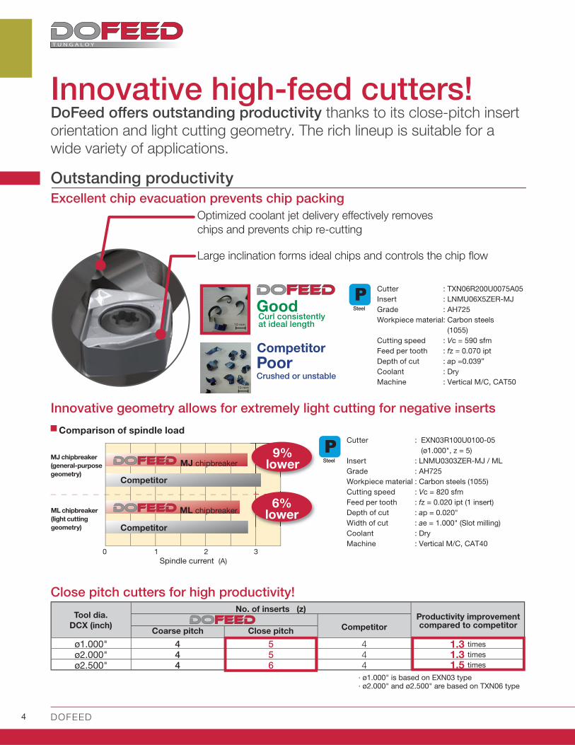
ø1.000" 4 5 4ø2.000" 4 5 4ø2.500" 4 6 4
Excellent chip evacuation prevents chip packing
MJ chipbreaker
(general-purpose
geometry)
ML chipbreaker
(light cutting
geometry)
Competitor
Innovative geometry allows for extremely light cutting for negative inserts
Large inclination forms ideal chips and controls the chip fl ow
Optimized coolant jet delivery eff ectively removes
chips and prevents chip re-cutting
Crushed or unstable
Curl consistently at ideal length10 mm
10 mm
: EXN03R100U0100-05
(ø1.000", z = 5)
: LNMU0303ZER-MJ / ML
: AH725
: Carbon steels (1055)
: Vc = 820 sfm
: fz = 0.020 ipt (1 insert)
: ap = 0.020"
: ae = 1.000" (Slot milling)
: Dry
: Vertical M/C, CAT40
Tool dia.
DCX (inch)Productivity improvement compared to competitor
1.3 times
1.3 times
1.5 times
Cutter
Insert
Grade
Workpiece material
Cutting speed
Feed per tooth
Depth of cut
Coolant
Machine
Competitor
No. of inserts (z)
Competitor
Competitor
Spindle current (A)
MJ chipbreaker
ML chipbreaker
Cutter
Insert
Grade
Workpiece material
Cutting speed
Feed per tooth
Depth of cut
Width of cut
Coolant
Machine
6%lower
9%lower
Comparison of spindle load
Good
Poor
Coarse pitch Close pitch
Close pitch cutters for high productivity!
Innovative high-feed cutters! DoFeed off ers outstanding productivity thanks to its close-pitch insert orientation and light cutting geometry. The rich lineup is suitable for a wide variety of applications.
Outstanding productivity
∙ ø1.000" is based on EXN03 type ∙ ø2.000" and ø2.500" are based on TXN06 type
Steel
Steel
: TXN06R200U0075A05
: LNMU06X5ZER-MJ
: AH725
: Carbon steels
(1055)
: Vc = 590 sfm
: fz = 0.070 ipt
: ap =0.039”
: Dry
: Vertical M/C, CAT50

w w w . t u n g a l o y . c o m / u s 5
A CC E L E R A T E D M A C H I N I N G
0 250 500 750 1000
MJGeneral machining ML Low cutting force
Optimal rake angle
Optimal rake angle
Large rake angle
Large landSmall land
4 cutting edges- Excellent combination of sharpness and
strength
- Ideal for machining steel, cast iron and hardened steel
4 cutting edges- Exceptional sharpness- Suitable for cutting stainless steel, titanium
alloys and other exotic materials- Reduces chattering when cutting with low
rigid set-ups
2 cutting edges- Excellent surface fi nish
while maintaining high productivity
Four chipbreakers and wiper insert for all machining needs
WWiper insert
LNGU06-W
Extensive application coverage with a large variety of items
MH Robust cutting edges
4 cutting edges- Robust cutting edges- Suitable for hardened steel
Small rake angle
Nega Land
MS For stainless steel
4 cutting edges- Sharp cutting edge- Most suited for stainless steel milling
Tool life comparison in stainless steel milling
MS chipbreaker - features
- Sharp cutting edge ensures light cutting, while preventing built-up edge to ensure long tool life during stainless steel machining
- Large inclination on the cutting edge reduces impact at the entry of the cut, eliminating chatter or chipping
Cutter
Insert
Grade
Workpiece material
Cutting speed
Feed per tooth
Depth of cut
Width of cut
Coolant
Machine
: EXN03R020M20.0-04-C
(ø20 mm, z = 4)
: LNMU0303ZER-MS
: AH130
: S30400
: Vc = 490 sfm
: fz = 0.024 ipt
: ap = 0.024"
: ae = 0.400 "
: Dry
: Vertical M/C, CAT40
Competitor
Machining length (ft)
Large inclination on cutting edge
Stainless
Tool lifeTool life
1.71.7 times times!!
6 DOFEED
AH725
AH120
AH130AH3035
AH8015 AH8005
New AH3225
AH3225
0 500 1000 1500 2000
- Exceptionally wear resistance in cast iron
machining
Stainless StainlessSuperalloys SuperalloysSteel Steel Cast iron
Cast iron
Hard Materials
- Superior grade for all general machining
applications.
- Excellent wear and fracture resistance in
cast iron machining.
- High chipping resistance
- Ideal for titanium alloy machining
- High wear, chipping resistance and
minimized built up edge due to nano
multi-layered AlTiN coating with high Al
content
- Well-suited for diffi cult materials of 45-55
HRc
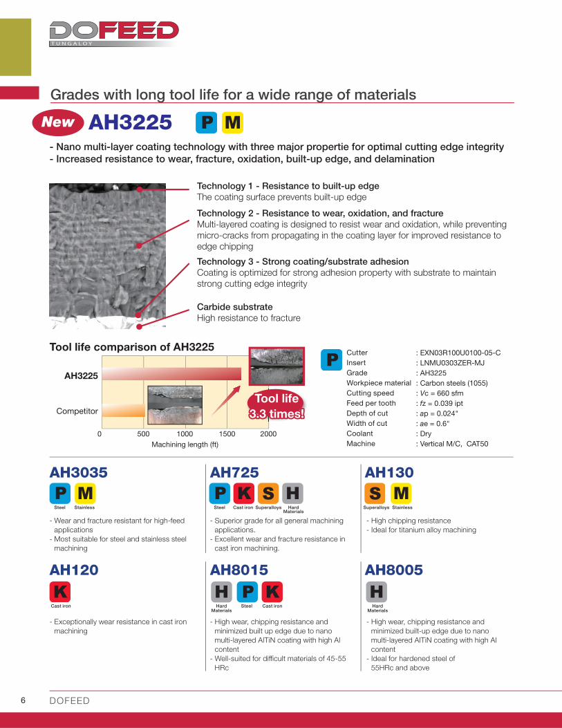
Grades with long tool life for a wide range of materials
- Wear and fracture resistant for high-feed
applications
- Most suitable for steel and stainless steel
machining
Hard Materials
Steel Cast iron
- High wear, chipping resistance and
minimized built-up edge due to nano
multi-layered AlTiN coating with high Al
content
- Ideal for hardened steel of
55HRc and above
Hard Materials
Technology 1 - Resistance to built-up edge
The coating surface prevents built-up edge
Technology 2 - Resistance to wear, oxidation, and fracture
Multi-layered coating is designed to resist wear and oxidation, while preventing
micro-cracks from propagating in the coating layer for improved resistance to
edge chipping
- Nano multi-layer coating technology with three major propertie for optimal cutting edge integrity
- Increased resistance to wear, fracture, oxidation, built-up edge, and delamination
Technology 3 - Strong coating/substrate adhesion
Coating is optimized for strong adhesion property with substrate to maintain
strong cutting edge integrity
Carbide substrate
High resistance to fracture
Competitor
Cutter
Insert
Grade
Workpiece material
Cutting speed
Feed per tooth
Depth of cut
Width of cut
Coolant
Machine
: EXN03R100U0100-05-C
: LNMU0303ZER-MJ
: AH3225
: Carbon steels (1055)
: Vc = 660 sfm
: fz = 0.039 ipt
: ap = 0.024"
: ae = 0.6"
: Dry
: Vertical M/C, CAT50Machining length (ft)
Tool life comparison of AH3225
Tool lifeTool life
3.33.3 times times!!
w w w . t u n g a l o y . c o m / u s 7
A CC E L E R A T E D M A C H I N I N G
0 10 20 30 40 50
Superalloys
Cutter
Insert
Grade
Workpiece material
Cutting speed
Feed per tooth
Depth of cut
Width of cut
Coolant
Process
Machine
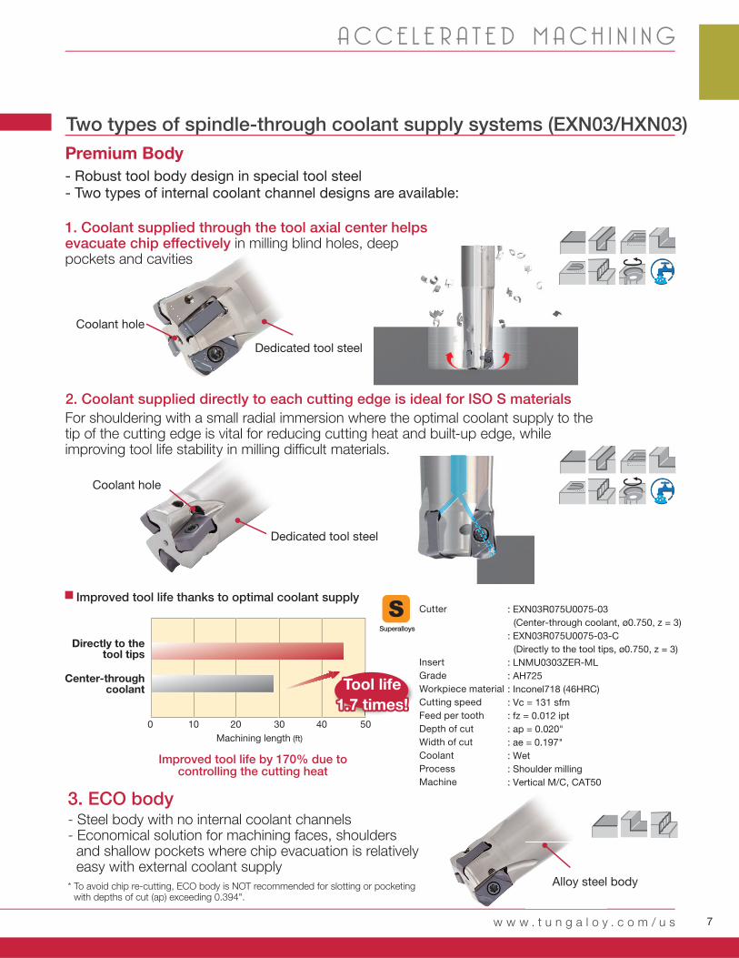
: EXN03R075U0075-03
(Center-through coolant, ø0.750, z = 3)
: EXN03R075U0075-03-C
(Directly to the tool tips, ø0.750, z = 3)
: LNMU0303ZER-ML
: AH725
: Inconel718 (46HRC)
: Vc = 131 sfm
: fz = 0.012 ipt
: ap = 0.020"
: ae = 0.197"
: Wet
: Shoulder milling
: Vertical M/C, CAT50
Two types of spindle-through coolant supply systems (EXN03/HXN03)
1. Coolant supplied through the tool axial center helps evacuate chip eff ectively in milling blind holes, deep pockets and cavities
2. Coolant supplied directly to each cutting edge is ideal for ISO S materials
Coolant hole
Coolant hole
For shouldering with a small radial immersion where the optimal coolant supply to the tip of the cutting edge is vital for reducing cutting heat and built-up edge, while improving tool life stability in milling diffi cult materials.
Improved tool life thanks to optimal coolant supply
Premium Body
- Robust tool body design in special tool steel- Two types of internal coolant channel designs are available:
Dedicated tool steel
Dedicated tool steel
Directly to the tool tips
Center-through coolant
Machining length (ft)
Tool lifeTool life
1.71.7 times times!!
3. ECO body- Steel body with no internal coolant channels- Economical solution for machining faces, shoulders
and shallow pockets where chip evacuation is relatively easy with external coolant supply
Alloy steel body* To avoid chip re-cutting, ECO body is NOT recommended for slotting or pocketing with depths of cut (ap) exceeding 0.394".
Improved tool life by 170% due to controlling the cutting heat

8 DOFEED
Inch APMX DCX CICT DC1 DC2 DCSFMS DCONMS CBDP LF b KWW KAPR WT (lb) Air hole Insert
TXN03R150U0050A05 0.039 1.500 5 1.248 1.247 1.460 0.500 0.750 1.575 0.160 0.252 17º 0.530 LN*U03...
TXN03R150U0050A06 0.039 1.500 6 1.248 1.247 1.380 0.500 0.600 1.575 0.160 0.252 17º 0.510 LN*U03...
TXN03R200U0075A05 0.039 2.000 5 1.718 1.757 1.693 0.750 0.750 1.969 0.197 0.315 17º 1.100 LN*U03...
TXN03R200U0075A08 0.039 2.000 8 1.718 1.757 1.693 0.750 0.750 1.969 0.197 0.315 17º 1.100 LN*U03...
TXN03R200U0075A10 0.039 2.000 10 1.718 1.757 1.693 0.750 0.750 1.969 0.197 0.315 17º 1.100 LN*U03...
GAMP = +6°,GAMF = +12° ~ 13°
TXN03
EXN03
HXN03CAT30
0.625 0.750 1.000 1.250 1.500 2.000 2.500 3.000 6.000
CAT40
CAT50 TXN06
EXN06
DCXDC1
CBDP
b
LF
DCSFMSDCONMSKWW
KAPR
APMX
DC2DCX
TXN03... CSPB-2.5 M-1000 C0.375X1.125H IP-8D
Super high feed mi l l ing cutters with double s ided inserts with 4 edges
TXN03
Mach
ine s
ize
Tool dia. : DCX (in)
Applicable area
Rich lineup of cutter bodies from ø0.625" to ø6.000"
TXN03 (DCX = 1.500" - 2.000")
TXN06 (DCX = 2.000" - 6.000")
EXN03 (DCX = 0.625" - 1.250")
EXN06 (DCX = 1.250" - 1.500")
HXN03 (DCX = 16 - 32 mm
0.630" - 1.260")
Max. ap = 0.039"
Max. ap = 0.059"
LN*U06
LNMU03
Insert Bore type Shank type Modular type
With LNGU03-MH
With LNMU03-MJ/ML
With
With
With
With
With
*Recommended clamping torque : CSPB-2.5=0.96 lbf·ft
SPARE PARTS
Clamping screw LubricantDesignation WrenchShell locking bolt(optional parts)

w w w . t u n g a l o y . c o m / u s 9
A CC E L E R A T E D M A C H I N I N G
LFLH
DCX
DC1
DCON
MS
KAPR
APMXLS
DCX
DC2
Super high feed mi l l ing endmil ls with double s ided inserts with 4 edges
(Through-center coolant supply)
EXN03
EXN03... CSPB-2.5 M-1000 IP-8D
Inch APMX DCX CICT DC DC2 DCONMS LF LH LS KAPR WT(Ib) Air hole InsertEXN03R062U0062-02 0.039 0.625 2 0.372 0.381 0.625 4.000 1.250 2.750 15º 0.310 LN*U03...
EXN03R062U0062-02L 0.039 0.625 2 0.372 0.381 0.625 6.000 2.000 4.000 15º 0.460 LN*U03...
EXN03R068U0062-02 0.039 0.688 2 0.434 0.436 0.625 4.000 1.250 2.750 17º 0.310 LN*U03...
EXN03R068U0062-02L 0.039 0.688 2 0.434 0.436 0.625 6.000 1.000 5.000 17º 0.490 LN*U03...
EXN03R075U0075-02 0.039 0.750 2 0.495 0.498 0.750 5.000 2.000 3.000 17º 0.550 LN*U03...
EXN03R075U0075-03 0.039 0.750 3 0.495 0.498 0.750 5.000 2.000 3.000 17º 0.550 LN*U03...
EXN03R075U0075-03L 0.039 0.750 3 0.495 0.498 0.750 6.500 3.500 3.000 17º 0.710 LN*U03...
EXN03R087U0075-02 0.039 0.875 2 0.621 0.623 0.750 5.000 2.000 3.000 17º 0.570 LN*U03...
EXN03R087U0075-03 0.039 0.875 3 0.621 0.623 0.750 5.000 2.000 3.000 17º 0.570 LN*U03...
EXN03R087U0075-03L 0.039 0.875 3 0.621 0.623 0.750 6.500 1.250 5.250 17º 0.750 LN*U03...
EXN03R100U0100-04 0.039 1.000 4 0.746 0.748 1.000 5.500 2.500 3.000 17º 1.080 LN*U03...
EXN03R100U0100-04L 0.039 1.000 4 0.746 0.748 1.000 7.000 4.000 3.000 17º 1.340 LN*U03...
EXN03R100U0100-05 0.039 1.000 5 0.746 0.748 1.000 5.500 2.500 3.000 17º 1.080 LN*U03...
EXN03R112U0100-04 0.039 1.125 4 0.871 0.872 1.000 5.500 2.500 3.000 17º 1.120 LN*U03...
EXN03R112U0100-04L 0.039 1.125 4 0.871 0.872 1.000 7.000 1.500 5.500 17º 1.460 LN*U03...
EXN03R112U0100-05 0.039 1.125 5 0.871 0.872 1.000 5.500 2.500 3.000 17º 1.120 LN*U03...
EXN03R125U0125-05 0.039 1.250 5 0.997 0.997 1.250 6.000 3.000 3.000 17º 1.870 LN*U03...
EXN03R125U0125-05L 0.039 1.250 5 0.997 0.997 1.250 8.000 5.000 3.000 17º 2.430 LN*U03...
EXN03R125U0125-06 0.039 1.250 6 0.997 0.997 1.250 6.000 3.000 3.000 17º 1.850 LN*U03...
with LNGU03-MHwith LNMU03-MJ/ML/MS
*Recommended clamping torque : CSPB-2.5=0.96 lbf·ft
SPARE PARTS
With
With
With
With
With
With
With
With
With
With
With
With
With
With
With
With
With
With
With
Designation Clamping screw Lubricant Wrench
10 DOFEED
GAMP = +6°,GAMF = +5° ~ +11°
GAMP = +6°, GAMF = +5° ~ +11°
LFLH
DCX
DC
DCON
MS
KAPR
APMX
DCX
LS
DC2
LFLH
DCX
DC
DCON
MS
KAPR
APMXLS
DCX
DC2
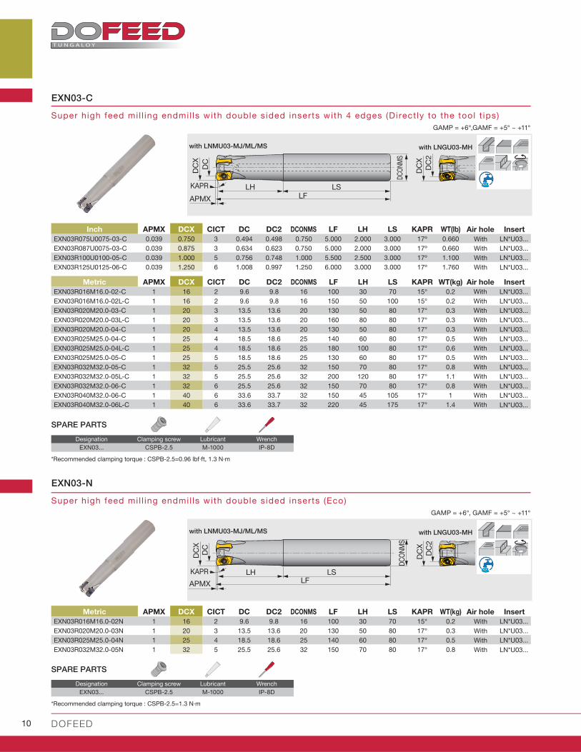
Super high feed mi l l ing endmil ls with double s ided inserts with 4 edges (Direct ly to the tool t ips)
Super high feed mi l l ing endmil ls with double s ided inserts (Eco)
EXN03-C
EXN03-N
Metric APMX DCX CICT DC DC2 DCONMS LF LH LS KAPR WT(kg)
EXN03R016M16.0-02-C 1 16 2 9.6 9.8 16 100 30 70 15° 0.2 LN*U03...EXN03R016M16.0-02L-C 1 16 2 9.6 9.8 16 150 50 100 15° 0.2 LN*U03...EXN03R020M20.0-03-C 1 20 3 13.5 13.6 20 130 50 80 17° 0.3 LN*U03...EXN03R020M20.0-03L-C 1 20 3 13.5 13.6 20 160 80 80 17° 0.3 LN*U03...EXN03R020M20.0-04-C 1 20 4 13.5 13.6 20 130 50 80 17° 0.3 LN*U03...EXN03R025M25.0-04-C 1 25 4 18.5 18.6 25 140 60 80 17° 0.5 LN*U03...EXN03R025M25.0-04L-C 1 25 4 18.5 18.6 25 180 100 80 17° 0.6 LN*U03...EXN03R025M25.0-05-C 1 25 5 18.5 18.6 25 130 60 80 17° 0.5 LN*U03...EXN03R032M32.0-05-C 1 32 5 25.5 25.6 32 150 70 80 17° 0.8 LN*U03...EXN03R032M32.0-05L-C 1 32 5 25.5 25.6 32 200 120 80 17° 1.1 LN*U03...EXN03R032M32.0-06-C 1 32 6 25.5 25.6 32 150 70 80 17° 0.8 LN*U03...EXN03R040M32.0-06-C 1 40 6 33.6 33.7 32 150 45 105 17° 1 LN*U03...EXN03R040M32.0-06L-C 1 40 6 33.6 33.7 32 220 45 175 17° 1.4 LN*U03...
Inch APMX DCX CICT DC DC2 DCONMS LF LH LS KAPR WT(Ib)
EXN03R075U0075-03-C 0.039 0.750 3 0.494 0.498 0.750 5.000 2.000 3.000 17º 0.660 LN*U03...EXN03R087U0075-03-C 0.039 0.875 3 0.634 0.623 0.750 5.000 2.000 3.000 17º 0.660 LN*U03...EXN03R100U0100-05-C 0.039 1.000 5 0.756 0.748 1.000 5.500 2.500 3.000 17º 1.100 LN*U03...EXN03R125U0125-06-C 0.039 1.250 6 1.008 0.997 1.250 6.000 3.000 3.000 17º 1.760 LN*U03...
Metric APMX DCX CICT DC DC2 DCONMS LF LH LS KAPR WT(kg)
EXN03R016M16.0-02N 1 16 2 9.6 9.8 16 100 30 70 15° 0.2 LN*U03...EXN03R020M20.0-03N 1 20 3 13.5 13.6 20 130 50 80 17° 0.3 LN*U03...EXN03R025M25.0-04N 1 25 4 18.5 18.6 25 140 60 80 17° 0.5 LN*U03...EXN03R032M32.0-05N 1 32 5 25.5 25.6 32 150 70 80 17° 0.8 LN*U03...
EXN03... CSPB-2.5 M-1000 IP-8D
EXN03... CSPB-2.5 M-1000 IP-8D
WithWithWithWithWithWithWithWithWithWithWithWithWith
Air hole Insert
WithWithWithWith
WithWithWithWith
Air hole Insert
Air hole Insert
SPARE PARTS
SPARE PARTS
Designation Clamping screw Lubricant Wrench
Designation Clamping screw Lubricant Wrench
*Recommended clamping torque : CSPB-2.5=0.96 lbf·ft, 1.3 N·m
*Recommended clamping torque : CSPB-2.5=1.3 N·m
with LNGU03-MH
with LNGU03-MH
with LNMU03-MJ/ML/MS
with LNMU03-MJ/ML/MS

w w w . t u n g a l o y . c o m / u s 11
A CC E L E R A T E D M A C H I N I N G
GAMP = +6°,GAMF = +5° ~ +11°
GAMP = +6°,GAMF = +5° ~ +11°
DCSF
MS
OALLF
DC
XD
C1
APMX
HCRKS
A
AKAPR A-A cross section
DC
XD
C2
DCSF
MS
OALLF
DC
XD
C
APMX
HCRKS
A
A A-A cross section
DC
X
DC
2
KAPR
Super high feed mi l l ing endmil ls (Dofeed) with TungFlex (Through-center coolant supply)
Super high feed mi l l ing endmil ls (Dofeed) with TungFlex (Direct ly to the tool t ips)
HXN03
HXN03-C
HXN03... CSPB-2.5 M-1000 IP-8D
HXN03... CSPB-2.5 M-1000 IP-8D
Metric APMX DCX CICT DC DC2 OAL LF H DCSFMS KAPR CRKS WT(kg)
HXN03R016MM08-02 1 16 2 9.6 9.8 42 25 10 12.8 15° M8 0.03 LN*U03...
HXN03R018MM08-02 1 18 2 11.5 11.7 42 25 10 14.5 17° M8 0.04 LN*U03...
HXN03R020MM10-03 1 20 3 13.5 13.6 49 30 15 17.8 17° M10 0.06 LN*U03...
HXN03R020MM10-04 1 20 4 13.5 13.6 49 30 15 17.8 17° M10 0.06 LN*U03...
HXN03R022MM10-03 1 22 3 15.5 15.6 49 30 15 17.8 17° M10 0.06 LN*U03...
HXN03R022MM10-04 1 22 4 15.5 15.6 49 30 15 17.8 17° M10 0.07 LN*U03...
HXN03R025MM12-04 1 25 4 18.5 18.6 57 35 17 20.8 17° M12 0.1 LN*U03...
HXN03R025MM12-05 1 25 5 18.5 18.6 57 35 17 20.8 17° M12 0.11 LN*U03...
HXN03R028MM12-04 1 28 4 21.5 21.6 57 35 17 23 17° M12 0.12 LN*U03...
HXN03R028MM12-05 1 28 5 21.5 21.6 57 35 17 23 17° M12 0.12 LN*U03...
HXN03R030MM16-04 1 30 4 23.5 23.6 63 40 22 28.8 17° M16 0.19 LN*U03...
HXN03R030MM16-05 1 30 5 23.5 23.6 63 40 22 28.8 17° M16 0.2 LN*U03...
HXN03R032MM16-05 1 32 5 25.5 25.6 63 40 22 28.8 17° M16 0.2 LN*U03...
HXN03R032MM16-06 1 32 6 25.5 25.6 63 40 22 28.8 17° M16 0.21 LN*U03...
Metric APMX DCX CICT DC DC2 OAL LF H DCSFMS KAPR CRKS WT(kg)
HXN03R016MM08-02-C 1 16 2 9.6 9.8 42 25 10 12.8 15° M8 0.03 LN*U03...
HXN03R020MM10-03-C 1 20 3 13.5 13.6 49 30 15 17.8 17° M10 0.06 LN*U03...
HXN03R020MM10-04-C 1 20 4 13.5 13.6 49 30 15 17.8 17° M10 0.06 LN*U03...
HXN03R025MM12-04-C 1 25 4 18.5 18.6 57 35 17 20.8 17° M12 0.1 LN*U03...
HXN03R025MM12-05-C 1 25 5 18.5 18.6 57 35 17 20.8 17° M12 0.1 LN*U03...
HXN03R032MM16-05-C 1 32 5 25.5 25.6 63 40 22 28.8 17° M16 0.2 LN*U03...
HXN03R032MM16-06-C 1 32 6 25.5 25.6 63 40 22 28.8 17° M16 0.2 LN*U03...
HXN03R040MM16-06-C 1 40 6 33.6 33.7 63 40 22 28.8 17° M16 0.27 LN*U03...
With LNGU03-MH
with LNMU03-MJ/ML/MS
SPARE PARTS
SPARE PARTS
Designation Clamping screw Lubricant Wrench
Designation Clamping screw Lubricant Wrench
*Recommended clamping torque : CSPB-2.5=1.3 N·m
*Recommended clamping torque : CSPB-2.5=1.3 N·m
Air hole Insert
Air hole Insert
With
With
With
With
With
With
With
With
With
With
With
With
With
With
With
With
With
With
With
With
With
With
with LNGU03-MH
with LNMU03-MJ/ML/MS
12 DOFEED
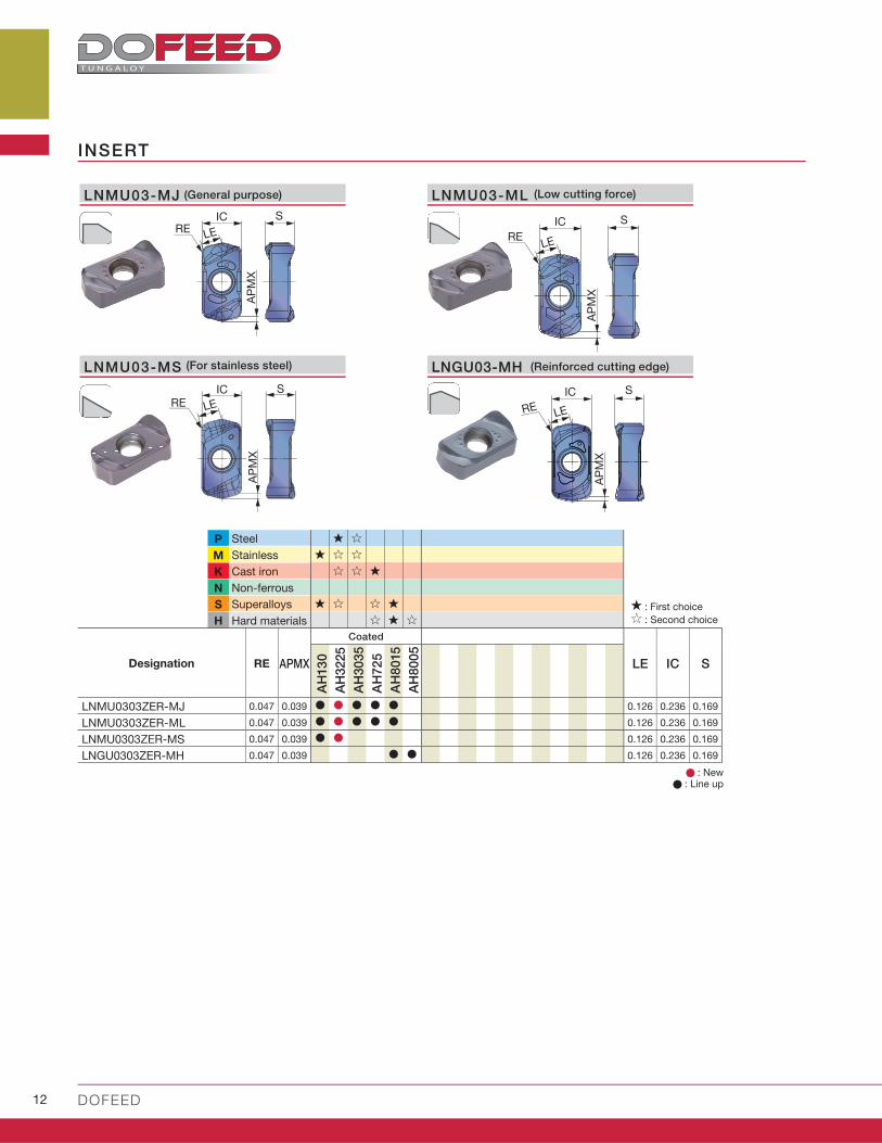
LNMU03-MJ
IC
LES
RE
AP
MX
LNMU03-ML
IC
LE
SRE
AP
MX
IC
LE
S
RE
AP
MX
LNGU03-MH
ICLE
SRE
AP
MX
P
M
K
N
S
H
RE APMX LE IC S
AH
13
0
AH
3225
AH
3035
AH
72
5
AH
8015
AH
80
05
LNMU0303ZER-MJ 0.047 0.039 0.126 0.236 0.169
LNMU0303ZER-ML 0.047 0.039 0.126 0.236 0.169
LNMU0303ZER-MS 0.047 0.039 0.126 0.236 0.169
LNGU0303ZER-MH 0.047 0.039 0.126 0.236 0.169
LNMU03-MS
INSERT
: New : Line up
: First choice : Second choice
SteelStainlessCast ironNon-ferrousSuperalloysHard materials
Designation
Coated
(General purpose) (Low cutting force)
(For stainless steel) (Reinforced cutting edge)
w w w . t u n g a l o y . c o m / u s 13
A CC E L E R A T E D M A C H I N I N G
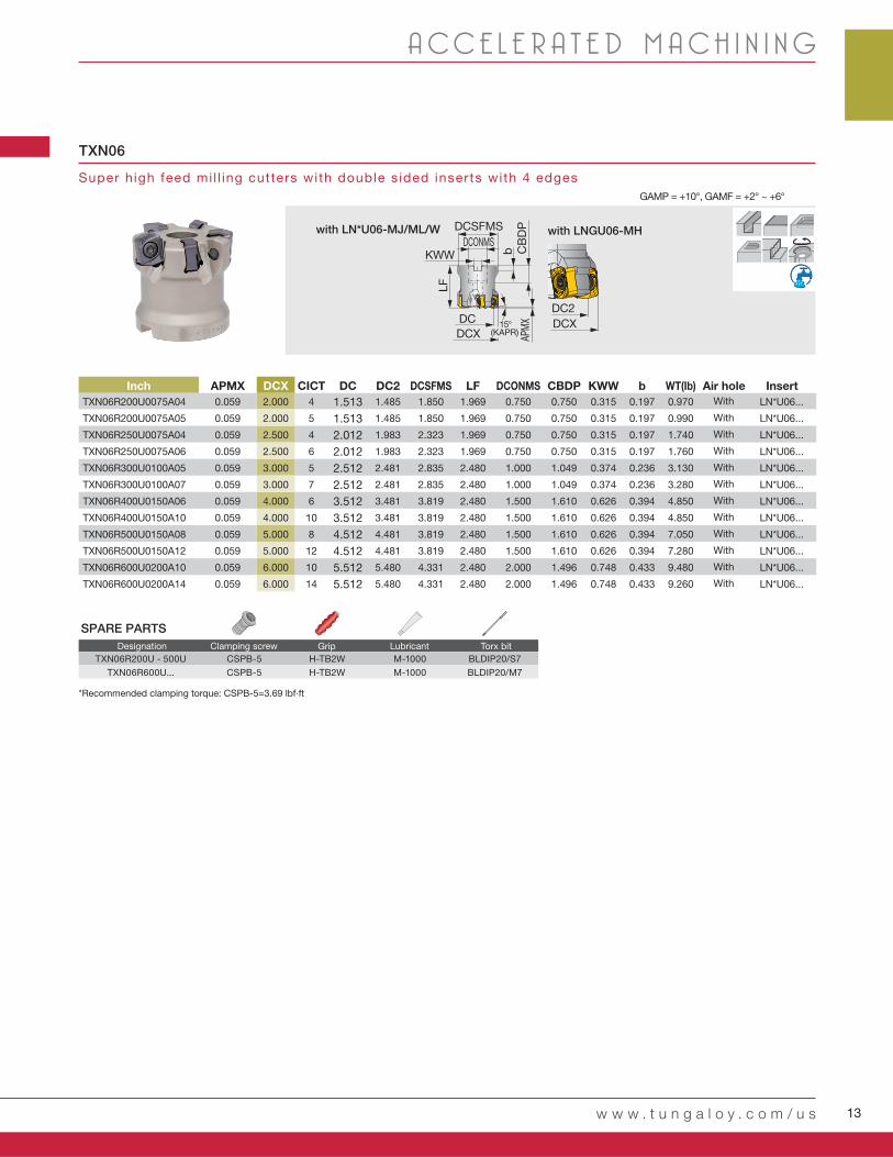
GAMP = +10°, GAMF = +2° ~ +6°
Super high feed mi l l ing cutters with double s ided inserts with 4 edges
TXN06
LF
CB
DP
DCXDC
DCSFMSDCONMS
KWW bAP
MX DCXDC2
15°(KAPR)
Inch APMX DCX CICT DC DC2 DCSFMS LF DCONMS CBDP KWW b WT(Ib)
TXN06R200U0075A04 0.059 2.000 4 1.513 1.485 1.850 1.969 0.750 0.750 0.315 0.197 0.970 LN*U06...
TXN06R200U0075A05 0.059 2.000 5 1.513 1.485 1.850 1.969 0.750 0.750 0.315 0.197 0.990 LN*U06...
TXN06R250U0075A04 0.059 2.500 4 2.012 1.983 2.323 1.969 0.750 0.750 0.315 0.197 1.740 LN*U06...
TXN06R250U0075A06 0.059 2.500 6 2.012 1.983 2.323 1.969 0.750 0.750 0.315 0.197 1.760 LN*U06...
TXN06R300U0100A05 0.059 3.000 5 2.512 2.481 2.835 2.480 1.000 1.049 0.374 0.236 3.130 LN*U06...
TXN06R300U0100A07 0.059 3.000 7 2.512 2.481 2.835 2.480 1.000 1.049 0.374 0.236 3.280 LN*U06...
TXN06R400U0150A06 0.059 4.000 6 3.512 3.481 3.819 2.480 1.500 1.610 0.626 0.394 4.850 LN*U06...
TXN06R400U0150A10 0.059 4.000 10 3.512 3.481 3.819 2.480 1.500 1.610 0.626 0.394 4.850 LN*U06...
TXN06R500U0150A08 0.059 5.000 8 4.512 4.481 3.819 2.480 1.500 1.610 0.626 0.394 7.050 LN*U06...
TXN06R500U0150A12 0.059 5.000 12 4.512 4.481 3.819 2.480 1.500 1.610 0.626 0.394 7.280 LN*U06...
TXN06R600U0200A10 0.059 6.000 10 5.512 5.480 4.331 2.480 2.000 1.496 0.748 0.433 9.480 LN*U06...
TXN06R600U0200A14 0.059 6.000 14 5.512 5.480 4.331 2.480 2.000 1.496 0.748 0.433 9.260 LN*U06...
TXN06R200U - 500U CSPB-5 H-TB2W M-1000 BLDIP20/S7
TXN06R600U... CSPB-5 H-TB2W M-1000 BLDIP20/M7
with LNGU06-MHwith LN*U06-MJ/ML/W
With
With
With
With
With
With
With
With
With
With
With
With
Air hole Insert
*Recommended clamping torque: CSPB-5=3.69 lbf·ft
SPARE PARTS
Clamping screw LubricantDesignation Torx bitGrip

14 DOFEED
Super high feed mi l l ing endmil ls with double s ided inserts with 4 edges
EXN06
LFLH LS
DCX
DC
DCONMS
APMX
15°
DCX
DC2
GAMP=+10°,GAMF= -2°~+6°
EXN06 CSPB-5 M-1000 IP-20D
Inch APMX DCX CICT DC DC2 DCONMS LF LH LS WT(Ib)
EXN06R125U0125W02 0.059 1.250 2 0.766 0.745 1.250 5.281 3.000 2.281 1.540 LN*U06...
EXN06R125U0125-02L 0.059 1.250 2 0.766 0.745 1.250 8.000 5.000 3.000 2.360 LN*U06...
EXN06R150U0125W03 0.059 1.500 3 1.014 0.989 1.250 5.781 3.500 2.281 1.830 LN*U06...
EXN06R150U0125-03L 0.059 1.500 3 1.014 0.989 1.250 10.000 2.000 8.000 3.310 LN*U06...
with LNGU06-MHwith LN*U06-MJ/ML/W
Clamping screw LubricantDesignation Wrench
Air hole Insert
With
With
With
With
SPARE PARTS
*Recommended clamping torque: CSPB-5=3.69 lbf·ft
w w w . t u n g a l o y . c o m / u s 15
A CC E L E R A T E D M A C H I N I N G
P
M
K
N
S
H
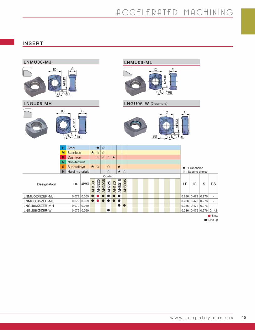
RE APMX LE IC S BS
AH
13
0
AH
3225
AH
3035
AH
72
5
AH
12
0
AH
8015
AH
80
05
LNMU06X5ZER-MJ 0.079 0.059 0.236 0.472 0.276 -
LNMU06X5ZER-ML 0.079 0.059 0.236 0.472 0.276 -
LNGU06X5ZER-MH 0.079 0.059 0.236 0.472 0.276 -
LNGU06X5ZER-W 0.079 0.059 0.236 0.472 0.276 0.142
IC
LEBS
S
RE
AP
MX
IC
LE
S
RE
AP
MX
LNGU06-MH LNGU06-W
IC
LE
S
RE
AP
MX
IC S
LE
AP
MX
RE
LNMU06-MJ LNMU06-ML
INSERT
SteelStainlessCast ironNon-ferrousSuperalloysHard materials
Coated
: New
: Line up
: First choice : Second choice
Designation
(2 corners)

16 DOFEED
0.040
0.028
0.020
0.012
0
RE17°
LE RPG
t1
RPG
t2
t1
APMX (in) RE (in)LE (in)
RPG t1 (in) t2 (in)0.039 0.047 0.118 0.039 0.018 -
0.039 0.047 0.118 0.060 0.014 -
0.039 0.047 0.118 0.079 0.008 0.004
0.039 0.047 0.118 0.098 0.003 0.011
Vc = 330 - 980 sfm
Vc = 260 - 650 sfm
APMX (in) RE (in)LE (in)
RPG t1 (in) t2 (in)0.039 0.047 0.118 0.039 0.018 -
0.039 0.047 0.118 0.060 0.014 -
0.039 0.047 0.118 0.079 0.008 0.004
0.039 0.047 0.118 0.098 0.003 0.011
ISO
ø0.625", CICT = 2 ø0.688", CICT = 2 ø0.75
Vc (sfm)
ø0.625 ~ ø0.875
ø1.000 ~ ø2.000
n Vf n Vf n VfCICT = 2 CICT = 3
- 300HB AH3225 MJ 330 - 9800.020
- 0.0470.020
- 0.0590.004
4,030 250 3,660 227 3,360 208 312
Vc = 660 sfm, fz = 0.031 ipt
- 300HB AH3225 MJ 330 - 9800.020
- 0.0470.020
- 0.0590.004
4,030 250 3,660 227 3,360 208 312
Vc = 660 sfm, fz = 0.031 ipt
30 - 40HRC
AH3225 MJ 330 - 6600.020
- 0.0390.020
- 0.0390.004
2,990 167 2,720 152 2,500 140 210
Vc = 490 sfm, fz = 0.028 ipt
30 - 40HRC
AH8015 MJ 330 - 6600.020
- 0.0390.020
- 0.0390.004
2,990 167 2,720 152 2,500 140 210
Vc = 490 sfm, fz = 0.028 ipt
- 200HB AH130 MS 260 - 4900.012
- 0.0310.012
- 0.0310.004
2,380 95 2,170 87 1,990 80 119
Vc = 390 sfm, fz = 0.02 ipt
28HRC -(H1150)
AH130 MS260 - 490
0.008 - 0.020
0.008 - 0.020
0.004 2,380 57 2,170 52 1,990 48 72
AH3225 MS Vc = 390 sfm, fz = 0.012 ipt
40HRC -(H900)
AH3035 ML260 - 390
0.004 - 0.012
0.004 - 0.012
0.004 2,020 32 1,830 29 1,680 27 40
AH3035 MJ Vc = 330 sfm, fz = 0.008 ipt
150 - 250HB
AH725 MJ 330 - 9800.020
- 0.0470.020
- 0.0590.004
4,030 250 3,660 227 3,360 208 312
Vc = 660 sfm, fz = 0.031 ipt
150 - 250HB
AH725 MJ 260 - 6600.020
- 0.0470.020
- 0.0590.004
2,990 185 2,720 169 2,500 155 233
Vc = 490 sfm, fz = 0.031 ipt
- 40HRCAH130 ML
100 - 200 0.012- 0.028
0.012- 0.028
0.003 790 25 720 23 660 21 32
AH130 MJ Vc = 130 sfm, fz = 0.016 ipt
- 40HRCAH8015 ML
70 - 1600.004
- 0.0120.004
- 0.0120.002
610 10 560 9 510 8 12
AH725 ML Vc = 100 sfm, fz = 0.008 ipt
40 - 55HRC
AH8015 MH260 - 490
0.004 - 0.020 0.004 - 0.0200.002
2,390 57 2,170 52 1,990 48 72
AH8015 MJ 0.004 - 0.012 0.004 - 0.012 Vc = 390 sfm, fz = 0.012 ipt
40 - 55HRC
AH8015 MJ160 - 330
0.004 - 0.012 0.004 - 0.0120.002
1,590 25 1,440 23 1,320 21 32
AH8015 MH 0.004 - 0.020 0.004 - 0.020 Vc = 260 sfm, fz = 0.008 ipt
55 - 60HRC
AH8005 MH 160 - 2300.002
- 0.008 0.001
- 0.0040.001
1,220 12 1,110 11 1,020 10 15
Vc = 200 sfm, fz = 0.005 ipt
55 - 60HRC
AH8015 MH 160 - 2300.001
- 0.0040.002
- 0.008 0.001
1,220 5 1,110 4 1,020 4 6
Vc = 200 sfm, fz = 0.002 ipt
Tool geometry on programmingThe use of a standard or long shank
Cautionary points in use
Tool dia.: DCX = ø0.625" - 1.250"Workpiece: 1015 (200HB)
L/D ratio of overhangStandard shank: L/D ≤ 3Long shank: L/D = 4
When using a long shank, please lower the cutting conditions (Vc, fz, ap) to 70% of the maximum conditions for the standard shank.
When programming for CAM, the tool should be considered as a radius cutter. Usually, the corner radius should be set as R = 0.060". If a larger radius is used, overcutting will occur. The following table shows the amount left uncut (t1) and overcut (t2).
Amount left overcut
- When chips stay in the cutting zone during slotting or pocketing, use air blast to remove chips from the work area.
- Tool overhang length must be as short as possible to avoid chatter. When the tool overhang length is long, decrease the number of revolutions and feed.
Standard shank
Long shank
Dep
th o
f cu
t:ap
(in
)
Feed per tooth: fz (ipt)
Max. d
ep
th
of
cut
Corner R when programming
Amount leftuncut
Each value in table is calculated theoretically at the maximum condition.
LNGU03-MH
LNMU03-MJ/ML
Corner R whenprogramming:
Corner R whenprogramming:
Corner radius
Corner radius
Max. depth of cut
Max. depth of cut
Amount leftuncut
Amount leftuncut
Amount left overcut
Amount left overcut
0.020 0.031 0.039 0.059
STANDARD CUTTING CONDITIONS TXN03/EXN03/HXN03
Plunging Chip-
breaker
Cutting speed
Feed per tooth: fz (ipt)Tool dia.: DCX (in)
Workpiece material Hardness Priority Grade
First choice
First choice
First choice
for wear resistance
First choice
First choice
for wear resistanceFirst choice
for impact resistance
First choice
First choice
First choice
for impact resistance
First choice
for impact resistance
First choice
Low resistance
First choice
for impact resistance
First choice
for impact resistance
Carbon steels
(S45C / C45, S55C / C55, etc.)
Alloy steels
(SCM440 / 42CrMo4, etc.)
Prehardened steels
(NAK80, PX5, etc.)
Austenitic stainless steels
(SUS304 / X5CrNi18-9, etc.)
Precipitation hardening
stainless steels (SUS630 /
X5CrNiCuNb16-4)
Gray cast irons
(FC250 / GG25 / 250, etc.)
Ductile cast irons
(FCD400, etc.)
Titanium alloy
(Ti-6Al-4V, etc.)
Heat-resistant alloy
(Inconel, Hastelloy, etc.)
Hot mold steel
(SKD61 / X40CrMoV5-1, etc.)
Hot mold steel of D.T.C materials
(DAC**, DH**, DIEVER, etc)
Cold mold steels
(SKD11 / X153CrMoV12,
etc.)
w w w . t u n g a l o y . c o m / u s 17
øD1, øD2
RMPX
a p A
Wae
a p
DCX APMX RMPX A W øD1 øD2 ae
EXN03R062U0062... 0.625 0.039 1.7 0.012 0.118 0.897 1.181 0.492
EXN03R068U0062... 0.688 0.039 1.7 0.012 0.118 0.991 1.339 0.571
EXN03R075U0075... 0.750 0.039 1.2 0.012 0.118 1.132 1.496 0.650
EXN03R087U0075... 0.875 0.039 1 0.012 0.118 1.371 1.654 0.728
EXN03R100U0100... 1.000 0.039 0.9 0.012 0.118 1.610 1.890 0.846
EXN03R112U0100... 1.125 0.039 0.8 0.012 0.118 1.857 2.126 0.965
EXN03R125U0125... 1.250 0.039 0.7 0.012 0.118 2.104 2.441 1.122
TXN03R150U0075... 1.500 0.039 0.5 0.012 0.118 2.750 3.070 1.437
TXN03R200U0075... 2.000 0.039 0.4 0.012 0.118 3.540 3.858 1.830
ø0.875 ø1 ø1.125 ø1.25 ø1.5 ø2
n Vf n Vf n Vf n Vf n Vf n VfCICT = 2 CICT = 3 CICT = 4 CICT = 5 CICT = 4 CICT = 5 CICT = 5 CICT = 6 CICT = 5 CICT = 6 CICT = 5 CICT = 8 CICT = 10
2,880 230 346 2,520 403 504 2,240 358 448 2,020 404 485 1,680 336 403 1,260 252 403 504
Vc = 660 sfm, fz = 0.04 ipt
2,880 230 346 2,520 403 504 2,240 358 448 2,020 404 485 1,680 336 403 1,260 252 403 504
Vc = 660 sfm, fz = 0.04 ipt
2,140 120 180 1,870 209 262 1,660 186 232 1,500 210 252 1,250 175 210 940 132 211 263
Vc = 490 sfm, fz = 0.028 ipt
2,140 120 180 1,870 209 262 1,660 186 232 1,500 210 252 1,250 175 210 940 132 211 263
Vc = 490 sfm, fz = 0.028 ipt
1,700 68 102 1,490 119 149 1,320 106 132 1,190 119 143 990 99 119 740 74 118 148
Vc = 390 sfm, fz = 0.02 ipt
1,700 41 61 1,490 72 89 1,320 63 79 1,190 71 86 990 59 71 740 44 71 89
Vc = 390 sfm, fz = 0.012 ipt
1,440 23 35 1,260 40 50 1,120 36 45 1,010 40 48 840 34 40 630 25 40 50
Vc = 330 sfm, fz = 0.008 ipt
2,880 230 346 2,520 403 504 2,240 358 448 2,020 404 485 1,680 336 403 1,260 252 403 504
Vc = 660 sfm, fz = 0.04 ipt
2,140 171 257 1,870 299 374 1,660 266 332 1,500 300 360 1,250 250 300 940 188 301 376
Vc = 490 sfm, fz = 0.04 ipt
570 23 34 500 40 50 440 35 44 400 40 48 330 33 40 250 25 40 50
Vc = 130 sfm, fz = 0.02 ipt
440 7 11 380 12 15 340 11 14 310 12 15 250 10 12 190 8 12 15
Vc = 100 sfm, fz = 0.008 ipt
1,700 41 61 1,490 72 89 1,320 63 79 1,190 71 86 990 59 71 740 44 71 89
Vc = 390 sfm, fz = 0.012 ipt
1,140 18 27 990 32 40 880 28 35 790 32 38 660 26 32 500 20 32 40
Vc = 260 sfm, fz = 0.008 ipt
870 7 10 760 12 15 680 11 14 610 12 15 510 10 12 380 8 12 15
Vc = 200 sfm, fz = 0.004 ipt
870 3 5 760 6 8 680 5 7 610 6 7 510 5 6 380 4 6 8
Vc = 200 sfm, fz = 0.002 ipt
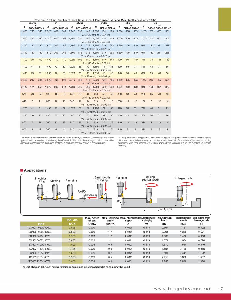
- The above table shows the conditions for standard shank type cutters. When using long shank type cutters, the number of teeth may be different. In this case, the cutting conditions should be changed by referring to: “The usage of standard and long shanks” shown in previous page.
- Cutting conditions are generally limited by the rigidity and power of the machine and the rigidity of the workpiece. When setting the conditions, start from half of the values of the standard cutting conditions and then increase the value gradually while making sure the machine is running normally.
Shoulder milling Slotting
Traversing
Small depth plungingRamping
Plunging Drilling(Helical feed) Enlarged hole
Tool dia.
· For DCX above ø1.300", slot milling, ramping or contouring is not recommended as chips may be re-cut.
Applications
Inch
Max. cutting width in enlarged hole
Max. cutting width in plunging
Max.machinablehole dia.
Min.machinablehole dia.
Max. plungingdepth
Max. depthof cut
Max. rampingangle
Tool dia.: DCX (in), Number of revolutions: n (rpm), Feed speed: Vf (ipm), Max. depth of cut: ap = 0.004"

18 DOFEED
ISOø1.25", CICT = 2 ø1.5", CICT = 3
Vc (sfm) n Vf n Vf
ø1.25" ~ ø6"
- 300HB AH3225 MJ 330 - 980 0.020 - 0.059 0.0062,020 162 1,680 202
Vc = 660 sfm, fz = 0.040 ipt
- 300HB AH3225 MJ 330 - 660 0.020 - 0.059 0.0062,020 162 1,680 202
Vc = 660 sfm, fz = 0.040 ipt
30 - 40HRC AH3225 MJ 330 - 660 0.020 - 0.047 0.0061,500 93 1,250 116
Vc = 490 sfm, fz = 0.031 ipt
30 - 40HRC AH8015 MJ 330 - 660 0.020 - 0.060 0.0061,500 120 1,250 150
Vc = 490 sfm, fz = 0.040 ipt
- 200HB AH130 ML 260 - 490 0.012 - 0.031 0.004 1,190 57 990 71
Vc = 390 sfm, fz = 0.024 ipt
28HRC - (H1150)
AH130 MS260 - 490 0.008 - 0.020 0.004
1,190 29 990 36
AH3225 MS Vc = 390 sfm, fz = 0.012 ipt
40HRC -
(H900)
AH3035 ML260 - 390 0.004 - 0.012 0.004
1,010 16 840 20
AH3035 MJ Vc = 330 sfm, fz = 0.008 ipt
150 - 250HB AH120 MJ 330 - 980 0.020 - 0.059 0.0062,020 162 1,680 202
Vc = 660 sfm, fz = 0.040 ipt
150 - 250HB AH120 MJ 260 - 660 0.020 - 0.059 0.0061,500 120 1,250 150
Vc = 490 sfm, fz = 0.040 ipt
- 40HRCAH130 ML
100 - 200 0.012 - 0.028 0.003400 16 330 20
AH130 MJ Vc = 130 sfm, fz = 0.020 ipt
- 40HRCAH8015 ML
70 - 160 0.004 - 0.012 0.002310 5 250 6
AH725 ML Vc = 100 sfm, fz = 0.008 ipt
40 - 55HRCAH8015 MH
260 - 4900.004 - 0.020
0.0021,190 29 990 36
AH8015 MJ 0.004 - 0.012 Vc = 390 sfm, fz = 0.012 ipt
40 - 55HRCAH8015 MJ
160 - 330 0.004 - 0.012
0.002790 13 660 16
AH8015 MH 0.004 - 0.020 Vc = 260 sfm, fz = 0.008 ipt
55 - 60HRC AH8005 MH 160 - 230 0.002 - 0.012 0.001610 5 510 6
Vc = 200 sfm, fz = 0.004 ipt
55 - 60HRC AH8015 MH 160 - 230 0.002 - 0.012 0.001610 2 510 3
Vc = 200 sfm, fz = 0.002 ipt
APMX (in) RE
LE (in)RPG t1 (in) t2 (in)
0.059 0.079 0.236 0.079 0.039 -
0.118 0.030 -0.157 0.021 0.010
RE15°
LE RPG
t2
t1 t1 RPG
0.020 0.039 0.059 0.078
0.060
0.040
0.020
0
Vc = 330 - 980 sfm
Vc = 260 - 650 sfm
APMX (in) RE
LE (in)RPG t1 (in) t2 (in)
0.059 0.079 0.236 0.079 0.035 -
0.118 0.026 -0.157 0.016 0.010
AP
MX
STANDARD CUTTING CONDITIONS TXN06 / EXN06
∙ The above table shows the conditions for standard shank type cutters. When using long shank type cutters, the number of teeth may be different. In this case, the cutting conditions should be changed by referring to: “The usage of standard and long shanks” shown in previous page.
∙ Cutting conditions are generally limited by the rigidity and power of the machine and the rigidity of the workpiece. When setting the conditions, start from half of the values of the standard cutting conditions and then increase the value gradually while making sure the machine is running normally.
Tool geometry on programmingWhen programming for CAM, the tool should be considered as a radius cutter. Usually, the corner radius should be set as R = 0.118". If a larger radius is used, overcutting will occur. The following table shows the amount left uncut (t1) and overcut (t2).
Amount left overcut
Max. d
ep
th o
f cut
Corner R when programmingAmount left
uncut
Corner R whenprogramming:
Corner R whenprogramming:
Corner radius
Corner radius
Max. depth of cut
Max. depth of cut
Amount leftuncut
Amount leftuncut
Amount left overcut
Amount left overcut
Each value in table is calculated theoretically at the maximum condition.
The use of a standard or long shankWhen using a long shank, please lower the cutting conditions (Vc, fz, ap) to 70% of the maximum conditions for the standard shank.
Tool dia.: DCX = ø1.250" - 1.500"Workpiece: 1055 (200HB)
L/D ratio of overhangStandard shank: L/D ≤ 3Long shank: L/D = 4
Standard shank
Long shank
Dep
th o
f cu
t:ap
(in
)
Feed per tooth: fz (ipt)
Cautionary points in use
LNGU06-MH
LNMU06-MJ/ML
Carbon steels(S45C / C45, S55C / C55, etc.)
Alloy steels (SCM440 / 42CrMo4, etc.)
Prehardened steels (NAK80, PX5, etc.)
Stainless steels (SUS304 / X5CrNi18-9, etc.)
Precipitation hardening stainless steels (SUS630 / X5CrNi-
CuNb16-4)
Gray cast irons (FC250 / GG25 / 250, etc.)
Titanium alloy (Ti-6Al-4V, etc.)
Heat-resistant alloy (Inconel, Hastelloy, etc.)
Hot mold steel (SKD61 / X40CrMoV5-1, etc.)
Hot mold steel of D.T.C materials(DAC**, DH**, DIEVER, etc)
Cold mold steels (SKD11 / X153CrMoV12, etc.)
First choice
First choice
First choice
for wear resistance
First choice
First choice
for wear resistance
First choice
for impact resistance
First choice
First choice
First choice
for impact resistance
First choice
for impact resistance
First choice
Low resistance
First choice
for impact resistance
First choice
for impact resistance
Plunging Chip-
breaker
Feed per tooth: fz (ipt)
Tool dia.: DCX (in)
Workpiece material Hardness Priority Grade
Cutting speed

w w w . t u n g a l o y . c o m / u s 19
ø2" ø2.5" ø3" ø4" ø5" ø6"
n Vf n Vf n Vf n Vf n Vf n VfCICT = 4 CICT = 5 CICT = 4 CICT = 6 CICT = 5 CICT = 7 CICT = 6 CICT = 10 CICT = 8 CICT = 12 CICT = 10 CICT = 14
1,260 202 252 1,010 162 242 840 168 235 630 151 252 500 160 240 420 168 235
Vc = 660 sfm, fz = 0.040 ipt
1,260 202 252 1,010 162 242 840 168 235 630 151 252 500 160 240 420 168 235
Vc = 660 sfm, fz = 0.040 ipt
940 117 146 750 93 140 620 96 135 470 87 146 370 92 138 310 96 135
Vc = 490 sfm, fz = 0.031 ipt
940 150 188 750 120 180 620 124 174 470 113 188 370 118 178 310 124 174
Vc = 490 sfm, fz = 0.040 ipt
740 71 89 600 58 86 500 60 84 370 53 89 300 58 86 250 60 84
Vc = 390 sfm, fz = 0.024 ipt
740 36 44 600 29 43 500 30 42 370 27 44 300 29 43 250 30 42
Vc = 390 sfm, fz = 0.012 ipt
630 20 25 500 16 24 420 17 24 320 15 26 250 16 24 210 17 24
Vc = 330 sfm, fz = 0.008 ipt
1,260 202 252 1,010 162 242 840 168 235 630 151 252 500 160 240 420 168 235
Vc = 660 sfm, fz = 0.040 ipt
940 150 188 750 120 180 620 124 174 470 113 188 370 118 178 310 124 174
Vc = 490 sfm, fz = 0.040 ipt
250 20 25 200 16 24 170 17 24 120 14 24 100 16 24 80 16 22
Vc = 130 sfm, fz = 0.020 ipt
190 6 8 150 5 7 130 5 7 100 5 8 80 5 8 60 5 7
Vc = 100 sfm, fz = 0.008 ipt
740 36 44 600 29 43 500 30 42 370 27 44 300 29 43 250 30 42
Vc = 390 sfm, fz = 0.012 ipt
500 16 20 400 13 19 330 13 18 250 12 20 200 13 19 170 14 19
Vc = 260 sfm, fz = 0.008 ipt
380 6 8 310 5 7 250 5 7 190 5 8 150 5 7 130 5 7
Vc = 200 sfm, fz = 0.004 ipt
380 3 4 310 2 4 250 3 4 190 2 4 150 2 4 130 3 4
Vc = 200 sfm, fz = 0.002 ipt
øD1, øD2
RMPXA
aeW
a p
Tool dia.
Inch DCX APMX RMPX A W øD1 øD2 ae
EXN06R125U... ø1.250 0.059 2.0º 0.020 0.236 1.830 2.300 0.970
EXN06R150U... ø1.500 0.059 1.5º 0.020 0.236 2.330 2.800 1.220
TXN06R200U... ø2.000 0.059 0.9º 0.020 0.236 3.330 3.800 1.720
TXN06R250U... ø2.500 0.059 0.6º 0.020 0.236 4.330 4.800 2.220
TXN06R300U... ø3.000 0.059 0.5º 0.020 0.236 5.330 5.800 2.720
Applications
Shoulder milling
Traversing
Small depth plunging Ramping Plunging
Drilling(Helical feed)
Enlarged hole
· For DCX above 4.000", slot milling, ramping or contouring is not recommended as chips may be re-cut.
Max. cutting width in enlarged hole
Max. cutting width in plunging
Max.machinablehole dia.
Min.machinablehole dia.
Max. plungingdepth
Max. depthof cut
Max. rampingangle
Tool dia.: DCX (mm), Number of revolutions: n (min-1), Feed speed: Vf (mm/min), Max. depth of cut: ap = 1.5 mm, Number of teeth: CICT

20 DOFEED
EXN03R100U0100-05 (ø1.000", z = 5) EXN03R100U0100-04 (ø1.000", z = 4)
LNMU0303ZER-MJ LNMU0303ZER-MJAH725 AH725
460 7200.019 0.0080.035 0.0201.000 1.000
TXN06R250U0075A04 (ø2.500", z = 4) TXN06R250U0075A06 (ø2.500", z = 6)
LNMU06X5ZER-MJ LNMU06X5ZER-MJ
AH3225 AH3035
650 3800.059 0.0280.030 0.0431.8 1.7
1009080706050403020100
100
80
60
40
20
0
6
4
2
0
1.8
1.2
0.6
0
650
New
Workpiece type CutterInsertGrade
Workpiece material
Cutting speed: Vc (sfm)
Feed per tooth: fz (ipt)
Depth of cut: ap (in)
Width of cut: ae (in)
Process
Coolant
Machine
Results
Workpiece type CutterInsertGrade
Workpiece material
Cutting speed: Vc (sfm)
Feed per tooth: fz (ipt)
Depth of cut: ap (in)
Width of cut: ae (in)
Process
Coolant
Machine
Results
Contouring
Dry
Vertical M/C, CAT50
PRACTICAL EX AMPLES
Meta
l re
mo
val ra
te:
Q (in
3/m
in)
Meta
l re
mo
val ra
te:
Q (in
3/m
in)
Prehardened steel HPM7 (30HRC)
Die & Mold / Back block
Contour milling
Air blow
Vertical M/C, CAT50
AH3035 grade showed better chipping resistance than competitor improving tool life by 50%.
Too
l lif
e (m
in)
Too
l lif
e (m
in)
Competitor Competitor
Thanks to DoFeed’s light cutting geometry, the MRR has improved by 650%, while maintaining the same level of, or even reduced, spindle load as the competitor’s tool. Chip re-cutting has signifi cantly reduced, while increasing the tool life by seven times.
Thanks to its low cutting geometry, DoFeed has improved the MRR even in the weak fi xture setting. Insert life has tripled even in high speed milling, while signifi cantly reducing insert fractures induced by thermal cracking.
Slot milling
Dry
Horizontal M/C, CAT50
Helical interpolation
Wet
Vertical M/C
SC360 (Cast steel)
Too
l lif
e (slo
t/co
rner)
Too
l lif
e
(wo
rkp
iece/c
orn
er)
S34700 (Heat resistant stainless steel)
Competitor Competitor
Tool lifeTool life
1.51.5 times times!!
Tool lifeTool life7 times!7 times!
Tool lifeTool life3 times!3 times!
ProductivityProductivity6.5 times!6.5 times!
ProductivityProductivity9.2 times!9.2 times!
Mold base Flange
Die & Mold
AH3225 reduced the damage of the bottom cutting edge, extending tool life by 4.5 times.
Tool lifeTool life
4.54.5 times times!!
Cutt
ing
co
nd
itio
ns
Cutt
ing
co
nd
itio
ns
1045 (20 - 35 HRC)

w w w . t u n g a l o y . c o m / u s 21
TXN06R300U0100A07 (ø3.000", z = 7) EXN03R125U0125-06-C (ø1.250", z = 6)
LNMU06X5ZER-ML x 6 / LNGU06X5ZER-W x 1 LNMU0303ZER-MS
AH130 / AH725 AH130
330 390
0.016 0.020
51 142
0.020 0.028
2.25 ~078
TXN06R600U0200A14 (ø6.000", z = 14) HXN03R020MM10-04 (ø0.787", z = 4)
LNMU06X5ZER-MJ LNMU0303ZER-MJ
AH120 AH725
500 620
0.040 0.016
0.020 0.012
4.700 0.354
160140120100806040200
15
12
9
6
3
0
200
150
100
50
0
360
300
240
180
120
60
0
Workpiece type CutterInsertGrade
Workpiece material
Cutting speed: Vc (sfm)
Feed per tooth: fz (ipt)
Feed speed: Vf (in)
Depth of cut: ap (in)
Width of cut: ae (in)
Process
Coolant
Machine
Results
Workpiece type CutterInsertGrade
Workpiece material
Cutting speed: Vc (sfm)
Feed per tooth: fz (ipt)
Depth of cut: ap (in)
Width of cut: ae (in)
Process
Coolant
Machine
Results
CompetitorCompetitor
Die & MoldLarge machine parts
Pocket milling
Dry (air)
Vertical M/C, CAT40
Face milling
Dry
Horizontal M/C, CAT50
Cutt
ing
tim
e (m
in)
Meta
l re
mo
val ra
te:
Q (cc/m
in)
Due to the lower cutting forces, DoFeed can increase the productivity 4 times higher. AH725 grade can eff ectively reduce sudden fracture, achieving double tool life.
DoFeed, with high density insert, can eff ectively increase productivity. Lower cutting forces reduce chattering, achieving 1.5 times tool life.
80-55-0680-55-06
S30400
Machine frame
Cutt
ing
tim
e (m
in/p
cs)
S17400
Automotive / Rod end
Face millingInternal supply
Turning center / 7.5 kW
DoFeed is a versatile cutter and was used against a shoulder milling cutter, achieving double tool life.
Part
s /
cu
ttin
g e
dg
e
(pcs)
Competitor Competitor
MRR MRR improvedimproved byby
1.21.2 times!times!
Competitor's tool took 300 minutes for roughing and fi nishing. DoFeed with wiper insert reduces time for fi nishing and improves total productivity by 5 times that of the competitor.
Face millingWet
Vertical M/C, CAT50
Tool lifeTool life
22 times times!!
Tool lifeTool life
22 times times!!
ProductivityProductivity
55 times times!!
Cutt
ing
co
nd
itio
ns
Cutt
ing
co
nd
itio
ns
22 DOFEED
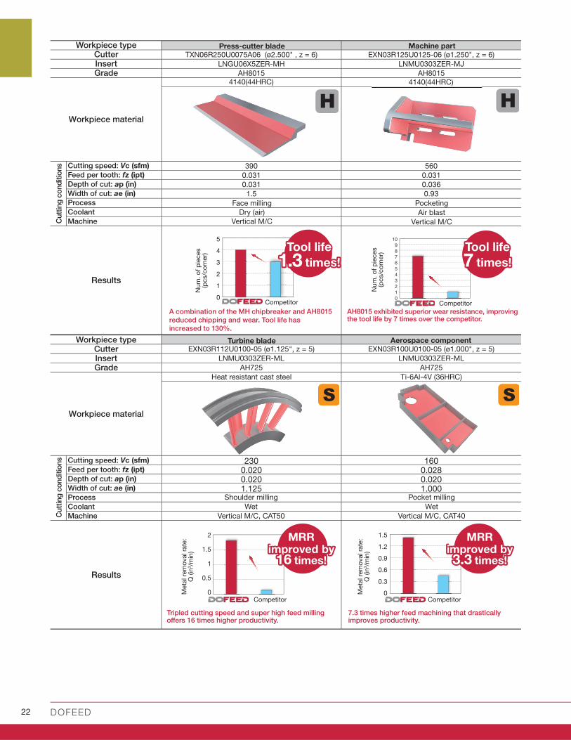
TXN06R250U0075A06 (ø2.500" , z = 6) EXN03R125U0125-06 (ø1.250", z = 6)
LNGU06X5ZER-MH LNMU0303ZER-MJ
AH8015 AH8015
390 560
0.031 0.031
0.031 0.036
1.5 0.93
EXN03R112U0100-05 (ø1.125", z = 5) EXN03R100U0100-05 (ø1.000", z = 5)
LNMU0303ZER-ML LNMU0303ZER-ML
AH725 AH725
230 1600.020 0.0280.020 0.0201.125 1.000
2
1.5
1
0.5
0
1.5
1.2
0.9
0.6
0.3
0
10
9
8
7
6
5
4
3
2
1
0
5
4
3
2
1
0
Workpiece type CutterInsertGrade
Workpiece material
Cutting speed: Vc (sfm)
Feed per tooth: fz (ipt)
Depth of cut: ap (in)
Width of cut: ae (in)
Process
Coolant
Machine
Results
Workpiece type CutterInsertGrade
Workpiece material
Cutting speed: Vc (sfm)
Feed per tooth: fz (ipt)
Depth of cut: ap (in)
Width of cut: ae (in)
Process
Coolant
Machine
Results
Turbine blade
Shoulder milling
Wet
Vertical M/C, CAT50
Tripled cutting speed and super high feed milling off ers 16 times higher productivity.
A combination of the MH chipbreaker and AH8015
reduced chipping and wear. Tool life has
increased to 130%.
Aerospace component
Pocket milling
Wet
Vertical M/C, CAT40
7.3 times higher feed machining that drastically improves productivity.
AH8015 exhibited superior wear resistance, improving the tool life by 7 times over the competitor.
Ti-6Al-4V (36HRC)
Competitor Competitor
Heat resistant cast steel
Meta
l re
mo
val ra
te:
Q (in
3/m
in)
Meta
l re
mo
val ra
te:
Q (in
3/m
in)
Press-cutter blade Machine part
Pocketing
Air blast
Vertical M/C
Face milling
Dry (air)
Vertical M/C
MRR MRR improvedimproved byby
1616 times!times!
MRR MRR improvedimproved byby
3.33.3 times!times!
Num
. o
f p
ieces
(pcs/c
orn
er)
Num
. o
f p
ieces
(pcs/c
orn
er)
Competitor Competitor
Tool lifeTool life
1.31.3 times times!!
Tool lifeTool life
77 times times!!
Cutt
ing
co
nd
itio
ns
Cutt
ing
co
nd
itio
ns
4140(44HRC)4140(44HRC)

Check our site and our App to get more info!
w w w . t u n g a l o y . c o m / u s

Distributed by:
May. 2021 (TA)
Scan for instant web access
facebook.com/tungaloyamer icatwit ter.com/tungaloyinstagram.com/tungaloyamer ical inkedin.com/company/tungaloy-amer ica
follow us at:
w w w . t u n g a l o y . c o m / u s
www.youtube.com/tungaloycorporation
To see this product in action visit:
Tungaloy America, Inc.3726 N Ventura Drive, Arlington Heights, IL 60004, U.S.A.
Inside Sales: +1-888-554-8394
Technical Support: +1-888-554-8391
Fax: +1-888-554-8392www.tungaloy.com/us
Tungaloy Canada432 Elgin St. Unit 3, Brantford, Ontario N3S 7P7, CanadaPhone: +1-519-758-5779 Fax: +1-519-758-5791
www.tungaloy.com/ca
Tungaloy de Mexico S.A.C Los Arellano 113, Parque Industrial Siglo XXIAguascalientes, AGS, Mexico 20290Phone:+52-449-929-5410 Fax:+52-449-929-5411
www.tungaloy.com/mx
Related Documents