* TM 1-1520-238-10 TECHNICAL MANUAL OPERATOR’s MANUAL FOR HELICOPTER, ATTACK, AH-64A APACHE DISTRIBUTION STATEMENT A: Approved for public release; distribution is unlimited. HEADQUARTERS, DEPARTMENT OF THE ARMY 31 AUGUST 1994 * This manual supersedes TM 55-1520-238-10, dated 28 June 1984, including all changes.

Welcome message from author
This document is posted to help you gain knowledge. Please leave a comment to let me know what you think about it! Share it to your friends and learn new things together.
Transcript
* TM 1-1520-238-10TECHNICAL MANUAL
OPERATOR’s MANUAL
FOR
HELICOPTER, ATTACK,AH-64A APACHE
DISTRIBUTION STATEMENT A: Approved for publicrelease; distribution is unlimited.
HEADQUARTERS,DEPARTMENT OF THE ARMY
31 AUGUST 1994* This manual supersedes TM 55-1520-238-10, dated 28 June
1984, including all changes.
URGENTTM l-1520-238-10
c7
CHANGE
>
.
NO. 7
HEADQUARTERSDEPARTMENT OF THE ARMY
WASHINGTON, D.C., 15 December 1999
Operator’s Manualfor
AH-64A HELICOPTER
DISTRIBUTION STATEMENT A: Approved for public release; distribution is unlimited.
TM l-1520-238-10,31 August 1994, is changed as follows:
1 . Remove and insert pages as indicated below. New or changed text material is indicated by a verticalbar in the margin. An illustration change is indicated by a miniature pointing hand.
Remove pages Insert pages
A and B A and B---- C/(D blank)9-13 and 9-14 9-13 and 9-14
2 . Retain this sheet in front of manual for reference purposes.
By Order of the Secretary of the Army:
ERIC K. SHINSEKIGeneral, United States Army
Official:
/4&q”*.
Chief of Staff
Administrative Assistant to theSecretary of the Amy
9933402 .
DISTRIBUTION:‘TTo To be distributed in accordance with initial distribution No. (IDN 310293) requirements for
TM 1-1520-238-10.

TM 1-1520-238-10C 6
CHANGE
NO. 6 } HEADQUARTERSDEPARTMENT OF THE ARMY
WASHINGTON, D.C., 4 June 1999
Operator’s Manualfor
AH-64A HELICOPTER
DISTRIBUTION STATEMENT A: Approved for public release; distribution is unlimited.
TM 1-1520-238-10, 31 August 1994, is changed as follows:
1. Remove and insert pages as indicated below. New or changed text material is indicated by a verticalbar in the margin. An illustration change is indicated by a miniature pointing hand.
Remove pages Insert pages
A and B A and B-- -- -- -- C/(D blank)2-55 and 2-56 2-55 and 2-562-87 and 2-88 2-87 and 2-882-93 and 2-94 2-93 and 2-942-97 and 2-98 2-97 and 2-983-29 through 3-32 3-29 through 3-323-63 and 3-64 3-63 and 3-643-64.27/(3-64.28 blank) 3-64.27/(3-64.28 blank)4-49 and 4-50 4-49 and 4-505-15 and 5-16 5-15 and 5-168-9 through 8-12 8-9 through 8-128-15 and 8-16 8-15 and 8-169-1 and 9-2 9-1 and 9-29-11 through 9-14 9-11 through 9-14
2. Retain this sheet in front of manual for reference purposes.
By Order of the Secretary of the Army:
DISTRIBUTION:To be distributed in accordance with initial distribution No. (IDN 310293) requirements forTM 1--1520--238--10.
TM 1-1520-238-10C 6
By Order of the Secretary of the Army:
ERIC K. SHINSEKIGenera/, United States Army
Chief of Staff
JOEL B. HUDSONActing Administrative Assistant to the
Secretary of the Army9914404
DISTRIBUTION:To be distributed in accordance with IDN 310293, requirements for TM 1-1520-238-10.
TM 1-1520-238-10C5
CHANGE
NO. 5
HEADQUARTERSDEPARTMENT OF THE ARMY
WASHINGTON, DC 27 February 1998
Operator’s Manualfor
HELICOPTER, ATTACK,AH-64A APACHE
DISTRIBUTATION STATEMENT A: Approved for public release; distribution is unlimited.
TM 1-1520-238-10, 31 August 1994, is changed as follows:
1. Remove old pages and insert new pages as indicated below. New or changed text material isindicated by a vertical bar in the margin. An illustration change is indicated by a miniature pointinghand.
Remove pages Insert pages
A and B A and B
i and ii i and ii
2-69 and 2-70 2-69 and 2-70- - - - - - 2-70.1/(2-70.2 blank)
4-75 and 4-76 4-75 and 4-76
4-77/(4-78 blank) 4-77 and 4-78
Index 2.1 and Index 2.2 Index 2.1 and Index 2.2
Index 7 and Index 8 Index 7 and Index 8
Cover 1/(Cover 2 blank) Cover 1/(Cover 2 blank)
2. Retain this sheet, in front of manual for reference purposes.
By Order of the Secretary of the Army:
Official:
JOEL B. HUDSON
Administrative Assistant to theSecretary of the Army
04914
DENNIS J. REIMERGeneral, United States Army
Chief of Staff
DISTRIBUTION:To be distributed in accordance with Initial Distribution No. (IDN) 310293 requirements forTM 1-1520-23310.

TM 1-1520-238-10C4
CHANGE
NO. 4
HEADQUARTERSDEPARTMENT OF THE ARMY
WASHINGTON, D.C., 30 July 1997
Operator’s Manualfor
AH-64A HELICOPTER
TM 1-1520-238-10, 31 August 1994, is changed as follows:
1. Remove and insert pages as indicated below. New or changed text material is indicated by a verticalbar in the margin. An illustration change is indicated by a miniature pointing hand.
Remove pages
A and Bi and ii1-1 and 1-22-7 and 2-82-45 through 2-542-71 through 2-742-85 through 2-883-7 and 3-83-18.3 and 3.18.43-18.9 through 3-18.11/(3-18.12 blank)3-19 and 3-203-33 and 3-34- - - -
3-55 and 3-563-61 through 3-643-64.1 through 3-64.26- - - -
3-65 and 3-664-1 and 4-24-5 through 4-144-14.1/(4-14.2 blank)4-15 and 4-16- - - -
4-17 through 4-204-33 and 4-344-49 through 4-564-59 and 4-604-63 through 4-664-66.1 through 4-66.3/(4-66.4 blank)4-67 through 4-70- - - -
5-9 through 5-146-1 and 6-26-5 and 6-68-9 through 8-16
Insert pages
A and Bi and iil-l and 1-22-7 and 2-82-45 through 2-542-71 through 2-742-85 through 2-883-7 and 3-83-18.3 and 3.18.43-18.9 through 3-18.123-19 and 3-203-33 and 3-343-34.1/(3-34.2 blank)3-55 and 3-563-61 through 3-643-64.1 through 3-64.263-64.27/(3-64.28 blank)3-65 and 3-664-1 and 4-24-5 through 4-144-14.1/(4-14.2 blank)4-15 and 4-164-16.1/(4-16.2 blank)4-17 through 4-204-33 and 4-344-49 through 4-564-59 and 4-604-63 through 4-664-66.1 through 4-66.3/(4-66.4 blank)4-67 through 4-704-70.1/(4-70.2 blank)5-9 through 5-146-1 and 6-26-5 and 6-68-9 through 8-16

TM 1-1520-238-10C4
Remove pages Insert pages
9-3 and 9-49-9 and 9-109-13 through 9-169-21 and 9-22Index 1 and Index 2Index 3 through Index 6Index 9 and index 10Index 13 through Index 20
9-3 and 9-49-9 and 9-109-13 through 9-169-21 and 9-22Index 1 and Index 2Index 3 through Index 6Index 9 and index 10Index 13 through Index 20
2. Retain this sheet in front of manual for reference purposes.
By Order of the Secretary of the Army:
Official:
Administrative Assistant to theSecretary of the Army
04011
DENNIS J. REIMERGeneral, United States Army
Chief of Staff
DISTRIBUTION:To be distributed in accordance with DA Form 12-31-E, block no. 0293, requirements for
TM 1-1520-238-10.

TM 1-1520-238-10C3
CHANGE HEADQUARTERS DEPARTMENTS OFTHE ARMY AND THE AIR FORCE
NO. 3 WASHINGTON, D.C., 20 September 1996
Operator’s Manualfor
HELICOPTER, ATTACK, AH-64A APACHE
DISTRIBUTION STATEMENT A: Approved for public release; distribution is unlimited
TM 1-1520-238-10 ,31 August 1994, is changed as follows:
1. Remove and insert pages as indicated below. New or changed text material is indicated by a vertical barin the margin. An illustration change is indicated by a miniature pointing hand.
Remove pages Insert pagesA and B A and B2-1 and 2-2 2-1 and 2-22-15 and 2-16 2-15 and 2-162-45 through 2-48 2-45 through 2-482-55 and 2-56 2-55 and 2-562-67 through 2-70 2-67 through 2-703-3 through 3-6 3-3 through 3-6-------- 3-18.1 through 3-18.11/(3-18.12 blank)3-19 and 3-20 3-19 and 3-203-29 through 3-64 3-29 through 3-643-64.1 through 3-64.263-65 and 3-66 3-65 and 3-664-1 through 4-6 4-1 through 4-64-9 and 4-10 4-9 and 4-104-19 and 4-20 4-19 and 4-204-25 and 4-26 4-25 and 4-264-33 and 4-34 4-33 and 4-344-39 through 4-42 4-39 through 4-424-47 through 4-50 4-47 through 4-504-61 and 4-62 4-61 and 4-624-69 and 4-70 4-69 and 4-705-1 through 5-4 5-1 through 5-45-9 through 5-14 5-9 through 5-146-5 and 6-6 6-5 and 6-66-17 and 6-18 6-17 and 6-187-1 through 7-4 7-1 through 7-4

TM 1-1520-238-10C3
Remove pages Insert pages7-11 and 7-12 7-11 and 7-127A-1 through 7A-4 7A-1 through 7A-47A-65 and 7A-66 7A-65 and 7A-668-3 through 8-6 8-3 through 8-68-11 and 8-12 8-11 and 8-128-15 and 8-16 8-15 and 8-169-3 and 9-4 9-3 Ind 9-49-7 through 9-22 9-7 through 9-22B-1 through B-8 B-1 through B-8B-11 and B-12 B-11 and B-12B-15 and B-16 B-15 and B-16Index 1 and Index 2 Index 1 and Index 2---------- Index 2.1 and Index 2.2Index 3 through Index 14 Index 3 through Index 14
2. Retain this sheet in front of manual for reference purposes.
By Order of the Secretary of the Army:
DENNIS J.REIMEROfficial: General, United States ArmyOfficial: Chief of Staff
JOEL B. HUDSONAdministrative Assistant to the
Secretary of the Army02728
DISTRIBUTION:To be distributed in accordance with DA Form 12-31-E, block no. 0293, requirements for
TM 1-1520-238-10.
TM 1-1520-238-10
CHANGE
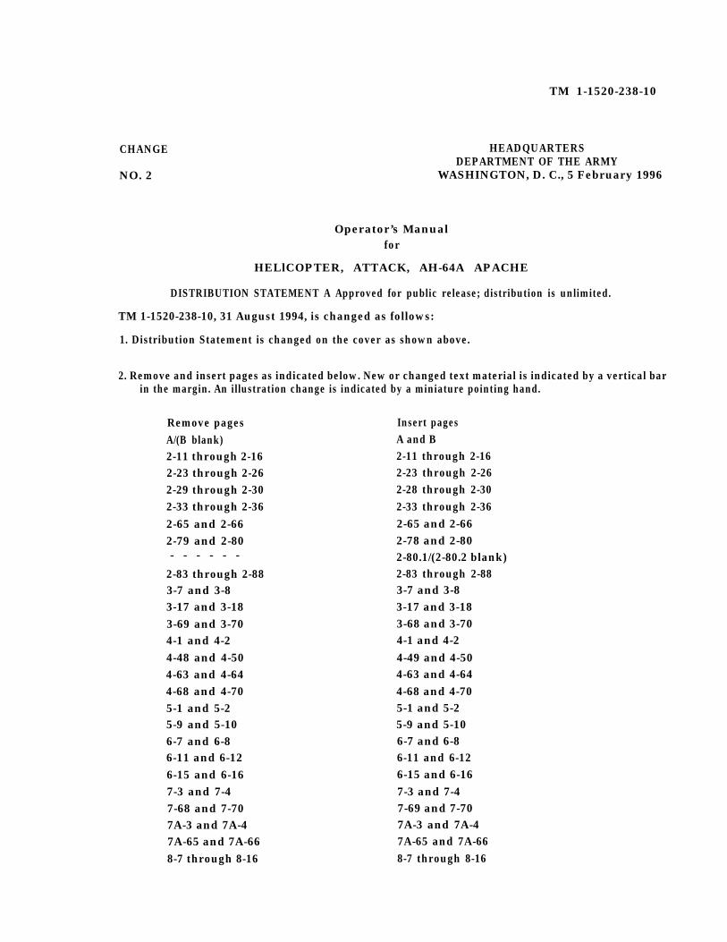
NO. 2
HEADQUARTERSDEPARTMENT OF THE ARMY
WASHINGTON, D. C., 5 February 1996
Operator’s Manualfor
HELlCOPTER, ATTACK, AH-64A APACHE
DISTRIBUTION STATEMENT A Approved for public release; distribution is unlimited.
TM 1-1520-238-10, 31 August 1994, is changed as follows:
1. Distribution Statement is changed on the cover as shown above.
2. Remove and insert pages as indicated below. New or changed text material is indicated by a vertical barin the margin. An illustration change is indicated by a miniature pointing hand.
Remove pagesA/(B blank)2-11 through 2-162-23 through 2-262-29 through 2-302-33 through 2-362-65 and 2-662-79 and 2-80- - - - - -
2-83 through 2-883-7 and 3-83-17 and 3-183-69 and 3-704-1 and 4-24-48 and 4-504-63 and 4-644-68 and 4-705-1 and 5-25-9 and 5-106-7 and 6-86-11 and 6-126-15 and 6-167-3 and 7-47-68 and 7-707A-3 and 7A-47A-65 and 7A-668-7 through 8-16
Insert pagesA and B2-11 through 2-162-23 through 2-262-28 through 2-302-33 through 2-362-65 and 2-662-78 and 2-802-80.1/(2-80.2 blank)2-83 through 2-883-7 and 3-83-17 and 3-183-68 and 3-704-1 and 4-24-49 and 4-504-63 and 4-644-68 and 4-705-1 and 5-25-9 and 5-106-7 and 6-86-11 and 6-126-15 and 6-167-3 and 7-47-69 and 7-707A-3 and 7A-47A-65 and 7A-668-7 through 8-16

`TM 1-1520-238-10C2
9-3 and 9-4 9-3 and 9-49-9 and 9-10 9-9 and 9-109-13 through 9-22 9-13 through 9-22Index 1 through Index 4 Index 1 through Index 4Index 11 through Index 14 Index 11 through Index 14Index 17 through Index 20 Index 17 through Index 20
3. Retain this sheet in front of manual for reference purposes.
By Order of the Secretaries of the Army:
DISTRIBUTION:To be distributed in accordance with DA Form 12-31-E, block no. 0293, requirements for
TM 1-1520-238-10.
Richard Woods
DENNIS J. REIMER General, United States Army Chief of Staff
Richard Woods
Richard Woods
Richard Woods
Richard Woods
Richard Woods
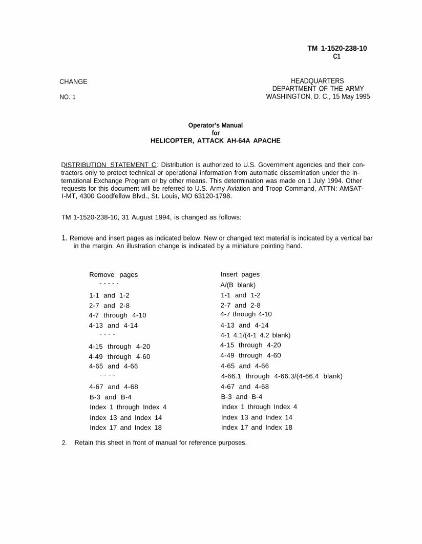
TM 1-1520-238-10C1
CHANGE
NO. 1
HEADQUARTERSDEPARTMENT OF THE ARMY
WASHINGTON, D. C., 15 May 1995
Operator’s Manualfor
HELICOPTER, ATTACK AH-64A APACHE
DISTRIBUTION STATEMENT C: Distribution is authorized to U.S. Government agencies and their con-tractors only to protect technical or operational information from automatic dissemination under the ln-ternational Exchange Program or by other means. This determination was made on 1 July 1994. Otherrequests for this document will be referred to U.S. Army Aviation and Troop Command, ATTN: AMSAT-I-MT, 4300 Goodfellow Blvd., St. Louis, MO 63120-1798.
TM 1-1520-238-10, 31 August 1994, is changed as follows:
1. Remove and insert pages as indicated below. New or changed text material is indicated by a vertical barin the margin. An illustration change is indicated by a miniature pointing hand.
Remove pages- - - - -
1-1 and 1-2
2-7 and 2-84-7 through 4-10
4-13 and 4-14- - - -
4-15 through 4-20
4-49 through 4-604-65 and 4-66
- - - -
4-67 and 4-68
B-3 and B-4
Index 1 through Index 4
Index 13 and Index 14
Index 17 and Index 18
Insert pages
A/(B blank)
1-1 and 1-2
2-7 and 2-84-7 through 4-10
4-13 and 4-14
4-1 4.1/(4-1 4.2 blank)
4-15 through 4-20
4-49 through 4-60
4-65 and 4-66
4-66.1 through 4-66.3/(4-66.4 blank)
4-67 and 4-68
B-3 and B-4
Index 1 through Index 4
Index 13 and Index 14
Index 17 and Index 18
2. Retain this sheet in front of manual for reference purposes.

TM 1-1520-238-10
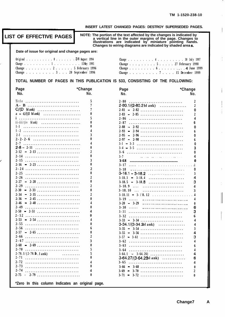
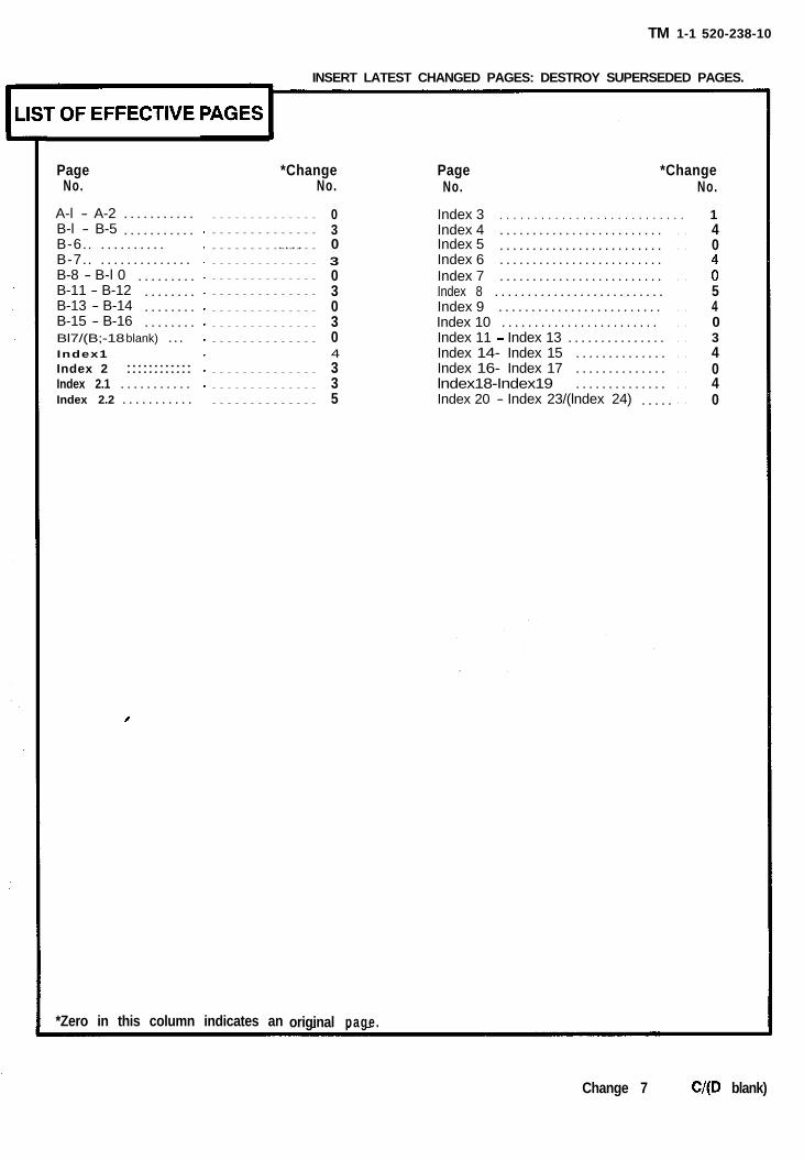
INSERT LATEST CHANGED PAGES: DESTROY SUPERSEDED PAGES.
LIST OF EFFECTIVE PAGES NOTE: The portion of the text affected by the changes is indicated by
L-a vertical line in the outer margins of the page. Changes to
I
illustrations are indicated by miniature pointing hands.Changes to wiring diagrams are indicated by shaded area
Date of issue for original and change pages are:
Original . . . . . . . . . . 0 . . . . . . .31 August 1994Change . . . . . . . . . 1 . . . . . . . . . 15May 1995Change . . . . . . . . . 2 . . . . . . 5 February 1996Change . . . . . . . . . 3 . . . 20 September 1996
Change . . . . . . . . . 4 . . . . . . . . . 30 July 1997Change . . . , . . . . . 5 . . . . . 27 February 1998Change . . . . . . . . . 6 . . . . . . ". . .4 June 1999Change . . . . . . . . . 7 . . . . 15 December 1999
TOTAL NUMBER OF PAGES IN THIS PUBLICATION IS 533, CONSISTING OF THE FOLLOWING:
PageNo.
*ChangeNo.
2-29
Title
..............................
..............................
2
5A - B .............................
2-30 - 2-33
7C/(D blank)
........................
........................
0
7a - c/(d blank)
2-34 - 2-35
.....................
........................
0i
2
i ..................................
2-36 - 2-45
5ii-iii/(iv blank)
........................
......................
0
0l-l
2-46 - 2-48
...............................
........................
0l-2
4
4
2-49
...............................
..............................
2-l
0
............................... 32-2-2-6 .......................... 02-7 ................................ 42-8- 2-11 ......................... 02-12 - 2-13 ........................ 22-14 .............................. 02-15 .............................. 32-16 - 2-23 ........................ 02-24 .............................. 22-25 .............................. 02-26 .............................. 22-27 - 2-28 ........................ 0
PageNo.
*ChangeNo.
2-80 ..............................2-80.1/(2-80.2 blank) ............... 22-81 - 2-82 ........................2-83 - 2-85 ........................2-86 ..............................2-87 .............................. 62-88 - 2-92 ........................2-93 - 2-94 ........................2-95 - 2-96 ........................2-97 - 2-98 ........................3-l - 3-3 .......................... 03-4 - 3-5 ..........................3-6 ...............................3-7 .. . .. .. . . .. . . . . . .. . . .
3-17 ..... . . . . . . . . . . . . . . . . . . . . . . . . .3-183-18.1 l&ii:i * : : : : : : : : : : : : : : : : : : : :3-18.3 - 3-18.4 ....................3-18.5 - 3-18.8 ....................
.......................
.......................1'8.12 . . . . . . . . . . . . . . . . . ........................
.......................
.......................
3-31 ..............................3-32
3-18.9
..............................3-33 - 3-34
....
........................3-34.1/(3-34.2 blank) ...............3-35 - 3-54
3-18.10 ...
........................3-55 - 3-56 ........................3-57 - 3-61
3-18.11 - 3-
........................3-62 ..............................3-63
3-19
..............................3-64
......
..............................3-64.1 - 3-64.26) ...................3-64.27/(3-64.28 blank)
3-20 - 3-29
.............3-65 ..............................3-66 - 3-68
3-30 ......
........................3-69 - 3-70 ........................3-71 - 3-72 ........................
2
024
0606
304
ii03
3"43440
3"6443
3"464
:4020
2-50 - 2-51 ........................ 42-52 .............................. 02-53 - 2-54 ........................ 42-55 .............................. 02-56 .............................. 62-57 - 2-65 ........................ 02-66 .............................. 22-67 .............................. 32-68 - 2-69 ........................ 02-70 .............................. 52-70.1/(2-70.2 b .lank) .......... 52-71 .............................. 02-72 .............................. 42-73 .............................. 02-74 .............................. 42-75 - 2-79 ........................ 0
*Zero In this column Indicates an original page.
Change7 A
TM l-1520-238-10
PageNo.
*ChangeNo.
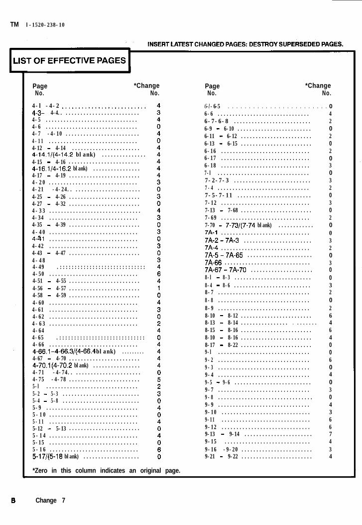
4-l -4-2 u.........................4-3- 4-4.. .........................4-5 ...............................4-6 ...............................4-7 -4-10 .........................4-11 ..............................4-12 - 4-14 .......................4-14.1/(4-14.2 blank) ...............4-15 - 4-16 ........................4-16.1/4-16.2 blank) ................4-17 - 4-19 ........................4-20 ..............................4-21 -4-24.. ......................4-25 - 4-26 ........................4-27 - 4-32 ........................4-33 ...............................4-34 ..............................4-35 - 4-39 ........................4-40 ..............................4-31 ..............................4-42 ..............................4-43 - 4-47 ........................4-484-49 .:::::::::::::::::::::::::::::4-50 ..............................4-51 - 4-55 ........................4-56 - 4-57 ........................4-58 - 4-59 ........................4-60 ..............................4-61 ..............................4-62 ..............................4-63 ..............................4-644-65 .:::::::::::::::::::::::::::::4-66 ..............................4-66-l- 4-66.3/(4-66.4 blank) .........4-67 - 4-70 ........................4-70.1(4-70.2 blank) ................4-71 -4-74.. ......................4-75 -4-78 ........................5-l ...............................5-2 - 5-3 ..........................5-4 - 5-8 ..........................5-9 ...............................5-10 ..............................5-11 ..............................5-12 - 5-13 ........................5-14 ..............................5-15 ..............................5-16 ..............................5-17/(5-18 blank) ...................
PageNo.
*ChangeNo.
6-l -6-5 . . . . . . . . . . . . . . . . . . . . . . . . .6-6 ...............................6-7-6-8 ..........................6-9 - 6-10 .........................6-11 - 6-12 ........................6-13 - 6-15 ........................6-16 ..............................6-17 ..............................6-18 ..............................7-l ...............................7-2-7-3 ..........................7-4 ...............................7-5-7-11 .........................7-12 ..............................7-13 - 7-68 ........................7-69 ..............................7-70 - 7-73/(7-74 blank) ............7A-1 ..............................7A-2-7A-3 .......................7A-4 ..............................7A-5-7A-65 ......................7A-66 .............................7A-67-7A-70 .....................8-l - 8-3 ..........................8-4 - 8-6 ..........................8-7 ...............................8-8 ...............................8-9 ...............................8-10 - 8-12 ........................8-13 - 8-14 ................ . .......8-15 - 8-16 ........................8-10 - 8-16 ........................8-17 - 8-22 ........................9-l ...............................9-2 ...............................9-3 ...............................9-4 ...............................9-5 - 9-6 ..........................9-7 ...............................9-8 ................................9-9 ...............................9-10 ..............................9-11 ..............................9-12 ..............................9-13 - 9-14 .......................9-15 .............................9-16 -9-20 ........................9-21 - 9-22 ........................
042020203032030200320300320264640060403043667434
*Zero in this column indicates an original page.
B Change 7
TM 1-1 520-238-10
PageNo.
*ChangeNo.
PageNo.
*ChangeNo.
A-l - A-2 . . . . . . . . . . .B-l - B-5 . . . . . . . . . . .B-6.. . . . . . . . . . . . . . . 0B-7.. . . . . . . . . . . . . . . B-8 - B-l 0 . . . . . . . . .B-11 - B-12 . . . . . . . .B-13 - B-14 . . . . . . . .B-15 - B-16 . . . . . . . .Bl7/(B;-18blank) . . .
Index 2 ::::::::::::Index 2.1 . . . . . . . . . . .Index 2.2 . . . . . . . . . . .
..............
..............
..............
..............
..............
..............
..............
..............
..............
Index1 4..............
..............
..............
03
303030
335
Index 3 . . . . . . . . . . . . . . . . . . . . . . . . . . .Index 4 . . . . . . . . . . . . . . . . . . . . . . . . .Index 5 . . . . . . . . . . . . . . . . . . . . . . . . .Index 6 . . . . . . . . . . . . . . . . . . . . . . . . .Index 7 . . . . . . . . . . . . . . . . . . . . . . . . .Index 8 . . . . . . . . . . . . . . . . . . . . . . . . . .Index 9 . . . . . . . . . . . . . . . . . . . . . . . . .Index 10 . . . . . . . . . . . . . . . . . . . . . . . . 0Index 11 - Index 13 . . . . . . . . . . . . . . .Index 14- Index 15 . . . . . . . . . . . . . .Index 16- Index 17 . . . . . . . . . . . . . .lndex18-Index19 . . . . . . . . . . . . . .Index 20 - Index 23/(lndex 24) . . . . .
. .
. .
. .
. .
. .
. .
. .
. .
. .
. .
1 40
:54
34040
INSERT LATEST CHANGED PAGES: DESTROY SUPERSEDED PAGES.
I
*Zero in this column indicates an original page.
Change 7 C/(D blank)
WARNING
AVIATION LIFE SUPPORT EQUIPMENT
WARNING
BATTERY ELECTROLYTE
WARNING
CANOPY JETTISON
EARNING
CARBON MONOXIDE
WARNING
ELECTROMAGNETIC INTERFERENCE (EMI)
TM 1-1520-238-10
WARNINGPersonnel performing operations, procedures, and practices which are includedor implied in this technical manual shall observe the following warnings.Disregard of these warnings and precautionary information can cause seriousinjury or loss of life.
Aviation life support equipment shall be utilized in accordance with AR 95-1 andFM 1-302. Failure to do so may result in personal injury or loss of life.
Battery electrolyte is harmful to the skin and clothing. Neutralize any spilledelectrolyte by thoroughly flushing contacted area with water.
Canopy jettison safety pins shall be installed in pilot, copilot/gunner, andexternal firing mechanisms when the helicopter is on the ground. The canopyjettison system is manually operated. The canopy can be jettisoned when noelectrical power is on the helicopter. Pilot and copilot/gunner safety pins shall beremoved before starting engines. Safety pins shall be Installed during engineshutdown check. Debris may be expelled 50 feet outward when system isactuated. Pilot and copilot/gunner helmet visor should be down to prevent eyeinjury.
When smoke, suspected carbon monoxide fumes, or symptoms of anoxia exist,the crew should immediately ventilate the cockpit.
No electrical/electronic devices of any sort, other than those described in thismanual or appropriate maintenance manuals, are to be operated by crewmembers during operation of this helicopter. Flights near high power radiotransmitters’ high intensity radio transmission areas (HIRTA) may causedegraded system operation.
a
GROUND OPERATION
HIGH VOLTAGE
LASER LIGHT
TM 1-1520-238-10
WARNING
FIRE EXTINGUISHER
Exposure to high concentrations of extinguishing agent or decompositionproducts should be avoided. The liquid should not be allowed to contact theskin; it may cause frostbite or low-temperature burns.
WARNING
Engines will be started and operatedAR 95-1 and AR 95-13.
only by authorized personnel. Reference
WARNING
HANDLING FUEL, OIL, AND HYDRAULIC FLUIDS
Turbine and lubricating oils contain additives which are poisonous and readilyabsorbed through the skin. Do not allow them to remain on skin longer thannecessary. Prolonged contact may cause skin rash. Prolonged contact withhydraulic fluid may cause burns. Refer to TM 10-1101 and FM 10-68 whenhandling fuel.
WARNING
All ground handling personnel must be informed of high voltage hazards whenworking near Target Acquisition Designator Sight (TADS) and Pilot Night VisionSensor (PNVS) equipment.
WARNING
laser light hazard
The laser light beam is dangerous and can cause blindness if it enters the eyeeither directly or reflected from a surface. Personnel should wear approved laserprotection whenever in a controlled area when laser rangefinder or laser targetdesignators are being used. Laser shall be used only in controlled areas byqualified personnel.
b
WARNING
NOISE
WARNING
STARTING ENGINES AND AUXILIARY POWER UNIT
WARNING
VERTIGO
WARNING
WEAPONS AND AMMUNITION
TM 1-1520-238-10
Sound pressure levels around helicopters during some operating conditionsexceed the Surgeon General’s hearing conservation criteria as defined InTB MED 251. Hearing protection devices, such as the aviator helmet or ear plugs,are required to be worn by all personnel in and around the helicopter during Itsoperation.
Be sure that the rotor and blast area is clear, and a fire guard is posted ifavailable.
The anti-collision strobe lights should be off during fright through clouds toprevent sensations of vertigo as a result of reflections of the light on the clouds.
Observe all standard safety precautions governing the handling of weapons andlive ammunition. When not in use, point all weapons in a direction away frompersonnel and property in case of accidental firing. Do not walk in front ofweapons. SAFE all weapons before servicing. To avoid potentially dangeroussituations, follow the procedural warnings in this text.
All jettison safety pins shall be installed when the helicopter is on the ground.Safety pins shall be removed prior to fright. Failure to do so will prevent jettisonof wing stores.
c/(d blank)

TM 1-1520-238-10
Technical Manual
No. 1-1520-238-10
HEADQUARTERSDEPARTMENT OF THE ARMY
WASHINGTON, D. C. 31 August 1994
OPERATOR’S MANUAL
FOR
HELICOPTER, ATTACK,AH-64A APACHE
REPORTING ERRORS AND RECOMMENDING IMPROVEMENTSYou can help improve this publication. If you find any mistakes, or if you know of a way to improvethese procedures, please let us know. Mail your letter or DA Form 2028 (Recommended Changes toPublications and Blank Forms) directly to: Commander, US Army Aviation and Missile Command,ATTN: AMSAM-MMC-LS-LP Redstone Arsenal, AL, 35898-5230. You may also submit yourrecommended changes by E-mail directly to [email protected]. A reply will be furnisheddirectly to you. Instructions for sending an electronic 2028 may be found at the end of this TMimmediately preceding the hard copy 2028.
DISTRIBUTION STATEMENT A: Approved for public release; distribution is unlimited.
TABLE OF CONTENTS
Page
CHAPTER 1
CHAPTER 2Section I.Section II.Section III.Section IV.Section V.Section VI.Section VII.Section VIII.Section IX.Section X.Section XI.Section XII.Section XIII.Section XIV.Section XV.
INTRODUCTION . . . . . . . . . . . . . . . . . . . . . . . . . . . . . . . . . . . . . . . . . . . . . . . . . 1-1
AIRCRAFT AND SYSTEMS DESCRIPTION AND OPERATION . . . . . .Aircraft . . . . . . . . . . . . . . . . . . . . . . . . . . . . . . . . . . . . . . . . . . . . . . . . . . . . . .Emergency Equipment . . . . . . . . . . . . . . . . . . . . . . . . . . . . . . . . . . . . . . . .Engines and Related Systems . . . . . . . . . . . . . . . . . . . . . . . . . . . . . . . . . .FuelSystem . . . . . . . . . . . . . . . . . . . . . . . . . . . . . . . . . . . . . . . . . . . . . . . . . .Flight Control System . . . . . . . . . . . . . . . . . . . . . . . . . . . . . . . . . . . . . . . . .Hydraulic and Pressurized Air Systems . . . . . . . . . . . . . . . . . . . . . . . . .Power Train System . . . . . . . . . . . . . . . . . . . . . . . . . . . . . . . . . . . . . . . . . . .Rotors . . . . . . . . . . . . . . . . . . . . . . . . . . . . . . . . . . . . . . . . . . . . . . . . . . . . . . .Utility Systems . . . . . . . . . . . . . . . . . . . . . . . . . . . . . . . . . . . . . . . . . . . . . . .Heating, Ventilation, Cooling, and Environmental Control SystemsElectrical Power Supply and Distribution Systems . . . . . . . . . . . . . . .Auxiliary Power Unit . . . . . . . . . . . . . . . . . . . . . . . . . . . . . . . . . . . . . . . . .Lighting . . . . . . . . . . . . . . . . . . . . . . . . . . . . . . . . . . . . . . . . . . . . . . . . . . . . .Flight Instruments . . . . . . . . . . . . . . . . . . . . . . . . . . . . . . . . . . . . . . . . . . . .Servicing, Parking, and Mooring . . . . . . . . . . . . . . . . . . . . . . . . . . . . . . .
2-12-12-192-222-342-422-502-562-592-602-642-662-722-742-762-86
* This manual supersedes TM 55-1520-238-10, dated 28 June 1984, including all changes.
Change 5 i
TM 1-1520-238-10
TABLE OF CONTENTS - continued
Page
CHAPTER 3
Section I.
Section II.
Section III.
Section IV.
CHAPTER 4
Section I.
Section II.
Section III.
CHAPTER 5
Section I.
Section II.
Section III.
Section IV.
Section V.
Section VI.
Section VII.
Section VIII.
CHAPTER 6
Section I.
Section II.
Section III.
Section IV.
Section V.
Section VI.
Section VII.
CHAPTER 7
Section I.
Section II.
Section III.
Section IV.
Section V.
Section VI.
Section VII.
ii
AVIONICS . . . . . . . . . . . . . . . . . . . . . . . . . . . . . . . . . . . . . . . . . . . . . . . . . . . . . . . .
General. . . . . . . . . . . . . . . . . . . . . . . . . . . . . . . . . . . . . . . . . . . . . . . . . . . . . .
Communications . . . . . . . . . . . . . . . . . . . . . . . . . . . . . . . . . . . . . . . . . . . . . .
Navigation . . . . . . . . . . . . . . . . . . . . . . . . . . . . . . . . . . . . . . . . . . . . . . . . . .
Transponder and Radar . . . . . . . . . . . . . . . . . . . . . . . . . . . . . . . . . . . . . . .
MISSION EQUIPMENT . . . . . . . . . . . . . . . . . . . . . . . . . . . . . . . . . . . . . . . . . . .
Mission Avionics . . . . . . . . . . . . . . . . . . . . . . . . . . . . . . . . . . . . . . . . . . . . . .
Armament . . . . . . . . . . . . . . . . . . . . . . . . . . . . . . . . . . . . . . . . . . . . . . . . . . .
Active and Passive Defense Equipment . . . . . . . . . . . . . . . . . . . . . . . . .
OPERATING LIMITS AND RESTRICTIONS . . . . . . . . . . . . . . . . . . . . . . . .
General . . . . . . . . . . . . . . . . . . . . . . . . . . . . . . . . . . . . . . . . . . . . . . . . . . . . . .
System Limits . . . . . . . . . . . . . . . . . . . . . . . . . . . . . . . . . . . . . . . . . . . . . . . .
Power Limit . . . . . . . . . . . . . . . . . . . . . . . . . . . . . . . . . . . . . . . . . . . . . . . . .
Loading Limits . . . . . . . . . . . . . . . . . . . . . . . . . . . . . . . . . . . . . . . . . . . . . . .
Airspeed Limits Maximum and Minimum . . . . . . . . . . . . . . . . . . . . . . .
Maneuvering Limits . . . . . . . . . . . . . . . . . . . . . . . . . . . . . . . . . . . . . . . . . .
Environmental Restrictions . . . . . . . . . . . . . . . . . . . . . . . . . . . . . . . . . . . .
Other Limits . . . . . . . . . . . . . . . . . . . . . . . . . . . . . . . . . . . . . . . . . . . . . . . . .
WEIGHT/BALANCE AND LOADING . . . . . . . . . . . . . . . . . . . . . . . . . . . . . . .
General. . . . . . . . . . . . . . . . . . . . . . . . . . . . . . . . . . . . . . . . . . . . . . . . . . . . . .
Weight and Balance . . . . . . . . . . . . . . . . . . . . . . . . . . . . . . . . . . . . . . . . . . .
Fuel and oil . . . . . . . . . . . . . . . . . . . . . . . . . . . . . . . . . . . . . . . . . . . . . . . . ..
Personnel . . . . . . . . . . . . . . . . . . . . . . . . . . . . . . . . . . . . . . . . . . . . . . . . . . . .
Mission Equipment . . . . . . . . . . . . . . . . . . . . . . . . . . . . . . . . . . . . . . . . . . .
Cargo Loading . . . . . . . . . . . . . . . . . . . . . . . . . . . . . . . . . . . . . . . . . . . . . . . .
Center of Gravity . . . . . . . . . . . . . . . . . . . . . . . . . . . . . . . . . . . . . . . . . . . . .
PERFORMANCE DATA FOR AH-64A HELICOPTERSEQUIPPED WITH T700-GE-701 ENGINES . . . . . . . . . . . . . . . . . . . . . . . . .
Introduction . . . . . . . . . . . . . . . . . . . . . . . . . . . . . . . . . . . . . . . . . . . . . . . . . .
Maximum Torque Available . . . . . . . . . . . . . . . . . . . . . . . . . . . . . . . . . . . .
Hover Ceiling . . . . . . . . . . . . . . . . . . . . . . . . . . . . . . . . . . . . . . . . . . . . . . . .
Hover Limits . . . . . . . . . . . . . . . . . . . . . . . . . . . . . . . . . . . . . . . . . . . . . . . . .
Cruise . . . . . . . . . . . . . . . . . . . . . . . . . . . . . . . . . . . . . . . . . . . . . . . . . . . . . . .
Drag . . . . . . . . . . . . . . . . . . . . . . . . . . . . . . . . . . . . . . . . . . . . . . . . . . . . . . . . .
Climb-Descent . . . . . . . . . . . . . . . . . . . . . . . . . . . . . . . . . . . . . . . . . . . . . . . .
3-1
3-1
3-7
3-30
3-66
4-1
4-1
4-10
4-69
5-1
5-1
5-2
5-9
5-10
5-11
5-14
5-16
5-17
6-1
6-1
6-3
6-6
6-10
6-11
6-16
6-17
7-1
7-1
7-4
7-9
7-11
7-13
7-69
7-72

TM 1-1520-238-10
TABLE OF CONTENTS - continuedPage
CHAPTER 7A
Section I.
Section II.
Section III.
Section IV.
Section V.
Section VI.
Section VII.
CHAPTER 8
Section I.
Section II.
Section III.
Section IV.
Section V.
CHAPTER 9
Section I.
Section II.
APPENDIX A
APPENDIX B
PERFORMANCE DATA FOR AH-64A HELICOPTERSEQUIPPED WITH T700-GE-701C ENGINES . . . . . . . . . . . . . . . . . . . . . . . .
Introduction . . . . . . . . . . . . . . . . . . . . . . . . . . . . . . . . . . . . . . . . . . . . . . . . . .
Maximum Torque Available . . . . . . . . . . . . . . . . . . . . . . . . . . . . . . . . . . . .
Hover Ceiling . . . . . . . . . . . . . . . . . . . . . . . . . . . . . . . . . . . . . . . . . . . . . . . .
Hover Limits . . . . . . . . . . . . . . . . . . . . . . . . . . . . . . . . . . . . . . . . . . . . . . . . .
Cruise . . . . . . . . . . . . . . . . . . . . . . . . . . . . . . . . . . . . . . . . . . . . . . . . . . . . . . .
Drag . . . . . . . . . . . . . . . . . . . . . . . . . . . . . . . . . . . . . . . . . . . . . . . . . . . . . . . . .
Climb-Descent . . . . . . . . . . . . . . . . . . . . . . . . . . . . . . . . . . . . . . . . . . . . . . . .
7A-1
7A-1
7A-4
7A-10
7A-13
7A-15
7A-66
7A-69
NORMAL PROCEDURES . . . . . . . . . . . . . . . . . . . . . . . . . . . . . . . . . . . . . . . . . . 8-1
Crew Duties . . . . . . . . . . . . . . . . . . . . . . . . . . . . . . . . . . . . . . . . . . . . . . . . . . 8-1
Operating Procedures and Maneuvers . . . . . . . . . . . . . . . . . . . . . . . . . . 8-2
Instrument Flight . . . . . . . . . . . . . . . . . . . . . . . . . . . . . . . . . . . . . . . . . . . . 8-17
Flight Characteristics . . . . . . . . . . . . . . . . . . . . . . . . . . . . . . . . . . . . . . . . . 8-18
Adverse Environmental Conditions . . . . . . . . . . . . . . . . . . . . . . . . . . . . . 8-19
EMERGENCY PROCEDURES . . . . . . . . . . . . . . . . . . . . . . . . . . . . . . . . . . . . . 9-1
Aircraft Systems . . . . . . . . . . . . . . . . . . . . . . . . . . . . . . . . . . . . . . . . . . . . . . 9-1
Mission Equipment . . . . . . . . . . . . . . . . . . . . . . . . . . . . . . . . . . . . . . . . . . . 9-21
REFERENCES . . . . . . . . . . . . . . . . . . . . . . . . . . . . . . . . . . . . . . . . . . . . . . . . . . . . A-1
ABBREVIATIONS AND TERMS . . . . . . . . . . . . . . . . . . . . . . . . . . . . . . . . . . . . B-1
ALPHABETICAL INDEX . . . . . . . . . . . . . . . . . . . . . . . . . . . . . . . . . . . . . . . . . . . . . . . . . . . . . . . . . . . . . Index 1
iii/(iv blank)

TM 1-1520-238-10
CHAPTER 1INTRODUCTION
1.1 GENERAL.
These instructions are for use of the operators. Theyapply to AH-64A helicopters.
1.2 WARNINGS, CAUTIONS, AND NOTES.
Warnings, Cautions, and Notes are used to emphasizeimportant and critical instruction and are used for thefollowing conditions:
An operating procedure, practice,condition or statement, which if notcorrectly followed, could result inpersonal injury or loss of life.
An operating procedure, practice,condition or statement, which if notstrictly observed, could result indamage to or destruction of equipment, loss of mission effectiveness orlong term health hazards to person-nel.
NOTE
An operating procedure, condition orstatement, which is essential to highlight.
1.3 DESCRIPTION.
This manual contains the best operating instructionsand procedures for the AH-64A under most circum-stances. The observance of limitations, performance,and weight balance data provided is mandatory. Theobservance of procedure is mandatory, except whenmodification is required because of multiple emergen-cies, adverse weather, terrain, etc. Basic flight prin-ciples are not included. THIS MANUAL SHALL BECARRIED IN THE HELICOPTER AT ALL TIMES.
The AH-64A helicopter is designed as a weapons-deliv-ery platform and is equipped with point target (Hellfiremissile), area weapon (30mm chain gun), and aerialrocket (2.75-inch folding-fin type) systems. TheAH-64A carries two crewmembers: a pilot and a copilot/gunner (CPG).
1.4 APPENDIX A, REFERENCES.
Appendix A is a listing of official publications citedwithin the manual applicable to, and available for,flight crews.
NOTE
Appendix A shall contain only those publi-cations referenced in the manual, andshall not contain Department of the Armyblank forms.
1.5 APPENDIX B, ABBREVIATIONS AND TERMS.
Definitions of all abbreviations and terms usedthroughout the manual are included in Appendix B.
1.6 INDEX.
The index lists, in alphabetical order, paragraphs, fig-ures, and tables contained in this manual by page num-ber.
1.7 ARMY AVIATION SAFETY PROGRAM.
Reports necessary to comply with the safety programare prescribed in AR 385-40.
1.8 DESTRUCTION OF ARMY MATERIAL TOPREVENT ENEMY USE.
For information concerning destruction of Army mate-riel to prevent enemy use, refer to TM 750-244-1-5.
1.9 FORMS AND RECORDS.
Army aviator’s flight record and aircraft maintenancerecords, which are to be used by crewmembers, are de-scribed in DA PAM 738-751 and TM 55-1500-342-23.
1-1
TM 1-1520-238-10
1.10 EXPLANATION OF CHANGE SYMBOLS.
Changes to the text and tables, including new materialon added pages, shall be identified by a vertical bar inthe outer margin of the column of text in which thechange appears, extending close to the entire area ofthe material affected. Change symbols for single col-umn text shall be placed in the margin opposite thebinding. Change symbols for double column text shallbe placed in the margin adjacent to the binding for thecolumns of text nearest the binding. The change sym-bols shall be placed in the outer margin opposite thebinding for the column of text farthest from the bind-ing. Pages with emergency markings, which consist ofblack diagonal lines around three edges, shall have thevertical bar or change symbol placed in the margin be-tween the text and the diagonal lines. Change symbolsshall indicate the current changes only. A miniaturepointing hand symbol shall be used to denote a changeto an illustration. However, a vertical line in the outermargin (opposite the binding) rather than miniaturepointing hands, shall be utilized when there have beenextensive changes made to an illustration. Changesymbols shall not be used to indicate changes in the fol-lowing:
a. Introductory material.
b. Indexes and tabular data where the change can-not be identified.
c. Correction of minor inaccuracies, such as spell-ing, punctuation, relocation of material, etc., unless
such correction changes the meaning of the instructiveinformation and procedures.
1.11 SERIES AND EFFECTIVITY CODES
All AH-64A helicopters have BUCS equipmentinstalled. In most helicopters, the system is deacti-vated; in some it is operable. The designator symbol @indicates text headings, text contents and illustrationspertaining to helicopters with an operable BUCS.
Some AH-64A helicopters have T700-GE-701C enginesinstalled. Those helicopters will have components,instrumentation, performance parameters, and proce-dures different from helicopters with T700-GE-701 en-gines installed. The designator symbols Bm and Bmpindicate material pertaining to those specific engines.
Some AH-64A helicopters have the 7-319200005-11Fire Control Computer (FCC) with -51 softwareinstalled (EGI Mod); others have the 7-319200005-9AFire Control Computer (FCC) with -49A softwareinstalled; others yet have the 7-319200005-5 FCC with-45 software. Because of differences in operation, dis-plays, etc. designator symbols, m, and m willindicate material peculiar to that software installation.
1.12 USE OF SHALL, SHOULD, AND MAY.
Within this technical manual, the word shall is used toindicate a mandatory requirement. The word should isused to indicate non-mandatory but preferred methodof accomplishment. The word may is used to indicatean acceptable method of accomplishment.
1-2 Change 4
TM 1-1520-238-10CHAPTER 2
AIRCRAFT AND SYSTEMS DESCRIPTION AND OPERATION
Section I. AIRCRAFT
2.1 GENERAL.
The AH-64A helicopter is a twin engine, tandem seat,aerial weapons platform.
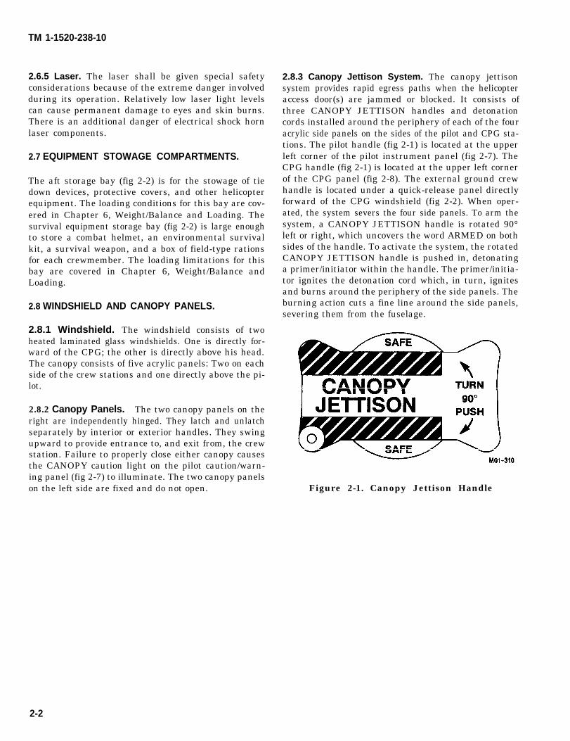
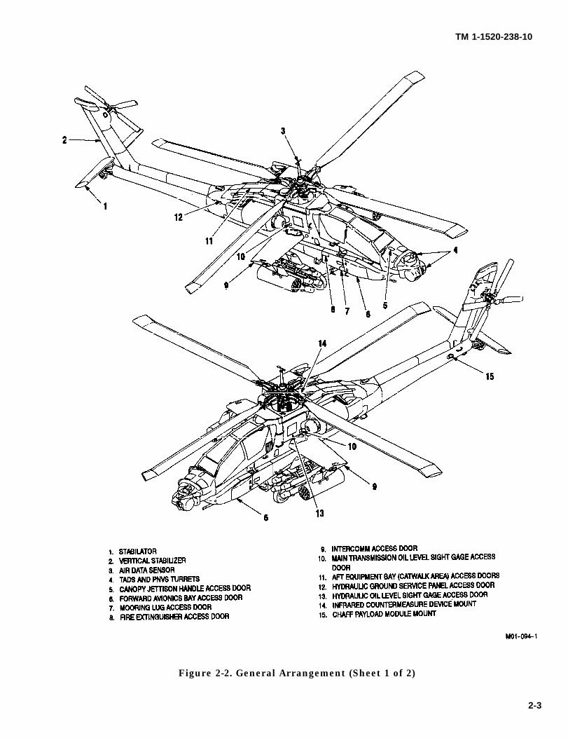
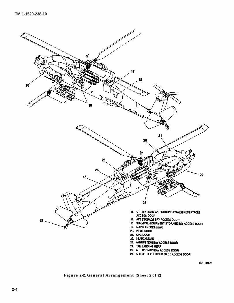
2.2 AIRCRAFT GENERAL ARRANGEMENT.
Figure 2-2 illustrates the general arrangement includingaccessing and some major exterior components.
2.2.1 Fuselage. The fuselage includes a forward, cen-ter, and aft section that employ aluminum alloy semi-monocoque construction. All major weight items (crew,fuel, and ammunition) are supported by bulkheads,frames, and a longitudinal support structure. The for-ward fuselage contains the copilot/gunner (CPG) sta-tion. There are also provisions for mounting the targetacquisition and designation sight (TADS), pilot nightvision sensor (PNVS), and a 30mm area weapon. Thecenter section contains the pilot crew station and pro-vides support for the oleo-damped main landing gear,main transmission, wings, fuel cells, and ammunitionbay. The aft section includes the vertical stabilizer andhas provisions for mounting the tail landing gear. Theavionics bay and stowage compartments are containedin the aft section. The tail rotor, drive shafts, gearboxes,and stabilator are attached to the aft section.
2.2.2 Wings. Left and right wings are attached to thecenter fuselage. They are of aluminum cantilever, spar,and rib construction. Each wing provides two hard-points for external stores and hydraulic and electricalquick disconnects.
2.2.3 Rotors. The helicopter has a fully articulated four-blade main rotor system equipped with elastomeric lead-lag dampers. The tail rotor is a semi-rigid design andconsists of four blades.
2.2.4 Engines. The helicopter is powered by two hori-zontally-mounted turbo-shaft engines. Power is sup-plied to the main transmission through engine- mountednose gearboxes, shafts, and overrunning
clutches. The main transmission drives the main and Xtail rotors and accessory gearbox.
2.3 SPECIAL MISSION KITS.
The helicopter can be equipped with an IR jammer kit,radar jammer kit, radar warning kit, winterization kit,chaff kit, and extended range kit. Refer to the applica-ble system for descriptive information.
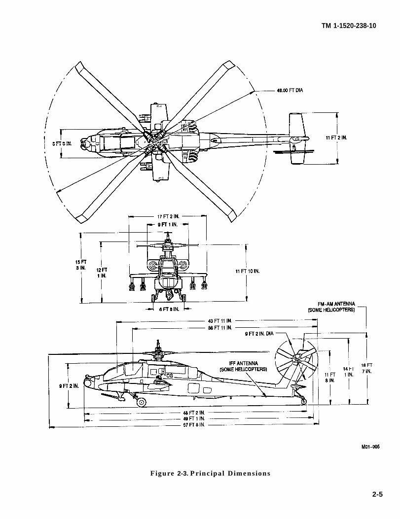
2.4 PRINCIPAL DIMENSIONS.
Figure 2-3 illustrates principal helicopter dimensions.
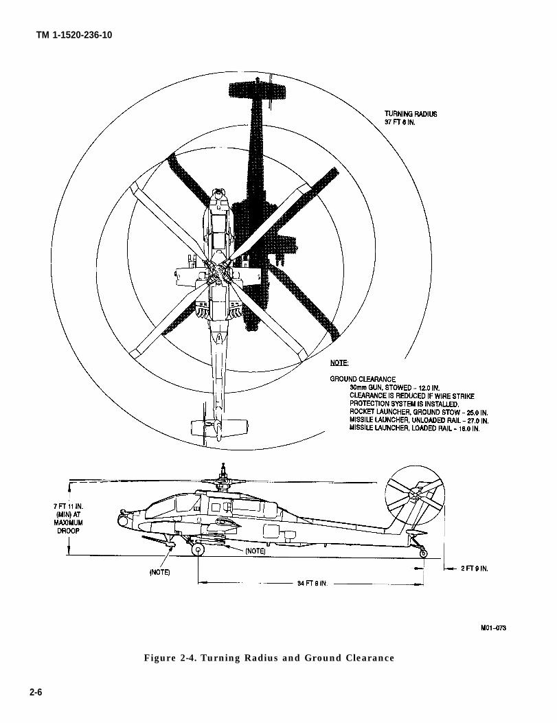
2.5 TURNING RADIUS AND GROUND CLEARANCE.
Figure 2-4 illustrates helicopter turning radius and groundclearance.
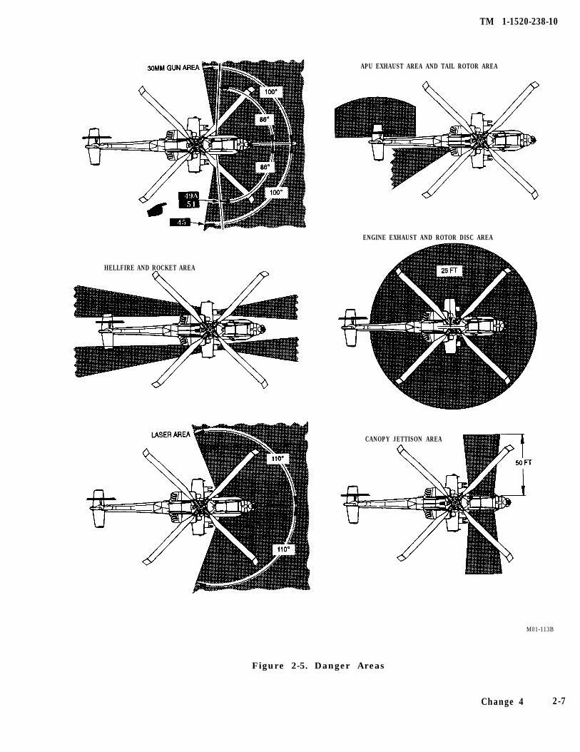
2.6 DANGER AREAS.
2.6.1 Shaded Areas Illustrated. The illustrated shadedareas (fig 2-5) can be hazardous. Personnel ap-proaching an operating helicopter must do so at a 45-degree angle from the front. The approach must bemade from well outside the rotor disc area until recog-nition is received from the pilot. The pilot will then sig-nal when closer approach is safe.
2.6.2 Air Flow. Air flow from the tail rotor and down-wash from the main rotor are dangerous, even outsidethe turning radius of the helicopter when it is in hover oroperating at takeoff power.
2.6.3 Exhaust Gases. Exhaust gases from the heli-copter engines and auxiliary power unit (APU) can causeburns. Personnel should remain clear of these areas.
2.6.4 Canopy Jettison. During canopy jettison, acrylicfragments will be propelled approximately 50 feet fromthe helicopter. Personnel approaching a crash-damagedhelicopter shall look for a signal from the crew that closerapproach is safe.
Change 3 2-1
TM 1-1520-238-10
2.6.5 Laser. The laser shall be given special safetyconsiderations because of the extreme danger involvedduring its operation. Relatively low laser light levelscan cause permanent damage to eyes and skin burns.There is an additional danger of electrical shock hornlaser components.
2.7 EQUIPMENT STOWAGE COMPARTMENTS.
The aft storage bay (fig 2-2) is for the stowage of tiedown devices, protective covers, and other helicopterequipment. The loading conditions for this bay are cov-ered in Chapter 6, Weight/Balance and Loading. Thesurvival equipment storage bay (fig 2-2) is large enoughto store a combat helmet, an environmental survivalkit, a survival weapon, and a box of field-type rationsfor each crewmember. The loading limitations for thisbay are covered in Chapter 6, Weight/Balance andLoading.
2.8 WINDSHIELD AND CANOPY PANELS.
2.8.1 Windshield. The windshield consists of twoheated laminated glass windshields. One is directly for-ward of the CPG; the other is directly above his head.The canopy consists of five acrylic panels: Two on eachside of the crew stations and one directly above the pi-lot.
2.8.2 Canopy Panels. The two canopy panels on theright are independently hinged. They latch and unlatchseparately by interior or exterior handles. They swingupward to provide entrance to, and exit from, the crewstation. Failure to properly close either canopy causesthe CANOPY caution light on the pilot caution/warn-ing panel (fig 2-7) to illuminate. The two canopy panelson the left side are fixed and do not open.
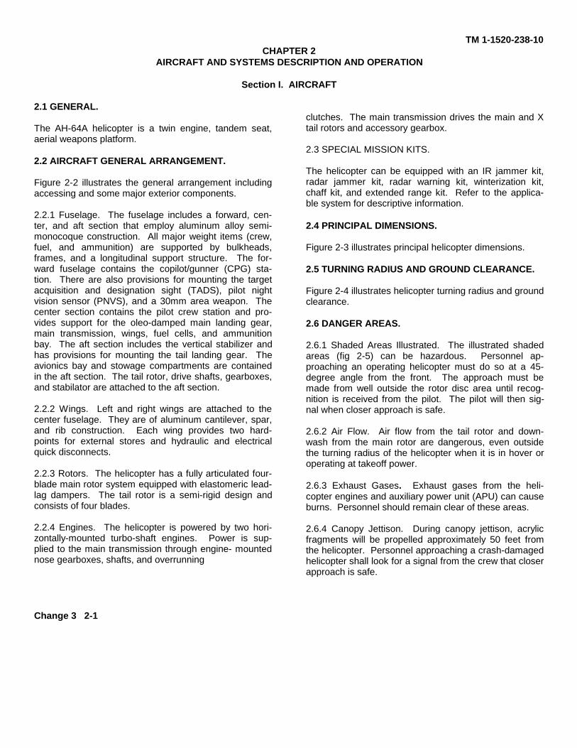
2.8.3 Canopy Jettison System. The canopy jettisonsystem provides rapid egress paths when the helicopteraccess door(s) are jammed or blocked. It consists ofthree CANOPY JETTISON handles and detonationcords installed around the periphery of each of the fouracrylic side panels on the sides of the pilot and CPG sta-tions. The pilot handle (fig 2-1) is located at the upperleft corner of the pilot instrument panel (fig 2-7). TheCPG handle (fig 2-1) is located at the upper left cornerof the CPG panel (fig 2-8). The external ground crewhandle is located under a quick-release panel directlyforward of the CPG windshield (fig 2-2). When oper-ated, the system severs the four side panels. To arm thesystem, a CANOPY JETTISON handle is rotated 90°left or right, which uncovers the word ARMED on bothsides of the handle. To activate the system, the rotatedCANOPY JETTISON handle is pushed in, detonatinga primer/initiator within the handle. The primer/initia-tor ignites the detonation cord which, in turn, ignitesand burns around the periphery of the side panels. Theburning action cuts a fine line around the side panels,severing them from the fuselage.
Figure 2-1. Canopy Jettison Handle
2-2
TM 1-1520-238-10
Figure 2-2. General Arrangement (Sheet 1 of 2)
2-3
TM 1-1520-238-10
Figure 2-2. General Arrangement (Sheet 2 of 2)
2-4
TM 1-1520-238-10
Figure 2-3. Principal Dimensions
2-5
TM 1-1520-236-10
Figure 2-4. Turning Radius and Ground Clearance
2-6
TM 1-1520-238-10
APU EXHAUST AREA AND TAIL ROTOR AREA
HELLFIRE AND ROCKET AREA
ENGINE EXHAUST AND ROTOR DISC AREA
CANOPY JETTISON AREA
M01-113B
Figure 2-5. Danger Areas
Change 4 2-7
TM 1-1520-238-10
2.9 LANDING GEAR.
The main landing gear (fig 2-2) supports the helicopterduring ground operation (taxiing, take-off, and towing).The landing gear system is a three-point system con-sisting of the main landing gear, tail landing gear, andmain landing gear brake system. The landing gear sys-tem provides for ease of maneuvering when taxiing andtowing, has shock struts to absorb normal and high im-pact landings, and kneels to facilitate transport of thehelicopter.
2.9.1 Main Landing Gear. Each main landing gearsupport consists of a trailing arm and a nitrogen/oilshock strut. The trailing arms transfer the helicopterlanding and static loads to the airframe, and the shockstruts absorb vertical loads. The upper ends of the leftand right trailing arms attach to a cross tube whichpasses through the fuselage and is supported by fuse-lage-anchored pivot bearings. The upper ends of theshock struts are attached to mounts on the fuselagestructure. In addition to its normal energy-absorbingfunction, each shock strut has a one-time high impactabsorbing feature: shear rings are sheared and a rup-ture disk bursts causing a controlled collapse of thestrut.
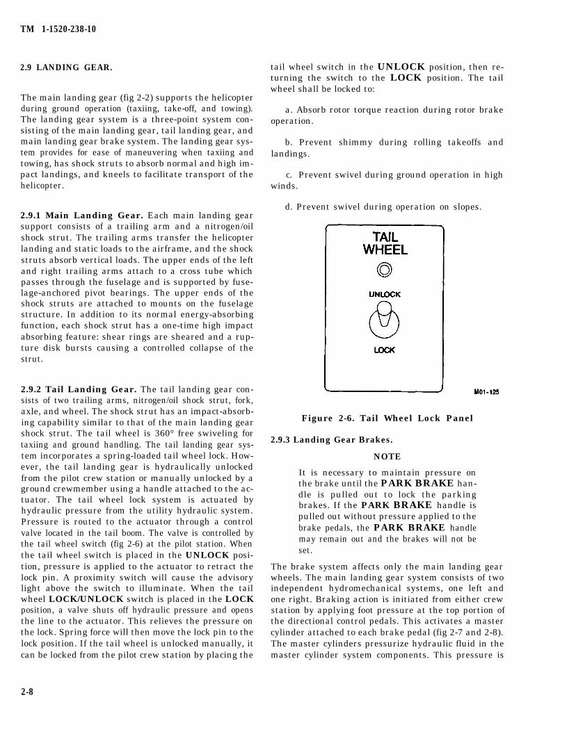
2.9.2 Tail Landing Gear. The tail landing gear con-sists of two trailing arms, nitrogen/oil shock strut, fork,axle, and wheel. The shock strut has an impact-absorb-ing capability similar to that of the main landing gearshock strut. The tail wheel is 360° free swiveling fortaxiing and ground handling. The tail landing gear sys-tem incorporates a spring-loaded tail wheel lock. How-ever, the tail landing gear is hydraulically unlockedfrom the pilot crew station or manually unlocked by aground crewmember using a handle attached to the ac-tuator. The tail wheel lock system is actuated byhydraulic pressure from the utility hydraulic system.Pressure is routed to the actuator through a controlvalve located in the tail boom. The valve is controlled bythe tail wheel switch (fig 2-6) at the pilot station. Whenthe tail wheel switch is placed in the UNLOCK posi-tion, pressure is applied to the actuator to retract thelock pin. A proximity switch will cause the advisorylight above the switch to illuminate. When the tailwheel LOCK/UNLOCK switch is placed in the LOCKposition, a valve shuts off hydraulic pressure and opensthe line to the actuator. This relieves the pressure onthe lock. Spring force will then move the lock pin to thelock position. If the tail wheel is unlocked manually, itcan be locked from the pilot crew station by placing the
2-8
tail wheel switch in the UNLOCK position, then re-turning the switch to the LOCK position. The tailwheel shall be locked to:
a. Absorb rotor torque reaction during rotor brakeoperation.
b. Prevent shimmy during rolling takeoffs andlandings.
c. Prevent swivel during ground operation in highwinds.
d. Prevent swivel during operation on slopes.
Figure 2-6. Tail Wheel Lock Panel
2.9.3 Landing Gear Brakes.
NOTE
It is necessary to maintain pressure onthe brake until the PARK BRAKE han-dle is pulled out to lock the parkingbrakes. If the PARK BRAKE handle ispulled out without pressure applied to thebrake pedals, the PARK BRAKE handlemay remain out and the brakes will not beset.
The brake system affects only the main landing gearwheels. The main landing gear system consists of twoindependent hydromechanical systems, one left andone right. Braking action is initiated from either crewstation by applying foot pressure at the top portion ofthe directional control pedals. This activates a mastercylinder attached to each brake pedal (fig 2-7 and 2-8).The master cylinders pressurize hydraulic fluid in themaster cylinder system components. This pressure is
TM 1-1520-238-10
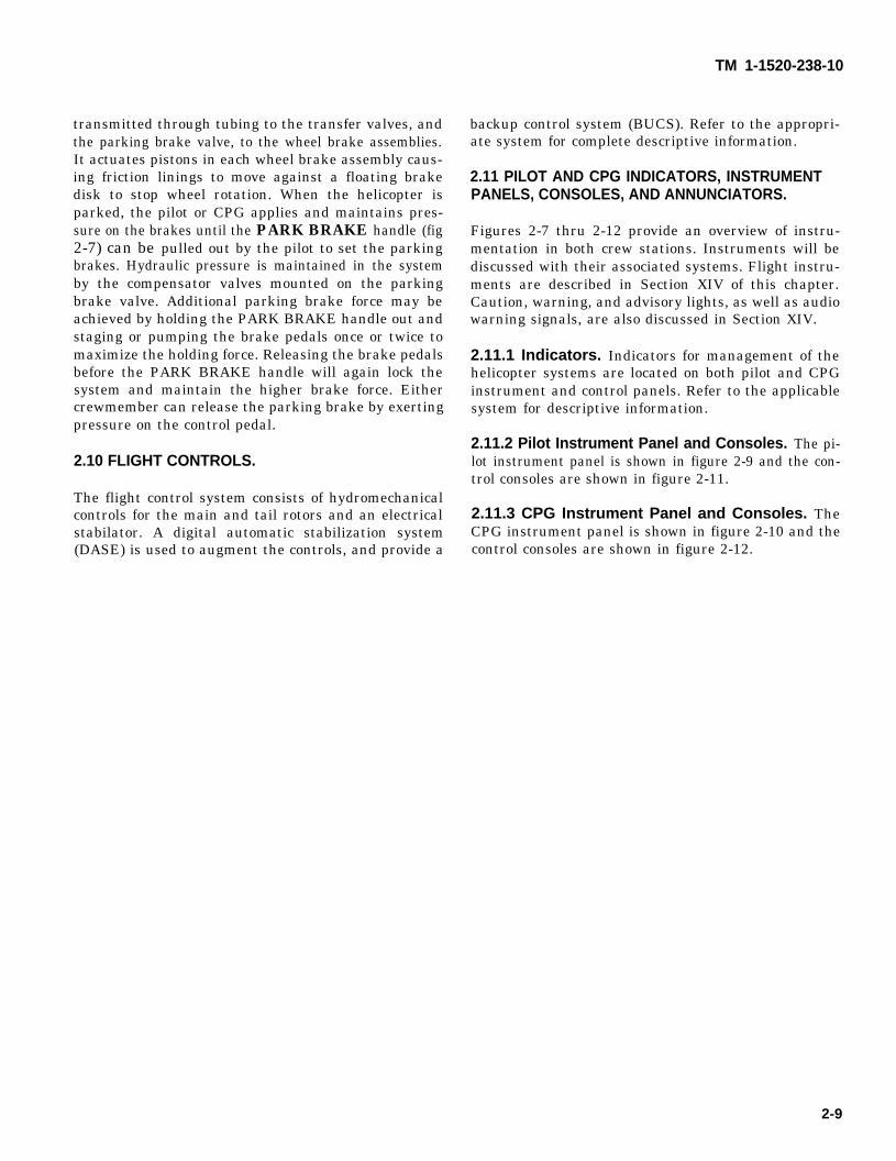
transmitted through tubing to the transfer valves, andthe parking brake valve, to the wheel brake assemblies.It actuates pistons in each wheel brake assembly caus-ing friction linings to move against a floating brakedisk to stop wheel rotation. When the helicopter isparked, the pilot or CPG applies and maintains pres-sure on the brakes until the PARK BRAKE handle (fig2-7) can be pulled out by the pilot to set the parkingbrakes. Hydraulic pressure is maintained in the systemby the compensator valves mounted on the parkingbrake valve. Additional parking brake force may beachieved by holding the PARK BRAKE handle out andstaging or pumping the brake pedals once or twice tomaximize the holding force. Releasing the brake pedalsbefore the PARK BRAKE handle will again lock thesystem and maintain the higher brake force. Eithercrewmember can release the parking brake by exertingpressure on the control pedal.
2.10 FLIGHT CONTROLS.
The flight control system consists of hydromechanicalcontrols for the main and tail rotors and an electricalstabilator. A digital automatic stabilization system(DASE) is used to augment the controls, and provide a
backup control system (BUCS). Refer to the appropri-ate system for complete descriptive information.
2.11 PILOT AND CPG INDICATORS, INSTRUMENTPANELS, CONSOLES, AND ANNUNCIATORS.
Figures 2-7 thru 2-12 provide an overview of instru-mentation in both crew stations. Instruments will bediscussed with their associated systems. Flight instru-ments are described in Section XIV of this chapter.Caution, warning, and advisory lights, as well as audiowarning signals, are also discussed in Section XIV.
2.11.1 Indicators. Indicators for management of thehelicopter systems are located on both pilot and CPGinstrument and control panels. Refer to the applicablesystem for descriptive information.
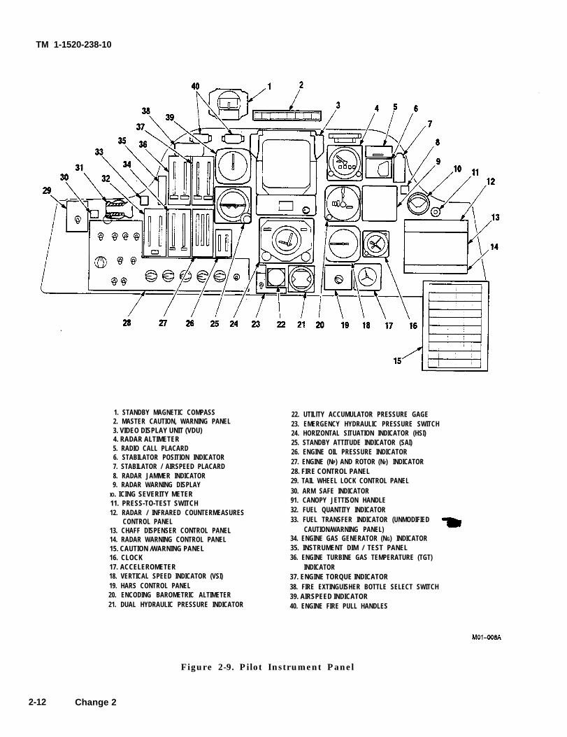
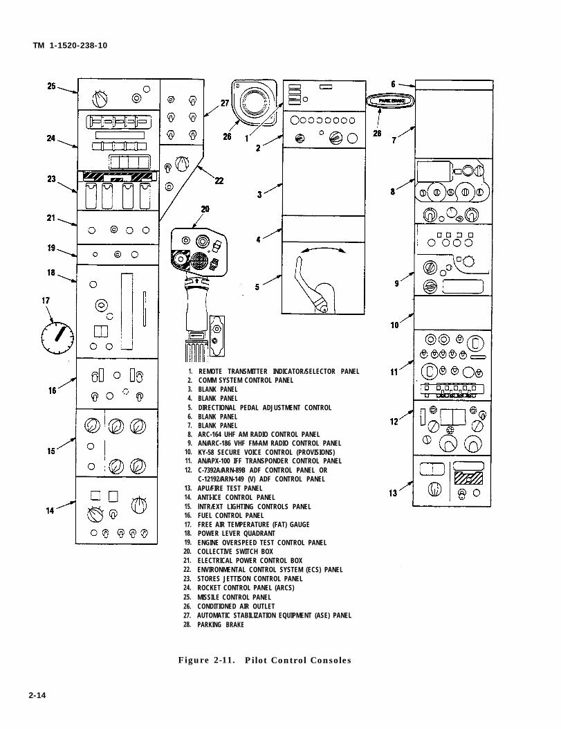
2.11.2 Pilot Instrument Panel and Consoles. The pi-lot instrument panel is shown in figure 2-9 and the con-trol consoles are shown in figure 2-11.
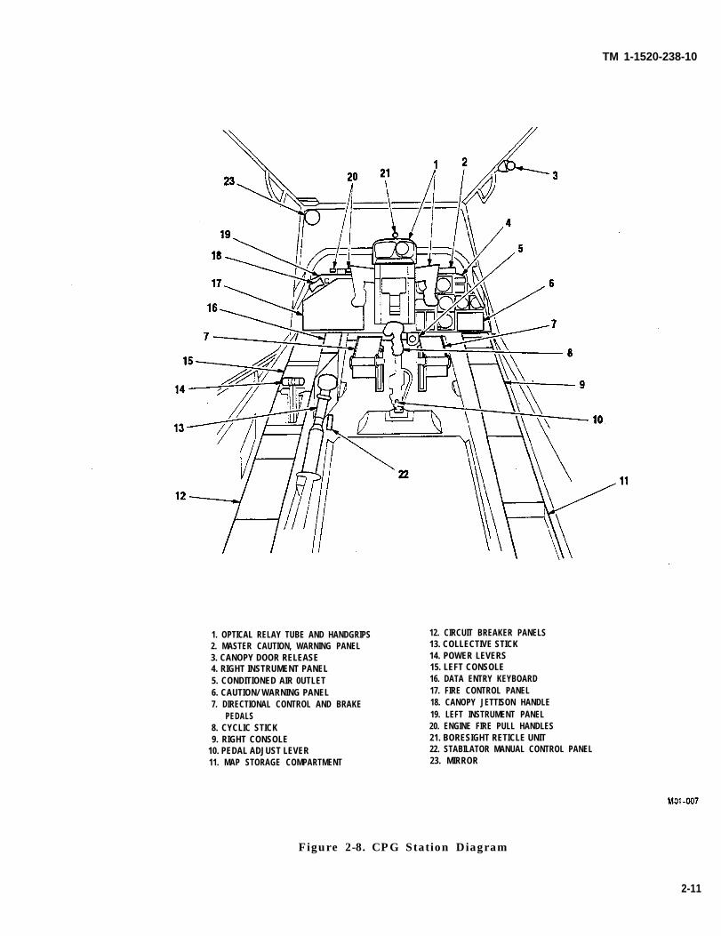
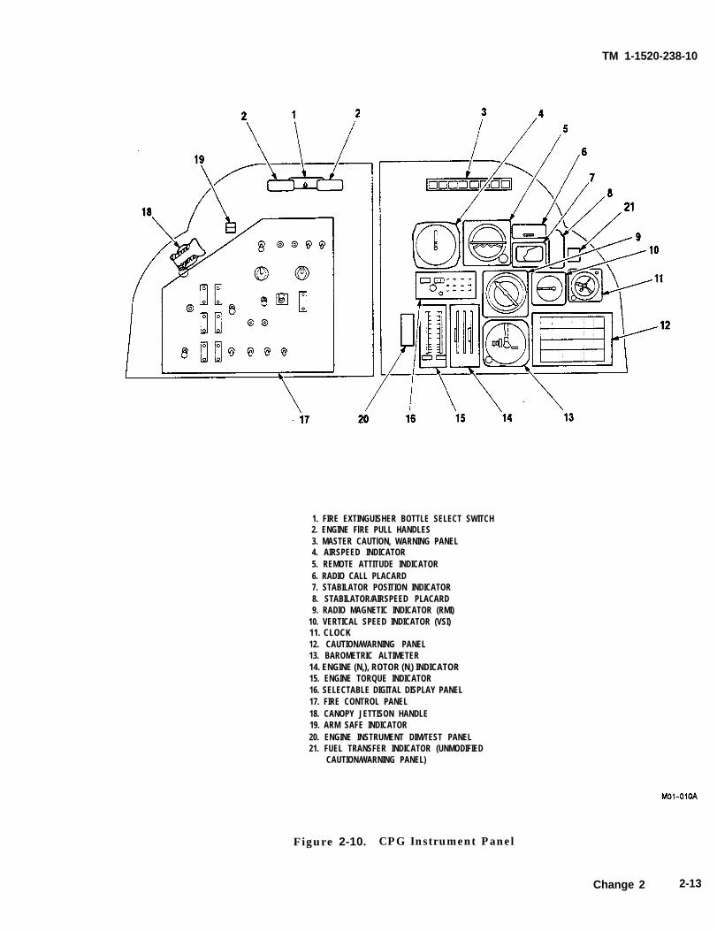
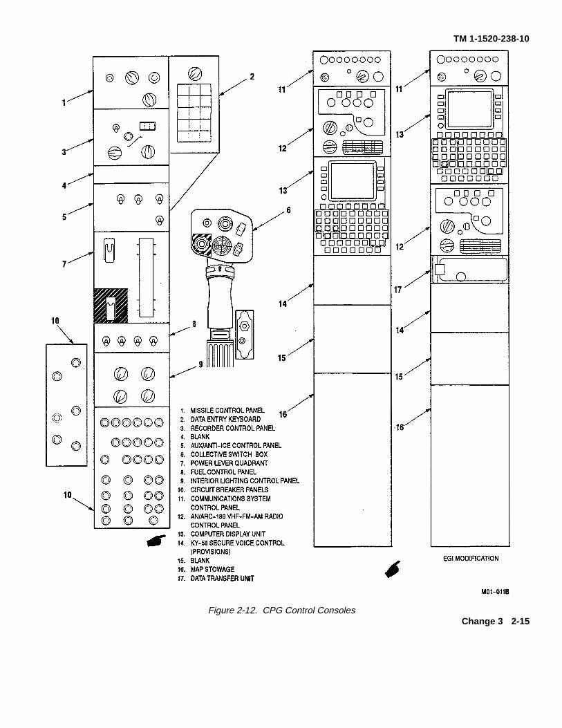
2.11.3 CPG Instrument Panel and Consoles. TheCPG instrument panel is shown in figure 2-10 and thecontrol consoles are shown in figure 2-12.
2-9

TM 1-1520-238-10
Figure 2-7. Pilot Station Diagram
2-10
TM 1-1520-238-10
1. OPTICAL RELAY TUBE AND HANDGRIPS2. MASTER CAUTION, WARNING PANEL3. CANOPY DOOR RELEASE4. RIGHT INSTRUMENT PANEL5. CONDITIONED AIR 0UTLET6. CAUTION/ WARNING PANEL7. DIRECTIONAL CONTROL AND BRAKE
PEDALS8. CYCLIC STICK9. RIGHT CONSOLE
10. PEDAL ADJUST LEVER11. MAP STORAGE COMPARTMENT
12. CIRCUIT BREAKER PANELS13. COLLECTIVE STICK14. POWER LEVERS15. LEFT CONSOLE16. DATA ENTRY KEYBOARD17. FIRE CONTROL PANEL18. CANOPY JETTISON HANDLE19. LEFT INSTRUMENT PANEL20. ENGINE FIRE PULL HANDLES21. BORESIGHT RETICLE UNIT22. STABILATOR MANUAL CONTROL PANEL23. MIRROR
Figure 2-8. CPG Station Diagram
2-11
TM 1-1520-238-10
1. STANDBY MAGNETIC COMPASS2. MASTER CAUTION, WARNING PANEL3. VIDEO DISPLAY UNIT (VDU)4. RADAR ALTIMETER5. RADIO CALL PLACARD6. STABILATOR POSITION INDICATOR7. STABILATOR / AIRSPEED PLACARD8. RADAR JAMMER INDICATOR9. RADAR WARNING DISPLAY
IO. ICING SEVERITY METER11. PRESS-TO-TEST SWITCH12. RADAR / INFRARED COUNTERMEASURES
CONTROL PANEL13. CHAFF DISPENSER CONTROL PANEL14. RADAR WARNING CONTROL PANEL15. CAUTION /WARNING PANEL16. CLOCK17. ACCELEROMETER18. VERTICAL SPEED INDICATOR (VSI)19. HARS CONTROL PANEL20. ENCODING BAROMETRIC ALTIMETER21. DUAL HYDRAULIC PRESSURE INDICATOR
22. UTILlTY ACCUMULATOR PRESSURE GAGE23. EMERGENCY HYDRAULIC PRESSURE SWITCH24. HORIZONTAL SITUATION INDICATOR (HSI)25. STANDBY ATTITUDE INDICATOR (SAI)26. ENGINE OIL PRESSURE INDICATOR27. ENGINE (NP) AND ROTOR (Nr) INDICATOR28. FIRE CONTROL PANEL29. TAIL WHEEL LOCK CONTROL PANEL30. ARM SAFE INDICATOR91. CANOPY JETTISON HANDLE32. FUEL QUANTITY INDICATOR33. FUEL TRANSFER INDICATOR (UNMODIFIED
CAUTION/WARNING PANEL)34. ENGINE GAS GENERATOR (NG) INDICATOR35. INSTRUMENT DIM / TEST PANEL 36. ENGINE TURBINE GAS TEMPERATURE (TGT)
INDICATOR37. ENGINE TORQUE INDICATOR38. FIRE EXTINGUISHER BOTTLE SELECT SWITCH39. AIRSPEED INDICATOR40. ENGINE FIRE PULL HANDLES
Figure 2-9. Pilot Instrument Panel
2-12 Change 2
TM 1-1520-238-10
1. FIRE EXTINGUISHER BOTTLE SELECT SWITCH2. ENGINE FlRE PULL HANDLES3. MASTER CAUTlON, WARNING PANEL4. AIRSPEED INDICATOR5. REMOTE ATTITUDE INDICATOR6. RADIO CALL PLACARD7. STABILATOR POSITION INDICATOR8. STABILATOR/AIRSPEED PLACARD9. RADIO MAGNETIC INDICATOR (RMI)
10. VERTICAL SPEED INDICATOR (VSI)11. CLOCK12. CAUTION/WARNING PANEL13. BAROMETRIC ALTIMETER14. ENGINE (NP), ROTOR (Nr) INDICATOR15. ENGINE TORQUE INDICATOR16. SELECTABLE DIGITAL DISPLAY PANEL17. FIRE CONTROL PANEL18. CANOPY JETTISON HANDLE19. ARM SAFE INDICATOR20. ENGINE INSTRUMENT DIM/TEST PANEL21. FUEL TRANSFER INDICATOR (UNMODIFIED
CAUTION/WARNING PANEL)
Figure 2-10. CPG Instrument Panel
Change 2 2-13
TM 1-1520-238-10
1.2.3.4.5.6.7.8.9.
10.11.12.
13.14.15.16.17.18.19.20.21.22.23.24.25.26.27.28.
REMOTE TRANSMITTER INDICATOR/SELECTOR PANELCOMM SYSTEM CONTROL PANELBLANK PANELBLANK PANELDIRECTIONAL PEDAL ADJUSTMENT CONTROLBLANK PANELBLANK PANELARC-164 UHF AM RADIO CONTROL PANELAN/ARC-186 VHF FM-AM RADIO CONTROL PANELKY-58 SECURE VOICE CONTROL (PROVISIONS)AN/APX-100 IFF TRANSPONDER CONTROL PANELC-7392A/ARN-89B ADF CONTROL PANEL ORC-12192/ARN-149 (V) ADF CONTROL PANELAPU/FIRE TEST PANELANTI-ICE CONTROL PANELlNTR/EXT LIGHTING CONTROLS PANELFUEL CONTROL PANELFREE AIR TEMPERATURE (FAT) GAUGEPOWER LEVER QUADRANTENGINE OVERSPEED TEST CONTROL PANELCOLLECTIVE SWITCH BOXELECTRICAL POWER CONTROL BOXENVIRONMENTAL CONTROL SYSTEM (ECS) PANELSTORES JETTISON CONTROL PANELROCKET CONTROL PANEL (ARCS)MISSILE CONTROL PANELCONDITIONED AIR OUTLETAUTOMATIC STABILIZATION EQUIPMENT (ASE) PANELPARKING BRAKE
Figure 2-11. Pilot Control Consoles
2-14
TM 1-1520-238-10
Figure 2-12. CPG Control ConsolesChange 3 2-15
WARNING
WARNING
TM 1-1520-236-10
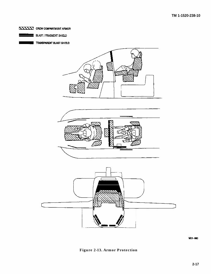
2.12 CREW COMPARTMENTS.
The crew compartments are arranged in tandem andare separated by a ballistic shield (fig 2-13). The pilotsits aft of the CPG. Handholds and steps permit bothcrewmembers to enter and exit at the right side of thehelicopter. A canopy covers both crew stations. Thecanopy frame and the transparent ballistic shield forma rollover structure. To provide for maximum survivaland minimum vulnerability, armored seats areinstalled in both crew compartments.
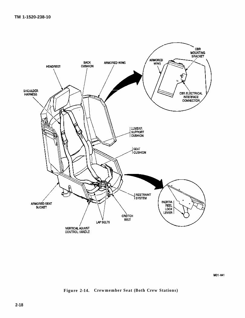
2.13 CREWMEMBER SEATS.
Seats stroke downward during acrash and any obstruction may in-crease the possibility of injury. Itemsshould not be placed beneath seats.
The pilot and CPG seats (fig 2-14) provide ballisticprotection and can be adjusted for height only. They areone-piece armored seats equipped with back, seat, andlumbar support cushions. Each seat is equipped with ashoulder harness lap belt, crotch belt, and inertial reel.The shoulder harness and belts have adjustment fit-tings and come together at a common attachment point.This provides a single release that can be rotated eitherclockwise or counterclockwise to simultaneously re-lease the shoulder harness and all belts.
2.13.1 Seat Height Adjustment. Vertical seat adjust-ment is controlled by a lever on the right front of theseat bucket. When the lever is pulled out (sideways),the seat can be moved vertically approximately 4 in-ches and locked at any 3/4-inch interval. Springs coun-terbalance the weight of the seat. The lever returns tothe locked position when released.
With the collective in other than full-down position, the inertia reel con-trol handle may be inaccessible.
2.13.2 Shoulder Harness Inertia Reel Lock Lever. Atwo-position shoulder harness inertia reel lock lever isinstalled on the lower left side of each seat (fig 2-14).When the lever is in the aft position, the shoulder har-ness lock will engage only when a forward force of 1-1/2to 2Gs is exerted on the mechanism. In the forwardposition, the shoulder harness lock assembly is firmlylocked. Whenever the inertia reels lock because of de-celeration forces, they remain locked until the lock le-ver is placed in forward and then aft position.
2.13.3 Chemical, Biological, Radiological (CBR) Fil-ter/Blower Mounting Bracket. The left side armoredwing of each seat has a mounting bracket (fig 2-14)with an electrical interface connector for a CBR filter/blower.
2-16
TM 1-1520-238-10
Figure 2-13. Armor Protection
2-17
TM 1-1520-238-10
Figure 2-14. Crewmember Seat (Both Crew Stations)
2-18
WARNING
TM 1-1520-236-10
Section Il. EMERGENCY EQUIPMENT
2.14 GENERAL.
Emergency equipment on the helicopter consists of fireextinguishing equipment and two first aid kits (fig 9-1).
Exposure to high concentration offire extinguishing agent or decom-position products should be avoided.The gas should not be allowed to con-tact the skin; it could cause frostbiteor low temperature burns. If agentcomes in contact with skin, seek med-ical help immediately.
2.15 PORTABLE FIRE EXTlNGUISHER.
A pressurized fire extinguisher is mounted on a quickrelease support located in the FAB fairing aft of theright FAB door and above the main landing gear wheel(fig 2-2). It is accessible through a hinged access paneland the panel is marked FIRE EXTINGUISHER IN-SIDE. The fire extinguisher compound is released by ahand-operated lever on top of the extinguisher. Inad-vertent discharge of the bottle is prevented by a break-away safety wire across the actuating lever. Operatinginstructions are printed on the extinguisher.
2.16 ENGINE AND AUXILIARY POWER UNIT (APU)FIRE DETECTION.
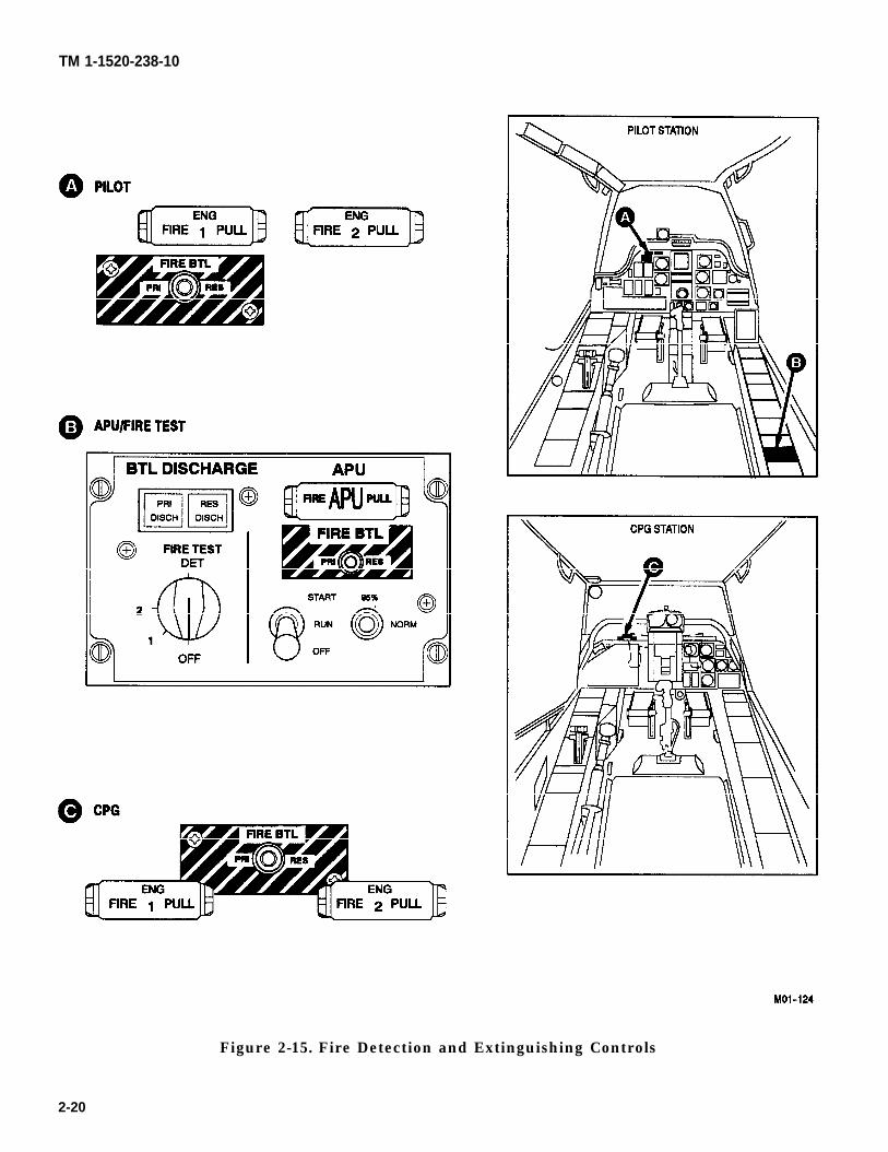
Two optical sensors, which react to visible flames, arelocated in each engine compartment and in the APUcompartment. Three pneumatic fire/overheat detectorsare located in the aft deck area. One detector ismounted on the main transmission support, and one oneach of the two firewall louver doors. Amplified electri-cal signals from the sensors located in the enginecompartment will illuminate the respective ENGFIRE PULL handle (fig 2-15) in both crew stations.The APU compartment sensors, or the aft deck fire/overheat detectors, will illuminate the FIRE APUPULL handle (fig 2-15) in the pilot station and theFIRE APU segment on the MASTER CAUTION pan-el in both crew stations. The engine fire pull handles(ENG FIRE 1 PULL and ENG FIRE 2 PULL) arelocated in similar positions in both crew stations; theyare at the upper left corner of the instrument panel.The FIRE APU PULL handle is located on the APUpanel on the pilot right console.
2.16.1 Engine and APU Fire Detector Testing. FIREPULL handle lamps are tested by pressing the PRESSTO TEST pushbutton on the MASTER CAUTIONpanel in either crew station. The fire detector circuitsreceive 28 vdc from the emergency dc bus through theFIRE DETR circuit breakers (ENG 1, ENG 2 andAPU) on the pilot overhead circuit breaker panel (fig2-39). The fire detector circuits are tested by turningthe FIRE TEST DET rotary switch located on the pi-lots aft right console (fig 2-15). The switch is spring-loaded to OFF. When set at 1, the first sensor circuit forNo. 1 engine, No. 2 engine, APU, and left and right fire-wall louver door fire detectors are tested, which causesall FIRE PULL handles to illuminate. The FIRE APUsegments on both MASTER CAUTION panels also il-luminate. When the FIRE TEST DET switch is set at2, the second sensor circuit for No. 1 engine, No. 2 en-gine, APU, and main transmission support fire detectorare tested; and all FIRE PULL handles and bothFIRE APU MASTER CAUTION panel segments willilluminate. In either test, failure of a handle to light upindicates a fault in that particular sensor circuit.
2.17 ENGINE AND APU FIRE EXTINGUISHINGSYSTEM
The fire extinguishing agent is stored in two sphericalbottles, each containing a nitrogen precharge. Thebottles, designated as primary (PRI) and reserve(RES) are mounted on the fuselage side of the No. 1 en-gine firewall. Tubing is installed to distribute the extin-guishing agent to either of the engine nacelles or to theAPU compartment. Bottle integrity maybe checked byinspecting the thermal relief discharge indicator whichis viewed from below the left engine nacelle. A pressuregage on each bottle provides an indication of the nitro-gen precharge pressure. Each bottle has three dis-charge valves that can be individually actuated by anelectrically ignited pyrotechnic squib. There is onevalve for each of the engine nacelles and one for theAPU compartment. When a FIRE PULL handle ispulled, four events occur: fuel is shut off to the affectedengine, engine cooling louvers to the affected engineclose (not applicable to the APU), the appropriate squibfiring circuit is armed, and the ENCU is shut off (notapplicable to the APU). The extinguishing agent is notreleased to the fire area, however, until the FIRE BTLswitch, located near each fire pull handle, is activated.The FIRE BTL switch is first set at PRI (primarybottle) . When the fire is extinguished, the light in the
2-19
TM 1-1520-238-10
Figure 2-15. Fire Detection and Extinguishing Controls
2-20

TM 1-1520-238-10
FIRE PULL handle will go out. If the fire is not extin-guished, setting the switch at RES discharges the se-cond bottle. Bottle discharge is indicated on the FIRETEST panel by illumination of the PRI DISCH andRES DISCH displays. The fire extinguishingequipment receives 28 vdc from the emergency dc busthrough the PILOT, CPG and APU FIRE EXTGHcircuit breakers on the pilot overhead circuit breakerpanel.
2.18 FIRST AID KITS.
Two first aid kits are provided: one on the inside, aftportion of the pilots right canopy panel and one on thelower side of the CPG left console.
2.19 CHEMICAL, BIOLOGICAL, ANDRADIOLOGICAL (CBR) FILTER/BLOWER.
The CBR filter/blower provides filtered air to the flightcrew when cockpit air is contaminated. Each crewmember carries his own CBR blower/mask on boardand connects it to the external power source, located onthe left side armored wing of his seat (fig 2-14).
Refer to TM 3-4240-312-12&P for CBR filter blower op-eration, installation and maintenance instructions.
2.20 EMERGENCY PROCEDURES.
Chapter 9 describes emergency procedures.
2 - 2 1
TM 1-1520-238-10
Section Ill. ENGINES AND RELATED SYSTEMS
2.21 ENGINES.
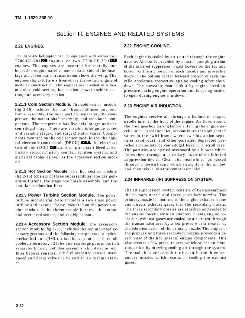
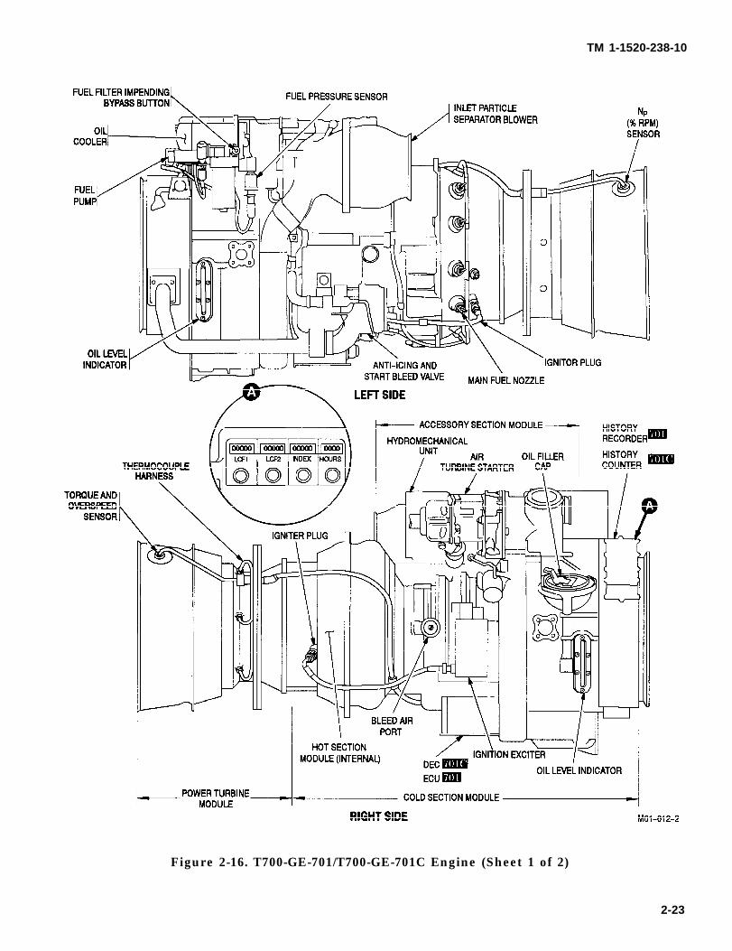
The AH-64A helicopter can be equipped with either twoT700-GE-701 engines or two T700-GE-701C engines. The engines are mounted horizontally andhoused in engine nacelles one on each side of the fuse-lage aft of the main transmission above the wing. Theengines (fig 2-16) are a front-drive turboshaft engine ofmodular construction. The engines are divided into fourmodules: cold section, hot section, power turbine sec-tion, and accessory section.
2.21.1 Cold Section Module. The cold section module(fig 2-16) includes the main frame, diffuser and midframe assembly, the inlet particle separator, the com-pressor, the output shaft assembly, and associated com-ponents. The compressor has five axial stages and onecentrifugal stage. There are variable inlet guide vanesand variable stage-1 and stage-2 stator vanes. Compo-nents mounted on the cold section module are: the digi-tal electronic control unit (DECU) , the electricalcontrol unit (ECU) , anti-icing and start bleed valve,history recorder/history counter, ignition system, andelectrical cables as well as the accessory section mod-ule.
2.21.2 Hot Section Module. The hot section module(fig 2-16) consists of three subassemblies: the gas gen-erator turbine, the stage one nozzle assembly, and theannular combustion liner.
2.21.3 Power Turbine Section Module. The powerturbine module (fig 2-16) includes a two stage powerturbine and exhaust frame. Mounted on the power tur-bine module is the thermocouple harness, the torqueand overspeed sensor, and the Np sensor.
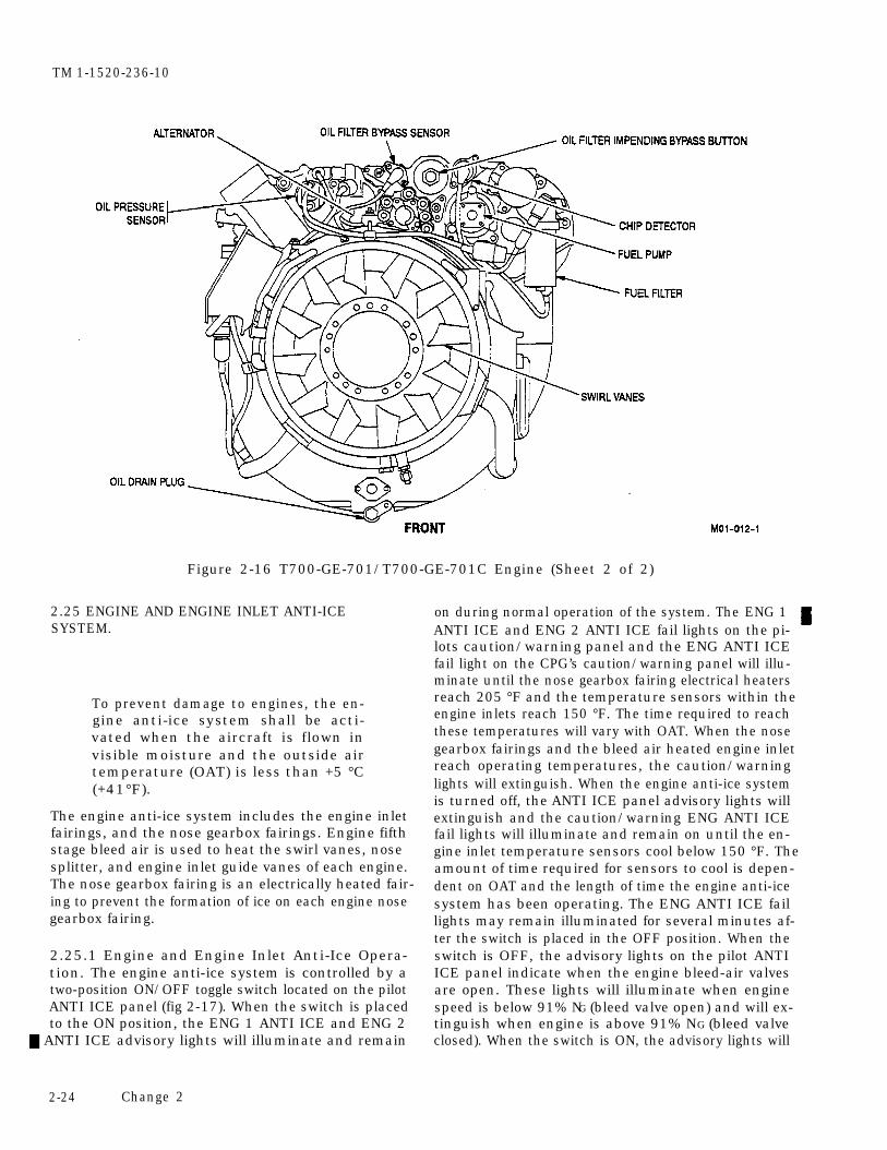
2.21.4 Accessory Section Module. The accessorysection module (fig 2-16) includes the top mounted ac-cessory gearbox and the following components: a hydro-mechanical unit (HMU), a fuel boost pump, oil filter, oilcooler, alternator, oil lube and scavenge pump, particleseparator blower, fuel filter assembly, chip detector, oil/filter bypass sensors, oil/fuel pressure sensor, over-speed and drain valve (ODV), and an air turbine start-er.
2.22 ENGINE COOLING.
Each engine is cooled by air routed through the enginenacelle. Airflow is provided by eductor pumping actionof the infrared suppressor. Fixed louvers on the top andbottom of the aft portion of each nacelle and moveabledoors in the bottom center forward portion of each na-celle accelerate convective engine cooling after shut-down. The moveable door is shut by engine bleed-airpressure during engine operation and is spring-loadedto open during engine shutdown.
2.23 ENGINE AIR INDUCTION.
The engines receive air through a bellmouth shapednacelle inlet at the front of the engine. Air flows aroundthe nose gearbox fairing before entering the engine na-celle inlet. From the inlet, air continues through cantedvanes in the swirl frame where swirling action sepa-rates sand, dust, and other particles. Separated par-ticles accumulate by centrifugal force in a scroll case.The particles are ejected overboard by a blower whichforces them through a secondary nozzle of the infraredsuppression device. Clean air, meanwhile, has passedthrough a deswirl vane which straightens the airflowand channels it into the compressor inlet.
2.24 INFRARED (IR) SUPPRESSION SYSTEM.
The IR suppression system consists of two assemblies:the primary nozzle and three secondary nozzles. Theprimary nozzle is mounted to the engine exhaust frameand directs exhaust gases into the secondary nozzle.The three secondary nozzles are attached and sealed tothe engine nacelle with an adapter. During engine op-eration, exhaust gases are cooled by air drawn throughthe transmission area by a low pressure area created bythe eduction action of the primary nozzle. The angles ofthe primary and three secondary nozzles prevents a di-rect view of the hot internal engine components. Thisalso creates a low pressure area which causes an educ-tion action by drawing cooling air through the system.The cool air is mixed with the hot air in the three sec-ondary nozzles which results in cooling the exhaustgases.
2-22
TM 1-1520-238-10
Figure 2-16. T700-GE-701/T700-GE-701C Engine (Sheet 1 of 2)
2-23
TM 1-1520-236-10
Figure 2-16 T700-GE-701/T700-GE-701C Engine (Sheet 2 of 2)
2.25 ENGINE AND ENGINE INLET ANTI-ICESYSTEM.
To prevent damage to engines, the en-gine anti-ice system shall be acti-vated when the aircraft is flown invisible moisture and the outside airtemperature (OAT) is less than +5 °C(+41°F).
The engine anti-ice system includes the engine inletfairings, and the nose gearbox fairings. Engine fifthstage bleed air is used to heat the swirl vanes, nose splitter, and engine inlet guide vanes of each engine.The nose gearbox fairing is an electrically heated fair-ing to prevent the formation of ice on each engine nosegearbox fairing.
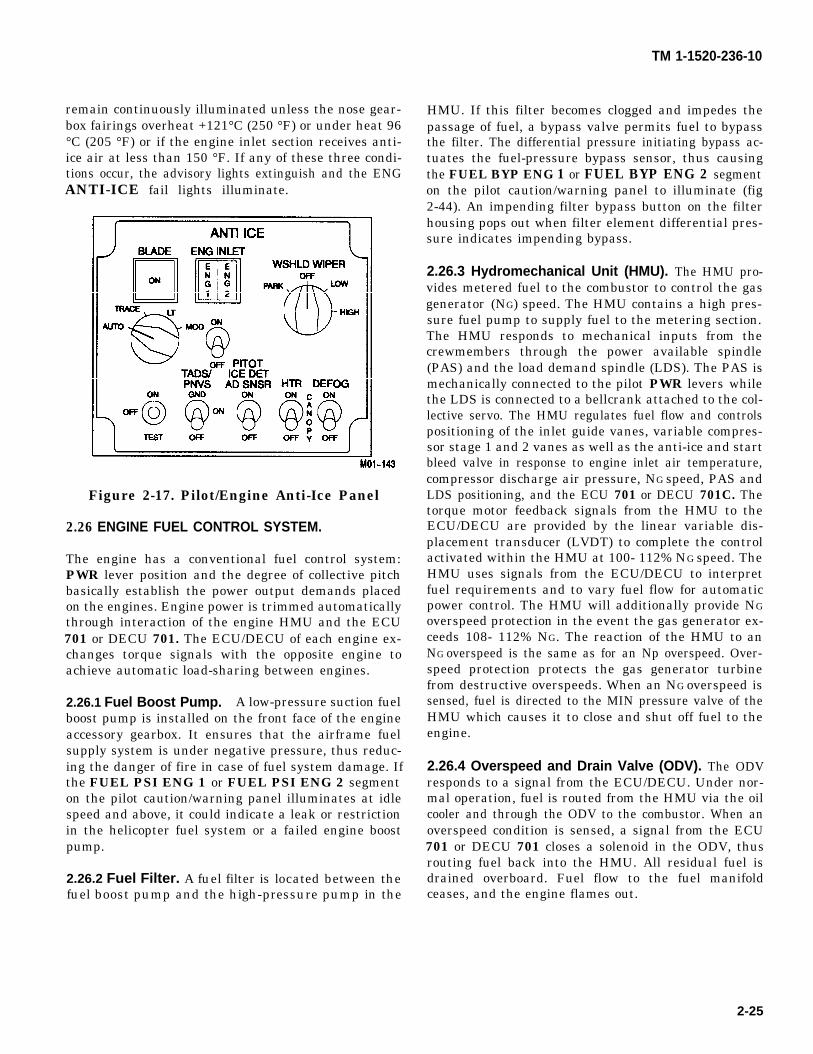
2.25.1 Engine and Engine Inlet Anti-Ice Opera-tion. The engine anti-ice system is controlled by atwo-position ON/OFF toggle switch located on the pilotANTI ICE panel (fig 2-17). When the switch is placedto the ON position, the ENG 1 ANTI ICE and ENG 2
ANTI ICE advisory lights will illuminate and remain
on during normal operation of the system. The ENG 1 ANTI ICE and ENG 2 ANTI ICE fail lights on the pi-lots caution/warning panel and the ENG ANTI ICEfail light on the CPG’s caution/warning panel will illu-minate until the nose gearbox fairing electrical heatersreach 205 °F and the temperature sensors within theengine inlets reach 150 °F. The time required to reachthese temperatures will vary with OAT. When the nosegearbox fairings and the bleed air heated engine inletreach operating temperatures, the caution/warninglights will extinguish. When the engine anti-ice systemis turned off, the ANTI ICE panel advisory lights willextinguish and the caution/warning ENG ANTI ICEfail lights will illuminate and remain on until the en-gine inlet temperature sensors cool below 150 °F. Theamount of time required for sensors to cool is depen-dent on OAT and the length of time the engine anti-icesystem has been operating. The ENG ANTI ICE faillights may remain illuminated for several minutes af-ter the switch is placed in the OFF position. When theswitch is OFF, the advisory lights on the pilot ANTIICE panel indicate when the engine bleed-air valvesare open. These lights will illuminate when enginespeed is below 91% NG (bleed valve open) and will ex-tinguish when engine is above 91% NG (bleed valveclosed). When the switch is ON, the advisory lights will
2-24 Change 2
TM 1-1520-236-10
remain continuously illuminated unless the nose gear-box fairings overheat +121°C (250 °F) or under heat 96°C (205 °F) or if the engine inlet section receives anti-ice air at less than 150 °F. If any of these three condi-tions occur, the advisory lights extinguish and the ENGANTI-ICE fail lights illuminate.
Figure 2-17. Pilot/Engine Anti-Ice Panel
2.26 ENGINE FUEL CONTROL SYSTEM.
The engine has a conventional fuel control system:PWR lever position and the degree of collective pitchbasically establish the power output demands placedon the engines. Engine power is trimmed automaticallythrough interaction of the engine HMU and the ECU701 or DECU 701. The ECU/DECU of each engine ex-changes torque signals with the opposite engine toachieve automatic load-sharing between engines.
2.26.1 Fuel Boost Pump. A low-pressure suction fuelboost pump is installed on the front face of the engineaccessory gearbox. It ensures that the airframe fuelsupply system is under negative pressure, thus reduc-ing the danger of fire in case of fuel system damage. Ifthe FUEL PSI ENG 1 or FUEL PSI ENG 2 segmenton the pilot caution/warning panel illuminates at idlespeed and above, it could indicate a leak or restrictionin the helicopter fuel system or a failed engine boostpump.
2.26.2 Fuel Filter. A fuel filter is located between thefuel boost pump and the high-pressure pump in the
HMU. If this filter becomes clogged and impedes thepassage of fuel, a bypass valve permits fuel to bypassthe filter. The differential pressure initiating bypass ac-tuates the fuel-pressure bypass sensor, thus causingthe FUEL BYP ENG 1 or FUEL BYP ENG 2 segmenton the pilot caution/warning panel to illuminate (fig2-44). An impending filter bypass button on the filterhousing pops out when filter element differential pres-sure indicates impending bypass.
2.26.3 Hydromechanical Unit (HMU). The HMU pro-vides metered fuel to the combustor to control the gasgenerator (NG) speed. The HMU contains a high pres-sure fuel pump to supply fuel to the metering section.The HMU responds to mechanical inputs from thecrewmembers through the power available spindle(PAS) and the load demand spindle (LDS). The PAS ismechanically connected to the pilot PWR levers whilethe LDS is connected to a bellcrank attached to the col-lective servo. The HMU regulates fuel flow and controlspositioning of the inlet guide vanes, variable compres-sor stage 1 and 2 vanes as well as the anti-ice and startbleed valve in response to engine inlet air temperature,compressor discharge air pressure, NG speed, PAS andLDS positioning, and the ECU 701 or DECU 701C. Thetorque motor feedback signals from the HMU to theECU/DECU are provided by the linear variable dis-placement transducer (LVDT) to complete the controlactivated within the HMU at 100- 112% NG speed. TheHMU uses signals from the ECU/DECU to interpretfuel requirements and to vary fuel flow for automaticpower control. The HMU will additionally provide NG
overspeed protection in the event the gas generator ex-ceeds 108- 112% NG. The reaction of the HMU to anNG overspeed is the same as for an Np overspeed. Over-speed protection protects the gas generator turbinefrom destructive overspeeds. When an NG overspeed issensed, fuel is directed to the MIN pressure valve of theHMU which causes it to close and shut off fuel to theengine.
2.26.4 Overspeed and Drain Valve (ODV). The ODVresponds to a signal from the ECU/DECU. Under nor-mal operation, fuel is routed from the HMU via the oilcooler and through the ODV to the combustor. When anoverspeed condition is sensed, a signal from the ECU701 or DECU 701 closes a solenoid in the ODV, thusrouting fuel back into the HMU. All residual fuel isdrained overboard. Fuel flow to the fuel manifoldceases, and the engine flames out.
2-25
(fig 2-16)
TM 1-1520-238-10
NOTE
terchangeable between -701 and -701Cengines.
(fig 2-16) controls the engine and transmits operationalinformation to the crew stations. It is a solid-state de-vice mounted below the engine compressor casing. Pow-ered by the engine alternator, the ECU receives inputsfrom the thermocouple harness, NP sensor, torque andoverspeed sensor, opposite engine torque for load shar-ing, NG signal horn the alternator, NP reference signalfrom the turbine speed control unit, and a feedback sig-nal from the HMU for system stabilization. The torque-sharing system increases power on the lower-outputengine to match it with the higher output engine. TheECU also receives opposite engine torque inputs to en-able contingency power. When this input signal is 51%torque or below, contingency power is automatically en-abled. However, contingency power is not applied untilthe flight crew pulls in collective above 867°C TGT. TheECU automatically allows the normally operating en-gine to increase its TGT limit, thereby increasing itstorque output. The overspeed protection system sensesa separate NP signal independently of the governingchannel. ECU also provides signals to the NP indicator,TORQUE indicator, and history recorder. In case of theECU malfunction, system operation maybe overriddenby momentarily advancing the engine PWR lever toLOCKOUT and then retarding the lever past the FLYposition to manually control engine power. This locksout the ECU from all control/limiting functions exceptNp overspeed protection, which remains operational. Toremove the ECU horn lockout operation, the enginePWR lever must be moved to IDLE, then back to FLY.
2.26.6 Digital Electronic Control Unit (DECU)
location as the ECU. The DECU can be overridden likethe ECU by momentarily advancing the engine PWRlever to LOCKOUT. The DECU, which incorporatesimproved technology, performs the same functions asthe ECU except for the following functional and controlimprovements.
The DECU can be fully powered by either the engine al- temator or by 400 Hz, 120 vac aircraft power. It incor-porates logic which will eliminate torque spike signalsduring engine start-up and shutdown. The DECU con-tains an automatic hot start preventer (HSP). TheDECU also provides signal validation for selected inputsignals within the electrical control system. Signals arecontinuously validated when the engine is operating atflight idle and above. If a failure has occurred on a se-lected input signal, the failed component or related cir-cuit will be identified by a pre-selected fault code. Faultcodes will be displayed on the engine torque meter (fig2-18), which defines fault codes in terms of enginetorque. Fault codes will be displayed starting with thelowest code for four seconds on/two seconds off, rotat-ing through all codes and then repeating the cycle. Thefault codes will be displayed on the engine torque meteronly when all of the following conditions are met:
● NG less than 20%
● Np less than 35%
● Other engine shutdown
● Aircraft 400 Hz power available
The fault codes can be suppressed by pressing eitherOVSP TEST switch. The fault codes can be recalled byagain pressing either OVSP TEST switch. Once a fail-ure has been identified, the fault code will remainavailable for diagnostic indication until starter dropouton the next engine start.
a. Hot Start Prevention (HSP). The HSP systemis a part of the DECU and prevents overtemperatureduring engine start, such as a compressor stall. TheHSP system receives power turbine speed (NP) signal,gas generator speed (NG) signal, and TGT. When NP
and NG are below their respective hot start reference,and TGT exceeds 900°C an output from the HSP sys-tem activates a solenoid in the ODV valve. This shutsoff fuel flow and causes the engine to shut down. TheHSP system will not operate if the aircraft 400 Hz pow-er is not present at the DECU. The HSP system can beturned off by pressing and holding either OVSP TESTswitch during the engine starting sequence.
2-26 Change 2
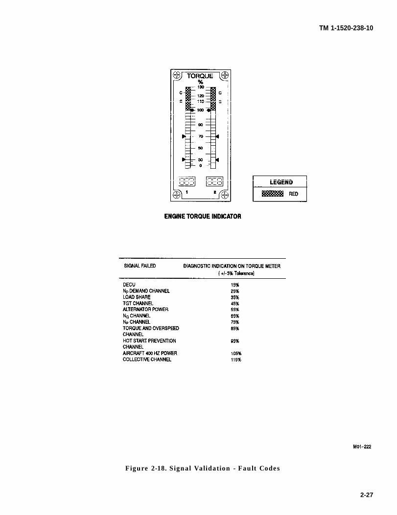
TM 1-1520-238-10
Figure 2-18. Signal Validation - Fault Codes
2-27
TM 1-1520-238-10
2.26.7 Fuel Pressure Warning System. The enginefuel pressure warning system for each engine consistsof a pressure switch that illuminates the FUEL PSIsegment on the pilot caution/warning panel. TheFUEL PSI ENG 1 and FUEL PSI ENG 2 segmentswill illuminate when fuel pressure drops below 9 psi.
2.27 ENGINE ALTERNATOR.
2.27.1 Engine Alternator 701. The engine alternator(fig 2-16 ) supplies AC power to the ignition circuitryand the ECU. It also supplies a signal to the NG speedindicator. All essential engine electrical functions arepowered by the alternator. When the alternator powerto the ECU is interrupted, a loss of Np and torque in-dications will occur on the affected engine(s), and theengine(s) will increase to the maximum power. PercentNp/Nrr will increase above 100% and T4.5 limiting willbe inoperative. When the alternator power providingthe NG signal is interrupted, a loss of NG indicationswill occur with a corresponding engine out audio signaland warning light being activated. Actual engine op-eration is unaffected. A complete loss of engine alterna-tor power results in affected engine(s) increasing tomaximum power with a loss of of Np, NG indication,torque and engine out audio signal and warning lightbeing activated, and by an inability to start the engine.
2.27.2 Engine Alternator 701C. When the engine al-ternator (fig 2-16) power supply to the DECU is inter-rupted, 400 Hz, 115 vac aircraft power is used to powerthe DECU, therefore preventing an engine (high side)failure. Np/torque indications will not be affected.When alternator power supply for the NG signal is in-terrupted, a loss of the associated engine NG indicationand an engine out audio signal and warning light willoccur. Actual engine operation is unaffected. Completefailure of the alternator will cause loss of NG indication,activation of an engine out audio and warning light,and inability to start the engine. Operation of the en-gine and all other indications will be normal.
2.28 ENGINE OIL SYSTEM.
Each engine is lubricated by a self-contained, pressur-ized, recirculating, dry sump system. Included are oilsupply and scavenge pumps, an emergency oil system,an integral oil tank, a filter, an oil cooler, and seal pres-surization and venting. A chip detector that illumi-nates the CHIPS ENG 1 or CHIPS ENG 2 segment onthe pilot caution/warning panel is in line downstreamof the scavenge pump.
2.28.1 Emergency Oil System. Small oil reservoirs,built into the engine oil sumps, are kept full during nor-mal operation by the oil pump. If oil pressure is lost, oilwill bleed slowly out of these reservoirs and be atom-ized by air jets thus providing an oil mist lubrication forthe engine bearings for thirty seconds at 75% NG. AnOIL PSI ENG 1 or OIL PSI ENG 2 light on the pilotcaution/warning panel will illuminate when oil pres-sure drops below 20-25 psi.
2.28.2 Oil Tank. Pertinent oil grades and specifica-tions are in table 2-7. The filler port is on the right sideof the engine (fig 2-16). The oil level is indicated by asight gage on each side of the tank. Oil is supplied tothe oil pump through a screen. The scavenge pump re-turns oil from the sumps to the oil tank through sixscavenge screens.
2.28.3 Oil Cooler and Filter. Scavenge oil passesthrough an oil cooler (fig 2-16) before returning to thetank. It is cooled by transferring heat from the oil tofuel routed through the cooler. If the oil cooler pressurebecomes too high, a relief valve will open to dump scav-enge oil directly into the oil tank. Oil discharged fromthe oil pump is routed through a disposable element fil-ter. As the pressure differential across the filter in-creases, the first indication will be a popped impendingbypass button. As the pressure increases further, theOIL BYP ENG 1 or OIL BYP ENG 2 segment on thepilot caution/warning panel will illuminate. During en-gine starting, with oil temperature below the normaloperating range, pressure may be high enough to closethe oil filter bypass sensor switch. In this situation, thecaution light or lights will remain on until the oilwarms up and oil pressure decreases. The impendingbypass indicator has a thermal lockout below +38 0C(100 °F) to prevent the button from popping.
2.28.4 Chip Detector. Each engine chip detector (fig2-16) is mounted on the forward right side of the acces-sory gearbox. It consists of an integral magnet, electri-cal connector, and a housing. A removable screen sur-rounds the magnet. The detector attracts magneticparticles at a primary chip detecting gap. If chips aredetected, a signal is sent to the pilot caution/warningpanel to illuminate a CHIPS ENG 1 or CHIPS ENG 2segment. These chip detectors are of the non-fizz burn-ing type.
2.29 ENGINE IGNITION SYSTEM.
Each engine has an ignition exciter unit with two ignit-er plugs. The exciter unit receives power from its en-gine alternator. The MASTER IGN keylock switch onthe pilot engine PWR lever quadrant (fig 2-19) is an en-abling switch to the ENG START switches. When an
2-28
TM 1-1520-238-10
ENG START switch is placed to START, pneumaticmotoring of the engine starter takes place and the igni-tion system is energized. Ignition cutout is automaticafter the engine starts. Following aborted starts (Chap-ter 9, Emergency Procedures), the engine must be mo-tored with the ignition system disabled. This is done byplacing the ENG START switch to IGN OVRD. Chap-ter 5 contains the starting cycle limitations.
2.30 ENGINE STARTING SYSTEM.
The engine uses an air turbine starter (fig 2-16) for en-gine starting. System components for starting consistof the engine starter, a start control valve, an externalstart connector, check valves, controls, and ducting.Three sources may provide air for engine starts: Theshaft driven compressor (SDC) (normally driven by theAPU for engine starts), No. 1 engine compressor bleedair, or an externally connected ground source. In anycase, the start sequence is the same. With the ENGFUEL switch ON and MASTER IGN switch ON, plac-ing the ENG START switch momentarily to STARTwill initiate an automatic start sequence. This will beevidenced by the illumination of the ENG 1 or ENG 2advisory light above the ENG START switch on the pi-lot PWR lever quadrant. Compressed air is then di-rected through the start control valve to the sir turbinestarter. As the air turbine starter begins to turn, anoverrun clutch engages which causes the engine to mo-tor. The starter turbine wheel and gear train automati-cally disengage from the engine when engine speed ex-ceeds starter input speed. At approximately 52% NG,air to the starter shuts off, and ignition is terminated. Ifthe engine does not start, the PWR lever must be re-turned to OFF and the ENG START switch must beplaced at IGN OVRD (which aborts the automatic en-gine start sequence) momentarily before another startis attempted. Chapter 8 explains abort start proce-dures, and Chapter 5 contains the start cycle limits. If
the engine will be automatically shut off if TGT exceeds900 °C during the start sequence. If this occurs, the
PWR lever must be returned to OFF and the ENGSTART switch must be placed in IGN OVRD (whichaborts the automatic engine start sequence).
2.30.1 Engine Start Using APU. The APU provideson-board power for system check by ground personnel.The APU is capable of driving the main transmissionaccessories which include the ac generators, the hy-draulic pumps, and the shaft driven compressor (SDC).The APU is normally left on during both engine starts,but it maybe shut down after one engine has reached100% NP. When NP has reached 100% and the APUshut down, that engine may be used to drive the SDCthrough the transmission and accessory gear train forstarting the second engine. A complete description ofthe auxiliary power unit appears in Section XII.
2.30.2 Engine Start Using External Source. An ex-ternal air receptacle under the No. 1 engine nacelleprovides an attachment point for an air line to start ei-ther engine from an external source. The assembly con-tains a check valve to prevent engine bleed air or SDCpressurized air from being vented overboard. An exter-nal air source of 40 psig and 30 pounds per minute(ppm) pressurizes the start system up to the enginestart control valves which requires only that electricalpower be applied for a normal start sequence.
2.30.3 Engine Start Using Engine Bleed AirSource. When the No. 1 engine is operating and it isnecessary to start the No. 2 engine, bleed air may beused from the No. 1 engine compressor under certaincircumstances. This technique is not normally used,however, it is fully automatic, and provides an altern-ative starting capability if the SDC shaft fails or if theSDC throttle valve or surge valve clogs (Section VI,Pressurized Air System). The starting sequence is thesame as for APU starting, only the source of air to thestart motor is different. When using this technique toensure an adequate air pressure and flow to the No. 2engine starter, collective pitch must be increased to avalue that will increase the NG of the No. 1 engine to aminimum of 95%.
Change 2 2-29
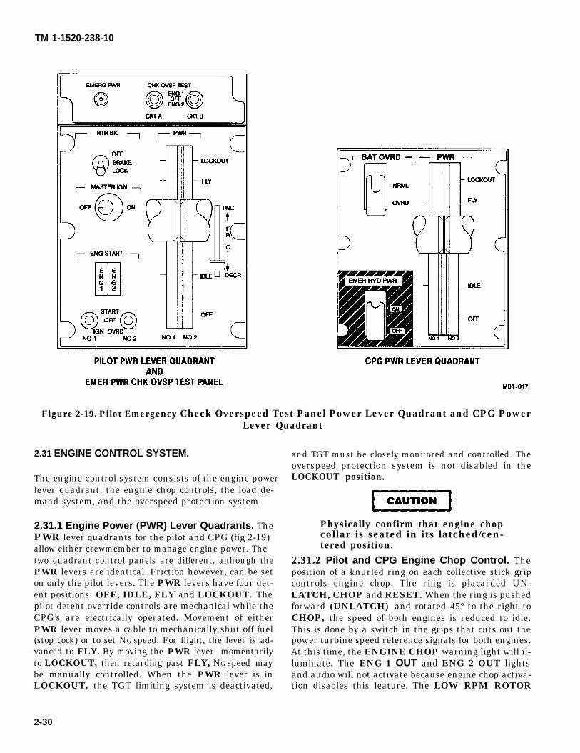
CAUTION
TM 1-1520-238-10
Figure 2-19. Pilot Emergency Check Overspeed Test Panel Power Lever Quadrant and CPG PowerLever Quadrant
2.31 ENGINE CONTROL SYSTEM.
The engine control system consists of the engine powerlever quadrant, the engine chop controls, the load de-mand system, and the overspeed protection system.
2.31.1 Engine Power (PWR) Lever Quadrants. ThePWR lever quadrants for the pilot and CPG (fig 2-19)allow either crewmember to manage engine power. Thetwo quadrant control panels are different, although thePWR levers are identical. Friction however, can be seton only the pilot levers. The PWR levers have four det-ent positions: OFF, IDLE, FLY and LOCKOUT. Thepilot detent override controls are mechanical while theCPG’s are electrically operated. Movement of eitherPWR lever moves a cable to mechanically shut off fuel(stop cock) or to set NG speed. For flight, the lever is ad-vanced to FLY. By moving the PWR lever momentarilyto LOCKOUT, then retarding past FLY, NG speed maybe manually controlled. When the PWR lever is inLOCKOUT, the TGT limiting system is deactivated,
and TGT must be closely monitored and controlled. Theoverspeed protection system is not disabled in theLOCKOUT position.
Physically confirm that engine chopcollar is seated in its latched/cen-tered position.
2.31.2 Pilot and CPG Engine Chop Control. Theposition of a knurled ring on each collective stick gripcontrols engine chop. The ring is placarded UN-LATCH, CHOP and RESET. When the ring is pushedforward (UNLATCH) and rotated 45° to the right toCHOP, the speed of both engines is reduced to idle.This is done by a switch in the grips that cuts out thepower turbine speed reference signals for both engines.At this time, the ENGINE CHOP warning light will il-luminate. The ENG 1 OUT and ENG 2 OUT lightsand audio will not activate because engine chop activa-tion disables this feature. The LOW RPM ROTOR
2-30
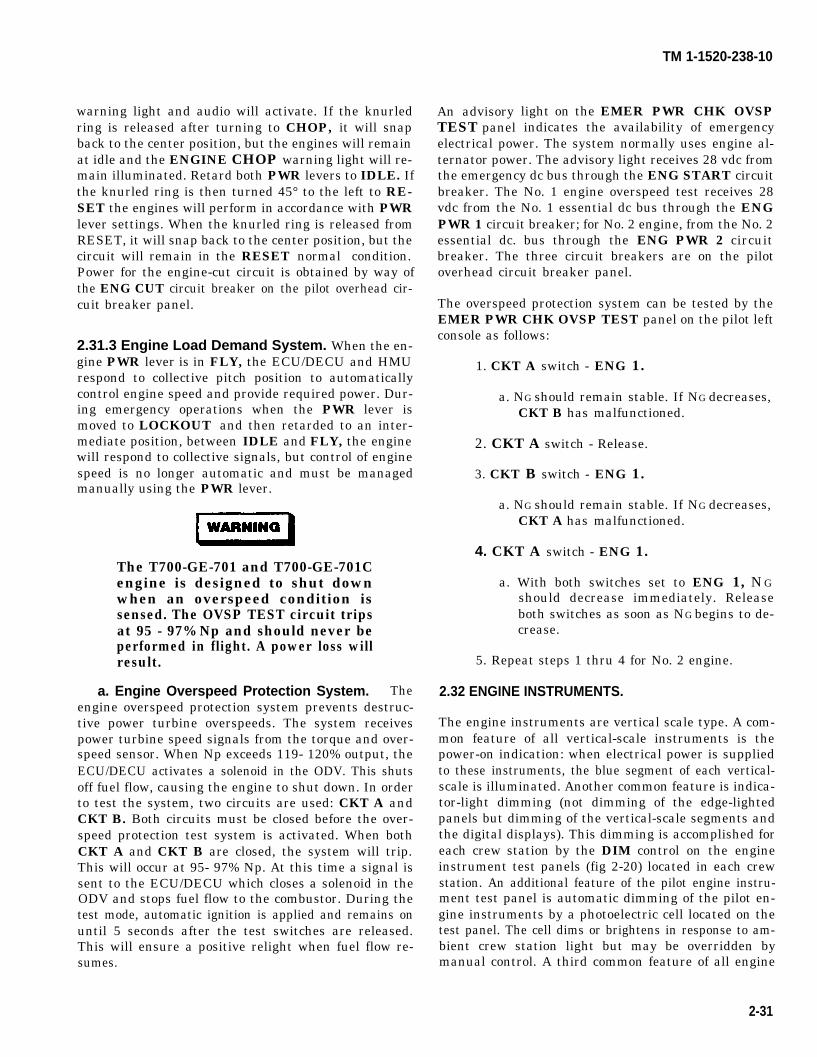
WARNING
warning light and audio will activate. If the knurledring is released after turning to CHOP, it will snapback to the center position, but the engines will remainat idle and the ENGINE CHOP warning light will re-main illuminated. Retard both PWR levers to IDLE. Ifthe knurled ring is then turned 45° to the left to RE-SET the engines will perform in accordance with PWRlever settings. When the knurled ring is released fromRESET, it will snap back to the center position, but thecircuit will remain in the RESET normal condition.Power for the engine-cut circuit is obtained by way ofthe ENG CUT circuit breaker on the pilot overhead cir-cuit breaker panel.
2.31.3 Engine Load Demand System. When the en-gine PWR lever is in FLY, the ECU/DECU and HMUrespond to collective pitch position to automaticallycontrol engine speed and provide required power. Dur-ing emergency operations when the PWR lever ismoved to LOCKOUT and then retarded to an inter-mediate position, between IDLE and FLY, the enginewill respond to collective signals, but control of enginespeed is no longer automatic and must be managedmanually using the PWR lever.
The T700-GE-701 and T700-GE-701Cengine is designed to shut downwhen an overspeed condition issensed. The OVSP TEST circuit tripsat 95 - 97% Np and should never beperformed in flight. A power loss willresult.
a. Engine Overspeed Protection System. Theengine overspeed protection system prevents destruc-tive power turbine overspeeds. The system receivespower turbine speed signals from the torque and over-speed sensor. When Np exceeds 119- 120% output, theECU/DECU activates a solenoid in the ODV. This shutsoff fuel flow, causing the engine to shut down. In orderto test the system, two circuits are used: CKT A andCKT B. Both circuits must be closed before the over-speed protection test system is activated. When bothCKT A and CKT B are closed, the system will trip.This will occur at 95- 97% Np. At this time a signal issent to the ECU/DECU which closes a solenoid in theODV and stops fuel flow to the combustor. During thetest mode, automatic ignition is applied and remains onuntil 5 seconds after the test switches are released.This will ensure a positive relight when fuel flow re-sumes.
An advisoryTEST panel
TM 1-1520-238-10
light on the EMER PWR CHK OVSPindicates the availability of emergency
electrical power. The system normally uses engine al-ternator power. The advisory light receives 28 vdc fromthe emergency dc bus through the ENG START circuitbreaker. The No. 1 engine overspeed test receives 28vdc from the No. 1 essential dc bus through the ENGPWR 1 circuit breaker; for No. 2 engine, from the No. 2essential dc. bus through the ENG PWR 2 circuitbreaker. The three circuit breakers are on the pilotoverhead circuit breaker panel.
The overspeed protection system can be tested by theEMER PWR CHK OVSP TEST panel on the pilot leftconsole as follows:
1. CKT A switch - ENG 1.
a. NG should remain stable. If NG decreases,CKT B has malfunctioned.
2. CKT A switch - Release.
3. CKT B switch - ENG 1.
a. NG should remain stable. If NG decreases,CKT A has malfunctioned.
4. CKT A switch - ENG 1.
a. With both switches set to ENG 1, NGshould decrease immediately. Releaseboth switches as soon as NG begins to de-crease.
5. Repeat steps 1 thru 4 for No. 2 engine.
2.32 ENGINE INSTRUMENTS.
The engine instruments are vertical scale type. A com-mon feature of all vertical-scale instruments is thepower-on indication: when electrical power is suppliedto these instruments, the blue segment of each vertical-scale is illuminated. Another common feature is indica-tor-light dimming (not dimming of the edge-lightedpanels but dimming of the vertical-scale segments andthe digital displays). This dimming is accomplished foreach crew station by the DIM control on the engineinstrument test panels (fig 2-20) located in each crewstation. An additional feature of the pilot engine instru-ment test panel is automatic dimming of the pilot en-gine instruments by a photoelectric cell located on thetest panel. The cell dims or brightens in response to am-bient crew station light but may be overridden bymanual control. A third common feature of all engine
2-31
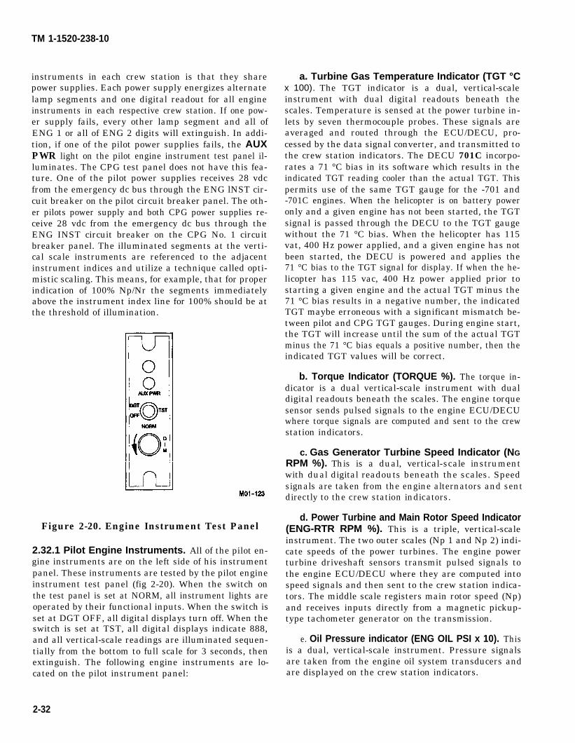
TM 1-1520-238-10
instruments in each crew station is that they sharepower supplies. Each power supply energizes alternatelamp segments and one digital readout for all engineinstruments in each respective crew station. If one pow-er supply fails, every other lamp segment and all ofENG 1 or all of ENG 2 digits will extinguish. In addi-tion, if one of the pilot power supplies fails, the AUXPWR light on the pilot engine instrument test panel il-luminates. The CPG test panel does not have this fea-ture. One of the pilot power supplies receives 28 vdcfrom the emergency dc bus through the ENG lNST cir-cuit breaker on the pilot circuit breaker panel. The oth-er pilots power supply and both CPG power supplies re-ceive 28 vdc from the emergency dc bus through theENG INST circuit breaker on the CPG No. 1 circuitbreaker panel. The illuminated segments at the verti-cal scale instruments are referenced to the adjacentinstrument indices and utilize a technique called opti-mistic scaling. This means, for example, that for properindication of 100% Np/Nr the segments immediatelyabove the instrument index line for 100% should be atthe threshold of illumination.
Figure 2-20. Engine Instrument Test Panel
2.32.1 Pilot Engine Instruments. All of the pilot en-gine instruments are on the left side of his instrumentpanel. These instruments are tested by the pilot engineinstrument test panel (fig 2-20). When the switch onthe test panel is set at NORM, all instrument lights areoperated by their functional inputs. When the switch isset at DGT OFF, all digital displays turn off. When theswitch is set at TST, all digital displays indicate 888,and all vertical-scale readings are illuminated sequen-tially from the bottom to full scale for 3 seconds, thenextinguish. The following engine instruments are lo-cated on the pilot instrument panel:
a. Turbine Gas Temperature Indicator (TGT °Cx 100). The TGT indicator is a dual, vertical-scaleinstrument with dual digital readouts beneath thescales. Temperature is sensed at the power turbine in-lets by seven thermocouple probes. These signals areaveraged and routed through the ECU/DECU, pro-cessed by the data signal converter, and transmitted tothe crew station indicators. The DECU 701C incorpo-rates a 71 °C bias in its software which results in theindicated TGT reading cooler than the actual TGT. Thispermits use of the same TGT gauge for the -701 and-701C engines. When the helicopter is on battery poweronly and a given engine has not been started, the TGTsignal is passed through the DECU to the TGT gaugewithout the 71 °C bias. When the helicopter has 115vat, 400 Hz power applied, and a given engine has notbeen started, the DECU is powered and applies the71 °C bias to the TGT signal for display. If when the he-licopter has 115 vac, 400 Hz power applied prior tostarting a given engine and the actual TGT minus the71 °C bias results in a negative number, the indicatedTGT maybe erroneous with a significant mismatch be-tween pilot and CPG TGT gauges. During engine start,the TGT will increase until the sum of the actual TGTminus the 71 °C bias equals a positive number, then theindicated TGT values will be correct.
b. Torque Indicator (TORQUE %). The torque in-dicator is a dual vertical-scale instrument with dualdigital readouts beneath the scales. The engine torquesensor sends pulsed signals to the engine ECU/DECUwhere torque signals are computed and sent to the crewstation indicators.
c. Gas Generator Turbine Speed Indicator (NGRPM %). This is a dual, vertical-scale instrumentwith dual digital readouts beneath the scales. Speedsignals are taken from the engine alternators and sentdirectly to the crew station indicators.
d. Power Turbine and Main Rotor Speed Indicator(ENG-RTR RPM %). This is a triple, vertical-scaleinstrument. The two outer scales (Np 1 and Np 2) indi-cate speeds of the power turbines. The engine powerturbine driveshaft sensors transmit pulsed signals tothe engine ECU/DECU where they are computed intospeed signals and then sent to the crew station indica-tors. The middle scale registers main rotor speed (Np)and receives inputs directly from a magnetic pickup-type tachometer generator on the transmission.
e. Oil Pressure indicator (ENG OIL PSI x 10). Thisis a dual, vertical-scale instrument. Pressure signalsare taken from the engine oil system transducers andare displayed on the crew station indicators.
2-32
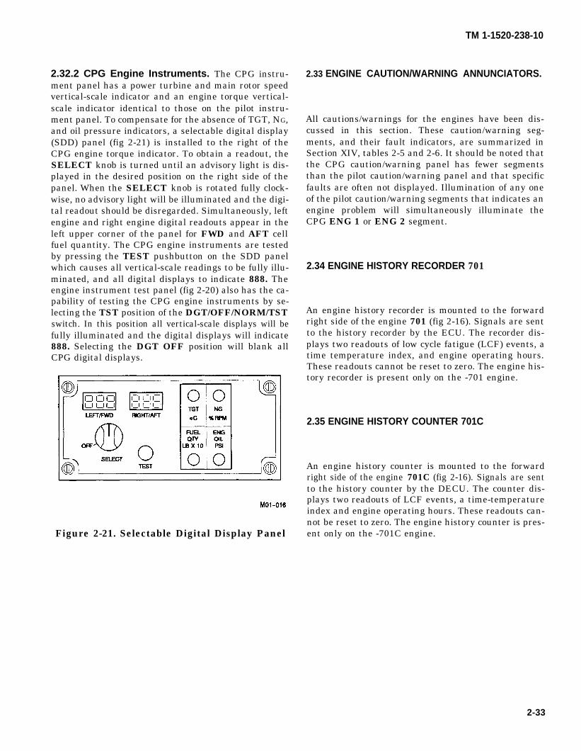
TM 1-1520-238-10
2.32.2 CPG Engine Instruments. The CPG instru-ment panel has a power turbine and main rotor speedvertical-scale indicator and an engine torque vertical-scale indicator identical to those on the pilot instru-ment panel. To compensate for the absence of TGT, NG,and oil pressure indicators, a selectable digital display(SDD) panel (fig 2-21) is installed to the right of theCPG engine torque indicator. To obtain a readout, theSELECT knob is turned until an advisory light is dis-played in the desired position on the right side of thepanel. When the SELECT knob is rotated fully clock-wise, no advisory light will be illuminated and the digi-tal readout should be disregarded. Simultaneously, leftengine and right engine digital readouts appear in theleft upper corner of the panel for FWD and AFT cellfuel quantity. The CPG engine instruments are testedby pressing the TEST pushbutton on the SDD panelwhich causes all vertical-scale readings to be fully illu-minated, and all digital displays to indicate 888. Theengine instrument test panel (fig 2-20) also has the ca-pability of testing the CPG engine instruments by se-lecting the TST position of the DGT/OFF/NORM/TSTswitch. In this position all vertical-scale displays will befully illuminated and the digital displays will indicate888. Selecting the DGT OFF position will blank allCPG digital displays.
Figure 2-21. Selectable Digital Display Panel
2.33 ENGINE CAUTION/WARNING ANNUNCIATORS.
All cautions/warnings for the engines have been dis-cussed in this section. These caution/warning seg-ments, and their fault indicators, are summarized inSection XIV, tables 2-5 and 2-6. It should be noted thatthe CPG caution/warning panel has fewer segmentsthan the pilot caution/warning panel and that specificfaults are often not displayed. Illumination of any oneof the pilot caution/warning segments that indicates anengine problem will simultaneously illuminate theCPG ENG 1 or ENG 2 segment.
2.34 ENGINE HISTORY RECORDER 701
An engine history recorder is mounted to the forwardright side of the engine 701 (fig 2-16). Signals are sentto the history recorder by the ECU. The recorder dis-plays two readouts of low cycle fatigue (LCF) events, atime temperature index, and engine operating hours.These readouts cannot be reset to zero. The engine his-tory recorder is present only on the -701 engine.
2.35 ENGINE HISTORY COUNTER 701C
An engine history counter is mounted to the forwardright side of the engine 701C (fig 2-16). Signals are sentto the history counter by the DECU. The counter dis-plays two readouts of LCF events, a time-temperatureindex and engine operating hours. These readouts can-not be reset to zero. The engine history counter is pres-ent only on the -701C engine.
2-33
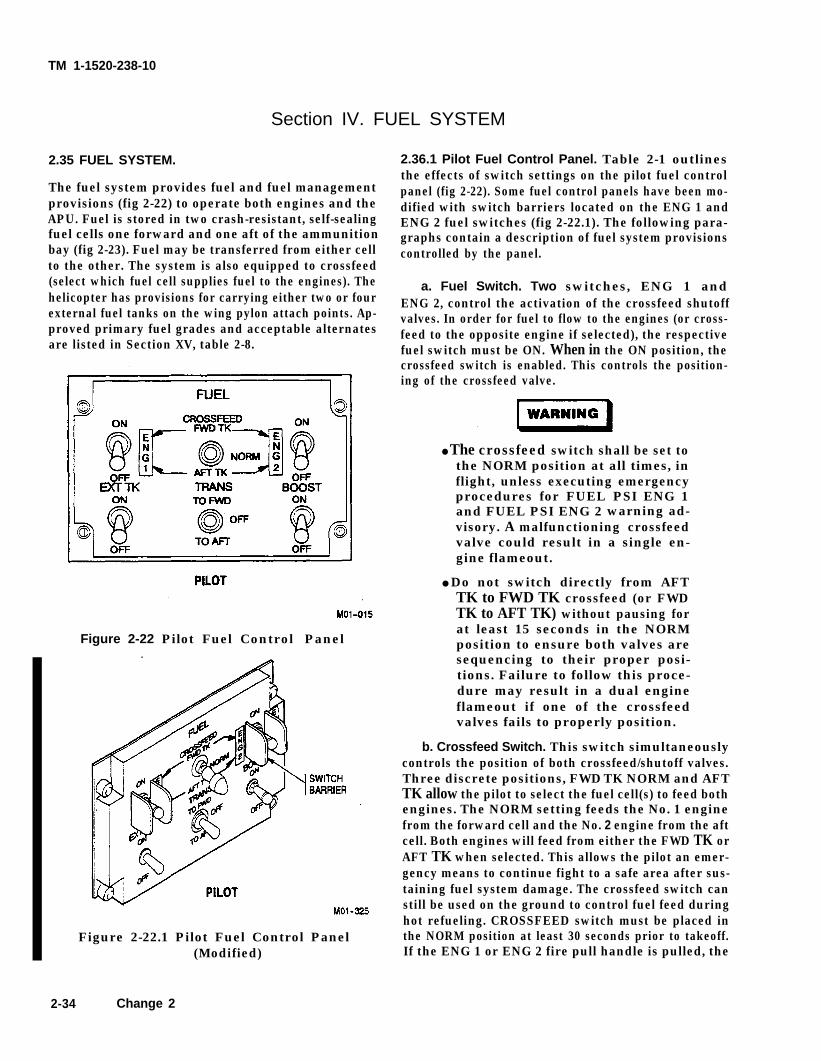
TM 1-1520-238-10
Section IV. FUEL SYSTEM
2.35 FUEL SYSTEM.
The fuel system provides fuel and fuel managementprovisions (fig 2-22) to operate both engines and theAPU. Fuel is stored in two crash-resistant, self-sealingfuel cells one forward and one aft of the ammunitionbay (fig 2-23). Fuel may be transferred from either cellto the other. The system is also equipped to crossfeed(select which fuel cell supplies fuel to the engines). Thehelicopter has provisions for carrying either two or fourexternal fuel tanks on the wing pylon attach points. Ap-proved primary fuel grades and acceptable alternatesare listed in Section XV, table 2-8.
Figure 2-22 Pilot Fuel Control Panel
Figure 2-22.1 Pilot Fuel Control Panel(Modified)
2.36.1 Pilot Fuel Control Panel. Table 2-1 outlinesthe effects of switch settings on the pilot fuel controlpanel (fig 2-22). Some fuel control panels have been mo-dified with switch barriers located on the ENG 1 andENG 2 fuel switches (fig 2-22.1). The following para-graphs contain a description of fuel system provisionscontrolled by the panel.
a. Fuel Switch. Two switches, ENG 1 andENG 2, control the activation of the crossfeed shutoffvalves. In order for fuel to flow to the engines (or cross-feed to the opposite engine if selected), the respectivefuel switch must be ON. When in the ON position, thecrossfeed switch is enabled. This controls the position-ing of the crossfeed valve.
● The crossfeed switch shall be set tothe NORM position at all times, inflight, unless executing emergencyprocedures for FUEL PSI ENG 1and FUEL PSI ENG 2 warning ad-visory. A malfunctioning crossfeedvalve could result in a single en-gine flameout.
● Do not switch directly from AFTTK to FWD TK crossfeed (or FWDTK to AFT TK) without pausing forat least 15 seconds in the NORMposition to ensure both valves aresequencing to their proper posi-tions. Failure to follow this proce-dure may result in a dual engineflameout if one of the crossfeedvalves fails to properly position.
b. Crossfeed Switch. This switch simultaneouslycontrols the position of both crossfeed/shutoff valves.Three discrete positions, FWD TK NORM and AFTTK allow the pilot to select the fuel cell(s) to feed bothengines. The NORM setting feeds the No. 1 enginefrom the forward cell and the No. 2 engine from the aftcell. Both engines will feed from either the FWD TK orAFT TK when selected. This allows the pilot an emer-gency means to continue fight to a safe area after sus-taining fuel system damage. The crossfeed switch canstill be used on the ground to control fuel feed duringhot refueling. CROSSFEED switch must be placed inthe NORM position at least 30 seconds prior to takeoff.If the ENG 1 or ENG 2 fire pull handle is pulled, the
2-34 Change 2
TM 1-1520-238-10
selected engine crossfeed/shutoff valve automaticallycloses.
Some helicopters have been modified with green andamber crossfeed (X FEED) annunciator lights locatedon the pilot and CPG caution/warning panels (fig2-44.1). The green X FEED annunicator light will illu-minate on both caution/warning panels when crossfeedis selected by the pilot and both engine fuel valves arecorrectly positioned for the selection. The green XFEED annunicator light will also illuminate whenoverride and crossfeed is selected by the CPG and bothvalves are correctly positioned. When the CROSS-FEED switch on the pilot fuel control panel is placed inthe FWD TK or AFT TK position the X FEED caution/warning lights will be inhibited for 3 ± 1 second whilethe fuel valves move to their selected position. The am-ber X FEED annunicator light and the MASTERCAUTION light (fig 2-43) will illuminate on both cau-tion/warning panels when the pilot has selected cross-feed or the CPG has selected override and one or bothfuel valves are incorrectly positioned. The amber XFEED caution/warning lights will also illuminatewhen a fuel valve is in the CLOSED position (in re-sponse to actuation of a fire handle or pilot fuel controlpanel ENG 1 or ENG 2 fuel switch in the OFF position.
NOTE
During engine start the amber X FEEDcaution/warning lights will illuminate ifthe CROSSFEED switch is not in theAFT TK position.
c. External Tank Switch (EXT TK). The pilot acti-vates fuel transfer from as many as four external fueltanks to the internal fuel cells by positioning the EXTTK switch to ON. The switch opens the auxiliary fueltank shutoff valve and the two transfer shutoff valves.Opening the auxiliary fuel tank shutoff valve allowspressurized air to force fuel from the left auxiliary fieltank into the forward Fuel cell and from the right auxil-iary fuel tank into the aft fuel cell. When all auxiliarytanks are empty, the EXT EMP caution light on the pi-lot caution/warning panel illuminates.
NOTE
● The REFUEL VALVE switch (locatedon the external fuel servicing panel (fig2-45) must be closed for operation of theTRANS switch to be effective. Thetransfer pump will not transfer fuel ifthe refuel valve is open.
● The fuel transfer system is the primarymethod of balancing loads.
d. Transfer Switch (TRANS). The TRANS switchcontrols the position of the fuel transfer air valve. Thefuel transfer air valve directs pressurized air to the bi-directional transfer pump which allows fuel transferbetween fuel cells. With the switch in the TO AFT orTO FWD position, pressurized air is directed to the airmotor which turns the transfer pump and transfers fuelforward or aft. If the transfer pump is transferring fueland the fuel cell to which it is transferring becomes full,a fuel level control valve will shut off the fuel flowthrough the pump. There is no need to stop the trans-ferring operation until the fuel cells are at the desiredlevel.
Some helicopters have been modified with green andamber transfer (FUEL XFR) annunciator lights lo-cated on the pilot and CPG caution/warning panels (fig2-44.1). The green FUEL XFR annunicator light willilluminate on both caution/warning panels when the pi-lot or CPG fuel transfer switch is in the transfer posi-tion and transfer occurs. The amber FUEL XFR annu-nicator light and the MASTER CAUTION light (fig2-43) will illuminate on both caution/warning panelswhen the pilot or CPG fuel transfer switch is in thetransfer position and transfer does not occur.
The CROSSFEED switch shall be setto the NORM position at all times un-less executing emergeney procedureafor FUEL PSI ENG 1 and FUEL PSIENG 2. Using the fuel system cross-feed may result in a dual engineflameout if one of the engine fuelvalves fails to properly position.
e. BOOST Switch. The boost pump (located in theaft fuel cell) is used for starting the engines and whenthe FUEL PSI ENG 1 and FUEL PSI ENG 2 cautionlights illuminate. The BOOST switch electricallyopens the boost pump shutoff valve which directs pres-surized air to the air driven boost pump. When theswitch is in the OFF position, the engines receive fuel(through a suction feed system) via the engine-mounted fuel pumps. When the BOOST switch is inthe ON position, and the CROSSFEED switch is inthe AFT TK position, both engines feed from the aftfuel cell. The boost pump is automatically started andshut down during the engine start sequence. Shutdownoccurs at approximately 52% NG. It should be notedthat the pilot CROSSFEED switch must be in theAFT TK position in order for the BOOST switch tolatch on.
Change 2 2-35
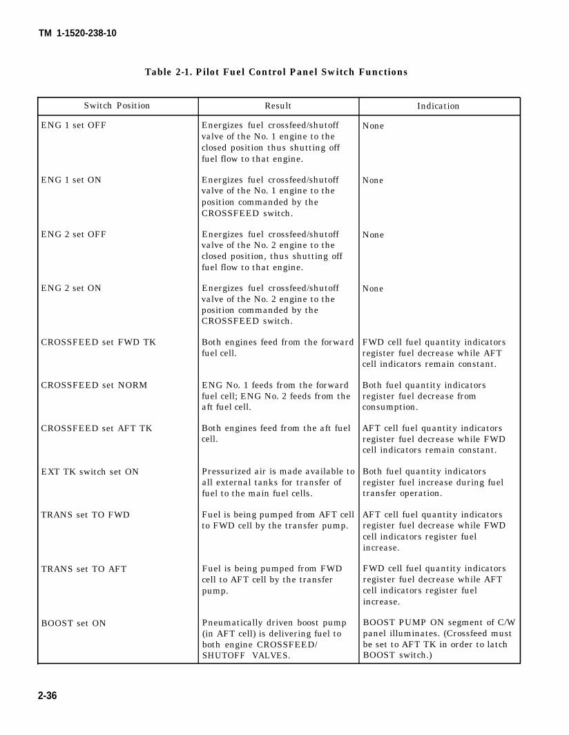
TM 1-1520-238-10
Table 2-1. Pilot Fuel Control Panel Switch Functions
Switch Position Result Indication
ENG 1 set OFF Energizes fuel crossfeed/shutoff Nonevalve of the No. 1 engine to theclosed position thus shutting offfuel flow to that engine.
ENG 1 set ON Energizes fuel crossfeed/shutoff Nonevalve of the No. 1 engine to theposition commanded by theCROSSFEED switch.
ENG 2 set OFF Energizes fuel crossfeed/shutoff Nonevalve of the No. 2 engine to theclosed position, thus shutting offfuel flow to that engine.
ENG 2 set ON Energizes fuel crossfeed/shutoff Nonevalve of the No. 2 engine to theposition commanded by theCROSSFEED switch.
CROSSFEED set FWD TK Both engines feed from the forward FWD cell fuel quantity indicatorsfuel cell. register fuel decrease while AFT
cell indicators remain constant.
CROSSFEED set NORM ENG No. 1 feeds from the forward Both fuel quantity indicatorsfuel cell; ENG No. 2 feeds from the register fuel decrease fromaft fuel cell. consumption.
CROSSFEED set AFT TK Both engines feed from the aft fuel AFT cell fuel quantity indicatorscell. register fuel decrease while FWD
cell indicators remain constant.
EXT TK switch set ON Pressurized air is made available to Both fuel quantity indicatorsall external tanks for transfer of register fuel increase during fuelfuel to the main fuel cells. transfer operation.
TRANS set TO FWD Fuel is being pumped from AFT cell AFT cell fuel quantity indicatorsto FWD cell by the transfer pump. register fuel decrease while FWD
cell indicators register fuelincrease.
TRANS set TO AFT Fuel is being pumped from FWD FWD cell fuel quantity indicatorscell to AFT cell by the transfer register fuel decrease while AFTpump. cell indicators register fuel
increase.
BOOST set ON Pneumatically driven boost pump BOOST PUMP ON segment of C/W(in AFT cell) is delivering fuel to panel illuminates. (Crossfeed mustboth engine CROSSFEED/ be set to AFT TK in order to latchSHUTOFF VALVES. BOOST switch.)
2-36
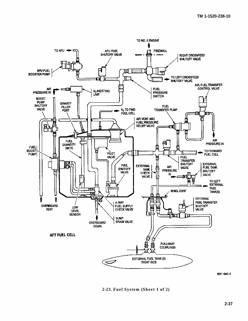
TM 1-1520-238-10
2-23. Fuel System (Sheet 1 of 2)
2-37
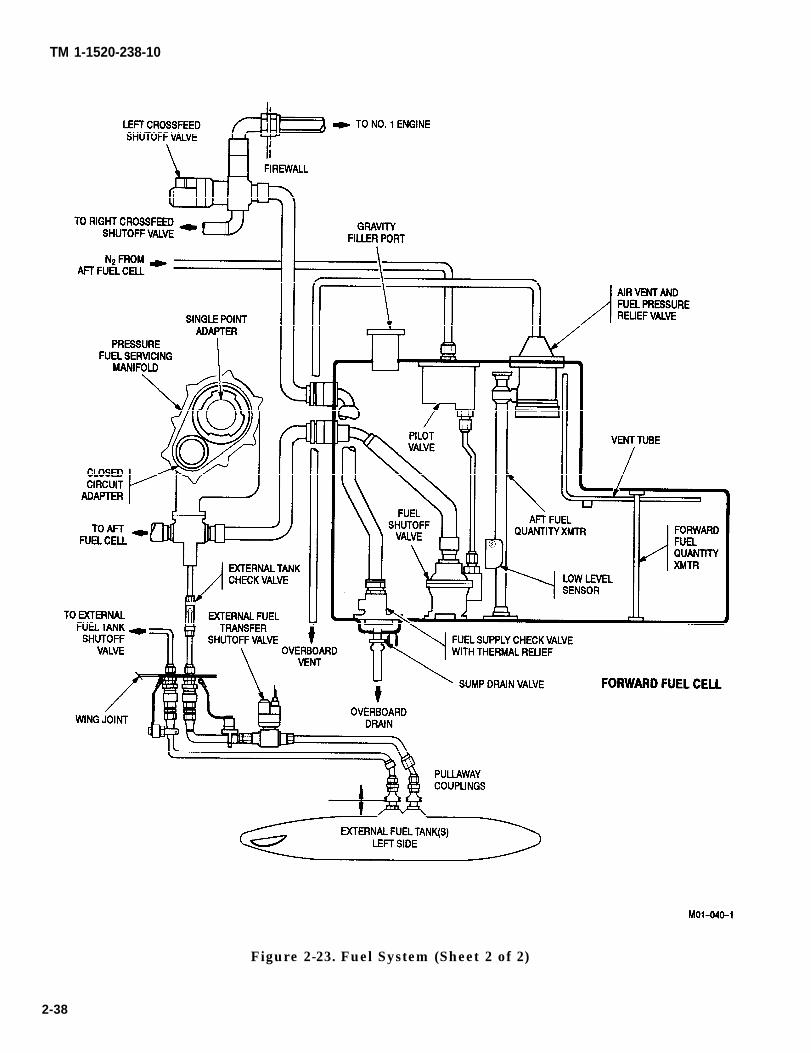
TM 1-1520-238-10
Figure 2-23. Fuel System (Sheet 2 of 2)
2-38
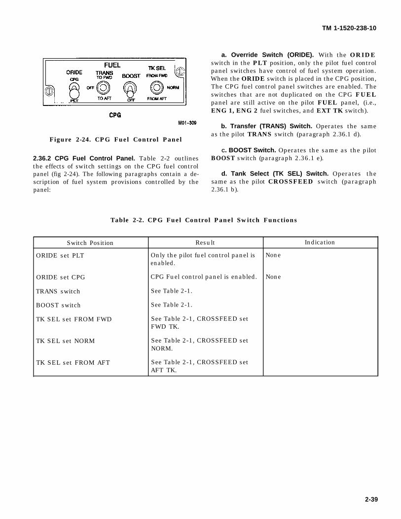
TM 1-1520-238-10
Figure 2-24. CPG Fuel Control Panel
2.36.2 CPG Fuel Control Panel. Table 2-2 outlinesthe effects of switch settings on the CPG fuel controlpanel (fig 2-24). The following paragraphs contain a de-scription of fuel system provisions controlled by thepanel:
a. Override Switch (ORIDE). With the ORIDEswitch in the PLT position, only the pilot fuel controlpanel switches have control of fuel system operation.When the ORIDE switch is placed in the CPG position,The CPG fuel control panel switches are enabled. Theswitches that are not duplicated on the CPG FUELpanel are still active on the pilot FUEL panel, (i.e.,ENG 1, ENG 2 fuel switches, and EXT TK switch).
b. Transfer (TRANS) Switch. Operates the sameas the pilot TRANS switch (paragraph 2.36.1 d).
C. BOOST Switch. Operates the same as the pilotBOOST switch (paragraph 2.36.1 e).
d. Tank Select (TK SEL) Switch. Operates thesame as the pilot CROSSFEED switch (paragraph2.36.1 b).
Table 2-2. CPG Fuel Control Panel Switch Functions
Switch Position Result Indication
ORIDE set PLT Only the pilot fuel control panel is Noneenabled.
ORIDE set CPG CPG Fuel control panel is enabled. None
TRANS switch See Table 2-1.
BOOST switch See Table 2-1.
TK SEL set FROM FWD See Table 2-1, CROSSFEED setFWD TK.
TK SEL set NORM See Table 2-1, CROSSFEED setNORM.
TK SEL set FROM AFT See Table 2-1, CROSSFEED setAFT TK.
2-39
NOTE
TM 1-1520-236-10
2.36.3 Fuel Quantity Indicators. The pilot vertical-scale fuel quantity indicator (fig 5-1) indicates thequantity (in pounds X 10) of fuel remaining in the for-ward and aft fuel cells. A digital display at the bottomof the indicator shows the combined total of remainingfuel (in pounds X 10). The CPG selectable digital dis-play (SDD) indicates the pounds of fuel remaining inthe forward and aft fuel cells. The SELECT knob is ro-tated until the FUEL QTY X 10 display is illuminatedthus causing the pounds of fuel remaining in each cellto appear on the digital display. Combined total fuel isnot indicated. The fuel quantity transmitters are ca-pacitance-type transmitters. There are three fuel quan-tity transmitters: two are in the forward fuel cell be-cause of the shape of the fuel cell, and one is in the aftfuel cell. The transmitters provide data to the fuel sig-nal conditioner which, in turn, provides a readout tothe fuel quantity indicators in the crew stations.
2.36.4 Fuel System Caution/Warning Lights. Fuelsystem caution/warning segments on the caution/warn-ing panel are discussed in Section XIV, (tables 2-4 and2-5). Their positions are shown on the caution/warningpanel (fig 2-44).
2.36.5 Auxiliary Fuel Tank. For ferry missions, thereare provisions for as many as four external fuel tanks tobe carried on the wing pylon attachment points. The ex-ternal tanks can be jettisoned in the same manner asany other externally mounted stores.
2.36.6 Refueling Provisions. All fuel service pointsare located on the right side of the helicopter. For all re-fueling operations, the REFUEL valve switch must beplaced in the OPEN position and then CLOSED aftercompletion of refueling. Section XV contains fuel speci-fications and weights. Chapter 6 describes the effects offuel loading on weight and balance.
a. Gravity Filling. The forward and aft cells andthe external auxiliary tanks are gravity-filled separate-ly. Fuel cell filler ports are located forward and aft ofthe wing. Refueling time required for gravity refuelingdepends on the flow-rate capability of the servicingequipment. Section XV contains specific filling proce-dures.
For gravity refueling, the closed vent sys-tem requires the refuel valve to be open toobtain maximum fill above the opening ofthe filler neck. When fuel has reached thislevel, the fuel flow rate will have to be de-creased to accommodate the restrictedvent flow rate.
b. Pressure Refueling. The pressure servicemanifold, located forward of the right wing, has twoadapters for accommodating either a single pointadapter (SPA) or a closed-circuit adapter (CGA). Usingeither nozzle, forward and aft cells may be filled sepa-rately or simultaneously dependent upon the refuelingpanel switch settings (fig 2-45). The shutoff valve at thebottom of each fuel cell responds to an adjoining float-type pilot valve at the top of the cell. This valve will au-tomatically stop fuel flow when the cell is full. Shutoffis set to allow space for a 3% expansion in each cell. TheIND switch to the left of the FUEL QTY indicator onthe refueling panel energizes the quantity indicatorand advisory lights. After refueling, the REFUELVALVE switch must be returned to the CLOSED posi-tion, or fuel transfer from cell-to-cell cannot be accom-plished by either crewmember. The inside panel of therefueling panel access door contains servicing instruc-tions. Section XV contains complete pressure refuelingprocedures.
2.36.7 APU Fuel Suppiy. The APU receives fuel fromthe aft fuel cell. Fuel is routed from the aft fuel cellthrough the APU fuel shutoff valve to the APU boostpump and onto the APU.
a. APU Fuel Shutoff Valve. The APU fuel shutoffvalve is controlled by the APU OFF, -RUN, and,-START switch When the switch is moved to the RUNposition, the shutoff valve is electrically opened to allowfuel flow to the APU boost pump. If the FIRE APUPULL handle is pulled, the APU fuel shutoff valve willclose.
b. APU Boost Pump. The electrically-driven APUboost pump is energized when the APU START/RUNswitch is at the START or RUN position. The pumpwill continue to run until the APU is shut down. Thepump delivers fuel to the APU integral fuel shutoffvalve. Pulling the FIRE APU PULL handle will stopthe pump.
2-40
TM 1-1520-238-10
2.38.8 Nitrogen Inerting Unit (NIU). The NIU reducesfire hazards associated with fuel cell ullages (airspace)by filling the ullage with oxygen-depleted air. The NIUis self-contained and automatically operated wheneverpressurized air and 115 vac power is available. Ago/no-go press-to-test monitor is located in the aft avionicsbay. The NIU uses pressurized air from the pressurizedair manifold and purges about 70% of the oxygen pres-ent. This air is then sent to the aft fuel cell and onwardto the forward fuel cell.
2.38.9 Fuel System Electrical Power Sources. Elec-trical power for the fuel system is controlled by the fol-lowing circuit breakers (fig 2-39):
a. FUEL FILL Circuit Breaker. The refuel panelreceives 24 vdc power directly from the battery throughthe FUEL FILL circuit breaker on the pilot overheadcircuit breaker panel.
b. FUEL BST, FUEL TRANS, and FUEL XFEED Clr-cult Breakers. Circuits controlled from the pilot andCPG FUEL control panels receive 28 vdc from theemergency dc bus through the FUEL BST, FUELTRANS, and FUEL XFEED circuit breakers on the pi-lot overhead circuit breaker panel. The EXT EMP lighton the pilot caution/warning panel receives 28 vdc fromthe No. 2 essential dc bus through the FUEL TRANS
circuit breaker on the pilot overhead circuit breakerpanel.
c. FUEL BST and APU HOLD Circuit Break-ers. Fuel supply system components, automaticallycontrolled by the APU control switch, receive 28 vdcfrom the emergency dc bus through the FUEL BSTand APU HOLD circuit breakers on the pilot overheadcircuit breaker panel and the APU circuit breaker inthe aft avionics bay.
d. ENG INST Circuit Breakers. All fuel systemgauges and caution/warning lights (except those on therefueling panel and the pilot EXT EMP caution light),receive 28 vdc from the emergency dc bus through theENG INST circuit breakers on the CPG No. 1 circuitbreaker panel and pilot overhead circuit breaker panel.
e. ENG START Circuit Breaker. Fuel Supply sys-tem components, automatically controlled by the auto-matic-engine start circuits, receive 28 vdc from theemergency dc bus through the ENG START circuitbreaker on the pilot overhead circuit breaker panel.
f. JETT Circuit Breaker. External tank jettisoncircuits receive 28 vdc from the No. 2 essential dc busthrough the JETT circuit breaker on the pilot overheadcircuit breaker panel.
2-41
CAUTION
TM 1-1520-238-10
Section V. FLIGHT CONTROL SYSTEM
2.37 FLIGHT CONTROL SYSTEM.
The flight control system (fig 2-25) consists of hydrome-chanical flight controls, augmented by digital automat-ic stabilization equipment (DASE), and an automati-cally or manually controlled stabilator. The flightcontrol system establishes vertical, longitudinal, later-al, and directional flight of the helicopter. The flightcontrols provide a cyclic stick, collective stick, anddirectional pedals in each crew station, connected intandem, to provide control inputs to the main and tailrotor hydraulic servo actuators. A mixing unit com-bines inputs from the servoactuators, and transmitsthem to a non-rotating swashplate. The swashplatechanges the linear motion from the mixer unit to rotat-ing motion. The swashplate provides pitch changes forthe four main rotor blades. Pedal inputs are trans-mitted in a similar manner to the tail rotor blades, ex-cept the mixer unit is not required. Description and op-eration of the main and tail rotor systems is in SectionVIII.
NOTE
Helicopters with operable BUCS haveshear pins installed in the SPADS in placeof steel pins. They also have servosequipped for BUCS operation.
Each mechanical flight control linkage has a shearpin actuated decoupler (SPAD) installed. The SPADsallow backup control system (BUCS) engagement bymeans of a microswitch inside each SPAD if a jam oc-curs in the mechanical flight controls. The shear pins inthe pilot SPADs shear at a force lower than those in theCPG SPADs. The SPADs are continuously monitoredby the FD/LS. A single microswitch failure in one ormore axes will cause a FD/LS message to appear.
● Do not move flight controls with-out hydraulic power. You may dam-age or shear pins in the SPADs.
● Care shall be exercised in extend-ing or folding down the CPG cyclicstick when the rotors are turning.Cyclic control system inputs mayoccur. It is recommended that thepilot hold his cyclic stick steadywhile the CPG is extending or fold-ing his cyclic stick.
2.37.1 Cyclic Sticks. The cyclic sticks, one in eachcrew station, provide for helicopter movement aboutthe pitch and roll axes. The CPG stick has a lockpin re-lease mechanism at the base of the stick. This allowsthe CPG to fold the stick down while viewing the heads-down display and provides greater ease for ingress/egress. The cyclic stick remains functional in this posi-tion and is returned to the extended position by pullingaft on a lever in front of the stick grip. Both cyclic stickgrips (fig 2-26) have switches for weapons firing, DASEdisengagement, trim feel, radio and intercommunica-tions, and flight modes symbology. The pilot grip alsohas a remote transmitter selector switch for radio selec-tion. These switches will be described in more detailwith their associated systems.
2.37.2 Collective Sticks. The collective sticks in bothcrew stations (fig 2-26) provide the crew with a meansof adjusting pitch angle of the main rotor blades andfuel flow metering requirements of the gas generatorturbine. Each collective stick has an engine chop collarjust aft of the collective stick switch box (see Section III)to permit both engines to be reduced to idle withoutmoving the PWR levers. A switch panel at the end ofeach collective stick contains a searchlight (SRCH LT)switch, an extend-retract (EXT-RET) momentarysearchlight switch, a wing stores jettison guarded but-ton (ST JTSN), a NVS switch, a BRSIT HMD/PLRTswitch, and a radio frequency override (RF OVRD)switch. The RF OVRD switch is nonfunctional. TheCPG collective stick has a BUCS select trigger switch.These switches will be discussed in more detail withtheir respective systems. A twist-type friction adjust-ment is installed on the collective assembly to preventthe collective stick from creeping during flight.
2.37.3 Directional Control Pedals. The directionalcontrol pedals, one set in each crew station, provide forhelicopter movement about the yaw axis. Both sets ofpedals are adjusted by applying foot pressure and mov-ing a pedal adjust quick-release lever. Pressing the up-per portion of either pedal actuates a master brake cyl-inder which delivers hydraulic power to a brake disc atthe respective main landing gear wheel. Section I con-tains descriptions of the main landing gear and brakesystem.
2-42
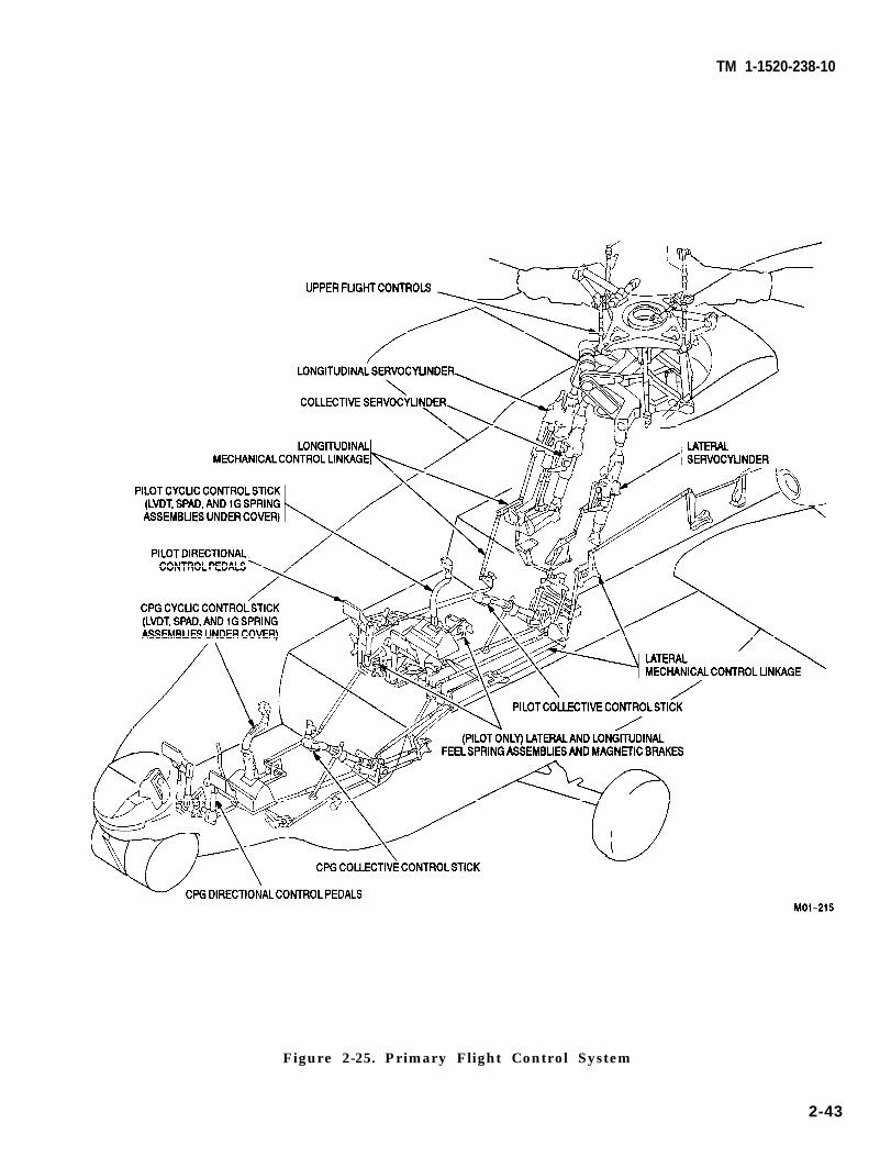
TM 1-1520-238-10
Figure 2-25. Primary Flight Control System
2-43
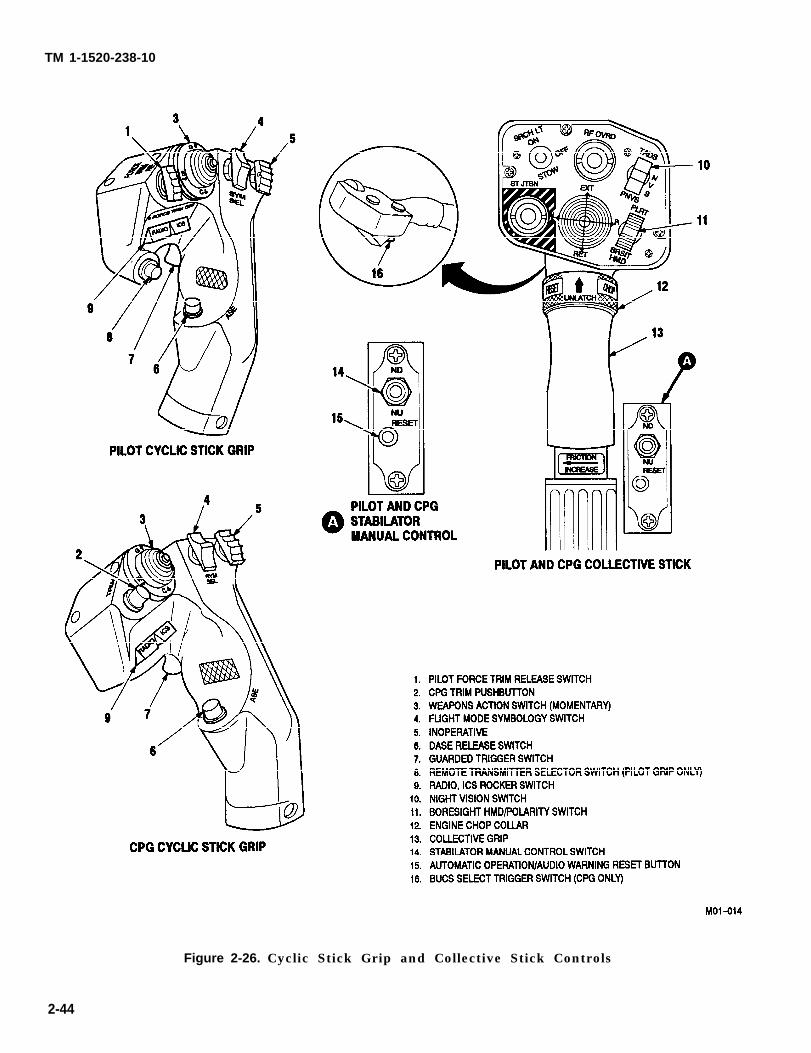
TM 1-1520-238-10
Figure 2-26. Cyclic Stick Grip and Collective Stick Controls
2-44
TM 1-1520-238-10
2.37.4 Trim Feel.
Use of the pilot FORCE TRIM RELswitch in the force trim off positionwith the helicopter on the ground isnot authorized. Inflight operationwith the pilot FORCE TRIM RELswitch in the force trim off position isauthorized when briefed and theforce trim off selection is acknowl-edged by both crewmembers.
Either crewmember can trim the cyclic and pedal con-trols. A lateral, longitudinal, and directional trim feelmagnetic brake and spring assembly is incorporatedinto each control system. Setting the pilot FORCETRIM REL switch to the on position will engage themagnetic brakes in the longitudinal, lateral, and direc-tional flight controls. The spring assemblies will holdthe cyclic stick and directional pedals in trim. Move-ment of the cyclic or directional controls, by either thepilot or CPG, with FORCE TRIM REL switch on, willcause the spring assemblies to compress and providefeel to the controls. When control pressure is released,the controls will return to their trimmed position. Re-trimming is accomplished by a TRIM pushbutton onthe CPG cyclic stick or by a FORCE TRIM REL switchon the pilot cyclic stick grip. Pressing the button orpressing up on the switch releases the magnetic brakeand allows the springs to travel to the new control posi-tion. Additionally, this action also allows the SAS ac-tuators to recenter, if necessary. Releasing the buttonor switch will then allow the magnetic brake to engageand hold the springs at the new position. The pilot maypress the FORCE TRIM REL switch to the full downposition to disable trim feel entirely.
For the CPG, trim feel is lost in the affected axiswhen the respective SPAD shear pin is broken or if me-chanical linkage severance has occurred between thepilot and CPG stations.
With the pilot FORCE TRIM REL switch in the downposition, the ATTD/HOVER HOLD and SAS actuatorcentering capabilities of the DASE are inoperative. Thecapabilities will return when the switch is returned tothe center position. The full down position of the pilotFORCE TRIM REL switch may be used momentarilyto unlatch the magnetic latch of the ATTD/HOVERHOLD switch on the ASE control panel (fig 2-27). TheDASE capabilities of the pilot FORCE TRIM RELswitch remain unaffected in the event of a trim system
failure such as with the magnetic brake or spring cap-sule. Trim feel is operable throughout all ranges of cy-clic stick or pedal travel. The trim system receives 28vdc from the emergency dc bus through the TRIM cir-cuit breaker on the pilot overhead circuit breaker pan-el.
2.37.5 Flight Control Servos. The four primary flightcontrol servos are tandem units that use hydraulicpressure from both the primary and utility hydraulicsystems. The primary and utility sides of the servos areindependent of each other which provides redundancyin the servos. If one hydraulic system fails, the remain-ing system can drive the flight control servos. If bothsystems fail simultaneously during flight, either crew-member can use stored accumulator hydraulic pressureto provide limited hydraulics for safe landing. SectionVI contains a detailed description of the emergency hy-draulic system. The primary side of each flight controlservo has two electrohydraulic solenoid valves. One re-sponds to DASE computer signals for stability aug-mentation.
w The second electrohydraulic solenoid valve respondsto DASE computer inputs for BUCS.
2.37.6 Digital Automatic Stabilization Equipment(DASE). The DASE augments stability and enhancesmaneuverability of the helicopter. DASE includes and/or controls the following: stability and command aug-mentation in pitch, roll, and yaw; attitude hold; head-ing hold; hover augmentation; turn coordination; andthe BUCS. Major components include an ASE controlpanel (fig 2-27), a DASE computer, eight linear variabledifferential transducers (LVDT), two 26 vac transform-ers, and four hydraulic servo actuators.
a. DASE Computer. The DASE computer receives28 vdc from the No. 3 essential dc bus through the ASEBUCS circuit breaker and a stepped down 26 vac refer-ence voltage from the No. 1 essential ac bus through theASE AC circuit breaker. Both circuit breakers are onthe pilot overhead circuit breaker panel. The DASEcomputer automatically disengages a mistrack of morethan 35% and lights the ASE FAIL indicator on bothcaution/warning panels; concurrently, the PITCH,ROLL, and YAW switches on the ASE control panelwill drop to OFF The squat switch on the left mainlanding gear disables the YAW CAS function duringground taxi to prevent overcontrol of the helicopter.The YAW channel circuitry in the DASE computer re-ceives sideslip data from the air data sensor which pro-vides turn coordination above 60 KTAS.
2-45
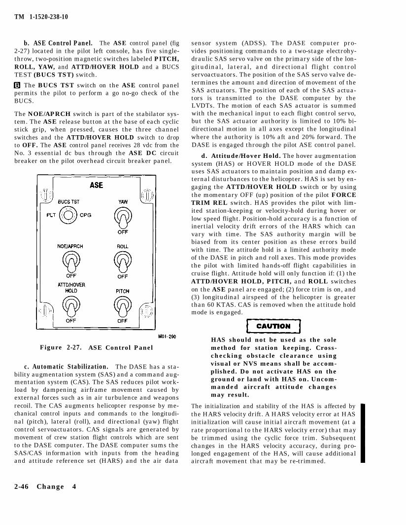
TM 1-1520-238-10
b. ASE Control Panel. The ASE control panel (fig2-27) located in the pilot left console, has five single-throw, two-position magnetic switches labeled PITCH,ROLL, YAW, and ATTD/HOVER HOLD and a BUCSTEST (BUCS TST) switch.
q The BUCS TST switch on the ASE control panelpermits the pilot to perform a go no-go check of theBUCS.
The NOE/APRCH switch is part of the stabilator sys-tem. The ASE release button at the base of each cyclicstick grip, when pressed, causes the three channelswitches and the ATTD/HOVER HOLD switch to dropto OFF. The ASE control panel receives 28 vdc from theNo. 3 essential dc bus through the ASE DC circuitbreaker on the pilot overhead circuit breaker panel.
Figure 2-27. ASE Control Panel
c. Automatic Stabilization. The DASE has a sta-bility augmentation system (SAS) and a command aug-mentation system (CAS). The SAS reduces pilot work-load by dampening airframe movement caused byexternal forces such as in air turbulence and weaponsrecoil. The CAS augments helicopter response by me-chanical control inputs and commands to the longitudi-nal (pitch), lateral (roll), and directional (yaw) flightcontrol servoactuators. CAS signals are generated bymovement of crew station flight controls which are sentto the DASE computer. The DASE computer sums theSAS/CAS information with inputs from the headingand attitude reference set (HARS) and the air data
sensor system (ADSS). The DASE computer pro-vides positioning commands to a two-stage electrohy-draulic SAS servo valve on the primary side of the lon-gitudinal, lateral, and directional flight controlservoactuators. The position of the SAS servo valve de-termines the amount and direction of movement of theSAS actuators. The position of each of the SAS actua-tors is transmitted to the DASE computer by theLVDTs. The motion of each SAS actuator is summedwith the mechanical input to each flight control servo,but the SAS actuator authority is limited to 10% bi-directional motion in all axes except the longitudinalwhere the authority is 10% aft and 20% forward. TheDASE is engaged through the pilot ASE control panel.
d. Attitude/Hover Hold. The hover augmentationsystem (HAS) or HOVER HOLD mode of the DASEuses SAS actuators to maintain position and damp ex-ternal disturbances to the helicopter. HAS is set by en-gaging the ATTD/HOVER HOLD switch or by usingthe momentary OFF (up) position of the pilot FORCETRIM REL switch. HAS provides the pilot with lim-ited station-keeping or velocity-hold during hover orlow speed flight. Position-hold accuracy is a function ofinertial velocity drift errors of the HARS which canvary with time. The SAS authority margin will bebiased from its center position as these errors buildwith time. The attitude hold is a limited authority modeof the DASE in pitch and roll axes. This mode providesthe pilot with limited hands-off flight capabilities incruise flight. Attitude hold will only function if: (1) theATTD/HOVER HOLD, PITCH, and ROLL switcheson the ASE panel are engaged; (2) force trim is on, and(3) longitudinal airspeed of the helicopter is greaterthan 60 KTAS. CAS is removed when the attitude holdmode is engaged.
HAS should not be used as the solemethod for station keeping. Cross-checking obstacle clearance usingvisual or NVS means shall be accom-plished. Do not activate HAS on theground or land with HAS on. Uncom-manded aircraft attitude changesmay result.
The initialization and stability of the HAS is affected bythe HARS velocity drift. A HARS velocity error at HASinitialization will cause initial aircraft movement (at arate proportional to the HARS velocity error) that maybe trimmed using the cyclic force trim. Subsequentchanges in the HARS velocity accuracy, during pro-longed engagement of the HAS, will cause additionalaircraft movement that may be re-trimmed.
2-46 Change 4
TM 1-1520-238-10
NOTE
m the GPS system is not keyed or istracking less than 4 satellites, HASperformance may degrade over time.Hover Position Box and Velocity Vectoraccuracy will be degraded.
Over time the SAS actuators may reachsaturation limit if not centered by rein-itializing. The ATTD/HOVER HOLDfeatures in pitch, roll, or yaw will belost if saturation occurs. The ATTD/HOVER HOLD feature is a limitedhands off feature and the controlsshould always be monitored carefully.
Heading hold is a function of HAS. The HAS mode willfunction only if: (1) the ATTD/HOVER HOLD and allASE channels are engaged; (2) force trim is on, and (3)airspeed is below 50 KTAS and ground speed is lessthan 15 knots. Degraded conditions will occur in atti-tude hold or HAS if individual ASE channel switchesare not engaged. The ATTD/HOVER HOLD switchwill disengage automatically when transitioning be-tween modes; attitude hold will disengage at approxi-mately 55 KTAS when decelerating. HAS will disen-gage when 15 knots ground speed or 50 KTAS isexceeded; or when ADSS fails or is turned off.
NOTE
Backup Control Systems (BUCS) are notincorporated on aircraft PV-529 (S/N88-0199) and prior.
2.37.7 Backup Control System (BUCS). TheBUCS is a single-channel or non-redundant fly-by-wireflight control system which electronically operates allfour flight controls. The BUCS provides full authorityflight control with identical handling characteristics toDASE OFF flight in the affected axis. This is accom-plished through the use of LVDTs attached to the flightcontrols in each crew station. The LVDT flight controlinputs are made to the DASE, which electronically con-trols the BUCS servovalve on the primary side of eachflight control actuator. For a given flight control, theBUCS will automatically engage when there is no me-chanical connection between the flight control actuatorand its flight control in both crew stations. The BUCSwill not engage for any flight control which retains me-chanical integrity between the flight control actuatorand the associated flight control in either crewstation.The primary hydraulic system must be functional forthe BUCS to operate. The BUCS ON caution light willilluminate when BUCS is engaged for any flight con-trol.
Illumination of the BUCS FAIL warn-ing light while in flight shall betreated as a flight control systememergency
a. q Control Severance Engagement Logic.The BUCS will automatically engage when a differenceor mistrack exists between both LVDTs for a givenflight control, one in each crewstation and both LVDTsfor the corresponding flight control actuator. For exam-ple: if the lateral cyclic control was severed between thelateral main rotor actuator and both crewstations, theBUCS would engage when the crewmember flyingmade a lateral input greater than approximately 1.75inches. For flight control severances, the required inputto engage the BUCS for each flight control is approxi-mately 1.75 inches, except longitudinal cyclic which isabout 2.25 inches.
In the example, the logic the BUCS used to automati-cally engage was that the pilot and CPG lateral cyclicLVDTs were in agreement and the two LVDTs on thelateral actuator were in agreement, but that the differ-ence or mistrack between the two sets was the equiva-lent of a lateral input greater than 1.75 inches. There-fore, the mechanical linkage must be severed betweenthe actuator and the lateral cyclic controls in both crewstations.
The effect of the CPG assuming con-trol with the BUCS select triggerswitch is to transfer control of the he-licopter from a flight control that stillretains some integrity to a non-re-dundant electronic means of flightcontrol. This shall only be done if thepilot is incapable of flying the heli-copter.
If the lateral cyclic is severed between the pilot andCPG stations, the BUCS will not automatically engagebecause the pilot still has mechanical integrity betweenhis lateral cyclic and the lateral actuator. The CPG isstill capable of flying the helicopter with lateral cyclicby pressing the BUCS select trigger switch on his col-lective and making greater than a 1.75 inch lateral in-put. This will cause the BUCS to engage for the lateralflight control. The CPG shall assume control in thismanner only in the most extreme of emergency condi-tions.
Change 4 2-47
TM 1-1520-238-10
b. a Control Jam Engagement Logic. To engagethe BUCS for a flight control jam, the crewmember fly-ing the helicopter must exert enough force on thejammed flight control to break the pin in the SPAD.Each flight control in each crewstation has its ownSPAD. The force required to break the pin in a SPAD isdifferent for each of the flight controls; the requiredforces are less for the pilot than the CPG. Micro-switches inside the SPAD cause the BUCS to engagewhen a pin is sheared. For example: if a lateral cyclicjam occurs, the pilot has to exert a force, left or right, tobreak the pin in the pilot lateral SPAD. The BUCS willthen engage using the pilot lateral cyclic LVDT for con-trol inputs. The CPG lateral cyclic may or may notmove in response to the lateral main rotor actuator mo-tion. If the jam is severe enough, the lateral cyclic con-trols may still be jammed from the CPG perspective.The mechanical flight control connections at the flightcontrol actuators are designed to allow full actuatormotion with the mechanical flight controls stilljammed.
In the example, the pilot, now unjammed, makes later-al control inputs and the lateral main rotor actuator re-sponds. If the act of breaking the pilot lateral SPAD al-lows freedom of motion for the lateral cyclic controllinkage, the CPG lateral cyclic will follow the lateral ac-tuator motion. If still jammed, the CPG lateral cyclicwill not move. The CPG is still capable of flying the he-licopter in either of these conditions. The CPG has tobreak his lateral SPAD to transfer control of the BUCSto his lateral cyclic LVDT. If the cyclic is following themotion of the actuator, the CPG only has to input aforce opposite the motion until his lateral SPAD shears.If the control linkage is still jammed, the CPG exertsenough force in either direction until his lateral SPADbreaks. This shall be done only in the most extreme ofemergency conditions and only if the pilot is incapableof flying the helicopter.
NOTE
To prevent an erroneous BUCS FAILlight during generator shutdown, turnGEN 2 switch (fig 2-37) OFF prior toGEN 1 switch. If BUCS FAIL light illu-minates during generator shutdown, turnlight off by toggling the PITCH, ROLL,or YAW switch on the ASE control panel.
C. 0 BUCS FD/LS. BUCS is monitored continu-ously. If a BUCS failure is detected, BUCS will not en-gage in the affected axis and the BUCS FAIL warninglight in each crew station illuminates. To assure thatBUCS is fully operational, a preflight self-test is pro-vided in addition to the on-command DASE FD/LS test.The self-test verifies the integrity of BUCS before start-ing engines. The BUCS self-test requires primary hy-draulic pressure within normal limits, RTR BRAKEswitch set to BRAKE, flight controls centered, collec-tive friction off, both PWR levers in the IDLE positionor below, the helicopter on the ground and BUCS notengaged. All DASE channels must be off.
d. a Control Locks. The control locks protect theshear pins in the pilot and CPG cyclic longitudinal andlateral SPADS, and pedal directional SPADS (fig 2-25)from accidental breaking when the helicopter is on theground without hydraulic power. They consist of two rigpins to prevent cyclic longitudinal and lateral move-ment and two pedal lock fixtures to prevent pedalmovement, one set for the pilot station and one for theCPG station.
The two sets, comprising four rig pins and four pedallocks, are in a pouch located in the crew station. Eachrig pin and pedal lock are attached together by a lan-yard with a warning streamer.
When installing and removing thecontrol locks, hydraulic power mustbe on the helicopter to prevent dam-age to the SPAD shear pins.
One rig pin is installed in the left side of the cyclic stickbase to prevent longitudinal movement. The other rigpin, to prevent lateral movement, is installed in thelower right side of the cyclic stick shroud cover where ithas been cut away to allow access for rig pin installa-tion.
After each pedal is moved forward, the pedal lock fix-ture is installed through the brushes and cutout in thefloor so it rests on the edge of a shelf. The pedal lock fix-ture is aligned so that when the pedal is moved aft, thepedal support fits into the fork of the pedal lock fixture.The pedal is then moved aft so the fork tightly engagesthe pedal support to prevent movement and the pedaladjust is tightened.
2-48 Change 4
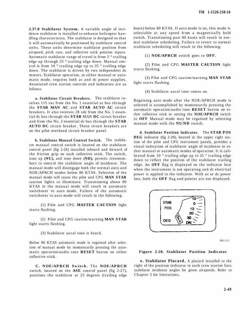
TM 1-1520-238-10
2.37.8 Stabilator System. A variable angle of inci-dence stabilator is installed to enhance helicopter han-dling characteristics. The stabilator is designed so thatit will automatically be positioned by stabilator controlunits. These units determine stabilator position fromairspeed, pitch rate, and collective stick position inputs.Automatic stabilator range of travel is from 5 ° trailingedge up through 25 ° trailing edge down. Manual con-trol is from 10 ° trailing edge up to 35 ° trailing edgedown. The stabilator is driven by two independent dcmotors. Stabilator operation, in either manual or auto-matic mode, requires both ac and dc power supplies.Associated crew station controls and indicators are asfollows:
a. Stabilator Circuit Breakers. The stabilator re-ceives 115 vac from the No. 1 essential ac bus throughthe STAB MAN AC and STAB AUTO AC circuitbreakers. It also receives 28 vdc from the No. 1 essen-tial dc bus through the STAB MAN DC circuit breakerand from the No. 3 essential dc bus through the STABAUTO DC circuit breaker. These circuit breakers areon the pilot overhead circuit breaker panel.
b. Stabilator Manual Control Switch. The stabila-tor manual control switch is located on the stabilatorcontrol panel (fig 2-26) installed inboard and forward ofthe friction grip on each collective stick. The switch,nose up (NU), and nose down (ND), permits crewmem-bers to control the stabilator angle of incidence. Themanual mode will disengage both the normal auto andNOE/APRCH modes below 80 KTAS. Selection of themanual mode will cause the pilot and CPG MAN STABcaution lights to illuminate. Transitioning above 80KTAS in the manual mode will result in automaticswitchover to auto mode. Failure of the automaticswitchover to auto mode will result in the following:
(1) Pilot and CPG MASTER CAUTION lightstarts flashing.
(2) Pilot and CPG caution/warning MAN STABlight starts flashing.
(3) Stabilator aural tone is heard.
Below 80 KTAS automatic mode is regained after selec-tion of manual mode by momentarily pressing the auto-matic operation/audio tone RESET button on eithercollective stick.
C. NOE/APRCH Switch. The NOE/APRCHswitch, located on the ASE control panel (fig 2-27),positions the stabilator at 25 degrees (trailing edge
down) below 80 KTAS. If auto mode is on, this mode isselectable at any speed from a magnetically heldswitch. Transitioning past 80 knots will result in nor-mal stabilator scheduling. Failure to revert to normalstabilator scheduling will result in the following:
(1) NOE/APRCH switch goes to OFF.
(2) Pilot and CPG MASTER CAUTION lightstarts flashing.
(3) Pilot and CPG caution/warning MAN STABlight starts flashing.
(4) Stabilator aural tone comes on.
Regaining auto mode after the NOE/APRCH mode isselected is accomplished by momentarily pressing theautomatic operation/audio tone RESET button on ei-ther collective stick or setting the NOE/APRCH switchto OFF Manual mode may be regained by selectingmanual mode with the NU/ND switch.
d. Stabilator Position Indicator. The STAB POSDEG indicator (fig 2-28), located in the upper right sec-tion of the pilot and CPG instrument panels, provides avisual indication of stabilator angle of incidence in ei-ther manual or automatic modes of operation. It is cali-brated from 10 ° trailing edge up to 35 ° trailing edgedown to reflect the position of the stabilator trailingedge. An OFF flag is displayed on the indicator facewhen the instrument is not operating and dc electricalpower is applied to the indicator. With ac or dc powerloss, both the OFF flag and pointer are not displayed.
M01-311
Figure 2-28. Stabilator Position Indicator
e. Stabilator Placard. A placard installed to theright of the position indicator in each crew station listsstabilator incidence angles for given airspeeds. Refer toChapter 5 for limitations.
2-49
TM 1-1520-238-10
Section VI. HYDRAULIC AND PRESSURIZED AIR SYSTEMS
2.38 HYDRAULIC SYSTEMS.
Two independent hydraulic systems are installed sothat failure of one system will not affect operation ofthe other. They are designated as the primary and util-ity hydraulic systems. They are similar but not identi-cal; they have separate, as well as shared functions.
2.38.1 Primary Hydraulic System. The primary hy-draulic system (fig 2-29) provides hydraulic power tothe primary side of the lateral cyclic, longitudinal cy-clic, collective, and directional servoactuators. Only theprimary sides of these servoactuators (discussed inmore detail in Section V) have electrohydraulic valvesthat allow the DASE and BUCS to affect the flight con-trols. Consequently, failure of the primary hydraulicsystem will result in the loss of DASE and BUCS. Theprimary hydraulic equipment includes the hydraulicpump, manifold, and servoactuators. The heat ex-changer may still be installed in the primary system onsome helicopters. The heat exchanger is obsolete and isbeing removed through attrition.
a. Servoactuators. The servoactuators (fig 2-29)can be commanded mechanically or electrically. Eachactuator contains two hydraulic pistons on a commonpiston rod. One piston is driven by the primary hydrau-lic system, the other by the utility hydraulic system.The hydraulic provisions in the actuator are completelyindependent of each other; there is no exchange of fluidbetween systems.
HEach actuator is controlled by a common manualtandem servo valve which ports hydraulic pressure toeach of the pistons. The servo valve spool is positionedby the associated mechanical control system to providefull authority control. Each actuator is also electricallycontrolled through the electrohydraulic valve sleeve toprovide SAS or BUCS control. Each actuator isequipped with a hydraulically powered plunger whichlocks the manual servo valve spool at mid positionwhen the DASEC powers the BUCS solenoid valve forBUCS engagement. Each actuator is also equippedwith a DASEC controlled SAS solenoid valve that portsprimary hydraulic pressure to the servo valve and theBUCS solenoid. Position transducer LVDT’s measurethe position of the servo valve sleeve and the actuatorposition. Each actuator incorporates a shear pin in thefeedback linkage to decouple the actuator motion from
2-50 Change 4
a jammed mechanical control and prevent damage tothe bellcrank attachments.
b. Primary Pump. The primary hydraulic pump ismounted on the accessory drive case of the main trans-mission (left side). The pump is of constant-pressurevariable-displacement design driven by the transmis-sion accessory gear train.
c. Primary Manifold. The primary manifold isinstalled on the left forward quadrant of the transmis-sion deck. Its function is to store, filter, supply, and reg-ulate the flow of hydraulic fluid. The manifold reservoiris pressurized on the return side by PAS air acting onthe manifold reservoir piston. This prevents pump inletcavitation. Servicing crews introduce fluid to the reser-voir through ground support equipment (GSE) connec-tions or the hand pump. Low pressure fluid enteringthe fill port is filtered by a 45 micron screen filter (be-fore MWO 1-1520-238-50-52) or a 5 micron cartridgefilter (after MWO 1-1520-238-50-52). The primary hydraulic system fluid capacity is six pints. The reservoirstores about one pint. Section XV contains specifica-tions, capacities, and procedures for oil system servic-ing. Other provisions within the primary manifold aredescribed below:
(1) Air-Bleed Valve. Used to deplete the pres-surized air on the manifold for system repair or service.
(2) High-Pressure and Low-pressure ReliefValves. Regulates fluid pressure from the pump andthe return to the manifold.
(3) Reservoir Low-Level Indication Switch.Switch is activated by the manifold reservoir piston.This illuminates an OIL LOW PRI HYD segment lighton the pilot caution/warning panel to indicate mini-mum operating level.
(4) Fluid Level indicator. Located in the man-ifold reservoir housing allows visual inspection of thereservoir oil level.
(5) Filters. Filters on both manifold pressureand return sides have mechanical impending bypassindicators for visual inspection. These indicators oper-ate on differential pressure. Both impending bypass in-dicators illuminate the OIL BYP PRI HYD segmenton the pilot caution/warning panel. Only the return fil-ter has bypass provisions.
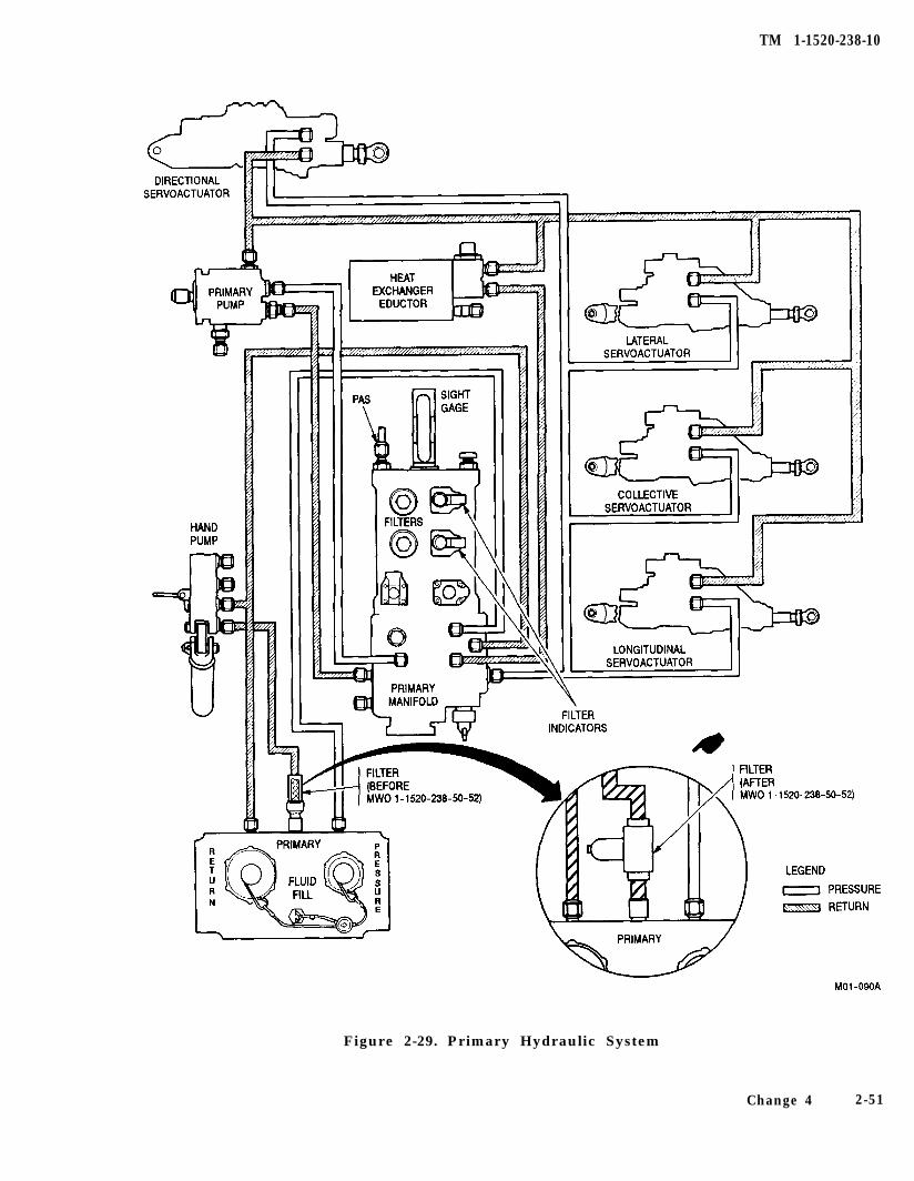
TM 1-1520-238-10
Figure 2-29. Primary Hydraulic System
Change 4 2-51
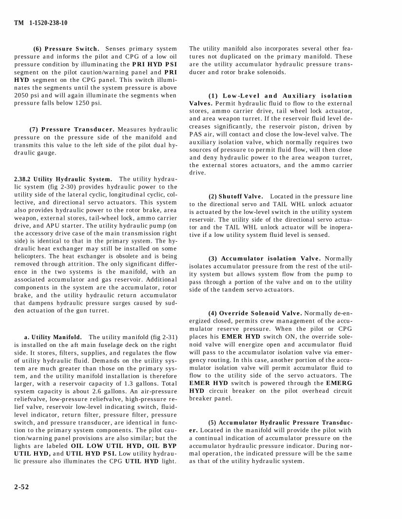
TM 1-1520-238-10
(6) Pressure Switch. Senses primary systempressure and informs the pilot and CPG of a low oilpressure condition by illuminating the PRI HYD PSIsegment on the pilot caution/warning panel and PRIHYD segment on the CPG panel. This switch illumi-nates the segments until the system pressure is above2050 psi and will again illuminate the segments whenpressure falls below 1250 psi.
(7) Pressure Transducer. Measures hydraulicpressure on the pressure side of the manifold andtransmits this value to the left side of the pilot dual hy-draulic gauge.
2.38.2 Utility Hydraulic System. The utility hydrau-lic system (fig 2-30) provides hydraulic power to theutility side of the lateral cyclic, longitudinal cyclic, col-lective, and directional servo actuators. This systemalso provides hydraulic power to the rotor brake, areaweapon, external stores, tail-wheel lock, ammo carrierdrive, and APU starter. The utility hydraulic pump (onthe accessory drive case of the main transmission rightside) is identical to that in the primary system. The hy-draulic heat exchanger may still be installed on somehelicopters. The heat exchanger is obsolete and is beingremoved through attrition. The only significant differ-ence in the two systems is the manifold, with anassociated accumulator and gas reservoir. Additionalcomponents in the system are the accumulator, rotorbrake, and the utility hydraulic return accumulatorthat dampens hydraulic pressure surges caused by sud-den actuation of the gun turret.
a. Utility Manifold. The utility manifold (fig 2-31)is installed on the aft main fuselage deck on the rightside. It stores, filters, supplies, and regulates the flowof utility hydraulic fluid. Demands on the utility sys-tem are much greater than those on the primary sys-tem, and the utility manifold installation is thereforelarger, with a reservoir capacity of 1.3 gallons. Totalsystem capacity is about 2.6 gallons. An air-pressurereliefvalve, low-pressure reliefvalve, high-pressure re-lief valve, reservoir low-level indicating switch, fluid-level indicator, return filter, pressure filter, pressureswitch, and pressure transducer, are identical in func-tion to the primary system components. The pilot cau-tion/warning panel provisions are also similar; but thelights are labeled OIL LOW UTIL HYD, OIL BYPUTIL HYD, and UTIL HYD PSI. Low utility hydrau-lic pressure also illuminates the CPG UTIL HYD light.
2-52
The utility manifold also incorporates several other fea-tures not duplicated on the primary manifold. Theseare the utility accumulator hydraulic pressure trans-ducer and rotor brake solenoids.
(1) Low-Level and Auxiliary isolationValves. Permit hydraulic fluid to flow to the externalstores, ammo carrier drive, tail wheel lock actuator,and area weapon turret. If the reservoir fluid level de-creases significantly, the reservoir piston, driven byPAS air, will contact and close the low-level valve. Theauxiliary isolation valve, which normally requires twosources of pressure to permit fluid flow, will then closeand deny hydraulic power to the area weapon turret,the external stores actuators, and the ammo carrierdrive.
(2) Shutoff Valve. Located in the pressure lineto the directional servo and TAIL WHL unlock actuatoris actuated by the low-level switch in the utility systemreservoir. The utility side of the directional servo actua-tor and the TAIL WHL unlock actuator will be inopera-tive if a low utility system fluid level is sensed.
(3) Accumulator isolation Valve. Normallyisolates accumulator pressure from the rest of the util-ity system but allows system flow from the pump topass through a portion of the valve and on to the utilityside of the tandem servo actuators.
(4) Override Solenoid Valve. Normally de-en-ergized closed, permits crew management of the accu-mulator reserve pressure. When the pilot or CPGplaces his EMER HYD switch ON, the override sole-noid valve will energize open and accumulator fluidwill pass to the accumulator isolation valve via emer-gency routing. In this case, another portion of the accu-mulator isolation valve will permit accumulator fluid toflow to the utility side of the servo actuators. TheEMER HYD switch is powered through the EMERGHYD circuit breaker on the pilot overhead circuitbreaker panel.
(5) Accumulator Hydraulic Pressure Transduc-er. Located in the manifold will provide the pilot witha continual indication of accumulator pressure on theaccumulator hydraulic pressure indicator. During nor-mal operation, the indicated pressure will be the sameas that of the utility hydraulic system.
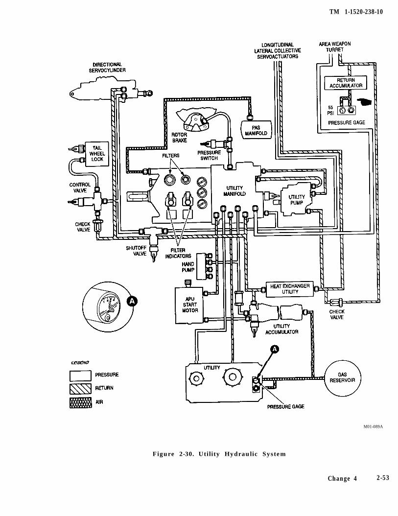
TM 1-1520-238-10
M01-089A
Figure 2-30. Utility Hydraulic System
Change 4 2-53
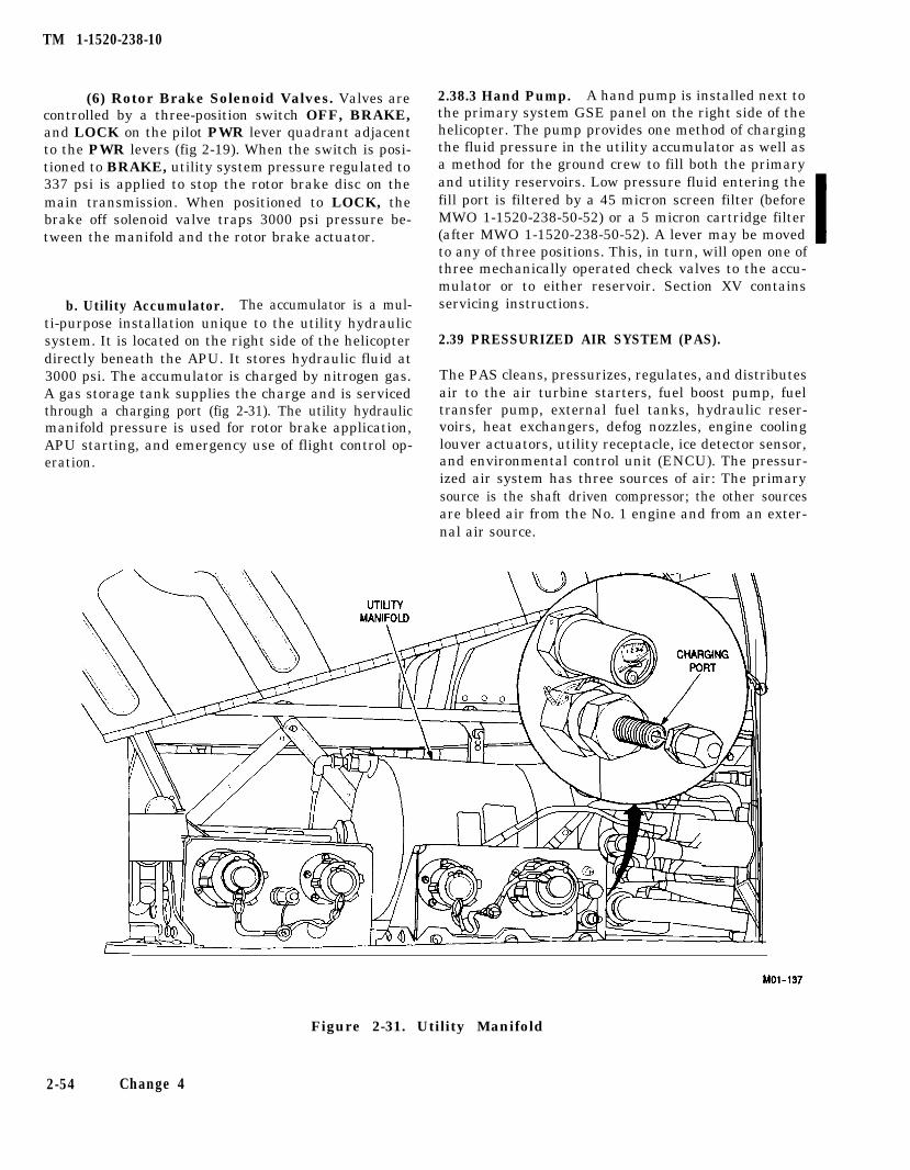
TM 1-1520-238-10
(6) Rotor Brake Solenoid Valves. Valves arecontrolled by a three-position switch OFF, BRAKE,and LOCK on the pilot PWR lever quadrant adjacentto the PWR levers (fig 2-19). When the switch is posi-tioned to BRAKE, utility system pressure regulated to337 psi is applied to stop the rotor brake disc on themain transmission. When positioned to LOCK, thebrake off solenoid valve traps 3000 psi pressure be-tween the manifold and the rotor brake actuator.
b. Utility Accumulator. The accumulator is a mul-ti-purpose installation unique to the utility hydraulicsystem. It is located on the right side of the helicopterdirectly beneath the APU. It stores hydraulic fluid at3000 psi. The accumulator is charged by nitrogen gas.A gas storage tank supplies the charge and is servicedthrough a charging port (fig 2-31). The utility hydraulicmanifold pressure is used for rotor brake application,APU starting, and emergency use of flight control op-eration.
2.38.3 Hand Pump. A hand pump is installed next tothe primary system GSE panel on the right side of thehelicopter. The pump provides one method of chargingthe fluid pressure in the utility accumulator as well asa method for the ground crew to fill both the primaryand utility reservoirs. Low pressure fluid entering thefill port is filtered by a 45 micron screen filter (beforeMWO 1-1520-238-50-52) or a 5 micron cartridge filter(after MWO 1-1520-238-50-52). A lever may be movedto any of three positions. This, in turn, will open one ofthree mechanically operated check valves to the accu-mulator or to either reservoir. Section XV containsservicing instructions.
2.39 PRESSURIZED AIR SYSTEM (PAS).
The PAS cleans, pressurizes, regulates, and distributesair to the air turbine starters, fuel boost pump, fueltransfer pump, external fuel tanks, hydraulic reser-voirs, heat exchangers, defog nozzles, engine coolinglouver actuators, utility receptacle, ice detector sensor,and environmental control unit (ENCU). The pressur-ized air system has three sources of air: The primarysource is the shaft driven compressor; the other sourcesare bleed air from the No. 1 engine and from an exter-nal air source.
Figure 2-31. Utility Manifold
2-54 Change 4
TM 1-1520-238-10
2.39.1 Shaft Driven Compressor (SDC). The SDC ismounted on the main transmission accessory case anduses outside air. The air passes through a particle sepa-rator and then through a butterfly-type throttle valve.This valve is closed by a time-delay solenoid when theAPU START switch is engaged. The valve remainsclosed for 60 seconds after the APU START switch isreleased. This reduces APU loads during starting. Theshaft driven compressor will compress air at 3:1 ratioand route it through a surge valve. This valve, mountedon top of the SDC, will open or close as necessary tokeep SDC air pressure constant with variable systemdemand. Pressurized air then passes through a spring-operated check valve and into the PAS manifold. Thischeck valve prevents pressurized air, from sources oth-er than the SDC, from reverse routing back to the SDC.The SDC is lubricated by the main transmission acces-sory oil pump and has its own scavenge. If the SDC oiltemperature exceeds 182 °C (360 °F), or if the SDCfails, the pilot SHAFT DRIVEN COMP caution light
illuminates.
2.39.2 No. 1 Engine Bleed Air. The No. 1 engine pro-vides an alternative source of pressurized air in case ofSDC failure. The engine compressor bleed air selectorvalve opens automatically if SDC output falls below 10psi. Simultaneously, a spring-operated check valveopens. When closed, this valve prevents pressurized airfrom going to the engine compressor when the SDC isoperating. Each engine provides bleed air to its engineinlet to prevent ice formation and to keep the enginecooling louvers closed while the engine is operating.The bleed air used in these last two instances is inde-pendent of the pressurized air system.
2.39.3 External Air Source Receptacles. The recep-tacle for external air source connection (fig 2-46) is onthe lower portion of No. 1 engine nacelle. When the airsource is connected and operating, a normally closedcheck valve to the pressurized air system opens to allowair to pressurize the manifold.
2-55
TM 1-1520-238-10
2-56 Change 6
Section VII. POWER TRAIN SYSTEM
2.40 POWER TRAIN.
The power train (fig 2-32) transmits engine power tothe rotors and transmission-mounted accessories. Thepower train includes two engine nose gearboxes, twoshafts to the main transmission, the main transmis-sion, main rotor drive shaft, tail rotor drive shafts, in-termediate gearbox, tail rotor gearbox, and APU driveshaft, and couplings.
2.40.1 Engine Nose Gearboxes. The engine nosegearboxes are mounted on the nose of each engine.They reduce nominal engine speed and change theangle of drive. Both nose gearboxes have self-containedpressurized oil systems with provisions to ensure lim-ited operation if a total loss of pressurized lubricationoccurs. These self-contained systems feature a pressurepump driven by the gearbox output shaft, filter withimpending bypass filter indicator and filter bypass ca-pability, high-pressure relief valve, and sump. Mountedon the nose gearbox output drive is an axial-type fanthat draws air through the gearbox fairing and pastcooling fins on the gearbox. The input drive shafts haveflexible couplings that require no lubrication. External-ly accessible accessories include a filler, breather, oillevel sight gage, chip detector/temperature sensor,pressure transducer, and temperature probe.
a. Engine Nose Gearbox Caution Light Provi-sions. High oil temperature, low oil pressure, and thepresence of chips are detected in each gearbox. The pi-lot is alerted to the condition by six caution segments:OIL HOT NOSE GRBX 1, OIL HOT NOSE GRBX 2,OIL PSI NOSE GRBX 1, OIL PSI NOSE GRBX 2,CHIPS NOSE GRBX 1, and CHIPS NOSE GRBX 2.Either the ENG 1 or ENG 2 segment will simulta-neously illuminate on the CPG caution/warning panel(fig 2-44).
2.40.2 Main Transmission. The main transmissioncombines the two engine nose gearbox inputs and pro-vides drive to the main rotor, tail rotor, accessories, androtor brake disc. Two overrunning clutches at the maintransmission permit either engine to be disengaged
from the transmission during autorotation. The maintransmission reduces the rpm input to the main rotor,tail rotor, and the rotor brake disc. The main transmis-sion is mounted below the main rotor static mast basewhich allows its removal without removing the uppercontrols, mast, hub, or blades. The main rotor driveshaft is designed to carry torque loads only. The rotorhub is on a static mast which carries vertical and bend-ing loads. The drive shaft rotates inside the static mast.The main transmission has primary and accessorydrive trains. The primary drive train, through threestages, changes the angle and speed of the power drivesto the main rotor, tail rotor, and rotor brake. Overrun-ning clutches allow the APU to drive the transmissionaccessory gearbox when the engines are not operating.The transmission accessories consist of two alternat-ing-current generators, two hydraulic pumps, and ashaft driven compressor. A magnetic pickup measuresmain rotor rpm.
a. Main Transmission Lubrication. The maintransmission has two independent oil systems. Eachsystem has its own sump, pump, filter and heat ex-changer. Oil level sight gauges are located in the trans-mission housing at each oil sump. These systems arenot totally independent in the usual sense because dur-ing normal operation, the oils will mix. If oil loss occursin either sump or in either heat exchanger, the diverter(float) valve will seal off that sump to prevent a totalloss of oil. There are provisions throughout the trans-mission so that even with a total loss of oil there will belimited lubrication. Each oil filter has a bypass capabil-ity and an impending bypass capability and an impend-ing bypass filter indicator. Each sump has a chip detec-tor/temperature sensor and temperature transducer.Pressure is measured downstream of each heat ex-changer. Oil passing through the heat exchanger.mounted inboard on each engine firewall, is air cooled.The heat exchangers have thermal bypass provisionsfor cold starts. A third oil pump, driven by the accessorydrive, lubricates the accessory gears during APU opera-tion. This pump draws oil from the right oil systemsump.
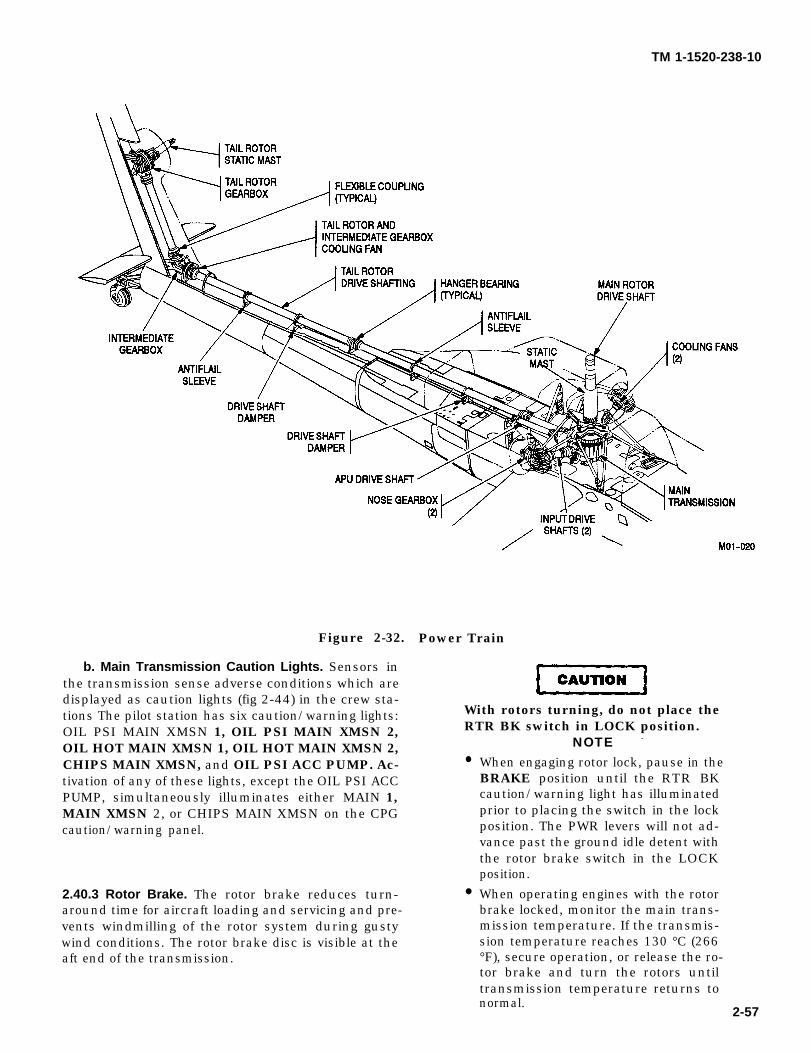
CAUTION
TM 1-1520-238-10
Figure 2-32. Power Train
b. Main Transmission Caution Lights. Sensors inthe transmission sense adverse conditions which aredisplayed as caution lights (fig 2-44) in the crew sta-tions The pilot station has six caution/warning lights:OIL PSI MAIN XMSN 1, OIL PSI MAIN XMSN 2,OIL HOT MAIN XMSN 1, OIL HOT MAIN XMSN 2,CHIPS MAIN XMSN, and OIL PSI ACC PUMP. Ac-tivation of any of these lights, except the OIL PSI ACCPUMP, simultaneously illuminates either MAIN 1,MAIN XMSN 2, or CHIPS MAIN XMSN on the CPGcaution/warning panel.
2.40.3 Rotor Brake. The rotor brake reduces turn-around time for aircraft loading and servicing and pre-vents windmilling of the rotor system during gustywind conditions. The rotor brake disc is visible at theaft end of the transmission.
With rotors turning, do not place theRTR BK switch in LOCK position.
NOTE -
●
●
When engaging rotor lock, pause in theBRAKE position until the RTR BKcaution/warning light has illuminatedprior to placing the switch in the lockposition. The PWR levers will not ad-vance past the ground idle detent withthe rotor brake switch in the LOCKposition.
When operating engines with the rotorbrake locked, monitor the main trans-mission temperature. If the transmis-sion temperature reaches 130 °C (266°F), secure operation, or release the ro-tor brake and turn the rotors untiltransmission temperature returns tonormal.
2-57
CAUTION
CAUTION
TM 1-1520-238-10
a. Rotor Brake (RTR BK) Switch. The rotor brakeis controlled by the RTR BK switch on the pilot PWRlever quadrant (fig 2-19). The switch has three posi-tions: OFF, BRAKE, and LOCK. When set at LOCKwith full utility hydraulic system pressure, the brakeprevents the gas turbines from driving the power tur-bines when both engines are at idle. When the rotor isstopped, the switch may be set at LOCK which causessolenoid valves in the manifold to deenergize and allavailable utility hydraulic system or accumulator pres-sure to be applied to the brake. A system of interlocksprevents the rotor brake from being locked when thePWR levers are in any position except IDLE and OFF.When the switch is set at BRAKE, solenoid valves inthe utility hydraulic manifold operate to actuate thebrake. With the switch at OFF, the only hydraulic pres-sure to the brake is 30 psi from the pressurized air sys-tem which, when operating, pressurizes the return sideof the utility hydraulic system.
b. Rotor Brake Solenoid and PressureSwitch. Rotor brake electrical solenoids and the pres-sure switch receive 28 vdc from the emergency dc busthrough the RTR BRK circuit breaker on the pilotoverhead circuit breaker panel. If this circuit breaker isopen, or if helicopter emergency electrical power is lostfor any reason, the rotor brake, if previously set atLOCK, will remain locked as long as accumulator pres-sure is available.
2.40.4 Tail Rotor Drive Shafts. There are four tail ro-tor drive shaft sections. Three tail rotor drive shaftslead from the transmission to the intermediate gear-box. Two are of equal length. The last shaft is installedon the vertical stabilizer between the intermediate andtail rotor gearboxes. Hanger bearings support the long-er shafts. They are covered by aerodynamic fairingswhich may be opened for maintenance and inspection.The two equal-length shafts incorporate friction damp-ers and antiflails. Flexible couplings, attached to theshaft ends, are capable of accommodating shaft mis-alignments throughout the power range.
2-56
Prolonged out of ground effect hover-ing (20 - 30 min.) with outside airtemperatures above 75 °F (24 °C) maycause the intermediate gearbox tooverheat.
2.40.5 intermediate Gearbox. The intermediategearbox, at the base of the vertical stabilizer, reducesthe rpm and changes the angle of drive. A fan mountedon the gearbox input shaft draws air from an inlet onthe vertical stabilizer. This air cools both the tail rotorgearbox and the intermediate gearbox. Four thermis-tors monitor temperature and an accelerometer mea-sures vibration limits. The intermediate gearbox is agrease-lubricated sealed unit.
a. intermediate Gearbox Caution Light indica-tors. The four thermistors and the accelerometer pro-vide crewmembers with temperature and vibrationcaution lights. Both crew stations have TEMP INT andVIB GRBX light segments.
Prolonged out of ground effect hover-ing (20 - 30 min.) with outside airtemperatures above 75 °F (24 °C) maycause the tail rotor gearbox to over-heat.
2.40.6 Tail Rotor Gearbox. The tail rotor gearbox,mounted on the vertical stabilizer, reduces the outputrpm and changes the angle of drive. The tail rotor out-put shaft passes through the gearbox static mast. Alltail rotor loads are transmitted to the static mast. Theoutput shaft transmits only torque to the tail rotor. Lu-brication of this gearbox is identical to that of the inter-mediate gearbox.
a. Tail Rotor Gearbox Caution Light indica-tors. The four thermistors and the accelerometerfunction in the same way as for the intermediate gear-box. The associated caution light on the pilot and CPGcaution/warning panels are labeled TEMP TR andVIB GRBX. (Both the intermediate and tail rotor gear-boxes activate the VIB GRBX light segment).
TM 1-1520-238-10
Section Vlll. ROTORS
2.41 ROTOR SYSTEM.
The rotor system consists of a single, four-bladed, fullyarticulated main rotor and a four-bladed tail rotor as-sembly with two teetering rotor hubs.
2.41.1 Main Rotor. The main rotor has four blades.The head is a fully articulated system that allows thefour blades to flap, feather, lead, or lag independent ofone another. The head consists of a hub assembly, pitchhousings, rotor dampers, and lead-lag links. Attachedto the rotor head are four easily removable blades. Themain rotor is controlled by the cyclic and collectivesticks through a swashplate mounted about the staticmast.
a. Hub Assembly. The main rotor hub is a steeland aluminum assembly that supports the main rotorblades; it is driven by the main rotor drive shaft. Thehub rotates about a static mast, which supports it. Thisarrangement allows the static mast, rather than themain rotor drive shaft, to assume all flight loads. Thehub is splined to the main rotor drive shaft by means ofa drive plate adapter that is bolted to the hub. The hubis secured to the static mast by a large locknut securedby multiple bolts. The hub houses two sets of taperedroller bearings that are grease-lubricated and sealed.These bearings transfer hub loads to the static mast.Mechanical droop stops limit blade droop. When bladedroop occurs, a striker plate on the pitch housing con-tacts a roller. The roller presses a plunger against adroop stop ring on the lower portion of the hub.
b. Pitch Housing. The pitch housing permitsblade pitch changes in response to flight control move-ments transmitted through the swashplate. This ismade possible within the four pitch housings by V-shaped stainless steel strap assemblies that are able totwist and flap to permit blade feathering and flapping.Cyclic and collective stick inputs are transmitted to thepitch housing horns by pitch links attached to theswashplate. Feather bearings are installed inboard onthe pitch housing to allow vertical and horizontal loadsto be transferred from the pitch housing to the hub.Centrifugal loads are transmitted by each strap assem-bly to the hub.
c. Lead-Lag Links. The lead-lag link for eachblade is connected to the outboard end of each pitchhousing and is secured in place by a pin and two bear-ings that allow the link to move horizontally. The pingoes through the V-portion of each strap within thepitch housing.
d. Damper Assemblies. Two damper assembliescontrol the lead-lag movement of each main rotor blade.Each damper attaches outboard to a link lug and in-board to a trunnion at the pitch housing. The dampercontains elastomeric elements that distort to allow theblade to lead or lag.
e. Main Rotor Blades. Each main rotor blade is aconstant-chord asymmetrical airfoil. The outboard tipis swept aft 20° and tapers to a thinner symmetricalsection. The blade has a 21-inch chord. Tip weights areinstalled within the blade. Chord-wise, the leading-edge and forward half of the blade is a four-cell struc-tural box of stainless steel and fiberglass with a stain-less steel spar. The aft half of the blade has fiberglassskin with a nomex honeycomb core and a bendabletrailing edge strip to aid in blade tracking. Each bladesecured to its lead-lag link by two blade attachmentpins. These pins can be removed without the use oftools and they pass vertically through the lead-lag linkand blade root fittings which are both made of tita-nium. Five sets of stainless steel doublers are locatedon the upper and lower surfaces of the blade at theblade root. The blades may be folded by removing theappropriate blade attachment pin (one for each blade)and any two adjacent pitch link bolts and pivoting theblade to the rear position using a hand-held blade sup-port device.
2.41.2 Tail Rotor. The tail rotor is of semirigid, teeter-ing design. Two pairs of blades, each pair fastened to itsown delta hinged hub, provide antitorque action anddirectional control. A titanium fork houses two elasto-meric teetering bearings and drives the rotating swash-plate through an attached scissors assembly. The tailrotor assembly is splined to, and driven by, the tail rotorgearbox drive shaft which passes through a static mast.Blade pitch changes when directional control inputscause the non-rotating swashplate to act upon the ro-tating swashplate. One pitch link for each blade, at-tached to the rotating swashplate and pitch horn,causes blade movement about two pitch-change bear-ings in the blade root. Centrifugal forces are carried bystainless steel strap assemblies that attach outboard tothe blade root and inboard at the hub center. An elasto-meric bearing assembly positions the hub and strappack in the tail rotor fork. Each blade has one stainlesssteel spar and two aluminum spars. Doublers and riv-ets attach the blade to the blade root. Brackets on theroot fitting hold chord-wise balance weights. Spanwisebalance weights are installed at the tip of each blade inan aluminum tip cap.
2-59
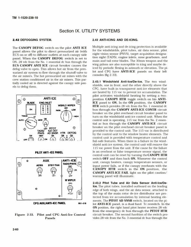
TM 1-1520-238-10
AIR DATA DC circuit breaker to the left wing pitotheater. Both circuit breakers are on the pilot overheadcircuit breaker panel. The AIR DATA DC circuitbreaker also provides 28 vdc to the ADS control relay.When energized, this relay sends 115 vac from the No.1 essential ac bus through the AIR DATA AC circuitbreaker to the air data sensor for anti-icing. In addi-tion, the CPG AUX panel ADSS switch, when set to on,energizes the ADS control relay to provide the air datasensor with 115 vac from the No. 3 essential ac busthrough the AIR DATA AC circuit breaker.
2.43.3 PNVS and TADS Anti-Ice/De-Ice. Three posi-tion TADS/PNVS toggle switches on the pilot ANTI-ICE panel and the CPG AUX/ANTI-ICE panel controlthe operation of the TADS/PNVS window heaters.These switches receive 28 vdc from the No. 1 essentialdc bus through the CANOPY ANTI-ICE CONTR cir-cuit breaker. Window heating is automatically con-trolled by a thermal control sensor in the respectiveheater power return circuits.
a. In Flight TADS/PNVS Anti-Ice/De-Ice. With thehelicopter in flight and the pilot or CPG TADS/PNVSswitch set to ON, the squat switch relay closes to pro-vide 28 vdc from the pilot or CPG TADS/PNVS switchto the MRTU. This causes the MRTU to send a signal toenergize anti-ice relays in the TADS power supply andPNVS electronic unit. The TADS and PNVS anti-ice re-lays then provide the TADS and PNVS window heaterswith 115 vac from the No. 1 essential ac bus throughthe TADS AC on the CPG circuit breaker panel and thePNVS AC circuit breakers on the pilot overhead circuitbreaker panel.
b. On Ground TADS/PNVS Anti-Ice/De-Ice. Whenthe helicopter is on the ground, the squat switch opensremoving power from the TADS/PNVS switches andthe TADS and PNVS window heaters. When eitherTADS/PNVS switch is set to GND, a signal is sent tothe MRTU which energizes the TADS/PNVS anti-icerelays. These relays then provide the TADS and PNVSwindow heaters with 115 vac from the No. 1 essentialac bus through the TADS AC and PNVS AC circuitbreakers.
2.43.4 Engine Inlet and Nose Gearbox Anti-Ice. En-gine bleed air is used to heat the engine air inlet, andheater blankets are used to anti-ice the nose gearbox.Engine anti-ice protection is controlled by a ENG IN-LET ON/OFF toggle switch on the pilot ANTI-ICEpanel. In the ON position, ENG 1 and ENG 2 advisorylights located above the switch will illuminate when the
system is functioning properly. The engine anti-icevalves and engine gearbox heater blanket controller re-ceive 28 vdc from the No. 1 essential dc bus through theENG ANTI-ICE circuit breaker on the pilot overheadcircuit breaker panel. The ENG INLET switch in theOFF position energizes both engine anti-ice valves tothe closed position. In the ON position, the ENG IN-LET switch deenergizes the anti-ice valves thus allow-ing them to open and furnish hot air to the engine inletfor anti-icing. It also energizes the engine gearbox heat-er blanket controller. The energized controller allows115 vac to be supplied from the No. 1 essential ac busthrough the NOSE GRBX HTR circuit breaker on thepilot overhead circuit breaker panel for the nose gear-box heater blankets.
2.43.5 Rotor Blade De-Icing System. The rotor bladede-ice three-position ON, OFF, and TEST toggleswitch, located on the pilot ANTI-ICE panel receives28 vdc from the No. 3 essential dc bus through theBLADE DE-ICE CONTR circuit breaker on the pilotoverhead circuit breaker panel. In the ON position, theswitch will provide 28 vdc power to the main rotor and-tail rotor de-icing controller and turn on the controller.When the controller is turned on, it collects data fromthe signal processor unit, ice detector/rate sensor, andthe outside air temperature sensor. If icing conditionsare present, the controller will energize the blade de-icecontrol relay. The energized blade de-ice control relayprovides a ground to the blade de-ice contactor controlrelay that receives 28 vdc from the No. 3 essential dcbus through the BLADE DE-ICE circuit breaker. Withthe blade de-ice contactor energized, 115 vat, 3 phasepower is furnished from Gen 2 through the blade de-icecontactor to the de-ice controller. (Gen 1 will only fur-nish power when an overload is sensed on Gen 2, andthe contactor is caused to trip). The de-ice controllerrectifies the 115 vac to 268 vdc ( ± 134 vdc) for the rotorblade heaters. The main rotor blades receive ± 134 vdcthrough slip rings at the main rotor distributor. Themain rotor distributor provides a sequential delivery tothe blade heater elements. In the TEST position, therotor blade de-ice switch provides that the controllerwill complete one full cycle of the blade anti-ice circuits.The tail rotor blades receive ± 134 vdc from the de-icingcontroller through tail rotor slip rings. Power to the tailrotor blade elements and main rotor blade elements iscontrolled by the de-icing controller which times theamount of current allowed to the blades for heating.The de-icing controller will detect faults within the sys-tem. When a fault occurs, the controller shuts off powerto the blades and illuminates the BLADE ANTI ICEFAIL segment on the pilot caution/warning panel.
2-61
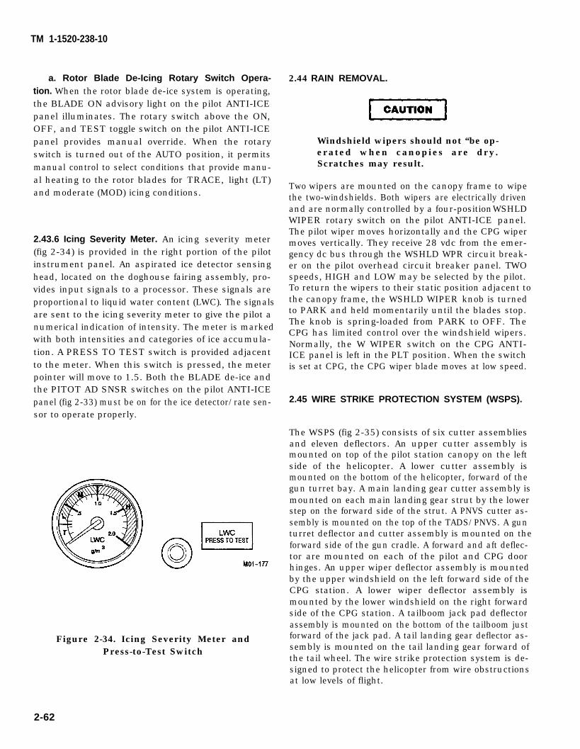
CAUTION
TM 1-1520-238-10
a. Rotor Blade De-Icing Rotary Switch Opera-tion. When the rotor blade de-ice system is operating,the BLADE ON advisory light on the pilot ANTI-ICEpanel illuminates. The rotary switch above the ON,OFF, and TEST toggle switch on the pilot ANTI-ICEpanel provides manual override. When the rotaryswitch is turned out of the AUTO position, it permitsmanual control to select conditions that provide manu-al heating to the rotor blades for TRACE, light (LT)and moderate (MOD) icing conditions.
2.43.6 Icing Severity Meter. An icing severity meter(fig 2-34) is provided in the right portion of the pilotinstrument panel. An aspirated ice detector sensinghead, located on the doghouse fairing assembly, pro-vides input signals to a processor. These signals areproportional to liquid water content (LWC). The signalsare sent to the icing severity meter to give the pilot anumerical indication of intensity. The meter is markedwith both intensities and categories of ice accumula-tion. A PRESS TO TEST switch is provided adjacentto the meter. When this switch is pressed, the meterpointer will move to 1.5. Both the BLADE de-ice andthe PITOT AD SNSR switches on the pilot ANTI-ICEpanel (fig 2-33) must be on for the ice detector/rate sen-sor to operate properly.
Figure 2-34. Icing Severity Meter andPress-to-Test Switch
2.44 RAIN REMOVAL.
Windshield wipers should not “be op-erated when canopies are dry.Scratches may result.
Two wipers are mounted on the canopy frame to wipethe two-windshields. Both wipers are electrically drivenand are normally controlled by a four-position WSHLDWIPER rotary switch on the pilot ANTI-ICE panel.The pilot wiper moves horizontally and the CPG wipermoves vertically. They receive 28 vdc from the emer-gency dc bus through the WSHLD WPR circuit break-er on the pilot overhead circuit breaker panel. TWOspeeds, HIGH and LOW may be selected by the pilot.To return the wipers to their static position adjacent tothe canopy frame, the WSHLD WIPER knob is turnedto PARK and held momentarily until the blades stop.The knob is spring-loaded from PARK to OFF. TheCPG has limited control over the windshield wipers.Normally, the W WIPER switch on the CPG ANTI-ICE panel is left in the PLT position. When the switchis set at CPG, the CPG wiper blade moves at low speed.
2.45 WIRE STRIKE PROTECTION SYSTEM (WSPS).
The WSPS (fig 2-35) consists of six cutter assembliesand eleven deflectors. An upper cutter assembly ismounted on top of the pilot station canopy on the leftside of the helicopter. A lower cutter assembly ismounted on the bottom of the helicopter, forward of thegun turret bay. A main landing gear cutter assembly ismounted on each main landing gear strut by the lowerstep on the forward side of the strut. A PNVS cutter as-sembly is mounted on the top of the TADS/PNVS. A gunturret deflector and cutter assembly is mounted on theforward side of the gun cradle. A forward and aft deflec-tor are mounted on each of the pilot and CPG doorhinges. An upper wiper deflector assembly is mountedby the upper windshield on the left forward side of theCPG station. A lower wiper deflector assembly ismounted by the lower windshield on the right forwardside of the CPG station. A tailboom jack pad deflectorassembly is mounted on the bottom of the tailboom justforward of the jack pad. A tail landing gear deflector as-sembly is mounted on the tail landing gear forward ofthe tail wheel. The wire strike protection system is de-signed to protect the helicopter from wire obstructionsat low levels of flight.
2-62
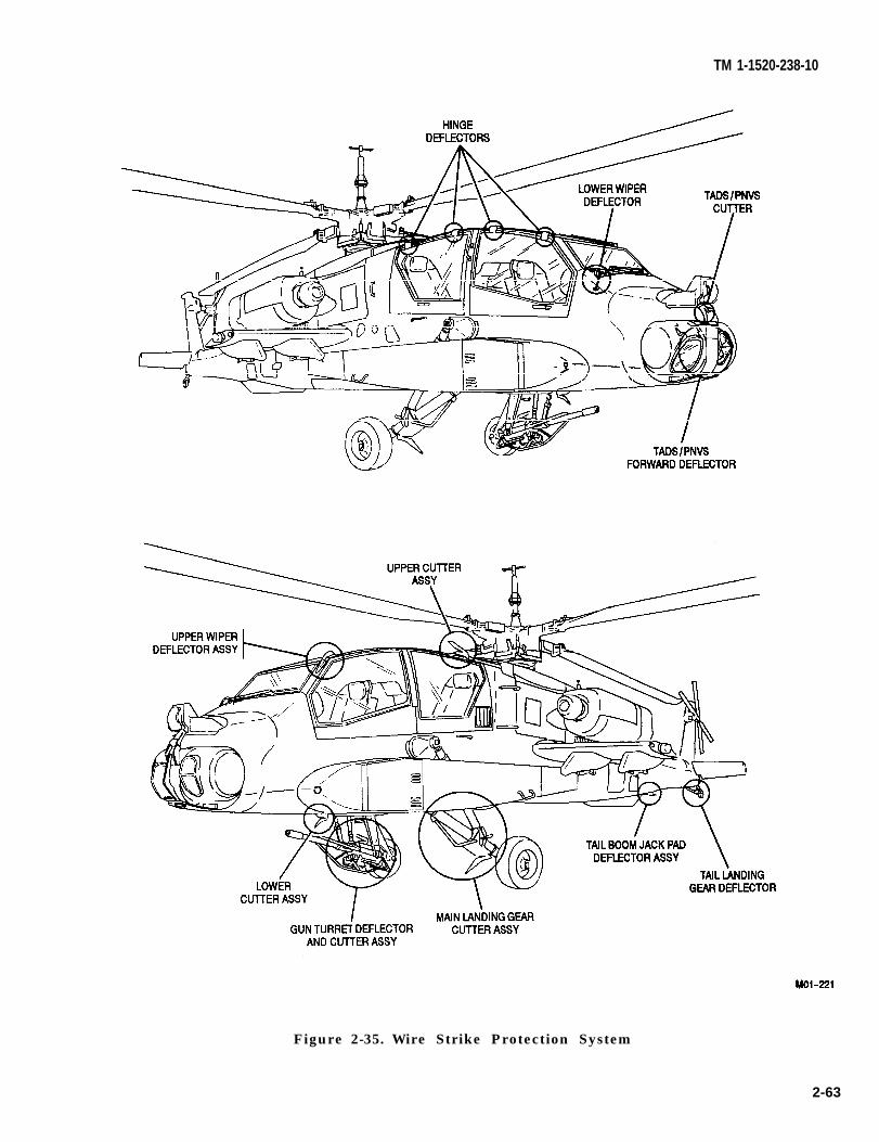
TM 1-1520-238-10
Figure 2-35. Wire Strike Protection System
2-63
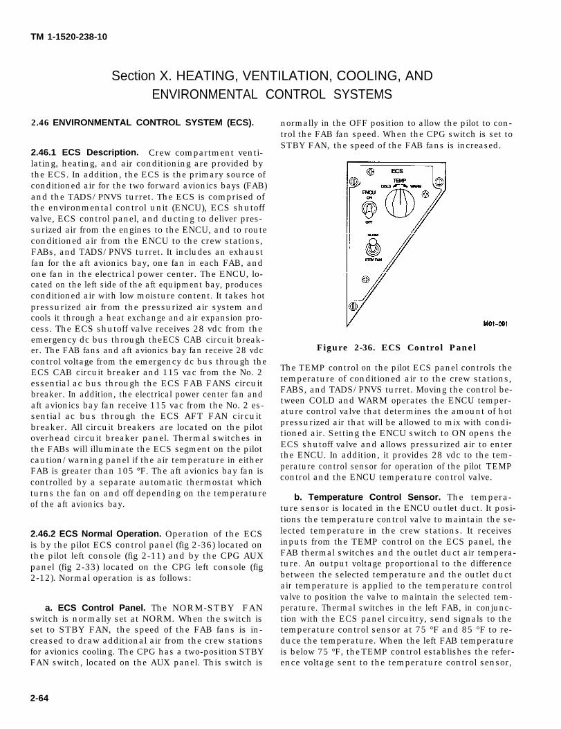
TM 1-1520-238-10
Section X. HEATING, VENTILATION, COOLING, ANDENVIRONMENTAL CONTROL SYSTEMS
2.46 ENVIRONMENTAL CONTROL SYSTEM (ECS).
2.46.1 ECS Description. Crew compartment venti-lating, heating, and air conditioning are provided bythe ECS. In addition, the ECS is the primary source ofconditioned air for the two forward avionics bays (FAB)and the TADS/PNVS turret. The ECS is comprised ofthe environmental control unit (ENCU), ECS shutoffvalve, ECS control panel, and ducting to deliver pres-surized air from the engines to the ENCU, and to routeconditioned air from the ENCU to the crew stations,FABs, and TADS/PNVS turret. It includes an exhaustfan for the aft avionics bay, one fan in each FAB, andone fan in the electrical power center. The ENCU, lo-cated on the left side of the aft equipment bay, producesconditioned air with low moisture content. It takes hotpressurized air from the pressurized air system andcools it through a heat exchange and air expansion pro-cess. The ECS shutoff valve receives 28 vdc from theemergency dc bus through the ECS CAB circuit break-er. The FAB fans and aft avionics bay fan receive 28 vdccontrol voltage from the emergency dc bus through theECS CAB circuit breaker and 115 vac from the No. 2essential ac bus through the ECS FAB FANS circuitbreaker. In addition, the electrical power center fan andaft avionics bay fan receive 115 vac from the No. 2 es-sential ac bus through the ECS AFT FAN circuitbreaker. All circuit breakers are located on the pilotoverhead circuit breaker panel. Thermal switches inthe FABs will illuminate the ECS segment on the pilotcaution/warning panel if the air temperature in eitherFAB is greater than 105 °F. The aft avionics bay fan iscontrolled by a separate automatic thermostat whichturns the fan on and off depending on the temperatureof the aft avionics bay.
2.46.2 ECS Normal Operation. Operation of the ECSis by the pilot ECS control panel (fig 2-36) located onthe pilot left console (fig 2-11) and by the CPG AUXpanel (fig 2-33) located on the CPG left console (fig2-12). Normal operation is as follows:
a. ECS Control Panel. The NORM-STBY FANswitch is normally set at NORM. When the switch isset to STBY FAN, the speed of the FAB fans is in-creased to draw additional air from the crew stationsfor avionics cooling. The CPG has a two-position STBYFAN switch, located on the AUX panel. This switch is
normally in the OFF position to allow the pilot to con-trol the FAB fan speed. When the CPG switch is set toSTBY FAN, the speed of the FAB fans is increased.
Figure 2-36. ECS Control Panel
The TEMP control on the pilot ECS panel controls thetemperature of conditioned air to the crew stations,FABS, and TADS/PNVS turret. Moving the control be-tween COLD and WARM operates the ENCU temper-ature control valve that determines the amount of hotpressurized air that will be allowed to mix with condi-tioned air. Setting the ENCU switch to ON opens theECS shutoff valve and allows pressurized air to enterthe ENCU. In addition, it provides 28 vdc to the tem-perature control sensor for operation of the pilot TEMPcontrol and the ENCU temperature control valve.
b. Temperature Control Sensor. The tempera-ture sensor is located in the ENCU outlet duct. It posi-tions the temperature control valve to maintain the se-lected temperature in the crew stations. It receivesinputs from the TEMP control on the ECS panel, theFAB thermal switches and the outlet duct air tempera-ture. An output voltage proportional to the differencebetween the selected temperature and the outlet ductair temperature is applied to the temperature controlvalve to position the valve to maintain the selected tem-perature. Thermal switches in the left FAB, in conjunc-tion with the ECS panel circuitry, send signals to thetemperature control sensor at 75 °F and 85 °F to re-duce the temperature. When the left FAB temperatureis below 75 °F, the TEMP control establishes the refer-ence voltage sent to the temperature control sensor,
2-64

TM 1-1520-238-10
thereby controlling the crew station temperature. If,during cold weather operations, the pilot adjusts theTEMP control to a position such that the temperatureof the mixed air would be too hot for the FABs, the tem-perature sensor will automatically reduce the de-manded air temperature. The amount that the temper-ature sensor can reduce the demanded air temperatureis limited.
c. ECS Caution/Warning Light. If the air temper-ature in either FAB exceeds 105 °F, the ECS caution/warning light will illuminate. If this occurs, the pilotshould reduce the demanded air temperature, but notto a level that adversely affects crew comfort, until theECS caution/warning light extinguishes. During hotweather operations if the ECS caution/warning light il-luminates, the pilot should adjust the TEMP control tofull COLD. In all cases of ECS light illumination, themission may be continued.
d. ECS Air Outlets. Conditioned air leaving theENCU is routed to both crew stations. The crew sta-tions each have four controllable crew air outlets. TheCPG station has an additional four nonadjustable out-lets to provide ECS air directly to each FAB, the TADS/PNVS turret, and the ORT. In the ECS cooling modethe two crew station floor outlets are closed and the
waist and shoulder outlets are open. For heating modethe crew shoulder outlets are closed and the waist andfloor outlets are open. The FAB and TADS/PNVS fansdraw CPG cabin air forward and expel it overboard. Pi-lot crew station air is drawn through the electrical pow-er center by a ventilation fan and then exhausted intothe transmission bay.
2.46.3 ECS Emergency Operation. In the event of anENCU failure, the actions of the pilot depend on the na-ture of the ambient temperature conditions. Crew sta-tion air flow with the ENCU inoperative is through thepilot’s station into the CPG station, and out through theFABs. During cold weather operations, the pilot may, athis discretion, open the auxiliary ventilation door to pe-riodically ventilate both crew stations. No other actionis required. During hot or warm weather operations,the pilot should open the auxiliary ventilation door toprovide crew station ventilation. If the ambient tem-perature is below 100 °F, no further action is recom-mended. If the ambient temperature is above 100 °F,the NORM-STBY FAN switch on the pilot ECS controlpanel should be set to the STBY FAN position. Depend-ing on the ambient outside air temperature, the ECScaution/warning light may illuminate if either FABtemperature is greater than 105 °F.
2-65
TM 1-1520-238-10
S e c t i o n X l . E L E C T R I C A L P O W E R S U P P L Y A N D D I S T R I B U T I O N
S Y S T E M S
2.47 ELECTRICAL POWER SYSTEM.
All the helicopter electrical power requirements aresupplied by two ac generators, two transformer/rectifi-ers (T/Rs) and in the case of complete failure, a 24-voltbattery will supply flight critical systems. For groundoperations, 115 vac external power can be supplied tothe helicopter through the external power receptacle.The electrical power distribution system is shown infigure 2-38. The system caution lights are listed intables 2-4 and 2-5.
In the event any circuit breakeropens for unknown reasons, do notattempt to reset the breaker morethan one time. Repeated tripping of acircuit breaker is an indication of apossible problem with equipment orelectrical wiring. Multiple attemptsto reset the circuit breaker may re-sult in equipment damage and/or anelectrical fire.
2.47.1 DC Power Supply System. Two essential acbusses supply power to the two 350-ampere T/Rsthrough the XFMR RECT 1 and XFMR RECT 2 cir-cuit breakers on the pilot overhead circuit breaker pan-el (fig 2-39). The No.1 and No. 2 T/Rs convert the ac in-put to 28 vdc. The 28 vdc power is applied to a dccontactor, which routes 28 vdc from T/R No. 1 to the No.1 essential dc bus and from T/R No.2 to the No. 2 essen-tial dc bus. The No. 1 and No. 2 essential dc buses eachapply 28 vdc, in parallel, through isolation diodes topower the emergency dc bus during normal operation.For emergency operation, the battery powers the emer-gency dc bus, and the emergency dc bus diodes isolatethe battery from the noncritical loads. The two essen-tial dc buses also supply 28 vdc power to the No. 3 es-sential dc bus. The T/Rs are self-monitoring for over-temperature and will illuminate the HOT RECT 1 andHOT RECT 2 caution lights on the pilot caution/war-ning panel when an overheat condition exists. The dccontact or monitors the T/Rs for output loss or drop involtage. If the dc contactor senses a fault in T/R No. 1,it disconnects T/R No. 1 from the No. 1 essential dc busand illuminates the RECT 1 caution light on the pilotcaution/warning panel. At the same time, it connectsNo. 1 essential dc bus to No. 2 essential dc bus through
relay action inside the contactor. The same action takesplace if T/R No. 2 fails. If both T/Rs fail, the ELEC SYSFAIL caution light on the CPG caution/warning panelwill illuminate. The caution/warning lights receive 28vdc from the emergency dc bus through the CAUT cir-cuit breaker on the pilot overhead circuit breaker paneland the EMERG BATT CAUT circuit breaker on theCPG main circuit breaker panel (fig 2-40).
a. Battery. A 24-volt, 13 ampere-hour, 19 cell,nickel-cadmium battery provides emergency power.The battery is located in the aft avionics bay. The bat-tery is charged by the battery charger which receives28 vdc power from the No. 1 essential dc bus throughthe BATT CHGR DC circuit breaker and 115 vac fromthe No. 2 essential ac bus through the BATT CHGRAC circuit breaker. Both circuit breakers are on the pi-lot overhead circuit breaker panel. The battery chargerwill completely charge the battery and then maintain atrickle charge. The battery charger also contains faultsensing that monitors battery temperature, cell bal-ance, and charger operation. If a fault occurs, either theHOT BAT or CHARGER caution light will illuminateon the pilot caution/warning panel. The helicopter isequipped with a battery heater which operates auto-matically when the battery is on.
b. CPG Battery Override Switch. A two-positionguarded toggle BAT OVRD switch is located on theCPG PWR lever quadrant (fig 2-12). With the guarddown, the switch is in the NRML position and enablesthe pilot EXT PWR/BATT switch on the pilot ELECPWR control panel (fig 2-37) located on the left console(fig 2-11). When the guard is positioned up and theswitch is set to OVRD, the pilot EXT PWR/BATTswitch is inoperative, and the battery is disconnectedfrom the emergency dc bus.
2.47.2 AC Power Supply System. The ac power supply system is the primary source of electrical power. Itsupplies 115 vac from twO 35 kilovolt-ampere genera-tors. Each generator and its associated componentscomprise an independent ac generating system thatsupplies about one-half of the total electrical require-ments to the ac buses. The generators are mounted on,and driven by, the main transmission accessory gearbox. The 115 vac power is monitored and regulated bythe generator control unit (GCU). If the generator out-put is normal, the GCU applies voltage to the ac contac-tor which energizes and connects the generator output
2-66 Change 2
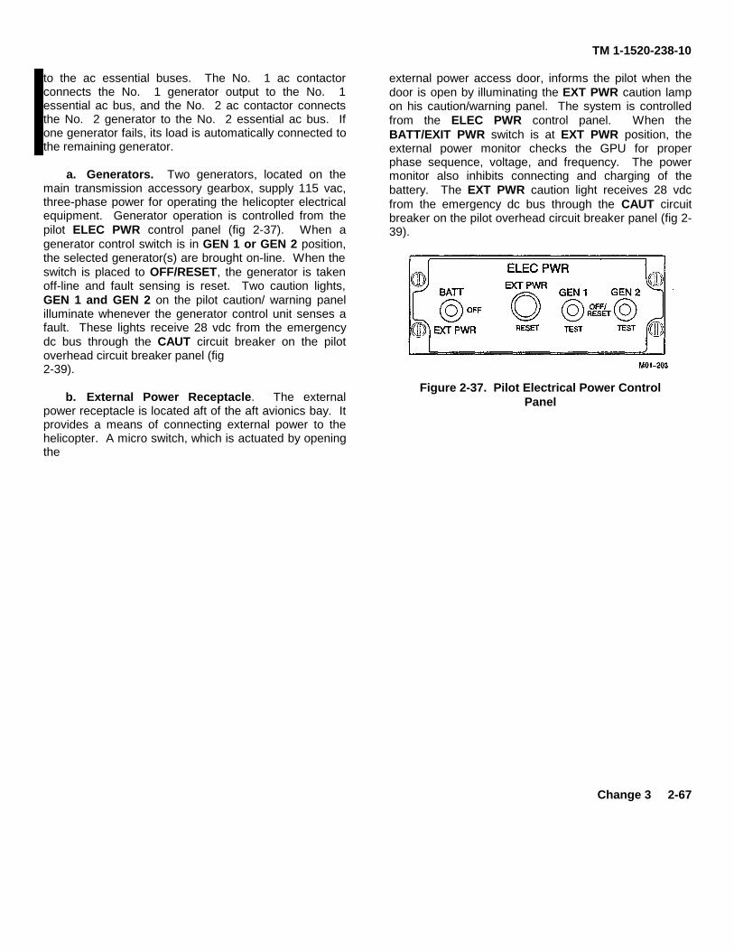
TM 1-1520-238-10
to the ac essential buses. The No. 1 ac contactorconnects the No. 1 generator output to the No. 1essential ac bus, and the No. 2 ac contactor connectsthe No. 2 generator to the No. 2 essential ac bus. Ifone generator fails, its load is automatically connected tothe remaining generator.
a. Generators. Two generators, located on themain transmission accessory gearbox, supply 115 vac,three-phase power for operating the helicopter electricalequipment. Generator operation is controlled from thepilot ELEC PWR control panel (fig 2-37). When agenerator control switch is in GEN 1 or GEN 2 position,the selected generator(s) are brought on-line. When theswitch is placed to OFF/RESET, the generator is takenoff-line and fault sensing is reset. Two caution lights,GEN 1 and GEN 2 on the pilot caution/ warning panelilluminate whenever the generator control unit senses afault. These lights receive 28 vdc from the emergencydc bus through the CAUT circuit breaker on the pilotoverhead circuit breaker panel (fig2-39).
b. External Power Receptacle. The externalpower receptacle is located aft of the aft avionics bay. Itprovides a means of connecting external power to thehelicopter. A micro switch, which is actuated by openingthe
external power access door, informs the pilot when thedoor is open by illuminating the EXT PWR caution lampon his caution/warning panel. The system is controlledfrom the ELEC PWR control panel. When theBATT/EXIT PWR switch is at EXT PWR position, theexternal power monitor checks the GPU for properphase sequence, voltage, and frequency. The powermonitor also inhibits connecting and charging of thebattery. The EXT PWR caution light receives 28 vdcfrom the emergency dc bus through the CAUT circuitbreaker on the pilot overhead circuit breaker panel (fig 2-39).
Figure 2-37. Pilot Electrical Power ControlPanel
Change 3 2-67
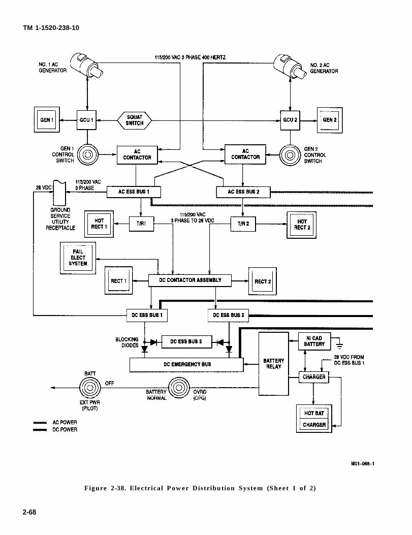
TM 1-1520-238-10
Figure 2-38. Electrical Power Distribution System (Sheet 1 of 2)
2-68
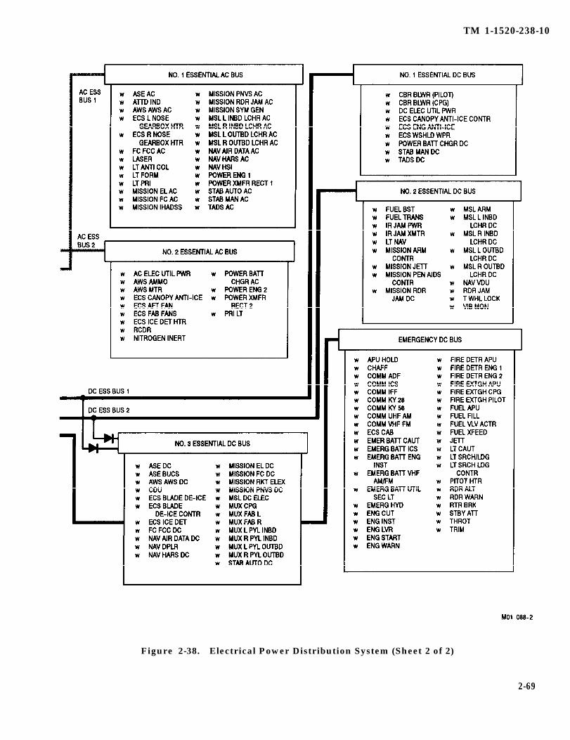
TM 1-1520-238-10
Figure 2-38. Electrical Power Distribution System (Sheet 2 of 2)
2-69

TM 1-1520-238-10
Figure 2-39. Pilot Overhead Circuit Breaker Panels (Sheet 1 of 2)
2-70 Change 5

TM 1-1520-238-10
CENTER CIRCUIT BREAKER PANEL
CENTER CIRCUIT BREAKER PANEL (LASER DETECTING SET MODIFICATION)
Figure 2-39 Pilot Overhead Circuit Breaker Panels (Sheet 2 of 2)
Change 5 2-70.1/(2-70.2 blank)

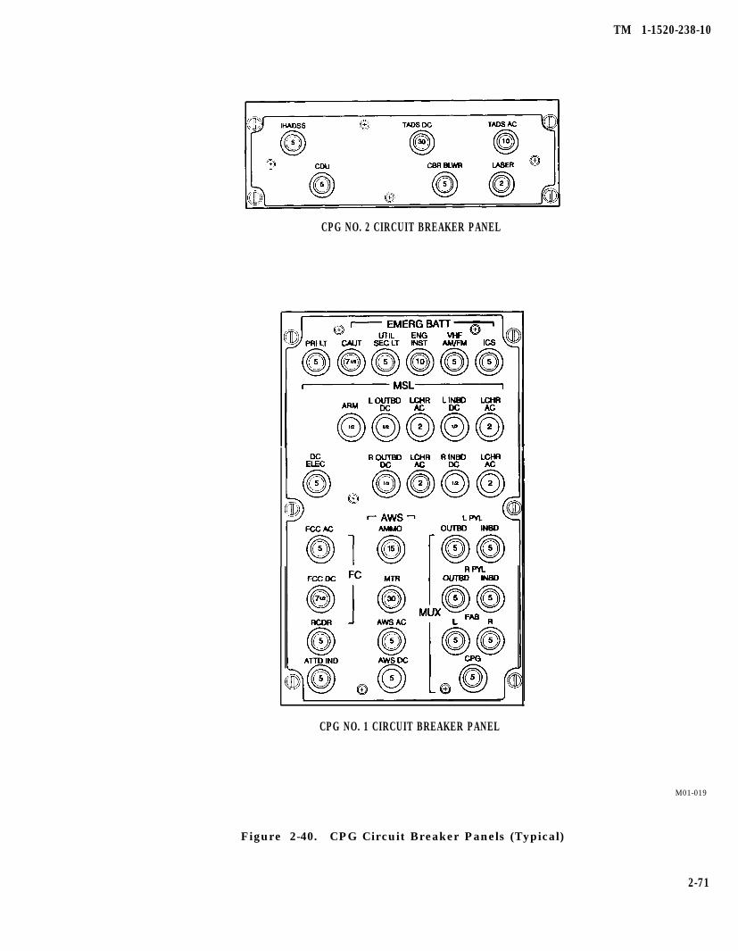
TM 1-1520-238-10
CPG NO. 2 CIRCUIT BREAKER PANEL
CPG NO. 1 CIRCUIT BREAKER PANEL
M01-019
Figure 2-40. CPG Circuit Breaker Panels (Typical)
2-71
TM 1-1520-238-10
Section
2.48 AUXILIARY POWER UNIT (APU).
XII. AUXILIARY POWER UNIT
To prevent an accidental APU start,the APU circuit breaker in the aftavionics bay and the APU HOLD cir-cuit breaker on the pilot overheadcircuit breaker panel shall be outwhen battery or external electricalpower is connected to the helicopterand unqualified personnel are in oraround the pilot crew station.
The APU indirectly provides hydraulic, pneumatic, andelectrical power for the operation of helicopter systemswhenever the engines are not driving the main trans-mission accessory section. The APU provides the meansof engine starting without the need for an aircraftground power unit (AGPU). It is located just inboard ofthe right engine nacelle in the aft equipment bay. TheAPU consists of a gearbox, a compressor, and a turbinesection, together with associated fuel, lubrication, andelectrical systems. The APU controller and the APUcontrol panel are installed separately from the APU.The utility hydraulic accumulator, located on the deckof the aft equipment bay below the APU, provides hy-draulic pressure to the APU hydraulic starter througha solenoid-operated hydraulic start valve. The startvalve opens when the APU START switch is positionedto START and closes automatically at 60% APU speed.The utility hydraulic accumulator is discussed in moredetail in Section VI of this chapter.
2.48.1 Fuel System. The aft fuel cell provides fuel forAPU operation and is discussed in more detail in Sec-tion IV of this chapter. The APU fuel control automati-cally regulates fuel flow. The APU burns approximately135 pounds of fuel per hour.
2.48.2 Lubrication System. The APU has a self-con-tained oil system. An oil filler cap is located on the leftside of the unit. Oil cooling is provided by airflow overcooling fins at the compressor inlet. The oil level sightgage (fig 2-45) is located on the right side and is an inte-gral part of the oil sump. The sight gage can be in-spected through an opening just below the right enginenacelle.
2.48.3 Electrical System. The APU electrical systemrequires dc power which is normally delivered by thehelicopter battery when the APU control switch is set toRUN. This switch will apply dc power to energize the
APU boost pump, open the APU fuel shutoff valve, andat the same time, send a signal to open the utility accu-mulator start solenoid valve to allow hydraulic pres-sure to turn the starter, and shut off the SDC inletthrottle valve to unload the SDC for an APU start. TheAPU ON caution light on the pilot caution/warningpanel illuminates when the APU is operating.
2.48.4 APU Controller. The APU controller providesfor automatic start and operation of the APU and powertake-offclutch (PTO) engagement. The controller moni-tors the APU for loss of thermocouple, overtempera-ture, overspeed, overcurrent, low oil pressure, percentrpm, and exhaust gas temperature. The APU controllertransmits a shutdown signal to the APU whenever theAPU control panel switch is set to OFF. The controlleralso transmits the shutdown signal automatically forfault detection of any of the monitored functions. TheAPU FAIL caution light on the pilot caution/ warningpanel is illuminated by the low oil pressure switchwhen automatic shutdown occurs. The PTO clutch ac-tuation is also controlled by the APU controller. Nor-mally, PTO clutch engagement occurs at 60% APUspeed if the main rotor is below 90% speed; however, ifthe main rotor is above 90% speed, it will engage at 95%APU speed. For cold weather starts below 0° F (-18° C),PTO clutch engagement is at 95% APU speed using acold start switch on the APU control panel.
2.48.5 APU Control Panel. The APU control panel(fig 2-41), on the pilot right console, has the followingthree distinct functions:
a. APU Control Switch. A three-position APUcontrol switch allows the pilot to START, RUN, andshut down (OFF) the APU. This switch is spring-loadedfrom the START to RUN position. Pilot pressure at theSTART position is required for only one or two secondsto ensure electrical circuit latching.
Do not use APU 95% cold start switchwhen the ambient temperature isabove 0° F C-18° C). Use of this switchwill reduce the power takeoff (PTO)clutch life drastically, and couldcause premature failure of the clutchduplex bearing/needle bearing aswell as main transmission accessorygear case component failure.
2-72 Change 4
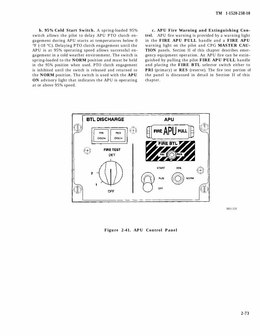
TM 1-1520-238-10
b. 95% Cold Start Switch. A spring-loaded 95%switch allows the pilot to delay APU PTO clutch en-gagement during APU starts at temperatures below 0°F (-18 °C). Delaying PTO clutch engagement until theAPU is at 95% operating speed allows successful en-gagement in a cold weather environment. The switch isspring-loaded to the NORM position and must be heldin the 95% position when used. PTO clutch engagementis inhibited until the switch is released and returned tothe NORM position. The switch is used with the APUON advisory light that indicates the APU is operatingat or above 95% speed.
c. APU Fire Warning and Extinguishing Con-trol. APU fire warning is provided by a warning lightin the FIRE APU PULL handle and a FIRE APUwarning light on the pilot and CPG MASTER CAU-TION panels. Section II of this chapter describes emer-gency equipment operation. An APU fire can be extin-guished by pulling the pilot FIRE APU PULL handleand placing the FIRE BTL selector switch either toPRI (primary) or RES (reserve). The fire test portion ofthe panel is discussed in detail in Section II of thischapter.
M01-319
Figure 2-41. APU Control Panel
2-73
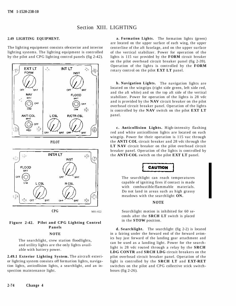
TM 1-1520-238-10
Section XIII. LIGHTING
2.49 LIGHTING EQUIPMENT.
The lighting equipment consists ofexterior and interiorlighting systems. The lighting equipment is controlledby the pilot and CPG lighting control panels (fig 2-42).
PILOT
CPG M01-022
Figure 2-42. Pilot and CPG Lighting ControlPanels
NOTE
The searchlight, crew station floodlights,and utility lights are the only lights avail-able with battery power.
2.49.1 Exterior Lighting System. The aircraft exteri-or lighting system consists off formation lights, naviga-tion lights, anticollision lights, a searchlight, and an in-spection maintenance light.
a. Formation Lights. The formation lights (green)are located on the upper surface of each wing, the uppercenterline of the aft fuselage, and on the upper surfaceof the vertical stabilizer. Power for operation of thelights is 115 vac provided by the FORM circuit breakeron the pilot overhead circuit breaker panel (fig 2-39).Operation of the lights is controlled by the FORMrotary control on the pilot EXT LT panel.
b. Navigation Lights. The navigation lights arelocated on the wingtips (right side green, left side red,and the aft white) and on the top aft side of the verticalstabilizer. Power for operation of the lights is 28 vdcand is provided by the NAV circuit breaker on the pilotoverhead circuit breaker panel. Operation of the lightsis controlled by the NAV switch on the pilot EXT LTpanel.
c. Anticollision Lights. High-intensity flashingred and white anticollision lights are located on eachwingtip. Power for their operation is 115 vac throughthe ANTI COL circuit breaker and 28 vdc through theLT NAV circuit breaker on the pilot overhead circuitbreaker panel. Operation of the lights is controlled bythe ANTI-COL switch on the pilot EXT LT panel.
The searchlight can reach temperaturescapable of igniting fires if contact is madewith combustible/flammable materials.Do not land in areas such as high grassymeadows with the searchlight ON.
NOTE
Searchlight motion is inhibited for 60 se-conds after the SRCH LT switch is placedin the STOW position.
d. Searchlight. The searchlight (fig 2-2) is locatedin a fairing under the forward end of the forward avion-ics bay just forward of the landing gear attachment andcan be used as a landing light. Power for the search-light is 28 vdc routed through a relay by the SRCHLDG CONTR and SRCH LDG circuit breakers on thepilot overhead circuit breaker panel. Operation of thelight is controlled by the SRCH LT and EXT-RETswitches on the pilot and CPG collective stick switch-boxes (fig 2-26).
2-74 Change 4
TM 1-1520-238-10
e. Inspection and Maintenance Light. The in-spection and maintenance light is stored in the leftequipment stowage compartment (fig 2-2). Two plug-inreceptacle locations provide electrical power and willfacilitate inspection and maintenance at all points onthe helicopter. The receptacle is located adjacent to theCPG station on the underside of the right FAB, forwardof the searchlight (fig 2-2). The second receptacle is lo-cated in the right aft avionics bay (fig 2-2). Power foroperating the light is 24 vdc directly from the batterythrough the MAINT LT circuit breaker in the right aftavionics bay. Operation of the inspection and mainte-nance light is controlled by an OFF-BRT rheostatswitch which is integral with the light.
2.49.2 Interior Lighting System. The helicopter inte-rior lighting system consists of dimming lighting for en-gine instruments, flight instruments, avionics panels,console panels, and circuit breaker panels. All engineand flight instruments are equipped with red surfacemounted edge lighting fixtures, and the avionics con-sole and circuit breaker panel lights are integrally illu-minated. Light is reflected to illuminate the panelmarkings and the clear edging around each switch orcircuit breaker. In the event of total electrical powergeneration failure, the pilot and CPG flood lights, util-ity lights, and searchlight remain operable through thedc emergency bus.
a. Pilot Interior Lighting. Interior lighting for thepilot is controlled by three switch/rheostats and athree-position FLOOD toggle switch located on the pi-lot INTR LT control panel. The three switch/rheostatsprovide a detented OFF position and dim to BRT posi-tion. AC voltage is the primary power for the interiorlights. The ac voltage is applied to a multichannel dim-mer assembly through the PRI circuit breaker on thepilot overhead circuit breaker panel. The multichanneldimmer converts 115 vac to the proper dc levels for thethree switch/rheostats. The INST, L CSL, and R/CTRCSL switch/rheostats vary the multichannel dimmeroutput. The INST switch/rheostat controls channels 1and 2 of the multichannel dimmer. Channel 1 is for theright instrument panel, and channel 2 is for the leftinstrument panel. Both channels vary the multichan-nel output from OFF position to BRT. The R/CTR CSLcontrol is split into two sections; A: OFF position, andBRT for APU FIRE TEST and APX100 control panel.B: OFF position, and BRT for the avionics control boxlights in the center and right console. The L CSL con-trols the circuit breaker panels and the collective stick
grip lights. The pilot also has an EDGE LT PNL ON/OFF switch located on the overhead circuit breakerpanel that allows him to turn off circuit breaker edgelights independent of other console lights.
b. CPG Interior Lighting. The CPG interior light-ing operation of the INTR LT switch/rheostats and themultichannel dimmer are the same as for the pilot op-eration. The INST switch/rheostat controls outputs tochannel 1 (right side instruments), channel 2 (left sideinstruments), and the ORT. The R CSL controls out-puts to channel 3 which is split into sections A and B. A:to the avionics lights; B: to the ASN 128 panel lights.The L CSL controls the circuit breaker and collectivestick grip lights.
C. Emergency Floodlight System. The emergen-cy floodlight system is installed under the glareshieldsof the pilot and CPG instrument panels. Power for theemergency floodlight system is emergency bus 28 vdcpower through the UTIL SEC circuit breaker on the pi-lot overhead circuit breaker panel and the UTIL SECLT circuit breaker on the CPG main circuit breakerpanel (fig 2-40). Operation of the emergency floodlightsystem is controlled by the FLOOD three-positiontoggle switch on the pilot and CPG INTR LT controlpanel. When the switch is positioned to the BRT posi-tion, it turns on the blue green secondary lights to thebrightest level. When in the dim position, the second-ary lighting is dimmed.
d. Utility Light. A detachable utility light with acoiled extension cord is located to the left of the pilotand CPG seats. The utility light provides emergencyred or white lighting in case instrument panel lightingfails. The light is operated by an OFF BRT rheostatswitch integral with the light. Rotating the front sec-tion of the light selects white flood or red flood. The util-ity light receives 28 vdc from the emergency dc busthrough the UTIL SEC LT circuit breaker on the pilotoverhead circuit breaker panel and the UTIL SEC LTcircuit breaker on the CPG No. 1 circuit breaker panel.
e. Dimming, MASTER CAUTION Panel, and Cau-tion/Warning Panel Advisory Segment Lights. Dim-ming of all caution/warning lights is controlled by theINST control on both the pilot and CPG INTR LT con-trol panels for the respective crew station. When theINST control is is in the OFF position, caution/warn-ing lights are bright; any other position will cause therespective lights to go to a preset dim condition.
2-75
TM 1-1520-236-10
Section XIV. FLIGHT INSTRUMENTS
2.50 FLIGHT INSTRUMENTS.
The instruments discussed in this section are, for themost part, those that directly measure flight perfor-mance. Caution, warning, audio systems, and someflight instruments are common to both crew stations.The instruments are grouped as common, pilot, andCPG flight instruments.
2.50.1 Common Flight instruments. The flightinstruments found in both the pilot instrument panel(fig 2-9) and the CPG instrument panel (fig 2-10) arethe pressure (barometric) altimeter, instantaneous ver-tical speed indicator, airspeed indicator, attitude indi-cator, and the clock.
a. Pilot Barometric Altimeter. The pilot has anAAU-32/A encoding barometric altimeter. This altime-ter is the same as the CPG’s except the AAU-32/A inter-faces with the IFF for Mode C operation.
b. CPG Barometric Altimeter. The CPG has anAAU-31/A barometric altimeter. The altimeter is gra-duated in 50-foot increments and marked at 100-footintervals (0 - 9 x 100). Just left of center is a 100-footdrum and a 1000-foot drum to supplement the scalepointer. The scale window, at the lower right section ofthe instrument face, indicates barometric pressure set-ting in inches of mercury. It is adjustable by use of thebarometric pressure set knob on the lower left corner ofthe indicator case. Maximum allowable altimeter erroris 70 feet.
c. Verticai Speed indicator (VSI). The VSI mea-sures the rates of change in static air pressure result-ing from climbs and descents. An adjustment screw onthe lower left corner is used to zero the pointer, if neces-sary, prior to flight.
d. Airspeed indicator. The airspeed indicatormeasures the difference between pitot pressure andstatic pressure. Instrument range markings and li-mitations are contained in Chapter 5, Section II, Sys-tem Limits. At low airspeeds and high power settings,indicated airspeeds may be unreliable and fluctuategreater than 10 KIAS.
e. Pilot Standby Attitude indicator. The pilotstandby attitude indicator provides an independentdisplay of helicopter attitude. The indicator can display360° of roll and ± 85° of pitch. A PULL TO CAGE knob
at the lower right corner has two functions. Pulling itout with power applied to the instrument will cage themotor-driven internal gyroscope and level the back-ground horizon line to 0° in pitch and roll. The knobmay be turned to adjust the pitch of the artificial hori-zon relative to the fixed aircraft symbol. The indicatorreceives 28 vdc from the emergency dc bus through theSTBY ATTD circuit breaker on the pilot overhead cir-cuit breaker panel.
f. CPG Remote Attitude indicator. The CPG re-mote attitude indicator (RAI) displays helicopter atti-tude from information obtained from the heading andattitude reference system (HARS). The indicator candisplay 360° of roll and ± 90° of pitch. HARS inputdrives roll and/or pitch servos, which results in the ap-propriate roll or pitch of the artificial horizon. If HARSinput ceases or becomes unreliable, 28-vdc power willcause an OFF flag to appear at the window on the leftside of the instrument face. A pitch trim knob at thelower right corner may be turned to adjust the pitch ofthe artificial horizon relative to the fixed aircraft refer-ence symbol. The RAI receives 115 vac from the No. 1essential ac bus through the ATTD IND circuit break-er on the CPG No. 1 circuit breaker panel.
g. Clock. The clock combines the features of astandard clock and a stopwatch by displaying normaland elapsed time in hours, minutes, and seconds. Oncewound, the clocks will run for eight days. The elapsed-time pushbutton control is on the upper right corner ofthe case. The clock is wound and set with a knob at thelower left corner of the case.
2.50.2 Pilot Flight instruments. The flight instru-ments in the pilot instrument panel (fig 2-9) are thevideo display unit, standby magnetic compass, free airtemperature gage, accelerometer, and radar altimeter.
a. Video Display Unit (VDU). The VDU is a multi-purpose instrument that provides the pilot with flight,navigation, and targeting information. A turn-and-slipindicator is located below the face of the cathode raytube. The signals for the turn rate indicator are pro-vided by the DASE.
b. Standby Magnetic Compass. The standbymagnetic compass is attached to the pilot glareshield.Primary heading information is taken from the hori-zontal situation indicator, which is discussed in Chap-ter 3, Section III.
2-76
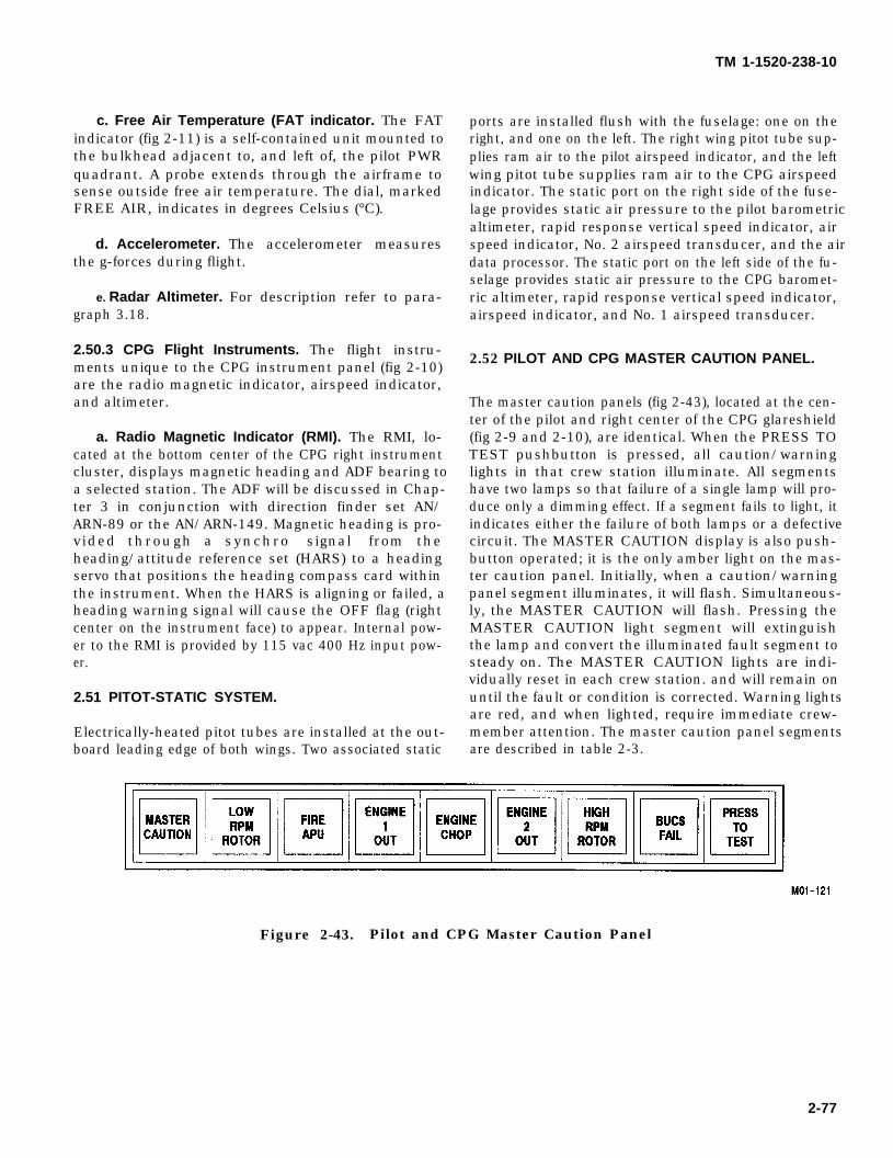
TM 1-1520-238-10
c. Free Air Temperature (FAT indicator. The FATindicator (fig 2-11) is a self-contained unit mounted tothe bulkhead adjacent to, and left of, the pilot PWRquadrant. A probe extends through the airframe tosense outside free air temperature. The dial, markedFREE AIR, indicates in degrees Celsius (°C).
d. Accelerometer. The accelerometer measuresthe g-forces during flight.
e. Radar Altimeter. For description refer to para-graph 3.18.
2.50.3 CPG Flight Instruments. The flight instru-ments unique to the CPG instrument panel (fig 2-10)are the radio magnetic indicator, airspeed indicator,and altimeter.
a. Radio Magnetic Indicator (RMI). The RMI, lo-cated at the bottom center of the CPG right instrumentcluster, displays magnetic heading and ADF bearing toa selected station. The ADF will be discussed in Chap-ter 3 in conjunction with direction finder set AN/ARN-89 or the AN/ARN-149. Magnetic heading is pro-vided through a synchro signal from theheading/attitude reference set (HARS) to a headingservo that positions the heading compass card withinthe instrument. When the HARS is aligning or failed, aheading warning signal will cause the OFF flag (rightcenter on the instrument face) to appear. Internal pow-er to the RMI is provided by 115 vac 400 Hz input pow-er.
2.51 PITOT-STATIC SYSTEM.
Electrically-heated pitot tubes are installed at the out-board leading edge of both wings. Two associated static
ports are installed flush with the fuselage: one on theright, and one on the left. The right wing pitot tube sup-plies ram air to the pilot airspeed indicator, and the leftwing pitot tube supplies ram air to the CPG airspeedindicator. The static port on the right side of the fuse-lage provides static air pressure to the pilot barometricaltimeter, rapid response vertical speed indicator, airspeed indicator, No. 2 airspeed transducer, and the airdata processor. The static port on the left side of the fu-selage provides static air pressure to the CPG baromet-ric altimeter, rapid response vertical speed indicator,airspeed indicator, and No. 1 airspeed transducer.
2.52 PILOT AND CPG MASTER CAUTION PANEL.
The master caution panels (fig 2-43), located at the cen-ter of the pilot and right center of the CPG glareshield(fig 2-9 and 2-10), are identical. When the PRESS TOTEST pushbutton is pressed, all caution/warninglights in that crew station illuminate. All segmentshave two lamps so that failure of a single lamp will pro-duce only a dimming effect. If a segment fails to light, itindicates either the failure of both lamps or a defectivecircuit. The MASTER CAUTION display is also push-button operated; it is the only amber light on the mas-ter caution panel. Initially, when a caution/warningpanel segment illuminates, it will flash. Simultaneous-ly, the MASTER CAUTION will flash. Pressing theMASTER CAUTION light segment will extinguishthe lamp and convert the illuminated fault segment tosteady on. The MASTER CAUTION lights are indi-vidually reset in each crew station. and will remain onuntil the fault or condition is corrected. Warning lightsare red, and when lighted, require immediate crew-member attention. The master caution panel segmentsare described in table 2-3.
Figure 2-43. Pilot and CPG Master Caution Panel
2-77
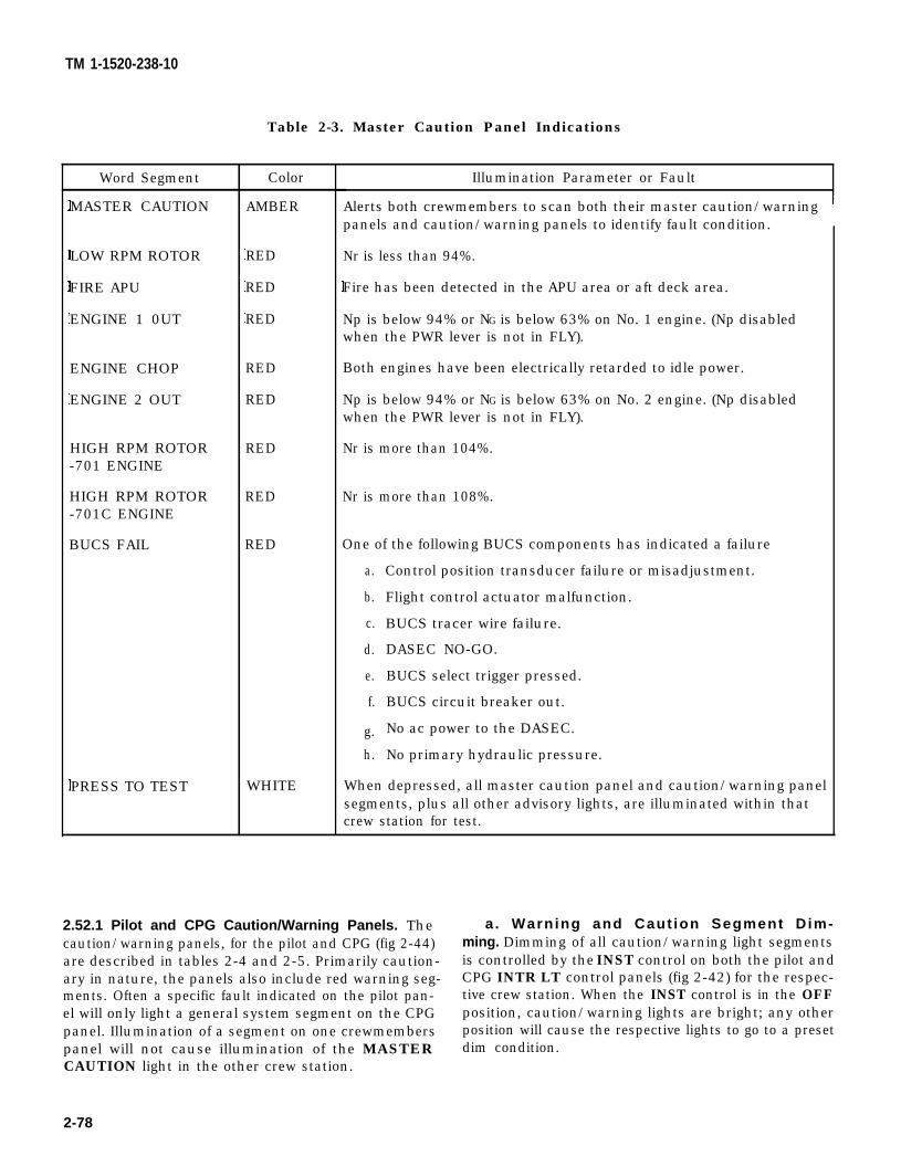
TM 1-1520-238-10
Table 2-3. Master Caution Panel Indications
Word Segment
MASTER CAUTION
LOW RPM ROTOR
FIRE APU
ENGINE 1 0UT
ENGINE CHOP
ENGINE 2 OUT
HIGH RPM ROTOR-701 ENGINE
HIGH RPM ROTOR-701C ENGINE
BUCS FAIL
PRESS TO TEST
Color
AMBER
RED
RED
RED
RED
RED
RED
RED
RED
WHITE
Illumination Parameter or Fault
Alerts both crewmembers to scan both their master caution/warningpanels and caution/warning panels to identify fault condition.
Nr is less than 94%.
Fire has been detected in the APU area or aft deck area.
Np is below 94% or NG is below 63% on No. 1 engine. (Np disabledwhen the PWR lever is not in FLY).
Both engines have been electrically retarded to idle power.
Np is below 94% or NG is below 63% on No. 2 engine. (Np disabledwhen the PWR lever is not in FLY).
Nr is more than 104%.
Nr is more than 108%.
One of the following BUCS components has indicated a failure
a.
b.
c.
d.
e.
f.
g.
h.
Control position transducer failure or misadjustment.
Flight control actuator malfunction.
BUCS tracer wire failure.
DASEC NO-GO.
BUCS select trigger pressed.
BUCS circuit breaker out.
No ac power to the DASEC.
No primary hydraulic pressure.
When depressed, all master caution panel and caution/warning panelsegments, plus all other advisory lights, are illuminated within thatcrew station for test.
2.52.1 Pilot and CPG Caution/Warning Panels. Thecaution/warning panels, for the pilot and CPG (fig 2-44)are described in tables 2-4 and 2-5. Primarily caution-ary in nature, the panels also include red warning seg-ments. Often a specific fault indicated on the pilot pan-el will only light a general system segment on the CPGpanel. Illumination of a segment on one crewmemberspanel will not cause illumination of the MASTERCAUTION light in the other crew station.
a. Warning and Caut ion Segment Dim-ming. Dimming of all caution/warning light segmentsis controlled by the INST control on both the pilot andCPG INTR LT control panels (fig 2-42) for the respec-tive crew station. When the INST control is in the OFFposition, caution/warning lights are bright; any otherposition will cause the respective lights to go to a presetdim condition.
2-78
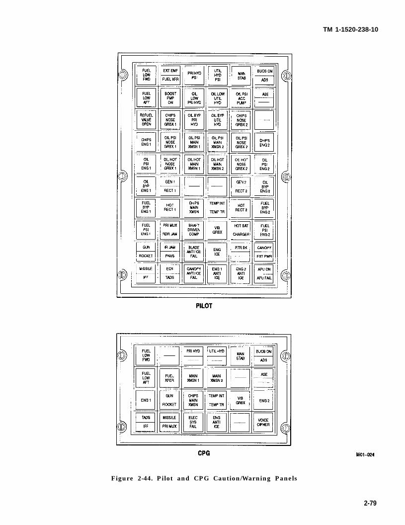
TM 1-1520-238-10
Figure 2-44. Pilot and CPG Caution/Warning Panels
2-79
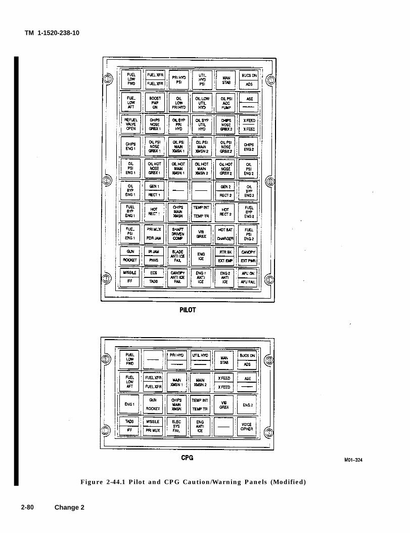
TM 1-1520-238-10
2-80
Figure 2-44.1 Pilot and CPG Caution/Warning Panels (Modified)
Change 2
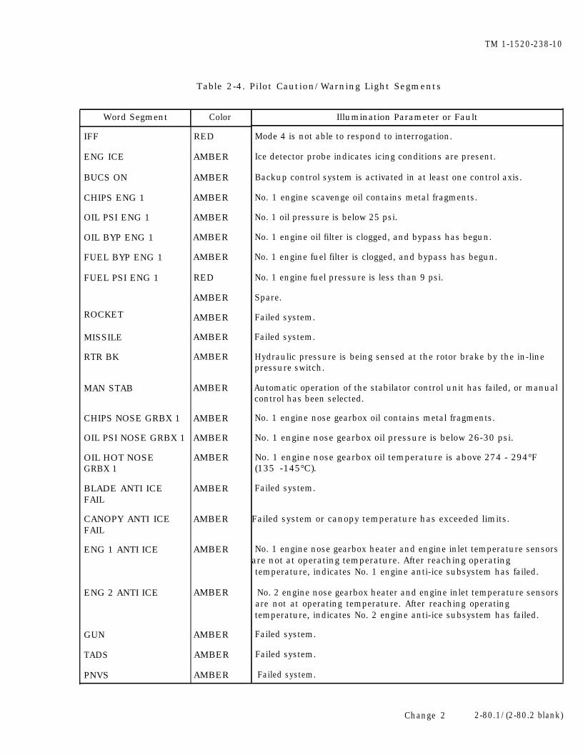
TM 1-1520-238-10
Table 2-4. Pilot Caution/Warning Light Segments
Word Segment Color I Illumination Parameter or Fault
IFF
ENG ICE
BUCS ON
CHIPS ENG 1
OIL PSI ENG 1
OIL BYP ENG 1
FUEL BYP ENG 1
FUEL PSI ENG 1
ROCKET
MISSILE
RTR BK
MAN STAB
CHIPS NOSE GRBX 1
OIL PSI NOSE GRBX 1
OIL HOT NOSEGRBX 1
BLADE ANTI ICEFAIL
CANOPY ANTI ICEFAIL
ENG 1 ANTI ICE
ENG 2 ANTI ICE
GUN
TADS
PNVS
RED
AMBER
AMBER
AMBER
AMBER
AMBER
AMBER
RED
AMBER
AMBER
AMBER
AMBER
AMBER
AMBER
AMBER
AMBER
AMBER
AMBER
AMBER
AMBER
AMBER
AMBER
AMBER
Mode 4 is not able to respond to interrogation.
Ice detector probe indicates icing conditions are present.
Backup control system is activated in at least one control axis.
No. 1 engine scavenge oil contains metal fragments.
No. 1 oil pressure is below 25 psi.
No. 1 engine oil filter is clogged, and bypass has begun.
No. 1 engine fuel filter is clogged, and bypass has begun.
No. 1 engine fuel pressure is less than 9 psi.
Spare.
Failed system.
Failed system.
Hydraulic pressure is being sensed at the rotor brake by the in-linepressure switch.
Automatic operation of the stabilator control unit has failed, or manualcontrol has been selected.
No. 1 engine nose gearbox oil contains metal fragments.
No. 1 engine nose gearbox oil pressure is below 26-30 psi.
No. 1 engine nose gearbox oil temperature is above 274 - 294°F(135 -145°C).
Failed system.
Failed system or canopy temperature has exceeded limits.
No. 1 engine nose gearbox heater and engine inlet temperature sensorsare not at operating temperature. After reaching operatingtemperature, indicates No. 1 engine anti-ice subsystem has failed.
No. 2 engine nose gearbox heater and engine inlet temperature sensorsare not at operating temperature. After reaching operating
temperature, indicates No. 2 engine anti-ice subsystem has failed.IFailed system.
Failed system.
Failed system.
Change 2 2-80.1/(2-80.2 blank)

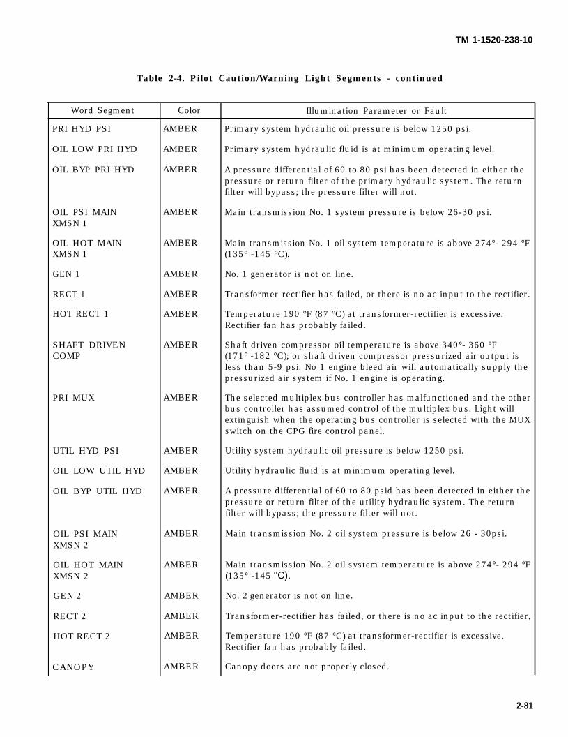
TM 1-1520-238-10
Table 2-4. Pilot Caution/Warning Light Segments - continued
Word Segment
PRI HYD PSI
OIL LOW PRI HYD
OIL BYP PRI HYD
OIL PSI MAINXMSN 1
OIL HOT MAINXMSN 1
GEN 1
RECT 1
HOT RECT 1
SHAFT DRIVENCOMP
PRI MUX
UTIL HYD PSI
OIL LOW UTIL HYD
OIL BYP UTIL HYD
OIL PSI MAINXMSN 2
OIL HOT MAINXMSN 2
GEN 2
RECT 2
HOT RECT 2
CANOPY
Color
AMBER
AMBER
AMBER
AMBER
AMBER
AMBER
AMBER
AMBER
AMBER
AMBER
AMBER
AMBER
AMBER
AMBER
AMBER
AMBER
AMBER
AMBER
AMBER
Illumination Parameter or Fault
Primary system hydraulic oil pressure is below 1250 psi.
Primary system hydraulic fluid is at minimum operating level.
A pressure differential of 60 to 80 psi has been detected in either thepressure or return filter of the primary hydraulic system. The returnfilter will bypass; the pressure filter will not.
Main transmission No. 1 system pressure is below 26-30 psi.
Main transmission No. 1 oil system temperature is above 274°- 294 °F(135° -145 °C).
No. 1 generator is not on line.
Transformer-rectifier has failed, or there is no ac input to the rectifier.
Temperature 190 °F (87 °C) at transformer-rectifier is excessive.Rectifier fan has probably failed.
Shaft driven compressor oil temperature is above 340°- 360 °F(171° -182 °C); or shaft driven compressor pressurized air output isless than 5-9 psi. No 1 engine bleed air will automatically supply thepressurized air system if No. 1 engine is operating.
The selected multiplex bus controller has malfunctioned and the otherbus controller has assumed control of the multiplex bus. Light willextinguish when the operating bus controller is selected with the MUXswitch on the CPG fire control panel.
Utility system hydraulic oil pressure is below 1250 psi.
Utility hydraulic fluid is at minimum operating level.
A pressure differential of 60 to 80 psid has been detected in either thepressure or return filter of the utility hydraulic system. The returnfilter will bypass; the pressure filter will not.
Main transmission No. 2 oil system pressure is below 26 - 30psi.
Main transmission No. 2 oil system temperature is above 274°- 294 °F(135° -145 °C).
No. 2 generator is not on line.
Transformer-rectifier has failed, or there is no ac input to the rectifier,
Temperature 190 °F (87 °C) at transformer-rectifier is excessive.Rectifier fan has probably failed.
Canopy doors are not properly closed.
2-81
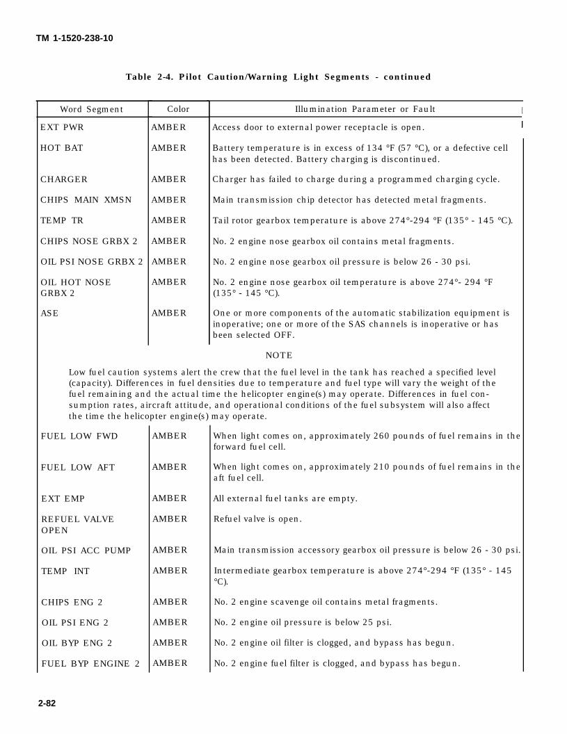
TM 1-1520-238-10
Table 2-4. Pilot Caution/Warning Light Segments - continued
Word Segment
EXT PWR
HOT BAT
CHARGER
CHIPS MAIN XMSN
TEMP TR
CHIPS NOSE GRBX 2
OIL PSI NOSE GRBX 2
OIL HOT NOSEGRBX 2
ASE
Color
AMBER
AMBER
AMBER
AMBER
AMBER
AMBER
AMBER
AMBER
AMBER
Illumination Parameter or Fault I
Access door to external power receptacle is open.
Battery temperature is in excess of 134 °F (57 °C), or a defective cellhas been detected. Battery charging is discontinued.
Charger has failed to charge during a programmed charging cycle.
Main transmission chip detector has detected metal fragments.
Tail rotor gearbox temperature is above 274°-294 °F (135° - 145 °C).
No. 2 engine nose gearbox oil contains metal fragments.
No. 2 engine nose gearbox oil pressure is below 26 - 30 psi.
No. 2 engine nose gearbox oil temperature is above 274°- 294 °F(135° - 145 °C).
One or more components of the automatic stabilization equipment isinoperative; one or more of the SAS channels is inoperative or hasbeen selected OFF.
NOTE
Low fuel caution systems alert the crew that the fuel level in the tank has reached a specified level(capacity). Differences in fuel densities due to temperature and fuel type will vary the weight of thefuel remaining and the actual time the helicopter engine(s) may operate. Differences in fuel con-sumption rates, aircraft attitude, and operational conditions of the fuel subsystem will also affectthe time the helicopter engine(s) may operate.
FUEL LOW FWD
FUEL LOW AFT
EXT EMP
REFUEL VALVEOPEN
OIL PSI ACC PUMP
TEMP INT
CHIPS ENG 2
OIL PSI ENG 2
OIL BYP ENG 2
FUEL BYP ENGINE 2
AMBER
AMBER
AMBER
AMBER
AMBER
AMBER
AMBER
AMBER
AMBER
AMBER
When light comes on, approximately 260 pounds of fuel remains in theforward fuel cell.
When light comes on, approximately 210 pounds of fuel remains in theaft fuel cell.
All external fuel tanks are empty.
Refuel valve is open.
Main transmission accessory gearbox oil pressure is below 26 - 30 psi.
Intermediate gearbox temperature is above 274°-294 °F (135° - 145°C).
No. 2 engine scavenge oil contains metal fragments.
No. 2 engine oil pressure is below 25 psi.
No. 2 engine oil filter is clogged, and bypass has begun.
No. 2 engine fuel filter is clogged, and bypass has begun.
2-82
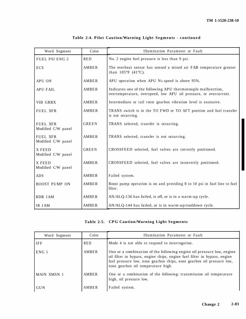
TM 1-1520-238-10
Table 2-4. Pilot Caution/Warning Light Segments - continued
Word Segment
FUEL PSI ENG 2
ECS
APU ON
APU FAIL
VIB GRBX
FUEL XFR
FUEL XFRModified C/W panel
FUEL XFRModified C/W panel
X FEEDModified C/W panel
X FEEDModified C/W panel
ADS
BOOST PUMP ON
RDR JAM
IR JAM
Word Segment
IFF
ENG 1
MAIN XMSN 1
GUN
Color
RED
AMBER
AMBER
AMBER
AMBER
AMBER
GREEN
AMBER
GREEN
AMBER
AMBER
AMBER
AMBER
AMBER
Table 2-5.
Color
RED
AMBER
AMBER
AMBER
Illumination Parameter or Fault
No. 2 engine fuel pressure is less than 9 psi.
The overheat sensor has sensed a mixed air FAB temperature greaterthan 105°F (41°C).
APU operation when APU NG speed is above 95%.
Indicates one of the following APU thermocouple malfunction,overtemperature, overspeed, low APU oil pressure, or overcurrent.
Intermediate or tail rotor gearbox vibration level is excessive.
TRANS switch is in the TO FWD or TO AFT position and fuel transferis not occurring.
TRANS selected, transfer is occurring.
TRANS selected, transfer is not occurring.
CROSSFEED selected, fuel valves are correctly positioned.
CROSSFEED selected, fuel valves are incorrectly positioned.
Failed system.
Boost pump operation is on and providing 8 to 10 psi in fuel line to fuelfilter.
AN/ALQ-136 has failed, is off, or is in a warm-up cycle.
AN/ALQ-144 has failed, or is in warm-up/cooldown cycle.
CPG Caution/Warning Light Segments
Illumination Parameter or Fault
Mode 4 is not able to respond to interrogation.
One or a combination of the following engine oil pressure low, engineoil filter in bypass, engine chips, engine fuel filter in bypass, enginefuel pressure low, nose gearbox chips, nose gearbox oil pressure low,nose gearbox oil temperature high.
One or a combination of the following: transmission oil temperaturehigh, oil pressure low.
Failed system.
Change 2 2-83
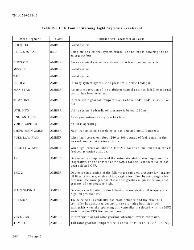
TM 1-1520-238-10
Table 2-5. CPG Caution/Warning Light Segments - continued
Word Segment
ROCKET4
ELEC SYS FAIL
BUCS ON
MISSILE
TADS
PRI HYD
MAN STAB
TEMP INT
UTIL HYD
ENG ANTI ICE
VOICE CIPHER
CHIPS MAIN XMSN
FUEL LOW FWD
FUEL LOW AFT
ASE
ENG 2
MAIN XMSN 2
PRI MUX
VIB GRBX
TEMP TR
2-84 Change 2
Color
AMBER
RED
AMBER
AMBER
AMBER
AMBER
AMBER
AMBER
AMBER
AMBER
AMBER
AMBER
AMBER
AMBER
AMBER
AMBER
AMBER
AMBER
AMBER
AMBER
Illumination Parameter or Fault
Failed system.
Complete dc electrical system failure. The battery is powering the dcemergency bus.
Backup control system is activated in at least one control axis.
Failed system.
Failed system.
Primary system hydraulic oil pressure is below 1250 psi.
Automatic operation of the stabilator control unit has failed, or manualcontrol has been selected.
Intermediate gearbox temperature is above 274°- 294°F (135° - 145°C).
Utility system hydraulic oil pressure is below 1250 psi.
An engine anti-ice subsystem has failed.
KY-58 is operating.
Main transmission chip detector has detected metal fragments.
When light comes on, about 260 to 300 pounds of fuel remain in theforward fuel cell at cruise attitude.
When light comes on, about 210 to 270 pounds of fuel remain in the aftfuel cell at cruise attitude.
One or more components of the automatic stabilization equipment isinoperative, or one or more of the SAS channels is inoperative or hasbeen selected OFF.
One or a combination of the following: engine oil pressure low, engineoil filter in bypass, engine chips, engine fuel filter bypass, engine fuelpressure low, nose gearbox chips, nose gearbox oil pressure low, nosegearbox oil temperature high.
One or a combination of the following: transmission oil temperaturehigh, oil pressure low.
The selected bus controller has malfunctioned and the other buscontroller has assumed control of the multiplex bus. Light willextinguish when the operating bus controller is selected with the MUXswitch on the CPG fire control panel.
Intermediate or tail rotor gearbox vibration level is excessive.
Tail rotor gearbox temperature is above 274°-294 °F (135° - 145°C).
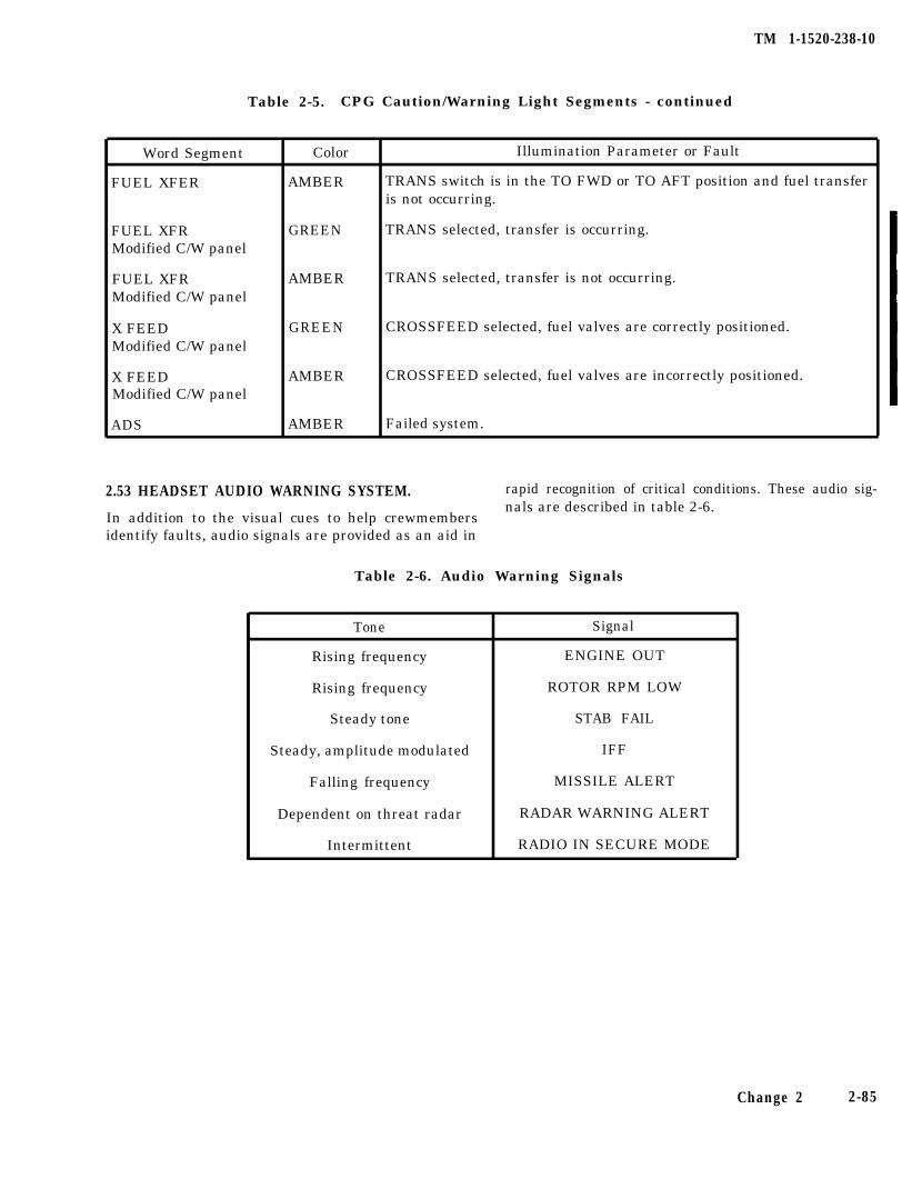
TM 1-1520-238-10
Table 2-5. CPG Caution/Warning Light Segments - continued
Word Segment Color
FUEL XFER AMBER
Illumination Parameter or Fault
TRANS switch is in the TO FWD or TO AFT position and fuel transferis not occurring.
FUEL XFRModified C/W panel
GREEN TRANS selected, transfer is occurring.
FUEL XFRModified C/W panel
AMBER TRANS selected, transfer is not occurring.
X FEEDModified C/W panel
GREEN CROSSFEED selected, fuel valves are correctly positioned.
X FEEDModified C/W panel
AMBER CROSSFEED selected, fuel valves are incorrectly positioned.
ADS AMBER Failed system.
2.53 HEADSET AUDIO WARNING SYSTEM. rapid recognition of critical conditions. These audio sig-
Table 2-6. Audio Warning Signals
In addition to the visual cues to help crewmembersnals are described in table 2-6.
identify faults, audio signals are provided as an aid in
Tone
Rising frequency
Rising frequency
Steady tone
Steady, amplitude modulated
Falling frequency
Dependent on threat radar
Intermittent
Signal
ENGINE OUT
ROTOR RPM LOW
STAB FAIL
IFF
MISSILE ALERT
RADAR WARNING ALERT
RADIO IN SECURE MODE
Change 2 2-85
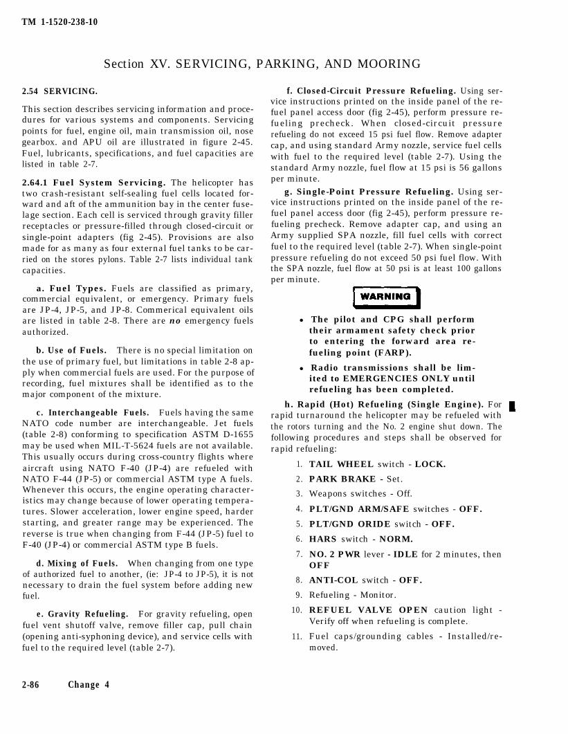
TM 1-1520-238-10
Section XV. SERVICING, PARKING, AND MOORING
2.54 SERVICING.
This section describes servicing information and proce-dures for various systems and components. Servicingpoints for fuel, engine oil, main transmission oil, nosegearbox. and APU oil are illustrated in figure 2-45.Fuel, lubricants, specifications, and fuel capacities arelisted in table 2-7.
2.64.1 Fuel System Servicing. The helicopter hastwo crash-resistant self-sealing fuel cells located for-ward and aft of the ammunition bay in the center fuse-lage section. Each cell is serviced through gravity fillerreceptacles or pressure-filled through closed-circuit orsingle-point adapters (fig 2-45). Provisions are alsomade for as many as four external fuel tanks to be car-ried on the stores pylons. Table 2-7 lists individual tankcapacities.
a. Fuel Types. Fuels are classified as primary,commercial equivalent, or emergency. Primary fuelsare JP-4, JP-5, and JP-8. Commerical equivalent oilsare listed in table 2-8. There are no emergency fuelsauthorized.
b. Use of Fuels. There is no special limitation onthe use of primary fuel, but limitations in table 2-8 ap-ply when commercial fuels are used. For the purpose ofrecording, fuel mixtures shall be identified as to themajor component of the mixture.
c. Interchangeable Fuels. Fuels having the sameNATO code number are interchangeable. Jet fuels(table 2-8) conforming to specification ASTM D-1655may be used when MIL-T-5624 fuels are not available.This usually occurs during cross-country flights whereaircraft using NATO F-40 (JP-4) are refueled withNATO F-44 (JP-5) or commercial ASTM type A fuels.Whenever this occurs, the engine operating character-istics may change because of lower operating tempera-tures. Slower acceleration, lower engine speed, harderstarting, and greater range may be experienced. Thereverse is true when changing from F-44 (JP-5) fuel toF-40 (JP-4) or commercial ASTM type B fuels.
d. Mixing of Fuels. When changing from one typeof authorized fuel to another, (ie: JP-4 to JP-5), it is notnecessary to drain the fuel system before adding newfuel.
e. Gravity Refueling. For gravity refueling, openfuel vent shutoff valve, remove filler cap, pull chain(opening anti-syphoning device), and service cells withfuel to the required level (table 2-7).
2-86 Change 4
f. Closed-Circuit Pressure Refueling. Using ser-vice instructions printed on the inside panel of the re-fuel panel access door (fig 2-45), perform pressure re-fueling precheck. When closed-circuit pressurerefueling do not exceed 15 psi fuel flow. Remove adaptercap, and using standard Army nozzle, service fuel cellswith fuel to the required level (table 2-7). Using thestandard Army nozzle, fuel flow at 15 psi is 56 gallonsper minute.
g. Single-Point Pressure Refueling. Using ser-vice instructions printed on the inside panel of the re-fuel panel access door (fig 2-45), perform pressure re-fueling precheck. Remove adapter cap, and using anArmy supplied SPA nozzle, fill fuel cells with correctfuel to the required level (table 2-7). When single-pointpressure refueling do not exceed 50 psi fuel flow. Withthe SPA nozzle, fuel flow at 50 psi is at least 100 gallonsper minute.
l The pilot and CPG shall performtheir armament safety check priorto entering the forward area re-fueling point (FARP).
l Radio transmissions shall be lim-ited to EMERGENCIES ONLY untilrefueling has been completed.
h. Rapid (Hot) Refueling (Single Engine). For rapid turnaround the helicopter may be refueled withthe rotors turning and the No. 2 engine shut down. Thefollowing procedures and steps shall be observed forrapid refueling:
1.
2.
3.
4.
5.
6.
7.
8.
9.
10.
11.
TAIL WHEEL switch - LOCK.
PARK BRAKE - Set.
Weapons switches - Off.
PLT/GND ARM/SAFE switches - OFF.
PLT/GND ORIDE switch - OFF.
HARS switch - NORM.
NO. 2 PWR lever - IDLE for 2 minutes, thenOFF
ANTI-COL switch - OFF.
Refueling - Monitor.
REFUEL VALVE OPEN caution light -Verify off when refueling is complete.
Fuel caps/grounding cables - Installed/re-moved.
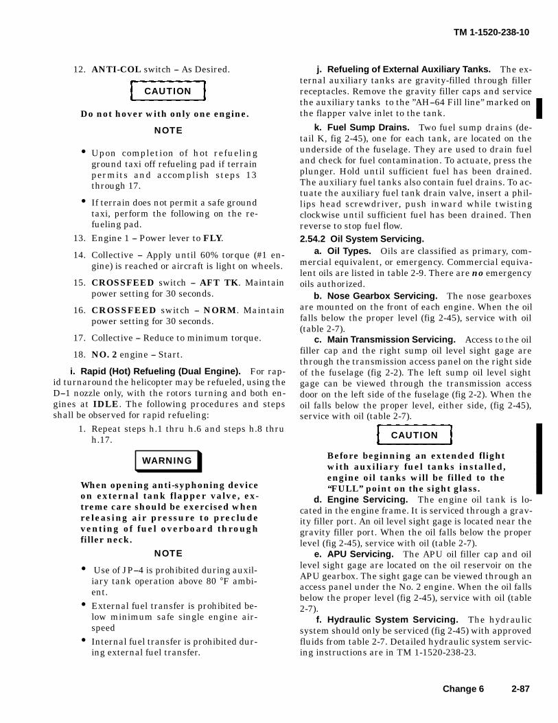
TM 1-1520-238-10
Change 6 2-87
12. ANTI-COL switch -- As Desired.
CAUTION
Do not hover with only one engine.
NOTE
• Upon completion of hot refuelingground taxi off refueling pad if terrainpermits and accomplish steps 13through 17.
• If terrain does not permit a safe groundtaxi, perform the following on the re-fueling pad.
13. Engine 1 -- Power lever to FLY.
14. Collective -- Apply until 60% torque (#1 en-gine) is reached or aircraft is light on wheels.
15. CROSSFEED switch -- AFT TK. Maintainpower setting for 30 seconds.
16. CROSSFEED switch -- NORM. Maintainpower setting for 30 seconds.
17. Collective -- Reduce to minimum torque.
18. NO. 2 engine -- Start.
i. Rapid (Hot) Refueling (Dual Engine). For rap-id turnaround the helicopter may be refueled, using theD--1 nozzle only, with the rotors turning and both en-gines at IDLE. The following procedures and stepsshall be observed for rapid refueling:
1. Repeat steps h.1 thru h.6 and steps h.8 thruh.17.
WARNING
When opening anti-syphoning deviceon external tank flapper valve, ex-treme care should be exercised whenreleasing air pressure to precludeventing of fuel overboard throughfiller neck.
NOTE
• Use of JP--4 is prohibited during auxil-iary tank operation above 80 °F ambi-ent.
• External fuel transfer is prohibited be-low minimum safe single engine air-speed
• Internal fuel transfer is prohibited dur-ing external fuel transfer.
j. Refueling of External Auxiliary Tanks. The ex-ternal auxiliary tanks are gravity-filled through fillerreceptacles. Remove the gravity filler caps and servicethe auxiliary tanks to the ”AH--64 Fill line” marked onthe flapper valve inlet to the tank.
k. Fuel Sump Drains. Two fuel sump drains (de-tail K, fig 2-45), one for each tank, are located on theunderside of the fuselage. They are used to drain fueland check for fuel contamination. To actuate, press theplunger. Hold until sufficient fuel has been drained.The auxiliary fuel tanks also contain fuel drains. To ac-tuate the auxiliary fuel tank drain valve, insert a phil-lips head screwdriver, push inward while twistingclockwise until sufficient fuel has been drained. Thenreverse to stop fuel flow.2.54.2 Oil System Servicing.
a. Oil Types. Oils are classified as primary, com-mercial equivalent, or emergency. Commercial equiva-lent oils are listed in table 2-9. There are no emergencyoils authorized.
b. Nose Gearbox Servicing. The nose gearboxesare mounted on the front of each engine. When the oilfalls below the proper level (fig 2-45), service with oil(table 2-7).
c. Main Transmission Servicing. Access to the oilfiller cap and the right sump oil level sight gage arethrough the transmission access panel on the right sideof the fuselage (fig 2-2). The left sump oil level sightgage can be viewed through the transmission accessdoor on the left side of the fuselage (fig 2-2). When theoil falls below the proper level, either side, (fig 2-45),service with oil (table 2-7).
CAUTION
Before beginning an extended flightwith auxiliary fuel tanks installed,engine oil tanks will be filled to the‘‘FULL” point on the sight glass.
d. Engine Servicing. The engine oil tank is lo-cated in the engine frame. It is serviced through a grav-ity filler port. An oil level sight gage is located near thegravity filler port. When the oil falls below the properlevel (fig 2-45), service with oil (table 2-7).
e. APU Servicing. The APU oil filler cap and oillevel sight gage are located on the oil reservoir on theAPU gearbox. The sight gage can be viewed through anaccess panel under the No. 2 engine. When the oil fallsbelow the proper level (fig 2-45), service with oil (table2-7).
f. Hydraulic System Servicing. The hydraulicsystem should only be serviced (fig 2-45) with approvedfluids from table 2-7. Detailed hydraulic system servic-ing instructions are in TM 1-1520-238-23.
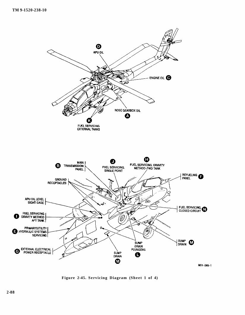
TM 9-1520-238-10
Figure 2-45. Servicing Diagram (Sheet 1 of 4)
2-88
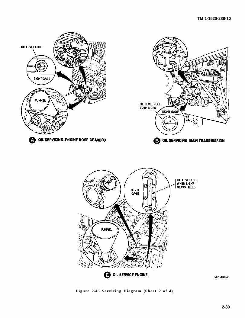
TM 1-1520-238-10
Figure 2-45 Servicing Diagram (Sheet 2 of 4)
2-89
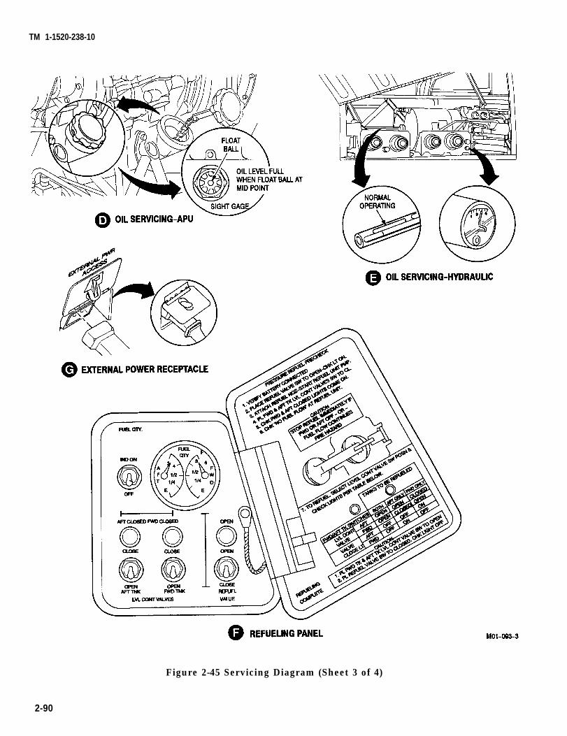
TM 1-1520-238-10
Figure 2-45 Servicing Diagram (Sheet 3 of 4)
2-90

TM 1-1520-238-10
Figure 2-45 Servicing Diagram (Sheet 4 of 4)
2-91
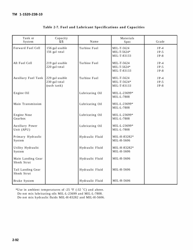
TM 1-1520-238-10
Table 2-7. Fuel and Lubricant Specifications and Capacities
Tank or Capacity MaterialsSystem us Name Spec Grade
Forward Fuel Cell 156 gal usable Turbine Fuel MIL-T-5624 JP-4156 gal total MIL-T-5624* JP-5
MIL-T-83133 JP-8
Aft Fuel Cell 219 gal usable Turbine Fuel MIL-T-5624 JP-4220 gal total MIL-T-5624* JP-5
MIL-T-83133 JP-8
Auxiliary Fuel Tank 229 gal usable Turbine Fuel MIL-T-5624 JP-4230 gal total MIL-T-5624* JP-5(each tank) MIL-T-83133 JP-8
Engine Oil Lubricating Oil MIL-L-23699*MIL-L-7808
Main Transmission Lubricating Oil MIL-L-23699*MIL-L-7808
Engine Nose Lubricating Oil MIL-L-23699*Gearbox MIL-L-7808
Auxiliary Power Lubricating Oil MIL-L-23699*Unit (APU) MIL-L-7808
Primary Hydraulic Hydraulic Fluid MIL-H-83282*System MIL-H-5606
Utility Hydraulic Hydraulic Fluid MIL-H-83282*System MIL-H-5606
Main Landing Gear Hydraulic Fluid MIL-H-5606Shock Strut
Tail Landing Gear Hydraulic Fluid MIL-H-5606Shock Strut
Brake System Hydraulic Fluid MIL-H-5606
*Use in ambient temperatures of -25 °F (-32 0 C) and above.Do not mix lubricating oils MIL-L-23699 and MIL-L-7808.Do not mix hydraulic fluids MIL-H-83282 and MIL-H-5606.
2-92
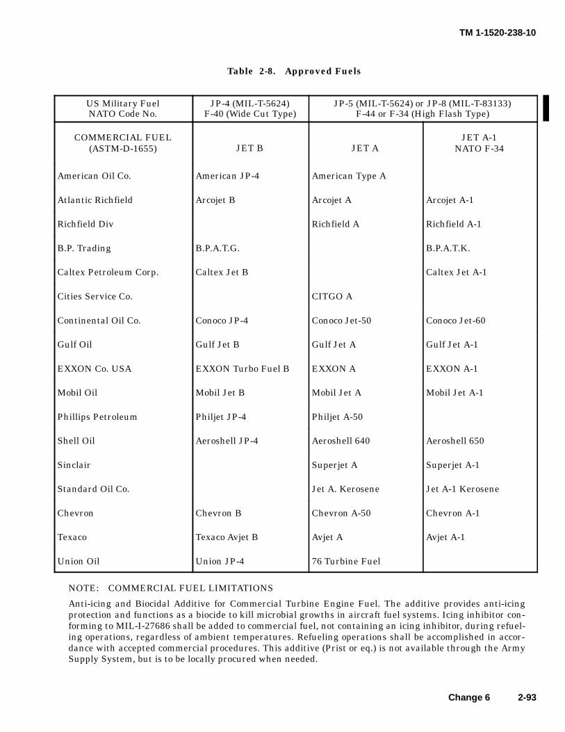
TM 1-1520-238-10
Change 6 2-93
Table 2-8. Approved Fuels
US Military FuelNATO Code No.
JP-4 (MIL-T-5624)F-40 (Wide Cut Type)
JP-5 (MIL-T-5624) or JP-8 (MIL-T-83133)F-44 or F-34 (High Flash Type)
COMMERCIAL FUEL(ASTM-D-1655) JET B JET A
JET A-1NATO F-34
American Oil Co. American JP-4 American Type A
Atlantic Richfield Arcojet B Arcojet A Arcojet A-1
Richfield Div Richfield A Richfield A-1
B.P. Trading B.P.A.T.G. B.P.A.T.K.
Caltex Petroleum Corp. Caltex Jet B Caltex Jet A-1
Cities Service Co. CITGO A
Continental Oil Co. Conoco JP-4 Conoco Jet-50 Conoco Jet-60
Gulf Oil Gulf Jet B Gulf Jet A Gulf Jet A-1
EXXON Co. USA EXXON Turbo Fuel B EXXON A EXXON A-1
Mobil Oil Mobil Jet B Mobil Jet A Mobil Jet A-1
Phillips Petroleum Philjet JP-4 Philjet A-50
Shell Oil Aeroshell JP-4 Aeroshell 640 Aeroshell 650
Sinclair Superjet A Superjet A-1
Standard Oil Co. Jet A. Kerosene Jet A-1 Kerosene
Chevron Chevron B Chevron A-50 Chevron A-1
Texaco Texaco Avjet B Avjet A Avjet A-1
Union Oil Union JP-4 76 Turbine Fuel
NOTE: COMMERCIAL FUEL LIMITATIONS
Anti-icing and Biocidal Additive for Commercial Turbine Engine Fuel. The additive provides anti-icingprotection and functions as a biocide to kill microbial growths in aircraft fuel systems. Icing inhibitor con-forming to MIL-I-27686 shall be added to commercial fuel, not containing an icing inhibitor, during refuel-ing operations, regardless of ambient temperatures. Refueling operations shall be accomplished in accor-dance with accepted commercial procedures. This additive (Prist or eq.) is not available through the ArmySupply System, but is to be locally procured when needed.
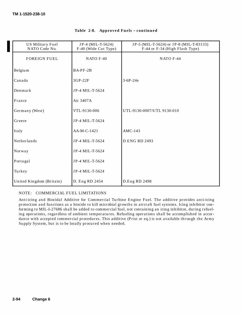
TM 1-1520-238-10
2-94 Change 6
Table 2-8. Approved Fuels -- continued
US Military FuelNATO Code No.
JP-4 (MIL-T-5624)F-40 (Wide Cut Type)
JP-5 (MIL-T-5624) or JP-8 (MIL-T-83133)F-44 or F-34 (High Flash Type)
FOREIGN FUEL NATO F-40 NATO F-44
Belgium BA-PF-2B
Canada 3GP-22F 3-6P-24e
Denmark JP-4 MIL-T-5624
France Air 3407A
Germany (West) VTL-9130-006 UTL-9130-0007/UTL 9130-010
Greece JP-4 MIL-T-5624
Italy AA-M-C-1421 AMC-143
Netherlands JP-4 MIL-T-5624 D ENG RD 2493
Norway JP-4 MIL-T-5624
Portugal JP-4 MIL-T-5624
Turkey JP-4 MIL-T-5624
United Kingdom (Britain) D. Eng RD 2454 D.Eng RD 2498
NOTE: COMMERCIAL FUEL LIMITATIONS
Anti-icing and Biocidal Additive for Commercial Turbine Engine Fuel. The additive provides anti-icingprotection and functions as a biocide to kill microbial growths in aircraft fuel systems. Icing inhibitor con-forming to MIL-I-27686 shall be added to commercial fuel, not containing an icing inhibitor, during refuel-ing operations, regardless of ambient temperatures. Refueling operations shall be accomplished in accor-dance with accepted commercial procedures. This additive (Prist or eq.) is not available through the ArmySupply System, but is to be locally procured when needed.
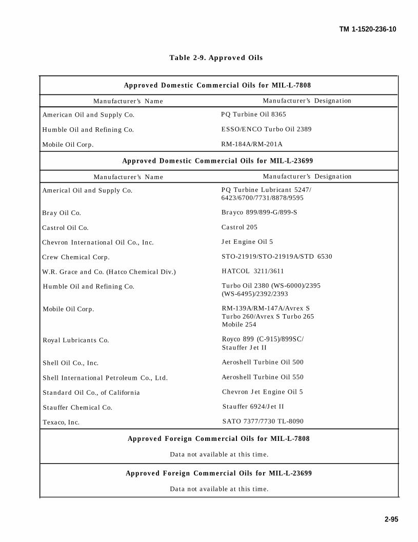
TM 1-1520-236-10
Table 2-9. Approved Oils
Approved Domestic Commercial Oils for MIL-L-7808
Manufacturer’s Name Manufacturer’s Designation
American Oil and Supply Co. PQ Turbine Oil 8365
Humble Oil and Refining Co. ESSO/ENCO Turbo Oil 2389
Mobile Oil Corp. RM-184A/RM-201A
Approved Domestic Commercial Oils for MIL-L-23699
Manufacturer’s Name Manufacturer’s Designation
Americal Oil and Supply Co. PQ Turbine Lubricant 5247/6423/6700/7731/8878/9595
Bray Oil Co. Brayco 899/899-G/899-S
Castrol Oil Co. Castrol 205
Chevron International Oil Co., Inc. Jet Engine Oil 5
Crew Chemical Corp. STO-21919/STO-21919A/STD 6530
W.R. Grace and Co. (Hatco Chemical Div.) HATCOL 3211/3611
Humble Oil and Refining Co. Turbo Oil 2380 (WS-6000)/2395(WS-6495)/2392/2393
Mobile Oil Corp. RM-139A/RM-147A/Avrex STurbo 260/Avrex S Turbo 265Mobile 254
Royal Lubricants Co. Royco 899 (C-915)/899SC/Stauffer Jet II
Shell Oil Co., Inc. Aeroshell Turbine Oil 500
Shell International Petroleum Co., Ltd. Aeroshell Turbine Oil 550
Standard Oil Co., of California Chevron Jet Engine Oil 5
Stauffer Chemical Co. Stauffer 6924/Jet II
Texaco, Inc. SATO 7377/7730 TL-8090
Approved Foreign Commercial Oils for MIL-L-7808
Data not available at this time.
Approved Foreign Commercial Oils for MIL-L-23699
Data not available at this time.
2-95
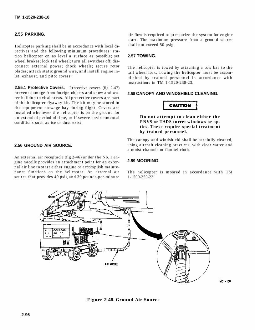
CAUTION
TM 1-1520-238-10
2.55 PARKING.
Helicopter parking shall be in accordance with local di-rectives and the following minimum procedures: sta-tion helicopter on as level a surface as possible; setwheel brakes; lock tail wheel; turn all switches off; dis-connect external power; chock wheels; secure rotorblades; attach static ground wire, and install engine in-let, exhaust, and pitot covers.
2.55.1 Protective Covers. Protective covers (fig 2-47)prevent damage from foreign objects and snow and wa-ter buildup to vital areas. Ail protective covers are partof the helicopter flyaway kit. The kit may be stored inthe equipment stowage bay during flight. Covers areinstalled whenever the helicopter is on the ground foran extended period of time, or if severe environmentalconditions such as ice or dust exist.
2.56 GROUND AIR SOURCE.
An external air receptacle (fig 2-46) under the No. 1 en-gine nacelle provides an attachment point for an exter-nal air line to start either engine or accomplish mainte-nance functions on the helicopter. An external airsource that provides 40 psig and 30 pounds-per-minute
air flow is required to pressurize the system for enginestart. The maximum pressure from a ground sourceshall not exceed 50 psig.
2.57 TOWING.
The helicopter is towed by attaching a tow bar to thetail wheel fork. Towing the helicopter must be accom-plished by trained personnel in accordance withinstructions in TM 1-1520-238-23.
2.58 CANOPY AND WINDSHIELD CLEANING.
Do not attempt to clean either thePNVS or TADS turret windows or op-tics. These require special treatmentby trained personnel.
The canopy and windshield shall be carefully cleaned,using aircraft cleaning practices, with clear water anda moist chamois or flannel cloth.
2.59 MOORING.
The helicopter is moored in accordance with TM1-1500-250-23.
Figure 2-46. Ground Air Source
2-96
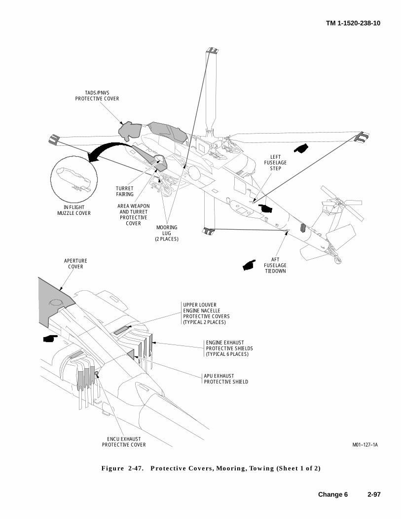
TM 1-1520-238-10
Change 6 2-97
M01--127--1A
MOORINGLUG
(2 PLACES)
IN FLIGHTMUZZLE COVER
ENGINE EXHAUSTPROTECTIVE SHIELDS(TYPICAL 6 PLACES)
AFTFUSELAGETIEDOWN
APERTURECOVER
APU EXHAUSTPROTECTIVE SHIELD
UPPER LOUVERENGINE NACELLEPROTECTIVE COVERS(TYPICAL 2 PLACES)
ENCU EXHAUSTPROTECTIVE COVER
TURRETFAIRING
AREA WEAPONAND TURRETPROTECTIVE
COVER
TADS/PNVSPROTECTIVE COVER
LEFTFUSELAGE
STEP
Figure 2-47. Protective Covers, Mooring, Towing (Sheet 1 of 2)
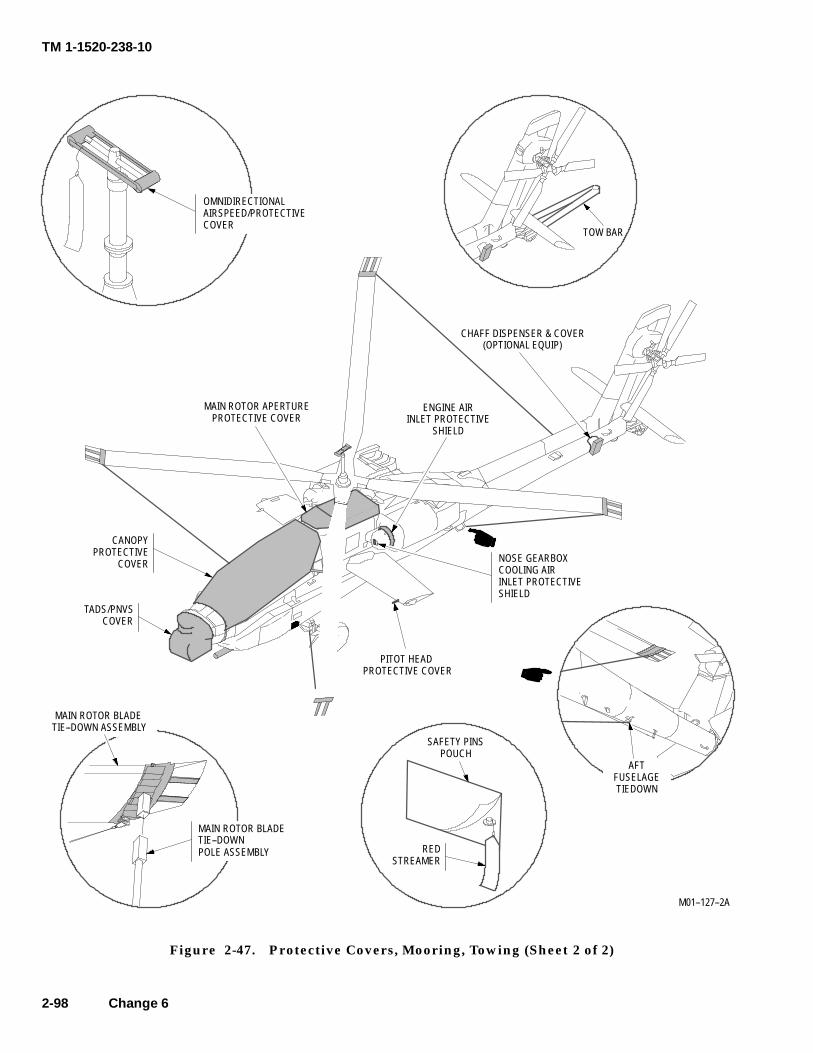
TM 1-1520-238-10
2-98 Change 6
M01--127--2A
NOSE GEARBOXCOOLING AIRINLET PROTECTIVESHIELD
ENGINE AIRINLET PROTECTIVE
SHIELD
PITOT HEADPROTECTIVE COVER
TADS/PNVSCOVER
CHAFF DISPENSER & COVER(OPTIONAL EQUIP)
TOW BAR
SAFETY PINSPOUCH
REDSTREAMER
MAIN ROTOR BLADETIE--DOWNPOLE ASSEMBLY
MAIN ROTOR APERTUREPROTECTIVE COVER
AFTFUSELAGETIEDOWN
CANOPYPROTECTIVE
COVER
MAIN ROTOR BLADETIE--DOWN ASSEMBLY
OMNIDIRECTIONALAIRSPEED/PROTECTIVECOVER
Figure 2-47. Protective Covers, Mooring, Towing (Sheet 2 of 2)
TM 1-1520-238-10
CHAPTER 3AVIONICS
Section 1. GENERAL
3.1 DESCRIPTION. item. Antenna locations on the airframe are shown (fig3-1).
This chapter covers the avionics equipment configura- 3.2 AVIONICS EQUIPMENT CONFIGURATIONS.tion installed in the AH-64A helicopter. It includes abrief description of the avionics equipment, its techni- Avionics equipment configurations are shown in Tablecal characteristics, capabilities, and locations. For mis- 3-1.sion avionics equipment, refer to Chapter 4, MissionEquipment. 3.3 AVIONICS POWER SUPPLY.
The communications equipment provides intercommu-nication between crewmembers and VHF AM-FM andUHF AM radio communication. If installed, VHF FMSingle Channel Ground and Airborne Radio Set (SINC-GARS) is also provided. The navigation equipment in-cludes an Automatic Direction Finder (ADF), a DopplerNavigation System (DNS) and a Heading Attitude Ref-erence Set (HARS). Transponder equipment consists ofan Identification Friend or Foe (IFF) receiver transmit-ter. Height above ground level is provided by a radar al-timeter. Each antenna is described with its major end
Power to operate most of the avionics equipment is pro-vided by the emergency dc bus. This allows for backupbattery power that is used in the event of a completeelectrical failure. External power may also be applied.Function selector should be OFF before applying heli-copter power.
3.4 EMERGENCY OPERATION.
If both generators or both transformer-rectifiers (T/R’s)fail, turn off all nonessential radio equipment to pre-vent excessive drain on the battery.
3-1
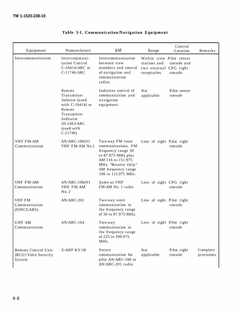
TM 1-1520-238-10
Table 3-1. Communication/Navigation Equipment
ControlEquipment Nomenclature use Range Location Remarks
Intercommunication
VHF FM-AMCommunication
VHF FM-AMCommunication
VHF FMCommunication(SINCGARS)
UHF AMCommunication
Remote Control Unit(RCU) Voice SecuritySystem
Intercommuni-cation ControlC-10414/ARC orC-11746/ARC
RemoteTransmitterSelector (usedwith C-10414) orRemoteTransmitterIndicatorID-2403/ARC(used withC-11746)
AN/ARC-186(V)VHF FM-AM No.1
AN/ARC-186(V)VHF FM-AMNo. 2
AN/ARC-201
AN/ARC-164
Z-AHP KY-58
Intercommunicationbetween crewmembers and controlof navigation andcommunicationradios.
Indicates control ofcommunication andnavigationequipment.
Two-way FM voicecommunications. FMfrequency range 30to 87.975 MHz plusAM 116 to 151.975MHz. “Receive Only”AM frequency range108 to 115.975 MHz.
Same as VHFFM-AM No. 1 radio.
Two-way voicecommunication inthe frequency rangeof 30 to 87.975 MHz.
Two-waycommunication inthe frequency rangeof 225 to 399.975MHz.
Securecommunication forpilot AN/ARC-186 orAN/ARC-201 radio.
Within crew Pilot centerstations and console andtwo external CPG rightreceptacles. console
Not Pilot centerapplicable console
Line of sight Pilot rightconsole
Line of sight CPG rightconsole
Line of sight Pilot rightconsole
Line of sight Pilot rightconsole
Not Pilot rightapplicable console
Completeprovisions
3-2
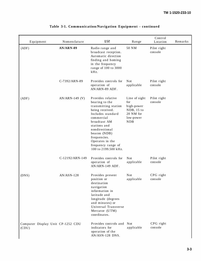
TM 1-1520-233-10
Table 3-1. Communication/Navigation Equipment - continued
ControlEquipment Nomenclature use Range Location Remarks
(ADF) AN/ARN-89
C-7392/ARN-89
(ADF) AN/ARN-149 (V)
C-12192/ARN-149
(DNS) AN/ASN-128
Computer Display Unit CP-1252 CDU(CDU)
Radio range andbroadcast reception.Automatic directionfinding and homingin the frequencyrange of 100 to 3000kHz.
Provides controls foroperation ofAN/ARN-89 ADF.
Provides relativebearing to thetransmitting stationbeing received.Includes standardcommercialbroadcast AMstations andnondirectionalbeacon (NDB)frequencies.Operates in thefrequency range of100 to 2199.500 kHz.
Provides controls foroperation ofAN/ARN-149 ADF.
Provides presentposition ordestinationnavigationinformation inlatitude andlongitude (degreesand minutes) orUniversal TransverseMercator (UTM)coordinates.
Provides controls andindicators foroperation of theAN/ASN-128 DNS.
50 NM
Notapplicable
Line of sightforhigh-powerNDB, 15 to20 NM forlow-powerNDB
Notapplicable
Notapplicable
Notapplicable
Pilot rightconsole
Pilot rightconsole
Pilot rightconsole
Pilot rightconsole
CPG rightconsole
CPG rightconsole
3-3

TM 1-1520-238-10
Table 3-1. Communication/Navigation Equipment - continued
ControlEquipment Nomenclature Use Range Location Remarks
(DNS) AN/ASN-137 Provides present Not CPG rightposition or applicable consoledestinationnavigationinformation inlatitude andlongitude (degreesand minutes) or(UTM) coordinates.
(CDU) IP-1552/G CDU Provides controls and Not CPG rightdisplays for applicable consoleoperation of theAN/ASN-137 DNS.
(IFF) AN/APX 100(V) Transmits a specially Line of sight Pilot rightcoded reply to a consoleground based IFFradar interrogatorsystem.
Absolute Altimeter AN/APN-209 Measures absolute 0 to 1500 feet Pilot rightaltitude. above ground instrument
level panel(HARS) Senses helicopter Not Pilot right
attitude and motion applicable instrumentto define roll, pitch, panelheading, and flightpath.
Data Transfer DR-902B Auto loading of Not CPG rightReceptacle (DTR) mission data applicable consoleEmbedded Global CN-1689(V)1/ASN Provides present Not CPG rightPositioning System position or applicable consoleInertial Navigation destination (CDU)Unit (EGI) navigation
information inlatitude andlongitude (degreesand minutes) or(UTM) coordinates.
3-4 Change 3
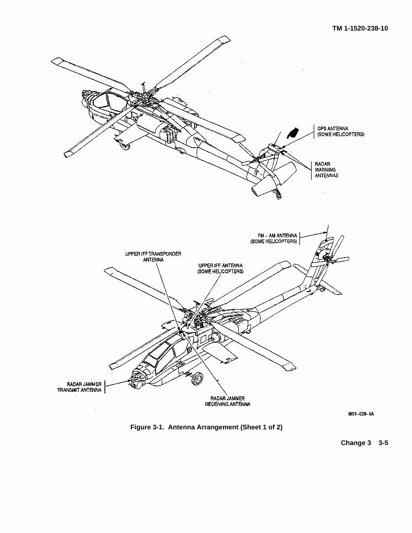
TM 1-1520-238-10
Figure 3-1. Antenna Arrangement (Sheet 1 of 2)
Change 3 3-5

TM 1-1520-238-10
Figure 3-1. Antenna Arrangement (Sheet 2 of 2)
3-6
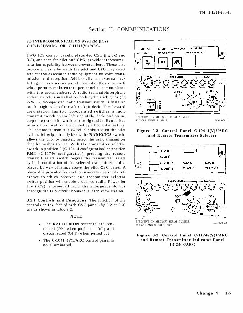
TM 1-1520-238-10
Section II. COMMUNICATIONS
3.5 INTERCOMMUNICATION SYSTEM (ICS)C-1041401)3/ARC OR C-11746(V)4/ARC.
TWO ICS control panels, placarded CSC (fig 3-2 and3-3), one each for pilot and CPG, provide intercommu-nication capability between crewmembers. These alsoprovide a means by which the pilot and CPG may selectand control associated radio equipment for voice trans-mission and reception. Additionally, an external jackfitting on each service panel, located outboard on eachwing, permits maintenance personnel to communicatewith the crewmembers. A radio transmit/interphonerocker switch is installed on both cyclic stick grips (fig2-26). A foot-operated radio transmit switch is installedon the right side of the aft cockpit deck. The forwardcrew station has two foot-operated switches: a radiotransmit switch on the left side of the deck, and an in-terphone transmit switch on the right side. Hands freeintercommunication is provided by a hot mike feature.The remote transmitter switch pushbutton on the pilotcyclic stick grip, directly below the RADIO/ICS switch,allows the pilot to remotely select the radio transmitterthat he wishes to use. With the transmitter selectorswitch in position 5 (C-10414 configuration) or positionRMT (C-11746 configuration), pressing the remotetransmit select switch begins the transmitter selectcycle. Identification of the selected transmitter is dis-played by way of lamps above the pilot CSC panel. Aplacard is provided for each crewmember as ready ref-erence to which receiver and transmitter selectorswitch position will enable a desired radio. Power forthe (ICS) is provided from the emergency dc busthrough the ICS circuit breaker in each crew station.
3.5.1 Controls and Functions. The function of thecontrols on the face of each CSC panel (fig 3-2 or 3-3)are as shown in table 3-2.
NOTE
l The RADIO MON switches are con-nected (ON) when pushed in fully anddisconnected (OFF) when pulled out.
l The C-10414(V)3/ARC control panel isnot illuminated.
EFFECTIVE ON AIRCRAFT SERIAL NUMBER83-23787 THRU 85-25415 M01-028-1
Figure 3-2. Control Panel C-10414(V)3/ARCand Remote Transmitter Selector
EFFECTIVE ON AIRCRAFT SERIAL NUMBER M01-028-2B85-25416 AND SUBSEQUENT
Figure 3-3. Control Panel C-11746(V)4/ARCand Remote Transmitter Indicator Panel
ID-2403/ARC
Change 4 3-7
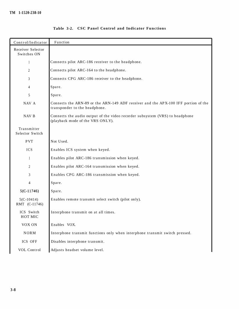
TM 1-1520-238-10
Table 3-2. CSC Panel Control and Indicator Functions
Control/Indicator Function
Receiver SelectorSwitches ON
1
2
3
4
5
NAV A
NAV B
TransmitterSelector Switch
PVT
ICS
1
2
3
4
5(C-11746)5(C-11746)
5(C-10414)RMT (C-11746)
ICS SwitchHOT MIC
VOX ON
NORM
ICS OFF
VOL Control
Connects pilot ARC-186 receiver to the headphone.
Connects pilot ARC-164 to the headphone.
Connects CPG ARC-186 receiver to the headphone.
Spare.
Spare.
Connects the ARN-89 or the ARN-149 ADF receiver and the APX-100 IFF portion of thetransponder to the headphone.
Connects the audio output of the video recorder subsystem (VRS) to headphone(playback mode of the VRS ONLY).
Not Used.
Enables ICS system when keyed.
Enables pilot ARC-186 transmission when keyed.
Enables pilot ARC-164 transmission when keyed.
Enables CPG ARC-186 transmission when keyed.
Spare.
Spare.
Enables remote transmit select switch (pilot only).
Interphone transmit on at all times.
Enables VOX.
Interphone transmit functions only when interphone transmit switch pressed.
Disables interphone transmit.
Adjusts headset volume level.
3-8
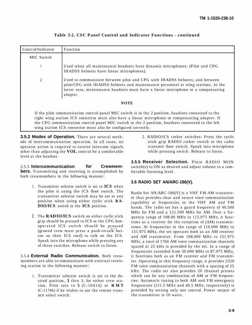
TM 1-1520-238-10
Table 3-2. CSC Panel Control and Indicator Functions - continued
Control/Indicator Function
MIC Switch
1 Used when all maintenance headsets have dynamic microphones. (Pilot and CPGIHADSS helmets have linear microphones).
2 Used to communicate between pilot and CPG with IHADSS helmets; and betweenpilot/CPG with IHADSS helmets and maintenance personnel at wing stations. In thelatter case, maintenance headsets must have a linear microphone or a compensatingadapter.
NOTE
If the pilot communication control panel MIC switch is in the 2 position, headsets connected to theright wing station ICS connector must also have a linear microphone or compensating adapter. Ifthe CPG communication control panel MIC switch in the 2 position, headsets connected to the leftwing station ICS connector must also be configured correctly.
3.5.2 Modes of Operation. There are several meth- 2. RADIO/ICS rocker switches- Press the cyclicods of intercommunication operation. In all cases, no stick grip RADIO rocker switch or the radiooperator action is required to receive intercom signals transmit floor switch. Speak into microphoneother than adjusting the VOL control for a comfortable while pressing switch. Release to listen.level at the headset.
3.5.5 Receiver Selection. Place RADIO MON3.5.3 Intercommunication for Crewmem- switch(s) to ON as desired and adjust volume to a com-bers. Transmitting and receiving is accomplished by fortable listening level.both crewmembers in the following manner:
1.
2.
Transmitter selector switch is set to ICS whenthe pilot is using the ICS floor switch. Thetransmitter selector switch may be set at anyposition when using either cyclic stick RA-DIO/ICS switch in the ICS position.
The RADIO/ICS switch on either cyclic stickgrip should be pressed to ICS or the CPG foot-operated ICS switch should be pressed- - -
3.6 RADIO SET AN/ARC-186(V).
Radio Set AN/ARC-186(V) is a VHF FM-AM transceiv-er that provides clear and secure voice communicationcapability at frequencies in the VHF AM and FMbands. The radio set has a guard frequency of 40.500MHz for FM and a 121.500 MHz for AM. Over a fre-quency range of 108.00 MHz to 115.975 MHz, it func-tions as a receiver for the reception of (AM) transmis-sions. At frequencies in the range of 116.000 MHz to
(ground crew must press a push-to-talk but- 151.975 MHz, the set operates both as an AM receiverton on their ICS cord) to talk on the ICS. and AM transmitter. From 108.000 MHz to 151.975Speak into the microphone while pressing any MHz, a total of 1760 AM voice communication channelsof these switches. Release switch to listen. spaced at 25 kHz is provided by the set. In a range of
frequencies extended from 30.000 MHz to 87.975 MHz,3.5.4 External Radio Communication. Both crew- it functions both as an FM receiver and FM transmit-members are able to communicate with external receiv- ter. Operating in this frequency range, it provides 2320ing station in the following manner: FM voice communication channels with a spacing of 25
1.kHz. The radio set also provides 20 channel presets
Transmitter selector switch is set to the de- which can be any combination of AM or FM frequen-sired position, 1 thru 3, for either crew sta- ties. Automatic tuning to both AM and FM emergencytion. Pilot sets to 5 (C-10414) or R M T frequencies (121.5 MHz and 40.5 MHz, respectively) is(C-11746) if he wishes to use the remote trans- provided by setting only one control. Power output ofmit select switch. the transmitter is 10 watts.
3-9
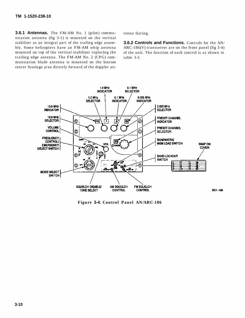
TM 1-1520-238-10
3.6.1 Antennas. The FM-AM No. 1 (pilot) commu- tenna fairing.nication antenna (fig 3-1) is mounted on the verticalstabilizer as an integral part of the trailing edge assem- 3.6.2 Controls and Functions. Controls for the AN/bly. Some helicopters have an FM-AM whip antenna ARC-186(V) transceiver are on the front panel (fig 3-4)mounted on top of the vertical stabilizer replacing the of the unit. The function of each control is as shown intrailing edge antenna. The FM-AM No. 2 (CPG) com- table 3-3.munication blade antenna is mounted on the bottomcenter fuselage area directly forward of the doppler an-
Figure 3-4. Control Panel AN/ARC-186
3-10
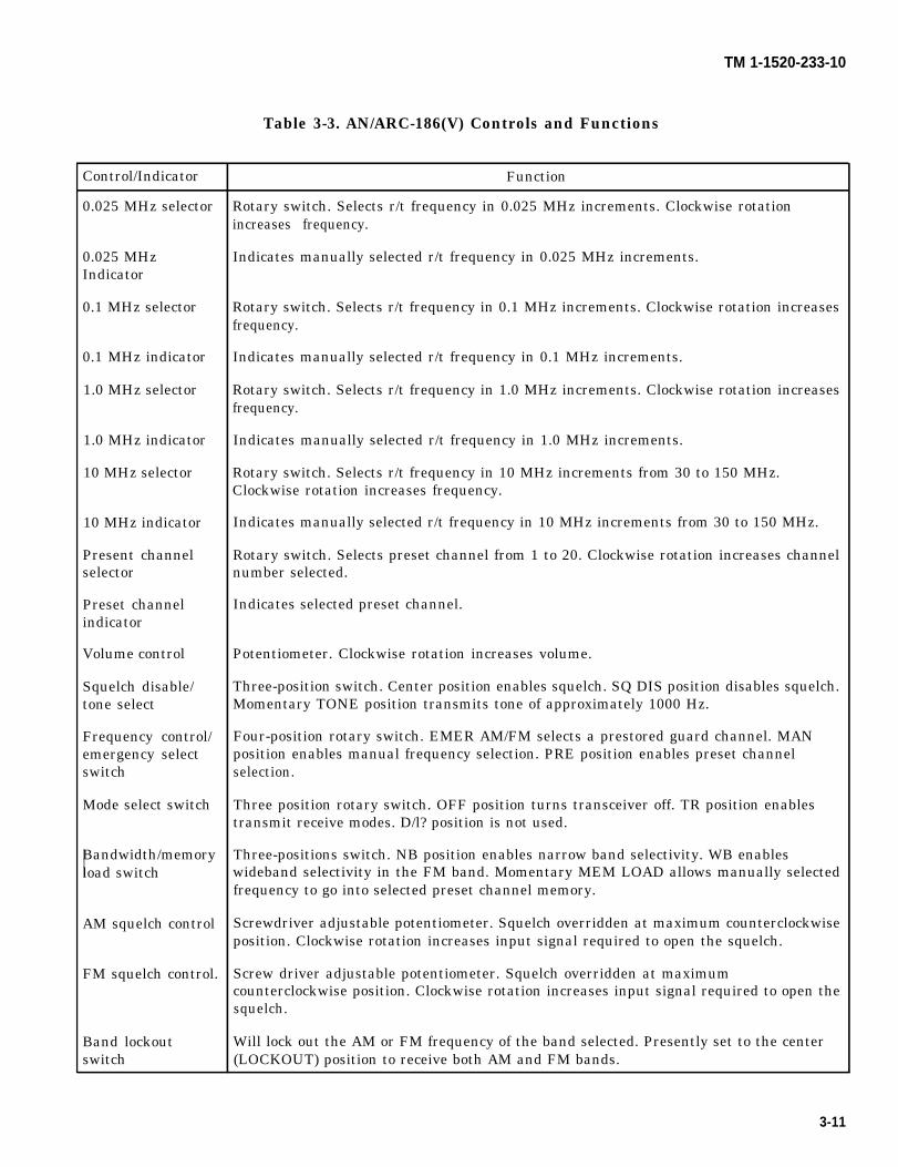
TM 1-1520-233-10
Table 3-3. AN/ARC-186(V) Controls and Functions
Control/Indicator Function
0.025 MHz selector Rotary switch. Selects r/t frequency in 0.025 MHz increments. Clockwise rotationincreases frequency.
0.025 MHz Indicates manually selected r/t frequency in 0.025 MHz increments.Indicator
0.1 MHz selector Rotary switch. Selects r/t frequency in 0.1 MHz increments. Clockwise rotation increasesfrequency.
0.1 MHz indicator Indicates manually selected r/t frequency in 0.1 MHz increments.
1.0 MHz selector Rotary switch. Selects r/t frequency in 1.0 MHz increments. Clockwise rotation increasesfrequency.
1.0 MHz indicator Indicates manually selected r/t frequency in 1.0 MHz increments.
10 MHz selector Rotary switch. Selects r/t frequency in 10 MHz increments from 30 to 150 MHz.Clockwise rotation increases frequency.
10 MHz indicator Indicates manually selected r/t frequency in 10 MHz increments from 30 to 150 MHz.
Present channel Rotary switch. Selects preset channel from 1 to 20. Clockwise rotation increases channelselector number selected.
Preset channel Indicates selected preset channel.indicator
Volume control Potentiometer. Clockwise rotation increases volume.
Squelch disable/ Three-position switch. Center position enables squelch. SQ DIS position disables squelch.tone select Momentary TONE position transmits tone of approximately 1000 Hz.
Frequency control/ Four-position rotary switch. EMER AM/FM selects a prestored guard channel. MANemergency select position enables manual frequency selection. PRE position enables preset channelswitch selection.
Mode select switch Three position rotary switch. OFF position turns transceiver off. TR position enablestransmit receive modes. D/l? position is not used.
Bandwidth/memory Three-positions switch. NB position enables narrow band selectivity. WB enablesload switch wideband selectivity in the FM band. Momentary MEM LOAD allows manually selected
frequency to go into selected preset channel memory.
AM squelch control Screwdriver adjustable potentiometer. Squelch overridden at maximum counterclockwiseposition. Clockwise rotation increases input signal required to open the squelch.
FM squelch control. Screw driver adjustable potentiometer. Squelch overridden at maximumcounterclockwise position. Clockwise rotation increases input signal required to open thesquelch.
Band lockout Will lock out the AM or FM frequency of the band selected. Presently set to the centerswitch (LOCKOUT) position to receive both AM and FM bands.
3-11
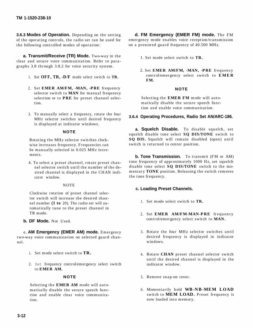
TM 1-1520-238-10
3.6.3 Modes of Operation. Depending on the settingof the operating controls, the radio set can be used forthe following controlled modes of operation:
a. Transmit/Receive (TR) Mode. Two-way in theclear and secure voice communication. Refer to para-graphs 3.8 through 3.8.2 for voice security system.
1.
2.
3.
Set OFF, TR, -D/F mode select switch to TR.
Set EMER AM/FM, -MAN, -PRE frequencyselector switch to MAN for manual frequencyselection or to PRE for preset channel selec-tion.
To manually select a frequency, rotate the fourMHz selector switches until desired frequencyis displayed at indicator windows.
NOTE
Rotating the MHz selector switches clock-wise increases frequency. Frequencies canbe manually selected in 0.025 MHz incre-ments.
4. To select a preset channel, rotate preset chan-nel selector switch until the number of the de-sired channel is displayed in the CHAN indi-cator window.
NOTE
Clockwise rotation of preset channel selec-tor switch will increase the desired chan-nel number (1 to 20). The radio set will au-tomatically tune to the preset channel inTR mode.
b. DF Mode. Not Used.
c. AM Emergency (EMER AM) mode. Emergencytwo-way voice communication on selected guard chan-nel.
1.
2.
Set mode select switch to TR.
Set frequency control/emergency select switchto EMER AM.
NOTE
Selecting the EMER AM mode will auto-matically disable the secure speech func-tion and enable clear voice communica-tion.
d. FM Emergency (EMER FM) mode. The FMemergency mode enables voice reception/transmissionon a prestored guard frequency of 40.500 MHz.
3.6.4
1. Set mode select switch to TR.
2. Set EMER AM/FM, -MAN, -PRE frequencycontrol/emergency select switch to EMERFM.
NOTE
Selecting the EMER FM mode will auto-matically disable the secure speech func-tion and enable voice communication.
Operating Procedures, Radio Set AN/ARC-186.
a. Squelch Disable. To disable squelch, setsquelch disable tone select SQ DIS/TONE switch toSQ DIS. Squelch will remain disabled (open) untilswitch is returned to center position.
b. Tone Transmission. To transmit (FM or AM)tone frequency of approximately 1000 Hz, set squelchdisable tone select SQ DIS/TONE switch to the mo-mentary TONE position. Releasing the switch removesthe tone frequency.
c. Loading Preset Channels.
1.
2.
3.
4.
5.
6.
Set mode select switch to TR.
Set EMER AM/FM-MAN-PRE frequencycontrol/emergency select switch to MAN.
Rotate the four MHz selector switches untildesired frequency is displayed in indicatorwindows.
Rotate CHAN preset channel selector switchuntil the desired channel is displayed in theindicator window.
Remove snap-on cover.
Momentarily hold WB-NB-MEM LOADswitch to MEM LOAD. Preset frequency isnow loaded into memory.
3-12
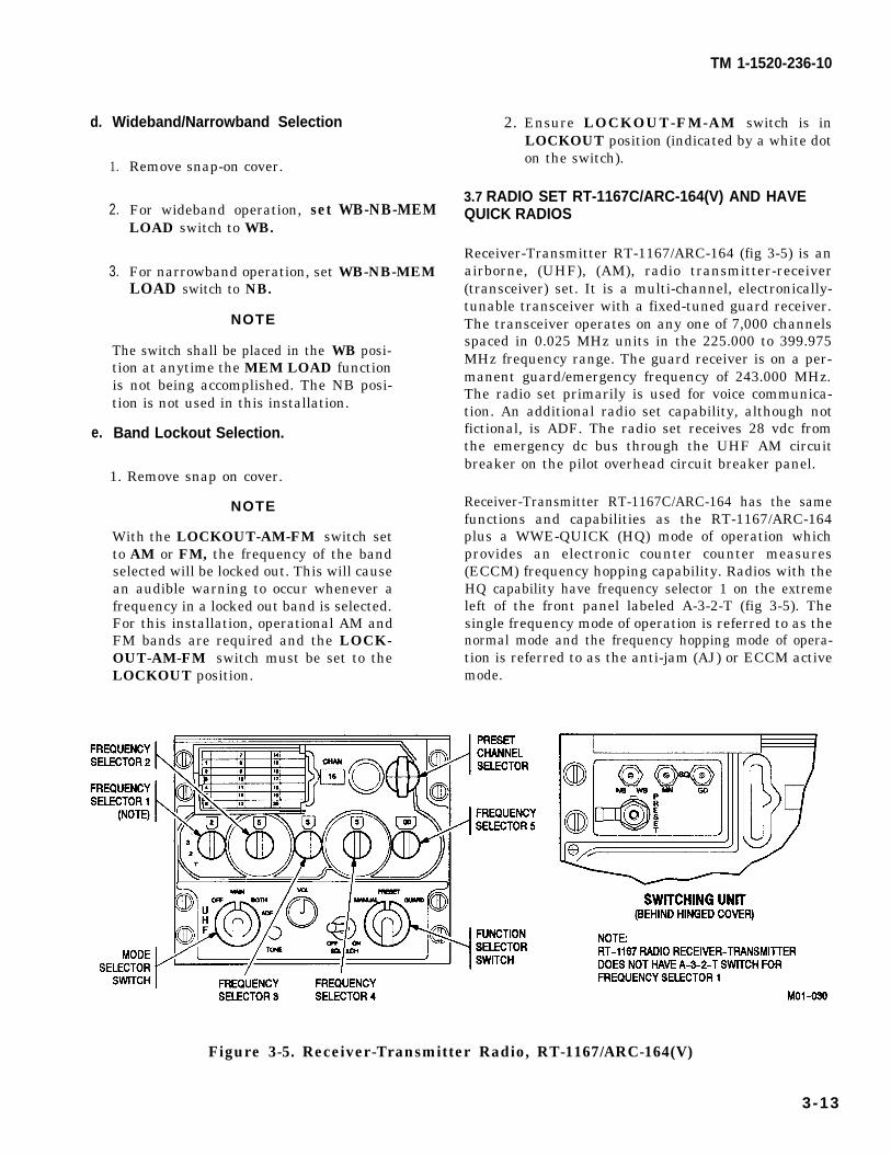
d.
e.
Wideband/Narrowband Selection
1.
2.
3.
Remove snap-on cover.
For wideband operation,LOAD switch to WB.
set WB-NB-MEM
For narrowband operation, set WB-NB-MEMLOAD switch to NB.
NOTE
The switch shall be placed in the WB posi-tion at anytime the MEM LOAD functionis not being accomplished. The NB posi-tion is not used in this installation.
Band Lockout Selection.
1. Remove snap on cover.
NOTE
With the LOCKOUT-AM-FM switch setto AM or FM, the frequency of the bandselected will be locked out. This will causean audible warning to occur whenever afrequency in a locked out band is selected.For this installation, operational AM andFM bands are required and the LOCK-OUT-AM-FM switch must be set to theLOCKOUT position.
TM 1-1520-236-10
2. Ensure LOCKOUT-FM-AM switch is inLOCKOUT position (indicated by a white doton the switch).
3.7 RADIO SET RT-1167C/ARC-164(V) AND HAVEQUICK RADIOS
Receiver-Transmitter RT-1167/ARC-164 (fig 3-5) is anairborne, (UHF), (AM), radio transmitter-receiver(transceiver) set. It is a multi-channel, electronically-tunable transceiver with a fixed-tuned guard receiver.The transceiver operates on any one of 7,000 channelsspaced in 0.025 MHz units in the 225.000 to 399.975MHz frequency range. The guard receiver is on a per-manent guard/emergency frequency of 243.000 MHz.The radio set primarily is used for voice communica-tion. An additional radio set capability, although notfictional, is ADF. The radio set receives 28 vdc fromthe emergency dc bus through the UHF AM circuitbreaker on the pilot overhead circuit breaker panel.
Receiver-Transmitter RT-1167C/ARC-164 has the samefunctions and capabilities as the RT-1167/ARC-164plus a WWE-QUICK (HQ) mode of operation whichprovides an electronic counter counter measures(ECCM) frequency hopping capability. Radios with theHQ capability have frequency selector 1 on the extremeleft of the front panel labeled A-3-2-T (fig 3-5). Thesingle frequency mode of operation is referred to as thenormal mode and the frequency hopping mode of opera-tion is referred to as the anti-jam (AJ) or ECCM activemode.
Figure 3-5. Receiver-Transmitter Radio, RT-1167/ARC-164(V)
3-13
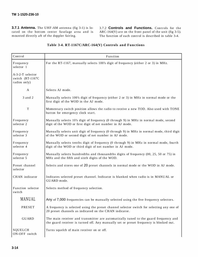
TM 1-1520-236-10
3.7.1 Antenna. The UHF-AM antenna (fig 3-1) is lo- 3.7.2 Controls and Functions. Controls for thecated on the bottom center fuselage area and is ARC-164(V) are on the front panel of the unit (fig 3-5).mounted directly aft of the doppler fairing. The function of each control is described in table 3-4.
Table 3-4. RT-1167C/ARC-164(V) Controls and Functions
Control
Frequencyselector 1
A-3-2-T selectorswitch (RT-1167Cradios only)
A
3 and 2
T
Frequencyselector 2
Frequencyselector 3
Frequencyselector 4
Frequencyselector 5
Preset channelselector
CHAN indicator
Function selectorswitch
MANUALPRESET
GUARD
SQUELCHON-OFF switch
Function
For the RT-1167, manually selects 100’s digit of frequency (either 2 or 3) in MHz.
Selects AJ mode.
Manually selects 100’s digit of frequency (either 2 or 3) in MHz in normal mode or thefirst digit of the WOD in the AJ mode.
Momentary switch position allows the radio to receive a new TOD. Also used with TONEbutton for emergency clock start.
Manually selects 10’s digit of frequency (0 through 9) in MHz in normal mode, seconddigit of the WOD or first digit of net number in AJ mode.
Manually selects unit digit of frequency (0 through 9) in MHz in normal mode, third digitof the WOD or second digit of net number in AJ mode.
Manually selects tenths digit of frequency (0 through 9) in MHz in normal mode, fourthdigit of the WOD or third digit of net number in AJ mode.
Manually selects hundredths and thousandths digits of frequency (00, 25, 50 or 75) inMHz and the fifth and sixth digits of the WOD.
Selects and stores one of 20 preset channels in normal mode or the WOD in AJ mode.
Indicates selected preset channel. Indicator is blanked when radio is in MANUAL orGUARD mode.
Selects method of frequency selection.
Any of 7,000 frequencies can be manually selected using the five frequency selectors.
A frequency is selected using the preset channel selector switch for selecting any one of20 preset channels as indicated on the CHAN indicator.
The main receiver and transmitter are automatically tuned to the guard frequency andthe guard receiver is turned off. Any manually set or preset frequency is blocked out.
Turns squelch of main receiver on or off.
3-14
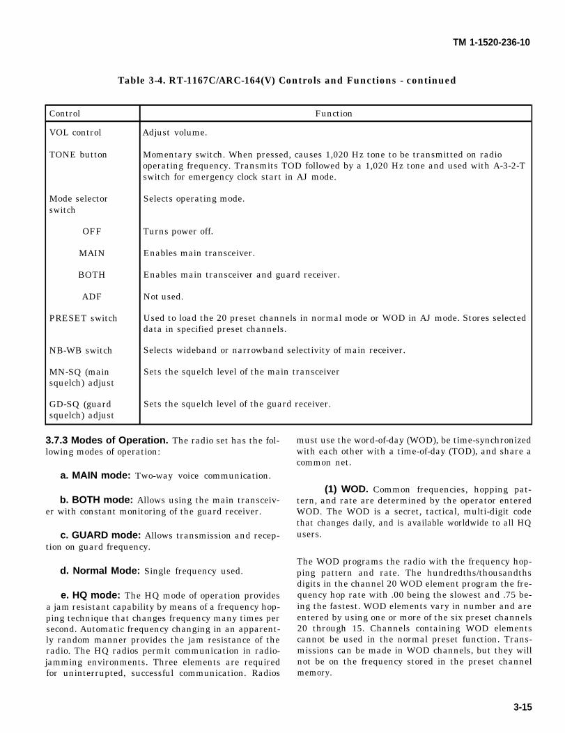
TM 1-1520-236-10
Table 3-4. RT-1167C/ARC-164(V) Controls and Functions - continued
Control Function
VOL control Adjust volume.
TONE button Momentary switch. When pressed, causes 1,020 Hz tone to be transmitted on radiooperating frequency. Transmits TOD followed by a 1,020 Hz tone and used with A-3-2-Tswitch for emergency clock start in AJ mode.
Mode selector Selects operating mode.switch
OFF Turns power off.
MAIN Enables main transceiver.
BOTH Enables main transceiver and guard receiver.
ADF Not used.
PRESET switch Used to load the 20 preset channels in normal mode or WOD in AJ mode. Stores selecteddata in specified preset channels.
NB-WB switch Selects wideband or narrowband selectivity of main receiver.
MN-SQ (main Sets the squelch level of the main transceiversquelch) adjust
GD-SQ (guard Sets the squelch level of the guard receiver.squelch) adjust
3.7.3 Modes of Operation. The radio set has the fol-lowing modes of operation:
a. MAIN mode: Two-way voice communication.
b. BOTH mode: Allows using the main transceiv-er with constant monitoring of the guard receiver.
c. GUARD mode: Allows transmission and recep-tion on guard frequency.
d. Normal Mode: Single frequency used.
e. HQ mode: The HQ mode of operation providesa jam resistant capability by means of a frequency hop-ping technique that changes frequency many times persecond. Automatic frequency changing in an apparent-ly random manner provides the jam resistance of theradio. The HQ radios permit communication in radio-jamming environments. Three elements are requiredfor uninterrupted, successful communication. Radios
must use the word-of-day (WOD), be time-synchronizedwith each other with a time-of-day (TOD), and share acommon net.
(1) WOD. Common frequencies, hopping pat-tern, and rate are determined by the operator enteredWOD. The WOD is a secret, tactical, multi-digit codethat changes daily, and is available worldwide to all HQusers.
The WOD programs the radio with the frequency hop-ping pattern and rate. The hundredths/thousandthsdigits in the channel 20 WOD element program the fre-quency hop rate with .00 being the slowest and .75 be-ing the fastest. WOD elements vary in number and areentered by using one or more of the six preset channels20 through 15. Channels containing WOD elementscannot be used in the normal preset function. Trans-missions can be made in WOD channels, but they willnot be on the frequency stored in the preset channelmemory.
3-15
TM 1-1520-236-10
The WOD is initially entered into the preset memoryand then transferred to volatile memory. After transfer,if power is lost or if channel 20 is selected when thefunction switch is set to PRESET, it will be necessaryto perform another transfer from the preset memory tovolatile memory. Start with channel 20 and set to pro-gressively lower channels until a double beep is heard.
The radio will not function in the AJ mode if a WOD isnot in volatile memory. If the AJ mode is selected with-out entering a WOD into the volatile memory, a steadywarning tone will be heard in the headset.
(2) TOD. Time synchronization is provided bya clock inside the radio. The internal clock is turned offwhen the radio is turned off.
A TOD signal must be received to reset the radio’s in-ternal clock when the radio is turned on. This signalmay be provided by another HQ radio or by an externaltime distribution system. Improper synchronizationwill prohibit proper communication. Reception ofgarbled communications in the AJ mode indicates thereceiving radio and transmitting radio are not in syn-chronization. In a multiple radio net, the radio receiv-ing all transmissions garbled is the radio that is out ofsynchronization.
TOD reception can be performed in both normal and AJmodes. The radio automatically accepts the first TODmessage after the radio is turned on and the WOD istransferred to volatile memory. Subsequent messagesare ignored unless the T position is selected by theA-3-2-T switch. The radio may be desynchronized bysetting the radio to the TOD transmission frequency,setting the A-3-2-T switch to T, and requesting anotherperson in the common net to transmit the TOD. The ra-dio then accepts the next TOD update, provided theTOD update arrives within one minute of selecting theT position on the A-3-2-T switch.
TOD is normally received by the main or guard receivervia a prearranged frequency from another HQ radiowhich has the desired time. When the radio receivesthe TOD from an external timing source, it updates/synchronizes the radio’s internal clock with the timingsource. This allows all radios in synchronization withthe source and one another to frequency hop simulta-neously for uninterrupted communication. Any arbi-trary time may be used, but operators are encouragedto obtain and use Universal Time Coordinated (UTC)time. The use of UTC time will allow operators toswitch from one HQ radio net to another without retim-ing their radios to arbitrary times (TODs).
3-16
If no TOD is available from another HQ radio, an emer-gency start of the TOD clock can be performed usingthe T position of the A-3-2-T switch and the TONE but-ton. Emergency startup of the TOD clock generates anarbitrary TOD that must be transferred to other radiosusing the same net. Operators using the emergencystartup method will not be able to communicate in theAJ mode with anyone that has not received this arbi-trary TOD. The net should update to UTC time as soonas possible so everyone entering or leaving the net willnot have to retime their radios.
The TOD can be transferred in both normal and AJmode by momentarily pressing the TONE button withthe A-3-2-T switch set to T. A TOD transmission allowsa time update if one radio has drifted out of synchro-nization.
(3) Common Net Numbers. In the AJ mode, acommunications channel is defined by a net numberinstead of a signal frequency as in the normal mode.
After WOD and TOD are entered, any valid AJ netnumber can be selected by using the frequency selectorswitches. The net number programs the entry point inthe WOD frequency hopping pattern, allowing for mul-tiple radio net operation using a common WOD andTOD.
f. Anti-Jamming Mode Operation. The A posi-tion of the A-3-2-T switch overrides the hundreds digitin both manual and preset modes. The A cannot be in-serted into the preset channel memory. It will be dis-played as a 3 on the frequency indicator, and acceptedas a 3 if inserted in a preset channel. If the next threedigits of a frequency in a preset channel are the same asthe desired net number, the preset channel can be usedin the AJ mode.
The radio will function in the AJ mode when a WODand TOD are programmed into the radio, A is set on theA-3-2-T switch, and MANUAL is selected on the func-tion switch with an appropriate net number in thethree frequency digits following the A. If the functionswitch is set to BOTH and the AJ mode is selected, anytransmission on the guard channel takes precedenceover the AJ mode.
TM 1-1520-238-10
3.7.4 Warning Tones.
a. A steady warning tone will be heard in the head-set when the AJ mode is selected and TOD, or a validWOD, has not been entered.
b. A pulsating warning tone will be heard in theheadset when an invalid operating net is selected.
3.7.5 Conference Capability.
NOTE
Conference communication is not possiblewhen operating in the secure voice mode.
In the AJ mode, the radio can receive and process twosimultaneous transmissions on the same net. This con-ference capability is available by selecting 00, 50, or 75with frequency selector 5 and then operating in the AJmode. Conferencing is not possible when the net num-ber ends in 25.
In a conference net, the second transmitting radio willautomatically shift its transmission frequency by 25kHz when it monitors a transmission on the primarynet frequency. The wide band receiver will read bothtransmissions without the interference normallyassociated with two radios transmitting on the samefrequency simultaneously. Three simultaneous trans-mission will result in garbled reception.
3.7.6 Guard Operation.
NOTE
If the guard frequency is being jammedwith the mode selector switch in theBOTH position and the radio in the AJ ornormal mode, set the mode selector switchto MAIN.
The guard receiver is not affected by AJ mode opera-tion. The guard frequency maybe monitored regardlessof mode as long as the mode selector switch is set toBOTH. The BOTH position turns on the main trans-ceiver and guard receiver. The guard receiver will re-main tuned to 243.000 MHz regardless of manual orpreset frequencies selected. When the function selectorswitch is set to GUARD, the AJ mode is removed, theguard receiver is turned off and the main transceiver isset at 243.00 MHz, making it possible to transmit andreceive on the guard frequency.
3.7.7 Secure Communication. The HQ radio has asecure (cipher) communication capability. In either the
normal or AJ mode, the radio can perform cipher modeoperation. The effectiveness of communications in theAJ cipher mode depends on the frequency hop rate. It isrecommended that the slowest hop rate (channel 20WOD set at 00) be used during AJ cipher mode opera-tion.
3.7.8 Normal Mode Operating Procedures.
a. Loading Preset Channels.
1. Mode selector switch - MAIN or BOTH.
2. Frequency selectors - Select frequency to beset in memory.
3. Function selector switch - PRESET.
NOTE
For HQ radios, do not select channel 20.
4.
5.
6.
7.
8.
Preset channel selector - Set to channel to beloaded.
Open the switching unit cover.
PRESET button - Press. The frequency isnow loaded into memory.
Repeat steps 2, 3, 4 and 6 to complete preset-ting channels.
Close and latch switching unit cover.
b. Transmit/Receive (MAIN) Operating Proce-dures.
1.
2.
3.
4.
Mode selector switch - MAIN.
Function selector switch - MANUAL.
To manually select a frequency, set the fiveMHz selector switches until desired frequencyis displayed in indicator windows.
To select a preset channel, rotate preset chan-nel selector until desired channel is displayedin CHAN indicator window.
c. Transmit/Receive/Guard Monitor OperatingProcedures.
1. Mode selector switch - BOTH.
NOTE
If reception on the selected frequency in-terferes with guard frequency reception,detune the radio set by selecting an openfrequency or set function selector switchto GUARD.
Change 2 3-17
TM1-1520-238-10
2. Select the desired manual frequency or presetchannel.
d. 1,020 Hz Tone Signal Transmission (MAIN) Pro-cedures.
NOTE
The tone-modulated signal may be used tocheck out the radio receiver.
1.
2.
3.
Mode selector switch - MAIN.
Select a desired frequency for tone signaltransmission, either manually orpreset channel selector.
TONE button - Press to transmitHz signal.
with the
the 1,020
3.7.9 HQ Mode (RT-1167C Only) Operating Proce-dures.
a. Activation of HQ Mode.
The HQ mode can be activated in
1. Function selector switchA-3-2-T switch - A.
one of two ways:
- MANUAL.
2. Function selector switch - PRESET. Presetchannel selector - Channel 20.
b. Entering the WOD.
NOTE
The WOD is normally entered beforeflight but can be entered in flight.
1. Mode selector switch - MAIN.
2. Function selector switch - PRESET.
NOTE
Channels containing WOD elements can-not be used in the normal preset function.Transmission can be made on WOD chan-nels, but they will not be on the frequencystored in the channel memory.
3. Preset channel selector - Channel 20.
4. Frequency selector 1- Set first WOD element.
5. Open switching unit cover.
3-18
6. PRESET button - Press.
NOTE
The WOD elements are entered intomemory through channels 20 through 15.The WOD varies in length and will re-quire from one to six of these channels.
7.
8.
9.
Preset channel selector - Next lower channel.
Repeat steps 4, 6, and 7 until all elements ofthe WOD are loaded into preset memory.
Close and latch the switching unit cover.
NOTE
A single beep indicates that the WOD inchannel 20 was entered into presetmemory and that an additional WOD ele-ment is in the next lowest preset channel.
10. Preset channel selector - Set to channel 20. Asingle beep is heard.
NOTE
The double beep heard at the last channelsignifies that the WOD elements havebeen transferred to volatile memory.
11. Preset channel selector - Set to progressivelylower channels. A single beep is heard at eachchannel until the last channel; a double beepis heard at the last channel.
3.7.10 HQ Emergency Startup of TOD clock.
NOTE
This method of providing TOD is usedwhen there is no TOD available fromanother HQ radio or external source.When using this method of synchroniza-tion, the flight commander or lead helicop-ter should emergency start his TOD clock.The lead helicopter then will transfer thisTOD to other helicopters in flight. A validTOD signal must be used by all helicop-ters before effective AJ communicationscan be achieved.
1. Function selector switch - MANUAL or PRE-SET, as desired.
NOTE
To preclude an inadvertent transmissionof a new time, release the TONE buttonprior to releasing the A-3-2-T switch.
2. A-3-2-T switch - T and hold.
TM 1-1520-238-10
3. TONE button - Press momentarily.4. A-3-2-T switch - Release.5. Return to designated frequency or
channel.
a. Transmitting TOD from Net Control Helicopter.NOTE
TOD transmission and reception isnormally performed before flight, but itcan be performed in flight.
1. Mode selector switch - MAIN or BOTH, asdesired.
2. Function selector switch - MANUAL orPRE- SET as desired.
3. Frequency selectors - Selectpredesignated frequency.
or
Preset channel selector - Set topredesignated channel.
4. Call other helicopter(s) to send time.5. TONE button - Press momentarily to send
TOD. Listen for 1,020 Hz tone.
b. Receiving TOD.NOTE
*. After power-up and WOD transfer, the radioautomatically accepts the first TODmessage received.
• To receive TOD in normal mode, after setting A-3-2-T switch to T, set the radio to the frequencybeing used.
1. Mode selector switch - MAIN.2. Function selector switch - MANUAL or
PRE-SET, as desired.3. Frequency selectors - Select
predesignated frequency for reception ofTOD.
or
Preset channel selector - Set to predesignated channel.
4. Listen for net control helicopter stateSTANDBY FOR TIME.
5. A-3-2-T switch Momentarily to T, thenback to A. Listen for momentary two-tonesignal followed by a single tone.
c. Entering Net Number.NOTE
Setting the A-3-2-T switch to A overridesthe hundredths digit in both manual andpreset functions, puts the radio in AJmode and programs the radio to use thenet number in the three digits followingthe A.1. Function selector switch - MANUAL
or PRE-SET, as desired.
2. Frequency selectors - Set second, thirdand fourth switches to the desired netnumber.
or
Preset channel selector Set to a presetchannel containing the desired netnumber in its second, third and fourthdigits.
3. A-3-2-T switch - A.
3.7A RADIO SET RT-1518/ARC-164 HAVEQUICK II(HQ II) RADIO
The HQ II system consists of a modification to AN/ ARC-164 airborne, (UHF), (AM), radio transmitter-receiver(transceiver) set providing a frequency hopping or anti-jamming capability. Frequency hopping is a techniquewhere the designated preset frequency being used forcommunication on a given link is automaticallyfrequency-hopped many times per second. The purposeof this is to make it difficult for an adversary to jam thelink since they cannot determine which channel is beingused. By the time determination is made as to whichfrequency is being used, the communication link haschanged to another frequency.
The frequency-hopping scheme is implemented in theequipment by storing or initializing every radio with aWord of Day (WOD), Time of Day (TOD), and a netnumber. The WOD programs the frequency-hoppingrate and frequency-hopping pattern. The radio cannotfunction in the anti-jamming mode without a valid WOD.Up to six WODs may be entered at one time. Theprocedure for storing multiple WODs is called Multiple
Change 3 3-18.1
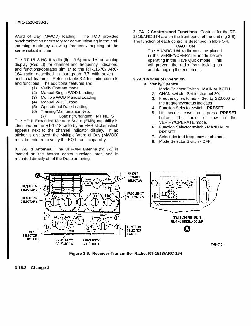
TM 1-1520-238-10
Word of Day (MWOD) loading. The TOD providessynchronization necessary for communicating in the anti-jamming mode by allowing frequency hopping at thesame instant in time.
The RT-1518 HQ II radio (fig. 3-6) provides an analogdisplay (Red Lt) for channel and frequency indicators,and functions/operates similar to the RT-1167C/ ARC-164 radio described in paragraph 3.7 with sevenadditional features. Refer to table 3-4 for radio controlsand functions. The additional features are:
(1) Verify/Operate mode(2) Manual Single WOD Loading(3) Multiple WOD Manual Loading(4) Manual WOD Erase(5) Operational Date Loading(6) Training/Maintenance Nets
(7) Loading/Changing FMT NETSThe HQ II Expanded Memory Board (EMB) capability isidentified on the RT-1518 radio by an EMB sticker whichappears next to the channel indicator display. If nosticker is displayed, the Multiple Word of Day (MWOD)must be entered to verify the HQ II radio capability.
3. 7A. 1 Antenna. The UHF-AM antenna (fig 3-1) islocated on the bottom center fuselage area and ismounted directly aft of the Doppler fairing.
3. 7A. 2 Controls and Functions. Controls for the RT-1518/ARC-164 are on the front panel of the unit (fig 3-6).The function of each control is described in table 3-4.
CAUTIONThe AN/ARC-164 radio must be placedin the VERIFY/OPERATE mode beforeoperating in the Have Quick mode. Thiswill prevent the radio from locking upand damaging the equipment.
3.7A.3 Modes of Operation.a. Verify/Operate.
1. Mode Selector Switch - MAIN or BOTH2. CHAN switch - Set to channel 20.3. Frequency switches - Set to 220.000 on
the frequency/status indicator.4. Function Selector switch - PRESET.5. Lift access cover and press PRESET
button. The radio is now in theVERIFY/OPERATE mode.
6. Function Selector switch - MANUAL orPRESET
7. Select desired frequency or channel.8. Mode Selector Switch - OFF.
Figure 3-6. Receiver-Transmitter Radio, RT-1518/ARC-164
3-18.2 Change 3
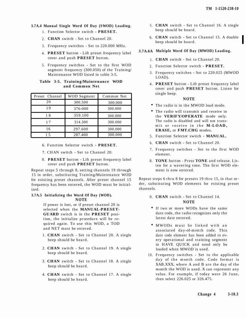
TM 1-1520-238-10
3.7A.4 Manual Single Word Of Day (SWOD) Loading.
1.
2.
3.
4.
5.
Function Selector switch - PRESET.
CHAN switch - Set to Channel 20.
Frequency switches - Set to 220.000 MHz.
PRESET button - Lift preset frequency labelcover and push PRESET button.
Frequency switches - Set to the first WODsegment frequency (300.050) of the Training/Maintenance WOD listed in table 3-5.
Table 3-5. Training/Maintenance WODand Common Net
Preset Channel WOD Segment Common Net20 300.500 300.00019 376-000 300.000
1 8 359.100 300.000
1 7 314.300 300.000
16 297.600 300.000
1 5 287.400 300.000
6. Function Selector switch - PRESET.
7. CHAN switch - Set to Channel 20.
8. PRESET button - Lift preset frequency labelcover and push PRESET button.
Repeat steps 5 through 8, setting channels 19 through15 in order, substituting Training/Maintenance WODfor existing preset channels. After preset channel 15frequency has been entered, the WOD must be initial-ized.
3.7A.5 Initializing the Word Of Day (WOD).NOTE
If power is lost, or if preset channel 20 isselected when the MANUAL-PRESET-GUARD switch is in the PRESET posi-tion, the initialize procedure will be re-quired again. To use this WOD, a TODand NET must be entered.
1. CHAN switch - Set to Channel 20. A singlebeep should be heard.
2. CHAN switch - Set to Channel 19. A singlebeep should be heard.
3. CHAN switch - Set to Channel 18. A singlebeep should be heard.
4. CHAN switch - Set to Channel 17. A singlebeep should be heard.
5.
6.
3.7A.6A
1.
2.
3.
4.
l
l
5.
6.
7.
8.
CHAN switch - Set to Channel 16. A singlebeep should be heard.
CHAN switch - Set to Channel 15. A doublebeep should be heard.
Multiple Word Of Day (MWOD) Loading.
CHAN switch - Set to Channel 20.
Function Selector switch - PRESET.
Frequency switches - Set to 220.025 (MWODLOAD).
PRESET button - Lift preset frequency labelcover and push PRESET button. Listen forsingle beep.
NOTEThe radio is in the MWOD load mode.
The radio will transmit and receive inthe VERIFY/OPERATE mode only.The radio is disabled and will not trans-mit or receive in the M-LOAD,ERASE, or FMT.CHG modes.
Function Selector switch - MANUAL.
CHAN switch - Set to Channel 20.
Frequency switches - Set to the first WODelement.
TONE button - Press TONE and release. Lis-ten for a wavering tone. The first WOD ele-ment is now entered.
Repeat steps 6 thru 8 for presets 19 thru 15, in that or-der, substituting WOD elements for existing presetchannels.
9. CHAN switch - Set to Channel 14.NOTE
l If two or more WODs have the samedate code, the radio recognizes only thelatest date entered.
l
10.
MWODs must be linked with anassociated day-of-month code. Thisdate code element has been added to ev-ery operational and training segmentin HAVE QUICK and need only beloaded when MWOD is used.Frequency switches - Set to the applicableday of the month code. Code format isXAB.XXX, where A and B are the day of themonth the WOD is used. X can represent anyvalue. For example, if today were 26 June,then select 226.025 or 326.475.
Change 4 3-18.3
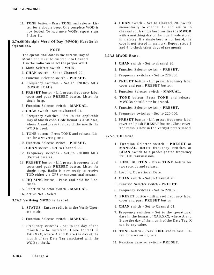
TM 1-1520-238-10
11. TONE button - Press TONE and release. Lis-ten for a double beep. One complete WOD isnow loaded. To load more WODs, repeat steps5 thru 11.
3.7A.66 Multiple Word Of Day (MWOD) HaveQuickOperations.
NOTE
The operational date is the current Day ofMonth and must be entered into Channel1 so the radio can select the proper WOD.1. Mode Selector switch - MAIN.2. CHAN switch - Set to Channel 20.
3. Function Selector switch - PRESET.
4. Frequency switches - Set to 220.025 MHz(MWOD LOAD).
5. PRESET button - Lift preset frequency labelcover and push PRESET button. Listen forsingle beep.
6. Function Selector switch - MANUAL.
7. CHAN switch - Set to Channel 01.
8. Frequency switches - Set to the applicableDay of Month code. Code format is XAB.XXX,where A and B are the day of the month theWOD is used.
9. TONE button - Press TONE and release. Lis-ten for a wavering tone.
10. Function Selector switch - PRESET.
11. CHAN switch - Set to Channel 20.
12. Frequency switches - Set to 220.000 MHz(Verify/Operate).
13. PRESET button - Lift preset frequency labelcover and push PRESET button. Listen forsingle beep. Radio is now ready to receiveTOD either via GPS or conventional means.
14. HQ SINC button - Press and hold for 3 se-conds.
15. Function Selector switch - MANUAL.
16. Active Net - Select.
3.7A.7 Verifying MWOD is Loaded.
1. STATUS - Ensure radio is in the Verify/Oper-ate mode.
2. Function Selector switch - MANUAL.
3. Frequency switches - Set to the day of themonth to be verif ied. Code format isXAB.XXX, where A and B are the day of themonth of the Date Tag associated with theWOD to check.
4. CHAN switch - Set to Channel 20. Switchmomentarily to channel 19 and return tochannel 20. A single beep verifies the MWODwith a matching day of the month code storedin memory. If a single beep is not heard, thecode is not stored in memory. Repeat steps 3and 4 to check other days of the month.
3.7A.8 MWOD Erase.
1. CHAN switch - Set to channel 20.
2. Function Selector switch - PRESET.
3. Frequency switches - Set to 220.050.
4. PRESET button - Lift preset frequency labelcover and push PRESET button.
5. Function Selector switch - MANUAL.
6. TONE button- Press TONE and release.MWODs should now be erased.
7. Function Selector switch - PRESET.
8. Frequency switches - Set to 220.000.
9. PRESET button - Lift preset frequency labelcover and push PRESET button. Close cover.The radio is now in the Verify/Operate model
3.7A.9 TOD Send.
1. Function Selector switch - PRESET orMANUAL. Rotate frequency switches orCHAN switch to a predesignated frequencyfor TOD transmission.
2. TONE BUTTON - Press TONE button fortwo seconds and release.
3. Loading Operational Date.
4. CHAN switch - Set to Channel 20.
5. Function Selector switch - PRESET.
6. Frequency switches - Set to 220.025.
7. PRESET button - Lift preset frequency labelcover and push PRESET button.
8. CHAN switch - Set to Channel 01.
9. Frequency switches - Set to the operationaldate in the format of XAB.XXX, where A andB are the day of the month of the Date Tag. Xcan be any value.
10. TONE button - Press TONE and release. Lis-ten for a wavering tone.
11. Function Selector switch - PRESET.
3-18.4 Change 4
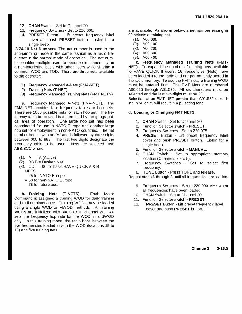
12. CHAN Switch - Set to Channel 20.13. Frequency Switches - Set to 220.000.14. PRESET Button - Lift preset frequency label
cover and push PRESET button. Listen for asingle beep.
3.7A.10 Net Numbers. The net number is used in theanti-jamming mode in the same fashion as a radio fre-quency in the normal mode of operation. The net num-ber enables multiple users to operate simultaneously ona non-interfering basis with other users while sharing acommon WOD and TOD. There are three nets availableto the operator:
(1) Frequency Managed A-Nets (FMA-NET).(2) Training Nets (T-NET).(3) Frequency Managed Training Nets (FMT NETS).
a. Frequency Managed A-Nets (FMA-NET). TheFMA NET provides four frequency tables or hop sets.There are 1000 possible nets for each hop set. The fre-quency table to be used is determined by the geographi-cal area of operation. One large hop set has beencoordinated for use in NATO-Europe and another largehop set for employment in non-NATO countries. The netnumber begins with an "A" and is followed by three digitsbetween 000 to 999. The last two digits designate thefrequency table to be used. Nets are selected IAWABB.BCC where:
(1). A = A (Active)(2). BB.B = Desired Net(3). CC = 00 for basic HAVE QUICK A & B
NETS.= 25 for NATO-Europe= 50 for non-NATO Europe= 75 for future use.
b. Training Nets (T-NETS). Each MajorCommand is assigned a training WOD for daily trainingand radio maintenance. Training WODs may be loadedusing a single WOD or MWOD methods. All trainingWODs are initialized with 300.OXX in channel 20. XXsets the frequency hop rate for the WOD in a SWODonly. In this training mode, the radio hops between thefive frequencies loaded in with the WOD (locations 19 to15) and five training nets
TM 1-1520-238-10
are available. As shown below, a net number ending in00 selects a training net.
(1). A00.000(2). A00.100(3). A00.200(4). A00.300(5). A00.400
c. Frequency Managed Training Nets (FMT-NET). To expand the number of training nets availableto HAVE QUICK II users, 16 frequencies (Nets) havebeen loaded into the radio and are permanently stored inthe radio memory. To use the FMT nets, a training WODmust be entered first. The FMT Nets are numberedA00.025 through A01.525. All six characters must beselected and the last two digits must be 25.Selection of an FMT NET greater than A01.525 or end-ing in 50 or 75 will result in a pulsating tone.
d. Loading or Changing FMT NETS.
1. CHAN Switch - Set to Channel 20.2. Function Selector switch - PRESET.3. Frequency Switches - Set to 220.075.4. PRESET Button - Lift preset frequency label
cover and push PRESET button. Listen for asingle beep.
5. Function Selector switch - MANUAL.6. CHAN Switch - Set to appropriate memory
location (Channels 20 to 5).7. Frequency Switches - Set to select first
frequency.8. TONE Button - Press TONE and release.
Repeat steps 6 through 8 until all frequencies are loaded.
9. Frequency Switches - Set to 220.000 MHz whenall frequencies have been loaded.
10. CHAN Switch - Set to Channel 20.11. Function Selector switch - PRESET.12. PRESET Button - Lift preset frequency label
cover and push PRESET button.
Change 3 3-18.5
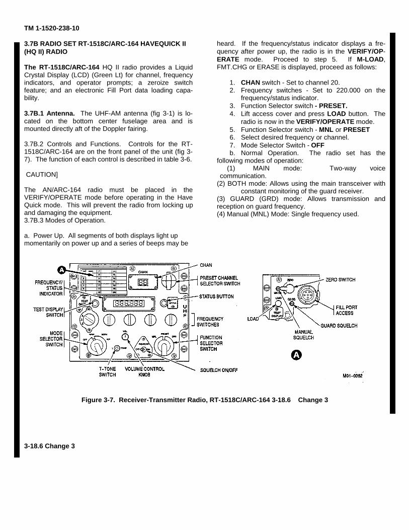
TM 1-1520-238-10
3.7B RADIO SET RT-1518C/ARC-164 HAVEQUICK II(HQ II) RADIO
The RT-1518C/ARC-164 HQ II radio provides a LiquidCrystal Display (LCD) (Green Lt) for channel, frequencyindicators, and operator prompts; a zeroize switchfeature; and an electronic Fill Port data loading capa-bility.
3.7B.1 Antenna. The UHF-AM antenna (fig 3-1) is lo-cated on the bottom center fuselage area and ismounted directly aft of the Doppler fairing.
3.7B.2 Controls and Functions. Controls for the RT-1518C/ARC-164 are on the front panel of the unit (fig 3-7). The function of each control is described in table 3-6.
CAUTION]
The AN/ARC-164 radio must be placed in theVERIFY/OPERATE mode before operating in the HaveQuick mode. This will prevent the radio from locking upand damaging the equipment.3.7B.3 Modes of Operation.
a. Power Up. All segments of both displays light upmomentarily on power up and a series of beeps may be
heard. If the frequency/status indicator displays a fre-quency after power up, the radio is in the VERIFY/OP-ERATE mode. Proceed to step 5. If M-LOAD,FMT.CHG or ERASE is displayed, proceed as follows:
1. CHAN switch - Set to channel 20.2. Frequency switches - Set to 220.000 on the
frequency/status indicator.3. Function Selector switch - PRESET.4. Lift access cover and press LOAD button. The
radio is now in the VERIFY/OPERATE mode.5. Function Selector switch - MNL or PRESET6. Select desired frequency or channel.7. Mode Selector Switch - OFFb. Normal Operation. The radio set has the
following modes of operation:(1) MAIN mode: Two-way voice
communication.(2) BOTH mode: Allows using the main transceiver with
constant monitoring of the guard receiver.(3) GUARD (GRD) mode: Allows transmission andreception on guard frequency.(4) Manual (MNL) Mode: Single frequency used.
Figure 3-7. Receiver-Transmitter Radio, RT-1518C/ARC-164 3-18.6 Change 3
3-18.6 Change 3
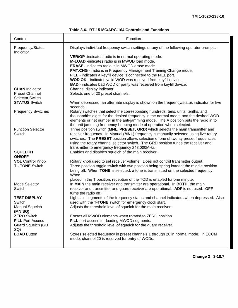
TM 1-1520-238-10
Table 3-6. RT-1518C/ARC-164 Controls and Functions
Control Function
Frequency/Status Displays individual frequency switch settings or any of the following operator prompts:Indicator
VER/OP- indicates radio is in normal operating mode.M-LOAD -indicates radio is in MWOD load mode.ERASE - indicates radio is in MWOD erase mode.FMT.CHG - radio is in Frequency Management Training Change mode.FILL - indicates a keyfill device is connected to the FILL port.WOD OK - indicates valid WOD was received from keyfill device.BAD - indicates bad WOD or parity was received from keyfill device.
CHAN Indicator Channel display indicatorPreset Channel Selects one of 20 preset channels.Selector SwitchSTATUS Switch When depressed, an alternate display is shown on the frequency/status indicator for five
seconds.Frequency Switches Rotary switches that select the corresponding hundreds, tens, units, tenths, and
thousandths digits for the desired frequency in the normal mode, and the desired WODelements or net number in the anti-jamming mode. The A position puts the radio in tothe anti-jamming frequency-hopping mode of operation when selected.
Function Selector Three position switch (MNL, PRESET, GRD) which selects the main transmitter andSwitch receiver frequency. In Manual (MNL) frequency is manually selected using five rotary
switches. The PRESET position allows selection of one of twenty preset frequenciesusing the rotary channel selector switch. The GRD position tunes the receiver andtransmitter to emergency frequency 243.000MHz.
SQUELCH Enables and disables squelch of the main receiver.ON/OFFVOL Control Knob Rotary knob used to set receiver volume. Does not control transmitter output.T - TONE Switch Three position toggle switch with two position being spring loaded; the middle position
being off. When TONE is selected, a tone is transmitted on the selected frequency. Whenplaced in the T position, reception of the TOD is enabled for one minute.
Mode Selector In MAIN the main receiver and transmitter are operational. In BOTH, the mainSwitch receiver and transmitter and guard receiver are operational. ADF is not used. OFF
turns the radio off.TEST DISPLAY Lights all segments of the frequency status and channel indicators when depressed. AlsoSwitch used with the T-TONE switch for emergency clock start.Manual Squelch Adjusts the threshold level of squelch for the main receiver.(MN SQ)ZERO Switch Erases all MWOD elements when rotated to ZERO position.FILL Port Access FILL port access for loading MWOD segments.Guard Squelch (GD Adjusts the threshold level of squelch for the guard receiver.SQ)LOAD Button Stores selected frequency in preset channels 1 through 20 in normal mode. In ECCM
mode, channel 20 is reserved for entry of WODs.
Change 3 3-18.7
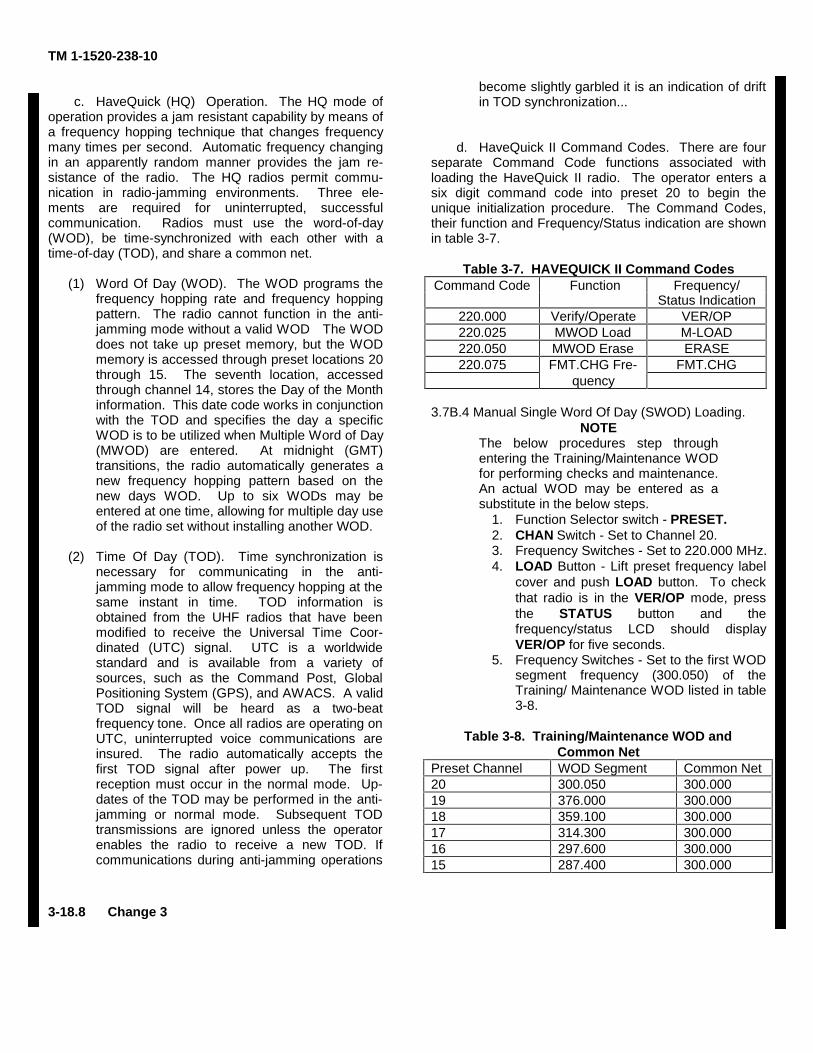
TM 1-1520-238-10
c. HaveQuick (HQ) Operation. The HQ mode ofoperation provides a jam resistant capability by means ofa frequency hopping technique that changes frequencymany times per second. Automatic frequency changingin an apparently random manner provides the jam re-sistance of the radio. The HQ radios permit commu-nication in radio-jamming environments. Three ele-ments are required for uninterrupted, successfulcommunication. Radios must use the word-of-day(WOD), be time-synchronized with each other with atime-of-day (TOD), and share a common net.
(1) Word Of Day (WOD). The WOD programs thefrequency hopping rate and frequency hoppingpattern. The radio cannot function in the anti-jamming mode without a valid WOD The WODdoes not take up preset memory, but the WODmemory is accessed through preset locations 20through 15. The seventh location, accessedthrough channel 14, stores the Day of the Monthinformation. This date code works in conjunctionwith the TOD and specifies the day a specificWOD is to be utilized when Multiple Word of Day(MWOD) are entered. At midnight (GMT)transitions, the radio automatically generates anew frequency hopping pattern based on thenew days WOD. Up to six WODs may beentered at one time, allowing for multiple day useof the radio set without installing another WOD.
(2) Time Of Day (TOD). Time synchronization isnecessary for communicating in the anti-jamming mode to allow frequency hopping at thesame instant in time. TOD information isobtained from the UHF radios that have beenmodified to receive the Universal Time Coor-dinated (UTC) signal. UTC is a worldwidestandard and is available from a variety ofsources, such as the Command Post, GlobalPositioning System (GPS), and AWACS. A validTOD signal will be heard as a two-beatfrequency tone. Once all radios are operating onUTC, uninterrupted voice communications areinsured. The radio automatically accepts thefirst TOD signal after power up. The firstreception must occur in the normal mode. Up-dates of the TOD may be performed in the anti-jamming or normal mode. Subsequent TODtransmissions are ignored unless the operatorenables the radio to receive a new TOD. Ifcommunications during anti-jamming operations
become slightly garbled it is an indication of driftin TOD synchronization...
d. HaveQuick II Command Codes. There are fourseparate Command Code functions associated withloading the HaveQuick II radio. The operator enters asix digit command code into preset 20 to begin theunique initialization procedure. The Command Codes,their function and Frequency/Status indication are shownin table 3-7.
Table 3-7. HAVEQUICK II Command CodesCommand Code Function Frequency/
Status Indication220.000 Verify/Operate VER/OP220.025 MWOD Load M-LOAD220.050 MWOD Erase ERASE220.075 FMT.CHG Fre- FMT.CHG
quency
3.7B.4 Manual Single Word Of Day (SWOD) Loading.NOTE
The below procedures step throughentering the Training/Maintenance WODfor performing checks and maintenance.An actual WOD may be entered as asubstitute in the below steps.
1. Function Selector switch - PRESET.2. CHAN Switch - Set to Channel 20.3. Frequency Switches - Set to 220.000 MHz.4. LOAD Button - Lift preset frequency label
cover and push LOAD button. To checkthat radio is in the VER/OP mode, pressthe STATUS button and thefrequency/status LCD should displayVER/OP for five seconds.
5. Frequency Switches - Set to the first WODsegment frequency (300.050) of theTraining/ Maintenance WOD listed in table3-8.
Table 3-8. Training/Maintenance WOD andCommon Net
Preset Channel WOD Segment Common Net20 300.050 300.00019 376.000 300.00018 359.100 300.00017 314.300 300.00016 297.600 300.00015 287.400 300.000
3-18.8 Change 3
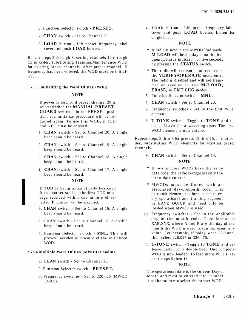
TM 1-1520-238-10
6. Function Selector switch - PRESET. 4.
7. CHAN switch - Set to Channel 20.
8. LOAD button - Lift preset frequency labelcover and push LOAD button. l
Repeat steps 5 through 8, setting channels 19 through15 in order, substituting Training/Maintenance WODfor existing preset channels. After preset channel 15frequency has been entered, the WOD must be initial-ized.
l
3.78.5 Initializing the Word Of Day (WOD).
NOTE
If power is lost, or if preset channel 20 isselected when the MANUAL-PRESET-GUARD switch is in the PRESET posi-tion, the initialize procedure will be re-quired again. To use this WOD, a TODand NET must be entered.
5.
6.
7.
8.
1.
2.
3.
4.
CHAN switch - Set to Channel 20. A singlebeep should be heard.
CHAN switch - Set to Channel 19. A singlebeep should be heard.
CHAN switch - Set to Channel 18. A singlebeep should be heard.
CHAN switch - Set to Channel 17. A singlebeep should be heard.
NOTE
If TOD is being automatically beaconedfrom another station, the first TOD mes-sage received within one minute of se-lected T position will be accepted.
5. CHAN switch - Set to Channel 16. A singlebeep should be heard.
6. CHAN switch - Set to Channel 15. A doublebeep should be heard.
7. Function Selector switch - MNL. This willprevent accidental erasure of the initializedWOD.
3.78.6 Multiple Word Of Day (MWOD) Loading.
1. CHAN switch - Set to Channel 20.
2. Function Selector switch - PRESET.
3. Frequency switches - Set to 220.025 (MWODLOAD).
LOAD button - Lift preset frequency labelcover and push LOAD button. Listen forsingle beep.
NOTE
If radio is now in the MWOD load mode.M-LOAD will be displayed on the fre-quency/status indicator for five secondsby pressing the STATUS switch.
The radio will transmit and receive inthe VERIFY/OPERATE mode only.The radio is disabled and will not trans-mit or receive in the M-LOAD,ERASE, or FMT.CHG modes.Function Selector switch - MNL.
CHAN switch - Set to Channel 20.
Frequency switches - Set to the first WODelement.
T-TONE switch - Toggle to TONE and re-lease. Listen for a wavering tone. The firstWOD element is now entered.
Repeat steps 5 thru 8 for presets 19 thru 15, in that or-der, substituting WOD elements for existing presetchannels.
9. CHAN switch - Set to Channel 14.
NOTEl If two or more WODs have the same
date code, the radio recognizes only thelatest date entered.
l
10.
11.
MWODs must be linked with anassociated day-of-month code. Thisdate code element has been added to ev-ery operational and training segmentin HAVE QUICK and need only beloaded when MWOD is used.
Frequency switches - Set to the applicableday of the month code. Code format isXAB.XXX, where A and B are the day of themonth the WOD is used. X can represent anyvalue. For example, if today were 26 June,then select 226.025 or 326.475.
T-TONE switch - Toggle to TONE and re-lease. Listen for a double beep. One completeWOD is now loaded. To load more WODs, re-peat steps 5 thru 11.
NOTE
The operational date is the current Day ofMonth and must be entered into Channel1 so the radio can select the proper WOD.
Change 4 3-18.9
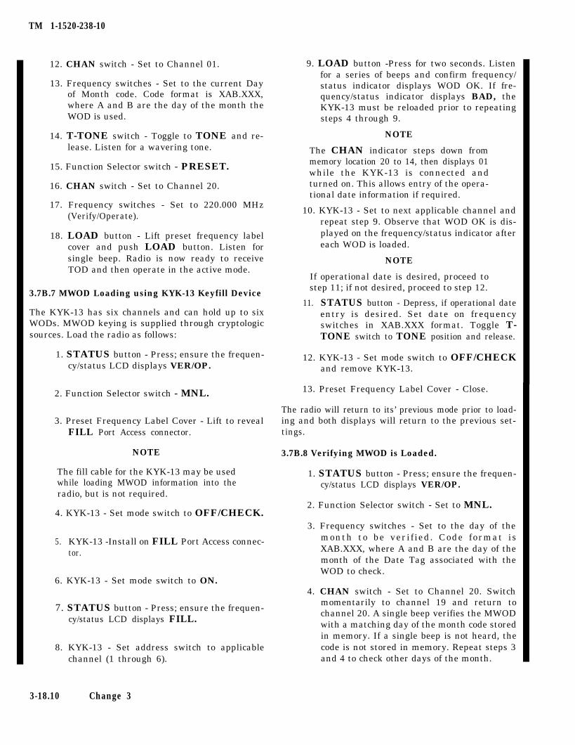
TM 1-1520-238-10
12. CHAN switch - Set to Channel 01.
13. Frequency switches - Set to the current Dayof Month code. Code format is XAB.XXX,where A and B are the day of the month theWOD is used.
14. T-TONE switch - Toggle to TONE and re-lease. Listen for a wavering tone.
15. Function Selector switch - PRESET.
16. CHAN switch - Set to Channel 20.
17. Frequency switches - Set to 220.000 MHz(Verify/Operate).
18. LOAD button - Lift preset frequency labelcover and push LOAD button. Listen forsingle beep. Radio is now ready to receiveTOD and then operate in the active mode.
3.7B.7 MWOD Loading using KYK-13 Keyfill Device
The KYK-13 has six channels and can hold up to sixWODs. MWOD keying is supplied through cryptologicsources. Load the radio as follows:
1. STATUS button - Press; ensure the frequen-cy/status LCD displays VER/OP.
2. Function Selector switch - MNL.
3. Preset Frequency Label Cover - Lift to revealFILL Port Access connector.
NOTE
The fill cable for the KYK-13 may be usedwhile loading MWOD information into theradio, but is not required.
4. KYK-13 - Set mode switch to OFF/CHECK.
5. KYK-13 -Install on FILL Port Access connec-tor.
6. KYK-13 - Set mode switch to ON.
7. STATUS button - Press; ensure the frequen-cy/status LCD displays FILL.
8. KYK-13 - Set address switch to applicablechannel (1 through 6).
3-18.10 Change 3
9. LOAD button -Press for two seconds. Listenfor a series of beeps and confirm frequency/status indicator displays WOD OK. If fre-quency/status indicator displays BAD, theKYK-13 must be reloaded prior to repeatingsteps 4 through 9.
NOTE
The CHAN indicator steps down frommemory location 20 to 14, then displays 01while the KYK-13 is connected andturned on. This allows entry of the opera-tional date information if required.
10. KYK-13 - Set to next applicable channel andrepeat step 9. Observe that WOD OK is dis-played on the frequency/status indicator aftereach WOD is loaded.
NOTE
If operational date is desired, proceed tostep 11; if not desired, proceed to step 12.
11. STATUS button - Depress, if operational dateentry is desired. Set date on frequencyswitches in XAB.XXX format. Toggle T-TONE switch to TONE position and release.
12. KYK-13 - Set mode switch to OFF/CHECKand remove KYK-13.
13. Preset Frequency Label Cover - Close.
The radio will return to its’ previous mode prior to load-ing and both displays will return to the previous set-tings.
3.7B.8 Verifying MWOD is Loaded.
1. STATUS button - Press; ensure the frequen-cy/status LCD displays VER/OP.
2. Function Selector switch - Set to MNL.
3. Frequency switches - Set to the day of themonth to be verif ied. Code format isXAB.XXX, where A and B are the day of themonth of the Date Tag associated with theWOD to check.
4. CHAN switch - Set to Channel 20. Switchmomentarily to channel 19 and return tochannel 20. A single beep verifies the MWODwith a matching day of the month code storedin memory. If a single beep is not heard, thecode is not stored in memory. Repeat steps 3and 4 to check other days of the month.

TM 1-1520-238-10
3.7B.9 MWOD Erase. NOTE
1.
2.
3.
4.
5. Function Selector switch - MNL. 2.
6. T-TONE switch - Toggle to TONE and re-lease. MWODs should now be erased.
7. Function Selector switch - PRESET.
8. Frequency switches - Set to 220.000.
9. LOAD button - Lift preset frequency labelcover and push LOAD button. Close cover.The radio is now in the Verify/Operate mode/
3.7B.10 Alternate MWOD Erase.
1. Preset Frequency Label Cover - Open to re-veal ZERO switch.
CHAN switch - Set to channel 20.
Function Selector switch - PRESET.
Frequency switches - Set to 220.050.
LOAD button - Lift preset frequency labelcover and push LOAD button.
2. ZERO switch - Rotate counterclockwise, thenreturn to normal position. ERASE should bedisplayed on the frequency/status indicator.All MWODs are now erased.
Receiving Time of Day (TOD) and TOD Up-3.7B.11date m.
NOTE
A steady warning tone will be heard whenthe anti-jamming mode is selected andthe TOD or a valid WOD has not been en-tered. A pulsating tone will be heard if aninvalid net is selected.
1. Function Selector switch - PRESET or MNL.
2. T-TONE switch - Toggle to T and release.
3. TOD - Request from another station.
If TOD is being automatically beaconedfrom another station, the first TOD mes-sage received within one minute of se-lected T position will be accepted.
a. TOD Send.
1.
3.
4.
5.
6.
7.
8.
9.
10.
11.
12.
13.
14.
Function Selector switch - PRESET or MNL.Rotate frequency switches or CHAN switch toa predesignated frequency for TOD transmis-sion.
T-TONE switch - Toggle to TONE positionfor two seconds and release.
Loading Operational Date.
CHAN switch - Set to Channel 20.
Function Selector switch - PRESET.
Frequency switches - Set to 220.025.
LOAD button - Lift preset frequency labelcover and push LOAD button.
CHAN switch - Set to Channel 01.
Frequency switches - Set to the operationaldate in the format of XAB.XXX, where A andB are the day of the month of the Date Tag. Xcan be any value.
T-TONE switch - Toggle to TONE and re-lease. Listen for a wavering tone.
Function Selector switch - PRESET.
CHAN switch - Set to Channel 20.
Frequency switches - Set to 220.000.
LOAD button - Lift preset frequencycover and push LOAD button. Listensingle beep.
labelfor a
b. Clock Start.
Press TEST DISPLAY switch while simultaneouslypressing the T-TONE switch to the T position. Tocheck if TOD is loaded, press the T-TONE switch tothe TONE position for two seconds; two tones should beheard.
Change 4 3-18.11
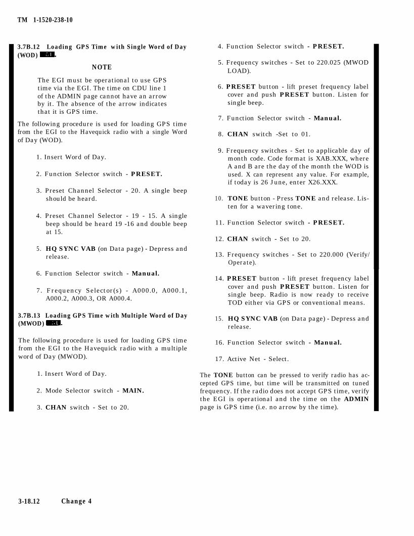
TM 1-1520-238-10
3.7B.12 Loading GPS Time with Single Word of Day(WOD) MB.
NOTE
The EGI must be operational to use GPStime via the EGI. The time on CDU line 1of the ADMIN page cannot have an arrowby it. The absence of the arrow indicatesthat it is GPS time.
The following procedure is used for loading GPS timefrom the EGI to the Havequick radio with a single Wordof Day (WOD).
1. Insert Word of Day.
2. Function Selector switch - PRESET.
3. Preset Channel Selector - 20. A single beepshould be heard.
4. Preset Channel Selector - 19 - 15. A singlebeep should be heard 19 -16 and double beepat 15.
5. HQ SYNC VAB (on Data page) - Depress andrelease.
6. Function Selector switch - Manual.
7. Frequency Selector(s) - A000.0, A000.1,A000.2, A000.3, OR A000.4.
3.7B.13 Loading GPS Time with Multiple Word of Day(MWOD) m.
The following procedure is used for loading GPS timefrom the EGI to the Havequick radio with a multipleword of Day (MWOD).
1. Insert Word of Day.
2. Mode Selector switch - MAIN.
3. CHAN switch - Set to 20.
4. Function Selector switch - PRESET.
5. Frequency switches - Set to 220.025 (MWODLOAD).
6. PRESET button - lift preset frequency labelcover and push PRESET button. Listen forsingle beep.
7. Function Selector switch - Manual.
8. CHAN switch -Set to 01.
9. Frequency switches - Set to applicable day ofmonth code. Code format is XAB.XXX, whereA and B are the day of the month the WOD isused. X can represent any value. For example,if today is 26 June, enter X26.XXX.
10. TONE button - Press TONE and release. Lis-ten for a wavering tone.
11. Function Selector switch - PRESET.
12. CHAN switch - Set to 20.
13. Frequency switches - Set to 220.000 (Verify/Operate).
14. PRESET button - lift preset frequency labelcover and push PRESET button. Listen forsingle beep. Radio is now ready to receiveTOD either via GPS or conventional means.
15. HQ SYNC VAB (on Data page) - Depress andrelease.
16. Function Selector switch - Manual.
17. Active Net - Select.
The TONE button can be pressed to verify radio has ac-cepted GPS time, but time will be transmitted on tunedfrequency. If the radio does not accept GPS time, verifythe EGI is operational and the time on the ADMINpage is GPS time (i.e. no arrow by the time).
3-18.12 Change 4
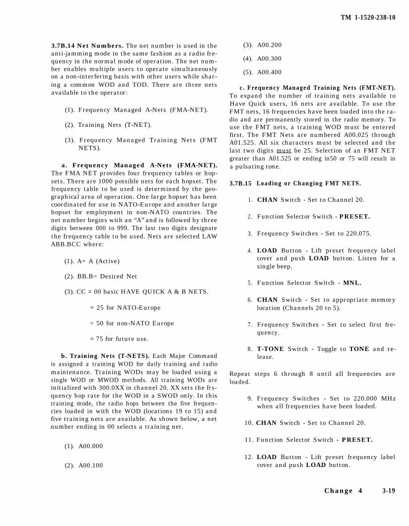
TM 1-1520-238-10
3.7B.14 Net Numbers. The net number is used in theanti-jamming mode in the same fashion as a radio fre-quency in the normal mode of operation. The net num-ber enables multiple users to operate simultaneouslyon a non-interfering basis with other users while shar-ing a common WOD and TOD. There are three netsavailable to the operator:
(3). A00.200
(4). A00.300
(5). A00.400
(1). Frequency Managed A-Nets (FMA-NET).
(2). Training Nets (T-NET).
(3). Frequency Managed Training Nets (FMTNETS).
a. Frequency Managed A-Nets (FMA-NET).The FMA NET provides four frequency tables or hop-sets. There are 1000 possible nets for each hopset. Thefrequency table to be used is determined by the geo-graphical area of operation. One large hopset has beencoordinated for use in NATO-Europe and another largehopset for employment in non-NATO countries. Thenet number begins with an “A” and is followed by threedigits between 000 to 999. The last two digits designatethe frequency table to be used. Nets are selected LAWABB.BCC where:
c. Frequency Managed Training Nets (FMT-NET).To expand the number of training nets available toHave Quick users, 16 nets are available. To use theFMT nets, 16 frequencies have been loaded into the ra-dio and are permanently stored in the radio memory. Touse the FMT nets, a training WOD must be enteredfirst. The FMT Nets are numbered A00.025 throughA01.525. All six characters must be selected and thelast two digits must be 25. Selection of an FMT NETgreater than A01.525 or ending in50 or 75 will result ina pulsating tone.
3.7B.15
1.
2.
3.
4.
(1). A= A (Active)
(2). BB.B= Desired Net
(3). CC = 00 basic HAVE QUICK A & B NETS.5.
6.= 25 for NATO-Europe
= 50 for non-NATO Europe 7.
= 75 for future use.
8.b. Training Nets (T-NETS). Each Major Command
is assigned a training WOD for daily training and radiomaintenance. Training WODs may be loaded using asingle WOD or MWOD methods. All training WODs areinitialized with 300.0XX in channel 20. XX sets the frs-quency hop rate for the WOD in a SWOD only. In thistraining mode, the radio hops between the five frequen-cies loaded in with the WOD (locations 19 to 15) andfive training nets are available. As shown below, a netnumber ending in 00 selects a training net.
Repeat steps 6 through 8 until all frequencies areloaded.
(1). A00.000
(2). A00.100
9. Frequency Switches - Set to 220.000 MHzwhen all frequencies have been loaded.
10. CHAN Switch - Set to Channel 20.
11. Function Selector Switch - PRESET.
12. LOAD Button - Lift preset frequency labelcover and push LOAD button.
Loading or Changing FMT NETS.
CHAN Switch - Set to Channel 20.
Function Selector Switch - PRESET.
Frequency Switches - Set to 220.075.
LOAD Button - Lift preset frequency labelcover and push LOAD button. Listen for asingle beep.
Function Selector Switch - MNL.
CHAN Switch - Set to appropriate memorylocation (Channels 20 to 5).
Frequency Switches - Set to select first fre-quency.
T-TONE Switch - Toggle to TONE and re-lease.
Change 4 3-19
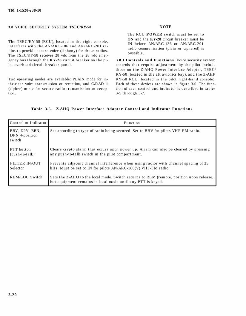
TM 1-1520-238-10
3.8 VOICE SECURITY SYSTEM TSEC/KY-58. NOTE
The TSEC/KY-58 (RCU), located in the right console,interfaces with the AN/ARC-186 and AN/ARC-201 ra-dios to provide secure voice (ciphony) for these radios.The TSEC/KY-58 receives 28 vdc from the 28 vdc emer-gency bus through the KY-28 circuit breaker on the pi-lot overhead circuit breaker panel.
Two operating modes are available: PLAIN mode for in-the-clear voice transmission or reception, and C/RAD 1(cipher) mode for secure radio transmission or recep-tion.
The RCU POWER switch must be set toON and the KY-28 circuit breaker must beIN before AN/ARC-136 or AN/ARC-201radio communication (plain or ciphered) ispossible.
3.8.1 Controls and Functions. Voice security systemcontrols that require adjustment by the pilot includethose on the Z-AHQ Power Interface Adapter, TSEC/KY-58 (located in the aft avionics bay), and the Z-AHPKY-58 RCU (located in the pilot right-hand console).Each of these devices are shown in figure 3-6. The func-tion of each control and indicator is described in tables3-5 through 3-7.
Table 3-5. Z-AHQ Power Interface Adapter Control and Indicator Functions
Control or Indicator Function
BBV, DPV, BBN,DPN 4-positionswitch
PTT button(push-to-talk)
FILTER IN/OUTSelector
REM/LOC Switch
Set according to type of radio being secured. Set to BBV for pilots VHF FM radio.
Clears crypto alarm that occurs upon power up. Alarm can also be cleared by pressingany push-to-talk switch in the pilot compartment.
Prevents adjacent channel interference when using radios with channel spacing of 25kHz. Must be set to IN for pilots AN/ARC-186(V) VHF-FM radio.
Sets the Z-AHQ to the local mode. Switch returns to REM (remote) position upon release,but equipment remains in local mode until any PTT is keyed.
3-20

TM 1-1520-238-10
Table 3-6. Z-AHP Remote Control Unit Control and Indicator Functions
Control or Indicator Function
ZEROIZE switch Use in an emergency to delete all crypto-net variables (CNVs) from KY-58 registers.(two-position toggle Renders KY-58 unusable until new variables are loaded.switch housedunder aspring-loadedcover)
DELAY switch Not used.
C/RAD 1/PLAIN Set switch to C/RAD 1 (cipher radio 1) to use secure voice. Set switch to PLAIN whenSwitch operating radio in the clear.
Switch guard Rotate to the left to prevent C/RAD1/PLAIN switch from accidentally being set toPLAIN.
MODE Switch Set to OP (operate) to use pilots VHF radio in either the Ciphered or Plain mode. Set toLD (load) when installing (CNV) in the TSEC/KY-58 (TM 11-5810-262-12&P). Set to RV(receive variable) during manual remote keying (TM 11-5810-262-12&P).
POWER switch Turns KY-58 on and off. Must be on (up) for operation in either plain or cipher mode.
FILL switch Selects desired (CNV).
Table 3-7. TSEC/KY-58 Control and Indicator Functions
Control or Indicator Function
VOLUME control Sets audio level of pilots VHF-FM radio.
MODE switch Set to P (Plain) to operate pilots VHF-FM radio in the clear. Set to C (Cipher) to operatepilot’s VHF-FM radio in the ciphered (secure speech) mode. Set to LD (load) wheninstalling (CNVs) in the TSEC/KY-58 (TM 11-5810-262-12&P). Set to RV (receivevariable) during manual remote keying (TM 11-5810-262-12&P).
FILL connector Used to load (CNVs) into the TSEC/KY-58 registers (TM 11-5810-262-12&P).
FILL switch Pull knob and set to Z1-5 to zeroize (delete) (CNVs) in TSEC/KY-58 registers 1-5. Set to1, 2, 3, 4 or 5 to select desired CNV. Pull knob and set to Z-ALL to zeroize (delete) (CNVs)in all TSEC/KY-58 registers. Zeroizing all registers renders TSEC/KY-58 unusable.
Power switch Set to OFF to turn off both the TSEC/KY-58 and the pilots VHF-FM radio. Set to ON tooperate the TSEC/KY-58 and pilots VHF-FM radio. The TD (time delay) position is notused.
3-21
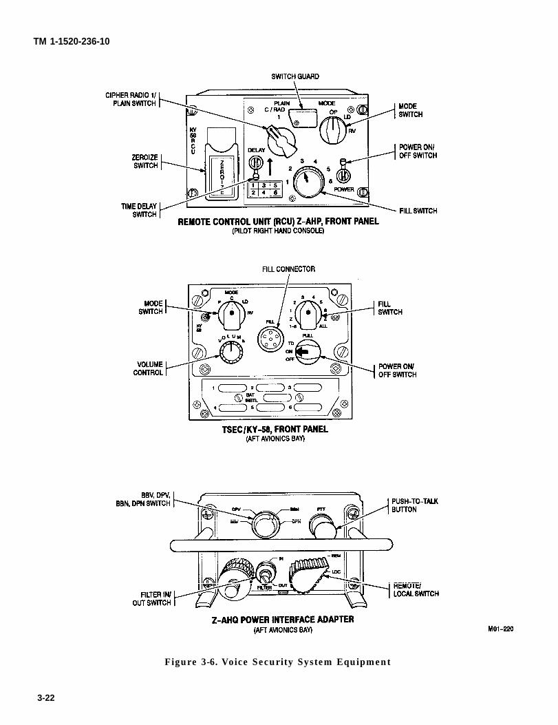
TM 1-1520-236-10
Figure 3-6. Voice Security System Equipment
3-22
3.8.2 Operating Procedures.
TM 1-1520-238-10
b. Cipher Mode.
a. Preliminary Operation.
NOTE
Before the pilot VHF-FM radio may be op-erated in ciphered (secure voice) mode, itmust be loaded with one or more (CNVS).Refer to TM 11-5810-262-12&P for com-plete details on loading these variables.
1. KY-58 POWER switch - ON.
2. KY-58 MODE switch - C (cipher).
3. KY-58 VOLUME control -As desired.
4. KY-58 Fill switch - Any numbered storageregister position (1-6).
5. Power Interface Adapter 4- Position switch toBBV
6. Power Interface Adapter FILTER selector -IN.
7. RCU DELAY switch - Down (off) position.
8. RCU C/RAD l-PLAIN switch - C/RAD 1.
9. RCU MODE switch - OP.
10. RCU Fill switch - Set to the proper (CNV).
11. RCU POWER switch - On.
NOTE
At this time you should hear an intermit-tent tone and background noise. The back-ground noise is normal. The tone is a cryp-to alarm that must be cleared before theradio can be used. If step 12 does not clearthe intermittent tone, double check steps1 through 11. If necessary, refer toTM 11-5810-262-12&P.
12. RADIO/ICS switch - RADIO press and re-lease (or the pilot push-to-talk floor switch).This should clear the crypto alarm.
1. After steps 1 through 12 are complete, the ra-dio is ready to transmit and receive securespeech in ciphered mode.
2. To transmit, press any push-to-talk switch.You may begin speaking following the beep.
c. Plain Mode.
1. C/RAD 1/PLAIN - PLAIN.
2. To transmit, press any push-to-talk switch.You may begin speaking immediately.
d. Automatic Remote Keying (AK).
NOTE
AK causes an old CNV in one of the regis-ters to be replaced by a new one, or anempty register to be filled. Your net con-troller simply transmits the new CNV toyour TSEC/KY-58.
1. Your net controller will contact you by using asecure voice channel, and tell you to wait foran AK transmission. You must not transmitduring this period.
2. You will hear one or two beeps in your headsetwhen the AK occurs.
e. Manual Remote Keying (MK).
NOTE
MK requires you to use the RCU to changeCNVs.
1. The net controller will contact you by using asecure voice channel. He will tell you to standby for a new or replacement CNV and that youwill use an MK action.
2. Fill switch -6. Notify the net controller by ra-dio when you have done this and stand by.
3. The net controller will tell you to set theMODE switch to RV. Notify the net controllerwhen you have done this and stand by.
4. When notified by the net controller, set the fillswitch to the storage position selected to re-ceive the CNV. Notify the net controller whenyou have done this and stand by.
3-23
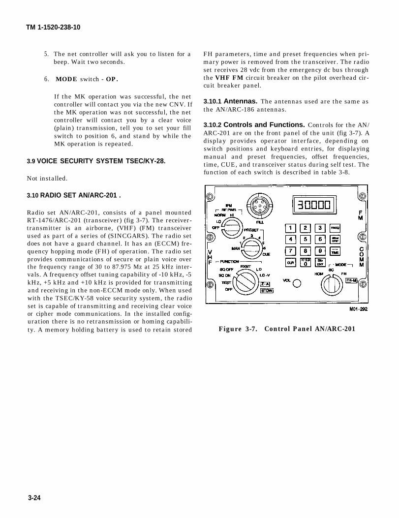
TM 1-1520-238-10
5.
6.
The net controller will ask you to listen for abeep. Wait two seconds.
MODE switch - OP.
If the MK operation was successful, the netcontroller will contact you via the new CNV. Ifthe MK operation was not successful, the netcontroller will contact you by a clear voice(plain) transmission, tell you to set your fillswitch to position 6, and stand by while theMK operation is repeated.
3.9 VOICE SECURITY SYSTEM TSEC/KY-28.
Not installed.
3.10 RADIO SET AN/ARC-201 .
Radio set AN/ARC-201, consists of a panel mountedRT-1476/ARC-201 (transceiver) (fig 3-7). The receiver-transmitter is an airborne, (VHF) (FM) transceiverused as part of a series of (SINCGARS). The radio setdoes not have a guard channel. It has an (ECCM) fre-quency hopping mode (FH) of operation. The radio setprovides communications of secure or plain voice overthe frequency range of 30 to 87.975 Mz at 25 kHz inter-vals. A frequency offset tuning capability of -10 kHz, -5kHz, +5 kHz and +10 kHz is provided for transmittingand receiving in the non-ECCM mode only. When usedwith the TSEC/KY-58 voice security system, the radioset is capable of transmitting and receiving clear voiceor cipher mode communications. In the installed config-uration there is no retransmission or homing capabili-ty. A memory holding battery is used to retain stored
3-24
FH parameters, time and preset frequencies when pri-mary power is removed from the transceiver. The radioset receives 28 vdc from the emergency dc bus throughthe VHF FM circuit breaker on the pilot overhead cir-cuit breaker panel.
3.10.1 Antennas. The antennas used are the same asthe AN/ARC-186 antennas.
3.10.2 Controls and Functions. Controls for the AN/ARC-201 are on the front panel of the unit (fig 3-7). Adisplay provides operator interface, depending onswitch positions and keyboard entries, for displayingmanual and preset frequencies, offset frequencies,time, CUE, and transceiver status during self test. Thefunction of each switch is described in table 3-8.
Figure 3-7. Control Panel AN/ARC-201
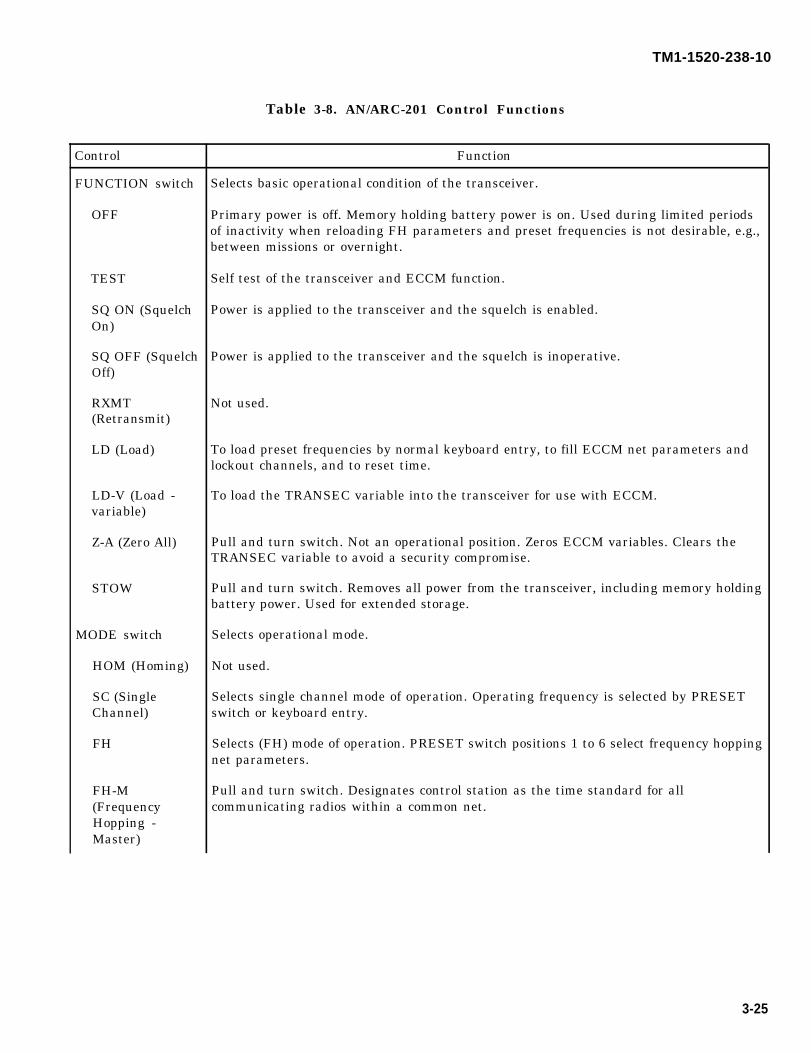
TM1-1520-238-10
Table 3-8. AN/ARC-201 Control Functions
Control
FUNCTION switch
OFF
TEST
SQ ON (SquelchOn)
SQ OFF (SquelchOff)
RXMT(Retransmit)
LD (Load)
LD-V (Load -variable)
Z-A (Zero All)
STOW
MODE switch
HOM (Homing)
SC (SingleChannel)
FH
FH-M(FrequencyHopping -Master)
Function
Selects basic operational condition of the transceiver.
Primary power is off. Memory holding battery power is on. Used during limited periodsof inactivity when reloading FH parameters and preset frequencies is not desirable, e.g.,between missions or overnight.
Self test of the transceiver and ECCM function.
Power is applied to the transceiver and the squelch is enabled.
Power is applied to the transceiver and the squelch is inoperative.
Not used.
To load preset frequencies by normal keyboard entry, to fill ECCM net parameters andlockout channels, and to reset time.
To load the TRANSEC variable into the transceiver for use with ECCM.
Pull and turn switch. Not an operational position. Zeros ECCM variables. Clears theTRANSEC variable to avoid a security compromise.
Pull and turn switch. Removes all power from the transceiver, including memory holdingbattery power. Used for extended storage.
Selects operational mode.
Not used.
Selects single channel mode of operation. Operating frequency is selected by PRESETswitch or keyboard entry.
Selects (FH) mode of operation. PRESET switch positions 1 to 6 select frequency hoppingnet parameters.
Pull and turn switch. Designates control station as the time standard for allcommunicating radios within a common net.
3-25
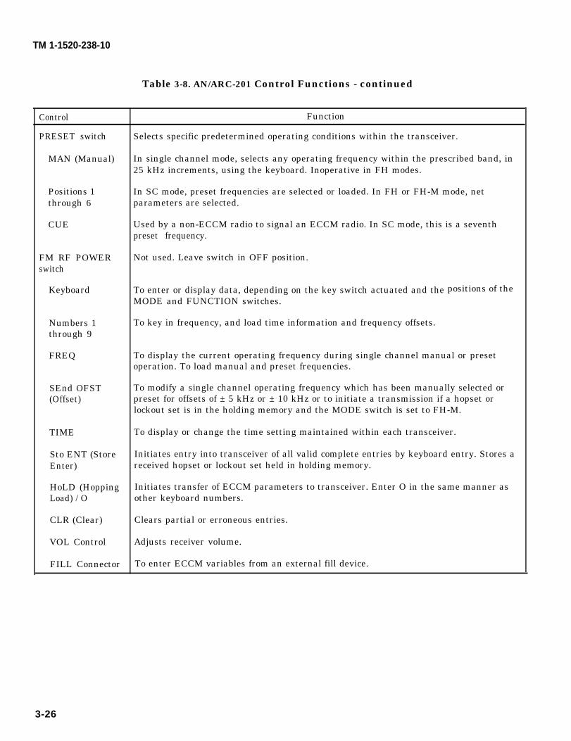
TM 1-1520-238-10
Table 3-8. AN/ARC-201 Control Functions - continued
Control
PRESET switch
MAN (Manual)
Positions 1through 6
CUE
FM RF POWERswitch
Keyboard
Numbers 1through 9
FREQ
SEnd OFST(Offset)
TIME
Sto ENT (StoreEnter)
HoLD (HoppingLoad) / O
CLR (Clear)
VOL Control
FILL Connector
Function
Selects specific predetermined operating conditions within the transceiver.
In single channel mode, selects any operating frequency within the prescribed band, in25 kHz increments, using the keyboard. Inoperative in FH modes.
In SC mode, preset frequencies are selected or loaded. In FH or FH-M mode, netparameters are selected.
Used by a non-ECCM radio to signal an ECCM radio. In SC mode, this is a seventhpreset frequency.
Not used. Leave switch in OFF position.
To enter or display data, depending on the key switch actuated and theMODE and FUNCTION switches.
To key in frequency, and load time information and frequency offsets.
positions of the
To display the current operating frequency during single channel manual or presetoperation. To load manual and preset frequencies.
To modify a single channel operating frequency which has been manually selected orpreset for offsets of ± 5 kHz or ± 10 kHz or to initiate a transmission if a hopset orlockout set is in the holding memory and the MODE switch is set to FH-M.
To display or change the time setting maintained within each transceiver.
Initiates entry into transceiver of all valid complete entries by keyboard entry. Stores areceived hopset or lockout set held in holding memory.
Initiates transfer of ECCM parameters to transceiver. Enter O in the same manner asother keyboard numbers.
Clears partial or erroneous entries.
Adjusts receiver volume.
To enter ECCM variables from an external fill device.
3-26
TM 1-1520-238-10
3.10.3 Modes of Operation.
a. ECCM Mode. The ECCM mode provides a jamresistant capability by means of a (FH) technique thatchanges frequency many times a second. Automatic fre-quency changing in an apparently random manner pro-vides the jam resistance of the radio. This capabilitypermits communications in radio jamming environ-ments. For uninterrupted successful communications,radios must be time synchronized with each other andshare a common net.
(1) Time Synchronization. Time synchroniza-tion is provided by a clock inside the radio set. The op-eration of the (FH) net is time dependent and the accu-racy of time, as it is registered in each radio set on acommon net, is of significant importance. A relativestandard or master must be established to preventgradual time creepage during normal communications.One radio set will be designated as master. The timedifference will be accommodated in the other radios,not the master radio. The net control station, or master,is designated as the time standard for all radio sets inthe net.
(2) Loading ECCM Parameters. TO use theECCM function, TRANSEC variables and hopsets orlockouts are loaded into the transceiver by an externalfill device connected to the FILL connector.
(3) Signalling an ECCM Radio. in a typicalECCM signaling operation, an operator with a non-ECCM radio set attempting a contact within an ECCMnet places the PRESET switch to CUE. The ECCM ra-dio display indicates CUE for 7 seconds and the ECCMradio operator hears a tone in his headset for 2 secondseach time the non-ECCM radio is keyed. The non-ECCM radio must be keyed for at least 4 seconds to in-sure reception by the ECCM radio. The ECCM radio isthen switched to the single channel CUE frequency orsome other predetermined frequency to establish con-tact.
b. Other Operational Modes. Depending on thesettings of the operational controls, the radio set can beused for the following modes of operation:
(1) Two way clear voice (SC).
(2) Two way secure voice with TSEC/KY-58installed (SC).
(3) Two way frequency hopping voice (FH or FH-M).
(4) Two way frequency hopping secure voicewith TSEC/KY-58 installed (FH or FH-M).
3.10.4 Operating Procedures.
a. Manually Entering Frequency. When using thenine digits on the keyboard, entry of information is nor-mally displayed digit-by-digit left to right on the dis-play. Operation of the transceiver is altered only aftercomplete, valid data is registered on the display and theSto ENT button pressed within the 7 second time-outperiod. Illegal entries will not register on the display.Incomplete entries will not be accepted when the StoENT button is pressed.
Acceptance of valid data is signaled by a momentaryblink of the display when the Sto ENT button ispressed. At this time, the transceiver acts upon theentry.
Partial or erroneous data can be erased at any time bypressing the CLR button, at which time the last read-out will be cleared.
1.
2.
3.
4.
5.
6.
7.
FUNCTION switch - SQ ON or SQ OFF, asdesired.
MODE switch - SC.
PRESET switch - MAN.
FREQ button - Press.played.
Frequency is dis-
CLR button - Press. Display shows all bottomdashes.
Keyboard - Enter 5 digits for frequency.
Sto ENT button - Press. Display blinks mo-mentarily.
b. Loading Preset Channels. Seven preset chan-nels are available (PRESET positions 1 through 6 andCUE). These channels select discrete frequencies innon-ECCM modes and provide an analogous functionin the (FH) ECCM mode. The function of the PRESETswitch is two-fold. In a normal single-channel mode(MODE switch set to SC), either manual or preset fre-quencies are selected. In an ECCM frequency hoppingmode (MODE switch set to FH or FH-M), nets are se-lected according to predetermined preloaded data.When a (FH) net is selected, the display will indicateFH followed by the corresponding valid (FH) data num-ber. The CUE frequency can serve as a seventh preset
3-27

TM 1-1520-238-10
channel in single-channel operation or as a specialsignaling frequency in the FH modes.
1. FUNCTION switch - LD.
2. PRESET switch - Number 1 through 6, asdesired.
3. MODE switch - SC.
4. FREQ button - Press. Frequency is dis-played.
5. CLR button - Press. Display shows all bottomdashes.
6. Keyboard - Enter 5 digits for frequency.
7. Sto ENT button - Press. Display blinks mo-mentarily.
8. Repeat steps 1 through 7 for each desired pre-set channel.
c. Setting a Frequency Offset (Non-ECCM ModeOnly).
NOTE
Frequency offset tuning is provided fortransmitting and receiving in the non-ECCM mode only.
A single channel operating frequency, either manuallyselected or preset, can be offset by +10 kHz, + 5 kHz, -5kHz, or -10 kHz. The offsets are shown in the two righthand digits of the display.
1. MODE switch - SC.
NOTE
Negative offsets are indicated on the dis-play by a negative sign (-) appearing inthe center digit position. Positive offsetsare indicated by no prefix. No offset is in-dicated by 00 in the two right side digits ofthe display.
2. SEnd OFST button - Press. Any current val-id offset applied to the selected single channelfrequency will be displayed.
3. CLR button - Press. Display shows all bottomdashes.
NOTE
Repeated pressing of SEnd OFST buttonwill alternate between plus and minus off-sets.
4. SEnd OFST button - Press if a negative off-set is desired. A negative sign (-) will appearin the center digit position.
5. Keyboard - Enter 5 or 1 and 0. The display in-dicates 05 or 10.
6. When a valid offset is shown on the display,along with a minus or plus (no indication)sign, press Sto ENT button within 7 secondsof keyboard entry. Display momentarilyblinks.
7. FREQ button - Press. The original operatingfrequency with the offset added or subtractedwill be displayed.
8. To cancel an offset:
a. SEnd OFST button - Press. Existing off-set will be displayed.
b. CLR button - Press. Display shows allbottom dashes.
c. HoLD button - Press. 00 is displayed.
d. Sto ENT button - Press. Operating fre-quency is returned to its non-offset condi-tion.
d. Setting Frequency Hopping.
1. MODE switch - FH or FH-M, depending onradio set which is to be the master station.
2. PRESET switch - Select frequency hoppingnet parameters 1 through 6, as desired.
3. FUNCTION switch - SQ ON or SQ OFF, asdesired.
e. Setting Time for Frequency Hopping.
1. FUNCTION switch - LD.
NOTE
● If an error occurs during any entry se-quence, pressing the CLR button willerase the display and start the se-quence over.
● Pressing the TIME button repeatedlywill cause the display field to change asdescribed.
3-28
2.
3.
4.
5.
6.
7.
TIME button - Press. Days are displayed.
CLR button - Press. Display shows all bottomdashes.
Keyboard - Enter new days digits.
Sto ENT button - Press. Display blinks mo-mentarily.
TIME button - Press. Hours and minutes aredisplayed.
CLR button - Press. Display shows all bottomdashes.
NOTE
When hours and minutes are entered, andthe Sto ENT button is pressed, minutesand seconds are displayed with secondszeroed and new time started. This is to ac-commodate presetting and display of timeprior to a time mark.
8. Keyboard - Enter new hours and minutes.
9. Sto ENT button - Press. Display blinks mo-mentarily.
f. Loading ECCM Net Parameters and LockoutChannels.
1.
2.
3.
MODE switch - LD or LD-V.
Connect fill device to the FILL connector.
HoLD button - Press.
9“ Continous Self Test.
NOTE
The tests will be continually repeated un-til terminated by changing the FUNC-TION switch position.
1.
2.
TM 1-1520-238-10
FUNCTION switch - TEST. Display showsE. After 3 seconds display changes to all 8s.
After 3 seconds, display indicates GOOD orFAIL followed by a- number to indicate thefailed component as follows:
a.
b.
c.
d.
1 indicates failure of the transceiver.
3 indicates failure of the ECCM module.
7 indicates failure of interface to thetransceiver.
8 indicates internal failure of control pan-el.
h. Other Continous Tests.
NOTE
The following tests are performed in anyoperational mode on a continuous basiswith the results of the test either audibleor visible.
(1) Voltage Standing Wave Ratio (VSWR)Test. This test is performed each time the transmitteris keyed and during the transmission. If VSWR exceeds5 to 1, the audio sidetone will be inhibited.
(2) Secure Mode Test. This test is performedeach time the transmitter is keyed if a TSEC/KY-58 isinstalled. A short beep indicates the TSEC/KY-58 is op-erating properly. A continuous tone indicates a faultyTSEC/KY-58.
(3) ECCM Test. When the PRESET switch ischanged while operating in a (FH) mode, the fill data isexamined and either FXXX, if a valid hopset has beenloaded, or FILLn, if no hopset or an invalid hopset hasbeen loaded, will be displayed. A built-in-test (BIT) isalso run on the non-volatile random-access memorywith the FUNCTION switch in the Z-A position.
3-29
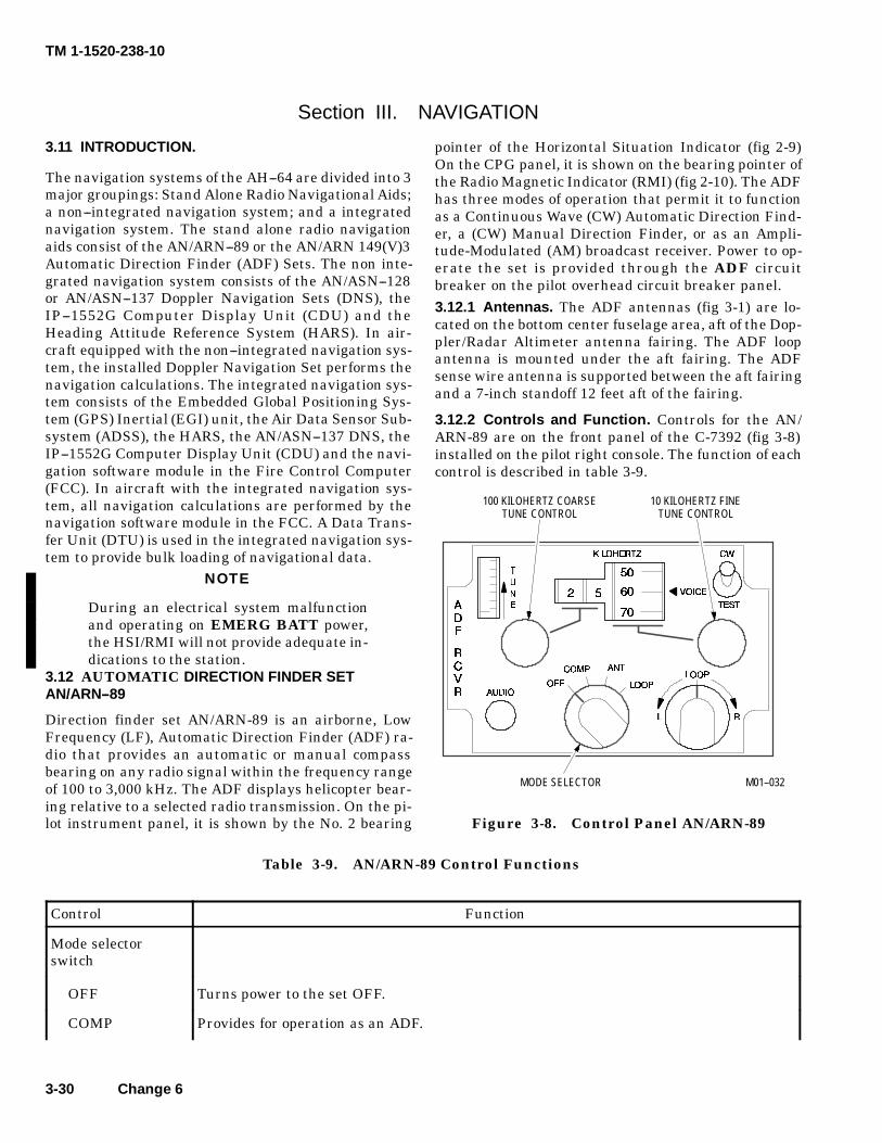
TM 1-1520-238-10
3-30 Change 6
Section III. NAVIGATION
3.11 INTRODUCTION.
The navigation systems of the AH--64 are divided into 3major groupings: Stand Alone Radio Navigational Aids;a non--integrated navigation system; and a integratednavigation system. The stand alone radio navigationaids consist of the AN/ARN--89 or the AN/ARN 149(V)3Automatic Direction Finder (ADF) Sets. The non inte-grated navigation system consists of the AN/ASN--128or AN/ASN--137 Doppler Navigation Sets (DNS), theIP--1552G Computer Display Unit (CDU) and theHeading Attitude Reference System (HARS). In air-craft equipped with the non--integrated navigation sys-tem, the installed Doppler Navigation Set performs thenavigation calculations. The integrated navigation sys-tem consists of the Embedded Global Positioning Sys-tem (GPS) Inertial (EGI) unit, the Air Data Sensor Sub-system (ADSS), the HARS, the AN/ASN--137 DNS, theIP--1552G Computer Display Unit (CDU) and the navi-gation software module in the Fire Control Computer(FCC). In aircraft with the integrated navigation sys-tem, all navigation calculations are performed by thenavigation software module in the FCC. A Data Trans-fer Unit (DTU) is used in the integrated navigation sys-tem to provide bulk loading of navigational data.
NOTE
During an electrical system malfunctionand operating on EMERG BATT power,the HSI/RMI will not provide adequate in-dications to the station.
3.12 AUTOMATIC DIRECTION FINDER SETAN/ARN--89
Direction finder set AN/ARN-89 is an airborne, LowFrequency (LF), Automatic Direction Finder (ADF) ra-dio that provides an automatic or manual compassbearing on any radio signal within the frequency rangeof 100 to 3,000 kHz. The ADF displays helicopter bear-ing relative to a selected radio transmission. On the pi-lot instrument panel, it is shown by the No. 2 bearing
pointer of the Horizontal Situation Indicator (fig 2-9)On the CPG panel, it is shown on the bearing pointer ofthe Radio Magnetic Indicator (RMI) (fig 2-10). The ADFhas three modes of operation that permit it to functionas a Continuous Wave (CW) Automatic Direction Find-er, a (CW) Manual Direction Finder, or as an Ampli-tude-Modulated (AM) broadcast receiver. Power to op-erate the set is provided through the ADF circuitbreaker on the pilot overhead circuit breaker panel.3.12.1 Antennas. The ADF antennas (fig 3-1) are lo-cated on the bottom center fuselage area, aft of the Dop-pler/Radar Altimeter antenna fairing. The ADF loopantenna is mounted under the aft fairing. The ADFsense wire antenna is supported between the aft fairingand a 7-inch standoff 12 feet aft of the fairing.
3.12.2 Controls and Function. Controls for the AN/ARN-89 are on the front panel of the C-7392 (fig 3-8)installed on the pilot right console. The function of eachcontrol is described in table 3-9.
100 KILOHERTZ COARSETUNE CONTROL
10 KILOHERTZ FINETUNE CONTROL
MODE SELECTOR M01--032
Figure 3-8. Control Panel AN/ARN-89
Table 3-9. AN/ARN-89 Control Functions
Control Function
Mode selectorswitch
OFF Turns power to the set OFF.
COMP Provides for operation as an ADF.
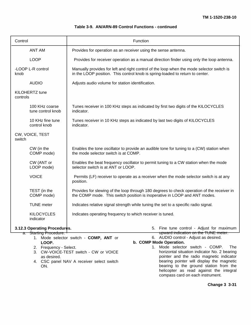
TM 1-1520-238-10
Table 3-9. AN/ARN-89 Control Functions - continued
Control Function
ANT AM Provides for operation as an receiver using the sense antenna.
LOOP Provides for receiver operation as a manual direction finder using only the loop antenna.
-LOOP L-R control Manually provides for left and right control of the loop when the mode selector switch isknob in the LOOP position. This control knob is spring-loaded to return to center.
AUDIO Adjusts audio volume for station identification.
KILOHERTZ tunecontrols
100 KHz coarse Tunes receiver in 100 KHz steps as indicated by first two digits of the KILOCYCLEStune control knob indicator.
10 KHz fine tune Tunes receiver in 10 KHz steps as indicated by last two digits of KILOCYCLEScontrol knob indicator.
CW, VOICE, TESTswitch
CW (in the Enables the tone oscillator to provide an audible tone for tuning to a (CW) station whenCOMP mode) the mode selector switch is at COMP.
CW (ANT or Enables the beat frequency oscillator to permit tuning to a CW station when the modeLOOP mode) selector switch is at ANT or LOOP.
VOICE Permits (LF) receiver to operate as a receiver when the mode selector switch is at anyposition.
TEST (in the Provides for slewing of the loop through 180 degrees to check operation of the receiver inCOMP mode) the COMP mode. This switch position is inoperative in LOOP and ANT modes.
TUNE meter Indicates relative signal strength while tuning the set to a specific radio signal.
KILOCYCLES Indicates operating frequency to which receiver is tuned.indicator
3.12.3 Operating Procedures.a. Starting Procedure.
1. Mode selector switch - COMP, ANT orLOOP.
2. Frequency - Select.3. CW-VOICE-TEST switch - CW or VOICE
as desired.4. CSC panel NAV A receiver select switch
ON.
5. Fine tune control - Adjust for maximumupward indication on the TUNE meter.
6. AUDIO control - Adjust as desired.b. COMP Mode Operation.
1. Mode selector switch - COMP. Thehorizontal situation indicator No. 2 bearingpointer and the radio magnetic indicatorbearing pointer will display the magneticbearing to the ground station from thehelicopter as read against the integralcompass card on each instrument.
Change 3 3-31
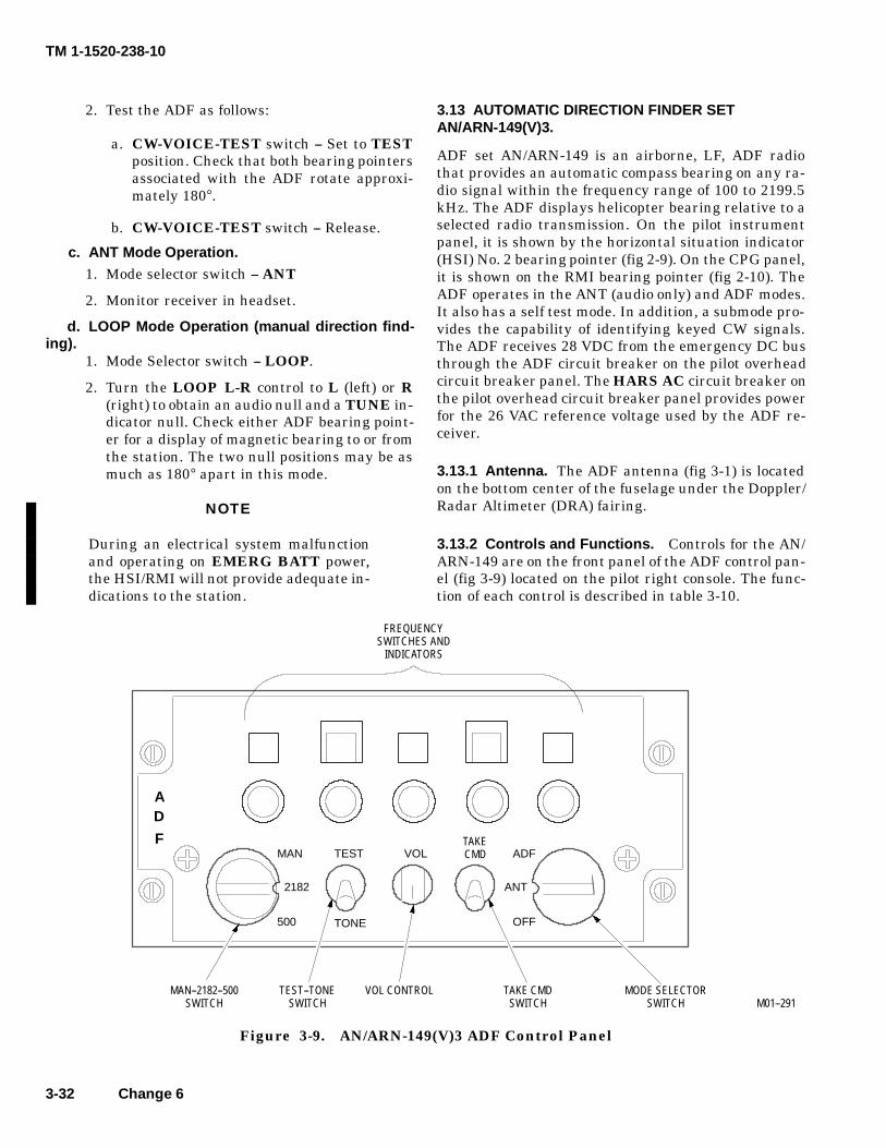
TM 1-1520-238-10
3-32 Change 6
2. Test the ADF as follows:
a. CW-VOICE-TEST switch -- Set to TESTposition. Check that both bearing pointersassociated with the ADF rotate approxi-mately 180°.
b. CW-VOICE-TEST switch -- Release.
c. ANT Mode Operation.1. Mode selector switch -- ANT
2. Monitor receiver in headset.
d. LOOP Mode Operation (manual direction find-ing).
1. Mode Selector switch -- LOOP.
2. Turn the LOOP L-R control to L (left) or R(right) to obtain an audio null and a TUNE in-dicator null. Check either ADF bearing point-er for a display of magnetic bearing to or fromthe station. The two null positions may be asmuch as 180° apart in this mode.
NOTE
During an electrical system malfunctionand operating on EMERG BATT power,the HSI/RMI will not provide adequate in-dications to the station.
3.13 AUTOMATIC DIRECTION FINDER SETAN/ARN-149(V)3.
ADF set AN/ARN-149 is an airborne, LF, ADF radiothat provides an automatic compass bearing on any ra-dio signal within the frequency range of 100 to 2199.5kHz. The ADF displays helicopter bearing relative to aselected radio transmission. On the pilot instrumentpanel, it is shown by the horizontal situation indicator(HSI) No. 2 bearing pointer (fig 2-9). On the CPG panel,it is shown on the RMI bearing pointer (fig 2-10). TheADF operates in the ANT (audio only) and ADF modes.It also has a self test mode. In addition, a submode pro-vides the capability of identifying keyed CW signals.The ADF receives 28 VDC from the emergency DC busthrough the ADF circuit breaker on the pilot overheadcircuit breaker panel. The HARS AC circuit breaker onthe pilot overhead circuit breaker panel provides powerfor the 26 VAC reference voltage used by the ADF re-ceiver.
3.13.1 Antenna. The ADF antenna (fig 3-1) is locatedon the bottom center of the fuselage under the Doppler/Radar Altimeter (DRA) fairing.
3.13.2 Controls and Functions. Controls for the AN/ARN-149 are on the front panel of the ADF control pan-el (fig 3-9) located on the pilot right console. The func-tion of each control is described in table 3-10.
M01--291
VOL
AD
F
MAN--2182--500SWITCH
TAKECMD ADF
OFF
ANT
TONE
MAN
500
2182
TEST
TEST--TONESWITCH
TAKE CMDSWITCH
VOL CONTROL MODE SELECTORSWITCH
FREQUENCYSWITCHES AND
INDICATORS
Figure 3-9. AN/ARN-149(V)3 ADF Control Panel
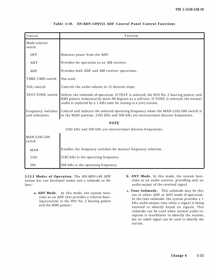
TM 1-1520-238-10
Table 3-10. AN/ARN-149(V)3 ADF Control Panel Control Functions
Control
Mode selectorswitch
Function
OFF Removes power from the ADF.
ANT Provides for operation as an AM receiver.
ADF Provides both ADF and AM receiver operations.
TARE CMD switch Not used.
VOL control Controls the audio volume in 12 discrete steps.
TEST-TONE switch Selects the submode of operation. If TEST is selected, the HSI No. 2 bearing pointer andRMI pointer momentarily move 90 degrees as a self-test. If TONE is selected, the normalaudio is replaced by a 1 kHz tone for tuning to a (cw) station.
Frequency switches Control and indicate the selected operating frequency when the MAN-2182-500 switch isand indicators in the MAN position. 2182 kHz and 500 kHz are international distress frequencies.
NOTE
MAN-2182-500switch
2182 kHz and 500 kHz are international distress frequencies.
MAN
2182
500
Enables the frequency switches for manual frequency selection.
2182 kHz is the operating frequency.
500 kHz is the operating frequency.
3.13.3 Modes of Operation. The AN/ARN-149 ADF b. ANT Mode. In this mode, the system func-system has two functional modes and a submode as fol- tions as an audio receiver, providing only anlows: audio output of the received signal.
a. ADF Mode. In this mode, the system func-tions as an ADF that provides a relative bear-ing-to-station to the HSI No. 2 bearing pointerand the RMI pointer.
c. Tone Submode. This submode may be cho-sen in either ADF or ANT mode of operation.In the tone submode, the system provides a 1kHz audio output tone when a signal is beingreceived to identify keyed cw signals. Thissubmode can be used when normal audio re-ception is insufficient to identify the station;the cw coded signal can be used to identify thestation.
Change 4 3-33
TM 1-1520-238-10
3.13.4 Operating Procedures.
a. ANT (audio only) Operation.
1. Mode selector switch - ANT.
2. MAN-2182-500 switch - As desired. If MANis selected, set the desired frequency with thefive frequency switches.
3. VOL control - As desired.
4. If cw operation is desired, TEST-TONEswitch - TONE.
b. ADF Operations.
1. Mode selector switch - ADF.
2. MAN-2182-600 switch - As desired. If MANis selected, set the desired frequency with thefive frequency switches.
3. VOL control - As desired. The HSI No. 2 bear-ing pointer and the RMI pointer will indicaterelative bearing to the selected ground sta-tion.
4. If cw operation is desired, TEST-TONEswitch - TONE.
c. Self-Test Operation.
NOTE
The ADF system must be in ADF modeand receiving a valid ground station sig-nal to perform the self-test.
1. Set to ADF mode (para. d.2). Note position ofHSI No. 2 bearing pointer and RMI pointer.
2. TEST-TONE switch - Momentarily TEST.
3. HSI No. 2 bearing pointer and the RMI point-er rotate 90° from their original positions andthen return to their original positions.
3.14 NON-INTEGRATED NAVIGATION SYSTEM
The non integrated navigation system does not meet FM requirementsfor use as a primary navigation systern for IFR operations in IMC.
The non-integrated navigation system consists of aHeading Attitude Reference System (HARS) and eitherthe AN/ASN-128 or AN/ASN-137 Doppler NavigationSet (DNS). The non-integrated navigation system isnot connected to, and operates independently of, theMission System 1553 multiplex (MUX) bus. The MUXbus is responsible for passing the DNS velocity datafrom the ARINC bus to the HARS through special hard-ware interfaces in the CPG and DASE MRTUs. TheMUX bus is also responsible for tracking/filteringMAGVAR changes that are calculated in the DNS andpassing these changes to the HARS via the same spe-cial interfaces. In this configuration the HARS is de-pendent upon receiving DNS velocity for internal veloc-ity damping and maintaining proper heading and/orattitude, and the DNS is dependent upon receivingHARS heading/attitude in order to perform the naviga-tion calculations. Additionally, the HARS is dependentupon proper MAGVAR updates for driving the HSI,RMI, and DNS magnetic heading inputs. The MUX buscontroller (FCC or BBC) uses the HARS inertial dataoutputs to drive all the inertial symbology presented onthe video displays. This includes the heading tape, ve-locity vector, acceleration cue, horizon line, hover posi-tion box and trim ball. The Hover Position Box will driftduring a stationary hover, and conversely, the aircraftwill drift if the aircraft is flown to hold the Hover Posi-tion Box centered on the display. The amount of driftmay reach as much as 21 feet per minute, and the driftmay be random in nature. This drift is caused by HARSvelocity errors, which are strongly influenced by theDNS velocity characteristics at these hover velocities.The following paragraphs provide a description of theHARS and DNS internal operations and the controlsand displays used by the crew to operate the non-inte-grated navigation system.
3.14.1 Heading Attitude Reference System (HARS).
a. System Description
The HARS is a doppler aided strapdown inertialreference system. The HARS provides all attitude,velocity, and acceleration data for the helicopter. TheHARS aligns itself by adjusting its own vertical axis tocoincide with the earth’s gravity vector and by measur-ing the rotational speed of the earth about its inertialaxis.
3-34 Change 4
TM 1-1520-238-10
By aligning the vertical axis with the earth’s gravity,the HARS is able to determine the UP direction. Inmeasuring the earth’s rotational speed the HARS isable to determine which direction is East; North is then90 degrees counter-clockwise from East. Any change ofheading or movement of the helicopter duringalignment while on the ground will disrupt accuratemeasurements and calculations resulting in analignment error. The only corrective action is for thehelicopter to be returned to a stationary condition andthe HARS realigned. Rotor vibrations at 100% Nr havelittle effect on the accuracy of the HARS alignment.Inflight, the HARS maintains alignment bycontinuously gyrocompassing and estimating systemerrors. Inflight alignments or restarts require validdoppler data. The HARS may be aligned using one offour methods. The accuracy of the HARS alignment isdependent on the method chosen. The methods andaccuracies are discussed in Table 3-11.
The HARS uses doppler velocities to damp the drift inthe inertial data. Both the doppler and inertialvelocities are combined by the Kalman filter programin the HARS to take advantage of the best of each. Ifdoppler velocities are not valid (memory ormalfunction), the HARS will reject the doppler dataand function in a free inertial mode. In free inertial, theheading and velocities will drift in a sinusoidaloscillation called a Schuler period; approximately 84minutes. The HARS free inertial condition is signaledto the flight crew by velocity vector flashing. The mostlikely cause for the HARS to reject doppler data is thatthe doppler is in memory. The doppler normally returnsvalid data over flat terrain. Over areas of tall grass orwater, doppler data inconsistencies can developresulting in a memory condition and invalid dopplerdata.
Change 4 3-34.1/(3-34.2 blank)

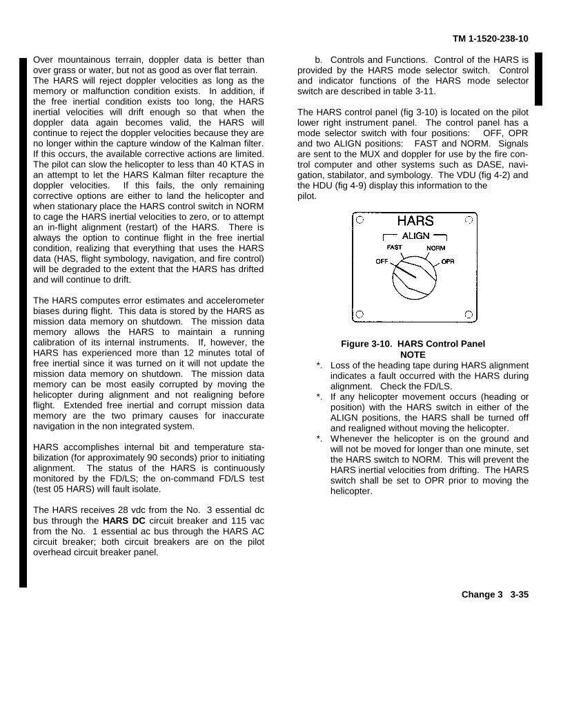
TM 1-1520-238-10
Over mountainous terrain, doppler data is better thanover grass or water, but not as good as over flat terrain.The HARS will reject doppler velocities as long as thememory or malfunction condition exists. In addition, ifthe free inertial condition exists too long, the HARSinertial velocities will drift enough so that when thedoppler data again becomes valid, the HARS willcontinue to reject the doppler velocities because they areno longer within the capture window of the Kalman filter.If this occurs, the available corrective actions are limited.The pilot can slow the helicopter to less than 40 KTAS inan attempt to let the HARS Kalman filter recapture thedoppler velocities. If this fails, the only remainingcorrective options are either to land the helicopter andwhen stationary place the HARS control switch in NORMto cage the HARS inertial velocities to zero, or to attemptan in-flight alignment (restart) of the HARS. There isalways the option to continue flight in the free inertialcondition, realizing that everything that uses the HARSdata (HAS, flight symbology, navigation, and fire control)will be degraded to the extent that the HARS has driftedand will continue to drift.
The HARS computes error estimates and accelerometerbiases during flight. This data is stored by the HARS asmission data memory on shutdown. The mission datamemory allows the HARS to maintain a runningcalibration of its internal instruments. If, however, theHARS has experienced more than 12 minutes total offree inertial since it was turned on it will not update themission data memory on shutdown. The mission datamemory can be most easily corrupted by moving thehelicopter during alignment and not realigning beforeflight. Extended free inertial and corrupt mission datamemory are the two primary causes for inaccuratenavigation in the non integrated system.
HARS accomplishes internal bit and temperature sta-bilization (for approximately 90 seconds) prior to initiatingalignment. The status of the HARS is continuouslymonitored by the FD/LS; the on-command FD/LS test(test 05 HARS) will fault isolate.
The HARS receives 28 vdc from the No. 3 essential dcbus through the HARS DC circuit breaker and 115 vacfrom the No. 1 essential ac bus through the HARS ACcircuit breaker; both circuit breakers are on the pilotoverhead circuit breaker panel.
b. Controls and Functions. Control of the HARS isprovided by the HARS mode selector switch. Controland indicator functions of the HARS mode selectorswitch are described in table 3-11.
The HARS control panel (fig 3-10) is located on the pilotlower right instrument panel. The control panel has amode selector switch with four positions: OFF, OPRand two ALIGN positions: FAST and NORM. Signalsare sent to the MUX and doppler for use by the fire con-trol computer and other systems such as DASE, navi-gation, stabilator, and symbology. The VDU (fig 4-2) andthe HDU (fig 4-9) display this information to thepilot.
Figure 3-10. HARS Control PanelNOTE
*. Loss of the heading tape during HARS alignmentindicates a fault occurred with the HARS duringalignment. Check the FD/LS.
*. If any helicopter movement occurs (heading orposition) with the HARS switch in either of theALIGN positions, the HARS shall be turned offand realigned without moving the helicopter.
*. Whenever the helicopter is on the ground andwill not be moved for longer than one minute, setthe HARS switch to NORM. This will prevent theHARS inertial velocities from drifting. The HARSswitch shall be set to OPR prior to moving thehelicopter.
Change 3 3-35
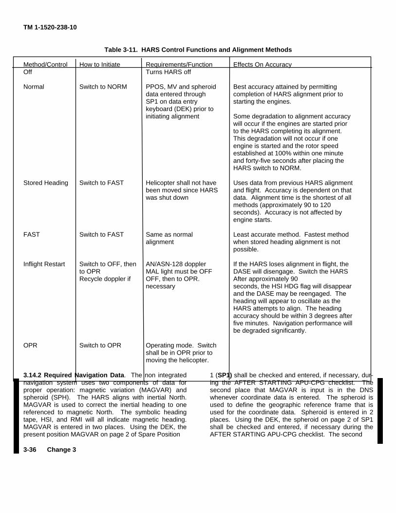
TM 1-1520-238-10
Table 3-11. HARS Control Functions and Alignment Methods
Method/Control How to Initiate Requirements/Function Effects On AccuracyOff Turns HARS off
Normal Switch to NORM PPOS, MV and spheroid Best accuracy attained by permittingdata entered through completion of HARS alignment prior toSP1 on data entry starting the engines.keyboard (DEK) prior toinitiating alignment Some degradation to alignment accuracy
will occur if the engines are started priorto the HARS completing its alignment.This degradation will not occur if oneengine is started and the rotor speedestablished at 100% within one minuteand forty-five seconds after placing theHARS switch to NORM.
Stored Heading Switch to FAST Helicopter shall not have Uses data from previous HARS alignmentbeen moved since HARS and flight. Accuracy is dependent on thatwas shut down data. Alignment time is the shortest of all
methods (approximately 90 to 120seconds). Accuracy is not affected byengine starts.
FAST Switch to FAST Same as normal Least accurate method. Fastest methodalignment when stored heading alignment is not
possible.
Inflight Restart Switch to OFF, then AN/ASN-128 doppler If the HARS loses alignment in flight, theto OPR MAL light must be OFF DASE will disengage. Switch the HARSRecycle doppler if OFF, then to OPR. After approximately 90
necessary seconds, the HSI HDG flag will disappearand the DASE may be reengaged. Theheading will appear to oscillate as theHARS attempts to align. The headingaccuracy should be within 3 degrees afterfive minutes. Navigation performance willbe degraded significantly.
OPR Switch to OPR Operating mode. Switchshall be in OPR prior tomoving the helicopter.
3.14.2 Required Navigation Data. The non integratednavigation system uses two components of data forproper operation: magnetic variation (MAGVAR) andspheroid (SPH). The HARS aligns with inertial North.MAGVAR is used to correct the inertial heading to onereferenced to magnetic North. The symbolic headingtape, HSI, and RMI will all indicate magnetic heading.MAGVAR is entered in two places. Using the DEK, thepresent position MAGVAR on page 2 of Spare Position
3-36 Change 3
1 (SP1) shall be checked and entered, if necessary, dur-ing the AFTER STARTING APU-CPG checklist. Thesecond place that MAGVAR is input is in the DNSwhenever coordinate data is entered. The spheroid isused to define the geographic reference frame that isused for the coordinate data. Spheroid is entered in 2places. Using the DEK, the spheroid on page 2 of SP1shall be checked and entered, if necessary during theAFTER STARTING APU-CPG checklist. The second
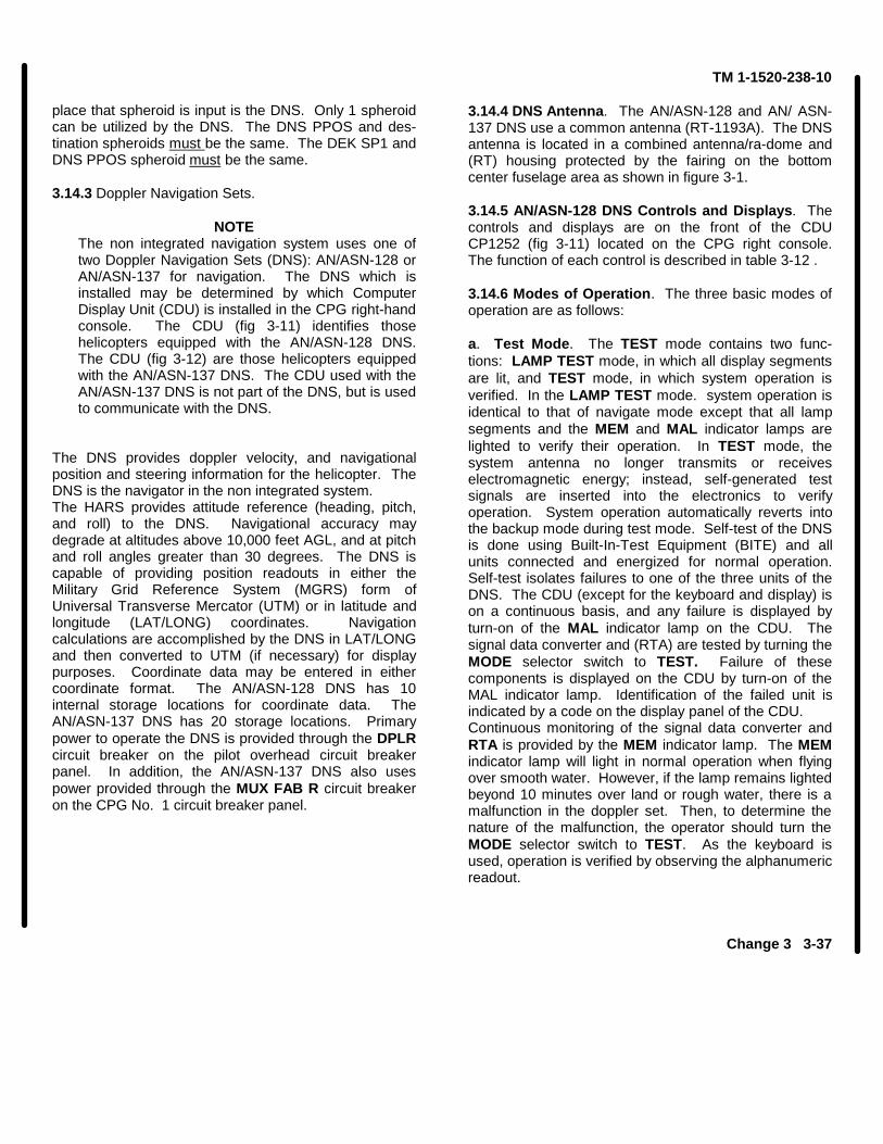
TM 1-1520-238-10
place that spheroid is input is the DNS. Only 1 spheroidcan be utilized by the DNS. The DNS PPOS and des-tination spheroids must be the same. The DEK SP1 andDNS PPOS spheroid must be the same.
3.14.3 Doppler Navigation Sets.
NOTEThe non integrated navigation system uses one oftwo Doppler Navigation Sets (DNS): AN/ASN-128 orAN/ASN-137 for navigation. The DNS which isinstalled may be determined by which ComputerDisplay Unit (CDU) is installed in the CPG right-handconsole. The CDU (fig 3-11) identifies thosehelicopters equipped with the AN/ASN-128 DNS.The CDU (fig 3-12) are those helicopters equippedwith the AN/ASN-137 DNS. The CDU used with theAN/ASN-137 DNS is not part of the DNS, but is usedto communicate with the DNS.
The DNS provides doppler velocity, and navigationalposition and steering information for the helicopter. TheDNS is the navigator in the non integrated system.The HARS provides attitude reference (heading, pitch,and roll) to the DNS. Navigational accuracy maydegrade at altitudes above 10,000 feet AGL, and at pitchand roll angles greater than 30 degrees. The DNS iscapable of providing position readouts in either theMilitary Grid Reference System (MGRS) form ofUniversal Transverse Mercator (UTM) or in latitude andlongitude (LAT/LONG) coordinates. Navigationcalculations are accomplished by the DNS in LAT/LONGand then converted to UTM (if necessary) for displaypurposes. Coordinate data may be entered in eithercoordinate format. The AN/ASN-128 DNS has 10internal storage locations for coordinate data. TheAN/ASN-137 DNS has 20 storage locations. Primarypower to operate the DNS is provided through the DPLRcircuit breaker on the pilot overhead circuit breakerpanel. In addition, the AN/ASN-137 DNS also usespower provided through the MUX FAB R circuit breakeron the CPG No. 1 circuit breaker panel.
3.14.4 DNS Antenna. The AN/ASN-128 and AN/ ASN-137 DNS use a common antenna (RT-1193A). The DNSantenna is located in a combined antenna/ra-dome and(RT) housing protected by the fairing on the bottomcenter fuselage area as shown in figure 3-1.
3.14.5 AN/ASN-128 DNS Controls and Displays. Thecontrols and displays are on the front of the CDUCP1252 (fig 3-11) located on the CPG right console.The function of each control is described in table 3-12 .
3.14.6 Modes of Operation. The three basic modes ofoperation are as follows:
a. Test Mode. The TEST mode contains two func-tions: LAMP TEST mode, in which all display segmentsare lit, and TEST mode, in which system operation isverified. In the LAMP TEST mode. system operation isidentical to that of navigate mode except that all lampsegments and the MEM and MAL indicator lamps arelighted to verify their operation. In TEST mode, thesystem antenna no longer transmits or receiveselectromagnetic energy; instead, self-generated testsignals are inserted into the electronics to verifyoperation. System operation automatically reverts intothe backup mode during test mode. Self-test of the DNSis done using Built-In-Test Equipment (BITE) and allunits connected and energized for normal operation.Self-test isolates failures to one of the three units of theDNS. The CDU (except for the keyboard and display) ison a continuous basis, and any failure is displayed byturn-on of the MAL indicator lamp on the CDU. Thesignal data converter and (RTA) are tested by turning theMODE selector switch to TEST. Failure of thesecomponents is displayed on the CDU by turn-on of theMAL indicator lamp. Identification of the failed unit isindicated by a code on the display panel of the CDU.Continuous monitoring of the signal data converter andRTA is provided by the MEM indicator lamp. The MEMindicator lamp will light in normal operation when flyingover smooth water. However, if the lamp remains lightedbeyond 10 minutes over land or rough water, there is amalfunction in the doppler set. Then, to determine thenature of the malfunction, the operator should turn theMODE selector switch to TEST. As the keyboard isused, operation is verified by observing the alphanumericreadout.
Change 3 3-37
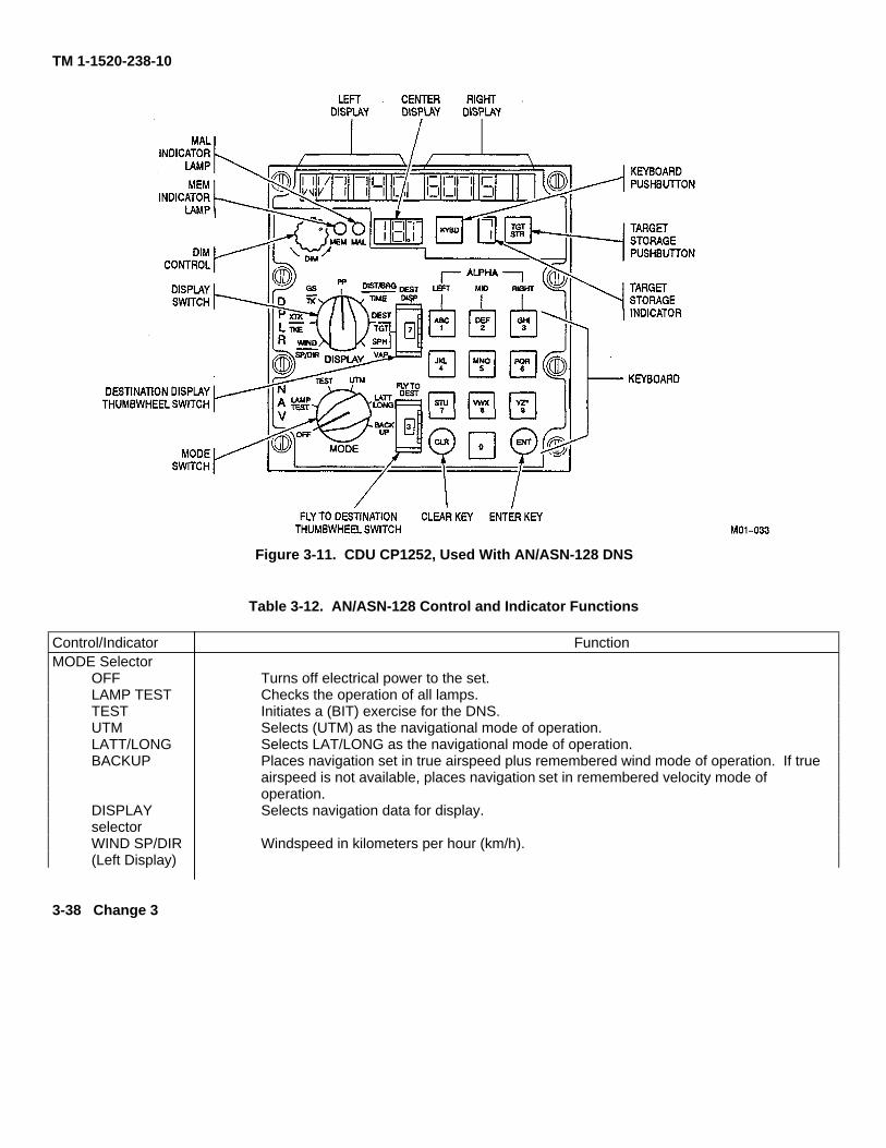
TM 1-1520-238-10
Figure 3-11. CDU CP1252, Used With AN/ASN-128 DNS
Table 3-12. AN/ASN-128 Control and Indicator Functions
Control/Indicator FunctionMODE Selector
OFF Turns off electrical power to the set.LAMP TEST Checks the operation of all lamps.TEST Initiates a (BIT) exercise for the DNS.UTM Selects (UTM) as the navigational mode of operation.LATT/LONG Selects LAT/LONG as the navigational mode of operation.BACKUP Places navigation set in true airspeed plus remembered wind mode of operation. If true
airspeed is not available, places navigation set in remembered velocity mode of operation.
DISPLAY Selects navigation data for display.selectorWIND SP/DIR Windspeed in kilometers per hour (km/h).(Left Display)
3-38 Change 3
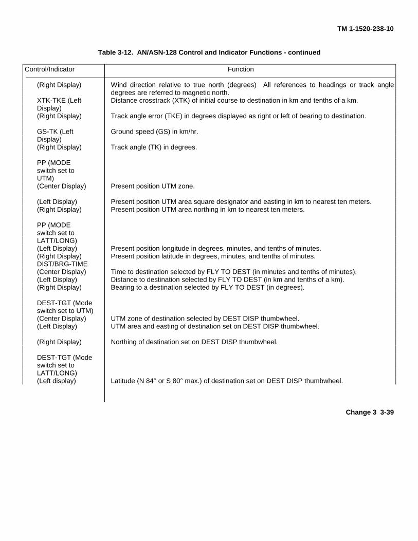
TM 1-1520-238-10
Table 3-12. AN/ASN-128 Control and Indicator Functions - continued
Control/Indicator Function
(Right Display) Wind direction relative to true north (degrees) All references to headings or track angledegrees are referred to magnetic north.
XTK-TKE (Left Distance crosstrack (XTK) of initial course to destination in km and tenths of a km.Display)(Right Display) Track angle error (TKE) in degrees displayed as right or left of bearing to destination.
GS-TK (Left Ground speed (GS) in km/hr.Display)(Right Display) Track angle (TK) in degrees.
PP (MODEswitch set toUTM)(Center Display) Present position UTM zone.
(Left Display) Present position UTM area square designator and easting in km to nearest ten meters.(Right Display) Present position UTM area northing in km to nearest ten meters.
PP (MODEswitch set toLATT/LONG)(Left Display) Present position longitude in degrees, minutes, and tenths of minutes.(Right Display) Present position latitude in degrees, minutes, and tenths of minutes.DIST/BRG-TIME(Center Display) Time to destination selected by FLY TO DEST (in minutes and tenths of minutes).(Left Display) Distance to destination selected by FLY TO DEST (in km and tenths of a km).(Right Display) Bearing to a destination selected by FLY TO DEST (in degrees).
DEST-TGT (Modeswitch set to UTM)(Center Display) UTM zone of destination selected by DEST DISP thumbwheel.(Left Display) UTM area and easting of destination set on DEST DISP thumbwheel.
(Right Display) Northing of destination set on DEST DISP thumbwheel.
DEST-TGT (Modeswitch set toLATT/LONG)(Left display) Latitude (N 84° or S 80° max.) of destination set on DEST DISP thumbwheel.
Change 3 3-39
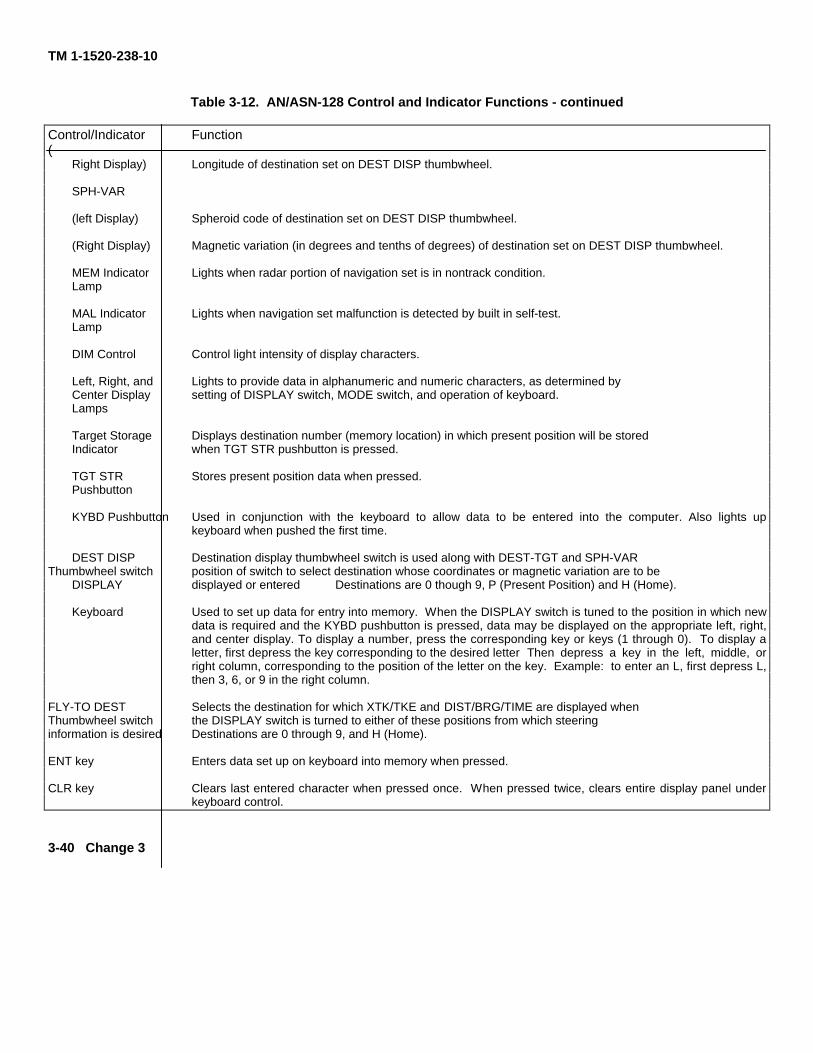
TM 1-1520-238-10
Table 3-12. AN/ASN-128 Control and Indicator Functions - continued
Control/Indicator Function(
Right Display) Longitude of destination set on DEST DISP thumbwheel.
SPH-VAR
(left Display) Spheroid code of destination set on DEST DISP thumbwheel.
(Right Display) Magnetic variation (in degrees and tenths of degrees) of destination set on DEST DISP thumbwheel.
MEM Indicator Lights when radar portion of navigation set is in nontrack condition.Lamp
MAL Indicator Lights when navigation set malfunction is detected by built in self-test.Lamp
DIM Control Control light intensity of display characters.
Left, Right, and Lights to provide data in alphanumeric and numeric characters, as determined byCenter Display setting of DISPLAY switch, MODE switch, and operation of keyboard.Lamps
Target Storage Displays destination number (memory location) in which present position will be storedIndicator when TGT STR pushbutton is pressed.
TGT STR Stores present position data when pressed.Pushbutton
KYBD Pushbutton Used in conjunction with the keyboard to allow data to be entered into the computer. Also lights upkeyboard when pushed the first time.
DEST DISP Destination display thumbwheel switch is used along with DEST-TGT and SPH-VARThumbwheel switch position of switch to select destination whose coordinates or magnetic variation are to be
DISPLAY displayed or entered Destinations are 0 though 9, P (Present Position) and H (Home).
Keyboard Used to set up data for entry into memory. When the DISPLAY switch is tuned to the position in which newdata is required and the KYBD pushbutton is pressed, data may be displayed on the appropriate left, right,and center display. To display a number, press the corresponding key or keys (1 through 0). To display aletter, first depress the key corresponding to the desired letter Then depress a key in the left, middle, orright column, corresponding to the position of the letter on the key. Example: to enter an L, first depress L,then 3, 6, or 9 in the right column.
FLY-TO DEST Selects the destination for which XTK/TKE and DIST/BRG/TIME are displayed whenThumbwheel switch the DISPLAY switch is turned to either of these positions from which steeringinformation is desired Destinations are 0 through 9, and H (Home).
ENT key Enters data set up on keyboard into memory when pressed.
CLR key Clears last entered character when pressed once. When pressed twice, clears entire display panel underkeyboard control.
3-40 Change 3
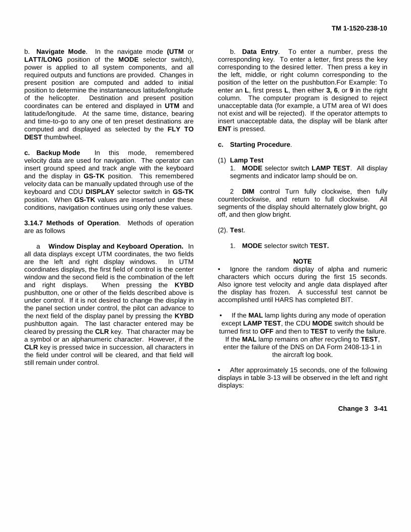
TM 1-1520-238-10
b. Navigate Mode. In the navigate mode (UTM orLATT/LONG position of the MODE selector switch),power is applied to all system components, and allrequired outputs and functions are provided. Changes inpresent position are computed and added to initialposition to determine the instantaneous latitude/longitudeof the helicopter. Destination and present positioncoordinates can be entered and displayed in UTM andlatitude/longitude. At the same time, distance, bearingand time-to-go to any one of ten preset destinations arecomputed and displayed as selected by the FLY TODEST thumbwheel.
c. Backup Mode In this mode, rememberedvelocity data are used for navigation. The operator caninsert ground speed and track angle with the keyboardand the display in GS-TK position. This rememberedvelocity data can be manually updated through use of thekeyboard and CDU DISPLAY selector switch in GS-TKposition. When GS-TK values are inserted under theseconditions, navigation continues using only these values.
3.14.7 Methods of Operation. Methods of operationare as follows
a Window Display and Keyboard Operation. Inall data displays except UTM coordinates, the two fieldsare the left and right display windows. In UTMcoordinates displays, the first field of control is the centerwindow and the second field is the combination of the leftand right displays. When pressing the KYBDpushbutton, one or other of the fields described above isunder control. If it is not desired to change the display inthe panel section under control, the pilot can advance tothe next field of the display panel by pressing the KYBDpushbutton again. The last character entered may becleared by pressing the CLR key. That character may bea symbol or an alphanumeric character. However, if theCLR key is pressed twice in succession, all characters inthe field under control will be cleared, and that field willstill remain under control.
b. Data Entry. To enter a number, press thecorresponding key. To enter a letter, first press the keycorresponding to the desired letter. Then press a key inthe left, middle, or right column corresponding to theposition of the letter on the pushbutton.For Example: Toenter an L, first press L, then either 3, 6, or 9 in the rightcolumn. The computer program is designed to rejectunacceptable data (for example, a UTM area of WI doesnot exist and will be rejected). If the operator attempts toinsert unacceptable data, the display will be blank afterENT is pressed.
c. Starting Procedure.
(1) Lamp Test1. MODE selector switch LAMP TEST. All displaysegments and indicator lamp should be on.
2 DIM control Turn fully clockwise, then fullycounterclockwise, and return to full clockwise. Allsegments of the display should alternately glow bright, gooff, and then glow bright.
(2). Test.
1. MODE selector switch TEST.
NOTE• Ignore the random display of alpha and numericcharacters which occurs during the first 15 seconds.Also ignore test velocity and angle data displayed afterthe display has frozen. A successful test cannot beaccomplished until HARS has completed BIT.
• If the MAL lamp lights during any mode of operationexcept LAMP TEST, the CDU MODE switch should be
turned first to OFF and then to TEST to verify the failure.If the MAL lamp remains on after recycling to TEST,
enter the failure of the DNS on DA Form 2408-13-1 inthe aircraft log book.
• After approximately 15 seconds, one of the followingdisplays in table 3-13 will be observed in the left and rightdisplays:
Change 3 3-41
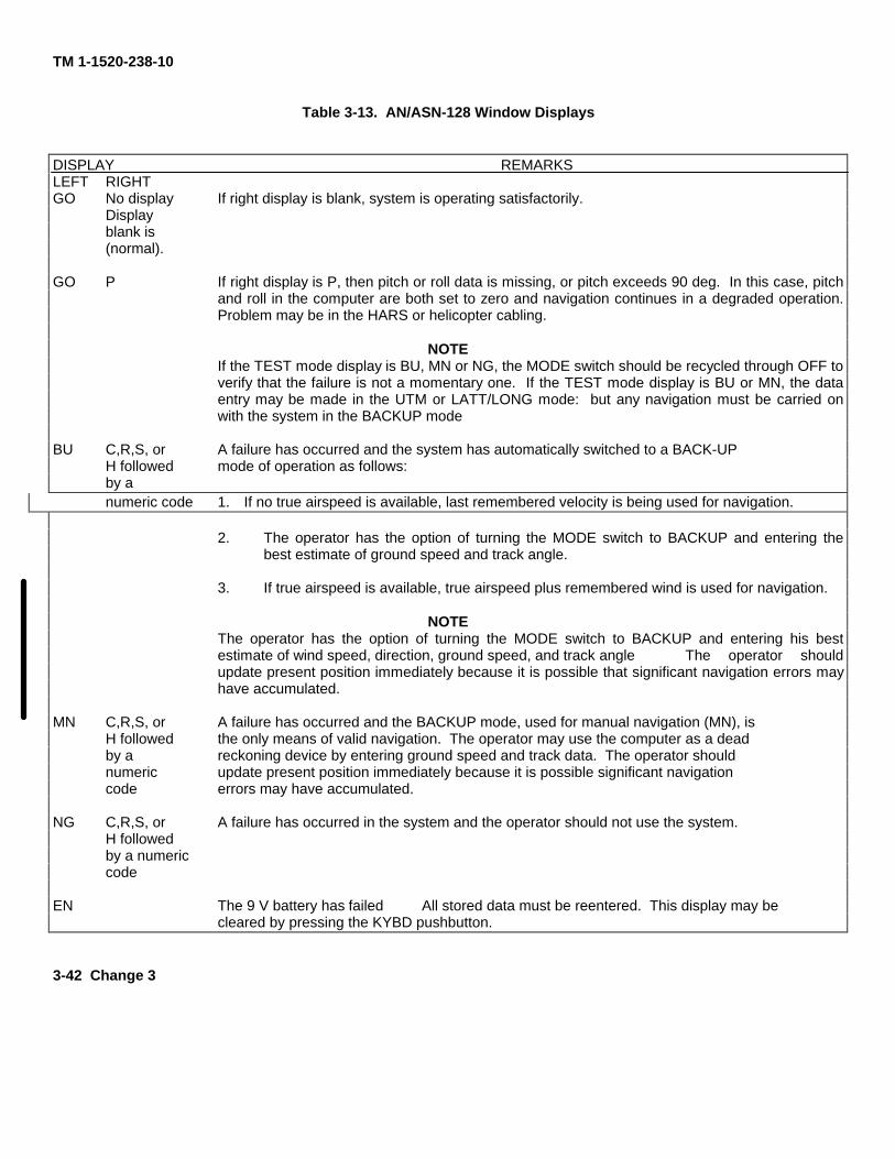
TM 1-1520-238-10
Table 3-13. AN/ASN-128 Window Displays
DISPLAY REMARKSLEFT RIGHTGO No display If right display is blank, system is operating satisfactorily.
Displayblank is(normal).
GO P If right display is P, then pitch or roll data is missing, or pitch exceeds 90 deg. In this case, pitchand roll in the computer are both set to zero and navigation continues in a degraded operation.Problem may be in the HARS or helicopter cabling.
NOTEIf the TEST mode display is BU, MN or NG, the MODE switch should be recycled through OFF toverify that the failure is not a momentary one. If the TEST mode display is BU or MN, the dataentry may be made in the UTM or LATT/LONG mode: but any navigation must be carried onwith the system in the BACKUP mode
BU C,R,S, or A failure has occurred and the system has automatically switched to a BACK-UPH followed mode of operation as follows:by anumeric code 1. If no true airspeed is available, last remembered velocity is being used for navigation.
2. The operator has the option of turning the MODE switch to BACKUP and entering thebest estimate of ground speed and track angle.
3. If true airspeed is available, true airspeed plus remembered wind is used for navigation.
NOTEThe operator has the option of turning the MODE switch to BACKUP and entering his bestestimate of wind speed, direction, ground speed, and track angle The operator shouldupdate present position immediately because it is possible that significant navigation errors mayhave accumulated.
MN C,R,S, or A failure has occurred and the BACKUP mode, used for manual navigation (MN), isH followed the only means of valid navigation. The operator may use the computer as a deadby a reckoning device by entering ground speed and track data. The operator shouldnumeric update present position immediately because it is possible significant navigationcode errors may have accumulated.
NG C,R,S, or A failure has occurred in the system and the operator should not use the system.H followedby a numericcode
EN The 9 V battery has failed All stored data must be reentered. This display may becleared by pressing the KYBD pushbutton.
3-42 Change 3
TM 1-1520-238-10
d Entering UTM DATA. Enter the following initial data(para 3.14.3.b) before navigating with the doppler:
(1). Spheroid of operation, when using UTM coor-dinates.
(2). UTM coordinates of present position zone, area,easting (four significant digits), and northing (foursignificant digits). Latitude/ longitudecoordinates may be used.
(3). Variation of present position to the nearest one-tenth degree.
(4). Coordinates of desired destination 0 through 5and H (6 through 9 are normally used for targetstore locations but may also be used fordestinations). It is not necessary to enter alldestinations in the same coordinate system.
NOTE
It is not necessary to enter destinations unlesssteering information is required; unless, it is desiredto update present position by overflying adestination; or, unless a present position variationcomputation is desired (paragraph 3.14.7.g.). If apresent position variation running up-date is desired,destination variation must be entered. The operatormay enter one or more destination variations toeffect the variation update. It is not necessary for alldestinations to have associated variations entered.
(5). Variations of destinations to be nearest one-tenth degree.
e. Entering Spheroid and/or Variation.
1. MODE selector switch - UTM (LATT/ LONG, orBACKUP may also be used).
2. DISPLAY selector switch - SPH-VAR.
3. DEST DISP thumbwheel - P, numeral, or H, asdesired.
4. RYBD pushbutton Press. Observe display freezesand TGT STR indicator blanks. Press KYBD pushbuttonagain and observe left display blanks. If no spheroiddata is to be entered, depress KYBD pushbutton againand proceed to step 6.
5. Enter Spheroid data. (Example: INO) Press keys 3(left window blanks), 3, 5, 5, and 0. Left display shouldindicate INO.6. KYBD pushbutton Press. Observe right displayblanks. If no variation data is to be entered, press ENTkey.7. Enter Variation data. (Example: E 01.2.) Presskeyboard 2 (right window blanks), 2, 0, 0, 1, and 2display indicates NO E 01.2. Press ENT key. The entiredisplay will blank and TGT STR number will reappear.Display should indicate INO E 01.2.
f. Entering Present Position or Destination InUTM.1. MODE selector switch - UTM.
2 DISPLAY selector switch - DEST-TGT
3. DEST DISP thumbwheel - P, numerical, orH, as desired.4. Enter present position and destination. (Example:entry of zone 31T, area CF, easting 0958, and northing3849.)
a. KYBD pushbutton Press. Observe that displayfreezes and TGT STR indicator blanks
b. To enter zone 31T KYBD button Press. Observethat center display blanks.
c. Keys 3, 1, 7, and 8 - Press.
d. To enter area CF, easting 0958, and northing3849, KYBD button - Press. Observe left andright displays blank.
e. Keys 1, 3, 2, 3, 0, 9, 5, 8, 3, 8, 4, and 9 - Press.
f. ENT pushbutton - Press. Left, right, and centerdisplays will momentarily blank and TGT STRnumber will appear. Displays should indicate31T CF 09583849.
Change 3 3-43
TM 1-1520-238-10
g. Entering Present Position or DestinationVariation In LAT/LONG. The variation of a destinationmust be entered after the associated destinationcoordinates are entered (since each time a destination isentered, its associated variation is deleted). The order ofentry for present position is irrelevant
NOTEIf operation is to occur in a region with relativelyconstant variation, the operator enters variation onlyfor present position, and the computer will use thisvalue throughout the flight.
1. MODE selector switch - LATT/LON
2. DISPLAY selector switch - DEST-TGT.
3. DEST DISP thumbwheel - P, numerical, or H, asdesired.
4. Present position or destination - Enter. (Ex-ample: Entry ofN41 degrees 10.1 minutes andEO 35 degrees 50.2 minutes.) Press KYBDpushbutton. Observe that display freezes andTGT STR indicator blanks. Press KYBDpushbutton again and observe left displayblanks. To enter latitude press keys 5, 5, 4, 1,1, 0 and 1. To enter longitude press KYBDpushbutton (right display should clear) andkeys 2, 2, 0, 3, 5, 5, 0, and 2
5 ENT pushbutton - Press. Entire display willblank and TGT STR number will reappear.Display should indicate N41 degrees 10.1 EO35 degrees 50.2.
h. Entering Ground Speed and Track.
1. MODE selector switch - BACK UP.
2. DISPLAY selector switch - GS-TK.
3. Ground speed and track - Enter. (Example:Enter 131 km/h and 024 degrees). PressKYBD pushbutton. Observe that left displayfreezes and TGT STR indicator blanks. To en-ter ground speed press keys 1, 3 and 1. Leftdisplay blanks: To enter track angle presskeys 0, 2, and 4.
4. ENT pushbutton - Press. The entire displaywill blank, and TGT STR number will reap-pear. Display should indicate 131 024 de-grees.
I. Initial Data Entry. Initial data entry variationcoordinates are normally done prior to takeoff. To makethe initial data entry, do the following:
1 Present position variation - Enter (para3.14.7.f).
2. DISPLAY selector switch - DEST-TGT.
3. DEST DISP thumbwheel - P. Do not pressENT key now.
4. ENT pushbutton - Press as helicopter is sit-ting over or overflies initial fix position.
5. FLY-TO DEST thumbwheel - Desired des-tination location.
3.14.8 Operating Procedures.
a. Update of Present Position From Stored Des-tination. The helicopter is flying to a destination setby the FLY TO DEST thumbwheel. When the helicop-ter is over the destination, the computer updates thepresent position when the KYBD pushbutton ispressed. This is accomplished by using stored destina-tion coordinates for the destination number shown inFLY TO DEST window and adding to them the dis-tance traveled between the time the KYBD pushbuttonwas pressed and the ENT key was pressed.
1. DISPLAY selector switch - DIST/BRG-TIME.
2. KYBD pushbutton - Press when helicopter isover the destination. Display freezes.
NOTEIf a present position update is not desiredas indicated by an appropriately smallvalue of distance to go on overflying thedestination, set the DISPLAY selector tosome other position. This aborts the up-date mode.3. ENT key - Press.
3-44 Change 3
TM 1-1520-238-10
b. Update of Present Position From Landmark.There are two methods for updating present positionfrom a landmark. Method 1 is useful if the landmarkcomes up unexpectedly and the operator needs time todetermine the coordinates. Method 2 is used when alandmark update is anticipated.
1. Method 1.a. DISPLAY selector switch PP.b. KYBD pushbutton Press as landmark is
overflown. Present position display willfreeze. Compare landmark coordinateswith those on display.
(1) Landmark coordinates Enter. If differencewarrant an update.
(2) ENT key Press if update is required.3) DISPLAY selector switch Set to some other
position to abort update.2. Method 2
a. DISPLAY selector switch DEST/TGT.b. DEST DISP thumbwheel P Present position
coordinates should be displayed.c. KYBD pushbutton Press. Observe that
display freezes.d. Landmark coordinates Manually enter via
keyboard.e. ENT key Press when overflying landmark.f. DISPLAY selector switch Set to some other
position to abort update.c. Left-Right Steering Signals. Flying shortestdistance to destination from present position:
1. DISPLAY selector switch XTK-TKE.2. MODE selector switch UTM.
3. To center the pointer, fly the helicopter in thedirection of the course deviation bar on the HSI.
d. Target Store (TGT STR) Operation. Two methodsmay be used for target store operation. Method 1 isnormally used when time is not available forpreplanning a target store operation. Method 2 isused when time is available and it is desired to storea target in a specific DEST DISP position.
1. Method 1.a. TGT STR pushbutton Press when flying overtarget. Present position is automatically stored andthe destination location is that which was displayedin the target store indicator (position 6, 7, 8, or 9)immediately before pressing the TGT STRpushbutton.
2. Method 2.a. MODE selector switch UTM or LATT/ LONG,
depending on coordinate format desired.b. DISPLAY selector switch DEST-TGT.c. DEST DISP thumbwheel P.d. KYBD pushbutton Press when overflying
potential target. Display should freeze.NOTE
Do not press ENT key while DEST DISP thumbwheel isat P.
e. If it is desired to store the target, turn DESTDISP thumbwheel to destination locationdesired and press ENT key.
f. If it is not desired to store the target,momentarily place DISPLAY selectorswitch to another position.
e. Transferring Stored Target Coordinates FromOne Location to Another. The following procedureallows the operator to transfer stored target coordinatesfrom one thumbwheel location to another. For example:it is assumed that the pilot wants to put the coordinatesof stored target 7 into location of destination 2.
Change 3 3-45
TM 1-1520-238-10NOTE
Throughout this procedure, range, time-to-go,bearing, and left/right steering data are computedand displayed for the destination selected via theFLY TO DEST thumbwheel.
1. DISPLAY selector switch DEST-TGT.2. DEST DISP thumbwheel 7.3. KYBD pushbutton Press.4. DEST DISP thumbwheel 2.5. ENT key Press.
f. Transferring Variation From One Location toAnother. The procedure to transfer variation data to thesame location where the associated stored targetcoordinates have been transferred is the same as in para3.14.8.e, except that the DISPLAY selector switch isplaced at SPH-VAR.g. Dead Reckoning Navigation. As an alternateBACKUP mode, dead reckoning navigation can be doneusing ground speed and track angle estimates providedby the operator.
1. MODE selector switch BACKUP.2. DISPLAY selector switch GS-TK.3. Best estimate of ground speed and track angle -
enter via keyboard.4. MODE selector switch Set to any other position
to abort procedure.
h. Operation During and After Power Interruption. During a dc power interruption, the random access
memory (RAM) (stored destination and present position)data is retained by power from a 9-volt dc dry nicadbattery. This makes it unnecessary to reenter anynavigational data when power returns or before each
flight. If the battery does not retain the stored destinationdata during power interruption, the display will indicate anEN when power returns. This indicates to the pilot thatpreviously stored data has been lost and present position(spheroid/variation) and destinations must be entered.The computer, upon return of power, resets presentposition variation to EO 00.0-degree destination, andassociated variations to a non-entered state, andremembers wind to zero and spheroid to CL6. Thefollowing data must be entered following battery failure:
1. Enter spheroid.2. Enter present position variation.3. Enter present position.4. Enter each destination and its associated
variation.i. Stopping Procedure.
1. MODE selector switch OFF.3.15 AN/ASN-137 DNS CONTROLS AND DISPLAYS.
The AN/ASN-137 DNS uses the IP-1552G CDU tocommunicate for data entry and display. The CDU (fig 3-12) has a full alphanumeric keyboard for data entry, 13special purpose fixed action buttons (FAB), and 8variable action buttons (VAB). In the non integratednavigation system only 6 of the FABs are active: NAV,FDLS, STR, SPC, CLR and FLPN. The CDU displayarchitecture is organized in page formats. Each pagecan display information on 8 separate lines. The bottomline is always the data entry scratchpad, which is 22characters wide. The 8 VABs are arranged 4 on eachside of the CDU display. The function performed by theVAB depends on the particular page displayed. VABsmay be used to transfer data to or from the scratchpad toa specific location on the display or select another pageto perform other functions. The CDU IP-1552G islocated in the CPG right-hand console. The function ofeach is described in table 3-14.
3-46 Change 3
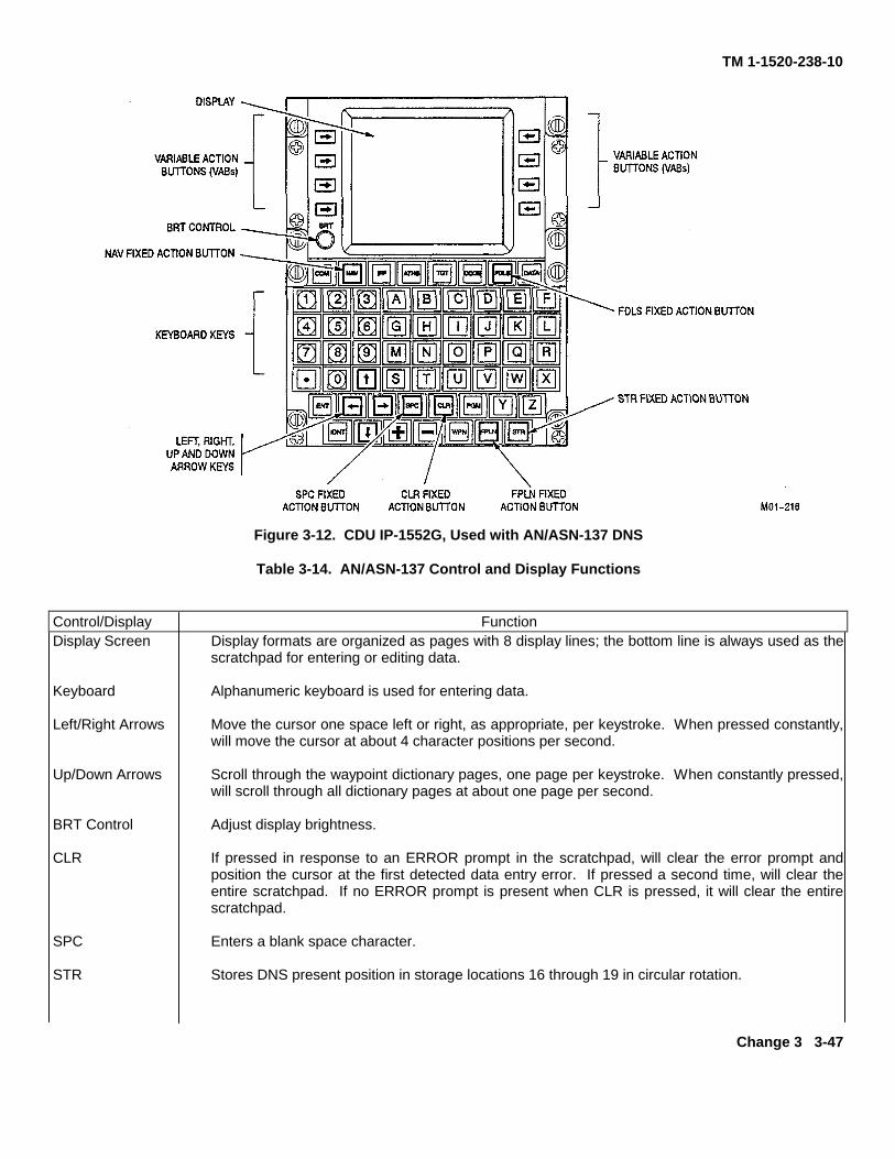
TM 1-1520-238-10
Figure 3-12. CDU IP-1552G, Used with AN/ASN-137 DNS
Table 3-14. AN/ASN-137 Control and Display Functions
Control/Display FunctionDisplay Screen Display formats are organized as pages with 8 display lines; the bottom line is always used as the
scratchpad for entering or editing data.
Keyboard Alphanumeric keyboard is used for entering data.
Left/Right Arrows Move the cursor one space left or right, as appropriate, per keystroke. When pressed constantly,will move the cursor at about 4 character positions per second.
Up/Down Arrows Scroll through the waypoint dictionary pages, one page per keystroke. When constantly pressed,will scroll through all dictionary pages at about one page per second.
BRT Control Adjust display brightness.
CLR If pressed in response to an ERROR prompt in the scratchpad, will clear the error prompt andposition the cursor at the first detected data entry error. If pressed a second time, will clear theentire scratchpad. If no ERROR prompt is present when CLR is pressed, it will clear the entirescratchpad.
SPC Enters a blank space character.
STR Stores DNS present position in storage locations 16 through 19 in circular rotation.
Change 3 3-47
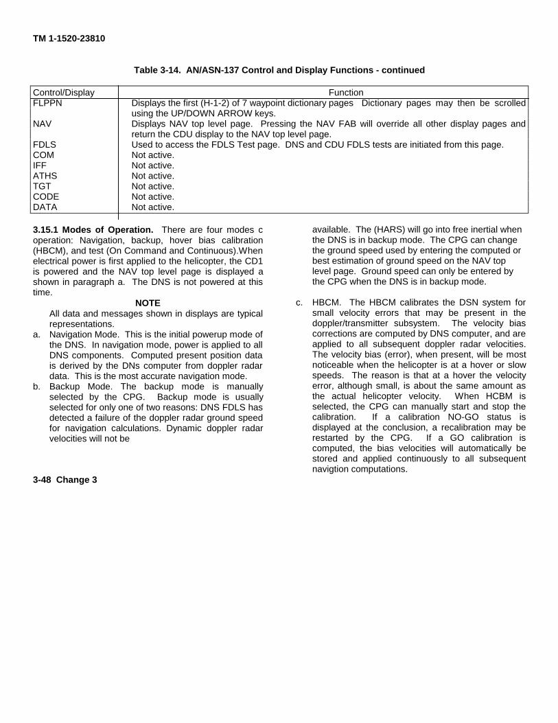
TM 1-1520-23810
Table 3-14. AN/ASN-137 Control and Display Functions - continued
Control/Display FunctionFLPPN Displays the first (H-1-2) of 7 waypoint dictionary pages Dictionary pages may then be scrolled
using the UP/DOWN ARROW keys.NAV Displays NAV top level page. Pressing the NAV FAB will override all other display pages and
return the CDU display to the NAV top level page.FDLS Used to access the FDLS Test page. DNS and CDU FDLS tests are initiated from this page.COM Not active.IFF Not active.ATHS Not active.TGT Not active.CODE Not active.DATA Not active.
3.15.1 Modes of Operation. There are four modes coperation: Navigation, backup, hover bias calibration(HBCM), and test (On Command and Continuous).Whenelectrical power is first applied to the helicopter, the CD1is powered and the NAV top level page is displayed ashown in paragraph a. The DNS is not powered at thistime.
NOTEAll data and messages shown in displays are typicalrepresentations.
a. Navigation Mode. This is the initial powerup mode ofthe DNS. In navigation mode, power is applied to allDNS components. Computed present position datais derived by the DNs computer from doppler radardata. This is the most accurate navigation mode.
b. Backup Mode. The backup mode is manuallyselected by the CPG. Backup mode is usuallyselected for only one of two reasons: DNS FDLS hasdetected a failure of the doppler radar ground speedfor navigation calculations. Dynamic doppler radarvelocities will not be
available. The (HARS) will go into free inertial whenthe DNS is in backup mode. The CPG can changethe ground speed used by entering the computed orbest estimation of ground speed on the NAV toplevel page. Ground speed can only be entered bythe CPG when the DNS is in backup mode.
c. HBCM. The HBCM calibrates the DSN system forsmall velocity errors that may be present in thedoppler/transmitter subsystem. The velocity biascorrections are computed by DNS computer, and areapplied to all subsequent doppler radar velocities.The velocity bias (error), when present, will be mostnoticeable when the helicopter is at a hover or slowspeeds. The reason is that at a hover the velocityerror, although small, is about the same amount asthe actual helicopter velocity. When HCBM isselected, the CPG can manually start and stop thecalibration. If a calibration NO-GO status isdisplayed at the conclusion, a recalibration may berestarted by the CPG. If a GO calibration iscomputed, the bias velocities will automatically bestored and applied continuously to all subsequentnavigtion computations.
3-48 Change 3
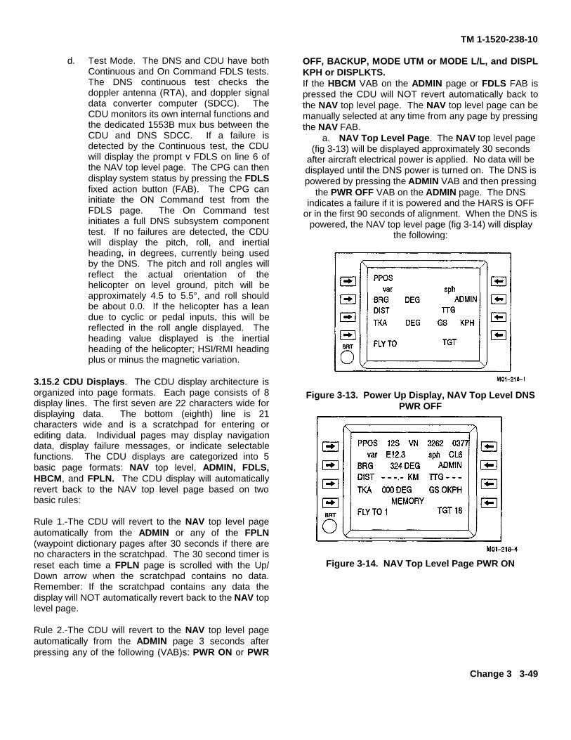
TM 1-1520-238-10
d. Test Mode. The DNS and CDU have bothContinuous and On Command FDLS tests.The DNS continuous test checks thedoppler antenna (RTA), and doppler signaldata converter computer (SDCC). TheCDU monitors its own internal functions andthe dedicated 1553B mux bus between theCDU and DNS SDCC. If a failure isdetected by the Continuous test, the CDUwill display the prompt v FDLS on line 6 ofthe NAV top level page. The CPG can thendisplay system status by pressing the FDLSfixed action button (FAB). The CPG caninitiate the ON Command test from theFDLS page. The On Command testinitiates a full DNS subsystem componenttest. If no failures are detected, the CDUwill display the pitch, roll, and inertialheading, in degrees, currently being usedby the DNS. The pitch and roll angles willreflect the actual orientation of thehelicopter on level ground, pitch will beapproximately 4.5 to 5.5°, and roll shouldbe about 0.0. If the helicopter has a leandue to cyclic or pedal inputs, this will bereflected in the roll angle displayed. Theheading value displayed is the inertialheading of the helicopter; HSI/RMI headingplus or minus the magnetic variation.
3.15.2 CDU Displays. The CDU display architecture isorganized into page formats. Each page consists of 8display lines. The first seven are 22 characters wide fordisplaying data. The bottom (eighth) line is 21characters wide and is a scratchpad for entering orediting data. Individual pages may display navigationdata, display failure messages, or indicate selectablefunctions. The CDU displays are categorized into 5basic page formats: NAV top level, ADMIN, FDLS,HBCM, and FPLN. The CDU display will automaticallyrevert back to the NAV top level page based on twobasic rules:
Rule 1.-The CDU will revert to the NAV top level pageautomatically from the ADMIN or any of the FPLN(waypoint dictionary pages after 30 seconds if there areno characters in the scratchpad. The 30 second timer isreset each time a FPLN page is scrolled with the Up/Down arrow when the scratchpad contains no data.Remember: If the scratchpad contains any data thedisplay will NOT automatically revert back to the NAV toplevel page.
Rule 2.-The CDU will revert to the NAV top level pageautomatically from the ADMIN page 3 seconds afterpressing any of the following (VAB)s: PWR ON or PWR
OFF, BACKUP, MODE UTM or MODE L/L, and DISPLKPH or DISPLKTS.If the HBCM VAB on the ADMIN page or FDLS FAB ispressed the CDU will NOT revert automatically back tothe NAV top level page. The NAV top level page can bemanually selected at any time from any page by pressingthe NAV FAB.
a. NAV Top Level Page. The NAV top level page(fig 3-13) will be displayed approximately 30 seconds
after aircraft electrical power is applied. No data will bedisplayed until the DNS power is turned on. The DNS ispowered by pressing the ADMIN VAB and then pressing
the PWR OFF VAB on the ADMIN page. The DNSindicates a failure if it is powered and the HARS is OFF
or in the first 90 seconds of alignment. When the DNS ispowered, the NAV top level page (fig 3-14) will display
the following:
Figure 3-13. Power Up Display, NAV Top Level DNSPWR OFF
Figure 3-14. NAV Top Level Page PWR ON
Change 3 3-49
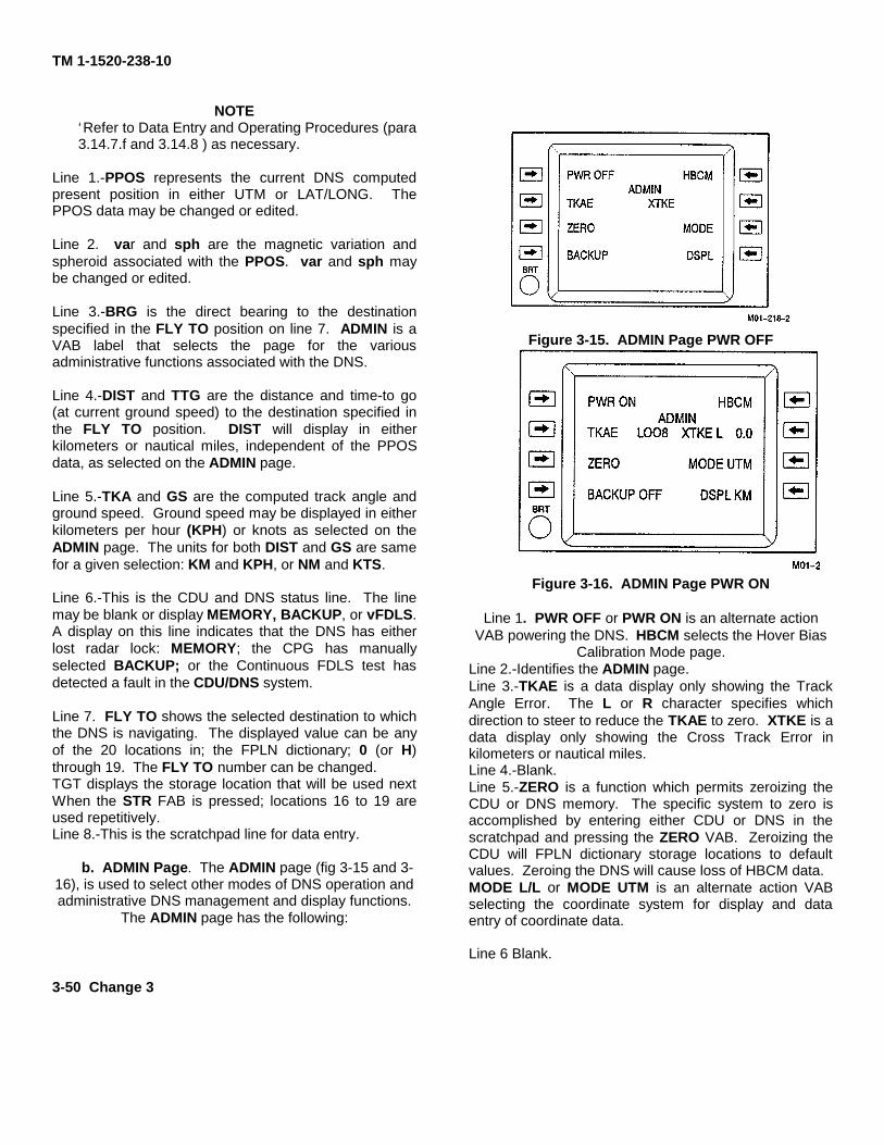
TM 1-1520-238-10
NOTE‘Refer to Data Entry and Operating Procedures (para3.14.7.f and 3.14.8 ) as necessary.
Line 1.-PPOS represents the current DNS computedpresent position in either UTM or LAT/LONG. ThePPOS data may be changed or edited.
Line 2. var and sph are the magnetic variation andspheroid associated with the PPOS. var and sph maybe changed or edited.
Line 3.-BRG is the direct bearing to the destinationspecified in the FLY TO position on line 7. ADMIN is aVAB label that selects the page for the variousadministrative functions associated with the DNS.
Line 4.-DIST and TTG are the distance and time-to go(at current ground speed) to the destination specified inthe FLY TO position. DIST will display in eitherkilometers or nautical miles, independent of the PPOSdata, as selected on the ADMIN page.
Line 5.-TKA and GS are the computed track angle andground speed. Ground speed may be displayed in eitherkilometers per hour (KPH) or knots as selected on theADMIN page. The units for both DIST and GS are samefor a given selection: KM and KPH, or NM and KTS.
Line 6.-This is the CDU and DNS status line. The linemay be blank or display MEMORY, BACKUP, or vFDLS.A display on this line indicates that the DNS has eitherlost radar lock: MEMORY; the CPG has manuallyselected BACKUP; or the Continuous FDLS test hasdetected a fault in the CDU/DNS system.
Line 7. FLY TO shows the selected destination to whichthe DNS is navigating. The displayed value can be anyof the 20 locations in; the FPLN dictionary; 0 (or H)through 19. The FLY TO number can be changed.TGT displays the storage location that will be used nextWhen the STR FAB is pressed; locations 16 to 19 areused repetitively.Line 8.-This is the scratchpad line for data entry.
b. ADMIN Page. The ADMIN page (fig 3-15 and 3-16), is used to select other modes of DNS operation andadministrative DNS management and display functions.
The ADMIN page has the following:
Figure 3-15. ADMIN Page PWR OFF
Figure 3-16. ADMIN Page PWR ON
Line 1. PWR OFF or PWR ON is an alternate actionVAB powering the DNS. HBCM selects the Hover Bias
Calibration Mode page.Line 2.-Identifies the ADMIN page.Line 3.-TKAE is a data display only showing the TrackAngle Error. The L or R character specifies whichdirection to steer to reduce the TKAE to zero. XTKE is adata display only showing the Cross Track Error inkilometers or nautical miles.Line 4.-Blank.Line 5.-ZERO is a function which permits zeroizing theCDU or DNS memory. The specific system to zero isaccomplished by entering either CDU or DNS in thescratchpad and pressing the ZERO VAB. Zeroizing theCDU will FPLN dictionary storage locations to defaultvalues. Zeroing the DNS will cause loss of HBCM data.MODE L/L or MODE UTM is an alternate action VABselecting the coordinate system for display and dataentry of coordinate data.
Line 6 Blank.
3-50 Change 3
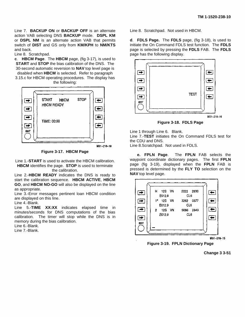
TM 1-1520-238-10
Line 7. BACKUP ON or BACKUP OFF is an alternateaction VAB selecting DNS BACKUP mode. DSPL KMor DSPL NM is an alternate action VAB that permitsswitch of DIST and GS only from KM/KPH to NM/KTSand back.Line 8. Scratchpad.c. HBCM Page. The HBCM page, (fig 3-17), is used toSTART and STOP the bias calibration of the DNS. The30-second automatic reversion to NAV top level page isdisabled when HBCM is selected. Refer to paragraph
3.15.c for HBCM operating procedures. The display hasthe following:
Figure 3-17. HBCM Page
Line 1.-START is used to activate the HBCM calibration.HBCM identifies the page. STOP is used to terminate
the calibration.Line 2.-HBCM READY indicates the DNS is ready tostart the calibration sequence. HBCM ACTIVE, HBCMGO, and HBCM NO-GO will also be displayed on the lineas appropriate.Line 3.-Error messages pertinent loan HBCM conditionare displayed on this line.Line 4.-Blank.Line 5.-TIME XX:XX indicates elapsed time inminutes/seconds for DNS computations of the biascalibration. The timer will stop while the DNS is inmemory during the bias calibration.Line 6.-Blank.Line 7.-Blank.
Line 8. Scratchpad. Not used in HBCM.
d. FDLS Page. The FDLS page, (fig 3-18), is used toinitiate the On Command FDLS test function. The FDLSpage is selected by pressing the FDLS FAB. The FDLSpage has the following display.
Figure 3-18. FDLS Page
Line 1 through Line 6. Blank.Line 7.-TEST initiates the On Command FDLS test forthe CDU and DNS.Line 8.Scratchpad. Not used in FDLS.
e. FPLN Page. The FPLN FAB selects thewaypoint coordinate dictionary pages. The first FPLNpage (fig 3-19), displayed when the FPLN FAB ispressed is determined by the FLY TO selection on theNAV top level page.
Figure 3-19. FPLN Dictionary Page
Change 3 3-51

TM 1-1520-238-10
The waypoints are organized on pages as shown intable 3-15.
Table 3-15. Waypoints
Page Waypoints1 Home 1, 22 3,4,53 6,7,84 9,10, 115 12, 13, 146 15, 16, 177 18 and 19
The Up/Down arrow keys can be used to scroll throughthe FPLN dictionary pages. An * is shown immediatelyafter the storage location currently being used for FLYTO computations and it cannot be changed until someother location is chosen to FLY TO. The page has thefollowing data organization:
Line 1. - Displays the coordinate location data.
Line 2. - Displays the magnetic variation and spheroidassociated with the coordinate data above it.
Line 3. - Displays the next coordinate location data.
Line 4. - Displays the magnetic variation and spheroidassociated with the coordinate data above it.
Line 5. - Displays the next coordinate location data.
Line 6. - Displays the magnetic variation and spheroidassociated with the coordinate data above it.
Line 7 - Blank.
Line 8. - Scratchpad for data input.
3.15.3 Data Entry Procedures. The CDU displaypresent position can be manually updated, waypointlocations stored, FLY TO destination selected and otherdata entries made via the CDU keyboard. Keyboardentries appear on the scratchpad. The CDU checks thevalidity of all data entered before it transfers the data tothe appropriate location on the display.
a. General Data Entry and Data Correction.General data entry and data correction procedures fol-low the example of PPOS, var, sph, and MODE UTM onthe NAV top level page.
DATA ENTRY EXAMPLE
1. Use the keyboard keys, (fig 3-11), enter the followinginto the scratchpad:
12SVN32620377E12C5NOTE
• The last character (5) is deliberately erroneous.• Observe that each character appears on thescratchpad, left justified, as it is entered.
2. PPOS Press. Observe that the scratchpad displayalternates between the data entered and the promptERROR.
3. CLR FAB - Press. Error prompt is cleared and thedata in the scratchpad has the cursor positioned underthe error as shown below:
12SVN32620377E12C5_
NOTEThe cursor is positioned under the first error detected. Ifmore than one error is detected, the cursor moves left toright to the next error. Continue editing until all data iscorrected.
4. Enter 6. Observe that 5 changes to 6.
5. PPOS - Press. Observe that the scratchpad is nowblank and lines 1 and 2 of the CDU display appear asfollows:
PPOS 12S VN 3262 0377var E012.0 sph CL6
3.15.4 Power Up Procedures. The steps in thisprocedure list actions required (and expected CDUdisplay results) to ready the DNS for flight. Refer to DataEntry (para 3.15.3 ) for detailed techniques andparameters of such actions as:
• UTM or L/L Coordinate Entries• Hover Bias Calibration
• • General Data Entry and Error Correction
3-52 Change 3
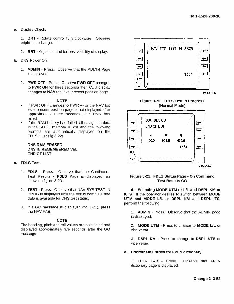
TM 1-1520-238-10
a. Display Check.
1. BRT - Rotate control fully clockwise. Observebrightness change.
2. BRT - Adjust control for best visibility of display.
b. DNS Power On.
1. ADMIN - Press. Observe that the ADMIN Pageis displayed
2. PWR OFF - Press. Observe PWR OFF changesto PWR ON for three seconds then CDU displaychanges to NAV top level present position page.
NOTE• If PWR OFF changes to PWR --- or the NAV top
level present position page is not displayed afterapproximately three seconds, the DNS hasfailed.
• If the RAM battery has failed, all navigation datain the SDCC memory is lost and the followingprompts are automatically displayed on theFDLS page (fig 3-22).
DNS RAM ERASEDDNS IN REMEMBERED VELEND OF LIST
c. FDLS Test.
1. FDLS - Press. Observe that the ContinuousTest Results - FDLS Page is displayed, asshown in figure 3-20.
2. TEST - Press. Observe that NAV SYS TEST INPROG is displayed until the test is complete anddata is available for DNS test status.
3. If a GO message is displayed (fig 3-21), pressthe NAV FAB.
NOTEThe heading, pitch and roll values are calculated anddisplayed approximately five seconds after the GOmessage.
Figure 3-20. FDLS Test in Progress(Normal Mode)
Figure 3-21. FDLS Status Page - On CommandTest Results GO
d. Selecting MODE UTM or L/L and DSPL KM orKTS. If the operator desires to switch between MODEUTM and MODE L/L or DSPL KM and DSPL ITS,perform the following:
1. ADMIN - Press. Observe that the ADMIN pageis displayed.
2. MODE UTM - Press to change to MODE L/L orvice versa.
3. DSPL KM - Press to change to DSPL KTS orvice versa.
e. Coordinate Entries for FPLN dictionary.
1. FPLN FAB - Press. Observe that FPLNdictionary page is displayed.
Change 3 3-53
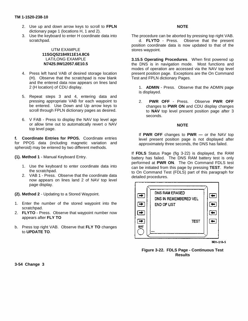
TM 1-1520-238-10
2. Use up and down arrow keys to scroll to FPLNdictionary page 1 (locations H, 1 and 2).
3. Use the keyboard to enter H coordinate data intoscratchpad.
UTM EXAMPLE11SGQ52184911E14.8C6
LAT/LONG EXAMPLEN7425.9W12057.6E10.5
4. Press left hand VAB of desired storage location(H). Observe that the scratchpad is now blankand the entered data now appears on lines land2 (H location) of CDU display.
5. Repeat steps 3 and 4, entering data andpressing appropriate VAB for each waypoint tobe entered. Use Down and Up arrow keys toscroll through FPLN dictionary pages as desired.
6. V FAB - Press to display the NAV top level ageor allow time out to automatically revert o NAVtop level page.
f. Coordinate Entries for PPOS. Coordinate entriesfor PPOS data (including magnetic variation andspheroid) may be entered by two different methods.
(1). Method 1 - Manual Keyboard Entry.
1. Use the keyboard to enter coordinate data intothe scratchpad.
2. VAB 1 - Press. Observe that the coordinate datanow appears on lines land 2 of NAV top levelpage display.
(2). Method 2 - Updating to a Stored Waypoint.
1. Enter the number of the stored waypoint into thescratchpad.
2. FLYTO - Press. Observe that waypoint number nowappears after FLY TO
b. Press top right VAB. Observe that FLY TO changesto UPDATE TO.
NOTE
The procedure can be aborted by pressing top right VAB.d. FLYTO - Press. Observe that the present
position coordinate data is now updated to that of thestores waypoint.
3.15.5 Operating Procedures. When first powered upthe DNS is in navigation mode. Most functions andmodes of operation are accessed via the NAV top levelpresent position page. Exceptions are the On CommandTest and FPLN dictionary Pages.
1. ADMIN - Press. Observe that the ADMIN pageis displayed.
2. PWR OFF - Press. Observe PWR OFFchanges to PWR ON and CDU display changesto NAV top level present position page after 3seconds.
NOTE
If PWR OFF changes to PWR --- or the NAV toplevel present position page is not displayed afterapproximately three seconds, the DNS has failed.
If FDLS Status Page (fig 3-22) is displayed, the RAMbattery has failed. The DNS RAM battery test is onlyperformed at PWR ON. The On Command FDLS testcan be initiated from this page by pressing TEST. Referto On Command Test (FDLS) part of this paragraph fordetailed procedures.
Figure 3-22. FDLS Page - Continuous TestResults
3-54 Change 3
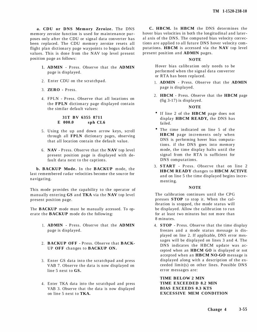
TM 1-1520-238-10
a. CDU or DNS Memory Zeroize. The DNSmemory zeroize function is used for maintenance pur-poses only after the CDU or signal data converter hasbeen replaced. The CDU memory zeroize resets allflight plan dictionary page waypoints to bogus defaultvalues. This is done from the NAV top level presentposition page as follows:
1.
2.
3.
4.
5.
6.
ADMIN - Press. Observe that the ADMINpage is displayed.
Enter CDU on the scratchpad.
ZERO - Press.
FPLN - Press. Observe that all locations onthe FPLN dictionary page displayed containthe similar default values:
31T BV 6355 8711E 000.0 sph CL6
Using the up and down arrow keys, scrollthrough all FPLN dictionary pages, observingthat all location contain the default value.
NAV - Press. Observe that the NAV top levelpresent position page is displayed with de-fault data next to the captions.
b. BACKUP Mode. In the BACKUP mode, thelast remembered radar velocities become the source fornavigating.
This mode provides the capability to the operator ofmanually entering GS and TKA via the NAV top levelpresent position page.
The BACKUP mode must be manually accessed. To op-erate the BACKUP mode do the following:
1.
2.
3.
4.
ADMIN - Press. Observe that the ADMINpage is displayed.
BACKUP OFF - Press. Observe that BACK-UP OFF changes to BACKUP ON.
Enter GS data into the scratchpad and pressVAB 7. Observe the data is now displayed online 5 next to GS.
Enter TKA data into the scratchpad and pressVAB 3. Observe that the data is now displayedon line 5 next to TKA.
C. HBCM. In HBCM the DNS determines thehover bias velocities in both the longitudinal and later-al axis of the DNS. The computed bias velocity correc-tions are applied to all future DNS hover velocity com-putations. HBCM is accessed via the NAV top levelpresent position and ADMIN pages.
NOTE
Hover bias calibration only needs to beperformed when the signal data converteror RTA has been replaced.
1.
2.
l
l
3.
ADMIN - Press. Observe that the ADMINpage is displayed.
HBCM - Press. Observe that the HBCM page(fig 3-17) is displayed.
NOTE
If line 2 of the HBCM page does notdisplay HBCM READY, the DNS hasfailed.
The time indicated on line 5 of theHBCM page increments only whenDNS is performing hover bias computa-tions. if the DNS goes into memorymode, the time display halts until thesignal from the RTA is sufficient forDNS computations.
START - Press. Observe that on line 2HBCM READY changes to HBCM ACTIVEand on line 5 the time displayed begins incre-menting.
NOTE
The calibration continues until the CPGpresses STOP to stop it. When the cal-ibration is stopped, the mode status willbe displayed. Allow the calibration to runfor at least two minutes but not more than8 minutes.
4. STOP - Press. Observe that the time displayfreezes and a mode status message is dis-played on line 2. If applicable, DNS error mes-sages will be displayed on lines 3 and 4. TheDNS indicates the HBCM update was ac-cepted when an HBCM GO is displayed or notaccepted when an HBCM NO-GO message isdisplayed along with a description of the ex-ceeded limit(s) on other lines. Possible DNSerror messages are:
TIME BELOW 2 MINTIME EXCEEDED 8.2 MINBIAS EXCEEDS 0.3 KTSEXCESSIVE MEM CONDITION
Change 4 3-55
TM 1-1520-238-10
NOTE
If a NO-GO condition is detected, a recal-ibration can be initiated by pressingSTART again. This will zero the timerand allow for additional bias velocities cal-culations. If either TIME message is dis-played, re-initiate the calibration. If theBIAS message is displayed, re-initiatecalibration one time. If the BIAS messageis displayed again, write up the system. Ifthe excessive memory message is dis-played, attempt to re-locate the aircraftover a surface area that is a non-reflectivesurface (short grass/coarse surface area)and re-initiate the calibration.
5. NAV FAB - Press to exit the HBCM. Observethe CDU displays the NAV top level page.
d. MODE UTM or L/L. This is an alternate actionfunction which toggles PPOS and waypoint dictionarycoordinate displays between UTM and LAT/LONG.This is done from the NAV top level present positionpage as follows:
1. ADMIN - Press. Observe that the ADMINpage is displayed.
2. MODE UTM - Press to change to MODE L/Lor vice versa.
e. DISPLAY KM or KTS. This is an alternate ac-tion function which toggles the DIST and GS displaysbetween KM and KPH or NM and KTS respectively.This is done from the NAV top level present positionpage as follows:
1. ADMIN - Press. Observe that the ADMINpage is displayed.
2. DSPL KM - Press to change to DSPL KTS orvice versa.
3-56 Change 4
f. PPOS Updates to a Stored Waypoint Coordi-nate. PPOS updates to a stored waypoint coordinateare implemented from the NAV top level present posi-tion page. When overflying a waypoint, do the follow-ing:
NOTE
A flashing UPDATE SPHEROID mes-sage will appear on the scratchpad if theFLY TO waypoint selected has a differentspheroid than the current present posi-tion data.
1.
2.
3.
VAB 5 - Press. Observe PPOS data freezesand FLY TO changes to UPDATE TO. TheDNS continues to compute aircraft presentposition.
FLY TO - Press to complete an update to theposition of the waypoint plus any offset dis-tance traveled following the initiation of aPPOS update.
To reject an update (abort), press either topright VAB again or the NAV FAB.
NOTE
Following either an acceptance or rejec-tion of a PPOS update, the CDU displaysFLY TO and resumes displaying DNScomputed PPOS and status data dynami-cally.
g. PPOS Updates to an Unstored Way-point. PPOS updates to an unstored waypoint are im-plemented from the NAV top level present positionpage as follows:
1. PPOS - Press. Observe PPOS changes to UP-DATE and display freezes. This allows forcomparison of DNS computed present positionlocation with a known present position loca-tion.
NOTE
This type of PPOS update does not requirethat the aircraft remain in a hover to up-date the present position. This type of up-date also provides for position compensa-tion for any distance traveled following aPPOS update.
2. To complete the PPOS update to a known val-ue, the operator enters the desired presentposition into the scratchpad and pressesUPDT or:
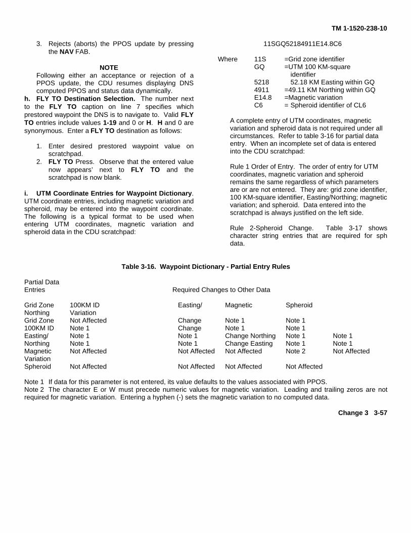
TM 1-1520-238-10
3. Rejects (aborts) the PPOS update by pressingthe NAV FAB.
NOTEFollowing either an acceptance or rejection of aPPOS update, the CDU resumes displaying DNScomputed PPOS and status data dynamically.
h. FLY TO Destination Selection. The number nextto the FLY TO caption on line 7 specifies whichprestored waypoint the DNS is to navigate to. Valid FLYTO entries include values 1-19 and 0 or H. H and 0 aresynonymous. Enter a FLY TO destination as follows:
1. Enter desired prestored waypoint value onscratchpad.
2. FLY TO Press. Observe that the entered valuenow appears’ next to FLY TO and thescratchpad is now blank.
i. UTM Coordinate Entries for Waypoint Dictionary.UTM coordinate entries, including magnetic variation andspheroid, may be entered into the waypoint coordinate.The following is a typical format to be used whenentering UTM coordinates, magnetic variation andspheroid data in the CDU scratchpad:
11SGQ52184911E14.8C6
Where 11S =Grid zone identifierGQ =UTM 100 KM-square
identifier5218 52.18 KM Easting within GQ 4911 =49.11 KM Northing within GQE14.8 =Magnetic variationC6 = Spheroid identifier of CL6
A complete entry of UTM coordinates, magneticvariation and spheroid data is not required under allcircumstances. Refer to table 3-16 for partial dataentry. When an incomplete set of data is enteredinto the CDU scratchpad:
Rule 1 Order of Entry. The order of entry for UTMcoordinates, magnetic variation and spheroidremains the same regardless of which parametersare or are not entered. They are: grid zone identifier,100 KM-square identifier, Easting/Northing; magneticvariation; and spheroid. Data entered into thescratchpad is always justified on the left side.
Rule 2-Spheroid Change. Table 3-17 showscharacter string entries that are required for sphdata.
Table 3-16. Waypoint Dictionary - Partial Entry Rules
Partial DataEntries Required Changes to Other Data
Grid Zone 100KM ID Easting/ Magnetic SpheroidNorthing VariationGrid Zone Not Affected Change Note 1 Note 1100KM ID Note 1 Change Note 1 Note 1Easting/ Note 1 Note 1 Change Northing Note 1 Note 1Northing Note 1 Note 1 Change Easting Note 1 Note 1Magnetic Not Affected Not Affected Not Affected Note 2 Not AffectedVariationSpheroid Not Affected Not Affected Not Affected Not Affected
Note 1 If data for this parameter is not entered, its value defaults to the values associated with PPOS.Note 2 The character E or W must precede numeric values for magnetic variation. Leading and trailing zeros are notrequired for magnetic variation. Entering a hyphen (-) sets the magnetic variation to no computed data.
Change 3 3-57

TM 1-1520-238-10
Table 3-17. Spheroid String Entries
Spheroid Character String Entry Automatic DisplayAUSTRALIAN AU AUOBESSEL BE BEOEVEREST EV EVOINTERNATIONAL IN INOCLARKE 1880 CO CLOCLARKE 1866 C6 CL6MALAYAN* MA MAO
*Currently not utilized
J. UTM Coordinate Entries for Present Position.When an incomplete set of UTM coordinate, magneticvariation and spheroid are entered into
PPOS, refer to table 3-18 for exceptions to waypointdictionary entries.
Table 3-18. PPOS - Partial Entry Rules
Partial Data Required Changes to Other Data
Entries Grid Zone 100KM ID Easting/ MagneticNorthing Variation Spheroid
Grid Zone Change Change Not Affected Not Affected100KM ID Not Affected Change Change Not Affected Not AffectedEasting/ Not Affected Not Affected Change Northing Not Affected Not AffectedNorthing Not Affected Not Affected Change Easting Not Affected Not AffectedMagnetic Not Affected Not Affected Not Affected Note 1 Not AffectedVariationSpheroid Not Affected Not Affected Not Affected Not AffectedNote 1: The character E or W must precede numeric values for magnetic variation. Leading and trailing zeros are notrequired for magnetic variation. Entering a hyphen (-) sets the magnetic variation to no computed data.
3-58 Change 3
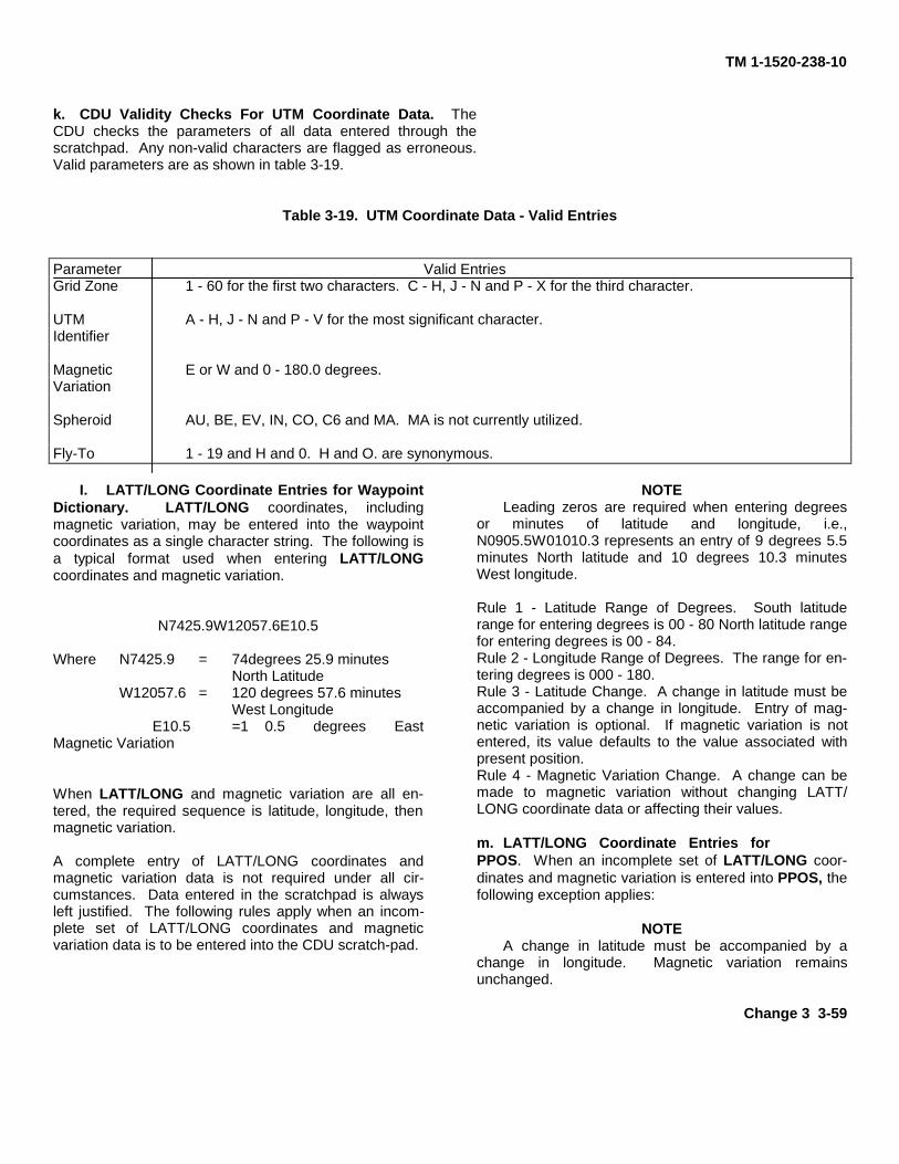
TM 1-1520-238-10
k. CDU Validity Checks For UTM Coordinate Data. TheCDU checks the parameters of all data entered through thescratchpad. Any non-valid characters are flagged as erroneous.Valid parameters are as shown in table 3-19.
Table 3-19. UTM Coordinate Data - Valid Entries
Parameter Valid EntriesGrid Zone 1 - 60 for the first two characters. C - H, J - N and P - X for the third character.
UTM A - H, J - N and P - V for the most significant character.Identifier
Magnetic E or W and 0 - 180.0 degrees.Variation
Spheroid AU, BE, EV, IN, CO, C6 and MA. MA is not currently utilized.
Fly-To 1 - 19 and H and 0. H and O. are synonymous.
I. LATT/LONG Coordinate Entries for WaypointDictionary. LATT/LONG coordinates, includingmagnetic variation, may be entered into the waypointcoordinates as a single character string. The following isa typical format used when entering LATT/LONGcoordinates and magnetic variation.
N7425.9W12057.6E10.5
Where N7425.9 = 74degrees 25.9 minutesNorth Latitude
W12057.6 = 120 degrees 57.6 minutesWest Longitude
E10.5 =1 0.5 degrees EastMagnetic Variation
When LATT/LONG and magnetic variation are all en-tered, the required sequence is latitude, longitude, thenmagnetic variation.
A complete entry of LATT/LONG coordinates andmagnetic variation data is not required under all cir-cumstances. Data entered in the scratchpad is alwaysleft justified. The following rules apply when an incom-plete set of LATT/LONG coordinates and magneticvariation data is to be entered into the CDU scratch-pad.
NOTELeading zeros are required when entering degrees
or minutes of latitude and longitude, i.e.,N0905.5W01010.3 represents an entry of 9 degrees 5.5minutes North latitude and 10 degrees 10.3 minutesWest longitude.
Rule 1 - Latitude Range of Degrees. South latituderange for entering degrees is 00 - 80 North latitude rangefor entering degrees is 00 - 84.Rule 2 - Longitude Range of Degrees. The range for en-tering degrees is 000 - 180.Rule 3 - Latitude Change. A change in latitude must beaccompanied by a change in longitude. Entry of mag-netic variation is optional. If magnetic variation is notentered, its value defaults to the value associated withpresent position.Rule 4 - Magnetic Variation Change. A change can bemade to magnetic variation without changing LATT/LONG coordinate data or affecting their values.
m. LATT/LONG Coordinate Entries forPPOS. When an incomplete set of LATT/LONG coor-dinates and magnetic variation is entered into PPOS, thefollowing exception applies:
NOTEA change in latitude must be accompanied by a
change in longitude. Magnetic variation remainsunchanged.
Change 3 3-59
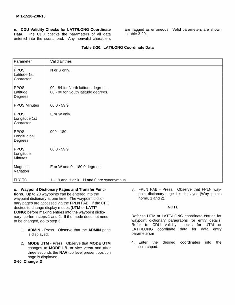
TM 1-1520-238-10
n. CDU Validity Checks for LATT/LONG CoordinateData. The CDU checks the parameters of all dataentered into the scratchpad. Any nonvalid characters
are flagged as erroneous. Valid parameters are shownin table 3-20.
Table 3-20. LAT/LONG Coordinate Data
Parameter Valid Entries
PPOS N or S only.Latitude 1stCharacter
PPOS 00 - 84 for North latitude degrees.Latitude 00 - 80 for South latitude degrees.Degrees
PPOS Minutes 00.0 - 59.9.
PPOS E or W only.Longitude 1stCharacter
PPOS 000 - 180.LongitudinalDegrees
PPOS 00.0 - 59.9.LongitudeMinutes
Magnetic E or W and 0 - 180.0 degrees.Variation
FLY TO 1 - 19 and H or 0 H and 0 are synonymous.
o. Waypoint Dictionary Pages and Transfer Func-tions. Up to 20 waypoints can be entered into thewaypoint dictionary at one time. The waypoint dictio-nary pages are accessed via the FPLN FAB. If the CPGdesires to change display modes (UTM or LATT/LONG) before making entries into the waypoint dictio-nary, perform steps 1 and 2. If the mode does not needto be changed, go to step 3.
1. ADMIN - Press. Observe that the ADMIN pageis displayed.
2. MODE UTM - Press. Observe that MODE UTMchanges to MODE L/L or vice versa and afterthree seconds the NAV top level present positionpage is displayed.
3. FPLN FAB - Press. Observe that FPLN way-point dictionary page 1 is displayed (Way- pointshome, 1 and 2).
NOTE
Refer to UTM or LATT/LONG coordinate entries forwaypoint dictionary paragraphs for entry details.Refer to CDU validity checks for UTM orLATT/LONG coordinate data for data entryparametersm
4. Enter the desired coordinates into thescratchpad.
3-60 Change 3
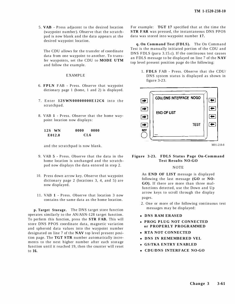
TM 1-1520-238-10
5. VAB - Press adjacent to the desired location(waypoint number). Observe that the scratch-pad is now blank and the data appears at thedesired waypoint location.
The CDU allows for the transfer of coordinatedata from one waypoint to another. To trans-fer waypoints, set the CDU to MODE UTMand follow the example.
EXAMPLE
6. FPLN FAB - Press. Observe that waypointdictionary page 1 (home, 1 and 2) is displayed.
7. Enter 12SWN00000000E12C6 into thescratchpad.
8. VAB 1 - Press. Observe that the home way-point location now displays:
12S WN 0000 0000E012.0 CL6
and the scratchpad is now blank.
9. VAB 5 - Press. Observe that the data in thehome location is unchanged and the scratch-pad now displays the data entered in step 2.
10. Press down arrow key. Observe that waypointdictionary page 2 (locations 3, 4, and 5) arenow displayed.
11. VAB 1 - Press. Observe that location 3 nowcontains the same data as the home location.
p. Target Storage. The DNS target store functionoperates similarly to the AN/ASN-128 target function.To perform this function, press the STR FAB. This willstore DNS PPOS coordinate data, magnetic variationand spheroid data values into the waypoint numberdesignated on line 7 of the NAV top level present posi-tion page. The TGT STR number automatically incre-ments to the next higher number after each storagefunction until it reached 19, then the counter will resetto 16.
For example: TGT 17 specified that at the time theSTR FAR was pressed, the instantaneous DNS PPOSdata was stored into waypoint number 17.
q. On Command Test (FDLS). The On CommandTest is the manually initiated portion of the CDU andDNS FDLS (para 3.15.c). If the continuous test causesan FDLS message to be displayed on line 7 of the NAVtop level present position page do the following:
1. FDLS FAB - Press. Observe that the CDU/DNS system status is displayed as shown infigure 3-23.
M01-218-8
Figure 3-23. FDLS Status Page On-CommandTest Results NO-GO
NOTE
An END OF LIST message is displayedfollowing the last message (GO or NO-GO). If there are more than three mal-functions detected, use the Down and Uparrow keys to scroll through the displaypages.
2. One or more of the following continuous testmessages may be displayed:
l l DNS RAM ERASED
l PROG PLUG NOT CONNECTEDor PROPERLY PROGRAMMED
l l RTA NOT CONNECTED
l l DNS IN REMEMBERED VEL
l GS/TKA ENTRY ENABLED
l l CDU/DNS INTERFACE NO-GO
Change 3 3-61
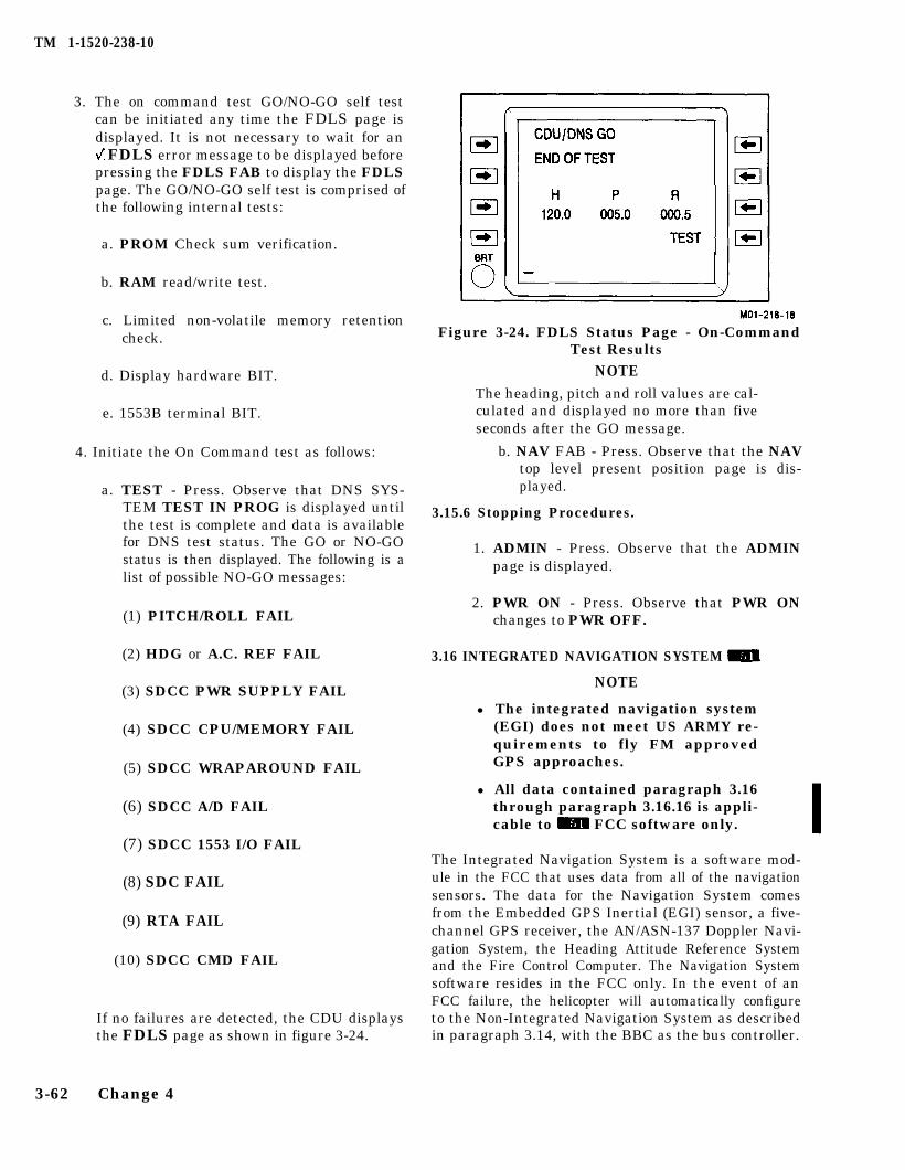
TM 1-1520-238-10
3. The on command test GO/NO-GO self testcan be initiated any time the FDLS page isdisplayed. It is not necessary to wait for an FDLS error message to be displayed beforepressing the FDLS FAB to display the FDLSpage. The GO/NO-GO self test is comprised ofthe following internal tests:
a. PROM Check sum verification.
b. RAM read/write test.
c. Limited non-volatile memory retentioncheck.
d. Display hardware BIT.
e. 1553B terminal BIT.
4. Initiate the On Command test as follows:
a. TEST - Press. Observe that DNS SYS-TEM TEST IN PROG is displayed untilthe test is complete and data is availablefor DNS test status. The GO or NO-GOstatus is then displayed. The following is alist of possible NO-GO messages:
(1) PITCH/ROLL FAIL
(2) HDG or A.C. REF FAIL
(3) SDCC PWR SUPPLY FAIL
(4) SDCC CPU/MEMORY FAIL
(5) SDCC WRAPAROUND FAIL
(6) SDCC A/D FAIL
(7) SDCC 1553 I/O FAIL
(8) SDC FAIL
(9) RTA FAIL
(10) SDCC CMD FAIL
If no failures are detected, the CDU displaysthe FDLS page as shown in figure 3-24.
3-62 Change 4
Figure 3-24. FDLS Status Page - On-CommandTest Results
NOTEThe heading, pitch and roll values are cal-culated and displayed no more than fiveseconds after the GO message.
b. NAV FAB - Press. Observe that the NAVtop level present position page is dis-played.
3.15.6 Stopping Procedures.
1. ADMIN - Press. Observe that the ADMINpage is displayed.
2. PWR ON - Press. Observe that PWR ONchanges to PWR OFF.
3.16 INTEGRATED NAVIGATION SYSTEM m
NOTE
l The integrated navigation system(EGI) does not meet US ARMY re-quirements to fly FM approvedGPS approaches.
l All data contained paragraph 3.16through paragraph 3.16.16 is appli-cable to m FCC software only.
The Integrated Navigation System is a software mod-ule in the FCC that uses data from all of the navigationsensors. The data for the Navigation System comesfrom the Embedded GPS Inertial (EGI) sensor, a five-channel GPS receiver, the AN/ASN-137 Doppler Navi-gation System, the Heading Attitude Reference Systemand the Fire Control Computer. The Navigation Systemsoftware resides in the FCC only. In the event of anFCC failure, the helicopter will automatically configureto the Non-Integrated Navigation System as describedin paragraph 3.14, with the BBC as the bus controller.
TM 1-1520-238-10
Change 6 3-63
NOTE
• Waypoints stored via the Data TransferUnit (DTU) will not be accessible if theBBC is the bus controller. The CPG canstore up to 20 waypoint coordinates inthe CDU with the MUX switch in SEC(Emergency return routes to be used asa backup in the event of a FCC failure).
• If HARS is free inertial for 20 or moreseconds, the HARSVEL? prompt is dis-played on the CDU. If HARS is free in-ertial for 20 or more seconds andgroundspeed is less than 10 knots, theelectronic trim ball will flash. Careshould be taken when engaging HAS asuncommanded aircraft drift may occur.Aircraft position should be carefullymonitored using visual cues andsymbology.
• If the GPS system is not keyed or istracking less than 4 satellites, HASperformance may degrade over time.Hover Position Box and Velocity Vectoraccuracy will be degraded.
In normal operation, the Navigation System redun-dantly integrates data from the sensors. The EGI is theprimary sensor for inertial data with the HARS as thebackup. The GPS is the primary sensor for helicopterposition. The Doppler provides helicopter velocity data.The GPS, if keyed and verified, will also provide veloc-ity data. The fire control system and flight symbologyuse the redundant data. There are three instrumentsand two subsystems that receive dedicated inputs fromthe sensor array. The HSI, RMI, and RAI receive datadirectly from the HARS for heading and attitude. TheDNS provides data directly to the distance--to--go andNo.1 needle displays on the HSI. The DASE and DNSreceive data directly from the HARS. For those instru-ments, including the DASE and DNS, that receive datadirectly from a sensor, there is no redundancy. If thesensor providing the data has failed, then the affectedinstrument or subsystem will not function. The dis-tance--to--go and steering information is always dis-played on the CDU and HMD symbology. The velocityvector, acceleration cue, vertical speed indicator, andheading tape are driven by the navigation system andnot by any single sensor. This allows redundancy in thedisplays in the event of invalid data or failure of anysensor. No one velocity sensor can cause the error. How-ever, because the Hover Augmentation System (HAS)of the DASE receives velocity data directly from the
HARS, it is possible for a velocity error in the HARS toaffect HAS and not affect the Navigation System. Inthe event that the HARS has been in a free inertialcondition for longer than 20 seconds the HARSVEL?message is displayed in the CDU, NAV status page. Ifthe HARS has been in a free inertial condition for long-er than 20 seconds and the groundspeed of the helicop-ter is less than 10 knots,the pilot HMD trim ball willflash. The purpose of the flashing trim ball is to alertthe pilot that if the HAS is engaged there may be an ini-tial drift of the helicopter.
With the integrated navigation system, the Hover Posi-tion Box drift varies according to whether the EGI orHARS is in use as the inertial sensor, and if using theEGI, whether or not the GPS is operating in PPS(keyed) or SPS (not keyed) mode or operating at all. Us-ing the EGI with the GPS keyed produces optimal HAS/Hover Position Box drift performance. The amount ofdrift may be up to 6 feet the first minute, and as muchas 23 feet after 5 minutes. All other modes of operation(EGI or HARS) may produce Hover Position Box driftthat is random and unpredictable. In these modes of op-eration, the HAS/Hover Position Box drift performancemay be similar to that of the non--integrated navigationsystem (up to 21 feet per minute).
3.16.1 Embedded GPS Inertial (EGI).
a. System Description. The EGI is a velocity aided,strapdown, ring laser gyro based inertial unit. The EGIunit also houses the 5--channel GPS receiver. The ringlaser inertial unit and GPS receiver are treated as sep-arate sensors by the Navigation System and have sepa-rate FD/LS indications. The ring laser gyro operates onan optical principle called the Sagnac Effect whichdeals with the properties of light beams traveling in op-posite directions around a closed loop. In operation, twolaser beams are directed around the ring in oppositedirections; clockwise and counter--clockwise. If the ringrotates in the clockwise direction while the light beamsare in transit then the clockwise beam will seem totravel a shorter distance than the counter--clockwisebeam. This is used as a measure of rotation by observ-ing the interference pattern created at the end of thering when the two laser beams mix together; the fasterthe rotation, the greater the interference pattern.
b. Operation. The EGI begins alignment whenever28 vdc power is available and aligns in the same man-ner as the HARS. The vertical axis is found by aligningthe vertical ring laser gyro with earth’s gravity vector.Inertial north is found by measuring the eastward rota-tion of the earth about its axis. The time to align for the
TM 1-1520-238-10
EGI is approximately 4 minutes. The time is not signifi-cantly affected by temperature. The heading tapesymbology will be displayed when the first platform,EGI or HARS aligns. There is no effect on NavigationSystem accuracy if the engines are started or the mainrotor is turning during alignment. There is no reason,other than normal checklist items, to delay enginestart.
3.16.2 Global Positioning System (GPS).
a. System Description. The GPS receiver installedin the EGI is a 5-channel receiver. The receiver is capa-ble of operating in either C/A code or encrypted P/Ycode. The Group User Variable (GUV) is the normal en-cryption key used. The GUV key is loaded into the EGIusing a KYK-13 or equivalent device. When keyed theGPS receiver will automatically use anti-spoof/jam ca-pabilities when they are in use. The EGI keying connec-tor is located on the aft portion of the right-hand FAB.The EGI will retain the key through power ON/OFF/ON cycles. Because of safeguards built into the EGI, itis not considered classified when keyed. The antennafor the GPS receiver is located on the top of the verticalstabilizer.
b. Operation. The operation of the GPS receiver isentirely automatic. The GPS receiver is powered whenthe EGI is powered. If the GPS is keyed it may take aslong as 12 minutes to verify the key with the satellites.The GPS receiver will provide position and time. TheNavigation System automatically configures to handlethe GPS and DNS velocities for velocity aiding of boththe EGI and HARS. When the GPS has tracked thefirst satellite, it will provide the date and time to theNavigation System. The date and time (ZULU) is dis-played at the top of the ADMIN page of the CDU. Thereare no specific operator actions that may be taken withthe GPS.
3.16.3 Data Transfer Unit (DTU).
The Data Transfer Unit (DTU) is located in the aft por-tion of the CPG right-hand console. The cartridge isprogrammed using the Aviation Mission Planning Sys-tem (AMPS). The AMPS writes the coordinate files forwaypoints, targets, present position and laser codes tothe cartridge. In the helicopter, the FCC handles allreading and writing to the cartridge. Whenever theCPG makes changes to any of the data, the FCC willautomatically update the cartridge with the changes.
3-64 Change 4
This will preserve any changes made by the CPG in theevent of a power transient. On power-up, either initialor following a transient, the FCC will check for copies ofthe files it has written out to the data cartridge. If itfinds the saved files present, it will automatically loadall of the saved files. It the saved files are not found, theFCC will load the AMPS files into the system. This hasthe effect of automatically loading the AMPS files whena “new” cartridge is used. The CPG has the capability ofmanually loading and saving files by using the pages onthe CDU. FCC memory data may only be “dumped” bypowering down the FCC.
3.16.4 Required Navigation Data.
The Integrated Navigation System uses two compo-nents of data for proper operation: map datum and alti-tude. Magnetic variation is automatically calculated bythe Navigation System and requires no action by theflightcrew. Spheroid is not used in any portion of the In-tegrated Navigation System.
a. Altitude. Altitude is used with all coordinatedata to permit the accurate prepointing or cueing toany of the coordinate data in the Navigation System. Ifaltitude is not entered and the coordinate data is usedto prepoint, the current helicopter altitude is used. Therange of altitude entry is -900 to +20000 ft. MSL.
b. Map datums. Map datums are mathematicalmodels of the Earth used to calculate the coordinates onmaps and charts. Currently, many datums are usedthroughout the world to produce maps. The standardfor US Forces is World Geodetic System 1984 (WGS 84).However, many US Military Grid Reference System(MGRS) and foreign maps are still based on other da-turns. Not correcting for different datums can cause sig-nificant errors. The coordinates for a point on theEarth’s surface in one datum will not match the coordi-nates from another datum for the same point. The Inte-grated Navigation System requires that the datum beentered with the coordinate data. If it is not entered, itwill default to the present position datum. The datumincluded with each set of coordinate data allows theNavigation System to calculate the compensations fordifferent datums. Multiple datums can be used and theNavigation System will accurately generate the com-pensated navigation or prepointing data. The datumused is identified by a 2 digit number. Table 3-21 listsall of the datums that may be used with the IntegratedNavigation System.
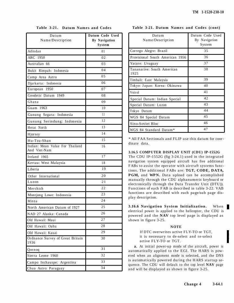
Table 3-21. Datum Names and Codes
DatumName/Description
Datum Code UsedBy Navigation
System
Adindan 01
ARC 1950 02
Australian 66
Bukit Rimpah: Indonesia
Camp Area Astro
Djarkarta: Indonesia
European 1950
Geodetic Datum 1949 08
Ghana 09
03
04
05
06
07
Guam 1963 10
Gunung Segara: Indonesia 11
Gunung Serindung: Indonesia 12
Herat North 13
Hjorsey 14
Hu-Tzu-Shan 15
Indian: Mean Value For ThailandAnd Viet-Nam
16
Ireland 1965 17
Kertau: West Malaysia 18
Liberia
Other International
Luzon
Merchich
Montjong Lowe: Indonesia 23
Minna 24
North American Datum of 1927 25
NAD 27 Alaska: Canada 26
Old Hawaii: Maui 27
Old Hawaii: Oahu 28
Old Hawaii: KauaiOrdnance Survey of Great Britain1936
Qornoq
Sierra Leone 1960
Campo Inchauspe: Argentina
29
30
31
32
33
Chua Astro: Paraguay 34
19
20
21
22
TM 1-1520-238-10
Table 3-21. Datum Names and Codes (cont)
Datum Datum Code UsedName/Description By Navigation
System
Corrego Alegre: Brazil 35
Provisional South American 1956 36
Yacare: Uruguay 37
Tananarive: South American 381925
Timbali: East Malaysia 39
Tokyo: Japan: Korea: Okinawa 40
Voirol 41
Special Datum: Indian Special 42
Special Datum: Luzon 43
Tokyo Datum 44
WGS 84 Special Datum 45
Sino-Soviet Bloc 46
WGS 84 Standard Datum* 47
* All FAA Sectionals and FLIP use this datum for coor-dinate data.
3.16.5 COMPUTER DISPLAY UNIT (CDU) IP-1552GThe CDU IP-1552G (fig 3-24.1) used in the integratednavigation system equipped aircraft has five additionalFABs to assist the operator with aircraft systems func-tions. The additional FABs are: TGT, CODE, DATA,PGM, and WPN. Data upload can be accomplishedmanually through the CDU alphanumeric keyboard orelectronically through the Data Transfer Unit (DTU)).Functions of each FAB is described in table 3-22. VABfunctions are described with each page/sub page dis-play description.
3.16.6 Navigation System Initialization. Whenelectrical power is applied to the helicopter, the CDU ispowered and the NAV top level page is displayed asshown in figure 3-25.
a.
If DTC overwrites active FLY-TO or TGT,it is necessary to de-select and re-selectactive FLY-TO or TGT.At initial power-up mode of the aircraft, power is
automatically applied to the EGI. The HARS is pow-ered when an alignment mode is selected, and the DNSis automatically powered during the HARS startup se-quence. The CDU will default to the top level NAV pageand will be displayed as shown in figure 3-25.
NOTE
Change 4 3-64.1
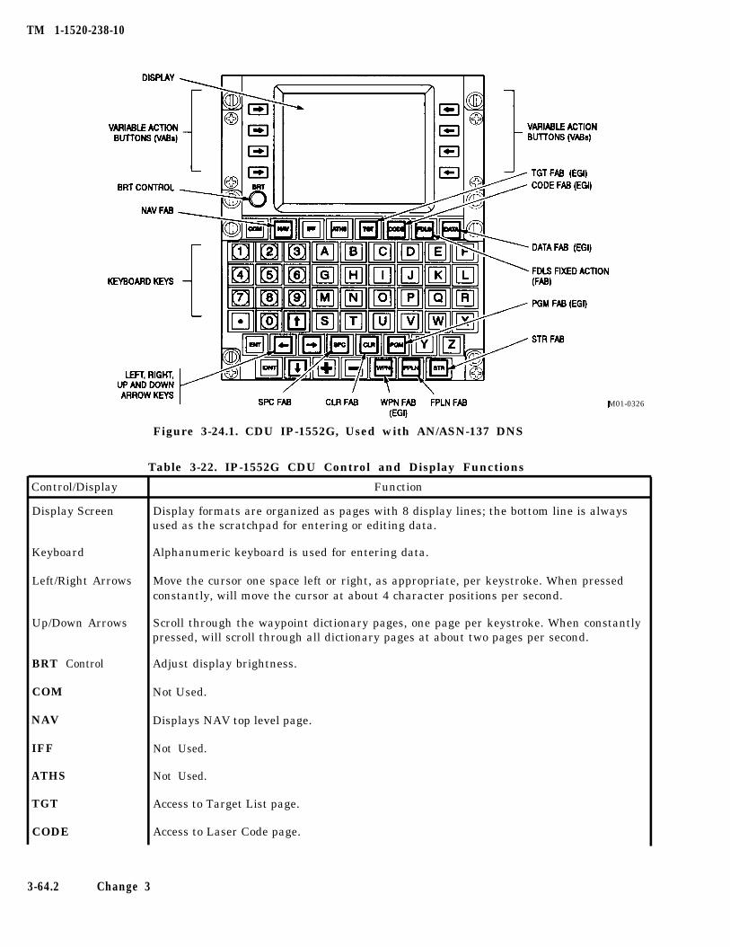
TM 1-1520-238-10
Control/Display
Display Screen
Keyboard
Left/Right Arrows
Up/Down Arrows
BRT Control
COM
NAV
IFF
ATHS
TGT
CODE
Figure 3-24.1. CDU IP-1552G, Used with AN/ASN-137 DNS
Table 3-22. IP-1552G CDU Control and Display Functions
M01-0326
Function
Display formats are organized as pages with 8 display lines; the bottom line is alwaysused as the scratchpad for entering or editing data.
Alphanumeric keyboard is used for entering data.
Move the cursor one space left or right, as appropriate, per keystroke. When pressedconstantly, will move the cursor at about 4 character positions per second.
Scroll through the waypoint dictionary pages, one page per keystroke. When constantlypressed, will scroll through all dictionary pages at about two pages per second.
Adjust display brightness.
Not Used.
Displays NAV top level page.
Not Used.
Not Used.
Access to Target List page.
Access to Laser Code page.
3-64.2 Change 3
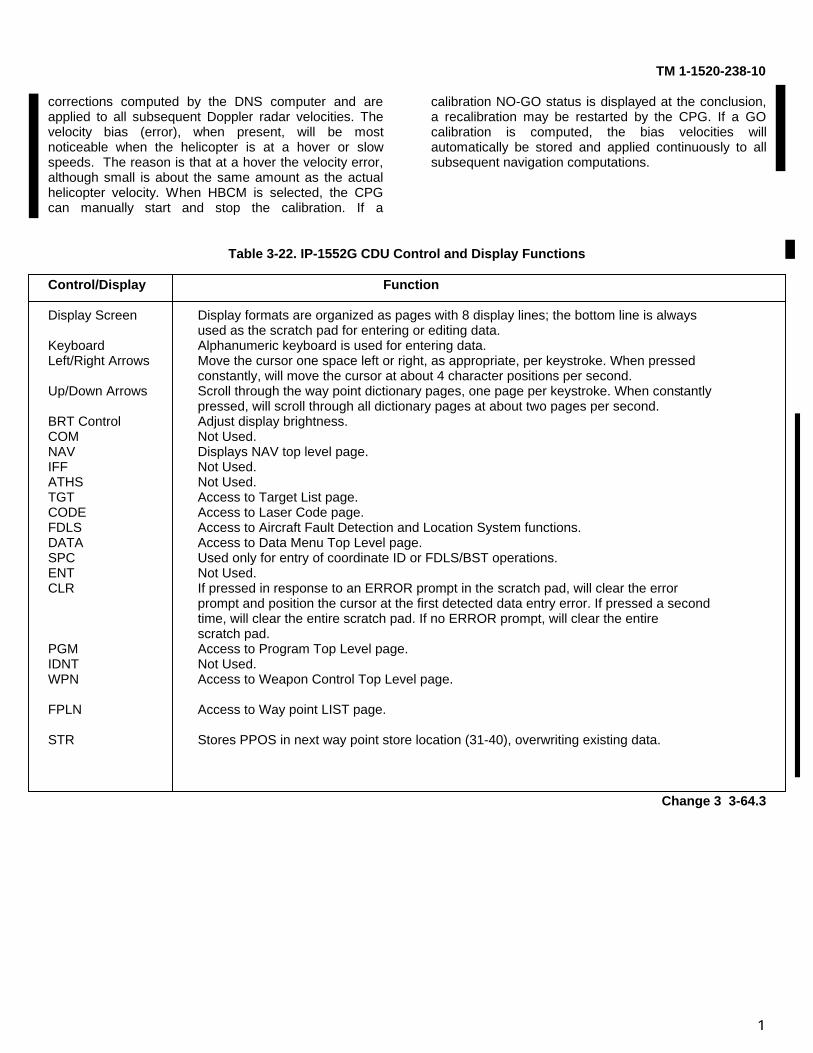
1
TM 1-1520-238-10
corrections computed by the DNS computer and areapplied to all subsequent Doppler radar velocities. Thevelocity bias (error), when present, will be mostnoticeable when the helicopter is at a hover or slowspeeds. The reason is that at a hover the velocity error,although small is about the same amount as the actualhelicopter velocity. When HBCM is selected, the CPGcan manually start and stop the calibration. If a
calibration NO-GO status is displayed at the conclusion,a recalibration may be restarted by the CPG. If a GOcalibration is computed, the bias velocities willautomatically be stored and applied continuously to allsubsequent navigation computations.
Table 3-22. IP-1552G CDU Control and Display Functions
Control/Display Function
Display Screen Display formats are organized as pages with 8 display lines; the bottom line is alwaysused as the scratch pad for entering or editing data.
Keyboard Alphanumeric keyboard is used for entering data.Left/Right Arrows Move the cursor one space left or right, as appropriate, per keystroke. When pressed
constantly, will move the cursor at about 4 character positions per second.Up/Down Arrows Scroll through the way point dictionary pages, one page per keystroke. When constantly
pressed, will scroll through all dictionary pages at about two pages per second.BRT Control Adjust display brightness.COM Not Used.NAV Displays NAV top level page.IFF Not Used.ATHS Not Used.TGT Access to Target List page.CODE Access to Laser Code page.FDLS Access to Aircraft Fault Detection and Location System functions.DATA Access to Data Menu Top Level page.SPC Used only for entry of coordinate ID or FDLS/BST operations.ENT Not Used.CLR If pressed in response to an ERROR prompt in the scratch pad, will clear the error
prompt and position the cursor at the first detected data entry error. If pressed a secondtime, will clear the entire scratch pad. If no ERROR prompt, will clear the entirescratch pad.
PGM Access to Program Top Level page.IDNT Not Used.WPN Access to Weapon Control Top Level page.
FPLN Access to Way point LIST page.
STR Stores PPOS in next way point store location (31-40), overwriting existing data.
Change 3 3-64.3
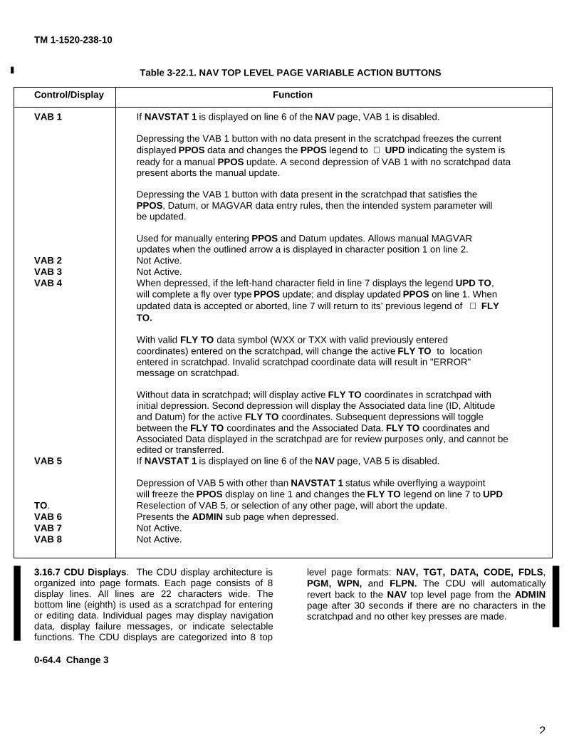
2
TM 1-1520-238-10
Table 3-22.1. NAV TOP LEVEL PAGE VARIABLE ACTION BUTTONS
Control/Display Function
VAB 1 If NAVSTAT 1 is displayed on line 6 of the NAV page, VAB 1 is disabled.
Depressing the VAB 1 button with no data present in the scratchpad freezes the currentdisplayed PPOS data and changes the PPOS legend to ⇒ UPD indicating the system isready for a manual PPOS update. A second depression of VAB 1 with no scratchpad datapresent aborts the manual update.
Depressing the VAB 1 button with data present in the scratchpad that satisfies thePPOS, Datum, or MAGVAR data entry rules, then the intended system parameter willbe updated.
Used for manually entering PPOS and Datum updates. Allows manual MAGVARupdates when the outlined arrow a is displayed in character position 1 on line 2.
VAB 2 Not Active.VAB 3 Not Active.VAB 4 When depressed, if the left-hand character field in line 7 displays the legend UPD TO,
will complete a fly over type PPOS update; and display updated PPOS on line 1. Whenupdated data is accepted or aborted, line 7 will return to its’ previous legend of ⇒ FLYTO.
With valid FLY TO data symbol (WXX or TXX with valid previously enteredcoordinates) entered on the scratchpad, will change the active FLY TO to locationentered in scratchpad. Invalid scratchpad coordinate data will result in "ERROR"message on scratchpad.
Without data in scratchpad; will display active FLY TO coordinates in scratchpad withinitial depression. Second depression will display the Associated data line (ID, Altitudeand Datum) for the active FLY TO coordinates. Subsequent depressions will togglebetween the FLY TO coordinates and the Associated Data. FLY TO coordinates andAssociated Data displayed in the scratchpad are for review purposes only, and cannot beedited or transferred.
VAB 5 If NAVSTAT 1 is displayed on line 6 of the NAV page, VAB 5 is disabled.
Depression of VAB 5 with other than NAVSTAT 1 status while overflying a waypointwill freeze the PPOS display on line 1 and changes the FLY TO legend on line 7 to UPD
TO. Reselection of VAB 5, or selection of any other page, will abort the update.VAB 6 Presents the ADMIN sub page when depressed.VAB 7 Not Active.VAB 8 Not Active.
3.16.7 CDU Displays. The CDU display architecture isorganized into page formats. Each page consists of 8display lines. All lines are 22 characters wide. Thebottom line (eighth) is used as a scratchpad for enteringor editing data. Individual pages may display navigationdata, display failure messages, or indicate selectablefunctions. The CDU displays are categorized into 8 top
level page formats: NAV, TGT, DATA, CODE, FDLS,PGM, WPN, and FLPN. The CDU will automaticallyrevert back to the NAV top level page from the ADMINpage after 30 seconds if there are no characters in thescratchpad and no other key presses are made.
0-64.4 Change 3
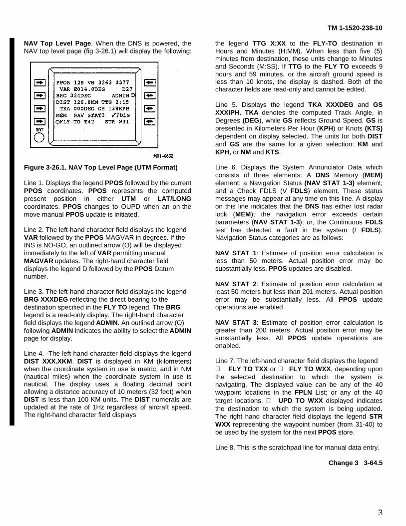
3
TM 1-1520-238-10
NAV Top Level Page. When the DNS is powered, theNAV top level page (fig 3-26.1) will display the following:
Figure 3-26.1. NAV Top Level Page (UTM Format)
Line 1. Displays the legend PPOS followed by the currentPPOS coordinates. PPOS represents the computedpresent position in either UTM or LAT/LONGcoordinates. PPOS changes to OUPD when an on-themove manual PPOS update is initiated.
Line 2. The left-hand character field displays the legendVAR followed by the PPOS MAGVAR in degrees. If theINS is NO-GO, an outlined arrow (O) will be displayedimmediately to the left of VAR permitting manualMAGVAR updates. The right-hand character fielddisplays the legend D followed by the PPOS Datumnumber.
Line 3. The left-hand character field displays the legendBRG XXXDEG reflecting the direct bearing to thedestination specified in the FLY TO legend. The BRGlegend is a read-only display. The right-hand characterfield displays the legend ADMIN. An outlined arrow (O)following ADMIN indicates the ability to select the ADMINpage for display.
Line 4. -The left-hand character field displays the legendDIST XXX.XKM. DIST is displayed in KM (kilometers)when the coordinate system in use is metric, and in NM(nautical miles) when the coordinate system in use isnautical. The display uses a floating decimal pointallowing a distance accuracy of 10 meters (32 feet) whenDIST is less than 100 KM units. The DIST numerals areupdated at the rate of 1Hz regardless of aircraft speed.The right-hand character field displays
the legend TTG X:XX to the FLY-TO destination inHours and Minutes (H:MM). When less than five (5)minutes from destination, these units change to Minutesand Seconds (M:SS). If TTG to the FLY TO exceeds 9hours and 59 minutes, or the aircraft ground speed isless than 10 knots, the display is dashed. Both of thecharacter fields are read-only and cannot be edited.
Line 5. Displays the legend TKA XXXDEG and GSXXXIPH. TKA denotes the computed Track Angle, inDegrees (DEG), while GS reflects Ground Speed. GS ispresented in Kilometers Per Hour (KPH) or Knots (KTS)dependent on display selected. The units for both DISTand GS are the same for a given selection: KM andKPH, or NM and KTS.
Line 6. Displays the System Annunciator Data whichconsists of three elements: A DNS Memory (MEM)element; a Navigation Status (NAV STAT 1-3) element;and a Check FDLS (V FDLS) element. These statusmessages may appear at any time on this line. A displayon this line indicates that the DNS has either lost radarlock (MEM); the navigation error exceeds certainparameters (NAV STAT 1-3); or, the Continuous FDLStest has detected a fault in the system (/ FDLS).Navigation Status categories are as follows:
NAV STAT 1: Estimate of position error calculation isless than 50 meters. Actual position error may besubstantially less. PPOS updates are disabled.
NAV STAT 2: Estimate of position error calculation atleast 50 meters but less than 201 meters. Actual positionerror may be substantially less. All PPOS updateoperations are enabled.
NAV STAT 3: Estimate of position error calculation isgreater than 200 meters. Actual position error may besubstantially less. All PPOS update operations areenabled.
Line 7. The left-hand character field displays the legend⇒ FLY TO TXX or ⇒ FLY TO WXX, depending uponthe selected destination to which the system isnavigating. The displayed value can be any of the 40waypoint locations in the FPLN List; or any of the 40target locations. ⇒ UPD TO WXX displayed indicatesthe destination to which the system is being updated.The right hand character field displays the legend STRWXX representing the waypoint number (from 31-40) tobe used by the system for the next PPOS store.
Line 8. This is the scratchpad line for manual data entry.
Change 3 3-64.5
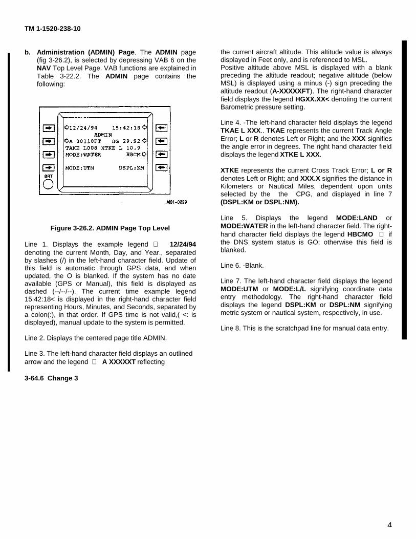
4
TM 1-1520-238-10
b. Administration (ADMIN) Page. The ADMIN page(fig 3-26.2), is selected by depressing VAB 6 on theNAV Top Level Page. VAB functions are explained inTable 3-22.2. The ADMIN page contains thefollowing:
Figure 3-26.2. ADMIN Page Top Level
Line 1. Displays the example legend ⇒ 12/24/94denoting the current Month, Day, and Year., separatedby slashes (/) in the left-hand character field. Update ofthis field is automatic through GPS data, and whenupdated, the O is blanked. If the system has no dateavailable (GPS or Manual), this field is displayed asdashed (--/--/--). The current time example legend15:42:18< is displayed in the right-hand character fieldrepresenting Hours, Minutes, and Seconds, separated bya colon(:), in that order. If GPS time is not valid,( <: isdisplayed), manual update to the system is permitted.
Line 2. Displays the centered page title ADMIN.
Line 3. The left-hand character field displays an outlinedarrow and the legend ⇒ A XXXXXT reflecting
the current aircraft altitude. This altitude value is alwaysdisplayed in Feet only, and is referenced to MSL.Positive altitude above MSL is displayed with a blankpreceding the altitude readout; negative altitude (belowMSL) is displayed using a minus (-) sign preceding thealtitude readout (A-XXXXXFT). The right-hand characterfield displays the legend HGXX.XX< denoting the currentBarometric pressure setting.
Line 4. -The left-hand character field displays the legendTKAE L XXX.. TKAE represents the current Track AngleError; L or R denotes Left or Right; and the XXX signifiesthe angle error in degrees. The right hand character fielddisplays the legend XTKE L XXX.
XTKE represents the current Cross Track Error; L or Rdenotes Left or Right; and XXX.X signifies the distance inKilometers or Nautical Miles, dependent upon unitsselected by the the CPG, and displayed in line 7(DSPL:KM or DSPL:NM).
Line 5. Displays the legend MODE:LAND orMODE:WATER in the left-hand character field. The right-hand character field displays the legend HBCMO ⇒ ifthe DNS system status is GO; otherwise this field isblanked.
Line 6. -Blank.
Line 7. The left-hand character field displays the legendMODE:UTM or MODE:L/L signifying coordinate dataentry methodology. The right-hand character fielddisplays the legend DSPL:KM or DSPL:NM signifyingmetric system or nautical system, respectively, in use.
Line 8. This is the scratchpad line for manual data entry.
3-64.6 Change 3
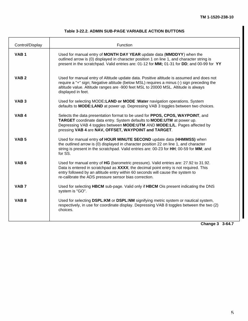
5
TM 1-1520-238-10
Table 3-22.2. ADMIN SUB-PAGE VARIABLE ACTION BUTTONS
Control/Display Function
VAB 1 Used for manual entry of MONTH DAY YEAR update data (MMDDYY) when theoutlined arrow is (0) displayed in character position 1 on line 1, and character string ispresent in the scratchpad. Valid entries are: 01-12 for MM; 01-31 for DD; and 00-99 for YY
VAB 2 Used for manual entry of Altitude update data. Positive altitude is assumed and does notrequire a "+" sign; Negative altitude (below MSL) requires a minus (-) sign preceding thealtitude value. Altitude ranges are -900 feet MSL to 20000 MSL. Altitude is alwaysdisplayed in feet.
VAB 3 Used for selecting MODE:LAND or MODE :Water navigation operations. Systemdefaults to MODE:LAND at power up. Depressing VAB 3 toggles between two choices.
VAB 4 Selects the data presentation format to be used for PPOS, CPOS, WAYPOINT, andTARGET coordinate data entry. System defaults to MODE:UTM at power up.Depressing VAB 4 toggles between MODE:UTM AND MODE:L/L. Pages affected bypressing VAB 4 are NAV, OFFSET, WAYPOINT and TARGET.
VAB 5 Used for manual entry of HOUR MINUTE SECOND update data (HHMMSS) whenthe outlined arrow is (0) displayed in character position 22 on line 1, and characterstring is present in the scratchpad. Valid entries are: 00-23 for HH; 00-59 for MM; andfor SS.
VAB 6 Used for manual entry of HG (barometric pressure). Valid entries are: 27.92 to 31.92.Data is entered in scratchpad as XXXX; the decimal point entry is not required. Thisentry followed by an altitude entry within 60 seconds will cause the system tore-calibrate the ADS pressure sensor bias correction.
VAB 7 Used for selecting HBCM sub-page. Valid only if HBCM Ois present indicating the DNSsystem is "GO".
VAB 8 Used for selecting DSPL:KM or DSPL:NM signifying metric system or nautical system,respectively, in use for coordinate display. Depressing VAB 8 toggles between the two (2)choices.
Change 3 3-64.7
6
TM 1-1520-238-10
c. HBCM Page. The HBCM page, (fig 3-26.3) isused to START and STOP the bias calibration of theDNS. VAB functions are explained in table 3-22.3. Thedisplay has the following:
Figure 3-26.3. HBCM Page
Line 1. Displays the legend O START in the left-handcharacter field; the HBCM title in the center characterfield; and the legend STOPO in the right-hand characterfield.
Line 2. Displays the legend(s) HBCM READY;.
HBCM ACTIVE, HBCM GO, or HBCM NO-GO asappropriate in the left-hand character field.
Lines 3. & 4 If line 2 displays HBCM READY or HBCMACTIVE, lines 3 & 4 will display the current DNS velocitybiases. If line 2 displays HBCM GO, lines & 4 will displaythe new DNS velocity biases. If line 2 displays HBCMNO-GO, line 3 will display the HBCM fail condition. If asecond fail condition exists, it will be displayed on line 4,otherwise line 4 is blanked. Possible DNS errormessages are:
TIME BELOW 2 MIN BIAS EXCEEDS 0.3 KTSEXCESSIVE MEM Line 5. Blank.
Line 6. Displays the legend TIME: XX:XX in the left-handcharacter field indicating elapsed time inminutes/seconds for DNS computations of the biascalibration. The timer will stop while the DNS is inmemory during the bias calibration. The legend MEM willbe displayed following ’TIME: XX:XC’ if the DNS velocityis invalid; otherwise the rest of line 6 is blanked.
Line 7. The right-hand character field displays the legendADMIN>O.
Line 8. Blank.
Table 3-22.3. HBCM SUB-PAGE VARIABLE ACTION BUTTONS
Control/Display Function
VAB 1 Used to initiate or re-start the calibration of the Hover Bias. Pressing VAB 1 causes the display on line 2 to change from "HBCM READY’ to "HBCM ACTIVE" and starts the timer display located on line 6. Calibration time is dynamic and is displayed in minutes and seconds (M: SS).
VAB 2 Not Used
VAB 3 Not Used
VAB 4 Not Used
VAB 5 Used to stop the calibration of the Hover Bias. Pressing VAB 5 will cause the message "HBCM GO" or "HBCM NO-GO" to appear on line 2. This indicates a "within limits" or "out of limits" calibration condition.
VAB 6 Not Used
VAB 7 Not Used
VAB 8 Used to return to the ADMIN sub-page display.
3.64.8 Change 3
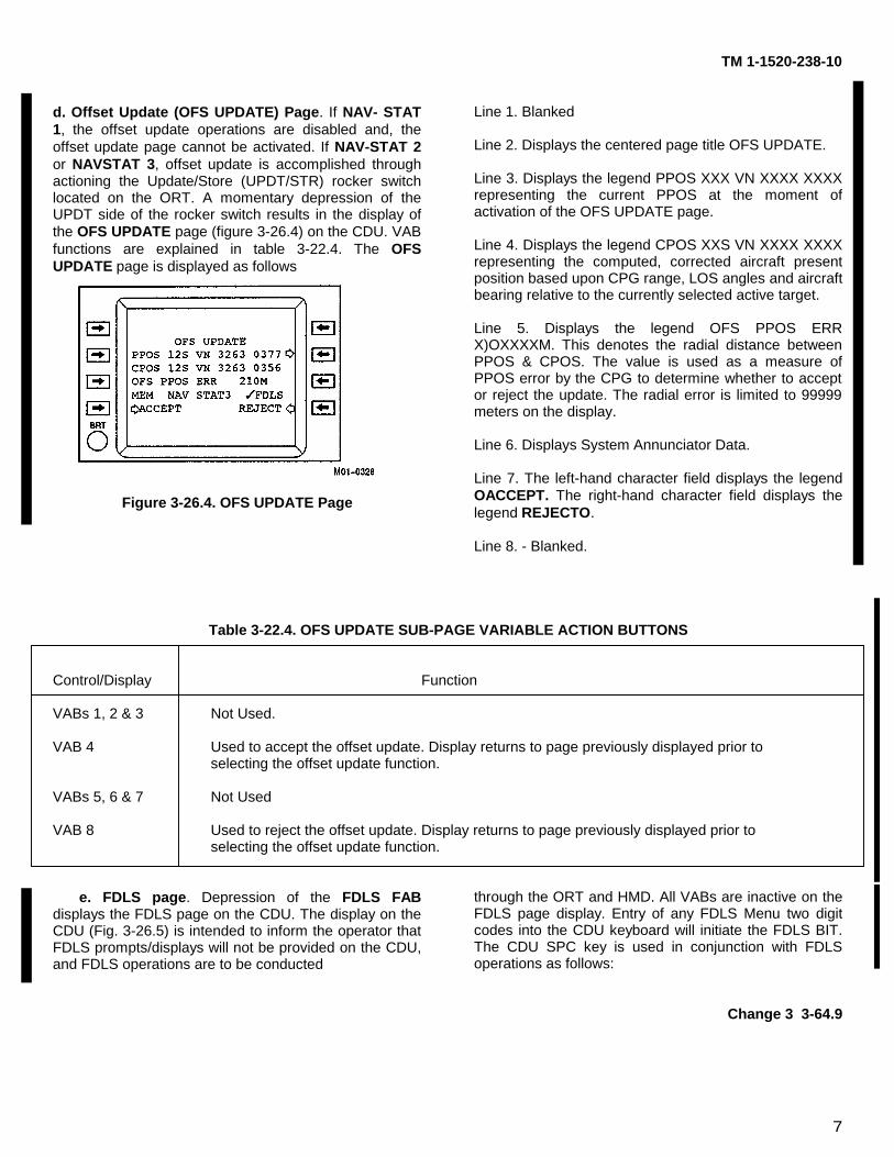
7
TM 1-1520-238-10
d. Offset Update (OFS UPDATE) Page. If NAV- STAT1, the offset update operations are disabled and, theoffset update page cannot be activated. If NAV-STAT 2or NAVSTAT 3, offset update is accomplished throughactioning the Update/Store (UPDT/STR) rocker switchlocated on the ORT. A momentary depression of theUPDT side of the rocker switch results in the display ofthe OFS UPDATE page (figure 3-26.4) on the CDU. VABfunctions are explained in table 3-22.4. The OFSUPDATE page is displayed as follows
Figure 3-26.4. OFS UPDATE Page
Line 1. Blanked
Line 2. Displays the centered page title OFS UPDATE.
Line 3. Displays the legend PPOS XXX VN XXXX XXXXrepresenting the current PPOS at the moment ofactivation of the OFS UPDATE page.
Line 4. Displays the legend CPOS XXS VN XXXX XXXXrepresenting the computed, corrected aircraft presentposition based upon CPG range, LOS angles and aircraftbearing relative to the currently selected active target.
Line 5. Displays the legend OFS PPOS ERRX)OXXXXM. This denotes the radial distance betweenPPOS & CPOS. The value is used as a measure ofPPOS error by the CPG to determine whether to acceptor reject the update. The radial error is limited to 99999meters on the display.
Line 6. Displays System Annunciator Data.
Line 7. The left-hand character field displays the legendOACCEPT. The right-hand character field displays thelegend REJECTO.
Line 8. - Blanked.
Table 3-22.4. OFS UPDATE SUB-PAGE VARIABLE ACTION BUTTONS
Control/Display Function
VABs 1, 2 & 3 Not Used.
VAB 4 Used to accept the offset update. Display returns to page previously displayed prior toselecting the offset update function.
VABs 5, 6 & 7 Not Used
VAB 8 Used to reject the offset update. Display returns to page previously displayed prior toselecting the offset update function.
e. FDLS page. Depression of the FDLS FABdisplays the FDLS page on the CDU. The display on theCDU (Fig. 3-26.5) is intended to inform the operator thatFDLS prompts/displays will not be provided on the CDU,and FDLS operations are to be conducted
through the ORT and HMD. All VABs are inactive on theFDLS page display. Entry of any FDLS Menu two digitcodes into the CDU keyboard will initiate the FDLS BIT.The CDU SPC key is used in conjunction with FDLSoperations as follows:
Change 3 3-64.9
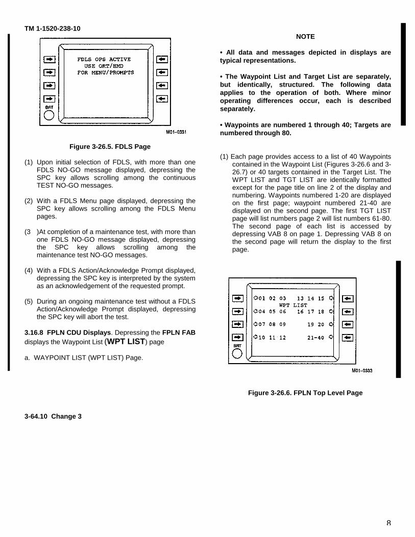
8
TM 1-1520-238-10
Figure 3-26.5. FDLS Page
(1) Upon initial selection of FDLS, with more than oneFDLS NO-GO message displayed, depressing theSPC key allows scrolling among the continuousTEST NO-GO messages.
(2) With a FDLS Menu page displayed, depressing theSPC key allows scrolling among the FDLS Menupages.
(3 )At completion of a maintenance test, with more thanone FDLS NO-GO message displayed, depressingthe SPC key allows scrolling among themaintenance test NO-GO messages.
(4) With a FDLS Action/Acknowledge Prompt displayed,depressing the SPC key is interpreted by the systemas an acknowledgement of the requested prompt.
(5) During an ongoing maintenance test without a FDLSAction/Acknowledge Prompt displayed, depressingthe SPC key will abort the test.
3.16.8 FPLN CDU Displays. Depressing the FPLN FABdisplays the Waypoint List (WPT LIST) page
a. WAYPOINT LIST (WPT LIST) Page.
NOTE
• All data and messages depicted in displays aretypical representations.
• The Waypoint List and Target List are separately,but identically, structured. The following dataapplies to the operation of both. Where minoroperating differences occur, each is describedseparately.
• Waypoints are numbered 1 through 40; Targets arenumbered through 80.
(1) Each page provides access to a list of 40 Waypointscontained in the Waypoint List (Figures 3-26.6 and 3-26.7) or 40 targets contained in the Target List. TheWPT LIST and TGT LIST are identically formattedexcept for the page title on line 2 of the display andnumbering. Waypoints numbered 1-20 are displayedon the first page; waypoint numbered 21-40 aredisplayed on the second page. The first TGT LISTpage will list numbers page 2 will list numbers 61-80.The second page of each list is accessed bydepressing VAB 8 on page 1. Depressing VAB 8 onthe second page will return the display to the firstpage.
Figure 3-26.6. FPLN Top Level Page
3-64.10 Change 3
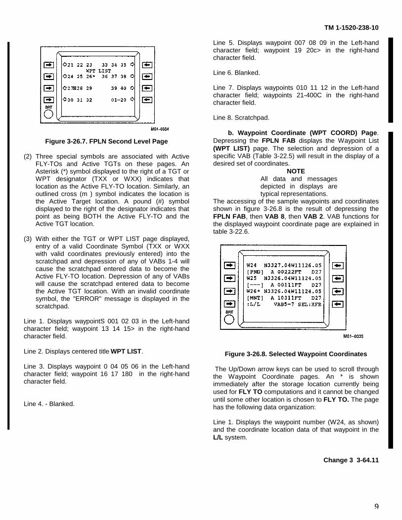
9
TM 1-1520-238-10
Figure 3-26.7. FPLN Second Level Page
(2) Three special symbols are associated with ActiveFLY-TOs and Active TGTs on these pages. AnAsterisk (*) symbol displayed to the right of a TGT orWPT designator (TXX or WXX) indicates thatlocation as the Active FLY-TO location. Similarly, anoutlined cross (m ) symbol indicates the location isthe Active Target location. A pound (#) symboldisplayed to the right of the designator indicates thatpoint as being BOTH the Active FLY-TO and theActive TGT location.
(3) With either the TGT or WPT LIST page displayed,entry of a valid Coordinate Symbol (TXX or WXXwith valid coordinates previously entered) into thescratchpad and depression of any of VABs 1-4 willcause the scratchpad entered data to become theActive FLY-TO location. Depression of any of VABswill cause the scratchpad entered data to becomethe Active TGT location. With an invalid coordinatesymbol, the "ERROR" message is displayed in thescratchpad.
Line 1. Displays waypointS 001 02 03 in the Left-handcharacter field; waypoint 13 14 15> in the right-handcharacter field.
Line 2. Displays centered title WPT LIST.
Line 3. Displays waypoint 0 04 05 06 in the Left-handcharacter field; waypoint 16 17 180 in the right-handcharacter field.
Line 4. - Blanked.
Line 5. Displays waypoint 007 08 09 in the Left-handcharacter field; waypoint 19 20c> in the right-handcharacter field.
Line 6. Blanked.
Line 7. Displays waypoints 010 11 12 in the Left-handcharacter field; waypoints 21-400C in the right-handcharacter field.
Line 8. Scratchpad.
b. Waypoint Coordinate (WPT COORD) Page.Depressing the FPLN FAB displays the Waypoint List(WPT LIST) page. The selection and depression of aspecific VAB (Table 3-22.5) will result in the display of adesired set of coordinates.
NOTEAll data and messagesdepicted in displays aretypical representations.
The accessing of the sample waypoints and coordinatesshown in figure 3-26.8 is the result of depressing theFPLN FAB, then VAB 8, then VAB 2. VAB functions forthe displayed waypoint coordinate page are explained intable 3-22.6.
Figure 3-26.8. Selected Waypoint Coordinates
The Up/Down arrow keys can be used to scroll throughthe Waypoint Coordinate pages. An * is shownimmediately after the storage location currently beingused for FLY TO computations and it cannot be changeduntil some other location is chosen to FLY TO. The pagehas the following data organization:
Line 1. Displays the waypoint number (W24, as shown)and the coordinate location data of that waypoint in theL/L system.
Change 3 3-64.11
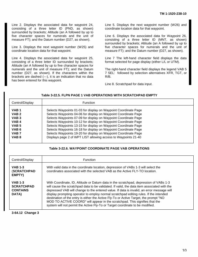
10
TM 1-1520-238-10
Line 2. Displays the associated data for waypoint 24,consisting of a three letter ID (PND, as shown)surrounded by brackets; Altitude (an A followed by up tofive character spaces for numerals and the unit ofmeasure FT); and the Datum number (D27, as shown).
Line 3. Displays the next waypoint number (W25) andcoordinate location data for that waypoint.
Line 4. Displays the associated data for waypoint 25,consisting of a three letter ID surrounded by brackets;Altitude (an A followed by up to five character spaces fornumerals and the unit of measure FT); and the Datumnumber (D27, as shown). If the characters within thebrackets are dashed (---), it is an indication that no datahas been entered for this waypoint.
Line 5. Displays the next waypoint number (W26) andcoordinate location data for that waypoint.
Line 6. Displays the associated data for Waypoint 26,consisting of a three letter ID (MNT, as shown)surrounded by brackets; Altitude (an A followed by up tofive character spaces for numerals and the unit ofmeasure FT); and the Datum number (D27, as shown).
Line 7 The left-hand character field displays the dataformat selected for page display (either L/L or UTM).
The right-hand character field displays the legend VAB 57 SEL: followed by selection alternatives XFR, TGT, orR/B.
Line 8. Scratchpad for data input.
Table 3-22.5. FLPN PAGE 1 VAB OPERATIONS WITH SCRATCHPAD EMPTY
Control/Display Function
VAB 1 Selects Waypoints 01-03 for display on Waypoint Coordinate PageVAB 2 Selects Waypoints 04-06 for display on Waypoint Coordinate PageVAB 3 Selects Waypoints 07-09 for display on Waypoint Coordinate PageVAB 4 Selects Waypoints 10-12 for display on Waypoint Coordinate PageVAB 5 Selects Waypoints 13-15 for display on Waypoint Coordinate PageVAB 6 Selects Waypoints 16-18 for display on Waypoint Coordinate PageVAB 7 Selects Waypoints 19-20 for display on Waypoint Coordinate PageVAB 8 Displays page 2 of WPT LIST allowing access to Waypoints 21-40
Table 3-22.6. WAYPOINT COORDINATE PAGE VAB OPERATIONS
Control/Display Function
VAB 1-3 With valid data in the coordinate location, depression of VABs 1-3 will select the(SCRATCHPAD coordinates associated with the selected VAB as the Active FLY-TO location.EMPTY)
VAB 1-3 With Coordinate, ID, Altitude or Datum data in the scratchpad, depression of VABs 1-3SCRATCHPAD will cause the scratchpad data to be validated. If valid, the data item associated with theCONTAINS depressed VAB will change to the entered value. If data is invalid, an error message willDATA) display prompting operator to employ normal scratchpad editing rules. If the intended
destination of the entry is either the Active Fly-To or Active Target, the prompt "NOMOD TO ACTIVE COORD" will appear in the scratchpad. This signifies that thesystem will not permit the Active Fly-To or Target coordinate to be modified.
3-64.12 Change 3
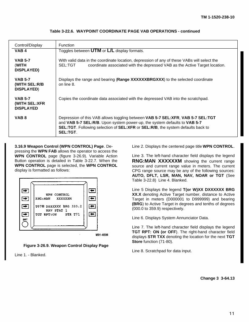
11
TM 1-1520-238-10
Table 3-22.6. WAYPOINT COORDINATE PAGE VAB OPERATIONS - continued
Control/Display FunctionVAB 4 Toggles between UTM or L/L display formats.
VAB 5-7 With valid data in the coordinate location, depression of any of these VABs will select the(WITH SEL:TGT coordinate associated with the depressed VAB as the Active Target location.DISPLAYED)
VAB 5-7 Displays the range and bearing (Range XXXXXXBRGXXX) to the selected coordinate(WITH SEL:R/B on line 8.DISPLAYED)
VAB 5-7 Copies the coordinate data associated with the depressed VAB into the scratchpad.(WITH SEL:XFRDISPLAYED
VAB 8 Depression of this VAB allows toggling between VAB 5-7 SEL:XFR, VAB 5-7 SEL:TGTand VAB 5-7 SEL:R/B. Upon system power-up, the system defaults to VAB 5-7SEL:TGT. Following selection of SEL:XFR or SEL:R/B, the system defaults back toSEL:TGT.
3.16.9 Weapon Control (WPN CONTROL) Page. De-pressing the WPN FAB allows the operator to access theWPN CONTROL page (figure 3-26.9). Variable ActionButton operation is detailed in Table 3-22.7. When theWPN CONTROL page is selected, the WPN CONTROLdisplay is formatted as follows:
Figure 3-26.9. Weapon Control Display Page
Line 1. - Blanked.
Line 2. Displays the centered page title WPN CONTROL.
Line 3. The left-hand character field displays the legendRNG:MAN XXXXXXM showing the current rangesource and current range value in meters. The currentCPG range source may be any of the following sources:AUTO, DFLT, LSR, MAN, NAV, NOAR or TGT (SeeTable 3-22.8) Line 4. Blanked.
Line 5 Displays the legend T(or W)XX DXXXXXX BRGXX.X denoting Active Target number, distance to ActiveTarget in meters (D000001 to D999999) and bearing(BRG) to Active Target in degrees and tenths of degrees(000.0 to 359.9) respectively.
Line 6. Displays System Annunciator Data.
Line 7. The left-hand character field displays the legendTGT RPT: ON (or OFF). The right-hand character fielddisplays STR TXX denoting the location for the next TGTStore function (71-80).
Line 8. Scratchpad for data input.
Change 3 3-64.13
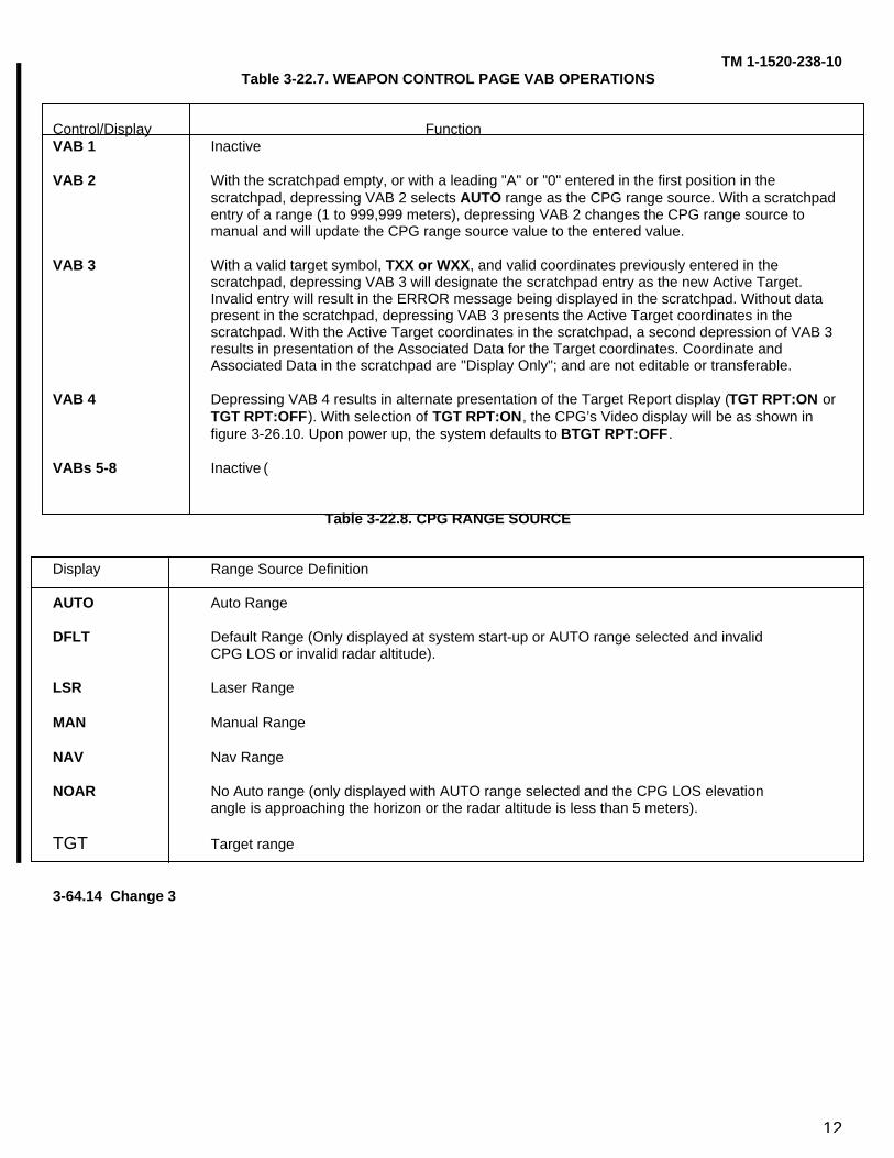
12
TM 1-1520-238-10Table 3-22.7. WEAPON CONTROL PAGE VAB OPERATIONS
Control/Display FunctionVAB 1 Inactive
VAB 2 With the scratchpad empty, or with a leading "A" or "0" entered in the first position in the scratchpad, depressing VAB 2 selects AUTO range as the CPG range source. With a scratchpad entry of a range (1 to 999,999 meters), depressing VAB 2 changes the CPG range source to manual and will update the CPG range source value to the entered value.
VAB 3 With a valid target symbol, TXX or WXX, and valid coordinates previously entered in the scratchpad, depressing VAB 3 will designate the scratchpad entry as the new Active Target. Invalid entry will result in the ERROR message being displayed in the scratchpad. Without data present in the scratchpad, depressing VAB 3 presents the Active Target coordinates in the scratchpad. With the Active Target coordinates in the scratchpad, a second depression of VAB 3 results in presentation of the Associated Data for the Target coordinates. Coordinate and Associated Data in the scratchpad are "Display Only"; and are not editable or transferable.
VAB 4 Depressing VAB 4 results in alternate presentation of the Target Report display (TGT RPT:ON or TGT RPT:OFF). With selection of TGT RPT:ON, the CPG’s Video display will be as shown in figure 3-26.10. Upon power up, the system defaults to BTGT RPT:OFF.
VABs 5-8 Inactive (
Table 3-22.8. CPG RANGE SOURCE
Display Range Source Definition
AUTO Auto Range
DFLT Default Range (Only displayed at system start-up or AUTO range selected and invalidCPG LOS or invalid radar altitude).
LSR Laser Range
MAN Manual Range
NAV Nav Range
NOAR No Auto range (only displayed with AUTO range selected and the CPG LOS elevationangle is approaching the horizon or the radar altitude is less than 5 meters).
TGT Target range
3-64.14 Change 3
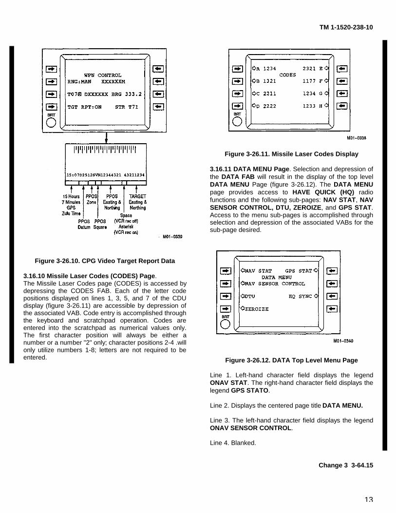
13
TM 1-1520-238-10
Figure 3-26.10. CPG Video Target Report Data
3.16.10 Missile Laser Codes (CODES) Page.The Missile Laser Codes page (CODES) is accessed bydepressing the CODES FAB. Each of the letter codepositions displayed on lines 1, 3, 5, and 7 of the CDUdisplay (figure 3-26.11) are accessible by depression ofthe associated VAB. Code entry is accomplished throughthe keyboard and scratchpad operation. Codes areentered into the scratchpad as numerical values only.The first character position will always be either anumber or a number "2" only; character positions 2-4 .willonly utilize numbers 1-8; letters are not required to beentered.
Figure 3-26.11. Missile Laser Codes Display
3.16.11 DATA MENU Page. Selection and depression ofthe DATA FAB will result in the display of the top levelDATA MENU Page (figure 3-26.12). The DATA MENUpage provides access to HAVE QUICK (HQ) radiofunctions and the following sub-pages: NAV STAT, NAVSENSOR CONTROL, DTU, ZEROIZE, and GPS STAT.Access to the menu sub-pages is accomplished throughselection and depression of the associated VABs for thesub-page desired.
Figure 3-26.12. DATA Top Level Menu Page
Line 1. Left-hand character field displays the legendONAV STAT. The right-hand character field displays thelegend GPS STATO.
Line 2. Displays the centered page title DATA MENU.
Line 3. The left-hand character field displays the legendONAV SENSOR CONTROL.
Line 4. Blanked.
Change 3 3-64.15
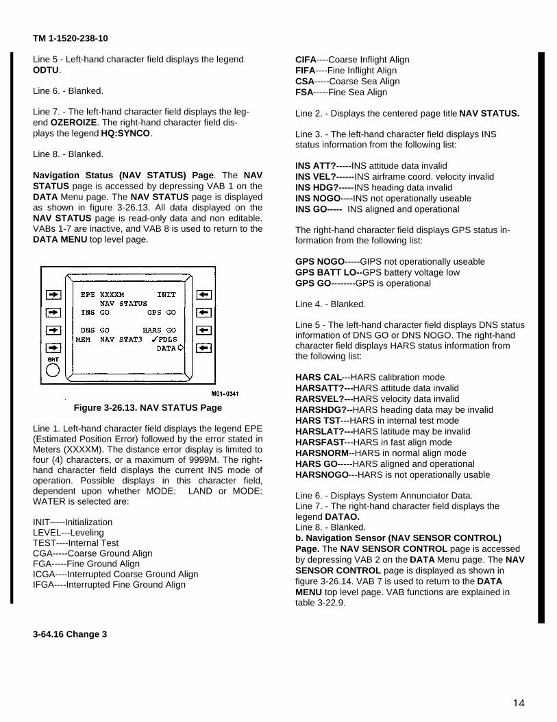
14
TM 1-1520-238-10
Line 5 - Left-hand character field displays the legendODTU.
Line 6. - Blanked.
Line 7. - The left-hand character field displays the leg-end OZEROIZE. The right-hand character field dis-plays the legend HQ:SYNCO.
Line 8. - Blanked.
Navigation Status (NAV STATUS) Page. The NAVSTATUS page is accessed by depressing VAB 1 on theDATA Menu page. The NAV STATUS page is displayedas shown in figure 3-26.13. All data displayed on theNAV STATUS page is read-only data and non editable.VABs 1-7 are inactive, and VAB 8 is used to return to theDATA MENU top level page.
Figure 3-26.13. NAV STATUS Page
Line 1. Left-hand character field displays the legend EPE(Estimated Position Error) followed by the error stated inMeters (XXXXM). The distance error display is limited tofour (4) characters, or a maximum of 9999M. The right-hand character field displays the current INS mode ofoperation. Possible displays in this character field,dependent upon whether MODE: LAND or MODE:WATER is selected are:
INIT-----InitializationLEVEL---LevelingTEST----Internal TestCGA-----Coarse Ground AlignFGA-----Fine Ground AlignICGA----Interrupted Coarse Ground AlignIFGA----Interrupted Fine Ground Align
CIFA----Coarse Inflight AlignFIFA----Fine Inflight AlignCSA-----Coarse Sea AlignFSA-----Fine Sea Align
Line 2. - Displays the centered page title NAV STATUS.
Line 3. - The left-hand character field displays INSstatus information from the following list:
INS ATT?-----INS attitude data invalidINS VEL?------INS airframe coord. velocity invalidINS HDG?-----INS heading data invalidINS NOGO----INS not operationally useableINS GO----- INS aligned and operational
The right-hand character field displays GPS status in-formation from the following list:
GPS NOGO-----GIPS not operationally useableGPS BATT LO--GPS battery voltage lowGPS GO--------GPS is operational
Line 4. - Blanked.
Line 5 - The left-hand character field displays DNS statusinformation of DNS GO or DNS NOGO. The right-handcharacter field displays HARS status information fromthe following list:
HARS CAL---HARS calibration modeHARSATT?---HARS attitude data invalidRARSVEL?---HARS velocity data invalidHARSHDG?--HARS heading data may be invalidHARS TST---HARS in internal test modeHARSLAT?---HARS latitude may be invalidHARSFAST---HARS in fast align modeHARSNORM--HARS in normal align modeHARS GO-----HARS aligned and operationalHARSNOGO---HARS is not operationally usable
Line 6. - Displays System Annunciator Data.Line 7. - The right-hand character field displays thelegend DATAO.Line 8. - Blanked.b. Navigation Sensor (NAV SENSOR CONTROL)Page. The NAV SENSOR CONTROL page is accessedby depressing VAB 2 on the DATA Menu page. The NAVSENSOR CONTROL page is displayed as shown infigure 3-26.14. VAB 7 is used to return to the DATAMENU top level page. VAB functions are explained intable 3-22.9.
3-64.16 Change 3
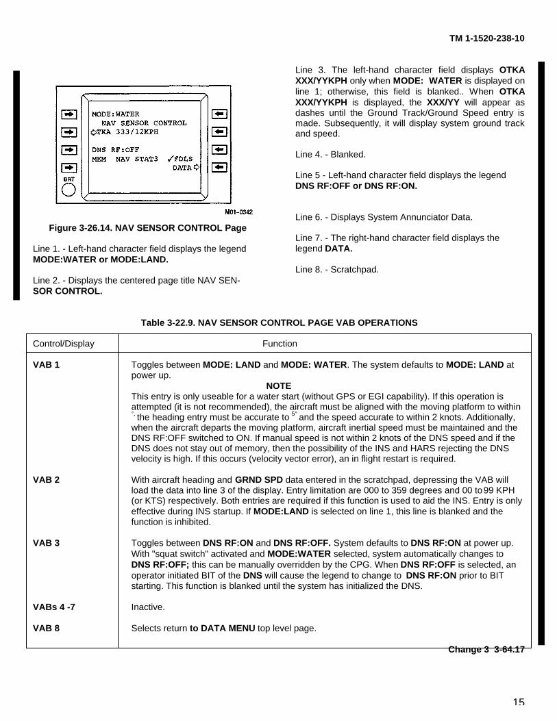
15
TM 1-1520-238-10
Figure 3-26.14. NAV SENSOR CONTROL Page
Line 1. - Left-hand character field displays the legendMODE:WATER or MODE:LAND.
Line 2. - Displays the centered page title NAV SEN-SOR CONTROL.
Line 3. The left-hand character field displays OTKAXXX/YYKPH only when MODE: WATER is displayed online 1; otherwise, this field is blanked.. When OTKAXXX/YYKPH is displayed, the XXX/YY will appear asdashes until the Ground Track/Ground Speed entry ismade. Subsequently, it will display system ground trackand speed.
Line 4. - Blanked.
Line 5 - Left-hand character field displays the legendDNS RF:OFF or DNS RF:ON.
Line 6. - Displays System Annunciator Data.
Line 7. - The right-hand character field displays thelegend DATA.
Line 8. - Scratchpad.
Table 3-22.9. NAV SENSOR CONTROL PAGE VAB OPERATIONS
Control/Display Function
VAB 1 Toggles between MODE: LAND and MODE: WATER. The system defaults to MODE: LAND at power up.
NOTEThis entry is only useable for a water start (without GPS or EGI capability). If this operation is attempted (it is not recommended), the aircraft must be aligned with the moving platform to within °, the heading entry must be accurate to 5° and the speed accurate to within 2 knots. Additionally, when the aircraft departs the moving platform, aircraft inertial speed must be maintained and the DNS RF:OFF switched to ON. If manual speed is not within 2 knots of the DNS speed and if the DNS does not stay out of memory, then the possibility of the INS and HARS rejecting the DNS velocity is high. If this occurs (velocity vector error), an in flight restart is required.
VAB 2 With aircraft heading and GRND SPD data entered in the scratchpad, depressing the VAB will load the data into line 3 of the display. Entry limitation are 000 to 359 degrees and 00 to 99 KPH (or KTS) respectively. Both entries are required if this function is used to aid the INS. Entry is only effective during INS startup. If MODE:LAND is selected on line 1, this line is blanked and the function is inhibited.
VAB 3 Toggles between DNS RF:ON and DNS RF:OFF. System defaults to DNS RF:ON at power up. With "squat switch" activated and MODE:WATER selected, system automatically changes to DNS RF:OFF; this can be manually overridden by the CPG. When DNS RF:OFF is selected, an operator initiated BIT of the DNS will cause the legend to change to DNS RF:ON prior to BIT starting. This function is blanked until the system has initialized the DNS.
VABs 4 -7 Inactive.
VAB 8 Selects return to DATA MENU top level page.
Change 3 3-64.17
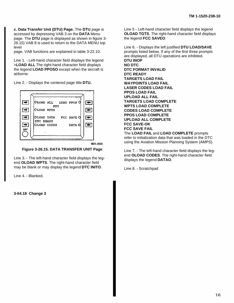
16
TM 1-1520-238-10
c. Data Transfer Unit (DTU) Page. The DTU page isaccessed by depressing VAB 3 on the DATA Menupage. The DTU page is displayed as shown in figure 3-26.15) VAB 8 is used to return to the DATA MENU toplevelpage. VAB functions are explained in table 3-22.10.
Line 1. - Left-hand character field displays the legend>LOAD ALL The right-hand character field displaysthe legend LOAD PPOSO except when the aircraft isairborne.
Line 2. - Displays the centered page title DTU.
Figure 3-26.15. DATA TRANSFER UNIT Page
Line 3. - The left-hand character field displays the leg-end OLOAD WPTS. The right-hand character fieldmay be blank or may display the legend DTC INITO.
Line 4. - Blanked.
Line 5 - Left-hand character field displays the legendOLOAD TGTS. The right-hand character field displaysthe legend FCC SAVEO.
Line 6. - Displays the left justified DTU LOAD/SAVEprompts listed below. If any of the first three promptsare displayed, all DTU operations are inhibited.DTU INOPNO DTCDTC FORMAT INVALIDDTC READYTARGETS LOAD FAILWAYPOINTS LOAD FAILLASER CODES LOAD FAILPPOS LOAD FAILUPLOAD ALL FAILTARGETS LOAD COMPLETEWPTS LOAD COMPLETECODES LOAD COMPLETEPPOS LOAD COMPLETEUPLOAD ALL COMPLETEFCC SAVE-OKFCC SAVE FAILThe LOAD FAIL and LOAD COMPLETE promptsrefer to initialization data that was loaded in the DTCusing the Aviation Mission Planning System (AMPS).
Line 7. - The left-hand character field displays the leg-end OLOAD CODES. The right-hand character fielddisplays the legend DATAO.
Line 8. - Scratchpad
3-64.18 Change 3
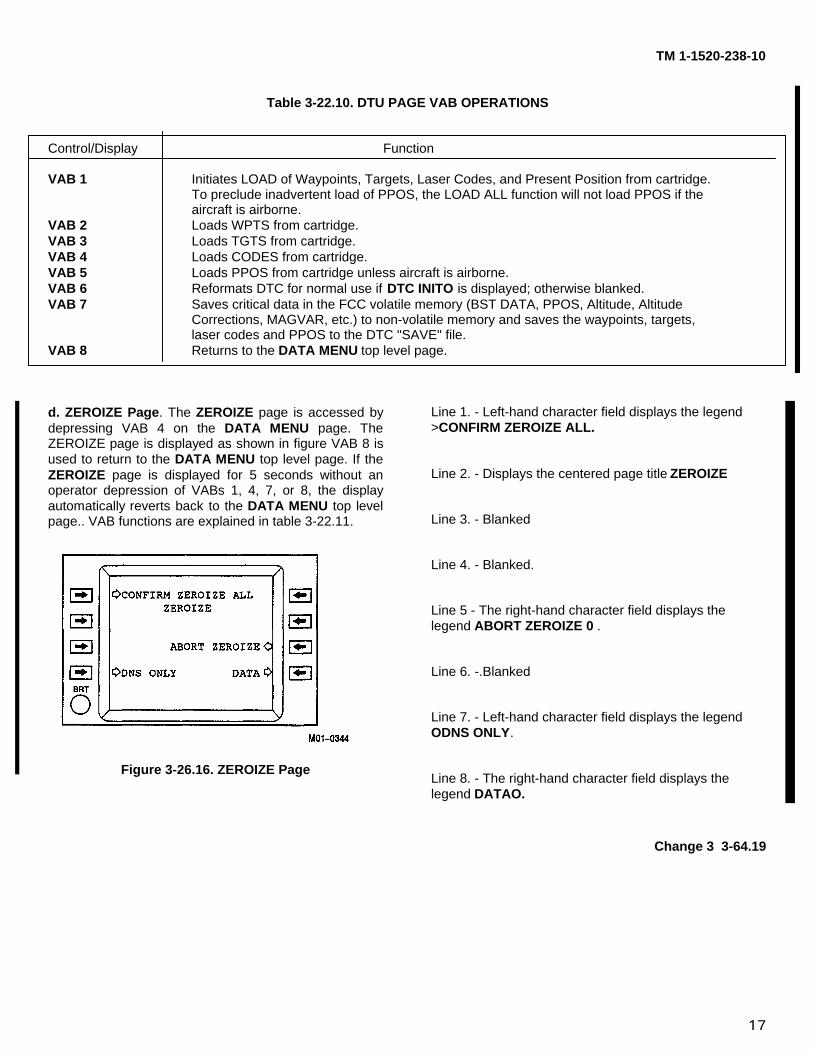
17
TM 1-1520-238-10
Table 3-22.10. DTU PAGE VAB OPERATIONS
Control/Display Function
VAB 1 Initiates LOAD of Waypoints, Targets, Laser Codes, and Present Position from cartridge.To preclude inadvertent load of PPOS, the LOAD ALL function will not load PPOS if theaircraft is airborne.
VAB 2 Loads WPTS from cartridge.VAB 3 Loads TGTS from cartridge.VAB 4 Loads CODES from cartridge.VAB 5 Loads PPOS from cartridge unless aircraft is airborne.VAB 6 Reformats DTC for normal use if DTC INITO is displayed; otherwise blanked.VAB 7 Saves critical data in the FCC volatile memory (BST DATA, PPOS, Altitude, Altitude
Corrections, MAGVAR, etc.) to non-volatile memory and saves the waypoints, targets,laser codes and PPOS to the DTC "SAVE" file.
VAB 8 Returns to the DATA MENU top level page.
d. ZEROIZE Page. The ZEROIZE page is accessed bydepressing VAB 4 on the DATA MENU page. TheZEROIZE page is displayed as shown in figure VAB 8 isused to return to the DATA MENU top level page. If theZEROIZE page is displayed for 5 seconds without anoperator depression of VABs 1, 4, 7, or 8, the displayautomatically reverts back to the DATA MENU top levelpage.. VAB functions are explained in table 3-22.11.
Figure 3-26.16. ZEROIZE Page
Line 1. - Left-hand character field displays the legend>CONFIRM ZEROIZE ALL.
Line 2. - Displays the centered page title ZEROIZE
Line 3. - Blanked
Line 4. - Blanked.
Line 5 - The right-hand character field displays thelegend ABORT ZEROIZE 0 .
Line 6. -.Blanked
Line 7. - Left-hand character field displays the legendODNS ONLY.
Line 8. - The right-hand character field displays thelegend DATAO.
Change 3 3-64.19
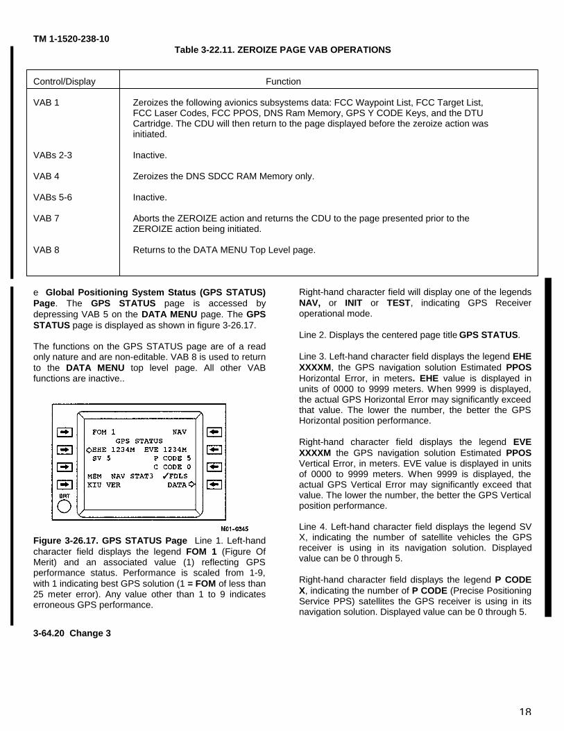
18
TM 1-1520-238-10Table 3-22.11. ZEROIZE PAGE VAB OPERATIONS
Control/Display Function
VAB 1 Zeroizes the following avionics subsystems data: FCC Waypoint List, FCC Target List,FCC Laser Codes, FCC PPOS, DNS Ram Memory, GPS Y CODE Keys, and the DTUCartridge. The CDU will then return to the page displayed before the zeroize action wasinitiated.
VABs 2-3 Inactive.
VAB 4 Zeroizes the DNS SDCC RAM Memory only.
VABs 5-6 Inactive.
VAB 7 Aborts the ZEROIZE action and returns the CDU to the page presented prior to theZEROIZE action being initiated.
VAB 8 Returns to the DATA MENU Top Level page.
e Global Positioning System Status (GPS STATUS)Page. The GPS STATUS page is accessed bydepressing VAB 5 on the DATA MENU page. The GPSSTATUS page is displayed as shown in figure 3-26.17.
The functions on the GPS STATUS page are of a readonly nature and are non-editable. VAB 8 is used to returnto the DATA MENU top level page. All other VABfunctions are inactive..
Figure 3-26.17. GPS STATUS Page Line 1. Left-handcharacter field displays the legend FOM 1 (Figure OfMerit) and an associated value (1) reflecting GPSperformance status. Performance is scaled from 1-9,with 1 indicating best GPS solution (1 = FOM of less than25 meter error). Any value other than 1 to 9 indicateserroneous GPS performance.
Right-hand character field will display one of the legendsNAV, or INIT or TEST, indicating GPS Receiveroperational mode.
Line 2. Displays the centered page title GPS STATUS.
Line 3. Left-hand character field displays the legend EHEXXXXM, the GPS navigation solution Estimated PPOSHorizontal Error, in meters. EHE value is displayed inunits of 0000 to 9999 meters. When 9999 is displayed,the actual GPS Horizontal Error may significantly exceedthat value. The lower the number, the better the GPSHorizontal position performance.
Right-hand character field displays the legend EVEXXXXM the GPS navigation solution Estimated PPOSVertical Error, in meters. EVE value is displayed in unitsof 0000 to 9999 meters. When 9999 is displayed, theactual GPS Vertical Error may significantly exceed thatvalue. The lower the number, the better the GPS Verticalposition performance.
Line 4. Left-hand character field displays the legend SVX, indicating the number of satellite vehicles the GPSreceiver is using in its navigation solution. Displayedvalue can be 0 through 5.
Right-hand character field displays the legend P CODEX, indicating the number of P CODE (Precise PositioningService PPS) satellites the GPS receiver is using in itsnavigation solution. Displayed value can be 0 through 5.
3-64.20 Change 3
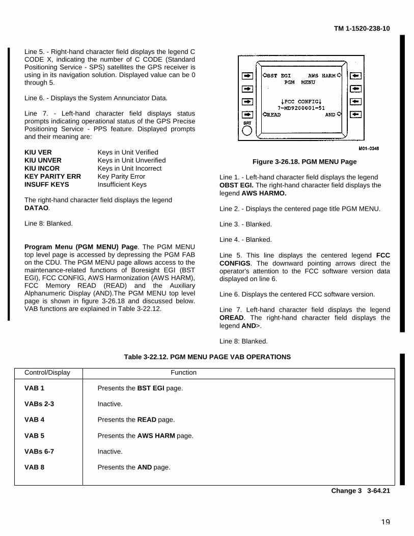
19
TM 1-1520-238-10
Line 5. - Right-hand character field displays the legend CCODE X, indicating the number of C CODE (StandardPositioning Service - SPS) satellites the GPS receiver isusing in its navigation solution. Displayed value can be 0through 5.
Line 6. - Displays the System Annunciator Data.
Line 7. - Left-hand character field displays statusprompts indicating operational status of the GPS PrecisePositioning Service - PPS feature. Displayed promptsand their meaning are:
KIU VER Keys in Unit VerifiedKIU UNVER Keys in Unit UnverifiedKIU INCOR Keys in Unit IncorrectKEY PARITY ERR Key Parity ErrorINSUFF KEYS Insufficient Keys
The right-hand character field displays the legendDATAO.
Line 8: Blanked.
Program Menu (PGM MENU) Page. The PGM MENUtop level page is accessed by depressing the PGM FABon the CDU. The PGM MENU page allows access to themaintenance-related functions of Boresight EGI (BSTEGI), FCC CONFIG, AWS Harmonization (AWS HARM),FCC Memory READ (READ) and the AuxiliaryAlphanumeric Display (AND).The PGM MENU top levelpage is shown in figure 3-26.18 and discussed below.VAB functions are explained in Table 3-22.12.
Figure 3-26.18. PGM MENU Page
Line 1. - Left-hand character field displays the legendOBST EGI. The right-hand character field displays thelegend AWS HARMO.
Line 2. - Displays the centered page title PGM MENU.
Line 3. - Blanked.
Line 4. - Blanked.
Line 5. This line displays the centered legend FCCCONFIGS. The downward pointing arrows direct theoperator’s attention to the FCC software version datadisplayed on line 6.
Line 6. Displays the centered FCC software version.
Line 7. Left-hand character field displays the legendOREAD. The right-hand character field displays thelegend AND>.
Line 8: Blanked.
Table 3-22.12. PGM MENU PAGE VAB OPERATIONS
Control/Display Function
VAB 1 Presents the BST EGI page.
VABs 2-3 Inactive.
VAB 4 Presents the READ page.
VAB 5 Presents the AWS HARM page.
VABs 6-7 Inactive.
VAB 8 Presents the AND page.
Change 3 3-64.21
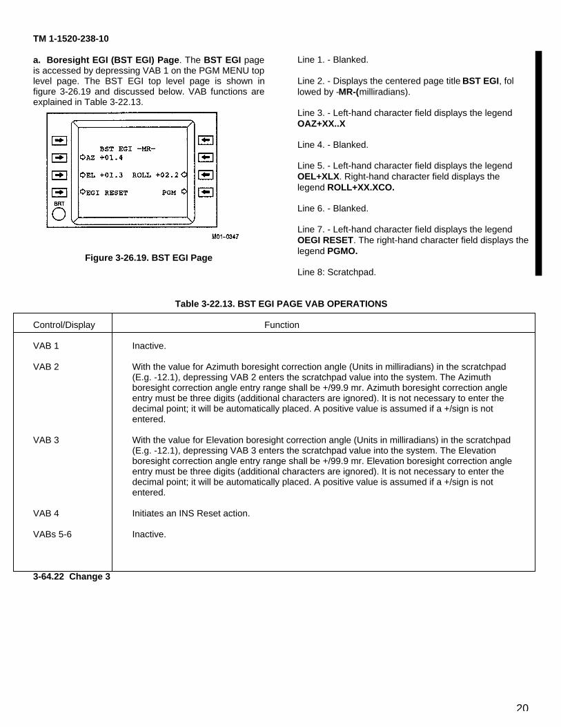
20
TM 1-1520-238-10
a. Boresight EGI (BST EGI) Page. The BST EGI pageis accessed by depressing VAB 1 on the PGM MENU toplevel page. The BST EGI top level page is shown infigure 3-26.19 and discussed below. VAB functions areexplained in Table 3-22.13.
Figure 3-26.19. BST EGI Page
Line 1. - Blanked.
Line 2. - Displays the centered page title BST EGI, followed by -MR-(milliradians).
Line 3. - Left-hand character field displays the legendOAZ+XX..X
Line 4. - Blanked.
Line 5. - Left-hand character field displays the legendOEL+XLX. Right-hand character field displays thelegend ROLL+XX.XCO.
Line 6. - Blanked.
Line 7. - Left-hand character field displays the legendOEGI RESET. The right-hand character field displays thelegend PGMO.
Line 8: Scratchpad.
Table 3-22.13. BST EGI PAGE VAB OPERATIONS
Control/Display Function
VAB 1 Inactive.
VAB 2 With the value for Azimuth boresight correction angle (Units in milliradians) in the scratchpad (E.g. -12.1), depressing VAB 2 enters the scratchpad value into the system. The Azimuth boresight correction angle entry range shall be +/99.9 mr. Azimuth boresight correction angle entry must be three digits (additional characters are ignored). It is not necessary to enter the decimal point; it will be automatically placed. A positive value is assumed if a +/sign is not entered.
VAB 3 With the value for Elevation boresight correction angle (Units in milliradians) in the scratchpad (E.g. -12.1), depressing VAB 3 enters the scratchpad value into the system. The Elevation boresight correction angle entry range shall be +/99.9 mr. Elevation boresight correction angle entry must be three digits (additional characters are ignored). It is not necessary to enter the decimal point; it will be automatically placed. A positive value is assumed if a +/sign is not entered.
VAB 4 Initiates an INS Reset action.
VABs 5-6 Inactive.
3-64.22 Change 3
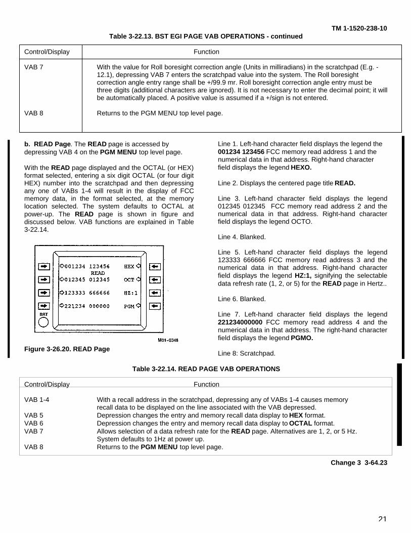
21
TM 1-1520-238-10Table 3-22.13. BST EGI PAGE VAB OPERATIONS - continued
Control/Display Function
VAB 7 With the value for Roll boresight correction angle (Units in milliradians) in the scratchpad (E.g. -12.1), depressing VAB 7 enters the scratchpad value into the system. The Roll boresight correction angle entry range shall be +/99.9 mr. Roll boresight correction angle entry must be three digits (additional characters are ignored). It is not necessary to enter the decimal point; it willbe automatically placed. A positive value is assumed if a +/sign is not entered.
VAB 8 Returns to the PGM MENU top level page.
b. READ Page. The READ page is accessed bydepressing VAB 4 on the PGM MENU top level page.
With the READ page displayed and the OCTAL (or HEX)format selected, entering a six digit OCTAL (or four digitHEX) number into the scratchpad and then depressingany one of VABs 1-4 will result in the display of FCCmemory data, in the format selected, at the memorylocation selected. The system defaults to OCTAL atpower-up. The READ page is shown in figure anddiscussed below. VAB functions are explained in Table3-22.14.
Figure 3-26.20. READ Page
Line 1. Left-hand character field displays the legend the001234 123456 FCC memory read address 1 and thenumerical data in that address. Right-hand characterfield displays the legend HEXO.
Line 2. Displays the centered page title READ.
Line 3. Left-hand character field displays the legend012345 012345 FCC memory read address 2 and thenumerical data in that address. Right-hand characterfield displays the legend OCTO.
Line 4. Blanked.
Line 5. Left-hand character field displays the legend123333 666666 FCC memory read address 3 and thenumerical data in that address. Right-hand characterfield displays the legend HZ:1, signifying the selectabledata refresh rate (1, 2, or 5) for the READ page in Hertz..
Line 6. Blanked.
Line 7. Left-hand character field displays the legend221234000000 FCC memory read address 4 and thenumerical data in that address. The right-hand characterfield displays the legend PGMO.
Line 8: Scratchpad.
Table 3-22.14. READ PAGE VAB OPERATIONS
Control/Display Function
VAB 1-4 With a recall address in the scratchpad, depressing any of VABs 1-4 causes memoryrecall data to be displayed on the line associated with the VAB depressed.
VAB 5 Depression changes the entry and memory recall data display to HEX format.VAB 6 Depression changes the entry and memory recall data display to OCTAL format.VAB 7 Allows selection of a data refresh rate for the READ page. Alternatives are 1, 2, or 5 Hz.
System defaults to 1Hz at power up.VAB 8 Returns to the PGM MENU top level page.
Change 3 3-64.23
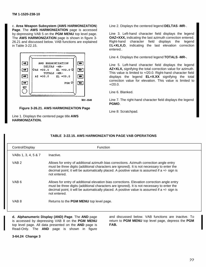
22
TM 1-1520-238-10
c. Area Weapon Subsystem (AWS HARMONIZATION)Page. The AWS HARMONIZATION page is accessedby depressing VAB 5 on the PGM MENU top level page.The AWS HARMONIZATION page is shown in figure 3-26.21 and discussed below. VAB functions are explainedin Table 3-22.15.
Figure 3-26.21. AWS HARMONIZATION Page
Line 1. Displays the centered page title AWSHARMONIZATION.
Line 2. Displays the centered legend DELTAS -MR-.
Line 3. Left-hand character field displays the legendOAZ+XXX, indicating the last azimuth correction entered.Right-hand character field displays the legendEL+XLX,O, indicating the last elevation correctionentered..
Line 4. Displays the centered legend TOTALS -MR-.
Line 5. Left-hand character field displays the legendAZ+XLX, signifying the total correction value for azimuth.This value is limited to +/20.0. Right-hand character fielddisplays the legend EL+X.XX signifying the totalcorrection value for elevation. This value is limited to+/20.0.
Line 6. Blanked.
Line 7. The right-hand character field displays the legendPGMO.
Line 8: Scratchpad.
TABLE 3-22.15. AWS HARMONIZAT’ION PAGE VAB OPERATIONS
Control/Display Function
VABs 1, 3, 4, 5 & 7 Inactive.
VAB 2 Allows for entry of additional azimuth bias corrections. Azimuth correction angle entrymust be three digits (additional characters are ignored). It is not necessary to enter thedecimal point; it will be automatically placed. A positive value is assumed if a +/- sign isnot entered.
VAB 6 Allows for entry of additional elevation bias corrections. Elevation correction angle entrymust be three digits (additional characters are ignored). It is not necessary to enter thedecimal point; it will be automatically placed. A positive value is assumed if a +/- sign isnot entered.
VAB 8 Returns to the PGM MENU top level page.
d. Alphanumeric Display (AND) Page. The AND pageis accessed by depressing VAB 8 on the PGM MENUtop level page. All data presented on the AND page isRead-Only. The AND page is shown in figure
and discussed below. VAB functions are inactive. Toreturn to PGM MENU top level page, depress the PGMFAB.
3-64.24 Change 3
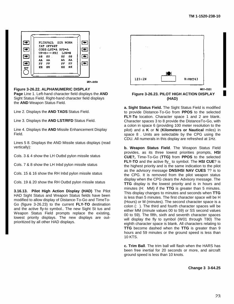
23
TM 1-1520-238-10
Figure 3-26.22. ALPHANUMERIC DISPLAYPage Line 1. Left-hand character field displays the ANDSight Status Field. Right-hand character field displaysthe AND Weapon Status Field.
Line 2. Displays the AND TADS Status Field.
Line 3. Displays the AND LST/RFD Status Field.
Line 4. Displays the AND Missile Enhancement DisplayField.
Lines 5 8. Displays the AND Missile status displays (readvertically):
Cols. 3 & 4 show the LH Outbd pylon missile status
Cols. 7 & 8 show the LH Inbd pylon missile status
Cols. 15 & 16 show the RH Inbd pylon missile status
Cols. 19 & 20 show the RH Outbd pylon missile status
3.16.13. Pilot High Action Display (HAD) The PilotHAD Sight Status and Weapon Status fields have beenmodified to allow display of Distance-To-Go and TimeTo-Go (figure 3-26.23) to the current FLY-TO destinationand the active fly-to symbol.. The new Sight St tus andWeapon Status Field prompts replace the existing,lowest priority displays. The new displays are out-prioritized by all other HAD displays.
Figure 3-26.23. PILOT HIGH ACTION DISPLAY(HAD)
a. Sight Status Field. The Sight Status Field is modifiedto provide Distance-To-Go from PPOS to the selectedFLY-To location. Character space 1 and 2 are blank.Character spaces 3 to 8 provide the DistanceTo-Go, witha colon in space 6 (providing 100 meter resolution to thepilot) and a K or N (Kilometers or Nautical miles) inspace 8 . Units are selectable by the CPG using theCDU. All numerals in this display are refreshed at 1Hz.
b. Weapon Status Field. The Weapon Status Fieldprovides, as its three lowest priorities prompts, HSICUE?, Time-To-Go (TTG) from PPOS to the selectedFLY-TO and the active fly_ to symbol. The HSI CUE? isthe highest priority and is the same indication to the pilotas the advisory message DNS/HSI NAV CUES ?? is tothe CPG. It is removed from the pilot weapon statusdisplay when the CPG clears the Advisory message. TheTTG display is the lowest priority and is in hours andminutes (H: MM) if the TTG is greater than 5 minutes.This display changes to minutes and seconds when TTGis less than 5 minutes. The first character space will be H(Hours) or M (minutes). The second character space is acolon (: ). The third and fourth character spaces will beeither MM (minute values 00 to 59) or SS second values00 to 59). The fifth, sixth and seventh character spaceswill display the fly to symbol (W01 through T80) Theeighth character space is blank. All characters relating toTTG become dashed when the TTG is greater than 9hours and 59 minutes or the ground speed is less than10 KTS.
c. Trim Ball. The trim ball will flash when the HARS hasbeen free inertial for 20 seconds or more, and aircraftground speed is less than 10 knots.
Change 3 3-64.25
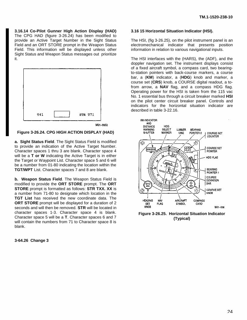
24
TM.1-1520-238-10
3.16.14 Co-Pilot Gunner High Action Display (HAD)The CPG HAD (figure 3-26.24) has been modified toprovide an Active Target Number in the Sight StatusField and an ORT STORE prompt in the Weapon StatusField. This information will be displayed unless otherSight Status and Weapon Status messages out prioritizeit.
Figure 3-26.24. CPG HIGH ACTION DISPLAY (HAD)
a. Sight Status Field. The Sight Status Field is modifiedto provide an indication of the Active Target Number.Character spaces 1 thru 3 are blank. Character space 4will be a T or W indicating the Active Target is in eitherthe Target or Waypoint List. Character space 5 and 6 willbe a number from 01-80 indicating the location within theTGT/WPT List. Character spaces 7 and 8 are blank.
b. Weapon Status Field. The Weapon Status Field ismodified to provide the ORT STORE prompt. The ORTSTORE prompt is formatted as follows: STR TXX. XX isa number from 71-80 to designate which location in theTGT List has received the new coordinate data. TheORT STORE prompt will be displayed for a duration of 2seconds and will then be removed. STR will be located incharacter spaces 1-3. Character space 4 is blank.Character space 5 will be a T. Character spaces 6 and 7will contain the numbers from 71 to Character space 8 isblank.
3.16 15 Horizontal Situation Indicator (HSI).
The HSI, (fig 3-26.25), on the pilot instrument panel is anelectromechanical indicator that presents positioninformation in relation to various navigational inputs.
The HSI interfaces with the (HARS), the (ADF), and thedoppler navigation set. The instrument displays consistof a fixed aircraft symbol, a compass card, two bearing-to-station pointers with back-course markers, a coursebar, a (KM) indicator, a (HDG) knob and marker, acourse set (CRS) knob, a COURSE digital readout, a to-from arrow, a NAV flag, and a compass HDG flag.Operating power for the HSI is taken from the 115 vacNo. 1 essential bus through a circuit breaker marked HSIon the pilot center circuit breaker panel. Controls andindicators for the horizontal situation indicator aredescribed in table 3-22.16.
Figure 3-26.25. Horizontal Situation Indicator(Typical)
3-64.26 Change 3
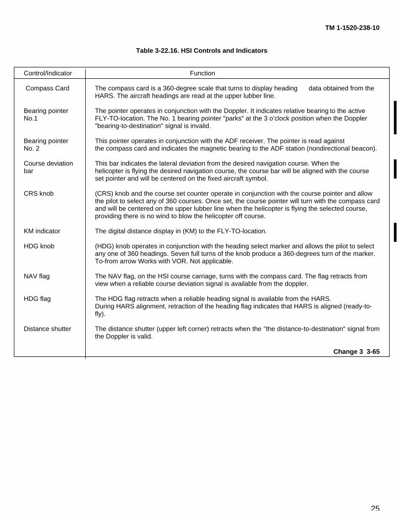
25
TM 1-1520-238-10
Table 3-22.16. HSI Controls and Indicators
Control/Indicator Function
Compass Card The compass card is a 360-degree scale that turns to display heading data obtained from the HARS. The aircraft headings are read at the upper lubber line.
Bearing pointer The pointer operates in conjunction with the Doppler. It indicates relative bearing to the activeNo.1 FLY-TO-location. The No. 1 bearing pointer "parks" at the 3 o’clock position when the Doppler
"bearing-to-destination" signal is invalid.
Bearing pointer This pointer operates in conjunction with the ADF receiver. The pointer is read againstNo. 2 the compass card and indicates the magnetic bearing to the ADF station (nondirectional beacon).
Course deviation This bar indicates the lateral deviation from the desired navigation course. When thebar helicopter is flying the desired navigation course, the course bar will be aligned with the course
set pointer and will be centered on the fixed aircraft symbol.
CRS knob (CRS) knob and the course set counter operate in conjunction with the course pointer and allow the pilot to select any of 360 courses. Once set, the course pointer will turn with the compass cardand will be centered on the upper lubber line when the helicopter is flying the selected course, providing there is no wind to blow the helicopter off course.
KM indicator The digital distance display in (KM) to the FLY-TO-location.
HDG knob (HDG) knob operates in conjunction with the heading select marker and allows the pilot to select any one of 360 headings. Seven full turns of the knob produce a 360-degrees turn of the marker.To-from arrow Works with VOR. Not applicable.
NAV flag The NAV flag, on the HSI course carriage, turns with the compass card. The flag retracts from view when a reliable course deviation signal is available from the doppler.
HDG flag The HDG flag retracts when a reliable heading signal is available from the HARS.During HARS alignment, retraction of the heading flag indicates that HARS is aligned (ready-to-fly).
Distance shutter The distance shutter (upper left corner) retracts when the ’’the distance-to-destination" signal fromthe Doppler is valid.
Change 3 3-65
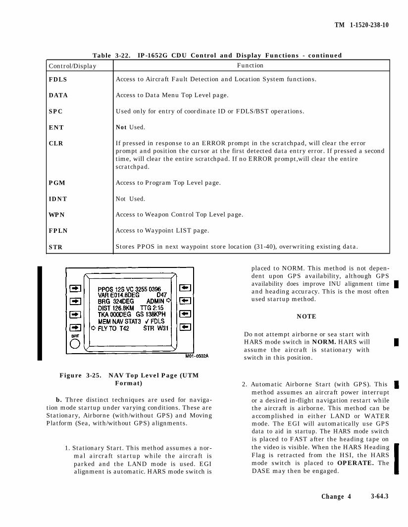
TM 1-1520-238-10
Table 3-22. IP-1652G CDU Control and Display Functions - continued
FunctionControl/Display
FDLS
DATA
SPC
ENT
CLR
Access to Aircraft Fault Detection and Location System functions.
Access to Data Menu Top Level page.
Used only for entry of coordinate ID or FDLS/BST operations.
Not Used.
If pressed in response to an ERROR prompt in the scratchpad, will clear the errorprompt and position the cursor at the first detected data entry error. If pressed a secondtime, will clear the entire scratchpad. If no ERROR prompt,will clear the entirescratchpad.
PGM
IDNT
WPN
FPLN
STR
Access to Program Top Level page.
Not Used.
Access to Weapon Control Top Level page.
Access to Waypoint LIST page.
Stores PPOS in next waypoint store location (31-40), overwriting existing data.
placed to NORM. This method is not depen-dent upon GPS availability, although GPSavailability does improve INU alignment timeand heading accuracy. This is the most oftenused startup method.
NOTE
Do not attempt airborne or sea start withHARS mode switch in NORM. HARS willassume the aircraft is stationary withswitch in this position.
Figure 3-25. NAV Top Level Page (UTMFormat)
b. Three distinct techniques are used for naviga-tion mode startup under varying conditions. These areStationary, Airborne (with/without GPS) and Moving
2. Automatic Airborne Start (with GPS). Thismethod assumes an aircraft power interruptor a desired in-flight navigation restart whilethe aircraft is airborne. This method can beaccomplished in either LAND or WATER
Platform (Sea, with/without GPS) alignments.
1. Stationary Start. This method assumes a nor-mal aircraft startup while the aircraft isparked and the LAND mode is used. EGIalignment is automatic. HARS mode switch is
mode. The EGI will automatically use GPSdata to aid in startup. The HARS mode switchis placed to FAST after the heading tape onthe video is visible. When the HARS HeadingFlag is retracted from the HSI, the HARSmode switch is placed to OPERATE. TheDASE may then be engaged.
Change 4 3-64.3
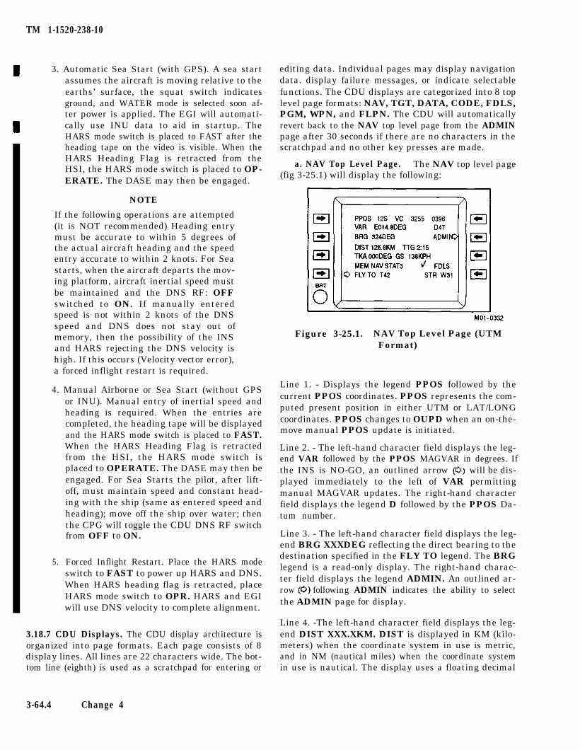
TM 1-1520-238-10
3. Automatic Sea Start (with GPS). A sea startassumes the aircraft is moving relative to theearths’ surface, the squat switch indicatesground, and WATER mode is selected soon af-ter power is applied. The EGI will automati-cally use INU data to aid in startup. TheHARS mode switch is placed to FAST after theheading tape on the video is visible. When theHARS Heading Flag is retracted from theHSI, the HARS mode switch is placed to OP-ERATE. The DASE may then be engaged.
NOTE
If the following operations are attempted(it is NOT recommended) Heading entrymust be accurate to within 5 degrees ofthe actual aircraft heading and the speedentry accurate to within 2 knots. For Seastarts, when the aircraft departs the mov-ing platform, aircraft inertial speed mustbe maintained and the DNS RF: OFFswitched to ON. If manually enteredspeed is not within 2 knots of the DNSspeed and DNS does not stay out ofmemory, then the possibility of the INSand HARS rejecting the DNS velocity ishigh. If this occurs (Velocity vector error),a forced inflight restart is required.
4. Manual Airborne or Sea Start (without GPSor INU). Manual entry of inertial speed andheading is required. When the entries arecompleted, the heading tape will be displayedand the HARS mode switch is placed to FAST.When the HARS Heading Flag is retractedfrom the HSI, the HARS mode switch isplaced to OPERATE. The DASE may then beengaged. For Sea Starts the pilot, after lift-off, must maintain speed and constant head-ing with the ship (same as entered speed andheading); move off the ship over water; thenthe CPG will toggle the CDU DNS RF switchfrom OFF to ON.
5. Forced Inflight Restart. Place the HARS modeswitch to FAST to power up HARS and DNS.When HARS heading flag is retracted, placeHARS mode switch to OPR. HARS and EGIwill use DNS velocity to complete alignment.
3.18.7 CDU Displays. The CDU display architecture isorganized into page formats. Each page consists of 8display lines. All lines are 22 characters wide. The bot-tom line (eighth) is used as a scratchpad for entering or
3-64.4 Change 4
editing data. Individual pages may display navigationdata. display failure messages, or indicate selectablefunctions. The CDU displays are categorized into 8 toplevel page formats: NAV, TGT, DATA, CODE, FDLS,PGM, WPN, and FLPN. The CDU will automaticallyrevert back to the NAV top level page from the ADMINpage after 30 seconds if there are no characters in thescratchpad and no other key presses are made.
a. NAV Top Level Page. The NAV top level page(fig 3-25.1) will display the following:
Figure 3-25.1. NAV Top Level Page (UTMFormat)
Line 1. - Displays the legend PPOS followed by thecurrent PPOS coordinates. PPOS represents the com-puted present position in either UTM or LAT/LONGcoordinates. PPOS changes to OUPD when an on-the-move manual PPOS update is initiated.
Line 2. - The left-hand character field displays the leg-end VAR followed by the PPOS MAGVAR in degrees. Ifthe INS is NO-GO, an outlined arrow will be dis-played immediately to the left of VAR permittingmanual MAGVAR updates. The right-hand characterfield displays the legend D followed by the PPOS Da-tum number.
Line 3. - The left-hand character field displays the leg-end BRG XXXDEG reflecting the direct bearing to thedestination specified in the FLY TO legend. The BRGlegend is a read-only display. The right-hand charac-ter field displays the legend ADMIN. An outlined ar-row following ADMIN indicates the ability to selectthe ADMIN page for display.
Line 4. -The left-hand character field displays the leg-end DIST XXX.XKM. DIST is displayed in KM (kilo-meters) when the coordinate system in use is metric,and in NM (nautical miles) when the coordinate systemin use is nautical. The display uses a floating decimal
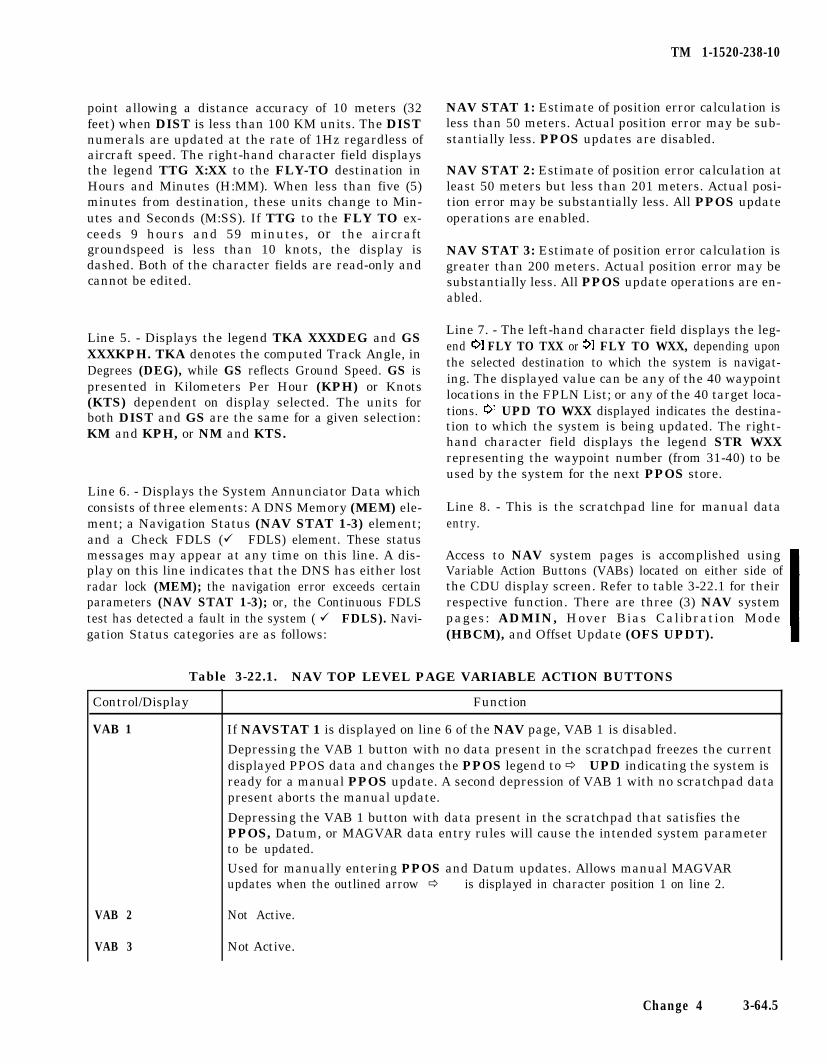
TM 1-1520-238-10
point allowing a distance accuracy of 10 meters (32feet) when DIST is less than 100 KM units. The DISTnumerals are updated at the rate of 1Hz regardless ofaircraft speed. The right-hand character field displaysthe legend TTG X:XX to the FLY-TO destination inHours and Minutes (H:MM). When less than five (5)minutes from destination, these units change to Min-utes and Seconds (M:SS). If TTG to the FLY TO ex-ceeds 9 hours and 59 minutes, or the aircraftgroundspeed is less than 10 knots, the display isdashed. Both of the character fields are read-only andcannot be edited.
Line 5. - Displays the legend TKA XXXDEG and GSXXXKPH. TKA denotes the computed Track Angle, inDegrees (DEG), while GS reflects Ground Speed. GS ispresented in Kilometers Per Hour (KPH) or Knots(KTS) dependent on display selected. The units forboth DIST and GS are the same for a given selection:KM and KPH, or NM and KTS.
Line 6. - Displays the System Annunciator Data whichconsists of three elements: A DNS Memory (MEM) ele-ment; a Navigation Status (NAV STAT 1-3) element;and a Check FDLS (ü FDLS) element. These statusmessages may appear at any time on this line. A dis-play on this line indicates that the DNS has either lostradar lock (MEM); the navigation error exceeds certainparameters (NAV STAT 1-3); or, the Continuous FDLStest has detected a fault in the system ( ü FDLS). Navi-gation Status categories are as follows:
Table 3-22.1. NAV TOP LEVEL PAGE VARIABLE ACTION BUTTONS
FunctionControl/Display
VAB 1
VAB 2
VAB 3
NAV STAT 1: Estimate of position error calculation isless than 50 meters. Actual position error may be sub-stantially less. PPOS updates are disabled.
NAV STAT 2: Estimate of position error calculation atleast 50 meters but less than 201 meters. Actual posi-tion error may be substantially less. All PPOS updateoperations are enabled.
NAV STAT 3: Estimate of position error calculation isgreater than 200 meters. Actual position error may besubstantially less. All PPOS update operations are en-abled.
Line 7. - The left-hand character field displays the leg-end FLY TO TXX or FLY TO WXX, depending uponthe selected destination to which the system is navigat-ing. The displayed value can be any of the 40 waypointlocations in the FPLN List; or any of the 40 target loca-tions. UPD TO WXX displayed indicates the destina-tion to which the system is being updated. The right-hand character field displays the legend STR WXXrepresenting the waypoint number (from 31-40) to beused by the system for the next PPOS store.
Line 8. - This is the scratchpad line for manual dataentry.
Access to NAV system pages is accomplished usingVariable Action Buttons (VABs) located on either side ofthe CDU display screen. Refer to table 3-22.1 for theirrespective function. There are three (3) NAV systempages: ADMIN, Hover Bias Calibration Mode(HBCM), and Offset Update (OFS UPDT).
If NAVSTAT 1 is displayed on line 6 of the NAV page, VAB 1 is disabled.
Depressing the VAB 1 button with no data present in the scratchpad freezes the currentdisplayed PPOS data and changes the PPOS legend to ð UPD indicating the system isready for a manual PPOS update. A second depression of VAB 1 with no scratchpad datapresent aborts the manual update.
Depressing the VAB 1 button with data present in the scratchpad that satisfies thePPOS, Datum, or MAGVAR data entry rules will cause the intended system parameterto be updated.
Used for manually entering PPOS and Datum updates. Allows manual MAGVARupdates when the outlined arrow ð is displayed in character position 1 on line 2.
Not Active.
Not Active.
Change 4 3-64.5
TM 1-1520-238-10
Table 3-22.1. NAV TOP LEVEL PAGE VARIABLE ACTION BUTTONS - continued
Control/Display
VAB 4
Function
When depressed, if the left-hand character field in line 7 displays the legend UPD TO,will complete a flyover type PPOS update; and display updated PPOS on line 1. Whenupdated data is accepted or aborted, line 7 will return to its’ previous legend of ð FLYTo.
With valid FLY TO data symbol (WXX or TXX with valid previously enteredcoordinates) entered on the scratchpad, will change the active FLY TO to locationentered in scratchpad. Invalid scratchpad coordinate data will result in “ERROR”message on scratchpad.
Without data in scratchpad; will display active FLY TO coordinates in scratchpad withinitial depression. Second depression will display the Associated data line (ID, Altitudeand Datum) for the active FLY To coordinates. Subsequent depressions will togglebetween the FLY TO coordinates and the Associated Data. FLY TO coordinates andAssociated Data displayed in the scratchpad are for review purposes only, and cannot beedited or transferred.
VAB 5 If NAVSTAT 1 is displayed on line 6 of the NAV page, VAB 5 is disabled.
Depression of VAB 5 with other than NAVSTAT 1 status while overflying a waypointwill freeze the PPOS display on line 1 and changes the FLY TO legend on line 7 to UPDTO. Reselection of VAB 5, or selection of any other page, will abort the update.
VAB 6
VAB 7
VAB 8
Presents the ADMIN sub page when depressed.
Not Active.
Not Active.
b. Administration (ADMIN) Page. The ADMIN Line 1. - Displays the example legend ð ð 12 /24/94 denot-page (fig 3-25.2), is selected by depressing VAB 6 on the ing the current Month, Day, and Year., separated byNAV Top Level Page. VAB functions are explained in slashes (/) in the left-hand character field. Update ofTable 3-22.2. The ADMIN page contains the following: this field is automatic through GPS data, and when up-
dated, the ð is blanked. If the system has no date avail-able (GPS or Manual), this field is displayed as dashed(--I--/--). The current time example legend 15:42:18 ðis displayed in the right-hand character field repre-senting Hours, Minutes, and Seconds, separated by acolon(:), in that order. If GPS time is not valid,( ð ð is dis-played), manual update to the system is permitted.
Line 2. - Displays the centered page title ADMIN.
Line 3. - The left-hand character field displays an out-lined arrow and the legend ð A XXXXXFT reflectingthe current aircraft altitude. This altitude value is al-ways displayed in Feet only, and is referenced to MSL.Positive altitude above MSL is displayed with a blankpreceding the altitude readout; negative altitude (be-low MSL) is displayed using a minus (-) sign precedingthe altitude readout (A-XXXXXFT). The right-handcharacter field displays the legend HGXX.XX ï denot-
Figure 3-25.2. ADMIN Page - Top Level ing the current Barometric pressure setting.
3-64.6 Change 4
TM 1-1520-238-10
Line 4. -The left-hand character field displays the leg-end TKAE L XXX.. TKAE represents the currentTrack Angle Error; L or R denotes Left or Right; andthe XXX signifies the angle error in degrees. The right-hand character field displays the legend XTKELXX.X.XTKE represents the current Cross Track Error; L or Rdenotes Left or Right; and XXX.X signifies the distancein Kilometers or Nautical Miles, dependent upon unitsselected by the the CPG, and displayed in line 7(DSPL:KM or DSPL:NM).
Line 5. - Displays the legend MODE:LAND orMODEWATER in the left-hand character field. The
right-hand character field displays the legendHBCM ð ð if the DNS system status is GO; otherwisethis field is blanked.
Line 6. -Blank.
Line 7. - The left-hand character field displays the leg-end MODE:UTM or MODE:L/L signifying coordinatedata entry methodology. The right-hand character fielddisplays the legend DSPL:KM or DSPL:NM signifyingmetric system or nautical system, respectively, in use.
Line 8. - This is the scratchpad line for manual dataentry.
Table 3-22.2. ADMIN SUB-PAGE VARIABLE ACTION BUTTONS
Control/Display
VAB 1
Function
Used for manual entry of MONTH DAY YEAR update data (MMDDYY) when theoutlined arrow is ( ð ) displayed in character position 1 on line 1, and character string ispresent in the scratchpad. Valid entries are: 01-12 for MM; 01-31 for DD; and 00-99 forYY.
VAB 2 Used for manual entry ofAltitude update data. Positive altitude is assumed and does notrequire a “+” sign; Negative altitude (below MSL) requires a minus (-) sign preceding thealtitude value. Altitude ranges are -900 feet MSL to 20000 MSL. Altitude is alwaysdisplayed in feet.
VAB 3 Used for selecting MODE:LAND or MODE:Water navigation operations. Systemdefaults to MODE:LAND at power up. Depressing VAB 3 toggles between two choices.
VAB 4 Selects the data presentation format to be used for PPOS, CPOS, WAYPOINT, andTARGET coordinate data entry. System defaults to MODE:UTM at power up.Depressing VAB 4 toggles between MODE:UTM AND MODE:L/L. Pages affected bypressing VAB 4 are NAV, OFFSET, WAYPOINT and TARGET.
VAB 6 Used for manual entry of HOUR MINUTE SECOND update data (HHMMSS) whenthe outlined arrow is ( ï ) displayed in character position 22 on line 1, and characterstring is present in the scratchpad. Valid entries are: 00-23 for HH; 00-59 for MM; and00-59 for SS.
VAB 6 Used for manual entry of HG (barometric pressure). Valid entries are: 27.92 to 31.92.Data is entered in scratchpad as XXXX; the decimal point entry is not required. Thisentry followed by an altitude entry within .60 seconds will cause the system tore-calibrate the ADS pressure sensor bias correction.
VAB 7 Used for selecting HBCM sub-page. Valid only if HBCM ð ð is present indicating the DNSsystem is “GO”.
VAB 8 Used for selecting DSPL:KM or DSPL:NM signifying metric system or nautical system,respectively, in use for coordinate display. Depressing VAB 8 toggles between the two (2)choices.
Change 4 3-64.7
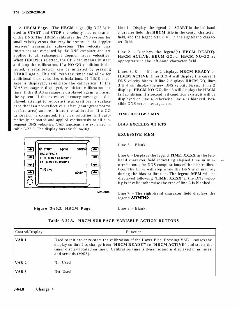
TM 1-1520-238-10
c. HBCM Page. The HBCM page, (fig 3-25.3) isused to START and STOP the velocity bias calibrationof the DNS. The HBCM calibrates the DNS system forsmall velocity errors that may be present in the dopplerreceiver/ transmitter subsystem. The velocity biascorrections are computed by the DNS computer and areapplied to all subsequent doppler radar velocities.When HBCM is selected, the CPG can manually startand stop the calibration. If a NO-GO condition is de-tected, a recalibration can be initiated by pressingSTART again. This will zero the timer and allow foradditional bias velocities calculations. If TIME mes-sage is displayed, re-initiate the calibration. If theBIAS message is displayed, re-initiate calibration onetime. If the BIAS message is displayed again, write upthe system. If the excessive memory message is dis-played, attempt to re-locate the aircraft over a surfacearea that is a non-reflective surface (short grass/coarsesurface area) and re-initiate the calibration. If a GOcalibration is computed, the bias velocities will auto-matically be stored and applied continuously to all sub-sequent DNS velocities. VAB functions are explained intable 3-22.3. The display has the following:
Line 7. - The right-hand character field displays the
Line 1. - Displays the legend ð START in the left-handcharacter field; the HBCM title in the center characterfield, and the legend STOP ð in the right-hand charac-ter field.
Line 2. - Displays the legend(s) HBCM READY;.HBCM ACTIVE, HBCM GO, or HBCM NO-GO asappropriate in the left-hand character field.
Lines 3. & 4 - If line 2 displays HBCM READY orHBCM ACTIVE, lines 3 & 4 will display the currentDNS velocity biases. If line 2 displays HBCM GO, lines3 & 4 will display the new DNS velocity biases. If line 2displays HBCM NO-GO, line 3 will display the HBCMfail condition. If a second fail condition exists, it will bedisplayed on line 4, otherwise line 4 is blanked. Pos-sible DNS error messages are:
TIME BELOW 2 MIN
BIAS EXCEEDS 0.3 KTS
EXCESSIVE MEM
Line 5. - Blank.
Line 6. - Displays the legend TIME: XX:XX in the left-hand character field indicating elapsed time in min- --utes/seconds for DNS computations of the bias calibra-tion. The timer will stop while the DNS is in memoryduring the bias calibration. The legend MEM will bedisplayed following "TIME: XX:XX" if the DNS veloc-ity is invalid; otherwise the rest of line 6 is blanked.
legend ADMINO.
Figure 3-25.3. HBCM Page Line 8. - Blank.
Table 3-22.3. HBCM SUB-PAGE VARIABLE ACTION BUTTONS
Control/Display
VAB 1
VAB 2
VAB 3
Function
Used to initiate or re-start the calibration of the Hover Bias. Pressing VAB 1 causes thedisplay on line 2 to change from “HBCM READY”’ to “HBCM ACTIVE” and starts thetimer display located on line 6. Calibration time is dynamic and is displayed in minutesand seconds (M:SS).
Not Used
Not Used
3-64.8 Change 4
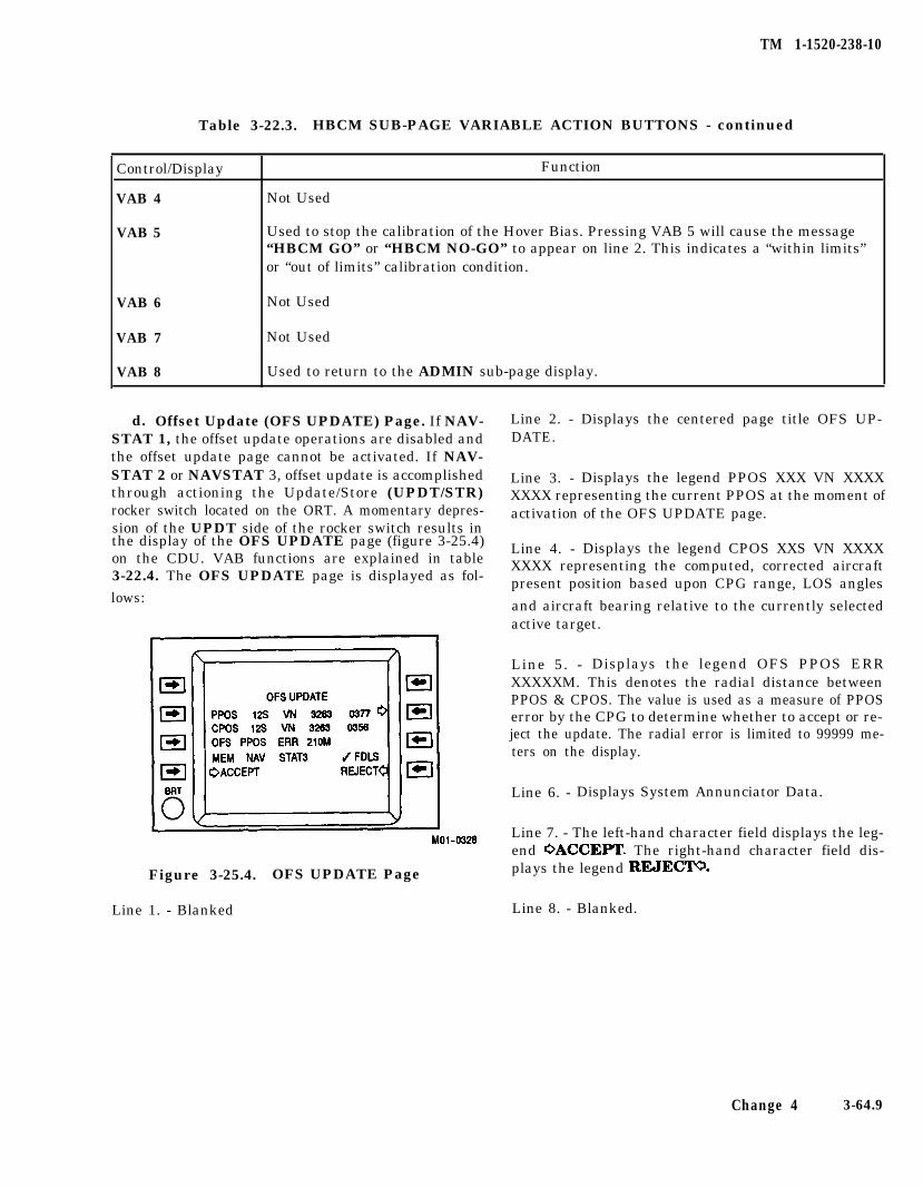
TM 1-1520-238-10
Table 3-22.3. HBCM SUB-PAGE VARIABLE ACTION BUTTONS - continued
Control/Display
VAB 4
VAB 5
Function
Not Used
Used to stop the calibration of the Hover Bias. Pressing VAB 5 will cause the message“HBCM GO” or “HBCM NO-GO” to appear on line 2. This indicates a “within limits”or “out of limits” calibration condition.
VAB 6 Not Used
VAB 7 Not Used
VAB 8 Used to return to the ADMIN sub-page display.
d. Offset Update (OFS UPDATE) Page. If NAV- Line 2. - Displays the centered page title OFS UP-STAT 1, the offset update operations are disabled and DATE.the offset update page cannot be activated. If NAV-STAT 2 or NAVSTAT 3, offset update is accomplished Line 3. -through actioning the Update/Store (UPDT/STR)
Displays the legend PPOS XXX VN XXXX
rocker switch located on the ORT. A momentary depres-XXXX representing the current PPOS at the moment ofactivation of the OFS UPDATE page.
sion of the UPDT side of the rocker switch results inthe display of the OFS UPDATE page (figure 3-25.4)on the CDU. VAB functions are explained in table
Line 4. - Displays the legend CPOS XXS VN XXXX
3-22.4. The OFS UPDATE page is displayed as fol-XXXX representing the computed, corrected aircraftpresent position based upon CPG range, LOS angles
lows: and aircraft bearing relative to the currently selectedactive target.
Line 5. - Displays the legend OFS PPOS ERRXXXXXM. This denotes the radial distance betweenPPOS & CPOS. The value is used as a measure of PPOSerror by the CPG to determine whether to accept or re-ject the update. The radial error is limited to 99999 me-ters on the display.
Line 6. - Displays System Annunciator Data.
Line 7. - The left-hand character field displays the leg-end OACCEPT. The right-hand character field dis-
Figure 3-25.4. OFS UPDATE Page plays the legend REJECT.
Line 1. - Blanked Line 8. - Blanked.
Change 4 3-64.9
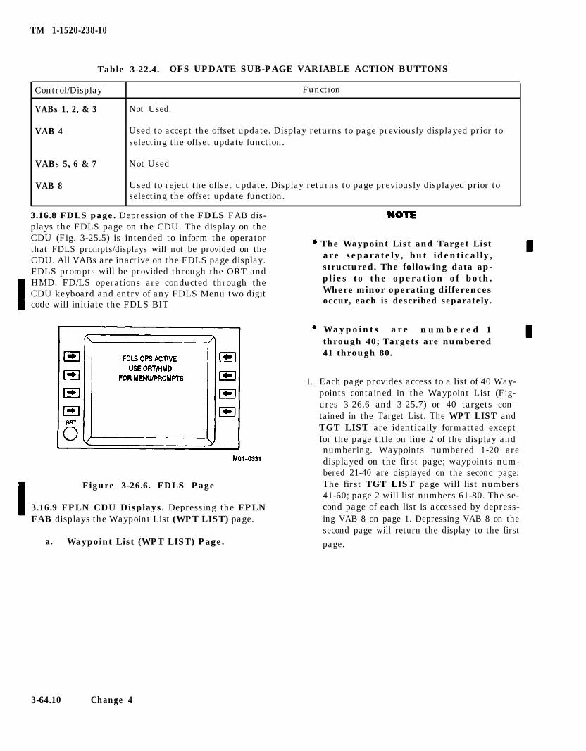
TM 1-1520-238-10
Table 3-22.4. OFS UPDATE SUB-PAGE VARIABLE ACTION BUTTONS
Control/Display Function
VABs 1, 2, & 3 Not Used.
VAB 4 Used to accept the offset update. Display returns to page previously displayed prior toselecting the offset update function.
VABs 5, 6 & 7 Not Used
VAB 8 Used to reject the offset update. Display returns to page previously displayed prior toselecting the offset update function.
3.16.8 FDLS page. Depression of the FDLS FAB dis-plays the FDLS page on the CDU. The display on theCDU (Fig. 3-25.5) is intended to inform the operatorthat FDLS prompts/displays will not be provided on theCDU. All VABs are inactive on the FDLS page display.FDLS prompts will be provided through the ORT andHMD. FD/LS operations are conducted through theCDU keyboard and entry of any FDLS Menu two digitcode will initiate the FDLS BIT
Waypoints are n u m b e r e d 1through 40; Targets are numbered41 through 80.
1. Each page provides access to a list of 40 Way-points contained in the Waypoint List (Fig-ures 3-26.6 and 3-25.7) or 40 targets con-tained in the Target List. The WPT LIST andTGT LIST are identically formatted exceptfor the page title on line 2 of the display and
The Waypoint List and Target Listare separately, but identically,structured. The following data ap-plies to the operation of both.Where minor operating differencesoccur, each is described separately.
numbering. Waypoints numbered 1-20 aredisplayed on the first page; waypoints num-bered 21-40 are displayed on the second page.
Figure 3-26.6. FDLS Page The first TGT LIST page will list numbers41-60; page 2 will list numbers 61-80. The se-
3.16.9 FPLN CDU Displays. Depressing the FPLNFAB displays the Waypoint List (WPT LIST) page.
cond page of each list is accessed by depress-ing VAB 8 on page 1. Depressing VAB 8 on thesecond page will return the display to the first
a. Waypoint List (WPT LIST) Page. page.
3-64.10 Change 4
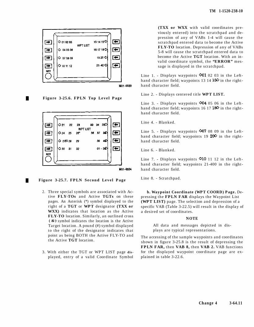
Figure 3-25.6. FPLN Top Level Page
Figure 3-25.7. FPLN Second Level Page
2. Three special symbols are associated with Ac-tive FLY-TOs and Active TGTs on thesepages. An Asterisk (*) symbol displayed to theright of a TGT or WPT designator (TXX orWXX) indicates that location as the ActiveFLY-TO location. Similarly, an outlined cross( q ) symbol indicates the location is the ActiveTarget location. A pound (#) symbol displayedto the right of the designator indicates thatpoint as being BOTH the Active FLY-TO andthe Active TGT location.
3. With either the TGT or WPT LIST page dis-
played, entry of a valid Coordinate Symbol
TM 1-1520-238-10
(TXX or WXX with valid coordinates pre-viously entered) into the scratchpad and de-pression of any of VABs 1-4 will cause thescratchpad entered data to become the ActiveFLY-TO location. Depression of any of VABs5-8 will cause the scratchpad entered data tobecome the Active TGT location. With an in-valid coordinate symbol, the “ERROR” mes-sage is displayed in the scratchpad.
Line 1. - Displays waypoints 001 02 03 in the Left-hand character field; waypoints 13 14 1% in the right-hand character field.
Line 2. - Displays centered title WPT LIST.
Line 3. - Displays waypoints 004 05 06 in the Left-hand character field; waypoints 16 17 180 in the right-hand character field.
Line 4. - Blanked.
Line 5. - Displays waypoints 007 08 09 in the Left-hand character field; waypoints 19 200 in the right-hand character field.
Line 6. - Blanked.
Line 7. - Displays waypoints 010 11 12 in the Left-hand character field; waypoints 21-400 in the right-hand character field.
Line 8. - Scratchpad.
b. Waypoint Coordinate (WPT COORD) Page. De-pressing the FPLN FAR displays the Waypoint List(WPT LIST) page. The selection and depression of aspecific VAB (Table 3-22.5) will result in the display ofa desired set of coordinates.
NOTE
All data and messages depicted in dis-plays are typical representations.
The accessing of the sample waypoints and coordinatesshown in figure 3-25.8 is the result of depressing theFPLN FAR, then VAB 8, then VAB 2. VAB functionsfor the displayed waypoint coordinate page are ex-plained in table 3-22.6.
Change 4 3-64.11
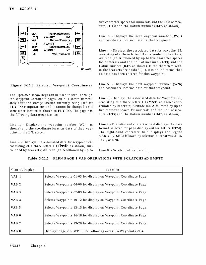
TM 1-1520-238-10
Figure 3-25.8. Selected Waypoint Coordinates
The Up/Down arrow keys can be used to scroll throughthe Waypoint Coordinate pages. An * is shown immedi-ately after the storage location currently being used forFLY TO computations and it cannot be changed untilsome other location is chosen to FLY TO. The page hasthe following data organization:
Line 1. - Displays the waypoint number (W24, asshown) and the coordinate location data of that way-point in the L/L system.
five character spaces for numerals and the unit of mea-sure - FT); and the Datum number (D47, as shown).
Line 3. - Displays the next waypoint number (W25)and coordinate location data for that waypoint.
Line 4. - Displays the associated data for waypoint 25,consisting of a three letter ID surrounded by brackets;Altitude (an A followed by up to five character spacesfor numerals and the unit of measure - FT); and theDatum number (D47, as shown). If the characters with-in the brackets are dashed (---), it is an indication thatno data has been entered for this waypoint.
Line 5. - Displays the next waypoint number (W26)and coordinate location data for that waypoint.
Line 6. - Displays the associated data for Waypoint 26,consisting of a three letter ID (MNT, as shown) sur-rounded by brackets; Altitude (an A followed by up tofive character spaces for numerals and the unit of mea-sure - FT); and the Datum number (D47, as shown).
Line 7 - The left-hand character field displays the dataformat selected for page display (either L/L or UTM).The right-hand character field displays the legendVAB 5 - 7 SEL: followed by selection alternatives XFR,
Line 2. - Displays the associated data for waypoint 24,TGT, or R/B.
consisting of a three letter ID (PND, as shown) sur-rounded by brackets; Altitude (an A followed by up to Line 8. - Scratchpad for data input.
Table 3-22.5. FLPN PAGE 1 VAB OPERATIONS WITH SCRATCHPAD EMPTY
Control/Display Function
VAB l Selects Waypoints 01-03 for display on Waypoint Coordinate Page
VAB 2 Selects Waypoints 04-06 for display on Waypoint Coordinate Page
VAB 3 Selects Waypoints 07-09 for display on Waypoint Coordinate Page
VAB 4 Selects Waypoints 10-12 for display on Waypoint Coordinate Page
VAB 5 Selects Waypoints 13-15 for display on Waypoint Coordinate Page
VAB 6 Selects Waypoints 16-18 for display on Waypoint Coordinate Page
VAB 7 Selects Waypoints 19-20 for display on Waypoint Coordinate Page
VAB 8 Displays page 2 of WPT LIST allowing access to Waypoints 21-40
3-64.12 Change 4
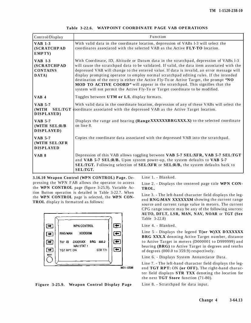
TM 1-1520-238-10
Table 3-22.6. WAYPOINT COORDINATE PAGE VAB OPERATIONS
Control/Display Function
VAB 1-3 With valid data in the coordinate location, depression of VABs l-3 will select the(SCRATCHPAD coordinates associated with the selected VAB as the Active FLY-TO location.EMPTY)
VAB l-3 With Coordinate, ID, Altitude or Datum data in the scratchpad, depression of VABs l-3(SCRATCHPAD will cause the scratchpad data to be validated. If valid, the data item associated with theCONTAINS depressed VAB will change to the entered value. If data is invalid, an error message willDATA) display prompting operator to employ normal scratchpad editing rules. If the intended
destination of the entry is either the Active Fly-To or Active Target, the prompt “NOMOD TO ACTIVE COORD” will appear in the scratchpad. This signifies that thesystem will not permit the Active Fly-To or Target coordinate to be modified.
VAB 4 Toggles between UTM or L/L display formats.
VAB 5-7 With valid data in the coordinate location, depression of any of these VABs will select the(WITH SEL:TGT coordinate associated with the depressed VAB as the Active Target location.DISPLAYED)
VAB 5-7 Displays the range and bearing (RangeXXXXXXBRGXXX.X) to the selected coordinate(WITH SEL:R/B on line 8.DISPLAYED)
VAB 5-7 Copies the coordinate data associated with the depressed VAB into the scratchpad.(WITH SEL:XFRDISPLAYED
VAB 8 Depression of this VAB allows toggling between VAB 5-7 SEL:XFR, VAB 5-7 SEL:TGTand VAB 5-7 SEL:R/B. Upon system power-up, the system defaults to VAB 5-7SEL:TGT. Following selection of SEL:XFR or SEL:R/B, the system defaults back toSEL:TGT.
3.16.10 Weapon Control (WPN CONTROL) Page. De- Line 1. - Blanked.pressing the WPN FAB allows the operator to accessthe WPN CONTROL page (figure 3-25.9). Variable Ac-
Line 2. - Displays the centered page title WPN CON-TROL.
tion Button operation is detailed in Table 3-22.7. Whenthe WPN CONTROL page is selected, the WPN CON-TROL display is formatted as follows:
Line 3. - The left-hand character field displays the leg-end RNG:MAN XXXXXXM showing the current rangesource and current range value in meters. The currentCPG range source may be any of the following sources:AUTO, DFLT, LSR, MAN, NAV, NOAR or TGT (SeeTable 3-22.8)
Line 4. - Blanked.
Line 5 - Displays the legend T(or W)XX DXXXXXXBRG XXX.X denoting Active Target number, distanceto Active Target in meters (D000001 to D999999) andbearing (BRG) to Active Target in degrees and tenthsof degrees (000.0 to 359.9) respectively.
Line 6. - Displays System Annunciator Data.
Line 7. - The left-hand character field displays the leg-end TGT RPT: ON (or OFF). The right-hand charac-ter field displays STR TXX denoting the location forthe next TGT Store function (71-80).
Figure 3-25.9. Weapon Control Display Page Line 8. - Scratchpad for data input.
Change 4 3-64.13
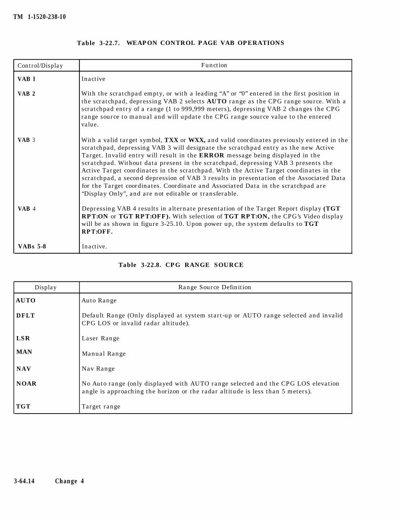
TM 1-1520-238-10
Table 3-22.7. WEAPON CONTROL PAGE VAB OPERATIONS
Control/Display Function
VAB l Inactive
VAB 2 With the scratchpad empty, or with a leading “A” or “0” entered in the first position inthe scratchpad, depressing VAB 2 selects AUTO range as the CPG range source. With ascratchpad entry of a range (1 to 999,999 meters), depressing VAB 2 changes the CPGrange source to manual and will update the CPG range source value to the enteredvalue.
VAB 3 With a valid target symbol, TXX or WXX, and valid coordinates previously entered in thescratchpad, depressing VAB 3 will designate the scratchpad entry as the new ActiveTarget. Invalid entry will result in the ERROR message being displayed in thescratchpad. Without data present in the scratchpad, depressing VAB 3 presents theActive Target coordinates in the scratchpad. With the Active Target coordinates in thescratchpad, a second depression of VAB 3 results in presentation of the Associated Datafor the Target coordinates. Coordinate and Associated Data in the scratchpad are“Display Only”, and are not editable or transferable.
VAB 4 Depressing VAB 4 results in alternate presentation of the Target Report display (TGTRPT:ON or TGT RPT:OFF). With selection of TGT RPT:ON, the CPG’s Video displaywill be as shown in figure 3-25.10. Upon power up, the system defaults to TGTRPT:OFF.
VABs 5-8 Inactive.
Table 3-22.8. CPG RANGE SOURCE
Display
AUTO
DFLT
LSR
MAN
NAV
NOAR
TGT
Range Source Definition
Auto Range
Default Range (Only displayed at system start-up or AUTO range selected and invalidCPG LOS or invalid radar altitude).
Laser Range
Manual Range
Nav Range
No Auto range (only displayed with AUTO range selected and the CPG LOS elevationangle is approaching the horizon or the radar altitude is less than 5 meters).
Target range
3-64.14 Change 4
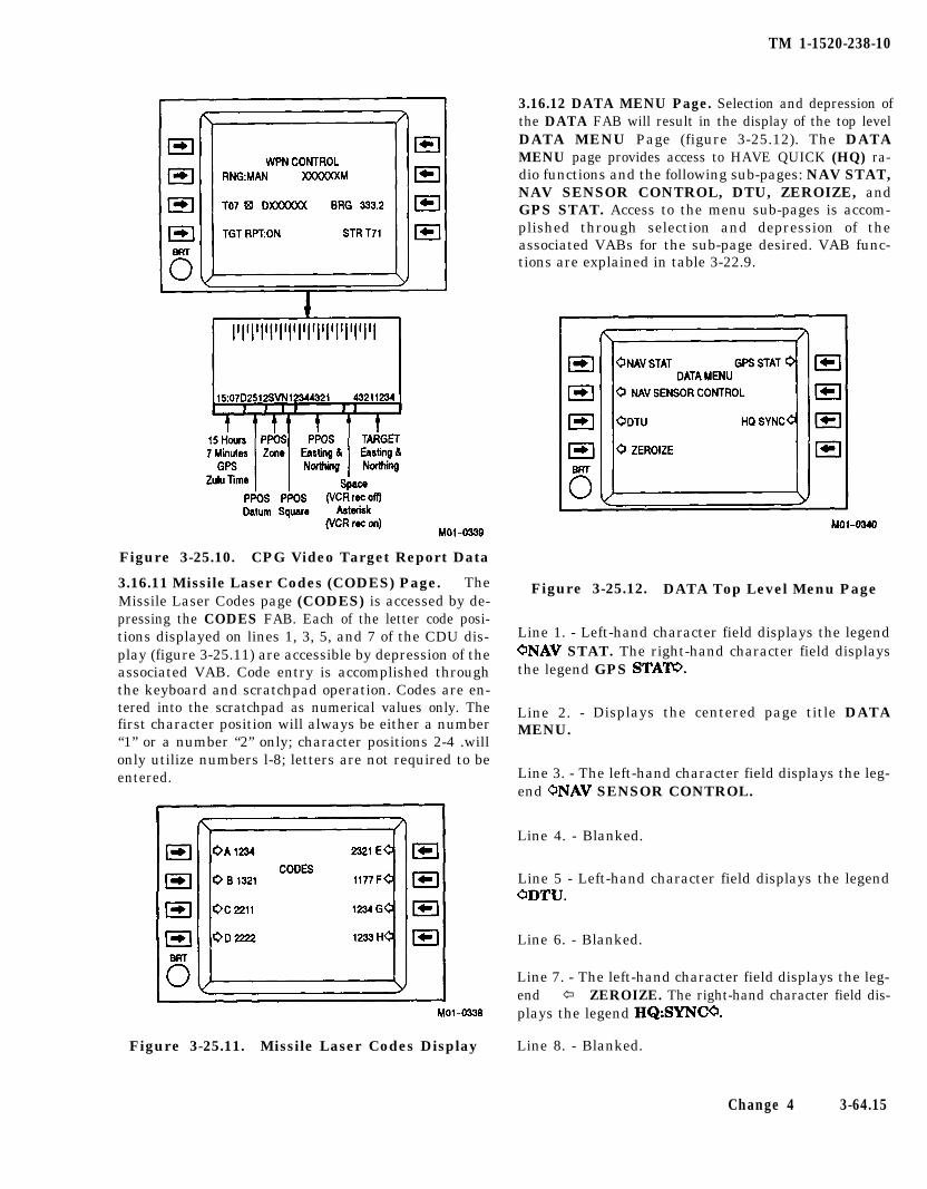
TM 1-1520-238-10
Figure 3-25.10. CPG Video Target Report Data
3.16.11 Missile Laser Codes (CODES) Page. TheMissile Laser Codes page (CODES) is accessed by de-pressing the CODES FAB. Each of the letter code posi-tions displayed on lines 1, 3, 5, and 7 of the CDU dis-play (figure 3-25.11) are accessible by depression of theassociated VAB. Code entry is accomplished throughthe keyboard and scratchpad operation. Codes are en-tered into the scratchpad as numerical values only. Thefirst character position will always be either a number“1” or a number “2” only; character positions 2-4 .willonly utilize numbers l-8; letters are not required to beentered.
Line 7. - The left-hand character field displays the leg-end ï ZEROIZE. The right-hand character field dis-plays the legend HQ:SYNCO.
Figure 3-25.11. Missile Laser Codes Display Line 8. - Blanked.
3.16.12 DATA MENU Page. Selection and depression ofthe DATA FAB will result in the display of the top levelDATA MENU Page (figure 3-25.12). The DATAMENU page provides access to HAVE QUICK (HQ) ra-dio functions and the following sub-pages: NAV STAT,NAV SENSOR CONTROL, DTU, ZEROIZE, andGPS STAT. Access to the menu sub-pages is accom-plished through selection and depression of theassociated VABs for the sub-page desired. VAB func-tions are explained in table 3-22.9.
Figure 3-25.12. DATA Top Level Menu Page
Line 1. - Left-hand character field displays the legendONAV STAT. The right-hand character field displaysthe legend GPS STATO.
Line 2. - Displays the centered page title DATAMENU.
Line 3. - The left-hand character field displays the leg-end ONAV SENSOR CONTROL.
Line 4. - Blanked.
Line 5 - Left-hand character field displays the legendODTU.
Line 6. - Blanked.
Change 4 3-64.15
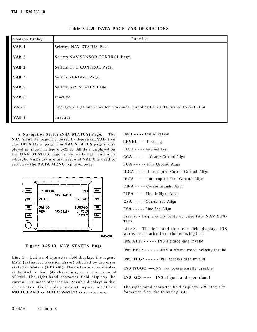
TM 1-1520-238-10
Table 3-22.9. DATA PAGE VAB OPERATIONS
Control/Display Function
VAB l Selectes NAV STATUS Page.
VAB 2 Selects NAV SENSOR CONTROL Page.
VAB 3 Selects DTU CONTROL Page.
VAB 4 Selects ZEROIZE Page.
VAB 5 Selects GPS STATUS Page.
VAB 6 Inactive
VAB 7 Energizes HQ Sync relay for 5 seconds. Supplies GPS UTC signal to ARC-164
VAB 8 Inactive
a. Navigation Status (NAV STATUS) Page. The INIT - - - - InitializationNAV STATUS page is accessed by depressing VAB 1 onthe DATA Menu page. The NAV STATUS page is dis-
LEVEL - - -Leveling
played as shown in figure 3-25.13. All data displayed on TEST - - - - Internal Test the NAV STATUS page is read-only data and non-editable. VABs 1-7 are inactive, and VAB 8 is used to
CGA- - - - - Coarse Ground Align
return to the DATA MENU top level page. FGA - - - - - Fine Ground Align
ICGA - - - - Interrupted Coarse Ground Align
CSA- - - - - Coarse Sea Align
FSA - - - - - Fine Sea Align
Line 2. - Displays the centered page title NAV STA-TUS.
IFGA - - - - Interrupted Fine Ground Align
CIFA - - - - Coarse Inflight Align
FIFA - - - - Fine Inflight Align
Line 3. - The left-hand character field displays INSstatus information from the following list:
Figure 3-25.13. NAV STATUS PageINS ATT? - - - - - INS attitude data invalid
INS VEL? - - - - - -INS airframe coord. velocity invalid
Line 1. - Left-hand character field displays the legendEPE (Estimated Position Error) followed by the error
INS HDG? - - - - - INS heading data invalid
stated in Meters (XXXXM). The distance error displayis limited to four (4) characters, or a maximum of
INS NOGO ----INS not operationally useable
9999M. The right-hand character field displays the INS GO ----- INS aligned and operationalcurrent INS mode ofoperation. Possible displays in thisc h a r a c t e r f i e l d , d e p e n d e n t u p o n w h e t h e r The right-hand character field displays GPS status in-MODE:LAND or MODE:WATER is selected are: formation from the following list:
3-64.16 Change 4
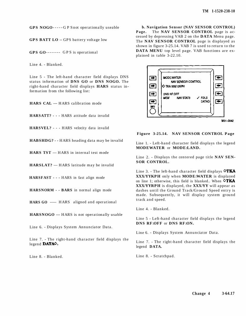
TM 1-1520-238-10
GPS NOGO- - - - - G P Snot operationally useable
GPS BATT LO -- GPS battery voltage low
GPS GO- - - - - - - - GPS is operational
Line 4. - Blanked.
Line 5 - The left-hand character field displays DNSstatus information of DNS GO or DNS NOGO. Theright-hand character field displays HARS status in-formation from the following list:
HARS CAL --- HARS calibration mode
HARSATT? - - - HARS attitude data invalid
HARSVEL? - - - HARS velocity data invalid
HABSHDG? - - HARS heading data may be invalid
HARS TST --- HARS in internal test mode
HARSLAT? --- HARS latitude may be invalid
HARSFAST - - - HARS in fast align mode
HARSNORM - - BARS in normal align mode
HARS GO ----- HARS aligned and operational
HARSNOGO --- HARS is not operationally usable
Line 6. - Displays System Annunciator Data.
Line 7. - The right-hand character field displays thelegend DATAO.
Line 8. - Blanked.
b. Navigation Sensor (NAV SENSOR CONTROL)Page. The NAV SENSOR CONTROL page is ac-cessed by depressing VAB 2 on the DATA Menu page.The NAV SENSOR CONTROL page is displayed asshown in figure 3-25.14. VAB 7 is used to return to theDATA MENU top level page. VAB functions are ex-plained in table 3-22.10.
Figure 3-25.14. NAV SENSOR CONTROL Page
Line 1. - Left-hand character field displays the legendMODEWATER or MODE:LAND.
Line 2. - Displays the centered page title NAV SEN-SOR CONTROL.
Line 3. - The left-hand character field displays WKAXXX/YYKPH only when MODE:WATER is displayedon line 1; otherwise, this field is blanked.. When WKAXXX/YYRPH is displayed, the XXX/YY will appear asdashes until the Ground Track/Ground Speed entry ismade. Subsequently, it will display system groundtrack and speed.
Line 4. - Blanked.
Line 5 - Left-hand character field displays the legendDNS RF:OFF or DNS RF:ON.
Line 6. - Displays System Annunciator Data.
Line 7. - The right-hand character field displays thelegend DATA.
Line 8. - Scratchpad.
Change 4 3-64.17
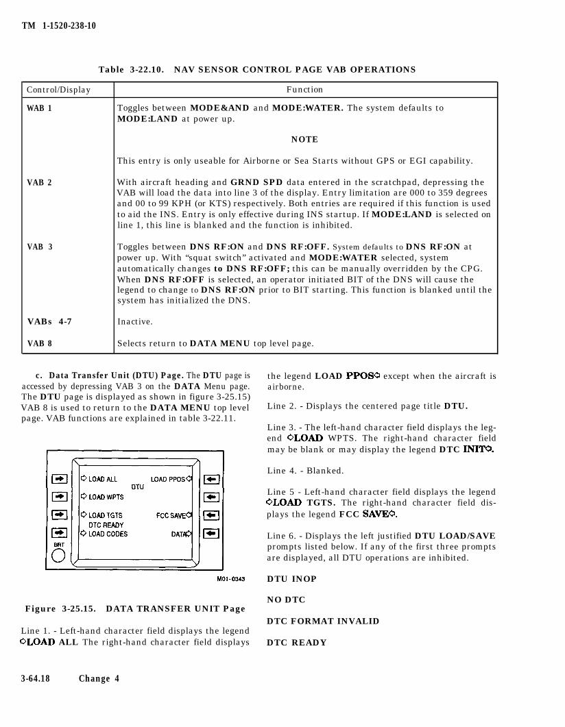
TM 1-1520-238-10
Table 3-22.10. NAV SENSOR CONTROL PAGE VAB OPERATIONS
Control/Display Function
WAB 1 Toggles between MODE&AND and MODE:WATER. The system defaults toMODE:LAND at power up.
NOTE
This entry is only useable for Airborne or Sea Starts without GPS or EGI capability.
VAB 2 With aircraft heading and GRND SPD data entered in the scratchpad, depressing theVAB will load the data into line 3 of the display. Entry limitation are 000 to 359 degreesand 00 to 99 KPH (or KTS) respectively. Both entries are required if this function is usedto aid the INS. Entry is only effective during INS startup. If MODE:LAND is selected online 1, this line is blanked and the function is inhibited.
VAB 3 Toggles between DNS RF:ON and DNS RF:OFF. System defaults to DNS RF:ON atpower up. With “squat switch” activated and MODE:WATER selected, systemautomatically changes to DNS RF:OFF; this can be manually overridden by the CPG.When DNS RF:OFF is selected, an operator initiated BIT of the DNS will cause thelegend to change to DNS RF:ON prior to BIT starting. This function is blanked until thesystem has initialized the DNS.
VABs 4-7 Inactive.
VAB 8 Selects return to DATA MENU top level page.
c. Data Transfer Unit (DTU) Page. The DTU page is the legend LOAD PPOSO except when the aircraft isaccessed by depressing VAB 3 on the DATA Menu page. airborne.The DTU page is displayed as shown in figure 3-25.15)VAB 8 is used to return to the DATA MENU top level Line 2. - Displays the centered page title DTU.page. VAB functions are explained in table 3-22.11.
Line 3. - The left-hand character field displays the leg-end OLOAD WPTS. The right-hand character fieldmay be blank or may display the legend DTC INITCt
Line 4. - Blanked.
Line 5 - Left-hand character field displays the legendOLOAD TGTS. The right-hand character field dis-plays the legend FCC SAVEO.
Line 6. - Displays the left justified DTU LOAD/SAVEprompts listed below. If any of the first three promptsare displayed, all DTU operations are inhibited.
DTU INOP
NO DTCFigure 3-25.15. DATA TRANSFER UNIT Page
DTC FORMAT INVALIDLine 1. - Left-hand character field displays the legendOLOAD ALL The right-hand character field displays DTC READY
3-64.18 Change 4
TM 1-1520-238-10
TARGETS LOAD FAIL UPLOAD ALL COMPLETE
WAYPOINTS LOAD FAIL
LASER CODES LOAD FAIL
PPOS LOAD FAIL
UPLOAD ALL FAIL
TARGETS LOAD COMPLETE
WPTS LOAD COMPLETE
FCC SAVE-OK
FCC SAVE FAIL
The LOAD FAIL and LOAD COMPLETE promptsrefer to initialization data that was loaded in the DTCusing the Aviation Mission Planning System (AMPS).
Line 7. - The left-hand character field displays the leg-end OLOAD CODES. The right-hand character fielddisplays the legend DATAO. -
Line 8. - Scratchpad
CODES LOAD COMPLETE
PPOS LOAD COMPLETE
Table 3-22.11. DTU PAGE VAB OPERATIONS
Control/Display Function
VAB l Initiates LOAD of Waypoints, Targets, Laser Codes, and Present Position from cartridge.To preclude inadvertent load of PPOS, the LOAD ALL function will not load PPOS if theaircraft is airborne.
VAB 2
VAB 3
VAB 4
VAB 5
VAB 6
VAB 7
Loads WPTS from cartridge.
Loads TGTS from cartridge.
Loads CODES from cartridge.
Loads PPOS from cartridge unless aircraft is airborne.
Reformats DTC for normal use if DTC INITOis displayed; otherwise blanked.
Saves critical data in the FCC volatile memory (BST DATA, PPOS, Altitude, AltitudeCorrections, MAGVAR, etc.) to non-volatile memory and saves the waypoints, targets,laser codes and PPOS to the DTC “SAVE” file.
VAB 8 Returns to the DATA MENU top level page.
d. ZEROIZE Page. The ZEROIZE page is accessed seconds without an operator depression of VABs 1,4,7,by depressing VAB 4 on the DATA MENU page. The or 8, the display automatically reverts back to theZEROIZE page is displayed as shown in figure DATA MENU top level page.. VAB functions are ex-3-25.16. VAB 8 is used to return to the DATA MENU plained in table 3-22.12.top level page. If the ZEROIZE page is displayed for 5
Change 4 3-64.19
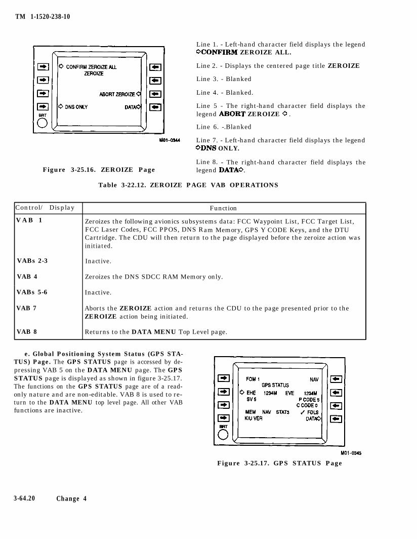
TM 1-1520-238-10
Figure 3-25.16. ZEROIZE Page
Control/ Display
V A B 1
VABs 2-3 Inactive.
VAB 4 Zeroizes the DNS SDCC RAM Memory only.
Inactive.VABs 5-6
VAB 7
VAB 8
Line 1. - Left-hand character field displays the legendOCONFIRM ZEROIZE ALL.
Line 2. - Displays the centered page title ZEROIZE
Line 3. - Blanked
Line 4. - Blanked.
Line 5 - The right-hand character field displays thelegend ABORT ZEROIZE 0 .
Line 6. -.Blanked
Line 7. - Left-hand character field displays the legendODNS ONLY.
Line 8. - The right-hand character field displays thelegend DATAO.
Table 3-22.12. ZEROIZE PAGE VAB OPERATIONS
Function
Zeroizes the following avionics subsystems data: FCC Waypoint List, FCC Target List,FCC Laser Codes, FCC PPOS, DNS Ram Memory, GPS Y CODE Keys, and the DTUCartridge. The CDU will then return to the page displayed before the zeroize action wasinitiated.
Aborts the ZEROIZE action and returns the CDU to the page presented prior to theZEROIZE action being initiated.
Returns to the DATA MENU Top Level page.
e. Global Positioning System Status (GPS STA-TUS) Page. The GPS STATUS page is accessed by de-pressing VAB 5 on the DATA MENU page. The GPSSTATUS page is displayed as shown in figure 3-25.17.The functions on the GPS STATUS page are of a read-only nature and are non-editable. VAB 8 is used to re-turn to the DATA MENU top level page. All other VABfunctions are inactive.
Figure 3-25.17. GPS STATUS Page
3-64.20 Change 4
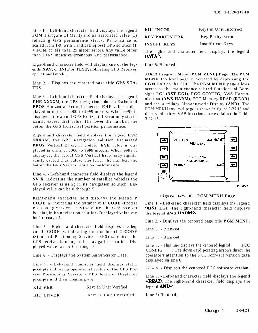
TM 1-1520-238-10
Line 1. - Left-hand character field displays the legendFOM 1 (Figure Of Merit) and an associated value (1)reflecting GPS performance status. Performance isscaled from 1-9, with 1 indicating best GPS solution (1= FOM of less than 25 meter error). Any value otherthan 1 to 9 indicates erroneous GPS performance.
Right-hand character field will display one of the leg-ends NAV, or INIT or TEST, indicating GPS Receiveroperational mode.
Line 2. - Displays the centered page title GPS STA-TUS.
Line 3. - Left-hand character field displays the legend,EHE XXXXM, the GPS navigation solution EstimatedPPOS Horizontal Error, in meters. EHE value is dis-played in units of 0000 to 9999 meters. When 9999 isdisplayed, the actual GPS Horizontal Error may signif-icantly exceed that value. The lower the number, thebetter the GPS Horizontal position performance.
Right-hand character field displays the legend EVEXXXXM, the GPS navigation solution EstimatedPPOS Vertical Error, in meters. EVE value is dis-played in units of 0000 to 9999 meters. When 9999 isdisplayed, the actual GPS Vertical Error may signifi-cantly exceed that value. The lower the number, thebetter the GPS Vertical position performance.
Line 4. - Left-hand character field displays the legendSV X, indicating the number of satellite vehicles theGPS receiver is using in its navigation solution. Dis-played value can be 0 through 5.
Right-hand character field displays the legend PCODE X, indicating the number of P CODE (PrecisePositioning Service - PPS) satellites the GPS receiveris using in its navigation solution. Displayed value canbe 0 through 5.
Line 5. - Right-hand character field displays the leg-end C CODE X, indicating the number of C CODE(Standard Positioning Service - SPS) satellites theGPS receiver is using in its navigation solution. Dis-played value can be 0 through 5.
Line 6. - Displays the System Annunciator Data.
Line 7. - Left-hand character field displays statusprompts indicating operational status of the GPS Pre-cise Positioning Service - PPS feature. Displayedprompts and their meaning are:
KIU VER Keys in Unit Verified
KIU UNVER Keys in Unit Unverified
KIU INCOR Keys in Unit Incorrect
KEY PARITY ERR Key Parity Error
INSUFF KEYS Insufficient Keys
The right-hand character field displays the legendDATAO.
Line 8: Blanked.
3.16.13 Program Menu (PGM MENU) Page. The PGMMENU top level page is accessed by depressing thePGM FAB on the CDU. The PGM MENU page allowsaccess to the maintenance-related functions of Bore-sight EGI (BST EGI), FCC CONFIG, AWS Harmo-nization (AWS HARM), FCC Memory READ (READ)and the Auxiliary Alphanumeric Display (AND). ThePGM MENU top level page is shown in figure 3-25.18 anddiscussed below. VAB functions are explained in Table3-22.13
Figure 3-25.18. PGM MENU Page
Line 1. - Left-hand character field displays the legendOBST EGI. The right-hand character field displaysthe legend AWS IIABMO.
Line 2. - Displays the centered page title PGM MENU.
Line 3. - Blanked.
Line 4. - Blanked.
Line 5. - This line displays the centered legend â â FCCCONFIG â â . The downward pointing arrows direct theoperator’s attention to the FCC software version datadisplayed on line 6.
Line 6. - Displays the centered FCC software version.
Line 7. - Left-hand character field displays the legendOREAD. The right-hand character field displays thelegend ANDO,
Line 8: Blanked.
Change 4 3-64.21
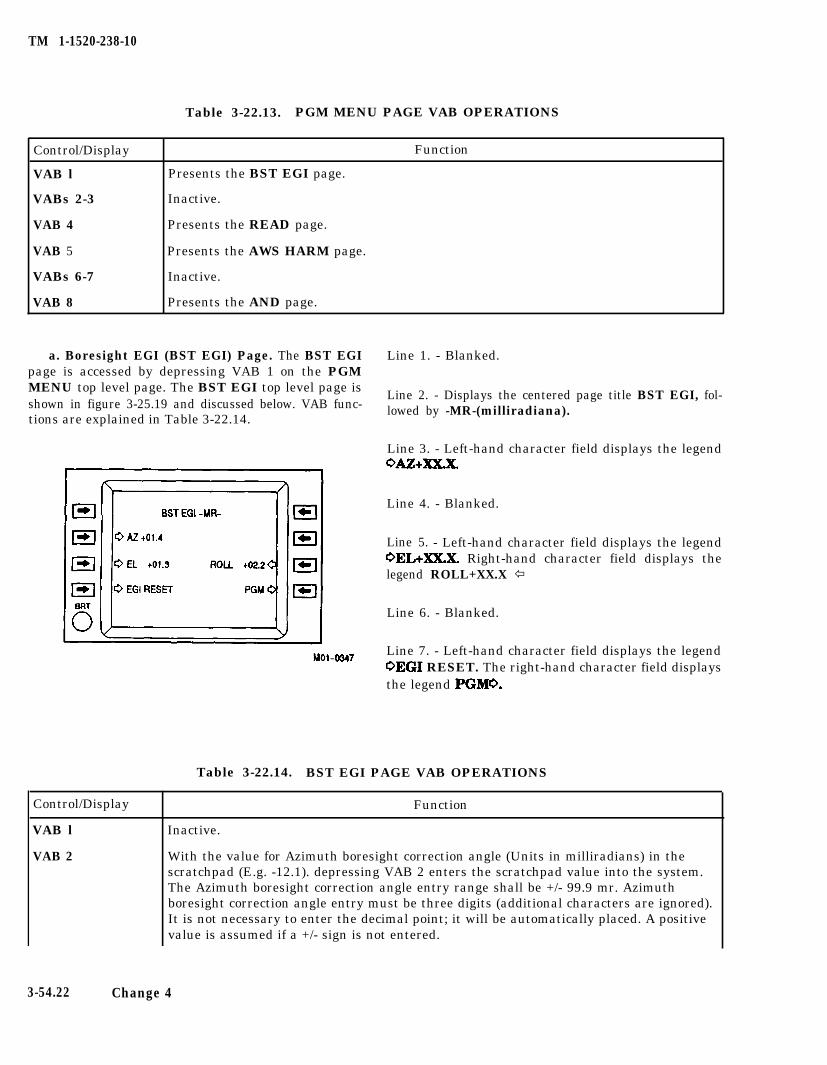
TM 1-1520-238-10
Table 3-22.13. PGM MENU PAGE VAB OPERATIONS
Control/Display Function
VAB l Presents the BST EGI page.
VABs 2-3 Inactive.
VAB 4 Presents the READ page.
VAB 5 Presents the AWS HARM page.
VABs 6-7 Inactive.
VAB 8 Presents the AND page.
a. Boresight EGI (BST EGI) Page. The BST EGIpage is accessed by depressing VAB 1 on the PGMMENU top level page. The BST EGI top level page isshown in figure 3-25.19 and discussed below. VAB func-tions are explained in Table 3-22.14.
Line 1. - Blanked.
Line 2. - Displays the centered page title BST EGI, fol-lowed by -MR-(milliradiana).
Line 3. - Left-hand character field displays the legendOAZ+2KXX.
Line 4. - Blanked.
Line 5. - Left-hand character field displays the legendOEL+XX.X. Right-hand character field displays thelegend ROLL+XX.X ï
Line 6. - Blanked.
Line 7. - Left-hand character field displays the legendOEGI RESET. The right-hand character field displaysthe legend PGM0.
Control/Display
VAB l
VAB 2
Table 3-22.14. BST EGI PAGE VAB OPERATIONS
Function
Inactive.
With the value for Azimuth boresight correction angle (Units in milliradians) in thescratchpad (E.g. -12.1). depressing VAB 2 enters the scratchpad value into the system.The Azimuth boresight correction angle entry range shall be +/- 99.9 mr. Azimuthboresight correction angle entry must be three digits (additional characters are ignored).It is not necessary to enter the decimal point; it will be automatically placed. A positivevalue is assumed if a +/- sign is not entered.
3-54.22 Change 4
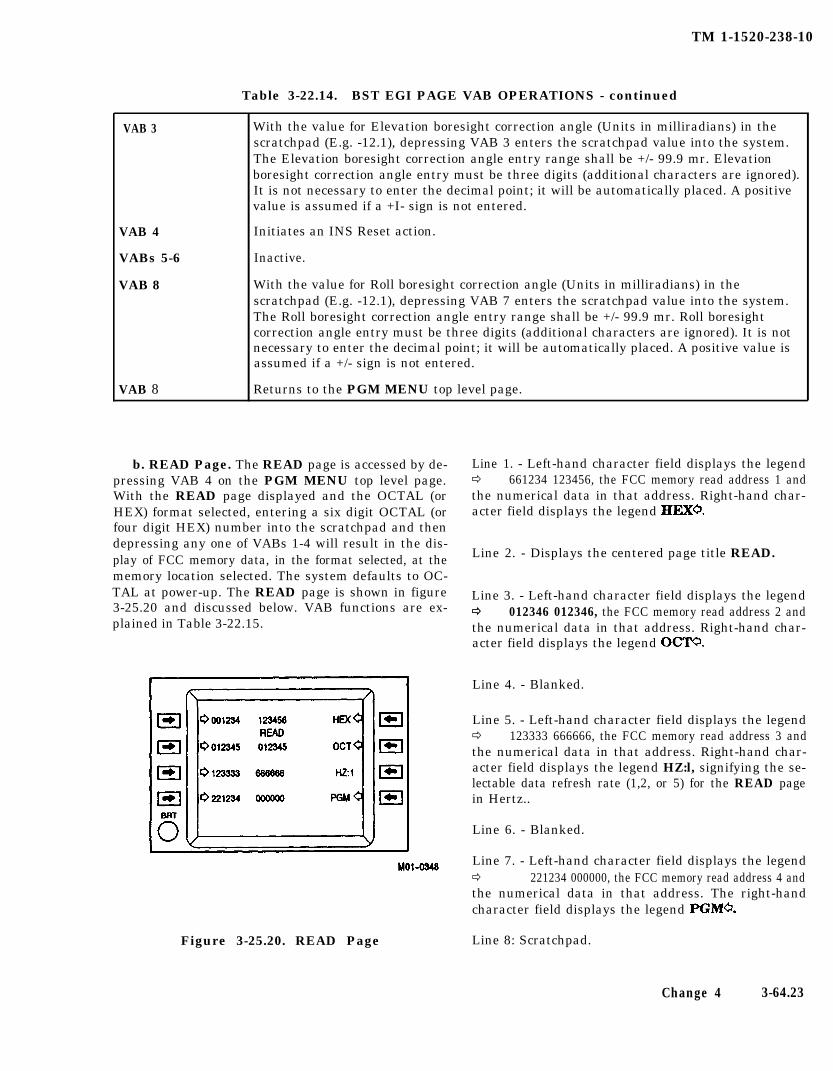
TM 1-1520-238-10
Table 3-22.14. BST EGI PAGE VAB OPERATIONS - continued
With the value for Elevation boresight correction angle (Units in milliradians) in thescratchpad (E.g. -12.1), depressing VAB 3 enters the scratchpad value into the system.The Elevation boresight correction angle entry range shall be +/- 99.9 mr. Elevationboresight correction angle entry must be three digits (additional characters are ignored).It is not necessary to enter the decimal point; it will be automatically placed. A positivevalue is assumed if a +I- sign is not entered.
VAB 3
VAB 4
VABs 5-6
VAB 8
Initiates an INS Reset action.
Inactive.
With the value for Roll boresight correction angle (Units in milliradians) in thescratchpad (E.g. -12.1), depressing VAB 7 enters the scratchpad value into the system.The Roll boresight correction angle entry range shall be +/- 99.9 mr. Roll boresightcorrection angle entry must be three digits (additional characters are ignored). It is notnecessary to enter the decimal point; it will be automatically placed. A positive value isassumed if a +/- sign is not entered.
VAB 8 Returns to the PGM MENU top level page.
b. READ Page. The READ page is accessed by de-pressing VAB 4 on the PGM MENU top level page.With the READ page displayed and the OCTAL (orHEX) format selected, entering a six digit OCTAL (orfour digit HEX) number into the scratchpad and thendepressing any one of VABs 1-4 will result in the dis-play of FCC memory data, in the format selected, at thememory location selected. The system defaults to OC-TAL at power-up. The READ page is shown in figure3-25.20 and discussed below. VAB functions are ex-plained in Table 3-22.15.
Figure 3-25.20. READ Page Line 8: Scratchpad.
Line 1. - Left-hand character field displays the legendð 661234 123456, the FCC memory read address 1 andthe numerical data in that address. Right-hand char-acter field displays the legend HEXO.
Line 2. - Displays the centered page title READ.
Line 3. - Left-hand character field displays the legendð ð 012346 012346, the FCC memory read address 2 andthe numerical data in that address. Right-hand char-acter field displays the legend OCW.
Line 4. - Blanked.
Line 5. - Left-hand character field displays the legendð 123333 666666, the FCC memory read address 3 andthe numerical data in that address. Right-hand char-acter field displays the legend HZ:l, signifying the se-lectable data refresh rate (1,2, or 5) for the READ pagein Hertz..
Line 6. - Blanked.
Line 7. - Left-hand character field displays the legendð 221234 000000, the FCC memory read address 4 andthe numerical data in that address. The right-handcharacter field displays the legend PGMO.
Change 4 3-64.23
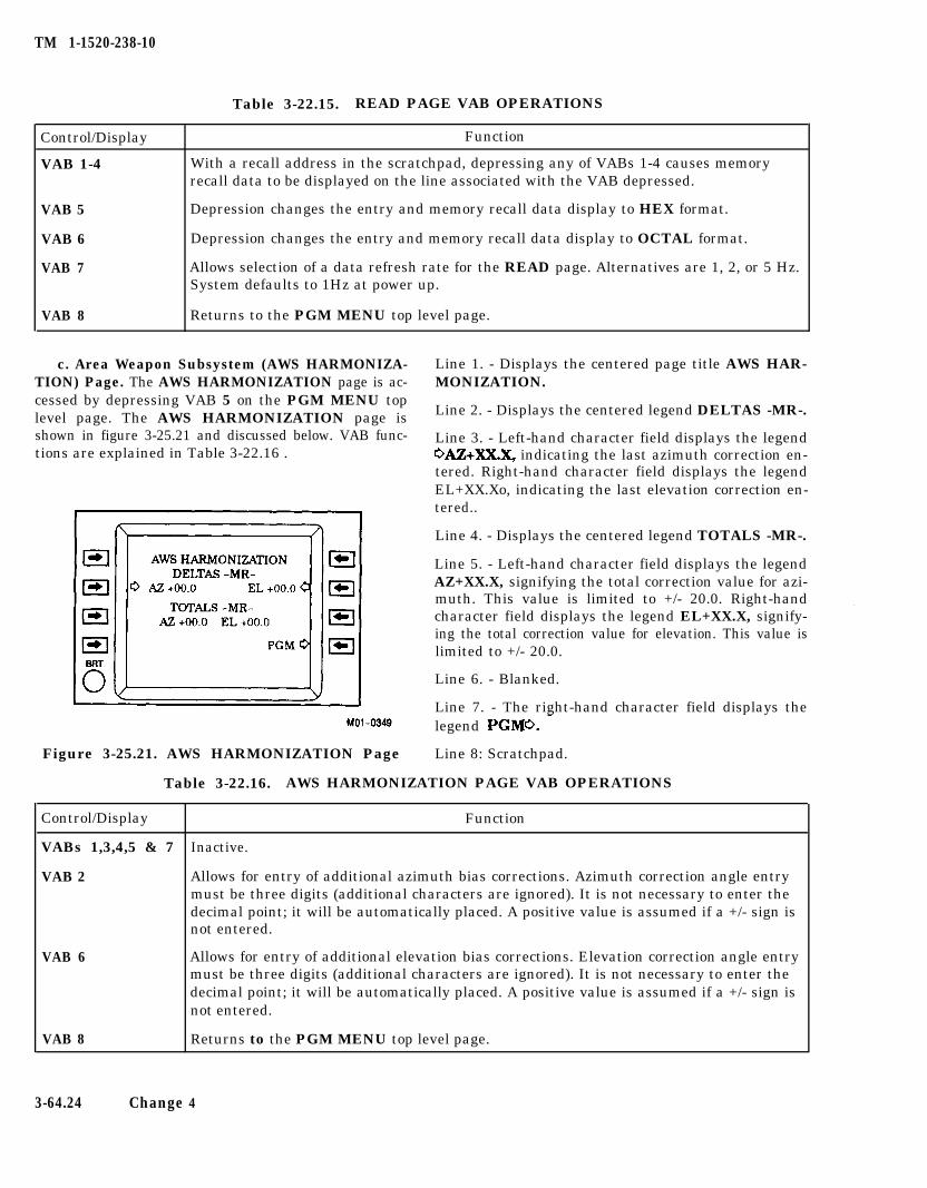
TM 1-1520-238-10
Table 3-22.15. READ PAGE VAB OPERATIONS
Control/Display Function
VAB 1-4 With a recall address in the scratchpad, depressing any of VABs 1-4 causes memoryrecall data to be displayed on the line associated with the VAB depressed.
VAB 5 Depression changes the entry and memory recall data display to HEX format.
VAB 6 Depression changes the entry and memory recall data display to OCTAL format.
VAB 7 Allows selection of a data refresh rate for the READ page. Alternatives are 1, 2, or 5 Hz.System defaults to 1Hz at power up.
VAB 8 Returns to the PGM MENU top level page.
c. Area Weapon Subsystem (AWS HARMONIZA- Line 1. - Displays the centered page title AWS HAR-TION) Page. The AWS HARMONIZATION page is ac- MONIZATION.cessed by depressing VAB 5 on the PGM MENU toplevel page. The AWS HARMONIZATION page is Line 2. - Displays the centered legend DELTAS -MR-.
shown in figure 3-25.21 and discussed below. VAB func- Line 3. - Left-hand character field displays the legendtions are explained in Table 3-22.16 . OAz+XX.X, indicating the last azimuth correction en-
tered. Right-hand character field displays the legendEL+XX.Xo, indicating the last elevation correction en-tered..
Line 4. - Displays the centered legend TOTALS -MR-.
Line 5. - Left-hand character field displays the legendAZ+XX.X, signifying the total correction value for azi-muth. This value is limited to +/- 20.0. Right-handcharacter field displays the legend EL+XX.X, signify-ing the total correction value for elevation. This value islimited to +/- 20.0.
Line 6. - Blanked.
Line 7. - The right-hand character field displays thelegend PGMO. -
Figure 3-25.21. AWS HARMONIZATION Page Line 8: Scratchpad.
Table 3-22.16. AWS HARMONIZATION PAGE VAB OPERATIONS
Control/Display Function
VABs 1,3,4,5 & 7 Inactive.
VAB 2 Allows for entry of additional azimuth bias corrections. Azimuth correction angle entrymust be three digits (additional characters are ignored). It is not necessary to enter thedecimal point; it will be automatically placed. A positive value is assumed if a +/- sign isnot entered.
VAB 6 Allows for entry of additional elevation bias corrections. Elevation correction angle entrymust be three digits (additional characters are ignored). It is not necessary to enter thedecimal point; it will be automatically placed. A positive value is assumed if a +/- sign isnot entered.
VAB 8 Returns to the PGM MENU top level page.
3-64.24 Change 4
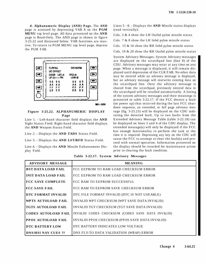
TM 1-1520-238-10
d. Alphanumeric Display (AND) Page. The ANDpage is accessed by depressing VAB 8 on the PGMMENU top level page. All data presented on the ANDpage is Read-Only. The AND page is shown in figure3-25.22 and discussed below. VAB functions are inac-tive. To return to PGM MENU top level page, depressthe PGM FAB.
Figure 3-25.22. ALPHANUMERIC DISPLAYPage
Line 1. - Left-hand character field displays the ANDSight Status Field. Right-hand character field displaysthe AND Weapon Status Field.
Line 2. - Displays the AND TADS Status Field.
Line 3. - Displays the AND LST/RFD Status Field.
Line 4. - Displays the AND Missile Enhancement Dis-
Cols. 7 & 8 show the LH Inbd pylon missile status
Cols. 15 & 16 show the RH Inbd pylon missile status
Cols. 19 & 20 show the RH Outbd pylon missile status
System Advisory Messages. System Advisory messagesare displayed on the scratchpad line (line 8) of theCDU. Advisory messages may occur at any time on anypage. When a message is displayed, it will remain dis-played until depression of the CLR FAB. No other datamay be entered while an advisory message is displayed,but an advisory message will overwrite existing data onthe scratchpad line. Once the advisory message iscleared from the scratchpad, previously entered data inthe scratchpad will be recalled automatically. A listingof the system advisory messages and their meanings ispresented in table 3-22.17. If the FCC detects a fault(on power up) that occurred during the last FCC shut-down sequence, an extended, or full page advisory mes-sage (fig. 3-25.23) will be displayed on the CDU indi-cating the detected fault. Up to two faults from theExtended Advisory Message Table (table 3-22.18) canbe displayed on lines 3 and 4 of the CDU display. Theextended message(s) will only be displayed if the FCChas enough functionality to perform the task at thetime it is required. Depressing any key on the CDU willcause the FCC to attempt to clear the fault(s) and pro-ceed with normal operation. Information presented onthe display should be recorded for maintenance action
play Field. prior to clearing the fault condition.
Table 3-22.17. System Advisory Messages
ADVISORY MESSAGE
BST DATA LOAD FAIL
INIT DATA LOAD FAIL
FCC SAVE COMPLETE
FCC SAVE FAIL
DTC FORMAT INVALID
WPTS AUTOLOAD FAIL
TGTS AUTOLOAD FAIL
CODES AUTOLOAD FAIL
PPOS AUTOLOAD FAIL
DTC BATTERY LOW
DNS/HSI NAV CUES ??
Lines 5 - 8. - Displays the AND Missile status displays(read vertically):
Cols. 3 & 4 show the LH Outbd pylon missile status
MEANING
FCC EEPROM TO RAM LOAD CHECKSUM ERROR
FCC EEPROM TO RAM LOAD CHECKSUM ERROR
FCC RAM TO EEPROM SUCCESSFUL
FCC RAM TO EEPROM SAVE CHECKSUM ERROR
DTC FILE FORMAT INVALID (DTC IS NOT USEABLE)
INVALID WPT CHECKSUM (WPT SAVE DATA INVALID)
INVALID TGT CHECKSUM (TGT SAVE DATA INVALID)
INVALID CODES CHECKSUM (CODES SAVE DATA INVALID)
INVALID PPOS CHECKSUM (PPOS SAVE DATA INVALID)
DTC BATTERY INDICATES LOW VOLTAGE
DNS FLY-TO DATA VALIDATION (WRAP) ERROR
Change 4 3-64.25
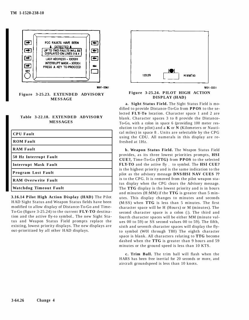
TM 1-1520-238-10
Figure 3-25.23. EXTENDED ADVISORYMESSAGE
Table 3-22.18. EXTENDED ADVISORYMESSAGES
CPU Fault
ROM Fault
RAM Fault
50 Hz Interrupt Fault
Interrupt Mask Fault
Program Lost Fault
RAM Overwrite Fault
Watchdog Timeout Fault
3.16.14 Pilot High Action Display (HAD) The PilotHAD Sight Status and Weapon Status fields have beenmodified to allow display of Distance-To-Go and Time-To-Go (figure 3-25.24) to the current FLY-TO destina-tion and the active fly-to symbol.. The new Sight Sta-tus and Weapon Status Field prompts replace theexisting, lowest priority displays. The new displays areout-prioritized by all other HAD displays.
Figure 3-25.24. PILOT HIGH ACTIONDISPLAY (HAD)
a. Sight Status Field. The Sight Status Field is mo-dified to provide Distance-To-Go from PPOS to the se-lected FLY-To location. Character space 1 and 2 areblank. Character spaces 3 to 8 provide the Distance-To-Go, with a colon in space 6 (providing 100 meter res-olution to the pilot) and a K or N (Kilometers or Nauti-cal miles) in space 8 . Units are selectable by the CPGusing the CDU. All numerals in this display are re-freshed at 1Hz.
b. Weapon Status Field. The Weapon Status Fieldprovides, as its three lowest priorities prompts, HSICUE?, Time-To-Go (TTG) from PPOS to the selectedFLY-TO and the active fly - to symbol. The HSI CUE?is the highest priority and is the same indication to thepilot as the advisory message DNS/HSI NAV CUES ??is to the CPG. It is removed from the pilot weapon sta-tus display when the CPG clears the Advisory message.The TTG display is the lowest priority and is in hoursand minutes (H:MM) if the TTG is greater than 5 min-utes. This display changes to minutes and seconds(M:SS) when TTG is less than 5 minutes. The firstcharacter space will be H (Hours) or M (minutes). Thesecond character space is a colon (:). The third andfourth character spaces will be either MM (minute val-ues 00 to 59) or SS second values 00 to 59). The fifth,sixth and seventh character spaces will display the fly-to symbol (W0l through T80) The eighth characterspace is blank. All characters relating to TTG becomedashed when the TTG is greater than 9 hours and 59minutes or the ground speed is less than 10 KTS.
c. Trim Ball. The trim ball will flash when theHARS has been free inertial for 20 seconds or more, andaircraft groundspeed is less than 10 knots.
3-64.26 Change 4
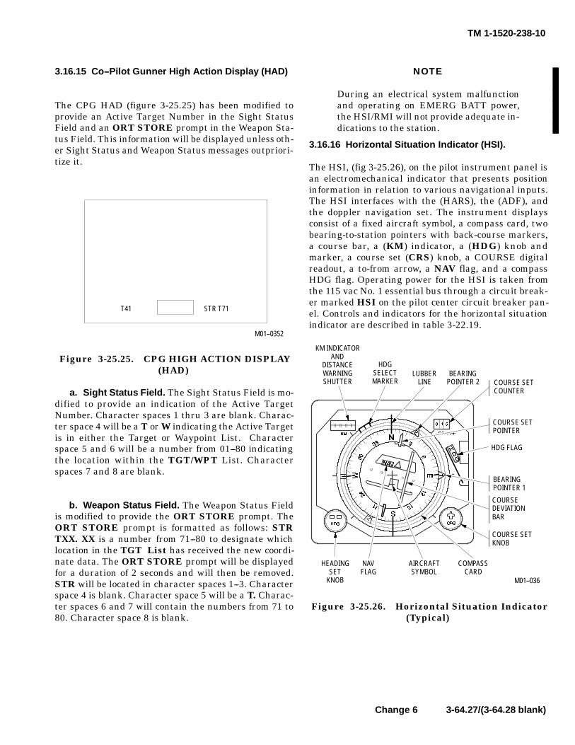
TM 1-1520-238-10
Change 6 3-64.27/(3-64.28 blank)
3.16.15 Co--Pilot Gunner High Action Display (HAD)
The CPG HAD (figure 3-25.25) has been modified toprovide an Active Target Number in the Sight StatusField and an ORT STORE prompt in the Weapon Sta-tus Field. This information will be displayed unless oth-er Sight Status and Weapon Status messages outpriori-tize it.
M01--0352
T41 STR T71
Figure 3-25.25. CPG HIGH ACTION DISPLAY(HAD)
a. Sight Status Field. The Sight Status Field is mo-dified to provide an indication of the Active TargetNumber. Character spaces 1 thru 3 are blank. Charac-ter space 4 will be a T or W indicating the Active Targetis in either the Target or Waypoint List. Characterspace 5 and 6 will be a number from 01--80 indicatingthe location within the TGT/WPT List. Characterspaces 7 and 8 are blank.
b. Weapon Status Field. The Weapon Status Fieldis modified to provide the ORT STORE prompt. TheORT STORE prompt is formatted as follows: STRTXX. XX is a number from 71--80 to designate whichlocation in the TGT List has received the new coordi-nate data. The ORT STORE prompt will be displayedfor a duration of 2 seconds and will then be removed.STR will be located in character spaces 1--3. Characterspace 4 is blank. Character space 5 will be a T. Charac-ter spaces 6 and 7 will contain the numbers from 71 to80. Character space 8 is blank.
NOTE
During an electrical system malfunctionand operating on EMERG BATT power,the HSI/RMI will not provide adequate in-dications to the station.
3.16.16 Horizontal Situation Indicator (HSI).
The HSI, (fig 3-25.26), on the pilot instrument panel isan electromechanical indicator that presents positioninformation in relation to various navigational inputs.The HSI interfaces with the (HARS), the (ADF), andthe doppler navigation set. The instrument displaysconsist of a fixed aircraft symbol, a compass card, twobearing-to-station pointers with back-course markers,a course bar, a (KM) indicator, a (HDG) knob andmarker, a course set (CRS) knob, a COURSE digitalreadout, a to-from arrow, a NAV flag, and a compassHDG flag. Operating power for the HSI is taken fromthe 115 vac No. 1 essential bus through a circuit break-er marked HSI on the pilot center circuit breaker pan-el. Controls and indicators for the horizontal situationindicator are described in table 3-22.19.
KM INDICATORAND
DISTANCEWARNINGSHUTTER
HDGSELECTMARKER
COURSE SETPOINTER
LUBBERLINE
BEARINGPOINTER 2 COURSE SET
COUNTER
HDG FLAG
BEARINGPOINTER 1
COURSE SETKNOB
COURSEDEVIATIONBAR
HEADINGSET
KNOB
AIRCRAFTSYMBOL
COMPASSCARD
NAVFLAG
M01--036
Figure 3-25.26. Horizontal Situation Indicator(Typical)

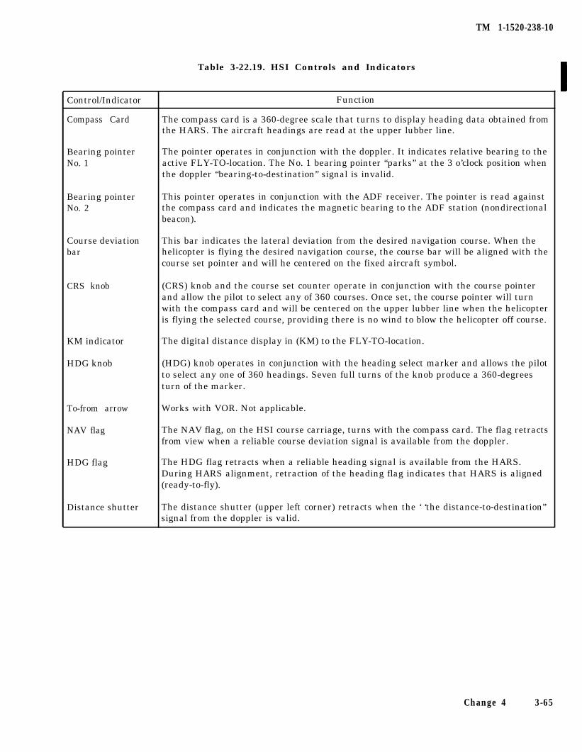
TM 1-1520-238-10
Table 3-22.19. HSI Controls and Indicators
Control/Indicator
Compass Card
Function
The compass card is a 360-degree scale that turns to display heading data obtained fromthe HARS. The aircraft headings are read at the upper lubber line.
Bearing pointerNo. 1
The pointer operates in conjunction with the doppler. It indicates relative bearing to theactive FLY-TO-location. The No. 1 bearing pointer “parks” at the 3 o’clock position whenthe doppler “bearing-to-destination” signal is invalid.
Bearing pointerNo. 2
This pointer operates in conjunction with the ADF receiver. The pointer is read againstthe compass card and indicates the magnetic bearing to the ADF station (nondirectionalbeacon).
Course deviationbar
This bar indicates the lateral deviation from the desired navigation course. When thehelicopter is flying the desired navigation course, the course bar will be aligned with thecourse set pointer and will he centered on the fixed aircraft symbol.
CRS knob (CRS) knob and the course set counter operate in conjunction with the course pointerand allow the pilot to select any of 360 courses. Once set, the course pointer will turnwith the compass card and will be centered on the upper lubber line when the helicopteris flying the selected course, providing there is no wind to blow the helicopter off course.
KM indicator
HDG knob
The digital distance display in (KM) to the FLY-TO-location.
(HDG) knob operates in conjunction with the heading select marker and allows the pilotto select any one of 360 headings. Seven full turns of the knob produce a 360-degreesturn of the marker.
To-from arrow
NAV flag
Works with VOR. Not applicable.
The NAV flag, on the HSI course carriage, turns with the compass card. The flag retractsfrom view when a reliable course deviation signal is available from the doppler.
HDG flag The HDG flag retracts when a reliable heading signal is available from the HARS.During HARS alignment, retraction of the heading flag indicates that HARS is aligned(ready-to-fly).
Distance shutter The distance shutter (upper left corner) retracts when the ‘ ‘the distance-to-destination”signal from the doppler is valid.
Change 4 3-65

TM 1-1520-238-10
Section IV. TRANSPONDER AND RADAR
3.17 TRANSPONDER RT-1295/APX-100(V)1(IFF) ANDRT-1557/APX-100(V)(IFF).
The transponder set (fig 3-26) provides automatic radaridentification of the helicopter to all suitably equippedchallenging aircraft as well as surface or ground facili-ties within the operating range of the system. TheRT-1296/APX-100(V) and the RT-1557/APX-1000 re-ceives, decodes, and responds to the characteristicinterrogation of operational MODE 1,2,3/A, C, and 4.Specially coded identification of position (IP) and emer-gency signals may be transmitted to interrogation sta-tions when conditions warrant. The transceiver can beoperated in any one of four master modes, each of whichmay be selected by the operator at the control panel.Five coding modes are available to the operator. Thefirst three modes may be used independently or in com-bination. MODE 1 provides 32 possible code combina-tions, any one of which may be selected in flight.MODE 2 provides 4096 possible code combinations,but only one is available and is normally preset beforetakeoff. MODE 3/A provides 4096 possible codes, anyone of which maybe selected in flight. MODE 4 is anexternal computer mode and can be selected to provide
any one of many classified operational codes for securi-ty identification. Power to operate the IFF system isprovided from the dc emergency bus through the IFFcircuit breaker on the pilot overhead circuit breakerpanel.
3.17.1 Antenna. Two blade antennas (fig 3-1) areused to receive interrogating signals and to transmitreply signals. The upper IFF antenna is installed on topof the fuselage area aft of the canopy, and the lower IFFantenna is installed on the bottom of the fuselage as anintegral part of the UHF-AM antenna. Some helicop-ters have the upper IFF antenna installed on the workplatform forward of the main rotor mast and the lowerIFF antenna installed on the bottom of the fuselage aftof the tail boom jack pad.
3.17.2 Controls and Functions. All operating andmode code select switches for transceiver operation areon identical control panels (fig 3-26) for theRT-1296/APX-100(V) and the RT-1557/APX-100(V).C o n t r o l a n d i n d i c a t o r f u n c t i o n s o f t h eRT-1296/APX-100(V) and the RT-1557/APX-100(V)transponder are described in table 3-23.
3-66
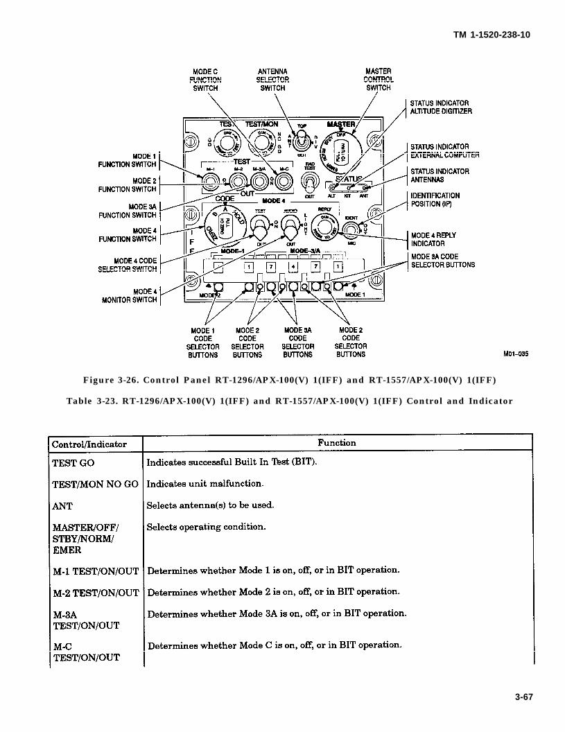
TM 1-1520-238-10
Figure 3-26. Control Panel RT-1296/APX-100(V) 1(IFF) and RT-1557/APX-100(V) 1(IFF)
Table 3-23. RT-1296/APX-100(V) 1(IFF) and RT-1557/APX-100(V) 1(IFF) Control and Indicator
3-67
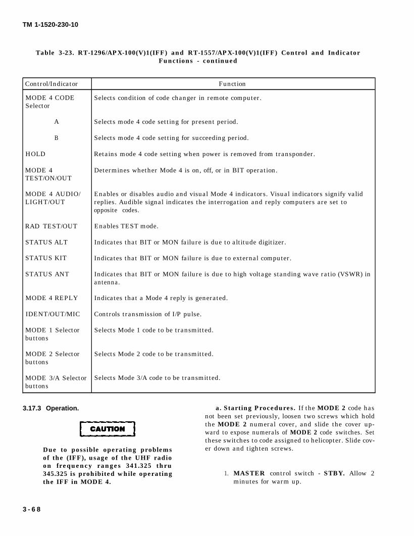
CAUTION
TM 1-1520-230-10
Table 3-23. RT-1296/APX-100(V)1(IFF) and RT-1557/APX-100(V)1(IFF) Control and IndicatorFunctions - continued
Control/Indicator Function
MODE 4 CODE Selects condition of code changer in remote computer.Selector
A Selects mode 4 code setting for present period.
B Selects mode 4 code setting for succeeding period.
HOLD Retains mode 4 code setting when power is removed from transponder.
MODE 4 Determines whether Mode 4 is on, off, or in BIT operation.TEST/ON/OUT
MODE 4 AUDIO/ Enables or disables audio and visual Mode 4 indicators. Visual indicators signify validLIGHT/OUT replies. Audible signal indicates the interrogation and reply computers are set to
opposite codes.
RAD TEST/OUT Enables TEST mode.
STATUS ALT Indicates that BIT or MON failure is due to altitude digitizer.
STATUS KIT Indicates that BIT or MON failure is due to external computer.
STATUS ANT Indicates that BIT or MON failure is due to high voltage standing wave ratio (VSWR) inantenna.
MODE 4 REPLY Indicates that a Mode 4 reply is generated.
IDENT/OUT/MIC Controls transmission of I/P pulse.
MODE 1 Selector Selects Mode 1 code to be transmitted.buttons
MODE 2 Selector Selects Mode 2 code to be transmitted.buttons
MODE 3/A Selector Selects Mode 3/A code to be transmitted.buttons
3.17.3 Operation. a. Starting Procedures. If the MODE 2 code hasnot been set previously, loosen two screws which holdthe MODE 2 numeral cover, and slide the cover up-ward to expose numerals of MODE 2 code switches. Setthese switches to code assigned to helicopter. Slide cov-
Due to possible operating problems er down and tighten screws.of the (IFF), usage of the UHF radioon frequency ranges 341.325 thru345.325 is prohibited while operating 1.the IFF in MODE 4.
MASTER control switch - STBY. Allow 2minutes for warm up.
3 - 6 8
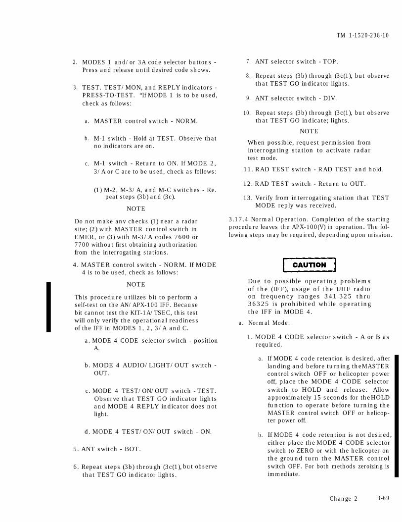
2.
3.
MODES 1 and/or 3A code selector buttons -Press and release until desired code shows.
TEST. TEST/MON, and REPLY indicators -PRESS-TO-TEST. “If MODE 1 is to be used,check as follows:
a.
b.
c.
MASTER control switch - NORM.
M-1 switch - Hold at TEST. Observe thatno indicators are on.
M-1 switch - Return to ON. If MODE 2,3/A or C are to be used, check as follows:
(1) M-2, M-3/A, and M-C switches - Re.peat steps (3b) and (3c).
NOTE
Do not make anv checks (1) near a radarsite; (2) with MASTER control switch inEMER, or (3) with M-3/A codes 7600 or7700 without first obtaining authorizationfrom the interrogating stations.
4. MASTER control switch - NORM. If MODE4 is to be used, check as follows:
NOTE
This procedure utilizes bit to perform aself-test on the AN/APX-100 IFF. Becausebit cannot test the KIT-1A/TSEC, this testwill only verify the operational readinessof the IFF in MODES 1, 2, 3/A and C.
a. MODE 4 CODE selector switch - positionA.
b. MODE 4 AUDIO/LIGHT/OUT switch -OUT.
c. MODE 4 TEST/ON/OUT switch - TEST.Observe that TEST GO indicator lightsand MODE 4 REPLY indicator does notlight.
d. MODE 4 TEST/ON/OUT switch - ON.
5. ANT switch - BOT.
6. Repeat steps (3b) through (3c(1),that TEST GO indicator lights.
but observe
7.
8.
9.
10.
TM 1-1520-238-10
ANT selector switch - TOP.
Repeat steps (3b) through (3c(1), but observethat TEST GO indicator lights.
ANT selector switch - DIV.
Repeat steps (3b) through (3c(1), but observethat TEST GO indicate; lights.
NOTE
When possible, request permission frominterrogating station to activate radartest mode.
11. RAD TEST switch - RAD TEST and hold.
12. RAD TEST switch - Return to OUT.
13. Verify from interrogating station that TESTMODE reply was received.
3.17.4 Normal Operation. Completion of the startingprocedure leaves the APX-100(V) in operation. The fol-lowing steps may be required, depending upon mission.
a.
Due to possible operating problemsof the (IFF), usage of the UHF radioon frequency ranges 341.325 thru36325 is prohibited while operatingthe IFF in MODE 4.
Normal Mode.
1. MODE 4 CODE selector switch - A or B asrequired.
a.
b.
If MODE 4 code retention is desired, afterlanding and before turning the MASTERcontrol switch OFF or helicopter poweroff, place the MODE 4 CODE selectorswitch to HOLD and release. Allowapproximately 15 seconds for the HOLDfunction to operate before turning theMASTER control switch OFF or helicop-ter power off.
If MODE 4 code retention is not desired,either place the MODE 4 CODE selectorswitch to ZERO or with the helicopter onthe ground turn the MASTER controlswitch OFF. For both methods zeroizing isimmediate.
Change 2 3-69
TM 1-1520-238-10
2. Mode M-1, M-2, M-3/A, M-C, or MODE 4switches - Select desired mode.
3. IP Switch - IDENT, when required, to trans-mit identification of position pulses or set IPswitch to MIC to transmit IP pulse only whenmicrophone press-to-talk switch is actuated.(IP pulses will be for 15 to 30-second durationwhen activated.)
b. Emergency Mode. During an emergency ordistress condition, the APX-100(V) may be used totransmit specially coded emergency signals on MODE1, 2, 3/4 and 4 to all interrogating stations. Thoseemergency signals will be transmitted as long as theMASTER control switch on the control panel remainsin EMER.
1. MASTER control switch - EMER.
c. Stopping Procedure. Refer to paragraph3.17.4 a. before stopping transponder.
1. MASTER control switch - OFF.
3.17.5 Transponder Computer KIT-1A/TSEC andKIT-1C/TSEC. The transponder computer operates inconjunction with MODE 4. A caution light on the pilotand CPG caution/warning panel, marked IFF, will goon when a malfunction occurs that will prevent a replywhen interrogated or the KIT-1A or KIT-1C computershave failed. MODE 4 operation is selected by placingthe MODE 4 switch ON. Placing the MODE 4 switchto OUT disables MODE 4. As with the other modes ofthe transponder, the MASTER control switch must beplaced in the NORM position to provide power and per-mit functioning of the selected modes. MODE 4 CODE
switch is placarded ZERO, B, A, and HOLD. Theswitch must be lifted over a detent when rotated toZERO. Position A selects the MODE 4 CODE for oneperiod, and position B selects the MODE 4 CODE foranother period. The switch is spring-loaded to returnfrom HOLD to the A position. Both A and B codes areeither mechanically inserted into the KIT-1A or elec-tronically inserted into the KIT-1C. A KYK-13 or simi-lar keying device is used to load the KIT-1C. TheKIT-1C must have operable batteries or have beenturned on, as previously described, before it will acceptand hold the codes. The KIT-1A does not require powerbecause it is mechanically keyed. Once keyed theKIT-IA and KIT-1C (with operable batteries) will re-tain the codes regardless of MASTER control switchposition or helicopter power as long as the helicopter ison the ground. Once the helicopter has become airborne(determined by the squat switch) the MODE 4 codeswill automatically zeroize anytime the MASTER con-trol switch or helicopter power is turned off or inter-rupted. The codes may be retained by using the HOLDfunction. After landing place the MODE 4 CODE se-lector switch to HOLD and release before turning theMASTER control switch OFF or helicopter power off.Allow approximately 15 seconds for the HOLD func-tion to operate before turning the MASTER controlswitch OFF or helicopter power off. The HOLD func-tion must be selected with the helicopter on the ground(determined by the squat switch). Selecting the HOLDfunction while the helicopter is airborne has no effectwhatsoever. MODE 4 codes can be zeroized anytimethe MASTER control switch is not in the OFF positionand the helicopter is powered by placing the MODE 4CODE switch in the ZERO position. Zeroizing is im-mediate. The transponder computer KIT-1A/TSEC andKIT-1C/TSEC operation is classified.
3-70 Change 2
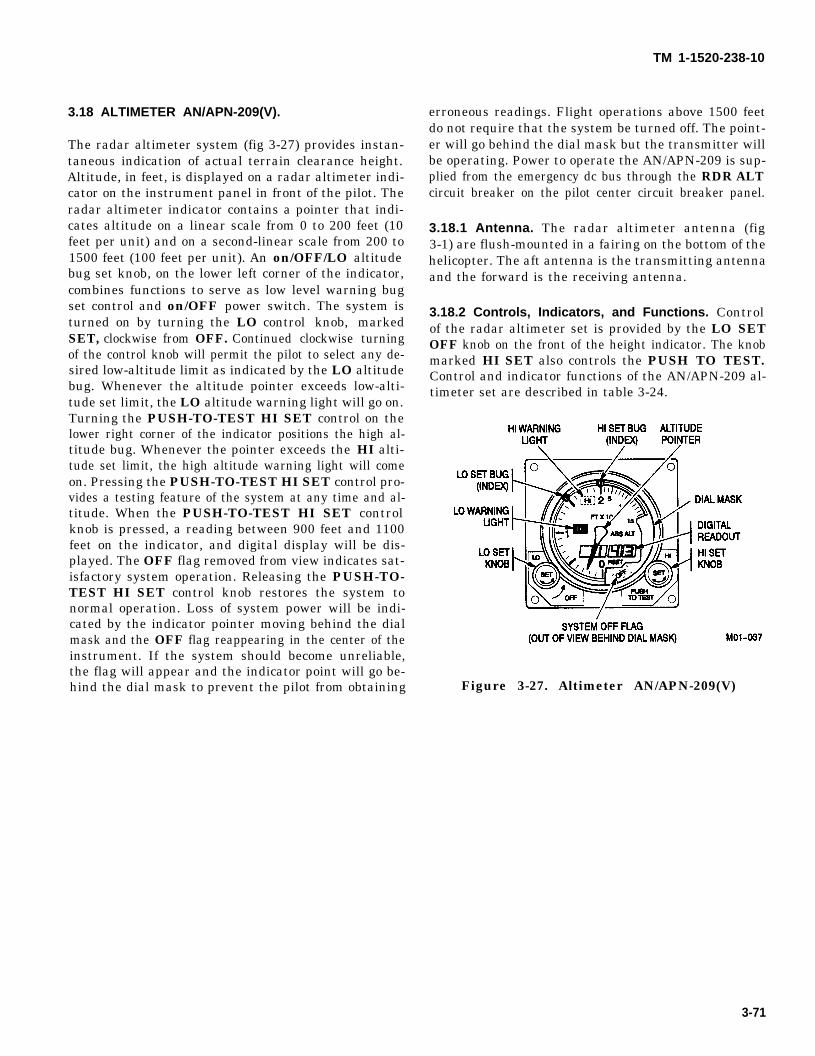
TM 1-1520-238-10
3.18 ALTIMETER AN/APN-209(V).
The radar altimeter system (fig 3-27) provides instan-taneous indication of actual terrain clearance height.Altitude, in feet, is displayed on a radar altimeter indi-cator on the instrument panel in front of the pilot. Theradar altimeter indicator contains a pointer that indi-cates altitude on a linear scale from 0 to 200 feet (10feet per unit) and on a second-linear scale from 200 to1500 feet (100 feet per unit). An on/OFF/LO altitudebug set knob, on the lower left corner of the indicator,combines functions to serve as low level warning bugset control and on/OFF power switch. The system isturned on by turning the LO control knob, markedSET, clockwise from OFF. Continued clockwise turningof the control knob will permit the pilot to select any de-sired low-altitude limit as indicated by the LO altitudebug. Whenever the altitude pointer exceeds low-alti-tude set limit, the LO altitude warning light will go on.Turning the PUSH-TO-TEST HI SET control on thelower right corner of the indicator positions the high al-titude bug. Whenever the pointer exceeds the HI alti-tude set limit, the high altitude warning light will comeon. Pressing the PUSH-TO-TEST HI SET control pro-vides a testing feature of the system at any time and al-titude. When the PUSH-TO-TEST HI SET controlknob is pressed, a reading between 900 feet and 1100feet on the indicator, and digital display will be dis-played. The OFF flag removed from view indicates sat-isfactory system operation. Releasing the PUSH-TO-TEST HI SET control knob restores the system tonormal operation. Loss of system power will be indi-cated by the indicator pointer moving behind the dialmask and the OFF flag reappearing in the center of theinstrument. If the system should become unreliable,the flag will appear and the indicator point will go be-hind the dial mask to prevent the pilot from obtaining
erroneous readings. Flight operations above 1500 feetdo not require that the system be turned off. The point-er will go behind the dial mask but the transmitter willbe operating. Power to operate the AN/APN-209 is sup-plied from the emergency dc bus through the RDR ALTcircuit breaker on the pilot center circuit breaker panel.
3.18.1 Antenna. The radar altimeter antenna (fig3-1) are flush-mounted in a fairing on the bottom of thehelicopter. The aft antenna is the transmitting antennaand the forward is the receiving antenna.
3.18.2 Controls, Indicators, and Functions. Controlof the radar altimeter set is provided by the LO SETOFF knob on the front of the height indicator. The knobmarked HI SET also controls the PUSH TO TEST.Control and indicator functions of the AN/APN-209 al-timeter set are described in table 3-24.
Figure 3-27. Altimeter AN/APN-209(V)
3-71
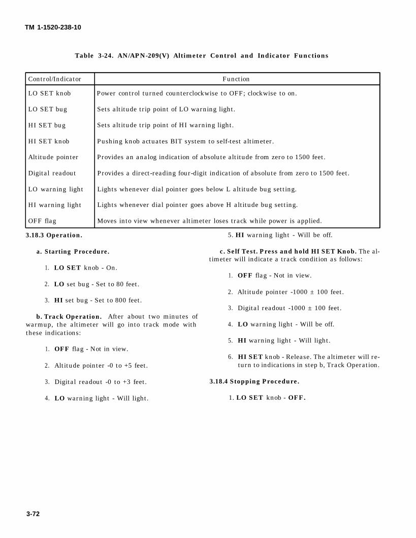
TM 1-1520-238-10
Table 3-24. AN/APN-209(V) Altimeter Control and Indicator Functions
Control/Indicator Function
LO SET knob Power control turned counterclockwise to OFF; clockwise to on.
LO SET bug Sets altitude trip point of LO warning light.
HI SET bug Sets altitude trip point of HI warning light.
HI SET knob Pushing knob actuates BIT system to self-test altimeter.
Altitude pointer Provides an analog indication of absolute altitude from zero to 1500 feet.
Digital readout Provides a direct-reading four-digit indication of absolute from zero to 1500 feet.
LO warning light Lights whenever dial pointer goes below L altitude bug setting.
HI warning light Lights whenever dial pointer goes above H altitude bug setting.
OFF flag Moves into view whenever altimeter loses track while power is applied.
3.18.3 Operation. 5. HI warning light - Will be off.
a. Starting Procedure. c. Self Test. Press and hold HI SET Knob. The al-timeter will indicate a track condition as follows:
1.
2.
3.
LO SET knob - On.1.
LO set bug - Set to 80 feet.2.
HI set bug - Set to 800 feet.3.
b. Track Operation. After about two minutes ofwarmup, the altimeter will go into track mode with 4.these indications:
1.
2.
3.
4.
3-72
5.OFF flag - Not in view.
6.Altitude pointer -0 to +5 feet.
OFF flag - Not in view.
Altitude pointer -1000 ± 100 feet.
Digital readout -1000 ± 100 feet.
LO warning light - Will be off.
HI warning light - Will light.
HI SET knob - Release. The altimeter will re-turn to indications in step b, Track Operation.
Digital readout -0 to +3 feet. 3.18.4 Stopping Procedure.
LO warning light - Will light. 1. LO SET knob - OFF.
TM 1-1520-238-10
CHAPTER 4MISSION EQUIPMENT
Section I. MISSION AVIONICS
4.1 INFRARED COUNTERMEASURES SETAN/ALQ-144A, 144(V)3. Data moved to Section III,paragraph 4.342A.
4.2 RADAR COUNTERMEASURES SET AN/ALQ-136.Data moved to Section III, paragraph 4.34B.
4.1 .l Infrared Countermeasures Set Control Panel. 4.2.1 Radar Countermeasures Set Control Panel.Data moved to Section III, para. 4.34A.l. Data moved to Section III, para. 4.34B.1.
Change 4 4-1
TM 1-1520-238-10
4.3 FLIGHT SYMBOLOGY.
The flight symbology has four modes; cruise, transition,hover, and bob-up. The symbology modes (fig 4-1) are-selectable using the flight symbology mode switch onthe cyclic. The symbols are defined in table 4-1.
When conducting sea operations thevelocity vector in the pilots symbolo-gy will indicate the speed of theaircraft relative to the earth and notto the ship.
The pilot flight symbology, particularly the velocity vec-tor, is always driven by inertial velocity. The indicatedvelocity is relative to actual motion over ground or wa-ter. When attempting to move or hover near or over amoving platform (such as a ship), the relative velocitybetween the aircraft and the moving platform is differ-ent than the true inertial velocity indicated by the ve-locity vector. If hovering over a ship moving at 10 knotsthrough the water, the velocity vector will indicate 10knots, not 0 knots, which is the relative velocity be-tween the aircraft and the ship. For this situation thepilot must use visual cues to derive the actual relativemotion with respect to the moving platform. The veloc-ity vector must not be used as an indiator of relativemotion between the aircraft and moving platform, sinceit will be inaccurate to the degree of the platforms’ ve-locity through the water.
4-2 Change 4
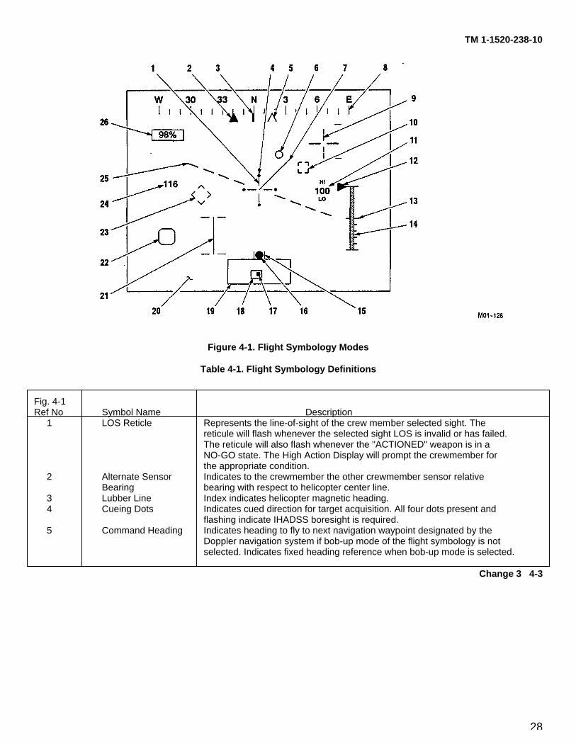
28
TM 1-1520-238-10
Figure 4-1. Flight Symbology Modes
Table 4-1. Flight Symbology Definitions
Fig. 4-1Ref No Symbol Name Description
1 LOS Reticle Represents the line-of-sight of the crew member selected sight. Thereticule will flash whenever the selected sight LOS is invalid or has failed.The reticule will also flash whenever the "ACTIONED" weapon is in aNO-GO state. The High Action Display will prompt the crewmember forthe appropriate condition.
2 Alternate Sensor Indicates to the crewmember the other crewmember sensor relativeBearing bearing with respect to helicopter center line.
3 Lubber Line Index indicates helicopter magnetic heading.4 Cueing Dots Indicates cued direction for target acquisition. All four dots present and
flashing indicate IHADSS boresight is required.5 Command Heading Indicates heading to fly to next navigation waypoint designated by the
Doppler navigation system if bob-up mode of the flight symbology is notselected. Indicates fixed heading reference when bob-up mode is selected.
Change 3 4-3

29
TM 1-1520-238-10
Table 4-1. Flight Symbology Definitions - continued
Fig. 4-1Ref No Symbol Name Description
6 Acceleration Cue A vectorial representation of the helicopter longitudinal and lateralacceleration; the display origin is normally the end of the velocity vector.In the hover and bob-up modes, when the velocity vector exceeds itsmaximum scale, the display origin changes to the center of the LOSreticule. The Acceleration Cue will flash when the HARS inertial platformhas gone into free inertial mode, usually as a result of the LDNS goinginto memory.
7 Velocity Vector A vectorial representation of the helicopter longitudinal and lateralground velocities; in hover mode, maximum scale is 6 knots ground speed;in transition mode 60 knots ground speed. The velocity vector will flashwhen the HARS inertial platform has gone into the free inertial mode ifMUX switch is in SEC.
8 Heading Scale Helicopter magnetic heading scale.9 Cued LOS Reticule A virtual reticule indicating the cued LOS to the appropriate crew
member. Used with the cueing dots.10 Missile Constraints Indicates the required orientation to align the helicopter into constraints
for Hellfire missile engagements. When all constraints for the mode ofengagement are satisfied, the box will go from ’dashed’ to ’solid’.
11 Radar Altitude A digital display of radar altitude. Displays in 1-foot increments to 50 feetand in 10-foot increments above 50 feet.
12 Rate of Climb An analog display of rate of climb moving along the left side of thevertical scale. Tick marks designate 500 and 1000 fpm rates of climb ordescent.
13 Radar Altitude A vertical scale for the analog display of radar altitude. Tick marksVertical Scale designate 10-foot increments from 0 to 50-feet, and 50-foot increments
from 50 to 200 feet. The scale is blanked when radar altitude is greaterthan 200 feet.
14 Radar Altitude An analog display of radar altitude moving within the vertical scale; alsoVertical Tape blanked above 200 feet.
15 Skid/Slip Lubber Represent the limits for ’ball centered’ flight.Lines
16 Skid/Slip Ball Indicates the amount of skid or slip the helicopter is experiencing.17 Cued LOS DOT Indicates the cued LOS location within the field of regard. The cued LOS
DOT will flash when the HARS inertial platform has gone into the freeinertial mode.
18 Field of View Represents the instantaneous FOV of the crewmember sensor within thefield of regard.
19 Sensor Field of Represents the total gimbal limits possible for the respective crewRegard member sensor.
20 High Action Display Refer to paragraph 4.28.
4-4 Change 3
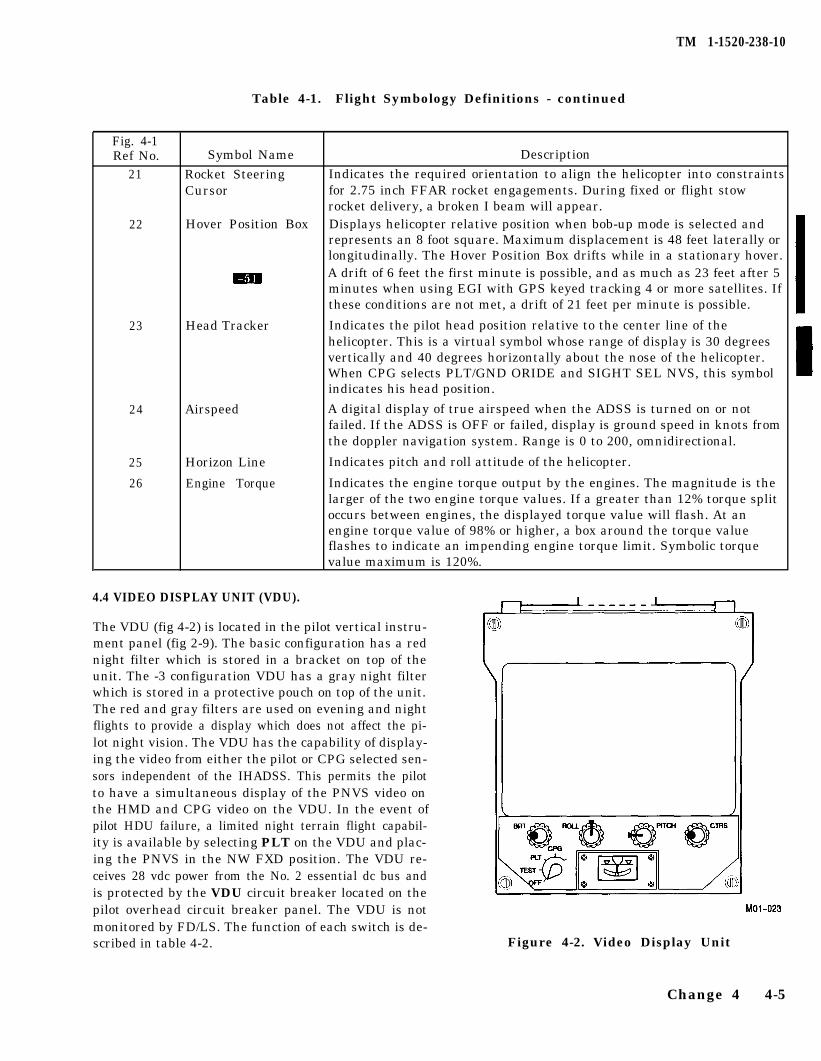
TM 1-1520-238-10
Table 4-1. Flight Symbology Definitions - continued
Fig. 4-1Ref No.
21
22
23
24
25
26
Symbol Name Description
Rocket Steering Indicates the required orientation to align the helicopter into constraintsCursor for 2.75 inch FFAR rocket engagements. During fixed or flight stow
rocket delivery, a broken I beam will appear.Hover Position Box Displays helicopter relative position when bob-up mode is selected and
represents an 8 foot square. Maximum displacement is 48 feet laterally orlongitudinally. The Hover Position Box drifts while in a stationary hover.A drift of 6 feet the first minute is possible, and as much as 23 feet after 5minutes when using EGI with GPS keyed tracking 4 or more satellites. Ifthese conditions are not met, a drift of 21 feet per minute is possible.
Head Tracker Indicates the pilot head position relative to the center line of thehelicopter. This is a virtual symbol whose range of display is 30 degreesvertically and 40 degrees horizontally about the nose of the helicopter.When CPG selects PLT/GND ORIDE and SIGHT SEL NVS, this symbolindicates his head position.
Airspeed A digital display of true airspeed when the ADSS is turned on or notfailed. If the ADSS is OFF or failed, display is ground speed in knots fromthe doppler navigation system. Range is 0 to 200, omnidirectional.
Horizon Line Indicates pitch and roll attitude of the helicopter.
Engine Torque Indicates the engine torque output by the engines. The magnitude is thelarger of the two engine torque values. If a greater than 12% torque splitoccurs between engines, the displayed torque value will flash. At anengine torque value of 98% or higher, a box around the torque valueflashes to indicate an impending engine torque limit. Symbolic torquevalue maximum is 120%.
4.4 VIDEO DISPLAY UNIT (VDU).
The VDU (fig 4-2) is located in the pilot vertical instru-ment panel (fig 2-9). The basic configuration has a rednight filter which is stored in a bracket on top of theunit. The -3 configuration VDU has a gray night filterwhich is stored in a protective pouch on top of the unit.The red and gray filters are used on evening and nightflights to provide a display which does not affect the pi-lot night vision. The VDU has the capability of display-ing the video from either the pilot or CPG selected sen-sors independent of the IHADSS. This permits the pilotto have a simultaneous display of the PNVS video onthe HMD and CPG video on the VDU. In the event ofpilot HDU failure, a limited night terrain flight capabil-ity is available by selecting PLT on the VDU and plac-ing the PNVS in the NW FXD position. The VDU re-ceives 28 vdc power from the No. 2 essential dc bus andis protected by the VDU circuit breaker located on thepilot overhead circuit breaker panel. The VDU is notmonitored by FD/LS. The function of each switch is de-scribed in table 4-2. Figure 4-2. Video Display Unit
Change 4 4-5
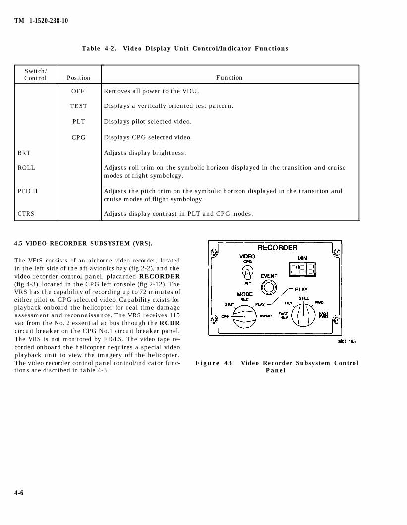
TM 1-1520-238-10
Table 4-2. Video Display Unit Control/Indicator Functions
Switch/Control
BRT
ROLL
PITCH
CTRS
Position
OFF
TEST
PLT
CPG
Function
Removes all power to the VDU.
Displays a vertically oriented test pattern.
Displays pilot selected video.
Displays CPG selected video.
Adjusts display brightness.
Adjusts roll trim on the symbolic horizon displayed in the transition and cruisemodes of flight symbology.
Adjusts the pitch trim on the symbolic horizon displayed in the transition andcruise modes of flight symbology.
Adjusts display contrast in PLT and CPG modes.
4.5 VIDEO RECORDER SUBSYSTEM (VRS).
The VFtS consists of an airborne video recorder, locatedin the left side of the aft avionics bay (fig 2-2), and thevideo recorder control panel, placarded RECORDER(fig 4-3), located in the CPG left console (fig 2-12). TheVRS has the capability of recording up to 72 minutes ofeither pilot or CPG selected video. Capability exists forplayback onboard the helicopter for real time damageassessment and reconnaissance. The VRS receives 115vac from the No. 2 essential ac bus through the RCDRcircuit breaker on the CPG No.1 circuit breaker panel.The VRS is not monitored by FD/LS. The video tape re-corded onboard the helicopter requires a special videoplayback unit to view the imagery off the helicopter.The video recorder control panel control/indicator func-tions are discribed in table 4-3.
Figure 43. Video Recorder Subsystem ControlPanel
4-6
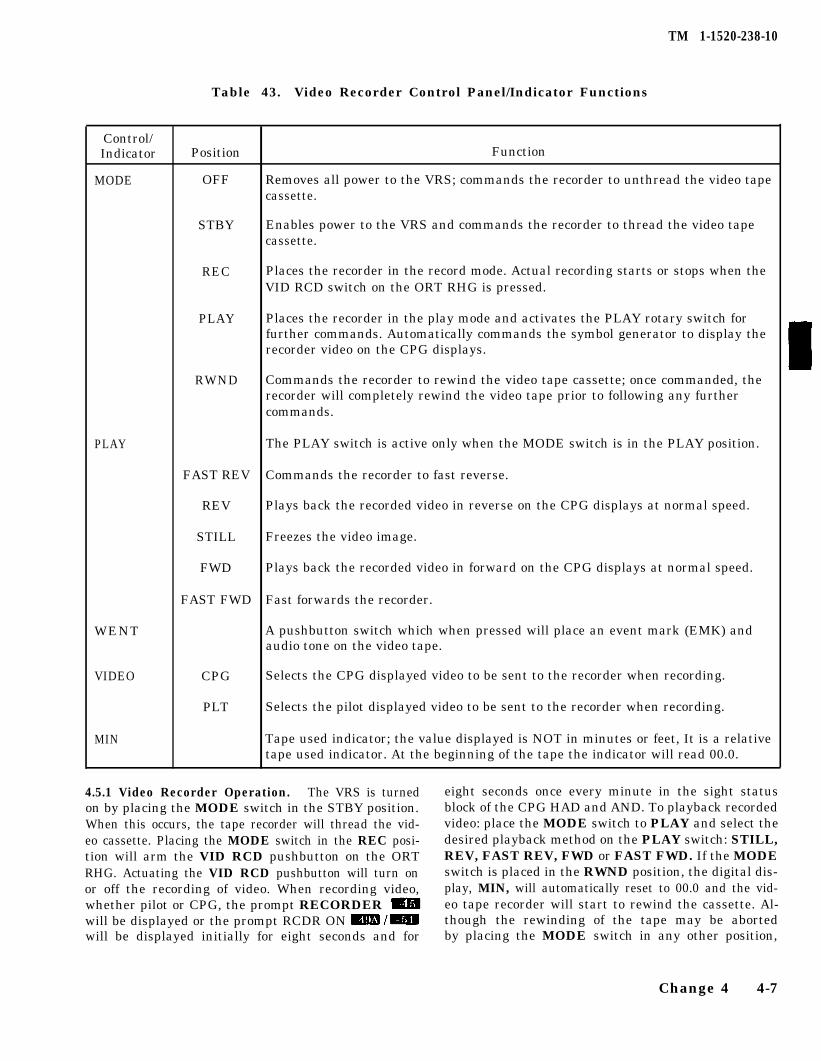
TM 1-1520-238-10
Table 43. Video Recorder Control Panel/Indicator Functions
Control/Indicator
MODE
Position Function
OFF Removes all power to the VRS; commands the recorder to unthread the video tapecassette.
STBY Enables power to the VRS and commands the recorder to thread the video tapecassette.
REC Places the recorder in the record mode. Actual recording starts or stops when theVID RCD switch on the ORT RHG is pressed.
PLAY Places the recorder in the play mode and activates the PLAY rotary switch forfurther commands. Automatically commands the symbol generator to display therecorder video on the CPG displays.
RWND Commands the recorder to rewind the video tape cassette; once commanded, therecorder will completely rewind the video tape prior to following any furthercommands.
PLAY
WENT
VIDEO
MIN
The PLAY switch is active only when the MODE switch is in the PLAY position.
FAST REV Commands the recorder to fast reverse.
REV Plays back the recorded video in reverse on the CPG displays at normal speed.
STILL Freezes the video image.
FWD Plays back the recorded video in forward on the CPG displays at normal speed.
FAST FWD Fast forwards the recorder.
A pushbutton switch which when pressed will place an event mark (EMK) andaudio tone on the video tape.
CPG Selects the CPG displayed video to be sent to the recorder when recording.
PLT Selects the pilot displayed video to be sent to the recorder when recording.
Tape used indicator; the value displayed is NOT in minutes or feet, It is a relativetape used indicator. At the beginning of the tape the indicator will read 00.0.
4.5.1 Video Recorder Operation. The VRS is turned eight seconds once every minute in the sight statuson by placing the MODE switch in the STBY position. block of the CPG HAD and AND. To playback recordedWhen this occurs, the tape recorder will thread the vid- video: place the MODE switch to PLAY and select theeo cassette. Placing the MODE switch in the REC posi- desired playback method on the PLAY switch: STILL,tion will arm the VID RCD pushbutton on the ORT REV, FAST REV, FWD or FAST FWD. If the MODERHG. Actuating the VID RCD pushbutton will turn on switch is placed in the RWND position, the digital dis-or off the recording of video. When recording video, play, MIN, will automatically reset to 00.0 and the vid-whether pilot or CPG, the prompt RECORDER eo tape recorder will start to rewind the cassette. Al-
will be displayed or the prompt RCDR ON m /m though the rewinding of the tape may be abortedwill be displayed initially for eight seconds and for by placing the MODE switch in any other position,
Change 4 4-7
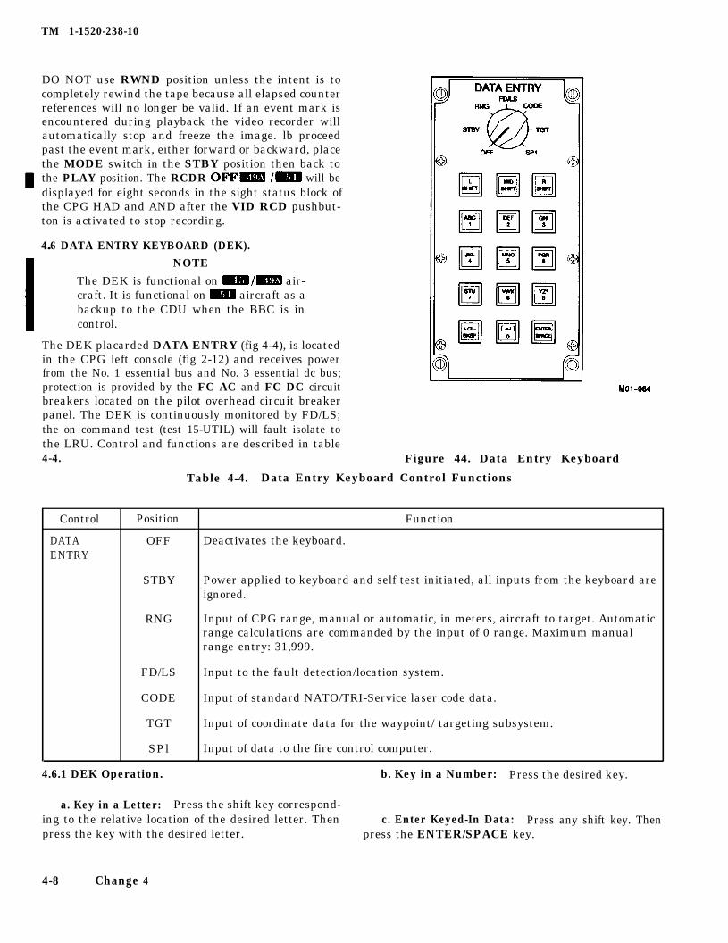
TM 1-1520-238-10
DO NOT use RWND position unless the intent is tocompletely rewind the tape because all elapsed counterreferences will no longer be valid. If an event mark isencountered during playback the video recorder willautomatically stop and freeze the image. lb proceedpast the event mark, either forward or backward, placethe MODE switch in the STBY position then back tothe PLAY position. The RCDR OFF- /m will bedisplayed for eight seconds in the sight status block ofthe CPG HAD and AND after the VID RCD pushbut-ton is activated to stop recording.
4.6 DATA ENTRY KEYBOARD (DEK).
NOTE
The DEK is functional on m/m air-craft. It is functional on Cm aircraft as abackup to the CDU when the BBC is incontrol.
The DEK placarded DATA ENTRY (fig 4-4), is locatedin the CPG left console (fig 2-12) and receives powerfrom the No. 1 essential bus and No. 3 essential dc bus;protection is provided by the FC AC and FC DC circuitbreakers located on the pilot overhead circuit breakerpanel. The DEK is continuously monitored by FD/LS;the on command test (test 15-UTIL) will fault isolate tothe LRU. Control and functions are described in table4-4. Figure 44. Data Entry Keyboard
Table 4-4. Data Entry Keyboard Control Functions
Control
DATAENTRY
Position Function
OFF Deactivates the keyboard.
STBY Power applied to keyboard and self test initiated, all inputs from the keyboard areignored.
RNG Input of CPG range, manual or automatic, in meters, aircraft to target. Automaticrange calculations are commanded by the input of 0 range. Maximum manualrange entry: 31,999.
FD/LS Input to the fault detection/location system.
CODE Input of standard NATO/TRI-Service laser code data.
TGT Input of coordinate data for the waypoint/ targeting subsystem.
SPl Input of data to the fire control computer.
4.6.1 DEK Operation. b. Key in a Number: Press the desired key.
a. Key in a Letter: Press the shift key correspond-ing to the relative location of the desired letter. Then c. Enter Keyed-In Data: Press any shift key. Thenpress the key with the desired letter. press the ENTER/SPACE key.
4-8 Change 4
TM 1-1520-238-10
d. DEK Special Characters:
(1) BKSP: Moves the cursor one position to theleft.
(2) CL: Clears the entire current input lineand moves the cursor to the leftmost position.
(3) ( ): Advance to the first position of the nextinput line.
(4) SPACE: Skip the next character position orperform automatic character inserts.
e. DEK Saving Functions.
Data entered through the DEK will be automaticallysaved m. Data entered through the DEK, in flightstorage of waypoint/targets and last PPOS will be auto-matically saved if a take off and landing was conducted(two squat switch activations) and the HARS switchwas placed to OFF (standard engine shutdown proce-dures for pilot) m.
For ground only operations, DEK entries can be manu-ally saved by selecting SP1, page 1 and entering an E.The message DATA SAVED will be displayed in theupper left corner of the display verifying that the datawas saved. Manual saving of data using the same pro-cedure as described for ground operations can be con-ducted by the flight crew at their option during flightoperations EBN.
Change 4 4-9
TM 1-1520-238-10
Section II. ARMAMENT
4.7 AUTHORIZED ARMAMENT CONFIGURATIONS. The M-230E1,30mm gun (fig 4-5) is a single barrel, ex-
For authorized configurations, refer to figure 7-18 mternally powered, chain drive weapon using M788/789or ADEN/DEFA type ammunition. The 30mm gun is
or figure 7A-18 m,- mounted in a hydraulically driven turret capable ofslewing the gun 100° m or 8S”m /m left or rightof the helicopter centerline and up 11° to 60° down. Inthe event of loss of hydraulics, the turret will lock in thecurrent azimuth position and the gun will return to theelevation stow position of 11° up. The rate of fire is setfor 600 to 650 rounds per minute. The maximum capac-ity of the linkless storage subsystem is 1200 rounds.The gun duty cycle is as follows: six 50-round burstswith 5 seconds between bursts followed by a lo-minutecooling period. For bursts limiter settings other than50, the duty cycle can be generalized as no more than300 rounds fired within 60 seconds before allowing thegun to cool for ten minutes, after which the cycle maybe repeated. The FCC limits the fire control solution toa maximum range of 4000 meters. The maximum rangeof the 30mm gun is approximately 4000 meters.
4.8 AREA WEAPON SYSTEM 30MM, M-230E1.
In the event of IHADSS failure withgun selected, the gun will be com-manded to the fixed forward posi-tion. Once in this position, the guncan still be fired without having tore-action the gun.
Prior to initiating AWS FD/LS check(IBIT), ensure the pilot ground over-ride (PLT/GND ORIDE) switch is inthe OFF position. Failure to performthis action may result in uncomman-ded gun turret slewing or uncom-manded gun firing during a AWS FD/LS (IBIT) manual abort.
If ECP 1206 (Mechanical Gun Stops)is installed, but not ECP 1251 (Elec-tronic Gun Stops), the M230E1 AWSmay be used with the following re-strictions:
If external tanks are installed, lim-it AWS azimuth travel to ± 45 de-grees.
If external tanks are not installed,limit AWS azimuth travel to ± 70degrees.
If both ECPs are installed, the AWS isnot restricted when external tanksare mounted.
If neither ECP is installed, the AWS isrestricted from use when externaltanks are mounted.
4.8.1 AWS Dynamic Harmonization m /m. Dy-namic harmonization is the capability of the flight crewto apply an in flight boresight correction procedure. Dy-namic harmonization corrects for AWS system varia-tions and firing characteristics for different aircraftand AWS combinations. The procedure involves live-fire of the 30mm gun to fine tune the system in additionto the CBHK static boresight.
Performance of dynamic harmonization is not a re-quirement but a crews option. This procedure is not in-tended to replace the CBHK static boresight or properAWS maintenance.
Any modification of boresight correctors must be en-tered in the aircraft logbook. Correctors remain in theFCC until changed via the boresight procedures.
4-10 Change 4
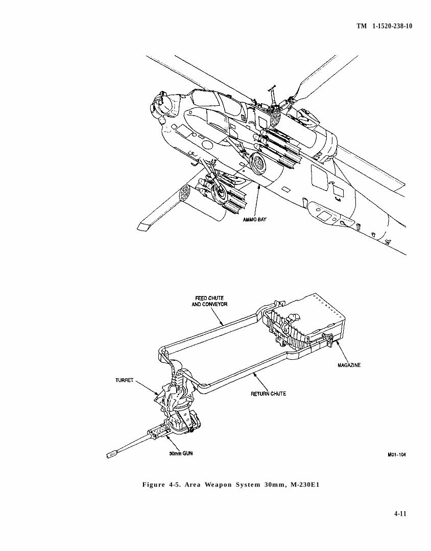
TM 1-1520-238-10
Figure 4-5. Area Weapon System 30mm, M-230E1
4-11
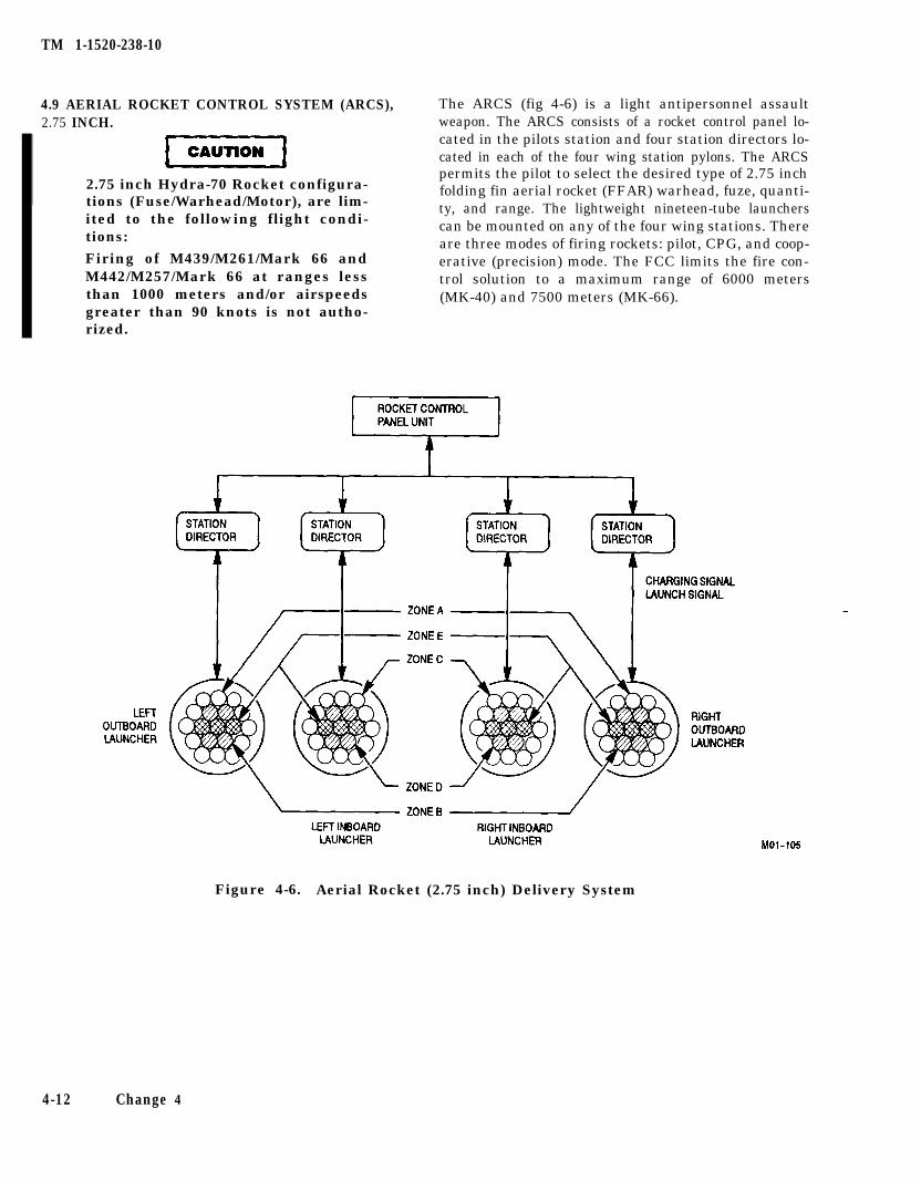
TM 1-1520-238-10
4.9 AERIAL ROCKET CONTROL SYSTEM (ARCS),2.75 INCH.
2.75 inch Hydra-70 Rocket configura-tions (Fuse/Warhead/Motor), are lim-ited to the following flight condi-tions:
Firing of M439/M261/Mark 66 andM442/M257/Mark 66 at ranges lessthan 1000 meters and/or airspeedsgreater than 90 knots is not autho-rized.
The ARCS (fig 4-6) is a light antipersonnel assaultweapon. The ARCS consists of a rocket control panel lo-cated in the pilots station and four station directors lo-cated in each of the four wing station pylons. The ARCSpermits the pilot to select the desired type of 2.75 inchfolding fin aerial rocket (FFAR) warhead, fuze, quanti-ty, and range. The lightweight nineteen-tube launcherscan be mounted on any of the four wing stations. Thereare three modes of firing rockets: pilot, CPG, and coop-erative (precision) mode. The FCC limits the fire con-trol solution to a maximum range of 6000 meters(MK-40) and 7500 meters (MK-66).
Figure 4-6. Aerial Rocket (2.75 inch) Delivery System
4-12 Change 4
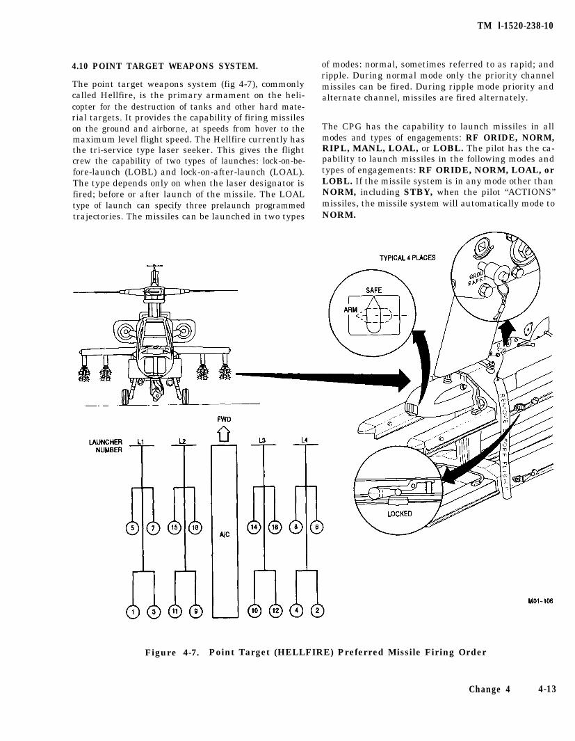
TM l-1520-238-10
4.10 POINT TARGET WEAPONS SYSTEM.
The point target weapons system (fig 4-7), commonlycalled Hellfire, is the primary armament on the heli-copter for the destruction of tanks and other hard mate-rial targets. It provides the capability of firing missileson the ground and airborne, at speeds from hover to themaximum level flight speed. The Hellfire currently hasthe tri-service type laser seeker. This gives the flightcrew the capability of two types of launches: lock-on-be-fore-launch (LOBL) and lock-on-after-launch (LOAL).The type depends only on when the laser designator isfired; before or after launch of the missile. The LOALtype of launch can specify three prelaunch programmedtrajectories. The missiles can be launched in two types
of modes: normal, sometimes referred to as rapid; andripple. During normal mode only the priority channelmissiles can be fired. During ripple mode priority andalternate channel, missiles are fired alternately.
The CPG has the capability to launch missiles in allmodes and types of engagements: RF ORIDE, NORM,RIPL, MANL, LOAL, or LOBL. The pilot has the ca-pability to launch missiles in the following modes andtypes of engagements: RF ORIDE, NORM, LOAL, orLOBL. If the missile system is in any mode other thanNORM, including STBY, when the pilot “ACTIONS”missiles, the missile system will automatically mode toNORM.
Figure 4-7. Point Target (HELLFIRE) Preferred Missile Firing Order
Change 4 4-13
TM 1-1520-238-10
The missile system prompts presented to the CPG areshown in either the sight status or weapons status sec-tion of the high action display. Autonomous designationmissile launch prompts are shown in the weapons sta-tus section: remote designation missile launch promptsare shown in the sight status section. Autonomous des-ignation is defined as when the missile code of thepriority channel and the code of the LRF/D are thesame and the selected sight is TADS plus the laser pow-er is turned on. Remote designation is defined as whenthe missile code of the priority channel and the code ofthe LRF/D are not the same.
Time of flight is displayed for all missile launches andreflects the time of flight for the missile closest to thetarget. Temperature compensation is incorporatedwhen calculating missile time of flight m /m. Rip-ple fire engagements have individual time of flightcounters displayed, one for the autonomous missile,and one for the remotely designated missile, regardlessof the order of their launch.
With -45 software the pilot cannot launch missiles forautonomous designation; consequently only one set ofprompts is displayed in the weapons status section ofthe high action display m. Time of flight is displayedto the pilot for any missile that he has launched. With-49 software the pilot can conduct autonomouslaunches. Pilot prompts and TOF displays remain thesame as described above. Steering commands for themissile constraints box will be driven by the TADS LOSduring LOAL DIR. The missile constraint steering boxwill be driven by the NAV LOS regardless of autono-mous or remote moding during LOAL HI and LOAL LOlaunches m / RZD.
The sight status section will reflect the codes of the up-per and lower channels, UP=ALO=B; the code of thepriority channel will flash. Authorized engagementranges for the Hellfire System are from 500 meters to8000 meters.
4.11 FIRE CONTROL COMPUTER (FCC).
The FCC is the primary bus controller. The FCC con-trols all data transmissions on the multiplex bus dur-ing normal operations. The FCC processes and com-putes data for all tire control capabilities on board thehelicopter (fig 4-8). The FCC continuously executes in-ternal built-in-tests and in the event of a failure signalsthe BBC to assume control of the bus. The FCC, BBCand FAB MRTUs are turned on with the switch labeled
FCC/MUX ON (fig 4-14). Flight crew personnel shallensure that this switch is in the ON position at all
4-14 Change 4
times, except for when applying power to the aircraftsystems when the aircraft has been heat soaked in di-rect sunlight for more than 1 hour and the ambienttemperature exceeds 100 degrees Fahrenheit. Withthese conditions present, the FCC/MUX switch shallbe placed in the OFF position for at least two minutesafter power has been applied with the FAB fans run-ning in the STBY position to remove the superheatedair from within the critical LRUs. Otherwise the switchis ON during any ground or flight operations. The FCCreceives 115 vac power from the No. 1 essential bus and28 vdc power from the No. 3 essential dc bus and is pro-tected by the FCC AC and FCC DC circuit breakers lo-cated on the CPG circuit breaker panel. To determinethe FCC software code, place the DEK to SPl andenter C. The software code is displayed to the right ofthe dash. To determine the m FCC software code,press the CDU PGM FAB. The software version is dis-played on line 6 of the CDU display.
4.12 BACKUP BUS CONTROLLER (BBC).
The BBC is part of the CPG MRTU (fig 4-8). The BBCmonitors the primary bus controller for faults duringnormal operations. The BBC automatically assumescontrol of the multiplex bus when it senses a failure ofthe FCC. The CPG can manually select the BBC as theprimary bus controller by placing the MUX switch onthe CPG FIRE CONTROL panel (fig 4-14) to the SECposition. When the BBC is the primary bus controllerseveral fire control operational capabilities are notavailable. They are: Gun and Rocket ballistic solutions;Fault Detection/Location System; and Waypoint/Tar-geting. All other fire control capabilities are availableand function identically as under FCC bus control. TheBBC receives 28 vdc power from the No. 3 Essential DCbus and is protected by the MUX/CPG circuit breakerlocated on the CPG circuit breaker panel. The status ofthe BBC is continuously monitored by FD/LS; the oncommand test (test OS-MUX) will fault isolate to theLRU.
4.13 MULTIPLEX BUS SUBSYSTEM (MUX).
The MUX (fig 4-8) consists of remote terminal (RT)units and a redundant data bus. The RTs are used tointerface the various subsystems on board the helicop-ter. Three helicopter subsystems, the digital automaticstabilization equipment (DASE), the remote Hellfireelectronics (RHE) unit, and the symbol generator alsofunction as RTs. The RHE provides multiplex bus inter-face for the missile system electronics. The DASE pro-vides multiplex bus interface for itself, ADSS, trans-mission and APU FD/LS, BUCS LVDTs, and theheading attitude reference system. The symbol genera-tor receives only data from the bus to use in generation
TM 1-1520-238-10
of symbols on the video displays. With the EGI modifi-cation, additional RTs are connected to the MUX bus.The DTU and EGI are new LRUs on the aircraft, andthey are connected directly to the MUX bus. The CDUand DNS SDCC are already installed on the aircraft,but are now connected to the MUX bus via data busswitches (DBS) that are normally de-energized. TheDBSs energize when the BBC takes control of the MUXbus, either manually via the MUX PRI/SEC switch onthe CPG FCP or automatically when the FCC indicatesa failure to the BBC. The data bus consists of two iden-tical bus networks separated down each side of the heli-copter and interconnected in such a manner that loss ofdata communications is minimized or avoided in theevent of battle damage. The multiplex bus system re-ceives 115 vac power from the No. 1 essential bus and28 vdc power from the No. 3 essential dc bus. TheMRTUs are protected by their own circuit breakers: theDASE by the ASE/AC and ASE/DC circuit breakers lo-cated on the pilot overhead circuit breaker panel; thesymbol generator by the SYM GEN circuit breaker lo-
cated on the pilot overhead circuit breaker panel; theremote Hellfire electronics unit by the MSL/ DC ELECcircuit breaker located on the CPG circuit breaker pan-el. The remaining MRTU circuit breakers are locatedon the CPG circuit breaker panel and are labeled MUX/L PYL OUTBD, MUX/L PYL INBD, MUX/ R PYLOUTBD, MUX/R PYL INBD, MUX/FAB L and MUX/FAB R. With the EGI modification, the DTU and EGIhave dedicated circuit breakers on the pilots forwardcircuit breaker panel. The CDU circuit breaker is lo-cated on the CPG circuit breaker panel, and the DNScircuit breaker is located on the pilots forward circuitbreaker panel. The status of the multiplex bus subsys-tern is continuously monitored by FD/LS; the on com-mand test (test OS-MUX) will fault isolate to the specif-ic LRU m or LRU and LRU bus failure m I=. With -45 software the RHE and symbol generatorMRTU functions are tested as part of each subsystemoverall on command test (tests 07-MSL; 13-SYMG)m. With -49A or -51 software the RHE MRTU func-tions are tested as part of the 08 MUX test m /m.
Change 4 4-14.1/(4-14.2 blank)

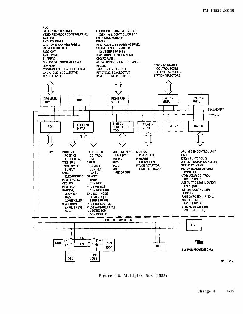
TM l-1520-238-10
Figure 4-8. Multiplex Bus (1553)
Change 4 4-15
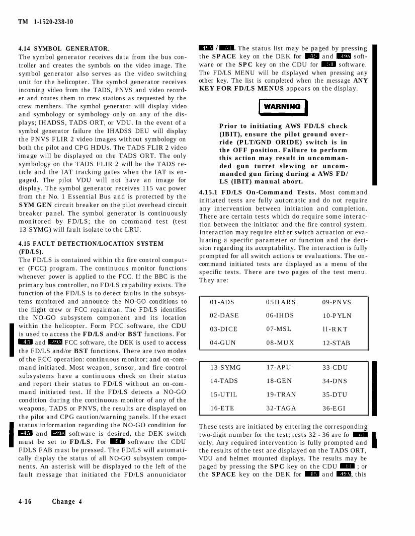
TM 1-1520-238-10
4.14 SYMBOL GENERATOR.The symbol generator receives data from the bus con-troller and creates the symbols on the video image. Thesymbol generator also serves as the video switchingunit for the helicopter. The symbol generator receivesincoming video from the TADS, PNVS and video record-er and routes them to crew stations as requested by thecrew members. The symbol generator will display videoand symbology or symbology only on any of the dis-plays; IHADSS, TADS ORT, or VDU. In the event of asymbol generator failure the IHADSS DEU will displaythe PNVS FLIR 2 video images without symbology onboth the pilot and CPG HDUs. The TADS FLIR 2 videoimage will be displayed on the TADS ORT. The onlysymbology on the TADS FLIR 2 will be the TADS re-ticle and the IAT tracking gates when the IAT is en-gaged. The pilot VDU will not have an image fordisplay. The symbol generator receives 115 vac powerfrom the No. 1 Essential Bus and is protected by theSYM GEN circuit breaker on the pilot overhead circuitbreaker panel. The symbol generator is continuouslymonitored by FD/LS; the on command test (test13-SYMG) will fault isolate to the LRU.
4.15 FAULT DETECTION/LOCATION SYSTEM(FD/LS).The FD/LS is contained within the fire control comput-er (FCC) program. The continuous monitor functionswhenever power is applied to the FCC. If the BBC is theprimary bus controller, no FD/LS capability exists. Thefunction of the FD/LS is to detect faults in the subsys-tems monitored and announce the NO-GO conditions tothe flight crew or FCC repairman. The FD/LS identifiesthe NO-GO subsystem component and its locationwithin the helicopter. Form FCC software, the CDUis used to access the FD/LS and/or BST functions. Form and m FCC software, the DEK is used to accessthe FD/LS and/or BST functions. There are two modesof the FCC operation: continuous monitor; and on-com-mand initiated. Most weapon, sensor, and fire controlsubsystems have a continuous check on their statusand report their status to FD/LS without an on-com-mand initiated test. If the FD/LS detects a NO-GOcondition during the continuous monitor of any of theweapons, TADS or PNVS, the results are displayed onthe pilot and CPG caution/warning panels. If the exactstatus information regarding the NO-GO condition forW and m software is desired, the DEK switchmust be set to FD/LS. For m software the CDUFDLS FAB must be pressed. The FD/LS will automati-cally display the status of all NO-GO subsystem compo-nents. An asterisk will be displayed to the left of thefault message that initiated the FD/LS annuniciator
4-16 Change 4
m /m. The status list may be paged by pressingthe SPACE key on the DEK for m and m soft-ware or the SPC key on the CDU for m software.The FD/LS MENU will be displayed when pressing anyother key. The list is completed when the message ANYKEY FOR FD/LS MENUS appears on the display.
Prior to initiating AWS FD/LS check(IBIT), ensure the pilot ground over-ride (PLT/GND ORIDE) switch is inthe OFF position. Failure to performthis action may result in uncomman-ded gun turret slewing or uncom-manded gun firing during a AWS FD/LS (IBIT) manual abort.
4.15.1 FD/LS On-Command Tests. Most commandinitiated tests are fully automatic and do not requireany intervention between initiation and completion.There are certain tests which do require some interac-tion between the initiator and the fire control system.Interaction may require either switch actuation or eva-luating a specific parameter or function and the deci-sion regarding its acceptability. The interaction is fullyprompted for all switch actions or evaluations. The on-command initiated tests are displayed as a menu of thespecific tests. There are two pages of the test menu.They are:
01-ADS
02-DASE
03-DICE
04-GUN
05HARS
06-IHDS
07-MSL
08-MUX
09-PNVS
10-PYLN
ll -RKT
12-STAB
13-SYMG 17-APU 33-CDU
14-TADS 18-GEN 34-DNS
15-UTIL 19-TRAN 35-DTU
16-ETE 32-TAGA 36-EGI
These tests are initiated by entering the correspondingtwo-digit number for the test; tests 32 - 36 are fo only. Any required intervention is fully prompted andthe results of the test are displayed on the TADS ORT,VDU and helmet mounted displays. The results may bepaged by pressing the SPC key on the CDU m ; orthe SPACE key on the DEK for m and m; this
TM l-1520-238-10
should be done until the message ANY KEY FOR FD/LS MENUS is displayed. The FD/LS status or on-com-mand initiated test may be accomplished without turn-ing the TADS on. The TADS heads out display can beused independently of the TADS for FD/LS by turningon the symbol generator to display the FD/LS on-com-mand tests. The FD/LS tests may request that the oper-ator acknowledge that an action has been completed.The method used to acknowledge (ACK) is to press theSPACE key on the DEK m and m m software.Form software the CDU SPC key must be pressed.
4.16 AIR DATA SENSOR SUBSYSTEM (ADSS).The ADSS consists of an omni-directional airspeed sen-sor (OAS) and air data processor (ADP). The OAS (fig2-2) measures the airspeed and temperature. The airdata processor senses static pressure and with the data
from the OAS calculates the air mass data required forfire control. The ADSS is interfaced with the multiplexbus through the DASE MRTU (fig 4-8). The ADSS is turned on with the switch labeled ADSS on the AUX/ANTI-ICE control panel in the CPG left console (fig2-12). If the ADSS fails or is turned OFF, the displayedairspeed will revert to ground speed in knots as com-puted by the doppler navigation system. The ADSS re-ceives 115 vac power from the No. 1 essential bus and23 vdc from the No. 3 essential dc bus and is protectedby the AIR DATA AC and AIR DATA DC circuitbreakers on the pilot overhead circuit breaker panel.The status of the ADSS is continuously monitored bythe Fault Detection/Location System (FD/LS); the oncommand test (test 01-ADS) will fault isolate to thespecific line replaceable unit (LRU).
Change 4 4-16.1/(4-16.2 blank)

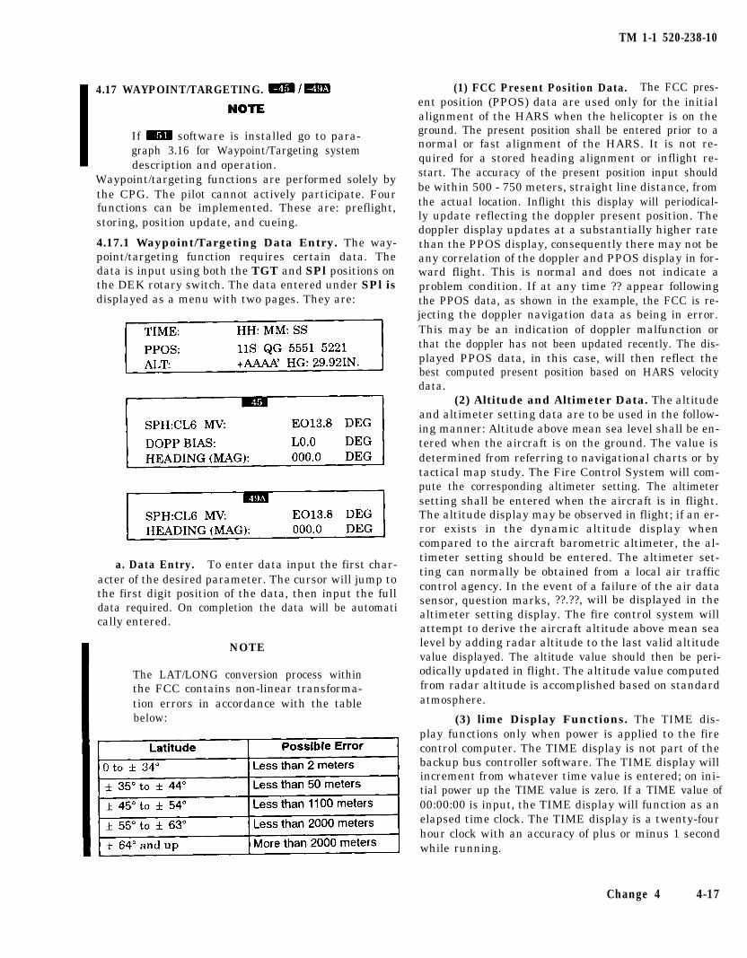
TM 1-1 520-238-10
4.17 WAYPOINT/TARGETING. m/m
If m software is installed go to para-graph 3.16 for Waypoint/Targeting systemdescription and operation.
Waypoint/targeting functions are performed solely bythe CPG. The pilot cannot actively participate. Fourfunctions can be implemented. These are: preflight,storing, position update, and cueing.
4.17.1 Waypoint/Targeting Data Entry. The way-point/targeting function requires certain data. Thedata is input using both the TGT and SPl positions onthe DEK rotary switch. The data entered under SPl isdisplayed as a menu with two pages. They are:
(1) FCC Present Position Data. The FCC pres-ent position (PPOS) data are used only for the initialalignment of the HARS when the helicopter is on theground. The present position shall be entered prior to anormal or fast alignment of the HARS. It is not re-quired for a stored heading alignment or inflight re-start. The accuracy of the present position input shouldbe within 500 - 750 meters, straight line distance, fromthe actual location. Inflight this display will periodical-ly update reflecting the doppler present position. Thedoppler display updates at a substantially higher ratethan the PPOS display, consequently there may not beany correlation of the doppler and PPOS display in for-ward flight. This is normal and does not indicate aproblem condition. If at any time ?? appear followingthe PPOS data, as shown in the example, the FCC is re-jecting the doppler navigation data as being in error.This may be an indication of doppler malfunction orthat the doppler has not been updated recently. The dis-played PPOS data, in this case, will then reflect thebest computed present position based on HARS velocitydata.
(2) Altitude and Altimeter Data. The altitudeand altimeter setting data are to be used in the follow-ing manner: Altitude above mean sea level shall be en-tered when the aircraft is on the ground. The value isdetermined from referring to navigational charts or bytactical map study. The Fire Control System will com-pute the corresponding altimeter setting. The altimetersetting shall be entered when the aircraft is in flight.The altitude display may be observed in flight; if an er-ror exists in the dynamic altitude display whencompared to the aircraft barometric altimeter, the al-timeter setting should be entered. The altimeter set-ting can normally be obtained from a local air trafficcontrol agency. In the event of a failure of the air datasensor, question marks, ??.??, will be displayed in thealtimeter setting display. The fire control system willattempt to derive the aircraft altitude above mean sealevel by adding radar altitude to the last valid altitudevalue displayed. The altitude value should then be peri-odically updated in flight. The altitude value computedfrom radar altitude is accomplished based on standardatmosphere.
(3) lime Display Functions. The TIME dis-play functions only when power is applied to the firecontrol computer. The TIME display is not part of thebackup bus controller software. The TIME display willincrement from whatever time value is entered; on ini-tial power up the TIME value is zero. If a TIME value of00:00:00 is input, the TIME display will function as anelapsed time clock. The TIME display is a twenty-fourhour clock with an accuracy of plus or minus 1 secondwhile running.
a. Data Entry. To enter data input the first char-acter of the desired parameter. The cursor will jump tothe first digit position of the data, then input the fulldata required. On completion the data will be automatically entered.
NOTE
The LAT/LONG conversion process withinthe FCC contains non-linear transforma-tion errors in accordance with the tablebelow:
Change 4 4-17
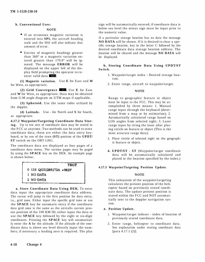
TM 1-1520-238-10
b. Conventional Uses:
NOTE
If an erroneous magnetic variation isentered into SPl, the aircraft headingscale and the HSI will also indicate thatamount of error.
Entries of magnetic headings greaterthan 360° or a magnetic variation en-tered greater than 179.9° will be ig-nored. The message ERROR will bedisplayed on the upper left of the dis-play field prompting the operator to re-enter valid data m.
(1) Magnetic variation. Use E for East and Wfor West, as appropriate.
(2) Grid Convergence m. Use E for Eastand W for West, as appropriate. Data may be obtainedfrom G-M angle diagram on UTM maps if applicable.
(3) Spheroid. Use the same codes utilized bythe doppler.
(4) Latitude. Use - for North and S for South,as appropriate.
4.17.2 Waypoint/Targeting Coordinate Data Stor-ing. Up to ten sets of coordinate data may be stored inthe FCC at anytime. Two methods can be used to storecoordinate data; these are either the data entry key-board, or by use of the store (ST) position of the UPDT/ST switch on the ORT LHG.
The coordinate data are displayed as four pages of acoordinate data menu. The various pages may be pagedby using the SPACE key on the DEK. An example pageis shown below:
a. Store Coordinate Data Using DEK. To enterdata input the appropriate coordinate data address.The cursor will jump to the first position for data entry,i.e., grid zone. Either input the specific grid zone or usethe SPACE key for automatic entry if the coordinatedata grid zone is the same as the aircrafts current pres-ent position of the 100 KM ID; either input the data oruse the SPACE key followed by the eight or six-digitcoordinates. Pressing the SPACE key will automatical-ly enter the A for the altitude. If the altitude of the coor-dinate data is above sea level directly input the num-bers; if necessary a leading zero is required. The plus
4-18 Change 4
sign will be automatically entered; if coordinate data isbelow sea level the minus sign must be input prior tothe numeric value.
If a particular storage location has no data the messageNO DATA will be shown. If it is desired to clear a spe-cific storage location, key in the letter C followed by thedesired coordinate data storage location address. Thelocation will be cleared and the message NO DATA willbe displayed.
b. Storing Coordinate Data Using UPDT/STSwitch.
1. Waypoint/target index - Desired storage loca-tion.
2. Enter range, aircraft to waypoint/target.
NOTE
Range to geographic feature or objectmust be input to the FCC. This may be ac-complished by three means: 1. Manualrange input through the keyboard (deter-mined from a map or by estimation); 2.Automatically calculated range based onLOS angles from selected sight; 3. Laserrange input by tiring the laser after plac-ing reticle on feature or object (This is themost accurate range data).
3. Place reticle of selected sight on the geograph-ic feature or object.
4. UPDT/ST - ST (Waypoint/target coordinatedata will be automatically calculated andplaced in the location specified by the index.)
4.17.3 Waypoint/Targeting Position Update.
a.
NOTE
This subsystem of the waypoint/targetingcalculates the present position of the heli-copter based on previously stored coordi-nate data. The update present position isstored within the FCC and NOT automat-ically sent to the doppler navigation sys-tem.
Position Update.
1. Waypoint/target indexer - index of location ofpreviously stored coordinate data.
2. Enter range, helicopter to coordinate data.See explanation under storing coordinate data[para 4.17.1 (2)].

3.
4.
Place reticle of selected sight on the geo-graphic feature or object of previously enteredcoordinate data.
UPDT/ST - UPDT. (The aircraft presentposition is calculated automatically, based onthe previously entered coordinate data.)
b. Recall Updated Hellcopter Present Position.
1. Data entry keyboard - SP1.
2. Input - U (The updated present position datais automatically displayed.)
c. Update Doppler.
1.
2.
3.
Waypoint/target indexer - Index of desiredcoordinate data.
Acquisition Select - TGT or NAV.
Slave button - Press.
1. Recall updated aircraft present position im-mediately after accomplishing update func-tion.
2. Insert the FCC displayed present position intothe doppler using normal procedures.
a. If the selected sight was TADS, TADS willbe slaved so as to place its LOS reticle overthe geographic feature or object on theground.
b. If the selected sight was other than TADS,the CPG will be cueing in the normal man-ner so as to cue the CPG to place the re-ticle of his selected sight over the geo-graphic feature or object.
d. Example of Updated Present Position Data. b. Recall Range and Bearing, Hellcopter PresentPosition to Stored Coordinate Data.
1. Input - U.
2. Display After Entering: UPDATE
A/C 11S QG56035160
1. Data entry keyboard - TGT.
2. Input - Rn. (Where n = coordinate data stor-age address.)
c. Example.
1.
2.
Input - R3.
DELEAS = +0065 After entering, display shows - 3R 15990B042.4 degrees.
DELNOR = -0012 Which decodes as follows:
3. Which decodes as follows:a. Waypoint/target storage (index) No.-3.
b. Range, helicopter to coordinate data -15990 meters.
Grid Zone - 11S
Coordinates - QG56035160
c. Bearing, helicopter to coordinate data -042.4 degrees.
NOTE
Doppler easting error - +65 meters
Doppler northing error - 12 meters
If no previously stored coordinate dataexists in the index location selected, amessage NO DATA will be displayed.
If the coordinates updated from had not beenpreviously stored, an attempt to recall the up-dated present position will result in a NODATA message on the display.
The range and bearing function can beaccomplished at any time after storingwaypoint/target data.
Maximum possible displayed range forthis function is 32000 meters.
TM 1-1520-238-10
4.17.4 Waypoint/Targeting Cueing.
Once waypoint/targeting data has been stored, sight-line cueing or TADS slaving to the stored coordinatescan be accomplished as follows:
a. Sightline Cueing or TADS Slaving.
Change 4 4-19
TM 1-1520-238-10
4.18 INTEGRATED HELMET AND DlSPLAY SIGHTSUBSYSTEM (IHADSS).
In the event of IHADSS failure withgun selected, the gun will be com-manded to the fixed forward posi-tion. Once in this position, the guncan still be fired without having tore-action the gun.
The IHADSS (fig 4-9) consists of the crewmember hel-met; a helmet display unit (HDU), sensor survey units(SSU), a display adjust panel (DAP), and a boresight re-ticle unit (BRU) located in each crew station; and thesight electronics unit (SEU) and display electronicsunit (DEU) located in the right forward avionics bay.Each helmet has two cable connections in the cockpit;they are: a TEMPEST ICS cable and a cable connectingthe helmet electronics to the IHADSS. The sensor sur-vey units, in conjunction with the sight electronics unit,determine the crewmembers line-of-sight (LOS). Theweapons and sensor turrets can be directed by eithercrew member LOS. The helmet display unit (HDU) con-sists of a CRT with optical elements which project theselected symbology and sensor imagery onto a combin-ing lens. The HDU is attached to the right side of thehelmet during normal use. the attached HDU is rotatedin front of the right eye for viewing of the display or canbe rotated vertically away from the eye when not in im-mediate use. When not attached to the helmet the HDUshall be stored in the holster located on the right con-sole inside kick panel. The display electronics unit pro-vides power and video signals to each crewmemberHDU through the display adjust panel located in eachcrew station. The display adjust panel is used to adjustthe image size, centering and electronic focus as it ap-pears on the combining lens. These adjustments arenormally required only after replacement of the DAP orHDU. The boresight reticle unit in each cockpit is used
to boresight the crewmember helmet. The IHADSS re-ceives 115 vac power from the No. 1 essential bus andthe SEU is protected by the IHADSS circuit breaker lo-cated on the pilot overhead circuit breaker panel; theDEU is protected by the IHADSS circuit breaker lo-cated on the CPG circuit breaker panel. The IHADSS iscontinuously monitored by FD/LS; the on commandtest (test 06-IHDS) will fault isolate to specific LRU in-cluding the crewmember helmet.
4.18.1 IHADSS Operation. Two actions shall be ac-complished by each crewmember each time theIHADSS is turned on. The HDU CRT shall be adjusted,and the crewmember helmet, boresighted. Adjustmentof the HDU is accomplished by selecting the gray scaleand adjusting the brightness and contrast to establisha displayed 10 shades of gray image on the HDU. Bore-sighting the helmet is accomplished by turning on theBRU, aligning the LOS reticle projected on the combin-ing lens with the BRU alignment reticle, and actuatingthe BRSIT HMD switch. The requirement to boresightthe IHADSS is announced to the crewmember in thesight status block of the high action display and by theflashing of all four cueing dots on the symbology proj-ected on the combining lens.The IHADSS can be bore-sighted in flight or on the ground. Display adjust paneladjustments are made usually following a maintenanceaction that replaced either the HDU or the DAP. Theprocedure requires assistance from the crew chief orFCC repairman. To accomplish: the crewmember at-taches the HDU to the helmet in the normal mannerand rotates the HDU in front of his eye, the gray scaleis selected and viewed, adjustments are first made forimage centering so that the gray scale appears centered(HORIZONTAL CTRG, VERTICAL CTRG) (fig 4-9),next the gray scale size is adjusted so that the four bor-ders of the image are just contained on the edges of thecombining lens (HORIZONTAL SIZE, VERTICALSIZE), and the corners are not visible, the last step is toadjust the electronic focus, (FOCUS), so that the grayscale image appears crisp and sharp.
4-20 Change 3
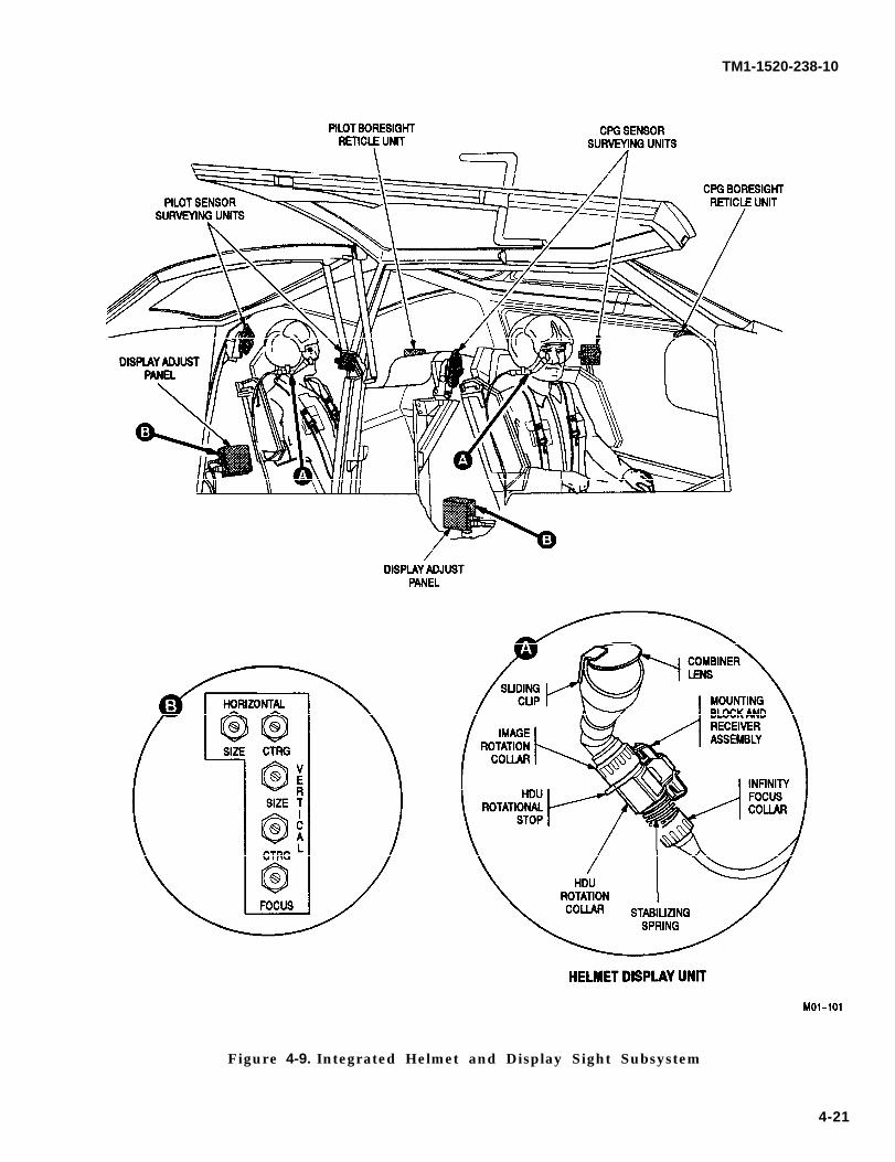
TM1-1520-238-10
Figure 4-9. Integrated Helmet and Display Sight Subsystem
4-21
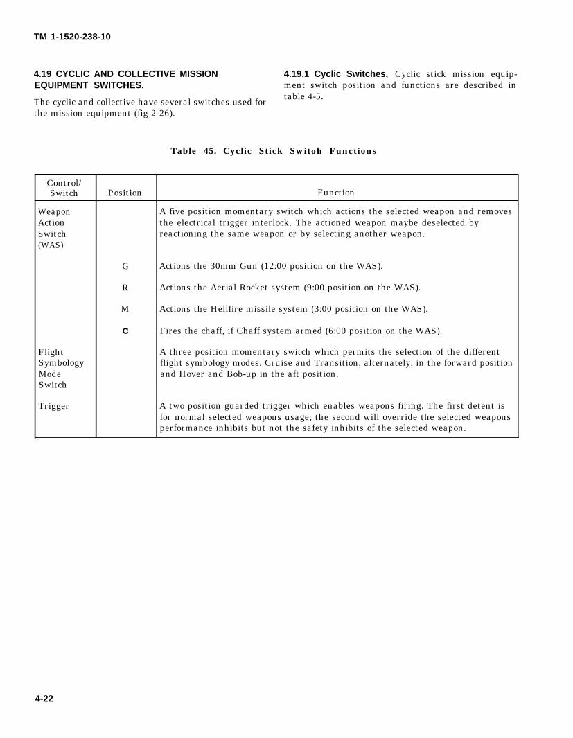
TM 1-1520-238-10
4.19 CYCLIC AND COLLECTIVE MISSION 4.19.1 Cyclic Switches, Cyclic stick mission equip-EQUIPMENT SWITCHES. ment switch position and functions are described in
The cyclic and collective have several switches used fortable 4-5.
the mission equipment (fig 2-26).
Table 45. Cyclic Stick Switoh Functions
Control/Switch Position Function
Weapon A five position momentary switch which actions the selected weapon and removesAction the electrical trigger interlock. The actioned weapon maybe deselected bySwitch reactioning the same weapon or by selecting another weapon.(WAS)
G Actions the 30mm Gun (12:00 position on the WAS).
R Actions the Aerial Rocket system (9:00 position on the WAS).
M Actions the Hellfire missile system (3:00 position on the WAS).
c Fires the chaff, if Chaff system armed (6:00 position on the WAS).
Flight A three position momentary switch which permits the selection of the differentSymbology flight symbology modes. Cruise and Transition, alternately, in the forward positionMode and Hover and Bob-up in the aft position.Switch
Trigger A two position guarded trigger which enables weapons firing. The first detent isfor normal selected weapons usage; the second will override the selected weaponsperformance inhibits but not the safety inhibits of the selected weapon.
4-22
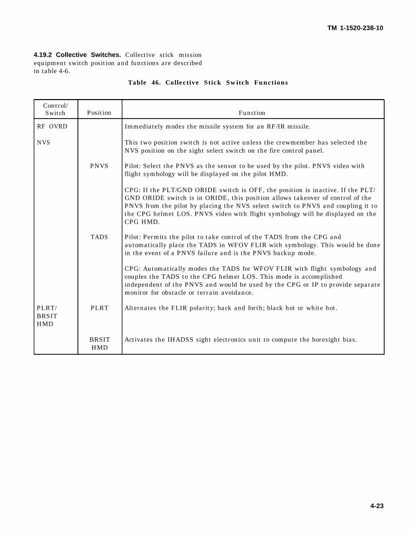
TM 1-1520-238-10
4.19.2 Collective Switches. Collective stick missionequipment switch position and functions are describedin table 4-6.
Table 46. Collective Stick Switch Functions
Control/Switch Position Function
RF OVRD Immediately modes the missile system for an RF/IR missile.
NVS This two position switch is not active unless the crewmember has selected theNVS position on the sight select switch on the fire control panel.
PNVS Pilot: Select the PNVS as the sensor to be used by the pilot. PNVS video withflight symbology will be displayed on the pilot HMD.
CPG: If the PLT/GND ORIDE switch is OFF, the position is inactive. If the PLT/GND ORIDE switch is in ORIDE, this position allows takeover of control of thePNVS from the pilot by placing the NVS select switch to PNVS and coupling it tothe CPG helmet LOS. PNVS video with flight symbology will be displayed on theCPG HMD.
TADS Pilot: Permits the pilot to take control of the TADS from the CPG andautomatically place the TADS in WFOV FLIR with symbology. This would be donein the event of a PNVS failure and is the PNVS backup mode.
CPG: Automatically modes the TADS for WFOV FLIR with flight symbology andcouples the TADS to the CPG helmet LOS. This mode is accomplishedindependent of the PNVS and would be used by the CPG or IP to provide separatemonitor for obstacle or terrain avoidance.
PLRT/ PLRT Alternates the FLIR polarity; back and forth; black hot or white hot.BRSITHMD
BRSIT Activates the IHADSS sight electronics unit to compute the boresight bias.HMD
4-23
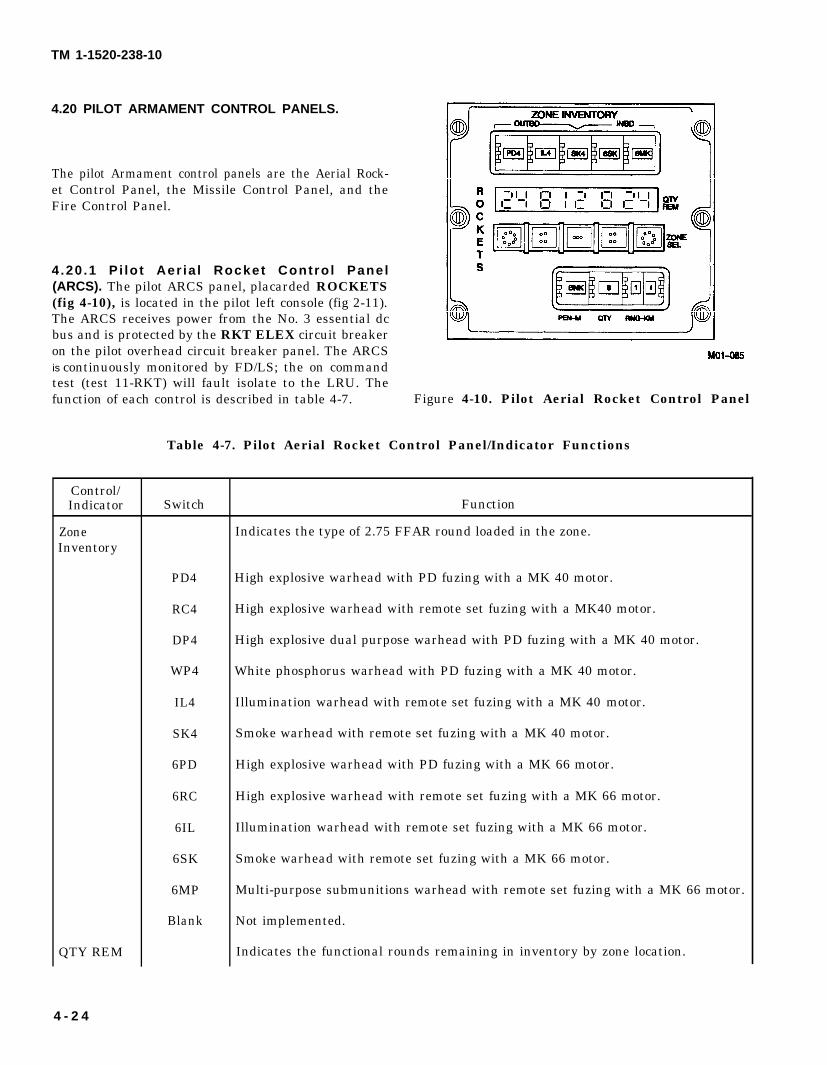
TM 1-1520-238-10
4.20 PILOT ARMAMENT CONTROL PANELS.
The pilot Armament control panels are the Aerial Rock-et Control Panel, the Missile Control Panel, and theFire Control Panel.
4.20 .1 P i lo t Aer ia l Rocket Contro l Panel(ARCS). The pilot ARCS panel, placarded ROCKETS(fig 4-10), is located in the pilot left console (fig 2-11).The ARCS receives power from the No. 3 essential dcbus and is protected by the RKT ELEX circuit breakeron the pilot overhead circuit breaker panel. The ARCSis continuously monitored by FD/LS; the on commandtest (test 11-RKT) will fault isolate to the LRU. Thefunction of each control is described in table 4-7. Figure 4-10. Pilot Aerial Rocket Control Panel
Table 4-7. Pilot Aerial Rocket Control Panel/Indicator Functions
Control/Indicator
ZoneInventory
QTY REM
Switch
PD4
RC4
DP4
WP4
IL4
SK4
6PD
6RC
6IL
6SK
6MP
Blank
Function
Indicates the type of 2.75 FFAR round loaded in the zone.
High explosive warhead with PD fuzing with a MK 40 motor.
High explosive warhead with remote set fuzing with a MK40 motor.
High explosive dual purpose warhead with PD fuzing with a MK 40 motor.
White phosphorus warhead with PD fuzing with a MK 40 motor.
Illumination warhead with remote set fuzing with a MK 40 motor.
Smoke warhead with remote set fuzing with a MK 40 motor.
High explosive warhead with PD fuzing with a MK 66 motor.
High explosive warhead with remote set fuzing with a MK 66 motor.
Illumination warhead with remote set fuzing with a MK 66 motor.
Smoke warhead with remote set fuzing with a MK 66 motor.
Multi-purpose submunitions warhead with remote set fuzing with a MK 66 motor.
Not implemented.
Indicates the functional rounds remaining in inventory by zone location.
4 - 2 4
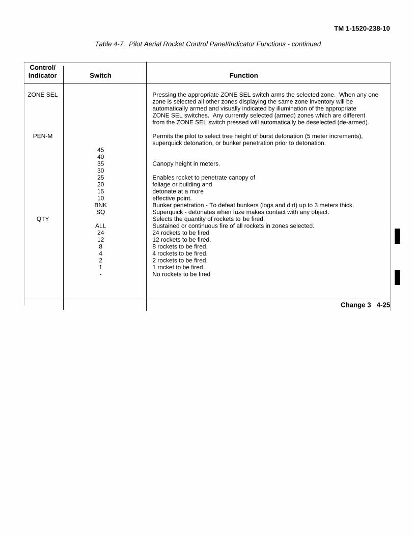
TM 1-1520-238-10
Table 4-7. Pilot Aerial Rocket Control Panel/Indicator Functions - continued
Control/Indicator Switch Function
ZONE SEL Pressing the appropriate ZONE SEL switch arms the selected zone. When any onezone is selected all other zones displaying the same zone inventory will beautomatically armed and visually indicated by illumination of the appropriateZONE SEL switches. Any currently selected (armed) zones which are differentfrom the ZONE SEL switch pressed will automatically be deselected (de-armed).
PEN-M Permits the pilot to select tree height of burst detonation (5 meter increments),superquick detonation, or bunker penetration prior to detonation.
454035 Canopy height in meters.3025 Enables rocket to penetrate canopy of20 foliage or building and15 detonate at a more10 effective point.
BNK Bunker penetration - To defeat bunkers (logs and dirt) up to 3 meters thick.SQ Superquick - detonates when fuze makes contact with any object.
QTY Selects the quantity of rockets to be fired.ALL Sustained or continuous fire of all rockets in zones selected.24 24 rockets to be fired12 12 rockets to be fired.8 8 rockets to be fired.4 4 rockets to be fired.2 2 rockets to be fired.1 1 rocket to be fired.- No rockets to be fired
Change 3 4-25
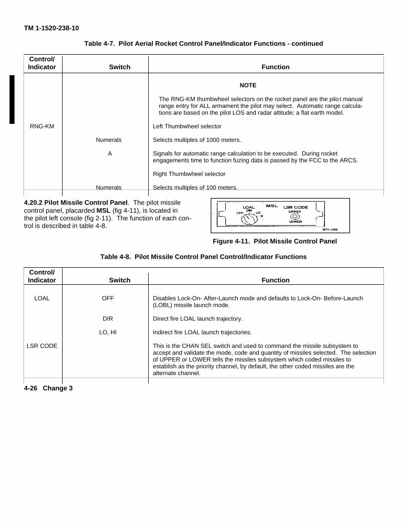
TM 1-1520-238-10
Table 4-7. Pilot Aerial Rocket Control Panel/Indicator Functions - continued
Control/Indicator Switch Function
NOTE
The RNG-KM thumbwheel selectors on the rocket panel are the pilo t manualrange entry for ALL armament the pilot may select. Automatic range calcula-tions are based on the pilot LOS and radar altitude; a flat earth model.
RNG-KM Left Thumbwheel selector
Numerals Selects multiples of 1000 meters.
A Signals for automatic range calculation to be executed. During rocketengagements time to function fuzing data is passed by the FCC to the ARCS.
Right Thumbwheel selector
Numerals Selects multiples of 100 meters.
4.20.2 Pilot Missile Control Panel. The pilot missilecontrol panel, placarded MSL (fig 4-11), is located inthe pilot left console (fig 2-11). The function of each con-trol is described in table 4-8.
Figure 4-11. Pilot Missile Control Panel
Table 4-8. Pilot Missile Control Panel Control/Indicator Functions
Control/Indicator Switch Function
LOAL OFF Disables Lock-On- After-Launch mode and defaults to Lock-On- Before-Launch(LOBL) missile launch mode.
DIR Direct fire LOAL launch trajectory.
LO, HI Indirect fire LOAL launch trajectories.
LSR CODE This is the CHAN SEL switch and used to command the missile subsystem toaccept and validate the mode, code and quantity of missiles selected. The selectionof UPPER or LOWER tells the missiles subsystem which coded missiles toestablish as the priority channel, by default, the other coded missiles are thealternate channel.
4-26 Change 3
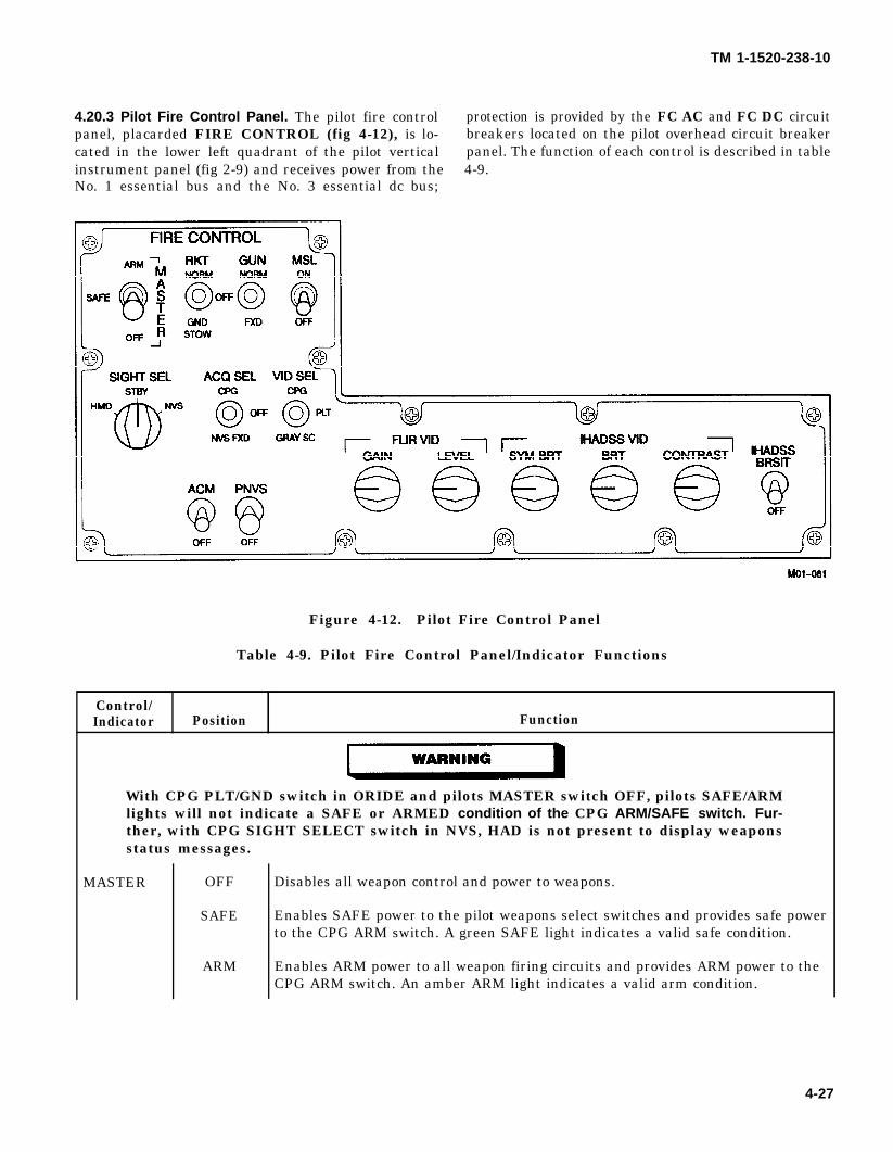
WARNING
TM 1-1520-238-10
4.20.3 Pilot Fire Control Panel. The pilot fire control protection is provided by the FC AC and FC DC circuitpanel, placarded FIRE CONTROL (fig 4-12), is lo- breakers located on the pilot overhead circuit breakercated in the lower left quadrant of the pilot vertical panel. The function of each control is described in tableinstrument panel (fig 2-9) and receives power from the 4-9.No. 1 essential bus and the No. 3 essential dc bus;
Figure 4-12. Pilot Fire Control Panel
Table 4-9. Pilot Fire Control Panel/Indicator Functions
Control/Indicator Position Function
With CPG PLT/GND switch in ORIDE and pilots MASTER switch OFF, pilots SAFE/ARMlights will not indicate a SAFE or ARMED condition of the CPG ARM/SAFE switch. Fur-ther, with CPG SIGHT SELECT switch in NVS, HAD is not present to display weaponsstatus messages.
MASTER OFF
SAFE
ARM
Disables all weapon control and power to weapons.
Enables SAFE power to the pilot weapons select switches and provides safe powerto the CPG ARM switch. A green SAFE light indicates a valid safe condition.
Enables ARM power to all weapon firing circuits and provides ARM power to theCPG ARM switch. An amber ARM light indicates a valid arm condition.
4-27
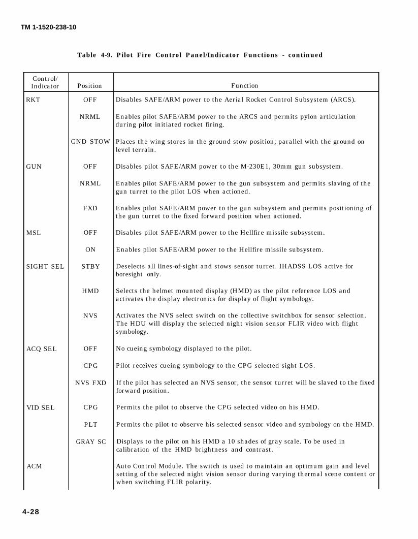
TM 1-1520-238-10
Control/Indicator
RKT
GUN
MSL
SIGHT SEL
ACQ SEL
VID SEL
ACM
Table 4-9. Pilot Fire Control Panel/Indicator Functions - continued
Position
OFF
NRML
GND STOW
OFF
NRML
FXD
OFF
ON
STBY
HMD
NVS
OFF
CPG
NVS FXD
CPG
PLT
GRAY SC
Function
Disables SAFE/ARM power to the Aerial Rocket Control Subsystem (ARCS).
Enables pilot SAFE/ARM power to the ARCS and permits pylon articulationduring pilot initiated rocket firing.
Places the wing stores in the ground stow position; parallel with the ground onlevel terrain.
Disables pilot SAFE/ARM power to the M-230E1, 30mm gun subsystem.
Enables pilot SAFE/ARM power to the gun subsystem and permits slaving of thegun turret to the pilot LOS when actioned.
Enables pilot SAFE/ARM power to the gun subsystem and permits positioning ofthe gun turret to the fixed forward position when actioned.
Disables pilot SAFE/ARM power to the Hellfire missile subsystem.
Enables pilot SAFE/ARM power to the Hellfire missile subsystem.
Deselects all lines-of-sight and stows sensor turret. IHADSS LOS active forboresight only.
Selects the helmet mounted display (HMD) as the pilot reference LOS andactivates the display electronics for display of flight symbology.
Activates the NVS select switch on the collective switchbox for sensor selection.The HDU will display the selected night vision sensor FLIR video with flightsymbology.
No cueing symbology displayed to the pilot.
Pilot receives cueing symbology to the CPG selected sight LOS.
If the pilot has selected an NVS sensor, the sensor turret will be slaved to the fixedforward position.
Permits the pilot to observe the CPG selected video on his HMD.
Permits the pilot to observe his selected sensor video and symbology on the HMD.
Displays to the pilot on his HMD a 10 shades of gray scale. To be used incalibration of the HMD brightness and contrast. - -
Auto Control Module. The switch is used to maintain an optimum gain and levelsetting of the selected night vision sensor during varying thermal scene content orwhen switching FLIR polarity.
4-28
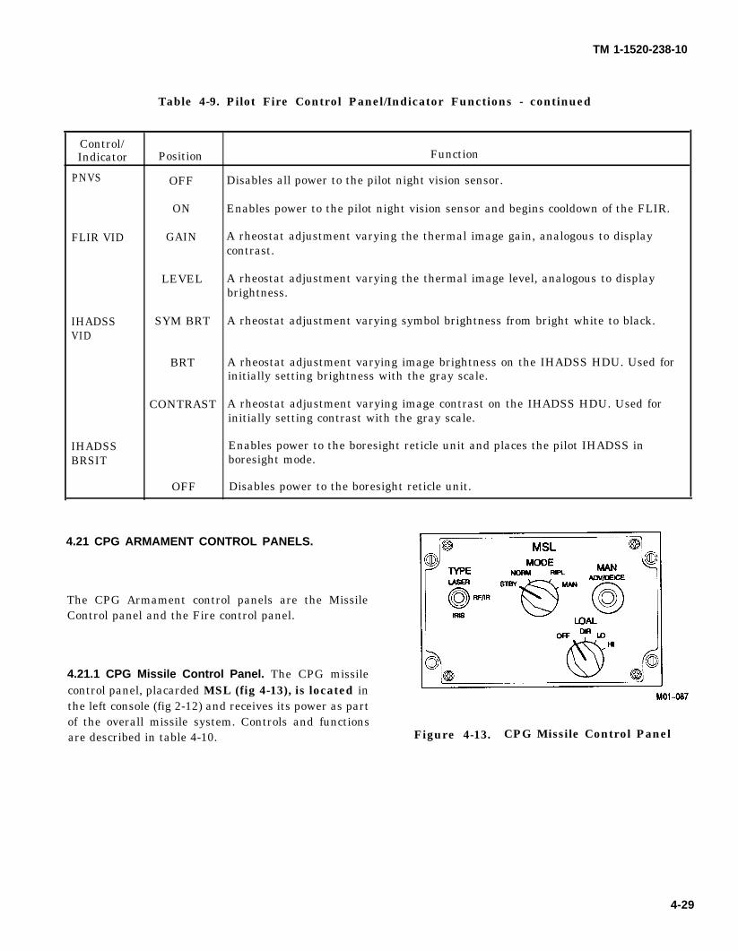
TM 1-1520-238-10
Table 4-9. Pilot Fire Control Panel/Indicator Functions - continued
Control/Indicator Position Function
PNVS OFF Disables all power to the pilot night vision sensor.
ON Enables power to the pilot night vision sensor and begins cooldown of the FLIR.
FLIR VID GAIN A rheostat adjustment varying the thermal image gain, analogous to displaycontrast.
LEVEL A rheostat adjustment varying the thermal image level, analogous to displaybrightness.
IHADSS SYM BRT A rheostat adjustment varying symbol brightness from bright white to black.VID
BRT A rheostat adjustment varying image brightness on the IHADSS HDU. Used forinitially setting brightness with the gray scale.
CONTRAST A rheostat adjustment varying image contrast on the IHADSS HDU. Used forinitially setting contrast with the gray scale.
IHADSS Enables power to the boresight reticle unit and places the pilot IHADSS inBRSIT boresight mode.
OFF Disables power to the boresight reticle unit.
4.21 CPG ARMAMENT CONTROL PANELS.
The CPG Armament control panels are the MissileControl panel and the Fire control panel.
4.21.1 CPG Missile Control Panel. The CPG missilecontrol panel, placarded MSL (fig 4-13), is located inthe left console (fig 2-12) and receives its power as partof the overall missile system. Controls and functionsare described in table 4-10. Figure 4-13. CPG Missile Control Panel
4-29
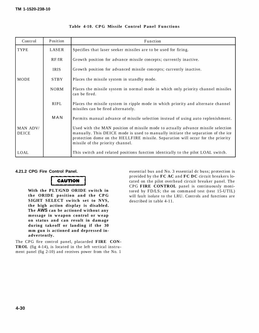
CAUTION
TM 1-1520-238-10
Table 4-10. CPG Missile Control Panel Functions
Control Position Function
TYPE LASER Specifies that laser seeker missiles are to be used for firing.
RF/IR Growth position for advance missile concepts; currently inactive.
IRIS Growth position for advanced missile concepts; currently inactive.
MODE STBY Places the missile system in standby mode.
NORM Places the missile system in normal mode in which only priority channel missilescan be fired.
RIPL Places the missile system in ripple mode in which priority and alternate channelmissiles can be fired alternately.
M A N Permits manual advance of missile selection instead of using auto replenishment.
MAN ADV/ Used with the MAN position of missile mode to actually advance missile selectionDEICE manually. This DEICE mode is used to manually initiate the separation of the ice
protection dome on the HELLFIRE missile. Separation will occur for the prioritymissile of the priority channel.
LOAL This switch and related positions function identically to the pilot LOAL switch.
4.21.2 CPG Fire Control Panel. essential bus and No. 3 essential dc buss; protection isprovided by the FC AC and FC DC circuit breakers lo-cated on the pilot overhead circuit breaker panel. TheCPG FIRE CONTROL panel is continuously moni-
With the PLT/GND ORIDE switch in tored by FD/LS; the on command test (test 15-UTIL)the ORIDE position and the CPG will fault isolate to the LRU. Controls and functions areSIGHT SELECT switch set to NVS, described in table 4-11.the high action display is disabled.The AWS can be actioned without anymessage in weapon control or weapon status and can result in damageduring takeoff or landing if the 30mm gun is actioned and depressed in-advertently.
The CPG fire control panel, placarded FIRE CON-TROL (fig 4-14), is located in the left vertical instru-ment panel (fig 2-10) and receives power from the No. 1
4-30
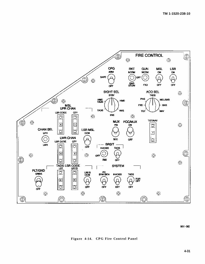
TM 1-1520-238-10
Figure 4-14. CPG Fire Control Panel
4-31
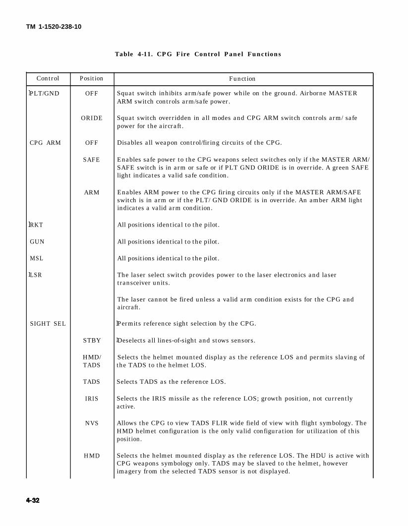
TM 1-1520-238-10
Table 4-11. CPG Fire Control Panel Functions
Control
PLT/GND
CPG ARM
RKT
GUN
MSL
LSR
SIGHT SEL
Position
OFF
ORIDE
OFF
SAFE
ARM
STBY
HMD/TADS
TADS
IRIS
NVS
HMD
Function
Squat switch inhibits arm/safe power while on the ground. Airborne MASTERARM switch controls arm/safe power.
Squat switch overridden in all modes and CPG ARM switch controls arm/ safepower for the aircraft.
Disables all weapon control/firing circuits of the CPG.
Enables safe power to the CPG weapons select switches only if the MASTER ARM/SAFE switch is in arm or safe or if PLT GND ORIDE is in override. A green SAFElight indicates a valid safe condition.
Enables ARM power to the CPG firing circuits only if the MASTER ARM/SAFEswitch is in arm or if the PLT/ GND ORIDE is in override. An amber ARM lightindicates a valid arm condition.
All positions identical to the pilot.
All positions identical to the pilot.
All positions identical to the pilot.
The laser select switch provides power to the laser electronics and lasertransceiver units.
The laser cannot be fired unless a valid arm condition exists for the CPG andaircraft.
Permits reference sight selection by the CPG.
Deselects all lines-of-sight and stows sensors.
Selects the helmet mounted display as the reference LOS and permits slaving ofthe TADS to the helmet LOS.
Selects TADS as the reference LOS.
Selects the IRIS missile as the reference LOS; growth position, not currentlyactive.
Allows the CPG to view TADS FLIR wide field of view with flight symbology. TheHMD helmet configuration is the only valid configuration for utilization of thisposition.
Selects the helmet mounted display as the reference LOS. The HDU is active withCPG weapons symbology only. TADS may be slaved to the helmet, howeverimagery from the selected TADS sensor is not displayed.
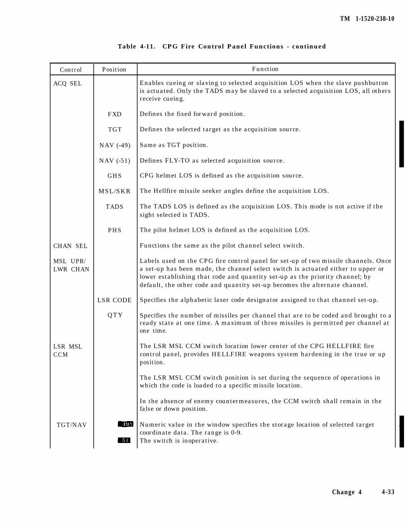
TM 1-1520-238-10
Table 4-11. CPG Fire Control Panel Functions - continued
Control
ACQ SEL
CHAN SEL
MSL UPR/LWR CHAN
LSR MSLCCM
TGT/NAV
Position
FXD
TGT
NAV (-49)
NAV (-51)
GHS
MSL/SKR
TADS
Defines the fixed forward position.
Defines the selected target as the acquisition source.
Same as TGT position.
Defines FLY-TO as selected acquisition source.
CPG helmet LOS is defined as the acquisition source.
The Hellfire missile seeker angles define the acquisition LOS.
The TADS LOS is defined as the acquisition LOS. This mode is not active if thesight selected is TADS.
PHS The pilot helmet LOS is defined as the acquisition LOS.
Functions the same as the pilot channel select switch.
Labels used on the CPG fire control panel for set-up of two missile channels. Oncea set-up has been made, the channel select switch is actuated either to upper orlower establishing that code and quantity set-up as the priority channel; bydefault, the other code and quantity set-up becomes the alternate channel.
LSR CODE
QTY
Specifies the alphabetic laser code designator assigned to that channel set-up.
Specifies the number of missiles per channel that are to be coded and brought to aready state at one time. A maximum of three missiles is permitted per channel atone time.
Function
Enables cueing or slaving to selected acquisition LOS when the slave pushbuttonis actuated. Only the TADS may be slaved to a selected acquisition LOS, all othersreceive cueing.
The LSR MSL CCM switch location lower center of the CPG HELLFIRE firecontrol panel, provides HELLFIRE weapons system hardening in the true or upposition.
The LSR MSL CCM switch position is set during the sequence of operations inwhich the code is loaded to a specific missile location.
In the absence of enemy countermeasures, the CCM switch shall remain in thefalse or down position.
Numeric value in the window specifies the storage location of selected targetcoordinate data. The range is 0-9.The switch is inoperative.
Change 4 4-33
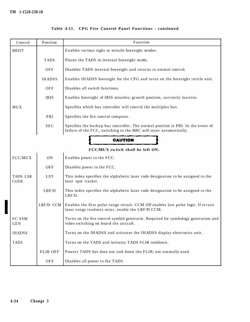
TM 1-1520-238-10
Table 4-11. CPG Fire Control Panel Functions - continued
Control
BRSIT
MUX
FCC/MUX
TADS LSRCODE
FC SYMGEN
IHADSS
TADS
Position
TADS
OFF
IHADSS
OFF
IRIS
PRI
SEC
ON
OFF
LST
LRF/D
LRF/D CCM
FLIR OFF
OFF
Function
Enables various sight or missile boresight modes.
Places the TADS in internal boresight mode.
Disables TADS internal boresight and returns to normal control.
Enables IHADSS boresight for the CPG and turns on the boresight reticle unit.
Disables all switch functions.
Enables boresight of IRIS missiles; growth position, currently inactive.
Specifies which bus controller will control the multiplex bus.
Specifies the fire control computer.
Specifies the backup bus controller. The normal position is PRI. In the event offailure of the FCC, switching to the BBC will occur automatically.
FCC/MUX switch shall be left ON.
Enables power to the FCC.
Disables power to the FCC.
This index specifies the alphabetic laser code designation to be assigned to thelaser spot tracker.
This index specifies the alphabetic laser code designation to be assigned to theLRF/D.
Enables the first pulse range circuit. CCM Off enables last pulse logic. If erraticlaser range readouts occur, enable the LRF/D CCM.
Turns on the fire control symbol generator. Required for symbology generation andvideo switching on board the aircraft.
Turns on the IHADSS and activates the IHADSS display electronics unit.
Turns on the TADS and initiates TADS FLIR cooldown.
Powers TADS but does not cool down the FLIR; not normally used.
Disables all power to the TADS.
4-34 Change 3
TM 1-1520-238-10
4.22 EXTERNAL STORES SUBSYSTEM (ESS).
The ESS consists of an external stores controller andup to four pylon assemblies. The external stores con-troller commands the pylons to the required elevationangles for the various fire control modes. The modesare: ground stow; flight stow; and FCC control.
The ground stow mode articulates the pylons so thatthe wing stores are parallel with the ground over levelterrain. The ground stow mode is automatically com-manded on landing when the squat switch goes toground mode, or in flight whenever the rocket selectswitch, RKT, (fig 4-14) is placed in the GND STOWposition. The GND STOW position would normally beselected immediately prior to landing on uneven ter-rain or when making a slope landing. The flight stowmode articulates the pylons to a single fixed position sothat the wing stores present minimum flat plate dragarea in forward flight. The flight stow mode is automat-ically commanded on takeoff whenever the squatswitch goes air mode. The PLT/GND ORIDE switchwill not override the squat switch for these functions.In flight, the pylons remain in the flight stow mode un-til missiles or rockets are actioned, which then placesthe pylons under FCC control. Under FCC control thepylons can be commanded through a range of +4.9 to-15 degrees. If the forward flight airspeed as sensed bythe ADSS is 100 KTAS or greater, the pylons will re-main in the flight stow position under FCC control andwill not articulate. The external stores controller re-ceives 115 vac power from the No. 1 essential bus and28 vdc from the No. 2 essential dc bus. The external
stores controller is monitored continuously by FD/LS;the on command test (test 10-PYLN) will fault isolate tothe LRU.
4.22.1 Pylon Assemblies. The pylon assembly con-tains the pylon MRTU, the pylon aerial rocket controlsubsystem station director, the ejector rack, and the hy-draulic actuator for articulation (fig 2-2). The pylonMRTU is used to interface the missile launcher and sta-tion director with the multiplex bus. The ejector rackcontains the attaching lugs for the wing store, thewinch assembly for lifting the wing store, and the bal-listic ejector for stores jettison. The pylon assembly con-nects to electrical and hydraulic power when attachedto the helicopter wing.
a. Wing Stores Jettison. Each pylon is equippedwith an electrically operated ballistic ejector to jettisonthe attached wing store. Selectable wing stores jettisonis activated by lifting the guard and pressing the springloaded switch for the desired store (fig 2-11). An emer-gency stores jettison switch is located on each collectiveswitchbox (fig 2-26) which when activated will jettisonall wing stations simultaneously. The wings stores jetti-son receives 28 vdc power from the No. 2 essential dcbus and the emergency dc bus; the selectable stores jet-tison circuit is protected by the MISSION JETT cir-cuit breaker on the pilot overhead circuit breaker pan-el; the emergency stores jettison circuit is protected bythe JETT circuit breaker on the pilot overhead circuitbreaker panel. The two stores jettison circuits are com-pletely independent.
4-35
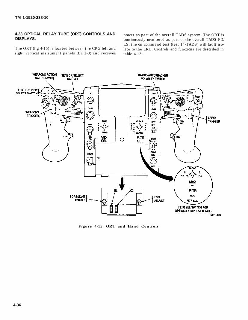
TM 1-1520-238-10
4.23 OPTICAL RELAY TUBE (ORT) CONTROLS AND power as part of the overall TADS system. The ORT isDISPLAYS. continuously monitored as part of the overall TADS FD/
LS; the on command test (test 14-TADS) will fault iso-The ORT (fig 4-15) is located between the CPG left and late to the LRU. Controls and functions are described inright vertical instrument panels (fig 2-8) and receives table 4-12.
Figure 4-15. ORT and Hand Controls
4-36
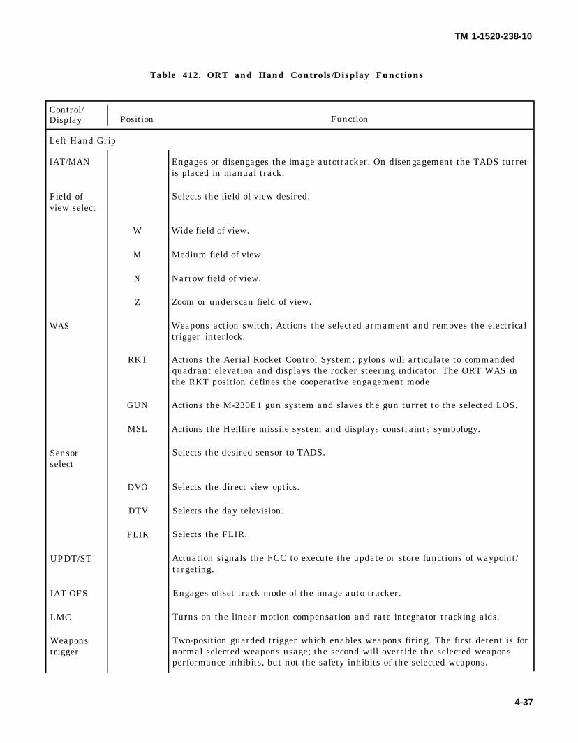
TM 1-1520-238-10
Table 412. ORT and Hand Controls/Display Functions
Control/Display I Position Function
Left Hand Grip
IAT/MAN
Field ofview select
WAS
Sensorselect
UPDT/ST
IAT OFS
LMC
Weaponstrigger
W
M
N
Z
RKT
GUN
MSL
DVO
DTV
FLIR
Engages or disengages the image autotracker. On disengagement the TADS turretis placed in manual track.
Selects the field of view desired.
Wide field of view.
Medium field of view.
Narrow field of view.
Zoom or underscan field of view.
Weapons action switch. Actions the selected armament and removes the electricaltrigger interlock.
Actions the Aerial Rocket Control System; pylons will articulate to commandedquadrant elevation and displays the rocker steering indicator. The ORT WAS inthe RKT position defines the cooperative engagement mode.
Actions the M-230E1 gun system and slaves the gun turret to the selected LOS.
Actions the Hellfire missile system and displays constraints symbology.
Selects the desired sensor to TADS.
Selects the direct view optics.
Selects the day television.
Selects the FLIR.
Actuation signals the FCC to execute the update or store functions of waypoint/targeting.
Engages offset track mode of the image auto tracker.
Turns on the linear motion compensation and rate integrator tracking aids.
Two-position guarded trigger which enables weapons firing. The first detent is fornormal selected weapons usage; the second will override the selected weaponsperformance inhibits, but not the safety inhibits of the selected weapons.
4-37
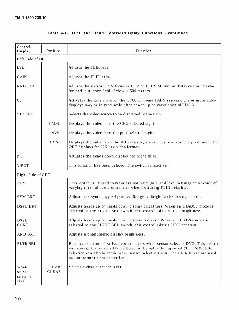
TM 1-1520-238-10
Table 4-12. ORT and Hand Controls/Display Functions - continued
Control/Display I Position Function
Left Side of ORT
LVL
GAIN
RNG FOC
GS
VID SEL
NT
V/RET
TADS
PNVS
IRIS
Right Side of ORT
ACM
SYM BRT
DSPL BRT
DSPLCONT
AND BRT
FLTR SEL
Whensensorselect isDVO
CLEAR/CLEAR
Adjusts the FLIR level.
Adjusts the FLIR gain.
Adjusts the narrow FOV focus in DTV or FLIR. Minimum distance that maybefocused in narrow field of view is 500 meters.
Activates the gray scale for the CPG. On some TADS systems, one or more videodisplays may be in gray scale after power up on completion of FD/LS.
Selects the video source to be displayed to the CPG.
Displays the video from the CPG selected sight.
Displays the video from the pilot selected sight.
Displays the video from the IRIS missile; growth position, currently will mode theORT displays for 525 line video format.
Actuates the heads down display red night filter.
This function has been deleted. The switch is inactive.
This switch is utilized to maintain optimum gain and level settings as a result ofvarying thermal scene content or when switching FLIR polarities.
Adjusts the symbology brightness. Range is: bright white through black.
Adjusts heads up or heads down display brightness. When an IHADSS mode isselected on the SIGHT SEL switch, this control adjusts HDU brightness.
Adjusts heads up or heads down display contrast. When an IHADSS mode isselected on the SIGHT SEL switch, this control adjusts HDU contrast.
Adjusts alphanumeric display brightness.
Permits selection of various optical filters when sensor select is DVO. This switchwill change the various DVO filters. In the optically improved (01) TADS, filterselection can also be made when sensor select is FLIR. The FLIR filters are usedas countermeasures protection.
Selects a clear filter for DVO.
4-38
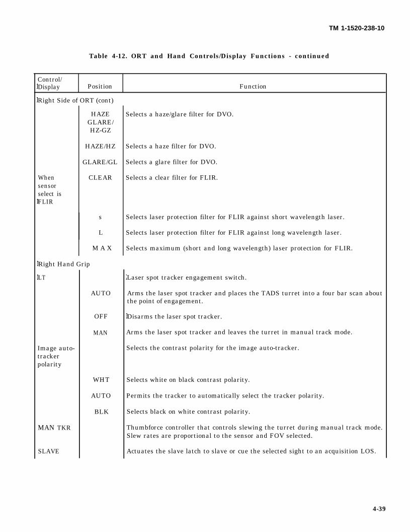
TM 1-1520-238-10
Table 4-12. ORT and Hand Controls/Display Functions - continued
Control/Display Position Function
Right Side of ORT (cont)
Whensensorselect isFLIR
HAZEGLARE/HZ-GZ
HAZE/HZ
GLARE/GL
CLEAR
s
L
M A X
Right Hand Grip
LT
Image auto-trackerpolarity
MAN TKR
SLAVE
AUTO
OFF
MAN
WHT
AUTO
BLK
Selects a haze/glare filter for DVO.
Selects a haze filter for DVO.
Selects a glare filter for DVO.
Selects a clear filter for FLIR.
Selects laser protection filter for FLIR against short wavelength laser.
Selects laser protection filter for FLIR against long wavelength laser.
Selects maximum (short and long wavelength) laser protection for FLIR.
Laser spot tracker engagement switch.
Arms the laser spot tracker and places the TADS turret into a four bar scan aboutthe point of engagement.
Disarms the laser spot tracker.
Arms the laser spot tracker and leaves the turret in manual track mode.
Selects the contrast polarity for the image auto-tracker.
Selects white on black contrast polarity.
Permits the tracker to automatically select the tracker polarity.
Selects black on white contrast polarity.
Thumbforce controller that controls slewing the turret during manual track mode.Slew rates are proportional to the sensor and FOV selected.
Actuates the slave latch to slave or cue the selected sight to an acquisition LOS.
4-39
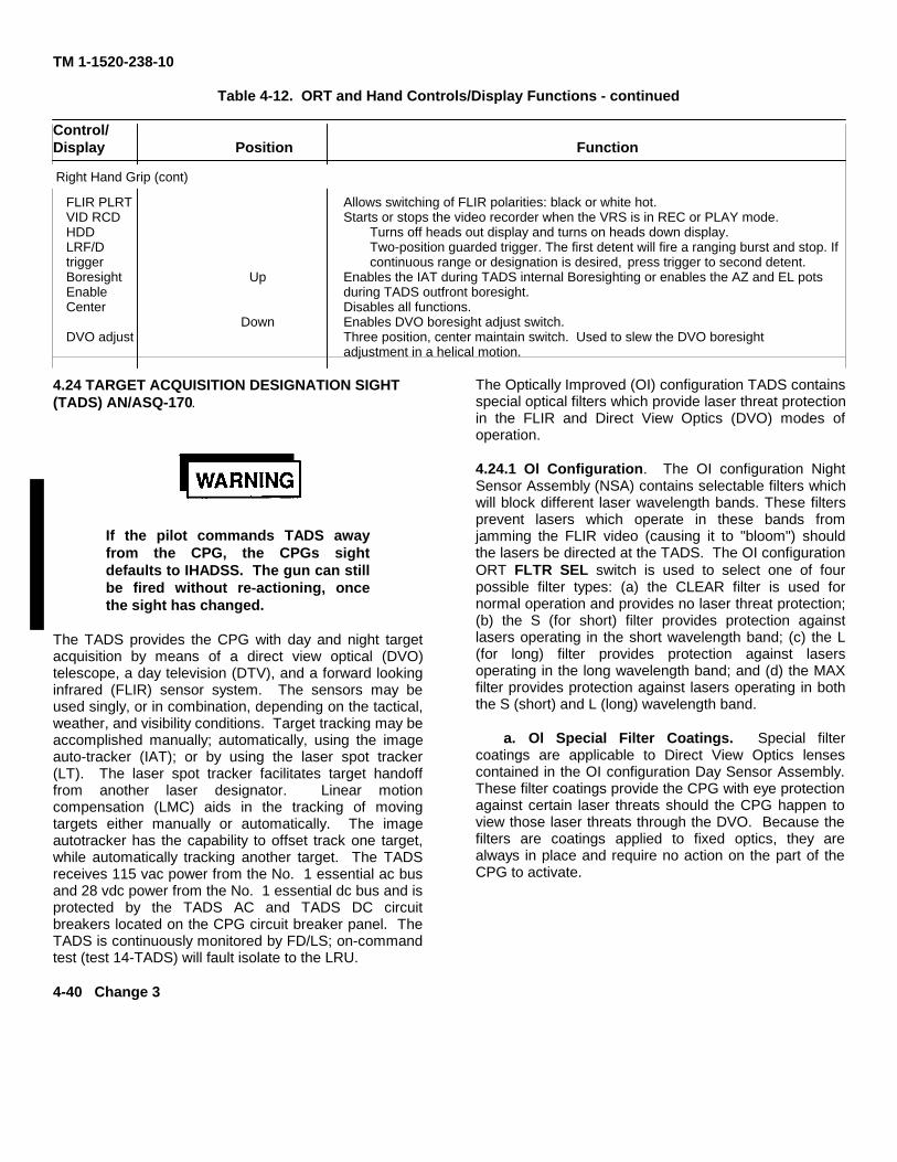
TM 1-1520-238-10
Table 4-12. ORT and Hand Controls/Display Functions - continued
Control/Display Position Function
FLIR PLRT Allows switching of FLIR polarities: black or white hot.VID RCD Starts or stops the video recorder when the VRS is in REC or PLAY mode.HDD Turns off heads out display and turns on heads down display.LRF/D Two-position guarded trigger. The first detent will fire a ranging burst and stop. Iftrigger continuous range or designation is desired, press trigger to second detent.Boresight Up Enables the IAT during TADS internal Boresighting or enables the AZ and EL potsEnable during TADS outfront boresight.Center Disables all functions.
Down Enables DVO boresight adjust switch.DVO adjust Three position, center maintain switch. Used to slew the DVO boresight
adjustment in a helical motion.
4.24 TARGET ACQUISITION DESIGNATION SIGHT(TADS) AN/ASQ-170.
If the pilot commands TADS awayfrom the CPG, the CPGs sightdefaults to IHADSS. The gun can stillbe fired without re-actioning, oncethe sight has changed.
The TADS provides the CPG with day and night targetacquisition by means of a direct view optical (DVO)telescope, a day television (DTV), and a forward lookinginfrared (FLIR) sensor system. The sensors may beused singly, or in combination, depending on the tactical,weather, and visibility conditions. Target tracking may beaccomplished manually; automatically, using the imageauto-tracker (IAT); or by using the laser spot tracker(LT). The laser spot tracker facilitates target handofffrom another laser designator. Linear motioncompensation (LMC) aids in the tracking of movingtargets either manually or automatically. The imageautotracker has the capability to offset track one target,while automatically tracking another target. The TADSreceives 115 vac power from the No. 1 essential ac busand 28 vdc power from the No. 1 essential dc bus and isprotected by the TADS AC and TADS DC circuitbreakers located on the CPG circuit breaker panel. TheTADS is continuously monitored by FD/LS; on-commandtest (test 14-TADS) will fault isolate to the LRU.
The Optically Improved (OI) configuration TADS containsspecial optical filters which provide laser threat protectionin the FLIR and Direct View Optics (DVO) modes ofoperation.
4.24.1 Ol Configuration. The OI configuration NightSensor Assembly (NSA) contains selectable filters whichwill block different laser wavelength bands. These filtersprevent lasers which operate in these bands fromjamming the FLIR video (causing it to "bloom") shouldthe lasers be directed at the TADS. The OI configurationORT FLTR SEL switch is used to select one of fourpossible filter types: (a) the CLEAR filter is used fornormal operation and provides no laser threat protection;(b) the S (for short) filter provides protection againstlasers operating in the short wavelength band; (c) the L(for long) filter provides protection against lasersoperating in the long wavelength band; and (d) the MAXfilter provides protection against lasers operating in boththe S (short) and L (long) wavelength band.
a. Ol Special Filter Coatings. Special filtercoatings are applicable to Direct View Optics lensescontained in the OI configuration Day Sensor Assembly.These filter coatings provide the CPG with eye protectionagainst certain laser threats should the CPG happen toview those laser threats through the DVO. Because thefilters are coatings applied to fixed optics, they arealways in place and require no action on the part of theCPG to activate.
4-40 Change 3
Right Hand Grip (cont)
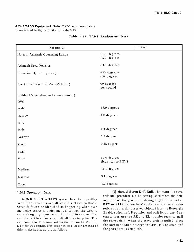
TM 1-1520-238-10
4.24.2 TADS Equipment Data. TADS equipment datais contained in figure 4-16 and table 4-13.
Table 4-13. TADS Equipment Data
Parameter Function
Normal Azimuth Operating Range +120 degrees/-120 degrees
Azimuth Stow Position -180 degrees
Elevation Operating Range +30 degrees/-60 degrees
Maximum Slew Rate (WFOV FLIR) 60 degreesper second
Fields of View (diagonal measurement)
DVO
Wide
Narrow
DTV
Wide
Narrow
Zoom
FLIR
Wide 50.0 degrees(identical to PNVS)
Medium 10.0 degrees
Narrow 3.1 degrees
Zoom 1.6 degrees
4.24.3 Operation Data. (1) Manual Servo Drift Null. The manual servo
18.0 degrees
4.0 degrees
4.0 degrees
0.9 degree
0.45 degree
a. Drift Null. The TADS system has the capabilityto null the turret servo drift by either of two methods.Servo drift can be identified as happening when everthe TADS turret is under manual control, the CPG isnot making any inputs with the thumbforce controllerand the reticle appears to drift off the aim point. Theaim point should remain within the narrow FOV of theDTV for 30-seconds. If it does not, or a lesser amount ofdrift is desirable, adjust as follows:
drift null procedure can be accomplished when the heli-copter is on the ground or during flight. First, selectDTV or FLIR narrow FOV as the sensor; then aim thereticle at an easily observed object. Place the BoresightEnable switch in UP position and wait for at least 5 se-conds; then use the AZ and EL thumbwheels to nullthe turret drift. When the servo drift is nulled, placethe Boresight Enable switch in CENTER position andthe procedure is complete.
4-41
TM 1-1520-238-10(2) Auto Drift Null. Auto drift null is active from the
time the TADS is first turned on. The only time it isinactive is when the manual servo drift null procedurehas been accomplished. If the manual procedure wasaccomplished, the auto drift null can be reactivated byplacing the Boresight Enable switch in UP position for 2seconds and then placing it back to CENTER position.Auto drift is not as precise as the manual procedure sosome residual servo drift will always be present when it isactive.
The narrow and zoom FOV TADSFLIR imagery has inaccuracies forlasing or weapons direction followingTADS internal boresight. TADSoutfront boresight validation andadjustment (if necessary) shall beperformed prior to using the TADSFLIR imagery for laser or weaponsoperations.
b. Boresight. Boresight procedures consist of cueupdate, internal boresight, outfront boresight, andmanual boresight.
(1) Cue Update. Performance of cue updateensures that the TADS turret is in proper position relativeto the boresight assembly prior to firing the laser forinternal boresight. If cue update is adjusted, outfrontboresight must be performed following the cue update.Cue update procedure is contained in paragraph4.31.7.a.
(2) Internal Boresight. Performance of internalboresight aligns DTV and FLIR to laser LOS and DVO toDTV LOS. Internal boresight shall be performed as partof preflight procedures prior to any firing of laser orweapons when TADS is used as imaging sensor.Internal boresight can also be performed in flight toensure boresight accuracy without requiring. outfrontboresight as a follow-up. Internal boresight procedure iscontained in paragraph 4.31.7.b.
(3) Outfront Boresight. Performance of outfrontboresight ensures FLIR LOS is in coincidence with laserLOS. Outfront boresight shall be checked as part ofpreflight procedures prior to any firing of laser orweapons when TADS FLIR is used as the imagingsensor. Outfront boresight must be performed after acue update adjustment. Target requirements for theoutfront boresight procedure are as follows:
(a) A target a minimum of 0.5 km away from thehelicopter is required. Target must be clearly visible andtrackable through both FLIR and TV sensor NFOV.Target must have the same center as viewed in bothFLIR and TV sensors.
(b) Outfront boresight procedure is contained inparagraph 4.31.7 c.
(4) Manual Boresight. The manual boresightprocedure is used only to recapture or center the FLIRlaser spot. It is not an acceptable boresight procedurefor normal flight operations. Manual boresight procedureis contained in paragraph 4.31.7 d.
4.25 PILOT NIGHT VISION SENSOR (PNVS) AN/AAQ-11.
IFF transmission on the upperantenna may cause the PNVS to slewtoward the fixed forward position andthen back to LOS. If this occurs, turnthe Transponder off or use the lowerantenna only duringnight NOE PNVSoperation.
The PNVS is used by the pilot for externally aided visionat night or during adverse weather. The PNVS consistsof a stabilized FLIR contained in a rotating turretmounted above the TADS (fig 4-16). Refer to table 4-14for PNVS equipment data. When selected, the turret isslaved to the crewmember helmet LOS. This isaccomplished using the IHADSS which also presents theFLIR image and symbology video to the crewmember onthe HMD. The PNVS image and symbology can bedisplayed on any of the displays in the helicopter throughuse of the VID SEL switch. Control of the PNVS turret isgoverned by the SIGHT SEL switch. Normal operationcalls for the pilot to have priority control of the PNVSturret; however, in the event the pilot becomesincapacitated, the CPG may take control of the PNVSthrough use of the PLT/GND ORIDE switch, the SIGHTSEL switch, and the collective NVS switch. Fourdegraded modes of operation exist when using thePNVS. In two of the degraded modes corrective actionby the fire control system occurs automatically. Theremaining two require pilot corrective action. In alldegraded modes there will be a loss of some operationalcapability, as described in paragraphs thru 4.25.5.
442 Change 3
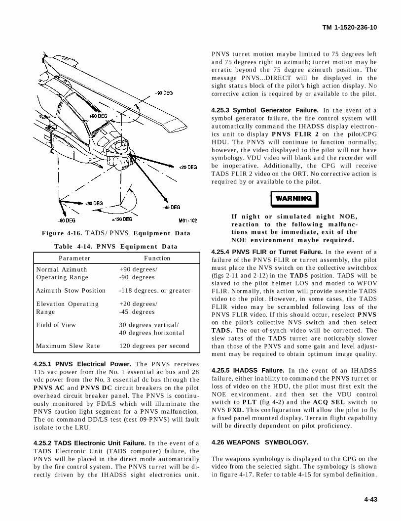
WARNING
TM 1-1520-236-10
PNVS turret motion maybe limited to 75 degrees left
Figure 4-16. TADS/PNVS Equipment Data
Table 4-14. PNVS Equipment Data
Parameter Function
Normal Azimuth +90 degrees/Operating Range -90 degrees
Azimuth Stow Position -118 degrees. or greater
Elevation Operating +20 degrees/Range -45 degrees
Field of View 30 degrees vertical/40 degrees horizontal
Maximum Slew Rate 120 degrees per second
4.25.1 PNVS Electrical Power. The PNVS receives115 vac power from the No. 1 essential ac bus and 28vdc power from the No. 3 essential dc bus through thePNVS AC and PNVS DC circuit breakers on the pilotoverhead circuit breaker panel. The PNVS is continu-ously monitored by FD/LS which will illuminate thePNVS caution light segment for a PNVS malfunction.The on command DD/LS test (test 09-PNVS) will faultisolate to the LRU.
4.25.2 TADS Electronic Unit Failure. In the event of aTADS Electronic Unit (TADS computer) failure, thePNVS will be placed in the direct mode automaticallyby the fire control system. The PNVS turret will be di-rectly driven by the IHADSS sight electronics unit.
and 75 degrees right in azimuth; turret motion may beerratic beyond the 75 degree azimuth position. Themessage PNVS...DIRECT will be displayed in thesight status block of the pilot’s high action display. Nocorrective action is required by or available to the pilot.
4.25.3 Symbol Generator Failure. In the event of asymbol generator failure, the fire control system willautomatically command the IHADSS display electron-ics unit to display PNVS FLIR 2 on the pilot/CPGHDU. The PNVS will continue to function normally;however, the video displayed to the pilot will not havesymbology. VDU video will blank and the recorder willbe inoperative. Additionally, the CPG will receiveTADS FLIR 2 video on the ORT. No corrective action isrequired by or available to the pilot.
If night or simulated night NOE,reaction to the following malfunc-tions must be immediate, exit of theNOE environment maybe required.
4.25.4 PNVS FLIR or Turret Failure. In the event of afailure of the PNVS FLIR or turret assembly, the pilotmust place the NVS switch on the collective switchbox(figs 2-11 and 2-12) in the TADS position. TADS will beslaved to the pilot helmet LOS and moded to WFOVFLIR. Normally, this action will provide useable TADSvideo to the pilot. However, in some cases, the TADSFLIR video may be scrambled following loss of thePNVS FLIR video. If this should occur, reselect PNVSon the pilot’s collective NVS switch and then selectTADS. The out-of-synch video will be corrected. Theslew rates of the TADS turret are noticeably slowerthan those of the PNVS and some gain and level adjust-ment may be required to obtain optimum image quality.
4.25.5 IHADSS Failure. In the event of an IHADSSfailure, either inability to command the PNVS turret orloss of video on the HDU, the pilot must first exit theNOE environment. and then set the VDU controlswitch to PLT (fig 4-2) and the ACQ SEL switch toNVS FXD. This configuration will allow the pilot to flya fixed panel mounted display. Terrain flight capabilitywill be directly dependent on pilot proficiency.
4.26 WEAPONS SYMBOLOGY.
The weapons symbology is displayed to the CPG on thevideo from the selected sight. The symbology is shownin figure 4-17. Refer to table 4-15 for symbol definition.
4-43
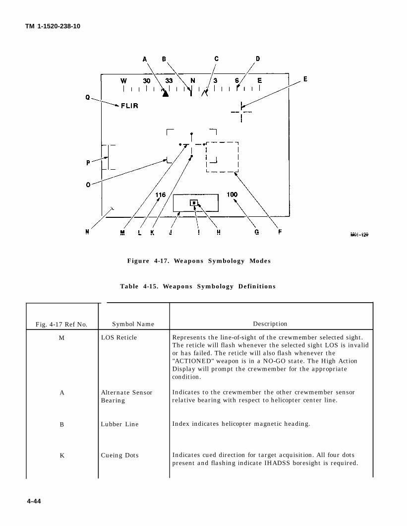
TM 1-1520-238-10
Fig. 4-17 Ref No.
M
A
B
K
Figure 4-17. Weapons Symbology Modes
Table 4-15. Weapons Symbology Definitions
Symbol Name
LOS Reticle
Alternate SensorBearing
Lubber Line
Cueing Dots
Description
Represents the line-of-sight of the crewmember selected sight.The reticle will flash whenever the selected sight LOS is invalidor has failed. The reticle will also flash whenever the"ACTIONED" weapon is in a NO-GO state. The High ActionDisplay will prompt the crewmember for the appropriatecondition.
Indicates to the crewmember the other crewmember sensorrelative bearing with respect to helicopter center line.
Index indicates helicopter magnetic heading.
Indicates cued direction for target acquisition. All four dotspresent and flashing indicate IHADSS boresight is required.
4-44
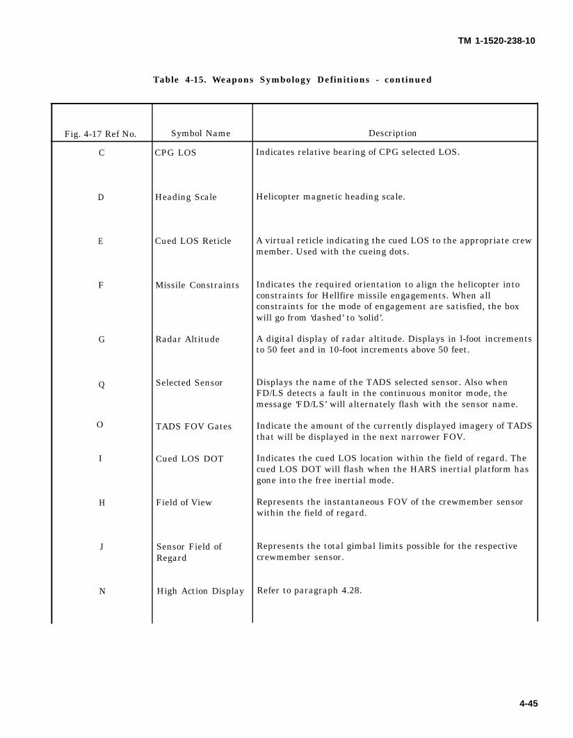
TM 1-1520-238-10
Table 4-15. Weapons Symbology Definitions - continued
Fig. 4-17 Ref No.
C
D
E
F
G
Q
O
I
H
J
N
Symbol Name
CPG LOS
Heading Scale
Cued LOS Reticle
Missile Constraints
Radar Altitude
Selected Sensor
TADS FOV Gates
Cued LOS DOT
Field of View
Sensor Field ofRegard
High Action Display
Description
Indicates relative bearing of CPG selected LOS.
Helicopter magnetic heading scale.
A virtual reticle indicating the cued LOS to the appropriate crewmember. Used with the cueing dots.
Indicates the required orientation to align the helicopter intoconstraints for Hellfire missile engagements. When allconstraints for the mode of engagement are satisfied, the boxwill go from ‘dashed’ to ‘solid’.
A digital display of radar altitude. Displays in l-foot incrementsto 50 feet and in 10-foot increments above 50 feet.
Displays the name of the TADS selected sensor. Also whenFD/LS detects a fault in the continuous monitor mode, themessage ‘FD/LS’ will alternately flash with the sensor name.
Indicate the amount of the currently displayed imagery of TADSthat will be displayed in the next narrower FOV.
Indicates the cued LOS location within the field of regard. Thecued LOS DOT will flash when the HARS inertial platform hasgone into the free inertial mode.
Represents the instantaneous FOV of the crewmember sensorwithin the field of regard.
Represents the total gimbal limits possible for the respectivecrewmember sensor.
Refer to paragraph 4.28.
4-45

TM 1-1520-238-10
L
Table 4-15. Weapons Symbology Definitions - oontinued
Fig. 4-17 Ref No. Symbol Name Description
P Rocket Steering Indicates the required orientation to align the helicopter intoCursor constraints for 2.75 inch FFAR rocket engagements. During
fixed or flight stow rocket delivery, a broken I beam will appear.
Airspeed A digital display of true airspeed when the ADSS is turned on ornot failed. If the ADSS is OFF or failed, display is ground speedin knots from the doppler navigation system. Range is 0 to 200,omnidirectional.
4..27 FIRE CONTROL SYSTEM MESSAGES. prompts are displayed in the high action display (HAD)
The fire control system displays to the crewmembersor the alphanumerical display (AND) contained in theTADS ORT.
messages and prompts for management of the subsys-tems on board the helicopter. The messages and
4-46
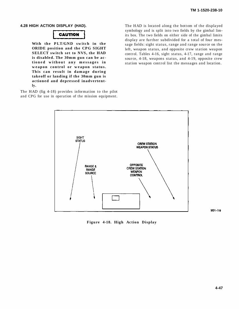
CAUTION
TM 1-1520-238-10
4.28 HIGH ACTION DISPLAY (HAD).
With the PLT/GND switch in theORIDE position and the CPG SIGHTSELECT switch set to NVS, the HADis disabled. The 30mm gun can be ac-tioned without any messages inweapon control or weapon status.This can result in damage duringtakeoff or landing if the 30mm gun isactioned and depressed inadvertent-ly.
The HAD (fig 4-18) provides information to the pilotand CPG for use in operation of the mission equipment.
The HAD is located along the bottom of the displayedsymbology and is split into two fields by the gimbal lim-its box. The two fields on either side of the gimbal limitsdisplay are further subdivided for a total of four mes-sage fields: sight status, range and range source on theleft, weapon status, and opposite crew station weaponcontrol. Tables 4-16, sight status, 4-17, range and rangesource, 4-18, weapons status, and 4-19, opposite crewstation weapon control list the messages and location.
Figure 4-18. High Action Display
4-47
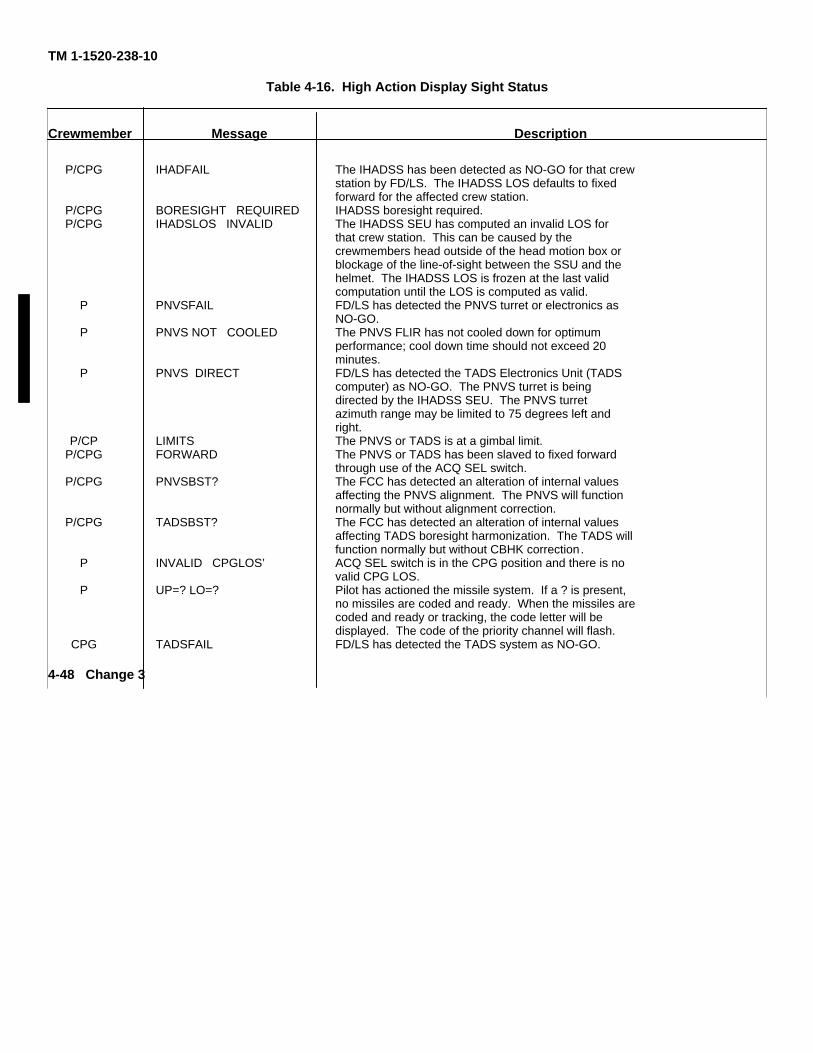
TM 1-1520-238-10
Table 4-16. High Action Display Sight Status
Crewmember Message Description
P/CPG IHADFAIL The IHADSS has been detected as NO-GO for that crewstation by FD/LS. The IHADSS LOS defaults to fixedforward for the affected crew station.
P/CPG BORESIGHT REQUIRED IHADSS boresight required.P/CPG IHADSLOS INVALID The IHADSS SEU has computed an invalid LOS for
that crew station. This can be caused by thecrewmembers head outside of the head motion box orblockage of the line-of-sight between the SSU and thehelmet. The IHADSS LOS is frozen at the last validcomputation until the LOS is computed as valid.
P PNVSFAIL FD/LS has detected the PNVS turret or electronics asNO-GO.
P PNVS NOT COOLED The PNVS FLIR has not cooled down for optimumperformance; cool down time should not exceed 20minutes.
P PNVS DIRECT FD/LS has detected the TADS Electronics Unit (TADScomputer) as NO-GO. The PNVS turret is beingdirected by the IHADSS SEU. The PNVS turretazimuth range may be limited to 75 degrees left andright.
P/CP LIMITS The PNVS or TADS is at a gimbal limit.P/CPG FORWARD The PNVS or TADS has been slaved to fixed forward
through use of the ACQ SEL switch.P/CPG PNVSBST? The FCC has detected an alteration of internal values
affecting the PNVS alignment. The PNVS will functionnormally but without alignment correction.
P/CPG TADSBST? The FCC has detected an alteration of internal valuesaffecting TADS boresight harmonization. The TADS willfunction normally but without CBHK correction.
P INVALID CPGLOS’ ACQ SEL switch is in the CPG position and there is novalid CPG LOS.
P UP=? LO=? Pilot has actioned the missile system. If a ? is present,no missiles are coded and ready. When the missiles arecoded and ready or tracking, the code letter will bedisplayed. The code of the priority channel will flash.
CPG TADSFAIL FD/LS has detected the TADS system as NO-GO.
4-48 Change 3
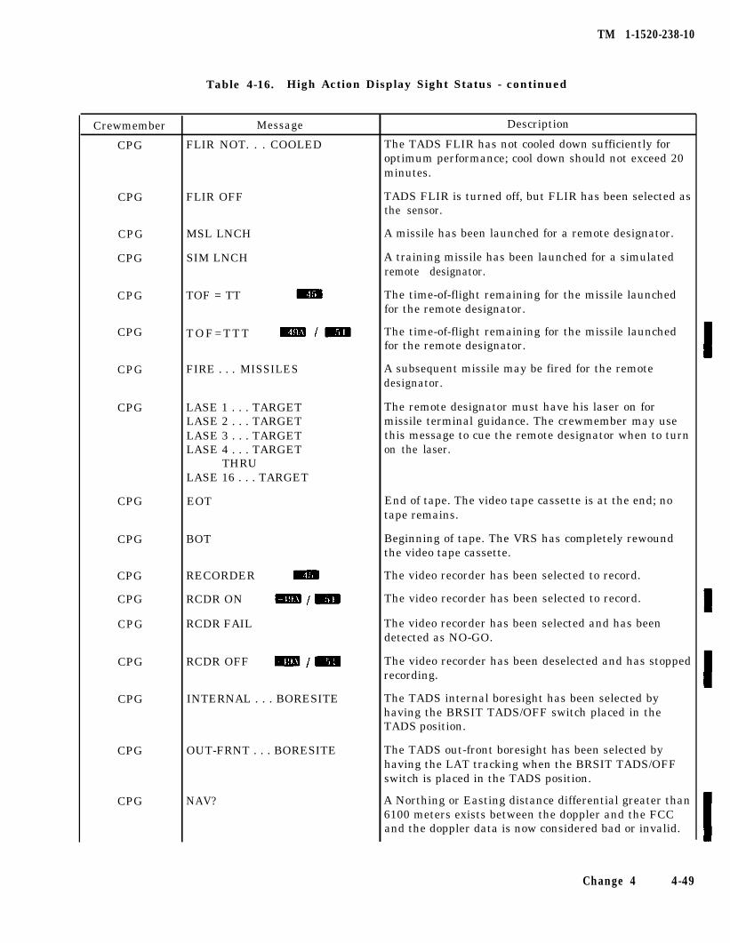
TM 1-1520-238-10
Table 4-16. High Action Display Sight Status - continued
Crewmember
CPG
CPG
CPG
CPG
CPG
CPG
CPG
CPG
CPG
CPG
CPG
CPG
CPG
CPG
CPG
CPG
CPG
Message
FLIR NOT. . . COOLED
FLIR OFF
MSL LNCH
SIM LNCH
TOF = TT
TOF=TTT
FIRE . . . MISSILES
LASE 1 . . . TARGETLASE 2 . . . TARGETLASE 3 . . . TARGETLASE 4 . . . TARGET
THRULASE 16 . . . TARGET
EOT
BOT
RECORDER
RCDR ON
RCDR FAIL
RCDR OFF
INTERNAL . . . BORESITE
OUT-FRNT . . . BORESITE
NAV?
Description
The TADS FLIR has not cooled down sufficiently foroptimum performance; cool down should not exceed 20minutes.
TADS FLIR is turned off, but FLIR has been selected asthe sensor.
A missile has been launched for a remote designator.
A training missile has been launched for a simulatedremote designator.
The time-of-flight remaining for the missile launchedfor the remote designator.
The time-of-flight remaining for the missile launchedfor the remote designator.
A subsequent missile may be fired for the remotedesignator.
The remote designator must have his laser on formissile terminal guidance. The crewmember may usethis message to cue the remote designator when to turnon the laser.
End of tape. The video tape cassette is at the end; notape remains.
Beginning of tape. The VRS has completely rewoundthe video tape cassette.
The video recorder has been selected to record.
The video recorder has been selected to record.
The video recorder has been selected and has beendetected as NO-GO.
The video recorder has been deselected and has stoppedrecording.
The TADS internal boresight has been selected byhaving the BRSIT TADS/OFF switch placed in theTADS position.
The TADS out-front boresight has been selected byhaving the LAT tracking when the BRSIT TADS/OFFswitch is placed in the TADS position.
A Northing or Easting distance differential greater than6100 meters exists between the doppler and the FCCand the doppler data is now considered bad or invalid.
Change 4 4-49
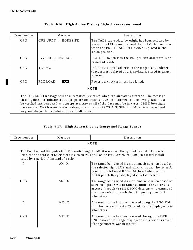
TM 1-1520-238-10
4-50 Change 6
Table 4-16. High Action Display Sight Status -- continued
Crewmember DescriptionMessage
CPG CUE UPDT . . . BORESITE The TADS cue update boresight has been selected byhaving the IAT in manual and the SLAVE latched Lowwhen the BRSIT TADS/OFF switch is placed in theTADS position.
CPG INVALID . . . PLT LOS ACQ SEL switch is in the PLT position and there is novalid PLT LOS.
CPG TGT = X Indicates selected address in the target NAV indexer(0-9). If X is replaced by a ?, no data is stored in targetlocation.
CPG FCC LOAD Power up, checksum test has failed.
NOTE
The FCC LOAD message will be automatically cleared when the aircraft is airborne. The messageclearing does not indicate that appropriate corrections have been entered. The following data mustbe verified and corrected as appropriate. Any or all of the data may be in error: CBHK boresightparameters, AWS harmonization values, aircraft data (PPOS ALT, SPH and MV), laser codes, andwaypoint/target latitude/longitude and altitudes.
Table 4-17. High Action Display Range and Range Source
Crewmember Message Description
NOTE
The Fire Control Computer (FCC) is controlling the MUX whenever the symbol located between Ki-lometers and tenths of Kilometers is a colon (:). The Backup Bus Controller (BBC) in control is indi-cated by a period (.) instead of a colon.
P AX . X The range being used is an automatic solution based onthe selected sight LOS and radar altitude. The letter Ais set in the leftmost RNG-KM thumbwheel on theARCS panel. Range displayed is in kilometers.
CPG AX . X The range being used is an automatic solution based onselected sight LOS and radar altitude. The value 0 isentered through the DEK RNG data entry to commandthe automatic range solution. Range displayed is inkilometers.
P MX . X A manual range has been entered using the RNG-KMthumbwheels on the ARCS panel. Range displayed is inkilometers.
CPG MX . X A manual range has been entered through the DEKRNG data entry. Range displayed is in kilometers evenif range entered was in meters.
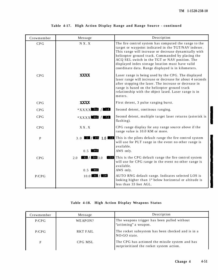
TM 1-1520-238-10
Table 4-17. High Action Display Range and Range Source - continued
Crewmember
CPG
CPG
CPG
CPG
CPG
CPG
P
CPG
P/CPG
Crewmember
P/CPG
Message
WEAPON?
P/CPG RKT FAIL
P CPG MSL
Message
N X . X
*XXXX
*XXXX
X X . X
3.0
0.5
2.0 3.0
0.5
10.0
Description
The fire control system has computed the range to thetarget or waypoint indicated in the TGT/NAV indexer.This range will increase or decrease dynamically withhelicopter ground track. Commanded by placing theACQ SEL switch in the TGT or NAV position. Thedisplayed index storage location must have validcoordinate data. Range displayed is in kilometers.
Laser range is being used by the CPG. The displayedlaser range will increase or decrease for about 4 secondsafter stopping the laser. The increase or decrease inrange is based on the helicopter ground trackrelationship with the object lased. Laser range is inmeters.
First detent, 3 pulse ranging burst.
Second detent, continous ranging.
Second detent, multiple target laser returns (asterisk isflashing).
CPG range display for any range source above if therange value is 10.0 KM or more.
This is the pilots default range the fire control systemwill use for PLT range in the event no other range isavailable.AWS only.
This is the CPG default range the fire control systemwill use for CPG range in the event no other range isavailable.AWS only.
AUTO RNG default range. Indicates selected LOS islooking higher than 1° below horizontal or altitude isless than 33 feet AGL.
Table 4-18. High Action Display Weapons Status
Description
The weapons trigger has been pulled without“actioning” a weapon.
The rocket subsystem has been checked and is in aNO-GO state.
The CPG has actioned the missile system and hasoutprioritized the rocket system action.
Change 4 4-51
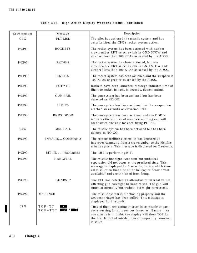
TM 1-1520-238-10
Table 4-18. High Action Display Weapons Status - continued
Crewmember
CPG
P/CPG
P/CPG
P/CPG
P/CPG
P/CPG
P/CPG
P/CPG
CPG
P/CPG
P/CPG
P/CPG
P/CPG
P/CPG
CPG
Message
PLT MSL
ROCKETS
RKT-G-S
RKT-F-S
TOF=TT
GUN FAIL
LIMITS
RNDS DDDD
MSL FAIL
INVALID... COMMAND
BIT IN. . . PROGRESS
HANGFIRE
GUNBST?
MSL LNCH
T O F = T TT O F = T T T
Description
The pilot has actioned the missile system and hasoutprioritized the CPG’s rocket system action.
The rocket system has been actioned with neithercrewmember RKT select switch in GND STOW andairspeed less than 100 KTAS as sensed by the ADSS.
The rocket system has been actioned, but onecrewmember RKT select switch in GND STOW andairspeed less than 100 KTAS as sensed by the ADSS.
The rocket system has been actioned and the airspeed is100 KTAS or greater as sensed by the ADSS.
Rockets have been launched. Message indicates time offlight to rocket impact, in seconds, decrementing.
The gun system has been actioned but has beendetected as NO-GO.
The gun system has been actioned but the weapon hasreached an azimuth or elevation limit.
The gun system has been actioned and the DDDDindicates the number of rounds remaining and willcount down one unit for each firing PULSE.
The missile system has been actioned but has beendeleted as NO-GO.
The remote Hellfire electronics has detected animproper command from a crewmember to the Hellfiremissile system. This message is displayed for 2 seconds.
The RHE is performing BIT.
The missile fire signal was sent but umbilicalseparation did not occur at the predicted time. Thismessage is displayed for 6 seconds, during which timeall missiles on that side of the helicopter become “notavailable” and are inhibited from firing.
The FCC has detected an alteration of internal valuesaffecting gun boresight harmonization. The gun willfunction normally but without boresight corrections.
The missile system is functioning properly and theweapons trigger has been pulled. This message isdisplayed for 2 seconds.
Time of flight remaining in seconds to missile impact,decrementing for autonomous launches. If more thanone missile is in flight, the display will show TOF forthe first launched missle, then subsequently launchedmissiles.
4-52 Change 4
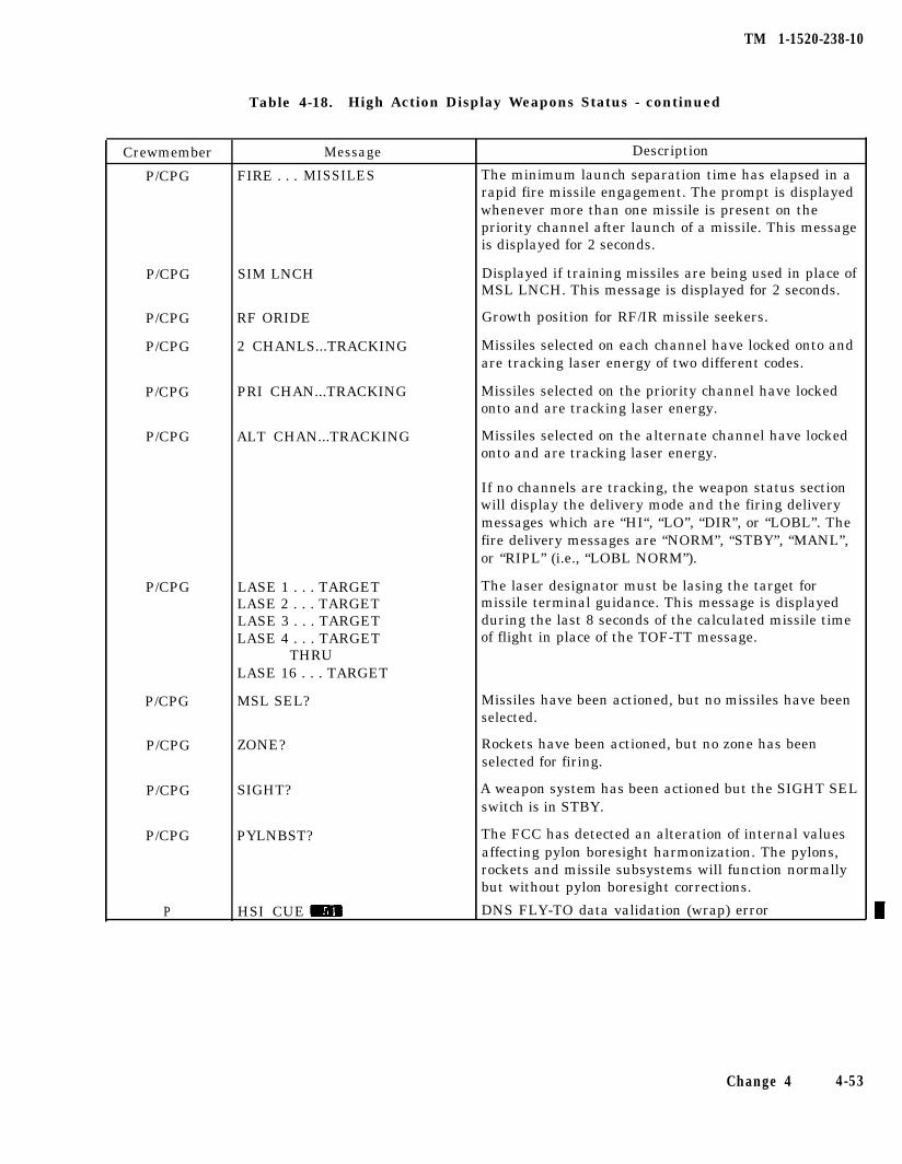
TM 1-1520-238-10
Table 4-18. High Action Display Weapons Status - continued
Crewmember Message Description
P/CPG FIRE . . . MISSILES The minimum launch separation time has elapsed in arapid fire missile engagement. The prompt is displayedwhenever more than one missile is present on thepriority channel after launch of a missile. This messageis displayed for 2 seconds.
P/CPG SIM LNCH Displayed if training missiles are being used in place ofMSL LNCH. This message is displayed for 2 seconds.
P/CPG
P/CPG
RF ORIDE
2 CHANLS...TRACKING
Growth position for RF/IR missile seekers.
Missiles selected on each channel have locked onto andare tracking laser energy of two different codes.
P/CPG PRI CHAN...TRACKING Missiles selected on the priority channel have lockedonto and are tracking laser energy.
P/CPG ALT CHAN...TRACKING Missiles selected on the alternate channel have lockedonto and are tracking laser energy.
If no channels are tracking, the weapon status sectionwill display the delivery mode and the firing deliverymessages which are “HI“, “LO”, “DIR”, or “LOBL”. Thefire delivery messages are “NORM”, “STBY”, “MANL”,or “RIPL” (i.e., “LOBL NORM”).
P/CPG LASE 1 . . . TARGETLASE 2 . . . TARGETLASE 3 . . . TARGETLASE 4 . . . TARGET
THRULASE 16 . . . TARGET
The laser designator must be lasing the target formissile terminal guidance. This message is displayedduring the last 8 seconds of the calculated missile timeof flight in place of the TOF-TT message.
P/CPG MSL SEL? Missiles have been actioned, but no missiles have beenselected.
P/CPG ZONE? Rockets have been actioned, but no zone has beenselected for firing.
P/CPG SIGHT? A weapon system has been actioned but the SIGHT SELswitch is in STBY.
P/CPG
P
PYLNBST?
HSI CUE
The FCC has detected an alteration of internal valuesaffecting pylon boresight harmonization. The pylons,rockets and missile subsystems will function normallybut without pylon boresight corrections.
DNS FLY-TO data validation (wrap) error
Change 4 4-53
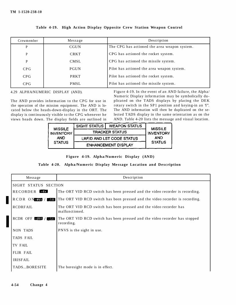
TM 1-1520-238-10
Table 4-19. High Action Display Opposite Crew Station Weapon Control
Crewmember Message Description
P
P
P
CPG
CPG
CPG
CGUN
CRKT
CMSL
PGUN
PRKT
PMSL
The CPG has actioned the area weapon system.
CPG has actioned the rocket system.
CPG has actioned the missile system.
Pilot has actioned the area weapon system.
Pilot has actioned the rocket system.
Pilot has actioned the missile system.
4.29 ALPHA/NUMERIC DISPLAY (AND). Figure 4-19. In the event of an AND failure, the Alpha/Numeric Display information may be symbolically du-
The AND provides information to the CPG for use in plicated on the TADS displays by placing the DEKthe operation of the mission equipment. The AND is lo- rotary switch in the SP1 position and keying-in an ‘I”.cated below the heads-down-display in the ORT. The The AND information will then be duplicated on the se-display is continuously visible to the CPG whenever he lected TADS display in the same orientation as on theviews heads down. The display fields are outlined in AND. Table 4-20 lists the message and visual location.
Figure 4-19. Alpha/Numeric Display (AND)
Table 4-20. Alpha/Numeric Display Message Location and Description
Message Description
SIGHT STATUS SECTION
RECORDER
R C D R O N
RCDRFAIL
RCDR OFF
NON TADS
TADS FAIL
TV FAIL
FLIR FAIL
IRISFAIL
TADS...BORESITE
4-54 Change 4
The ORT VID RCD switch has been pressed and the video recorder is recording.
The ORT VID RCD switch has been pressed and the video recorder is recording.
The ORT VID RCD switch has been pressed and the video recorder hasmalfunctioned.
The ORT VID RCD switch has been pressed and the video recorder has stoppedrecording.
PNVS is the sight in use.
The boresight mode is in effect.
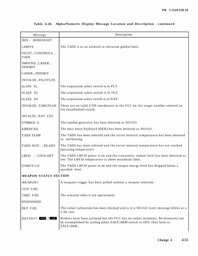
TM 1-1520-238-10
Table 4-20. Alpha/Numeric Display Message Location and Description - continued
Message
IRIS.. .BORESIGHT
LIMITS
PILOT...CONTROLS...TADS
IMPEND...LASER...INHIBIT
LASER...INHIBIT
INVALID...PILOTLOS
SLAVE PL
SLAVE TG
SLAVE NV
INVALID...TARGTLOS
INVALID...NAV LOS
SYMBOL G
KBRDFAIL
TADS TEMP
TADS NOT. . READY
LRFD . . . COOLANT
ENRGY LO
WEAPON STATUS
Description
The TADS is at an azimuth or elevation gimbal limit.
The acquisition select switch is in PLT.
The acquisition select switch is in TGT.
The acquisition select switch is in NAV.
There are no valid UTM coordinates in the FCC for the target number selected onthe thumbwheel switch.
The symbol generator has been detected as NO-GO.
The data entry keyboard (DEK) has been detected as NO-GO.
The TADS has been selected and the turret internal temperature has been detectedas overheating.
The TADS has been selected and the turret internal temperature has not reachedoperating temperature.
The TADS LRF/D power is on and the transceiver coolant level has been detected aslow. The LRF/D temperature is above maximum limit.
The TADS LRF/D power is on and the output energy level has dropped below aspecified level.
SECTION
WEAPON?
GUN FAIL
TADS FAIL
RNDSDDDD
RKT FAIL
RKTINV?
A weapons trigger has been pulled without a weapon selection.
The selected video is not operational.
The rocket subsystem has been checked and is in a NO-GO state; message blinks at a2 Hz rate.
Rockets have been actioned but the FCC has no rocket inventory. Re-inventory canbe accomplished by cycling pilots SAFE/ARM switch to OFF, then back toSAFE/ARM.
Change 4 4-55
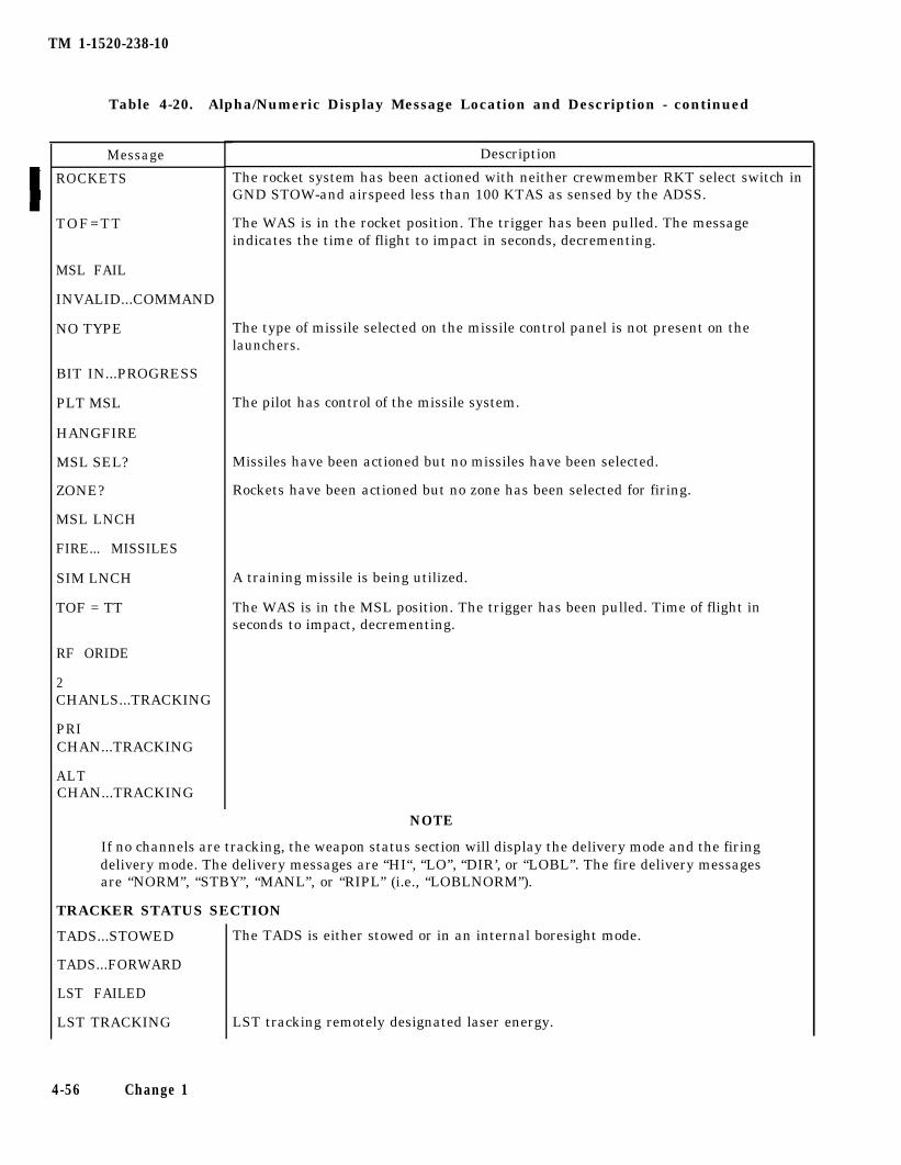
TM 1-1520-238-10
Table 4-20. Alpha/Numeric Display Message Location and Description - continued
Message
ROCKETS
TOF=TT
MSL FAIL
INVALID...COMMAND
NO TYPE
BIT IN...PROGRESS
PLT MSL
HANGFIRE
MSL SEL?
ZONE?
MSL LNCH
FIRE... MISSILES
SIM LNCH
TOF = TT
RF ORIDE
2CHANLS...TRACKING
PRICHAN...TRACKING
ALTCHAN...TRACKING
Description
The rocket system has been actioned with neither crewmember RKT select switch inGND STOW-and airspeed less than 100 KTAS as sensed by the ADSS.
The WAS is in the rocket position. The trigger has been pulled. The messageindicates the time of flight to impact in seconds, decrementing.
The type of missile selected on the missile control panel is not present on thelaunchers.
The pilot has control of the missile system.
Missiles have been actioned but no missiles have been selected.
Rockets have been actioned but no zone has been selected for firing.
A training missile is being utilized.
The WAS is in the MSL position. The trigger has been pulled. Time of flight inseconds to impact, decrementing.
NOTE
If no channels are tracking, the weapon status section will display the delivery mode and the firingdelivery mode. The delivery messages are “HI“, “LO”, “DIR’, or “LOBL”. The fire delivery messagesare “NORM”, “STBY”, “MANL”, or “RIPL” (i.e., “LOBLNORM”).
TRACKER STATUS SECTION
TADS...STOWED
TADS...FORWARD
LST FAILED
LST TRACKING
The TADS is either stowed or in an internal boresight mode.
LST tracking remotely designated laser energy.
4-56 Change 1
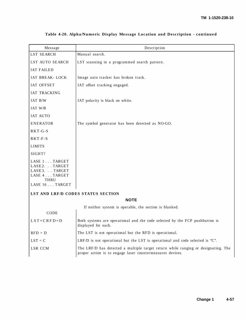
TM 1-1520-238-10
Table 4-20. Alpha/Numeric Display Message Location and Description - continued
Message
LST SEARCH
LST AUTO SEARCH
IAT FAILED
IAT BREAK- LOCK
IAT OFFSET
IAT TRACKING
IAT B/W
IAT W/B
IAT AUTO
ENERATOR
RKT-G-S
RKT-F-S
LIMITS
SIGHT?
LASE 1 . . . TARGETLASE2. . . TARGETLASE3. . . TARGETLASE 4 . . . TARGET
THRULASE 16 . . . TARGET
Description
Manual search.
LST scanning in a programmed search pattern.
Image auto tracker has broken track.
IAT offset tracking engaged.
IAT polarity is black on white.
The symbol generator has been detected as NO-GO.
LST AND LRF/D CODES STATUS SECTION
CODE
LST=CRFD=D
RFD = D
LST = C
LSR CCM
NOTE
If neither system is operable, the section is blanked.
Both systems are operational and the code selected by the FCP pushbutton isdisplayed for each.
The LST is not operational but the RFD is operational.
LRF/D is not operational but the LST is operational and code selected is “C”.
The LRF/D has detected a multiple target return while ranging or designating. Theproper action is to engage laser countermeasures devices.
Change 1 4-57
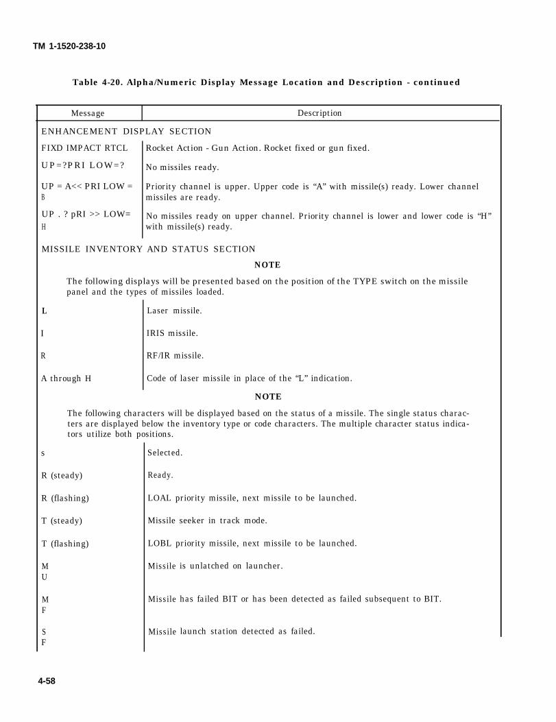
TM 1-1520-238-10
Table 4-20. Alpha/Numeric Display Message Location and Description - continued
Message Description
ENHANCEMENT DISPLAY SECTION
FIXD IMPACT RTCL
UP=?PRI LOW=?
UP = A<< PRI LOW =B
UP . ? pRI >> LOW=H
Rocket Action - Gun Action. Rocket fixed or gun fixed.
No missiles ready.
Priority channel is upper. Upper code is “A” with missile(s) ready. Lower channelmissiles are ready.
No missiles ready on upper channel. Priority channel is lower and lower code is “H”with missile(s) ready.
MISSILE INVENTORY AND STATUS SECTION
NOTE
The following displays will be presented based on the position of the TYPE switch on the missilepanel and the types of missiles loaded.
L
I
R
A through H
Laser missile.
IRIS missile.
RF/IR missile.
Code of laser missile in place of the “L” indication.
NOTE
The following characters will be displayed based on the status of a missile. The single status charac-ters are displayed below the inventory type or code characters. The multiple character status indica-tors utilize both positions.
s
R (steady)
R (flashing)
T (steady)
T (flashing)
MU
MF
SF
4-58
Selected.
Ready.
LOAL priority missile, next missile to be launched.
Missile seeker in track mode.
LOBL priority missile, next missile to be launched.
Missile
Missile
Missile
is unlatched on launcher.
has failed BIT or has been detected as failed subsequent to BIT.
launch station detected as failed.
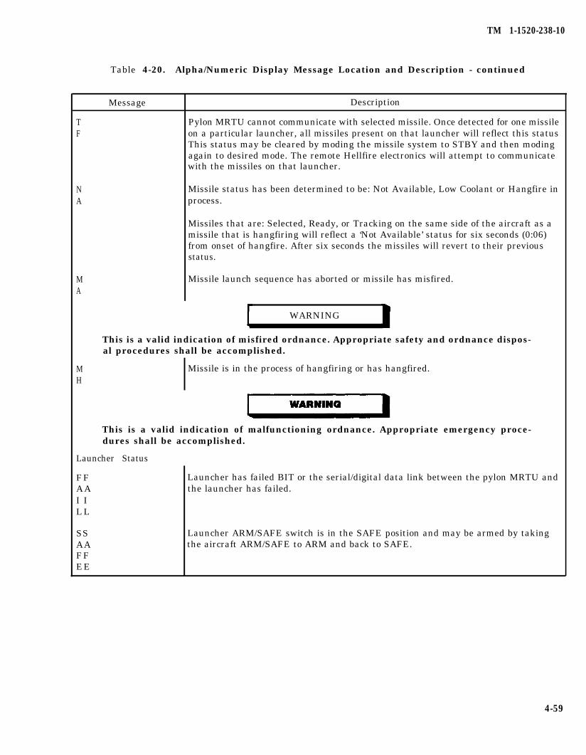
TM 1-1520-238-10
Table 4-20. Alpha/Numeric Display Message Location and Description - continued
Message Description
T Pylon MRTU cannot communicate with selected missile. Once detected for one missileF on a particular launcher, all missiles present on that launcher will reflect this status
This status may be cleared by moding the missile system to STBY and then modingagain to desired mode. The remote Hellfire electronics will attempt to communicatewith the missiles on that launcher.
NA
Missile status has been determined to be: Not Available, Low Coolant or Hangfire inprocess.
Missiles that are: Selected, Ready, or Tracking on the same side of the aircraft as amissile that is hangfiring will reflect a ‘Not Available’ status for six seconds (0:06)from onset of hangfire. After six seconds the missiles will revert to their previousstatus.
MA
Missile launch sequence has aborted or missile has misfired.
WARNING
This is a valid indication of misfired ordnance. Appropriate safety and ordnance dispos-al procedures shall be accomplished.
MH
Missile is in the process of hangfiring or has hangfired.
This is a valid indication of malfunctioning ordnance. Appropriate emergency proce-dures shall be accomplished.
Launcher Status
FFAAI ILL
Launcher has failed BIT or the serial/digital data link between the pylon MRTU andthe launcher has failed.
SSAAFFEE
Launcher ARM/SAFE switch is in the SAFE position and may be armed by takingthe aircraft ARM/SAFE to ARM and back to SAFE.
4-59
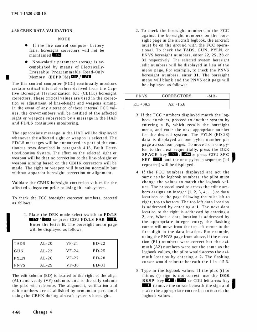
TM 1-1520-238-10
4.30 CBHK DATA VALIDATION.
NOTE
l If the fire control computer batteryfails, boresight correctors will not bemaintained
l Non-volatile parameter storage is ac-complished by means of Electrically-Eraseable Programmable Read-OnlyMemory (EEPROM)
The fire control computer (FCC) continually monitorscertain critical internal values derived from the Cap-tive Boresight Harmonization Kit (CBHK) boresightcorrectors. These critical values are used in the correc-tion or adjustment of line-of-sight and weapons aiming.In the event of any alteration of these internal FCC val-ues, the crewmembers will be notified of the affectedsight or weapons subsystem by a message in the HADand FD/LS continuous monitoring.
The appropriate message in the HAD will be displayedwhenever the affected sight or weapon is selected. TheFD/LS messages will be announced as part of the con-tinuous tests described in paragraph 4.15, Fault Detec-tion/Location System. The effect on the selected sight orweapon will be that no correction to the line-of-sight orweapon aiming based on the CBHK correctors will bemade. The sight or weapon will function normally butwithout apparent boresight correction or alignment.
Validate the CBHK boresight correction values for theaffected subsystem prior to using the subsystem.
To check the FCC boresight corrector numbers, proceedas follows:
1. Place the DEK mode select switch to FD/LSor press CDU FD/LS FAB
Enter the letter B. The boresight menu pagewill be displayed as follows:
TADS AL-20 VF-21 ED-22
GUN AL-23 VF-24 ED-25
PYLN AL-26 VF-27 ED-28
PNVS AL-29 VF-30 ED-31
The edit column (ED) is located to the right of the align(AL) and verify (VF) columns and is the only columnthe pilot will reference. The alignment, verification andedit numbers are established by armament personnelusing the CBHK during aircraft systems boresight.
2. To check the boresight numbers in the FCCagainst the boresight numbers on the bore-sight page in the aircraft logbook, the aircraftmust be on the ground with the FCC opera-tional. To check the TADS, GUN, PYLN, orPNVS boresight numbers, enter 22, 25, 28 or31 respectively. The selected system boresightedit numbers will be displayed in lieu of themenu page. For example, to check the PNVSboresight numbers, enter 31. The boresightmenu will blank and the PNVS edit page willbe displayed as follows:
PNVS CORRECTORS -MR-
EL +09.3 AZ -15.6
3. If the FCC numbers displayed match the log-book numbers, proceed to another system byentering a B, which recalls the boresightmenu, and enter the next appropriate numberfor the desired system. The PYLN (ED-28)data is displayed as one pylon number perpage across four pages. To move from one py-lon to the next sequentially, press the DEKSPACE key or press CDU SPCKEY and the next pylon in sequence (1-4repeated) will be displayed.
4. If the FCC numbers displayed are not thesame as the logbook numbers, the pilot mustchange the values to match the logbook val-ues. The protocol used to access the edit num-bers assigns an integer (1, 2, 3, 4, . . ) to datalocations on the page following the rule: left toright, top to bottom. The top left data locationis addressed by entering a 1. The next datalocation to the right is addressed by entering a2, etc. When a data location is addressed bythe appropriate integer entry, the flashingcursor will move from the top left corner to thefirst digit in the data location. For example,using the PNVS page from above, if the eleva-tion (EL) numbers were correct but the azi-muth (AZ) numbers were not the same as thelogbook values, the pilot would access the azi-muth location by entering a 2. The flashingcursor would relocate beneath the 1 in -15.6.
5. Type in the logbook values. If the plus (t) orminus (-) sign is not correct, use the DEKBKSP key or CDU left arrow key
to move the cursor beneath the sign andmake the appropriate correction to match thelogbook values.
4-60 Change 4
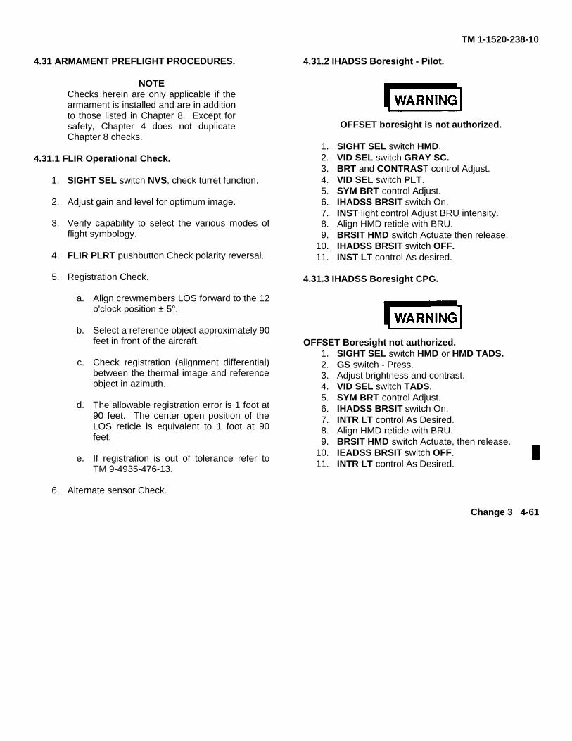
TM 1-1520-238-10
4.31 ARMAMENT PREFLIGHT PROCEDURES.
NOTEChecks herein are only applicable if thearmament is installed and are in additionto those listed in Chapter 8. Except forsafety, Chapter 4 does not duplicateChapter 8 checks.
4.31.1 FLIR Operational Check.
1. SIGHT SEL switch NVS, check turret function.
2. Adjust gain and level for optimum image.
3. Verify capability to select the various modes offlight symbology.
4. FLIR PLRT pushbutton Check polarity reversal.
5. Registration Check.
a. Align crewmembers LOS forward to the 12o'clock position ± 5°.
b. Select a reference object approximately 90feet in front of the aircraft.
c. Check registration (alignment differential)between the thermal image and referenceobject in azimuth.
d. The allowable registration error is 1 foot at90 feet. The center open position of theLOS reticle is equivalent to 1 foot at 90feet.
e. If registration is out of tolerance refer toTM 9-4935-476-13.
6. Alternate sensor Check.
4.31.2 IHADSS Boresight - Pilot.
OFFSET boresight is not authorized.
1. SIGHT SEL switch HMD.2. VID SEL switch GRAY SC.3. BRT and CONTRAST control Adjust.4. VID SEL switch PLT.5. SYM BRT control Adjust.6. IHADSS BRSIT switch On.7. INST light control Adjust BRU intensity.8. Align HMD reticle with BRU.9. BRSIT HMD switch Actuate then release.
10. IHADSS BRSIT switch OFF.11. INST LT control As desired.
4.31.3 IHADSS Boresight CPG.
OFFSET Boresight not authorized.1. SIGHT SEL switch HMD or HMD TADS.2. GS switch - Press.3. Adjust brightness and contrast.4. VID SEL switch TADS.5. SYM BRT control Adjust.6. IHADSS BRSIT switch On.7. INTR LT control As Desired.8. Align HMD reticle with BRU.9. BRSIT HMD switch Actuate, then release.
10. IEADSS BRSIT switch OFF.11. INTR LT control As Desired.
Change 3 4-61
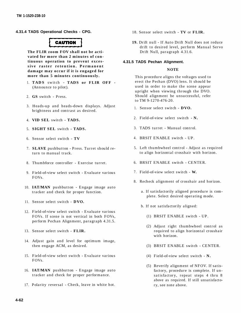
CAUTION
TM 1-1520-238-10
4.31.4 TADS Operational Checks - CPG.
The FLIR zoom FOV shall not be acti-vated for more than 2 minutes of con-tinuous operation to prevent exces-sive raster retention. Permanentdamage may occur if it is engaged formore than 5 minutes continuously.
1.
2.
3.
4.
5.
6.
7.
8.
9.
10.
11.
12.
13.
14.
15.
16.
17.
4-62
TADS switch - TADS or FLIR OFF -(Announce to pilot).
GS switch - Press.
Heads-up and heads-down displays. Adjustbrightness and contrast as desired.
VID SEL switch - TADS.
SIGHT SEL switch - TADS.
Sensor select switch - TV
SLAVE pushbutton - Press. Turret should re-turn to manual track.
Thumbforce controller - Exercise turret.
Field-of-view select switch - Evaluate variousFOVs.
IAT/MAN pushbutton - Engage image autotracker and check for proper function.
Sensor select switch - DVO.
Field-of-view select switch - Evaluate variousFOVs. If scene is not vertical in both FOVs,perform Pechan Alignment, paragraph 4.31.5.
Sensor select switch - FLIR.
Adjust gain and level for optimum image,then engage ACM, as desired.
Field-of-view select switch - Evaluate variousFOVs.
IAT/MAN pushbutton - Engage image autotracker and check for proper performance.
Polarity reversal - Check, leave in white hot.
18. Sensor select switch - TV or FLIR.
19. Drift null - If Auto Drift Null does not reducedrift to desired level, perform Manual ServoDrift Null, paragraph 4.31.6.
4.31.5 TADS Pechan Alignment.
NOTE
This procedure aligns the voltages used toerect the Pechan (DVO) lens. It should beused in order to make the scene appearupright when viewing through the DVO.Should alignment be unsuccessful, referto TM 9-1270-476-20.
1.
2.
3.
4.
5.
6.
7.
8.
Sensor select switch - DVO.
Field-of-view select switch - N.
TADS turret - Manual control.
BRSIT ENABLE switch - UP.
Left thumbwheel control - Adjust as requiredto align horizontal crosshair with horizon.
BRSIT ENABLE switch - CENTER.
Field-of-view select switch - W.
Recheck alignment of crosshair and horizon.
a. If satisfactorily aligned procedure is com-plete. Select desired operating mode.
b. If not satisfactorily aligned:
(1)
(2)
(3)
(4)
(5)
BRSIT ENABLE switch - UP.
Adjust right thumbwheel control asrequired to align horizontal crosshairwith horizon.
BRSIT ENABLE switch - CENTER.
Field-of-view select switch - N.
Reverify alignment of NFOV. If satis-factory, procedure is complete. If un-satisfactory, repeat steps 4 thru 8above as required. If still unsatisfacto-ry, see note above.
TM 1-1520-238-10
4.31.6 TADS Manual Servo Drift Null.
1. SLAVE switch - Press and verify dottedcrosshair is present on selected display (HODor HDD).
2.
3.
SIGHT SEL switch - TADS.
Verify TADS turret slews to fixed forwardposition by observing solid crosshair coming tocenter of display and cueing LOS centering oncueing dot.
4.
5.
SLAVE Switch - Press.
Sensor select switch - TV or FLIR. For great-est accuracy, use TV.
6.
7.
8.
Field-of-view select switch - N.
Aim reticle at an easily observed object.
BRSIT ENABLE switch - UP, wait 5 secondsthen adjust left and right thumbwheel con-trols for drift null.
9. BRSIT ENABLE switch - CENTER.
4.31.7 TADS Boresight.a.
b.
PLT/GND ORIDE switch - As required.
CPG ARM/SAFE switch - ARM.
Ensure proper laser safety proce-dures are followed.
C.
d.
SIGHT SEL switch - TADS.
NOTEBoresighting of the DTV and FLIR narrowand zoom fields-of-view occurs indepen-dently; the actual order is not critical.However, DTV must be boresighted priorto boresighting the DVO.
e.
f.
BRSIT switch - TADS. Confirm INTER-NAL BORESIGHT message is present.
LSR switch - ON.
Sensor select switch - TV.
a. CUE Update Procedure.
NOTEThe CUE update procedure should be ac-complished whenever the TADS FLIR isreportedas being unable to be internal-ly boresighted. Once the CUE updateprocedure has been accomplished andthe TADS FLIR still cannot be bore-sighted, continue with troubleshootingas specified in TM 9-1270-476-20.
1. SIGHT SEL switch - TADS.
g.
h.
i.
j.
Field-of-view select switch - N.
Tracker polarity white over black.
Laser trigger - Press and hold.
BRSIT ENABLE switch - UP. Observetracking gates capture laser spot. Contin-ue to fire laser until tracking gates disap-pear. If spot cannot be captured by track-ing gates, perform manual boresightadjustment, paragraph 4.31.7 d.
2. Sensor select switch - TV. k. BRSIT ENABLE switch - CENTER.
3.
4.
5.
6.
Field-of-view select switch - W.
BRSIT switch - TADS.
SLAVE switch - Actuate. Verify internalboresight message replaced by cue updatemessage.
If reticle does not appear centered on theblack cross, execute the following:
a. BRSIT ENABLE switch - UP.
b. Use thumbforce controller to position DTVreticle in proximity to the black cross.
c. BRSIT ENABLE switch - CENTER.
d. SLAVE switch - Actuate. Verify cue up-date message replaced by internal bore-sight message.
e. BRSIT TADS switch - OFF. Procedurecomplete, continue as desired.
b. TADS Internal Boresight.
1. DTV
Change 2 4-63
TM 1-1520-238-10
1. Laser trigger - Release.
The DTV zoom FOV shall not be acti-vated for more than 2 minutes of con-tinuous operation to prevent exces-sive raster retention. Permanentdamage may occur if it is engaged formore than 5 minutes continuously.
m. Field-of-view select switch - Z.
n. Repeat steps i. thru 1.
2. FLIR.
a.
b.
C.
Sensor select switch - FLIR.
Field-of-view select switch - N.
FLIR - Adjust level fully counterclock-wise.
d.
e.
f.
g.
h.
FLIR - Adjust gain mid-range.
Laser trigger - Press and hold.
Observe laser spot, and optimize FLIR. Iflaser spot is not visible, perform CUE Update Procedure, paragraph 4.31.7 a.
BRSIT ENABLE switch - UP. Observetracking gates capture laser spot. Contin-ue to fire the laser until tracking gatesdisappear. If spot cannot be captured bytracking gates, perform manual boresightadjustment, paragraph 4.31.7 d.
BRSIT ENABLE switch - CENTER.
i. Laser trigger - Release.
The FLIR zoom FOV shall not be acti-vated for more than 2 minutes of con-tinuous operation to prevent exces-sive raster retention. Permanentdamage may occur if it is engaged formore than 5 minutes continuously.
j. Field-of-view select switch - Z.
k. Repeat steps e. thru i.
1. LSR switch - OFF.
m. CPG ARM/SAFE switch - SAFE.
n. PLT/GND ORIDE switch - OFF.
4-64 Change 4
3. DVO
a.
b.
C.
d.
e.
f.
g.
h.
1.
Sensor select switch - DVO.
Field-of-view select switch - N.
Observe position of DVO crosshairs; if co-incident with DTV reticle, go to step g, be-low.
BRSIT ENABLE switch - DOWN.
DVO BRSIT - Adjust DVO crosshairs intocoincidence with DTV reticle.
BRSIT ENABLE switch - CENTER.
BRSIT TADS - OFF
ACQ SEL switch - FXD.
SLAVE switch - Press, TADS returns tothe fixed forward position.
c. TADS Outfront Boresight.
TADS Outfront Boresight validationand adjustment (if necessary) shallbe performed prior to using the TADSFLIR imagery for laser or weaponsoperations, after performing a cueupdate, a TADS component change orif the helicopter experiences an ab-normal electrical shutdown.
1. Position helicopter on the ground over identi-fied location for this procedure.
2. If on an approved laser firing range, fire laserto obtain range. Otherwise, enter manuallythe range from helicopter to the outfront bore-sight target.
NOTE
If the target is between 0.5 km and1.5 km, the range entered on the DEKmust be within 10 meters. If the target isbetween 1.5 km and 5 km, the range en-tered on the DEK must be within 50 me-ters. If the target is greater than 5 km, therange entered on the DEK must be within1 km.
3. Observe the outfront boresight target inNFOV FLIR, adjust gain and level for opti-mum autotracker image. Engage LAT.
TM 1-1520-238-10
4. Sensor select switch - TV, observe light 8. Laser trigger - Press.source. NOTE
5. If not precisely centered on the TADS reticle,perform the following:
a. BRSIT TADS switch - TADS. Confirmmessage, OUTFRONT BORESIGHT ispresent.
b. BRSIT ENABLE switch - UP.
c. Adjust right and left thumbwheel controlsto center the target on the reticle.
d. BRSIT ENABLE switch - CENTER.
6. IAT switch - Off.
7. BRSIT TADS switch - OFF
d. TADS Manual Boresight Adjust.
NOTE
The manual boresight procedure is usedonly to recapture or center the laser spot.It is not an acceptable boresight procedurefor normal flight operations.
1.
2.
3.
BRSIT TADS switch - TADS. Confirm mes-sage INTERNAL BORESIGHT is present.
LSR select switch - ON.
Sensor select switch - FLIR or TV as re-quired.
4. FLIR PLRT pushbutton - Press to selectwhite hot.
5. Field-of-view select switch - N.
6. GAIN - Midrange (if using FLIR).
7. LVL - Fully counterclockwise (if using FLIR).
Ensure proper laser safety proce-dures are followed.
If the laser spot is too weak or not visible,perform Cue update.
9. Observe laser spot and optimize FLIR.
10. BRSIT ENABLE switch - UP for 1 second,then move to center position. After 5 seconds,the left and right thumbwheel controls will beactive; adjust laser spot in elevation and azi-muth.
11. Laser trigger - Release.
12. LSR switch - OFF.
4.32 RAPID REARMING.
1. TAIL WHEEL switch - LOCK.
2. PARK BRAKE - Set.
3. HARS switch - NORM.
4. Weapons select switches - On.
5. PLT/GND ORIDE switch - ORIDE.
6. CPG ARM/SAFE switch - ARM.
7. ROCKETS control panel - Arm.
8. ANTI-COL switch - OFF.
9. Stray current check - Perform.
10. Weapons select switches - OFF
11. CPG ARM/SAFE switch - OFF
12. PLT/GND ORIDE switch - OFF.
13. Armament and pylon safety pins - Installed.
14. Rearming - Monitor.
15. ANTI-COL switch - As Desired.
16. Armament and pylon safety pins - Removed.
4-65
TM 1-1520-238-10
4.33 ARMAMENT INFLIGHT PROCEDURES.
4.33.1 30mm Gun System.
If 300 or more rounds have been firedin the preceding ten minutes, and astoppage occurs, personnel must re-main clear of the aircraft for 30 min-utes. Aircraft crewmembers shouldremain in the aircraft and continuepositive gun control.
1. CPG ARM/SAFE switches - ARM.
2. GUN select switch - As desired.
3. Crewmember desiring to fire - Establishrange to target and track target with selectedsight.
4. WAS switch - GUN.
5. Weapons trigger - Press, continue to fire asrequired.
6. WAS - Deselect GUN.
4.33.2 AWS Harmonization Procedures
1. Locate target approximately 1000 meters(± 50) from aircraft position.
2. Hover aircraft 100 FT (± 20) above target alti-tude and maintain heading (± 5°) azimuth.
3. Sensor select switch - TV d.
4.
5.
6.
Field-of-view select switch - N or Z.
LSR select switch - ON. e.
Laser trigger - Press. Ensure the displayedrange to target is accurate to ± 10 meters.
7. Laser trigger - Press. Confirm range.
NOTE
Harmonization burst shall be accom-plished in the narrowest field of viewwhich the CPG can observe the rounds im-pact (wide/narrow).
f.
g.
4-66 Change 4
8. Field-of-view select switch - W or N.
NOTE
A video recording may be used to verifyimpact area.
9. Fire one or two 10 round bursts. Note centroidof impact area.
10. Determine the appropriate sector from the ap-propriate field of view Corrector Guides (figs4-19.1 and 4-19.2) for harmonization offsetvalues.
NOTE
l A fraction of the offset values in a sectorcan be used to improve accuracy
l Go to step 12 to enter modifiedcorrectors.
11. For enter modified correctors:
a. DEK switch - SP1.
b. Enter G on the DEK.
C. The screen will display harmonizationcorrector Deltas and Totals in the follow-ing format:
AWS HARMONIZATIONDELTAS -MR-
AZ=+00.0 EL=+00.0TOTALS -MR-
AZ=+00.0 EL=+00.0
On the DEK enter 1 to access azimuth or 2to access elevation corrector value(s) to bechanged.
Enter corrector Delta value(s) from theCorrector Guides (figs 4-19.1 and 4-19.2).
Repeat steps 1 through 11 while reducingfield of view as appropriate to DTV-NFOVuntil center of impact is verified to bewithin zoom FOV gates. When FOV gatesare achieved, proceed to step g.
DEK ENTER button - Press. This willcomplete the modification.
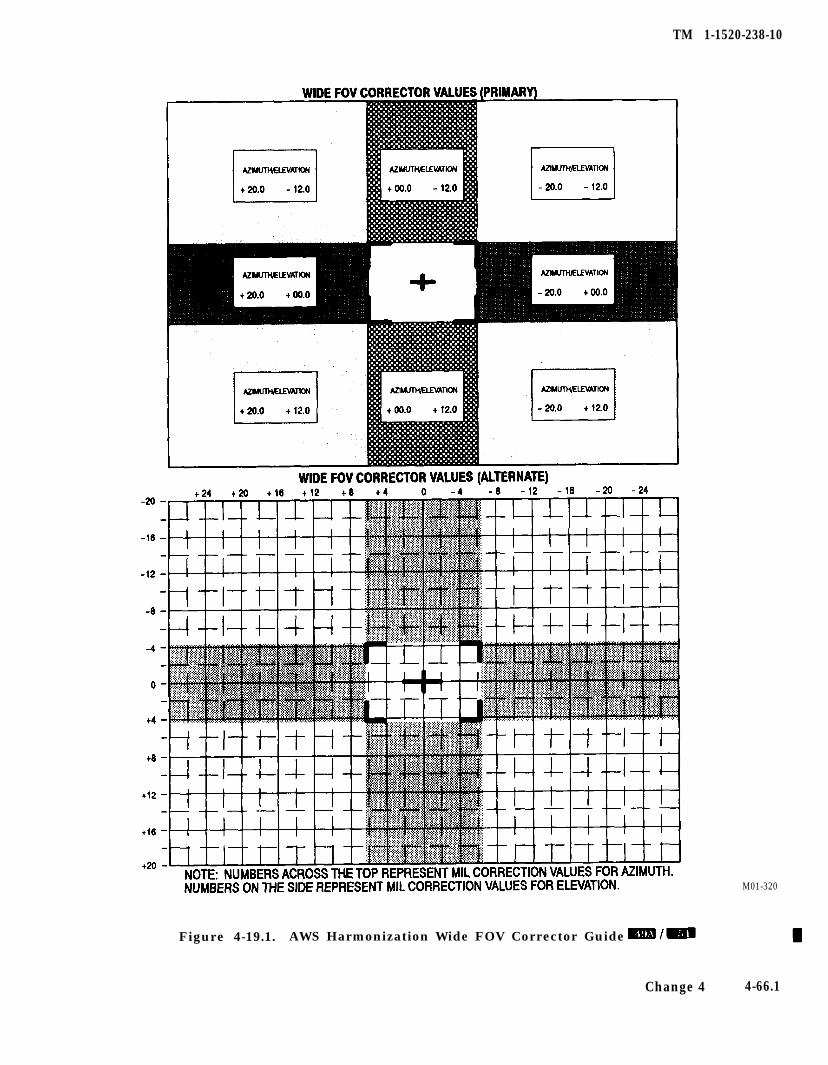
TM 1-1520-238-10
M01-320
Figure 4-19.1. AWS Harmonization Wide FOV Corrector Guide
Change 4 4-66.1
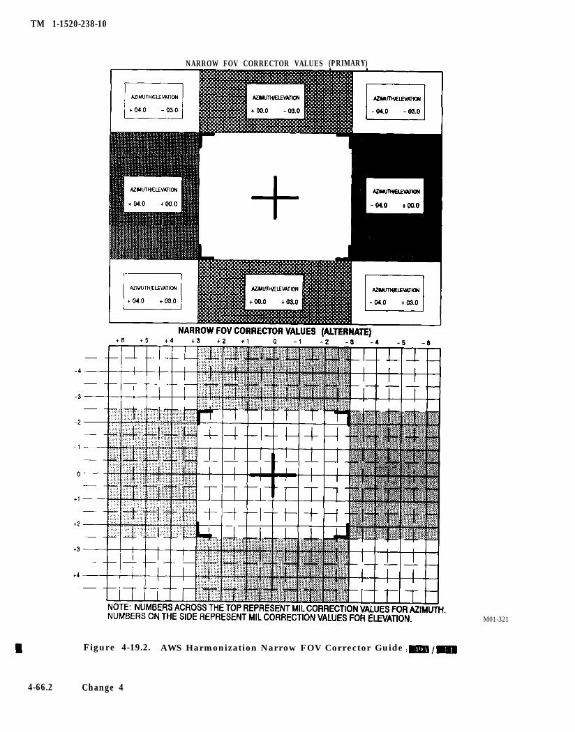
TM 1-1520-238-10
NARROW FOV CORRECTOR VALUES (PRIMARY)
M01-321
Figure 4-19.2. AWS Harmonization Narrow FOV Corrector Guide
4-66.2 Change 4
TM 1-1520-238-10
12. For enter modified correctors:
a. CDU - Select PGM.
b. CDU - Select AWS HARM.
c. Enter appropriate correction data (AZ orEL) on CDU scratchpad.
d. Depress VAB 2 (AZ) or VAB 6 (EL), as ap-propriate, to enter correction factors intoFCC.
e. The CDU screen will display harmoniza-tion corrector Deltas and Totals in the fol-lowing format:
AWS HARMONIZATIONDELTAS -MR-
AZ=+00.0 EL=+00.0TOTALS -MR-
AZ=+00.0 EL=+00.0
f. Repeat steps 1 through 10 and 12 whilereducing field of view as appropriate toDTV-NFOV until center of impact is veri-fied to be within zoom FOV gates. WhenFOV gates are achieved, proceed to step g.
g. Press PGM VAB to return to top levelpage.
4.33.3 Aerial Rocket Control System.
NOTE
If one or more pylons have failed, rocketfiring from the failed pylon is disabledwithout inhibiting rocket firing from theremaining pylons.
a. CPG Cooperative Engagement Mode.
1. CPG ARM/SAFE switch - ARM.
2. RKT select switch - As desired.
3. Desired target - Acquire and track.
4. CPG ORT WAS - RKT.
5. Laser trigger - Press. Establish range of heli-copter to target.
6. On completion of engagement: ORT WAS -Deselect RKT
b. Pilot Cooperative Engagement Mode.
1. MASTER ARM/SAFE switch - ARM.
2. RKT select switch - As desired.
3. ROCKETS panel - Set QTY, PEN-M andZONE SEL.
4. WAS - RKT.
5. Align rocket steering symbology.
6. Weapons trigger - Press until selected quanti-ty has been fired or target neutralized.
7. WAS - Deselect RKT.
c. Pilot or CPG Only Mode.
1. CPG ARM/SAFE switches - ARM.
2. RKT select switch - As desired.
3. ROCKETS control panel - Set QTY, PEN-Mand ZONE SEL.
4. Crewmember desiring to fire - Track targetwith HMD, maintain LOS reticle on target.Establish range.
5. WAS - RKT.
6. Align rocket steering symbology.
7. Weapons trigger - Press until selected quanti-ty has been fired or target neutralized.
8. WAS - Deselect RKT.
Change 4 4-66.3/(4-66.4 blank)

TM 1-1520-238-10
4.33.4 Point Target Weapons System.
W h e n f i r i n g H e l l f i r e m i s s i l eAGM-114A at temperatures below-10 °C, severe ice fog can be formedby the missile exhaust plume. The icefog can obscure crew visibility andalso interfere with autonomous des-ignation.
1. MSL switch - ON, observe BIT IN PROG-RESS message on high action display andAND. When message disappears any failedBIT status will be displayed on AND.
NOTE
l If BIT failure indicates MSL failure,and that missile is required to completethe mission, another BIT cycle may beinitiated. If additional BIT indicates ago, then missile is considered function-al and may be launched. If missile failssecond Built-In-Test (BIT) then mis-siles shall be rejected.
l BIT may be overridden at any time byplacing the MSL MODE switch in anymode other than STBY.
a. Types of Engagements.
1. Normal Mode - LOBL.
a. UPR/LWR CHAN CODE - As desired.
b. UPR/LWR CHAN QTY - As desired.
c. MSL MODE - NORM.
d. CHAN SEL switch - Establish prioritychannel.
e. Observe AND for missile selection, codingand ready status.
f. CPG ARM/SAFE switch - ARM.
g. Lase target or call for remote designator.
h. Observe AND or HIGH ACTION displayfor proper missile track status.
i. CPG WAS - MSL.
j. Pilot establish helicopter in constraints.
k. Weapons trigger - Press and release.
NOTE
If ‘in constraints’ criteria are not met, the2nd detent of the weapons trigger may beused to override constraints inhibits andfire missile.
1. If autonomously designating, continuelasing until missile impact.
2. Normal Mode - LOAL.
a. UPR/LWR CHAN CODE -As desired.
b. UPR/LWR CHAN QTY - As desired.
c. MSL MODE - NORM.
d. CHAN SEL switch - Establish prioritychannel.
e. Observe AND or HIGH ACTION displayfor missile selection, coding and ready sta-tus.
f. LOAL select switch - As desired.
g. CPG ARM/SAFE - ARM.
h. CPG WAS - MSL.
i. Pilot establish helicopter in constraints.
j. Weapons trigger - Press and release.
k. Lase target or call for remote designatorin adequate time for terminal guidance.
3. Ripple Mode - LOBL.
a. UPR/LWR CHAN CODE - As desired.
b. UPR/LWR CHAN QTY - As desired.
c. MSL MODE - RIPL.
d. CHAN SEL switch - Establish prioritychannel.
e. Observe AND for missile selection, codingand ready status.
Change 4 4-67
TM 1-1520-238-10
f. CPG ARM/SAFE - ARM.
g.
h.
i.
j.
Lase target or call for remote designator.
Observe AND or HIGH ACTION displayfor missile system messages.
CPG WAS - MSL.
Pi lot es tabl i sh the he l i copter inconstraints.
k.
1.
m.
Weapons trigger - Press and release,
Pilot establish helicopter in constraints.
Repeat steps j. thru 1. until desired num-ber of missiles have been fired.
4. Ripple Mode - LOAL.
a.
b.
C.
d.
e.
f.
g.
h.
i.
j.
k.
UPR/LWR CHAN CODE - As desired.
UPR/LWR CHAN QTY - As desired.
MSL MODE - RIPL.
CHAN SEL switch - Establish prioritychannel.
Observe AND or HIGH ACTION displayfor missile selection, coding, ready status.
LOAL select switch - As desired.
CPG ARM/SAFE - ARM.
CPG WAS - MSL.
Pilot establish helicopter in constraints.
Weapons trigger - Press and release.
Pilot establish helicopter in constraintsfor alternate channel.
1. Weapons trigger - Press and release.
m. Lase target or call for terminal guidance.
n. Execute steps i. thru m. until desirednumber of missiles have been fired.
b. Missile System Shutdown Procedures.
1. MSL MODE - STBY.
2. LOAL select switch - OFF.
3. CHAN SEL - Actuate either direction.
4. MSL switch - OFF.
4.34 ARMAMENT POSTFLIGHT PROCEDURES.
If armament system has been used, check as follows:
1.
2.
3.
4.
5.
6.
7.
7.
Right FAB - Open. Check carrier drive forrounds.
Gun chute assembly - Check for rounds.
Bolt status indicator - FEED (green range).
Transfer door - Open. Check bolt is to rear, norounds in transfer assembly, and chamberclear.
Transfer door - Secure.
AWS - General condition and security. Checkfor leaks and proper piston index groove in-dication.
Wing stores pylon - Check for unexpendedordnance.
4-68 Change 4
TM 1-1520-238-10
Section Ill. ACTIVE AND PASSIVE DEFENSE EQUIPMENT
4.34A INFRARED COUNTERMEASURES SETAN/ALQ-144A, -144(V)3.
Do not continuously look at the in-frared countermeasure transmitter(fig 2-2) during operation, or for aperiod of over 1 minute from a dis-tance of less than 3 feet. Skin expo-sure to countermeasure radiation forlonger than 10 seconds at a distanceless than 4 inches shall be avoided.
The infrared countermeasures set (IR jammer) pro-vides infrared countermeasure capability. It transmitsradiation modulated mechanically at high and low fre-quencies using an electrically heated source. The IRjammer consists of a control panel (fig 4-20), on theright side of the pilot instrument panel, and a transmit-ter, located on the fairing immediately aft of the mainrotor (fig 2-2). A built-in test monitors operation andalerts the pilot when a malfunction occurs. If the IRjammer malfunctions, the IR JAM segment on the pi-lot caution/warning panel illuminates. The IR jammeris not monitored by FD/LS. The IR transmitter receives28 vdc from the No. 1 essential dc bus through the IRJAMMER circuit breaker in the electical power centerwhen the IR JAM/PWR circuit breaker is closed. TheIR jammer cooling fan receives 28 vdc from the No. 2essential dc bus through the IR JAM/XMTR circuitbreaker. The IR JAM/PWR and IR JAM/XMTR cir-cuit breakers are located on the pilot overhead circuitbreaker panel.
4.34A.1 Infrared Countermeasures Set Control Panel.Control of the IR jammer is provided by the IRCM (in-frared countermeasures) part of the IRCM/RDRCMcontrol panel (fig 4-20) located on the right side of thepilot instrument panel. The control panel receives 28vdc from the No. 2 essential dc bus through the PENAIDS CONTR circuit breaker on the pilot overheadcircuit breaker panel. When the ON-OFF switch on theIRCM panel is set to ON, the power distribution andcontrol circuits are activated. The source begins toheat, and the servo motor and drive circuits are ener-gized, turning on the high and low speed modulators. Asignal is applied to stabilize subsystem operations be-fore energizing the built-in test function. After a one
minute warmup period, the stabilizing signal is re-moved and the subsystem operates normally. Settingthe ON-OFF switch to OFF causes the power distribu-tion and control circuits to de-energize the source andinitiates a cool-down period. During the one minutecool-down period, the servo motor drive circuits remainin operation, applying power to the motors that causethe modulators to continue turning and the IR JAMsegment on the pilot caution/warning panel to illumi-nate. After the cool-down period, the power distributionand control circuits de-energize, all subsystem voltagesare removed and the IR JAM caution light segment isextinguished.
4.34B RADAR COUNTERMEASURES SETAN/ALQ-136.
Do not stand within 3 feet of the frontof the transmit antenna when theequipment is turned on. High fre-quency electromagnetic radiationcan cause internel burns withoutcausing any sensation of heat. If youfeel the slightest warming effect whilenear the transmit antenna, moveaway quickly.
The radar countermeasures set (radar jammer) pro-vides the helicopter with protection against groundbased fire control radars. When operating, the radarjammer transmits modulating signals at radar fre-quencies, causing range and angle measurement errorsto the radar. The radar jammer consists of a controlpanel (fig 4-20), located on the right side of the pilotinstrument panel, a receiver transmitter, and transmitand receive antennas. A built-in test monitors opera-tion and alerts the pilot when a malfunction occurs. Ifthe radar jammer malfunctions, the RDR JAM seg-ment on the pilot caution/warning panel illuminates.The radar jammer is not monitored by FD/LS. The re-ceiver/transmitter receives 28 vdc from the No. 2 essen-tial dc bus through the RDR JAMMER circuit breakerin the electrical power center when the RDR JAM cir-cuit breaker is closed. The radar jammer set cooling fanreceives 115 vac from the No. 1 essential ac bus throughthe RDR JAM AC circuit breaker. The RDR JAM ACand RDR JAM DC circuit breakers are located on thepilot overhead circuit breaker panel.
Change 4 4-69
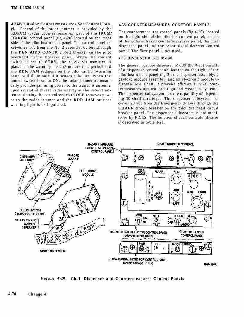
TM 1-1520-238-10
4.34B.1 Radar Countermeasures Set Control Pan-el. Control of the radar jammer is provided by theRDRCM (radar countermeasures) part of the IRCM/RDRCM control panel (fig 4-20) located on the rightside of the pilot instrument panel. The control panel re-ceives 23 vdc from the No. 2 essential dc bus throughthe PEN AIDS CONTR circuit breaker on the pilotoverhead circuit breaker panel. When the controlswitch is set to STBY, the receiver/transmitter isplaced in the warm-up mode (3 minute time period) andthe RDR JAM segment on the pilot caution/warningpanel will illuminate if it senses a failure. When thecontrol switch is set to ON, the radar jammer automati-cally provides jamming power to the transmit antennaupon receipt of threat radar energy at the receive an-tenna. Setting the control switch to OFF removes pow-er to the radar jammer and the RDR JAM caution/warning light is extinguished.
4.35 COUNTERMEASURES CONTROL PANELS.
The countermeasures control panels (fig 4-20), locatedon the right side of the pilot instrument panel, consistof the radar/infrared countermeasures panel, the chaffdispenser panel and the radar signal detector controlpanel. The flare panel is not used.
4.36 DISPENSER KIT M-130.
The general purpose dispenser M-130 (fig 4-20) consistsof a dispenser control panel located on the right of thepilot instrument panel (fig 2-9), a dispenser assembly, apayload module assembly, and an electronic module todispense M-1 Chaff. It provides effective survival coun-termeasures against radar guided weapons systems.The dispenser subsystem has the capability of dispens-ing 30 chaff cartridges. The dispenser subsystem re-ceives 28 vdc from the Emergency dc Bus through theCHAFF circuit breaker on the pilot overhead circuitbreaker panel. The dispenser subsystem is not moni-tored by FD/LS. The function of each control/indicatoris described in table 4-21.
Figure 4-20. Chaff Dispenser and Countermeasures Control Panels
4-70 Change 4
TM 1-1520-238-10
Table 4-21. Dispenser Control Panel Control/Indicator Function
Control/Indicator
CHAFFcounter
Position Function
Displays the number of chaff cartridges remaining in the payload module.
CHAFFcounterknob
Adjusts counter to correspond to number of chaff cartridges loaded in payloadmodule.
ARM light Indicates that the ARM/SAFE switch is at ARM, safety flag pin is removed, andpayload module is armed.
A R M / S A F E A R Mswitch
Applies electrical power through safety flag switch to cyclic WAS for firing.
MODEselector
SAFE Removes power from dispenser subsystem.
Selects type of chaff release.
Dispenses one chaff cartridge each time the WAS chaff fire position is toggled.
PGRM Allows setting electronic module controls before flight to automatically dispensechaff according to predetermined number of chaff cartridges per burst and numberof salvos.
4.36.1 Dispenser Assembly. The dispenser assembly(fig 4-20) contains the C-F (chaff-flare) selector switch,chaff counter control, and a housing containing the se-quencer assembly. The sequencer assembly receives 28vdc through the WAS and furnishes pulses to each ofthe 30 contacts of the breech assembly, in sequential or-der 1 through 30, thus firing each of the chaff car-tridges.
4.36.2 Remote Safety Switch. The remote safetyswitch is located on the tailboom just forward of the dis-penser assembly. This switch safes the dispenser bygrounding the chaff dispenser contacts and opening thefiring circuit when the safety pin is installed in theswitch.
4.36.3 Payload Module Assembly. The payload mod-ule assembly (fig 4-20) consists of the payload moduleand the retaining plate. The payload module has 30chambers which will accept chaff. The chaff cartridges
are loaded, one per chamber, and are held in place bythe retaining plate. The payload module assembly isloaded into the dispenser assembly.
4.36.4 Electronic Module. The electronic module (fig4-20) provides signals to fire the chaff and to change thechaff counter accordingly. It contains a programmerand a cable assembly which includes a 28 volt supplyreceptacle. The programmer consists of a programmingcircuit which allows the setting of chaff burst quantity,burst interval, salvo quantity, and salvo interval. Thesafety switch on the electronic module is not used. Theelectronic module is located in the right aft avionicsbay.
4.36.5 Electronic Module Controls. The switches onthe electronic module (fig 4-20) are used to program thechaff dispenser for predetermined release of chaff car-tridges. The function of each switch is described intable 4-22.
Change 4 4-70.1/(4-70.2 blank)

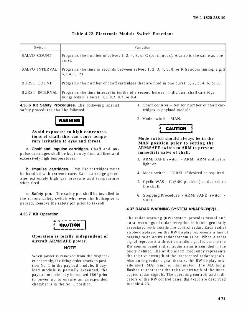
WARNING
CAUTION
CAUTION
TM 1-1520-238-10
Table 4-22. Electronic Module Switch Functions
Switch Function
SALVO COUNT Programs the number of salvos: 1, 2, 4, 8, or C (continuous). A salvo is the same as oneburst.
SALVO INTERVAL Programs the time in seconds between salvos: 1, 2, 3, 4, 5, 8, or R (random timing, e.g. 2,5,3,4,3, 2).
BURST COUNT Programs the number of chaff cartridges that are fired in one burst: 1, 2, 3, 4, 6, or 8.
BURST INTERVAL Programs the time interval in tenths of a second between individual chaff cartridgefirings within a burst: 0.1, 0.2, 0.3, or 0.4.
4.36.6 Kit Safety Procedures. The following special 1. Chaff counter - Set for number of chaff car-safety procedures shall be followed: tridges in payload module.
2. Mode switch - MAN.
Avoid exposure to high concentra-tions of chaff; this can cause tempo-rary irritation to eyes and throat.
Mode switch should always be in theMAN position prior to setting the
a. Chaff and Impulse cartridges. Chaff and im- ARM/SAFE switch to ARM to preventpulse cartridges shall be kept away from all fires and immediate salvo of chaff.excessively high temperatures. 3.
b. Impulse cartridges. Impulse cartridges mustbe handled with extreme care. Each cartridge gener- 4.ates extremely high gas pressure and temperaturewhen fired. 5.
c. Safety pin. The safety pin shall be installed inthe remote safety switch whenever the helicopter isparked. Remove the safety pin prior to takeoff.
4.36.7 Kit Operation.
Operation is totally independent ofaircraft ARM/SAFE power.
NOTE
When power is removed from the dispens-er assembly, the firing order resets to posi-tion No. 1 in the payload module. If pay-load module is partially expended, thepayload module may be rotated 180° priorto power up to ensure an unexpendedchamber is in the No. 1 position.
6 .
ARM/SAFE switch - ARM; ARM indicatorlight on.
Mode switch - PGRM -if desired or required.
Cyclic WAS - C (6:00 position) as desired tofire chaff.
Stopping Procedure - ARM/SAFE switch -SAFE.
4.37 RADAR WARNING SYSTEM AN/APR-39(V)1 .
The radar warning (RW) system provides visual andaural warnings of radar reception in bands generallyassociated with hostile fire control radar. Each radialstrobe displayed on the RW display represents a line ofbearing to an active radar transmission. When a radarsignal represents a threat an audio signal is sent to theRW control panel and an audio alarm is sounded in thepilots helmet. The audio alarm frequency representsthe relative strength of the intercepted radar signals.Also during radar signal threats, the RW display mis-sile alert (MA) lamp is illuminated. The MA lampflashes to represent the relative strength of the inter-cepted radar signals. The operating controls and indi-cators of the RW control panel (fig 4-20) are describedin table 4-23.
4-71
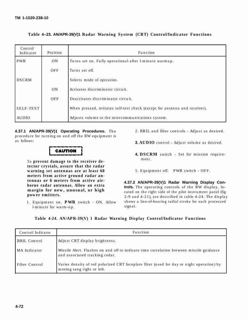
CAUTION
TM 1-1520-238-10
Table 4--23. AN/APR-39(V)1 Radar Warning System (CRT) Control/Indicator Functions
Control/Indicator Position Function
PWR ON Turns set on. Fully operational after l-minute warmup.
OFF Turns set off.
DSCRM Selects mode of operation.
ON Activates discriminator circuit.
OFF Deactivates discriminator circuit.
SELF-TEST When pressed, initiates self-test check (except for antenna and receiver).
AUDIO Adjusts volume to the intercommunications system.
4.37.1 AN/APR-39(V)1 Operating Procedures. The 2. BRIL and filter controls - Adjust as desired.procedure for turning on and off the RW equipment isas follows:
To prevent damage to the receiver de-tector crystals, assure that the radarwarning set antennas are at least 60meters from active ground radar an-tennas or 6 meters from active air-borne radar antennas. Allow an extramargin for new, unusual, or highpower emitters.
1. Equipment on. PWR switch - ON. Allow
3. AUDIO control - Adjust volume as desired.
4. DSCRM switch - Set for mission require-ment.
5. Equipment off. PWR switch - OFF.
4.37.2 AN/APR-39(V)1 Radar Warning Display Con-trols. The operating controls of the RW display, lo-cated on the right side of the pilot instrument panel (fig2-9 and 4-21), are described in table 4-24. The displayshows a line-of-bearing radial stroke for each processed
l-minute for warm-up. signal.
Table 4-24. AN/APR-39(V) 1 Radar Warning Display Control/Indicator Functions
Control/Indicator Function
BRIL Control Adjust CRT display brightness.
MA Indicator Missile Alert. Flashes on and off to indicate time correlation between missile guidanceand associated tracking radar.
Filter Control Varies density of red polarized CRT faceplate filter (used for day or night operation) bymoving tang right or left.
4-72
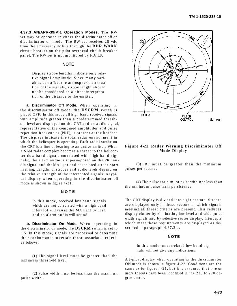
TM 1-1520-238-10
4.37.3 AN/APR-39(V)1 Operation Modes. The RWset may be operated in either the discriminator off ordiscriminator on mode. The RW set receives 28 vdcfrom the emergency dc bus through the RDR WARNcircuit breaker on the pilot overhead circuit breaker
panel. The RW set is not monitored by FD/LS.
NOTE
Display strobe lengths indicate only rela-tive signal amplitude. Since many vari-ables can affect the atmospheric attenua-tion of the signals, strobe length shouldnot be considered as a direct interpreta-tion of the distance to the emitter.
a. Discriminator Off Mode. When operating inthe discriminator off mode, the DSCRM switch isplaced OFF. In this mode all high band received signalswith amplitude greater than a predetermined thresh-old level are displayed on the CRT and an audio signal,representative of the combined amplitudes and pulserepetition frequencies (PRF), is present at the headset.The displays indicate the total radar environment inwhich the helicopter is operating. Each radial strobe onthe CRT is a line of bearing to an active emitter. Whena SAM radar complex becomes a threat to the helicop-ter (low band signals correlated with high band sig-nals), the alarm audio is superimposed on the PRF au-dio signal and the MA light and associated strobe startflashing. Lengths of strobes and audio levels depend onthe relative strength of the intercepted signals. A typi-cal display when operating in the discriminator offmode is shown in figure 4-21.
N O T E
In this mode, received low band signalswhich are not correlated with a high bandintercept will cause the MA light to flashand an alarm audio will sound.
b. Discriminator On Mode. When operating inthe discriminator on mode, the DSCRM switch is set toON. In this mode, signals are processed to determinetheir conformance to certain threat associated criteriaas follows:
(1) The signal level must be greater than theminimum threshold level.
(2) Pulse width must be less than the maximumpulse width.
Figure 4-21. Radar Warning Discriminator OffMode Display
(3) PRF must be greater than the minimumpulses per second.
(4) The pulse train must exist with not less thanthe minimum pulse train persistence.
The CRT display is divided into eight sectors. Strobesare displayed only in those sectors in which signalsmeeting all threat criteria are present. This reducesdisplay clutter by eliminating low-level and wide pulsewidth signals and by selective sector display. Interceptswhich meet these requirements are displayed as de-scribed in paragraph 4.37.3 a.
NOTE
In this mode, uncorrelated low band sig-nals will not give any indications.
A typical display when operating in the discriminatorON mode is shown in figure 4-22. Conditions are thesame as for figure 4-21, but it is assumed that one ormore threats have been identified in the 225 to 270 de-gree sector.
4-73
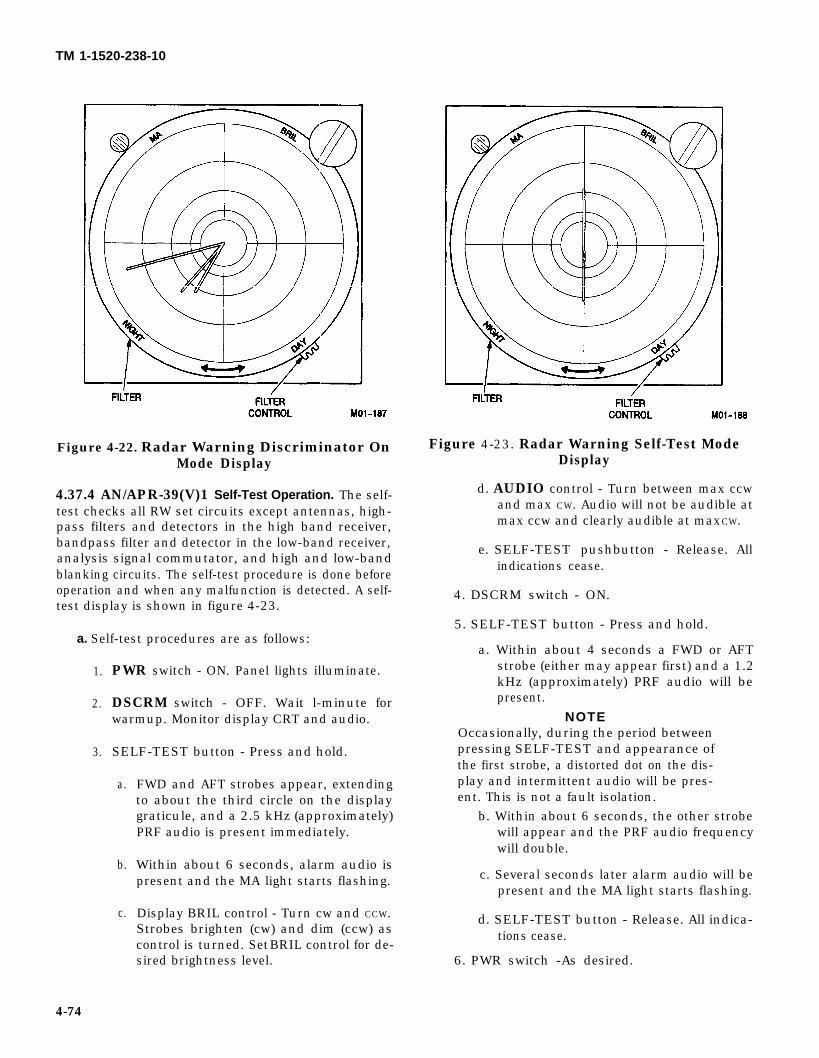
TM 1-1520-238-10
Figure 4-22. Radar Warning Discriminator OnMode Display
4.37.4 AN/APR-39(V)1 Self-Test Operation. The self-test checks all RW set circuits except antennas, high-pass filters and detectors in the high band receiver,bandpass filter and detector in the low-band receiver,analysis signal commutator, and high and low-bandblanking circuits. The self-test procedure is done beforeoperation and when any malfunction is detected. A self-test display is shown in figure 4-23.
a. Self-test procedures are as follows:
1.
2.
3.
PWR switch - ON. Panel lights illuminate.
DSCRM switch - OFF. Wait l-minute forwarmup. Monitor display CRT and audio.
SELF-TEST button - Press and hold.
a.
b.
c.
FWD and AFT strobes appear, extendingto about the third circle on the displaygraticule, and a 2.5 kHz (approximately)PRF audio is present immediately.
Within about 6 seconds, alarm audio ispresent and the MA light starts flashing.
Display BRIL control - Turn cw and CCW.Strobes brighten (cw) and dim (ccw) ascontrol is turned. Set BRIL control for de-sired brightness level.
Figure 4-23. Radar Warning Self-Test ModeDisplay
d. AUDIO control - Turn between max ccwand max CW. Audio will not be audible atmax ccw and clearly audible at max CW.
e. SELF-TEST pushbutton - Release. Allindications cease.
4. DSCRM switch - ON.
5. SELF-TEST button - Press and hold.
a. Within about 4 seconds a FWD or AFTstrobe (either may appear first) and a 1.2kHz (approximately) PRF audio will bepresent.
NOTEOccasionally, during the period betweenpressing SELF-TEST and appearance ofthe first strobe, a distorted dot on the dis-play and intermittent audio will be pres-ent. This is not a fault isolation.
b. Within about 6 seconds, the other strobewill appear and the PRF audio frequencywill double.
c. Several seconds later alarm audio will bepresent and the MA light starts flashing.
d. SELF-TEST button - Release. All indica-tions cease.
6. PWR switch -As desired.
4-74
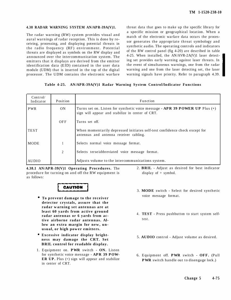
TM 1-1520-238-10
4.38 RADAR WARNING SYSTEM AN/APR-39A(V)1.
The radar warning (RW) system provides visual andaural warnings of radar reception. This is done by re-ceiving, processing, and displaying potential threats inthe radio frequency (RF) environment. Potentialthreats are displayed as symbols on the RW display andannounced over the intercommunication system. Theemitters that it displays are derived from the emitteridentification data (EID) contained in the user datamodule (UDM) that is inserted in the top of the digitalprocessor. The UDM contains the electronic warfare
threat data that goes to make up the specific library fora specific mission or geographical location. When amatch of the electronic warfare data occurs the proces-sor generates the appropriate threat symbology andsynthetic audio. The operating controls and indicatorsof the RW control panel (fig 4-20) are described in table4-25. When installed, the AN/AVR-2A(V)1 laser detect-ing set provides early warning against laser threats. Inthe event of simultaneous warnings, one from the radarwarning and one from the laser detecting set, the laserwarning signals have priority. Refer to paragraph 4.39.
Table 4-25. AN/APR-39A(V)1 Radar Warning System Control/Indicator Functions
Control/Indicator
PWR
Position Function
ON Turns set on. Listen for synthetic voice message - APR 39 POWER UP Plus (+)sign will appear and stabilize in center of CRT.
TEST
OFF Turns set off.
When momentarily depressed initiates self-test confidence check except forantennas and antenna receiver cabling.
MODE 1 Selects normal voice message format.
2 Selects terse/abbreviated voice message format.
AUDIO Adjusts volume to the intercommunications system.
4.38.1 AN/APR-39(V)1 Operating Procedures. The 2. BRIL - Adjust as desired for best indicatorprocedure for turning on and off the RW equipment is display of + symbol.as follows:
To prevent damage to the receiverdetector crystals, assure that theradar warning set antennas are atleast 60 yards from active groundradar antennas or 6 yards from ac-tive airborne radar antennas. Al-low an extra margin for new, un-usual, or high power emitters.
Excessive indicator display bright-ness may damage the CRT. SetBRIL control for readable display.
3. MODE switch - Select for desired syntheticvoice message format.
4. TEST - Press pushbutton to start system self-test.
5. AUDIO control - Adjust volume as desired.
1. Equipment on. PWR switch - ON. Listenfor synthetic voice message - APR 39 POW-ER UP. Plus (+) sign will appear and stabilizein center of CRT.
6. Equipment off. PWR switch - OFF. (PullPWR switch handle out to disengage lock.)
Change 5 4-75
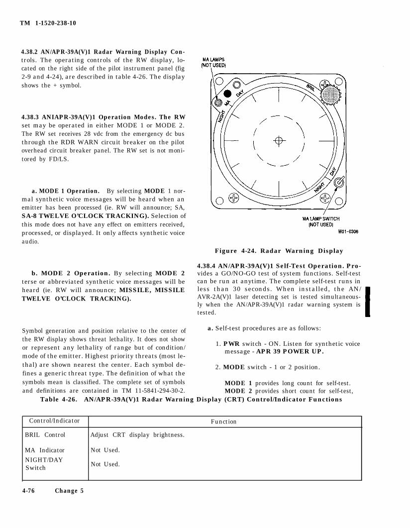
TM 1-1520-238-10
4.38.2 AN/APR-39A(V)1 Radar Warning Display Con-trols. The operating controls of the RW display, lo-cated on the right side of the pilot instrument panel (fig2-9 and 4-24), are described in table 4-26. The displayshows the + symbol.
4.38.3 ANIAPR-39A(V)1 Operation Modes. The RWset may be operated in either MODE 1 or MODE 2.The RW set receives 28 vdc from the emergency dc busthrough the RDR WARN circuit breaker on the pilotoverhead circuit breaker panel. The RW set is not moni-tored by FD/LS.
a. MODE 1 Operation. By selecting MODE 1 nor-mal synthetic voice messages will be heard when anemitter has been processed (ie. RW will announce; SA,SA-8 TWELVE O’CLOCK TRACKING). Selection ofthis mode does not have any effect on emitters received,processed, or displayed. It only affects synthetic voiceaudio.
b. MODE 2 Operation. By selecting MODE 2terse or abbreviated synthetic voice messages will beheard (ie. RW will announce; MISSILE, MISSILETWELVE O’CLOCK TRACKING).
Symbol generation and position relative to the center ofthe RW display shows threat lethality. It does not showor represent any lethality of range but of condition/mode of the emitter. Highest priority threats (most le-thal) are shown nearest the center. Each symbol de-fines a generic threat type. The definition of what thesymbols mean is classified. The complete set of symbolsand definitions are contained in TM 11-5841-294-30-2.
a. Self-test procedures are as follows:
1. PWR switch - ON. Listen for synthetic voicemessage - APR 39 POWER UP.
2. MODE switch - 1 or 2 position.
MODE 1 provides long count for self-test.MODE 2 provides short count for self-test,
Table 4-26. AN/APR-39A(V)1 Radar Warning Display (CRT) Control/Indicator Functions
Figure 4-24. Radar Warning Display
4.38.4 AN/APR-39A(V)1 Self-Test Operation. Pro-vides a GO/NO-GO test of system functions. Self-testcan be run at anytime. The complete self-test runs inless than 30 seconds. When installed, the AN/AVR-2A(V)1 laser detecting set is tested simultaneous-ly when the AN/APR-39A(V)1 radar warning system istested.
Control/Indicator
BRIL Control
MA Indicator
NIGHT/DAYSwitch
Function
Adjust CRT display brightness.
Not Used.
Not Used.
4-76 Change 5
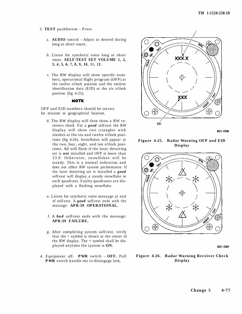
NOTE
TM 1-1520-238-10
3. TEST pushbutton - Press
a. AUDIO control - Adjust as desired duringlong or short count.
b. Listen for synthetic voice long or shortcount. SELF-TEST SET VOLUME 1, 2,3, 4, 5, 6, 7, 8, 9, 10, 11, 12.
c. The RW display will show specific num-bers, operational flight program (OFP) atthe twelve o’clock position and the emitteridentification data (EID) at the six o’clockposition (fig 4-25).
OFP and EID numbers should be correctfor mission or geographical location.
d. The RW display will then show a RW re-ceivers check. For a good self-test the RWdisplay will show two triangles withslashes at the six and twelve o’clock posi-tions (fig 4-26). Snowflakes will appear atthe two, four, eight, and ten o’clock posi-tions. All will flash if the laser detectingset is not installed and OFP is lower than23.9. Otherwise, snowflakes will besteady. This is a normal indication anddoes not affect RW system performance. Ifthe laser detecting set is installed a goodself-test will display a steady snowflake ineach quadrant. Faulty quadrants are dis-played with a flashing snowflake.
e. Listen for synthetic voice message at endof self-test. A good self-test ends with themessage: APR-39 OPERATIONAL.
f. A bad self-test ends with the message:APR-39 FAILURE.
g. After completing system self-test, verifythat the + symbol is shown at the center ofthe RW display. The + symbol shall be dis-played anytime the system is ON.
4. Equipment off. PWR switch - OFF. PullPWR switch handle out to disengage lock.
Figure 4-25. Radar Warning OFP and EIDDisplay
Figure 4-26. Radar Warning Receiver CheckDisplay
Change 5 4-77
TM 1-1520-238-10
4.39 AN/AVR-2 (V)1 LASER DETECTING SET
4.39.1 AN/AWMA(V)1 Laser Detecting Set (LDS)System Description. The AN/AVR-2A(V) Laser De-tecting Set (LDS) is a passive electronic warfare systemthat detects, locates, and identifies hostile laser-aidedweapon threats fired from both airborne and ground-based platforms. The LDS is a frequency extension ofthe Radar Warning (RW) system and interfaces withthe RW receivers and processor to function as an inte-grated Radar Laser Warning Receiver (RLWR). Thesystem detects optical radiation illuminating the heli-copter, processes this laser data into laser threat mes-sages, and sends these messages to the RW digital pro-cessor. The digital processor processes these inputs toprovide for both visual and aural threat indications forthe system. The LDS can also be used with both the RWand the Air-to-Ground Engagement Systems (AGES) toprovide an engagement simulation system, in the op-erational training mode. The system is composed of fivecomponents: four laser sensor units and an InterfaceUnit Comparator (IFU). The four sensor units are stra-tegically located around the helicopter with twomounted forward, facing forward and two mounted aft,facing aft. Each sensor unit provides a 100° Field-Of-View (FOV) and +/- 45° of coverage in elevation. Thisconfiguration provides for 360° coverage in azimuthand t/-45° in elevation about the helicopter with sub-stantial overlap. Each sensor unit contains four sepa-rate laser detectors. They are located under a specialoptical window and supply coverage of three differentspectral regions: Electra-Optical (EO) bands I, II, and[II. Two detectors are employed in the band III region,the band IILA and band IIIB detectors, to provide therequired band III detection coverage.
4.39.2 System Operation. The sensor units performthe actual laser detection function for the system andcontain the necessary electronics to process detected la-ser signals. If a valid laser signal is detected, a threatmessage containing the laser type (band I, II, or III) issent to the IFU for processing. Each sensor unit con-tains optical and electrical Built-In Test (BIT) electron-ics to perform a self-test upon command from the IFU.When a self-test command is received, the sensor unitdisables detection of all externally generated signalsand performs a self-test. When the self-test is com-pleted, the appropriate pass or fail message is sent tothe IFU for processing and normal operation is re-sumed. The IFU is located in the LH aft avionics bay. Itis mounted just forward of the RW digital processorwith which it directly interfaces. The IFU provides thecontrol and timing necessary for the interface with the
sensor units. It also provides the interface with the RWsystem. The LDS was designed to operate in conjunc-tion with the RW system, therefore, being an integralpart of the RW system. The IFU provides the majorityof the wiring interface between the RW system and theassociated helicopter systems. If the IFU is removedfrom the helicopter, a jumper box must be installed inthe system or an alternate connector configurationemployed to permit the RW system to operate. The LDSemploys a removable User Data Module (UDM) whichis mounted in the face of the IFU. The UDM containsthe classified operational software required for tacticaloperation of the system. This software gets downloadedinto volatile memory within the sensor units duringsystem power-up and initialization, and the sensorunits then become classified. When system power is re-moved, the sensor units zeroize the classified softwareand become unclassified components. The removal ofsystem power and the UDM for the IFU effectively de-classifies the system. The LDS has the capability to op-erate in two modes, training and tactical. In the train-ing mode, the system operates with AGES in theMultiple Integrated Laser Engagement System(MILES) to provide the crewmembers with a realisticcombat tactical training system that closely simulatesthe effect of weapon engagements.
a. Training. During training operation, the LDS op-erates as a detecting system in a MILES environmentand the operating software within the LDS does notrecognize .904 micron gallium arsenide (GaAs) MILESlaser hits as actual laser threats.
b. Tactical. During tactical operation, the LDS de-tects, identifies, and characterizes three different typesof optical signals. Each sensor unit provides laserthreat detection in three different spectral bands; bandI, band II, and band III. When a sensor unit detects op-tical, coherent radiation within its FOV, it providesband and pulse characteristics as laser threat data tothe IFU. The IFU further processes this threat data,thus comparing received signal characteristics withstored parameters. It then determines the existence ofa laser threat, threat type, and Angle-Of-Arrival (AOA)(quadrant resolution only). This threat data is sent aslaser threat messages to the RW digital processor formanipulation to provide visual threat indications onthe RW display and aural voice threat messages overthe helicopter ICS. Both the visual and aural threat in-dications provide threat type and relative position in-formation to the crewmembers.
c. Operating Procedures. Refer to para. 4.38.1.
4-78 Change 5
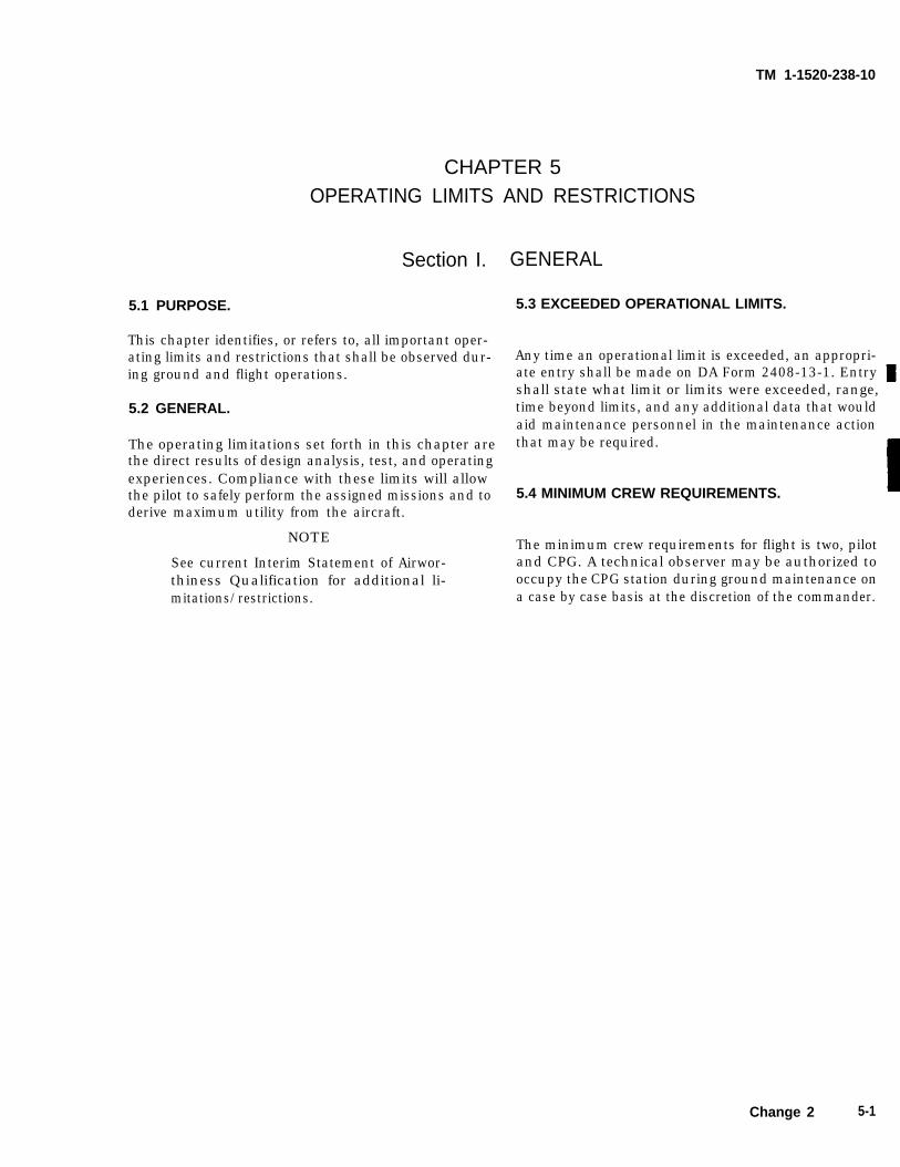
TM 1-1520-238-10
CHAPTER 5OPERATING LIMITS AND RESTRICTIONS
Section I.
5.1 PURPOSE.
This chapter identifies, or refers to, all important oper-ating limits and restrictions that shall be observed dur-ing ground and flight operations.
5.2 GENERAL.
The operating limitations set forth in this chapter arethe direct results of design analysis, test, and operatingexperiences. Compliance with these limits will allowthe pilot to safely perform the assigned missions and toderive maximum utility from the aircraft.
NOTE
See current Interim Statement of Airwor-thiness Qualification for additional li-mitations/restrictions.
GENERAL
5.3 EXCEEDED OPERATIONAL LIMITS.
Any time an operational limit is exceeded, an appropri-ate entry shall be made on DA Form 2408-13-1. Entryshall state what limit or limits were exceeded, range,time beyond limits, and any additional data that wouldaid maintenance personnel in the maintenance actionthat may be required.
5.4 MINIMUM CREW REQUIREMENTS.
The minimum crew requirements for flight is two, pilotand CPG. A technical observer may be authorized tooccupy the CPG station during ground maintenance ona case by case basis at the discretion of the commander.
Change 2 5-1
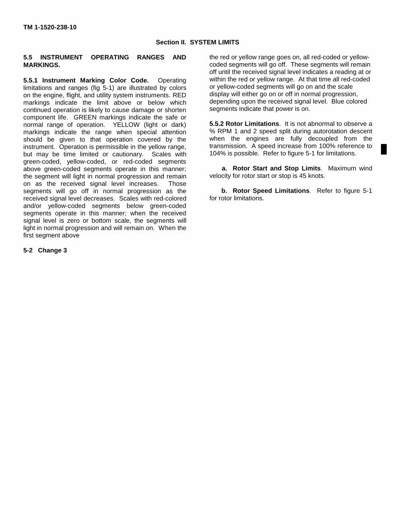
TM 1-1520-238-10
Section II. SYSTEM LIMITS
5.5 INSTRUMENT OPERATING RANGES ANDMARKINGS.
5.5.1 Instrument Marking Color Code. Operatinglimitations and ranges (fig 5-1) are illustrated by colorson the engine, flight, and utility system instruments. REDmarkings indicate the limit above or below whichcontinued operation is likely to cause damage or shortencomponent life. GREEN markings indicate the safe ornormal range of operation. YELLOW (light or dark)markings indicate the range when special attentionshould be given to that operation covered by theinstrument. Operation is permissible in the yellow range,but may be time limited or cautionary. Scales withgreen-coded, yellow-coded, or red-coded segmentsabove green-coded segments operate in this manner;the segment will light in normal progression and remainon as the received signal level increases. Thosesegments will go off in normal progression as thereceived signal level decreases. Scales with red-coloredand/or yellow-coded segments below green-codedsegments operate in this manner; when the receivedsignal level is zero or bottom scale, the segments willlight in normal progression and will remain on. When thefirst segment above
the red or yellow range goes on, all red-coded or yellow-coded segments will go off. These segments will remainoff until the received signal level indicates a reading at orwithin the red or yellow range. At that time all red-codedor yellow-coded segments will go on and the scaledisplay will either go on or off in normal progression,depending upon the received signal level. Blue coloredsegments indicate that power is on.
5.5.2 Rotor Limitations. It is not abnormal to observe a% RPM 1 and 2 speed split during autorotation descentwhen the engines are fully decoupled from thetransmission. A speed increase from 100% reference to104% is possible. Refer to figure 5-1 for limitations.
a. Rotor Start and Stop Limits. Maximum windvelocity for rotor start or stop is 45 knots.
b. Rotor Speed Limitations. Refer to figure 5-1for rotor limitations.
5-2 Change 3
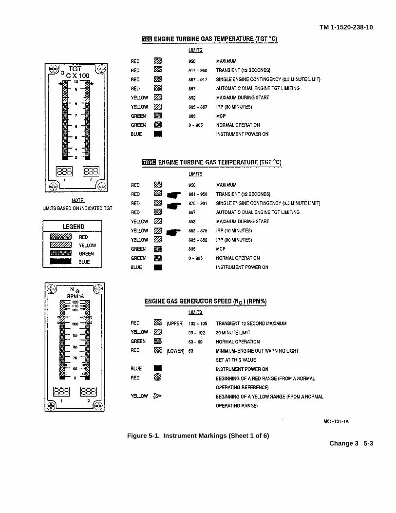
TM 1-1520-238-10
Figure 5-1. Instrument Markings (Sheet 1 of 6)Change 3 5-3
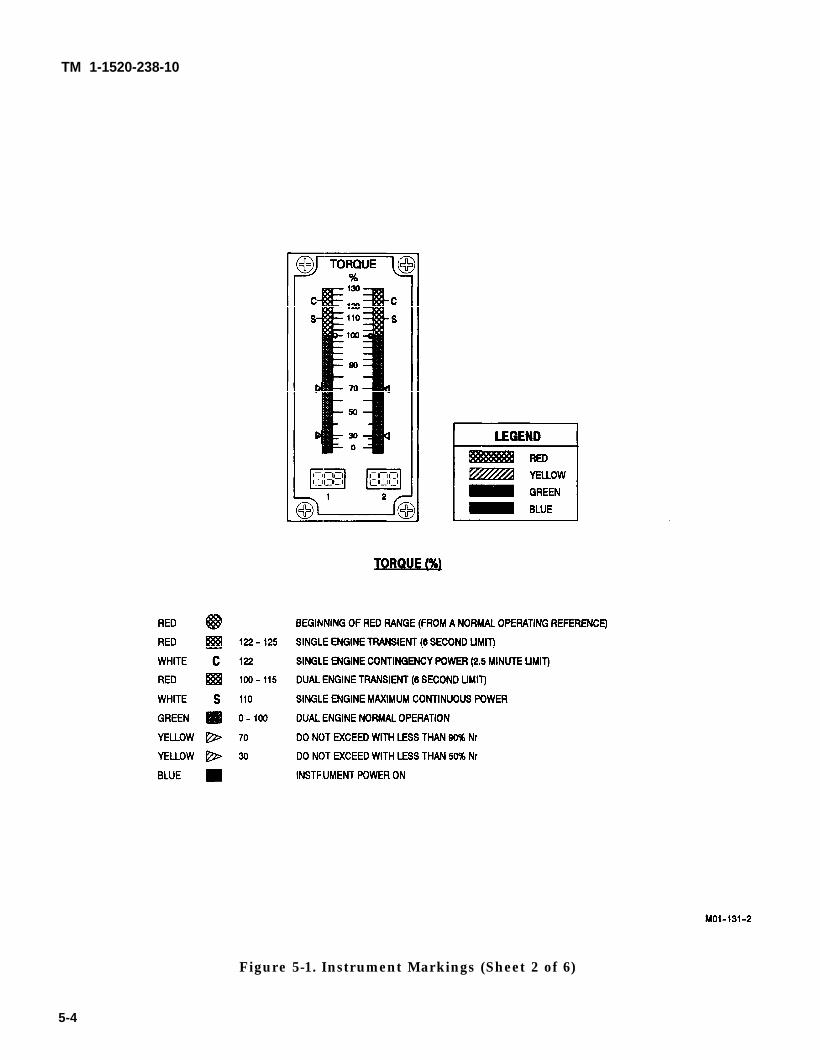
TM 1-1520-238-10
Figure 5-1. Instrument Markings (Sheet 2 of 6)
5-4
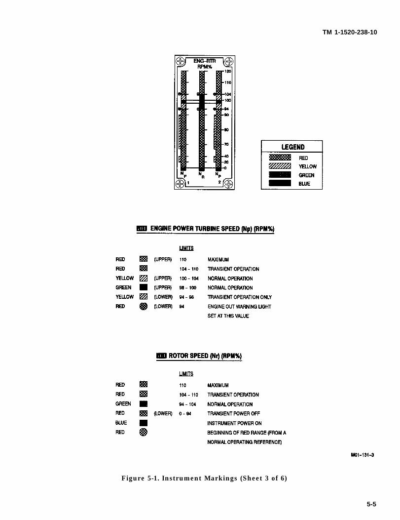
TM 1-1520-238-10
Figure 5-1. Instrument Markings (Sheet 3 of 6)
5-5
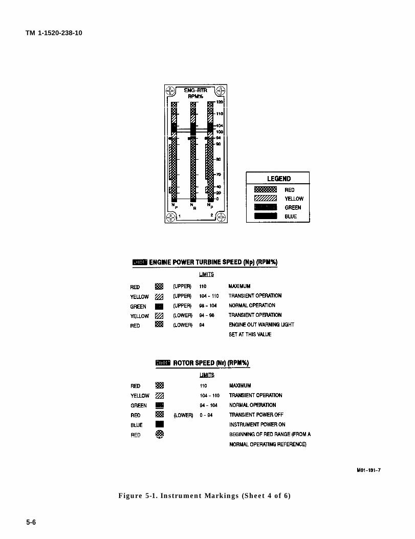
TM 1-1520-238-10
Figure 5-1. Instrument Markings (Sheet 4 of 6)
5-6
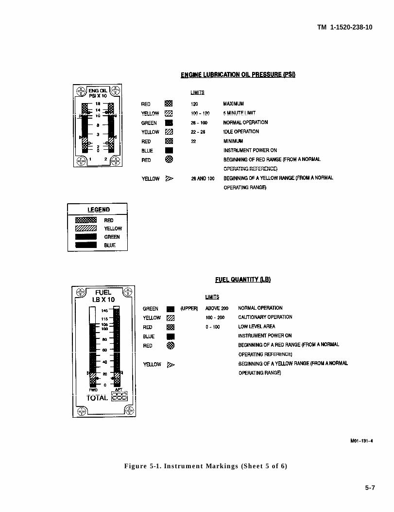
TM 1-1520-238-10
Figure 5-1. Instrument Markings (Sheet 5 of 6)
5-7
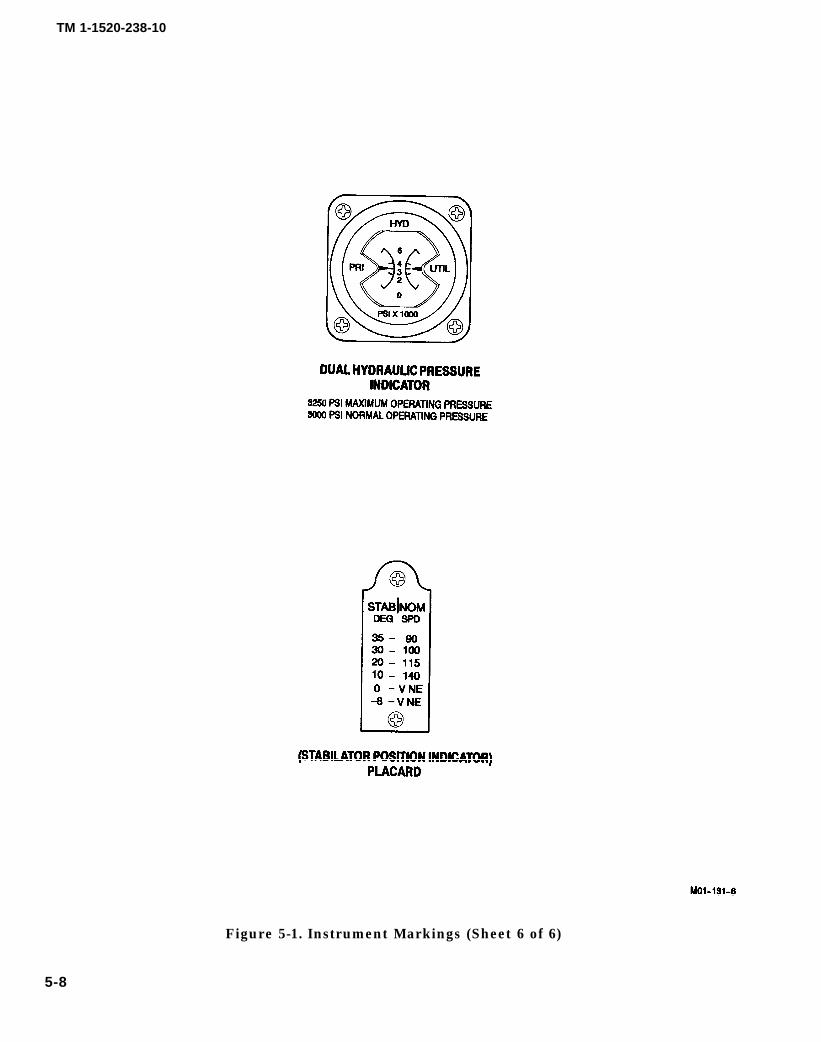
TM 1-1520-238-10
Figure 5-1. Instrument Markings (Sheet 6 of 6)
5-8
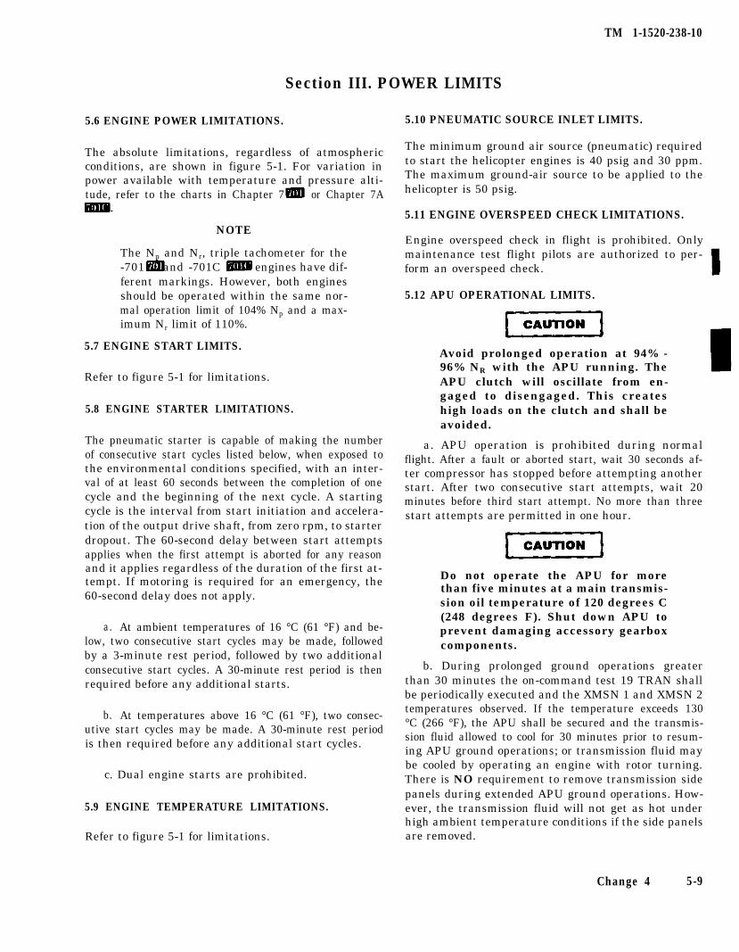
TM 1-1520-238-10
5.6 ENGINE POWER LIMITATIONS.
The absolute limitations, regardless of atmosphericconditions, are shown in figure 5-1. For variation inpower available with temperature and pressure alti-tude, refer to the charts in Chapter 7 or Chapter 7A
NOTE
The Np and Nr, triple tachometer for the-701 and -701C engines have dif-ferent markings. However, both enginesshould be operated within the same nor-mal operation limit of 104% Np and a max-imum Nr limit of 110%.
5.7 ENGINE START LIMITS.
Refer to figure 5-1 for limitations.
5.8 ENGINE STARTER LIMITATIONS.
The pneumatic starter is capable of making the numberof consecutive start cycles listed below, when exposed tothe environmental conditions specified, with an inter-val of at least 60 seconds between the completion of onecycle and the beginning of the next cycle. A startingcycle is the interval from start initiation and accelera-tion of the output drive shaft, from zero rpm, to starterdropout. The 60-second delay between start attemptsapplies when the first attempt is aborted for any reasonand it applies regardless of the duration of the first at-tempt. If motoring is required for an emergency, the60-second delay does not apply.
a. At ambient temperatures of 16 °C (61 °F) and be-low, two consecutive start cycles may be made, followedby a 3-minute rest period, followed by two additionalconsecutive start cycles. A 30-minute rest period is thenrequired before any additional starts.
b. At temperatures above 16 °C (61 °F), two consec-utive start cycles may be made. A 30-minute rest periodis then required before any additional start cycles.
c. Dual engine starts are prohibited.
5.9 ENGINE TEMPERATURE LIMITATIONS.
Refer to figure 5-1 for limitations.
Section III. POWER LIMITS
5.10 PNEUMATIC SOURCE INLET LIMITS.
The minimum ground air source (pneumatic) requiredto start the helicopter engines is 40 psig and 30 ppm.The maximum ground-air source to be applied to thehelicopter is 50 psig.
5.11 ENGINE OVERSPEED CHECK LIMITATIONS.
Engine overspeed check in flight is prohibited. Onlymaintenance test flight pilots are authorized to per-form an overspeed check.
5.12 APU OPERATIONAL LIMITS.
Avoid prolonged operation at 94% -96% NR with the APU running. TheAPU clutch will oscillate from en-gaged to disengaged. This createshigh loads on the clutch and shall beavoided.
a. APU operation is prohibited during normalflight. After a fault or aborted start, wait 30 seconds af-ter compressor has stopped before attempting anotherstart. After two consecutive start attempts, wait 20minutes before third start attempt. No more than threestart attempts are permitted in one hour.
Do not operate the APU for morethan five minutes at a main transmis-sion oil temperature of 120 degrees C(248 degrees F). Shut down APU toprevent damaging accessory gearboxcomponents.
b. During prolonged ground operations greaterthan 30 minutes the on-command test 19 TRAN shallbe periodically executed and the XMSN 1 and XMSN 2temperatures observed. If the temperature exceeds 130°C (266 °F), the APU shall be secured and the transmis-sion fluid allowed to cool for 30 minutes prior to resum-ing APU ground operations; or transmission fluid maybe cooled by operating an engine with rotor turning.There is NO requirement to remove transmission sidepanels during extended APU ground operations. How-ever, the transmission fluid will not get as hot underhigh ambient temperature conditions if the side panelsare removed.
Change 4 5-9

TM 1-1520-238-10
Section IV. LOADING LIMITS
5.13 CENTER OF GRAVITY LIMITS. 5.14 WEIGHT LIMITATIONS.
The maximum gross weight of the helicopter is 21,000pounds.
Center of gravity limits for the helicopter to which thismanual applies and instructions for computation of the
5.15 TURBULENCE.
center of gravity are contained in Chapter 6. Intentional flight in extreme turbulence is prohibited.
5-10
TM 1-1520-238-10
Section V. AIRSPEED LIMITS MAXIMUM AND MINIMUM
5.16 AIRSPEED OPERATING LIMITS.
See figure 5-2 to determine the never exceed velocity(VNE) as a function of weight, altitude, and tempera-ture. Additional airspeed limits are:
a. Maximum airspeed during autorotation is 145KTAS.
b. Maximum airspeed with one engine inoperativeshall not exceed the greater of
(1) 67% of VNE determined from figure 5-2 sheet1 using the GROSS WEIGHT line.
(2) The speed for minimum power determinedfrom the cruise charts in Chapter 7 or Chapter 7A
using the MAX END/MAX R/C lines.
c. The NOM SPD values depicted on the stabilatorposition (STAB POS) indicator placard (fig 5-1) shallbe observed as maximum indicated airspeeds duringmanual stabilator operations.
d. Maximum rearward/sideward flight speed is 45KTAS for all gross weights.
e. Maximum airspeed for searchlight extension is90 KIAS.
f. Maximum airspeed with symetrically loaded ex-ternal fuel tanks (2 or 4) installed is 130 KLAS.
g. Jettison of external armament stores is not au-thorized except for emergency conditions, and thenonly from unaccelerated flight during:
(1) Maximum airspeed for stores jettison is 120KIAS, or
(2) Level flight - Hover to 40 KIAS (minimizeside slip), or
or(3) Level flight - 40 to 120 KIAS (ball centered),
(4) Descents (0 fpm to full autorotation) 80 to100 KIAS (ball centered).
h. Jettison of external fuel tanks is not authorizedexcept for emergency conditions, and then only fromairspeeds less than 100 KIAS. Jettison from level flightif possible, and if not, jettison at an airspeed whichminimizes the rate of descent at the time of jettison.
5.16.1 Airspeed Operating Limits Chart. Referringto figure 5-2 sheet 1, note that free air temperaturelines and pressure altitude scale are provided in the up-per grid, and gross weight lines and true airspeed scaleon the lower grid. Using the observed free air tempera-ture and altitude obtained from the aircraft instru-ments and the calculated aircraft weight, enter thechart as directed in the chart example. Determine max-imum true airspeed at the left side of the lower grid. Todetermine the maximum indicated airspeed (pilotsgauge), refer to figure 5-2 sheet 2 and enter as directedin the chart example with the true airspeed and densityaltitude determined from figure 5-2 sheet 1.
Change 4 5-11
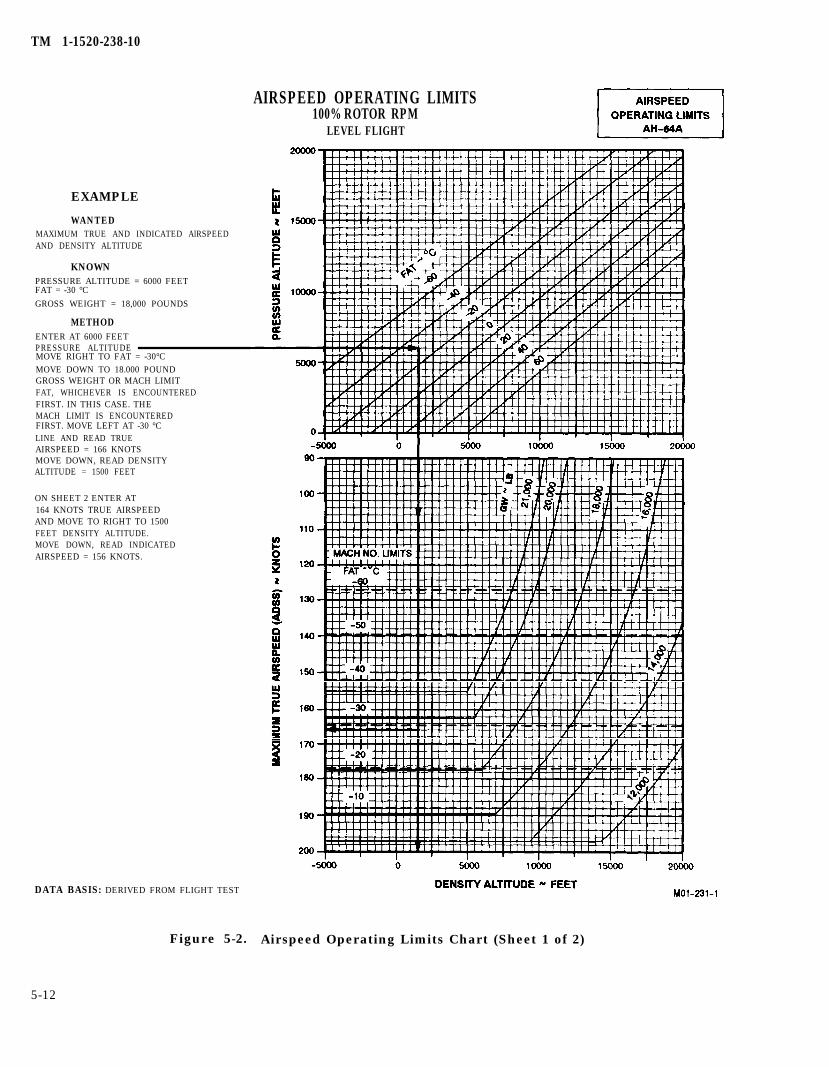
TM 1-1520-238-10
EXAMPLE
WANTEDMAXIMUM TRUE AND INDICATED AlRSPEEDAND DENSITY ALTITUDE
KNOWNPRESSURE ALTITUDE = 6000 FEETFAT = -30 °C
GROSS WEIGHT = 18,000 POUNDS
METHODENTER AT 6000 FEETPRESSURE ALTITUDEMOVE RIGHT TO FAT = -30°CMOVE DOWN TO 18.000 POUNDGROSS WEIGHT OR MACH LIMITFAT, WHICHEVER IS ENCOUNTEREDFIRST. IN THIS CASE. THEMACH LIMIT IS ENCOUNTEREDFIRST. MOVE LEFT AT -30 °CLINE AND READ TRUEAIRSPEED = 166 KNOTSMOVE DOWN, READ DENSITYALTITUDE = 1500 FEET
ON SHEET 2 ENTER AT164 KNOTS TRUE AIRSPEEDAND MOVE TO RIGHT TO 1500FEET DENSITY ALTITUDE.MOVE DOWN, READ INDICATEDAIRSPEED = 156 KNOTS.
DATA BASIS: DERIVED FROM FLIGHT TEST
AIRSPEED OPERATING LIMITS100% ROTOR RPM
LEVEL FLIGHT
Figure 5-2. Airspeed Operating Limits Chart (Sheet 1 of 2)
5-12
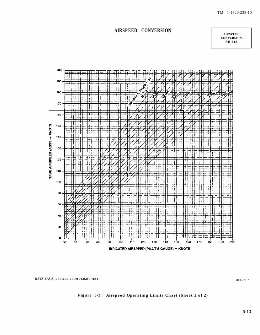
TM 1-1520-238-10
AIRSPEED CONVERSIONAIRSPEED
CONVERSIONAH-64A
DATA BASIS: DERIVED FROM FLIGHT TEST
Figure 5-2. Airspeed Operating Limits Chart (Sheet 2 of 2)
M01-231-2
5-13
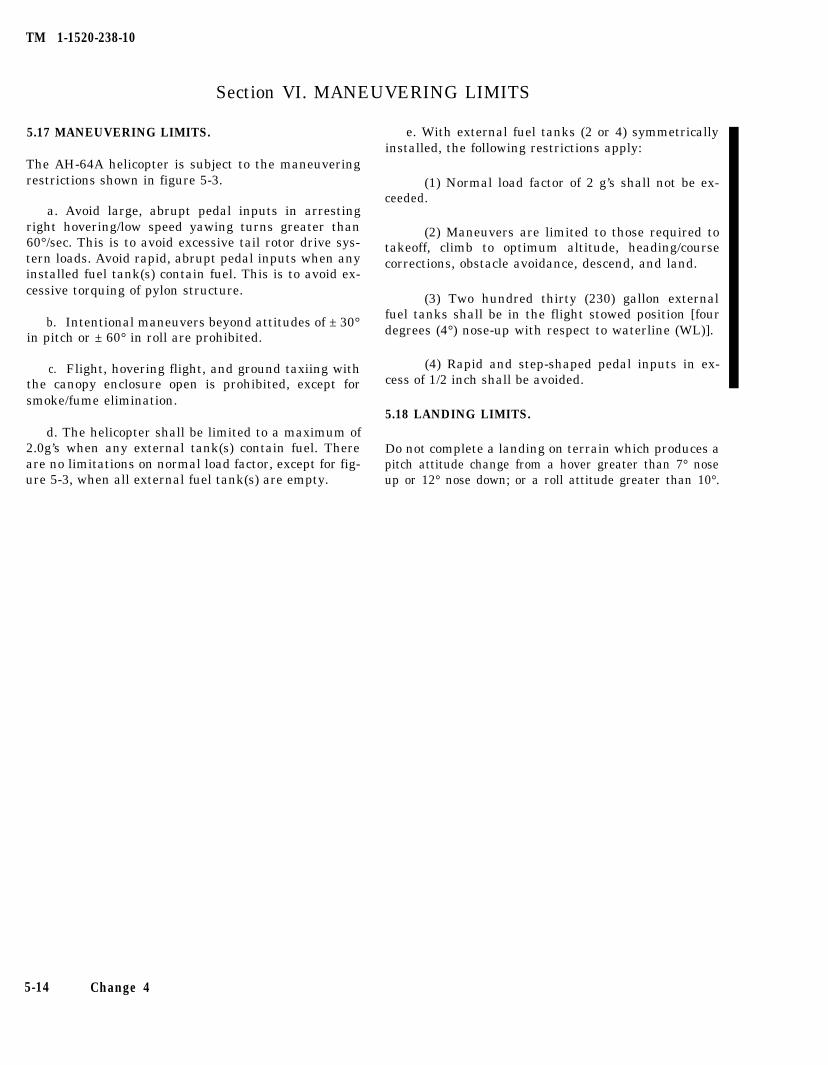
TM 1-1520-238-10
Section VI. MANEUVERING LIMITS
5.17 MANEUVERING LIMITS.
The AH-64A helicopter is subject to the maneuveringrestrictions shown in figure 5-3.
a. Avoid large, abrupt pedal inputs in arrestingright hovering/low speed yawing turns greater than60°/sec. This is to avoid excessive tail rotor drive sys-tern loads. Avoid rapid, abrupt pedal inputs when anyinstalled fuel tank(s) contain fuel. This is to avoid ex-cessive torquing of pylon structure.
b. Intentional maneuvers beyond attitudes of ± 30°in pitch or ± 60° in roll are prohibited.
c. Flight, hovering flight, and ground taxiing withthe canopy enclosure open is prohibited, except forsmoke/fume elimination.
d. The helicopter shall be limited to a maximum of2.0g’s when any external tank(s) contain fuel. Thereare no limitations on normal load factor, except for fig-ure 5-3, when all external fuel tank(s) are empty.
e. With external fuel tanks (2 or 4) symmetricallyinstalled, the following restrictions apply:
(1) Normal load factor of 2 g’s shall not be ex-ceeded.
(2) Maneuvers are limited to those required totakeoff, climb to optimum altitude, heading/coursecorrections, obstacle avoidance, descend, and land.
(3) Two hundred thirty (230) gallon externalfuel tanks shall be in the flight stowed position [fourdegrees (4°) nose-up with respect to waterline (WL)].
(4) Rapid and step-shaped pedal inputs in ex-cess of 1/2 inch shall be avoided.
5.18 LANDING LIMITS.
Do not complete a landing on terrain which produces apitch attitude change from a hover greater than 7° noseup or 12° nose down; or a roll attitude greater than 10°.
5-14 Change 4
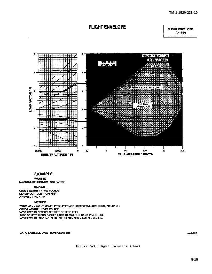
TM 1-1520-238-10
Figure 5-3. Flight Envelope Chart
5-15

TM 1-1520-238-10
5-16 Change 6
Section VII. ENVIRONMENTAL RESTRICTIONS
5.19 ENVIRONMENTAL RESTRICTIONS.
CAUTION
Intentional flight into known or fore-cast moderating icing is prohibited.
a. The AH-64A helicopter is equipped with de-icingand anti-icing equipment for flights into light icingconditions.
b. This aircraft is qualified for operation in instru-ment meteorological conditions.
c. Deleted.
d. For operation in adverse enviormental condi-tions, reference Chapter 8, Section V.
TM 1-1520-238-10
Section Vlll.
5.20 WING STORES CONFIGURATION.
For authorized wing stores configurations refer to fig-ure 7-18 701 or figure 7A-18 701C.
5.21 ALTERATION OF CBHK VALUES.
Only maintenance qualified personnel are authorizedto alter values from current CBHK values, unless per-forming the AWS dynamic harmonization procedure.Aviators may only verify and correct CBHK values, oth-er than the gun, to the current CBHK values as re-corded in the aircraft logbook. When aviators modify
OTHER LIMITS
gun values while performing dynamic harmonization,the new values will be entered on DA form 2408-13-1for maintenance review and transcription.
5.22 TRIM AND FORCE FEEL.
Use of the Trim and Force Feel Release switch in theFORCE TRIM OFF position with the helicopter onthe ground is not authorized. Inflight operation withthe Trim and Force Feel Release switch in FORCETRIM OFF position is authorized when briefed andthe FORCE TRIM OFF selection is acknowledged byboth crewmembers.
5-17/(5-18 blank)

TM 1-1520-238-10
CHAPTER 6WEIGHT/BALANCE AND LOADING
Section I. GENERAL
6.1 INTRODUCTION.
This chapter provides information required for helicop-ter loading and computing weight and balance. Thischapter contains sufficient instructions and data sothat an aviator, knowing the basic weight and momentof the helicopter, can compute any combination ofweight and balance using the prescribed Army chartsand forms.
centroid is at station 82.2, but the seat can be adjustedso the CPG centroid can vary from station 81.9 to 82.8.This produces a small moment variation and should beignored.
6.2 HELICOPTER CLASS.
6.3.2 Pilot Crew Station. The pilot station extendsfrom station 115.0 to station 168.0. The pilot nominalcentroid is at station 143.3, but the seat can be adjustedso the pilot centroid can vary from station 142.8 to143.8. This produces a small moment change andshould be ignored.
The Army AH-64A helicopter is in Class 2. Additionaldirectives governing weight and balance of Class 2 air-craft forms and records are contained in AR 95-1.
6.3 HELICOPTER COMPARTMENTS AND STATIONS.
The helicopter has many compartments (fig 6-1). Mostof them contain electronic or other equipment. Theboundaries of all compartments and a listing of theequipment in each compartment are provided in the he-licopter records Chart A - Basic Weight Checklist, DDForm 365-1. The compartments of primary concern tothe pilot, when loading, are the CPG and pilot crew sta-tions, left aft storage bay, and survival kit bay. Thesecompartments may contain personal items or extraequipment not accounted for in basic weight. (Refer toparagraph 6.18). Any additional items must be enteredon the Weight and Balance Form F (DD 365-4).
6.3.3 Left Aft Storage Bay. The aft storage bay is onthe left side from fuselage station 280.0 to 310.0 andcan be loaded to 15 pounds per square foot with a capac-ity of 60 pounds. The floor area is approximately 4.16square feet and the volume is approximately 21 cubicfeet. Floor tiedown fittings are in place to accommodatethe flyaway kit.
6.3.4 Survival Kit Bay. The survival kit bay isreached from either side. From fuselage station 310.0to 340.0, it can be loaded to 15 pounds per square footwith a capacity of 100 pounds. A single concentratedload of 45 pounds with a load density of 45 pounds persquare foot may be carried. The floor area is approxi-mately 7.3 square feet and the volume is approximately17 cubic feet. Floor tiedown fittings are in place to ac-commodate the survival kit.
NOTE
6.3.1 CPG Crew Station. The CPG station extends When loading these two bays, check forfrom station 35.5 to station 115.0. The CPG nominal exceeding the aft cg limit.
6-1
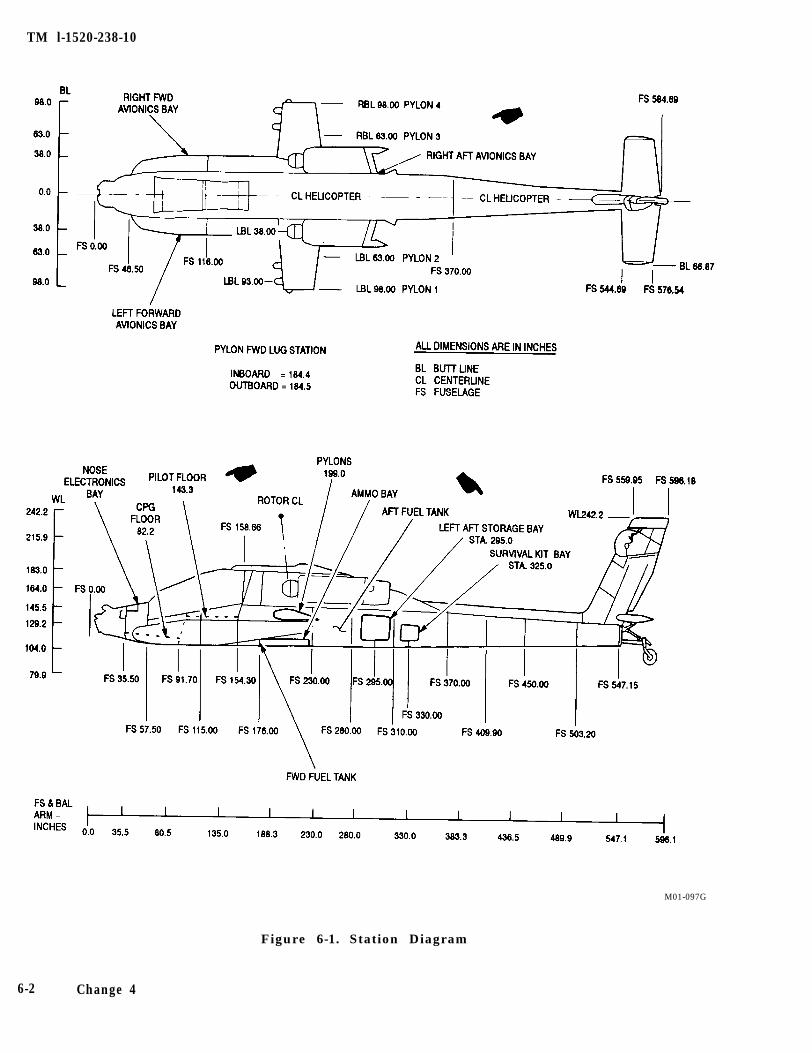
TM l-1520-238-10
M01-097G
Figure 6-1. Station Diagram
6-2 Change 4
TM 1-1520-238-10
Section Il. WEIGHT AND BALANCE
6.4 WEIGHT AND BALANCE.
This section contains information needed to computethe weight and balance for an individual helicopter byusing the prescribed standard charts and forms.
6.5 WEIGHT DEFINITIONS.
6.5.1 Basic Weight. The normal basic weight of thishelicopter includes wing pylons, all fixed operatingequipment, 30mm gun, all oil, and trapped fuel. It isonly necessary to add the variables or expendable tothese items for the missions.
NOTE
The basic weight of the helicopter willvary with mission requirements andstructural modifications such as additionor removal of wing pylons, peculiar kits,30mm gun, turret, ammo handling sys-tem, etc. A continuing record of an indi-vidual helicopter’s basic weight is main-tained on Chart C - Basic Weight andBalance Record, DD Form 365-3.
6.5.2 Operating Weight. The operating weight of thehelicopter is the basic weight plus those variableswhich remain substantially constant for a particularmission. These items include crew, baggage, rocketlaunchers, Hellfire launchers, and any emergency orextra equipment that may be required.
6.5.3 Gross Weight. The gross weight is the totalweight of the helicopter and its contents.
6.6 BALANCE Definitions.
6.6.1 Reference Datum. The reference datum is animaginary vertical plane from which all horizontal dis-tances are measured (in inches) for balance purposes.
6.6.2 Arm. For balance purposes, the term ARM isthe horizontal distance (in inches) from the referencedatum to the center of gravity of a given item. For spe-cial cases, ARM can be determined form figure 6-1. Forthe AH-64A helicopter, ARM and fuselage station (FS)are the same.
6.6.3 Moment. Moment is the weight of an item mul-tiplied by its arm. For the AH-64A helicopter, momentdivided by 100 (moment/100) is used to simplify cal-culations by reducing the number of digits.
NOTE
Throughout this chapter, moment/100 fig-ures have been rounded off to the nearestwhole number. When moments from othersources are being used, they must be di-vided by 100 and rounded off.
6.6.4 Average Arm. Average arnris the arm obtainedby adding the weights and the moments of a number ofitems and dividing the total moment by the totalweight.
6.6.5 Basic Moment. Basic moment is the sum of themoments of all items making up the basic weight withrespect to the helicopter reference datum.
6.6.6 Center of Gravity (CG). Center of gravity is thepoint about which the helicopter would balance if sus-pended. Distance from the reference datum is found bydividing the total moment by the gross weight of the he-licopter.
6.6.7 CG Limits. The cg limits are the extremes ofmovement to which the helicopter cg can travel withoutendangering controllability or structural integrity. Thecg of the loaded helicopter must remain within theselimits at takeoff, throughout flight, and during landing.
6.7 LOADING DATA.
The loading data in this chapter is intended to provideinformation necessary to work loading problems for thehelicopter. From this data, weight and moment/100 areobtained for all variable load items and are added to thecurrent basic weight and moment/100 from Chart C(DD Form 365-3) to determine the gross weight andmoment/100 using Form F (DD Form 365-4). The effecton helicopter cg of expending the fuel and armament ina logical sequence may be checked by subtracting theweight and moment/100 of each item from the takeoffgross weight and moment/100; then, checking the newmoment (or helicopter cg) with the cg limits chart. Thischeck should be made to determine if the cg will remainwithin limits during the entire flight. Refer to para-graph 6.10 for helicopter cg management.
6.8 CHART C - BASIC WEIGHT AND BALANCERECORD, DD FORM 365-3.
Chart C is a continuous history of the basic weight andmoment resulting from structural and equipmentchanges in service. At all times, the last weight and mo-ment/100 entries are considered the current weight andbalance status of the basic helicopter.
6-3
TM 1-1520-238-10
6.9 WEIGHT AND BALANCE CLEARANCE FORM F,DD FORM 3654.
Form F is the summary of the actual disposition of loadin the helicopter. It records the balance status of the he-licopter step-by-step. It serves as a work sheet on whichto record weight and balance calculations and anycorrections that must be made to ensure that the heli-copter will be within weight and cg limits throughoutthe mission. There are two versions of this form: Trans-port and Tactical. Each was designed to provide for therespective loading arrangement of these two types ofaircraft. The general use and fulfillment of either ver-sion is the same.
6.10 CENTER OF GRAVITY MANAGEMENT.
This paragraph contains fuel loading/managementmethods that can be used to maintain cg limits in flightand during the expending of external stores for somehelicopter configurations. The table of expendable(table 6-1) provides a guide for quick definition of inter-mediate flight cg as stores/fuel are expended at variousgross weights and at forward and aft cg limits. Table6-1 eliminate calculation of intermediate cg when thehelicopter is well within limits. When flight limits aredoubtful or when operation is close to cg limits, a de-tailed calculation must be made to determine any cglimit violation. When the storage bays are used for mis-cellaneous equipment it is possible to cause an aft cgcondition.
6.10.1 Fuel Loading. The helicopter takeoff cg can bemoved by loading either tank with more fuel than theother. Example: to move the cg forward, fill the forwardtank (1014 pounds of JP-4) and reduce fuel load in theaft tank depending on cg shift required. For some mis-sions, it maybe necessary to reduce the stowed weight.
6.10.2 Fuel Management. The following examplepresents normal cg/fuel management where each fuel
tank supplies an engine. This procedure prevents dras-tic helicopter cg shifts as fuel is expended. Refer toChapter 2 for fuel system details.
EXAMPLE:
1. Using table 6-1, refer to FUEL EXPENDED500 lb EACH line. Note that fuel expended at15,000 gross weight at forward cg limit pro-duces a helicopter forward cg shift of -0.13inch; and at aft cg limits, +0.29 inch. Whenthe helicopter cg is at the combined fuel cg(202.8 inches) expending fuel will produce azero shift. This is true only when the forwardtank fuel remains in the lower portion of theL-shape tank. Refer to paragraph 6.12.
2. When filling the forward tank into the upperportion of the L-shape, the combined fuel ex-pended cg moves aft to 212.4 inches whichmeans that the helicopter cg will always shiftforward during fuel burnoff in this area.
3. Refer to the 1000 lb fuel expended each tankline in table 6-1. Note that fuel expended at15,000 gross weight at aft cg limit is +0.41 in-ches. This is correct when the total 2,000pounds of fuel is expended, but this includes ahelicopter cg shift forward during initial fuelburn-off due to the forward L-shaped tank.
4. For the full fuel example based on a conserva-tive gross weight of 15,000 pounds and cg of201.0 inches, 208 pounds of aft fuel must betransferred so that all fuel can be expendedequally. A helicopter cg shift of- 1.49 to -1.68inches is produced depending on when thetransfer occurs. When working with full fuel,it is advisable to calculate several intermedi-ate points and determine when it’s best totransfer fuel.
6-4
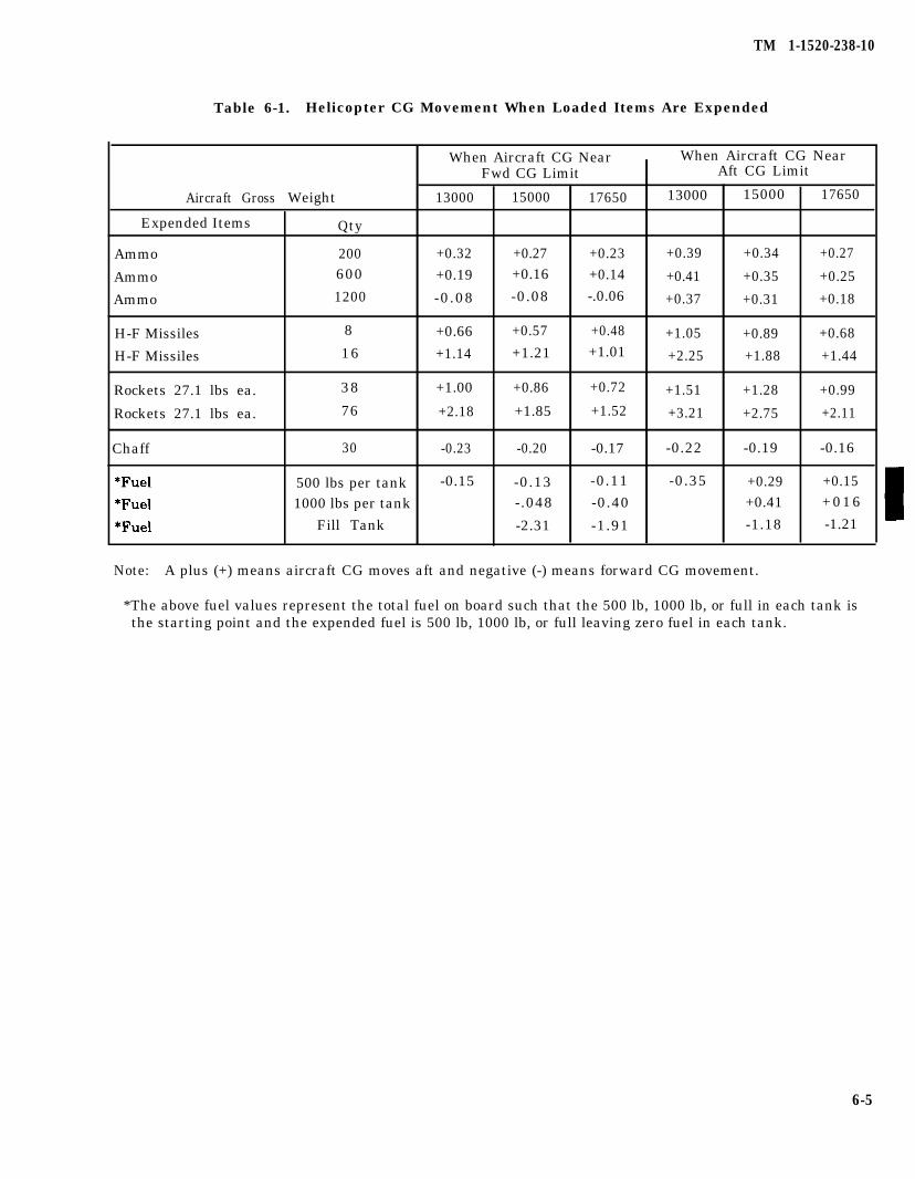
TM 1-1520-238-10
Table 6-1. Helicopter CG Movement When Loaded Items Are Expended
Aircraft Gross
Expended Items
Ammo
Ammo
Ammo
H-F Missiles
H-F Missiles
600 +0.19 +0.16 +0.14
1200 -0.08 -0.08 -.0.06
8 +0.66 +0.57 +0.48
16 +1.14 +1.21 +1.01
38 +1.00 +0.86 +0.72
76 +2.18 +1.85 +1.52Rockets 27.1 lbs ea.
Rockets 27.1 lbs ea.
Chaff
Weight
Qty
200
When Aircraft CG NearFwd CG Limit
13000 15000 17650
+0.32 +0.27 +0.23
30 -0.23 -0.20 -0.17
When Aircraft CG NearAft CG Limit
13000 15000 17650
+0.39 +0.34 +0.27
+0.41 +0.35 +0.25
+0.37 +0.31 +0.18
+1.05 +0.89 +0.68
+2.25 +1.88 +1.44
+1.51 +1.28 +0.99
+3.21 +2.75 +2.11
-0.22 -0.19 -0.16
500 lbs per tank -0.15 -0.13 -0.11 -0.35 +0.29 +0.15
1000 lbs per tank -.048 -0.40 +0.41 +016
Fill Tank -2.31 -1.91 -1.18 -1.21
Note: A plus (+) means aircraft CG moves aft and negative (-) means forward CG movement.
*The above fuel values represent the total fuel on board such that the 500 lb, 1000 lb, or full in each tank isthe starting point and the expended fuel is 500 lb, 1000 lb, or full leaving zero fuel in each tank.
6-5
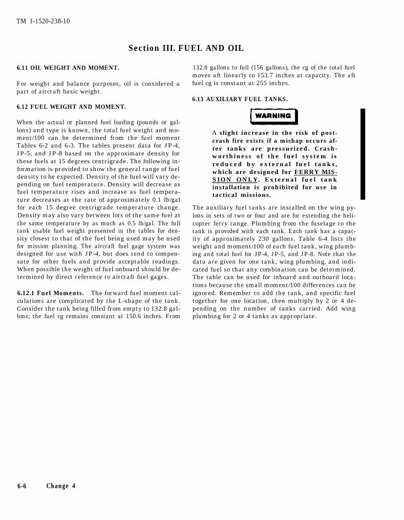
TM 1-1520-238-10
Section III. FUEL AND OIL
6.11 OIL WEIGHT AND MOMENT.
For weight and balance purposes, oil is considered apart of aircraft basic weight.
6.12 FUEL WEIGHT AND MOMENT.
When the actual or planned fuel loading (pounds or gal-lons) and type is known, the total fuel weight and mo-ment/100 can be determined from the fuel momentTables 6-2 and 6-3. The tables present data for JP-4,JP-5, and JP-8 based on the approximate density forthese fuels at 15 degrees centrigrade. The following in-formation is provided to show the general range of fueldensity to be expected. Density of the fuel will vary de-pending on fuel temperature. Density will decrease asfuel temperature rises and increase as fuel tempera-ture decreases at the rate of approximately 0.1 lb/galfor each 15 degree centrigrade temperature change.Density may also vary between lots of the same fuel atthe same temperature by as much as 0.5 lb/gal. The fulltank usable fuel weight presented in the tables for den-sity closest to that of the fuel being used may be usedfor mission planning. The aircraft fuel gage system wasdesigned for use with JP-4, but does tend to compen-sate for other fuels and provide acceptable readings.When possible the weight of fuel onboard should be de-termined by direct reference to aircraft fuel gages.
6.12.1 Fuel Moments. The forward fuel moment cal-culations are complicated by the L-shape of the tank.Consider the tank being filled from empty to 132.8 gal-lons; the fuel cg remains constant at 150.6 inches. From
132.8 gallons to full (156 gallons), the cg of the total fuelmoves aft linearly to 153.7 inches at capacity. The aftfuel cg is constant at 255 inches.
6.13 AUXILIARY FUEL TANKS.
A slight increase in the risk of post-crash fire exists if a mishap occurs af-ter tanks are pressurized. Crash-worthiness of the fuel system isreduced by external fuel tanks,which are designed for FERRY MIS-SION ONLY. External fuel tankinstallation is prohibited for use intactical missions.
The auxiliary fuel tanks are installed on the wing py-lons in sets of two or four and are for extending the heli-copter ferry range. Plumbing from the fuselage to thetank is provided with each tank. Each tank has a capac-ity of approximately 230 gallons. Table 6-4 lists theweight and moment/100 of each fuel tank, wing plumb-ing and total fuel for JP-4, JP-5, and JP-8. Note that thedata are given for one tank, wing plumbing, and indi-cated fuel so that any combination can be determined.The table can be used for inboard and outboard loca-tions because the small moment/100 differences can beignored. Remember to add the tank, and specific fueltogether for one location, then multiply by 2 or 4 de-pending on the number of tanks carried. Add wingplumbing for 2 or 4 tanks as appropriate.
6-6 Change 4
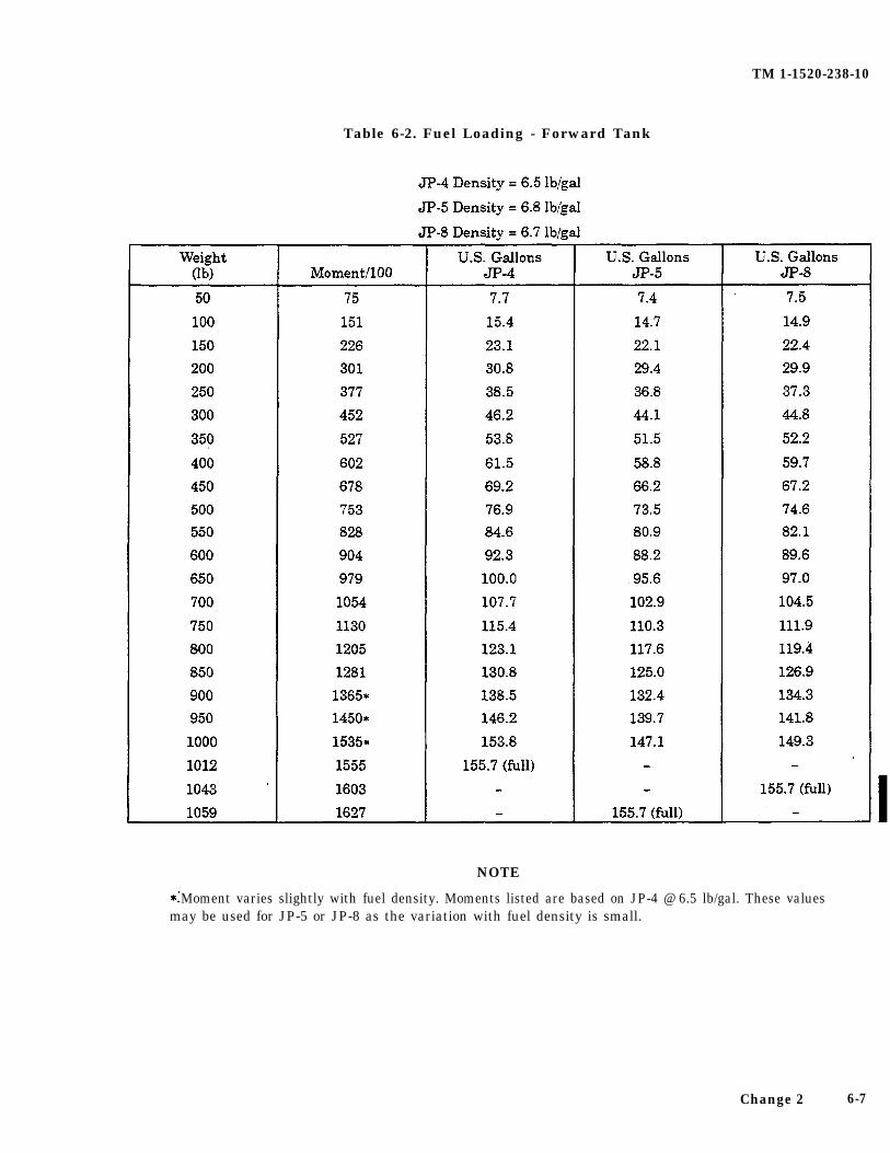
TM 1-1520-238-10
Table 6-2. Fuel Loading - Forward Tank
NOTE
Moment varies slightly with fuel density. Moments listed are based on JP-4 @ 6.5 lb/gal. These valuesmay be used for JP-5 or JP-8 as the variation with fuel density is small.
Change 2 6-7
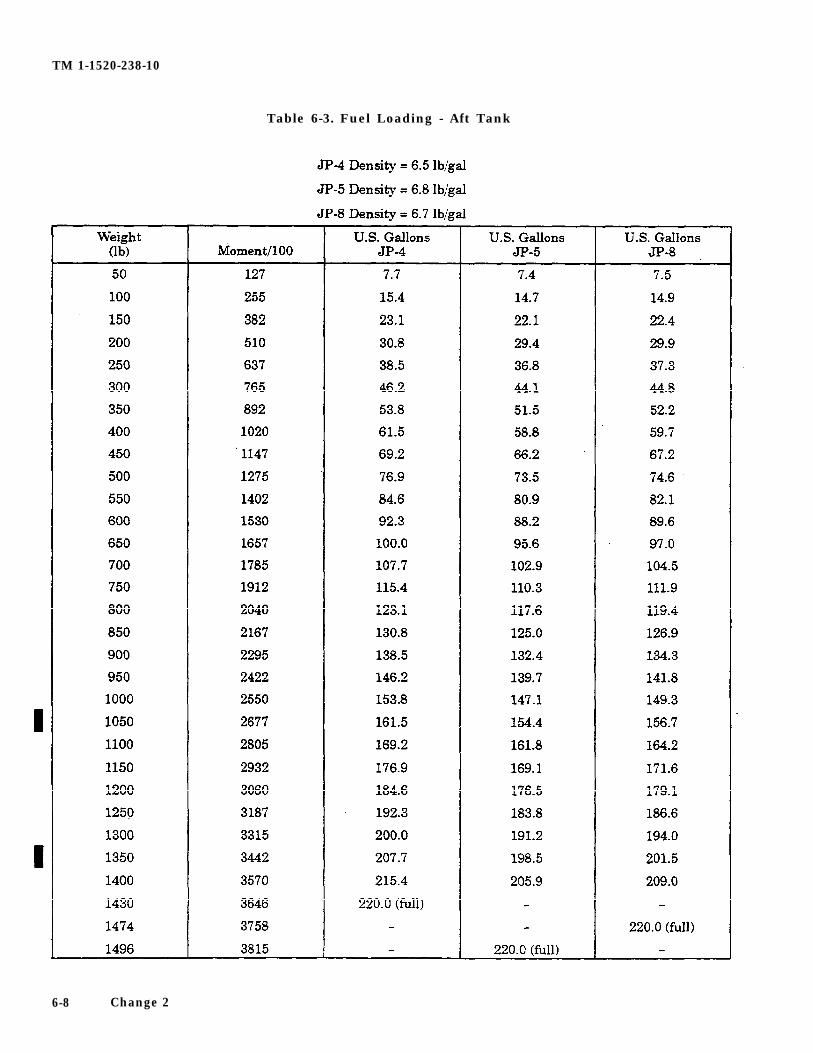
TM 1-1520-238-10
Table 6-3. Fuel Loading - Aft Tank
6-8 Change 2
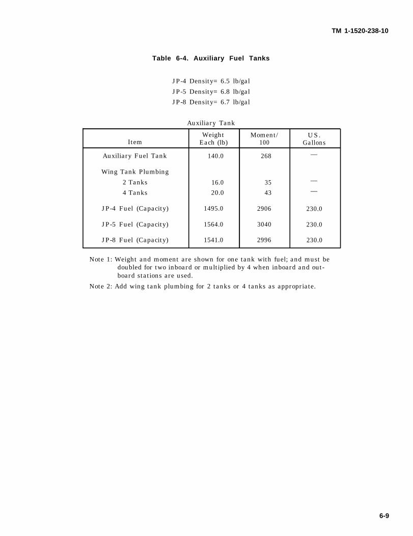
TM 1-1520-238-10
Table 6-4. Auxiliary Fuel Tanks
JP-4 Density= 6.5 lb/gal
JP-5 Density= 6.8 lb/gal
JP-8 Density= 6.7 lb/gal
Auxiliary Tank.
Weight Moment/ US.Item Each (lb) 100 Gallons
Auxiliary Fuel Tank 140.0 268 —
Wing Tank Plumbing
2 Tanks 16.0 35 —
4 Tanks 20.0 43 —
JP-4 Fuel (Capacity) 1495.0 2906 230.0
JP-5 Fuel (Capacity) 1564.0 3040 230.0
JP-8 Fuel (Capacity) 1541.0 2996 230.0
Note 1: Weight and moment are shown for one tank with fuel; and must bedoubled for two inboard or multiplied by 4 when inboard and out-board stations are used.
Note 2: Add wing tank plumbing for 2 tanks or 4 tanks as appropriate.
6-9
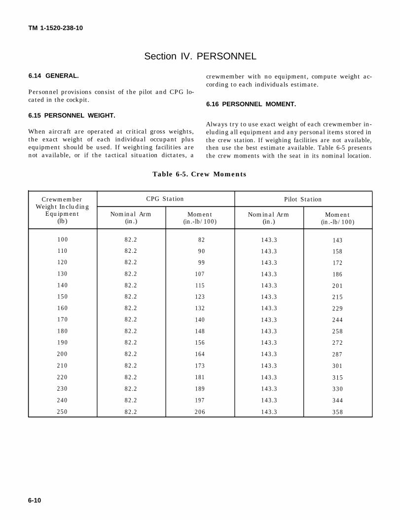
TM 1-1520-238-10
Section IV. PERSONNEL
6.14 GENERAL. crewmember with no equipment, compute weight ac-cording to each individuals estimate.
Personnel provisions consist of the pilot and CPG lo-cated in the cockpit.
6.16 PERSONNEL MOMENT.
6.15 PERSONNEL WEIGHT.Always try to use exact weight of each crewmember in-
When aircraft are operated at critical gross weights, eluding all equipment and any personal items stored inthe exact weight of each individual occupant plus the crew station. If weighing facilities are not available,equipment should be used. If weighting facilities are then use the best estimate available. Table 6-5 presentsnot available, or if the tactical situation dictates, a the crew moments with the seat in its nominal location.
Table 6-5. Crew Moments
Crewmember CPG Station Pilot StationWeight Including
Equipment Nominal Arm Moment Nominal Arm Moment(lb) (in.) (in.-lb/100) (in.) (in.-lb/100)
100 82.2 82 143.3 143
110 82.2 90 143.3 158
120 82.2 99 143.3 172
130 82.2 107 143.3 186
140 82.2 115 143.3 201
150 82.2 123 143.3 215
160 82.2 132 143.3 229
170 82.2 140 143.3 244
180 82.2 148 143.3 258
190 82.2 156 143.3 272
200 82.2 164 143.3 287
210 82.2 173 143.3 301
220 82.2 181 143.3 315
230 82.2 189 143.3 330
240 82.2 197 143.3 344
250 82.2 206 143.3 358
6-10
TM 1-1520-238-10
Section V. MISSION EQUIPMENT
6.17 MISSION EQUIPMENT.
The AH-64A helicopter mission equipment includesHellfire missiles and launchers, 2.75-inch rockets andlaunchers, 30mm ammunition, chaff cartridges, andCBR filters/blowers. External fuel tanks are describedin paragraph 6.13. All electronic mission equipment ispart of basic weight and may be found in Chart A (FormDD 365-1).
6.17.1 Hellfire Launchers. Figure 6-2 presents theM-272 Hellfire launchers, in pairs, weight, and mo-ment/100. When four launchers are required, doublethe numbers.
6.17.2 Hellfire Missiles. The present training,dummy, and laser seeker missiles weigh the same.Table 6-6 lists the weight and moment/100 of each mis-sile accumulated to a capacity of four missiles perlauncher. When a pair of inboard launchers are filled tocapacity, double the (missile No. 4) weight and mo-ment/100. When four launchers are used, multiply thenumbers by four.
6.17.3 Rocket Launchers (2.75 inch). Figure 6-2presents the M-261 2.75-inch rocket launchers, inpairs, weight, and moment/100. Double the weight andmoment/100 when four launchers are used.
6.17.4 Rockets (2.75-inch). Present training rocketsare designated H519 with an M156 warhead, M423fuse, and a MK 40 MOD 3 rocket motor. Dummy andtraining rockets are the same weight. Table 6-7 lists the2.75-inch rocket accumulated weight and moment/100
to a capacity of 19 per launcher. Select the correct num-ber of rockets, then double the weight and moment/100for a pair of launchers loaded evenly. Table 6-8 lists anMPSM warhead with a MK 66 rocket motor. The tablesare presented so that any combination or mix can beeasily determined for a launcher.
6.17.5 Ammunition (30mm). Table 6-9 presents theM-788 or M-789 30mm linkless aluminum case am-munition accumulated weight, and moment/100 to a ca-pacity of 1200 rounds. Approximately 90 rounds are inthe right chute and the remainder is in the magazine. Anote at the bottom of the table allows conversion of thetable numbers to ADEN or DEFA ammunition.
6.17.6 Chaff Cartridges. The helicopter survivabilityequipment is a kit. It is added to the helicopter as dic-tated by mission requirements. The electronic equip-ment, controls, and chaff supports are part of the basicweight and are listed in Chart A (DD 365-1). Table 6-10lists the chaff dispenser empty and the chaff dispenser(full) with 30 chaff(M-1) cartridges. These values are tobe used on Form F (DD 365-4) when chaff is on board.
6.17.7 Chemical, Biological, and Radiological (CBR)Filters/Blowers. The CBR filters/blowers are used bythe crewmembers as dictated by mission requirements.The CBR mounting bracket, located on the seats left ar-mored wing, is listed on Chart A (DD 365-1) and wheninstalled shall be accounted for on Chart C (DD 365-3)as part of the basic weight. When the filters/blowers areaboard, the values listed in table 6-11 are to be used torecord the weights and moments of the filters/blowersas a part of the helicopter loading on Form F (DD365-4).
Change 2 6-11
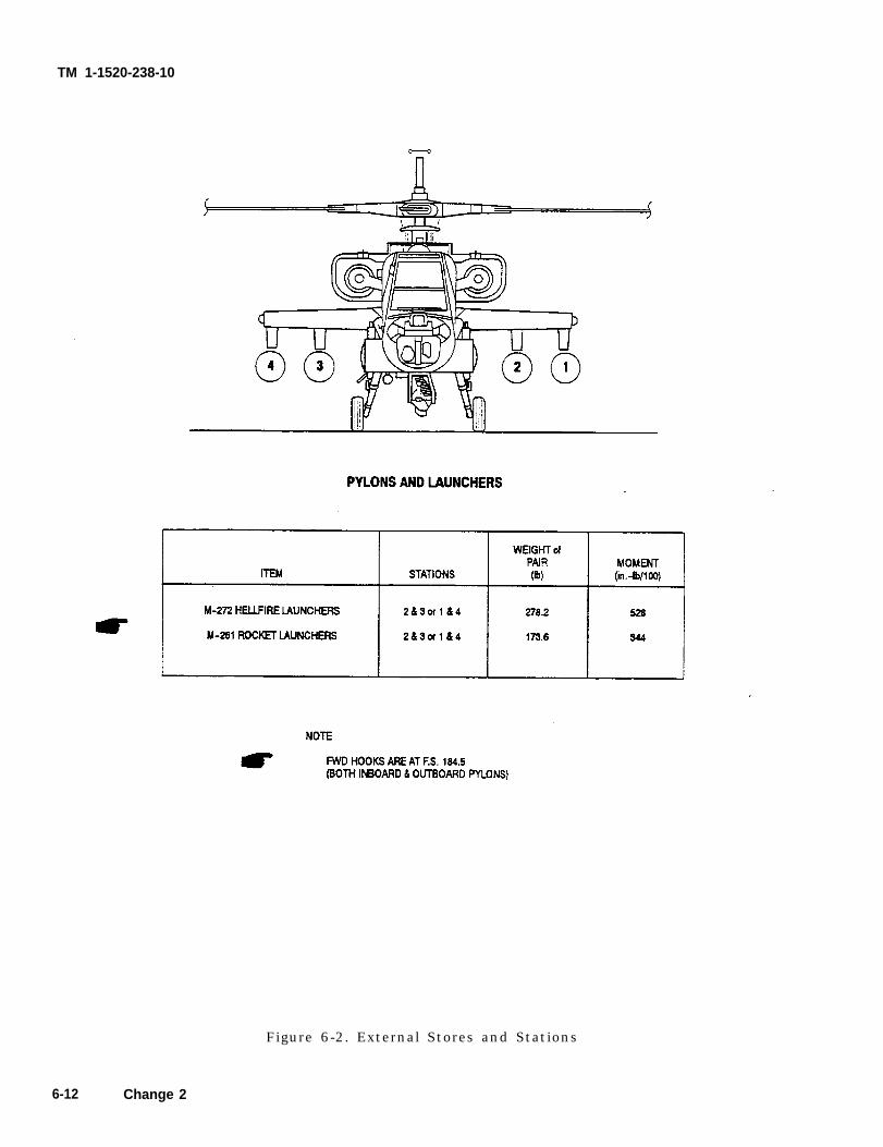
TM 1-1520-238-10
Figure 6-2. External Stores and Stations
6-12 Change 2
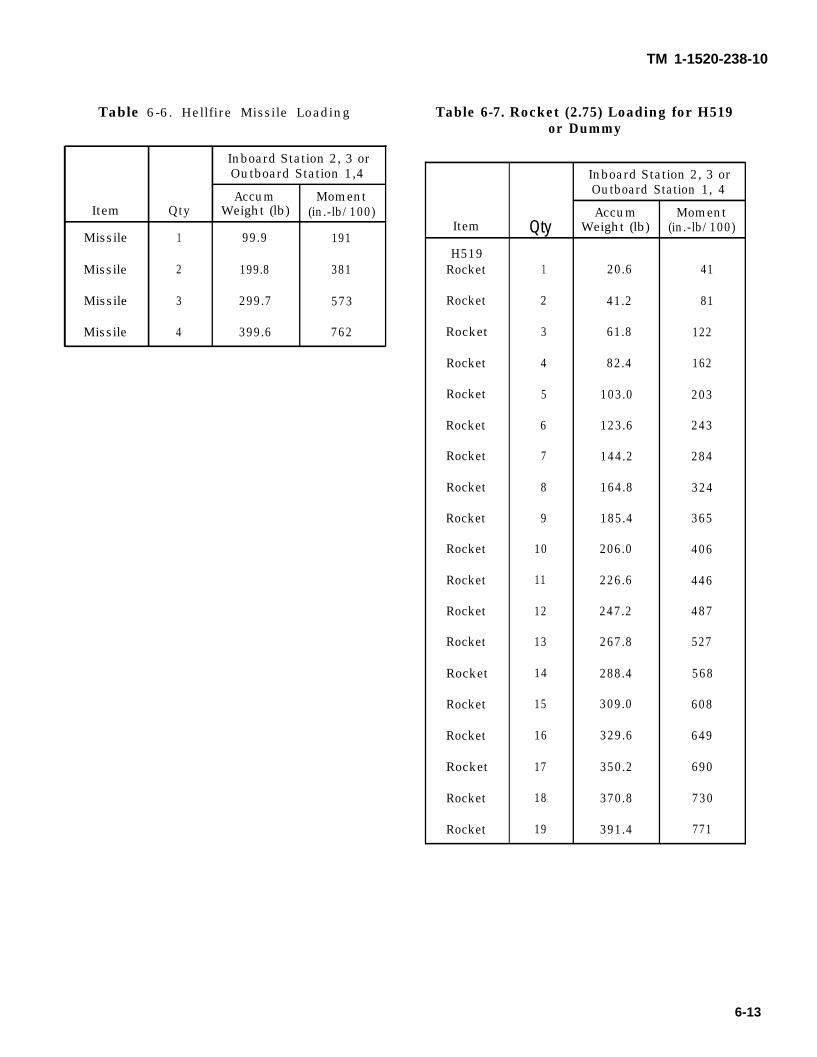
TM 1-1520-238-10
Table 6-6. Hellfire Missile Loading
Inboard Station 2, 3 orOutboard Station 1,4
Accum MomentItem Qty Weight (lb) (in.-lb/100)
Missile 1 99.9 191
Missile 2 199.8 381
Missile 3 299.7 573
Missile 4 399.6 762
Table 6-7. Rocket (2.75) Loading for H519or Dummy
Inboard Station 2, 3 orOutboard Station 1, 4
Accum MomentItem Qty Weight (lb) (in.-lb/100)
H519Rocket 1 20.6 41
Rocket 2 41.2 81
Rocket 3 61.8 122
Rocket 4 82.4 162
Rocket 5 103.0 203
Rocket 6 123.6 243
Rocket 7 144.2 284
Rocket 8 164.8 324
Rocket 9 185.4 365
Rocket 10 206.0 406
Rocket 11 226.6 446
Rocket 12 247.2 487
Rocket 13 267.8 527
Rocket 14 288.4 568
Rocket 15 309.0 608
Rocket 16 329.6 649
Rocket 17 350.2 690
Rocket 18 370.8 730
Rocket 19 391.4 771
6-13
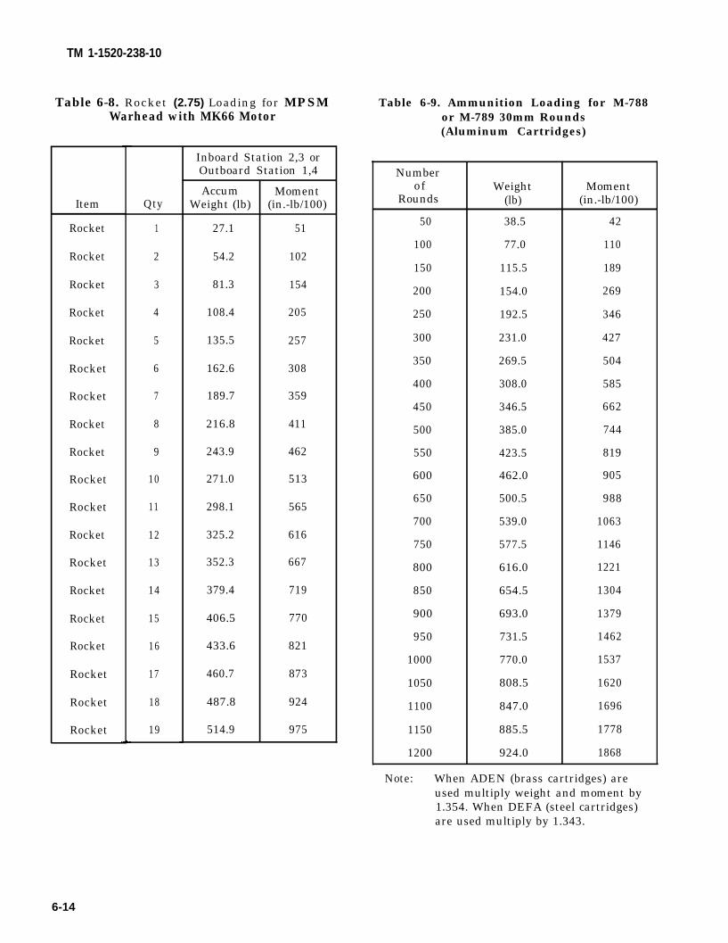
TM 1-1520-238-10
Table 6-8. Rocket (2.75) Loading for MPSMWarhead with MK66 Motor
Item
Rocket
Rocket
Rocket
Rocket
Rocket
Rocket
Rocket
Rocket
Rocket
Rocket
Rocket
Rocket
Rocket
Rocket
Rocket
Rocket
Rocket
Rocket
Rocket
Qty
1
2
3
4
5
6
7
8
9
10
11
12
13
14
15
16
17
18
19
Inboard Station 2,3 orOutboard Station 1,4
AccumWeight (lb)
27.1
54.2
81.3
108.4
135.5
162.6
189.7
216.8
243.9
271.0
298.1
325.2
352.3
379.4
406.5
433.6
460.7
487.8
514.9
Moment(in.-lb/100)
51
102
154
205
257
308
359
411
462
513
565
616
667
719
770
821
873
924
975
Table 6-9. Ammunition Loading for M-788or M-789 30mm Rounds(Aluminum Cartridges)
Numberof
Rounds
50
100
150
200
250
300
350
400
450
500
550
600
650
700
750
800
850
900
950
1000
1050
1100
1150
1200
Weight(lb)
38.5
77.0
115.5
154.0
192.5
231.0
269.5
308.0
346.5
385.0
423.5
462.0
500.5
539.0
577.5
616.0
654.5
693.0
731.5
770.0
808.5
847.0
885.5
924.0
Moment(in.-lb/100)
42
110
189
269
346
427
504
585
662
744
819
905
988
1063
1146
1221
1304
1379
1462
1537
1620
1696
1778
1868
Note: When ADEN (brass cartridges) areused multiply weight and moment by1.354. When DEFA (steel cartridges)are used multiply by 1.343.
6-14
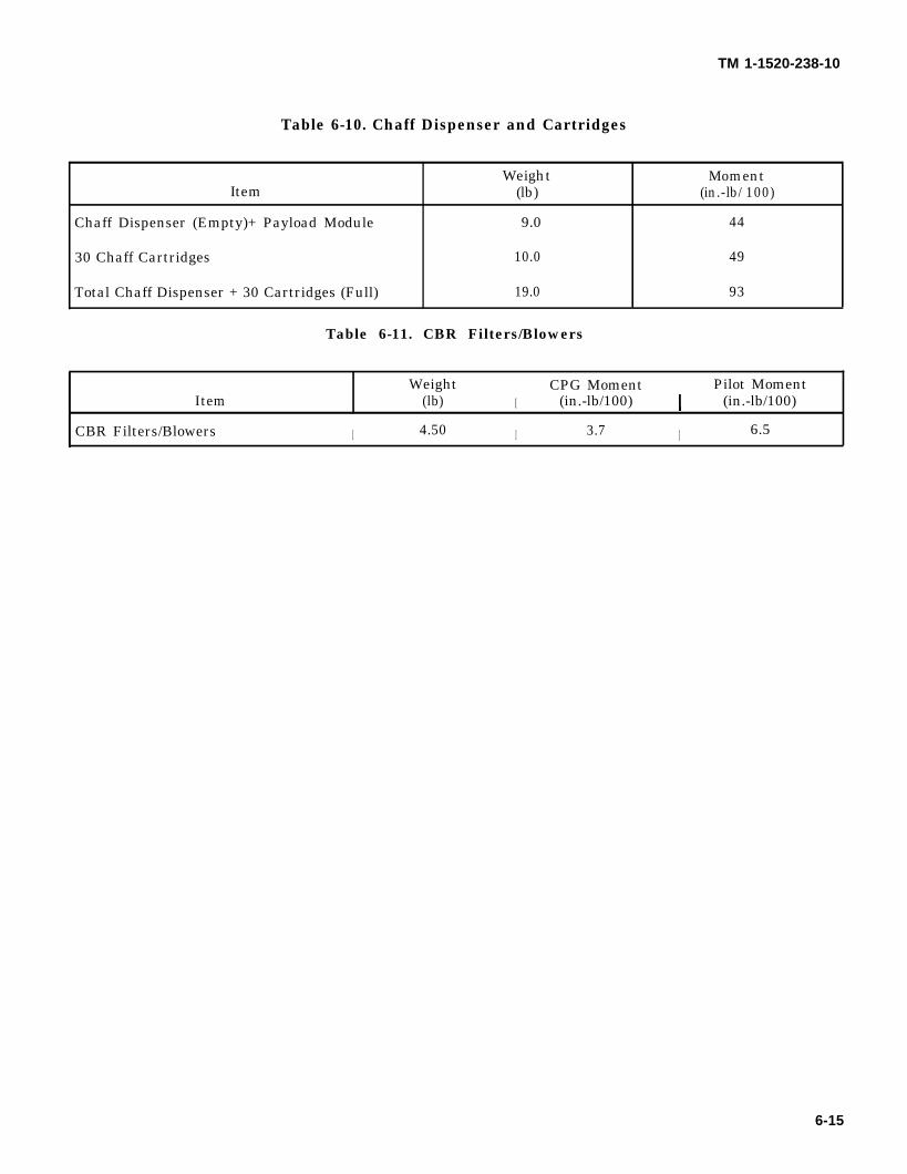
TM 1-1520-238-10
Table 6-10. Chaff Dispenser and Cartridges
Weight MomentItem (lb) (in.-lb/100)
Chaff Dispenser (Empty)+ Payload Module 9.0 44
30 Chaff Cartridges 10.0 49
Total Chaff Dispenser + 30 Cartridges (Full) 19.0 93
Table 6-11. CBR Filters/Blowers
WeightI
CPG Moment Pilot MomentItem (lb) (in.-lb/100) (in.-lb/100)
CBR Filters/Blowers I 4.50 I 3.7 I 6.5
6-15
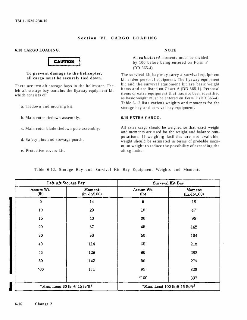
TM 1-1520-238-10
S e c t i o n V I . C A R G O L O A D I N G
6.18 CARGO LOADING.
To prevent damage to the helicopter,all cargo must be securely tied down.
There are two aft storage bays in the helicopter. Theleft aft storage bay contains the flyaway equipment kitwhich consists of:
a. Tiedown and mooring kit.
b. Main rotor tiedown assembly.
c. Main rotor blade tiedown pole assembly.
d. Safety pins and stowage pouch.
e. Protective covers kit.
NOTE
All calculated moments must be dividedby 100 before being entered on Form F(DD 365-4).
The survival kit bay may carry a survival equipmentkit and/or personal equipment. The flyaway equipmentkit and the survival equipment kit are basic weightitems and are listed on Chart A (DD 365-1). Personalitems or extra equipment that has not been identifiedas basic weight must be entered on Form F (DD 365-4).Table 6-12 lists various weights and moments for thestorage bay and survival bay equipment.
6.19 EXTRA CARGO.
All extra cargo should be weighed so that exact weightand moments are used for the weight and balance com-putations. If weighing facilities are not available,weight should be estimated in terms of probable maxi-mum weight to reduce the possibility of exceeding theaft cg limits.
Table 6-12. Storage Bay and Survival Kit Bay Equipment Weights and Moments
6-16 Change 2
TM 1-1520-238-10
Section VII. CENTER OF GRAVITY
6.20 CENTER OF GRAVITY.
This section contains information needed to determinewhether the helicopter loading (gross weight and mo-ment combination) will fall within the helicopter centerof gravity limits.
6.21 CENTER OF GRAVITY LIMITS CHART.
a. The normal forward cg limit is at fuselage sta-tion 201.0 inches to 19,400 pounds and a straight taperfrom 201.0 to 202.2 inches from 19,400 to 21,000pounds. The normal aft cg limit is at fuselage station207.0 inches to 14,660 pounds and a straight taper from207.0 to 203.3 inches from 14,660 to 21,000 pounds.
b. The normal center of gravity limits chart isshown in figure 6-3. All flight cg must remain withinthese limits. This chart is used in conjunction withChart F (DD 365F) as follows:
1.
2.
3.
4.
5.
Load the helicopter to takeoff condition anddetermine takeoff cg (Form F, ref 12 and ref13).
Check cg limits using the chart (fig 6-3). If cglimits are exceeded, then the loading must berevised. Refer to paragraph 6.10 for guidance.
After the takeoff cg limits are satisfied, deter-mine estimated landing weightF, ref 15 and ref 16).
Check cg limits using the chart
and cg (Form
(fig 6-3). If cglimits are exceeded, ‘the loading must be re-vised. Refer to paragraph 6.10 for guidance.
When either takeoff or landing cg is close tothe cg limits, further analysis is required todetermine if intermediate flight conditionswill exceed limits. Refer to paragraph 6.10 forguidance.
6-17
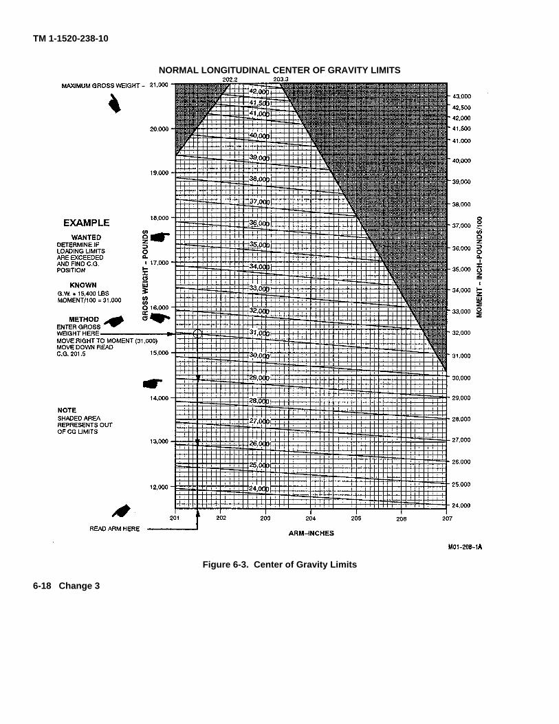
TM 1-1520-238-10
NORMAL LONGITUDINAL CENTER OF GRAVITY LIMITS
Figure 6-3. Center of Gravity Limits
6-18 Change 3
CAUTION
TM 1-1520-238-10
CHAPTER 7
PERFORMANCE DATA FOR AH-64A HELlCOPTERS EQUIPPED
WITH T-700-GE-701 ENGINES
Section I. INTRODUCTION
NOTE NOTE
This chapter contains performance datafor helicopters equipped withT-700-GE-701 engines. Performancedata for helicopters equipped withT-700-GE-701C ~ engines is containedin Chapter 7A. Users are authorized toremove the chapter that is not applicableand are not required to carry both chap-ters on the helicopter.
7.1 PERFORMANCE DATA.
The purpose of this chapter is to provide the best avail-able performance data for the AH-64A helicopterequipped with -701 engines. Regular use of this in-formation will allow maximum safe use of the helicop-ter. Although maximum performance is not always re-quired, regular use of the information in this chapter isrecommended for the following reasons:
a. Knowledge of performance margins will allowbetter decisions when unexpected conditions or alter-nate missions are encountered.
b. Situations requiring maximum performance willbe more readily recognized.
c. Familiarity with the data will allow performanceto be computed more easily and quickly.
d. Experience will be gained in accurately estimat-ing the effects of conditions for which data is not pres-ented.
The information is primarily intended formission planning and is most useful whenplanning operations in unfamiliar areasor at extreme conditions. The data mayalso be used in flight, to establish unit orarea standing operating procedures, andto inform ground commanders of perfor-mance/risk tradeoffs.
The data presented covers the maximum range ofconditions and performance that can reasonably be ex-pected. In each area of performance, the effects of alti-tude, temperature, gross weight and other parametersrelating to that phase of flight are presented. In addi-tion to the presented data, judgment and experiencewill be necessary to accurately determine performanceunder a given set of circumstances. The conditions forthe data are listed under the title of each chart. The ef-fects of different conditions are discussed in the text ac-companying each phase of performance. Where practi-cal, data is presented at conservative conditions.However, NO GENERAL CONSERVATISM HASBEEN APPLIED.
7.2 OPERATIONAL LIMITS.
Exceeding operational limits cancause permanent damage to criticalcomponents. Overlimit operation candecrease performance, cause im-mediate failure or failure on a subse-quent flight.
Applicable limits are shown on the charts as bold lineswith a description. Performance generally deterioratesrapidly beyond limits. If limits are exceeded, minimizethe amount and time. Enter the maximum value andtime beyond limits on DA Form 2408-13 to ensure prop-er maintenance action is taken.
7-1
TM 1-1520-238-10
7.3 USE OF PERFORMANCE CHARTS.
7.3.1 Chart Explanation. The first page of each sectiondescribes the chart or charts in that section, and explainshow each chart is used.
7.3.2 Reading the Charts. The primary use of eachchart is given in an example. The use of a straight edge(ruler or page edge) and a hard fine-point pencil isrecommended to avoid cumulative errors. The majorityof the charts provide a standard pattern for use asfollows: Enter first variable on top left scale, move right tosecond variable, deflect down at right angles to thirdvariable, deflect left at right angles to fourth variable, anddeflect down, etc, until final variable is read out on finalscale. In addition to the primary use, other uses of eachchart are explained in the text accompanying each set ofperformance charts. Abbreviations and symbols used inthe charts are listed in Appendix B.
NOTEAn example of an auxiliary use of theperformance charts follows: Althoughthe hover chart is primarily arranged tofind torque required to hover, maximumwheel height for hover can also be foundby entering torque available as torquerequired. In general, any single variablecan be found if all others are known.Also, the tradeoffs between twovariables can be found. For example, ata given pressure altitude and wheelheight you can find the maximum grossweight capability as free air temperaturechanges.
7.3.3 Data Basis. The type of data used is indicated atthe bottom of each performance chart under DATABASIS. The applicable report and date are also given.The data provided generally is based on one of thefollowing categories.
a. Flight Test Data. Data obtained by flight test ofthe aircraft at precisely known conditions using sensitivecalibrated instruments.
b. Calculated Data. Data based on test, but noton flight test of the complete aircraft.
c. Estimated Data. Data based on estimatesusing aerodynamic theory or other means but not verifiedby flight test.
7.4 PERFORMANCE SPECIFIC CONDITIONS.
The data presented is accurate only for specificconditions listed under the title of each chart. Variablesfor which data is not presented, but which may affect thatphase of performance, are discussed in the text. Wheredata is available or reasonable estimates can be made,the amount that each variable affects performance isgiven.
7.5 PERFORMANCE GENERAL CONDITIONS.
In addition to the specific conditions, the followinggeneral conditions are applicable to the performancedata:
7.5.1 Rigging. All airframe and engine controls areassumed to be rigged within allowable tolerances.
7.5.2 Pilot Technique. Normal pilot technique isassumed. Control movements should be smooth andcontinuous.
7.5.3 Aircraft Variation. Variations in performancebetween individual helicopters are known to exist; theyare considered small, however, and cannot beindividually accounted for.
7.5.4 Instrument Variation. The data shown in theperformance charts does not account for instrumentinaccuracies or malfunctions.
7.5.5 Configurations. Except as otherwise noted, alldata is for the primary mission configuration consisting ofthe basic helicopter plus a pylon and a fully loadedHellfire missile launcher on each inboard stores station,no pylons or stores on outboard stations.
7.5.6 Types of Fuel. All flight performance data isbased on JP-4 fuel. The change in fuel flow and torqueavailability, when using approved alternate fuels (table 2-8), is insignificant.
7.6 PERFORMANCE DISCREPANCIES.
Regular use of this chapter will also allow monitoringinstruments and other helicopter systems formalfunction, by comparing actual performance withplanned performance. Knowledge will also be gainedconcerning the affects of variables for which data is notprovided, thereby increasing the accuracy ofperformance predictions.
7.7 TEMPERATURE CONVERSION.
A temperature conversion chart (fig 7-1) is included inthis section for the purpose of converting Fahrenheittemperatures to Celsius.
7-2 Change 3
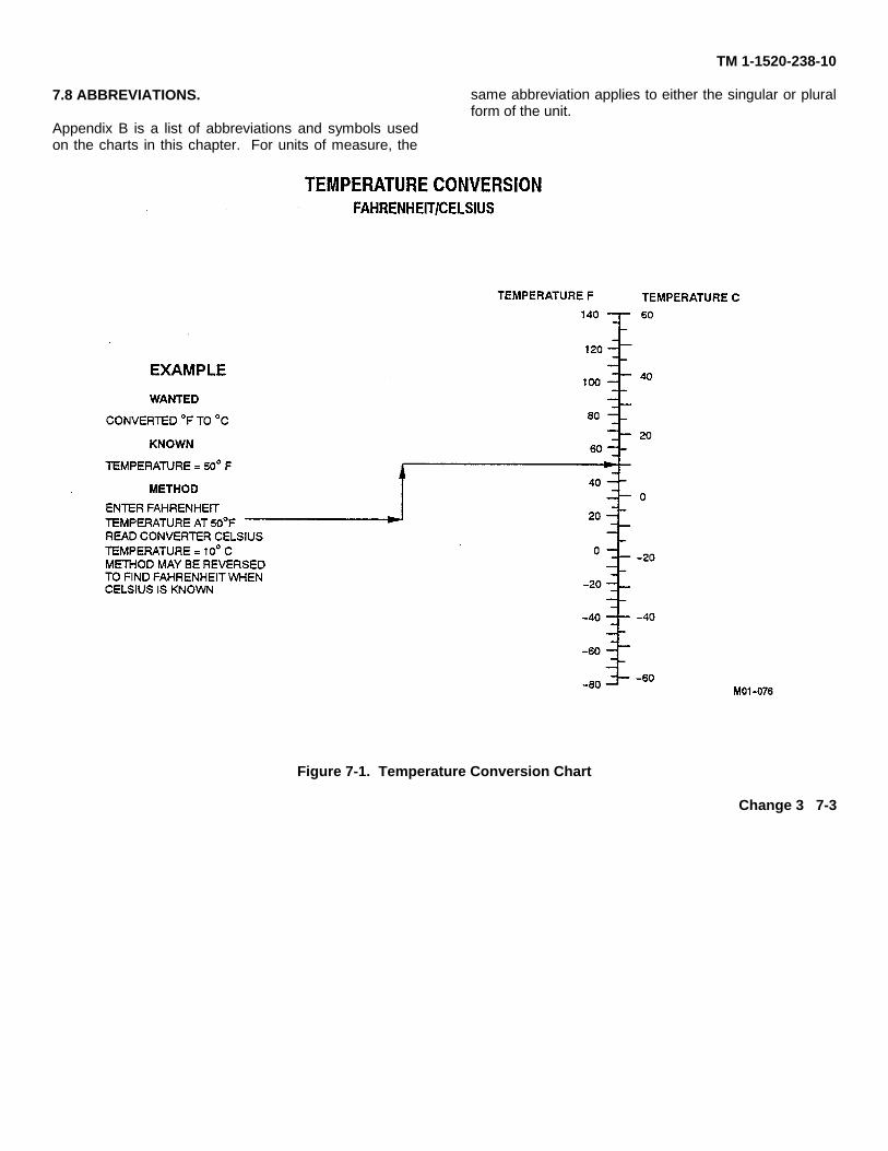
TM 1-1520-238-10
7.8 ABBREVIATIONS.
Appendix B is a list of abbreviations and symbols usedon the charts in this chapter. For units of measure, the
same abbreviation applies to either the singular or pluralform of the unit.
Figure 7-1. Temperature Conversion Chart
Change 3 7-3
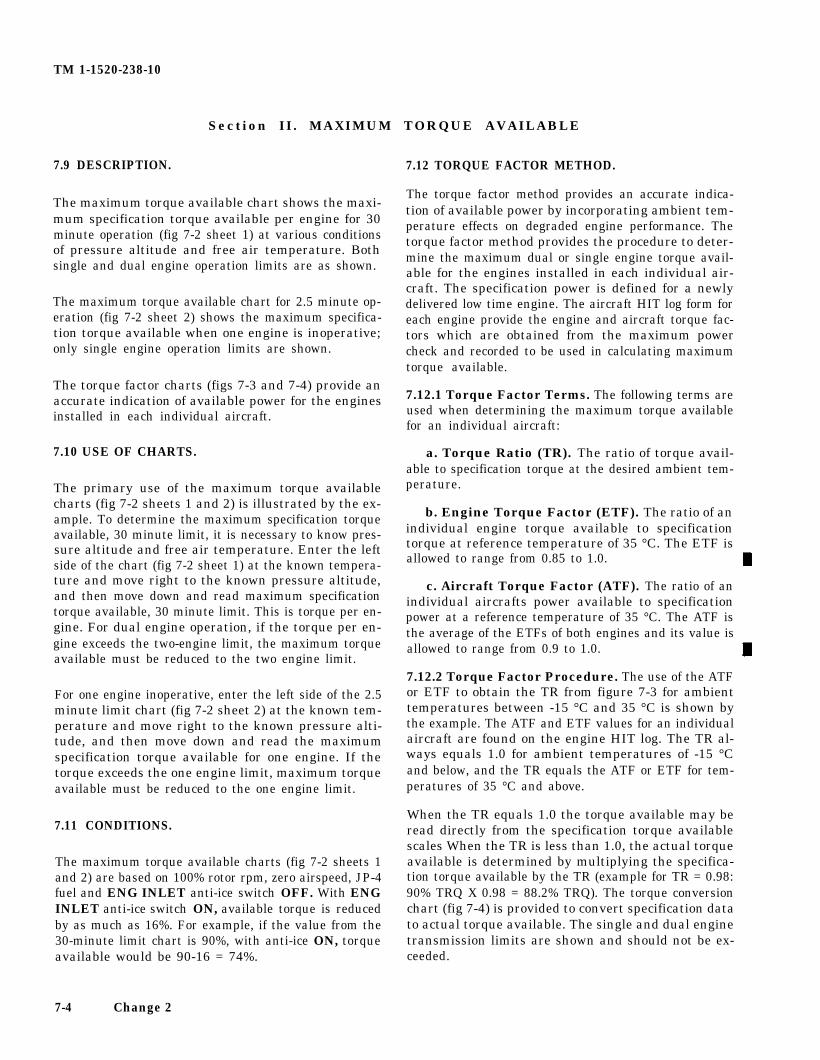
TM 1-1520-238-10
Section II. MAXIMUM TORQUE AVAILABLE
7.9 DESCRIPTION.
The maximum torque available chart shows the maxi-mum specification torque available per engine for 30minute operation (fig 7-2 sheet 1) at various conditionsof pressure altitude and free air temperature. Bothsingle and dual engine operation limits are as shown.
The maximum torque available chart for 2.5 minute op-eration (fig 7-2 sheet 2) shows the maximum specifica-tion torque available when one engine is inoperative;only single engine operation limits are shown.
The torque factor charts (figs 7-3 and 7-4) provide anaccurate indication of available power for the enginesinstalled in each individual aircraft.
7.10 USE OF CHARTS.
The primary use of the maximum torque availablecharts (fig 7-2 sheets 1 and 2) is illustrated by the ex-ample. To determine the maximum specification torqueavailable, 30 minute limit, it is necessary to know pres-sure altitude and free air temperature. Enter the leftside of the chart (fig 7-2 sheet 1) at the known tempera-ture and move right to the known pressure altitude,and then move down and read maximum specificationtorque available, 30 minute limit. This is torque per en-gine. For dual engine operation, if the torque per en-gine exceeds the two-engine limit, the maximum torqueavailable must be reduced to the two engine limit.
For one engine inoperative, enter the left side of the 2.5minute limit chart (fig 7-2 sheet 2) at the known tem-perature and move right to the known pressure alti-tude, and then move down and read the maximumspecification torque available for one engine. If thetorque exceeds the one engine limit, maximum torqueavailable must be reduced to the one engine limit.
7.11 CONDITIONS.
The maximum torque available charts (fig 7-2 sheets 1and 2) are based on 100% rotor rpm, zero airspeed, JP-4fuel and ENG INLET anti-ice switch OFF. With ENGINLET anti-ice switch ON, available torque is reducedby as much as 16%. For example, if the value from the30-minute limit chart is 90%, with anti-ice ON, torqueavailable would be 90-16 = 74%.
7.12 TORQUE FACTOR METHOD.
The torque factor method provides an accurate indica-tion of available power by incorporating ambient tem-perature effects on degraded engine performance. Thetorque factor method provides the procedure to deter-mine the maximum dual or single engine torque avail-able for the engines installed in each individual air-craft. The specification power is defined for a newlydelivered low time engine. The aircraft HIT log form foreach engine provide the engine and aircraft torque fac-tors which are obtained from the maximum powercheck and recorded to be used in calculating maximumtorque available.
7.12.1 Torque Factor Terms. The following terms areused when determining the maximum torque availablefor an individual aircraft:
a. Torque Ratio (TR). The ratio of torque avail-able to specification torque at the desired ambient tem-perature.
b. Engine Torque Factor (ETF). The ratio of anindividual engine torque available to specificationtorque at reference temperature of 35 °C. The ETF isallowed to range from 0.85 to 1.0.
c. Aircraft Torque Factor (ATF). The ratio of anindividual aircrafts power available to specificationpower at a reference temperature of 35 °C. The ATF isthe average of the ETFs of both engines and its value isallowed to range from 0.9 to 1.0.
7.12.2 Torque Factor Procedure. The use of the ATFor ETF to obtain the TR from figure 7-3 for ambienttemperatures between -15 °C and 35 °C is shown bythe example. The ATF and ETF values for an individualaircraft are found on the engine HIT log. The TR al-ways equals 1.0 for ambient temperatures of -15 °Cand below, and the TR equals the ATF or ETF for tem-peratures of 35 °C and above.
When the TR equals 1.0 the torque available may beread directly from the specification torque availablescales When the TR is less than 1.0, the actual torqueavailable is determined by multiplying the specifica-tion torque available by the TR (example for TR = 0.98:90% TRQ X 0.98 = 88.2% TRQ). The torque conversionchart (fig 7-4) is provided to convert specification datato actual torque available. The single and dual enginetransmission limits are shown and should not be ex-ceeded.
7-4 Change 2
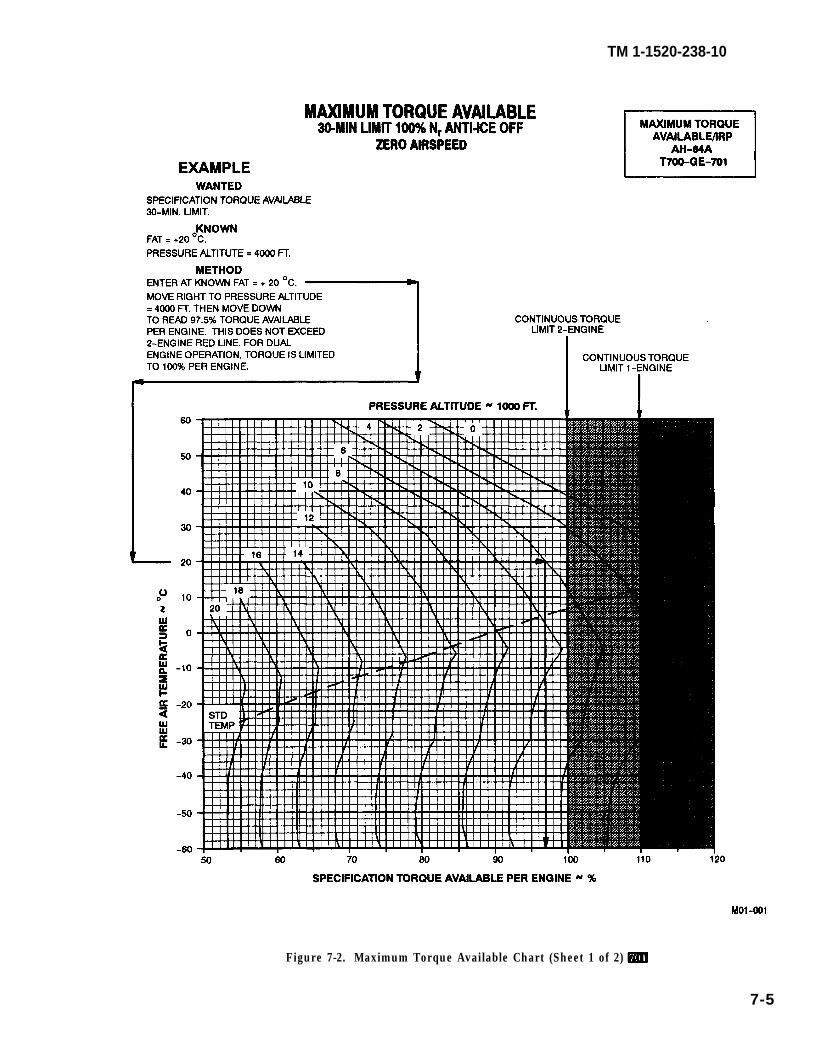
TM 1-1520-238-10
Figure 7-2. Maximum Torque Available Chart (Sheet 1 of 2)
7-5
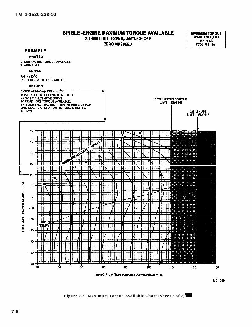
TM 1-1520-238-10
Figure 7-2. Maximum Torque Available Chart (Sheet 2 of 2)
7-6
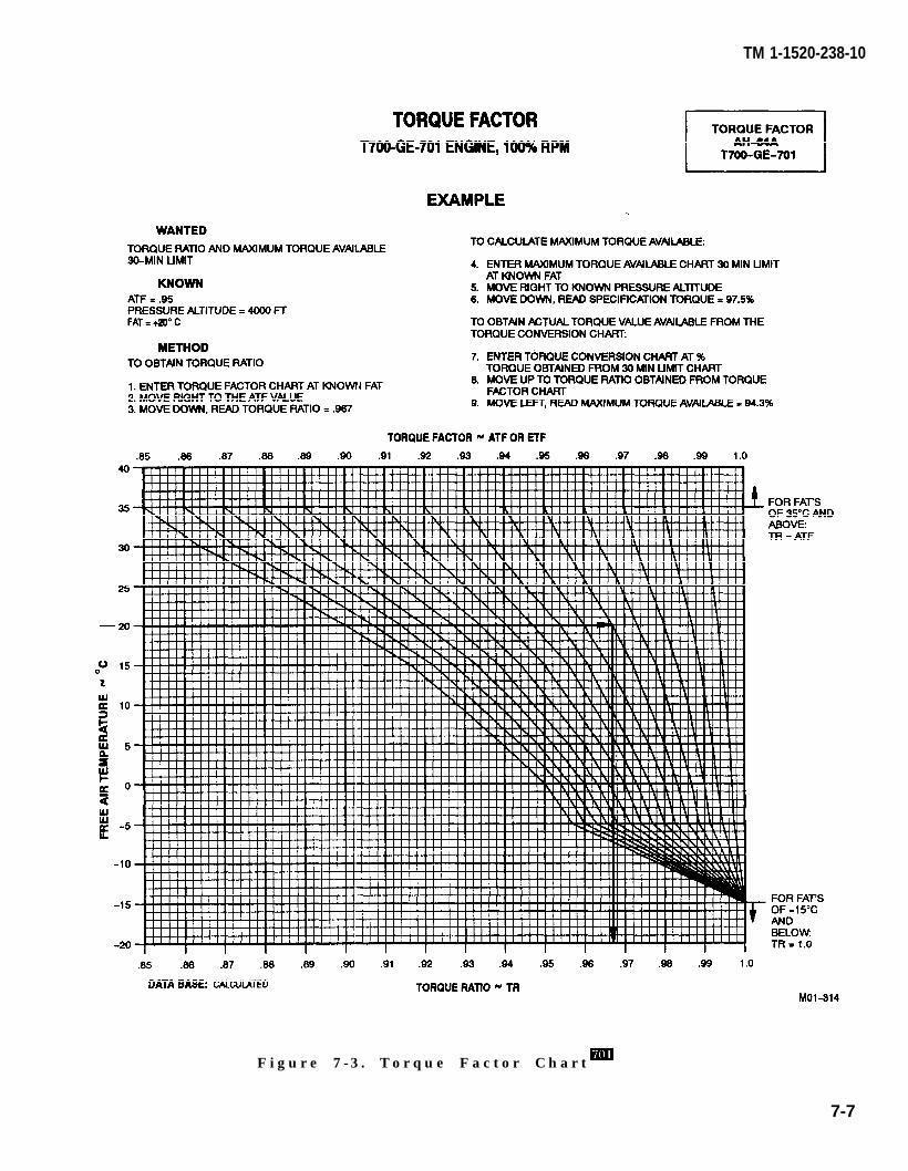
TM 1-1520-238-10
F i g u r e 7 - 3 . T o r q u e F a c t o r C h a r t
7-7
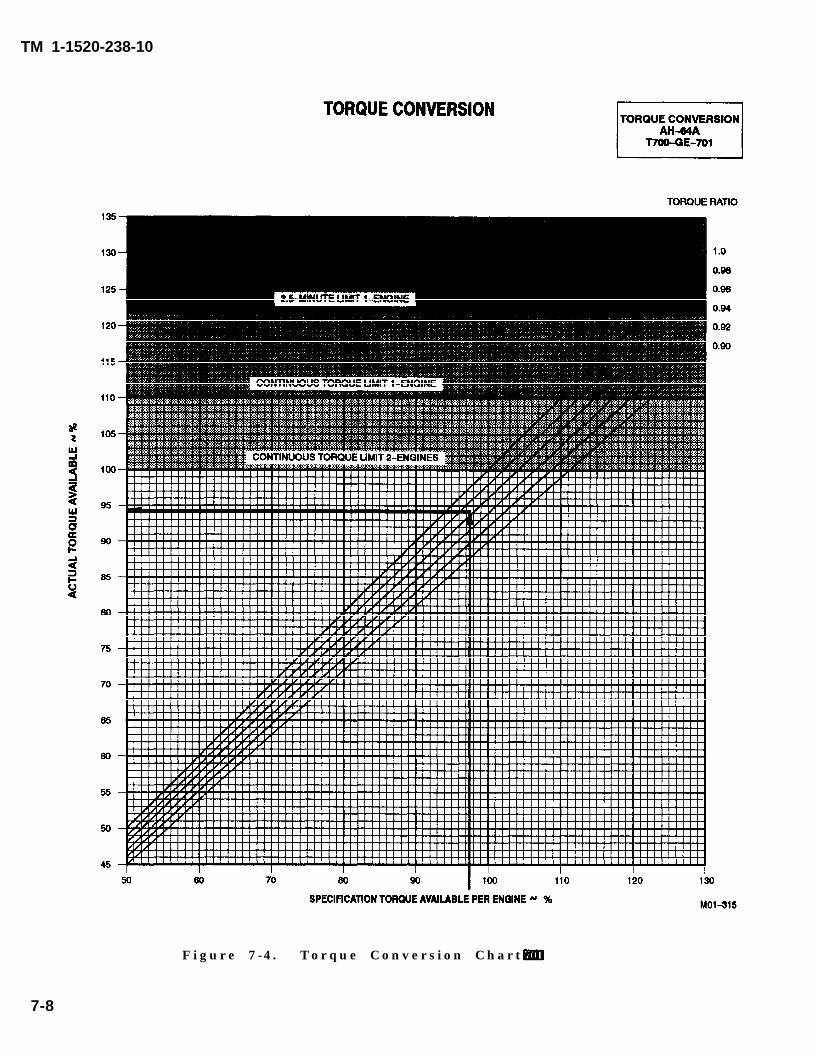
TM 1-1520-238-10
Figure 7-4 . Torque Conversion Chart
7-8
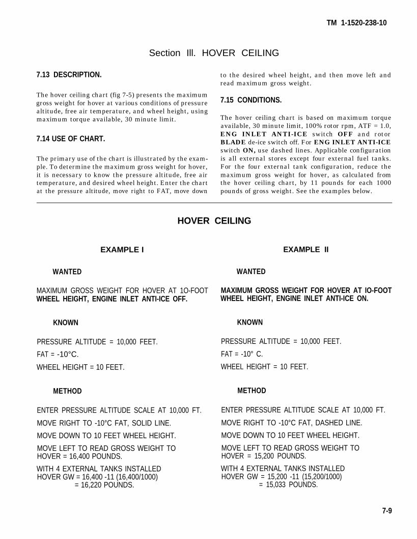
TM 1-1520-238-10
Section Ill. HOVER CEILING
7.13 DESCRIPTION.
The hover ceiling chart (fig 7-5) presents the maximumgross weight for hover at various conditions of pressurealtitude, free air temperature, and wheel height, usingmaximum torque available, 30 minute limit.
7.14 USE OF CHART.
The primary use of the chart is illustrated by the exam-ple. To determine the maximum gross weight for hover,it is necessary to know the pressure altitude, free airtemperature, and desired wheel height. Enter the chartat the pressure altitude, move right to FAT, move down
to the desired wheel height, and then move left andread maximum gross weight.
7.15 CONDITIONS.
The hover ceiling chart is based on maximum torqueavailable, 30 minute limit, 100% rotor rpm, ATF = 1.0,ENG INLET ANTI-ICE switch OFF and rotorBLADE de-ice switch off. For ENG INLET ANTI-ICEswitch ON, use dashed lines. Applicable configurationis all external stores except four external fuel tanks.For the four external tank configuration, reduce themaximum gross weight for hover, as calculated fromthe hover ceiling chart, by 11 pounds for each 1000pounds of gross weight. See the examples below.
HOVER CEILING
EXAMPLE I EXAMPLE II
WANTED WANTED
MAXIMUM GROSS WEIGHT FOR HOVER AT 1O-FOOT MAXIMUM GROSS WEIGHT FOR HOVER AT IO-FOOTWHEEL HEIGHT, ENGINE INLET ANTI-ICE OFF. WHEEL HEIGHT, ENGINE INLET ANTI-ICE ON.
KNOWN KNOWN
PRESSURE ALTITUDE = 10,000 FEET. PRESSURE ALTITUDE = 10,000 FEET.
FAT = -10°C. FAT = -10° C.
WHEEL HEIGHT = 10 FEET. WHEEL HEIGHT = 10 FEET.
METHOD METHOD
ENTER PRESSURE ALTITUDE SCALE AT 10,000 FT.
MOVE RIGHT TO -10°C FAT, SOLID LINE.
MOVE DOWN TO 10 FEET WHEEL HEIGHT.
MOVE LEFT TO READ GROSS WEIGHT TOHOVER = 16,400 POUNDS.
WITH 4 EXTERNAL TANKS INSTALLEDHOVER GW = 16,400 -11 (16,400/1000)
= 16,220 POUNDS.
ENTER PRESSURE ALTITUDE SCALE AT 10,000 FT.
MOVE RIGHT TO -10°C FAT, DASHED LINE.
MOVE DOWN TO 10 FEET WHEEL HEIGHT.
MOVE LEFT TO READ GROSS WEIGHT TOHOVER = 15,200 POUNDS.
WITH 4 EXTERNAL TANKS INSTALLEDHOVER GW = 15,200 -11 (15,200/1000)
= 15,033 POUNDS.
7-9
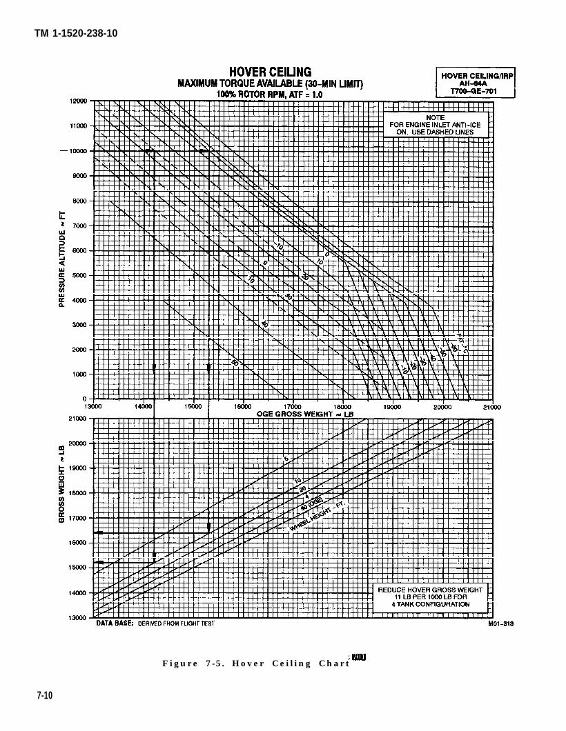
TM 1-1520-238-10
Figure 7-5. Hover Ceiling Chart
7-10
TM 1-1520-238-10
Section IV. HOVER LIMITS
7.16 DESCRIPTION.
The hover chart (fig 7-6) shows the torque required tohover at various conditions of pressure altitude, free airtemperature, gross weight, wheel height, and with ex-ternal tanks or without external tanks.
7.17 USE OF CHART.
The primary use of the chart is illustrated by the exam-ple. To determine the torque required to hover, it is nec-essary to know the pressure altitude, free air tempera-ture, gross weight, and desired wheel height. Enter theupper right grid at the known pressure altitude, moveright to the temperature, move down to the grossweight, move left to the desired wheel height, and thenmove down and read the torque required to hover.
In addition to its primary use, the hover chart maybeused to predict the maximum hover height. To deter-mine maximum hover height, it is necessary to knowpressure altitude, free air temperature, gross weight,
and maximum torque available. Enter the known pres-sure altitude, move right to the temperature, movedown to the gross weight, then move left to intersectionwith maximum torque available and read wheel height.This wheel height is the maximum hover height.
The hover chart may also be used to determine themaximum gross weight for hover at a given wheelheight, pressure altitude, and temperature condition.Enter at the known pressure altitude, move right to thetemperature, then draw a line down to the bottom ofthe lower grid. Now enter lower grid at maximumtorque available, move up to wheel height, and thenmove right to intersect the previously drawn line andread gross weight. This is maximum gross weight atwhich the helicopter will hover.
7.18 CONDITIONS.
The hover chart is based on calm wind, level surface,100% rotor rpm and rotor BLADE de-ice switch off.With rotor BLADE de-ice switch ON, torque requiredwill increase 1.4%
7-11

TM 1-1520-238-10
Figure 7-6. Hover Chart Mill
7-12 Change 3
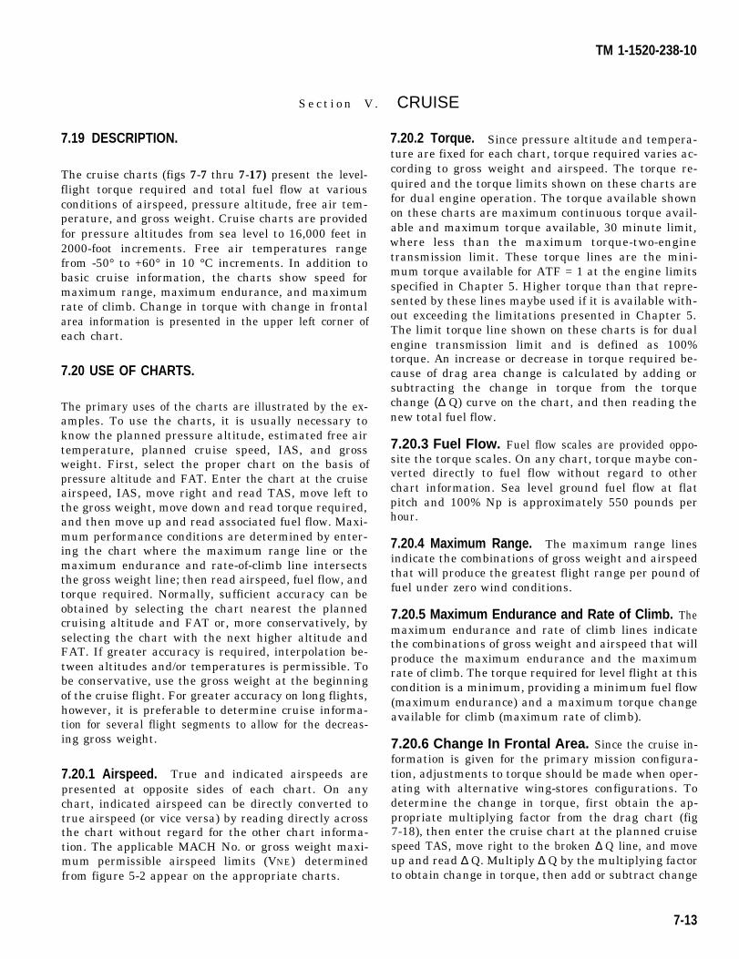
TM 1-1520-238-10
7.19 DESCRIPTION.
The cruise charts (figs
S e c t i o n V .
7-7 thru 7-17) present the level-flight torque required and total fuel flow at variousconditions of airspeed, pressure altitude, free air tem-perature, and gross weight. Cruise charts are providedfor pressure altitudes from sea level to 16,000 feet in2000-foot increments. Free air temperatures rangefrom -50° to +60° in 10 °C increments. In addition tobasic cruise information, the charts show speed formaximum range, maximum endurance, and maximumrate of climb. Change in torque with change in frontalarea information is presented in the upper left corner ofeach chart.
7.20 USE OF CHARTS.
The primary uses of the charts are illustrated by the ex-amples. To use the charts, it is usually necessary toknow the planned pressure altitude, estimated free airtemperature, planned cruise speed, IAS, and grossweight. First, select the proper chart on the basis ofpressure altitude and FAT. Enter the chart at the cruiseairspeed, IAS, move right and read TAS, move left tothe gross weight, move down and read torque required,and then move up and read associated fuel flow. Maxi-mum performance conditions are determined by enter-ing the chart where the maximum range line or themaximum endurance and rate-of-climb line intersectsthe gross weight line; then read airspeed, fuel flow, andtorque required. Normally, sufficient accuracy can beobtained by selecting the chart nearest the plannedcruising altitude and FAT or, more conservatively, byselecting the chart with the next higher altitude andFAT. If greater accuracy is required, interpolation be-tween altitudes and/or temperatures is permissible. Tobe conservative, use the gross weight at the beginningof the cruise flight. For greater accuracy on long flights,however, it is preferable to determine cruise informa-tion for several flight segments to allow for the decreas-ing gross weight.
7.20.1 Airspeed. True and indicated airspeeds arepresented at opposite sides of each chart. On anychart, indicated airspeed can be directly converted totrue airspeed (or vice versa) by reading directly acrossthe chart without regard for the other chart informa-tion. The applicable MACH No. or gross weight maxi-mum permissible airspeed limits (VNE) determinedfrom figure 5-2 appear on the appropriate charts.
CRUISE
7.20.2 Torque. Since pressure altitude and tempera-ture are fixed for each chart, torque required varies ac-cording to gross weight and airspeed. The torque re-quired and the torque limits shown on these charts arefor dual engine operation. The torque available shownon these charts are maximum continuous torque avail-able and maximum torque available, 30 minute limit,where less than the maximum torque-two-enginetransmission limit. These torque lines are the mini-mum torque available for ATF = 1 at the engine limitsspecified in Chapter 5. Higher torque than that repre-sented by these lines maybe used if it is available with-out exceeding the limitations presented in Chapter 5.The limit torque line shown on these charts is for dualengine transmission limit and is defined as 100%torque. An increase or decrease in torque required be-cause of drag area change is calculated by adding orsubtracting the change in torque from the torquechange (∆ Q) curve on the chart, and then reading thenew total fuel flow.
7.20.3 Fuel FIow. Fuel flow scales are provided oppo-site the torque scales. On any chart, torque maybe con-verted directly to fuel flow without regard to otherchart information. Sea level ground fuel flow at flatpitch and 100% Np is approximately 550 pounds perhour.
7.20.4 Maximum Range. The maximum range linesindicate the combinations of gross weight and airspeedthat will produce the greatest flight range per pound offuel under zero wind conditions.
7.20.5 Maximum Endurance and Rate of Climb. Themaximum endurance and rate of climb lines indicatethe combinations of gross weight and airspeed that willproduce the maximum endurance and the maximumrate of climb. The torque required for level flight at thiscondition is a minimum, providing a minimum fuel flow(maximum endurance) and a maximum torque changeavailable for climb (maximum rate of climb).
7.20.6 Change In Frontal Area. Since the cruise in-formation is given for the primary mission configura-tion, adjustments to torque should be made when oper-ating with alternative wing-stores configurations. Todetermine the change in torque, first obtain the ap-propriate multiplying factor from the drag chart (fig7-18), then enter the cruise chart at the planned cruisespeed TAS, move right to the broken ∆ Q line, and moveup and read ∆ Q. Multiply ∆ Q by the multiplying factorto obtain change in torque, then add or subtract change
7-13
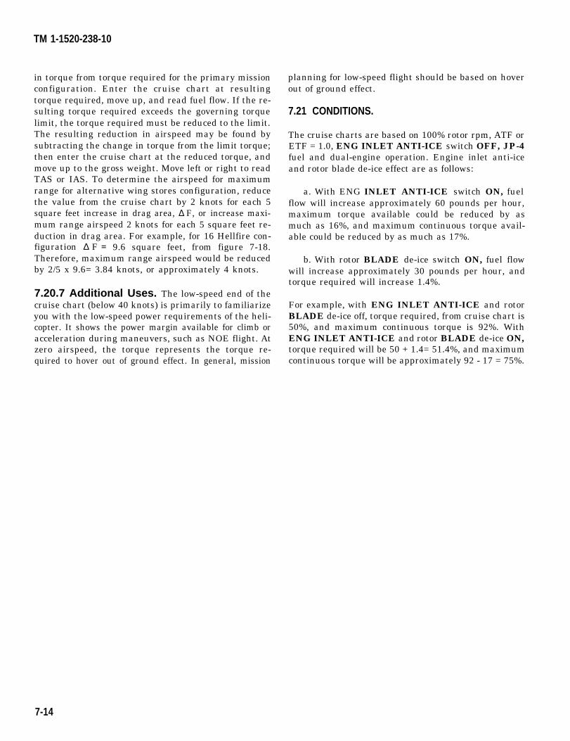
TM 1-1520-238-10
in torque from torque required for the primary missionconfiguration. Enter the cruise chart at resultingtorque required, move up, and read fuel flow. If the re-sulting torque required exceeds the governing torquelimit, the torque required must be reduced to the limit.The resulting reduction in airspeed may be found bysubtracting the change in torque from the limit torque;then enter the cruise chart at the reduced torque, andmove up to the gross weight. Move left or right to readTAS or IAS. To determine the airspeed for maximumrange for alternative wing stores configuration, reducethe value from the cruise chart by 2 knots for each 5square feet increase in drag area, ∆ F, or increase maxi-mum range airspeed 2 knots for each 5 square feet re-duction in drag area. For example, for 16 Hellfire con-figuration ∆ F = 9.6 square feet, from figure 7-18.Therefore, maximum range airspeed would be reducedby 2/5 x 9.6= 3.84 knots, or approximately 4 knots.
7.20.7 Additional Uses. The low-speed end of thecruise chart (below 40 knots) is primarily to familiarizeyou with the low-speed power requirements of the heli-copter. It shows the power margin available for climb oracceleration during maneuvers, such as NOE flight. Atzero airspeed, the torque represents the torque re-quired to hover out of ground effect. In general, mission
planning for low-speed flight should be based on hoverout of ground effect.
7.21 CONDITIONS.
The cruise charts are based on 100% rotor rpm, ATF orETF = 1.0, ENG INLET ANTI-ICE switch OFF, JP-4fuel and dual-engine operation. Engine inlet anti-iceand rotor blade de-ice effect are as follows:
a. With ENG INLET ANTI-ICE switch ON, fuelflow will increase approximately 60 pounds per hour,maximum torque available could be reduced by asmuch as 16%, and maximum continuous torque avail-able could be reduced by as much as 17%.
b. With rotor BLADE de-ice switch ON, fuel flowwill increase approximately 30 pounds per hour, andtorque required will increase 1.4%.
For example, with ENG INLET ANTI-ICE and rotorBLADE de-ice off, torque required, from cruise chart is50%, and maximum continuous torque is 92%. WithENG INLET ANTI-ICE and rotor BLADE de-ice ON,torque required will be 50 + 1.4= 51.4%, and maximumcontinuous torque will be approximately 92 - 17 = 75%.
7-14
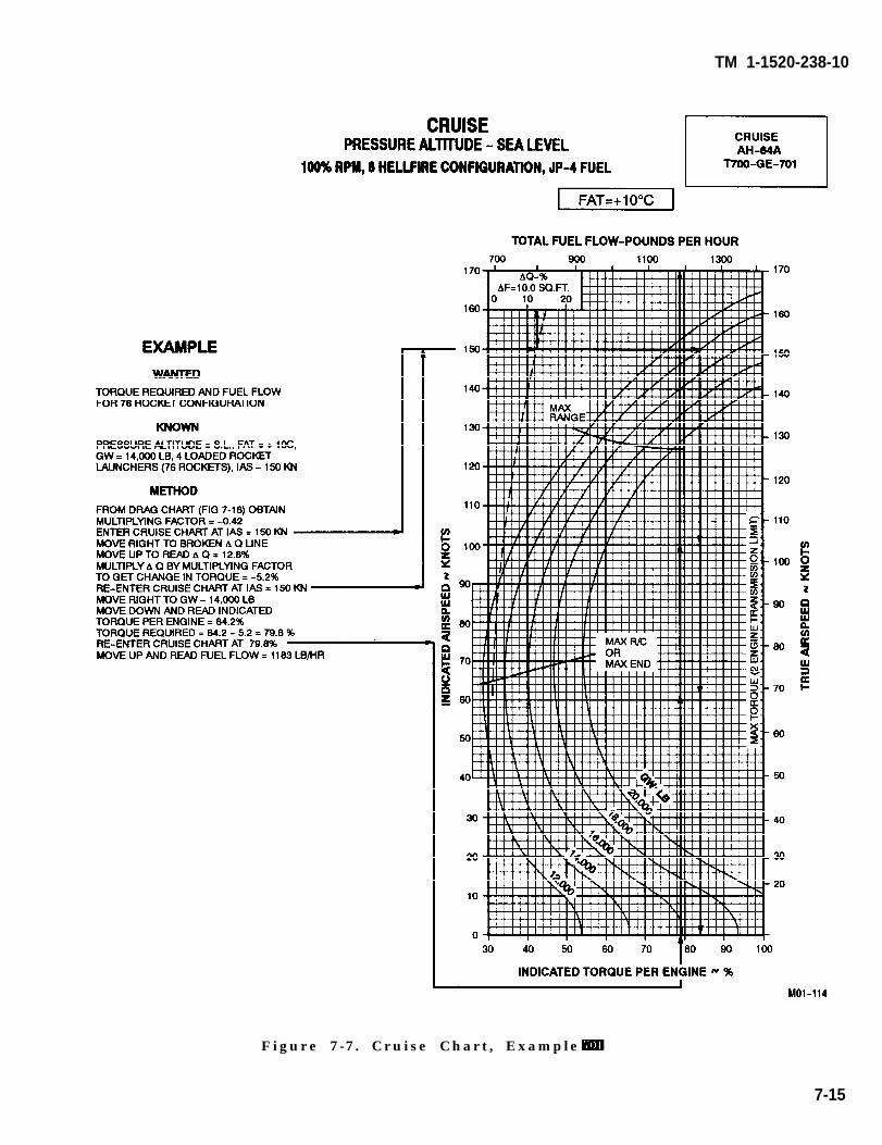
TM 1-1520-238-10
Figure 7-7. Cruise Chart, Example
7-15
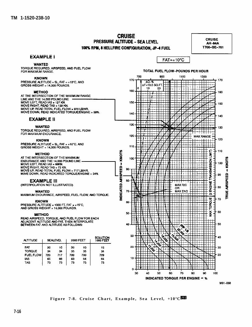
TM 1-1520-238-10
Figure 7-8. Cruise Chart, Example, Sea Level, +10°C
7-16
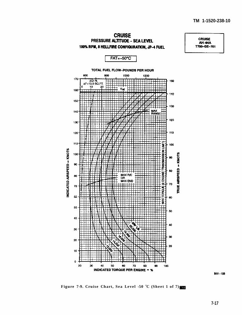
TM 1-1520-238-10
Figure 7-9. Cruise Chart, Sea Level -50 0C (Sheet 1 of 7)
7-17
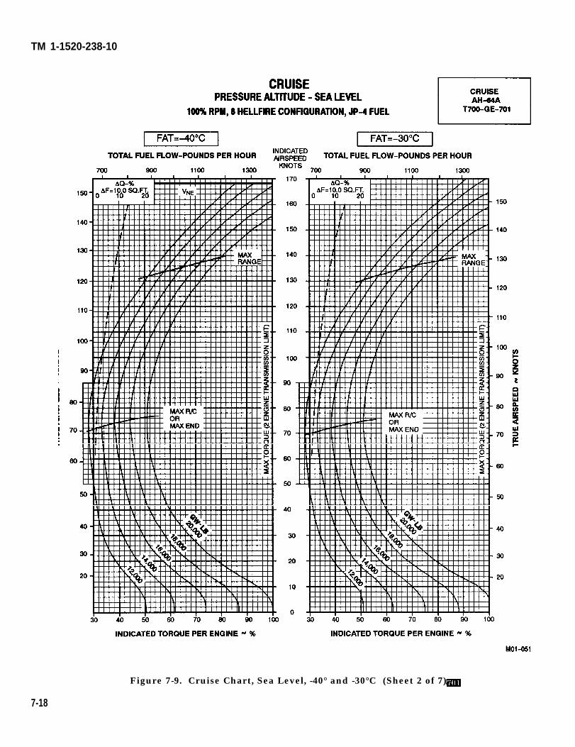
TM 1-1520-238-10
Figure 7-9. Cruise Chart, Sea Level, -40° and -30°C (Sheet 2 of 7)
7-18
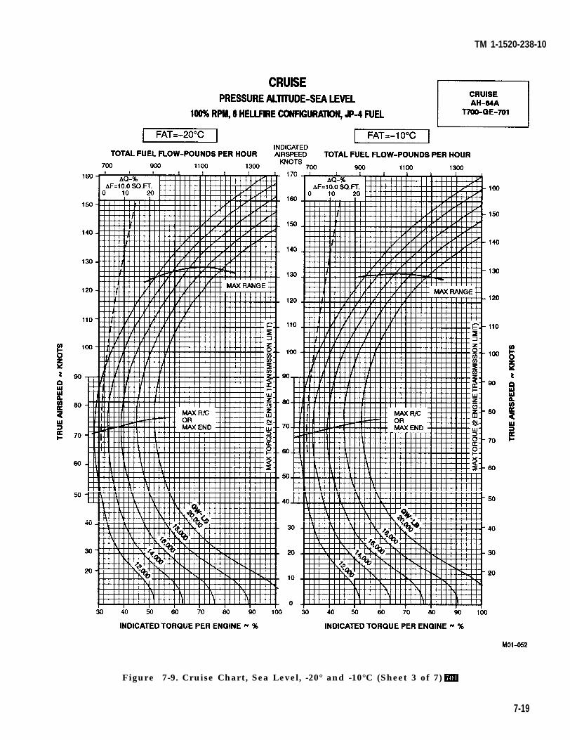
TM 1-1520-238-10
Figure 7-9. Cruise Chart, Sea Level, -20° and -10°C (Sheet 3 of 7)
7-19
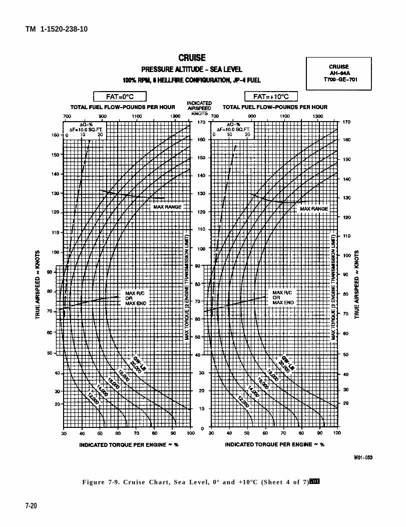
TM 1-1520-238-10
Figure 7-9. Cruise Chart, Sea Level, 0° and +10°C (Sheet 4 of 7)
7-20
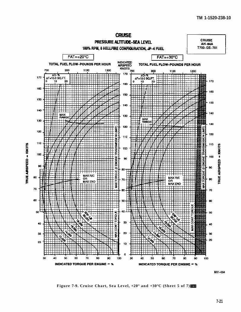
TM 1-1520-238-10
Figure 7-9. Cruise Chart, Sea Level, +20° and +30°C (Sheet 5 of 7)
7-21
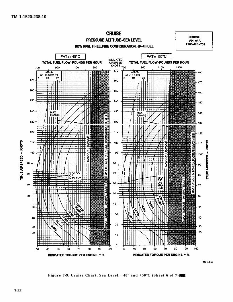
TM 1-1520-238-10
Figure 7-9. Cruise Chart, Sea Level, +40° and +50°C (Sheet 6 of 7)
7-22
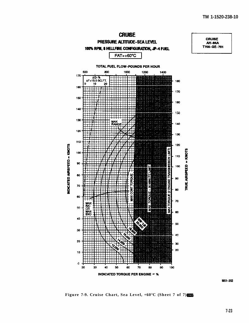
TM 1-1520-238-10
Figure 7-9. Cruise Chart, Sea Level, +60°C (Sheet 7 of 7)
7-23
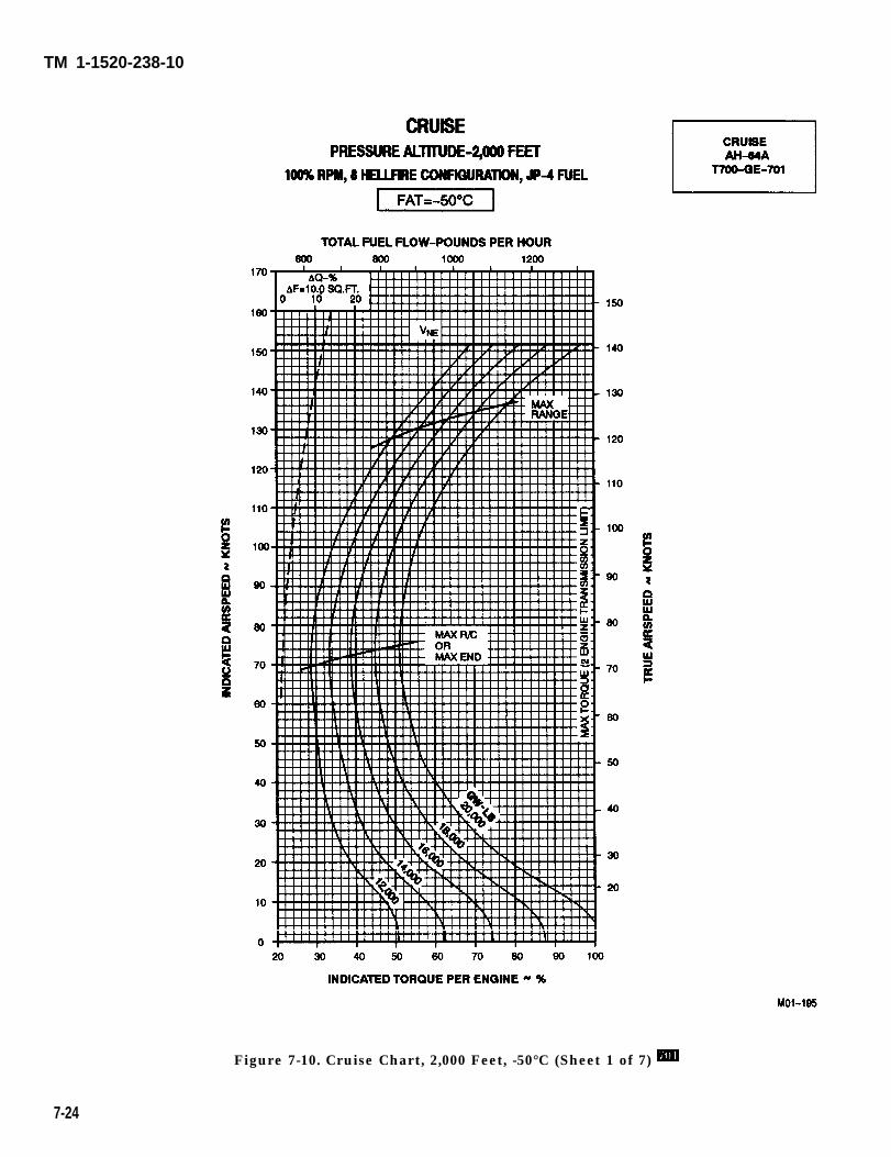
TM 1-1520-238-10
Figure 7-10. Cruise Chart, 2,000 Feet, -50°C (Sheet 1 of 7)
7-24
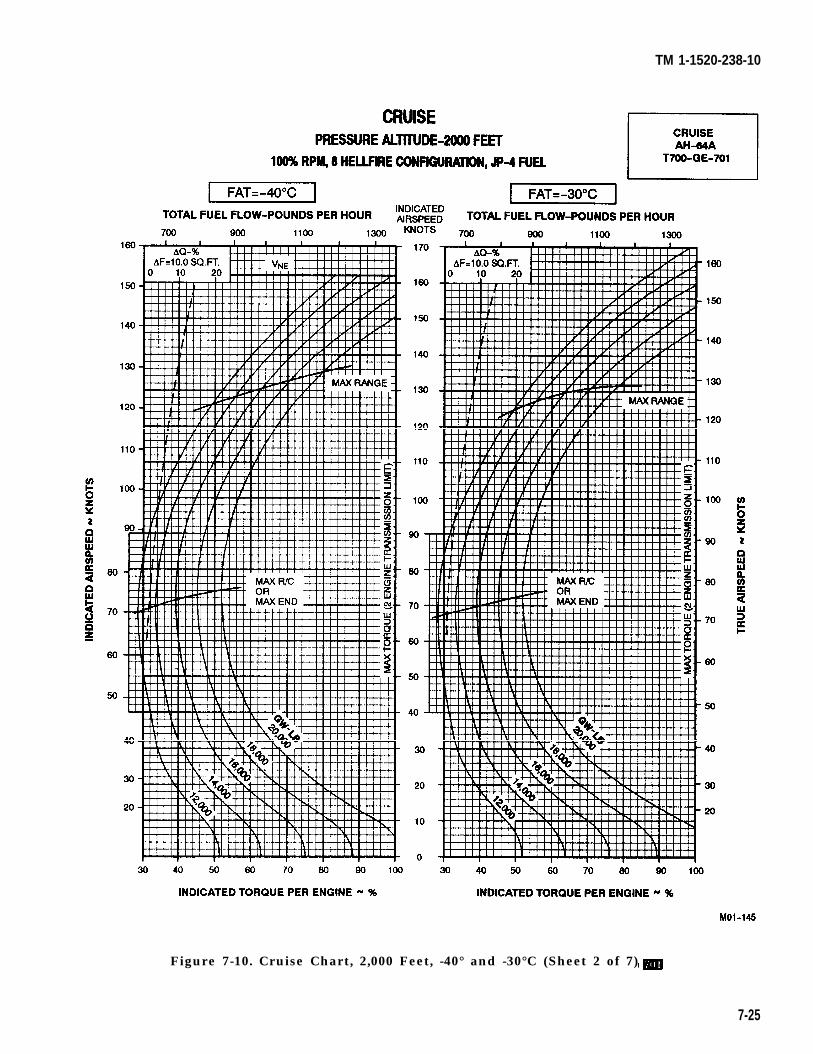
TM 1-1520-238-10
Figure 7-10. Cruise Chart, 2,000 Feet, -40° and -30°C (Sheet 2 of 7)
7-25
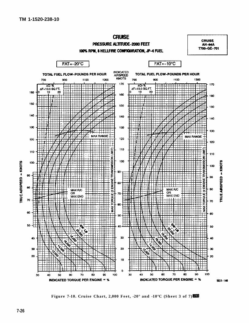
TM 1-1520-238-10
Figure 7-10. Cruise Chart, 2,000 Feet, -20° and -10°C (Sheet 3 of 7)
7-26
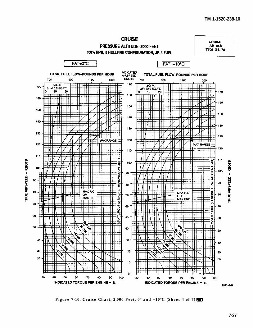
TM 1-1520-238-10
Figure 7-10. Cruise Chart, 2,000 Feet, 0° and +10°C (Sheet 4 of 7)
7-27
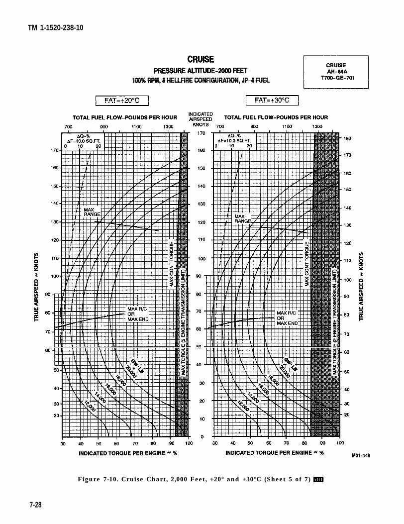
TM 1-1520-238-10
Figure 7-10. Cruise Chart, 2,000 Feet, +20° and +30°C (Sheet 5 of 7)
7-28
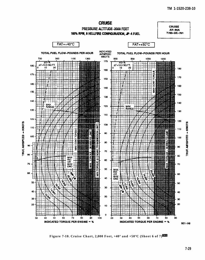
TM 1-1520-238-10
Figure 7-10. Cruise Chart, 2,000 Feet, +40° and +50°C (Sheet 6 of 7)
7-29
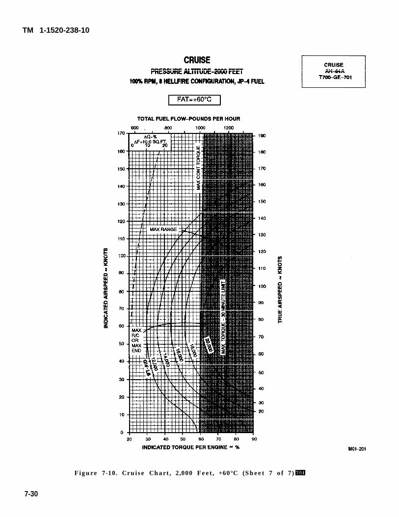
TM 1-1520-238-10
Figure 7-10. Cruise Chart, 2,000 Feet, +60°C (Sheet 7 of 7)
7-30
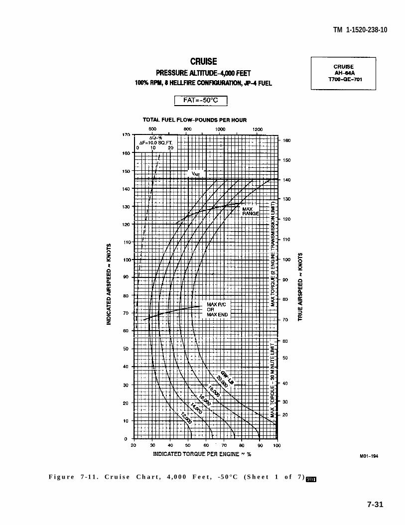
TM 1-1520-238-10
Figure 7-11. Cruise Chart, 4,000 Feet, -50°C (Sheet 1 of 7)
7-31
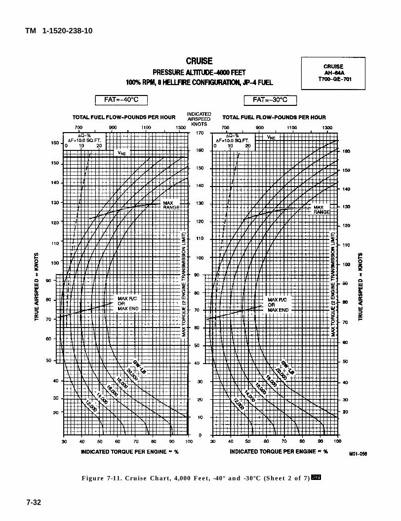
TM 1-1520-238-10
Figure 7-11. Cruise Chart, 4,000 Feet, -40° and -30°C (Sheet 2 of 7)
7-32
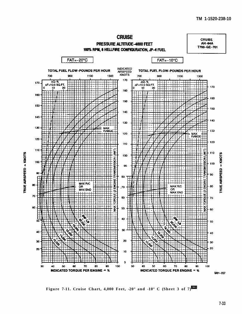
TM 1-1520-238-10
Figure 7-11. Cruise Chart, 4,000 Feet, -20° and -10° C (Sheet 3 of 7)
7-33
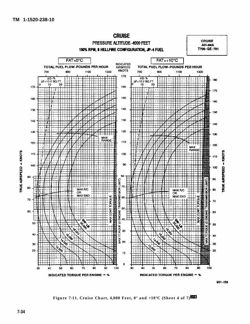
TM 1-1520-238-10
Figure 7-11. Cruise Chart, 4,000 Feet, 0° and +10°C (Sheet 4 of 7)
7-34
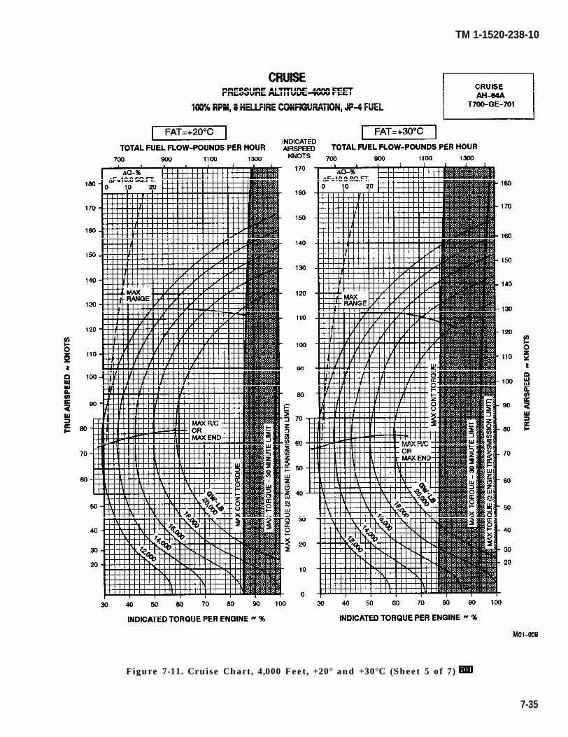
TM 1-1520-238-10
Figure 7-11. Cruise Chart, 4,000 Feet, +20° and +30°C (Sheet 5 of 7)
7-35
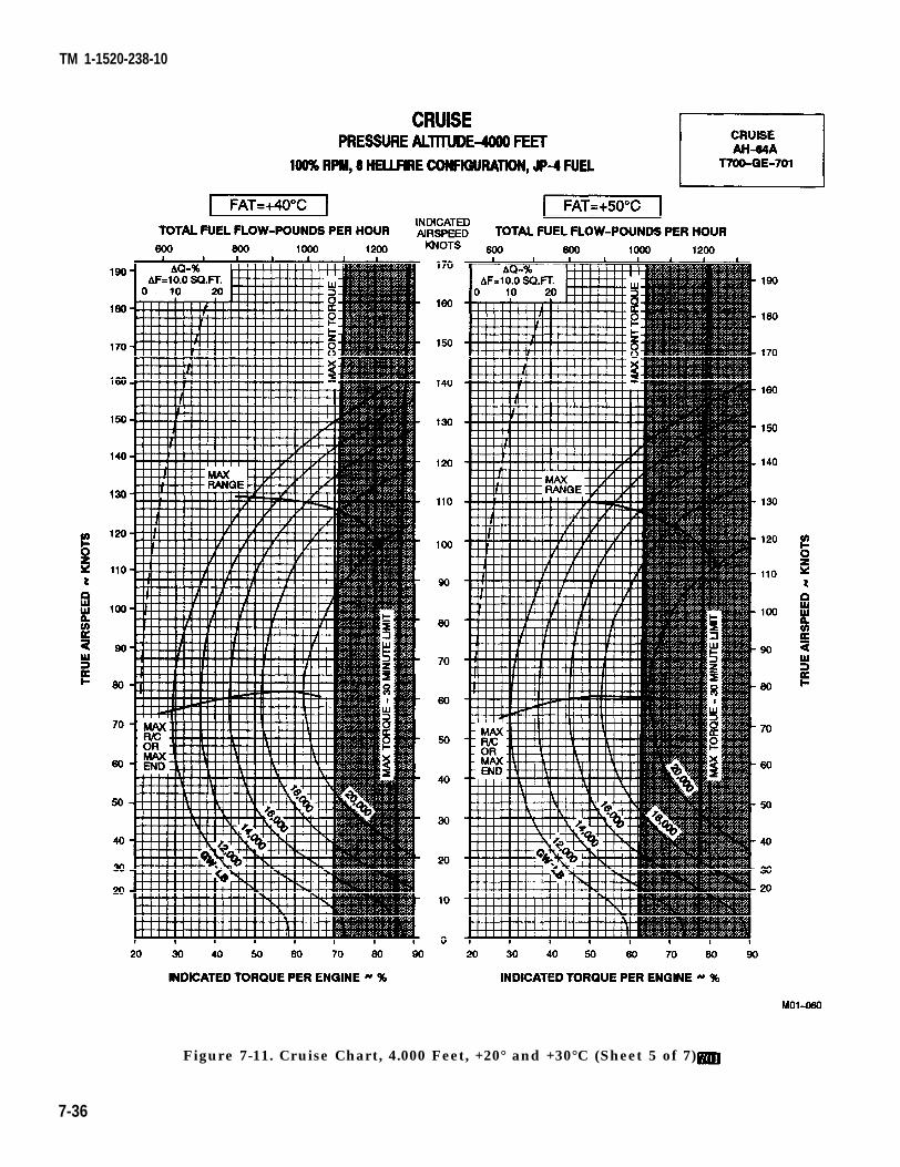
TM 1-1520-238-10
Figure 7-11. Cruise Chart, 4.000 Feet, +20° and +30°C (Sheet 5 of 7)
7-36
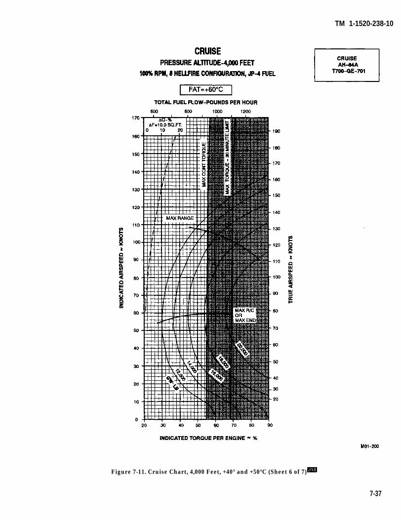
TM 1-1520-238-10
Figure 7-11. Cruise Chart, 4,000 Feet, +40° and +50°C (Sheet 6 of 7)
7-37
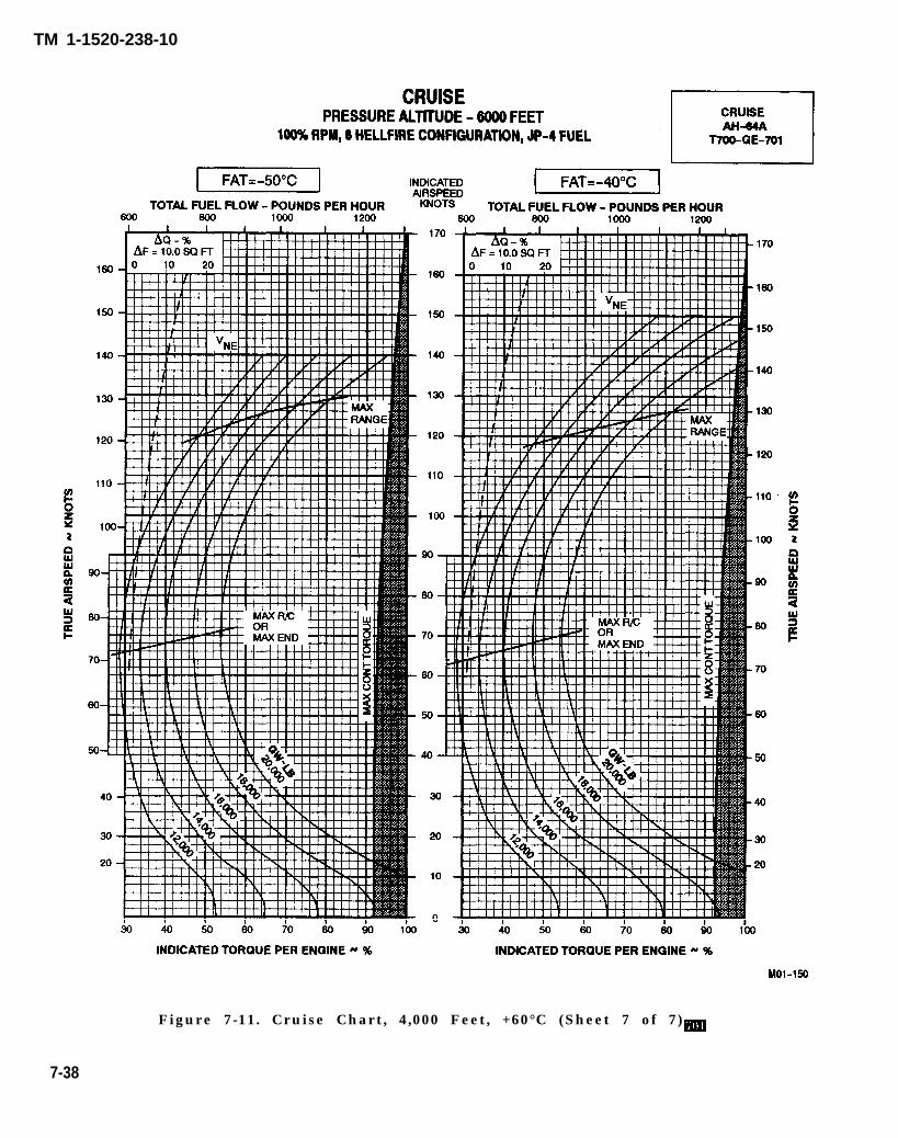
TM 1-1520-238-10
Figure 7-11. Cruise Chart, 4,000 Feet, +60°C (Sheet 7 of 7)
7-38
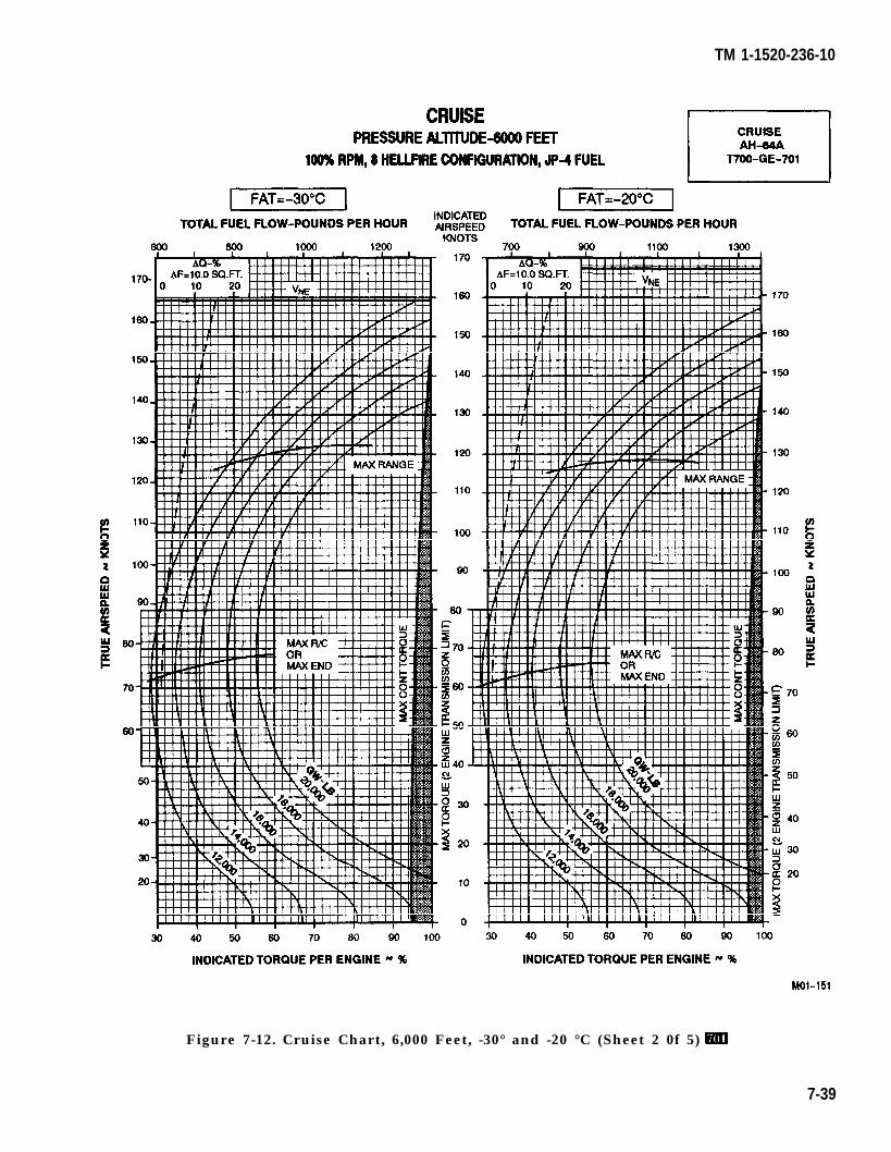
TM 1-1520-236-10
Figure 7-12. Cruise Chart, 6,000 Feet, -30° and -20 °C (Sheet 2 0f 5)
7-39
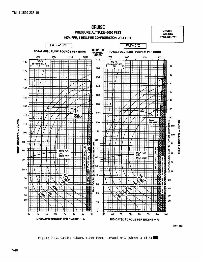
TM 1-1520-238-10
Figure 7-12. Cruise Chart, 6,000 Feet, -10°and 0°C (Sheet 3 of 5)
7-40
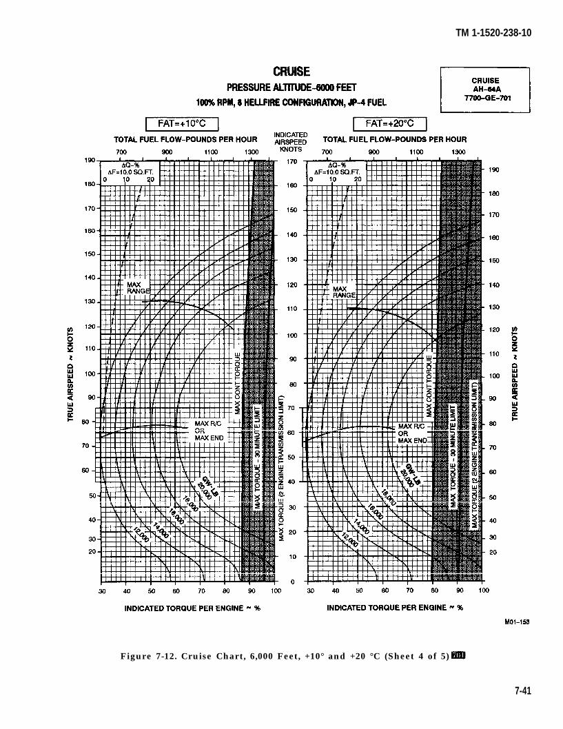
TM 1-1520-238-10
Figure 7-12. Cruise Chart, 6,000 Feet, +10° and +20 °C (Sheet 4 of 5)
7-41
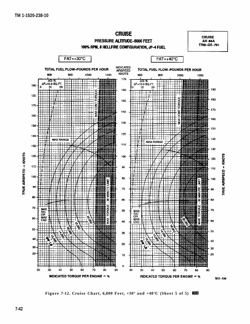
TM 1-1520-238-10
Figure 7-12. Cruise Chart, 6,000 Feet, +30° and +40°C (Sheet 5 of 5)
7-42

TM 1-1520-238-10
Figure 7-13. Cruise Chart, 8,000 Feet, -50° and -40°C (Sheet 1 of 5)
7-43
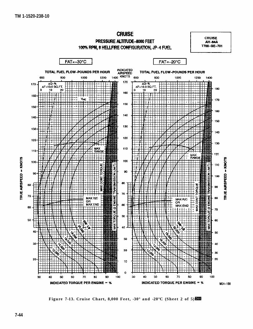
TM 1-1520-238-10
Figure 7-13. Cruise Chart, 8,000 Feet, -30° and -20°C (Sheet 2 of 5)
7-44
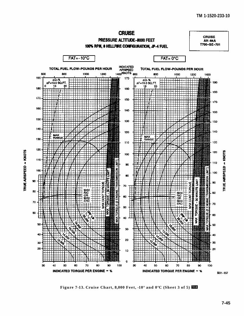
TM 1-1520-233-10
Figure 7-13. Cruise Chart, 8,000 Feet, -10° and 0°C (Sheet 3 of 5)
7-45
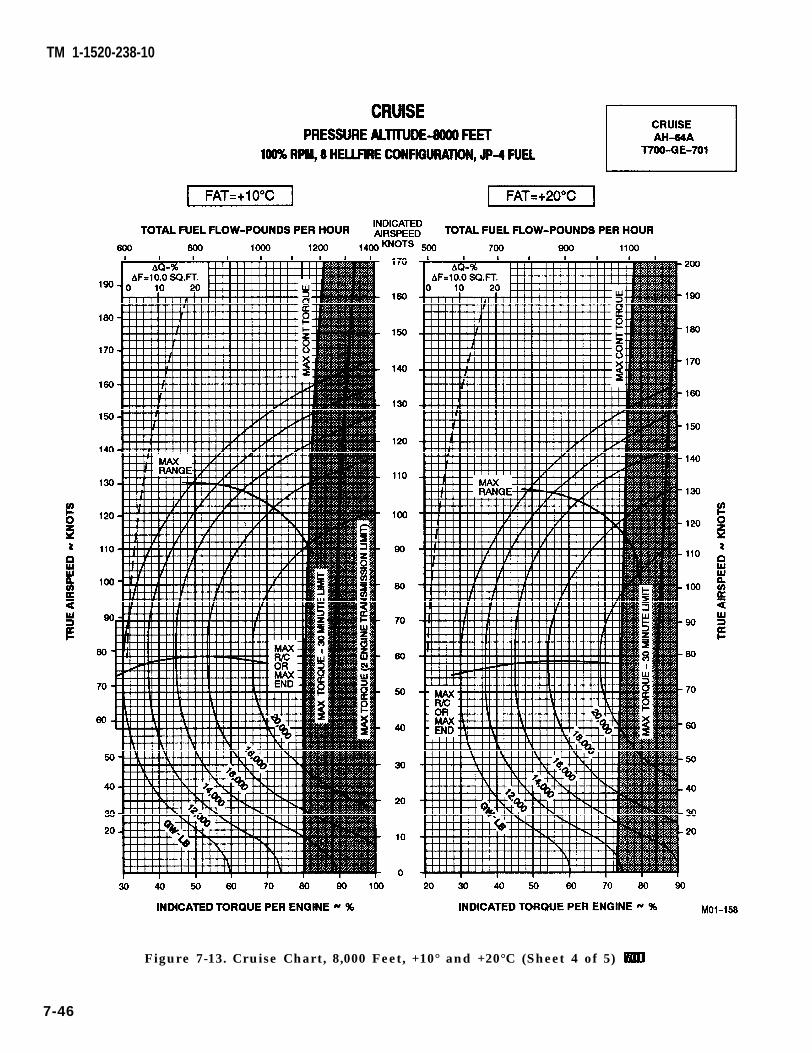
TM 1-1520-238-10
Figure 7-13. Cruise Chart, 8,000 Feet, +10° and +20°C (Sheet 4 of 5)
7-46
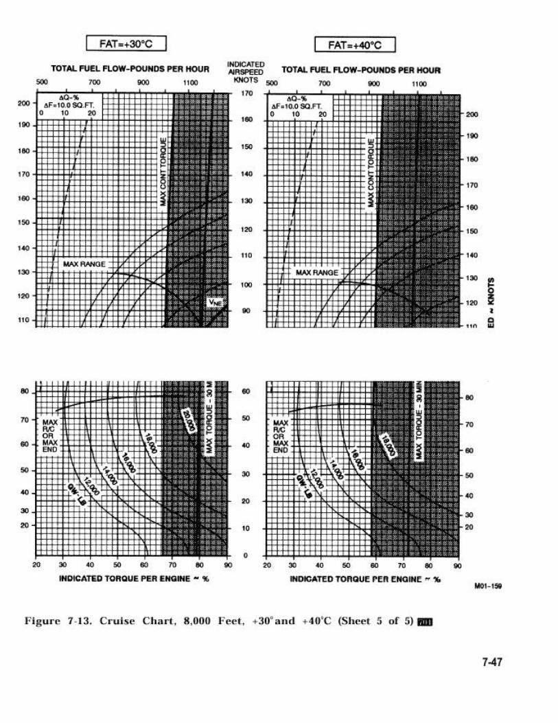
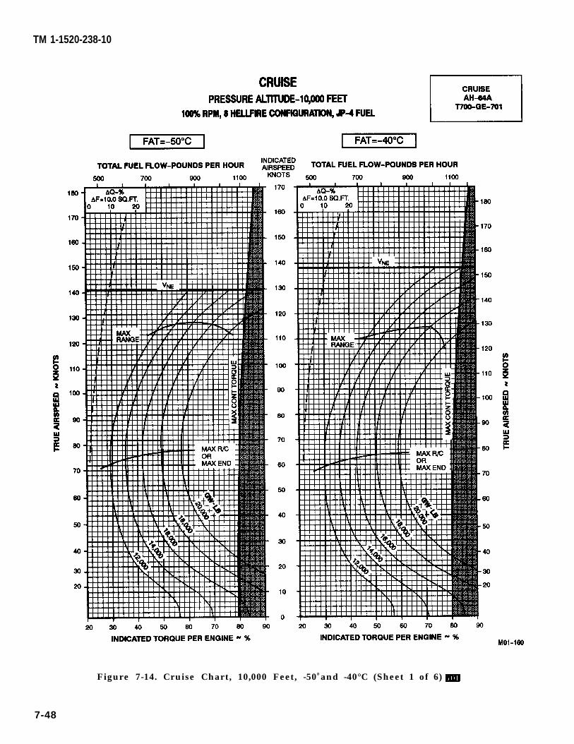
TM 1-1520-238-10
Figure 7-14. Cruise Chart, 10,000 Feet, -500 and -40°C (Sheet 1 of 6)
7-48
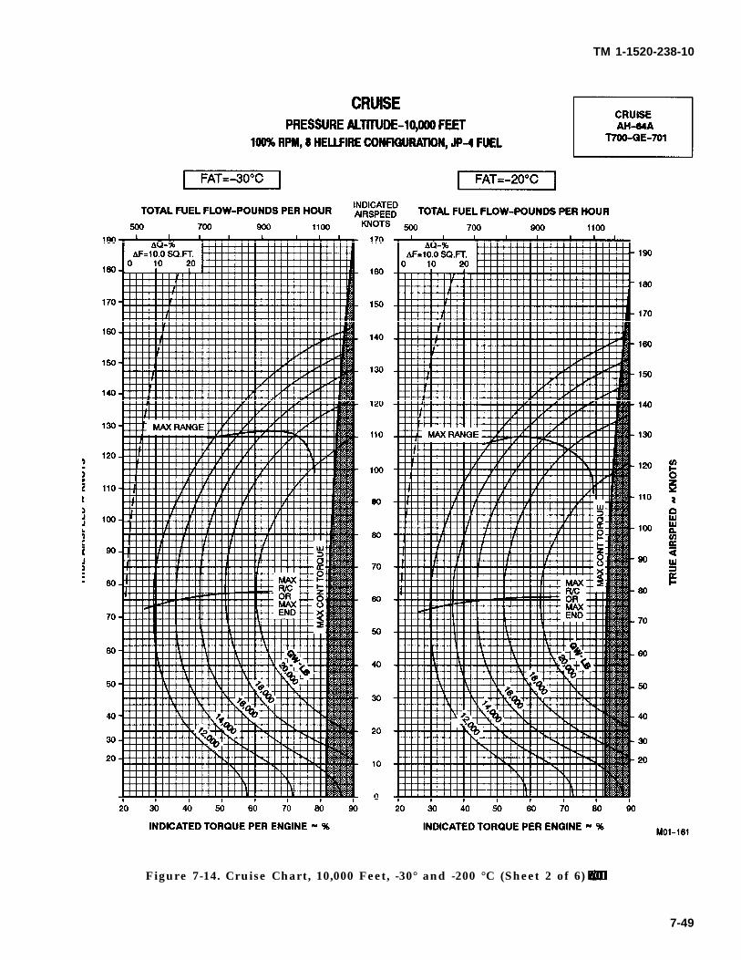
TM 1-1520-238-10
Figure 7-14. Cruise Chart, 10,000 Feet, -30° and -200 °C (Sheet 2 of 6)
7-49
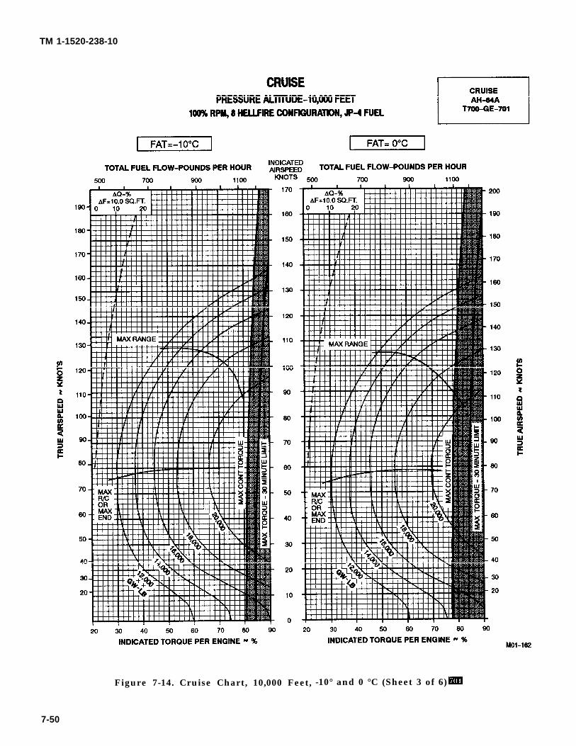
TM 1-1520-238-10
Figure 7-14. Cruise Chart, 10,000 Feet, -10° and 0 °C (Sheet 3 of 6)
7-50
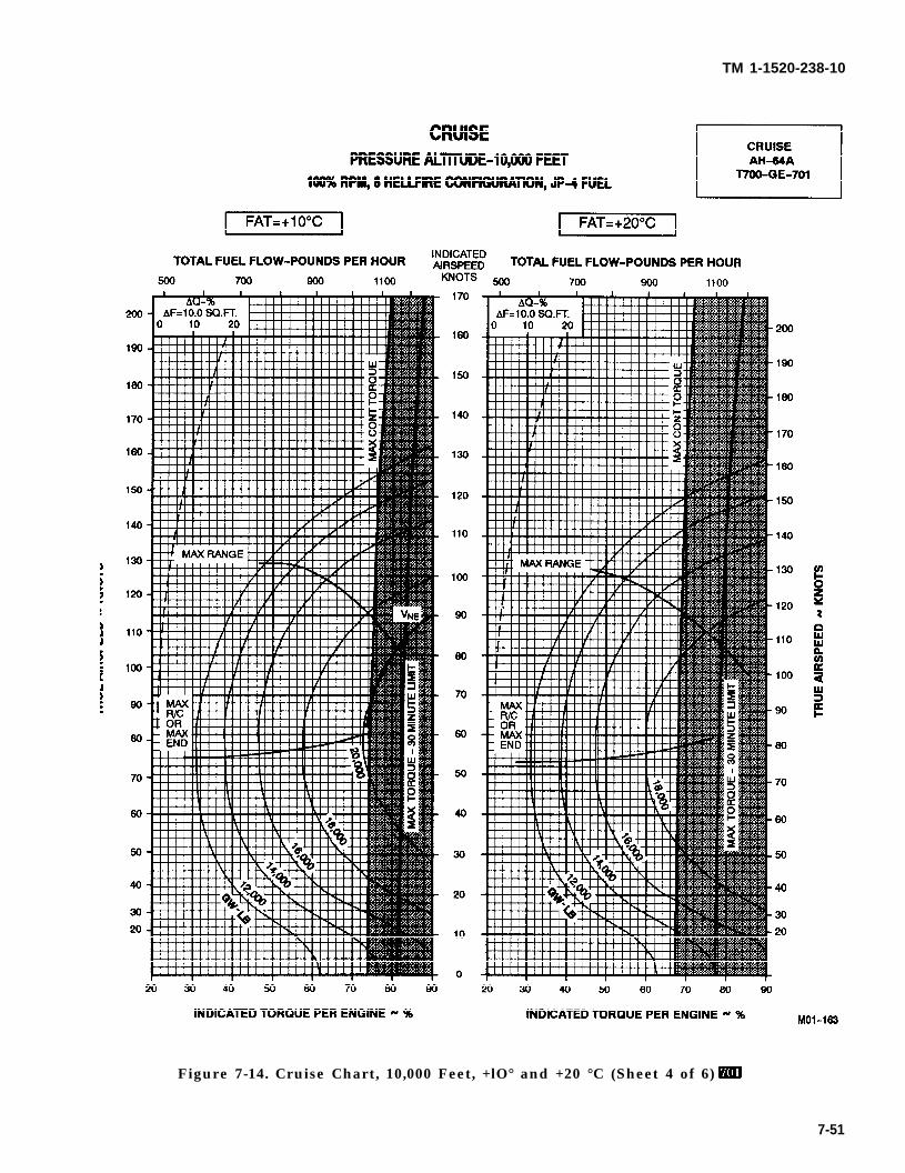
TM 1-1520-238-10
Figure 7-14. Cruise Chart, 10,000 Feet, +lO° and +20 °C (Sheet 4 of 6)
7-51
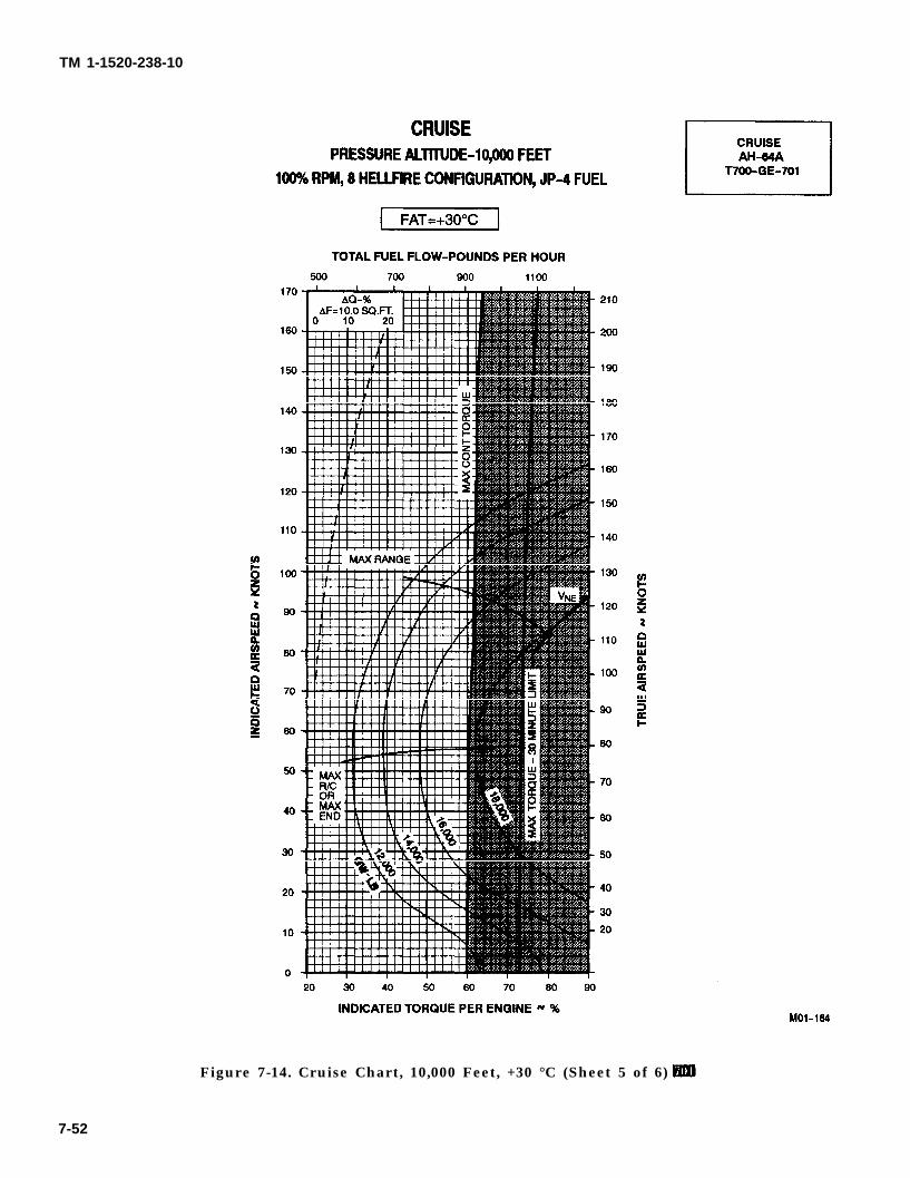
TM 1-1520-238-10
Figure 7-14. Cruise Chart, 10,000 Feet, +30 °C (Sheet 5 of 6)
7-52
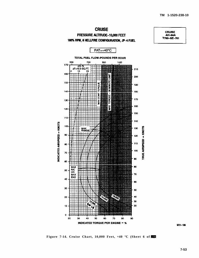
TM 1-1520-238-10
Figure 7-14. Cruise Chart, 10,000 Feet, +40 °C (Sheet 6 of 6)
7-53
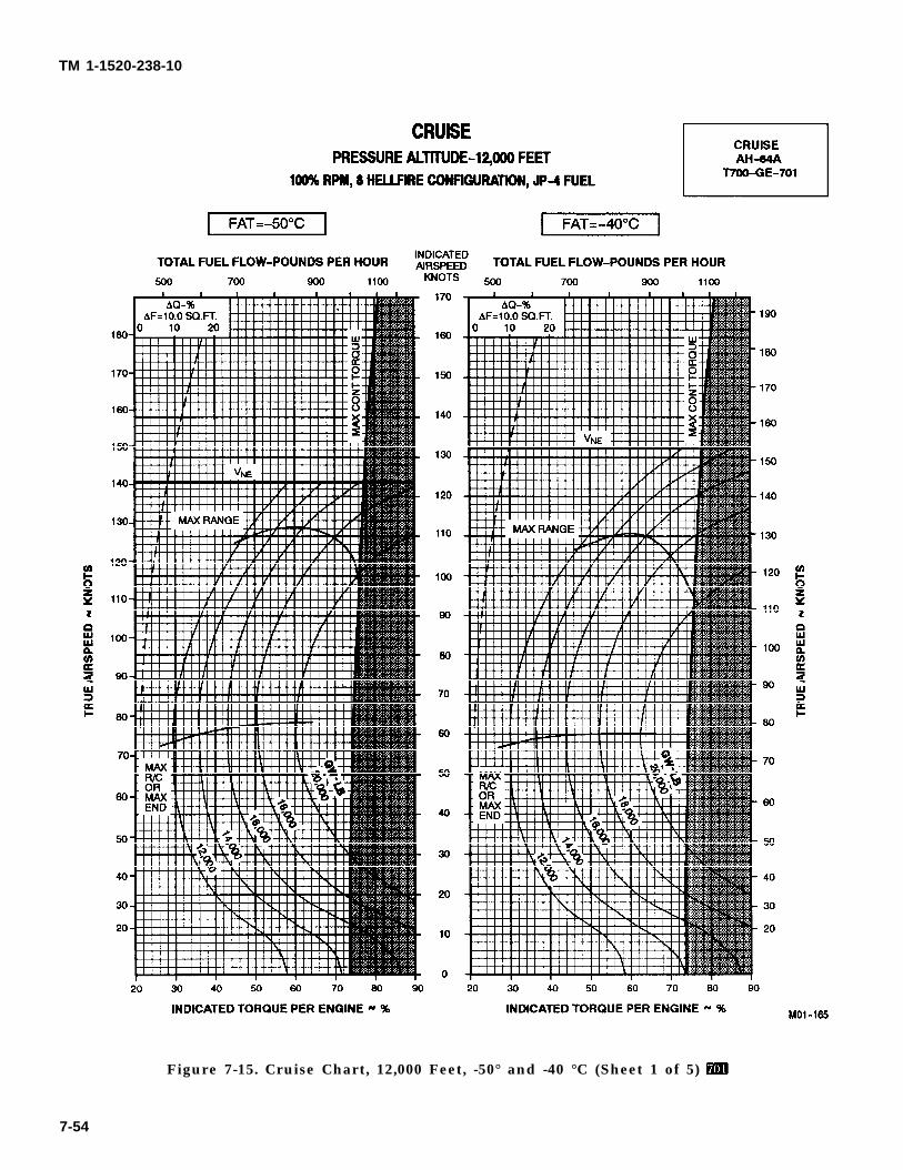
TM 1-1520-238-10
Figure 7-15. Cruise Chart, 12,000 Feet, -50° and -40 °C (Sheet 1 of 5)
7-54
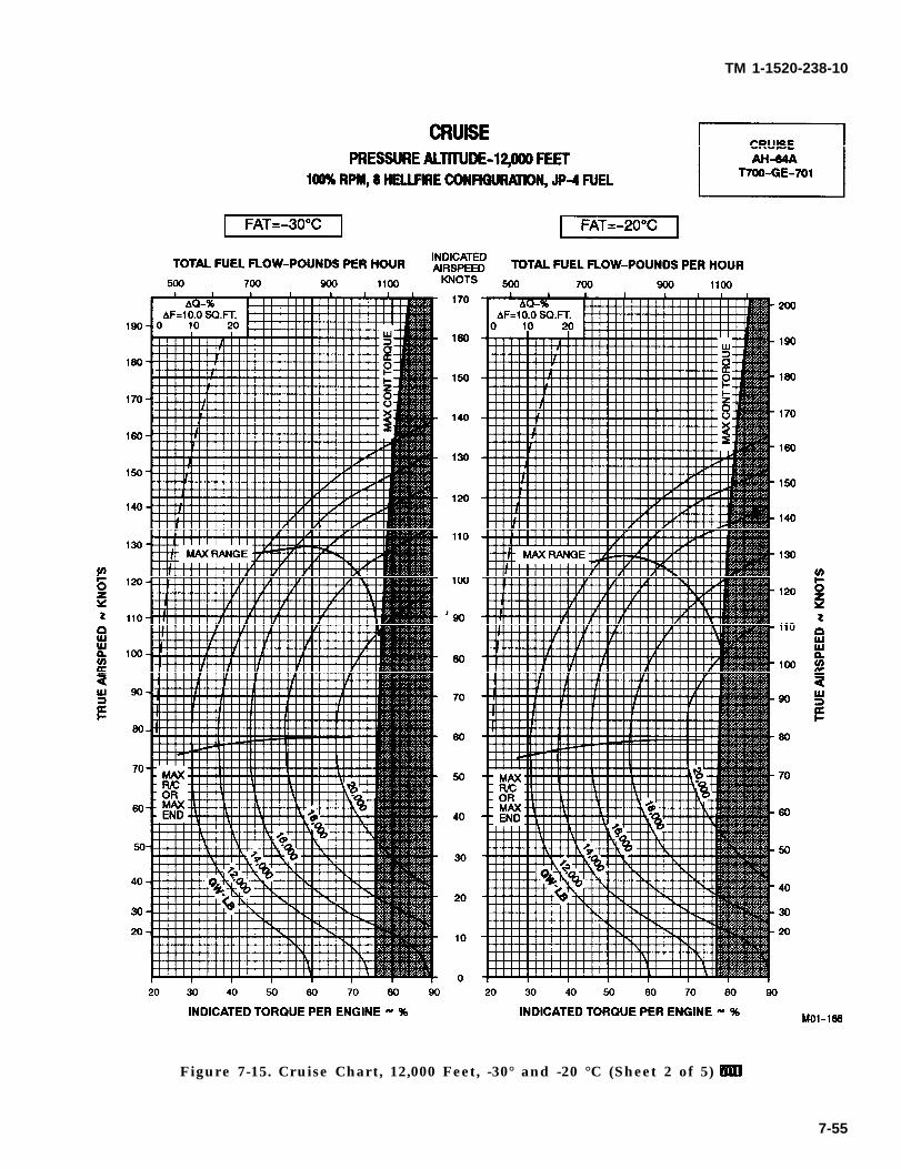
TM 1-1520-238-10
Figure 7-15. Cruise Chart, 12,000 Feet, -30° and -20 °C (Sheet 2 of 5)
7-55
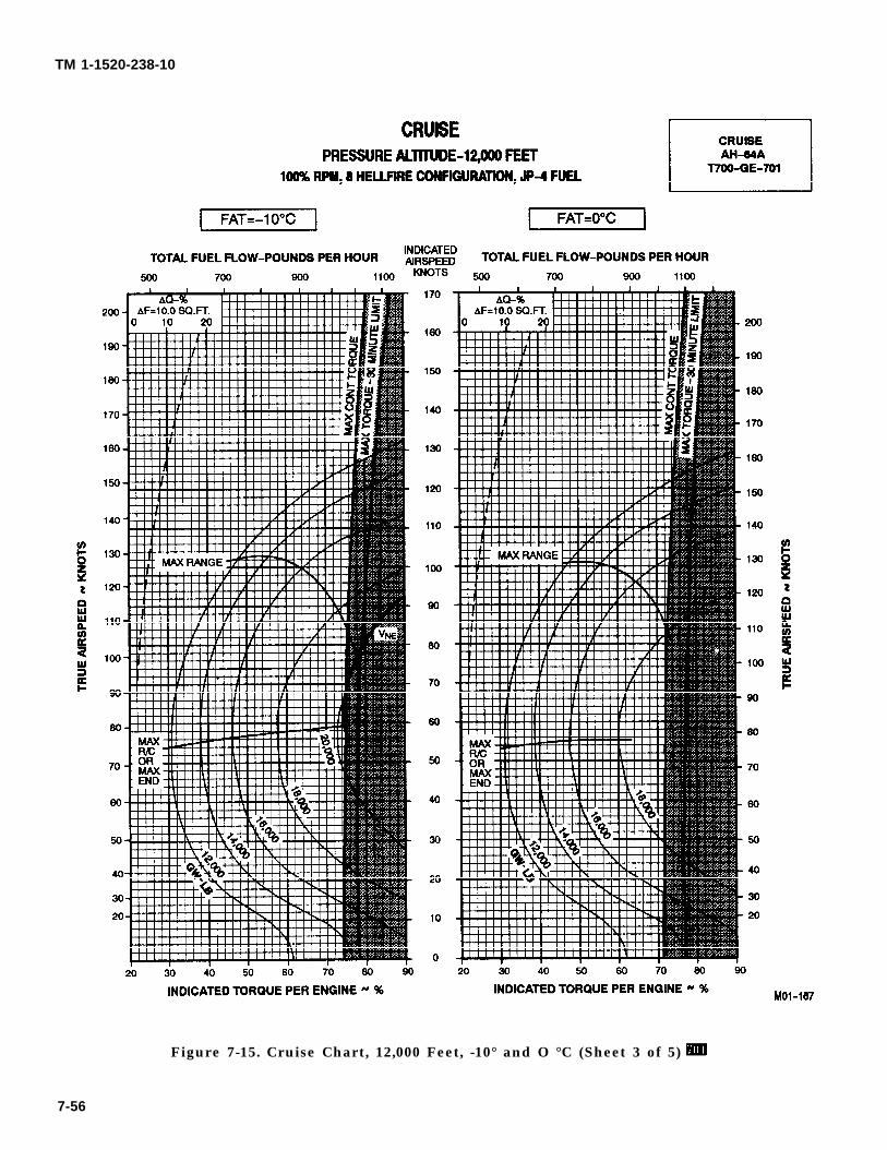
TM 1-1520-238-10
Figure 7-15. Cruise Chart, 12,000 Feet, -10° and O °C (Sheet 3 of 5)
7-56
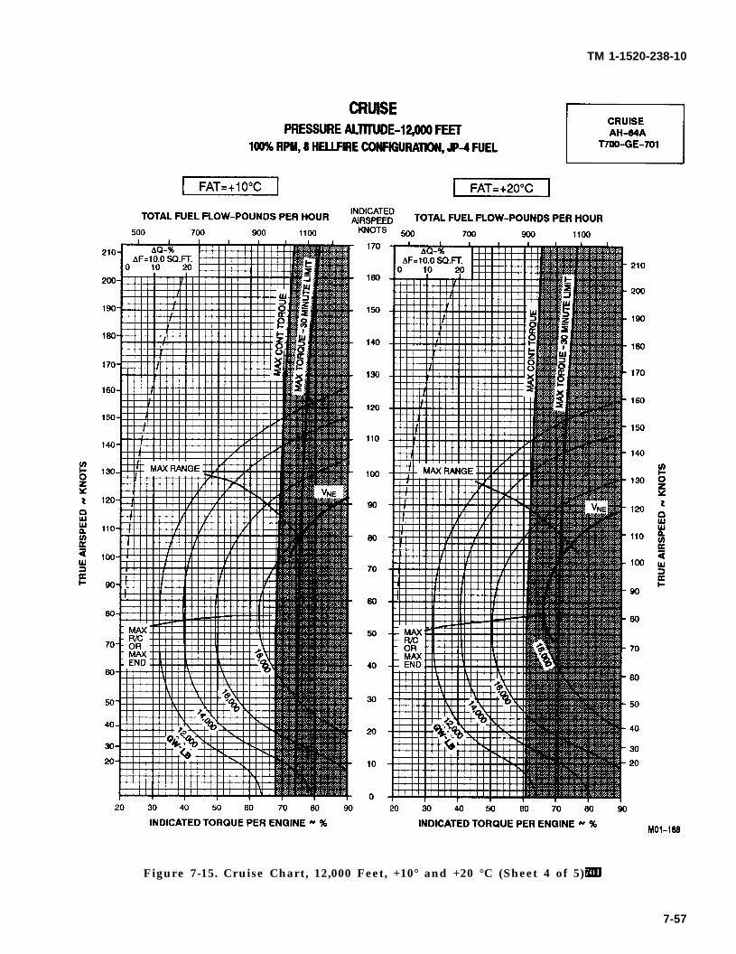
TM 1-1520-238-10
Figure 7-15. Cruise Chart, 12,000 Feet, +10° and +20 °C (Sheet 4 of 5)
7-57
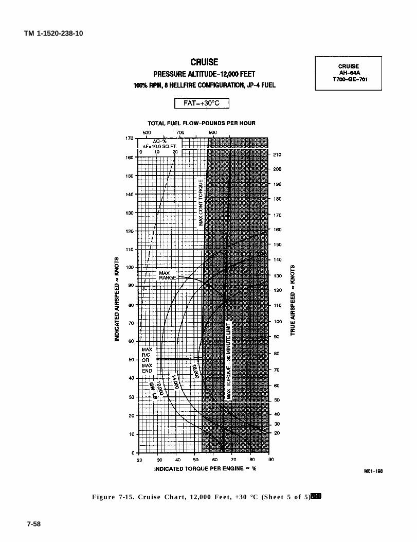
TM 1-1520-238-10
Figure 7-15. Cruise Chart, 12,000 Feet, +30 °C (Sheet 5 of 5)
7-58
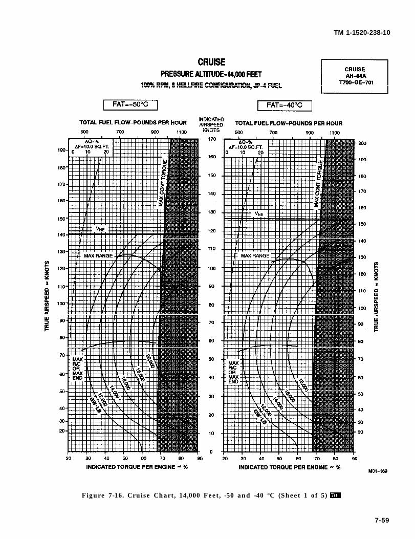
TM 1-1520-238-10
Figure 7-16. Cruise Chart, 14,000 Feet, -50 and -40 °C (Sheet 1 of 5)
7-59
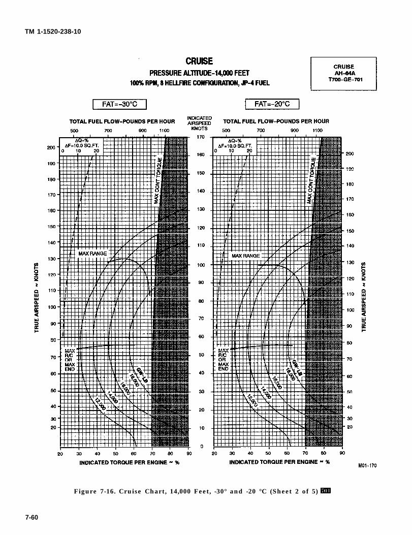
TM 1-1520-238-10
7-60
Figure 7-16. Cruise Chart, 14,000 Feet, -30° and -20 °C (Sheet 2 of 5)
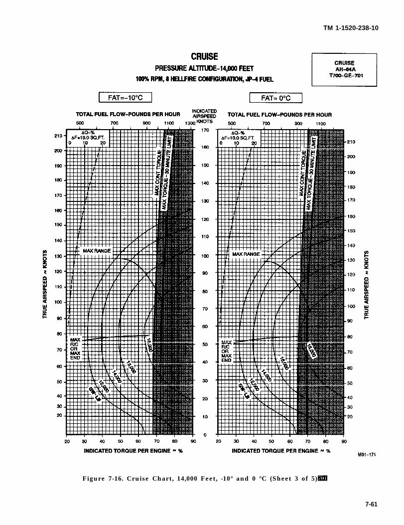
TM 1-1520-238-10
Figure 7-16. Cruise Chart, 14,000 Feet, -10° and 0 °C (Sheet 3 of 5)
7-61
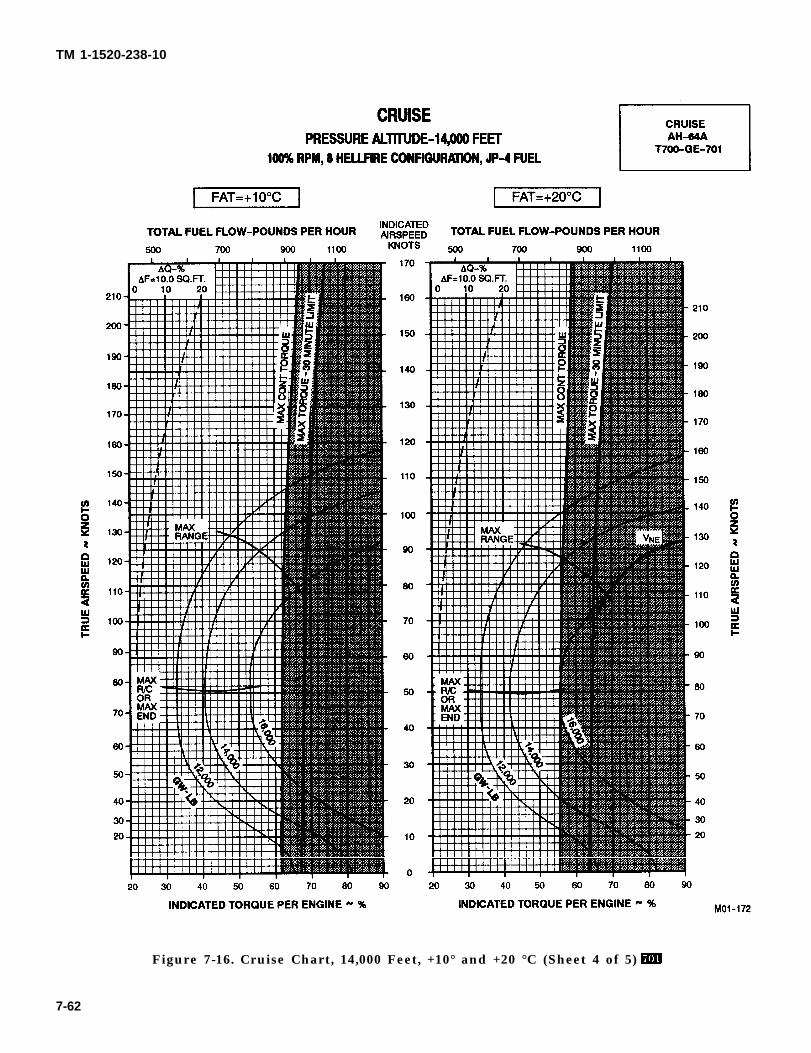
TM 1-1520-238-10
Figure 7-16. Cruise Chart, 14,000 Feet, +10° and +20 °C (Sheet 4 of 5)
7-62
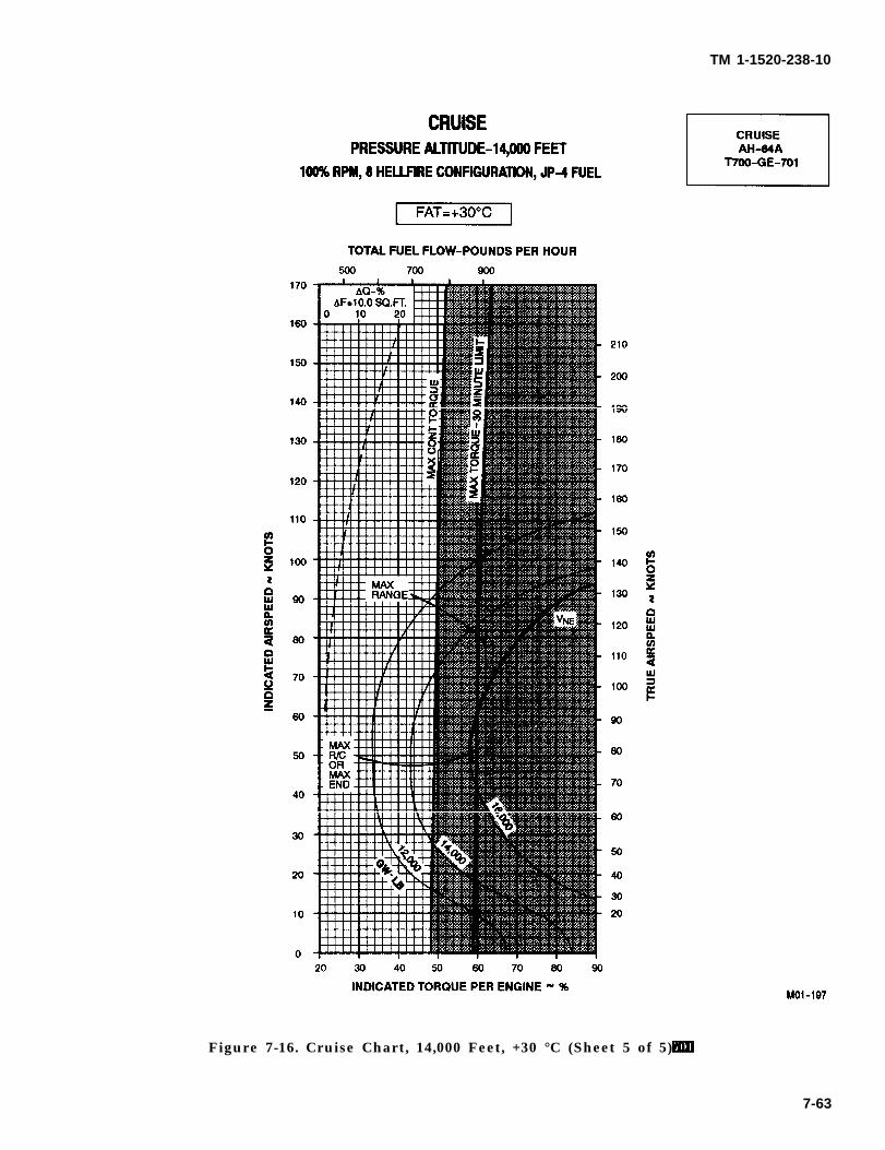
TM 1-1520-238-10
Figure 7-16. Cruise Chart, 14,000 Feet, +30 °C (Sheet 5 of 5)
7-63
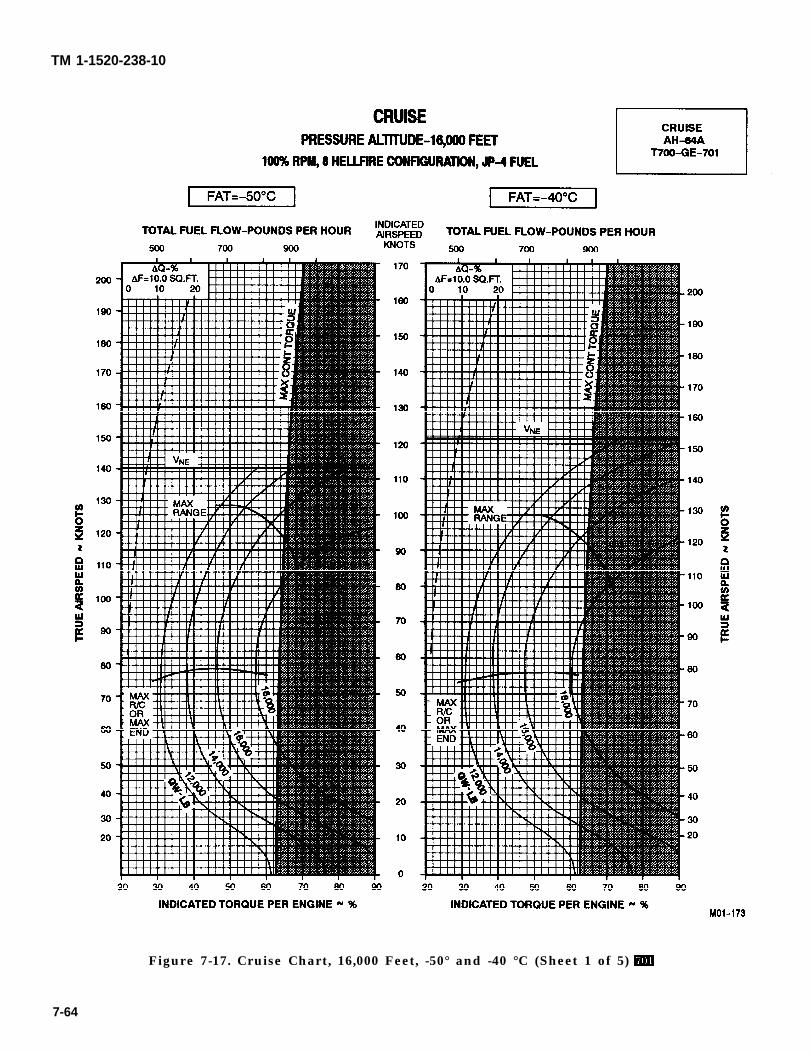
TM 1-1520-238-10
7-64
Figure 7-17. Cruise Chart, 16,000 Feet, -50° and -40 °C (Sheet 1 of 5)
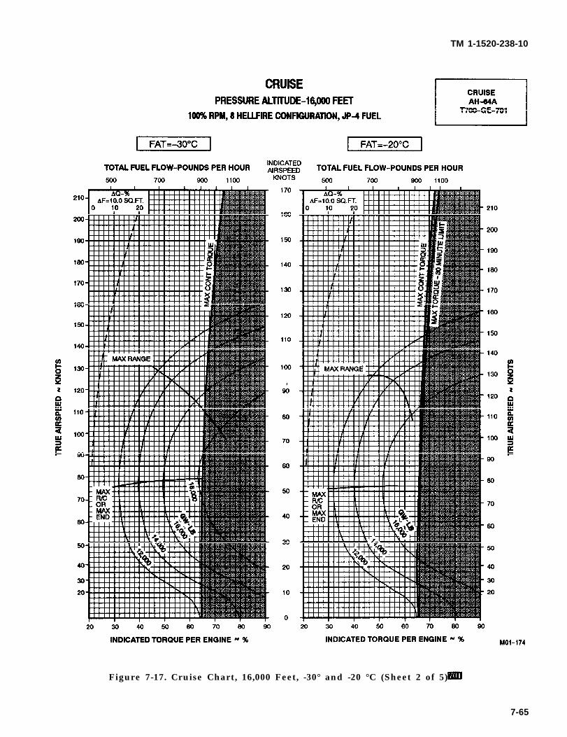
TM 1-1520-238-10
Figure 7-17. Cruise Chart, 16,000 Feet, -30° and -20 °C (Sheet 2 of 5)
7-65
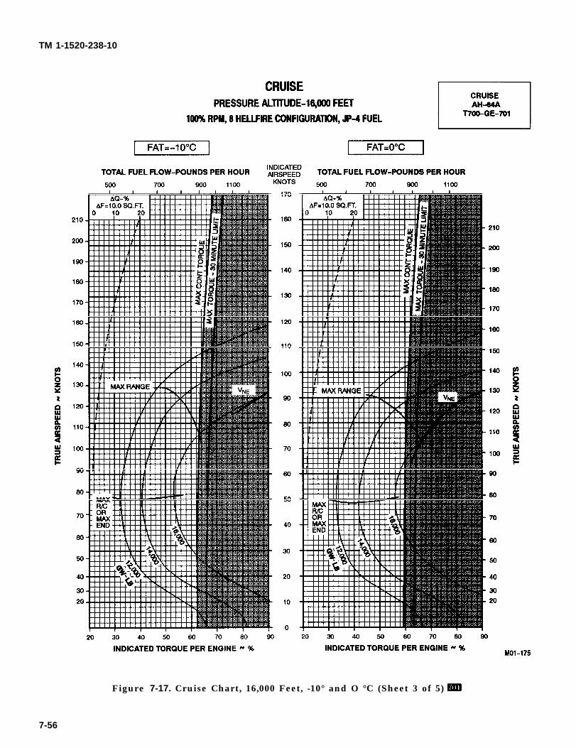
TM 1-1520-238-10
Figure 7-17. Cruise Chart, 16,000 Feet, -10° and O °C (Sheet 3 of 5)
7-56
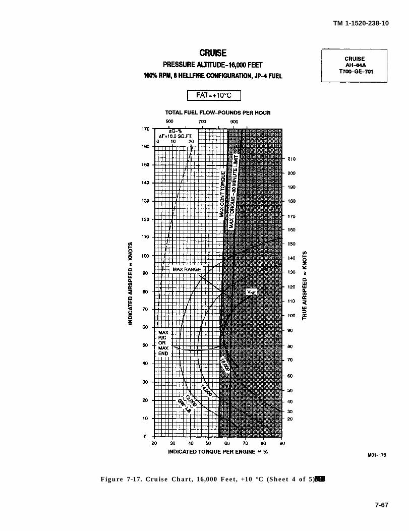
TM 1-1520-238-10
Figure 7-17. Cruise Chart, 16,000 Feet, +10 °C (Sheet 4 of 5)
7-67
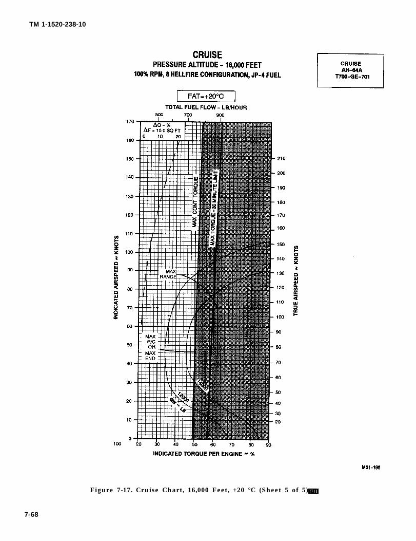
TM 1-1520-238-10
Figure 7-17. Cruise Chart, 16,000 Feet, +20 °C (Sheet 5 of 5)
7-68

TM 1-1520-238-10
Section VI. DRAG
7.22 DESCRIPTION. the desired combination, and then move right and readAF and the multiplying factor. Use the multiplying fac-
The drag chart (fig 7-18) shows the change in frontal tor and data in Section VI, Cruise to determine there-area for each wing-stores combination that can be suiting change in torque.installed on the helicopter. The baseline configurationdoes not include the Wire Strike Protection System(WSPS).
7.24 CONDITIONS.
7.23 USE OF CHART. The drag chart is based on the primary mission configu-ration having zero change in frontal area. If the WSPS
To determine the change in frontal area (AF) and the is installed, increase the frontal area for all configura-associated multiplying factor, it is necessary to know tions in the drag table (including the primary missionwhat combination. of stores is installed. Enter the chart configuration) by 1.9 sq ft and increase the multiplyingat the top, move down to the illustration that matches factor by 0.19.
Change 2 7-69
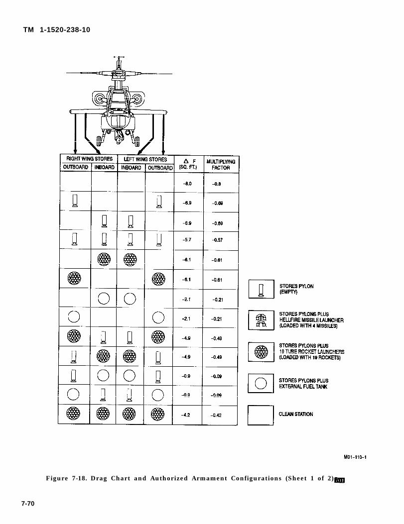
TM 1-1520-238-10
Figure 7-18. Drag Chart and Authorized Armament Configurations (Sheet 1 of 2)
7-70
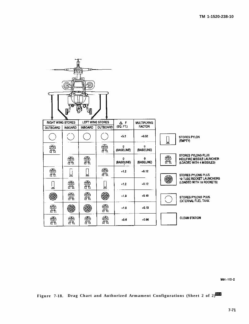
TM 1-1520-238-10
Figure 7-18. Drag Chart and Authorized Armament Configurations (Sheet 2 of 2)
7-71
TM 1-1520-238-10
Section VIl. CLIMB-DESCENT
7.25 DESCRIPTION
The climb descent chart (fig 7-19) shows the change intorque (above and below the torque required for levelflight under the same configuration, gross weight, andatmospheric conditions) to obtain a desired rate ofclimb or descent.
7.26 USE OF CHART.
The primary use of the chart is illustrated by the exam-ple. To determine the change in torque, it is necessaryto know the gross weight and the desired rate of climbor descent. Enter the chart at the desired rate of climbor descent, move right to the known gross weight, and
7-72
then move down and read the torque change, Thistorque change must be added to (for climb) or sub-tracted from (for descent) the torque required for levelflight (obtained from the appropriate cruise chart) toobtain a total climb or descent torque.
By entering the chart with a known torque change, andmoving up to the known gross weight and then left, thecorresponding rate of climb or descent can also be ob-tained.
7.27 CONDITIONS.
The climb-descent chart is based on 100% rotor rpm.
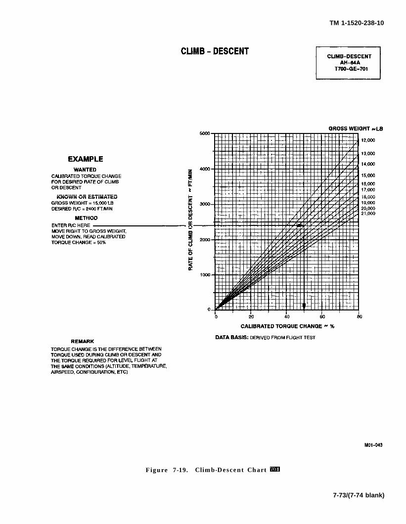
TM 1-1520-238-10
Figure 7-19. Climb-Descent Chart
7-73/(7-74 blank)

CAUTION
TM 1-1520-238-10
CHAPTER 7APERFORMANCE DATA FOR AH-64A HELlCOPTERS
EQUIPPED WITH T-700-GE-701C ENGINES
Section I. INTRODUCTION
NOTE
This chapter contains performance datafor helicopters equipped withT-700-GE-701C 701C engines. Perfor-mance data for helicopters equipped withT-700-GE-701 701 engines is contained inChapter 7. Users are authorized to re-move the chapter that is not applicableand are not required to carry both chap-ters on the helicopter.
7A.1. PERFORMANCE DATA.
The purpose of this chapter is to provide the best avail-able performance data for the AH-64A helicopterequipped with -701C engines. Regular use of this in-formation will allow maximum safe use of the helicop-ter. Although maximum performance is not always re-quired, regular use of the information in this chapter isrecommended for the following reasons:
a. Knowledge of performance margins will allowbetter decisions when unexpected conditions or alter-nate missions are encountered.
b. Situations requiring maximum performance willbe more readily recognized.
c. Familiarity with the data will allow performanceto be computed more easily and quickly.
d. Experience will be gained in accurately estimat-ing the effects of conditions for which data is not pres-ented.
NOTE
The information is primarily intended formission planning and is most useful whenplanning operations in unfamiliar areasor at extreme conditions. The data mayalso be used in flight, to establish unit orarea standing operating procedures, andto inform ground commanders of perfor-mance/risk tradeoffs.
The data presented covers the maximum range ofconditions and performance that can reasonably be ex-pected. In each area of performance, the effects of alti-tude, temperature, gross weight and other parametersrelating to that phase of flight are presented. In addi-tion to the presented data, judgment and experiencewill be necessary to accurately determine performanceunder a given set of circumstances. The conditions forthe data are listed under the title of each chart. The ef-fects of different conditions are discussed in the text ac-companying each phase of performance. Where practi-cal, data is presented at conservative conditions.However, NO GENERAL CONSERVATISM HASBEEN APPLIED.
7A.2. OPERATIONAL LIMITS.
Exceeding operational limits cancause permanent damage to criticalcomponents. Overlimit operation candecrease performance, cause im-mediate failure or failure on a subse-quent flight.
Applicable limits are shown on the charts as bold lineswith a description. Performance generally deterioratesrapidly beyond limits. If limits are exceeded, minimizethe amount and time. Enter the maximum value andtime beyond limits on DA Form 2408-13 to ensure prop-er maintenance action is taken.
7A-1
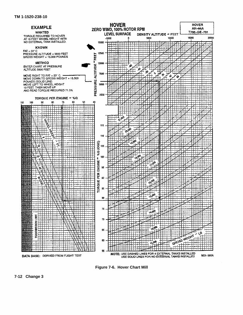
TM 1-1520-238-10
Figure 7-6. Hover Chart Mill
7-12 Change 3
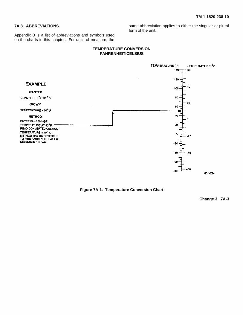
TM 1-1520-238-10
7A.8. ABBREVIATIONS.
Appendix B is a list of abbreviations and symbols usedon the charts in this chapter. For units of measure, the
same abbreviation applies to either the singular or pluralform of the unit.
TEMPERATURE CONVERSIONFAHRENHEITICELSIUS
Figure 7A-1. Temperature Conversion Chart
Change 3 7A-3
TM 1-1520-238-10
Section II. MAXIMUM TORQUE AVAILABLE
7A.9. DESCRIPTION. 7A.12. TORQUE FACTOR METHOD.
The maximum torque available charts shows the maxi-mum specification torque available per engine for 30minute operation (fig 7A-2 sheet 1) and 10 minute op-eration (fig 7A-2 sheet 2) at various conditions of pres-sure altitude and free air temperature. Both single anddual engine operation limits are shown.
The maximum torque available for 2.5 minute opera-tion (fig 7A-2 sheet 3) shows the maximum specifica-tion torque available when one engine is inoperative;only single engine operation limits are shown.
The torque factor charts (figs 7A-3 and 7A-4) provide anaccurate indication of available power for the enginesinstalled in each individual aircraft.
7A.10. USE OF CHARTS.
The primary use of the maximum torque availablecharts (fig 7A-2 sheets 1, 2, and 3) is illustrated by theexample. To determine the maximum specificationtorque available, it is necessary to know pressure alti-tude and free air temperature. Enter the left side of ei-ther the 30 minute or the 10 minute chart (fig 7A-2sheets 1 or 2) at the known temperature and move rightto the known pressure altitude, and then move downand read the maximum specification torque available.This is torque per engine. For dual engine operation, ifthe torque per engine exceeds the two engine limit, themaximum torque available must be reduced to the twoengine limit.
For one engine inoperative, enter the left side of the 2.5minute limit chart (fig 7A-2 sheet 3) at the known tem-perature and move right to the known pressure alti-tude, and then move down and read the maximumspecification torque available for one engine. If thetorque exceeds the one engine limit, maximum torqueavailable must be reduced to the one engine limit.
7A.11 . CONDITIONS.
The maximum torque available charts (fig 7A-2 sheets1, 2, and 3) are based on 100% rotor rpm, zero airspeed,JP-4 fuel and ENG INLET anti-ice switch OFF. WithENG INLET anti-ice switch ON, available torque is re-duced by as much as 19.3% for 30 minute operation and18.6% for 10 minute operation. For example, if valuefrom the chart is 90%, with anti-ice ON, torque avail-able would be 90 - 19.3 = 70.7%, 30 minute limit.
The torque factor method provides an accurate indica-tion of available power by incorporating ambient tem-perature effects on degraded engine performance. Thetorque factor method provides the procedure to deter-mine the maximum dual or single engine torque avail-able for the engines installed in each individual air-craft. The specification power is defined for a newlydelivered low time engine. The aircraft HIT log form foreach engine provide the engine and aircraft torque fac-tors which are obtained from the maximum powercheck and recorded to be used in calculating maximumtorque available.
7A.12.1 Torque Factor Terms. The following termsare used when determining the maximum torque avail-able for an individual aircraft:
a. Torque Ratio (TR). The ratio of torque avail-able to specification torque at the desired ambient tem-perature.
b. Engine Torque Factor (ETF). The ratio of anindividual engine torque available to specificationtorque at reference temperature of 35 °C. The ETF isallowed to range from 0.85 to 1.0.
c. Aircraft Torque Factor (ATF). The ratio of anindividual aircrafts power available to specificationpower at a reference temperature of 35 °C. The ATF isthe average of the ETFs of both engines and its value isallowed to range from 0.9 to 1.0.
7A.12.2 Torque Factor Procedure. The use of theATF or ETF to obtain the TR from figure 7A-3 for ambi-ent temperatures between -15 °C and 35 °C is shownby the example. The ATF and ETF values for an indi-vidual aircraft are found on the engine HIT log. The TRalways equals 1.0 for ambient temperatures of -15 °Cand below, and the TR equals the ATF or ETF for tem-peratures of 35 °C and above.
When the TR equals 1.0 the torque available may beread directly from the specification torque availablescales. When the TR is less than 1.0, the actual torqueavailable is determined by multiplying the specifica-tion torque available by the TR (example for TR = 0.98:90% TRQ X 0.98 = 88.2% TRQ). The torque conversionchart (fig 7A-4) is provided to convert specification datato actual torque available. The single and dual enginetransmission limits are shown and should not be ex-ceeded.
7A-4 Change 2

TM 1-1520-238-10
Figure 7A-2. Maximum Torque Available Chart (Sheet 1 of 3)
7A-5
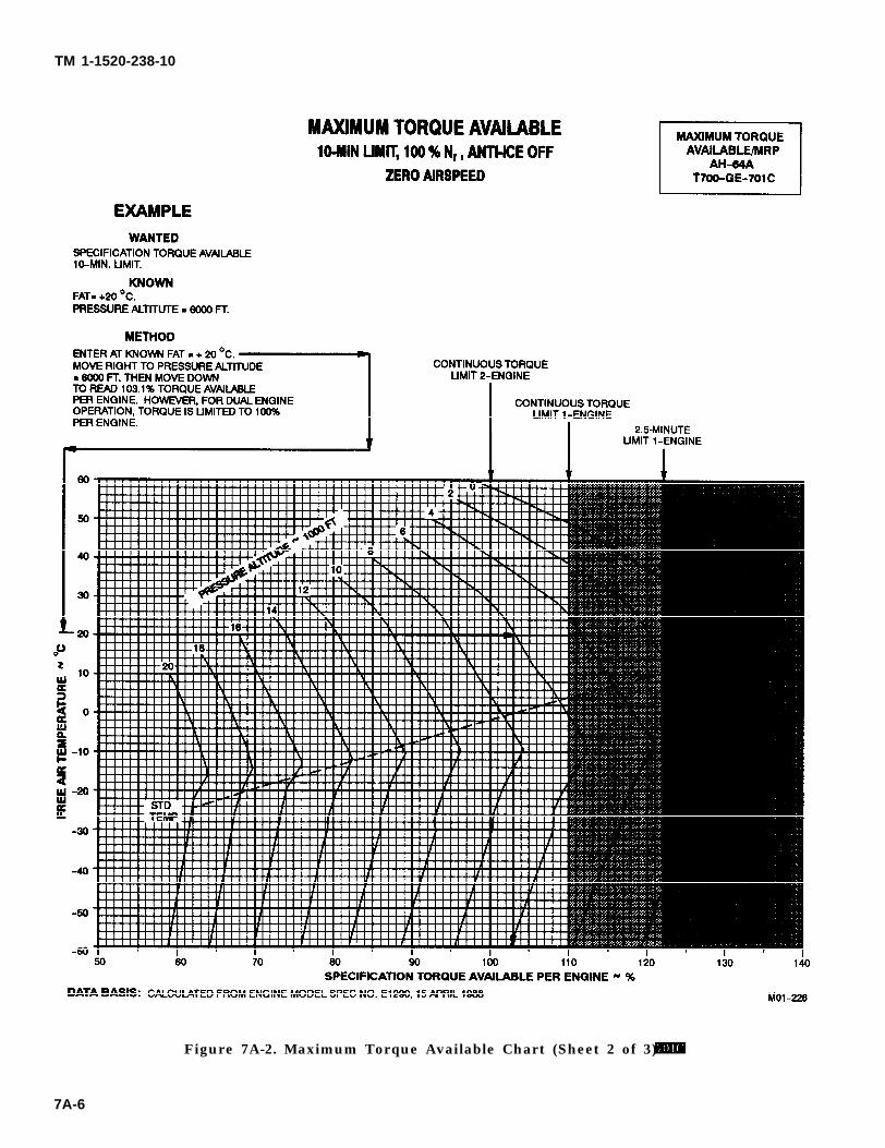
TM 1-1520-238-10
Figure 7A-2. Maximum Torque Available Chart (Sheet 2 of 3)
7A-6
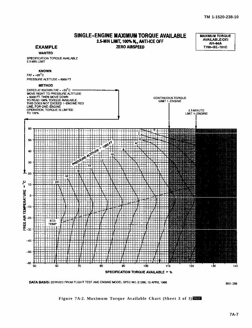
TM 1-1520-238-10
Figure 7A-2. Maximum Torque Available Chart (Sheet 3 of 3)
7A-7
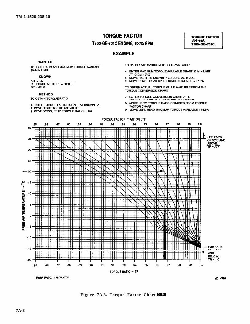
TM 1-1520-238-10
Figure 7A-3. Torque Factor Chart
7A-8
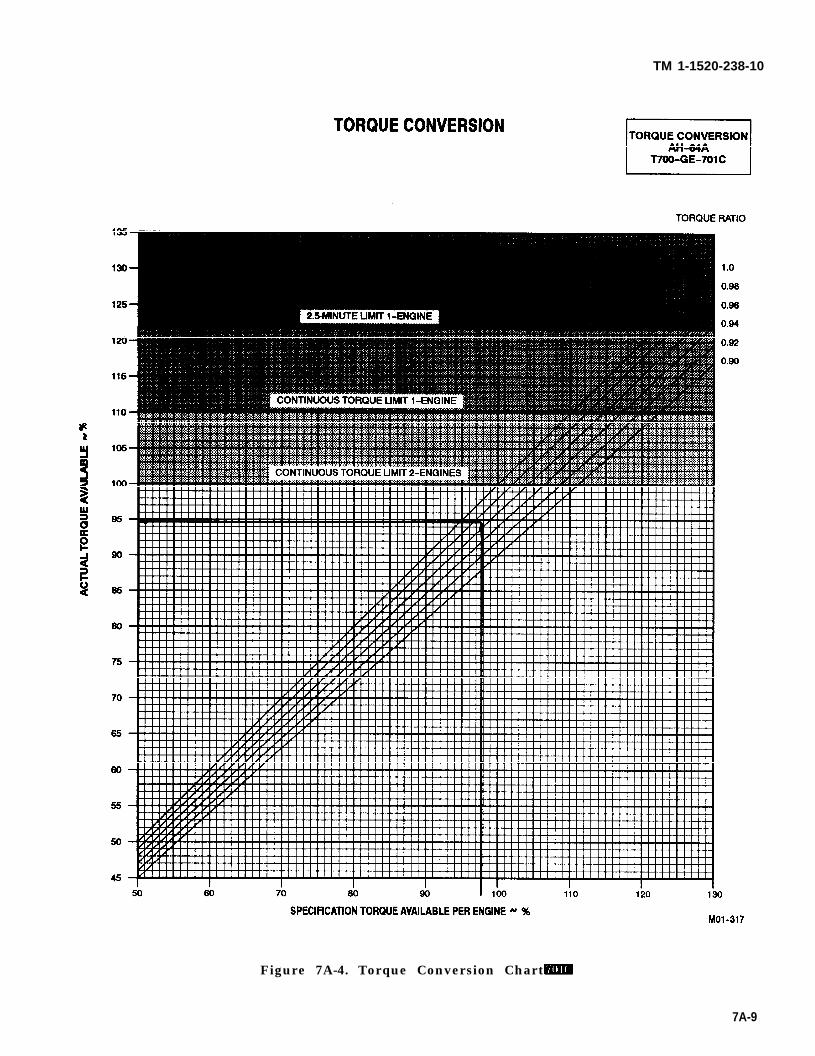
TM 1-1520-238-10
Figure 7A-4. Torque Conversion Chart
7A-9
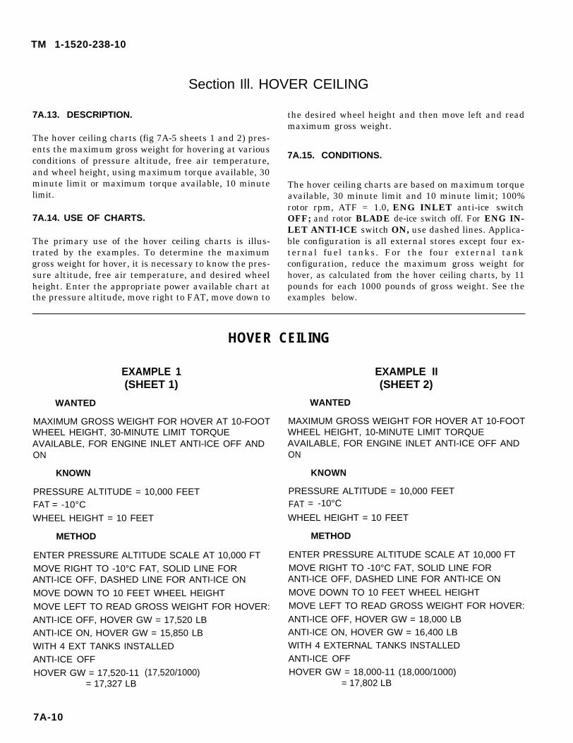
TM 1-1520-238-10
Section Ill. HOVER CEILING
7A.13. DESCRIPTION.
The hover ceiling charts (fig 7A-5 sheets 1 and 2) pres-ents the maximum gross weight for hovering at variousconditions of pressure altitude, free air temperature,and wheel height, using maximum torque available, 30minute limit or maximum torque available, 10 minutelimit.
7A.14. USE OF CHARTS.
The primary use of the hover ceiling charts is illus-trated by the examples. To determine the maximumgross weight for hover, it is necessary to know the pres-sure altitude, free air temperature, and desired wheelheight. Enter the appropriate power available chart atthe pressure altitude, move right to FAT, move down to
the desired wheel height and then move left and readmaximum gross weight.
7A.15. CONDITIONS.
The hover ceiling charts are based on maximum torqueavailable, 30 minute limit and 10 minute limit; 100%rotor rpm, ATF = 1.0, ENG INLET anti-ice switchOFF; and rotor BLADE de-ice switch off. For ENG IN-LET ANTI-ICE switch ON, use dashed lines. Applica-ble configuration is all external stores except four ex-ternal fuel tanks. For the four external tankconfiguration, reduce the maximum gross weight forhover, as calculated from the hover ceiling charts, by 11pounds for each 1000 pounds of gross weight. See theexamples below.
HOVER CEILING
EXAMPLE 1(SHEET 1)
WANTED
MAXIMUM GROSS WEIGHT FOR HOVER AT 10-FOOTWHEEL HEIGHT, 30-MINUTE LIMIT TORQUEAVAILABLE, FOR ENGINE INLET ANTI-ICE OFF ANDON
KNOWN
PRESSURE ALTITUDE = 10,000 FEETFAT = -10°C
WHEEL HEIGHT = 10 FEET
METHOD
ENTER PRESSURE ALTITUDE SCALE AT 10,000 FTMOVE RIGHT TO -10°C FAT, SOLID LINE FORANTI-ICE OFF, DASHED LINE FOR ANTI-ICE ON
MOVE DOWN TO 10 FEET WHEEL HEIGHT
MOVE LEFT TO READ GROSS WEIGHT FOR HOVER:ANTI-ICE OFF, HOVER GW = 17,520 LBANTI-ICE ON, HOVER GW = 15,850 LBWITH 4 EXT TANKS INSTALLEDANTI-ICE OFF
HOVER GW = 17,520-11= 17,327 LB
(17,520/1000)
EXAMPLE II(SHEET 2)
WANTED
MAXIMUM GROSS WEIGHT FOR HOVER AT 10-FOOTWHEEL HEIGHT, 10-MINUTE LIMIT TORQUEAVAILABLE, FOR ENGINE INLET ANTI-ICE OFF ANDON
KNOWN
PRESSURE ALTITUDE = 10,000 FEETFAT = -10°C
WHEEL HEIGHT = 10 FEET
METHOD
ENTER PRESSURE ALTITUDE SCALE AT 10,000 FTMOVE RIGHT TO -10°C FAT, SOLID LINE FORANTI-ICE OFF, DASHED LINE FOR ANTI-ICE ON
MOVE DOWN TO 10 FEET WHEEL HEIGHTMOVE LEFT TO READ GROSS WEIGHT FOR HOVER:
ANTI-ICE OFF, HOVER GW = 18,000 LBANTI-ICE ON, HOVER GW = 16,400 LBWITH 4 EXTERNAL TANKS INSTALLEDANTI-ICE OFFHOVER GW = 18,000-11 (18,000/1000)
= 17,802 LB
7A-10
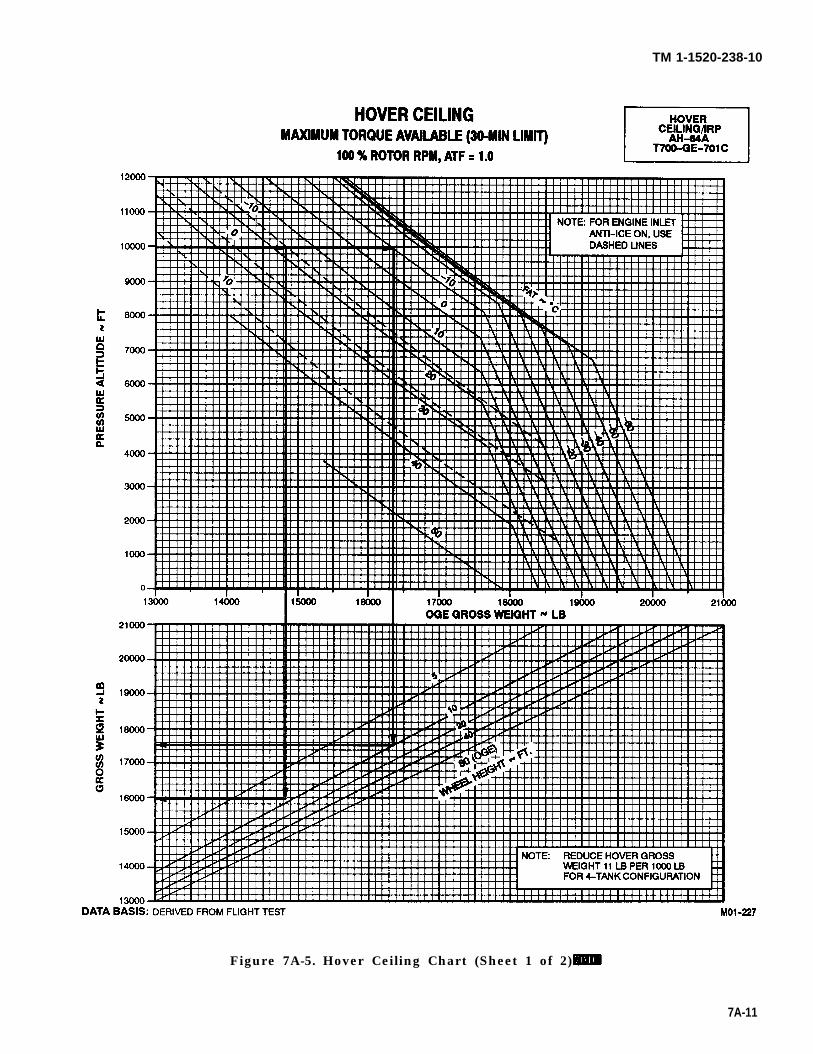
TM 1-1520-238-10
Figure 7A-5. Hover Ceiling Chart (Sheet 1 of 2)
7A-11
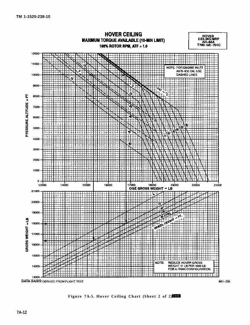
TM 1-1520-238-10
Figure 7A-5. Hover Ceiling Chart (Sheet 2 of 2)
7A-12
TM 1-1520-238-10
Section IV. HOVER LIMITS
7A.16. DESCRIPTION.
The hover chart (fig 7A-6) shows the torque required tohover at various conditions of pressure altitude, free airtemperature, gross weight, wheel height, and with ex-ternal tanks or without external tanks.
7A.17. USE OF CHART.
The primary use of the chart is illustrated by the exam-ple. To determine the torque required to hover, it is nec-essary to know the pressure altitude, free air tempera-ture, gross weight, and desired wheel height. Enter theupper right grid at the known pressure altitude, moveright to the temperature, move down to the grossweight, move left to the desired wheel height, and thenmove up and read the torque required to hover.
In addition to its primary use, the hover chart maybeused to predict the maximum hover height. To deter-mine maximum hover height, it is necessary to knowpressure altitude, free air temperature, gross weight,
and maximum torque available. Enter the known pres-sure altitude, move right to the temperature, movedown to the gross weight, then move left to intersectionwith maximum torque available and read wheel height.This wheel height is the maximum hover height.
The hover chart may also be used to determine themaximum gross weight for hover at a given wheelheight, pressure altitude, and temperature condition.Enter at the known pressure altitude, move right to thetemperature, then draw a line down to the bottom ofthe lower grid. Now enter upper left grid at maximumtorque available, move down to wheel height, and thenmove right to intersect the previously drawn line andread gross weight. This is maximum gross weight atwhich the helicopter will hover.
7A.18. CONDITIONS.
The hover chart is based on calm wind, level surface,100% rotor rpm and rotor BLADE de-ice switch off.With rotor BLADE de-ice switch ON, torque requiredwill increase 1.4%.
7A-13
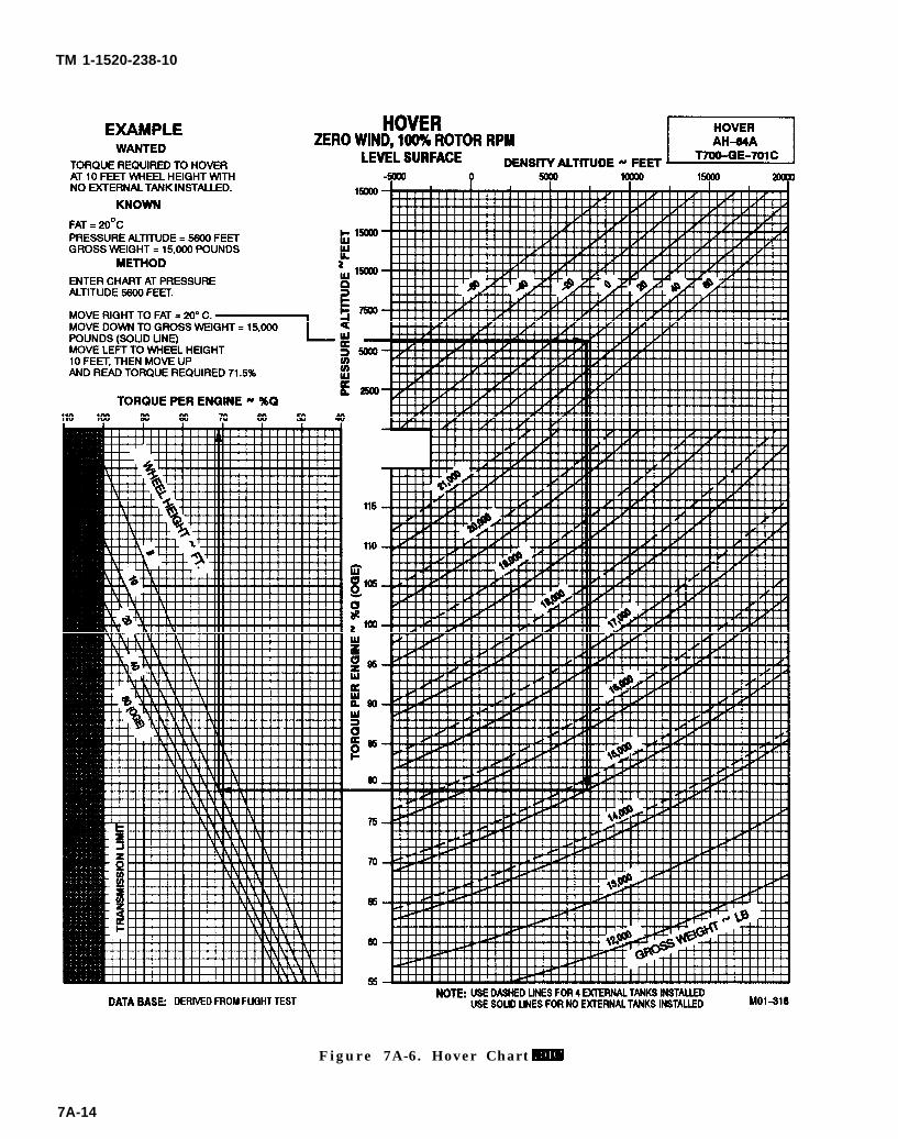
TM 1-1520-238-10
Figure 7A-6. Hover Chart
7A-14
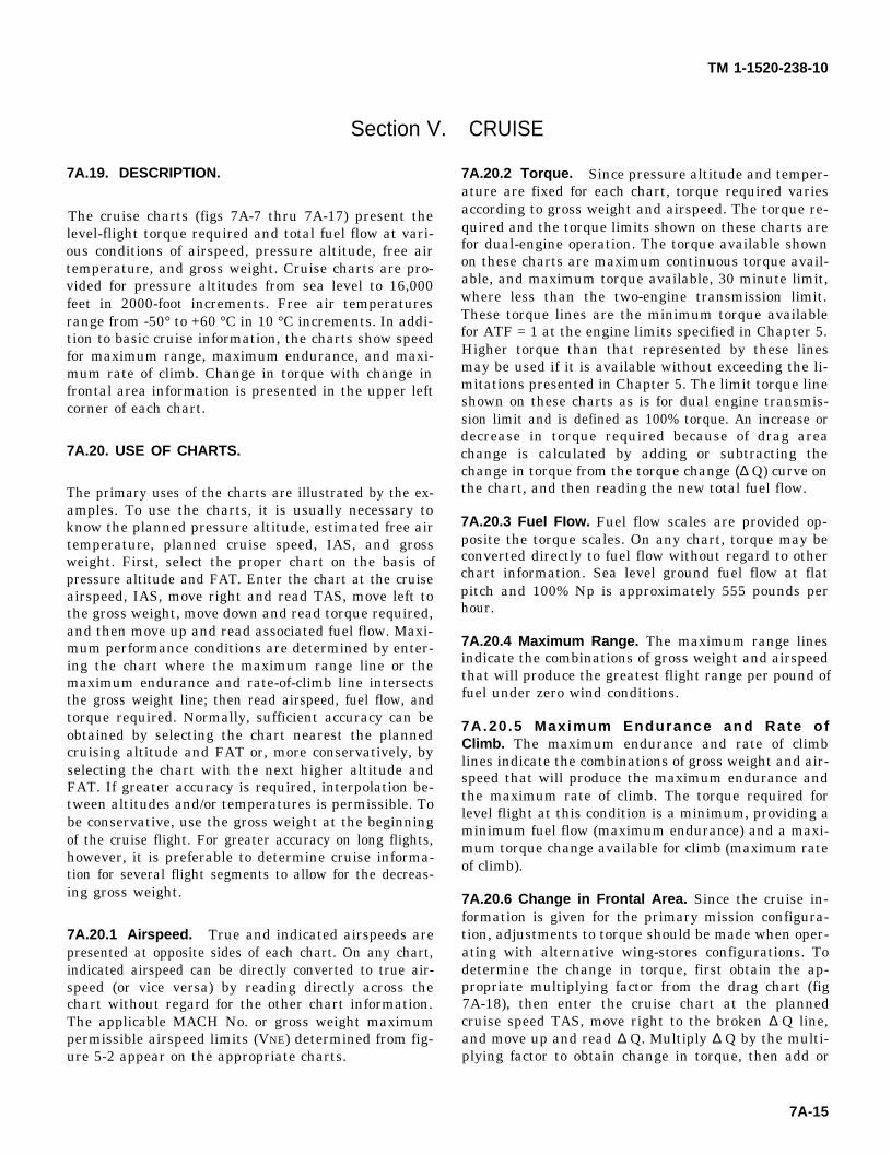
TM 1-1520-238-10
7A.19.
Section V.
DESCRIPTION.
The cruise charts (figs 7A-7 thru 7A-17) present thelevel-flight torque required and total fuel flow at vari-ous conditions of airspeed, pressure altitude, free airtemperature, and gross weight. Cruise charts are pro-vided for pressure altitudes from sea level to 16,000feet in 2000-foot increments. Free air temperaturesrange from -50° to +60 °C in 10 °C increments. In addi-tion to basic cruise information, the charts show speedfor maximum range, maximum endurance, and maxi-mum rate of climb. Change in torque with change infrontal area information is presented in the upper leftcorner of each chart.
7A.20. USE OF CHARTS.
The primary uses of the charts are illustrated by the ex-amples. To use the charts, it is usually necessary toknow the planned pressure altitude, estimated free airtemperature, planned cruise speed, IAS, and grossweight. First, select the proper chart on the basis ofpressure altitude and FAT. Enter the chart at the cruiseairspeed, IAS, move right and read TAS, move left tothe gross weight, move down and read torque required,and then move up and read associated fuel flow. Maxi-mum performance conditions are determined by enter-ing the chart where the maximum range line or themaximum endurance and rate-of-climb line intersectsthe gross weight line; then read airspeed, fuel flow, andtorque required. Normally, sufficient accuracy can beobtained by selecting the chart nearest the plannedcruising altitude and FAT or, more conservatively, byselecting the chart with the next higher altitude andFAT. If greater accuracy is required, interpolation be-tween altitudes and/or temperatures is permissible. Tobe conservative, use the gross weight at the beginningof the cruise flight. For greater accuracy on long flights,however, it is preferable to determine cruise informa-tion for several flight segments to allow for the decreas-ing gross weight.
7A.20.1 Airspeed. True and indicated airspeeds arepresented at opposite sides of each chart. On any chart,indicated airspeed can be directly converted to true air-speed (or vice versa) by reading directly across thechart without regard for the other chart information.The applicable MACH No. or gross weight maximumpermissible airspeed limits (VNE) determined from fig-ure 5-2 appear on the appropriate charts.
CRUISE
7A.20.2 Torque. Since pressure altitude and temper-ature are fixed for each chart, torque required variesaccording to gross weight and airspeed. The torque re-quired and the torque limits shown on these charts arefor dual-engine operation. The torque available shownon these charts are maximum continuous torque avail-able, and maximum torque available, 30 minute limit,where less than the two-engine transmission limit.These torque lines are the minimum torque availablefor ATF = 1 at the engine limits specified in Chapter 5.Higher torque than that represented by these linesmay be used if it is available without exceeding the li-mitations presented in Chapter 5. The limit torque lineshown on these charts as is for dual engine transmis-sion limit and is defined as 100% torque. An increase ordecrease in torque required because of drag areachange is calculated by adding or subtracting thechange in torque from the torque change (∆ Q) curve onthe chart, and then reading the new total fuel flow.
7A.20.3 Fuel FIow. Fuel flow scales are provided op-posite the torque scales. On any chart, torque may beconverted directly to fuel flow without regard to otherchart information. Sea level ground fuel flow at flatpitch and 100% Np is approximately 555 pounds perhour.
7A.20.4 Maximum Range. The maximum range linesindicate the combinations of gross weight and airspeedthat will produce the greatest flight range per pound offuel under zero wind conditions.
7A.20 .5 Maximum Endurance and Rate ofClimb. The maximum endurance and rate of climblines indicate the combinations of gross weight and air-speed that will produce the maximum endurance andthe maximum rate of climb. The torque required forlevel flight at this condition is a minimum, providing aminimum fuel flow (maximum endurance) and a maxi-mum torque change available for climb (maximum rateof climb).
7A.20.6 Change in Frontal Area. Since the cruise in-formation is given for the primary mission configura-tion, adjustments to torque should be made when oper-ating with alternative wing-stores configurations. Todetermine the change in torque, first obtain the ap-propriate multiplying factor from the drag chart (fig7A-18), then enter the cruise chart at the plannedcruise speed TAS, move right to the broken ∆ Q line,and move up and read ∆ Q. Multiply ∆ Q by the multi-plying factor to obtain change in torque, then add or
7A-15
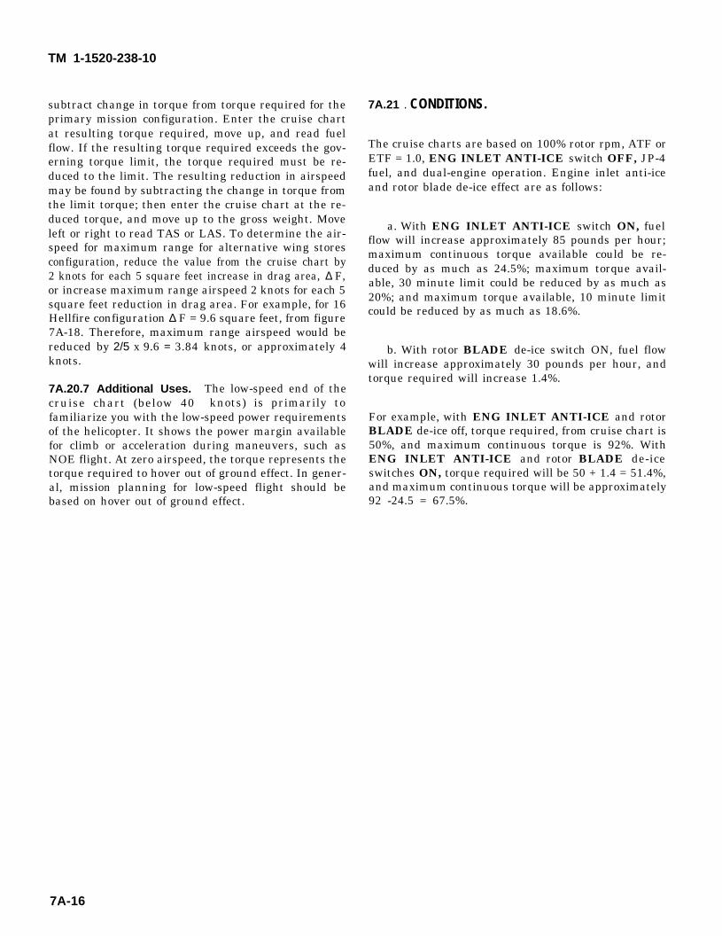
TM 1-1520-238-10
subtract change in torque from torque required for theprimary mission configuration. Enter the cruise chartat resulting torque required, move up, and read fuelflow. If the resulting torque required exceeds the gov-erning torque limit, the torque required must be re-duced to the limit. The resulting reduction in airspeedmay be found by subtracting the change in torque fromthe limit torque; then enter the cruise chart at the re-duced torque, and move up to the gross weight. Moveleft or right to read TAS or LAS. To determine the air-speed for maximum range for alternative wing storesconfiguration, reduce the value from the cruise chart by2 knots for each 5 square feet increase in drag area, ∆ F,or increase maximum range airspeed 2 knots for each 5square feet reduction in drag area. For example, for 16Hellfire configuration ∆ F = 9.6 square feet, from figure7A-18. Therefore, maximum range airspeed would bereducedknots.
7A.20.7
by 2/5 x 9.6 = 3.84
Additional Uses.cruise chart (below 40
knots, or approximately 4
The low-speed end of theknots) is primarily to
familiarize you with the low-speed power requirementsof the helicopter. It shows the power margin availablefor climb or acceleration during maneuvers, such asNOE flight. At zero airspeed, the torque represents thetorque required to hover out of ground effect. In gener-al, mission planning for low-speed flight should bebased on hover out of ground effect.
7A.21 . CONDITIONS.
The cruise charts are based on 100% rotor rpm, ATF orETF = 1.0, ENG INLET ANTI-ICE switch OFF, JP-4fuel, and dual-engine operation. Engine inlet anti-iceand rotor blade de-ice effect are as follows:
a. With ENG INLET ANTI-ICE switch ON, fuelflow will increase approximately 85 pounds per hour;maximum continuous torque available could be re-duced by as much as 24.5%; maximum torque avail-able, 30 minute limit could be reduced by as much as20%; and maximum torque available, 10 minute limitcould be reduced by as much as 18.6%.
b. With rotor BLADE de-ice switch ON, fuel flowwill increase approximately 30 pounds per hour, andtorque required will increase 1.4%.
For example, with ENG INLET ANTI-ICE and rotorBLADE de-ice off, torque required, from cruise chart is50%, and maximum continuous torque is 92%. WithENG INLET ANTI-ICE and rotor BLADE de-iceswitches ON, torque required will be 50 + 1.4 = 51.4%,and maximum continuous torque will be approximately92 -24.5 = 67.5%.
7A-16
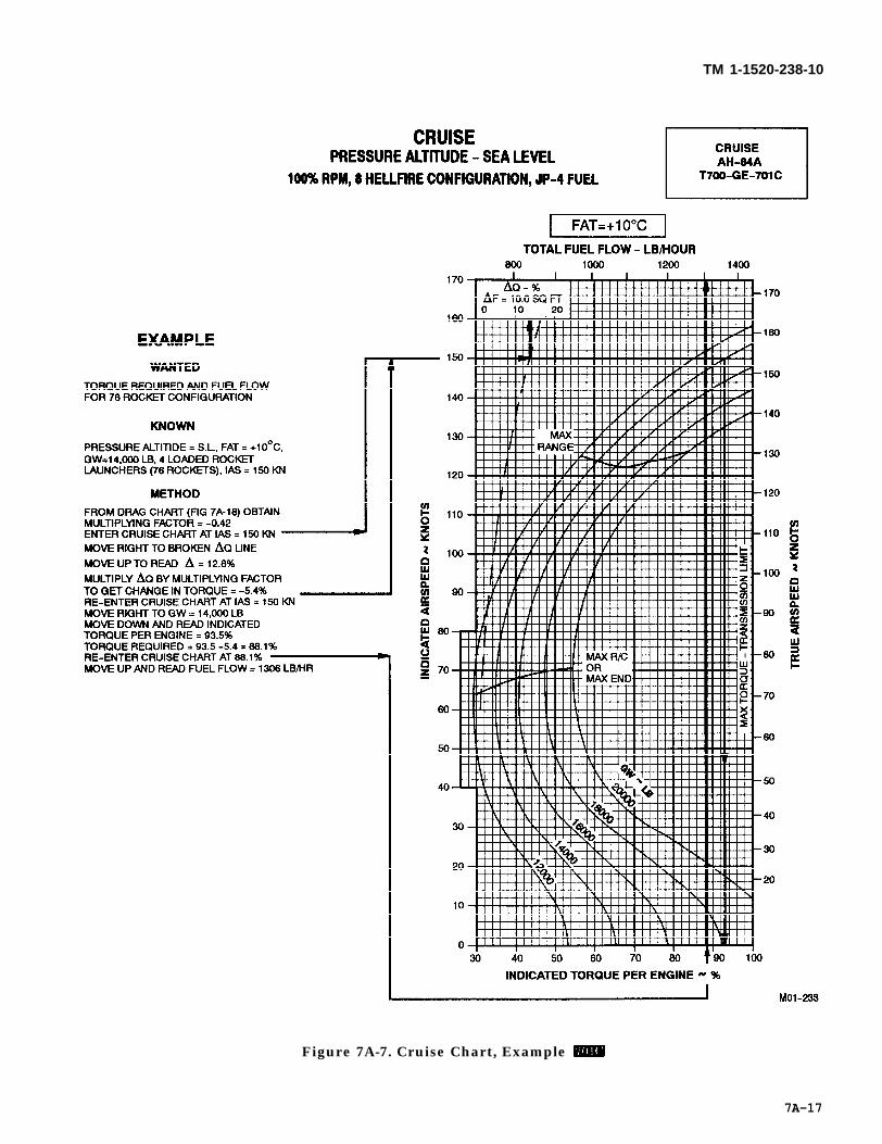
TM 1-1520-238-10
Figure 7A-7. Cruise Chart, Example
7A-17

TM 1-1520-238-10
Figure 7A-8. Cruise Chart, Sea Level, +10 °C Example
7A-18
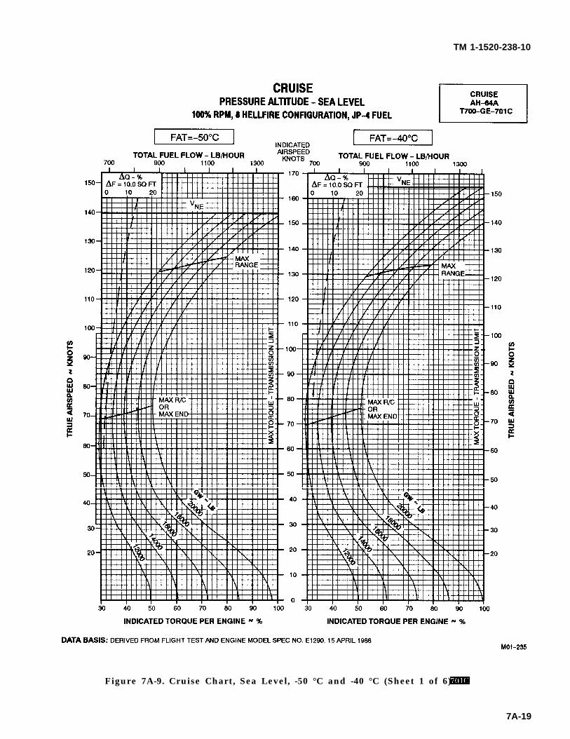
TM 1-1520-238-10
Figure 7A-9. Cruise Chart, Sea Level, -50 °C and -40 °C (Sheet 1 of 6)
7A-19
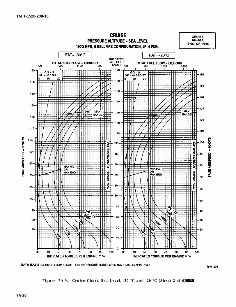
TM 1-1520-238-10
Figure 7A-9. Cruise Chart, Sea Level, -30 °C and -20 °C (Sheet 2 of 6)
7A-20
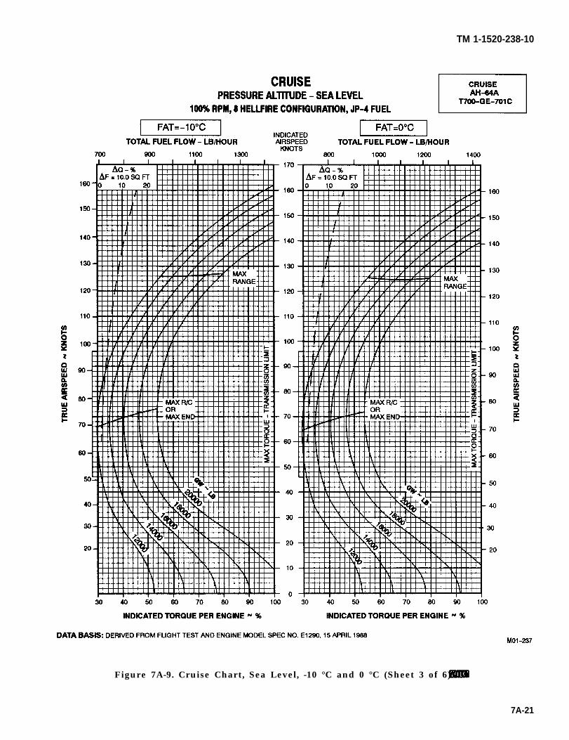
TM 1-1520-238-10
Figure 7A-9. Cruise Chart, Sea Level, -10 °C and 0 °C (Sheet 3 of 6)
7A-21
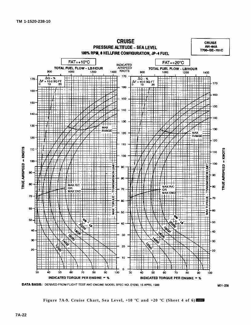
TM 1-1520-238-10
Figure 7A-9. Cruise Chart, Sea Level, +10 °C and +20 °C (Sheet 4 of 6)
7A-22
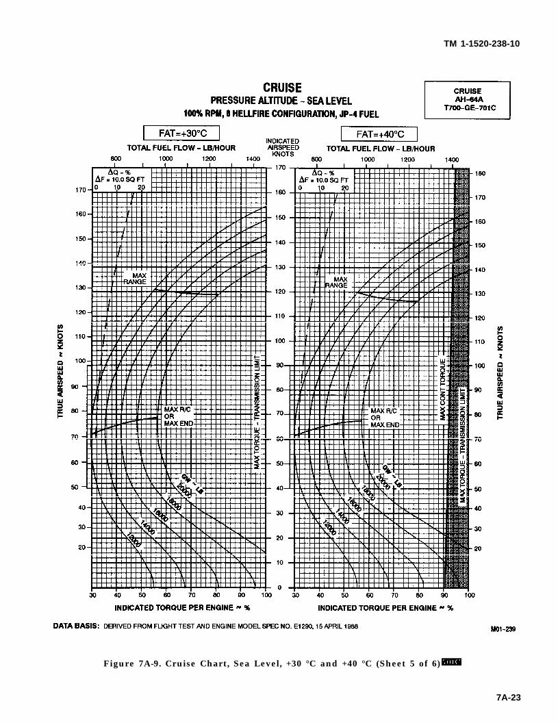
TM 1-1520-238-10
Figure 7A-9. Cruise Chart, Sea Level, +30 °C and +40 °C (Sheet 5 of 6)
7A-23
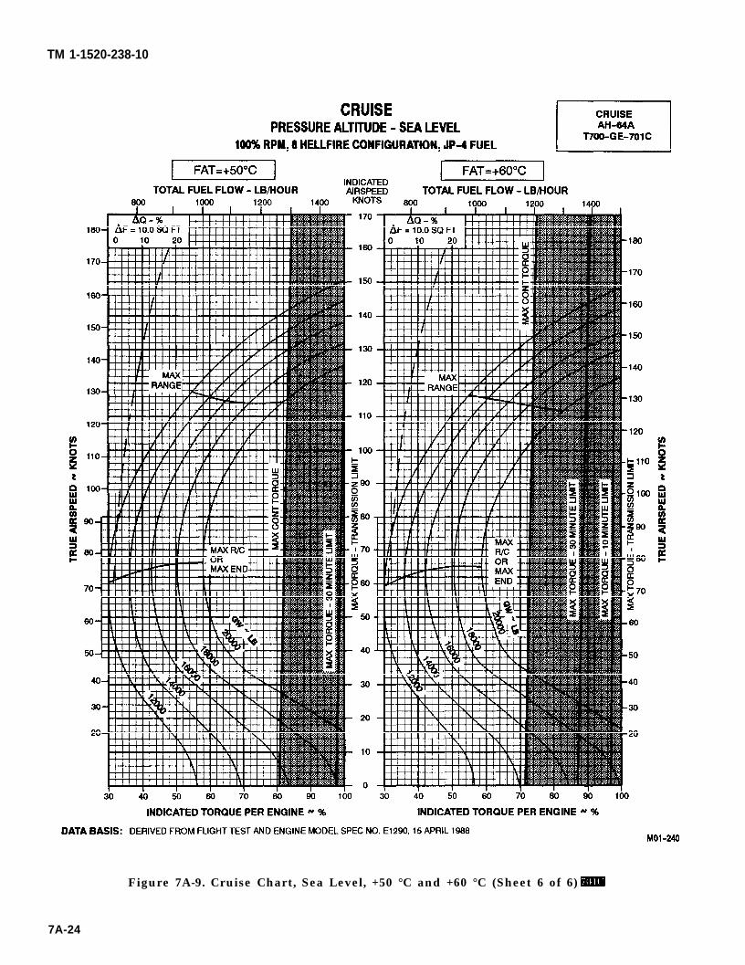
TM 1-1520-238-10
Figure 7A-9. Cruise Chart, Sea Level, +50 °C and +60 °C (Sheet 6 of 6)
7A-24
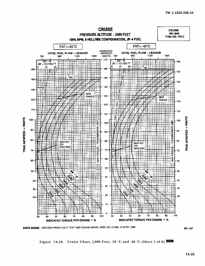
TM 1-1520-238-10
Figure 7A-10. Cruise Chart, 2,000 Feet, -50 °C and -40 °C (Sheet 1 of 6)
7A-25
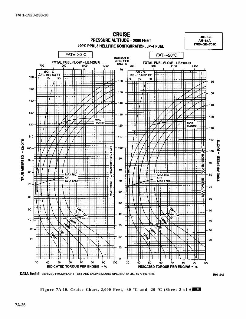
TM 1-1520-238-10
Figure 7A-10. Cruise Chart, 2,000 Feet, -30 °C and -20 °C (Sheet 2 of 6)
7A-26
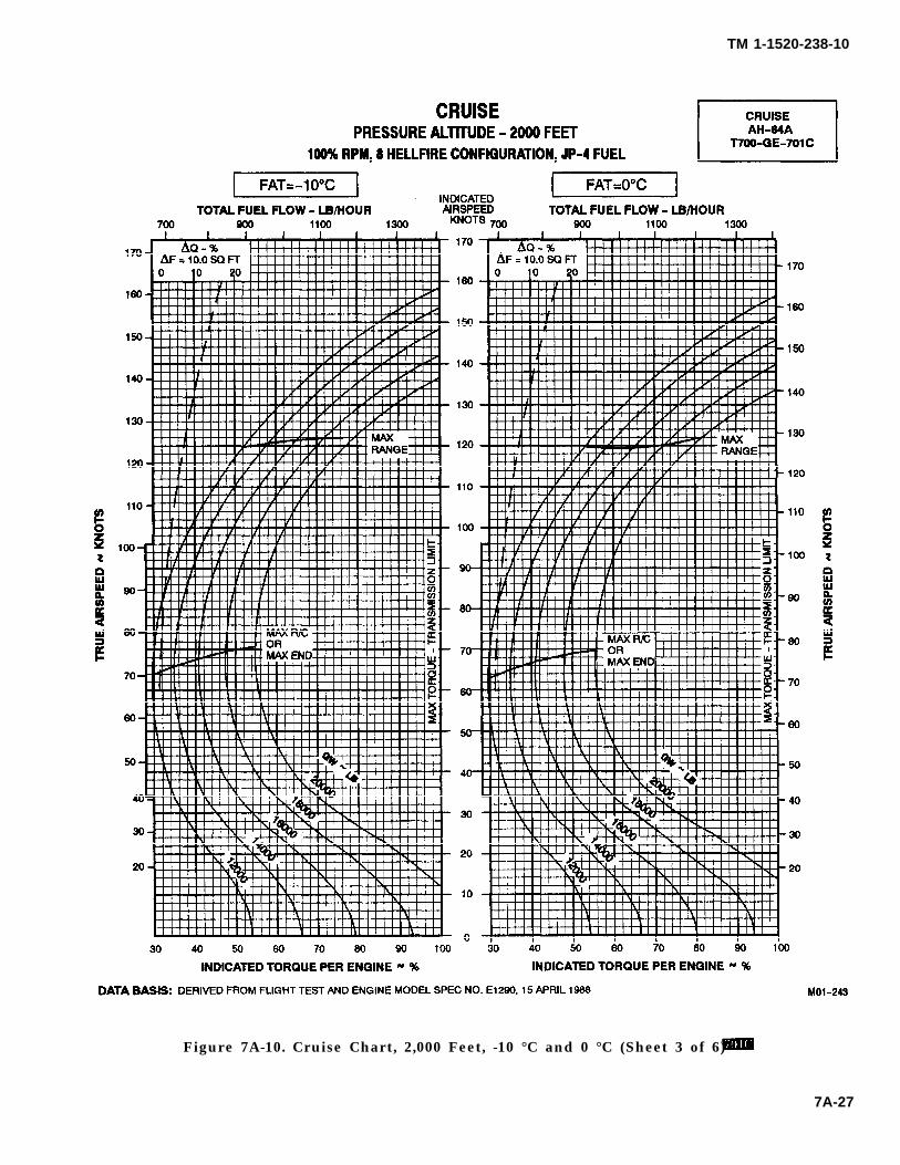
TM 1-1520-238-10
Figure 7A-10. Cruise Chart, 2,000 Feet, -10 °C and 0 °C (Sheet 3 of 6)
7A-27
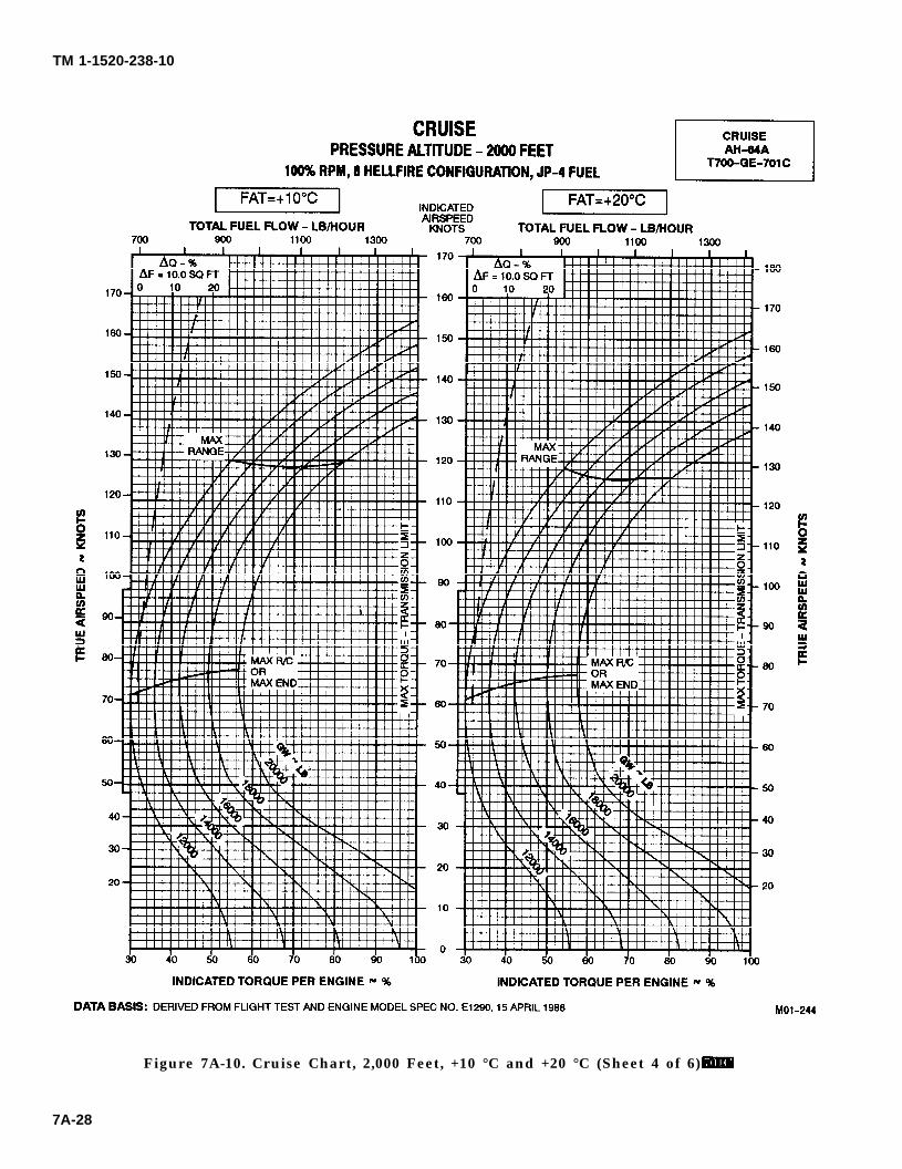
TM 1-1520-238-10
Figure 7A-10. Cruise Chart, 2,000 Feet, +10 °C and +20 °C (Sheet 4 of 6)
7A-28
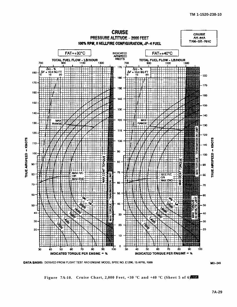
TM 1-1520-238-10
Figure 7A-10. Cruise Chart, 2,000 Feet, +30 °C and +40 °C (Sheet 5 of 6)
7A-29
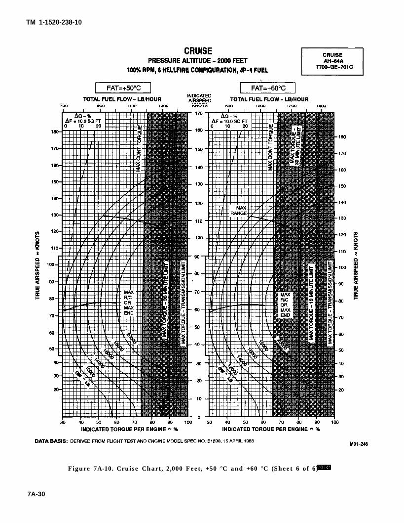
TM 1-1520-238-10
Figure 7A-10. Cruise Chart, 2,000 Feet, +50 °C and +60 °C (Sheet 6 of 6)
7A-30
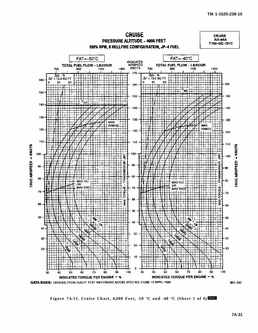
TM 1-1520-238-10
Figure 7A-11. Cruise Chart, 4,000 Feet, -50 °C and -40 °C (Sheet 1 of 6)
7A-31
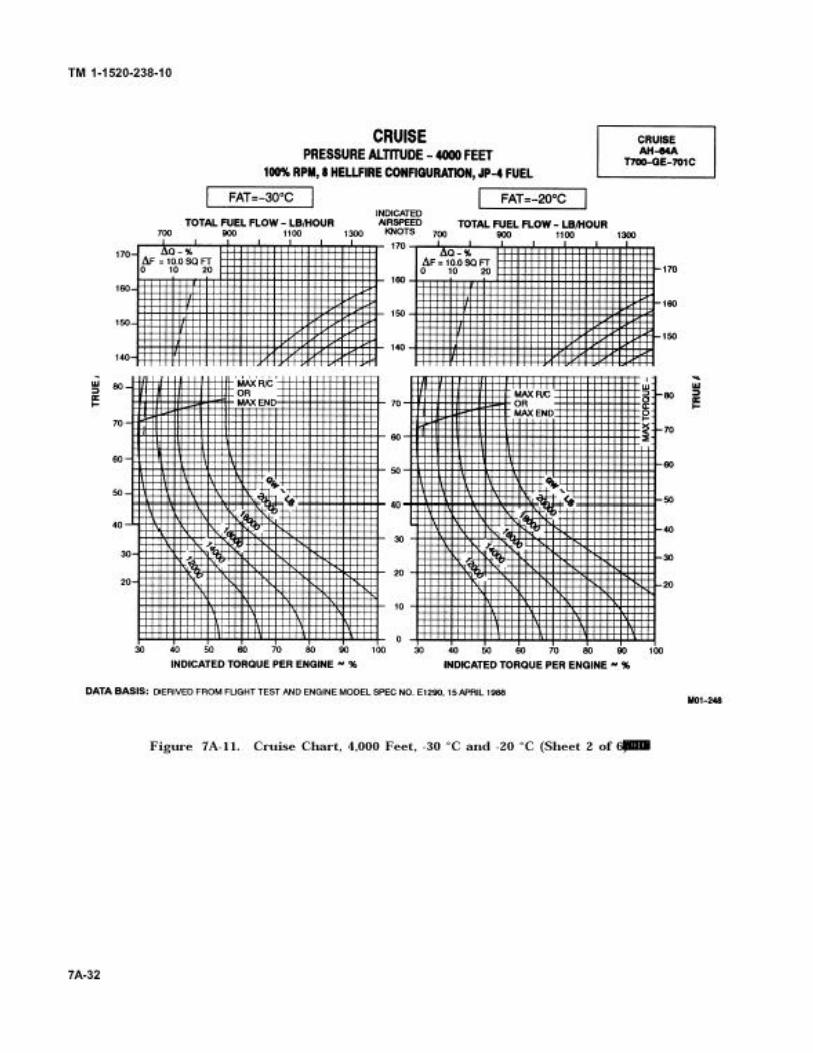
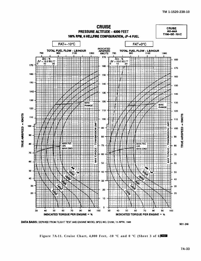
TM 1-1520-238-10
Figure 7A-11. Cruise Chart, 4,000 Feet, -10 °C and 0 °C (Sheet 3 of 6)
7A-33
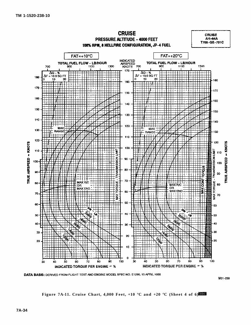
TM 1-1520-238-10
Figure 7A-11. Cruise Chart, 4,000 Feet, +10 °C and +20 °C (Sheet 4 of 6)
7A-34
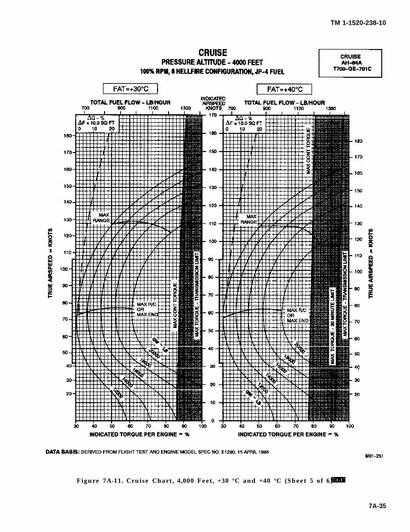
TM 1-1520-238-10
Figure 7A-11. Cruise Chart, 4,000 Feet, +30 °C and +40 °C (Sheet 5 of 6)
7A-35
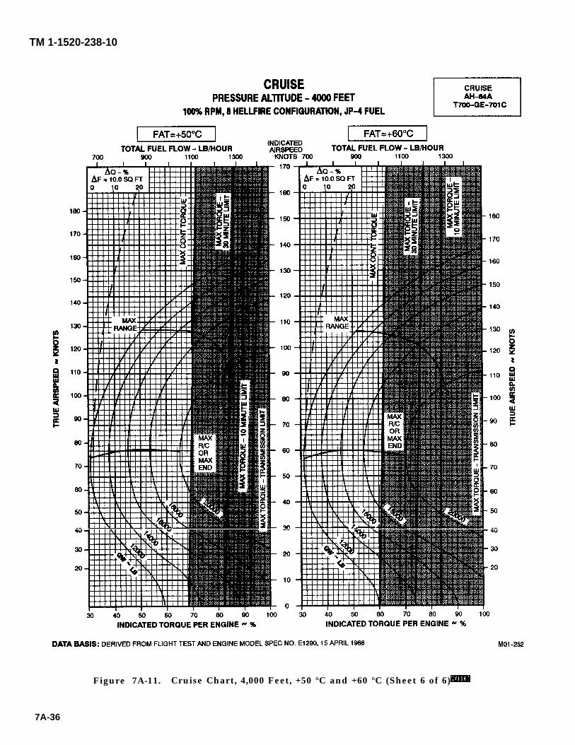
TM 1-1520-238-10
Figure 7A-11. Cruise Chart, 4,000 Feet, +50 °C and +60 °C (Sheet 6 of 6)
7A-36
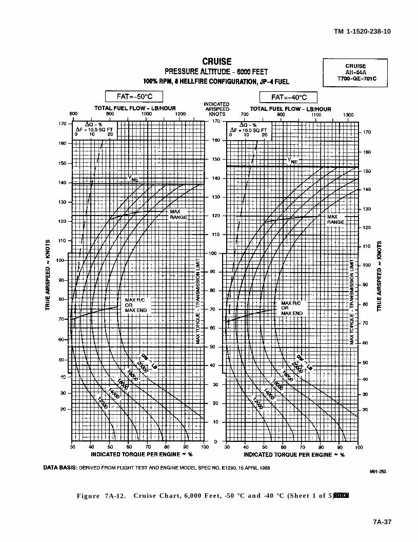
TM 1-1520-238-10
Figure 7A-12. Cruise Chart, 6,000 Feet, -50 °C and -40 °C (Sheet 1 of 5)
7A-37
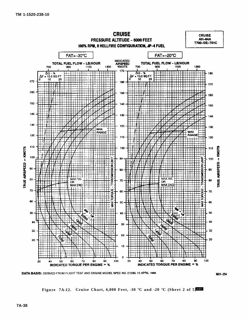
TM 1-1520-238-10
Figure 7A-12. Cruise Chart, 6,000 Feet, -30 °C and -20 °C (Sheet 2 of 5)
7A-38
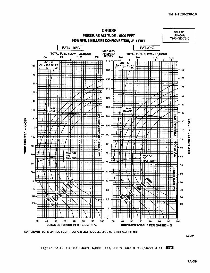
TM 1-1520-238-10
Figure 7A-12. Cruise Chart, 6,000 Feet, -10 °C and 0 °C (Sheet 3 of 5)
7A-39
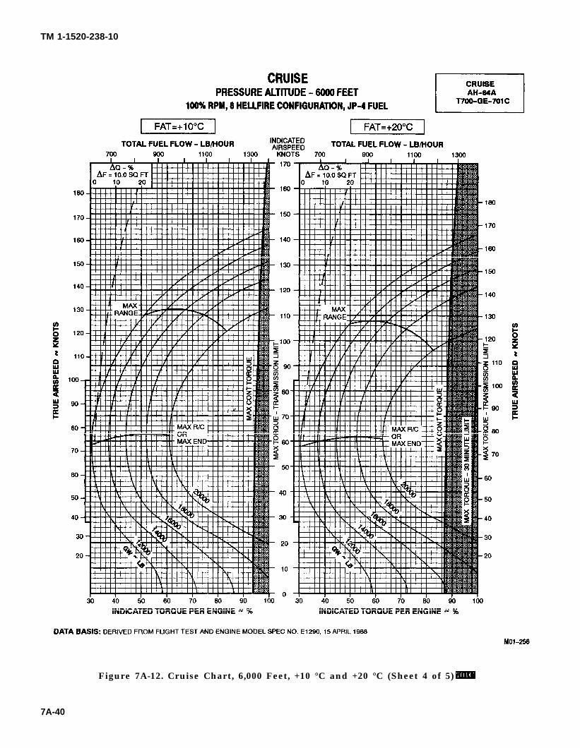
TM 1-1520-238-10
Figure 7A-12. Cruise Chart, 6,000 Feet, +10 °C and +20 °C (Sheet 4 of 5)
7A-40
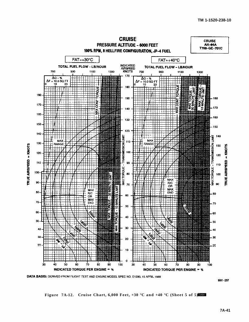
TM 1-1520-238-10
Figure 7A-12. Cruise Chart, 6,000 Feet, +30 °C and +40 °C (Sheet 5 of 5)
7A-41
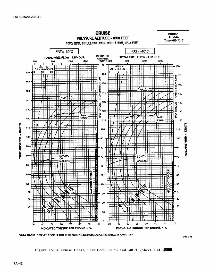
TM 1-1520-238-10
Figure 7A-13. Cruise Chart, 8,000 Feet, -50 °C and -40 °C (Sheet 1 of 5)
7A-42
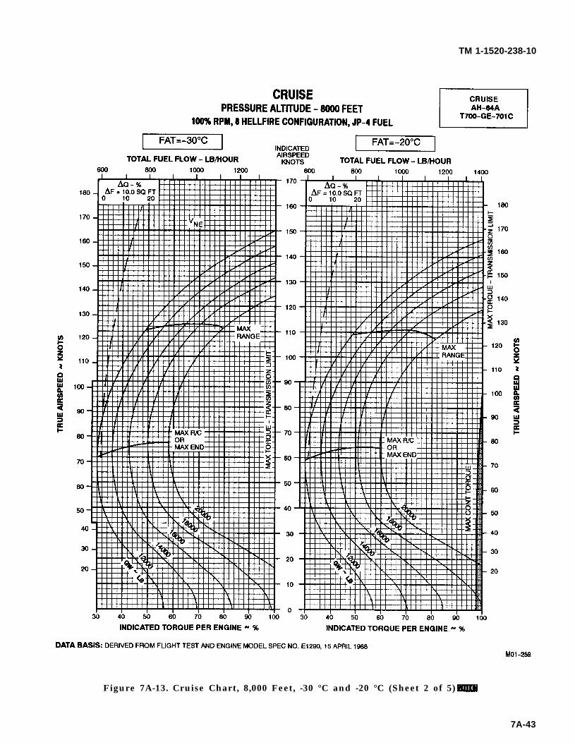
TM 1-1520-238-10
Figure 7A-13. Cruise Chart, 8,000 Feet, -30 °C and -20 °C (Sheet 2 of 5)
7A-43
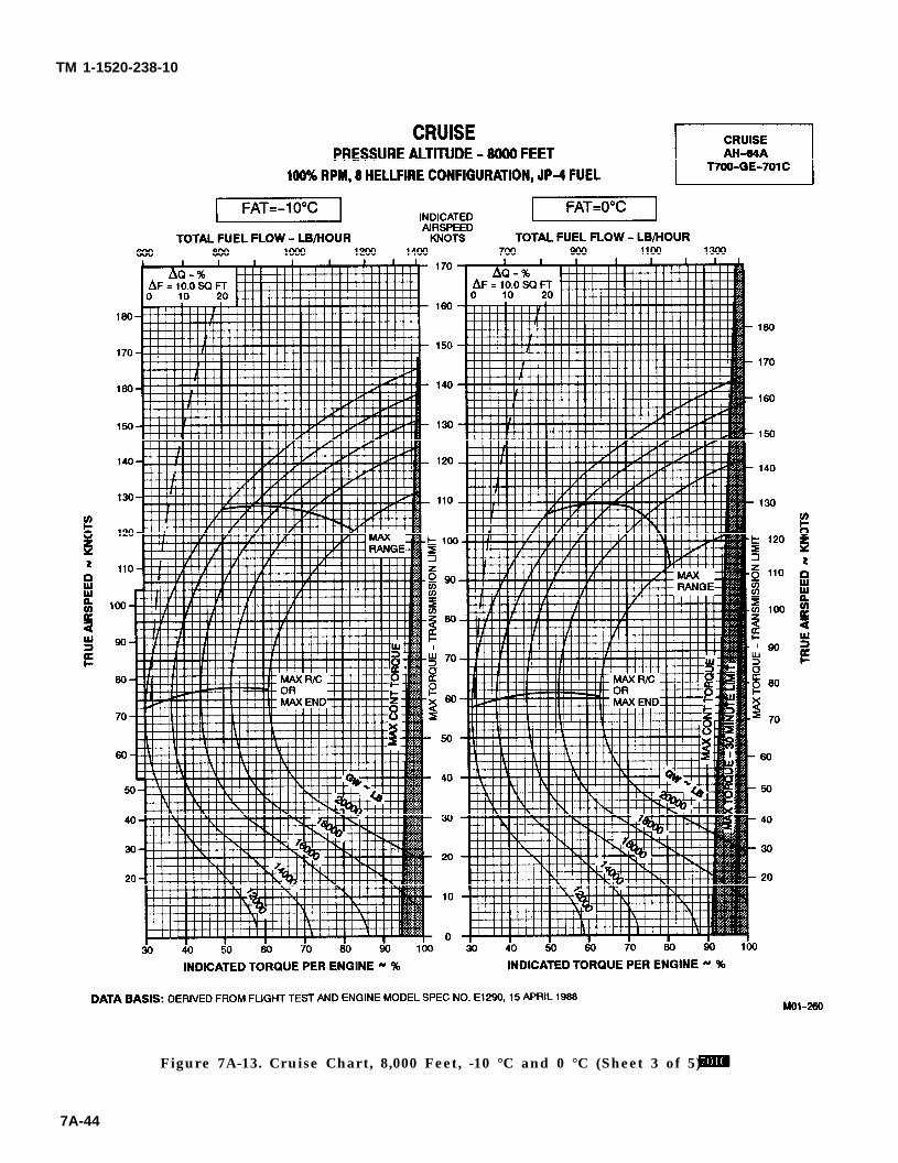
TM 1-1520-238-10
Figure 7A-13. Cruise Chart, 8,000 Feet, -10 °C and 0 °C (Sheet 3 of 5)
7A-44

TM 1-1520-238-10
Figure 7A-13. Cruise Chart, 8,000 Feet, +10 °C and +20 °C (Sheet 4 of 5)
7A-45
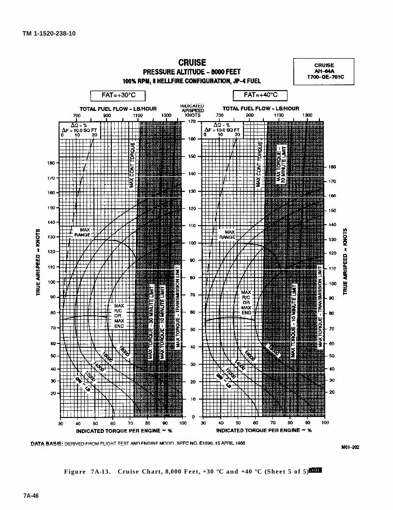
TM 1-1520-238-10
Figure 7A-13. Cruise Chart, 8,000 Feet, +30 °C and +40 °C (Sheet 5 of 5)
7A-46
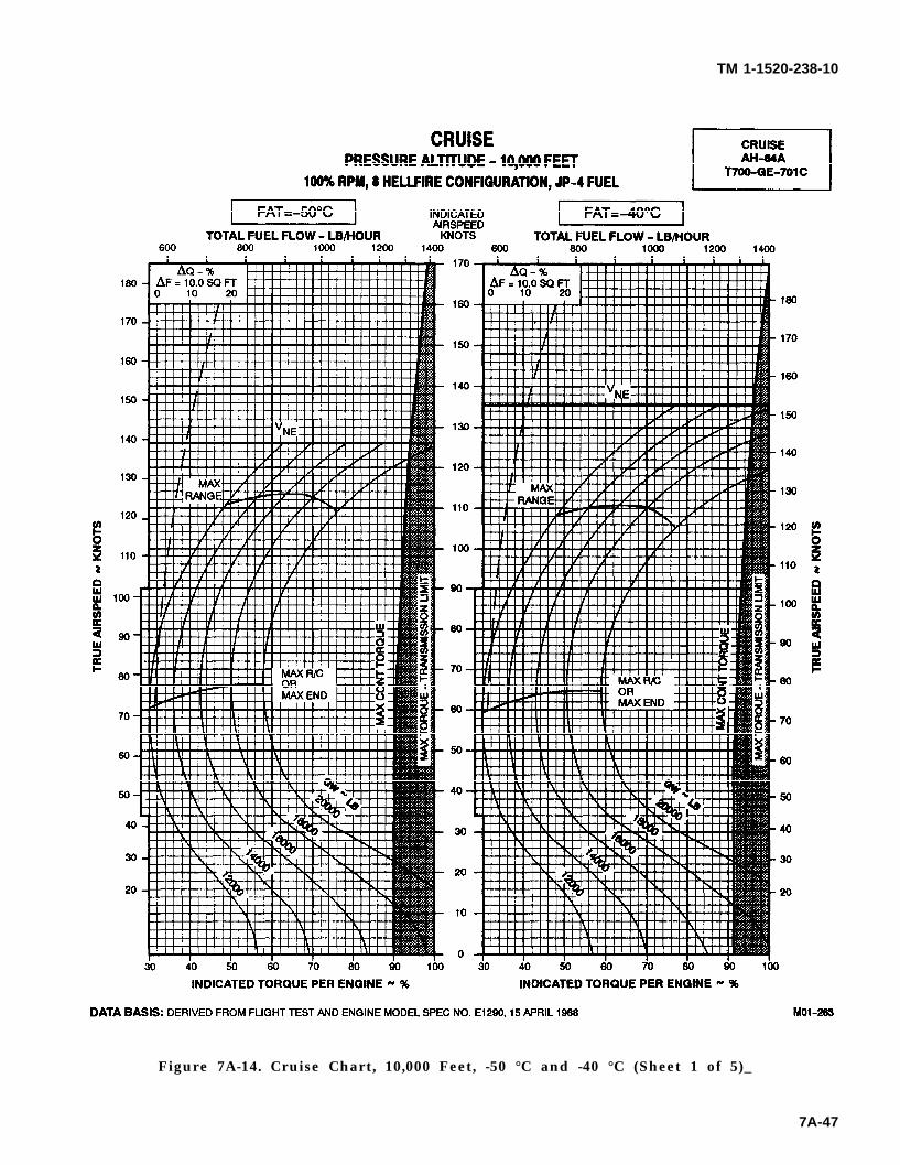
TM 1-1520-238-10
Figure 7A-14. Cruise Chart, 10,000 Feet, -50 °C and -40 °C (Sheet 1 of 5)_
7A-47
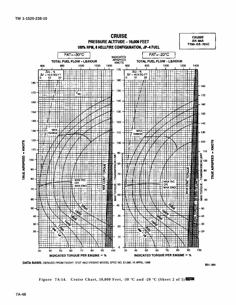
TM 1-1520-238-10
Figure 7A-14. Cruise Chart, 10,000 Feet, -30 °C and -20 °C (Sheet 2 of 5)
7A-48
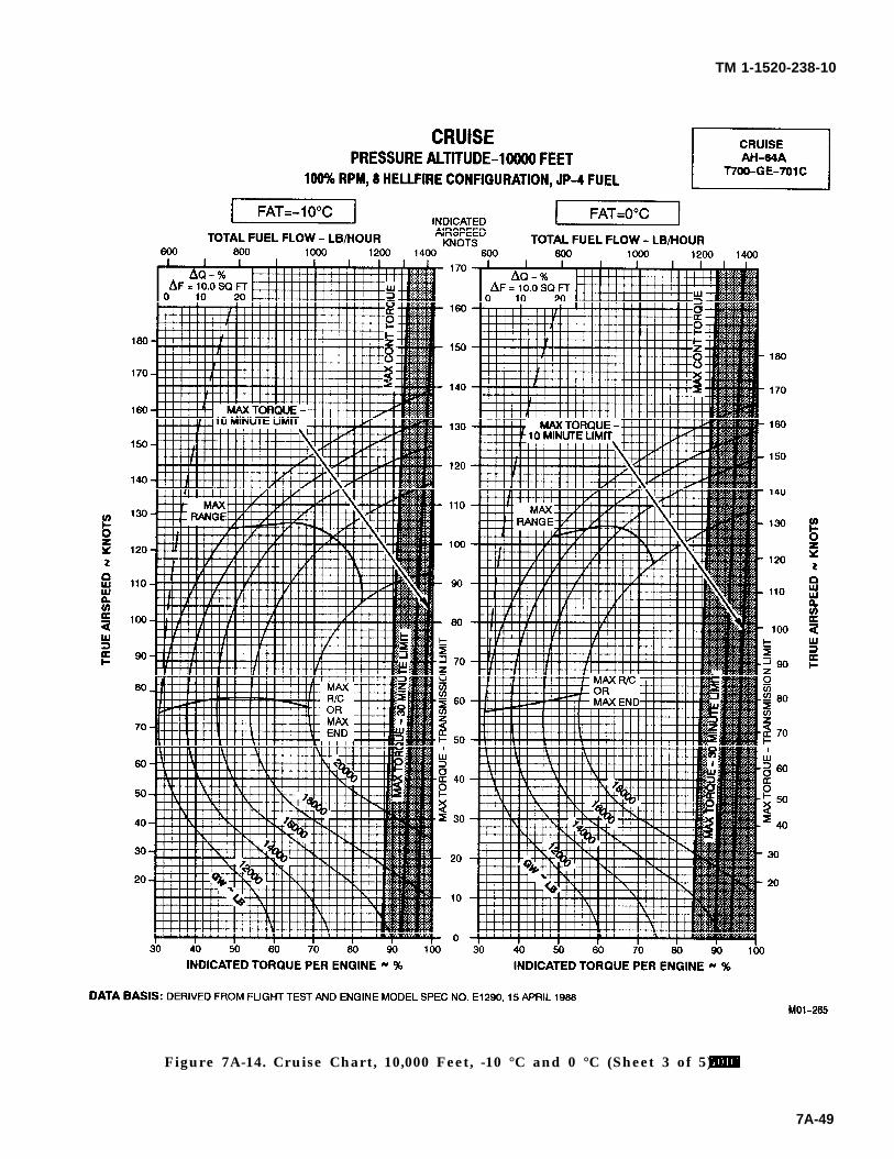
TM 1-1520-238-10
Figure 7A-14. Cruise Chart, 10,000 Feet, -10 °C and 0 °C (Sheet 3 of 5)
7A-49
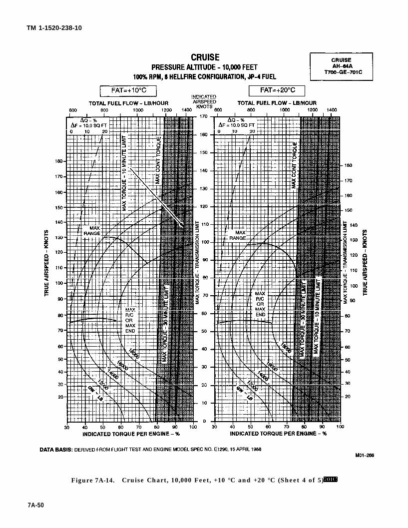
TM 1-1520-238-10
Figure 7A-14. Cruise Chart, 10,000 Feet, +10 °C and +20 °C (Sheet 4 of 5)
7A-50
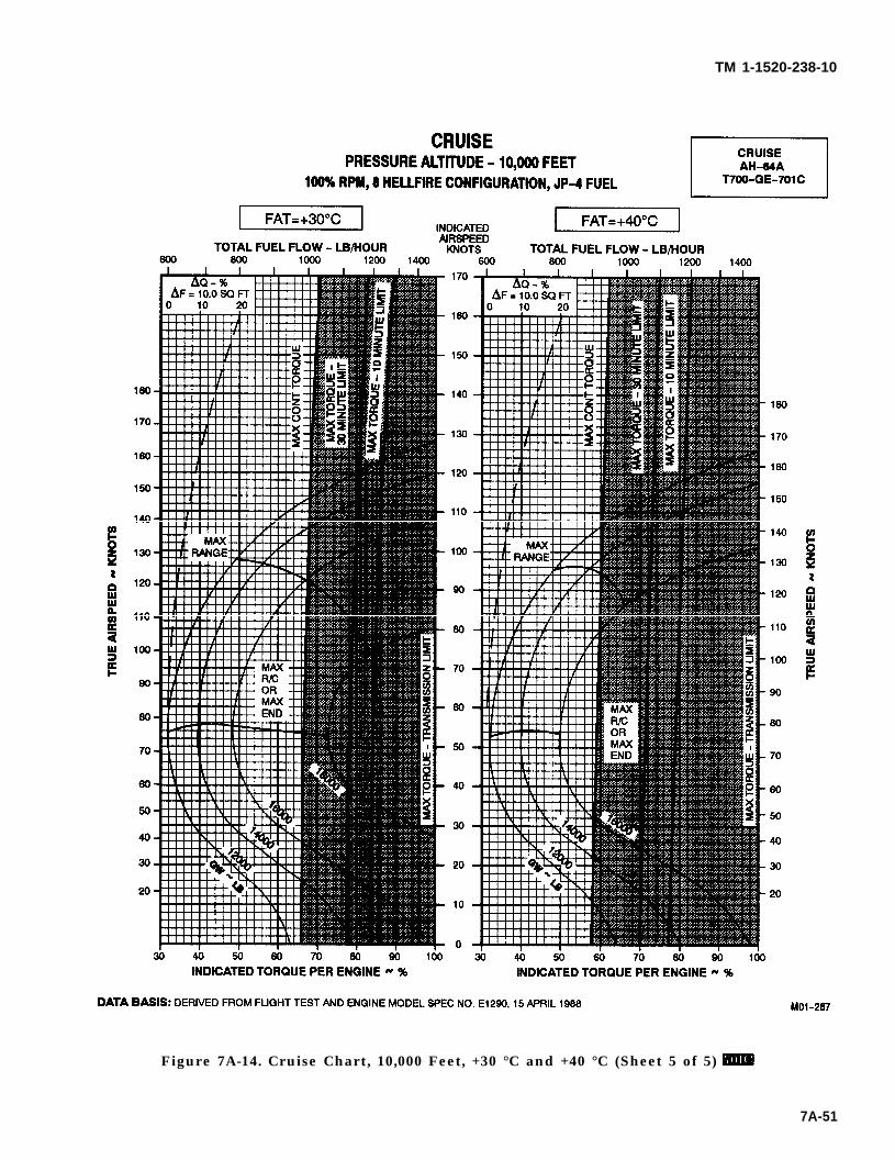
TM 1-1520-238-10
Figure 7A-14. Cruise Chart, 10,000 Feet, +30 °C and +40 °C (Sheet 5 of 5)
7A-51
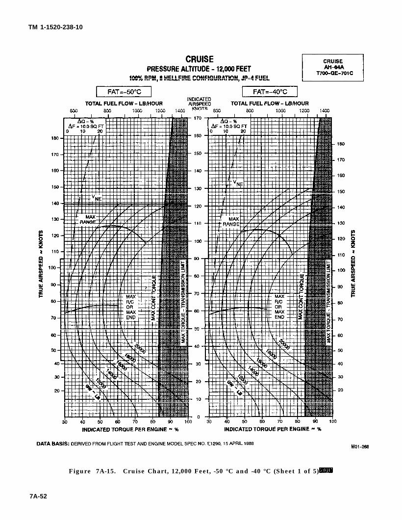
TM 1-1520-238-10
Figure 7A-15. Cruise Chart, 12,000 Feet, -50 °C and -40 °C (Sheet 1 of 5)
7A-52
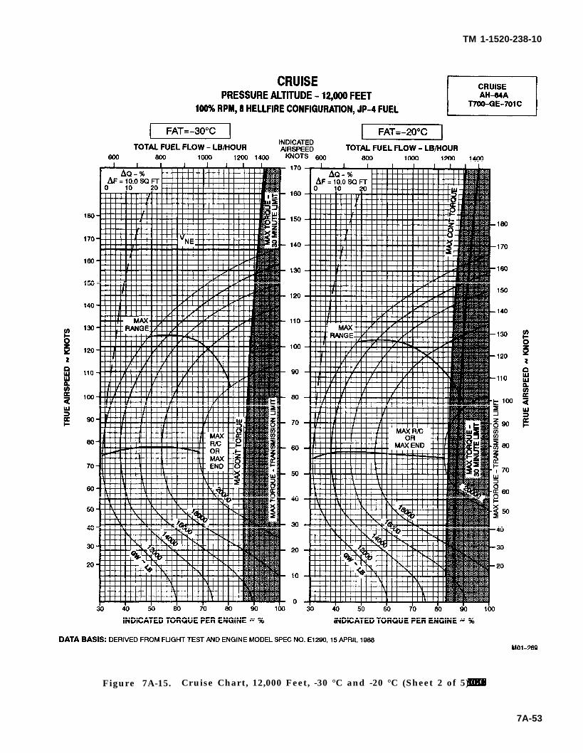
TM 1-1520-238-10
Figure 7A-15. Cruise Chart, 12,000 Feet, -30 °C and -20 °C (Sheet 2 of 5)
7A-53
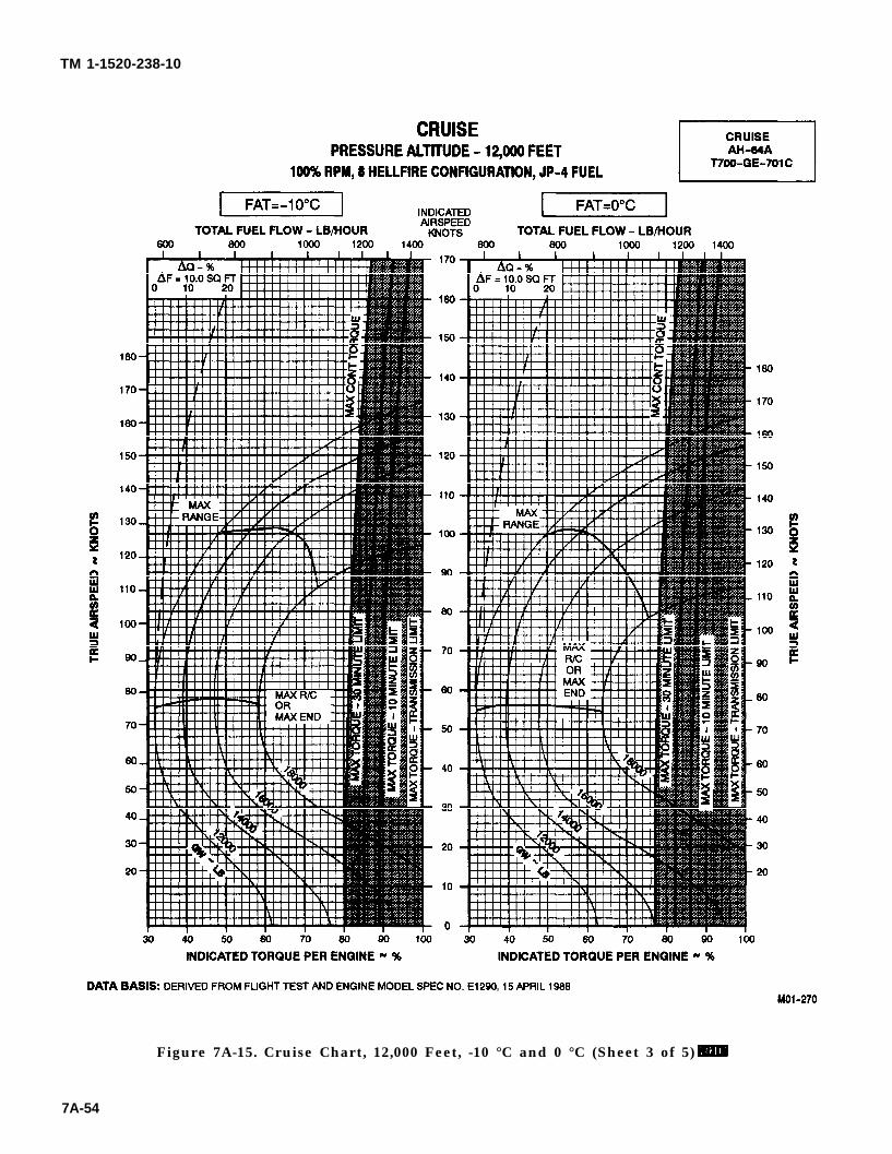
TM 1-1520-238-10
Figure 7A-15. Cruise Chart, 12,000 Feet, -10 °C and 0 °C (Sheet 3 of 5)
7A-54
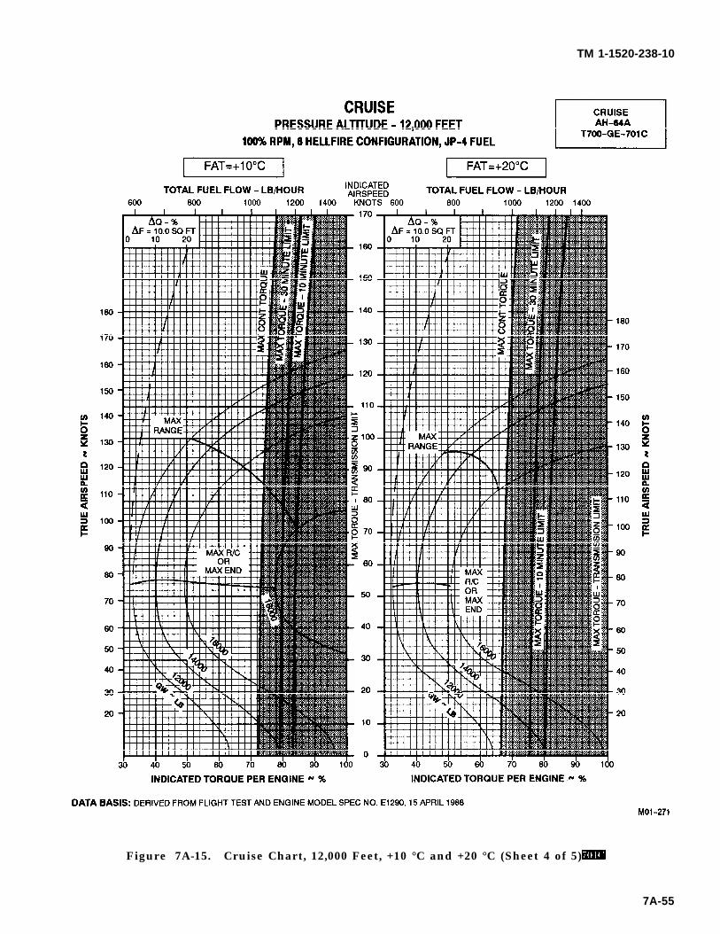
TM 1-1520-238-10
Figure 7A-15. Cruise Chart, 12,000 Feet, +10 °C and +20 °C (Sheet 4 of 5)
7A-55
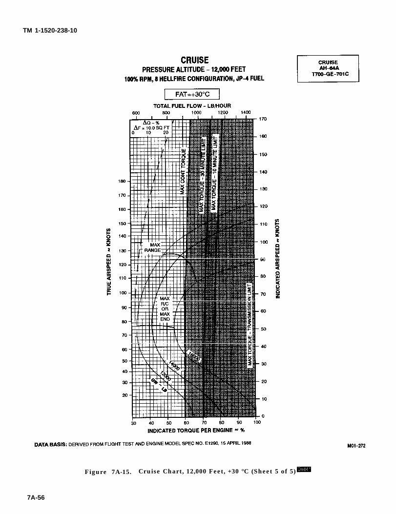
TM 1-1520-238-10
Figure 7A-15. Cruise Chart, 12,000 Feet, +30 °C (Sheet 5 of 5)
7A-56
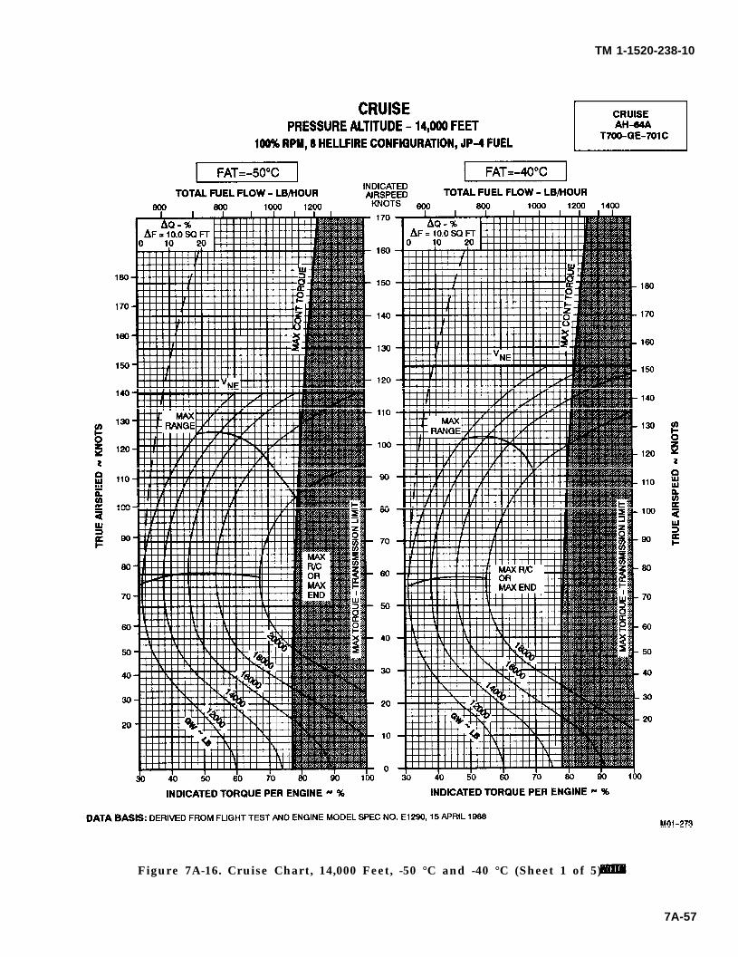
TM 1-1520-238-10
Figure 7A-16. Cruise Chart, 14,000 Feet, -50 °C and -40 °C (Sheet 1 of 5)
7A-57
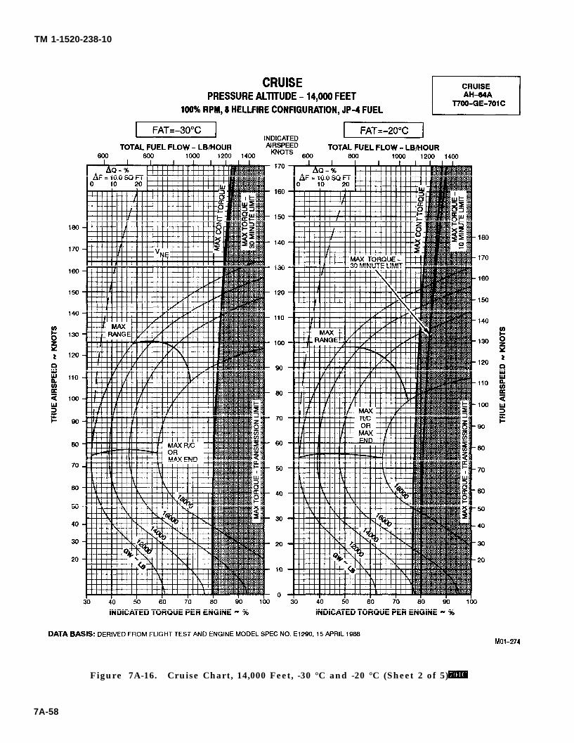
TM 1-1520-238-10
Figure 7A-16. Cruise Chart, 14,000 Feet, -30 °C and -20 °C (Sheet 2 of 5)
7A-58
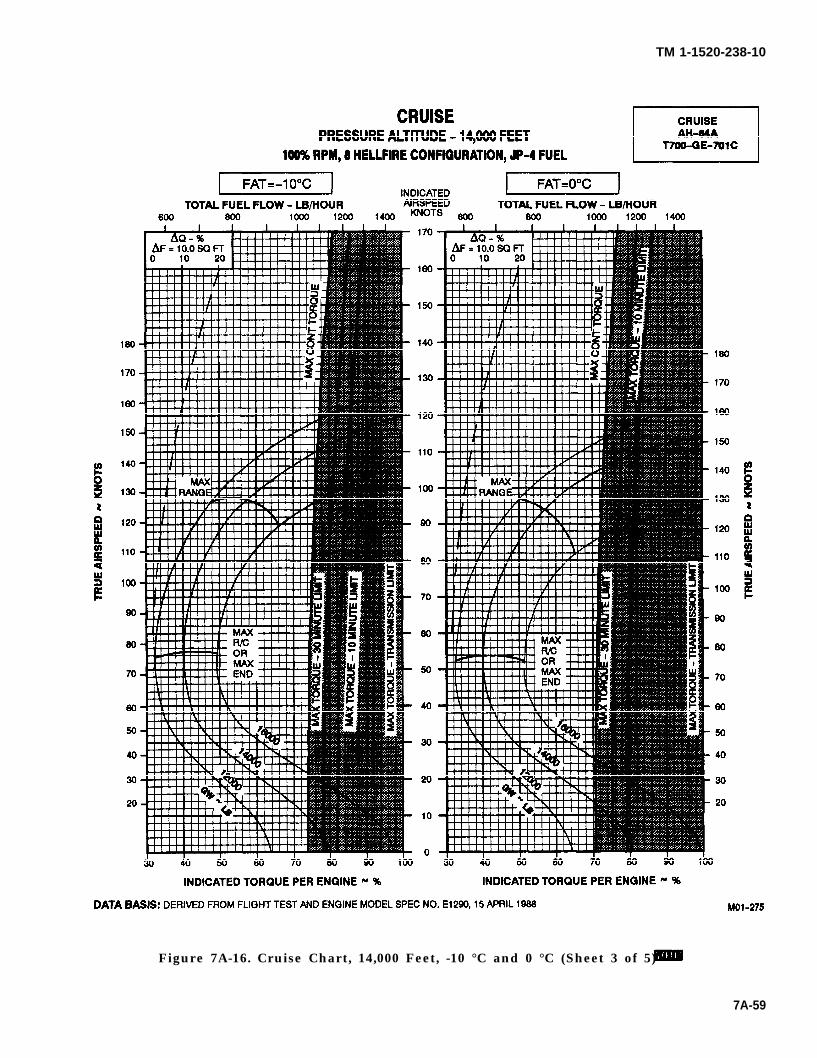
TM 1-1520-238-10
Figure 7A-16. Cruise Chart, 14,000 Feet, -10 °C and 0 °C (Sheet 3 of 5)
7A-59
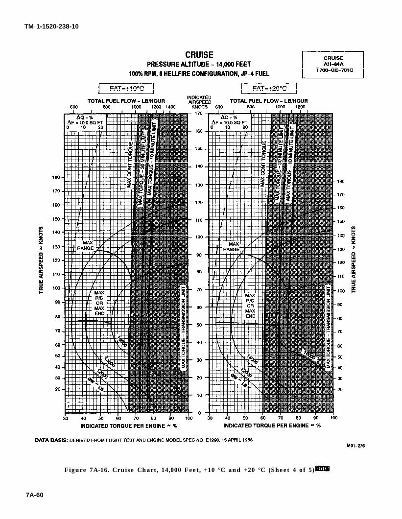
TM 1-1520-238-10
Figure 7A-16. Cruise Chart, 14,000 Feet, +10 °C and +20 °C (Sheet 4 of 5)
7A-60
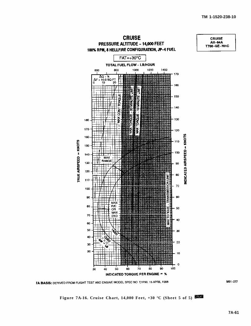
TM 1-1520-238-10
Figure 7A-16. Cruise Chart, 14,000 Feet, +30 °C (Sheet 5 of 5)
7A-61
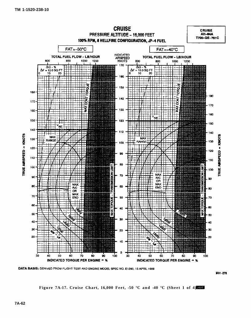
TM 1-1520-238-10
Figure 7A-17. Cruise Chart, 16,000 Feet, -50 °C and -40 °C (Sheet 1 of 4)
7A-62
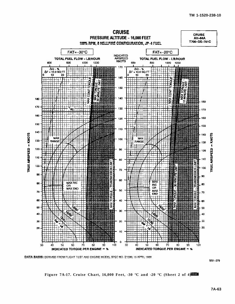
TM 1-1520-238-10
Figure 7A-17. Cruise Chart, 16,000 Feet, -30 °C and -20 °C (Sheet 2 of 4)
7A-63
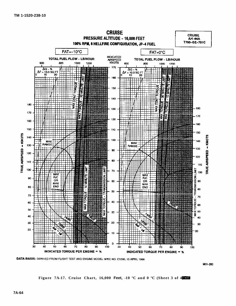
TM 1-1520-238-10
Figure 7A-17. Cruise Chart, 16,000 Feet, -10 °C and 0 °C (Sheet 3 of 4)
7A-64
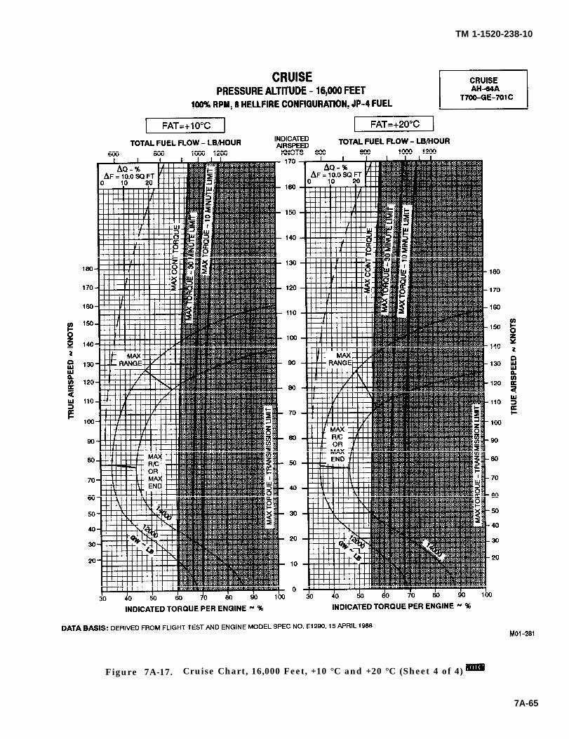
TM 1-1520-238-10
Figure 7A-17. Cruise Chart, 16,000 Feet, +10 °C and +20 °C (Sheet 4 of 4)
7A-65

TM 1-1520-238-10
Section VI. DRAG
7A.22. DESCRIPTION.
The drag chart (fig 7A-18) shows the change in frontalarea for each wing-stores combination that can beinstalled on the helicopter. The baseline configurationincludes the Wire Strike Protection System (WSPS).
7A.23. USE OF CHART.
To determine the change in frontal area (AF) and theassociated multiplying factor, it is necessary to knowwhat combination of stores is installed. Enter the chartat the top, move down to the illustration that matches
the desired combination, and then move right and read∧F and the multiplying factor. Use the multiplying factorand data in Section VI, Cruise to determine the resultingchange in torque.
7A.24. CONDITIONS.
The drag chart is based on the mission configurationhaving zero change in frontal area. If the WSPS isinstalled, increase the frontal area for all configurations inthe drag table by 1.9 sq ft and increase the multiplyingfactor by 0.19.
7A-66 Change 3
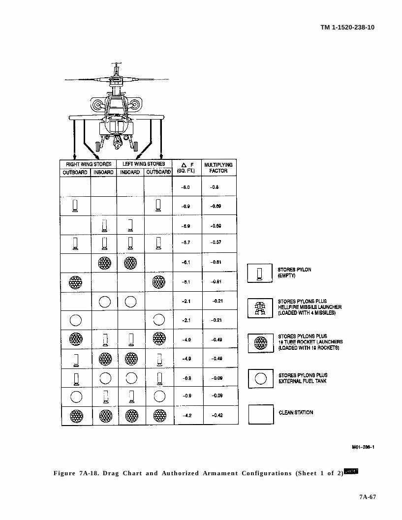
TM 1-1520-238-10
Figure 7A-18. Drag Chart and Authorized Armament Configurations (Sheet 1 of 2)
7A-67
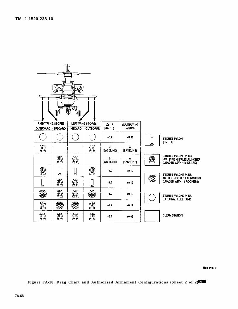
TM 1-1520-238-10
Figure 7A-18. Drag Chart and Authorized Armament Configurations (Sheet 2 of 2)
7A-68
TM 1-1520-238-10
7A.25 . DESCRIPTION.
Section VIl. CLIMB-DESCENT
The climb descent chart (fig 7A-19) shows the change intorque (above and below the torque required for levelflight under the same configuration, gross weight, andatmospheric conditions) to obtain a desired rate ofclimb or descent.
7A.26. USE OF CHART.
The primary use of the climb-descent chart is illus-trated by the example. To determine the change intorque, it is necessary to know the gross weight and thedesired rate of climb or descent. Enter the chart at thedesired rate of climb or descent, move right to the
known gross weight, and then move down and read thetorque change. This torque change must be added to(for climb) or subtracted from (for descent) the torquerequired for level flight (obtained from the appropriatecruise chart) to obtain a total climb or descent torque.
By entering the chart with a known torque change, andmoving up to the known gross weight and then left, thecorresponding rate of climb or descent can also be ob-tained.
7A.27. CONDITIONS.
The climb-descent chart is based on 100% rotor rpm.
7A-69
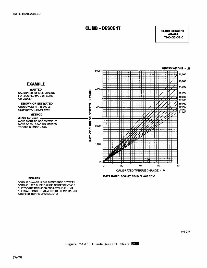
TM 1-1520-238-10
Figure 7A-19. Climb-Descent Chart
7A-70
TM 1-1520-238-10
CHAPTER 8
NORMAL PROCEDURES
Section I. CREW
8.1 CREW DUTIES.
8.1.1 PILOT. The pilot in command is responsible forall aspects of mission planning, preflight, and operationof the helicopter. He will assign duties and functions toall other crewmembers as required. Prior to or duringpreflight, the pilot will brief the CPG on items perti-nent to the mission; e.g., performance data, monitoringof instruments, communications, and emergency proce-dures.
8.1.2 CPG. The CPG must be familiar with the pilotsduties. The CPG will assist the pilot as directed.
8.2 CREW BRIEFING.
A crew briefing shall be conducted to ensure a thoroughunderstanding of individual and team responsibilities.The briefing should include, but not be limited to, CPGand ground crew responsibilities, and the coordinationnecessary to complete the mission in the most efficientmanner. A review of visual signals is desirable whenground guides do not have direct voice communicationslink with the crew.
8.2.1
8.2.2
a.
b.
c.
8.2.3
a.
b.
c,
Crew Introduction.
Equipment.
Personal, to include I.D. tags.
Professional.
Survival.
Flight Data.
Route.
Altitude.
Time enroute.
d.
8.2.4
a.
b.
c.
d.
e.
f.
g.
h.
i.
j.
8.2.5
a.
b.
c.
DUTIES
Weather.
Normal Procedures.
Entry and exit from aircraft.
Seating.
Seat Belts.
Movement in aircraft.
Internal communications.
Security of equipment.
Smoking.
Refueling.
Weapons.
Protective masks.
Emergency Procedures.
Emergency exits.
Emergency equipment.
Emergency landing/ditching procedures.
8.3 MISSION PLANNING.
Mission planning begins when the mission is assigned,and extends to the preflight check of the helicopter. Itincludes, but is not limited to, checks of operating limitsand restrictions; weight, balance, and loading; perfor-mance; publications; flight plan; and crew briefings.The pilot in command shall ensure compliance with thecontents of this manual that are applicable to the mis-sion.
8.4 AVIATION LIFE SUPPORT EQUIPMENT (ALSE).
All ALSE required for the mission; e.g. helmets, gloves,survival vests, survival kits, etc , shall be checked.
8-1
WARNING
TM 1-1520-238-10
Section II. OPERATING PROCEDURES AND MANEUVERS
8.5 OPERATING PROCEDURES AND MANEUVERS.
This section deals with normal procedures. It includesall steps necessary for safe, efficient operation of thehelicopter from the time a preflight check begins untilthe flight is completed and the helicopter is parked andsecured. Unique feel, helicopter characteristics, andreaction of the helicopter during various phases of op-eration and the techniques and procedures used fortaxiing, taking off, climbing, etc., are described, includ-ing precautions to be observed. Your flying experienceis recognized; therefore, basic flight principles areavoided. Only the duties of the minimum crew neces-sary for the actual operation of the helicopter are in-cluded. Mission equipment checks are contained inChapter 4, MISSION EQUIPMENT. Procedures specif-ically related to instrument flight that are differentfrom normal procedures are covered in this section, fol-lowing normal procedures. Descriptions of functions,operations, and effects of controls are covered in Sec-tion IV, FLIGHT CHARACTERISTICS, and are re-peated in this section only when required for emphasis.Checks that must be performed under adverse environ-mental conditions, such as desert and cold-weather op-erations, supplement normal procedures checks in thissection and are covered in Section V, ADVERSE ENVI-RONMENTAL CONDITIONS.
8.6 SYMBOL DEFINITIONS.
Items which apply only to night or only to instrumentflying shall have an N or an I, respectively, immediatelypreceding the check to which it is pertinent. The symbolO shall be used to indicate if installed. Those dutieswhich are the responsibility of the CPG, will be indi-cated by a circle around the step number: i.e. Thesymbol star ✭ indicates an operational check is re-quired. Operational checks are contained in the perfor-mance section of the condensed checklist. The symbolasterisk * indicates that performance of step is manda-tory for all thru-flights. The asterisk applies only tochecks performed prior to takeoff. Placarded items suchas switch and control labels appear in boldface uppercase.
8.7 CHECKLIST.
Normal procedures areform, and amplified as
8-2
given primarily in checklistnecessary in accompanying
paragraph form, when a detailed description of a proce-dure or maneuver is required. A condensed version ofthe amplified checklist, omitting all explanatory text, iscontained in the operators checklist. To provide for eas-ier cross-referencing, the procedural steps in the check-list are numbered to coincide with the correspondingnumbered steps in this manual.
8.8 PREFLIGHT CHECK.
The pilots walk-around and interior checks are out-lined in the following procedures. The preflight checkis not intended to be a detailed mechanical inspection.The steps that are essential for safe helicopter opera-tion are included. The preflight may be made as com-prehensive as conditions warrant at the discretion ofthe pilot.
8.9 BEFORE EXTERIOR CHECK.
Do not preflight until armament sys-tems are safe.
* 1. Helicopter covers, locking devices, tiedownsand grounding cables – removed and stowed.Pylon safety pins - installed.
2. Cockpit safety - Check as follows:
a.
b.
c.
d.
e.
BATT switch - OFF (CPG BAT OVRD -NRML).
Interior CANOPY JETTISON pins -installed.
ENG FIRE PULL fire handles - In.
APU FIRE PULL handle - In.
APU START switch - OFF.
3. Armament subsystems - Safe as follows:
a. PILOT
(1) MASTER ARM/SAFE switch - OFF.
(2) STORES JETT switches - OFF.
TM 1-1520-238-10
8.10
4.
5.
6.
b. CPG:
(1) CPG ARM/SAFE switch - OFF.
(2) PLT/GND ORIDE switch - OFF.
Cockpit - General.
a.
b.
c.
d.
e.
f.
Ignition key - In and ON.
First aid kits - Installed.
Seat cushions - Conditions.
Restraint system - Condition.
Canopy - Check.
Loose equipment - Secured.
P u b l i c a t i o n s - A s r e q u i r e d b yDA PAM 738-751; locally required forms andpublications, and availability of Operator’sManual.
Fuel sample - Check for first flight of day.
EXTERIOR CHECK.
See figure 8-1
8.10.1 Right Side - Under Side Fuselage (Area 1).
1. 30mm gun turret - Check.
a. Gun mounting - Check.
b. Feed chute - Check.
2. Searchlight - Check.
8.10.2 Right Side - Lower Center Fuselage (Area 2).
1.
2.
3.
4.
5.
Radar warning antenna - Check.
Forward avionics bay - Check.
Static port - Unobstructed.
Right main landing gear - Check.
Portable fire extinguisher - Check.
* 6
7.
8.
Refueling panel - Secure door.
Forward gravity fuel cap - Secure.
Single point fuel access - Secure.
8.10.3 Right Side - Mast (Area 3).
*1.
*2,
3.
*4.
5.
*6.
Main transmission - Check oil level.
Nose gearbox - Check oil level, oil cap se-cured, cowling secure.
Engine inlet - Unobstructed.
Engine oil level - Check and secure door.
Upper flight controls and swashplate - Check.
Main rotor head and blades - Check.
8.10.4 Right Side - Wing (Area 4).
1. Wing - Check.
O 2. Pylons - Check.
N O T E
When icing conditions exist, or are pre-dicted and HELLFIRE operations are ex-pected, launcher arm/safe switch locatedon each HELLFIRE launcher must bemanually placed in the ARM positionprior to liftoff. It is possible for this switchto be rendered inoperative by icing.
O 3. HELLFIRE - Check as follows:
a.
b.
c.
Launcher ARM/SAFE switch - As re-quired.
Launcher mounting - Check that aft andforward attach lugs are secure to rack.Rack swaybrace bolts firmly againstlauncher swaybrace pads.
Electrical connector - Check that HELL-FIRE harness cannon plug is connected tolauncher. Jettison quick-disconnect lan-yard is attached to connector plug andrack.
8-3
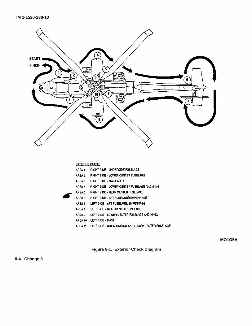
TM 1-1520-238-10
MO1O5A
Figure 8-1. Exterior Check Diagram
8-4 Change 3
TM 1-1520-238-10
d. Missile installation Check that each missile isseated and hold-back latch is locked.
O 4. Rocket launcher Check as follows:
a. Electrical connector Check that rocket harnessconnector plug is connected to launcher andjettison quick disconnect lanyard is attached toconnector plug and rack.
b. Launcher Check launcher exterior and tubeinteriors for damage and corrosion.
c. Rocket installation Check that rocket aft end issecure in launcher tube aft detent. Note numberand zones of rocket loading.
d. Igniter arms Check for damage and corrosion.Check arms are in contact with rockets.
O 5. External fuel tanks Check.
6. Pitot tube Check tube unobstructed.
7. Wing lighting Check condition of anticollision,navigation and formation lights.
8. Ammunition bay access Secure.
8.10.5 Right Side Rear Center Fuselage (Area 5).
NOTEEnsure that nacelle access doors areproperly latched and secured.
1. Nacelle fire louvers Check open.
*2. APU oil level Check and secure door.
3. Aft gravity fuel cap Check security.
4. Aft avionics bay Secure door.
5. APU exhaust Check.
6. IR suppressor/engine exhaust Check.
*7. Utility hydraulic accumulator Check hydraulic pressure (2600 psi minimum).
8. Survival kit bay Check and secure door.
9. External power receptacle Access door closed ifexternal power source is not used.
10. Belly antennas Check.
8.10.6 Right Side Aft Fuselage/Empennage (Area 6).
1. Aft tailboom and empennage (right side) Check.
2. Stabilator Check.
3. Tail landing gear Check.
8.10.7 Left Side Aft Fuselage/Empennage (Area 7).
1. Empennage Check.
O 2. FM-AM whip antenna Check.
O 3. GPS antenna - Check.
4. Tail rotor, controls, hub, and blades Check.
5. Stabilator Check.
8.10.8 Left Side Rear Center Fuselage (Area 8).
NOTEEnsure that nacelle access doors areproperly latched and secured.
1. Aft tailboom Check.
2. Transmission deck catwalk area for FOD, fire bottles for charge and APU enclosure for security.
3. Transmission deck catwalk doors Check security.
4. Survival kit bay Check and secure door.
5. IR suppressor/engine exhaust Check.
6. Aft storage bay Check and secure door.
7. Nacelle fire louvers Check open.
8. Fire extinguisher disc Check that yellow disc is visible.
9. Ammunition bay access Secure.
Change 3 8-5
TM 1-1520-238-10
8.10.9 Left Side Wing (Area 9).
1. Wing Check.
2. Wing lighting Check anti-collision, navigation,and formation lights.
3. Pitot tube Check.
O 4. Pylons Check.
O 5. HELLFIRE Check, same as right side.
O 6. Rocket launcher Same as right side.
O 7. External fuel tanks Check.
8.10.10 Left Side Mast (Area 10).
* 1. Main transmission Check oil level.
* 2. Nose gearbox Check oil level; secure oil cap andcowling.
* 3. Primary hydraulic manifold Check oil level.
4. Engine inlet Unobstructed.
* 5. Engine oil level Check and secure door.
6. Upper flight controls and swashplate Check.
7. Main rotor head and blades Check.
8. Air data sensor Check.
8.10.11 Left Side Lower Center Fuselage and Nose(Area 11).
1. Canopy Check.
2. OAT gauge extension Check security.
3. Static port Unobstructed.
4. Utility hydraulic accumulator Check.
5. Left main landing gear Check.
6. Static ground cable Check.
7. Forward avionics bay Check.
8. Radar warning antenna Check.
NOTEWhen icing conditions exist, ensure thatTADS/PNVS gear teeth are free of ice.
9. TADS/PNVS turrets Check.
10. Crew briefing Complete as required.
8.11 INTERIOR CHECK PILOT.
* 1. Canopy door As desired.
*2. Loose equipment Secured.
3. Seat Adjust to design eye position.
*4. Restraint harness Fasten and adjust.
NOTERouting the IHADSS HDU cable underthe right arm may cause entanglementduring emergency egress.
5. Inertial reel lock Check.
6. Pedals Check and adjust.
*7. PARK BRAKE Set.
8. EDGE LT PNL switch As desired.
NOTEThe left and right nose gearbox heatercircuit breakers shall be opened unlessthe system is required.
*9. Overhead circuit breakers As desired.
10. Collective switches As desired.
CAUTIONPhysically confirm that engine chopcollar is seated in its latched/centeredposition and safetied.
11. Auxiliary vent handle Closed.
12. Utility light As desired.
13. OAT gauge Check.
14. ANTI-ICE panel switches OFF.
*15. EXT LT and INTR LT panel switches andcontrols As desired.
*16. FUEL panel switches Set as follows: a. EXT TKswitch OFF.
8-6 Change 3
TM 1-1520-238-10
b. TRANS switch - OFF. g. RKT select switch - OFF.
h. GUN select switch - OFF.c. CROSSFEED switch - NORM.
i. MSL select switch - OFF.
29. Magnetic compass - Check.
30. BRU - Check.
d. ENG 1 switch - ON.
e. ENG 2 switch - ON.
17. PWR levers - OFF. 31. Engine instrument test panel switch - As de-sired.
32. Flight instruments - Check or set as follows:18. ENG START switch - OFF.
* 19. MASTER IGN switch - Verify ON.a. Airspeed indicator.
20. RTR BK - OFF.b. Standby attitude indicator - Cage.
21. ELEC PWR panel switches - Check switchOFF.
c. VDU - OFF.
d. Radar altimeter - OFF.22. STORES JETT select switches - Guard cov-
ers down. e. Altimeter - Check.
f. Vertical speed indicator.*23. ROCKETS control panel - Set.
g. HSI.24. ECS control panel - Set as follows
h. Stabilator position indicator and placard.a. ENCU - ON.
33. Clock - Set.b. FAN - NORM.
34. Accelerometer - Reset.
35. HARS - OFF.c. TEMP control - As desired.
25. TAIL WHEEL switch - LOCK.36. EMERG HYD switch - OFF:
*26. CANOPY JETTISON pin - Remove andstow.
37. CSC panel switches - As desired.
38. Right console avionics - OFF. Set frequenciesas desired.27. FIRE BTL select switch - Centered.
28. FIRE CONTROL panel - Set as follows: 8.12 INTERIOR CHECK - CPG.
*1. Canopy door - As desired.a. SIGHT SEL switch - STBY.
*2. Loose equipment - Secured.b. ACQ SEL switch - OFF.
3. Seat - Adjusted to design eye position.c. VID SEL switch - PLT.
*4. Restraint harness - Fastened and adjust.
NOTE
Routing the IHADSS HDU cable underthe right arm may cause entanglementduring emergency egress.
d. ACM switch - OFF.
e. PNVS switch - OFF.
f. IHADSS BRSIT switch - OFF.
Change 2 8-7
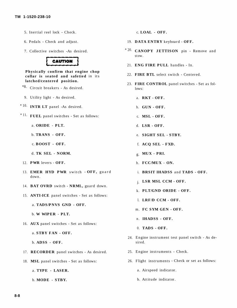
CAUTION
TM 1-1520-238-10
5. Inertial reel lock - Check.
6. Pedals - Check and adjust.
7. Collective switches -As desired.
Physically confirm that engine chopcollar is seated and safetiedlatched/centered position.
in its
*8.
9.
* 10.
* 11.
12.
13.
14.
15.
16.
17.
18.
Circuit breakers - As desired.
Utility light - As desired.
INTR LT panel -As desired.
FUEL panel switches - Set as follows:
a. ORIDE - PLT.
b. TRANS - OFF.
c. BOOST - OFF.
d. TK SEL - NORM.
PWR levers - OFF.
EMER HYD PWR switch - OFF, guarddown.
BAT OVRD switch - NRML, guard down.
ANTI-ICE panel switches - Set as follows:
a. TADS/PNVS GND - OFF.
b. W WIPER - PLT.
AUX panel switches - Set as follows:
a. STBY FAN - OFF.
b. ADSS - OFF.
RECORDER panel switches - As desired.
MSL panel switches - Set as follows:
a. TYPE - LASER.
b. MODE - STBY.
8-8
19.
* 20.
21.
22.
23.
24.
25.
26.
c. LOAL - OFF.
DATA ENTRY keyboard - OFF.
CANOPY JETTISON pin - Remove andstow.
ENG FIRE PULL handles - In.
FIRE BTL select switch - Centered.
FIRE CONTROL panel switches - Set as fol-lows:
a.
b.
c.
d.
e.
f.
g.
h.
i.
j.
k.
l.
m.
n.
0.
RKT - OFF.
GUN - OFF.
MSL - OFF.
LSR - OFF.
SIGHT SEL - STBY.
ACQ SEL - FXD.
MUX - PRI.
FCC/MUX - ON.
BRSIT IHADSS and TADS - OFF.
LSR MSL CCM - OFF.
PLT/GND ORIDE - OFF.
LRF/D CCM - OFF.
FC SYM GEN - OFF.
IHADSS - OFF.
TADS - OFF.
Engine instrument test panel switch - As de-sired.
Engine instruments - Check.
Flight instruments - Check or set as follows:
a. Airspeed indicator.
b. Attitude indicator.
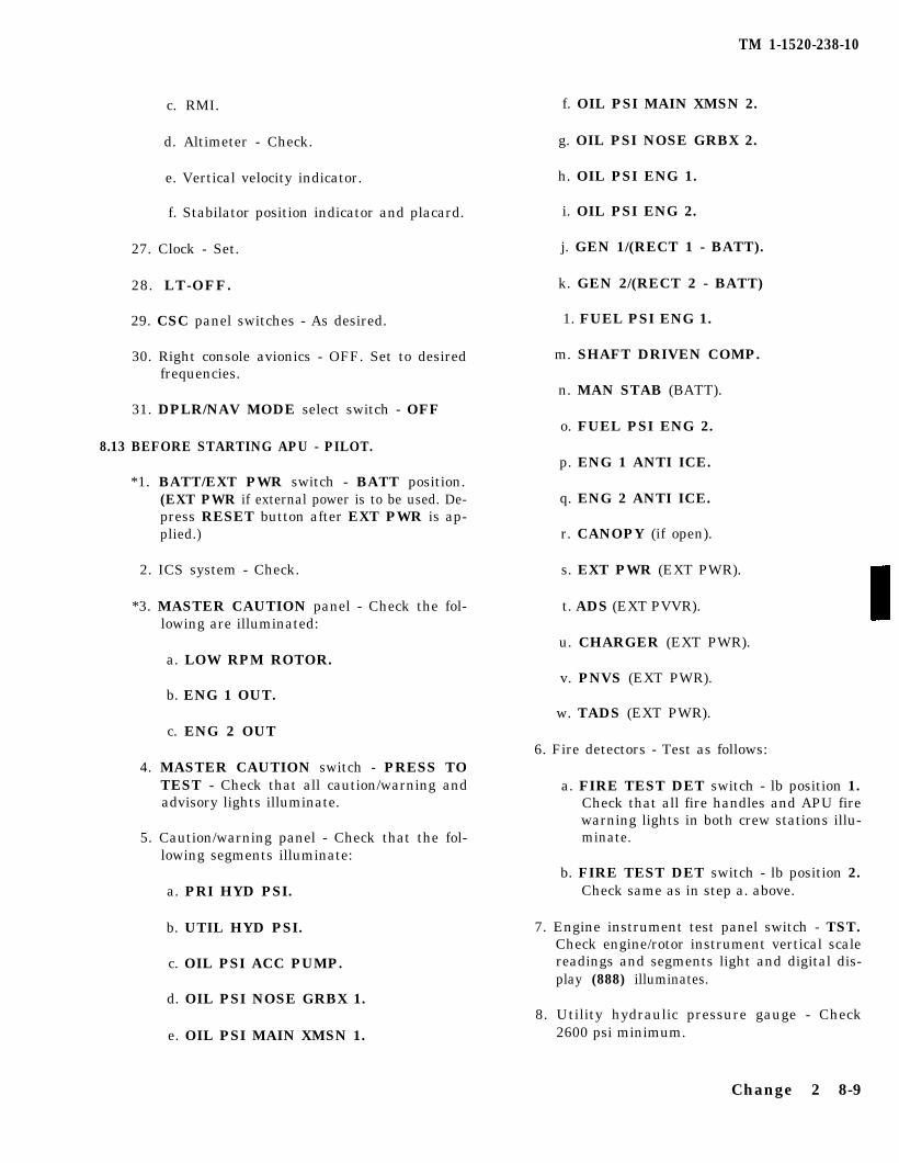
c. RMI. f. OIL PSI MAIN XMSN 2.
d. Altimeter - Check.
e. Vertical velocity indicator.
g. OIL PSI NOSE GRBX 2.
h. OIL PSI ENG 1.
f. Stabilator position indicator and placard.
27. Clock - Set.
i. OIL PSI ENG 2.
28. LT-OFF.
29. CSC panel switches - As desired.
j. GEN 1/(RECT 1 - BATT).
k. GEN 2/(RECT 2 - BATT)
1. FUEL PSI ENG 1.
30. Right console avionics - OFF. Set to desiredfrequencies.
m. SHAFT DRIVEN COMP.
n. MAN STAB (BATT).31. DPLR/NAV MODE select switch - OFF
o. FUEL PSI ENG 2.8.13 BEFORE STARTING APU - PILOT.
p. ENG 1 ANTI ICE.*1. BATT/EXT PWR switch - BATT position.
(EXT PWR if external power is to be used. De-press RESET button after EXT PWR is ap-plied.)
q. ENG 2 ANTI ICE.
r. CANOPY (if open).
2. ICS system - Check. s. EXT PWR (EXT PWR).
*3. MASTER CAUTION panel - Check the fol-lowing are illuminated:
a. LOW RPM ROTOR.
t. ADS (EXT PVVR).
u. CHARGER (EXT PWR).
v. PNVS (EXT PWR).b. ENG 1 OUT.
w. TADS (EXT PWR).c. ENG 2 OUT
6. Fire detectors - Test as follows:4. MASTER CAUTION switch - PRESS TO
TEST - Check that all caution/warning andadvisory lights illuminate.
5. Caution/warning panel - Check that the fol-lowing segments illuminate:
a. PRI HYD PSI.
a. FIRE TEST DET switch - lb position 1.Check that all fire handles and APU firewarning lights in both crew stations illu-minate.
b. FIRE TEST DET switch - lb position 2.Check same as in step a. above.
b. UTIL HYD PSI.
c. OIL PSI ACC PUMP.
d. OIL PSI NOSE GRBX 1.
7. Engine instrument test panel switch - TST.Check engine/rotor instrument vertical scalereadings and segments light and digital dis-play (888) illuminates.
e. OIL PSI MAIN XMSN 1.8. Utility hydraulic pressure gauge - Check
2600 psi minimum.
TM 1-1520-238-10
Change 2 8-9
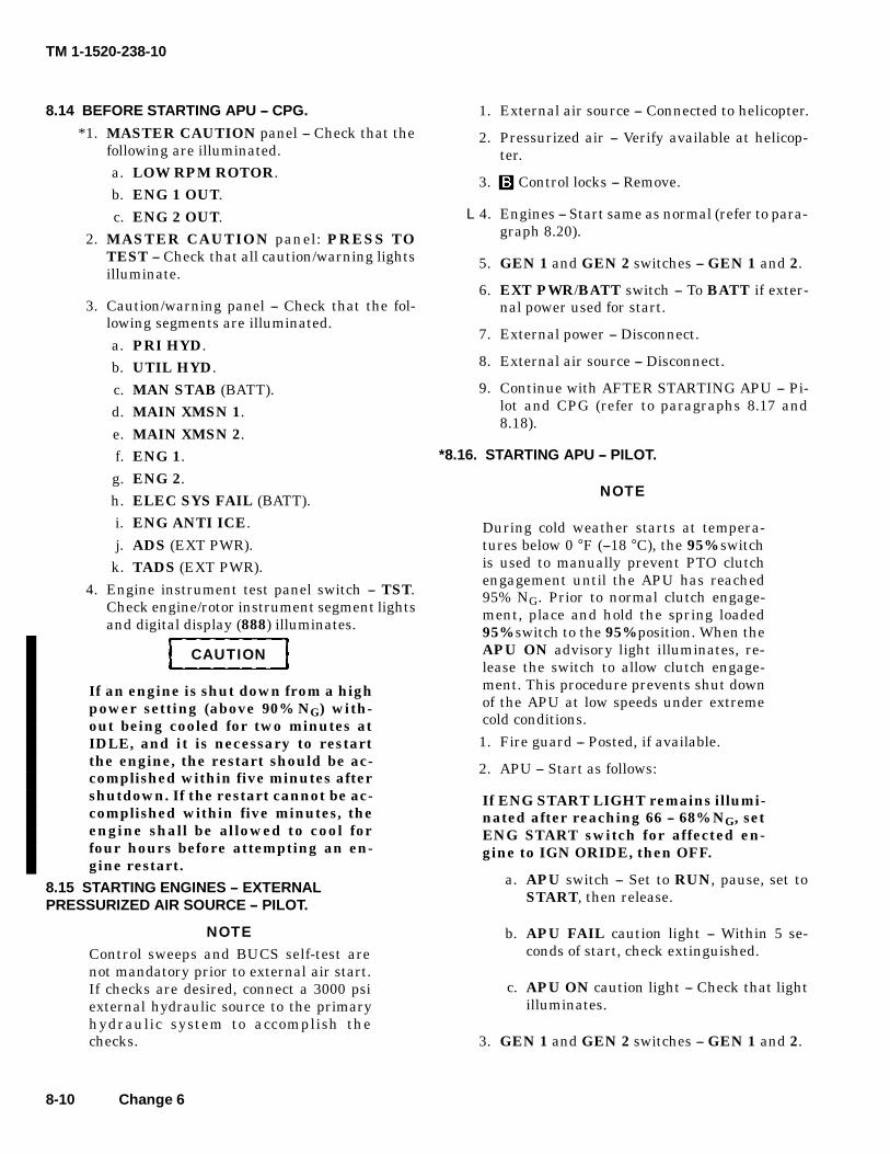
TM 1-1520-238-10
8-10 Change 6
8.14 BEFORE STARTING APU -- CPG.
*1. MASTER CAUTION panel -- Check that thefollowing are illuminated.a. LOW RPM ROTOR.b. ENG 1 OUT.
c. ENG 2 OUT.2. MASTER CAUTION panel: PRESS TO
TEST -- Check that all caution/warning lightsilluminate.
3. Caution/warning panel -- Check that the fol-lowing segments are illuminated.
a. PRI HYD.b. UTIL HYD.
c. MAN STAB (BATT).d. MAIN XMSN 1.
e. MAIN XMSN 2.f. ENG 1.
g. ENG 2.h. ELEC SYS FAIL (BATT).i. ENG ANTI ICE.
j. ADS (EXT PWR).k. TADS (EXT PWR).
4. Engine instrument test panel switch -- TST.Check engine/rotor instrument segment lightsand digital display (888) illuminates.
CAUTION
If an engine is shut down from a highpower setting (above 90% NG) with-out being cooled for two minutes atIDLE, and it is necessary to restartthe engine, the restart should be ac-complished within five minutes aftershutdown. If the restart cannot be ac-complished within five minutes, theengine shall be allowed to cool forfour hours before attempting an en-gine restart.
8.15 STARTING ENGINES -- EXTERNALPRESSURIZED AIR SOURCE -- PILOT.
NOTEControl sweeps and BUCS self-test arenot mandatory prior to external air start.If checks are desired, connect a 3000 psiexternal hydraulic source to the primaryhydraulic system to accomplish thechecks.
1. External air source -- Connected to helicopter.
2. Pressurized air -- Verify available at helicop-ter.
3. Control locks -- Remove.
L4. Engines -- Start same as normal (refer to para-graph 8.20).
5. GEN 1 and GEN 2 switches -- GEN 1 and 2.
6. EXT PWR/BATT switch -- To BATT if exter-nal power used for start.
7. External power -- Disconnect.
8. External air source -- Disconnect.
9. Continue with AFTER STARTING APU -- Pi-lot and CPG (refer to paragraphs 8.17 and8.18).
*8.16. STARTING APU -- PILOT.
NOTE
During cold weather starts at tempera-tures below 0 °F (--18 °C), the 95% switchis used to manually prevent PTO clutchengagement until the APU has reached95% NG. Prior to normal clutch engage-ment, place and hold the spring loaded95% switch to the 95% position. When theAPU ON advisory light illuminates, re-lease the switch to allow clutch engage-ment. This procedure prevents shut downof the APU at low speeds under extremecold conditions.
1. Fire guard -- Posted, if available.
2. APU -- Start as follows:
If ENG START LIGHT remains illumi-nated after reaching 66 -- 68% NG, setENG START switch for affected en-gine to IGN ORIDE, then OFF.
a. APU switch -- Set to RUN, pause, set toSTART, then release.
b. APU FAIL caution light -- Within 5 se-conds of start, check extinguished.
c. APU ON caution light -- Check that lightilluminates.
3. GEN 1 and GEN 2 switches -- GEN 1 and 2.
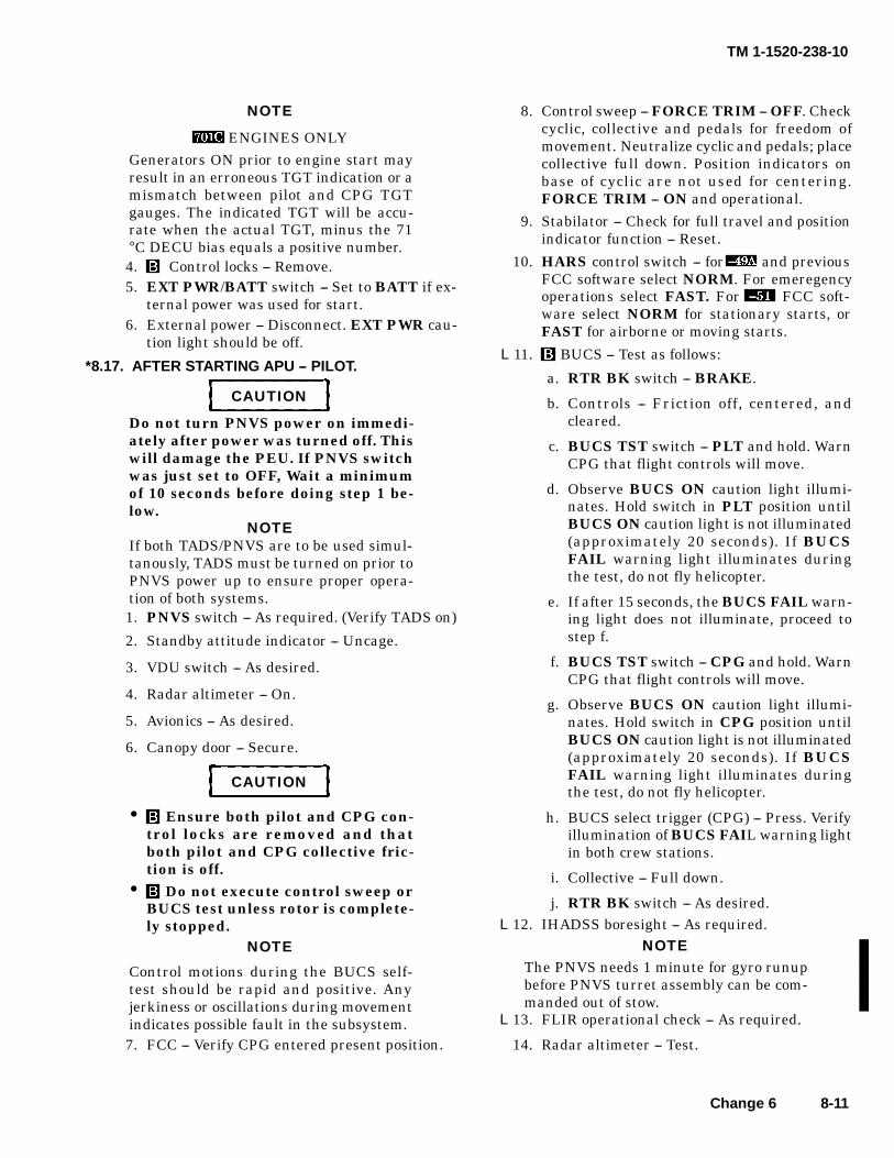
TM 1-1520-238-10
Change 6 8-11
NOTE
ENGINES ONLYGenerators ON prior to engine start mayresult in an erroneous TGT indication or amismatch between pilot and CPG TGTgauges. The indicated TGT will be accu-rate when the actual TGT, minus the 71°C DECU bias equals a positive number.4. Control locks -- Remove.5. EXT PWR/BATT switch -- Set to BATT if ex-
ternal power was used for start.6. External power -- Disconnect. EXT PWR cau-
tion light should be off.
*8.17. AFTER STARTING APU -- PILOT.
CAUTION
Do not turn PNVS power on immedi-ately after power was turned off. Thiswill damage the PEU. If PNVS switchwas just set to OFF, Wait a minimumof 10 seconds before doing step 1 be-low.
NOTEIf both TADS/PNVS are to be used simul-tanously, TADS must be turned on prior toPNVS power up to ensure proper opera-tion of both systems.1. PNVS switch -- As required. (Verify TADS on)
2. Standby attitude indicator -- Uncage.
3. VDU switch -- As desired.
4. Radar altimeter -- On.
5. Avionics -- As desired.
6. Canopy door -- Secure.
CAUTION
• Ensure both pilot and CPG con-trol locks are removed and thatboth pilot and CPG collective fric-tion is off.
• Do not execute control sweep orBUCS test unless rotor is complete-ly stopped.
NOTE
Control motions during the BUCS self-test should be rapid and positive. Anyjerkiness or oscillations during movementindicates possible fault in the subsystem.7. FCC -- Verify CPG entered present position.
8. Control sweep -- FORCE TRIM -- OFF. Checkcyclic, collective and pedals for freedom ofmovement. Neutralize cyclic and pedals; placecollective full down. Position indicators onbase of cyclic are not used for centering.FORCE TRIM -- ON and operational.
9. Stabilator -- Check for full travel and positionindicator function -- Reset.
10. HARS control switch -- for and previousFCC software select NORM. For emeregencyoperations select FAST. For FCC soft-ware select NORM for stationary starts, orFAST for airborne or moving starts.
L11. BUCS -- Test as follows:
a. RTR BK switch -- BRAKE.
b. Controls -- Friction off, centered, andcleared.
c. BUCS TST switch -- PLT and hold. WarnCPG that flight controls will move.
d. Observe BUCS ON caution light illumi-nates. Hold switch in PLT position untilBUCS ON caution light is not illuminated(approximately 20 seconds). If BUCSFAIL warning light illuminates duringthe test, do not fly helicopter.
e. If after 15 seconds, the BUCS FAIL warn-ing light does not illuminate, proceed tostep f.
f. BUCS TST switch -- CPG and hold. WarnCPG that flight controls will move.
g. Observe BUCS ON caution light illumi-nates. Hold switch in CPG position untilBUCS ON caution light is not illuminated(approximately 20 seconds). If BUCSFAIL warning light illuminates duringthe test, do not fly helicopter.
h. BUCS select trigger (CPG) -- Press. Verifyillumination of BUCS FAIL warning lightin both crew stations.
i. Collective -- Full down.
j. RTR BK switch -- As desired.L12. IHADSS boresight -- As required.
NOTEThe PNVS needs 1 minute for gyro runupbefore PNVS turret assembly can be com-manded out of stow.
L13. FLIR operational check -- As required.
14. Radar altimeter -- Test.
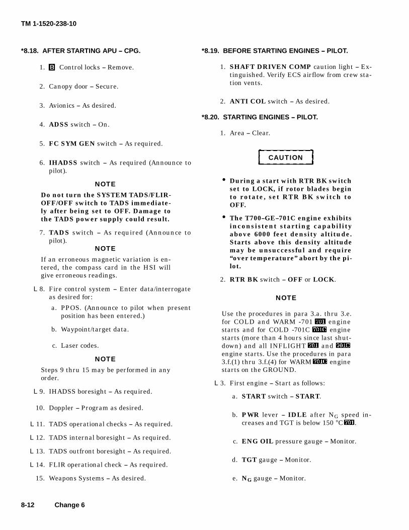
TM 1-1520-238-10
8-12 Change 6
*8.18. AFTER STARTING APU -- CPG.
1. Control locks -- Remove.
2. Canopy door -- Secure.
3. Avionics -- As desired.
4. ADSS switch -- On.
5. FC SYM GEN switch -- As required.
6. IHADSS switch -- As required (Announce topilot).
NOTE
Do not turn the SYSTEM TADS/FLIR-OFF/OFF switch to TADS immediate-ly after being set to OFF. Damage tothe TADS power supply could result.
7. TADS switch -- As required (Announce topilot).
NOTE
If an erroneous magnetic variation is en-tered, the compass card in the HSI willgive erroneous readings.
L8. Fire control system -- Enter data/interrogateas desired for:
a. PPOS. (Announce to pilot when presentposition has been entered.)
b. Waypoint/target data.
c. Laser codes.
NOTE
Steps 9 thru 15 may be performed in anyorder.
L9. IHADSS boresight -- As required.
10. Doppler -- Program as desired.
L11. TADS operational checks -- As required.
L12. TADS internal boresight -- As required.
L13. TADS outfront boresight -- As required.
L14. FLIR operational check -- As required.
15. Weapons Systems -- As desired.
*8.19. BEFORE STARTING ENGINES -- PILOT.
1. SHAFT DRIVEN COMP caution light -- Ex-tinguished. Verify ECS airflow from crew sta-tion vents.
2. ANTI COL switch -- As desired.
*8.20. STARTING ENGINES -- PILOT.
1. Area -- Clear.
CAUTION
• During a start with RTR BK switchset to LOCK, if rotor blades beginto rotate, set RTR BK switch toOFF.
• The T700--GE--701C engine exhibitsinconsistent starting capabilityabove 6000 feet density altitude.Starts above this density altitudemay be unsuccessful and require“over temperature” abort by the pi-lot.
2. RTR BK switch -- OFF or LOCK.
NOTE
Use the procedures in para 3.a. thru 3.e.for COLD and WARM -701 enginestarts and for COLD -701C enginestarts (more than 4 hours since last shut-down) and all INFLIGHT andengine starts. Use the procedures in para3.f.(1) thru 3.f.(4) for WARM enginestarts on the GROUND.
L3. First engine -- Start as follows:
a. START switch -- START.
b. PWR lever -- IDLE after NG speed in-creases and TGT is below 150 °C .
c. ENG OIL pressure gauge -- Monitor.
d. TGT gauge -- Monitor.
e. NG gauge -- Monitor.
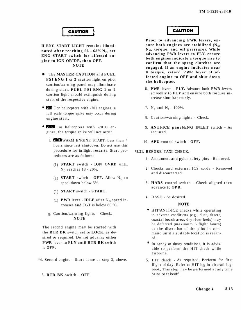
TM 1-1520-238-10
If ENG START LIGHT remains illumi-nated after reaching 66 - 68% NG, setENG START switch for affected en-gine to IGN ORIDE, then OFF.
NOTE
l The MASTER CAUTION and FUELPSI ENG 1 or 2 caution light on pilotcaution/warning panel may illuminateduring start. FUEL PSI ENG 1 or 2caution light should extinguish duringstart of the respective engine.
For helicopters with -701 engines, afull scale torque spike may occur duringengine start.
For helicopters with -701C en-gines, the torque spike will not occur.
f. WARM ENGINE START. Less than 4hours since last shutdown. Do not use thisprocedure for inflight restarts. Start pro-cedures are as follows:
(1)
(1)
(1)
(1)
START switch - IGN OVRD untilNG reaches 18 - 20%.
START switch - OFF. Allow NG tospool down below 5%.
START switch - START.
PWR lever - IDLE after NG speed in-creases and TGT is below 80 °C.
g. Caution/warning lights - Check.NOTE
The second engine may be started withthe RTR BK switch set to LOCK, as de-sired or required. Do not advance eitherPWR lever to FLY until RTR BK switchis OFF.
*4. Second engine - Start same as step 3, above.
5. RTR BK switch - OFF
Prior to advancing PWR levers, en-sure both engines are stabilized (Np,NG, torque, and oil pressure). Whileadvancing PWR levers to FLY, ensureboth engines indicate a torque rise toconfirm that the sprag clutches areengaged. If an engine indicates near0 torque, retard PWR lever of af-fected engine to OFF and shut downthe helicopter.
6.
7.
8.
9.
10.
PWR levers - FLY. Advance both PWR leverssmoothly to FLY and ensure both torques in-crease simultaneously.
Np and Nr - 100%.
Caution/warning lights - Check.
ANTI-ICE panel/ENG INLET switch - Asrequired.
APU control switch - OFF.
*8.21. BEFORE TAXI CHECK.
1.
2.
3.
4.
l
5.
Armament and pylon safety pins - Removed.
Chocks and external ICS cords - Removedand disconnected.
HARS control switch - Check aligned thenadvance to OPR.
DASE - As desired.
NOTEHIT/ANTI-ICE checks while operatingin adverse conditions (e.g., dust, desert,coastal beach area, dry river beds) maybe deferred (maximum 5 flight hours)at the discretion of the pilot in com-mand until a suitable location is reach-ed.
In sandy or dusty conditions, it is advis-able to perform the HIT check whileairborne.
HIT check - As required. Perform for firstflight of day. Refer to HIT log in aircraft log-book, This step may be performed at any timeprior to takeoff.
Change 4 8-13
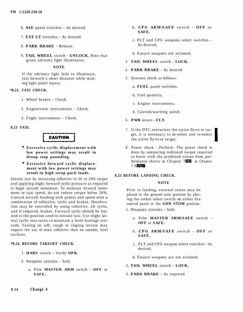
TM 1-1520-238-10
6. ASE panel switches - As desired.
7. EXT LT switches - As desired.
8. PARK BRAKE - Release.
9. TAIL WHEEL switch - UNLOCK. Note thatgreen advisory light illuminates.
NOTE
If the advisory light fails to illuminate,taxi forward a short distance while mak-ing light pedal inputs.
*8.22. TAXI CHECK.
1. Wheel brakes - Check.
2. Engine/rotor instruments - Check.
3. Flight instruments - Check.
8.23 TAXI.
Excessive cyclic displacement withlow power settings may result indroop stop pounding.
Excessive forward cyclic displace-ment with low power settings mayresult in high strap pack loads.
Initiate taxi by increasing collective to 20 to 24% torqueand applying slight forward cyclic pressure as requiredto begin aircraft movement. To maintain forward move-ment or taxi speed, do not reduce torque below 20%.Control aircraft heading with pedals and speed with acombination of collective, cyclic and brakes. Decelera-tion may be controlled by using collective, aft cyclic,and if required, brakes. Forward cyclic should be lim-ited to the position used to initiate taxi. Use slight lat-eral cyclic into turns to maintain a level fuselage atti-tude. Taxiing on soft, rough or sloping terrain mayrequire the use of more collective than on smooth, levelsurfaces.
*8.24. BEFORE TAKEOFF CHECK.
1. HARS switch - Verify OPR.
2. Weapons systems - Safe.
a. Pilot MASTER ARM switch - OFF orSAFE.
8-14 Change 4
3.
4.
5.
6.
7.
8.
b. CPG ARM/SAFE switch - OFF orSAFE.
c. PLT and CPG weapons select switches -As desired.
d. Ensure weapons not actioned.
TAIL WHEEL switch - LOCK.
PARK BRAKE - As desired
Systems check as follows:
a. FUEL panel switches.
b. Fuel quantity.
c. Engine instruments.
d. Caution/warning panel.
PWR levers - FLY.
If the DTC overwrites the active fly-to or tar-get, it is necessary to de-select and re-selectthe active fly-to or target.
Power check - Perform. The power check isdone by comparing indicated torque requiredto hover with the predicted values from per-formance charts in Chapter 7 or Chapter7 A
8.25 BEFORE LANDING CHECK.
NOTE
Prior to landing, external stores may beplaced in the ground stow position by plac-ing the rocket select switch on either firecontrol panel in the GND STOW position.
1. Weapons systems - Safe.
a. Pilot MASTER ARM/SAFE switch -OFF or SAFE.
b. CPG ARM/SAFE switch - OFF orSAFE.
c. PLT and CPG weapon select switches - Asdesired.
d. Ensure weapons are not actioned.
2. TAIL WHEEL switch - LOCK.
3. PARK BRAKE - As required.
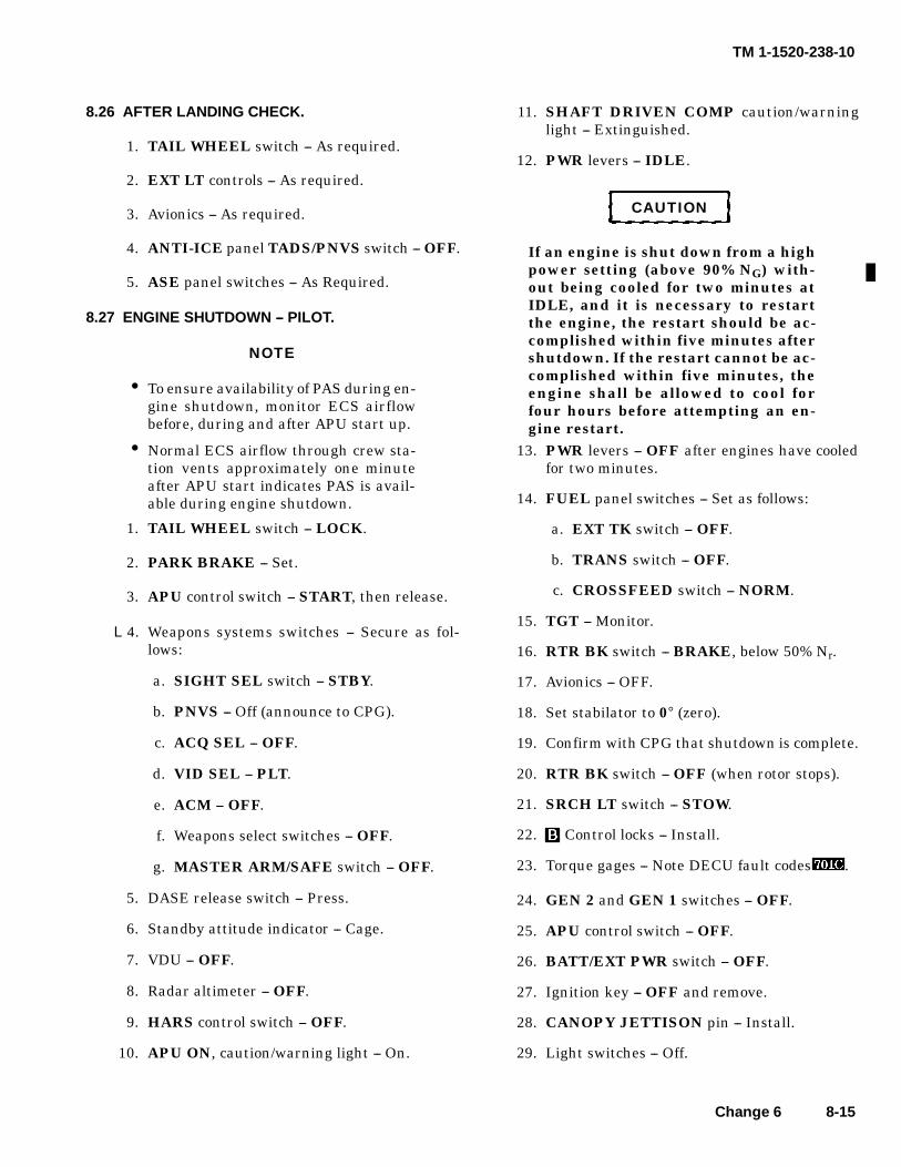
TM 1-1520-238-10
Change 6 8-15
8.26 AFTER LANDING CHECK.
1. TAIL WHEEL switch -- As required.
2. EXT LT controls -- As required.
3. Avionics -- As required.
4. ANTI-ICE panel TADS/PNVS switch -- OFF.
5. ASE panel switches -- As Required.
8.27 ENGINE SHUTDOWN -- PILOT.
NOTE
• To ensure availability of PAS during en-gine shutdown, monitor ECS airflowbefore, during and after APU start up.
• Normal ECS airflow through crew sta-tion vents approximately one minuteafter APU start indicates PAS is avail-able during engine shutdown.
1. TAIL WHEEL switch -- LOCK.
2. PARK BRAKE -- Set.
3. APU control switch -- START, then release.
L4. Weapons systems switches -- Secure as fol-lows:
a. SIGHT SEL switch -- STBY.
b. PNVS -- Off (announce to CPG).
c. ACQ SEL -- OFF.
d. VID SEL -- PLT.
e. ACM -- OFF.
f. Weapons select switches -- OFF.
g. MASTER ARM/SAFE switch -- OFF.
5. DASE release switch -- Press.
6. Standby attitude indicator -- Cage.
7. VDU -- OFF.
8. Radar altimeter -- OFF.
9. HARS control switch -- OFF.
10. APU ON, caution/warning light -- On.
11. SHAFT DRIVEN COMP caution/warninglight -- Extinguished.
12. PWR levers -- IDLE.
CAUTION
If an engine is shut down from a highpower setting (above 90% NG) with-out being cooled for two minutes atIDLE, and it is necessary to restartthe engine, the restart should be ac-complished within five minutes aftershutdown. If the restart cannot be ac-complished within five minutes, theengine shall be allowed to cool forfour hours before attempting an en-gine restart.
13. PWR levers -- OFF after engines have cooledfor two minutes.
14. FUEL panel switches -- Set as follows:
a. EXT TK switch -- OFF.
b. TRANS switch -- OFF.
c. CROSSFEED switch -- NORM.
15. TGT -- Monitor.
16. RTR BK switch -- BRAKE, below 50% Nr.
17. Avionics -- OFF.
18. Set stabilator to 0° (zero).
19. Confirm with CPG that shutdown is complete.
20. RTR BK switch -- OFF (when rotor stops).
21. SRCH LT switch -- STOW.
22. Control locks -- Install.
23. Torque gages -- Note DECU fault codes .
24. GEN 2 and GEN 1 switches -- OFF.
25. APU control switch -- OFF.
26. BATT/EXT PWR switch -- OFF.
27. Ignition key -- OFF and remove.
28. CANOPY JETTISON pin -- Install.
29. Light switches -- Off.

TM 1-1520-238-10
8-16 Change 6
8.28 ENGINE SHUTDOWN -- CPG.
1. SIGHT SEL switch -- STBY.
NOTE
• For TADS OI aircraft, monitor HODCRT as TADS/FLIR switch is placed inOFF. After approximately 15 seconds,HOD should flash and loss of SYM BRTcontrol should be experienced. Whensymbol brightness is no longer adjust-able, the system is in independent HODmode and power-down can be contin-ued.
• Prior to turning TADS off, ensurePNVS is turned off to allow proper datatransfer into the TADS non--volatilememory.
2. TADS switch -- OFF (verify PNVS off).
NOTE
Prior to turning IHADSS off, confirmTADS power down sequence is completeby waiting 15 seconds after TADS isturned off and verifying ORT SYM BRTswitch is inoperative.
3. ORT SYM BRT switch -- Inoperative.
4. IHADSS switch -- OFF.
5. FC SYM GEN switch -- OFF.
6. Weapons select switches -- OFF.
7. CPG ARM/SAFE switch -- OFF.
8. PLT/GND ORIDE switch -- OFF.
9. ADSS switch -- OFF.
10. MSL MODE switch -- STBY.
11. RECORDER MODE switch -- OFF.
12. Avionics -- Off.
13. Control locks -- Install.
14. CANOPY JETTISON pin -- Install.
15. Light switches -- Off.
8.29 BEFORE LEAVING THE HELICOPTER.
1. Armament and pylon safety pins -- Installed.
2. Conduct walkaround.
3. Complete forms. An entry in DA form 2408-13is required if helicopter was:
a. Flown in loose grass environment.
b. Operated within 10 NM of salt water.
c. Operated within 200 NM of volcanic activ-ity.
d. Exposed to radioactivity.
4. Secure helicopter -- As required.

TM 1-1520-238-10
Section III. INSTRUMENT FLIGHT
8.30 INSTRUMENT FLIGHT. 8.31 INSTRUMENT FLIGHT PROCEDURES.
This helicopter is qualified for operation in instrumentmeteorological conditions. Refer to AR 95-1 and FM 1-240.
8-17
CAUTION
TM 1-1520-238-10
Section IV. FLIGHT CHARACTERISTICS
8.32 FLIGHT CHARACTERISTICS - GENERAL.
The safe maximum operating airspeed range is de-scribed in Chapter 5, Section V.
8.33 STABILATOR OPERATION.
The stabilator is normally operated in the automaticmode. However, the two additional modes available tothe pilot can improve helicopter flight characteristicsduring certain maneuvers.
8.33.1 NOE/APPR Mode.
These are:
If the pilot desires to im-prove his over-the-nose visibility for landings or duringNOE flight, the NOE/APPR mode may be engaged atany time. An additional benefit is improved forwardspeed control in NOE flight.
8-18
8.33.2 Manual Mode. The manual mode of operationis particularly useful for positioning the stabilator tohelp minimize airframe vibrations when hovering incrosswinds or tailwinds.
8.34 SLOPE/ROUGH TERRAIN LANDING.
Care shall be exercised when operat-ing the helicopter on rough terrain.Damage to the underside antennasmay result.
For slope landings and all ground operations, avoid us-ing combinations of excessive cyclic and low collectivesettings. Where minimum collective is used, maintaincyclic near neutral position and avoid abrupt cyclic in-puts. If cyclic pitch is required, increase collectiveslightly to avoid hitting the droop stops and possible ro-tor-blade-to-fuselage contact.
CAUTION
CAUTION
CAUTION
TM 1-1520-238-10
Section V. ADVERSE
8.35 GENERAL
ENVIRONMENTAL CONDITIONS
ice. Any indication that flow is restricted is cause forapplication of heat.
This section informs the crewmembers of the specialprecautions and procedures to be followed during thevarious weather and climatic conditions that may beencountered. This material will be additional to thatalready covered in other chapters regarding the opera-tion of various helicopter systems.
8.36 COLD WEATHER OPERATION.
Helicopter operation in cold weather or an arctic envi-ronment presents no unusual problems if the flightcrew is aware of the various changes that occur in lowtemperature conditions.
8.37 PREPARATION FOR FLIGHT.
Ice removal shall never be done byscraping or chipping. Remove ice byapplying heat or de-ice liquid(TM 1-1500-204-23).
In addition to doing a normal preflight in Section 11, therotor head, main rotor blades, tail rotor, and flight con-trols should be free of all ice and snow. Failure to re-move snow and ice accumulations while on the groundcan result in serious aerodynamics and structural ef-fects in flight. Check that all fuel tank vents, staticports, pitot tubes, engine inlet, APU inlet, ENCU inlet,and heat exchangers are free of snow and ice; and thattires, landing gear struts, and the hydraulic accumula-tor are properly serviced.
a. If ice or snow is found in engine inlets and ex-haust, remove as much as possible by hand and thawengine out with hot air before attempting to start. Actu-ate PWR levers for freedom of movement before start-ing main engine.
b. Attempt to turn rotor system by rotating APUdrive shaft by hand in the direction of rotation. If rotorcannot be turned, apply heat to main transmissionarea.
c. As long as fuel will flow freely from the drains inthe tanks, it can be assumed that the system is free of
Fuel draining from the affected com-ponent after several minutes of heatapplication does not necessarily indi-cate that all ice has been melted. Icemay still remain in the unit, and itcould be a serious hazard to flight op-erations. Heat should be applied for ashort time after fuel begins to flowfrom the drain, and the drainageshould be checked frequently until itis evident that all water has been re-moved.
d. If water collected in sumps has frozen (indicatedby a lack of flow from drain), apply heat liberally andopen drain frequently. Catch all drainage in a clear con-tainer and inspect for water globules in the fuel. Con-tinue sampling until fuel is free of water globules.
Due to an elapsed time requirement,it is recommended that the tail rotorteetering bearings warmup proce-dure be accomplished as the last itemof the exterior check during theflight crew preflight inspection. At-31 °C (-24 °F), the helicopter must bestarted and the tail rotor must beturning within 5 minutes of teeterbearing warmup. Below -32 °C (-25°F), elapsed time is reduced to 2 min-utes. At a temperature of -32 °C (-25°F) or below, the tail rotor must becycled by an applied force no greaterthan 75 lbs.
The tail rotor teetering bearings are made of elastomer-ic material which prior to certain cold weather flightsrequire special warmup procedures as follows:
e. One crewmember should apply a teetering mo-tion by manually pushing back-and-forth at the tip ofthe tail rotor blade until the blade has reached its tee-tering stops. When the blade can be pushed to the top,the bearing has been sufficiently warmed up.
8-19
TM 1-1520-238-10
f. Based on unapplied force of 75 lbs, the blademust be cycled one time at -32 °C (-25 °F), five times at-42 °C (-44 °F), and ten times at -54 °C (-65 °F).
8.38 ENGINE STARTING.
When starting in cold weather below -40 °C (-40 °F), iflight-off does not occur within 10 seconds after placingthe PWR lever to IDLE, quickly move engine PWR le-ver for the affected engine to OFF and then to IDLEthree times. Then, leave the PWR lever in IDLE. Iflight-off still does not occur within 40 seconds, abortstart and do the following:
1.
2.
3.
4.
5.
6.
Engine PWR lever (affected engine) - Hold atLOCKOUT.
Fuel CROSSFEED switch - AFT TK.
Fuel BOOST switch ON. Check that groundcrew verifies fuel flow from upper drain.
Engine PWR lever (affected engine) - OFF.
Attempt another start.
After engine start - CROSSFEED switch -NORM. -
8.39 WARMUP AND GROUND TESTS.
It is normal for engine oil pressure to be high duringinitial starts when oil is cold. Run engine at idle untiloil pressure is within normal operating limits. Oil pres-sure should return to the normal range within five min-utes. However, time required for warmup will dependon temperature of the engine and lubrication systembefore start.
During starts in extremely cold weather (near -54 °C,-65 °F), the following engine oil pressure characteris-tics are typical:
a. Oil pressure may remain at zero from 20 to 30 se-conds after initiating the start. Abort start if oil pres-sure does not register within one minute of initiatingstart.
b. Once oil pressure begins to indicate on thegauge, it will increase rapidly and go over the 100 psiglimit. The pressure will decrease as oil temperaturerises and return to within the green band on the gauge.This condition is considered normal. The time for oilpressure to decrease to 100 psig or below will depend on
the severity of the ambient temperature, but it shouldbe inside the green band within five minutes of startingthe engine.
c. Oil pressure may increase above the maximumpressure limit of 100 psig if the engine is acceleratedabove idle while oil temperature is below normal oper-ating range. The pressure will decrease to within thenormal operating range as oil temperature increases.
d. The OIL BYP ENG 1 or 2 caution light normallygoes on when starting an engine with oil below normaloperating temperatures because of the relatively highoil viscosity and the amount of contamination in the oilfilter. When oil temperature reaches about 38 °C (100°F) during engine warmup, the light should go off.
e. At temperatures between -17 °C and -43 °C (1°F and -45 °F), warmup engines during engine run-upfor three minutes.
To eliminate any possibility of main rotor droop stopwear should the main rotor blades move through apitch change angle while resting on the droop stop, theflight crew should observe the following:
At a temperature of -42 °C (-44 °F) or below, and witha rotor speed of 100% Nr, maintain neutral cyclic posi-tion for one minute. Then move the cyclic forward oneinch and hold for one minute. Move the cyclic forwardone additional inch and hold for one minute. The totalprocedure requires three minutes after reaching nor-mal rotor RPM and can be accomplished simultaneous-ly with the engine warmup procedures.
8.40 DESERT AND HOT WEATHER OPERATIONS.
a. In sandy or dusty conditions, it is advisable toperform the HIT check while airborne.
b. Refer to FM 1-202, Environmental Flight.
8.41 TURBULENCE AND THUNDERSTORMOPERATION.
8.41.1 Turbulence Operation:
a. For moderate turbulence, airspeed should be lessthan 150 knots.
b. For light turbulence, reduce airspeed, if desired,to minimize vibration.
8-20
WARNING
CAUTION
TM 1-1520-238-10
8.41.2 Thunderstorm Operation:
a. Lightning strikes may result in the loss of thedigital automatic stabilization equipment (DASE), sta-bilator control, engine electronic control units, and heli-copter electrical power. The high voltages passingthrough the helicopter structure are expected to coupleinto the helicopter wiring, producing secondary effectswhich cause degradation to the mission equipment.
b. If a lightning strike occurs where all helicopterelectrical power and engine electrical control units arelost, both engines will go immediately to maximumpower output, as if in LOCKOUT. The flight crew shallhave to react immediately to retard the PWR levers toIDLE and enter autorotation. The pilot could then ad-vance the PWR levers, restoring power, relying solelyon rotor and engine sounds and general helicopter han-dling because of the high probability that all engineinstruments would be inoperative.
8.42 ICE AND RAIN.
Prolonged operation of the anti-ice/de-ice systems while on the groundmay result in damage.
8.42.1 Preflight/Runup. Prior to flight in icing condi-tions (visible moisture and below freezing tempera-tures), special care should be taken to ensure that allnecessary anti-ice/de-ice systems are operational. Theblade de-ice system may be checked by holding theBLADE de-ice switch, on the pilots ANTI-ICE panel(fig 2-17), to the TEST position. The BLADE ON advi-sory light, on the same panel, will illuminate forapproximately 3 to 4 seconds. Additionally, the on-com-mand FD/LS may be used to ensure proper system op-eration. The engine inlet and nose gearbox anti-ice sys-tem may be checked by moving the ENG INLETswitch, on the pilots ANTI-ICE panel, to the ON posi-tion. The ENG 1 and ENG 2 ANTI-ICE lights on thepilots caution/warning panel will illuminate and re-main on until the fairing heaters reach operating tem-perature. After approximately 30 to 40 seconds, theENG 1 and ENG 2 ANTI-ICE lights on the pilots cau-tion/warning panel will extinguish and the ENG 1 andENG 2 advisory lights, on the pilots ANTI-ICE panel,will illuminate.
8.42.2 Inflight. Anti-ice/de-ice systems should be acti-vated prior to flight in potential icing conditions (visiblemoisture and below freezing conditions).
a. The green BLADE, ENG 1, and ENG 2 advisorylights on the pilots ANTI-ICE panel should be illumi-nated. When actual icing conditions are encountered,the ENG ICE light on the caution/warning panel willilluminate and remain on during the icing encounter.The main and tail rotor blades will accumulate ice be-tween heating cycles. This will result in approximately6 to 10% increase in indicated torque (without collec-tive movement). When the main and tail rotor bladesheat and shed ice, there will be a slight momentary in-crease in airframe vibrations and the indicated torquewill drop to approximately the original reading.
b. Particular attention should be devoted to unusu-al torque rises or persistent airframe vibrations asthese may be the first indications of a blade de-ice sys-tem malfunction. Icing rates tend to vary, even overshort distances, and may result in continuous changesin the indicated icing rate on the ice rate meter. If con-tinuous large erratic rate needle movements of morethan 0.3 gm/m3 and/or large indicated torque rises areobserved, recommend moving the de-ice mode switch(fig 2-17) to the manual MOD position, and depart theicing conditions.
c. Prolonged flight in icing conditions will reduceaircraft maximum range. For fuel consumption, refer toChapter 7 or Chapter 7A .
d. After departing the icing conditions, recommendminimum use of the windshield wipers as shed ice maydamage main rotors, tail rotors, and engines.
8.43 GROUND OPERATIONS DURING HIGH WINDS.
The maximum wind velocity for rotorstart or stops is 45 knots from anydirection. Ground operation of thehelicopter in winds greater than 45knots may cause the main rotorblades to contact the fuselage or thehelicopter to roll over.
a. If surface winds above 45 knots are anticipated,ground operations should cease and the helicoptershould be hangered or moored in accordance withTM 1-1520-238-23. If the helicopter cannot be hang-ered or moored, and sufficient time exists to shut thehelicopter down prior to winds exceeding 45 knots, do
8-21

TM 1-1520-238-10
so. Ensure rotor blades are positioned to the 45° point into the wind and maintain 100% Np/Nr, T A I Ldisplacement and place RTR BK switch - LOCK prior WHEEL switch - LOCK, PARK BRAKE - set, andto shutting down the APU. operate the stabilator in automatic. Adjust the cyclic
b. If surface winds above 45 knots are inadvertent-and collective as necessary to prevent droop ‘stop
ly encountered during ground operations, head aircraftpounding and keep the helicopter upright.
8-22
CAUTION
9.1 AIRCRAFT SYSTEMS.
TM 1-1520-238-10
CHAPTER 9EMERGENCY PROCEDURES
Section I. AIRCRAFT SYSTEMS
This section describes the aircraft system emergenciesthat may reasonably be expected to occur and presentsthe procedures to be followed. Table 9-1 shows the mes-sages displayed on the MASTER CAUTION panels,the caution/warning panels, and the corrective actionrequired. Emergency procedures are given in checklistform when applicable. A condensed version of theseprocedures is contained in the condensed checklist,TM 1-1520-238-CL.
NOTE
The urgency of certain emergencies re-quires immediate and instinctive ac-tion by the pilot. The most importantsingle consideration is helicopter con-trol. All procedures are subordinate tothis requirement.
The MASTER CAUTION segmentshould be reset after each malfunctionto allow systems to respond to possiblesubsequent malfunctions. If time per-mits during a critical emergency, trans-mit a MAYDAY call.
9.2 DEFINITION OF EMERGENCY TERMS.
Those steps that must be performed immediately in anemergency situation are underlined. These steps mustbe performed without reference to the checklist. Whenthe situation permits, non-underlined steps will be ac-complished with use of the checklist.
a. The term LAND AS SOON AS POSSIBLE is de-fined as landing at the nearest suitable landing area(e.g., open field) without delay. (The primary consider-ation is to ensure the survival of occupants.)
b. The term “LAND AS SOON AS PRACTICABLE”is defined as landing at a suitable landing area. (Theprimary consideration is the urgency of the emergency.)
c. The term AUTORO TATE is defined as adjustingthe flight controls as necessary to establish an auto-rotational descent.
●
●
When shutting down an enginethat has malfunctioned in flight, itis important to identify the mal-functioning engine to avoid shut-ting the wrong engine down.
Monitor TGT after shutdown. IfTGT rises above 540 °C, or there isevidence of combustion as indi-cated by a rapid rise in TGT, placethe engine START switch in IGNOVRD position and motor engineuntil TGT decreases below 540 °C.
d. The term "EMER ENG SHUTDOWN" is definedas engine shutdown without delay. Engine shutdown inflight is usually not an immediate-action item unless afire exists. Before attempting an engine shutdown,identify the affected engine by checking engine-outwarning lights, torque meters, TGT indicators, NG, Np,and engine oil pressure indicators.
e. Other terms may be defined, as necessary, tosimplify the procedural memory steps within the exist-ing emergency procedures. The term can then be usedas an emergency procedure step instead of the stepsused to define it. EXAMPLE: The term EMER ENGSHUTDOWN is defined as engine stoppage withoutdelay and is accomplished as follows:
1.
2.
PWR leve r (affected engine) – OFF.
FUEL switch (affected engine) – OFF
9-1
TM 1-1520-238-10
9-2 Change 6
9.3 AFTER-EMERGENCY ACTION.
After a malfunction of equipment has occurred, ap-propriate emergency actions have been taken and thehelicopter is on the ground, an entry shall be made inthe Remarks Section of DA Form 2408-13-1 describingthe malfunction. Ground and flight operations shall bediscontinued until corrective action has been taken.
9.4 EMERGENCY EXITS AND EQUIPMENT.
Emergency exits and equipment are shown in figure9-1.
WARNING
• Activation of the canopy removalsystem when combustible fuel/va-pors are present in the cockpit canresult in an explosion/fire. An ex-plosion/fire can also occur if theaircraft has rolled on its side andfuel/vapors have gathered on theground adjacent to the canopy sidepanels. The crewmembers survivalknife may be used to fracture thecanopy side panels as an alternatemeans of egress.
• Rotate the CANOPY JETTISONhandle to the ARM (90°) positionand release. Push the jettison han-dle to actuate the canopy jettison.Continuing to twist the jettisonhandle while trying to push maycause the actuator piston to jamand thereby prevent operation ofthe canopy severance system. Ifcanopy jettison does not occur onthe first attempt, ensure the jetti-son handle is in the 90° position,and push again. A push force of 140-- 150 lbs may be required to over-come the jam and initiate canopyjettison.
• In the event that canopy jettisondoes not occur when the canopy re-moval system is actuated, the per-sonal survival knife should be usedto fracture the canopy panel andpermit egress.
9.4.1 Emergency Egress.
WARNING
• If emergency egress is required be-fore the rotor blades have stopped,ensure cyclic remains centered.BATT and FORCE TRIM switchesshall be left on to prevent rotorsfrom striking the aircraft or per-sonnel.
• In all cases of canopy jettison, re-main clear of canopy side panels toavoid high velocity canopy frag-ments.
Emergency egress is accomplished by exiting throughthe emergency exits. If possible, use the manual canopyopening handles to exit the aircraft. To permit emer-gency egress by the pilot and CPG from the helicopter,the transparent portion of the four canopy side panelscan be jettisoned by activating a detonation cord. Turn-ing 90° and pushing any of three CANOPY JETTI-SON handles will initiate canopy side panel jettison. Ifemergency egress becomes necessary, proceed as fol-lows:
1. Helmet visors --Down.
2. CANOPY JETTISON handle -- Either crewmember turn 90° release, then push.
9.4.2 Emergency Entrance. If it becomes necessaryto jettison the canopy to gain entrance in case of an em-ergency.
1. Canopy emergency release door -- Open.
2. Area around helicopter -- Clear of personnel atleast 50 feet from all canopy side panels.
3. CANOPY JETTISON handle -- Turn 90° re-lease, then push to jettison canopy.
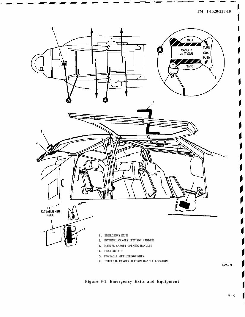
TM 1-1520-238-10
1 . EMERGENCY EXITS
2. INTERNAL CANOPY JETTISON HANDLES
3. MANUAL CANOPY OPENING HANDLES
4. FIRST AID KITS
5. PORTABLE FIRE EXTINGUISHER
6. EXTERNAL CANOPY JETTSON HANDLE LOCATION
Figure 9-1. Emergency Exits and Equipment
9-3
TM 1-1520-238-10
9.5 ENGINE FAILURE.
The various conditions under which an engine may failprevent a standard procedure for all cases. A thoroughknowledge of both emergency procedures and flightcharacteristics will enable the pilot to respond correctlyand automatically in an emergency. The engine instru-ments often provide ample warning of an impeding fail-ure by deviating from normal behavior. Engine failureis normally indicated by a rapid drop in NG, Np, torque,TGT, oil pressure and the engine and symbolic torquevalue will flash for the affected engine. The ENGINEOUT 1 or 2 warning lights will illuminate and an audiosignal will be heard through both headsets. Enginesmay fail only partially, and the degree of failure(amount of power loss) is another factor affecting crew-member response.
When an engine fails completely, the engine PWR leverand FUEL panel switch of the failed engine should beturned OFF. The reduction required in collective afterengine failure will vary with altitude and airspeed atthe time of failure. For example, the collective shouldnot be reduced when an engine fails while the helicop-ter is hovering below 15 feet. During cruise flight, whenaltitude and airspeed permit a significant reduction incollective pitch, Nr can be restored to 100% before land-ing. During single-engine flight or during autorotationairspeed should be kept at the optimum. Optimum au-torotation airspeeds are shown in figure 9-3. In auto-rotation, as airspeed increases above 70 - 80 KIAS, therate of descent and glide distance increase significantly.As airspeed decreases below 64 KIAS, the rate of de-scent will increase and glide distance will decrease. Au-torotation during an out-of-trim condition will increasethe rate of decent and decrease the glide distance. En-gine failure accompanied by an explosion or loud noisewould indicate engine damage, and there is a possibil-ity that an attempt of restart the engine would result ina fire.
9.51 Engine Failure Flight Characteristics. Theflight characteristics and the required crewmembercontrol response after a dual engine failure are similarto those during a normal power-on descent. Full controlof the helicopter can be maintained during autorota-tional descent. When one engine has failed, the helicop-ter can often maintain altitude and airspeed until asuitable landing site can be selected. Whether or notthis is possible becomes a function of such combinedvariables as aircraft weight, density altitude, and alti-tude and airspeed at the time of the engine failure.
9-4 Change 4
Crewmember response time and control technique maybe additional factors.
9.5.2 Single Engine Failure.
Prior to movement of either PWR le-ver, it is imperative that the malfunc-tioning engine and the correspond-ing PWR lever be identified.
Proper response to an engine failure depends on vari-ous factors: density altitude, airspeed, aircraft weight,single engine performance, and environmental condi-tions. The SAFE region in the height velocity diagram(fig 9-2) defines the airspeed and wheel-height com-binations at various gross weight and density altitudecombinations that will permit a safe landing in event ofan engine failure. Crewmember recognition and subse-quent action are essential and should be based on thefollowing general guidelines: At low altitude and lowairspeed, it may be necessary to lower the collectiveonly enough to maintain Nr normal range. At higherdensity altitude, however, the collective may be loweredsignificantly to increase Nr to 100%. When hovering inground effect, the collective should be used only as re-quired to cushion the landing, and the primary consid-eration is in maintaining a level attitude. In forwardflight at low altitude (as in takeoff), when a single-en-gine capability to maintain altitude does not exist, a de-celerating attitude will initially be required to preparefor landing. Conversely, if airspeed is low and altitudesufficient, the helicopter should be placed in an acceler-ating attitude to gain sufficient airspeed for single-en-gine fly-away to a selected landing site. When the pow-er available during single-engine operation is marginalor less; consideration should be given to jettisoning theexternal wing stores.
9.5.3 Single Engine Failure Low Altitude/Low Air-speed and Cruise.
Continued flight is possible.
1. LAND AS SOON AS PRACTICABLE.
Continued flight is not possible.
2. STORES JETT switches - Activate ifrequired.
3. LAND AS SOON AS POSSIBLE.
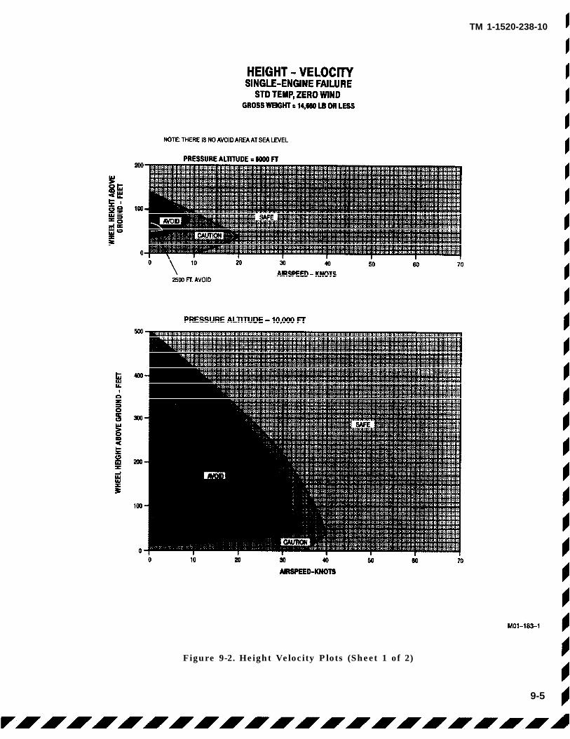
TM 1-1520-238-10
Figure 9-2. Height Velocity Plots (Sheet 1 of 2)
9-5
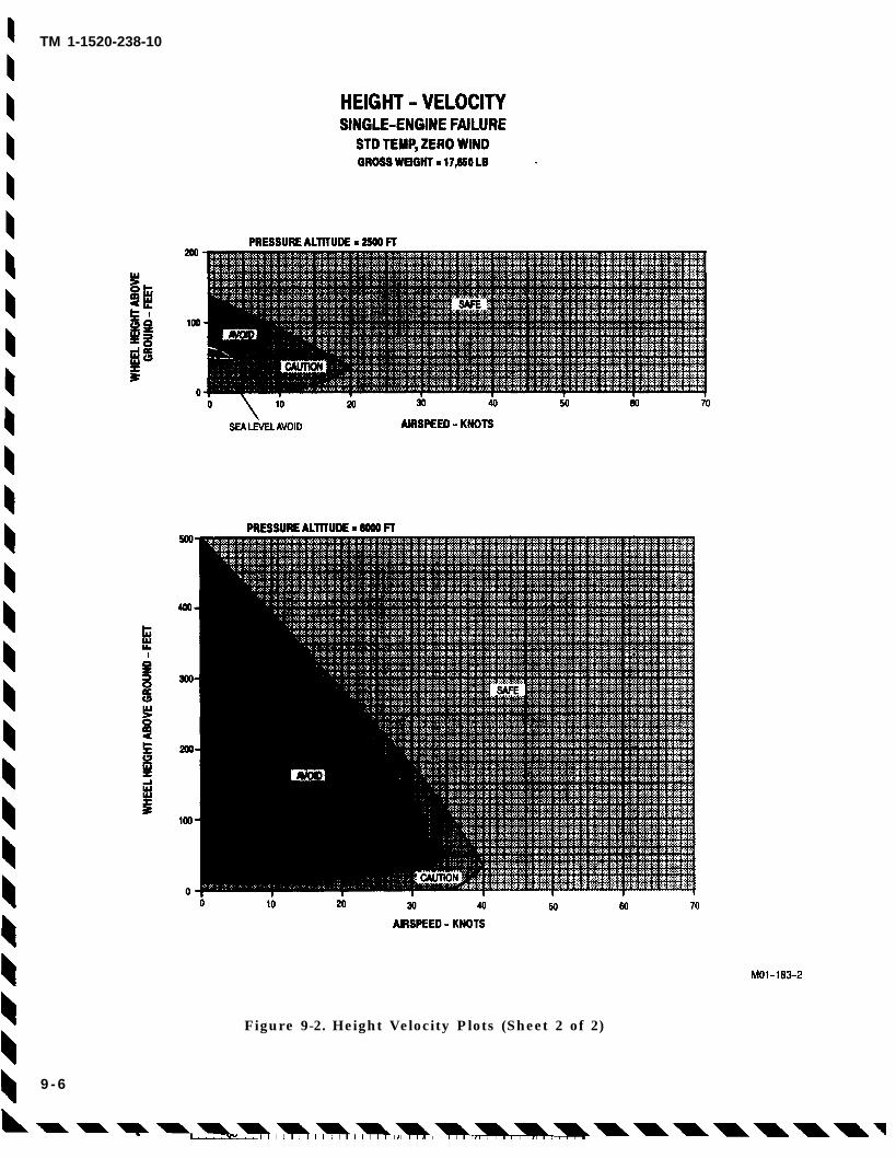
TM 1-1520-238-10
Figure 9-2. Height Velocity Plots (Sheet 2 of 2)
9 - 6
TM 1-1520-238-10
9.5.4 Dual Engine Failure.
WARNING
In the event of an inadvertent activation of the enginechop collar, initial indications from Np and Nr could beinterpreted as a dual engine failure. Indications ofengine chop collar activation are the ENGINE CHOPlight illuminates and engine idle indications on the NG,TGT and Np There is NO illumination of the ENGINEOUT 1 or 2 lights on the MASTER CAUTION panel.
If both engines fail, immediate action is required to makea safe autorotative descent. The altitude and airspeed atwhich a two engine failure occurs will dictate the action tobe taken. After the failure, main rotor rpm will decayrapidly and the aircraft will yaw to the left. Unless a two-engine failure occurs near the ground, it is mandatorythat autorotation be established immediately. At grossweights above 15,000 lbs, immediate considerationshould be given to jettisoning the external wing stores.During cruise at airspeeds to Vne, reduce collectiveimmediately to regain Nr and then adjust as required tomaintain rpm. The cyclic should be adjusted asnecessary to attain and maintain airspeed in theoptimum range (fig 9-3) An airspeed between 64 and 98KIAS should be maintained except for high altitude highgross weight conditions where the maximum allowableautorotation airspeed should be maintained if it is lessthan 64 KIAS. A landing area must be selectedimmediately after both engines fail, and control inputsmust be made to fly to the intended site. Throughout thedescent, adjust collective as necessary to maintain Nrwithin normal range. At high gross weights, the rotormay tend to overspeed and the collective must be usedto maintain the desired rotor rpm (fig
5-1). Nr should be maintained at or slightly above 100%to allow ample rpm before touchdown, and headingmaintained by pedals.
Main rotor rpm will increase momentarily when the cyclicis moved aft with no change in collective pitch setting.An autorotative rpm of approximately 100% provides fora good rate of descent. Nr above 100% may result in ahigher than desired rate of descent. At 100 to 125 feetAGL, use aft cyclic to decelerate. This reduces airspeedand rate of descent and causes an increase in Nr. Thedegree of increase depends upon the amount and rate ofdeceleration. An increase in Nr can be desirable in thatmore inertial energy in the rotor system will be availableto cushion the landing. Ground contact should be madewith some forward speed. If a rough landing is selected,a more pronounced deceleration is necessary andtouchdown speed should approach zero. It is possiblethat during the autorotative approach, the situation mayrequire additional deceleration. In that case, it isnecessary to assume a landing attitude at a higheraltitude than normal. Should both engines fail at lowairspeed, initial collective reduction may vary widely. Theobjective is to reduce collective as necessary to maintainNr within normal range. In some instances at lowaltitude or low airspeed, settling may be so rapid that littlecan be done to avoid a hard-impact landing.In that case, it is critical to maintain a level landingattitude. Cushion the landing with remaining collectiveas helicopter settles to the ground.
9.5.5 Dual Engine Failure Low Altitude/Low Airspeedand Cruise.
1. AUTOROTATE.
2. Chop Collar - Reset.
3. STORES JETT switches - Activate as desired (time permitting)
Change 3 9-7
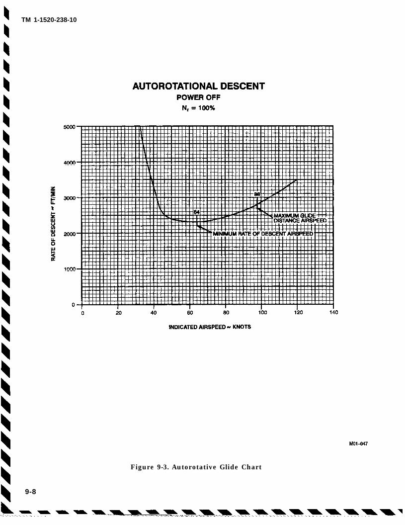
TM 1-1520-238-10
Figure 9-3. Autorotative Glide Chart
9-8
9.6 ENGINE COMPRESSOR STALL.
An engine compressor stall is normally recognized by anoticeable bang or popping noise and possible aircraftyaw. These responses are normally accompanied by arapid increase in TGT and fluctuations in NG, torque,and Np readings for the affected engine. In the event ofa compressor stall:
1. Collective - Reduce,
If condition persists:
2. PWR lever (affected engine) - Retard. (TGTshould decrease.)
3. PWR lever (affected engine) - FLY.
If stall condition reoccurs:
4. PWR lever (affected engine) - IDLE.
5. LAND AS SOON AS PRACTICABLE.
9.7 ENGINE RESTART DURING FLIGHT.
After an engine failure in flight, an engine restart maybe attempted. A failed engine should not be restartedunless it can be determined that it is reasonably safe todo so.
9.8 ENGINE EMERGENCY START (DECUINSTALLED ONLY
Engine overspeed and overtemper-ature protection are not providedwhen the ENG 1 or ENG 2 (as ap-propriate) circuit breaker is out.
The T700-GE-701C engine exhibitsinconsistent starting capabilityabove 6000 feet density altitude.Starts above this density altitudemay be unsuccessful and require“over temperature” abort by the pi-lot.
The following emergency start may be attempted if thehot start preventer will not permit a normal enginestart and starting is necessary because of a tactical
emergency situation.
1. ENG 1 or ENG 2 (engine to be started) circuitbreaker - OUT.
2. Start engine using normal starting procedure.
TM 1-1520-238-10
3. ENG 1 or ENG 2 circuit breaker - IN,prior to advancing PWR lever - FLY.
9.9 ROTORS, TRANSMISSIONS, AND DRIVESYSTEM FAILURES AND MALFUNCTIONS.
9.9.1 Tail Rotor Malfunctions.
Pilot situational awareness and cor-rect analysis of the helicopters condi-tion and operational environmentare critical in the successful accom-plishment of these procedures. Thelow inertia rotor system, coupledwith high rates of descent during ver-tical autorotations, may not providethe pilot with adequate reaction timeand cushioning pitch. Activation ofthe CHOP collar or retarding thePWR levers prior to reduction of thecollective will result in rapid decay ofrotor RPM. Successful completion ofan out-of-ground-effect hovering au-torotation is doubtful.
These procedures represent a best estimate of helicop-ter reactions and crewmember procedures. The mostcritical consideration in responding to any tail rotormalfunction is that the crewmember correctly inter-prets the nature and extent of the problem.
9.9.2
NOTE
Tail wheel should be lockedlandings.
during all
Loss of Tail Rotor Thrust.
If engine chop is used to minimizemain rotor torque, increasing collec-tive pitch without first retardingPWR levers to IDLE may cause an un-commanded yaw.
Loss of tail rotor thrust occurs when there is a break inthe drive system; for example, a severed drive shaft.The nose of the helicopter will turn to the right. If thehelicopter is in forward flight, there will be a right rollof the fuselage along the longitudinal axis, and the noseof the helicopter may pitch downward. Normal pilot in-put to compensate for the right roll will produce a leftside-slip. This downward pitch will be more pro-nounced if a tail rotor component has separated from
Change 4 9-9
TM 1-1520-238-10
the helicopter. In some cases, depending on the severityof the right rotation, powered flight to a suitable land-ing area can be accomplished by maintaining or in-creasing airspeed. The degree of side-slip and theamount of roll may be varied by changing airspeed andby varying collective pitch. Neither, however, can becompletely eliminated.
9.9.3 Loss of Tail Rotor Thrust in Cruise Flight.
If the airspeed is allowed to approacheffective translational lift, the side-slip angle may become quite severeand helicopter control may be lost.
a. Continued Flight Possible. At cruise air-speeds, it may be possible that level flight at some sta-bilized yaw angle can be maintained. The degree ofsideslip will depend on the airspeed and power requiredto maintain flight. Some left cyclic should be used tostop the slow right turn induced by loss of thrust. Careshould be taken to avoid slowing the helicopter. Theairspeed indicator may not provide useful informationonce the sideslip is established, but true airspeed, yawangle, engine torque, and rate of climb or descentshould provide the cues necessary to maintain flight. Ifyaw angle becomes excessive, reduce power and lowerthe nose to regain adequate airspeed. A minimum of 80knots during a shallow approach to a roll-on landingshould be maintained until approximately 10 to 20 feetabove the touchdown point. Begin a gradual decelera-tion to arrive at approximately 5 to 10 feet above touch-down as the yaw angle begins to increase (to the right).At this point, retard the PWR levers as necessary toalign the helicopter fuselage with the landing direction.Care should be taken to use minimum collective pitchto cushion the landing during touchdown.
After touchdown, the wheel brakes should be used tomaintain heading and the collective should be loweredto minimize torque.
Airspeed - 80 KIAS minimum (until 10 to 20feet above toucdown
PWR levers - Reduce as necessary (5 to 10feet above touchdown).
Change 3
b. Continued Flight Not Possible. If poweredflight at an airspeed sufficient to maintain helicoptercontrol is not possible, enter autorotation, and shut-down both engines using the CHOP collar (altitudeand airspeed permitting). In autorotation, the sideslipand roll angles may be significantly reduced by main-taining a sufficiently high airspeed to allow the fuse-lage to streamline. A roll-on landing during touchdownwill minimize the required pitch application and shouldbe used if terrain permits.
Before touchdown, time permitting, the engine PWRlevers should be retarded to OFF.
1. AUTOROTATE.
2. CHOP collar - CHOP,
3. PWR levers - OFF (time permitting).
9.9.4 Loss of Tail Rotor Thrust At Low Airspeed/Hover.
Continuous right rotation during de-scent and touchdown can be ex-pected.
Loss of tail rotor thrust at low speed may result in ex-treme yaw angles and uncontrolled rotation to theright. Immediate collective pitch reduction should beinitiated to reduce the yaw and begin a controlled rateof descent. If the helicopter is high enough above theground, an attempt should be made to increase air-speed to streamline the helicopter. This may permitcontinued flight with a stabilized and manageable yawangle. If this increase in airspeed does reduce yawangle, proceed as outlined in LOSS of TAIL ROTORTHRUST in CRUISE FLIGHT (Continued Flight Pos-sible) paragraph 9.9.3. If the aircraft cannot be acceler-ated into forward flight, initiate a power-on descent.Collective should be adjusted so that an acceptablecompromise between rate of turn and rate of descent ismaintained. At approximately 5 to 10 feet above touch-down, perform a hovering autorotation by CHOP collar- CHOP or PWR levers - OFF.
1.
2.
Collective - Reduce.
PWR levers or chop collar - OFF or CHOP (5to 10 feet above touchdown).
9-10
TM 1-1520-238-10
Change 6 9-11
9.9.5 Tail Rotor Fixed Pitch Malfunction. A fixedpitch failure may be evident by slow, intermittent, or noresponse to pedal input or no pedal movement. A left orright yaw may be apparent.
a. In Ground Effect. If a failure occurs during in-ground-effect hover, reaction may vary from adjustingcollective and PWR levers during a left rotation to acti-vating the CHOP collar to stop a right rotation. In anycase, the primary concern should be to land the aircraftwith as little yaw rate as possible.
1. If the aircraft has an uncontrolled turn to theleft, a reduction in the PWR levers coordi-nated with an increase in collective may slowor stop the rotation so that a controlled poweron descent to landing can be accomplished.
2. If the aircraft is not turning, a slight reductionin collective pitch will begin a descent. Duringthe descent, a slight rotation to the left may bepresent; increasing collective just prior totouchdown should stop the rotation.
3. If the aircraft has an uncontrolled turn to theright, reduce collective to begin descent. Atapproximately 5 to 10 feet AGL perform a hov-ering autorotation by CHOP Collar -- CHOPor PWR Levers -- OFF.
b. Out-Of-Ground Effect.
1. If little or no right rotation or if left rotation isexperienced and control can be maintained,the aircraft should be accelerated into forwardflight and perform approach and landing ap-propriate to power setting and condition offlight at time of failure.
2. If the aircraft cannot be accelerated into for-ward flight, initiate a power-on descent. Col-lective should be adjusted so that an accept-able compromise between rate of turn andrate of descent is maintained. At approxi-mately 5 to 10 feet above touchdown, performa hovering autorotation by CHOP Collar --CHOP or PWR Levers -- OFF.
9.9.6 Main Transmission Input Drive Clutch Fail-ure. An input drive clutch malfunction is most likelyto occur during engine start or when an engine powerlever is advanced. Indications may include: erratictorque indication on the affected engine, or a completeloss of torque indication on the affected engine, and/orNp of the affected engine exceeding Nr. If the failure isa sudden disengagement, the torque of the opposite en-gine will double as it attempts to carry the load. A sud-den high torque input drive clutch engagement maycause severe engine and/or drive train damage. A sud-den engagement is indicated by a loud noise and/or asudden increase in engine torque. Should an inputdrive clutch fail to engage, perform the following:
a. In Flight.
1. PWR lever (affected engine) -- IDLE.
If NP (affected engine) does not drop below NR:
2. LAND AS SOON AS POSSIBLE.
If NP (affected engine) goes below NR:
3. EMER ENG SHUTDOWN (affected engineonly).
4. LAND AS SOON AS PRACTICABLE.
b. On Ground.
CAUTION
Do not shutdown both engines simul-taneously.
1. EMER ENG SHUTDOWN (affected engineonly)
2. Check NG is less than 10% (affected engine)
3. Perform normal engine shutdown.
9.9.7 High RPM Rotor (Warning Light On) NP FailedHigh.
1. Collective -- Adjust to Maintain Nr within lim-its.
If condition persists:
2. PWR lever (affected engine) -- Retard toequalize torque on both engines.
3. LAND AS SOON AS PRACTICABLE.
TM 1-1520-238-10
9.9.8 Low RPM Rotor (Warning Light On) Np FailedLow.
1. Collective - Adjust to maintain Nr withinlimits.
If condition persists:
2. PWR lever (affected engine) LOCKOUTthen retard to equalize torque output of bothengines.
NOTE
Advancing the PWR lever of the engine withlow torque and TGT to LOCKOUT locks outthe signal from the ECU 701 or DECU 701C.The engine must be controlled manually toensure that it does not exceed operatinglimits.
If manual control is not possible:
3. PWR lever (affected engine) IDLE.
4. LAND AS SOON AS PRACTICABLE.
9.10 FIRES.
The safety of the helicopter occupants is the primaryconsideration when a fire occurs. On the ground, it isessential that the engine(s), and APU be shut down, thecrew evacuated, and fire fighting begin immediately. Iftime permits, a MAYDAY radio call should be madebefore electrical power is OFF to expedite assistancefrom fire fighting equipment and personnel. If airborne,the most important single action that can be taken by thei crew is to land the helicopter. Consideration should begiven to jettisoning external stores prior to landing.
NOTE
• The PRI bottle should be selected first; inthe event of a malfunction or failure toextinguish the fire, select RES.
• The fire bottle discharge switch directlyassociated with the fire handle pulled mustbe used to dispense extinguishing agent.
•· If the APU is running, accomplish an APUshutdown prior to evacuating the aircraft.
9.10.1 Engine/Fuselage Fire on Ground. If ENG FIREPULL handle illuminates or if fire is observed:
1. PWR levers OFF.
2. Illuminated ENG FIRE PULL handle Pull ifapplicable.
3. FIRE BTL switch Activate if applicable.
9.10.2 APU FIRE PULL Handle Illumination in Flight.An APU FIRE PULL handle illumination in flight may bean indication of a fire in the transmission area. If the fireis in the transmission area, pulling the APU FIRE PULLhandle and discharging the fire bottles may have little orno effect on the fire.
1. APU FIRE PULL handle - Pull
2. ECS Off
3. LAND AS SOON AS POSSIBLE.
9.10.3 APU Compartment Fire. If fire is observed inAPU compartment or if APU FIRE PULL handle on pilotright console illuminates:
1. APU FIRE PULL handle - Pull
2. FIRE BTL switch Activate.
3. ECS Off
9.10.4 Engine Fire in Flight.
1. PWR lever (affected engine) OFF.
2. Illuminated ENG FIRE PULL handle Pull.
3. FIRE BTL switch Activate.
4. LAND AS SOON AS POSSIBLE.
9.10.5 Electrical Fire in Flight. Prior to shutting off allelectrical power, the pilot must consider the equipmentthat is essential to a particular flight environment whichwill be affected; e.g., flight instruments, flight controls,etc. With electrical power off, engine anti-ice isautomatically on. If an immediate landing cannot bemade, the defective circuit may be isolated by selectivelyturning off electrical equipment and/or pulling circuitbreakers.
1. GEN 1 and 2 switches OFF.
2. LAND AS SOON AS POSSIBLE.
9-12 Change 6
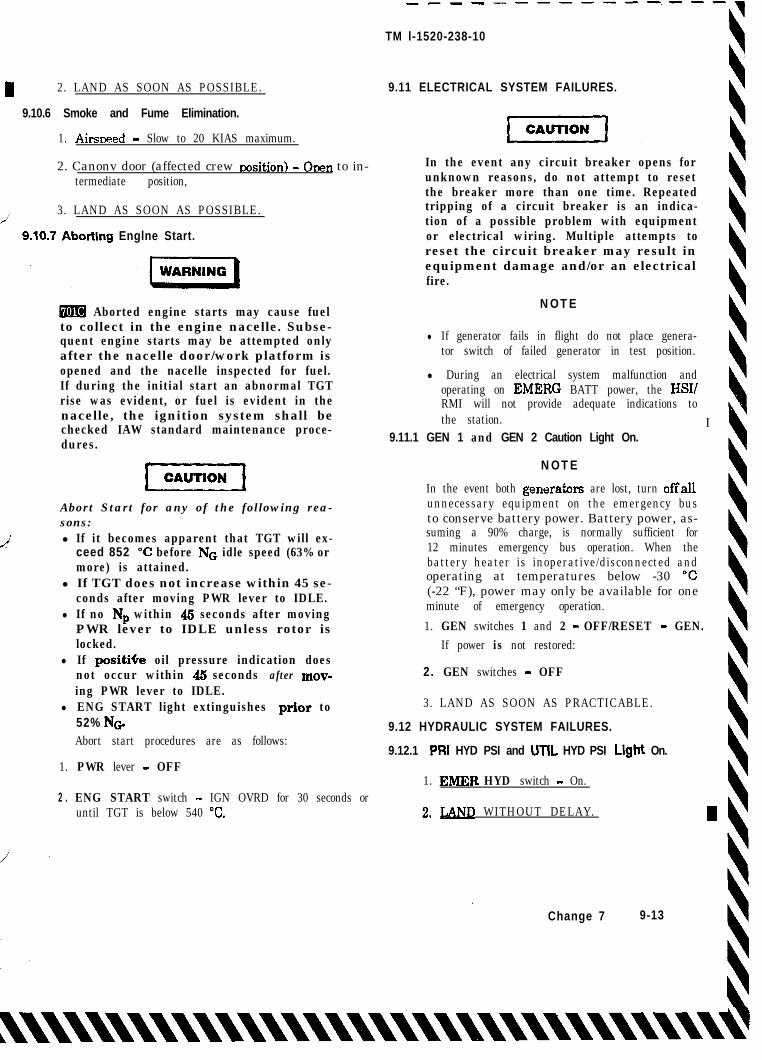
pGq
Abort Start for any of the following rea-sons:
L-J l If it becomes apparent that TGT will ex-ceed 852 “C before NG idle speed (63% ormore) is attained.
l If TGT does not increase within 45 se-conds after moving PWR lever to IDLE.
l If no Np within 46 seconds after movingPWR lever to IDLE unless rotor islocked.
l If positiGe oil pressure indication doesnot occur within 45 seconds after mov-ing PWR lever to IDLE.
l ENG START light extinguishes prior to52% NG.
I 2. LAND AS SOON AS POSSIBLE.
9.10.6 Smoke and Fume Elimination.
1. Airsneed - Slow to 20 KIAS maximum.
2. Canonv door (affected crew nosition) - Onen to in-termediate position,
/ 3. LAND AS SOON AS POSSIBLE.
9.10.7 Aborting Englne Start.
W Aborted engine starts may cause fuelto collect in the engine nacelle. Subse-quent engine starts may be attempted onlyafter the nacelle door/work platform isopened and the nacelle inspected for fuel.If during the initial start an abnormal TGTrise was evident, or fuel is evident in thenacelle, the ignition system shall bechecked IAW standard maintenance proce-dures.
Abort start procedures are as follows:
1. PWR lever - OFF
2 . ENG START switch - IGN OVRD for 30 seconds oruntil TGT is below 540 “C.
----
TM l-1520-238-10
9.11 ELECTRICAL SYSTEM FAILURES.
In the event any circuit breaker opens forunknown reasons, do not attempt to resetthe breaker more than one time. Repeatedtripping of a circuit breaker is an indica-tion of a possible problem with equipmentor electrical wiring. Multiple attempts toreset the circuit breaker may result inequipment damage and/or an electricalfire.
NOTE
l If generator fails in flight do not place genera-tor switch of failed generator in test position.
l During an electrical system malfunction andoperating on EMERG BATT power, the HSI/RMI will not provide adequate indications tothe station. I
9.11.1 GEN 1 and GEN 2 Caution Light On.
NOTE
In the event both generacars are lost, turn offal1unnecessary equipment on the emergency busto conserve battery power. Battery power, as-suming a 90% charge, is normally sufficient for12 minutes emergency bus operation. When thebattery heater is inoperative/disconnected andoperating at temperatures below -30 “C(-22 “F), power may only be available for oneminute of emergency operation.
1. GEN switches 1 and 2 - OFF/RESET - GEN.If power is not restored:
2. GEN switches - OFF
3. LAND AS SOON AS PRACTICABLE.
9.12 HYDRAULIC SYSTEM FAILURES.
9.12.1 PRI HYD PSI and UTIL HYD PSI Light On.
1. EMSR HYD switch - On.
2. LAND WITHOUT DELAY. I
.Change 7 9-13
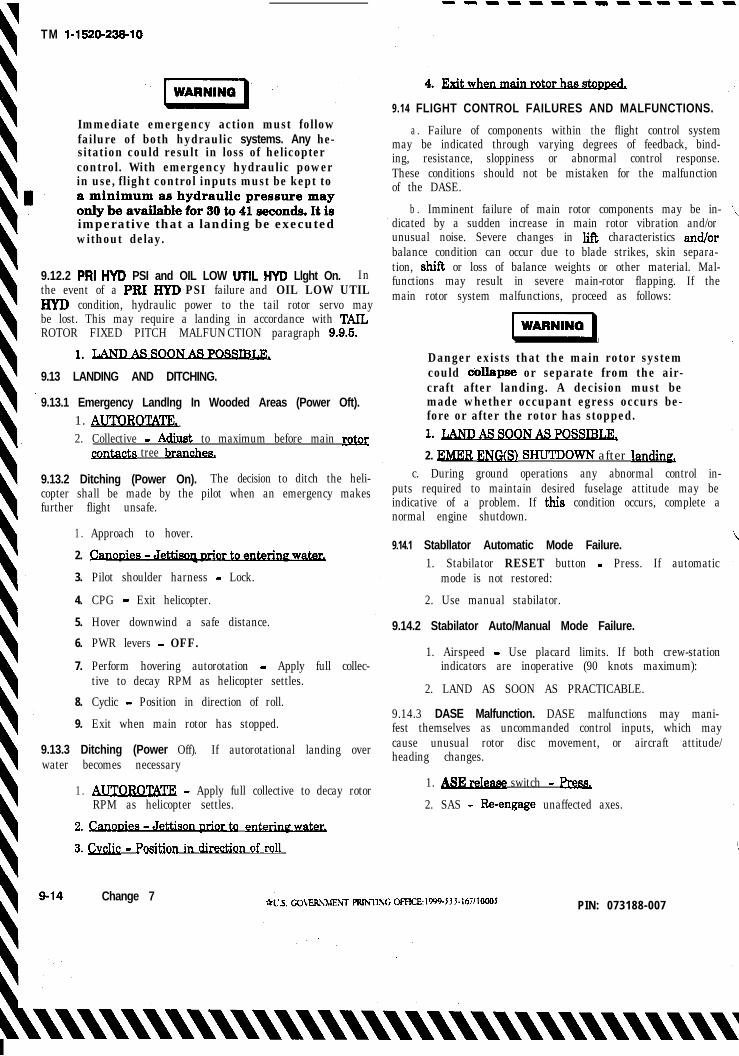
--B----B---B----Y
TM l-1520-23%10
Immediate emergency action must followfailure of both hydraulic systems. Any he-sitation could result in loss of helicoptercontrol. With emergency hydraulic powerin use, flight control inputs must be kept to-
imperative that a landing be executedwithout delay.
9.12.2 PRI HYD PSI and OIL LOW UTIL HYD Llght On. Inthe event of a PRI HYD PSI failure and OIL LOW UTILHYD condition, hydraulic power to the tail rotor servo maybe lost. This may require a landing in accordance with TAILROTOR FIXED PITCH MALFUNCTION paragraph 9..9.5.
1. LAND
9.13 LANDING AND DITCHING.
9.13.1 Emergency Landlng In Wooded Areas (Power Oft).1. AUTOROTATE,2. Collective - Adjust to maximum before main rota
acts tree branches.
9.13.2 Ditching (Power On). The decision to ditch the heli-copter shall be made by the pilot when an emergency makesfurther flight unsafe.
1 .
2.
3.
4.
5.
6.
7.
8.
9.
Approach to hover.
Pilot shoulder harness - Lock.
CPG - Exit helicopter.
Hover downwind a safe distance.
PWR levers - OFF.
Perform hovering autorotation - Apply full collec-tive to decay RPM as helicopter settles.
Cyclic - Position in direction of roll.
Exit when main rotor has stopped.
9.13.3 Ditching (Power Off). If autorotational landing overwater becomes necessary
1 . AIJTOROTm - Apply full collective to decay rotorRPM as helicopter settles.
2. ~oDies-J&tiso&r~ entw
3. &lic - position in d&&on of roll
Change 7
9.14 FLIGHT CONTROL FAILURES AND MALFUNCTIONS.
a . Failure of components within the flight control systemmay be indicated through varying degrees of feedback, bind-ing, resistance, sloppiness or abnormal control response.These conditions should not be mistaken for the malfunctionof the DASE.
b . Imminent failure of main rotor components may be in-dicated by a sudden increase in main rotor vibration and/orunusual noise. Severe changes in lift characteristics and/orbalance condition can occur due to blade strikes, skin separa-tion, shift or loss of balance weights or other material. Mal-functions may result in severe main-rotor flapping. If themain rotor system malfunctions, proceed as follows:
piiii-1
Danger exists that the main rotor systemcould dollapse or separate from the air-craft after landing. A decision must bemade whether occupant egress occurs be-fore or after the rotor has stopped.
1. LAND
2. EMRR ENG(S) SHUTDOWN after la&ng,c. During ground operations any abnormal control in-
puts required to maintain desired fuselage attitude may beindicative of a problem. If this condition occurs, complete anormal engine shutdown.
9.14.1 Stabllator Automatic Mode Failure.1. Stabilator RESET button - Press. If automatic
mode is not restored:
2. Use manual stabilator.
9.14.2 Stabilator Auto/Manual Mode Failure.
1. Airspeed - Use placard limits. If both crew-stationindicators are inoperative (90 knots maximum):
2. LAND AS SOON AS PRACTICABLE.
9.14.3 DASE Malfunction. DASE malfunctions may mani-fest themselves as uncommanded control inputs, which maycause unusual rotor disc movement, or aircraft attitude/heading changes.
1. ASE switch - Prem
2. SAS - &engage unaffected axes.
PIN: 073188-007
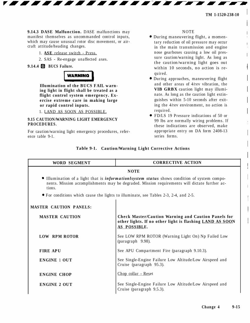
9.14.3 DASE Malfunction. DASE malfunctions maymanifest themselves as uncommanded control inputs,which may cause unusual rotor disc movement, or air-craft attitude/heading changes.
1. ASE release switch - Press.2. SAS - Re-engage unaffected axes.
9.14.4 BUCS Failure.
Illumination of the BUCS FAIL warn-ing light in flight shall be treated as aflight control system emergency. Ex-ercise extreme care in making largeor rapid control inputs.1. LAND AS SOON AS POSSIBLE,
9.15 CAUTION/WARNING LIGHT EMERGENCYPROCEDURES.
For caution/warning light emergency procedures, refer-ence table 9-1.
TM 1-1520-238-10
NOTEDuring maneuvering flight, a momen-tary reduction of oil pressure may occurin the main transmission and enginenose gearboxes causing a low oil pres-sure caution/warning light. As long asthe caution/warning light goes outwithin 10 seconds, no action is re-quired.During approaches, maneuvering flightand other areas of 4/rev vibration, theVIB GRBX caution light may illumi-nate. As long as the caution light extin-guishes within 5-10 seconds after exit-ing the 4/rev environment, no action isrequired.
FD/LS 19 Pressure indications of 50 or99 lbs are normally wiring problems. Ifthese indications are observed, makeappropriate entry on DA form 2408-13series forms.
Table 9-1. Caution/Warning Light Corrective Actions
WORD SEGMENT CORRECTIVE ACTION
NOTE
Illumination of a light that is informationlsystem status shows condition of system compo-nents. Mission accomplishments may be degraded. Mission requirements will dictate further ac-tions.
For conditions which cause the lights to illuminate, see Tables 2-3, 2-4, and 2-5.
MASTER CAUTION PANELS:
MASTER CAUTION
LOW RPM ROTOR
FIRE APU
ENGINE 1 OUT
ENGINE CHOP
ENGINE 2 OUT
Check Master/Caution Warning and Caution Panels forother lights. If no other light is flashing LAND AS SOONAS POSSIBLE.
See LOW RPM ROTOR (Warning Light On) Np Failed Low(paragraph 9.98).
See APU Compartment Fire (paragraph 9.10.3).
See Single-Engine Failure Low Altitude/Low Airspeed andCruise (paragraph 95.3).
See Single-Engine Failure Low Altitude/Low Airspeed andCruise (paragraph 9.5.3).
Change 4 9-15
Chop collar - Reset
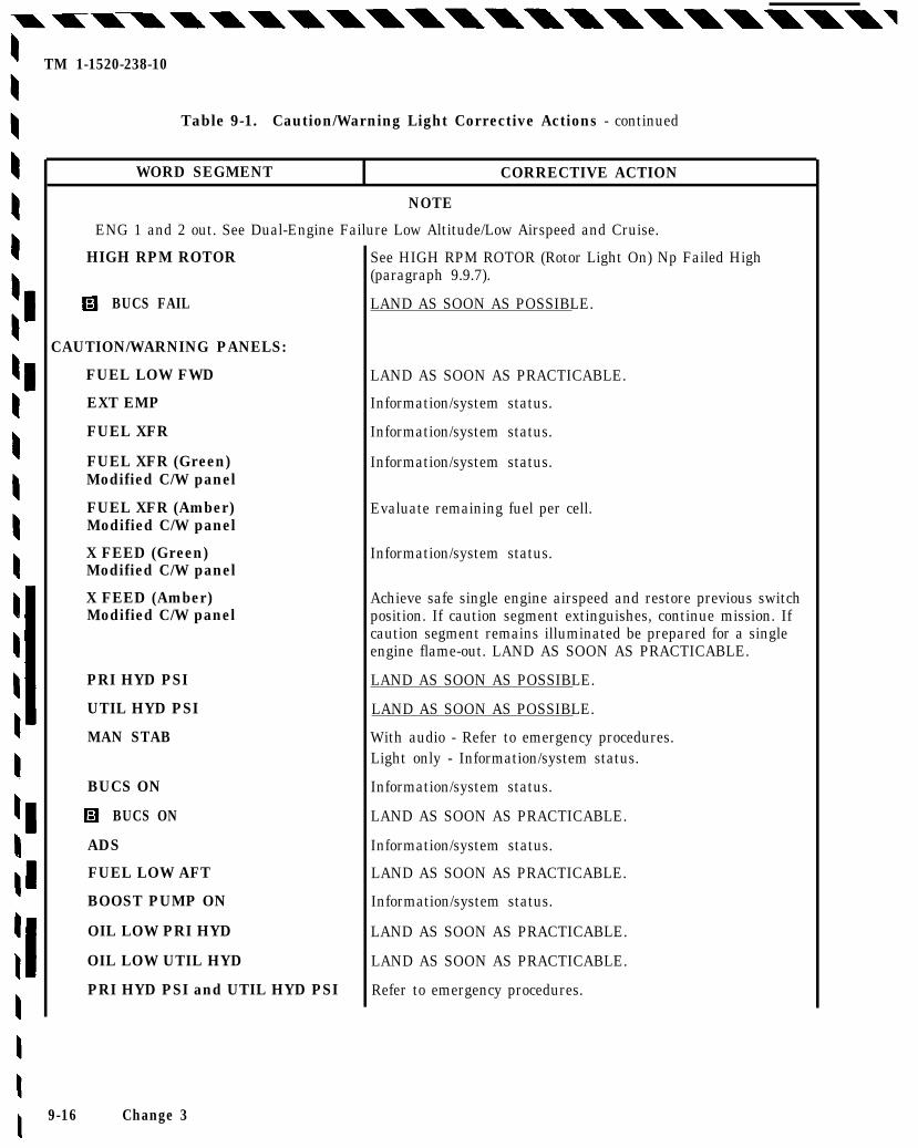
TM 1-1520-238-10
Table 9-1. Caution/Warning Light Corrective Actions - continued
WORD SEGMENT CORRECTIVE ACTION
NOTE
ENG 1 and 2 out. See Dual-Engine Failure Low Altitude/Low Airspeed and Cruise.
HIGH RPM ROTOR See HIGH RPM ROTOR (Rotor Light On) Np Failed High(paragraph 9.9.7).
BUCS FAIL
CAUTION/WARNING PANELS:
FUEL LOW FWD
EXT EMP
FUEL XFR
FUEL XFR (Green)Modified C/W panel
FUEL XFR (Amber)Modified C/W panel
X FEED (Green)Modified C/W panel
X FEED (Amber)Modified C/W panel
PRI HYD PSI
UTIL HYD PSI
MAN STAB
BUCS ON
BUCS ON
ADS
FUEL LOW AFT
BOOST PUMP ON
OIL LOW PRI HYD
OIL LOW UTIL HYD
PRI HYD PSI and UTIL HYD PSI
9-16 Change 3
LAND AS SOON AS POSSIBLE.
LAND AS SOON AS PRACTICABLE.
Information/system status.
Information/system status.
Information/system status.
Evaluate remaining fuel per cell.
Information/system status.
Achieve safe single engine airspeed and restore previous switchposition. If caution segment extinguishes, continue mission. Ifcaution segment remains illuminated be prepared for a singleengine flame-out. LAND AS SOON AS PRACTICABLE.
LAND AS SOON AS POSSIBLE.
LAND AS SOON AS POSSIBLE.
With audio - Refer to emergency procedures.Light only - Information/system status.
Information/system status.
LAND AS SOON AS PRACTICABLE.
Information/system status.
LAND AS SOON AS PRACTICABLE.
Information/system status.
LAND AS SOON AS PRACTICABLE.
LAND AS SOON AS PRACTICABLE.
Refer to emergency procedures.
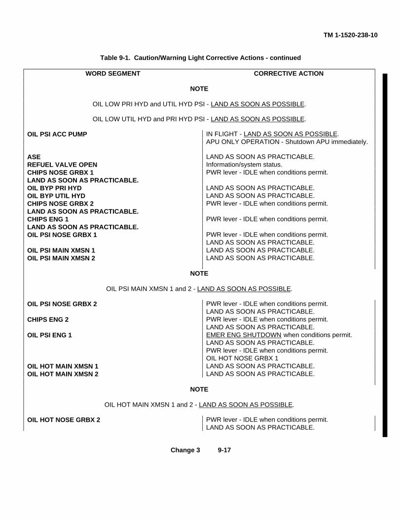
TM 1-1520-238-10
Table 9-1. Caution/Warning Light Corrective Actions - continued
WORD SEGMENT CORRECTIVE ACTION
NOTE
OIL LOW PRI HYD and UTIL HYD PSI - LAND AS SOON AS POSSIBLE.
OIL LOW UTIL HYD and PRI HYD PSI - LAND AS SOON AS POSSIBLE.
OIL PSI ACC PUMP IN FLIGHT - LAND AS SOON AS POSSIBLE.APU ONLY OPERATION - Shutdown APU immediately.
ASE LAND AS SOON AS PRACTICABLE.REFUEL VALVE OPEN Information/system status.CHIPS NOSE GRBX 1 PWR lever - IDLE when conditions permit.LAND AS SOON AS PRACTICABLE.OIL BYP PRI HYD LAND AS SOON AS PRACTICABLE.OIL BYP UTIL HYD LAND AS SOON AS PRACTICABLE.CHIPS NOSE GRBX 2 PWR lever - IDLE when conditions permit.LAND AS SOON AS PRACTICABLE.CHIPS ENG 1 PWR lever - IDLE when conditions permit.LAND AS SOON AS PRACTICABLE.OIL PSI NOSE GRBX 1 PWR lever - IDLE when conditions permit.
LAND AS SOON AS PRACTICABLE.OIL PSI MAIN XMSN 1 LAND AS SOON AS PRACTICABLE.OIL PSI MAIN XMSN 2 LAND AS SOON AS PRACTICABLE.
NOTE
OIL PSI MAIN XMSN 1 and 2 - LAND AS SOON AS POSSIBLE.
OIL PSI NOSE GRBX 2 PWR lever - IDLE when conditions permit.LAND AS SOON AS PRACTICABLE.
CHIPS ENG 2 PWR lever - IDLE when conditions permit.LAND AS SOON AS PRACTICABLE.
OIL PSI ENG 1 EMER ENG SHUTDOWN when conditions permit.LAND AS SOON AS PRACTICABLE.PWR lever - IDLE when conditions permit.OIL HOT NOSE GRBX 1
OIL HOT MAIN XMSN 1 LAND AS SOON AS PRACTICABLE.OIL HOT MAIN XMSN 2 LAND AS SOON AS PRACTICABLE.
NOTE
OIL HOT MAIN XMSN 1 and 2 - LAND AS SOON AS POSSIBLE.
OIL HOT NOSE GRBX 2 PWR lever - IDLE when conditions permit.LAND AS SOON AS PRACTICABLE.
Change 3 9-17
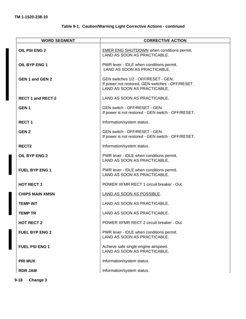
TM 1-1520-238-10
Table 9-1. Caution/Warning Light Corrective Actions - continued
WORD SEGMENT CORRECTIVE ACTION
OIL PSI ENG 2 EMER ENG SHUTDOWN when conditions permit.LAND AS SOON AS PRACTICABLE.
OIL BYP ENG 1 PWR lever - IDLE when conditions permit. LAND AS SOON AS PRACTICABLE.
GEN 1 and GEN 2 GEN switches 1/2 - OFF/RESET - GEN.If power not restored, GEN switches - OFF/RESET.LAND AS SOON AS PRACTICABLE.
RECT 1 and RECT 2 LAND AS SOON AS PRACTICABLE.
GEN 1 GEN switch - OFF/RESET - GEN.If power is not restored - GEN switch - OFF/RESET.
RECT 1 Information/system status.
GEN 2 GEN switch - OFF/RESET - GEN.If power is not restored - GEN switch - OFF/RESET.
RECT2 Information/system status.
OIL BYP ENG 2 PWR lever - IDLE when conditions permit.LAND AS SOON AS PRACTICABLE.
FUEL BYP ENG 1 PWR lever - IDLE when conditions permit.LAND AS SOON AS PRACTICABLE.
HOT RECT 1 POWER XFMR RECT 1 circuit breaker - Out.
CHIPS MAIN XMSN LAND AS SOON AS POSSIBLE.
TEMP INT LAND AS SOON AS PRACTICABLE.
TEMP TR LAND AS SOON AS PRACTICABLE.
HOT RECT 2 POWER XFMR RECT 2 circuit breaker - Out
FUEL BYP ENG 2 PWR lever - IDLE when conditions permit.LAND AS SOON AS PRACTICABLE.
FUEL PSI ENG 1 Achieve safe single-engine airspeed.LAND AS SOON AS PRACTICABLE.
PRI MUX Information/system status.
RDR JAM Information/system status.
9-18 Change 3
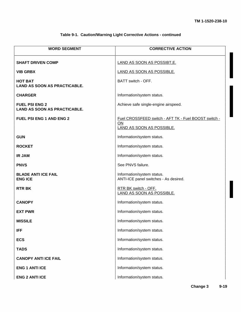
TM 1-1520-238-10
Table 9-1. Caution/Warning Light Corrective Actions - continued
WORD SEGMENT CORRECTIVE ACTION
SHAFT DRIVEN COMP LAND AS SOON AS POSSIBT,E.
VIB GRBX LAND AS SOON AS POSSIBLE.
HOT BAT BATT switch - OFF.LAND AS SOON AS PRACTICABLE.
CHARGER Information/system status.
FUEL PSI ENG 2 Achieve safe single-engine airspeed.LAND AS SOON AS PRACTICABLE.
FUEL PSI ENG 1 AND ENG 2 Fuel CROSSFEED switch - AFT TK - Fuel BOOST switch -ONLAND AS SOON AS POSSIBLE.
GUN Information/system status.
ROCKET Information/system status.
IR JAM Information/system status.
PNVS See PNVS failure.
BLADE ANTI ICE FAIL Information/system status.ENG ICE ANTI-ICE panel switches - As desired.
RTR BK RTR BK switch - OFF.LAND AS SOON AS POSSIBLE.
CANOPY Information/system status.
EXT PWR Information/system status.
MISSILE Information/system status.
IFF Information/system status.
ECS Information/system status.
TADS Information/system status.
CANOPY ANTI ICE FAIL Information/system status.
ENG 1 ANTI ICE Information/system status.
ENG 2 ANTI ICE Information/system status.
Change 3 9-19
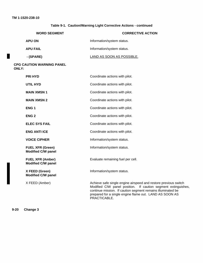
TM 1-1520-238-10
Table 9-1. Caution/Warning Light Corrective Actions - continued
WORD SEGMENT CORRECTIVE ACTION
APU ON Information/system status.
APU FAIL Information/system status.
- (SPARE) LAND AS SOON AS POSSIBLE.
CPG CAUTION WARNING PANELONLY:
PRI HYD Coordinate actions with pilot.
UTIL HYD Coordinate actions with pilot.
MAIN XMSN 1 Coordinate actions with pilot.
MAIN XMSN 2 Coordinate actions with pilot.
ENG 1 Coordinate actions with pilot.
ENG 2 Coordinate actions with pilot.
ELEC SYS FAIL Coordinate actions with pilot.
ENG ANTI ICE Coordinate actions with pilot.
VOICE CIPHER Information/system status.
FUEL XFR (Green) Information/system status.Modified C/W panel
FUEL XFR (Amber) Evaluate remaining fuel per cell.Modified C/W panel
X FEED (Green) Information/system status.Modified C/W panel
X FEED (Amber) Achieve safe single engine airspeed and restore previous switchModified CIW panel position. If caution segment extinguishes,continue mission. If caution segment remains illuminated beprepared for a single engine flame out. LAND AS SOON ASPRACTICABLE.
9-20 Change 3
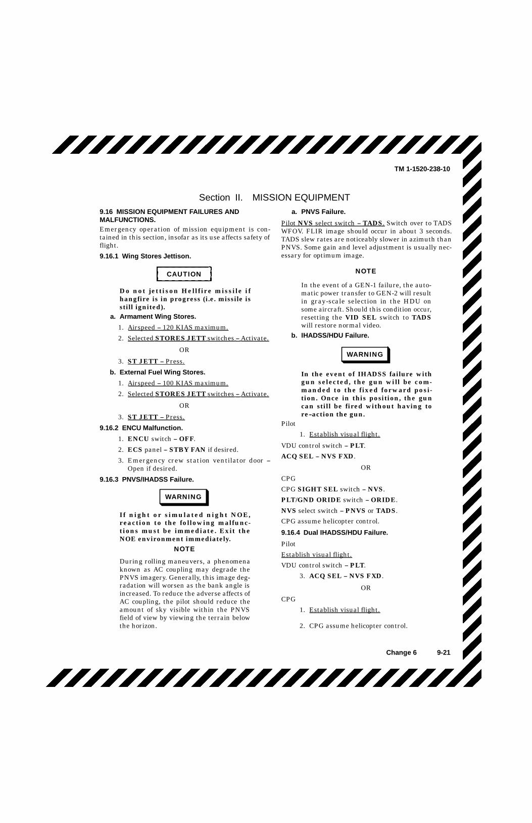
TM 1-1520-238-10
Change 6 9-21
Section II. MISSION EQUIPMENT9.16 MISSION EQUIPMENT FAILURES ANDMALFUNCTIONS.Emergency operation of mission equipment is con-tained in this section, insofar as its use affects safety offlight.
9.16.1 Wing Stores Jettison.
CAUTION
Do not jettison Hellfire missile ifhangfire is in progress (i.e. missile isstill ignited).
a. Armament Wing Stores.
1. Airspeed -- 120 KIAS maximum.
2. Selected STORES JETT switches -- Activate.
OR
3. ST JETT -- Press.
b. External Fuel Wing Stores.
1. Airspeed -- 100 KIAS maximum.
2. Selected STORES JETT switches -- Activate.
OR
3. ST JETT -- Press.
9.16.2 ENCU Malfunction.
1. ENCU switch -- OFF.
2. ECS panel -- STBY FAN if desired.
3. Emergency crew station ventilator door --Open if desired.
9.16.3 PNVS/IHADSS Failure.
WARNING
If night or simulated night NOE,reaction to the following malfunc-tions must be immediate. Exit theNOE environment immediately.
NOTE
During rolling maneuvers, a phenomenaknown as AC coupling may degrade thePNVS imagery. Generally, this image deg-radation will worsen as the bank angle isincreased. To reduce the adverse affects ofAC coupling, the pilot should reduce theamount of sky visible within the PNVSfield of view by viewing the terrain belowthe horizon.
a. PNVS Failure.
Pilot NVS select switch -- TADS. Switch over to TADSWFOV. FLIR image should occur in about 3 seconds.TADS slew rates are noticeably slower in azimuth thanPNVS. Some gain and level adjustment is usually nec-essary for optimum image.
NOTE
In the event of a GEN-1 failure, the auto-matic power transfer to GEN-2 will resultin gray-scale selection in the HDU onsome aircraft. Should this condition occur,resetting the VID SEL switch to TADSwill restore normal video.
b. IHADSS/HDU Failure.
WARNING
In the event of IHADSS failure withgun selected, the gun will be com-manded to the fixed forward posi-tion. Once in this position, the guncan still be fired without having tore--action the gun.
Pilot
1. Establish visual flight.
VDU control switch -- PLT.
ACQ SEL -- NVS FXD.
OR
CPG
CPG SIGHT SEL switch -- NVS.
PLT/GND ORIDE switch -- ORIDE.
NVS select switch -- PNVS or TADS.
CPG assume helicopter control.
9.16.4 Dual IHADSS/HDU Failure.
Pilot
Establish visual flight.
VDU control switch -- PLT.
3. ACQ SEL -- NVS FXD.
OR
CPG
1. Establish visual flight.
2. CPG assume helicopter control.
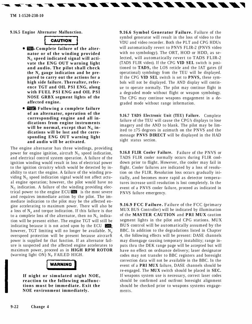
TM 1-1520-238-10
9.16.5 Engine Alternator Malfunction.
Complete failure of the alter-nator or of the winding providedNG speed indicated signal will acti-vate the ENG OUT warning lightand audio. The pilot shall checkthe Nr gauge indication and be pre-pared to carry out the actions for ahigh side failure. Thereafter, refer-ence TGT and OIL PSI ENG, alongwith FUEL PSI ENG and OIL PSINOSE GRBX segment lights of theaffected engine.
Following a complete failureof an alternator, operation of thecorresponding engine and all in-dications from engine instrumentswill be normal, except that NG in-dications will be lost and the corre-sponding ENG OUT warning lightand audio will be activated.
The engine alternator has three windings, providingpower for engine ignition, aircraft NG speed indication,and electrical control system operation. A failure of theignition winding would result in loss of electrical powerto the ignition circuitry which would be detected by in-ability to start the engine. A failure of the winding pro-viding NG speed indication signal would not affect actu-al engine operation; however, the pilot would have noNG indication. A failure of the winding providing elec-trical power to the engine ECU is the most severeand requires immediate action by the pilot. The im-mediate indication to the pilot may be the affected en-gine accelerating to maximum power. There will also bea loss of Np and torque indication. If this failure is dueto a complete loss of the alternator, then no NG indica-tion will be present either. The engine TGT will still beindicating because it is not acted upon by the ECUhowever, TGT limiting will no longer be available. Npoverspeed protection will be present because aircrarftpower is supplied for that function. If an alternator fail-ure is suspected and the affected engine accelerates tomaximum power, proceed as in HIGH RPM ROTOR(warning light ON) NP FAILED HIGH.
If night or simulated night NOE,reaction to the following malfunc-tions must be immediate. Exit theNOE environment immediately.
9-22 Change 4
9.16.6 Symbol Generator Failure. Failure of thesymbol generator will result in the loss of video to theVDU and video recorder. Both the PLT and CPG HDUswill automatically revert to PNVS FLIR-2 (PNVS videowith no symbology). The ORT, HOD or HDD, as se-lected, will automatically revert to TADS FLIR-2(TADS FLIR video). If the CPG VID SEL switch is posi-tioned to TADS, the LOS reticle and the IAT gates (ifoperational) symbology from the TEU will be displayed.If the CPG VID SEL switch is set to PNVS, these sym-bols will not be displayed. The AND display will contin-ue to operate normally. The pilot may continue flight ina degraded mode without flight or weapon symbology.The CPG may continue weapons engagement in a de-graded mode without range information.
9.16.7 TADS Electronic Unit (TEU) Failure. Completefailure of the TEU will cause the CPG’s displays to loseimagery and the AND to blank. The pilot may be lim-ited to ±75 degrees in azimuth on the PNVS and themessage PNVS DIRECT will be displayed in the HADsight status section.
9.16.8 FLIR Cooler Failure. Failure of the PNVS orTADS FLIR cooler normally occurs during FLIR cool-down prior to flight. However, the cooler may fail inflight. Cooler failures are indicated by a loss of resolu-tion on the FLIR. Resolution loss occurs gradually ini-tially, and becomes more rapid as detector tempera-tures increase until resolution is lost completely. In theevent of a PNVS cooler failure, proceed as indicated inPNVS failure emergency.
9.16.9 FCC Failure. Failure of the FCC (primaryMUX BUS Controller) will be indicated by illuminationof the MASTER CAUTION and PRI MUX cautionsegment lights in the pilot and CPG stations. MUXBUS control will be automatically assumed by theBBC. In addition to the degradations listed in Chapter4, the following effects will be present: DASE channelsmay disengage causing temporary instability; range in-puts thru the DEK range page will be accepted but willhave no effect on ordnance delivery; laser designatorcodes may not transfer to BBC registers and boresightcorrection data will not be available in the BBC. In theevent of a PRI MUX failure, DASE channels should bere-engaged. The MUX switch should be placed in SEC.If weapons system use is necessary, correct laser codesshould be confirmed and outfront boresight alignmentshould be checked prior to weapons systems engage-ments.
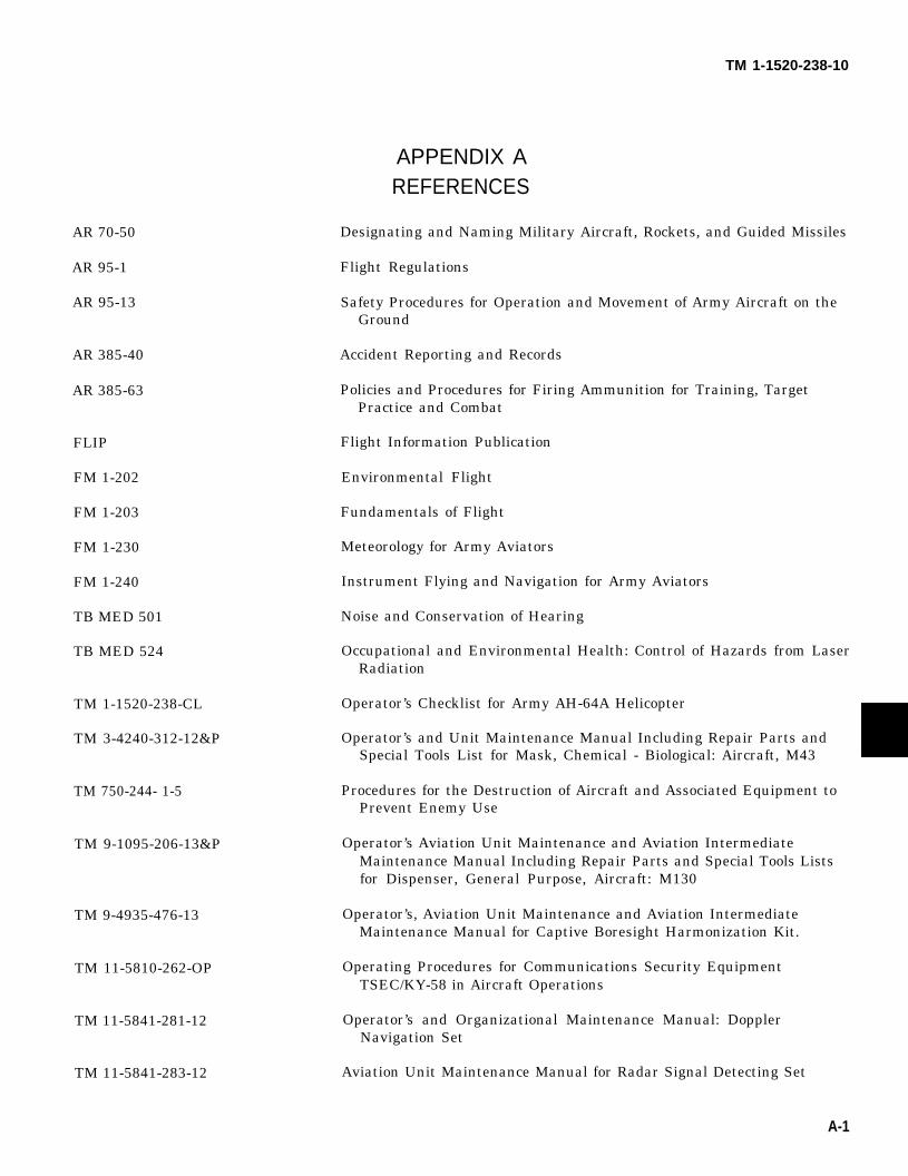
TM 1-1520-238-10
APPENDIX AREFERENCES
AR 70-50
AR 95-1
AR 95-13
AR 385-40
AR 385-63
FLIP
FM 1-202
FM 1-203
FM 1-230
FM 1-240
TB MED 501
TB MED 524
TM 1-1520-238-CL
TM 3-4240-312-12&P
TM 750-244- 1-5
TM 9-1095-206-13&P
TM 9-4935-476-13
TM 11-5810-262-OP
TM 11-5841-281-12
TM 11-5841-283-12
Designating and Naming Military Aircraft, Rockets, and Guided Missiles
Flight Regulations
Safety Procedures for Operation and Movement of Army Aircraft on theGround
Accident Reporting and Records
Policies and Procedures for Firing Ammunition for Training, TargetPractice and Combat
Flight Information Publication
Environmental Flight
Fundamentals of Flight
Meteorology for Army Aviators
Instrument Flying and Navigation for Army Aviators
Noise and Conservation of Hearing
Occupational and Environmental Health: Control of Hazards from LaserRadiation
Operator’s Checklist for Army AH-64A Helicopter
Operator’s and Unit Maintenance Manual Including Repair Parts andSpecial Tools List for Mask, Chemical - Biological: Aircraft, M43
Procedures for the Destruction of Aircraft and Associated Equipment toPrevent Enemy Use
Operator’s Aviation Unit Maintenance and Aviation IntermediateMaintenance Manual Including Repair Parts and Special Tools Listsfor Dispenser, General Purpose, Aircraft: M130
Operator’s, Aviation Unit Maintenance and Aviation IntermediateMaintenance Manual for Captive Boresight Harmonization Kit.
Operating Procedures for Communications Security EquipmentTSEC/KY-58 in Aircraft Operations
Operator’s and Organizational Maintenance Manual: DopplerNavigation Set
Aviation Unit Maintenance Manual for Radar Signal Detecting Set
A-1

TM 1-1520-238-10
TM 11-5841 -294-30-2
TM 11-5865-200-12
TM 11-5895-1199-12
TM 55-1500-342-23
TM 55-2840-248-23
TM 55-6600-200-20
TM 55-9150-200-25
Aviation Intermediate Maintenance Manual for Radar Signal DetectingSet. AN/APR-39(V).
Operator’s and Aviation Unit Maintenance Manual Aviation UnitMaintenance (AVUM) Countermeasures Sets
Operator’s and Organizational Maintenance for Mark-XII IFF System
Army Aviation Maintenance Engineering Manual: Weight and Balance
Aviation Unit and Intermediate Maintenance Instructions. Engine,Aircraft Turboshaft, Models T700-GE-700, T700-GE-701, andT700-GE-701C.
Marking of Instruments and Interpretation of Markings
Engine and Transmission Oils, Fuels, and Additives for Army Aircraft
A-2

APPENDIX BABBREVIATIONS AND TERMS
SYMBOLS
* Used as a decimal
°C Degrees Celsius
°F Degrees Fahrenheit
AF Change in Frontal Area
AQ Torque change for AF of 5 sq. ft.
A
A Ampere
AH Attack Helicopter
AC, ac Alternating Current
A/C Aircraft
ACC Accumulator
ACM Auto Control Module
ACQ Acquire
ACT, ACTN Action
ADF Automatic Direction Finder
ADMIN Administration
ADS Air Data Sensor
AGL Above Ground Level
ALT Altimeter
AM Amplitude Modulation
AMMO Ammunition
AMP Ampere
AND Alphanumeric Display
Change 3 B-1

TM 1-1520-238-10
Appendix B - Abbreviations and Terms (cont)
ANT Antenna
ANTI COL Anticollision
APU Auxiliary Power Unit
ARCS Aerial Rocket Control System
ATTD Attitude
AUTO Automatic
AUX Auxiliary
AVAIL Available
AWS Area Weapon System
AZ Azimuth
B
BATT (or BAT) Battery
BITE Built-in Test Equipment
BRK Brake
BL Blade (rotor)
BNK Bunker
BOT Beginning of Tape
BRG Bearing
BRK Brake
BRSIT Boresight
BRT Bright (switch position)
BRU Boresight Reticle Unit
BST Boost
BST Boresight
BTL Bottle (fire extinguisher)
BUCS Backup Control System
BYP Bypass
B-2 Change 3

TM 1-1520-238-10Appendix B - Abbreviations and Terms (cont)
C
C Celsius
CAN Canopy
CAS Command Augmentation System
CAUT Caution
CBHK Captive Boresight Harmonization Kit
CDU Computer Display Unit
CG, cg Center of Gravity
CHK Check
CHRGR Charger (battery)
CK Check
CKT Circuit
CL Clear
CM, cm Centimeter
CMD Command
CNTST Contrast
CNV Crypto-Net Variables
COL Collision
COLL, coll Collective
COMM Communication
COMM CONT Communication Control
COMP Compressor, Compass
CONT Continuous, Control
COORD Coordinate
CPG Copilot/Gunner
CRS Course
CRT Cathode Ray Tube
Change 3 B-3
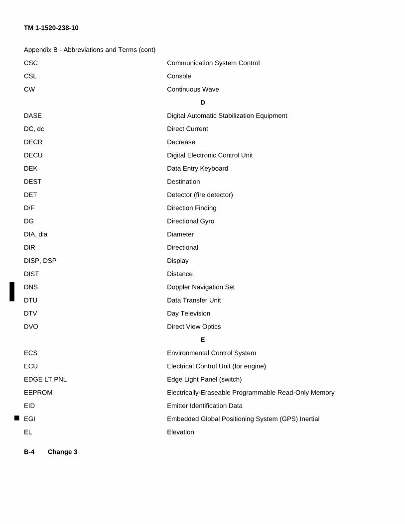
TM 1-1520-238-10
Appendix B - Abbreviations and Terms (cont)
CSC Communication System Control
CSL Console
CW Continuous Wave
D
DASE Digital Automatic Stabilization Equipment
DC, dc Direct Current
DECR Decrease
DECU Digital Electronic Control Unit
DEK Data Entry Keyboard
DEST Destination
DET Detector (fire detector)
D/F Direction Finding
DG Directional Gyro
DIA, dia Diameter
DIR Directional
DISP, DSP Display
DIST Distance
DNS Doppler Navigation Set
DTU Data Transfer Unit
DTV Day Television
DVO Direct View Optics
E
ECS Environmental Control System
ECU Electrical Control Unit (for engine)
EDGE LT PNL Edge Light Panel (switch)
EEPROM Electrically-Eraseable Programmable Read-Only Memory
EID Emitter Identification Data
EGI Embedded Global Positioning System (GPS) Inertial
EL Elevation
B-4 Change 3

TM 1-1520-238-10
Appendix B - Abbreviations and Terms (cont)
ELEC, ELECT Electrical, Electric
ELEV Elevation
ELEX Electronics
EMER Emergency
EMERG Emergency
EN, ENT Enter, Entry
ENCU Environmental Control Unit
END Endurance
ENG Engine
ENG CUT Engine cut
ENG INST Engine Instrument (lighting)
ENS Environment Control System
ESS Essential
EXT Extend, External, Extinguisher
EXT LTS External Lights
EXT-RET Extend, Retract
EXT TK External Tank, Auxiliary Fuel Tank
F
FAB Fixed Action Button
FAB Forward Avionics Bay
FAT Free Air Temperature
FCC (AC) Fire Control Computer
FCS Fire Control System
FD/LS Fault Detection and Location System
FFAR Folding-fin Aerial Rocket
FIRE BTL Fire Bottle
FLIR Forward Looking Infrared
FLPN Flight Planning
Change 3 B-5

TM 1-1520-238-10
Appendix B - Abbreviations and Terms (cont)
FLT INST
FLTR
FM
FOC
FOD
FORM LT
FOV
FRL
FT, ft
FT/MIN
FTR
FWD
FXD
G, g
GEN
GND
GPM, gpm
GRB, GRBX
GRWT
GS
GSE
GUN MTR
GW
Flight Instrument (lighting)
Filter
Frequency Modulation
Focus
Foreign Object Damage
Formation Light
Field of View
Fuselage Reference Line
Foot, Feet
Feet per Minute
Filter
Forward
Fixed
G
Gravity
Generator
Ground
Gallons per Minute
Gearbox
Gross Weight
Ground Speed, Gray Scale
Ground Support Equipment
Gun Motor
Gross Weight
B-6

TM 1-1520-238-10
Appendix B - Abbreviations and Terms (cont)
H
H Home
HAD High Action Display
HARS Heading and Attitude Reference System (set)
HAS Hover Augmentation System
HBCM Hover Bias Calibration Mode
HDG Heading, Heading Set
HE High Explosive
HF High Frequency, Hellfire
HIGE Hover In Ground Effect
HIT Health Indicator Test
HMD Helmet-Mounted Display
HMMS Hellfire Module Missile System
HMS Helmet-Mounted Sight
HMU Hydromechanical Unit
HOGE Hover Out of Ground Effect
HOV Hover
HSI Horizontal Situation Indicator
HSP Hot Start Preventor
HT Heat, Heater, Height
HTR Heater
HYD Hydraulic
Hz Hertz
I
IAS Indicated Airspeed
ICS Intercommunication System, Internal Communication System
IDENT Identification
Change 3 B-7

TM 1-1520-238-10
Appendix B - Abbreviations and Terms (cont)
IFF
IFR
IGE
IGN
IHADSS
IMC
INBD
INCR
IND
INST, INSTR
INTMD
INTR LTS
IP, I/P
IPAS
IR
IRIS
IR JMR
IRP
JETT
JMR
KG, kg
KHz
KIAS
KTAS
Identification Friend or Foe (transponder)
Instrument Flight Rules
In Ground Effect
Ignition
Integrated Helmet and Display Sight System
Instrument Meteorological Conditions
Inboard
Increase
Indicator
Instrument
Intermediate
Interior Lights
Identification of Position
Integrated Pressurized Air System
Infrared
Infrared Imaging Seeker
Infrared Jammer
Intermediate Rated Power
J
Jettison
Jammer
K
Kilogram
Kilohertz
Knots, Indicated Airspeed
Knots, True Airspeed
B-8

TM 1-1520-238-10
Appendix B - Abbreviations and Terms (cont)
KVA, kva Kilovolt Ampere
KYBD Keyboard
L
L
LAT
LB
LB/HR
LCHR
LCF
LDG
LDGLT
LDNS
LDS
LF
LH
LOAL
LOBL
LONG
LOS
LRF/D
LRU
LSR
LT
LTS
LVDT
LVR
Left
Latitude
Pound
Pounds per Hour
Launcher
Low Cycle Fatigue
Landing
Landing Light
Lightweight Doppler Navigation System
Load Demand Spindle
Low Frequency
Lefthand
Lock On After Launch
Lock On Before Launch
Longitude
Line Of Sight
Laser Range Finder Designator
Line Replaceable Unit
Laser
Light, Laser Tracker
Lights
Linear Variable Differential Transducer (position sensor)
Lever
B-9

TM 1-1520-238-10
Appendix B - Abbreviations and Terms (cont)
M
M, m
MAL
MAN
M A X
MCP
MEM
MHz
mHz
MIC
MIKE
MIN
MLG
MM, mm
MON
MRP
MRTU
M/R
MSL
MTR
MUX
M230E1
NAV
NAV LT
NDB
Meter
Malfunction
Manual
Maximum
Maximum Continuous Power
Memory
Megahertz
Millihertz
Microphone
Microphone
Minimum, Minutes
Main Landing Gear
Millimeter
Monitor
Maximum Rated Power
Multiplex Remote Terminal Unit
Main Rotor
Missile, Mean Sea Level
Motor
Multiplexer, Multiplex
30mm Gun
N
Navigation
Navigation Light
Nondirectional Beacon
B-10

TM 1-1520-238-10
Appendix B - Abbreviations and Terms (cont)
NFOV Narrow Field of View
NG, NG Engine Gas Generator Speed
NM Nautical Mile
NOE Nap Of the Earth
NP, Np Engine Power Turbine Speed
NR, Nr Main Rotor Speed
NRML, NORM Normal
NVS Night Vision System
0
OAT Outside Air Temperature
ODV Overspeed and Drain Valve
OEI One Engine Inoperative
OFP Operational Flight Program
OFS Offset
OGE Out of Ground Effect
OI Optical Improvement
OPR Operator
ORT Optical Relay Tube
OTBD Outboard
Overtemp Overtemperature
ORIDE Override
OVSP Overspeed
P
para Paragraph
PAS Pressurized Air System, Power Available Spindle
PCT Percent
PEN Penetration
Change 3 B-11

TM 1-1520-238-10
Appendix B - Abbreviations and Terms (cont)
PGM Program
PLT Pilot
PNL Panel
PNVS Pilots Night Vision System
PP Present Position
ppm Pounds per Minute
PRES, PRESS Pressure
PRI Primary
PSI, psi Pounds per Square Inch
PSID Pounds per Square Inch Delta
PSIG, psig Pounds per Square Inch Gage
PTO Power Takeoff
PWR Power
PYL Pylon
Q
Q Torque
QTY Quantity
R
R Right, Red
RAD Radio, Radar
RAD ALT Radar Altimeter
RAI Remote Attitude Indicator
R/C Rate of Climb
RCDR Recorder
RCVR Receiver
RDR Radar
READ Read Page
RNDS Rounds
B-12 Change 3

TM 1-1520-238-10
Appendix B - Abbreviations and Terms (cont)
REC
RECT
REF
REL
REM
RES
RET, RETR
RETRAN
RF
RH
RHE
RIPL
RKT
RMI
RNG
RPM, rpm
RTR
RTR BK
RTR BL
RTSS
Recorder
Rectifier, Transformer-Rectifier
Reference
Release
Remote
Reserve
Retract
Retransmit
Radio Frequency
Righthand
Remote Hellfire Electronics
Ripple
Rocket
Radio Magnetic Indicator
Range
Revolutions per Minute
Rotor
Rotor Brake
Rotor Blade
Radio Transmitter Select System
S
SAS Stability Augmentation Subsystem
SCAS Stability and Command Augmentation System
SCL Scale
SDC Shaft Driven Compressor
SDD Selectable Digital Display
B-13

TM 1-1520-238-10
Appendix B - Abbreviations and Terms (cont)
SEC
SEL
SEU
SG
SHP
SKR
SL
SN
SPAD(S)
SPH
SQ
SQ FT, sq ft
SCHLT
SRCH PWR
ST
STA, STN
STAB
STBY
STBY ATT
STD
STR
STRS
SYM GEN
SYS
Secondary
Select
Sight Electronics Unit
Symbol Generator
Shaft Horsepower
Seeker
Sea Level
Serial Number
Shear-pin-actuated Decoupler (system)
Spheroid
Super Quick
Square Foot, Square Feet
Searchlight
Searchlight Power
Stores
Station
Stabilizer, Stabilator
Standby
Standby Attitude
Standard
Storage, Store
Stores
Symbol Generator
System
B-14

TM 1-1520-238-10
Appendix B - Abbreviations and Terms (cant)
T
T1, T2 Test patterns 1 and 2
T4.5 Five-probe harness measuring gas temperature at power turbine inlet
TADS Target Acquisition Designation System
TAS True Airspeed
TBD To Be Determined
TBS To Be Supplied
TEMP Temperature
TGT Turbine Gas Temperature, Target
TGT Target
TK Tank, Track
TK SEL Tank Select (switch)
TKE Tracking Angle Error
TLG Tail Landing Gear
TNK Tank
T/R Transmitter-receiver, Transmit-receive,Transformer-rectifier
TRANS Transfer
TST Test
U
UHF Ultra-high Frequency
UTL Utility
UTM Universal Transverse Mercator
Change 3 B-15

TM 1-1520-238-10
Appendix B - Abbreviations and Terms (cent)
V
V, v Volt
VAB Variable Action Button
VAC, vac Volts Alternating Current
VAR Variation, Variable
VDC, vdc Volts Direct Current
VDU Video Display Unit
VHF Very High Frequency
VID Video
VID RCDR Video Recorder
Vne, VNE Velocity, Never Exceed (airspeed limit)
VOL Volume
VROC Vertical Rate of Climb
VSI Vertical Speed Indicator
VSWR Voltage Standing Wave Ratio
W
W Watt
WAS Weapon Action Select
WE Weight Empty
WHL Wheel
WHT White (Switch position)
WPN Weapon
WPT Waypoint
WRP Wiper (windshield)
WSHLD Windshield
WSHLD WPR Windshield Wiper
WSPS Wire Striker Protection System
B-16 Change 3

TM 1-1520-238-10
Appendix B - Abbreviations and Terms (cont)
X
XFEED
XFER
XMSN
XTK
Y
Crossfeed
Transfer
Transmission
Crosstrack
Yellow
Y
Z
B-17/(B-18 blank)

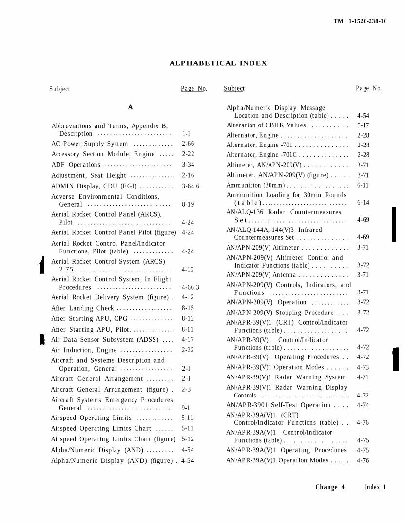
TM 1-1520-238-10
ALPHABETICAL INDEX
Subject Page No. Subject Page No.
A
Abbreviations and Terms, Appendix B,Description . . . . . . . . . . . . . . . . . . . . . . . . 1-1
AC Power Supply System . . . . . . . . . . . . . 2-66
Accessory Section Module, Engine . . . . . 2-22
ADF Operations . . . . . . . . . . . . . . . . . . . . . . 3-34
Adjustment, Seat Height . . . . . . . . . . . . . . 2-16
ADMIN Display, CDU (EGI) . . . . . . . . . . . 3-64.6
Adverse Environmental Conditions,General . . . . . . . . . . . . . . . . . . . . . . . . . . . 8-19
Aerial Rocket Control Panel (ARCS),Pilot . . . . . . . . . . . . . . . . . . . . . . . . . . . . . . 4-24
Aerial Rocket Control Panel Pilot (figure) 4-24
Aerial Rocket Control Panel/IndicatorFunctions, Pilot (table) . . . . . . . . . . . . . 4-24
Aerial Rocket Control System (ARCS)2.75.. . . . . . . . . . . . . . . . . . . . . . . . . . . . . . 4-12
Aerial Rocket Control System, In FlightProcedures . . . . . . . . . . . . . . . . . . . . . . . . 4-66.3
Aerial Rocket Delivery System (figure) . 4-12
After Landing Check . . . . . . . . . . . . . . . . . . 8-15
After Starting APU, CPG . . . . . . . . . . . . . . 8-12
After Starting APU, Pilot. . . . . . . . . . . . . . 8-11
Air Data Sensor Subsystem (ADSS) . . . . 4-17
Air Induction, Engine . . . . . . . . . . . . . . . . . 2-22
Aircraft and Systems Description andOperation, General . . . . . . . . . . . . . . . . . 2-l
Aircraft General Arrangement . . . . . . . . . 2-l
Aircraft General Arrangement (figure) . 2-3
Aircraft Systems Emergency Procedures,General . . . . . . . . . . . . . . . . . . . . . . . . . . . 9-1
Airspeed Operating Limits . . . . . . . . . . . . 5-11
Airspeed Operating Limits Chart . . . . . . 5-11
Airspeed Operating Limits Chart (figure) 5-12
Alpha/Numeric Display (AND) . . . . . . . . . 4-54
Alpha/Numeric Display (AND) (figure) . 4-54
Alpha/Numeric Display MessageLocation and Description (table) . . . . . 4-54
Alteration of CBHK Values . . . . . . . . . . . 5-17Alternator, Engine . . . . . . . . . . . . . . . . . . . . 2-28Alternator, Engine -701 . . . . . . . . . . . . . . . 2-28Alternator, Engine -701C . . . . . . . . . . . . . . 2-28Altimeter, AN/APN-209(V) . . . . . . . . . . . . 3-71Altimeter, AN/APN-209(V) (figure) . . . . . 3-71
6-11
6-14
4-69
4-693-71
Ammunition (30mm) . . . . . . . . . . . . . . . . . .Ammunition Loading for 30mm Rounds
( t a b l e ) . . . . . . . . . . . . . . . . . . . . . . . . . . . . .AN/ALQ-136 Radar Countermeasures
S e t . . . . . . . . . . . . . . . . . . . . . . . . . . . . . . . .AN/ALQ-144A,-144(V)3 Infrared
Countermeasures Set . . . . . . . . . . . . . . .AN/APN-209(V) Altimeter . . . . . . . . . . . . .
AN/APN-209(V) Altimeter Control andIndicator Functions (table) . . . . . . . . . .
AN/APN-209(V) Antenna . . . . . . . . . . . . . .AN/APN-209(V) Controls, Indicators, and
Functions . . . . . . . . . . . . . . . . . . . . . . . . .AN/APN-209(V) Operation . . . . . . . . . . . .
AN/APN-209(V) Stopping Procedure . . .AN/APR-39(V)1 (CRT) Control/Indicator
Functions (table) . . . . . . . . . . . . . . . . . . .AN/APR-39(V)1 Control/Indicator
Functions (table) . . . . . . . . . . . . . . . . . . .AN/APR-39(V)1 Operating Procedures . .
3-723-71
3-713-72
3-72
4-72
4-724-72
AN/APR-39(V)1 Operation Modes . . . . . . 4-73AN/APR-39(V)1 Radar Warning System 4-71
AN/APR-39(V)1 Radar Warning DisplayControls . . . . . . . . . . . . . . . . . . . . . . . . . . . 4-72
AN/APR-3901 Self-Test Operation . . . . 4-74AN/APR-39A(V)1 (CRT)
Control/Indicator Functions (table) . . 4-76AN/APR-39A(V)1 Control/Indicator
Functions (table) . . . . . . . . . . . . . . . . . . . 4-75AN/APR-39A(V)1 Operating Procedures 4-75AN/APR-39A(V)1 Operation Modes . . . . . 4-76
Change 4 Index 1
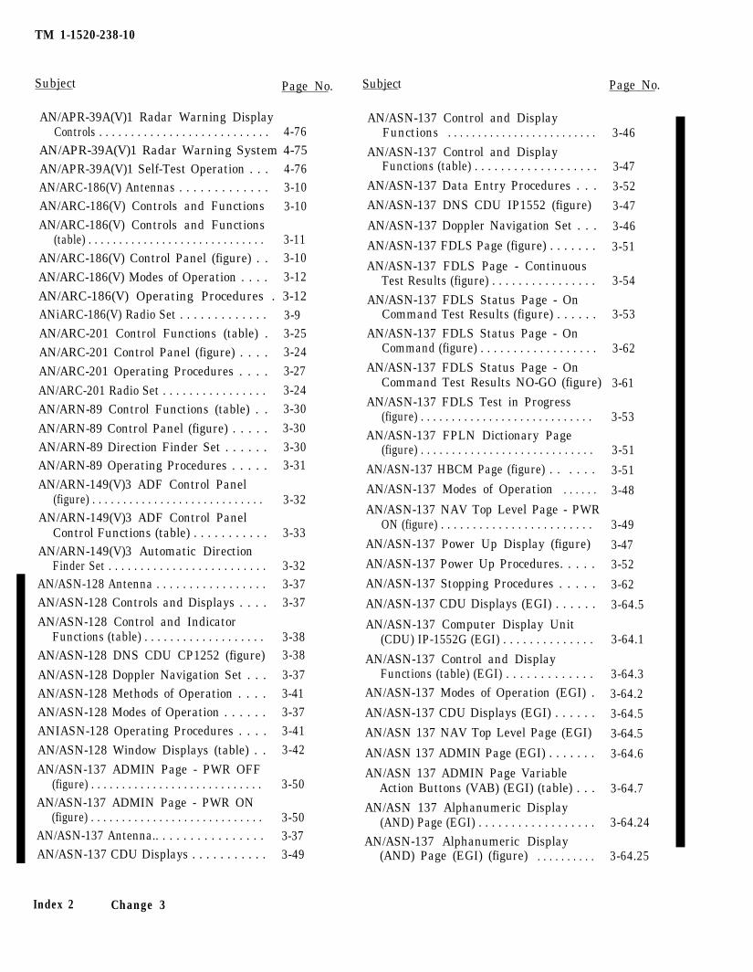
TM 1-1520-238-10
Subject Page No.
AN/APR-39A(V)1 Radar Warning DisplayControls . . . . . . . . . . . . . . . . . . . . . . . . . . . 4-76
AN/APR-39A(V)1 Radar Warning System 4-75AN/APR-39A(V)1 Self-Test Operation . . . 4-76AN/ARC-186(V) Antennas . . . . . . . . . . . . . 3-10AN/ARC-186(V) Controls and Functions 3-10AN/ARC-186(V) Controls and Functions
(table) . . . . . . . . . . . . . . . . . . . . . . . . . . . . . 3-11AN/ARC-186(V) Control Panel (figure) . . 3-10
AN/ARC-186(V) Modes of Operation . . . . 3-12
AN/ARC-186(V) Operating Procedures . 3-12ANiARC-186(V) Radio Set . . . . . . . . . . . . . 3-9AN/ARC-201 Control Functions (table) . 3-25AN/ARC-201 Control Panel (figure) . . . . 3-24
AN/ARC-201 Operating Procedures . . . . 3-27
AN/ARC-201 Radio Set . . . . . . . . . . . . . . . . 3-24AN/ARN-89 Control Functions (table) . . 3-30
AN/ARN-89 Control Panel (figure) . . . . . 3-30AN/ARN-89 Direction Finder Set . . . . . . 3-30AN/ARN-89 Operating Procedures . . . . . 3-31
AN/ARN-149(V)3 ADF Control Panel(figure) . . . . . . . . . . . . . . . . . . . . . . . . . . . . 3-32
AN/ARN-149(V)3 ADF Control PanelControl Functions (table) . . . . . . . . . . . 3-33
AN/ARN-149(V)3 Automatic DirectionFinder Set . . . . . . . . . . . . . . . . . . . . . . . . . 3-32
AN/ASN-128 Antenna . . . . . . . . . . . . . . . . . 3-37AN/ASN-128 Controls and Displays . . . . 3-37
AN/ASN-128 Control and IndicatorFunctions (table) . . . . . . . . . . . . . . . . . . . 3-38
AN/ASN-128 DNS CDU CP1252 (figure) 3-38
AN/ASN-128 Doppler Navigation Set . . . 3-37AN/ASN-128 Methods of Operation . . . . 3-41AN/ASN-128 Modes of Operation . . . . . . 3-37ANIASN-128 Operating Procedures . . . . 3-41
AN/ASN-128 Window Displays (table) . . 3-42
AN/ASN-137 ADMIN Page - PWR OFF(figure) . . . . . . . . . . . . . . . . . . . . . . . . . . . . 3-50
AN/ASN-137 ADMIN Page - PWR ON(figure) . . . . . . . . . . . . . . . . . . . . . . . . . . . . 3-50
AN/ASN-137 Antenna.. . . . . . . . . . . . . . . . 3-37AN/ASN-137 CDU Displays . . . . . . . . . . . 3-49
Index 2 Change 3
Subject Page No.
AN/ASN-137 Control and DisplayFunctions . . . . . . . . . . . . . . . . . . . . . . . . .
AN/ASN-137 Control and DisplayFunctions (table) . . . . . . . . . . . . . . . . . . .
AN/ASN-137 Data Entry Procedures . . .
AN/ASN-137 DNS CDU IP1552 (figure)
AN/ASN-137 Doppler Navigation Set . . .
AN/ASN-137 FDLS Page (figure) . . . . . . .
AN/ASN-137 FDLS Page - ContinuousTest Results (figure) . . . . . . . . . . . . . . . .
AN/ASN-137 FDLS Status Page - OnCommand Test Results (figure) . . . . . .
AN/ASN-137 FDLS Status Page - OnCommand (figure) . . . . . . . . . . . . . . . . . .
AN/ASN-137 FDLS Status Page - OnCommand Test Results NO-GO (figure)
AN/ASN-137 FDLS Test in Progress(figure) . . . . . . . . . . . . . . . . . . . . . . . . . . . .
AN/ASN-137 FPLN Dictionary Page(figure) . . . . . . . . . . . . . . . . . . . . . . . . . . . .
AN/ASN-137 HBCM Page (figure) . . . . . .
AN/ASN-137 Modes of Operation . . . . . .
AN/ASN-137 NAV Top Level Page - PWRON (figure) . . . . . . . . . . . . . . . . . . . . . . . .
AN/ASN-137 Power Up Display (figure)
AN/ASN-137 Power Up Procedures. . . . .
AN/ASN-137 Stopping Procedures . . . . .
AN/ASN-137 CDU Displays (EGI) . . . . . .
AN/ASN-137 Computer Display Unit(CDU) IP-1552G (EGI) . . . . . . . . . . . . . .
AN/ASN-137 Control and DisplayFunctions (table) (EGI) . . . . . . . . . . . . .
AN/ASN-137 Modes of Operation (EGI) .
AN/ASN-137 CDU Displays (EGI) . . . . . .
AN/ASN 137 NAV Top Level Page (EGI)
AN/ASN 137 ADMIN Page (EGI) . . . . . . .
AN/ASN 137 ADMIN Page VariableAction Buttons (VAB) (EGI) (table) . . .
AN/ASN 137 Alphanumeric Display(AND) Page (EGI) . . . . . . . . . . . . . . . . . .
AN/ASN-137 Alphanumeric Display(AND) Page (EGI) (figure) . . . . . . . . . .
3-46
3-47
3-52
3-47
3-46
3-51
3-54
3-53
3-62
3-61
3-53
3-51
3-51
3-48
3-49
3-47
3-52
3-62
3-64.5
3-64.1
3-64.3
3-64.2
3-64.5
3-64.5
3-64.6
3-64.7
3-64.24
3-64.25
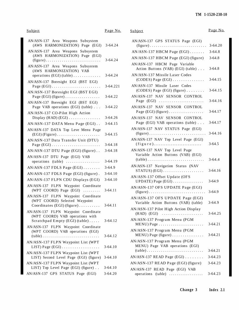
TM 1-1520-238-10
Subject Page No. Subject Page No.
AN/ASN-137 Area Weapons Subsystem(AWS HARMONIZATION) Page (EGI) 3-64.24
AN/ASN-137 Area Weapons Subsystem(AWS HARMONIZATION) Page (EGI)(figure) . . . . . . . . . . . . . . . . . . . . . . . . . . . . 3-64.24
AN/ASN-137 Area Weapons Subsystem(AWS HARMONIZATION) VABoperations (EGI) (table) . . . . . . . . . . . . . 3-64.24
AN/ASN-137 Boresight EGI (BST EGI)Page (EGI) . . . . . . . . . . . . . . . . . . . . . . . . 3-64.221
AN/ASN-137 Boresight EGI (BST EGI)Page (EGI) (figure) . . . . . . . . . . . . . . . . . 3-64.22
AN/ASN-137 Boresight EGI (BST EGI)Page VAB operations (EGI) (table) . . . 3-64.22
AN/ASN-137 CO-Pilot High ActionDisplay (HAD) (EGI) . . . . . . . . . . . . . . . 3-64.26
AN/ASN-137 DATA Menu Page (EGI) . . 3-64.15
AN/ASN-137 DATA Top Leve Menu Page(EGI) (Figure) . . . . . . . . . . . . . . . . . . . . . 3-64.15
AN/ASN-137 Data Transfer Unit (DTU)Page (EGI) . . . . . . . . . . . . . . . . . . . . . . . . 3-64.18
AN/ASN-137 DTU Page (EGI) (figure) . . 3-64.18
AN/ASN-137 DTU Page (EGI) VABoperations (table) . . . . . . . . . . . . . . . . . . 3-64.19
AN/ASN-137 FDLS Page (EGI) . . . . . . . . 3-64.9
AN/ASN-137 FDLS Page (EGI) (figure) . 3-64.10
AN/ASN-137 FLPN CDU Displays (EGI) 3-64.10
AN/ASN-137 FLPN Waypoint Coordinate(WPT COORD) Page (EGI) . . . . . . . . . 3-64.11
AN/ASN-137 FLPN Waypoint Coordinate(WPT COORD) Selected WaypointCoordinates (EGI) (figure) . . . . . . . . . . 3-64.11
AN/ASN-137 FLPN Waypoint Coordinate(WPT COORD) VAB operations withScratchpad Empty (EGI) (table) . . . . . 3-64.12
AN/ASN-137 FLPN Waypoint Coordinate(WPT COORD) VAB operations (EGI)(table) . . . . . . . . . . . . . . . . . . . . . . . . . . . . . 3-64.12
AN/ASN-137 FLPN Waypoint List (WPTLIST) Page (EGI) . . . . . . . . . . . . . . . . . . 3-64.10
AN/ASN-137 FLPN Waypoint List (WPTLIST) Second Level Page (EGI) (figure) 3-64.10
AN/ASN-137 FLPN Waypoint List (WPTLIST) Top Level Page (EGI) (figure) . . 3-64.10
AN/ASN-137 GPS STATUS Page (EGI) 3-64.20
AN/ASN-137 GPS STATUS Page (EGI)(figure) . . . . . . . . . . . . . . . . . . . . . . . . . . . .
AN/ASN-137 HBCM Page (EGI) . . . . . . .
AN/ASN-137 HBCM Page (EGI) (figure)
AN/ASN-137 HBCM Page VariableAction Buttons (VAB) (EGI) (table) . . .
AN/ASN-137 Missile Laser Codes(CODES) Page (EGI) . . . . . . . . . . . . . . .
AN/ASN-137 Missile Laser Codes(CODES) Page (EGI) (figure) . . . . . . . .
AN/ASN-137 NAV SENSOR CONTROLPage (EGI) . . . . . . . . . . . . . . . . . . . . . . . .
AN/ASN-137 NAV SENSOR CONTROLPage (EGI) (figure) . . . . . . . . . . . . . . . . .
AN/ASN-137 NAV SENSOR CONTROLPage (EGI) VAB operations (table) . . .
AN/ASN-137 NAV STATUS Page (EGI)(figure) . . . . . . . . . . . . . . . . . . . . . . . . . . . .
AN/ASN-137 NAV Top Level Page (EGI)( f i g u r e ) . . . . . . . . . . . . . . . . . . . . . . . . . . . .
AN/ASN-137 NAV Top Level PageVariable Action Buttons (VAB) (EGI)(table) . . . . . . . . . . . . . . . . . . . . . . . . . . . . .
3-64.20
3-64.8
3-64.8
3-64.8
3-64.15
3-64.15
3-64.16
3-64.17
3-64.17
3-64.16
3-64.5
3-64.4
AN/ASN-137 Navigation Status (NAVSTATUS) (EGI) . . . . . . . . . . . . . . . . . . . .
AN/ASN-137 Offset Update (OFSUPDATE) Page (EGI) . . . . . . . . . . . . . . .
AN/ASN-137 OFS UPDATE Page (EGI)(figure) . . . . . . . . . . . . . . . . . . . . . . . . . . . .
AN/ASN-137 OFS UPDATE Page (EGI)Variable Action Buttons (VAB) (table)
AN/ASN-137 Pilot High Action Display(HAD) (EGI) . . . . . . . . . . . . . . . . . . . . . .
AN/ASN-137 Program Menu (PGMMENU) Page . . . . . . . . . . . . . . . . . . . . . .
AN/ASN-137 Program Menu (PGMMENU) Page (figure) . . . . . . . . . . . . . . .
AN/ASN-137 Program Menu (PGMMENU) Page VAB operations (EGI)(table) . . . . . . . . . . . . . . . . . . . . . . . . . . . . .
3-64.16
3-64.9
3-64.9
3-64.9
3-64.25
3-64.21
3-64.21
AN/ASN-137 READ Page (EGI) . . . . . . . .
AN/ASN-137 READ Page (EGI) (figure)
AN/ASN-137 READ Page (EGI) VABoperations (table) . . . . . . . . . . . . . . . . . .
3-64.21
3-64.23
3-64.23
3-64.23
Change 3 Index 2.1
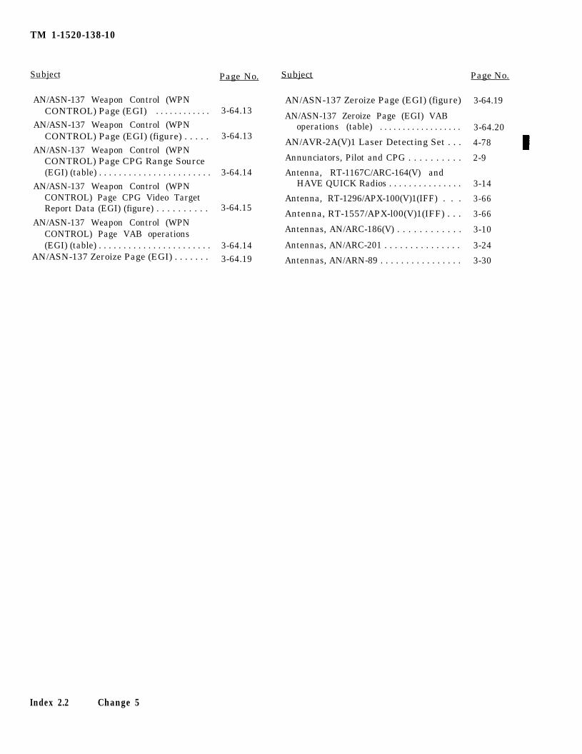
TM 1-1520-138-10
Subject Page No.
AN/ASN-137 Weapon Control (WPNCONTROL) Page (EGI) . . . . . . . . . . . . 3-64.13
AN/ASN-137 Weapon Control (WPNCONTROL) Page (EGI) (figure) . . . . . 3-64.13
AN/ASN-137 Weapon Control (WPNCONTROL) Page CPG Range Source(EGI) (table) . . . . . . . . . . . . . . . . . . . . . . . 3-64.14
AN/ASN-137 Weapon Control (WPNCONTROL) Page CPG Video TargetReport Data (EGI) (figure) . . . . . . . . . . 3-64.15
AN/ASN-137 Weapon Control (WPNCONTROL) Page VAB operations(EGI) (table) . . . . . . . . . . . . . . . . . . . . . . . 3-64.14
AN/ASN-137 Zeroize Page (EGI) . . . . . . . 3-64.19
Subject Page No.
AN/ASN-137 Zeroize Page (EGI) (figure) 3-64.19
AN/ASN-137 Zeroize Page (EGI) VABoperations (table) . . . . . . . . . . . . . . . . . . 3-64.20
AN/AVR-2A(V)1 Laser Detecting Set . . . 4-78
Annunciators, Pilot and CPG . . . . . . . . . . 2-9
Antenna, RT-1167C/ARC-164(V) andHAVE QUICK Radios . . . . . . . . . . . . . . . 3-14
Antenna, RT-1296/APX-100(V)1(IFF) . . . 3-66
Antenna, RT-1557/APX-l00(V)1(IFF) . . . 3-66
Antennas, AN/ARC-186(V) . . . . . . . . . . . . 3-10
Antennas, AN/ARC-201 . . . . . . . . . . . . . . . 3-24
Antennas, AN/ARN-89 . . . . . . . . . . . . . . . . 3-30
Index 2.2 Change 5
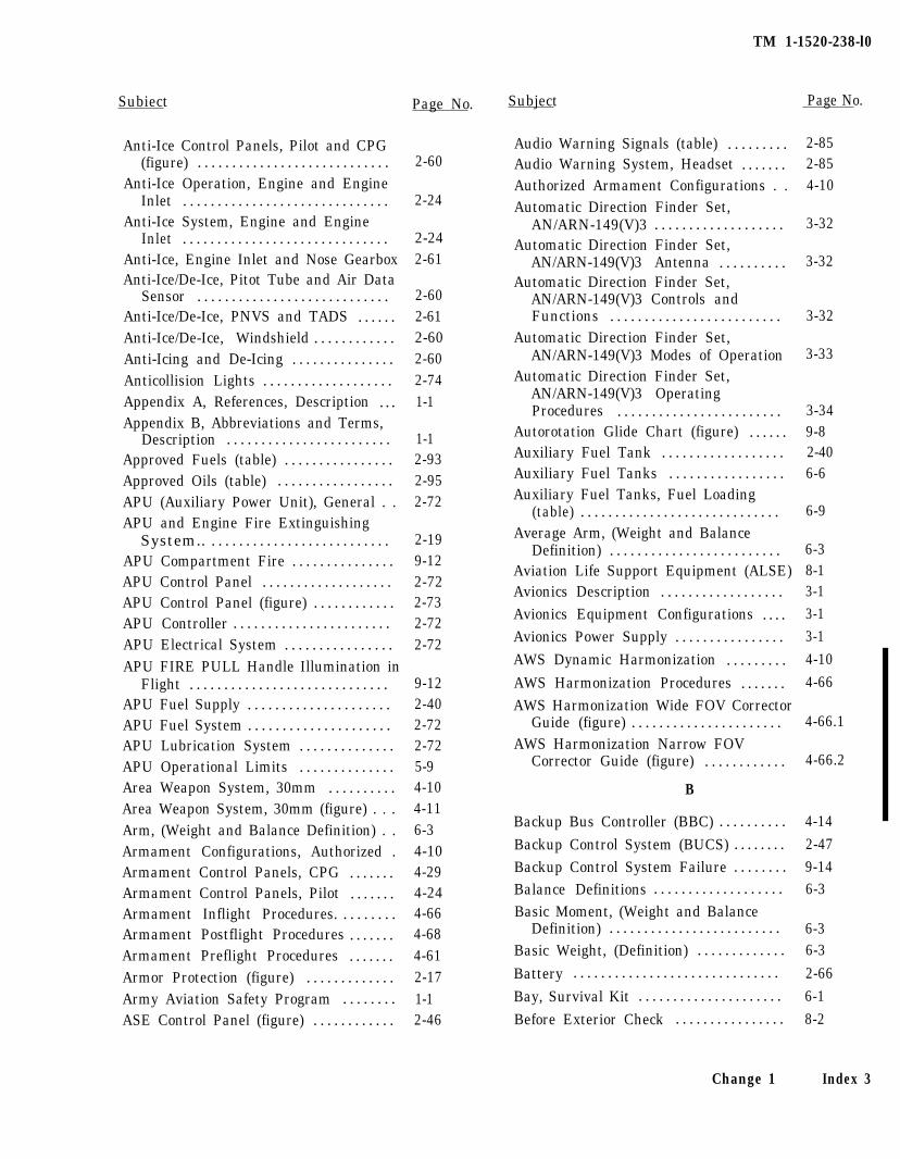
TM 1-1520-238-l0
Subiect
2-60
2-24
2-242-61
2-602-612-602-602-741-1
1-12-932-952-72
Anti-Ice Control Panels, Pilot and CPG(figure) . . . . . . . . . . . . . . . . . . . . . . . . . . . .
Anti-Ice Operation, Engine and EngineInlet . . . . . . . . . . . . . . . . . . . . . . . . . . . . . .
Anti-Ice System, Engine and EngineInlet . . . . . . . . . . . . . . . . . . . . . . . . . . . . . .
Anti-Ice, Engine Inlet and Nose GearboxAnti-Ice/De-Ice, Pitot Tube and Air Data
Sensor . . . . . . . . . . . . . . . . . . . . . . . . . . . .Anti-Ice/De-Ice, PNVS and TADS . . . . . .Anti-Ice/De-Ice, Windshield . . . . . . . . . . . .Anti-Icing and De-Icing . . . . . . . . . . . . . . .Anticollision Lights . . . . . . . . . . . . . . . . . . .Appendix A, References, Description . . .Appendix B, Abbreviations and Terms,
Description . . . . . . . . . . . . . . . . . . . . . . . .Approved Fuels (table) . . . . . . . . . . . . . . . .Approved Oils (table) . . . . . . . . . . . . . . . . .APU (Auxiliary Power Unit), General . .APU and Engine Fire Extinguishing
System.. . . . . . . . . . . . . . . . . . . . . . . . . . .APU Compartment Fire . . . . . . . . . . . . . . .APU Control Panel . . . . . . . . . . . . . . . . . . .APU Control Panel (figure) . . . . . . . . . . . .APU Controller . . . . . . . . . . . . . . . . . . . . . . .APU Electrical System . . . . . . . . . . . . . . . .APU FIRE PULL Handle Illumination in
Flight . . . . . . . . . . . . . . . . . . . . . . . . . . . . .APU Fuel Supply . . . . . . . . . . . . . . . . . . . . .APU Fuel System . . . . . . . . . . . . . . . . . . . . .APU Lubrication System . . . . . . . . . . . . . .APU Operational Limits . . . . . . . . . . . . . .Area Weapon System, 30mm . . . . . . . . . .Area Weapon System, 30mm (figure) . . .Arm, (Weight and Balance Definition) . .Armament Configurations, Authorized .Armament Control Panels, CPG . . . . . . .Armament Control Panels, Pilot . . . . . . .Armament Inflight Procedures. . . . . . . . .Armament Postflight Procedures . . . . . . .Armament Preflight Procedures . . . . . . .Armor Protection (figure) . . . . . . . . . . . . .Army Aviation Safety Program . . . . . . . .ASE Control Panel (figure) . . . . . . . . . . . .
2-199-122-722-732-722-72
9-122-402-722-725-94-104-116-34-104-294-244-664-684-612-171-12-46
Page No. Subject Page No.
Audio Warning Signals (table) . . . . . . . . .Audio Warning System, Headset . . . . . . .Authorized Armament Configurations . .Automatic Direction Finder Set,
AN/ARN-149(V)3 . . . . . . . . . . . . . . . . . . .Automatic Direction Finder Set,
AN/ARN-149(V)3 Antenna . . . . . . . . . .Automatic Direction Finder Set,
AN/ARN-149(V)3 Controls andFunctions . . . . . . . . . . . . . . . . . . . . . . . . .
Automatic Direction Finder Set,AN/ARN-149(V)3 Modes of Operation
Automatic Direction Finder Set,AN/ARN-149(V)3 OperatingProcedures . . . . . . . . . . . . . . . . . . . . . . . .
Autorotation Glide Chart (figure) . . . . . .Auxiliary Fuel Tank . . . . . . . . . . . . . . . . . .Auxiliary Fuel Tanks . . . . . . . . . . . . . . . . .Auxiliary Fuel Tanks, Fuel Loading
(table) . . . . . . . . . . . . . . . . . . . . . . . . . . . . .Average Arm, (Weight and Balance
Definition) . . . . . . . . . . . . . . . . . . . . . . . . .Aviation Life Support Equipment (ALSE)Avionics Description . . . . . . . . . . . . . . . . . .Avionics Equipment Configurations . . . .Avionics Power Supply . . . . . . . . . . . . . . . .
AWS Dynamic Harmonization . . . . . . . . .
AWS Harmonization Procedures . . . . . . .AWS Harmonization Wide FOV Corrector
Guide (figure) . . . . . . . . . . . . . . . . . . . . . .AWS Harmonization Narrow FOV
Corrector Guide (figure) . . . . . . . . . . . .
B
2-852-854-10
3-32
3-32
3-32
3-33
3-349-82-406-6
6-9
6-38-13-13-13-1
4-10
4-66
4-66.1
4-66.2
Backup Bus Controller (BBC) . . . . . . . . . . 4-14
Backup Control System (BUCS) . . . . . . . . 2-47
Backup Control System Failure . . . . . . . . 9-14Balance Definitions . . . . . . . . . . . . . . . . . . . 6-3Basic Moment, (Weight and Balance
Definition) . . . . . . . . . . . . . . . . . . . . . . . . . 6-3Basic Weight, (Definition) . . . . . . . . . . . . . 6-3
Battery . . . . . . . . . . . . . . . . . . . . . . . . . . . . . . 2-66
Bay, Survival Kit . . . . . . . . . . . . . . . . . . . . . 6-1
Before Exterior Check . . . . . . . . . . . . . . . . 8-2
Change 1 Index 3
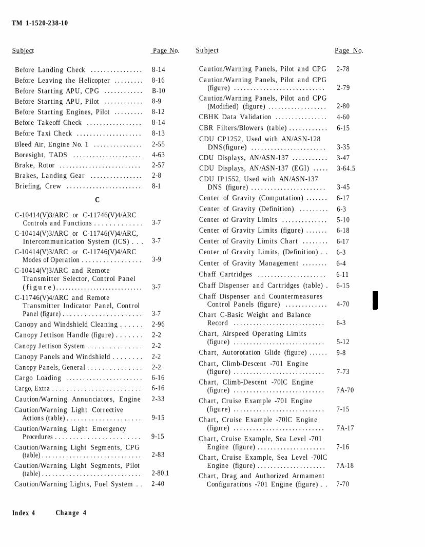
TM 1-1520-238-10
Subject
Before Landing Check . . . . . . . . . . . . . . . .
Before Leaving the Helicopter . . . . . . . . .Before Starting APU, CPG . . . . . . . . . . . .
Before Starting APU, Pilot . . . . . . . . . . . .
Before Starting Engines, Pilot . . . . . . . . .
Before Takeoff Check . . . . . . . . . . . . . . . . .
Before Taxi Check . . . . . . . . . . . . . . . . . . . .
Bleed Air, Engine No. 1 . . . . . . . . . . . . . . .Boresight, TADS . . . . . . . . . . . . . . . . . . . . .Brake, Rotor . . . . . . . . . . . . . . . . . . . . . . . . .Brakes, Landing Gear . . . . . . . . . . . . . . . .Briefing, Crew . . . . . . . . . . . . . . . . . . . . . . .
C
C-10414(V)3/ARC or C-11746(V)4/ARCControls and Functions . . . . . . . . . . . . .
C-10414(V)3/ARC or C-11746(V)4/ARC,Intercommunication System (ICS) . . .
C-10414(V)3/ARC or C-11746(V)4/ARCModes of Operation . . . . . . . . . . . . . . . . .
C-10414(V)3/ARC and RemoteTransmitter Selector, Control Panel( f i g u r e ) . . . . . . . . . . . . . . . . . . . . . . . . . . . .
C-11746(V)4/ARC and RemoteTransmitter Indicator Panel, ControlPanel (figure) . . . . . . . . . . . . . . . . . . . . . .
Canopy and Windshield Cleaning . . . . . .Canopy Jettison Handle (figure) . . . . . . .
Canopy Jettison System . . . . . . . . . . . . . . .Canopy Panels and Windshield . . . . . . . .Canopy Panels, General . . . . . . . . . . . . . . .Cargo Loading . . . . . . . . . . . . . . . . . . . . . . .
Cargo, Extra . . . . . . . . . . . . . . . . . . . . . . . . .
Caution/Warning Annunciators, EngineCaution/Warning Light Corrective
Actions (table) . . . . . . . . . . . . . . . . . . . . .Caution/Warning Light Emergency
Procedures . . . . . . . . . . . . . . . . . . . . . . . .Caution/Warning Light Segments, CPG
(table) . . . . . . . . . . . . . . . . . . . . . . . . . . . . .Caution/Warning Light Segments, Pilot
(table) . . . . . . . . . . . . . . . . . . . . . . . . . . . . .Caution/Warning Lights, Fuel System . .
3-7
3-7
3-9
3-7
3-72-962-2
2-2
2-22-26-166-16
2-33
9-15
9-15
2-83
2-80.12-40
Index 4 Change 4
Page No. Subject Page No.
8-148-16B-108-98-128-14
8-13
2-554-632-572-88-1
Caution/Warning Panels, Pilot and CPG
Caution/Warning Panels, Pilot and CPG(figure) . . . . . . . . . . . . . . . . . . . . . . . . . . . .
Caution/Warning Panels, Pilot and CPG(Modified) (figure) . . . . . . . . . . . . . . . . . .
CBHK Data Validation . . . . . . . . . . . . . . . .
CBR Filters/Blowers (table) . . . . . . . . . . . .
CDU CP1252, Used with AN/ASN-128DNS(figure) . . . . . . . . . . . . . . . . . . . . . . .
CDU Displays, AN/ASN-137 . . . . . . . . . . .CDU Displays, AN/ASN-137 (EGI) . . . . .
CDU IP1552, Used with AN/ASN-137DNS (figure) . . . . . . . . . . . . . . . . . . . . . . .
Center of Gravity (Computation) . . . . . . .
Center of Gravity (Definition) . . . . . . . . .
Center of Gravity Limits . . . . . . . . . . . . . .Center of Gravity Limits (figure) . . . . . . .
Center of Gravity Limits Chart . . . . . . . .
Center of Gravity Limits, (Definition) . .
Center of Gravity Management . . . . . . . .
Chaff Cartridges . . . . . . . . . . . . . . . . . . . . .
Chaff Dispenser and Cartridges (table) .
Chaff Dispenser and CountermeasuresControl Panels (figure) . . . . . . . . . . . . .
Chart C-Basic Weight and BalanceRecord . . . . . . . . . . . . . . . . . . . . . . . . . . . .
Chart, Airspeed Operating Limits(figure) . . . . . . . . . . . . . . . . . . . . . . . . . . . .
Chart, Autorotation Glide (figure) . . . . . .
Chart, Climb-Descent -701 Engine(figure) . . . . . . . . . . . . . . . . . . . . . . . . . . . .
Chart, Climb-Descent -70lC Engine(figure) . . . . . . . . . . . . . . . . . . . . . . . . . . . .
Chart, Cruise Example -701 Engine(figure) . . . . . . . . . . . . . . . . . . . . . . . . . . . .
Chart, Cruise Example -70lC Engine(figure) . . . . . . . . . . . . . . . . . . . . . . . . . . . .
Chart, Cruise Example, Sea Level -701Engine (figure) . . . . . . . . . . . . . . . . . . . . .
Chart, Cruise Example, Sea Level -70lCEngine (figure) . . . . . . . . . . . . . . . . . . . . .
Chart, Drag and Authorized ArmamentConfigurations -701 Engine (figure) . .
2-78
2-79
2-80
4-60
6-15
3-35
3-473-64.5
3-45
6-17
6-35-106-18
6-17
6-3
6-4
6-11
6-15
4-70
6-3
5-12
9-8
7-73
7A-70
7-15
7A-17
7-16
7A-18
7-70
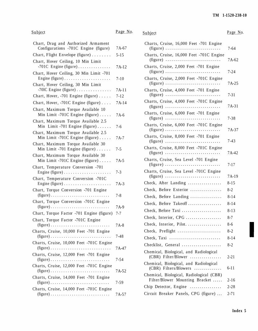
Subject Page No.
Chart, Drag and Authorized ArmamentConfigurations -701C Engine (figure) 7A-67
Chart, Flight Envelope (figure) . . . . . . . . 5-15Chart, Hover Ceiling, 10 Min Limit
-701C Engine (figure) . . . . . . . . . . . . . . . 7A-12Chart, Hover Ceiling, 30 Min Limit -701
Engine (figure) . . . . . . . . . . . . . . . . . . . . . 7-10Chart, Hover Ceiling, 30 Min Limit
-70lC Engine (figure) . . . . . . . . . . . . . . . 7A-11Chart, Hover, -701 Engine (figure) . . . . . 7-12
Chart, Hover, -701C Engine (figure) . . . . 7A-14
Chart, Maximum Torque Available 10Min Limit -701C Engine (figure) . . . . . 7A-6
Chart, Maximum Torque Available 2.5Min Limit -701 Engine (figure) . . . . . . 7-6
Chart, Maximum Torque Available 2.5Min Limit -701C Engine (figure) . . . . . 7A-7
Chart, Maximum Torque Available 30Min Limit -701 Engine (figure) . . . . . . 7-5
Chart, Maximum Torque Available 30Min Limit -701C Engine (figure) . . . . . 7A-5
Chart, Temperature Conversion -701Engine (figure) . . . . . . . . . . . . . . . . . . . . . 7-3
Chart, Temperature Conversion -701CEngine (figure) . . . . . . . . . . . . . . . . . . . . . 7A-3
Chart, Torque Conversion -701 Engine(figure) . . . . . . . . . . . . . . . . . . . . . . . . . . . . 7-8
Chart, Torque Conversion -701C Engine(figure) . . . . . . . . . . . . . . . . . . . . . . . . . . . . 7A-9
Chart, Torque Factor -701 Engine (figure) 7-7
Chart, Torque Factor -701C Engine(figure) . . . . . . . . . . . . . . . . . . . . . . . . . . . . 7A-8
Charts, Cruise, 10,000 Feet -701 Engine(figure) . . . . . . . . . . . . . . . . . . . . . . . . . . . . 7-48
Charts, Cruise, 10,000 Feet -701C Engine(figure) . . . . . . . . . . . . . . . . . . . . . . . . . . . . 7A-47
Charts, Cruise, 12,000 Feet -701 Engine(figure) . . . . . . . . . . . . . . . . . . . . . . . . . . . . 7-54
Charts, Cruise, 12,000 Feet -701C Engine(figure) . . . . . . . . . . . . . . . . . . . . . . . . . . . . 7A-52
Charts, Cruise, 14,000 Feet -701 Engine(figure) . . . . . . . . . . . . . . . . . . . . . . . . . . . . 7-59
Charts, Cruise, 14,000 Feet -701C Engine(figure) . . . . . . . . . . . . . . . . . . . . . . . . . . . . 7A-57
TM 1-1520-238-10
Subject Page No.
Charts, Cruise, 16,000 Feet -701 Engine(figure) . . . . . . . . . . . . . . . . . . . . . . . . . . . . 7-64
Charts, Cruise, 16,000 Feet -701C Engine(figure) . . . . . . . . . . . . . . . . . . . . . . . . . . . . 7A-62
Charts, Cruise, 2,000 Feet -701 Engine(figure) . . . . . . . . . . . . . . . . . . . . . . . . . . . . 7-24
Charts, Cruise, 2,000 Feet -701C Engine(figure) . . . . . . . . . . . . . . . . . . . . . . . . . . . . 7A-25
Charts, Cruise, 4,000 Feet -701 Engine(figure) . . . . . . . . . . . . . . . . . . . . . . . . . . . . 7-31
Charts, Cruise, 4,000 Feet -701C Engine(figure) . . . . . . . . . . . . . . . . . . . . . . . . . . . . 7A-31
Charts, Cruise, 6,000 Feet -701 Engine(figure) . . . . . . . . . . . . . . . . . . . . . . . . . . . . 7-38
Charts, Cruise, 6,000 Feet -701C Engine(figure) . . . . . . . . . . . . . . . . . . . . . . . . . . . . 7A-37
Charts, Cruise, 8,000 Feet -701 Engine(figure) . . . . . . . . . . . . . . . . . . . . . . . . . . . . 7-43
Charts, Cruise, 8,000 Feet -701C Engine(figure) . . . . . . . . . . . . . . . . . . . . . . . . . . . . 7A-42
Charts, Cruise, Sea Level -701 Engine(figure) . . . . . . . . . . . . . . . . . . . . . . . . . . . . 7-17
Charts, Cruise, Sea Level -701C Engine(figure) . . . . . . . . . . . . . . . . . . . . . . . . . . . . 7A-19
Check, After Landing . . . . . . . . . . . . . . . . . 8-15
Check, Before Exterior . . . . . . . . . . . . . . . . 8-2
Check, Before Landing . . . . . . . . . . . . . . . . 8-14
Check, Before Takeoff . . . . . . . . . . . . . . . . . 8-14
Check, Before Taxi . . . . . . . . . . . . . . . . . . . . 8-13
Check, Interior, CPG . . . . . . . . . . . . . . . . . . 8-7
Check, Interior, Pilot. . . . . . . . . . . . . . . . . . 8-6
Check, Preflight . . . . . . . . . . . . . . . . . . . . . . 8-2
Check, Taxi . . . . . . . . . . . . . . . . . . . . . . . . . . 8-14
Checklist, General . . . . . . . . . . . . . . . . . . . . 8-2
Chemical, Biological, and Radiological(CBR) Filter/Blower . . . . . . . . . . . . . . . . 2-21
Chemical, Biological, and Radiological(CBR) Filters/Blowers . . . . . . . . . . . . . . 6-11
Chemical, Biological, Radiological (CBR)Filter/Blower Mounting Bracket . . . . . 2-16
Chip Detector, Engine . . . . . . . . . . . . . . . . 2-28
Circuit Breaker Panels, CPG (figure) . . . 2-71
Index 5
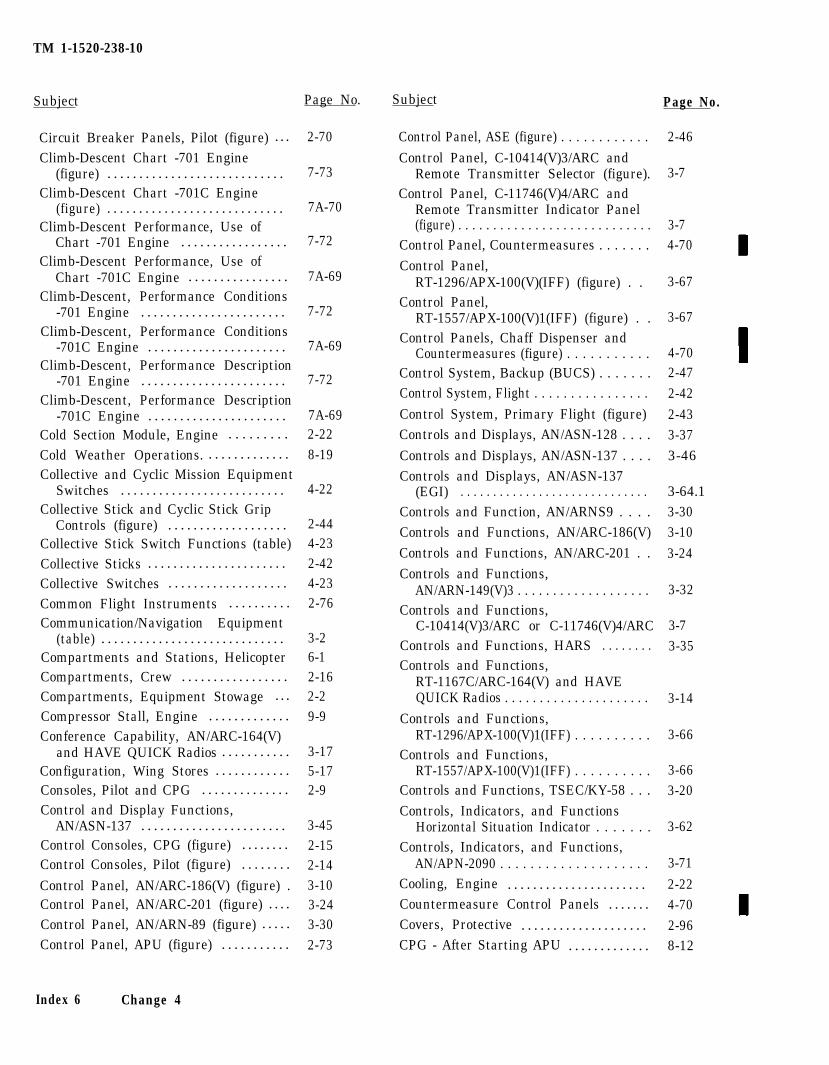
TM 1-1520-238-10
Subject Page No. Subject Page No.
Circuit Breaker Panels, Pilot (figure) . . .
Climb-Descent Chart -701 Engine(figure) . . . . . . . . . . . . . . . . . . . . . . . . . . . .
Climb-Descent Chart -701C Engine(figure) . . . . . . . . . . . . . . . . . . . . . . . . . . . .
Climb-Descent Performance, Use ofChart -701 Engine . . . . . . . . . . . . . . . . .
Climb-Descent Performance, Use ofChart -701C Engine . . . . . . . . . . . . . . . .
Climb-Descent, Performance Conditions-701 Engine . . . . . . . . . . . . . . . . . . . . . . .
Climb-Descent, Performance Conditions-701C Engine . . . . . . . . . . . . . . . . . . . . . .
Climb-Descent, Performance Description-701 Engine . . . . . . . . . . . . . . . . . . . . . . .
Climb-Descent, Performance Description-701C Engine . . . . . . . . . . . . . . . . . . . . . .
Cold Section Module, Engine . . . . . . . . .
Cold Weather Operations. . . . . . . . . . . . . .Collective and Cyclic Mission Equipment
Switches . . . . . . . . . . . . . . . . . . . . . . . . . .Collective Stick and Cyclic Stick Grip
Controls (figure) . . . . . . . . . . . . . . . . . . .Collective Stick Switch Functions (table)Collective Sticks . . . . . . . . . . . . . . . . . . . . . .Collective Switches . . . . . . . . . . . . . . . . . . .Common Flight Instruments . . . . . . . . . .Communication/Navigation Equipment
(table) . . . . . . . . . . . . . . . . . . . . . . . . . . . . .Compartments and Stations, HelicopterCompartments, Crew . . . . . . . . . . . . . . . . .Compartments, Equipment Stowage . . .
Compressor Stall, Engine . . . . . . . . . . . . .Conference Capability, AN/ARC-164(V)
and HAVE QUICK Radios . . . . . . . . . . .Configuration, Wing Stores . . . . . . . . . . . .Consoles, Pilot and CPG . . . . . . . . . . . . . .Control and Display Functions,
AN/ASN-137 . . . . . . . . . . . . . . . . . . . . . . .Control Consoles, CPG (figure) . . . . . . . .Control Consoles, Pilot (figure) . . . . . . . .
Control Panel, AN/ARC-186(V) (figure) .Control Panel, AN/ARC-201 (figure) . . . .Control Panel, AN/ARN-89 (figure) . . . . .
Control Panel, APU (figure) . . . . . . . . . . .
Index 6 Change 4
2-70
7-73
7A-70
7-72
7A-69
7-72
7A-69
7-72
7A-692-228-19
4-22
2-444-232-424-232-76
3-26-12-162-29-9
3-175-172-9
3-452-152-143-103-243-302-73
Control Panel, ASE (figure) . . . . . . . . . . . .
Control Panel, C-10414(V)3/ARC andRemote Transmitter Selector (figure).
Control Panel, C-11746(V)4/ARC andRemote Transmitter Indicator Panel(figure) . . . . . . . . . . . . . . . . . . . . . . . . . . . .
Control Panel, Countermeasures . . . . . . .Control Panel,
2-46
3-7
3-74-70
RT-1296/APX-100(V)(IFF) (figure) . . Control Panel,
3-67
RT-1557/APX-100(V)1(IFF) (figure) . .Control Panels, Chaff Dispenser and
Countermeasures (figure) . . . . . . . . . . .Control System, Backup (BUCS) . . . . . . .Control System, Flight . . . . . . . . . . . . . . . .
Control System, Primary Flight (figure)Controls and Displays, AN/ASN-128 . . . .
Controls and Displays, AN/ASN-137 . . . .Controls and Displays, AN/ASN-137
(EGI) . . . . . . . . . . . . . . . . . . . . . . . . . . . . .Controls and Function, AN/ARNS9 . . . .Controls and Functions, AN/ARC-186(V)Controls and Functions, AN/ARC-201 . .
3-67
4-702-472-42
2-433-373-46
3-64.13-303-10
3-24Controls and Functions,
AN/ARN-149(V)3 . . . . . . . . . . . . . . . . . . .Controls and Functions,
C-10414(V)3/ARC or C-11746(V)4/ARCControls and Functions, HARS . . . . . . . .Controls and Functions,
RT-1167C/ARC-164(V) and HAVEQUICK Radios . . . . . . . . . . . . . . . . . . . . .
Controls and Functions,RT-1296/APX-100(V)1(IFF) . . . . . . . . . .
Controls and Functions,RT-1557/APX-100(V)1(IFF) . . . . . . . . . .
Controls and Functions, TSEC/KY-58 . . .Controls, Indicators, and Functions
Horizontal Situation Indicator . . . . . . .Controls, Indicators, and Functions,
AN/APN-2090 . . . . . . . . . . . . . . . . . . . .Cooling, Engine . . . . . . . . . . . . . . . . . . . . . .Countermeasure Control Panels . . . . . . .Covers, Protective . . . . . . . . . . . . . . . . . . . . 2-96CPG - After Starting APU . . . . . . . . . . . . . 8-12
3-32
3-73-35
3-14
3-66
3-663-20
3-62
3-71
2-224-70
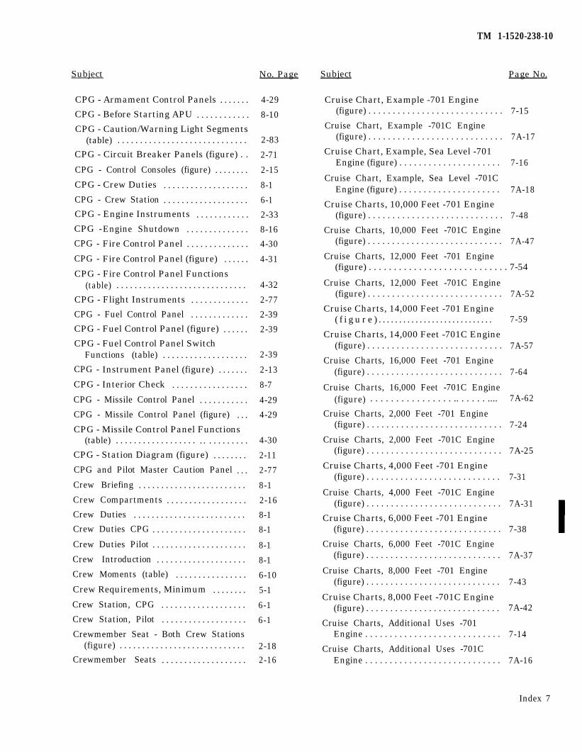
Subject No. Page
CPG - Armament Control Panels . . . . . . .
CPG - Before Starting APU . . . . . . . . . . . .
CPG - Caution/Warning Light Segments(table) . . . . . . . . . . . . . . . . . . . . . . . . . . . . .
CPG - Circuit Breaker Panels (figure) . .
CPG - Control Consoles (figure) . . . . . . . .
CPG - Crew Duties . . . . . . . . . . . . . . . . . . .
CPG - Crew Station . . . . . . . . . . . . . . . . . . .
CPG - Engine Instruments . . . . . . . . . . . .
CPG -Engine Shutdown . . . . . . . . . . . . . .
CPG - Fire Control Panel . . . . . . . . . . . . . .
CPG - Fire Control Panel (figure) . . . . . .
CPG - Fire Control Panel Functions(table) . . . . . . . . . . . . . . . . . . . . . . . . . . . . .
CPG - Flight Instruments . . . . . . . . . . . . .
CPG - Fuel Control Panel . . . . . . . . . . . . .
CPG - Fuel Control Panel (figure) . . . . . .
CPG - Fuel Control Panel SwitchFunctions (table) . . . . . . . . . . . . . . . . . . .
CPG - Instrument Panel (figure) . . . . . . .
CPG - Interior Check . . . . . . . . . . . . . . . . .
CPG - Missile Control Panel . . . . . . . . . . .
CPG - Missile Control Panel (figure) . . .
CPG - Missile Control Panel Functions(table) . . . . . . . . . . . . . . . . . . . . . . . . . . . . .
CPG - Station Diagram (figure) . . . . . . . .
CPG and Pilot Master Caution Panel . . .
Crew Briefing . . . . . . . . . . . . . . . . . . . . . . . .
Crew Compartments . . . . . . . . . . . . . . . . . .
Crew Duties . . . . . . . . . . . . . . . . . . . . . . . . .
Crew Duties CPG . . . . . . . . . . . . . . . . . . . . .
4-29
8-10
2-83
2-71
2-15
8-1
6-1
2-33
8-16
4-30
4-31
4-32
2-77
2-39
2-39
2-39
2-13
8-7
4-29
4-29
4-30
2-11
2-77
8-1
2-16
8-1
8-1
Crew Duties Pilot . . . . . . . . . . . . . . . . . . . . . 8-1
Crew Introduction . . . . . . . . . . . . . . . . . . . . 8-1
Crew Moments (table) . . . . . . . . . . . . . . . . 6-10
Crew Requirements, Minimum . . . . . . . . 5-1
Crew Station, CPG . . . . . . . . . . . . . . . . . . . 6-1
Crew Station, Pilot . . . . . . . . . . . . . . . . . . . 6-1
Crewmember Seat - Both Crew Stations(figure) . . . . . . . . . . . . . . . . . . . . . . . . . . . . 2-18
Crewmember Seats . . . . . . . . . . . . . . . . . . . 2-16
TM 1-1520-238-10
Subject Page No.
Cruise Chart, Example -701 Engine(figure) . . . . . . . . . . . . . . . . . . . . . . . . . . . . 7-15
Cruise Chart, Example -701C Engine(figure) . . . . . . . . . . . . . . . . . . . . . . . . . . . . 7A-17
Cruise Chart, Example, Sea Level -701Engine (figure) . . . . . . . . . . . . . . . . . . . . . 7-16
Cruise Chart, Example, Sea Level -701CEngine (figure) . . . . . . . . . . . . . . . . . . . . . 7A-18
Cruise Charts, 10,000 Feet -701 Engine(figure) . . . . . . . . . . . . . . . . . . . . . . . . . . . . 7-48
Cruise Charts, 10,000 Feet -701C Engine(figure) . . . . . . . . . . . . . . . . . . . . . . . . . . . . 7A-47
Cruise Charts, 12,000 Feet -701 Engine(figure) . . . . . . . . . . . . . . . . . . . . . . . . . . . . 7-54
Cruise Charts, 12,000 Feet -701C Engine(figure) . . . . . . . . . . . . . . . . . . . . . . . . . . . . 7A-52
Cruise Charts, 14,000 Feet -701 Engine( f i g u r e ) . . . . . . . . . . . . . . . . . . . . . . . . . . . . 7-59
Cruise Charts, 14,000 Feet -701C Engine(figure) . . . . . . . . . . . . . . . . . . . . . . . . . . . . 7A-57
Cruise Charts, 16,000 Feet -701 Engine(figure) . . . . . . . . . . . . . . . . . . . . . . . . . . . . 7-64
Cruise Charts, 16,000 Feet -701C Engine(figure) . . . . . . . . . . . . . . . . .. . . . . . .... 7A-62
Cruise Charts, 2,000 Feet -701 Engine(figure) . . . . . . . . . . . . . . . . . . . . . . . . . . . . 7-24
Cruise Charts, 2,000 Feet -701C Engine(figure) . . . . . . . . . . . . . . . . . . . . . . . . . . . . 7A-25
Cruise Charts, 4,000 Feet -701 Engine(figure) . . . . . . . . . . . . . . . . . . . . . . . . . . . . 7-31
Cruise Charts, 4,000 Feet -701C Engine(figure) . . . . . . . . . . . . . . . . . . . . . . . . . . . . 7A-31
Cruise Charts, 6,000 Feet -701 Engine(figure) . . . . . . . . . . . . . . . . . . . . . . . . . . . . 7-38
Cruise Charts, 6,000 Feet -701C Engine(figure) . . . . . . . . . . . . . . . . . . . . . . . . . . . . 7A-37
Cruise Charts, 8,000 Feet -701 Engine(figure) . . . . . . . . . . . . . . . . . . . . . . . . . . . . 7-43
Cruise Charts, 8,000 Feet -701C Engine(figure) . . . . . . . . . . . . . . . . . . . . . . . . . . . . 7A-42
Cruise Charts, Additional Uses -701Engine . . . . . . . . . . . . . . . . . . . . . . . . . . . . 7-14
Cruise Charts, Additional Uses -701CEngine . . . . . . . . . . . . . . . . . . . . . . . . . . . . 7A-16
Index 7
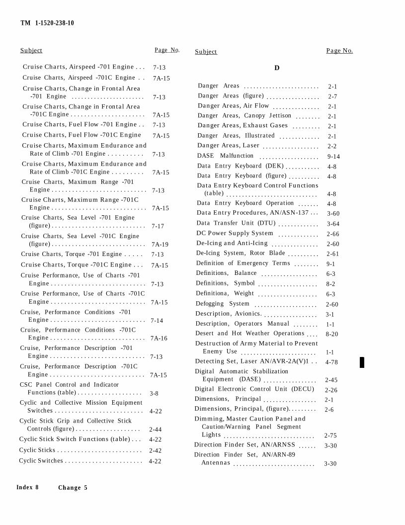
TM 1-1520-238-10
Subject Page No.
Cruise Charts, Airspeed -701 Engine . . . 7-13
Cruise Charts, Airspeed -701C Engine . . 7A-15
Cruise Charts, Change in Frontal Area-701 Engine . . . . . . . . . . . . . . . . . . . . . . . 7-13
Cruise Charts, Change in Frontal Area-701C Engine . . . . . . . . . . . . . . . . . . . . . . 7A-15
Cruise Charts, Fuel Flow -701 Engine . . 7-13
Cruise Charts, Fuel Flow -701C Engine 7A-15
Cruise Charts, Maximum Endurance andRate of Climb -701 Engine . . . . . . . . . . 7-13
Cruise Charts, Maximum Endurance andRate of Climb -701C Engine . . . . . . . . . 7A-15
Cruise Charts, Maximum Range -701Engine . . . . . . . . . . . . . . . . . . . . . . . . . . . . 7-13
Cruise Charts, Maximum Range -701CEngine . . . . . . . . . . . . . . . . . . . . . . . . . . . . 7A-15
Cruise Charts, Sea Level -701 Engine(figure) . . . . . . . . . . . . . . . . . . . . . . . . . . . . 7-17
Cruise Charts, Sea Level -701C Engine(figure) . . . . . . . . . . . . . . . . . . . . . . . . . . . . 7A-19
Cruise Charts, Torque -701 Engine . . . . . 7-13
Cruise Charts, Torque -701C Engine . . . 7A-15
Cruise Performance, Use of Charts -701Engine . . . . . . . . . . . . . . . . . . . . . . . . . . . . 7-13
Cruise Performance, Use of Charts -701CEngine . . . . . . . . . . . . . . . . . . . . . . . . . . . . 7A-15
Cruise, Performance Conditions -701Engine . . . . . . . . . . . . . . . . . . . . . . . . . . . . 7-14
Cruise, Performance Conditions -701CEngine . . . . . . . . . . . . . . . . . . . . . . . . . . . . 7A-16
Cruise, Performance Description -701Engine . . . . . . . . . . . . . . . . . . . . . . . . . . . . 7-13
Cruise, Performance Description -701CEngine . . . . . . . . . . . . . . . . . . . . . . . . . . . . 7A-15
CSC Panel Control and IndicatorFunctions (table) . . . . . . . . . . . . . . . . . . . 3-8
Cyclic and Collective Mission EquipmentSwitches . . . . . . . . . . . . . . . . . . . . . . . . . . 4-22
Cyclic Stick Grip and Collective StickControls (figure) . . . . . . . . . . . . . . . . . . . 2-44
Cyclic Stick Switch Functions (table) . . . 4-22
Cyclic Sticks . . . . . . . . . . . . . . . . . . . . . . . . . 2-42
Cyclic Switches . . . . . . . . . . . . . . . . . . . . . . . 4-22
Index 8 Change 5
Subject Page No.
D
Danger Areas . . . . . . . . . . . . . . . . . . . . . . . . 2-1Danger Areas (figure) . . . . . . . . . . . . . . . . . 2-7Danger Areas, Air Flow . . . . . . . . . . . . . . . 2-1Danger Areas, Canopy Jettison . . . . . . . . 2-1Danger Areas, Exhaust Gases . . . . . . . . . 2-1Danger Areas, Illustrated . . . . . . . . . . . . . 2-1Danger Areas, Laser . . . . . . . . . . . . . . . . . . 2-2DASE Malfunction . . . . . . . . . . . . . . . . . . . 9-14Data Entry Keyboard (DEK) . . . . . . . . . . . 4-8Data Entry Keyboard (figure) . . . . . . . . . . 4-8Data Entry Keyboard Control Functions
(table) . . . . . . . . . . . . . . . . . . . . . . . . . . . . . 4-8Data Entry Keyboard Operation . . . . . . . 4-8Data Entry Procedures, AN/ASN-137 . . . 3-60Data Transfer Unit (DTU) . . . . . . . . . . . . . 3-64DC Power Supply System . . . . . . . . . . . . . 2-66De-Icing and Anti-Icing . . . . . . . . . . . . . . . 2-60De-Icing System, Rotor Blade . . . . . . . . . . 2-61Definition of Emergency Terms . . . . . . . . 9-1Definitions, Balance . . . . . . . . . . . . . . . . . . 6-3Definitions, Symbol . . . . . . . . . . . . . . . . . . . 8-2Definitiona, Weight . . . . . . . . . . . . . . . . . . . 6-3Defogging System . . . . . . . . . . . . . . . . . . . . 2-60Description, Avionics. . . . . . . . . . . . . . . . . . 3-1Description, Operators Manual . . . . . . . . 1-1Desert and Hot Weather Operations . . . . 8-20Destruction of Army Material to Prevent
Enemy Use . . . . . . . . . . . . . . . . . . . . . . . . 1-1Detecting Set, Laser AN/AVR-2A(V)1 . . 4-78Digital Automatic Stabilization
Equipment (DASE) . . . . . . . . . . . . . . . . . 2-45Digital Electronic Control Unit (DECU) 2-26Dimensions, Principal . . . . . . . . . . . . . . . . . 2-1Dimensions, Principal, (figure). . . . . . . . . 2-6Dimming, Master Caution Panel and
Caution/Warning Panel SegmentLights . . . . . . . . . . . . . . . . . . . . . . . . . . . . . 2-75
Direction Finder Set, AN/ARNSS . . . . . . 3-30Direction Finder Set, AN/ARN-89
Antennas . . . . . . . . . . . . . . . . . . . . . . . . . . 3-30
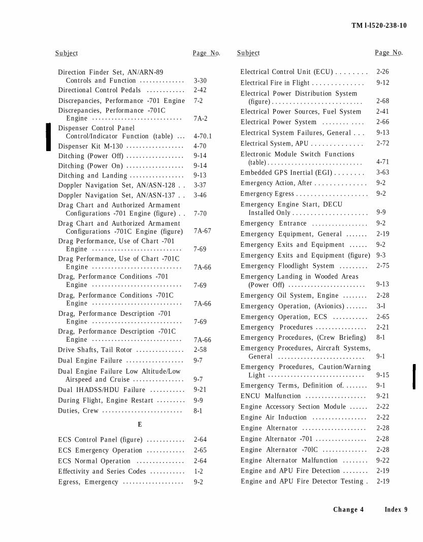
TM l-l520-238-10
Subject Page No. Subject Page No.
Direction Finder Set, AN/ARN-89Controls and Function . . . . . . . . . . . . . . 3-30
Directional Control Pedals . . . . . . . . . . . . 2-42
Discrepancies, Performance -701 Engine 7-2Discrepancies, Performance -701C
Engine . . . . . . . . . . . . . . . . . . . . . . . . . . . . 7A-2Dispenser Control Panel
Control/Indicator Function (table) . . . 4-70.1Dispenser Kit M-130 . . . . . . . . . . . . . . . . . . 4-70Ditching (Power Off) . . . . . . . . . . . . . . . . . . 9-14Ditching (Power On) . . . . . . . . . . . . . . . . . . 9-14Ditching and Landing . . . . . . . . . . . . . . . . . 9-13Doppler Navigation Set, AN/ASN-128 . . 3-37Doppler Navigation Set, AN/ASN-137 . . 3-46Drag Chart and Authorized Armament
Configurations -701 Engine (figure) . . 7-70Drag Chart and Authorized Armament
Configurations -701C Engine (figure) 7A-67Drag Performance, Use of Chart -701
Engine . . . . . . . . . . . . . . . . . . . . . . . . . . . . 7-69Drag Performance, Use of Chart -701C
Engine . . . . . . . . . . . . . . . . . . . . . . . . . . . . 7A-66Drag, Performance Conditions -701
Engine . . . . . . . . . . . . . . . . . . . . . . . . . . . . 7-69Drag, Performance Conditions -701C
Engine . . . . . . . . . . . . . . . . . . . . . . . . . . . . 7A-66Drag, Performance Description -701
Engine . . . . . . . . . . . . . . . . . . . . . . . . . . . . 7-69Drag, Performance Description -701C
Engine . . . . . . . . . . . . . . . . . . . . . . . . . . . . 7A-66Drive Shafts, Tail Rotor . . . . . . . . . . . . . . . 2-58
Dual Engine Failure . . . . . . . . . . . . . . . . . . 9-7
Dual Engine Failure Low Altitude/LowAirspeed and Cruise . . . . . . . . . . . . . . . . 9-7
Dual IHADSS/HDU Failure . . . . . . . . . . . 9-21
During Flight, Engine Restart . . . . . . . . . 9-9Duties, Crew . . . . . . . . . . . . . . . . . . . . . . . . . 8-1
E
Electrical Control Unit (ECU) . . . . . . . .
Electrical Fire in Flight . . . . . . . . . . . . . .
Electrical Power Distribution System
2-26
9-12
(figure) . . . . . . . . . . . . . . . . . . . . . . . . . .Electrical Power Sources, Fuel SystemElectrical Power System . . . . . . . . . . . .
Electrical System Failures, General . . .
Electrical System, APU . . . . . . . . . . . . . .
Electronic Module Switch Functions
2-682-412-66
9-13
2-72
(table) . . . . . . . . . . . . . . . . . . . . . . . . . . . .Embedded GPS Inertial (EGI) . . . . . . . .Emergency Action, After . . . . . . . . . . . . . .
Emergency Egress . . . . . . . . . . . . . . . . . . . .
Emergency Engine Start, DECUInstalled Only . . . . . . . . . . . . . . . . . . . . .
Emergency Entrance . . . . . . . . . . . . . . . . .
4-713-639-2
9-2
Emergency Equipment, General . . . . . . .
Emergency Exits and Equipment . . . . . .
Emergency Exits and Equipment (figure)Emergency Floodlight System . . . . . . . . .
9-9
9-2
2-19
9-29-32-75
ECS Control Panel (figure) . . . . . . . . . . . . 2-64
ECS Emergency Operation . . . . . . . . . . . . 2-65
ECS Normal Operation . . . . . . . . . . . . . . . 2-64Effectivity and Series Codes . . . . . . . . . . . 1-2Egress, Emergency . . . . . . . . . . . . . . . . . . . 9-2
Emergency Landing in Wooded Areas(Power Off) . . . . . . . . . . . . . . . . . . . . . . . . 9-13
Emergency Oil System, Engine . . . . . . . . 2-28
Emergency Operation, (Avionics) . . . . . . . 3-l
Emergency Operation, ECS . . . . . . . . . . . 2-65Emergency Procedures . . . . . . . . . . . . . . . . 2-21Emergency Procedures, (Crew Briefing) 8-1
Emergency Procedures, Aircraft Systems,General . . . . . . . . . . . . . . . . . . . . . . . . . . . 9-1
Emergency Procedures, Caution/WarningLight . . . . . . . . . . . . . . . . . . . . . . . . . . . . . . 9-15
Emergency Terms, Definition of. . . . . . . . 9-1ENCU Malfunction . . . . . . . . . . . . . . . . . . . 9-21
Engine Accessory Section Module . . . . . . 2-22
Engine Air Induction . . . . . . . . . . . . . . . . . 2-22
Engine Alternator . . . . . . . . . . . . . . . . . . . . 2-28
Engine Alternator -701 . . . . . . . . . . . . . . . . 2-28
Engine Alternator -70lC . . . . . . . . . . . . . . 2-28
Engine Alternator Malfunction . . . . . . . . 9-22Engine and APU Fire Detection . . . . . . . . 2-19Engine and APU Fire Detector Testing . 2-19
Change 4 Index 9
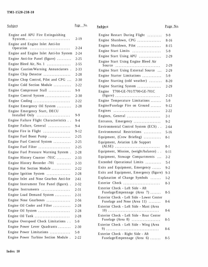
TM1-1520-238-10
Subject Page No.
Engine and APU Fire ExtinguishingSystem.. . . . . . . . . . . . . . . . . . . . . . . . . . .
Engine and Engine Inlet Anti-IceOperation . . . . . . . . . . . . . . . . . . . . . . . . .
Engine and Engine Inlet Anti-Ice System
Engine Anti-Ice Panel (figure) . . . . . . . . .Engine Bleed Air, No. 1 . . . . . . . . . . . . . . .Engine Caution/Warning Annunciators .Engine Chip Detector . . . . . . . . . . . . . . . . .Engine Chop Control, Pilot and CPG . . .
Engine Cold Section Module . . . . . . . . . . .
Engine Compressor Stall . . . . . . . . . . . . . .Engine Control System . . . . . . . . . . . . . . . .Engine Cooling . . . . . . . . . . . . . . . . . . . . . . .Engine Emergency Oil System . . . . . . . . .Engine Emergency Start, DECU
Installed Only . . . . . . . . . . . . . . . . . . . . .Engine Failure Flight Characteristics . .
Engine Failure, General . . . . . . . . . . . . . .
Engine Fire in Flight . . . . . . . . . . . . . . . . .Engine Fuel Boost Pump . . . . . . . . . . . . . .Engine Fuel Control System . . . . . . . . . . .Engine Fuel Filter . . . . . . . . . . . . . . . . . . . .Engine Fuel Pressure Warning System .
Engine History Counter -701C . . . . . . . . .Engine History Recorder -701 . . . . . . . . .
Engine Hot Section Module . . . . . . . . . . . .Engine Ignition System . . . . . . . . . . . . . . .Engine Inlet and Nose Gearbox Anti-Ice
Engine Instrument Test Panel (figure). .
Engine Instruments . . . . . . . . . . . . . . . . . .
Engine Load Demand System . . . . . . . . . .
Engine Nose Gearboxes . . . . . . . . . . . . . . .Engine Oil Cooler and Filter . . . . . . . . . . .Engine Oil System . . . . . . . . . . . . . . . . . . . .Engine Oil Tank . . . . . . . . . . . . . . . . . . . . . .Engine Overspeed Check Limitations . .
Engine Power Lever Quadrants . . . . . . . .
Engine Power Limitations . . . . . . . . . . . . .Engine Power Turbine Section Module .
Index 10
2-19
2-24
2-24
2-25
2-552-332-28
2-30
2-22
9-9
2-30
2-222-28
9-9
9-4
9-4
9-12
2-252-25
2-25
2-28
2-33
2-33
2-222-28
2-612-32
2-31
2-31
2-56
2-282-28
2-28
5-9
2-30
5-9
2-22
Subject Page No.
Engine Restart During Flight . . . . . . . . .Engine Shutdown, CPG . . . . . . . . . . . . . . .Engine Shutdown, Pilot . . . . . . . . . . . . . . .Engine Start Limits . . . . . . . . . . . . . . . . . .Engine Start Using APU . . . . . . . . . . . . . .Engine Start Using Engine Bleed Air
Source . . . . . . . . . . . . . . . . . . . . . . . . . . . .Engine Start Using External Source . . .Engine Starter Limitations . . . . . . . . . . . .Engine Starting (cold weather) . . . . . . . .Engine Starting System . . . . . . . . . . . . . . .Engine T700-GE-701/T700-GE-701C
(figure) . . . . . . . . . . . . . . . . . . . . . . . . . . . .Engine Temperature Limitations . . . . . . .Engine/Fuselage Fire on Ground . . . . . . .Engines . . . . . . . . . . . . . . . . . . . . . . . . . . . . .
Engines, General . . . . . . . . . . . . . . . . . . . . .Entrance, Emergency . . . . . . . . . . . . . . . . .Environmental Control System (ECS) . .
Environmental Restrictions . . . . . . . . . . .Equipment, (Crew Briefing) . . . . . . . . . . .Equipment, Aviation Life Support
(ALSE) . . . . . . . . . . . . . . . . . . . . . . . . . . . .Equipment, Mission, (weight/balance) . .
Equipment, Stowage Compartments . . .Exceeded Operational Limits . . . . . . . . . .Exits and Equipment, Emergency . . . . . .Exits and Equipment, Emergency (figure)Explanation of Change Symbols . . . . . . .Exterior Check . . . . . . . . . . . . . . . . . . . . . . .Exterior Check - Left Side - Aft
Fuselage/Empennage (Area 7) . . . . . . .Exterior Check - Left Side - Lower Center
Fuselage and Nose (Area 11) . . . . . . . .Exterior Check - Left Side - Mast (Area
10) . . . . . . . . . . . . . . . . . . . . . . . . . . . . . . . .Exterior Check - Left Side - Rear Center
Fuselage (Area 8) . . . . . . . . . . . . . . . . . .Exterior Check - Left Side - Wing (Area
9) . . . . . . . . . . . . . . . . . . . . . . . . . . . . . . . . .Exterior Check - Right Side - Aft
Fuselage/Empennage (Area 6) . . . . . . .
9-98-16
8-15
5-92-29
2-292-295-9
8-20
2-29
2-235-99-122-22
2-1
9-2
2-64
5-168-1
8-16-11
2-2
5-l
9-29-3l-2
8-3
8-5
8-6
8-6
8-5
8-6
8-5
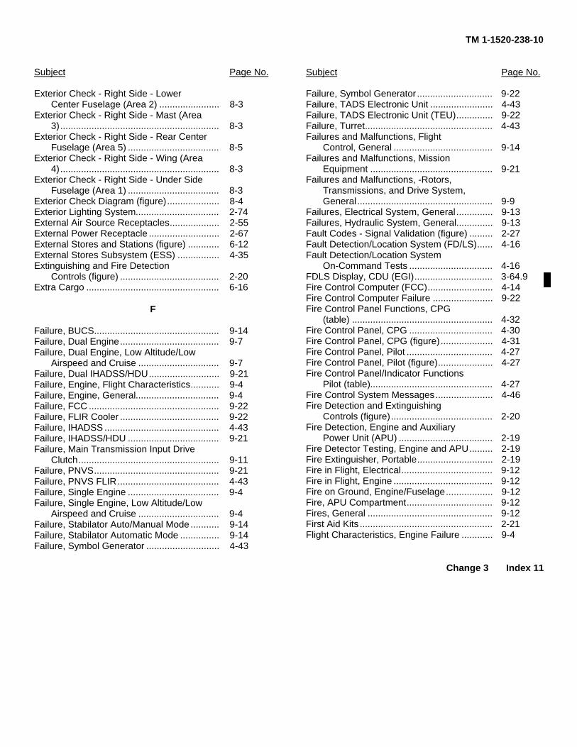
TM 1-1520-238-10
Subject Page No.
Exterior Check - Right Side - LowerCenter Fuselage (Area 2) ....................... 8-3
Exterior Check - Right Side - Mast (Area3)............................................................. 8-3
Exterior Check - Right Side - Rear CenterFuselage (Area 5) ................................... 8-5
Exterior Check - Right Side - Wing (Area4)............................................................. 8-3
Exterior Check - Right Side - Under SideFuselage (Area 1) ................................... 8-3
Exterior Check Diagram (figure).................... 8-4Exterior Lighting System................................ 2-74External Air Source Receptacles................... 2-55External Power Receptacle ........................... 2-67External Stores and Stations (figure) ............ 6-12External Stores Subsystem (ESS) ................ 4-35Extinguishing and Fire Detection
Controls (figure) ...................................... 2-20Extra Cargo ................................................... 6-16
F
Failure, BUCS................................................ 9-14Failure, Dual Engine...................................... 9-7Failure, Dual Engine, Low Altitude/Low
Airspeed and Cruise ............................... 9-7Failure, Dual IHADSS/HDU........................... 9-21Failure, Engine, Flight Characteristics........... 9-4Failure, Engine, General................................ 9-4Failure, FCC .................................................. 9-22Failure, FLIR Cooler ...................................... 9-22Failure, IHADSS ............................................ 4-43Failure, IHADSS/HDU ................................... 9-21Failure, Main Transmission Input Drive
Clutch...................................................... 9-11Failure, PNVS................................................ 9-21Failure, PNVS FLIR....................................... 4-43Failure, Single Engine ................................... 9-4Failure, Single Engine, Low Altitude/Low
Airspeed and Cruise ............................... 9-4Failure, Stabilator Auto/Manual Mode ........... 9-14Failure, Stabilator Automatic Mode ............... 9-14Failure, Symbol Generator ............................ 4-43
Subject Page No.
Failure, Symbol Generator ............................. 9-22Failure, TADS Electronic Unit ........................ 4-43Failure, TADS Electronic Unit (TEU).............. 9-22Failure, Turret................................................. 4-43Failures and Malfunctions, Flight
Control, General ...................................... 9-14Failures and Malfunctions, Mission
Equipment ............................................... 9-21Failures and Malfunctions, -Rotors,
Transmissions, and Drive System,General.................................................... 9-9
Failures, Electrical System, General .............. 9-13Failures, Hydraulic System, General.............. 9-13Fault Codes - Signal Validation (figure) ......... 2-27Fault Detection/Location System (FD/LS)...... 4-16Fault Detection/Location System
On-Command Tests ................................ 4-16FDLS Display, CDU (EGI).............................. 3-64.9Fire Control Computer (FCC)......................... 4-14Fire Control Computer Failure ....................... 9-22Fire Control Panel Functions, CPG
(table) ...................................................... 4-32Fire Control Panel, CPG ................................ 4-30Fire Control Panel, CPG (figure).................... 4-31Fire Control Panel, Pilot ................................. 4-27Fire Control Panel, Pilot (figure)..................... 4-27Fire Control Panel/Indicator Functions
Pilot (table)............................................... 4-27Fire Control System Messages...................... 4-46Fire Detection and Extinguishing
Controls (figure)....................................... 2-20Fire Detection, Engine and Auxiliary
Power Unit (APU) .................................... 2-19Fire Detector Testing, Engine and APU......... 2-19Fire Extinguisher, Portable............................. 2-19Fire in Flight, Electrical................................... 9-12Fire in Flight, Engine ...................................... 9-12Fire on Ground, Engine/Fuselage.................. 9-12Fire, APU Compartment................................. 9-12Fires, General ................................................ 9-12First Aid Kits ................................................... 2-21Flight Characteristics, Engine Failure ............ 9-4
Change 3 Index 11
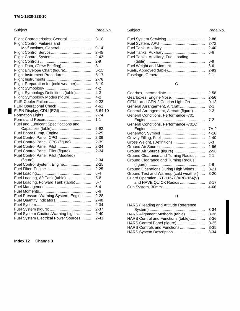
TM 1-1520-238-10
Subject Page No.
Flight Characteristics, General ...................... 8-18Flight Control Failures and
Malfunctions, General ............................. 9-14Flight Control Servos..................................... 2-45Flight Control System .................................... 2-42Flight Controls ............................................... 2-9Flight Data, (Crew Briefing) ........................... 8-1Flight Envelope Chart (figure)........................ 5-15Flight Instrument Procedures ........................ 8-17Flight Instruments.......................................... 2-76Flight Preparation for (cold weather) ............. 8-19Flight Symbology........................................... 4-2Flight Symbology Definitions (table).............. 4-3Flight Symbology Modes (figure)................... 4-2FLIR Cooler Failure ....................................... 9-22FLIR Operational Check................................ 4-61FLPN Display, CDU (EGI) ............................. 3-64.10Formation Lights............................................ 2-74Forms and Records....................................... 1-1Fuel and Lubricant Specifications and
Capacities (table) .................................... 2-92Fuel Boost Pump, Engine.............................. 2-25Fuel Control Panel, CPG............................... 2-39Fuel Control Panel, CPG (figure) .................. 2-39Fuel Control Panel, Pilot................................ 2-34Fuel Control Panel, Pilot (figure) ................... 2-34Fuel Control Panel, Pilot (Modified)
(figure)..................................................... 2-34Fuel Control System, Engine......................... 2-25Fuel Filter, Engine ......................................... 2-25Fuel Loading.................................................. 6-4Fuel Loading, Aft Tank (table) ....................... 6-8Fuel Loading, Forward Tank (table) .............. 6-7Fuel Management ......................................... 6-4Fuel Moments................................................ 6-6Fuel Pressure Warning System, Engine ....... 2-28Fuel Quantity Indicators................................. 2-40Fuel System................................................... 2-34Fuel System (figure) ...................................... 2-37Fuel System Caution/Warning Lights ............ 2-40Fuel System Electrical Power Sources.......... 2-41
Subject Page No.
Fuel System Servicing ................................... 2-86Fuel System, APU.......................................... 2-72Fuel Tank, Auxiliary........................................ 2-40Fuel Tanks, Auxiliary...................................... 6-6Fuel Tanks, Auxiliary, Fuel Loading
(table) ...................................................... 6-9Fuel Weight and Moment............................... 6-6Fuels, Approved (table).................................. 2-93Fuselage, General.......................................... 2-1
G
Gearbox, Intermediate ................................... 2-58Gearboxes, Engine Nose............................... 2-56GEN 1 and GEN 2 Caution Light On.............. 9-13General Arrangement, Aircraft ....................... 2-1General Arrangement, Aircraft (figure)........... 2-3General Conditions, Performance -701
Engine...................................................... 7-2General Conditions, Performance -701C
Engine...................................................... 7A-2Generator, Symbol ......................................... 4-16Gravity Filling, Fuel......................................... 2-40Gross Weight, (Definition) .............................. 6-3Ground Air Source ......................................... 2-96Ground Air Source (figure) ............................. 2-96Ground Clearance and Turning Radius ......... 2-1Ground Clearance and Turning Radius
(figure) ..................................................... 2-6Ground Operations During High Winds ......... 8-21Ground Test and Warmup (cold weather) ..... 8-20Guard Operation, RT-1167C/ARC-164(V)
and HAVE QUICK Radios ....................... 3-17Gun System, 30mm ....................................... 4-66
H
HARS (Heading and Attitude ReferenceSystem) ................................................... 3-34
HARS Alignment Methods (table) .................. 3-36HARS Control and Functions (table).............. 3-36HARS Control Panel (figure) .......................... 3-35HARS Controls and Functions ....................... 3-35HARS System Description ............................. 3-34
Index 12 Change 3
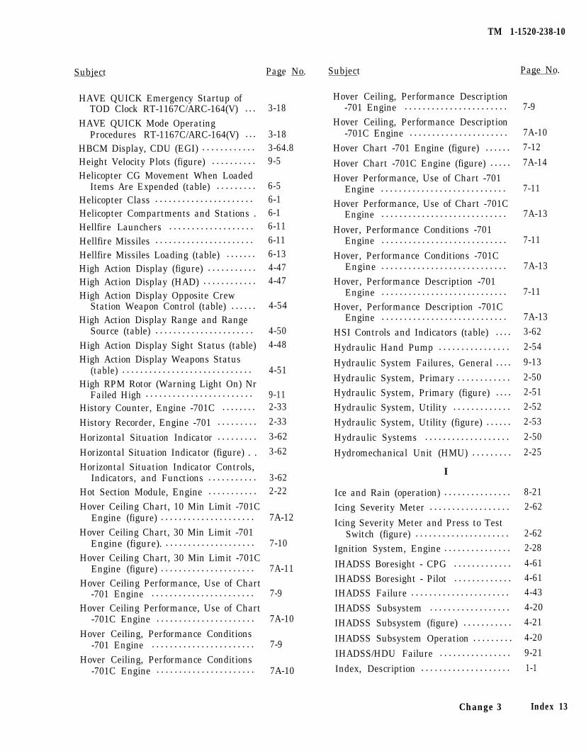
Subject Page No.
HAVE QUICK Emergency Startup ofTOD Clock RT-1167C/ARC-164(V) . . . 3-18
HAVE QUICK Mode OperatingProcedures RT-1167C/ARC-164(V) . . . 3-18
HBCM Display, CDU (EGI) . . . . . . . . . . . . 3-64.8Height Velocity Plots (figure) . . . . . . . . . . 9-5Helicopter CG Movement When Loaded
Items Are Expended (table) . . . . . . . . . 6-5Helicopter Class . . . . . . . . . . . . . . . . . . . . . . 6-1Helicopter Compartments and Stations . 6-1Hellfire Launchers . . . . . . . . . . . . . . . . . . . 6-11
Hellfire Missiles . . . . . . . . . . . . . . . . . . . . . . 6-11
Hellfire Missiles Loading (table) . . . . . . . 6-13High Action Display (figure) . . . . . . . . . . . 4-47High Action Display (HAD) . . . . . . . . . . . . 4-47High Action Display Opposite Crew
Station Weapon Control (table) . . . . . . 4-54High Action Display Range and Range
Source (table) . . . . . . . . . . . . . . . . . . . . . . 4-50High Action Display Sight Status (table) 4-48High Action Display Weapons Status
(table) . . . . . . . . . . . . . . . . . . . . . . . . . . . . . 4-51High RPM Rotor (Warning Light On) Nr
Failed High . . . . . . . . . . . . . . . . . . . . . . . . 9-11History Counter, Engine -701C . . . . . . . . 2-33
History Recorder, Engine -701 . . . . . . . . . 2-33
Horizontal Situation Indicator . . . . . . . . . 3-62
Horizontal Situation Indicator (figure) . . 3-62
Horizontal Situation Indicator Controls,Indicators, and Functions . . . . . . . . . . . 3-62
Hot Section Module, Engine . . . . . . . . . . . 2-22
Hover Ceiling Chart, 10 Min Limit -701CEngine (figure) . . . . . . . . . . . . . . . . . . . . . 7A-12
Hover Ceiling Chart, 30 Min Limit -701Engine (figure). . . . . . . . . . . . . . . . . . . . . 7-10
Hover Ceiling Chart, 30 Min Limit -701CEngine (figure) . . . . . . . . . . . . . . . . . . . . . 7A-11
Hover Ceiling Performance, Use of Chart-701 Engine . . . . . . . . . . . . . . . . . . . . . . . 7-9
Hover Ceiling Performance, Use of Chart-701C Engine . . . . . . . . . . . . . . . . . . . . . . 7A-10
Hover Ceiling, Performance Conditions-701 Engine . . . . . . . . . . . . . . . . . . . . . . . 7-9
Hover Ceiling, Performance Conditions-701C Engine . . . . . . . . . . . . . . . . . . . . . . 7A-10
TM 1-1520-238-10
Subject Page No.
Hover Ceiling, Performance Description-701 Engine . . . . . . . . . . . . . . . . . . . . . . . 7-9
Hover Ceiling, Performance Description-701C Engine . . . . . . . . . . . . . . . . . . . . . . 7A-10
Hover Chart -701 Engine (figure) . . . . . . 7-12
Hover Chart -701C Engine (figure) . . . . . 7A-14
Hover Performance, Use of Chart -701Engine . . . . . . . . . . . . . . . . . . . . . . . . . . . . 7-11
Hover Performance, Use of Chart -701CEngine . . . . . . . . . . . . . . . . . . . . . . . . . . . . 7A-13
Hover, Performance Conditions -701Engine . . . . . . . . . . . . . . . . . . . . . . . . . . . . 7-11
Hover, Performance Conditions -701CEngine . . . . . . . . . . . . . . . . . . . . . . . . . . . . 7A-13
Hover, Performance Description -701Engine . . . . . . . . . . . . . . . . . . . . . . . . . . . . 7-11
Hover, Performance Description -701CEngine . . . . . . . . . . . . . . . . . . . . . . . . . . . . 7A-13
HSI Controls and Indicators (table) . . . . 3-62
Hydraulic Hand Pump . . . . . . . . . . . . . . . . 2-54
Hydraulic System Failures, General . . . . 9-13
Hydraulic System, Primary . . . . . . . . . . . . 2-50
Hydraulic System, Primary (figure) . . . . 2-51
Hydraulic System, Utility . . . . . . . . . . . . . 2-52
Hydraulic System, Utility (figure) . . . . . . 2-53
Hydraulic Systems . . . . . . . . . . . . . . . . . . . 2-50
Hydromechanical Unit (HMU) . . . . . . . . . 2-25
I
Ice and Rain (operation) . . . . . . . . . . . . . . . 8-21
Icing Severity Meter . . . . . . . . . . . . . . . . . . 2-62
Icing Severity Meter and Press to TestSwitch (figure) . . . . . . . . . . . . . . . . . . . . . 2-62
Ignition System, Engine . . . . . . . . . . . . . . . 2-28
IHADSS Boresight - CPG . . . . . . . . . . . . . 4-61
IHADSS Boresight - Pilot . . . . . . . . . . . . . 4-61
IHADSS Failure . . . . . . . . . . . . . . . . . . . . . . 4-43
IHADSS Subsystem . . . . . . . . . . . . . . . . . . 4-20
IHADSS Subsystem (figure) . . . . . . . . . . . 4-21
IHADSS Subsystem Operation . . . . . . . . . 4-20
IHADSS/HDU Failure . . . . . . . . . . . . . . . . 9-21
Index, Description . . . . . . . . . . . . . . . . . . . . 1-1
Change 3 Index 13
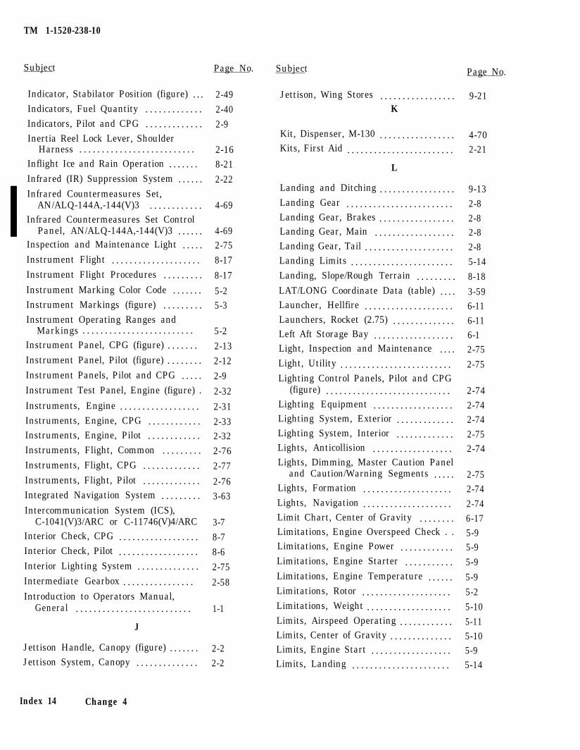
TM 1-1520-238-10
Subject Page No. Subject
Indicator, Stabilator Position (figure) . . .Indicators, Fuel Quantity . . . . . . . . . . . . .Indicators, Pilot and CPG . . . . . . . . . . . . .Inertia Reel Lock Lever, Shoulder
Harness . . . . . . . . . . . . . . . . . . . . . . . . . .Inflight Ice and Rain Operation . . . . . . .Infrared (IR) Suppression System . . . . . .Infrared Countermeasures Set,
AN/ALQ-144A,-144(V)3 . . . . . . . . . . . .Infrared Countermeasures Set Control
Panel, AN/ALQ-144A,-144(V)3 . . . . . .Inspection and Maintenance Light . . . . .Instrument Flight . . . . . . . . . . . . . . . . . . . .Instrument Flight Procedures . . . . . . . . .
Instrument Marking Color Code . . . . . . .Instrument Markings (figure) . . . . . . . . .Instrument Operating Ranges and
Markings . . . . . . . . . . . . . . . . . . . . . . . . .Instrument Panel, CPG (figure) . . . . . . .Instrument Panel, Pilot (figure) . . . . . . . .Instrument Panels, Pilot and CPG . . . . .Instrument Test Panel, Engine (figure) .
Instruments, Engine . . . . . . . . . . . . . . . . . .Instruments, Engine, CPG . . . . . . . . . . . .Instruments, Engine, Pilot . . . . . . . . . . . .Instruments, Flight, Common . . . . . . . . .Instruments, Flight, CPG . . . . . . . . . . . . .Instruments, Flight, Pilot . . . . . . . . . . . . .Integrated Navigation System . . . . . . . . .Intercommunication System (ICS),
C-1041(V)3/ARC or C-11746(V)4/ARCInterior Check, CPG . . . . . . . . . . . . . . . . . .Interior Check, Pilot . . . . . . . . . . . . . . . . . .Interior Lighting System . . . . . . . . . . . . . .Intermediate Gearbox . . . . . . . . . . . . . . . .Introduction to Operators Manual,
General . . . . . . . . . . . . . . . . . . . . . . . . . .
J
Jettison Handle, Canopy (figure) . . . . . . . 2-2Jettison System, Canopy . . . . . . . . . . . . . . 2-2
2-49
2-40
2-9
2-168-21
2-22
4-69
4-692-75
8-17
8-17
5-25-3
5-2
2-13
2-12
2-9
2-32
2-31
2-332-32
2-76
2-77
2-763-63
3-7
8-7
8-6
2-75
2-58
1-1
Page No.
Jettison, Wing Stores . . . . . . . . . . . . . . . . . 9-21K
Kit, Dispenser, M-130 . . . . . . . . . . . . . . . . . 4-70Kits, First Aid . . . . . . . . . . . . . . . . . . . . . . . . 2-21
L
Landing and Ditching . . . . . . . . . . . . . . . . . 9-13Landing Gear . . . . . . . . . . . . . . . . . . . . . . . . 2-8Landing Gear, Brakes . . . . . . . . . . . . . . . . . 2-8Landing Gear, Main . . . . . . . . . . . . . . . . . . 2-8Landing Gear, Tail . . . . . . . . . . . . . . . . . . . . 2-8Landing Limits . . . . . . . . . . . . . . . . . . . . . . . 5-14Landing, Slope/Rough Terrain . . . . . . . . . 8-18LAT/LONG Coordinate Data (table) . . . . 3-59Launcher, Hellfire . . . . . . . . . . . . . . . . . . . . 6-11Launchers, Rocket (2.75) . . . . . . . . . . . . . . 6-11Left Aft Storage Bay . . . . . . . . . . . . . . . . . . 6-1Light, Inspection and Maintenance . . . . 2-75Light, Utility . . . . . . . . . . . . . . . . . . . . . . . . . 2-75Lighting Control Panels, Pilot and CPG
(figure) . . . . . . . . . . . . . . . . . . . . . . . . . . . . 2-74Lighting Equipment . . . . . . . . . . . . . . . . . . 2-74Lighting System, Exterior . . . . . . . . . . . . . 2-74Lighting System, Interior . . . . . . . . . . . . . 2-75Lights, Anticollision . . . . . . . . . . . . . . . . . . 2-74Lights, Dimming, Master Caution Panel
and Caution/Warning Segments . . . . . 2-75Lights, Formation . . . . . . . . . . . . . . . . . . . . 2-74Lights, Navigation . . . . . . . . . . . . . . . . . . . . 2-74Limit Chart, Center of Gravity . . . . . . . . 6-17Limitations, Engine Overspeed Check . . 5-9Limitations, Engine Power . . . . . . . . . . . . 5-9Limitations, Engine Starter . . . . . . . . . . . 5-9Limitations, Engine Temperature . . . . . . 5-9Limitations, Rotor . . . . . . . . . . . . . . . . . . . . 5-2Limitations, Weight . . . . . . . . . . . . . . . . . . . 5-10Limits, Airspeed Operating . . . . . . . . . . . . 5-11Limits, Center of Gravity . . . . . . . . . . . . . . 5-10Limits, Engine Start . . . . . . . . . . . . . . . . . . 5-9Limits, Landing . . . . . . . . . . . . . . . . . . . . . . 5-14
Index 14 Change 4
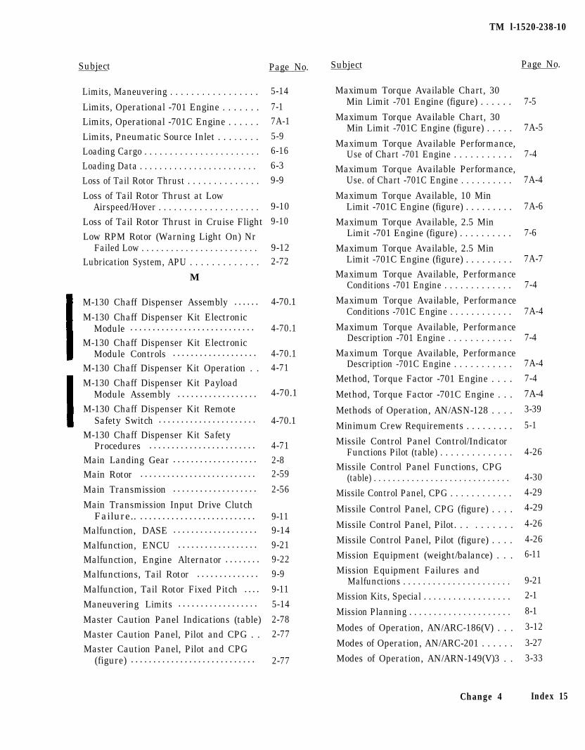
TM l-1520-238-10
Subject Page No. Subject Page No.
Limits, Maneuvering . . . . . . . . . . . . . . . . . 5-14
Limits, Operational -701 Engine . . . . . . . 7-1
Limits, Operational -701C Engine . . . . . . 7A-1
Limits, Pneumatic Source Inlet . . . . . . . . 5-9
Loading Cargo . . . . . . . . . . . . . . . . . . . . . . . 6-16
Loading Data . . . . . . . . . . . . . . . . . . . . . . . . 6-3
Loss of Tail Rotor Thrust . . . . . . . . . . . . . . 9-9
Loss of Tail Rotor Thrust at LowAirspeed/Hover . . . . . . . . . . . . . . . . . . . . 9-10
Loss of Tail Rotor Thrust in Cruise Flight 9-10
Low RPM Rotor (Warning Light On) NrFailed Low . . . . . . . . . . . . . . . . . . . . . . . . 9-12
Lubrication System, APU . . . . . . . . . . . . . 2-72
M
M-130 Chaff Dispenser Assembly . . . . . . 4-70.1
M-130 Chaff Dispenser Kit ElectronicModule . . . . . . . . . . . . . . . . . . . . . . . . . . . . 4-70.1
M-130 Chaff Dispenser Kit ElectronicModule Controls . . . . . . . . . . . . . . . . . . . 4-70.1
M-130 Chaff Dispenser Kit Operation . . 4-71
M-130 Chaff Dispenser Kit PayloadModule Assembly . . . . . . . . . . . . . . . . . . 4-70.1
M-130 Chaff Dispenser Kit RemoteSafety Switch . . . . . . . . . . . . . . . . . . . . . . 4-70.1
M-130 Chaff Dispenser Kit SafetyProcedures . . . . . . . . . . . . . . . . . . . . . . . . 4-71
Main Landing Gear . . . . . . . . . . . . . . . . . . . 2-8Main Rotor . . . . . . . . . . . . . . . . . . . . . . . . . . 2-59
Main Transmission . . . . . . . . . . . . . . . . . . . 2-56
Main Transmission Input Drive ClutchFailure.. . . . . . . . . . . . . . . . . . . . . . . . . . . 9-11
Malfunction, DASE . . . . . . . . . . . . . . . . . . . 9-14
Malfunction, ENCU . . . . . . . . . . . . . . . . . . 9-21
Malfunction, Engine Alternator . . . . . . . . 9-22
Malfunctions, Tail Rotor . . . . . . . . . . . . . . 9-9
Malfunction, Tail Rotor Fixed Pitch . . . . 9-11
Maneuvering Limits . . . . . . . . . . . . . . . . . . 5-14
Master Caution Panel Indications (table) 2-78
Master Caution Panel, Pilot and CPG . . 2-77
Master Caution Panel, Pilot and CPG(figure) . . . . . . . . . . . . . . . . . . . . . . . . . . . . 2-77
Maximum Torque Available Chart, 30Min Limit -701 Engine (figure) . . . . . . 7-5
Maximum Torque Available Chart, 30Min Limit -701C Engine (figure) . . . . . 7A-5
Maximum Torque Available Performance,Use of Chart -701 Engine . . . . . . . . . . . 7-4
Maximum Torque Available Performance,Use. of Chart -701C Engine . . . . . . . . . . 7A-4
Maximum Torque Available, 10 MinLimit -701C Engine (figure) . . . . . . . . . 7A-6
Maximum Torque Available, 2.5 MinLimit -701 Engine (figure) . . . . . . . . . . 7-6
Maximum Torque Available, 2.5 MinLimit -701C Engine (figure) . . . . . . . . . 7A-7
Maximum Torque Available, PerformanceConditions -701 Engine . . . . . . . . . . . . . 7-4
Maximum Torque Available, PerformanceConditions -701C Engine . . . . . . . . . . . . 7A-4
Maximum Torque Available, PerformanceDescription -701 Engine . . . . . . . . . . . . 7-4
Maximum Torque Available, PerformanceDescription -701C Engine . . . . . . . . . . . 7A-4
Method, Torque Factor -701 Engine . . . . 7-4
Method, Torque Factor -701C Engine . . . 7A-4
Methods of Operation, AN/ASN-128 . . . . 3-39
Minimum Crew Requirements . . . . . . . . . 5-1
Missile Control Panel Control/IndicatorFunctions Pilot (table) . . . . . . . . . . . . . . 4-26
Missile Control Panel Functions, CPG(table) . . . . . . . . . . . . . . . . . . . . . . . . . . . . . 4-30
Missile Control Panel, CPG . . . . . . . . . . . . 4-29
Missile Control Panel, CPG (figure) . . . . 4-29
Missile Control Panel, Pilot. . . . . . . . . . 4-26
Missile Control Panel, Pilot (figure) . . . . 4-26
Mission Equipment (weight/balance) . . . 6-11
Mission Equipment Failures andMalfunctions . . . . . . . . . . . . . . . . . . . . . . 9-21
Mission Kits, Special . . . . . . . . . . . . . . . . . . 2-1
Mission Planning . . . . . . . . . . . . . . . . . . . . . 8-1
Modes of Operation, AN/ARC-186(V) . . . 3-12
Modes of Operation, AN/ARC-201 . . . . . . 3-27
Modes of Operation, AN/ARN-149(V)3 . . 3-33
Change 4 Index 15
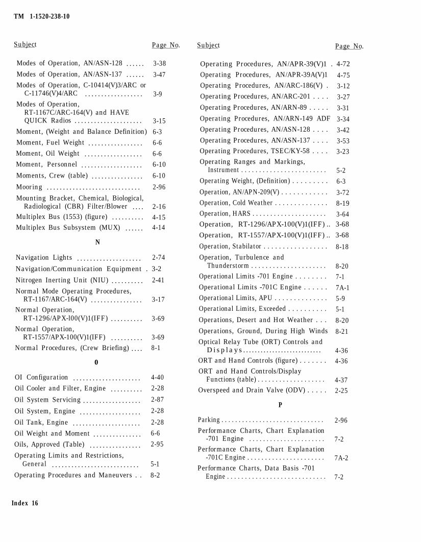
TM 1-1520-238-10
Subject Page No.
Modes of Operation, AN/ASN-128 . . . . . . 3-38
Modes of Operation, AN/ASN-137 . . . . . . 3-47Modes of Operation, C-10414(V)3/ARC or
C-11746(V)4/ARC . . . . . . . . . . . . . . . . . . 3-9Modes of Operation,
RT-1167C/ARC-164(V) and HAVEQUICK Radios . . . . . . . . . . . . . . . . . . . . . 3-15
Moment, (Weight and Balance Definition) 6-3Moment, Fuel Weight . . . . . . . . . . . . . . . . . 6-6Moment, Oil Weight . . . . . . . . . . . . . . . . . . 6-6Moment, Personnel . . . . . . . . . . . . . . . . . . . 6-10
Moments, Crew (table) . . . . . . . . . . . . . . . . 6-10
Mooring . . . . . . . . . . . . . . . . . . . . . . . . . . . . . 2-96
Mounting Bracket, Chemical, Biological,Radiological (CBR) Filter/Blower . . . . 2-16
Multiplex Bus (1553) (figure) . . . . . . . . . . 4-15Multiplex Bus Subsystem (MUX) . . . . . . 4-14
N
Navigation Lights . . . . . . . . . . . . . . . . . . . . 2-74
Navigation/Communication Equipment . 3-2
Nitrogen Inerting Unit (NIU) . . . . . . . . . . 2-41
Normal Mode Operating Procedures,RT-1167/ARC-164(V) . . . . . . . . . . . . . . . . 3-17
Normal Operation,RT-1296/APX-l00(V)1(IFF) . . . . . . . . . . 3-69
Normal Operation,RT-1557/APX-100(V)1(IFF) . . . . . . . . . . 3-69
Normal Procedures, (Crew Briefing) . . . . 8-1
0
OI Configuration . . . . . . . . . . . . . . . . . . . . . 4-40
Oil Cooler and Filter, Engine . . . . . . . . . . 2-28
Oil System Servicing . . . . . . . . . . . . . . . . . . 2-87
Oil System, Engine . . . . . . . . . . . . . . . . . . . 2-28
Oil Tank, Engine . . . . . . . . . . . . . . . . . . . . . 2-28
Oil Weight and Moment . . . . . . . . . . . . . . . 6-6
Oils, Approved (Table) . . . . . . . . . . . . . . . . 2-95
Operating Limits and Restrictions,General . . . . . . . . . . . . . . . . . . . . . . . . . . . 5-1
Operating Procedures and Maneuvers . . 8-2
Index 16
Subject Page No.
Operating Procedures, AN/APR-39(V)1 . 4-72
Operating Procedures, AN/APR-39A(V)1 4-75Operating Procedures, AN/ARC-186(V) . 3-12Operating Procedures, AN/ARC-201 . . . . 3-27Operating Procedures, AN/ARN-89 . . . . . 3-31Operating Procedures, AN/ARN-149 ADF 3-34Operating Procedures, AN/ASN-128 . . . . 3-42Operating Procedures, AN/ASN-137 . . . . 3-53Operating Procedures, TSEC/KY-58 . . . . 3-23Operating Ranges and Markings,
Instrument . . . . . . . . . . . . . . . . . . . . . . . . 5-2Operating Weight, (Definition) . . . . . . . . . 6-3Operation, AN/APN-209(V) . . . . . . . . . . . . 3-72Operation, Cold Weather . . . . . . . . . . . . . . 8-19Operation, HARS . . . . . . . . . . . . . . . . . . . . . 3-64Operation, RT-1296/APX-100(V)1(IFF) .. 3-68
Operation, RT-1557/APX-100(V)1(IFF) .. 3-68
Operation, Stabilator . . . . . . . . . . . . . . . . . 8-18Operation, Turbulence and
Thunderstorm . . . . . . . . . . . . . . . . . . . . . 8-20Operational Limits -701 Engine . . . . . . . . 7-1Operational Limits -701C Engine . . . . . . 7A-1Operational Limits, APU . . . . . . . . . . . . . . 5-9Operational Limits, Exceeded . . . . . . . . . . 5-1Operations, Desert and Hot Weather . . . 8-20Operations, Ground, During High Winds 8-21Optical Relay Tube (ORT) Controls and
Displays . . . . . . . . . . . . . . . . . . . . . . . . . . . 4-36ORT and Hand Controls (figure) . . . . . . . 4-36ORT and Hand Controls/Display
Functions (table) . . . . . . . . . . . . . . . . . . . 4-37Overspeed and Drain Valve (ODV) . . . . . 2-25
P
Parking . . . . . . . . . . . . . . . . . . . . . . . . . . . . . . 2-96Performance Charts, Chart Explanation
-701 Engine . . . . . . . . . . . . . . . . . . . . . . 7-2Performance Charts, Chart Explanation
-701C Engine . . . . . . . . . . . . . . . . . . . . . . 7A-2Performance Charts, Data Basis -701
Engine . . . . . . . . . . . . . . . . . . . . . . . . . . . . 7-2
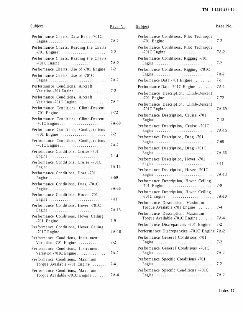
Subject
Performance Charts, Data Basis -701CEngine . . . . . . . . . . . . . . . . . . . . . . . . . . . .
Performance Charts, Reading the Charts-701 Engine . . . . . . . . . . . . . . . . . . . . . . .
Performance Charts, Reading the Charts-701C Engine . . . . . . . . . . . . . . . . . . . . . .
Performance Charts, Use of -701 Engine
Performance Charts, Use of -701CEngine . . . . . . . . . . . . . . . . . . . . . . . . . . . .
Performance Conditions, AircraftVariation -701 Engine . . . . . . . . . . . . . .
Performance Conditions, AircraftVariation -701C Engine . . . . . . . . . . . . .
Performance Conditions, Climb-Descent-701 Engine . . . . . . . . . . . . . . . . . . . . . . .
Performance Conditions, Climb-Descent-701C Engine . . . . . . . . . . . . . . . . . . . . . .
Performance Conditions, Configurations-701 Engine . . . . . . . . . . . . . . . . . . . . . . .
Performance Conditions, Configurations-701C Engine . . . . . . . . . . . . . . . . . . . . . .
Performance Conditions, Cruise -701Engine . . . . . . . . . . . . . . . . . . . . . . . . . . . .
Performance Conditions, Cruise -701CEngine . . . . . . . . . . . . . . . . . . . . . . . . . . . .
Performance Conditions, Drag -701Engine . . . . . . . . . . . . . . . . . . . . . . . . . . . .
Performance Conditions, Drag -701CEngine . . . . . . . . . . . . . . . . . . . . . . . . . . . .
Performance Conditions, Hover -701Engine . . . . . . . . . . . . . . . . . . . . . . . . . . . .
Performance Conditions, Hover -701CEngine . . . . . . . . . . . . . . . . . . . . . . . . . . . .
Performance Conditions, Hover Ceiling-701 Engine . . . . . . . . . . . . . . . . . . . . . . .
Performance Conditions, Hover Ceiling-701C Engine . . . . . . . . . . . . . . . . . . . . . .
Performance Conditions, InstrumentVariation -701 Engine . . . . . . . . . . . . . .
Performance Conditions, InstrumentVariation -701C Engine . . . . . . . . . . . . .
Performance Conditions, MaximumTorque Available -701 Engine . . . . . . .
Performance Conditions, MaximumTorque Available -701C Engine . . . . . .
Page No.
7A-2
7-2
7A-2
7-2
7A-2
7-2
7A-2
7-72
7A-69
7-2
7A-2
7-14
7A-16
7-69
7A-66
7-11
7A-13
7-9
7A-10
7-2
7A-2
7-4
7A-4
TM 1-1520-238-10
Subject Page No.
Performance Conditions, Pilot Technique-701 Engine . . . . . . . . . . . . . . . . . . . . . . . 7-2
Performance Conditions, Pilot Technique-701C Engine . . . . . . . . . . . . . . . . . . . . . . 7A-2
Performance Conditions, Rigging -701Engine . . . . . . . . . . . . . . . . . . . . . . . . . . . . 7-2
Performance Conditions, Rigging -701CEngine . . . . . . . . . . . . . . . . . . . . . . . . . . . . 7A-2
Performance Data -701 Engine . . . . . . . . 7-1
Performance Data -701C Engine . . . . . . . 7A-1
Performance Description, Climb-Descent-701 Engine . . . . . . . . . . . . . . . . . . . . . . . 7-72
Performance Description, Climb-Descent-701C Engine . . . . . . . . . . . . . . . . . . . . . . 7A-69
Performance Description, Cruise -701Engine . . . . . . . . . . . . . . . . . . . . . . . . . . . . 7-13
Performance Description, Cruise -701CEngine . . . . . . . . . . . . . . . . . . . . . . . . . . . . 7A-15
Performance Description, Drag -701Engine . . . . . . . . . . . . . . . . . . . . . . . . . . . . 7-69
Performance Description, Drag -701CEngine . . . . . . . . . . . . . . . . . . . . . . . . . . . . 7A-66
Performance Description, Hover -701Engine . . . . . . . . . . . . . . . . . . . . . . . . . . . . 7-11
Performance Description, Hover -701CEngine . . . . . . . . . . . . . . . . . . . . . . . . . . . . 7A-13
Performance Description, Hover Ceiling-701 Engine . . . . . . . . . . . . . . . . . . . . . . . 7-9
Performance Description, Hover Ceiling-701C Engine . . . . . . . . . . . . . . . . . . . . . . 7A-10
Performance Description, MaximumTorque Available -701 Engine . . . . . . . 7-4
Performance Description, MaximumTorque Available -701C Engine . . . . . . 7A-4
Performance Discrepancies -701 Engine 7-2
Performance Discrepancies -701C Engine 7A-2
Performance General Conditions -701Engine . . . . . . . . . . . . . . . . . . . . . . . . . . . . 7-2
Performance General Conditions -701CEngine . . . . . . . . . . . . . . . . . . . . . . . . . . . . 7A-2
Performance Specific Conditions -701Engine . . . . . . . . . . . . . . . . . . . . . . . . . . . . 7-2
Performance Specific Conditions -701CEngine . . . . . . . . . . . . . . . . . . . . . . . . . . . . 7A-2
Index 17
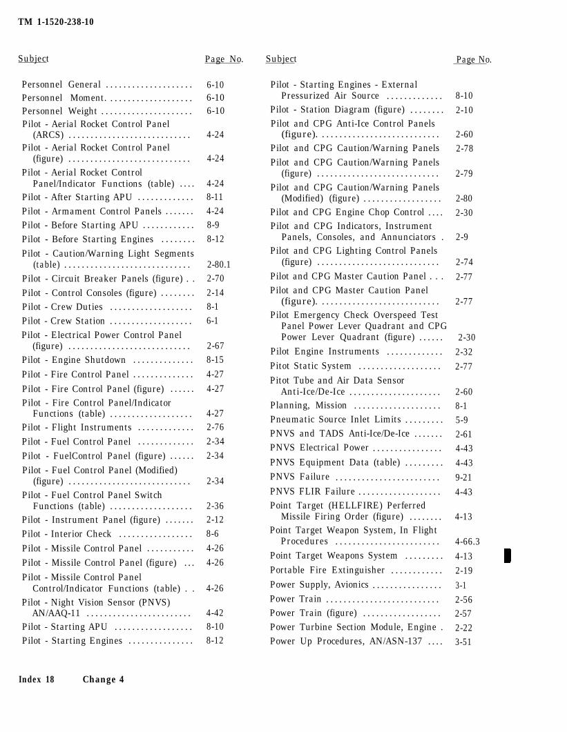
TM 1-1520-238-10
Subject Page No. Subject Page No.
Personnel General . . . . . . . . . . . . . . . . . . . . 6-10Personnel Moment. . . . . . . . . . . . . . . . . . . . 6-10Personnel Weight . . . . . . . . . . . . . . . . . . . . . 6-10Pilot - Aerial Rocket Control Panel
(ARCS) . . . . . . . . . . . . . . . . . . . . . . . . . . . . 4-24Pilot - Aerial Rocket Control Panel
(figure) . . . . . . . . . . . . . . . . . . . . . . . . . . . . 4-24Pilot - Aerial Rocket Control
Panel/Indicator Functions (table) . . . . 4-24Pilot - After Starting APU . . . . . . . . . . . . . 8-11Pilot - Armament Control Panels . . . . . . . 4-24Pilot - Before Starting APU . . . . . . . . . . . . 8-9Pilot - Before Starting Engines . . . . . . . . 8-12
Pilot - Caution/Warning Light Segments(table) . . . . . . . . . . . . . . . . . . . . . . . . . . . . . 2-80.1
Pilot - Circuit Breaker Panels (figure) . . 2-70
Pilot - Control Consoles (figure) . . . . . . . . 2-14Pilot - Crew Duties . . . . . . . . . . . . . . . . . . . 8-1Pilot - Crew Station . . . . . . . . . . . . . . . . . . . 6-1Pilot - Electrical Power Control Panel
(figure) . . . . . . . . . . . . . . . . . . . . . . . . . . . . 2-67Pilot - Engine Shutdown . . . . . . . . . . . . . . 8-15
Pilot - Fire Control Panel . . . . . . . . . . . . . . 4-27
Pilot - Fire Control Panel (figure) . . . . . . 4-27Pilot - Fire Control Panel/Indicator
Functions (table) . . . . . . . . . . . . . . . . . . . 4-27Pilot - Flight Instruments . . . . . . . . . . . . . 2-76
Pilot - Fuel Control Panel . . . . . . . . . . . . . 2-34
Pilot - FuelControl Panel (figure) . . . . . . 2-34
Pilot - Fuel Control Panel (Modified)(figure) . . . . . . . . . . . . . . . . . . . . . . . . . . . . 2-34
Pilot - Fuel Control Panel SwitchFunctions (table) . . . . . . . . . . . . . . . . . . . 2-36
Pilot - Instrument Panel (figure) . . . . . . . 2-12Pilot - Interior Check . . . . . . . . . . . . . . . . . 8-6
Pilot - Missile Control Panel . . . . . . . . . . . 4-26
Pilot - Missile Control Panel (figure) . . . 4-26
Pilot - Missile Control PanelControl/Indicator Functions (table) . . 4-26
Pilot - Night Vision Sensor (PNVS)AN/AAQ-11 . . . . . . . . . . . . . . . . . . . . . . . . 4-42
Pilot - Starting APU . . . . . . . . . . . . . . . . . . 8-10Pilot - Starting Engines . . . . . . . . . . . . . . . 8-12
8-10
2-10
2-602-78
2-79
2-802-30
2-9
2-74
2-77
2-77
Pilot - Starting Engines - ExternalPressurized Air Source . . . . . . . . . . . . .
Pilot - Station Diagram (figure) . . . . . . . .Pilot and CPG Anti-Ice Control Panels
(figure). . . . . . . . . . . . . . . . . . . . . . . . . . . .Pilot and CPG Caution/Warning PanelsPilot and CPG Caution/Warning Panels
(figure) . . . . . . . . . . . . . . . . . . . . . . . . . . . .Pilot and CPG Caution/Warning Panels
(Modified) (figure) . . . . . . . . . . . . . . . . . .Pilot and CPG Engine Chop Control . . . .Pilot and CPG Indicators, Instrument
Panels, Consoles, and Annunciators .Pilot and CPG Lighting Control Panels
(figure) . . . . . . . . . . . . . . . . . . . . . . . . . . . .Pilot and CPG Master Caution Panel . . .Pilot and CPG Master Caution Panel
(figure). . . . . . . . . . . . . . . . . . . . . . . . . . . .Pilot Emergency Check Overspeed Test
Panel Power Lever Quadrant and CPGPower Lever Quadrant (figure) . . . . . .
Pilot Engine Instruments . . . . . . . . . . . . .Pitot Static System . . . . . . . . . . . . . . . . . . .Pitot Tube and Air Data Sensor
Anti-Ice/De-Ice . . . . . . . . . . . . . . . . . . . . .Planning, Mission . . . . . . . . . . . . . . . . . . . .Pneumatic Source Inlet Limits . . . . . . . . .PNVS and TADS Anti-Ice/De-Ice . . . . . . .PNVS Electrical Power . . . . . . . . . . . . . . . .PNVS Equipment Data (table) . . . . . . . . .PNVS Failure . . . . . . . . . . . . . . . . . . . . . . . .PNVS FLIR Failure . . . . . . . . . . . . . . . . . . .Point Target (HELLFIRE) Perferred
Missile Firing Order (figure) . . . . . . . .Point Target Weapon System, In Flight
Procedures . . . . . . . . . . . . . . . . . . . . . . . .Point Target Weapons System . . . . . . . . .Portable Fire Extinguisher . . . . . . . . . . . .Power Supply, Avionics . . . . . . . . . . . . . . . .Power Train . . . . . . . . . . . . . . . . . . . . . . . . . .Power Train (figure) . . . . . . . . . . . . . . . . . .Power Turbine Section Module, Engine .Power Up Procedures, AN/ASN-137 . . . .
2-30
2-32
2-77
2-608-15-92-614-43
4-43
9-21
4-43
4-13
4-66.3
4-132-19
3-12-562-572-223-51
Index 18 Change 4
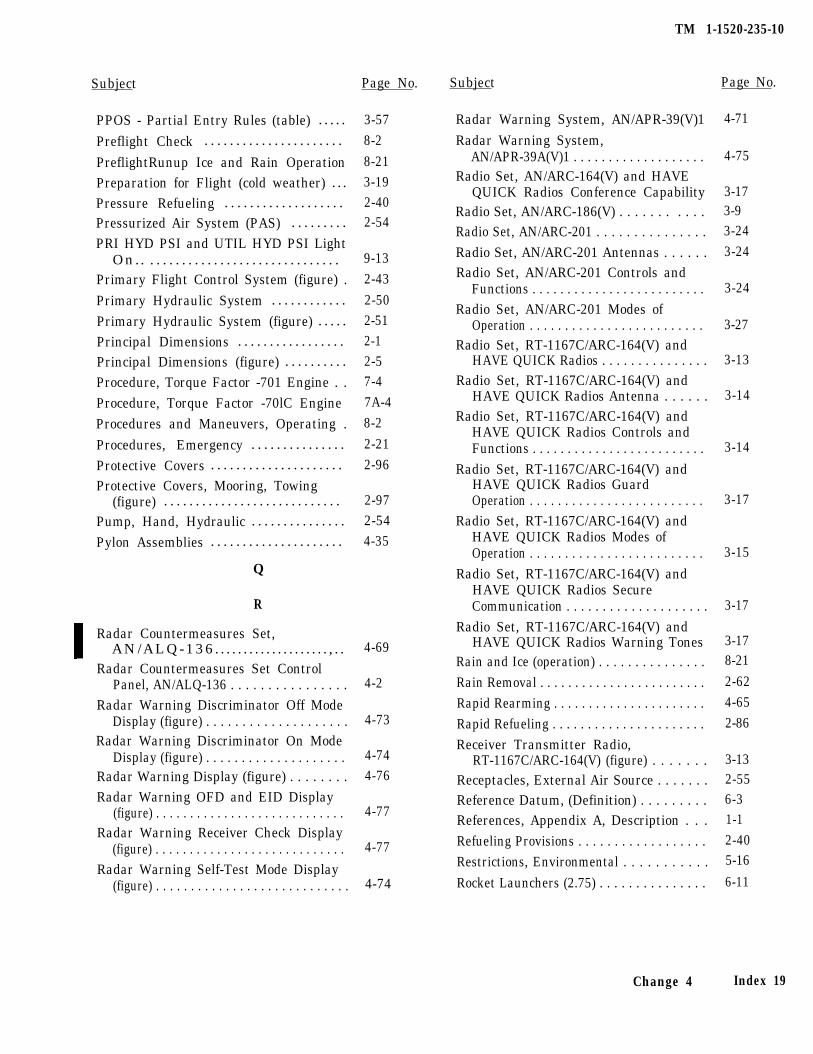
Subject Page No.
PPOS - Partial Entry Rules (table) . . . . .
Preflight Check . . . . . . . . . . . . . . . . . . . . . .
PreflightRunup Ice and Rain OperationPreparation for Flight (cold weather) . . .Pressure Refueling . . . . . . . . . . . . . . . . . . .Pressurized Air System (PAS) . . . . . . . . .
PRI HYD PSI and UTIL HYD PSI LightOn.. . . . . . . . . . . . . . . . . . . . . . . . . . . . . . .
Primary Flight Control System (figure) .
Primary Hydraulic System . . . . . . . . . . . .
Primary Hydraulic System (figure) . . . . .
Principal Dimensions . . . . . . . . . . . . . . . . .Principal Dimensions (figure) . . . . . . . . . .
Procedure, Torque Factor -701 Engine . .Procedure, Torque Factor -70lC EngineProcedures and Maneuvers, Operating .
Procedures, Emergency . . . . . . . . . . . . . . .
Protective Covers . . . . . . . . . . . . . . . . . . . . .
Protective Covers, Mooring, Towing(figure) . . . . . . . . . . . . . . . . . . . . . . . . . . . .
Pump, Hand, Hydraulic . . . . . . . . . . . . . . .
Pylon Assemblies . . . . . . . . . . . . . . . . . . . . .
Q
R
4-69
4-2
4-73
Radar Countermeasures Set,AN/ALQ-136. . . . . . . . . . . . . . . . . . . . , . .
Radar Countermeasures Set ControlPanel, AN/ALQ-136 . . . . . . . . . . . . . . . .
Radar Warning Discriminator Off ModeDisplay (figure) . . . . . . . . . . . . . . . . . . . .
Radar Warning Discriminator On ModeDisplay (figure) . . . . . . . . . . . . . . . . . . . .
Radar Warning Display (figure) . . . . . . . .Radar Warning OFD and EID Display
(figure) . . . . . . . . . . . . . . . . . . . . . . . . . . . .Radar Warning Receiver Check Display
(figure) . . . . . . . . . . . . . . . . . . . . . . . . . . . .Radar Warning Self-Test Mode Display
(figure) . . . . . . . . . . . . . . . . . . . . . . . . . . . .
4-744-76
4-77
4-77
4-74
3-578-2
8-213-192-402-54
9-132-43
2-502-512-12-57-47A-48-2
2-212-96
2-972-544-35
TM 1-1520-235-10
Subject Page No.
Radar Warning System, AN/APR-39(V)1 4-71
Radar Warning System,AN/APR-39A(V)1 . . . . . . . . . . . . . . . . . . . 4-75
Radio Set, AN/ARC-164(V) and HAVEQUICK Radios Conference Capability 3-17
Radio Set, AN/ARC-186(V) . . . . . . . . . . . 3-9
Radio Set, AN/ARC-201 . . . . . . . . . . . . . . . 3-24
Radio Set, AN/ARC-201 Antennas . . . . . . 3-24
Radio Set, AN/ARC-201 Controls andFunctions . . . . . . . . . . . . . . . . . . . . . . . . . 3-24
Radio Set, AN/ARC-201 Modes ofOperation . . . . . . . . . . . . . . . . . . . . . . . . . 3-27
Radio Set, RT-1167C/ARC-164(V) andHAVE QUICK Radios . . . . . . . . . . . . . . . 3-13
Radio Set, RT-1167C/ARC-164(V) andHAVE QUICK Radios Antenna . . . . . . 3-14
Radio Set, RT-1167C/ARC-164(V) andHAVE QUICK Radios Controls andFunctions . . . . . . . . . . . . . . . . . . . . . . . . . 3-14
Radio Set, RT-1167C/ARC-164(V) andHAVE QUICK Radios GuardOperation . . . . . . . . . . . . . . . . . . . . . . . . . 3-17
Radio Set, RT-1167C/ARC-164(V) andHAVE QUICK Radios Modes ofOperation . . . . . . . . . . . . . . . . . . . . . . . . . 3-15
Radio Set, RT-1167C/ARC-164(V) andHAVE QUICK Radios SecureCommunication . . . . . . . . . . . . . . . . . . . . 3-17
Radio Set, RT-1167C/ARC-164(V) andHAVE QUICK Radios Warning Tones 3-17
Rain and Ice (operation) . . . . . . . . . . . . . . . 8-21
Rain Removal . . . . . . . . . . . . . . . . . . . . . . . . 2-62
Rapid Rearming . . . . . . . . . . . . . . . . . . . . . . 4-65
Rapid Refueling . . . . . . . . . . . . . . . . . . . . . . 2-86
Receiver Transmitter Radio,RT-1167C/ARC-164(V) (figure) . . . . . . . 3-13
Receptacles, External Air Source . . . . . . . 2-55
Reference Datum, (Definition) . . . . . . . . . 6-3
References, Appendix A, Description . . . 1-1
Refueling Provisions . . . . . . . . . . . . . . . . . . 2-40
Restrictions, Environmental . . . . . . . . . . . 5-16
Rocket Launchers (2.75) . . . . . . . . . . . . . . . 6-11
Change 4 Index 19
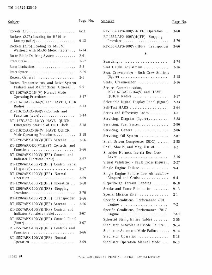
TM 1-1520-235-10
Subject Page No. Subject Page No.
Rockets (2.75) . . . . . . . . . . . . . . . . . . . . . . . .
Rockets (2.75) Loading for H519 orDummy (table) . . . . . . . . . . . . . . . . . . . . .
Rockets (2.75) Loading for MPSMWarhead with MK66 Motor (table) . . .
Rotor Blade De-Icing System . . . . . . . . . .Rotor Brake . . . . . . . . . . . . . . . . . . . . . . . . . .
Rotor Limitations . . . . . . . . . . . . . . . . . . . . .Rotor System . . . . . . . . . . . . . . . . . . . . . . . . .Rotors, General . . . . . . . . . . . . . . . . . . . . . .Rotors, Transmissions, and Drive System
Failures and Malfunctions, General . .RT-1167/ARC-164(V) Normal Mode
Operating Procedures . . . . . . . . . . . . . .RT-1167C/ARC-164(V) and HAVE QUICK
Radios . . . . . . . . . . . . . . . . . . . . . . . . . . . .RT-1167C/ARC-164(V) Controls and
Functions (table) . . . . . . . . . . . . . . . . . . .RT-1167C/ARC-164(-V) HAVE QUICK
Emergency Startup of TOD Clock . . .
RT-1167C/ARC-164(V) HAVE QUICKMode Operating Procedures . . . . . . . . .
RT-1296/APX-100(V)1(IFF) Antenna . . .RT-1296/APX-l00(V)1(IFF) Controls and
Functions . . . . . . . . . . . . . . . . . . . . . . . . .RT-1296/APX-100(V)1(IFF) Control and
Indicator Functions (table) . . . . . . . . . .RT-1296/APX-100(V)1(IFF) Control Panel
( f i g u r e ) . . . . . . . . . . . . . . . . . . . . . . . . . . . .RT-1296/APX-100(V)1(IFF) Normal
Operation . . . . . . . . . . . . . . . . . . . . . . . . .RT-1296/APX-100(V)1(IFF) Operation . .RT-1296/APX-100(V)1(IFF) Stopping
Procedure . . . . . . . . . . . . . . . . . . . . . . . . .RT-1296/APX-100(V)1(IFF) Transponder
RT-1557/APX-100(V)1(IFF) Antenna . . .
RT-1557/APX-100(V)1(IFF) Control andIndicator Functions (table) . . . . . . . . . .
RT-1557/APX-100(V)1(IFF) Control Panel(figure) . . . . . . . . . . . . . . . . . . . . . . . . . . . .
RT-1557/APX-100(V)1(IFF) Controls andFunctions . . . . . . . . . . . . . . . . . . . . . . . . .
RT-1557/APX-100(V)1(IFF) NormalOperation . . . . . . . . . . . . . . . . . . . . . . . . .
6-11
6-13
6-14
2-612-57
5-22-592-1
9-9
3-17
3-13
3-14
3-18
3-18
3-66
3-66
3-67
3-67
3-693-68
3-70
3-66
3-66
3-67
3-67
3-66
3-69
RT-1557/APX-100(V)1(IFF) Operation . .
RT-1557/APX-100(V)1(IFF) StoppingProcedure . . . . . . . . . . . . . . . . . . . . . . . . .
RT-1557/APX-100(V)l(IFF) Transponder
S
Searchlight . . . . . . . . . . . . . . . . . . . . . . . . . .
Seat Height Adjustment . . . . . . . . . . . . . . .Seat, Crewmember - Both Crew Stations
(figure) . . . . . . . . . . . . . . . . . . . . . . . . . . . .
Seats, Crewmember . . . . . . . . . . . . . . . . . .
Secure Communication,RT-1167C/ARC-164(V) and HAVEQUICK Radios . . . . . . . . . . . . . . . . . . . . .
Selectable Digital Display Panel (figure)
Self-Test HARS . . . . . . . . . . . . . . . . . . . . . . .
Series and Effectivity Codes . . . . . . . . . . .
Servicing, Diagram (figure) . . . . . . . . . . . .
Servicing, Fuel System . . . . . . . . . . . . . . . .
Servicing, General . . . . . . . . . . . . . . . . . . . .
Servicing, Oil System . . . . . . . . . . . . . . . . .
Shaft Driven Compressor (SDC) . . . . . . .
Shall, Should, and May, Use of. . . . . . . . .
Shoulder Harness Inertia Reel LockLever . . . . . . . . . . . . . . . . . . . . . . . . . . . . .
Signal Validation - Fault Codes (figure) .
Single Engine Failure . . . . . . . . . . . . . . . . .
Single Engine Failure Low Altitude/LowAirspeed and Cruise . . . . . . . . . . . . . . . .
Slope/Rough Terrain Landing . . . . . . . . . .
Smoke and Fume Elimination . . . . . . . . .
Special Mission Kits . . . . . . . . . . . . . . . . . .
Specific Conditions, Performance -701Engine . . . . . . . . . . . . . . . . . . . . . . . . . . . .
Specific Conditions, Performance -701CEngine . . . . . . . . . . . . . . . . . . . . . . . . . . . .
Spheroid String Enties (table) . . . . . . . . .
Stabilator Auto/Manual Mode Failure . .
Stabilator Automatic Mode Failure . . . . .
Stabilator Operation . . . . . . . . . . . . . . . . . .
Stabilator Operation Manual Mode . . . . .
3-68
3-70
3-66
2-74
2-16
2-18
2-16
3-17
2-33
3-64
1-2
2-88
2-86
2-86
2-87
2-55
1-2
2-16
2-27
9-4
9-4
8-18
9-13
2-1
7-2
7A-2
3-56
9-14
9-14
8-18
8-18
Index 20 *U.S. GOVERNMENT PRINTING OFFICE: 1997-554-121/60109
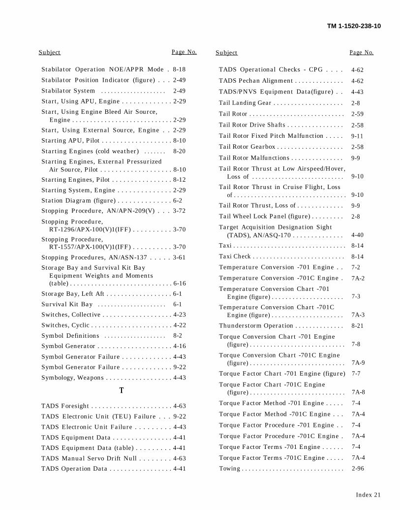
TM 1-1520-238-10
Subject Page No. Page No.
Stabilator Operation NOE/APPR Mode . 8-18
Stabilator Position Indicator (figure) . . . 2-49
Stabilator System . . . . . . . . . . . . . . . . . . . . 2-49
Start, Using APU, Engine . . . . . . . . . . . . . 2-29
Start, Using Engine Bleed Air Source,Engine . . . . . . . . . . . . . . . . . . . . . . . . . . . . 2-29
Start, Using External Source, Engine . . 2-29
Starting APU, Pilot . . . . . . . . . . . . . . . . . . . 8-10
Starting Engines (cold weather) . . . . . . . 8-20
Starting Engines, External PressurizedAir Source, Pilot . . . . . . . . . . . . . . . . . . . 8-10
Starting Engines, Pilot . . . . . . . . . . . . . . . . 8-12
Starting System, Engine . . . . . . . . . . . . . . 2-29
Station Diagram (figure) . . . . . . . . . . . . . . 6-2
Stopping Procedure, AN/APN-209(V) . . . 3-72
Stopping Procedure,RT-1296/APX-100(V)1(IFF) . . . . . . . . . . 3-70
Stopping Procedure,RT-1557/APX-100(V)1(IFF) . . . . . . . . . . 3-70
Stopping Procedures, AN/ASN-137 . . . . . 3-61
Storage Bay and Survival Kit BayEquipment Weights and Moments(table) . . . . . . . . . . . . . . . . . . . . . . . . . . . . . 6-16
Storage Bay, Left Aft . . . . . . . . . . . . . . . . . . 6-1
Survival Kit Bay . . . . . . . . . . . . . . . . . . . . . 6-1
Switches, Collective . . . . . . . . . . . . . . . . . . . 4-23
Switches, Cyclic . . . . . . . . . . . . . . . . . . . . . . 4-22
Symbol Definitions . . . . . . . . . . . . . . . . . . . 8-2
Symbol Generator . . . . . . . . . . . . . . . . . . . . 4-16
Symbol Generator Failure . . . . . . . . . . . . . 4-43
Symbol Generator Failure . . . . . . . . . . . . . 9-22
Symbology, Weapons . . . . . . . . . . . . . . . . . . 4-43
T
TADS Foresight . . . . . . . . . . . . . . . . . . . . . . 4-63
TADS Electronic Unit (TEU) Failure . . . 9-22
TADS Electronic Unit Failure . . . . . . . . . 4-43
TADS Equipment Data . . . . . . . . . . . . . . . . 4-41
TADS Equipment Data (table) . . . . . . . . . 4-41
TADS Manual Servo Drift Null . . . . . . . . 4-63
TADS Operation Data . . . . . . . . . . . . . . . . . 4-41
Subject
TADS Operational Checks - CPG . . . .
TADS Pechan Alignment . . . . . . . . . . . . . .
TADS/PNVS Equipment Data(figure) . .
Tail Landing Gear . . . . . . . . . . . . . . . . . . . .
Tail Rotor . . . . . . . . . . . . . . . . . . . . . . . . . . . .
Tail Rotor Drive Shafts . . . . . . . . . . . . . . . .
Tail Rotor Fixed Pitch Malfunction . . . . .
Tail Rotor Gearbox . . . . . . . . . . . . . . . . . . .
Tail Rotor Malfunctions . . . . . . . . . . . . . . .
Tail Rotor Thrust at Low Airspeed/Hover,Loss of . . . . . . . . . . . . . . . . . . . . . . . . . . . .
Tail Rotor Thrust in Cruise Flight, Lossof . . . . . . . . . . . . . . . . . . . . . . . . . . . . . . . . .
Tail Rotor Thrust, Loss of . . . . . . . . . . . . .
Tail Wheel Lock Panel (figure) . . . . . . . . .
Target Acquisition Designation Sight(TADS), AN/ASQ-170 . . . . . . . . . . . . . .
Taxi . . . . . . . . . . . . . . . . . . . . . . . . . . . . . . . . .
Taxi Check . . . . . . . . . . . . . . . . . . . . . . . . . . .
Temperature Conversion -701 Engine . .
Temperature Conversion -701C Engine .
Temperature Conversion Chart -701Engine (figure) . . . . . . . . . . . . . . . . . . . . .
Temperature Conversion Chart -701CEngine (figure) . . . . . . . . . . . . . . . . . . . . .
Thunderstorm Operation . . . . . . . . . . . . . .
Torque Conversion Chart -701 Engine(figure) . . . . . . . . . . . . . . . . . . . . . . . . . . . .
Torque Conversion Chart -701C Engine(figure) . . . . . . . . . . . . . . . . . . . . . . . . . . . .
Torque Factor Chart -701 Engine (figure)
Torque Factor Chart -701C Engine(figure) . . . . . . . . . . . . . . . . . . . . . . . . . . . .
Torque Factor Method -701 Engine . . . . .
Torque Factor Method -701C Engine . . .
Torque Factor Procedure -701 Engine . .
Torque Factor Procedure -701C Engine .
Torque Factor Terms -701 Engine . . . . . .
Torque Factor Terms -701C Engine . . . . .
Towing . . . . . . . . . . . . . . . . . . . . . . . . . . . . . .
4-62
4-62
4-43
2-8
2-59
2-58
9-11
2-58
9-9
9-10
9-10
9-9
2-8
4-40
8-14
8-14
7-2
7A-2
7-3
7A-3
8-21
7-8
7A-9
7-7
7A-8
7-4
7A-4
7-4
7A-4
7-4
7A-4
2-96
Index 21
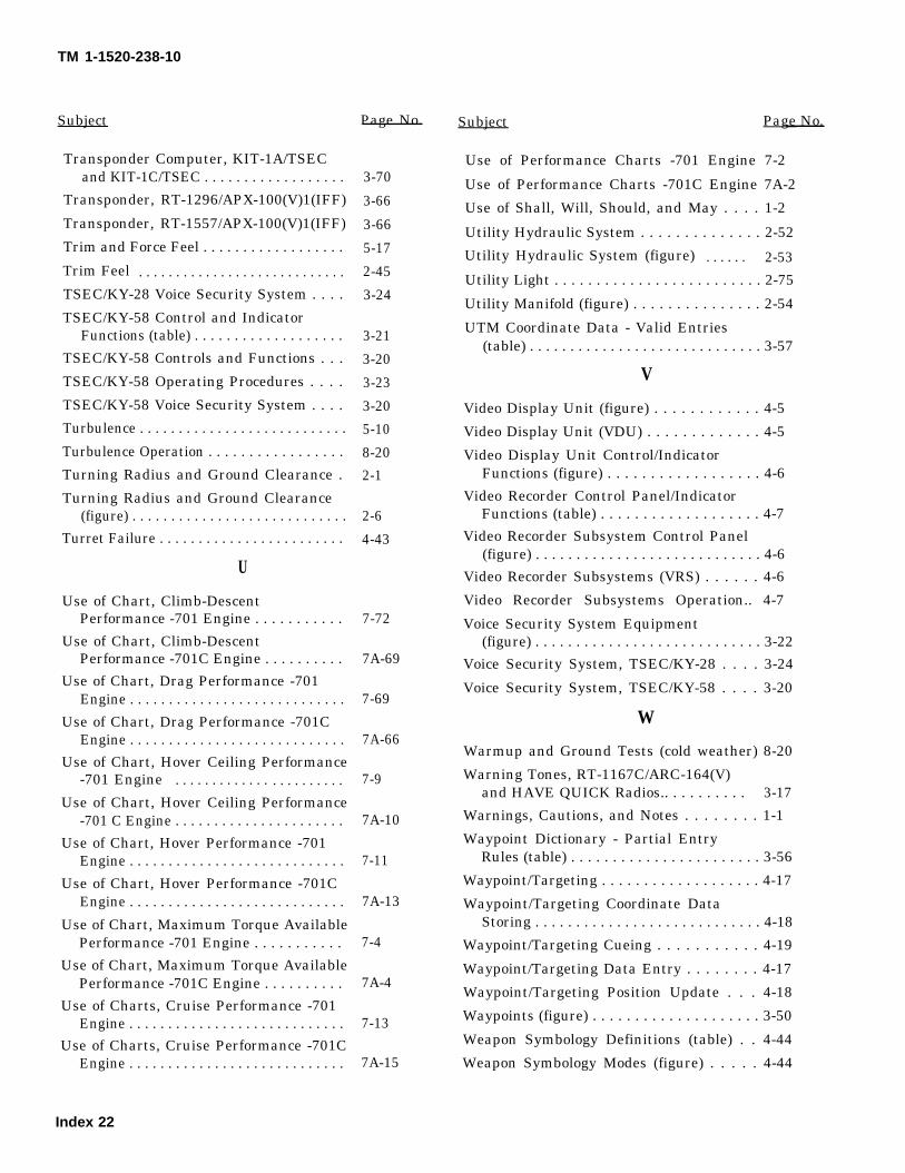
TM 1-1520-238-10
Subject
Transponder Computer, KIT-1A/TSECand KIT-1C/TSEC . . . . . . . . . . . . . . . . . .
Transponder, RT-1296/APX-100(V)1(IFF)
Transponder, RT-1557/APX-100(V)1(IFF)
Trim and Force Feel . . . . . . . . . . . . . . . . . .
Trim Feel . . . . . . . . . . . . . . . . . . . . . . . . . . . .
TSEC/KY-28 Voice Security System . . . .
TSEC/KY-58 Control and IndicatorFunctions (table) . . . . . . . . . . . . . . . . . . .
TSEC/KY-58 Controls and Functions . . .
TSEC/KY-58 Operating Procedures . . . .
TSEC/KY-58 Voice Security System . . . .
Turbulence . . . . . . . . . . . . . . . . . . . . . . . . . . .
Turbulence Operation . . . . . . . . . . . . . . . . .
Turning Radius and Ground Clearance .
Turning Radius and Ground Clearance(figure) . . . . . . . . . . . . . . . . . . . . . . . . . . . .
Turret Failure . . . . . . . . . . . . . . . . . . . . . . . .
U
Use of Chart, Climb-DescentPerformance -701 Engine . . . . . . . . . . .
Use of Chart, Climb-DescentPerformance -701C Engine . . . . . . . . . .
Use of Chart, Drag Performance -701Engine . . . . . . . . . . . . . . . . . . . . . . . . . . . .
Use of Chart, Drag Performance -701CEngine . . . . . . . . . . . . . . . . . . . . . . . . . . . .
Use of Chart, Hover Ceiling Performance-701 Engine . . . . . . . . . . . . . . . . . . . . . . .
Use of Chart, Hover Ceiling Performance-701 C Engine . . . . . . . . . . . . . . . . . . . . . .
Use of Chart, Hover Performance -701Engine . . . . . . . . . . . . . . . . . . . . . . . . . . . .
Use of Chart, Hover Performance -701CEngine . . . . . . . . . . . . . . . . . . . . . . . . . . . .
Use of Chart, Maximum Torque AvailablePerformance -701 Engine . . . . . . . . . . .
Use of Chart, Maximum Torque AvailablePerformance -701C Engine . . . . . . . . . .
Use of Charts, Cruise Performance -701Engine . . . . . . . . . . . . . . . . . . . . . . . . . . . .
Use of Charts, Cruise Performance -701CEngine . . . . . . . . . . . . . . . . . . . . . . . . . . . .
Page No.
3-70
3-66
3-66
5-17
2-45
3-24
3-21
3-20
3-23
3-20
5-10
8-20
2-1
2-6
4-43
7-72
7A-69
7-69
7A-66
7-9
7A-10
7-11
7A-13
7-4
7A-4
7-13
7A-15
Subject Page No.
Use of Performance Charts -701 Engine 7-2
Use of Performance Charts -701C Engine 7A-2
Use of Shall, Will, Should, and May . . . . 1-2
Utility Hydraulic System . . . . . . . . . . . . . . 2-52
Utility Hydraulic System (figure) . . . . . . 2-53
Utility Light . . . . . . . . . . . . . . . . . . . . . . . . . 2-75
Utility Manifold (figure) . . . . . . . . . . . . . . . 2-54
UTM Coordinate Data - Valid Entries(table) . . . . . . . . . . . . . . . . . . . . . . . . . . . . . 3-57
V
Video Display Unit (figure) . . . . . . . . . . . . 4-5
Video Display Unit (VDU) . . . . . . . . . . . . . 4-5
Video Display Unit Control/IndicatorFunctions (figure) . . . . . . . . . . . . . . . . . . 4-6
Video Recorder Control Panel/IndicatorFunctions (table) . . . . . . . . . . . . . . . . . . . 4-7
Video Recorder Subsystem Control Panel(figure) . . . . . . . . . . . . . . . . . . . . . . . . . . . . 4-6
Video Recorder Subsystems (VRS) . . . . . . 4-6
Video Recorder Subsystems Operation.. 4-7
Voice Security System Equipment(figure) . . . . . . . . . . . . . . . . . . . . . . . . . . . . 3-22
Voice Security System, TSEC/KY-28 . . . . 3-24
Voice Security System, TSEC/KY-58 . . . . 3-20
W
Warmup and Ground Tests (cold weather) 8-20
Warning Tones, RT-1167C/ARC-164(V)and HAVE QUICK Radios.. . . . . . . . . . 3-17
Warnings, Cautions, and Notes . . . . . . . . 1-1
Waypoint Dictionary - Partial EntryRules (table) . . . . . . . . . . . . . . . . . . . . . . . 3-56
Waypoint/Targeting . . . . . . . . . . . . . . . . . . . 4-17
Waypoint/Targeting Coordinate DataStoring . . . . . . . . . . . . . . . . . . . . . . . . . . . . 4-18
Waypoint/Targeting Cueing . . . . . . . . . . . 4-19
Waypoint/Targeting Data Entry . . . . . . . . 4-17
Waypoint/Targeting Position Update . . . 4-18
Waypoints (figure) . . . . . . . . . . . . . . . . . . . . 3-50
Weapon Symbology Definitions (table) . . 4-44
Weapon Symbology Modes (figure) . . . . . 4-44
Index 22
TM 1-1520-238-10
Subject Page No. Subject Page No.
Weapons Symbology . . . . . . . . . . . . . . . . . .
Weight and Balance . . . . . . . . . . ..
Weight and Balance Clearance Form F .
Weight Definitions . . . . . . . . . . . . . . . . . . . .
Weight Limitations . . . . . . . . . . . . . . ..
Weight, Basic, (Definition) . . . . . . . . . . . . .
Weight, Gross, (Definition) . . . . . . . . . . . .
Weight, Operating, (Definition) . . . . . . . .
Weight, Personnel . . . . . . . . . . . . . . . . . . . .
Weight/Balance and Loading,Introduction . . . . . . . . . . . . . . . . . . . . . . .
Weights and Moments, Storage Bay andSurvival Kit Bay Equipment (table). .
Windshield and Canopy Cleaning . . . . . .
Windshield and Canopy Panels . . . . . . . .
Windshield Anti-Ice/De-Ice . . . . . . . . . . . .
4-43
6-3
6-4
6-3
5-10
6-3
6-3
6-3
6-10
Windshield, General . . . . . . . . . . . . . . . . . .
Wing Stores Configuration . . . . . . . . . . . .
Wing Stores Jettison . . . . . . . . . . . . . . . . . .
Wings, General . . . . . . . . . . . . . . . . . . . . . . .
Wire Strike Protection System (figure) .
Wire Strike Protection System (WSPS) .
X
Y6-1
Z6-16
2-96
2-2
2-60
Z-AHP Remote Control Unit Control andIndicator Functions (table) . . . . . . . . . .
Z-AHQ Power Interface Adapter Controland Indicator Functions (table) . . . . . .
2-2
5-17
9-21
2-1
2-63
2-62
3-21
3-20
Index 23/(Index 24 blank)

TM1-1520-238-10
By Order of the Secretary of the Army:
Official:
GORDON R. SULLIVANGeneral, United States Army
Chief of Staff
MILTON H. HAMILTONAdministrative Assistant to the
Secretary of the Army07462
DISTRIBUTION:To be distributed in accordance with DA Form 12-31-E, block no. 0293, requirements for
TM 1-1520-238-10.
* U.S. GOVERNMENT PRINTING OFFICE: 1994-555-121/00026

TM 55-1520-238-10
THESE ARE THE INSTRUCTIONS FOR SENDING AN ELECTRONIC 2028
The following format must be used if submitting an electronic 2028. The subject line must be exactly thesame and all fields must be included; however only the following fields are mandatory: 1, 3, 4, 5, 6, 7, 8, 9,10, 13, 15, 16, 17, and 27.
From: ‘Whomever” <[email protected]>
Subject: DA Form 20281.
2.
3.
4.
5.
6.
7.
8.
9.
10.
11.
12.
13.
14.
15.
16.
17.
18.
19.
20.
21.
22.
23.
24.
25.
26.
27.
From: Joe Smith
Unit: Home
Address: 4300 Park
City: Hometown
St: MO
Zip: 77777
Date Sent: 19-Oct-93
Pub no: 55-2840-229-23
Pub Title: TM
Publication Date: 04-Jul-85
Change Number: 7
Submitter Rank: MSG
Submitter Fname: Joe
Submitter Mname: T
Submitter Lname: Smith
Submitter Phone: (123) 123-1234
Problem: 1
Page: 2
Paragraph: 3
Line: 4
NSN: 5
Reference: 6
Figure: 7
Table: 8
Item: 9
Total: 123
Text:
This is the text for the problem below line 27.
U.S. GOVERNMENT PRINTING OFFICE: 1998-633-280/60195 Change 5

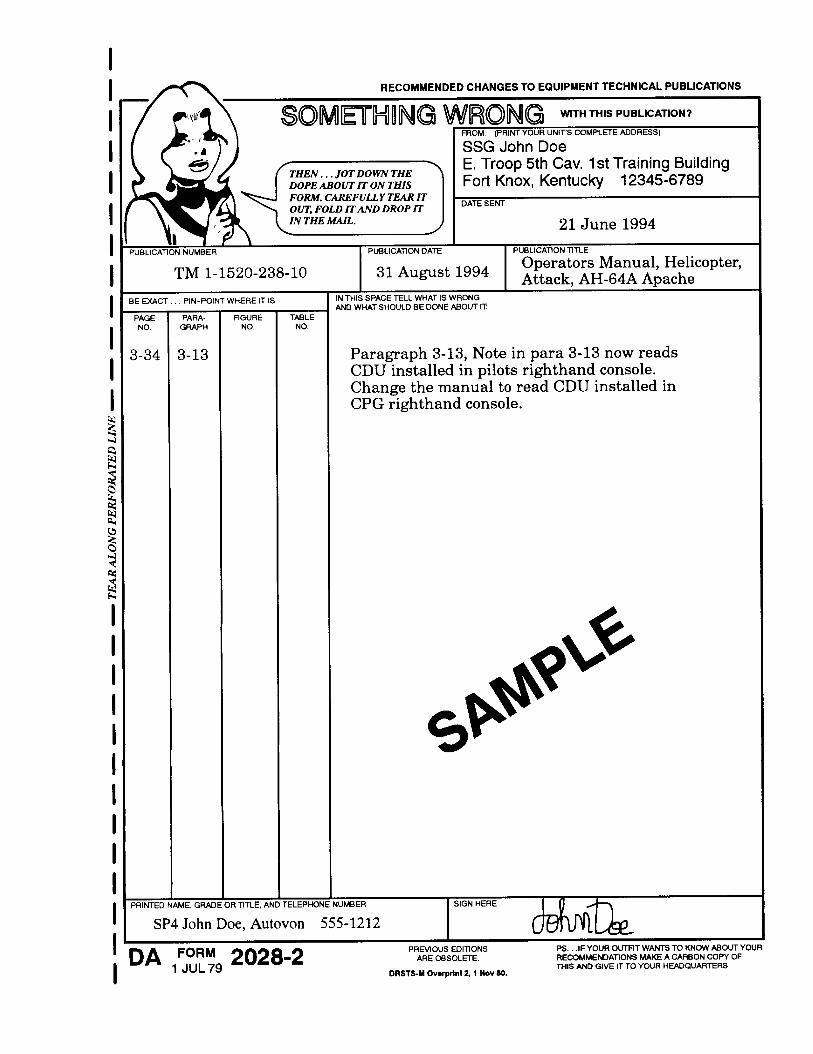


Related Documents